Embed Size (px)
Citation preview

SCI PUBLICATION 101
C U RTAIN WALL CONNECTIONS TO STEEL FRAMES
R G OGDEN BA(Hons), Dip Arch, PhD(Prod. Eng), MCSD
ISBN 1 870004 78 7
A catalogue record for this book is available from the British Library
0 The Steel Construction Institute 1992
The Steel Construction Institute Silwood Park, Ascot Berkshire SL5 7QN Telephonle: 0344 23345 Fax: 034,4 22944
l
P101: Curtain wall connections to steel frames
Discuss me ...C
reat
ed o
n 22
Jul
y 20
09T
his
mat
eria
l is
copy
right
- a
ll rig
hts
rese
rved
. Use
of t
his
docu
men
t is
subj
ect t
o th
e te
rms
and
cond
ition
s of
the
Ste
elbi
z Li
cenc
e A
gree
men
t
INTERFACES FOREWORD
This publication is intended to promote efficiency in the design and erection of cladding systems, and their attachments to steel frames. The research into 'Interface Problems in Modern Commercial Building Design' was initiated by the Steel Construction Review. The author of this publication was Dr R G Ogden of the Steel Construction Institute. The group responsible for leading this project was as follows: Mr R Gordon (Chairman) Bovis Construction Ltd.
Mr B Boys British Steel
Mr P Craddock Ove Arup and Partners Mr E V Girardier Steel Construction Industry
Federation
Mr G Raven Ward Structures Ltd now with, The Steel Construction Institute
Mr M Downing Trent Concrete Ltd.
Mr R Naman Jenkins and Potter Consulting
The work leading to this publication was funded by British Steel (General Steels), the Department of the Environment, and by the following industrial and professional sponsors: Ove Arup Partnership Octavius Atkinson and Sons Ltd. Booth Industries Plc.
McCalls Special Products Ltd. Gifford and Partners
Grant Judge Partnership William Hare Ltd.
Hilti (Great Britain) Ltd.
Jenkins and Potter Consulting Engineers J N Rowen Ltd.
Graham Wood Structural Ltd. Taylor Woodrow Construction Ltd. Robert Watson and Co. Ltd.
A companion publication, Brick Cladding to Steel Framed Buildings by British Steel and the Brick Development Association addresses the fixing of brickwork to steel frames.
Engineers
P101: Curtain wall connections to steel frames
Discuss me ...C
reat
ed o
n 22
Jul
y 20
09T
his
mat
eria
l is
copy
right
- a
ll rig
hts
rese
rved
. Use
of t
his
docu
men
t is
subj
ect t
o th
e te
rms
and
cond
ition
s of
the
Ste
elbi
z Li
cenc
e A
gree
men
t
CONTENTS
SUMMARY INTRODUCTION REVIEW OF MAIN THEMES SUMMARY’ OF RECOMMENDATIONS AND CHECKLISTS
1 DESIGN lntroductioln to Section 1 1 . l
1.2 1.3 1.4 1.5 1.6 1.7 1.8 1.9 1 . I O
Generic cladding types Principles of support and restraint
Installation and erection The cladding / frame interface Tolerances
Loads and their effects Post installation movements
Corrosion protection of fixings Fire protection of fixings Constraints on internal layout
2 SYSTEM!;
Introduction to Section 2 2.1
2.2
2.3
2.4 2.5 2.6
Integral concrete panel with integral boot, top hung Integral concrete panel with integral boot, bottom supported Integral concrete panel with flat back, top hung Strongback system with slab fixing Strongback system with column fixing
Stick system with slab edge fixing
Page no. iv 1 2
4
7 8
14 16 19 23 28 29 33 34 34
35
37
43
49 55 61 67
... I l l
P101: Curtain wall connections to steel frames
Discuss me ...C
reat
ed o
n 22
Jul
y 20
09T
his
mat
eria
l is
copy
right
- a
ll rig
hts
rese
rved
. U
se o
f th
is d
ocum
ent
is s
ubje
ct t
o th
e te
rms
and
cond
ition
s of
the
Ste
elbi
z Li
cenc
e A
gree
men
t
INTERFACES SUMMARY
The correct design of connections between cladding panels and steel frames is of critical importance to the performance of the cladding and to the building programme. Since cladding is a critical path operation, cladding connections have to be developed such that they not only have sound structural and physical properties, but also permit efficient and rapid erection. A characteristic of many of the most successful cladding systems is that much preparatory work (lining and levelling etc.) is done in advance of the erection operation, and therefore off the critical path. Section 1 of this publication details the advantages of such practice and Section 2 appraises six generic cladding systems in relation to the optimised practices set out in Section 1.
Assemblage du revetement a une structure en acier' Resume fa conception correcte des assemblages entre panneaux de revktement et structure en acier est d'une importance critique tant pour la performance des rev6tements que pour le programme de construction. Comme la pose des rev6tements constitue une operation se situant sur le chemin critique de la construction, les moyens d'assemblages doivent non seulement avoir de bonnes caracteristiques structurales et physiques, mais doivent aussi permettre un montage rapide et efficace. Une caracteristique des systemes de revktements les plus performants est que de nombreuses operations (garniture de I'interieur des panneaux, nivellement, . . .) peuvent etre executees avant le montage proprement dit et donc hors du chemin critique. La premiere partie de la publication decrit les avantages d'une telle pratique et donne une guidance du dimensionnernent. fa seconde partie evalue six systemes de rev6tement en fonction des conclusions tirees dans la premiere partie.
Verbindungen von Verkleidungen mit Stahltragwerken Zusammenfassung Der richtige Entwurf der Verbindungen zwischen Verkleidungen und Stahltragwerken ist von groBer Bedeutung fur das Verhalten der Verkleidungen und des Bauablaufs. Da das Verkleiden einen "Kritischen- Weg-Vorgang" darstellt, mussen Verbindungen nicht nur bauphysikalische und statische Kriterien erfullen, sondern auch eine effiziente und schnelle Montage erlauben.
iv
P101: Curtain wall connections to steel frames
Discuss me ...C
reat
ed o
n 22
Jul
y 20
09T
his
mat
eria
l is
copy
right
- a
ll rig
hts
rese
rved
. Use
of t
his
docu
men
t is
subj
ect t
o th
e te
rms
and
cond
ition
s of
the
Ste
elbi
z Li
cenc
e A
gree
men
t

Ein Merknlal der erfolgreichsten Verkleidungs-Systeme ist, daB vorbereitende Arbeiten (Fullung, Ausrichten etc.) vor der Montage erfolgen, und damit auBerhalb des kritischen Weges. Teil 7 dieser Veroffentlichung zeigt die Vorteile dilses Vorgehens auf und vermittelt Entwurfschilfen. Teil2 beurteilt sechs Verkleidungs- Systeme hinsichtlich der optimierten Vorgehensweisen, die in Teil 1 vorgestellt werden.
Collegamento di pannelli di rivestimento a telai di acciaio Sommario Una corretta progettazione dei collegamenti tra i pannelli di rivestimento ed I' telai di acciaio risulta molto importante sia per il comportamento globale del sistema di rivestimento sia per I'assemblaggio dell'edificio. Poiche' la progettazione dei pannelli di rivestimento rappresenita, un 'operazione molto delicata (costituisce un percorso critico ne1 diagramma di flusso relativo alla progettazione), i collegamenti dei pannelli devono essere progettati in modo che non solo abbiano adeguate proprieta' meccaniche e fisiche ma permettano anche una rapid21 ed agevole erezione. Una carattersitica di molti tra i piu' diffusi sistemi di rivestimento e' che il lavoro di preparazione (foderazione ed livellamento) viene fatto prima della operazione di mesa in opera e quindi non appartiene a1 percorso critico della progettazione. La prima parte di questa pubblicazione tratta in dlettaglio i benefic; di tali applicazioni e fornisce criteri pro!gettuali. La parte 2 analizza sei sistemi di collegamento in relazione ai criteri di ottimizzazione presentati nella Parte 1.
Union de chapados a estructuras de acero Resumen El proyecto adecuado de las uniones entre paneles de chapado y estructuras de acero es de una importancia critica tanto para el funcionamiento del chapado como para el proceso constructivo. Puesto que el chapado es una operacion generalmente contenida en el Camino Critico, sus uniones deben ser eficaces dlesde el punto de vista fisico y estructural y permiten ademas una instalacion rapida y efficiente.
Es tipico ole la mayoria de 10s sistemas de chapado la realizacion de gran cantidad de trabajo (alineacion, topografia, etc.) previamente a /as operaciones de colocacion y por tanto, fuera del Camino Critico. La primem parte de esta publicacion detalla las ventajas de esta ccstumbre y da consejos para su proyecto. La parte 2 de un panorama de 10s seis sistemas de chapado en relacion con las practicas optimizadas establecidas en la primera parte.
V
P101: Curtain wall connections to steel frames
Discuss me ...C
reat
ed o
n 22
Jul
y 20
09T
his
mat
eria
l is
copy
right
- a
ll rig
hts
rese
rved
. Use
of t
his
docu
men
t is
subj
ect t
o th
e te
rms
and
cond
ition
s of
the
Ste
elbi
z Li
cenc
e A
gree
men
t
INTRODUCTION
The wall cladding to steel framed buildings may have a value of up to a quarter of the total building cost. Not surprisingly, much attention is given to the appearance of the cladding and to its functional performance, but there is another less apparent, but equally important consideration. Fixing wall cladding to multi-storey steel frames is an activity firmly on the critical path of the construction process. A cladding support detail which allows panels to be lifted into position and installed quickly will decrease the period during which the crane cannot be used for other site operations. This has clear programming and financial advantages. Many cladding support details have been used successfully in the UK. However recent history does include examples, sometimes in relation to major projects, of needless programme overruns arising from the cladding operation. These are often attributable to poor detailing and are therefore avoidable if account is taken of buildability and tolerances a t the design stage.
The study leading to this publication was based on a thorough survey of the different forms of modern cladding that may be used with steel or 'composite' steel-concrete frames, in commercial and similar buildings. Masonry (i.e. brick and blockwork) has been specifically excluded since it is already covered by the British SteeVBrick Development Association publication Brick Cladding to Steel Framed Buildings. Profiled sheeting for cladding and roofing is also excluded since these materials are rarely associated with commercial buildings and the standard of connection details and their integration with the steel frame is generally good. These materials are covered by the publication Profiled Sheet Metal Roofing and Cladding, a Guide to Good Practice produced by the National Federation of Roofing Contractors. The following sections set down a summary of the technical requirements, and design issues, associated with the connection of cladding to the steel frame. It is written for architects, engineers, steelwork contractors, cladding manufacturers, site managers, clients and developers. It presents the flow of information required between these parties in respect of the cladding operation, and gives examples of various cladding support details, which in part or whole, realise those technical qualities advocated by the study.
1
P101: Curtain wall connections to steel frames
Discuss me ...C
reat
ed o
n 22
Jul
y 20
09T
his
mat
eria
l is
copy
right
- a
ll rig
hts
rese
rved
. Use
of t
his
docu
men
t is
subj
ect t
o th
e te
rms
and
cond
ition
s of
the
Ste
elbi
z Li
cenc
e A
gree
men
t

INTERFACES REVIEW OF MAIN THEMES
Cladding panels, be they of concrete, stone, or other materials, share many aspects of their connection to the supporting structure. Panels are usually designed as storey high units, or alternatively, are supported on secondary steel or aluminium members such as mullions (columns), or transoms (cross-members). Full panel units may be supported from their bases or hung from their tops. They may be fixed either to concrete floor slabs or to steel edge beams; or where the module of the building permits, may be fixed to columns. A variety of generic types of system, are outlined later. Cladding panels are supported in such a way as to resist the local forces applied to them (wind loading etc.; refer to Section 1.6), but they play no part in the overall structural behaviour of the building, i.e. there is no structural interaction between the cladding and the building frame. The connections are therefore designed to avoid panels being stressed when the building moves, or when the panels themselves expand or contract as a result of temperature changes. Some examples of the forces developed due to 'restrained movement' are given in the Section 2 on 'Post Installation Movements'. Panel connections must also incorporate adjustment to take up tolerances in the frame. Generally, cladding tolerances are of the order of one third to one quarter of those associated with the frame. These finer tolerances have to be achieved by adjustment of the connection detail. The following text argues two themes. Firstly, that those cladding details which have proven most successful in practice, are the result of an integrated approach, where the building is seen as a total product. The successful design of such systems is not only a response to the forces applied to the connections, but also a response to installation considerations; notably, the ease and speed with which the site workforce is able to manipulate the cladding units on site into their final position. The second theme relates to the forethought applied to the work undertaken on site. A characteristic of the most successful cladding systems is that much preparatory work is done prior to installation, so that critical path operations can be completed in minimum time. Notably, this preparatory work includes the lining and levelling of fixings, such that cladding units can be lifted from the delivery vehicle, and fixed directly onto the building frame. This rapid fixing accelerates the cladding operation and has a general benefit on the building programme since subsequent trades can have confidence that their vehicle delivery space, and their crane hook time, will be available precisely according to their schedule of activities. Given that in principle these are relatively straightfoward issues, it is curious as to why responsive methodologies
2
P101: Curtain wall connections to steel frames
Discuss me ...C
reat
ed o
n 22
Jul
y 20
09T
his
mat
eria
l is
copy
right
- a
ll rig
hts
rese
rved
. Use
of t
his
docu
men
t is
subj
ect t
o th
e te
rms
and
cond
ition
s of
the
Ste
elbi
z Li
cenc
e A
gree
men
t

have not been developed. There are numerous reasons why this is so. Not least, is that the design of cladding attachments falls between the traditional roles of both the architect and structural engineer. This can mean that decisions on fixing details are taken late in the design process, and as a result are poorly resolved. Furthermore, fixings which are capable of being lined and levelled in advance of the cladding operation are often perceived as expensive, particularly when connections are designed and fabricated on a one off project basis. However, given the advantages which such fixings present in global cost terms, such misgivings have dubious validity. Finally, there is a suggestion of a fundamental problem viz. the industry in general has yet to comprehend fully the advantages of rationalising the cladding operation in terms of the overall efficiency of construction.
3
P101: Curtain wall connections to steel frames
Discuss me ...C
reat
ed o
n 22
Jul
y 20
09T
his
mat
eria
l is
copy
right
- a
ll rig
hts
rese
rved
. Use
of t
his
docu
men
t is
subj
ect t
o th
e te
rms
and
cond
ition
s of
the
Ste
elbi
z Li
cenc
e A
gree
men
t
INTERFACES SUMMARY OF RECOMMENDATIONS AND CHECKLISTS
There are many broad considerations which determine the overall quality of cladding systems. None however, have such a profound effect upon buildability as connection design. In principle the following considerations should be taken into account when designing cladding connections: 0 The safe transmission of forces arising from the weight
of the cladding and from wind loading, to the main structure.
layout of structure (slab edge and perimeter column detail etc.), and services.
0 Constraints imposed on the fixing by the internal
0 The ease and speed of erection, and inspection. 0 The adjustments that are required to allow for
differential tolerances and constructional inaccuracies. 0 Post installation movements of both the structure and
cladding. Fire protection of the fixing.
0 Corrosion resistance (which should relate to the design
0 Standardisation of details. 0 Supply and fix costs and the cost of the system to the
overall programme (more expensive systems which can be fixed rapidly, may yield an overall cost saving).
0 Design responsibilities to be clearly delineated within the design team.
Specific recommendations relating to the installation and erection of cladding include: 0 Panel fixings should be lined and levelled in advance
of the cladding operation. 0 Sizes of panels should be optimised. Generally large
panel systems can be erected more quickly, on a total area basis than smaller panel systems.
preferably from the same floor level.
life of the cladding).
0 There should be good access to all connections,
0 There should be a minimum number of connections. 0 Cranage time should be minimised by the manner in
which panels are presented and installed. From these recommendations it is advised that the following pre-design, design and installation considerations be taken into account when developing cladding systems and associated erection procedures:
Pre-design Pre-design issues include: (a) the zoning of services and structure adjacent to the cladding; (b) reconciliation of tolerances between the cladding and other building elements; and (c) co-ordination of the various professions
4
P101: Curtain wall connections to steel frames
Discuss me ...C
reat
ed o
n 22
Jul
y 20
09T
his
mat
eria
l is
copy
right
- a
ll rig
hts
rese
rved
. Use
of t
his
docu
men
t is
subj
ect t
o th
e te
rms
and
cond
ition
s of
the
Ste
elbi
z Li
cenc
e A
gree
men
t
involved in the design, production and installation of the cladding systems.
Checklist 1 : Pre-design 1. The location of cladding supports must be determined
early in the building design programme, and agreed with services and structural engineers. If necessary, floor voids, ceiling voids, and wall ducts, should be zoned to avoid clashes.
2. All parties should be kept fully aware of any variations made to the agreed arrangement.
3. Buffer zones (i.e. spacial zones which absorb moderate unpredicted dimensional variations in the as built system, refer to Section 1.5), should be incorporated in addition to conventional manufacturing and installation tolerances. These should be able to absorb exceptional compound dimensional variations, without compromising the integrity of the cladding system. In this way, buffers help to ensure that work proceeds on programme, even when accuracy (normally of the frame), is moderately less than specified. Effective use of buffers should help to ensure that remedial building work, is avoided.
4. Anticipated movements in the building frame should be determined by the structural engineer at an early stage, and agreed with the cladding contractor. Increasing the stiffness of the frame should be considered if deflections are potentially large.
Design Each component within a cladding system should be designed to achieve optimum overall performance of the combined elements. The most significant components, in respect of the connection detail, are the fixings themselves, the panel and the frame. Primary areas of consideration must therefore include:
Checklist 2a: Design - Fixings 1. Fixings should be designed in such a way that
eccentric loading of the columns and edge beams is minimised.
2. Wherever possible, connections to edge beams at mid- span should be avoided in order to reduce longitudinal bending.
3. Cladding connections should be designed to induce minimum lateral bending. In practice this means avoiding connections to the lower flange of edge beams.
4. Where fixings are sited on the concrete slab, cast-in types or through bolts in cast holes should be used, since reinforcing bars in the thin concrete floor edge make drilling difficult.
5. Cladding fixings should allow relative movement to
5
P101: Curtain wall connections to steel frames
Discuss me ...C
reat
ed o
n 22
Jul
y 20
09T
his
mat
eria
l is
copy
right
- a
ll rig
hts
rese
rved
. Use
of t
his
docu
men
t is
subj
ect t
o th
e te
rms
and
cond
ition
s of
the
Ste
elbi
z Li
cenc
e A
gree
men
t

INTERFACES take place between the cladding and frame (both vertical and horizontal), without over-stressing either element.
details, both for erection, and inspection. 6. It should be possible to gain easy access to fixing
Checklist 2b: Design - Frame 1. It is generally advantageous to keep the number of
frame edge conditions to a minimum. Economies brought about by designing the frame to have the smallest necessary edge beam for each span loading condition, are unlikely to be of net benefit, if they result in a wide variety of panel sizes or fixing conditions.
Checklist 2c: Design - Panel 1. Panel size should be optimised. In principle, the larger
the panel the more rapid the erection operation, up to a practical maximum size for delivery and subsequent on-site handling. Interaction between the various members of the design, fabrication and construction disciplines will be required to determine the most appropriate size.
2. Joints between cladding panels should be designed to accommodate dimensional variations arising from compounded tolerances, and relative movements of the building frame. The magnitude of these movements should be determined, and agreed by all concerned parties, a t the pre-design stage.
3. Panel joints and fixing locations should be well coordinated.
Installation The importance of effective installation procedures for cladding systems must not be underestimated. Proper procedures can have profound effect, not only upon the length of the critical path, but on the reliability of the entire building programme, since they afford greater certainty that following trades will be able to proceed on schedule. Installation should be of prime consideration, a t conceptual design stage, and throughout the development programme.
Checklist 3: Installation 1. Lining and levelling of fixing should take place before
panel erection, and therefore off the critical path. Only minor adjustments should be required in situ, and ideally, there should be provision to make these after the crane hook is released.
2. Cladding panels should preferably arrive on site in a predetermined sequence, and be lifted directly from the lorry onto the building frame (i.e. without double handling).
6
P101: Curtain wall connections to steel frames
Discuss me ...C
reat
ed o
n 22
Jul
y 20
09T
his
mat
eria
l is
copy
right
- a
ll rig
hts
rese
rved
. Use
of t
his
docu
men
t is
subj
ect t
o th
e te
rms
and
cond
ition
s of
the
Ste
elbi
z Li
cenc
e A
gree
men
t
1 DESIGN
INTRODUCTION TO SECTION 1
There are many types of wall cladding available. The various types may be categorised both in terms of their materials, and systems of support. Materials that come within the scope of this publication are:
Glazing Aluminium and Steel Panels (excluding profiled sheeting) Precast Concrete Panels Stone Cladding Units or Veneer
7
P101: Curtain wall connections to steel frames
Discuss me ...C
reat
ed o
n 22
Jul
y 20
09T
his
mat
eria
l is
copy
right
- a
ll rig
hts
rese
rved
. Use
of t
his
docu
men
t is
subj
ect t
o th
e te
rms
and
cond
ition
s of
the
Ste
elbi
z Li
cenc
e A
gree
men
t

INTERFACES
Figure 1 . 1 Integral panel
Materials which are already properly covered in other guides, include profiled sheeting and masonry, whilst a guide is currently being produced by the GRCA for connections to Glass Reinforced Cement (GRC) panels.
1 . l GENERIC CLADDING TYPES
It may be proposed that there are three basic generic families of cladding, from which bespoke and hybrid systems are derived: (a) Integral panels, (b) Strongback panels, (c) Stick systems and (d) Hybrid systems.
(a) Integral panels
Integral panels (Figures 1 .l and 1.2) are able to support their own weight and resist wind loads without additional structural systems. Panels may be top hung or bottom supported and typically will bear onto the floor slab using a boot arrangement, or bolted on bracketry. This detail also provides for structural connection to the floor slab. Some form of wind restraint is also required to prevent rotation of the panel about its bearing.
8
P101: Curtain wall connections to steel frames
Discuss me ...C
reat
ed o
n 22
Jul
y 20
09T
his
mat
eria
l is
copy
right
- a
ll rig
hts
rese
rved
. Use
of t
his
docu
men
t is
subj
ect t
o th
e te
rms
and
cond
ition
s of
the
Ste
elbi
z Li
cenc
e A
gree
men
t

Figure 1.2 Integral panel; elevation and
section
Integral panels may be clad in other materials (typically concrete panels are clad in stone). Panels tend to have higher mass than strongback and stick systems. Panel weights of approximately 300 kg/m2 are typical, with storey height panel widths of between 3 and 9 m (height typically 4 to 5 m). The maximum size of panel is restricted by transport considerations and crane lifting capacity (both on site and at the concrete works). 15 to 20 tonnes are typical maximum weights.
(b) Strongback panels
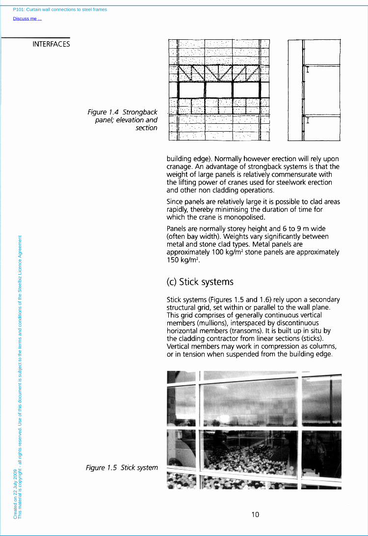
Strongback panels (Figures 1.3 and 1.4) comprise panels restrained by structural frameworks (often triangulated trusses). Units are normally of storey height, and span between primary structural elements. Supporting frameworks are generally steel although aluminium or other materials can be used. The facing material (often stone) and frame are assembled prior to erection.
Since strongback systems are relatively light in comparison to integral panels, it is sometimes practical to lift panels into place using small powered hoists and lifting tackle (sometimes attached to steelwork at the
9
P101: Curtain wall connections to steel frames
Discuss me ...C
reat
ed o
n 22
Jul
y 20
09T
his
mat
eria
l is
copy
right
- a
ll rig
hts
rese
rved
. Use
of t
his
docu
men
t is
subj
ect t
o th
e te
rms
and
cond
ition
s of
the
Ste
elbi
z Li
cenc
e A
gree
men
t
INTERFACES
Figure 1.4 Strongback panel; elevation and
section
Figure l . 5 Stick system
building edge). Normally however erection will rely upon cranage. An advantage of strongback systems is that the weight of large panels is relatively commensurate with the lifting power of cranes used for steelwork erection and other non cladding operations.
Since panels are relatively large it is possible to clad areas rapidly, thereby minimising the duration of time for which the crane is monopolised.
Panels are normally storey height and 6 to 9 m wide (often bay width). Weights vary significantly between metal and stone clad types. Metal panels are approximately 100 kg/m2 stone panels are approximately 150 kg/m2.
(c) Stick systems
Stick systems (Figures 1.5 and 1.6) rely upon a secondary structural grid, set within or parallel to the wall plane. This grid comprises of generally continuous vertical members (mullions), interspaced by discontinuous horizontal members (transoms). It is built up in situ by the cladding contractor from linear sections (sticks). Vertical members may work in compression as columns, or in tension when suspended from the building edge.
10
P101: Curtain wall connections to steel frames
Discuss me ...C
reat
ed o
n 22
Jul
y 20
09T
his
mat
eria
l is
copy
right
- a
ll rig
hts
rese
rved
. Use
of t
his
docu
men
t is
subj
ect t
o th
e te
rms
and
cond
ition
s of
the
Ste
elbi
z Li
cenc
e A
gree
men
t

Figure 1.6 Stick system; elevation and section
Stick systems are generally used for lighter cladding materials such as aluminium panels and glazing. A prime example is curtain walling of the type which comprises rectangular glazed panels restrained along four edges by extruded aluminium mullions and transoms. It is less well acknowledged that stick systems also include certain proprietary designs which comprise composite panels, fixed back onto frameworks of light gauge cold rolled steel sections. Significantly, lighter stick systems do not require cranage, and may therefore present considerable programming advantages since during the erection period cranes will be free to attend other trades. Stick systems are amongst the lightest cladding systems weighing approximately 50 kg/m2. Mullion spacings are typically in the range 1.2 to 1.5 m, although spacings of up to 3 m are possible. Transom spacings are generally determined by the sheeting material (fabrication and erection considerations) and the architectural order of the facade.
(d) Hybrid systems Any system which does not fall within previous classification may be considered a hybrid. Hybrid approaches include innovative systems which straddle classification. Commonly occuring types include:
Unitised panels
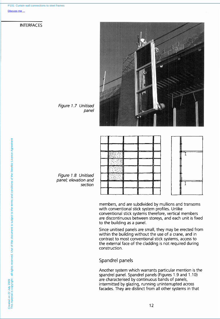
A hybrid system which warrants particular mention is unitised cladding. Unitised cladding panels (Figures 1.7 and 1.8) are conceptually panelised stick systems, or smaller strongback panels, without horizontally spanning trusses. Unitised panels are typically narrow storey height units which arrive on site fully assembled (unlike stick systems).
Strongback derivatives rely on an appropriately designed light framework which spans vertically between slab edges. Derivatives of stick systems typically comprise an outside frame made up of four specially profiled edge
11
P101: Curtain wall connections to steel frames
Discuss me ...C
reat
ed o
n 22
Jul
y 20
09T
his
mat
eria
l is
copy
right
- a
ll rig
hts
rese
rved
. U
se o
f th
is d
ocum
ent
is s
ubje
ct t
o th
e te
rms
and
cond
ition
s of
the
Ste
elbi
z Li
cenc
e A
gree
men
t
INTERFACES
Figure l .7 Unitised panel
Figure l .8 Unitised panel; elevation and
section
members, and are subdivided by mullions and transoms with conventional stick system profiles. Unlike conventional stick systems therefore, vertical members are discontinuous between storeys, and each unit is fixed to the building as a panel.
Since unitised panels are small, they may be erected from within the building without the use of a crane, and in contrast to most conventional stick systems, access to the external face of the cladding is not required during construction.
Spandrel panels
Another system which warrants particular mention is the spandrel panel. Spandrel panels (Figures 1.9 and 1 . l 0) are characterised by continuous bands of panels, intermitted by glazing, running uninterrupted across facades. They are distinct from all other systems in that
12
P101: Curtain wall connections to steel frames
Discuss me ...C
reat
ed o
n 22
Jul
y 20
09T
his
mat
eria
l is
copy
right
- a
ll rig
hts
rese
rved
. Use
of t
his
docu
men
t is
subj
ect t
o th
e te
rms
and
cond
ition
s of
the
Ste
elbi
z Li
cenc
e A
gree
men
t

Figure 1.9 Spandrel panel
Figure 1.10 Spandrel panel; elevation and
section
they do not span between storeys. Rather, both self weight and wind restraint occurs at, or about, a single slab level.
This is normally achieved in one of four ways: (a) The self weight of the panel may be taken a t the top
of the slab, and wind restraint connections made to the soffit of the floor.
(b) The self weight of the panel may be taken at top of the slab, and wind restraint fixings made at the columns.
(c) The panel may be designed to span between columns with wind restraints a t the floor edge.
(d) The panel may be designed to span between columns, with no connections to the floor edge. Both structural and wind restraint connections are made directly to the columns.
13
P101: Curtain wall connections to steel frames
Discuss me ...C
reat
ed o
n 22
Jul
y 20
09T
his
mat
eria
l is
copy
right
- a
ll rig
hts
rese
rved
. Use
of t
his
docu
men
t is
subj
ect t
o th
e te
rms
and
cond
ition
s of
the
Ste
elbi
z Li
cenc
e A
gree
men
t

INTERFACES 1.2 PRINCIPLES OF SUPPORT AND RESTRAINT
Cladding panels are usually designed as statically determinate structural elements, and are fixed such that no potentially damaging internal forces (arising from thermal effects etc.) are generated. The weight of individual panels has to be supported a t two (or more) attachments. Conventionally, these are located a t either the top or bottom of the panel. Wind restraints fixings which keep the panels in vertical alignment by resisting horizontal wind loads are located a t the opposite edge of the panel. There are, however, other established systems of support, most notably those used in relation to spandrel panels and stick systems.
Integral, strongback and unitised systems
The relative merits of top-hung and bottom-supported systems are presented in detail in Section 2. Generally however, bottom fixings permit the whole panel to be used in compression. This can be an advantage, especially with pre-cast concrete units which are less susceptible to cracking when used in compression (particularly in the region of the connection). Wind restraint may take the form of bracketry, or panels may simply interlock with adjacent units as described in later Sections. Restraint arrangements should have equal compressive and tensile capacity, since peak wind positive and negative pressures are similar in most cases except adjacent to the corner of a building where negative pressures are greater. These wind loads are transmitted either to adjacent panels (where interlocking details are used), or to fixing devices located opposite the structural attachments (refer examples in Section 2).
Stick systems
As already introduced, curtain wall type stick systems typically comprise vertical mullions which are continuous over several storeys. These members may act as columns (only supporting the cladding), or may be hung from floor edges. In addition to these structural connections (one per vertical member), wind restraint is normally provided a t each floor level. These wind restraint connections prevent lateral movement a t these points but leave mullions free to move in the vertical dimension. Brackets may be attached to the slab edge, to edge beams or to edge channels. Tall buildings may be divided into a number of distinct vertical zones, each with its own points of attachment to the building edge. In this way the magnitude of vertical movements a t the wind restraints is contained, and the load carried by the mullions is moderated.
14
P101: Curtain wall connections to steel frames
Discuss me ...C
reat
ed o
n 22
Jul
y 20
09T
his
mat
eria
l is
copy
right
- a
ll rig
hts
rese
rved
. Use
of t
his
docu
men
t is
subj
ect t
o th
e te
rms
and
cond
ition
s of
the
Ste
elbi
z Li
cenc
e A
gree
men
t

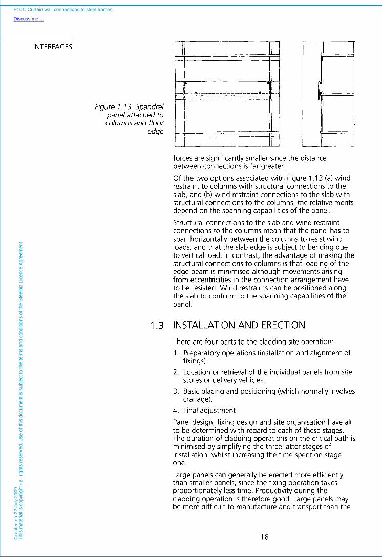
Spandrel panels Since spandrel panels do not span between floors, the support and restraint details may be significantly different to those used for integral and strongback units. If the panel is supported entirely from the columns i.e. both structural and wind restraint connections are made to the columns, then structurally the panel performs very similarly to those discussed in the previous Section (Figure 1 . l 1). Conceptually, the panel straddles the floor edge, rather than spanning between floors.
Figure l . 1 7 Spandrel panel attachment to
columns only
Where, however, attachments are made to the top and bottom surfaces of the slab as described previously, or to the columns and floor slab, the structural system is very different.
When connections are above and below the slab (Figure 1 . l 2), the potential rotation of the unit about the support fixings induces a particularly large moment about the connection detail. For this reason such small lever arms are regarded as bad practice. Panels will often require to be attached to adjacent panels which span between floor edges, or which have a more favourable fixing configuration. In the alternative situation (Figure 1 .13), where the uppermost corners of the panel are restrained at the columns and the self weight of the panel is taken at the floor edge, or vice versa, the magnitude of the restraining
Figure 1.12 Spandrel panel attached to floor
edge only
P101: Curtain wall connections to steel frames
Discuss me ...C
reat
ed o
n 22
Jul
y 20
09T
his
mat
eria
l is
copy
right
- a
ll rig
hts
rese
rved
. Use
of t
his
docu
men
t is
subj
ect t
o th
e te
rms
and
cond
ition
s of
the
Ste
elbi
z Li
cenc
e A
gree
men
t
INTERFACES
Figure 1.13 Spandrel panel attached to columns and floor
edge
forces are significantly smaller since the distance between connections is far greater. Of the two options associated with Figure 1.13 (a) wind restraint to columns with structural connections to the slab, and (b) wind restraint connections to the slab with structural connections to the columns, the relative merits depend on the spanning capabilities of the panel. Structural connections to the slab and wind restraint connections to the columns mean that the panel has to span horizontally between the columns to resist wind loads, and that the slab edge is subject to bending due to vertical load. In contrast, the advantage of making the structural connections to columns is that loading of the edge beam is minimised although movements arising from eccentricities in the connection arrangement have to be resisted. Wind restraints can be positioned along the slab to conform to the spanning capabilities of the panel.
1.3 INSTALLATION AND ERECTION
There are four parts to the cladding site operation: 1. Preparatory operations (installation and alignment of
2. Location or retrieval of the individual panels from site
3. Basic placing and positioning (which normally involves
4. Final adjustment.
Panel design, fixing design and site organisation have all to be determined with regard to each of these stages. The duration of cladding operations on the critical path is minimised by simplifying the three latter stages of installation, whilst increasing the time spent on stage one. Large panels can generally be erected more efficiently than smaller panels, since the fixing operation takes proportionately less time. Productivity during the cladding operation is therefore good. Large panels may be more difficult to manufacture and transport than the
fixings).
stores or delivery vehicles.
cranage).
16
P101: Curtain wall connections to steel frames
Discuss me ...C
reat
ed o
n 22
Jul
y 20
09T
his
mat
eria
l is
copy
right
- a
ll rig
hts
rese
rved
. Use
of t
his
docu
men
t is
subj
ect t
o th
e te
rms
and
cond
ition
s of
the
Ste
elbi
z Li
cenc
e A
gree
men
t
smaller variants, but since neither the manufacturing operation nor transportation need be on the critical path, such disadvantages are offset by the speed of the erection operation. The rapid erection of large areas of cladding in a single operation reduces total crane hook time, and so shortens the critical path. Efficient cladding operations therefore benefit the overall building programme.
The size of integral and strongback cladding units is limited by the capacity of site cranage and by transport considerations. The optimum panel size has to be determined in consultation with both the contractor, and panel supplier. If such discussions are not possible, because for example, the general contractor has not been appointed by,the time that the cladding contract is complete, then panel sizes should be set realistically, and a full description of the cladding system should be included in the tender documentation.
Panel dimensions should be such that the cladding can be transported by lorries of a size which are able to access the site easily. Large lorries may not be able to access or unload to tight urban locations, or may have to be brought in at night. Weight has also to be kept within the crane and transportation limits. Cladding panels can often be the determining factor in the size of crane used for a particular project. Concrete panels can be up to 12 tonnes, and may therefore be significantly heavier than any other building elements which require cranage. Depending on the particular project scenario, it may be appropriate to take either of the following:
(a) to restrict the size of cladding units in order to use smaller lifting plant, where the additional costs associated with heavy cranage cannot be offset by economies in the cladding operation; or
(b) to increase the cranage capacities where there is nett benefit to the economics of the construction programme.
Such decisions require careful global analysis of construction costs.
There are two noteworthy exceptions to the notion that optimum efficiency is achieved using large panels:
Light stick systems generally do not require cranage. Sub-framework and the cladding panel can be assembled by hand, often in situ, with larger items being hoisted into place using hand lifting tackle. In this instance, erection speed is a product of correct detailing, and the efficiency of the fixing operation.
Similarly, in certain situations, integral or strongback systems, may be lifted into place from within a building, using trolleys equipped with lifting devices. Site cranage is therefore not necessarily required, but panels should be of a size which may be transported conveniently by trolley within the building.
17
P101: Curtain wall connections to steel frames
Discuss me ...C
reat
ed o
n 22
Jul
y 20
09T
his
mat
eria
l is
copy
right
- a
ll rig
hts
rese
rved
. Use
of t
his
docu
men
t is
subj
ect t
o th
e te
rms
and
cond
ition
s of
the
Ste
elbi
z Li
cenc
e A
gree
men
t

INTERFACES Fixings There are many types of fixings used to attach cladding to the structural frame, a selected number of these being presented in Section 2 of this publication. Most load transfer fixings (as distinct from wind restraints), attach to the concrete slab. This connection is often made via 'Tee' bolts or similar devices, locating into cast-in dovetail shaped channel sections, set parallel to the slab edge. Naturally, it is important that these inserts are held in their correct position during the concreting operation, and that they are protected from damage and being filled with concrete. To ensure dimensional reliability and maintain optimum integrity of the cast concrete, inserts should be held in place by the formwork, and not attached to reinforcement. An alternative detail is to use through bolts in cast holes.
In most systems that rely on heavy concrete panels, locating dowels are also required. These are cast into the slab edge, such that they project into over-sized holes in the bearing detail of the panel. Owing to the relatively coarse tolerances involved in concreting, such devices may not be used for accurate positioning of the panel, and act instead as construction aids. In the case of concrete panels these dowels may subsequently be grouted into the oversized hole as a means of preventing relative movement between the panel and slab a t selected locations. This is discussed in detail in Section 2.
The alternative to cast-in fixings are drilled-in types; however these should only be considered in relation to light loads, or as remedial or supplementary devices, since the thin concrete slab may prohibit drilled-in fixings from reaching their maximum capacities, and the presence of reinforcing bars may prevent fixings from being placed in the desired locations.
Erection I t is important that the crane hook is able to connect quickly to units on the delivery vehicle, and that units arrive on site as they are required, and in the order in which they are to be fixed. These can then be presented for immediate hoisting thereby avoiding double handling and multiple uses of the crane.
To simplify panel installation, and reduce the number of operations in the erection sequence, panels should be designed with a minimum number of fixings (normally four). Fixings should be easily accessible, and it is an advantage if all can be approached from the same floor; i.e. that work does not have to be coordinated between levels. This means that the number of teams required to install panels, can be kept to a minimum; or alternatively, that time is not wasted whilst operatives move from one level to the next.
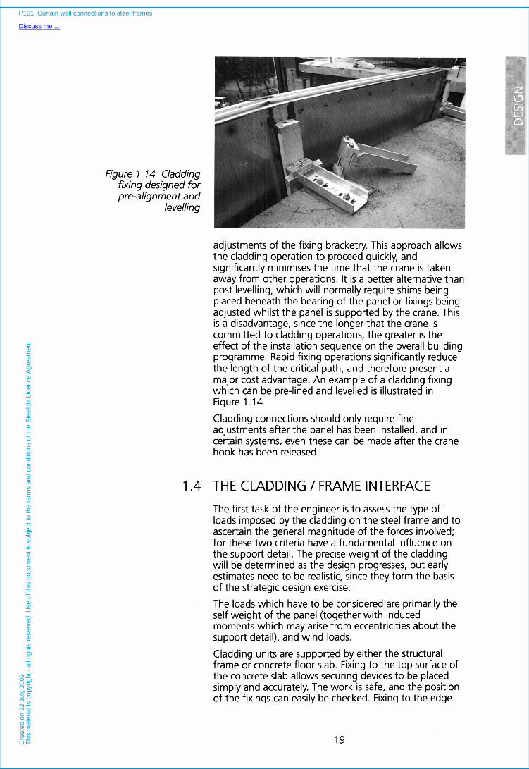
Good practice requires that fixings are pre-lined and levelled. This involves either pre-shimming, or
18
P101: Curtain wall connections to steel frames
Discuss me ...C
reat
ed o
n 22
Jul
y 20
09T
his
mat
eria
l is
copy
right
- a
ll rig
hts
rese
rved
. Use
of t
his
docu
men
t is
subj
ect t
o th
e te
rms
and
cond
ition
s of
the
Ste
elbi
z Li
cenc
e A
gree
men
t
I Figure 1.14 Cladding
fixing designed for pre-alignment and
levelling
adjustments of the fixing bracketry. This approach allows the cladding operation to proceed quickly, and significantly minimises the time that the crane is taken away from other operations. It is a better alternative than post levelling, which will normally require shims being placed beneath the bearing of the panel or fixings being adjusted whilst the panel is supported by the crane. This is a disadvantage, since the longer that the crane is committed to cladding operations, the greater is the effect of the installation sequence on the overall building programme. Rapid fixing operations significantly reduce the length of the critical path, and therefore present a major cost advantage. An example of a cladding fixing which can be pre-lined and levelled is illustrated in Figure 1 .14.
Cladding connections should only require fine adjustments after the panel has been installed, and in certain systems, even these can be made after the crane hook has been released.
1.4 THE CLADDING / FRAME INTERFACE
The first task of the engineer is to assess the type of loads imposed by the cladding on the steel frame and to ascertain the general magnitude of the forces involved; for these two criteria have a fundamental influence on the support detail. The precise weight of the cladding will be determined as the design progresses, but early estimates need to be realistic, since they form the basis of the strategic design exercise. The loads which have to be considered are primarily the self weight of the panel (together with induced moments which may arise from eccentricities about the support detail), and wind loads.
Cladding units are supported by either the structural frame or concrete floor slab. Fixing to the top surface of the concrete slab allows securing devices to be placed simply and accurately. The work is safe, and the position of the fixings can easily be checked. Fixing to the edge
19
P101: Curtain wall connections to steel frames
Discuss me ...C
reat
ed o
n 22
Jul
y 20
09T
his
mat
eria
l is
copy
right
- a
ll rig
hts
rese
rved
. Use
of t
his
docu
men
t is
subj
ect t
o th
e te
rms
and
cond
ition
s of
the
Ste
elbi
z Li
cenc
e A
gree
men
t

INTERFACES
Figure l . 15 Fixing to the lower flange of
edge beams should be avoided unless stiffening
measures are used
face of concrete slabs is more difficult, and is generally restricted to lightweight cladding units.
Support for the cladding may also be taken from columns, or from column slab combinations. The advantage of taking support from columns is that they are intrinsically less prone to bending than edge beams as the vertical load is carried axially. The space between columns and the inside face of the cladding may be restrictive and difficult to access, and so connections are often made to the side of columns. This is discussed in Section 2.5).
Site welding may be used to attach support fixings to columns but the viability of the approach must be carefully appraised. Site welding in general, and in the UK in particular, suffers from the following:
Shortage of skilled operatives 0 Shortage of experienced management 0 Onerous inspection and testing requirements 0 Special access requirements 0 Difficulties of getting power and equipment to the
0 Possible lack of continuity within the project 0 Lack of continuous work for specialist subcontractors
0 Difficulties in setting out steelwork to the accuracy
In principle, site welding should be used only where contractors have suitable expertise, are able to locate skilled operatives and welding operations are covered by a suitable specification. Complicated fabrication work on site should be avoided, since such operations can be
workface
on a project to project basis.
required for welding operations.
-r I I I I
J
P101: Curtain wall connections to steel frames
Discuss me ...C
reat
ed o
n 22
Jul
y 20
09T
his
mat
eria
l is
copy
right
- a
ll rig
hts
rese
rved
. Use
of t
his
docu
men
t is
subj
ect t
o th
e te
rms
and
cond
ition
s of
the
Ste
elbi
z Li
cenc
e A
gree
men
t

Figure l . 16 Additional beams to transfer the
torsion of the edge beams are not recommended
21
P101: Curtain wall connections to steel frames
Discuss me ...C
reat
ed o
n 22
Jul
y 20
09T
his
mat
eria
l is
copy
right
- a
ll rig
hts
rese
rved
. Use
of t
his
docu
men
t is
subj
ect t
o th
e te
rms
and
cond
ition
s of
the
Ste
elbi
z Li
cenc
e A
gree
men
t
INTERFACES
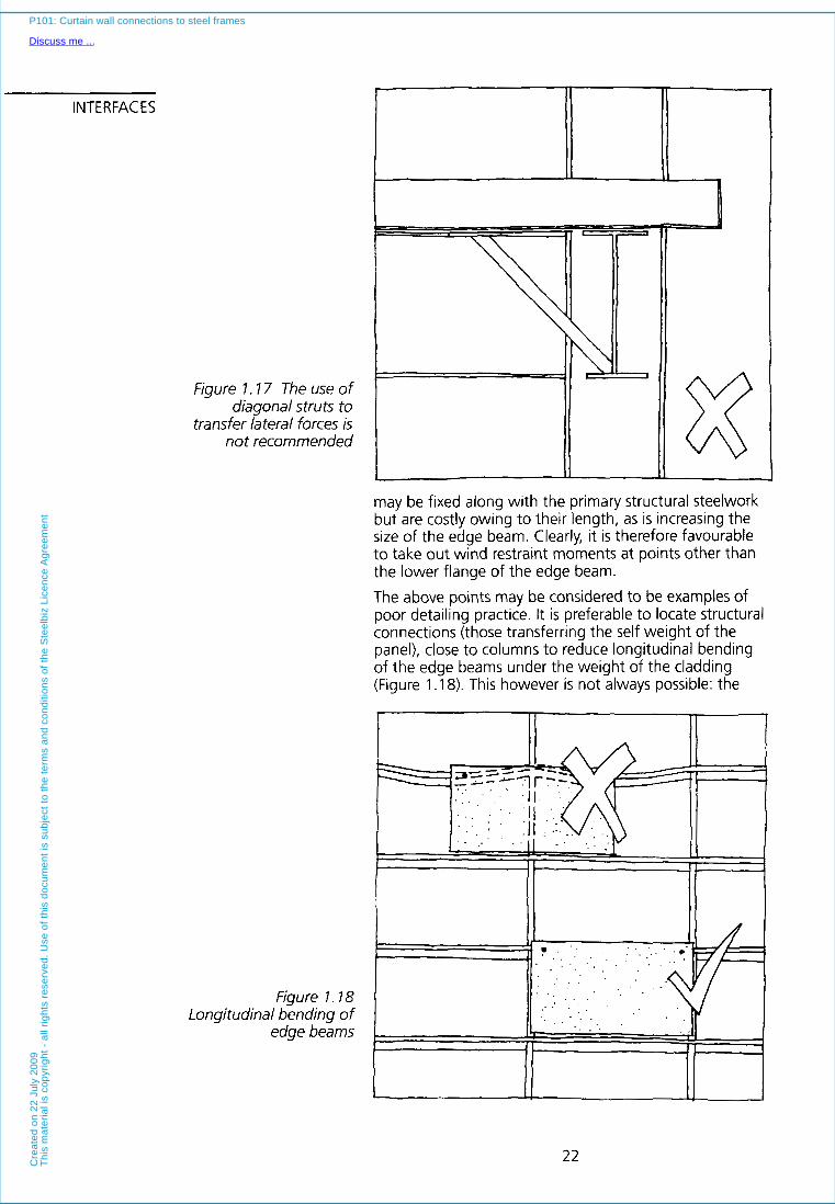
Figure 1.17 The use of diagonal struts to
transfer lateral forces is not recommended
may be fixed along with the primary structural steelwork but are costly owing to their length, as is increasing the size of the edge beam. Clearly, it is therefore favourable to take out wind restraint moments at points other than the lower flange of the edge beam. The above points may be considered to be examples of poor detailing practice. It is preferable to locate structural
Figure l . 18 Longitudinal bending of
edge beams
connections (those transferring the self weight of the panel), close to columns to reduce longitudinal bending of the edge beams under the weight of the cladding (Figure 1.18). This however is not always possible: the
- . . . . .
c
22
P101: Curtain wall connections to steel frames
Discuss me ...C
reat
ed o
n 22
Jul
y 20
09T
his
mat
eria
l is
copy
righ
t -
all r
ight
s re
serv
ed.
Use
of
this
doc
umen
t is
sub
ject
to
the
term
s an
d co
nditi
ons
of t
he S
teel
biz
Lice
nce
Agr
eem
ent

1.5
cladding unit may not be strong enough to span between columns; there may be architectural demands for joints at mid-span; or the cladding unit may prove too large for transportation, or too heavy for cranage. In these cases the floor edge must be designed such that the deflections are within the limits provided by the cladding contractor. Wind loads vary with the position and height of panels. For example, wind suctions tend to be high a t the corners of buildings, with pressures twice those a t the centre of the facade. Similarly, in a 30 m high building, wind loads on the upper storey, can be twice those a t the ground floor. I t is possible to lighten the steel frame by varying the size of edge beams to exactly correspond to the loads placed on them. This may however force the cladding contractor to produce a variety of units to match the different edge beam conditions, and the cost of doing this may well exceed savings associated with the steelwork. Consistent edge details, either standardised, or relying on only a small number of variants, make for good economic practice.
TOLERANCES Variations between the plane of the building facade and the alignment of the structural steelwork, need to be absorbed by the cladding support details. The principal geometric errors are likely to be in the level of the slab surface, and the alignment of the slab edge. The edge of the steel decking is often set out from the centre line of the steel edge beam, (irrespective of what is written into specifications), as in practice it is difficult when working in the open space of a steel frame, to set out from a grid line. This is not good practice, and should be discouraged since dimensional variations in the frame are transferred to the alignment of the edge trim. Furthermore, cast in inserts may subsequently be set out from the edge trim of the metal decking, and these too will reflect the same inaccuracies. Optimum practice is to set out all slab edges from grid lines using appropriate setting out equipment. These horizontal errors may compound with vertical errors. The level of the slab is normally determined by the edge trim upstand which should be installed accurately, but deflections due to the self weight of the structure may still give rise to variations in finished slab levels, and allowances must be made in the connection detail to accommodate these movements in addition to horizontal setting out errors. A similar situation applies with precast concrete slabs. The precast floor unit will be placed centrally on the inner floor beam, with its free end oversailing the steel edge beam. The floor unit will sit directly on the structural steelwork, and thus will follow the level of the frame. The position of a precast floor slab will combine inaccuracies of both the structural steelwork, and the precast manufacturing process.
23
P101: Curtain wall connections to steel frames
Discuss me ...C
reat
ed o
n 22
Jul
y 20
09T
his
mat
eria
l is
copy
righ
t -
all r
ight
s re
serv
ed.
Use
of
this
doc
umen
t is
sub
ject
to
the
term
s an
d co
nditi
ons
of t
he S
teel
biz
Lice
nce
Agr
eem
ent
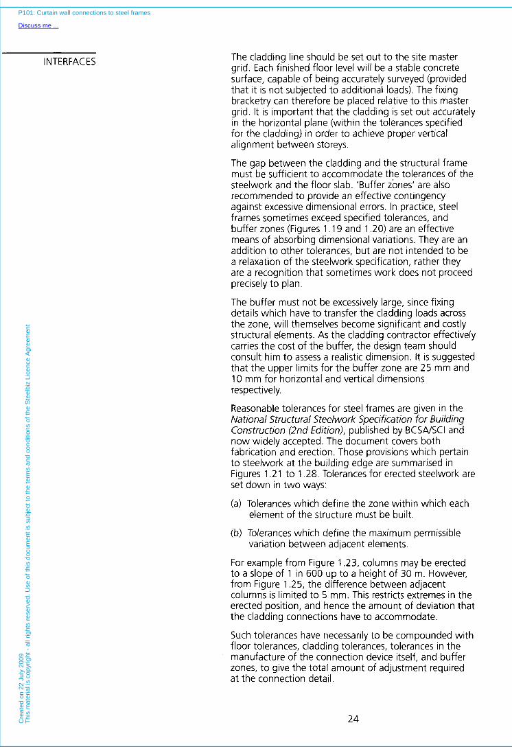
INTERFACES The cladding line should be set out to the site master grid. Each finished floor level will be a stable concrete surface, capable of being accurately surveyed (provided that it is not subjected to additional loads). The fixing bracketry can therefore be placed relative to this master grid. I t is important that the cladding is set out accurately in the horizontal plane (within the tolerances specified for the cladding) in order to achieve proper vertical alignment between storeys.
The gap between the cladding and the structural frame must be sufficient to accommodate the tolerances of the steelwork and the floor slab. ‘Buffer zones’ are also recommended to provide an effective contingency against excessive dimensional errors. In practice, steel frames sometimes exceed specified tolerances, and buffer zones (Figures 1 . l 9 and 1.20) are an effective means of absorbing dimensional variations. They are an addition to other tolerances, but are not intended to be a relaxation of the steelwork specification, rather they are a recognition that sometimes work does not proceed precisely to plan.
The buffer must not be excessively large, since fixing details which have to transfer the cladding loads across the zone, will themselves become significant and costly structural elements. As the cladding contractor effectively carries the cost of the buffer, the design team should consult him to assess a realistic dimension. It is suggested that the upper limits for the buffer zone are 25 mm and 10 mm for horizontal and vertical dimensions respectively.
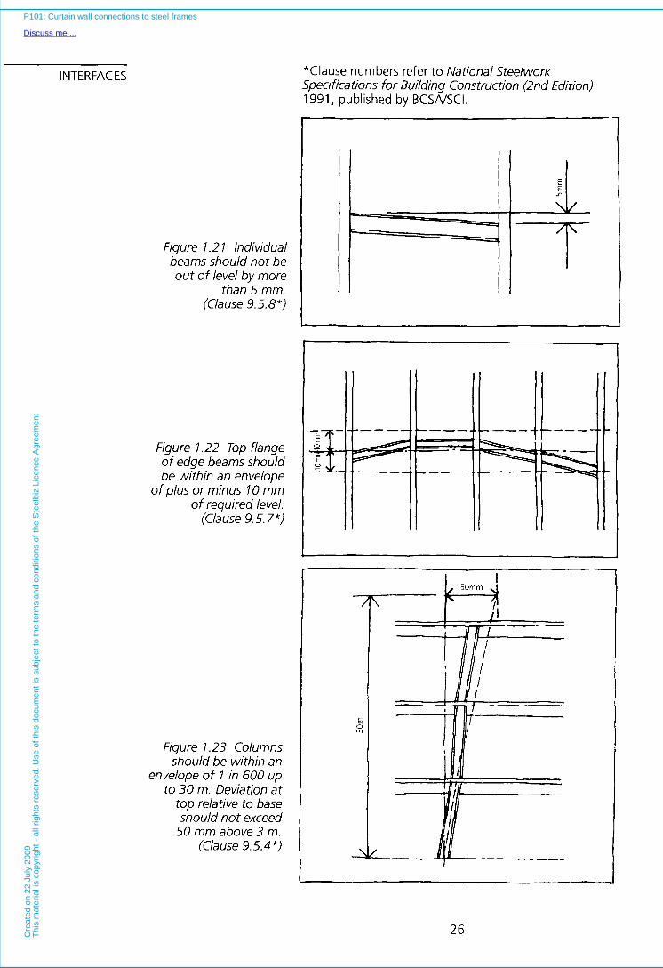
Reasonable tolerances for steel frames are given in the National Structural Steelwork Specification for Building Construction (2nd Edition), published by BCSNSCI and now widely accepted. The document covers both fabrication and erection. Those provisions which pertain to steelwork at the building edge are summarised in Figures 1.21 to 1.28. Tolerances for erected steelwork are set down in two ways:
(a) Tolerances which define the zone within which each element of the structure must be built.
(b) Tolerances which define the maximum permissible variation between adjacent elements.
For example from Figure 1.23, columns may be erected to a slope of 1 in 600 up to a height of 30 m. However, from Figure 1.25, the difference between adjacent columns is limited to 5 mm. This restricts extremes in the erected position, and hence the amount of deviation that the cladding connections have to accommodate.
Such tolerances have necessarily to be compounded with floor tolerances, cladding tolerances, tolerances in the manufacture of the connection device itself, and buffer zones, to give the total amount of adjustment required a t the connection detail.
24
P101: Curtain wall connections to steel frames
Discuss me ...C
reat
ed o
n 22
Jul
y 20
09T
his
mat
eria
l is
copy
right
- a
ll rig
hts
rese
rved
. Use
of t
his
docu
men
t is
subj
ect t
o th
e te
rms
and
cond
ition
s of
the
Ste
elbi
z Li
cenc
e A
gree
men
t

,* r- Cladding tolerance
I I I 1
Figure 1.19 Horizontal buffer zone
Total
offset - vertlcal
-Buffer zone
Figure 1.20 Vertical buffer zone
Cladding tolerance 1 Claddlng tolerance
Bolt down arrangements for the connection of the fixing bracketry to the building must also include tolerances to accommodate variations in the positions of cast in connection devices such as fixing channels in the concrete slab, or the location of bolt holes in the erected structural steelwork.
25
P101: Curtain wall connections to steel frames
Discuss me ...C
reat
ed o
n 22
Jul
y 20
09T
his
mat
eria
l is
copy
right
- a
ll rig
hts
rese
rved
. Use
of t
his
docu
men
t is
subj
ect t
o th
e te
rms
and
cond
ition
s of
the
Ste
elbi
z Li
cenc
e A
gree
men
t
INTERFACES
Figure l .2 l Individual beams should not be out of level by more
than 5 mm. (Clause 9.5.8")
Figure 1.22 Top flange of edge beams should be within an envelope
of plus or minus IO mm of required level.
(Cia use 9.5.7 *)
Figure 1.23 Columns should be within an
envelope of 1 in 600 up to 30 m. Deviation at
top relative to base should not exceed
50 mm above 3 m. (Clause 9.5.4 *)
"Clause numbers refer to National Steelwork Specifications for Building Construction (2nd Edition) 1991, published by BCSNSCI.
T
ll / l / I l / l
26
P101: Curtain wall connections to steel frames
Discuss me ...C
reat
ed o
n 22
Jul
y 20
09T
his
mat
eria
l is
copy
right
- a
ll rig
hts
rese
rved
. Use
of t
his
docu
men
t is
subj
ect t
o th
e te
rms
and
cond
ition
s of
the
Ste
elbi
z Li
cenc
e A
gree
men
t
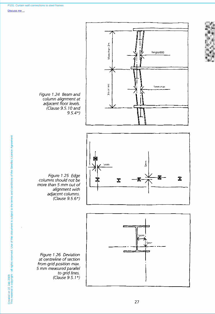
Figure 7.24 Beam and column alignment at adjacent floor levels.
(Clause 9.5.7 0 and 9.5.4*)
Figure l .25 Edge columns should not be
more than 5 mm out of alignment with
adjacent columns. (Clause 9.5.6 *)
Figure l .26 Deviation at centreline of section from grid position max.
5 mm measured parallel to grid lines.
(Clause 9.5.7 *)
3
I
I
27
P101: Curtain wall connections to steel frames
Discuss me ...C
reat
ed o
n 22
Jul
y 20
09T
his
mat
eria
l is
copy
right
- a
ll rig
hts
rese
rved
. Use
of t
his
docu
men
t is
subj
ect t
o th
e te
rms
and
cond
ition
s of
the
Ste
elbi
z Li
cenc
e A
gree
men
t
INTERFACES
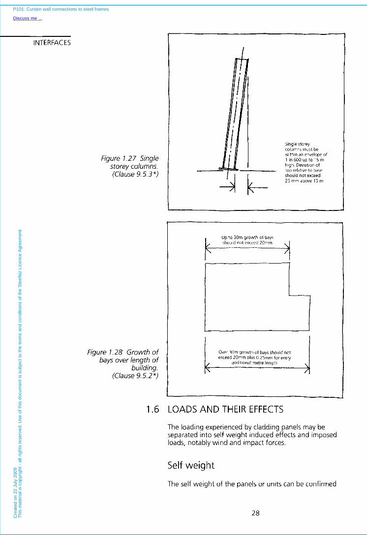
Figure 1.27 Single storey columns. (Clause 9.5.3 *)
Figure 1.28 Growth of bays over length of
building. (Clause 9.5.2 *)
1.6
Stngle storey
wtthln an envelope of columns must be
hlgh Deviatlon of 1 In 600 up to 15 m
top relatlve to base should not exceed 25 mm above 15 m
t Up to 30m growth of bays
exceed 20mm plus 0.25mm for every Over 30m growth of bays should not
addltlonal metre length
0 LOADS AND THEIR EFFECTS
The loading experienced by cladding panels may be separated into self weight induced effects and imposed loads, notably wind and impact forces.
Self weight
The self weight of the panels or units can be confirmed
28
P101: Curtain wall connections to steel frames
Discuss me ...C
reat
ed o
n 22
Jul
y 20
09T
his
mat
eria
l is
copy
right
- a
ll rig
hts
rese
rved
. Use
of t
his
docu
men
t is
subj
ect t
o th
e te
rms
and
cond
ition
s of
the
Ste
elbi
z Li
cenc
e A
gree
men
t
by reference to the manufacturer. Concrete and stone panels can be relatively heavy and therefore the eccentricity of their weight relative to the support positions should be minimised. Details should be developed early in the design process jointly by the structure and cladding designers. Even with lighter cladding the combined effect of constructional tolerances, 'buffer zones', and supports set back from the facade can mean that the bending effect becomes a significant factor influencing the design of the cladding fixings.
Wind loads
Wind loads in the form of negative (suction) or positive pressures are usually the dominant load case in the design of the cladding.
It is normally found that negative pressures are greatest a t the corners of the building, and these conditions can dominate the design of panels and their fixings. Wind forces may be considered to act perpendicular to the cladding and cause tension or compression in the attachment to the frame. These forces are then transferred onto the frame, and eventually to vertical bracings or core walls. In addition to wind pressures, tall buildings are subject to stack effect. In winter hot air rises to the top of the building increasing internal air pressure; whilst in summer, in cooled buildings, negative pressures can be experienced. This additional load on the cladding connections is added to the wind force.
Impact loads
All panels have to be capable of withstanding, and transferring back to the frame, a certain amount of impact loading. Where the self weight of a panel is relatively high, this is unlikely to make a significant difference to the connection detail. However, when connections are designed in relation to lightweight panels (metal sandwich panels, GRC and alike), the same impact loading is likely to increase significantly the design strength of the connection detail.
1.7 POST INSTALLATION MOVEMENTS
Provision has to be made to absorb relative movement between cladding units. Causes of movement include wind sway, thermal expansion and contraction, settlement of foundations, and structural deflections. Of these, structural deflections normally account for the largest and most significant movements. All of these
29
P101: Curtain wall connections to steel frames
Discuss me ...C
reat
ed o
n 22
Jul
y 20
09T
his
mat
eria
l is
copy
right
- a
ll rig
hts
rese
rved
. Use
of t
his
docu
men
t is
subj
ect t
o th
e te
rms
and
cond
ition
s of
the
Ste
elbi
z Li
cenc
e A
gree
men
t

INTERFACES effects compound together and have to be absorbed a t the panel joint, and taken into account in the design of the connection detail. If no provision is made for these movements cladding panels are likely to become over- stressed, a t worst leading to failure of the units or their fixings. A balance must be made between on one hand achieving a light weight structural frame (which is likely to deflect more significantly than a heavier one), and on the other hand confining post installation movements to realistic practical levels. The engineer must calculate the magnitude of movements which the frame and cladding are likely to experience, and agree these with the cladding contractor. Consultations should take place as early as possible as the cost of producing cladding systems capable of absorbing large movements may exceed the cost of a stiffer frame or a more substantial foundation. Once the foundations are complete, or the steel frame is under fabrication, the opportunity for discussion is lost.
The engineer should not rely totally on the allowable movements given by the structural codes of practice. The deflection limits of BS 5950: Part 1, for example, applied to a long span edge beam may well exceed those which can be comfortably tolerated in most cladding systems. Engineers’ drawings should include movement tables for the frame, so that the cladding contractor is fully aware of the anticipated deflections. Post-installation movements must be considered, at least in relation to the following areas. There may be additional considerations (shrinkage of pre-cast concrete panels, movement and creep in concrete frames, and expansion of brickwork etc.) which warrant further consideration in particular instances:
Thermal movement
It is apparent that many engineers consider thermal movement to have only limited importance in the design of cladding systems. This view is only acceptable when panel sizes are small. There are inherent dangers in adopting such a stance, without first ascertaining the magnitude of thermal movements. There has been a trend toward very wide spans between columns, and storey high, long span cladding units (up to 9 m). In this situation thermal movement is certainly significant. Even if movements are only a few millimetres, the forces generated in the panel may be sufficient to cause failure at the connections or restraint points if the panel shape is stiff, or if there are mid-span restraints.
It is likely that designs with no specific provision for movement have succeeded by virtue of some flexibility in the connections and panel joints. Also, the thermal inertia of concrete is usually such that the mid-thickness
30
P101: Curtain wall connections to steel frames
Discuss me ...C
reat
ed o
n 22
Jul
y 20
09T
his
mat
eria
l is
copy
right
- a
ll rig
hts
rese
rved
. Use
of t
his
docu
men
t is
subj
ect t
o th
e te
rms
and
cond
ition
s of
the
Ste
elbi
z Li
cenc
e A
gree
men
t

Settlement of foundations
As cladding panels either hang from, or bear on the frame, a uniform settlement of foundations will not affect the panels significantly. However, any uneven settlement along the length of the building, may result in rotation of the panel (Figure 1.29). If such settlement is possible, then the potential magnitudes of this rotation need to be determined, and provision made for the resulting horizontal and vertical displacements to be accommodated by the support details. Relative movements between panels, and the associated variations in joint widths which arise from panel rotations need also to be absorbed.
Elastic shortening of columns
When a building is clad and occupied, further deflections in the beams, and elastic shortening of the columns can occur. Shortening of the columns is unlikely to exceed 1 mm per storey, unlike in reinforced concrete columns
Figure l .29. Relative movements between
panel and frame caused by settlement of
foundations
temperature of the panel is less than the surface temperature, leading to smaller in-plane movements due to daily temperature variations, than may initially be anticipated. The installation temperature (bolt temperature) of the panel is also significant since panels installed at temperatures toward the top of the service temperature range are less likely to expand against adjacent panels and generate in plane stresses than panels installed a t lower temperatures.
1 l
31
P101: Curtain wall connections to steel frames
Discuss me ...C
reat
ed o
n 22
Jul
y 20
09T
his
mat
eria
l is
copy
right
- a
ll rig
hts
rese
rved
. Use
of t
his
docu
men
t is
subj
ect t
o th
e te
rms
and
cond
ition
s of
the
Ste
elbi
z Li
cenc
e A
gree
men
t

INTERFACES where the additional effects of creep and shrinkage can increase the shortening significantly. This type of movement in steel frames can normally be accommodated without any special provision being made.
Edge beam deflections
Edge beam deflections adjacent to the facade are caused by the load of the floor and the weight of the cladding. These bending deflections are significantly greater than column shortening. When subject to imposed load the edge beam deflections could be up to beam span divided by 360 (as specified in BS 5959: Part l ) , leading to a deflection of 16.7 mm for a 6 m beam.
This deflection has a significant effect upon lightweight stick systems where the maximum allowable movement should not exceed 2 mm per module (dimension between mullions). If this is exceeded it is likely that the frame and infill material will touch, and in the case of glass, that breakage will result. To overcome deflection problems, mullions may be designed with intermediate sliding fixings designed by the cladding contractor (early discussions are essential), or in the case of lower rise buildings the mullions may be ground based and therefore move independently of the edge beams.
Integral and strongback units with edge beam fixings are generally better able to accommodate edge beam deflections. The majority of movement is taken up by the joints between panels, and so generally it is the design of the joint and the fixing position which determine the magnitude of acceptable deflections. Naturally the deflections will be greatest toward the centre of the beam (assuming generally uniform loading from the floor slab), and less toward the column connections. As previously discussed, the supports for the self-weight of the panel should be positioned as close as possible to the columns, and provision made for relative movement between the cladding and structure in the mid-span zone.
If the deflection of the edge beams is ignored, it may lead to in-plane loading of the cladding, and eventually, to compression failure or other associated problems.
Sway deflections
BS 5950: Part 1 allows a horizontal wind deflection for columns, given by their height / 300. This equates to about 13 mm deflection between floors over a 4 m storey height. In practice, movements of this magnitude are often considered impractically large, and many designers limit sway deflections to height / 500 under extreme wind loads (1 in 50 year recurrence).
32
P101: Curtain wall connections to steel frames
Discuss me ...C
reat
ed o
n 22
Jul
y 20
09T
his
mat
eria
l is
copy
righ
t -
all r
ight
s re
serv
ed.
Use
of
this
doc
umen
t is
sub
ject
to
the
term
s an
d co
nditi
ons
of t
he S
teel
biz
Lice
nce
Agr
eem
ent

The effect of sway deflections is different to those of differential foundation settlement. Whereas foundation settlement may cause tilting of the floor slabs whilst columns remain vertical, sway deflections do the opposite. Floors tend to remain horizontal, but columns move away from the vertical. The attitude of panels subjected to wind sway movements in the frame, will therefore be generally unaffected, but panels will move horizontally in relation to those above and below (Figure 1.30).
Figure l .30. Relative movements between
panel and frame caused by wind sway
Spandrel panels effectively break down the vertical height of the building into smaller bands and reduce the magnitude of movement that has to be absorbed a t each horizontal joint.
1.8 CORROSION PROTECTION OF FIXINGS
Two forms of corrosion warrant consideration; the oxidation (rusting) of steel, and bi-metallic corrosion
Steel is the most commonly used material for support fixings, since it is both relatively strong and inexpensive. Its use is however generally limited to the dry side of the building envelope, where the atmosphere is reasonably warm and moisture content is controlled. If the metal forms a significant cold bridge and attracts condensation, or if the metal is exposed to weathering or high levels of moisture, stainless steel or non-ferrous materials are used. Precast concrete, and stone cladding, both tend to absorb water, and therefore generally require corrosion resistant fixings.
33
P101: Curtain wall connections to steel frames
Discuss me ...C
reat
ed o
n 22
Jul
y 20
09T
his
mat
eria
l is
copy
right
- a
ll rig
hts
rese
rved
. Use
of t
his
docu
men
t is
subj
ect t
o th
e te
rms
and
cond
ition
s of
the
Ste
elbi
z Li
cenc
e A
gree
men
t
INTERFACES Bi-metallic corrosion occurs when dissimilar metals are in contact in the presence of moisture. Depending on the elctro-chemical potential of the metals, one material will corrode whilst the other remains relatively intact (e.g. ferrous steel when connected to stainless steel). I t is therfore essential that dissimilar metals do not touch if there is a risk of wetting. Gaskets, bushes and coatings of PTFE, neoprene or nylon, achieve this separation adequately, whilst allowing the fixing detail to perform effectively. Paint will however often be adequate in situations where the connections are dry. Stainless steel fixings require little routine maintenance and are often used when inspection of fixings is difficult. If there is a significant risk of corrosion, and fixings are difficult to access, stainless steel fixings may be essential, for instance, when fire protection measures (sprayed systems, boxing in of fixings, or protection with concrete) preclude easy inspection.
Jointing systems between panels should be subject to routine inspection as a part of the maintenance plan to minimise any danger of water ingress to the connection detail.
1.9 FIRE PROTECTION OF FIXINGS
Cladding supports are often protected from the effects of fire by the building fabric (floor slabs, internal and external cladding etc.), and by protective systems such as firestops. I t is useful to hold early discussions with the statutory authorities to ensure that the fixing details are protected to their satisfaction. If a fire protection system is required specifically for the cladding support fixings, it must be such that the free movement of cladding units is not restricted. Additional fire stopping is normally required to seal the gap between the cladding and slab edge (usually mineral wool blanket or similar deformable material) to prevent the passage of smoke and fire between compartments.
1 . l 0 CONSTRAINTS ON INTERNAL LAYOUT
The perimeter of the building is an area often congested with services, particularly if heating and cooling units are placed there. Raised floors and internal walls need to be carefully detailed at their junctions with the perimeter and properly reconciled with cladding fixings.
If all parties - architect, cladding contractor, structural engineer and services designer, are appointed sufficiently early there is the opportunity to conduct a full dialogue relating to the integration of building elements about the cladding fixings. If a key organisation, such as the service trades contractor, is not in place a t the time decisions are taken on the cladding supports, the design team must define spacial zones within which each must work.
34
P101: Curtain wall connections to steel frames
Discuss me ...C
reat
ed o
n 22
Jul
y 20
09T
his
mat
eria
l is
copy
right
- a
ll rig
hts
rese
rved
. Use
of t
his
docu
men
t is
subj
ect t
o th
e te
rms
and
cond
ition
s of
the
Ste
elbi
z Li
cenc
e A
gree
men
t

2 SYSTEMS
INTRODUCTION TO SECTION 2
There are numerous considerations which influence the type of cladding and connection detail selected for any given situation.
The desired location of joints between panels is important since different types of cladding imply joints a t particular heights on the building facade, and with different relationships to the perimeter columns.
Cladding materials dictate certain structural considerations. Concrete is well suited for use in integral panels. Stone performs well in systems based on strongbacks, whilst glass curtain walling is conventionally
35
P101: Curtain wall connections to steel frames
Discuss me ...C
reat
ed o
n 22
Jul
y 20
09T
his
mat
eria
l is
copy
right
- a
ll rig
hts
rese
rved
. Use
of t
his
docu
men
t is
subj
ect t
o th
e te
rms
and
cond
ition
s of
the
Ste
elbi
z Li
cenc
e A
gree
men
t

INTERFACES supported using stick systems, it is also available from some manufacturers in panel form.
The general arrangement of elements a t the edge of the building has a significant influence upon the choice of a cladding system, and the connection details. The slab edge, edge beams, perimeter columns, and the system of structural support for the cladding have all to be properly reconciled. Installation criteria, such as the need to work from a single level, or fix from within the building have to be accommodated.
The following text and examples present the principles behind a number of generic cladding systems that have been used recently in the UK. The details vary in cost, quality and complexity, and are appraised accordingly.
36
P101: Curtain wall connections to steel frames
Discuss me ...C
reat
ed o
n 22
Jul
y 20
09T
his
mat
eria
l is
copy
right
- a
ll rig
hts
rese
rved
. Use
of t
his
docu
men
t is
subj
ect t
o th
e te
rms
and
cond
ition
s of
the
Ste
elbi
z Li
cenc
e A
gree
men
t
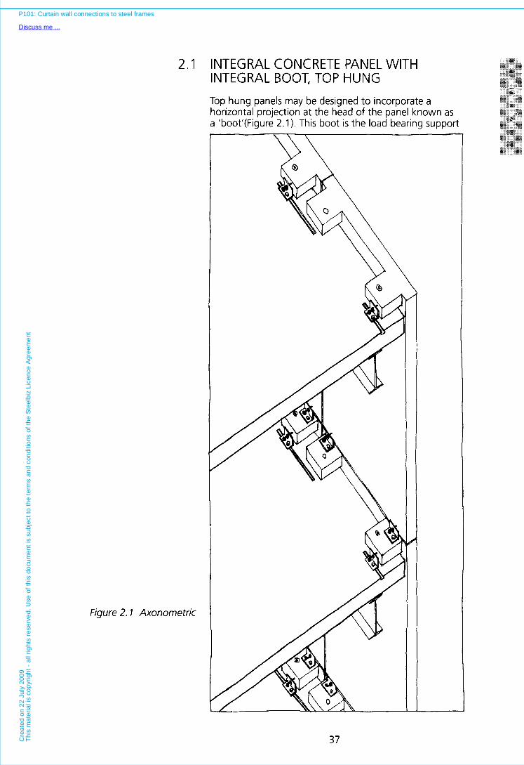
2.1 INTEGRAL CONCRETE PANEL WITH INTEGRAL BOOT, TOP HUNG Top hung panels may be designed to incorporate a horizontal projection a t the head of the panel known as a 'boot'(Figure 2.1). This boot is the load bearing support
Figure 2.1 Axonometric
37
P101: Curtain wall connections to steel frames
Discuss me ...C
reat
ed o
n 22
Jul
y 20
09T
his
mat
eria
l is
copy
right
- a
ll rig
hts
rese
rved
. Use
of t
his
docu
men
t is
subj
ect t
o th
e te
rms
and
cond
ition
s of
the
Ste
elbi
z Li
cenc
e A
gree
men
t
INTERFACES for the panel, and normally will locate loosely over vertical dowels cast into the slab edge, and bear on levelling shims set on top of the floor slab. Movement of the boot in the horizontal plane is normally controlled by brackets mounted on the floor slab, whilst the bottom of the panel is restrained by similar, but generally lighter brackets set on the top of the panel beneath.
Pre-levelling is normally done using horse-shoe shaped shims set around the vertical dowels cast into the slab edge whilst the correct vertical alignment is achieved by adjusting the connections at each of the panel corners.
Top hung booted systems are relatively simple to install, and, in contrast to many other types, the wind restraint details do not introduce significant torsion in the edge beams. Top hung systems do however require special details at the roof parapet to achieve successful waterproofing (fixing brackets complicate waterproofing arrangements). Panels may also project above the floor edge, creating a stepping of levels, which has either to be lost within a raised floor, or within the dry lining. The boot may also compete with service runs, particularly risers a t the building edge. Top hung panels require work a t two floor levels during installation.
Vertical joints between adjacent panels may be located as required. However horizontal joints are naturally sited immediately above the uppermost face of the boot.
Tolerances
Dimensional tolerances both for the panel, and frame, have to be taken up at the joints. Shims at the head of the panel are pre-levelled to the correct height but there is no opportunity to pre-align panels. This has to be done whilst the panel is supported by the crane. Building tolerances and dimensional variations in the panel size are taken up by the alignment process. Fine adjustments to the line of a panel are possible after installation, but adjustments to level are not desirable since it is difficult to raise the boot to insert or withdraw shims.
Oversized holes in the boot, which locate on the slab edge dowels, give initial (approximate) location of the panel. Tolerances in the positioning of these dowels are determined by the degree of play available within the hole, and the tolerancs of the hole spacing in the boot (the latter should not be a problem). Joints between panels have therefore to accommodate both post installation movements and building tolerances. An additional buffer zone should be allowed to cater for marginal dimensional variations beyond the maximum specified.
P101: Curtain wall connections to steel frames
Discuss me ...C
reat
ed o
n 22
Jul
y 20
09T
his
mat
eria
l is
copy
right
- a
ll rig
hts
rese
rved
. Use
of t
his
docu
men
t is
subj
ect t
o th
e te
rms
and
cond
ition
s of
the
Ste
elbi
z Li
cenc
e A
gree
men
t

Forces
The self weight of each panel is transferred by the boot to the slab edge, via levelling shims. The wind restraint a t the foot simply keeps the panel vertical; it does not support the weight of the panel.
The head of the panel is kept in line by the grouted-in dowel at one corner and restraint bracket a t the other. Both of these resist any movement in the direction perpendicular to the panel face whilst the dowelled connection also resists movement parallel to the slab edge.
Wind restraint brackets a t the base of the panel transfer wind load to the head of the panel beneath, where they combine to increase the forces acting on the panel slab connections (dowel and bracket).
Figure 2.2 Movement pattern
Movement
Top hung panels are fixed in such a way as to prevent movement about one of the uppermost fixings. In the system illustrated (Figure 2.1), one of the two dowels cast into the slab edge is grouted into the boot, preventing any relative movement between the floor slab and one corner of the panel (Figure 2.2). The bracket a t this corner may subsequently be removed since after grouting it fulfils no purpose.
Thermal movement of the panel generates horizontal movement a t the top opposing corner. The boot slides over the supporting shims whilst being maintained in line by the restraint fixing.
Thermal movement in the vertical plane together with compounded vertical and horizontal movement a t the lower edge, is accommodated by the wind restraint fixings.
39
P101: Curtain wall connections to steel frames
Discuss me ...C
reat
ed o
n 22
Jul
y 20
09T
his
mat
eria
l is
copy
right
- a
ll rig
hts
rese
rved
. Use
of t
his
docu
men
t is
subj
ect t
o th
e te
rms
and
cond
ition
s of
the
Ste
elbi
z Li
cenc
e A
gree
men
t
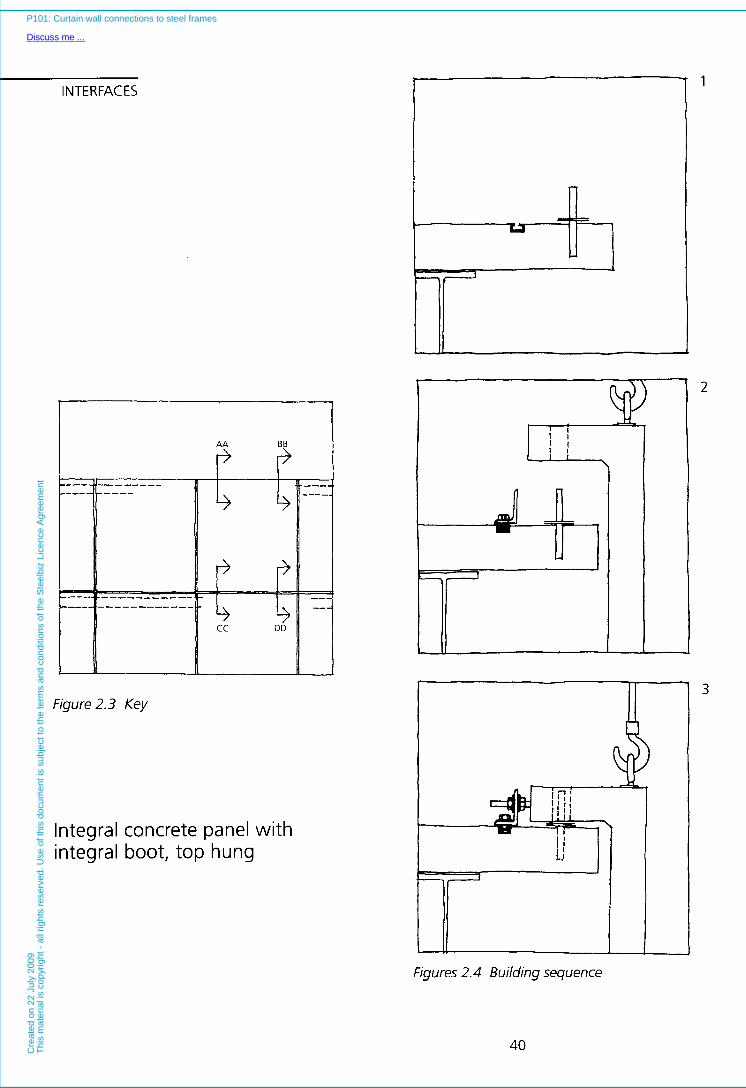
INTERFACES
Figure 2.3 Key
Integral concrete panel with integral boot, top hung
Figures 2.4 Building sequence
40
P101: Curtain wall connections to steel frames
Discuss me ...C
reat
ed o
n 22
Jul
y 20
09T
his
mat
eria
l is
copy
right
- a
ll rig
hts
rese
rved
. Use
of t
his
docu
men
t is
subj
ect t
o th
e te
rms
and
cond
ition
s of
the
Ste
elbi
z Li
cenc
e A
gree
men
t
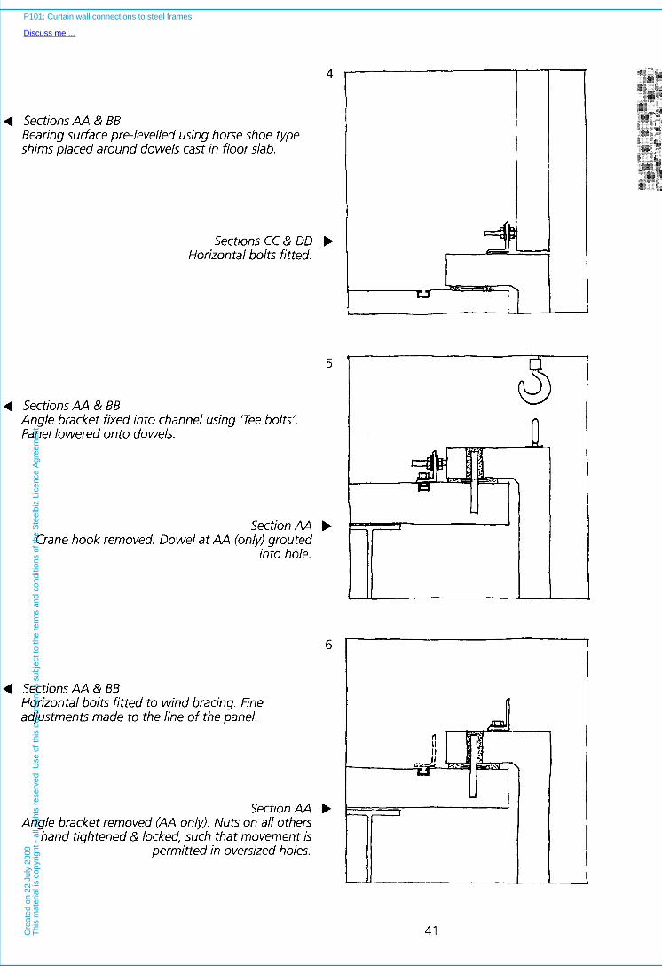
4
4 Sections AA & BB Bearing surface pre-levelled using horse shoe type shims placed around dowels cast in floor slab.
Sections CC & DD b Horizontal bolts fitted.
5
4 Sections M & BB Angle bracket fixed into channel using 'Tee bolts'. Panel lowered onto dowels.
Section AA b Crane hook removed. Dowel at AA (only) grouted
into hole.
6
4 Sections M & BB Horizontal bolts fitted to wind bracing. Fine adjustments made to the line of the panel.
Section AA b Angle bracket removed (AA onlv). Nuts on all others
hand tightened & locked, such that movement is permitted in oversized holes.
41
P101: Curtain wall connections to steel frames
Discuss me ...C
reat
ed o
n 22
Jul
y 20
09T
his
mat
eria
l is
copy
right
- a
ll rig
hts
rese
rved
. Use
of t
his
docu
men
t is
subj
ect t
o th
e te
rms
and
cond
ition
s of
the
Ste
elbi
z Li
cenc
e A
gree
men
t
INTERFACES ~~~
Critical appraisal
Top hung panels of this type may be pre-levelled, but the nature of the bracketry means that pre-alignment is not possible. This has to be done whilst the panel is supported by the crane thus slowing the erection process.
The self weight of the cladding will cause deflection of the edge beam. The exact magnitude of these deflections may be difficult to calculate accurately, since slab edge deflections in particular, are affected by concreting tolerances. Some post levelling may therefore be required particularly where panels are hung a significant distance away from the columns. Since the panels have a high self-weight such adjustments are difficult. There is no 'fine adjustment' designed into the fixing, and re-levelling will necessitate altering the shims.
The fixing operation is further complicated by the need to work a t two levels.
42
P101: Curtain wall connections to steel frames
Discuss me ...C
reat
ed o
n 22
Jul
y 20
09T
his
mat
eria
l is
copy
right
- a
ll rig
hts
rese
rved
. Use
of t
his
docu
men
t is
subj
ect t
o th
e te
rms
and
cond
ition
s of
the
Ste
elbi
z Li
cenc
e A
gree
men
t
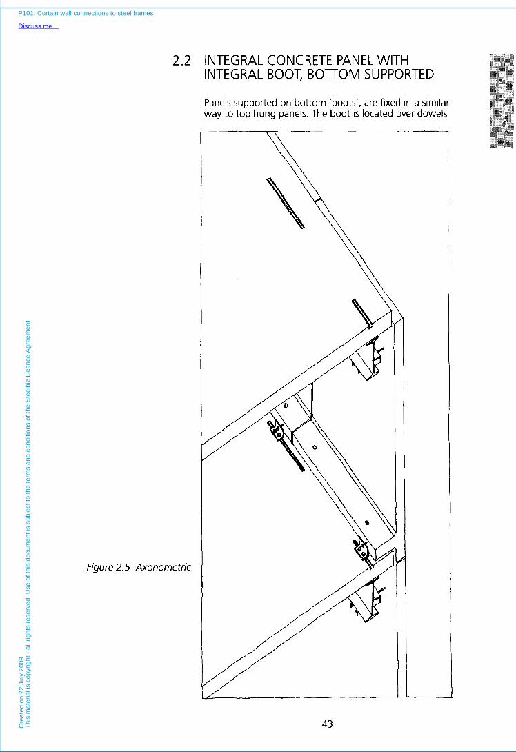
2.2 INTEGRAL CONCRETE PANEL WITH INTEGRAL BOOT, BOlTOM SUPPORTED
Panels supported on bottom 'boots', are fixed in a similar way to top hung panels. The boot is located over dowels
Figure 2.5 Axonometric
L i 43
P101: Curtain wall connections to steel frames
Discuss me ...C
reat
ed o
n 22
Jul
y 20
09T
his
mat
eria
l is
copy
right
- a
ll rig
hts
rese
rved
. Use
of t
his
docu
men
t is
subj
ect t
o th
e te
rms
and
cond
ition
s of
the
Ste
elbi
z Li
cenc
e A
gree
men
t

INTERFACES cast into the floor edge, and set to the correct height using shims. However, in contrast to top hung panels, wind restraint is often taken from the edge beam rather than the floor slab (Figure 2.5).
Shims should be pre-levelled, and horizontal alignment is achieved in the same way as for a top hung panel.
Bottom supported panels may be erected from a single level, and generate simple parapet details. They do however impinge on the floor edge in the same way as top hung panels (the boot has to be absorbed into either a raised floor or dry lining system), and services have generally to avoid the slab edge. The bottom boot may however be removed in favour of a twin corbel arrangement as in the preceding top hung design. Vertical joints between adjacent panels may be located as required; however horizontal joints are usually sited above the lower flange of the edge beam. Therfore, the horizontal joints are normally lower relative to finished floor levels, than top hung systems.
Tolerances
In terms of tolerances, a bottom supported panel performs as an inverted top hung panel. However, since wind restraint brackets are mounted directly onto the edge beam, rather than connecting to an adjacent panel, variations in storey height can be more critical. When wind restraints are mounted onto the head of an adjacent cladding panel (top hung situation), the pre- levelling operation can take out minor variations in storey height. Where all connections are made directly to the structure, this opportunity is lost and the bracketry has to be able to absorb the dimensional variations.
Forces
Bottom supported panels act in compression and transfer the self weight to the slab edge via the boot a t the foot of the panel which bears on levelling shims. The slab takes this loading onto the edge beams and these bring it in turn to the columns. Wind restraint is taken from the lower flange of the edge beam, and so unlike top hung panels, all fixings are made directly onto to the structural frame -there are no panel to panel connections. Edge beams are subjected to a combination of torsional forces from the wind restraint, and vertical downward forces arising from the self weight of the panel. The dowel and bracket arrangement to the boot performs in the same way as a top hung panel, but since there is no panel to panel connection, it does not have to provide wind restraint in the same way.
44
P101: Curtain wall connections to steel frames
Discuss me ...C
reat
ed o
n 22
Jul
y 20
09T
his
mat
eria
l is
copy
right
- a
ll rig
hts
rese
rved
. Use
of t
his
docu
men
t is
subj
ect t
o th
e te
rms
and
cond
ition
s of
the
Ste
elbi
z Li
cenc
e A
gree
men
t

Movement
Figure 2.6 Movement pattern
Bottom supported panels are fixed in such that there is no relative movement of the panel and frame about one of the lower fixings (Figure 2.6). In principle they perform as inverted top hung systems. In the example, one of the two dowels cast into the slab edge is grouted into the
boot and therefore fixed in position. Thermal expansion and contraction of the panel generates horizontal movement a t the lower opposing corner. This movement is accommodated by the boot sliding over its shims, whilst the panel is maintained in line by the restraint fixings (bracket and dowel). A different but functionally equivalent detail would be to retain angle type restraint brackets at both ends of the boot (or at each of the twin corbels if the alternative bearing detail is used), and to lock one of these whilst leaving the other free to move parallel to the slab edge. This produces exactly the same movement pattern as the grouted in dowel and single bracket combination. In principle, the dowel is simply substituted for the locked bracket. The advantage of using such an arrangement is that cladding erectors do not have to attend to the panel a second time (after grout has hardened), to remove temporary bracketry. Thermal movement in the vertical plane is catered for by the wind restraint a t the head of the panel.
45
P101: Curtain wall connections to steel frames
Discuss me ...C
reat
ed o
n 22
Jul
y 20
09T
his
mat
eria
l is
copy
right
- a
ll rig
hts
rese
rved
. Use
of t
his
docu
men
t is
subj
ect t
o th
e te
rms
and
cond
ition
s of
the
Ste
elbi
z Li
cenc
e A
gree
men
t

INTERFACES
~-
Figure 2.7 Key
Integral concrete panel with integral boot, bottom supported
3:;
1
2
3
Figures 2.8 Building sequence
46
P101: Curtain wall connections to steel frames
Discuss me ...C
reat
ed o
n 22
Jul
y 20
09T
his
mat
eria
l is
copy
right
- a
ll rig
hts
rese
rved
. Use
of t
his
docu
men
t is
subj
ect t
o th
e te
rms
and
cond
ition
s of
the
Ste
elbi
z Li
cenc
e A
gree
men
t

4
4 Sections CC & DD Bearing surface pre-levelled using horse shoe type shims placed around dowels cast in floor slab.
Sections AA & BB b Horizontal bolts fitted to wind bracing. Fine adjustments made to the line of the panel.
5
4 Sections CC & DD Angle brackets fixed into channel using ‘Tee bolts’ Panel lowered onto dowels.
Section CC b Crane hook removed. Dowel at CC (onk) grouted
into hole.
4 Sections CC& DD Horizontal bolts fitted.
Section CC Angle bracket removed (CC only). Nuts on all others
hand tightened & secured, such that movement is permitted in oversized holes.
6
b
47
P101: Curtain wall connections to steel frames
Discuss me ...C
reat
ed o
n 22
Jul
y 20
09T
his
mat
eria
l is
copy
right
- a
ll rig
hts
rese
rved
. Use
of t
his
docu
men
t is
subj
ect t
o th
e te
rms
and
cond
ition
s of
the
Ste
elbi
z Li
cenc
e A
gree
men
t
INTERFACES Critical appraisal
Unlike most top hung systems, bottom supported panels of this type may be installed from a single level. Such panels do cause deflection of the edge beam which, if different from the calculated deflection, is difficult to rectify since again there is no ‘fine adjustment’ to level, and the large self weight makes re-shimming difficult. Minor adjustments to line and plumb are possible and may be made without use of cranage. I t is usual to line and plumb a run of panels (a day’s fixing for instance) to average out tolerances. Wind restraint fixings cause torsion in the edge beams. This may necessitate heavier beams than would be used with equivalent top hung systems or the introduction of restraint beams or stiffeners.
48
P101: Curtain wall connections to steel frames
Discuss me ...C
reat
ed o
n 22
Jul
y 20
09T
his
mat
eria
l is
copy
right
- a
ll rig
hts
rese
rved
. Use
of t
his
docu
men
t is
subj
ect t
o th
e te
rms
and
cond
ition
s of
the
Ste
elbi
z Li
cenc
e A
gree
men
t

Figure 2.9
2.3 INTEGRAL CONCRETE PANEL WITH FLAT BACK, TOP HUNG
In the system illustrated the self weight of the panel is transferred to the floor edge by angle brackets a t the panel head. Wind restraint is in the form of a fish plate,
Axonometric
49
P101: Curtain wall connections to steel frames
Discuss me ...C
reat
ed o
n 22
Jul
y 20
09T
his
mat
eria
l is
copy
right
- a
ll rig
hts
rese
rved
. Use
of t
his
docu
men
t is
subj
ect t
o th
e te
rms
and
cond
ition
s of
the
Ste
elbi
z Li
cenc
e A
gree
men
t
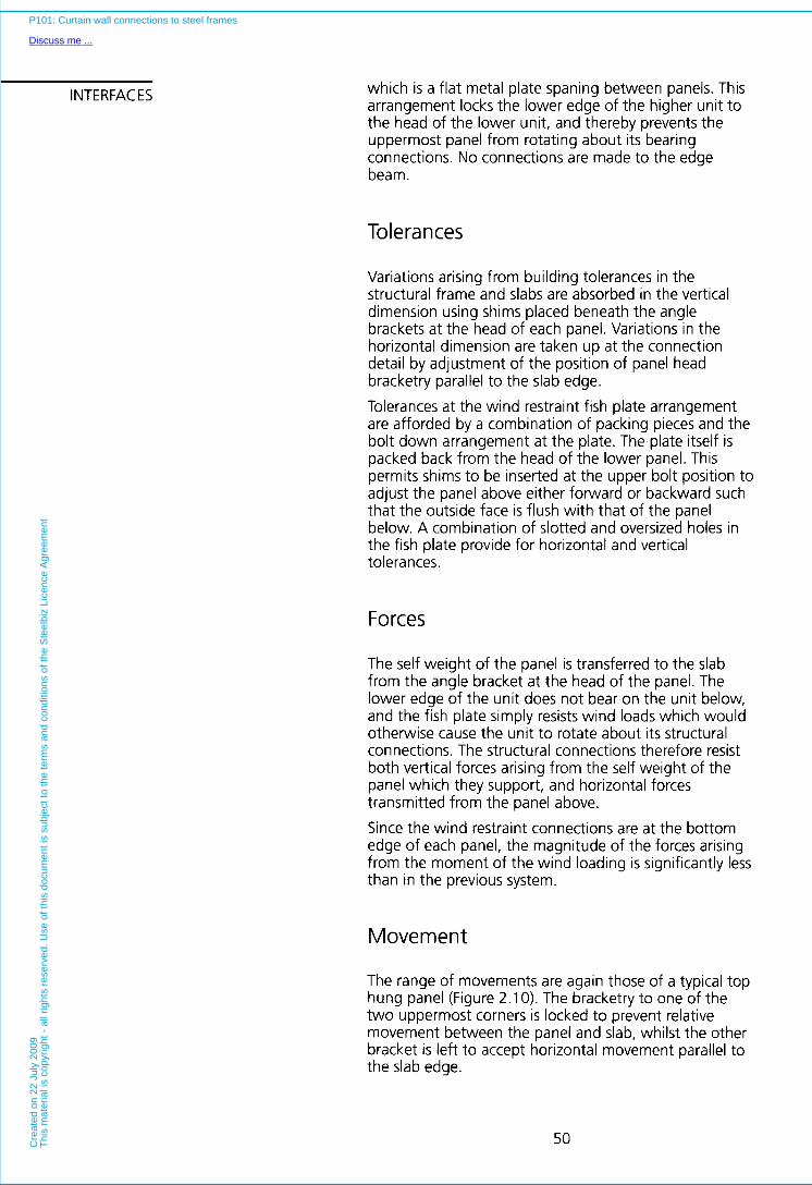
INTERFACES which is a flat metal plate spaning between panels. This arrangement locks the lower edge of the higher unit to the head of the lower unit, and thereby prevents the uppermost panel from rotating about its bearing Connections. No connections are made to the edge beam.
Tolerances
Variations arising from building tolerances in the structural frame and slabs are absorbed in the vertical dimension using shims placed beneath the angle brackets at the head of each panel. Variations in the horizontal dimension are taken up a t the connection detail by adjustment of the position of panel head bracketry parallel to the slab edge. Tolerances at the wind restraint fish plate arrangement are afforded by a combination of packing pieces and the bolt down arrangement a t the plate. The plate itself is packed back from the head of the lower panel. This permits shims to be inserted at the upper bolt position to adjust the panel above either forward or backward such that the outside face is flush with that of the panel below. A combination of slotted and oversized holes in the fish plate provide for horizontal and vertical tolerances.
Forces
The self weight of the panel is transferred to the slab from the angle bracket a t the head of the panel. The lower edge of the unit does not bear on the unit below, and the fish plate simply resists wind loads which would otherwise cause the unit to rotate about its structural Connections. The structural connections therefore resist both vertical forces arising from the self weight of the panel which they support, and horizontal forces transmitted from the panel above.
Since the wind restraint connections are a t the bottom edge of each panel, the magnitude of the forces arising from the moment of the wind loading is significantly less than in the previous system.
Movement
The range of movements are again those of a typical top hung panel (Figure 2.10). The bracketry to one of the two uppermost corners is locked to prevent relative movement between the panel and slab, whilst the other bracket is left to accept horizontal movement parallel to the slab edge.
50
P101: Curtain wall connections to steel frames
Discuss me ...C
reat
ed o
n 22
Jul
y 20
09T
his
mat
eria
l is
copy
right
- a
ll rig
hts
rese
rved
. Use
of t
his
docu
men
t is
subj
ect t
o th
e te
rms
and
cond
ition
s of
the
Ste
elbi
z Li
cenc
e A
gree
men
t

Figure 2.10 Movement pattern
a t the wind restraints is accommodated by slotted bolt down connections. Vertical movement is experienced immediately below the locked structural connection whilst combined horizontal and vertical movement is experienced a t the opposite restraint.
51
P101: Curtain wall connections to steel frames
Discuss me ...C
reat
ed o
n 22
Jul
y 20
09T
his
mat
eria
l is
copy
right
- a
ll rig
hts
rese
rved
. Use
of t
his
docu
men
t is
subj
ect t
o th
e te
rms
and
cond
ition
s of
the
Ste
elbi
z Li
cenc
e A
gree
men
t
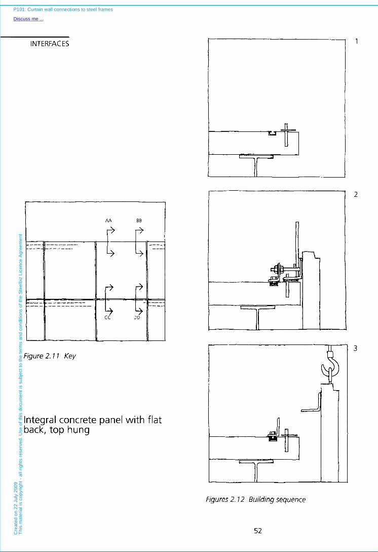
INTERFACES
AA BB
-
Figure 2.1 1 Key
Integral concrete panel with flat back, top hung
I
Figures 2.7 2 Building sequence
52
P101: Curtain wall connections to steel frames
Discuss me ...C
reat
ed o
n 22
Jul
y 20
09T
his
mat
eria
l is
copy
right
- a
ll rig
hts
rese
rved
. U
se o
f th
is d
ocum
ent
is s
ubje
ct t
o th
e te
rms
and
cond
ition
s of
the
Ste
elbi
z Li
cenc
e A
gree
men
t
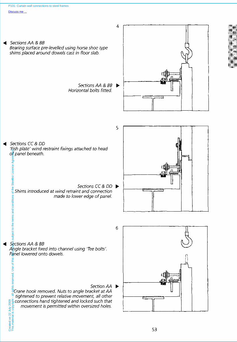
4. Sections AA & BB Bearing surface pre-levelled using horse shoe type shims placed around dowels cast in floor slab.
Sections AA & BB Horizontal bolts fitted.
4 Sections CC & DD ‘Fish plate’ wind restraint fixings attached to head of panel beneath.
Sections CC & DD Shims introduced at wind retraint and connection
made to lower edge of panel.
5
b
4 Sections AA & BB Angle bracket fixed into channel using ‘Tee bolts’. Panel lowered onto dowels.
Section AA Crane hook removed. Nuts to angle bracket at AA tightened to prevent relative movement, all other connections hand tightened and locked such that
movement is permitted within oversized holes.
b
53
P101: Curtain wall connections to steel frames
Discuss me ...C
reat
ed o
n 22
Jul
y 20
09T
his
mat
eria
l is
copy
right
- a
ll rig
hts
rese
rved
. Use
of t
his
docu
men
t is
subj
ect t
o th
e te
rms
and
cond
ition
s of
the
Ste
elbi
z Li
cenc
e A
gree
men
t
INTERFACES Critical appraisal
The primary advantage of this system is that no connection is made to the edge beams. These therefore do not have to resist moments arising from the potential rotation of the panel about its structural fixings, as experienced in many alternative designs. Panels can, and should, be pre-lined and levelled in advance of the erection operation. Unlike panels with old type interlocking dovetail type profiles at horizontal joints, the more recent types may be removed once installed. Special details are required where the lower panel meets the ground.
54
P101: Curtain wall connections to steel frames
Discuss me ...C
reat
ed o
n 22
Jul
y 20
09T
his
mat
eria
l is
copy
right
- a
ll rig
hts
rese
rved
. Use
of t
his
docu
men
t is
subj
ect t
o th
e te
rms
and
cond
ition
s of
the
Ste
elbi
z Li
cenc
e A
gree
men
t

F
Figure 2.13 Axonometric
2.4 STRONGBACK SYSTEM WITH SLAB . " _ . " . "_
FIXING
Stone veneer cladding and other 'thin' materials, or materials with inadequate spanning capabilities, may be
7
55
P101: Curtain wall connections to steel frames
Discuss me ...C
reat
ed o
n 22
Jul
y 20
09T
his
mat
eria
l is
copy
right
- a
ll rig
hts
rese
rved
. Use
of t
his
docu
men
t is
subj
ect t
o th
e te
rms
and
cond
ition
s of
the
Ste
elbi
z Li
cenc
e A
gree
men
t
INTERFACES supported on frames known as 'strongbacks'. Typically, these are aluminium, steel or stainless steel frameworks, onto which panels are screwed or bolted. One strongback may receive several cladding panels, enabling cladding such as stone to be used in relatively small manageable sizes, appropriate to the structural properties of the veneer. Since the strongback takes the structural loads, it can invariably be designed to span from column to column, thus eliminating the need for mid-span cladding support points. Alternatively, large storey height units may be designed, with slab fixings.
The system illustrated (Figure 2.13) is of the latter type, and conforms well to the ideal that all fixings should be pre-lined and levelled, and should require only a minimum of adjustment after erection. The system relies on fairly complex but well resolved standardised components, based upon cast dovetail blocks with machined surfaces. These blocks give adjustment in the vertical and horizontal dimensions, whilst the bolt down arrangement to the slab gives perpendicular to the panel face adjustment. DovGtaiIs are free to move in their slots, unless held in place against an adjustable stop by their own self weight, or fixed using a locking screw. It is notable, that the fixings shown work equally well for both top hung, and bottom supported panels. Fixings can be pre-set in all three dimensions (allowing for theoretical deflections of the slab and edge beams, arising from the self weight of the cladding panels etc.). Panels can be simply craned into place such that the vertical dovetail blocks may be lowered into the appropriate slots until they bear on the adjustable levelling stop. After the panel is set in place, the crane hook can be released and any necessary minor adjustments may be made to the alignment of the panel. Finally, a locking screw is tightened on one of the structural connections, so as to determine the final pattern of panel movement. The relatively high cost of the fixing is offset by the expediency and reliability of the fixing operation.
Tolerances
Building tolerances can be taken up by the pre-alignment and levelling operations, which characterise this system. Dimensional variations in the vertical plane can be accommodated by adjusting the levelling stop in the lower support detail, whilst horizontal variations may be absorbed by bolting down the fixing detail in an appropriate location along the slab edge, and in such a way that it projects outward the correct distance relative to the setting out grid. This latter adjustment is achieved using longitudinal slotted holes in the channel section. The wind restraint is adjusted in a similar manner.
56
P101: Curtain wall connections to steel frames
Discuss me ...C
reat
ed o
n 22
Jul
y 20
09T
his
mat
eria
l is
copy
right
- a
ll rig
hts
rese
rved
. Use
of t
his
docu
men
t is
subj
ect t
o th
e te
rms
and
cond
ition
s of
the
Ste
elbi
z Li
cenc
e A
gree
men
t
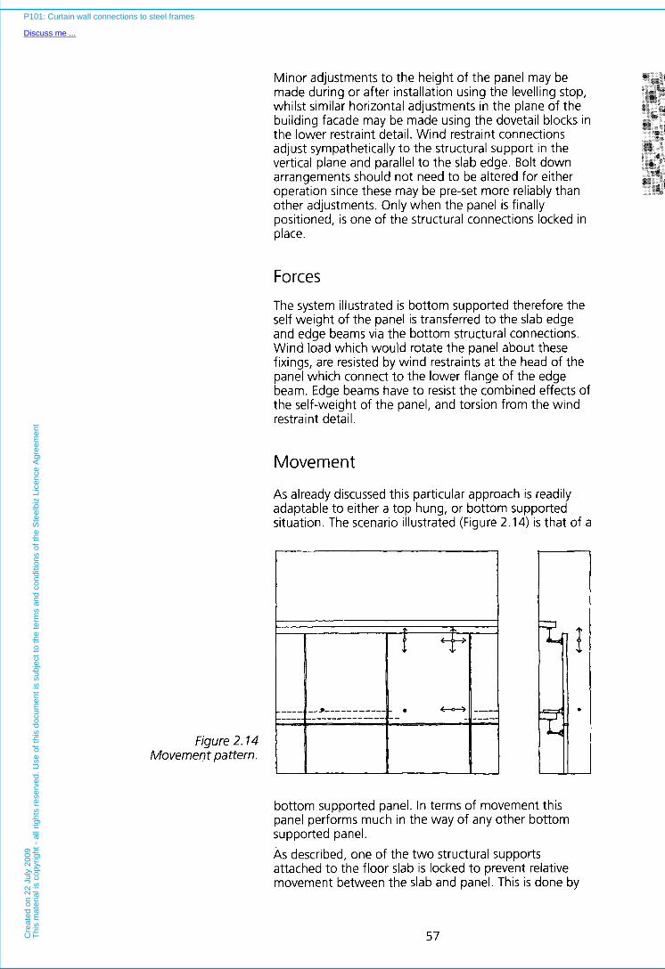
Minor adjustments to the height of the panel may be &g@ made during or after installation using the levelling stop,
"x&@ la8:J.d
whilst similar horizontal adjustments in the plane of the y&%.e%? g aOsl*.?"% %"+
building facade may be made using the dovetail blocks in as-"'"% &@"$J'L
the lower restraint detail. Wind restraint connections &;*@$p$:
adjust sympathetically to the structural support in the vertical plane and parallel to the slab edge. Bolt down ;;$&r";
arrangements should not need to be altered for either .""#ii" ;:B@$g
operation since these may be pre-set more reliably than other adjustments. Only when the panel is finally positioned, is one of the structural connections locked in place.
* ", ryn
> " ""V*#
*pe -2
..p& B%Fi "~seaa, g p * W B **g, .*&*.~
%*"B d l ,,_,e= n*.= ~
**/S
" = * " I
.*p*i, p$
4>&@$8 i"",,5&l .. 'Sie...
3t"a ~8&@:$ . nl ~.
Forces The system illustrated is bottom supported therefore the self weight of the panel is transferred to the slab edge and edge beams via the bottom structural connections. Wind load which would rotate the panel about these fixings, are resisted by wind restraints a t the head of the panel which connect to the lower flange of the edge beam. Edge beams have to resist the combined effects of the self-weight of the panel, and torsion from the wind restraint detail.
Movement
As already discussed this particular approach is readily adaptable to either a top hung, or bottom supported situation. The scenario illustrated (Figure 2.14) is that of a
Figure 2.14 Movement pattern.
I I I M I
bottom supported panel. In terms of movement this panel performs much in the way of any other bottom supported panel. As described, one of the two structural supports attached to the floor slab is locked to prevent relative movement between the slab and panel. This is done by
57
P101: Curtain wall connections to steel frames
Discuss me ...C
reat
ed o
n 22
Jul
y 20
09T
his
mat
eria
l is
copy
right
- a
ll rig
hts
rese
rved
. Use
of t
his
docu
men
t is
subj
ect t
o th
e te
rms
and
cond
ition
s of
the
Ste
elbi
z Li
cenc
e A
gree
men
t
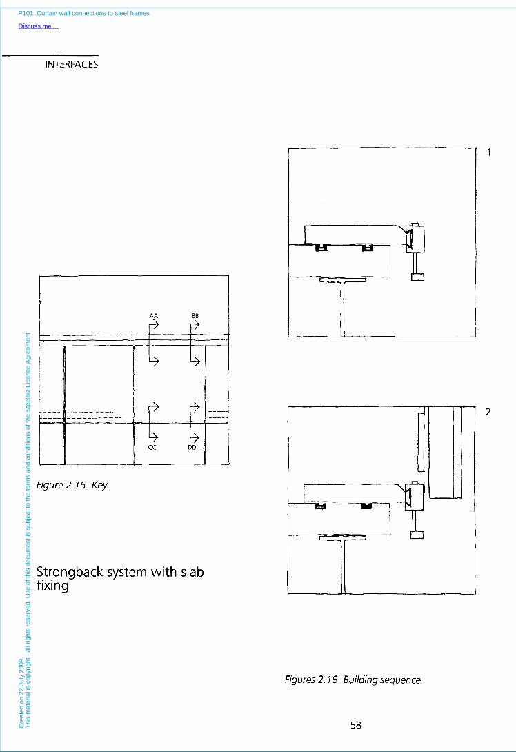
INTERFACES
1
I AA BB
Figure 2.15 Key
Strongback system with slab fixing
2
Figures 2.16 Building sequence
58
P101: Curtain wall connections to steel frames
Discuss me ...C
reat
ed o
n 22
Jul
y 20
09T
his
mat
eria
l is
copy
right
- a
ll rig
hts
rese
rved
. Use
of t
his
docu
men
t is
subj
ect t
o th
e te
rms
and
cond
ition
s of
the
Ste
elbi
z Li
cenc
e A
gree
men
t

4 Sections CC & DD Support bracket set to line and level.
3
Sections AA & BB Top wind restraint fixed in place. Crane hook
released.
F
I I I
4 Sections CC & DD Panel lowered into position until vertical dovetail comes to rest on pre-levelled stop.
Sections CC & DD Fine adjustments made using levelling bolts. Fixing at CC then locked, all other dovetail blocks free to
move.
4
F
59
P101: Curtain wall connections to steel frames
Discuss me ...C
reat
ed o
n 22
Jul
y 20
09T
his
mat
eria
l is
copy
right
- a
ll rig
hts
rese
rved
. Use
of t
his
docu
men
t is
subj
ect t
o th
e te
rms
and
cond
ition
s of
the
Ste
elbi
z Li
cenc
e A
gree
men
t

INTERFACES tightening a locking screw against the horizontal dovetail block (the vertical block will not move owing to the self weight of the panel forcing the block down against the levelling stop).
With one structural support locked, the other absorbs movement in the horizontal direction, whilst the wind restraint accommodates both vertical and horizontal movements in the normal way.
Critical appraisal
This system conforms well with the recommendations of Section 1 .
The design of the fixing bracketry means that both pre- alignment and pre-levelling is possible. Fine adjustments to the line of panels also may be made after installation. The speed of critical path operations is therefore optimised, since the crane can very rapidly move from one panel to the next.
Additionally, access to connections is good, and the system does not monopolise the slab edge. Wind restraint fixings induce undesirable torsion in the edge beams. Again, this may necessitate use of a heavier section, or of special restraints to the lower flange of the edge beam.
60
P101: Curtain wall connections to steel frames
Discuss me ...C
reat
ed o
n 22
Jul
y 20
09T
his
mat
eria
l is
copy
right
- a
ll rig
hts
rese
rved
. Use
of t
his
docu
men
t is
subj
ect t
o th
e te
rms
and
cond
ition
s of
the
Ste
elbi
z Li
cenc
e A
gree
men
t
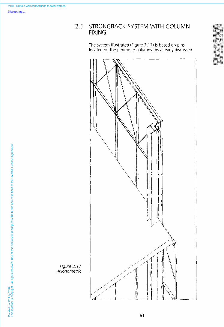
2.5 STRONGBACK SYSTEM WITH COLUMN FIXING
The system illustrated (Figure 2.17) is based on pins located on the perimeter columns. As already discussed
Figure 2.17 Axonometric
61
P101: Curtain wall connections to steel frames
Discuss me ...C
reat
ed o
n 22
Jul
y 20
09T
his
mat
eria
l is
copy
right
- a
ll rig
hts
rese
rved
. Use
of t
his
docu
men
t is
subj
ect t
o th
e te
rms
and
cond
ition
s of
the
Ste
elbi
z Li
cenc
e A
gree
men
t

INTERFACES in Section 1, problems associated with excessive deflection of the edge beams are avoided, wherever it is possible to take structural support for the cladding directly from the columns.
The system shown is particularly simple, since there are no wind restraint brackets. Instead, the tops of panels are hung from the columns, whilst pins at the foot locate into holes a t the head of the panel beneath (which is also fixed back to the columns). Strongbacks are designed to span from column to column, and are supported by carefully aligned braccets welded to the outside face of the perimeter columns.
Only top hung panels are possible with this system, since if the approach were to be used for bottom supported cladding, the absence of conventional wind restraints would necessitate temporary support being given to each panel between the time of installation, and the time when the next higher panel became available to retain it.
The other potential disadvantage is that fine adjustment to the line or level of the panel after installation, is both limited and difficult. The bracketry has to be lined and levelled fairly accurately prior to the cladding being erected. Shims are used to give vertical level, whilst slotted holes in the x-x and y-y directions allow the pins on the bearing plate, to be located correctly. This latter adjustment is difficult to alter after the cladding is erected, however marginal height adjustments are possible using an adjuster screw at the head of the strongback.
Since panels of this design interlock, it is difficult to remove them after erection (except a t the parapet).
Tolerances
Building tolerances are taken up separately in the x-x, y-y and z-z dimensions. Vertically, the two parts of the column connection are packed with shims, whilst horizontally two sets of slotted holes give combined adjustment in the x-x and y-y planes. Fine adjustments to the level of the panel may be made using levelling screws a t the head of the strongback. These bear onto the column connection, and either raise or lower the panel on its pins. There is no arrangement for fine adjustment of the line of the panel. The accurate alignment of the pin and hole, which secure one corner of the panel against relative movement between the panel and frame is essential if vertical joints are to remain straight, and the width of these joints is to be reliable.
62
P101: Curtain wall connections to steel frames
Discuss me ...C
reat
ed o
n 22
Jul
y 20
09T
his
mat
eria
l is
copy
right
- a
ll rig
hts
rese
rved
. Use
of t
his
docu
men
t is
subj
ect t
o th
e te
rms
and
cond
ition
s of
the
Ste
elbi
z Li
cenc
e A
gree
men
t

corner.
r-----l Figure 2.18
Movement pattern
63
P101: Curtain wall connections to steel frames
Discuss me ...C
reat
ed o
n 22
Jul
y 20
09T
his
mat
eria
l is
copy
right
- a
ll rig
hts
rese
rved
. Use
of t
his
docu
men
t is
subj
ect t
o th
e te
rms
and
cond
ition
s of
the
Ste
elbi
z Li
cenc
e A
gree
men
t
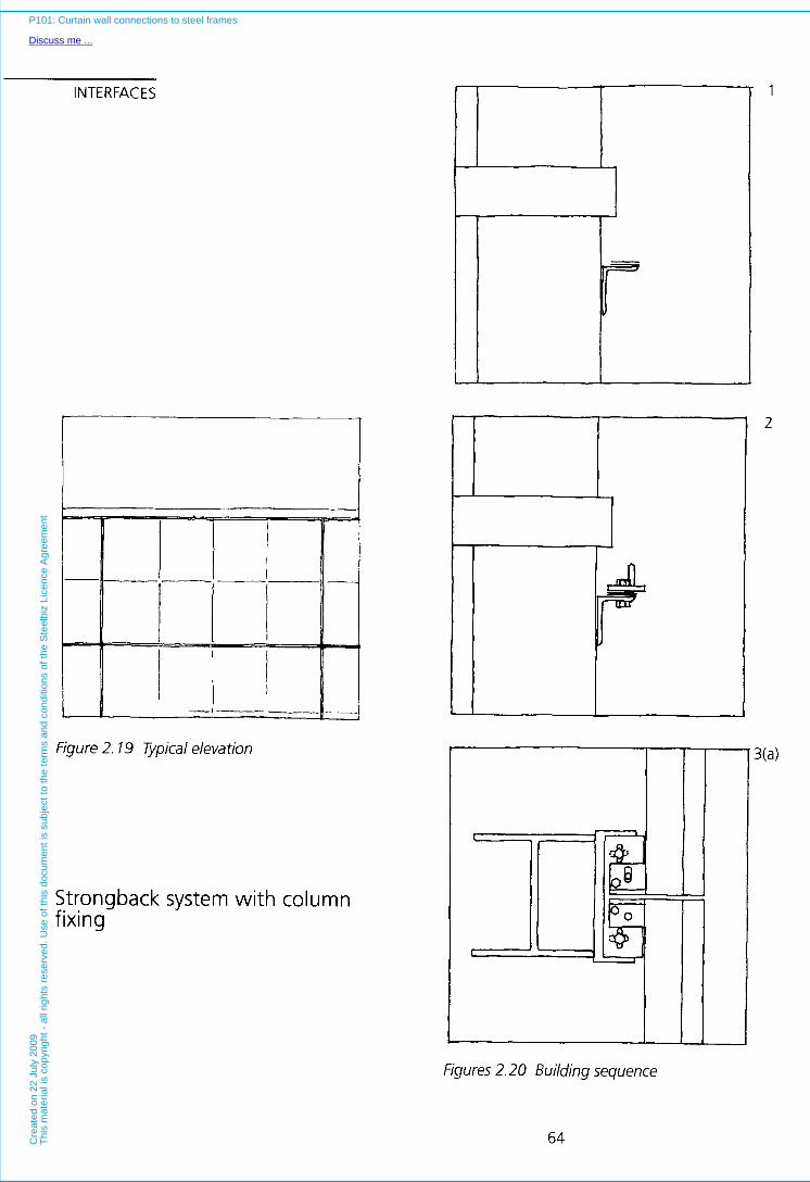
INTERFACES
--
Figure 2.19 7-ypical elevation
Strongback system with column fixing
- 1
2
Figures 2.20 Building sequence
64
P101: Curtain wall connections to steel frames
Discuss me ...C
reat
ed o
n 22
Jul
y 20
09T
his
mat
eria
l is
copy
right
- a
ll rig
hts
rese
rved
. Use
of t
his
docu
men
t is
subj
ect t
o th
e te
rms
and
cond
ition
s of
the
Ste
elbi
z Li
cenc
e A
gree
men
t
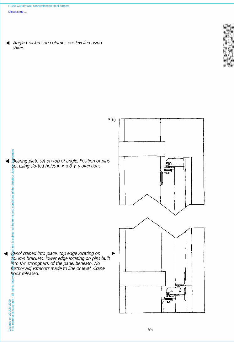
4 Angle brackets on columns pre-levelled using shims.
4 Bearing plate set on top of angle. Position of pins set using slotted holes in x-x & y-y directions.
4 Panel craned into place, top edge locating on column brackets, lower edge locating on pins built into the strongback of the panel beneath. No further adjustments made to line or level. Crane hook released.
\
1
65
P101: Curtain wall connections to steel frames
Discuss me ...C
reat
ed o
n 22
Jul
y 20
09T
his
mat
eria
l is
copy
right
- a
ll rig
hts
rese
rved
. Use
of t
his
docu
men
t is
subj
ect t
o th
e te
rms
and
cond
ition
s of
the
Ste
elbi
z Li
cenc
e A
gree
men
t
INTERFACES Critical appraisal
This system, like the previous system, conforms well to the recommendations of Section 1.
Panels can be fixed from a single level, and since there is no formal wind restraint bracketry, erection operations are relatively few.
The particular bracketry illustrated, may be pre-set, however, post installation adjustments to level are also possible using the levelling screws. Since brackets are located on the columns, the floor edge is kept clear, but access to the connections may be difficult owing to the confined space that is available. One way of overcoming the problem of confined workspace is to attach the connection bracketry to the sides of columns rather than to the outside face. Two brackets are located on either side of columns which themselves are rotated through ninety degrees such that the web of the column runs parallel to the slab edge rather than perpendicular to it as in the example. The advantage of rotating the column is that brackets locate on the outside of the flanges and seating/bolting back arrangements are simple. This alternative design is particularly suitable for situations where the added width of the connection may be lost within a suspended ceiling. Pin connections of the type shown make removal of individual panels below the uppermost storey impossible without either breaking out the pins or removing the vertical stack of panels above that which is to be taken out. On the other hand, the use of conventional wind restraint connections a t the bottom edge of the panel is also a positive option. These make the panels structurally independent and allow them to be removed without disturbing the units above and below.
66
P101: Curtain wall connections to steel frames
Discuss me ...C
reat
ed o
n 22
Jul
y 20
09T
his
mat
eria
l is
copy
right
- al
l rig
hts
rese
rved
. Use
of t
his
docu
men
t is
subj
ect t
o th
e te
rms
and
cond
ition
s of
the
Ste
elbi
z Li
cenc
e A
gree
men
t

2.6 STICK SYSTEM WITH SLAB EDGE FIXING Stick systems are very different to conventional "panel only" based approaches.
Stick systems comprise vertical mullions and horizontal transoms (Figure 2.21). Typically, the vertical members are
Figure 2.2 1 Axonometric
67
P101: Curtain wall connections to steel frames
Discuss me ...C
reat
ed o
n 22
Jul
y 20
09T
his
mat
eria
l is
copy
right
- a
ll rig
hts
rese
rved
. Use
of t
his
docu
men
t is
subj
ect t
o th
e te
rms
and
cond
ition
s of
the
Ste
elbi
z Li
cenc
e A
gree
men
t

INTERFACES continuous, or rigidly joined, and run from ground level to the full height of the building (as described in Section 1.2). These mullions are interspaced horizontally with discontinuous transoms. Mullions may act as columns transmitting the weight of the cladding to the ground, or may be hung from the roof slab, or selected floor edges.
Generally, mullions are fixed onto the top of the slab or to the outside face using shoe type brackets. On occasions however, shoes may be fixed to the back of steel channels fitted in place of edge beams. This arrangement presents an uninterrupted flush surface on which to fix the brackets, and also benefits from the fact that channels have more appropriate sheer centres than conventional edge beam profiles.
Irrespective of location, brackets may be pre-aligned, either by accurate bolting down, or more favourably, by using screw adjusters a t either side of the bracket. Slab top brackets which act as only wind restraints do not require shimming since they locate into vertically slotted holes. These brackets are set to achieve the correct vertical alignment by adjusting them relative to the bolt down position. Suspension devices on the slab top from which mullions are hung, and brackets on the face of the slab, may be aligned using a combination of shims and adjustments about the bolt down position. Bracket tolerance is usually plus or minus 20 mm in all three planes (idout, up/down, sidehide) relative to the bolt down position. Shoes may be fabricated from either steel or aluminium, but mullions are often aluminium since this can be easily and accurately extruded. The fixing bolts or anchors which attach the shoe to the slab edge, and their pins, will almost invariably be either steel or stainless steel. This variety of metals can lead to problems of bi-metallic corrosion which must be consciously designed out through the use of similar metals or insulating devices.
Tolerances
Where rigid joints are used between mullions and transoms, dimensional tolerances have to be closely monitored. Dimensional variations in the length of transoms will compound down the length of the facade. These have to be accommodated within the shoe design by providing adequate horizontal adjustment both to cope with these dimensional variations, and also to accommodate a realistic tolerance associated with the positioning of the shoe itself. Tolerances in the vertical plane are taken up by the slotted hole arrangement in the mullion/shoe connection detail already described. The mechanism which takes up expansion and contraction of the mullion is also a convenient method of affording some tolerance in the height of the shoe.
68
P101: Curtain wall connections to steel frames
Discuss me ...C
reat
ed o
n 22
Jul
y 20
09T
his
mat
eria
l is
copy
right
- a
ll rig
hts
rese
rved
. Use
of t
his
docu
men
t is
subj
ect t
o th
e te
rms
and
cond
ition
s of
the
Ste
elbi
z Li
cenc
e A
gree
men
t
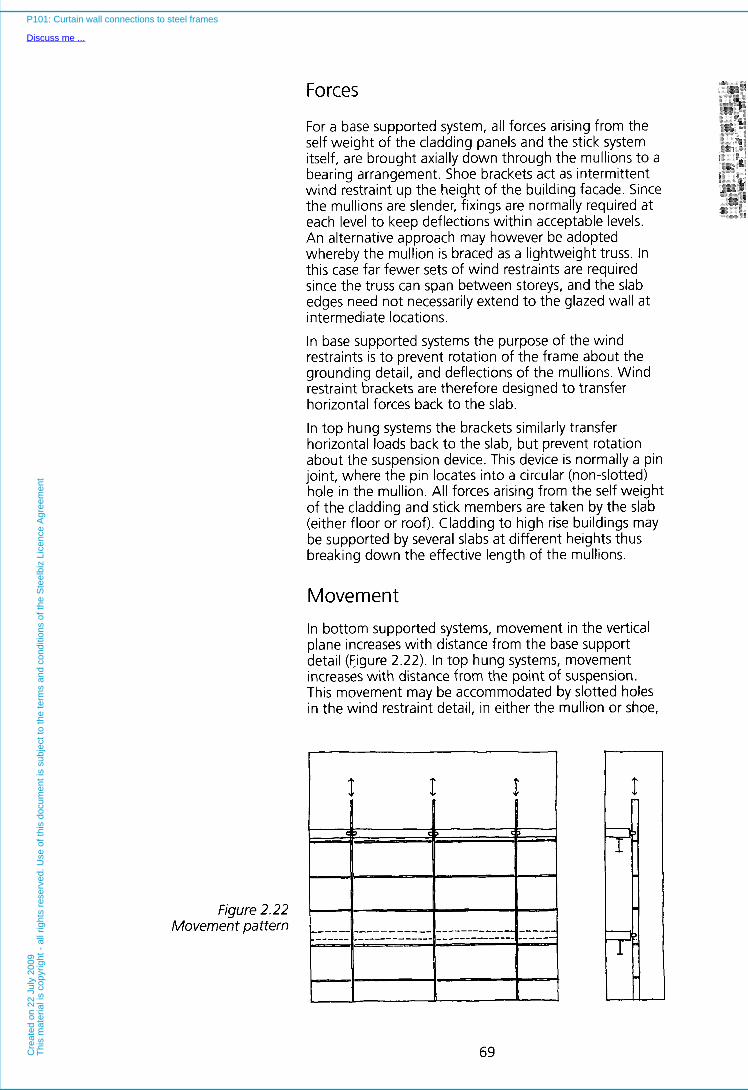
Figure 2.22 Movement pattern
69
P101: Curtain wall connections to steel frames
Discuss me ...C
reat
ed o
n 22
Jul
y 20
09T
his
mat
eria
l is
copy
right
- a
ll rig
hts
rese
rved
. Use
of t
his
docu
men
t is
subj
ect t
o th
e te
rms
and
cond
ition
s of
the
Ste
elbi
z Li
cenc
e A
gree
men
t
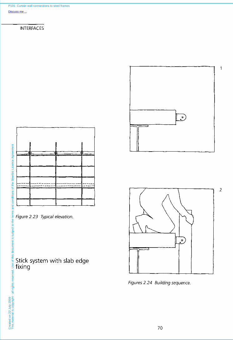
INTERFACES
1
Figure 2.23 vpical elevation.
Stick system with slab edge fixing
Figures 2.24 Building sequence.
2
70
P101: Curtain wall connections to steel frames
Discuss me ...C
reat
ed o
n 22
Jul
y 20
09T
his
mat
eria
l is
copy
right
- a
ll rig
hts
rese
rved
. U
se o
f th
is d
ocum
ent
is s
ubje
ct t
o th
e te
rms
and
cond
ition
s of
the
Ste
elbi
z Li
cenc
e A
gree
men
t
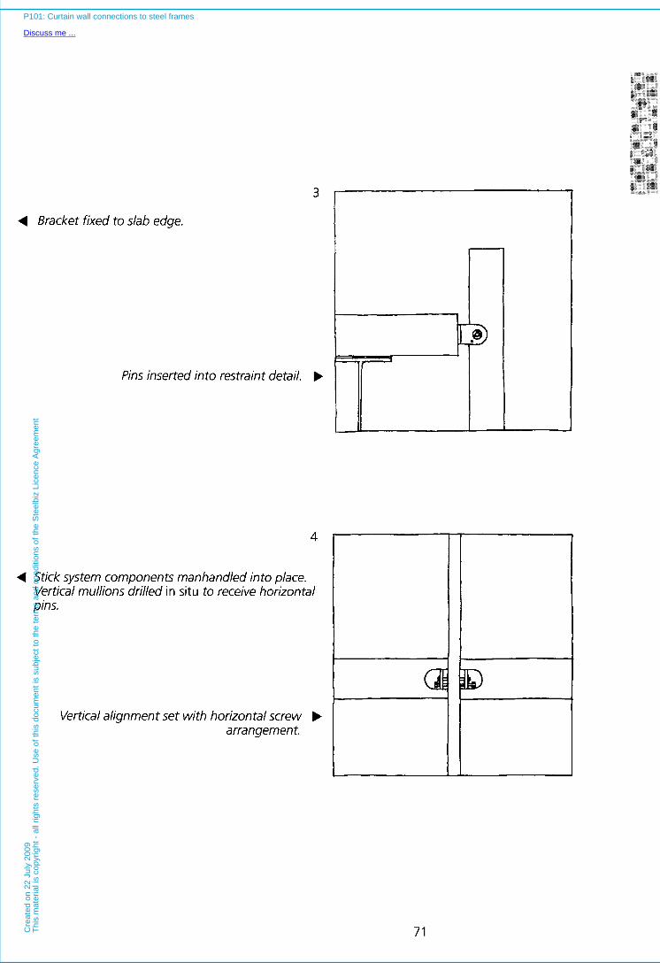
4 Bracket fixed to slab edge.
Pins inserted into restraint detail. b
4
4 Stick system components manhandled into place. Vertical mullions drilled in situ to receive horizontal pins.
Vertical alignment set with horizontal screw b arrangement.
i I
71
P101: Curtain wall connections to steel frames
Discuss me ...C
reat
ed o
n 22
Jul
y 20
09T
his
mat
eria
l is
copy
right
- a
ll rig
hts
rese
rved
. Use
of t
his
docu
men
t is
subj
ect t
o th
e te
rms
and
cond
ition
s of
the
Ste
elbi
z Li
cenc
e A
gree
men
t
INTERFACES or by a slip joint in mullion length connections.
Transoms are more difficult to design in relation to movement. I t is possible in some instances to use spigotted connections to the mullion to absorb movements a t the joint. Often there will be sufficient flex in both the transom and panel to take up any expansion (particularly when the action of glazing or panel gaskets is taken into account), however where neither of these approaches is successful, vertical expansion joints may be required at intervals along the facade of the building.
In this latter, rather rare case, some horizontal movement will be required at most of the slab edge brackets and a t the grounding detail. Areas of the facade may be prevented from moving relative to the structure about a single central mullion, but be free to expand to either side along the length of the facade. This requires relative movement to occur between the mullion and pin.
Critical appraisal
This type of system can be pre-levelled. General positioning of the wind restraint brackets can be done ahead of the erection operation, with only fine adjustments taking place (ideally using built in adjusters) during the erection operation. Stick systems of this type do not induce torsion in the edge beams (since there is no direct connection of the wind bracing to these beams, either eccentrically or otherwise), and in base supported systems there is little or no deflection of the frame from the self weight of the cladding. Some deflection will be induced by wind loads, and in top hung systems there will be horizontal deflection of the frame at and about the points of suspension.
When brackets are located on the vertical face of the slab edge, the adjacent floor is relatively free of bracketry. If brackets are located on the top of the slab the floor edge may still be used for distributions of the services since brackets are relatively small (but a t frequent centres corresponding to the spacing of the mullions).
Conversely, stick systems may be complicated to erect since they are assembled from many components (although partial prefabrication can to some extent offset this), and long mullions have generally to be erected from several levels. The overall speed of erection of a stick system comprising panels of less than storey height, is not likely to be as rapid as a properly designed panel based system. However, in situations where cladding can be erected without the use of cranage (i.e. in small components rather than large non-manhandleable prefabricated units), such matters may be of little consequence, since the erection operations need not be on the critical path.
72
P101: Curtain wall connections to steel frames
Discuss me ...C
reat
ed o
n 22
Jul
y 20
09T
his
mat
eria
l is
copy
righ
t -
all r
ight
s re
serv
ed.
Use
of
this
doc
umen
t is
sub
ject
to
the
term
s an
d co
nditi
ons
of t
he S
teel
biz
Lice
nce
Agr
eem
ent