Embed Size (px)
Citation preview
Ac
BP
a
ARRA
1
hwbgtmbt
soSegdbrasFt
0d
Nuclear Engineering and Design 239 (2009) 455–469
Contents lists available at ScienceDirect
Nuclear Engineering and Design
journa l homepage: www.e lsev ier .com/ locate /nucengdes
case study of the effect of cladding panels on the response of reinforcedoncrete frames subjected to distant blast loadings
ing Li ∗, Tso-Chien Pan, Anand Nairrotective Technology Research Center, Nanyang Technological University, 50 Nanyang Ave, Singapore 639798, Singapore
r t i c l e i n f o
rticle history:eceived 6 September 2008eceived in revised form 1 December 2008ccepted 1 December 2008
a b s t r a c t
The turbine building is a vital structure within nuclear power plants that houses turbines, moisture sep-arators and electric generators among other important equipment. Turbine buildings are typically framestructures that in most cases have not been designed to resist blast loadings. The authors to determinethe dynamic responses of reinforced concrete (RC) frame structures when subjected to distant intense
surface loadings caused by explosions carried out a numerical study. The study was extended furtherto investigate the influence of claddings on frame structures when exposed to blast loadings. A three-dimensional (3D) nonlinear dynamic finite element model was created and utilized to determine thedynamic responses of RC frame structures from both local and global perspectives. It was observed fromthe results obtained from the finite element (FE) simulations carried out that the dynamic responses offrame structures with claddings were more severe. This is due to the variations in blast forces received by the structure.. Introduction and background
Security in nuclear power plants has to take an additionaleightened level with the recent surge in the occurrence of world-ide explosive events caused by terrorism. In nuclear power plants,
oiling water reactors present unique challenges since the wateroing through the turbines are radioactive. This means that theurbine hall has to be slightly contained and may require unique
aintenance routines. The focus of this study is to investigate theehavior of these turbine buildings, which are typically frame struc-ures, when subjected to distant blast loadings.
After the trigger of a blast, a blast wave including a high-pressurehock front is formed and expands outward from the center of det-nation (ASCE, 1985; Biggs, 1964; Baker et al., 1983; Forbes, 1999;mith and Hetherington, 1994). As the blast wave strikes a building,xplosive detonations may cause extensive damage to both the tar-et structure and nearby buildings. The analysis of overpressure andrag force of the blast wave load on a structure, and the interactionetween them is extremely complicated. However, considering theelative distance of the detonation center with the target structure
s well as the size of the structure itself, two classes of blast wave-tructure interaction can be generally identified and is shown inig. 1 (Smith and Hetherington, 1994). The first class is the interac-ion of a blast wave produced by the detonation of a smaller charge∗ Corresponding author.E-mail address: [email protected] (B. Li).
029-5493/$ – see front matter © 2008 Elsevier B.V. All rights reserved.oi:10.1016/j.nucengdes.2008.12.003
© 2008 Elsevier B.V. All rights reserved.
loading a target structure at a short standoff distance, which istypical for most terrorist attacks such as car bombings (Corley etal., 1998; Longinow and Mniszewski, 1996; Luccioni et al., 2003).The second class is the interaction of a blast wave on a relativelydistant structure as might be present due to an accidental severesurface explosion of petroleum refineries, chemical plants, ammu-nition storage areas (Glasstone and Dolan, 1977; Kletz, 1975) andturbine buildings.
The profile of blast loadings on a structure tends to be differ-ent within these two classes of blast wave-structure interaction. Inthe first class, the blast pressures are produced locally to individ-ual structural members and the members are likely to be loadedsequentially. In contrast, during the second class of blast wave-structure interaction, the target structure is engulfed due to thediffraction of the blast wave and a normal squashing force willbe applied to all of the exposed surfaces. There is also a transla-tional drag force, which tends to move the body of the structurelaterally. Many explosion tests and numerical analyses have beencarried out to determine the behaviors of structures in the firstclass of blast wave-structure interaction where the blast pressuresare applied locally to individual structural members. This results inthe possibility of an excessive local failure of several critical struc-tural members that could lead to a progressive collapse noticeably
in a non-redundant structure (Corley et al., 1998; Longinow andMniszewski, 1996; Luccioni et al., 2003). However, little literature isavailable due to the limited research that has been devoted towardsthe behavior of structures and their possible failure mechanisms inthe second class of blast wave-structure interaction.
456 B. Li et al. / Nuclear Engineering and Design 239 (2009) 455–469
st wa
sccstTmtdtpcmapaStsaitdn
Fig. 1. Two classes of bla
The blast incidents producing the second class of blast wave-tructure interaction are very rare. If they do occur, the consequencean be extremely severe, particularly upon structures not specifi-ally designed to withstand blast effects. There have been cases ofevere damage or even collapse of surrounding buildings caused byhe event of such incidents (Glasstone and Dolan, 1977; Kletz, 1975).his would be a very catastrophic event in a nuclear power plant. Toinimize blast consequences to buildings, an effective blast resis-
ant design is needed. For this purpose, knowledge of structuralynamic behaviors and the corresponding potential damage dis-ributions under such blast situations is imperative. This paperresents a case study of the structural behaviors in the secondlass of blast wave-structure interaction. The study is focused onoment-resisting RC frame structures, which is the typical design
dopted in turbine buildings. The results emphasizes on the com-licated interaction between the blast wave, and structure as wells the nonlinear material properties of concrete and reinforcement.ince the exterior cladding panels might have noticeable effects onhe structural behaviors under blast conditions, two types of multi-torey frame structures, with and without exterior cladding panels
re analyzed. The corresponding structural dynamic responses aredentified and compared. The findings from this study are usedo reach conclusions and recommendations in the blast resistantesign concerning explosive safety for typical turbine buildings inuclear power plants.Fig. 2. Blast loadings on a simply
ve-structure interaction.
2. Blast loadings
The hemispherical wave front, produced by distant intense sur-face explosions that, exerts loading on the frame structure bysubjecting it to blast waves produced by distant intense surfaceexplosions, can be reasonably idealized as a planar blast wave front.The idealization is conducted by considering the size of the face ofthe structure that is essentially parallel to the front faces of the tar-get as illustrated in Fig. 2. As the blast wave strikes on the front faceof a closed structure target, a reflected pressure is instantly devel-oped. The blast wave diffracts around the target, subjecting initiallythe sides and roof and finally the rear face to pressures equal to inci-dent overpressures (air-blast pressure occurring in the free-field).At the same time, these faces are loaded by drag pressures that area function of a drag coefficient. This dynamic pressure is associatedwith the airflow behind the shock causing drag or wind type loads.The pressure causes a push on the front face of the target followedby a suction force on the back and sides as the blast dynamic pres-sure passes over and around the target (Forbes, 1999; Smith andHetherington, 1994).
Determination of the exact blast loadings created by a distantexplosion on the front, top sides, and the rear faces of the closed tar-get is almost unrealistic considering the complicated process of theinteraction of the blast wave with the target in concern. In order toreduce this complex problem of blast loadings to reasonable terms,
closed rectangular target.

B. Li et al. / Nuclear Engineering and Design 239 (2009) 455–469 457
ayout
abgoatsoc
Fig. 3. Details of the target six-storey frame structure. (a) Structural l
computational procedure is recommended in TM 5-855-1 (1986)ased on two assumptions that (a) the target is generally rectan-ular in shape, and (b) the object being loaded is in the regionf the Mach reflection (ASCE, 1985; TM 5-855-1, 1986). These two
ssumptions are computed in a rational manner during the deriva-ion of the blast loadings on rectangular targets in a relatively largetandoff blast environment. The simplified loading configurationsn various faces are shown in Fig. 2 whose parameters can be cal-ulated with the equations listed in TM 5-855-1 (1986) for a closedFig. 4. Modeling of the three-dimensional six-storey sub-frame structure. (a)
. (b) Elevation view. (c) Reinforcement details of structural members.
rectangular aboveground target, i.e. a column, a beam, or a closedstructure.
The computation of the blast loadings on a frame structure isrelatively more complicated than illustrated in Fig. 2. This is caused
by the fact that the frame structure as a whole not being able tobe taken as an arbitrarily closed rectangular target. The loadingprofiles applied to a frame structure are dependent on the out-of-plane strength and stiffness of exterior cladding panels, as wellas their connection details within the beam and column membersFrame structure with exterior cladding panels. (b) Bare frame structure.
4 ng and
tl
•
•
msmtbsitlaTfoa
iTnTbsebvofuebclddt
etrtbtths
3
s(trF
o1
only beams, columns and floor slabs are modeled for the numericalsimulations in the second model. The modeling of frames for thesemodels is illustrated in Fig. 4.
58 B. Li et al. / Nuclear Engineeri
hat make up the frame when subjected to the direct action of blastoadings. In this study, two extreme cases are considered:
exterior cladding panels constructed from reinforced concretethat posses significant strength and stiffness;no exterior cladding panels for the frame structure (bare framestructure).
For the case of the frame structure with exterior cladding panelsade out of RC, the cladding panels possess significant out-of-plane
trength, stiffness and strong connection details with other frameembers. As the blast wave hits the outer surfaces of the struc-
ure (including outer surfaces of exterior cladding panels, exterioreams and columns), it would not be able to penetrate into thetructure. The blast loadings subjected to the cladding panels wouldn turn be transferred to its primary frame members through reac-ion forces. These transferred reaction forces together with the blastoadings acting directly on the outer surfaces of the exterior beamsnd columns will produce a dynamic response from the structure.he method utilized to compute the blast forces exerted upon theront, roof and rear surfaces of the structure adopts this methodol-gy and assumes that it is reasonable to treat the whole structures a closed target.
In the second case, the blast wave front would enter the build-ng producing a high pressure on the rear faces of the columns.his varied load path implies that the structure as a whole can-ot be assumed to take the form of a closed rectangular target.his means the pressure distribution illustrated in Fig. 2 cannote used directly as when computing blast loadings on a bare frametructures. However, the shock wave front from a distant surfacexplosion condition is essentially parallel to the front faces of thelast-loaded columns and thus, the blast loading subjected to indi-idual columns of the structure can be computed by taking eachf its front faced columns as a closed rectangular target. The blastorces on the front and rear faces of the columns can then be eval-ated in accordance to Fig. 2. The parameters (L, Ws and Hs) arequal to those of the dimensions of each individual column. Thelast loadings on both side faces of each column are identical. Thisauses the top and bottom surfaces of each slab to have identicaloadings which in turn leads to it experiencing a zero resultant forceue to the blast wave. This loading thus approximates to one pro-uced by a planar wave, and therefore is not accounted for duringhe analysis.
In addition to the effects of blast overpressures, intense surfacexplosions are also capable of producing ground shocks as a result ofhe directly induced ground motion propagating through the soil orock and might have some effect on structural responses. The arrivalime of these ground shocks would differ from the arrival time of thelast wave on the structure. However, considering the fact that thearget to be studied is located at a large standoff distance relative tohe source of explosion, the magnitude of the ground shock wouldave been greatly diminished. Therefore the effects of direct groundhocks are ignored in this analysis.
. Design of the target frame structure
A three-dimensional, six-storey moment-resisting RC frametructure is designed in accordance with the design code BS 81101997) to study the dynamic behaviors of frame structures underhe distant blast conditions. The layout of the structure and the
einforcement details within structural members are shown inig. 3.The blast wave produced by detonating the equivalent weightf 50 tons of TNT placed at ground level at a standoff distance of00 m is considered in this study. In these blast conditions, where
Design 239 (2009) 455–469
the standoff distance is significantly larger than the size of the tar-get structure, the blast wave can be reasonably modeled as a planarwave as illustrated in Fig. 3. This planar wave engulfs the wholestructure resulting in uniformly distributed blast pressures on allits exposed surfaces along both the width and height of the tar-get. Due to the symmetry in both the configuration of the targetstructure and the blast pressure distribution, a three-dimensionalsub-frame including a planar frame and half of its adjacent compo-nents are modeled to simulate the dynamic responses of the wholestructure.
Two separate numerical simulations are performed on the six-storey frame structure in order to determine the effect of theexterior cladding panels on the structural blast responses. In thefirst model, the exterior cladding panels are assumed to be made ofRC with sufficiently out-of-plane strength and stiffness to preventthe blast waves from entering the building. This model includesexterior cladding panels (whose reinforcement arrangements arefound in Fig. 3c), together with the floor slabs, beams and columns.In the second model, the structure is built without exterior claddingpanels. As discussed previously, such a frame structure can beassumed as a bare frame against the blast loadings. Accordingly,
Fig. 5. Material modeling. (a) Concrete in compression and tension. (b) Reinforce-ment.
ng and
4
mdlmit
4
Tcosebgboe4woba
B. Li et al. / Nuclear Engineeri
. Finite element models
The three-dimensional six-storey sub-frame structures areodeled to perform the numerical simulations of the structural
ynamic responses under the concerned blast conditions by uti-izing the ABAQUS (2005) computer software. The finite element
odeling process consists of structural modeling, material model-ng of concrete and reinforcement, type of loads, analysis steps, andhe integration methods.
.1. Structural modeling
Two types of structural members are included in the sub-frames.hey include beams and columns and the planar members thatomprise of exterior cladding panels and floor slabs. In order tobtain a more accurate simulation of the structural response whenubjected to blast conditions, three-dimensional continuum solidlements were employed when modeling these structural mem-ers. However, creation of these elements demands considerablyreater computational effort due to the complicated nonlinearehaviors of the materials and results in an extremely large sizef the finite element model. For simplicity, Timoshenko beamlements for modeling frame beams and columns, together with
-node shell elements for exterior cladding panels and floor slabsere adopted. The accuracy of the numerical simulation resultsf the responses for different structural members modeled as theeam or shear elements will be examined by comparison with thevailable data in the latter part of this paper. Reinforcements within
Fig. 6. DIFs for concrete a
Design 239 (2009) 455–469 459
the concrete structures are modeled by means of rebars, which areone-dimensional strain theory elements (rods) defined singly orembedded in oriented surfaces. Each rebar is placed at its corre-sponding location for the beam elements while the layers of rebarare defined using the shell elements with the needed data-inputof reinforcing bar’s area and location, and its space length. Thestructural modeling for the six-storey frame structure with/withoutexterior cladding panels is shown in Fig. 4. The bottom ends of struc-tural columns are modeled to be perfectly fixed to the solid groundand symmetry boundary conditions are applied to the edges of theslabs and cladding panels.
4.2. Material modeling
The dynamic responses of RC structures under blast conditionsare highly dependent on the material properties of the concreteand reinforcement that each of its individual members is made upfrom. The accurate modeling of the material properties is essentialto ensure the validity in the results from the numerical simulationsthat determine the dynamic responses of structures. In finite ele-ment analysis, the material behaviors of concrete, reinforcing barsand the bond between them should be taken into account. It is pre-sumed that the bars form a perfect bond with concrete. Although
this assumption will impose a certain level of errors, it is the onlypractical means of finding a solution for the numerical simulationsto determine the responses of RC structural systems. This is causedby the unmanageable size of the computational works and the lackof reliable data on the topic of blast environments.nd reinforcement.
4 ng and
bsTwstatatas
f
mOh
Ff
60 B. Li et al. / Nuclear Engineeri
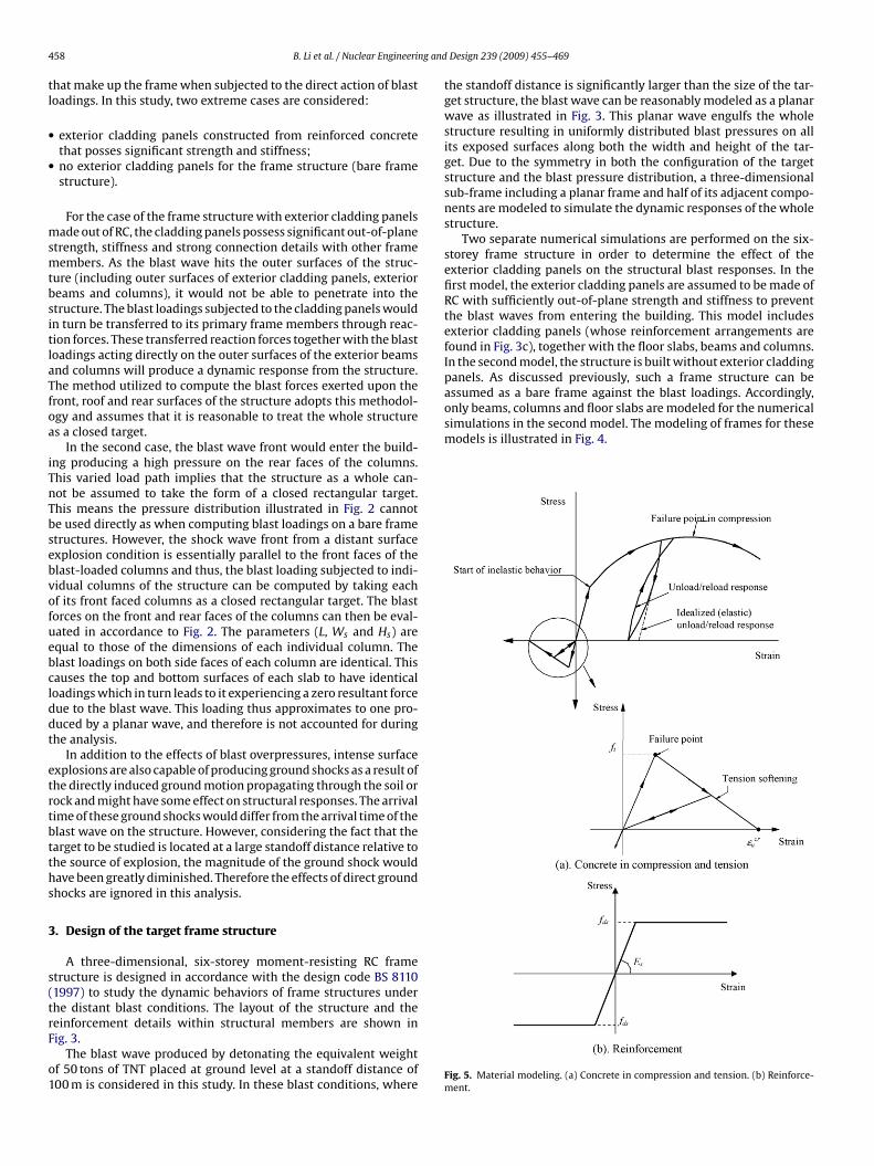
The smeared cracking model is utilized to represent the tensileehavior of concrete. In this model, concrete begins to crack as theurface reaches the defined maximum principal tensile stresses.his will in turn affect the stress and material stiffness associatedith each material point at the related elements. To simulate the
oftening effect of the concrete in tension after cracking, a bilinearension stress–strain curve is defined as in Fig. 5, where εcr
u is takens 10−3. The selection of this value is based on the assumption thathe strain softening after failure reduces the stress linearly to zerot a total strain of about 10 times the strain at failure of concrete inension, which is typically 10−4 in standard concrete (Hilleborg etl., 1976). The tensile strength ft is determined from the compressivetrength fc as (CEB-FIP, 1993)
t = 0.30f 2/3c (1)
In compression, concrete is simulated by an elastic–plasticodel where the elastic stress state is limited by a yield surface.nce yielding has occurred, an associated flow rule with isotropicardening is used. This yield surface can be written in terms of the
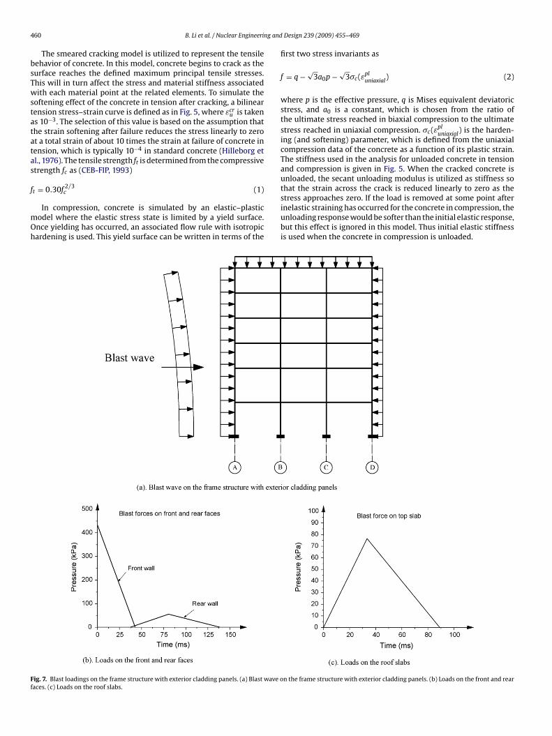
ig. 7. Blast loadings on the frame structure with exterior cladding panels. (a) Blast wave oaces. (c) Loads on the roof slabs.
Design 239 (2009) 455–469
first two stress invariants as
f = q −√
3a0p −√
3�c(εpluniaxial
) (2)
where p is the effective pressure, q is Mises equivalent deviatoricstress, and a0 is a constant, which is chosen from the ratio ofthe ultimate stress reached in biaxial compression to the ultimatestress reached in uniaxial compression. �c(εpl
uniaxial) is the harden-
ing (and softening) parameter, which is defined from the uniaxialcompression data of the concrete as a function of its plastic strain.The stiffness used in the analysis for unloaded concrete in tensionand compression is given in Fig. 5. When the cracked concrete isunloaded, the secant unloading modulus is utilized as stiffness sothat the strain across the crack is reduced linearly to zero as the
stress approaches zero. If the load is removed at some point afterinelastic straining has occurred for the concrete in compression, theunloading response would be softer than the initial elastic response,but this effect is ignored in this model. Thus initial elastic stiffnessis used when the concrete in compression is unloaded.n the frame structure with exterior cladding panels. (b) Loads on the front and rear

ng and
sst
Fo
B. Li et al. / Nuclear Engineeri
The Von-Mises yield criterion is used to describe the con-titutive behavior of the reinforcement within the concrete. Thetress–strain relationship of reinforcement is shown in Fig. 5, wherehe reinforcement is modeled as an elasto-plastic curve. Strain
ig. 8. Blast loadings on the bare frame structure. (a) Blast wave on the bare frame structun columns at Axis C. (e) Loading on columns at Axis D.
Design 239 (2009) 455–469 461
hardening of reinforcement is not considered in this analysis due tothe lack of experimental data available to support it. The ultimatestrain value is often not reported in current literatures because ofthe difficulty in determining the exact peak stress when it occurs
re. (b) Loading on columns at Axis A. (c) Loading on columns at Axis B. (d) Loading

4 ng and
at
i(Mdiaoss
D
62 B. Li et al. / Nuclear Engineeri
nd also because of the unresolved ability to distinguish betweenhe materials ultimate and its rupture strain.
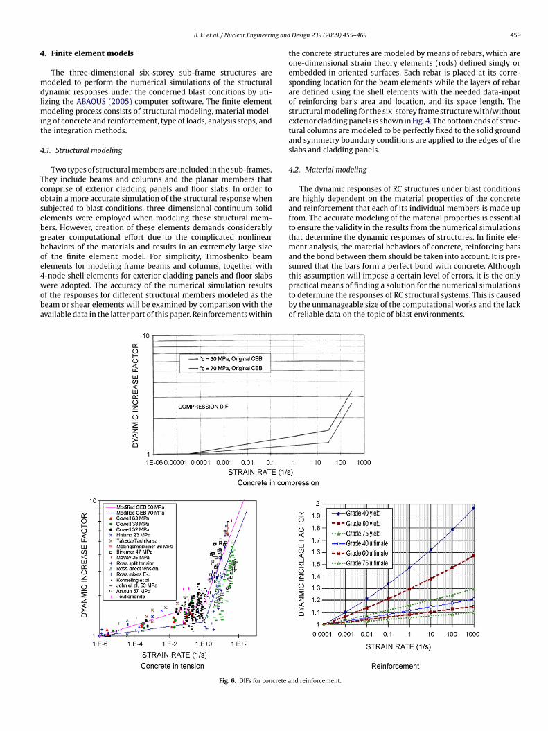
In order to consider the fact that under higher loading ratesn both concrete and reinforcement exhibit increased strengthsDharan and Hauser, 1970; Fu et al., 1991; Georgin et al., 1998;
alvar and Crawford, 1998a,b), a dynamic increase factor (DIF),efined as the ratio of the dynamic to static strength, is employed
n this analysis. The expressions by Malvar and Crawford (1998a,b)re utilized and are derived from a literature review comprisingf extensive test data revealing the effects of strain rate on thetrength of concrete and reinforcement. For the concrete compres-
ive strength, DIF is given asIF ={
(ε̇/ε̇s)1.026˛s ε̇ ≤ 30 s−1
�s(ε̇/ε̇s)1/3 ε̇ > 30 s−1 (3)
Fig. 9. Verification of finite element models showing compar
Design 239 (2009) 455–469
where ε̇ is the strain rate in the range of 30 × 10−6 to300 s−1; ε̇s = 30 × 10−6 s−1 (static strain rate); log �s = 6.156˛s − 2;˛s = 1/(5 + 9fc/fco); fco = 10 MPa; fc is the static compressive strengthof concrete. For the concrete in tension, the formula is
DIF ={
(ε̇/ε̇s)ı ε̇ ≤ 1.0 s−1
ˇ(ε̇/ε̇s)1/3 ε̇ > 30 s−1
(4)
where ε̇ is the strain rate in the range of 10−6 to 160 s−1; ε̇s =
10−6 s−1; log ˇ = 6ı − 2; ı = 1/(1 + 8fc/fco); fco = 10 MPa. A plot of theproposed formulae for the DIF of concrete in tension and com-pression is shown in Fig. 6, which indicates that the strengthenhancement is different for tension and compression. The DIF for-mula for the yield stress of reinforcement (Malvar and Crawford,ison between the numerical and experimental results.
ng and
1
D
wswb
(taabd
4
dsiTbsfst
F(
B. Li et al. / Nuclear Engineeri
998a,b) is
IF =(
ε̇
10−4
)˛
(5)
here ˛ = ˛fs and ˛fs = 0.074 − 0.04 fs/414; fs is the reinforcementtatic yield strength in MPa. This formula is valid for reinforcementith yield stresses between 290 and 710 MPa and for strain rates
etween 10−4 and 225 s−1.The user subroutine USDFLD in ABAQUS is used to integrate Eqs.
3)–(5) into the analysis. This subroutine allows the user to definehe field variable of a material point as a function of any of thevailable material point quantities. Thus by taking the strain rate asfield variable, the strain rate-dependent material properties cane introduced into the analysis since such properties can be easilyefined as functions of the strain rate with Eqs. (3)–(5).
.3. Application of loads and analysis procedure
Two steps of analyses are carried out in accordance to twoifferent loading stages, during the simulation to determine thetructural blast responses. The service loads would initially bemposed onto the structure prior to the occurrence of the explosion.he intensity and distribution of the stresses and strains induced
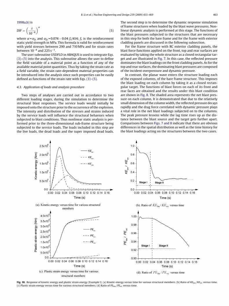
y the service loads will influence the structural behaviors whenubjected to blast conditions. Thus nonlinear static analysis is per-ormed prior to the three-dimensional sub-frame structure beingubjected to the service loads. The loads included in this step arehe live loads, the dead loads and the super imposed dead loads.ig. 10. Response of kinetic energy and plastic strain energy (Example I). (a) Kinetic enerc) Plastic strain energy versus time for various structural members. (d) Ratio of PEbm/PEw
Design 239 (2009) 455–469 463
The second step is to determine the dynamic response simulationof frame structures when loaded by the blast wave pressures. Non-linear dynamic analysis is performed at this stage. The functions ofthe blast pressures subjected to the structures that are necessaryin this step for both the bare frame and for the frame with exteriorcladding panels are discussed in the following subsection.
For the frame structure with RC exterior cladding panels, theblast force functions applied on the front, top and rear surfaces areevaluated by taking the whole structure as a closed rectangular tar-get and are illustrated in Fig. 7. In this case, the reflected pressuredominates the blast loadings on the front cladding panels. As for thetop and rear surfaces, the dominating blast pressures are composedof the incident overpressure and dynamic pressure.
In contrast, the planar wave enters the structure loading eachof the exposed columns, of the bare frame structure. This imposesthe blast loading on each column by taking it as a closed rectan-gular target. The functions of blast forces on each of its front andrear faces are obtained and the results under this blast conditionare shown in Fig. 8. The shaded area represents the net blast pres-sure on each column. It is demonstrated that due to the relativelysmall dimension of the column width, the reflected pressure decaysrapidly and the drag force correlated with dynamic pressure playsa vital role in the net blast loadings subjected on to the columns.
The peak pressure lessens while the lag time rises up as the dis-tance between the blast source and the target gets further apart.Comparisons between Figs. 7 and 8 indicate that there are obviousdifferences in the spatial distribution as well as the time history forthe blast loadings acting on the structures between the two cases.gy versus time for various structural members. (b) Ratio of KEbm/KEws versus time.s versus time.
4 ng and
4
sriiutettiasawtsbtwom0
64 B. Li et al. / Nuclear Engineeri
.4. Integration method
A general implicit dynamic integration method is employed toolve the nonlinear dynamic problem. In order to ensure the accu-acy of the numerical solutions with this method, an automaticncremental scheme is adopted to calculate the length of each timencrement through a half-step residual control. The half-step resid-al is the equilibrium residual error (out-of-balance forces) halfwayhrough a time increment. The acceptable half-step residual tol-rance is specified by the HAFTOL option in ABAQUS, which hashe dimensions of force and is usually chosen by comparison withypical actual force values such as applied forces. In this study, its taken as a near approximate of the maximum blast pressurepplied to the structure. Such an action will lead to a highly accurateolution for the problem and includes the effect of plasticity. Thisutomatic incremental scheme is especially effective for the casehere a sudden blast event initiates a dynamic problem and when
he structural response involves large amounts of energy being dis-ipated by plasticity effects. In such a case, minor increments wille required immediately after the sudden blast event, while at later
ime steps the response can be modeled with equivalent accuracyith larger time increments. Moreover in order to limit the rangef each time steps in the numerical simulations, the minimum andaximum allowable time increments are taken as 1 × 10⁻⁷ and
.01 s, respectively.
Fig. 11. Damage propagation
Design 239 (2009) 455–469
5. Verification of finite element models
The verification of the finite element models as mentioned aboveis carried out by implementing it into the analysis of a simply sup-ported beam subjected to blast loadings tested by Seabold (1967)and a square slab, clamped and longitudinally restrained along alledges exposed to uniform lateral pressure as tested by Keenan(1969). The computed and experimental displacement-time histo-ries at the mid-span for the beam and the center of the slab arecompared in Fig. 9. It can be observed that for the simply supportedbeam a peak experimental response of 28.5 mm was recorded at19.5 ms. This agrees well with the analytical results for whichthe computed peak displacement of 28.8 mm that was reached at19.2 ms. The recorded permanent deformation of this beam was20.8 mm. It also correlated well with the predicted deflection of21.7 mm. In the case of the RC slab, the maximum deflection at thecenter recorded from the experiment was 12 mm that appearedat time 7.4 ms, which is fairly close to the numerically predicteddeflection of 11.9 mm at time 7.2 ms. In addition, the analytical andexperimental results of top compressive strain history of concrete,
strain history of main reinforcement, support reaction history, andmid-span velocity history of the RC structural member are alsocompared in Fig. 9. It is demonstrated that the numerical analy-sis reasonably agrees with the observed experimental behaviors.Therefore the numerical model integrated into the nonlinear anal-with time (Example I).

ng and
yhr
6
6
stkt
B. Li et al. / Nuclear Engineeri
sis of the blast-loaded six-storey frame structure has shown toave the ability to simulate the failure process of concrete andeinforcement.
. Numerical examples
.1. Example I—frame structure with exterior cladding panels
In order to obtain a general view of the dynamic responses of theix-storey frame structure with RC exterior cladding panels underhe considered blast condition, its energy responses including theinetic energy and the plastic strain energy are plotted in Fig. 10. Inhese figures, the symbols of KEws and PEws are the kinetic energy
Fig. 12. Responses of the first-storey
Design 239 (2009) 455–469 465
and plastic strain energy within the whole structure respectively.KEbm and PEbm represent their respective energies within the crit-ical blast-loaded members (including the front exterior claddingpanels and columns, the top-storey beams and roof slabs) whileKEom and PEom represent the kinetic and plastic strain energieswithin other structural members, respectively.
From Fig. 10, it can be observed that from 0 ms to 30 ms, KEbmcomposes the most significant part of KEws covering averagely about85%. This reflects the predominant role of the localized responses of
the critical blast-loaded members in the structural responses dur-ing this time frame. Subsequently, the ratio of KEbm/KEws decreasesrapidly to a value of approximately 23% at about 50 ms and keepsalmost constant at that value. This demonstrates that the dynamicresponse of the structure is in a mode where the global response ofcolumn at Axis A (Example I).
4 ng and Design 239 (2009) 455–469
tditctboFPepcmaw
6
ebrphmwtac
idtwssbctAp
tcat
66 B. Li et al. / Nuclear Engineeri
he structural system as a whole dominates. Therefore, the entireynamic response of the structure can be approximately divided
nto two stages at a time of 40 ms as shown in Fig. 10(b). Withinhe initial stage, the dynamic responses are concentrated on severalritical blast-loaded members while as time progresses, more struc-ural members are motivated and the structural global responsesecome more predominant. The plastic strain energy responsef the structure shows the same stage division as illustrated inig. 10(d) where the ratio of PEbm/PEws versus time is plotted.Ebm accounts for almost all of PEws at the time of 40 ms. How-ver with the global response of the structure motivated later, morelastic deformation occurs on the members other than the criti-al blast-loaded ones and thus the ratio of PEbm/PEws declines. Aore detailed description of the structure responses and its dam-
ge propagation with time will be made in the following sectionsith reference to these two response stages.
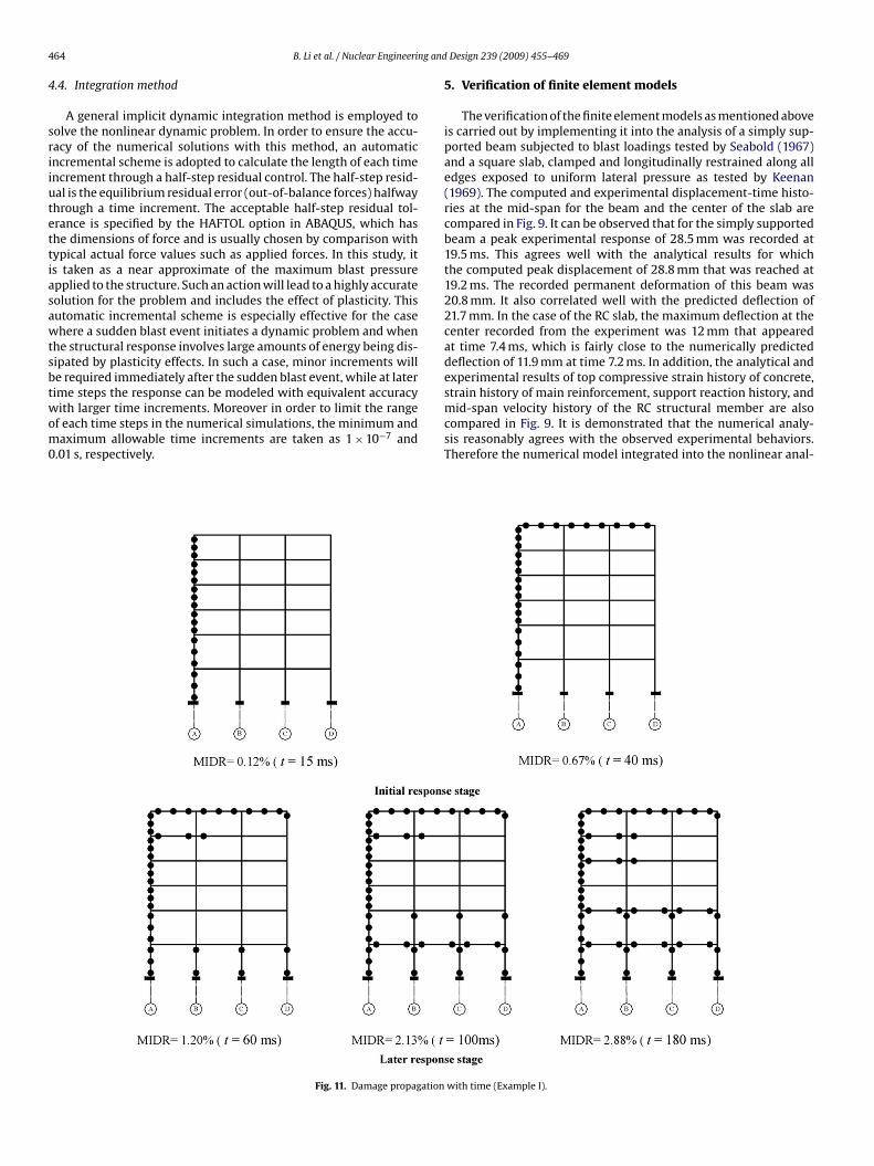
.1.1. Initial response stageAt the initial response stage, both kinetic and plastic strain
nergy responses are concentrated on critical blast-loaded mem-ers. As such, special attention is focused on their dynamicesponses and corresponding damage levels with the respectivelastic hinge distributions, as plotted in Fig. 11. A flexural plasticinge is assumed to initiate when the longitudinal tensile reinforce-ent first yields at a point along the beam element and the hingeill continue to spread over a continuous portion of the beam. Thus
he occurrence time of the hinge corresponds with the first appear-nce of plastic strain of reinforcement whose variation with timean be found from the numerical analysis in ABAQUS (2005).
It can be observed from Fig. 11 that due to the intensive local-zed responses on these members induced by the blast loadingsuring this stage, three plastic hinges have been formed on the bot-om, mid-height and top sections of the front columns at 15 ms asell as the left end, mid-span and right end sections for the top-
torey beams at 40 ms. This results in a typical damage mechanismimilar to that on the flexural structural members. The differenceetween the time of forming this damage mechanism on the frontolumns and top-storey beams is caused by the difference of theime when the peak blast pressures acting upon them is attained.s for the other frame members (beams and columns), almost nolastic deformation is present.
The flexural deformation plays a relatively important role onhe dynamic responses of structural members under distant blastonditions as indicated in Fig. 12, where typical moment-curvaturend shear force–shear strain curves for different cross-sections ofhe first-storey columns at A–A are plotted. It can be seen that a
Fig. 14. Storey drifts for the structure (Example I). (a) Storey drift resp
Fig. 13. Lateral deflection of the front cladding panels (Example I).
linear relationships exist between the shear forces and the shearstrains for these cross-sections while all the irrecoverable defor-mation is induced by their curvature responses. These phenomenaare reflected on the cross-sectional responses of other structuralmembers as well.
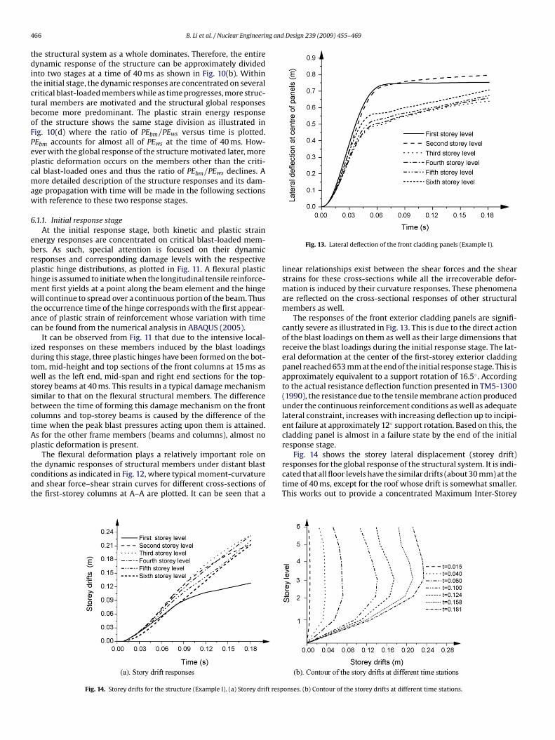
The responses of the front exterior cladding panels are signifi-cantly severe as illustrated in Fig. 13. This is due to the direct actionof the blast loadings on them as well as their large dimensions thatreceive the blast loadings during the initial response stage. The lat-eral deformation at the center of the first-storey exterior claddingpanel reached 653 mm at the end of the initial response stage. This isapproximately equivalent to a support rotation of 16.5◦. Accordingto the actual resistance deflection function presented in TM5-1300(1990), the resistance due to the tensile membrane action producedunder the continuous reinforcement conditions as well as adequatelateral constraint, increases with increasing deflection up to incipi-ent failure at approximately 12◦ support rotation. Based on this, thecladding panel is almost in a failure state by the end of the initialresponse stage.
Fig. 14 shows the storey lateral displacement (storey drift)responses for the global response of the structural system. It is indi-cated that all floor levels have the similar drifts (about 30 mm) at thetime of 40 ms, except for the roof whose drift is somewhat smaller.This works out to provide a concentrated Maximum Inter-Storey
onses. (b) Contour of the storey drifts at different time stations.

ng and
Dotti
6
mdiasfi
B. Li et al. / Nuclear Engineeri
rift Ratio (MIDR—the drift difference between adjacent storeys),f about 0.67%. This is the ratio of maximum inter-storey drift tohe inter-storey height occurring at the first storey. The contour ofhe storey drifts for the structure at this time location can be foundn Fig. 14b.
.1.2. Response stage IIAt the later response stage II, the structural dynamic response
oves to a mode where the global response of the structural system
ominates as a whole. Hence, the distribution of damage as well asts propagation with the progression of time is in a different manners compared to the initial response stage I. During this responsetage, plastic hinges are formed firstly on both end sections of therst-storey columns at a time of about 60 ms as the inter-storey
Fig. 15. Responses of some structural members
Design 239 (2009) 455–469 467
drift within this storey increases as shown in Fig. 11. Subsequently,the damage spreads upward with more plastic hinges successivelyforming on connected cross-sections around the joints located inthe first and second floor levels. Since the plastic hinges formed atthis stage are caused by large global sideway responses, they appearonly at the end sections of structural members.
The storey drift distributions with time for this frame structureunder the concerned blast condition are demonstrated in Fig. 14,to provide a better understanding of structural global responses.
It can be seen that during the time of up to 80 ms the structuralglobal responses are obviously concentrated within the first storeywhile the inter-storey drifts within other storey levels are trivial. Astime progresses, the increase in the gradient of the first-storey driftdrops to a relatively small value and the structural global responseother than blast-loaded ones (Example I).
468 B. Li et al. / Nuclear Engineering and
Table 1Three response levels.
Response level Inter-storey drift ratio Damage description
Low 1/50 Localized building/component damageMedium 1/35 Widespread building/component
damageH
bmfiatbctd
atoom
igh 1/25 Building/component losing structuralintegrity and having possibility ofcollapse due to environment condition
egins to focus on the second-storey level. The structural maxi-um inter-storey drifts within the two critical storey levels (the
rst and the second storeys) have reached 129 and 85 mm, whichre equivalent to a MIDR of 2.88% and 1.90% respectively by theime of 180 ms. Referring to Table 1, where a global damage criteriaased on the inter-storey drift ratio for a frame structure under blastonditions have been suggested in the reference (Bounds, 1997),he frame structure at time 180 ms has sustained a high level ofamage.
From the structural global responses concentrated in the first
nd second-storey levels at the time of 180 ms, it can be deducedhat plastic rotations of the joints distributed in the first and sec-nd floor levels are focused on those cross-sections at the endsf the connected columns and beams as shown in Fig. 11. Typicaloment-curvature and shear force–shear strain curves for theseFig. 16. Responses of the kinetic energy and plastic strain energy (Example I
Fig. 17. Storey drifts for the structure (Example II). (a) Storey drift resp
Design 239 (2009) 455–469
cross-sections where plastic hinges are formed at the later responsestage II are plotted in Fig. 15. It is clear that plastic deformation isinduced by their flexural responses where irrecoverable curvaturesappear at the end sections of the members.
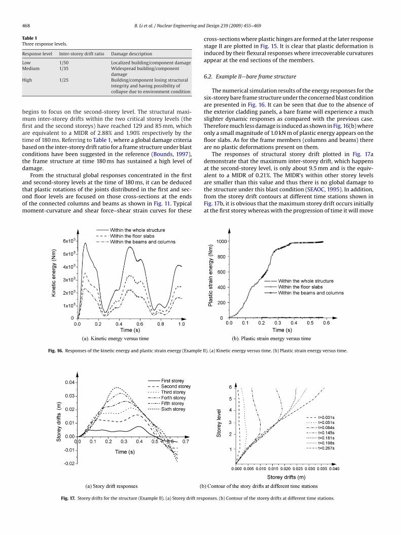
6.2. Example II—bare frame structure
The numerical simulation results of the energy responses for thesix-storey bare frame structure under the concerned blast conditionare presented in Fig. 16. It can be seen that due to the absence ofthe exterior cladding panels, a bare frame will experience a muchslighter dynamic responses as compared with the previous case.Therefore much less damage is induced as shown in Fig. 16(b) whereonly a small magnitude of 1.0 kN m of plastic energy appears on thefloor slabs. As for the frame members (columns and beams) thereare no plastic deformations present on them.
The responses of structural storey drift plotted in Fig. 17ademonstrate that the maximum inter-storey drift, which happensat the second-storey level, is only about 9.5 mm and is the equiv-alent to a MIDR of 0.21%. The MIDR’s within other storey levels
are smaller than this value and thus there is no global damage tothe structure under this blast condition (SEAOC, 1995). In addition,from the storey drift contours at different time stations shown inFig. 17b, it is obvious that the maximum storey drift occurs initiallyat the first storey whereas with the progression of time it will moveI). (a) Kinetic energy versus time. (b) Plastic strain energy versus time.
onses. (b) Contour of the storey drifts at different time stations.
ng and
uw
7
Rwpf
2
3
4
R
A
Tso-Chien Pan is a Professor in the School of Civil and Environmental Engineeringat Nanyang Technological University, Singapore.
B. Li et al. / Nuclear Engineeri
pward the structure in the sequence of the floors. Thus a transverseave is formed in the frame structure.
. Summary
The study presented in this paper investigates the responses ofC frame structures that are typical of turbine buildings locatedithin nuclear power plants, with and without exterior claddinganels when exposed to distant intense surface explosions. Theollowing conclusions may be drawn:
1. The study provides an insight into the behavior of typical tur-bine building frame structures when subjected to distant intenseblast loadings. These blast scenarios are typical of accidents orintended attacks from terrorist organizations.
. The response of the frame structures with RC exterior wall pan-els can be approximately divided into two stages. They are thelocalized responses of the blast-loaded members that are criticalduring the initial response of stage I, and the global responses ofthe structural system that dominate the later response of stage II.In addition, the flexural responses play a more important role inthe plastic deformation of the beams and columns in the framein comparison to their respective shear responses.
. The existence of RC exterior cladding panels produces moresevere dynamic responses than those of the bare frame structurewith all other blast parameters held constant. Reflected pressurewill quickly reduce to zero for the bare frame structure and onlythe drag forces associated with dynamic pressures are critical inthe net blast loadings on the structure. This is due to the diffrac-tion of the blast waves around the columns. However, the exteriorcladding panels cause the structure to be loaded with reflectedblast pressure, overpressure, and dynamic pressure, thus causingthe blast forces subjected to the frame structure with claddingpanels to be much greater. The numerical simulations show thatsome plastic deformation would appear to the structure to dis-sipate the work produced by such a large blast force, and resultsin the structure experiencing some levels of damage.
. The results obtained emphasizes that the concept of using duc-tile exterior cladding as a mechanism for the control of blastresponse appears to be somewhat unorthodox. Its potential ben-efits warrant further investigation. It is apparent that if properductile panel response is utilized, the concept should be veryeffective for enhancing the blast resistant performance of tur-bine buildings within nuclear power plants and provide them
with the much needed additional level of security.eferences
BAQUS, 2005. ABAQUS/Standard User’s Manual. HKS, Inc.
Design 239 (2009) 455–469 469
ASCE Manual 42, 1985. Design of structures to resist nuclear weapons effects. Amer-ican Society of Civil Engineers.
Baker, W.E., Cox, P.A., Westine, P.S., Kulesz, J.J., Strehlow, R.A., 1983. An ExplosionHazard and Evaluation: Fundamental Studies in Engineering. Elsevier ScientificPublishing Company, NY.
Biggs, J.M., 1964. Introduction to Structural Dynamic. McGraw-Hill, New York.Bounds, W.L., 1997. Design of blast resistant building in petrochemical facilities, ASCE
Task Committee Report on Blast Resistant Design.BS 8110, 1997. Structural use of concrete: code of practice for design and construction.
British Standard.CEB-FIP Model Code 1990, 1993. Design code. Thomas Telford, Switzerland.Corley, W.G., Mlakar, P.F., Sozen, M.A., Thornton, C.H., 1998. The Oklahoma City
bombing: summary and recommendation for multi-hazard mitigation. Journalof Performance of Constructed Facilities, ASCE 12 (3), 100–112.
Dharan, C.K.H., Hauser, F.E., 1970. Determination of stress–strain characteristics atvery high strain rates. Experimental Mechanics 10, 370–376.
Forbes, D.F., 1999. Blast loading on petrochemical buildings. Journal of Energy Engi-neering, ASCE 125 (3), 94–102.
Fu, H.C., Erki, M.A., Seckin, M., 1991. Review of effects of loading rate on con-crete in compression. Journal of Structural Engineering, ASCE 117 (12), 3645–3659.
Georgin, J.F., Reynouard, J.M., Merabet, O., 1998. Modeling of concrete at high strainrate. Computational Modeling of Concrete Structures 2, 593–601.
Glasstone, S., Dolan, P.J., 1977. The Effects of nuclear Weapons, third ed. U.S. Dept. ofDefense and U. S. Dept. of Energy, Washington, D.C.
Hilleborg, A., Modeer, M., Petersson, P.E., 1976. Analysis of crack formation and crackgrowth in concrete by means of fracture mechanics and finite elements. Cementand Concrete Research 6, 773–782.
Keenan, W.A., 1969. Strength and behavior of restrained reinforced concrete slabsunder static and dynamic loadings, Technical Report R-621, Y-F008-08-02-123,DASA-RSS3318, Naval Civil Engineering Laboratory, California.
Kletz, T.A., 1975. The Flixborough Cyclohexane Disaster, vol. 8. Loss Prevention, Amer-ican Institute of Chemical Engineers, New York, pp. 106–118.
Longinow, A., Mniszewski, K.R., 1996. Protective building against vehicle bombattacks. Practice Periodical on Structural Design and Construction, ASCE 1 (1),51–54.
Luccioni, B.M., Ambrosini, R.D., Danesi, R.F., 2003. Analysis of building collapse underblast loads. Engineering Structures 26 (1), 63–71.
Malvar, L.J., Crawford, J.E., 1998a. Dynamic increase factors for concrete. In: Twenty-Eighth DDESB Seminar, Orlando, FL.
Malvar, L.J., Crawford, J.E., 1998b. Dynamic increase factors for steel reinforcing bar.In: Twenty-Eighth DDESB Seminar, Orlando, FL.
Seabold, R.H., 1967. Dynamic Shear Strength of Reinforced Concrete Beams, Part II.Naval Civil Engineering Laboratory, Port Hueneme, California.
SEAOC, 1995. Performance based on seismic engineering of buildings. The StructuralEngineers Association of California, San Francisco, USA.
Smith, P.D., Hetherington, J.G., 1994. Blast and Ballistic Loading of Structures.Butterworth-Herinmann Ltd., Linacre House, Jordan Hill, Oxford.
TM 5-855-1, 1986. Fundamental of protective design for conventional weapons.United States Department of the Army, Washington, D.C.
TM5-1300, 1990. Structures to resist the effects of accidental explosions. UnitedStates Department of the Army, Washington, D.C.
Bing Li is an Associate Professor in the School of Civil and Environmental Engineeringat Nanyang Technological University, Singapore.
Anand Nair is a MEng candidate in the School of Civil and Environmental Engineeringat Nanyang Technological University, Singapore. He received his B.Eng.(Hons) fromthe Nanyang Technological University, Singapore.