Embed Size (px)
Citation preview

c© 2011 Danesh J. Esteki
REQUIREMENTS FOR KEYLESS JAMMING MITIGATION
BY
DANESH J. ESTEKI
THESIS
Submitted in partial fulfillment of the requirementsfor the degree of Master of Science in Electrical and Computer Engineering
in the Graduate College of theUniversity of Illinois at Urbana-Champaign, 2011
Urbana, Illinois
Adviser:
Associate Professor Yih-Chun Hu
ABSTRACT
One of the primary advantages of spread spectrum communication is its resis-
tance to interference and jamming. However, it has the drawback of requiring
the pre-establishment of a secret code between sender and receiver. This re-
quirement can lead to scaling and security issues, especially in a broadcast
setting; as a result, several “uncoordinated” approaches have been proposed
that do not require a pre-established secret code.
In this thesis, we examine the underlying assumptions of these approaches
and their resource requirements. In particular, we develop the model of a
reactive jammer, parameterize it with varying levels of ability, and use this
model to analyze three proposed keyless jamming mitigation techniques.
We show that many of the uncoordinated spread spectrum schemes are
infeasible for realistic computational powers and allocations of bandwidth
even if the attacker simply uses commercial-off-the-shelf equipment. We also
show that the third scheme, BBC codes, is vulnerable to a mark-cancellation-
and-insertion attack. In particular, we show how an attacker can use multiple
sinusoids to “search” for a cancellation signal over the space of phase and
channel condition. We also propose modifications to improve the BBC codes,
which can provide more robust jamming resistance with plausible system
bandwidth requirements.
ii

To my parents, for their love and support
iii
ACKNOWLEDGMENTS
I would like thank my adviser, Yih-Chun Hu, for all of his help and advice
as he guided me through completing this thesis. I am especially grateful for
his patience throughout the entire process.
I would also like to thank the other members of my research group for
both their assistance and their companionship. In particular, I would like
to thank Jerry for answers he provided to my innumerable questions, and
my office mate Parisa for all of the stimulating conversations we had in the
office.
Finally, I am thankful for my parents, for constantly providing me with
advice, love, and encouragement, without which I would not have made it
this far.
iv
TABLE OF CONTENTS
CHAPTER 1 INTRODUCTION . . . . . . . . . . . . . . . . . . . . 1
CHAPTER 2 PHYSICAL LAYER LIMITATIONS . . . . . . . . . . 32.1 Shannon-Hartley Theorem . . . . . . . . . . . . . . . . . . . . 32.2 Nyquist Constraint . . . . . . . . . . . . . . . . . . . . . . . . 32.3 Spectrum Allocation . . . . . . . . . . . . . . . . . . . . . . . 4
CHAPTER 3 SPREAD SPECTRUM TECHNIQUES . . . . . . . . . 53.1 Frequency Hopping Spread Spectrum . . . . . . . . . . . . . . 53.2 Direct Sequence Spread Spectrum . . . . . . . . . . . . . . . . 6
CHAPTER 4 ATTACKER MODEL . . . . . . . . . . . . . . . . . . 84.1 Figure . . . . . . . . . . . . . . . . . . . . . . . . . . . . . . . 11
CHAPTER 5 DEFENSE MODEL . . . . . . . . . . . . . . . . . . . . 12
CHAPTER 6 PREVIOUSLY PROPOSED JAMMING MITIGA-TION TECHNIQUES . . . . . . . . . . . . . . . . . . . . . . . . . 146.1 Uncoordinated Spread Spectrum . . . . . . . . . . . . . . . . . 146.2 Indelible Marks and BBC Codes . . . . . . . . . . . . . . . . . 176.3 Figures . . . . . . . . . . . . . . . . . . . . . . . . . . . . . . . 21
CHAPTER 7 JAMMING MITIGATION ANALYSIS OF PREVI-OUSLY PROPOSED PROTOCOLS . . . . . . . . . . . . . . . . . 227.1 Uncoordinated Frequency Hopping . . . . . . . . . . . . . . . 227.2 Uncoordinated Direct Sequence . . . . . . . . . . . . . . . . . 237.3 BBC Codes . . . . . . . . . . . . . . . . . . . . . . . . . . . . 277.4 Summary of Protocol Performance . . . . . . . . . . . . . . . 337.5 Figures . . . . . . . . . . . . . . . . . . . . . . . . . . . . . . . 36
CHAPTER 8 CONCLUSION . . . . . . . . . . . . . . . . . . . . . . 39
REFERENCES . . . . . . . . . . . . . . . . . . . . . . . . . . . . . . . 40
v
CHAPTER 1
INTRODUCTION
Due to the symmetric nature of the wireless channel, wireless transmissions
are inherently vulnerable to interference, both intentional and unintentional.
Attackers typically are able to emit large amounts of energy compared to a
regular user and can thus transmit signals that overshadow legitimate trans-
missions, making detection and reception difficult. Traditionally, spread
spectrum techniques have been used to offset the jammer’s energy advan-
tage and mitigate the effects of any jamming attack. To achieve a sufficient
amount of jamming mitigation, spread spectrum requires that the sender and
receiver have an established spreading code. The sender uses the spreading
code to modulate the data in such a way that it is difficult for an attacker
to jam. However, an attacker with knowledge of the spreading code will be
able to perform jamming attacks that are roughly as effective as if spread
spectrum was not employed. Therefore, it is necessary for the spreading code
to be kept secret between sender and receiver. In a broadcast environment,
such a requirement can be problematic. Consider a scenario where a sender
who wishes to broadcast a message to N users. One option would be for a
user to transmit to all N users using a single spreading code. However, if
any of the users are malicious, they will be able to jam using the spreading
code and disrupt communications to all legitimate users. An alternative ap-
proach is for the sender to perform N unicast transmissions, each using a
secret spreading code. However, if N is large, this approach becomes highly
inefficient and is thus not desirable.
Several recently proposed protocols aim to provide jamming resistant com-
munication that can be used without a pre-established key. This thesis char-
acterizes the three approaches in terms of how they modulate data and re-
assemble fragmented packets, and how susceptible they are to computational
exhaustion attacks. We present a realistic attacker model and then analyze
how well the approaches respond to various attacks possible in this attacker
1

model. Finally, we discuss some potential improvements to the three strate-
gies that increase the number of situations in which they can be used securely.
2
CHAPTER 2
PHYSICAL LAYER LIMITATIONS
There are two basic theorems that limit the actions available to a protocol.
First, the Shannon-Hartley theorem limits the capacity of a channel given
the bandwidth and the relative powers of the signal and the noise. Second,
Nyquist’s sampling rate limits the symbol rate at which a sender can send
its data without creating inter-symbol interference or exceeding its frequency
band. We also discuss some practical issues relating to the allocation of RF
bandwidth to potential antijamming schemes.
2.1 Shannon-Hartley Theorem
In their seminal work on information theory, Shannon and Hartley showed
that there is a fundamental limit on the achievable rate R of a channel
with bandwidth B. The limit is related to the signal-to-noise-ratio (SNR)
experienced by the receiver [1, 2]. This relation, known as the Shannon-
Hartley theorem, is expressed as
R = B log2(1 + SNR) (2.1)
This capacity is a bound, and no known algorithm achieves that capacity,
though some come close [3].
2.2 Nyquist Constraint
While the Shannon-Hartley theorem bounds the capacity of a channel, the
Nyquist limit dictates the maximum rate at which individual symbols can
be modulated. In particular, in order to avoid aliasing, the minimum system
bandwidth to send R symbols per second is R2
Hz [4]. In other words, if
3
we have a frequency band of B Hz, then the maximum symbol rate without
aliasing is 2B symbols per second. This limit defines the minimum time be-
tween symbols such that each symbol can be distinctly demodulated without
interference from adjacent signals.
2.3 Spectrum Allocation
Because many RF signals can travel long distances and through and around
objects, they can easily interfere with other transmitted signals, if the por-
tions of spectrum used overlap. If a large number of nearby users were to
make use of the same portion of spectrum, the quality of each transmis-
sion would likely be poor. For example, if two radio stations in the same
metropolitan area were to make use of the same frequency band, a radio
listener would likely not be able to receive a clear signal from either station,
due to the interference from the other station’s transmission. In addition,
some priority users, such as emergency crews and law enforcement may re-
quire guaranteed access to portions of the frequency spectrum in order to
carry out their tasks and thus cannot tolerate other users using the same RF
frequencies. Therefore in most countries, the use of the RF spectrum is co-
ordinated in order to give users access to suitable areas of the RF spectrum.
Many areas of the spectrum, such as the portions used by radio and television
stations, require licenses for use. Some consumer products, such as cellular
phones, operate in licensed frequency bands. Others, such as WiFi devices,
Bluetooth devices, and cordless telephones, operate in portions of the spec-
trum that do not require a license. The most popular of such bands are the
Industrial, Science and Medical (ISM) bands. Perhaps the most well-known
of the ISM bands is the 100 MHz wide band centered at 2.45 GHz (used
by 802.11b), but there are other ISM bands at both higher and lower center
frequencies, including the 150 MHz band at 5.8 GHz (used by 802.11a). In
this thesis, we focus on protocols that operate with bandwidths of up to 150
MHz.
4
CHAPTER 3
SPREAD SPECTRUM TECHNIQUES
In this chapter we give a brief overview of spread spectrum technologies that
are traditionally used to provide jamming mitigation.
3.1 Frequency Hopping Spread Spectrum
In frequency hopping spread spectrum (FHSS) systems, the total system
bandwidth B is divided into a number of smaller frequency channels, and
time is divided into time slots. The sender uses a pseudorandom number
generator to create a sequence known as the hopping pattern. During a
given time slot, a sender modulates the data signal and transmits it over the
frequency channel, as indidcated by the hop pattern. The receiver possesses
an identically configured pseudorandom generator and uses it to duplicate the
sender’s hop pattern. During each hop in the pattern, the receiver listens on
the appropriate frequency channel to receive that portion of the transmitted
signal.
We now discuss what the Shannon-Hartley theorem can tell us about the
relationships between rate and bandwidth in a FHSS system. Consider a
FHSS system with η frequency channels, total bandwidth B, and signal-to-
noise ratio SNR. Then each channel has a channel bandwidth of Bη. At any
given time, the receiver is only interested in the contents of a single channel,
so the remaining η − 1 channels can be filtered out. Assuming the noise and
interference are distributed evenly across the spectrum, the noise power will
then be decreased by a factor of η, resulting in an increase in SNR of a factor
of η. Therefore, the Shannon-Hartley theorem gives the following relation:
R =B
ηlog2(1 + ηSNR) (3.1)
We note that since R decreases as η increases, an FHSS system with band-
5
width B actually has a lower achievable rate than it would if it did not
use spread spectrum techniques. However, the increase in SNR of η, also
known as the processing gain, enables users to detect and decode transmis-
sions even in environments with high amounts of noise or interference, such
as when jammers are present.
We note that such processing gain applies in the usual case that the jammer
does not know the hopping pattern in use. A jammer with knowledge of
a hopping pattern can simply ignore all η − 1 channels not in use at any
given time and only jam on the currently active channel, thus cancelling the
processing gain achieved by FHSS. Therefore, the ability of an FHSS system
to mitigate the effects of jamming relies on the hopping pattern being kept
as a secret between sender and receiver.
3.2 Direct Sequence Spread Spectrum
In direct sequence spread spectrum (DSSS), a pseudorandom spreading code
c is used to encode the message before transmission. The length of the
spreading code is the processing gain η, which as in FHSS represents both the
proportional increase in signal bandwidth and the increase in the immunity
of the transmitted signal to interference.
Consider a message m = (m0,m1, . . .mN) that a sender wishes to trans-
mit. When not using spread spectrum, the sender would modulate these bits
using BPSK or another digital modulation technique and then transmit the
resulting symbols. In DSSS, the sender instead modulates and transmits a
spreading code c in place of a bit mk if mk = 0, and transmits the complement
c if mk = 1. Since the time duration of each message bit is kept constant,
the time duration of each bit in the code, or chip, is η times shorter. Thus,
though the effective data rate remains constant, the actual symbol rate, and
thus the bandwidth, of the transmitted signal increases by a factor of η.
Assuming the sender and receiver are synchronized so that the receiver
knows where one message bit ends and the next begins, the receiver can
decode each message bit by calculating the correlation between the received
chips and c. A large positive result indicates a zero was most likely transmit-
ted, while a large negative result indicates the sender most likely transmitted
a one.
6
As with FHSS, we note that the spreading code being used must be kept
secret from jammers in order for a DSSS system to mitigate jamming. A
jammer with knowledge of the spreading code can transmit its own message
using the same spreading code. Since jammers may be able to transmit at
much higher power than a legitimate user, the receiver will usually decode
the jammer’s bogus message when performing the bit correlation.
7
CHAPTER 4
ATTACKER MODEL
In this chapter we discuss our attacker model, which describes a reactive jam-
mer, and specify some reasonable parameters for this jammer. Our attacker
is one that attempts, through any means possible, to prevent a recipient
from receiving the message. We assume a power-limited jammer, that is, one
whose maximum transmission power at any given time is bounded. This is
a reasonable assumption, as a jammer with unlimited power could simply
choose to inject noise across the spectrum at all times, causing the SNR, and
thus system capacity, to approach zero. We are primarily interested in cases
where the jammer’s ability to emit power is at least equal to (and is typi-
cally much larger than) that of the sender; otherwise, the sender can achieve
satisfactory rates without using jamming-resistant communication [5].
We also assume that the attacker cannot defeat any of the standard cryp-
tographic primitives that are assumed by the protocols under evaluation; for
example, we assume signatures are unforgeable and pseudorandom functions
are unpredictable.
We are agnostic to whether or not the attacker can predict the channel
conditions between the transmitter, the receiver, and the jammer. Specif-
ically, we examine attacks regardless of whether or not the jammer knows
the difference between the transmitter-receiver attenuation and the combined
transmitter-jammer plus jammer-receiver attenuations (we call this the dif-
ferential channel condition). In our analysis, we will consider environments
in which the jammer does and does not have channel condition information.
The majority of attacks we consider are reactive in nature. An attacker em-
ploying reactive jamming receives a portion of the sender’s transmission and
attempts to determine and then use some characteristic of the transmission,
such as hopping frequency or direct sequence code, to jam the remainder of
the transmission. For reactive attacks, we assume that there is a delay, from
the point at which the receiver begins receiving the sender’s transmission un-
8
til the point at which any jammer signal arrives at the receiver. This delay,
which we will refer to as the attacker delay, has several factors contributing
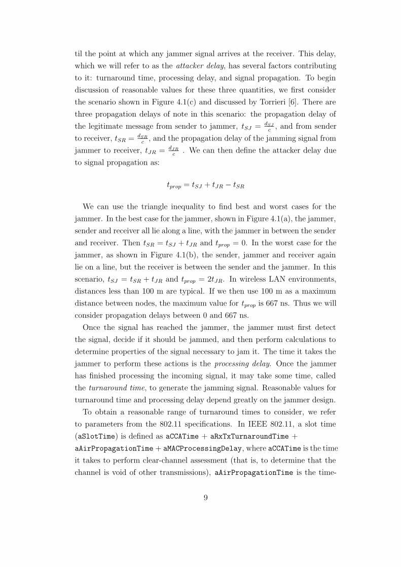
to it: turnaround time, processing delay, and signal propagation. To begin
discussion of reasonable values for these three quantities, we first consider
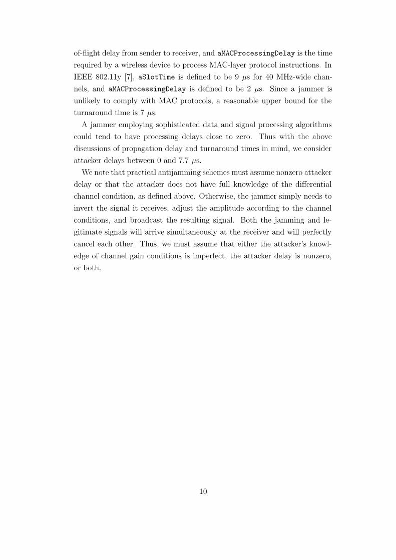
the scenario shown in Figure 4.1(c) and discussed by Torrieri [6]. There are
three propagation delays of note in this scenario: the propagation delay of
the legitimate message from sender to jammer, tSJ = dSJ
c, and from sender
to receiver, tSR = dSR
c, and the propagation delay of the jamming signal from
jammer to receiver, tJR = dJR
c. We can then define the attacker delay due
to signal propagation as:
tprop = tSJ + tJR − tSR
We can use the triangle inequality to find best and worst cases for the
jammer. In the best case for the jammer, shown in Figure 4.1(a), the jammer,
sender and receiver all lie along a line, with the jammer in between the sender
and receiver. Then tSR = tSJ + tJR and tprop = 0. In the worst case for the
jammer, as shown in Figure 4.1(b), the sender, jammer and receiver again
lie on a line, but the receiver is between the sender and the jammer. In this
scenario, tSJ = tSR + tJR and tprop = 2tJR. In wireless LAN environments,
distances less than 100 m are typical. If we then use 100 m as a maximum
distance between nodes, the maximum value for tprop is 667 ns. Thus we will
consider propagation delays between 0 and 667 ns.
Once the signal has reached the jammer, the jammer must first detect
the signal, decide if it should be jammed, and then perform calculations to
determine properties of the signal necessary to jam it. The time it takes the
jammer to perform these actions is the processing delay. Once the jammer
has finished processing the incoming signal, it may take some time, called
the turnaround time, to generate the jamming signal. Reasonable values for
turnaround time and processing delay depend greatly on the jammer design.
To obtain a reasonable range of turnaround times to consider, we refer
to parameters from the 802.11 specifications. In IEEE 802.11, a slot time
(aSlotTime) is defined as aCCATime + aRxTxTurnaroundTime +
aAirPropagationTime + aMACProcessingDelay, where aCCATime is the time
it takes to perform clear-channel assessment (that is, to determine that the
channel is void of other transmissions), aAirPropagationTime is the time-
9
of-flight delay from sender to receiver, and aMACProcessingDelay is the time
required by a wireless device to process MAC-layer protocol instructions. In
IEEE 802.11y [7], aSlotTime is defined to be 9 μs for 40 MHz-wide chan-
nels, and aMACProcessingDelay is defined to be 2 μs. Since a jammer is
unlikely to comply with MAC protocols, a reasonable upper bound for the
turnaround time is 7 μs.
A jammer employing sophisticated data and signal processing algorithms
could tend to have processing delays close to zero. Thus with the above
discussions of propagation delay and turnaround times in mind, we consider
attacker delays between 0 and 7.7 μs.
We note that practical antijamming schemes must assume nonzero attacker
delay or that the attacker does not have full knowledge of the differential
channel condition, as defined above. Otherwise, the jammer simply needs to
invert the signal it receives, adjust the amplitude according to the channel
conditions, and broadcast the resulting signal. Both the jamming and le-
gitimate signals will arrive simultaneously at the receiver and will perfectly
cancel each other. Thus, we must assume that either the attacker’s knowl-
edge of channel gain conditions is imperfect, the attacker delay is nonzero,
or both.
10
4.1 Figure
(a) Best Case for Jammer
(b) Worst Case for Jammer
(c) General Case
Figure 4.1: Best case, worst case and the general case situations used fordescribing the attacker delay of a reactive jammer.
11
CHAPTER 5
DEFENSE MODEL
We will examine how each proposed broadcast antijamming protocol per-
forms three functions: packet modulation and coding, fragment reassembly,
and avoiding computational-exhaustion attacks.
Packet modulation and coding refers to the manner in which a protocol
encodes messages and transmits them along the wireless channel. The mod-
ulation and encoding scheme used should provide some sort of processing
gain to offset an attacker’s typically superior ability to emit energy. In addi-
tion, the modulation and coding scheme should allow users to operate at a
sufficiently high bit rate in order to be useful in a practical setting.
In order to reduce the time the jammer has to react to a transmission,
some protocols reduce the length of transmission by breaking a packet into a
number of smaller fragments, which must then be reassembled by the receiver.
The challenges posed by fragment reassembly are well-known (e.g., [8, 9]). For
the purposes of providing a secure anti-jamming protocol, we must ensure
that fragments can be correctly reassembled and verified. In other words, we
must ensure that the attacker cannot replay previously transmitted fragments
or forge new fragments in such a way that the receiver cannot detect them.
In some cases a protocol may be vulnerable to a computational exhaustion
attack. In the protocols we analyze, this can occur when a receiver is at-
tempting to decode or reassemble a received packet. For example, in some
protocols this process will result in a set of packets P = {p1, p2, . . .} from
which the receiver must be able to correctly identify the correct packet. If
the receiver identifies the correct packet by verifying each packet’s digital
signature, the receiver could suffer from computational exhaustion if P is
very large. As a more concrete example, consider a protocol in which each
packet is split into 50 fragments and a signature verification is performed
upon reassembly. Then if an attacker is able to insert one false fragment
per valid fragment, the receiver must perform 250 verifications, which could
12
result in computational exhaustion. In creating a protocol that is resistant to
computational exhaustion attacks, we wish to prevent situations, such as the
one outlined above, in which the receiver workload is exponential in relation
to the attacker’s workload.
13
CHAPTER 6
PREVIOUSLY PROPOSED JAMMINGMITIGATION TECHNIQUES
In this chapter, we describe the three major approaches to providing key-
less jamming mitigation: uncoordinated frequency hopping spread spectrum,
uncoordinated direct sequence spread spectrum, and BBC codes. We then
describe the assumptions that these approaches make, and frame them in
terms of our defense model.
6.1 Uncoordinated Spread Spectrum
Two related techniques have been recently proposed, called uncoordinated
direct sequence spread spectrum (UDSSS) [10], and uncoordinated frequency
hopping spread spectrum (UFHSS) [11, 12]. These two approaches modu-
late data similarly to their corresponding traditional spread spectrum tech-
niques. However, unlike traditional direct sequence and frequency hopping
spread spectrum, users in UDSSS and UFHSS do not share a spreading code
beforehand; instead, the sender chooses a spreading code and relies on the
receiver’s ability to exhaustively search through the set of possible codes for
correct code.
6.1.1 Uncoordinated Frequency Hopping
In UFHSS, the sender divides a data packet into a number of smaller frag-
ments. Each fragment is repeatedly transmitted on randomly chosen fre-
quency channels, while the receiver in turn listens on randomly chosen chan-
nels. When the sender’s and receiver’s choices of frequency channels overlap,
the receiver will be able to successfully receive the fragment, assuming the
channel conditions are such that the SNR is sufficiently large. In most cases,
the transmission will fail, as the sender’s and receiver’s choices of frequency
14
channels will not overlap. However, as the sender continues to retransmit a
fragment, the probability of the channel choices overlapping at least once,
and therefore the the probability of successful reception, can be made arbi-
trarily close to one.
In addition to being able to successfully receive the fragments with high
probability, the receiver must be able to reassemble the fragments back into
packets. The fragments must be linked together in such a way that a receiver
is not only able to verify the correct ordering of fragments within a packet,
but is also able to authenticate fragments as being from the sender. UFHSS
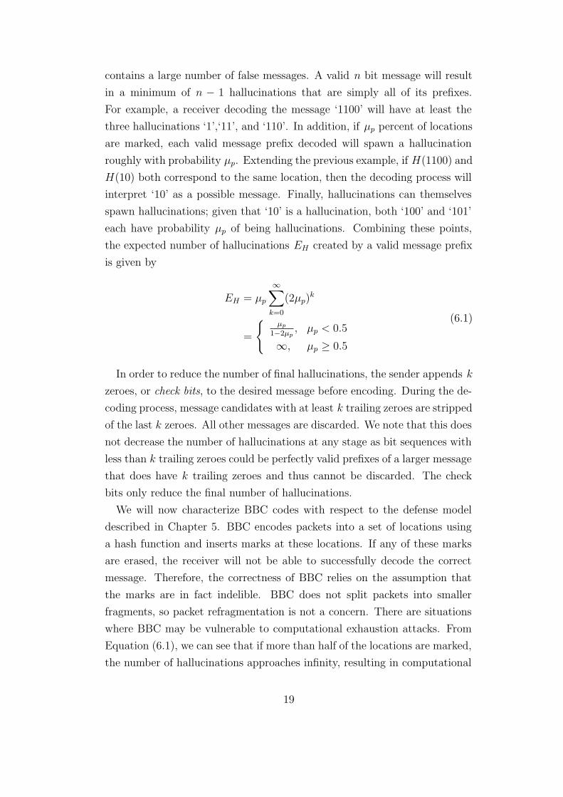
links fragments together using a cryptographic hash function, as shown in
Figure 6.1. Each fragment contains a fragment number and a hash field that,
with the exception of the last fragment, is a hash of the entirety of the next
fragment. In order to avoid a circular dependence in the hash fields, the last
fragment’s hash field contains a hash only of the data portion of the first
fragment.
6.1.2 Uncoordinated Direct Sequence Spread Spectrum
In UDSSS, the sender uses spreading codes from a publicly known set of
spreading code sequences C. Each sequence ci consists of a number of spread-
ing codes cij . When transmitting a packet, a sender randomly chooses a
spreading sequence ci and uses the first code ci0 to transmit the first bit of
data, the second code ci1 to transmit the second bit of data, and the jth
code ci(j−1) to spread the jth data bit. The receiver searches C for the cor-
rect spreading sequence by correlating several codes in each sequence with
the received codes. After a code sequence candidate is identified, the receiver
decodes the packet using that sequence.
Without trying to determine the spreading code in use, an attacker could
attempt to create fake packets by encoding and transmitting bogus data using
code sequences randomly chosen from C. In order to prevent an attacker from
forging packets, each packet must be signed by the sender. The sender also
includes a time stamp in each packet in order to prevent the attacker from
replaying old legitimate messages.
15
6.1.3 Protocol Characterization
We now characterize the two uncoordinated approaches with respect to mod-
ulation and coding, fragment reassembly, and computational exhaustion, as
defined in Chapter 5 . We will evaluate the reasonableness and consequences
of these assumptions in Chapter 7.
Both UFHSS and UDSSS perform modulation in a similar manner to their
traditional counterparts; however, they place additional restrictions on the
use of spreading codes. Specifically, UFHSS limits the sender to using a
single hopping frequency for each fragment transmission, and UDSSS limits
the sender to a single code sequence from a publicly known set of codes.
Both approaches rely on the assumption that these code restrictions do not
allow the jammer to guess the spreading code in use in time to jam the
transmission.
UFHSS performs fragment reassembly by storing hash values of another
fragment in the header of each fragment. As proposed, UDSSS does not break
packets into fragments and thus is not impacted by fragment reassembly.
In UDSSS, the code search overhead is largely independent of the number
of packets being received. Whether a code ci will be checked during a code
search is independent of whether an attacker uses that sequence to spread
a jamming signal. The only additional computational cost is that of the
additional signature and time stamp verification of any packet the jammer
transmits. Therefore, in UDSSS attackers are not able to inflict computa-
tional exhaustion on the receiver; however, because of the computational
costs incurred by checking codes, the size of the codebook must not be so
large that a receiver cannot perform a code search in a practical amount of
time.
The packet reassembly mechanism in UFHSS does present the opportunity
for a computational exhaustion attack. As mentioned earlier, each legitimate
fragment fi contains a hash field such that fi.hash = H(fi+1) with the sole
exception of the last packet, whose hash field fN .hash = H(f1.data). If an
attacker is able to create a bogus fragment f ′i such that H(f ′
i) = H(fi), then
the attacker will be able to create a “branch” in the receiver’s decoding pro-
cess, as shown in Figure 6.2(a). The additional bogus fragments f ′i+1, f
′i+2, . . .
have the property H(f ′i+j) = f ′
i+j+1.data. For each branch created, the re-
ceiver must verify an additional packet candidate, resulting in only a linear
16
increase in receiver effort. Figure 6.2(b) shows a powerful attack in which the
fragments in the additional branch have the property that H(fi) = H(f ′i) and
f ′i .hash = fi.hash. The receiver is then forced to verify 2N fragment com-
binations, where N is the number of fragments in a chain. A more general
attack is shown in Figure 6.2(c) in which fragments are created such that
f ′i .hash = H(fi+1)
f ′i+1.hash = H(f ′
i+2)
f ′i+2.hash = H(f ′
i+3)
. . .
f ′i+j .hash = H(f ′
i+j+1)
H(f ′i+j) = H(fi+j)
If the attacker can create several such paths, the receiver may be forced
to search through a set of possible packets that is exponential in size, which
would prove infeasible for any realistic packet size.
6.2 Indelible Marks and BBC Codes
Instead of modifying the key management strategy of existing spread spec-
trum technologies, another method of providing jamming-resistant commu-
nication is to modulate the data in such a way that they are resistant to
jamming.
Cagalj et al. [13] proposed Integrity Codes, a modulation scheme in which
the sender transmits a high power noise-like pulse in place of a bit value of
one and keeps quiet for bits with value of zero. In such a scheme, a jammer
is easily able to flip zeroes to ones, by simply inserting noise-like pulses of its
own at the appropriate times. However, the jammer cannot easily flip ones
to zeroes. In order to do so, the jammer would need to be able to transmit
a signal that has similar amplitude and is close to 180◦ out of phase with
the corresponding pulse. However, due to the random nature of the pulse, it
would be difficult for the jammer to predict the nature of the pulse accurately
enough to create such a cancellation signal. Because the pulses cannot be
erased by a jammer or other interference, they are known as indelible marks.
17
Once a receiver has received a message m′, possibly containing additional
marks inserted due to interference, the sender’s transmitted message m can
be recovered by searching the space M of all possible messages that have
zeroes in the same locations as m′. However, such a search has computational
overhead that is exponential in the number of flipped bits; therefore Integrity
Codes are not practical for use in jamming mitigation.
Baird et al. [14, 15] proposed a scheme called BBC codes in which trans-
missions can in many cases be decoded in a time that scales linearly with
respect to the length of the transmitted packet. As with Integrity Codes,
senders using BBC code insert indelible marks in place of 1-bits and stay
quiet for 0-bits. However, senders using BBC codes first map the message
to a set of locations and insert an indelible mark at each location in the set.
These locations can be defined in either the time or frequency domains. If
the locations are defined using time division, then each location corresponds
to a time slot, and the sender will transmit an indelible mark during time
slots that are part of the set, and will keep quiet during all other time slots.
In the case of frequency division, the marks correspond to a number of (pre-
sumably even-spaced) frequencies. A message is transmitted in one time
duration, and for each location in the set, the sender transmits a sinusoid
with the corresponding frequency.
BBC codes perform the aforementioned mapping of a message to a set of
locations by using a publicly known hash function H. The set of locations
is determined by calculating the hash of each one of the message’s prefixes.
For example, a sender wishing to transmit the message 1100 will transmit
indelible marks at locations {H(1), H(11), H(110), H(1100)}.
To decode a message, the receiver begins by calculating H(0) and H(1).
If, for example, a mark is found at the location corresponding to H(1) but
not at H(0), the message ‘1’ is added to a list of possible messages, and the
receiver then checks for marks at locations H(10) and H(11). The receiver
need not check locations H(00) and H(01); if either of these two messages
were transmitted, the location H(0) would also have been marked. Repeating
the above process, if a mark is found at H(10), then message ‘10’ is a possible
message, and locations H(100) and H(101) are then checked. The receiver
continues in this manner until the hash values of no new message locations
correspond to marked locations.
The resulting set of possible messages using the coding scheme described
18
contains a large number of false messages. A valid n bit message will result
in a minimum of n − 1 hallucinations that are simply all of its prefixes.
For example, a receiver decoding the message ‘1100’ will have at least the
three hallucinations ‘1’,‘11’, and ‘110’. In addition, if μp percent of locations
are marked, each valid message prefix decoded will spawn a hallucination
roughly with probability μp. Extending the previous example, if H(1100) and
H(10) both correspond to the same location, then the decoding process will
interpret ‘10’ as a possible message. Finally, hallucinations can themselves
spawn hallucinations; given that ‘10’ is a hallucination, both ‘100’ and ‘101’
each have probability μp of being hallucinations. Combining these points,
the expected number of hallucinations EH created by a valid message prefix
is given by
EH = μp
∞∑
k=0
(2μp)k
=
{μp
1−2μp, μp < 0.5
∞, μp ≥ 0.5
(6.1)
In order to reduce the number of final hallucinations, the sender appends k
zeroes, or check bits, to the desired message before encoding. During the de-
coding process, message candidates with at least k trailing zeroes are stripped
of the last k zeroes. All other messages are discarded. We note that this does
not decrease the number of hallucinations at any stage as bit sequences with
less than k trailing zeroes could be perfectly valid prefixes of a larger message
that does have k trailing zeroes and thus cannot be discarded. The check
bits only reduce the final number of hallucinations.
We will now characterize BBC codes with respect to the defense model
described in Chapter 5. BBC encodes packets into a set of locations using
a hash function and inserts marks at these locations. If any of these marks
are erased, the receiver will not be able to successfully decode the correct
message. Therefore, the correctness of BBC relies on the assumption that
the marks are in fact indelible. BBC does not split packets into smaller
fragments, so packet refragmentation is not a concern. There are situations
where BBC may be vulnerable to computational exhaustion attacks. From
Equation (6.1), we can see that if more than half of the locations are marked,
the number of hallucinations approaches infinity, resulting in computational
19

exhaustion during the decoding process. Therefore, BBC decoding relies on
the jammer not being able to insert enough marks to cause the number of
marks to be at least half of the total number of locations.
20
6.3 Figures
Figure 6.1: Hash values for fragment chaining.
(a) Polynomial effort
(b) Strongest attack
(c) Exponential effort
Figure 6.2: Conditions for computation effort in UFHSS.
21
CHAPTER 7
JAMMING MITIGATION ANALYSIS OFPREVIOUSLY PROPOSED PROTOCOLS
In this chapter, we evaluate the effectiveness of the aforementioned antijam-
ming schemes under our attacker model.
7.1 Uncoordinated Frequency Hopping
We now analyze uncoordinated frequency hopping spread spectrum (UFHSS)
using our attacker model.
For an attacker delay of τp, a transmission rate r, and a fragment length P ,
a transmission will not be jammed if the transmission delay of the fragment
is less than that of the attacker. Thus we have that Pr≤ τp, or r ≥ P
τp. The
Shannon-Hartley theorem then gives us a minimum required bandwidth:
r ≤B
ηlog2(1 + ηSNR)
B ≥ηr
log2(1 + ηSNR)
≥ηP
τp log2(1 + ηSNR)
= Bmin
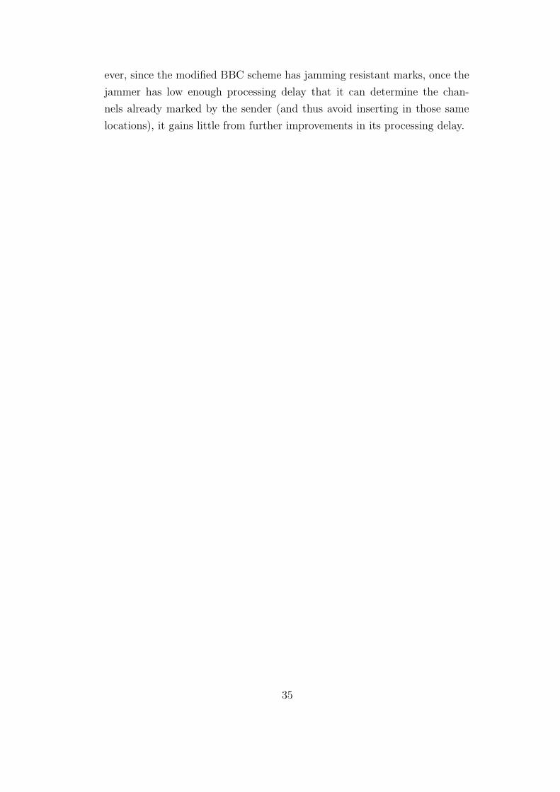
We now proceed to discuss realistic values for τp, η, P , and SNR. In Chap-
ter 4, we determined that τp should lie on (0, 7.7] μs. Decreasing η would
result in smaller bandwidth requirements, but would also reduce the advan-
tage frequency hopping gives to the receiver for jamming mitigation. We
also specified a maximum transmission range of roughly 100 meters. A jam-
mer who is relatively close to the receiver, say 10 meters away, could easily
have a channel gain of 20 dB relative to a sender who is 100 meters away.
Therefore, η values of at least 100 may be required to ensure jamming re-
sistant communication. In addition, in the 5.8 GHz ISM band, the FCC
22
requires η ≥ 75 [16]. For these two reasons we assume η ≈ 100. Next, we
consider the fragment (frame) size. A fragment consists of a hash, header
information including the fragment identifier, and some data. To avoid com-
putational exhaustion, we need to avoid computational searches of power 2 `,
and storage-based searches on storage 22`. With current computation and
storage costs, the attacker will usually resort to 2` computational effort, and
232 computation is quite feasible. Thus, hash output on the order of 36 bits
or 40 bits is a bare minimum to avoid injections. Adding all the other infor-
mation needed for a fragment, such as the fragment sequence number, will
result in a fragment between 50 and 60 bits long. As was mentioned earlier,
SNR values of -20 dB are quite possible, so we assume an SNR value of -20
dB. In this environment,
Bmin =ηP
τp log2(1 + ηSNR)=
5000
τp
When τp is at its maximum value of 7.7 μs, the required bandwidth is almost
650 MHz as shown in Figure 7.1, which is impractical in any non-UWB
system.
7.2 Uncoordinated Direct Sequence
In traditional direct sequence systems, any code can be used, so the set
of possible codes is exponential with respect to code length, and codes are
typically generated pseudorandomly. Therefore, if the jammer receives, say,
the first half of the code used to spread a bit, that portion of the code contains
no information about the remaining half of the spreading code. Furthermore,
if new spreading codes are generated to transmit each bit of a message, then
knowing the code used to spread the current bit gives no information about
future codes. However, in uncoordinated direct sequence spread spectrum
(UDSSS), this is not the case. As was mentioned in Section 6.1.2, UDSSS
restricts senders to choosing from a publicly known set C of code sequences.
The restrictions placed on the codeset C give two advantages to the jam-
mer. First, for any data bit, the jammer only needs to check |C| codes at
most. Second, as the jammer hears more of the code sequence in use, the
size of the subset of C of possible sequences decreases, meaning that the
23
attacker needs to search fewer codes. For example, consider a realization
of C in which none of the codes that could be used to spread the first bit
of a message, or their complements, are identical (that is, ∀i, j with i 6= j,
ci0 6= cj0 and ci0 6= cj0). In this case, a jammer could simply receive the
first bit, and identify the code c that was used. Since the first codes in all of
the sequences are distinct, there is only one sequence that uses c to spread
the first data bit. Therefore, after listening to just the first bit, the jammer
knows the entire code sequence and will be able to disrupt the remainder of
the message. In other words, the entropy of the entire code sequence was
contained in a single code, so identifying that code is the same as identifying
the entire sequence.
It is clear, then, that the choice of C must be such that the entropy of the
code sequence is not immediately leaked and is instead spread out in some
manner across the entire sequence. We now examine how such sequences may
perform in the presence of a full-duplex jammer. We begin first by defining
the attacker delay τd in terms of chips, rather than time. We then normalize
the codes so that the first bit of each code is a one. Then, considering each
code sequence as a very long string of chips ci = ci0||ci1|| . . . ||ci(`−1). we
define a sequence e, where each element in the sequence ej represents the
entropy of chip cij given all previous chips in the sequence. For example, if
each sequence consists of one code (` = 1) and C = {1111, 1000, 1110, 1001},
then e0 = 0, e1 = 1, e2 = 0, and e3 = 0.
It is well known that the entropy of |C| pseudorandomly chosen sequences
is equal to log2 |C|. Therefore, the jammer initially has an entropy of log2 |C|
in guessing the code sequence. As the jammer processes each chip cj , the total
entropy is reduced by ej. We assume the jammer cannot begin processing a
chip until it has completely received it. Therefore, information from chip cj
can only be used to jam chips that arrive τ + 1 chips later. For simplicity
of analysis, we initially assume that each τ + 1 block of chips has the chip
entropy pattern, so that ei = ei−(τ+1)x for all i ≥ τ + 1.
We first consider the scenario in which τ + 1 = η, meaning the jammer’s
delay is equal to the length of a spreading code. At any time, the jammer has
the option of either jamming wideband, in which case the processing gain is
the length of a code, η, or jamming according to a probability distribution
based on the current code sequences in C that are still possible. If the jammer
chooses to jam according to a probability distribution, the processing gain
24
for a particular code will be
η′ = 2∑η−1
k=0 ei
We assume the jammer acts optimally, so in general the processing gain
for a code will be
ηtrue = min{η, η′}
= min{η, 2∑η−1
k=0 ei}
Thus we have an expression for the processing gain when τ +1 = η. When
τ +1 < η, the processing gain for the code remains the same, but the entropy
is divided evenly among each τ +1 block of chips. Similarly, when τ +1 > η,
the processing gain for each code is again the same.
As was mentioned earlier, the bound on the total entropy is log 2 |C|. Thus
we have the bounds:
`η−1∑
i=0
ei ≤ log2 |C|
ηtrue ≤ 2(τ+1) log2 |C|
`η
To optimize overhead, we want η = ηtrue, so
η = 2(τ+1) log2 |C|
`η
`η log2 η = (τ + 1) log2 |C|
τ + 1 =`η log2 η
log2 |C|
Remembering that τ ≤ 2Bτd from the Nyquist limit,
2Bτd =`η log2 η − log2 |C|
log2 |C|
B =`η log2 η − log2 |C|
2τd log2 |C|
For example, for η = 100, τd = 7.7, |C| = 222 and ` = 50, the required
amount of storage for the codebook is 2.6 gigabytes, and the required band-
width is 98 MHz.
25
We now make a few observations. First, UDSSS is not well-suited to
processing gains far in excess of 20 dB. The required bandwidth is O(η log η),
so to go from 20 dB to 30 dB would require a 30-fold increase in bandwidth.
Second, UDSSS is not well-suited to long packets. We used a length of
50 bits because our previous analysis of UFHSS showed that it is feasible
when combined with the fragment reassembly proposed for UFHSS; however,
the original proposal of UDSSS did not include a fragmentation mechanism,
though we have shown that the required bandwidth is O(`). Since each
packet must be signed, we can assume a packet size of at least 1024 for the
originally proposed UDSSS, which results in a required bandwidth of 2.01
GHz for otherwise identical parameters. Third, since `η log2 n >> log2 |C|, B
varies roughly inversely with log2 |C|. Thus while it is helpful to keep a large
|C|, using codebook sizes larger than the value of 222 used in our example
would result in little improvement in bandwidth requirement and likely a
prohibitively large amount of hard drive storage. Finally, we observe that
we achieve this performance against a relatively strong full-duplex attacker.
A half-duplex attacker would need to make a decision as to when to stop
listening (and narrowing down elements from C) and when to start jamming.
Our analysis holds whenever the entropy sequence is τ + 1-periodic. We
now show that even when the entropy sequence is not τ + 1-periodic, our
bound on B is within a factor of 2 of tight, as long as all ` bits are equally
important. If any τ + 1 interval has zero entropy (that is, each entropy
value is 0), then any following τ + 1 interval is trivially jammed unless it
has non-zero entropy. Thus the most diversity that could possibly be useful
is to alternate frames of τ + 1 chips with non-zero entropy and ones of zero
entropy. In this case, among the frames of τ + 1 chips that have non-zero
entropy, the one with the least entropy will have at most twice the entropy of
a τ + 1-periodic sequence. In other words, the log2 |C| total entropy will be
split up between at least half as many τ + 1-chip frames, so the entropy per
frame is no more than double. Following the derivation of B, we see that for
any scheme that treats all bits equally, the minimum amount of bandwidth
required is at least half of the `η log2 η−log2 |C|2τd log2 |C| bound given above.
26
7.3 BBC Codes
As described in Section 6.2, a receiver cannot decode any original message if
half of the available locations have been marked. Thus the goal of the jam-
mer is to insert enough marks that 50% of slots are occupied. In addition
to simply inserting as many marks as possible in unmarked locations, the
jammer can use some of his available power to attempt to attenuate one or
more of the sender’s marks. If marks are constructed using sinusoids of a
particular frequency, causing such attenuation is possible. For example, the
sum of two sinusoids of equal amplitude and with π in phase difference is
zero. Even if the received sinusoids are of different amplitudes or are not
perfectly out of phase, the sum may exhibit some attenuation, similar to
the multipath-induced fading behavior experienced in wireless networks. If a
sinusoid experiences sufficient attenuation, the signal power will drop below
the receiver’s detection threshold, resulting in the receiver incorrectly deter-
mining that location is unmarked. As a way of counteracting the jammer’s
attempt to attenuate a valid mark, the receiver can decrease his detection
threshold so that the location would still considered marked. However, doing
so enables the jammer to increase the number of extra marks that can be
inserted with the jammer’s remaining power.
We first consider the ability of the jammer to insert marks without at-
tempting to create cancellation. We, for the time being, assume that all
indelible marks are guaranteed to be decoded as marked by the receiver, re-
gardless of the channel condition. To send a message that is b bits long, the
sender will need to mark ns = b + k locations, where k is some number of
marks used as check bits during decoding. We express the number of marks
the jammer can insert as nj = αns locations, where α is the ratio between
the jammer and the sender’s transmission power. Then for a total number
of locations N , the percent of locations marked is at most
μp ≤ns(1 + α)
N
Since hallucinations can be efficiently rejected only if μp < 12, a lower
bound on the number of required locations N is:
N > 2ns(1 + α) (7.1)
27
We now consider a jammer that attempts to cancel marks inserted by
the legitimate transmitter. A reactive jammer is much more able to create
cancellations than a nonreactive one, because a reactive jammer knows which
locations have been marked. Specifically, for a reactive jammer to cancel one
of the first ` bits takes ` attempts, but for a non-reactive jammer, it takes
2`+1−2 bits, assuming all prefixes are equally likely. In both cases we assume
the jammer divides its power between attempting to create cancellations and
inserting marks of a lower amplitude. The power is divided so that at most
half of the jammer’s power, but not more than the power required to cancel
all ns marks, is used to create cancellations. The number of marks a reactive
jammer can attempt to cancel is given by nc = min (0.5αns, ns). A non-
reactive jammer does not know which locations have been marked, but can
use the nature of BBC encoding to make an intelligent guess. For example,
regardless of the message sent, at least one of the two locations corresponding
to H(0) and H(1) will be marked. Similarly, at least one of the four locations
{H(00), H(01), H(10), H(11)} will be marked as well. Thus by marking a
total of 2`+1 − 2 locations, the non-reactive jammer can attempt to cancel at
least ` marks (given that the message is encoded with at least ` marks).
A reactive jammer that also has knowledge of the differential channel con-
dition (as described in Chapter 4) will be able to transmit marks that have
the same amplitude as the ones transmitted by the sender. The amplitude
of the sum of two equal amplitude cosines that are out of phase by π ± θ is:
A =√
2 − 2 cos θ
If the attacker’s goal is to cancel at least 1 sinusoidal mark, the jammer can
distribute the phase of his marks evenly on [−π, π]. This means that for `
cancellation attempts, the minimum phase difference between the jammer’s
insertion and the marks is at most π`+1
. As a result, the minimum amplitude
28
of a mark being cancelled is bounded above by
Areactive ≤
√
2 − 2 cosπ
` + 1
≈
√√√√2 − 2
(
1 −1
2
(π
(` + 1)
)2)
=π
` + 1
(7.2)
A non-reactive jammer can only seek to cancel `′ = log2(` + 2) − 1 marks
instead of ` marks. Thus the minimum amplitude of the received mark would
be bounded above by:
Anon−reactive ≤
√
2 − 2 cos
(π
log2(` + 2)
)
≈π
log2(` + 2)
However, we note that, unless there are collisions in the hash function,
the effects of such a cancellation attempt by a nonreactive jammer can be
mitigated by prepending a random nonce of length `′ to the message before
encoding. When decoding, the receiver must then assume all prefixes in
{0, 1}`′ are valid candidates. Therefore, BBC codes can resist non-reactive
cancellation at an added computational cost to the receiver of roughly a
factor of `.
If a jammer lacks perfect knowledge of the differential channel condition,
the jammer can only guess the channel condition. One of the jammer’s
possible approaches is similar to that of the differential channel condition
case, except that rather than only spacing the marks equally apart in phase,
the jammer spaces them equally apart in both amplitude and phase. One
possible jammer strategy is to subdivide both the amplitude range and phase
range into√
` choices per range. Using this strategy, a jammer attempting
to estimate the differential channel condition and then cancel at least 1 of
` marks cannot do better than one that has knowledge of the differential
channel condition and cancels at least 1 of√
` marks.
Now that we have described the ability of different types of attackers to
attenuate sinusoidal marks, we discuss the impact of attacker delay for a
29
reactive jammer. Since a reactive attacker must take some time to process
the transmitted signal, it can only cause the attenuation indicated above for
a portion of the mark transmission time. The Nyquist rate gives an upper
bound on the symbol rate, and thus a minimum for the symbol duration.
We will first examine a jammer’s behavior when the sender transmits at the
Nyquist rate and later discuss transmissions at lower rates.
The jammer will need to wait some amount of time, τp, to attempt to
determine which locations are marked before its own jamming signal. We
define the quantity τ = τp
Tto be the fraction of the transmission duration
which the jammer spends detecting marks. After the detection period, the
jammer will have a frequency resolution of
Δf = BcT
τp
=Bc
τ
(7.3)
For example, if the jammer waits for one half of the Nyquist period before
attempting cancelation, the frequency resolution will be 2Bc, and the jammer
cannot distinguish between a mark in channel 2k and one in channel 2k + 1.
However, the jammer can assume both locations are marked and transmit
sinusoids at both frequencies to attempt to cancel marks. This means that
the jammer can attempt only `′′ = `2
cancellations. Increasing the detection
duration allows the jammer to cancel more marks, but it also increases the
percentage of the transmission not being jammed. For the first τ percent of
the transmission, the sender’s signal is not attenuated, and for the remaining
(1 − τ) the signal amplitude is given by Equation (7.3) for `τ number of
marks. Therefore, the resulting reduction in signal power is given by:
P ≤ τ + (1 − τ)
(π
`τ + 1
)2
(7.4)
We observe that in many cases, when ` >> τ , this bound is approximately
equal to τ . If the attacker delay is large enough that the jammer cannot
cause a sufficient amount of attenuation, it may be optimal for the jammer
to simply insert marks, rather than attempt to cause cancellations.
As an example, we consider a jammer equidistant from the receiver as the
30
transmitter, that divides his power evenly between cancellation and inser-
tion strategies. A 256 byte message can correspond to as many as 2048 + k
marks, and the jammer can seek to cancel as many as 1024 + k2
marks . For
convenience, we let k = 0. Equation (7.3) reaches a minimum of approxi-
mately .039 for ` = 1024 when τ ≈ .026. Since at least one mark will have
been attenuated to .039 of its original power, the receiver will need to set
the power detection threshold no higher than .039 in order to prevent mark
erasure. However, this enables the jammer to use the remaining energy to
insert 1024.039
= 26256 marks. In a 150 MHz system, the channel bandwidth
must then be at least
BC ≤150 ∙ 106
2 ∙ (2048 + 26256) + 1
= 2.65 kHz
(7.5)
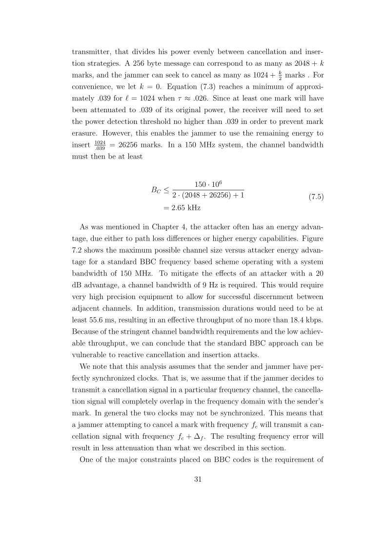
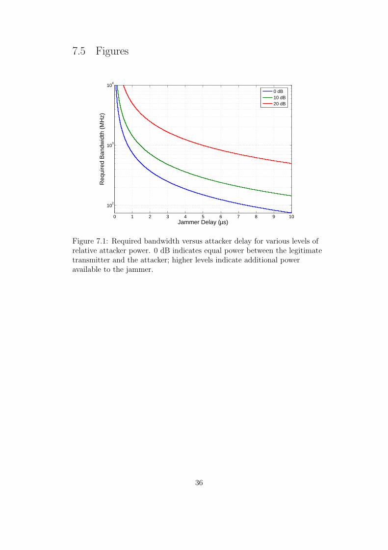
As was mentioned in Chapter 4, the attacker often has an energy advan-
tage, due either to path loss differences or higher energy capabilities. Figure
7.2 shows the maximum possible channel size versus attacker energy advan-
tage for a standard BBC frequency based scheme operating with a system
bandwidth of 150 MHz. To mitigate the effects of an attacker with a 20
dB advantage, a channel bandwidth of 9 Hz is required. This would require
very high precision equipment to allow for successful discernment between
adjacent channels. In addition, transmission durations would need to be at
least 55.6 ms, resulting in an effective throughput of no more than 18.4 kbps.
Because of the stringent channel bandwidth requirements and the low achiev-
able throughput, we can conclude that the standard BBC approach can be
vulnerable to reactive cancellation and insertion attacks.
We note that this analysis assumes that the sender and jammer have per-
fectly synchronized clocks. That is, we assume that if the jammer decides to
transmit a cancellation signal in a particular frequency channel, the cancella-
tion signal will completely overlap in the frequency domain with the sender’s
mark. In general the two clocks may not be synchronized. This means that
a jammer attempting to cancel a mark with frequency fc will transmit a can-
cellation signal with frequency fc + Δf . The resulting frequency error will
result in less attenuation than what we described in this section.
One of the major constraints placed on BBC codes is the requirement of
31
a digital signature in each packet. This requirement results in packets that
are at least 1024 bits long, which greatly increases the number of locations
the sender has to mark. The signature cannot be simply removed, as that
would prevent the receiver from being able to verify the identity of the sender.
However, if BBC codes were used to transmit fragments linked together as in
UFHSS, the minimum number of sender marks in each transmission could be
reduced by roughly a factor of 20. This would enable the sender to transmit
using larger frequency channels, which will in turn mean that the jammer
can attack a smaller portion of the transmission.
To this point we have considered marks that are largely deterministic.
We have assumed that marks are transmitted at the center frequency of
each channel and with equal power. Using a more spectrally dense signal
may increase the difficulty for a jammer to adequately identify and predict
transmissions. We divide each frequency subchannel into N frequency bins.
In each bin of a marked channel, the sender can choose to transmit a sinusoid
with some amplitude Ai and phase φi. In the regular BBC scheme, the
jammer needed only to cause significant attenuation in a single sinusoid at
a known frequency in order to cause mark cancellation. Using this more
robust type of mark, for a transmission of suitable duration, the jammer
may need to cause significant attenuation on up to N sinusoids in order to
cause cancellation. In order for a jammer to reactively jam the N sinusoidal
components contained in a mark, the jammer must wait N times as long in
order to identify each component. However, the receiver does not need to
wait this extra time, as it only needs to determine that a mark is present in
a particular channel, not what its exact frequency content is. As a result, it
would prove difficult for a jammer to reactively cancel this more robust type
of mark.
We now examine the performance of a jammer attempting to cause can-
cellations in a channel by simply guessing the frequency content of each
sinusoidal component. As a simple example, consider a modulation scheme
in which the amplitude of each sinusoid Ai is constant, and the possible phase
values are 0 and π. In order to cause cancellation the jammer must guess
whether the phase in each bin is 0 or π. If the jammer guesses correctly, the
frequency content of that particular bin is cancelled completely; however, an
incorrect guess results in the cancellation mark and the transmitted mark
constructively interfering, resulting in a sinusoid with double the amplitude.
32
A jammer wishing to cause attenuation of at least ψ will thus need to cause
at least(1 − ψ
2
)N cancellations. Let X be a random variable describing how
much a mark is attenuated. Then the probability of the jammer causing
enough attenuation is:
P{X > ψ} =N∑
k=d1−ψ2e
(N
k
)(1
2
)k (1
2
)n−k
= 2−N
N∑
k=dN−Nψ2
e
(N
k
)
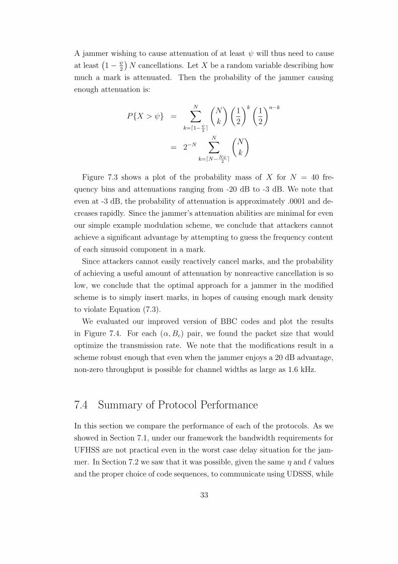
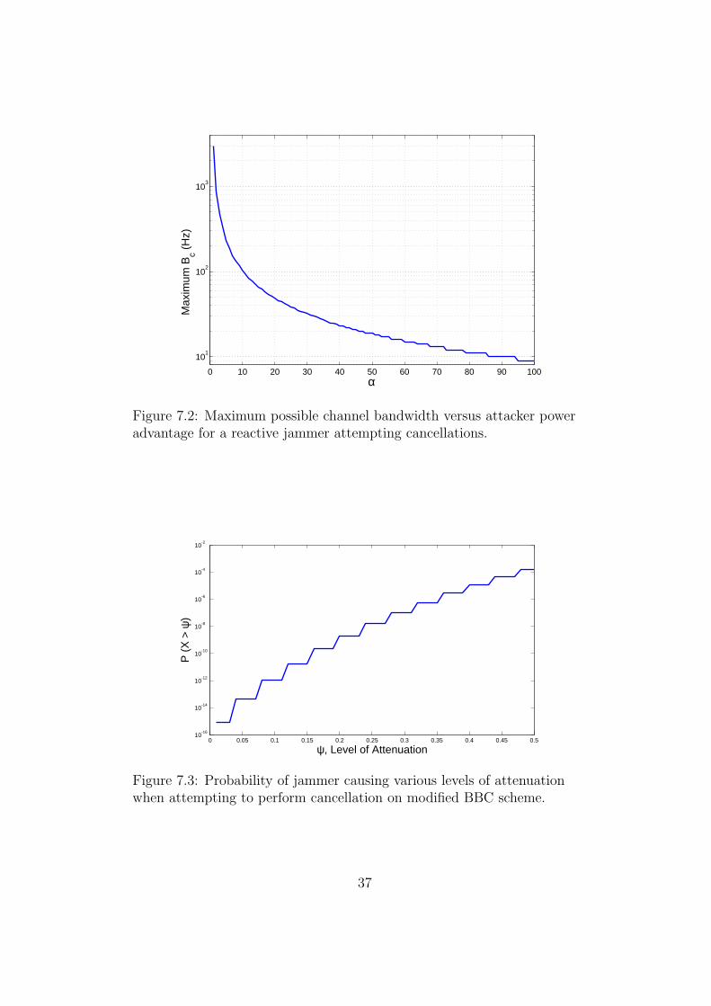
Figure 7.3 shows a plot of the probability mass of X for N = 40 fre-
quency bins and attenuations ranging from -20 dB to -3 dB. We note that
even at -3 dB, the probability of attenuation is approximately .0001 and de-
creases rapidly. Since the jammer’s attenuation abilities are minimal for even
our simple example modulation scheme, we conclude that attackers cannot
achieve a significant advantage by attempting to guess the frequency content
of each sinusoid component in a mark.
Since attackers cannot easily reactively cancel marks, and the probability
of achieving a useful amount of attenuation by nonreactive cancellation is so
low, we conclude that the optimal approach for a jammer in the modified
scheme is to simply insert marks, in hopes of causing enough mark density
to violate Equation (7.3).
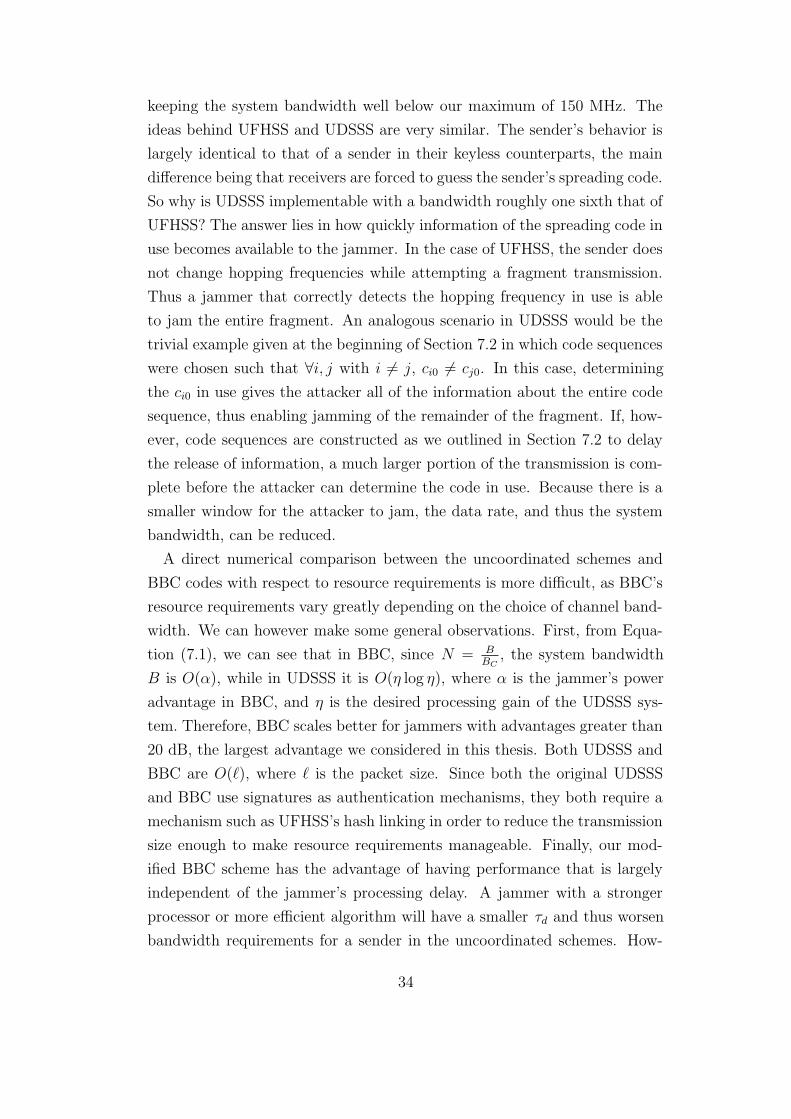
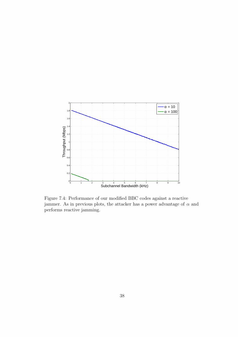
We evaluated our improved version of BBC codes and plot the results
in Figure 7.4. For each (α,Bc) pair, we found the packet size that would
optimize the transmission rate. We note that the modifications result in a
scheme robust enough that even when the jammer enjoys a 20 dB advantage,
non-zero throughput is possible for channel widths as large as 1.6 kHz.
7.4 Summary of Protocol Performance
In this section we compare the performance of each of the protocols. As we
showed in Section 7.1, under our framework the bandwidth requirements for
UFHSS are not practical even in the worst case delay situation for the jam-
mer. In Section 7.2 we saw that it was possible, given the same η and ` values
and the proper choice of code sequences, to communicate using UDSSS, while
33
keeping the system bandwidth well below our maximum of 150 MHz. The
ideas behind UFHSS and UDSSS are very similar. The sender’s behavior is
largely identical to that of a sender in their keyless counterparts, the main
difference being that receivers are forced to guess the sender’s spreading code.
So why is UDSSS implementable with a bandwidth roughly one sixth that of
UFHSS? The answer lies in how quickly information of the spreading code in
use becomes available to the jammer. In the case of UFHSS, the sender does
not change hopping frequencies while attempting a fragment transmission.
Thus a jammer that correctly detects the hopping frequency in use is able
to jam the entire fragment. An analogous scenario in UDSSS would be the
trivial example given at the beginning of Section 7.2 in which code sequences
were chosen such that ∀i, j with i 6= j, ci0 6= cj0. In this case, determining
the ci0 in use gives the attacker all of the information about the entire code
sequence, thus enabling jamming of the remainder of the fragment. If, how-
ever, code sequences are constructed as we outlined in Section 7.2 to delay
the release of information, a much larger portion of the transmission is com-
plete before the attacker can determine the code in use. Because there is a
smaller window for the attacker to jam, the data rate, and thus the system
bandwidth, can be reduced.
A direct numerical comparison between the uncoordinated schemes and
BBC codes with respect to resource requirements is more difficult, as BBC’s
resource requirements vary greatly depending on the choice of channel band-
width. We can however make some general observations. First, from Equa-
tion (7.1), we can see that in BBC, since N = BBC
, the system bandwidth
B is O(α), while in UDSSS it is O(η log η), where α is the jammer’s power
advantage in BBC, and η is the desired processing gain of the UDSSS sys-
tem. Therefore, BBC scales better for jammers with advantages greater than
20 dB, the largest advantage we considered in this thesis. Both UDSSS and
BBC are O(`), where ` is the packet size. Since both the original UDSSS
and BBC use signatures as authentication mechanisms, they both require a
mechanism such as UFHSS’s hash linking in order to reduce the transmission
size enough to make resource requirements manageable. Finally, our mod-
ified BBC scheme has the advantage of having performance that is largely
independent of the jammer’s processing delay. A jammer with a stronger
processor or more efficient algorithm will have a smaller τd and thus worsen
bandwidth requirements for a sender in the uncoordinated schemes. How-
34
ever, since the modified BBC scheme has jamming resistant marks, once the
jammer has low enough processing delay that it can determine the chan-
nels already marked by the sender (and thus avoid inserting in those same
locations), it gains little from further improvements in its processing delay.
35
7.5 Figures
0 1 2 3 4 5 6 7 8 9 10
102
103
104
Jammer Delay (μs)
Req
uire
d B
andw
idth
(M
Hz)
0 dB10 dB20 dB
Figure 7.1: Required bandwidth versus attacker delay for various levels ofrelative attacker power. 0 dB indicates equal power between the legitimatetransmitter and the attacker; higher levels indicate additional poweravailable to the jammer.
36
0 10 20 30 40 50 60 70 80 90 100
101
102
103
α
Max
imum
Bc (
Hz)
Figure 7.2: Maximum possible channel bandwidth versus attacker poweradvantage for a reactive jammer attempting cancellations.
0 0.05 0.1 0.15 0.2 0.25 0.3 0.35 0.4 0.45 0.510
-16
10-14
10-12
10-10
10-8
10-6
10-4
10-2
ψ, Level of Attenuation
P (
X >
ψ)
Figure 7.3: Probability of jammer causing various levels of attenuationwhen attempting to perform cancellation on modified BBC scheme.
37
0 1 2 3 4 5 6 7 8 9 100
0.2
0.4
0.6
0.8
1
1.2
1.4
1.6
1.8
2
Subchannel Bandwidth (kHz)
Thr
ough
put (
Mbp
s)
α = 10α = 100
Figure 7.4: Performance of our modified BBC codes against a reactivejammer. As in previous plots, the attacker has a power advantage of α andperforms reactive jamming.
38
CHAPTER 8
CONCLUSION
In our analysis, we have compared the three proposed keyless jamming mit-
igation techniques. We developed the model of a reactive jammer and pa-
rameterized it for varying levels of difficulty and used this model to analyze
the three proposed keyless jamming mitigation techniques. First, we showed
that uncoordinated schemes are infeasible for realistic computational pow-
ers and allocations of bandwidth. For example, in uncoordinated frequency
hopping spread spectrum, we found that an attacker with a 20 dB channel
advantage can jam a receiver unless the system has nearly 650 MHz of band-
width. We then showed that uncoordinated direct sequence spread spectrum
can provide 20 dB of processing gain within 100 MHz of bandwidth as long
as the codeset C is chosen to leak entropy uniformly, packets are kept short
(around 50 bits), and attacker reaction times are at least 7.7 μs. Our results
hold even if the jammer is capable of full-duplex operation. We showed that
BBC codes as proposed are vulnerable to a mark cancellation and insertion
attack. In particular, when marks are sent as sinusoids, we showed how an
attacker can use multiple sinusoids to “search” for a canceling signal over
the space of phase and channel condition. We then proposed modifications
to make BBC codes more resistant to jamming by reducing packet size and
using robust signals as marks, in place of sinusoids.
39
REFERENCES
[1] R. Hartley, “Transmission of information,” Bell Systems Technical Jour-nal, vol. 7, pp. 535–560, 1928.
[2] C. Shannon, “A mathematical theory of communication,” SIGMOBILEMobile Computing and Communication Review, vol. 5, no. 1, pp. 3–55,2001.
[3] C. Berrou, A. Glavieux, and P. Thitimajshima, “Near Shannon limiterror-correcting coding and decoding: Turbo-codes. 1,” in Proceedingsof IEEE International Conference on Communications (ICC 93), vol. 2,May 1993, pp. 1064–1070.
[4] H. Nyquist, “Certain topics in telegraph transmission theory,” in Pro-ceedings of the IEEE, vol. 90, 2002, pp. 280–305.
[5] A. Kashyap and T. Basar, “Correlated jamming on MIMO Gaussianfading channels,” IEEE Transactions on Information Theory, vol. 50,no. 9, pp. 2119–2123, Sep 2004.
[6] D. Torrieri, “Fundamental limitations on repeater jamming of frequency-hopping communications,” IEEE Journal on Selected Areas of Commu-nications, vol. 7, no. 4, pp. 569–575, 1989.
[7] Wireless LAN medium access control (MAC) and physical layer(PHY) specifications, IEEE standard 802.11y, 2008, available fromhttp://standards.ieee.org/getieee802/802.11.html.
[8] S. A. Crosby and D. S. Wallach, “Denial of service via algorithmiccomplexity attacks,” in Proceedings of the 12th conference on USENIXSecurity Symposium - Volume 12, 2003, pp. 3–3. [Online]. Available:http://portal.acm.org/citation.cfm?id=1251353.1251356
[9] G. Ziemba, D. Reed, and P. Traina, “Security considerations for IP frag-ment filtering,” IETF RFC 1858, Oct. 1995. Available: http://www.rfc-editor.org/rfc/rfc1858.txt
[10] C. Popper, M. Strasser, and S. Capkun, “Jamming-resistant broadcastcommunication without shared keys,” in USENIX Security Symposium,2009, pp. 231–248.
40
[11] M. Strasser, S. Capkun, C. Popper, and M. Cagalj, “Jamming-resistantkey establishment using uncoordinated frequency hopping,” in 2008IEEE Symposium on Security and Privacy, 2008, pp. 64–78.
[12] M. Strasser, C. Popper, and S. Capkun, “Efficient uncoordinated FHSSanti-jamming communication,” in 2008 IEEE Symposium on Securityand Privacy, 2008, pp. 64–78.
[13] M. Cagalj, J.-P. Hubaux, S. Capkun, R. K. Rengaswamy, I. Tsigko-giannis, and M. B. Srivastava, “Integrity (I) codes: Message integrityprotection and authentication over insecure channels,” in IEEE Sympo-sium on Security and Privacy, 2006, pp. 280–294.
[14] L. Baird, W. Bahn, and M. Collins, “Jam-resistant communication with-out shared secrets,” in 3rd International Conference on InformationWarfare and Security, 2008, pp. 37–44.
[15] L. Baird, W. Bahn, M. Collins, M. Carlisle, and S. Butler, “Keyless jamresistance,” in 2007 IEEE Workshop on Information Assurance, 2007,pp. 143–150.
[16] Federal Communications Commission, “Electronic code of federal regu-lations,” pp. 735–736, available from http://www.gpoaccess.gov/ecfr/.
41