Embed Size (px)
Citation preview
Control and Robotics Labaratory 1
The Panorama Creator
byYevgeny Yusepovsky & Diana
Tsamalashvili
the supervisor:Arie Nakhmani
08/07/2010

Control and Robotics Labaratory 2
Contents
1)The Goal of the project
2)Possible solutions
3)The FFT algorithm
4)The FFT result
5)The feature based algorithm
6)Normalized Weighted sum result
7)Weighted Stitching result
8)Summary
Control and Robotics Labaratory 3
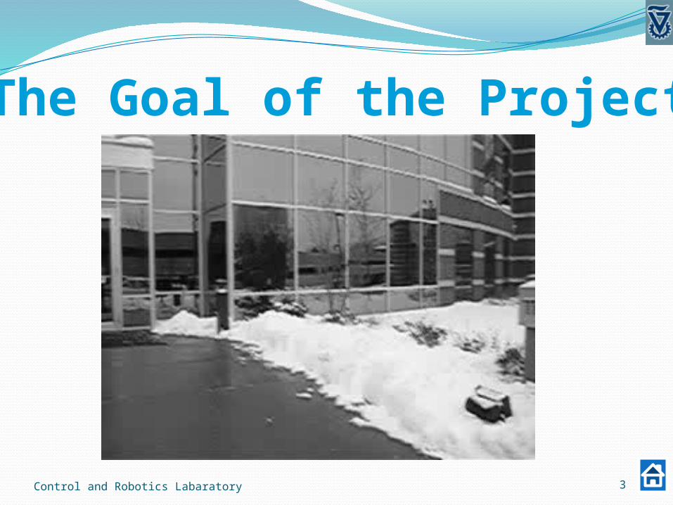
The Goal of the Project

Control and Robotics Labaratory 4
Possible Solutions
Direct Alignment method
Autocorrelation
FFT based algorithm
Feature based method
SIFT based algorithm

Control and Robotics Labaratory 5
The basic idea behind FFT algorithm
0 02 ( )2 1( , ) ( , )j x yF e F
0 0
0 0
0 0
1 2
1 2
2 ( )1 1
2 ( )1 1
1
2 ( )
( , ) ( ( , ))( ( , )) ( ( , ))
( , ) ( , )( , ) ( , )
j x y
j x y
j x y
F conj FR
abs F abs F
F F eF F e
e

Control and Robotics Labaratory 6
The FFT algorithm1)Calculating:
2)Applying high pass filter3)Transform to log-polar images:
4)Calculating:
1 21 , ; 2 ,F abs FFT I F abs FFT I
ln lncos sinx e y e
1 , 1 , ; 2 , 2 ,Flp FFT F Flp FFT F

Control and Robotics Laboratory 7
Original image FFT in Cartesian coordinates FFT in Log-polar coordinates
Rotated image FFT in Cartesian coordinates FFT in Log-polar coordinates
The log-polar transformation

Control and Robotics Labaratory 8
The FFT algorithm
5) Computing R1:
6)Extracting the rotation and angle parameters:
7)Constructing I3 using extracted parameters
8)Repeating step 5-6 for images I1 and I3
0 0 0 0
1
2 ( cos sin )
1( , ) ( 2( , ))( 1( , )) ( 2( , ))
j
Flp conj FlpR
abs Flp abs Flp
e
0max 1 ,oIR
Control and Robotics Labaratory 9
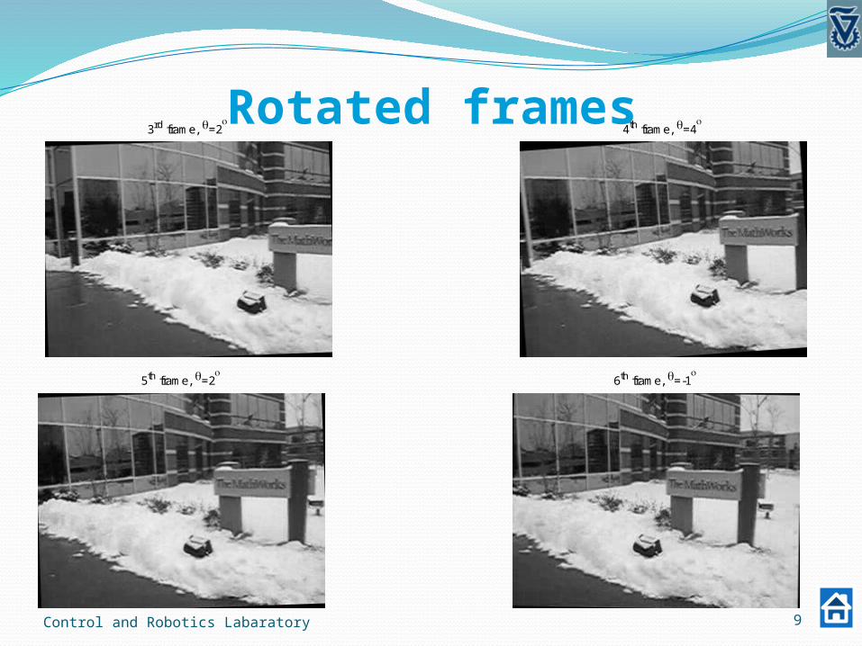
3rd frame, =2
4th frame, =4
5th frame, =2
6th frame, =-1
Rotated frames

Control and Robotics Labaratory 10
Panorama of 7 frames

Control and Robotics Labaratory 11
Full Panorama based on FFT algorithm
Number of frames: 46 (full movie)Time elapsed during creation: 11 seconds

Control and Robotics Labaratory 12
The limitations of FFT algorithm
I. The algorithm only works for two images of the exact same size. Especially for the rotation and scale computation, images also need to be square.
II. The algorithm requires images that have an overlapping area larger than 30%.
III. The algorithm only works for images in which the scale changes less than 1.8. Otherwise, the criterion of 30% overlapping area is not satisfied.
IV. We cannot get full homography parameters for creating the panorama.

Control and Robotics Labaratory 13
Two dimensional transformations

Control and Robotics Labaratory 14
The feature based Algorithm
Extract features from frames. (SIFT)Find and match common features between
two adjusted framesObtain a transformation between the frames.
(RANSAC)Stitch the transformed frames together (WEIGHTED STITCHING)

Control and Robotics Labaratory 15
SIFT (Scale Invariant Feature Transform)

Control and Robotics Labaratory 16
RANSAC (Random Sample Consensus)choose ‘n’ data points
(Hypothetical inliers)
Calculate the result (Hypothesize)Find all data points which meets
error<‘Threshold’ ( Consensus)
Return ‘k’ times.Use the best result till now and its
consensus to obtain the final result.

Control and Robotics Labaratory 17
Not every choice of parameters is good

Control and Robotics Labaratory 18
Least Square
Control and Robotics Labaratory 19
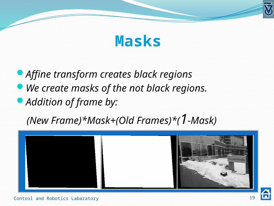
Masks
Affine transform creates black regionsWe create masks of the not black regions.Addition of frame by:
(New Frame)*Mask+(Old Frames)*(1-Mask)
Control and Robotics Labaratory 20
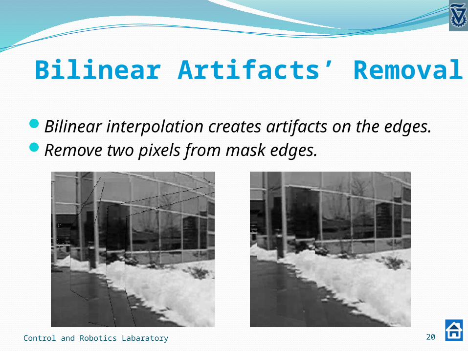
Bilinear Artifacts’ Removal
Bilinear interpolation creates artifacts on the edges.Remove two pixels from mask edges.
Control and Robotics Labaratory 21
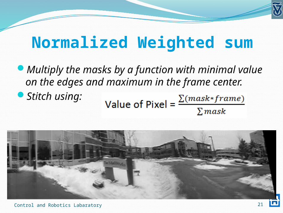
Normalized Weighted sum
Multiply the masks by a function with minimal value on the edges and maximum in the frame center.
Stitch using:

Control and Robotics Labaratory 22
Weighted Stitching
Weighted stitching of each two adjusted framesFast transition functionSmoothing is decreased by averaging on less
frames, with lesser index difference between them.
Control and Robotics Labaratory 23
Summary
Implemented two algorithms to obtain panorama.Researched and optimized the parameters.Used masks to stitch frames and delete border
artifacts.Implemented two stitching methods for
smoothing the transitions between frames.Obtained panorama using models of Translation,
Euclidean, Similarity and Affine transforms.
Control and Robotics Labaratory 24
Conclusion
Direct alignment method FastGives satisfying results for a simple Translation modelMay also be used for Euclidean and Similarity models
Feature based methodReliable and robust Can resolve complex transformation models
Sub pixel accuracy is required for complex transformsWeighted stitching is sharper, but in some cases less
accurate than the normalized weighted sum.


![CALOREE: Learning Control for Predictable Latency and Low Energyhankhoffmann/caloree.pdf · 2018. 1. 23. · Netlix algorithm[3, 12]Ðand a hierarchical Bayesian model 1Control And](https://img.pdfslide.us/doc/110x75/6122b7313b86c272f9625409/caloree-learning-control-for-predictable-latency-and-low-energy-hankhoffmanncaloreepdf.jpg)