Embed Size (px)
Citation preview
AN INTEGRATED DESIGN APPROACH FOR PIPELINES AND APPURTENANCES
BASED ON HYDRODYNAMIC LOADING
by
David L. McPherson
A thesis submitted in conformity with the requirements
for the degree of Doctor of Philosophy
Graduate Department of Civil Engineering
University of Toronto
© Copyright by David L. McPherson 2013

Abstract Page ii
ABSTRACT
AN INTEGRATED DESIGN APPROACH FOR PIPELINES AND APPURTENANCES
BASED ON HYDRODYNAMIC LOADING
Doctor of Philosophy
by
David L. McPherson
Department of Civil Engineering
University of Toronto
2013
Water and wastewater conveyance research is steeply based in advancements of numerical
methods and models. Design engineers need more than refinements in analysis methods to
evolve the standards of practice and the related design guidelines. In an effort to improve the
design efficiency and operating reliability of pipeline systems, design guidelines have been
developed to enfold the various technological advancements and elevate the standard of care
used in the pipeline design process. In this respect, the guidelines have been successful.
However, design engineers, manufacturers, and owners have developed a level of dependency on
the success of the guidelines. The guidelines, which were developed as and are clearly still held
to be by the various publishing associations, a minimum standard of care, have become the
default standard of care. Such statements are, of course, gross generalizations, but this thesis is
dedicated to move the standard of care forward through an integrated design approach that
provides a roadmap to inter-relate the independent design guidelines into a composite design
approach based on hydrodynamic loading. Hydrodynamic loading introduces of a temporal
parameter into the design process. With the temporal parameter this work demonstrates how the
consideration of both the frequency and the influence of acceleration head on the magnitude of
the hydraulic loading can be used to integrate and evolve the individual component designs into
a more efficient, cost effective, reliable composite design result. With a temporal parameter

Abstract Page iii
present in design, many opportunities present themselves to advance the current design
procedures outlined in the present design guidelines. This thesis identifies some of the present
shortcomings found in the modern pipeline and appurtenance design standards and introduces a
recommended path forward. Specific changes to the present standards are proposed in this work
and a unique analysis procedure to identify the failure potential of cement mortar lining has been
developed. Introducing the integrated design approach will allow for a significant evolution to
the present standard of practice in water and wastewater conveyance system designs.

Acknowledgements Page iv
ACKNOWLEDGMENTS
A long path with high peaks and deep valleys, the horizon is beautiful. I thank all who I have met along the way. With special regards to:
Dr. Bryan W. Karney: Advocate, Mentor, Trusted Advisor, Motivator, Professor, Colleague, Friend
Dr. Junn-Ling Chao:
Advocate, Mentor, Trusted Advisor, Colleague, Friend
John R. Plattsmier: Advocate, Sponsor, Colleague, Friend
Robert J. Card:
Teacher, Colleague, Friend
Mary T. and Charles L. McPherson: Patient Advocates, Advisors
Sydney A. McPherson, Thomas L. McPherson, and Isabel K. McPherson: Lifelong Inspiration, My Motive to Reach Higher

Table of Contents Page v
TABLE OF CONTENTS
CHAPTER 1 – INTRODUCTION ....................................................................................................................... 1
1.1 INTRODUCTION ................................................................................................................................ 1
1.2 THESIS OBJECTIVES ........................................................................................................................... 2
1.2.1 Improving Definition of Risk ................................................................................................... 3
1.2.2 Integrated Design Approach ................................................................................................... 7
1.3 PUBLICATIONS RELATED TO THESIS RESEARCH ....................................................................................... 9
1.4 FRAMING THE RESEARCH ................................................................................................................. 13
1.5 FRAMING OF THE THESIS ................................................................................................................. 14
1.6 PIPELINE DESIGN ............................................................................................................................ 15
1.7 AIR VALVE DESIGN ......................................................................................................................... 17
CHAPTER 2 – A REVIEW OF EXISTING DESIGN STANDARDS ....................................................................... 19
2.1 INTRODUCTION .............................................................................................................................. 19
2.2 PIPELINE DESIGN STANDARDS AND MANUALS OF PRACTICE .................................................................. 19
2.3 DESIGN STANDARDS ON THE SELECTION OF AIR VALVES........................................................................ 23
2.4 SUMMARY OF REVIEW OF THE STANDARDS OF PRACTICE ...................................................................... 25
CURRENT DESIGN APPROACHES WITH REGARD TO HYDRODYNAMIC LOADING ....................................... 26
2.5 VALUE BASED HYDRAULIC TRANSIENT MITIGATION TECHNIQUES ........................................................... 26
2.6 COMMON SURGE CONTROL METHODOLOGIES .................................................................................... 29
2.7 NORTH AMERICAN STANDARD DESIGN PRACTICES FOR FLEXIBLE (STEEL) PIPELINES .................................. 31
2.7.1 Internal Pressure ................................................................................................................... 31
2.7.2 Thrust Design ........................................................................................................................ 35
2.7.3 External Pressure .................................................................................................................. 37
2.8 NORTH AMERICAN STANDARD DESIGN PRACTICES FOR AIR VALVES ........................................................ 40

Table of Contents Page vi
2.9 OTHER CRUCIAL DESIGN CONSIDERATIONS ........................................................................................ 47
2.9.1 Transient Pressure and Pipeline Wall Thickness Design ....................................................... 48
2.9.2 Joint Design ........................................................................................................................... 49
2.9.3 Lining System Design ............................................................................................................. 51
2.10 CHAPTER 2 SUMMARY .................................................................................................................... 53
CHAPTER 3 – AN APPROACH TOWARD A HYDRODYNAMIC DESIGN PROSPECTIVE ................................... 54
3.1 A PROSPECTIVE FOR PIPELINE DESIGN ............................................................................................... 54
3.2 INTEGRATED DESIGN APPROACH ....................................................................................................... 55
3.3 QUANTIFYING THE HYDRODYNAMIC BEHAVIOR OF A SYSTEM ................................................................ 56
3.3.1 Understanding the Sensitivity of a System to Transient Pressure ........................................ 57
3.3.2 Defining the Sensitivity of a System for Transient Pressures ................................................ 58
3.4 CHARACTERIZATION OF HYDRODYNAMIC LOADING TYPE ....................................................................... 62
3.5 CHAPTER 3 PROVISIONAL SUMMARY ................................................................................................. 69
3.6 CHAPTER 3 CONCLUSION ................................................................................................................. 71
CHAPTER 4 – MODIFIED DESIGN APPROACHES FOR LININGS WITH CONSIDERATION OF HYDRODYNAMIC
LOADING ..................................................................................................................................................... 73
4.1 INTRODUCTION .............................................................................................................................. 73
4.2 HYDRODYNAMIC ANALYSIS OF CEMENT MORTAR LINING ...................................................................... 73
4.2.1 Lining Assumptions .................................................................................................................. 75
4.2.2 Hydraulic Transient Loading Analysis of Lining ..................................................................... 76
4.3 CONCLUSIONS TO CEMENT MORTAR LINING ANALYSIS ......................................................................... 81
CHAPTER 5 – MODIFIED DESIGN APPROACHES FOR AIR VALVES WITH CONSIDERATION OF
HYDRODYNAMIC LOADING ......................................................................................................................... 83
INTRODUCTION .............................................................................................................................. 83 5.1
AIR VALVE DESIGN ......................................................................................................................... 83 5.2

Table of Contents Page vii
5.2.1 Analysis of Standard Air Valve Design Approach and Proposed Changes ............................ 84
5.2.2 Air Valve Sizing for a Pumped System ................................................................................... 90
5.2.3 Air Valve Sizing and Location for a Pipeline System .............................................................. 90
5.2.4 Air Valve Location .................................................................................................................. 94
AIR VALVE DESIGN ANALYSIS PROCEDURE .......................................................................................... 94 5.3
5.3.1 Base Case, AWWA M51 Design Procedure ........................................................................... 94
5.3.2 Modified Design Scenario 1, AWWA M51 Controlled Draining Procedure ........................ 100
5.3.3 Modified Design Scenario 2, Air Flow Rate for Air Release of 0.5% of Fluid Flow Rate ...... 103
5.3.4 Modified Design Scenario 3, Compressed Air Volume for Air Release Valve Sizing ........... 105
5.3.5 Modified Design Scenario 4, Composite Design Procedure ................................................ 109
AIR VALVE DESIGN ANALYSIS SUMMARY .......................................................................................... 111 5.4
CONCLUSIONS OF AIR VALVE DESIGN WITH CONSIDERATION OF HYDRODYNAMIC LOADING ..................... 113 5.5
5.5.1 Air Valve Design................................................................................................................... 116
6.1 HYDRODYNAMICS ANALYSIS APPLIED IN DESIGN ................................................................................ 119
6.2 PROSPECTIVE WORK ..................................................................................................................... 120
REFERENCES .............................................................................................................................................. 123
LIST OF FIGURES
TABLE 1.2.1: CONCEPTUAL DESIGN DECISION MATRIX USING ACCELERATION HEAD ....................................................................... 5
FIGURE 1.2.1: CLASSIFICATION OF HYDRODYNAMIC LOADING ..................................................................................................... 6
FIGURE 1.2.2: INTEGRATED DESIGN APPROACH ....................................................................................................................... 8
FIGURE 2.7.1: AWWA M11 INTERNAL PRESSURE DESIGN ...................................................................................................... 32
FIGURE 2.7.2: INTERNAL LOADING FREE BODY DIAGRAM ........................................................................................................ 33
FIGURE 2.7.3: EXTERNAL PRESSURE FREE BODY DIAGRAM ....................................................................................................... 39
FIGURE 2.8.1: AWWA M51 AIR VALVE LOCATIONS .............................................................................................................. 41

Table of Contents Page viii
FIGURE 2.8.2: AIR RELEASE VALVE SIZING NOMAGRAPH FROM APCO‐WILLAMETTE VALVE AND PRIMER CORPORATION .................... 45
FIGURE 2.9.1: EXAMPLES OF PIPE JOINT FAILURES ................................................................................................................... 50
FIGURE 3.4.1: CLASSIFICATION OF HYDRODYNAMIC LOADING ................................................................................................... 66
FIGURE 3.5.1: INTEGRATED DESIGN APPROACH ..................................................................................................................... 70
FIGURE 4.2.1: TYPICAL MORTAR LINING FAILURE ON ETIWANDA .............................................................................................. 74
PIPELINE (MCREYNOLDS, PENG, ROMER, 2010) .................................................................................................................... 74
FIGURE 4.2.2 ‐ FREE BODY DIAGRAM OF DYNAMIC LOADING .................................................................................................... 78
FIGURE 4.2.3: TIME TO EQUILIBRATE THE TRANSIENT PRESSURE ACROSS THE LINING THICKNESS ..................................................... 80
FIGURE 5.2.1: PERCENT DISSOLVED AIR IN WATER (FULLY SATURATED CONDITION) .................................................................... 86
FIGURE 5.2.2: RELATIONSHIP OF PERCENT DISSOLVED AIR AND SATURATED AIR DENSITY ............................................................. 88
FIGURE 5.2.3: AIR RELEASE VALVE SIZING USING COMPRESSED AIR VOLUME ............................................................................. 89
FIGURE 5.2.4: PIPELINE PROFILE OF HYPOTHETICAL CASE STUDY ............................................................................................... 91
FIGURE 5.2.5: COMPARISON OF AIR RELEASE VALVE SIZING FLOW RATE (QAIR) CRITERION .......................................................... 93
FIGURE 5.3.1: BASE CASE STEADY STATE HGL AND HYDRAULIC TRANSIENT ENVELOPE ................................................................. 96
FIGURE 5.3.2: AWWA M51‐ STEADY STATE HGL AND HYDRAULIC TRANSIENT ENVELOPE ........................................................... 98
FIGURE 5.3.3: AWWA M51‐ACCUMULATIVE AIR VOLUME AND PRESSURE HEAD HISTORY AT AIR VALVE STATION ........................... 99
FIGURE 5.3.4: SCENARIO 1‐STEADY STATE HGL AND HYDRAULIC TRANSIENT ENVELOPE ............................................................. 101
FIGURE 5.3.5: SCENARIO 1‐ACCUMULATIVE AIR VOLUME AND PRESSURE HEAD HISTORY AT AIR VALVE STATION ............................ 102
FIGURE 5.3.6: SCENARIO 2‐STEADY STATE HGL AND HYDRAULIC TRANSIENT ENVELOPE ............................................................. 104
FIGURE 5.3.7: SCENARIO 2‐ACCUMULATIVE AIR VOLUME AND PRESSURE HEAD HISTORY AT AIR VALVE STATION ............................ 105
FIGURE 5.3.8: SCENARIO 3‐STEADY STATE HGL AND HYDRAULIC TRANSIENT ENVELOPE ............................................................. 107
FIGURE 5.3.9: SCENARIO 3‐ACCUMULATIVE AIR VOLUME AND PRESSURE HEAD HISTORY AT AIR VALVE STATION ............................ 108
FIGURE 5.3.10: SCENARIO 3‐ACCUMULATIVE AIR VOLUME OVER 60 SECONDS .......................................................................... 109
FIGURE 5.3.11: SCENARIO 3‐STEADY STATE HGL AND HYDRAULIC TRANSIENT ENVELOPE ........................................................... 110
FIGURE 5.3.12: SCENARIO 3‐ACCUMULATIVE AIR VOLUME AND PRESSURE HEAD HISTORY AT AIR VALVE STATION .......................... 111

Table of Contents Page ix
LIST OF TABLES
TABLE 3.3.1: CONCEPTUAL DESIGN DECISION MATRIX USING ACCELERATION HEAD ..................................................................... 61
TABLE 3.4.2: HYDRODYNAMIC LOADING DECISION MODEL ...................................................................................................... 68
TABLE 5.2.1: DATA AND ASSUMPTIONS USED IN SOLUBILITY ANALYSIS ...................................................................................... 86
TABLE 5.2.2: AIR RELEASE VALVE SIZING COMPARISON ........................................................................................................... 91
TABLE 5.2.3: TIMING FOR AIR RELEASE FOR EXCESS AIR .......................................................................................................... 93
Chapter 1 – Introduction and Framing the Research Page 1
CHAPTER 1 – INTRODUCTION
"No one wants to learn by mistakes, but we cannot learn enough from successes to go beyond the state of the art." (Petroski, 1992)
1.1 Introduction
Engineering is not a pure science, but is a judicious speculation and intervention on the interplay
of multiple, complex systems in an effort to produce a safe, efficient and reliably operating
composite. The composite design of a ‘standard’ pipeline conveyance system has evolved over
time, with more recent refinements in the numerical analysis of individual system components
and loadings. The materials used and the methods of combining these materials to form a
pipeline structure are continuing to improve, resulting in improvements of material elasticity and
durability. The methods of joining pipeline segments have also improved resulting in more
reliable conveyance systems operating at higher pressures with less joint leakage. Pumping units
and specialty valve designs have been developed to handle a wide range of operating conditions
while maintaining their efficiency and reliability. The number and scope of these component
improvements has inevitably developed into a long and complex list of options for the design
engineer to consider. As a result, various groups, American Water Works Association (AWWA),
American Society of Civil Engineers (ASCE), American Society of Mechanical Engineers
(ASME), International Organization for Standardization (ISO), and others, have developed
design guidelines and manuals of practice for the water and wastewater engineer to help facilitate
and guide the engineer through the complexities of the modern pipeline system design process.

Chapter 1 – Introduction and Framing the Research Page 2
The goal of the various guidelines has been to elevate the standard of care used in the pipeline
design process and as a result to improve the design efficiency and operating reliability of
pipeline systems in general. In this respect, the guidelines have been successful. However, the
continued success of the guidelines has developed into a form of dependency on them by design
engineers, manufacturers and owners. The guidelines, which were developed as a minimum
standard of care, have become the default standard of care. As a result, a non-standard design
approach which may benefit the risk profile, the cost, and/or the sustainability of a system are not
fully explored or engineered because the guidelines, as used by design engineers, do not clearly
define the rationale that was used to develop the standard nor do the guidelines clearly define the
level of conservativeness or promote exploration of design parameter sensitivity that may
introduce a deviations from the standard of practice. Such statements are, of course, gross
generalizations, but this thesis is dedicated to move the state of design and care forward: it is
developed in order to identify some of the shortcomings found in the modern pipeline design
standards as well as to provide a recommended path forward for various standard shortcomings
via a proposed “integrated design approach” to pipeline engineering.
1.2 Thesis Objectives
In the analysis of pipeline conveyance systems, significant research has been performed in the
past years in the advancement of numerical methods and models to better characterize and define
various loads, in both their spatial and temporal variations, and their inter-relationship to design.
However, to a design engineer in the water and wastewater conveyance industry, many times
these refinements in analysis methods are not relevant nor do they drive change to the standard
design practice. This resistance to evolution of the standard practice could simply be the culture
Chapter 1 – Introduction and Framing the Research Page 3
for which the standard in maintained, or could be the result of a misaligned love affair of
research engineers to development of numerical theory and “minimum publishable units” over
the use of physical modeling and empirically developed approaches. It is the author’s opinion
that numerical theory has in many respects replaced experience, recorded knowledge and applied
science and as a result the standard of practice for pipeline design is diverging from the
advancements in numerical theory.
This thesis does not follow a completely standard outline. This work has been developed and
written in context of the author’s 18 years of design and consultancy experience in the water and
wastewater pipeline and pump system planning and design industry and 7 years as a standing,
contributing member of several standard and technical committees. These standards committees
are the American Water Works Association (AWWA) Standard C512 and Design Manual M51
for air valves, the AWWA C906 Standard and Design Manual M55 for polyethylene (PE) pipe,
and the American Society for Civil Engineers (ASCE) Pipeline Division – Pipeline Planning and
Installation Committee and sitting vice chair of the ASCE technical committee for hydraulic
transient analysis and control. The author is also responsible for many of conference papers as
well as several peer reviewed papers that are referenced and utilized within this thesis. Specific
objectives relating to the definition of pipeline risk and the creating of an integrated design
framework are outlined next.
1.2.1 Improving Definition of Risk
Understanding the increasing complexity of the pipeline design practice with regard to the
amount of numerical research available and the lack of complementary empirical data, a primary

Chapter 1 – Introduction and Framing the Research Page 4
objective of this thesis is to provide a roadmap for integrating various research concepts to the
published design standards and guidelines used in the water and wastewater conveyance
industry. The roadmap is developed around the existing pipeline design standards and includes
the introduction of several assessment tools and proposed design parameters that introduce the
use of hydrodynamic loading for pipeline systems. The present pipeline design standards are
integrally based in static hydraulic loading. The identification and quantification of the temporal
nature of hydraulic loading is noticeably absent. There are simple and robust evaluation
techniques that can be introduced and applied early in the conceptual design process to help
evaluate the hydrodynamic sensitivity of a pipeline system. One example of this is the use of
acceleration head to couple the physical elements of a pipeline design, namely length, with
operating conditions described by the rate of change of flow, not just flow. By considering the
rate of change of flow or acceleration/deceleration of flow, a temporal component is introduced
to the conceptual design analysis.
The acceleration head is dependent not only on the change in velocity and change in time
(temporal characteristic), but is also dependent on the distance along the pipeline. This thesis
shows how an acceleration head parameter,
Acceleration Head ~ (L/g) (∆v/∆t) Eq: 1.2.1
where: L is the length of the pipeline system, ∆v is the change in velocity and ∆t is the time in
which the change in velocity occurs, can be used to inter-relate the three inter-dependent
variables, change in velocity, change in time and length, so that the designer can make a measure

Chapter 1 – Introduction and Framing the Research Page 5
of hydraulic transient sensitivity of the system. The primary objective of this work is to use
hydrodynamic loading to influence and evolve the design guidelines and standards that are used
in pipeline and appurtenance design. The introduction of an acceleration head parameter to the
various design guidelines is the first example how this work can evolve the standards of the
practice of designing pipe. The acceleration head parameter can be developed to produce a
conceptual level decision matrix (Table 1.2.1) that can be coupled with a decision criterion to
assess if the transient behavior of the system warrants consideration of a full, comprehensive
transient model. This concept is further explored in Chapter 3. The use of hydrodynamic loading,
which is both time and spatially dependent, as a base for design introduces this temporal
parameter into the design process. Figure 1.2.1 shows the boundaries of the temporal parameter
for both the frequency and the magnitude of the loading.
Table 1.2.1: Conceptual Design Decision Matrix using Acceleration Head Time of Change (∆t) (s) -> 1000 100 10 1 0.1 0.01
Instantaneous
Time (t<2L/a)
Length
(dx) (m) (L/g)*( ∆v/∆t), Acceleration Head
0.002 1 0.0001 0.001 0.01 0.1 1 10
0.02 10 0.001 0.01 0.1 1 10 100
0.2 100 0.01 0.1 1 10 100 1000
2 1,000 0.1 1 10 100 1000 10000
20 10,000 1 10 100 1000 10000 100000
200 100,000 10 100 1000 10000 100000 1000000
Chapter 1 – Introduction and Framing the Research Page 6
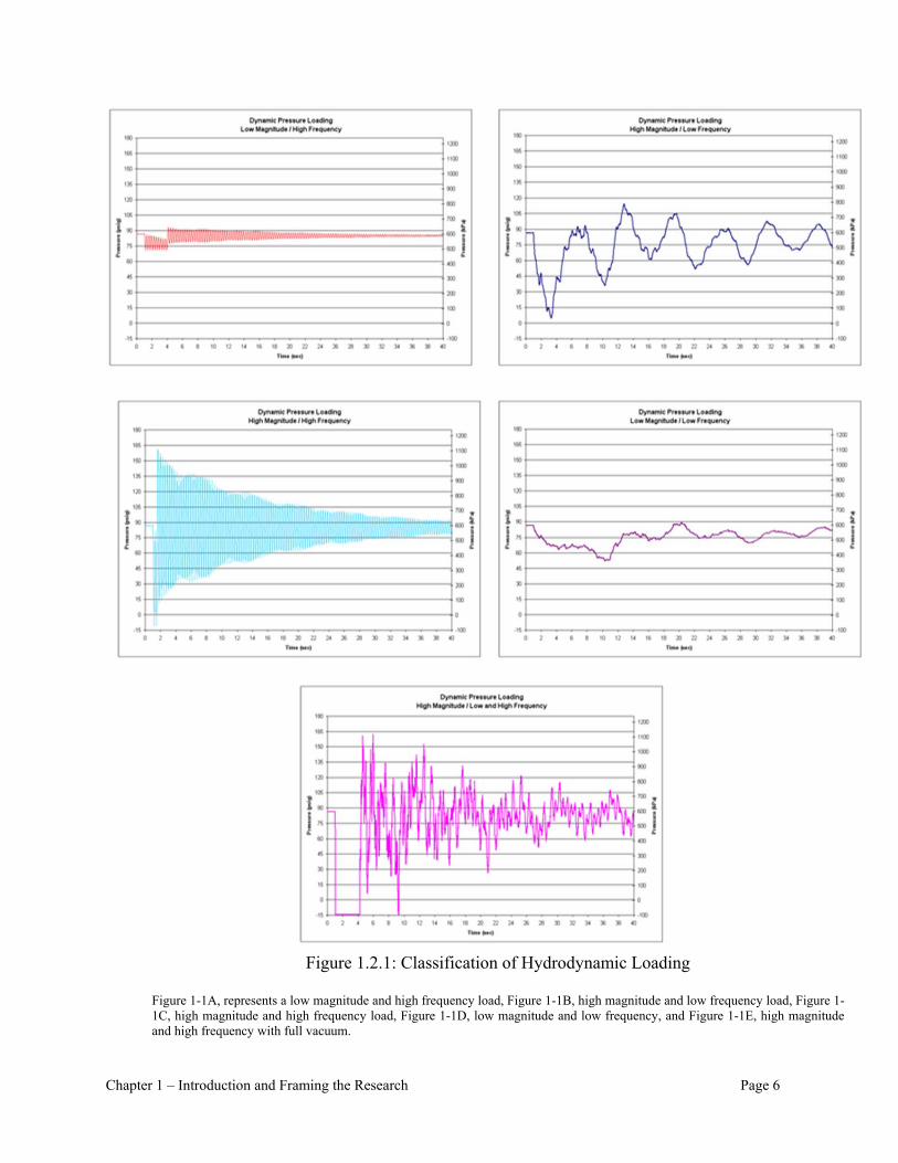
Figure 1.2.1: Classification of Hydrodynamic Loading
Figure 1-1A, represents a low magnitude and high frequency load, Figure 1-1B, high magnitude and low frequency load, Figure 1-1C, high magnitude and high frequency load, Figure 1-1D, low magnitude and low frequency, and Figure 1-1E, high magnitude and high frequency with full vacuum.

Chapter 1 – Introduction and Framing the Research Page 7
With a temporal parameter present in design, many opportunities present themselves to evolve
the current design procedures. As a prime example to illustrate and flesh out this concept, the
initial evaluation of suitable pipeline materials, linings, and joint types is explored in Chapter 3.
The introduction of a temporal parameter that correlates type of hydrodynamic loading with
consequence will allow a risk component to be established for design. Presently in pressure
pipeline design, safety factors or design factors are used as a measure of design risk. However,
these factors fall short of accurately evaluating risk and are often inappropriately used to imply
safety when they are simply a measure of ultimate strength of a material relative to an applied
stress (pressure). The AWWA Standards for both Polyethylene (PE, HDPE) and
Polyvinylchloride (PVC) pipe ask the designer to estimate cyclic loading and suggest the
pipeline strength be de-rated after a set number of cyclic loads. PE and PVC pipeline are
susceptible to failure from fatigue. However, the AWWA standards for Steel, Ductile Iron,
Concrete and other commonly used material do not include a temporal component nor do they
recognize fatigue in the design procedures.
1.2.2 Integrated Design Approach
At its core this thesis proposes an Integrated Design Approach (IDA) that utilizes hydrodynamic
analyses as a roadmap for design procedure. The concept of using hydrodynamic analyses as a
link is evident in various fluid-structure interface research projects (Wiggert and Tijsseling,
2001) that seek to define the various active and reactive forces at fluid to solid interfaces, but
using the hydrodynamic analyses to bridge the component design for water pipeline design is
unique. The thesis concludes by using an IDA coupled with improved monitoring, and allowing
an improvement in the definitions of probability and consequence (risk), will ultimately

Chapter 1 – Introduction and Framing the Research Page 8
culminate into an Integrated Design Standard (IDS) for the water conveyance industry. A
conceptual outline of the roadmap is described in the Figure 1.2.2.
Figure 1.2.2: Integrated Design Approach
The thesis focuses on design issues that the author has identified within the standards of practice,
issues that provide relevant context to the divergence of theory and practice. The thesis
introduces multiple, tangible concepts that can be introduced to the existing standards and design
guides to promote the idea of an IDA.
Specific aspects of the IDA are elucidated in dedicated chapters. For example, in Chapter 5, the
IDA is used to evaluate the standard practice of sizing and locating air valves in design of a
water transmission system. An evaluation of the standard practice is made and an example

Chapter 1 – Introduction and Framing the Research Page 9
system is presently to change the paradigm used for sizing and locating air valves. The paradigm
shift is based on the re-definition of the prescribed design flow rate, the deconstruction of the air
valve into performance component design, and the use of transient modeling to evaluate the
sizing and location.
1.3 Publications Related to Thesis Research
The core of this thesis work has been published in various places during the process of the thesis
development. These published works are listed here with a description on where and how they
have contributed to the work.
Chapter 1 introduces the concepts within the thesis and provides the framework from which the
research was drawn. Along with the 18 years of professional experience there were several key
publications that inspired the concepts and framework described herein. The need of an
Integrated Design Approach became evident to the author over a number of years trying to inter-
relate various, many times conflicting, design allowances for different components within a
pipeline system design. The concept of the Integrated Design Approach was fleshed out in
several works, but mainly can be attributed to:
1. McPherson, D.L., Karney, B.W, “Sub-atmospheric transient pressure conditions – where
and what it may influence in design”, BHRA 10th International Conference on Pressure
Surges, Edinburgh, Scotland, May 2008, Pages 99-110;
Along with work generated as a member of various ASCE and AWWA technical committee
memberships:

Chapter 1 – Introduction and Framing the Research Page 10
2. American Water Works Association (AWWA), McPherson, D.L. as a member of the
C512 Standard and M51 Design Guide for Air Valves, AWWA, Denver, CO, Work in
progress at the printing of this work;
3. American Water Works Association (AWWA), McPherson, D.L. as a member of the
C906 Standard and M55 Design Guide for High Density Polyethylene Pipe, AWWA,
Denver, CO, Work in progress at the printing of this work;
4. American Society of Civil Engineers (ASCE), McPherson, D.L. as a Member of the Task
Committee on Transient Analysis, “Hydraulic Transient Analysis in the Planning and
Design of Transmission Pipeline Systems, Manual of Practice”, ASCE, Reston, VA,
Work in progress at the printing of this work;
During this research and drafting of this thesis, the author was fortunate to be a member of an
ASCE Task Committee on Buried Flexible Pipe Load Stability and Design. This committee
included a collection of highly qualified design and manufacturing personnel who at the core had
the integrity and quality of the civil engineering industry in mind. One member of this committee
Reynold K. Watkins, PhD, who along with Bryan W. Karney, PhD, inspired and reaffirmed my
drive to continuously and persistently improve on the standards of the engineering practice. The
work that was produced and was published is:
5. American Society of Civil Engineers (ASCE), McPherson, D.L. as a Member of the Task
Committee on Buried Flexible Pipe Load Stability and Design, “Buried Flexible Steel
Chapter 1 – Introduction and Framing the Research Page 11
Pipe: Design and Structural Analysis - ASCE Manuals and Reports on Engineering
Practice No. 119”, ASCE Reston, VA, August, 2009
The contributing participation on the ASCE and AWWA committees, listed above also provided
insights for reviews that are outlined in Chapter 2. These committee memberships have also
allowed me to better understand the means and methods in which standards slowly, but
continuously evolve.
Chapter 2 outlines specific analysis techniques and identifies strategic areas within the current
design standards and manual of practice in which the over-arching use of hydrodynamic loading
can be realized and used in the Integrated Design Approach. Several published works
contributed to Chapter 2, namely:
6. McPherson, D.L, Charles, T.J., “Surge Control: When and Where In the Life of A
Pipeline System, ASCE National Pipeline Conference, Keystone, CO, August, 2010,
Pages 496-507;
7. McPherson, D.L, Haeckler, C, “Answering the Question: Is a Surge Analysis Required?”,
ASCE National Pipeline Conference, Seattle, WA, July, 2011, Pages 929-936;
8. McPherson, D.L, “Choice of Pipeline Material: PVC or DI Using a Life Cycle Cost
Analysis”, ASCE National Pipeline Conference, San Diego, CA, August, 2009, Pages
1342-1354.
Chapter 3 provides the roadmap for the Integrated Design Approach with context on the analysis
techniques presented in Chapter 2 and where and how to apply these analyses to best inter-relate

Chapter 1 – Introduction and Framing the Research Page 12
the designed components using hydrodynamic analyses. Chapters 4 and 5 are where the thesis
shows where the analyses should be applied in design. Several papers were published as Chapter
4 and 5 were being developed, namely:
9. Katherine, Q.Z., Karney, B.W., McPherson, D.L., “Pressure-relief Valve Selection and
Transient Pressure Control”, AWWA Journal, Vol. 100 Num. 8, August 2008, Pages 62-
69;
10. McPherson, D.L, “Air Valve Sizing and Location: A Prospective”, ASCE National
Pipeline Conference, San Diego, CA, August, 2009, Pages 905-919;
11. McPherson, D.L, Haeckler, C, “Untangling the Mysteries of Air Valves?”, ASCE
National Pipeline Conference, Miami, FL, August, 2012, Pages 983-989.
During the preparation of this research and thesis, the author has prepared and published several
papers through volunteer work on the ASCE Task Committee for Sustainable Design of
Pipelines Pipeline Sustainability. These papers include:
12. American Society of Civil Engineers (ASCE), McPherson, D.L. as a Member of the Task
Committee on Sustainable Design of Pipelines, Lead Author of Materials Section of
ASCE White Paper and Workshop for “Sustainable Design of Pipeline”, ASCE National
Pipeline Conference, Seattle, WA, July, 2011, Pages
13. Hatton, S., McPherson, D., Mueller, R. “60” Demostration Installation of Pressure Cast
Steel Pipe for Tarrant Regional Water District”, ASCE National Pipeline Conference,
Miami, FL, August, 2012, Pages 737-745;

Chapter 1 – Introduction and Framing the Research Page 13
14. McPherson, D.L, Walker, R., “Consideration of Embodied Energy in Sustainability
Evaluation of Pipeline Projects”, ASCE National Pipeline Conference, Miami, FL,
August, 2012, Pages 544-551.
The author also has participated in the first International Symposium on Hydraulic Surge and Air
Control in April, 2013 and has served as a reviewer for the ASCE Journal of Pipeline Systems
Engineering and Practice from 2011 to present.
1.4 Framing the research
As the organization of this work is not strictly conventional, it is worthwhile to carefully frame
the work within its professional and research contexts. Two particular topics are given special
emphasis both in this framing and in the work as a whole, these topics being flexible pipe design
and air valve design. Many forms of analysis and calculations go into the design of a flexible
pipeline conveyance system. These design processes and ultimately the pipeline products have
evolved through time by successive theoretical and empirical advancements. The history of these
design and production advancements has been well distilled and today is represented by a series
of a succinct, yet mainly empirical design practices. The evolution of these practices has been
aided not only by academia, but also by design professionals requiring quality within the pipeline
industry and manufacturing. However as the existing conveyance infrastructure ages and a
continual push for higher pipeline capacity is made, it is opportune to reevaluate the strengths
and weaknesses of these design practices.
With consideration of the past successes and strength of the existing approaches, this thesis
specifically proposes that an improved approach or prospective be used in select design

Chapter 1 – Introduction and Framing the Research Page 14
processes, calling for the consideration of a composite system or an Integrated Design Approach
rather than an approach that considers the pipeline system as a rather loose collection of
individual components (e.g., pipeline, joints, linings, pumps, valves, etc.) that have been
engineered to “play well” together.
It is the opinion of the author that the current design practices are highly focused on the
individual components and as a result have generated a prescribed narrowly focused design
approach that may borderline on deterministic. Also the typical interrelationships of the
individual components that affect design has been integrated so well into the component design
protocols that the practicing engineer is unaware of potential risk and/or improvement that may
be present if the design were broken down into the basic building blocks and reconstructed with
a more inclusive and/or comprehensive objective.
1.5 Framing of the Thesis
This thesis develops an outline with specific examples of how to break down this deterministic
approach that has pervaded the current design practice, and allow a re-introduction of basic
conceptual design philosophy into the pipeline design process.
Pipeline design practices have evolved over time to consider static or at best step-wise
advancements in the industry. There have been provisions within the design practice to allow the
introduction of new material. For example, the design practice for selecting the appropriate
thickness and type of polyethylene (PE) pipeline material for a pressurized pipeline application is
based on a method developed by the Plastic Pipeline Institute (PPI) and is known as the
Hydrostatic Basis of Design (HDB). This design procedure which is outlined in AWWA M55

Chapter 1 – Introduction and Framing the Research Page 15
(AWWA M55, 2006) is coupled with research performed by manufacturers and regulated by
PPI. In turn, PPI periodically produces a report entitled PPI TR-4 (PPI, 2011). This report
interprets the industry research and defines the material’s tolerances and allowances as
parameters that are used in the HDB design protocol. As a result, the introduction of the once
new PE material was quickly made available to the industry for consideration in design, and
widely adopted. What is not provided to the engineer in the AWWA M55 design manual is a
method to deal with hydrodynamic loading, nor is there a discussion of typical failure modes of
PE pipeline systems. Also, the above design method concentrates on the pipeline segment and
not the pipeline system. There is literature clearly defining the predominate failure mode of
Polyethylene pipeline systems are at the joint and fittings and not the pipeline segment. Neither
HDB nor the AWWA M55 design manual identify or address this issue.
This thesis proposes that both static and dynamic, not just hydrodynamic, evaluations of the
pipeline linings, coatings, joints, operating conditions (both normal and abnormal), transient
control systems as well as handling and installation issues be considered. In pipeline design,
individual components have been researched extensively, but the interrelationship and the
interdependencies of the components has not. With the general considerations presented, this
thesis outlines a prospective of how and where hydraulic transient pressures should be used in
pipeline system design and how and where design professionals can introduce practical and
theoretical improvements to the design process by using more advanced tools and techniques.
1.6 Pipeline Design
A review of applicable standards conducted for this thesis turned up no information on the
influence of dynamic loading in relation to a common pipe lining known as cement mortar lining
Chapter 1 – Introduction and Framing the Research Page 16
which is a thin layer of cement paste that is applied to the interior of metallic pipe to reduce the
corrosion potential of the pipe in the presence of water. The literature found mainly focused on
the allowable deformation or deflection of the pipeline if a cement mortar lining was to be
considered. This information was similar in for the information found for elastomeric seals and
gaskets. The collection of empirical work performed by Reynold K. Watkins at Iowa State and
then Utah State University which resulted in the Iowa Formula (Watkins and Anderson, 1999)
has guided the flexible pipeline design industry ongoing 50 years; however this work is fairly
crude with respect to hydrodynamic loading. The design loadings, for which internal pressure is
one, are simply used to predict deflection of the pipeline. This predicted deflection is then used
to establish performance limits of various design components; such as, a cement mortar lined and
flexible coated pipeline is allowed a 3% deflection because of the performance limit of the
lining. The loading rate is not a variable in this analysis.
To address this, a basic analysis approach (developed with brief correspondence with Ivo Pothof
of Deltares) is outlined in Chapter 4 of this thesis that considers the both the loading rate and
magnitude on cement mortar lining. It is proposed that this improved procedure be used to
evaluate the integrity of cement mortar lining design and be included in any MOP that references
cement mortar lining. The key parameter in this analysis is the hydraulic connectivity of the
cement lining mixture. In summary of this approach, if the cement mixtures hydraulic
conductivity is relatively low then the balancing force to equilibrate the transient pressure may
occur too slowly so that a full differential loading is experienced by the lining. Therefore, during
a hydraulic transient event the full force resulting from the differential pressure could be realized
putting the lining integrity at risk and potentially drawing the lining into the pipeline flow.
Chapter 1 – Introduction and Framing the Research Page 17
1.7 Air Valve Design
A second context developed in this work is that of air valve design. Air valves are not generally
used in the petroleum or natural gas industry due to the compressible nature of the conveyed
fluid. However, water is relatively incompressible and therefore the introduction of air into and
out of the system has become necessary as free air is dissolved, entrained and released within the
flow during the conveyance as pressure rising and falls along the pipeline profile. The
introduction of air to the system when the water is at or near vacuum pressure conditions can
prevent or limit the formation of vapor cavities in the pipeline. The expulsion of air through air
release valves prevents a phenomenon known as air binding from occurring. Air binding happens
when dissolved air is released from the fluid and collects at localized high points or low pressure
points. The volume of air, which is seeking a lower energy state and therefore a lower pressure
within the pipeline system, will be held at this high point. Over time, as the free air accumulates,
the increasing air volume will begin to restrict the flow of water and begin to hydraulically bind
the system (Falvey, 1980). This phenomenon is well documented and has been studied
extensively. In general the primary duty of an air vacuum valve is to help prevent the pipeline
from collapsing and the primary purpose of an air release valve is to help maintain the full
hydraulic capacity of the pipeline system. This thesis discusses additional features of the air
valve that are not thoroughly addressed in the current design practices. These include:
1. Proper sizing of the air release valves with respect to the compressed air volume at the
valve and the hydrodynamic loading during air release,
2. Proper sizing of air vacuum valves with respect to closure after a hydraulic transient
event and prevention of a secondary transient event, and

Chapter 1 – Introduction and Framing the Research Page 18
3. The composite design of air valves for both startup/shutdown, normal and transient
operations.
The framing of the research draws attention to the various components that have evolved in
relative isolation to other components of water and wastewater system. The next step to
formulate a resolution to this issue is to identify and refine the understanding of the
interdependencies that exist within the current design guidelines, but have not been coupled in a
way that can benefit the design of each component as well as benefit the entire conveyance
system design.

Chapter 2 – A Review and Preliminary Critique of Current Page 19 Design Approaches with Regard to Hydrodynamic Loading
CHAPTER 2 – A REVIEW OF EXISTING DESIGN STANDARDS
Chapter 2 provides a review of a series of commonly used North American design standards and
manuals of practices that are used worldwide to design and specify pipeline systems. This
review highlights the divergence in the standards as the standards become more specific for
various system components rather than integrated. The issue and problematic result of this
specific component design is an overall over-simplification of the design standards.
2.1 Introduction
The hydrodynamic loading of a pipeline system is not thoroughly addressed in current design
guidelines and as a result is not considered in design practice. Where hydrodynamic loading is
addressed, it is simply framed as a statically determinant system with no temporal characteristic.
These design guidelines and approaches have been developed through years of both theoretical
and empirical research. The research for loading characteristics on buried pipeline has generally
focused on the soil/trench conditions and its influence on the integrity of the pipeline structure
and the resistance to thrust at various fittings and deflections in the system. The review of these
guidelines performed for this thesis can be grouped into two categories, the first category is a
thorough review of the North American and European design standards of buried pipeline design
practices and standards for the water and wastewater industry and the second is the review of
applicable academic and manufacturing studies that have been performed for specific pipeline
materials and appurtenances.
2.2 Pipeline Design Standards and Manuals of Practice
Chapter 2 – A Review and Preliminary Critique of Current Page 20 Design Approaches with Regard to Hydrodynamic Loading
The American Water Works Association (AWWA) and the American Society of Civil Engineers
(ASCE) are two societies that serve the civil engineering profession in North America. Both
societies, in which the author is an active member, maintain committees to periodically update
pipeline design practices and standards. These two societies produce manuals of practice (MOP)
and design guidelines that provide brief histories of the applicable product as well as define
minimum design standards for various pipeline materials and appurtenances used in the pipeline
industry. In the review of these MOPs, it has become evident that each guideline has evolved
into a specific guideline for an individual material and/or service. For example in the AWWA
design guideline for Steel (AWWA M11, 2004) and the associated standard (AWWA C200,
2005), Ductile Iron (AWWA M41, 1996), PVC (AWWA M23, 2002) and HDPE (AWWWA
M55, 2006) and its associated standard (AWWA C906, 2007), the recommended calculation for
imposed thrust as well as the calculation of thrust restraint are different. Also and more important
to this thesis is the fact that none of the design guidelines above considers hydrodynamic loading
in the design procedure. Granted, in regard to thrust, the dynamic loading is relatively small at
normal design flow velocity, but the current guidelines simply do not consider it. This makes the
design less robust. For instance, if a design professional considers only static thrust in design of a
steel pipeline and in that design the designer assumes that only 50% of the yield strength will be
used to resist the combined bearing load and load induced by the internal pressure then the
assumed factor of safety in the current design guideline is 2.0. In fact because the hydrodynamic
loading is not considered in the factor of safety, the factor of safety is not 2.0 but something
unspecified, but certainly less. The amount less is of course dependent on the velocity and the
rate of change in the loading, but the calculated safety factor in the current standard is erroneous.
The author understands that the factor of safety is meant to protect the design from unknown,

Chapter 2 – A Review and Preliminary Critique of Current Page 21 Design Approaches with Regard to Hydrodynamic Loading
uncertain or immeasurable elements inherent in design, but the hydrodynamic load is
quantifiable and therefore it should be routinely considered in the loading characteristics of the
system.
The recent effort of the society’s (ASCE, AWWA) committees, that are responsible to update the
various design guidelines, there has been a simple debate over which current practice is better
rather than a concerted effort to research and develop resolutions to outstanding and/or
misrepresented design approaches. With the current design guidelines evolving over time with
different design recommendations for basic design parameters, such as internal loading
magnitude, the design professional is left with an inherent conflict within the guidelines that
limits the ability for the profession to further evolve or modify the design practices. Today, the
framework used to design a steel pipeline is not similar to the design of a polyethylene pipeline.
Even though both design procedures consider similar design parameters such as thrust, allowable
deflection, and loading, the DESIGN GUIDELINEs and the method of design and the results of
design are different. The AWWA M55 design guideline for Polyethylene pipeline utilizes a
hydrostatic design basis for the pipe barrel which was developed by the Plastic Pipe Institute
(PPI), where the steel pipeline design guideline, M11, utilizes static loading consideration and
elastic limits of the material. The European guidelines which are outlined in the Information and
Guidance Notes (IGN) 4-32-18 “The choice of pressure ratings for polyethylene pipe systems for
water supply and sewerage duties” and IGN 4-37-02 “Design Against Surge and Fatigue
Conditions for Thermoplastic Pipes.” are similar in their approach, but what is evident is the lack
of a consideration of the composite system. The IGN 4-37-02 opens in the foreword stating,
“Past advice on dealing with transient pressures in plastic pipelines given in the Pipeline

Chapter 2 – A Review and Preliminary Critique of Current Page 22 Design Approaches with Regard to Hydrodynamic Loading
Materials Selection Manual (PMSM) issued for the Water Industry in 1995 by WSA, and has
been recognized as being extremely conservative.” This statement would make one believe that a
pipeline system conforming to these standards would be over-designed or at least highly
conservative. Even using this older approach, failures and/or leaks are still evident in systems
using this design approach as well as the North American design approaches.
Another issue with the current design practices is that the manufacturers are steering the research
and the associated guidelines. The manufacturers are conscious of the owner’s interest in refining
the design guidelines and MOPs for consideration of both initial capital cost as well as life cycle
cost through continued improvement of the pipeline product (e.g., improvements in pipeline
stiffness and retardation of crack propagation), but these improvements to the MOPs, which are
generally driven by the manufacturers of the specific material, do not consider the pipeline
system as a composite. A more comprehensive improvement to the MOPs would be to integrate
the design procedure for all elements of the pipeline system not just the pipe barrel. If the MOPs
were to consider the specific pipeline material with respect to the various seals and gaskets that
make up the joints in the system, then a more comprehensive MOP may be obtained. Interesting
enough the IGN 4-37-02 alludes to the significance of this consideration in Section A.3.2
Defining Surge, “If sub-atmospheric troughs occur, these may cause wall collapse by buckling
and for a system joined by sockets and spigots there may be permanent problems with sealing
ring displacements.” However, this IGN does not elaborate or reference any work with regard to
this issue.

Chapter 2 – A Review and Preliminary Critique of Current Page 23 Design Approaches with Regard to Hydrodynamic Loading
In the ASTM Standard Specification for Joints for Plastic Pressure Pipes Using Flexible
Elastomeric Seals (D 3139-98) Section 6.3, the statement is made, “The gasket shall be the sole
element depended upon to make the joint flexible and water tight.” In this standard in Section 8,
the joint is required to pass a test under three specific positive pressure conditions without
leakage. The first positive pressure requirement is 50% of design pressure rating, the second is
250% of design pressure rating and the third is minimum short term rupture requirement of the
pipeline. The caveat is that the standard requires that the increase in pressure from 250% times
the design and the short term rupture pressure should be made over a period of 60 to 70 seconds.
This allows for a relative smooth increase in pressure with little dynamic or impulse loading
consideration. As a note this standard also requires a sustained vacuum pressure of -10.9 psig (-
75 kPa gage), which is not a full vacuum condition for water at sea level. The material research
for the elastomeric seals is vague with regard to transient (hydrodynamic loading) and none of
this research is included in the current design guidelines.
2.3 Design Standards on the Selection of Air Valves
The design approaches for transient control that are outlined in the AWWA and ASME design
guidelines as well as the European guidelines for combination air valves do not address transient
or hydrodynamic loading. The research and guidelines due reference transient considerations in
the sizing, location and the operation of the valves; however the reference is simply a procedure
to apply a rated flow and pressure condition to the design process. No true consideration of the
hydrodynamic loading is made.
The AWWA manual of design practices for air valves, M51, is the standard design guidelines
that are used in the water and wastewater pipeline design industry in the USA. This manual

Chapter 2 – A Review and Preliminary Critique of Current Page 24 Design Approaches with Regard to Hydrodynamic Loading
references several previous works that define the allowable performance limits of air valves but
does not discuss rate of loading. Two documents are used primarily in this manual of design
practice. These include the 1971 ASME paper “Fluid Meters” (ASME- Fluid Meters, 1971)
which defines the pressure performance limits of air valves and the Val-Matic Valve &
Manufacturing Corporation work entitled “Theory, Application, and Sizing of Air Valves.”
(Val-Matic, 1997) that describes location and function of various air valves in a pipeline system.
Neither of these referenced works provides a quantitative nor a qualitative approach to air valve
sizing and design with regard to hydrodynamic loading.
Another paper published in the 1972 AWWA Journal entitled “Locating and Sizing Air-Release
Valves” and written by Lescovich provides an outline of the various design considerations for
locating and sizing air valves. The paper nicely describes some design limitation of both air
release and air vacuum valves with respect to hydrodynamic loading, but does not provide
solutions nor steps forward to resolve these issues. The paper describes the response of the air
valve during a blowback phenomenon that results when the vacuum valve releases air too rapidly
after the air is drawn into the pipeline system following a vacuum pressure condition. The paper
also briefly discusses the difficulty of sizing the air release and air vacuum orifices for the range
of flow that the valve(s) will be required to operate as well as the rate of flow for which the
valves should be sized. Both these issues are resultant of hydrodynamic forces in the pipeline
system. The paper does not make recommendations for sizing the valves with respect to
hydrodynamic forces; but nonetheless is a significant contribution to the subject.
Chapter 2 – A Review and Preliminary Critique of Current Page 25 Design Approaches with Regard to Hydrodynamic Loading
Potentially, Lescovich’s paper has resulted in some unintended impacts to the air valve and
pipeline industry. In the first paragraph of the paper, Lescovich writes “…, under ordinary
circumstances, water contains more than 2% dissolved air by volume, and often a much higher
percentage.” In Chapter 5 an argument is made that the volume of dissolved air is much lower
than 2% in the vast majority of normal operating pressurized pipeline systems. However,
Lescovish’s statement is frequently used as a default value of air valve volume and as a result in
the current design standards 2% is used as the volumetric flow rate to size air valves. The
AWWA M51, the design guideline for air valves, actually uses 2% of the fluid flow rate as the
default volumetric flow rate to size both air vacuum and air release valves and makes no mention
of consideration of the lower compressed air volumes. In AWWA M51, the two parameters that
are variables in the analysis to size air valves are the orifice size and the allowable differential
pressure. No discussion of the air volume or the rate of air flow rate is presented. The value of
2% dissolved air as used in AWWA M51 is a legacy of Lescovich’s paper and is simply an
approximate of the dissolved air in a body water at atmospheric pressure.
2.4 Summary of Review of the Standards of Practice
The standards of practice that have been evaluated in this review and are widely used in design
practice for water and wastewater conveyance projects throughout the world; collectively they
show a clear progression towards simplification and discretization. The simplification is strongly
based in the use of static hydraulic loads to simplify the structural evaluation of the stresses in
the system. Due to the use to the static loads, the hydrodynamic connection has been lost in
many of the standards and as a result the driving design intent of conveying a fluid has been
substituted by a static structural design of individual components. Continued efforts are being
made throughout academia to account for the complexity of hydrodynamic loading (Fluid

Chapter 2 – A Review and Preliminary Critique of Current Page 26 Design Approaches with Regard to Hydrodynamic Loading
Structure Interface) and soil support/loading and structure interface, but this research has not
developed into changes in the design paradigm.
The remainder of the thesis discusses how the over-simplification of the design standards and
manuals of practice can be resolved by introducing key hydrodynamic loadings concepts to
bridge the component design while utilizing an integrated design approach to identify pipeline
system allowable limits and design constraints.
Current Design Approaches with Regard to Hydrodynamic Loading
The next step for this thesis is to introduce how this information, this road map, can be used and
introduced into the design standards and manuals of practice to help facilitate a more inclusive,
and value oriented design. This chapter discusses transient control mitigation and how it should
be represented in the Integrated Design Approach as a cost savings mechanism rather than be
relegated to a device whose primary purpose is emergency control and system failure prevention.
This chapter also discusses pipeline design and how hydrodynamic loading can be used to
evaluate and improve the design approach for pipeline barrel, joint and lining and coating
designs.
2.5 Value Based Hydraulic Transient Mitigation Techniques
A hydraulic transient condition in a pressurized pipeline system is caused by the change of the
fluid’s velocity in the pipeline. Pressure fluctuations result as the velocity changes. The
magnitude of the pressure fluctuations is indirectly dependent on the rate in which the velocity
changes and directly on the amount the velocity changes in a system. These velocity changes can

Chapter 2 – A Review and Preliminary Critique of Current Page 27 Design Approaches with Regard to Hydrodynamic Loading
result from either normal or abnormal operating conditions in a pipeline system. Normal velocity
changes can be caused by opening or closure of a valve, or normal startup or shutdown of the
pump station. Abnormal velocity changes typically result from a rapid closure of an in-line valve
or a sudden uncontrolled shutdown of a pump station during a power outage. Each of these
situations is briefly discussed below. Section 5.2 provides a description of commonly used surge
control devices. Sections 5.3 and 5.4 will provide a description of the North American design
practices for flexible pipeline design and air valve design.
Normal Hydrodynamic Loading
Pump Station Startup: In normal operations, pump startups follow an orderly, predetermined
procedure. When a pump is activated, a positive hydraulic transient pressure (pressure rise or
upsurge) is generated in the discharge pipeline as the flow velocity increases. The magnitude of
the upsurge varies with the rate of change of the flow increase. High upsurges are not normally
generated by normal pump startups; as long as the flow increases steadily, the pump shutoff head
is not exceptionally high, and there are no air pockets in the pipeline. If variable frequency drives
(VFDs) are present, the VFDs control the startup by allowing the pumps to ramp up slowly
through a two-step startup procedure. The first step of the VFD operation should ramp one pump
up to a discharge head equal to the static head condition in the system and then the second step
of the VFD operation should slowly ramp the pump discharge head to the desired operating head
and flow condition. The author notes, however, that many engineers mistake electrical soft starts
and stops as a means of hydraulic transient control. In fact, an electrical soft start and stop has
little influence over the movement of the fluid. The electrical soft starts and stops regulate the
flux of electrical loading and therefore resolve electrical surging. This electrical surge may cause

Chapter 2 – A Review and Preliminary Critique of Current Page 28 Design Approaches with Regard to Hydrodynamic Loading
power outages but the electrical soft start/stop does not affect the rate of flow change in the
system.
Pump Station Shutdown: In normal operations, pump shutdowns also follow an orderly,
predetermined procedure. The shutdown procedure allows the flow rate in the pipeline to slowly
decrease. This can be down by slowly decreasing the speed of a pump motor that is equipped
with a VFD drive or by slowly closing a pump control valve until the valve is full closed. The
timing of the VFD turndown and the valve closure is dependent on the characteristics of the
system. Under these conditions, the pipeline would not experience any uncontrolled pressure
drops, and therefore would not experience significant downsurge or adverse hydraulic transient
pressure drops. However, an uncontrolled pump shutdown, as discussed later may result in a
downsurge followed by a high upsurge in the pipeline.
Valve Operation: Rapid closing or opening of an in-line valve in a pipeline is a potential source
of surge in a pumped system. Rapid closure of a downstream valve can generate a sudden
pressure rise upstream of the valve as the flow velocity rapidly decreases. Whereas, a rapid
opening of a downstream valve will cause a sudden upstream pressure drop that could then
propagate throughout the pipeline system resulting in an unacceptable downsurge or vacuum
pressure conditions. Under normal operation, no valve should be closed or opened rapidly.
Abnormal Hydrodynamic Loading
Pump Station Power Failure: A pump suddenly stopping due to power failure often causes the
most severe surge conditions in a pumped pipeline system. The sudden stopping of a pump

Chapter 2 – A Review and Preliminary Critique of Current Page 29 Design Approaches with Regard to Hydrodynamic Loading
causes a rapid downsurge immediately downstream of the pump. The magnitude of the
downsurge is primarily controlled by the polar (rotational) moment of inertia of the pump and
motor and its influence on the rate of change of the flow velocity of the fluid. Under certain
conditions, the downsurge may reach full vacuum (-14.7 psig (-101.3 kPa) @ standard
temperature and at sea level), causing the water to vaporize (boil) and create vapor pockets.
Subsequently, depending on the pipeline length, profile, and material, column separation may
occur from a full vacuum pressure condition, resulting in the formation of vapor cavities. As
time elapses after the pump failure and depending on the amount of static head in the system, the
forward velocity will diminish, and flow reversal will follow. The rejoining of water columns at
the location of the vapor cavity may result in the cavities collapsing explosively, thereby
generating extremely high, localized pressures. This phenomenon is typically referred to as
“waterhammer”. It is difficult to accurately predict the location and magnitude of vapor cavities
and resulting waterhammer pressures. However, a possible consequence of inadequate design for
waterhammer pressures would be the collapse of the pipeline from repeated vacuum conditions
and/or the failure of pipeline joint systems resulting in significant leakage or bursting of the
pipeline from a waterhammer pressure spike.
2.6 Common Surge Control Methodologies
This section summarizes commonly used surge control devices and briefly describes the proper
application of these surge control devices in a hydraulic system.
Non-mechanical surge control design: Surge control devices are generally mechanical devices
that mitigate or lessen the impact of an uncontrolled or unplanned hydraulic transient. Because
surge control devices are mechanical, the surge control device itself can be susceptible to failure
Chapter 2 – A Review and Preliminary Critique of Current Page 30 Design Approaches with Regard to Hydrodynamic Loading
if not properly designed and maintained. With this being said, the best way to control adverse
hydraulic transient conditions is not through the addition of mechanical surge control devices but
through inclusion of design features that prevent or reduce the severity of the hydraulic transient.
If the hydraulic system can be designed to react to uncontrolled and/or unplanned hydraulic
transient conditions without putting the system at risk, then these design considerations should
always be made. These design features may include larger or parallel piping systems to reduce
flow velocity or a pipeline route and profile selection to limit the static head and/or potential
vapor cavity collapse and waterhammer effect. Use of non-mechanical design features to
mitigate or prevent hydraulic transients is rarely practical due to physical constraints or high
costs that render the approach unfeasible.
Mechanical transient control design: Because design solutions to prevent or mitigate hydraulic
transients by themselves are generally impractical or cost prohibitive, mechanical hydraulic
transient control devices are commonly used to mitigate and control adverse hydraulic transient
conditions. These hydraulic transient control devices can be categorized into two groups, primary
control devices and secondary control devices. Primary mechanical controls include
appurtenances like hydropneumatic tanks, flywheels, and standpipes. A primary hydraulic
transient control system consists of a control device that is always present and will immediately
begin to influence the system’s hydraulic behavior once positive control is lost, such as after an
uncontrolled pump shutdown. These primary control devices prevent the hydraulic transient
pressures from fully forming or becoming severe. In addition, a primary control device provides
a positive benefit to all components of the system including pumps, valves, pipelines and other
hydraulically connected appurtenances.
Chapter 2 – A Review and Preliminary Critique of Current Page 31 Design Approaches with Regard to Hydrodynamic Loading
Secondary transient control devices are reactionary devices that respond to transient pressures
that have already formed in the system. The secondary transient control devices are more suited
to mitigating or protecting the system at specific point within the system. As a result, the
number of devices required to protect a system is dependent on the allowable limits of the design
and length of the pipeline. This thesis includes an unique evaluation of a secondary transient
control device. The evaluation of air-vacuum valves is made and a procedure to use hydro-
dynamic loading characteristics to site and size the valves is presented.
2.7 North American Standard Design Practices for Flexible (Steel) Pipelines
To select an appropriate wall thickness for a steel pipeline, three elements are primarily
considered; the internal pressure, the external pressure, and the soil (embedment) stiffness. If
these three elements are appropriately accounted for, then a pipeline can be designed to be well
within the applicable design standards. Although other design considerations may influence the
pipeline thickness, including the types of joint and lining systems utilized, these considerations
are outside the scope of this work.
2.7.1 Internal Pressure
At its most basic level, internal pressure originates from the forces the fluid applies to the
pipeline wall as a result of molecular collisions. In practice, this force arises from the pressure
head which is simply computed from the location of the Hydraulic Grade Line (HGL) in relation
to the pipeline’s position (elevation) along the pipeline profile. In design, once identified, the
positive hydraulic transient pressure is assumed as an additive component of this internal
pressure and is subsequently considered a fixed (invariant with time) pressure condition. Other
Chapter 2 – A Review and Preliminary Critique of Current Page 32 Design Approaches with Regard to Hydrodynamic Loading
components of internal pressure are the normal and maximum operating pressures, the
hydrostatic test pressure and finally the static pressure. If the system is a pumped system, then
the pressure generated by a pump at the shut-off head condition should also be considered in
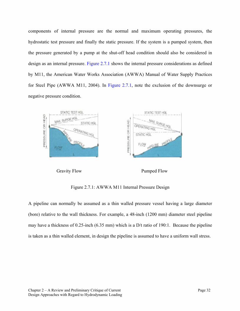
design as an internal pressure. Figure 2.7.1 shows the internal pressure considerations as defined
by M11, the American Water Works Association (AWWA) Manual of Water Supply Practices
for Steel Pipe (AWWA M11, 2004). In Figure 2.7.1, note the exclusion of the downsurge or
negative pressure condition.
Gravity Flow Pumped Flow
Figure 2.7.1: AWWA M11 Internal Pressure Design
A pipeline can normally be assumed as a thin walled pressure vessel having a large diameter
(bore) relative to the wall thickness. For example, a 48-inch (1200 mm) diameter steel pipeline
may have a thickness of 0.25-inch (6.35 mm) which is a D/t ratio of 190:1. Because the pipeline
is taken as a thin walled element, in design the pipeline is assumed to have a uniform wall stress.

Chapter 2 – A Review and Preliminary Critique of Current Page 33 Design Approaches with Regard to Hydrodynamic Loading
Figure 2.7.2: Internal Loading Free Body Diagram
As a result, the internal pressures are assumed to be acting uniform and radial on the pipeline
cylinder. Figure 2.7.2 shows the internal loading considered in pipeline design. The standard
design process assumes:
S = PD/2t Eq. 2.7.1
where S is the Hoop Stress, P is the internal pressure, D is the inside diameter and t is the wall
thickness. Note that in the standard design, the radial stress (normal) and the longitudinal stress
are not considered in the wall thickness design; rather, only the hoop stress is considered.
The above simplified hoop stress equation has become entrenched in the pipeline design
community and is commonly referred to as the Barlow Formula (AWWA M11, 2004). In most
design manuals, the variables are manipulated to solve directly for wall thickness (t). Because of
its simplicity, inexperienced engineers and designers use this formula to quickly quantify the
thickness requirements of the pipeline. What should be understood is that this is where the basic
factors of safety and material properties are many times mistakenly assigned. In the AWWA
Internal
Steel Shell
Cement Lining

Chapter 2 – A Review and Preliminary Critique of Current Page 34 Design Approaches with Regard to Hydrodynamic Loading
M11 Manual of Water Supply Practices for Steel Pipe (AWWA M11, 2004), the allowable hoop
stress is assumed to be 50% of the material’s minimum yield strength. This would equate to a
safety factor against yield of 2.0. As long as the material (steel) does not approach yield the
material recovers its original shape and characteristics and therefore the pipeline is deemed safe.
The problem in this formulation is the choice of an appropriate design pressure. Many design
firms assume the “worst case condition” which may be a static condition in a gravity pipeline, or
a pump shut-off pressure condition in a pumped system, the hydraulic transient pressure
condition, or even the specified test pressure of the pipeline. However, because of the cost of the
material, many standards use a tolerance greater than 50% of yield to be used for transient and
test pressures, which is typically 75% of the material’s minimum yield strength (AWWA M11,
2004). This provides a 1.5 multiplier against exceeding the material yield stress for these
infrequent higher pressure conditions. For steel the AWWA standard limits these allowances to
50% and 75% of yield. The American Society of Civil Engineers (ASCE) Steel Penstock Manual
(ASCE MOP 79, 2012) allows an emergency load stress of 90% of the tensile strength. It should
also be noted that this design is for the steel thickness only and that the composite strength of the
lining, coatings and joints components are not considered in this analysis for hoop stress from
internal pressure.
It can be argued that the ASCE Penstock design for internal pressure is highly conservative for
tensile stresses in a pipeline system. Later in this Chapter, an argument is made that, for normal
operating pressures seen in a water system, the design for internal pressure rarely controls and
the control for thickness in a steel pipeline is simply ring stiffness for handling. This naturally
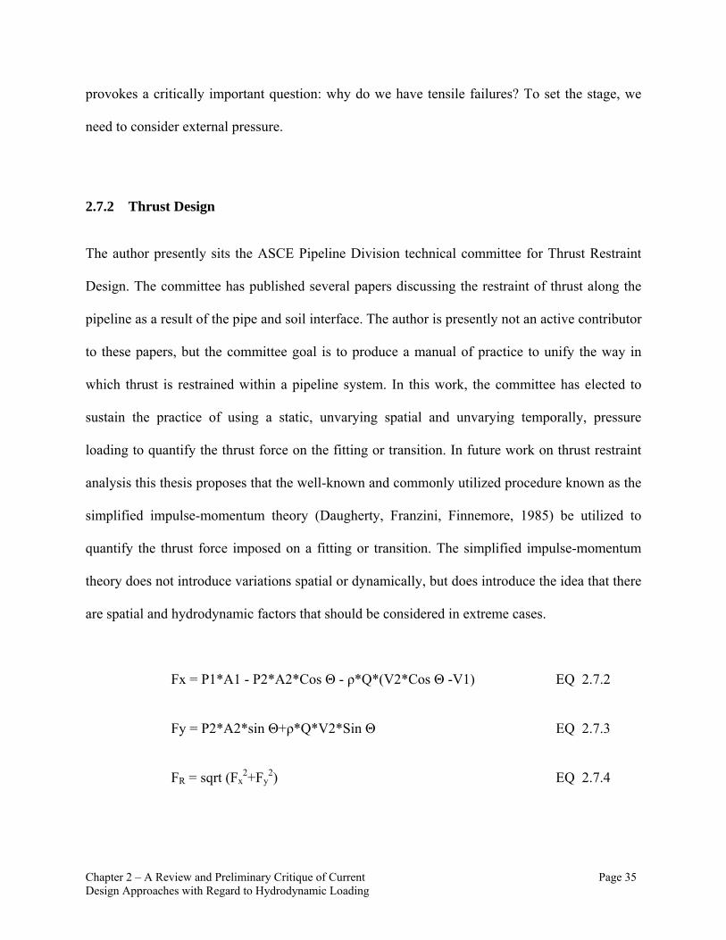
Chapter 2 – A Review and Preliminary Critique of Current Page 35 Design Approaches with Regard to Hydrodynamic Loading
provokes a critically important question: why do we have tensile failures? To set the stage, we
need to consider external pressure.
2.7.2 Thrust Design
The author presently sits the ASCE Pipeline Division technical committee for Thrust Restraint
Design. The committee has published several papers discussing the restraint of thrust along the
pipeline as a result of the pipe and soil interface. The author is presently not an active contributor
to these papers, but the committee goal is to produce a manual of practice to unify the way in
which thrust is restrained within a pipeline system. In this work, the committee has elected to
sustain the practice of using a static, unvarying spatial and unvarying temporally, pressure
loading to quantify the thrust force on the fitting or transition. In future work on thrust restraint
analysis this thesis proposes that the well-known and commonly utilized procedure known as the
simplified impulse-momentum theory (Daugherty, Franzini, Finnemore, 1985) be utilized to
quantify the thrust force imposed on a fitting or transition. The simplified impulse-momentum
theory does not introduce variations spatial or dynamically, but does introduce the idea that there
are spatial and hydrodynamic factors that should be considered in extreme cases.
Fx = P1*A1 - P2*A2*Cos Θ - ρ*Q*(V2*Cos Θ -V1) EQ 2.7.2
Fy = P2*A2*sin Θ+ρ*Q*V2*Sin Θ EQ 2.7.3
FR = sqrt (Fx2+Fy
2) EQ 2.7.4

Chapter 2 – A Review and Preliminary Critique of Current Page 36 Design Approaches with Regard to Hydrodynamic Loading
In Equations 2.7.2 to 2.7.4 A1 and A2 represent the cross sectional area of the fitting or
transition at two points in the system that represent the changed condition, Fx, Fy and FR
represent the horizontal, vertical and resultant thrust force, P1 and P2 represent the pressure at
the two points defined by A1 and A2, and ρ is the fluid density and Θ is the angle of the
transition. As noted, the equation(s) shown are a simplification of the stream force equation for
which momentum and energy flux is considered. The first assumption for simplification is that
the fluid is ideal and therefore transmits no tangential stresses. This assumption results in a
normal velocity profile and allows for a finite definition of the change in velocity relative to
direction through the fitting or transition. The second simplifying assumption is that the flow rate
is steady. A steady flow rate means that there is no time dependence or impulse and the resultant
force is static. These simplifications allow a coupling with the static longitudinal (axial) and
circumferential (hoop) loading along the pipeline. This equation is commonly referred to as the
simplified impulse-momentum equation. By using the simplified impulse momentum equation to
quantify thrust force a hydrodynamic context is introduced which is the variation in the velocity
Impulse is a measure of force over time. However, it should be noted that the equations are a
simplified form of the impulse-momentum equation and do not represent any dynamic or
impulse loading with regard to thrust. It also does not assume any loading in the third axis. In
special cases, impulse loading may be critical and special analysis can be made to consider the
thrust force in the three spatial dimensions (x,y,z) and time. This can be done by using
computational fluid dynamic (CFD) software to define the velocity profile and characterize the
fluid momentum flux. This can be loaded into a finite element model (FEM) to better consider
Chapter 2 – A Review and Preliminary Critique of Current Page 37 Design Approaches with Regard to Hydrodynamic Loading
the effect of the distributed velocity profile and effect of the loading rate (impulse). In Chapter 3
of this thesis, it is proposed that a series of analyses can be developed for a range or flow and
transient conditions for common fittings and transitions to develop a catalogue that can be
referenced by each manual of practice or design standard.
2.7.3 External Pressure
External pressure(s) arise from over-bearing loads such as the weight of the soil on a buried
pipeline, the weight of equipment or vehicles above the pipeline, the hydrostatic pore pressure of
the groundwater on the pipeline wall, and last but not least the internal pressure below
atmospheric pressure (partial or full vacuum pressure) that may be present. Since atmospheric
pressure forces are normally ignored, this last external pressure condition actually originates as
an internal pressure; in design, it is coupled with the external pressure calculation because of the
direction of its forces on the pipeline wall. As was the case for internal pressures, external
pressures are traditionally treated as fixed values in design. This means the dynamic loading
condition in not routinely factored into the design for internal or external pressure conditions.
In design, the external pressure is the accumulative load applied to the pipeline as a result of four
loading conditions: 1) the hydrostatic load, 2) the earth load, 3) the live load, and 4) the internal
vacuum load. The external pressures introduce a compressive force on the pipeline and in design
this load is assumed uniform and radial. Also, the pipeline is usually assumed empty requiring
the pipeline to resist all the external forces with no benefit from the internal pressures. The
design approach is to sum up all the characteristics of the over-bearing load and to evaluate the
summed equivalent pressure. This loading is then analyzed with respect to allowable deflection
of the pipeline, the lining, the coating, and the joint. Pipeline deflection is the key or index

Chapter 2 – A Review and Preliminary Critique of Current Page 38 Design Approaches with Regard to Hydrodynamic Loading
parameter that is usually best understood by design professional when discussing the
performance limits in a pipeline design. Many pipeline design specialist assign an allowable
deflection relative to the type of pipeline lining and coating and joint systems. That is, for more
rigid (relatively inflexible) lining and coating systems (e.g., mortar lining, mortar coating) less
deflection is tolerated. The AWWA M11 suggest using a 2% allowable deflection limit for
mortar lined and mortar coated pipe, a 3% allowable deflection limit for mortar lined and flexible
coated pipe and a 5% allowable deflection limit for flexible lined and flexible coated pipe. In the
pipeline design process, deflection is the only parameter that considers the pipeline design as a
system rather than as individual components simply because of its consideration in lining,
coating and joint selection, but the loading is still taken as static. Figure 2.7.3 shows the external
loading considered in pipeline design.
A significant amount of analysis and research work has been performed on flexible pipeline
design over the last 50+ years (AWWA Manual M11 (AWWA, 2004), AISI manuals on Welded
Steel Water Pipe (AISI, 2007) , and ASCE Buried Steel Penstock Manual, ASCE, 2012). During
this period, Watkins and Anderson of Utah State University has been a key player in the
development and understanding of external loading on the pipeline shell (Watkins and Anderson,
1999) and the influence of soil mechanics in the design of flexible pipeline. Professor Watkins is
famous, at least in American pipeline circles, for his acerbic comment “It’s the soil stupid”. And
of course, for buried pipeline there is a known and practically understood benefit to having good
embedment and soil material around your pipeline to help offset or redirect the over-bearing
loads of external pressures. It can be shown that when comparing soil stiffness to ring stiffness
that the soil strength accounts for over 95% of the buried pipeline strength.
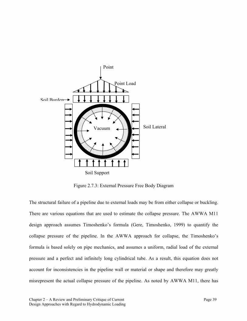
Chapter 2 – A Review and Preliminary Critique of Current Page 39 Design Approaches with Regard to Hydrodynamic Loading
Figure 2.7.3: External Pressure Free Body Diagram
The structural failure of a pipeline due to external loads may be from either collapse or buckling.
There are various equations that are used to estimate the collapse pressure. The AWWA M11
design approach assumes Timoshenko’s formula (Gere, Timoshenko, 1999) to quantify the
collapse pressure of the pipeline. In the AWWA approach for collapse, the Timoshenko’s
formula is based solely on pipe mechanics, and assumes a uniform, radial load of the external
pressure and a perfect and infinitely long cylindrical tube. As a result, this equation does not
account for inconsistencies in the pipeline wall or material or shape and therefore may greatly
misrepresent the actual collapse pressure of the pipeline. As noted by AWWA M11, there has
Point
Point Load
Soil Burden
Soil Lateral
Soil Support
Vacuum
Chapter 2 – A Review and Preliminary Critique of Current Page 40 Design Approaches with Regard to Hydrodynamic Loading
been many attempts to develop an empirical formula to estimate the relevance of these
inconsistencies/imperfections in the pipeline, but none have been adopted by the standard design
guidelines.
It should also be noted that the dynamic behavior of the over-bearing loads (external loads) albeit
a vehicle’s live load or a hydraulic transient condition are not considered. The American
Association of State of Highway Transportation Officials (ASHTO) and the American Society of
Mechanical Engineers (ASME) have developed some impact factors for dynamic live loads
(Warman and Hart, 2005), but no impact factors have been considered for hydraulic transient
pressures conditions.
2.8 North American Standard Design Practices for Air Valves
The American Water Works Association has a manual of water supply practices that specifically
details the pipeline design consideration of air valves in potable water systems. The manual is
M51 and is entitled “Air-Release, Air/Vacuum, & Combination Air Valves.” (AWWA, 2001)
There is also an AWWA standard for Air-Release, Air/Vacuum, and Combination Air Valves for
Waterworks Service. This standard is AWWA standard is C512-07. These two documents are
widely used by pipeline design professionals to size and locate air valves. These documents are
used in this chapter to establish a comparison to the proposed design procedure (see Chapter 5)
for sizing an air valve. At this point it should be noted that both the AWWA manual of practice
and standard contain a reference to hydraulic transient (hydrodynamic loading), but this
reference is broad and does not provide any detail to appropriately sizing the air valve in regard
to hydrodynamic air release.

Chapter 2 – A Review and Preliminary Critique of Current Page 41 Design Approaches with Regard to Hydrodynamic Loading
The following is a list of normal design considerations for air valves as outlined in the AWWA
Manual of Practice M51 (AWWA, 2001). For air valve locations, the following list is provided
along with the Figure 2.8.1.
Air Valve Location:
High Points Mainline Valves (downstream) Increased Down Slope Decreased Up Slope Long Ascents Long Descents Horizontal Runs Venturi Meters (upstream) Deep Well and Vertical Turbine Pumps (discharge header) Siphons (air release valve with vacuum check)
Figure 2.8.1: AWWA M51 Air Valve Locations
The recommended locations of the air valves as outlined in AWWA M51 are general and the
reasoning for each valves location as well as its type is somewhat intuitive. In areas along the
pipeline that will draw air into the system when the pipeline is dewatered a vacuum valve is
recommended. The vacuum valves are recommended for long ascending pipelines (Sta. 11 in

Chapter 2 – A Review and Preliminary Critique of Current Page 42 Design Approaches with Regard to Hydrodynamic Loading
Figure 2.8.1) and where the ascending slope changes abruptly (Stas. 5, 13, and 16 in Figure
2.8.1). Also downstream of isolation or in-line control valves is another location where air may
be drawn into the system as the valves are closed and a partial vacuum pressure condition is
experienced. At isolation and control valve locations, air vacuum valves are recommended (Sta.
1 in Figure 2.8.1).
Air release valves are used in areas where air may collect and build up in the top or crown of the
pipeline. Where it occurs an air release valve is installed to release or “burp” a small volume of
air from the system to maintain hydraulic efficiency. Air captured in a system is generally not
wanted because it introduces a reduction in the pipeline’s conveyance capacity by restricting the
cross sectional area for which fluid is allowed to flow. Also air captured in a system that is under
pressure will be compressed and depending on the pressure the compressed air will store a
significant amount of energy. Because air density is much less than water, if a large volume of
trapped, compressed air is quickly released, an explosive event may result. In this condition, the
pipeline has taken on the characteristics of a pressure vessel for which it has not been designed.
A pipeline designed as a pressure vessel per following even the lowest standards of the American
Society of Mechanical Engineers (ASME) Boiler Pressure Code, would be cost prohibitive. Air
release, properly located and sized, is essential in conveyance pipeline designs.
Other locations in a pipeline system require both the egress and ingress of air to the pipeline.
These locations are typically equipped with a combination air valve that has both a large vacuum
valve port and a smaller air release valve port within the same valve assembly. The location of
the combination air valves are shown in Figure 2.8.1 at Stations 2, 6, 8, 14 and 15. The

Chapter 2 – A Review and Preliminary Critique of Current Page 43 Design Approaches with Regard to Hydrodynamic Loading
combination air valve is a relatively complex valve, which if not properly designed can have an
adverse impact to the pipeline system. Because the combination air valve has both the
functionality of the air release and the air vacuum valve, it is installed as a ‘catch-all’ valve to
handle the normal operating as well as the maintenance and emergency and transient control
operational functionality of an air valve. It is common for a designer to size the air valve for the
highest required flow rate and/or pressure condition and assume that the valve will function
properly for all operating requirements.
The AWWA M51 guideline also lists various assumptions and equations to help size and select
orifices for both air release and vacuum valves. The following is a summary of those
assumptions and equations (these are expressed in conventional units in M51 and are retained
here in this original form). These equations have been presented to provide the understanding
that the operating limits of air valves are bounded by the choked condition for air inlet during a
partial vacuum condition and by a supersonic condition for air release under pressure. With an
understanding of the imposed constraint on air valves as a result of these bounded operating
conditions, the importance of the proper sizing and location of air valves becomes more evident.
Air Release Orifice Size:
Assumptions: Standard conditions (60o F and sea level), Compressible adiabatic sonic flow Air flow rate equal to 2% of fluid design flow (Qair) = 0.02*Qfluid
)/(678 12
gdair TSPPCYdQ EQ. 2.8.1
Where:

Chapter 2 – A Review and Preliminary Critique of Current Page 44 Design Approaches with Regard to Hydrodynamic Loading
Qair = air flow rate (scfm) Y = expansion factor, (AWWA M51 assumes 0.71 for air flow from
Crane Technical Paper 410, 1982) d = orifice diameter (inch)
Cd = coefficient of discharge, (AWWA M51 assumes 0.7) DP = differential pressure, (for sonic flow = 0.47 P1) P1 = inlet pressure (psia) T = inlet temperature (Rankine)
Sg = specific gravity, (1.0 for air)
Air Vacuum Orifice for Controlled Pipeline Filling and Draining:
Assumptions:
Standard conditions (60o F and sea level) Compressible adiabatic subsonic flow Qair = Qfillrate psiP 2
o
)7.14(77.14 2 PPdQair EQ. 2.8.2
Where:
P = pipeline pressure (psig)
Emergency Pipeline Draining:
Assumptions:
Standard conditions (60o F and sea level) Assume compressible adiabatic subsonic flow Qair = Qfillrate psiP 5
)7.14(77.14 2 PPdQair Same as Eq. 2.8.2

Chapter 2 – A Review and Preliminary Critique of Current Page 45 Design Approaches with Regard to Hydrodynamic Loading
The AWWA approach is based on a static pressure differential at the valve location. This static
pressure is only used to develop a volumetric flow rate for sizing the air valve’s orifices. The
design process does not account for the dynamic internal pressure experienced by the valve nor
does the design procedure account for the change in air volume in relation to the local pressure.
Because the approach does not consider the dynamic loading nor the highly compressible nature
of air, using this approach as outlined in AWWA M51 will generally result in an oversized air
valve (see also Chapter 5 in this thesis). A typical air release valve sizing nomograph using the
sizing procedure outlined in AWWA M51 is shown in Figure 2.8.2.
Figure 2.8.2: Air Release Valve Sizing Nomagraph from APCO-Willamette Valve and Primer Corporation
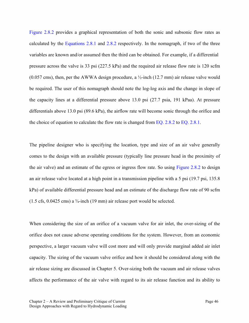
Chapter 2 – A Review and Preliminary Critique of Current Page 46 Design Approaches with Regard to Hydrodynamic Loading
Figure 2.8.2 provides a graphical representation of both the sonic and subsonic flow rates as
calculated by the Equations 2.8.1 and 2.8.2 respectively. In the nomagraph, if two of the three
variables are known and/or assumed then the third can be obtained. For example, if a differential
pressure across the valve is 33 psi (227.5 kPa) and the required air release flow rate is 120 scfm
(0.057 cms), then, per the AWWA design procedure, a ½-inch (12.7 mm) air release valve would
be required. The user of this nomagraph should note the log-log axis and the change in slope of
the capacity lines at a differential pressure above 13.0 psi (27.7 psia, 191 kPaa). At pressure
differentials above 13.0 psi (89.6 kPa), the airflow rate will become sonic through the orifice and
the choice of equation to calculate the flow rate is changed from EQ. 2.8.2 to EQ. 2.8.1.
The pipeline designer who is specifying the location, type and size of an air valve generally
comes to the design with an available pressure (typically line pressure head in the proximity of
the air valve) and an estimate of the egress or ingress flow rate. So using Figure 2.8.2 to design
an air release valve located at a high point in a transmission pipeline with a 5 psi (19.7 psi, 135.8
kPa) of available differential pressure head and an estimate of the discharge flow rate of 90 scfm
(1.5 cfs, 0.0425 cms) a ¾-inch (19 mm) air release port would be selected.
When considering the size of an orifice of a vacuum valve for air inlet, the over-sizing of the
orifice does not cause adverse operating conditions for the system. However, from an economic
perspective, a larger vacuum valve will cost more and will only provide marginal added air inlet
capacity. The sizing of the vacuum valve orifice and how it should be considered along with the
air release sizing are discussed in Chapter 5. Over-sizing both the vacuum and air release valves
affects the performance of the air valve with regard to its air release function and its ability to

Chapter 2 – A Review and Preliminary Critique of Current Page 47 Design Approaches with Regard to Hydrodynamic Loading
mitigate adverse hydraulic transient pressures. An over-sized air valve may result in too rapid of
an air release through either the vacuum orifice and/or air release orifice. In a pressurized
pipeline system, a water column drives this rapid air release. When the air is released at a high
velocity, the water column will fill the void in which the air is released. As a result, the water
column will seat the valve float at a high velocity and once the valve float is seated, the flow will
come to rest. Because of the significant difference in density between air and water when the
water column is rapidly brought to rest, an abrupt change in kinetic energy (velocity) to potential
energy (pressure) is experienced. This phenomenon is commonly known as air valve slamming.
Air valve slamming introduces transient pressures to the pipeline system. This type of transient
event, which is referred to here as a secondary transient event, commonly occurs after a primary
transient event where the air valve is called to respond to vacuum pressure conditions. The
AWWA design procedures provide no direction or insight to the sizing of an air valve with
consideration to air valve slamming.
This thesis proposes that the standard sizing procedure that is currently used and outlined in
AWWA M51 be modified to consider the hydrodynamic loading as well as consider the
localized differential pressure and its effect on the compressed air volume. This is developed in
more detail in Chapter 5.
2.9 Other Crucial Design Considerations
In a flexible pipeline design, especially at larger diameters, the stability of the ring stiffness
provides great advantages to the pipeline during its transport and installation. Before the pipeline
is backfilled and the stability of the embedding material can be added to support the pipeline, the
maximum allowable deflection must be carried by the thin steel shell itself. This component of

Chapter 2 – A Review and Preliminary Critique of Current Page 48 Design Approaches with Regard to Hydrodynamic Loading
the thickness design is significant because the required ring stiffness alone may exceed the
required thickness of the pipeline for internal or external pressure designs. Also, pipelines with
mortar lining and coatings, benefit from the lining and coating’s added rigidity, but the allowable
deflection is greatly decreased if cement mortar lining and/or coatings are used. So this can be
seen as a “Catch-22” or a double bind. The equation used for the minimum thickness in steel
pipeline design for handling has been empirically developed over time and is given a great deal
of attention because transportation is generally seen as the riskiest part of the installation and
also any damage to the pipeline (wall, lining, coating, etc.) can be easily observed. It should be
noted that the AWWA M11 recommendation for this minimum handling thickness was
developed by J. Parmakian in 1982 also known for his publication “Waterhammer Analysis”
outlining the use of the graphical method in transient analysis.
2.9.1 Transient Pressure and Pipeline Wall Thickness Design
As discussed above, in pipeline system design, transient pressure conditions are traditionally
considered as fixed pressures that are included in the analysis of the pipeline with respect to
pipeline’s yield strength and collapse/buckling pressure. Currently the transient or dynamic
nature of the pressure fluctuation is not accounted for in design. So is the current design
approach appropriate? If not, what changes should be made to benefit future design?
There are two evident areas in which the dynamic pressure condition should be considered. The
first is at the joint, especially at gasketed (push-on) joint connections. The second is in the lining.
The remainder of this chapter discusses the potential use of transient pressure analysis with
regard to the joint and lining designs. Special attention is paid to cement mortar lining, which is a
Chapter 2 – A Review and Preliminary Critique of Current Page 49 Design Approaches with Regard to Hydrodynamic Loading
commonly used lining system on both steel and ductile iron pipelines in the potable water
industry.
2.9.2 Joint Design
There are various mechanical systems that make up the available joints in a steel pipeline.
Because steel can be welded at reasonable temperatures, many designers and owners require a
welded joint. The welded joint, if made properly, is excellent from a structural integrity
perspective; however, it is also expensive. Not only is the joint costly to manufacturer, to
properly weld a pipeline, a significant delay in construction is required and time is money.
The joint with the least initial capital and installation cost is the simple gasketed push on joint.
These joint types are typically used in smaller diameter pipelines and at pressure below 250 psig
(1700 kPa). However, because of the cost of the welded joint, many owners have asked for better
justification for why a push-on joint should not be used. The qualitative answer is that a push-on
joint is not viable for high pressures and larger diameter pipeline systems. From the earlier
discussion about the design standards and what standard design parameter effects joint design, it
is clear that the pipeline deflection is the only design parameter. So, under a given external load,
the deflection is limited so that the gasket does not unseat from the joint. The pipeline
manufacturers (Northwest Pipe Company, American Cast Iron Pipe Company) have tested their
gasketed joint systems under various loads and deflections and have been able to document the
joint’s performance. Again these tests have been static test and have been performed under
controlled and relative uniform deflection scenarios. In mechanical system a flanged joint with a
gasket is commonly used. The potential failure mode of the gasketed joint, albeit a push-on or a
flanged joint, is the gaskets extrusion through the joint due to high pressure or the disbonding or
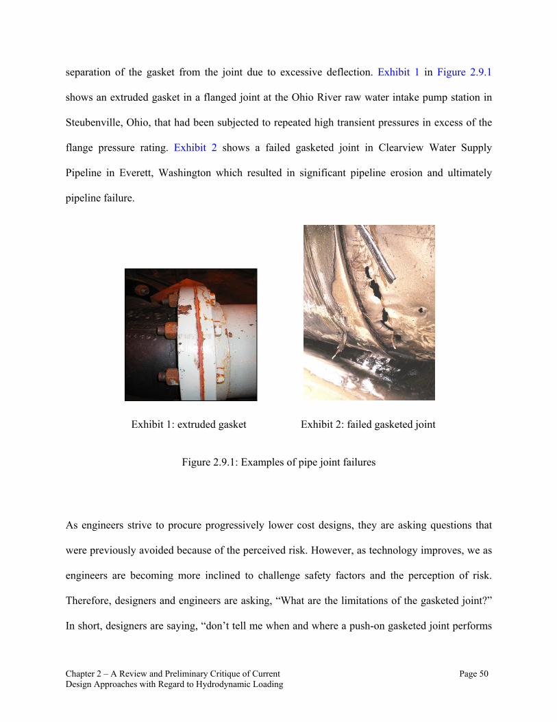
Chapter 2 – A Review and Preliminary Critique of Current Page 50 Design Approaches with Regard to Hydrodynamic Loading
separation of the gasket from the joint due to excessive deflection. Exhibit 1 in Figure 2.9.1
shows an extruded gasket in a flanged joint at the Ohio River raw water intake pump station in
Steubenville, Ohio, that had been subjected to repeated high transient pressures in excess of the
flange pressure rating. Exhibit 2 shows a failed gasketed joint in Clearview Water Supply
Pipeline in Everett, Washington which resulted in significant pipeline erosion and ultimately
pipeline failure.
Exhibit 1: extruded gasket Exhibit 2: failed gasketed joint
Figure 2.9.1: Examples of pipe joint failures
As engineers strive to procure progressively lower cost designs, they are asking questions that
were previously avoided because of the perceived risk. However, as technology improves, we as
engineers are becoming more inclined to challenge safety factors and the perception of risk.
Therefore, designers and engineers are asking, “What are the limitations of the gasketed joint?”
In short, designers are saying, “don’t tell me when and where a push-on gasketed joint performs
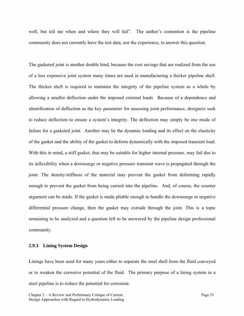
Chapter 2 – A Review and Preliminary Critique of Current Page 51 Design Approaches with Regard to Hydrodynamic Loading
well, but tell me when and where they will fail”. The author’s contention is the pipeline
community does not currently have the test data, nor the experience, to answer this question.
The gasketed joint is another double bind, because the cost savings that are realized from the use
of a less expensive joint system many times are used in manufacturing a thicker pipeline shell.
The thicker shell is required to maintain the integrity of the pipeline system as a whole by
allowing a smaller deflection under the imposed external loads. Because of a dependence and
identification of deflection as the key parameter for assessing joint performance, designers seek
to reduce deflection to ensure a system’s integrity. The deflection may simply be one mode of
failure for a gasketed joint. Another may be the dynamic loading and its effect on the elasticity
of the gasket and the ability of the gasket to deform dynamically with the imposed transient load.
With this in mind, a stiff gasket, that may be suitable for higher internal pressure, may fail due to
its inflexibility when a downsurge or negative pressure transient wave is propagated through the
joint. The density/stiffness of the material may prevent the gasket from deforming rapidly
enough to prevent the gasket from being carried into the pipeline. And, of course, the counter
argument can be made. If the gasket is made pliable enough to handle the downsurge or negative
differential pressure change, then the gasket may extrude through the joint. This is a topic
remaining to be analyzed and a question left to be answered by the pipeline design professional
community.
2.9.3 Lining System Design
Linings have been used for many years either to separate the steel shell from the fluid conveyed
or to weaken the corrosive potential of the fluid. The primary purpose of a lining system in a
steel pipeline is to reduce the potential for corrosion.
Chapter 2 – A Review and Preliminary Critique of Current Page 52 Design Approaches with Regard to Hydrodynamic Loading
Although there are various kinds of linings used, there are two main types. The first type utilizes
Polyurethane. The Polyurethane material is heated and then sprayed on to the pipeline wall like a
painting process. The bond of the Polyurethane lining to the pipeline wall is through adhesion.
Because of how the Polyurethane lining is installed (generally sprayed on) there is a potential to
develop “painter holidays” that expose the steel to the product fluid and thus introducing a
corrosion cell. These gaps may also become a point in which the pressurized fluid can seep
behind the lining and potentially disbond the lining from the pipeline wall during a change in
pressure or transient pressure event.
The second lining type, which is much more common in the raw and potable water industry, is
the cement mortar lining. This lining system consists of a dense homogenous cement and sand
mixture that is centrifugally cast onto the pipeline wall by the manufacturer. It can also be hand
applied in the field during installation. In the centrifugal application process the lining is not
adhesively bonded to the pipe wall, so once the cement has dried and set the lining is simply held
in place by the radial stresses in the lining. Additional stresses occur in the lining during the
transport of the pipeline due to the allowed ring deflection of the pipeline. These stresses due to
ring deflection generates small cracks in the lining system. Also, because the cement mortar
lining is a porous material, it is proposed that the hydraulically conductive property of the lining
allows a differential pressure to set up across the lining thickness during a hydraulic transient
event. Currently, transient pressure is not considered in the design of the lining system. Actually,
there is little consideration, other than the lining’s influence of ring stiffness, of the lining in the
pipeline system design process. Overall, the cement mortar lining is a thin layer of fine grain

Chapter 2 – A Review and Preliminary Critique of Current Page 53 Design Approaches with Regard to Hydrodynamic Loading
cement that is centrifugally cast in the past following the pipe barrel manufacturing. There are
typically no adhesives applied to the cement mortar to bond it to the pipe interior wall; therefore
the cement mortar is relatively free to move within the pipeline.
In large diameter (greater than 48 inch, 1200 mm) flexible pipeline designs it is common to
increase the mortar thickness with the pipeline diameter. The AWWA C205-07 (AWWA, 2007)
Standard entitled “Cement-Mortar Protective Lining and Coating for Steel Water Pipe-4 In. (100
mm) and Larger-Shop Applied requires a minimum lining thickness of 0.25” (6 mm) for pipeline
4-10 inches (100-250 mm) up to 0.5” (13 mm) for pipelines over 36” (900 mm). The author is
presently designing a 108” (2750 mm) steel pipeline that is specified to have a minimum of
0.75” (19 mm) of cement mortar lining applied. The extra lining is proposed as a sacrificial layer
to prolong the leaching of the cement in the presence of the acidic raw water being conveyed.
The thickening of the lining is an appropriate measure with the current understanding and lack of
developed research for lining failure in the presence of hydraulic transient conditions. In Chapter
4 a hydrodynamic analysis of cement mortar lining is made that shows a potential for a failure
mechanism in the presence of a hydrodynamic load.
2.10 Chapter 2 Summary
Chapter 2 identifies multiple areas in the current design guidelines for various appurtenances and
components that are common in water and wastewater pipeline designs. With consideration of a
more comprehensive roadmap, as outlined by the Integrated Design Approach in Chapter 3 along
with the introduction of a temporal parameter defined through the use of hydrodynamic
analyses, Chapter 4 and 5 will propose multiple improvements that can be readily introduced to
the present design guidelines to improve and refine the risk profile used in design.

Chapter 3 – An Approach to a Hydrodynamic Design Prospective Page 54
CHAPTER 3 – AN APPROACH TOWARD A HYDRODYNAMIC DESIGN PROSPECTIVE
Chapter 3 begins to outline an approach to use hydrodynamic loading coupled with an integrated
design approach to resolve conflicts that have developed within the devolving North American
design standards. The standards have become too specific and the inter-relationships and
dependencies on other system components goes unrealized resulting in gross over design of
some components and/or under design of other components. The concept of an Integrated Design
Approach that requires the designer to identify the performance limitations of each of the
pipeline system’s components, and introduces an overarching design parameter, hydrodynamic
loading, that can be used to evaluate these performance limitations. The hydrodynamic loading is
evaluated not only on the interrelation of the various components of a system, but also on the
sensitivity of the system to handle a range of operating conditions. This Hydrodynamic Loading
Map can be used to properly select viable materials and operating conditions for a system.
3.1 A Prospective for Pipeline Design
A broad definition of a hydrodynamic pipeline design approach would include all parameters
that are changing, varying, or altering in one way or another in reference to a varying hydraulic
loading. As an engineer it is easy to be lost in the physical definition of hydrodynamic loading
and begin to use it to define extremes in the system rather than applying it to more practical
refinements in the standard design of a system within its normal, or common operating
conditions.
Pipeline design taken in consideration of this thesis which recommends the identification of a
system’s performance limits and allowances is actually quite linear. The various

Chapter 3 – An Approach to a Hydrodynamic Design Prospective Page 55
interdependencies and inter-relationships that are introduced are direct and can be simply applied
to the pipeline design guidelines. The goal is to identify these simple steps in an Integrated
Design Approach that helps quantify physical inter-relationships of various components in a
pipeline system design so that they can be recognized as the pipeline design processes evolves
and improves. Taking the Integrated Design Approach further, the dynamic nature of social and
political influences may also be enfolded and finally, the ever dynamic definition of risk and
value may be considered.
The concepts introduced in the Integrated Design Approach are mentioned here to bring a more
inclusive, multi-component approach to the design process. The true intent of this research is not
to re-define proven practices but to re-open specific concepts, and reuse these basic principles to
enrich a relatively deterministic design philosophy.
3.2 Integrated Design Approach
The hydrodynamic loading consideration is a piece of the design process that has been
insufficiently considered in the evolution of manufacturing and design practices for the water
and wastewater pipeline industry. What is needed is a way to integrate the current design
standards and practices that have been developed in isolation into a more comprehensive and
Integrated Design Approach. This requires a conceptual map for framework to inter-relate the
relevant factors of each component. This thesis proposes that a more comprehensive
consideration of hydrodynamic loading is the key means to develop such a map of the inter-
relationships.
Chapter 3 – An Approach to a Hydrodynamic Design Prospective Page 56
The first step in this development is to better define the understanding of hydrodynamic loads
within the pipeline industry. In practice, the rupture of a pipeline system is almost inevitably
blamed on a hydrodynamic load or “Surge” condition. This term, “surge” has become a catchall
for many types of failures and as a result has been demonized as something to avoid or at least
minimize the influence of in design, or as a scapegoat for blame. There are indeed hydraulic
transient or “surge” failures, but the duration of the transient may be years and may be better
characterized by the number of loading cycles instead of the instantaneous magnitude of the
loading. The current design standards do not address normal and/or abnormal hydrodynamic
loading. The magnitude of the loading is considered as a static force. The duration and frequency
of hydrodynamic loading is not explicitly considered, and the probability and/or risk of failure
are only considered from a statically determinate perspective via the question, “What is the
safety factor of the maximum static load?”
This Integrated Design Approach proposes that if the hydrodynamic loading of the pipeline
system is considered in conceptual design then the sensitivity of the system to the loading can be
considered so that the potential for failure can be abated and potentially the efficiency of the
design may be increased. For the Integrated Design Approach, each component should be inter-
related to other components via the hydrodynamic loading characteristics. With this integrated
approach a composite model of what is a susceptible to failure in the system may be developed.
3.3 Quantifying the Hydrodynamic Behavior of a System
In many cases, during a pipeline design scoping study or a system pre-design, the information
and time/budget required to perform a comprehensive transient analysis, assess the severity of
the transient pressures, and recommend a surge control strategy is not available. When this
Chapter 3 – An Approach to a Hydrodynamic Design Prospective Page 57
occurs, the design engineer will generally default to using various design guidelines or pipeline
design manuals where the well-known Joukowsky equation is utilized. (Wylie and Streeter,
1993)
∆H a ∆ EQ 3.3.1
In Equation 3.3.1, ∆H is the transient pressure head, (a) is the celerity or pressure wave speed
within the pipeline, ∆v is the instantaneous change in velocity, and (g) is gravitational
acceleration. The Joukowsky equation is often used to quantify the transient pressure potential.
The fault with the Joukowsky equation is not the equation itself, but in its unintended application
and use. The Joukowsky equation calculates a change in pressure head resulting from an
instantaneous change in velocity of an ideal and incompressible fluid. In pipeline systems, rarely
is a transient pressure generated from an instantaneous change in velocity. The results generated
by the Joukowsky equation usually leads to disbelief from the design engineer because the
estimate of the resultant transient pressure head is typically high. For a system with an
instantaneous change in velocity of 2 m/s (6.6 ft/s) a transient pressure head of ~200 m (656 ft)
would be anticipated using only the Joukowsky equation.
3.3.1 Understanding the Sensitivity of a System to Transient Pressure
The current method used in all the AWWA pipeline design standards to quantify the magnitude
of a transient event is the Joukowsky equation. As discussed, this method is simplistic and, as
used, grossly over-estimates the transient pressure for all but a very limited number of transient
events. Also, the current method does not provide a means to introduce the time dependence of
Chapter 3 – An Approach to a Hydrodynamic Design Prospective Page 58
the transient event nor rate the sensitivity of the system to a transient condition. This thesis
proposes that a transient analysis that defines the sensitivity of a pipeline system to a hydraulic
transient condition rather than quantifying the transient condition would be of higher value
within the standards. Once a designer understands the sensitivity of a system to a transient
condition, the designer can make a value based decision on the type and effort required to
facilitate a safe design. This decision may result in the development of a full hydraulic transient
model or may show that the current Joukowsky equation is most applicable.
3.3.2 Defining the Sensitivity of a System for Transient Pressures
In long pipeline systems, the idea of an instantaneous change in velocity is defined as a change in
velocity that occurs any time less than the time for the pressure wave to travel down the pipeline
and back (t < 2L/a) (reference Wylie Streeter), where L is the length of the pipeline system.
However, in lieu of using the Joukowsky equation when a hydraulic transient occurs within this
instantaneous time, this thesis recommends that a full, comprehensive transient model and
analysis be performed. A rapid (instantaneous) change in velocity will generate a large number
of pressure waves that will require a sophisticated model to properly track and quantify the
pressure fluctuations within a system. Also with an instantaneous change in velocity, the
formation of a full vacuum and the potential for vapor cavity formation is more likely and a more
sophisticated modeling tool is required for design to better estimate the sensitivity of the system
to a hydraulic transient as well as define the magnitude of the resultant transient pressure
conditions.
However, for the likely case that the time of the transient event is greater than the instantaneous
time (t > 2L/a) of the pipeline system, a better tool is needed to rate the sensitivity of a pipeline

Chapter 3 – An Approach to a Hydrodynamic Design Prospective Page 59
system to the transient event. Understanding this sensitivity will allow the designer to employ the
correct resources to perform a proper transient analysis. In an integrated design approach for a
pipeline system, a designer is considering the various design limits of each component. An early
assessment of the transient behavior of a system may allow for early refinements in the type of
material and appurtenances used with the system.
A transient event is defined best by three inter-dependent constituents: 1) the time of change (∆t)
of velocity, 2) the magnitude of the change in velocity (∆v), and 3) the physical and spatial
characteristics (∆x) of the pipeline system. Therefore, an efficient first step in the integrated
design approach is to understand the sensitivity of the system to a transient condition. This
understanding will allow the analyst to better apply the required resources.
In hydraulic modeling, there are three equations that when solved simultaneously represent the
hydraulic characteristics of a system. These three equations are simply conservation of mass
(Qin=Qout), the conservation of momentum (F=ma), and conservation of Energy(Ein=Eout).
One of the main differences in transient hydraulic models when compared to steady state
hydraulic models is the use of the momentum equation. The momentum equation introduces an
interrelationship of hydraulic head and velocity of the fluid to space and time within the system.
This relationship provides a way to record disturbances in the fluid that can be quantified and
tracked as they form and propagate. The momentum equation can be expressed in a partial
differential form:
v – g sin Φ 0 EQ 3.3.2
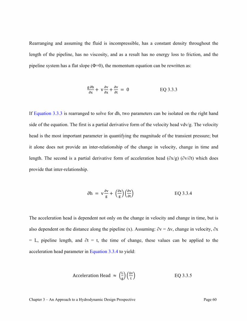
Chapter 3 – An Approach to a Hydrodynamic Design Prospective Page 60
Rearranging and assuming the fluid is incompressible, has a constant density throughout the
length of the pipeline, has no viscosity, and as a result has no energy loss to friction, and the
pipeline system has a flat slope (Φ=0), the momentum equation can be rewritten as:
v 0 EQ 3.3.3
If Equation 3.3.3 is rearranged to solve for dh, two parameters can be isolated on the right hand
side of the equation. The first is a partial derivative form of the velocity head vdv/g. The velocity
head is the most important parameter in quantifying the magnitude of the transient pressure; but
it alone does not provide an inter-relationship of the change in velocity, change in time and
length. The second is a partial derivative form of acceleration head (∂x/g) (∂v/∂t) which does
provide that inter-relationship.
∂h v EQ 3.3.4
The acceleration head is dependent not only on the change in velocity and change in time, but is
also dependent on the distance along the pipeline (x). Assuming: ∂v = ∆v, change in velocity, ∂x
= L, pipeline length, and ∂t = t, the time of change, these values can be applied to the
acceleration head parameter in Equation 3.3.4 to yield:
AccelerationHead ∆ EQ 3.3.5

Chapter 3 – An Approach to a Hydrodynamic Design Prospective Page 61
Equation 3.3.5 is not intended to represent a real or a quantifiable solution to the acceleration
head but is simply a way to inter-relate the three inter-dependent variables so that the designer
can make a measure of hydraulic transient sensitivity of the system. Written this way, the
designer can introduce values to the dependent variables and develop a matrix that can be
coupled with a decision criterion to assess if the transient behavior of the system warrants
consideration of a full, comprehensive transient model.
Introducing a change in velocity of ∆v = 1 m/s (3.3 ft/s) with a range of pipeline lengths (L) and
time of change (t) the following table can be generated that shows the sensitivity of a pipeline
system to hydraulic transient conditions using the relationship found using Equation 3.3.5. In
Table 3.3.1, the smaller acceleration head indicates a lower sensitivity of the system to hydraulic
transient conditions.
Table 3.3.1: Conceptual Design Decision Matrix using Acceleration Head
Time of Change (∆t) (s) -> 1000 100 10 1 0.1 0.01
Instantaneous
Time (t<2L/a)
Length
(dx) (m) (L/g)*( ∆v/∆t), Acceleration Head
0.002 1 0.0001 0.001 0.01 0.1 1 10
0.02 10 0.001 0.01 0.1 1 10 100
0.2 100 0.01 0.1 1 10 100 1000
2 1,000 0.1 1 10 100 1000 10000
20 10,000 1 10 100 1000 10000 100000
200 100,000 10 100 1000 10000 100000 1000000

Chapter 3 – An Approach to a Hydrodynamic Design Prospective Page 62
3.4 Characterization of Hydrodynamic Loading Type
In current design practices, hydrostatic loading is the norm. Even the surge or transient pressure
are considered as a maximum or minimum with no duration and therefore by definition are static.
These transient pressures are simply higher or lower in magnitude and therefore are used as test
pressure to check the structural integrity of the system. In fact in AWWA M11 which is the
manual of practice for steel pipeline design, this “static” transient pressure is used to define only
two parameters. The first is the thickness of the steel shell. In this calculation the transient
pressure is given a higher allowable limit with respect to the yield stress than the normal
operating pressure and therefore can be rationalized as a design check rather than an actual
design parameter.
The second consideration is within the definition of thrust. The design procedure asks the
designer to identify the highest pressure in the system whether it be test pressure or pump shut
off head or maximum expected transient pressure. This pressure is then used as a variable in a
statically determinant equation that defines the appropriate level of thrust restraint for the system.
Currently the author is a member of the ASCE committee for Pipeline Location and Installation
and sits on a subcommittee to evaluate the current industry methods used to define pipeline
system thrust and thrust restraint. As part of this research, the author sat on a committee that
assessed current standard practices for thrust restraint analysis which was presented in multiple
papers at the 2009 and 2010 ASCE Pipeline Conference.
Presently, and surprisingly, no pipeline design guideline documents hydrodynamic loading in
thrust. The consideration of hydrodynamic loading and its influence on thrust is presented in
Chapter 3 – An Approach to a Hydrodynamic Design Prospective Page 63
multiple texts (Daugherty, R., Franzini, J, Finnemore, E., 1989) and has become known as the
‘impulse-momentum’ theory. This theory, when applied in general design, uses a loose definition
of dynamic thrust in the sense that the applied equation assumes a time of loading is equal to 0
and the velocity profile is assumed non-distributed (plug flow), normal to the cross section. The
first assumption effectively removes the concept of duration and thus makes the loading static
and the second assumption does not identify loading concentrations that may form as a result of a
distributed, non-normal velocity profile. This is an example of where the techniques required to
evaluate the loading appropriately are available, but the manuals of practice do not utilize this
technique nor do they even recognize the existence of a hydrodynamic load.
In fact, the evaluation of hydrodynamic loads can be performed using simple, well defined tools.
The distribution of the velocity profile can be fairly well represented by a two dimensional
model of the flow field through the use of a computation fluid dynamic (CFD) model which
identifies vectorization of the flow velocity profile. Once the flow velocity distribution is
developed, a finite element or even a method of characteristic algorithm could be used along
with the establish velocity distribution to model various loading rates to develop a resultant
hydrodynamic thrust. The cost of this type of modeling may be prohibitive. However, this type
of modeling can be performed on a select group of typical fittings and fluid transitions and
through a typical range of transient flow conditions that will result in a catalogue of
hydrodynamic loading that can be made available in the design guidelines for the designers.
This thesis proposes that the manuals of practice introduce the static, non-distributed normal
form of the impulse-momentum theory as a minimum for the calculation of thrust. The thesis
Chapter 3 – An Approach to a Hydrodynamic Design Prospective Page 64
also proposes that the manuals of design practice include catalogs of hydrodynamic loadings so
that the designer, end user of the manual of practice, can decide on the level of conservativeness
that is appropriate in the design. Currently the AWWA M11 as well as other manuals of practice
are void of these considerations. Chapter 2, Section 2.7.2 discusses the use of the impulse
momentum theory as a refinement to the static loading that is currently utilized throughout the
standards and manuals of practice.
Work has been performed with regard to hydrodynamic loading on various materials used for
water and wastewater conveyance (JANA Labs, 2012). These studies have been primarily
concerned with the limits of the associated material and the allowances with regard to magnitude
of the applied hydrodynamic loads. The manufacturers of PVC and PE pipeline material are
generally concerned with frequency and duration of loading due to material fatigue issues. In the
review of papers and journals for this work, the author found no work that considered the
pipeline barrels, fittings, and joints as a composite system with regard to hydrodynamic loading.
Even though the number and the quality of the studies that have been performed are adequate to
draw basic conclusions about the sensitivity of hydrodynamic loads on individual components,
the piece of work that is still missing within the pipeline design industry is the road map that
inter-relates the research of hydrodynamic loading with design and with operational design
considerations. The history (Loading Magnitude (psi or kPa) vs. Time (sec)) of various
hydrodynamic loads are shown in Figure 3.4.1A-E. A basic understanding of the magnitude and
relative frequency of the hydraulic loading conditions will allow engineers to make better
decisions early in the design process on the viability of various materials that the pipeline barrel
Chapter 3 – An Approach to a Hydrodynamic Design Prospective Page 65
and appurtenance can be manufactured from, as well as what type of joints and linings should be
considered for the design application. Figure 3.4.1 shows five (A through E) basic loading
conditions that represent typical operating hydrodynamic loads within a conveyance system. At
the end of this section , these five basic loading conditions have been used to develop a roadmap
or decision model (Table 3.4.2) to select viable design alternatives for materials, joints and
linings.
Figure 3.4.1A shows a low magnitude transient load with a high frequency of the loading rate.
While Figure 3.4.1B shows a high magnitude transient load with a low frequency loading rate.
The Figures 3.4.1C and 3.4.1D represent the extremes of high-high magnitude to loading rates
and low-low respectively. The loading history shown in Figure 3.4.1E is unique in that it shows
the extremes of the high-high loading rate, but it also includes a full vacuum condition. This type
of loading may introduce to phase flow by vaporizing the conveyed fluid that is brought to a
vacuum condition. These loading histories can be used to develop this road map. These loads can
be crudely classified by frequency and magnitude. If this type of loading information were
available during the design process, a conscientious pipeline designer should be able to piece
together, using the various design guidelines and manufacturing literature, several basic
assumptions to help select what pipeline material should be considered. A low frequency and
low magnitude loading would allow design options that a high frequency and high magnitude
loading may not.
The pipeline system appurtenances, including linings, fittings, and joint systems are not as well
prescribed in the existing design guidelines. In addition, the inter-relationships of these elements
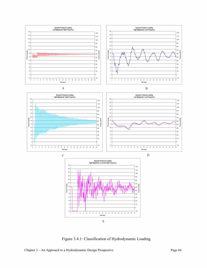
Chapter 3 – An Approach to a Hydrodynamic Design Prospective Page 66
Figure 3.4.1: Classification of Hydrodynamic Loading
A
C D
E
B

Chapter 3 – An Approach to a Hydrodynamic Design Prospective Page 67
and their strengths and weaknesses are not well defined, nor is the type of surge control that may
be most suitable for the system protection. Many of the components of a pipeline system have
elastic and/or poroelastic characteristics that may leave the system susceptible to failure. The key
is defining the sensitive loading characteristics of all the design components and making design
decisions that are complementary rather than are isolated. The following is a short list of key
facts and data that the designer must bear in mind as part of the decision matrix that begins to
steer the designer into a more comprehensive design approach.
Elastic (Flexible) Pipeline Material
Higher transient magnitudes acceptable, but limited by number and frequency of loading High magnitude / low frequency loading usually acceptable Inelastic (Rigid) Pipeline Material
Relatively insensitive to high frequency loading, but magnitude of transient loading limited Low magnitude / high frequency loading usually acceptable Gasketed Joints with Elastic Characteristics
Sensitive to both magnitude and frequency of loading Low magnitude/low frequency loading usually acceptable Cement Mortar Lining
Insensitive to frequency of loading, but may be a limit to magnitude of loading Low magnitude / high frequency loading usually acceptable An elastic or flexible system has the ability to deflect and recover with hydrodynamic loading.
This ability to deflect is important in the design so that performance limits are not exceeded
where the requirement for the elastic material to recover itself to its original shape or form.
Examples of elastic or flexible pipeline are Steel, PVC and PE pipelines. In a buried flexible

Chapter 3 – An Approach to a Hydrodynamic Design Prospective Page 68
pipeline design, close consideration of soil strength and soil stiffness are required for structural
support of the pipeline (ASCE MOP 119, 2009). An inelastic (rigid) buried pipeline design is
much less dependent on the soil support and therefore may be more suitable for installation in
soils with low strength and stiffness (Watkins and Anderson, 1999). Again, the inter-
relationships of loading on deflection and deflection on material and appropriate bedding
conditions are not well evolved in the current design manuals. Table 3.4.2 summarizes the
decision attributes:
Magnitude of Hydrodynamic Loading
Fre
quen
cy o
f H
ydro
dyna
mic
Loa
ding
High Low
High PM: Elastic (Steel, Iron)
LM: Bonded
J: Weld
PM: Inelastic (Concrete)
LM: Cement
J: Weld, Special Gasket
Low PM: Elastic (Steel, Iron, PVC/PE)
LM: Bonded
J: Weld, Fused
PM: All Acceptable
LM: All Acceptable
J: All Acceptable
Note: PM: Pipeline Material, LM: Lining Material, J: Joint Type
Table 3.4.2: Hydrodynamic Loading Decision Model
A pipeline system design using current design guidelines and design practices generally steers
the designer away from high magnitude and/or high frequency loading characteristics. From an
integrated design perspective, is this direction necessary? A concrete pipeline would be suitable
for applications with a high frequency loading characteristic, but that same material would be
sensitive to high magnitude with high positive pressure spikes. Whereas, steel would be suitable
Chapter 3 – An Approach to a Hydrodynamic Design Prospective Page 69
for both high frequency and magnitude; however in a steel pipeline design, it is ideal to have
pressure fluctuations that remain positive and as a result do not add to the existing external,
overbearing load on the pipeline. For a flexible pipeline, a positive pressure will allow the
pipeline wall to remain in tension. A large diameter flexible pipeline has a thin shell and may be
susceptible to collapse. A concrete pipeline is good in low and/or vacuum pressure conditions
because concrete has good compressive strength and is durable in this environment but is less
durable when put in tensional loading. Concrete is common in low pressure pumped sewerage
conveyance because in these systems the static head is generally low and as a result, the dynamic
head (hydro dynamic load) becomes a high percentage of the total head condition in the system.
Sewer force mains are also required to come on and off line frequently. So a concrete sewer
force main would typically experience high frequency as well as a high magnitude
hydrodynamic fluctuation in head every time the pump unit is put on or taken off line. Using
only the Hydrodynamic Decision Model shown in Table 3.4.2 would steer the design engineer
away from both the concrete pipeline material as well as the bonded lining system. Therefore,
this author wants to reiterate the need for an Integrated Design Approach in which the
Hydrodynamic Design Model is considered as a step in the process.
3.5 Chapter 3 Provisional Summary
In a pipeline system design, the design is invariably presumed linear, and in many ways it is.
Certainly, a failure of one component in the system results in a failure of the entire system.
However, the design parameters and the criteria used to formulate the design are anything but
linear and because of that the isolated and monotonic approach that currently is used in the
design guidelines requires a rethinking. It is proposed that a hydrodynamic inter-relationship of

Chapter 3 – An Approach to a Hydrodynamic Design Prospective Page 70
all the system components be required in the design standards. The inter-relation of the strengths
and weaknesses of the system components is required for an Integrated Design Approach.
Figure 3.5.1: Integrated Design Approach
An Integrated Design Approach (IDA) requires:
A better definition (empirical and theoretical) of strengths and weaknesses of
pipeline segments and pipeline system components with respect to hydrodynamic
loading,
Development of a design approach, a MAP, that requires associative design of all
components, and
Early identification of the sensitivity of the system to hydrodynamic loads and the
characteristics of the hydrodynamic loadings within a system.

Chapter 3 – An Approach to a Hydrodynamic Design Prospective Page 71
With these parameters defined a value based design can be performed for all the
components of within the system, and transient control and mitigation designs can
be considered to allow or broaden the list of viable design components. This may
allow for a more flexible and/or more economic design options.
This IDA helps identify a more economically and socially responsible design by exposing the
systems components strengths and weaknesses and their inter-relationships through a parameter
(hydrodynamic loading) that has been studied, in detail, in isolation but has not been considered
as an overarching decision variable.
3.6 Chapter 3 Conclusion
When utilized, the roadmap developed by identifying sensitivity of the system to transient
conditions, the transient loading histories along with the integrated design approach will allow a
designer to quickly assess the most appropriate materials and appurtenances for the pipeline
system design and if transient control and mitigation may prove cost effective. Ultimately, this
integrated design approach will allow for a more efficient design with a greater potential to
consider the allowances and constraints of the integrated components resulting in a cost
effective, valuable oriented design.
Chapter 4 and 5 of this thesis explore these inter-relationships via control of hydro-dynamic
loads and design considerations. Chapter 4 uses hydrodynamic analysis as a basis for assessing
the viability and characteristics of pipeline linings. Chapter 5 uses the current air valve design
guideline published by the America Water Works Association to propose ways to better include

Chapter 3 – An Approach to a Hydrodynamic Design Prospective Page 72
hydrodynamic loading into air valve design. These discussions will ultimately be proposed to
become integral parts of an Integrated Design Approach for pipeline systems.

Chapter 4 – Modified Design Approaches for Pipeline Linings Page 73 with Consideration of Hydrodynamic Loading
CHAPTER 4 – MODIFIED DESIGN APPROACHES FOR LININGS WITH CONSIDERATION OF HYDRODYNAMIC LOADING
The hydrodynamic loading consideration is a piece of the design process that has been
insufficiently considered in the evolution of manufacturing and design practices for the water
and wastewater pipeline industry. This thesis has proposed several ways to use hydrodynamic
loading to integrate the current design standards and practices and evaluate the inter-relationships
of various components that make up a pipeline system using an Integrated Design Approach. As
outlined in Chapters 2 and 3, this integrated design approach acts as a roadmap for an engineer in
the design and starts with the evaluation of the hydrodynamic sensitivity of each of the
components in the system.
4.1 Introduction
This thesis proposes that a more comprehensive consideration of hydrodynamic loading within
the AWWA Standards and ASCE and AWWA manuals of practice, with consideration of both
hydraulic loading magnitude and temporal parameters, is the key for development of an
integrated design approach. Chapter 4 uses hydrodynamic loading to evaluate the performance
limits of cement mortar lining in the presence of a hydraulic transient load. Through the use of
the hydrodynamic loading a designer will be able to more readily understand the inter-
relationship of the design parameters.
4.2 Hydrodynamic Analysis of Cement Mortar Lining
Introduced in the paper “Sub-atmospheric transient pressure conditions – where and what it may
influence in design” (McPherson, Karney, 2008) and subsequently identified as a potential
failure mode in a case study outlined in a paper (McReynolds, Peng, Romer, 2010) presented at

Chapter 4 – Modified Design Approaches for Pipeline Linings Page 74 with Consideration of Hydrodynamic Loading
the 2010 ASCE Pipelines conference. The case study was an analysis of potential failure modes
that caused the delamination of approximately 35% of the cement mortar lining in 5.3 miles (8.5
km) within the 144 inch (3650 mm) diameter Etiwanda pipeline located within the Metropolitan
Water District (Los Angeles, California) system Figure 4.2.1.
Figure 4.2.1: Typical Mortar Lining Failure on Etiwanda Pipeline (McReynolds, Peng, Romer, 2010)
An analysis is developed herein to assess the failure potential of cement mortar lining due to the
dynamic loading from a hydraulic transient event. The current design procedure for cement
mortar lining only considers the static loading on the pipeline. Even though the extreme static
loading procedure may be adequate for the thin steel shell design, the author proposes that the
static analysis is not adequate when considering a porous lining material (cement) that has low
tensile strength. To properly analyze the dynamic loading on the cement mortar lining, two

Chapter 4 – Modified Design Approaches for Pipeline Linings Page 75 with Consideration of Hydrodynamic Loading
elements need to be closely considered. The first is a description of the loading itself and how the
differential pressure is setup across the lining. The second is the analysis of the stress incurred
by the loading and how it compares to the lining’s material strength.
4.2.1 Lining Assumptions
This analysis, as proposed, requires several general assumptions to allow the problem to be
simplified and analytically formulated. It is assumed that the cement mortar lining has no
adhesion to the pipeline wall, and therefore, the mortar and steel are two separate bodies not
acting on one another. When the pipeline is operating normally, the internal pressure will stress
the pipeline wall and slightly expand the steel. The cement mortar lining, which was
centrifugally cast on to the pipeline wall, will also be positively stressed from this expansion.
However, this analysis assumes that the additional stress resulting from the expansion of the steel
is not present. Therefore when the dynamic load is applied, the relaxation of the steel and the
cement lining is not considered. Also the shear stress at the steel/lining interface will not be
realized. When combined with the shear stress in the lining, this unconsidered shear stress at the
pipeline wall may have significant strengthening effect on the lining. Even though the adhesive
property of the centrifugal casting is not high, it is proposed that this parameter along with the
normal operating stress imposed should be evaluated for sensitivity.
A failure is considered as a stress greater than the ultimate tensile strength of the mortar itself. So
the dynamic load (normal to the pipe wall and mortar) would need to overcome the
circumferential stresses and ultimate shear strength of the mortar. Only the hoop stress is
considered; the longitudinal stress and the radial stress are not considered. The cement mortar
lining is initially fully saturated and therefore the initial pore pressure throughout the lining is
Chapter 4 – Modified Design Approaches for Pipeline Linings Page 76 with Consideration of Hydrodynamic Loading
assumed to be the same. The cement mortar lining is homogenous with fixed conductivity
through its entire cross section. The dynamic load is uniform and radial.
4.2.2 Hydraulic Transient Loading Analysis of Lining
If the cement mortar lining is homogenous and 100% saturated and free of air voids, then a
common assumption in soil mechanics is the celerity (sonic wave speed) through the lining
would be equal to the fluid sonic wave speed. However, this also assumes that the fluid is
incompressible and the boundary layers are rigid. These two later assumptions would result in a
instantaneous pressure change across the lining and therefore, the dynamic nature of the loading
would not be realized. The author proposes that these later assumptions are invalid with regards
to the lining.
Because of the porous nature of the cement mortar lining, many hydraulic analyses, similar to the
analysis considered here, can be found in soil mechanics. In soil mechanics there is a classic one
dimensional theory describing the dynamic behavior of hydraulic loading to the corresponding
change in volume for a completely saturated compressible soil. This theory, introduced by Karl
Terzaghi in the early 1920's, is now known as the Terzaghi One Dimensional Theory of
Consolidation (Whitlow, 1990). The author proposes that, through a similar approach to
Terzaghi’s, a succinct and viable numerical method can be developed to assess the dynamic
loading and differential pressure across the cement mortar lining during a hydraulic transient
event.
A basic approach using Darcy Law is shown for a differential pressure across the porous lining.
This analysis shows that depending on the density, porosity and thickness of the lining material
and the hydrodynamic loading rate additional investigation is warranted through

Chapter 4 – Modified Design Approaches for Pipeline Linings Page 77 with Consideration of Hydrodynamic Loading
experimentation. For this simplified analysis, there are two assumptions required. The first
provides the description of the lining material and the pore space and pore velocity due to the
transient loading. The Darcy equation is used to describe this component of the loading rate.
The second describes the transient pressure through the lining material. The two assumptions are
then coupled to describe the failure potential of the lining due to the hydrodynamic loading.
The pore volume per unit length ( ) is dependent on the diameter of the pipe (D), porosity (n)
and thickness (e) of the lining.
(L3/L) Eq 4.2.1
Pore velocity (ν) is described by the one dimensional Darcy equation with hydraulic conductivity
(K) of the lining material and the thickness of the lining material (y).
ν K (L/s) Eq 4.2.2
With the pore volume per unit length and the pore velocity characterized, the effect of the
transient pressure can be assessed by setting the resistance to flow that is inherent to the
hydraulic conductivity parameter and to the change in velocity for the given pressure differential.
To relate these two components at a position along the thickness of the lining (dy) the
Joukowsky equation is utilized.
ν ν (L) Eq 4.2.3
In Equation 4.2.3 ν dy / K is the resistance and c is the sonic wave speed through the lining
material and c Δv /g is the driving force per unit area of the transient pressure head ΔH. An
inverse relationship of conductivity to transient pressure is shown. A more conductively thinner
lining will transfer the transient pressure very quickly while a less conductive, thicker lining
would be susceptible to failure.

Chapter 4 – Modified Design Approaches for Pipeline Linings Page 78 with Consideration of Hydrodynamic Loading
A model was formulated to analyze the lining characteristics with consideration of the
hydrodynamic loading. The boundaries of the model are shown in Figure 4.2.2 below where the
exterior or wall side of the lining is assumed to be a reflective boundary and the interior or water
side of the lining is assumed a constant pressure head boundary.
0, transient, t > 0 Eq 4.2.4
, 0 0 , 0< y < e Eq 4.2.5
, 0 Eq 4.2.6
Figure 4.2.2 - Free Body Diagram of dynamic loading (Po = steady state pressure at pipe wall, outside of lining; P1 = transient pressure at pipe interior, inside lining)
Where H0 is the initial liquid and pore pressure and prior to the transient pressure and Htransient is
the transient pressure after the transient pressure has passed. The flow and continuity equations
can be combined by taking the derivate across the lining thickness (y) and substituting for dv/dy
for the y term. Assuming the characteristics of a standard one dimensional diffusion process as
derived by DuChateau and Zachmann (DuChateau and Zachmann, 1989) a standard partial
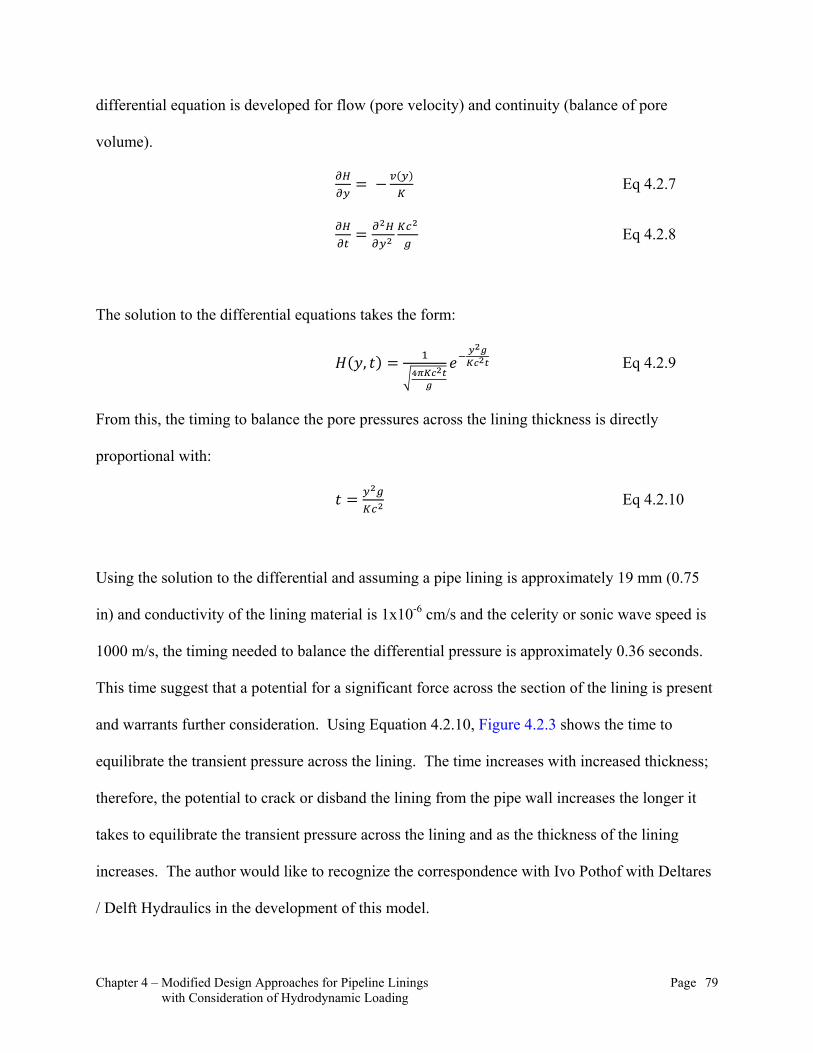
Chapter 4 – Modified Design Approaches for Pipeline Linings Page 79 with Consideration of Hydrodynamic Loading
differential equation is developed for flow (pore velocity) and continuity (balance of pore
volume).
Eq 4.2.7
Eq 4.2.8
The solution to the differential equations takes the form:
, Eq 4.2.9
From this, the timing to balance the pore pressures across the lining thickness is directly
proportional with:
Eq 4.2.10
Using the solution to the differential and assuming a pipe lining is approximately 19 mm (0.75
in) and conductivity of the lining material is 1x10⁻⁶ cm/s and the celerity or sonic wave speed is
1000 m/s, the timing needed to balance the differential pressure is approximately 0.36 seconds.
This time suggest that a potential for a significant force across the section of the lining is present
and warrants further consideration. Using Equation 4.2.10, Figure 4.2.3 shows the time to
equilibrate the transient pressure across the lining. The time increases with increased thickness;
therefore, the potential to crack or disband the lining from the pipe wall increases the longer it
takes to equilibrate the transient pressure across the lining and as the thickness of the lining
increases. The author would like to recognize the correspondence with Ivo Pothof with Deltares
/ Delft Hydraulics in the development of this model.

Chapter 4 – Modified Design Approaches for Pipeline Linings Page 80 with Consideration of Hydrodynamic Loading
Figure 4.2.3: Time to Equilibrate the Transient Pressure across the Lining Thickness
When a dynamic load is introduced to the internal wall of the cement lining, the pressure and
stress on the top side of the cement lining will for a time maintain the initial pressure (Po)
pressure condition while the internal face of the lining will be subjected to a lower transient
pressure (P1). Because of the hydraulic conductivity, assumed similar to the Terzaghi’s One
Dimensional Theory of Consolidation of the porous material (Whitlow, 1990), a pressure
differential will develop due to the flow resistance across the media. Using a simply one
dimensional analysis as described above the potential for failure of the cement lining in the
presence of a transient pressure is present.

Chapter 4 – Modified Design Approaches for Pipeline Linings Page 81 with Consideration of Hydrodynamic Loading
4.3 Conclusions to Cement Mortar Lining Analysis
Although structural considerations are crucial to the success of any pipeline system, there has
been a strong tendency to treat transient loadings superficially and simplistically during pipeline
design. The unwarranted simplifications can arise when the range of loadings are being
considered, when their duration and transient nature is neglected, or when the behavior of the
lining is being considered. One mode of failure that is particularly worrisome and almost wholly
neglected is associated with the possible influence of transient loadings on cement motor linings.
This analysis of cement motor linings when subjected to transient events comes down to how
much differential uniform radial load introduced by a negative transient pressure wave can the
cement mortar lining resist without failing. The only resistant force holding the lining together is
the circumferential compressive load. Due to the history of cement mortar lining and steel
pipeline systems as a whole, the author believe that the stresses incurred from the sub-
atmospheric dynamic loading of the cement mortar lining will not introduce a failure concern.
However, this research may allow for refinements in the thickness and characteristics of the
lining material allowed and which may result cost savings and increased reliability of the piping
system. The author proposes that the pipeline manufacturers be solicited to perform physical
testing to evaluate the potential for lining failure.
When considering the dynamic behavior of an elastic/flexible or rigid/inflexible material, a
dynamic loading is required to properly assess the deformation and ultimate strength/strain that
the material has. In hydraulic transient analysis, there has been a significant history of empirical
analysis and testing of mechanical equipment so that the analyst can better define the dynamic

Chapter 4 – Modified Design Approaches for Pipeline Linings Page 82 with Consideration of Hydrodynamic Loading
characteristics of the pipeline system. However, the author proposes that the inclusion of the
dynamic behavior of the joints and lining systems and a closer assessment of sub-atmospheric
pressure conditions may provide the pipeline design community a more refined and possibly a
justifiably less expensive product through an equally robust design process.
Because cement mortar lining is used in both Steel and Ductile Iron pipelines to reduce the
corrosion potential of water, if this failure mode proves to be significant, then the need for more
proactive or primary hydraulic transient control will be required in conveyance systems not only
to protect against catastrophic failures but also to provide a comprehensive corrosion control on
the pipeline by allowing the lining systems to maintain its integrity. This may also influence the
design professional on the type of hydraulic transient control devices that may be used.
Chapter 5 – Modified Design Approaches for Air Valves Page 83 with Consideration of Hydrodynamic Loading
CHAPTER 5 – MODIFIED DESIGN APPROACHES FOR AIR VALVES WITH CONSIDERATION OF HYDRODYNAMIC LOADING
Chapter 4 addressed the use of hydrodynamic loading in analysis of the design performance limit
of cement mortar lining. Chapter 5 introduces the integrated design approach for the analysis for
sizing and locating air valves within a conveyance system with an undulating profile.
Introduction 5.1
Chapter 5 provides an evaluation procedure using hydrodynamic loading to identify the purpose,
size and locate an air valve. This procedure will refine the present standard of practice as
identified in AWWA M51.
Air Valve Design 5.2
Air valves in pipeline systems serve two primary functions. The first and most common is the
release of unwanted, accumulated air that comes out of solution within the pipeline. This freed
air will result in bubble formation, which will coalesce at localized high points along the pipeline
profile. This air accumulation will occur when the bubble’s buoyancy is greater than the energy
to convey the bubble with the fluid. The air valve used to release this free air is known as an air
release valve. The second function of an air valve is to draw air into the system when the
pipeline’s internal pressure falls below atmospheric pressures. By drawing air into the pipeline
system during as the internal vacuum condition develops, the magnitude of the vacuum pressure
can be reduced and as a result help prevent the pipeline from experiencing excessive deflection
and/or collapse as well as help prevent the formation of a full vacuum condition in which vapor
cavities may form from the fluid vaporizing. This air valve is commonly referred to as an air
vacuum valve. An air vacuum valve is also used to release large volumes of air from the
Chapter 5 – Modified Design Approaches for Air Valves Page 84 with Consideration of Hydrodynamic Loading
pipeline system when the pipeline is initial filled and after a hydraulic transient event occurs that
drew in a significant volume of air. Unless designed otherwise a positive pressure and/or an
elevated water level within the valve, body is required to seat the vacuum valve float. During
pipeline filling, the vacuum valve will be in an open position. When both an air release and an
air vacuum valve are present, the air valve is known as a combination air valve. There are many
variations in air valve design including subtle design differences in the valve float arrangement,
changes in shape and characteristics of the valve body design, as well as changes in the valves
actuation and response. Each of these design characteristics allows the designer a wide range of
choices to meet specific operations and design requirements.
A design detail specific to the air valve itself is the orifice sizing. The orifice sizing will directly
influence how much and how quickly air can be either released from or drawn into the pipeline
system. Another critical design consideration for air valves is their placement in the system.
Most air valve manufacturers have sizing tables to size the orifice and qualitative
recommendations of where to install air valves in a pipeline system. This chapter will critique
the current procedures used for sizing and locating air valves and propose a new process for
sizing the air release orifice with consideration of both the compressed air volume, which is
directly impacted by its location and hydrodynamic loading.
5.2.1 Analysis of Standard Air Valve Design Approach and Proposed Changes
Air release valves used in pressurized systems are necessary because of the amount of air that is
dissolved in water under normal atmospheric pressures and temperature ranges. The standard
approach to air valve sizing that has been used in the industry for an extended period of time
defines the mass of air in water as 2% by volume. As a result, it has become standard practice to

Chapter 5 – Modified Design Approaches for Air Valves Page 85 with Consideration of Hydrodynamic Loading
define the airflow rate (Qair in Equations 2.8.1 and 2.8.2) as 2% of the fluid flow rate. For
example, in a system that has a fluid flow rate of 100 cfs, the Qair will be 2.0 cfs or 120 cfm. It
should be noted that an air valve designed for this flow rate is designed to release all the air
dissolved in the fluid at any one air valve station.
The volume of dissolved air in a saturated fluid has been studied and empirically quantified at
various temperatures and pressures. It should be noted that the solubility of air, assumed as an
ideal gas, in water is most significantly influenced by changes in pressure and only slightly by
temperature. Because the solubility of air in water changes very subtly with temperature, this
thesis assumes a standard temperature of 68 F (20 C) for both the fluid and the air. In pipeline
systems with undulating profiles, the pressure may fluctuate significantly from high to low and
low to high as the water is conveyed through the pipeline. Because the volume of dissolved air in
fluid is more influenced by pressure, this thesis assumes a range in pressure of 0.0 to 250 psig,
which is a typical operating pressure range for a water conveyance system.
Using the mole fraction solubility of O2, N2 and Ar in water as presented in the 2009 CRC
Handbook of Chemistry and Physics, the percent volume of air was calculated over a pressure
range of 0.0 to 250 psig. Table 5.2.1 provides the data and assumptions used in this analysis and
Figure 5.2.1 shows the result of this analysis at three temperatures 59 F (15 C), 68 F (20 C), and
77 F (25 C). Figure 5.2.1 shows not only the significance of pressure to solubility but also the
insensitivity of temperature to solubility.

Chapter 5 – Modified Design Approaches for Air Valves Page 86 with Consideration of Hydrodynamic Loading
Table 5.2.1: Data and Assumptions Used in Solubility Analysis
Figure 5.2.1: Percent Dissolved Air in Water (Fully Saturated Condition)
As reference above, the current AWWA M51 manual of practice for air valves utilizes 2% of the
fluid flow rate to size the airflow rate through the air release valve. As can be seen in Figure
Percent Dissolved Air in Waterfor Pressures 0 to 250 psig at Temperatures 59, 68 and 77 F
0.00%
0.50%
1.00%
1.50%
2.00%
2.50%
0 25 50 75 100 125 150 175 200 225 250
Pressure (psig)
Dis
solv
ed A
ir (
%)
T = 59 F
T = 68 F
T = 77 F
Chapter 5 – Modified Design Approaches for Air Valves Page 87 with Consideration of Hydrodynamic Loading
5.2.1, the percent dissolved air by volume varies significantly with pressure. However, a 2%
dissolved air content in water only occurs at or near an atmospheric pressure or 0.0 psig. What
the author wants to highlight and will subsequently focus the remainder of this section on, is the
dissolved air volume. In the current design procedure, the general use of 2% to establish an
airflow rate will produce oversized air release valves in most pressurized water distribution and
conveyance systems in North America where the current procedure is used.
In a typical pressurized water system, air is introduced at a free water surface. Once the water is
pressurized, the introduction of air or any gas is very difficult and will require an active air
compression and injection. This analysis assumes that all air volume is introduced at atmospheric
pressure conditions and as a result, the total volume of air is approximately 2.12% by volume at
68 F, as shown in Figure 5.2.1. As pressure is increased albeit by a pumping unit or gravity flow
to a lower elevation in the profile, the mass of air will remain constant in the system; however,
the density of air will increase and as a result, the percent air volume in the fluid is reduced.
Currently the standard approach of air valve sizing does not account for the reduction in air
volume with pressure. The air volume compressed in the air valve body at any position along the
pipeline profile will be dependent on the local pressure, saturated air density, and air mass.
Assuming the mass of dry air is held constant at 0.025 grams for each liter at 68 F, the percent
volume of dissolved air will change inversely with saturated air density. Figure 5.2.2 shows the
relationship between percent dissolved air and saturated air density.
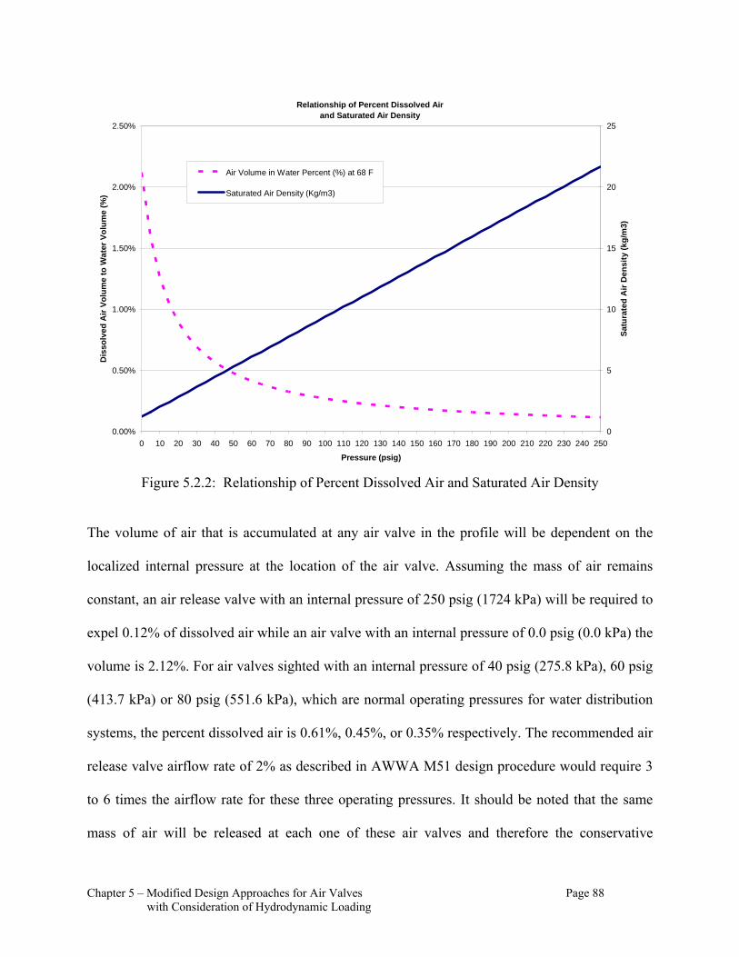
Chapter 5 – Modified Design Approaches for Air Valves Page 88 with Consideration of Hydrodynamic Loading
Figure 5.2.2: Relationship of Percent Dissolved Air and Saturated Air Density
The volume of air that is accumulated at any air valve in the profile will be dependent on the
localized internal pressure at the location of the air valve. Assuming the mass of air remains
constant, an air release valve with an internal pressure of 250 psig (1724 kPa) will be required to
expel 0.12% of dissolved air while an air valve with an internal pressure of 0.0 psig (0.0 kPa) the
volume is 2.12%. For air valves sighted with an internal pressure of 40 psig (275.8 kPa), 60 psig
(413.7 kPa) or 80 psig (551.6 kPa), which are normal operating pressures for water distribution
systems, the percent dissolved air is 0.61%, 0.45%, or 0.35% respectively. The recommended air
release valve airflow rate of 2% as described in AWWA M51 design procedure would require 3
to 6 times the airflow rate for these three operating pressures. It should be noted that the same
mass of air will be released at each one of these air valves and therefore the conservative
Relationship of Percent Dissolved Air and Saturated Air Density
0.00%
0.50%
1.00%
1.50%
2.00%
2.50%
0 10 20 30 40 50 60 70 80 90 100 110 120 130 140 150 160 170 180 190 200 210 220 230 240 250
Pressure (psig)
Dis
solv
ed A
ir V
olu
me
to W
ate
r V
olu
me
(%)
0
5
10
15
20
25
Sat
ura
ted
Air
Den
sity
(kg
/m3)
Air Volume in Water Percent (%) at 68 F
Saturated Air Density (Kg/m3)

Chapter 5 – Modified Design Approaches for Air Valves Page 89 with Consideration of Hydrodynamic Loading
assumption that any one air valve will be capable of expelling the full volume of air is
maintained. Following in Section 5.2.3 is an analysis using the compressed air volume to size a
series of air release valve orifices with a comparison to the AWWA M51 procedure. This
comparative analysis assumed a range of fluid flow rate from 0 to 100 cfs (2.83 cms). The
results of this sizing are charted in Figure 5.2.3
Figure 5.2.3: Air Release Valve Sizing Using Compressed Air Volume
This thesis proposes that the compressed air volume in saturated dissolved air be used to size air
release valves rather than 2% of the design flow rate.
Air Release Valve Sizing
0.0
2.0
4.0
6.0
8.0
10.0
12.0
14.0
16.0
18.0
20.0
22.0
24.0
0 10 20 30 40 50 60 70 80 90 100
Design Flow Rate (cfs)
Air
Rel
ease
Val
ve D
iam
eter
(m
m)
P = 5 psig, Dissolved Air 1.70%
P = 20 psig, Dissolved Air 0.89%
P = 60 psig, Dissolved Air 0.41%
P = 100 psig, Dissolved Air 0.27%

Chapter 5 – Modified Design Approaches for Air Valves Page 90 with Consideration of Hydrodynamic Loading
5.2.2 Air Valve Sizing for a Pumped System
The addition of potential energy to a system through a pump will rapidly compress the dissolved
air from one volume to another. As a result of the analysis shown in Figure 5.2.2, an air release
valve placed on the discharge of the pump assembly can be sized in consideration of the pump
pressure head. Therefore, a pump adding 125 psig (861.8 kPa) of pressure to a system will
require an air release valve sized for 0.24% of the fluid flow rate. It should be noted that a 0.24%
dissolved air release sizing criterion does not consider the air that may be present in the pump
column (i.e. vertical turbine pump), but is simply the rational sizing required through
consideration of the compressed air volume. When sizing air release valves on wellhead and
vertical turbine pump discharge manifolds, it is common to use specially designed air release
valves that have been equipped with oil-filled dashpots to retard or slow down the air release.
These dashpots are used to prevent air valves from slamming which will result in high transient
pressure conditions. A reduction in the air release orifice will help mitigate this air valve
slamming and may resolve the need for this dampening mechanism.
5.2.3 Air Valve Sizing and Location for a Pipeline System
In a pipeline system, as the elevation changes, pressure changes. The pressure may increase and
decrease significantly depending on the location along the pipeline profile. Figure 5.2.4 shows a
hypothetical profile with air valves located through the qualitative procedure outlined in the
AWWA M51 manual of practice. Table 5.2.2 provides a summary of the air release valve sizes
for both the AWWA M51 design procedure and the proposed compressed air design procedure.
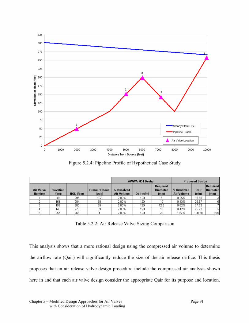
Chapter 5 – Modified Design Approaches for Air Valves Page 91 with Consideration of Hydrodynamic Loading
Figure 5.2.4: Pipeline Profile of Hypothetical Case Study
Table 5.2.2: Air Release Valve Sizing Comparison
This analysis shows that a more rational design using the compressed air volume to determine
the airflow rate (Qair) will significantly reduce the size of the air release orifice. This thesis
proposes that an air release valve design procedure include the compressed air analysis shown
here in and that each air valve design consider the appropriate Qair for its purpose and location.
0
25
50
75
100
125
150
175
200
225
250
275
300
325
0 1000 2000 3000 4000 5000 6000 7000 8000 9000 10000
Distance from Source (feet)
Ele
vat
ion
or
Hea
d (
feet
)
Steady State HGL
Pipeline Profile
1
2
3
4
5
Air Valve Location
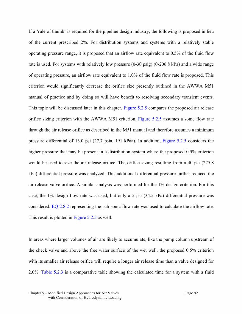
Chapter 5 – Modified Design Approaches for Air Valves Page 92 with Consideration of Hydrodynamic Loading
If a ‘rule of thumb’ is required for the pipeline design industry, the following is proposed in lieu
of the current prescribed 2%. For distribution systems and systems with a relatively stable
operating pressure range, it is proposed that an airflow rate equivalent to 0.5% of the fluid flow
rate is used. For systems with relatively low pressure (0-30 psig) (0-206.8 kPa) and a wide range
of operating pressure, an airflow rate equivalent to 1.0% of the fluid flow rate is proposed. This
criterion would significantly decrease the orifice size presently outlined in the AWWA M51
manual of practice and by doing so will have benefit to resolving secondary transient events.
This topic will be discussed later in this chapter. Figure 5.2.5 compares the proposed air release
orifice sizing criterion with the AWWA M51 criterion. Figure 5.2.5 assumes a sonic flow rate
through the air release orifice as described in the M51 manual and therefore assumes a minimum
pressure differential of 13.0 psi (27.7 psia, 191 kPaa). In addition, Figure 5.2.5 considers the
higher pressure that may be present in a distribution system where the proposed 0.5% criterion
would be used to size the air release orifice. The orifice sizing resulting from a 40 psi (275.8
kPa) differential pressure was analyzed. This additional differential pressure further reduced the
air release valve orifice. A similar analysis was performed for the 1% design criterion. For this
case, the 1% design flow rate was used, but only a 5 psi (34.5 kPa) differential pressure was
considered. EQ 2.8.2 representing the sub-sonic flow rate was used to calculate the airflow rate.
This result is plotted in Figure 5.2.5 as well.
In areas where larger volumes of air are likely to accumulate, like the pump column upstream of
the check valve and above the free water surface of the wet well, the proposed 0.5% criterion
with its smaller air release orifice will require a longer air release time than a valve designed for
2.0%. Table 5.2.3 is a comparative table showing the calculated time for a system with a fluid
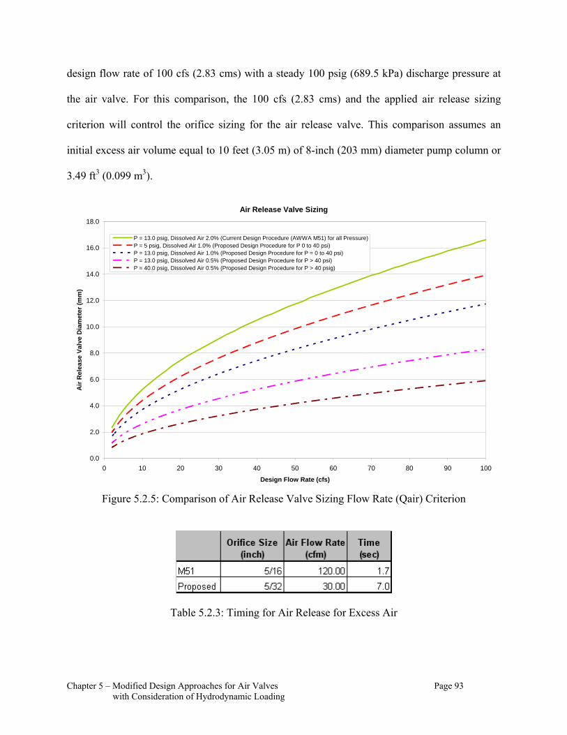
Chapter 5 – Modified Design Approaches for Air Valves Page 93 with Consideration of Hydrodynamic Loading
design flow rate of 100 cfs (2.83 cms) with a steady 100 psig (689.5 kPa) discharge pressure at
the air valve. For this comparison, the 100 cfs (2.83 cms) and the applied air release sizing
criterion will control the orifice sizing for the air release valve. This comparison assumes an
initial excess air volume equal to 10 feet (3.05 m) of 8-inch (203 mm) diameter pump column or
3.49 ft3 (0.099 m3).
Figure 5.2.5: Comparison of Air Release Valve Sizing Flow Rate (Qair) Criterion
Table 5.2.3: Timing for Air Release for Excess Air
Air Release Valve Sizing
0.0
2.0
4.0
6.0
8.0
10.0
12.0
14.0
16.0
18.0
0 10 20 30 40 50 60 70 80 90 100
Design Flow Rate (cfs)
Air
Rel
ease
Val
ve D
iam
eter
(m
m)
P = 13.0 psig, Dissolved Air 2.0% (Current Design Procedure (AWWA M51) for all Pressure)P = 5 psig, Dissolved Air 1.0% (Proposed Design Procedure for P 0 to 40 psi)P = 13.0 psig, Dissolved Air 1.0% (Proposed Design Procedure for P = 0 to 40 psi)P = 13.0 psig, Dissolved Air 0.5% (Proposed Design Procedure for P > 40 psi)P = 40.0 psig, Dissolved Air 0.5% (Proposed Design Procedure for P > 40 psig)
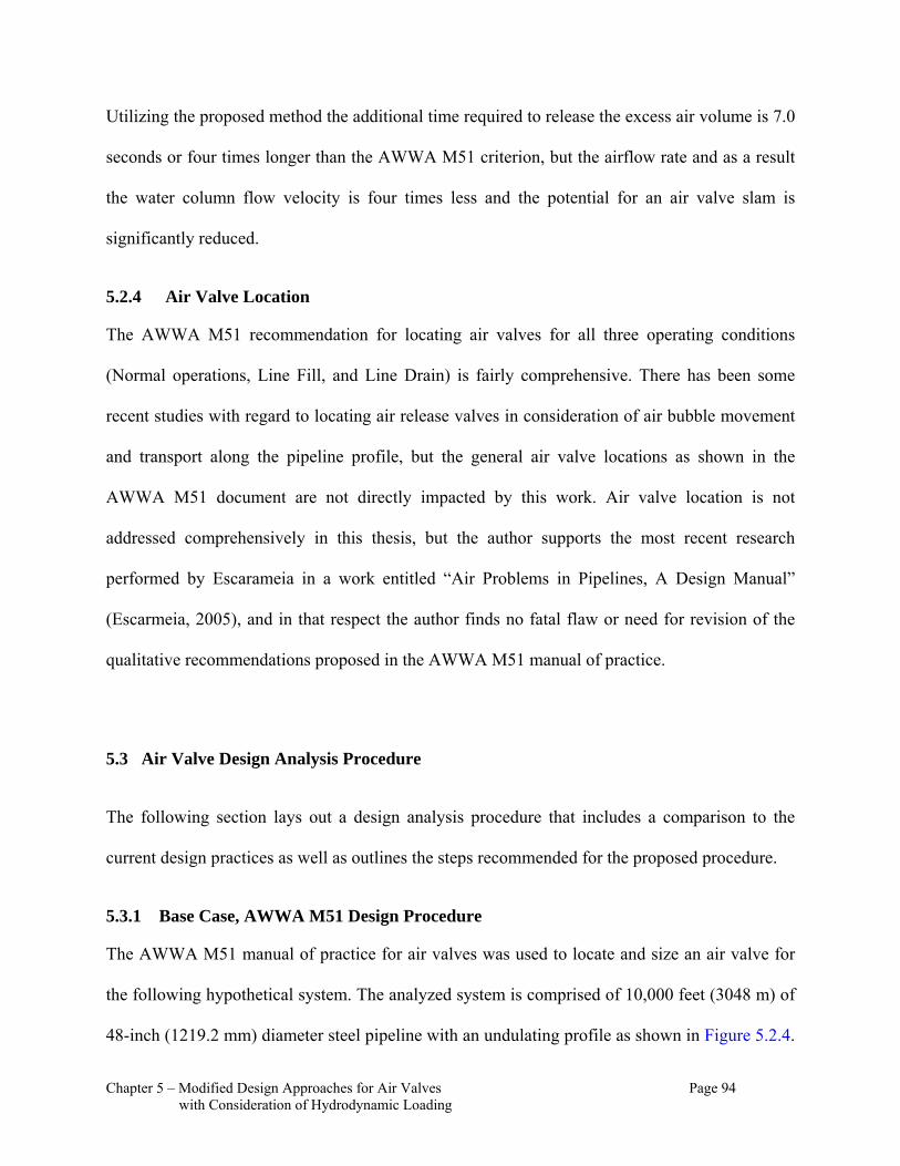
Chapter 5 – Modified Design Approaches for Air Valves Page 94 with Consideration of Hydrodynamic Loading
Utilizing the proposed method the additional time required to release the excess air volume is 7.0
seconds or four times longer than the AWWA M51 criterion, but the airflow rate and as a result
the water column flow velocity is four times less and the potential for an air valve slam is
significantly reduced.
5.2.4 Air Valve Location
The AWWA M51 recommendation for locating air valves for all three operating conditions
(Normal operations, Line Fill, and Line Drain) is fairly comprehensive. There has been some
recent studies with regard to locating air release valves in consideration of air bubble movement
and transport along the pipeline profile, but the general air valve locations as shown in the
AWWA M51 document are not directly impacted by this work. Air valve location is not
addressed comprehensively in this thesis, but the author supports the most recent research
performed by Escarameia in a work entitled “Air Problems in Pipelines, A Design Manual”
(Escarmeia, 2005), and in that respect the author finds no fatal flaw or need for revision of the
qualitative recommendations proposed in the AWWA M51 manual of practice.
Air Valve Design Analysis Procedure 5.3
The following section lays out a design analysis procedure that includes a comparison to the
current design practices as well as outlines the steps recommended for the proposed procedure.
5.3.1 Base Case, AWWA M51 Design Procedure
The AWWA M51 manual of practice for air valves was used to locate and size an air valve for
the following hypothetical system. The analyzed system is comprised of 10,000 feet (3048 m) of
48-inch (1219.2 mm) diameter steel pipeline with an undulating profile as shown in Figure 5.2.4.
Chapter 5 – Modified Design Approaches for Air Valves Page 95 with Consideration of Hydrodynamic Loading
This system has been set up to convey 100 cfs (2.83 cms) of water with a water and air
temperature of 68º F (20º C). The water is lifted approximately 302 feet (92 m) from a free water
surface level of 0.0 feet (0.0 m) to an elevated reservoir with a free water surface level of 266
feet (81 m). Therefore, there is 36 feet (10.97 m) of pressure head loss in the system. A hydraulic
transient event was imposed on this system by reducing the flow by 20% (20 cfs, 0.566 cms) in
3.75 seconds. Figure 5.3.1 shows the steady state hydraulic grade line (HGL) and the hydraulic
transient head envelopes resulting from this imposed hydraulic transient event. As shown in the
results, the minimum pressure in the system does not reach a full vacuum (-34 feet, -14.7 psig, -
101.3 kPa) at the intermediate high point which is located approximately 6000 feet (1828.8 m)
from the source. However, the pressure does drop to -29.3 feet (-8.93 m) below the pipeline
crown producing a negative internal pressure of -12.7 psig (-87.56 kPa). As a result of this sub-
atmospheric pressure condition, this system would most likely be designed with an air valve at
this location to resolve this negative pressure issue developed during a hydraulic transient event.
It should also be noted that an air valve would also be located at this position for initial filling
and potential draining of the pipeline system as well as for normal operating air release.
Using the AWWA M51 design approach the air valve(s) would have a ½ inch (12.7 mm) orifice
for air release to pass 2% of the design flow (Qdesgin = 100 cfs, 2.83 cms) at 33.5 psig (230.97
kPa) which is 120 cfm (0.0566 cms). This air release orifice sizing can also be obtained by using
the nomagraph in Figure 5.4.1. The large air valve orifice would be designed at 3 inch (76.2 mm)
for the controlled line filling and draining at 1 ft/s (0.3048 m/s) with an airflow rate of 754 cfm
(0.356 cms) at 2 psig (13.79 kPa) differential pressure. However, the large orifice for a gravity
flow condition would require a 14-inch (355.6 mm) orifice producing an airflow rate of 21, 901.5

Chapter 5 – Modified Design Approaches for Air Valves Page 96 with Consideration of Hydrodynamic Loading
cfm (10.34 cms) that is equivalent to a free discharge in a pipeline with a 5% slope and an
allowable negative pressure
Figure 5.3.1: Base Case Steady State HGL and Hydraulic Transient Envelope
differential of -5.0 psig (-34.5 kPa). Therefore, the design, with consideration of a line break with
gravity flow condition, would generate a combination air valve design a ½-inch (12.7 mm) air
release and 14-inch (355.6 mm) vacuum orifice.
To test this design with regards to the transient loading, the system was analyzed with a
representative transient model. The two primary equations used in predicting transient flow
conditions for hydraulic transient events are the continuity and momentum equations. These
equations form a pair of quasi-linear hyperbolic partial differential equations in terms of two
0
100
200
300
400
500
600
0 1000 2000 3000 4000 5000 6000 7000 8000 9000 10000
Distance from Source (feet)
Ele
vati
on
or
Hea
d (
feet
)
Steady State HGL
Pipeline Profile
Max Head Envelope with No Air Valve
Min Head Envelope with No Air Valve

Chapter 5 – Modified Design Approaches for Air Valves Page 97 with Consideration of Hydrodynamic Loading
dependent variables, velocity and HGL elevation, and two independent variables, distance along
the pipeline and time. For numeric modeling, the equations are transformed into four ordinary
differential equations by the characteristics method. A model that utilizes the characteristics
method was used to analyze this system. The TransAM model was developed by Duncan
McInnis, Bryan Karney, and David Axworthy and is commercially available software used in the
analysis of hydraulic transient phenomenon. The TransAM model utilizes the method of
characteristics to solve the transient equations and the model uses Benjamin Wylie and Victor
Streeter’s formulation of air volume expansion and contraction (TransAM Reference Manual,
2004) for analysis of air valves.
In TransAM, the air valve assembly was modeled as a 3-stage air valve where the large orifice
would draw and vent air during a transient event until a positive differential pressure was
developed to close the orifice. With the large orifice (vacuum orifice) closed the air release
orifice would be isolated and continue to release air until the full air volume that was drawn into
the system during the transient event is expelled. The modeling of the air valve assembly using
this 3-stage characterization more closely represents the function of a standard combination air
valve. The TransAM model contains a boundary condition for a 3-stage air valve to facilitate this
type of analysis.
The results of the base analysis assuming the AWWA M51 design procedure is shown in Figures
5.3.2 and 5.3.3. Figure 5.3.2 provides a plot of result similar to Figure 5.3.1 in that the
maximum and minimum transient head envelopes are shown along with the pipeline profile and

Chapter 5 – Modified Design Approaches for Air Valves Page 98 with Consideration of Hydrodynamic Loading
steady state HGL. Figure 5.3.3 plots the model result representing the air volume history and
pressure history at the air valve during the transient event.
Figure 5.3.2: AWWA M51- Steady State HGL and Hydraulic Transient Envelope
In Figure 5.3.2, the sub-atmospheric pressure condition at the air valve location has been
resolved. However, through further inspection of the plot, the model results show that both the
rising and falling limbs of the pipeline on either side of the air valve location will experience a
full vacuum pressure condition. A full internal vacuum pressure condition within the pipeline
introduces the potential for vapor cavity formation. The collapse of this vapor cavity will
introduce a positive shock pressure. This shock pressure is commonly known as ‘waterhammer’.
Therefore, in this system, as modeled, a combination air valve sized with the AWWA M51
0
100
200
300
400
500
600
0 1000 2000 3000 4000 5000 6000 7000 8000 9000 10000
Distance from Source (feet)
Ele
vati
on
or
Hea
d (
feet
)
Steady State HGL
Pipeline Profile
Maximum Head Envelope with 14" Vacuum and 1/2" Release Orifice
Minimum Head Envelope with 14" Vacuum and 1/2" Release Orifice

Chapter 5 – Modified Design Approaches for Air Valves Page 99 with Consideration of Hydrodynamic Loading
procedure will exacerbate the transient pressure problem rather than resolve the issue. In
comparison of Figure 5.3.2 and Figure 5.3.3, the reader can see that both the downsurge or low
transient pressure and the upsurge or high transient pressure are greater than the system analyzed
without the air valve.
Figure 5.3.3: AWWA M51-Accumulative Air Volume and Pressure Head History at Air Valve Station
As can be seen in Figure 5.3.3, the rate of inflow and outflow through the large orifice of the air
valve has a similar volumetric flow rate. The volumetric flow rate through the air valve can be
qualitatively considered by inspecting the slope of the volume history. What is also shown is that
there is a significant and sudden increase in pressure after all the air is released from the system.
Through further inspection of the model result data, it can be shown that this upsurge resulting
0
2
4
6
8
10
12
14
16
18
10 12 14 16 18 20 22 24 26 28 30
Time (seconds)
Air
Vo
lum
e (
cu
bic
fe
et)
0
50
100
150
200
250
300
Pre
ssu
re H
ead
at
Air
Va
lve
Co
nn
ecti
on
(fe
et)
Volume History 14" Large, 1/2" Small
Pressure History at Air Valve
Chapter 5 – Modified Design Approaches for Air Valves Page 100 with Consideration of Hydrodynamic Loading
from the air valve rapidly closing is the cause of the full vacuum pressure condition shown on
the falling and rising limbs of the pipeline. The secondary transient event caused by the air valve
closure is the root of the more severe high and low hydraulic transient pressures. The model
results show that the minimum pressure occurs in the rising limb feeding the terminal reservoir at
T = 26.0 seconds or 16 seconds after the initial transient event from the decrease in source flow.
Also in Figure 5.3.3, it can be seen that the ½-inch (12.7 mm) air release valve is not providing
any benefit during the hydraulic transient event because all the air is being vented through the
large vacuum orifice. If the smaller orifice were being utilized the slope of the accumulated air
volume history would change abruptly. The TransAM model provides the user with a
notification when the large orifice is seated and the small orifice is activated. This notification
was not shown and therefore, as modeled, the air release valve remained inactive.
The remainder of this analysis section provides various air valve sizing scenarios set up to
resolve the secondary transient event and better protect the pipeline system than the “do nothing”
or “provide no air valve” scenario.
5.3.2 Modified Design Scenario 1, AWWA M51 Controlled Draining Procedure
The Base Case considered the sizing of the vacuum valve for gravity flow and/or line break
rather than for controlled draining. Scenario 1 considers the reduction in the vacuum valve size
to the size required for a controlled drain down. This sizing, based on the AWWA M51 design
procedure is 3 inch (76.2 mm). Figures 5.3.4 and 5.3.5 show the profile and head envelope and
air volume and pressure history for this scenario, respectively.

Chapter 5 – Modified Design Approaches for Air Valves Page 101 with Consideration of Hydrodynamic Loading
Figure 5.3.4: Scenario 1-Steady State HGL and Hydraulic Transient Envelope
Reducing the vacuum valve orifice alone does not provide appreciably better results. A full
vacuum pressure on the rising limb to the terminal reservoir is still shown in the model results.
The minimum transient pressure is still along this rising limb and occurs at approximately the
same time or T = 26.1 seconds or 16.1 seconds after the transient event is initiated. In addition, it
should be noted that in this scenario the pipeline system is no longer protected from a line break
or gravity flow condition.
0
100
200
300
400
500
600
0 1000 2000 3000 4000 5000 6000 7000 8000 9000 10000
Distance from Source (feet)
Ele
vati
on
or
Hea
d (
feet
)
Steady State HGL
Pipeline Profile
Maximum Head Envelope with 3" Vacuum and 1/2" Release Orifice
Minimum Head Envelope with 3" Vacuum and 1/2" Release Orifice
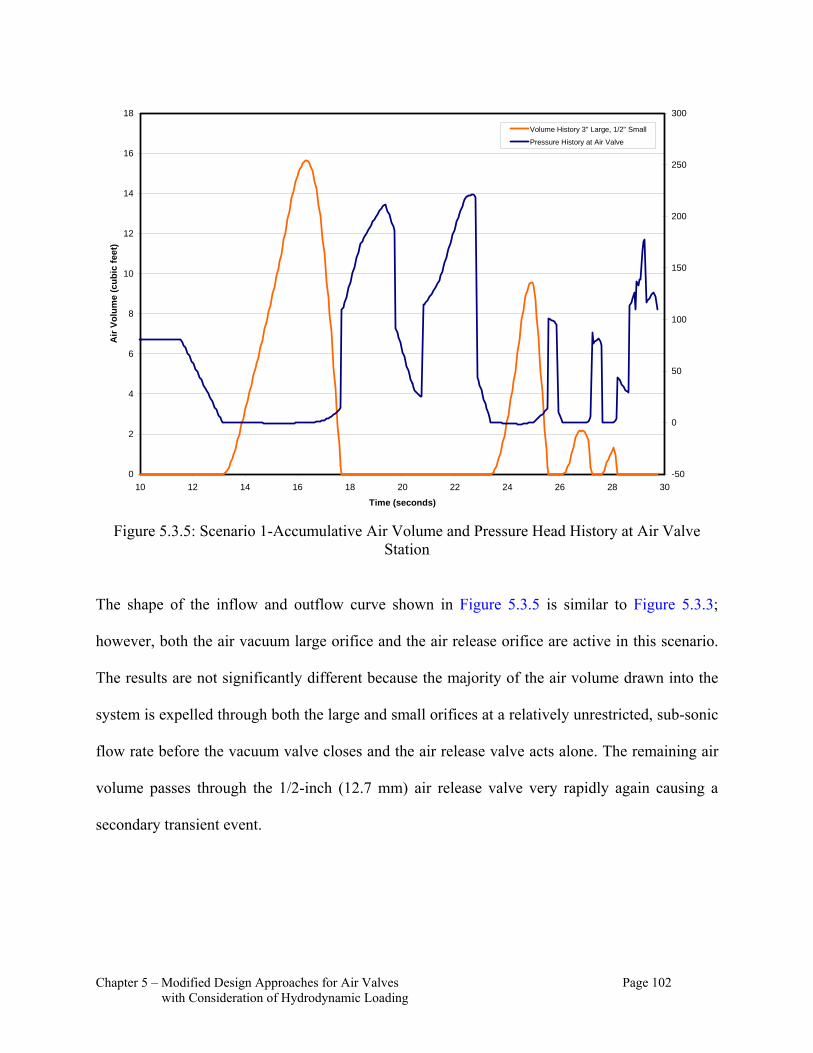
Chapter 5 – Modified Design Approaches for Air Valves Page 102 with Consideration of Hydrodynamic Loading
Figure 5.3.5: Scenario 1-Accumulative Air Volume and Pressure Head History at Air Valve Station
The shape of the inflow and outflow curve shown in Figure 5.3.5 is similar to Figure 5.3.3;
however, both the air vacuum large orifice and the air release orifice are active in this scenario.
The results are not significantly different because the majority of the air volume drawn into the
system is expelled through both the large and small orifices at a relatively unrestricted, sub-sonic
flow rate before the vacuum valve closes and the air release valve acts alone. The remaining air
volume passes through the 1/2-inch (12.7 mm) air release valve very rapidly again causing a
secondary transient event.
0
2
4
6
8
10
12
14
16
18
10 12 14 16 18 20 22 24 26 28 30
Time (seconds)
Air
Vo
lum
e (c
ub
ic f
eet)
-50
0
50
100
150
200
250
300
Volume History 3" Large, 1/2" Small
Pressure History at Air Valve

Chapter 5 – Modified Design Approaches for Air Valves Page 103 with Consideration of Hydrodynamic Loading
5.3.3 Modified Design Scenario 2, Air Flow Rate for Air Release of 0.5% of Fluid Flow Rate
The next scenario considers the reduction of the air release valve size. The size criterion used in
this scenario was the ‘rule of thumb’ criterion established for systems with stable pressure
conditions; therefore, the air release valve was sized for an airflow rate of 0.5% of the fluid flow
rate. This air release valve orifice size will produce a sonic flow rate during the air release. A
sonic flow rate will be achieved through the air release valve when the air is being expelled at
pressures in excess of the critical pressure, which is 13.0 psig (89.63 kPa) or 27.7 psia (190.98
kPaa) (Fluid Meters, Their Theory and Application, ASME 1971). For this scenario, the vacuum
orifice or large orifice is kept at 3-inch (76.2 mm) but the air release or small orifice is reduced to
¼ inch (6.35 mm). Figures 5.3.6 and 5.3.7 show the model results for this scenario including the
profile and head envelope and air volume and pressure history. As can be seen in Figure 5.3.6,
the full vacuum pressure previously shown at or near the air valve and along the rising limb to
the terminal reservoir has been eliminated. This is due to the more restricted air release generated
by the smaller air release orifice. The ¼-inch (6.35 mm) air release orifice, which is sized for
approximately 0.5% of the design flow rate rather than 2% of the design flow rate provides a
dampening effect on the release of air from the system thus resolving the occurrence of the
secondary transient event that had previously resulted in the Base Case and Scenario 1 from than
air valve closure.
However, by using a ¼-inch (6.35 mm) air release design, the air that is drawn into the system by
the 3-inch (76.2 mm) vacuum valve is not fully expelled during the first open and closing cycle
of the air valve. Figure 5.3.7 clearly shows that the volume of air drawn into the system is never
fully expelled. This remaining air volume does not cause problems during the transient event, but

Chapter 5 – Modified Design Approaches for Air Valves Page 104 with Consideration of Hydrodynamic Loading
the system will require additional time to expel all the air before full capacity is again realized. In
that respect,
Figure 5.3.6: Scenario 2-Steady State HGL and Hydraulic Transient Envelope
0
100
200
300
400
500
600
0 1000 2000 3000 4000 5000 6000 7000 8000 9000 10000
Distance from Source (feet)
Ele
vati
on
or
Hea
d (
feet
)
Steady State HGL
Pipeline Profile
Maximum Head Envelope with 3" Vacuum and 1/4" Release Orifice
Minimum Head Envelope with 3" Vacuum and 1/4" Release Orifice

Chapter 5 – Modified Design Approaches for Air Valves Page 105 with Consideration of Hydrodynamic Loading
Figure 5.3.7: Scenario 2-Accumulative Air Volume and Pressure Head History at Air Valve Station
the sizing the air release valve for 0.5% of fluid flow rate would introduce a need for an
operating plan to re-startup the system slowly after the transient event. In this scenario, it should
be noted that the lowest pressure is a result of the initial pressure transient condition and is no
longer due to the air valve closure and secondary transient event. In that respect, this air valve
design provides good protection to the system for a hydraulic transient event.
5.3.4 Modified Design Scenario 3, Compressed Air Volume for Air Release Valve Sizing
The compressed dissolved air volume analysis outlined in Section 5.3 showed that for a system
with an air valve with a normal operating pressure of 35 psig (241.3 kPa) the compressed air
0
2
4
6
8
10
12
14
16
18
10 12 14 16 18 20 22 24 26 28 30
Time (seconds)
Air
Vo
lum
e (c
ub
ic f
eet)
0
20
40
60
80
100
120
140
160
180
200
Pre
ssu
re (
psi
g)
Volume History 3" Large, 1/4" Small
Pressure History at Air Valve
Chapter 5 – Modified Design Approaches for Air Valves Page 106 with Consideration of Hydrodynamic Loading
volume would be 0.67%. Using this design procedure, an air release valve designed for 0.67% of
the fluid flow rate would be a rational criterion. Therefore, at a 100 cfs (2.83 cms) design flow
rate, an airflow rate (Qair) would be equivalent to 40.2 cfm (0.0189 cms). At 40.2 cfm (0.0189
cms) and a differential pressure of 35 psi (242.3 kPa), the air release orifice size is 9/32 inch
(7.14 mm). Therefore, in this scenario, the vacuum orifice is maintained at 3-inch (76.2 mm) and
the air release is sized at 9/32-inch (7.14 mm). This air vacuum valve sizing will allow a sub
sonic inflow rate while the air release flow rate will be sonic. Figures 5.3.8 and 5.3.9 again show
the profile and head envelope and air volume and pressure history for the reduced air valve
respectively. The pressure envelope in Figure 5.3.8 shows that the low pressure everywhere
along the profile is maintained at atmospheric pressure (0 psig, 0 kPa) or higher and the lowest
pressure occurs at the valve location approximately 6000 feet (1828.8 m) from the source. Again,
in this scenario, it should be noted that the lowest pressure is a result of the initial pressure
transient condition and is no longer due to the air valve closure and secondary transient event. In
that respect, this air valve design provides good protection to the system for a hydraulic transient

Chapter 5 – Modified Design Approaches for Air Valves Page 107 with Consideration of Hydrodynamic Loading
event
Figure 5.3.8: Scenario 3-Steady State HGL and Hydraulic Transient Envelope
Similar to the ¼-inch (6.35 mm) air release design in Scenario 2, an air release valve design with
an orifice of 9/32 inch (7.14 mm) will not fully expel the air in the first opening and closing
cycle that is drawn into the system by the 3-inch (76.2 mm) vacuum valve. Figure 5.3.9 shows
that the volume of air drawn into the system is never fully expelled. This remaining air volume
does not cause problems during the transient event, but the system will require additional time to
expel all the air before full capacity is regained. In that respect, sizing the air release for actual
compressed air volume would introduce an additional design and operational issue for re-startup
0
100
200
300
400
500
600
0 1000 2000 3000 4000 5000 6000 7000 8000 9000 10000
Distance from Source (feet)
Ele
vati
on
or
Hea
d (
feet
)
Steady State HGL
Pipeline Profile
Maximum Head Envelope with 3" Vacuum and 9/32" Release Orifice
Minimum Head Envelope with 3" Vacuum and 9/32" Release Orifice
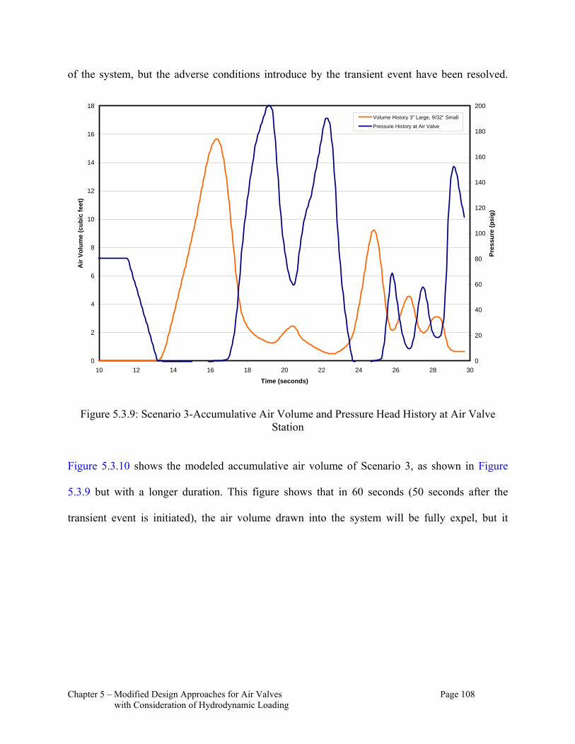
Chapter 5 – Modified Design Approaches for Air Valves Page 108 with Consideration of Hydrodynamic Loading
of the system, but the adverse conditions introduce by the transient event have been resolved.
Figure 5.3.9: Scenario 3-Accumulative Air Volume and Pressure Head History at Air Valve Station
Figure 5.3.10 shows the modeled accumulative air volume of Scenario 3, as shown in Figure
5.3.9 but with a longer duration. This figure shows that in 60 seconds (50 seconds after the
transient event is initiated), the air volume drawn into the system will be fully expel, but it
0
2
4
6
8
10
12
14
16
18
10 12 14 16 18 20 22 24 26 28 30
Time (seconds)
Air
Vo
lum
e (c
ub
ic f
eet)
0
20
40
60
80
100
120
140
160
180
200
Pre
ssu
re (
psi
g)
Volume History 3" Large, 9/32" Small
Pressure History at Air Valve

Chapter 5 – Modified Design Approaches for Air Valves Page 109 with Consideration of Hydrodynamic Loading
should be noted that this is after multiple openings and closings of the air valve assembly.
Figure 5.3.10: Scenario 3-Accumulative Air Volume over 60 seconds
The last scenario will provide a composite design that considers the normal operations, the
transient control, and the subsequent air release required to allow the system to restart (come
back on line) quickly after a transient event is experienced.
5.3.5 Modified Design Scenario 4, Composite Design Procedure
In the final scenario, the air release orifice was sized to maintain the restricted, sonic airflow rate
through the air release valve but was also sized to release all the air that is drawn into the system
during a hydraulic transient event in the first cycle of the air valve opening and closing. It is
important to sustain the dampening affect introduced by the restricted air release so the adverse
0
2
4
6
8
10
12
14
16
18
10 15 20 25 30 35 40 45 50 55 60
Time (seconds)
Air
Vo
lum
e (c
ub
ic f
eet)
Volume History 3" Large, 9/32" Small
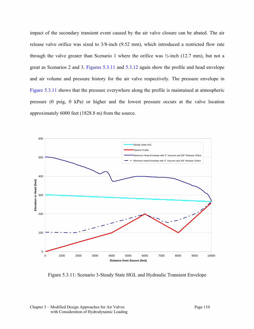
Chapter 5 – Modified Design Approaches for Air Valves Page 110 with Consideration of Hydrodynamic Loading
impact of the secondary transient event caused by the air valve closure can be abated. The air
release valve orifice was sized to 3/8-inch (9.52 mm), which introduced a restricted flow rate
through the valve greater than Scenario 1 where the orifice was ½-inch (12.7 mm), but not a
great as Scenarios 2 and 3. Figures 5.3.11 and 5.3.12 again show the profile and head envelope
and air volume and pressure history for the air valve respectively. The pressure envelope in
Figure 5.3.11 shows that the pressure everywhere along the profile is maintained at atmospheric
pressure (0 psig, 0 kPa) or higher and the lowest pressure occurs at the valve location
approximately 6000 feet (1828.8 m) from the source.
Figure 5.3.11: Scenario 3-Steady State HGL and Hydraulic Transient Envelope
0
100
200
300
400
500
600
0 1000 2000 3000 4000 5000 6000 7000 8000 9000 10000
Distance from Source (feet)
Ele
vati
on
or
Hea
d (
feet
)
Steady State HGL
Pipeline Profile
Maximum Head Envelope with 3" Vacuum and 3/8" Release Orifice
Minimum Head Envelope with 3" Vacuum and 3/8" Release Orifice

Chapter 5 – Modified Design Approaches for Air Valves Page 111 with Consideration of Hydrodynamic Loading
Again, it should be noted that the low pressure is a result of the initial pressure transient
condition and is no longer due to the subsequent air valve closure and secondary transient event.
As shown in Figure 5.3.12, all the air drawn into the system is expelled. This air valve design
provides good protection to the system for a hydraulic transient event and provides no additional
time to expel air. The air release valve design for this scenario is equivalent to 1.2% of the fluid
design flow rate. The AWWA M51 recommendation is 2% of the fluid flow rate.
Figure 5.3.12: Scenario 3-Accumulative Air Volume and Pressure Head History at Air Valve Station
Air Valve Design Analysis Summary 5.4
From the analyses presented above, it is proposed that the combination valve’s air vacuum valve
orifice be sized utilizing the AWWA M51 procedure for controlled pipeline drain down and/or
line filling, which for this example, resulted in a 3-inch (76.2 mm) orifice sizing. This vacuum
0
2
4
6
8
10
12
14
16
18
10 12 14 16 18 20 22 24 26 28 30
Time (seconds)
Air
Vo
lum
e (c
ub
ic f
eet)
0
20
40
60
80
100
120
140
160
180
200
Pre
ssu
re (
psi
g)
Volume History 3" Large, 3/8" Small
Pressure History at Air Valve
Chapter 5 – Modified Design Approaches for Air Valves Page 112 with Consideration of Hydrodynamic Loading
valve sizing procedure is simply a controlled drain down rate, which maintains a pipeline fluid
flow velocity of 1 ft/s (0.3048 m/s). In the AWWA M51 procedure for controlled drain down,
the air vacuum valve is sized to flow at a sub-sonic rate with a differential pressure of 2 psi
(13.79 kPa). The benefit of this sizing is that a vacuum valve sized using the controlled drain
down procedure will be more likely to close during a hydraulic transient event because the
vacuum valve is smaller and lighter than the valve sized using the line break or gravity flow
sizing criterion. As a result, the air vacuum valve float will be smaller and therefore more easily
displaced when positive pressure is experience in the pipeline at the valve. Once the large
vacuum orifice is closed, the air release valve will be allowed to operate as designed and reduce
the potential for secondary hydraulic transient events.
This thesis proposes that the current design practice for sizing air release valves be modified. It is
proposed that the most defensible and rational approach to sizing air release valves would be to
size the air release orifice with consideration of the compressed air volume. It should also be
noted that the 2% of design flow rate criterion that is currently recommended by AWWA M51 is
a relic of a paper written by Lescovich in the July 1972 AWWA Journal. The 2% represents the
volume of dissolved air in water in a fully saturated condition. This measure of air volume is
relatively inaccurate when one considers the range of pressure in a pipeline system. The author
would like to note that the volume of free air in a pipeline system under higher pressure is small
and the release of air in high pressure pipelines is not significant. The compressed free air is
generally conveyed to a point within the pipeline system where operating pressures are much
lower. At this lower pressure and expanded air volume is where air will most be released from
the system. The author would also like to take note that many distribution systems are equipped

Chapter 5 – Modified Design Approaches for Air Valves Page 113 with Consideration of Hydrodynamic Loading
with air release valves throughout. Because these air release valves generally do not see low
operating pressures, many times these valves are persistently inactive which may result in the air
valve float and seal developing a calcium deposit over time. Calcification, if allowed to build up
on the valve ports, will likely prevent the valve from operating properly and potentially
exacerbate the problem (a potential point of leakage or cross-contamination) rather than an aid in
the operation of the pipeline. It is recommended that AWWA M51 make note of this common
problem and recommend maintenance strategies.
With regard to the gravity flow design of the vacuum valve, this thesis proposes that a larger
vacuum valve be designed as a second air valve. This second air valve assembly, separate from
the combination valve design, should be set to open only under a severe vacuum condition. The
severe vacuum condition can be defined with a safety factor in relation to the theoretical collapse
pressure of the pipeline system. The definition of collapse pressure is well documented
throughout the pipeline industry. It is important that this larger vacuum valve be designed so that
the pipeline’s allowable negative pressure limits are not exceeded. For this larger vacuum valve,
the orifice can be spring loaded to prevent opening under minor partial vacuum pressure where
only the combination valve is required.
Conclusions of Air Valve Design with Consideration of Hydrodynamic Loading 5.5
The analysis of dissolved air and the subsequent series of modeled scenarios provide an
important critique of the standard design practices in North America with regard to air valve
sizing. The analysis shows that air valve sizing utilizing the AWWA M51 practices may be
inadequate and may introduce or exacerbate hydraulic transient conditions. By using a

Chapter 5 – Modified Design Approaches for Air Valves Page 114 with Consideration of Hydrodynamic Loading
compressed air analysis along with a dynamic hydraulic model a better understanding of the
dynamic loading characteristics present over the life of an air valve may be considered in design.
Special consideration will be required for air release valves sighted on pump discharge headers
and at locations where excess air is introduced to the system. Currently, the AWWA M51 design
procedure recommends to upsize both the air release and air vacuum orifices if the orifices are
shown to have a capacity that is marginal in relation to the sizing criterion. This thesis proposes
that if the air release valve capacity is marginal then the air release valve be down sized instead
of upsized.
Along with the changes to the design practices discussed above, this thesis also proposes changes
to the monitoring and maintenance requirements for air valves. Currently supervisory control and
data acquisition (SCADA) systems are used throughout the water conveyance industry to help
identify and improve upon performance goals. However, the author through fifteen years of
design experience and exhaustive research has yet to come across a comprehensive SCADA
system that monitors air valve performance. With a comprehensive monitoring system in which
air valve open/close positions are recorded as well as differential pressures, a better
understanding of both the air valve sizing and location can be made. For example utilizing the
current design practices outlined in the AWWA M51 manual of practice a 30 mile (48.3 kM)
long transmission pipeline may have more than 100 air valve assembles. Many of these air valve
assemblies will be used once (during line filling) in the life span of the pipeline and will never be
required again. However, some of these facilities may be used every time a pump starts or stops
or the flow rate is changed in the system. Without thorough monitoring, the location of these two
Chapter 5 – Modified Design Approaches for Air Valves Page 115 with Consideration of Hydrodynamic Loading
extreme cases may never be known over the life of the pipeline and as a result, the maintenance
of one extreme will be given similar consideration as the other. This thesis proposes that
modified design practices and guidelines (e.g. AWWA M51) include a recommendation for
SCADA systems that monitor air valves stations. Then with this recorded data, a more systemic
maintenance program can be developed as well as a more comprehensive design procedure that
considers the true operational requirements of each valve and valve location. This procedure can
be used as a feedback loop to assess where additional maintenance may be required or where
there may be a potential for an alternate design. For example, at air valve stations that are only
required during startup and shutdown the air valves may be replace with secured pit cocks. This
will reduce the up from capital cost as well as provide a more solid boundary against cross
contamination, and reduce the maintenance requirement as well. The valves that are found to be
frequently used can be assessed for performance in relation to sizing and location as well as be
assigned to a more rigorous maintenance program. Conceptually, it is easy to assume that this
type of monitoring and feedback to re-design may pay for itself within the first few years of
operation and if considering the reduction in potential cross contamination the pay back may be
immediate. In any regards, as can be seen in the above analyses, air valve sizing is not wholly
conducive to prescribed tables or nomagraphs. These proposed changes to the standard design
practices also require a unique study of the air valve location and sizing requirements. Utilizing
transient models that allow a way to consider the hydrodynamic loading characteristics is critical
to a proper design. Also, the assessment of the designed system through monitoring and feedback
with consideration for re-design should also be noted on the critical path as well. Ultimately, this
thesis proposes that the AWWA M51 “Air-Release, Air/Vacuum, & Combination Air Valves” be
re-written with this chapter as a foundation.
Chapter 5 – Modified Design Approaches for Air Valves Page 116 with Consideration of Hydrodynamic Loading
This thesis also proposes that a standard data request developed by design professionals be
introduced to the manual of practice. The data that is not readily available through published
manufacturer’s data but is required for a basic design is the pressure requirement needed to seat
the float of the large vacuum orifice. This data can be calculated if the mass and effective surface
area of the float is known, but that information is not widely published and as a result, many of
the installed vacuum valves also provide full air release during hydraulic transient events. As
shown in the modeling above, this rapid expulsion through the air vacuum valve may cause a
significant secondary transient event from air valve slam that may result in more severe
hydraulic transient pressures within the pipeline system.
5.5.1 Air Valve Design
Several important observations should be highlighted from the analysis proposed in this TM. An
air valve is a reactionary device and has several components that need to be carefully considered
both individually and collectively. The first consideration is the primary function of the valve.
This TM proposes that the most flexible air valve design would include two air valve assemblies.
One valve assembly contains a combination air valve with a vacuum valve and air release valve
sized for normal operation and hydraulic transient control. The second air valve assembly will be
a large ported air valve sized for a line break scenario.
The design and locating of air valves has become deterministic in modern design. Simple tables
and nomagraphs have replaced analysis for locating and sizing air valves within a system. Even
though this paper has proposed multiple changes in how air valves are considered in design;
there is very little empirical evidence of the benefit of these proposed changes. A fundamental
Chapter 5 – Modified Design Approaches for Air Valves Page 117 with Consideration of Hydrodynamic Loading
and relative obvious argument can be made outlining the cost savings of the reduced air valves,
but in a large system, the collective cost savings for each valve may not meet the savings
provided by a manufacturer for specifying a common valve size and type. Another issue to
consider is that air valves are obvious points of cross contamination and are known to be remote
and un-maintained appurtenances in most water conveyance systems. Given this basic argument,
it is critical that air valves be considered with more care and diligence in future design.

Chapter 6 – Conclusions and Prospective Work Page 118
CHAPTER 6 – CONCLUSIONS AND PROSPECTIVE WORK
Throughout the world, societies have become dependent, although in large part unaware of the
dependency, on inexpensive, reliable, and safe conveyance systems that deliver raw and potable
drinking water as well as that collect wastewater. The dialectic nature of the aging conveyance
infrastructure to remain inexpensive while sustaining the safety and reliability of service requires
a fundamental change in how we consider and assess the design and use of piping systems.
This thesis makes two basic research contributions to the field of pipeline and conveyance
system design. The first is outlined in the Integrated Design Approach (IDA) where
hydrodynamic loading is used as a means to inter-relate and assess the design, in many ways
conflicting design, approaches of the various components necessary within a pipeline system.
The IDA also allows for more comprehensive planning for when, where and what type of
components and/or materials should be considered in relation to the inter-dependencies of the
components as defined by the magnitude and frequency associated with hydrodynamic loading.
The second contribution is the development of an analysis procedure to quantify the performance
limits and sensitivity of cement mortar lining and air valves in the presence of a hydrodynamic
load. The analyses that are developed in this work are directly applicable to the improvement of
the present design practice and can be integrated into the standards and manuals of practice.
The present North American pipeline and appurtenance design standards were thoroughly
reviewed and areas where a temporal parameter, resulting from the consideration of
hydrodynamic loading, were identified. These areas included early design decisions such as the
type of pipeline material, the type of joint, gasket/seal material, and type of lining material. Each

Chapter 6 – Conclusions and Prospective Work Page 119
of these component’s design and performance limits is identified in their respective design
guidelines and controlling standard, but a means to inter-relate the interdependences of the
various performance limits is not. This work provides that roadmap that inter-related and/or
identified the interdependences of the various components that can be introduced to the standard
of practice. Through the classification that is characterized by the magnitude and frequency of a
hydrodynamic load, these interdependent relationships define that needed roadmap. This
concept can easily be introduced into the design guidelines to refine the material, components
considered for design as well as introduce a quantifiable temporal consideration for the future
analysis of fatigue, and probability of failure.
6.1 Hydrodynamics Analysis Applied in Design
The second significant contribution of this work is the use of hydrodynamic loading to formulate
a model to assess the performance limits of cement mortar lining and the development of an
analysis procedure to refine the proper selection of air valves in a transmission pipeline system.
1. It is common in the design and specification of pipe to consider an additional thickness of
cement mortar lining when a corrosive (acidic) raw or treated water is conveyed. What is
not considered, in the standards and design guidelines, is the presence of a hydrodynamic
force and the influence of the lining thickness on the ability to resolve the impulse of that
force. A simple model was developed using Darcy’s law in the presence of a
hydrodynamic load. The model found that the duration of the loading introduced a
potential for failure of the lining. This simple model resulted in a once overlooked
interdependency of cement mortar lining thickness and hydrodynamic loads. This alone is
a significant contribution to the industry, but put in context of this work, shows the need
and value of considering a hydrodynamic load to design a conveyance system.
Chapter 6 – Conclusions and Prospective Work Page 120
2. The present design procedure for air valves does not adequately consider the range of
hydrodynamic loading in which an air valve may encounter over its useful life. Many
times the air valve is designed for a principal purpose, irrespective of the range of
pressures it may be called to operate within. This work outlines a procedure using
hydraulic transient modeling software to help select the type and primary and secondary
purpose of the air valve and select the size and the location of the valve. In the analysis
presented in Chapter 7, it should that the proper sizing and control of both the air vacuum
port and the air release port resulted in the need for one (1) air valve, where if the
AWWA M51 procedure were followed, five (5) valves would have been required. This
analysis procedure is a significant contribution and again put in context of this work,
shows the need for the consideration of hydrodynamic loading in design.
6.2 Prospective Work
The intent of this work is to evolve the standards of practice and design guidelines that are
presently used in the industry. These standards and guidelines have developed over the years
and have repeatedly shown to produce high quality products. Due to the increasing cost of
operating, maintaining and/or replacing the conveyance infrastructure throughout the world, the
need to refine and identify areas where excessive, and therefore expensive, factors of safety have
been utilized needs to occur. Of course in this pursuit for design efficiency, the level of quality
should not be compromised because the comfort of “knowing” that water will flow when the
faucet is turned on is immeasurable. Through the use of hydrodynamic analysis, the author
believes that this design efficiency can be achieved and quantifiable, simply models can be
developed to identify and improve on the standard of design. Three steps are required.

Chapter 6 – Conclusions and Prospective Work Page 121
1. Using the hydrodynamic loading, the interdependencies of each component in a
composite design must be evaluated and identified so that models can be formulated. It
should be noted that the research, analysis, and development of the models must break
from the practice of sizing and refinement of individual components to the identification
of composite system interdependencies. At this stage the interdependencies, not the
models, are introduced to the design guidelines. This will demonstrate the value and
stimulate the research for the further development of the concept.
2. The new models must then be tested and vetted to identify limitations of practical use.
The simple models such as the cement mortar-lining model, once vetted, can be
introduced into the design guidelines. The more complex numerical models and/or
physical models can be run with multiple design parameters, these design parameters are
defined by the context of the model, to develop nomagraphs or reference catalogs, lookup
tables, or databases. These are published.
3. The final step is to develop a comprehensive design procedure to outline the use and
application of the hydrodynamic design approach to allow design of each component and
allow specification in design.
The author is presently contributing to the re-drafting of multiple standards and manuals of
practice for the American Water Works Association and American Society of Civil Engineers. In
this work on the standards and manuals, the author has concluded that the practicing arm of
conveyance design is failing to evolve as quickly as the numerical methods and analysis
techniques developed within the universities. This disconnect along with the understanding that
it is in human nature to treat the unknown or unfamiliar with skepticism and/or suspicion, leads

Chapter 6 – Conclusions and Prospective Work Page 122
the author to believe the only path forward for this work is the three (3) steps. On to step one I
go.

Reference List Page 123
REFERENCES
APCO Willamette, “Bulletin 2200 / 2600 Millennium Edition Ball & Cone Valves”, apcovalves.com
ASME – Fluid Meters: Their Theory and Application : Report of ASME Research Committee on Fluid Meters, Sixth Edition, ASME, New York, New York, 1971.
AWWA M11 Steel Pipe – A Guide for Design and Installation, Manual of Water Supply Practices M11, Fourth Edition, AWWA, Denver, Colorado, 2004.
AWWA M23 PVC Pipe – Design and Installation, Manual of Water Supply Practices M23, Second Edition, AWWA, Denver, Colorado, 2002.
AWWA M41 Ductile Iron Pipe and Fittings, Manual of Water Supply Practices M41, First Edition, AWWA, Denver, Colorado, 1996.
AWWA M51 Air Release, Air/Vacuum, & Combination Air Valves, Manual of Water Supply Practices M51, First Edition, AWWA, Denver, Colorado, 2001.
AWWA M55 PE Pipe – Design and Installation, Manual of Water Supply Practices M55, First Edition, AWWA, Denver, Colorado, 2006.
AWWA C200-05: Steel Water Pipe – 6 In. (150 mm) and Larger, AWWA Standard, 2005 Edition, AWWA, Denver, Colorado, 2005.
AWWA C205-07: Cement Mortar Protective Lining and Coating for Steel Water Pipe – 4 In. (100 mm) and Larger – Shop Applied, AWWA Standard, 2007 Edition, AWWA, Denver, Colorado, 2007.
AWWA C512-07: Air Release, Air/Vacuum, and Combination Air Valves for Waterworks Service, AWWA Standard, 2007 Edition, AWWA, Denver, Colorado, 2007.
AWWA C906-07: Polyethylene (PE) Pressure Pipe and Fittings, 4 in. (100 mm) Through 63 in. (1,600 mm), for Water Distribution and Transmission, AWWA Standard, 2007 Edition, AWWA, Denver, Colorado, 2007.
Reference List Page 124
Bergant, A., Arregui, F.J., Cabrera, E., Bournaski, E., Kruisbrink, A.C.H., Pereira, A.,Thorley, A.R.D. “Dynamic Behaviour of Air Valves, Measuring Report No. 1412”, Listostroj E. I., Ljublijana, Slovenia, December 2007.
Bergant, A., Kruisbrink, A.,Francisco, A. “Dynamic Behaviour of Air Valves in a Large-Scale Pipeline Apparatus” Journal of Mechanical Engineering 58, Strojniski vestnik, 2012.
Buried Flexible Steel Pipe: Design and Structural Analysis, ASCE Manuals and Reports on Engineering Practice No. 119. ASCE Reston, Virginia, 2009.
Daugherty, R., Franzini, J, Finnemore, E. Fluid Mechanics with Engineering Applications, Eight Edition. McGraw Hill, Singapore, 1989.
Design against surge and fatigue conditions for Thermoplastic pipes, UK Water Industry Information & Guidance Note (IGN 4-37-02), 1999.
DuChateau, P., Zachmann, D. Applied Partial Differential Equations. Dover Publications Inc. Mineola, New York, 1989.
Escarameia, “Air Problems in Pipelines, A Design Manual”, HR Wallingford, 2005
Farr, J.R., Jawad, M. H. Guidebook for the Design of ASME Section VIII Pressure Vessels, Second Edition. ASME Press, New York, 2001.
Gere, J., Timoshenko, S. Mechanics of Materials 4th Edition. Cheltenham, U.K., Stanley Thornes, 1999.
Gere, J., Timoshenko, S. Theory of Elastic Stability. Engineering Society. Monographs. McGraw-Hill Book Co. (First Edition, 1936).
Lescovich, J.E., “Locating and Sizing Air Release Valves” Journal of American Water Works Association (AWWA), AWWA, Denver, Colorado, 1972.
McInnis, D.A., Karney, B.W., Axworthy, D.H. TransAM Reference Manual, Hydra Tek Solutions, Inc. Ajax, ON 2004.
Reference List Page 125
McPherson, D.L. “Air Valve Sizing and Location: A Prospective”, ASCE International Pipeline Conference, San Diego, CA, August, 2009
McPherson, D.L., Karney, B.W, “Sub-atmospheric transient pressure conditions – where and what it may influence in design”, BHRA 10th International Conference on Pressure Surges, Edinburgh, Scotland, May 2008.
McReynolds, M., Peng, T., Romer, A. “Causes of Etiwanda Pipeline Lining Failure”, ASCE International Pipeline Conference, Keystone, Co, August, 2010.
Parmakian, J. Waterhammer Analysis. Dover Publications Inc. New York, New York, 1963.
Petroski, H. To Engineer is Human: The Role of Failure in Successful Design. Vintage, 1992.
Steel Penstocks (Second Edition), ASCE Manuals and Reports on Engineering Practice No. 79. ASCE Reston, Virginia, 2012.
Val-Matic - Theory, Application, and Sizing of Air Valves, Val-Matic Valve and Manufacturing Corporation, Elmhurst, Illinois, 1997.
Warman, D, Hart, J. Development of Pipeline Surface Loading Screening Process & Assessment of Surface Load Dispersing Methods for the Canadian Energy Pipeline Associate (CEPA), 2005.
Watkins, R. Report on parallel plate tests on mortar lined and coated steel pipe for Smith-Scott Company of California, 1965
Watkins, R.K., Anderson, L. R. Structural Mechanics of Buried Pipes. CRC Press, 1999.
Whitlow, R. Basic Soil Mechanics, 2nd Edition. Longman Scientific and Technical, Essex, England, 1983.
Wiggert, D.C., Tijsseling, A.S. “Fluid transients and fluid-structure interaction in flexible liquid-filled piping”, Journal of Applied Mechanics Reviews, Volume 54, Number 5, September, 455-481. American Society of Mechanical Engineers. 2001.

Reference List Page 126
Wylie, E. B., Streeter, V.L. Fluid Transients in Systems. Prentice Hall, 1993.