Embed Size (px)
Citation preview

B U L L E T I N
334GI N S T A L L A T I O N & O P E R A T I O N
®
BulkSonics® Ultrasonic Continuous LevelMeasurement for Solids and Liquids
Solids Smart Transmitter ModelsSST-15, SST-30 and SST-40
Liquid Smart Transmitter ModelsLST-20, LST-40, LST-50 and LST-80
Model LST
Thank you for purchasing a quality product from Monitor TechnologiesLLC. We realize that you do have a choice of vendors when procuringlevel measurement equipment and we sincerely appreciate your busi-ness!
This manual contains the information necessary to ensure a safe andsuccessful installation. Please read and comply with the section onpage 27 of this manual pertaining to SAFETY. Doing so will ensure prop-er operation of the equipment and the safety of all personnel.
Before discarding the shipping container, please inspect it thoroughlyand verify that all parts ordered are accounted for. Sometimes smallerparts become stuck under carton flaps and other packaging materials.
In the event that information contained herein does not completely sat-isfy your requirements or answer your questions, you may contactTechnical Support on our website www.monitortech.com, by telephoneat 800-766-6486 (630-365-9403), or by fax at 630-365-5646. If yourlevel sensor ever requires service either in or out of warranty, pleasecontact us and obtain an RMA (return material authorization) numberprior to shipping the unit to us.
Model SST

2
ATTENTION:USE OF VOLUME &
WEIGHT CALCULATIONSThe BulkSonics® line of ultrasonic equipment makes a directmeasurement of the distance between the sensor and the materi-al surface. This equipment does not measure the volume or weightof the material within the vessel. The QUEST+ software can per-form calculations to display the volume and weight of the material.These calculations are based upon the distance measurementand the vessel dimensions and material bulk density entered bythe user during setup.
NOTE: The calculated volume and weight values should be con-sidered "estimates". Monitor Technologies LLC accepts noresponsibility for the accuracy of the calculated and displayed vol-ume and weight values. The accuracy (not stated or warranted) ofthe volume/weight calculations are effected by the fluctuation andaccuracy of various factors. These factors include, but may not belimited to, actual vessel dimensions, sensor mounting location,sensor aiming, angle of repose (negative and positive), materialbulk density, material flow properties (ratholes, bridging, etc.),material inlet/discharge locations, and material packing.
Please consult the factory to discuss applications where vol-ume/weight is of critical importance.

3
The BulkSonics® ultrasonic continuous level product lineconsists of smart transmitters as well as sensor/controllersystems (See Bulletins 334E and 334F). The smart trans-mitters consist of a sensor mounted at the top of the tankor silo with integral mounted electronics controller withlocal display (optional on LST models) and outputs. Thesmart transmitters are available for solids and liquid appli-cations. The transmitter’s sensor is a non-contact devicewith no moving parts.
The BulkSonics smart transmitters are available in twoconfigurations, those used specifically for solids (SST:solids smart transmitter) and those used specifically forliquids (LST: liquid smart transmitter). Models include theSST-15, SST-30 and SST-40 for solids applications andthe LST-20, LST-40, LST-50 and LST-80 for use with liq-uids. Each model can provide accurate level measure-ment in a variety of difficult applications.
P R E - I N S TA L L AT I O N C O N S I D E R AT I O N S
P R I N C I P L E O F O P E R AT I O NThe BulkSonics® ultrasonic continuous level measure-ment product line utilizes the principles of ultrasonic tech-nology to provide accurate level measurements in solidsand liquids storage vessels as well as open channel flowmetering applications (LST models only).
Ultrasonic pulses are emitted from the transmitter’s sen-sor into the tank or silo and reflected back from the sur-face of the material. A reflected pulse is called an echo.The distance measurement from the sensor to the materi-al is directly related to the duration of time necessary forthe echo to return to the sensor. The intelligent electron-ics in the smart transmitter interfaces with the sensor andprocesses the received signal from the sensor to displaythe measured distance/level and generate all output sig-nals. Smart transmitters have an analog output and arelay (4-wire version only) and can be equipped withHART® communications option.
Beam Angle: A total beamangle of 5-7˚ at–3db exists onBulkSonics ®
smart transmit-ters. A smallbeam angle isimportant fors u c c e s s f u lapplication ofultrasonic tech-nology. Thiscan ensure a reliable measurement in narrow vessels,vessels with protruding objects and focuses the soundenergy for good penetration through gases, vapor, foamand dust. Consult the product specifications for the totalbeam angle for the specific smart transmitter you areusing.
Figure 1: Diameters corresponding to 5˚beam angle
Make sure that no object with a reflecting surface pro-trudes into the ultrasonic beam of the smart transmitter(See Figure 1 for typical beam angle. Actual dimensionsmay vary.). Due to their narrow beam angle and uniquesignal processing features, the BulkSonics smart trans-mitters can tolerate smaller objects (E.g.: probe of a limitswitch, smooth vessel wall) within the sonic cone, howev-er, avoid these whenever possible.
Sensor Dead Zone:This is a feature common to all ultrasonic continuous levelmeasurement devices. Each smart transmitter’s sensorhas a “dead zone” (distance from the sensor face) withinwhich the unit is unable to measure. The dead zone forBulkSonics Smart Transmitters are as follows:
SST-15 = 3.3ft (1.0m)SST-30 = 2.0ft (0.6m)SST-40 = 2.0ft (0.6m)LST-20 = 2.0ft (0.6m)LST-40 = 1.5ft (0.45m)LST-50 = 1.2ft (0.35m)LST-80 = 0.8ft (0.25m)
In solids level measurement (SST models only), due tothe angle of repose, the smart transmitter can usually belocated such that the dead zone is not an issue. In liquidlevel measurement (LST models only), if measurementwithin the dead zone distance is critical, the transmittermay need to be recessed with a standoff pipe or mountingneck (See Choosing the Transmitter Location for LiquidLevel Measurement Applications).
Choosing The Transmitter Location:Model LST (Liquid Level Measurement Applications): Thebest location for a smart transmitter is 1/4 to 2/3 the diam-eter of the tank away from a sidewall and in a locationwhere it does not interfere with incoming material or anyfixed internal obstructions within the vessel.1) Do not install the smart
transmitter above mate-rial inlet flow paths or internal objects, e.g.: cooling pipes, ladders, bracing members, ther-mometers, etc (Figure 2).
2) Mount the smart trans-mitter with its face paral-lel to the liquid surface ±2-3˚ (Figure 3).
3) In agitated tanks, position the smart transmitter where the material sur-face is flat. Try mounting it closer tothe sidewall where the liquid surfacemay form a less steeper angle of repose. In case of heavily agitated tanks with a steep angle of repose ultrasonic measurement may not be possible (Figure 4).
4) The smart transmitter should be protected against overheating
Figure 2
Figure 3

4
(e.g. by direct sunshine) to avoid inaccurate measure-ments (Figure 5).
5) Foaming of the liquid surface may render ultrasonic level metering impossible. If possible, a location should be found where foaming is the smallest (the device should be located as far as possible from liquidinflow) or a stilling pipe or well should be used.
HEIGHT(L) DIAMETER(D)LST-80 LST-50 LST-40 LST-20
5.9in/150mm 2.4in/60mm 2.4in/60mm Consult Stand-off pipeMonitor can not be
7.9in/200mm 2.4in/60mm 3in/75mm used as the transducer
9.8in/250mm 2.6in/65mm 3.5in/90mm face mustprotrude
11.8in/300mm 3in/75mm 4.1in/105mm into tank(See Figure 6)
13.8in/350mm 3.3in/85mm 4.7in/120mm
Table 1
Figure 5Figure 4
6) Mounting liquid smart transmitters on standoff pipes isalso possible (See Figure 6). The structure of the standoff pipe should be rigid. The inner rim where theultrasonic beam leaves the pipe should be rounded. For minimum dimensions refer Table 1.
Figure 6
Model SST (Solids Level Measurement Applications): Thebest location for a smart transmitter is 1/6 to 1/2 of thediameter of the silo away from a sidewall. The smarttransmitter should be mounted in a location where it canbe properly aimed at a point representative of the averagematerial level and not be interfered with by incomingmaterial or internal obstructions. A joystick mounting
assembly is provided on all model SST smart transmittersand is required for aiming. As a rule of the thumb and tocomply with the above requirements:1) Position transmitter as far away from the fill inlet
point(s) of the silo as possible (See Figure 7).2) In applications where the material is pneumatically con-
veyed into the vessel, position the sensor where the speed of material inflow is at its lowest value (See Figure 8).
Figure 8Figure 7
3) Make certain you can aim the smart transmitter’s sen--sor towards the discharge/outlet of the silo (See Figure9).
Figure 9
4) Smart transmitters can also be mounted on existing (manhole) covers, access lids, or for instance on a steel structure lowered into a larger opening on the roof, e.g.: 20 by 20 inch / 500 x 500 mm. This solutionis to be used with roofs thicker than 14 to 15 inch / 350to 380 mm.
5) Silos constructed of concrete may require special pro-visions to prevent the edges of the hole from interferingwith the beam. If the entire tilting range of the joystickis required (±20˚), then the thickness of the concrete roof can not exceed the value as specified in Table 2.
DIAMETER OF OPENING THICKNESS OF ROOF[inch/mm] [inch/mm]
6.3”/160 mm 4.3”/110 mm
7.5”/190 mm 5.9”/150 mm
9”/230 mm 7.9”/200 mm
11.8”/300 mm 11”/280 mm
13.4”/340 mm 11.8”/300 mm
Table 2
Open Channel Flow Measurement:(Liquid Smart Transmitters Only) For the best possibleperformance and measurement accuracy, the smarttransmitter should be installed as close to the expectedmaximum liquid level as possible. However, the transmit-ter should NOT be so close to the maximum liquid level as

5
M E C H A N I C A L I N S TA L L AT I O N
to be within the transmitter sensor’s dead zone (Refer tosection on Sensor Dead Zone and Specifications formeasuring range).
Install the device upstream in a place defined by the char-acteristics of overflow and metering channel along the lon-gitudinal axis of the flume or weir.
From the point of view of measurement accuracy, thelength of the channel sections preceding and following themeasuring flume and their method of joining to the meas-uring channel section are of critical importance.
Despite even the most careful installation, the accuracy offlow metering will be lower than that specified for distancemeasurement. The features of the flume or weir useddetermine measurement accuracy.
Choose the best location for the smart transmitter accord-ing to the Pre-Installation Considerations section.
Liquid Level Measurement Applications:(Models LST only)
LSTs with threaded connection: Thread the device into thecoupling and tighten using the wrench flats provided onthe sensor part. Never attempt to tighten the transmit-ter by its housing! Once the transmitter is screwed tight,rotate the housing (max. 300˚) to reach the desired cableoutlet position.
LSTs with flange: Mount a counter flange on the tankaccording to the diameter of the transmitter’s sensor andhole pattern of the flange. Attach the flange to the count-er flange using 1/2” to 3/4”/M12 bolts.
Solids Level Measurement Applications:(Models SST only) Although it may be most convenient tomount the transmitter on a removable port cover, the bestlocation may be elsewhere. Consult the factory forapproval of the mounting location. Engineering drawingsor properly dimensioned hand sketches are adequate forcommunicating with the factory.
SPLIT-FLANGE SEALING AFTER INSTALLATIONWhen using flanges with the “split insertion” feature itis critically important to seal the “split joint” with a sealant that can withstand the particular environment(RTV, etc). Failure to seal the joint may permit moisture to penetrate the vessel.
Standard Installation:1) Remove the split insertion from the flange and put the
flange around the joystick.2) Slide the insertion back to its place and screw the ball-
joint housing to the flange with the (4) 1/2” to 3/4”/M12bolts and tighten only to such an extent that will allow free movement of the aiming arm around the ball joint for the aiming process.
3) Cut and drill the appropriate holes on the vessel
according to the diameter of the transmitter and hole pattern of the flange.
4) Attach the flange to the vessel using 1/2” to 3/4”/M12 bolts.
5) Aim the sensor using the joystick/flange assembly (SeeAiming), then tighten the ball-joint housing (maximum 2.58ft-lbs/3.5 Nm).
Installation from inside the vessel: If the roof opening forany reason can not be as big in diameter as the transmit-ter (See Figure 10):1) Push the unit out of the silo (upwards) (See Figure 10,
Item 1).2) Remove the split insertion from the flange and put the
flange around the joystick (See Figure 10, Item 2).3) Slide the insertion back to its place (See Figure 10,
Item 3).4) Screw the ball-joint housing to the flange with the (4)
1/2” to 3/4”/M12 bolts and tighten only to such an extent that will allow free movement of the aiming armaround the ball joint for the aiming process (See Figure10, Item 4).
5) Cut and drill the appropriate holes on the vessel
Figure 10
according to the diameter of the transmitter and hole pattern of the flange.
6) Screw the flange to the vessel using 1/2” to 3/4”/M12 bolts.
7) Aim the sensor using the joystick/flange assembly (SeeAiming), then tighten the ball-joint housing (maximum 2.58ft-lbs/3.5 Nm).

6
Aiming:To reduce weak signal reflection from the material surfacecaused by the angle of repose, it is recommended to tiltthe sensor by the aiming arm of the transmitter. In mostcases, the transmitter’s sensor should be aimed towardsthe middle of the tank/silo bottom by aiming at the silo dis-charge outlet. In applications where material angle ofrepose is not present or with tall and narrow silos(height/diameter ≥ 5) aiming is not critical: i.e. the sensorshould face straight down. Refer to the section in Pre-Installation Considerations entitled “Model SST (SolidsLevel Measurement Applications)” for additional informa-tion regarding sensor aiming.
E L E C T R I C A L I N S TA L L AT I O N
Hazardous Location Precautions:(European Approvals Pending) Observe the regulationslisted in the National Electrical Code regarding equipmentin hazardous locations. Refer to Specifications for ratingof equipment.
Factory Wiring:Do not alter any factory wiring within the smart transmitter.Wire only to the terminal connections within the wiringconnector or instrument enclosure.
Permanently Connected Equipment:Disconnecting devices shall be included in the systeminstallation. In installations where multiple circuits areused individual disconnects are required. The discon-nects shall be within close proximity of the equipment,accessible to operators, and marked appropriately as thedisconnect for the associated circuit. Assure the discon-nect ratings are appropriately sized to the circuit protect-ed (refer to Specifications).
Circuit Separation:Two cable entry locations are provided to aid in maintain-ing separation of “hazardous live” (typically mains volt-ages such as 115VAC and 230VAC) and limited circuits(typically control voltages less than 30Vrms or 42.5VDC).However, since the smart transmitter’s single wiring com-partment can not absolutely protect against physical con-tact between multiple circuits, it is required that all wiringused must have an insulation rating of 300V minimum,and a temperature rating of 176˚ F (80˚ C) minimum.
Protective Earthing:Each transmitter is provided with an internal and external“protective conductor terminal” which shall be terminatedto the local earth ground potential to eliminate shock haz-ard in the unlikely event of internal insulation breakdown.Select wire size that can carry in excess of the sum of allcircuits maximum amperage. If the smart transmitter hasa plastic housing (optional on some units) use the exter-nal “protective conductor terminal”.
4-Wire Smart Transmitters:(High or Low VAC/VDC Power Supply - See Figure 11)The smart transmitter electronics may be damaged by
electrostatic discharge (EDS), therefore, apply the neces-sary precautions required to avoid electrostatic discharge,e.g. by touching a properly grounded point before remov-ing the cover of the enclosure.
Unscrew the locking nut on the side of enclosure and tiltthe upper part of the enclosure open to access the termi-nal blocks. Route cable(s) through the 1/2" NPT fittings orPg16 cord connectors provided. High voltage wiring(power input and possibly relay contact) and signal wiring(analog 4-20mA output; RS-485 communications) mustnot be led in a common duct or conduit.
Tighten cable glands or conduit connections as well asenclosure cover after installation to ensure proper sealing.
Power Input: (See Figure 11) Smart transmitters can beprovided with either a high voltage AC or a low voltageAC/DC power supply. Verify the specific power supplyrequired for your transmitter by looking at the nameplateon the side of the enclosure. Connect power input wiringin accordance with the diagram in Figure 11. DC poweredtransmitters can be connected in a 3-wire configuration(uses the unit’s DC power source to drive the analog out-put). In this situation, terminals “1” and “6” must be inter-connected. Please note that galvanic isolation of the 4-20mA output will not exist in a 3-wire configuration. Makesure to connect DC powered transmitters with the correctpolarity. Improper wiring of the power input will preventproper operation and may damage the unit.
Analog Output: Wiring for the analog signal should beconnected to terminals labeled 6 and 7. Connect wiringfor analog output in accordance with Figure 11.
Relay Contact Output: Wiring for the relay output uses ter-minals labeled 3, 4 and 5. Connect wiring for the contactoutput in accordance with Figure 11. The SPDT outputcontact can be used to switch high voltage/high currentloads (See Specifications for ratings). Whenever possible,use an independent voltage source to operate the loads.Follow all electrical codes and use proper wire gaugesize.
Figure 11

7
S TA RT- U P
2-Wire Smart Transmitters:(Loop Powered, Model LST only - See Figure 12) Thesmart transmitter electronics may be damaged by electro-static discharge (EDS), therefore, apply the necessaryprecautions required to avoid electrostatic discharge, e.g.by touching a properly grounded point before removingthe cover of the enclosure.
Unscrew the enclosure cover and remove the displaymodule (if present) to access the terminal block. Routecable through the 1/2" NPT fittings or Pg16 cord connec-tors provided.
Tighten cable glands or conduit connections as well asenclosure cover after installation to ensure proper sealing.
Power/Signal Connection: The 2-wire smart transmitter ispowered over the same wiring as the 4-20mA signalcable. Refer to the Specifications section for informationabout the power supply limits and requirements. Connectthe power/signal connection in accordance with Figure 12.
Loop Current Check: After removing the cover and thedisplay module (if present), the actual loop current can bemeasured to within an accuracy of 0.5% using a digitalmultimeter (in the range of 200 mV) and connecting themeasuring leads of the meter to the points indicated inFigure 12.
Figure 12
For solids applications using model SST smart transmit-ters, refer to Aiming section. In addition, certain program-ming parameters may assist you in properly aiming thesmart transmitter for solids applications or may assist youin enhancing your smart transmitter performance for anyapplication. Refer to the details in the following section onprogramming your smart transmitter.
# DESCRIPTION AIMING GOAL
P70 Number of Echoes/Echo Map/ Minimize the number of echoes if Manual Echo Selection possible. The echo map shows the
distance and amplitude of each echo. STEP through this parameter
to ensure the correct echo is strongest. The greater the disparity the better; Manual selection allows the selection of an echo other than
the one shown.
P71 Distance of Measuring Window Distance of the echo the smarttransmitter is locking onto.
P72 Amplitude of Echo in Window Displays the amplitude of the echo locked onto. An amplitude over 20-
25 is typically adequate, but the higher the better.
P74 Signal/Noise Ratio Ensure that this value is > 30.
P R O G R A M M I N GTo assist in programming your smart transmitter, beadvised that your BulkSonics® smart transmitter has thefollowing factory default settings:
Analog output, display and bargraph: LEVEL4 mA: assigned to the minimum
level 0%20 mA: assigned to the maximum
level 100%Error indication by the analog output: hold last valueDamping: 60 sec for Liquid Smart
Transmitters, 300 sec for Solids Smart Transmitters
Smart transmitters can be programmed in one of twomethods. The 4-wire smart transmitter can be pro-grammed using “Touch-Magnet Programming” methods(Liquid Smart Transmitters only) and also can be pro-

grammed using the keypad display programmer (standardon all SST models for solids application and optional onLST models for liquids). The 2-wire smart transmitters(liquid only) can be programmed with or without the dis-play programmer. Programming without the display pro-grammer on 2-wire and 4-wire units is limited. Choose theappropriate programming method for your application.Review the appropriate programming section in this man-ual for your specific smart transmitter.
Touch-Magnet Programming:(4-wire LST models only) Touch-magnet programming isaccomplished with the magnetic screwdriver supplied withthe smart transmitter.
The following can be programmed: 1) Assignment of the 4mA analog output to the minimum
level/maximum distance.2) Assignment of the 20mA analog output to the maximum
level/minimum distance3) Error indication by the analog output (Hold, 3.6mA,
22mA). Refer to the section on programming the ana-log output parameter P12
4) Relay switch points5) Damping (10, 30 and 60 sec)6) Smart transmitter Reset (to the factory default)
Note: Analog output can also be assigned in invertedmode:
4mA= 100% (Full), 20mA= 0% (Empty)
Programming is only possible if the smart transmitterreceives a valid echo (i.e. “ECHO” LED is illuminated)and transmitter is in “LEV” (level) measuring mode (facto-ry default).
The accuracy of the setting of level/distance with thetouch-magnet programming method is limited to ±0.78inch (20 mm). Therefore, the relay switch point differencebetween “On” and “OFF” must be greater than 0.78 inch(20mm).
8
Figure 13
To program, place the magnetic screwdriver on the pro-gramming area in accordance with Figure 13 (either atsymbol A or B) and check the LEDs for their status:
= LED is on = LED is blinking= LED is off = LEDs are blinking alternatively
Make sure that after programming is completed all othermagnetic influences will be avoided.
ACTION LED INDICATION
1) Check valid echo = Valid echo received, trans-mitter programmable
2) Place magnet to symbol “A” and = Transmitter in programming mode
3) Hold magnet in place = Distance assigned to 4mA
4) Remove magnet when all LEDs = Programming completedare off
Use level in tank or a fixed targete.g. the wall
Minimum level, 0%, empty tank (assignment to 4 mA):Place the smart transmitter at a distance to the target cor-responding to the required maximum distance/minimumlevel.
Maximum level 100%, full tank (assignment to 20mA):Place the smart transmitter at a distance to the target cor-responding to the required minimum distance/maximumlevel.
ACTION LED INDICATION
1) Check valid echo = Valid echo received, trans-mitter programmable
2) Place magnet to symbol “B” and = Transmitter in programming mode
3) Hold magnet in place = Distance assigned to 20mA
4) Remove magnet when all LEDs = Programming completedare off
Use level in tank or a fixed targete.g. the wall
Programming relay switch-on point:(The level where relay becomes energized) Place thesmart transmitter at a distance to the target correspondingto the required switch-on point for the relay. (Do not forgetto check for a valid echo!)
ACTION LED INDICATION
1) Place magnet to symbol “A” = Programming mode
2) Place magnet to symbol “B” and = Programming in progress
3) Hold magnet to symbol “B” = Programming in progress
4) Place magnet to symbol “A” = Programming in progress
5) Remove magnet when all LEDs = End of programmingare off
Use level in tank or a fixed targete.g. the wall

9
Programming relay switch-off point:(The level where relay becomes de-energized) Place thesmart transmitter at a distance to the target correspondingto the required switch-off point. (Do not forget to check fora valid echo!)
ACTION LED INDICATION
1) Place magnet to symbol “A” = Programming mode
2) Place magnet to symbol “B” and = Programming in progress
3) Hold magnet to symbol “B” = Programming in progress
4) Keep holding magnet to symbol = Programming in progress“B”
5) Remove magnet when all LEDs = End of programmingare off
Use level in tank or a fixed targete.g. the wall
Please note that the smallest switch-differential achiev-able with magnet programming is 0.78 inch (20 mm).
“Error indication” by the analog output:(Check for valid echo as above)
ACTION LED INDICATION
1) Place magnet to symbol “A” = Programming mode
2) Place magnet to symbol “B” = Hold last valuerepeatedly to select the required = 3.6mAerror indication mode = 22mA
3) Place magnet to symbol “A” = Programming completed
“Damping”:(Check for valid echo as above)
ACTION LED INDICATION
1) Place magnet to symbol “B” = Programming mode
2) Place magnet to symbol “A” = 10 secrepeatedly to select the required = 30 secdamping = 60 sec
3) Place magnet to symbol “B” = Programming completed
Reset to factory default:
ACTION LED INDICATION
1) Place magnet to symbol “B” = Programming mode
2) Place magnet to symbol “A” and = Reset in progress
3) Hold magnet to symbol “A” = Reset in progress
4) Remove magnet when all LEDs = Programming completedare off
ACTION LED STATUS CORRECTION
1) Attempted = blinking twice = Find valid echoprogramming No Echo
2) Attempted = blinking three times = Use the optional dis-programming access denied play programmer and
(access code active) refer to section for parameter P99.
3) Attempted = blinking four times = Use the optional dis-programming Transmitter not in play programmer and
LEV (Level) measur- refer to section for ing mode parameter P01.
4) Programming = blinking alternately = Set relay switch differ-of the relay relay switch differen- ential (on-off) greater
tial (on-off) too small than 0.78 in (20 mm).
Error indications during programming:(By LEDs)
Programming without Display Module:(2-wire units only) Programming is only possible if thesmart transmitter is in LEV (level) measuring mode andreceives a valid echo i.e. the “ECHO” LED is illuminated.
The following can be programmed without display mod-ule:1) Assignment of the 4mA value to the required minimum
level/maximum distance2) Assignment of the 20mA value to the required maxi-
mum level/minimum distance3) Error indication by the analog output (Hold, 3.6mA or
22mA)4) Damping (10, 30 or 60 sec)5) Reset to the factory default
Note: Analog output can also be assigned in invertedmode:
4mA = 100% (Full), 20mA = 0% (Empty)
To program, press the button in the relevant sequence asshown in the procedures below and check the state of theLEDs. Symbols for the states of the LEDs:
= LED is on = LED is blinking= LED is off = LEDs are blinking alternatively= Don’t care
Minimum level, (0%, empty tank) assignment to 4mA:
ACTION LED STATE FOLLOWING ACTION
1) Check for a valid ECHO = Valid ECHO, transmitter programmable
2) Press NEXT button steadily = Programming mode
3) Press UP button steadily = 4mA assigned to the distance (See diagram)
4) Release buttons = Programming completed
Use level in tank or a fixed targete.g. the wall

10
Maximum level (100%, full tank) assignment to 20mA:
ACTION LED STATE FOLLOWING ACTION
1) Check for a valid ECHO = Valid ECHO, transmitter programmable
2) Press NEXT button steadily = Programming mode
3) Press UP button steadily = 20mA assigned to the distance (See diagram)
4) Release buttons = Programming completed
Use level in tank or a fixed targete.g. the wall
“Error state” indication by the analog output:(Check for a valid echo as above) As a result of this set-ting the value of the analog output will be 3.6mA; 22mA orthe last known good value (hold) until the error conditionno longer exists.
ACTION LED STATE FOLLOWING ACTION
1) Check for a valid ECHO = Valid ECHO, transmitter programmable
2) Press UP button steadily = Programming mode
3) Press the DOWN button DOWN key (hold last knownsteadily to set function to “hold good value) last known good value”, press = ENTER key (3.6mA)the ENTER button steadily to NEXT key (22mA) set function to 3.8mA, or press the NEXT button steadily to set function to 22mA.
4) Release buttons = Programming completed
Damping time setting: (Check for a valid echo as above)
ACTION LED STATE FOLLOWING ACTION
1) Check for a valid ECHO = Valid ECHO, transmitter programmable
2) Press ENTER button steadily = Programming mode
3) Press the NEXT button 10 secondssteadily to set damping time to = 30 seconds10 seconds, press the UP 60 seconds button steadily to set the damping time to 30 seconds, or press the DOWN button steadily to set the damping time to 60 seconds.
4) Release buttons = Programming completed
RESET - Returning to the default:(Check for a valid echo as above)
ACTION LED STATE FOLLOWING ACTION
1) Press NEXT button steadily = Programming mode
3) Press ENTER button steadily = Default loaded
Indication of mistakes made during programming:(By LEDs)
ACTION LED STATE CORRECTION
1) Attempted = blinking twice = No Find valid echoprogramming Echo
2) Attempted = blinking three times = Use the display pro-programming no access possible grammer, refer to sec-
tion for parameter P99.
3) Attempted = blinking four times = Use the display pro-programming Transmitter not in grammer, refer to sec-
LEV (Level) tion for parameter P01.measurement mode
Programming with the Display Programmer:(4-wire or 2-wire: SST or LST models)
Programming Modes: BulkSonics smart transmitters sup-port two different methods of programming using the dis-play programmer (standard with all model SST units andoptional with LST models): QUICKSET and FullParameter Access (Refer to Figure 14).1) QUICKSET: A fast and easy way to start up your smart
transmitter. Using the QUICKSET menu-driven pro-gramming mode, set up for most applications can be completed quickly and easily.
2) Full Parameter Access: Enables the user to access allparameters of the smart transmitter, providing the flex-ibility to tune the transmitter to your specific application.
Figure 14
QUICKSET: The QUICKSET method of programming isrecommended as a simple and fast way to set up aBulkSonics smart transmitter by using 8 basic parame-ters. This menu driven programming mode supports thefollowing basic settings:1) Engineering units for the display (US/English or Metric)2) Maximum Measuring Distance3) 4mA Calibration4) 20mA Calibration5) Error Indication by the analog output6) Damping time7) Relay ON switching point (Level at which relay ener-
gizes) – Only with 4-wire versions8) Relay OFF switching point (Level at which relay de-
energizes) – Only with 4-wire versions

11
Full Parameter Access: All features of the smart transmit-ter can be accessed by parameter addresses including:1) Measurement configuration2) Outputs3) Measurement optimization4) Pre-programmed tank shapes for volume calculation5) 32-point linearization table6) Open channel flow metering functions
Display and Keypad:
1) Symbols used on the LCD:DIST: Distance (measuring) modeLEV: Level (measuring) modeVOL: Volume (measuring) modeFLOW: Open channel (flow metering) modePROG: Programming mode (device under
programming)RELAY: Relay (4-wire units only)T1: TOT1 volume flow totalizer (resetable
aggregate)T2: TOT2 volume flow totalizer (aggregate)FAIL: Measurement / Device errorÕÔ: Level changing direction (increasing or
decreasing)Bargraph: Assigned to either Analog Output or Echo
Strength2) Symbols used on the frame of the display pro-
grammer unit (denoted by pointer arrows):M: Metric systemUS - US: (English) calculation systemVarious Engineering units
3) LEDs:ECHO LED: Illuminated as long as the device receives
a valid echo signalRELAY LED: Illuminated when the relay is energized
(only with 4-wire models)COM LED: Illuminated during communication (HART
communications output option only)4) Display indication: Depending on the selected Meas-
urement Mode (See Parameter P01 in Parameters sec-tion), the following process values can be displayed byrepeatedly pressing the NEXT button. To return to the primary display mode press the ENTER button.- Level- Volume or Flow- Distance- TOT1 and TOT2 (if Flow metering is setup)- Error code (if “FAIL” is blinking)
To display the temperature at the transmitter’s sensor,press the UP button:
To display the analog current output value, press DOWN :
Quick Guide to Programming Using the DisplayProgrammer with Keypad:(See details in QUICKSET or Full Parameter Access forspecific programming instructions)
Double key pressing: (Press keys simultaneously for 3seconds)1) Enter into or Quit programming modes
2) Basic steps while parameter address is blinking
3) Basic steps while parameter value is blinking
Single button pressing:1) ENTER : To select parameter address and go to
parameter value or to save parameter value and returnto parameter address
2) NEXT : To move to the digit to the left (blinking high-lights digit that can be changed)
3) UP : To increase the value of the blinking digit4) DOWN : To decrease the value of the blinking digit

12
yy parameter address (P01, P02…P99)
xxxx parameter value (dcba) Bargraph is to the right of yy.xxxx characters
Note: During programming the smart transmitter will con-tinue to operate according to the existing settings. Newparameter entry will be valid only after returning to theMeasurement mode from the Programming mode.
QUICKSET Programming:Recommended as a simple and fast way to start up thesmart transmitter. QUICKSET programming is aided by 8screens (6 for 2-wire units) to set the 8 basic parameters(6 for 2-wire units) of the transmitter if the required appli-cation is uncomplicated level measurement (recommend-ed for liquids only). Other parameters can be modified inthe Full Parameter Access programming mode (refer tothat section for details).
Attention! The FACTORY DEFAULT for Analog Outputand Relay (4-wire units only) calibration is LEVEL. Thiscan be modified only in the Full Parameter Access Mode(See parameter P01 in the Full Parameter Access sec-tion).
BUTTONS FUNCTION
ENTER +DOWN Enter or Exit the QUICKSET programming mode(Press for 3 seconds)
UP /DOWN Increase/decrease the blinking digit or scroll up/down
NEXT Move left with the blinking digit
UP + DOWN "GET LEVEL" function: displays the actualmeasurement value
ENTER Confirm value on the screen and move to the next screen
NEXT + UP Quit QUICKSET programming mode without saving the modifications
NEXT + DOWN Display Factory Default value of the relevant screen
Note: A brief description of QUICKSET can also be foundon the front panel of the smart transmitter (remove cover).
SCREEN ACTIONS
AP: xxyy – Application/Engineering Units
xx = select “EU” (European) for metric or “US” for US engineering units (Use UP /DOWN buttons)yy = indicating “Li” for liquids or “So” for solids (4-wire units selection only) level measurement (can not be changed).
FACTORY DEFAULT: EU Programming of this parameter will result in loading the factory defaults with the selected engineering units.
SCREEN ACTIONS
H: xxxx – Maximum Measuring Distance(Distance between transducer face and tank/silo bottom)
Manual calibration: Use UP /DOWN /NEXTbuttons to set the desired value, then confirm it by ENTER
Automatic (wet calibration): Use the “GETLEVEL” function (UP + DOWN ) to obtain actual measurement of level in vessel or a fixed target then confirm it by ENTER
Note: “GET LEVEL” functions only if ECHO LED is illuminated, i.e. the transmitter receives a return signal from a target
FACTORY DEFAULT: Maximum Measuring Distance of the Transmitter (Refer to Specifications)
4mA: xxxx – Level value assigned to the 4mAvalue of the analog output
Manual calibration: Use UP /DOWN /NEXTbuttons to set the desired value, then confirm it by ENTER
Automatic (wet) calibration: Use the “GETLEVEL” function (UP 0 + DOWN ) to obtain actual measurement of level in vessel or a fixed target then confirm it by ENTER
Note: “GET LEVEL” functions only if ECHO LED is illuminated, i.e. the transmitter receives a return signal from a target
FACTORY DEFAULT: 0 m/ft (0%, Empty tank)
20mA: xxxx – Level assigned to the 20mAvalue of the analog output
Manual calibration: Use UP /DOWN /NEXTbuttons to set the desired value, then confirm it by ENTER
Automatic (wet) calibration: Use the “GETLEVEL” function (UP + DOWN ) to obtain actual measurement of level in vessel or a fixed target then confirm it by ENTER
Note: “GET LEVEL” functions only if ECHO LED is illuminated, i.e. the transmitter receives a return signal from a target
FACTORY DEFAULT: Maximum Level = Maximum Measuring Distance – Dead Band (100%, Full tank)
Er: xxxx – Error indication by the analog output
Select between “Hold” last value, “3.6” (mA) or “22” (mA) using the UP /DOWN buttons then confirm it by ENTER
FACTORY DEFAULT: Hold last value
Dt: xxxx – Damping (settling) time
Select required damping using the by UP / DOWN buttons then confirm it by ENTER
FACTORY DEFAULT: 60 sec for liquids (Model LST), 300 sec for solids (Model SST)
rE: xxxx – Relay energized (4-wire units only)
If the value exceeds this value the relay will energize.
FACTORY DEFAULT: 0

MEASUREMENT DISPLAY READINGS AVAILABLE a MODE SYMBOL ON THE DISPLAY
0 Distance DIST Distance
1 Level LEV Level, Distance
2 Level in percentage LEV% Level%, Level, Distance
3 Volume VOL Volume, Level, Distance
4 Volume in percentage VOL% Volume%, Volume, Level, Distance
5 Flow FLOW Flow, TOT1, TOT2, Level, Distance
13
SCREEN ACTIONS
rd: xxxx – Relay de-energized(4-wire units only)
If the value drops below this value the relay will de-energize
FACTORY DEFAULT: 0
Note: The analog output can also be programmed forinverted operation: 4mA = 100% (Full), 20mA = 0%(Empty). Description of error codes can be found in thatsection on page 24.
Full Parameter Access:For accessing all features provided by the BulkSonicssmart transmitter. Display indication in Full ParameterAccess programming mode:
yy Parameter Address (P01, P02 … P99)
xxxx Parameter ValueBargraph is to the right of yy:xxxx characters
The value that is blinking is always the value that can beedited.
If the parameter value can not be accessed: (The param-eter address keeps blinking after pressing ENTER ) 1) The parameter is either a read-only type, or2) The secret code (password) prevents parameter modi-
fication (Refer to P99).
If the modification of a parameter value is not accepted:(The parameter value keeps blinking after pressingENTER )1) The modified value is either out of the range, or2) The code entered is not valid for this parameter
BUTTONS FUNCTION
ENTER + NEXT Enter or Exit the Full Parameter Access program-(press for 3 seconds) ming mode
PRESSING WHILE PARAMETER WHILE PARAMETERBUTTON(S) ADDRESS IS BLINKING VALUE IS BLINKING
ENTER Go to the Parameter Value Confirm the modifica-tion of the Parameter
Value and return to the Parameter Address
NEXT + UP Cancel all modifications of Neglect the modifica- the actual programming tion of the Parameter
phase. Pressing for 3 sec Value and return to theis required while CANCEL Parameter Address is displayed for warning without saving the
modifications
NEXT + DOWN Reset entire device to Display default of theFactory Default. Since this Parameter Value (also
action will reset all confirmed by pressingparameters, “LOAD” will ENTER )appear on the display:
To confirm: press ENTER aTo escape: press any
other keyException: clearing TOT 1
NEXT Move blinking of the digit to the left
UP /DOWN Increase/decrease value of blinking digit, or scroll up/down
Note: Description of all parameters can be found in theParameters section below. Measuring is going on duringprogramming in accordance with the old parameter set.The new parameter set will be valid only after returning tothe measurement mode from the programming mode.
PA R A M E T E R SMeasurement Configuration:P00:-cba Application/Engineering UnitsModifying this parameter will reload the Factory Defaultwith the corresponding engineering units. Attention! Becareful of the sequence! When programming this param-eter the right-hand value (“a”) will be blinking first.
FACTORY DEFAULT: 000
a OPERATING (MEASUREMENT) MODE DISPLAY INDICATION
0 Liquid level measurement “Li”
1 Free flowing solids level measurement “So”(4-wire units only)
ENGINEERING UNITS (ACCORDING TO “c” BELOW)b Metric US
0 m ft
1 cm Inch
c CALCULATION SYSTEM
0 Metric
1 US
P01:--ba Measurement Mode and Bargraph configuration
Display, Analog Output and Relay (4-wire units only)parameters will be interpreted in the engineering units ofthe process value corresponding to the programmedMeasurement Mode. In addition, the higher value set for“a”, the more process values can be displayed.Attention! Be careful of the sequence! When program-ming this parameter the right-hand value “a” will be blink-ing first.
FACTORY DEFAULT: 11
b BARGRAPH INDICATION
0 Echo strength
1 Analog Output

DISPLAYED VALUE DISPLAYED FORM
0.000 – 9.999 x.xxx
10.000 – 99.999 xx.xx
100.000 – 999.999 xxxx.
1000.000 – 9999.999 xxxxx.
100000.000 – 99999.999 xxxxxx.
1 million – 9.99999*109 x.xxxx : e (exponential form)
over 1*1010 (overflow) Err4
a STEPS IN THE DISPLAYED VALUE
0 No rounding (1)
1 2-step
2 5-step
3 10-step
4 20-step
5 50-step
c TIME
0 Sec
1 Min
2 Hour
3 Day
14
P02:-cba Calculation unitsAttention! Be careful of the sequence! When program-ming this parameter the right-hand value “a” will be blink-ing first.
FACTORY DEFAULT: 000
a TEMPERATURE
0 ˚C
1 ˚F
This below table is to be interpreted according to P00(c),P01(a) and P02(c) and is irrelevant in case of percentagemeasurement ( P01(a)= 2 or 4 ).
VOLUME WEIGHT (Also set P32) VOLUME FLOWb Metric US Metric US Metric US
0 m3 ft3 - lb (pound) m3/time ft3/time
1 Liter Gallons tons tons liter/time gallons/time
P03:---a Display RoundingThe smart transmitter measures distance. This parame-ter is used only when it is desired to “calculate” and dis-play Volume/Weight or Flow.
FACTORY DEFAULT: 0
The resolution is dependent on the distance being meas-ured and can be considered as a kind of rounding that willbe contained in all other values (of level, volume or vol-ume flow) calculated. Therefore, if programmed for DISTor LEV measurement the setting of P03 is irrelevant.
MEASURED DISTANCE RESOLUTION
Xmin – 6.5ft (2m) 0.04 in (1mm)
2m – 16.4 ft (5m) 0.08 in (2mm)
5m – 32.8ft (10m) 0.2 in (5mm)
over 32.8 ft (10m) 0.4 in (10mm)
A fraction of an inch or a couple of millimeters of fluctua-tion in the principal measurement value, Distance, will beenlarged by the mathematical calculations. This enlargedfluctuation in displaying Volume/Weight or Flow can (if dis-turbing) be avoided by setting a rounding factor using thisparameter. The rounding factors 2, 5, 10, etc. representthe steps by which the calculated value will be changed inits (one or two) last digit(s).
Examples:P03=1 steps by 2: 1.000; 1.002; 1.004P03=5 steps by 50: 1.000; 1.050; 1.100 or 10.00;
10.05(0); 10.10(0); 10.15(0)(the 0 from the steps 50, 100, 150 etc will not be displayed)
Displaying Volume and Flow Calculation:The decimal position will be shifted with increasing valuedisplayed.
Values over one million will be displayed in exponentialformat whereas the value (e) represents the exponent.Over the value of 1x10¹⁰, “Err4” (overflow) will be dis-played.
P04: Maximum measuring distance (See Figures 15and 16)
The maximum measuring distance is the only parameterthat must be programmed for each application, other thandistance measurement mode. The DEFAULT value ofP04 can also be displayed by pressing the NEXT +DOWN buttons simultaneously.
Model LST Smart Transmitters for Liquids (See Figure 15)
MODEL MAXIMUM MEASURING DISTANCE
LST-80 20 ft/6 m
LST-50 26 ft/8 m
LST-40 50 ft/15 m
LST-20 82 ft/25 m

15
Figure 15: Liquid level applications (Model LST)
Model SST Smart Transmitters for Solids (See Figure 16)
MODEL MAXIMUM MEASURING DISTANCE
SST-40 50 ft/15 m
SST-30 100 ft/30 m
SST-15 200 ft/60 m
Note: 1) LEVEL (as the result of the distance measurement) =
P04 (programmed) – DISTANCE (measured by the smart transmitter)
2) The accuracy of the level value (and all other calculat-ed values) depends on the accuracy of the maximum measuring distance of the application programmed intoP04 (the distance between the sensor face and the
Figure 16: Free flowing solids applications (Model SST)
16
tank/silo bottom). To obtain the best accuracy for a liq-uid level measurement, measure the maximum measuring distance in the empty tank with the smart trans-mitter. To do this use the “GET LEVEL” function (pressUP and DOWN keys simultaneously) and confirm the measured value by pressing the ENTER button,so long as the bottom of the tank/silo is flat.
The format of the values displayed for the maximum measuring distance will be in accordance with the tablebelow:
ENGINEERING UNIT DISPLAY FORMAT
m x.xxx or xx.xx
cm xxx.x
ft xx.xx or xxx.x
inch xxx.x
P05: Minimum measuring distance (Dead Zone/Band)
This parameter does not need to be altered for standardapplications. The BulkSonics® smart transmitter will notaccept any echo within the blocking distance set here.
FACTORY DEFAULT: Automatic Dead Zone/Band Control
Automatic Dead Zone/Band control: (Automatic close-endblocking) By using the factory default value, the unit willautomatically set the smallest possible close-end-blockingdistance i.e. the dead band.
Manual Dead Zone/Band control: (Manual close-endblocking) Manual close-end-blocking would be used, asan example, to block out the echo originating from the bot-tom rim of a stand-off pipe or from any object protrudinginto the ultrasonic cone near the smart transmitter.
By entering a value higher than the factory default theminimum measuring range will be extended and fixed tothe specified value. To display the factory default ofthe minimum measuring distance press NEXT +DOWN simultaneously.
Model LST Smart Transmitters for Liquids
MODEL MINIMUM MEASURING DISTANCE
LST-80 0.8 ft/0.25 m
LST-50 1.2 ft/0.35 m
LST-40 1.5 ft/0.45 m
LST-20 2 ft/0.6 m
Model SST Smart Transmitters for Solids
MODEL MINIMUM MEASURING DISTANCE
SST-40 2 ft/0.6 m
SST-30 2 ft/0.6 m
SST-15 3.3 ft/1 m
P06: Far-end blockingThis parameter does not need to be altered for standardapplications.
FACTORY DEFAULT: 0
Level measurement: Far end blocking is used to eliminateincorrect level/volume readings and output actions belowa pre-set level. In the far-end of the measuring range, forexample, tanks with heaters or other interfering objects(sludge, cone of silo, etc.) may cause faulty readings.1) If the level of the process material/medium drops below
the blocked out range:- “Sub 0” will be displayed for the level and volume- The analog output will hold the value corresponding to
the far end blocking level- Distance value is not interpretable
2) If the process material/medium level is above the blocked out range: The calculation of level and volumewill be based on the programmed tank dimensions, therefore, the measured or calculated process values will not be influenced in any way by the far end block-ing value.
Figure 17
Open channel flow metering: Far end blocking will beused to eliminate incorrect volume flow readings and out-put actions below a pre-set level, where accurate volumeflow calculations are no longer possible.1) If the liquid level in the flume/weir falls below the
blocked out range the smart transmitter will act as fol-lows:- Indicate “No Flow” on the Display- Hold the last valid data on the analog output
2) If the level in the flume/weir is above the blocked out range: The calculation of volume flow will be based onthe programmed flume/weir data. Therefore, the measurement values will not be influenced in any wayby the far end blocking value.
Analog Output:P10: Value (of distance, level, volume or flow)
assigned to 4mA analog outputValues are interpreted according to the MeasurementMode selected in P01(a).
FACTORY DEFAULT: 0 level (maximum distance)

17
P11: Value (of distance, level, volume or flow) assigned to 20mA analog output
Values are interpreted according to the MeasurementMode selected in P01(a).
FACTORY DEFAULT: Maximum level (minimum distance)
If the selected Measurement Mode is Percentage of Level(LEV%) or Volume (VOL%), the 4/20mA values must beentered in their corresponding engineering units (LEV:m/ft, VOL: m3/ft3). The analog output can also be pro-grammed for inverted operation: 4mA= 100% (Full),20mA= 0% (Empty)
P12:---a Error indication by the Analog OutputIn case of error the smart transmitter will assume one ofthe analog output values below.
FACTORY DEFAULT: 0
A Error indication of analog output (according to NAMUR)
0 Hold last value
1 3.6mA
2 22mA
Relay Output Configuration: (4-wire units only)P13:---a Relay functionFACTORY DEFAULT: 2
a RELAY FUNCTION ALSO SET
0 DIFFERENTIAL LEVEL CONTROL P14, P15(Hysteresis control) Differential level
must exceedRelay energizes above the setpoint value in P14. 20mm/0.78in
Relay de-energizes below the setpoint value in P15.
1 Relay is energized in case of Echo Loss -
2 Relay is de-energized in case of Echo Loss -
3 COUNTER P16= 0: 1m3
Used for open channel flow metering. P16= 1: 10m3
P16= 2: 100m3
A 140msec pulse is generated every 1, 10, 100, P16= 3: 1.000m3
1.000 or 10.000m3 according to P16. P16= 4: 10.000m3
P14: Relay Energized setpoint valueFACTORY DEFAULT: 0
P15: Relay De-energized setpoint valueFACTORY DEFAULT: 0
P16: Relay Pulse rateFACTORY DEFAULT: 0
Measurement Optimization Parameters:These parameters do not need to be altered for standardapplications.
P20:---a Damping TimeUse this parameter to reduce unwanted fluctuation of thedisplay and output.
FACTORY DEFAULT: 60 SEC FOR LIQUIDS300 SEC FOR SOLIDS
a DAMPING LIQUIDS FREE FLOWING SOLIDSTIME None/ Heavy/dense Granules Powders
moderate fume or > 1in/3mm < 1in/3mmfumes or turbulent
waves waves
0 No filter Recommended for testing only
1 3 sec Applicable Not NA NARecommended
2 6 sec Recommended Applicable NA NA
3 10 sec Recommended Recommended NA NA
4 30 sec Recommended Recommended NA NA
5 60 sec Recommended Recommended Applicable Applicable
6 100 sec Applicable Applicable Recommended Recommended
7 300 sec Applicable Applicable Recommended Recommended
8 600 sec NA NA Recommended Recommended
9 1000 sec NA NA Applicable Applicable
Note: 0 - 5 are the only settings available for the 2-wiresmart transmitter units.
P22:---a Dome top tank compensation (Model LST units only) To reduce the effects of possiblemultiple echoes.
FACTORY DEFAULT: 0
a COMPENSATION APPLIED
0 OFF In case the transmitter is mounted off-center of a flat top tank/silo
1 ON In case the transmitter is mounted in the center of a tank/silo with dome-shaped top
P23:---a Angle of repose(Only for solids applications) This parameter providesinformation for the software to optimize the echo-searchpattern.
FACTORY DEFAULT: 0
a ESTIMATED ANGLE OF REPOSE
0 No angle of repose (default)
1 Below 15˚ (α)
2 Over 15˚ (α)

The optimal setting of this parametercan be determined with the help ofchecking the echo strength in theread-out parameter P72 indicatingthe echo amplitude in dB.
The ideal setting of P23 is such thatthe parameter value in P72 becomesthe best (nearest “0”).
1) Set P23 for a=1, confirm it with [E]and switch to Measurement Modethen return to Programming Mode.
2) Observe the change of echo amplitude in P72 and record an average value.
3) Perform the above with the P23=2 setting.4) Finally set P23 with the value of (a) at which the ampli-
tude value in P72 is nearest to 0.
P24:---a Target tracking speed FACTORY DEFAULT: 0
18
a TRACKING SPEED DESCRIPTION
0 Standard For most applications
1 Fast For fast changing level
2 Special Only for special applications (measuring range is reduced to 50% of the nominal value).
The measuring window is inactive and the transmitter will respond practically instantly to
any target. Recommended for fast target tracking,but usually not applicable for level metering.
P25:---a Selection of Echo within the Measuring Window
Consult Factory before altering this parameter. Someapplications involve multiple echoes (target + distur-bance/obstruction) even within the measuring window.Basic echo selection will be done automatically by thesoftware. This parameter only influences the echo selec-tion within the measuring window.
FACTORY DEFAULT: 0
a ECHO SELECTION DESCRIPTION
0 With the highest For most applications (both with liquids and amplitude solids)
1 First one For liquids applications with multiple echoes withinthe Measuring Window.
2 Largest one Recommended for certain free flowing solids applications. Not available on 2-wire units.
A “Measuring Window” is formed around the echo signal.The position of this measuring window determines theflight time for calculation of the distance to the target.
P26: Level elevation rate (filling speed)P27: Level descent rate (emptying speed)Use P26 and P27 to provide additional protection againstecho loss in applications involving dust during the fillingprocess (powders, dusting granules) or in case of veryheavy fumes/vapors.
These parameters must not be smaller than the fastestpossible filling/emptying rate of the actual technology.
For all other applications, use the factory default setting.
FACTORY DEFAULT: FOR LIQUIDS: 2000m/h (6,560ft/hour) FOR SOLIDS: 500m/h (1,640ft/hour)
P28:---a Echo-loss handlingFACTORY DEFAULT: 0
a ECHO-LOSS REMARKERROR INDICATION
0 Delayed During echo-loss, the display and analog output will hold the last value.
If the echo-loss prevails for 10 sec plus the time period set in P20 (Damping Time), the reading on
the display will change to "no Echo" and the outputs will change according to the "Error
Indication Mode" preset in P12.
1 None For the time of echo-loss, display and analog output will hold the last value.
2 Advance to full In case of echo-loss during filling, the reading on the display and the analog output
will shift towards the "full" tank/silo state with a level elevation rate (filling speed) as set in P26.
3 Immediate In case of echo-loss, the display will immediately change to “no Echo” and the outputs will change according to the "Error Indication Mode" as set
in P12.
4 No echo-loss Echo-loss may occur in completely empty tanksindication in case of with a spherical bottom due to deflection of the
empty tank/silo ultrasonic beam, or in case of silos with an open outlet.
If the echo is lost when the tank/silo is completely empty, the indication will correspond to empty tank, in all other cases echo-loss indication will
function according to the “Delayed” setting mentioned above.
P29 Blocking out of object #1P30 Blocking out of object #2Up to two fixed objects (one object in the case of 2-wiresmart transmitters) in the tank/silo that disturb the meas-urement can be blocked out. Enter the distance of theobject from the transducer. Use the Echo Map (P70) toread out the precise distance of the disturbing objects.
FACTORY DEFAULT: 0

19
P31: Sound velocity at 20˚C/ 68˚F (m/sec or ft/sec depending on P00(c) )
Use this parameter if the sound velocity in the vapor/gasabove the measured surface differs largely from that of inair.
Recommended for applications where the vapor/gas ismore or less homogeneous. If it is not, the accuracy of themeasurement can be improved using the 32-point lin-earization (P48, P49).
For sound velocities in various gases see the section on“Sound Velocities in Various Gases” on page 27.
FACTORY DEFAULT: Metric (P00: “EU”): 343.8 m/sUS (P00: “US”): 1128 ft/s
P32: Specific gravityIf you enter a value (other than “0”) of specific gravity inthis parameter, the weight calculation will be displayedinstead of volume when VOL is selected in P01.
FACTORY DEFAULT: 0 [kg/dm3] or [lb/ft3] depending on P00(c)
P33: Manual echo selection by moving the Measuring Window (not on 2-wire units)
A measuring window is formed around the echo signal(See Figure 18). The distance to the target will be calcu-lated from the flight time in accordance with the position ofthe measuring window.
Figure 18
Use this parameter if the SmartTransmitter unambiguouslyselects a wrong echo. Forexample: the echo reflected fromthe surface is much weaker thanthe interfering one(s).
Enter the Distance of the correctecho and the software will movethe measuring window and cali-brate itself to the echo foundthere.
To determine the distance of thecorrect echo, either use the EchoMap (to load-in a value from theEcho Map refer to parameter P70), or measure the dis-tance with an appropriate device, and enter this value inP33.
When this parameter is used (P33 is not 0), its value willbe continuously updated with the valid echo position. Thismeans, that in case of a power loss, the smart transmitterwill restart the signal processing with the measuring win-dow at the last updated position.
To switch-off this function, set P33= 0.
FACTORY DEFAULT: 0

20
Volumetric Calculations:P40:--ba Tank/silo shapeFACTORY DEFAULT: 00
ba TANK/SILO SHAPE ALSO SET
b0 Standing cylindrical tank shape with flat or P40(b), P41hemispherical bottom (See Figure in P41-45
instructions for value of “b”)
01 Standing cylindrical tank/silo with conical bottom P41, P43, P44
02 Standing rectangular tank/silo (with or P41, P42, (P43,without chute) P44, P45)
b3 Lying cylindrical tank shape with value of “b” P40(b), P41, P42from Figure in P41-45 instructions
04 Spherical tank P41
P41-45: Tank/silo dimensions
LEFT: Standing cylindrical tank/silo with hemispherical bottomRIGHT: Standing cylindrical tank/silo with conical bottom
LEFT: Standing rectangular tank/silo with or without chuteRIGHT: Spherical tank
Lying cylindrical tank
Volume Flow Calculations:P40:--ba Appliances, formula, dataFACTORY DEFAULT: 0
ba APPLIANCES, FORMULA, DATA ALSO SET
09 General PARSHALL flume P46, P42
10 PALMER-BOWLUS (D/2) P46, P41
11 PALMER-BOWLUS (D/3) P46, P41
12 PALMER-BOWLUS (Rectangular) P46, P41, P42
13 Khafagi Venturi P46, P42
14 Bottom-step weir P46, P42
15 Suppressed rectangular or BAZIN weir P46, P41, P42
16 Trapezoidal weir P46, P41, P42
17 Special trapezoidal (4:1) weir P46, P42
18 V-notch weir P46, P42
19 THOMSON (90°-notch) weir P46
20 Circular weir P46, P41
21 General flow formula: Q[l/s]= 1000*P41*hP42, h [m] P46, P41, P42
P41-45: Flume/weir dimensionsSee figures in P46 instructions.
FACTORY DEFAULT: 0
P46: Distance between transducer face and level of Q=0
P46 is always the distance between the transducer faceand the level, where the volume flow is 0.
FACTORY DEFAULT: 0
P40=09 General Parshall flume0.305 < P42(width) <2.440.026
Q[m3/s]= 0.372*P42*(h/0.305)1.569*s
2.5 < P42Q[m3/s]= K*P42*h1.6
P= 2/3*A
s[m] K
3.05 2.450
4.57 2.400
6.10 2.370
7.62 2.350
9.14 2.340
15.24 2.320

P40=10 Palmer-Bowlus (D/2) flumeQ[m3/s]= f(h1/P41)*P412.5
where h1[m]= h+(P41/10)
P40=11 Palmer-Bowlus (D/3) flumeQ[m3/s]= f(h1/P41)*P412.5
where h1[m]= h+(P41/10)
P40=12 Palmer-Bowlus (Rectangular) flumeQ[m3/s]= C*P42*h1.5
where C= f(P41/P42)
P40=13 Khafagi Venturi flumeQ[m3/s]= P42*1.744*h1.5 + 0.091*h2.5
P40=14 Bottom step weir0.0005 < Q[m3/s] < 10.3 < P42[m] < 150.1 < h[m] < 10Q[m3/s]= 5.073*P42*h1.5
Accuracy: ±10%
P40=15 Suppressed rectangular or BAZIN weir0.001 < Q[m3/s] < 50.15 < P41[m] < 0.80.15 < P42[m] < 30.015 < h[m] < 0.8Q[m3/s]= 1.7599*[1+(0.1534/P41)]*P42*(h+0.001)1.5
Accuracy: ±1%
P40=16 Trapezoidal weir0.0032 < Q[m3/s] < 8220 < P41[°] < 1000.5 < P42[m] < 150.1 < h[m] < 2Q[m3/s]= 1.772*P42*h1.5+1.320*tg(P41/2)*h2.47
Accuracy: ±5%
P40=17 Special Trapezoidal (4:1) weir0.0018 < Q[m3/s] < 500.3 < P42[m] < 100.1 < h[m] < 2Q[m3/s]= 1.866*P42*h1.5
Accuracy: ±3%
21

P40=18 V-notch weir0.0002 < Q[m3/s] < 120 < P42[°] < 1000.05 < h[m] < 1Q[m3/s]= 1.320*tg(P42/2)*h2.47
Accuracy: ±3%
22
P40=19 THOMSON (90°-notch) weir0.0002 < Q[m3/s] < 10.05 < h[m] < 1Q[m3/s]= 1.320*h2.47
Accuracy: ±3%
P40=20 Circular weir0.0003 < Q[m3/s] < 250.02 < h[m] < 2Q[m3/s]= m*b*D2.5
M= 0.555+0.418h/P41+(P41/(0.11*h))Accuracy: ±5%
32-Point Linearization Curve:P47:---a Linearization
a LINEARIZATION
0 OFF (FACTORY DEFAULT)
1 ON
P48: Linearization table(See Figure 19) Linearization is the method of assigningrequested (calibrated or calculated) level, volume or flowto values measured by the smart transmitter.
It can be used, as an example, if the sound velocity is notknown (LEVEL⇒LEVEL) or in the case of vertical cylin-drical tank (LEVEL⇒VOLUME) etc. Data-pairs of theLinearization table are handled in a 2x32 matrix, consist-ing of two columns.
The left column values (indicated on the display as “L”)contain the measured LEVEL values. The right columnvalues (indicated on the display as “r”) contain the cali-brated values and are interpreted according to the select-ed measurement value in P01(a).
Conditions of correct programming of the data pairs:
LEFT COLUMN “L” RIGHT COLUMN “r”
Measured LEVEL Calibrated LEVEL, VOLUME or FLOW
Figure 19
LEFT COLUMN “L” RIGHT COLUMN “r”
L(1)= 0 r(1)
L(i) r(i)
: :
L(j) r(j)
1) The table must always start with: L(1)= 0 and r(1)= value (assigned to 0 level).
23
2) The table must be ended either with the 32nd data pair, i.e. j=32, or if the linearization table contains less than32 data-pairs, j<32, the table must be closed by a levelvalue “0”, e.g. L (j<32) = 0.
3) The transmitter will ignore data after recognizing the level value “0” with serial number other than “1”.
If the above conditions are not met, error codes will be dis-played (See Error Codes on page 24).
Informational Parameters:P60:[h] Overall operating hours of the unitIndication varies according to the elapsed time:
OPERATING HOURS INDICATION FORM
0 to 999.9h xxx.x
1000 to 9999h xxxx
Over 9999h X.xx: e meaning x.xx 10e
P61:[h] Time elapsed after last power-onP62:[h] Operating hours of the relay (4-wire units only)P63: Number of switching cycles of the relay
(4-wire units only)For P61, P62 and P63 the indication is the same as inP60.
P64:[˚C/˚F]Actual temperature of the transmitter’s sensorP65:[˚C/˚F]Maximum temperature of the transmitter’s
sensorP66:[˚C/˚F]Minimum temperature of the transmitter’s
sensorIn case of a break in the temperature measuring Pt10 ele-ment “PtErr” will be displayed (See Error Codes on page24). The transmitter will perform temperature correctioncorresponding to 20˚C/68˚F.
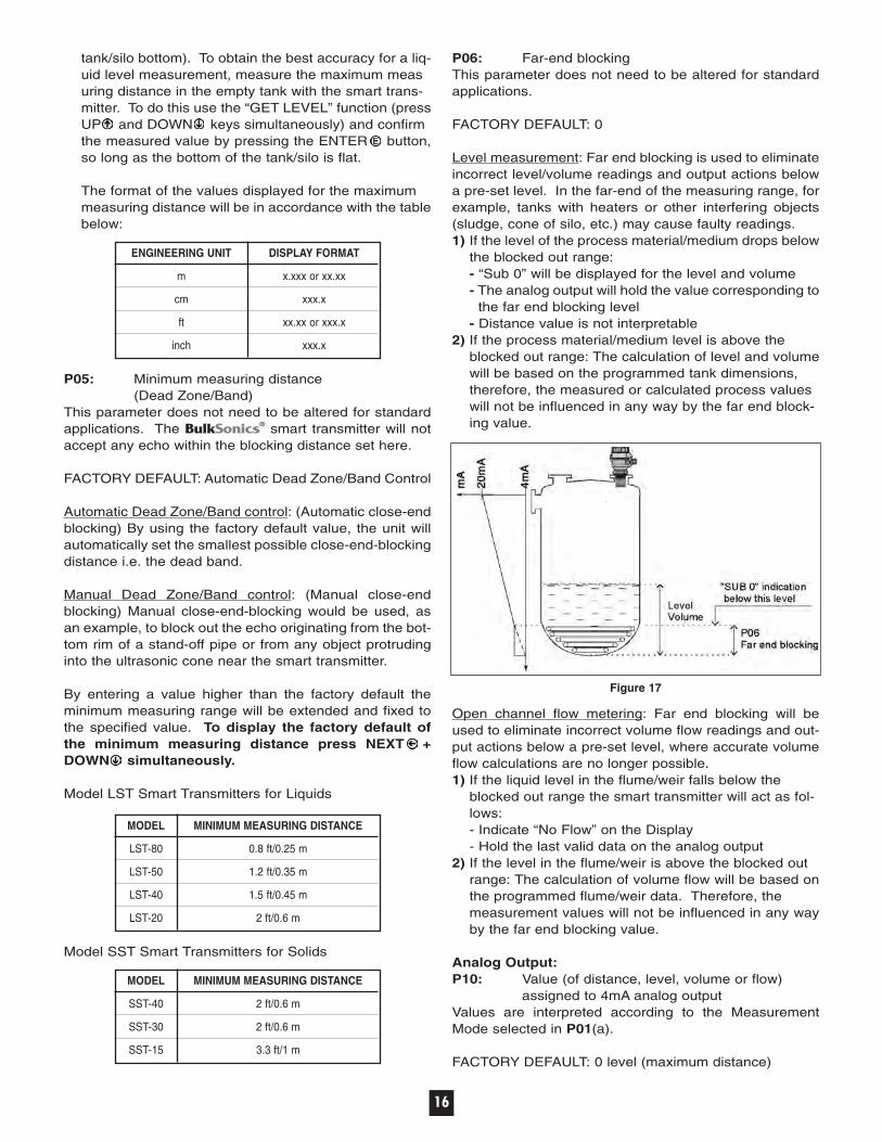
P70: Number of Echoes/Echo Map(See Figure 20) The smart transmitter is continuouslymonitoring the echo conditions. When entering this
Figure 20
parameter, echo monitoring will freeze and the number,distance and amplitude of the last recorded echoes canbe viewed.
Manual Echo selection (According to P33):(4-wire units only) To move the Measuring Window man-ually to one of the echoes displayed in the Echo Map:1) Select an echo in the Echo map (display should indi-
cate the distance of the selected echo)2) Press the UP + DOWN keys simultaneously (dis-
play will indicate “Set 33”)3) The selected echo is loaded into the P33 parameter
(See P33)
P71: Distance of the Measuring WindowP72:[dB] Amplitude of the Echo in the Measuring
WindowP73:[msec] Echo Position (time)P74: Signal To Noise Ratio
RATIO MEASUREMENT CONDITIONS
Over 70 Excellent
Between 70 and 30 Good
Under 30 Unreliable
P75: Blocking DistanceThe actual close-end blocking distance is displayed.Provides useful information if automatic blocking wasselected in P05.
Additional Parameters for Open Channel FlowMetering:P76:[LEV]Head of flowThe Headwater value can be checked here. This is the “h”value in the formula for flow calculation.

24
P77:TOT1 Volume flow totalizer (resetable)P78:TOT2 Volume flow totalizer (non-resetable)Resetting TOT1 totalizer:1) Go to the parameter P77.2) Press NEXT + DOWN simultaneously.3) Display will indicate: “t1 Clr”.4) Press ENTER for deleting.
Test Parameters:P80:[mA] Analog Output testEntering this parameter will result in displaying the actualanalog output. Set any value between 3.6 and 20.5 andpress the ENTER button. Check the analog output using a digital multimeter (Amp. Meter). It has to show thesame value set previously. Return to the parameteraddress by pressing ENTER .
P81:---a Relay test (4-wire units only)The actual state of the relay can be seen on the display(code according to the table below and symbol on thescreen). Test the relay by pressing UP and DOWN while observing change of the symbol and the code or lis-tening to the ticking of the relay or checking on-off resist-ance by a suitable resistance meter.
a RELAY STATE
0 De-energized
1 Energized
P97:b:a.aa Software codea.aa: Number of the software versionb: Code of the special version
Simulation Mode:This function enables the user to test the settings of theoutputs. The smart transmitter can simulate a static orcontinuous change of level, according to the preset simu-lation parameters. Set the required simulation by pro-gramming P84, P85, P86 and P87.
P84:---a Simulation ModeThe simulation levels must be within the programmedmeasuring range: P04 and P05.
a SIMULATION TYPE
0 No simulation (FACTORY DEFAULT)
1 The level changes continuously up and down between the level values set in P86 and P87 with a cycle time set in P85
2 Static level simulation: the level will be the value set in P86
P85:[sec] Cycle time for simulation P86:[m/ft] Simulated low level value P87:[m/ft] Simulated high level valueTo start the Simulation Mode, return to the measurementmode. While the transmitter is in Simulation Mode theDIST, LEV or VOL symbol will be blinking.
To quit the Simulation Mode, set: P84= 0.
Access Lock:P99:dcba Access Lock by Secret Code (Password)The purpose of this feature is to provide protection againstaccidental (or intentional) re-programming of parameters.
The Secret Code (password) can be a numeric valueother than 0000. Setting a Secret Code will automatical-ly be activated when the smart transmitter is returned tothe Measurement Mode. If the Secret Code is activated,the parameters can only be viewed, this is indicated bythe flashing colon “:” between the parameter address andthe parameter value.
In order to program the device locked by a secret code,first enter the Secret Code in P99. The Secret Code is re-activated each time the smart transmitter is returned toMeasurement Mode.
To delete the Secret Code, enter the Secret Code in P99.After confirming it with [E], re-enter the parameter P99and enter 0000.
[dcba(Secret Code)] → [E] → [E] → [0000] → [E] ⇒Secret Code deleted
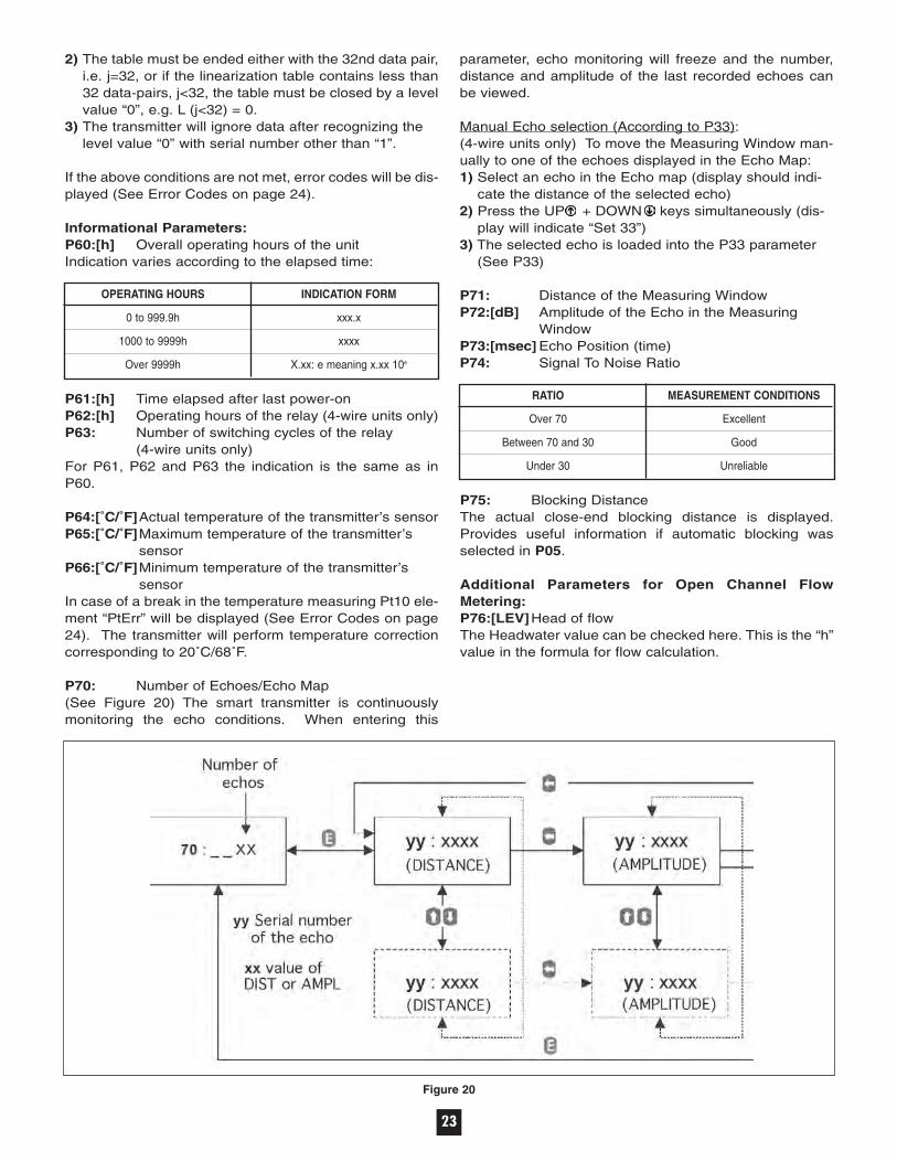
Error Codes:
CODE ERROR REMEDY
01 Memory error Contact factory or localrepresentative
No Echo Echo loss No echo received or 2 (no reflection)
3 Hardware error Contact factory or localrepresentative
04 Overflow Check settings
05 Code referring to sensor error or Verify sensor for correct improper installation/mounting operation and check for
level in the dead band correct mounting
06 The measurement is at the Re-aim sensor or try to find a reliability threshold (only for free better location
flowing solids level measurement)
07 No signal received within the Review programming,and measuring range specified in look for installation mistake
P04 and P05
12 Linearization table error: L(1) and See “Linearization” L(2) are both zero (no valid
data-pairs)
13 Linearization table error: there are See “Linearization”two same L(i) data in the table
14 Linearization table error: the r(i) See “Linearization” values are not increasing properly
25
CODE ERROR REMEDY
15 Linearization table error: See “Linearization” measured Level is higher than
the last Volume or Flow data-pair
16 The checksum of the program in Contact factory or local the EEPROM is wrong representative
PtErr Break in the temperature Contact factory or localsensor circuit representative
PAR PAGE DESCRIPTION
P44 20 Tank/silo dimensions/Flume/weir dimensions
P45 20 Tank/silo dimensions/Flume/weir dimensions
P46 20 Dist. Btw. transducer face & level of Q=0
P47 22 Linearization
P48 22 Linearization table
P60 23 Overall operating hours of the unit
P61 23 Time elapsed after last switch-on
P62 23 Operating hours of the relay
P63 23 Number of switching cycle of the relay
P64 23 Actual temperature of the transducer
P65 23 Maximum temperature of the transducer
P66 23 Minimum temperature of the transducer
P70 23 Number of echoes/Echo Map
P71 23 Distance of the Measuring Window(read-out parameter)
P72 23 Amplitude of the echo in the MeasuringWindow (read-out parameter)
P72 23 Echo position (time) (read-out parameter)
P74 23 Signal to noise ratio (read-out parameter)
P75 23 Blocking distance
P76 23 Head of flow
P77 24 TOT1 volume flow totalizer (resetable)
P78 24 TOT2 volume flow totalizer (non-resetable)
P80 24 Analog output test
P81 24 Relay test
P84 24 Simulation mode
P85 24 Cycle time for simulation
P86 24 Simulated low level value
P87 24 Simulated high level value
P97 24 Software code
P99 24 Access lock by secret code
PAR PAGE DESCRIPTION
P00 13 Application/Engineering Units
P01 13 Measurement Mode
P02 14 Calculation units
P03 14 Values Displayed-Rounding
P04 14 Maximum measuring distance
P05 16 Min measuring dist. (Close-end blocking)
P06 16 Far-end blocking
P10 16 Value assigned to 4 mA analog output
P11 16 Value to 20 mA analog output
P12 16 Error indication by the analog output
P13 17 Relay function
P14 17 Relay parameter – Setpoint value
P15 17 Relay parameter – Setpoint value
P16 17 Relay parameter – Pulse rate
P20 17 Damping
P22 17 Dome top tank compensation
P23 17 Angle of repose (free flowing solids only)
P24 18 Target tracking speed
P25 18 Selection of Echo in measuring window
P26 18 Level elevation rate (filling speed)
P27 18 Level descent rate (emptying speed)
P28 18 Echo-loss handling
P29 18 Blocking out of object #1
P30 18 Blocking out of object #2
P31 19 Sound velocity at 20˚C
P32 19 Specific gravity
P33 19 Manual echo selection
P40 20 Tank/silo shape/Appliances, formula, data
P41 20 Tank/silo dimensions/Flume/weir dimensions
P42 20 Tank/silo dimensions/Flume/weir dimensions
P43 20 Tank/silo dimensions/Flume/weir dimensions
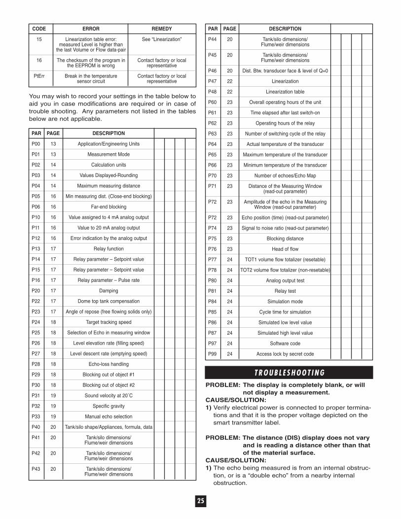
You may wish to record your settings in the table below toaid you in case modifications are required or in case oftrouble shooting. Any parameters not listed in the tablesbelow are not applicable.
T R O U B L E S H O O T I N GPROBLEM: The display is completely blank, or will
not display a measurement.CAUSE/SOLUTION:1) Verify electrical power is connected to proper termina-
tions and that it is the proper voltage depicted on the smart transmitter label.
PROBLEM: The distance (DIS) display does not vary and is reading a distance other than that of the material surface.
CAUSE/SOLUTION:1) The echo being measured is from an internal obstruc-
tion, or is a “double echo” from a nearby internal obstruction.

Smart transmitters may require occasional cleaning inapplications involving adhesive or sticky materials thatmay contact the sensor surface. The maintenance con-sists of a visual inspection of the sensor surface andcleaning whenever necessary. While in operation, thesensor face is vibrating which has a self-cleaning effect. Ifthe material is not sticky, no cleaning is required.
M A I N T E N A N C E
M E C H A N I C A L SDIMENSIONS ARE SHOWN IN INCHES WITH MILLIMETER EQUIVALENT IN BRACKETS
26
2) Re-aim the smart transmitter away from the obstruction.
3) Block the obstruction out using parameters P29 and/orP30 (See Parameter section). If the false echo is a double echo, however, you may not be able to block itout. Re-aim the smart transmitter.
4) Use the Echo Map parameter P70 to locate all echoesand their corresponding amplitudes.
5) Unit may require power-down to re-boot.
PROBLEM: The measurement stops (goes into an error mode) during filling operation.
CAUSE/SOLUTION:1) Airborne dust and/or falling material is interfering with
the measurement.2) Re-aim the smart transmitter away from incoming
material.
PROBLEM: The DIS measurement is twice that of theexpected value.
CAUSE/SOLUTION:1) The material level has entered the dead-band of the
smart transmitter and is locking on to the second reflection coming from the material surface.
2) Make sure the material does not exceed the level cor-responding to the dead-band of the smart transmitter (See P05 in Parameter section).
PROBLEM: The DIS measurement does vary, but is longer than that of the expected value.
CAUSE/SOLUTION:1) This may be a “ring-out”, caused by mechanical reso-
nance if the smart transmitter is not secured firmly enough. Verify the transmitter mounting.
2) The echo may also be reflecting off a flat material sur-face, then off the silo wall, then back to the transmitter.Re-aim the smart transmitter.
Model LST-20
Model LST-40
Model LST-50
Model LST-80

27
S O U N D V E L O C I T I E S I N VA R I O U S G A S E S
GASES SOUND VELOCITY (m/s)
Acetaldehyde C2H4O 252.8
Acetylene C2H2 340.8
Ammonia NH3 429.9
Argon Ar 319.1
Bensol C6H6 183.4
Carbon dioxide CO2 268.3
Carbon monoxide CO 349.2
Carbon tetrachloride CCl4 150.2
Chlorine Cl2 212.7
Dimethyl ether CH3OCH3 213.4
Ethane C2H6 327.4
Ethanol C2H3OH 267.3
Ethylene C2H4 329.4
Helium He 994.5
Hydrogen sulfide H2S 321.1
The following table contains the sound velocity of variousgases measured at 68˚F (20˚C).
S A F E T Y
General Safety:CAUTION! It is essential that all instructions in this man-ual be followed to ensure proper operation of the equip-ment and safety of operating personnel. The use of thissymbol is used within this manual to highlight importantsafety issues. Please pay particular attention to theseitems.
Electrical Shock Caution: The BulkSonics® smart transmitter can be powered withHIGH VOLTAGE. No operator serviceable parts areinside. All servicing is to be performed by qualified per-sonnel. Extreme care shall be taken if the unit’s cover isremoved and live electrical terminations are exposed. Toavoid electrical shock, do not contact any exposed elec-trical connections. Each unit is provided with a “protectiveground” wire, which shall be terminated to the ground con-nection at the transmitter.
CE Mark:The BulkSonics® smart transmitters comply with the fol-lowing EC regulations:
Directive 93/68 EEC (CE Mark)Directive 73/23 EEC (LVD)Directive 89/336 EEC (EMC)EN 61010-1:1993/A2:1995CEI/IEC 61326-1:2000EN 50081-1:1993EN 50082-2:1997
WA R R A N T YMonitor Technologies LLC warrants each BulkSonics® ultrasonic con-tinuous level measurement product it manufactures to be free fromdefects in material and workmanship under normal use and servicewithin two (2) years from the date of purchase. The purchaser must givenotice of any defect to Monitor within the warranty period, return theproduct intact and prepay transportation charges. The obligation ofMonitor Technologies LLC under this warranty is limited to repair orreplacement at its factory. This warranty shall not apply to any productwhich is repaired or altered outside of the Monitor Technologies LLCfactory, or which has been subject to misuse, negligence, accident,incorrect wiring by others or improper installation. Monitor TechnologiesLLC reserves the right to change the design and/or specifications with-out prior notice.
GASES SOUND VELOCITY (m/s)
Methane CH4 445.5
Methanol CH3OH 347
Neon Ne 449.6
Nitrogen N2 349.1
Nitrogen monoxide NO 346
Oxygen O2 328.6
Propane C3H8 246.5
Sulfur hexafluoride SF6 137.8
Model SST-15, SST-30 and SST-40
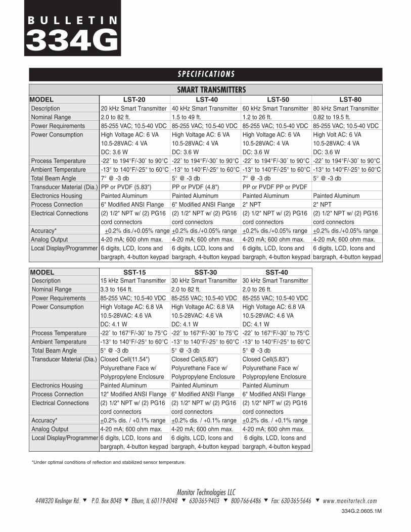
B U L L E T I N
334G
334G.2.0605.1M
Monitor Technologies LLC44W320 Keslinger Rd. t P.O. Box 8048 t Elburn, IL 60119-8048 t 630-365-9403 t 800-766-6486 t Fax: 630-365-5646 t www.mon i to r tech . com
S P E C I F I C AT I O N S
SST-1515 kHz Smart Transmitter3.3 to 164 ft.85-255 VAC; 10.5-40 VDCHigh Voltage AC: 6.8 VA10.5-28VAC: 4.6 VADC: 4.1 W-22˚ to 167°F/-30˚ to 75°C-13° to 140°F/-25° to 60°C5° @ -3 dbClosed Cell(11.54")Polyurethane Face w/Polypropylene EnclosurePainted Aluminum12" Modified ANSI Flange(2) 1/2" NPT w/ (2) PG16cord connectors+0.2% dis. / +0.1% range4-20 mA; 600 ohm max.6 digits, LCD, Icons andbargraph, 4-button keypad
SST-3030 kHz Smart Transmitter2.0 to 82 ft.85-255 VAC; 10.5-40 VDCHigh Voltage AC: 6.8 VA10.5-28VAC: 4.6 VADC: 4.1 W-22˚ to 167°F/-30˚ to 75°C-13° to 140°F/-25° to 60°C5° @ -3 dbClosed Cell(5.83")Polyurethane Face w/Polypropylene EnclosurePainted Aluminum6" Modified ANSI Flange(2) 1/2" NPT w/ (2) PG16cord connectors+0.2% dis. / +0.1% range4-20 mA; 600 ohm max.6 digits, LCD, Icons andbargraph, 4-button keypad
SST-4030 kHz Smart Transmitter2.0 to 26 ft.85-255 VAC; 10.5-40 VDCHigh Voltage AC: 6.8 VA10.5-28VAC: 4.6 VADC: 4.1 W-22˚ to 167°F/-30˚ to 75°C-13° to 140°F/-25° to 60°C5° @ -3 dbClosed Cell(5.83")Polyurethane Face w/Polypropylene EnclosurePainted Aluminum6" Modified ANSI Flange(2) 1/2" NPT w/ (2) PG16cord connectors+0.2% dis. / +0.1% range4-20 mA; 600 ohm max.6 digits, LCD, Icons and
bargraph, 4-button keypad
*Under optimal conditions of reflection and stabilized sensor temperature.
MODELDescriptionNominal RangePower RequirementsPower Consumption
Process TemperatureAmbient TemperatureTotal Beam AngleTransducer Material (Dia.)
Electronics HousingProcess ConnectionElectrical Connections
Accuracy*Analog OutputLocal Display/Programmer
MODEL LST-20 LST-40 LST-50 LST-80Description 20 kHz Smart Transmitter 40 kHz Smart Transmitter 60 kHz Smart Transmitter 80 kHz Smart TransmitterNominal Range 2.0 to 82 ft. 1.5 to 49 ft. 1.2 to 26 ft. 0.82 to 19.5 ft.Power Requirements 85-255 VAC; 10.5-40 VDC 85-255 VAC; 10.5-40 VDC 85-255 VAC; 10.5-40 VDC 85-255 VAC; 10.5-40 VDCPower Consumption High Voltage AC: 6 VA High Voltage AC: 6 VA High Voltage AC: 6 VA High Volt AC: 6 VA
10.5-28VAC: 4 VA 10.5-28VAC: 4 VA 10.5-28VAC: 4 VA 10.5-28VAC: 4 VADC: 3.6 W DC: 3.6 W DC: 3.6 W DC: 3.6 W
Process Temperature -22˚ to 194°F/-30˚ to 90°C -22˚ to 194°F/-30˚ to 90°C -22˚ to 194°F/-30˚ to 90°C -22˚ to 194°F/-30˚ to 90°CAmbient Temperature -13° to 140°F/-25° to 60°C -13° to 140°F/-25° to 60°C -13° to 140°F/-25° to 60°C -13° to 140°F/-25° to 60°CTotal Beam Angle 7° @ -3 db 5° @ -3 db 7° @ -3 db 5° @ -3 dbTransducer Material (Dia.) PP or PVDF (5.83") PP or PVDF (4.8") PP or PVDF PP or PVDFElectronics Housing Painted Aluminum Painted Aluminum Painted Aluminum Painted AluminumProcess Connection 6" Modified ANSI Flange 6" Modified ANSI Flange 2" NPT 2" NPTElectrical Connections (2) 1/2" NPT w/ (2) PG16 (2) 1/2" NPT w/ (2) PG16 (2) 1/2" NPT w/ (2) PG16 (2) 1/2" NPT w/ (2) PG16
cord connectors cord connectors cord connectors cord connectorsAccuracy* +0.2% dis./+0.05% range +0.2% dis./+0.05% range +0.2% dis./+0.05% range +0.2% dis./+0.05% rangeAnalog Output 4-20 mA; 600 ohm max. 4-20 mA; 600 ohm max. 4-20 mA; 600 ohm max. 4-20 mA; 600 ohm max.Local Display/Programmer 6 digits, LCD, Icons and 6 digits, LCD, Icons and 6 digits, LCD, Icons and 6 digits, LCD, Icons and
bargraph, 4-button keypad bargraph, 4-button keypad bargraph, 4-button keypad bargraph, 4-button keypad
SMART TRANSMITTERS
![Flexible flatfoot - JournalAgentshoes had harmful effects on the formation of lon-gitudinal arch of the foot [17, 18]. The reason why Hippocrates had not mentioned about flatfoot can](https://img.pdfslide.us/doc/110x75/60a02407adc81b1adc1c7148/flexible-flatfoot-journalagent-shoes-had-harmful-effects-on-the-formation-of-lon-gitudinal.jpg)


![[XLS]help.carecentrix.comhelp.carecentrix.com/ProviderResources/CareCentrix... · Web view6477 6478 6479 6480 6481 6482 6483 6484 6485 6486 6487 6488 6489 6490 6491 6492 6493 6494](https://img.pdfslide.us/doc/110x75/5af3fdb47f8b9a74448c4006/xlshelp-view6477-6478-6479-6480-6481-6482-6483-6484-6485-6486-6487-6488-6489.jpg)