Embed Size (px)
Citation preview

Rules for Building and Classing Bulk Carriers for Service on the Great Lakes
RULES FOR BUILDING AND CLASSING
BULK CARRIERS FOR SERVICE ON THE GREAT LAKES 2017
(Updated March 2018 – see next page)
American Bureau of Shipping Incorporated by Act of Legislature of the State of New York 1862
2016 American Bureau of Shipping. All rights reserved. 1701 City Plaza Drive Spring, TX 77389 USA

Updates
March 2018 consolidation includes: • July 2017 version plus Corrigenda/Editorials
July 2017 consolidation includes: • April 2017 version plus Notice No. 1
April 2017 consolidation includes: • January 2017 version plus Corrigenda/Editorials

T a b l e o f C o n t e n t s
RULES FOR BUILDING AND CLASSING
BULK CARRIERS FOR SERVICE ON THE GREAT LAKES
CONTENTS Notices and General Information .................................................................................. 1 PART 1 Conditions of Classification .................................................................. 5
CHAPTER 1 Scope and Conditions of Classification ................................. 6 [See also separately published booklet ABS Rules for Conditions of Classification (Part 1)]
PART 2 Materials and Welding ......................................................................... 11
[See separately published booklet ABS Rules for Materials and Welding (Part 2)]
PART 3 Hull Construction and Equipment ...................................................... 12
CHAPTER 1 General ................................................................................ 13 CHAPTER 2 Hull Structures and Arrangements ....................................... 23 CHAPTER 3 Equipment ............................................................................ 78
PART 7 Surveys After Construction ................................................................. 85
[See also separately published booklet ABS Rules for Survey After Construction (Part 7)]
APPENDIX 1 Comparison of the Numbering System of the 1978 Rules vs.
2017 Rules ............................................................................................ 86
ABS RULES FOR BUILDING AND CLASSING BULK CARRIERS FOR SERVICE ON THE GREAT LAKES . 2017 iii

This Page Intentionally Left Blank

N o t i c e s a n d G e n e r a l I n f o r m a t i o n
Notices and General Information
CONTENTS Introduction ..................................................................................................................... 2
TABLE 1 Applicable Editions of Booklets Comprising 2017 Great Lakes Bulk Carrier Rules ...................................................................... 3
TABLE 2 Division and Numbering of Rules .............................................. 3 Change Notice (2017) ..................................................................................................... 4
TABLE 3 Summary of Changes from the 2017 Rules .............................. 4
ABS RULES FOR BUILDING AND CLASSING BULK CARRIERS FOR SERVICE ON THE GREAT LAKES . 2017 1

Notices and General Information
Introduction For the year 2017 edition of the Rules for Building and Classing Bulk Carriers for Service on the Great Lakes, the Rules have been re-organized and re-formatted for the purpose of improving their ease of use. In this regard, we advise the following primary changes.
1. The year 2017 edition is a complete re-print of the Great Lakes Bulk Carrier Rules.
2. A new numbering system was incorporated into the Rules, in accordance with Table 2, which organizes the requirements into “Parts,” “Chapters” and “Sections”. A comparison of the old “1978” numbering system versus the new “2017” numbering system is shown in Appendix 1 as a guide map for users who are familiar with the existing Rules.
3. The 2017 edition of the Rules becomes effective on 1 January 2017.
4. The effective date of each technical change is shown in parenthesis at the end of the subsection/ paragraph titles within the text of each Part. Unless a particular date and month are shown, the years in parentheses refer to the following effective dates:
(2000) and after 1 January 2000 (and subsequent years) (1995) 15 May 1995 (1999) 12 May 1999 (1994) 9 May 1994 (1998) 13 May 1998 (1993) 11 May 1993 (1997) 19 May 1997 (1992) 13 May 1992 (1996) 9 May 1996
5. The Rule Changes contained in the previously published Notices 1 through 4 to the 1978 Great Lakes Bulk Carrier Rules (together with Corrigenda) have been incorporated into the text of the reformatted 2017 Great Lakes Bulk Carrier Rules.
6. Until the next edition of the Great Lakes Bulk Carrier Rules is published, Rule Change Notices and/or Corrigenda, as necessary, will be published on the ABS website – www.eagle.org – and will be available free for downloading. It is not intended to publish hard copies of future Notices and/or Corrigenda to existing Rules or Guides. The consolidated edition of the Rules for Building and Classing Bulk Carriers for Service on the Great Lakes, which includes Notices and/or Corrigenda using different colors for easy recognition, will be published on the ABS website only when Notices and/or Corrigenda are issued.
7. The listing of CLASSIFICATION SYMBOLS AND NOTATIONS is available from the Rules and Guides Downloads page of the ABS website www.eagle.org for download.
2 ABS RULES FOR BUILDING AND CLASSING BULK CARRIERS FOR SERVICE ON THE GREAT LAKES . 2017

Notices and General Information
TABLE 1 Applicable Editions of Booklets Comprising 2017 Great Lakes Bulk Carrier Rules
Rules for Building and Classing Bulk Carriers for Service on the Great Lakes Notices and General Information 2017 Part 1: Conditions of Classification (Supplement to the
ABS Rules for Conditions of Classification) (2) 2017
Part 3: Hull Construction and Equipment 2017 Rules for Conditions of Classification – not included (1,2) Part 1: Rules for Conditions of Classification 2017 Rules for Materials and Welding – not included (1) Part 2: Rules for Materials and Welding 2017 Rules for Survey After Construction – not included (1) Part 7: Rules for Survey After Construction 2017
Notes: 1 These Rules are available for download from the ABS website at www.eagle.org, Rules and Guides, Downloads or
may be ordered separately from the ABS Publications online catalog at www.eagle.org, Rules and Guides, Catalog.
2 The requirements for conditions of classification are contained in the separate, generic ABS Rules for Conditions of Classification (Part 1). Additional specific requirements are contained in Part 1 of these Rules.
TABLE 2 Division and Numbering of Rules
Division Number Part Part 1 Chapter Part 1, Chapter 1 Section Section 1-1-1 Subsection (see Note 1) 1-1-1/1 Paragraph (see Note 1) 1-1-1/1.1 Subparagraph 1-1-1/1.1.1 Item 1-1-1/1.1.1(a) Subitem 1-1-1/1.1.1(a)i) Appendix Appendix 1-1-A1
or Appendix 1-A1-1
Note:
1 An odd number (1, 3, 5, etc.) numbering system is used for the Rules. The purpose is to permit future insertions of even-numbered paragraphs (2, 4, 6, etc.) of text and to avoid the necessity of having to renumber the existing text and associated cross-references, as applicable, within the Rules and associated process instructions, check sheets, etc.
ABS RULES FOR BUILDING AND CLASSING BULK CARRIERS FOR SERVICE ON THE GREAT LAKES . 2017 3

Change Notice (2017)
TABLE 3 Summary of Changes from the 2017 Rules
Notice No. 1 (effective on 1 July 2017) to the 2017 Rules, is summarized below.
EFFECTIVE DATE 1 July 2017 – shown as (1 July 2017) (based on the contract date for new construction between builder and Owner)
Part/Para. No. Title/Subject Status/Remarks PART 3 Hull Construction and Equipment 3-2-3/19 (New)
Hopper Slope To clarify the requirements for the case when the hopper slope is not part of a tank. (Incorporates Notice No. 1)
3-2-6/11 (New)
Construction of Screen Bulkheads To clarify the requirements for screen bulkheads. (Incorporates Notice No. 1)
4 ABS RULES FOR BUILDING AND CLASSING BULK CARRIERS FOR SERVICE ON THE GREAT LAKES . 2017

P A R T Part 1: Conditions of Classification (Supplement to the ABS Rules for Conditions of Classification)
1 Conditions of Classification (Supplement to the ABS Rules for Conditions of Classification)
CONTENTS CHAPTER 1 Scope and Conditions of Classification ............................................... 6
Section 1 Classification .......................................................................... 8 Section 2 Classification Symbols and Notations .................................... 9 Section 3 Rules for Classification ........................................................ 10
ABS RULES FOR BUILDING AND CLASSING BULK CARRIERS FOR SERVICE ON THE GREAT LAKES . 2017 5

P A R T F o r e w o r d
1 Foreword (1 January 2008)
In 2008, Part 1, “Conditions of Classification” was consolidated into a generic booklet, entitled Rules for Conditions of Classification (Part 1) for all vessels other than those in offshore service. The purpose of this consolidation was to emphasize the common applicability of the classification requirements in “Part 1” to ABS-classed vessels, other marine structures and their associated machinery, and thereby make “Conditions of Classification” more readily a common Rule of the various ABS Rules and Guides, as appropriate.
Thus, this supplement specifies only the unique requirements applicable to bulk carriers for service on the Great Lakes. This supplement is always to be used with the aforementioned Rules for Conditions of Classification (Part 1).
6 ABS RULES FOR BUILDING AND CLASSING BULK CARRIERS FOR SERVICE ON THE GREAT LAKES . 2017

P A R T C h a p t e r 1 : S c o p e a n d C o n d i t i o n s o f C l a s s i f i c a t i o n
1 C H A P T E R 1 Scope and Conditions of Classification
CONTENTS SECTION 1 Classification .......................................................................................... 8 SECTION 2 Classification Symbols and Notations ................................................. 9
1 Great Lakes Service ........................................................................... 9 3 Unloading Equipment .......................................................................... 9 5 Heavy Density Cargoes ...................................................................... 9
SECTION 3 Rules for Classification ....................................................................... 10
1 Application of Rules .......................................................................... 10
ABS RULES FOR BUILDING AND CLASSING BULK CARRIERS FOR SERVICE ON THE GREAT LAKES . 2017 7

P A R T S e c t i o n 1 : C l a s s i f i c a t i o n
1 C H A P T E R 1 Scope and Conditions of Classification
S E C T I O N 1 Classification (1 January 2008)
The requirements for conditions of classification are contained in the separate, generic ABS Rules for Conditions of Classification (Part 1).
Additional requirements specific to bulk carriers for service on the Great Lakes are contained in the following Sections of this Part.
8 ABS RULES FOR BUILDING AND CLASSING BULK CARRIERS FOR SERVICE ON THE GREAT LAKES . 2017

P A R T S e c t i o n 2 : C l a s s i f i c a t i o n S y m b o l s a n d N o t a t i o n s
1 C H A P T E R 1 Scope and Conditions of Classification
S E C T I O N 2 Classification Symbols and Notations (1 January 2008)
A listing of Classification Symbols and Notations available to the Owners of vessels, offshore drilling and production units and other marine structures and systems, “List of ABS Notations and Symbols” is available from the ABS website “http://www.eagle.org”.
The following notations are specific to bulk carriers for service on the Great Lakes.
1 Great Lakes Service Vessels which have been built under the supervision of the ABS Surveyors to the requirements of the ABS Rules for Building and Classing Steel Vessels, except where these are modified by the requirements contained in these Rules, or to their equivalent, will be classed and distinguished in the Record by the symbols À A1 Great Lakes Service.
3 Unloading Equipment Where the vessel has been specially arranged and provided with special equipment for unloading, it will be distinguished in the Record with an appropriate notation regarding the arrangements.
5 Heavy Density Cargoes Where the vessel has been specially reinforced for the carriage of heavy-density cargoes, special loading arrangements, or both, it will be distinguished in the Record with a notation describing the special arrangements. Full particulars of the loading conditions and the maximum density of the cargoes to be provided for are to be given on the basic design plans.
ABS RULES FOR BUILDING AND CLASSING BULK CARRIERS FOR SERVICE ON THE GREAT LAKES . 2017 9

P A R T S e c t i o n 3 : R u l e s f o r C l a s s i f i c a t i o n
1 C H A P T E R 1 Scope and Conditions of Classification
S E C T I O N 3 Rules for Classification (1 January 2008)
1 Application of Rules These requirements are intended to apply to new vessels of the Great Lakes bulk/carrier type, having machinery aft, at least one complete deck, a double bottom and side tanks, a longitudinal system of framing for the deck and bottom, and two continuous longitudinal bulkheads fitted between the freeboard deck and the bottom shell. They are intended to apply generally to vessels of welded construction, of usual form and having depths not less than L/15 at 400 ft (122 in) length and L/21 at 700 ft (213 m) length and over. Vessels whose proportions and general characteristics represent departures from the foregoing and whose scantlings and arrangements differ from those specifically mentioned elsewhere in these Rules be subject to special consideration.
These requirements are applicable to those features that are permanent in nature and can be verified by plan review, calculation, physical survey, or other appropriate means. Any statement in the Rules regarding other features is to be considered as a guidance to the designer, builder, Owner, et al.
10 ABS RULES FOR BUILDING AND CLASSING BULK CARRIERS FOR SERVICE ON THE GREAT LAKES . 2017

P A R T P a r t 2 : M a t e r i a l s a n d W e l d i n g
2 Materials and Welding
The independent booklet, ABS Rules for Materials and Welding (Part 2), for steels, irons, bronzes, etc., is to be referred to. This booklet consists of the following Chapters:
Rules for Testing and Certification of Materials CHAPTER 1 Materials for Hull Construction CHAPTER 2 Equipment CHAPTER 3 Materials for Machinery, Boilers, Pressure Vessels, and Piping APPENDIX 1 List of Destructive and Nondestructive Tests Required for Materials
and Responsibility for Verifying APPENDIX 4 Procedure for the Approval of Manufacturers of Hull Structural Steel APPENDIX 5 Procedure for the Approval of Manufacturers of Hull Structural
Steels Intended for Welding with High Heat Input APPENDIX 6 Nondestructive Examination of Marine Steel Castings APPENDIX 7 Nondestructive Examination of Hull and Machinery Steel Forgings APPENDIX 8 Additional Approval Procedure for Steel with Enhanced Corrosion
Resistance Properties
Rules for Welding and Fabrication CHAPTER 4 Welding and Fabrication APPENDIX 2 Requirements for the Approval of Filler Metals APPENDIX 3 Application of Filler Metals to ABS Steels APPENDIX 9 Welding Procedure Qualification Tests of Steels for Hull
Construction and Marine Structures
ABS RULES FOR BUILDING AND CLASSING BULK CARRIERS FOR SERVICE ON THE GREAT LAKES . 2017 11

P A R T P a r t 3 : H u l l C o n s t r u c t i o n a n d E q u i p m e n t
3 Hull Construction and Equipment
CONTENTS CHAPTER 1 General .................................................................................................. 13
Section 1 Definitions ............................................................................ 14 Section 2 General Requirements ......................................................... 15
CHAPTER 2 Hull Structures and Arrangements ..................................................... 23
Section 1 Longitudinal Strength ........................................................... 28 Section 2 Shell Plating ......................................................................... 43 Section 3 Decks ................................................................................... 45 Section 4 Bottom Structure .................................................................. 51 Section 5 Framing ................................................................................ 54 Section 6 Watertight Bulkheads ........................................................... 58 Section 7 Tank Boundary Bulkheads ................................................... 64 Section 8 Superstructures and Deckhouses ........................................ 68 Section 9 Protection of Deck Openings ............................................... 72 Appendix 1 Calculation of Shear Stresses ............................................. 75
CHAPTER 3 Equipment ............................................................................................. 78
Section 1 Anchoring, Mooring and Towing Equipment ........................ 79
12 ABS RULES FOR BUILDING AND CLASSING BULK CARRIERS FOR SERVICE ON THE GREAT LAKES . 2017

P A R T C h a p t e r 1 : G e n e r a l
3 C H A P T E R 1 General
CONTENTS SECTION 1 Definitions ............................................................................................. 14
1 Length ............................................................................................... 14 3 Breadth.............................................................................................. 14 5 Depth ................................................................................................. 14 7 Draft .................................................................................................. 14 9 Strength Deck ................................................................................... 14
SECTION 2 General Requirements ......................................................................... 15
1 Arrangements ................................................................................... 15 3 Breaks ............................................................................................... 15 5 Structural Sections ............................................................................ 15 TABLE 1 Scantlings – Inch Units ........................................................... 16 TABLE 1 Scantlings – Metric Units ........................................................ 19 TABLE 2 Thickness and Flanges of Brackets ........................................ 22
ABS RULES FOR BUILDING AND CLASSING BULK CARRIERS FOR SERVICE ON THE GREAT LAKES . 2017 13

P A R T S e c t i o n 1 : D e f i n i t i o n s
3 C H A P T E R 1 General
S E C T I O N 1 Definitions
1 Length L is the length between perpendiculars, in ft (m), measured on the estimated summer load waterline from the fore side of the stem to the centerline of the rudder stock.
3 Breadth B is the greatest molded breadth, in ft (m).
5 Depth D is the molded depth at side, in ft (m), measured at the middle of L, from the molded baseline to the top of the strength deck beams.
7 Draft d is the molded draft, in ft (m), from the molded baseline to the summer load waterline.
9 Strength Deck The strength deck is the deck which forms the top of the effective hull girder at any part of its length. See 3-2-1/5.1.
14 ABS RULES FOR BUILDING AND CLASSING BULK CARRIERS FOR SERVICE ON THE GREAT LAKES . 2017

P A R T S e c t i o n 2 : G e n e r a l R e q u i r e m e n t s
3 C H A P T E R 1 General
S E C T I O N 2 General Requirements
1 Arrangements A transverse watertight bulkhead is to be provided at the forward end of the machinery space and a collision bulkhead is to be provided in accordance with Section 3-2-6. An afterpeak bulkhead is to be fitted to enclose the shaft tube in a watertight compartment. In addition, intermediate bulkheads or equivalent supporting arrangements are to be provided in such number and location which will, when acting in conjunction with the web frames and deep arches, provide adequate transverse strength in the hull.
3 Breaks Special care is to be taken throughout the structure to provide against local stress concentrations at the ends of the cargo spaces, superstructures, etc.
5 Structural Sections The scantling requirements of these Rules are applicable to structural angles, channels, bars, and rolled or built-up sections. The required section moduli of members; such as girders, webs, etc., supporting frames and stiffeners are to be obtained on an effective width of plating basis as described below unless otherwise noted. The section is to include the structural member in association with an effective width of plating equal to one-half the sum, of spacing on each side of the member, or 33% of the unsupported span , whichever is less; for girders and webs along hatch openings, an effective breadth of plating equal to one-half the spacing or 16.5% of the unsupported span , whichever is less, is to be used. The required section modulus of each frame and stiffener is assumed to be provided by the stiffener and one frame space of the plating to which it is attached.
ABS RULES FOR BUILDING AND CLASSING BULK CARRIERS FOR SERVICE ON THE GREAT LAKES . 2017 15

Part 3 Hull Construction and Equipment Chapter 1 General Section 2 General Requirements 3-1-2
TABLE 1 Scantlings – Inch Units
1 2 3 4 5 6 7 8 9 Length of
Vessel Basic Depth Basic
Design Draft
Bottom & Side
Shell (1,7)
Immersed Box & Stern
Plating
Shell at Ends
Forecastle and Poop
Sides
Center Keelson (8)
Floors & Side
Keelson 400 26.67 16.0 0.40 0.45 0.42 0.36 331/2 × 0.42 0.30
410 26.97 16.4 0.41 0.45 0.42 0.36 341/4 × 0.42 0.30
420 27.27 16.8 0.42 0.46 0.42 0.36 343/4 × 0.43 0.31
430 27.56 17.2 0.43 0.46 0.42 0.36 351/2 × 0.43 0.31
440 27.85 17.6 0.44 0.47 0.42 0.36 36 × 0.44 0.32
450 28.13 18.0 0.45 0.47 0.42 0.36 363/4 × 0.44 0.32
460 28.40 18.4 0.46 0.47 0.43 0.37 371/2 × 0.44 0.32
470 28.66 18.8 0.47 0.48 0.43 0.37 38 × 0.45 0.33 480 28.92 19.2 0.48 0.48 0.43 0.37 383/4 × 0.45 0.33
490 29.17 19.6 0.49 0.48 0.43 0.37 391/4 × 0.46 0.34
500 29.41 20.0 0.50 0.49 0.43 0.37 40 × 0.46 0.34 510 29.65 20.4 0.50 0.49 0.43 0.37 403/4 × 0.46 0.34
520 29.89 20.8 0.51 0.49 0.44 0.38 411/4 × 0.47 0.35
530 30.11 21.2 0.52 0.49 0.44 0.38 42 × 0.47 0.35 540 30.34 21.6 0.53 0.50 0.44 0.38 421/2 × 0.48 0.36
550 30.56 22.0 0.54 0.50 0.44 0.38 411/4 × 0.48 0.36
560 30.77 22.4 0.55 0.51 0.44 0.38 44 × 0.48 0.36 570 30.98 22.8 0.56 0.51 0.45 0.39 341/2 × 0.49 0.37
580 31.18 23.2 0.57 0.52 0.45 0.39 451/4 × 0.49 0.37
590 31.38 23.6 0.58 0.52 0.45 0.39 453/4 × 0.50 0.38
600 31.58 24.0 0.59 0.53 0.45 0.39 461/2 × 0.50 0.38
610 31.77 24.4 0.60 0.53 0.45 0.39 471/4 × 0.50 0.38
620 31.96 24.8 0.61 0.53 0.46 0.40 471/2 × 0.51 0.39
630 32.14 25.2 0.62 0.54 0.46 0.40 481/2 × 0.51 0.39
640 32.32 25.6 0.63 0.54 0.46 0.40 49 × 0.52 0.40
650 32.50 26.0 0.64 0.54 0.46 0.40 453/4 × 0.52 0.40
660 32.67 26.4 0.65 0.55 0.46 0.40 481/2 × 0.52 0.40
670 32.84 26.8 0.66 0.55 0.47 0.41 51 × 0.53 0.41 680 33.01 27.2 0.67 0.55 0.47 0.41 453/4 × 0.53 0.41
690 33.17 27.6 0.68 0.56 0.47 0.41 471/4 × 0.54 0.42
700 33.33 28.0 0.69 0.56 0.47 0.41 53 × 0.54 0.42 710 33.81 28.0 0.69 0.57 0.47 0.41 531/4 × 0.54 0.42
720 34.29 28.0 0.70 0.57 0.48 0.42 531/2 × 0.55 0.43
730 34.76 28.0 0.71 0.58 0.48 0.42 533/4 × 0.55 0.43
740 35.24 28.0 0.72 0.58 0.48 0.42 54 × 0.56 0.44
16 ABS RULES FOR BUILDING AND CLASSING BULK CARRIERS FOR SERVICE ON THE GREAT LAKES . 2017

Part 3 Hull Construction and Equipment Chapter 1 General Section 2 General Requirements 3-1-2
TABLE 1 (continued) Scantlings – Inch Units
1 2 3 4 5 6 7 8 9 Length of
Vessel Basic Depth Basic
Design Draft
Bottom & Side
Shell (1,7)
Immersed Box & Stern
Plating
Shell at Ends
Forecastle and Poop
Sides
Center Keelson (8)
Floors & Side
Keelson 750 35.71 28.0 0.73 0.58 0.48 0.42 541/4 × 0.56 0.44
760 36.19 28.0 0.74 0.59 0.48 0.42 541/2 × 0.56 0.44
770 36.67 28.0 0.75 0.59 0.49 0.43 543/4 × 0 57 0.45
780 37.14 28.0 0.76 0.59 0.49 0.43 55 × 0.57 0.45 790 37.62 28.0 0.77 0.60 0.49 0.43 551/4 × 0.58 0.46
800 38.10 28.0 0.78 0.60 0.49 0.43 551/2 × 0.58 0.46
810 38.57 28.0 0.79 0.60 0.49 0.43 553/4 × 0.58 0.46
820 39.05 28.0 0.80 0.61 0.50 0.44 56 × 0.59 0.47 830 39.52 28.0 0.81 0.61 0.50 0.44 561/4 × 0.59 0.47
840 40.00 28.0 0.82 0.61 0.50 0.44 561/2 × 0.60 0.48
850 40.48 28.0 0.83 0.62 0.50 0.44 563/4 × 0.60 0.48
860 40.95 28.0 0.84 0.62 0.50 0.44 57 × 0.60 0.48 870 41.43 28.0 0.85 0.62 0.50 0.44 571/4 × 0.61 0.49
880 41.90 28.0 0.86 0.62 0.50 0.44 571/2 × 0.61 0.49
890 42.38 28.0 0.87 0.62 0.50 0.44 573/4 × 0.62 0.50
900 42.86 28.0 0.88* 0.62 0.50 0.44 58 × 0.62 0.50 910 43.33 28.0 0.88* 0.62 0.50 0.44 581/4 × 0.62 0.50
920 43.81 28.0 0.89* 0.62 0.50 0.44 581/2 × 0.62 0.50
930 44.29 28.0 0.90* 0.62 0.50 0.44 583/4 × 0.62 0.50
940 44.76 28.0 0.91* 0.62 0.50 0.44 59 × 0.62 0.50
950 45.24 28.0 0.92* 0.62 0.50 0.44 591/4 × 0.62 0.50
960 45.71 28.0 0.93* 0.62 0.50 0.44 591/2 × 0.62 0.50
970 46.19 28.0 0.94* 0.62 0.50 0.44 593/4 × 0.62 0.50
980 46.67 28.0 0.95* 0.62 0.50 0.44 60 × 0.62 0.50 990 47.14 28.0 0.96* 0.62 0.50 0.44 601/4 × 0.62 0.50
1000 47.62 28.0 0.97* 0.62 0.50 0.44 601/2 × 0.62 0.50
1100 52.38 28.0 0.97* 0.62 0.50 0.44 603/4 × 0.62 0.50
1200 57.14 28.0 0.97* 0.62 0.50 0.44 61 × 0.62 0.50
* The tabular thickness for side shell plating for vessels 900 ft and over in length may be taken as 0.88 in.
ABS RULES FOR BUILDING AND CLASSING BULK CARRIERS FOR SERVICE ON THE GREAT LAKES . 2017 17
Part 3 Hull Construction and Equipment Chapter 1 General Section 2 General Requirements 3-1-2
TABLE 1 (continued) Scantlings – Inch Units
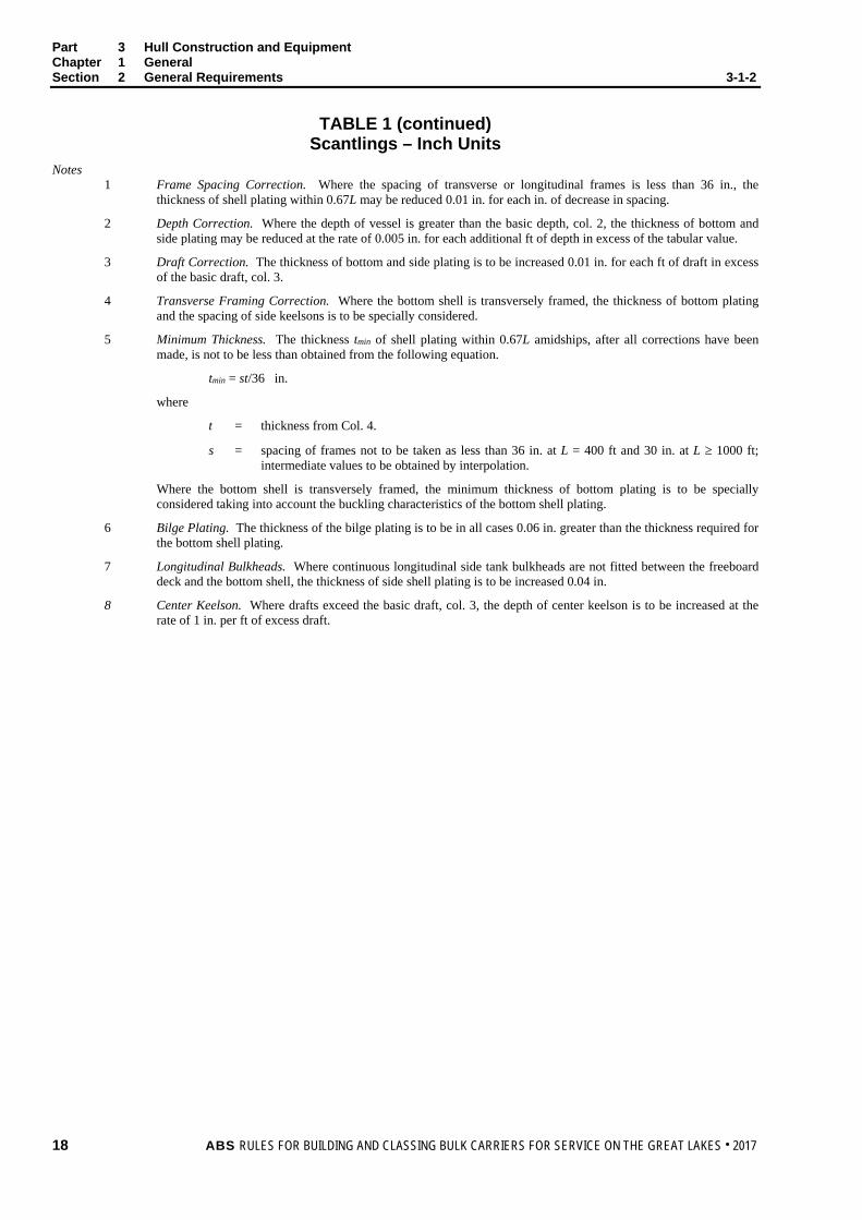
Notes 1 Frame Spacing Correction. Where the spacing of transverse or longitudinal frames is less than 36 in., the
thickness of shell plating within 0.67L may be reduced 0.01 in. for each in. of decrease in spacing.
2 Depth Correction. Where the depth of vessel is greater than the basic depth, col. 2, the thickness of bottom and side plating may be reduced at the rate of 0.005 in. for each additional ft of depth in excess of the tabular value.
3 Draft Correction. The thickness of bottom and side plating is to be increased 0.01 in. for each ft of draft in excess of the basic draft, col. 3.
4 Transverse Framing Correction. Where the bottom shell is transversely framed, the thickness of bottom plating and the spacing of side keelsons is to be specially considered.
5 Minimum Thickness. The thickness tmin of shell plating within 0.67L amidships, after all corrections have been made, is not to be less than obtained from the following equation.
tmin = st/36 in.
where
t = thickness from Col. 4.
s = spacing of frames not to be taken as less than 36 in. at L = 400 ft and 30 in. at L ≥ 1000 ft; intermediate values to be obtained by interpolation.
Where the bottom shell is transversely framed, the minimum thickness of bottom plating is to be specially considered taking into account the buckling characteristics of the bottom shell plating.
6 Bilge Plating. The thickness of the bilge plating is to be in all cases 0.06 in. greater than the thickness required for the bottom shell plating.
7 Longitudinal Bulkheads. Where continuous longitudinal side tank bulkheads are not fitted between the freeboard deck and the bottom shell, the thickness of side shell plating is to be increased 0.04 in.
8 Center Keelson. Where drafts exceed the basic draft, col. 3, the depth of center keelson is to be increased at the rate of 1 in. per ft of excess draft.
18 ABS RULES FOR BUILDING AND CLASSING BULK CARRIERS FOR SERVICE ON THE GREAT LAKES . 2017

Part 3 Hull Construction and Equipment Chapter 1 General Section 2 General Requirements 3-1-2
TABLE 1 Scantlings – Metric Units
1 2 3 4 5 6 7 8 9 Length of
Vessel Basic Depth Basic
Design Draft
Bottom & Side
Shell (1,7)
Immersed Box & Stern
Plating
Shell at Ends
Forecastle and Poop
Sides
Center Keelson (8)
Floors & Side
Keelson 122 8.13 4.88 10.0 11.5 10.5 9.0 850 × 10.5 7.5 125 8.22 5.00 10.5 11.5 10.5 9.0 870 × 10.5 7.5 128 8.31 5.12 10.5 11.5 10.5 9.0 885 × 11.0 8.0 131 8.40 5.24 11.0 11.5 10.5 9.0 900 × 11.0 8.0 134 4.49 5.36 11.0 12.0 10.5 9.0 915 × 11.0 8.0
137 8.57 5.49 11.5 12.0 10.5 9.0 935 × 11.0 8.0 140 8.66 5.61 11.5 12.0 11.0 9.5 950 × 11.0 8.0 143 8.74 5.73 12.0 12.0 11.0 9.5 965 × 11.5 8.5 146 8.81 5.85 12.0 12.0 11.0 9.5 985 × 11.5 8.5 149 8.89 5.97 12.5 12.0 11.0 9.5 995 × 11.5 8.5
152 8.96 6.10 12.5 12.5 11.0 9.5 1015 × 11.5 8.5 155 9.04 6.22 12.5 12.5 11.0 9.5 1035 × 11.5 8.5 158 9.11 6.34 13.0 12.5 11.0 9.5 1050 × 12.0 9.0 162 9.18 6.46 13.0 12.5 11.0 9.5 1065 × 12.0 9.0 165 9.25 6.58 13.5 12.5 11.0 9.5 1080 × 12.0 9.0
168 9.31 6.71 13.5 12.5 11.0 9.5 1100 × 12.0 9.0 171 9.38 6.83 14.0 13.0 11.0 9.5 1120 × 12.0 9.0 174 9.44 6.95 14.0 13.0 11.5 10.0 1130 × 12.5 9.5 177 9.50 7.07 14.5 13.0 11.5 10.0 1150 × 12.5 9.5 180 9.56 7.19 14.5 13.0 11.5 10.0 1160 × 12.5 9.5
183 9.63 7.31 15.0 13.5 11.5 10.0 1180 × 12.5 9.5 186 9.68 7.44 15.0 13.5 11.5 10.0 1200 × 12.5 9.5 189 9.74 7.56 15.5 13.5 11.5 10.0 1215 × 13.0 10.0 192 9.80 7.68 15.5 13.5 11.5 10.0 1230 × 13.0 10.0 195 9.85 7.80 16.0 13.5 11.5 10.0 1245 × 13.0 10.0
198 9.91 7.92 16.5 13.5 11.5 10.0 1265 × 13.0 10.0 201 9.96 8.05 16.5 14.0 11.5 10.0 1285 × 13.0 10.0 204 10.01 8.17 17.0 14.0 12.0 10.5 1295 × 13.5 10.5 207 10.06 8.29 17.0 14.0 12.0 10.5 1315 × 13.5 10.5 210 10.11 8.41 17.5 14.0 12.0 10.5 1325 × 13.5 10.5
213 10.16 8.53 17.5 14.0 12.0 10.5 1345 × 13.5 10.5 216 10.30 8.53 17.5 14.5 12.0 10.5 1355 × 13.5 10.5 219 10.45 8.53 18.0 14.5 12.0 10.5 1360 × 14.0 11.0 222 10.59 8.53 18.0 14.5 12.0 10.5 1365 × 14.0 11.0 226 10.74 8.53 18.5 14.5 12.0 10.5 1370 × 14.0 11.0
ABS RULES FOR BUILDING AND CLASSING BULK CARRIERS FOR SERVICE ON THE GREAT LAKES . 2017 19

Part 3 Hull Construction and Equipment Chapter 1 General Section 2 General Requirements 3-1-2
TABLE 1 (continued) Scantlings – Metric Units
1 2 3 4 5 6 7 8 9 Length of
Vessel Basic Depth Basic
Design Draft
Bottom & Side
Shell (1,7)
Immersed Box & Stern
Plating
Shell at Ends
Forecastle and Poop
Sides
Center Keelson (8)
Floors & Side
Keelson 229 10.88 8.53 18.5 14.5 12.0 10.5 1380 × 14.0 11.0 232 11.03 8.53 19.0 15.0 12.0 10.5 1385 × 14.0 11.0 235 11.18 8.53 19.0 15.0 12.5 11.0 1390 × 14.5 11.5 238 11.32 8.53 19.5 15.0 12.5 11.0 1395 × 14.5 11.5 241 11.47 8.53 19.5 15.0 12.5 11.0 1405 × 14.5 11.5
244 11.61 8.53 20.0 15.0 12.5 11.0 1410 × 14.5 11.5 247 11.76 8.53 20.0 15.0 12.5 11.0 1415 × 14.5 11.5 250 11.90 8.53 20.5 15.5 12.5 11.0 1420 × 15.0 12.0 253 12.05 8.53 20.5 15.5 12.5 11.0 1430 × 15.0 12.0 256 12.19 8.53 21.0 15.5 12.5 11.0 1435 × 15.0 12.0
259 12.34 8.53 21.0 15.5 12.5 11.0 1440 × 15.0 12.0 262 12.48 8.53 21.5 15.5 12.5 11.0 1450 × 15.0 12.0 265 12.63 8.53 21.5 15.5 12.5 11.0 1455 × 15.5 12.5 268 12.77 8.53 22.0 15.5 12.5 11.0 1460 × 15.5 12.5 271 12.92 8.53 22.0 15.5 12.5 11.0 1465 × 15.5 12.5
274 13.06 8.53 22.5* 15.5 12.5 11.0 1475 ×.15.5 12.5 277 13.21 8.53 22.5* 15.5 12.5 11.0 1480 × 15.5 12.5 280 13.35 8.53 22.5* 15.5 12.5 11.0 1485 × 15.5 12.5 283 13.50 8.53 23.0* 15.5 12.5 11.0 1490 × 15.5 12.5 286 13.64 8.53 23.0* 15.5 12.5 11.0 1500 × 15.5 12.5
290 13.79 8.53 23.5* 15.5 12.5 11.0 1505 × 15.5 12.5 293 13.93 8.53 23.5* 15.5 12.5 11.0 1510 × 15.5 12.5 296 14.08 8.53 24.0* 15.5 12.5 11.0 1520 × 15.5 12.5 299 14.22 8.53 24.0* 15.5 12.5 11.0 1525 × 15.5 12.5 302 14.37 8.53 24.5* 15.5 12.5 11.0 1530 × 15.5 12.5
305 14.51 8.53 24.5* 15.5 12.5 11.0 1535 × 15.5 12.5 335 15.96 8.53 24.5* 15.5 12.5 11.0 1545 × 15.5 12.5 366 17.42 8.53 24.5* 15.5 12.5 11.0 1550 × 15.5 12.5
* The tabular thickness for side shell plating for vessels 274 m and over in length may be taken as 22.5 mm.
20 ABS RULES FOR BUILDING AND CLASSING BULK CARRIERS FOR SERVICE ON THE GREAT LAKES . 2017

Part 3 Hull Construction and Equipment Chapter 1 General Section 2 General Requirements 3-1-2
TABLE 1 (continued) Scantlings – Metric Units
Notes 1 Frame Spacing Correction. Where the spacing of transverse or longitudinal frames is less than 915 mm, the
thickness of shell plating within 0.67L may be reduced 1.0 mm for each 100 mm of decrease in spacing.
2 Depth Correction. Where the depth of vessel is greater than the basic depth, col. 2, the thickness of bottom and side plating may be reduced at the rate of 0.04 mm for each additional 100 mm of depth in excess of the tabular value.
3 Draft Correction. The thickness of bottom and side plating is to be increased 0.09 mm for each 100 mm of draft in excess of the basic draft, col. 3.
4 Transverse Framing Correction. Where the bottom shell is transversely framed, the thickness of bottom plating and the spacing of side keelsons is to be specially considered.
5 Minimum Thickness. The thickness tmin of shell plating within 0.67L amidships, after all corrections have been made, is not to be less than obtained from the following equation.
tmin = st/915 mm
where
t = thickness from Col. 4.
s = spacing of frames not to be taken as less than 915 mm at L = 122 m and 760 mm at L ≥ 305 m; intermediate values to be obtained by interpolation.
Where the bottom shell is transversely framed, the minimum thickness of bottom plating is to be specially considered taking into account the buckling characteristics of the bottom shell plating.
6 Bilge Plating. The thickness of the bilge plating is to be in all cases 1.5 mm greater than the thickness required for the bottom shell plating.
7 Longitudinal Bulkheads. Where continuous longitudinal side tank bulkheads are not fitted between the freeboard deck and the bottom shell, the thickness of side shell plating is to be increased 1.0 mm.
8 Center Keelson. Where drafts exceed the basic draft, col. 3, the depth of center keelson is to be increased at the rate of 8.4 mm per 100 mm of excess draft.
ABS RULES FOR BUILDING AND CLASSING BULK CARRIERS FOR SERVICE ON THE GREAT LAKES . 2017 21

Part 3 Hull Construction and Equipment Chapter 1 General Section 2 General Requirements 3-1-2
TABLE 2 Thickness and Flanges of Brackets
Where brackets at end connections of girders, webs and stringers are fitted having thicknesses not less than the girder or web plates, the value fort may be modified in accordance with the following:
• Where the face area on the bracket is not less than one-half that on the girder or web and the face bar or flange on the girder or web is carried to the bulkhead or base, the length may be measured to a point 6 in. (150 mm) on to the bracket.
• Where the face area on the bracket is less than one-half that on the girder or web and the face bar or flange on the girder or web is carried to the bulkhead or base, may be measured to a point where the area of the bracket and its flange, outside the line of the girder or web, is equal to the flange area on the girder.
• Where the flange area of the girder or web is carried along the face of the bracket, which may be curved for the purpose, may be measured to the point of the bracket.
• Brackets are not to be considered effective beyond the point where the length of arm on the girder or web is 11/2 times the length of the arm on the bulkhead or base; in no case is the allowance in at either end to exceed one-quarter of the overall length of the girder or web.
• Brackets are not to be considered effective beyond the point where the depth of longer arm exceeds 11/2 times the depth of the shorter arm.
Inches Millimeters
Depth of Longer Arm
Thickness Width of Flange
Depth of Longer Arm
Thickness Width of Flange Plain Flanged Plain Flanged
6.0 0.26 150 6.5 7.5 0.28 175 7.0 9.0 0.30 0.26 11/4 200 7.0 6.5 30
10.5 0.32 0.26 11/4 225 7.5 6.5 30 12.0 0.34 0.28 11/2 250 8.0 6.5 30
13.5 0.36 0.28 11/2 275 8.0 7.0 35 15.0 0.38 0.30 13/4 300 8.5 7.0 35 16.5 0.40 0.30 13/4 325 9.0 7.0 40 18.0 0.42 0.32 2 350 9.0 7.5 40 19.5 0.44 0.32 2 375 9.5 7.5 45
21.0 0.46 0.34 21/4 400 10.0 7.5 45 22.5 0.48 0.34 21/4 425 10.0 8.0 45 24.0 0.50 0.36 21/2 450 11.5 8.0 50 25.5 0.52 0.36 21/2 475 11.0 8.0 50 27.0 0.54 0.38 23/4 500 11.0 8.5 55
28.5 0.56 0.38 23/4 525 11.5 8.5 55 30.0 0.58 0.40 3 550 12.0 8.5 55 33.0 0.42 31/4 600 12.5 9.0 60 36.0 0.44 31/2 650 13.0 9.5 65 39.0 0.46 33/4 700 14.0 9.5 70
42.0 0.48 4 750 14.5 10.0 75 45.0 0.50 41/4 800 10.5 80
850 10.5 85 900 11.0 90 950 11.5 90
1000 11.5 95 1050 12.0 100 1100 12.5 105 1150 12.5 110 1200 13.0 110
22 ABS RULES FOR BUILDING AND CLASSING BULK CARRIERS FOR SERVICE ON THE GREAT LAKES . 2017

P A R T C h a p t e r 2 : H u l l S t r u c t u r e s a n d A r r a n g e m e n t s
3 C H A P T E R 2 Hull Structures and Arrangements
CONTENTS SECTION 1 Longitudinal Strength .......................................................................... 28
1 General ............................................................................................. 28 3 Longitudinal Hull Girder Strength ...................................................... 28
3.1 Strength Standard ......................................................................... 28 3.3 Total Bending Moment .................................................................. 30 3.5 Permissible Shear Stress .............................................................. 32
5 Strength Deck and Other Effective Decks ........................................ 33 5.1 Strength Deck ................................................................................ 33
7 Loading Guidance ............................................................................. 33 9 Higher-Strength Materials ................................................................. 34
9.1 General.......................................................................................... 34 9.3 Hull-girder Section Modulus .......................................................... 34 9.5 Permissible Shear Stress .............................................................. 34 9.7 Hull-girder Moment of Inertia ......................................................... 35
TABLE 1 Combined Dynamic Bending Moment Distribution Factor ...... 36 TABLE 2 Values of Z, in in2, for Q = 1.0 (Ordinary Strength Steel) ........ 37 TABLE 2 Values of Z, in in2, for Q = 0.78 ............................................... 38 TABLE 2 Values of Z, in in2, for Q = 0.72 ............................................... 39 TABLE 2 Values of Z, in cm2, for Q = 1.0 (Ordinary Strength Steel) ...... 40 TABLE 2 Values of Z, in cm2, for Q = 0.78 ............................................. 41 TABLE 2 Values of Z, in cm2, for Q = 0.72 ............................................. 42 FIGURE 1 Envelope of Wave-Induced Shearing Forces ......................... 35
SECTION 2 Shell Plating .......................................................................................... 43
1 Amidships ......................................................................................... 43 3 Sheerstrake ....................................................................................... 43 5 End Plating ........................................................................................ 43 7 Compensation ................................................................................... 43 9 Special Material ................................................................................ 43 11 Higher-strength Steel ........................................................................ 43
11.1 Bottom Plating ............................................................................... 44 11.3 Side Shell Plating .......................................................................... 44 11.5 End Plating .................................................................................... 44
ABS RULES FOR BUILDING AND CLASSING BULK CARRIERS FOR SERVICE ON THE GREAT LAKES . 2017 23

SECTION 3 Decks ..................................................................................................... 45 1 General ............................................................................................. 45 3 Testing .............................................................................................. 45 5 Plating ............................................................................................... 45
5.1 Freeboard Deck ............................................................................. 45 5.3 Lower Decks .................................................................................. 45 5.5 Superstructure Decks and Tops of Houses ................................... 46 5.7 Special Material Requirements ...................................................... 46
7 Beams ............................................................................................... 46 9 Deep Beams and Girders ................................................................. 47
9.1 Strength Requirements .................................................................. 47 9.3 Proportions .................................................................................... 47 9.5 Proportions of Deep Beams and Girders in Tanks......................... 47 9.7 Arch Beams ................................................................................... 47
11 Special Heavy Beams and Girders ................................................... 47 13 Openings ........................................................................................... 48 15 Higher-strength Steel ........................................................................ 48
15.1 Freeboard Deck Plating ................................................................. 48 15.3 Lower Decks, Superstructure Decks, Deckhouse Tops, and
Girder Webs .................................................................................. 48 15.5 Section Modulus ............................................................................ 48
17 Continuous Longitudinal Hatch Coamings ........................................ 49 19 Hopper Slope .................................................................................... 49
19.1 Hopper Slope as a Part of a Tank.................................................. 49 19.3 Hopper Slope not a Part of a Tank ................................................ 49
TABLE 1 Minimum Thickness of Deck Plating ....................................... 50
SECTION 4 Bottom Structure .................................................................................. 51
1 General ............................................................................................. 51 3 Center Keelson ................................................................................. 51 5 Side Keelsons ................................................................................... 51 7 Floors ................................................................................................ 51
7.1 Bilge Brackets ................................................................................ 51 9 Lightening and Access Holes............................................................ 51 11 Inner Bottom Plating ......................................................................... 52 13 Bottom Structure in Self-unloading Vessels ..................................... 52
13.1 Inner Bottom Plating ...................................................................... 52 13.3 Floors ............................................................................................. 52 13.5 Longitudinal Girders ....................................................................... 52
15 Higher-strength Materials .................................................................. 52 15.1 General .......................................................................................... 52 15.3 Inner Bottom Plating ...................................................................... 52 15.5 Center Girders, Side Girders, and Floors ...................................... 53 15.7 Bottom Girders in Self-unloading Vessels ..................................... 53
24 ABS RULES FOR BUILDING AND CLASSING BULK CARRIERS FOR SERVICE ON THE GREAT LAKES . 2017

SECTION 5 Framing ................................................................................................. 54 1 General ............................................................................................. 54 3 Scantlings ......................................................................................... 54 5 Frame Spacing .................................................................................. 54 7 Bottom ............................................................................................... 54 9 Inner Bottom Longitudinals ............................................................... 55 11 Stringers and Webs .......................................................................... 55
11.1 Strength Requirements ................................................................. 55 11.3 Proportions .................................................................................... 55 11.5 Stiffeners and Tripping Brackets ................................................... 56
13 Special Strengthening ....................................................................... 56 15 Topside Tunnel or Side Tank Structure ............................................ 56 17 Higher-strength Steel ........................................................................ 56
17.1 Section Modulus ............................................................................ 56 17.3 Plating ........................................................................................... 56
19 Struts ................................................................................................. 57 SECTION 6 Watertight Bulkheads .......................................................................... 58
1 General ............................................................................................. 58 3 Arrangement of Watertight Bulkheads .............................................. 58
3.1 Collision Bulkheads ....................................................................... 58 3.3 After Peak Bulkheads .................................................................... 58 3.5 Machinery Space ........................................................................... 58
5 Chain Lockers ................................................................................... 58 7 Construction of Watertight Bulkheads .............................................. 58
7.1 Plating ........................................................................................... 58 7.3 Stiffeners ....................................................................................... 59 7.5 Stringers and Webs ....................................................................... 59 7.7 Watertight Doors ........................................................................... 60 7.9 Testing........................................................................................... 60
9 Higher-strength Steel ........................................................................ 60 9.1 Section Modulus ............................................................................ 60 9.3 Plating ........................................................................................... 60
11 Construction of Screen Bulkheads ................................................... 61 FIGURE 1 Curves for Watertight Bulkhead Plating Thickness – Inch
Units ........................................................................................ 61 FIGURE 1 Curves for Watertight Bulkhead Plating Thickness – Metric
Units ........................................................................................ 62 FIGURE 2 Screen Bulkhead Section Modulus Calculation – Double
Hulls ........................................................................................ 63
ABS RULES FOR BUILDING AND CLASSING BULK CARRIERS FOR SERVICE ON THE GREAT LAKES . 2017 25

SECTION 7 Tank Boundary Bulkheads .................................................................. 64 1 General ............................................................................................. 64 3 Construction of Tank Boundary Bulkheads ...................................... 64
3.1 Plating ............................................................................................ 64 3.3 Stiffeners ....................................................................................... 64 3.5 Stringers and Webs ....................................................................... 64 3.7 Attachments ................................................................................... 65
5 Testing .............................................................................................. 65 7 Topside Tunnel or Side Tank Bulkheads .......................................... 65 9 Higher-strength Steel ........................................................................ 65
9.1 Section Modulus ............................................................................ 65 9.3 Plating ............................................................................................ 66
FIGURE 1 Curves for Tank Bulkhead Plating Thickness – Inch
Units ........................................................................................ 66 FIGURE 1 Curves for Tank Bulkhead Plating Thickness – Metric
Units ........................................................................................ 67 SECTION 8 Superstructures and Deckhouses ...................................................... 68
1 Superstructures ................................................................................. 68 1.1 Side Plating ................................................................................... 68 1.3 Side Frames .................................................................................. 68 1.5 Decks ............................................................................................. 68 1.7 Superstructure Bulkheads and Deckhouse Bulkheads on
Freeboard Deck ............................................................................. 69 1.9 Windlass Room Bulkhead .............................................................. 69
3 Deckhouses on Superstructure Decks ............................................. 69 3.1 Bulkheads ...................................................................................... 69 3.3 Stacks ............................................................................................ 70 3.5 House Tops ................................................................................... 70
5 Openings ........................................................................................... 70 7 Higher-strength Steel ........................................................................ 70
7.1 Section Modulus ............................................................................ 70 7.3 Deck Plating .................................................................................. 71 7.5 Side and Bulkhead Plating ............................................................. 71
SECTION 9 Protection of Deck Openings .............................................................. 72
1 General ............................................................................................. 72 3 Position of Deck Openings ................................................................ 72 5 Hatchway Coamings ......................................................................... 72
5.1 Height of Coamings ....................................................................... 72 5.3 Coaming Plates ............................................................................. 72 5.5 Coaming Stiffening ........................................................................ 72 5.7 Continuous Longitudinal Hatch Coamings ..................................... 72
26 ABS RULES FOR BUILDING AND CLASSING BULK CARRIERS FOR SERVICE ON THE GREAT LAKES . 2017

7 Hatchways Closed by Sectional Sliding Covers and Secured Weathertight by Tarpaulins and Battening Devices .......................... 73 7.1 Sliding Steel Hatch Covers ............................................................ 73 7.3 Cleats ............................................................................................ 73 7.5 Wedges ......................................................................................... 73 7.7 Battening Bars ............................................................................... 73 7.9 Tarpaulins ...................................................................................... 73 7.11 Security of Hatchway Covers ........................................................ 73
9 Hatchways Closed by Covers of Steel Fitted with Gaskets and Clamping Devices ............................................................................. 73 9.1 Strength of Covers ........................................................................ 73 9.3 Other Materials .............................................................................. 74 9.5 Means for Securing Weathertightness .......................................... 74
11 Miscellaneous Openings in Freeboard and Superstructure Decks ................................................................................................ 74 11.1 Manholes and Scuttles .................................................................. 74 11.3 Other Openings ............................................................................. 74 11.5 Escape Openings .......................................................................... 74 11.7 Companionway Sills ...................................................................... 74
APPENDIX 1 Calculation of Shear Stresses ............................................................. 75
1 General ............................................................................................. 75 3 Shear Stress ..................................................................................... 75 5 Allowable Still-water Shearing Force ................................................ 76 FIGURE 1 Shear Distribution Configurations ........................................... 77
ABS RULES FOR BUILDING AND CLASSING BULK CARRIERS FOR SERVICE ON THE GREAT LAKES . 2017 27

P A R T S e c t i o n 1 : L o n g i t u d i n a l S t r e n g t h
3 C H A P T E R 2 Hull Structures and Arrangements
S E C T I O N 1 Longitudinal Strength
1 General Vessels of 400 ft (122 m) to 1200 ft (366 m) in length, intended to be classed for Great Lakes service, are to have longitudinal strength in accordance with the requirements of this Section. The equations in this Section are valid for vessels having depths not less than L/15 at 400 ft (122 m) length and L/21 at 700 ft (213 m) length and over. Intermediate values will be determined by interpolation. Vessels whose depths are less than this, or which have an arrangement departing from those specified by the Rules, will be subject to special consideration. In general, the breadth of the vessel is not to exceed 2.6 times the depth of the vessel.
3 Longitudinal Hull Girder Strength
3.1 Strength Standard 3.1.1 Section Modulus
The hull-girder section modulus amidships SM expressed in inches squared-feet (centimeters squared-meters), is not to be less than obtained from the following equation.
SM = Mt/fp
where
Mt = total vertical bending moment, in long tons-feet (metric tons-meters), see 3-2-1/3.3
fp = permissible bending stress, in long tons per inch squared (metric tons per centimeter squared), for ordinary strength steel
= 12.367 + 1.4
1000
L – 2.6672
1000
L 400 ≤ L ≤ 700 ft
= 12.709 + 0.287
1000
L – 1.7882
1000
L 700 < L ≤ 850 ft
= 11.479 + 3.2
1000
L – 3.52
1000
L 850 < L ≤ 1050 ft
= 15.74 – 4.533
1000
L 1050 < L ≤ 1200 ft
= 1.948 + 0.221
305L – 0.42
2
305
L 122 ≤ L ≤ 213 m
= 2.001 + 0.045
305L – 0.28
2
305
L 213 < L ≤ 259 m
28 ABS RULES FOR BUILDING AND CLASSING BULK CARRIERS FOR SERVICE ON THE GREAT LAKES . 2017

Part 3 Hull Construction and Equipment Chapter 2 Hull Structures and Arrangements Section 1 Longitudinal Strength 3-2-1
= 1.808 + 0.504
305L – 0.551
2
305
L 259 < L ≤ 320 m
= 2.478 – 0.714
305L 320 < L ≤ 366 m
L = length of vessel, in ft (m), as defined in 3-1-1/1
The required hull-girder section modulus at locations other than amidships is to be obtained using the fp, values given above and the maximum total bending moment Mt determined from the envelope curves of still-water and combined dynamic bending moments (see 3-2-1/3.1.2 and 3-2-1/3.3). In general, the hull-girder section modulus throughout 0.67L amidships is to be not less than that required at amidships. Special consideration will be given to the approval, away from amidships, of still-water bending moments greater than the maximum permissible midship value.
3.1.2 Minimum Section Modulus The hull-girder section modulus amidships, expressed in inches squared feet (centimeters squared-meters), for all vessels with lengths from 400 ft (122 m) to 1200 ft (366 m) is not to be less than the minimum SM determined from 3-2-1/Table 2.
Where the maximum still-water bending moment is not greater than the minimum value Ms, given in 3-2-1/3.1.1, the required section modulus amidships as specified in 3-2-1/3.1.1 may be determined directly from 3-2-1/Table 2.
3.1.3 Section Modulus Calculation In general, the following items may be included in the calculation of the section modulus, provided they are continuous or effectively developed.
• Deck plating (strength deck and other effective decks)
• Shell and inner-bottom plating
• Deck and bottom girders
• Plating and longitudinal stiffeners of longitudinal bulkheads
• All longitudinals of deck, sides, bottom and inner bottom
• Deep longitudinal bottom girders and crown plates in self-unloading vessels
The items included in the hull-girder section modulus amidships are generally to be extended throughout the 0.67L, amidships and gradually tapered beyond. In general, the net sectional areas of longitudinal strength members are to be used in the hull-girder section modulus calculations.
The section modulus to the deck or bottom is obtained by dividing the moment of inertia by the distance from the neutral axis to the molded deck fine at side or to the base line respectively.
3.1.4 Section Modulus with Continuous Coaming (14 May 1991) Where longitudinal coamings of length greater than 0.14L are provided, they are to comply with the requirements of 3-2-3/17. Such continuous coamings may be included in the calculation of hull girder inertia which is to be divided by the sum of the distance from neutral axis to deck at side and the height of continuous hatch coaming, to obtain the section modulus to the top of the coaming.
ABS RULES FOR BUILDING AND CLASSING BULK CARRIERS FOR SERVICE ON THE GREAT LAKES . 2017 29

Part 3 Hull Construction and Equipment Chapter 2 Hull Structures and Arrangements Section 1 Longitudinal Strength 3-2-1
3.3 Total Bending Moment The total bending moment Mt, expressed in long tons-feet (metric tons-meters), is to be obtained from the following equation:
Mt = Msw + Mc
where
Msw = still-water bending moment, in long tons-feet (metric tons-meters), see 3-2-1/3.3.1
Mc = maximum combined dynamic bending moment, in long tons-feet (metric tons-meters), see 3-2-1/3.3.2
3.3.1 Still-water Bending Moment and Shear Force For all vessels, still-water bending moments Msw and shear force Fsw calculations for the anticipated loaded and ballasted conditions are to be submitted. The results of these calculations are to be submitted in the form of curves showing hull-girder shear forces and bending moment values along the entire ship length.
In determination of the total bending moment Mt amidships, the value of Msw, is not to be taken as less than the value of Ms obtained from the following equation:
Ms = [2.64L – 336]B 400 ≤ L ≤ 650 ft
= [3.0L – 570]B 650 < L ≤ 750 ft
= [3.2L – 720]B 750 < L ≤ 850 ft
= [3.867L – 1287]B 850 < L ≤ 1000 ft
= [74.34(L/100)2 – 10.34L + 5482]B 1000 < L ≤ 1200 ft
= [8.8L – 341]B 122 ≤ L ≤ 198 m
= [10.0L – 579]B 198 < L ≤ 229 m
= [10.67L – 732]B 229 < L ≤ 259 m
= [12.89L – 1308]B 259 < L ≤ 305 m
= [75.54(L/30.5)2 – 34.47L + 5571]B 305 < L ≤ 366 m
where
Ms = minimum still-water bending moment amidships, in long tons-feet (metric tons-meters)
L and B are as defined in Section 3-1-1.
3.3.2 Combined Dynamic Bending Moment Amidships The combined dynamic bending moment Mc amidships, in long tons-feet (metric tons-meters), may be obtained from the following equation:
Mc = Cs22spw MM +
where
Mw = maximum-wave-induced bending moment amidships, in long tons-feet (metric tons-meters), see 3-2-1/3.3.3
Msp = maximum springing bending moment amidships, in long tons-feet (metric tons-meters), see 3-2-1/3.3.4
30 ABS RULES FOR BUILDING AND CLASSING BULK CARRIERS FOR SERVICE ON THE GREAT LAKES . 2017

Part 3 Hull Construction and Equipment Chapter 2 Hull Structures and Arrangements Section 1 Longitudinal Strength 3-2-1
Cs = correlation coefficient
= 0.995 – 0.172[(L/1000) – 0.4]2 inch/pound units
= 0.995 – 0.172[(L/305) – 0.4]2 metric units
L = length of vessel, in ft (m), as defined in 3-1-1/1
The maximum combined dynamic bending moment at locations other than amidships may be determined in accordance with the distribution factor given in 3-2-1/Table 1.
Consideration will be given to the combined dynamic as well as the wave-induced and springing bending moments calculated by means of a statistical analysis based on ship motion and vibration calculations in realistic sea states. In such cases, the calculations, computer programs used, and the computed results are to be submitted for review.
3.3.3 Wave-induced Bending Moment Amidships The maximum wave-induced bending moment amidships, in long tons-feet (metric tons-meters), may be obtained from the following equations:
Mw = CwB(L/1000)2 t-ft Mw = CwB(L/305)2 t-m
where
Cw = 9113 – 1.410L 400 ≤ L ≤ 600 ft
= 8850 – 0.972L 600 < L ≤ 800 ft
= 8663 – 0.738L 800 < L ≤ 1000 ft
= 8518 – 0.593L 1000 < L ≤ 1200 ft
= 9261 – 4.700L 122 ≤ L ≤ 183 m
= 8993 – 3.240L 183 < L ≤ 244 m
= 8803 – 2.460L 244 < L ≤ 305 m
= 8656 – 1.977L 305 < L ≤ 366 m
L and B are as defined in Section 3-1-1.
3.3.4 Springing Bending Moment Amidships The maximum springing bending moment amidships, in long tons-feet (metric tons-meters), may be obtained from the following equations.
Msp = CCspB(L/1000)3 t-ft Msp = CCspB(L/305)3 t-m
where
C = 2296 – 0.3839L 400 ≤ L ≤ 600 ft
= 2224 – 0.2640L 600 < L ≤ 800 ft
= 2173 – 0.2001L 800 < L ≤ 1000 ft
= 2134 – 0.1606L 1000 < L ≤ 1200 ft
= 2333 – 1.2798L 122 ≤ L ≤ 183 m
= 2260 – 0.8800L 183 < L ≤ 244 m
= 2208 – 0.6670L 244 < L ≤ 305 m
= 2168 – 0.5353L 305 < L ≤ 366 m
ABS RULES FOR BUILDING AND CLASSING BULK CARRIERS FOR SERVICE ON THE GREAT LAKES . 2017 31

Part 3 Hull Construction and Equipment Chapter 2 Hull Structures and Arrangements Section 1 Longitudinal Strength 3-2-1
Csp = 5.58 – ω 1.0 ≤ ω ≤ 2.0
= 5.06/ ω 2.0 < ω
ω = Cf ( )23 102
LdBY
ID . inch/pound units
= ( )23 1023327
LdBY
IDC f ..
metric units
Cf = 1645 –0.7549L 400 ≤ L ≤ 600 ft
= 1483 – 0.4836L 600 < L ≤ 800 ft
= 1374 – 0.3479L 800 < L ≤ 1000 ft
= 1294 – 0.2678L 1000 < L ≤ 1200 ft
= 1645 – 2.4768L 122 ≤ L ≤ 183 m
= 1483 – 1.5867L 183 < L ≤ 244 m
= 1374 – 1.1411L 244 < L ≤ 305 m
= 1294 – 0.8784L 305 < L ≤ 366 m
Y = distance from the neutral axis to the strength deck at side or to the bottom shell, in ft (m), whichever is greater
I = moment of inertia of the midship section, in in2-ft2 (cm2-m2)
L, B, D, d are as defined in Section 3-1-1.
The actual moment of inertia I of the vessel is to be used for calculating Msp. When the value of I is changed as a result of section modulus modifications, the modified I is to be used for calculating the new Msp and new section modulus requirements. When the actual value of I is not known at the early design stages, the I values determined from 3-2-1/Table 2 may be taken as initial value.
3.5 Permissible Shear Stress In general, the thicknesses of the side shell and longitudinal bulkhead, where fitted, are to be such that the total shear stresses as obtained from 3-2-1/3.5.1 are not greater than 6.75 long tons per inch squared (1.065 metric tons per centimeter squared) provided the critical shear buckling stress of the plating is satisfactory.
3.5.1 Calculation of Shear Stresses In calculating the total shear stresses due to still-water and dynamic loads in the side shell and longitudinal bulkhead plating, the maximum numerical sum of the shearing force in still water Fsw and that induced by wave and springing Fd at the station examined, is to be used. For vessels without continuous longitudinal bulkheads, the total shear stress fs in the side shell plating clear of the wing tanks may be obtained from the following equation:
fs = (Fsw + Fd)m/(24tI) t/in2 fs = (Fsw + Fd)m/(200tI) t/cm2
where
fs = total shear stress, in long tons per inch squared (metric tons per centimeter squared)
I = moment of inertia, in in2-ft2 (cm2-m2), of the hull girder section at the section under consideration
m = first moment, in in2-ft2 (cm2-m2), about the neutral axis, of the area of the effective longitudinal material, taken at the section under consideration
32 ABS RULES FOR BUILDING AND CLASSING BULK CARRIERS FOR SERVICE ON THE GREAT LAKES . 2017

Part 3 Hull Construction and Equipment Chapter 2 Hull Structures and Arrangements Section 1 Longitudinal Strength 3-2-1
t = thickness, in in. (cm), of the side shell plating at the position under consideration
Fsw = as specified by 3-2-1/3.5.2
Fd = as specified by 3-2-1/3.5.2
The total shear stress in the side shell in way of wing tanks, and for vessels having continuous longitudinal bulkheads, the total shear stress in the side shell and longitudinal bulkhead plating is to be calculated by an acceptable method. One simplified method is shown in Appendix A. Consideration will be given to alternative methods for shear stress calculations.
3.5.2 Hull-girder Shearing Force The hull-girder shearing forces in still water Fsw, are to be submitted as required by 3-2-1/3.3.1. The envelope curve of maximum shearing forces induced by wave and springing Fd as shown in 3-2-1/Figure 1 may be obtained from the following equation:
Fd = KMc/L
where
Fd = maximum shearing force induced by wave and springing, in long tons (metric tons)
Mc = maximum combined dynamic hull-girder bending moment amidships, in long tons-feet (metric-tons-meters), as specified by 3-2-1/3.3.2
L = length of vessel, in ft (m), as defined in 3-1-1/1
K = 3.4 between 0.85L and 0.70L
= 2.3 between 0.60L and 0.45L
= 3.2 between 0.35L and 0.20L
= 0.0 at FP and AP
The length range is measured from the AP, and at intermediate locations the K value may be obtained by interpolation.
5 Strength Deck and Other Effective Decks
5.1 Strength Deck The uppermost deck to which the side shell plating extends for any part of the length of the vessel is to be considered the strength deck for that portion the length. The thickness of the stringer plates and deck plating are to comply with the requirement of 3-2-3/5. In general, the effective sectional area of the deck for calculating the section modulus is to exclude hatchways and other openings in the deck and is to be maintained throughout 0.67L amidships.
5.3 Effective Lower Decks To be considered effective for use in calculating the hull-girder section modulus, the thickness of the deck plating is to comply with the requirement of 3-2-3/5. The sectional areas of effective lower decks used in calculating the section modulus are to be generally maintained throughout 0.67L amidships.
7 Loading Guidance (14 May 1991) A loading manual based on still-water bending conditions is to be provided on all vessels and submitted for review. This manual is to show the effect of the various loaded and ballasted conditions upon the longitudinal bending. The loading manual is to indicate the still-water bending moments at amidships and at other locations along the length of the vessel as necessary.
ABS RULES FOR BUILDING AND CLASSING BULK CARRIERS FOR SERVICE ON THE GREAT LAKES . 2017 33

Part 3 Hull Construction and Equipment Chapter 2 Hull Structures and Arrangements Section 1 Longitudinal Strength 3-2-1
A loading instrument where installed is to be of a type suitable for the intended service. The check conditions and other relevant data are to be submitted for review. The accuracy of the loading instrument is to be checked at regular intervals by applying approved test loading conditions. In the event the loading instrument malfunctions, the loading manual is to be used, for assessing the suitability of the intended loading condition.
9 Higher-Strength Materials
9.1 General Vessels in which the effective longitudinal material of the upper, lower, or both flanges of the main., hull girder are constructed of materials having mechanical properties greater than those of ordinary-strength hull structural steel are to have longitudinal strength generally, in accordance with the preceding paragraphs of this section, except as modified by 3-2-1/9. Applications of higher-strength material are to be continuous throughout the midship 0.67L of the vessel, and are to be extended to suitable locations below the strength deck and above the bottom, so that the stress levels will be satisfactory also for the mild steel structure. Longitudinal framing members are to be essentially of the same material as the plating they support. Calculations showing that adequate strength has been provided against buckling are to be submitted for review. Care is to be taken against the adoption of reduced thicknesses of members which may be subject to damage during normal operation.
9.3 Hull-girder Section Modulus When either the top or bottom of the hull girder, or both, is constructed of higher-strength material, the section modulus SMhts may be obtained from 3-2-1/3.3.1 by substituting the permissible stress fp with fp/Q.
SMhts = Mt/(fp/Q)
where
Q = 70900/(Y + 2U/3) inch/pound units
= 49.92/(Y + 2U/3) metric units
Y = specified minimum yield point for the higher-strength material or its specified minimum yield at 0.2% offset, or 72% of the specified minimum strength, in psi (kg/mm2), whichever is the lesser
U = specified minimum tensile strength of the higher-strength material, in psi (kg/mm2)
Mt = total bending moment, in long tons-feet (metric tons-meters), see 3-2-1/3.3
For determining the maximum total bending moment Mt, the actual moment of inertia of the higher-strength midship section is to be used to calculate Msp as specified in 3-2-1/3.3.4.
The value of fp/Q is not to be taken greater than the critical buckling stress of the deck and bottom plating. Special consideration will be given to the application of Q less than 0.72.
In addition, the hull-girder section modulus amidships of a vessel constructed of higher-strength materials is also not to be less than the minimum SM given in 3-2-1/Table 2 for Q = 0.78 or 0.72. For intermediate Q values, the minimum SM may he obtained by interpolation.
9.5 Permissible Shear Stress Where the side shell or longitudinal bulkhead is constructed of higher-strength material, the permissible shear stresses indicated in 3-2-1/3.5 may be increased by the factor 1/Q, provided the critical buckling stress of the plating is satisfactory.
34 ABS RULES FOR BUILDING AND CLASSING BULK CARRIERS FOR SERVICE ON THE GREAT LAKES . 2017

Part 3 Hull Construction and Equipment Chapter 2 Hull Structures and Arrangements Section 1 Longitudinal Strength 3-2-1
9.7 Hull-girder Moment of Inertia As specified in 3-2-1/3.3.4, the actual moment of inertia of the midship section for a vessel constructed of higher-strength material is to be used to calculate the springing bending moment. A set of initial values of I is shown in 3-2-1/Table 2, for ordinary-strength steel (Q = 1.0) and for higher-strength materials with Q = 0.78 and 0.72 respectively. For higher-strength materials with Q values between 0.72 and 1.00, the initial I values may be obtained by interpolation. The inertia of a vessel constructed of higher-strength material in the top, bottom or both flanges of the hull girder is to be not less than obtained from the following equation:
Ihts = 0.45(SM)Da
where
Ihts = hull girder moment of inertia of higher-strength material, in in2-ft2 (cm2-m2)
SM = minimum hull-girder section modulus of an ordinary strength steel vessel of the same dimensions as determined from 3-2-1/3.1.2
Da = basic depth from 3-1-2/Table 1, column 2
FIGURE 1 Envelope of Wave-Induced Shearing Forces
AP FP
L
K = 3.2
K = 2.3
K = 3.4
0.2L 0.35L 0.45L 0.6L 0.7L 0.85L
ABS RULES FOR BUILDING AND CLASSING BULK CARRIERS FOR SERVICE ON THE GREAT LAKES . 2017 35

Part 3 Hull Construction and Equipment Chapter 2 Hull Structures and Arrangements Section 1 Longitudinal Strength 3-2-1
TABLE 1 Combined Dynamic Bending Moment Distribution Factor Intermediate values of distribution factor may be determined by interpolation.
Position Distribution Factor Station 0 AP 0
2 0.17 4 0.57 6 0.76 8 0.95 9 1.00
10 1.00 11 1.00 12 0.96 14 0.76 16 0.44 18 0.12 20 FP 0
36 ABS RULES FOR BUILDING AND CLASSING BULK CARRIERS FOR SERVICE ON THE GREAT LAKES . 2017

Part 3 Hull Construction and Equipment Chapter 2 Hull Structures and Arrangements Section 1 Longitudinal Strength 3-2-1
TABLE 2 Values of Z, in in2, for Q = 1.0 (Ordinary Strength Steel)
ZB = Minimum SM
ZBD/2 = Initial Values of I
B, D, and d are as defined in Section 3-1-1, in ft, Q is as defined in 3-2-1/9.3.
L (ft)
BdD / 0.70 0.75 0.80 0.85 0.90 0.95 1.00 1.05 1.10 1.15 1.20
400 168 168 168 168 168 168 168
420 184 184 184 184 183 183 183
440 200 200 200 200 200 200 200
460 217 217 217 217 217 217 216
480 235 235 235 234 234 234 234
500 254 253 253 253 253 253 252
520 273 273 272 272 272 272 272 271
540 293 293 292 292 292 292 291 291
560 314 314 313 313 313 312 312 312
580 336 336 335 335 334 334 334 333
600 359 358 358 357 357 357 356 356
620 383 382 382 381 381 380 380 379
640 408 407 407 406 405 405 404 404
660 435 434 433 432 431 431 430 433
680 462 461 460 459 458 458 457 456 456
700 491 490 489 488 487 486 485 484 484
720 521 520 518 517 516 515 514 513 513
740 552 551 549 548 547 546 545 544 543
760 585 583 582 580 579 577 576 575 574
780 619 617 615 614 612 611 609 608 607
800
653 651 649 647 645 644 642 641
820
689 687 685 683 681 680 673 677
840
728 725 723 721 719 717 715 714 712
860
768 765 763 760 758 756 754 752 751
880
810 807 804 802 799 797 795 793 791
900
855 851 848 845 842 840 837 835 833
920
901 897 893 890 887 885 882 879 877
940
945 941 937 934 931 928 926 923
960
995 991 987 983 980 977 974 971
980
1047 1042 1038 1034 1031 1027 1024 1021
1000
1102 1097 1092 1088 1084 1080 1077 1073 1070 1020
1159 1153 1148 1144 1140 1135 1132 1128 1125
1040
1219 1213 1207 1202 1198 1193 1189 1185 1182 1060
1281 1275 1269 1264 1259 1254 1250 1245 1241
1080
1340 1334 1328 1323 1318 1313 1308 1304
1100
1408 1402 1395 1390 1384 1379 1374 1369 1120
1479 1472 1465 1459 1453 1447 1442 1437
1140
1553 1545 1538 1531 1525 1519 1513 1508 1160
1630 1622 1614 1607 1600 1594 1588 1582
1180
1712 1703 1695 1687 1680 1673 1667 1660 1200
1799 1789 1781 1772 1765 1757 1750 1744
ABS RULES FOR BUILDING AND CLASSING BULK CARRIERS FOR SERVICE ON THE GREAT LAKES . 2017 37

Part 3 Hull Construction and Equipment Chapter 2 Hull Structures and Arrangements Section 1 Longitudinal Strength 3-2-1
TABLE 2 Values of Z, in in2, for Q = 0.78
ZB = Minimum SM
ZBD/2 = Initial Values of I
B, D, and d are as defined in Section 3-1-1, in ft, Q is as defined in 3-2-1/9.3.
L (ft)
BdD / 0.70 0.75 0.80 0.85 0.90 0.95 1.00 1.05 1.10 1.15 1.20
400 131 131 131 131 131 131 131 420 144 143 143 143 143 143 143 440 156 156 156 156 156 156 156 460 170 170 170 169 169 169 169 480 184 184 183 183 183 183 183
500 198 198 198 198 198 198 197 520 214 213 213 213 213 213 212 212 540 229 229 229 229 228 228 228 228 560 246 246 245 245 245 245 244 244 580 263 263 263 262 262 262 261 261
600 282 281 281 280 280 280 279 279 620 301 300 300 299 299 298 298 298 640 321 320 319 319 318 318 317 317 660 342 341 340 339 339 338 338 337 680 363 363 362 361 360 360 359 358 358
700 386 385 384 384 383 382 381 381 380 720 410 409 408 407 406 405 405 404 403 740 435 434 433 432 431 430 429 428 427 760 461 460 459 457 456 455 454 453 452 780 489 487 486 484 483 482 480 479 478
800 515 514 512 511 509 508 507 506 820 545 543 541 539 538 537 535 534 840 576 573 571 570 568 566 565 563 562 860 608 606 603 601 599 598 596 594 593 880 642 639 637 635 632 631 629 627 625
900 677 674 672 669 667 665 663 661 659 920 714 711 708 706 703 701 698 696 604 940 750 746 743 741 738 736 733 731 960 790 786 783 780 777 775 772 770 980 832 828 824 821 818 815 812 810
1000 875 871 868 864 861 858 855 852 849 1020 921 917 913 909 905 902 899 896 893 1040 969 965 960 956 952 949 945 942 939 1060 1020 1015 1010 1005 1001 997 994 990 987 1080 1067 1062 1057 1053 1049 1045 1041 1037
1100 1122 1116 1111 1106 1102 1098 1094 1090 1120 1179 1173 1167 1162 1157 1153 1148 1144 1140 1238 1232 1226 1220 1215 1210 1205 1201 1160 1300 1293 1287 1281 1276 1270 1265 1261 1180 1366 1359 1352 1346 1340 1334 1329 1324 1200 1436 1428 1421 7414 1408 1402 1396 1391
38 ABS RULES FOR BUILDING AND CLASSING BULK CARRIERS FOR SERVICE ON THE GREAT LAKES . 2017

Part 3 Hull Construction and Equipment Chapter 2 Hull Structures and Arrangements Section 1 Longitudinal Strength 3-2-1
TABLE 2 Values of Z, in in2, for Q = 0.72
ZB = Minimum SM
ZBD/2 = Initial Values of I
B, D, and d are as defined in Section 3-1-1, in ft, Q is as defined in 3-2-1/9.3.
L (ft)
BdD / 0.70 0.75 0.80 0.85 0.90 0.95 1.00 1.05 1.10 1.15 1.20
400 121 121 121 121 121 121 121 420 133 132 132 132 132 132 132 440 144 144 144 144 144 144 144 460 157 157 157 156 156 156 156 480 170 170 169 169 169 169 169
500 183 183 183 183 183 182 182 520 197 197 197 197 197 196 196 196 540 212 212 212 211 211 211 211 211 560 228 227 227 227 226 226 226 226 580 244 243 243 243 242 242 242 241
600 261 260 260 259 259 259 258 258 620 278 278 277 277 276 276 275 275 640 297 296 295 295 294 294 294 293 660 316 315 315 314 313 313 312 312 680 336 336 335 334 333 333 332 332 331
700 358 357 356 355 354 354 353 352 352 720 380 379 378 377 376 375 375 374 373 740 403 402 401 400 399 398 397 396 395 760 428 426 425 424 423 421 421 420 419 780 453 451 450 449 447 446 445 444 443
800 478 476 475 473 472 471 470 468 820 505 503 502 500 499 497 496 495 840 534 532 530 528 527 525 524 522 521 860 564 562 560 558 556 554 553 551 550 880 595 593 591 589 587 585 583 581 580
900 628 626 623 621 619 617 615 613 611 920 663 660 657 655 652 650 648 646 644 940 696 693 690 687 685 683 681 679 960 733 730 727 724 721 719 717 714 980 772 769 765 762 759 757 754 752
1000 813 809 806 802 799 796 794 791 788 1020 856 852 848 844 841 838 835 832 829 1040 901 896 892 888 885 881 878 875 872 1060 948 943 938 934 930 927 923 920 917 1080 992 987 982 978 974 971 967 964
1100 1043 1038 1033 1028 1024 1020 1016 1013 1120 1096 1090 1085 1080 1076 1071 1067 1063 1140 1151 1145 1139 1134 1129 1125 1120 1116 1160 1209 1203 1197 1191 1186 1181 1176 1172 1180 1270 1263 1257 1251 1246 1240 1235 1231 1200 1335 1328 1321 1315 1309 1303 1298 1293
ABS RULES FOR BUILDING AND CLASSING BULK CARRIERS FOR SERVICE ON THE GREAT LAKES . 2017 39
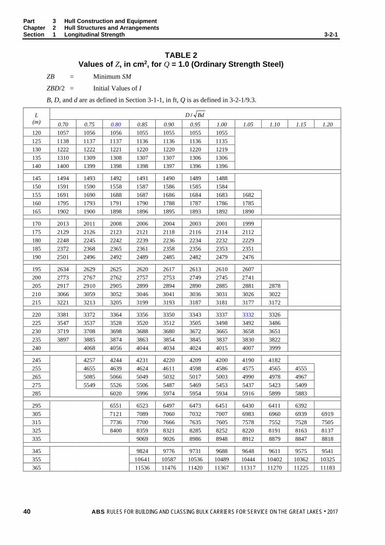
Part 3 Hull Construction and Equipment Chapter 2 Hull Structures and Arrangements Section 1 Longitudinal Strength 3-2-1
TABLE 2 Values of Z, in cm2, for Q = 1.0 (Ordinary Strength Steel)
ZB = Minimum SM
ZBD/2 = Initial Values of I
B, D, and d are as defined in Section 3-1-1, in ft, Q is as defined in 3-2-1/9.3.
L (m)
BdD / 0.70 0.75 0.80 0.85 0.90 0.95 1.00 1.05 1.10 1.15 1.20
120 1057 1056 1056 1055 1055 1055 1055 125 1138 1137 1137 1136 1136 1136 1135 130 1222 1222 1221 1220 1220 1220 1219 135 1310 1309 1308 1307 1307 1306 1306 140 1400 1399 1398 1398 1397 1396 1396
145 1494 1493 1492 1491 1490 1489 1488 150 1591 1590 1558 1587 1586 1585 1584 155 1691 1690 1688 1687 1686 1684 1683 1682 160 1795 1793 1791 1790 1788 1787 1786 1785 165 1902 1900 1898 1896 1895 1893 1892 1890
170 2013 2011 2008 2006 2004 2003 2001 1999 175 2129 2126 2123 2121 2118 2116 2114 2112 180 2248 2245 2242 2239 2236 2234 2232 2229 185 2372 2368 2365 2361 2358 2356 2353 2351 190 2501 2496 2492 2489 2485 2482 2479 2476
195 2634 2629 2625 2620 2617 2613 2610 2607 200 2773 2767 2762 2757 2753 2749 2745 2741 205 2917 2910 2905 2899 2894 2890 2885 2881 2878 210 3066 3059 3052 3046 3041 3036 3031 3026 3022 215 3221 3213 3205 3199 3193 3187 3181 3177 3172
220 3381 3372 3364 3356 3350 3343 3337 3332 3326 225 3547 3537 3528 3520 3512 3505 3498 3492 3486 230 3719 3708 3698 3688 3680 3672 3665 3658 3651 235 3897 3885 3874 3863 3854 3845 3837 3830 3822 240 4068 4056 4044 4034 4024 4015 4007 3999
245 4257 4244 4231 4220 4209 4200 4190 4182 255 4655 4639 4624 4611 4598 4586 4575 4565 4555 265 5085 5066 5049 5032 5017 5003 4990 4978 4967 275 5549 5526 5506 5487 5469 5453 5437 5423 5409 285 6020 5996 5974 5954 5934 5916 5899 5883
295 6551 6523 6497 6473 6451 6430 6411 6392 305 7121 7089 7060 7032 7007 6983 6960 6939 6919 315 7736 7700 7666 7635 7605 7578 7552 7528 7505 325 8400 8359 8321 8285 8252 8220 8191 8163 8137 335 9069 9026 8986 8948 8912 8879 8847 8818
345 9824 9776 9731 9688 9648 9611 9575 9541 355 10641 10587 10536 10489 10444 10402 10362 10325 365 11536 11476 11420 11367 11317 11270 11225 11183
40 ABS RULES FOR BUILDING AND CLASSING BULK CARRIERS FOR SERVICE ON THE GREAT LAKES . 2017

Part 3 Hull Construction and Equipment Chapter 2 Hull Structures and Arrangements Section 1 Longitudinal Strength 3-2-1
TABLE 2 Values of Z, in cm2, for Q = 0.78
ZB = Minimum SM
ZBD/2 = Initial Values of I
B, D, and d are as defined in Section 3-1-1, in ft, Q is as defined in 3-2-1/9.3.
L (m)
BdD / 0.70 0.75 0.80 0.85 0.90 0.95 1.00 1.05 1.10 1.15 1.20
120 825 825 825 824 824 824 823 125 839 889 888 888 887 887 887 130 955 955 954 954 953 953 952 135 1024 1023 1022 1022 1021 1021 1020 140 1095 1094 1093 1093 1092 1091 1091
145 1169 1168 1167 1166 1165 1164 1164 150 1245 1244 1243 1242 1241 1240 1239 155 1324 1322 1321 1320 1312 1313 1317 1316 160 1406 1404 1402 1401 1400 1399 1398 1397 165 1490 1488 1487 1485 1484 1482 1481 1480
170 1578 1576 1574 1572 1570 1569 1567 1566 175 1669 1667 1664 1662 1660 1658 1657 1655 180 1764 1761 1758 1756 1753 1751 1749 1747 185 1862 1859 1855 1853 1850 1848 1845 1843 190 1964 1960 1957 1953 1950 1948 1945 1943
195 2070 2065 2061 2058 2054 2051 2048 2046 200 2180 2175 2170 2166 2163 2159 2156 2153 205 2294 2289 2284 2279 2275 2271 2267 2264 2261 210 2413 2407 2401 2396 2391 2387 2383 2379 2375 215 2536 2529 2523 2517 2512 2507 2502 2498 2494
220 2664 2656 2649 2643 2637 2631 2626 2621 2617 225 2796 2788 2780 2773 2766 2760 2754 2749 2711 230 2934 2924 2915 2908 2900 2893 2887 2881 2876 235 3076 3065 3056 3047 3039 3032 3025 3018 3012 240 3212 3201 3192 3183 3175 3167 3160 3153
245 3363 3352 3341 3332 3323 3314 3306 3299 255 3682 3668 3656 3644 3633 3623 3614 3605 3597 265 4026 4010 3996 3982 3969 3957 3946 3936 3926 275 4398 4379 4362 4346 4331 4317 4304 4292 4281 285 4776 4756 4737 4720 4704 4689 4674 4661
295 5202 5179 5157 5137 5119 5101 5085 5069 305 5660 5634 5609 5586 5565 5545 5526 5508 5491 315 6154 6124 6097 6071 6046 6023 6002 5981 5962 325 6688 6654 6622 6593 6565 6539 6515 6492 6470 335 7225 7189 7156 7125 7096 7068 7042 7017
345 7832 7792 7755 7720 7688 7657 7627 7599 355 8488 8444 8403 8364 8328 8293 8260 8229 365 9206 9158 9112 9069 9029 8990 8954 8919
ABS RULES FOR BUILDING AND CLASSING BULK CARRIERS FOR SERVICE ON THE GREAT LAKES . 2017 41

Part 3 Hull Construction and Equipment Chapter 2 Hull Structures and Arrangements Section 1 Longitudinal Strength 3-2-1
TABLE 2 Values of Z, in cm2, for Q = 0.72
ZB = Minimum SM
ZBD/2 = Initial Values of I
B, D, and d are as defined in Section 3-1-1, in ft, Q is as defined in 3-2-1/9.3.
L (m)
BdD / 0.70 0.75 0.80 0.85 0.90 0.95 1.00 1.05 1.10 1.15 1.20
120 762 762 762 761 761 761 760 125 821 821 820 820 820 819 819 130 882 882 881 881 880 880 880 135 946 945 944 944 943 943 943 140 1012 1011 1010 1009 1009 1008 1008
145 1080 1079 1078 1077 1076 1076 1075 150 1150 1149 1148 1147 1146 1146 1145 155 1224 1222 1221 1220 1219 1218 1217 1216 160 1299 1298 1296 1295 1294 1293 1292 1291 165 1378 1376 1374 1373 1371 1370 1369 1368
170 1459 1457 1455 1453 1452 1450 1449 1447 175 1544 1541 1539 1537 1535 1533 1532 1530 180 1631 1628 1626 1624 1621 1619 1618 1616 185 1722 1719 1716 1714 1711 1709 1707 1705 190 1817 1813 1810 1807 1804 1802 1799 1797
195 1915 1911 1907 1904 1901 1898 1895 1892 200 2018 2013 2009 2005 2001 1998 1995 1992 205 2124 2119 2114 2109 2105 2102 2098 2095 2092 210 2234 2228 2223 2218 2213 2209 2205 2202 2198 215 2349 2342 2336 2331 2326 2321 2317 2312 2309
220 2468 2460 2454 2447 2442 2437 2432 2427 2423 225 2591 2583 2575 2568 2562 2556 2551 2546 2541 230 2718 2709 2701 2694 2637 2680 2674 2669 2663 235 2851 2841 2832 2823 2816 2809 2802 2796 2790 240 2977 2967 2958 2949 2942 2934 2922 2921
245 3118 3107 3097 3088 3079 3071 3064 3057 255 3415 3402 3390 3379 3369 3359 3350 3342 3334 265 3735 3720 3706 3693 3681 3670 3660 3650 3640 275 4082 4064 4048 4033 4019 4005 3993 3981 3970 285 4433 4414 4397 4381 4365 4351 4337 4325
295 4830 4808 4788 4769 4752 4735 4720 4705 305 5257 5233 5210 5188 5168 5149 5131 5114 5098 315 5718 5690 5664 5639 5616 5595 5574 5555 5537 325 6215 6183 6154 6126 6100 6076 6053 6031 6010 335 6715 6682 6651 6622 6594 6568 6544 6521
345 7281 7244 7209 7177 7146 7117 7089 7063 355 7892 7851 7813 7777 7743 7710 7679 7650 365 8561 8516 8474 8434 8396 8360 8326 8293
42 ABS RULES FOR BUILDING AND CLASSING BULK CARRIERS FOR SERVICE ON THE GREAT LAKES . 2017

P A R T S e c t i o n 2 : S h e l l P l a t i n g
3 C H A P T E R 2 Hull Structures and Arrangements
S E C T I O N 2 Shell Plating
1 Amidships The thickness of the shell plating within the midship 0.67L is not to be less than is required for purposes of longitudinal hull girder strength in accordance with 3-2-1/1 nor is it to be less than is required by 3-1-2/Table 1, column 4, with associated footnotes. The thickness of the bilge plating is to be in all cases 0.06 in. (1.5 mm) greater than the thickness required for the bottom shell plating.
3 Sheerstrake The thickness of the sheerstrake within the midship 0.67L, is to approximate that of the stringer plate on the freeboard deck. The top edge of the sheerstrake is to be smooth and, in general, fittings are not to be welded to the top edge of the sheerstrake within the midship 0.75L.
5 End Plating The thickness of shell plating at ends, and immersed bow and stern plating is to be in accordance with 3-1-2/Table 1, columns 6 and 5, respectively. End thicknesses are not to extend for more than 0.1L, at ends and are to be gradually tapered to the midship thickness. Plate thickness and connections to the stern frame and boss are to be specially considered. In the vicinity of the hawse pipes and below the anchor pockets, the plating is to be increased in thickness over a width sufficient to provide added protection in way of the anchor flukes.
7 Compensation All shell openings are to have well-rounded corners and are to be kept well clear of breaks in superstructures or other highly stressed areas and local compensation may be required to maintain the longitudinal and transverse strength of the hull.
9 Special Material Vessels with a length of 450 ft (137 m) and above are to be provided with sheerstrakes of special material in accordance with the ABS Rules for Building and Classing Steel Vessels (Steel Vessel Rules). Where a radiused gunwale plate is fitted, the above requirements for special material may be modified. Strakes of the same special material are also to be provided at the lower turn of the bilge in vessel of 450 ft (137 m) in length and above. These strakes of special material are to be extended throughout the midship 0.67L. Riveted seams as an alternative the material requirements of this paragraph will be specially considered. See also 3-2-3/5.7.
11 Higher-strength Steel In general, applications of higher-strength materials for shell plating are to take into consideration the suitable extension of the higher-strength material above and below the bottom and deck respectively, as required by 3-2-1/9.1. Care is to be exercised against the adoption of reduced thickness of material that might he subject to damage during normal operation. Calculations showing that adequate, buckling strength is provided may be required to be submitted. The thicknesses of longitudinal bottom and. side shell are not to be less than required for longitudinal strength by Section 3-2-1. The requirement of the preceding paragraphs of Section 4 may be modified but are not to be less obtained from 3-2-4/11.1 through 3-2-4/11.3.
ABS RULES FOR BUILDING AND CLASSING BULK CARRIERS FOR SERVICE ON THE GREAT LAKES . 2017 43
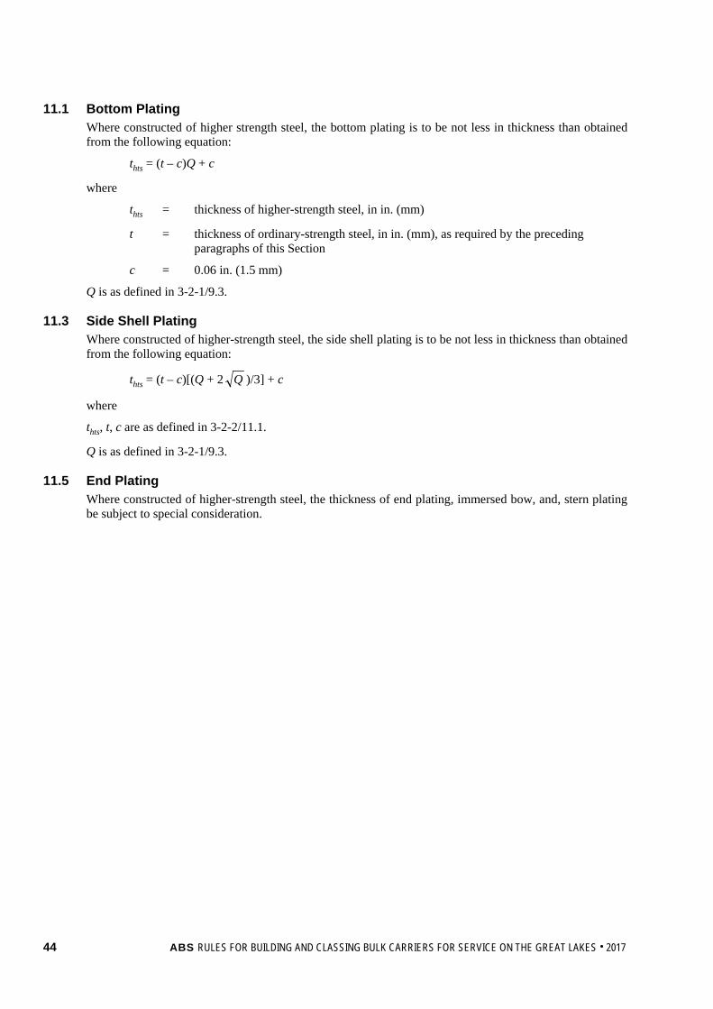
11.1 Bottom Plating Where constructed of higher strength steel, the bottom plating is to be not less in thickness than obtained from the following equation:
thts = (t – c)Q + c
where
thts = thickness of higher-strength steel, in in. (mm)
t = thickness of ordinary-strength steel, in in. (mm), as required by the preceding paragraphs of this Section
c = 0.06 in. (1.5 mm)
Q is as defined in 3-2-1/9.3.
11.3 Side Shell Plating Where constructed of higher-strength steel, the side shell plating is to be not less in thickness than obtained from the following equation:
thts = (t – c)[(Q + 2 Q )/3] + c
where
thts, t, c are as defined in 3-2-2/11.1.
Q is as defined in 3-2-1/9.3.
11.5 End Plating Where constructed of higher-strength steel, the thickness of end plating, immersed bow, and, stern plating be subject to special consideration.
44 ABS RULES FOR BUILDING AND CLASSING BULK CARRIERS FOR SERVICE ON THE GREAT LAKES . 2017

P A R T S e c t i o n 3 : D e c k s
3 C H A P T E R 2 Hull Structures and Arrangements
S E C T I O N 3 Decks
1 General Strength decks are to be effectively continuous, preferably in one plane; should they change level, the change is to be accomplished by a gradually sloping section or by the deck material at each level being extended so as to provide a suitable overlap and being effectively tied together by diaphragms or webs. All decks exposed to the weather are to be weathertight.
3 Testing Riveted boundaries of weathertight decks are to be subjected to hose testing after all fittings affecting the weathertightness are fastened in position, and the pressure of water in the hose is not to be less than 30 psi (2.1 kg/cm2). Decks forming the top of tanks are to be tested as required by Section 3-2-7 and decks forming steps in watertight bulkheads are to be tested as required by Section 3-2-6.
5 Plating
5.1 Freeboard Deck The exposed plating of the freeboard deck, outboard of the cargo hatchways within the midship 0.67L, is to have the sectional area required for purposes of longitudinal hull-girder strength as required by 3-2-1/1 and be of approximately the same thickness as the sheer strake. The stringer plate is to be of sufficient width to extend well inboard of the line of the hatch openings to allow for a generous radius at the corners of the openings, but where the inboard seam is riveted, this requirement may be modified. At the ends of the vessel, the stringer plate thickness is not to be less than the shell plating thickness at ends, see 3-1-2/Table 1, Column 6. End thicknesses are not to extend for more than 0.1L and are to be gradually tapered to the midship thickness. Local increases in thickness in way of breaks at superstructures may be required and will be subject to special consideration. Exposed plating within the line of the hatchway openings is to be of the thickness required by 3-2-3/Table 1, line 1. However, the thickness in way of the arch beams is not to be less than that required to provide an efficient top flange for these members. Within enclosed spaces, the plating thickness within the line of openings is not to be less than required by 3-2-3/Table 1, lines 2 or 3, for platform decks.
5.3 Lower Decks 5.3.1 Strength Decks
Lower decks which are considered as effective members of the hull girder (see 3-2-1/1) are to be treated as strength decks (see 3-2-3/1). The thickness of the plating is not to be less than given in 3-2-3/Table 1, line 1, or where the deck forms the top of a tank, as required for tank boundary bulkhead plating at that level, see 3-2-7/3.1 whichever is greater.
5.3.2 Platform Decks Lower decks which are not considered to be effective decks for longitudinal strength are termed platform decks. The plating which forms the top of a tank is to be of the thickness required for tank boundary bulkhead plating at that level (see 3-2-7/3.1). Elsewhere, the thickness is not to be less than required by 3-2-3/Table 1, lines 2 or 3, in way of boilers and within coal hunkers, the thickness is to be increased 0.06 in. (1.5 mm). Platform decks which have a length greater than 0.1L are to be fitted with tapering brackets to the shell, the thickness of which may be specially considered.
ABS RULES FOR BUILDING AND CLASSING BULK CARRIERS FOR SERVICE ON THE GREAT LAKES . 2017 45

Part 3 Hull Construction and Equipment Chapter 2 Hull Structures and Arrangements Section 3 Decks 3-2-3
5.5 Superstructure Decks and Tops of Houses 5.5.1 Forecastle and Poop Decks
Exposed plating of the forecastle and poop decks is to be of the thickness required by 3-2-3/Table 1, line 1,and within enclosed spaces, the thickness is not to be less than given in 3-2-3/Table 1, lines 2 or 3, for platform decks. Where the length of the forecastle or poop exceeds 0.1L, the thickness of the stringer and adjacent plating beyond 0.1L may be required to be increased. In all cases, the thickness of the stringer plate in way of the forecastle or poop bulkhead is to be specially considered.
5.5.2 Tops of Houses The plating thickness of the tops of houses is not to be less than required by 3-2-3/Table 1, line 2, where the house top is at the first level above the freeboard deck, or as required by line 3, where it is at the second level above the freeboard deck, Where deck houses have a length greater than 0.1L, the thickness of deck plating may be required to be increased.
5.7 Special Material Requirements Vessels are to have stringer plates of special material in accordance with the Steel Vessel Rules. These strakes are to extend throughout the midship 0.67L. Riveted seams as an alternative to the material requirements of this paragraph will be specially considered. See also 3-2-2/9.
7 Beams Beams supporting decks which form the tops of tanks are to be of the sizes required for tank boundary bulkhead stiffeners at the same level (see 3-27/3.3). Elsewhere, each deck beam is to have a section modulus SM not less than obtained from the following equation.
SM = 0.0041chs2 in3 SM = 7.9chs2 cm3
where
c = 1.00 for longitudinal beams considered as part of the effective hull girder (see 3-2-1/3.1.3)
= 0.54 for all other beams
h = 7.0 ft (2.13 m) for beams in way of exposed plating of freeboard and forecastle decks
= 6.0 ft (1.83 m) for beams of the freeboard and forecastle decks within superstructures of deck houses, and for beams of effective lower decks and platform decks in machinery spaces
= 5.0 ft (1.52 m) for beams of the poop deck and for the tops of houses located aft, forming the first level above the freeboard deck
= 4.0 ft (1.22 m) for beams of tops of houses forming the second level above the freeboard deck, and for beams of platform decks outside machinery spaces
= 3.0 ft (0.915 m) for beams of tops of houses forming the third and higher levels above the freeboard deck
s = spacing of the beams, in ft (m)
= span between girders or deep beams or between toes of brackets where fitted in accordance with 3-1-2/Table 2, in ft (m)
46 ABS RULES FOR BUILDING AND CLASSING BULK CARRIERS FOR SERVICE ON THE GREAT LAKES . 2017

Part 3 Hull Construction and Equipment Chapter 2 Hull Structures and Arrangements Section 3 Decks 3-2-3
9 Deep Beams and Girders
9.1 Strength Requirements Deep beams and girders are to be so located in relation to webs, bulkheads, etc., as to provide the necessary continuity for the strength and stiffness of the hull. Those located under decks which form the tops of tanks are to be as required for the stringers of tank boundary bulkheads at the same level. Elsewhere, each is to have section modulus SM not less than obtained from the following equation:
SM = 0.0025cbh2 in3 SM = 4.74cbh2 cm3
where c = 1.0
b = sum of the half breaths of the area supported, in ft (m)
h = appropriated value for the location as given in 3-2-3/7
= span between bulkheads or stanchions or other supports, in ft (m)
Where effective brackets are fitted, may be modified as described in 3-1-2/Table 2.
9.3 Proportions In general, girders and deep beams, except arch beams as given in 3-2-3/9.7, are to have depths not less than 0.7 in. per ft (6 mm per 100 mm) of span . The depth is to be not less than twice the depth of the slots, and the thickness is not to be less than 0.01 in. per in. (1 mm per 100 mm) of depth, plus 0.12 in. (3 mm), and may be required to be increased in way of concentrated loads.
9.5 Proportions of Deep Beams and Girders in Tanks Girders and deep beams are to have depths not less than 1 in. per ft (8.4 mm per 100 mm) of span . The depth is not to be less than 2.5 times the depth of the slots, and the thickness is not to be less than 0.01 in. per in. (1 mm per 100 mm) of depth plus 0.12 in. (3 mm), but need not exceed 0.44 in. (11 mm).
9.7 Arch Beams Each arch beam under the freeboard deck is to have a section modulus SM not less than obtained from the following equation:
SM = 0.0025cs2 in3 SM = 4.74cs2 cm3
where
c = 7.0 ft (2.13 m)
s = spacing of arch beams, in ft (m)
= span, in ft or m, between longitudinal bulkheads or between the inboard faces or web frames
Where effective brackets are fitted, may be modified as described in 3-1-2Table 2.
The depth of arch beams is to be 1 in. per ft (8.4 mm per 100 mm) of span . The web thickness is not to be less than 0.38 in. (9.5 mm) in association with brackets and panel stiffeners spaced 36 in. (915 mm).
11 Special Heavy Beams and Girders Special heavy beams and girders are to be arranged as may be required to carry concentrated loads.
ABS RULES FOR BUILDING AND CLASSING BULK CARRIERS FOR SERVICE ON THE GREAT LAKES . 2017 47

Part 3 Hull Construction and Equipment Chapter 2 Hull Structures and Arrangements Section 3 Decks 3-2-3
13 Openings Openings in decks are to be framed so as to provide efficient support and are to have well rounded corners. Access openings in the freeboard deck, such as companionways or trunks, are to be located well within the line of cargo hatchways. Openings in the stringer plate of the freeboard deck for scuppers and air pipes are to be well rounded and smooth, and generally compensation will not be required.
15 Higher-strength Steel In general, proposed applications of higher-strength steel for decks are to be accompanied by submission of calculations in support of adequate strength against buckling. Higher-strength steel members are to be continuous at their intersection with those of ordinary strength steel. Care is to be exercised to avoid the adoption of reduced thicknesses of material such as might be subject to damage during normal operation. The deck supporting members and the deck plating to which they are attached are to generally have the same strength properties and strength decks are to be generally longitudinally framed. Subject to the foregoing and compliance with the longitudinal strength requirement of 3-2-1/9, the scantlings given in the preceding paragraphs of this section may be modified as permitted by 3-2-3/15.1 through 3-2-3/15.5.
15.1 Freeboard Deck Plating Where constructed of higher-strength steel, the plate thickness is to be not less than obtained from the following equation.
thts = (t – c)Q + c
where
thts = thickness of higher-strength steel, in in. (mm)
t = thickness of ordinary-strength steel, as required by 3-2-3/5.1, in in. (mm)
c = 0.06 in. (1.5 mm)
Q is as defined in 3-2-1/9.3.
15.3 Lower Decks, Superstructure Decks, Deckhouse Tops, and Girder Webs Where constructed of higher-strength steel, the plate thickness is not to be less than obtained from the following equation.
thts = (t – c)[(Q + 2 Q )/3] + c
where
thts = thickness of higher-strength steel, in in. (mm)
t = thickness of ordinary-strength steel, in in. (mm), for which a requirement is given in the preceding paragraphs of this section
c = 0.06 in. (1.5 mm)
Q is as defined in 3-2-1/9.3.
15.5 Section Modulus The section modulus of each higher-strength steel member is not to be less than obtained from the following equation:
SMhts = SM(Q)
where SMhts = section modulus of higher-strength steel member, in in3 (cm3)
SM = section modulus of ordinary-strength steel member, in in3 (cm3), as required by the preceding paragraphs of this Section
Q is as defined in 3-2-1/9.3.
48 ABS RULES FOR BUILDING AND CLASSING BULK CARRIERS FOR SERVICE ON THE GREAT LAKES . 2017

Part 3 Hull Construction and Equipment Chapter 2 Hull Structures and Arrangements Section 3 Decks 3-2-3
17 Continuous Longitudinal Hatch Coamings (14 May 1991) Where longitudinal hatch coamings of length greater than 0.14L, are supported by longitudinal bulkheads or deep girders, they are in general to be longitudinally stiffened. The coaming plates and stiffeners are to have scantlings as required for decks. Special consideration will be given where calculations are submitted to show adequate buckling strength in the maximum expected sagging conditions.
19 Hopper Slope (1 July 2017)
19.1 Hopper Slope as a Part of a Tank Where the hopper slope forms a part of a tank, the plating and strength requirements are as required for tank boundary bulkhead, see 3-2-7/3.
19.3 Hopper Slope not a Part of a Tank Where hopper slope is not a part of a tank, the inner bottom plating is to meet the minimum thickness requirement for inner bottom plating, see 3-2-4/11. In lieu of meeting the inner bottom plating thickness requirement 3-2-4/11, the hopper slope plating and stiffeners are to meet 3-2-3/19.3.1 and 3-2-319.3.2.
19.3.1 Plating In lieu of meeting the inner bottom plating thickness requirement 3-2-4/11, the net thickness of the hopper slope plating is not to be less than t1, t2, and t3, as obtained from the following equations:
t1 = 0.73s(k1p/f1)1/2 mm (in.)
t2 = 0.73s(k2p/f2)1/2 mm (in.)
t3 = 6.35 mm (0.25 in.)
where
s = stiffener spacing, in mm (in.)
k1 = 0.342
k2 = 0.500
p = nominal pressure due to gravity at the lower edge of each plate, in N/cm2 (kgf/cm2, lbf/in2)
= k3ρghc[cos2α + (1 – sinαo)sin2α]
k3 = adjustment factor to account for the Great Lakes environment
= 0.870
ρg = specific weight of the bulk cargo considered, in N/cm2-m (kgf/cm2-m, lbf/in2-ft). ρg is not to be taken less than 1.471 N/cm2-m (0.15 kgf/cm2-m, 0.6503 lbf/in2-ft)
α = slope of wall measured from horizontal plane, in degrees
αo = angle of repose for the bulk cargo considered, normally 30 degrees (Re: “Code of Safe Practice for Solid Bulk Cargoes” published by IMO)
hc = vertical distance from the top cargo surface to the wall point considered in upright condition, in m (ft)
f1 = permissible bending stress, in the longitudinal direction, in N/cm2 (kgf/cm2, lbf/in2)
= 0.60SmY
ABS RULES FOR BUILDING AND CLASSING BULK CARRIERS FOR SERVICE ON THE GREAT LAKES . 2017 49

Part 3 Hull Construction and Equipment Chapter 2 Hull Structures and Arrangements Section 3 Decks 3-2-3
f2 = permissible bending stress, in the vertical direction, in N/cm2 (kgf/cm2, lbf/in2)
= 0.85SmY
Sm = strength reduction factor
= 1 for Ordinary Strength Steel, as specified in 2-1-2/Table 2 of the ABS Rules for Materials and Welding (Part 2)
= 0.95 for Grade H32, as specified in 2-1-3/Table 2 of the ABS Rules for Materials and Welding (Part 2)
= 0.908 for Grade H36, as specified in 2-1-3/Table 2 of the ABS Rules for Materials and Welding (Part 2)
= 0.875 for Grade H40, as specified in 2-1-3/Table 2 of the ABS Rules for Materials and Welding (Part 2)
Y = minimum specified yield point of the plating, in N/cm2 (kgf/cm2, lbf/in2)
Nominal Design Corrosion Value (NDCV) is to be taken as 2 mm (0.08 in.).
19.3.2 Stiffeners Each stiffener is to have sufficient section modulus SM to withstand the pressure p as defined in 3-2-3/19.3.1.
TABLE 1 Minimum Thickness of Deck Plating
Spacing of Longitudinal or Transverse Beams in. mm
24 27 30 33 36 610 685 760 835 915 1 Freeboard decks within line of hatch openings;
exposed forecastle and poop decks; effective lower decks
0.28 0.31 0.33 0.35 0.37 7.00 8.00 8.50 9.00 9.50
2 House tops, first level above freeboard deck; platform decks within enclosed cargo or machinery spaces
0.25 0.28 0.29 0.30 0.31 6.50 7.00 7.50 8.00 8.00
3 Platform decks within enclosed passenger or crew spaces; house tops at second level above freeboard deck
0.21 0.22 0.24 0.24 0.28 5.50 5.50 6.00 6.50 7.00
50 ABS RULES FOR BUILDING AND CLASSING BULK CARRIERS FOR SERVICE ON THE GREAT LAKES . 2017

P A R T S e c t i o n 4 : B o t t o m S t r u c t u r e
3 C H A P T E R 2 Hull Structures and Arrangements
S E C T I O N 4 Bottom Structure
1 General A double bottom is to be fitted between peak bulkheads where practicable. In general, it is to be arranged with a center keelson and a system of side keelsons and plate floors in accordance with the following paragraphs.
3 Center Keelson The depth and thickness of the center keelson is not to be less than given in 3-1-2/Table 1, column 8, nor is the depth to be less than 0.75 in. per ft (6.3 mm per 100 mm) of beam B, where B may be measured between longitudinal side tank bulkheads. Where plate floors are spaced more than 3 ft (0.915 m), intermediate stiffening of the keelson may be required. Where floors are spaced more than 7.5 ft (2.3 m), intermediate docking brackets of the same thickness as the floors are to be provided. Docking brackets are to extend and be attached to the first longitudinals outboard. For depth of double bottom requirements for self-unloading vessels, see 3-2-4/13.3.
5 Side Keelsons Full depth side keelsons, spaced not more than 10 ft (3 m), are to be not less in thickness than given in 3-1-2/Table 1, column 9. Where plate floors are spaced more than 3 ft (0.915 m), intermediate stiffening may be required.
7 Floors Full depth floors of the thickness given in 3-1-2/Table 1, column 9, are to be fitted at maximum intervals of 6 ft (1.8 m) in way of the cargo spaces and stiffeners are to be fitted in line with each bottom longitudinal. Within the machinery space the floors are to be spaced at every frame under the engine, boiler, and major auxiliary foundations. Within the peaks, the spacing of floors is not to be greater than 24 in. (610 mm) and the depth, thickness, and stiffening arrangements are to be specially considered. Tank end floors are to meet the requirements for tank bulkheads in the same location.
7.1 Bilge Brackets Where floors are spaced more than 4 ft (1.2 m), intermediate bilge brackets are to be fitted. Alternatively, the shell at the bilge may be reinforced by one or more suitably spaced longitudinal frames having scantlings intermediate between the adjacent bottom and side shell longitudinals.
9 Lightening and Access Holes In general, the center keelson in way of the double bottom is to be intact, except this requirement may be modified near the ends of the vessel or where other intact longitudinal divisions are provided. Lightening and access holes in floors and side keelsons are generally to be located at mid-depth of the member and are not to have a vertical dimension greater than one-half of the depth of the member. Where lightening or access holes are in close proximity to drainage Cut-out or longitudinal frames, chocks or other compensation may be required. Lightening or access holes are not to be cut in the floors in the panel immediately inboard of plane of side tank bulkhead or in other location subject to high shear or buckling loads.
ABS RULES FOR BUILDING AND CLASSING BULK CARRIERS FOR SERVICE ON THE GREAT LAKES . 2017 51

Part 3 Hull Construction and Equipment Chapter 2 Hull Structures and Arrangements Section 4 Bottom Structure 3-2-4
11 Inner Bottom Plating Flush inner-bottom plating is to be adopted throughout the cargo space and the least thickness is to be 0.50 in. (12.5 mm) where stiffeners are spaced 24 in. (610 mm) or less, and 0.75 in. (19 mm) with 36 in. (915 mm) stiffener spacing. Other method of construction, such as associated with the use of the channels, will be specially considered.
13 Bottom Structure in Self-unloading Vessels
13.1 Inner Bottom Plating Where the inner bottom is longitudinally framed, plating thicknesses may be determined in accordance with Section 3-2-7 for tank bulkheads. Where transverse frames are fitted, the plating thicknesses will be specially considered, taking into account the buckling characteristics of the inner bottom plating.
13.3 Floors In vessels where the bottom is supported by a deep centerline girder or a system girders, the depth of the double bottom is not to be less than 30 in. (760 mm) or 1.5 in. per ft (12.6 mm per 100 mm) of span, whichever is greater, where the span may be measured between deep girders or between a deep girder and side tank bulkheads. Full-depth floors may be fitted at intervals of not more than 8 ft (2.44 m) and stiffeners are to be fitted in line with each longitudinal. The thickness of the floors may be required to be increased over the thickness required by 3-1-2/Table 1, column 9, or intermediate floors added where subject to high shear leads.
13.5 Longitudinal Girders Each longitudinal girder, when fitted, is to have a depth not less than 1.5 in. per ft (12.6 mm per 100 mm) of span . The required section modulus, SM, is to be not less than obtained from the following equation:
SM = 0.0025cbh2 in3 SM = 4.74cbh2 cm3
where c = 1.5
b = sum of half-lengths (on each side of girder) of floors supported, in ft (m)
h = one-half the distance from the base line to the load line, in ft (m)
= span between transverse bulkhead or other supports, in ft (m)
Where effective brackets are fitted, may be modified as described in 3-1-2/Table 2.
15 Higher-strength Materials
15.1 General In general, proposed application of higher-strength materials for bottom structures are to meet the requirements of this section, but may be modified as permitted by 3-2-4/15.3 through 3-2-4/15.7. Care is to be exercised to avoid the adoption of reduced thickness of material such as might be subject to damage during normal operation, and calculations showing adequate buckling strength is provided may be required to be submitted. Longitudinal framing members are to be of essentially the same material as the plating they support.
15.3 Inner Bottom Plating Inner bottom plating ,where constructed of higher-strength material and where longitudinally framed, is to be not less in thickness than required by preceding paragraphs of this section as modified by the following equation:
52 ABS RULES FOR BUILDING AND CLASSING BULK CARRIERS FOR SERVICE ON THE GREAT LAKES . 2017

Part 3 Hull Construction and Equipment Chapter 2 Hull Structures and Arrangements Section 4 Bottom Structure 3-2-4
thts = (t – c)[(Q + 2 Q )/3] + c
where
thts = thickness of higher-strength material, in in. (mm)
t = thickness of mild steel, as required by preceding paragraphs of this Section, in in. (mm)
c = 0.06 in. (1.5 mm)
Q is as defined in 3-2-1/9.3.
15.5 Center Girders, Side Girders, and Floors Center girders, side girders, and floors, where constructed of higher strength materials, are generally to comply with requirements of 3-2-4/3, 3-2-4/5, 3-2-4/7, or 3-2-4/13.3 but may be modified as permitted by the following equation:
thts = (t – c)[(Q + 2 Q )/3] + c
where
thts, t, c are as defined in 3-2-4/15.3.
Q is as defined in 3-2-1/9.3.
15.7 Bottom Girders in Self-unloading Vessels The section modulus required by 3-2-4/13.5 may be modified provided the plating to which the higher strength steel girder is attached has the same strength properties. The section modulus of the higher strength steel girder is not to be less than obtained from the following equation.
SMhts = SM(Q)
where
SMhts = section modulus of higher strength steel members, in in3 (cm3)
SM = section modulus of ordinary strength steel members as required by 3-2-4/13.5, in in3 (cm3)
Q is as defined in 3-2-1/9.3.
ABS RULES FOR BUILDING AND CLASSING BULK CARRIERS FOR SERVICE ON THE GREAT LAKES . 2017 53

P A R T S e c t i o n 2 : F r a m i n g
3 C H A P T E R 2 Hull Structures and Arrangements
S E C T I O N 5 Framing
1 General The sizes and arrangement of frames are to be as required by this Section. The equations apply to vessels having bulkhead and web frame arrangements as outlined by 3-1-2/1.
3 Scantlings The frames may be flat bars, inverted angles, flanged plates, or other rolled structural sections, Holes cut in webs or outstanding flanges may require compensation.
5 Frame Spacing 3-1-2/Table 1 is based on a 36 in. (915 mm) spacing of frames throughout the midship portion of the vessel, longitudinal framing of the bottom shell, and either transverse or longitudinal framing of the side shell.
The spacing in peaks and the distance from the stem to the first frame is not to exceed 24 in. (610 mm).
7 Bottom Each structural section for bottom longitudinals and shell frames in the side tanks is to have a section modulus SM not less than obtained from the following equation:
SM = 0.0041chs2 in3 SM = 7.9chs2 cm3
where
c = 1.30 for bottom longitudinals
= 1.00 for longitudinal or vertical side shell frames
h = distance from the longitudinal, or from the middle of for vertical members, to the loadline, or to a point located at two-thirds of the distance from the top of the tank to the top of the overflow, in ft (m), whichever is greater. h is not to be taken at less than 6 ft (1.83 m).
s = spacing of frames, in ft (m)
= span between floors, between decks or supporting stringers, between transverse bulkheads or webs, or between the toes of brackets where fitted in accordance with 3-1-2/Table 2, in ft (m). The value of is not to be taken as less than 6 ft (1.83 m).
It is recommended that the longitudinal system of framing of the bottom be carried at least to the lower turn of the bilge. Longitudinals around the bilge, if fitted, are to be graded in size from that required for the lowest side longitudinal to that required for bottom longitudinals. Where the hull-girder section modulus to the bottom is in excess of the required hull-girder section modulus, the c value of 1.30 for bottom longitudinals may be modified.
54 ABS RULES FOR BUILDING AND CLASSING BULK CARRIERS FOR SERVICE ON THE GREAT LAKES . 2017

Part 3 Hull Construction and Equipment Chapter 2 Hull Structures and Arrangements Section 5 Framing 3-2-5
9 Inner Bottom Longitudinals Where cargo is carried on the inner bottom, the section modulus SM for inner-bottom longitudinals is not to be less than 85% of that required for bottom longitudinals as described in 3-2-5/7 nor is the section modulus for inner-bottom longitudinals throughout the cargo space of bulk carriers where subject to mechanical damage to be less than obtained from the following equation:
SM = 0.0041chs2 in3 SM = 7.9chs2 cm3
where
c = 1.75
h = distance from the inner bottom to the deck at the center, in ft (m)
s = spacing of frames, in ft (m)
= span between floors, in ft (m)
Where the density of the cargo to be carried is greater than 150 lb/ft3 (2400 kg/m3), the section modulus is to be increased in the ratio of the actual density to 150 lb/ft3 (2400 kg/m3). Where cargo is not carried on the inner bottom, the required section modulus is to be obtained from the above equation using a value of c equal to 1.00, and a value of h equal to the distance, in ft (m), from the inner bottom to the load line, or to a point located at two-thirds of the distance from the top of the tank to the top of the overflow, whichever is greater. However, h is not to be taken as less than 6 ft (1.83 m).
11 Stringers and Webs
11.1 Strength Requirements Each stringer and web which supports frames in the side tanks is to have a section modulus SM not less than obtained from the following equation:
SM = 0.0025chs2 in3 SM = 4.74chs2 cm3
where
c = 1.5
h = distance from the center of the area supported to the load line, or to a point located at two-thirds of the distance from the top of the tank to the top of the overflow, in ft (m), whichever is greater
s = sum of the half-lengths on each side of the stringer or web of the frames supported, in ft (m)
= span between floors, between transverse bulkheads or webs, or between decks or other supports, in ft (m)
Where effective brackets are fitted, may be modified as described in 3-1-2/Table 2.
Transverse webs are to be arranged in line with solid floors. Where efficient struts are fitted between the side shell web and a web on the side tank bulkhead, the combined section moduli of the webs may be used.
In self-unloading vessels where web frames serve as the only supporting structure for the arch beams, the web-frame section modulus is to be not less than 75% of that required for the arch beam.
11.3 Proportions Stringers and webs are to have depths not less than 1.5 in. per ft (12.6 mm per 100 mm) of span when no struts are fitted and 1 in. per ft (8.4 mm per 100 mm) when struts are fitted. The depth is not to be less than 2.5 times the depth of the slots and the thickness is not to be less than 0.01 in. per in. (1 mm per 100 mm) of depth plus 0.12 in. (3 mm), but need not exceed 0.44 in. (11 mm).
ABS RULES FOR BUILDING AND CLASSING BULK CARRIERS FOR SERVICE ON THE GREAT LAKES . 2017 55
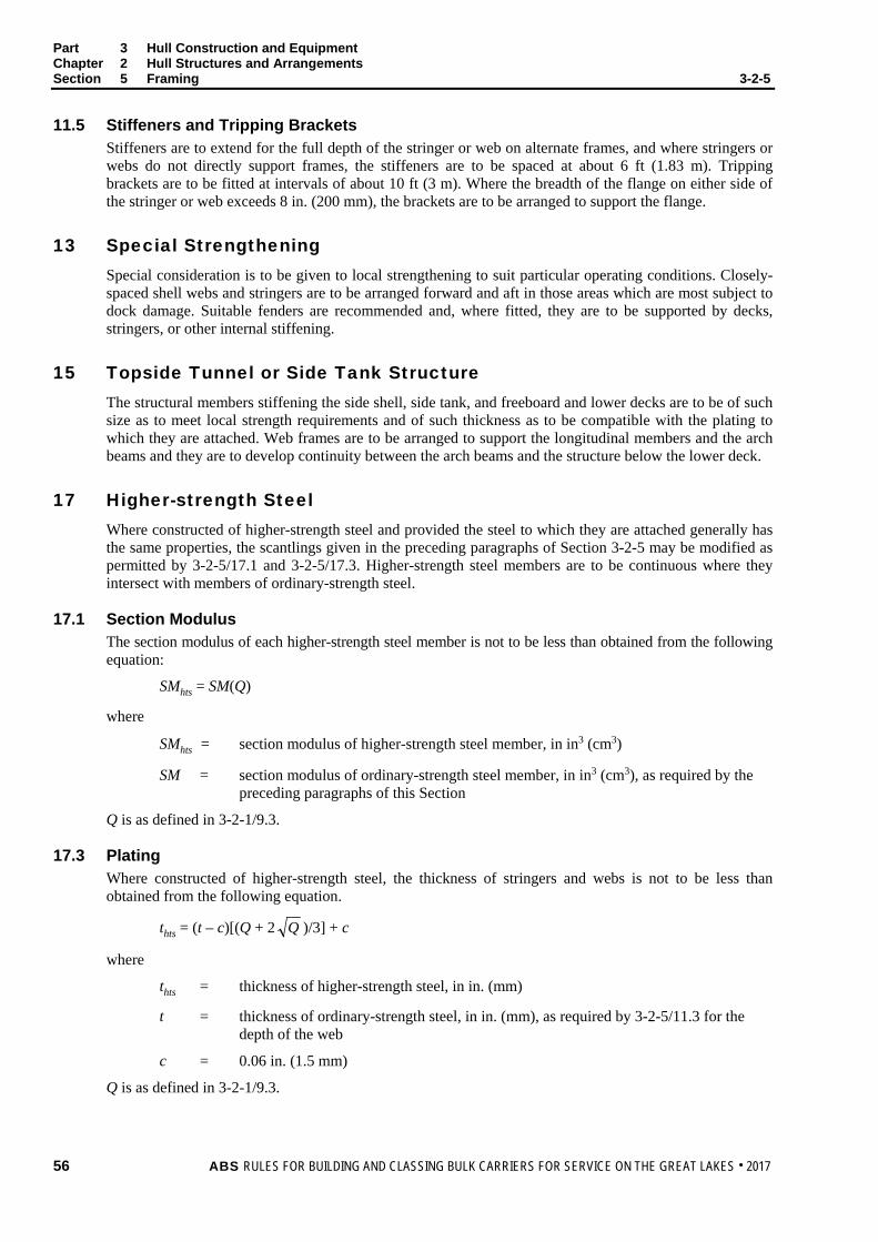
Part 3 Hull Construction and Equipment Chapter 2 Hull Structures and Arrangements Section 5 Framing 3-2-5
11.5 Stiffeners and Tripping Brackets Stiffeners are to extend for the full depth of the stringer or web on alternate frames, and where stringers or webs do not directly support frames, the stiffeners are to be spaced at about 6 ft (1.83 m). Tripping brackets are to be fitted at intervals of about 10 ft (3 m). Where the breadth of the flange on either side of the stringer or web exceeds 8 in. (200 mm), the brackets are to be arranged to support the flange.
13 Special Strengthening Special consideration is to be given to local strengthening to suit particular operating conditions. Closely-spaced shell webs and stringers are to be arranged forward and aft in those areas which are most subject to dock damage. Suitable fenders are recommended and, where fitted, they are to be supported by decks, stringers, or other internal stiffening.
15 Topside Tunnel or Side Tank Structure The structural members stiffening the side shell, side tank, and freeboard and lower decks are to be of such size as to meet local strength requirements and of such thickness as to be compatible with the plating to which they are attached. Web frames are to be arranged to support the longitudinal members and the arch beams and they are to develop continuity between the arch beams and the structure below the lower deck.
17 Higher-strength Steel Where constructed of higher-strength steel and provided the steel to which they are attached generally has the same properties, the scantlings given in the preceding paragraphs of Section 3-2-5 may be modified as permitted by 3-2-5/17.1 and 3-2-5/17.3. Higher-strength steel members are to be continuous where they intersect with members of ordinary-strength steel.
17.1 Section Modulus The section modulus of each higher-strength steel member is not to be less than obtained from the following equation:
SMhts = SM(Q)
where
SMhts = section modulus of higher-strength steel member, in in3 (cm3)
SM = section modulus of ordinary-strength steel member, in in3 (cm3), as required by the preceding paragraphs of this Section
Q is as defined in 3-2-1/9.3.
17.3 Plating Where constructed of higher-strength steel, the thickness of stringers and webs is not to be less than obtained from the following equation.
thts = (t – c)[(Q + 2 Q )/3] + c
where
thts = thickness of higher-strength steel, in in. (mm)
t = thickness of ordinary-strength steel, in in. (mm), as required by 3-2-5/11.3 for the depth of the web
c = 0.06 in. (1.5 mm)
Q is as defined in 3-2-1/9.3.
56 ABS RULES FOR BUILDING AND CLASSING BULK CARRIERS FOR SERVICE ON THE GREAT LAKES . 2017

Part 3 Hull Construction and Equipment Chapter 2 Hull Structures and Arrangements Section 5 Framing 3-2-5
19 Struts The value of W for struts is not to be less than obtained from the following equation:
W = 0.03bhs long tons W = 1.07bhs metric tons
where
b = mean breadth of the area supported, in ft (m)
h = distance from the center of the area supported to the load line, or to a point located at two-thirds of the distance from the top of the tank to the top of the overflow, in ft (m), whichever is greater
s = spacing of stringers or webs, in ft (m)
The sizes of struts are to satisfy the following equation.
W = (7.83 − 0.345/r')A long tons W = (1.232 − 0.00452/r')A metric tons
where
= unsupported span of the strut, in ft (cm)
r' = least radius of gyration, in in. (cm)
A = area of the strut, in in2 (cm2)
Struts within tanks are to be of solid section. Special attention is to be given to the end connections for tension members.
ABS RULES FOR BUILDING AND CLASSING BULK CARRIERS FOR SERVICE ON THE GREAT LAKES . 2017 57

P A R T S e c t i o n 6 : W a t e r t i g h t B u l k h e a d s
3 C H A P T E R 2 Hull Structures and Arrangements
S E C T I O N 6 Watertight Bulkheads
1 General All vessels are to be provided with watertight bulkheads in accordance with this section and as outlined by 3-1-2/1; in vessels of special type where adherence to these requirements is found to be impracticable, the arrangements will be specially considered. In all cases, the plans submitted are to show clearly the location and extent of the bulkheads. Watertight bulkheads constructed in accordance with these requirements will be recorded in the Record as WT (watertight), the symbols being prefixed in each case by the number of such bulkheads. Watertight bulkheads which serve as tank boundaries are to have scantlings not less than obtained from Section 3-2-7.
3 Arrangement of Watertight Bulkheads
3.1 Collision Bulkheads Collision bulkheads are to be fitted in all vessels. They are to be approximately 20 ft (6.1 m) abaft the stem at the load line in vessels 400 ft (122 m) in length and 30 ft (9.15 m) abaft the stem in vessels 1000 ft (305 m) and over in length; values for lengths between 400 ft (122 m) and 1000 ft (305 m) are to be obtained by interpolation. They are to extend to the freeboard deck preferably in one plane, and in vessels with superstructures at the forward end, the bulkheads are to be extended weathertight to the superstructure deck. The extension need not be fitted directly over the bulkhead below provided the part of the freeboard deck which forms the step is made effectively weathertight.
3.3 After Peak Bulkheads After peak bulkheads are to be arranged to enclose the shaft tubes in watertight compartments.
3.5 Machinery Space Bulkheads are to be fitted at the forward ends of machinery spaces and are to extend to the freeboard deck.
5 Chain Lockers Chain lockers which extend into the forepeak tank are to be made watertight.
7 Construction of Watertight Bulkheads
7.1 Plating Plating is to be of the thickness obtained from 3-2-6/Figure 1 for the spacing of stiffeners and the distance h measured from the lower edge of the plate to the bulkhead deck at center. The plating of collision bulkheads is obtained from the same Figure using a spacing 6 in. (150 mm) greater than actually adopted. In way of the stern tube, the after peak bulkhead plating is to be increased in thickness, or doubled, to provide suitable support for the tube.
58 ABS RULES FOR BUILDING AND CLASSING BULK CARRIERS FOR SERVICE ON THE GREAT LAKES . 2017

Part 3 Hull Construction and Equipment Chapter 2 Hull Structures and Arrangements Section 6 Watertight Bulkheads 3-2-6
7.3 Stiffeners Each stiffener is to have a section modulus SM not less than obtained from the following equation.
SM = 0.0041chs2 in3 SM = 7.9chs2 cm3
where
c = 0.54 for stiffeners between stringers or for stiffeners having bracketed or clipped end connections
= 0.60 for stiffeners having no end attachments
h = distance from the middle oft to the bulkhead deck at center, in ft (m). Where that distance is less than 20 ft (6.1 m), h is to be taken as 0.8 times the distance in ft plus 4 (m plus 1.22).
s = spacing of the stiffeners, in ft (m)
= span between supporting stringers or decks or between the toes of brackets where fitted in accordance with 3-1-2/Table 2, in ft (m)
The section modulus of stiffeners on collision bulkheads is to be at least 25% greater than required for ordinary bulkheads. Stiffeners on watertight bulkheads in way of the cargo holds are to have end attachments. Stiffening arrangements on the after-peak bulkhead are to be specially considered, particularly in way of the stern tube; additional stiffening may be required to minimize the effect of vibration.
7.5 Stringers and Webs 7.5.1 Strength Requirements
Each stringer and web which supports bulkhead stiffeners is to have a section modulus SM not less than obtained from the following equation:
SM = 0.0025chs2 in3 SM = 4.74chs2 cm3
where
c = 1.0
h = distance from the center of the area supported to the bulkhead deck at center, in ft (m). Where that distance is less than 20 ft (6.1 m), the value of h is to be 0.8 times the distance in ft plus 4 (m plus 1.22).
s = sum of half-lengths (on each side of the stringer or web) of the stiffeners supported, in ft (m)
= span between bulkheads or webs or between decks or other supports, in ft (m)
Where effective brackets are fitted, may be modified as described in 3-1-2/Table 2.
The section modulus of stringers and webs on collision bulkheads is to be at least 25% greater than required for similar supporting members on ordinary bulkheads.
7.5.2 Proportions Stringers and webs are to have depths not less than 1 in. per ft (8.4 mm per 100 mm) of span . The depth is not to be less than two times the depth of the slots, and the thickness is not to be less than 0.01 in. per in. (1 mm per 100 mm) of depth plus 0.12 in. (3 mm), but need not exceed 0.44 in. (11 mm).
7.5.3 Tripping Brackets Tripping brackets arranged to support the flanges are to be located at intervals of about 10 ft (3 m).
7.5.4 Attachments Where stiffeners cross decks or bulkheads on the opposite side of the plating, chocks are to be fitted.
ABS RULES FOR BUILDING AND CLASSING BULK CARRIERS FOR SERVICE ON THE GREAT LAKES . 2017 59

Part 3 Hull Construction and Equipment Chapter 2 Hull Structures and Arrangements Section 6 Watertight Bulkheads 3-2-6
7.7 Watertight Doors Watertight doors of an approved type are to be of ample strength for the water pressure to which they may be subjected, and fitted with gaskets and dogs spaced and designed to insure that the opening may be closed thoroughly watertight. Those doors below the freeboard deck which may require to be opened at sea are to have either audible or visual alarms located in the pilot house to indicate whether the doors are in the open or closed position. Where stiffeners are cut in way of watertight doors, the openings are to be framed and bracketed so as to maintain the full strength of the bulkhead without taking the strength of the door frames into consideration. Where doors are hinged, they are to be quick-acting type. The doors are to be closed and dogs secured at all times except when the vessel is in port or when the door is used for access. Where used at sea for access the door is to be closed and dogs secured immediately access is gained. Signs informing of this requirement are to be posted on either side adjacent to the door.
7.9 Testing Testing of watertight bulkheads, recesses, and decks is to be carried out after the completion of all work affecting the watertightness. A hose test is to be carried out under simultaneous inspection of both sides of the plating and the pressure of the water in the hose is not to be less than 30 psi. (2.1 kg/cm2). Shaft tube compartments and forepeaks are to be tested with a head of water to the load line. Where shaft tube compartments and forepeaks are used as tanks, the test heads are not to be less than required in 3-2-7/3.
9 Higher-strength Steel Where constructed of higher-strength steel, the scantlings given in the preceding paragraphs may be modified as permitted by 3-2-6/9.1 and 3-2-6/5.3.
Care is to be taken to avoid the adoption of reduced thicknesses of members that might be subject to damage during normal operation. Calculations, showing that adequate buckling strength is provided, may be required to be submitted. The structural members and the plating to which they are attached are to generally have the same strength properties.
9.1 Section Modulus The section modulus of each higher-strength steel member is not to be less than obtained from the following equation:
SMhts = SM(Q)
where
SMhts = section modulus of higher-strength steel member, in in3 (cm3)
SM = section modulus of ordinary-strength steel member, in in3 (cm3), as required by the preceding paragraphs of this Section
Q is as defined in 3-2-1/9.3.
9.3 Plating Where constructed of higher-strength steel, the plate thickness required by the preceding paragraphs of this Section may be modified but is not to be less than obtained from the following equation:
thts = (t – c)[(Q + 2 Q )/3] + c
where
thts = thickness of higher-strength steel, in in. (mm)
t = thickness of ordinary-strength steel, in in. (mm), as required by 3-2-5/11.3 for the depth of the web
c = 0.06 in. (1.5 mm)
Q is as defined in 3-2-1/9.3.
60 ABS RULES FOR BUILDING AND CLASSING BULK CARRIERS FOR SERVICE ON THE GREAT LAKES . 2017

Part 3 Hull Construction and Equipment Chapter 2 Hull Structures and Arrangements Section 6 Watertight Bulkheads 3-2-6
11 Construction of Screen Bulkheads (1 July 2017) Screen bulkheads are non-watertight bulkheads often used to separate cargoes. Strength requirements for screen bulkhead plating, stiffeners, stringers, and webs are to be obtained from 3-2-6/7 with the corresponding h value reduced by half for thickness and section modulus calculations. However, in no case, is the screen bulkhead plating thickness to be taken less than 0.25 in. (6.35 mm).
In lieu of applying the requirement indicated above, the “U” shaped part, which runs along the deck and side tanks for double hulls or the deck and side shell for single hulls, is to have section modulus SM not less than obtained from 3-2-5/11.1. See 3-2-6/Figure 2 for an example of screen bulkhead section modulus calculation.
FIGURE 1 Curves for Watertight Bulkhead Plating Thickness – Inch Units
Note: Curves are based on the following equation:
t = (0.0228 )s + 0.06 in.
s = stiffener spacing, in ft
h = as defined in 3-2-6/7.1
ABS RULES FOR BUILDING AND CLASSING BULK CARRIERS FOR SERVICE ON THE GREAT LAKES . 2017 61

Part 3 Hull Construction and Equipment Chapter 2 Hull Structures and Arrangements Section 6 Watertight Bulkheads 3-2-6
FIGURE 1 Curves for Watertight Bulkhead Plating Thickness – Metric Units
Note: Curves are based on the following equation:
t = (3.45 )s + 1.5 mm
s = stiffener spacing, in m
h = as defined in 3-2-6/7.1
62 ABS RULES FOR BUILDING AND CLASSING BULK CARRIERS FOR SERVICE ON THE GREAT LAKES . 2017

Part 3 Hull Construction and Equipment Chapter 2 Hull Structures and Arrangements Section 6 Watertight Bulkheads 3-2-6
FIGURE 2 Screen Bulkhead Section Modulus Calculation – Double Hulls (1 July 2017)
ABS RULES FOR BUILDING AND CLASSING BULK CARRIERS FOR SERVICE ON THE GREAT LAKES . 2017 63

P A R T S e c t i o n 6 : T a n k B o u n d a r y B u l k h e a d s
3 C H A P T E R 2 Hull Structures and Arrangements
S E C T I O N 7 Tank Boundary Bulkheads
1 General All tank boundary bulkheads are to be constructed in accordance with the requirements of this section. Tanks are to be arranged with swash bulkheads in such number and location as to minimize the dynamic stress of the structure. The arrangements of all tanks, together with their intended service and the height of the overflow pipes, are to be clearly indicated on the plans submitted for approval.
3 Construction of Tank Boundary Bulkheads
3.1 Plating The thickness of the plating is to be obtained from 3-2-7/Figure 1 for the spacing of the stiffeners with the distance h, in ft (m), measured from the lower edge of the plating to a point located at two-thirds of the distance from the top of the tank to the top of the overflow. The thickness of plating of side tank bulkheads when subject to mechanical damage, and the hopper slopes forming tank boundaries in self-unloading vessels, is to be increased 0.06 in. (1.5 mm).
3.3 Stiffeners Each stiffener is to have a section modulus SM not less than obtained from the following equation.
SM = 0.0041chs2 in3 SM = 7.9chs2 cm3
where
c = 1.0
h = distance from the middle of to a point two-thirds of the distance from the top of the tank to the top of the overflow, in ft (m). The value of h is not to be taken at less than 6 ft (1.83 m).
s = spacing of the stiffeners, in ft (m)
= span between supporting stringers or decks or between the toes of brackets where fitted in accordance with 3-1-2/Table 2, in ft (m).
All stiffeners which pass through decks, girders, or stringers are to be attached to these members, and elsewhere they are to be fitted with brackets or clips which are to extend to the adjacent frame or beam.
3.5 Stringers and Webs 3.5.1 Strength Requirements
Each stringer and web which supports stiffeners in deep tanks is to have a section modulus SM not less than obtained from the following equation:
SM = 0.0025chs2 in3 SM = 4.74chs2 cm3
64 ABS RULES FOR BUILDING AND CLASSING BULK CARRIERS FOR SERVICE ON THE GREAT LAKES . 2017

Part 3 Hull Construction and Equipment Chapter 2 Hull Structures and Arrangements Section 7 Tank Boundary Bulkheads 3-2-7
where
c = 1.5
h = distance from the center of the area supported to a point located at two-thirds of the distance from the top of the tank to the top of the overflow, in ft (m). The value of h is not to be taken at less than 6.0 ft (1.83 m)
s = sum of half-lengths (on each side of the stringer or web) of the stiffeners supported, in ft (m)
= span between bulkheads or webs or between decks or other supports, in ft (m)
Where effective brackets are fitted, may be modified as described in 3-1-2/Table 2. Where efficient struts are fitted between stringers or webs, the combined section moduli of the stringers or webs may be used.
3.5.2 Proportions Stringers and webs are to have depths not less than 1.5 in. per ft (12.6 mm per 100 mm) of span when no struts or ties are fitted, and 1 in. per ft (8.4 mm per 100 mm) when struts are fitted. The depth is not to be less than 2.5 times the depth of the slots, and the thickness is not to be less than 0.01 in. per in. (1 mm per 100 mm) of depth plus 0.12 in. (3 mm), but need not exceed 0.44 in. (11 mm).
3.5.3 Tripping Brackets and Web Plate Stiffeners Tripping brackets arranged to support the flanges are to be located at intervals of about 10 ft (3 m). Where the bulkhead may be subject to mechanical damage, flat bars or other web plate stiffeners are to be fitted at each stiffener for the full depth of the stringer or web, and elsewhere they are to be fitted at alternate stiffeners.
3.7 Attachments Where stiffeners cross decks or bulkheads on the opposite side of the bulkhead plating, the stiffeners are to be attached to the bulkhead by chocks in line with the deck or bulkhead on the opposite side of the bulkhead.
5 Testing All tanks are to be tested with a head of water to the overflow.
7 Topside Tunnel or Side Tank Bulkheads It is recommended that the uppermost strake of continuous longitudinal side tank or tunnel side bulkheads which extend to the freeboard deck not be less than 0.44 in. (11 mm) in vessels of 400 ft (122 m) length and 0.62 in. (15.5 mm) in vessels of 700 ft (213 m) length and above. Openings, where cut, are to have well-rounded corners and may require compensation.
9 Higher-strength Steel Where constructed of higher-strength steel, the scantlings given in the preceding paragraphs of this section may be modified as permitted by 3-2-7/9.1 and 3-2-7/9.3. The structural members and the plating to which they are attached are to generally have the same strength properties.
9.1 Section Modulus The section modulus of higher-strength steel members is not to be less than obtained from the following equation:
SMhts = SM(Q)
ABS RULES FOR BUILDING AND CLASSING BULK CARRIERS FOR SERVICE ON THE GREAT LAKES . 2017 65

Part 3 Hull Construction and Equipment Chapter 2 Hull Structures and Arrangements Section 7 Tank Boundary Bulkheads 3-2-7
where
SMhts = section modulus of higher-strength steel member, in in3 (cm3)
SM = section modulus of ordinary-strength steel member, in in3 (cm3), as required by the preceding paragraphs of this Section
Q is as defined in 3-2-1/9.3.
9.3 Plating Where constructed of higher-strength steel, the plate thickness required by the preceding paragraphs of this section may be modified but is not to be less than obtained from the following equation:
thts = (t – c)[(Q + 2 )/3] + c
where
thts = thickness of higher-strength steel, in in. (mm)
t = thickness of ordinary-strength steel, in in. (mm), as required by the preceding paragraphs of this Section
c = 0.06 in. (1.5 mm)
Q is as defined in 3-2-1/9.3.
FIGURE 1 Curves for Tank Bulkhead Plating Thickness – Inch Units
Note: Curves are based on the following equation:
t = (0.02792 )s in.
s = stiffener spacing, in ft
h = as defined in 3-2-7/3.1
66 ABS RULES FOR BUILDING AND CLASSING BULK CARRIERS FOR SERVICE ON THE GREAT LAKES . 2017

Part 3 Hull Construction and Equipment Chapter 2 Hull Structures and Arrangements Section 7 Tank Boundary Bulkheads 3-2-7
FIGURE 1 Curves for Tank Bulkhead Plating Thickness – Metric Units
Note: Curves are based on the following equation:
t = (4.214 )s mm
s = stiffener spacing, in m
h = as defined in 3-2-7/3.1
ABS RULES FOR BUILDING AND CLASSING BULK CARRIERS FOR SERVICE ON THE GREAT LAKES . 2017 67

P A R T S e c t i o n 8 : S u p e r s t r u c t u r e s a n d D e c k h o u s e s
3 C H A P T E R 2 Hull Structures and Arrangements
S E C T I O N 8 Superstructures and Deckhouses
1 Superstructures
1.1 Side Plating The thickness of side plating of the poop and forecastle is not to be less than given in 3-1-2/Table 1, Column 7, for a distance of 0.1L from the ends of the vessel. Beyond 0.1L, the thickness is to be gradually increased. In way of the forecastle and poop bulkheads, a further increase may be required. The plating is to be carried well beyond the end bulkheads and fashioned so as to provide a long gradual taper to the sheerstrake. Where the plating is welded to the sheerstrake, the termination of the joint is to be ground smooth and faired into the top edge of the sheerstrake.
1.3 Side Frames The side frames of the poop and forecastle are to be aligned with the frames below the freeboard deck. Each frame abaft the collision bulkhead is to have a section modulus SM not less than obtained from the following equation:
SM = 0.0041cs2 in3 SM = 7.9cs2 cm3
where
c = for forecastle side frames abaft the collision bulkhead
= 20 (6.1) for vessels 400 ft (122 m) in length
= 30 (9.15) for vessels 800 ft (244 m) or over in length
c = for poop side frames
= 16 (4.9) for vessels 400 ft (122 m) in length
= 24 (7.3) for vessels 800 ft (244 m) or over in length
Intermediate values of c are to be obtained by interpolation.
s = spacing of the frames, in ft (m)
= span, in ft (m), between decks or between toes of brackets where fitted in accordance with 3-1-2/Table 2
Forecastle side frames forward of the collision bulkhead are to be of the same size as those abaft, are to be aligned with each frame below the freeboard deck, and are to be bracketed to the deck beams. Web frames or partial bulkheads are to be lilted over main bulkheads or webs as may be required to provide adequate transverse rigidity to the superstructures.
1.5 Decks The thickness of plating on superstructure decks is to be in accordance with the requirements of 3-2-3/5.5.1. Deck beams and girders are to be as required by 3-2-3/7, 3-2-3/9, and 3-2-3/11.
68 ABS RULES FOR BUILDING AND CLASSING BULK CARRIERS FOR SERVICE ON THE GREAT LAKES . 2017

Part 3 Hull Construction and Equipment Chapter 2 Hull Structures and Arrangements Section 8 Superstructures and Deckhouses 3-2-8
1.7 Superstructure Bulkheads and Deckhouse Bulkheads on Freeboard Deck 1.7.1 Plating
The plating is to be not less in thickness than obtained as follows.
0.38 in. (9.5 mm) for poop front and deckhouse front bulkheads
0.30 in. (7.5 mm) for deckhouse sides and after bulkhead, poop and forecastle after bulkheads
Where the spacing of stiffeners is greater or less than 30 in. (760 mm), the thickness is to be increased, or may be reduced, at the rate of 0.02 in. for each 4 in. (0.5 mm per 100 mm) difference in spacing, respectively.
1.7.2 Stiffeners Each stiffener is to have section modulus SM not less than obtained from the following equation.
SM = 0.0041cs2 in3 SM = 7.9cs2 cm3
where
c = 10 (3) at L = 400 ft (122 m) and 14.5 (4.4) at L ≥ 500 ft (152 m) for poop front and deckhouse front bulkhead. Intermediate values may be obtained by interpolation.
= 4.75 (1.45) for deckhouse sides
= 4.0 (1.22) for poop and deckhouse after bulkheads
= 3.4 (1.04) for forecastle after bulkhead
s = spacing of the stiffeners, in ft (m)
= tween deck height, in ft (m)
Stiffeners on the poop front or deckhouse front bulkheads are to be attached to the decks at their ends, and elsewhere they may have sniped ends.
1.9 Windlass Room Bulkhead Where the anchor windlass is located on the freeboard deck, a bulkhead is to be fitted abaft the windlass and is to have the scantlings required for forecastle bulkheads. See also 3-2-6/3.1.
3 Deckhouses on Superstructure Decks
3.1 Bulkheads 3.1.1 Plating
The plating is to be not less in thickness than obtained as follows:
0.30 in. (7.5 mm) for deckhouse fronts
0.28 in. (7.0 mm) for deckhouse sides
0.25 in. (6.5 mm) for deckhouse after ends
Where the spacing of stiffeners is greater or less than 30 in.(760 mm), the thickness is to be increased, or may be reduced, at the rate of 0.02 in. for each 4 in. (0.5 mm per 100 mm) difference in spacing, respectively.
ABS RULES FOR BUILDING AND CLASSING BULK CARRIERS FOR SERVICE ON THE GREAT LAKES . 2017 69
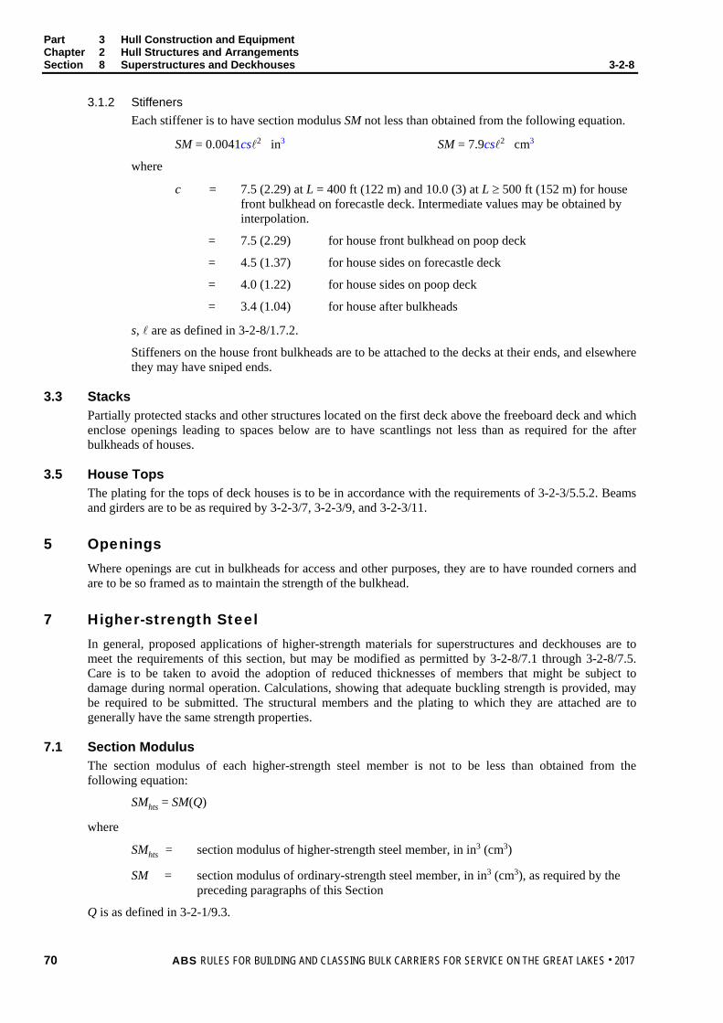
Part 3 Hull Construction and Equipment Chapter 2 Hull Structures and Arrangements Section 8 Superstructures and Deckhouses 3-2-8
3.1.2 Stiffeners Each stiffener is to have section modulus SM not less than obtained from the following equation.
SM = 0.0041cs2 in3 SM = 7.9cs2 cm3
where
c = 7.5 (2.29) at L = 400 ft (122 m) and 10.0 (3) at L ≥ 500 ft (152 m) for house front bulkhead on forecastle deck. Intermediate values may be obtained by interpolation.
= 7.5 (2.29) for house front bulkhead on poop deck
= 4.5 (1.37) for house sides on forecastle deck
= 4.0 (1.22) for house sides on poop deck
= 3.4 (1.04) for house after bulkheads
s, are as defined in 3-2-8/1.7.2.
Stiffeners on the house front bulkheads are to be attached to the decks at their ends, and elsewhere they may have sniped ends.
3.3 Stacks Partially protected stacks and other structures located on the first deck above the freeboard deck and which enclose openings leading to spaces below are to have scantlings not less than as required for the after bulkheads of houses.
3.5 House Tops The plating for the tops of deck houses is to be in accordance with the requirements of 3-2-3/5.5.2. Beams and girders are to be as required by 3-2-3/7, 3-2-3/9, and 3-2-3/11.
5 Openings Where openings are cut in bulkheads for access and other purposes, they are to have rounded corners and are to be so framed as to maintain the strength of the bulkhead.
7 Higher-strength Steel In general, proposed applications of higher-strength materials for superstructures and deckhouses are to meet the requirements of this section, but may be modified as permitted by 3-2-8/7.1 through 3-2-8/7.5. Care is to be taken to avoid the adoption of reduced thicknesses of members that might be subject to damage during normal operation. Calculations, showing that adequate buckling strength is provided, may be required to be submitted. The structural members and the plating to which they are attached are to generally have the same strength properties.
7.1 Section Modulus The section modulus of each higher-strength steel member is not to be less than obtained from the following equation:
SMhts = SM(Q)
where
SMhts = section modulus of higher-strength steel member, in in3 (cm3)
SM = section modulus of ordinary-strength steel member, in in3 (cm3), as required by the preceding paragraphs of this Section
Q is as defined in 3-2-1/9.3.
70 ABS RULES FOR BUILDING AND CLASSING BULK CARRIERS FOR SERVICE ON THE GREAT LAKES . 2017
Part 3 Hull Construction and Equipment Chapter 2 Hull Structures and Arrangements Section 8 Superstructures and Deckhouses 3-2-8
7.3 Deck Plating Where constructed of higher-strength steel, the thickness of superstructure decks and deckhouse tops is to be in accordance with the requirements of 3-2-3/15.3.
7.5 Side and Bulkhead Plating Where constructed of higher-strength steel, the thicknesses of superstructure sides and of the superstructure and deckhouse bulkheads, as required by the preceding paragraphs of this section, may be modified but are not to be less than obtained from the following equation:
thts = (t – c)[(Q + 2 Q )/3] + c
where
thts = thickness of higher-strength steel, in in. (mm)
t = thickness of ordinary-strength steel, in in. (mm), for which a requirement is given in the preceding paragraphs of this Section
c = 0.06 in. (1.5 mm)
Q is as defined in 3-2-1/9.3.
ABS RULES FOR BUILDING AND CLASSING BULK CARRIERS FOR SERVICE ON THE GREAT LAKES . 2017 71
P A R T S e c t i o n 9 : P r o t e c t i o n o f D e c k O p e n i n g s
3 C H A P T E R 2 Hull Structures and Arrangements
S E C T I O N 9 Protection of Deck Openings (9 May 1996)
1 General All openings in decks are to be framed to provide efficient support and attachment to the ends of the deck beams. The proposed arrangements and details for all hatchways are to be submitted for approval.
3 Position of Deck Openings For the purpose of the Rules, two positions of deck openings are defined as follows:
Position 1 Upon exposed freeboard decks, and upon exposed superstructure decks or a trunk deck situated forward of a point located a quarter of the vessel’s length from the forward perpendicular.
Position 2 Upon exposed superstructure decks or trunk of at least standard* height and situated abaft a quarter of the vessel's length from the forward perpendicular.
* Standard height as defined in Load Line Regulations for Great Lakes Vessels
5 Hatchway Coamings
5.1 Height of Coamings The height of coamings of hatchways secured weathertight by tarpaulins and battening devices is to be at least as follows:
18.0 in. (457 mm) if in Position 1
12.0 in. (305 mm) if in Position 2
Where hatch covers are made of steel or other equivalent material and made tight by means of gaskets and clamping devices, these heights may be reduced, or the coamings omitted entirely, provided that the safety of the vessel is not thereby impaired in any sea condition.
5.3 Coaming Plates Coaming plates are to be of steel or equivalent material and not less than 0.375 in. (9.5 mm) thick.
5.5 Coaming Stiffening Efficient brackets or stays are to be fitted from the upper edge of the coaming to the deck at intervals of not more than 10 ft (3 m). All exposed coamings other than Position 1 which are 30 in. (760 mm) or more in height are to be similarly supported. Where the height of any exposed coaming exceeds 36 in. (915 mm), the arrangement of the stiffeners and brackets or stays is to be specially considered. Where end coamings are protected, the arrangement of the stiffeners and brackets or stays may be modified.
5.7 Continuous Longitudinal Hatch Coamings Strength deck longitudinal hatch coamings of length greater than 0.14L are to be effectively supported by longitudinal bulkheads or deep girders and they are in general to be longitudinally stiffened. Special consideration will be given to the coaming scantlings. Calculations showing that adequate buckling strength is provided may be required to be submitted.
72 ABS RULES FOR BUILDING AND CLASSING BULK CARRIERS FOR SERVICE ON THE GREAT LAKES . 2017

Part 3 Hull Construction and Equipment Chapter 2 Hull Structures and Arrangements Section 9 Protection of Deck Openings 3-2-9
7 Hatchways Closed by Sectional Sliding Covers and Secured Weathertight by Tarpaulins and Battening Devices
7.1 Sliding Steel Hatch Covers Covers of the sliding plate type with flanges on one edge or with stiffeners welded to one edge are to have a sufficient number of sections so that when closed, the spacing of the stiffeners does not exceed 42 in. (1070 mm). Plates are not to be less in thickness than required for solid steel covers in association with the spacing of the stiffeners when closed. The stiffening at the edge of the covers is not to be less effective than required for solid covers. If hatch covers of the sliding plate type are used for spans exceeding 12 ft-1 in. (3.68 m), additional support is to be provided, the detail of which will be specially considered.
7.3 Cleats Cleats are to be set to fit the taper of the wedges. They are to be at least 2.5 in. (65 mm) wide and spaced at intervals of approximately 24 in. (610 mm) center to center; the cleats along each side or end are to be not more than 6 in. (150 mm) from the hatch corners.
7.5 Wedges Wedges are to be of tough wood; they are to have a taper of not more than 1 in 6 and are to be not less than 0.5 in. (13 mm) thick at the toes.
7.7 Battening Bars Battening bars are to be provided for properly securing the tarpaulins; they are to have a width of 2.5 in. (64 mm) and a thickness of not less than 0.375 in. (9.5 mm).
7.9 Tarpaulins At least one tarpaulin in good condition thoroughly waterproofed and of ample strength is to be provided for each exposed hatchway. The material is to be guaranteed free from jute, and is not to be less than No. 4 cotton canvas or equal before waterproofing. Synthetic fabrics which have been demonstrated to be equivalent will be specially approved.
7.11 Security of Hatchway Covers At all hatchways in exposed positions on the freeboard or superstructure decks suitable provision is to be made for securing the covers after the tarpaulins are battened down.
9 Hatchways Closed by Covers of Steel Fitted with Gaskets and Clamping Devices
9.1 Strength of Covers Where weathertight covers are of steel, the strength is to be calculated with assumed loads not less than 250 pounds per square foot (1.22 metric tons per square meter) on the hatchways in Position 1, and not less than 200 pounds per square foot (0.98 metric tons per square meter) on hatchways in Position 2, and the product of the maximum stress thus calculated and the factor of 4.25 is not to exceed the minimum ultimate tensile strength of the material. They are to be so designed as to limit the deflection to not more than 0.0028 times the span under these loads. Steel plating forming the tops of covers is to be not less in thickness than 1% of the spacing of stiffeners or 0.24 in. (6 mm) if that be greater. Where higher strength steels are used that have a higher resistance to corrosion a minimum thickness of 0.19 in. (4.8 mm) will be acceptable provided the limiting deflection noted above is not exceeded and calculations are submitted to show adequate provision against buckling. The hatch covers are to be provided with stiffening bar or plates required to provide the necessary rigidity to permit the cover being handled without permanent deformation.
ABS RULES FOR BUILDING AND CLASSING BULK CARRIERS FOR SERVICE ON THE GREAT LAKES . 2017 73

Part 3 Hull Construction and Equipment Chapter 2 Hull Structures and Arrangements Section 9 Protection of Deck Openings 3-2-9
9.3 Other Materials The strength and stiffness of covers made of materials other than steel is to be equivalent to those of steel and is to subject to special consideration.
9.5 Means for Securing Weathertightness 9.5.1 Weathertightness
The means for securing the maintaining weathertightness are to be such that the tightness can be maintained in any sea condition. The covers are to be hose-tested in position under a water pressure of at least 30 psi (2.1 kgf/cm2) at the time of construction and, if considered necessary, at subsequent surveys.
9.5.2 Clamping Devices Where the hatch cover edges are stiffened with a horizontal gasket retaining bar, clamping devices equivalent to the over-the-center type may be fitted at a maximum spacing of 24 in. (610mm) center to center.
Where the hatch cover edges is stiffened by a deep bat to witch the stiffener and gasket retainer are attached the spacing of the clamps may be increased. The inertia of the cover edge is to be not less than:
IR = 0.0062 41S in4 IR = 30 4
1S cm4
where
S1 = spacing of the cleats, in ft (m)
IR = inertia of cover edge, in in4 (cm4)
11 Miscellaneous Openings in Freeboard and Superstructure Decks
11.1 Manholes and Scuttles Manholes and flush scuttles in Position 1 or 2 or within superstructures other than enclosed superstructures are to be closed by substantial covers capable of being made watertight. Unless secured by closely spaced bolts, the covers are to be permanently attached.
11.3 Other Openings Openings in freeboard decks other than hatchways, machinery-space openings, manholes and flush scuttles are to be protected by an enclosed superstructure, or by a deckhouse or companionway of equivalent strength and weathertightness. Any such opening in an exposed superstructure deck or in the top of a deckhouse on the freeboard deck which gives access to a space below the freeboard deck or a space within an enclosed superstructure is to be protected by an efficient deckhouse or companionway. Doorways in such deckhouses or companionways are to be fitted with weathertight doors.
11.5 Escape Openings The closing appliances of escape openings are to be readily operable from each side.
11.7 Companionway Sills In Position 1 the height above the deck of sills to the doorways in companionways is to be at least 18 in. (457 mm). In Position 2 they are to be at least 12 in. (305 mm)
74 ABS RULES FOR BUILDING AND CLASSING BULK CARRIERS FOR SERVICE ON THE GREAT LAKES . 2017

P A R T A p p e n d i x 1 : C a l c u l a t i o n o f S h e a r S t r e s s e s
3 C H A P T E R 2 Hull Structures and Arrangements
A P P E N D I X 1 Calculation of Shear Stresses
1 General The shear stresses in the side shell, and longitudinal bulkhead plating for vessels having continuous longitudinal bulkheads, and in the side shell in way of wing tanks for vessels without continuous longitudinal bulkheads are to be calculated, as specified by 3-2-1/3.5.1, by an acceptable method. In general, the shear stresses should be determined based on the shear flow in the transverse section. The shear stress is the shear flow divided by the plate thickness, at the location considered.
For calculating shear flows, a computer program similar to ABS Hull Girder Section Analysis (HGSA) should be generally used. Information about ABS Hull Girder Section Analysis (HGSA) can be obtained from ABS’s Houston office.
When a computer program is not available, or at the early design stages, the following simplified method may be used to calculate shear stresses.
3 Shear Stress The total shear stresses fs, in long tons per inch squared (metric tons per centimeter squared), in the side shell and longitudinal bulkhead plating may be determined by the following equation:
fs = cK1NF/tH
where
c = 0.083 inch/pound units
= 0.01 metric units
K1 = 1 + y/8 y
y = distance, measured from the deck or bottom (depending on whether the strake considered is above or below the neutral axis of the section) to the point under consideration, in ft (m)
y = distance, measured from the deck (bottom) to the neutral axis of the section, when the strake under consideration is above (below) the neutral axis, in ft (m)
N = shear distribution factor as given in 3-2-A1/Figure 1
F = total shearing force, Fsw + Fd at the location considered, in long tons (metric tons)
t = plate thickness at the location considered, in in. (cm)
H = depth of the side shell or longitudinal bulkhead plating considered, in ft (m), see 3-2-1A1/Figure 1
For vessels having structural configurations departing from those shown in 3-2-A1/Figure 1, the calculation of shear stresses will be subject to special consideration.
ABS RULES FOR BUILDING AND CLASSING BULK CARRIERS FOR SERVICE ON THE GREAT LAKES . 2017 75

Part 3 Hull Construction and Equipment Chapter 2 Hull Structures and Arrangements Appendix 1 Calculation of Shear Stresses 3-2-A1
5 Allowable Still-water Shearing Force Alternatively, the allowable still-water shearing forces SWSF, in long tons or metric tons, at transverse sections of the hull-girder may be determined by the following equation.
SWSF = cfstH/(NK1) – fd
where
c = 12 inch/pound units
= 100 metric units
fs = permissible shear stress, in long toms/in2 or metric tons/cm2, as specified in 3-2-1/3.5
fd = dynamic shearing force, in long tons or metric tons, at the section considered as specified in 3-2-1/3.5.2
K1, N, t, and H are as defined in 3-2-1A1/3.
The allowable still-water shearing forces are to be determined for both the side shell and longitudinal bulkhead plating at various locations for each transverse section and the lowest value is to be used as the allowable still-water shearing force at the section under consideration.
76 ABS RULES FOR BUILDING AND CLASSING BULK CARRIERS FOR SERVICE ON THE GREAT LAKES . 2017

Part 3 Hull Construction and Equipment Chapter 2 Hull Structures and Arrangements Appendix 1 Calculation of Shear Stresses 3-2-A1
FIGURE 1 Shear Distribution Configurations
h
H2
D
N = Ns2
N = Ns1 H = H1
H = H2s
CL Type 1
Ns1 = 0.59H1/D – 0.05
Ns2 = 0.5 – Ns1 – Nb
Nb = (0.21Ab/As2 + 0.09)H2/D
As2 = total area of side shell plating with the region of H2, in in-ft (cm-m)
h
H2
D
N = Ns2
N = Ns1 H = H1
H = H2s
C
N = Nb1
L Type 2a
h
H2
D
N = Ns2
N = Ns1 H = H1
H = H2s
CL
N = Nb1
Type 2b
Ns = 0.5 – Nb
Ns1 = NsH1/D
Ns2 = Ns – Ns1
Nb = 0.16Ab/As + C1
Nb1 = NbH1/D
Nb2 = Nb[H2/D + C2]
C2 = 0 when h ≤ 0.15H2
= (0.6h/H2 – 0.09) when h > 0.15H2
C1 = 0.115 for Type 2a
= 0.08 for Type 2b A = total area of the vertical projected
longitudinal bulkhead plating, in in-ft (cm-m)
As = total projected area of the side shell plating for the full depth of the vessel, in in-ft (cm-m)
ABS RULES FOR BUILDING AND CLASSING BULK CARRIERS FOR SERVICE ON THE GREAT LAKES . 2017 77

P A R T C h a p t e r 3 : E q u i p m e n t
3 C H A P T E R 3 Equipment
CONTENTS SECTION 1 Anchoring, Mooring and Towing Equipment ..................................... 79
1 General ............................................................................................. 79 3 Equipment Weight and Size .............................................................. 79 5 Tests ................................................................................................. 80 7 Anchor Types .................................................................................... 80 9 Windlass ............................................................................................ 80 11 Hawse Pipes and Anchor Pockets .................................................... 80 TABLE 1 Equipment Weights and Sizes Inch/Pound Units ................... 81 TABLE 1 Equipment Weights and Sizes Metric Units ............................ 83
78 ABS RULES FOR BUILDING AND CLASSING BULK CARRIERS FOR SERVICE ON THE GREAT LAKES . 2017

P A R T S e c t i o n 1 : A n c h o r i n g , M o o r i n g a n d T o w i n g E q u i p m e n t
3 C H A P T E R 3 Equipment
S E C T I O N 1 Anchoring, Mooring and Towing Equipment
1 General All vessels are to have a complete equipment of anchors and chains. The symbol Á included in the classification symbols as published in the Record will signify that the equipment is in compliance with these requirements and has been tested in the presence of the ABS Surveyors in accordance with the requirements of the ABS Rules for Materials and Welding (Part 2). Chains which are intended to form part of the equipment are not to be used as check chains when the vessel is launched. Anchors and their chains are to be effectively secured and arrangements for stopping each chain as it is paid out are to be provided. The windlass is to be capable of heaving in either chain and suitable arrangements for securing the anchors and stowing the chains are to be provided.
3 Equipment Weight and Size Each vessel is to be provided with two bower anchors (stockless) and 180 fathoms (330 m) [90 fathoms (165 m) on each anchor], the weights and sizes of these being in accordance with 3-3-1/Table 1 and regulated by the tonnage for equipment as obtained from the following equations. Anchors of other types and chains of other material will be specially considered. Where the calculated tonnage falls between two values given in the Table, the lower value may be used.
Tonnage under freeboard deck = 0.01cLBD inch units
= 0.35cLBD metric units
where
c = 0.85
L = length of vessel, as defined in 3-1-1/1, in ft (m)
B = breadth of vessel, as defined in 3-1-1/3, in ft (m)
D = depth of vessel to freeboard deck, in ft (m)
Addition for superstructures or deck houses on freeboard deck = 0.0066cbd inch units
= 0.2355 cbd metric units
where
c = 0.75
= length of superstructure or deck house, in m (ft)
b = mean breadth of superstructure or deck house, in m (ft)
d = mean height of superstructure or deck house, in m (ft)
For the second tier of houses or superstructures the multiplier is to be 0.005 (0.1766) instead of 0.0066 (0.2355).
ABS RULES FOR BUILDING AND CLASSING BULK CARRIERS FOR SERVICE ON THE GREAT LAKES . 2017 79

Part 3 Hull Construction and Equipment Chapter 3 Equipment Section 1 Anchoring, Mooring and Towing Equipment 3-3-1
5 Tests Tests are to be in accordance with the Table requirements for the respective sizes as set forth in ABS Rules for Materials and Welding (Part 2). Anchors and chains are to be tested in an approved machine in the presence of a Surveyor.
7 Anchor Types Anchors are to be of the stockless type in which the weight of the head is not less than three-fifths of the total weight of the anchor. Where specifically requested by the Owners, the Bureau is prepared to give consideration to the use of special types of anchors and where these are of proven superior holding ability, consideration may also be given to some reduction in the weight, up to a maximum of 20%, from the weight specified in 3-3-1/Table 1. In such cases an appropriate notation will be made in the Record.
9 Windlass The windlass is to be of good and substantial make, suitable for the size of chain required by 3-3-1/Table 1. Care is to be taken to insure a fair lead for the chain from the windlass to the hawse pipes and to the chain pipes. The windlass foundation and deck supporting arrangements are to be specially considered.
11 Hawse Pipes and Anchor Pockets Hawse pipes and anchor pockets are to be of ample size and strength. They are to be secured to thick plating and, after installation, are to be hose tested for watertightness, with the pressure of the water in the hose not to be less than 30 psi (2.1 kg/cm2). The hawse pipes are to have the easiest possible lead and full round flanges so as to minimize the nip on the chains. The anchors are to be shipped and unshipped so that the Surveyor may be satisfied that there is no risk of the anchors jamming in the hawse pipes or anchor pockets.
80 ABS RULES FOR BUILDING AND CLASSING BULK CARRIERS FOR SERVICE ON THE GREAT LAKES . 2017

Part 3 Hull Construction and Equipment Chapter 3 Equipment Section 1 Anchoring, Mooring and Towing Equipment 3-3-1
TABLE 1 Equipment Weights and Sizes
Inch/Pound Units
Equipment Tonnage
Weight Each Anchor lb
Chain Cable Stud Link Bower Chain Diameter
Normal Strength Steel (Grade 1), in.
High-Strength Steel (Grade 2), in.
Extra High-Strength Steel (Grade 3), in.
2000 3750 15/8 17/16 11/4 2500 4000 15/8 17/16 11/4 3000 4500 13/4 11/2 15/16 3500 4750 17/8 15/8 17/16 4000 5000 115/16 111/16 17/16
4500 5250 2 13/4 11/2 5000 5750 21/16 113/16 19/16 5500 6000 21/16 113/16 19/16 6000 6300 21/16 113/16 19/16 6500 6500 21/16 113/16 19/16
7000 6750 21/8 17/8 15/8 7500 7000 21/8 17/8 15/8 8000 7250 21/8 17/8 15/8 8500 7250 23/16 115/16 13/4 9000 7600 23/16 115/16 13/4
9500 7600 25/16 2 113/16 10000 8100 25/16 2 113/16 10750 8600 25/16 2 113/16 11500 8600 23/8 21/16 113/16 12250 9000 23/8 21/16 113/16
13000 9000 27/16 21/8 17/8 13750 9500 27/16 21/8 17/8 14500 10000 27/16 21/8 17/8 15250 10000 21/2 23/16 2 16000 10000 21/2 23/16 2
16750 10000 21/2 23/16 2 17500 11000 29/16 21/4 2 18250 11000 29/16 21/4 2 19000 11000 29/16 21/4 2 19750 11000 25/8 25/16 2
20500 12000 25/8 25/16 2 21250 12000 211/16 23/8 21/16 22000 12000 211/16 23/8 21/16 23000 13000 211/16 23/8 21/16 24000 13000 23/4 27/16 21/8
ABS RULES FOR BUILDING AND CLASSING BULK CARRIERS FOR SERVICE ON THE GREAT LAKES . 2017 81

Part 3 Hull Construction and Equipment Chapter 3 Equipment Section 1 Anchoring, Mooring and Towing Equipment 3-3-1
TABLE 1 (continued) Equipment Weights and Sizes
Inch/Pound Units
Equipment Tonnage
Weight Each Anchor lb
Chain Cable Stud Link Bower Chain Diameter
Normal Strength Steel (Grade 1), in.
High-Strength Steel (Grade 2), in.
Extra High-Strength Steel (Grade 3), in.
25000 13000 23/4 27/16 21/8 26000 14000 23/4 27/16 21/8 27000 14000 27/8 21/2 23/16 28000 14000 27/8 21/2 23/16 29000 15000 27/8 21/2 23/16
30000 15000 215/16 29/16 21/4 31500 16000 215/16 29/16 21/4 33000 16000 215/16 29/16 21/4 34500 16000 3 25/8 25/16 36000 18000 3 25/8 25/16
37500 18000 3 25/8 25/16 39000 18000 3 25/8 25/16 40500 18000 31/16 211/16 23/8 42000 20000 31/16 211/16 23/8 44000 20000 31/16 211/16 23/8
46000 20000 33/16 23/4 27/16 48000 20000 33/16 23/4 27/16 50000 22500 33/16 23/4 27/16 52000 22500 31/4 213/16 27/16 54000 22500 35/16 27/8 21/2
56000 25000 35/16 27/8 21/2 58000 25000 35/16 27/8 21/2 60000 25000 33/8 215/16 29/16 62000 25000 33/8 215/16 29/16 64000 27500 33/8 215/16 29/16
66000 27500 33/8 215/16 29/16 68000 27500 37/16 3 25/8 70000 27500 37/16 3 25/8
82 ABS RULES FOR BUILDING AND CLASSING BULK CARRIERS FOR SERVICE ON THE GREAT LAKES . 2017

Part 3 Hull Construction and Equipment Chapter 3 Equipment Section 1 Anchoring, Mooring and Towing Equipment 3-3-1
TABLE 1 Equipment Weights and Sizes
Metric Units
Equipment Tonnage
Weight Each Anchor kg
Chain Cable Stud Link Bower Chain Diameter
Normal Strength Steel (Grade 1), mm
High-Strength Steel (Grade 2), mm
Extra High-Strength Steel (Grade 3), mm
2000 1700 42 36 32 2500 1815 42 36 32 3000 2040 44 38 34 3500 2155 48 42 36 4000 2270 49 43 36
4500 2380 50 44 38 5000 2610 52 46 40 5500 2720 52 46 40 6000 2860 52 46 40 6500 2950 52 46 40
7000 3060 54 48 42 7500 3175 54 48 42 8000 3290 54 48 42 8500 3290 56 50 44 9000 3445 56 50 44
9500 3445 58 50 46 10000 3675 58 50 46 10750 3900 58 50 46 11500 3900 60 52 46 12250 4080 60 52 46
13000 4080 62 54 48 13750 4310 62 54 48 14500 4535 62 54 48 15250 4535 64 56 50 16000 4535 64 56 50
16750 4535 64 56 50 17500 4990 65 57 50 18250 4990 65 57 50 19000 4990 65 57 50 19750 4990 66 58 50
20500 5445 66 58 50 21250 5445 68 60 52 22000 5445 68 60 52 23000 5895 68 60 52 24000 5895 70 62 54
ABS RULES FOR BUILDING AND CLASSING BULK CARRIERS FOR SERVICE ON THE GREAT LAKES . 2017 83

Part 3 Hull Construction and Equipment Chapter 3 Equipment Section 1 Anchoring, Mooring and Towing Equipment 3-3-1
TABLE 1 (continued) Equipment Weights and Sizes
Inch/Pound Units
Equipment Tonnage
Weight Each Anchor kg
Chain Cable Stud Link Bower Chain Diameter
Normal Strength Steel (Grade 1), mm
High-Strength Steel (Grade 2), mm
Extra High-Strength Steel (Grade 3), mm
25000 5895 70 62 54 26000 6350 70 62 54 27000 6350 73 64 56 28000 6350 73 64 56 29000 6805 73 64 56
30000 6805 75 65 57 31500 7260 75 65 57 33000 7260 75 65 57 34500 7260 76 66 58 36000 8165 76 66 58
37500 8165 76 66 58 39000 8165 76 66 58 40500 8165 78 68 60 42000 9070 78 68 60 44000 9070 78 68 60
46000 9070 81 70 62 48000 9070 81 70 62 50000 10205 81 70 62 52000 10205 83 71 62 54000 10205 84 73 64
56000 11340 84 73 64 58000 11340 84 73 64 60000 11340 86 75 65 62000 11340 86 75 65 64000 12475 86 75 65
66000 12475 86 75 65 68000 12475 87 76 66 70000 12475 87 76 66
84 ABS RULES FOR BUILDING AND CLASSING BULK CARRIERS FOR SERVICE ON THE GREAT LAKES . 2017

P A R T P a r t 7 : S u r v e y s A f t e r C o n s t r u c t i o n
7 Surveys After Construction (1 January 2001)
The independent booklet, ABS Rules for Survey After Construction (Part 7) is to be referred to. This booklet consists of the following Chapters:
CHAPTER 1 Conditions for Survey After Construction
CHAPTER 2 Survey Intervals
CHAPTER 3 Hull Surveys
CHAPTER 4 Drydocking Surveys
CHAPTER 5 Tailshaft Surveys
CHAPTER 6 Machinery Surveys
CHAPTER 7 Boiler Surveys
CHAPTER 8 Shipboard Automatic and Remote-control Systems
CHAPTER 9 Survey Requirements for Additional Systems and Services
CHAPTER 10 Steel Floating Drydocks
CHAPTER 11 Underwater Vehicles, Systems and Hyperbaric Facilities
CHAPTER 12 Sailing Yachts not Receiving AMS Notation
APPENDIX
ABS RULES FOR BUILDING AND CLASSING BULK CARRIERS FOR SERVICE ON THE GREAT LAKES . 2017 85

Appendix 1
Comparison of the Numbering System of the 1978 Rules vs. 2017 Rules

Comparison of the Numbering System of the 1978 Rules vs. the 2017 Rules
GLBC 1978 Title GLBC 2017 Section 1 Conditions of Classification
Whole Section
The requirements for “Conditions of Classification” in Section 1 of the 1978 edition of the Rules for Building and Classing Bulk Carriers for Service on the Great Lakes were relocated to the generically re-titled ABS Rules for Conditions of Classification (Part 1), which now includes consolidated requirements applicable to all offshore units, installations, vessels or systems. Those classification requirements specific to Great Lakes bulk carriers were retained in a supplemental Part 1 of the Great Lakes Bulk Carrier Rules. In the list below, references to the ABS Rules for Conditions of Classification (Part 1) are given as “CC 1-1-X/Y.Y.Y” and references to Part 1 of the Great Lakes Bulk Carrier Rules are given as “1-1-X/Y.Y.Y”.
Part 1 and New “Generic” Part 1
1.1 Classification Section 1-1-2 1.2 Application 1-1-3/1 1.3 Arrangements 3-1-2/1 1.4 Breaks 3-1-2/3 1.5 Structural Sections 3-1-2/5 1.6 Governmental Requirements CC 1-1-5/1 1.7 Alternatives CC 1-1-4/7.1 1.8 Definitions Section 3-1-1 1.8.1 Length 3-1-1/1 1.8.2 Breadth 3-1-1/3 1.8.3 Depth 3-1-1/5 1.8.4 Draft 3-1-1/1 1.8.5 Strength Deck 3-1-1/9 Section 2 Longitudinal Strength Section 2 Longitudinal Strength Section 3-2-1 2.1 General 3-2-1/1 2.2 Longitudinal Hull Girder Strength 3-2-1/3 2.2.1 Strength Standard 3-2-1/3.1 2.2.1a Section Modulus 3-2-1/3.1.1 2.2.1b Minimum Section Modulus 3-2-1/3.1.2 2.2.1c Section Modulus Calculation 3-2-1/3.1.3 2.2.1d Section Modulus with Continuous Coaming 3-2-1/3.1.4 2.2.2 Total Bending Moment 3-2-1/3.3 2.2.2a Still-water Bending Moment and Shear Force 3-2-1/3.3.1 2.2.2b Combined Dynamic Bending Moment Amidships 3-2-1/3.3.2 2.2.2c Wave-induced Bending Moment Amidships 3-2-1/3.3.3 2.2.2d Springing Bending Moment Amidships 3-2-1/3.3.4 2.2.3 Permissible Shear Stress 3-2-1/3.5 2.2.3a Calculation of Shear Stresses 3-2-1/3.5.1 2.2.3b Hull-girder Shearing Stress 3-2-1/3.5.2 2.3 Strength Deck and Other Effective Decks 3-2-1/5 2.3.1 Strength Decks 3-2-1/5.1 2.3.2 Effective Lower Decks 3-2-1/5.3 2.4 Loading Guidance 3-2-1/7 2.5 Higher-Strength Materials 3-2-1/9 2.5.1 General 3-2-1/9.1 2.5.2 Hull-girder Section Modulus 3-2-1/9.3 2.5.3 Permissible Shear Stress 3-2-1/9.5 2.5.4 Hull Girder Moment of Inertia 3-2-1/9.7 Table 2.1 Combined Dynamic Bending Moment Distribution Factor 3-2-1/Table 1 Table 2.2 Values of Z, in in.2, for Q = 1.0 (Ordinary Strength Steel) 3-2-1/Table 2 Table 2.2 Values of Z, in in.2, for Q = 0.78 3-2-1/Table 2 Table 2.2 Values of Z, in in.2, for Q = 0.72 3-2-1/Table 2 Table 2.2 Values of Z, in cm2, for Q = 1.0 (Ordinary Strength Steel) 3-2-1/Table 2 Table 2.2 Values of Z, in cm2, for Q = 0.78 3-2-1/Table 2 Table 2.2 Values of Z, in cm2, for Q = 0.72 3-2-1/Table 2 Figure 2.1 Envelope of Wave-induced Shearing Forces 3-2-1/Figure 1
ABS RULES FOR BUILDING AND CLASSING BULK CARRIERS FOR SERVICE ON THE GREAT LAKES . 2017 87

Comparison of the Numbering System of the 1978 Rules vs. the 2017 Rules
GLBC 1978 Title GLBC 2017 Section 3 Bottom Structure Section 3 Bottom Structure Section 3-2-4 3.1 General 3-2-4/1 3.2 Center Keelson 3-2-4/3 3.3 Side Keelsons 3-2-4/5 3.4 Floors 3-2-4/7 3.4.1 Bilge Brackets 3-2-4/7.1 3.5 Lightening and Access Holes 3-2-4/9 3.6 Inner-bottom Plating 3-2-4/11 3.7 Bottom Structure in Self-unloading Vessels 3-2-4/13 3.7.1 Inner-bottom Plating 3-2-4/13.1 3.7.2 Floors 3-2-4/13.3 3.7.3 Longitudinal Girders 3-2-4/13.5 3.8 Higher-strength Materials 3-2-4/15 3.8.1 General 3-2-4/15.1 3.8.2 Inner-bottom Plating 3-2-4/15.3 3.8.3 Center Girders, Side Girders, and Floors 3-2-4/15.5 3.8.4 Bottom Girders in Self-unloading Vessels 3-2-4/15.7 Section 4 Shell Plating Section 4 Shell Plating Section 3-2-2 4.1 Amidships 3-2-2/1 4.2 Sheerstrake 3-2-2/3 4.3 End Plating 3-2-2/5 4.4 Compensation 3-2-2/7 4.5 Special Material 3-2-2/9 4.6 Higher-strength Steel 3-2-2/11 4.6.1 Bottom Plating 3-2-2/11.1 4.6.2 Side Shell Plating 3-2-2/11.3 4.6.3 End Plating 3-2-2/11.5 Section 5 Framing Section 5 Framing Section 3-2-5 5.1 General 3-2-5/1 5.2 Scantlings 3-2-5/3 5.3 Frame Spacing 3-2-5/5 5.4 Bottom and Side Shell Framing 3-2-5/7 5.5 Inner-bottom Longitudinals 3-2-5/9 5.6 Stringers and Webs 3-2-5/11 5.6.1 Strength Requirements 3-2-5/11.1 5.6.2 Proportions 3-2-5/11.3 5.6.3 Stiffeners and tripping Brackets 3-2-5/11.5 5.7 Special Strengthening 3-2-5/13 5.8 Topside Tunnel or Side Tank Structure 3-2-5/15 5.9 Higher-strength Steel 3-2-5/17 5.9.1 Section Modulus 3-2-5/17.1 5.9.2 Plating 3-2-5/17.3 5.10 Struts 3-2-5/19 Section 6 Watertight Bulkheads Section 6 Watertight Bulkheads Section 3-2-6 6.1 General 3-2-6/1 6.2 Arrangement of Watertight Bulkheads 3-2-6/3 6.2.1 Collision Bulkheads 3-2-6/3.1 6.2.2 After Peak Bulkheads 3-2-6/3.3 6.2.3 Machinery Space 3-2-6/3.5 6.3 Chain Lockers 3-2-6/5 6.4 Construction of Watertight Bulkheads 3-2-6/7 6.4.1 Plating 3-2-6/7.1 6.4.2 Stiffeners 3-2-6/7.3 6.4.3 Stringers and Webs 3-2-6/7.5 6.4.3a Strength Requirements 3-2-6/7.5.1 6.4.3b Proportions 3-2-6/7.5.2 6.4.3c Tripping Brackets 3-2-6/7.5.3 6.4.3d Attachments 3-2-6/7.5.4 6.4.4 Watertight Doors 3-2-6/7.7
88 ABS RULES FOR BUILDING AND CLASSING BULK CARRIERS FOR SERVICE ON THE GREAT LAKES . 2017

Comparison of the Numbering System of the 1978 Rules vs. the 2017 Rules
GLBC 1978 Title GLBC 2017 6.4.5 Testing 3-2-6/7.9 6.5 Higher-strength Steel 3-2-6/9 6.5.1 Section Modulus 3-2-6/9.1 6.5.2 Plating 3-2-6/9.3 Figure 6.1 Curves for Watertight Bulkhead Plating Thickness – Inch Units 3-2-6/Figure 1 Figure 6.1 Curves for Watertight Bulkhead Plating Thickness – Metric Units 3-2-6/Figure 1 Section 7 Tank Boundary Bulkheads Section 7 Tank Boundary Bulkheads Section 3-2-7 7.1 General 3-2-7/1 7.2 Construction of Tank Boundary Bulkheads 3-2-7/3 7.2.1 Plating 3-2-7/3.1 7.2.2 Stiffeners 3-2-7/3.3 7.2.3 Stringer and Webs 3-2-7/3.5 7.2.3a Strength Requirements 3-2-7/3.5.1 7.2.3b Proportions 3-2-7/3.5.2 7.2.3c Tripping Brackets and Web Plate Stiffeners 3-2-7/3.5.3 7.2.4 Attachments 3-2-7/3.7 7.3 Testing 3-2-7/5 7.4 Topside Tunnel or Side Tank Bulkheads 3-2-7/7 7.5 Higher-strength Steel 3-2-7/9 7.5.1 Section Modulus 3-2-7/9.1 7.5.2 Plating 3-2-7/9.3 Figure 7.1 Curves for Tank Bulkhead Plating Thickness – Inch Units 3-2-7/Figure 1 Figure 7.1 Curves for Tank Bulkhead Plating Thickness – Metric Units 3-2-7/Figure 1 Section 8 Decks Section 8 Decks Section 3-2-3 8.1 General 3-2-3/1 8.2 Testing 3-2-3/3 8.3 Plating 3-2-3/5 8.3.1 Freeboard Deck 3-2-3/5.1 8.3.2 Lower Decks 3-2-3/5.3 8.3.2a Strength Decks 3-2-3/5.3.1 8.3.2b Platform Decks 3-2-3/5.3.2 8.3.3 Superstructure Decks and Tops of Houses 3-2-3/5.5 8.3.3a Forecastle and Poop Decks 3-2-3/5.5.1 8.3.3b Tops of Houses 3-2-3/5.5.2 8.3.4 Special Material Requirements 3-2-3/5.7 8.4 Beams 3-2-3/7 8.5 Deep Beams and Girders 3-2-3/9 8.5.1 Strength Requirements 3-2-3/9.1 8.5.2 Proportions 3-2-3/9.3 8.5.3 Proportions of Deep Beams and Girders in Tanks 3-2-3/9.5 8.5.4 Arch Beams 3-2-3/9.7 8.6 Special Heavy Beams and Girders 3-2-3/11 8.7 Openings 3-2-3/13 8.8 Higher-strength Steel 3-2-3/15 8.8.1 Freeboard Deck Plating 3-2-3/15.1 8.8.2 Lower Decks, Superstructure Decks, Deckhouse Tops, and Girder Webs 3-2-3/15.3 8.8.3 Section Modulus 3-2-3/15.5 8.9 Continuous Longitudinal Hatch Coamings 3-2-3/17 Table 8.1 Minimum Thickness of Deck Plating 3-2-3/Table 1 Section 9 Superstructures and Deckhouses Section 9 Superstructures and Deckhouses Section 3-2-8 9.1 Superstructures 3-2-8/1 9.1.1 Side Plating 3-2-8/1.1 9.1.2 Side Frames 3-2-8/1.3 9.1.3 Decks 3-2-8/1.5 9.1.4 Superstructure Bulkheads and Deckhouse Bulkheads on Freeboard Deck 3-2-8/1.7 9.1.5 Windlass Room Bulkhead 3-2-8/1.9 9.2 Deckhouses on Superstructure Decks 3-2-8/3 9.2.1 Bulkheads 3-2-8/3.1 9.2.1a Plating 3-2-8/3.1.1 9.2.1b Stiffeners 3-2-8/3.1.2
ABS RULES FOR BUILDING AND CLASSING BULK CARRIERS FOR SERVICE ON THE GREAT LAKES . 2017 89

Comparison of the Numbering System of the 1978 Rules vs. the 2017 Rules
GLBC 1978 Title GLBC 2017 9.2.2 Stacks 3-2-8/3.3 9.2.3 House Tops 3-2-8/3.5 9.3 Openings 3-2-8/5 9.4 Higher-strength Steel 3-2-8/7 9.4.1 Section Modulus 3-2-8/7.1 9.4.2 Deck Plating 3-2-8/7.3 9.4.3 Side and Bulkhead Plating 3-2-8/7.5 Section 10 Equipment Section 10 Equipment Section 3-3-1 10.1 General 3-3-1/1 10.2 Equipment Weight and Size 3-3-1/3 10.3 Tests 3-3-1/5 10.4 Anchor Types 3-3-1/7 10.5 Hawsers, Towlines, Stern Anchor, and Chain 3-3-1/9 10.6 Windlass 3-3-1/11 10.7 Hawse Pipes and Anchor Pockets 3-3-1/13 Table 10.1 Equipment Weight and Sizes 3-3-1/Table 1 Section 11 Tables of Scantlings Section 11 Tables of Scantlings Section 3-1-2 Table 11.1 Scantlings – Inch Units 3-1-2/Table 1 Table 11.1 Scantlings – Metric Units 3-1-2/Table 1 Table 11.2 Thickness and Flanges of Brackets 3-1-2/Table 2 Section 12 Protection of Deck Openings Section 12 Protection of Deck Openings Section 3-2-9 12.1 General 3-2-9/1 12.2 Position of Deck Openings 3-2-9/3 12.3 Hatchway Coamings 3-2-9/5 12.3.1 Height of Coamings 3-2-9/5.1 12.3.2 Coaming Plates 3-2-9/5.3 12.3.3 Coaming Stiffening 3-2-9/5.5 12.3.4 Continuous Longitudinal Hatch Coamings 3-2-9/5.7
12.4 Hatchways Closed by Sectional Sliding Covers and Secured Weathertight by Tarpaulins and Battening Devices 3-2-9/7
12.4.1 Sliding Steel Hatch Covers 3-2-9/7.1 12.4.2 Cleats 3-2-9/7.3 12.4.3 Wedges 3-2-9/7.5 12.4.4 Battening Bars 3-2-9/7.7 12.4.5 Tarpaulins 3-2-9/7.9 12.4.6 Security of Hatch Covers 3-2-9/7.11 12.5 Hatchways Closed by Covers of Steel Fitted with Gaskets and Clamping Devices 3-2-9/9 12.5.1 Strength of Covers 3-2-9/9.1 12.5.2 Other Materials 3-2-9/9.3 12.5.3 Means for Securing Watertightness 3-2-9/9.5 12.5.3a Weathertightness 3-2-9/9.5.1 12.5.3b Clamping Devices 3-2-9/9.5.2 12.6 Miscellaneous Openings in Freeboard and Superstructure Decks 3-2-9/11 12.6.1 Manholes and Scuttles 3-2-9/11.1 12.6.2 Other Openings 3-2-9/11.3 12.6.3 Escape Openings 3-2-9/11.5 12.6.4 Companionway Sills 3-2-9/11.7 Section 13 Surveys After Construction
Whole Section
The requirements for “Survey After Construction” in Section 13 of the 1978 edition of the Rules for Building and Classing Bulk Carriers for Service on the Great Lakes were relocated to the generically re-titled ABS Rules for Survey After Construction (Part 7), which now includes consolidated requirements applicable to all types and sizes of vessels, barges and specific shipboard arrangements/systems, etc., as specified in Part 7, Chapter 1, Section 1.
New “Generic” Part 7
Appendix A Calculation of Shear Stresses Appendix A Calculation of Shear Stresses Appendix 3-2-A1 A.1 General 3-2-1A1/1 A.2 Shear Stress 3-2-1A1/3 A.3 Allowable Still-water Shearing Force 3-2-1A1/5 Figure A.1 Shear Distribution Configurations 3-2-1A1/Figure 1
90 ABS RULES FOR BUILDING AND CLASSING BULK CARRIERS FOR SERVICE ON THE GREAT LAKES . 2017

Comparison of the Numbering System of the 1978 Rules vs. the 2017 Rules
GLBC 1978 Title GLBC 2017 Appendix B Load Line Markings Appendix B Load Line Markings CC 1-1-A2 Inches CC 1-1-A2/5 Millimeters CC 1-1-A2/6
ABS RULES FOR BUILDING AND CLASSING BULK CARRIERS FOR SERVICE ON THE GREAT LAKES . 2017 91