Embed Size (px)
Citation preview
Technical Bulletin PAGE: 1/4 Reissued: 19-Mar-03 Model: General RTB Date: 4-Feb-03 No.: RGene013b
RTB Reissue The items in bold italics have been corrected or updated. Subject: Service remarks at installation Prepared by: T. Itoh From: Technical Service Sec. Service Planning Dept. Classification: Troubleshooting
Mechanical Paper path
Part information Electrical Transmit/receive
Action required Service manual revision Retrofit information
Other (Specification change)
Please note the following change in counter specification. Although a production line modification will not be applied to some products, the action described in 4. Important Notes for Installation below must be taken for all products at installation.
Overview: Electronic counters will now be set to 0 when released from the factory, instead of being set to a negative value.
Background: Previously, counters were set to a negative value when shipped from the factory, and later set to �0� at installation, following installation test copies/prints. However this may cause confusion among some customers as to why the counter value at the commencement of the contract is �0�, even though some installation test copies have already been made.
Details:
1. Specification Change Specification Current • The initial value of the electrical counter is negative when products
are shipped from the factory.
Note: After making test samples at installation, the negative counter value can be set to �0� with SP mode.
New • The initial value of the electrical counter is �0� when products are shipped from the factory.
Note: After making test samples at installation, the (positive) counter value cannot be set back to �0� with SP mode.
Technical Bulletin PAGE: 2/4 Reissued: 19-Mar-03 Model: General RTB Date: 4-Feb-03 No.: RGene013b
2. Firmware Modification Due to the counter modification, SP5-849 has also been changed as follows for products that have this SP mode (listed below).
SP mode name: Specification: Current Counter Clear
Day • When the electrical counter is changed from a
negative value to 0, the machine recognizes this as the counter clear day and stores this date in the NVRAM.
New Installation Date • When the electrical counter reaches a value of 20, the machine recognizes this as the installation date and stores this date in the NVRAM.
NOTE: The following products have SP5-849. The new firmware for these products has
not yet been released. However the release notes for each will clearly mention the new firmware version. New products: Bellini-C2, Adonis C3 Current products: Martini C1, Model-U C1
3. Schedule for the Counter Modification The following is the current schedule for when the counter modification will be applied. Please note that there are some models to which the change will not be applied (marked as �---�), due to production schedules, production lot quantities and sales figures. NOTE: The actual cut-in months that have been confirmed appear in the �Cut-in
production month� column below. This RTB will be reissued when these dates have been confirmed for the remaining products.
(1) New products Product Name Product
Code Target cut-in
production month Cut-in production month
Bellini C2 B070 2003.03 April �03 production Adonis C3 B079/82 2003.03 First mass production lot Model J-P2 G080 2003.03 March �03 production Model J-P2 CF G367 2003.03 March �03 production Model AR- P1 G081/92 2003.03 March �03 production Model K-C1a B120 2003.03 March �03 production
Technical Bulletin PAGE: 3/4 Reissued: 19-Mar-03 Model: General RTB Date: 4-Feb-03 No.: RGene013b
(2) Current products Product Name Product
Code Target cut-in
production month Cut-in production month
Digital B&W Copiers Bellini C1 A294 --- --- Martini C1 B064/65 2003.03 April �03 production (see Note) Model M-C2b B098 2003.03 March �03 production Adonis C2 B003/04/06/07 --- --- Russian C2 B022/27/31 2003.03 February �03 production Model K-C1 B039/40/43 2003.03 March �03 production Stella C1 B044/45/46/49 2003.03 March �03 production Digital WF Copiers Dolphin B010 2003.03 March �03 production Analog Copiers All products - --- --- J2SS-C3 B047/48 March �03 production Whale A174
(See Note) March �03 production
Color Copiers Model I2 B018 --- --- Model L2 B017 --- --- Model C2 B023 2003.02 February �03 production Model U-C1 B051/52 2003.03 April �03 production Color Printers Model J-P1 G060 --- --- Model J-P1 CF G570 --- --- Model U-P1 G071 2003.03 March �03 production Pomelo P3 G063 2003.03 March �03 production
NOTE: The counter change will be applied as a running change to production units only.
For machines already shipped out or in the field, please be sure to take the action described below in Section 4.
NOTE: For Martini-C1 mainframes assembled in Japan, the counter change will be applied from the first unit of April �03 production. For mainframes assembled at REI, the change will be applied midway through April production. These cut-in serial numbers will be announced as soon as they have been confirmed.
NOTE: The change will also be applied to analog models J2SS-C3 and Whale, as
production will continue for a while. However, as these models use only mechanical counters, the initial value when shipped from the factory will be 1 or 2 (not 0), following the 1 or 2 factory test copies.
Technical Bulletin PAGE: 4/4 Reissued: 19-Mar-03 Model: General RTB Date: 4-Feb-03 No.: RGene013b
4. Important Notes for Machine Installation � All Products Please be sure to perform the following at machine installation: 1. If the product is from before the counter modification, i.e. the counter is at a negative
value, be sure to set the counter value to 0 first, then make the installation test samples. Digital products Set the electrical counter to 0 with SP mode. Analog products Set the mechanical counter to 0 with a reset key (tool).
2. If the product is modified, i.e. the counter is already at 0 (or above 0 following pre-
installation at a service depot), simply make the installation test samples. 3. After completing the installation, make sure to record the counter value. This is very
important, as this value will be used for billing with Meter Click contracts. Also, inform the customer of the value along with the reason why the counter does not start from �0�.
Technical Bulletin PAGE: 1/1
Model: Adonis-C3 Date: 28-Mar-03 No.: RB082001
Subject: Page sequence of PCL booklet print job becomes strange
Prepared by: Nobutaka Hanaoka
From: Overseas DTS Sec. Service Planning Dept. Classification: Troubleshooting
Mechanical Paper path
Part information Electrical Transmit/receive
Action required Service manual revision Retrofit information
Other (Printer Driver)
SYMPTOM The page sequence of PCL booklet print jobs becomes strange, when printing booklets with center stapling using the SR890 finisher (booklet finisher).
Example: Printing an 8 page job with the booklet + 2 at Center. Page Order will be 5 ! 6 ! 7 ! 8 ! 1 ! 2 ! 3 ! 4. (NT/2K/XP Driver) Page Order will be 7 ! 8 ! 5 ! 6 ! 3 ! 4 ! 1 ! 2. (9x Driver)
This problem occurs in the following conditions. Conditions: ・PCL5e/PCL6 driver Version 1.0.0.0 in the Drivers and Utilities CD-ROM
Version 1.00 - AND -
・A-C3 with SR890 finisher (Note: Printing with SR790 or SR880 finisher does not cause this problem, even if booklet is selected in the PCL drivers)
Frequency of Occurrence: ・100% in the above combination
CAUSE PCL driver bug
SOLUTION Temporary Workaround: ・Printing with the RPCS driver (The RPCS drivers do not have this problem.) ・Printing through Document Server (all PDL)
Permanent Solution: ・Updating the PCL5e/PCL6 drivers to Version 1.1.0.0 to be posted on the
Global Server [Web]. ・Release date: April 4th 2003
Notes: ・The Printer/Scanner Kit for the North American market will have CD-ROMs with
fixed PCL drivers from the 1st production. ・The Printer/Scanner Kit for other markets will have updated CD-ROMs with
fixed PCL drivers from April production.
Technical Bulletin PAGE: 1/1 Reissued: 31-Jul-03 Model: Adonis-C3 Date: 1-Apr-03 No.: RB082002a
RTB Reissue The items in bold italics have been added. Subject: Firmware Release History (Controller) Prepared by: K. Takagi From: 1st Tech. Support Sec. Service Support Dept. Classification: Troubleshooting
Mechanical Paper path
Part information Electrical Transmit/receive
Action required Service manual revision Retrofit information
Other ( )
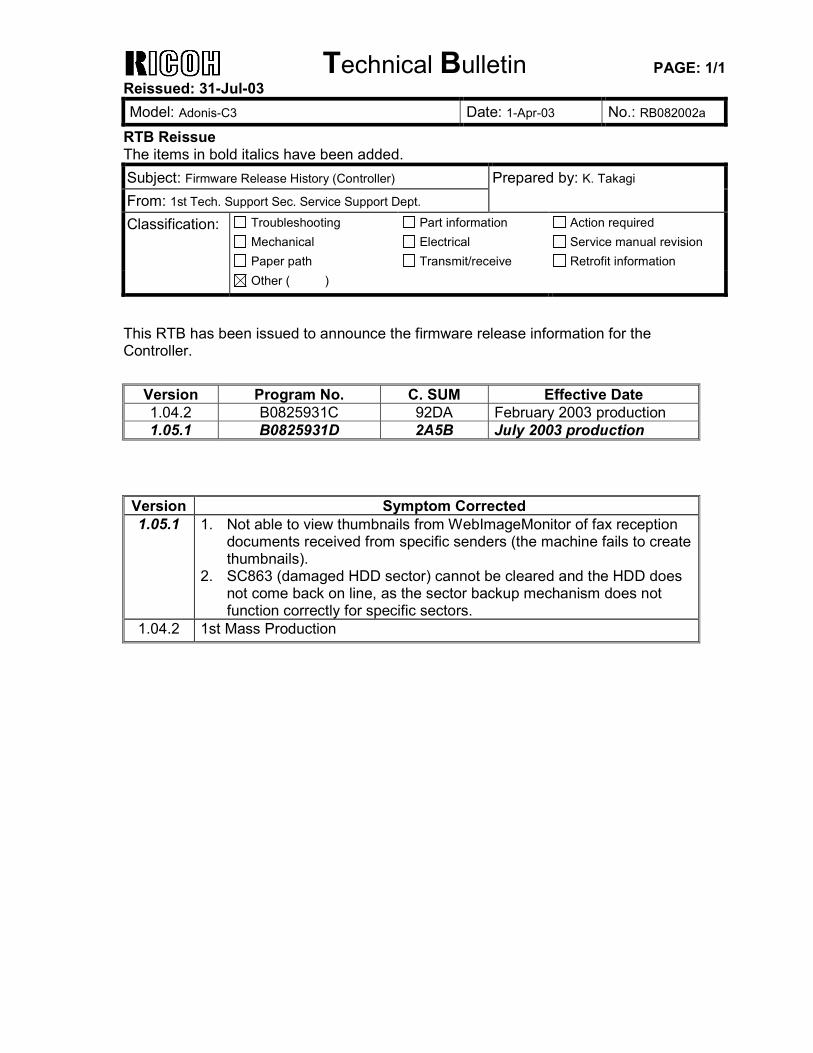
This RTB has been issued to announce the firmware release information for the Controller.
Version Program No. C. SUM Effective Date 1.04.2 B0825931C 92DA February 2003 production 1.05.1 B0825931D 2A5B July 2003 production
Version Symptom Corrected 1.05.1 1. Not able to view thumbnails from WebImageMonitor of fax reception
documents received from specific senders (the machine fails to create thumbnails).
2. SC863 (damaged HDD sector) cannot be cleared and the HDD does not come back on line, as the sector backup mechanism does not function correctly for specific sectors.
1.04.2 1st Mass Production
Technical Bulletin PAGE: 1/1 Reissued: 31-Jul-03 Model: Adonis-C3 Date: 1-Apr-03 No.: RB082003b
RTB Reissue The items in bold italics have been added. Subject: Firmware Release History (BICU) Prepared by: K. Takagi From: 1st Tech. Support Sec. Service Support Dept. Classification: Troubleshooting
Mechanical Paper path
Part information Electrical Transmit/receive
Action required Service manual revision Retrofit information
Other ( )
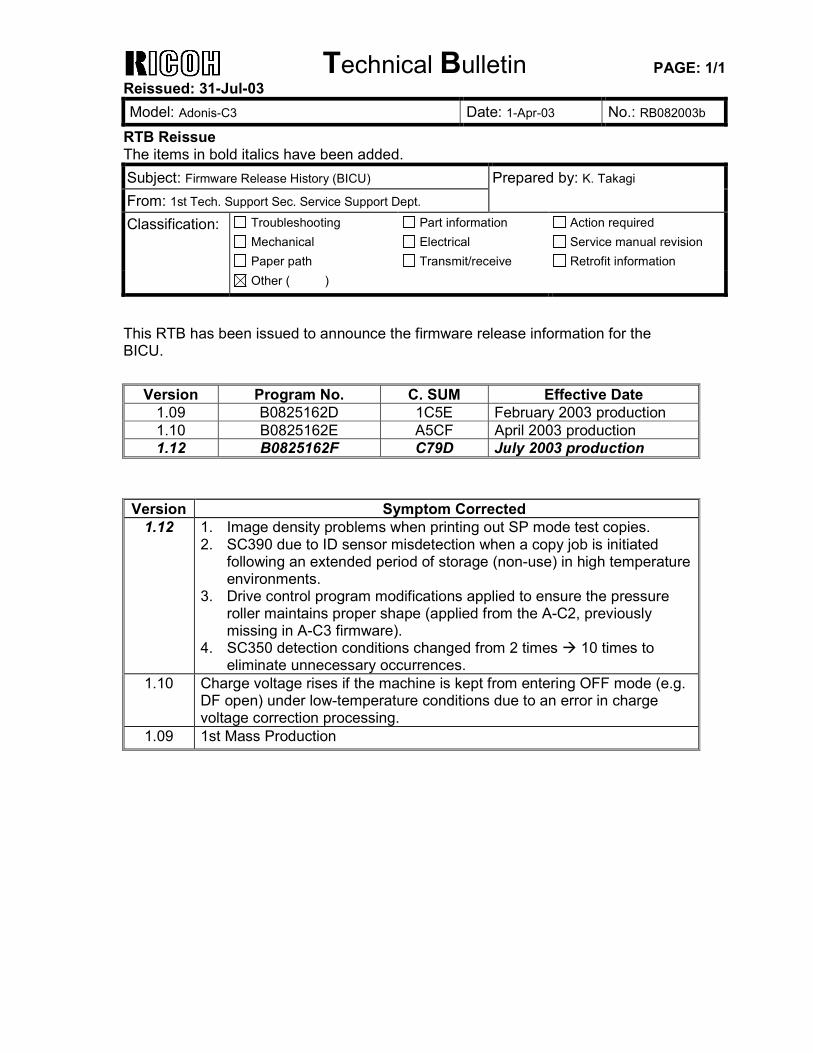
This RTB has been issued to announce the firmware release information for the BICU.
Version Program No. C. SUM Effective Date 1.09 B0825162D 1C5E February 2003 production 1.10 B0825162E A5CF April 2003 production 1.12 B0825162F C79D July 2003 production
Version Symptom Corrected
1.12 1. Image density problems when printing out SP mode test copies. 2. SC390 due to ID sensor misdetection when a copy job is initiated
following an extended period of storage (non-use) in high temperature environments.
3. Drive control program modifications applied to ensure the pressure roller maintains proper shape (applied from the A-C2, previously missing in A-C3 firmware).
4. SC350 detection conditions changed from 2 times ! 10 times to eliminate unnecessary occurrences.
1.10 Charge voltage rises if the machine is kept from entering OFF mode (e.g. DF open) under low-temperature conditions due to an error in charge voltage correction processing.
1.09 1st Mass Production
Technical Bulletin PAGE: 1/1
Model: Adonis-C3 Date: 1-Apr-03 No.: RB082004
Subject: Firmware Release History (LCDC) Prepared by: K. Takagi From: 1st Tech. Support Sec. Service Support Dept. Classification: Troubleshooting
Mechanical Paper path
Part information Electrical Transmit/receive
Action required Service manual revision Retrofit information
Other ( )
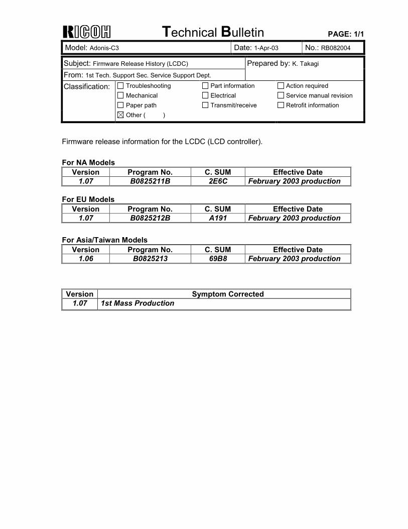
Firmware release information for the LCDC (LCD controller). For NA Models
Version Program No. C. SUM Effective Date 1.07 B0825211B 2E6C February 2003 production
For EU Models
Version Program No. C. SUM Effective Date 1.07 B0825212B A191 February 2003 production
For Asia/Taiwan Models
Version Program No. C. SUM Effective Date 1.06 B0825213 69B8 February 2003 production
Version Symptom Corrected
1.07 1st Mass Production
Technical Bulletin PAGE: 1/1
Model: Adonis-C3 Date: 1-Apr-03 No.: RB082005
Subject: Firmware Release History (MFP Service Card) Prepared by: K. Takagi From: 1st Tech. Support Sec. Service Support Dept. Classification: Troubleshooting
Mechanical Paper path
Part information Electrical Transmit/receive
Action required Service manual revision Retrofit information
Other ( )
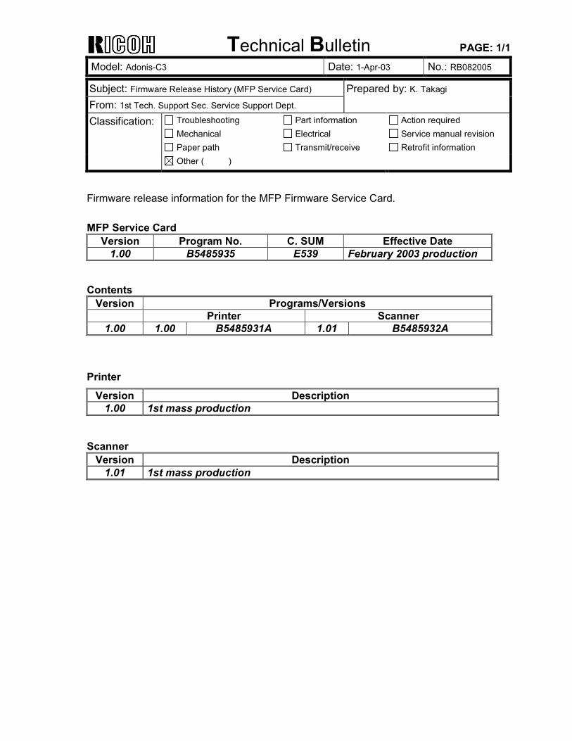
Firmware release information for the MFP Firmware Service Card. MFP Service Card
Version Program No. C. SUM Effective Date 1.00 B5485935 E539 February 2003 production
Contents
Version Programs/Versions Printer Scanner
1.00 1.00 B5485931A 1.01 B5485932A Printer
Version Description 1.00 1st mass production
Scanner
Version Description 1.01 1st mass production
Technical Bulletin PAGE: 1/1
Model: Adonis-C3 Date: 1-Apr-03 No.: RB082006
Subject: Firmware Release History (NET Service Card) Prepared by: K. Takagi From: 1st Tech. Support Sec. Service Support Dept. Classification: Troubleshooting
Mechanical Paper path
Part information Electrical Transmit/receive
Action required Service manual revision Retrofit information
Other ( )
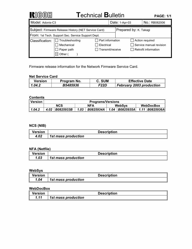
Firmware release information for the Network Firmware Service Card. Net Service Card
Version Program No. C. SUM Effective Date 1.04.2 B5485936 F22D February 2003 production
Contents Version Programs/Versions
NCS NFA WebSys WebDocBox 1.04.2 4.02 B0825933B 1.03 B0825934A 1.04 B0825935A 1.11 B0825936A
NCS (NIB)
Version Description 4.02 1st mass production
NFA (Netfile)
Version Description 1.03 1st mass production
WebSys
Version Description 1.04 1st mass production
WebDocBox
Version Description 1.11 1st mass production
Technical Bulletin PAGE: 1/1
Model: Adonis-C3 Date: 1-Apr-03 No.: RB082007
Subject: Firmware Release History (FAX Service Card) Prepared by: K. Takagi From: 1st Tech. Support Sec. Service Support Dept. Classification: Troubleshooting
Mechanical Paper path
Part information Electrical Transmit/receive
Action required Service manual revision Retrofit information
Other ( )
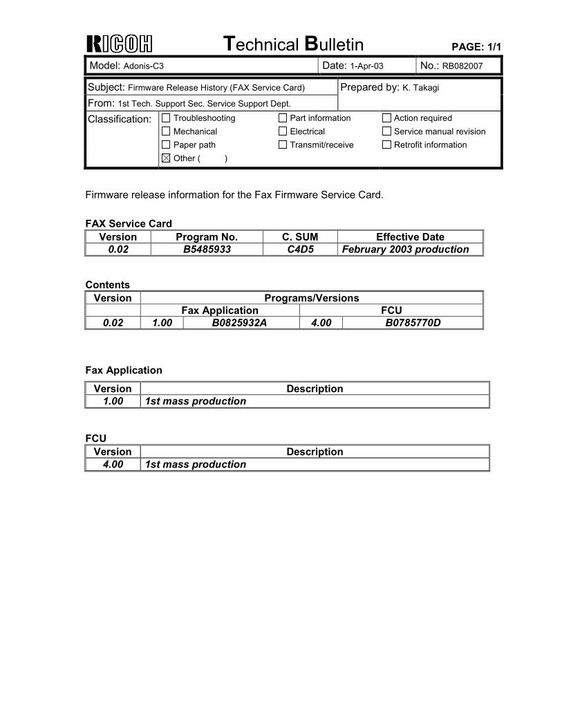
Firmware release information for the Fax Firmware Service Card. FAX Service Card
Version Program No. C. SUM Effective Date 0.02 B5485933 C4D5 February 2003 production
Contents
Version Programs/Versions Fax Application FCU
0.02 1.00 B0825932A 4.00 B0785770D Fax Application
Version Description 1.00 1st mass production
FCU
Version Description 4.00 1st mass production
Technical Bulletin PAGE: 1/1 Reissued: 25-Apr-03 Model: Adonis-C3 Date: 1-Apr-03 No.: RB082008b
RTB Correction The items in bold italics have been corrected or added. Subject: Firmware Release History (PostScript3) Prepared by: K. Takagi From: 1st Tech. Support Sec. Service Support Dept. Classification: Troubleshooting
Mechanical Paper path
Part information Electrical Transmit/receive
Action required Service manual revision Retrofit information
Other ( )
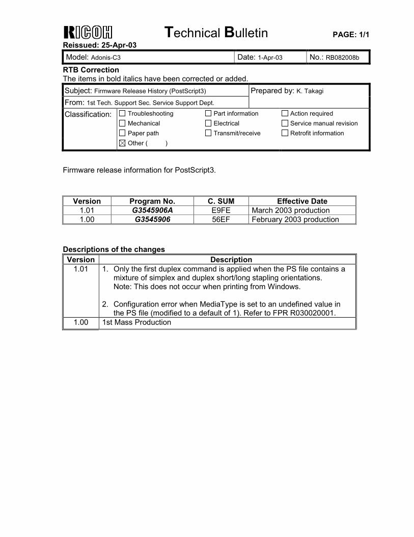
Firmware release information for PostScript3.
Version Program No. C. SUM Effective Date 1.01 G3545906A E9FE March 2003 production 1.00 G3545906 56EF February 2003 production
Descriptions of the changes Version Description
1.01 1. Only the first duplex command is applied when the PS file contains a mixture of simplex and duplex short/long stapling orientations. Note: This does not occur when printing from Windows.
2. Configuration error when MediaType is set to an undefined value in
the PS file (modified to a default of 1). Refer to FPR R030020001. 1.00 1st Mass Production
Technical Bulletin PAGE: 1/3
Model: Adonis-C3 Date: 1-Apr-03 No.: RB082009
Subject: Software Release History (Language) Prepared by: K. Takagi From: 1st Tech. Support Sec. Service Support Dept. Classification: Troubleshooting
Mechanical Paper path
Part information Electrical Transmit/receive
Action required Service manual revision Retrofit information
Other ( )
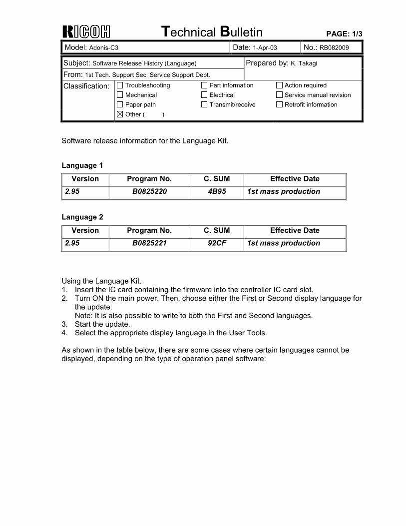
Software release information for the Language Kit. Language 1
Version Program No. C. SUM Effective Date 2.95 B0825220 4B95 1st mass production
Language 2
Version Program No. C. SUM Effective Date 2.95 B0825221 92CF 1st mass production
Using the Language Kit. 1. Insert the IC card containing the firmware into the controller IC card slot. 2. Turn ON the main power. Then, choose either the First or Second display language for
the update. Note: It is also possible to write to both the First and Second languages.
3. Start the update. 4. Select the appropriate display language in the User Tools. As shown in the table below, there are some cases where certain languages cannot be displayed, depending on the type of operation panel software:
Technical Bulletin PAGE: 2/3
Model: Adonis-C3 Date: 1-Apr-03 No.: RB082009
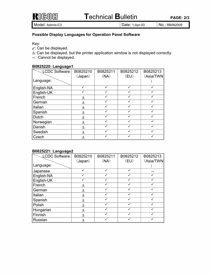
Possible Display Languages for Operation Panel Software Key: !: Can be displayed. ∆: Can be displayed, but the printer application window is not displayed correctly. --: Cannot be displayed. B0825220: Language1
LCDC Software: Language:
B0825210 (Japan)
B0825211 (NA)
B0825212 (EU)
B0825213 (Asia/TWN
) English-NA ! ! ! ! English-UK ! ! ! ! French ∆ ! ! ! German ∆ ! ! ! Italian ∆ ! ! ! Spanish ∆ ! ! ! Dutch ∆ ! ! ! Norwegian ∆ ! ! ! Danish ∆ ! ! ! Swedish ∆ ! ! ! Czech ∆ ! ! ! B0825221: Language2
LCDC Software: Language:
B0825210 (Japan)
B0825211 (NA)
B0825212 (EU)
B0825213 (Asia/TWN
) Japanese ! ! ! -- English-NA ! ! ! ! English-UK ! ! ! ! French ∆ ! ! ! German ∆ ! ! ! Italian ∆ ! ! ! Spanish ∆ ! ! ! Polish ∆ ! ! ! Hungarian ∆ ! ! ! Finnish ∆ ! ! ! Russian ∆ ! ! !
Technical Bulletin PAGE: 3/3
Model: Adonis-C3 Date: 1-Apr-03 No.: RB082009
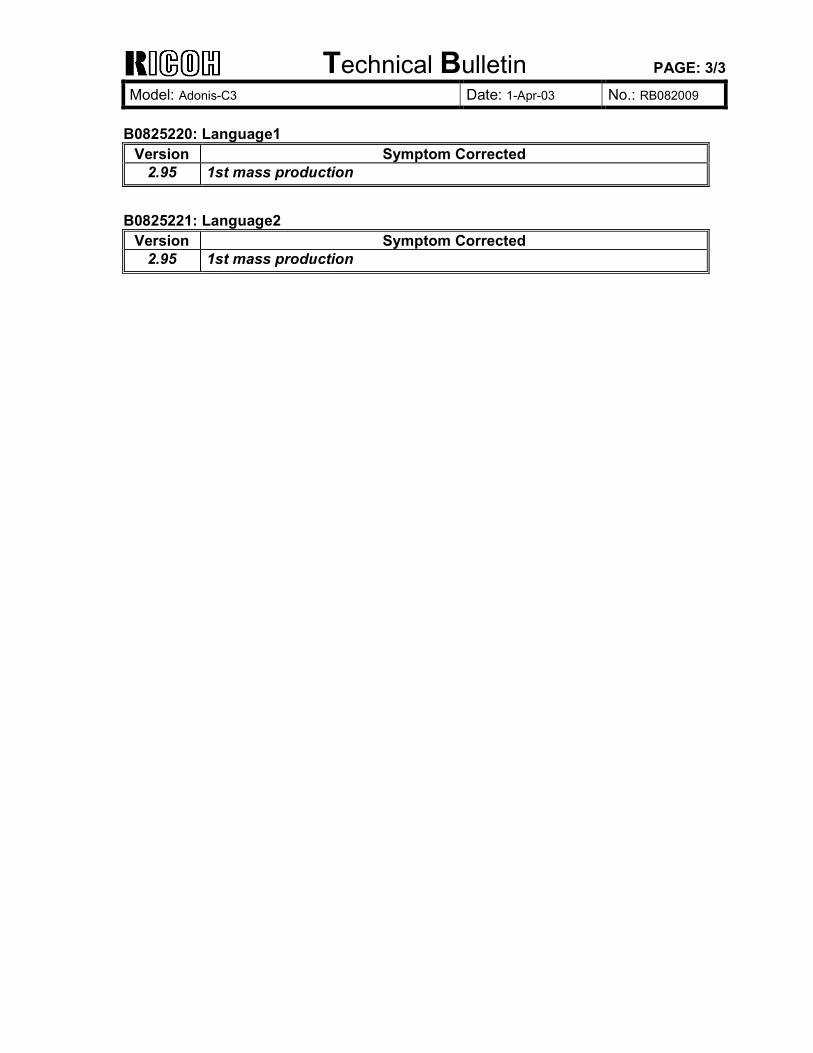
B0825220: Language1
Version Symptom Corrected 2.95 1st mass production
B0825221: Language2
Version Symptom Corrected 2.95 1st mass production
Technical Bulletin PAGE: 1/1
Model: Adonis-C3 Date: 25-Apr-03 No.: RB082010
Subject: Firmware Release History (BICU) Prepared by: K. Takagi From: 1st Tech. Support Sec. Service Support Dept. Classification: Troubleshooting
Mechanical Paper path
Part information Electrical Transmit/receive
Action required Service manual revision Retrofit information
Other ( )
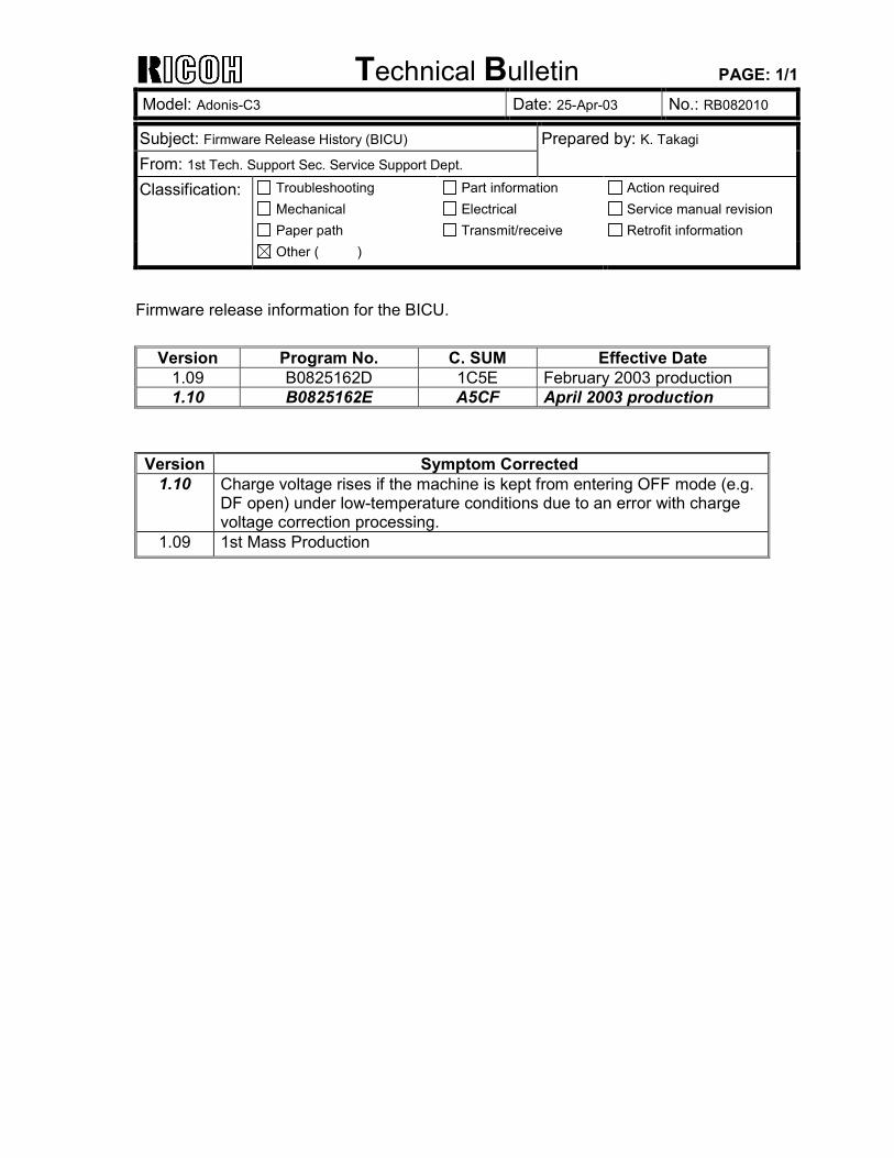
Firmware release information for the BICU.
Version Program No. C. SUM Effective Date 1.09 B0825162D 1C5E February 2003 production 1.10 B0825162E A5CF April 2003 production
Version Symptom Corrected
1.10 Charge voltage rises if the machine is kept from entering OFF mode (e.g. DF open) under low-temperature conditions due to an error with charge voltage correction processing.
1.09 1st Mass Production
Technical Bulletin PAGE: 1/1
Model: Adonis-C3 Date: 8-May-03 No.: RB082011
Subject: Controller Handling Prepared by: K. Takagi From: 1st Tech. Support Sec. Service Support Dept. Classification: Troubleshooting
Mechanical Paper path
Part information Electrical Transmit/receive
Action required Service manual revision Retrofit information
Other ( )
SYMPTOM The data stored in the NVRAM (e.g. time, S/N, SP data) is sometimes overwritten when the controller is removed and reattached.
CAUSE Static electricity builds up on the board when it is removed.
SOLUTION As a temporary measure, please observe the following cautionary notes whenever removing/reattaching the controller, such as when repairing the machine or installing an option. Important: 1. Before removing the controller board, make sure to unplug the main power cord and all
interface cables first. 2. Before touching the controller board or other components, make sure to discharge any
static electricity from your hands by touching a metallic surface nearby (machine frame or other).
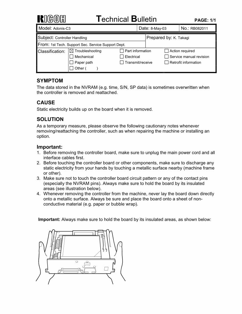
3. Make sure not to touch the controller board circuit pattern or any of the contact pins (especially the NVRAM pins). Always make sure to hold the board by its insulated areas (see illustration below).
4. Whenever removing the controller from the machine, never lay the board down directly onto a metallic surface. Always be sure and place the board onto a sheet of non-conductive material (e.g. paper or bubble wrap).
Important: Always make sure to hold the board by its insulated areas, as shown below:
Technical Bulletin PAGE: 1/2 Reissued: 19-May-03 Model: Adonis-C3 Date: 1-Apr-03 No.: RB082005a
RTB Correction The items in bold italics have been corrected or added. Subject: Firmware Release History (MFP Service Card) Prepared by: K. Takagi From: 1st Tech. Support Sec. Service Support Dept. Classification: Troubleshooting
Mechanical Paper path
Part information Electrical Transmit/receive
Action required Service manual revision Retrofit information
Other ( )
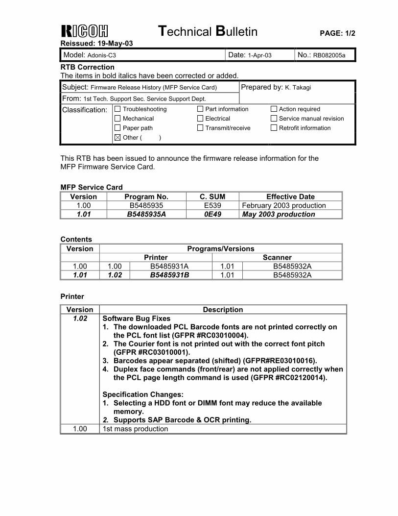
This RTB has been issued to announce the firmware release information for the MFP Firmware Service Card. MFP Service Card
Version Program No. C. SUM Effective Date 1.00 B5485935 E539 February 2003 production 1.01 B5485935A 0E49 May 2003 production
Contents
Version Programs/Versions Printer Scanner
1.00 1.00 B5485931A 1.01 B5485932A 1.01 1.02 B5485931B 1.01 B5485932A
Printer
Version Description 1.02 Software Bug Fixes
1. The downloaded PCL Barcode fonts are not printed correctly on the PCL font list (GFPR #RC03010004).
2. The Courier font is not printed out with the correct font pitch (GFPR #RC03010001).
3. Barcodes appear separated (shifted) (GFPR#RE03010016). 4. Duplex face commands (front/rear) are not applied correctly when
the PCL page length command is used (GFPR #RC02120014). Specification Changes: 1. Selecting a HDD font or DIMM font may reduce the available
memory. 2. Supports SAP Barcode & OCR printing.
1.00 1st mass production

Technical Bulletin PAGE: 2/2 Reissued: 19-May-03 Model: Adonis-C3 Date: 1-Apr-03 No.: RB082005a
Scanner
Version Description 1.01 1st mass production
Technical Bulletin PAGE: 1/1
Model: Adonis-C3 Date: 20-May-03 No.: RB082012
Subject: SR790 Finisher Installation Prepared by: K. Takagi From: 1st Tech. Support Sec. Service Support Dept. Classification: Troubleshooting
Mechanical Paper path
Part information Electrical Transmit/receive
Action required Service manual revision Retrofit information
Other ( )
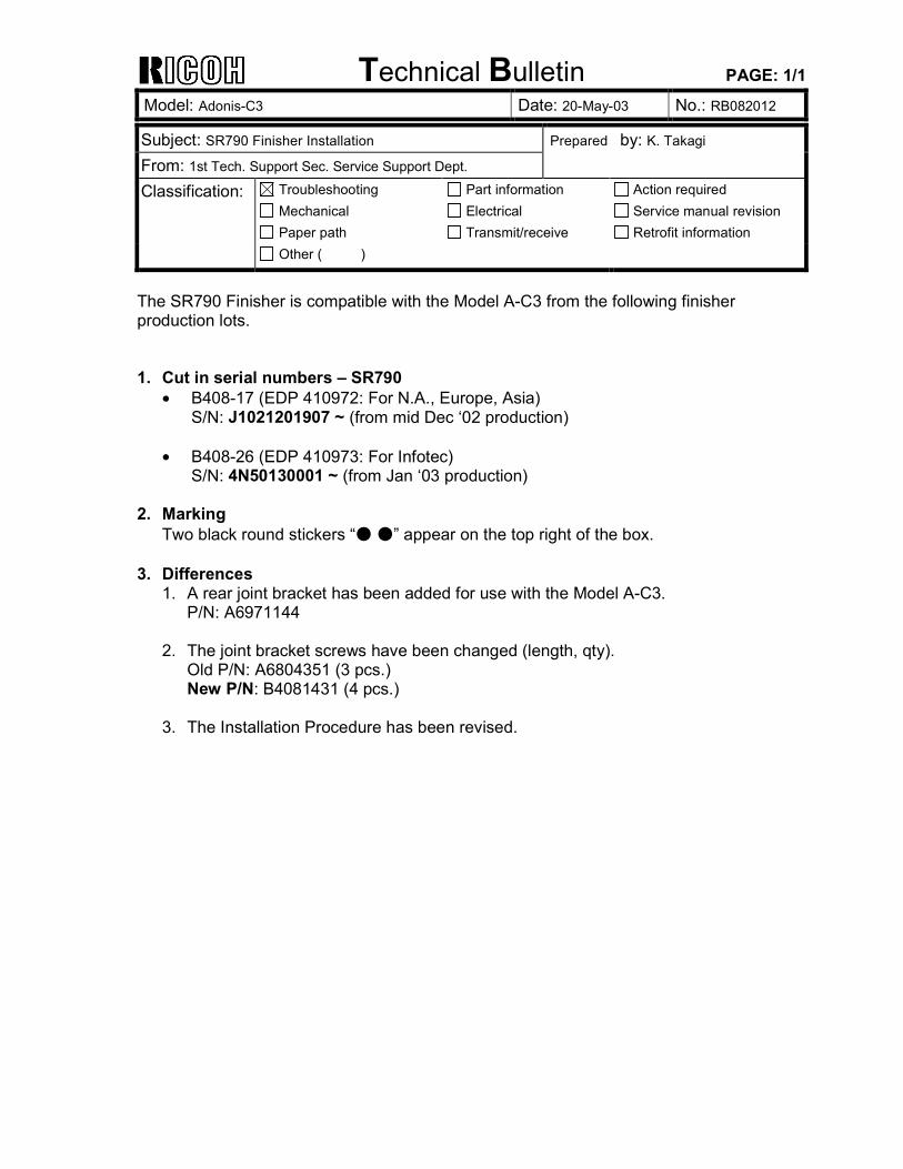
The SR790 Finisher is compatible with the Model A-C3 from the following finisher production lots. 1. Cut in serial numbers � SR790
• B408-17 (EDP 410972: For N.A., Europe, Asia) S/N: J1021201907 ~ (from mid Dec �02 production)
• B408-26 (EDP 410973: For Infotec) S/N: 4N50130001 ~ (from Jan �03 production)
2. Marking Two black round stickers �● ●� appear on the top right of the box.
3. Differences
1. A rear joint bracket has been added for use with the Model A-C3. P/N: A6971144
2. The joint bracket screws have been changed (length, qty). Old P/N: A6804351 (3 pcs.) New P/N: B4081431 (4 pcs.)
3. The Installation Procedure has been revised.
Technical Bulletin PAGE: 1/1
Model: Adonis-C3 Date: 26-May-03 No.: RB082013
Subject: Offset with 128 mm pitch Prepared by: K. Takagi From: 1st Tech. Support Sec. Service Support Dept. Classification: Troubleshooting
Mechanical Paper path
Part information Electrical Transmit/receive
Action required Service manual revision Retrofit information
Other ( )
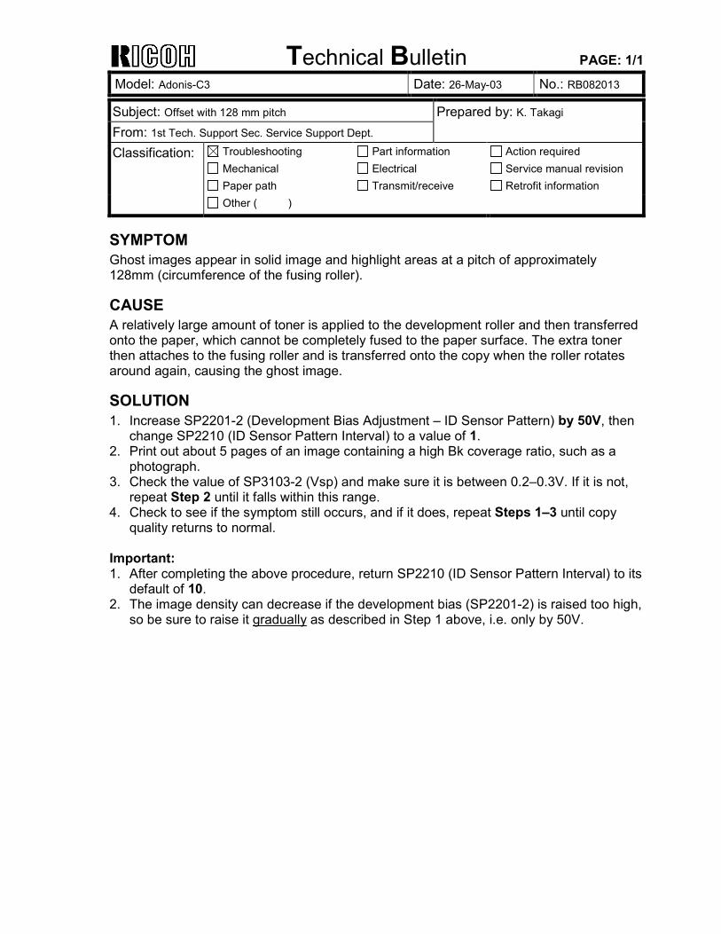
SYMPTOM Ghost images appear in solid image and highlight areas at a pitch of approximately 128mm (circumference of the fusing roller).
CAUSE A relatively large amount of toner is applied to the development roller and then transferred onto the paper, which cannot be completely fused to the paper surface. The extra toner then attaches to the fusing roller and is transferred onto the copy when the roller rotates around again, causing the ghost image.
SOLUTION 1. Increase SP2201-2 (Development Bias Adjustment � ID Sensor Pattern) by 50V, then
change SP2210 (ID Sensor Pattern Interval) to a value of 1. 2. Print out about 5 pages of an image containing a high Bk coverage ratio, such as a
photograph. 3. Check the value of SP3103-2 (Vsp) and make sure it is between 0.2�0.3V. If it is not,
repeat Step 2 until it falls within this range. 4. Check to see if the symptom still occurs, and if it does, repeat Steps 1�3 until copy
quality returns to normal. Important: 1. After completing the above procedure, return SP2210 (ID Sensor Pattern Interval) to its
default of 10. 2. The image density can decrease if the development bias (SP2201-2) is raised too high,
so be sure to raise it gradually as described in Step 1 above, i.e. only by 50V.
Technical Bulletin PAGE: 1/2 Reissued: 25-Jun-03 Model: Adonis-C3 Date: 1-Apr-03 No.: RB082007a
RTB Correction The items in bold italics have been corrected or added. Subject: Firmware Release History (FAX Service Card) Prepared by: K. Takagi From: 1st Tech. Support Sec. Service Support Dept. Classification: Troubleshooting
Mechanical Paper path
Part information Electrical Transmit/receive
Action required Service manual revision Retrofit information
Other ( )
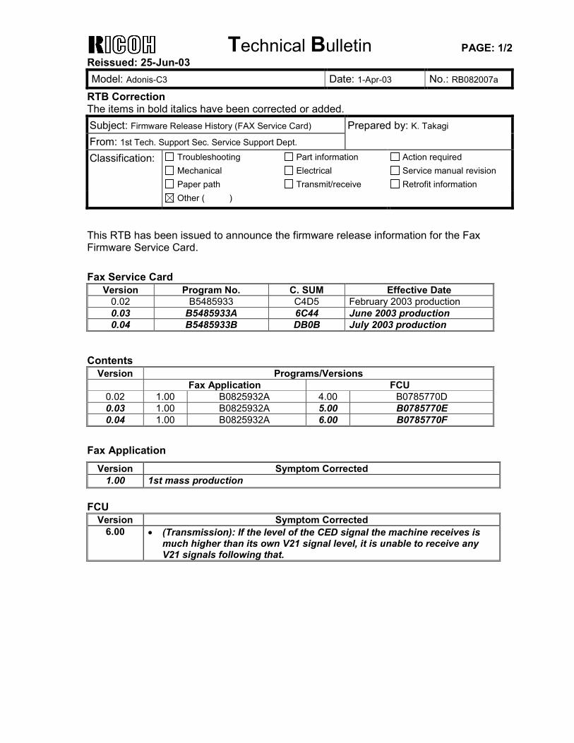
This RTB has been issued to announce the firmware release information for the Fax Firmware Service Card. Fax Service Card
Version Program No. C. SUM Effective Date 0.02 B5485933 C4D5 February 2003 production 0.03 B5485933A 6C44 June 2003 production 0.04 B5485933B DB0B July 2003 production
Contents
Version Programs/Versions Fax Application FCU
0.02 1.00 B0825932A 4.00 B0785770D 0.03 1.00 B0825932A 5.00 B0785770E 0.04 1.00 B0825932A 6.00 B0785770F
Fax Application
Version Symptom Corrected 1.00 1st mass production
FCU
Version Symptom Corrected 6.00 • (Transmission): If the level of the CED signal the machine receives is
much higher than its own V21 signal level, it is unable to receive any V21 signals following that.
Technical Bulletin PAGE: 2/2 Reissued: 25-Jun-03 Model: Adonis-C3 Date: 1-Apr-03 No.: RB082007a
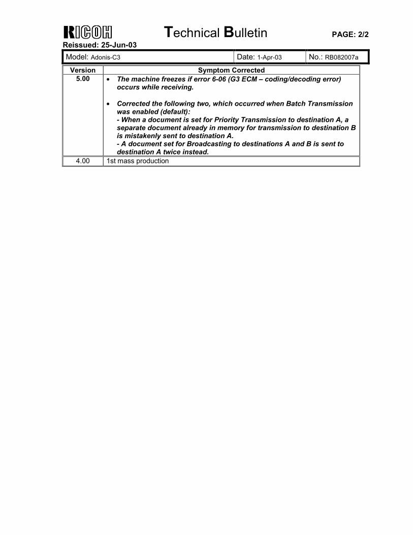
Version Symptom Corrected 5.00 • The machine freezes if error 6-06 (G3 ECM � coding/decoding error)
occurs while receiving. • Corrected the following two, which occurred when Batch Transmission
was enabled (default): - When a document is set for Priority Transmission to destination A, a separate document already in memory for transmission to destination B is mistakenly sent to destination A. - A document set for Broadcasting to destinations A and B is sent to destination A twice instead.
4.00 1st mass production
Technical Bulletin PAGE: 1/1
Model: Adonis-C3 Date: 26-Jun-03 No.: RB082014
Subject: Incorrect Batch Transmission Prepared by: K. Takagi From: 1st Tech. Support Sec. Service Support Dept. Classification: Troubleshooting
Mechanical Paper path
Part information Electrical Transmit/receive
Action required Service manual revision Retrofit information
Other ( )
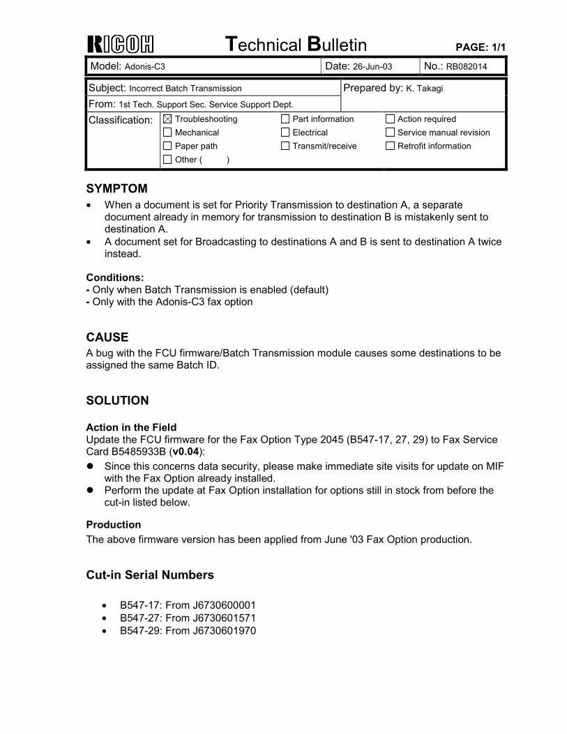
SYMPTOM • When a document is set for Priority Transmission to destination A, a separate
document already in memory for transmission to destination B is mistakenly sent to destination A.
• A document set for Broadcasting to destinations A and B is sent to destination A twice instead.
Conditions: - Only when Batch Transmission is enabled (default) - Only with the Adonis-C3 fax option
CAUSE A bug with the FCU firmware/Batch Transmission module causes some destinations to be assigned the same Batch ID.
SOLUTION Action in the Field Update the FCU firmware for the Fax Option Type 2045 (B547-17, 27, 29) to Fax Service Card B5485933B (v0.04): ! Since this concerns data security, please make immediate site visits for update on MIF
with the Fax Option already installed. ! Perform the update at Fax Option installation for options still in stock from before the
cut-in listed below.
Production The above firmware version has been applied from June '03 Fax Option production.
Cut-in Serial Numbers
• B547-17: From J6730600001 • B547-27: From J6730601571 • B547-29: From J6730601970
Technical Bulletin PAGE: 1/10
Model: Adonis-C3 Date: 27-Jun-03 No.: RB082015
Subject: Service Manual Correction (Mainframe) Prepared by: K. Takagi From: 1st Tech. Support Sec. Service Support Dept. Classification: Troubleshooting
Mechanical Paper path
Part information Electrical Transmit/receive
Action required Service manual revision Retrofit information
Other ( )
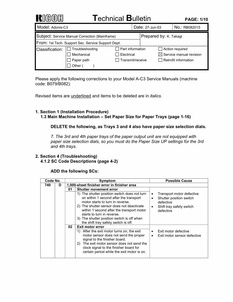
Please apply the following corrections to your Model A-C3 Service Manuals (machine code: B079/B082). Revised items are underlined and items to be deleted are in italics. 1. Section 1 (Installation Procedure)
1.3 Main Machine Installation � Set Paper Size for Paper Trays (page 1-16) DELETE the following, as Trays 3 and 4 also have paper size selection dials. 7. The 3rd and 4th paper trays of the paper output unit are not equipped with paper size selection dials, so you must do the Paper Size UP settings for the 3rd and 4th trays.
2. Section 4 (Troubleshooting) 4.1.2 SC Code Descriptions (page 4-2)
ADD the following SCs:
Code No. Symptom Possible Cause 1,000-sheet finisher error in finisher area 01 Shutter movement error 1) The shutter position switch does not turn
on within 1 second after the transport motor starts to turn in reverse.
2) The shutter sensor does not deactivate within 1 second after the transport motor starts to turn in reverse.
3) The shutter position switch is off when the shift tray safety switch is off.
• Transport motor defective • Shutter position switch
defective • Shift tray safety switch
defective
Exit motor error
740 D
02 1) After the exit motor turns on, the exit
motor sensor does not send the proper signal to the finisher board.
2) The exit motor sensor does not send the clock signal to the finisher board for certain period while the exit motor is on.
• Exit motor defective • Exit motor sensor defective
Technical Bulletin PAGE: 2/10
Model: Adonis-C3 Date: 27-Jun-03 No.: RB082015
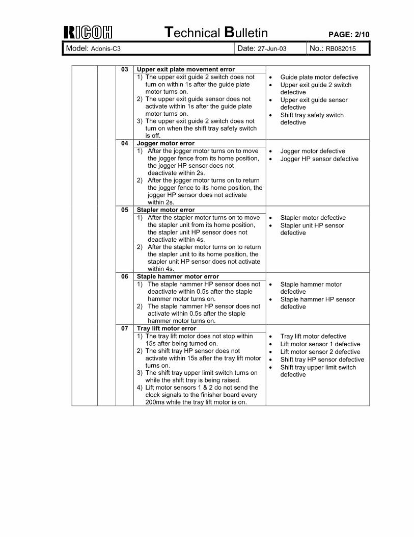
Upper exit plate movement error 03 1) The upper exit guide 2 switch does not
turn on within 1s after the guide plate motor turns on.
2) The upper exit guide sensor does not activate within 1s after the guide plate motor turns on.
3) The upper exit guide 2 switch does not turn on when the shift tray safety switch is off.
• Guide plate motor defective • Upper exit guide 2 switch
defective • Upper exit guide sensor
defective • Shift tray safety switch
defective
Jogger motor error 04 1) After the jogger motor turns on to move
the jogger fence from its home position, the jogger HP sensor does not deactivate within 2s.
2) After the jogger motor turns on to return the jogger fence to its home position, the jogger HP sensor does not activate within 2s.
• Jogger motor defective • Jogger HP sensor defective
Stapler motor error 05 1) After the stapler motor turns on to move
the stapler unit from its home position, the stapler unit HP sensor does not deactivate within 4s.
2) After the stapler motor turns on to return the stapler unit to its home position, the stapler unit HP sensor does not activate within 4s.
• Stapler motor defective • Stapler unit HP sensor
defective
Staple hammer motor error 06 1) The staple hammer HP sensor does not
deactivate within 0.5s after the staple hammer motor turns on.
2) The staple hammer HP sensor does not activate within 0.5s after the staple hammer motor turns on.
• Staple hammer motor
defective • Staple hammer HP sensor
defective
Tray lift motor error
07 1) The tray lift motor does not stop within
15s after being turned on. 2) The shift tray HP sensor does not
activate within 15s after the tray lift motor turns on.
3) The shift tray upper limit switch turns on while the shift tray is being raised.
4) Lift motor sensors 1 & 2 do not send the clock signals to the finisher board every 200ms while the tray lift motor is on.
• Tray lift motor defective • Lift motor sensor 1 defective • Lift motor sensor 2 defective • Shift tray HP sensor defective • Shift tray upper limit switch
defective
Technical Bulletin PAGE: 3/10
Model: Adonis-C3 Date: 27-Jun-03 No.: RB082015
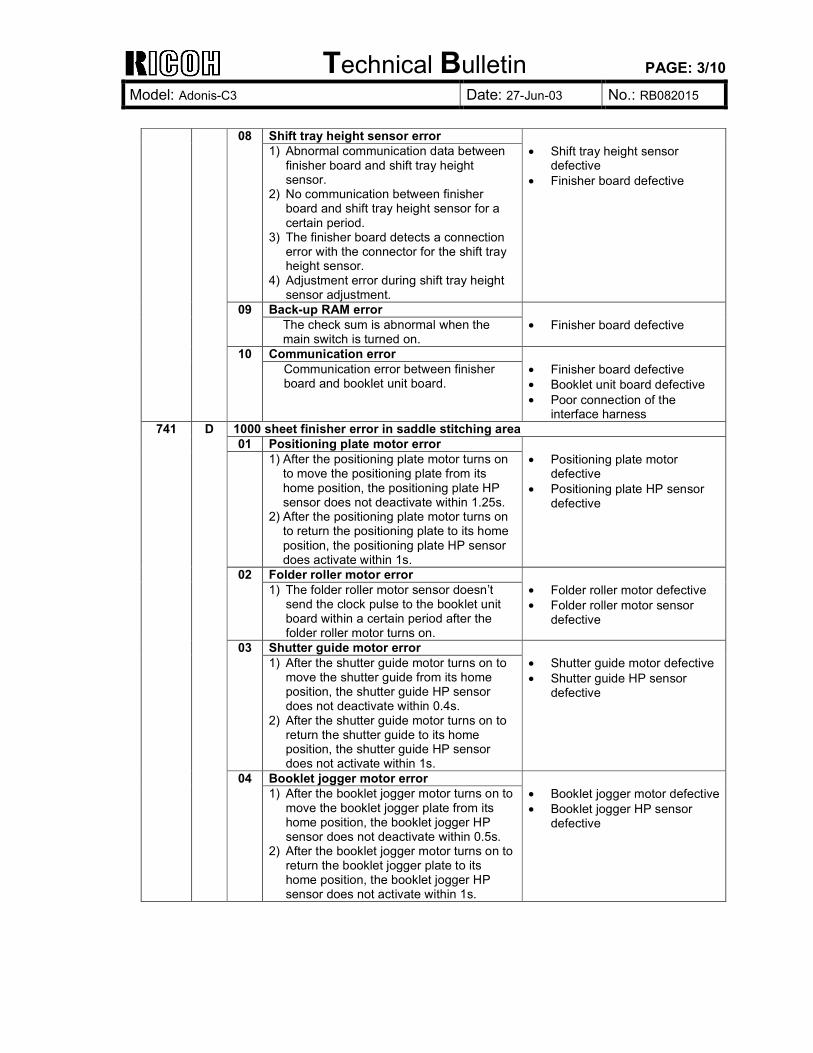
Shift tray height sensor error 08 1) Abnormal communication data between
finisher board and shift tray height sensor.
2) No communication between finisher board and shift tray height sensor for a certain period.
3) The finisher board detects a connection error with the connector for the shift tray height sensor.
4) Adjustment error during shift tray height sensor adjustment.
• Shift tray height sensor
defective • Finisher board defective
Back-up RAM error 09 The check sum is abnormal when the main switch is turned on.
• Finisher board defective
Communication error
10 Communication error between finisher board and booklet unit board.
• Finisher board defective • Booklet unit board defective • Poor connection of the
interface harness 1000 sheet finisher error in saddle stitching area 01 Positioning plate motor error 1) After the positioning plate motor turns on
to move the positioning plate from its home position, the positioning plate HP sensor does not deactivate within 1.25s.
2) After the positioning plate motor turns on to return the positioning plate to its home position, the positioning plate HP sensor does activate within 1s.
• Positioning plate motor
defective • Positioning plate HP sensor
defective
Folder roller motor error 02 1) The folder roller motor sensor doesn�t
send the clock pulse to the booklet unit board within a certain period after the folder roller motor turns on.
• Folder roller motor defective • Folder roller motor sensor
defective
Shutter guide motor error 03 1) After the shutter guide motor turns on to
move the shutter guide from its home position, the shutter guide HP sensor does not deactivate within 0.4s.
2) After the shutter guide motor turns on to return the shutter guide to its home position, the shutter guide HP sensor does not activate within 1s.
• Shutter guide motor defective • Shutter guide HP sensor
defective
Booklet jogger motor error
741 D
04 1) After the booklet jogger motor turns on to
move the booklet jogger plate from its home position, the booklet jogger HP sensor does not deactivate within 0.5s.
2) After the booklet jogger motor turns on to return the booklet jogger plate to its home position, the booklet jogger HP sensor does not activate within 1s.
• Booklet jogger motor defective• Booklet jogger HP sensor
defective
Technical Bulletin PAGE: 4/10
Model: Adonis-C3 Date: 27-Jun-03 No.: RB082015
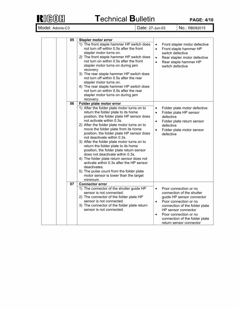
Stapler motor error 05 1) The front staple hammer HP switch does
not turn off within 0.5s after the front stapler motor turns on.
2) The front staple hammer HP switch does not turn on within 0.5s after the front stapler motor turns on during jam recovery.
3) The rear staple hammer HP switch does not turn off within 0.5s after the rear stapler motor turns on.
4) The rear staple hammer HP switch does not turn on within 0.5s after the rear stapler motor turns on during jam recovery.
• Front stapler motor defective • Front staple hammer HP
switch defective • Rear stapler motor defective • Rear staple hammer HP
switch defective
Folder plate motor error 06 1) After the folder plate motor turns on to
return the folder plate to its home position, the folder plate HP sensor does not activate within 0.3s.
2) After the folder plate motor turns on to move the folder plate from its home position, the folder plate HP sensor does not deactivate within 0.3s.
3) After the folder plate motor turns on to return the folder plate to its home position, the folder plate return sensor does not deactivate within 0.3s.
4) The folder plate return sensor does not activate within 0.3s after the HP sensor deactivates.
5) The pulse count from the folder plate motor sensor is lower than the target minimum.
• Folder plate motor defective • Folder plate HP sensor
defective • Folder plate return sensor
defective • Folder plate motor sensor
defective
Connector error
07 1) The connector of the shutter guide HP
sensor is not connected. 2) The connector of the folder plate HP
sensor is not connected. 3) The connector of the folder plate return
sensor is not connected.
• Poor connection or no
connection of the shutter guide HP sensor connector
• Poor connection or no connection of the folder plate HP sensor connector
• Poor connection or no connection of the folder plate return sensor connector
Technical Bulletin PAGE: 5/10
Model: Adonis-C3 Date: 27-Jun-03 No.: RB082015
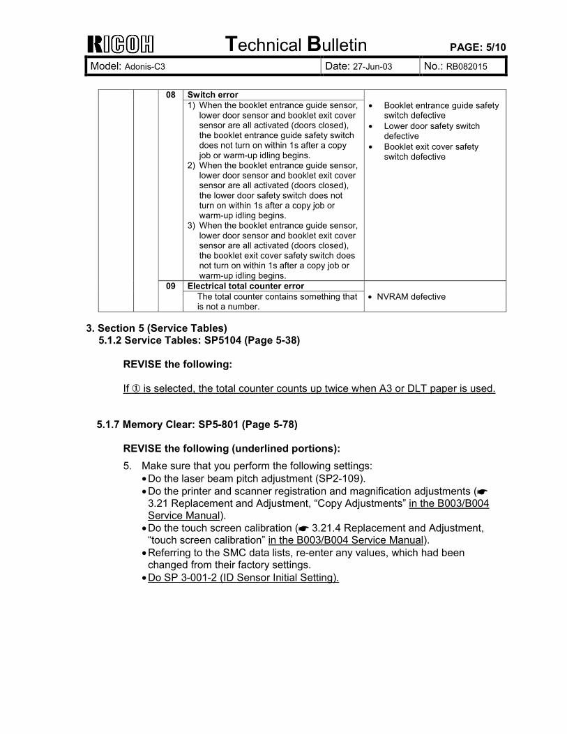
Switch error 08 1) When the booklet entrance guide sensor,
lower door sensor and booklet exit cover sensor are all activated (doors closed), the booklet entrance guide safety switch does not turn on within 1s after a copy job or warm-up idling begins.
2) When the booklet entrance guide sensor, lower door sensor and booklet exit cover sensor are all activated (doors closed), the lower door safety switch does not turn on within 1s after a copy job or warm-up idling begins.
3) When the booklet entrance guide sensor, lower door sensor and booklet exit cover sensor are all activated (doors closed), the booklet exit cover safety switch does not turn on within 1s after a copy job or warm-up idling begins.
• Booklet entrance guide safety
switch defective • Lower door safety switch
defective • Booklet exit cover safety
switch defective
Electrical total counter error
09 The total counter contains something that is not a number.
• NVRAM defective
3. Section 5 (Service Tables)
5.1.2 Service Tables: SP5104 (Page 5-38) REVISE the following: If ! is selected, the total counter counts up twice when A3 or DLT paper is used.
5.1.7 Memory Clear: SP5-801 (Page 5-78) REVISE the following (underlined portions): 5. Make sure that you perform the following settings:
• Do the laser beam pitch adjustment (SP2-109). • Do the printer and scanner registration and magnification adjustments (☛
3.21 Replacement and Adjustment, �Copy Adjustments� in the B003/B004 Service Manual).
• Do the touch screen calibration (☛ 3.21.4 Replacement and Adjustment, �touch screen calibration� in the B003/B004 Service Manual).
• Referring to the SMC data lists, re-enter any values, which had been changed from their factory settings.
• Do SP 3-001-2 (ID Sensor Initial Setting).
Technical Bulletin PAGE: 6/10
Model: Adonis-C3 Date: 27-Jun-03 No.: RB082015
5.1.7 Retrieving the Debug Log (Page 5-84)
DELETE the following: A software application (GWLOG.EXE) is provided to convert the binary data file to a text file which can be read on screen or printed. On the DOS command line, type: C:\GWLOG<Path>
and press ENTER. The <Path> is the path to the directory (folder) where the converted binary file created in the previous was saved. NOTE: 1) The program converts binary file to a text file in the same directory.
2) The target file name for the text file is generated automatically. 3) If the debug log was copied to an IC card of the wrong format, then an
error is issued and the program halts.
Technical Bulletin PAGE: 7/10
Model: Adonis-C3 Date: 27-Jun-03 No.: RB082015
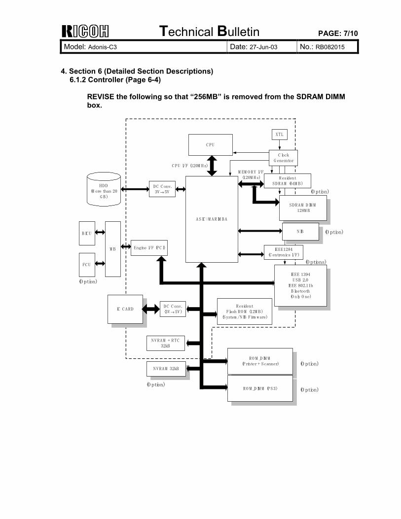
4. Section 6 (Detailed Section Descriptions)
6.1.2 Controller (Page 6-4) REVISE the following so that �256MB� is removed from the SDRAM DIMM box.
IC C ARD
C PU
A SIC : M ARIM BA
ResidentSD RAM (64M B)
SD RAM D IM M 128M B
XTL
C lockG enerator
NIB
IEEE1284(C entronics I/F)
Engine I/F (PC I)M B
HD D(M ore than 20
G B)
D C C onv.3V→ 5V
IEEE 1394USB 2.0
IEEE 802.11bB luetooth(O nly O ne)
NVRAM + RTC32kB
NVRAM 32kB
C PU I/F (120M Hz)
M EM O RY I/F(120M Hz)
D C C onv.(3V→ 5V)
ResidentFlash RO M (12M B)
(System /NIB Firm w are)
RO M _D IM M(Printer + Scanner)
RO M _D IM M (PS3)
(O ption)
(O ption)
(O ptions)
(O ption)
BIC U
FC U
(O ption)
(O ption)
(O ption)
Technical Bulletin PAGE: 8/10
Model: Adonis-C3 Date: 27-Jun-03 No.: RB082015
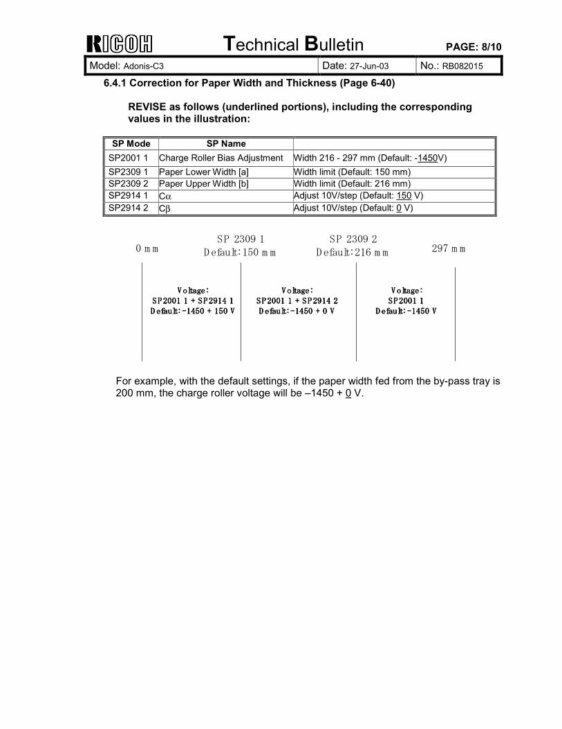
6.4.1 Correction for Paper Width and Thickness (Page 6-40) REVISE as follows (underlined portions), including the corresponding values in the illustration:
SP Mode SP Name
SP2001 1 Charge Roller Bias Adjustment Width 216 - 297 mm (Default: -1450V) SP2309 1 Paper Lower Width [a] Width limit (Default: 150 mm) SP2309 2 Paper Upper Width [b] Width limit (Default: 216 mm) SP2914 1 Cα Adjust 10V/step (Default: 150 V) SP2914 2 Cβ Adjust 10V/step (Default: 0 V)
0 m mSP 2309 1
Default: 150 m mSP 2309 2
Default: 216 m m 297 m m
Voltage:Voltage:Voltage:Voltage:SP2001 1 + SP2914 1SP2001 1 + SP2914 1SP2001 1 + SP2914 1SP2001 1 + SP2914 1D efault: -1450 + 150 VD efault: -1450 + 150 VD efault: -1450 + 150 VD efault: -1450 + 150 V
Voltage:Voltage:Voltage:Voltage:SP2001 1 + SP2914 2SP2001 1 + SP2914 2SP2001 1 + SP2914 2SP2001 1 + SP2914 2D efault: -1450 + 0 VD efault: -1450 + 0 VD efault: -1450 + 0 VD efault: -1450 + 0 V
Voltage:Voltage:Voltage:Voltage:SP2001 1SP2001 1SP2001 1SP2001 1
D efault: -1450 VD efault: -1450 VD efault: -1450 VD efault: -1450 V
For example, with the default settings, if the paper width fed from the by-pass tray is 200 mm, the charge roller voltage will be �1450 + 0 V.
Technical Bulletin PAGE: 9/10
Model: Adonis-C3 Date: 27-Jun-03 No.: RB082015
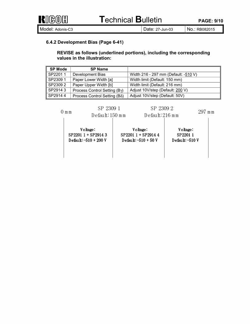
6.4.2 Development Bias (Page 6-41)
REVISE as follows (underlined portions), including the corresponding values in the illustration:
SP Mode SP Name
SP2201 1 Development Bias Width 216 - 297 mm (Default: -510 V) SP2309 1 Paper Lower Width [a] Width limit (Default: 150 mm) SP2309 2 Paper Upper Width [b] Width limit (Default: 216 mm) SP2914 3 Process Control Setting (Bγ) Adjust 10V/step (Default: 200 V) SP2914 4 Process Control Setting (Bδ) Adjust 10V/step (Default: 50V)
0 m mSP 2309 1
Default: 150 m mSP 2309 2
Default: 216 m m297 m m
Voltage:Voltage:Voltage:Voltage:SP2201 1 + SP2914 3SP2201 1 + SP2914 3SP2201 1 + SP2914 3SP2201 1 + SP2914 3Default: -510 + 200 VDefault: -510 + 200 VDefault: -510 + 200 VDefault: -510 + 200 V
Voltage:Voltage:Voltage:Voltage:SP2201 1 + SP2914 4SP2201 1 + SP2914 4SP2201 1 + SP2914 4SP2201 1 + SP2914 4Default: -510 + 50 VDefault: -510 + 50 VDefault: -510 + 50 VDefault: -510 + 50 V
Voltage:Voltage:Voltage:Voltage:SP2201 1SP2201 1SP2201 1SP2201 1
Default: -510 VDefault: -510 VDefault: -510 VDefault: -510 V
Technical Bulletin PAGE: 10/10
Model: Adonis-C3 Date: 27-Jun-03 No.: RB082015
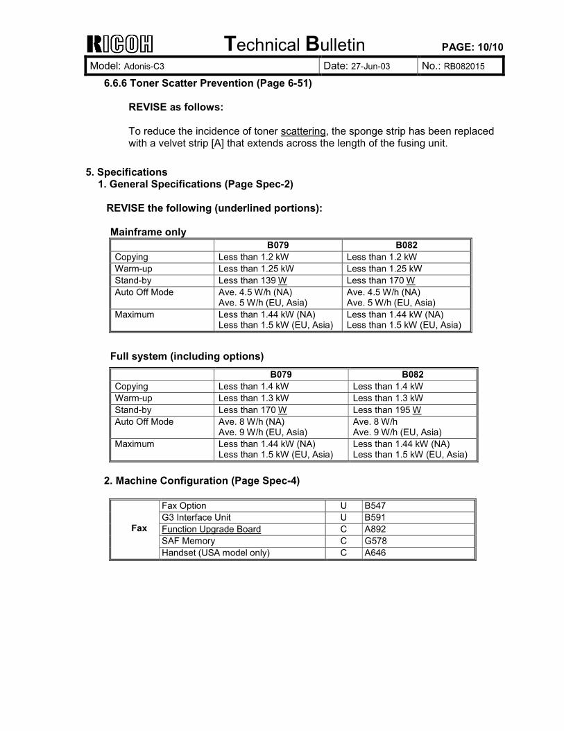
6.6.6 Toner Scatter Prevention (Page 6-51) REVISE as follows: To reduce the incidence of toner scattering, the sponge strip has been replaced with a velvet strip [A] that extends across the length of the fusing unit.
5. Specifications 1. General Specifications (Page Spec-2)
REVISE the following (underlined portions): Mainframe only B079 B082 Copying Less than 1.2 kW Less than 1.2 kW Warm-up Less than 1.25 kW Less than 1.25 kW Stand-by Less than 139 W Less than 170 W Auto Off Mode Ave. 4.5 W/h (NA)
Ave. 5 W/h (EU, Asia) Ave. 4.5 W/h (NA) Ave. 5 W/h (EU, Asia)
Maximum Less than 1.44 kW (NA) Less than 1.5 kW (EU, Asia)
Less than 1.44 kW (NA) Less than 1.5 kW (EU, Asia)
Full system (including options) B079 B082 Copying Less than 1.4 kW Less than 1.4 kW Warm-up Less than 1.3 kW Less than 1.3 kW Stand-by Less than 170 W Less than 195 W Auto Off Mode Ave. 8 W/h (NA)
Ave. 9 W/h (EU, Asia) Ave. 8 W/h Ave. 9 W/h (EU, Asia)
Maximum Less than 1.44 kW (NA) Less than 1.5 kW (EU, Asia)
Less than 1.44 kW (NA) Less than 1.5 kW (EU, Asia)
2. Machine Configuration (Page Spec-4)
Fax Option U B547 G3 Interface Unit U B591 Function Upgrade Board C A892 SAF Memory C G578
Fax
Handset (USA model only) C A646
Technical Bulletin PAGE: 1/3
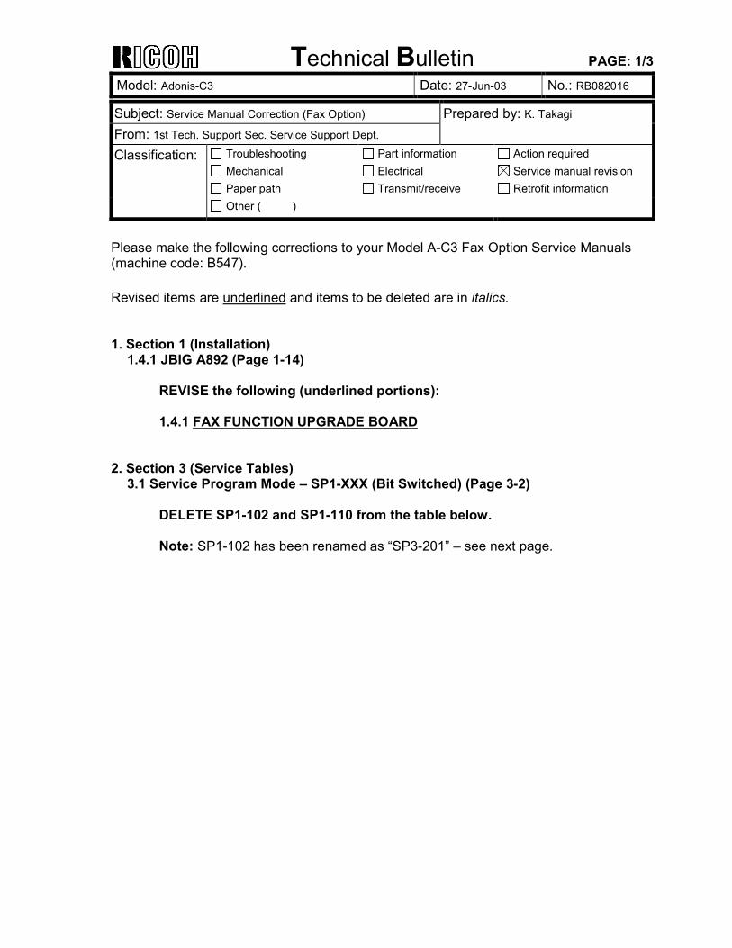
Model: Adonis-C3 Date: 27-Jun-03 No.: RB082016
Subject: Service Manual Correction (Fax Option) Prepared by: K. Takagi From: 1st Tech. Support Sec. Service Support Dept. Classification: Troubleshooting
Mechanical Paper path
Part information Electrical Transmit/receive
Action required Service manual revision Retrofit information
Other ( )
Please make the following corrections to your Model A-C3 Fax Option Service Manuals (machine code: B547). Revised items are underlined and items to be deleted are in italics. 1. Section 1 (Installation)
1.4.1 JBIG A892 (Page 1-14) REVISE the following (underlined portions): 1.4.1 FAX FUNCTION UPGRADE BOARD
2. Section 3 (Service Tables) 3.1 Service Program Mode � SP1-XXX (Bit Switched) (Page 3-2)
DELETE SP1-102 and SP1-110 from the table below. Note: SP1-102 has been renamed as �SP3-201� � see next page.
Technical Bulletin PAGE: 2/3
Model: Adonis-C3 Date: 27-Jun-03 No.: RB082016
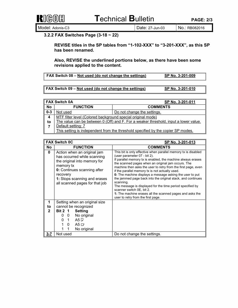
3.2.2 FAX Switches Page (3-18 ~ 22) REVISE titles in the SP tables from �1-102-XXX� to �3-201-XXX�, as this SP has been renamed. Also, REVISE the underlined portions below, as there have been some revisions applied to the content.
FAX Switch 08 � Not used (do not change the settings) SP No. 3-201-009
FAX Switch 09 � Not used (do not change the settings) SP No. 3-201-010
FAX Switch 0A SP No. 3-201-011 No FUNCTION COMMENTS 0-3 Not used Do not change the settings. 4 to 7
MTF filter level (Colored background special original mode) The value can be between 0 (Off) and F. For a weaker threshold, input a lower value. Default setting: 7 This setting is independent from the threshold specified by the copier SP modes.
FAX Switch 0C SP No. 3-201-013 No FUNCTION COMMENTS 0 Action when an original jam
has occurred while scanning the original into memory for memory tx 0: Continues scanning after recovery 1: Stops scanning and erases all scanned pages for that job
This bit is only effective when parallel memory tx is disabled (user parameter 07 - bit 2). If parallel memory tx is enabled, the machine always erases the scanned pages when an original jam occurs. The machine then asks the user to retry from the first page, even if the parallel memory tx is not actually used. 0: The machine displays a message asking the user to put the jammed page back into the original stack, and continues scanning. The message is displayed for the time period specified by scanner switch 0E, bit 2. 1: The machine erases all the scanned pages and asks the user to retry from the first page.
1 to 2
Setting when an original size cannot be recognized Bit 2 1 Setting 0 0 No original 0 1 A5 ! 1 0 A5 " 1 1 No original
3-7 Not used Do not change the settings.
Technical Bulletin PAGE: 3/3
Model: Adonis-C3 Date: 27-Jun-03 No.: RB082016
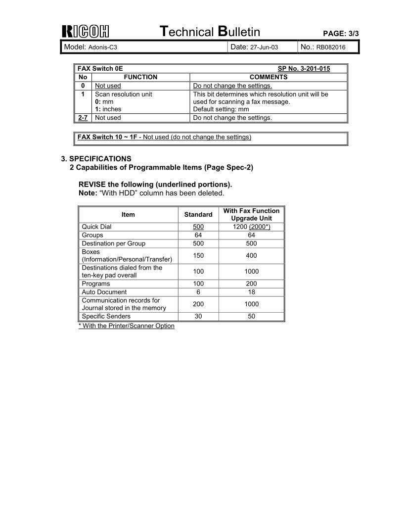
FAX Switch 0E SP No. 3-201-015 No FUNCTION COMMENTS 0 Not used Do not change the settings. 1 Scan resolution unit
0: mm 1: inches
This bit determines which resolution unit will be used for scanning a fax message. Default setting: mm
2-7 Not used Do not change the settings. FAX Switch 10 ~ 1F - Not used (do not change the settings)
3. SPECIFICATIONS
2 Capabilities of Programmable Items (Page Spec-2) REVISE the following (underlined portions). Note: �With HDD� column has been deleted.
Item Standard With Fax Function Upgrade Unit
Quick Dial 500 1200 (2000*) Groups 64 64 Destination per Group 500 500 Boxes (Information/Personal/Transfer) 150 400
Destinations dialed from the ten-key pad overall 100 1000
Programs 100 200 Auto Document 6 18 Communication records for Journal stored in the memory 200 1000
Specific Senders 30 50 * With the Printer/Scanner Option
Technical Bulletin PAGE: 1/2 Reissued: 25-Jul-03 Model: Adonis-C3 Date: 1-Apr-03 No.: RB082005b
RTB Correction The items in bold italics have been corrected or added. Subject: Firmware Release History (MFP Service Card) Prepared by: K. Takagi From: 1st Tech. Support Sec. Service Support Dept. Classification: Troubleshooting
Mechanical Paper path
Part information Electrical Transmit/receive
Action required Service manual revision Retrofit information
Other ( )
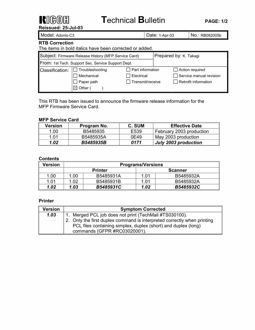
This RTB has been issued to announce the firmware release information for the MFP Firmware Service Card. MFP Service Card
Version Program No. C. SUM Effective Date 1.00 B5485935 E539 February 2003 production 1.01 B5485935A 0E49 May 2003 production 1.02 B5485935B 0171 July 2003 production
Contents
Version Programs/Versions Printer Scanner
1.00 1.00 B5485931A 1.01 B5485932A 1.01 1.02 B5485931B 1.01 B5485932A 1.02 1.03 B5485931C 1.02 B5485932C
Printer
Version Symptom Corrected 1.03 1. Merged PCL job does not print (TechMail #TS030100).
2. Only the first duplex command is interpreted correctly when printing PCL files containing simplex, duplex (short) and duplex (long) commands (GFPR #RC03020001).
Technical Bulletin PAGE: 2/2 Reissued: 25-Jul-03 Model: Adonis-C3 Date: 1-Apr-03 No.: RB082005b
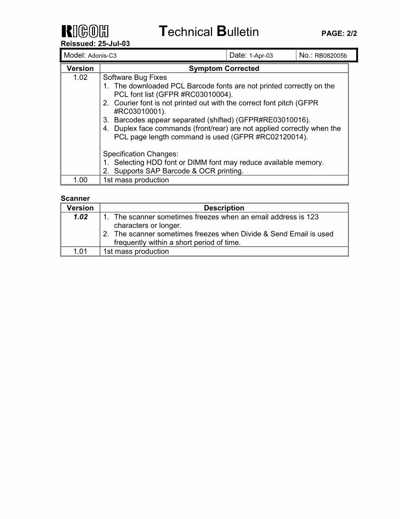
Version Symptom Corrected 1.02 Software Bug Fixes
1. The downloaded PCL Barcode fonts are not printed correctly on the PCL font list (GFPR #RC03010004).
2. Courier font is not printed out with the correct font pitch (GFPR #RC03010001).
3. Barcodes appear separated (shifted) (GFPR#RE03010016). 4. Duplex face commands (front/rear) are not applied correctly when the
PCL page length command is used (GFPR #RC02120014). Specification Changes: 1. Selecting HDD font or DIMM font may reduce available memory. 2. Supports SAP Barcode & OCR printing.
1.00 1st mass production Scanner
Version Description 1.02 1. The scanner sometimes freezes when an email address is 123
characters or longer. 2. The scanner sometimes freezes when Divide & Send Email is used
frequently within a short period of time. 1.01 1st mass production
Technical Bulletin PAGE: 1/2 Reissued: 31-Jul-03 Model: Adonis-C3 Date: 1-Apr-03 No.: RB082006a
RTB Reissue The items in bold italics have been added. Subject: Firmware Release History (NET Service Card) Prepared by: K. Takagi From: 1st Tech. Support Sec. Service Support Dept. Classification: Troubleshooting
Mechanical Paper path
Part information Electrical Transmit/receive
Action required Service manual revision Retrofit information
Other ( )
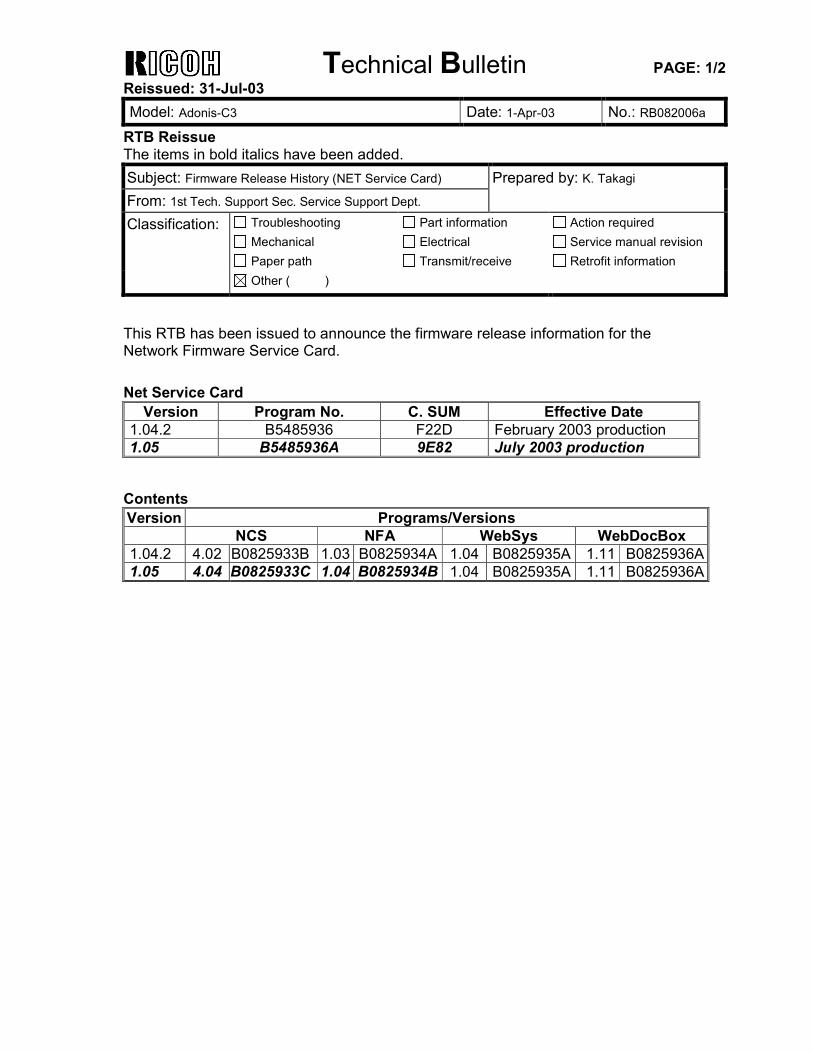
This RTB has been issued to announce the firmware release information for the Network Firmware Service Card. Net Service Card
Version Program No. C. SUM Effective Date 1.04.2 B5485936 F22D February 2003 production 1.05 B5485936A 9E82 July 2003 production
Contents Version Programs/Versions
NCS NFA WebSys WebDocBox 1.04.2 4.02 B0825933B 1.03 B0825934A 1.04 B0825935A 1.11 B0825936A 1.05 4.04 B0825933C 1.04 B0825934B 1.04 B0825935A 1.11 B0825936A
Technical Bulletin PAGE: 2/2 Reissued: 31-Jul-03 Model: Adonis-C3 Date: 1-Apr-03 No.: RB082006a
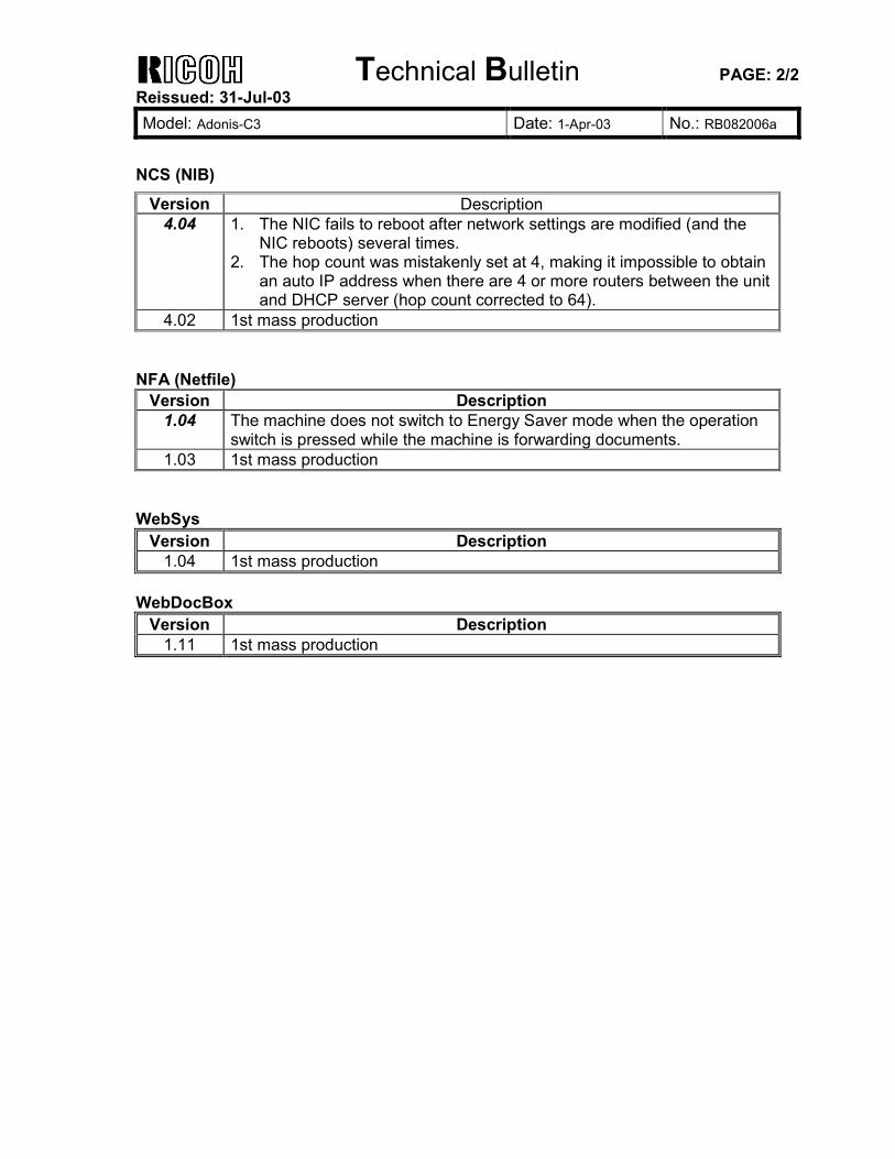
NCS (NIB)
Version Description 4.04 1. The NIC fails to reboot after network settings are modified (and the
NIC reboots) several times. 2. The hop count was mistakenly set at 4, making it impossible to obtain
an auto IP address when there are 4 or more routers between the unit and DHCP server (hop count corrected to 64).
4.02 1st mass production NFA (Netfile)
Version Description 1.04 The machine does not switch to Energy Saver mode when the operation
switch is pressed while the machine is forwarding documents. 1.03 1st mass production
WebSys
Version Description 1.04 1st mass production
WebDocBox
Version Description 1.11 1st mass production