Embed Size (px)
Citation preview

BUILDING LOCO
CHASSIS THE
COMET WAY
£1.50
Building Loco Chassis the Comet Way Comet Models offer a wide range of products for the 4mm scale locomotive modeller, and this guide attempts to help you in your understanding of
the Comet approach to model building, enable you to get the most from the Comet range, and provide you with some hints and tips on their
construction.
As with many other aspects of life you will probably not succeed if you dive in at the deep end and expect to swim straight away. If you have
experience of building other locomotive kits then you may have acquired the necessary skills to construct a complete Comet locomotive already, but
if you are not at that stage then take a little time to read this guide and maybe even follow its advice.
What you need before you begin You will need some tools to complete your model, and in addition to the usual screwdrivers, wire cutters etc., you will need the following :-
25W Soldering iron
Standard solder (i.e. not lowmelt)
Extra flux (either paste or liquid)
Superglue or similar
A tapered broach, 3 to 4 mm diameter
Drills, 0.75mm (for brake cross shafts), 0.85mm (for rivets in valve gear) and 1.2mm for crankpins.
Optional extra Depending on how accessible your layout is when you’re working on your model, you may find a small test track useful. It doesn’t have to be any
thing too sophisticated, maybe just a piece of MDF or similar, about 2'6" by 1'. On this board fix some of your chosen make of track as one straight
length along the board and a curve to your chosen minimum radius alongside it. If you have room then also have an ‘S’ bend, or reverse curve,
which will be especially useful to check the clearance of bogies etc. You can supply power to whichever track you’re using by means of small
crocodile clips on the ends of wires from your controller. For safety’s sake fit some blocks of wood at the end of each track to act as buffer stops.
You may never need them, but just in case…
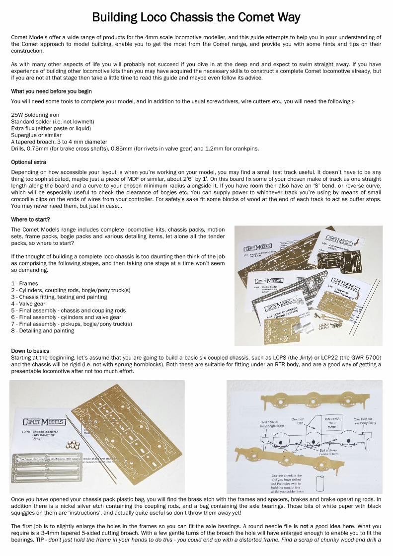
Where to start? The Comet Models range includes complete locomotive kits, chassis packs, motion
sets, frame packs, bogie packs and various detailing items, let alone all the tender
packs, so where to start?
If the thought of building a complete loco chassis is too daunting then think of the job
as comprising the following stages, and then taking one stage at a time won’t seem
so demanding.
1 - Frames
2 - Cylinders, coupling rods, bogie/pony truck(s)
3 - Chassis fitting, testing and painting
4 - Valve gear
5 - Final assembly - chassis and coupling rods
6 - Final assembly - cylinders and valve gear
7 - Final assembly - pickups, bogie/pony truck(s)
8 - Detailing and painting
Down to basics
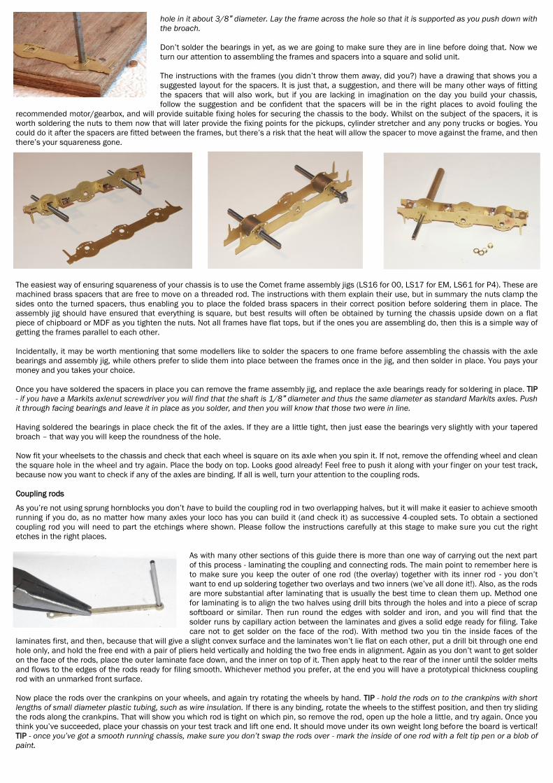
Starting at the beginning, let’s assume that you are going to build a basic six-coupled chassis, such as LCP8 (the Jinty) or LCP22 (the GWR 5700)
and the chassis will be rigid (i.e. not with sprung hornblocks). Both these are suitable for fitting under an RTR body, and are a good way of getting a
presentable locomotive after not too much effort.
Once you have opened your chassis pack plastic bag, you will find the brass etch with the frames and spacers, brakes and brake operating rods. In
addition there is a nickel silver etch containing the coupling rods, and a bag containing the axle bearings. Those bits of white paper with black
squiggles on them are ‘instructions’, and actually quite useful so don’t throw them away yet!
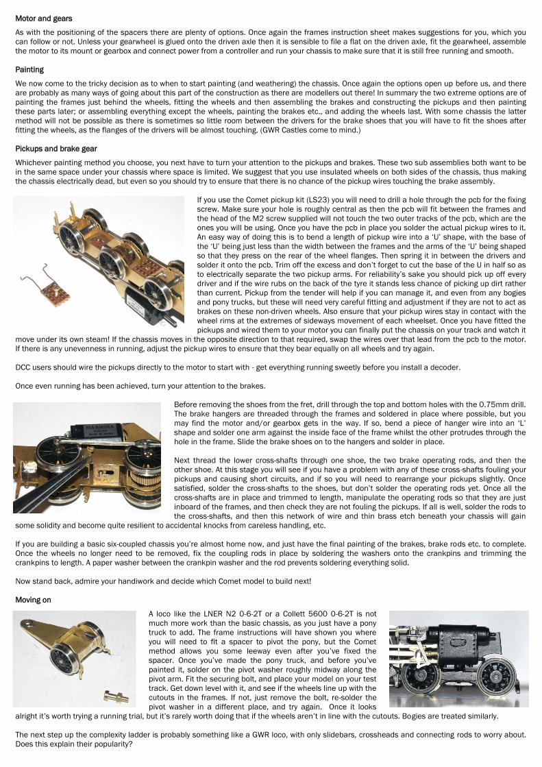
The first job is to slightly enlarge the holes in the frames so you can fit the axle bearings. A round needle file is not a good idea here. What you
require is a 3-4mm tapered 5-sided cutting broach. With a few gentle turns of the broach the hole will have enlarged enough to enable you to fit the
bearings. TIP - don’t just hold the frame in your hands to do this - you could end up with a distorted frame. Find a scrap of chunky wood and drill a
hole in it about 3/8" diameter. Lay the frame across the hole so that it is supported as you push down with
the broach.
Don’t solder the bearings in yet, as we are going to make sure they are in line before doing that. Now we
turn our attention to assembling the frames and spacers into a square and solid unit.
The instructions with the frames (you didn’t throw them away, did you?) have a drawing that shows you a
suggested layout for the spacers. It is just that, a suggestion, and there will be many other ways of fitting
the spacers that will also work, but if you are lacking in imagination on the day you build your chassis,
follow the suggestion and be confident that the spacers will be in the right places to avoid fouling the
recommended motor/gearbox, and will provide suitable fixing holes for securing the chassis to the body. Whilst on the subject of the spacers, it is
worth soldering the nuts to them now that will later provide the fixing points for the pickups, cylinder stretcher and any pony trucks or bogies. You
could do it after the spacers are fitted between the frames, but there’s a risk that the heat will allow the spacer to move against the frame, and then
there’s your squareness gone.
The easiest way of ensuring squareness of your chassis is to use the Comet frame assembly jigs (LS16 for 00, LS17 for EM, LS61 for P4). These are
machined brass spacers that are free to move on a threaded rod. The instructions with them explain their use, but in summary the nuts clamp the
sides onto the turned spacers, thus enabling you to place the folded brass spacers in their correct position before soldering them in place. The
assembly jig should have ensured that everything is square, but best results will often be obtained by turning the chassis upside down on a flat
piece of chipboard or MDF as you tighten the nuts. Not all frames have flat tops, but if the ones you are assembling do, then this is a simple way of
getting the frames parallel to each other.
Incidentally, it may be worth mentioning that some modellers like to solder the spacers to one frame before assembling the chassis with the axle
bearings and assembly jig, while others prefer to slide them into place between the frames once in the jig, and then solder in place. You pays your
money and you takes your choice.
Once you have soldered the spacers in place you can remove the frame assembly jig, and replace the axle bearings ready for soldering in place. TIP
- if you have a Markits axlenut screwdriver you will find that the shaft is 1/8" diameter and thus the same diameter as standard Markits axles. Push
it through facing bearings and leave it in place as you solder, and then you will know that those two were in line.
Having soldered the bearings in place check the fit of the axles. If they are a little tight, then just ease the bearings very slightly with your tapered
broach – that way you will keep the roundness of the hole.
Now fit your wheelsets to the chassis and check that each wheel is square on its axle when you spin it. If not, remove the offending wheel and clean
the square hole in the wheel and try again. Place the body on top. Looks good already! Feel free to push it along with your finger on your test track,
because now you want to check if any of the axles are binding. If all is well, turn your attention to the coupling rods.
Coupling rods As you’re not using sprung hornblocks you don’t have to build the coupling rod in two overlapping halves, but it will make it easier to achieve smooth
running if you do, as no matter how many axles your loco has you can build it (and check it) as successive 4-coupled sets. To obtain a sectioned
coupling rod you will need to part the etchings where shown. Please follow the instructions carefully at this stage to make sure you cut the right
etches in the right places.
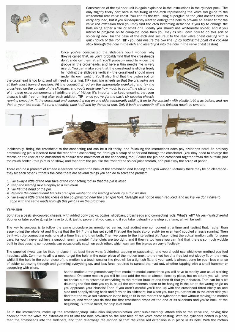
As with many other sections of this guide there is more than one way of carrying out the next part
of this process - laminating the coupling and connecting rods. The main point to remember here is
to make sure you keep the outer of one rod (the overlay) together with its inner rod - you don’t
want to end up soldering together two overlays and two inners (we’ve all done it!). Also, as the rods
are more substantial after laminating that is usually the best time to clean them up. Method one
for laminating is to align the two halves using drill bits through the holes and into a piece of scrap
softboard or similar. Then run round the edges with solder and iron, and you will find that the
solder runs by capillary action between the laminates and gives a solid edge ready for filing. Take
care not to get solder on the face of the rod). With method two you tin the inside faces of the
laminates first, and then, because that will give a slight convex surface and the laminates won’t lie flat on each other, put a drill bit through one end
hole only, and hold the free end with a pair of pliers held vertically and holding the two free ends in alignment. Again as you don’t want to get solder
on the face of the rods, place the outer laminate face down, and the inner on top of it. Then apply heat to the rear of the inner until the solder melts
and flows to the edges of the rods ready for filing smooth. Whichever method you prefer, at the end you will have a prototypical thickness coupling
rod with an unmarked front surface.
Now place the rods over the crankpins on your wheels, and again try rotating the wheels by hand. TIP - hold the rods on to the crankpins with short
lengths of small diameter plastic tubing, such as wire insulation. If there is any binding, rotate the wheels to the stiffest position, and then try sliding
the rods along the crankpins. That will show you which rod is tight on which pin, so remove the rod, open up the hole a little, and try again. Once you
think you’ve succeeded, place your chassis on your test track and lift one end. It should move under its own weight long before the board is vertical!
TIP - once you’ve got a smooth running chassis, make sure you don’t swap the rods over - mark the inside of one rod with a felt tip pen or a blob of
paint.
Motor and gears As with the positioning of the spacers there are plenty of options. Once again the frames instruction sheet makes suggestions for you, which you
can follow or not. Unless your gearwheel is glued onto the driven axle then it is sensible to file a flat on the driven axle, fit the gearwheel, assemble
the motor to its mount or gearbox and connect power from a controller and run your chassis to make sure that it is still free running and smooth.
Painting We now come to the tricky decision as to when to start painting (and weathering) the chassis. Once again the options open up before us, and there
are probably as many ways of going about this part of the construction as there are modellers out there! In summary the two extreme options are of
painting the frames just behind the wheels, fitting the wheels and then assembling the brakes and constructing the pickups and then painting
these parts later; or assembling everything except the wheels, painting the brakes etc., and adding the wheels last. With some chassis the latter
method will not be possible as there is sometimes so little room between the drivers for the brake shoes that you will have to fit the shoes after
fitting the wheels, as the flanges of the drivers will be almost touching. (GWR Castles come to mind.)
Pickups and brake gear Whichever painting method you choose, you next have to turn your attention to the pickups and brakes. These two sub assemblies both want to be
in the same space under your chassis where space is limited. We suggest that you use insulated wheels on both sides of the chassis, thus making
the chassis electrically dead, but even so you should try to ensure that there is no chance of the pickup wires touching the brake assembly.
If you use the Comet pickup kit (LS23) you will need to drill a hole through the pcb for the fixing
screw. Make sure your hole is roughly central as then the pcb will fit between the frames and
the head of the M2 screw supplied will not touch the two outer tracks of the pcb, which are the
ones you will be using. Once you have the pcb in place you solder the actual pickup wires to it.
An easy way of doing this is to bend a length of pickup wire into a ‘U’ shape, with the base of
the ‘U’ being just less than the width between the frames and the arms of the ‘U’ being shaped
so that they press on the rear of the wheel flanges. Then spring it in between the drivers and
solder it onto the pcb. Trim off the excess and don’t forget to cut the base of the U in half so as
to electrically separate the two pickup arms. For reliability’s sake you should pick up off every
driver and if the wire rubs on the back of the tyre it stands less chance of picking up dirt rather
than current. Pickup from the tender will help if you can manage it, and even from any bogies
and pony trucks, but these will need very careful fitting and adjustment if they are not to act as
brakes on these non-driven wheels. Also ensure that your pickup wires stay in contact with the
wheel rims at the extremes of sideways movement of each wheelset. Once you have fitted the
pickups and wired them to your motor you can finally put the chassis on your track and watch it
move under its own steam! If the chassis moves in the opposite direction to that required, swap the wires over that lead from the pcb to the motor.
If there is any unevenness in running, adjust the pickup wires to ensure that they bear equally on all wheels and try again.
DCC users should wire the pickups directly to the motor to start with - get everything running sweetly before you install a decoder.
Once even running has been achieved, turn your attention to the brakes.
Before removing the shoes from the fret, drill through the top and bottom holes with the 0.75mm drill.
The brake hangers are threaded through the frames and soldered in place where possible, but you
may find the motor and/or gearbox gets in the way. If so, bend a piece of hanger wire into an ‘L’
shape and solder one arm against the inside face of the frame whilst the other protrudes through the
hole in the frame. Slide the brake shoes on to the hangers and solder in place.
Next thread the lower cross-shafts through one shoe, the two brake operating rods, and then the
other shoe. At this stage you will see if you have a problem with any of these cross-shafts fouling your
pickups and causing short circuits, and if so you will need to rearrange your pickups slightly. Once
satisfied, solder the cross-shafts to the shoes, but don’t solder the operating rods yet. Once all the
cross-shafts are in place and trimmed to length, manipulate the operating rods so that they are just
inboard of the frames, and then check they are not fouling the pickups. If all is well, solder the rods to
the cross-shafts, and then this network of wire and thin brass etch beneath your chassis will gain
some solidity and become quite resilient to accidental knocks from careless handling, etc.
If you are building a basic six-coupled chassis you’re almost home now, and just have the final painting of the brakes, brake rods etc. to complete.
Once the wheels no longer need to be removed, fix the coupling rods in place by soldering the washers onto the crankpins and trimming the
crankpins to length. A paper washer between the crankpin washer and the rod prevents soldering everything solid.
Now stand back, admire your handiwork and decide which Comet model to build next!
Moving on A loco like the LNER N2 0-6-2T or a Collett 5600 0-6-2T is not
much more work than the basic chassis, as you just have a pony
truck to add. The frame instructions will have shown you where
you will need to fit a spacer to pivot the pony, but the Comet
method allows you some leeway even after you’ve fixed the
spacer. Once you’ve made the pony truck, and before you’ve
painted it, solder on the pivot washer roughly midway along the
pivot arm. Fit the securing bolt, and place your model on your test
track. Get down level with it, and see if the wheels line up with the
cutouts in the frames. If not, just remove the bolt, re-solder the
pivot washer in a different place, and try again. Once it looks
alright it’s worth trying a running trial, but it’s rarely worth doing that if the wheels aren’t in line with the cutouts. Bogies are treated similarly.
The next step up the complexity ladder is probably something like a GWR loco, with only slidebars, crossheads and connecting rods to worry about.
Does this explain their popularity?
Construction of the cylinder unit is again explained in the instructions in the cylinder pack. The
only slightly tricky part here is the fixing of the etch representing the valve rod guide to the
whitemetal rear valve chest. You can fix the two using superglue as the joint doesn’t have to
carry any load, but if you subsequently want to enlarge the hole to provide an easier fit for the
valve rod extension then you may find the etch becoming detached if you try to enlarge the
hole using either a file or small drill. Ideally you should use whitemetal solder, and if you
intend to progress on to complete locos then you may as well learn how to do this sort of
soldering now. Tin the base of the etch and secure it to the rear valve chest casting with a
quick touch of the iron. TIP - you can ensure the two line up by putting the point of a cocktail
stick through the hole in the etch and inserting it into the hole in the valve chest casting.
Once you’ve constructed the slidebars you’ll wonder why
they’re called that, as you’ll probably find that the crossheads
don’t slide on them at all! You’ll probably need to widen the
groove in the crossheads, and here a thin needle file is very
useful. You can make sure that the crosshead is sliding freely
by holding the slidebars vertical - the crosshead should move
under its own weight. You’ll also find that the piston rod on
the crosshead is too long, and will need shortening. TIP - turn the wheels so that the crankpins are
at their most forward position. Fit the connecting rod on the appropriate crankpin, and lay the
crosshead on the outside of the slidebars, and you’ll easily see how much to cut off the piston rod.
With these extra components all adding a bit of friction it’s important to keep ensuring that your
chassis is still free running after each addition. TIP - once you’ve got the basic six-coupled chassis
running smoothly, fit the crosshead and connecting rod on one side, temporarily holding it on to the crankpin with plastic tubing as before, and run
that on your test track. If it runs smoothly, take it off and try the other one. Only if both are smooth will the finished result be smooth!
Incidentally, fitting the crosshead to the connecting rod can be a bit tricky, and following the instructions does pay dividends here! An ordinary
dressmaking pin is inserted from the rear of the connecting rod, through a scrap of paper and through the crosshead. (You may need to enlarge the
recess on the rear of the crosshead to ensure free movement of the connecting rod.) Solder the pin and crosshead together from the outside (not
too much solder - this joint is on show) and then trim the pin, file the front of the solder joint smooth, and pull away the scrap of paper.
There can be a problem of limited clearance between the back of the crosshead and leading crankpin washer. (actually there may be no clearance -
they hit each other!) If that’s the case there are several things you can do to solve the problem.
1 File away a little of the rear face of the connecting rod so that the pin is inset
2 Keep the leading axle sideplay to a minimum
3 File flat the head of the pin.
4 Replace the conventional Markits crankpin washer on the leading wheels by a thin washer
5 File away a little of the thickness of the coupling rod near the crankpin hole. Strength will not be much reduced, and luckily we don’t have to
cope with the same loads through this joint as on the prototype.
Valve gear So that’s a basic six-coupled chassis, with added pony trucks, bogies, slidebars, crossheads and connecting rods. What’s left? Ah yes - Walschaerts!
Sooner or later you’re going to have to do it, just to prove that you can, and if you take it steadily one step at a time, all will be well.
The key to success is to follow the same procedure as mentioned earlier, just adding one component at a time and testing that, rather than
assembling the whole lot and finding that the @#!* thing has set solid! First get the basic six- or eight- (or even ten-) coupled chassis running. Then
try it with the connecting rods, one at a time first and then both. Then we come to the interesting bit! Assembling the actual motion calls for some
care, for you’ll never achieve a smooth running model if the joints are too tight, and if they’re too loose you can find that there’s so much wobble
built in that passing components can occasionally catch on each other, which can jam the brakes on very effectively.
The supplied rivets can be fixed in place in at least three ways (soldering, tapping or squeezing), and you should use whichever method you feel
happiest with. Common to all is a need to get the hole in the outer piece of the motion (next to the rivet head) a free but not sloppy fit on the rivet,
whilst if the hole in the other piece of the motion is a touch smaller the rivet will be a tightish fit, and your work is almost done for you - less chance
of solder squeezing through and gumming everything up, and less force required to spread the rivet out, whether tapping with a small hammer or
squeezing with pliers.
As the motion arrangements vary from model to model, sometimes you will have to modify your usual working
method. On some models you will be able add the motion almost piece by piece, but on others you will have
no choice but to assemble everything to the motion bracket and then fit that your chassis. That can be a bit
daunting the first time you try it, as all the components seem to be hanging in the air at the wrong angle as
you approach your chassis! Then if you aren’t careful you’ll end up with the crosshead fitted nicely on one
side and happily sliding back and forth on its slidebars, but when you turn your attention to the other side you
find that the valve rod extension is too long to fit in the rear of the cylinder bracket without moving the motion
bracket, and when you do that the first crosshead drops off the end of its slidebars and you’re back at the
beginning! But take heart, for help is at hand.
As in the instructions, make up the crosshead/drop link/union link/combination lever sub-assembly. Attach this to the valve rod, having first
checked that the valve rod extension will fit into the hole provided on the rear face of the valve chest casting. With the cylinders bolted in place,
feed the crossheads into the slidebars, and then re-arrange the motion so that the valve rod extension is in place in its hole. With the motion

bracket also bolted in place, temporarily fix the rear end of the valve rod to it by passing a small length of 0.45mm wire through the holes and
doubling it over. You can now test run your chassis to ensure that this side is running smoothly. When satisfied, remove your bent wire, remove the
motion from that side and repeat the procedure for the other side.
Time for a cup of coffee or whatever now, before you challenge the next part. Remove the motion
bracket and attach the return crank/eccentric rod/expansion link assembly to it, but you’ll notice
from the drawing in the motion set instruction that you also have to attach the valve rod as well.
As this has the combination lever/etc. hanging from it, the challenge is to keep the fixing holes in
line as you try to feed through the wire that forms the pivot. The only help we can give you here is
to suggest that you file the end of the wire to a point so that it will stand more chance of finding
the various holes as it is jiggled about and pushed. To cut down on the number of hands you need
to complete this task, try taping the motion bracket down to your workbench until everything is
skewered, the ends of the wire soldered in place and the excess cut off. But mainly you just need
to be careful and patient. TIP - on most motion brackets there is more room than needed between
the two supports for the valve rod and the expansion link. To take up some of this space and
reduce ‘slop’ in these components, solder a Markits washer to the rear face of the valve rod over
the pivot hole.
Once you’ve fixed both sides of the gear to the motion bracket, start the process of re-fitting it
to the chassis by feeding the crosshead back into the slidebars and the valve rod extension
into its hole. Then bolt the motion bracket back in place, and leave the two expansion link/
eccentric rod/return crank assemblies dangling. Fit the connecting rods onto the crankpins
and temporarily secure them with a piece of plastic tubing. Now lift the return crank and you’ll
probably find that by wiggling it around you’ll manage to find a way of getting it to lie on top of
the cylinder block. Once there, hold it place with a small piece of insulation tape or similar.
You can now test your chassis with effectively only half of the Walschaerts gear in place. If it
does not run smoothly, you know the problem must lie in the ‘front half’ of the gear, so you can
now find the problem more easily than if you’d assembled it all in one go.
If it runs smoothly, solder in place first the one return crank and then the other, testing after the first one. Once you have soldered the second return
crank in place, the final run on the test track should not be a heart stopping moment, as you know that each sub assembly stage was running
smoothly, and so you should end up with a finely detailed, smooth running chassis. Just add the cylinder covers and details such as inspection
covers with superglue, then stand back and admire. Well done!
Crosskitting By this we mean using a chassis in a body, plastic or whitemetal, for which it was not intended. To achieve a satisfactory fit either the chassis or the
body may need surgery, so this is perhaps a technique for the more experienced modeller. Temporarily fit the bearings to the frames, assemble the
frames using the Comet frame assembly jig in the centre axle hole, and also fit the front and rear drivers and axles. Offer up this makeshift chassis
to the body, and the places where surgery is required will be seen. Once the correct ride height has been achieved, turn your attention to where you
will need to fit spacers in your chassis to accommodate the appropriate body fixings. But before making a firm decision about the spacers,
remember that you have to allow for your motor and gearbox. If the body that you are going to use doesn’t allow the fitting of the motor in the same
place as in the instructions, then you may have to modify the placing of the spacers. Once you think you’ve coped with all these problems go ahead
and assemble your chassis in the normal way, and everything should fit.
Complete Locomotive kits Now that you’re capable of all the variants of chassis that Comet can throw at you, the next step is to have a go a full Comet Locomotive Kit.
At present you have 4 to choose from, a Rebuilt Royal Scot, an 8F, an Ivatt 2MT and a Caprotti Black 5. The Royal Scot and the Ivatt 2MT are the full
works, in that you will need to make a chassis (with Walschaerts!) and the body and a full tender, but the other two require a little less work. With
the Caprotti 5 you still have all the body and tender to make, but on one side of the loco the valve gear is non-existent, and on the other it’s just a
simple eccentric rod. And with the 8F you have a full chassis to make (again with Walschaerts), but the loco body is a ready made plastic moulding
requiring only detailing, thus making the construction much simpler. TIP - when constructing a loco kit you will almost certainly need to solder a half-
etched overlay onto an underlying brass part. If you use 140 solder then you’ll need less heat than with conventional solder, and thus stand less
chance of distorting the thin half-etch. And of course whitemetal is soldered with special lowmelt (70) whitemetal solder, flux and, ideally, a
temperature controlled iron.
The biggest difficulty when building a complete loco is controlling the sinking feeling you get when you open the box! Because of the Comet
philosophy of separate sub-assemblies you will find what seems at first like an infinite number of plastic bags, all neatly sealed, each with a
separate set of components. And some of these bags contain smaller bags! It can seem a bit daunting, but if you take them out of the box you will
find it much easier to understand. You will have the bag containing the chassis pack (frames, spacers, bearings, motion and so on) and then there’s
the bogie pack, the tender pack, the etchings for the loco footplate and the castings for the loco body. The Golden Rule is to not open a bag until
you need to! Many people choose to build the tender first to get the ‘feel’ of a kit, and that will enable you to work through some of the components
in your box, and reduce the bag count! Once you’ve completed the tender, complete the loco itself, and you will find that the reason for all those
bags becomes clear.
In summary, Comet Models aim to provide you with components and kits that enable you to equip your showcase or layout with a wide range of
accurate, high quality models. We hope you’ll enjoy building them as much as we enjoyed designing and producing them.
We hope that your experience of using Comet Models kits and components will be a pleasant one, but if you have any comments or suggestions for
improvement, then please contact us at the address below.
Comet Models is part of Wizard Models Limited, PO Box 70, Barton upon Humber DN18 5XY
Tel 01652 635885, web www.wizardmodels.ltd, e-mail [email protected]
© Wizard Models Limited 2019