Embed Size (px)
Citation preview
Introduction to Engineering Design — 6-1Book 9, 3rd Edition: Engineering Skills and Hovercraft Missions
CHAPTER 6
BUILDING A HOVERCRAFT CONTROLSYSTEM IN ROBOTC
1. INTRODUCTION: PROGRAMMINGCONCEPTSThe computer is basically a calculator, just without the push buttons. There is little (in most cases,nothing) that a computer can do that a calculator cannot; the one thing that separates the two is theway that they are controlled. A push-button calculator is controlled when a person presses itsbuttons, which causes it to perform various functions—in particular, the functions that the personwanted, acting in the order that the person pushed the buttons, on whatever data the person enteredinto the calculator … by pushing buttons.
The computer is fundamentally identical to this picture: a person gets a computer to performspecified functions in a specified order, on data that is either entered into the computer by the personor gathered by the computer from its environment at run time. The only significant difference is thatthere is no button-pushing; the person controlling the computer must decide ahead of time whatfunctions to perform, and, because the data values might not be known until run time, the personmust anticipate the possible values and provide contingency plans. For example, a person using acalculator to perform a complex calculation will stop halfway through if it is clear that the divisor ofa term is zero or so near to zero as to produce an essentially infinite result. There is no such humanoversight at the time of running a computer program, so the possibilities must be written explicitlyinto the sequence of steps, in this case by checking the value of a divisor against zero before using itin a division operation.
This, then, is the main point to remember when writing control systems for computers: thatthey are like very fast, very small (and trusting) children. They will do whatever you tell them to,even divide by zero, a billion times a second, so it is up to you to be quite certain that what you tellthem to do is exactly what you want them to do, because 999,999 times out of a million, anyperceived misbehavior on the part of a computer is due to a design error in the program—i.e., it isdoing precisely what you told it to do.
What makes autonomous control interesting (and extremely challenging) is the interplaybetween the computer program and the real-world environment in which the computer finds itself.When you drive a car, you are well aware of your senses, and you respond to what you see and hearby changing the car’s controls (steering wheel, accelerator, brakes, etc.). You also anticipate the

6-2 — Chapter 6Building a Hovercraft Control System in ROBOTC
behavior of the car; for instance, you probably prepare for a right-hand turn well before you reachthe street at which you intend to take the turn. When you control an RC hovercraft, you doessentially the same thing: you watch what the hovercraft is doing, how much it drifts when you turnoff the fans; you also anticipate where it will be and how much to correct for oversteer and tailspin inmaking turns.
What you will find the most challenging is how to operate in an environment where yoursenses are taken from you and replaced with far simpler and far more limiting ones. Compared toyour senses, the hovercraft you build will have extremely rudimentary sensory inputs—such asbinary tape detectors (light sensors detecting the presence or absence of a black tape underneath),distance sensors, and/or gyroscopes. Unless you explicitly create it in your program, your hovercraftwill have no ability to remember past behavior (e.g., where it was a moment ago and what it wasdoing) or anticipate future stimuli and prepare for appropriate reactions.
What is Programming All About?
You have a set of resources at your disposal, for example:
• Computer/s (one or more microprocessors)
• Memory (temporary and/or permanent storage)
• Input devices (sensors)
• Output devices (actuators)
You also have a set of desired behaviors, for example:
• Follow a path
• Avoid hitting obstacles
• Turn on/off lamp when handclap detected
• Play brief salsa motif when simple task accomplished
A program is the connection between these two sets of things; it is your way to tell the system (e.g.,hovercraft) how to behave. For instance, here is a program that will cause a walking robot to followa path:
do the following forever:if on the path and the path is in front of you
take a step forwardotherwise
turn slightly to the right
It should be relatively clear what this does, and how it does it. The robot is instructed to take a singlestep at a time and only when it is guaranteed that the step will keep the robot on the path (the “take astep forward” action is only allowed if the path is directly ahead). When the path is not directlyahead, the robot turns, a little bit at a time, until the path is directly ahead.
But what else does the robot do? What would be expected behavior of the robot, and whatwould be unexpected? Is walking the wrong way down the path an expected behavior? How aboutspinning in one place, forever? How about walking in circles or in a zig-zag manner? Should weexpect the robot to exhibit any of these behaviors?
One should be able to look at code and imagine all its possible behaviors. For instance, atthe end of the path, we should expect the robot not to stop, but to make a 180-degree turn, little by

Introduction to Engineering Design — 6-3Book 9, 3rd Edition: Engineering Skills and Hovercraft Missions
little, and return the way it came, so walking backward down the path is expected. How about doingthis before we reach the end of the path—is that possible? Consider cases in which the path turns tothe left, or the robot is walking at an angle a little to the right of the path—the robot will reach theedge of the path, at which point there will be no path directly ahead, and the robot will turn to theright until it is facing the way it came, at which point it will walk the wrong way down the path.
Can the robot spin in one place forever? What happens if it starts off the path, or if itaccidentally steps off the path? In those circumstances, you should expect the robot to spin forever,because the code will not allow it to take a step unless the robot is already standing on the path. Inaddition, if the “slight” amount the robot turns is about 90 degrees and the robot is pointing 45degrees away from the direction of the path, no matter how many times the robot turns, it will neverface down the length of the path, and so it will never take a step forward. How about walking incircles? Is that ever possible? Yes, in scenarios similar to the one above (if the degree of turningand width of the path are just right). How about a zig-zag motion? Since the code does not everhave the robot turn left, this would be an unexpected behavior.
These are the types of questions that it is well worth asking of your code, as even thesimplest code can produce complex behaviors. Will the code work if the robot starts out off the path,for instance next to it but facing it? Or how about starting off next to it but facing away? Is the coderobust enough to handle unexpected situations, such as walking in a line that is just slightly askew,so that after some number of steps the robot finds itself off the path? Or what if the steps that therobot takes are so large that it could step off the path when close to the edge?
Here is a more robust version of the code, one that handles many of these odd conditions:
do the following forever:if the path is in front of you
take a step forwardotherwise
turn slightly to the right
Can this spin forever? Yes, but only if the path is out of sensory range. Can this walk in circles?Just like before, it depends on the degree of turning and the width of the path relative to the step size.Unlike the previous code, this handles situations where the robot is not on the path, for instance atstart or if the robot accidentally steps off the path; it also handles cases where the robot is pointingslightly askew relative to the path. Zig-zag is unlikely to happen, but the robot can still accidentallyturn around and walk the wrong way down the path if it hits the right edge of the path beforereaching the end of the path. The following would be an obvious solution to that problem:
do the following forever:if the path is in front of you
take a step forwardotherwise
turn slightly toward the path
This avoids making 180-degree turns before the end of the path, but this code presupposes the abilityto know just where the path is. Previously, all code worked with simple binary detectors: i.e., thepath is or is not in front of us. This last piece of code requires more information: the path is in frontof us, or, if not, we can tell whether it is to the left or to the right of us. Depending on the types ofsensors you have at your disposal, this information may be trivial to get, or it may be impossible toget, and so understanding the abilities of your sensor devices is crucial in the development of yoursystem’s capabilities.
Just as important is understanding the abilities of your actuators: for instance, how is it thatyou cause the robot to turn? How do you know how far it turns each time? Do you need to know

6-4 — Chapter 6Building a Hovercraft Control System in ROBOTC
whether you are pointing straight or not, and, if so, how do you verify it? What actuator “takes astep forward” for you? How does it work? How far forward do you travel, and does the robot haltimmediately after a step, or come to a “rolling stop,” or drift significantly (e.g. if the robot is actuallyon wheels or rollers or floating off the ground)?
What is the NXT?
We will describe the Lego NXT controller in more detail a few pages from now, but here it isworthwhile to look at it in purely functional terms, including the sensory inputs that it accepts andthe actuators it can control.
The NXT is a small computer, and so it can be programmed like any other computer. Itsadvantages are firstly that it is lightweight and battery powered and thus makes a good hovercraftcontroller (as opposed to a desktop or even laptop computer, which would weigh too much for asmall hovercraft), and secondly that it has a diverse modular array of sensors and actuators designedto work with it, for instance:
• light sensor — a sensor returning a value proportional to the amount of light it detects, whichcan be used to determine the lightness/darkness of the terrain that you are traveling over orto head toward a bright light in the darkness
• accelerometer — a sensor returning values proportional to the amount of acceleration itdetects along 3 axes, which can be used to measure a system’s movement in 3 dimensions(acceleration is the 1st derivative of velocity and the 2nd derivative of position) … note thatthe accelerometer measures both its movements and the effects of gravity, the sensor’sconstant acceleration in the up/down direction
• gyroscope — a sensor returning values proportional to the angular rotation it detects, whichcan be used to measure a system’s movement in three dimensions, much like anaccelerometer; its advantage is that, unlike the accelerometer, it does not also lump togetherthe effects of movement and the effects of gravity
• compass — a sensor returning a heading (which way it is pointing relative to MagneticNorth), which can be used to keep a system pointing in a known direction
• proximity sensor — an ultrasonic sensor returning a value proportional to the distance to thenearest object along the line of sight, which can be used to sense when approachingobstacles such as people, walls, traffic cones, etc.
• servo — an actuator that can be told to rotate any number of degrees, which can be used toimplement wheels for propulsion, wheels for steering, doors that open and close, roboticarms, rudders and vanes, pulley systems, etc.
• motor — an actuator that can be told to spin at different speeds (i.e., run at different powerlevels), which can be used to implement wheels for propulsion, fans/propellers, etc.
• home-grown actuators such as relays and transistors, which can be connected to the NXT bycustomizing a Lego output cable (i.e., cutting and splicing) and that enable the NXT tocontrol actuators requiring much more power than the NXT is capable of delivering, such ashigh-power lift fans and thrust fans—in particular, the kinds of fans you will need to poweryour hovercraft
These are extremely powerful sensors and actuators. At any time, the NXT can read the values offour different sensors connected to its inputs, and it can control the behavior of three differentactuators connected to its outputs. Your job in the development of your hovercraft’s control system

Introduction to Engineering Design — 6-5Book 9, 3rd Edition: Engineering Skills and Hovercraft Missions
is to determine which of these sensors and actuators make the most sense for you to work with, andthen to develop a control program that periodically reads the input sensors values and controls thevarious actuators accordingly.
Examples of How To Get the NXT To Do Stuff
The following are some code samples of how to write RobotC code for the NXT. Do not worry ifthe syntax is confusing; we will discuss C-language specifics in detail in the “C ProgrammingBasics” section of the chapter. This section is meant to serve as a preview.
The first example is a basic “hello, world” program, which just means that this is one of thesimplest possible complete programs that you can imagine.
task main(){
nxtDisplayTextLine(3, “Hello”);nxtDisplayTextLine(4, “World”);
}
This prints a message on the NXT’s LCD screen, taking up two separate lines of the display. Severalthings to note:
• The task main statement indicates two things: first, that it is a “task,” a unit of code toexecute together that is delimited by the curly braces, and second that it is the “main” task,which means that it will get executed first, before any other group of code that might befound in the program.
• As mentioned above, the curly braces delimit the code—like parentheses in mathematics,curly braces in C indicate what things should be grouped together.
• The print-out statements are function calls, wherein the stuff in the parentheses is thefunction’s arguments—the instructions to the print-out mechanism. The first argument tellsthe NXT which line on the LCD display to print on, and the second is a string (a bunch ofcharacters beginning and ending with double quotes) that tells the NXT what to print.
• All statements end in semicolons; this is a C-language convention.
Note also that the display function nxtDisplayTextLine can take additional arguments,allowing it to print out variables (a tool that is quite useful for debugging). The following exampledemonstrates this ability:
// Port to which the sensor is connectedconst tSensors LightSensor = (tSensors) S1;
task main(){
int light_reading;
/*this is another way to specify comments -- everything between the slash-asterisk and the asterisk-slash is ignored, within a line or multi-line*/while (true) {
light_reading = SensorValue(LightSensor);nxtDisplayTextLine(2, “Light = %d”, light_reading);
}}

6-6 — Chapter 6Building a Hovercraft Control System in ROBOTC
This example has a bit more to it:
• The very first line begins with two ‘/’ slash characters. This is a comment: the double-slashindicates that the rest of the line should be ignored by the NXT, as it only containsinformation useful to the programmer. This is where you make notes to yourself in the code.
• The second line is actually generated by the RobotC programming environment (we’ll get tothat in class), and it declares that the object LightSensor is a sensor object thatcorresponds to a light sensor plugged into input 1 of the NXT.
• The first line of the main task is a variable declaration. It specifies that the objectlight_reading is to be used as an integer.
• The while (true) statement indicates that the subsequent code block (the set ofstatements delimited by the curly braces) should get executed repeatedly, as long as thevalue in parentheses evaluates to true. Since it is already declared to be true, that means thecode block will loop forever. This is how you implement the do the followingforever: statements in the pseudocode examples at the beginning of the chapter.
• The nxtDisplayTextLine function now has an additional parameter at the end: thevariable that we wish to print to the screen. Also in the string is the odd-looking “%d” whichindicates that a decimal-value integer will be printed out at that point.
So far we have shown how to print textual information to the NXT’s display and how to get readdata values from the NXT’s sensor-input ports. The following example shows how to drive values tothe NXT’s output ports:
// Port to which the sensor is connectedconst tSensors LightSensor = (tSensors) S1;
task main(){
motor[motorA] = 50;motor[motorB] = 50;
wait1Msec(1000);
while (SensorValue(LightSensor) > 50) {// do nothing, i.e. keep going
}
motor[motorA] = 0;motor[motorB] = 0;
}
This starts up the NXT’s motors at a 50% power level (presumably driving wheels on the left- andright-hand sides), which moves the NXT forward at about half speed. After a 1-second delay, theNXT starts reading its input sensor value: it keeps reading the value over and over again while thevalue is greater than 50 (a percentage value, indicating the presence of light). Once the light readingis less than 50%, indicating the presence of a shadow or dark object, the while loop exits, and themotor power levels are set to 0, turning them off. Some things to note:
• motor, motorA, motorB, etc. are all reserved keywords. This means that the NXTexpects them to be used in a certain way (as shown). So, for example, you can’t have a

Introduction to Engineering Design — 6-7Book 9, 3rd Edition: Engineering Skills and Hovercraft Missions
variable called “motor” or “motorB” that you read and write the way the variablelight_reading was used in the previous code example.
• The square brackets indicate an array, a C-language data structure that gathers together a setof similar objects. The name of this particular array is “motor”, and the number in thebrackets is the index into the array—so in this example motor indicates an array of things(probably motors), motorA being one and motorB being another.
• The value used to set a motor value is a number between 0 and 100, indicating a power levelcorresponding to a percentage of maximum.
• The wait1Msec function does as one would expect: it stalls for the specified number ofmilliseconds and then goes on. This stalls the execution of code, not the NXT, so while thecode is stalling, the motors are still running along at power level 50.
Returning to the earlier theme of fully understanding one’s code, how could this example produceodd behavior? For instance, note that it does not have the behavior of moving forward until detectinga dark spot and then stopping: it moves forward for a minimum of 1 second before it even looks forlightness/darkness, so if the dark spot is small and less than one second of travel away, the NXTcould drive right over it without ever stopping—however, there are times when you might wantexactly this behavior.
The following starts detecting the lightness/darkness immediately and also gives an exampleof time measurement:
// Port to which the sensor is connectedconst tSensors LightSensor = (tSensors) S1;
task main(){
int timeTaken;
ClearTimer(T1);motor[motorA] = 50;motor[motorB] = 50;
while (SensorValue(LightSensor) > 50) {// do nothing, i.e. keep going
}
// found dark – stop & print resultstimeTaken = time1[T1]; // stop timingmotor[motorA] = 0; // shut down motorsmotor[motorB] = 0;
nxtDisplayTextLine(2, “Time = %d”, timeTaken);}
This starts moving immediately and stops as soon as darkness is detected; in particular, if the NXTstarts on a dark spot, it will halt before the motors have much time to get moving. Like the “motor”keywords, time1 and T1 are reserved keywords that must be used as shown: time1 is an array oftimers, T1 being one of those timers. The call to ClearTimer sets timer T1 to 0, so that thereading of the timer later on (in the statement timeTaken = time1[T1];) gets the time inmilliseconds from the time of the clearing to the time of the reading. This gives the amount of timethe NXT spent driving around, searching for darkness.

6-8 — Chapter 6Building a Hovercraft Control System in ROBOTC
Pseudocode as a First Draft
In the beginning of the chapter, some code was offered as example control programs, but the codewas written in English and probably would not run on any computer as-is. This is pseudocode, themost commonly used form of sketching out one’s programming ideas.
In general, before writing a complex piece of software, one should formulate a reasonablepicture of what it is the program should do: just as an artist draws sketches before starting to paint, soshould an engineer sketch out the overall program before starting to write actual code. Pseudocodeis a popular medium because it tends to be self-explanatory, and, despite its simplicity, it can stillhelp discover design flaws, as we saw in the previous examples. For example, here is a rudimentaryvehicle-control algorithm for following a dark line on a light floor, assuming that the vehicle has twodownward-pointing light sensors (lightL and lightR) at the front, each one positioned on either sideof the line, and two motors (motorL and motorR) that provide forward thrust:
do forever:read forward light sensors (lightL, lightR)respond to the 4 possible combinations of values:
1. (light, light) –- sensors are straddling lineset motor speeds as follows:
motorL = 100%motorR = 100%
2. (light, dark) –- lightR is on the tape, so turn rightset motor speeds as follows:
motorL = 100%motorR = 50%
3. (dark, light) –- lightL is on the tape, so turn leftset motor speeds as follows:
motorL = 50%motorR = 100%
4. (dark, dark) –- we are perpendicular to the tape, so spin slowly in a clockwise motion until we are not perpendicular to tape
set motor speeds as follows:motorL = 20%motorR = -20%
This is not a particularly robust program, but it does specify reasonably well what is intended andhow it will happen. Because the “code” is mostly human-readable English, it is self-documenting;any engineer reading it should be able to understand what it is intended to do as well as how itexpects to go about it.
Note in particular the indentation; here, as in regular programming languages, the nesting ofstatements indicates their “scope” … e.g., everything below and indented further right than the doforever statement is subservient to that statement (it comprises a loop that will execute until thecomputer is shut off); the numbered statements that are indented more than the respond to the4 possible combos statement are the four possible sensor-value combinations, and one wouldexpect that only one could be true, so for any given sensor reading only one will execute; themotorX = … statements are indented further right than the set motor speeds statementsabove them, and so both motorL and motorR will be set if the previous set motor speedsstatement is executed.

Introduction to Engineering Design — 6-9Book 9, 3rd Edition: Engineering Skills and Hovercraft Missions
6.2 C PROGRAMMING BASICSThe RobotC environment does not implement the entire C programming language; it implementsonly a subset, but the subset it implements is more than powerful enough to create just about anycontrol system you will need. This section offers a primer on the topic … in general, when acomplete valid statement is shown, it is terminated with a semicolon; code snippets withoutsemicolons at the end represent code that would be part of a larger statement.
Data Types
The following RobotC data types are at your disposal, not all of which are classic C types:
• Boolean values — Booleans are useful for specifying variables that indicate “true” or“false” and nothing else in between. For instance, your code could use these to indicatelight/darkness detected by various sensors. Ultimately, they are represented by integershaving the value 0 (false) or 1 (true).
bool right_sensor_onTape;bool left_sensor_onTape;
if (right_sensor_onTape) {// do something
}
• Integers — We have seen integer values in the previous code examples; integers aredeclared as “int” and hold positive or negative integers. In the NXT, they are 16-bitquantities, so they hold values between –32768 and 32767. Any number outside of this rangedoes not exist, as far as the NXT is concerned; for instance, if you have the value 32767 in avariable and you add the value 27 to it, the result will “wrap around” the number scale, andyou will be left with a large negative number.
• Floating point numbers — Floating point numbers are used to represent fractions, whichare otherwise not convenient to do with integers. For instance, if you did the following:
int a = 3;int b = 5;int c = a / b;
nxtDisplayTextLine(2, “Value = %d”, c);
you would get garbage results. The variable “a” would get the results of the division,rounded down to the nearest integer, because a is incapable of holding a non-integer value.
float a = 3.0;float b = 5.0;float c = a / b;
nxtDisplayTextLine(2, “Value = %f”, c);
This works as expected. Note the “%f” in the display function … this indicates that thevariable is a floating-point number and should be interpreted and printed out as such.

6-10 — Chapter 6Building a Hovercraft Control System in ROBOTC
• Characters — Characters are a subtype of integer; they are 8-bit quantities that range from0 to 256 and are used to represent ASCII alphanumeric codes. They are declared as follows:
char a, b;
One thing to note about characters is that, while it is possible to use them like integers, it ismore convenient to use them as printable ASCII codes, as follows:
char a = 37; // this is valid, but only used in small computersa = a + 1; // this is valid, but only used in small computers
char b = ’G’; // this is more often used
Note that when you use an ASCII value directly (like the letter G in the example above),you need to put single quotes around it.
• Arrays — An array is an aggregate data type, in particular a linear set of similar dataobjects. So, for example, you could have a bunch of integers packed together as follows:
int array[25];
This produces a grouping of 25 integers that are all packed together right next to oneanother. They are accessed as follows:
array[0] // the first item in the arrayarray[1] // the second item in the arrayarray[i] // the “ith” item in the array (valid for 0 <= i <= 24)array[24] // the last item in the arrayarray[25] // a bug in your code just waiting to wreak havoc
Note that the index into the array has to be an integer, and in particular it has to be a positiveinteger value that is less than the size of the array, otherwise you get weirdness. If you indexinto an array using an index value that is negative or equal to/larger than the size of thearray, you will be reading data, but not data that is part of the array; you’ll get garbage.
• Strings — A string is a character array, declared as follows:
string robotName = “wallE”;
Note the double quotes at the beginning and end. In particular, the double quotes at the endcome before the terminating semicolon. This will drive you nuts if you are American andhave spent the last two decades of your life being told by your teachers always to put thepunctuation inside the quotes. The rest of the English-speaking world is a bit more logical inthis regard.
• Structures — Like arrays, structs are another aggregate data type. While arrays are greatfor collecting sets of similar data items, sometimes you want to create a set of potentiallyheterogeneous objects. The C “struct” type allows just that. The following gives an exampleof how to declare a struct:

Introduction to Engineering Design — 6-11Book 9, 3rd Edition: Engineering Skills and Hovercraft Missions
typedef struct {int grade;string firstname;string lastname;char letterGrade;float GPA;int examplearray[12];
} myStruct_t;
This example creates a new user-defined data type called a “myStruct_t” which can be usedto create variables in the same way that you can create variables of type bool, int,float, and char. Note that not all the fields need to be of different type; for instance, onecould have a struct that is entirely integers. Also note that a struct can contain aggregate datatypes like arrays (or even other structs).
The members of the struct are not indexed as in an array; they are referenced by name. Thefollowing code snippet shows how to create an object of this type, as well as how the variousfields of the struct are referenced.
task main(){
myStruct_t example;
example.grade = 10;example.firstname = “Brockton”;example.lastname = “Veendorp”;example.letterGrade = ’A’;example.GPA = 3.5;
if (/* student is graduating */) {example.grade = example.grade + 1;
}}
• Arrays of Structs — Often times, the main reason to use a struct is to create a whole arrayof data records. The following is an example, which could be used within a hovercraft tokeep track of the previous 50 sensor readings.
struct {int lightL;int lightR;int fanL;int fanR;
} history[50];
For example, if sensor readings and corresponding actions were taken once every tenth of asecond, this would keep track of the last five seconds’ worth of light-sensor readings and thepower levels given to the two thrust fans. Individual components in this aggregate data typewould be referenced as follows:
history[10].fanLhistory[i].lightR

6-12 — Chapter 6Building a Hovercraft Control System in ROBOTC
One thing to note about the invocation above is that the syntax is slightly different thanshown in the previous section; specifically, there is no “typedef” keyword. Thus, thisstatement creates an array of structs called history, but it does not create a type that can beinstantiated. The more complex method would be as follows:
typedef struct {int lightL;int lightR;int fanL;int fanR;
} state_t;state_t history[50];
For the relatively small control programs you will write in this class, the simpler facility(making a single struct, not a whole typeclass of them) is probably more than sufficient.
• Void — the non-type. For purposes of basic programming in RobotC, this is generally onlyuseful for declaring a function that does not return a value, i.e.
void turn_off_motor(int id){
motor[id] = 0;return;
}
as opposed to the following, which returns an integer value:
int add_two_ints(int a, int b){
return a + b;}
We’ll get into more detail on functions in the Control Structures section below.
Operations on Data
You can read data, you can write data, and you can perform various arithmetic and logical operationson data. Examples are given below.
• Reading/writing data
a = 3; // assignment operation; puts the integer 3 into variable aa = 3.5; // puts the floating-point value 3.5 into the variable aa = b; // reads variable b and puts whatever is found into variable ax = list[2] // reads the 3rd item in array “list” & writes it to variable xlist[0] = y; // reads y and writes it to the first item in the array “list”list[i] = y; // puts y into the ith slot of the array, e.g.:
// if i=1, y is written into the second slot of the array;// if i=32, y is written into the 33rd slot of the array; etc.
a[x] = b[y]; // yes, this is possible, and can be very usefula[f(x)] = 1; // works if we know that function f returns an integer
// of the proper size
• Arithmetic and logic operations — these operations work on integers and floating pointnumbers and produce a result of the same type as the input variables. So — add an integer toan integer, and you get an integer; add a float to a float, and you get a float. Be careful when
Introduction to Engineering Design — 6-13Book 9, 3rd Edition: Engineering Skills and Hovercraft Missions
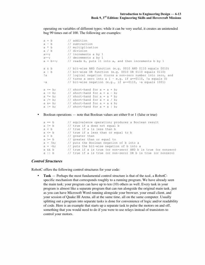
operating on variables of different types; while it can be very useful, it creates an unintendedbug 99 times out of 100. The following are examples:
a + b // additiona – b // subtractiona * b // multiplicationa / b // divisiona++; // increments a by 1a--; // decrements a by 1a = b++; // reads b, puts it into a, and then increments b by 1
a & b // bit-wise AND function (e.g. 0010 AND 0110 equals 0010)a | b // bit-wise OR function (e.g. 0010 OR 0110 equals 0110)!a // logical negation (turns a non-zero number into zero, and
// turns a zero into a 1 – e.g. if a==0110, !a equals 0)~a // bit-wise negation (e.g., if a==0110, ~a equals 1001)
a += b; // short-hand for a = a + b;a -= b; // short-hand for a = a – b;a *= b; // short-hand for a = a * b;a /= b; // short-hand for a = a / b;a &= b; // short-hand for a = a & b;a |= b; // short-hand for a = a | b;
• Boolean operations — note that Boolean values are either 0 or 1 (false or true)
a == b // equivalence operation; produces a Boolean resulta != b // true if a does not equal ba < b // true if a is less than ba <= b // true if a less than or equal to ba > b // greater thana >= b // greater than or equal toa = !b; // puts the Boolean negation of b into aa = ~b; // puts the bit-wise negation of b into aa && b // true if a is true (or non-zero) AND b is true (or nonzero)a || b // true if a is true (or non-zero) OR b is true (or nonzero)
Control Structures
RobotC offers the following control structures for your code:
• Task — Perhaps the most fundamental control structure is that of the task, a RobotC-specific mechanism that corresponds roughly to a running program. We have already seenthe main task; your program can have up to ten (10) others as well. Every task in yourprogram is almost like a separate program that can run alongside the original main task, justas you can have Microsoft Word running alongside your browser, your email client, andyour session of Quake III Arena, all at the same time, all on the same computer. Usuallysplitting out a program into separate tasks is done for convenience of logic and/or readabilityof code. Here is an example that starts up a separate task to pulse the motors on and off,something that you would need to do if you were to use relays instead of transistors tocontrol your motors.

6-14 — Chapter 6Building a Hovercraft Control System in ROBOTC
// global variables – necessary since we can’t pass args directly to tasksint motorA_power = 0;int motorB_power = 0;
// reads motorA_power power value and “stutters” the output to motorA// to approximate that power value -- loop 10 times per secondtask stutter_motorA(){
int mSec_on = motorA_power;int mSec_off = 100 – mSec_on;
// loops ten times a secondwhile (true) {
motor[motorA] = 100;wait1Msec(mSec_on);motor[motorA] = 0;wait1Msec(mSec_off);
}}
// reads motorB_power power value and “stutters” the output to motorB// to approximate that power value -- loop 10 times per secondtask stutter_motorB(){
int mSec_on = motorB_power;int mSec_off = 100 – mSec_on;
// loops ten times a secondwhile (true) {
motor[motorB] = 100;wait1Msec(mSec_on);motor[motorB] = 0;wait1Msec(mSec_off);
}}
// assumes motorA is on left and motorB is on righttask main(){
// start them up just so we know it is safe to stop them latermotorA_power = 0;motorB_power = 0;StartTask(stutter_motorA);StartTask(stutter_motorB);

Introduction to Engineering Design — 6-15Book 9, 3rd Edition: Engineering Skills and Hovercraft Missions
while (true) {if (/* sensor readings tell us we should turn right*/) {
StopTask(stutter_motorA);StopTask(stutter_motorB);motorA_power = 100;motorB_power = 50;StartTask(stutter_motorA);StartTask(stutter_motorB);
} else if (/* sensor readings tell us we should turn left */) {StopTask(stutter_motorA);StopTask(stutter_motorB);motorA_power = 50;motorB_power = 100;StartTask(stutter_motorA);StartTask(stutter_motorB);
} else if (/* sensor readings tell us we should stop */) {StopTask(stutter_motorA);StopTask(stutter_motorB);motorA_power = 0;motorB_power = 0;StartTask(stutter_motorA);StartTask(stutter_motorB);
} else { // go forwardStopTask(stutter_motorA);StopTask(stutter_motorB);motorA_power = 75;motorB_power = 75;StartTask(stutter_motorA);StartTask(stutter_motorB);
}}
}
The main task starts up the tasks whenever it wants the thrust fans to go; the global valuesare used to indicate the desired power levels for the fans.
The responsibility of the tasks is to buffer the main task from having to stutter the motors(this is one way to effectively achieve a lower power level, which would be useful if you areusing relays and not transistors to control your fans). You can imagine how difficult it wouldbe if you had to intertwine into the main code loop the while(true) loops in the stuttertasks that implement the timed on/off behavior. It would be nasty-looking code, prone toexhibiting weird bugs, etc. The task allows the behavior to be consolidated in one place,where it can be shut off at will and from outside the task. Unfortunately, RobotC does notallow one to pass arguments directly to a task, thus the necessity of the motorX_powerglobal variables (which are a bit hack-ish).
We start the tasks with zero power levels at the beginning of the program (first actions of themain task); this is done in case trying to stop a non-existent task turns out to cause a run-timeerror (it may or may not; you might want to experiment to find out for yourself).
• Function — We have already seen functions in action. For instance, the StartTask andStopTask primitives are functions predefined by RobotC. You can also declare your ownfunctions. When invoked, functions are unlike tasks in that they do not become independententities. That is, when you call a function, it is as if you executed the function’s code inplace. The following erroneous code example illustrates:
6-16 — Chapter 6Building a Hovercraft Control System in ROBOTC
// takes as arguments the motor identifier and a power value and “stutters”// the output to approximate that power value -- loop 10 times per secondvoid stutter_motor(int whichMotor, int powerLevel){
int mSec_on = powerLevel;int mSec_off = 100 – mSec_on;
// loops ten times a secondwhile (true) {
motor[whichMotor] = 100;wait1Msec(mSec_on);motor[whichMotor] = 0;wait1Msec(mSec_off);
}return;
}
// assumes motorA is on left and motorB is on righttask main(){
while (true) {if (/* sensor readings tell us we should turn right*/) {
stutter_motor(motorA, 100);stutter_motor(motorB, 50);
} else if (/* sensor readings tell us we should turn left */) {stutter_motor(motorA, 50);stutter_motor(motorB, 100);
} else if (/* sensor readings tell us we should stop */) {motor[motorA] = 0;motor[motorB] = 0;
} else { // go forwardstutter_motor(motorA, 75);stutter_motor(motorB, 75);
}}
}
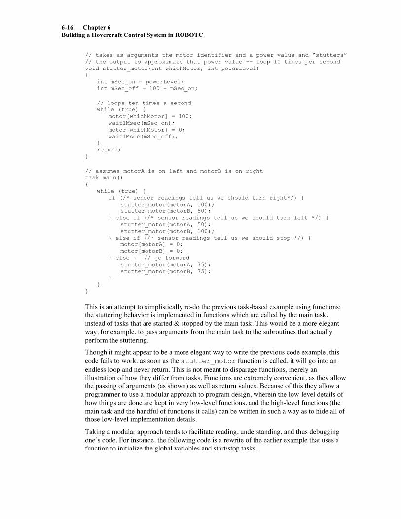
This is an attempt to simplistically re-do the previous task-based example using functions;the stuttering behavior is implemented in functions which are called by the main task,instead of tasks that are started & stopped by the main task. This would be a more elegantway, for example, to pass arguments from the main task to the subroutines that actuallyperform the stuttering.
Though it might appear to be a more elegant way to write the previous code example, thiscode fails to work: as soon as the stutter_motor function is called, it will go into anendless loop and never return. This is not meant to disparage functions, merely anillustration of how they differ from tasks. Functions are extremely convenient, as they allowthe passing of arguments (as shown) as well as return values. Because of this they allow aprogrammer to use a modular approach to program design, wherein the low-level details ofhow things are done are kept in very low-level functions, and the high-level functions (themain task and the handful of functions it calls) can be written in such a way as to hide all ofthose low-level implementation details.
Taking a modular approach tends to facilitate reading, understanding, and thus debuggingone’s code. For instance, the following code is a rewrite of the earlier example that uses afunction to initialize the global variables and start/stop tasks.

Introduction to Engineering Design — 6-17Book 9, 3rd Edition: Engineering Skills and Hovercraft Missions
// global variables – necessary since we can’t pass args directly to tasksint motorA_power = 0;int motorB_power = 0;
task stutter_motorA(){
// as before}
task stutter_motorB(){
// as before}
// takes as input power levels for motorA and motorBvoid run_motors(int mA, int mB){
StopTask(stutter_motorA);StopTask(stutter_motorB);motorA_power = mA;motorB_power = mB;StartTask(stutter_motorA);StartTask(stutter_motorB);return;
}
// assumes motorA is on left and motorB is on righttask main(){
// start them up just so we know it is safe to stop them latermotorA_power = 0;motorB_power = 0;StartTask(stutter_motorA);StartTask(stutter_motorB);
while (true) {if (/* sensor readings tell us we should turn right*/) {
run_motors(100, 50);} else if (/* sensor readings tell us we should turn left */) {
run_motors(50, 100);} else if (/* sensor readings tell us we should stop */) {
run_motors(0, 0);} else { // go forward
run_motors(75, 75);}
}}
This code should be much easier to read than the original example upon which it is based.This is the power of functions; whenever you see the same block of code happening over andover again, with only minor variations, that is a sure bet that you should encapsulate the codein a function call.
As mentioned, another aspect of functions is that they can return values, as in the followingcode example.

6-18 — Chapter 6Building a Hovercraft Control System in ROBOTC
const tSensors light1 = (tSensors) S1;const tSensors light2 = (tSensors) S2;const tSensors light3 = (tSensors) S3;const tSensors light4 = (tSensors) S4;
float get_sensor_avg(){
float avg;int sum = SensorValue(light1);
sum += SensorValue(light2);sum += SensorValue(light3);sum += SensorValue(light4);
avg = (float)sum;return avg / 4.0;
}
// prints out a new sensor reading every 0.1 secondtask main(){
while (true) {nxtDisplayTextLine(2, “Avg = %f”, get_sensor_avg());wait1Msec(100); // wait a tenth of a second
}}
Among other things, this code example illustrates the C-language notation for casting datatypes into other types, in particular how to create a floating-point number out of an integer.The (float) notation in front of the variable name sum near the end of the function tellsthe system to read the integer value of sum and then turn it into a floating-point numberbefore putting its value into the variable avg (which is a floating-point number).
• While loop — We have already seen the while loop in action. Formally, it takes as anargument a Boolean statement (something that evaluates to either true or false) andconditionally executes whatever code block comes after it. The important thing to rememberis this ordering: first the evaluation of the condition statement and then the execution of thefollowing code block. This happens repeatedly until the condition statement evaluates tofalse, at which point the NXT moves on to execute the instructions that come after the whileloop.
while (condition) {// code block to be executed (one or more instructions),// often called the “loop body”
}// following instructions
This produces a loop format, because the code block will be executed repeatedly until thecondition becomes false (the integer value 0). As soon as the condition evaluates to false, theNXT jumps to the “following instructions” after the loop body.
Note again that the condition test happens before the loop body; this means that it is possiblefor the loop body to be skipped, if for example on the first test of the condition it evaluates tofalse. Sometimes, this is not desired; sometimes a programmer might wish for the loop bodyto be executed at least once before evaluating the conditional value. This is what the do-while loop is for, described next.

Introduction to Engineering Design — 6-19Book 9, 3rd Edition: Engineering Skills and Hovercraft Missions
• Do-while loop — As mentioned above, sometimes a programmer needs a loop structure inwhich the loop body is executed at least once before evaluating the conditional value. Forthis, the do-while loop is used, as shown below.
do {// code block to be executed (one or more instructions),// often called the “loop body”
} while (condition);// following instructions
This structure is also a loop; the loop body will be executed repeatedly until the NXTevaluates the Boolean condition to false. The difference is that the loop body is guaranteedto be executed at least once, even if we know ahead of time that the condition is false, forinstance in the following (contrived) case:
do {// loop body
} while (false);
This will execute the loop body once, then test the conditional which is hard-coded to befalse; the condition will fail, and the loop will terminate, passing control to the followinginstructions.
One thing to note: the semicolon at the end of the while(); statement is required for ado-while loop.
• For loop — The for loop is generally used for iteration; it takes the following form:
for ( /*initialization*/ ; /*condition*/ ; /*update*/ ) {// loop body
}
The semicolons between the three components (initialization, condition, update) arerequired, even if a particular component is left blank. The components function as follows:
• initialization — This happens once, at the start of the loop, before the conditionevaluation. It is a good way to set up the variables that will be in use.
• condition — This is identical to the while-loop condition; it is evaluated before theloop body, so if it evaluates to false on the first pass, the loop body is neverexecuted.
• update — This is a statement that is executed after the loop body and before thenext evaluation of the condition statement.
Here is a typical use of the for loop:
int i, array[1024];
for (i=0; i<1024; i++) {array[i] = 0;
}
Note that the initialization and update components can have multiple statements, eachseparated by commas.

6-20 — Chapter 6Building a Hovercraft Control System in ROBOTC
• If/then/else — This control-flow structure was shown in an earlier code example. It allows aprogrammer to specify one or more code blocks, at most one of which will be executed,based on one or more conditionals.
A simple if-then example that executes the code body only if the sensor value satisfies someconditional, so the code body may or may not be exeucted:
if (SensorValue(mySensor) < 50) {// code body -- react to the sensor result
}
The following if-then-else example provides two options, one of which is guaranteed to beexecuted:
if (SensorValue(mySensor) < 50) {// turn left
} else {// turn right
}
Having a simple else statement at the end of an “if” construct is the default case; itspecifies code that will be executed if all other conditionals fail. The following is a morecomplex example:
int value = SensorValue(mySensor);if (value < 25) {
// turn left} else if (value < 50) {
// turn right} else if (value < 75) {
// go back} else {
// stop}
Note that later conditions in an if-else control block are tested only if all earlier ones fail, andlater conditions are not tested if an earlier test succeeds, so only one code block will execute,in particular the first to satisfy its corresponding condition. So the following would be anerror:
int value = SensorValue(mySensor);if (value < 25) {
// turn left} else if (value < 75) {
// go back} else if (value < 50) {
// turn right} else {
// stop}
The third condition will never succeed; any value greater than 25 and less than 50 will becaught by the second conditional. Note also that we read the sensor value only once and notmultiple times, which would have been the case, at least potentially, if we had placed theSensorValue(mySensor) function call in each of the conditionals.

Introduction to Engineering Design — 6-21Book 9, 3rd Edition: Engineering Skills and Hovercraft Missions
• Switch — If you have a control structure similar to the following, where your conditionalsare, for the most part, testing for equality as opposed to greater than/less than, you mightwant to use a switch statement:
int value = SensorValue(mySensor);if (value == 1) {
// turn left} else if (value == 2) {
// go back} else if (value == 3) {
// turn right} else if (value == 4) {
// spin around} else if (value == 5) {
// stop} else if (value == 6) {
// spin clockwise} else if (value == 7) {
// spin counterclockwise} else if (value == 0) {
// shut down} else {
// blink lights}
This type of construct can be difficult to read, and because it is difficult to read, it can harborlatent bugs easily. A better construct is the switch statement, which would implement theconstruct above as follows:
int value = SensorValue(mySensor);switch (value) {
case 1:// turn leftbreak;
case 2:// go backbreak;
case 3:// turn rightbreak;
case 4:// spin aroundbreak;
case 5:// stopbreak;
case 6:// spin clockwisebreak;
case 7:// spin counterclockwisebreak;
case 0:// shut downbreak;
default:// blink lights
}

6-22 — Chapter 6Building a Hovercraft Control System in ROBOTC
At the switch (value) statement, the value will be read once, and the NXT willimmediately jump to which ever code block has the corresponding value expressed with itscase statement. The default case is not required but is an extremely good idea to use,even if it is left empty by putting no code after it (perhaps include a comment to the effectthat the omission of corresponding code is intentional).
The various break; statements are required, except for the very last case in the list. If aparticular break; statement is omitted, the program will compile successfully, but at run-time the control flow will “fall through” from one case to the next.
• Continue and break in loops — There are two statements that provide extremely powerfulways to augment the behavior of loops. The continue statement causes a loop to halt mid-loop and go directly to the top of the loop. For example, here is its use in a while loop:
while (true) {int value = SensorValue(mySensor);if (value == 1) {
// turn left} else if (value == 2) {
// go back} else {
continue;}// blink lights// update state// etc.
}
In this example, the continue statement causes the execution of the code to skip over thestuff at the end of the loop (blink lights, update state, etc.) and go straight to the top of theloop, at which point the conditional is re-evaluated, and the sensor value is read.
A break statement similarly disrupts control flow, but it instead causes control to exit theloop entirely.
while (true) {int value = SensorValue(mySensor);if (value == 1) {
// turn left} else if (value == 2) {
// go back} else {
break;}// blink lights// update state// etc.
}
nxtDisplayTextLine(3, “Error situation”);
This example is just like the previous one, except that the continue statement is now a breakstatement. This is one way to exit a loop that would otherwise execute forever. It is usuallyused in loops to detect anomalous or erroneous situations; normal events should be reflectedin the while loop’s conditional.

Introduction to Engineering Design — 6-23Book 9, 3rd Edition: Engineering Skills and Hovercraft Missions
An additional note on loop and if/then conditionals: they are usually Boolean statements, statementsthat evaluate to either 0 (false) or 1 (true). Because a computer only understands numbers, these arerepresented with integers, which can have the value 2 or –37, or 1023, and so on. Thus, while it isbest practice to use code similar to this:
char x, array[1024];int i;
for (i=1023; i > 0; i--) {x = array[i];
}
it is just as valid to say the following (the only change to the code is that i > 0 has been replacedby simply i).
char x, array[1024];int i;
for (i=1023; i; i--) {x = array[i];
}
Why does this work? Because the NXT checks to see if the conditional is zero or non-zero; it doesnot do a strict test of 0 vs. 1. So any number other than 1 is considered equivalent to 1 for thepurposes of determining a Boolean result. As soon as the variable i reaches the value zero, both ofthese loops will terminate.
6.3 THE LEGO® NXT® CONTROLLERThe NXT incorporates a microprocessor capable of storing programs that provide instructions forcontrolling the fans and other actuators used in your team’s hovercraft. In this application, thecontrol of the fans was complicated by the need to steer the hovercraft and to control its speedparticularly around curves in the track. Moreover, the requirement is for autonomous control, whichimplies that the NXT must be programmed so that it provides command signals to the lift andpropulsion fans that enable the hovercraft to negotiate the track in the minimum possible time.
Decision based control requires sensors in the system that provide feedback signals, whichgive information essential in controlling the system. When the system is in operation, the sensorsprovide continuous signals that are monitored by the NXT. When the level of a feedback signaldeviates sufficiently from a specified level, the power to one or more actuators (fans) is adjusted tomaintain the sensor signal within a control band centered about the control level. For decision-basedcontrol to be effective, the microprocessor must be provided with instructions that establish the upperand lower levels of the control band. Sensor signals that are outside the control band cause thecontroller to energize actuators (fans), which adjust the parameters affecting the system so as tomaintain control. Programming for decision-based control is more challenging as the programentails a more structure involving forks, jumps and loops and sometimes loops within loops.
The NXT, shown in Fig. 6.7, is a controller that contains an Atmel ARM processor(AT91SAM7S256), which incorporates a high performance 32 bit RISC architecture. This processorcontains 256 Kbytes of flash memory (non-volatile) with single cycle access at 30MHz. It alsocontains an additional 64 Kbytes of SRAM (static random access memory). The ARM processor

6-24 — Chapter 6Building a Hovercraft Control System in ROBOTC
includes three different clocks to provide timing signals with frequencies that range from 22 to 42kHz for the slow clock and 80 to 220 MHz for the PLL clock.
Fig 6.7 The NXT controls theactions of autonomous robots and vehicles.The NXT also contains an 8-bit Atmel co-processor (ATmega48) that is used with the mainprocessor for measuring voltage and controlling actuators. This processor contains 4 Kbytes of flashmemory (non-volatile) with single cycle access at 30MHz. It also contains an additional 512 bytesof SRAM and 256 bytes of EEPROM memory. It has two 8-bit timer/counters, one 16-bittimer/counter and a real time counter. Voltage is measured with an eight channel 10 bit analog todigital converter (ADC). The 10-bit ADC in the NXT can acquire and store voltage measurements atfrequencies up to 200 Hz. Six pulse width modulated (PWM) channels are available in the co-processor for supplying power to the motors and actuators, although the NXT only uses three ofthese channels.
Communication between the NXT and a computer is accomplished with either a USB cableor by Bluetooth wireless connection (radio). A CSR BlueCore™ 4 single chip radio and base bandintegrated circuit is employed to implement a Bluetooth 2.4GHz system, which provides enhanceddata rates up to 3Mbps. The chip interfaces to 8Mbit of external flash memory and contains 47Kbytes of RAM. When used with the CSR Bluetooth software stack, it provides a fully compliantBluetooth system for data and voice communications. The BlueCore™ transmitter is powered by a6-bit digital-to-analog-converter with a dynamic range greater than 30 dB. Its receiver incorporateschannel filters and a digital demodulator for improved sensitivity and co-channel rejection. TheUSB 2.0 communication port is capable of 12 Mbits/s.
Four input ports
Operator buttons
Speaker
USB portThree outputports
LCD display

Introduction to Engineering Design — 6-25Book 9, 3rd Edition: Engineering Skills and Hovercraft Missions
The number of programs you can store in the NXT is only limited by the memory available.The NXT microprocessor can perform both integer and floating point (decimal) mathematics. Youcan program the NXT to read and write files to its memory.
Input Ports and Sensors
There are eight ports on the NXT. The four input ports are located on the base of the unit below thedisplay and control buttons, as shown in Fig. 6.7. These ports, numbered 1, 2, 3 and 4 are equippedwith a six wire interface that can receive both analog and digital signals from sensors. Instructions inthe LEGO User Guide for the NXT give the standard port locations for each of their sensors as:
Port 1: Touch sensorPort 2: Sound sensorPort 3: Light SensorPort 4: Ultrasound sensor
It is important to note that Port 4 is a high speed data connection that functions with an I2Ccommunication protocol, which is used with the LEGO ultrasonic sensor. The sensors are wired tothe input ports using the 6-wire industry standard RJ121 connector with right side adjustment.
Sensors are classified as either active or passive. The passive sensors do not require powerfrom the NXT to operate. The LEGO touch sensor, a simple momentary switch shown in Fig. 6.8,and the LEGO sound sensor, a microphone shown in Fig. 6.9, are examples of passive sensors. Onthe other hand, active sensors require power from the NXT tofunction. The LEGO light sensor, which contains a IR lightsource and a photodiode as shown in Fig. 6.10, is an example ofan active sensor. The LEGO ultrasonic sensor, shown in Fig.6.11, requires a communication channel to accommodate thetiming signals required when bursts of sound are transmitted andreceived.
Fig. 6.8 The LEGO touch sensor(a contact switch) is a passive
device that does not require powerto function.
Fig. 6.9 The LEGO sound sensor (a microphone) is a passive devicethat does not require power to function. It measures sound in
decibels (dB) or adjusted decibels (DbA).

6-26 — Chapter 6Building a Hovercraft Control System in ROBOTC
Fig. 6.10 The LEGO light sensor is an activedevice that requires power to light its IR source.Its readings range from 1 (dark) to 100 (bright).
Fig. 6.11 The LEGO ultrasonic (sonar) sensorrequires a communication channel to send and
receive signals in order to measure time for soundpropagation to and from a target.
Output Ports
The three output ports, located on the top edge of the NXT above the LCD, are labeled as A, B, andC. These ports are also equipped with a 6-wire interface to provide power (voltage pulses) tomotors, lights or sound making devices and to receive input from encoders that are installed in theLEGO servo motors. Instructions in the LEGO User Guide for the NXT give the standard portsettings for the motors as:
Poet A: Motor for additional functionPort B: Motor for movementPort C: Motor for movement
Each port may be operated in one of three modes—on, off and floating. When a port is programmedin the on mode, a motor or actuator connected to that port receives pulse width modulated power.When a port is programmed in the off mode, the motor actuator attached to that port is braked so itstops abruptly. When a port is programmed in the floating mode, a motor connected to that portdoes not receive power, but it is permitted to freewheel until it stops due to frictional forces.

Introduction to Engineering Design — 6-27Book 9, 3rd Edition: Engineering Skills and Hovercraft Missions
The LEGO servomotor, shown in Fig. 6.12, contains a small motor, gearing and an encoder.The gearing increases the torque of the motor but decreases its speed. The motor is equipped with anencoder that provides a signal which enablesmeasurement of the angle of rotation of themotor shaft to within ± 1°. Two of the sixwires in the standard RJ121 connector areused to connect the encoder signal to theNXT.
Fig. 6.12 The LEGO servomotor isconnected to the output ports.
Fig. 6.13 Sensors and motors arranged around the NXT controller.

6-28 — Chapter 6Building a Hovercraft Control System in ROBOTC
RCX motors and lights can be connected to the output ports of the NXT; however, anadapter cable is required to interface with its 6-wire RJ121 connector. In addition severalcompanies1 are producing special purpose sensors and output devices that are compatible with theNXT.
Communication with the NXT
Communication between the NXT and a computer is accomplished with either a USB cable or byBluetooth wireless connection (radio). A CSR BlueCore™ 4 single chip radio and base bandintegrated circuit is employed to implement a Bluetooth 2.4GHz system. This chip provides a fullycompliant Bluetooth system for data and voice communications at rates up to 3Mbps. The USB 2.0communication port is faster with a transfer rate of 12 Mbps.
The Controller Buttons and Display
Near the center of the NXT, you will notice a liquid crystal display (LCD) and four buttons as shownin Fig. 6.7 and Fig. 6.13. The square orange button performs three functions—turns the NXT on,enters (selects) the icon that appears in the lower center of the LCD window and runs the programselected. The two light-gray triangular buttons are used for menu navigation as they to move thevarious icons across the LCD window. The small dark gray rectangular button is used to cancel theselection or to go back. It is pressed repeatedly until the “Turn-off” icon appears. Pressing theorange button when this icon is centered in the LCD shuts down the NXT.
When the NXT is turned on a short tune is heard and three icons appear near the bottom ofthe LCD, which include the “My Files”, “NXT Program” and “Try Me” icons. These and othericons are defined in Fig. 6.14 to Fig. 6.17.The gray triangular button enables youmove progressively among the variousoptions available. The icon of interest iscentered in the display and it is selected bypressing the square orange button.
Fig. 6.14 The My Files icon and the threetypes of files that are options for storage in
the NXT.
Storing Programs
The NXT stores three different types of programs as indicated in Fig. 6.14, which include soundfiles, software files and NXT files. Programs written on a computer are downloaded into “softwarefiles” and songs written on a computer are downloaded into “sound files’. Programs written directlyon the NXT without using a computer are stored in the “NXT files”. The NXT Program icon thatprovides entry into a large number of commands available within the NXT is presented in Fig. 6.15.The programs written on a computer are downloaded to the NXT by a USB cable connected to a 1 These companies include: www.mindsensors.com; www.techno-stuff.com; www.hitechnic.com; andwww.Imsensors.com.

Introduction to Engineering Design — 6-29Book 9, 3rd Edition: Engineering Skills and Hovercraft Missions
computer’s serial port. The NXT can also send and receive signals with its Blue tooth technology.When a program is successfully downloaded, the NXT responds with a burst of sound confirming itstransmission.
Fig. 6.15 The NXT program icon that enables programming to beperformed directly on the controller.
The signals from the sensors are monitored by selecting the “View” icon that is accessed on the LCDby repeatedly pressing the triangular gray button. After the “View” icon is selected you have achoice of monitoring the signalfrom a large number of differentLEGO sensors as indicated inFig. 6.16. If a sensor is wired toa port, its output can bemonitored on the LCDindependent of a programrunning. In this sense, the NXTis functioning as a digitalmultimeter with its outputconverted to the units ofmeasurement for the sensorinvolved.
Fig. 6.16 The View iconenables measurements from theLEGO sensors to be monitored
on the NXT display.

6-30 — Chapter 6Building a Hovercraft Control System in ROBOTC
When a program is running, the output from the sensors connected to the four ports isdisplayed in a listing that is shown continuously on the LCD. The NXT display also shows theoutput of its internal clock in hour, minute, second and tenth of a second running time for theprogram. Turning the NXT does not reset its internal clock and the time displayed is cumulative fora given program.
Fig. 6.17 The Bluetooth, Settings and Try Me iconsthat enable communication, NXT adjustments and a
simple trial program.
The Bluetooth, Settings and Try Me icons are defined in Fig. 6.17. The Bluetooth iconprovides access to several icons not presented in Fig. 6.17, which include Contacts, Connections,Search, On/Off and Visibility. The Settings icon enables access to Volume, Sleep and Deleting files.The Try Me icon issues a burst of sound when it is selected.