Embed Size (px)
Citation preview
School of Electrical Engineering and Telecommunications
UNSW
Copyright ©
1
16/04/2017 Tim Moors
Buffering
97518P
School of Electrical Engineering and Telecommunications
UNSW
Copyright ©
2
16/04/2017 Tim Moors
Outline
Should a switch buffer?:
Reasons for buffering
Goals for buffering
Forwarding modes Store-and-forward Cut-through
How to buffer Memory technologies FIFOs, Where to buffer
prioritised queues, per-flow queueing
What if the buffer overflows?
[Background: Congestion]
Discard policies
Early and Explicit Congestion Notification (separate set of slides)
9751KR
School of Electrical Engineering and Telecommunications
UNSW
Copyright ©
3
16/04/2017 Tim Moors
Resources
Buffering: Keshav § 8.5
Varghese § 9.1 (end-systems)
G. Appenzeller, I. Keslassy and N. McKeown: 'Sizing router buffers', Proc. SIGCOMM, pp. 281-92
Memory technologies: Varghese pp. 440-1
Random Early Detection: • Varghese § 14.2 • Keshav § 9.7.3 • RFC: 2309
Explicit Congestion Notification†: • Keshav § 13.4.9 • RFC 3168
† Known as Explicit Forward Congestion Indication (EFCI) in ATM,
Forward ECN (FECN) in Frame Relay. 9751V1
School of Electrical Engineering and Telecommunications
UNSW
Copyright ©
Background
• statistical multiplexing (slides 6-8) we'll see how this relates
to buffer utilisation)
• Ethernet frame format, CRC, minimum & maximum frame
length (slides 13-14 and 20)
• IPv4 header checksums (slide 8), application reliability
requirements (slide 13), reliability bit in IP TOS field (DSCP)
(slides 6-7), IP fragmentation & reassembly
• loss from being late in multimedia playback (slides 5-11)
• definition and consequences of congestion, TCP congestion
control (in particular multiplicative decrease after loss), Slow
Start, TCP header flags (slide 10)
• and an introduction to ECN which we'll cover in more depth
4
16/04/2017 Tim Moors 9751!!!

School of Electrical Engineering and Telecommunications
UNSW
Copyright ©
Cisco Nexus context
Yes this text is tiny: This lecture is highly relevant to the Cisco Nexus! • “The cut-through switching … enables the product to offer a low latency …which remains constant
regardless of the size of the packet being switched” / “In the cut-through switching mode, packets that
exceed the MTU value are truncated. In the store and forwarding mode, MTU violations lead to
packet drop.”
• “there are four fabric buffers with 10,240 bytes of memory buffer per egress port.”
• “The buffering strategy on the UPC includes ingress and egress buffers from the pool of 640 KB of
memory. Ingress buffering constitutes the majority of the buffering needs”
• “Each system class has an independent buffer allocation, … independent drop behavior” / “For the
drop system class, the buffer management module starts to drop the packets when the maximum
buffer size allocated for the system class is reached.”
• “uses input queuing system … The architecture implements both ingress and egress queues. On
ingress, VOQs are used to eliminate head-of-line blocking so that a congested egress port …does not
affect any other … For each ingress interface of the Cisco Nexus 5500 platform, there are 8 VOQs per
egress port”
• “ECN … The Cisco Nexus 5500 platform can set a mark in the IP header, instead of dropping a
packet, to signal impending congestion.”
5
16/04/2017 Tim Moors 9751MC*
School of Electrical Engineering and Telecommunications
UNSW
Copyright ©
Links
• Switches maintain packet integrity <6Q] by checking
CRC between store (in buffer)-and-forward
• Packet length optimisation <60] forces segmentation &
reassembly => partial packet discard.
• Shared memory fabrics <2X] (packet or TSI): buffer is
central
• Crossbar
• Uses output port buffers <5D]; Knockout reduces size/speed
• with arbiter <ZP] uses Virtual Output Queues @ inputs
• Optical networks: Buffering is hard. Serial buffering with
fibre loop. <NG]
6
16/04/2017 Tim Moors 9751J9
School of Electrical Engineering and Telecommunications
UNSW
Copyright ©
7
16/04/2017 Tim Moors
Reasons for switch buffering
To gain time: hold packets while doing things such as classification or checking integrity
To avoid packet loss, during times of: • Contention: Competition for the same output. Only one packet can go
out at a time; others must be buffered (or deflected <N6]).
• Short-term overload (congestion): Input rate exceeds output rate; need to buffer some inputs so that they can go out later. Buffering can only accommodate short-term overload.
In the long term, real buffers (of finite size) will overflow.
For switching: • Buffers are central to shared-memory switches • Reordering
• e.g. to achieve TSI switching • after mis-sequencing in the fabric (e.g. recirculating Banyan)
To reduce burstiness: To prevent overload downstream.
9751RU

School of Electrical Engineering and Telecommunications
UNSW
Copyright ©
8
16/04/2017 Tim Moors
Goals for buffering
• Low chance of loss from overflow
• Small buffers
• Delay
• Implementation cost
• Simple (e.g. prefer FIFO)
• Preserve modularity from layering
• c.f. Cut-through routers [YW> and RED [FL>
9751Y8

School of Electrical Engineering and Telecommunications
UNSW
Copyright ©
9
16/04/2017 Tim Moors
Review: Statistical Multiplexing
Slide from Nick McKeown, based on animations from http://yuba.stanford.edu/~appenz/animations.html
Observations
1. The bigger the buffer, the lower the packet loss.
2. If the buffer never goes empty, the outgoing line
is busy 100% of the time.
975165

School of Electrical Engineering and Telecommunications
UNSW
Copyright ©
10
16/04/2017 Tim Moors
Example
• 10Gb/s linecard
• Rule-of-thumb: 250ms of buffering (RTT)
• Requires 300Mbytes of buffering.
• Read and write 40 byte packet every 32ns.
• Memory technologies
• SRAM: require 80 devices, 1kW, $2000.
• DRAM: require 4 devices, but too slow.
• Problem gets harder at 40Gb/s
Slide from Nick McKeown 9751ZZ
School of Electrical Engineering and Telecommunications
UNSW
Copyright ©
11
16/04/2017 Tim Moors
Outline
• Forwarding modes
• Basics:
• Store-and-forward
• Cut-through
• Details
9751FF
School of Electrical Engineering and Telecommunications
UNSW
Copyright ©
12
16/04/2017 Tim Moors
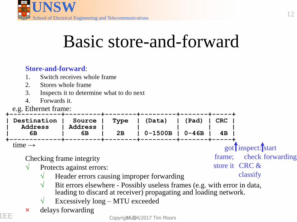
Basic store-and-forward
Store-and-forward: 1. Switch receives whole frame
2. Stores whole frame
3. Inspects it to determine what to do next
4. Forwards it.
Checking frame integrity
√ Protects against errors:
√ Header errors causing improper forwarding
√ Bit errors elsewhere - Possibly useless frames (e.g. with error in data, leading to discard at receiver) propagating and loading network.
√ Excessively long – MTU exceeded
× delays forwarding
+-------------+---------+--------+---------+-------+-----+ | Destination | Source | Type | (Data) | (Pad) | CRC | | Address | Address | | | | | | 6B | 6B | 2B | 0-1500B | 0-46B | 4B | +-------------+---------+--------+---------+-------+-----+
start
forwarding
inspect:
check
CRC &
classify
got
frame;
store it
e.g. Ethernet frame:
time →
9751EE
School of Electrical Engineering and Telecommunications
UNSW
Copyright ©
13
16/04/2017 Tim Moors
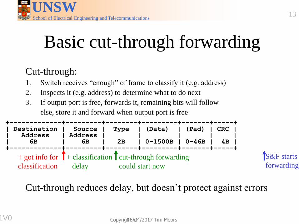
Basic cut-through forwarding
Cut-through: 1. Switch receives “enough” of frame to classify it (e.g. address)
2. Inspects it (e.g. address) to determine what to do next
3. If output port is free, forwards it, remaining bits will follow
else, store it and forward when output port is free
Cut-through reduces delay, but doesn’t protect against errors
+-------------+---------+--------+---------+-------+-----+ | Destination | Source | Type | (Data) | (Pad) | CRC | | Address | Address | | | | | | 6B | 6B | 2B | 0-1500B | 0-46B | 4B | +-------------+---------+--------+---------+-------+-----+
+ classification
delay
cut-through forwarding
could start now
+ got info for
classification
S&F starts
forwarding
9751V0
School of Electrical Engineering and Telecommunications
UNSW
Copyright ©
14
16/04/2017 Tim Moors
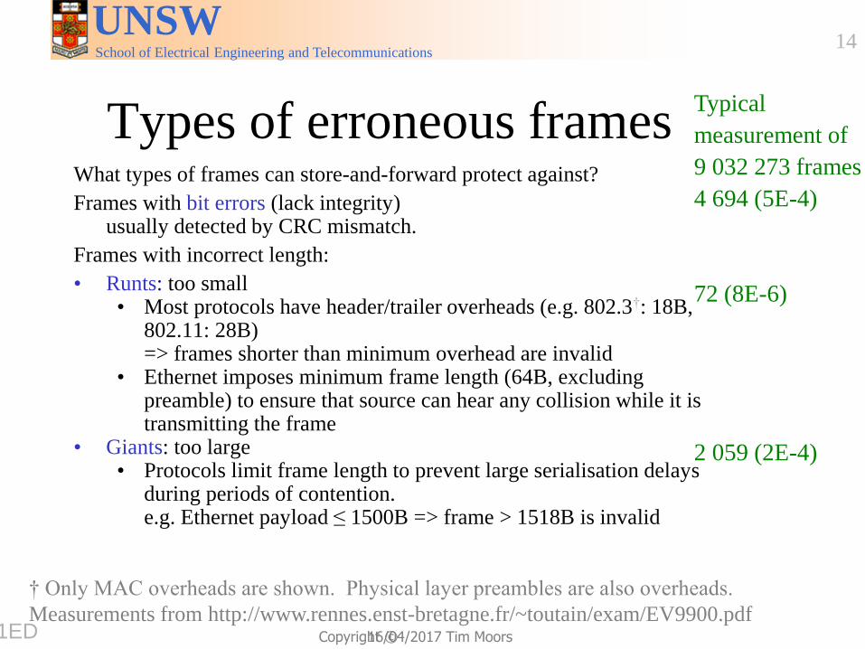
Types of erroneous frames What types of frames can store-and-forward protect against?
Frames with bit errors (lack integrity) usually detected by CRC mismatch.
Frames with incorrect length:
• Runts: too small • Most protocols have header/trailer overheads (e.g. 802.3†: 18B,
802.11: 28B) => frames shorter than minimum overhead are invalid
• Ethernet imposes minimum frame length (64B, excluding preamble) to ensure that source can hear any collision while it is transmitting the frame
• Giants: too large • Protocols limit frame length to prevent large serialisation delays
during periods of contention. e.g. Ethernet payload ≤ 1500B => frame > 1518B is invalid
Typical
measurement of
9 032 273 frames
4 694 (5E-4)
72 (8E-6)
2 059 (2E-4)
† Only MAC overheads are shown. Physical layer preambles are also overheads.
Measurements from http://www.rennes.enst-bretagne.fr/~toutain/exam/EV9900.pdf 9751ED
School of Electrical Engineering and Telecommunications
UNSW
Copyright ©
15
16/04/2017 Tim Moors
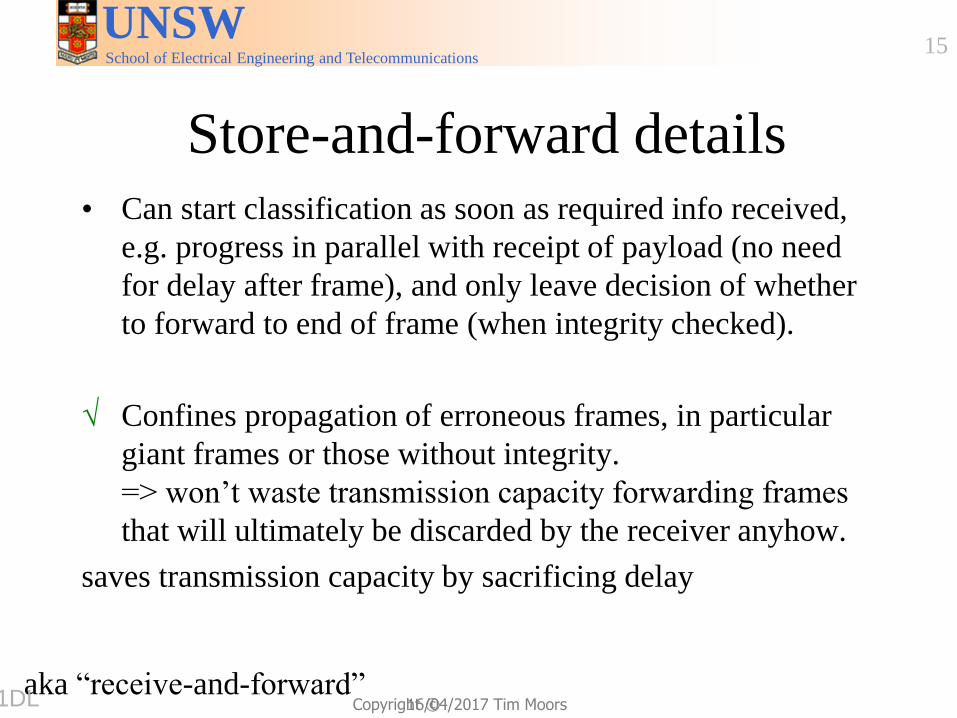
Store-and-forward details • Can start classification as soon as required info received,
e.g. progress in parallel with receipt of payload (no need
for delay after frame), and only leave decision of whether
to forward to end of frame (when integrity checked).
√ Confines propagation of erroneous frames, in particular
giant frames or those without integrity.
=> won’t waste transmission capacity forwarding frames
that will ultimately be discarded by the receiver anyhow.
saves transmission capacity by sacrificing delay
aka “receive-and-forward” 9751DL
School of Electrical Engineering and Telecommunications
UNSW
Copyright ©
16
16/04/2017 Tim Moors
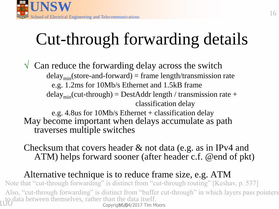
Cut-through forwarding details
√ Can reduce the forwarding delay across the switch delaymin(store-and-forward) = frame length/transmission rate
e.g. 1.2ms for 10Mb/s Ethernet and 1.5kB frame
delaymin(cut-through) = DestAddr length / transmission rate +
classification delay
e.g. 4.8us for 10Mb/s Ethernet + classification delay May become important when delays accumulate as path
traverses multiple switches Checksum that covers header & not data (e.g. as in IPv4 and
ATM) helps forward sooner (after header c.f. @end of pkt) Alternative technique is to reduce frame size, e.g. ATM
Note that “cut-through forwarding” is distinct from “cut-through routing” [Keshav, p. 537]
Also, “cut-through forwarding” is distinct from “buffer cut-through” in which layers pass pointers to data between themselves, rather than the data itself.
9751UU
School of Electrical Engineering and Telecommunications
UNSW
Copyright ©
17
16/04/2017 Tim Moors
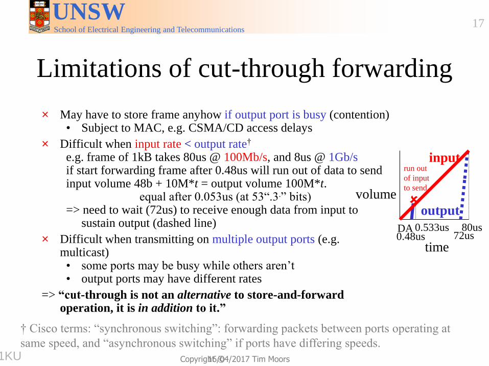
Limitations of cut-through forwarding
× May have to store frame anyhow if output port is busy (contention) • Subject to MAC, e.g. CSMA/CD access delays
× Difficult when input rate < output rate†
e.g. frame of 1kB takes 80us @ 100Mb/s, and 8us @ 1Gb/s if start forwarding frame after 0.48us will run out of data to send input volume 48b + 10M*t = output volume 100M*t. equal after 0.053us (at 53“.3.” bits) => need to wait (72us) to receive enough data from input to
sustain output (dashed line)
× Difficult when transmitting on multiple output ports (e.g. multicast) • some ports may be busy while others aren’t • output ports may have different rates
=> “cut-through is not an alternative to store-and-forward operation, it is in addition to it.”
input
output
DA 0.48us 72us
80us
run out
of input
to send
0.533us
† Cisco terms: “synchronous switching”: forwarding packets between ports operating at
same speed, and “asynchronous switching” if ports have differing speeds.
volume
time
9751KU
School of Electrical Engineering and Telecommunications
UNSW
Copyright ©
18
16/04/2017 Tim Moors
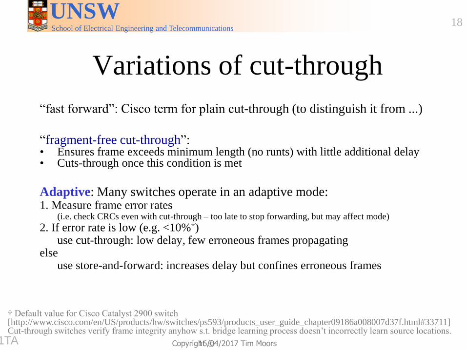
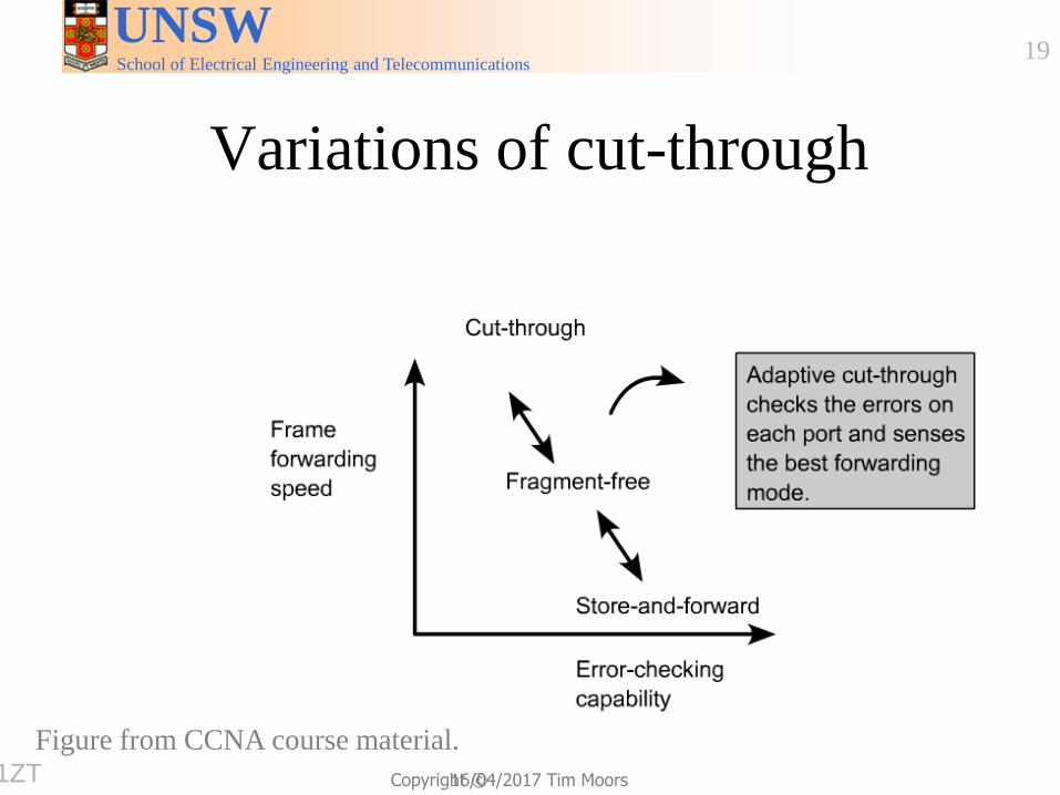
Variations of cut-through
“fast forward”: Cisco term for plain cut-through (to distinguish it from ...)
“fragment-free cut-through”: • Ensures frame exceeds minimum length (no runts) with little additional delay • Cuts-through once this condition is met
Adaptive: Many switches operate in an adaptive mode: 1. Measure frame error rates
(i.e. check CRCs even with cut-through – too late to stop forwarding, but may affect mode)
2. If error rate is low (e.g. <10%†) use cut-through: low delay, few erroneous frames propagating else use store-and-forward: increases delay but confines erroneous frames
† Default value for Cisco Catalyst 2900 switch [http://www.cisco.com/en/US/products/hw/switches/ps593/products_user_guide_chapter09186a008007d37f.html#33711] Cut-through switches verify frame integrity anyhow s.t. bridge learning process doesn’t incorrectly learn source locations.
9751TA
School of Electrical Engineering and Telecommunications
UNSW
Copyright ©
19
16/04/2017 Tim Moors
Variations of cut-through
Figure from CCNA course material. 9751ZT

School of Electrical Engineering and Telecommunications
UNSW
Copyright ©
20
16/04/2017 Tim Moors
Cut-through & layer of operation
Practice:
• Multi-layer switches may interpret higher layer fields before
completing low layer processing. e.g. frame switch may inspect IP address to determine outgoing port.
• Violates insulation benefits of layering, but provides marketing
advantage (network layer routing, without high delays).
“[Ethernet] Switches can cut-through, but routers can’t. So switches are faster”
Theory: Layers are separate, and higher layer doesn’t start processing incoming packet until lower layer has finished with it.
=> Interpretation of network layer (IP) fields can’t start until frame has been fully received and link layer has checked integrity.
9751YW
School of Electrical Engineering and Telecommunications
UNSW
Copyright ©
21
16/04/2017 Tim Moors
Summary of forwarding modes
Store-and-forward: • Receives whole frame before starting to forward it. • Checks integrity before forwarding.
• Can prevent erroneous frames being forwarded.
Cut-through:
• Can start forwarding as soon as packet classified and output is free
• Potentially low delay.
• May have to store-and-forward if output isn’t free.
• Checks integrity while forwarding.
• Can’t prevent erroneous frames being forwarded
• But can monitor error rate. Adaptive system will switch to store-
and-forward if past error rate is high.
97513V
School of Electrical Engineering and Telecommunications
UNSW
Copyright ©
22
16/04/2017 Tim Moors
Outline
9751EP
School of Electrical Engineering and Telecommunications
UNSW
Copyright ©
23
16/04/2017 Tim Moors
Basic memory device options
Want:
• Multiple ports (switch input and output); preferably concurrent access
• Fast I/O of frames (sequences of bits/words)
• Random access to some memory content (e.g. for switch to inspect address fields)
Multi-port memories
• Buffer (e.g. FIFO) devices, e.g. Dual-ported RAM
• Video RAM →
97510J
School of Electrical Engineering and Telecommunications
UNSW
Copyright ©
25
16/04/2017 Tim Moors
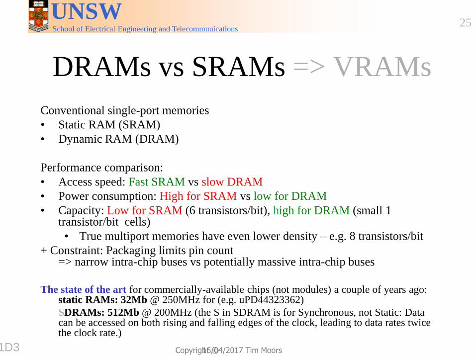
DRAMs vs SRAMs => VRAMs
Conventional single-port memories
• Static RAM (SRAM)
• Dynamic RAM (DRAM)
Performance comparison:
• Access speed: Fast SRAM vs slow DRAM
• Power consumption: High for SRAM vs low for DRAM
• Capacity: Low for SRAM (6 transistors/bit), high for DRAM (small 1 transistor/bit cells)
• True multiport memories have even lower density – e.g. 8 transistors/bit
+ Constraint: Packaging limits pin count => narrow intra-chip buses vs potentially massive intra-chip buses
The state of the art for commercially-available chips (not modules) a couple of years ago:
static RAMs: 32Mb @ 250MHz for (e.g. uPD44323362)
SDRAMs: 512Mb @ 200MHz (the S in SDRAM is for Synchronous, not Static: Data can be accessed on both rising and falling edges of the clock, leading to data rates twice the clock rate.)
9751D3

School of Electrical Engineering and Telecommunications
UNSW
Copyright ©
26
16/04/2017 Tim Moors
Video RAM
Consider old (pre-LCD) Cathode Ray Tube (CRT) displays in which a raster zig-zags across a screen, illuminating a series of pixels.
Video application needs:
• Multiport memory:
• 1 random-access port for CPU
• 1 serial port read to feed CRT
• Large size: 1024×768 pixels×16b = 12.6Mb
• High speed:12.6Mb@24 frames/sec=0.3Gb/s
Networking needs:
√ Multiport memory
√ Large size
√ High speed
97513K
School of Electrical Engineering and Telecommunications
UNSW
Copyright ©
27
16/04/2017 Tim Moors
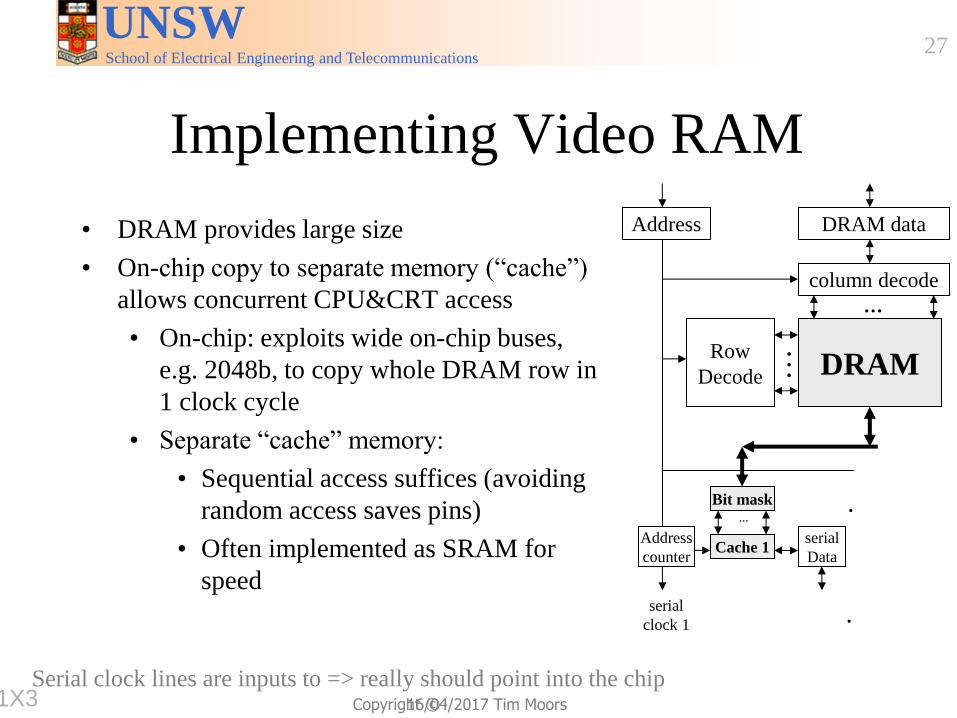
Implementing Video RAM
• DRAM provides large size
• On-chip copy to separate memory (“cache”)
allows concurrent CPU&CRT access
• On-chip: exploits wide on-chip buses,
e.g. 2048b, to copy whole DRAM row in
1 clock cycle
• Separate “cache” memory:
• Sequential access suffices (avoiding
random access saves pins)
• Often implemented as SRAM for
speed
DRAM
column decode
DRAM data
Row
Decode
Address
Bit mask
Address
counter Cache 1
serial
Data
serial
clock 1
…
…
Bit mask
Address
counter Cache n
serial
Data
serial
clock n
…
…
…
Serial clock lines are inputs to => really should point into the chip 9751X3
School of Electrical Engineering and Telecommunications
UNSW
Copyright ©
28
16/04/2017 Tim Moors
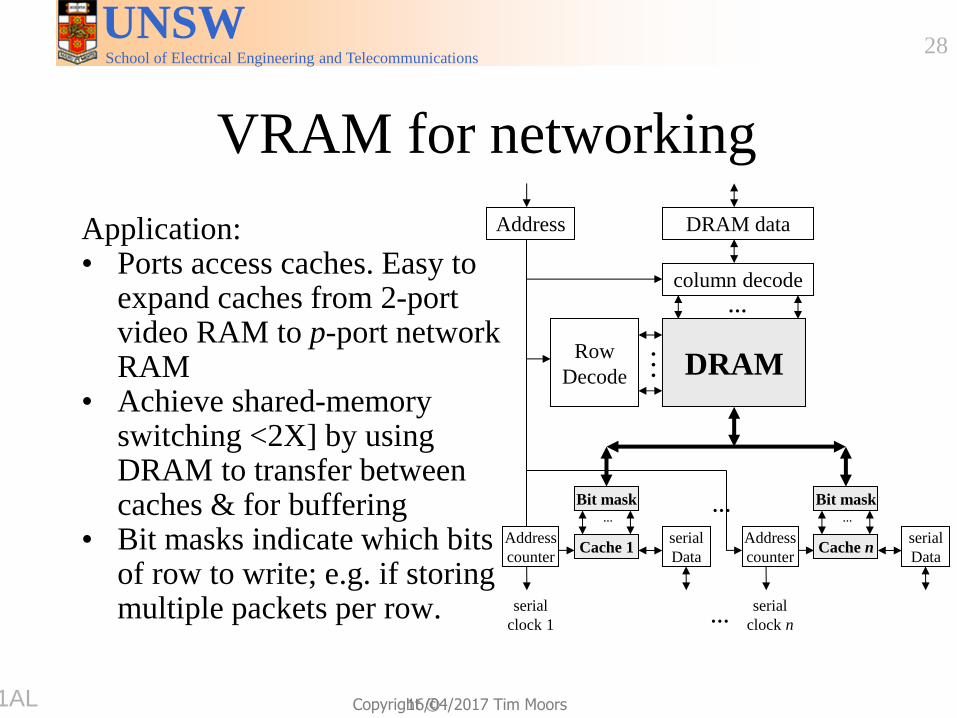
VRAM for networking
Application: • Ports access caches. Easy to
expand caches from 2-port video RAM to p-port network RAM
• Achieve shared-memory switching <2X] by using DRAM to transfer between caches & for buffering
• Bit masks indicate which bits of row to write; e.g. if storing multiple packets per row.
DRAM
column decode
DRAM data
Row
Decode
Address
Bit mask
Address
counter Cache 1
serial
Data
serial
clock 1
…
…
Bit mask
Address
counter Cache n
serial
Data
serial
clock n
…
…
…
9751AL

School of Electrical Engineering and Telecommunications
UNSW
Copyright ©
29
16/04/2017 Tim Moors
Example of a
VRAM switch:
IDT 77V400 chip
9751L4
SAM =
“Sequential
Access Memory =
“cache” earlier

School of Electrical Engineering and Telecommunications
UNSW
Copyright ©
30
16/04/2017 Tim Moors
Outline
• !!! Add photo that shows progression of
these ideas?
• Perhaps reorder a little?
• !!! Start by saying FIFO sre natural since
BYTES within a packet are treated FIFIO;
can that also be extended to FIFO of
PACKETS?
• !!!Recall lists of rules for packet
classification: sequential RAM addresses
<14L> like FIFO; linked lists like non-
FIFO?
9751AH
School of Electrical Engineering and Telecommunications
UNSW
Copyright ©
31
16/04/2017 Tim Moors
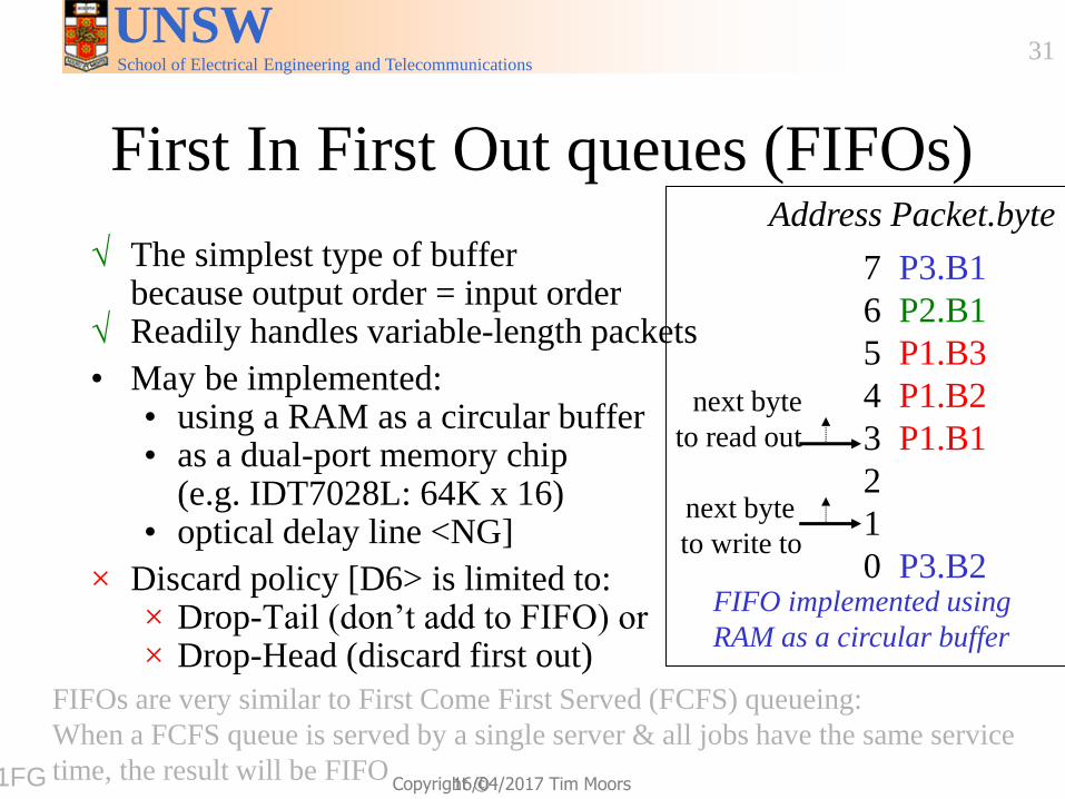
First In First Out queues (FIFOs)
√ The simplest type of buffer because output order = input order
√ Readily handles variable-length packets
• May be implemented: • using a RAM as a circular buffer • as a dual-port memory chip
(e.g. IDT7028L: 64K x 16) • optical delay line <NG]
× Discard policy [D6> is limited to: × Drop-Tail (don’t add to FIFO) or × Drop-Head (discard first out)
FIFOs are very similar to First Come First Served (FCFS) queueing:
When a FCFS queue is served by a single server & all jobs have the same service
time, the result will be FIFO
7 P3.B1
6 P2.B1
5 P1.B3
4 P1.B2
3 P1.B1
2
1
0 P3.B2
next byte
to read out
next byte
to write to
Address Packet.byte
FIFO implemented using
RAM as a circular buffer
9751FG
School of Electrical Engineering and Telecommunications
UNSW
Copyright ©
32
16/04/2017 Tim Moors
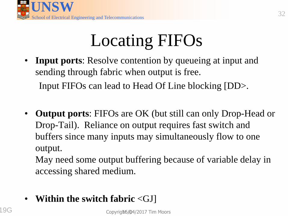
Locating FIFOs • Input ports: Resolve contention by queueing at input and
sending through fabric when output is free.
Input FIFOs can lead to Head Of Line blocking [DD>.
• Output ports: FIFOs are OK (but still can only Drop-Head or
Drop-Tail). Reliance on output requires fast switch and
buffers since many inputs may simultaneously flow to one
output.
May need some output buffering because of variable delay in
accessing shared medium.
• Within the switch fabric <GJ] 97519G
School of Electrical Engineering and Telecommunications
UNSW
Copyright ©
33
16/04/2017 Tim Moors
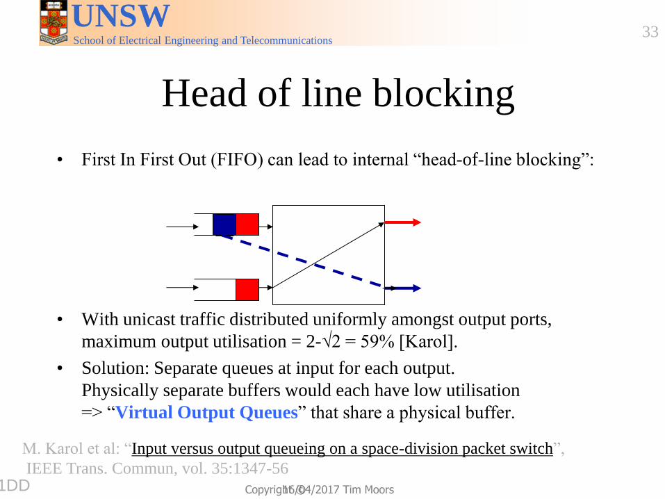
Head of line blocking
• First In First Out (FIFO) can lead to internal “head-of-line blocking”:
• With unicast traffic distributed uniformly amongst output ports,
maximum output utilisation = 2-√2 = 59% [Karol].
• Solution: Separate queues at input for each output.
Physically separate buffers would each have low utilisation
=> “Virtual Output Queues” that share a physical buffer.
M. Karol et al: “Input versus output queueing on a space-division packet switch”,
IEEE Trans. Commun, vol. 35:1347-56 9751DD
School of Electrical Engineering and Telecommunications
UNSW
Copyright ©
34
16/04/2017 Tim Moors
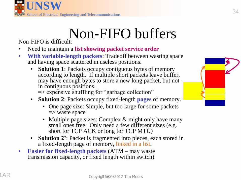
Non-FIFO buffers Non-FIFO is difficult:
• Need to maintain a list showing packet service order
• With variable-length packets: Tradeoff between wasting space and having space scattered in useless positions.
• Solution 1: Packets occupy contiguous bytes of memory according to length. If multiple short packets leave buffer, may have enough bytes to store a new long packet, but not in contiguous positions. => expensive shuffling for “garbage collection”
• Solution 2: Packets occupy fixed-length pages of memory.
• One page size: Simple, but too large for some packets => waste space
• Multiple page sizes: Complex & might only have many small ones free. Only need a few different sizes (e.g. short for TCP ACK or long for TCP MTU)
• Solution 2’: Packet is fragmented into pieces, each stored in a fixed-length page of memory, linked in a list.
• Easier for fixed-length packets (ATM – may waste transmission capacity, or fixed length within switch)
9751AR
School of Electrical Engineering and Telecommunications
UNSW
Copyright ©
35
16/04/2017 Tim Moors
Prioritized queues
Separate queues (e.g. linked lists) for different packets having different delay requirements, e.g. voice: high priority, file transfer low priority.
Service disciplines (see also next week):
• Preemptive: Empty high priority queue before serving low priority queue. New high priority arrivals preempt existing low priority jobs.
• Weighted: Serve high priority queue more often than low priority queue. High priority gets better service, but not exclusive service.
9751YL
Note that we are not considering “priority queues” here in the same sense as heap-
like data structures, but rather simple queues that are served in some prioritised
order.
School of Electrical Engineering and Telecommunications
UNSW
Copyright ©
36
16/04/2017 Tim Moors
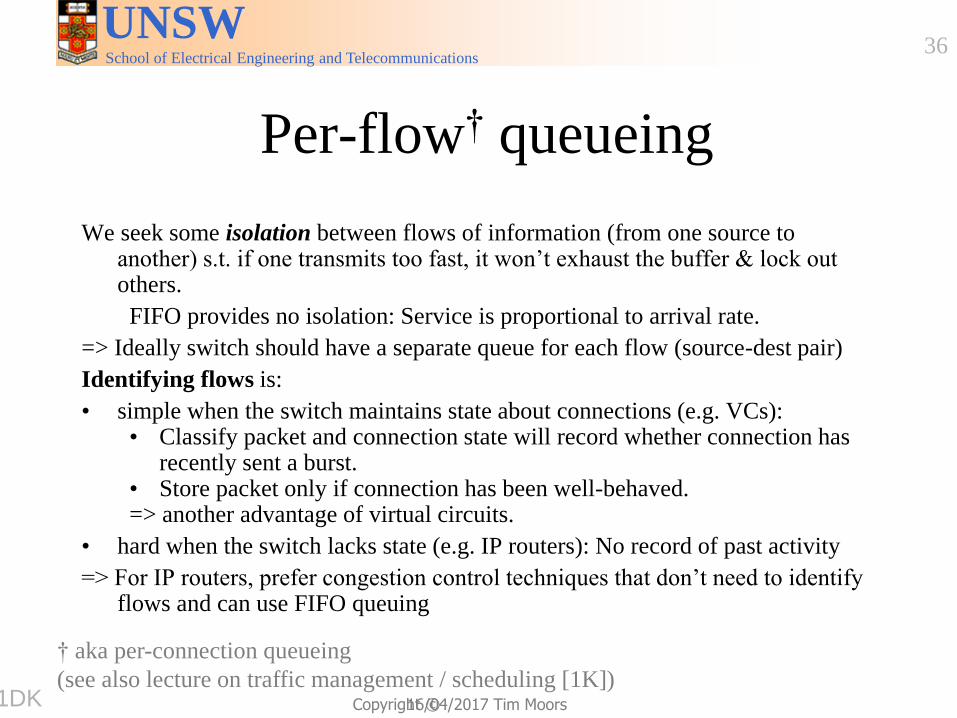
Per-flow† queueing
We seek some isolation between flows of information (from one source to another) s.t. if one transmits too fast, it won’t exhaust the buffer & lock out others.
FIFO provides no isolation: Service is proportional to arrival rate.
=> Ideally switch should have a separate queue for each flow (source-dest pair)
Identifying flows is:
• simple when the switch maintains state about connections (e.g. VCs): • Classify packet and connection state will record whether connection has
recently sent a burst. • Store packet only if connection has been well-behaved. => another advantage of virtual circuits.
• hard when the switch lacks state (e.g. IP routers): No record of past activity
=> For IP routers, prefer congestion control techniques that don’t need to identify flows and can use FIFO queuing
† aka per-connection queueing
(see also lecture on traffic management / scheduling [1K]) 9751DK

School of Electrical Engineering and Telecommunications
UNSW
Copyright ©
37
16/04/2017 Tim Moors
Outline
Discard policies/strategies (for when buffer is congested)
• According to position in queue
• Loss priorities (Reasons for varying priority discussed earlier <XN])
• Source marking
• Network marking (next week [FM>)
• Discarding when buffers aren’t full:
Partial Packet Discard
Early Packet Discard
Random Early Detection
Explicit Congestion Notification – an alternative to discard
try to manage congestion next
slide
set
9751D6

School of Electrical Engineering and Telecommunications
UNSW
Copyright ©
38
16/04/2017 Tim Moors
Discard strategies†
• Strategies can be applied
• to all packets (simple), or
• separately to packets from different flows
• harder, but won’t penalise well-behaved flows
• recall Per-flow queueing <DK]
• Strategies that exploit knowledge of higher layers risk
creating dependencies that impede modularity
• e.g. hard to introduce new transport protocol because
switches/routers assume older transport protocol
9751VJ † Aka “drop strategies”, e.g. in the Cisco Nexus switch white paper
School of Electrical Engineering and Telecommunications
UNSW
Copyright ©
39
16/04/2017 Tim Moors
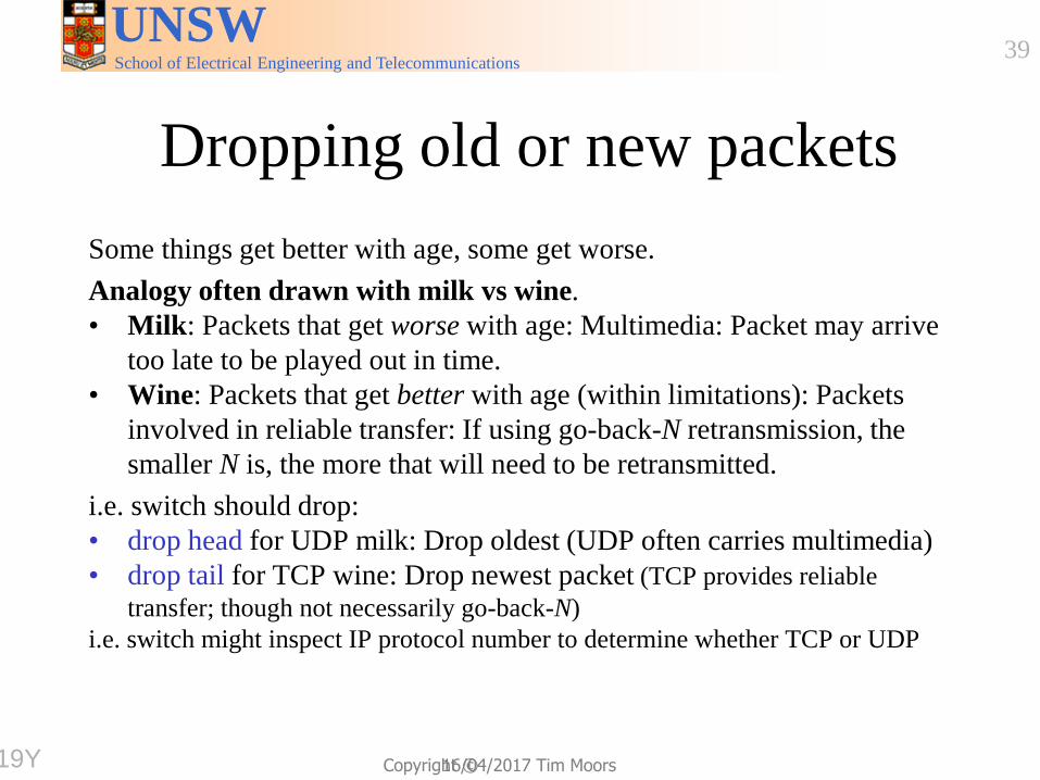
Dropping old or new packets
Some things get better with age, some get worse.
Analogy often drawn with milk vs wine.
• Milk: Packets that get worse with age: Multimedia: Packet may arrive
too late to be played out in time.
• Wine: Packets that get better with age (within limitations): Packets
involved in reliable transfer: If using go-back-N retransmission, the
smaller N is, the more that will need to be retransmitted.
i.e. switch should drop:
• drop head for UDP milk: Drop oldest (UDP often carries multimedia)
• drop tail for TCP wine: Drop newest packet (TCP provides reliable
transfer; though not necessarily go-back-N)
i.e. switch might inspect IP protocol number to determine whether TCP or UDP
97519Y

School of Electrical Engineering and Telecommunications
UNSW
Copyright ©
40
16/04/2017 Tim Moors
Tagging packets that may be lost
Source may transmit packets with varying loss requirements <XN]
e.g. lecture: loss(slide text)<loss(voice)<loss(video)
Source may tag packets to guide switches to discard least important
Network may tag packets according to compliance to permitted flow [J5]
ATM: Cell Loss Priority bit in cell header
IPv4: TOS (prior to Diffserv† reuse of this field)
IPv6: set the Traffic Class/Differentiated Services field to indicate the required per hop behaviour (drop priority)
+-+-+-+-+-+-+-+-+-+-+-+-+-+-+-+-+-+-+-+-+-+-+-+-+-+-+-+-+-+-+-+-+ |Version| IHL |Type of Service| Total Length | PRECE.D T R 0 0 +-+-+-+-+-+-+-+-+-+-+-+-+-+-+-+-+-+-+-+-+-+-+-+-+-+-+-+-+-+-+-+-+ | Identification |Flags| Fragment Offset | 0 DF MF +-+-+-+-+-+-+-+-+-+-+-+-+-+-+-+-+-+-+-+-+-+-+-+-+-+-+-+-+-+-+-+-+ | Time to Live | Protocol | Header Checksum | +-+-+-+-+-+-+-+-+-+-+-+-+-+-+-+-+-+-+-+-+-+-+-+-+-+-+-+-+-+-+-+-+ | Source Address | +-+-+-+-+-+-+-+-+-+-+-+-+-+-+-+-+-+-+-+-+-+-+-+-+-+-+-+-+-+-+-+-+ | Destination Address | +-+-+-+-+-+-+-+-+-+-+-+-+-+-+-+-+-+-+-+-+-+-+-+-+-+-+-+-+-+-+-+-+ | Options | Padding | +-+-+-+-+-+-+-+-+-+-+-+-+-+-+-+-+-+-+-+-+-+-+-+-+-+-+-+-+-+-+-+-+
R = reliability (1=lower loss, 0=higher loss)
9751YK † The Diffserv Assured Forwarding service uses 2 bits to indicate drop precedence [1YN>
School of Electrical Engineering and Telecommunications
UNSW
Copyright ©
41
16/04/2017 Tim Moors
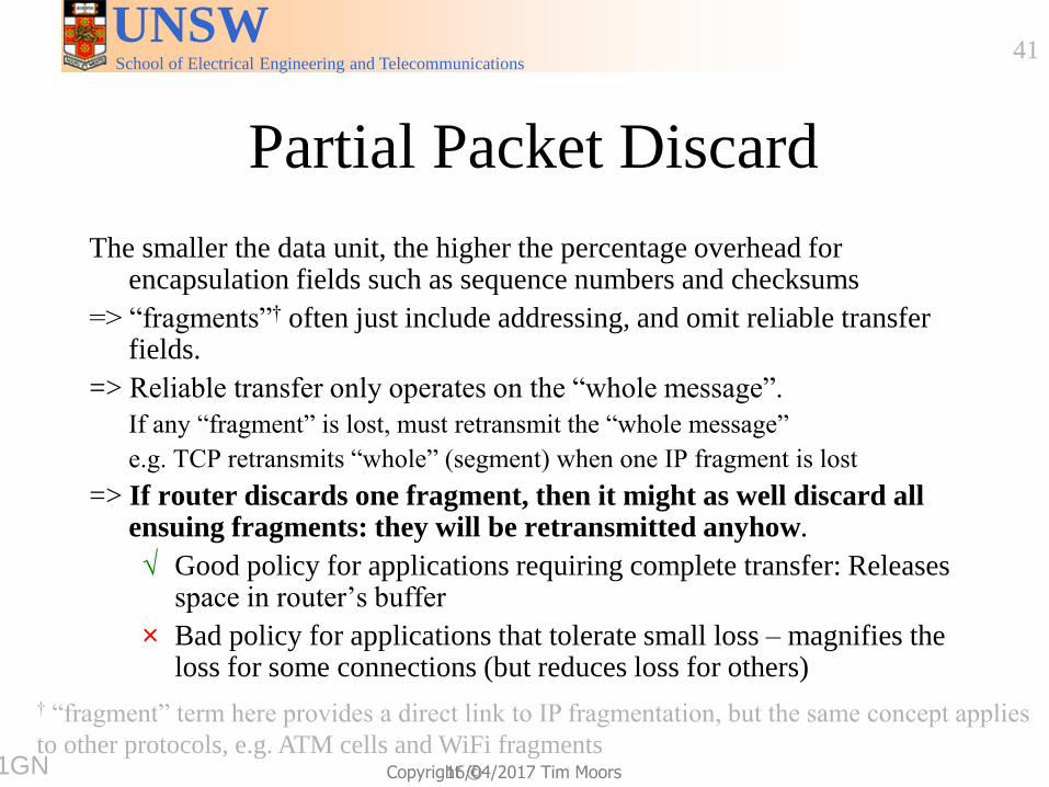
Partial Packet Discard
The smaller the data unit, the higher the percentage overhead for encapsulation fields such as sequence numbers and checksums
=> “fragments”† often just include addressing, and omit reliable transfer fields.
=> Reliable transfer only operates on the “whole message”.
If any “fragment” is lost, must retransmit the “whole message”
e.g. TCP retransmits “whole” (segment) when one IP fragment is lost
=> If router discards one fragment, then it might as well discard all ensuing fragments: they will be retransmitted anyhow.
√ Good policy for applications requiring complete transfer: Releases space in router’s buffer
× Bad policy for applications that tolerate small loss – magnifies the loss for some connections (but reduces loss for others)
9751GN
† “fragment” term here provides a direct link to IP fragmentation, but the same concept applies
to other protocols, e.g. ATM cells and WiFi fragments
School of Electrical Engineering and Telecommunications
UNSW
Copyright ©
42
16/04/2017 Tim Moors
Outline
• ECN continued in another slide set
9751RQ

School of Electrical Engineering and Telecommunications
UNSW
Copyright ©
Things to think about • Critical thinking: Which other Internet protocols should defend
against cheating participants, in the way that the relatively
modern ECN defends against receivers lying about congestion?
• Engineering methods:
• Hybrid systems are a common way to gain the benefits of
different technologies for different operating points (like
cut-through vs store-and-forward for different error rates).
• Like video RAM, which other technologies have been
invented for one application but are useful for others?
• Links to other areas: Consider how congestion is addressed in
other systems (e.g. vehicular transportation) and how
communication networks differ.
• Independent learning: Search for articles about “bufferbloat”
which encompasses the problems that arise from large buffers
Tele9751!!!!
2017 Tim Moors
43
School of Electrical Engineering and Telecommunications
UNSW
Copyright ©
44
16/04/2017 Tim Moors
Outline
• Background: Congestion
97519D
School of Electrical Engineering and Telecommunications
UNSW
Copyright ©
45
16/04/2017 Tim Moors
Congestion
T Fig. 5-25
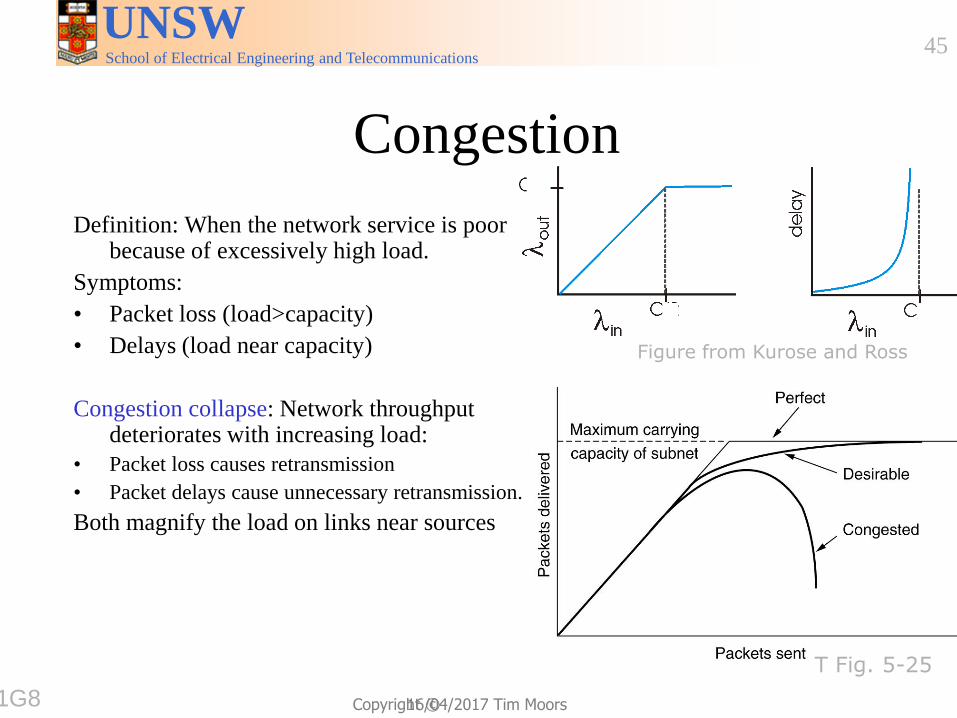
Figure from Kurose and Ross
Definition: When the network service is poor because of excessively high load.
Symptoms:
• Packet loss (load>capacity)
• Delays (load near capacity)
Congestion collapse: Network throughput deteriorates with increasing load:
• Packet loss causes retransmission
• Packet delays cause unnecessary retransmission.
Both magnify the load on links near sources
9751G8
School of Electrical Engineering and Telecommunications
UNSW
Copyright ©
46
16/04/2017 Tim Moors
Transmission Control Protocol
• TCP provides reliable unicast transfer for applications like
web and email access
• The early Internet lacked mechanisms to deal with
congestion, leading to episodes of congestion collapse in
the late 1980s.
• Too hard to change routers (often implemented in
hardware)
=> change TCP (implemented in software & BSD Unix was
widely used)
9751HQ
School of Electrical Engineering and Telecommunications
UNSW
Copyright ©
47
16/04/2017 Tim Moors
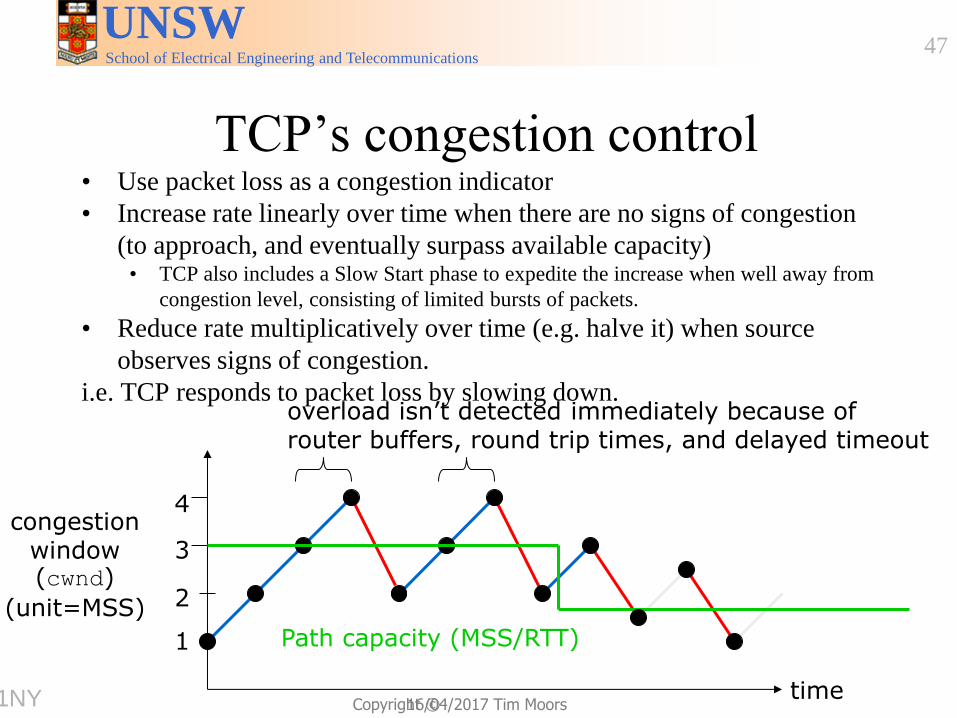
TCP’s congestion control • Use packet loss as a congestion indicator
• Increase rate linearly over time when there are no signs of congestion
(to approach, and eventually surpass available capacity) • TCP also includes a Slow Start phase to expedite the increase when well away from
congestion level, consisting of limited bursts of packets.
• Reduce rate multiplicatively over time (e.g. halve it) when source
observes signs of congestion.
i.e. TCP responds to packet loss by slowing down.
congestion window (cwnd)
(unit=MSS)
1
2
3
4
Path capacity (MSS/RTT)
overload isn’t detected immediately because of router buffers, round trip times, and delayed timeout
time 9751NY
School of Electrical Engineering and Telecommunications
UNSW
Copyright ©
48
16/04/2017 Tim Moors
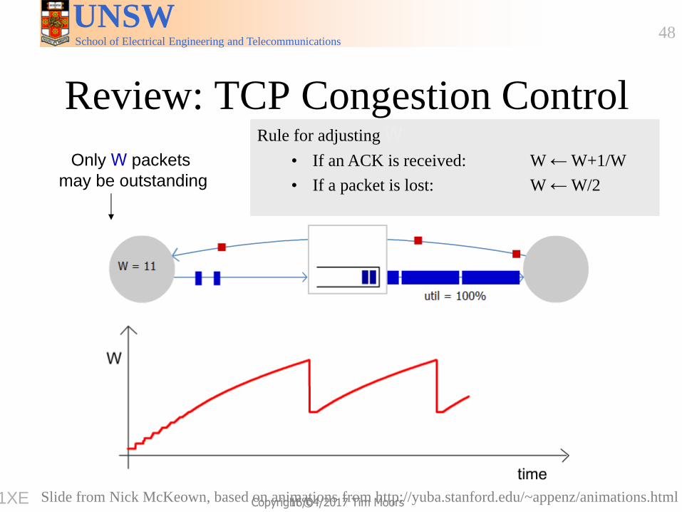
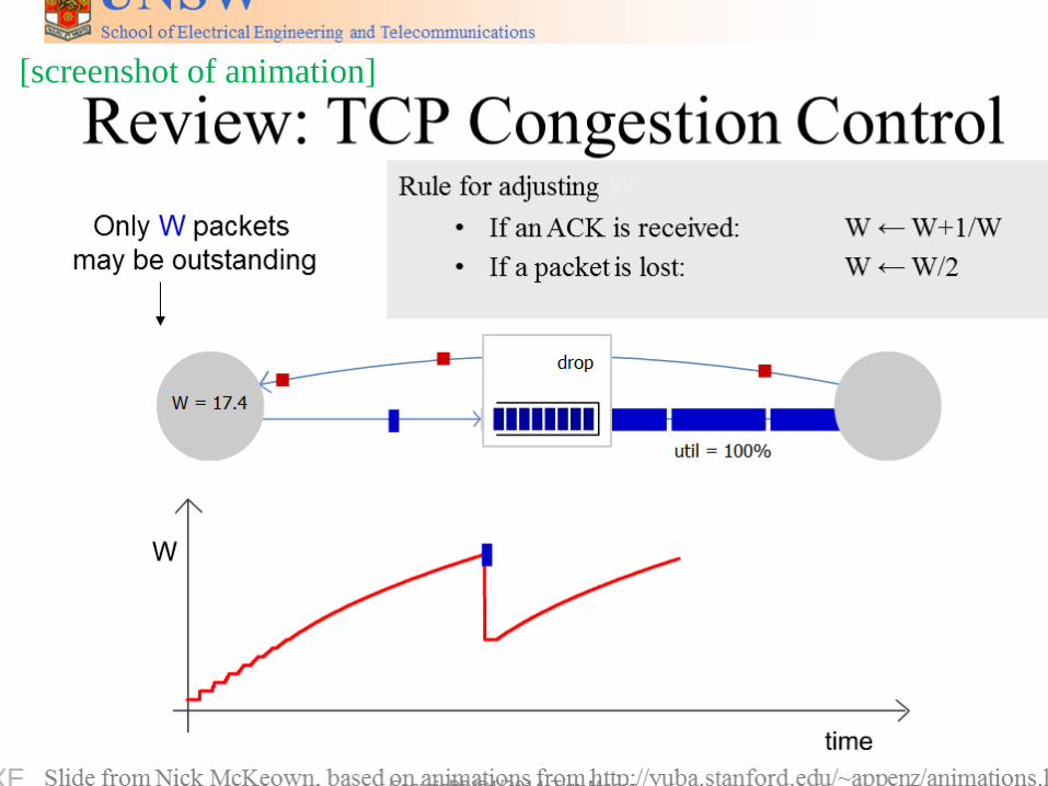
Review: TCP Congestion Control
Only W packets
may be outstanding
Rule for adjusting W
• If an ACK is received: W ← W+1/W
• If a packet is lost: W ← W/2
Slide from Nick McKeown, based on animations from http://yuba.stanford.edu/~appenz/animations.html 9751XE
School of Electrical Engineering and Telecommunications
UNSW
Copyright ©
49
16/04/2017 Tim Moors
[screenshot of animation]
School of Electrical Engineering and Telecommunications
UNSW
Copyright ©
50
16/04/2017 Tim Moors
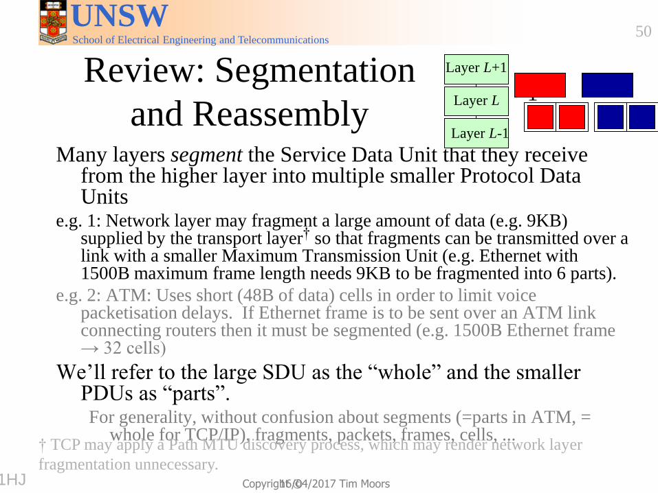
Review: Segmentation
and Reassembly Many layers segment the Service Data Unit that they receive
from the higher layer into multiple smaller Protocol Data Units
e.g. 1: Network layer may fragment a large amount of data (e.g. 9KB) supplied by the transport layer† so that fragments can be transmitted over a link with a smaller Maximum Transmission Unit (e.g. Ethernet with 1500B maximum frame length needs 9KB to be fragmented into 6 parts).
e.g. 2: ATM: Uses short (48B of data) cells in order to limit voice packetisation delays. If Ethernet frame is to be sent over an ATM link connecting routers then it must be segmented (e.g. 1500B Ethernet frame → 32 cells)
We’ll refer to the large SDU as the “whole” and the smaller PDUs as “parts”. For generality, without confusion about segments (=parts in ATM, =
whole for TCP/IP), fragments, packets, frames, cells, ... † TCP may apply a Path MTU discovery process, which may render network layer
fragmentation unnecessary.
1 2 Layer L
Layer L+1
Layer L-1
9751HJ