Embed Size (px)
DESCRIPTION
Huawei Material
Citation preview
Product Name Confidentiality Level
HUAWEI BTS3900&BTS3900A INTERNAL
Product Version
Total 129 pagesV100R008
BTS3900&BTS3900A IP Site&HDLC Site Deployment Guide
(For internal use only)
Prepared by G Transmission Team, Site Software Platform Development Department
Date 2009-07-20
Reviewed by Date
Approved by Date
Huawei Technologies Co., Ltd.All rights reserved
HUAWEI BTS3900&BTS3900A IP Site&HDLC Site Deployment Guide INTERNAL
HUAWEI GBTS3900&BTS3900A IP Site Deployment Guide
Keywords
GBTS3900, IP site, deployment
Abstract
This document describes the deployment of the BTS3900&BTS3900A IP site V100R008.
Acronyms and Abbreviations
Abbreviations
Explanation
BTS Base Transceiver Station
MS Mobile Station
BSC Base Station Controller
2023-4-19 Huawei Confidential Page 2 of 129
HUAWEI BTS3900&BTS3900A IP Site&HDLC Site Deployment Guide INTERNAL
Contents
1 Introduction to the GBTS3900 IP Site............................................131.1 HDLC Site.......................................................................................................................................................13
1.2 HDLC HUB Site..............................................................................................................................................14
1.3 IP Site...............................................................................................................................................................14
2 Networking Modes of IP Site.........................................................152.1 Concepts...........................................................................................................................................................15
2.1.1 IP Address and Mask..............................................................................................................................15
2.1.2 Route and Routing Table........................................................................................................................15
2.1.3 DHCP Relay...........................................................................................................................................16
2.2 Recommended Networking Scenarios.............................................................................................................16
2.2.1 Layer 3 Networking – Active Networking Mode...................................................................................17
2.2.2 Layer 2 Networking – Limited Standby Networking Mode...................................................................22
2.2.3 MSTP Application Scenarios..................................................................................................................25
2.2.4 PTN Equipment......................................................................................................................................27
2.3 Clock................................................................................................................................................................28
2.3.1 Setting the Clock Mode of a Site............................................................................................................28
2.3.2 Configuring the IP Clock Server............................................................................................................32
3 Hardware Installation and Data Configuration...............................353.1 Hardware Installation.......................................................................................................................................35
3.2 Adding an HDLC Site......................................................................................................................................35
3.2.1 Adding an HDLC Site on the BSC6000 LMT........................................................................................35
3.2.2 Configuring Hardware and the Transmission Network..........................................................................53
3.2.3 Upgrading a TDM Site on the Existing Network to an HDLC Site.......................................................54
3.3 Adding an HDLC HUB Site............................................................................................................................59
3.3.1 Adding an HDLC HUB Site on the BSC6000 LMT..............................................................................59
3.3.2 Configuring Hardware and the Transmission Network..........................................................................77
3.3.3 Upgrading a TDM Site on the Existing Network to an HDLC HUB Site..............................................78
3.4 Adding an IP Site.............................................................................................................................................83
3.4.1 Obtaining the Bar Code of a Site............................................................................................................83
3.4.2 Adding an IP Site on the BSC6000 LMT...............................................................................................84
3.4.3 Configuring the IP Clock Server..........................................................................................................109
3.4.4 Configuring Hardware and the Transmission Network........................................................................111
2023-4-19 Huawei Confidential Page 3 of 129
HUAWEI BTS3900&BTS3900A IP Site&HDLC Site Deployment Guide INTERNAL
3.4.5 Upgrading a TDM Site on the Existing Network to an IP Site.............................................................113
3.4.6 Switching an IP Site Back to a TDM Site............................................................................................121
4 Software Installation and Upgrade..............................................1254.1 Loading Software...........................................................................................................................................125
5 Troubleshooting.........................................................................1265.1 Basic Operations for Site Troubleshooting....................................................................................................126
5.1.1 Basic Operations for Troubleshooting an HDLC or HDLC HUB Site................................................126
5.1.2 Basic Operations for Troubleshooting an IP Site.................................................................................126
5.2 FAQ................................................................................................................................................................127
5.2.1 IP Site Problems...................................................................................................................................127
5.2.2 HDLC Site Problems............................................................................................................................127
6 Appendix...................................................................................1286.1 LEDs on the TMU Board...............................................................................................................................128
6.2 References......................................................................................................................................................129
2023-4-19 Huawei Confidential Page 4 of 129
HUAWEI BTS3900&BTS3900A IP Site&HDLC Site Deployment Guide INTERNAL
Figures
Figure 2-1 Network topology................................................................................................................................17
Figure 2-2 Network topology................................................................................................................................18
Figure 2-3 Layer 3 networking model..................................................................................................................20
Figure 2-4 Adding a route in layer 3 networking mode........................................................................................21
Figure 2-5 Network topology................................................................................................................................22
Figure 2-6 Layer 2 networking model..................................................................................................................24
Figure 2-7 Network topology................................................................................................................................25
Figure 2-8 Network topology................................................................................................................................26
Figure 2-9 PTN networking..................................................................................................................................28
Figure 2-10 Maintain Clock dialog box................................................................................................................29
Figure 2-11 Set Clock Information dialog box.....................................................................................................30
Figure 2-12 Site Attributes dialog box..................................................................................................................31
Figure 2-13 Set Clock Information dialog box.....................................................................................................32
Figure 2-14 Position of the clock server in a network..........................................................................................33
Figure 2-15 Configuring the clock on the BSC6000 LMT...................................................................................34
Figure 3-1 Adding a site........................................................................................................................................36
Figure 3-2 Add Site dialog box.............................................................................................................................36
Figure 3-3 Add New Site dialog box....................................................................................................................37
Figure 3-4 Add Cell dialog box.............................................................................................................................38
Figure 3-5 Add New Cell dialog box....................................................................................................................39
Figure 3-6 Configure Site Attributes dialog box...................................................................................................39
Figure 3-7 Adding the RXU chain........................................................................................................................40
Figure 3-8 Add RXU Chain dialog box................................................................................................................40
Figure 3-9 RXU chain added................................................................................................................................41
Figure 3-10 Adding the RXU................................................................................................................................41
Figure 3-11 Setting the RXU name and number...................................................................................................42
2023-4-19 Huawei Confidential Page 5 of 129
HUAWEI BTS3900&BTS3900A IP Site&HDLC Site Deployment Guide INTERNAL
Figure 3-12 Binding logical TRXs........................................................................................................................42
Figure 3-13 Assigning logical TRXs....................................................................................................................43
Figure 3-14 Configure Site Board Attributes tab page.........................................................................................43
Figure 3-15 Adding a cascaded GRFU.................................................................................................................44
Figure 3-16 Configuring a chain...........................................................................................................................45
Figure 3-17 Add or Delete Site Chain dialog box.................................................................................................45
Figure 3-18 Add Site Slave Chain dialog box.......................................................................................................46
Figure 3-19 Configuring cell attributes.................................................................................................................46
Figure 3-20 Set Cell Attributes dialog box...........................................................................................................47
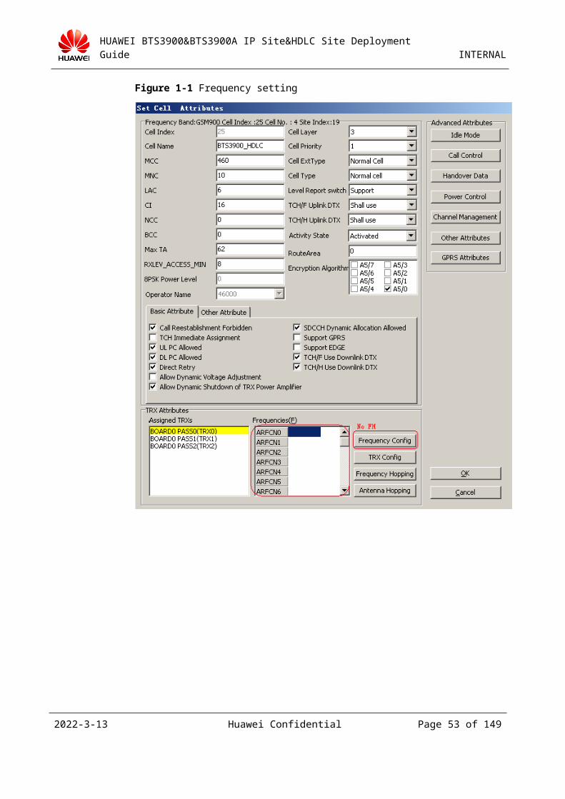
Figure 3-21 Frequency setting..............................................................................................................................48
Figure 3-22 Set Cell Frequency dialog box..........................................................................................................49
Figure 3-23 Frequency Attributes tab page...........................................................................................................50
Figure 3-24 Channel Attributes tab page..............................................................................................................51
Figure 3-25 Device Attributes tab page................................................................................................................51
Figure 3-26 Set Cell Attributes dialog box...........................................................................................................52
Figure 3-27 Completing the Add Site wizard.......................................................................................................53
Figure 3-28 Moving a site (1)...............................................................................................................................54
Figure 3-29 Moving a site (2)...............................................................................................................................55
Figure 3-30 Moving a site (3)...............................................................................................................................56
Figure 3-31 Choice Board&Port dialog box.........................................................................................................56
Figure 3-32 Moving a site (4)...............................................................................................................................57
Figure 3-33 Result of moving a site (1)................................................................................................................57
Figure 3-34 Result of moving a site (2)................................................................................................................58
Figure 3-35 Adding a site......................................................................................................................................59
Figure 3-36 Add Site dialog box...........................................................................................................................60
Figure 3-37 Add New Site dialog box..................................................................................................................61
Figure 3-38 Add Cell dialog box...........................................................................................................................62
Figure 3-39 Add New Cell dialog box..................................................................................................................62
Figure 3-40 Configure Site Attributes dialog box.................................................................................................63
Figure 3-41 Adding the RXU chain......................................................................................................................63
Figure 3-42 Add RXU Chain dialog box..............................................................................................................64
Figure 3-43 RXU chain added..............................................................................................................................64
Figure 3-44 Adding the RXU................................................................................................................................65
2023-4-19 Huawei Confidential Page 6 of 129
HUAWEI BTS3900&BTS3900A IP Site&HDLC Site Deployment Guide INTERNAL
Figure 3-45 Setting the RXU name and number...................................................................................................65
Figure 3-46 Binding logical TRXs........................................................................................................................66
Figure 3-47 Assigning logical TRXs....................................................................................................................66
Figure 3-48 Configure Site Board Attributes tab page.........................................................................................67
Figure 3-49 Adding a cascaded GRFU.................................................................................................................67
Figure 3-50 Configuring a chain...........................................................................................................................68
Figure 3-51 Add or Delete Site Chain dialog box.................................................................................................68
Figure 3-52 Add Site Slave Chain dialog box.......................................................................................................69
Figure 3-53 Configuring cell attributes.................................................................................................................69
Figure 3-54 Set Cell Attributes dialog box...........................................................................................................70
Figure 3-55 Frequency setting..............................................................................................................................71
Figure 3-56 Set Cell Frequency dialog box..........................................................................................................72
Figure 3-57 Frequency Attributes tab page...........................................................................................................73
Figure 3-58 Channel Attributes tab page..............................................................................................................74
Figure 3-59 Device Attributes tab page................................................................................................................75
Figure 3-60 Completing frequency settings of the cell.........................................................................................76
Figure 3-61 Completing the Add Site wizard.......................................................................................................77
Figure 3-62 Moving a site (1)...............................................................................................................................78
Figure 3-63 Moving a site (2)...............................................................................................................................79
Figure 3-64 Moving a site (3)...............................................................................................................................80
Figure 3-65 Choice Board&Port dialog box.........................................................................................................80
Figure 3-66 Moving a site (4)...............................................................................................................................81
Figure 3-67 Result of moving a site (1)................................................................................................................81
Figure 3-68 Result of moving a site (2)................................................................................................................82
Figure 3-69 Location of the bar code....................................................................................................................84
Figure 3-70 20-bit bar code...................................................................................................................................84
Figure 3-71 Setting the device IP address.............................................................................................................85
Figure 3-72 Adding a device IP address...............................................................................................................86
Figure 3-73 Setting port IP addresses...................................................................................................................86
Figure 3-74 Configure Ethernet Port IP dialog box..............................................................................................87
Figure 3-75 Setting the IP address for port 5........................................................................................................87
Figure 3-76 Configuring a BSC router.................................................................................................................88
Figure 3-77 BSC router.........................................................................................................................................89
2023-4-19 Huawei Confidential Page 7 of 129
HUAWEI BTS3900&BTS3900A IP Site&HDLC Site Deployment Guide INTERNAL
Figure 3-78 Adding a BSC router.........................................................................................................................89
Figure 3-79 Adding a site......................................................................................................................................90
Figure 3-80 Add Site dialog box...........................................................................................................................91
Figure 3-81 Add New Site dialog box..................................................................................................................92
Figure 3-82 Add Cell dialog box...........................................................................................................................93
Figure 3-83 Add New Cell dialog box..................................................................................................................93
Figure 3-84 Configure Site Attributes dialog box.................................................................................................94
Figure 3-85 Adding the RXU chain......................................................................................................................94
Figure 3-86 Add RXU Chain dialog box..............................................................................................................95
Figure 3-87 RXU chain added..............................................................................................................................95
Figure 3-88 Adding the GRFU..............................................................................................................................96
Figure 3-89 Setting the RXU name and number...................................................................................................96
Figure 3-90 Binding logical TRXs........................................................................................................................97
Figure 3-91 Binding logical TRXs........................................................................................................................97
Figure 3-92 Configure Site Board Attributes tab page.........................................................................................98
Figure 3-93 Adding a cascaded GRFU.................................................................................................................98
Figure 3-94 Setting an electronic label.................................................................................................................99
Figure 3-95 Setting a bar code of the electronic label..........................................................................................99
Figure 3-96 Setting parameters of the FE port....................................................................................................100
Figure 3-97 Configuring cell attributes...............................................................................................................101
Figure 3-98 Set Cell Attributes dialog box.........................................................................................................102
Figure 3-99 Frequency setting............................................................................................................................103
Figure 3-100 Set Cell Frequency dialog box......................................................................................................104
Figure 3-101 Frequency Attributes tab page.......................................................................................................105
Figure 3-102 Channel Attributes tab page..........................................................................................................106
Figure 3-103 Device Attributes tab page............................................................................................................107
Figure 3-104 Set Cell Attributes dialog box.......................................................................................................108
Figure 3-105 Completing the Add Site wizard...................................................................................................109
Figure 3-106 Position of the clock server in a network......................................................................................110
Figure 3-107 Configuring the clock on the BSC6000 LMT...............................................................................111
Figure 3-108 Ping connection.............................................................................................................................112
Figure 3-109 Setting the CRC4 check switch.....................................................................................................114
Figure 3-110 Moving a site (1)............................................................................................................................116
2023-4-19 Huawei Confidential Page 8 of 129
HUAWEI BTS3900&BTS3900A IP Site&HDLC Site Deployment Guide INTERNAL
Figure 3-111 Moving a site (2)............................................................................................................................117
Figure 3-112 Moving a site (3)............................................................................................................................118
Figure 3-113 Choice Board&Port dialog box.....................................................................................................118
Figure 3-114 Moving a site (4)............................................................................................................................119
Figure 3-115 Result of moving a site (1)............................................................................................................119
Figure 3-116 Result of moving a site (2)............................................................................................................120
Figure 3-117 Setting the CRC4 check switch.....................................................................................................121
Figure 3-118 Moving a site (1)...........................................................................................................................122
Figure 3-119 Moving a site (2)...........................................................................................................................122
Figure 3-120 Moving a site (3)...........................................................................................................................123
Figure 3-121 Choice Board&Port dialog box.....................................................................................................123
Figure 3-122 Moving a site (4)...........................................................................................................................124
2023-4-19 Huawei Confidential Page 9 of 129
HUAWEI BTS3900&BTS3900A IP Site&HDLC Site Deployment Guide INTERNAL
Tables
Table 3-1 Comparison between the port IP address and the device IP address.....................................................83
Table 3-2 Network planning in the lab..................................................................................................................84
2023-4-19 Huawei Confidential Page 11 of 129
HUAWEI BTS3900&BTS3900A IP Site&HDLC Site Deployment Guide INTERNAL
1 Introduction to the GBTS3900 IP
Site
The GBTS3900 IP site is different from the GBTS3900 TDM site. For details about the GBTS3900 TDM site, see its development guide.
1.1 HDLC SiteThe High level Data Link Control (HDLC) site is developed on the basis of the existing GBTS3900 Time Division Multiplexing (TDM) site. An HDLC site does not change a lot in the system architecture and division of subsystems. Only one new feature is added to optimize the transmission through the Abis interface.
Traditionally, the Abis interface works in TDM mode. Each service channel, radio signaling link (RSL), and operation and maintenance link (OML) are separately allocated by 16 K or 64 K sub-timeslot over E1. Even if no service is transmitted over the current service channel, the sub-timeslot allocated to it over E1 is still in use. Other service channels, RSLs, or OMLs cannot use the sub-timeslot. The introduction of the FlexAbis function helps to allocate the transmission resources over the Abis interface for service channels according to service requirements. When the current service channel is idle, the Abis interface does not allocate Abis transmission resources to it. This realizes time-based multiplexing of the Abis transmission resources. The prerequisite of the multiplexing is that some service channels are idle in different cells or sites.
The function of Abis transmission optimization over the Abis interface achieves the multiplexing of transmission resources through HDLC. The function increases the number of transceivers (TRXs) over each E1. Each E1 supports up to 24 TRXs. (There are restrictions: a. full rate voice service; b. The voice active factor is 0.5; c. Cascaded Base Transceiver Stations (BTSs) do not exist over a single E1.) The prerequisite of the multiplexing is that mass mute frames or idle opportunities exist in a service channel. The multiplexing is no more based on some idle service channels. Therefore, the function does not have additional restrictions on services. After Abis transmission is optimized, the transmission resources over E1 or T1, such as single 64 K sub-timeslots, multiple consecutive 64 K sub-timeslots, or multiple nonconsecutive 64 K sub-timeslots are incorporated into an HDLC channel based on the 64 K sub-timeslot through the Abis interface. The OMLs, RSLs, and Transcoding and Rate Adaptation Unit (TRAU) links are multiplexed over the same HDLC. Compared with the TDM resource, the HDLC resource is a shared resource for multiple user flows. When sending and receiving signals over an RSL, OML, or TRAU link, an HDLC site must adapt to
2023-4-19 Huawei Confidential Page 13 of 129
HUAWEI BTS3900&BTS3900A IP Site&HDLC Site Deployment Guide INTERNAL
the multiplexing mechanism. In downstream direction, the site needs to obtain its site information from the HDLC channel. In upstream direction, the site needs to share the resource sent through the HDLC channel.
1.2 HDLC HUB SiteDue to existing restrictions on site design, the Abis transmission resources cannot be directly multiplexed across sites. To support the convergence of the Abis transmission resources of multiple sites, a transmission module is introduced to the GTMU.
The cross-site convergence of Abis transmission resources is achieved through the new transmission module. All timeslots of each E1 or T1 between the Base Station Controller (BSC) and the GTMU can be incorporated into a single HDLC channel. The BTSs at the GTMU level and the OMLs, RSLs, and TRAU links of multiple branch BTSs can be multiplexed through the HDLC channel.
The transmission module implements the exchange of upstream packets from the GTMU to the TRX over an OML, RSL, and TRAU. The transmission module also implements the exchange of upstream data to the Abis interface over E1. In addition, the transmission module implements BSC loopback and BTS loopback.
1.3 IP SiteThe IP site is different from the HDLC site. The transmission network between the BSC and the IP site is carried over IP. The control plane and the service plane are carried according to the optimized Abis transmission solution.
Compared with traditional networks, the IP network is competitive in new service support, high bandwidth, and networking costs. The advantages are described as follows:
High performance, such as bandwidths of 100 Mbit/s and 1000 Mbit/s resolving the bottleneck of 2 Mbit/s based transmission, high forwarding capabilities, and high efficiency
Flexible maintenance, such as simple operation and maintenance over IP, flexible routing configuration, and ease of disaster tolerance
Cost effectiveness, such as low costs of network building and maintenance, developed IP technology, time-saving network building
Evolution in line with all-IP networks
Between the BSC and the BTS, the Abis interface uses IP over FE for transmission. The DPTU transmission module implements the exchange of upstream packets from the GTMU to the TRX over an OML, RSL, and TRAU. The transmission module also implements the exchange of upstream packets to the Fast Ethernet (FE). In addition, the transmission module implements BSC loopback and BTS loopback.
In IP transmission mode, the software version supports only the electrical-port communication instead of the optical-port communication and IP over E1.
After obtaining the IP address through DHCP, the IP site automatically learns the gateway address. As only one gateway address can be obtained, you must ensure that all the devices that communicate with the BTS (for example, IPCLK Server) use the gateway address.
2023-4-19 Huawei Confidential Page 14 of 129
HUAWEI BTS3900&BTS3900A IP Site&HDLC Site Deployment Guide INTERNAL
2 Networking Modes of IP Site
2.1 Concepts
2.1.1 IP Address and MaskDevice IP: Generally, the IP address identifies only one interface. If a device has multiple interfaces, multiple IP addresses must be configured for the device. For the purpose of clear management, the device IP address is introduced to logically identify a device, for example, BTS. When the BTS communicates with the BSC, the device IP address is used to transmit data.
Port IP: It refers to the IP address of the physical port on the BTS BBU.
Subnet mask: It is a 32-bit numeral corresponding to the IP address. Generally, the more significant bits of the subnet mask are continuous 1s and the less significant bits are continuous 0s. The subnet mask divides the IP address into two parts: subnet IP address and host IP address. In the IP address and subnet mask, the part corresponding to bit 1 is the subnet IP address and the part corresponding to other bits is the host IP address.
To check whether two IP addresses are on the same network segment, AND the two IP addresses with their own subnet masks. If the operation results are the same, the two IP addresses are on the same network segment.
For example:
192.168.1.0/255.255.255.0 is divided into two subnets as follows:
192.168.1.0/255.255.255.128 and 192.168.1.128/255.255.255.128
The 255.255.255.128 subnet mask is a 25-bit mask. The 192.168.1.0 network segment is divided into two subnets, and each subnet has 126 IP addresses.
In practice, to save IP address resources, the customer requires a large subnet mask (for example, 29-bit or 30-bit subnet mask) and about 10 IP addresses on each network segment. Therefore, when configuring IP addresses, you must check whether they are on the same network segment. As a route is required for communication between network segments, the IP communication may fail due to no route configuration.
2.1.2 Route and Routing TableRoute: A router is required for route selection in a network. Based on the destination address of a received packet, the router selects a proper route and transmits the packet to the next router across a network. The last router in the path is responsible for transmitting the packet to the destination host.
Routing table: The routing information is maintained by a routing table. The routing table contains the following key items:
2023-4-19 Huawei Confidential Page 15 of 129
HUAWEI BTS3900&BTS3900A IP Site&HDLC Site Deployment Guide INTERNAL
Destination address: It identifies the destination address of an IP packet or the destination network.
Subnet mask: The subnet mask, together with the destination address, identifies the address of the network segment of the destination host or router. That is, the address of the network segment of the destination host or router can be obtained by ADDing the destination address with the subnet mask.
Outgoing port: It refers to the port of the router through which an IP packet is forwarded.
IP address of next hop: It indicates the next router that an IP packet reaches. The address is called a gateway address on the BSC.
2.1.3 DHCP RelayThe BTS obtains an IP address from the BSC through DHCP. A DHCP DISCOVER packet is transmitted in the form of broadcast. In layer 2 networking mode, the BTS can directly obtain an IP address from the BSC. In layer 3 networking mode, the DHCP relay must be configured on the router closest to the BTS.
The DHCP relay can forward DHCP broadcast packets. When the BTS and BSC are not in the same subnet, the DHCP relay can convert broadcast packets from the BTS to unicast packets and transmit them to the BSC over the LAN of the BSC. For configuration details, see 2.2.1 Figure 2-1.
2.2 Recommended Networking ScenariosThis section describes the configurations of port IP addresses on the BSC and BTS sides and provides the active solution and standby solution. In addition, the restrictions on the standby solution are described.
BTS3000V100R008C11 does not support VLAN.
2023-4-19 Huawei Confidential Page 16 of 129
HUAWEI BTS3900&BTS3900A IP Site&HDLC Site Deployment Guide INTERNAL
2.2.1 Layer 3 Networking – Active Networking Mode
Active and Standby Ports + VRRP for Two Routers or L3 Switches + Data Network – Active Solution
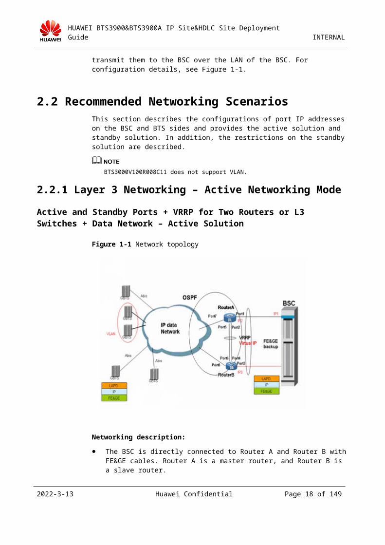
Figure 2-1 Network topology
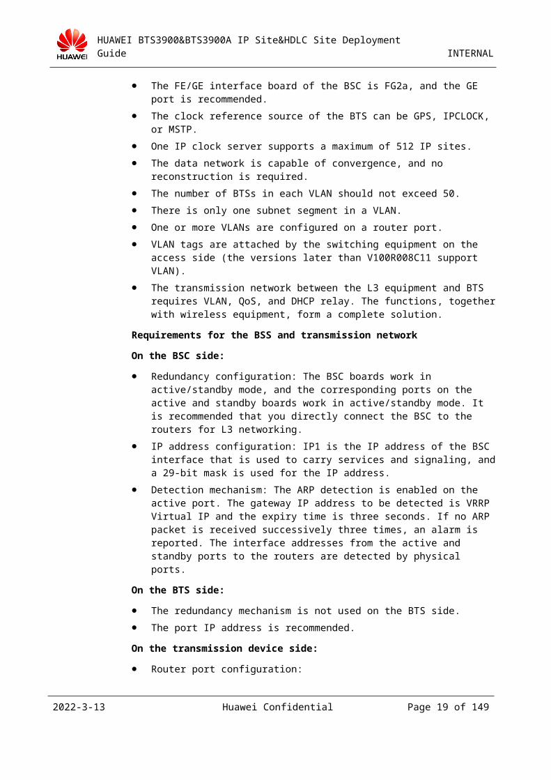
Networking description:
The BSC is directly connected to Router A and Router B with FE&GE cables. Router A is a master router, and Router B is a slave router.
The FE/GE interface board of the BSC is FG2a, and the GE port is recommended.
The clock reference source of the BTS can be GPS, IPCLOCK, or MSTP.
One IP clock server supports a maximum of 512 IP sites.
The data network is capable of convergence, and no reconstruction is required.
The number of BTSs in each VLAN should not exceed 50.
There is only one subnet segment in a VLAN.
One or more VLANs are configured on a router port.
VLAN tags are attached by the switching equipment on the access side (the versions later than V100R008C11 support VLAN).
The transmission network between the L3 equipment and BTS requires VLAN, QoS, and DHCP relay. The functions, together with wireless equipment, form a complete solution.
Requirements for the BSS and transmission network
On the BSC side:
2023-4-19 Huawei Confidential Page 17 of 129
HUAWEI BTS3900&BTS3900A IP Site&HDLC Site Deployment Guide INTERNAL
Redundancy configuration: The BSC boards work in active/standby mode, and the corresponding ports on the active and standby boards work in active/standby mode. It is recommended that you directly connect the BSC to the routers for L3 networking.
IP address configuration: IP1 is the IP address of the BSC interface that is used to carry services and signaling, and a 29-bit mask is used for the IP address.
Detection mechanism: The ARP detection is enabled on the active port. The gateway IP address to be detected is VRRP Virtual IP and the expiry time is three seconds. If no ARP packet is received successively three times, an alarm is reported. The interface addresses from the active and standby ports to the routers are detected by physical ports.
On the BTS side:
The redundancy mechanism is not used on the BTS side.
The port IP address is recommended.
On the transmission device side:
Router port configuration:
Port1, Port2, Port3, Port4, Port5, and Port6 are configured to work in Portswitch mode and belong to VLAN A. Port2, Port5, Port4, and Port6 are bound to a trunk and Permit all VLAN is configured.
Port7 and Port8 are routing ports and the dynamic routing protocol is enabled.
Detection mechanism: None.
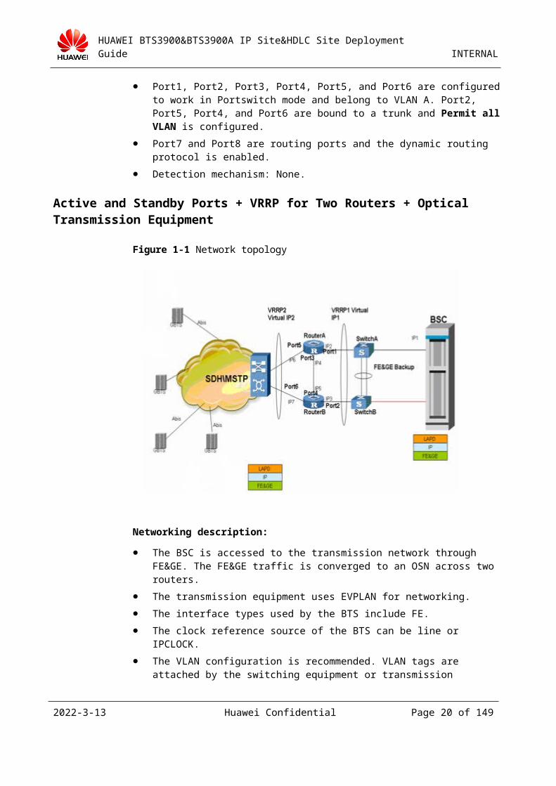
Active and Standby Ports + VRRP for Two Routers + Optical Transmission Equipment
Figure 2-1 Network topology
Networking description:
2023-4-19 Huawei Confidential Page 18 of 129
HUAWEI BTS3900&BTS3900A IP Site&HDLC Site Deployment Guide INTERNAL
The BSC is accessed to the transmission network through FE&GE. The FE&GE traffic is converged to an OSN across two routers.
The transmission equipment uses EVPLAN for networking.
The interface types used by the BTS include FE.
The clock reference source of the BTS can be line or IPCLOCK.
The VLAN configuration is recommended. VLAN tags are attached by the switching equipment or transmission equipment, and the VLAN is transparent to wireless equipment.
Requirements for the BSS and transmission equipment
On the BSC side:
Redundancy configuration: The BSC boards work in active/standby mode, and the corresponding ports on the active and standby boards work in active/standby mode. It is recommended that you directly connect the BSC to the routers for L3 networking.
IP address configuration: IP1 is the IP address of the BSC interface that is used to carry services and signaling.
Detection mechanism: The ARP detection is enabled on the active port. The gateway IP address to be detected is VRRP Virtual IP and the expiry time is three seconds. If no ARP packet is received successively three times, an alarm is reported. The interface addresses from the active and standby ports to the routers are detected by physical ports.
On the BTS side:
The redundancy mechanism is not used on the BTS side.
The port IP address is recommended.
On the transmission device side:
Port configuration: The ports on Router A and Router B are routing ports, and the dynamic routing protocol is enabled between Router A and Router B.
MSTP configuration: The MSTP equipment uses board-level BPS protection.
The router works with the MSTP equipment for BPS switchover. As only one port on the two routers that are connected to the MSTP equipment is UP, one router in VRRP2 is a master router and the other router is an initial router.
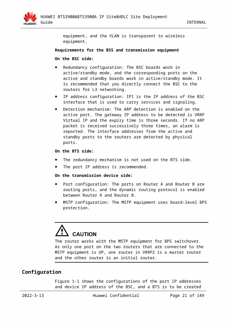
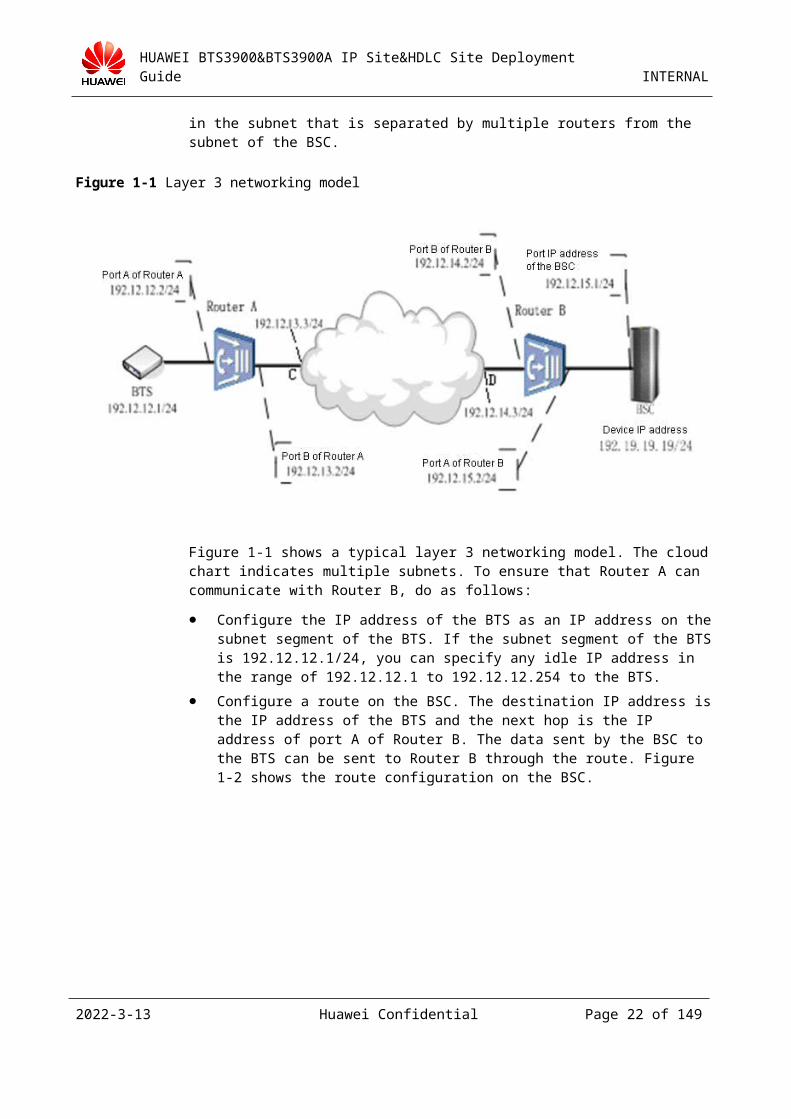
Configuration
Figure 2-1 shows the configurations of the port IP addresses and device IP address of the BSC, and a BTS is to be created in the subnet that is separated by multiple routers from the subnet of the BSC.
2023-4-19 Huawei Confidential Page 19 of 129
HUAWEI BTS3900&BTS3900A IP Site&HDLC Site Deployment Guide INTERNAL
Figure 2-1 Layer 3 networking model
Figure 2-1 shows a typical layer 3 networking model. The cloud chart indicates multiple subnets. To ensure that Router A can communicate with Router B, do as follows:
Configure the IP address of the BTS as an IP address on the subnet segment of the BTS. If the subnet segment of the BTS is 192.12.12.1/24, you can specify any idle IP address in the range of 192.12.12.1 to 192.12.12.254 to the BTS.
Configure a route on the BSC. The destination IP address is the IP address of the BTS and the next hop is the IP address of port A of Router B. The data sent by the BSC to the BTS can be sent to Router B through the route. Figure 2-2 shows the route configuration on the BSC.
2023-4-19 Huawei Confidential Page 20 of 129
HUAWEI BTS3900&BTS3900A IP Site&HDLC Site Deployment Guide INTERNAL
Figure 2-2 Adding a route in layer 3 networking mode
Configure a route on Router B. The destination IP address is the IP address of the BTS and the next hop is the IP address of the equipment (port D) that is connected to port B of Router B. The data sent by the BSC to the BTS can be sent from port B of Router B to the next router through the route. The configuration procedure is as follows:
To add a route (the destination IP address is 192.12.12.1, the mask is a 24-bit mask, and the next hop is 192.12.14.3), run the following command:
[Quidway]ip route-static 192.12.12.1 24 192.12.14.3
To delete a route, run the following command:
[Quidway]undo ip route-static 192.12.12.1 24 192.12.14.3
To query route information, run the following command:
[Quidway]dis ip routing-table
Routing Table: public net
Destination/Mask Protocol Pre Cost Nexthop Interface
192.12.12.1 /24 STATIC 60 0 192.12.14.3 Vlan-interface2
Configure a route on the Router B. The destination IP address is the device IP address of the BSC and the next hop is the port IP address of BSC. The data sent by the BTS to the BSC can be sent from port B of Router B to the BSC through the route. The configuration procedure is the same as the preceding one.
Configure a route on Router A. The destination IP address is the device IP address of the BSC and the next hop is the IP address of the equipment (port C) that is connected to port B of Router A. The data sent by the BTS to the BSC can be sent from port B of Router A to the next router through the route. The configuration procedure is the same as the preceding one.
Configure the DHCP relay on Router A (on the local BTS side). The IP address of the DHCP server is the port IP address of the interface board on the BSC side. The BTS can
2023-4-19 Huawei Confidential Page 21 of 129
HUAWEI BTS3900&BTS3900A IP Site&HDLC Site Deployment Guide INTERNAL
obtain IP addresses from the BSC servers in different subnets only after the DHCP relay is configured. The configuration procedure is as follows:
To enable the DHCP service, run the following command:
[Quidway] dhcp enable
To create a DHCP server with group number 1 (the IP address of the DHCP server is 192.19.19.19 (device IP address of the BSC)), run the following command:
[Quidway] dhcp-server 1 ip192.19.19.19
To enter the vlan1 view (port A of Router A belongs to VLAN 1), run the following command:
[Quidway] interface vlan-interface 1
To add VLAN 1 to DHCP server group 1, run the following command:
[Quidway-Vlan-interface1] dhcp-server 1
To query the information on the DHCP server, run the following command:
[Quidway] display dhcp-server all
To query the mapping between the DHCP server and VLAN interfaces, run the following command:
[Quidway] display dhcp-server interface Vlan-interface
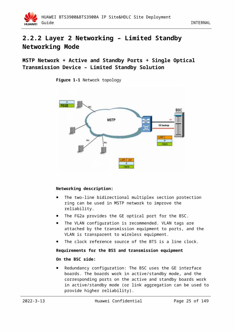
2.2.2 Layer 2 Networking – Limited Standby Networking Mode
MSTP Network + Active and Standby Ports + Single Optical Transmission Device – Limited Standby Solution
Figure 2-1 Network topology
Networking description:
2023-4-19 Huawei Confidential Page 22 of 129

HUAWEI BTS3900&BTS3900A IP Site&HDLC Site Deployment Guide INTERNAL
The two-line bidirectional multiplex section protection ring can be used in MSTP network to improve the reliability.
The FG2a provides the GE optical port for the BSC.
The VLAN configuration is recommended. VLAN tags are attached by the transmission equipment to ports, and the VLAN is transparent to wireless equipment.
The clock reference source of the BTS is a line clock.
Requirements for the BSS and transmission equipment
On the BSC side:
Redundancy configuration: The BSC uses the GE interface boards. The boards work in active/standby mode, and the corresponding ports on the active and standby boards work in active/standby mode (or link aggregation can be used to provide higher reliability).
IP address configuration: IP1 is the IP address of the BSC interface that is used to carry services and signaling.
Detection mechanism: physical detection.
On the BTS side:
The redundancy mechanism is not used on the BTS side.
The port IP address is recommended.
On the transmission device side:
The MSTP equipment uses the GE (HUAWEI OSN: EMS4) interface board, and the port PPS protection is configured.
The transmission network is a ring network that provides higher reliability.
When the port on the OSN is deactivated, the active and standby ports are simultaneously deactivated. In this case, the transmission is disconnected. Therefore, you cannot deactivate the port.
Configuration
Figure 2-1 shows the configurations of the port IP addresses and device IP address of the BSC, and a BTS is to be created in the subnet of the BSC.
2023-4-19 Huawei Confidential Page 23 of 129
HUAWEI BTS3900&BTS3900A IP Site&HDLC Site Deployment Guide INTERNAL
Figure 2-1 Layer 2 networking model
Figure 2-1 shows a typical layer 2 networking model. The dashed line indicates that there are one or more switches between Switch A and Switch B. To ensure that Switch A can communicate with Switch B, do as follows:
Configure the IP address of the BTS as an IP address on the subnet segment of the port IP address of the BSC. As the port IP address of the BSC is 192.12.15.1/24, you can specify any idle IP address in the range of 192.12.15.1 to 192.12.15.254 to the BTS.
2023-4-19 Huawei Confidential Page 24 of 129
HUAWEI BTS3900&BTS3900A IP Site&HDLC Site Deployment Guide INTERNAL
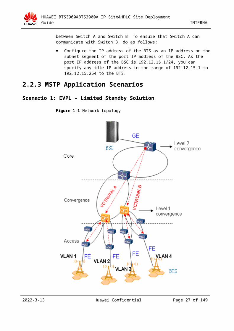
2.2.3 MSTP Application Scenarios
Scenario 1: EVPL – Limited Standby Solution
Figure 2-1 Network topology
Advantages:
A VLAN is configured for each BTS. As the VLANs are used to distinguish BTSs and paths, the network structure is clear, the configuration is simple, and the internal faults can be located easily.
On the BTS side, the transmission equipment divides VLANs for wireless services by ports. On the BSC side, VLAN tags are attached for services by BTSs.
The VLAN isolation ensures network security and no broadcast storm occurs.
Disadvantages:
2023-4-19 Huawei Confidential Page 25 of 129

HUAWEI BTS3900&BTS3900A IP Site&HDLC Site Deployment Guide INTERNAL
Too many VLANs are required. If independent VLANs are configured for the OM, the consumption of VLAN resources is larger. In addition, the BSC is required to have higher VLAN capability.
The VLAN ID must be unique. If the VLANs are reused between regions, the planning and configuration are very difficult.
When the wireless side and transmission side are based on VLAN tight coupling, an error easily occurs, the flexibility is poor, and the expansion and adjustment in the future are very difficult.
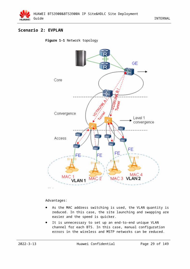
Scenario 2: EVPLAN
Figure 2-1 Network topology
Advantages:
2023-4-19 Huawei Confidential Page 26 of 129
HUAWEI BTS3900&BTS3900A IP Site&HDLC Site Deployment Guide INTERNAL
As the MAC address switching is used, the VLAN quantity is reduced. In this case, the site launching and swapping are easier and the speed is quicker.
It is unnecessary to set up an end-to-end unique VLAN channel for each BTS. In this case, manual configuration errors in the wireless and MSTP networks can be reduced.
Disadvantages:
When a packet is forwarded on the basis of the MAC address in the MSTP network, the problem location and the maintenance are difficult.
To prevent the port loopback from affecting services, you need to disable the loopback on any port (including Ethernet port and VCTRUNK optical cable) or upgrade the MSTP network to support the Ethernet OAM feature that automatically blocks the port loopback.
The EVPLAN solution is recommended to save VLAN resources and reduce the configuration complexity. The networking details are as follows:
MSTP uses 2-level convergence, and the EVPLAN solution is used for both level 1 and level 2. EGS4 is mapped on the basis of MAC and VC.
The OSN and CE use the BPS+VRRP networking mode. To prevent the network storm and identify the L2 priority, you are advised to assign one VLAN ID to a maximum of 50 BTSs under a BSC.
The Ethernet port of the transmission equipment at the access layer is configured to work in Hybrid mode for commissioning before site launching.
You are advised to configure one VLAN for the BTSs under two pairs of EGS4s in the level 1 convergence (in the level 1 convergence, a pair of EGS4s support a maximum of 64 BTSs). The IP addresses are planned on the same network segment so that the CE attaches VLAN tags based on the IP addresses.
In the level 2 convergence, one BSC is configured with a pair of EGS4s. In phase 1, each pair of boards are configured with a pair of GE ports. For the later expansion, two pairs of GE ports are configured.
The VLAN tags of downlink services on the BSC side are attached by the layer 3 equipment based on the destination IP address, and the VLAN tags of uplink services on the BTS side are attached by the transmission equipment based on ports.
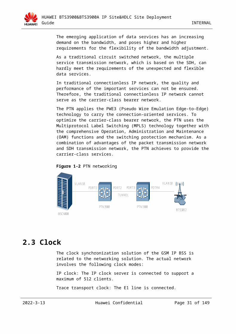
2.2.4 PTN EquipmentThe PTN is a new generation metropolitan fiber transmission platform which adopts the packet transmission mode.
The emerging application of data services has an increasing demand on the bandwidth, and poses higher and higher requirements for the flexibility of the bandwidth adjustment.
As a traditional circuit switched network, the multiple service transmission network, which is based on the SDH, can hardly meet the requirements of the unexpected and flexible data services.
In traditional connectionless IP network, the quality and performance of the important services can not be ensured. Therefore, the traditional connectionless IP network cannot serve as the carrier-class bearer network.
The PTN applies the PWE3 (Pseudo Wire Emulation Edge-to-Edge) technology to carry the connection-oriented services. To optimize the carrier-class bearer network, the PTN uses the Multiprotocol Label Switching (MPLS) technology together with the comprehensive Operation, Administration and Maintenance (OAM) functions and the switching protection
2023-4-19 Huawei Confidential Page 27 of 129
HUAWEI BTS3900&BTS3900A IP Site&HDLC Site Deployment Guide INTERNAL
mechanism. As a combination of advantages of the packet transmission network and SDH transmission network, the PTN achieves to provide the carrier-class services.
Figure 2-1 PTN networking
PORT1 PORT2 PORT3 POTR4
TUNNEL
BSC6000BTS3012
PTN3900 PTN1900
VLAN10 VLAN10
Clock
The clock synchronization solution of the GSM IP BSS is related to the networking solution. The actual network involves the following clock modes:
IP clock: The IP clock server is connected to support a maximum of 512 clients.
Trace transport clock: The E1 line is connected.
External synchronization clock: The clock source is connected.
Trace GPS clock: The DGPS of the BSC is connected.
2.2.5 Setting the Clock Mode of a SiteYou can set the clock mode by one of the following two methods:
Method 1
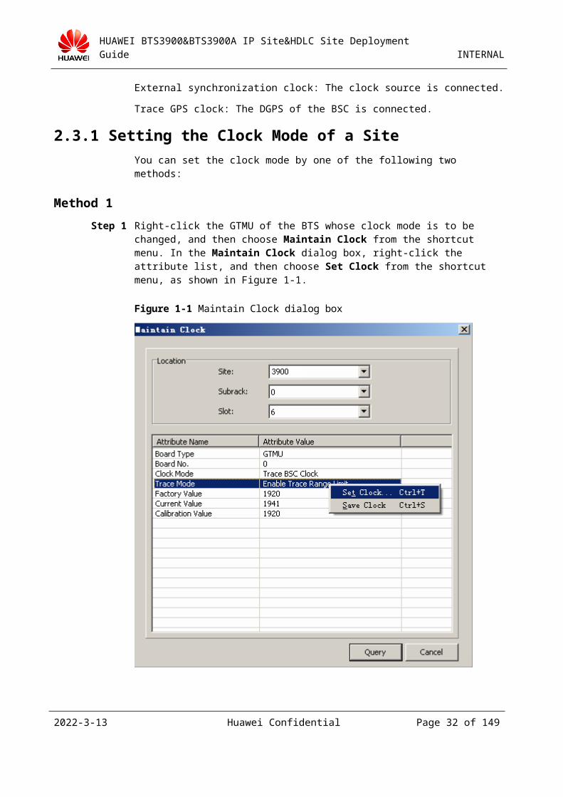
Step 1 Right-click the GTMU of the BTS whose clock mode is to be changed, and then choose Maintain Clock from the shortcut menu. In the Maintain Clock dialog box, right-click the attribute list, and then choose Set Clock from the shortcut menu, as shown in Figure 2-1.
2023-4-19 Huawei Confidential Page 28 of 129
HUAWEI BTS3900&BTS3900A IP Site&HDLC Site Deployment Guide INTERNAL
Figure 2-1 Maintain Clock dialog box
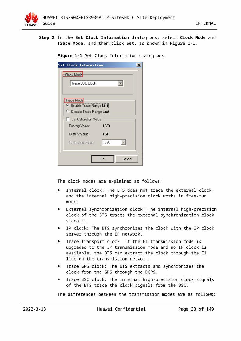
Step 2 In the Set Clock Information dialog box, select Clock Mode and Trace Mode, and then click Set, as shown in Figure 2-1.
2023-4-19 Huawei Confidential Page 29 of 129
HUAWEI BTS3900&BTS3900A IP Site&HDLC Site Deployment Guide INTERNAL
Figure 2-1 Set Clock Information dialog box
The clock modes are explained as follows:
Internal clock: The BTS does not trace the external clock, and the internal high-precision clock works in free-run mode.
External synchronization clock: The internal high-precision clock of the BTS traces the external synchronization clock signals.
IP clock: The BTS synchronizes the clock with the IP clock server through the IP network.
Trace transport clock: If the E1 transmission mode is upgraded to the IP transmission mode and no IP clock is available, the BTS can extract the clock through the E1 line on the transmission network.
Trace GPS clock: The BTS extracts and synchronizes the clock from the GPS through the DGPS.
Trace BSC clock: The internal high-precision clock signals of the BTS trace the clock signals from the BSC.
The differences between the transmission modes are as follows:
If the IP transmission mode is used, Trace Transport Clock can be configured and Trace BSC Clock cannot be configured.
If the non-IP transmission mode is used, Trace BSC Clock can be configured and Trace Transport Clock cannot be configured.
The BTS obtains the clock signals from the E1 port regardless of whether Trace BSC Clock or Trace Transport Clock is configured.
When Trace BSC Clock is configured, you do not need to configure the E1 port from which the clock signals are obtained.
When Trace Transport Clock is configured, you need to configure the E1 port from which the clock signals are obtained.
2023-4-19 Huawei Confidential Page 30 of 129
HUAWEI BTS3900&BTS3900A IP Site&HDLC Site Deployment Guide INTERNAL
The trace modes are explained as follows:
If Disable Trace Range Limit is selected, the BTS always traces the upper-level reference clock.
If Enable Trace Range Limit is selected and |f| 2 Hz, the reference clock is traced. If Enable Trace Range Limit is selected and |f| > 2 Hz, the internal clock works in free-run mode and the reference clock is not traced.
----End
Method 2
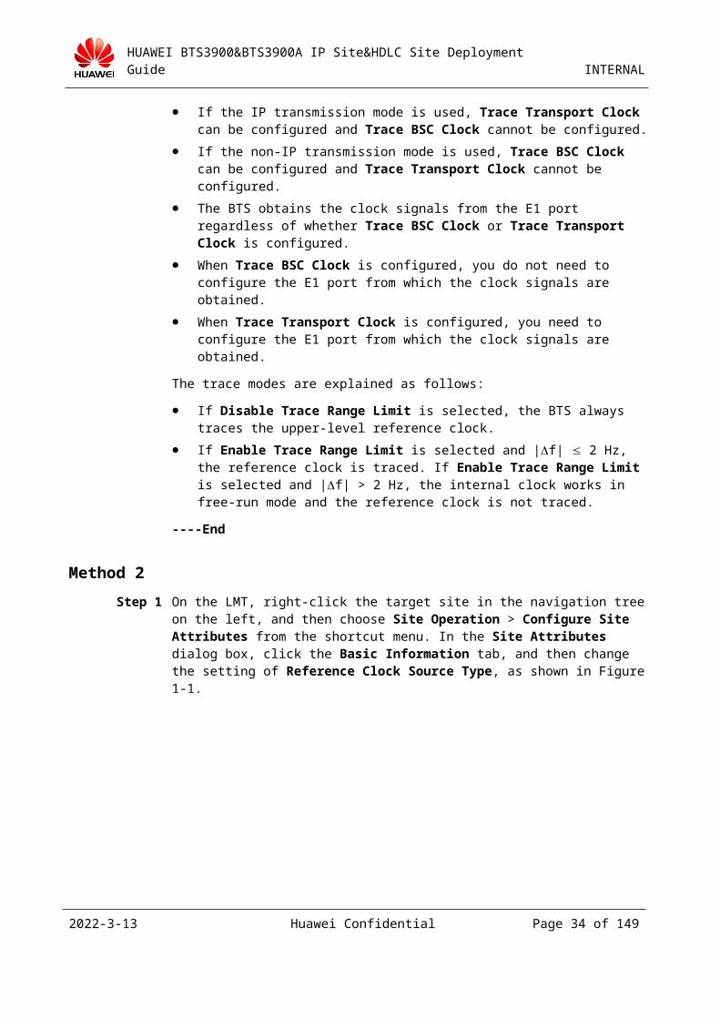
Step 1 On the LMT, right-click the target site in the navigation tree on the left, and then choose Site Operation > Configure Site Attributes from the shortcut menu. In the Site Attributes dialog box, click the Basic Information tab, and then change the setting of Reference Clock Source Type, as shown in Figure 2-1.
Figure 2-1 Site Attributes dialog box
2023-4-19 Huawei Confidential Page 31 of 129
HUAWEI BTS3900&BTS3900A IP Site&HDLC Site Deployment Guide INTERNAL
Both method 1 and method 2 can be used to set the clock mode of the BTS. If method 2 is used, you can also change the setting of Clock Mode as described in method 1. See Figure 2-1. If method 1 is used, the setting of Reference Clock Source Type cannot be changed as described in method 2. Thus, if the settings of the two parameters are inconsistent, the setting of Clock Mode is valid.
If the offset of the DA calibration value is high during the deployment, the lock time of the clock is long. In this case, you need to adjust the DA calibration value on the LMT.
Step 2 Right-click the GTMU of the BTS whose DA value is to be changed, and then choose Maintain Clock from the shortcut menu.
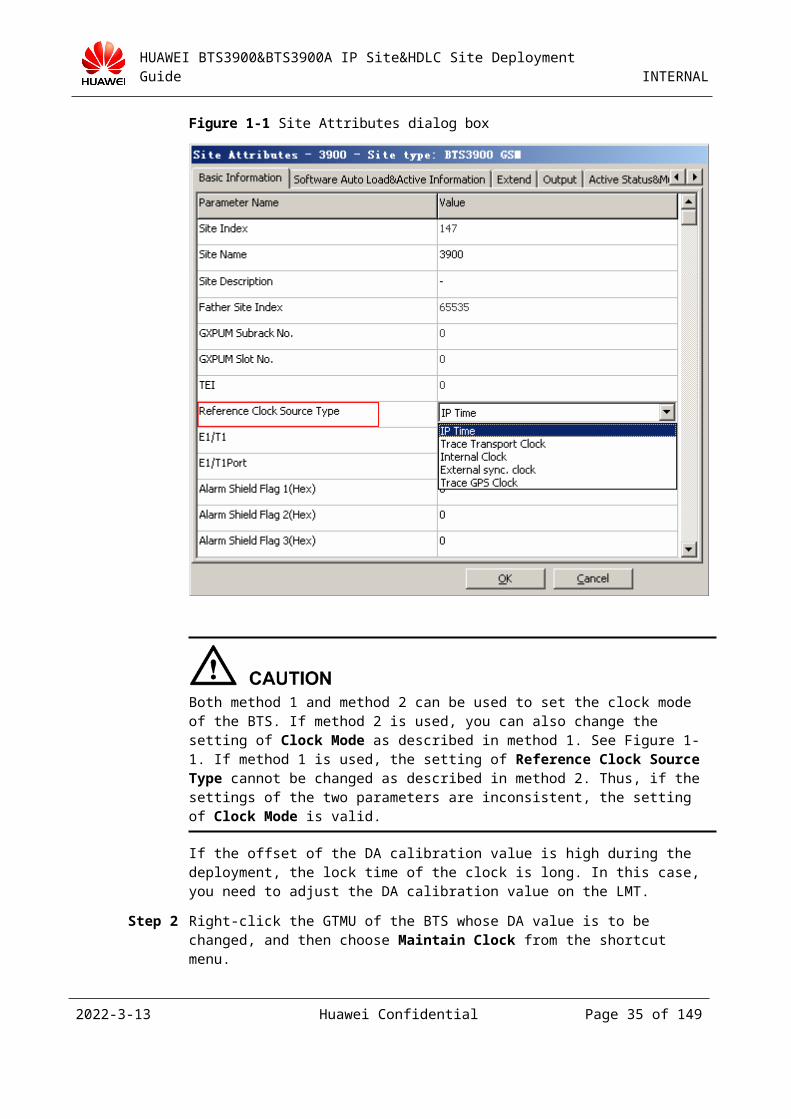
Step 3 In the Maintain Clock dialog box, right-click the attribute list, and then choose Set Clock from the shortcut menu.
Step 4 Select Set Calibration Value in the Set Clock Information dialog box, as shown in Figure 2-1.
Figure 2-1 Set Clock Information dialog box
----End
2.2.6 Configuring the IP Clock ServerThe IP clock server can work with the IP site to provide the standard clock reference source.
2023-4-19 Huawei Confidential Page 32 of 129
HUAWEI BTS3900&BTS3900A IP Site&HDLC Site Deployment Guide INTERNAL
Configuring the Clock Server
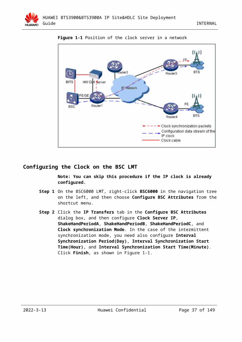
The contents to be configured include the working mode of the clock server, the type of the client connected to the clock server, system time, clock source mode, clock source, DA value, and route between the clock server and the BTS. For details, see the related clock server document. Figure 2-1 shows the position of the clock server in a network.
Figure 2-1 Position of the clock server in a network
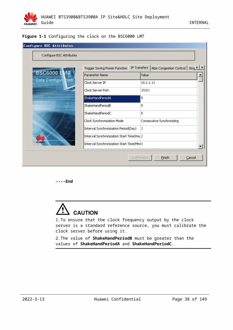
Configuring the Clock on the BSC LMT
Note: You can skip this procedure if the IP clock is already configured.
Step 1 On the BSC6000 LMT, right-click BSC6000 in the navigation tree on the left, and then choose Configure BSC Attributes from the shortcut menu.
Step 2 Click the IP Transfers tab in the Configure BSC Attributes dialog box, and then configure Clock Server IP, ShakeHandPeriodA, ShakeHandPeriodB, ShakeHandPeriodC, and Clock synchronization Mode. In the case of the intermittent synchronization mode, you need also configure Interval Synchronization Period(Day), Interval Synchronization Start Time(Hour), and Interval Synchronization Start Time(Minute). Click Finish, as shown in Figure 2-1.
2023-4-19 Huawei Confidential Page 33 of 129
HUAWEI BTS3900&BTS3900A IP Site&HDLC Site Deployment Guide INTERNAL
Figure 2-1 Configuring the clock on the BSC6000 LMT
----End
1.To ensure that the clock frequency output by the clock server is a standard reference source, you must calibrate the clock server before using it.
2.The value of ShakeHandPeriodB must be greater than the values of ShakeHandPeriodA and ShakeHandPeriodC.
2023-4-19 Huawei Confidential Page 34 of 129
HUAWEI BTS3900&BTS3900A IP Site&HDLC Site Deployment Guide INTERNAL
3 Hardware Installation and Data
Configuration
3.1 Hardware InstallationFor details, see the BTS3900&BTS3900A Deployment Guide.
3.2 Adding an HDLC SiteThis topic describes how to add an HDLC site. This procedure consists of the following operations:Adding an HDLC Site on the BSC6000 LMT > Adding a Physical Connection Between the Site and the BSC > Configuring the Transmission Network > Powering On and Checking Status > Loading and Upgrading Software
3.2.1 Adding an HDLC Site on the BSC6000 LMTYou can dynamically add an HDLC site on the BSC6000 local maintenance terminal (LMT). For example, to configure a GRFU TRX on a BTS3900 site, do as follows:
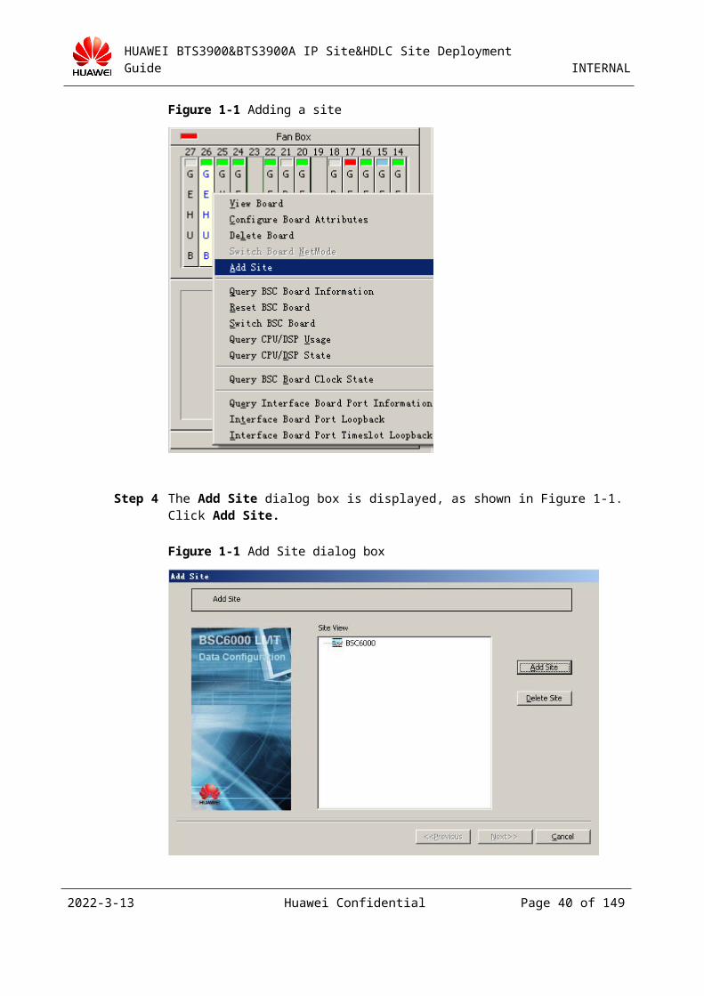
Step 1 On the BSC6000 LMT, right-click a GEHUB and choose Add Site from the shortcut menu, as shown in Figure 3-1.
2023-4-19 Huawei Confidential Page 35 of 129
HUAWEI BTS3900&BTS3900A IP Site&HDLC Site Deployment Guide INTERNAL
Figure 3-1 Adding a site
Step 2 The Add Site dialog box is displayed, as shown in Figure 3-1. Click Add Site.
Figure 3-1 Add Site dialog box
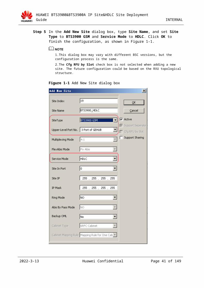
Step 3 In the Add New Site dialog box, type Site Name, and set Site Type to BTS3900 GSM and Service Mode to HDLC. Click OK to finish the configuration, as shown in Figure 3-1.
2023-4-19 Huawei Confidential Page 36 of 129
HUAWEI BTS3900&BTS3900A IP Site&HDLC Site Deployment Guide INTERNAL
1.This dialog box may vary with different BSC versions, but the configuration process is the same.
2.The Cfg RFU by Slot check box is not selected when adding a new site. The future configuration could be based on the RXU topological structure.
Figure 3-1 Add New Site dialog box
2023-4-19 Huawei Confidential Page 37 of 129
HUAWEI BTS3900&BTS3900A IP Site&HDLC Site Deployment Guide INTERNAL
The following describes the meanings of the parameters in the Add New Site dialog box.
Ring Mode: The value of this parameter is either YES or NO. YES indicates that the cascading of BTSs is supported and the ring network is established. Thus, if any BTS in the cascaded BTSs is disconnected, all the other BTSs can still communicate with the BSC properly. Abis By Pass Mode cannot be set regardless of whether Ring Mode is set.
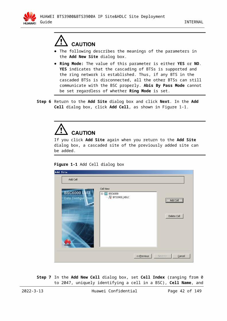
Step 4 Return to the Add Site dialog box and click Next. In the Add Cell dialog box, click Add Cell, as shown in Figure 3-1.
If you click Add Site again when you return to the Add Site dialog box, a cascaded site of the previously added site can be added.
Figure 3-1 Add Cell dialog box
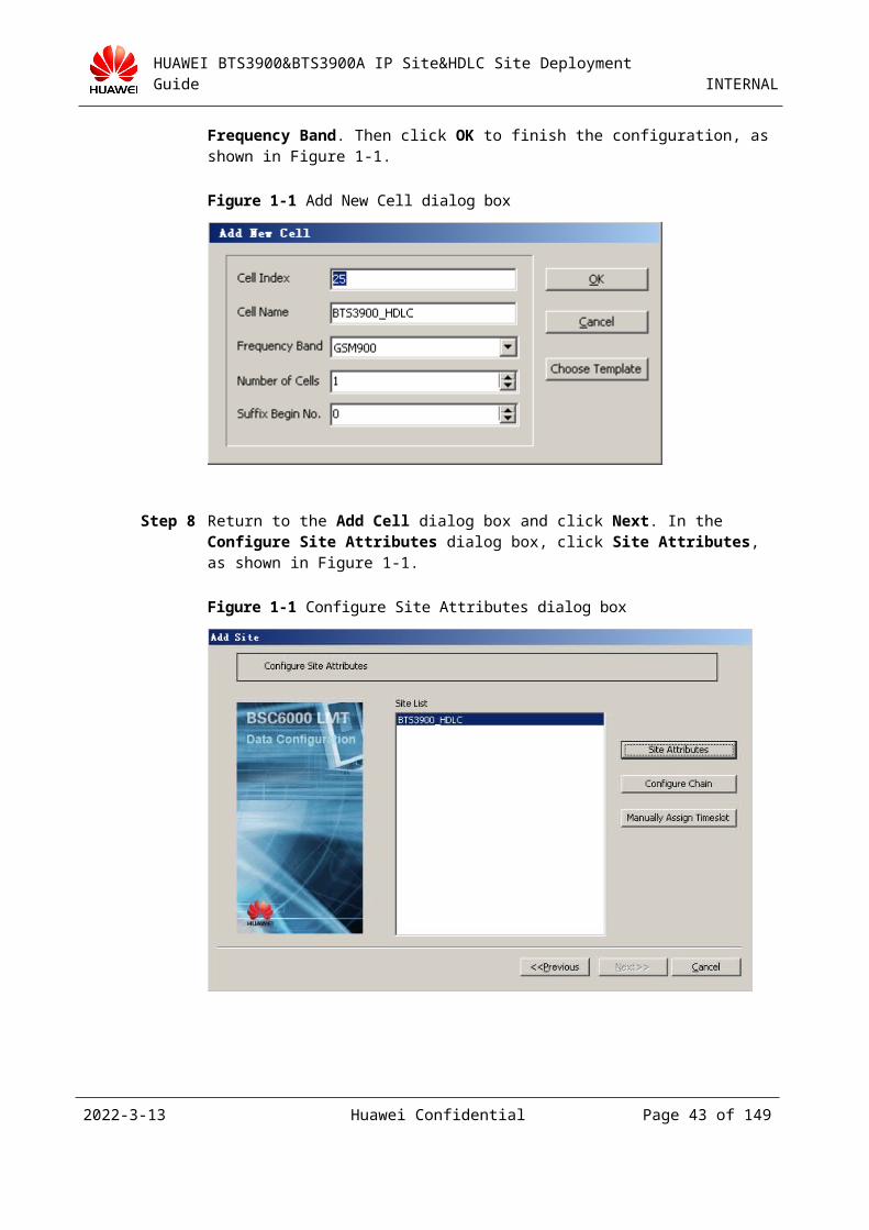
Step 5 In the Add New Cell dialog box, set Cell Index (ranging from 0 to 2047, uniquely identifying a cell in a BSC), Cell Name, and Frequency Band. Then click OK to finish the configuration, as shown in Figure 3-1.
2023-4-19 Huawei Confidential Page 38 of 129
HUAWEI BTS3900&BTS3900A IP Site&HDLC Site Deployment Guide INTERNAL
Figure 3-1 Add New Cell dialog box
Step 6 Return to the Add Cell dialog box and click Next. In the Configure Site Attributes dialog box, click Site Attributes, as shown in Figure 3-1.
Figure 3-1 Configure Site Attributes dialog box
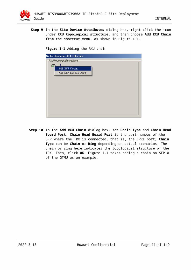
Step 7 In the Site Device Attributes dialog box, right-click the icon under RXU topological structure, and then choose Add RXU Chain from the shortcut menu, as shown in Figure 3-1.
2023-4-19 Huawei Confidential Page 39 of 129
HUAWEI BTS3900&BTS3900A IP Site&HDLC Site Deployment Guide INTERNAL
Figure 3-1 Adding the RXU chain
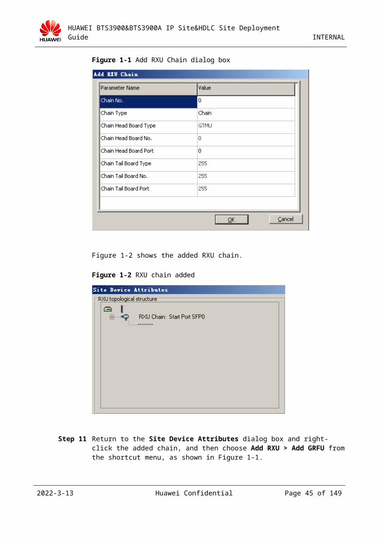
Step 8 In the Add RXU Chain dialog box, set Chain Type and Chain Head Board Port. Chain Head Board Port is the port number of the SFP where the TRX is connected, that is, the CPRI port; Chain Type can be Chain or Ring depending on actual scenarios. The chain or ring here indicates the topological structure of the TRX. Then, click OK. Figure 3-1 takes adding a chain on SFP 0 of the GTMU as an example.
Figure 3-1 Add RXU Chain dialog box
Figure 3-2 shows the added RXU chain.
2023-4-19 Huawei Confidential Page 40 of 129
HUAWEI BTS3900&BTS3900A IP Site&HDLC Site Deployment Guide INTERNAL
Figure 3-2 RXU chain added
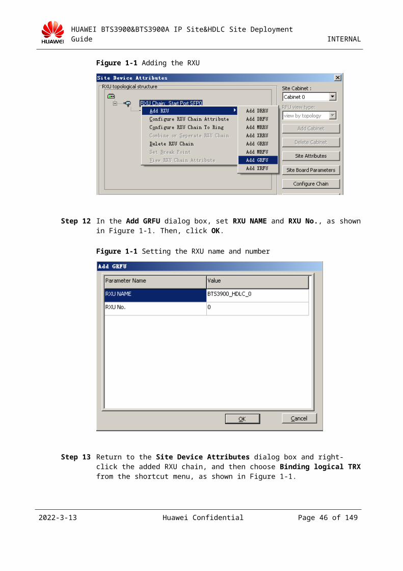
Step 9 Return to the Site Device Attributes dialog box and right-click the added chain, and then choose Add RXU > Add GRFU from the shortcut menu, as shown in Figure 3-1.
Figure 3-1 Adding the RXU
Step 10 In the Add GRFU dialog box, set RXU NAME and RXU No., as shown in Figure 3-1. Then, click OK.
2023-4-19 Huawei Confidential Page 41 of 129
HUAWEI BTS3900&BTS3900A IP Site&HDLC Site Deployment Guide INTERNAL
Figure 3-1 Setting the RXU name and number
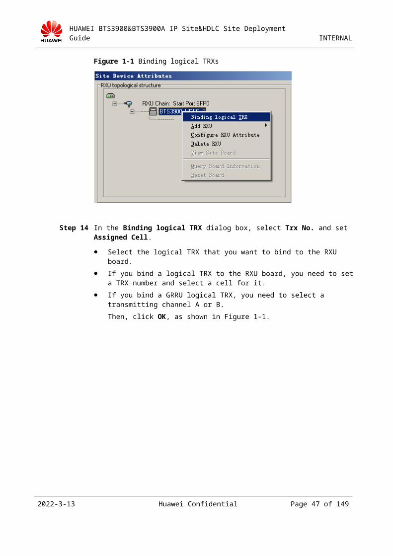
Step 11 Return to the Site Device Attributes dialog box and right-click the added RXU chain, and then choose Binding logical TRX from the shortcut menu, as shown in Figure 3-1.
Figure 3-1 Binding logical TRXs
Step 12 In the Binding logical TRX dialog box, select Trx No. and set Assigned Cell.
Select the logical TRX that you want to bind to the RXU board.
If you bind a logical TRX to the RXU board, you need to set a TRX number and select a cell for it.
If you bind a GRRU logical TRX, you need to select a transmitting channel A or B.
2023-4-19 Huawei Confidential Page 42 of 129
HUAWEI BTS3900&BTS3900A IP Site&HDLC Site Deployment Guide INTERNAL
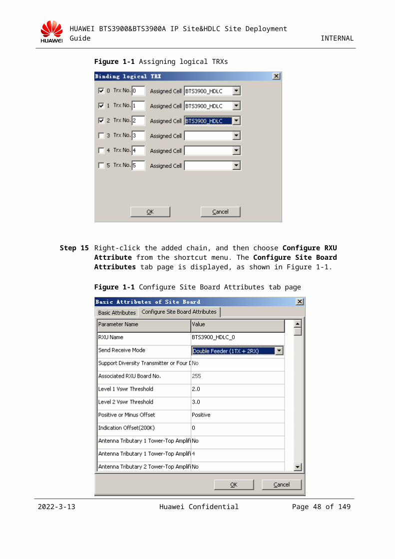
Then, click OK, as shown in Figure 3-1.
Figure 3-1 Assigning logical TRXs
Step 13 Right-click the added chain, and then choose Configure RXU Attribute from the shortcut menu. The Configure Site Board Attributes tab page is displayed, as shown in Figure 3-1.
Figure 3-1 Configure Site Board Attributes tab page
2023-4-19 Huawei Confidential Page 43 of 129
HUAWEI BTS3900&BTS3900A IP Site&HDLC Site Deployment Guide INTERNAL
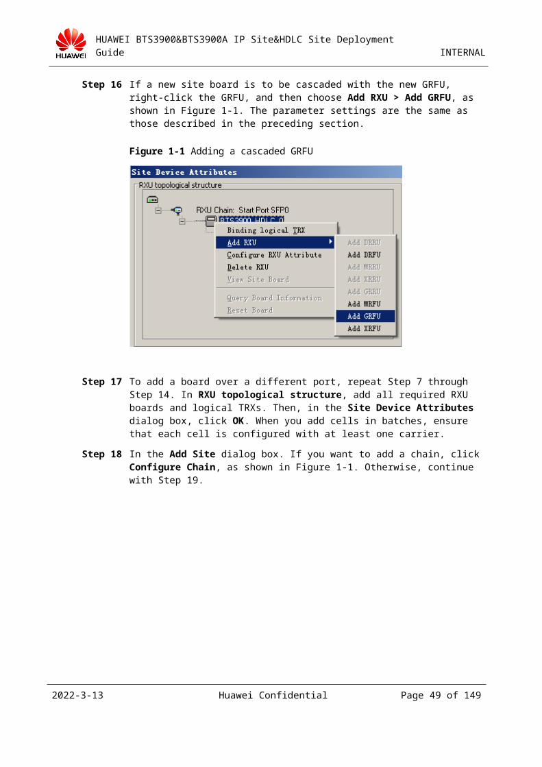
Step 14 If a new site board is to be cascaded with the new GRFU, right-click the GRFU, and then choose Add RXU > Add GRFU, as shown in Figure 3-1. The parameter settings are the same as those described in the preceding section.
Figure 3-1 Adding a cascaded GRFU
Step 15 To add a board over a different port, repeat Step 7 through Step 14. In RXU topological structure, add all required RXU boards and logical TRXs. Then, in the Site Device Attributes dialog box, click OK. When you add cells in batches, ensure that each cell is configured with at least one carrier.
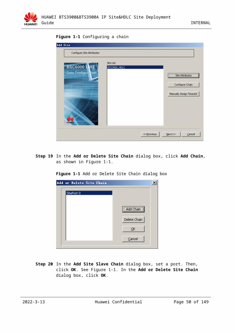
Step 16 In the Add Site dialog box. If you want to add a chain, click Configure Chain, as shown in Figure 3-1. Otherwise, continue with Step 19.
2023-4-19 Huawei Confidential Page 44 of 129
HUAWEI BTS3900&BTS3900A IP Site&HDLC Site Deployment Guide INTERNAL
Figure 3-1 Configuring a chain
Step 17 In the Add or Delete Site Chain dialog box, click Add Chain, as shown in Figure 3-1.
Figure 3-1 Add or Delete Site Chain dialog box
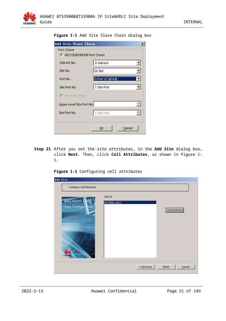
Step 18 In the Add Site Slave Chain dialog box, set a port. Then, click OK. See Figure 3-1. In the Add or Delete Site Chain dialog box, click OK.
2023-4-19 Huawei Confidential Page 45 of 129
HUAWEI BTS3900&BTS3900A IP Site&HDLC Site Deployment Guide INTERNAL
Figure 3-1 Add Site Slave Chain dialog box
Step 19 After you set the site attributes, in the Add Site dialog box, click Next. Then, click Cell Attributes, as shown in Figure 3-1.
Figure 3-1 Configuring cell attributes
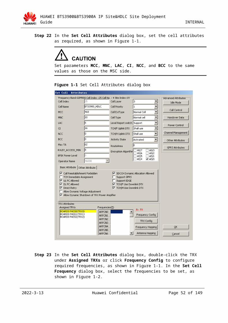
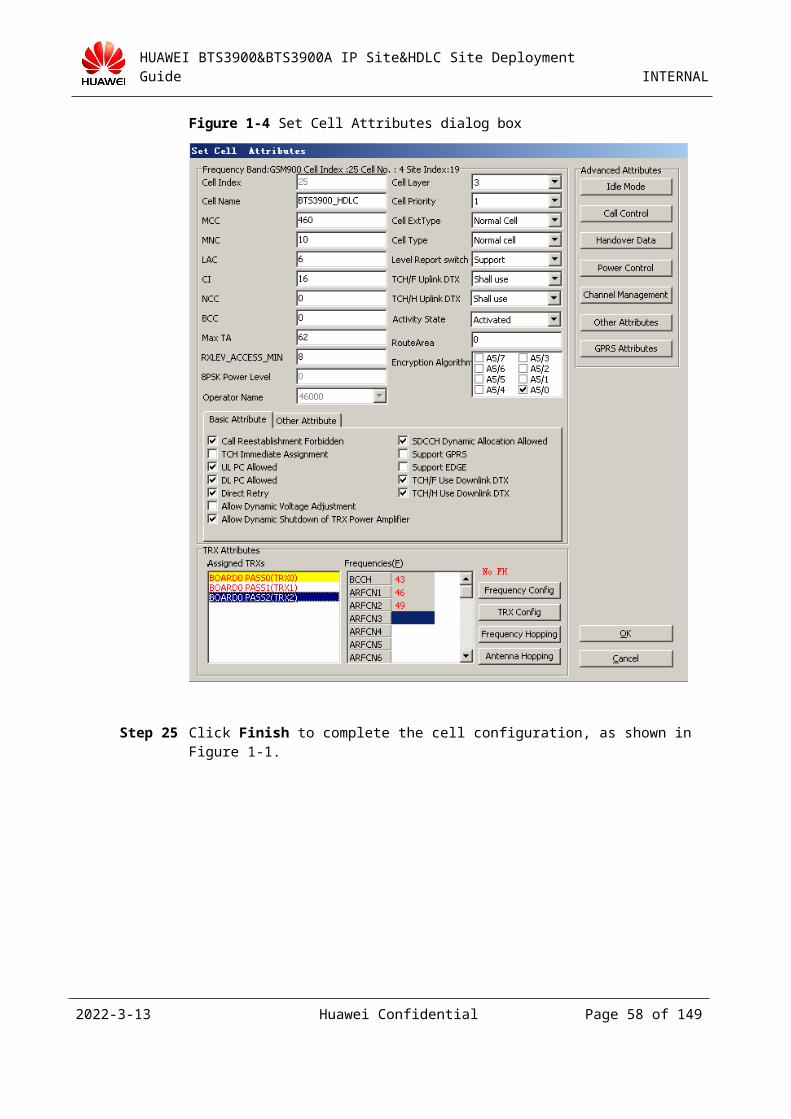
Step 20 In the Set Cell Attributes dialog box, set the cell attributes as required, as shown in Figure 3-1.
2023-4-19 Huawei Confidential Page 46 of 129
HUAWEI BTS3900&BTS3900A IP Site&HDLC Site Deployment Guide INTERNAL
Set parameters MCC, MNC, LAC, CI, NCC, and BCC to the same values as those on the MSC side.
Figure 3-1 Set Cell Attributes dialog box
Step 21 In the Set Cell Attributes dialog box, double-click the TRX under Assigned TRXs or click Frequency Config to configure required frequencies, as shown in Figure 3-1. In the Set Cell Frequency dialog box, select the frequencies to be set, as shown in Figure 3-2.
2023-4-19 Huawei Confidential Page 47 of 129
HUAWEI BTS3900&BTS3900A IP Site&HDLC Site Deployment Guide INTERNAL
Figure 3-1 Frequency setting
2023-4-19 Huawei Confidential Page 48 of 129
HUAWEI BTS3900&BTS3900A IP Site&HDLC Site Deployment Guide INTERNAL
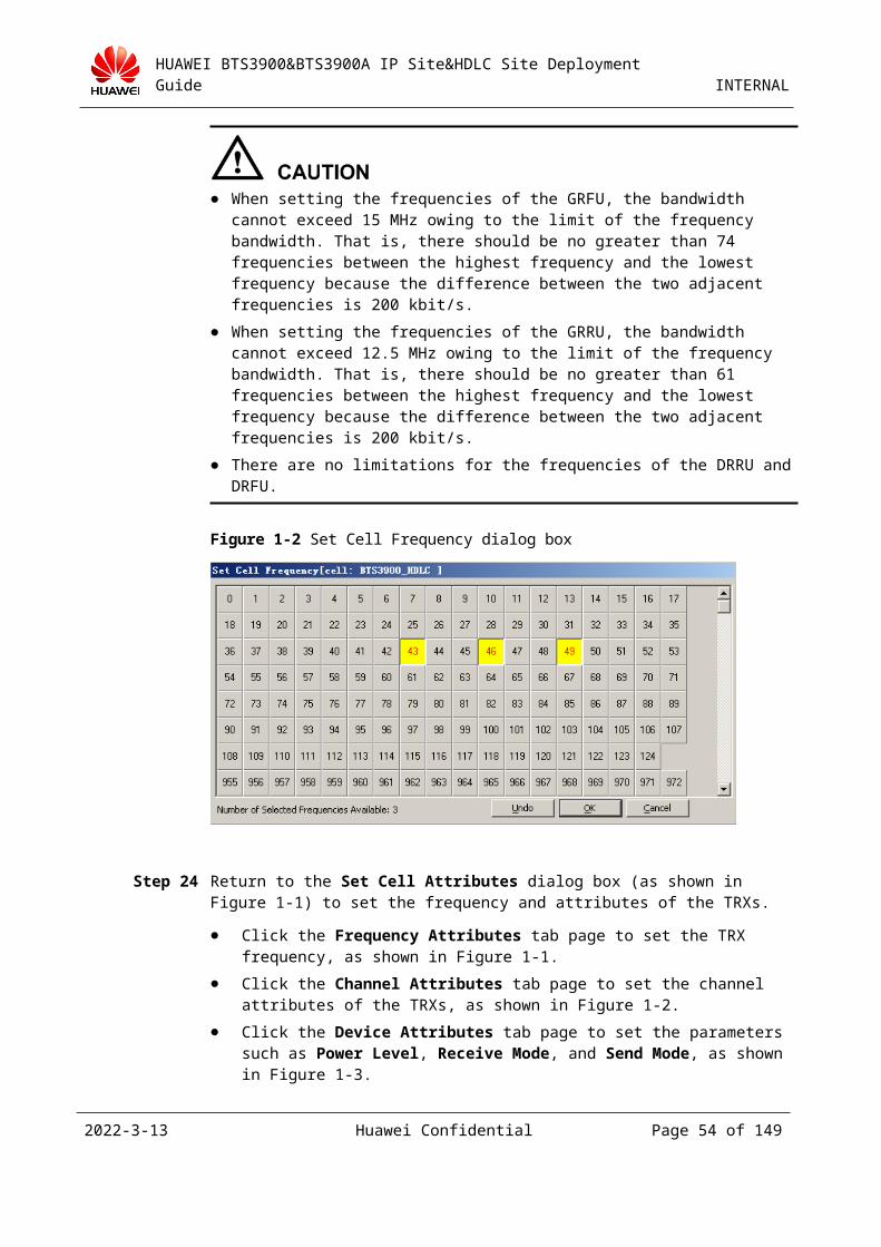
When setting the frequencies of the GRFU, the bandwidth cannot exceed 15 MHz owing to the limit of the frequency bandwidth. That is, there should be no greater than 74 frequencies between the highest frequency and the lowest frequency because the difference between the two adjacent frequencies is 200 kbit/s.
When setting the frequencies of the GRRU, the bandwidth cannot exceed 12.5 MHz owing to the limit of the frequency bandwidth. That is, there should be no greater than 61 frequencies between the highest frequency and the lowest frequency because the difference between the two adjacent frequencies is 200 kbit/s.
There are no limitations for the frequencies of the DRRU and DRFU.
Figure 3-2 Set Cell Frequency dialog box
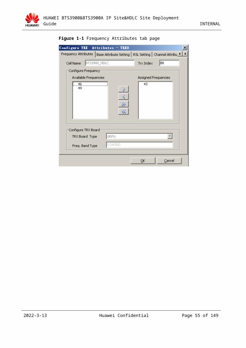
Step 22 Return to the Set Cell Attributes dialog box (as shown in Figure 3-1) to set the frequency and attributes of the TRXs.
Click the Frequency Attributes tab page to set the TRX frequency, as shown in Figure 3-1.
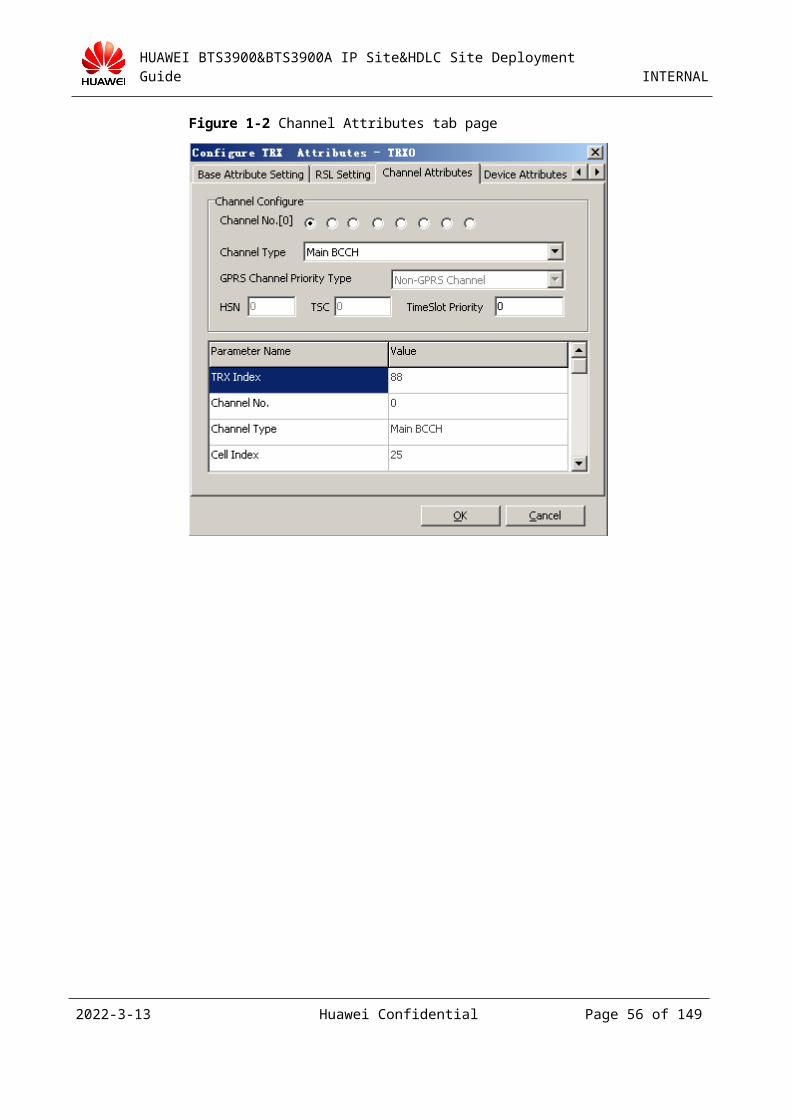
Click the Channel Attributes tab page to set the channel attributes of the TRXs, as shown in Figure 3-2.
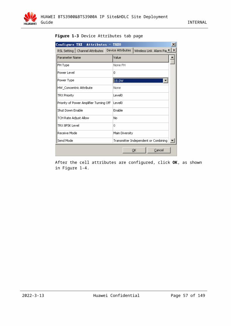
Click the Device Attributes tab page to set the parameters such as Power Level, Receive Mode, and Send Mode, as shown in Figure 3-3.
2023-4-19 Huawei Confidential Page 49 of 129
HUAWEI BTS3900&BTS3900A IP Site&HDLC Site Deployment Guide INTERNAL
Figure 3-1 Frequency Attributes tab page
2023-4-19 Huawei Confidential Page 50 of 129
HUAWEI BTS3900&BTS3900A IP Site&HDLC Site Deployment Guide INTERNAL
Figure 3-2 Channel Attributes tab page
Figure 3-3 Device Attributes tab page
2023-4-19 Huawei Confidential Page 51 of 129
HUAWEI BTS3900&BTS3900A IP Site&HDLC Site Deployment Guide INTERNAL
After the cell attributes are configured, click OK, as shown in Figure 3-4.
Figure 3-4 Set Cell Attributes dialog box
Step 23 Click Finish to complete the cell configuration, as shown in Figure 3-1.
2023-4-19 Huawei Confidential Page 52 of 129
HUAWEI BTS3900&BTS3900A IP Site&HDLC Site Deployment Guide INTERNAL
Figure 3-1 Completing the Add Site wizard
----End
3.2.2 Configuring Hardware and the Transmission Network
Selecting the Port Corresponding to the GEHUB Board
Select the E1 line led out through the port that corresponds to the GEHUB board specified in 3.2.1 "Adding an HDLC Site on the BSC6000 LMT." The numbering of E1 lines starts with 1 whereas the numbering of port numbers starts with 0. Therefore, you can select an E1 line based on a port number plus 1. For example, in 3.2.1 "Adding an HDLC Site on the BSC6000 LMT", the number of the upper-level port is 3. Therefore, you should select #4 E1 line led out from the GEHUB board.
When you connect the E1 line between the BSC and the site, ensure that the sending end of the BSC connects to the receiving end of the site and the receiving end of the BSC connects to the sending end of the site. On the E1 line, the sending end is marked with TX, and the receiving end is marked with RX.
Configuring the Transmission Network
Ensure that the E1 line is properly connected from the port of the site to the port of the BSC. You can use E1 line loopback to check whether the line is physically connected.
Powering On and Checking Status
Check whether the status of the RUN LED on the GTMU board in the common subrack is normal (on for one second and off for one second).
Check whether the status of the LIU LED is off.
2023-4-19 Huawei Confidential Page 53 of 129
HUAWEI BTS3900&BTS3900A IP Site&HDLC Site Deployment Guide INTERNAL
For details about the LEDs on the TMU panel, see 6.1 "LEDs on the TMU Board."
3.2.3 Upgrading a TDM Site on the Existing Network to an HDLC Site
Generally, the TDM site is configured on the GEIUB of the BSC rack. To upgrade a TDM site to an HDLC site, you must ensure that the GEHUB is available on the BSC side. If no GEHUB is available on the BSC rack, you need to insert the board and then complete the configuration.
You can upgrade a TDM site on the existing network to an HDLC site by one of the following two methods: 1. Upgrade a TDM site on the existing network to an HDLC site by the site movement function; 2. Directly build an HDLC site.
Method 1: Upgrade a TDM site on the existing network to an HDLC site by the site movement function (method 1 is recommended to facilitate the construction and reduce the service interruption time)
Step 1 Select the GEHUB of the BSC corresponding to the target HDLC site and the available port of the GEHUB.
Step 2 To move a site, do as follows:
On the BSC6000 LMT, right-click the TDM site to be upgraded in the navigation tree, and then choose Site Operation > Move Site from the shortcut menu, as shown in Figure 3-1.
Figure 3-1 Moving a site (1)
2023-4-19 Huawei Confidential Page 54 of 129
HUAWEI BTS3900&BTS3900A IP Site&HDLC Site Deployment Guide INTERNAL
In the Move Site dialog box, select the target site from the Site View area, and then click Move Site, as shown in Figure 3-2.
Figure 3-2 Moving a site (2)
In the Move Site dialog box, select HDLC to change the TDM site to the HDLC site, as shown in Figure 3-3. Click BSC Port. In the displayed dialog box, click YES. The Choice Board&Port dialog box is displayed, as shown in Figure 3-4.
2023-4-19 Huawei Confidential Page 55 of 129
HUAWEI BTS3900&BTS3900A IP Site&HDLC Site Deployment Guide INTERNAL
Figure 3-3 Moving a site (3)
Figure 3-4 Choice Board&Port dialog box
Set the parameters Dest SubRack No., Dest Slot No., and Dest Port No. to proper values based on the GEHUB position. Then, click OK. In the displayed dialog box, click OK to return to the Move Site dialog box, and then click Next, as shown in Figure 3-5.
2023-4-19 Huawei Confidential Page 56 of 129
HUAWEI BTS3900&BTS3900A IP Site&HDLC Site Deployment Guide INTERNAL
Figure 3-5 Moving a site (4)
In the displayed Move Site dialog box, the original connection of the site and the connection after the site is moved are available in the Move Site Result area. Ensure that the current connection of the site is correct, and then click Finish, as shown in Figure 3-6.
Figure 3-6 Result of moving a site (1)
2023-4-19 Huawei Confidential Page 57 of 129
HUAWEI BTS3900&BTS3900A IP Site&HDLC Site Deployment Guide INTERNAL
Click Continue, as shown in Figure 3-7. After the timeslots in the TDM site are arranged, a message is displayed to prompt you to confirm the operation. Then, click OK.
Figure 3-7 Result of moving a site (2)
Step 3 Remove the E1 cable that connects the TDM site to the GEIUB. Then, insert the E1 cable into the GEHUB in the BSC rack. (Remove the original E1 cable that connects the TDM site to the GEIUB in the BSC rack, and then insert the cable into the corresponding port on the GEHUB that is connected to the added HDLC site.) The OML is established after two minutes and the RSL is established after five minutes.
Step 4 After the previous operations, the site still runs properly. The services processed on the site are disrupted for about 15 minutes during the entire process.
----End
Method 2: Upgrade a TDM site on the existing network to an HDLC site by directly building an HDLC site
If the existing TDM site is attached to the GEIUB board, you can perform the following operations on the BSC LMT:Configuring an HDLC Site (For details, see 3.2.1 "Adding an HDLC Site on the BSC6000 LMT.") > Preparing the E1 Line from the BSC to the Site > Loading the Latest Version of the TMU > Disconnecting the Existing Network Cable from the TDM Site and Inserting the E1 Line into the Subrack > Activating the TMU Version > Loading the Latest Version of the TRX > Activating the TRX Version
For details on how to connect the hardware and the transmission network, see 3.2.2 "Configuring Hardware and the Transmission Network."
2023-4-19 Huawei Confidential Page 58 of 129

HUAWEI BTS3900&BTS3900A IP Site&HDLC Site Deployment Guide INTERNAL
3.3 Adding an HDLC HUB SiteThis topic describes how to add an HDLC HUB site. This procedure consists of the following operations:Adding an HDLC HUB Site on the BSC6000 LMT > Adding a Physical Connection Between the Site and the BSC > Configuring the Transmission Network > Powering On and Checking Status > Loading and Upgrading Software
3.3.1 Adding an HDLC HUB Site on the BSC6000 LMTYou can dynamically add an HDLC HUB site on the BSC6000 LMT. For example, to configure a GRFU TRX on a BTS3900 site, do as follows:
Step 1 On the BSC6000 LMT, right-click a GEHUB and choose Add Site from the shortcut menu, as shown in Figure 3-1.
Figure 3-1 Adding a site
Step 2 The Add Site dialog box is displayed, as shown in Figure 3-1. Click Add Site.
2023-4-19 Huawei Confidential Page 59 of 129
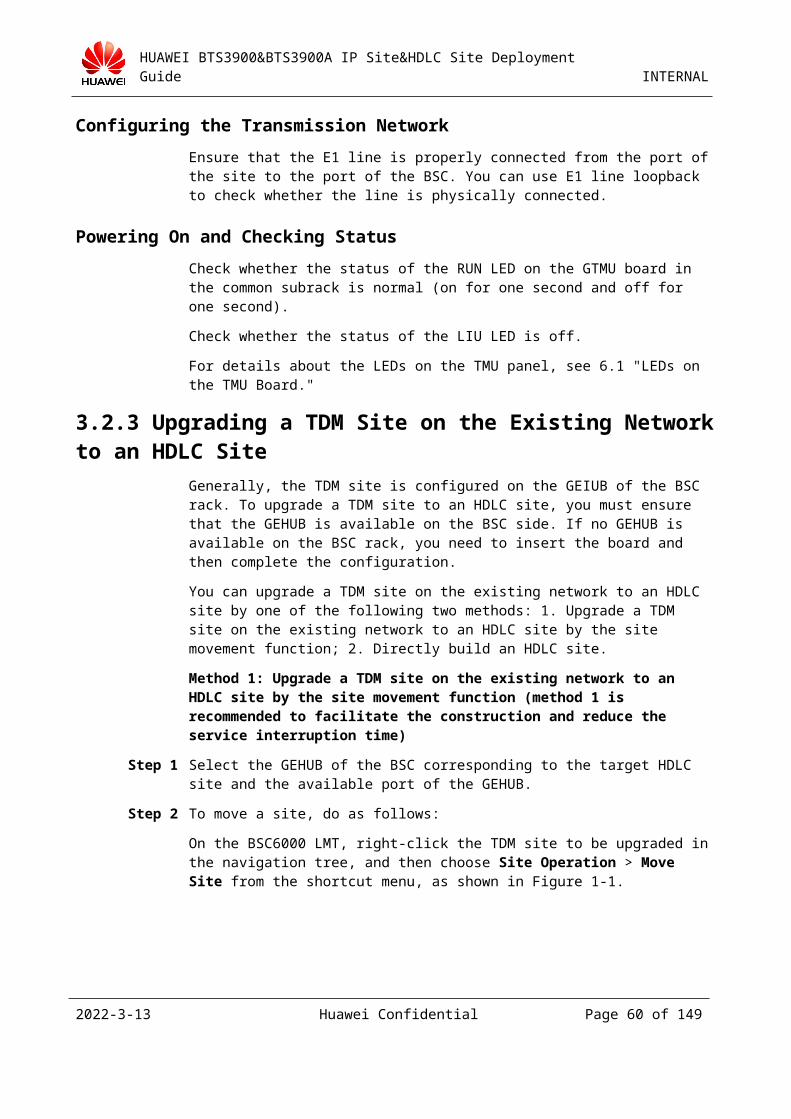
HUAWEI BTS3900&BTS3900A IP Site&HDLC Site Deployment Guide INTERNAL
Figure 3-1 Add Site dialog box
Step 3 In the Add New Site dialog box, type Site Name, and set Site Type to BTS3900 GSM and Service Mode to HubBTS. Click OK to finish the configuration, as shown in Figure 3-1.
1.This dialog box may vary with different BSC versions, but the configuration process is the same.
2.The Cfg RFU by Slot check box is not selected when adding a new site. The future configuration could be based on the RXU topological structure.
2023-4-19 Huawei Confidential Page 60 of 129
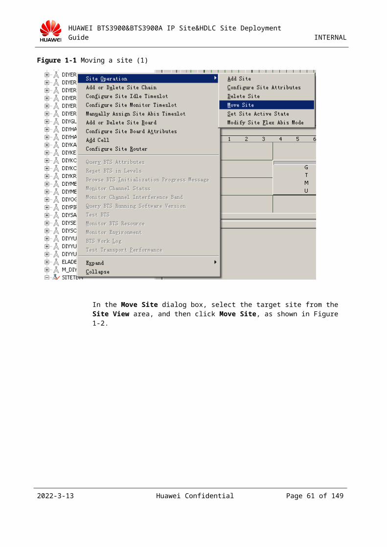
HUAWEI BTS3900&BTS3900A IP Site&HDLC Site Deployment Guide INTERNAL
Figure 3-1 Add New Site dialog box
Step 4 Return to the Add Site dialog box and click Next. In the Add Cell dialog box, click Add Cell, as shown in Figure 3-1.
If you click Add Site again when you return to the Add Site dialog box, a cascaded site of the previously added site can be added.
2023-4-19 Huawei Confidential Page 61 of 129
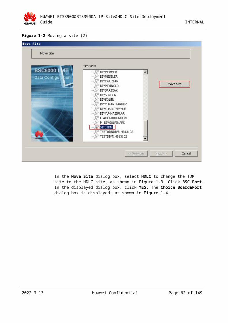
HUAWEI BTS3900&BTS3900A IP Site&HDLC Site Deployment Guide INTERNAL
Figure 3-1 Add Cell dialog box
Step 5 In the Add New Cell dialog box, set Cell Index (ranging from 0 to 2047, uniquely identifying a cell in a BSC), Cell Name, and Frequency Band. Then click OK to finish the configuration, as shown in Figure 3-1.
Figure 3-1 Add New Cell dialog box
Step 6 Return to the Add Cell dialog box and click Next. In the Configure Site Attributes dialog box, click Site Attributes, as shown in Figure 3-1.
2023-4-19 Huawei Confidential Page 62 of 129
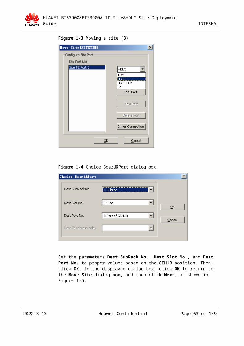
HUAWEI BTS3900&BTS3900A IP Site&HDLC Site Deployment Guide INTERNAL
Figure 3-1 Configure Site Attributes dialog box
Step 7 In the Site Device Attributes dialog box, right-click the icon under RXU topological structure, and then choose Add RXU Chain from the shortcut menu, as shown in Figure 3-1.
Figure 3-1 Adding the RXU chain
Step 8 In the Add RXU Chain dialog box, set Chain Type and Chain Head Board Port. Chain Head Board Port is the port number of the SFP where the TRX is connected, that is, the CPRI port; Chain Type can be Chain or Ring depending on actual scenarios. The chain or ring here indicates the topological structure of the TRX. Then, click OK. Figure 3-1 takes adding a chain on SFP 0 of the GTMU as an example.
2023-4-19 Huawei Confidential Page 63 of 129
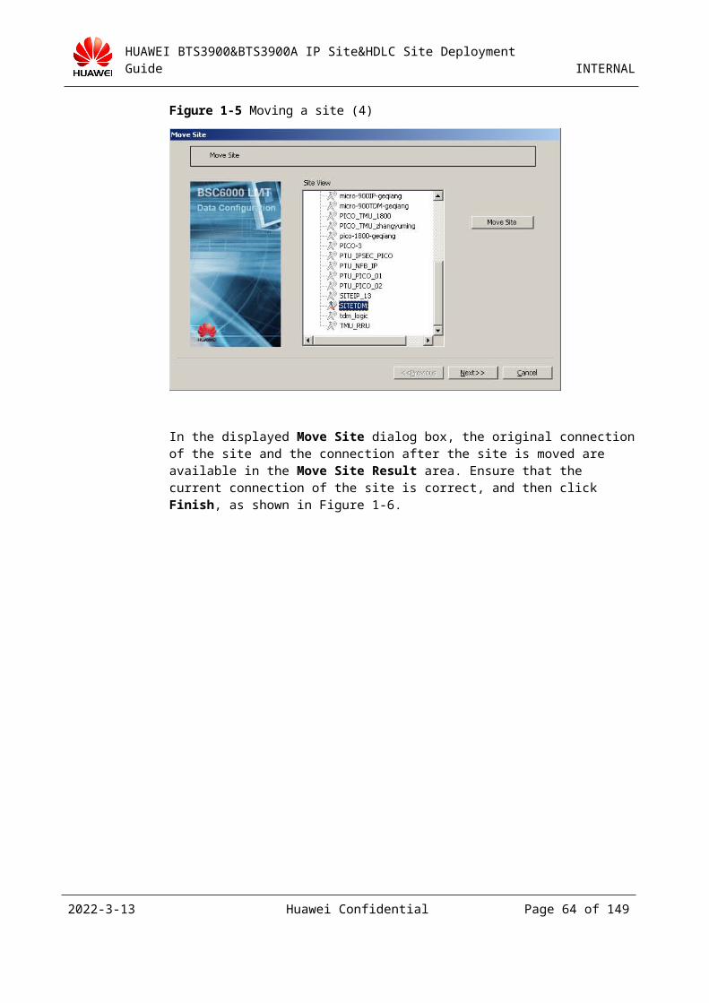
HUAWEI BTS3900&BTS3900A IP Site&HDLC Site Deployment Guide INTERNAL
Figure 3-1 Add RXU Chain dialog box
Figure 3-2 shows the added RXU chain.
Figure 3-2 RXU chain added
Step 9 Return to the Site Device Attributes dialog box and right-click the added chain, and then choose Add RXU > Add GRFU from the shortcut menu, as shown in Figure 3-1.
2023-4-19 Huawei Confidential Page 64 of 129
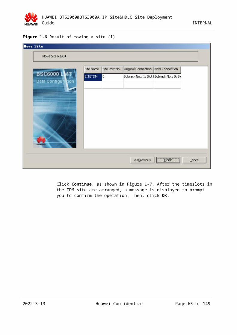
HUAWEI BTS3900&BTS3900A IP Site&HDLC Site Deployment Guide INTERNAL
Figure 3-1 Adding the RXU
Step 10 In the Add GRFU dialog box, set RXU NAME and RXU No., as shown in Figure 3-1. Then, click OK.
Figure 3-1 Setting the RXU name and number
Step 11 Return to the Site Device Attributes dialog box and right-click the added RXU chain, and then choose Binding logical TRX from the shortcut menu, as shown in Figure 3-1.
2023-4-19 Huawei Confidential Page 65 of 129
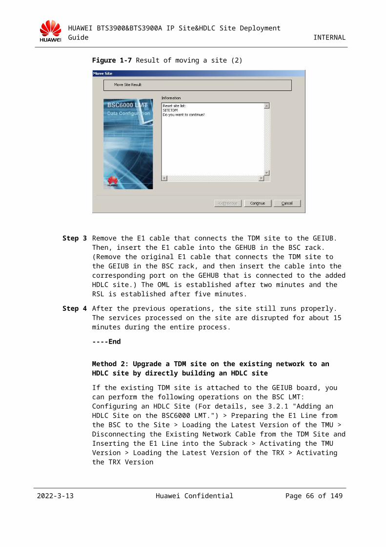
HUAWEI BTS3900&BTS3900A IP Site&HDLC Site Deployment Guide INTERNAL
Figure 3-1 Binding logical TRXs
Step 12 In the Binding logical TRX dialog box, select Trx No. and set Assigned Cell.
Select the logical TRX that you want to bind to the RXU board.
If you bind a logical TRX to the RXU board, you need to set a TRX number and select a cell for it.
If you bind a GRRU logical TRX, you need to select a transmitting channel A or B.
Then, click OK, as shown in Figure 3-1.
Figure 3-1 Assigning logical TRXs
Step 13 Right-click the added chain, and then choose Configure RXU Attribute from the shortcut menu. The Configure Site Board Attributes tab page is displayed, as shown in Figure 3-1.
2023-4-19 Huawei Confidential Page 66 of 129
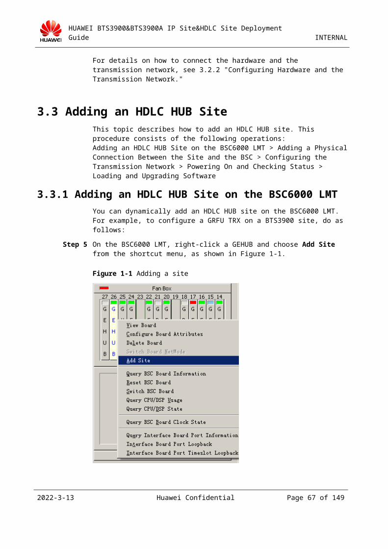
HUAWEI BTS3900&BTS3900A IP Site&HDLC Site Deployment Guide INTERNAL
Figure 3-1 Configure Site Board Attributes tab page
Step 14 If a new site board is to be cascaded with the new GRFU, right-click the GRFU, and then choose Add RXU > Add GRFU, as shown in Figure 3-1. The parameter settings are the same as those described in the preceding section.
Figure 3-1 Adding a cascaded GRFU
2023-4-19 Huawei Confidential Page 67 of 129
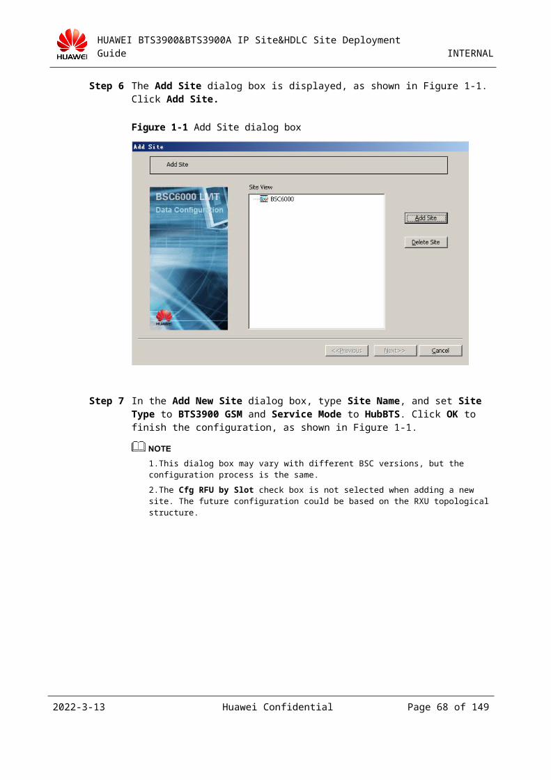
HUAWEI BTS3900&BTS3900A IP Site&HDLC Site Deployment Guide INTERNAL
Step 15 To add a board over a different port, repeat Step 7 through Step 14. In RXU topological structure, add all required RXU boards and logical TRXs. Then, in the Site Device Attributes dialog box, click OK. When you add cells in batches, ensure that each cell is configured with at least one carrier.
Step 16 In the Add Site dialog box. If you want to add a chain, click Configure Chain, as shown in Figure 3-1. Otherwise, continue with Step 19.
Figure 3-1 Configuring a chain
Step 17 In the Add or Delete Site Chain dialog box, click Add Chain, as shown in Figure 3-1.
Figure 3-1 Add or Delete Site Chain dialog box
Step 18 In the Add Site Slave Chain dialog box, set a port. Then, click OK. See Figure 3-1. In the Add or Delete Site Chain dialog box, click OK.
2023-4-19 Huawei Confidential Page 68 of 129
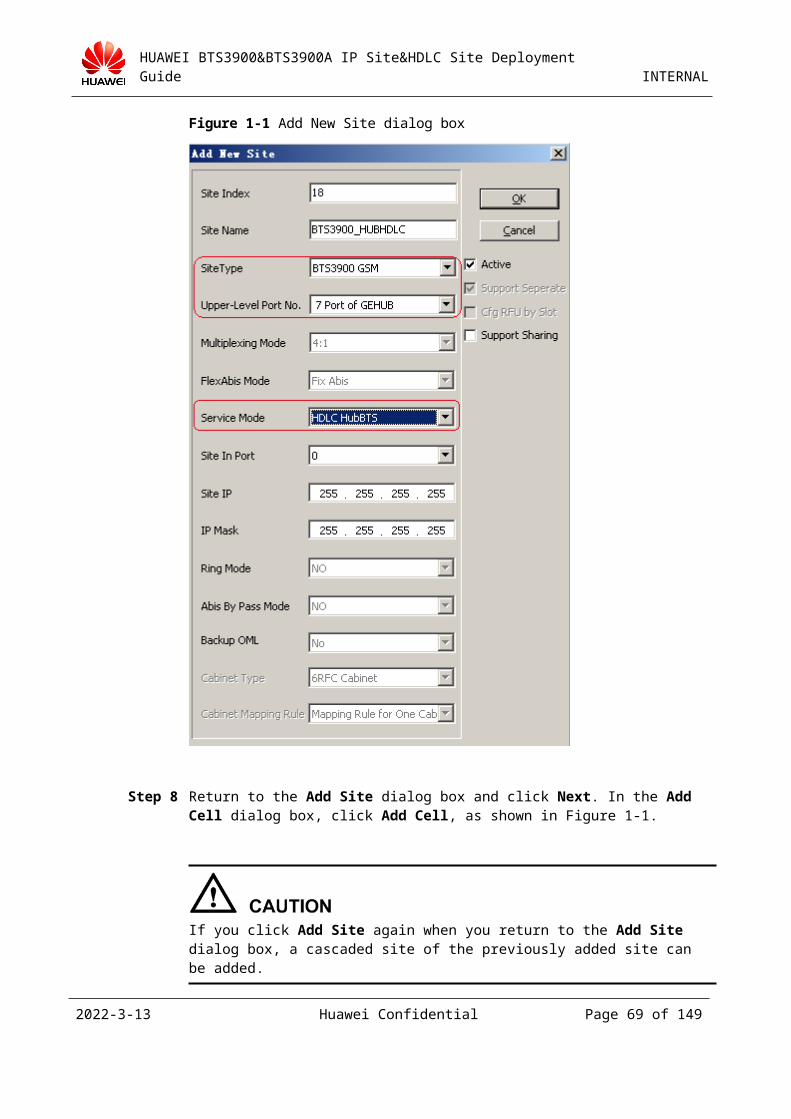
HUAWEI BTS3900&BTS3900A IP Site&HDLC Site Deployment Guide INTERNAL
Figure 3-1 Add Site Slave Chain dialog box
Step 19 After you set the site attributes, in the Add Site dialog box, click Next. Then, click Cell Attributes, as shown in Figure 3-1.
Figure 3-1 Configuring cell attributes
Step 20 In the Set Cell Attributes dialog box, set the cell attributes as required, as shown in Figure 3-1.
2023-4-19 Huawei Confidential Page 69 of 129
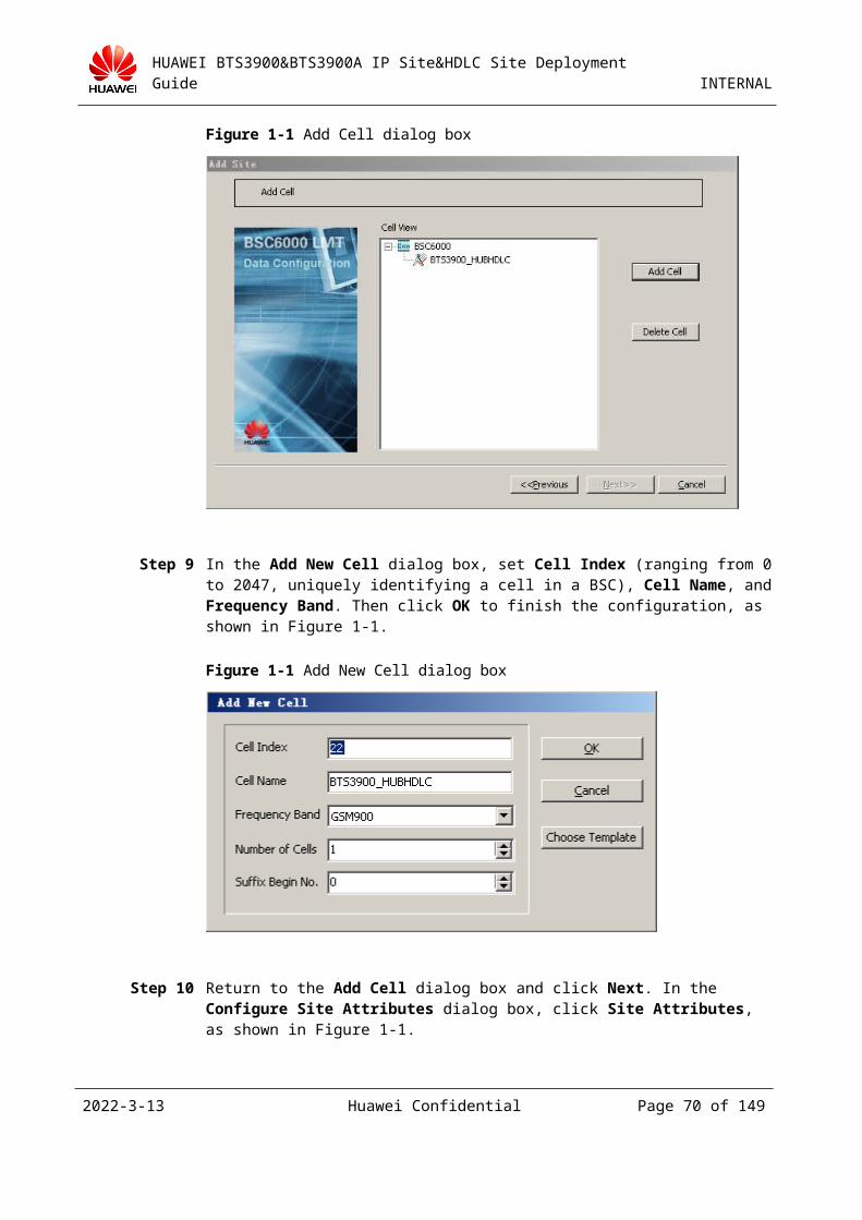
HUAWEI BTS3900&BTS3900A IP Site&HDLC Site Deployment Guide INTERNAL
Set parameters MCC, MNC, LAC, CI, NCC, and BCC to the same values as those on the MSC side.
Figure 3-1 Set Cell Attributes dialog box
Step 21 In the Set Cell Attributes dialog box, double-click the TRX under Assigned TRXs or click Frequency Config to configure required frequencies, as shown in Figure 3-1. In the Set Cell Frequency dialog box, select the frequencies to be set, as shown in Figure 3-2.
2023-4-19 Huawei Confidential Page 70 of 129
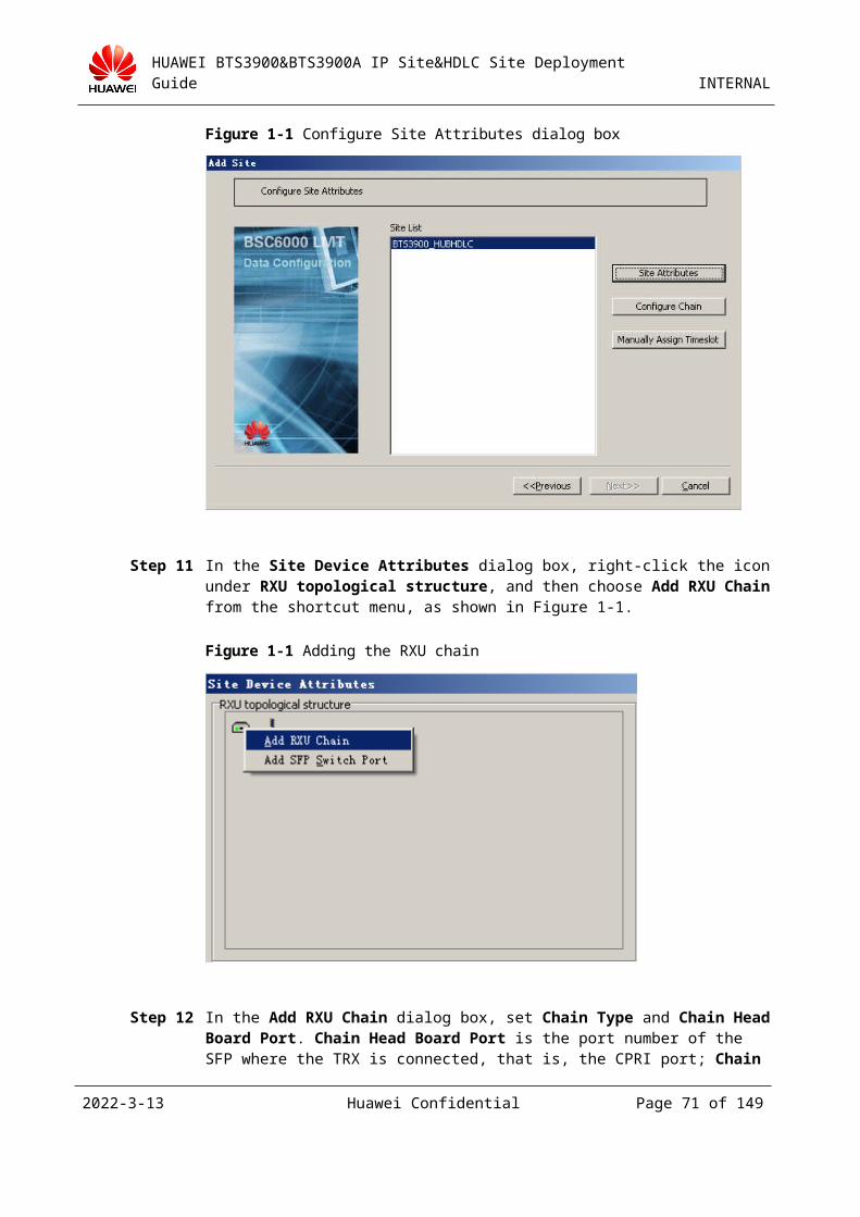
HUAWEI BTS3900&BTS3900A IP Site&HDLC Site Deployment Guide INTERNAL
Figure 3-1 Frequency setting
2023-4-19 Huawei Confidential Page 71 of 129
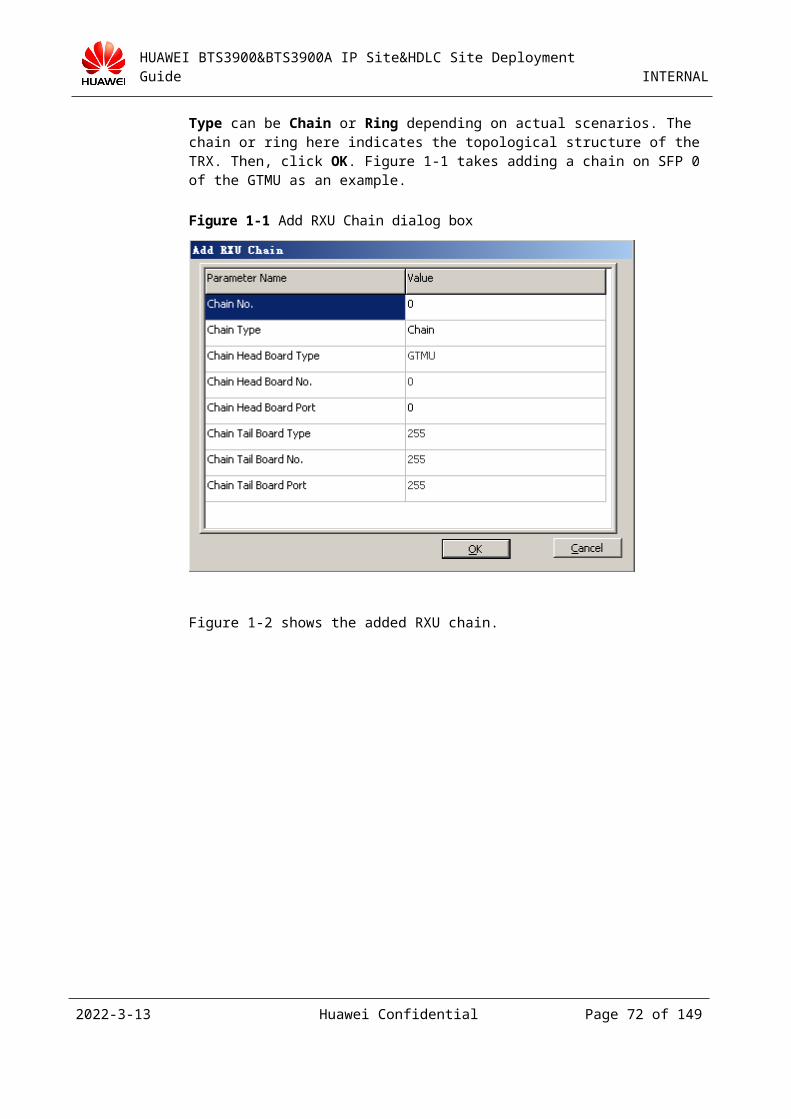
HUAWEI BTS3900&BTS3900A IP Site&HDLC Site Deployment Guide INTERNAL
When setting the frequencies of the GRFU, the bandwidth cannot exceed 15 MHz owing to the limit of the frequency bandwidth. That is, there should be no greater than 74 frequencies between the highest frequency and the lowest frequency because the difference between the two adjacent frequencies is 200 kbit/s.
When setting the frequencies of the GRRU, the bandwidth cannot exceed 12.5 MHz owing to the limit of the frequency bandwidth. That is, there should be no greater than 61 frequencies between the highest frequency and the lowest frequency because the difference between the two adjacent frequencies is 200 kbit/s.
There are no limitations for the frequencies of the DRRU and DRFU.
Figure 3-2 Set Cell Frequency dialog box
Step 22 Return to the Set Cell Attributes dialog box (as shown in Figure 3-1) to set the frequency and attributes of the TRXs.
Click the Frequency Attributes tab page to set the TRX frequency, as shown in Figure 3-1.
Click the Channel Attributes tab page to set the channel attributes of the TRXs, as shown in Figure 3-2.
Click the Device Attributes tab page to set the parameters such as Power Level, Receive Mode, and Send Mode, as shown in Figure 3-3.
2023-4-19 Huawei Confidential Page 72 of 129
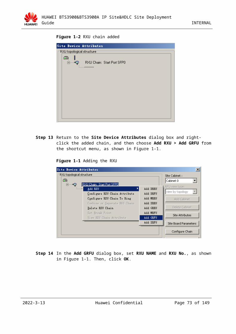
HUAWEI BTS3900&BTS3900A IP Site&HDLC Site Deployment Guide INTERNAL
Figure 3-1 Frequency Attributes tab page
2023-4-19 Huawei Confidential Page 73 of 129
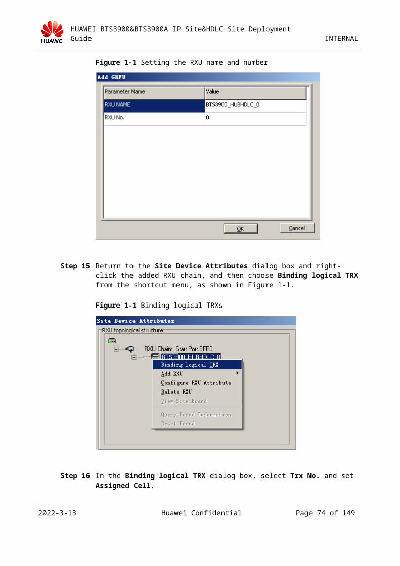
HUAWEI BTS3900&BTS3900A IP Site&HDLC Site Deployment Guide INTERNAL
Figure 3-2 Channel Attributes tab page
2023-4-19 Huawei Confidential Page 74 of 129
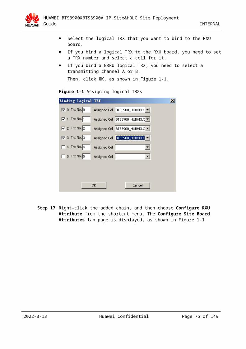
HUAWEI BTS3900&BTS3900A IP Site&HDLC Site Deployment Guide INTERNAL
Figure 3-3 Device Attributes tab page
Figure 3-4 shows the attributes of the cell after configuration.
2023-4-19 Huawei Confidential Page 75 of 129
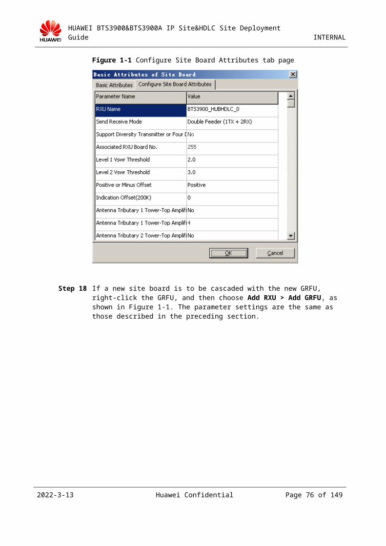
HUAWEI BTS3900&BTS3900A IP Site&HDLC Site Deployment Guide INTERNAL
Figure 3-4 Completing frequency settings of the cell
Step 23 Click Finish to complete the cell configuration, as shown in Figure 3-1.
2023-4-19 Huawei Confidential Page 76 of 129
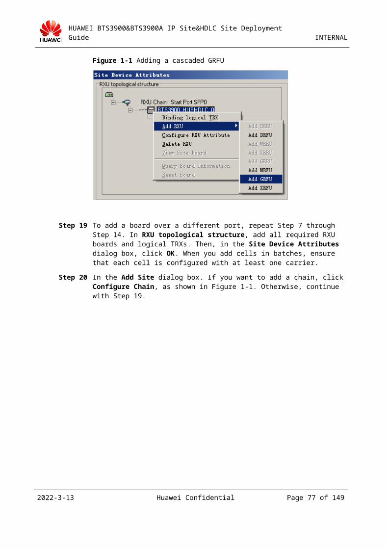
HUAWEI BTS3900&BTS3900A IP Site&HDLC Site Deployment Guide INTERNAL
Figure 3-1 Completing the Add Site wizard
----End
3.3.2 Configuring Hardware and the Transmission Network
Selecting the Port Corresponding to the GEHUB Board
Select the E1 line led out through the port that corresponds to the GEHUB board specified in 3.3.1 "Adding an HDLC HUB Site on the BSC6000 LMT." The numbering of E1 lines starts with 1 whereas the numbering of port numbers starts with 0. Therefore, you can select an E1 line based on a port number plus 1. For example, in 3.3.1 "Adding an HDLC HUB Site on the BSC6000 LMT", the number of the upper-level port is 7. Therefore, you should select #8 E1 line led out from the GEHUB board.
When you connect the E1 line between the BSC and the site, ensure that the sending end of the BSC connects to the receiving end of the site and the receiving end of the BSC connects to the sending end of the site. On the E1 line, the sending end is marked with TX, and the receiving end is marked with RX.
Configuring the Transmission Network
Ensure that the E1 line is properly connected from the port of the site to the port of the BSC. You can use E1 line loopback to check whether the line is physically connected.
Powering On and Checking Status
Check whether the status of the RUN LED on the GTMU board is normal (on for one second and off for one second).
2023-4-19 Huawei Confidential Page 77 of 129
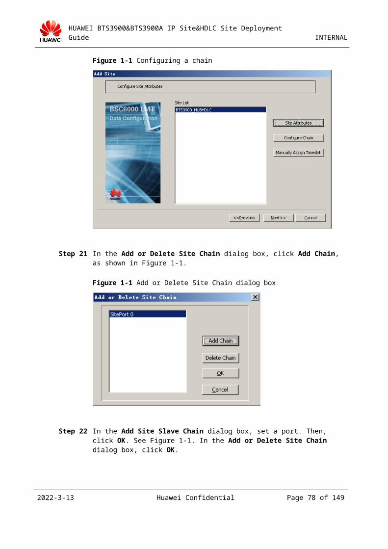
HUAWEI BTS3900&BTS3900A IP Site&HDLC Site Deployment Guide INTERNAL
Check whether the status of the LIU LED is off.
For details about the LEDs on the TMU panel, see 6.1 "LEDs on the TMU Board."
3.3.3 Upgrading a TDM Site on the Existing Network to an HDLC HUB Site
Generally, the TDM site is configured on the GEIUB of the BSC rack. To upgrade a TDM site to an HDLC HUB site, you must ensure that the GEHUB is available on the BSC side. If no GEHUB is available on the BSC rack, you need to insert the board and then complete the configuration.
You can upgrade a TDM site on the existing network to an HDLC HUB site by one of the following two methods: 1. Upgrade a TDM site on the existing network to an HDLC HUB site by the site movement function; 2. Directly build an HDLC HUB site.
Method 1: Upgrade a TDM site on the existing network to an HDLC HUB site by the site movement function (method 1 is recommended to facilitate the construction and reduce the service interruption time)
Step 1 Select the GEHUB of the BSC corresponding to the target HDLC HUB site and the available port of the GEHUB.
Step 2 To move a site, do as follows:
On the BSC6000 LMT, right-click the TDM site to be upgraded in the navigation tree, and then choose Site Operation > Move Site from the shortcut menu, as shown in Figure 3-1.
Figure 3-1 Moving a site (1)
2023-4-19 Huawei Confidential Page 78 of 129
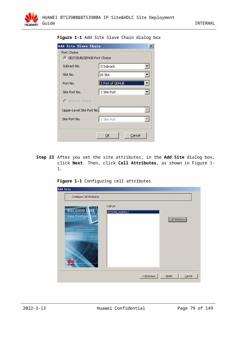
HUAWEI BTS3900&BTS3900A IP Site&HDLC Site Deployment Guide INTERNAL
In the Move Site dialog box, select the target site from the Site View area, and then click Move Site, as shown in Figure 3-2.
Figure 3-2 Moving a site (2)
2023-4-19 Huawei Confidential Page 79 of 129
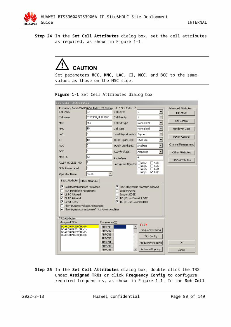
HUAWEI BTS3900&BTS3900A IP Site&HDLC Site Deployment Guide INTERNAL
In the Move Site dialog box, select HDLC Hub to change the TDM site to the HDLC site, as shown in Figure 3-3. Click BSC Port. In the displayed dialog box, click YES. The Choice Board&Port dialog box is displayed, as shown in Figure 3-4.
Figure 3-3 Moving a site (3)
Figure 3-4 Choice Board&Port dialog box
Set the parameters Dest SubRack No., Dest Slot No., and Dest Port No. to proper values based on the GEHUB position. Then, click OK.
In the displayed dialog box, click OK to return to the Move Site dialog box, and then click Next, as shown in Figure 3-5.
2023-4-19 Huawei Confidential Page 80 of 129
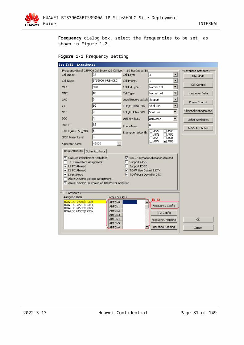
HUAWEI BTS3900&BTS3900A IP Site&HDLC Site Deployment Guide INTERNAL
Figure 3-5 Moving a site (4)
In the displayed Move Site dialog box, the original connection of the site and the connection after the site is moved are available in the Move Site Result area. Ensure that the current connection of the site is correct, and then click Finish, as shown in Figure 3-6.
Figure 3-6 Result of moving a site (1)
Click Continue, as shown in Figure 3-7. After the timeslots in the TDM site are arranged, a message is displayed to prompt you to confirm the operation. Then, click OK.
2023-4-19 Huawei Confidential Page 81 of 129
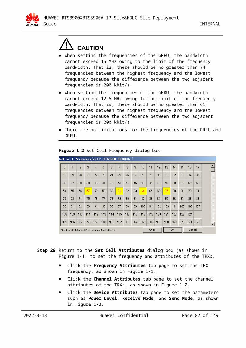
HUAWEI BTS3900&BTS3900A IP Site&HDLC Site Deployment Guide INTERNAL
Figure 3-7 Result of moving a site (2)
Step 3 To complete the configuration of the lower-level site to the HDLC HUB site after the site is moved, you need add the lower-level site by referring to 3.3.1 "Adding an HDLC HUB Site on the BSC6000 LMT" after moving the BTS.
Step 4 Remove the E1 cable that connects the TDM site to the GEIUB. Then, insert the E1 cable into the GEHUB in the BSC rack. (Remove the original E1 cable that connects the TDM site to the GEIUB in the BSC rack, and then insert the cable into the corresponding port on the GEHUB that is connected to the added HDLC site.) The OML is established after two minutes and the RSL is established after five minutes.
Step 5 After the previous operations, the site still runs properly. The services processed on the site are disrupted for about 18 to 20 minutes during the entire process.
----End
Method 2: Upgrade a TDM site on the existing network to an HDLC HUB site by directly building an HDLC HUB site
To reduce the time of service interruption, you can upgrade a TDM site to an HDLC HUB site as follows:Configuring an HDLC HUB Site on the BSC6000 LMT > Preparing the E1 Line from the BSC to the Site > Loading the Latest Version of the TMU > Loading the Latest Version of the TRX > Activating the Latest Version of the TMU (Supporting the PTU) > Disconnecting the Existing Network Cable from the TDM Site and Inserting the E1 Line into the Subrack
The operations for configuring the HDLC HUB site on the BSC6000 LMT are the same as those for adding an HDLC HUB site. For details, see 3.3.1 "Adding an HDLC HUB Site on the BSC6000 LMT."
The operations for configuring hardware and the transmission network are the same as those for adding an HDLC HUB site. For details, see 3.3.1 "Adding an HDLC HUB Site on the BSC6000 LMT."
2023-4-19 Huawei Confidential Page 82 of 129
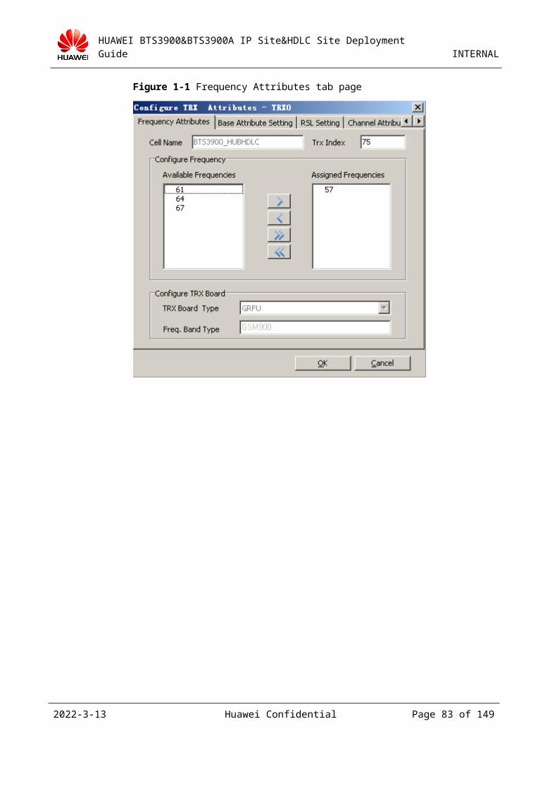
HUAWEI BTS3900&BTS3900A IP Site&HDLC Site Deployment Guide INTERNAL
3.4 Adding an IP SiteTo support an IP site, you need to add the GFGUB (an IP Abis interface board) on the BSC6000. For details, see the related BSC6000 deployment guide.
This topic describes how to add an IP site. This procedure consists of the following operations:Adding an IP Site on the BSC6000 LMT > Installing the BBU > Adding a Physical Connection Between the Site and the BSC > Configuring the Transmission Network > Powering On and Checking Status > Loading and Upgrading Software
The BSC provides the port IP address and the device IP address for communication with the BTS. Table 3-1 lists the comparison between the two communication modes. For details, see the related BSC6000 deployment guide.
Table 3-1 Comparison between the port IP address and the device IP address
Port IP Address Device IP Address
Advantage 1. The configuration is simple.
2. The port IP address is visible to the intermediate transmission network.
3. When the port IP address serves as a service IP address, fewer addresses are required.
When a physical link is faulty, the communication mode is simpler to implement mutual aid between links and ensure that services are not affected.
Disadvantage When a physical link is faulty, the communication mode is more complex to implement mutual aid between links and ensure that services are not affected.
1. A static route to the device IP address must be configured.
2. When the L3 transmission equipment exists between the BTS and the BSC, the route to the device IP address must be known. In this case, the requirements for the transmission network are high.
3. When the device IP address serves as a service IP address, more addresses are required.
3.4.1 Obtaining the Bar Code of a SiteThe bar code uniquely identifies a site in the BSC. Before adding an IP site, you need to obtain the bar code of the site. The bar code is marked in three places of the BBU subrack, as shown in the yellow areas in Figure 3-1 (another place is the bottom of the subrack). The bar code of the BBU subrack is the bar code of the site (20 bits), as shown in the red area in Figure 3-2.
If the bar code is configured improperly on the BSC, the BTS cannot obtain an IP address through DHCP. During the deployment, you must ensure that the bar code of the BBU is consistent with that configured on the BSC.
2023-4-19 Huawei Confidential Page 83 of 129

HUAWEI BTS3900&BTS3900A IP Site&HDLC Site Deployment Guide INTERNAL
Figure 3-1 Location of the bar code
Figure 3-2 20-bit bar code
3.4.2 Adding an IP Site on the BSC6000 LMT
Table 3-1 Network planning in the lab
Parameter Configuration
Device IP address of the BSC 4.4.4.4
Subnet mask of the BSC 255.255.255.0
Communication mode of the Abis interface Device IP address
GFGUB port Port 5
BTS communication type Port IP address
Port IP address of the BSC 12.13.11.10
Port IP address of the BTS 12.13.11.11
Port subnet mask of the BTS 255.255.255.0
Bar code of the BTS 12345678901234567890
TRX type GRFU TRX
2023-4-19 Huawei Confidential Page 84 of 129
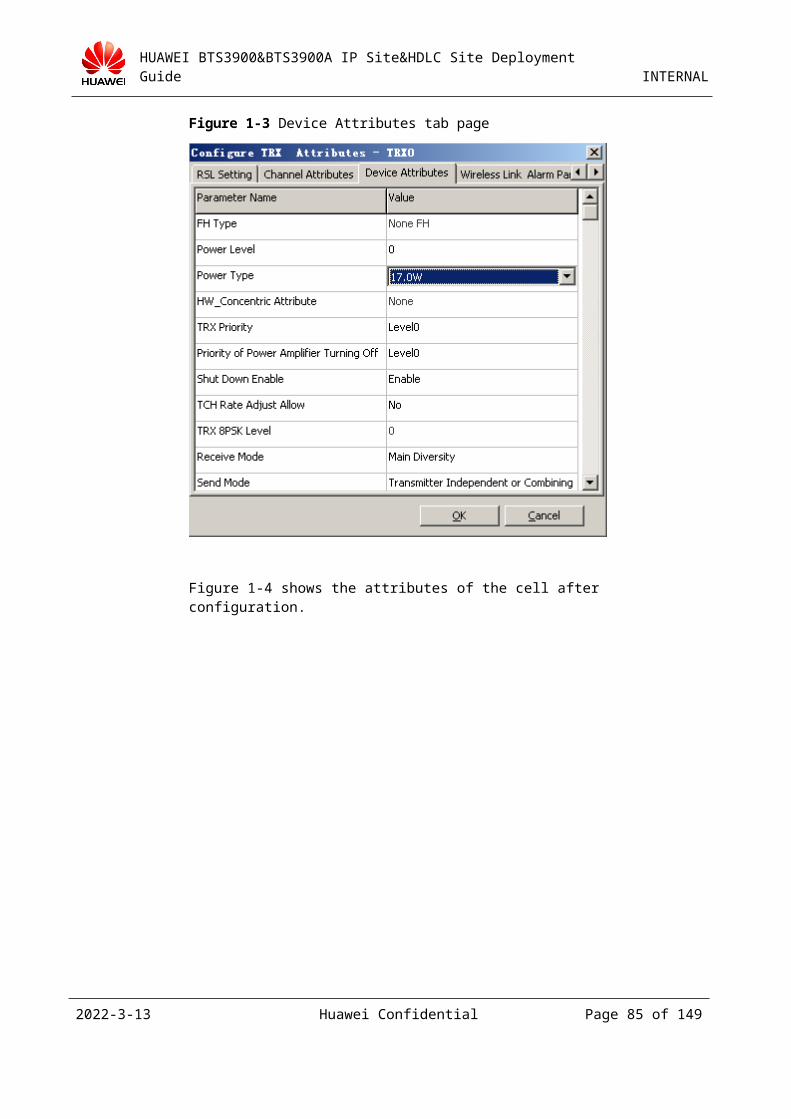
HUAWEI BTS3900&BTS3900A IP Site&HDLC Site Deployment Guide INTERNAL
When the BSC6000 communicates with the BTS through the device IP address or the port IP address, the configurations on the BTS side are the same.
When the active and standby GFGUBs are used, a switch must be configured between the BSC and BTS (that is, the ports with the same number on the active and standby GFGUBs are connected to the switch). Generally, the data configuration is performed for the active board, and the BSC automatically backs up the data to the standby board.
Step 1 Configure the device IP address (skip this step if you have set the device IP address of the BSC). On the BSC6000 LMT, right-click a GFGUB board and choose Configure Device IP, as shown in Figure 3-1.
Figure 3-1 Setting the device IP address
In the Configure Device IP dialog box, click Add. Set the logical IP address and the subnet mask. Then, click OK, as shown in Figure 3-2.
2023-4-19 Huawei Confidential Page 85 of 129
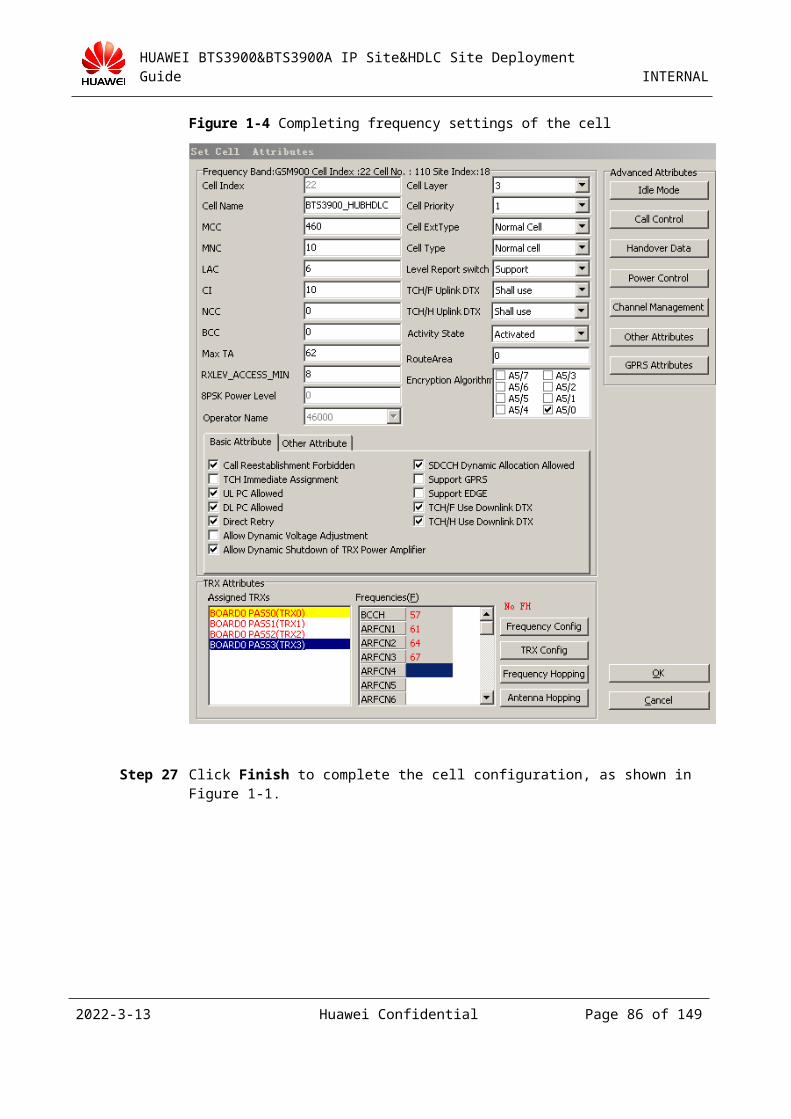
HUAWEI BTS3900&BTS3900A IP Site&HDLC Site Deployment Guide INTERNAL
Figure 3-2 Adding a device IP address
Step 2 Set port IP addresses. On the BSC6000 LMT, right-click a GFGUB board and choose Configure Ethernet Port Ip, as shown in Figure 3-1.
Figure 3-1 Setting port IP addresses
The Configure Ethernet Port IP dialog box is displayed, as shown in Figure 3-2.
2023-4-19 Huawei Confidential Page 86 of 129
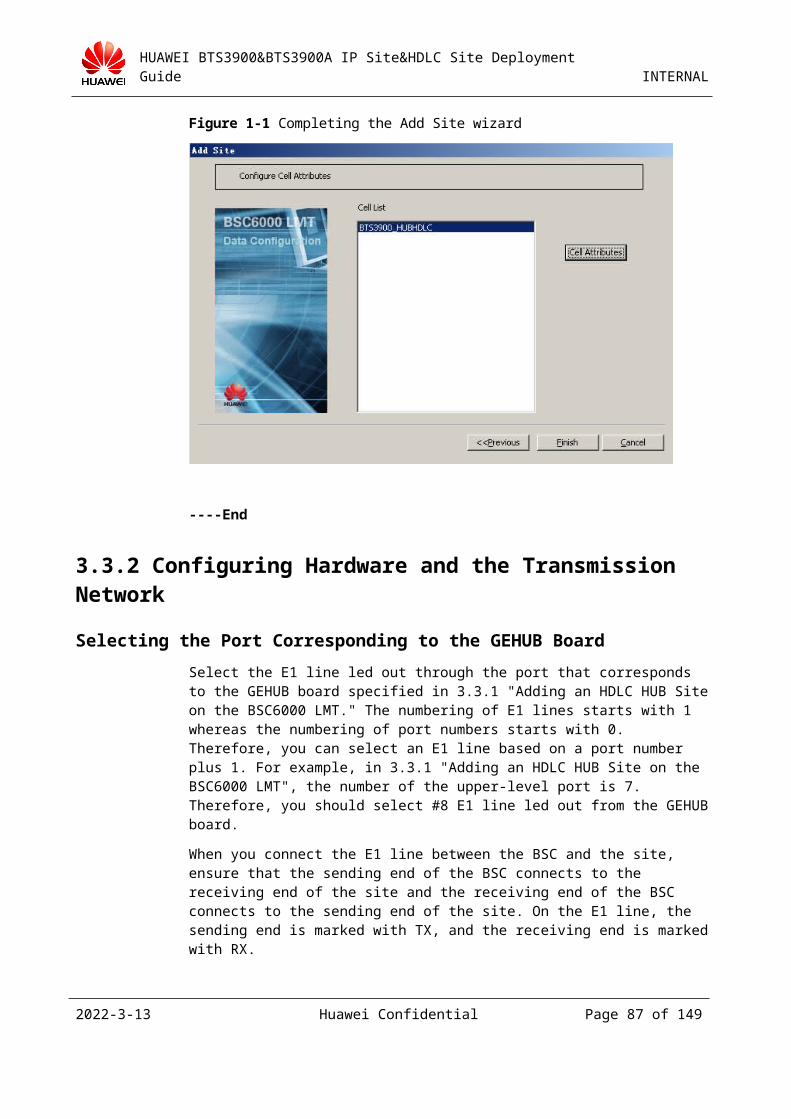
HUAWEI BTS3900&BTS3900A IP Site&HDLC Site Deployment Guide INTERNAL
Figure 3-2 Configure Ethernet Port IP dialog box
Select a port that is not in use, for example, port 5. Set the port number, host IP address, and subnet mask, and then click OK, as shown in Figure 3-3.
Figure 3-3 Setting the IP address for port 5
2023-4-19 Huawei Confidential Page 87 of 129
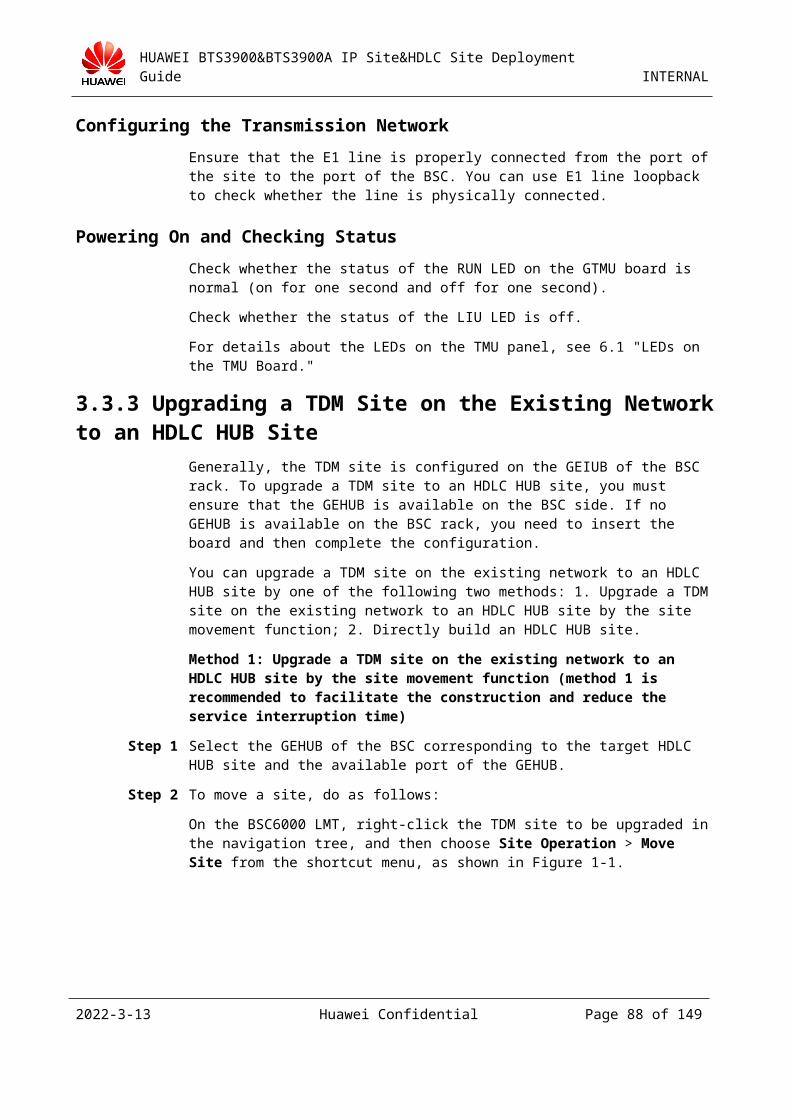
HUAWEI BTS3900&BTS3900A IP Site&HDLC Site Deployment Guide INTERNAL
Step 3 Configure the router between the BSC and the BTS. For layer 2 networking, skip this step. On the BSC6000 LMT, right-click the GFGUB board and choose Configure BSC router, as shown in Figure 3-1.
Figure 3-1 Configuring a BSC router
The Configure BSC router dialog box is displayed, as shown in Figure 3-2.
2023-4-19 Huawei Confidential Page 88 of 129

HUAWEI BTS3900&BTS3900A IP Site&HDLC Site Deployment Guide INTERNAL
Figure 3-2 BSC router
In the Configure BSC Router dialog box, click Add to add a BSC router, as shown in Figure3-3.
Figure 3-3 Adding a BSC router
The destination IP address of the route is the network segment where the IP address of the BTS is located. The next hop is the IP address of the port of the router that is connected to the
2023-4-19 Huawei Confidential Page 89 of 129
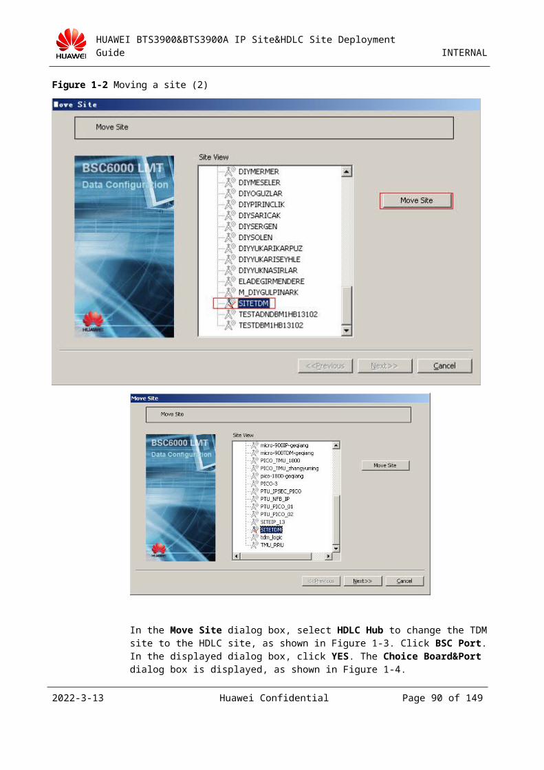
HUAWEI BTS3900&BTS3900A IP Site&HDLC Site Deployment Guide INTERNAL
BSC. The DHCP relay is configured on the router that is connected to the BTS and not configured on the port of the BSC.
In layer 3 networking, the IP address and the subnet mask of the site should be changed to the IP address and the subnet mask of the corresponding destination network segment.
Step 4 On the BSC6000 LMT, right-click a GFHUB and choose Add Site from the shortcut menu, as shown in Figure 3-1.
Figure 3-1 Adding a site
Step 5 The Add Site dialog box is displayed, as shown in Figure 3-1. Click Add Site.
2023-4-19 Huawei Confidential Page 90 of 129
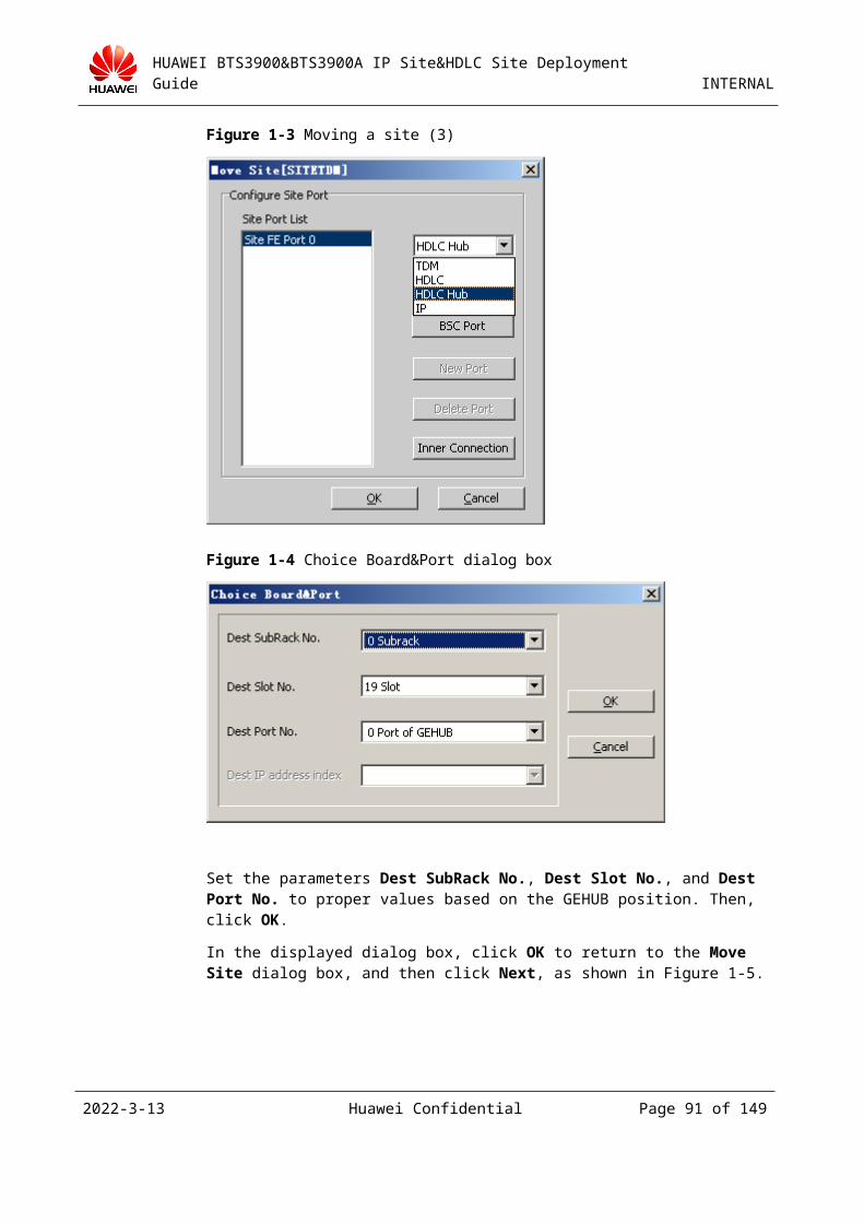
HUAWEI BTS3900&BTS3900A IP Site&HDLC Site Deployment Guide INTERNAL
Figure 3-1 Add Site dialog box
Step 6 In the Add New Site dialog box, set the parameters as required. Set Site Type to BTS3900 GSM to Service Mode to IP. Then, click OK to finish the configuration, as shown in Figure 3-1.
1.This dialog box may vary with different BSC versions, but the configuration process is the same.
2.The Cfg RFU by Slot check box is not selected when adding a new site. The future configuration could be based on the RXU topological structure (for details, see Step 9).
2023-4-19 Huawei Confidential Page 91 of 129
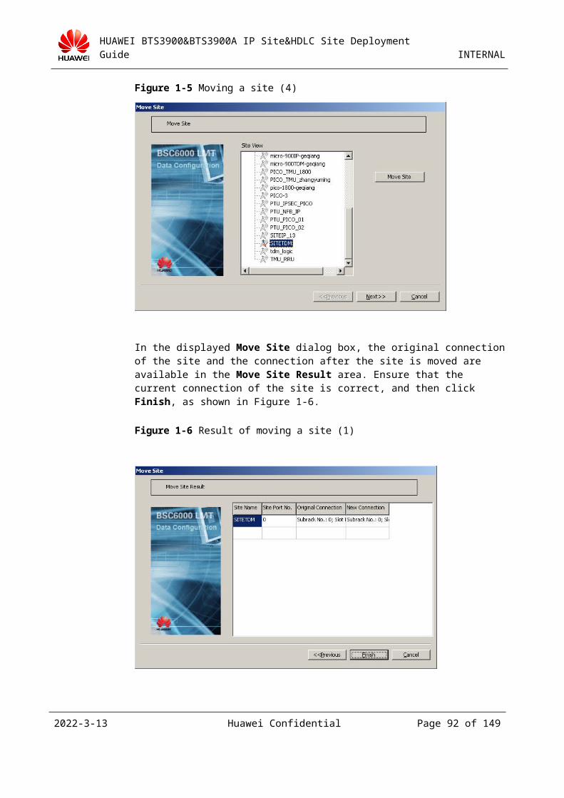
HUAWEI BTS3900&BTS3900A IP Site&HDLC Site Deployment Guide INTERNAL
Figure 3-1 Add New Site dialog box
The following describes the meanings of the parameters in the Add New Site dialog box.
Site IP and IP Mask: Currently, the BTS can communicate with the BSC through the IP network. Therefore, Site IP and IP Mask should be set. In layer 2 networking mode, the IP address of the BTS should be on the same network segment as that of port 5 on the BSC.
Step 7 In the Add Site dialog box, click Next. In the Add Cell dialog box, click Add Cell, as shown in Figure 3-1.
2023-4-19 Huawei Confidential Page 92 of 129
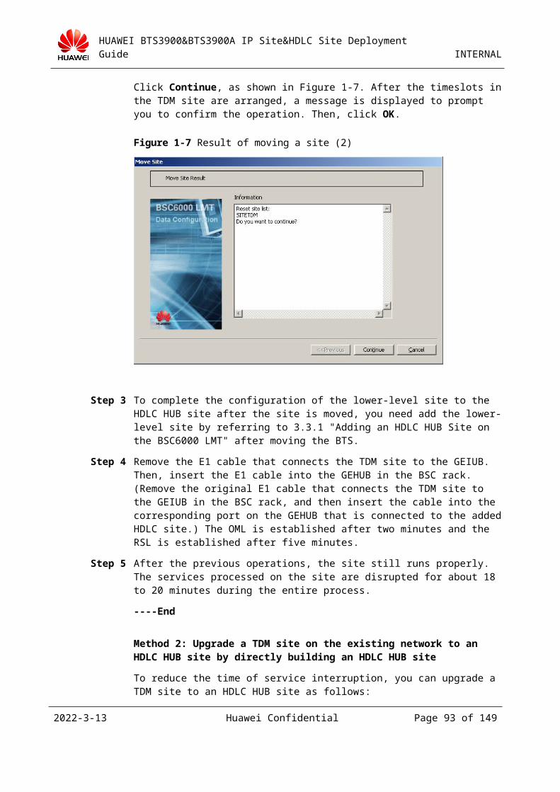
HUAWEI BTS3900&BTS3900A IP Site&HDLC Site Deployment Guide INTERNAL
The IP sites cannot be cascaded.
Figure 3-1 Add Cell dialog box
In the Add New Cell dialog box, set Cell Name and Frequency Band. Then click OK to finish the configuration, as shown in Figure 3-2.
Figure 3-2 Add New Cell dialog box
Step 8 Return to the Add Site dialog box, and then click Next. In the Configure Site Attributes dialog box, click Site Attributes, as shown in Figure 3-1.
2023-4-19 Huawei Confidential Page 93 of 129
HUAWEI BTS3900&BTS3900A IP Site&HDLC Site Deployment Guide INTERNAL
Figure 3-1 Configure Site Attributes dialog box
Step 9 In the Site Device Attributes dialog box, right-click the icon under RXU topological structure. Choose Add RXU Chain from the shortcut menu, as shown in Figure 3-1.
Figure 3-1 Adding the RXU chain
In the Add RXU Chain dialog box, set Chain Type and Chain Head Board Port. Chain Head Board Port is the port number of the SFP where the TRX is connected, that is, the CPRI port; Chain Type can be Chain or Ring depending on actual scenarios. The chain or ring here indicates the topological structure of the TRX. Then, click OK. Figure 3-2 takes adding a chain on SFP 0 of the GTMU as an example.
2023-4-19 Huawei Confidential Page 94 of 129
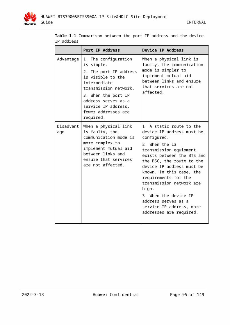
HUAWEI BTS3900&BTS3900A IP Site&HDLC Site Deployment Guide INTERNAL
Figure 3-2 Add RXU Chain dialog box
Figure 3-3 shows the added RXU chain.
Figure 3-3 RXU chain added
Step 10 Return to the Site Device Attributes dialog box and right-click the added chain, and then choose Add RXU > Add GRFU from the shortcut menu, as shown in Figure 3-1.
2023-4-19 Huawei Confidential Page 95 of 129
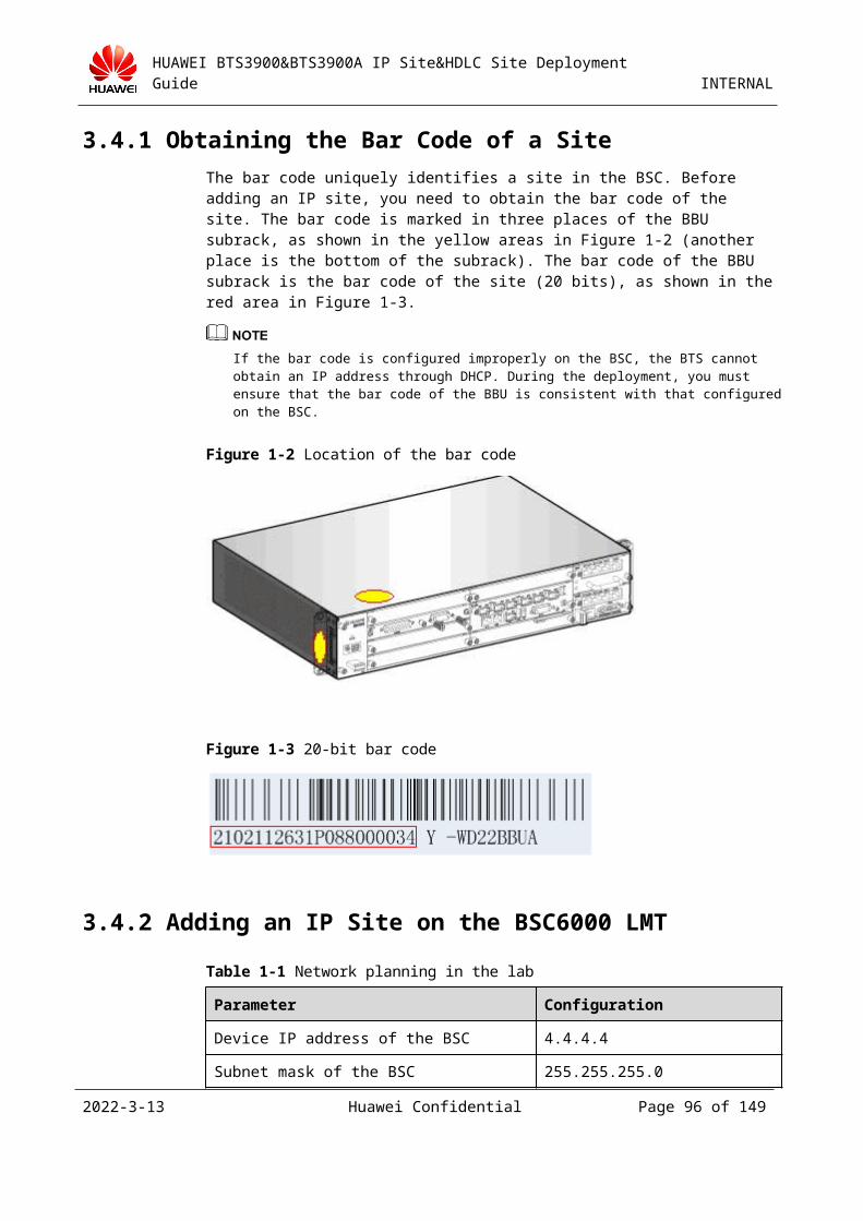
HUAWEI BTS3900&BTS3900A IP Site&HDLC Site Deployment Guide INTERNAL
Figure 3-1 Adding the GRFU
In the Add GRFU dialog box, set RXU NAME and RXU No., as shown in Figure 3-2. Then, click OK.
Figure 3-2 Setting the RXU name and number
Step 11 Return to the Site Device Attributes dialog box and right-click the added RXU chain, and then choose Binding logical TRX from the shortcut menu, as shown in Figure 3-1.
2023-4-19 Huawei Confidential Page 96 of 129
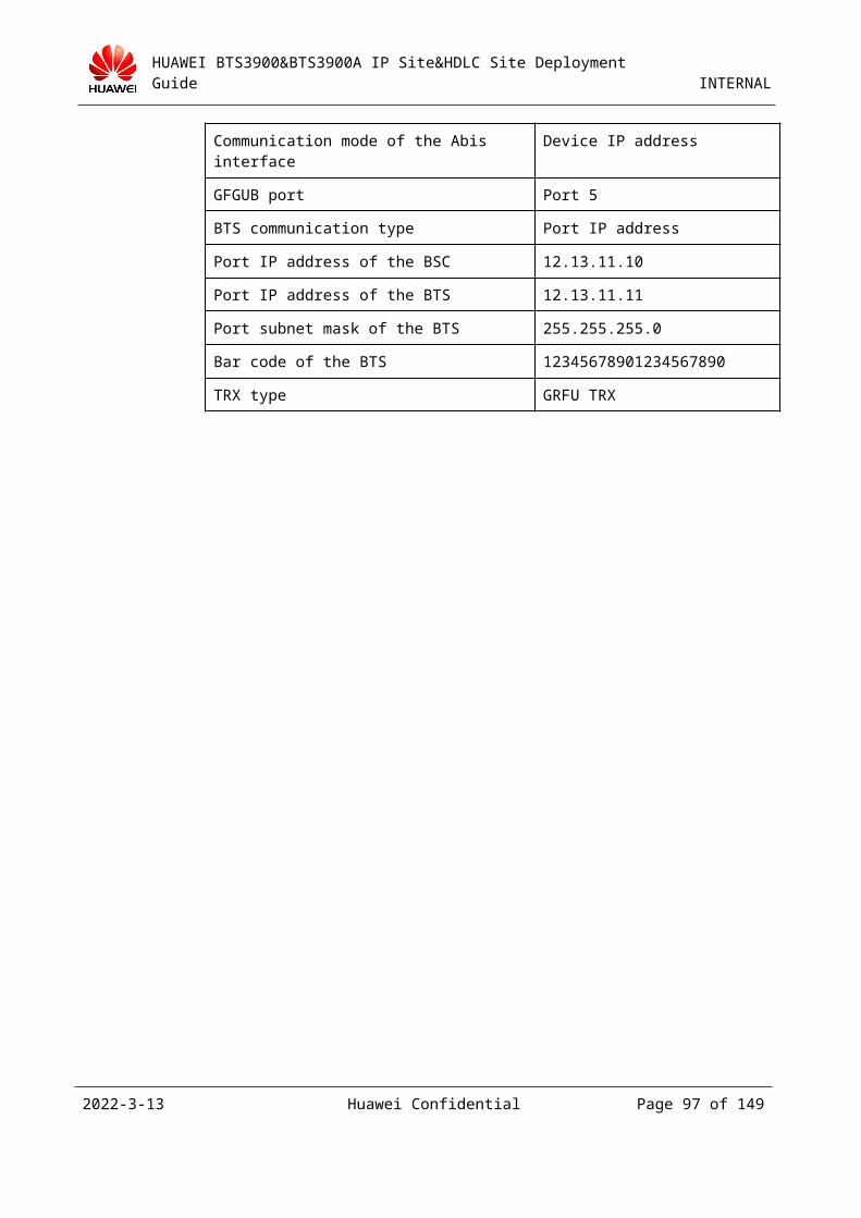
HUAWEI BTS3900&BTS3900A IP Site&HDLC Site Deployment Guide INTERNAL
Figure 3-1 Binding logical TRXs
In the Binding logical TRX dialog box, select Trx No. and set Assigned Cell.
Select the logical TRX that you want to bind to the RXU board.
If you bind a logical TRX to the RXU board, you need to set a TRX number and select a cell for it.
If you bind a GRRU logical TRX, you need to select a transmitting channel A or B.
Then, click OK, as shown in Figure 3-2.
Figure 3-2 Binding logical TRXs
Step 12 Right-click the added chain, and then choose Configure RXU Attribute from the shortcut menu to set board attributes as planned, as shown in Figure 3-1.
2023-4-19 Huawei Confidential Page 97 of 129
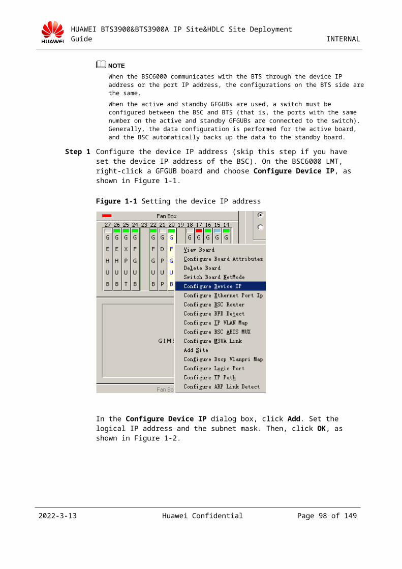
HUAWEI BTS3900&BTS3900A IP Site&HDLC Site Deployment Guide INTERNAL
Figure 3-1 Configure Site Board Attributes tab page
Step 13 If a new site board is to be cascaded with the GRFU, right-click the GRFU, and then choose Add RXU > Add GRFU from the shortcut menu, as shown in Figure 3-1.
Figure 3-1 Adding a cascaded GRFU
2023-4-19 Huawei Confidential Page 98 of 129
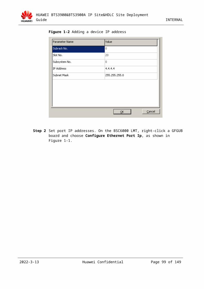
HUAWEI BTS3900&BTS3900A IP Site&HDLC Site Deployment Guide INTERNAL
To add a board over a different port, repeat Step 9 through Step 13. In RXU topological structure, add all required RXU boards and logical TRXs. When you add cells in batches, ensure that each cell is configured with at least one carrier.
Step 14 In the Site Device Attributes dialog box, right-click a GTMU board and choose Configure Board Attributes, as shown in Figure 3-1.
Figure 3-1 Setting an electronic label
In the Basic Attributes of Site Board dialog box, click the IP Interface Board Parameter of BTS tab. According to the bar code of the BBU, set BTS Interface Board Bar Code 1. Then, click the FE port parameter of BTS tab to set port parameters. After you set the port parameters, click OK, as shown in Figure 3-2 and Figure 3-3.
Figure 3-2 Setting a bar code of the electronic label
2023-4-19 Huawei Confidential Page 99 of 129
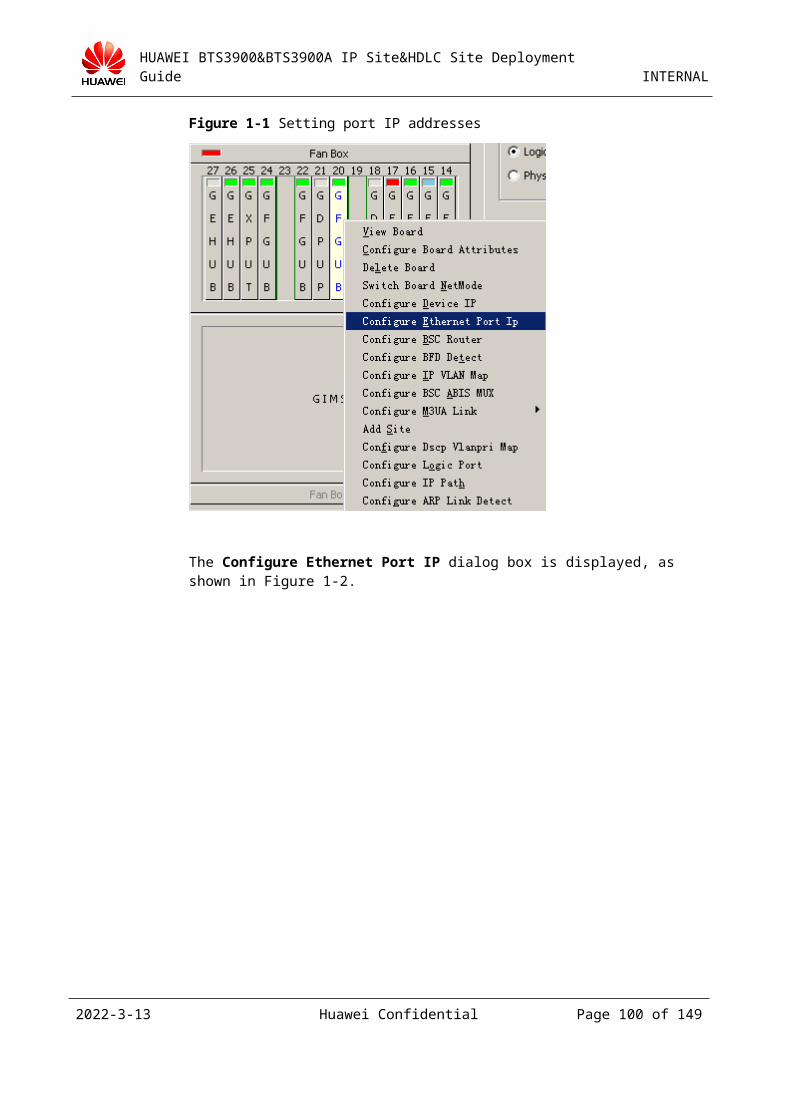
HUAWEI BTS3900&BTS3900A IP Site&HDLC Site Deployment Guide INTERNAL
Figure 3-3 Setting parameters of the FE port
The current version supports only 100 Mbit/s full duplex. It does not support 10 Mbit/s full duplex, 10 Mbit/s half duplex, or 100 Mbit/s half duplex.
Step 15 After you set the site attributes, in the Add Site dialog box, click Next. Then, click Cell Attributes, as shown in Figure 3-1.
2023-4-19 Huawei Confidential Page 100 of 129
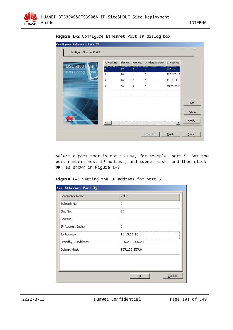
HUAWEI BTS3900&BTS3900A IP Site&HDLC Site Deployment Guide INTERNAL
Figure 3-1 Configuring cell attributes
In the Set Cell Attributes dialog box, set the cell attributes as required, as shown in Figure 3-2.
Set parameters MCC, MNC, LAC, CI, NCC, and BCC to the same values as those on the MSC side.
2023-4-19 Huawei Confidential Page 101 of 129
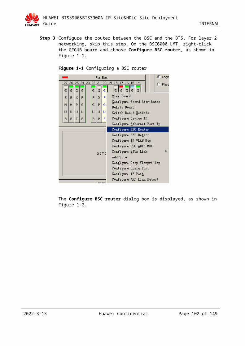
HUAWEI BTS3900&BTS3900A IP Site&HDLC Site Deployment Guide INTERNAL
Figure 3-2 Set Cell Attributes dialog box
In the Set Cell Attributes dialog box, double-click the TRX under Assigned TRXs or click Frequency Config to configure required frequencies, as shown in Figure 3-3. In the Set Cell Frequency dialog box, select the frequencies to be set, as shown in Figure 3-4.
2023-4-19 Huawei Confidential Page 102 of 129
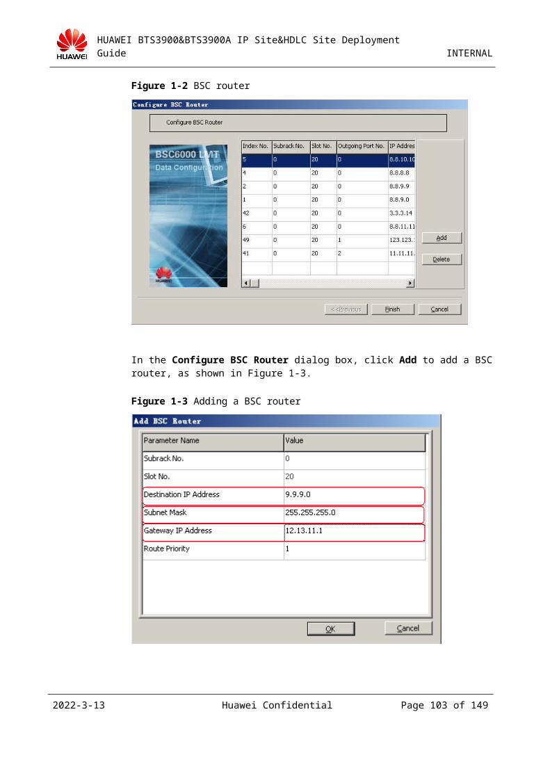
HUAWEI BTS3900&BTS3900A IP Site&HDLC Site Deployment Guide INTERNAL
Figure 3-3 Frequency setting
2023-4-19 Huawei Confidential Page 103 of 129
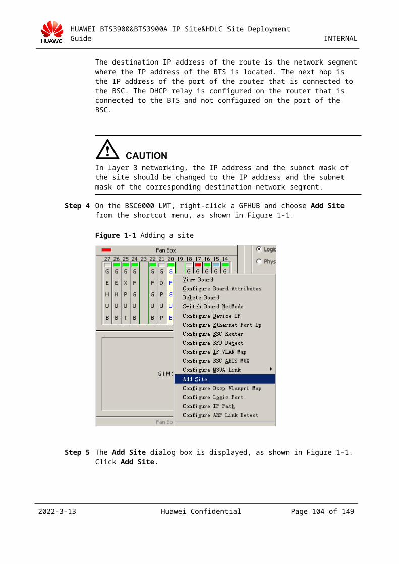
HUAWEI BTS3900&BTS3900A IP Site&HDLC Site Deployment Guide INTERNAL
When setting the frequencies of the GRFU, the bandwidth cannot exceed 15 MHz owing to the limit of the frequency bandwidth. That is, there should be no greater than 75 frequencies between the highest frequency and the lowest frequency because the difference between the two adjacent frequencies is 200 kbit/s.
When setting the frequencies of the GRRU, the bandwidth cannot exceed 12.5 MHz owing to the limit of the frequency bandwidth. That is, there should be no greater than 62 frequencies between the highest frequency and the lowest frequency because the difference between the two adjacent frequencies is 200 kbit/s.
There are no limitations for the frequencies of the DRRU and DRFU.
Figure 3-4 Set Cell Frequency dialog box
Return to the Set Cell Attributes dialog box (as shown in Figure 3-2) to set the frequency and attributes of the TRXs.
Click the Frequency Attributes tab page to set the TRX frequency, as shown in Figure 3-5.
Click the Channel Attributes tab page to set the channel attributes of the TRXs, as shown in Figure 3-6.
Click the Device Attributes tab page to set the parameters such as Power Level, Receive Mode, and Send Mode, as shown in Figure 3-7.
2023-4-19 Huawei Confidential Page 104 of 129
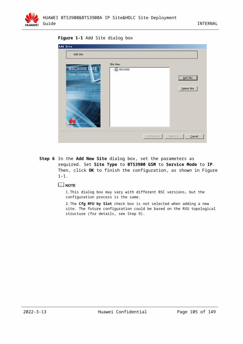
HUAWEI BTS3900&BTS3900A IP Site&HDLC Site Deployment Guide INTERNAL
Figure 3-5 Frequency Attributes tab page
2023-4-19 Huawei Confidential Page 105 of 129
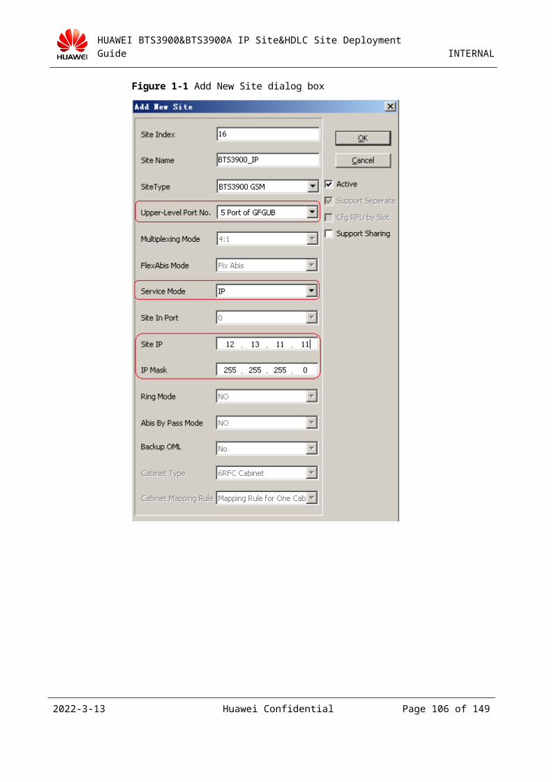
HUAWEI BTS3900&BTS3900A IP Site&HDLC Site Deployment Guide INTERNAL
Figure 3-6 Channel Attributes tab page
2023-4-19 Huawei Confidential Page 106 of 129
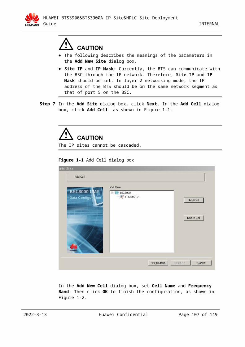
HUAWEI BTS3900&BTS3900A IP Site&HDLC Site Deployment Guide INTERNAL
Figure 3-7 Device Attributes tab page
Figure 3-8 shows the attributes of the cell after configuration.
2023-4-19 Huawei Confidential Page 107 of 129

HUAWEI BTS3900&BTS3900A IP Site&HDLC Site Deployment Guide INTERNAL
Figure 3-8 Set Cell Attributes dialog box
Click Finish to complete the cell configuration, as shown in Figure 3-9.
2023-4-19 Huawei Confidential Page 108 of 129
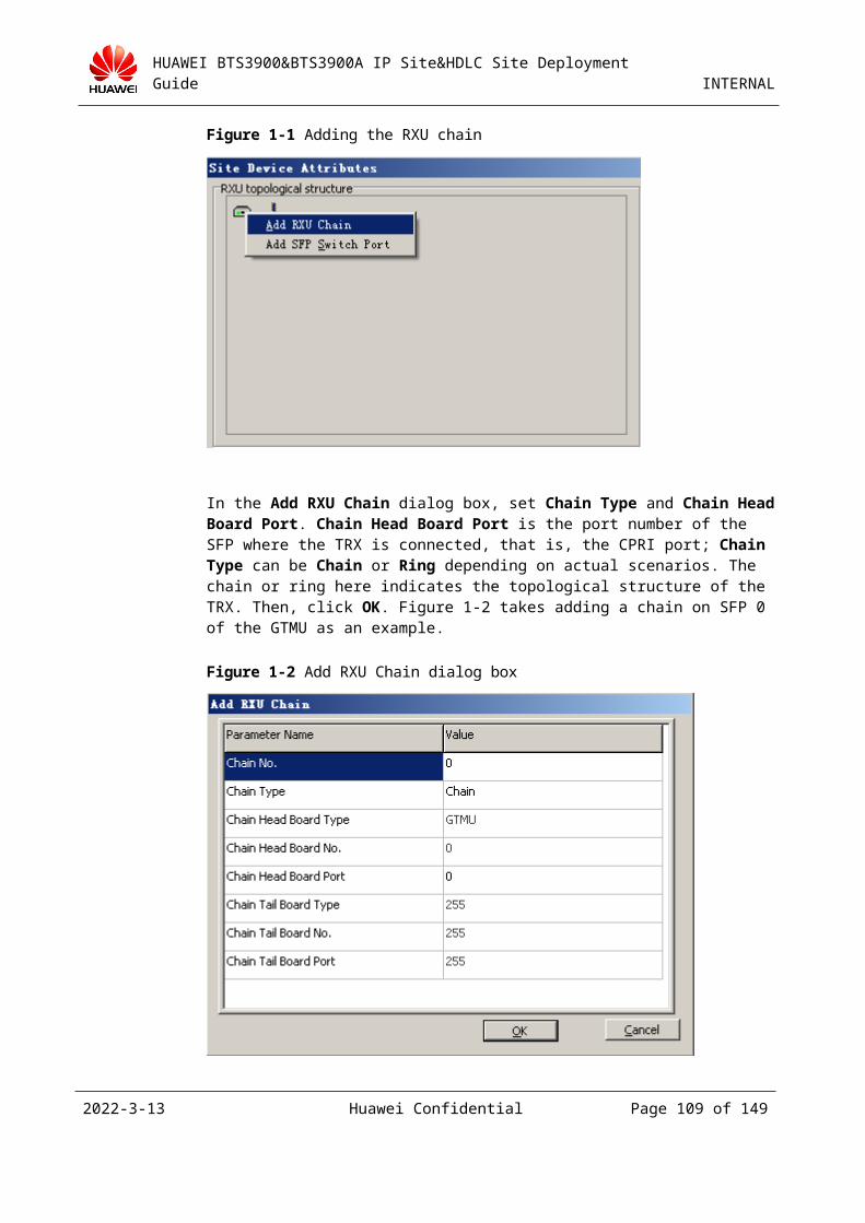
HUAWEI BTS3900&BTS3900A IP Site&HDLC Site Deployment Guide INTERNAL
Figure 3-9 Completing the Add Site wizard
----End
3.4.3 Configuring the IP Clock ServerThe IP clock server can work with the IP site to provide the standard clock reference source.
Configuring the Clock Server
The contents to be configured include the working mode of the clock server, the type of the client connected to the clock server, system time, clock source mode, clock source, DA value, and route between the clock server and the BTS. For details, see the related clock server document. Figure 3-1 shows the position of the clock server in a network.
2023-4-19 Huawei Confidential Page 109 of 129
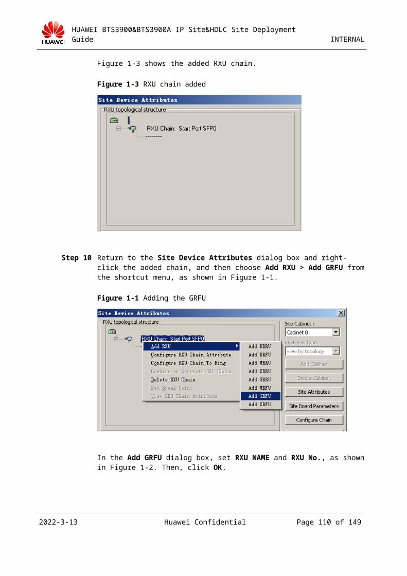
HUAWEI BTS3900&BTS3900A IP Site&HDLC Site Deployment Guide INTERNAL
Figure 3-1 Position of the clock server in a network
Configuring the Clock on the BSC6000 LMT
Note: You can skip this procedure if the IP clock is already configured.
Step 1 On the BSC6000 LMT, right-click BSC6000 in the navigation tree on the left, and then choose Configure BSC Attributes from the shortcut menu.
Step 2 Click the IP Transfers tab in the Configure BSC Attributes dialog box, and then configure Clock Server IP, ShakeHandPeriodA, ShakeHandPeriodB, ShakeHandPeriodC, and Clock synchronization Mode. In the case of the intermittent synchronization mode, you need also configure Interval Synchronization Period(Day), Interval Synchronization Start Time(Hour), and Interval Synchronization Start Time(Minute). Click Finish, as shown in Figure 3-1.
2023-4-19 Huawei Confidential Page 110 of 129
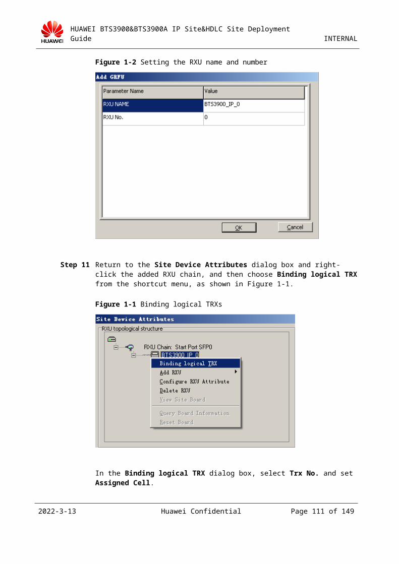
HUAWEI BTS3900&BTS3900A IP Site&HDLC Site Deployment Guide INTERNAL
Figure 3-1 Configuring the clock on the BSC6000 LMT
----End
1.To ensure that the clock frequency output by the clock server is a standard reference source, you must calibrate the clock server before using it.
2.The value of ShakeHandPeriodB must be greater than the values of ShakeHandPeriodA and ShakeHandPeriodC.
3.4.4 Configuring Hardware and the Transmission Network
Selecting the Port Corresponding to the GEHUB Board
Select the E1 line led out through the port that corresponds to the GFGUB board specified in 3.4.2 "Adding an IP Site on the BSC6000 LMT." The new site is set up over a port. Ensure that you connect the network cable from the specific port to the site. For example, in 3.4.2 "Adding an IP Site on the BSC6000 LMT", the new IP site is attached to the GFGUB board in
2023-4-19 Huawei Confidential Page 111 of 129
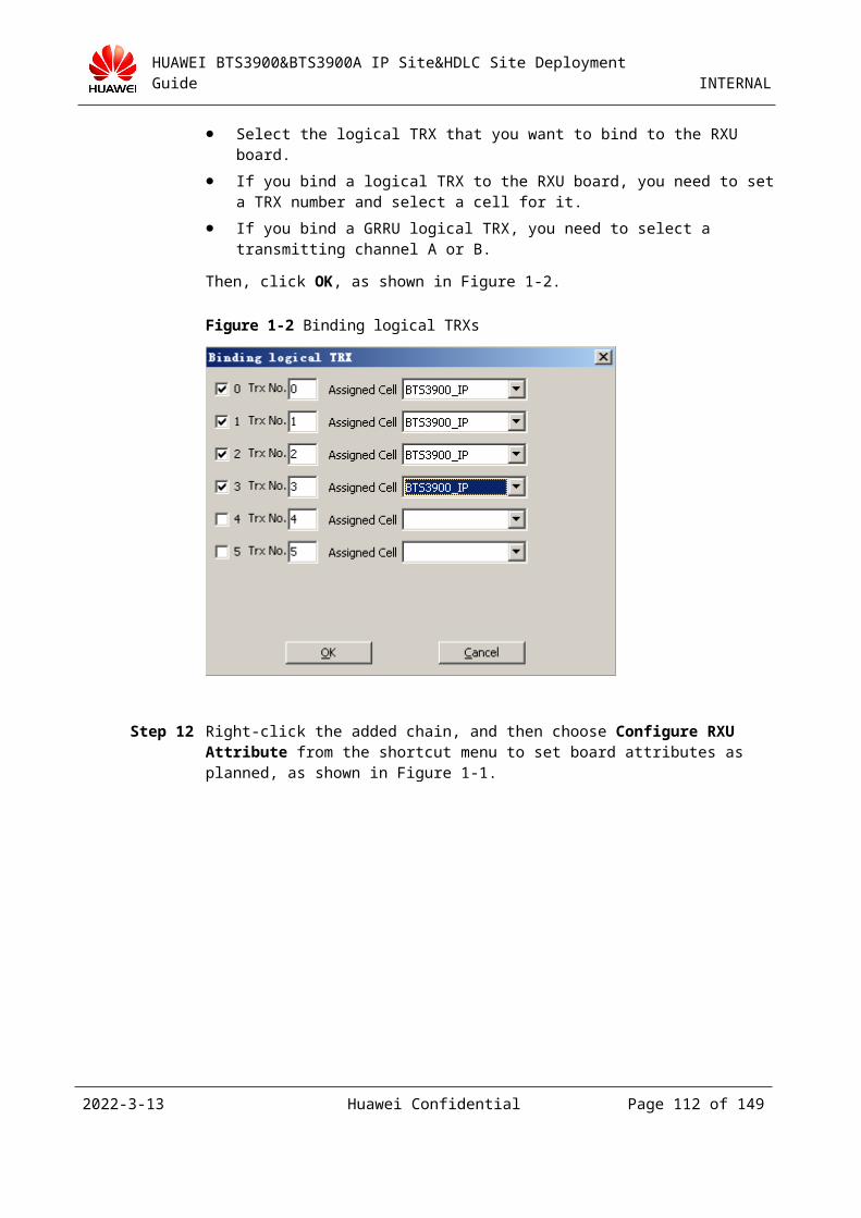
HUAWEI BTS3900&BTS3900A IP Site&HDLC Site Deployment Guide INTERNAL
slot 20 and uses #5 upper-level port. (The numbering of ports starts with 0.) Therefore, you should connect the sixth port of the GFGUB board from top down to the port of the IP site.
Configuring the Transmission Network
Ensure that the connection is normal from the port of the site to the port of the BSC.
You can use the following method to test the connectivity:Step 1 Connect the network cable from the FE0 port of the TMU board to a PC.Step 2 Change the IP address of the PC to the address set for the FE0 port of the TMU board.Step 3 On the PC, run the ping command to ping the physical IP address of the GFGUB board corresponding to the BSC.If the ping is successful, it indicates that the physical connection is normal. Otherwise, check the network cable. You can use the same method to test the FE1 port.
The details are as follows:
Figure 3-1 Ping connection
Check the continuity between the BSC and the BTS when the optical interface board of the BSC is used.
The optical signals from the optical interface board of the BSC can be accessed to the optical transmission network of the customer in two modes: direct access or access through optical switching. As the BTS3900 does not support an optical transmission connection currently, there must be an optical and electrical switch on the BTS side.
To check whether the transmission link is normal, do as follows:(1) Connect a PC to the switch that is accessed by the BTS.(2) Ping the interface board of the BSC.(3) Ping the PC on the BSC.If the preceding ping operations are successful, it indicates that two interfaces of the BSC and the BTS on the transmission network can communicate with each other. If a link cannot be set up on the site, you need to check the BSC configuration, physical connections of the BTS, and board status. You can capture packets on the switch on the BTS side and feed them back to the R&D personnel for analysis.
2023-4-19 Huawei Confidential Page 112 of 129
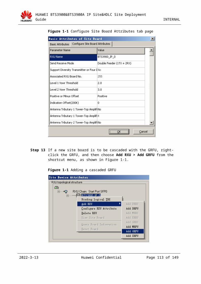
HUAWEI BTS3900&BTS3900A IP Site&HDLC Site Deployment Guide INTERNAL
If the ping operations are failed, you can add a switch on the BSC side and connect a PC to the switch. Then, ping the PCs on the BTS side and the BSC side. If the ping operation is successful, you need to check the physical connections of the BSC. If the ping operation is still failed, you can request the network engineer of the customer to check whether the transmission network properly allocates resources.
Check the continuity between the BSC and the BTS when the electrical interface board of the BSC is used.
The check method is basically the same as that for the optical transmission.
Note: If the transmission network is abnormal, an optical and electrical switch may be required so that a PC is connected to the switch for pinging and packet capturing.
The transmission network is very complex and may contain NEs of multiple vendors. Currently, there is no effective and accurate location method for a transmission link fault. In practice, if the transmission link is faulty, you can only perform loopback tests for the entire transmission network section by section to find faulty nodes.
3.4.5 Upgrading a TDM Site on the Existing Network to an IP Site
Generally, the TDM site is configured on the GEIUB of the BSC rack. To upgrade a TDM site to an IP site, you must ensure that the GFGUB is available on the BSC side. If no GFGUB is available on the BSC rack, you need to insert the board and then complete the configuration. You can upgrade a TDM site on the existing network to an IP site by one of the following two methods: 1. Upgrade a TDM site on the existing network to an IP site by the site movement function; 2. Directly build an IP site.
When the TDM site works normally, you can run the DSP ELABLE command (with the subrack number set to 0 and the slot number set to 23) to obtain the bar code of the BTS.
DSP ELABEL: DEVTYPE=BTSBRD, IDXTYPE=BYIDX, BTSIDX=73, SRN=0, SN=23;
The IP functions of the BTS3900 are supported in V100R008 and later versions. If the current version does not support the IP functions, you must upgrade the current version to the version that supports the IP functions in TDM mode.
If the BSC corresponding to the TDM site and the BSC corresponding to the target IP site are located in different places, method 1 cannot be used because that different BSC racks are involved. In this case, only method 2 can be used.
Generally, the BTS and BSC are placed in different places. For convenient construction, the upgrade procedure consists of the operations on the BTS side and those on the BSC side. The operations on the BTS side are mainly to connect network cables. The operations on the BSC side are to upgrade the software version of the BTS on the BSC6000 LMT, configure the BSC GFGUB and corresponding ports, and move the BTS on the BSC6000 LMT.
If an external PCU is configured for GPRS services in a cell under the TDM site, you must disable the GPRS services under the site. Otherwise, the configuration for site movement fails.
Method 1: Upgrade a TDM site on the existing network to an IP site by the site movement function
Step 1 Select the GFGUB of the BSC corresponding to the target IP site and the available port of the GFGUB, and then configure related IP addresses for the BSC. For details, see Step 1 through Step 3 in 3.4.2 "Adding an IP Site on the BSC6000 LMT."
Step 2 Connect the transmission cable between the BSC and the BTS (for details, see 3.4.4 "Configuring Hardware and the Transmission Network").
2023-4-19 Huawei Confidential Page 113 of 129
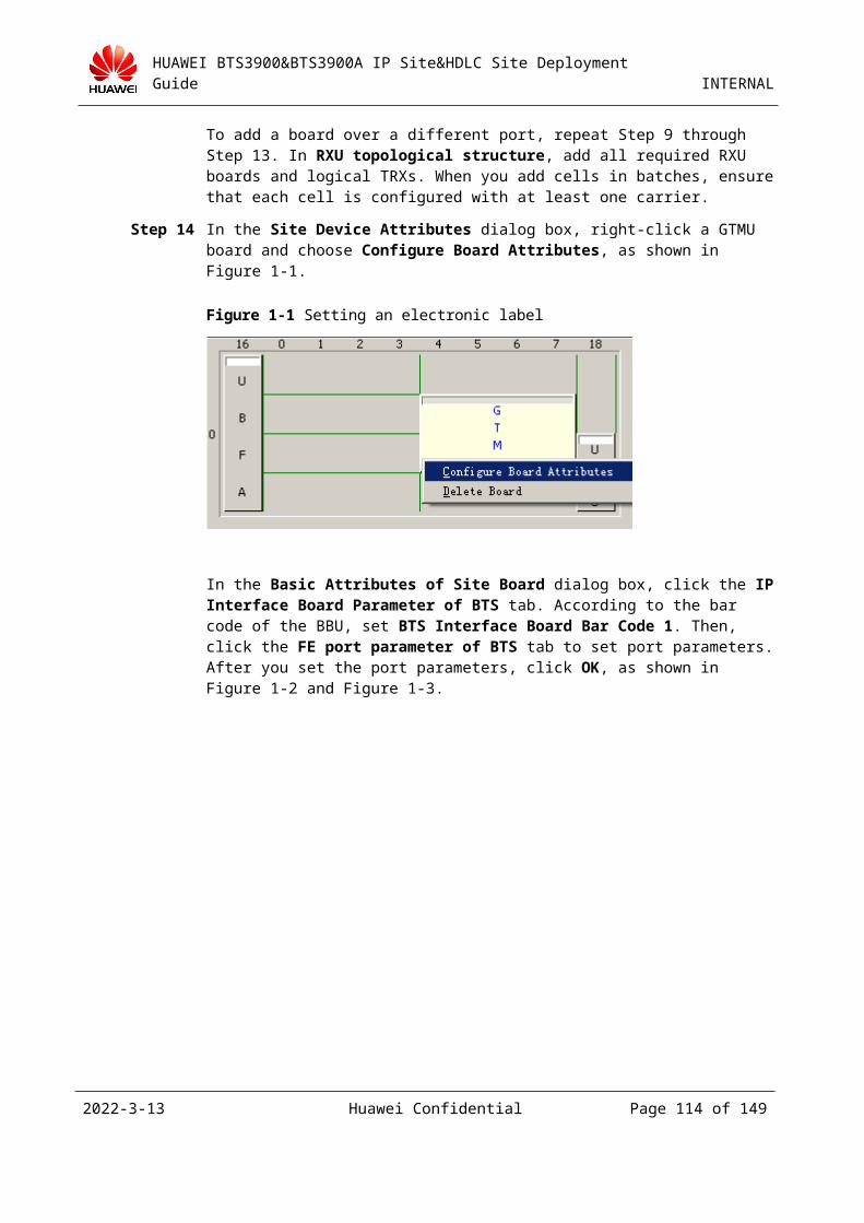
HUAWEI BTS3900&BTS3900A IP Site&HDLC Site Deployment Guide INTERNAL
Step 3 Right-click the TDM site to be upgraded and choose Site Operation > Configure Site Attributes from the shortcut menu. Then, set CRC4 Check Switch to ON on the Basic Information tab page in the displayed Site Attributes dialog box, as shown in Figure 3-1.
Figure 3-1 Setting the CRC4 check switch
Step 4 Deactivate the TDM site (optional). Right-click the TDM site to be upgraded and choose Site Operation > Set Site Active State from the shortcut menu. Then, set Site Active State to Not Activated.
After the TDM site is deactivated, the operations in Step 6 cannot be performed because that the operation time of the IP site is long.
2023-4-19 Huawei Confidential Page 114 of 129
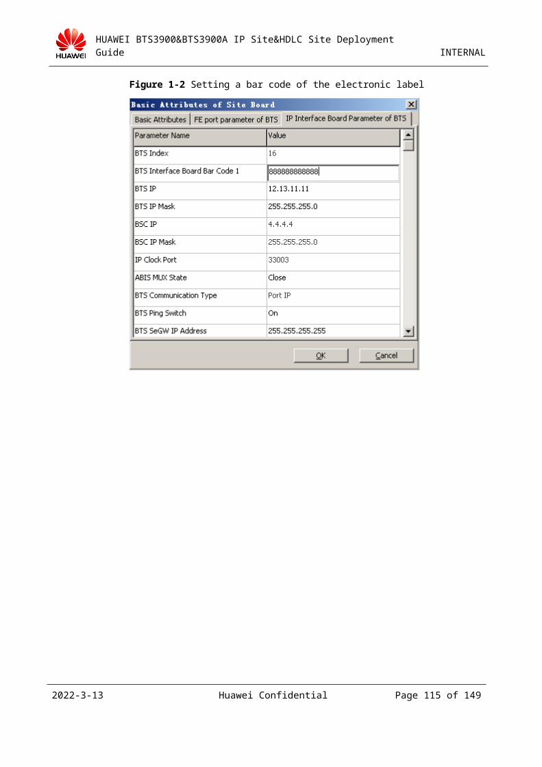
HUAWEI BTS3900&BTS3900A IP Site&HDLC Site Deployment Guide INTERNAL
Step 5 Delete the monitoring timeslots of the site.
Right-click the TDM site to be upgraded, and then choose Configure Site Monitor Timeslot from the shortcut menu. In the Configure Site Monitor Timeslot dialog box, delete all the monitoring timeslots.
Step 6 Reset the site so that the site works in probe state to reduce the interruption duration (optional).
Step 7 To move a site, do as follows:
Note: You must delete the monitoring timeslots before moving a site.
On the BSC6000 LMT, right-click the TDM site to be upgraded in the navigation tree, and then choose Site Operation > Move Site from the shortcut menu, as shown in Figure 3-1.
2023-4-19 Huawei Confidential Page 115 of 129
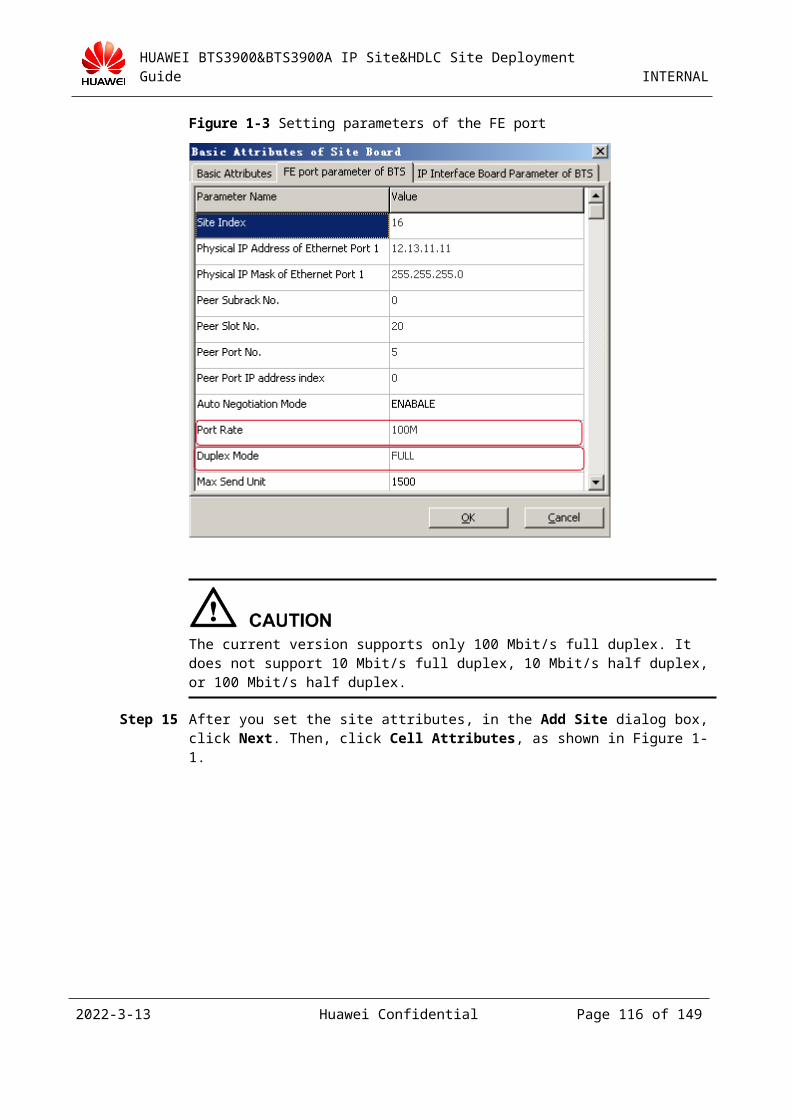
HUAWEI BTS3900&BTS3900A IP Site&HDLC Site Deployment Guide INTERNAL
Figure 3-1 Moving a site (1)
In the Move Site dialog box, select the target site from the Site View area, and then click Move Site, as shown in Figure 3-2.
2023-4-19 Huawei Confidential Page 116 of 129
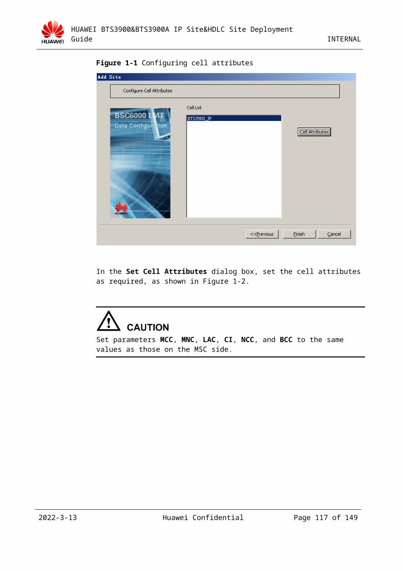
HUAWEI BTS3900&BTS3900A IP Site&HDLC Site Deployment Guide INTERNAL
Figure 3-2 Moving a site (2)
In the Move Site dialog box, select IP to change the TDM site to the IP site, as shown in Figure 3-3.Click BSC Port. In the displayed dialog box, click YES. The Choice Board&Port dialog box is displayed, as shown in Figure 3-4.
2023-4-19 Huawei Confidential Page 117 of 129
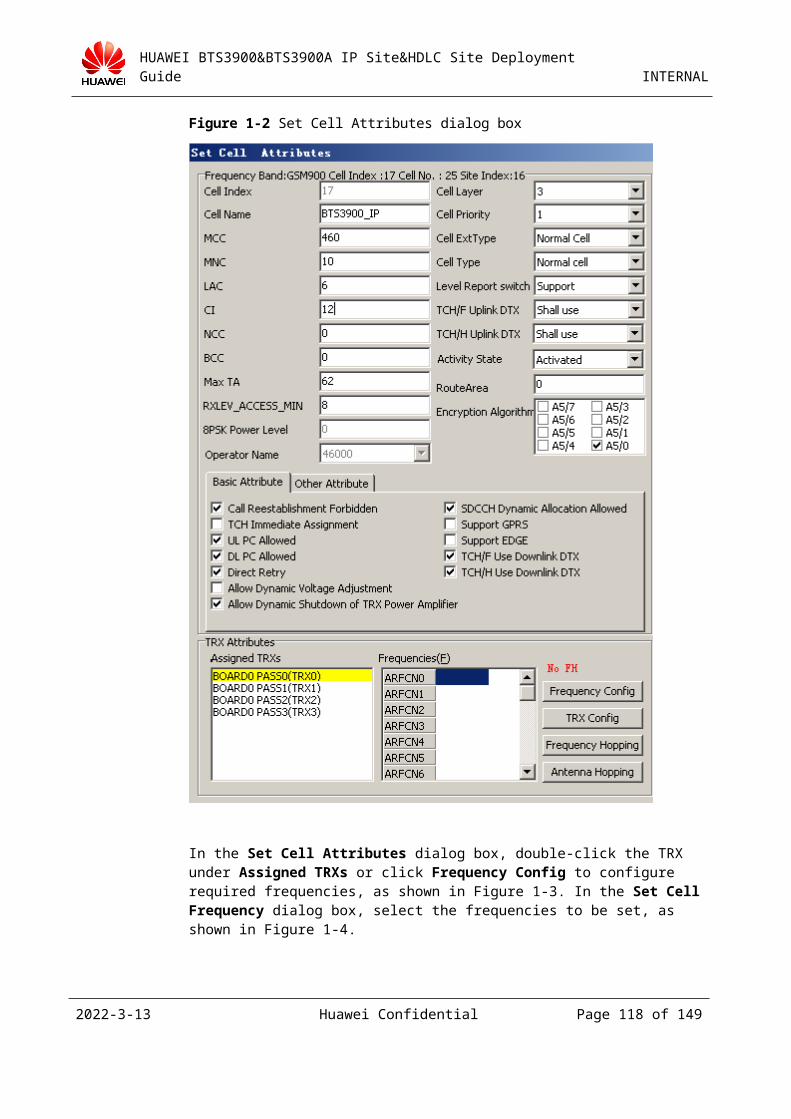
HUAWEI BTS3900&BTS3900A IP Site&HDLC Site Deployment Guide INTERNAL
Figure 3-3 Moving a site (3)
Figure 3-4 Choice Board&Port dialog box
Set the parameters Dest SubRack No., Dest Slot No., and Dest Port No. to proper values based on the GFGUB position. Then, click OK.
In the displayed dialog box, click OK to return to the Move Site dialog box, and then click Next, as shown in Figure 3-5.
The bar code of the BBU and the IP information of the site are not configured when the site is moved. In this case, a dialog box is displayed, prompting you to confirm the settings. You can click OK to ignore this message. (The attributes of the BBU are separately configured after the site is moved.)
2023-4-19 Huawei Confidential Page 118 of 129
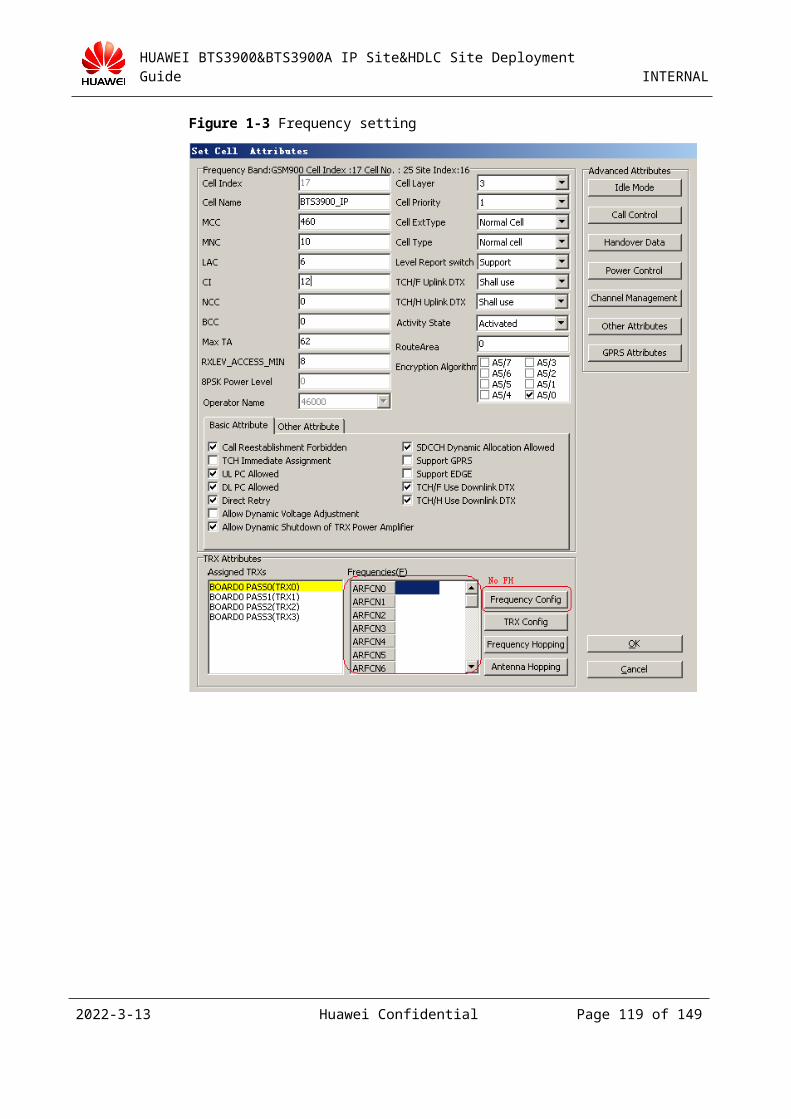
HUAWEI BTS3900&BTS3900A IP Site&HDLC Site Deployment Guide INTERNAL
Figure 3-5 Moving a site (4)
In the displayed Move Site dialog box, the original connection of the site and the connection after the site is moved are available in the Move Site Result area. Ensure that the current connection of the site is correct, and then click Finish, as shown in Figure 3-6.
Figure 3-6 Result of moving a site (1)
Click Continue, as shown in Figure 3-7. After the timeslots in the TDM site are arranged, a message is displayed to prompt you to confirm the operation. Then, click OK.
2023-4-19 Huawei Confidential Page 119 of 129
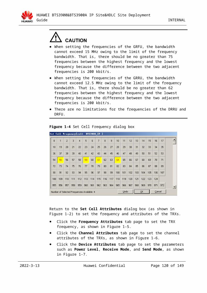
HUAWEI BTS3900&BTS3900A IP Site&HDLC Site Deployment Guide INTERNAL
Figure 3-7 Result of moving a site (2)
Step 8 Configure the parameters of the GTMU.
The configuration contents include the attributes of the board (for details, see Step 14 in 3.4.2 "Adding an IP Site on the BSC6000 LMT"), bar code of the BBU, IP address information of the BTS (IP address and subnet mask of the BTS), and FE port parameters of the BTS.
Step 9 Activate the IP site (optional).
Set Site Active State to Activated (for details, see Step 4).
Step 10 Check the operation status of the site 20 minutes after the operations are complete.
----End
Method 2: Upgrade a TDM site on the existing network to an IP site by directly building an IP site
Step 1 Select the GFGUB of the BSC corresponding to the target IP site and the available port of the GFGUB, and then configure related IP addresses for the BSC. For details, see Step 1 through Step 3 in 3.4.2 "Adding an IP Site on the BSC6000 LMT."
Step 2 Connect the transmission cable between the BSC and the BTS (for details, see 3.4.4 "Configuring Hardware and the Transmission Network").
Step 3 Configure the IP site on the BSC LMT (for details, see 3.4.2 "Adding an IP Site on the BSC6000 LMT").
Step 4 Check the operation status of the site 20 minutes after the operations are complete.
----End
2023-4-19 Huawei Confidential Page 120 of 129
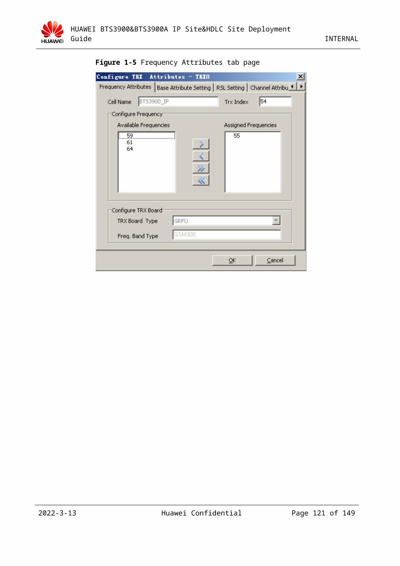
HUAWEI BTS3900&BTS3900A IP Site&HDLC Site Deployment Guide INTERNAL
3.4.6 Switching an IP Site Back to a TDM SiteIf a TDM site is upgraded to an IP site by building the IP site, the procedure for switching an IP site back to a TDM site is as follows: Remove the network cable, restore the original connections of the TDM site, and then wait for the reset of the site.
If a TDM site is upgraded to an IP site by the site movement function, the procedure for switching an IP site back to a TDM site is as follows:
Step 1 Remove the network cable from the BSC, and then restore the original connections of the TDM site.
Step 2 Right-click the TDM site to be upgraded and choose Site Operation > Configure Site Attributes from the shortcut menu. Then, set CRC4 Check Switch to OFF on the Basic Information tab page in the displayed Site Attributes dialog box, as shown in Figure 3-1.
Figure 3-1 Setting the CRC4 check switch
Step 3 Reset the site so that the site works in probe state to reduce the interruption duration (optional).
Step 4 On the BSC6000 LMT, right-click the IP site to be switched in the navigation tree, and then choose Site Operation > Move Site from the shortcut menu, as shown in Figure 3-1.
2023-4-19 Huawei Confidential Page 121 of 129
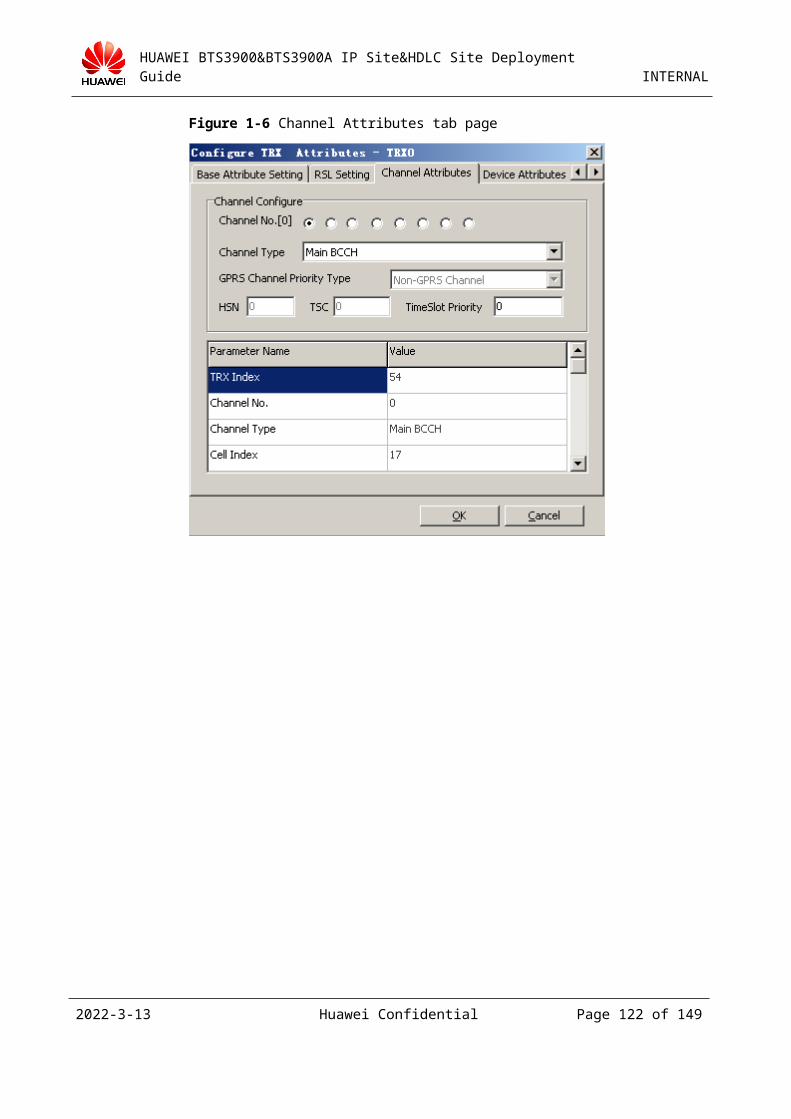
HUAWEI BTS3900&BTS3900A IP Site&HDLC Site Deployment Guide INTERNAL
Figure 3-1 Moving a site (1)
Step 5 In the Move Site dialog box, select the target site from the Site View area, and then click Move Site, as shown in Figure 3-1.
Figure 3-1 Moving a site (2)
Step 6 In the Move Site dialog box, select TDM to change the IP site to the TDM site, as shown in Figure 3-1.Click BSC Port. In the displayed dialog box, click YES. The Choice Board&Port dialog box is displayed, as shown in Figure 3-2.Set the parameters Dest SubRack No., Dest Slot No., and Dest Port No. to proper values based on the GEIUB position. Then, click OK.
2023-4-19 Huawei Confidential Page 122 of 129
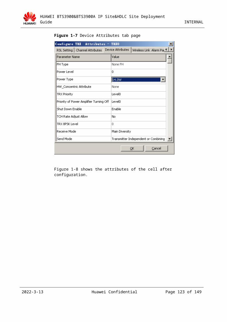
HUAWEI BTS3900&BTS3900A IP Site&HDLC Site Deployment Guide INTERNAL
Figure 3-1 Moving a site (3)
Figure 3-2 Choice Board&Port dialog box
Step 7 In the displayed dialog box, click OK to return to the Move Site dialog box, and then click Next, as shown in Figure 3-1.
2023-4-19 Huawei Confidential Page 123 of 129
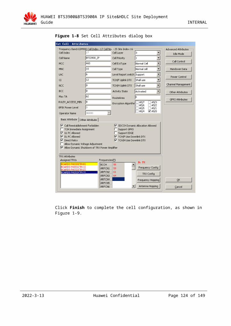
HUAWEI BTS3900&BTS3900A IP Site&HDLC Site Deployment Guide INTERNAL
Figure 3-1 Moving a site (4)
Step 8 In the displayed Move Site dialog box, the original connection of the site and the connection after the site is moved are available in the Move Site Result area. Ensure that the current connection of the site is correct, and then click Finish. After the timeslots in the TDM site are arranged, a message is displayed to prompt you to confirm the operation. Then, click OK. Check the operation status of the site 20 minutes after the operations are complete.
----End
2023-4-19 Huawei Confidential Page 124 of 129
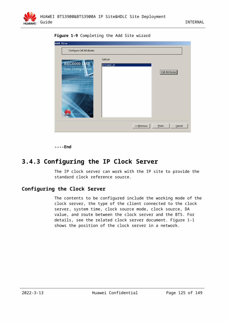
HUAWEI BTS3900&BTS3900A IP Site&HDLC Site Deployment Guide INTERNAL
4 Software Installation and
Upgrade
4.1 Loading SoftwareFor details, see the upgrade guide issued with the version, which can be obtained from http://support.huawei.com.
2023-4-19 Huawei Confidential Page 125 of 129
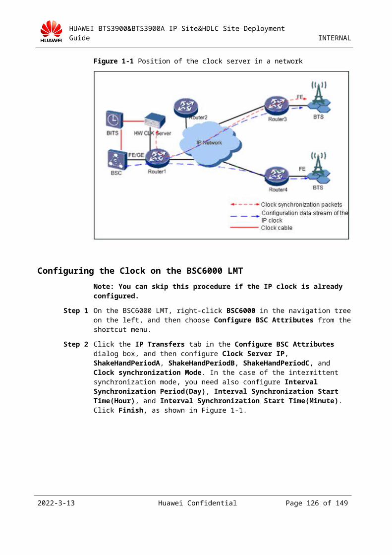
HUAWEI BTS3900&BTS3900A IP Site&HDLC Site Deployment Guide INTERNAL
5 Troubleshooting
5.1 Basic Operations for Site Troubleshooting
5.1.1 Basic Operations for Troubleshooting an HDLC or HDLC HUB Site
To troubleshoot an HDLC or HDLC HUB site, do as follows:
Step 1 Check whether the E1 line is properly connected from the BSC to the site.
1. Check whether the port number of the GEHUB board that corresponds to the site is consistent with the sequence number of the E1 line. For details, see 3.2.2 "Configuring Hardware and the Transmission Network."2. Check whether the sending end and the receiving end of the E1 line are in pairs. For details, see 3.2.2 "Configuring Hardware and the Transmission Network."
Step 2 Check the LEDs on the TMU board for alarms.
If the problem still persists, check the LEDs on the TMU board and view the related alarm information. (For details, see 6.1 "LEDs on the TMU Board.") Then, correct the problem according to the solution to the alarm.
----End
5.1.2 Basic Operations for Troubleshooting an IP SiteTo troubleshoot an IP site, do as follows:
Step 1 Check whether the network cable is properly connected from the BSC to the site.
Check whether the network cable for connecting to the site is inserted into the corresponding port of the GFGUB board. For details, see 3.4.2 "Adding an IP Site on the BSC6000 LMT."
Step 2 On the BSC6000 LMT, check whether the site attributes are properly set.
1. Check whether the IP address of the site is correct. For details, see 3.4.2 "Adding an IP Site on the BSC6000 LMT."
2. Check whether the IP address for the FE port is correct. For details, see 3.4.2 "Adding an IP Site on the BSC6000 LMT."
2023-4-19 Huawei Confidential Page 126 of 129

HUAWEI BTS3900&BTS3900A IP Site&HDLC Site Deployment Guide INTERNAL
3. Check whether the bar code for the site is correct. For details, see 3.4.2 "Adding an IP Site on the BSC6000 LMT."
Step 3 Check the LEDs on the TMU board for alarms.
If the problem still persists, check the LEDs on the TMU board and view the related alarm information. (For details, see 6.1 "LEDs on the TMU Board.") Then, correct the problem according to the solution to the alarm.
----End
5.2 FAQ
5.2.1 IP Site Problems
Problem Description
After an IP site is set up, it does not work for a long time.
Network management software indicates that the port of the optical transceiver for the IP site is not connected.
Cause Analysis The IP site is probably not powered on.
The network cable between the optical transceiver and the IP site is probably faulty.
Solution
Take a new network cable and tools to the site. The on-site survey indicates that the construction teams failed to prepare a quality network cable. Replace the existing network cable with a new one. The connection is normal.
5.2.2 HDLC Site Problems
Problem Description
After an HDLC site is configured and the E1 line is connected, the site link fails to be set up.
Cause Analysis
A check on the BSC6000 LMT indicates that the HDLC site is attached to port 4 of the BSC PIU board whereas the E1 line is inserted to port 5 of the PIU board.
Solution
Insert the E1 line to port 4.
2023-4-19 Huawei Confidential Page 127 of 129
HUAWEI BTS3900&BTS3900A IP Site&HDLC Site Deployment Guide INTERNAL
6 Appendix
6.1 LEDs on the TMU Board
LED Color Status Description
RUN Green ON The board is faulty.
Green OFF There is no power supply or the board is faulty.
Green Blinking (on for 1s and off for 1s)
The board is operational.
Green Blinking (on for 2s and off for 2s)
The OML link is abnormal.
Green Blinking (on for 0.125s and off for 0.125s)
The board is loading software.
ALM Red ON A fault occurs in the running board.
OFF No fault occurs.
ACT Green ON The board is operational.
OFF The board is faulty.
LIU0-LIU3 Green ON A local E1/T1 alarm is generated.
Blinking (on for 0.125s and off for 0.125s)
A remote E1/T1 alarm is generated.
OFF The link is normal or the alarm is cleared.
CPRI0-CPRI5 Green ON The CPRI link is functional.
Red ON The reception of the optical or electrical module is abnormal and an alarm is generated.
2023-4-19 Huawei Confidential Page 128 of 129
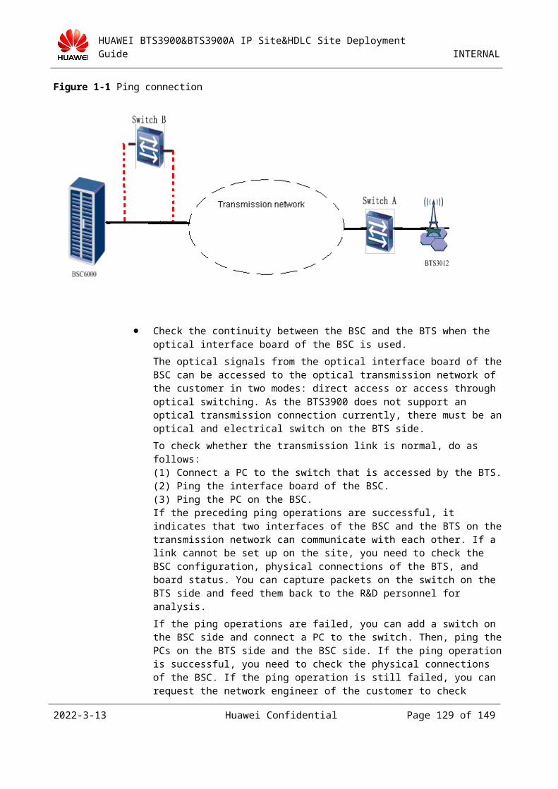
HUAWEI BTS3900&BTS3900A IP Site&HDLC Site Deployment Guide INTERNAL
6.2 References1. BTS3900&BTS3900A Deployment Guide
2. IP Clock Server User Guide
3. BSC6000 Deployment Guide
2023-4-19 Huawei Confidential Page 129 of 129