Embed Size (px)
DESCRIPTION
This document describes routine maintenance items for BTS3900 (Ver.C) (referred to asBTS3900) cabinet. The maintenance items are equipment room environment, power system,grounding system, and BTS3900 cabinet. It also explains how to replace components, modules,and boards.
Citation preview
BTS3900 (Ver.C)
Site Maintenance Guide
Issue 03
Date 2012-08-30
HUAWEI TECHNOLOGIES CO., LTD.
Copyright © Huawei Technologies Co., Ltd. 2012. All rights reserved.No part of this document may be reproduced or transmitted in any form or by any means without prior writtenconsent of Huawei Technologies Co., Ltd. Trademarks and Permissions
and other Huawei trademarks are trademarks of Huawei Technologies Co., Ltd.All other trademarks and trade names mentioned in this document are the property of their respective holders. NoticeThe purchased products, services and features are stipulated by the contract made between Huawei and thecustomer. All or part of the products, services and features described in this document may not be within thepurchase scope or the usage scope. Unless otherwise specified in the contract, all statements, information,and recommendations in this document are provided "AS IS" without warranties, guarantees or representationsof any kind, either express or implied.
The information in this document is subject to change without notice. Every effort has been made in thepreparation of this document to ensure accuracy of the contents, but all statements, information, andrecommendations in this document do not constitute a warranty of any kind, express or implied.
Huawei Technologies Co., Ltd.Address: Huawei Industrial Base
Bantian, LonggangShenzhen 518129People's Republic of China
Website: http://www.huawei.com
Email: [email protected]
Issue 03 (2012-08-30) Huawei Proprietary and ConfidentialCopyright © Huawei Technologies Co., Ltd.
i
About This Document
PurposeThis document describes routine maintenance items for BTS3900 (Ver.C) (referred to asBTS3900) cabinet. The maintenance items are equipment room environment, power system,grounding system, and BTS3900 cabinet. It also explains how to replace components, modules,and boards.
Product VersionsThe following table lists the product versions related to this document.
Product Name Product Version
BTS3900 V100R003C00
BTS3900 GSM V100R009C00
V100R012C00
BTS3900 WCDMA V200R012C00
Intended AudienceThis document is intended for:
System engineers
Site maintenance engineers
Organization1 Changes in the BTS3900 (Ver.C) Site Maintenance Guide
This section describes the changes in the BTS3900 (Ver.C) Site Maintenance Guide.
2 Preparations for Base Station Site Maintenance
BTS3900 (Ver.C)Site Maintenance Guide About This Document
Issue 03 (2012-08-30) Huawei Proprietary and ConfidentialCopyright © Huawei Technologies Co., Ltd.
ii

This section describes the preparation strategy for base station site maintenance. Thepreparations for site maintenance involve obtaining site information, selecting maintenanceitems, and arranging maintenance tools and spare parts.
3 BTS3900 Hardware Routine Maintenance
The routine maintenance for the BTS3900 hardware involves the equipment room environment,power system, grounding system, and BTS3900 cabinet.
4 Powering On and Power Off a BTS3900
This section describes how to power on or power off a BTS3900 during maintenance. To poweron the BTS3900, follow the power-on procedure. To power off the BTS3900, follow the normalpower-off or emergency power-off procedure as required.
5 Replacing BTS3900 Components
This section describes the procedures of replacing the faulty BTS3900 functional components.
ConventionsSymbol Conventions
The symbols that may be found in this document are defined as follows.
Symbol Description
Indicates a hazard with a high level of risk, which if notavoided, will result in death or serious injury.
Indicates a hazard with a medium or low level of risk, whichif not avoided, could result in minor or moderate injury.
Indicates a potentially hazardous situation, which if notavoided, could result in equipment damage, data loss,performance degradation, or unexpected results.
Indicates a tip that may help you solve a problem or savetime.
Provides additional information to emphasize or supplementimportant points of the main text.
General Conventions
The general conventions that may be found in this document are defined as follows.
Convention Description
Times New Roman Normal paragraphs are in Times New Roman.
Boldface Names of files, directories, folders, and users are inboldface. For example, log in as user root.
BTS3900 (Ver.C)Site Maintenance Guide About This Document
Issue 03 (2012-08-30) Huawei Proprietary and ConfidentialCopyright © Huawei Technologies Co., Ltd.
iii

Convention Description
Italic Book titles are in italics.
Courier New Examples of information displayed on the screen are inCourier New.
Command Conventions
The command conventions that may be found in this document are defined as follows.
Convention Description
Boldface The keywords of a command line are in boldface.
Italic Command arguments are in italics.
[ ] Items (keywords or arguments) in brackets [ ] are optional.
{ x | y | ... } Optional items are grouped in braces and separated byvertical bars. One item is selected.
[ x | y | ... ] Optional items are grouped in brackets and separated byvertical bars. One item is selected or no item is selected.
{ x | y | ... }* Optional items are grouped in braces and separated byvertical bars. A minimum of one item or a maximum of allitems can be selected.
[ x | y | ... ]* Optional items are grouped in brackets and separated byvertical bars. Several items or no item can be selected.
GUI Conventions
The GUI conventions that may be found in this document are defined as follows.
Convention Description
Boldface Buttons, menus, parameters, tabs, window, and dialog titlesare in boldface. For example, click OK.
> Multi-level menus are in boldface and separated by the ">"signs. For example, choose File > Create > Folder.
Keyboard Operations
The keyboard operations that may be found in this document are defined as follows.
BTS3900 (Ver.C)Site Maintenance Guide About This Document
Issue 03 (2012-08-30) Huawei Proprietary and ConfidentialCopyright © Huawei Technologies Co., Ltd.
iv
Format Description
Key Press the key. For example, press Enter and press Tab.
Key 1+Key 2 Press the keys concurrently. For example, pressing Ctrl+Alt+A means the three keys should be pressed concurrently.
Key 1, Key 2 Press the keys in turn. For example, pressing Alt, A meansthe two keys should be pressed in turn.
Mouse Operations
The mouse operations that may be found in this document are defined as follows.
Action Description
Click Select and release the primary mouse button without movingthe pointer.
Double-click Press the primary mouse button twice continuously andquickly without moving the pointer.
Drag Press and hold the primary mouse button and move thepointer to a certain position.
BTS3900 (Ver.C)Site Maintenance Guide About This Document
Issue 03 (2012-08-30) Huawei Proprietary and ConfidentialCopyright © Huawei Technologies Co., Ltd.
v
Contents
About This Document.....................................................................................................................ii
1 Changes in the BTS3900 (Ver.C) Site Maintenance Guide...................................................1
2 Preparations for Base Station Site Maintenance.....................................................................3
3 BTS3900 Hardware Routine Maintenance................................................................................53.1 Maintenance Items of the Equipment Room Environment................................................................................63.2 Power Supply and Grounding System Maintenance Items................................................................................73.3 Maintenance Items of the Main Components.....................................................................................................7
4 Powering On and Power Off a BTS3900...................................................................................94.1 Powering On a BTS3900..................................................................................................................................104.2 Powering Off a BTS3900.................................................................................................................................13
5 Replacing BTS3900 Components..............................................................................................155.1 Querying an Electronic Label...........................................................................................................................16
5.1.1 Querying the Electronic Label for a Board..............................................................................................165.1.2 Query Electronic Label of the Cabinet....................................................................................................16
5.2 Replacing BBU3900 Components....................................................................................................................165.2.1 Replacing BBU3900 Cases.....................................................................................................................175.2.2 Replacing the GTMU..............................................................................................................................195.2.3 Replacing the WMPT..............................................................................................................................225.2.4 Replacing the LMPT...............................................................................................................................255.2.5 Replacing the WBBP...............................................................................................................................325.2.6 Replacing the LBBP................................................................................................................................345.2.7 Replacing the FAN Unit..........................................................................................................................365.2.8 Replacing a UPEU...................................................................................................................................385.2.9 Replacing the UEIU.................................................................................................................................415.2.10 Replacing the USCU.............................................................................................................................435.2.11 Replacing a UTRP.................................................................................................................................455.2.12 Replacing a UBRI..................................................................................................................................475.2.13 Replacing the Optical Module...............................................................................................................50
5.3 Adding Components in the BBU3900..............................................................................................................535.3.1 Adding a UPEU.......................................................................................................................................535.3.2 Adding a WBBP......................................................................................................................................63
BTS3900 (Ver.C)Site Maintenance Guide Contents
Issue 03 (2012-08-30) Huawei Proprietary and ConfidentialCopyright © Huawei Technologies Co., Ltd.
vi
5.4 Replacing an RFU............................................................................................................................................645.5 Replacing a DCDU-11A...................................................................................................................................685.6 Replacing the Fan Assembly............................................................................................................................705.7 Replacing the Power Equipment (AC/DC)......................................................................................................73
5.7.1 Replacing the Power Subrack (AC/DC)..................................................................................................735.7.2 Replacing the PMU.................................................................................................................................765.7.3 Replacing a PSU (AC/DC)......................................................................................................................78
BTS3900 (Ver.C)Site Maintenance Guide Contents
Issue 03 (2012-08-30) Huawei Proprietary and ConfidentialCopyright © Huawei Technologies Co., Ltd.
vii
1 Changes in the BTS3900 (Ver.C) SiteMaintenance Guide
This section describes the changes in the BTS3900 (Ver.C) Site Maintenance Guide.
03 (2012-08-30)This is the third commercial release.
Compared with issue 02 (2011-10-25), this issue adds no topic.
Compared with issue 02 (2011-10-25), this issue incorporates the following changes:
Topic Change Description
5.2.4 Replacing the LMPT Changed the steps of backing up theconfiguration file and license.
5.2.2 Replacing the GTMU Changed the steps of blocking all cells of theBTS.
5.2.1 Replacing BBU3900 Cases
5.2.8 Replacing a UPEU
5.2.3 Replacing the WMPT l Add the steps by using a USB flash drivel Add the steps of checking for alarms in the
prerequisitesl Add the steps of backing up the
configuration file in the prerequisites
5.2.2 Replacing the GTMU
5.2.5 Replacing the WBBP l Add the steps of checking for alarms in theprerequisites
l Add the time estimation for how long needthe board to come up
5.2.6 Replacing the LBBP
5.2.13 Replacing the Optical Module Add the steps of confirming the type of afaulty board.
Compared with issue 02 (2011-10-25), this issue deletes no content.
BTS3900 (Ver.C)Site Maintenance Guide 1 Changes in the BTS3900 (Ver.C) Site Maintenance Guide
Issue 03 (2012-08-30) Huawei Proprietary and ConfidentialCopyright © Huawei Technologies Co., Ltd.
1
02 (2011-10-25)This is the second commercial release.
Compared with issue 01 (2011-08-30), no topic is added.
Compared with issue 01 (2011-08-30), this issue incorporates the following change:
Content Change Description
About This Document Added the version V300R009 to BTS3900(Ver.C) GSM.
Compared with issue 01 (2011-08-30), no content is deleted.
01 (2011-08-30)This is the first commercial release.
BTS3900 (Ver.C)Site Maintenance Guide 1 Changes in the BTS3900 (Ver.C) Site Maintenance Guide
Issue 03 (2012-08-30) Huawei Proprietary and ConfidentialCopyright © Huawei Technologies Co., Ltd.
2
2 Preparations for Base Station SiteMaintenance
This section describes the preparation strategy for base station site maintenance. Thepreparations for site maintenance involve obtaining site information, selecting maintenanceitems, and arranging maintenance tools and spare parts.
Collecting Site Information
Before you maintain the base station site, collect the following information:
l Faults and alarms that are not cleared
l Hardware configurations
l Local environment
l Spare parts
Selecting Maintenance Items
Select suitable maintenance items based on actual requirements of the base station. Themaintenance items are as follows:
l Equipment room environment of the base station
l Power supply and grounding system of the base station
l Main components in the base station
l Antenna system of the base station
Preparing Maintenance Tools and Spare Parts
Prepare the related maintenance tools and spare parts based on the site information andmaintenance items of the base station.
The most commonly used tools for site maintenance are as follows:
l Frequency test devices, such as a frequency generator and a spectrum analyzer.
l Power test devices that are used to test and analyze the output power of the base station.Power meter is a commonly used power test device.
BTS3900 (Ver.C)Site Maintenance Guide 2 Preparations for Base Station Site Maintenance
Issue 03 (2012-08-30) Huawei Proprietary and ConfidentialCopyright © Huawei Technologies Co., Ltd.
3
l Antenna and feeder test devices that are used to test the Voltage Standing Wave Ratio(VSWR), return loss, and cable insertion loss for fault location. The commonly usedantenna and feeder test device is the SiteMaster.
l Other devices– Multimeter– Diagnosis tools and robustness test devices– Local Maintenance Terminal (LMT)– Rubidium clock (used to locate the clock of the base station)
NOTE
More tools and new parts are required when faulty parts are found during the maintenance.
BTS3900 (Ver.C)Site Maintenance Guide 2 Preparations for Base Station Site Maintenance
Issue 03 (2012-08-30) Huawei Proprietary and ConfidentialCopyright © Huawei Technologies Co., Ltd.
4
3 BTS3900 Hardware Routine Maintenance
About This Chapter
The routine maintenance for the BTS3900 hardware involves the equipment room environment,power system, grounding system, and BTS3900 cabinet.
3.1 Maintenance Items of the Equipment Room EnvironmentThis section describes the maintenance items, maintenance intervals, operation instructions, andreference standards for the equipment room environment.
3.2 Power Supply and Grounding System Maintenance ItemsThis section provides the maintenance items, maintenance intervals, operation instructions, andreference standards for the power supply and grounding system of the base station.
3.3 Maintenance Items of the Main ComponentsThis section describes the maintenance items, maintenance intervals, operation instructions, andreference standards for the main components in the cabinet.
BTS3900 (Ver.C)Site Maintenance Guide 3 BTS3900 Hardware Routine Maintenance
Issue 03 (2012-08-30) Huawei Proprietary and ConfidentialCopyright © Huawei Technologies Co., Ltd.
5
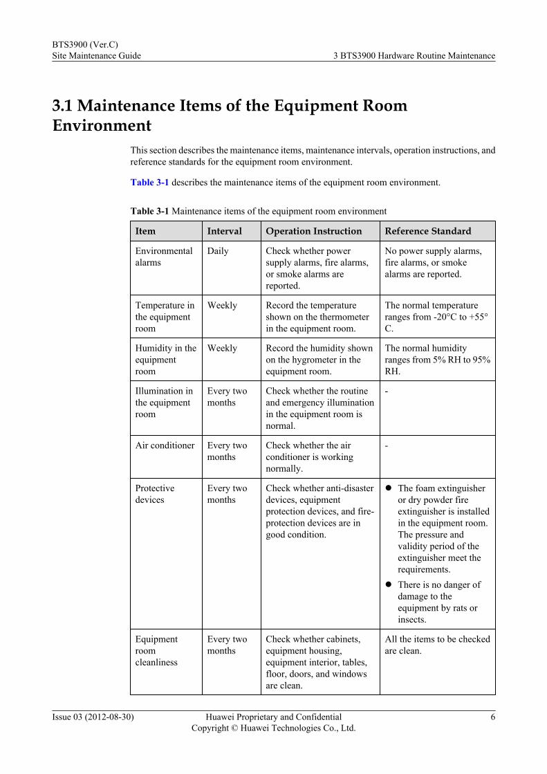
3.1 Maintenance Items of the Equipment RoomEnvironment
This section describes the maintenance items, maintenance intervals, operation instructions, andreference standards for the equipment room environment.
Table 3-1 describes the maintenance items of the equipment room environment.
Table 3-1 Maintenance items of the equipment room environment
Item Interval Operation Instruction Reference Standard
Environmentalalarms
Daily Check whether powersupply alarms, fire alarms,or smoke alarms arereported.
No power supply alarms,fire alarms, or smokealarms are reported.
Temperature inthe equipmentroom
Weekly Record the temperatureshown on the thermometerin the equipment room.
The normal temperatureranges from -20°C to +55°C.
Humidity in theequipmentroom
Weekly Record the humidity shownon the hygrometer in theequipment room.
The normal humidityranges from 5% RH to 95%RH.
Illumination inthe equipmentroom
Every twomonths
Check whether the routineand emergency illuminationin the equipment room isnormal.
-
Air conditioner Every twomonths
Check whether the airconditioner is workingnormally.
-
Protectivedevices
Every twomonths
Check whether anti-disasterdevices, equipmentprotection devices, and fire-protection devices are ingood condition.
l The foam extinguisheror dry powder fireextinguisher is installedin the equipment room.The pressure andvalidity period of theextinguisher meet therequirements.
l There is no danger ofdamage to theequipment by rats orinsects.
Equipmentroomcleanliness
Every twomonths
Check whether cabinets,equipment housing,equipment interior, tables,floor, doors, and windowsare clean.
All the items to be checkedare clean.
BTS3900 (Ver.C)Site Maintenance Guide 3 BTS3900 Hardware Routine Maintenance
Issue 03 (2012-08-30) Huawei Proprietary and ConfidentialCopyright © Huawei Technologies Co., Ltd.
6
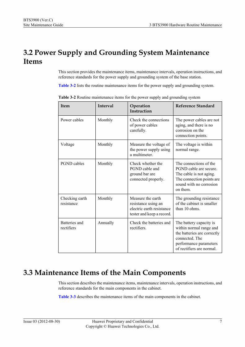
3.2 Power Supply and Grounding System MaintenanceItems
This section provides the maintenance items, maintenance intervals, operation instructions, andreference standards for the power supply and grounding system of the base station.
Table 3-2 lists the routine maintenance items for the power supply and grounding system.
Table 3-2 Routine maintenance items for the power supply and grounding system
Item Interval OperationInstruction
Reference Standard
Power cables Monthly Check the connectionsof power cablescarefully.
The power cables are notaging, and there is nocorrosion on theconnection points.
Voltage Monthly Measure the voltage ofthe power supply usinga multimeter.
The voltage is withinnormal range.
PGND cables Monthly Check whether thePGND cable andground bar areconnected properly.
The connections of thePGND cable are secure.The cable is not aging.The connection points aresound with no corrosionon them.
Checking earthresistance
Monthly Measure the earthresistance using anelectric earth resistancetester and keep a record.
The grounding resistanceof the cabinet is smallerthan 10 ohms.
Batteries andrectifiers
Annually Check the batteries andrectifiers.
The battery capacity iswithin normal range andthe batteries are correctlyconnected. Theperformance parametersof rectifiers are normal.
3.3 Maintenance Items of the Main ComponentsThis section describes the maintenance items, maintenance intervals, operation instructions, andreference standards for the main components in the cabinet.
Table 3-3 describes the maintenance items of the main components in the cabinet.
BTS3900 (Ver.C)Site Maintenance Guide 3 BTS3900 Hardware Routine Maintenance
Issue 03 (2012-08-30) Huawei Proprietary and ConfidentialCopyright © Huawei Technologies Co., Ltd.
7
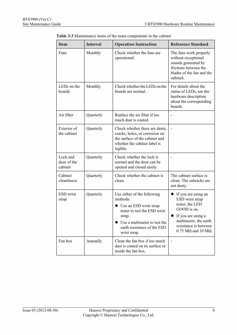
Table 3-3 Maintenance items of the main components in the cabinet
Item Interval Operation Instruction Reference Standard
Fans Monthly Check whether the fans areoperational.
The fans work properlywithout exceptionalsounds generated byfrictions between theblades of the fan and thesubrack.
LEDs on theboards
Monthly Check whether the LEDs on theboards are normal.
For details about thestatus of LEDs, see thehardware descriptionabout the correspondingboards.
Air filter Quarterly Replace the air filter if toomuch dust is coated.
-
Exterior ofthe cabinet
Quarterly Check whether there are dents,cracks, holes, or corrosion onthe surface of the cabinet andwhether the cabinet label islegible.
-
Lock anddoor of thecabinet
Quarterly Check whether the lock isnormal and the door can beopened and closed easily.
-
Cabinetcleanliness
Quarterly Check whether the cabinet isclean.
The cabinet surface isclean. The subracks arenot dusty.
ESD wriststrap
Quarterly Use either of the followingmethods:l Use an ESD wrist strap
tester to test the ESD wriststrap.
l Use a multimeter to test theearth resistance of the ESDwrist strap.
l If you are using anESD wrist straptester, the LEDGOOD is on.
l If you are using amultimeter, the earthresistance is between0.75 MΩ and 10 MΩ.
Fan box Annually Clean the fan box if too muchdust is coated on its surface orinside the fan box.
-
BTS3900 (Ver.C)Site Maintenance Guide 3 BTS3900 Hardware Routine Maintenance
Issue 03 (2012-08-30) Huawei Proprietary and ConfidentialCopyright © Huawei Technologies Co., Ltd.
8
4 Powering On and Power Off a BTS3900
About This Chapter
This section describes how to power on or power off a BTS3900 during maintenance. To poweron the BTS3900, follow the power-on procedure. To power off the BTS3900, follow the normalpower-off or emergency power-off procedure as required.
4.1 Powering On a BTS3900This section describes how to power on a BTS3900 and handle failures in power supply to thecomponents in the cabinet.
4.2 Powering Off a BTS3900The procedure for powering off a BTS3900 varies with the actual condition, for example, in anormal situation or an emergency. You must power off the BTS3900 in a normal situation suchas moving the equipment or anticipating a territorial blackout. You must also power off theBTS3900 in an emergency such as a fire, smoke, or water damage.
BTS3900 (Ver.C)Site Maintenance Guide 4 Powering On and Power Off a BTS3900
Issue 03 (2012-08-30) Huawei Proprietary and ConfidentialCopyright © Huawei Technologies Co., Ltd.
9
4.1 Powering On a BTS3900This section describes how to power on a BTS3900 and handle failures in power supply to thecomponents in the cabinet.
Prerequisitesl Input power cables are correctly and securely connected.l The power supply to the BTS3900 meets the specifications listed in Power Supply
Requirements of the BTS3900.l Power switches on the DCDU-11A panel are all set to OFF.l External power supply to the BTS3900 is shut down.
Context
CAUTIONAfter the cabinet is unpacked, it must be powered on within 7 days. If you power off the cabinetfor maintenance, you must restore power to the cabinet within 48 hours.
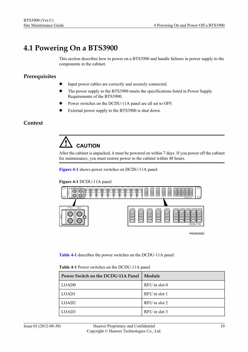
Figure 4-1 shows power switches on DCDU-11A panel.
Figure 4-1 DCDU-11A panel
Table 4-1 describes the power switches on the DCDU-11A panel.
Table 4-1 Power switches on the DCDU-11A panel
Power Switch on the DCDU-11A Panel Module
LOAD0 RFU in slot 0
LOAD1 RFU in slot 1
LOAD2 RFU in slot 2
LOAD3 RFU in slot 3
BTS3900 (Ver.C)Site Maintenance Guide 4 Powering On and Power Off a BTS3900
Issue 03 (2012-08-30) Huawei Proprietary and ConfidentialCopyright © Huawei Technologies Co., Ltd.
10
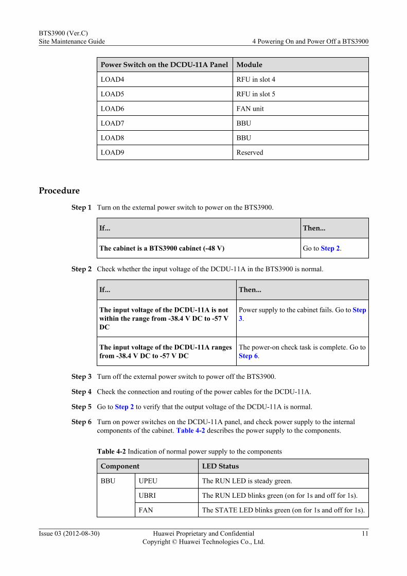
Power Switch on the DCDU-11A Panel Module
LOAD4 RFU in slot 4
LOAD5 RFU in slot 5
LOAD6 FAN unit
LOAD7 BBU
LOAD8 BBU
LOAD9 Reserved
Procedure
Step 1 Turn on the external power switch to power on the BTS3900.
If... Then...
The cabinet is a BTS3900 cabinet (-48 V) Go to Step 2.
Step 2 Check whether the input voltage of the DCDU-11A in the BTS3900 is normal.
If... Then...
The input voltage of the DCDU-11A is notwithin the range from -38.4 V DC to -57 VDC
Power supply to the cabinet fails. Go to Step3.
The input voltage of the DCDU-11A rangesfrom -38.4 V DC to -57 V DC
The power-on check task is complete. Go toStep 6.
Step 3 Turn off the external power switch to power off the BTS3900.
Step 4 Check the connection and routing of the power cables for the DCDU-11A.
Step 5 Go to Step 2 to verify that the output voltage of the DCDU-11A is normal.
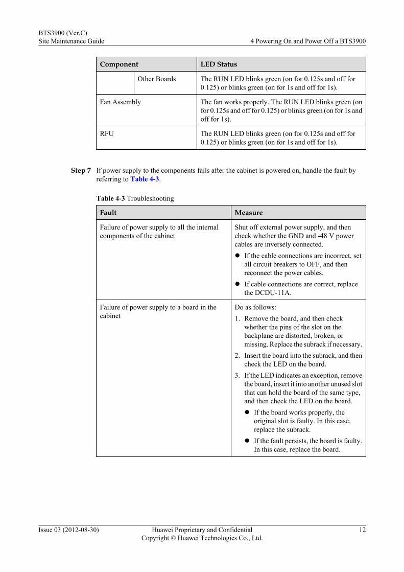
Step 6 Turn on power switches on the DCDU-11A panel, and check power supply to the internalcomponents of the cabinet. Table 4-2 describes the power supply to the components.
Table 4-2 Indication of normal power supply to the components
Component LED Status
BBU UPEU The RUN LED is steady green.
UBRI The RUN LED blinks green (on for 1s and off for 1s).
FAN The STATE LED blinks green (on for 1s and off for 1s).
BTS3900 (Ver.C)Site Maintenance Guide 4 Powering On and Power Off a BTS3900
Issue 03 (2012-08-30) Huawei Proprietary and ConfidentialCopyright © Huawei Technologies Co., Ltd.
11
Component LED Status
Other Boards The RUN LED blinks green (on for 0.125s and off for0.125) or blinks green (on for 1s and off for 1s).
Fan Assembly The fan works properly. The RUN LED blinks green (onfor 0.125s and off for 0.125) or blinks green (on for 1s andoff for 1s).
RFU The RUN LED blinks green (on for 0.125s and off for0.125) or blinks green (on for 1s and off for 1s).
Step 7 If power supply to the components fails after the cabinet is powered on, handle the fault byreferring to Table 4-3.
Table 4-3 Troubleshooting
Fault Measure
Failure of power supply to all the internalcomponents of the cabinet
Shut off external power supply, and thencheck whether the GND and -48 V powercables are inversely connected.l If the cable connections are incorrect, set
all circuit breakers to OFF, and thenreconnect the power cables.
l If cable connections are correct, replacethe DCDU-11A.
Failure of power supply to a board in thecabinet
Do as follows:1. Remove the board, and then check
whether the pins of the slot on thebackplane are distorted, broken, ormissing. Replace the subrack if necessary.
2. Insert the board into the subrack, and thencheck the LED on the board.
3. If the LED indicates an exception, removethe board, insert it into another unused slotthat can hold the board of the same type,and then check the LED on the board.l If the board works properly, the
original slot is faulty. In this case,replace the subrack.
l If the fault persists, the board is faulty.In this case, replace the board.
BTS3900 (Ver.C)Site Maintenance Guide 4 Powering On and Power Off a BTS3900
Issue 03 (2012-08-30) Huawei Proprietary and ConfidentialCopyright © Huawei Technologies Co., Ltd.
12
Fault Measure
Failure of power supply to any other type ofcomponent in the cabinet
Use a multimeter to measure the input voltageof the component.l If the input power is normal, that is,
ranging from -38.4 V DC to -57 V DC,replace the component.
l If the input power is abnormal, checkwhether the power cables of thecomponent are securely connected.– If cable connections are not secure, set
all the circuit breakers on theDCDU-11A to OFF, and thenreconnect the power cables.
– If cable connections are secure, thepower switches on the DCDU-11A orpower cables may be damaged. In thiscase, replace the DCDU-11A or powercables.
----End
4.2 Powering Off a BTS3900The procedure for powering off a BTS3900 varies with the actual condition, for example, in anormal situation or an emergency. You must power off the BTS3900 in a normal situation suchas moving the equipment or anticipating a territorial blackout. You must also power off theBTS3900 in an emergency such as a fire, smoke, or water damage.
Procedurel Normal power-off
1. Modify the management status to block all the RFUs in the cabinet.
NOTE
l RFUs can be blocked either remotely or locally. However, you are advised to block theRFUs remotely.
l If the RFUs works in dual mode, block the modules in dual mode.
l The RFUs cannot be blocked on the GSM side. Only the carriers of the RFUs can beblocked.
2. Set all circuit breakers on the DCDU-11A to OFF.3. Shut off external power supply. Set the battery power switch to OFF when the
BTS3900 cabinet is configured with external batteries or the PS4890 cabinet isconfigured with built-in batteries.
l Emergency power-off
BTS3900 (Ver.C)Site Maintenance Guide 4 Powering On and Power Off a BTS3900
Issue 03 (2012-08-30) Huawei Proprietary and ConfidentialCopyright © Huawei Technologies Co., Ltd.
13
CAUTIONEmergency power-off may lead to damage on the equipment or boards. Therefore, this typeof power-off is not recommended in normal cases.
1. Shut off external power supply. Set the battery power switch to OFF when theBTS3900 cabinet is configured with external batteries or the PS4890 cabinet isconfigured with built-in batteries.
2. Set all the DC power switches on the DCDU-11A panel to OFF if time permits.
----End
BTS3900 (Ver.C)Site Maintenance Guide 4 Powering On and Power Off a BTS3900
Issue 03 (2012-08-30) Huawei Proprietary and ConfidentialCopyright © Huawei Technologies Co., Ltd.
14
5 Replacing BTS3900 Components
About This Chapter
This section describes the procedures of replacing the faulty BTS3900 functional components.
5.1 Querying an Electronic LabelBefore replacing a board or an component, you should confirm the type of board or componentto be replaced by querying the electronic label.
5.2 Replacing BBU3900 ComponentsThe components that can be replaced are the BBU3900 case, BBU3900 boards and modules,and optical modules.
5.3 Adding Components in the BBU3900This chapter describes how to add new boards in the BBU during the maintenance.
5.4 Replacing an RFUAn RFU is a radio frequency unit. Replacing an RFU interrupts services carried by the RFU.
5.5 Replacing a DCDU-11AThe DCDU-11A, installed above the BBU, supplies DC power to the cabinet.
5.6 Replacing the Fan AssemblyThe fan assembly and the air inlets of the cabinet form a ventilation loop, which providesventilation and heat dissipation.
5.7 Replacing the Power Equipment (AC/DC)Replacing the power equipment (AC/DC) involves replacing the PMU, replacing PSUs (AC/DC), and replacing the power subrack (AC/DC).
BTS3900 (Ver.C)Site Maintenance Guide 5 Replacing BTS3900 Components
Issue 03 (2012-08-30) Huawei Proprietary and ConfidentialCopyright © Huawei Technologies Co., Ltd.
15
5.1 Querying an Electronic LabelBefore replacing a board or an component, you should confirm the type of board or componentto be replaced by querying the electronic label.
5.1.1 Querying the Electronic Label for a BoardBefore replacing a board, you need to query the board information to confirm the type of boardto be replaced.
1. If the board is configured on the GSM side, run the DSP BTSELABEL command on theLMT to query the information of the board. If the board is configured on the UMTS side,run the LST BRDINFO command on the LMT to query the information of the board. Ifthe board is configured on the LTE side, run the DSP BRDMFRINFO command on theLMT to query the information of the board.
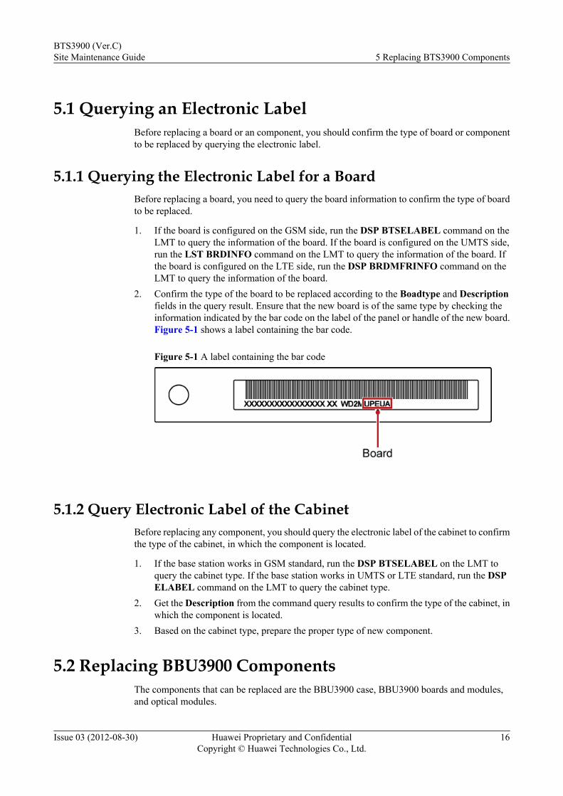
2. Confirm the type of the board to be replaced according to the Boadtype and Descriptionfields in the query result. Ensure that the new board is of the same type by checking theinformation indicated by the bar code on the label of the panel or handle of the new board.Figure 5-1 shows a label containing the bar code.
Figure 5-1 A label containing the bar code
5.1.2 Query Electronic Label of the CabinetBefore replacing any component, you should query the electronic label of the cabinet to confirmthe type of the cabinet, in which the component is located.
1. If the base station works in GSM standard, run the DSP BTSELABEL on the LMT toquery the cabinet type. If the base station works in UMTS or LTE standard, run the DSPELABEL command on the LMT to query the cabinet type.
2. Get the Description from the command query results to confirm the type of the cabinet, inwhich the component is located.
3. Based on the cabinet type, prepare the proper type of new component.
5.2 Replacing BBU3900 ComponentsThe components that can be replaced are the BBU3900 case, BBU3900 boards and modules,and optical modules.
BTS3900 (Ver.C)Site Maintenance Guide 5 Replacing BTS3900 Components
Issue 03 (2012-08-30) Huawei Proprietary and ConfidentialCopyright © Huawei Technologies Co., Ltd.
16

5.2.1 Replacing BBU3900 CasesAs the core of a base station, a BBU3900 processes the baseband signals of the entire base stationand communicates with the RNC/BSC and RFU/RRU. Replacing a BBU3900 interrupts servicescarried by the base station.
Prerequisitesl Query alarms reported by the base station. For details, see Browsing the Current Alarm.l The following tools and materials are available: an ESD wrist strap or ESD gloves and an
M6 screwdriver.l The type and quantity of BBU cases to be replaced are confirmed. New BBU cases are
available.l A computer equipped with the service maintenance terminal (SMT) and a network cable
is available for a GBTS using a static IP address. For details about the hardwarerequirements for the computer, see the GSM SMT User Guide.
l Associated personnel have been permitted to access the site and have obtained the requiredkeys.
Procedure
Step 1 Ask the M2000 administrator to perform the following operations for the replacement of theBBU case:
NOTEIn a multi-mode base station, block the cells of each mode respectively.
1. On the NodeB, run the BLK LOCELL command to block all cells working in UMTSmode. Modify the ESN on the RNC to the same as the ESN on the new BBU case. Fordetails, see Creating NodeB Commissioning Tasks.
2. On the eNodeB, run the BLK CELL command to block all cells working in LTE mode.Modify the ESN in the DHCP management interface to the same as the new BBU case. Fordetails, see Creating an eNodeB Commissioning Task.
3. On the BSC, run the LST GCELL command to query the configuration of all cells of thebase station, and run the SET GCELLADMSTAT command and set ADMSTAT toLOCK to block these cells. Modify the ESN on the BSC to the same as the new BBU case.For details, see Creating GBTS Commissioning Tasks.
Step 2 Power off the BBU. For details, see Powering Off the BBU3900.
Step 3 Put on an ESD wrist strap or ESD gloves.
WARNINGTake proper ESD protection measures, for example, put on an ESD wrist strap or ESD gloves,to prevent electrostatic damage to the boards, modules, or other electronic components.
Step 4 Record all cable connections on the panels of the boards in the BBU case to be replaced.
Step 5 Disconnect the power cables, transmission cables, common public radio interface (CPRI) cables,and alarm cables from the panels of the boards in the BBU case.
BTS3900 (Ver.C)Site Maintenance Guide 5 Replacing BTS3900 Components
Issue 03 (2012-08-30) Huawei Proprietary and ConfidentialCopyright © Huawei Technologies Co., Ltd.
17
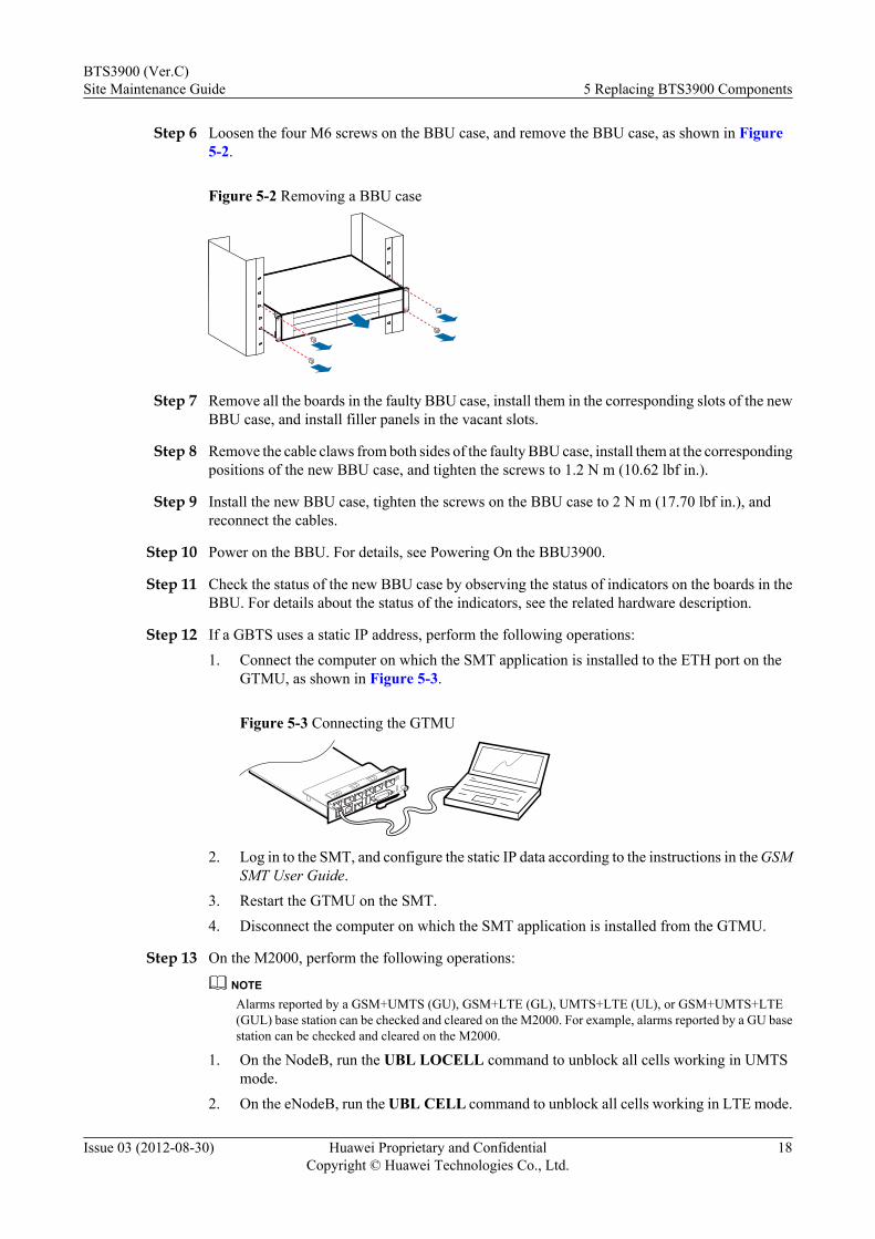
Step 6 Loosen the four M6 screws on the BBU case, and remove the BBU case, as shown in Figure5-2.
Figure 5-2 Removing a BBU case
Step 7 Remove all the boards in the faulty BBU case, install them in the corresponding slots of the newBBU case, and install filler panels in the vacant slots.
Step 8 Remove the cable claws from both sides of the faulty BBU case, install them at the correspondingpositions of the new BBU case, and tighten the screws to 1.2 N m (10.62 lbf in.).
Step 9 Install the new BBU case, tighten the screws on the BBU case to 2 N m (17.70 lbf in.), andreconnect the cables.
Step 10 Power on the BBU. For details, see Powering On the BBU3900.
Step 11 Check the status of the new BBU case by observing the status of indicators on the boards in theBBU. For details about the status of the indicators, see the related hardware description.
Step 12 If a GBTS uses a static IP address, perform the following operations:1. Connect the computer on which the SMT application is installed to the ETH port on the
GTMU, as shown in Figure 5-3.
Figure 5-3 Connecting the GTMU
2. Log in to the SMT, and configure the static IP data according to the instructions in the GSMSMT User Guide.
3. Restart the GTMU on the SMT.4. Disconnect the computer on which the SMT application is installed from the GTMU.
Step 13 On the M2000, perform the following operations:
NOTEAlarms reported by a GSM+UMTS (GU), GSM+LTE (GL), UMTS+LTE (UL), or GSM+UMTS+LTE(GUL) base station can be checked and cleared on the M2000. For example, alarms reported by a GU basestation can be checked and cleared on the M2000.
1. On the NodeB, run the UBL LOCELL command to unblock all cells working in UMTSmode.
2. On the eNodeB, run the UBL CELL command to unblock all cells working in LTE mode.
BTS3900 (Ver.C)Site Maintenance Guide 5 Replacing BTS3900 Components
Issue 03 (2012-08-30) Huawei Proprietary and ConfidentialCopyright © Huawei Technologies Co., Ltd.
18
3. On the BSC, run the SET GCELLADMSTAT command and set ADMSTAT toUNLOCK to unblock all cells of the BTS.
4. Check whether any new alarms are generated by the base station according to theinstructions in Browsing the Current Alarm. Then handle all NodeB alarms according tothe instructions in Handling NodeB Alarms.
5. Check whether any new alarms are generated by the base station according to theinstructions in Browsing the Current Alarm. Then handle all GBTS alarms according tothe instructions in Handling GBTS Alarms.
6. Check whether any new alarms are generated by the base station according to theinstructions in Browsing the Current Alarm. Then handle all eNodeB alarms according tothe instructions in Browsing Active Alarms or Events.
7. Synchronize the inventory information manually. For details, see Synchronizing InventoryData.
Step 14 Take off the ESD wrist strap or ESD gloves, and pack up all the tools.
----End
Follow-up Procedurel Place the replaced component into an ESD box or bag. Then, place the ESD box or bag
into a foam-padded carton or into the packing box of the new component.l Fill in the fault form with detailed information about the replaced component.l Contact the local Huawei office to handle the faulty component.
5.2.2 Replacing the GTMUThe GSM transmission and management unit (GTMU) is the basic transmission and controlfunction entity of the BBU. It provides the reference clock, power supply port, maintenance port,and external alarm collection port, and controls and manages the entire base station.
Prerequisitesl To confirm the type of a faulty board, do as follows:
– If the board can be queried online, run the associated command on the LMT followingthe instructions in 5.1.1 Querying the Electronic Label for a Board.
– If the board is faulty and cannot be queried online, query the board information offlineon the M2000 following the instructions in Querying Inventory Data.
l To query the base station information, do as follows:– On the BSC, run the LST BTSAUTODLDACTINFO command to check whether the
function of automatically loading and activating base station software has been enabled.– Query alarms reported by the base station. For details, see Browsing the Current Alarm.– If a GBTS uses a static IP address, run the LST BTSIPRT, LST BTSDEVIP, and LST
BTSIP commands to query the IP addresses and routing information.l To back up the configuration file and software, see Manually Backing Up NE Data.l If the configuration file and software are downloaded by using a USB flash drive, see section
"Preparations for the Upgrade" in the DBS3900 GSM Commissioning Guide.l The following tools and materials are available: an ESD wrist strap or a pair of ESD gloves
and an M3 Phillips screwdriver.
BTS3900 (Ver.C)Site Maintenance Guide 5 Replacing BTS3900 Components
Issue 03 (2012-08-30) Huawei Proprietary and ConfidentialCopyright © Huawei Technologies Co., Ltd.
19
l A computer equipped with the service maintenance terminal (SMT) and a network cableis available for a GBTS using a static IP address. For details about the hardwarerequirements for the computer, see the GSM SMT User Guide.
l Associated personnel have gained permission to access the site and have obtained therequired keys.
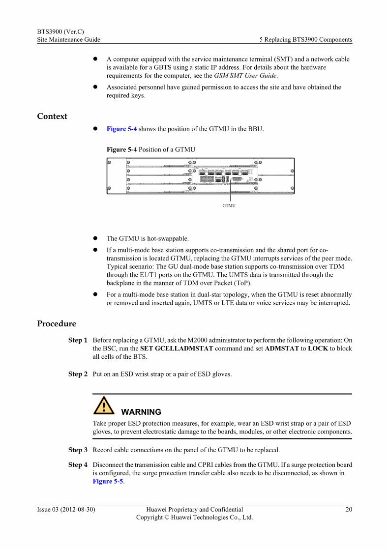
Contextl Figure 5-4 shows the position of the GTMU in the BBU.
Figure 5-4 Position of a GTMU
GTMU
GTMU
ETH FE0 FE1
CPRI0 CPRI2 CPRI4
CPRI3CPRI1 CPRI5TX RX
TX0 RX0 TX1 RX1 TX2 RX2 TX3 RX3 TX4 RX4 TX5 RX5 LIU0LIU2
LIU1LIU3
USB TST E1/T1 RST
RUNALMACT
1 2 3 4 5
l The GTMU is hot-swappable.
l If a multi-mode base station supports co-transmission and the shared port for co-transmission is located GTMU, replacing the GTMU interrupts services of the peer mode.Typical scenario: The GU dual-mode base station supports co-transmission over TDMthrough the E1/T1 ports on the GTMU. The UMTS data is transmitted through thebackplane in the manner of TDM over Packet (ToP).
l For a multi-mode base station in dual-star topology, when the GTMU is reset abnormallyor removed and inserted again, UMTS or LTE data or voice services may be interrupted.
Procedure
Step 1 Before replacing a GTMU, ask the M2000 administrator to perform the following operation: Onthe BSC, run the SET GCELLADMSTAT command and set ADMSTAT to LOCK to blockall cells of the BTS.
Step 2 Put on an ESD wrist strap or a pair of ESD gloves.
WARNINGTake proper ESD protection measures, for example, wear an ESD wrist strap or a pair of ESDgloves, to prevent electrostatic damage to the boards, modules, or other electronic components.
Step 3 Record cable connections on the panel of the GTMU to be replaced.
Step 4 Disconnect the transmission cable and CPRI cables from the GTMU. If a surge protection boardis configured, the surge protection transfer cable also needs to be disconnected, as shown inFigure 5-5.
BTS3900 (Ver.C)Site Maintenance Guide 5 Replacing BTS3900 Components
Issue 03 (2012-08-30) Huawei Proprietary and ConfidentialCopyright © Huawei Technologies Co., Ltd.
20
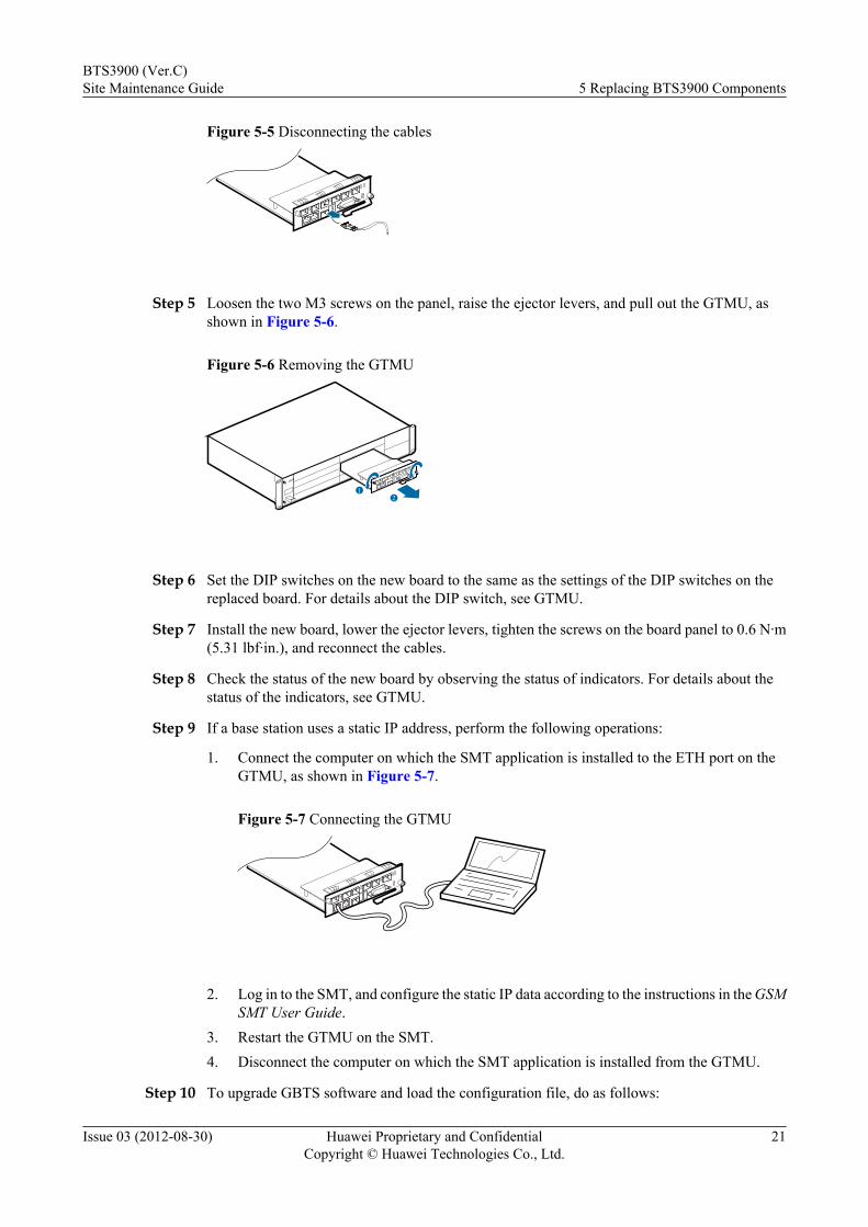
Figure 5-5 Disconnecting the cables
Step 5 Loosen the two M3 screws on the panel, raise the ejector levers, and pull out the GTMU, asshown in Figure 5-6.
Figure 5-6 Removing the GTMU
12
Step 6 Set the DIP switches on the new board to the same as the settings of the DIP switches on thereplaced board. For details about the DIP switch, see GTMU.
Step 7 Install the new board, lower the ejector levers, tighten the screws on the board panel to 0.6 N·m(5.31 lbf·in.), and reconnect the cables.
Step 8 Check the status of the new board by observing the status of indicators. For details about thestatus of the indicators, see GTMU.
Step 9 If a base station uses a static IP address, perform the following operations:
1. Connect the computer on which the SMT application is installed to the ETH port on theGTMU, as shown in Figure 5-7.
Figure 5-7 Connecting the GTMU
2. Log in to the SMT, and configure the static IP data according to the instructions in the GSM
SMT User Guide.3. Restart the GTMU on the SMT.4. Disconnect the computer on which the SMT application is installed from the GTMU.
Step 10 To upgrade GBTS software and load the configuration file, do as follows:
BTS3900 (Ver.C)Site Maintenance Guide 5 Replacing BTS3900 Components
Issue 03 (2012-08-30) Huawei Proprietary and ConfidentialCopyright © Huawei Technologies Co., Ltd.
21

l To upgrade the GBTS software and load the configuration file by using a USB flash drive,perform operations described in section "Upgrade Operations and Verification" in theDBS3900 GSM Commissioning Guide.
l To upgrade the GBTS software and load the configuration file using the SMT locally andthe LMT remotely.
– a. Query the software version of the board according to the instructions in section"Checking the Current Software Version on the SMT" in the DBS3900 GSMCommissioning Guide. If the software version is the target version, go to Step 11. If no,go to b.
– b. On the LMT, run the LST BTSAUTODLDACTINFO command to check whetherthe automatic load and activation of the BTS software is enabled on the BSC. If not,load and activate the GTMU software and TRXs of the corresponding base stationaccording to sections "Forcibly Loading Software" and "Activating Software" in theDBS3900 GSM Site Maintenance Terminal User Guide. If yes, go to Step 11.
Step 11 Inform the M2000 administrator that the replacement is complete, and instruct the administratorto perform the following operations:1. Run the SET GCELLADMSTAT command and set ADMSTAT to UNLOCK to unblock
all cells of the BTS.2. Check whether any new alarms are generated by the base station according to the
instructions in Browsing the Current Alarm. Then handle all GBTS alarms according tothe instructions in Handling GBTS Alarms.
3. Synchronize the inventory information manually following the instructions inSynchronizing Inventory Data.
4. Ask the onsite engineers to perform dialing tests to check whether the cells can normallyprovide services.
Step 12 Take off the ESD wrist strap or ESD gloves, and pack up all tools.
----End
Follow-up Procedurel Place the replaced component into an ESD box or bag. Then, place the ESD box or bag
into a foam-padded carton or the packing box of the new module.l Fill in the fault form with detailed information about the replaced component.l Contact the local Huawei office to handle the faulty component.
5.2.3 Replacing the WMPTThe WCDMA main processing and transmission unit (WMPT) processes signals and managesresources on other boards.
Prerequisitesl To confirm the type of a faulty board, do as follows:
– If the board can be queried online, run the associated command on the LMT followingthe instructions in 5.1.1 Querying the Electronic Label for a Board.
– If the board is faulty and cannot be queried online, query the board information offlineon the M2000 following the instructions in Querying Inventory Data.
BTS3900 (Ver.C)Site Maintenance Guide 5 Replacing BTS3900 Components
Issue 03 (2012-08-30) Huawei Proprietary and ConfidentialCopyright © Huawei Technologies Co., Ltd.
22

l To back up the configuration file and software, see Manually Backing Up NE Data.l To download the backup configuration file and software, do as follows:
– If the configuration file and software are downloaded by using a USB flash drive, seesection "Preparing the USB Disk for Local Commissioning" in the NodeBCommissioning Guide.
– If the WMPT needs to be upgraded on the LMT after the replacement, upload theconfiguration file of the base station to the FTP server of the M2000 following theinstructions in Transferring Files from NEs to a Client.
l Query alarms reported by the base station. For details, see Browsing the Current Alarm.l The following tools and materials are available: an ESD wrist strap or a pair of ESD gloves
and an M3 Phillips screwdriver.l Associated personnel have gained permission to access the site and have obtained the
required keys.
Context
l Figure 5-8 shows the position of the WMPT in the BBU.
Figure 5-8 Position of the WMPT in the BBU
WMPT
WMPT
ETH FE0 FE1 USB TST E1/T1 RST GPS
RUNALMACT
TX RX
l The WMPT is hot-swappable.l If a multi-mode base station supports co-transmission and the shared ports for co-
transmission are on the WMPT, replacing the WMPT interrupts the services of the peermode. Typical scenario: The GU dual-mode base station supports co-transmission over IPthrough the Ethernet link on the WMPT. The GSM data is transmitted through the FE portsinterconnecting the WMPT and GTMU panels.
l For a multi-mode base station in dual-star topology, when the WMPT is removed andinserted again, the rate of GSM or LTE data services may decrease. However, voice serviceswill not be affected.
Procedure
Step 1 Before replacing the WMPT, ask the M2000 administrator to perform the following operations:1. On the NodeB, run the BLK LOCELL command to block all cells of the NodeB.
NOTEIf this command cannot be executed or services of this cell are interrupted, go to Step 1.2.
2. Change the ESN on the RNC by referring to the new WMPT. For detailed operations, seeCreating NodeB Commissioning Tasks.
Step 2 Put on an ESD wrist strap or a pair of ESD gloves.
BTS3900 (Ver.C)Site Maintenance Guide 5 Replacing BTS3900 Components
Issue 03 (2012-08-30) Huawei Proprietary and ConfidentialCopyright © Huawei Technologies Co., Ltd.
23
WARNINGTake proper ESD protection measures, for example, wear an ESD wrist strap or a pair of ESDgloves, to prevent electrostatic damage to the boards, modules, or other electronic components.
Step 3 Record cable connections on the panel of the WMPT to be replaced.
Step 4 Disconnect the transmission cable from the WMPT. If a surge protection board is configured,the surge protection transfer cable also needs to be disconnected, as shown in Figure 5-9.
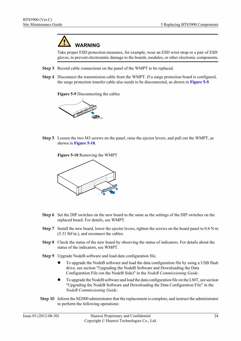
Figure 5-9 Disconnecting the cables
Step 5 Loosen the two M3 screws on the panel, raise the ejector levers, and pull out the WMPT, asshown in Figure 5-10.
Figure 5-10 Removing the WMPT
2
1
Step 6 Set the DIP switches on the new board to the same as the settings of the DIP switches on thereplaced board. For details, see WMPT.
Step 7 Install the new board, lower the ejector levers, tighten the screws on the board panel to 0.6 N·m(5.31 lbf·in.), and reconnect the cables.
Step 8 Check the status of the new board by observing the status of indicators. For details about thestatus of the indicators, see WMPT.
Step 9 Upgrade NodeB software and load data configuration file.l To upgrade the NodeB software and load the data configuration file by using a USB flash
drive, see section "Upgrading the NodeB Software and Downloading the DataConfiguration File (on the NodeB Side)" in the NodeB Commissioning Guide.
l To upgrade the NodeB software and load the data configuration file on the LMT, see section"Upgrading the NodeB Software and Downloading the Data Configuration File" in theNodeB Commissioning Guide.
Step 10 Inform the M2000 administrator that the replacement is complete, and instruct the administratorto perform the following operations:
BTS3900 (Ver.C)Site Maintenance Guide 5 Replacing BTS3900 Components
Issue 03 (2012-08-30) Huawei Proprietary and ConfidentialCopyright © Huawei Technologies Co., Ltd.
24
1. On the NodeB, run the UBL LOCELL command to unblock all cells of the NodeB.2. Check whether any new alarms are generated by the base station according to the
instructions in Browsing the Current Alarm. Then handle all NodeB alarms according tothe instructions in Handling NodeB Alarms.
3. Synchronize the inventory information manually following the instructions inSynchronizing Inventory Data.
4. Ask the onsite engineers to perform dialing tests to check whether the cells can normallyprovide services.
Step 11 Take off the ESD wrist strap or ESD gloves, and pack up all tools.
----End
Follow-up Procedurel Place the replaced component into an ESD box or bag. Then, place the ESD box or bag
into a foam-padded carton or the packing box of the new module.l Fill in the fault form with detailed information about the replaced component.l Contact the local Huawei office to handle the faulty component.
5.2.4 Replacing the LMPTThe LTE main processing and transmission unit (LMPT) manages the entire eNodeB system interms of OM and signaling processing and provides system clock for the BBU.
Prerequisitesl To confirm the type of a faulty board, do as follows:
– If the board can be queried online, run the associated command on the LMT followingthe instructions in 5.1.1 Querying the Electronic Label for a Board.
– If the board is faulty and cannot be queried online, query the board information offlineon the M2000 following the instructions in Querying Inventory Data.
l Make preparations according to onsite conditions of the eNodeB.
Scenario Preparation
No SeGW is configured and theLOFD-002004 Self-configurationfeature is available.
1. Download the eNodeB softwareworking with the product version of theeNodeB from http://support.huawei.com.
2. Run the BKP CFGFILE command toback up a configuration file and run theULD CFGFILE command to upload itto the server.
3. Run the ULD LICENSE command toupload the license file to the server.
BTS3900 (Ver.C)Site Maintenance Guide 5 Replacing BTS3900 Components
Issue 03 (2012-08-30) Huawei Proprietary and ConfidentialCopyright © Huawei Technologies Co., Ltd.
25

Scenario Preparation
No SeGW is configured and theLOFD-002004 Self-configurationfeature is unavailable.
1. Download the eNodeB softwareworking with the product version of theeNodeB from http://support.huawei.com.
2. Run the BKP CFGFILE command toback up a configuration file and run theULD CFGFILE command to upload itto the server.
3. Run the ULD LICENSE command toupload the license file to the server.
4. Prepare a USB flash drive. For details,see section "Obtaining the USB StorageDevice for Onsite eNodeBCommissioning" in the eNodeBCommissioning Guide.
An SeGW is configured and theLOFD-002004 Self-configurationfeature is available.
1. Download the eNodeB softwareworking with the product version of theeNodeB from http://support.huawei.com.
2. Run the BKP CFGFILE command toback up a configuration file and run theULD CFGFILE command to upload itto the server.
3. Run the ULD LICENSE command toupload the license file to the server.
4. Obtain the certificate from the root CAfor the operator.
An SeGW is configured and theLOFD-002004 Self-configurationfeature is unavailable.
1. Download the eNodeB softwareworking with the product version of theeNodeB from http://support.huawei.com.
2. Run the BKP CFGFILE command toback up a configuration file and run theULD CFGFILE command to upload itto the server.
3. Run the ULD LICENSE command toupload the license file to the server.
4. Obtain the certificate from the root CAfor the operator.
5. Prepare a USB flash drive. For details,see section "Obtaining the USB StorageDevice for Onsite eNodeBCommissioning" in the eNodeBCommissioning Guide.
BTS3900 (Ver.C)Site Maintenance Guide 5 Replacing BTS3900 Components
Issue 03 (2012-08-30) Huawei Proprietary and ConfidentialCopyright © Huawei Technologies Co., Ltd.
26
l Query alarms reported by the base station. For details, see Browsing the Current Alarm.l The serial number of the board is in the whitelist of the PKI system.l The following tools and materials are available: an ESD wrist strap or a pair of ESD gloves
and an M3 Phillips screwdriver.l Associated personnel have gained permission to access the site and have obtained the
required keys.
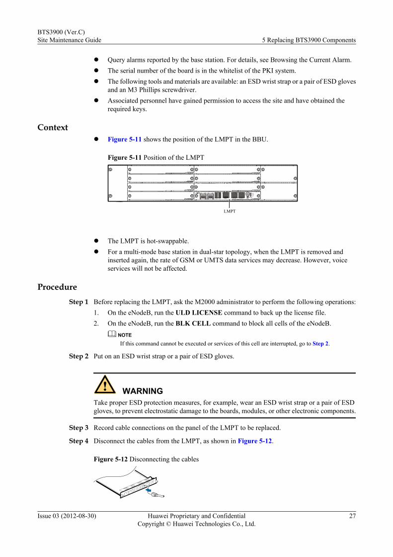
Contextl Figure 5-11 shows the position of the LMPT in the BBU.
Figure 5-11 Position of the LMPT
TX
SFP 0
RX TX
SFP 1
RX
USB TST ETH FE/GE0 FE/GE1GPSRST
RUNALMACT
LMPT
LMPT
l The LMPT is hot-swappable.l For a multi-mode base station in dual-star topology, when the LMPT is removed and
inserted again, the rate of GSM or UMTS data services may decrease. However, voiceservices will not be affected.
ProcedureStep 1 Before replacing the LMPT, ask the M2000 administrator to perform the following operations:
1. On the eNodeB, run the ULD LICENSE command to back up the license file.2. On the eNodeB, run the BLK CELL command to block all cells of the eNodeB.
NOTEIf this command cannot be executed or services of this cell are interrupted, go to Step 2.
Step 2 Put on an ESD wrist strap or a pair of ESD gloves.
WARNINGTake proper ESD protection measures, for example, wear an ESD wrist strap or a pair of ESDgloves, to prevent electrostatic damage to the boards, modules, or other electronic components.
Step 3 Record cable connections on the panel of the LMPT to be replaced.
Step 4 Disconnect the cables from the LMPT, as shown in Figure 5-12.
Figure 5-12 Disconnecting the cables
BTS3900 (Ver.C)Site Maintenance Guide 5 Replacing BTS3900 Components
Issue 03 (2012-08-30) Huawei Proprietary and ConfidentialCopyright © Huawei Technologies Co., Ltd.
27
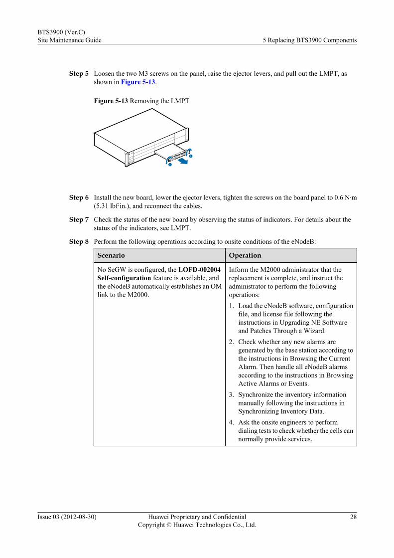
Step 5 Loosen the two M3 screws on the panel, raise the ejector levers, and pull out the LMPT, asshown in Figure 5-13.
Figure 5-13 Removing the LMPT
2
1
Step 6 Install the new board, lower the ejector levers, tighten the screws on the board panel to 0.6 N·m(5.31 lbf·in.), and reconnect the cables.
Step 7 Check the status of the new board by observing the status of indicators. For details about thestatus of the indicators, see LMPT.
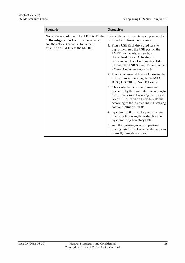
Step 8 Perform the following operations according to onsite conditions of the eNodeB:
Scenario Operation
No SeGW is configured, the LOFD-002004Self-configuration feature is available, andthe eNodeB automatically establishes an OMlink to the M2000.
Inform the M2000 administrator that thereplacement is complete, and instruct theadministrator to perform the followingoperations:1. Load the eNodeB software, configuration
file, and license file following theinstructions in Upgrading NE Softwareand Patches Through a Wizard.
2. Check whether any new alarms aregenerated by the base station according tothe instructions in Browsing the CurrentAlarm. Then handle all eNodeB alarmsaccording to the instructions in BrowsingActive Alarms or Events.
3. Synchronize the inventory informationmanually following the instructions inSynchronizing Inventory Data.
4. Ask the onsite engineers to performdialing tests to check whether the cells cannormally provide services.
BTS3900 (Ver.C)Site Maintenance Guide 5 Replacing BTS3900 Components
Issue 03 (2012-08-30) Huawei Proprietary and ConfidentialCopyright © Huawei Technologies Co., Ltd.
28
Scenario Operation
No SeGW is configured, the LOFD-002004Self-configuration feature is unavailable,and the eNodeB cannot automaticallyestablish an OM link to the M2000.
Instruct the onsite maintenance personnel toperform the following operations:1. Plug a USB flash drive used for site
deployment into the USB port on theLMPT. For details, see section"Downloading and Activating theSoftware and Data Configuration FileThrough the USB Storage Device" in theeNodeB Commissioning Guide.
2. Load a commercial license following theinstructions in Installing the WiMAXBTS (BTS3701B)/eNodeB License.
3. Check whether any new alarms aregenerated by the base station according tothe instructions in Browsing the CurrentAlarm. Then handle all eNodeB alarmsaccording to the instructions in BrowsingActive Alarms or Events.
4. Synchronize the inventory informationmanually following the instructions inSynchronizing Inventory Data.
5. Ask the onsite engineers to performdialing tests to check whether the cells cannormally provide services.
BTS3900 (Ver.C)Site Maintenance Guide 5 Replacing BTS3900 Components
Issue 03 (2012-08-30) Huawei Proprietary and ConfidentialCopyright © Huawei Technologies Co., Ltd.
29
Scenario Operation
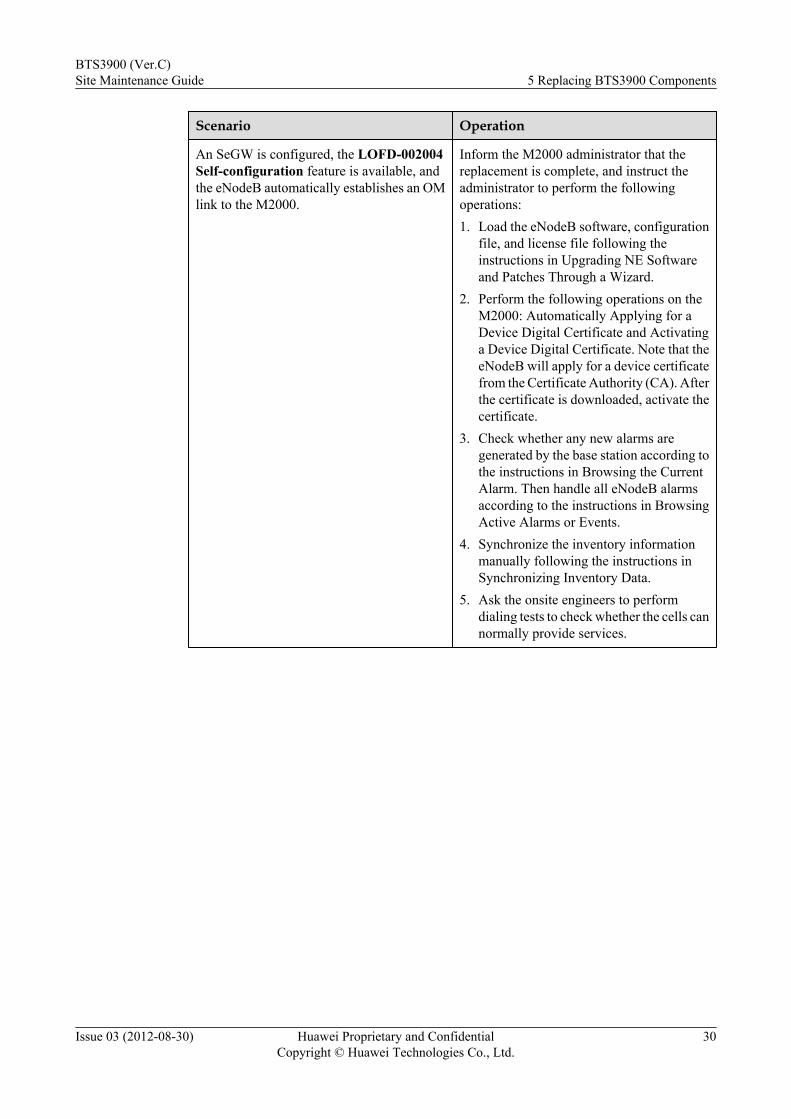
An SeGW is configured, the LOFD-002004Self-configuration feature is available, andthe eNodeB automatically establishes an OMlink to the M2000.
Inform the M2000 administrator that thereplacement is complete, and instruct theadministrator to perform the followingoperations:1. Load the eNodeB software, configuration
file, and license file following theinstructions in Upgrading NE Softwareand Patches Through a Wizard.
2. Perform the following operations on theM2000: Automatically Applying for aDevice Digital Certificate and Activatinga Device Digital Certificate. Note that theeNodeB will apply for a device certificatefrom the Certificate Authority (CA). Afterthe certificate is downloaded, activate thecertificate.
3. Check whether any new alarms aregenerated by the base station according tothe instructions in Browsing the CurrentAlarm. Then handle all eNodeB alarmsaccording to the instructions in BrowsingActive Alarms or Events.
4. Synchronize the inventory informationmanually following the instructions inSynchronizing Inventory Data.
5. Ask the onsite engineers to performdialing tests to check whether the cells cannormally provide services.
BTS3900 (Ver.C)Site Maintenance Guide 5 Replacing BTS3900 Components
Issue 03 (2012-08-30) Huawei Proprietary and ConfidentialCopyright © Huawei Technologies Co., Ltd.
30
Scenario Operation
An SeGW is configured, the LOFD-002004Self-configuration feature is unavailable,and the eNodeB cannot automaticallyestablish an OM link to the M2000.
Instruct the onsite maintenance personnel toperform the following operations:1. Power off the BBU following the
instructions in Powering Off theBBU3900.
2. Plug a USB flash drive used for sitedeployment into the USB port on theLMPT. For details, see section"Downloading and Activating theSoftware and Data Configuration FileThrough the USB Storage Device" in theeNodeB Commissioning Guide.
3. Load a commercial license following theinstructions in Installing the WiMAXBTS (BTS3701B)/eNodeB License.
4. Power on the BBU. For details, seePowering On the BBU3900. Note that theeNodeB software and configuration filewill be loaded in 20 minutes. After this,the eNodeB will automatically establishan OM link to the M2000. After an OMlink is established, ask the M2000administrator to perform the followingoperations:
5. Check whether any new alarms aregenerated by the base station according tothe instructions in Browsing the CurrentAlarm. Then handle all eNodeB alarmsaccording to the instructions in BrowsingActive Alarms or Events.
6. Synchronize the inventory informationmanually following the instructions inSynchronizing Inventory Data.
7. Ask the onsite engineers to performdialing tests to check whether the cells cannormally provide services.
Step 9 Take off the ESD wrist strap or ESD gloves, and pack up all tools.
----End
Follow-up Procedurel Place the replaced component into an ESD box or bag. Then, place the ESD box or bag
into a foam-padded carton or the packing box of the new module.
l Fill in the fault form with detailed information about the replaced component.
l Contact the local Huawei office to handle the faulty component.
BTS3900 (Ver.C)Site Maintenance Guide 5 Replacing BTS3900 Components
Issue 03 (2012-08-30) Huawei Proprietary and ConfidentialCopyright © Huawei Technologies Co., Ltd.
31
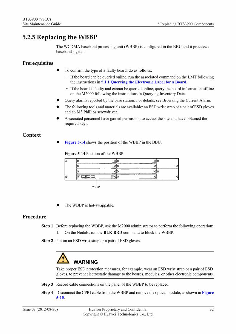
5.2.5 Replacing the WBBPThe WCDMA baseband processing unit (WBBP) is configured in the BBU and it processesbaseband signals.
Prerequisitesl To confirm the type of a faulty board, do as follows:
– If the board can be queried online, run the associated command on the LMT followingthe instructions in 5.1.1 Querying the Electronic Label for a Board.
– If the board is faulty and cannot be queried online, query the board information offlineon the M2000 following the instructions in Querying Inventory Data.
l Query alarms reported by the base station. For details, see Browsing the Current Alarm.l The following tools and materials are available: an ESD wrist strap or a pair of ESD gloves
and an M3 Phillips screwdriver.l Associated personnel have gained permission to access the site and have obtained the
required keys.
Contextl Figure 5-14 shows the position of the WBBP in the BBU.
Figure 5-14 Position of the WBBP
WBBP
WBBP TX RX
CPRI0/EIH0 CPRI1/EIH1 CPRI2/EIH2
TX RX TX RXRUNALMACT
l The WBBP is hot-swappable.
Procedure
Step 1 Before replacing the WBBP, ask the M2000 administrator to perform the following operation:1. On the NodeB, run the BLK BRD command to block the WBBP.
Step 2 Put on an ESD wrist strap or a pair of ESD gloves.
WARNINGTake proper ESD protection measures, for example, wear an ESD wrist strap or a pair of ESDgloves, to prevent electrostatic damage to the boards, modules, or other electronic components.
Step 3 Record cable connections on the panel of the WBBP to be replaced.
Step 4 Disconnect the CPRI cable from the WBBP and remove the optical module, as shown in Figure5-15.
BTS3900 (Ver.C)Site Maintenance Guide 5 Replacing BTS3900 Components
Issue 03 (2012-08-30) Huawei Proprietary and ConfidentialCopyright © Huawei Technologies Co., Ltd.
32
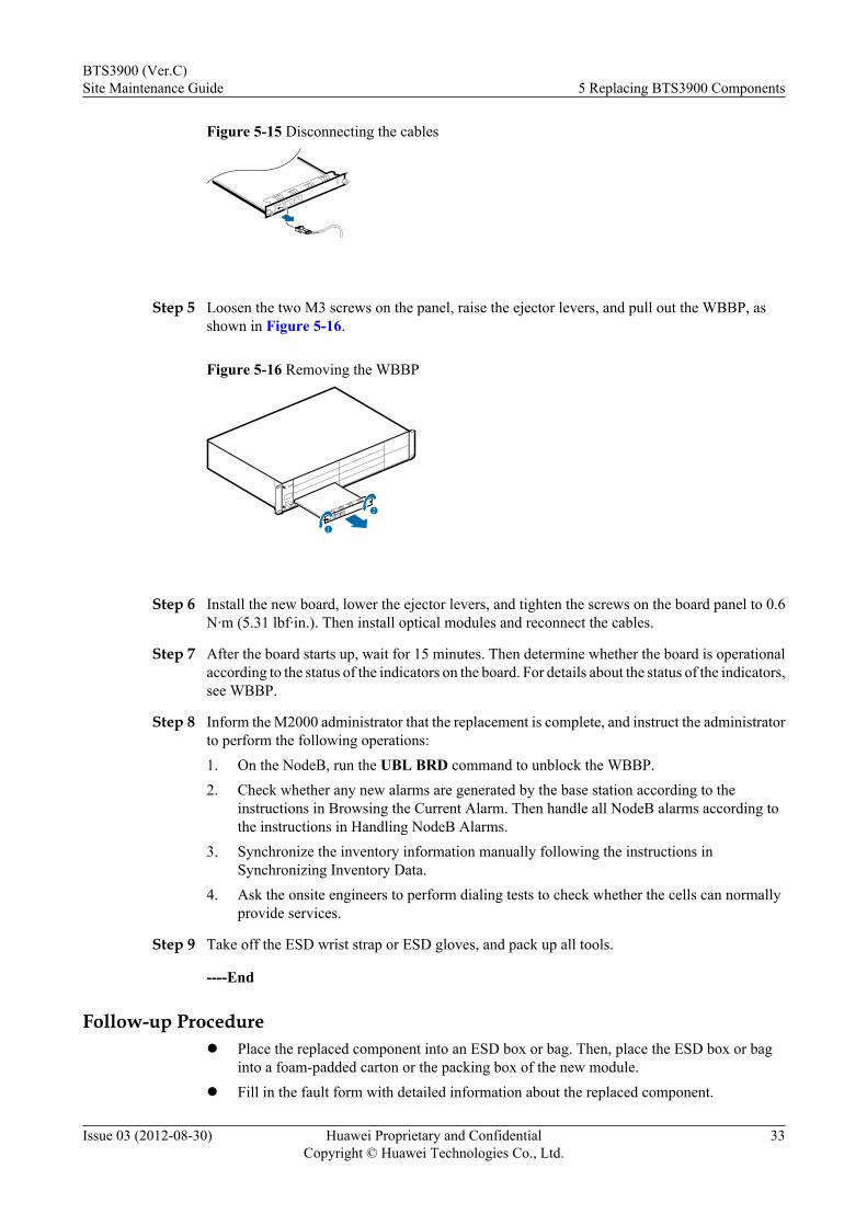
Figure 5-15 Disconnecting the cables
Step 5 Loosen the two M3 screws on the panel, raise the ejector levers, and pull out the WBBP, asshown in Figure 5-16.
Figure 5-16 Removing the WBBP
2
1
Step 6 Install the new board, lower the ejector levers, and tighten the screws on the board panel to 0.6N·m (5.31 lbf·in.). Then install optical modules and reconnect the cables.
Step 7 After the board starts up, wait for 15 minutes. Then determine whether the board is operationalaccording to the status of the indicators on the board. For details about the status of the indicators,see WBBP.
Step 8 Inform the M2000 administrator that the replacement is complete, and instruct the administratorto perform the following operations:1. On the NodeB, run the UBL BRD command to unblock the WBBP.2. Check whether any new alarms are generated by the base station according to the
instructions in Browsing the Current Alarm. Then handle all NodeB alarms according tothe instructions in Handling NodeB Alarms.
3. Synchronize the inventory information manually following the instructions inSynchronizing Inventory Data.
4. Ask the onsite engineers to perform dialing tests to check whether the cells can normallyprovide services.
Step 9 Take off the ESD wrist strap or ESD gloves, and pack up all tools.
----End
Follow-up Procedurel Place the replaced component into an ESD box or bag. Then, place the ESD box or bag
into a foam-padded carton or the packing box of the new module.l Fill in the fault form with detailed information about the replaced component.
BTS3900 (Ver.C)Site Maintenance Guide 5 Replacing BTS3900 Components
Issue 03 (2012-08-30) Huawei Proprietary and ConfidentialCopyright © Huawei Technologies Co., Ltd.
33
l Contact the local Huawei office to handle the faulty component.
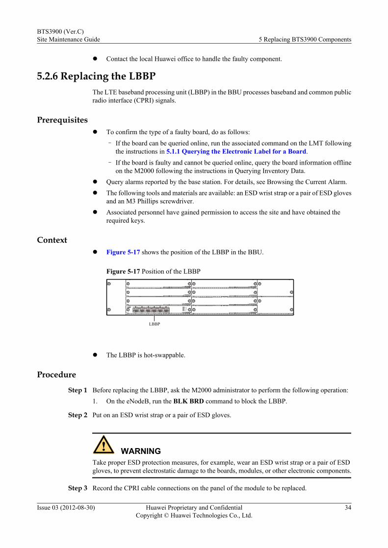
5.2.6 Replacing the LBBPThe LTE baseband processing unit (LBBP) in the BBU processes baseband and common publicradio interface (CPRI) signals.
Prerequisitesl To confirm the type of a faulty board, do as follows:
– If the board can be queried online, run the associated command on the LMT followingthe instructions in 5.1.1 Querying the Electronic Label for a Board.
– If the board is faulty and cannot be queried online, query the board information offlineon the M2000 following the instructions in Querying Inventory Data.
l Query alarms reported by the base station. For details, see Browsing the Current Alarm.l The following tools and materials are available: an ESD wrist strap or a pair of ESD gloves
and an M3 Phillips screwdriver.l Associated personnel have gained permission to access the site and have obtained the
required keys.
Contextl Figure 5-17 shows the position of the LBBP in the BBU.
Figure 5-17 Position of the LBBP
CPRI 0 CPRI 1 CPRI 2 CPRI 3 CPRI 4 CPRI 5
TX RX TX RX TX RX TX RX TX RX TX RXLBBP RUNALMACT
LBBP
l The LBBP is hot-swappable.
Procedure
Step 1 Before replacing the LBBP, ask the M2000 administrator to perform the following operation:1. On the eNodeB, run the BLK BRD command to block the LBBP.
Step 2 Put on an ESD wrist strap or a pair of ESD gloves.
WARNINGTake proper ESD protection measures, for example, wear an ESD wrist strap or a pair of ESDgloves, to prevent electrostatic damage to the boards, modules, or other electronic components.
Step 3 Record the CPRI cable connections on the panel of the module to be replaced.
BTS3900 (Ver.C)Site Maintenance Guide 5 Replacing BTS3900 Components
Issue 03 (2012-08-30) Huawei Proprietary and ConfidentialCopyright © Huawei Technologies Co., Ltd.
34

Step 4 Disconnect CPRI cables from the LBBP, as shown in Figure 5-18.
Figure 5-18 Disconnecting the cables
Step 5 Loosen the two M3 screws on the panel, raise the ejector levers, and pull out the LBBP, as shownin Figure 5-19.
Figure 5-19 Removing the LBBP
2
1
Step 6 Install the new board, lower the ejector levers, tighten the screws on the board panel to 0.6 N·m(5.31 lbf·in.), and reconnect the cables.
Step 7 After the board starts up, wait for 15 minutes. Then determine whether the board is operationalaccording to the status of the indicators on the board. For details about the status of the indicators,see LBBP.
Step 8 Inform the M2000 administrator that the replacement is complete, and instruct the administratorto perform the following operations:1. On the eNodeB, run the UBL BRD command to unblock the LBBP.2. Check whether any new alarms are generated by the base station according to the
instructions in Browsing the Current Alarm. Then handle all eNodeB alarms according tothe instructions in Browsing Active Alarms or Events.
3. Synchronize the inventory information manually following the instructions inSynchronizing Inventory Data.
4. Ask the onsite engineers to perform dialing tests to check whether the cells can normallyprovide services.
Step 9 Take off the ESD wrist strap or ESD gloves, and pack up all tools.
----End
Follow-up Procedurel Place the replaced component into an ESD box or bag. Then, place the ESD box or bag
into a foam-padded carton or the packing box of the new module.
BTS3900 (Ver.C)Site Maintenance Guide 5 Replacing BTS3900 Components
Issue 03 (2012-08-30) Huawei Proprietary and ConfidentialCopyright © Huawei Technologies Co., Ltd.
35
l Fill in the fault form with detailed information about the replaced component.l Contact the local Huawei office to handle the faulty component.
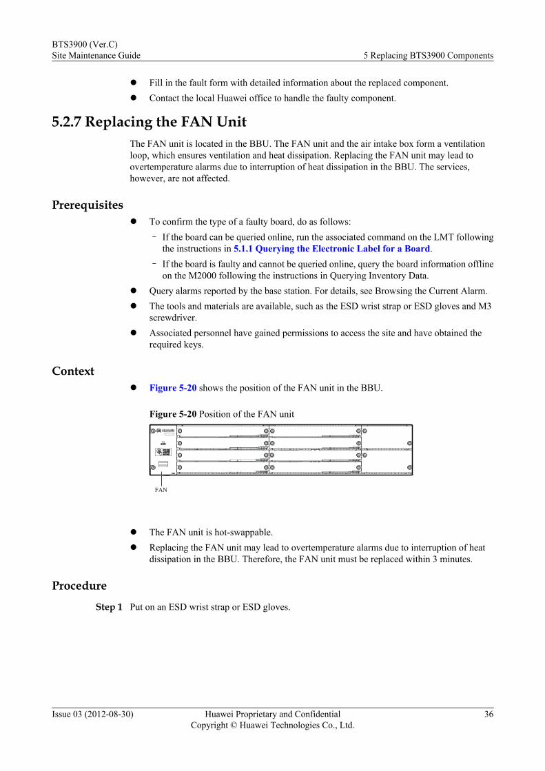
5.2.7 Replacing the FAN UnitThe FAN unit is located in the BBU. The FAN unit and the air intake box form a ventilationloop, which ensures ventilation and heat dissipation. Replacing the FAN unit may lead toovertemperature alarms due to interruption of heat dissipation in the BBU. The services,however, are not affected.
Prerequisitesl To confirm the type of a faulty board, do as follows:
– If the board can be queried online, run the associated command on the LMT followingthe instructions in 5.1.1 Querying the Electronic Label for a Board.
– If the board is faulty and cannot be queried online, query the board information offlineon the M2000 following the instructions in Querying Inventory Data.
l Query alarms reported by the base station. For details, see Browsing the Current Alarm.l The tools and materials are available, such as the ESD wrist strap or ESD gloves and M3
screwdriver.l Associated personnel have gained permissions to access the site and have obtained the
required keys.
Contextl Figure 5-20 shows the position of the FAN unit in the BBU.
Figure 5-20 Position of the FAN unit
FAN
l The FAN unit is hot-swappable.l Replacing the FAN unit may lead to overtemperature alarms due to interruption of heat
dissipation in the BBU. Therefore, the FAN unit must be replaced within 3 minutes.
Procedure
Step 1 Put on an ESD wrist strap or ESD gloves.
BTS3900 (Ver.C)Site Maintenance Guide 5 Replacing BTS3900 Components
Issue 03 (2012-08-30) Huawei Proprietary and ConfidentialCopyright © Huawei Technologies Co., Ltd.
36
WARNINGTake proper ESD protection measures, for example, wear an ESD wrist strap or a pair of ESDgloves, to prevent electrostatic damage to the boards, modules, or electronic components.
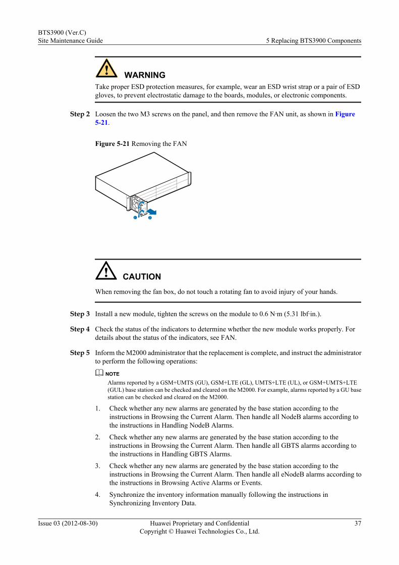
Step 2 Loosen the two M3 screws on the panel, and then remove the FAN unit, as shown in Figure5-21.
Figure 5-21 Removing the FAN
1 2
CAUTIONWhen removing the fan box, do not touch a rotating fan to avoid injury of your hands.
Step 3 Install a new module, tighten the screws on the module to 0.6 N·m (5.31 lbf·in.).
Step 4 Check the status of the indicators to determine whether the new module works properly. Fordetails about the status of the indicators, see FAN.
Step 5 Inform the M2000 administrator that the replacement is complete, and instruct the administratorto perform the following operations:
NOTEAlarms reported by a GSM+UMTS (GU), GSM+LTE (GL), UMTS+LTE (UL), or GSM+UMTS+LTE(GUL) base station can be checked and cleared on the M2000. For example, alarms reported by a GU basestation can be checked and cleared on the M2000.
1. Check whether any new alarms are generated by the base station according to theinstructions in Browsing the Current Alarm. Then handle all NodeB alarms according tothe instructions in Handling NodeB Alarms.
2. Check whether any new alarms are generated by the base station according to theinstructions in Browsing the Current Alarm. Then handle all GBTS alarms according tothe instructions in Handling GBTS Alarms.
3. Check whether any new alarms are generated by the base station according to theinstructions in Browsing the Current Alarm. Then handle all eNodeB alarms according tothe instructions in Browsing Active Alarms or Events.
4. Synchronize the inventory information manually following the instructions inSynchronizing Inventory Data.
BTS3900 (Ver.C)Site Maintenance Guide 5 Replacing BTS3900 Components
Issue 03 (2012-08-30) Huawei Proprietary and ConfidentialCopyright © Huawei Technologies Co., Ltd.
37
5. Ask the onsite engineers to perform dialing tests to check whether the cells can normallyprovide services.
Step 6 Take off the ESD wrist strap or ESD gloves, and pack up all tools.
----End
Follow-up Procedurel Place the replaced component into the ESD box or bag. Then, place the ESD box or bag
into a foam-padded carton or the packing box of the new component.
l Fill in the fault form with detailed information about the replaced component.
l Contact the local Huawei office to handle the faulty component.
5.2.8 Replacing a UPEUA universal power and environment interface unit (UPEU) is configured in a BBU and it converts-48 V DC or +24 V DC power into +12 V DC power.
Prerequisitesl To confirm the type of a faulty board, do as follows:
– If the board can be queried online, run the associated command on the LMT followingthe instructions in 5.1.1 Querying the Electronic Label for a Board.
– If the board is faulty and cannot be queried online, query the board information offlineon the M2000 following the instructions in Querying Inventory Data.
l Query alarms reported by the base station. For details, see Browsing the Current Alarm.
l The following tools and materials are available: an ESD wrist strap or ESD gloves and anM3 Phillips screwdriver.
l Associated personnel have been permitted to access the site and have obtained the requiredkeys.
Contextl Figure 5-22 shows the position of a UPEU in the BBU.
Figure 5-22 Position of a UPEU
UPEU
l If the only one UPEU in the base station is faulty, replacing the UPEU interrupts powersupply to a BBU and accordingly interrupts services carried by the BBU. To avoid theimpact, perform Step 1to Step 8to replace the UPEU.
BTS3900 (Ver.C)Site Maintenance Guide 5 Replacing BTS3900 Components
Issue 03 (2012-08-30) Huawei Proprietary and ConfidentialCopyright © Huawei Technologies Co., Ltd.
38
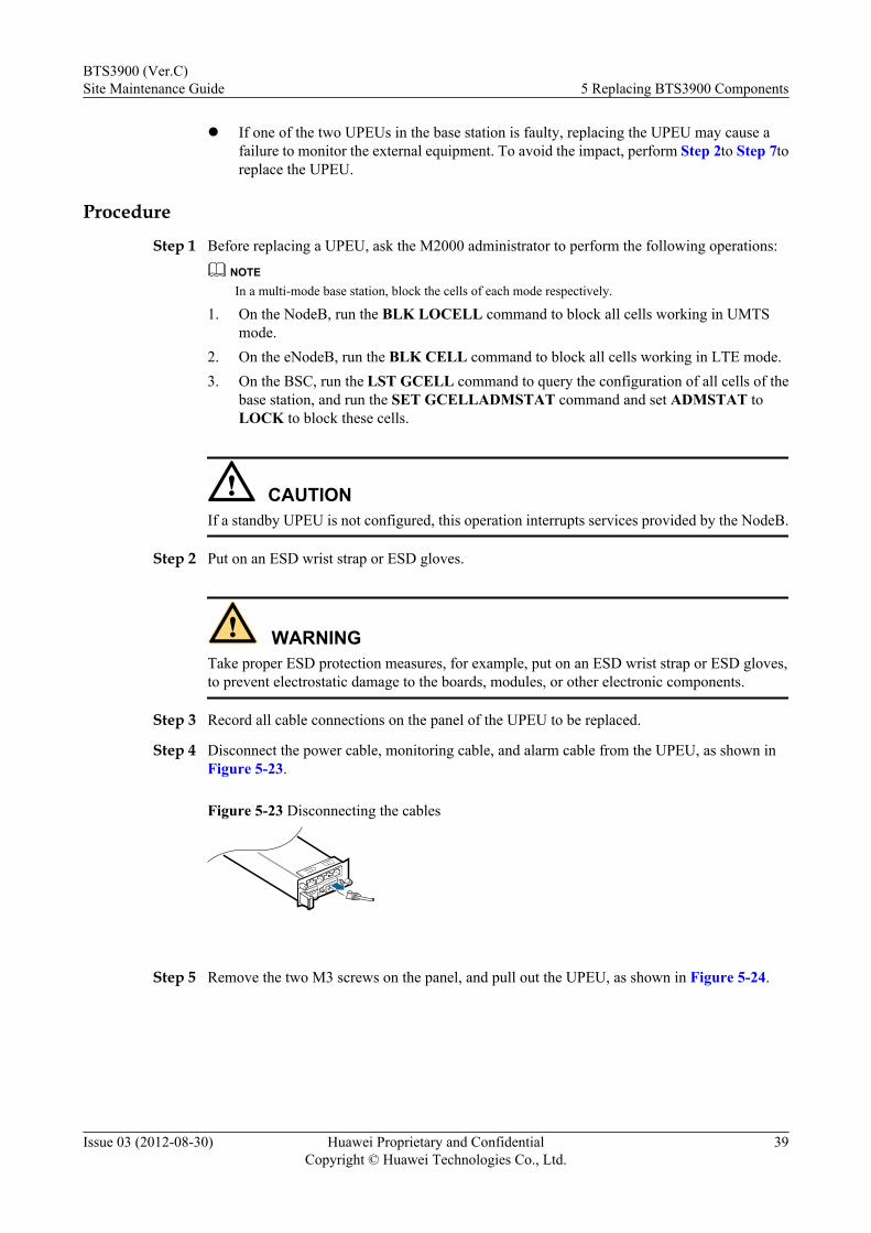
l If one of the two UPEUs in the base station is faulty, replacing the UPEU may cause afailure to monitor the external equipment. To avoid the impact, perform Step 2to Step 7toreplace the UPEU.
Procedure
Step 1 Before replacing a UPEU, ask the M2000 administrator to perform the following operations:
NOTEIn a multi-mode base station, block the cells of each mode respectively.
1. On the NodeB, run the BLK LOCELL command to block all cells working in UMTSmode.
2. On the eNodeB, run the BLK CELL command to block all cells working in LTE mode.3. On the BSC, run the LST GCELL command to query the configuration of all cells of the
base station, and run the SET GCELLADMSTAT command and set ADMSTAT toLOCK to block these cells.
CAUTIONIf a standby UPEU is not configured, this operation interrupts services provided by the NodeB.
Step 2 Put on an ESD wrist strap or ESD gloves.
WARNINGTake proper ESD protection measures, for example, put on an ESD wrist strap or ESD gloves,to prevent electrostatic damage to the boards, modules, or other electronic components.
Step 3 Record all cable connections on the panel of the UPEU to be replaced.
Step 4 Disconnect the power cable, monitoring cable, and alarm cable from the UPEU, as shown inFigure 5-23.
Figure 5-23 Disconnecting the cables
Step 5 Remove the two M3 screws on the panel, and pull out the UPEU, as shown in Figure 5-24.
BTS3900 (Ver.C)Site Maintenance Guide 5 Replacing BTS3900 Components
Issue 03 (2012-08-30) Huawei Proprietary and ConfidentialCopyright © Huawei Technologies Co., Ltd.
39
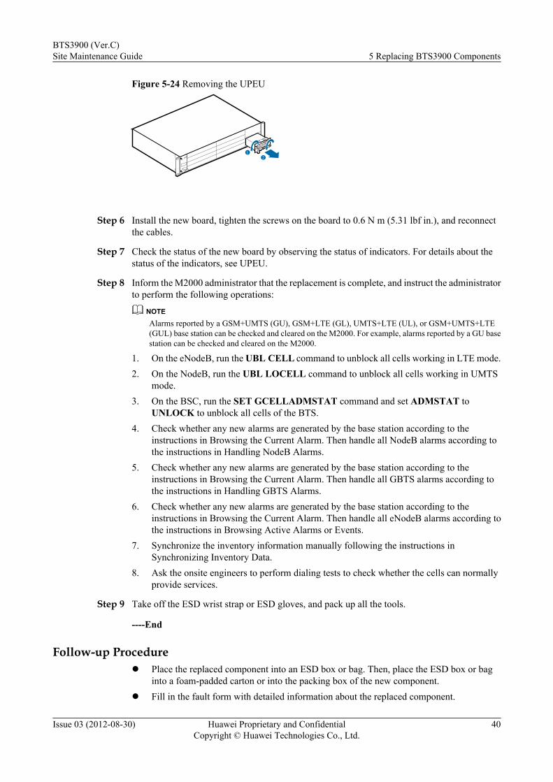
Figure 5-24 Removing the UPEU
12
Step 6 Install the new board, tighten the screws on the board to 0.6 N m (5.31 lbf in.), and reconnectthe cables.
Step 7 Check the status of the new board by observing the status of indicators. For details about thestatus of the indicators, see UPEU.
Step 8 Inform the M2000 administrator that the replacement is complete, and instruct the administratorto perform the following operations:
NOTEAlarms reported by a GSM+UMTS (GU), GSM+LTE (GL), UMTS+LTE (UL), or GSM+UMTS+LTE(GUL) base station can be checked and cleared on the M2000. For example, alarms reported by a GU basestation can be checked and cleared on the M2000.
1. On the eNodeB, run the UBL CELL command to unblock all cells working in LTE mode.2. On the NodeB, run the UBL LOCELL command to unblock all cells working in UMTS
mode.3. On the BSC, run the SET GCELLADMSTAT command and set ADMSTAT to
UNLOCK to unblock all cells of the BTS.4. Check whether any new alarms are generated by the base station according to the
instructions in Browsing the Current Alarm. Then handle all NodeB alarms according tothe instructions in Handling NodeB Alarms.
5. Check whether any new alarms are generated by the base station according to theinstructions in Browsing the Current Alarm. Then handle all GBTS alarms according tothe instructions in Handling GBTS Alarms.
6. Check whether any new alarms are generated by the base station according to theinstructions in Browsing the Current Alarm. Then handle all eNodeB alarms according tothe instructions in Browsing Active Alarms or Events.
7. Synchronize the inventory information manually following the instructions inSynchronizing Inventory Data.
8. Ask the onsite engineers to perform dialing tests to check whether the cells can normallyprovide services.
Step 9 Take off the ESD wrist strap or ESD gloves, and pack up all the tools.
----End
Follow-up Procedurel Place the replaced component into an ESD box or bag. Then, place the ESD box or bag
into a foam-padded carton or into the packing box of the new component.l Fill in the fault form with detailed information about the replaced component.
BTS3900 (Ver.C)Site Maintenance Guide 5 Replacing BTS3900 Components
Issue 03 (2012-08-30) Huawei Proprietary and ConfidentialCopyright © Huawei Technologies Co., Ltd.
40

l Contact the local Huawei office to handle the faulty component.
5.2.9 Replacing the UEIUThe Universal Environment Interface Unit (UEIU) provides channels for transmitting themonitoring signals from external equipment to the BBU.
Prerequisitesl To confirm the type of a faulty board, do as follows:
– If the board can be queried online, run the associated command on the LMT followingthe instructions in 5.1.1 Querying the Electronic Label for a Board.
– If the board is faulty and cannot be queried online, query the board information offlineon the M2000 following the instructions in Querying Inventory Data.
l Query alarms reported by the base station. For details, see Browsing the Current Alarm.l The tools and materials are available, such as the ESD wrist strap or ESD gloves and M3
screwdriver.l Associated personnel have gained permissions to access the site and have obtained the
required keys.
Contextl Figure 5-25 shows the position of the UEIU in the BBU.
Figure 5-25 Position of the UEIU
UEIU
l The UEIU is hot-swappable.l Replacing the UEIU may cause the failure to monitor the external equipment. Therefore,
the UEIU must be replaced within 5 minutes.
Procedure
Step 1 Put on an ESD wrist strap or ESD gloves.
WARNINGTake proper ESD protection measures, for example, wear an ESD wrist strap or a pair of ESDgloves, to prevent electrostatic damage to the boards, modules, or electronic components.
Step 2 Record all the cable connections on the panel of the module to be replaced.
Step 3 Disconnect the monitoring cable and alarm cable from the UEIU. as shown in Figure 5-26.
BTS3900 (Ver.C)Site Maintenance Guide 5 Replacing BTS3900 Components
Issue 03 (2012-08-30) Huawei Proprietary and ConfidentialCopyright © Huawei Technologies Co., Ltd.
41
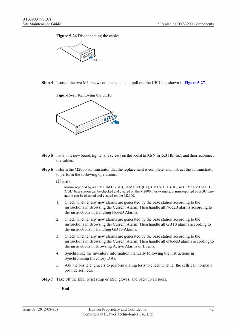
Figure 5-26 Disconnecting the cables
Step 4 Loosen the two M3 screws on the panel, and pull out the UEIU, as shown in Figure 5-27.
Figure 5-27 Removing the UEIU
21
Step 5 Install the new board, tighten the screws on the board to 0.6 N·m (5.31 lbf·in.), and then reconnectthe cables.
Step 6 Inform the M2000 administrator that the replacement is complete, and instruct the administratorto perform the following operations:
NOTEAlarms reported by a GSM+UMTS (GU), GSM+LTE (GL), UMTS+LTE (UL), or GSM+UMTS+LTE(GUL) base station can be checked and cleared on the M2000. For example, alarms reported by a GU basestation can be checked and cleared on the M2000.
1. Check whether any new alarms are generated by the base station according to theinstructions in Browsing the Current Alarm. Then handle all NodeB alarms according tothe instructions in Handling NodeB Alarms.
2. Check whether any new alarms are generated by the base station according to theinstructions in Browsing the Current Alarm. Then handle all GBTS alarms according tothe instructions in Handling GBTS Alarms.
3. Check whether any new alarms are generated by the base station according to theinstructions in Browsing the Current Alarm. Then handle all eNodeB alarms according tothe instructions in Browsing Active Alarms or Events.
4. Synchronize the inventory information manually following the instructions inSynchronizing Inventory Data.
5. Ask the onsite engineers to perform dialing tests to check whether the cells can normallyprovide services.
Step 7 Take off the ESD wrist strap or ESD gloves, and pack up all tools.
----End
BTS3900 (Ver.C)Site Maintenance Guide 5 Replacing BTS3900 Components
Issue 03 (2012-08-30) Huawei Proprietary and ConfidentialCopyright © Huawei Technologies Co., Ltd.
42

Follow-up Procedurel Place the replaced component into the ESD box or bag. Then, place the ESD box or bag
into a foam-padded carton or the packing box of the new component.l Fill in the fault form with detailed information about the replaced component.l Contact the local Huawei office to handle the faulty component.
5.2.10 Replacing the USCUThe Universal Satellite card and Clock Unit (USCU) in the BBU receives clock signals, such asGlobal Positioning System (GPS), remote global position system (RGPS), building integratedtiming supply (BITS), and M-1PPS signals. In addition, it transmits or receives 1PPS+TODclock signals.
Prerequisitesl To confirm the type of a faulty board, do as follows:
– If the board can be queried online, run the associated command on the LMT followingthe instructions in 5.1.1 Querying the Electronic Label for a Board.
– If the board is faulty and cannot be queried online, query the board information offlineon the M2000 following the instructions in Querying Inventory Data.
l Query alarms reported by the base station. For details, see Browsing the Current Alarm.l The tools and materials are available, such as the ESD wrist strap or ESD gloves and M3
screwdriver.l Associated personnel have gained permissions to access the site and have obtained the
required keys.
Contextl Figure 5-28 shows the position of the USCU in the BBU.
Figure 5-28 Position of the USCU
USCUUSCUALMALMRUNRUN
ACTACT
TOD1TOD1
GPSRX+ RX- TX+ TX-
BITSGR
EEN IN
YELLO
W O
UT
RGPS
M-1PPS
TOD0
GPSRX+ RX- TX+ TX-
BITSGR
EEN IN
YELLO
W O
UT
RGPS
M-1PPS
TOD0
1S+ 1S- GND PWR1S+ 1S- GND PWR
USCU
l The USCU is hot-swappable.
Procedure
Step 1 Put on an ESD wrist strap or ESD gloves.
BTS3900 (Ver.C)Site Maintenance Guide 5 Replacing BTS3900 Components
Issue 03 (2012-08-30) Huawei Proprietary and ConfidentialCopyright © Huawei Technologies Co., Ltd.
43
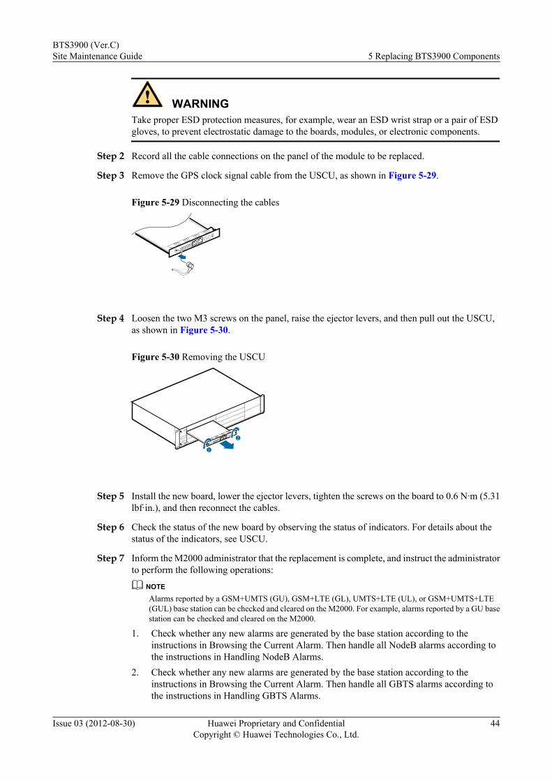
WARNINGTake proper ESD protection measures, for example, wear an ESD wrist strap or a pair of ESDgloves, to prevent electrostatic damage to the boards, modules, or electronic components.
Step 2 Record all the cable connections on the panel of the module to be replaced.
Step 3 Remove the GPS clock signal cable from the USCU, as shown in Figure 5-29.
Figure 5-29 Disconnecting the cables
Step 4 Loosen the two M3 screws on the panel, raise the ejector levers, and then pull out the USCU,as shown in Figure 5-30.
Figure 5-30 Removing the USCU
2
1
Step 5 Install the new board, lower the ejector levers, tighten the screws on the board to 0.6 N·m (5.31lbf·in.), and then reconnect the cables.
Step 6 Check the status of the new board by observing the status of indicators. For details about thestatus of the indicators, see USCU.
Step 7 Inform the M2000 administrator that the replacement is complete, and instruct the administratorto perform the following operations:
NOTEAlarms reported by a GSM+UMTS (GU), GSM+LTE (GL), UMTS+LTE (UL), or GSM+UMTS+LTE(GUL) base station can be checked and cleared on the M2000. For example, alarms reported by a GU basestation can be checked and cleared on the M2000.
1. Check whether any new alarms are generated by the base station according to theinstructions in Browsing the Current Alarm. Then handle all NodeB alarms according tothe instructions in Handling NodeB Alarms.
2. Check whether any new alarms are generated by the base station according to theinstructions in Browsing the Current Alarm. Then handle all GBTS alarms according tothe instructions in Handling GBTS Alarms.
BTS3900 (Ver.C)Site Maintenance Guide 5 Replacing BTS3900 Components
Issue 03 (2012-08-30) Huawei Proprietary and ConfidentialCopyright © Huawei Technologies Co., Ltd.
44
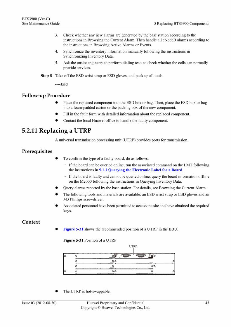
3. Check whether any new alarms are generated by the base station according to theinstructions in Browsing the Current Alarm. Then handle all eNodeB alarms according tothe instructions in Browsing Active Alarms or Events.
4. Synchronize the inventory information manually following the instructions inSynchronizing Inventory Data.
5. Ask the onsite engineers to perform dialing tests to check whether the cells can normallyprovide services.
Step 8 Take off the ESD wrist strap or ESD gloves, and pack up all tools.
----End
Follow-up Procedurel Place the replaced component into the ESD box or bag. Then, place the ESD box or bag
into a foam-padded carton or the packing box of the new component.l Fill in the fault form with detailed information about the replaced component.l Contact the local Huawei office to handle the faulty component.
5.2.11 Replacing a UTRPA universal transmission processing unit (UTRP) provides ports for transmission.
Prerequisitesl To confirm the type of a faulty board, do as follows:
– If the board can be queried online, run the associated command on the LMT followingthe instructions in 5.1.1 Querying the Electronic Label for a Board.
– If the board is faulty and cannot be queried online, query the board information offlineon the M2000 following the instructions in Querying Inventory Data.
l Query alarms reported by the base station. For details, see Browsing the Current Alarm.l The following tools and materials are available: an ESD wrist strap or ESD gloves and an
M3 Phillips screwdriver.l Associated personnel have been permitted to access the site and have obtained the required
keys.
Contextl Figure 5-31 shows the recommended position of a UTRP in the BBU.
Figure 5-31 Position of a UTRP
RUNALMACT
E1/T1(0-3)
UTRP
E1/T1(4-7)
UTRP
l The UTRP is hot-swappable.
BTS3900 (Ver.C)Site Maintenance Guide 5 Replacing BTS3900 Components
Issue 03 (2012-08-30) Huawei Proprietary and ConfidentialCopyright © Huawei Technologies Co., Ltd.
45
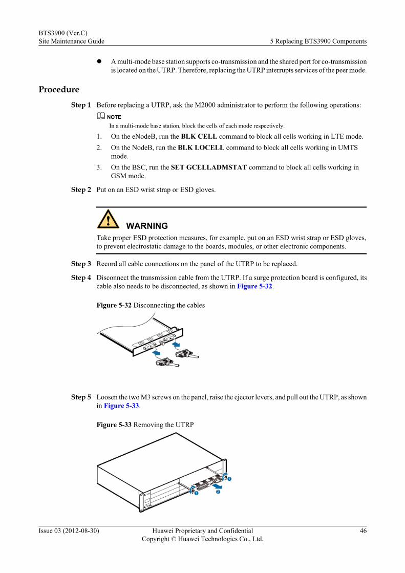
l A multi-mode base station supports co-transmission and the shared port for co-transmissionis located on the UTRP. Therefore, replacing the UTRP interrupts services of the peer mode.
ProcedureStep 1 Before replacing a UTRP, ask the M2000 administrator to perform the following operations:
NOTEIn a multi-mode base station, block the cells of each mode respectively.
1. On the eNodeB, run the BLK CELL command to block all cells working in LTE mode.2. On the NodeB, run the BLK LOCELL command to block all cells working in UMTS
mode.3. On the BSC, run the SET GCELLADMSTAT command to block all cells working in
GSM mode.
Step 2 Put on an ESD wrist strap or ESD gloves.
WARNINGTake proper ESD protection measures, for example, put on an ESD wrist strap or ESD gloves,to prevent electrostatic damage to the boards, modules, or other electronic components.
Step 3 Record all cable connections on the panel of the UTRP to be replaced.
Step 4 Disconnect the transmission cable from the UTRP. If a surge protection board is configured, itscable also needs to be disconnected, as shown in Figure 5-32.
Figure 5-32 Disconnecting the cables
Step 5 Loosen the two M3 screws on the panel, raise the ejector levers, and pull out the UTRP, as shownin Figure 5-33.
Figure 5-33 Removing the UTRP
BTS3900 (Ver.C)Site Maintenance Guide 5 Replacing BTS3900 Components
Issue 03 (2012-08-30) Huawei Proprietary and ConfidentialCopyright © Huawei Technologies Co., Ltd.
46

Step 6 Set the DIP switches on the new board to the same as the settings of the DIP switches on thereplaced board. For details about the DIP switch, see UTRP.
Step 7 Install the new board, lower the ejector levers, tighten the screws on the board panel to 0.6 N m(5.31 lbf in.), and reconnect the cables.
Step 8 Check the status of the new board by observing the status of indicators. For details about thestatus of the indicators, see UTRP.
Step 9 Inform the M2000 administrator that the replacement is complete, and instruct the administratorto perform the following operations:
NOTEAlarms reported by a GSM+UMTS (GU), GSM+LTE (GL), UMTS+LTE (UL), or GSM+UMTS+LTE(GUL) base station can be checked and cleared on the M2000. For example, alarms reported by a GU basestation can be checked and cleared on the M2000.
1. On the eNodeB, run the UBL CELL command to unblock all cells working in LTE mode.2. On the NodeB, run the UBL LOCELL command to unblock all cells working in UMTS
mode.3. On the BSC, run the SET GCELLADMSTAT command to unblock all cells working in
GSM mode.4. Check whether any new alarms are generated by the base station according to the
instructions in Browsing the Current Alarm. Then handle all NodeB alarms according tothe instructions in Handling NodeB Alarms.
5. Check whether any new alarms are generated by the base station according to theinstructions in Browsing the Current Alarm. Then handle all GBTS alarms according tothe instructions in Handling GBTS Alarms.
6. Check whether any new alarms are generated by the base station according to theinstructions in Browsing the Current Alarm. Then handle all eNodeB alarms according tothe instructions in Browsing Active Alarms or Events.
7. Synchronize the inventory information manually following the instructions inSynchronizing Inventory Data.
8. Ask the onsite engineers to perform dialing tests to check whether the cells can normallyprovide services.
Step 10 Take off the ESD wrist strap or ESD gloves, and pack up all the tools.
----End
Follow-up Procedurel Place the replaced component into an ESD box or bag. Then, place the ESD box or bag
into a foam-padded carton or into the packing box of the new component.
l Fill in the fault form with detailed information about the replaced component.
l Contact the local Huawei office to handle the faulty component.
5.2.12 Replacing a UBRIA universal baseband radio interface board (UBRI) provides ports for common public radiointerface (CPRI) cables. Replacing a UBRI interrupts services carried by the board.
BTS3900 (Ver.C)Site Maintenance Guide 5 Replacing BTS3900 Components
Issue 03 (2012-08-30) Huawei Proprietary and ConfidentialCopyright © Huawei Technologies Co., Ltd.
47
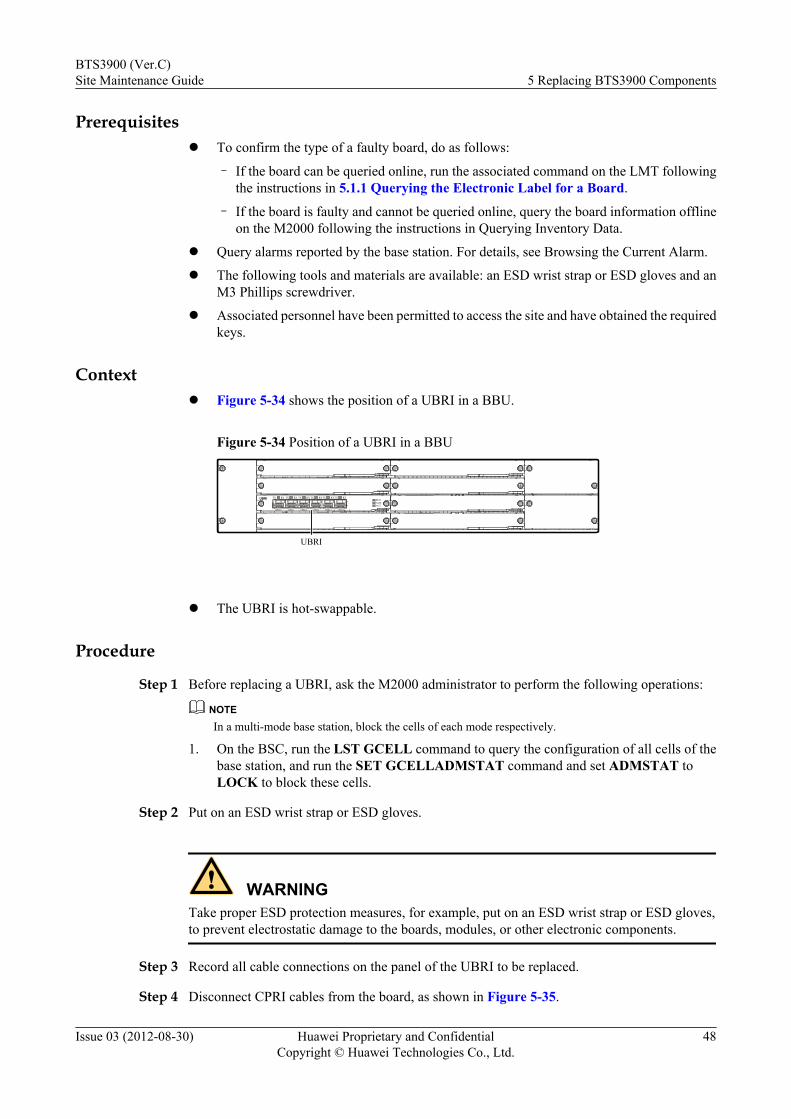
Prerequisitesl To confirm the type of a faulty board, do as follows:
– If the board can be queried online, run the associated command on the LMT followingthe instructions in 5.1.1 Querying the Electronic Label for a Board.
– If the board is faulty and cannot be queried online, query the board information offlineon the M2000 following the instructions in Querying Inventory Data.
l Query alarms reported by the base station. For details, see Browsing the Current Alarm.
l The following tools and materials are available: an ESD wrist strap or ESD gloves and anM3 Phillips screwdriver.
l Associated personnel have been permitted to access the site and have obtained the requiredkeys.
Contextl Figure 5-34 shows the position of a UBRI in a BBU.
Figure 5-34 Position of a UBRI in a BBU
UBRI
CPRI 0 CPRI 1 CPRI 2 CPRI 3 CPRI 4 CPRI 5
TX RX TX RX TX RX TX RX TX RX TX RXRUNALMACT
UBRI
l The UBRI is hot-swappable.
Procedure
Step 1 Before replacing a UBRI, ask the M2000 administrator to perform the following operations:
NOTEIn a multi-mode base station, block the cells of each mode respectively.
1. On the BSC, run the LST GCELL command to query the configuration of all cells of thebase station, and run the SET GCELLADMSTAT command and set ADMSTAT toLOCK to block these cells.
Step 2 Put on an ESD wrist strap or ESD gloves.
WARNINGTake proper ESD protection measures, for example, put on an ESD wrist strap or ESD gloves,to prevent electrostatic damage to the boards, modules, or other electronic components.
Step 3 Record all cable connections on the panel of the UBRI to be replaced.
Step 4 Disconnect CPRI cables from the board, as shown in Figure 5-35.
BTS3900 (Ver.C)Site Maintenance Guide 5 Replacing BTS3900 Components
Issue 03 (2012-08-30) Huawei Proprietary and ConfidentialCopyright © Huawei Technologies Co., Ltd.
48
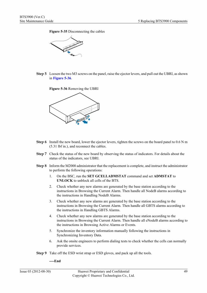
Figure 5-35 Disconnecting the cables
Step 5 Loosen the two M3 screws on the panel, raise the ejector levers, and pull out the UBRI, as shownin Figure 5-36.
Figure 5-36 Removing the UBRI
2
1
Step 6 Install the new board, lower the ejector levers, tighten the screws on the board panel to 0.6 N m(5.31 lbf in.), and reconnect the cables.
Step 7 Check the status of the new board by observing the status of indicators. For details about thestatus of the indicators, see UBRI.
Step 8 Inform the M2000 administrator that the replacement is complete, and instruct the administratorto perform the following operations:1. On the BSC, run the SET GCELLADMSTAT command and set ADMSTAT to
UNLOCK to unblock all cells of the BTS.2. Check whether any new alarms are generated by the base station according to the
instructions in Browsing the Current Alarm. Then handle all NodeB alarms according tothe instructions in Handling NodeB Alarms.
3. Check whether any new alarms are generated by the base station according to theinstructions in Browsing the Current Alarm. Then handle all GBTS alarms according tothe instructions in Handling GBTS Alarms.
4. Check whether any new alarms are generated by the base station according to theinstructions in Browsing the Current Alarm. Then handle all eNodeB alarms according tothe instructions in Browsing Active Alarms or Events.
5. Synchronize the inventory information manually following the instructions inSynchronizing Inventory Data.
6. Ask the onsite engineers to perform dialing tests to check whether the cells can normallyprovide services.
Step 9 Take off the ESD wrist strap or ESD gloves, and pack up all the tools.
----End
BTS3900 (Ver.C)Site Maintenance Guide 5 Replacing BTS3900 Components
Issue 03 (2012-08-30) Huawei Proprietary and ConfidentialCopyright © Huawei Technologies Co., Ltd.
49
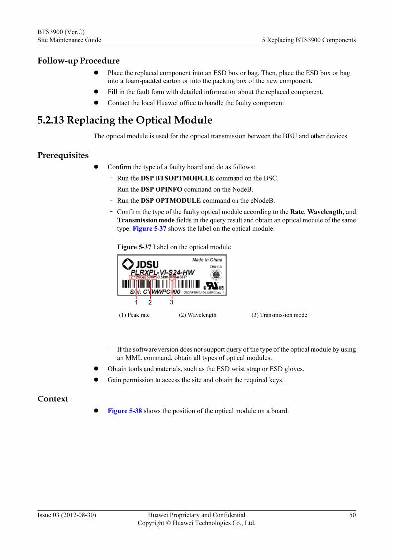
Follow-up Procedurel Place the replaced component into an ESD box or bag. Then, place the ESD box or bag
into a foam-padded carton or into the packing box of the new component.l Fill in the fault form with detailed information about the replaced component.l Contact the local Huawei office to handle the faulty component.
5.2.13 Replacing the Optical ModuleThe optical module is used for the optical transmission between the BBU and other devices.
Prerequisitesl Confirm the type of a faulty board and do as follows:
– Run the DSP BTSOPTMODULE command on the BSC.– Run the DSP OPINFO command on the NodeB.– Run the DSP OPTMODULE command on the eNodeB.– Confirm the type of the faulty optical module according to the Rate, Wavelength, and
Transmission mode fields in the query result and obtain an optical module of the sametype. Figure 5-37 shows the label on the optical module.
Figure 5-37 Label on the optical module
(1) Peak rate (2) Wavelength (3) Transmission mode
– If the software version does not support query of the type of the optical module by using
an MML command, obtain all types of optical modules.l Obtain tools and materials, such as the ESD wrist strap or ESD gloves.l Gain permission to access the site and obtain the required keys.
Contextl Figure 5-38 shows the position of the optical module on a board.
BTS3900 (Ver.C)Site Maintenance Guide 5 Replacing BTS3900 Components
Issue 03 (2012-08-30) Huawei Proprietary and ConfidentialCopyright © Huawei Technologies Co., Ltd.
50

Figure 5-38 Position of the optical module
1
(1) Optical module
l Optical modules are hot-swappable.l Replacing the optical module interrupts the services carried on this port.
Procedure
Step 1 Put on an ESD wrist strap or a pair of ESD gloves.
CAUTIONTake proper ESD protection measures, for example, wear an ESD wrist strap or a pair of ESDgloves, to prevent electrostatic damage to the boards, modules, or electronic components.
Step 2 If all types of optical modules get prepared, obtain an optical module of the same type or theoptical module that can replace the faulty optical module according to the label on the opticalmodule and spare part catalog.
NOTEThe optical modules to be installed must have a matching rate with the corresponding CPRI port.
Step 3 Record the position of the faulty optical module on the board.
Step 4 Press the latch on the optical cable connector, and remove the connector from the faulty opticalmodule, as shown in Figure 5-39.
BTS3900 (Ver.C)Site Maintenance Guide 5 Replacing BTS3900 Components
Issue 03 (2012-08-30) Huawei Proprietary and ConfidentialCopyright © Huawei Technologies Co., Ltd.
51
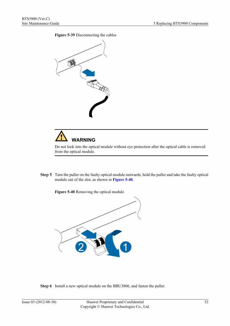
Figure 5-39 Disconnecting the cables
WARNINGDo not look into the optical module without eye protection after the optical cable is removedfrom the optical module.
Step 5 Turn the puller on the faulty optical module outwards, hold the puller and take the faulty opticalmodule out of the slot, as shown in Figure 5-40.
Figure 5-40 Removing the optical module
Step 6 Install a new optical module on the BBU3806, and fasten the puller.
BTS3900 (Ver.C)Site Maintenance Guide 5 Replacing BTS3900 Components
Issue 03 (2012-08-30) Huawei Proprietary and ConfidentialCopyright © Huawei Technologies Co., Ltd.
52
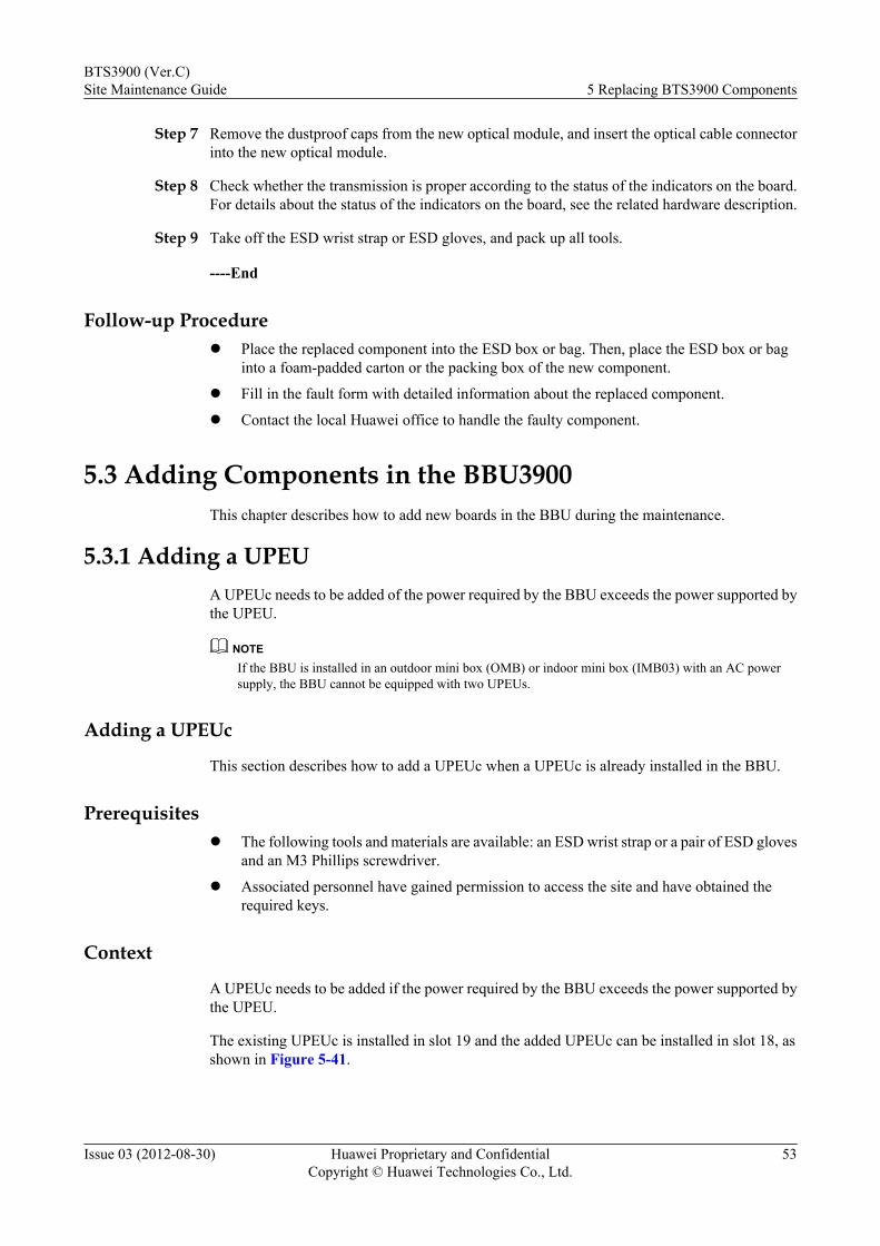
Step 7 Remove the dustproof caps from the new optical module, and insert the optical cable connectorinto the new optical module.
Step 8 Check whether the transmission is proper according to the status of the indicators on the board.For details about the status of the indicators on the board, see the related hardware description.
Step 9 Take off the ESD wrist strap or ESD gloves, and pack up all tools.
----End
Follow-up Procedurel Place the replaced component into the ESD box or bag. Then, place the ESD box or bag
into a foam-padded carton or the packing box of the new component.
l Fill in the fault form with detailed information about the replaced component.
l Contact the local Huawei office to handle the faulty component.
5.3 Adding Components in the BBU3900This chapter describes how to add new boards in the BBU during the maintenance.
5.3.1 Adding a UPEUA UPEUc needs to be added of the power required by the BBU exceeds the power supported bythe UPEU.
NOTEIf the BBU is installed in an outdoor mini box (OMB) or indoor mini box (IMB03) with an AC powersupply, the BBU cannot be equipped with two UPEUs.
Adding a UPEUc
This section describes how to add a UPEUc when a UPEUc is already installed in the BBU.
Prerequisitesl The following tools and materials are available: an ESD wrist strap or a pair of ESD gloves
and an M3 Phillips screwdriver.
l Associated personnel have gained permission to access the site and have obtained therequired keys.
Context
A UPEUc needs to be added if the power required by the BBU exceeds the power supported bythe UPEU.
The existing UPEUc is installed in slot 19 and the added UPEUc can be installed in slot 18, asshown in Figure 5-41.
BTS3900 (Ver.C)Site Maintenance Guide 5 Replacing BTS3900 Components
Issue 03 (2012-08-30) Huawei Proprietary and ConfidentialCopyright © Huawei Technologies Co., Ltd.
53
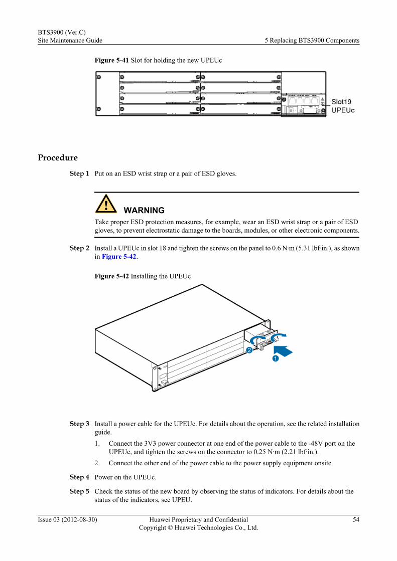
Figure 5-41 Slot for holding the new UPEUc
Procedure
Step 1 Put on an ESD wrist strap or a pair of ESD gloves.
WARNINGTake proper ESD protection measures, for example, wear an ESD wrist strap or a pair of ESDgloves, to prevent electrostatic damage to the boards, modules, or other electronic components.
Step 2 Install a UPEUc in slot 18 and tighten the screws on the panel to 0.6 N·m (5.31 lbf·in.), as shownin Figure 5-42.
Figure 5-42 Installing the UPEUc
Step 3 Install a power cable for the UPEUc. For details about the operation, see the related installationguide.1. Connect the 3V3 power connector at one end of the power cable to the -48V port on the
UPEUc, and tighten the screws on the connector to 0.25 N·m (2.21 lbf·in.).2. Connect the other end of the power cable to the power supply equipment onsite.
Step 4 Power on the UPEUc.
Step 5 Check the status of the new board by observing the status of indicators. For details about thestatus of the indicators, see UPEU.
BTS3900 (Ver.C)Site Maintenance Guide 5 Replacing BTS3900 Components
Issue 03 (2012-08-30) Huawei Proprietary and ConfidentialCopyright © Huawei Technologies Co., Ltd.
54
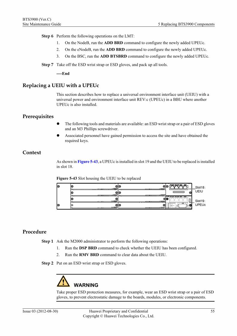
Step 6 Perform the following operations on the LMT:1. On the NodeB, run the ADD BRD command to configure the newly added UPEUc.2. On the eNodeB, run the ADD BRD command to configure the newly added UPEUc.3. On the BSC, run the ADD BTSBRD command to configure the newly added UPEUc.
Step 7 Take off the ESD wrist strap or ESD gloves, and pack up all tools.
----End
Replacing a UEIU with a UPEUcThis section describes how to replace a universal environment interface unit (UEIU) with auniversal power and environment interface unit REV:c (UPEUc) in a BBU where anotherUPEUc is also installed.
Prerequisitesl The following tools and materials are available: an ESD wrist strap or a pair of ESD gloves
and an M3 Phillips screwdriver.l Associated personnel have gained permission to access the site and have obtained the
required keys.
ContextAs shown in Figure 5-43, a UPEUc is installed in slot 19 and the UEIU to be replaced is installedin slot 18.
Figure 5-43 Slot housing the UEIU to be replaced
Procedure
Step 1 Ask the M2000 administrator to perform the following operations:1. Run the DSP BRD command to check whether the UEIU has been configured.2. Run the RMV BRD command to clear data about the UEIU.
Step 2 Put on an ESD wrist strap or ESD gloves.
WARNINGTake proper ESD protection measures, for example, wear an ESD wrist strap or a pair of ESDgloves, to prevent electrostatic damage to the boards, modules, or electronic components.
BTS3900 (Ver.C)Site Maintenance Guide 5 Replacing BTS3900 Components
Issue 03 (2012-08-30) Huawei Proprietary and ConfidentialCopyright © Huawei Technologies Co., Ltd.
55
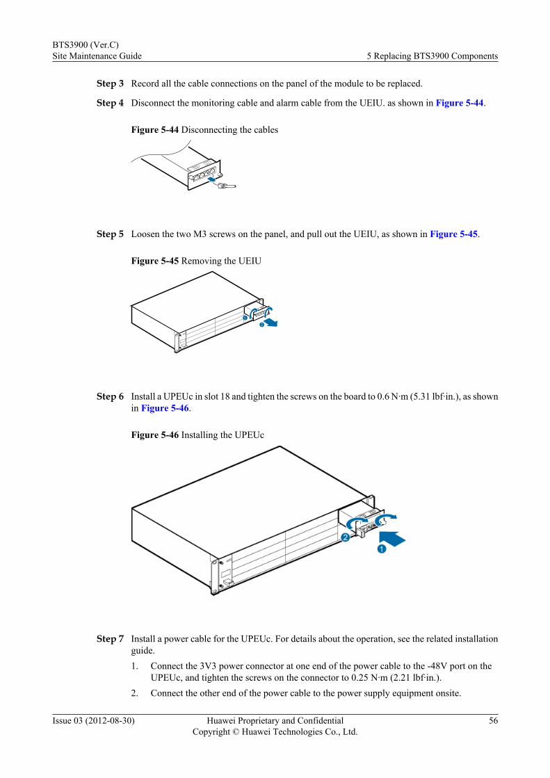
Step 3 Record all the cable connections on the panel of the module to be replaced.
Step 4 Disconnect the monitoring cable and alarm cable from the UEIU. as shown in Figure 5-44.
Figure 5-44 Disconnecting the cables
Step 5 Loosen the two M3 screws on the panel, and pull out the UEIU, as shown in Figure 5-45.
Figure 5-45 Removing the UEIU
21
Step 6 Install a UPEUc in slot 18 and tighten the screws on the board to 0.6 N·m (5.31 lbf·in.), as shownin Figure 5-46.
Figure 5-46 Installing the UPEUc
Step 7 Install a power cable for the UPEUc. For details about the operation, see the related installationguide.1. Connect the 3V3 power connector at one end of the power cable to the -48V port on the
UPEUc, and tighten the screws on the connector to 0.25 N·m (2.21 lbf·in.).2. Connect the other end of the power cable to the power supply equipment onsite.
BTS3900 (Ver.C)Site Maintenance Guide 5 Replacing BTS3900 Components
Issue 03 (2012-08-30) Huawei Proprietary and ConfidentialCopyright © Huawei Technologies Co., Ltd.
56
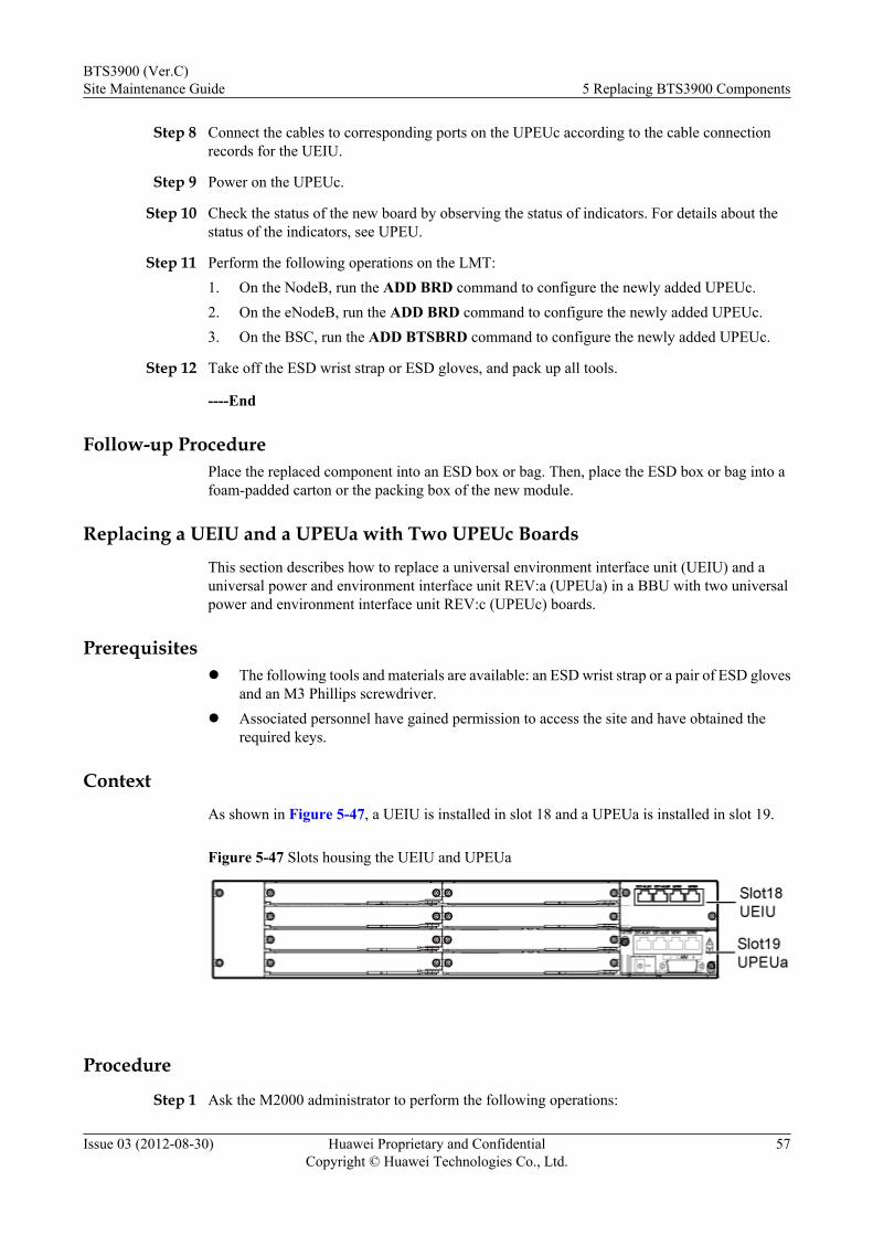
Step 8 Connect the cables to corresponding ports on the UPEUc according to the cable connectionrecords for the UEIU.
Step 9 Power on the UPEUc.
Step 10 Check the status of the new board by observing the status of indicators. For details about thestatus of the indicators, see UPEU.
Step 11 Perform the following operations on the LMT:1. On the NodeB, run the ADD BRD command to configure the newly added UPEUc.2. On the eNodeB, run the ADD BRD command to configure the newly added UPEUc.3. On the BSC, run the ADD BTSBRD command to configure the newly added UPEUc.
Step 12 Take off the ESD wrist strap or ESD gloves, and pack up all tools.
----End
Follow-up ProcedurePlace the replaced component into an ESD box or bag. Then, place the ESD box or bag into afoam-padded carton or the packing box of the new module.
Replacing a UEIU and a UPEUa with Two UPEUc BoardsThis section describes how to replace a universal environment interface unit (UEIU) and auniversal power and environment interface unit REV:a (UPEUa) in a BBU with two universalpower and environment interface unit REV:c (UPEUc) boards.
Prerequisitesl The following tools and materials are available: an ESD wrist strap or a pair of ESD gloves
and an M3 Phillips screwdriver.l Associated personnel have gained permission to access the site and have obtained the
required keys.
ContextAs shown in Figure 5-47, a UEIU is installed in slot 18 and a UPEUa is installed in slot 19.
Figure 5-47 Slots housing the UEIU and UPEUa
Procedure
Step 1 Ask the M2000 administrator to perform the following operations:
BTS3900 (Ver.C)Site Maintenance Guide 5 Replacing BTS3900 Components
Issue 03 (2012-08-30) Huawei Proprietary and ConfidentialCopyright © Huawei Technologies Co., Ltd.
57
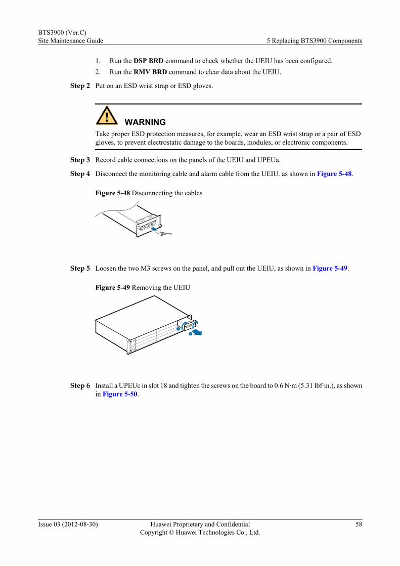
1. Run the DSP BRD command to check whether the UEIU has been configured.2. Run the RMV BRD command to clear data about the UEIU.
Step 2 Put on an ESD wrist strap or ESD gloves.
WARNINGTake proper ESD protection measures, for example, wear an ESD wrist strap or a pair of ESDgloves, to prevent electrostatic damage to the boards, modules, or electronic components.
Step 3 Record cable connections on the panels of the UEIU and UPEUa.
Step 4 Disconnect the monitoring cable and alarm cable from the UEIU. as shown in Figure 5-48.
Figure 5-48 Disconnecting the cables
Step 5 Loosen the two M3 screws on the panel, and pull out the UEIU, as shown in Figure 5-49.
Figure 5-49 Removing the UEIU
21
Step 6 Install a UPEUc in slot 18 and tighten the screws on the board to 0.6 N·m (5.31 lbf·in.), as shownin Figure 5-50.
BTS3900 (Ver.C)Site Maintenance Guide 5 Replacing BTS3900 Components
Issue 03 (2012-08-30) Huawei Proprietary and ConfidentialCopyright © Huawei Technologies Co., Ltd.
58
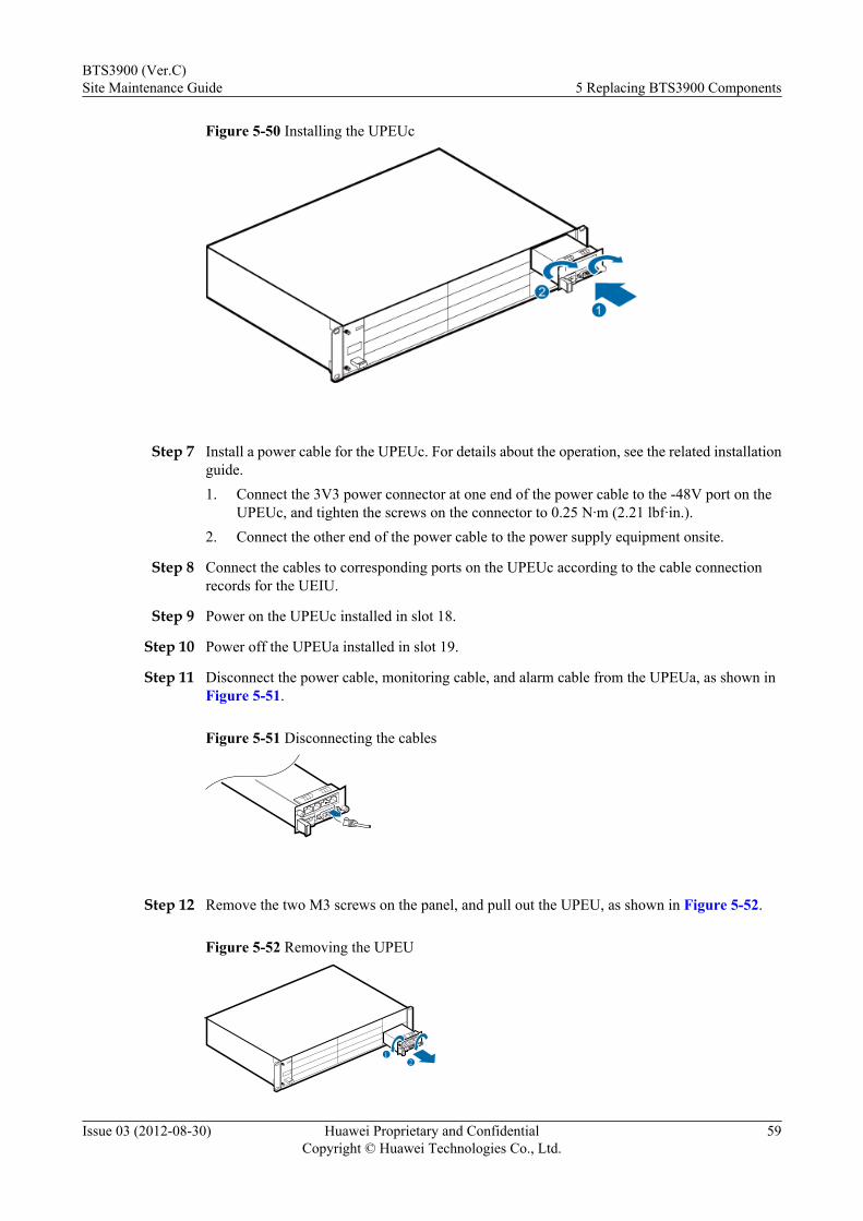
Figure 5-50 Installing the UPEUc
Step 7 Install a power cable for the UPEUc. For details about the operation, see the related installationguide.1. Connect the 3V3 power connector at one end of the power cable to the -48V port on the
UPEUc, and tighten the screws on the connector to 0.25 N·m (2.21 lbf·in.).2. Connect the other end of the power cable to the power supply equipment onsite.
Step 8 Connect the cables to corresponding ports on the UPEUc according to the cable connectionrecords for the UEIU.
Step 9 Power on the UPEUc installed in slot 18.
Step 10 Power off the UPEUa installed in slot 19.
Step 11 Disconnect the power cable, monitoring cable, and alarm cable from the UPEUa, as shown inFigure 5-51.
Figure 5-51 Disconnecting the cables
Step 12 Remove the two M3 screws on the panel, and pull out the UPEU, as shown in Figure 5-52.
Figure 5-52 Removing the UPEU
12
BTS3900 (Ver.C)Site Maintenance Guide 5 Replacing BTS3900 Components
Issue 03 (2012-08-30) Huawei Proprietary and ConfidentialCopyright © Huawei Technologies Co., Ltd.
59
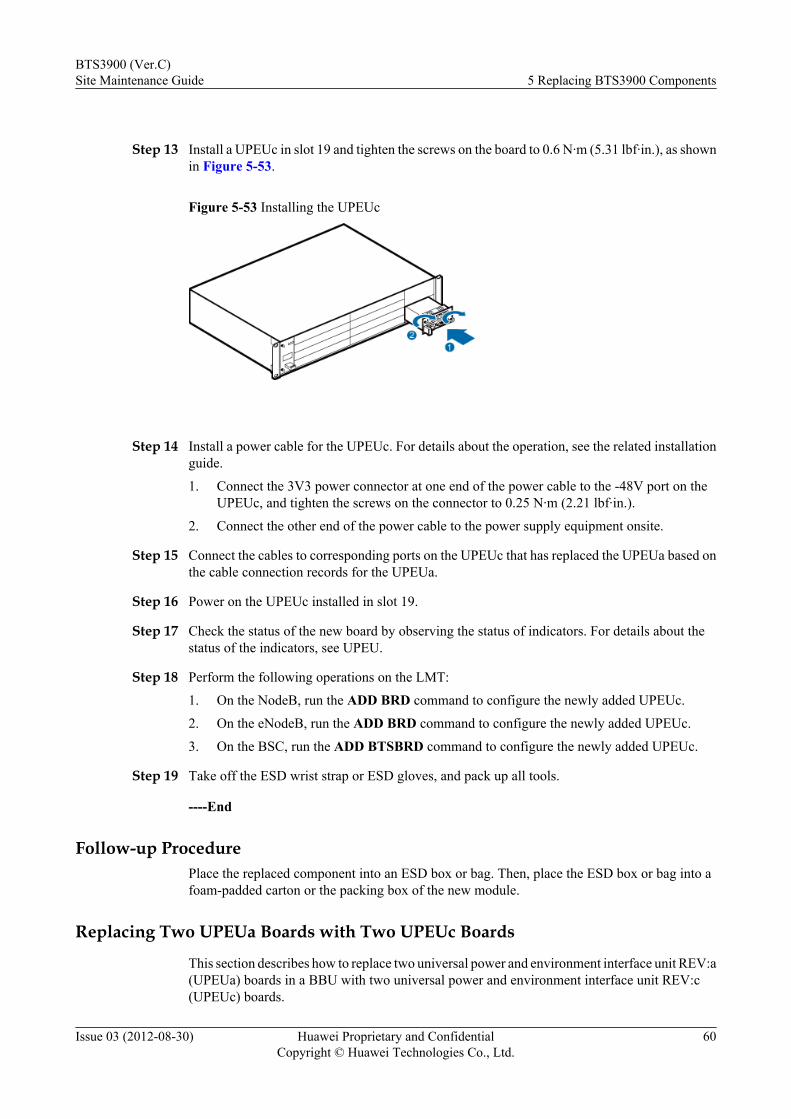
Step 13 Install a UPEUc in slot 19 and tighten the screws on the board to 0.6 N·m (5.31 lbf·in.), as shownin Figure 5-53.
Figure 5-53 Installing the UPEUc
Step 14 Install a power cable for the UPEUc. For details about the operation, see the related installationguide.
1. Connect the 3V3 power connector at one end of the power cable to the -48V port on theUPEUc, and tighten the screws on the connector to 0.25 N·m (2.21 lbf·in.).
2. Connect the other end of the power cable to the power supply equipment onsite.
Step 15 Connect the cables to corresponding ports on the UPEUc that has replaced the UPEUa based onthe cable connection records for the UPEUa.
Step 16 Power on the UPEUc installed in slot 19.
Step 17 Check the status of the new board by observing the status of indicators. For details about thestatus of the indicators, see UPEU.
Step 18 Perform the following operations on the LMT:
1. On the NodeB, run the ADD BRD command to configure the newly added UPEUc.
2. On the eNodeB, run the ADD BRD command to configure the newly added UPEUc.
3. On the BSC, run the ADD BTSBRD command to configure the newly added UPEUc.
Step 19 Take off the ESD wrist strap or ESD gloves, and pack up all tools.
----End
Follow-up ProcedurePlace the replaced component into an ESD box or bag. Then, place the ESD box or bag into afoam-padded carton or the packing box of the new module.
Replacing Two UPEUa Boards with Two UPEUc Boards
This section describes how to replace two universal power and environment interface unit REV:a(UPEUa) boards in a BBU with two universal power and environment interface unit REV:c(UPEUc) boards.
BTS3900 (Ver.C)Site Maintenance Guide 5 Replacing BTS3900 Components
Issue 03 (2012-08-30) Huawei Proprietary and ConfidentialCopyright © Huawei Technologies Co., Ltd.
60

Prerequisitesl The following tools and materials are available: an ESD wrist strap or a pair of ESD gloves
and an M3 Phillips screwdriver.
l Associated personnel have gained permission to access the site and have obtained therequired keys.
Context
As shown in Figure 5-54, two UPEUa boards to be replaced are installed in slots 18 and 19separately.
Figure 5-54 Slots housing two UPEUa boards
Procedure
Step 1 Put on an ESD wrist strap or ESD gloves.
WARNINGTake proper ESD protection measures, for example, wear an ESD wrist strap or a pair of ESDgloves, to prevent electrostatic damage to the boards, modules, or electronic components.
Step 2 Record cable connections on the panels of the two UPEUa boards.
Step 3 Power off the UPEUa installed in slot 18.
Step 4 Disconnect cables from the UPEUa installed in slot 18, as shown in Figure 5-55.
Figure 5-55 Disconnecting the cables
Step 5 Remove the UPEUa from slot 18, as shown in Figure 5-56.
BTS3900 (Ver.C)Site Maintenance Guide 5 Replacing BTS3900 Components
Issue 03 (2012-08-30) Huawei Proprietary and ConfidentialCopyright © Huawei Technologies Co., Ltd.
61
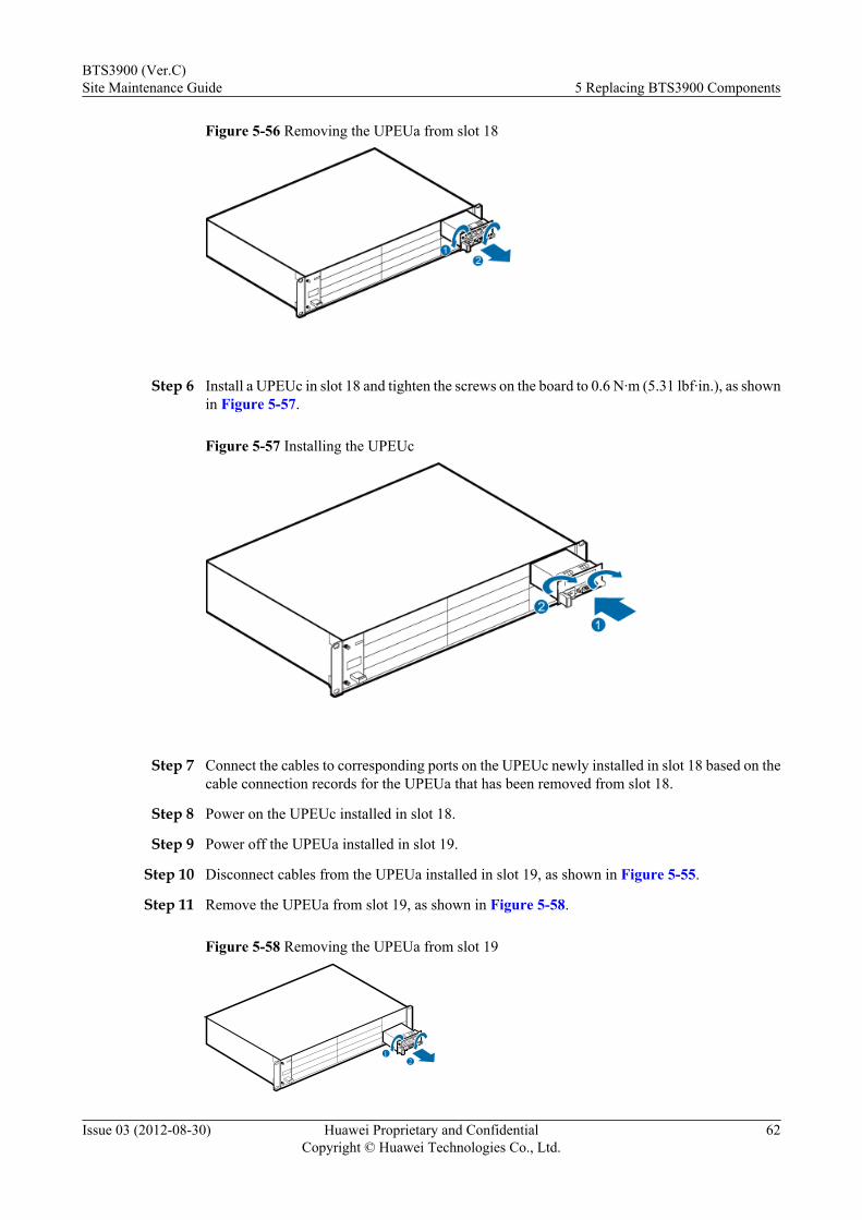
Figure 5-56 Removing the UPEUa from slot 18
Step 6 Install a UPEUc in slot 18 and tighten the screws on the board to 0.6 N·m (5.31 lbf·in.), as shownin Figure 5-57.
Figure 5-57 Installing the UPEUc
Step 7 Connect the cables to corresponding ports on the UPEUc newly installed in slot 18 based on thecable connection records for the UPEUa that has been removed from slot 18.
Step 8 Power on the UPEUc installed in slot 18.
Step 9 Power off the UPEUa installed in slot 19.
Step 10 Disconnect cables from the UPEUa installed in slot 19, as shown in Figure 5-55.
Step 11 Remove the UPEUa from slot 19, as shown in Figure 5-58.
Figure 5-58 Removing the UPEUa from slot 19
12
BTS3900 (Ver.C)Site Maintenance Guide 5 Replacing BTS3900 Components
Issue 03 (2012-08-30) Huawei Proprietary and ConfidentialCopyright © Huawei Technologies Co., Ltd.
62
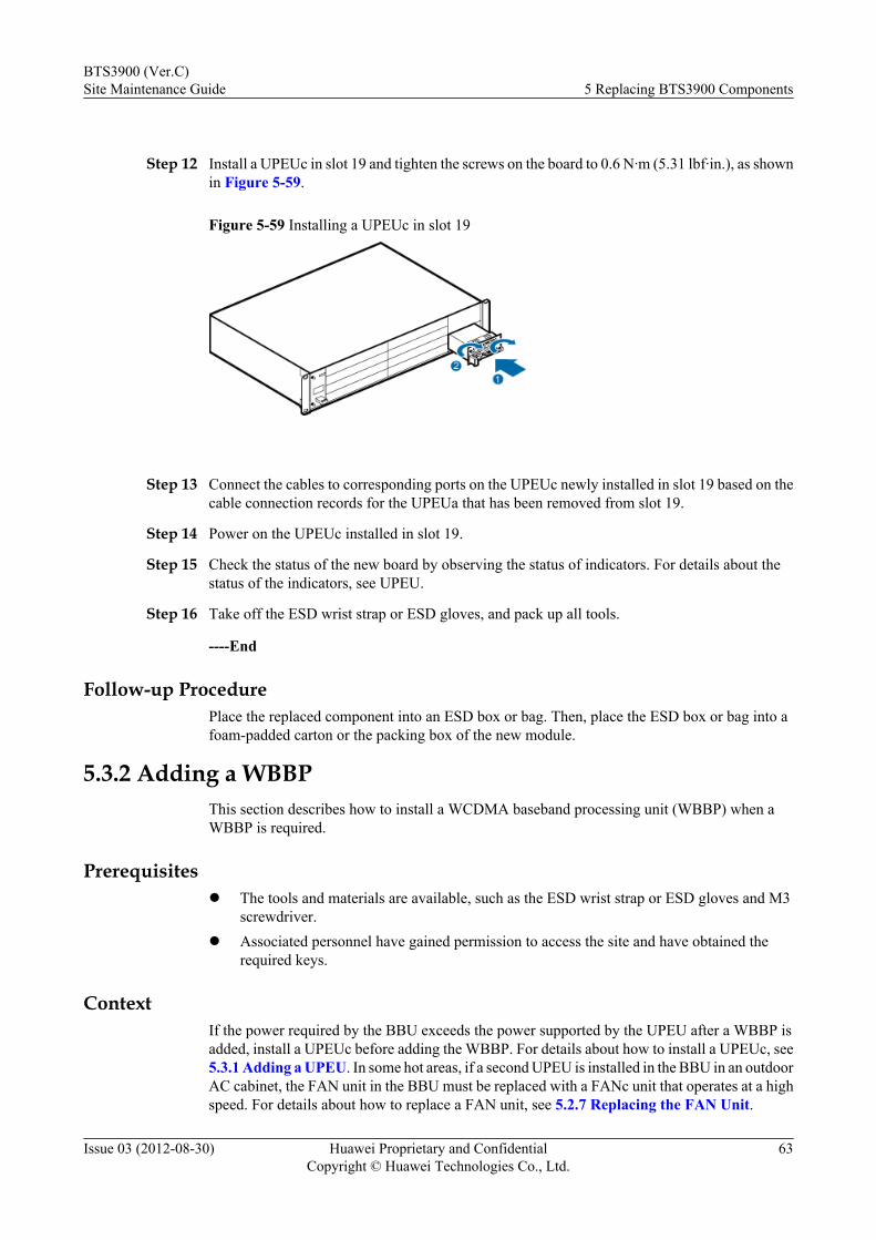
Step 12 Install a UPEUc in slot 19 and tighten the screws on the board to 0.6 N·m (5.31 lbf·in.), as shownin Figure 5-59.
Figure 5-59 Installing a UPEUc in slot 19
Step 13 Connect the cables to corresponding ports on the UPEUc newly installed in slot 19 based on thecable connection records for the UPEUa that has been removed from slot 19.
Step 14 Power on the UPEUc installed in slot 19.
Step 15 Check the status of the new board by observing the status of indicators. For details about thestatus of the indicators, see UPEU.
Step 16 Take off the ESD wrist strap or ESD gloves, and pack up all tools.
----End
Follow-up ProcedurePlace the replaced component into an ESD box or bag. Then, place the ESD box or bag into afoam-padded carton or the packing box of the new module.
5.3.2 Adding a WBBPThis section describes how to install a WCDMA baseband processing unit (WBBP) when aWBBP is required.
Prerequisitesl The tools and materials are available, such as the ESD wrist strap or ESD gloves and M3
screwdriver.l Associated personnel have gained permission to access the site and have obtained the
required keys.
ContextIf the power required by the BBU exceeds the power supported by the UPEU after a WBBP isadded, install a UPEUc before adding the WBBP. For details about how to install a UPEUc, see5.3.1 Adding a UPEU. In some hot areas, if a second UPEU is installed in the BBU in an outdoorAC cabinet, the FAN unit in the BBU must be replaced with a FANc unit that operates at a highspeed. For details about how to replace a FAN unit, see 5.2.7 Replacing the FAN Unit.
BTS3900 (Ver.C)Site Maintenance Guide 5 Replacing BTS3900 Components
Issue 03 (2012-08-30) Huawei Proprietary and ConfidentialCopyright © Huawei Technologies Co., Ltd.
63
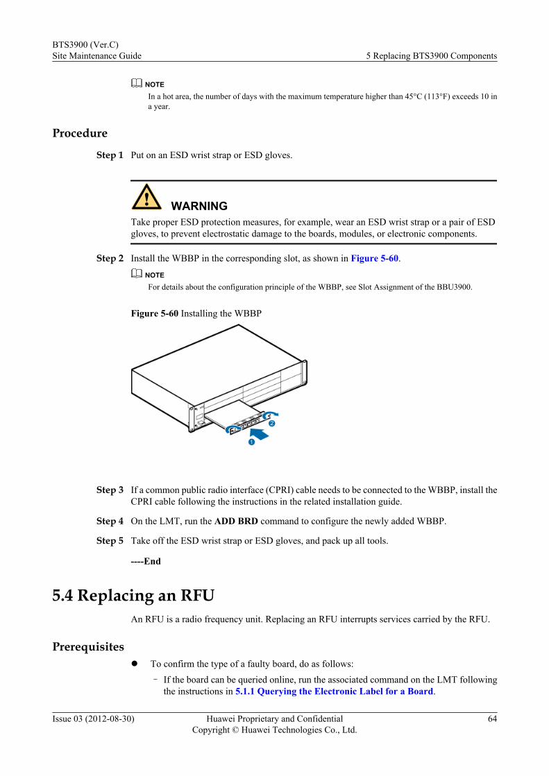
NOTEIn a hot area, the number of days with the maximum temperature higher than 45°C (113°F) exceeds 10 ina year.
Procedure
Step 1 Put on an ESD wrist strap or ESD gloves.
WARNINGTake proper ESD protection measures, for example, wear an ESD wrist strap or a pair of ESDgloves, to prevent electrostatic damage to the boards, modules, or electronic components.
Step 2 Install the WBBP in the corresponding slot, as shown in Figure 5-60.
NOTEFor details about the configuration principle of the WBBP, see Slot Assignment of the BBU3900.
Figure 5-60 Installing the WBBP
Step 3 If a common public radio interface (CPRI) cable needs to be connected to the WBBP, install theCPRI cable following the instructions in the related installation guide.
Step 4 On the LMT, run the ADD BRD command to configure the newly added WBBP.
Step 5 Take off the ESD wrist strap or ESD gloves, and pack up all tools.
----End
5.4 Replacing an RFUAn RFU is a radio frequency unit. Replacing an RFU interrupts services carried by the RFU.
Prerequisitesl To confirm the type of a faulty board, do as follows:
– If the board can be queried online, run the associated command on the LMT followingthe instructions in 5.1.1 Querying the Electronic Label for a Board.
BTS3900 (Ver.C)Site Maintenance Guide 5 Replacing BTS3900 Components
Issue 03 (2012-08-30) Huawei Proprietary and ConfidentialCopyright © Huawei Technologies Co., Ltd.
64
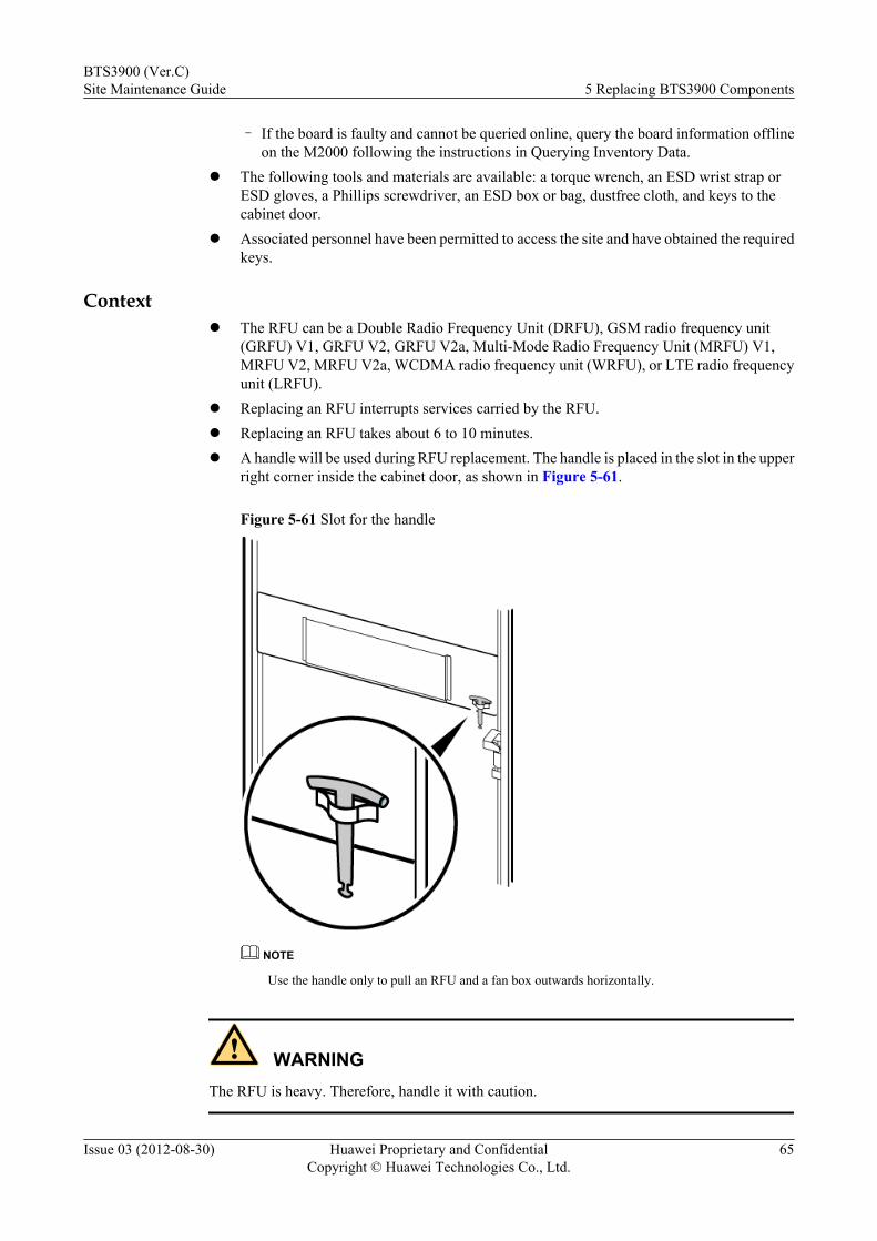
– If the board is faulty and cannot be queried online, query the board information offlineon the M2000 following the instructions in Querying Inventory Data.
l The following tools and materials are available: a torque wrench, an ESD wrist strap orESD gloves, a Phillips screwdriver, an ESD box or bag, dustfree cloth, and keys to thecabinet door.
l Associated personnel have been permitted to access the site and have obtained the requiredkeys.
Contextl The RFU can be a Double Radio Frequency Unit (DRFU), GSM radio frequency unit
(GRFU) V1, GRFU V2, GRFU V2a, Multi-Mode Radio Frequency Unit (MRFU) V1,MRFU V2, MRFU V2a, WCDMA radio frequency unit (WRFU), or LTE radio frequencyunit (LRFU).
l Replacing an RFU interrupts services carried by the RFU.l Replacing an RFU takes about 6 to 10 minutes.l A handle will be used during RFU replacement. The handle is placed in the slot in the upper
right corner inside the cabinet door, as shown in Figure 5-61.
Figure 5-61 Slot for the handle
NOTE
Use the handle only to pull an RFU and a fan box outwards horizontally.
WARNINGThe RFU is heavy. Therefore, handle it with caution.
BTS3900 (Ver.C)Site Maintenance Guide 5 Replacing BTS3900 Components
Issue 03 (2012-08-30) Huawei Proprietary and ConfidentialCopyright © Huawei Technologies Co., Ltd.
65
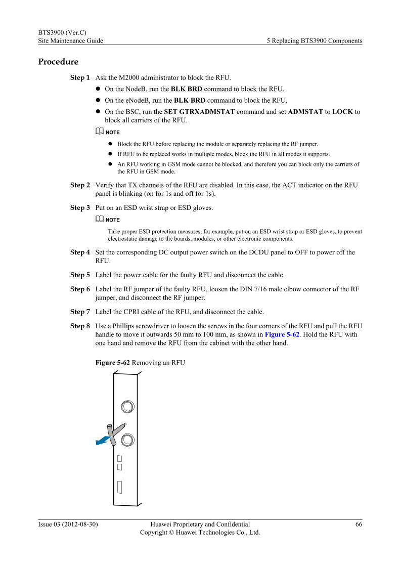
Procedure
Step 1 Ask the M2000 administrator to block the RFU.l On the NodeB, run the BLK BRD command to block the RFU.l On the eNodeB, run the BLK BRD command to block the RFU.l On the BSC, run the SET GTRXADMSTAT command and set ADMSTAT to LOCK to
block all carriers of the RFU.
NOTE
l Block the RFU before replacing the module or separately replacing the RF jumper.
l If RFU to be replaced works in multiple modes, block the RFU in all modes it supports.
l An RFU working in GSM mode cannot be blocked, and therefore you can block only the carriers ofthe RFU in GSM mode.
Step 2 Verify that TX channels of the RFU are disabled. In this case, the ACT indicator on the RFUpanel is blinking (on for 1s and off for 1s).
Step 3 Put on an ESD wrist strap or ESD gloves.
NOTE
Take proper ESD protection measures, for example, put on an ESD wrist strap or ESD gloves, to preventelectrostatic damage to the boards, modules, or other electronic components.
Step 4 Set the corresponding DC output power switch on the DCDU panel to OFF to power off theRFU.
Step 5 Label the power cable for the faulty RFU and disconnect the cable.
Step 6 Label the RF jumper of the faulty RFU, loosen the DIN 7/16 male elbow connector of the RFjumper, and disconnect the RF jumper.
Step 7 Label the CPRI cable of the RFU, and disconnect the cable.
Step 8 Use a Phillips screwdriver to loosen the screws in the four corners of the RFU and pull the RFUhandle to move it outwards 50 mm to 100 mm, as shown in Figure 5-62. Hold the RFU withone hand and remove the RFU from the cabinet with the other hand.
Figure 5-62 Removing an RFU
BTS3900 (Ver.C)Site Maintenance Guide 5 Replacing BTS3900 Components
Issue 03 (2012-08-30) Huawei Proprietary and ConfidentialCopyright © Huawei Technologies Co., Ltd.
66
WARNINGAn RFU is heavy. Therefore, handle it with caution.
Step 9 Place the handle back to the original position.
Step 10 Place the new RFU on guide rails and slide it into the subrack until it snaps shut.
Step 11 Tighten the captive screws in the four corners of the RFU panel to secure the RFU onto thesubrack.
Step 12 Connect the labeled CPRI cable to the new RFU.
Step 13 Use a torque wrench to connect the labeled RF jumper to the new RFU and tighten the DIN maleelbow connector to 25 N m (221.25 lbf in.) to 35 N m (309.75 lbf in.).
Step 14 Connect the labeled power cable to the new RFU and tighten it.
Step 15 Set the corresponding DC output power switch on the DCDU panel to ON to power on the RFU.
Step 16 Check the operating status of the RFU by observing indicator status. For details about the statusof the indicators, see the hardware description of RFUs.
Step 17 On the M2000, perform the following operations:NOTEAlarms reported by a GSM+UMTS (GU), GSM+LTE (GL), UMTS+LTE (UL), or GSM+UMTS+LTE(GUL) base station can be checked and cleared on the M2000. For example, alarms reported by a GU basestation can be checked and cleared on the M2000
1. Unblock the RFU.l On the NodeB, run the BLK BRD command to unblock the RFU.l On the eNodeB, run the BLK BRD command to unblock the RFU.l On the BSC, run the SET GTRXADMSTAT command and set ADMSTAT to
UNLOCK to unblock all carriers of the RFU.2. Handle alarms by the following operations:
l Check whether any new alarms are generated by the base station according to theinstructions in Browsing the Current Alarm. Then handle all NodeB alarms accordingto the instructions in Handling NodeB Alarms.
l Check whether any new alarms are generated by the base station according to theinstructions in Browsing the Current Alarm. Then handle all eNodeB alarms accordingto the instructions in Browsing Active Alarms or Events.
l Check whether any new alarms are generated by the base station according to theinstructions in Browsing the Current Alarm. Then handle all GBTS alarms accordingto the instructions in Handling GBTS Alarms.
3. Synchronize the inventory information manually. For details, see Synchronizing InventoryData.
Step 18 Take off the ESD wrist strap or ESD gloves, and pack up all the tools.NOTE
After replacing an RFU, decide whether to immediately add new TRXs to the hopping set. For details, seesection "Configuring TRX Mutual Aid" in the SingleRAN Reconfiguration Guide.
----End
BTS3900 (Ver.C)Site Maintenance Guide 5 Replacing BTS3900 Components
Issue 03 (2012-08-30) Huawei Proprietary and ConfidentialCopyright © Huawei Technologies Co., Ltd.
67
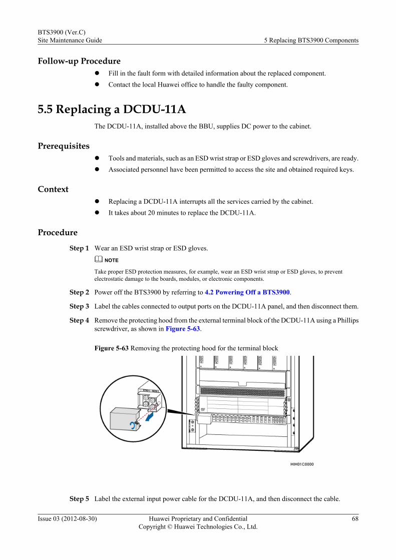
Follow-up Procedurel Fill in the fault form with detailed information about the replaced component.l Contact the local Huawei office to handle the faulty component.
5.5 Replacing a DCDU-11AThe DCDU-11A, installed above the BBU, supplies DC power to the cabinet.
Prerequisitesl Tools and materials, such as an ESD wrist strap or ESD gloves and screwdrivers, are ready.l Associated personnel have been permitted to access the site and obtained required keys.
Contextl Replacing a DCDU-11A interrupts all the services carried by the cabinet.l It takes about 20 minutes to replace the DCDU-11A.
Procedure
Step 1 Wear an ESD wrist strap or ESD gloves.
NOTE
Take proper ESD protection measures, for example, wear an ESD wrist strap or ESD gloves, to preventelectrostatic damage to the boards, modules, or electronic components.
Step 2 Power off the BTS3900 by referring to 4.2 Powering Off a BTS3900.
Step 3 Label the cables connected to output ports on the DCDU-11A panel, and then disconnect them.
Step 4 Remove the protecting hood from the external terminal block of the DCDU-11A using a Phillipsscrewdriver, as shown in Figure 5-63.
Figure 5-63 Removing the protecting hood for the terminal block
Step 5 Label the external input power cable for the DCDU-11A, and then disconnect the cable.
BTS3900 (Ver.C)Site Maintenance Guide 5 Replacing BTS3900 Components
Issue 03 (2012-08-30) Huawei Proprietary and ConfidentialCopyright © Huawei Technologies Co., Ltd.
68
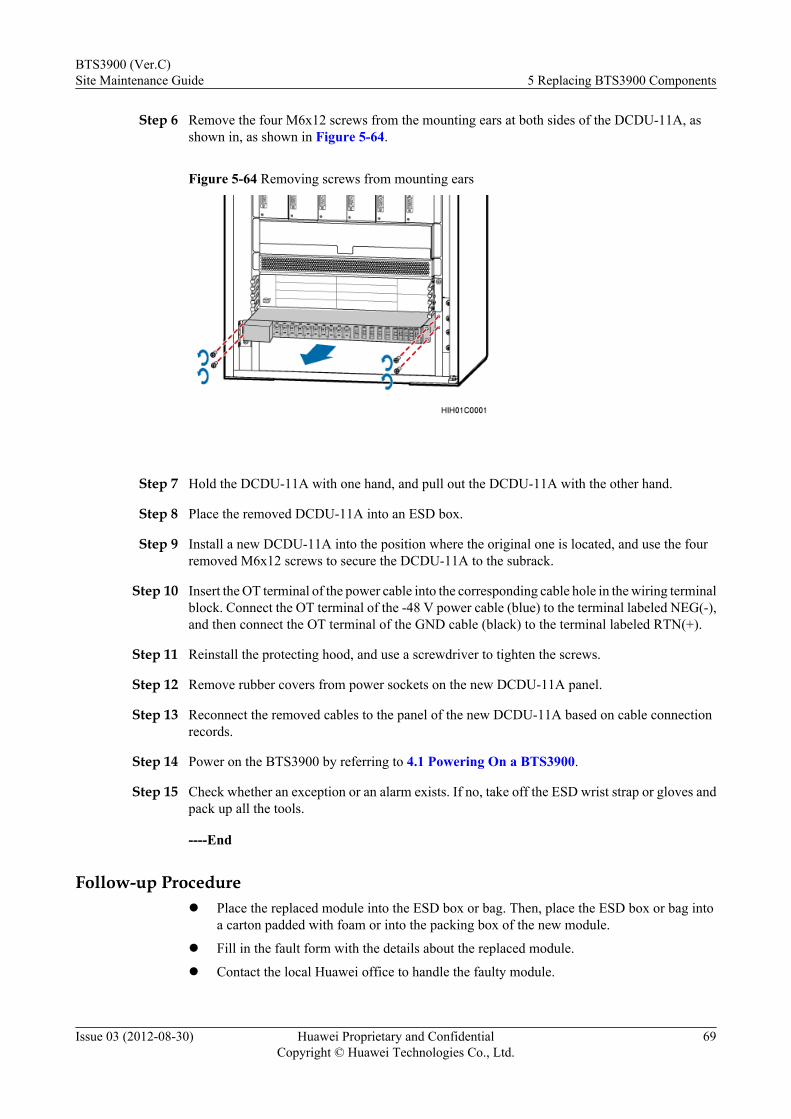
Step 6 Remove the four M6x12 screws from the mounting ears at both sides of the DCDU-11A, asshown in, as shown in Figure 5-64.
Figure 5-64 Removing screws from mounting ears
Step 7 Hold the DCDU-11A with one hand, and pull out the DCDU-11A with the other hand.
Step 8 Place the removed DCDU-11A into an ESD box.
Step 9 Install a new DCDU-11A into the position where the original one is located, and use the fourremoved M6x12 screws to secure the DCDU-11A to the subrack.
Step 10 Insert the OT terminal of the power cable into the corresponding cable hole in the wiring terminalblock. Connect the OT terminal of the -48 V power cable (blue) to the terminal labeled NEG(-),and then connect the OT terminal of the GND cable (black) to the terminal labeled RTN(+).
Step 11 Reinstall the protecting hood, and use a screwdriver to tighten the screws.
Step 12 Remove rubber covers from power sockets on the new DCDU-11A panel.
Step 13 Reconnect the removed cables to the panel of the new DCDU-11A based on cable connectionrecords.
Step 14 Power on the BTS3900 by referring to 4.1 Powering On a BTS3900.
Step 15 Check whether an exception or an alarm exists. If no, take off the ESD wrist strap or gloves andpack up all the tools.
----End
Follow-up Procedurel Place the replaced module into the ESD box or bag. Then, place the ESD box or bag into
a carton padded with foam or into the packing box of the new module.
l Fill in the fault form with the details about the replaced module.
l Contact the local Huawei office to handle the faulty module.
BTS3900 (Ver.C)Site Maintenance Guide 5 Replacing BTS3900 Components
Issue 03 (2012-08-30) Huawei Proprietary and ConfidentialCopyright © Huawei Technologies Co., Ltd.
69
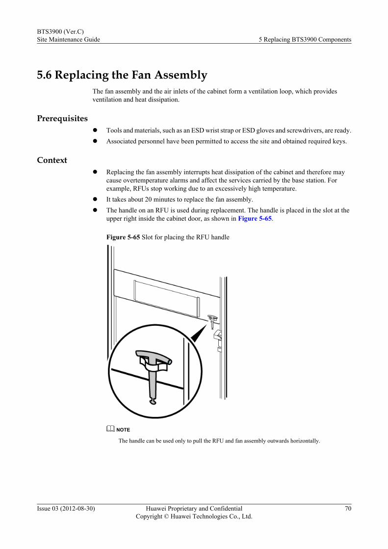
5.6 Replacing the Fan AssemblyThe fan assembly and the air inlets of the cabinet form a ventilation loop, which providesventilation and heat dissipation.
Prerequisitesl Tools and materials, such as an ESD wrist strap or ESD gloves and screwdrivers, are ready.l Associated personnel have been permitted to access the site and obtained required keys.
Contextl Replacing the fan assembly interrupts heat dissipation of the cabinet and therefore may
cause overtemperature alarms and affect the services carried by the base station. Forexample, RFUs stop working due to an excessively high temperature.
l It takes about 20 minutes to replace the fan assembly.l The handle on an RFU is used during replacement. The handle is placed in the slot at the
upper right inside the cabinet door, as shown in Figure 5-65.
Figure 5-65 Slot for placing the RFU handle
NOTE
The handle can be used only to pull the RFU and fan assembly outwards horizontally.
BTS3900 (Ver.C)Site Maintenance Guide 5 Replacing BTS3900 Components
Issue 03 (2012-08-30) Huawei Proprietary and ConfidentialCopyright © Huawei Technologies Co., Ltd.
70
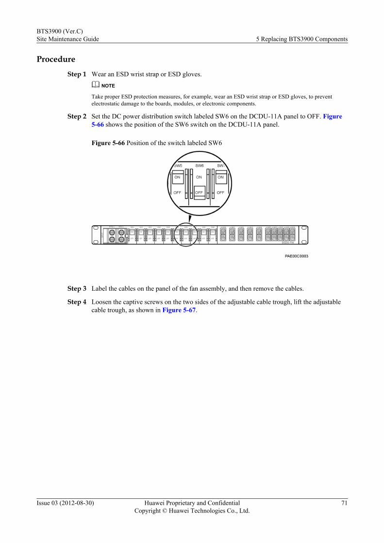
Procedure
Step 1 Wear an ESD wrist strap or ESD gloves.
NOTE
Take proper ESD protection measures, for example, wear an ESD wrist strap or ESD gloves, to preventelectrostatic damage to the boards, modules, or electronic components.
Step 2 Set the DC power distribution switch labeled SW6 on the DCDU-11A panel to OFF. Figure5-66 shows the position of the SW6 switch on the DCDU-11A panel.
Figure 5-66 Position of the switch labeled SW6
Step 3 Label the cables on the panel of the fan assembly, and then remove the cables.
Step 4 Loosen the captive screws on the two sides of the adjustable cable trough, lift the adjustablecable trough, as shown in Figure 5-67.
BTS3900 (Ver.C)Site Maintenance Guide 5 Replacing BTS3900 Components
Issue 03 (2012-08-30) Huawei Proprietary and ConfidentialCopyright © Huawei Technologies Co., Ltd.
71
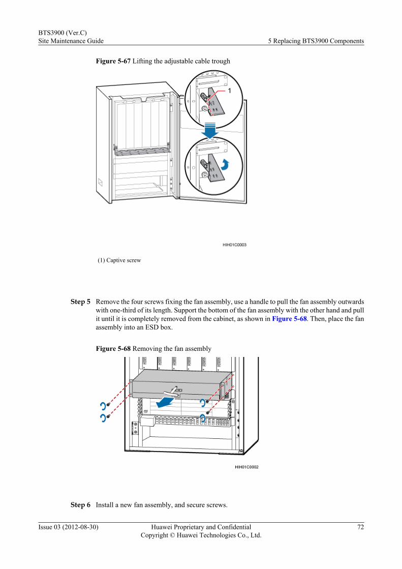
Figure 5-67 Lifting the adjustable cable trough
(1) Captive screw
Step 5 Remove the four screws fixing the fan assembly, use a handle to pull the fan assembly outwardswith one-third of its length. Support the bottom of the fan assembly with the other hand and pullit until it is completely removed from the cabinet, as shown in Figure 5-68. Then, place the fanassembly into an ESD box.
Figure 5-68 Removing the fan assembly
Step 6 Install a new fan assembly, and secure screws.
BTS3900 (Ver.C)Site Maintenance Guide 5 Replacing BTS3900 Components
Issue 03 (2012-08-30) Huawei Proprietary and ConfidentialCopyright © Huawei Technologies Co., Ltd.
72
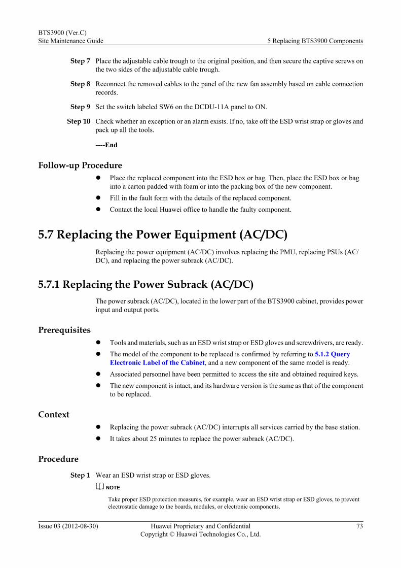
Step 7 Place the adjustable cable trough to the original position, and then secure the captive screws onthe two sides of the adjustable cable trough.
Step 8 Reconnect the removed cables to the panel of the new fan assembly based on cable connectionrecords.
Step 9 Set the switch labeled SW6 on the DCDU-11A panel to ON.
Step 10 Check whether an exception or an alarm exists. If no, take off the ESD wrist strap or gloves andpack up all the tools.
----End
Follow-up Procedurel Place the replaced component into the ESD box or bag. Then, place the ESD box or bag
into a carton padded with foam or into the packing box of the new component.l Fill in the fault form with the details of the replaced component.l Contact the local Huawei office to handle the faulty component.
5.7 Replacing the Power Equipment (AC/DC)Replacing the power equipment (AC/DC) involves replacing the PMU, replacing PSUs (AC/DC), and replacing the power subrack (AC/DC).
5.7.1 Replacing the Power Subrack (AC/DC)The power subrack (AC/DC), located in the lower part of the BTS3900 cabinet, provides powerinput and output ports.
Prerequisitesl Tools and materials, such as an ESD wrist strap or ESD gloves and screwdrivers, are ready.l The model of the component to be replaced is confirmed by referring to 5.1.2 Query
Electronic Label of the Cabinet, and a new component of the same model is ready.l Associated personnel have been permitted to access the site and obtained required keys.l The new component is intact, and its hardware version is the same as that of the component
to be replaced.
Contextl Replacing the power subrack (AC/DC) interrupts all services carried by the base station.l It takes about 25 minutes to replace the power subrack (AC/DC).
Procedure
Step 1 Wear an ESD wrist strap or ESD gloves.
NOTE
Take proper ESD protection measures, for example, wear an ESD wrist strap or ESD gloves, to preventelectrostatic damage to the boards, modules, or electronic components.
BTS3900 (Ver.C)Site Maintenance Guide 5 Replacing BTS3900 Components
Issue 03 (2012-08-30) Huawei Proprietary and ConfidentialCopyright © Huawei Technologies Co., Ltd.
73
Step 2 Power off the BTS3900 by referring to 4.2 Powering Off a BTS3900.
Step 3 Label the cables on the panels of the power subrack (AC/DC) and PMU, and disconnect them.
Step 4 Loosen the screws on the panels of the PMU or PSUs (AC/DC), which are located in the powersubrack (AC/DC), as shown in Figure 5-69.
Figure 5-69 Removing the PMU or PSU (AC/DC)
(1) Screws on the PMU panel (2) PMU
NOTE
Figure 5-69 shows the procedure for removing the PMU. The two screws on the PSU (AC/DC) panel arein the same positions as the screws on the PMU panel.
Step 5 Raise the ejector lever on the panel of the PMU or PSU, and remove the PMU or PSU from thesubrack along guide rails, as shown in Figure 5-69.
Step 6 Repeat steps Step 4 and Step 5 to remove the PMU and all PSUs from the power subrack (AC/DC), and then place the removed PMU and PSUs into an ESD box.
Step 7 Remove the four M6x12 screws from the mounting ears at both sides of the power subrack (AC/DC), as shown in Figure 5-70.
BTS3900 (Ver.C)Site Maintenance Guide 5 Replacing BTS3900 Components
Issue 03 (2012-08-30) Huawei Proprietary and ConfidentialCopyright © Huawei Technologies Co., Ltd.
74

Figure 5-70 Removing screws from mounting ears
Step 8 Hold the power subrack (AC/DC) with one hand, and pull out the power subrack (AC/DC) withthe other hand.
Step 9 Place the removed power subrack (AC/DC) into an ESD box.
Step 10 Take out a new power subrack (AC/DC), perform the preceding steps in reverse sequence toinstall the new power subrack (AC/DC) in the cabinet, and install the removed PMU and PSUsinto the power subrack (AC/DC).
Step 11 Reconnect the removed cables to the panels of the new power subrack (AC/DC) and PMU basedon cable connection records.
CAUTIONFor 220V AC three-phase power cable, remove the short-circuiting plate from the wiringterminals of the power subrack (AC/DC), and then connect the three live wires and the neutralwire. Refer to "Installing an Input Power Cable for a BTS3900 Cabinet (220 V AC)" in BTS3900(Ver.C) Installation Guide.
Step 12 Power on the BTS3900 by referring to 4.1 Powering On a BTS3900.
Step 13 Take off the ESD wrist strap or gloves, and pack up all the tools.
----End
BTS3900 (Ver.C)Site Maintenance Guide 5 Replacing BTS3900 Components
Issue 03 (2012-08-30) Huawei Proprietary and ConfidentialCopyright © Huawei Technologies Co., Ltd.
75
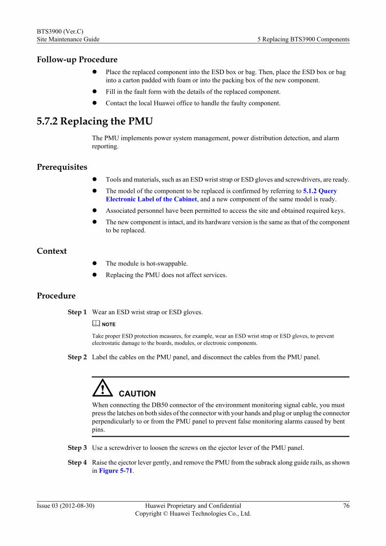
Follow-up Procedurel Place the replaced component into the ESD box or bag. Then, place the ESD box or bag
into a carton padded with foam or into the packing box of the new component.
l Fill in the fault form with the details of the replaced component.
l Contact the local Huawei office to handle the faulty component.
5.7.2 Replacing the PMUThe PMU implements power system management, power distribution detection, and alarmreporting.
Prerequisitesl Tools and materials, such as an ESD wrist strap or ESD gloves and screwdrivers, are ready.
l The model of the component to be replaced is confirmed by referring to 5.1.2 QueryElectronic Label of the Cabinet, and a new component of the same model is ready.
l Associated personnel have been permitted to access the site and obtained required keys.
l The new component is intact, and its hardware version is the same as that of the componentto be replaced.
Contextl The module is hot-swappable.
l Replacing the PMU does not affect services.
Procedure
Step 1 Wear an ESD wrist strap or ESD gloves.
NOTE
Take proper ESD protection measures, for example, wear an ESD wrist strap or ESD gloves, to preventelectrostatic damage to the boards, modules, or electronic components.
Step 2 Label the cables on the PMU panel, and disconnect the cables from the PMU panel.
CAUTIONWhen connecting the DB50 connector of the environment monitoring signal cable, you mustpress the latches on both sides of the connector with your hands and plug or unplug the connectorperpendicularly to or from the PMU panel to prevent false monitoring alarms caused by bentpins.
Step 3 Use a screwdriver to loosen the screws on the ejector lever of the PMU panel.
Step 4 Raise the ejector lever gently, and remove the PMU from the subrack along guide rails, as shownin Figure 5-71.
BTS3900 (Ver.C)Site Maintenance Guide 5 Replacing BTS3900 Components
Issue 03 (2012-08-30) Huawei Proprietary and ConfidentialCopyright © Huawei Technologies Co., Ltd.
76
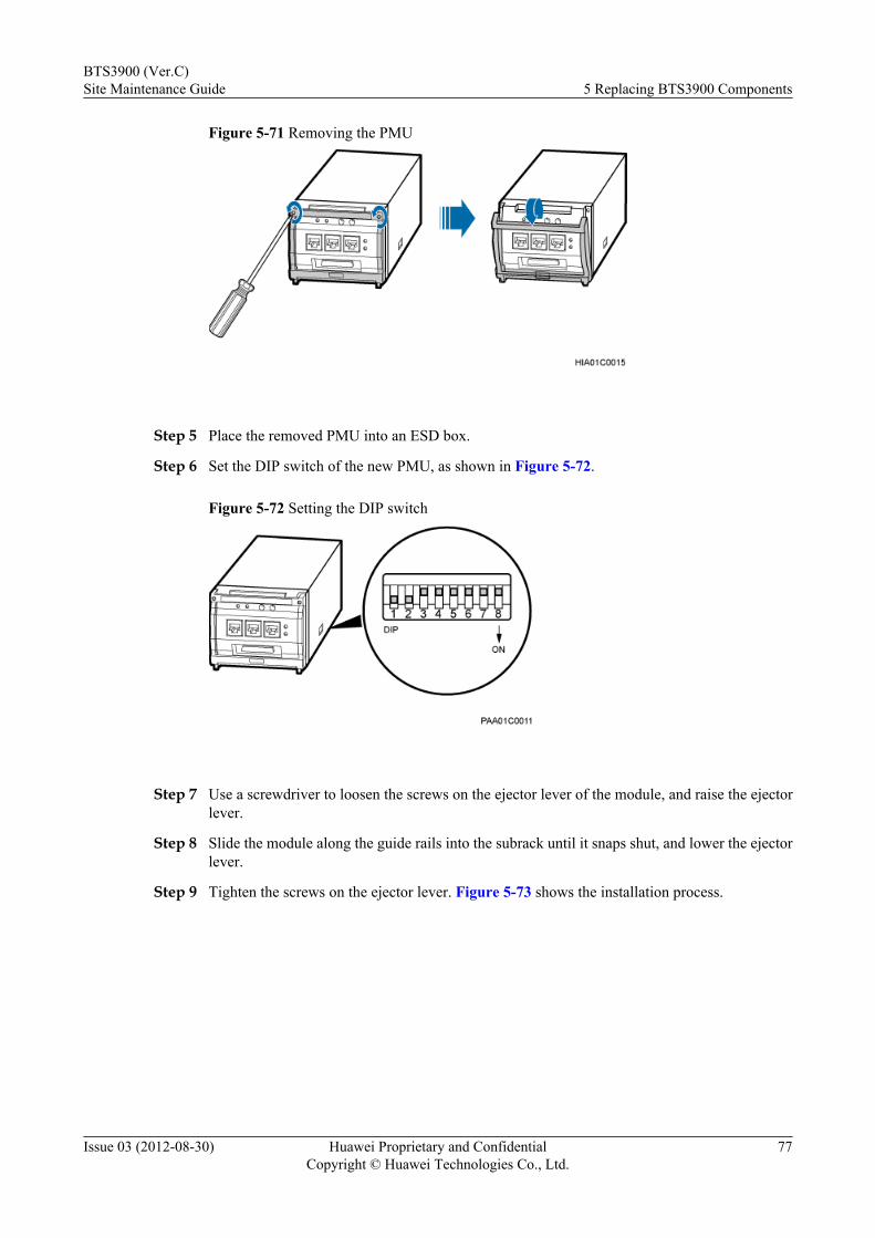
Figure 5-71 Removing the PMU
Step 5 Place the removed PMU into an ESD box.
Step 6 Set the DIP switch of the new PMU, as shown in Figure 5-72.
Figure 5-72 Setting the DIP switch
Step 7 Use a screwdriver to loosen the screws on the ejector lever of the module, and raise the ejectorlever.
Step 8 Slide the module along the guide rails into the subrack until it snaps shut, and lower the ejectorlever.
Step 9 Tighten the screws on the ejector lever. Figure 5-73 shows the installation process.
BTS3900 (Ver.C)Site Maintenance Guide 5 Replacing BTS3900 Components
Issue 03 (2012-08-30) Huawei Proprietary and ConfidentialCopyright © Huawei Technologies Co., Ltd.
77
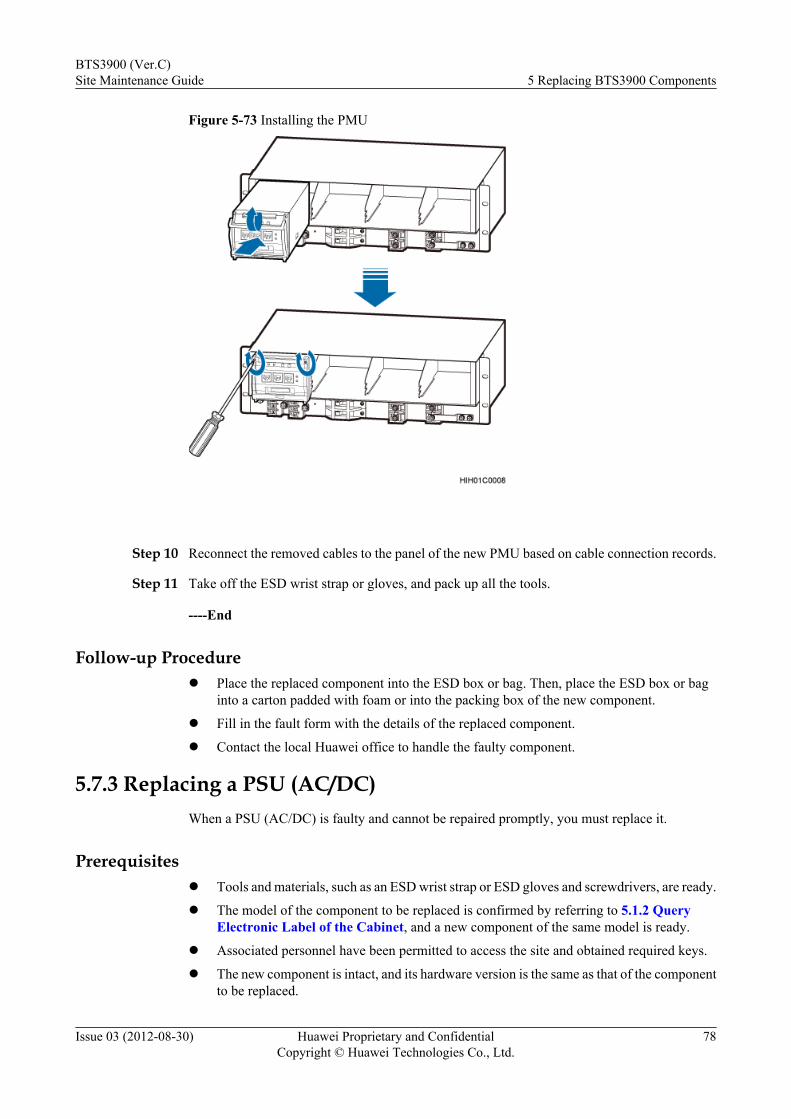
Figure 5-73 Installing the PMU
Step 10 Reconnect the removed cables to the panel of the new PMU based on cable connection records.
Step 11 Take off the ESD wrist strap or gloves, and pack up all the tools.
----End
Follow-up Procedurel Place the replaced component into the ESD box or bag. Then, place the ESD box or bag
into a carton padded with foam or into the packing box of the new component.
l Fill in the fault form with the details of the replaced component.
l Contact the local Huawei office to handle the faulty component.
5.7.3 Replacing a PSU (AC/DC)When a PSU (AC/DC) is faulty and cannot be repaired promptly, you must replace it.
Prerequisitesl Tools and materials, such as an ESD wrist strap or ESD gloves and screwdrivers, are ready.
l The model of the component to be replaced is confirmed by referring to 5.1.2 QueryElectronic Label of the Cabinet, and a new component of the same model is ready.
l Associated personnel have been permitted to access the site and obtained required keys.
l The new component is intact, and its hardware version is the same as that of the componentto be replaced.
BTS3900 (Ver.C)Site Maintenance Guide 5 Replacing BTS3900 Components
Issue 03 (2012-08-30) Huawei Proprietary and ConfidentialCopyright © Huawei Technologies Co., Ltd.
78
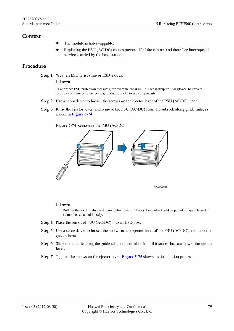
Contextl The module is hot-swappable.l Replacing the PSU (AC/DC) causes power-off of the cabinet and therefore interrupts all
services carried by the base station.
Procedure
Step 1 Wear an ESD wrist strap or ESD gloves.
NOTE
Take proper ESD protection measures, for example, wear an ESD wrist strap or ESD gloves, to preventelectrostatic damage to the boards, modules, or electronic components.
Step 2 Use a screwdriver to loosen the screws on the ejector lever of the PSU (AC/DC) panel.
Step 3 Raise the ejector lever, and remove the PSU (AC/DC) from the subrack along guide rails, asshown in Figure 5-74.
Figure 5-74 Removing the PSU (AC/DC)
NOTEPull out the PSU module with your palm upward. The PSU module should be pulled out quickly and itcannot be remained loosely.
Step 4 Place the removed PSU (AC/DC) into an ESD box.
Step 5 Use a screwdriver to loosen the screws on the ejector lever of the PSU (AC/DC), and raise theejector lever.
Step 6 Slide the module along the guide rails into the subrack until it snaps shut, and lower the ejectorlever.
Step 7 Tighten the screws on the ejector lever. Figure 5-75 shows the installation process.
BTS3900 (Ver.C)Site Maintenance Guide 5 Replacing BTS3900 Components
Issue 03 (2012-08-30) Huawei Proprietary and ConfidentialCopyright © Huawei Technologies Co., Ltd.
79
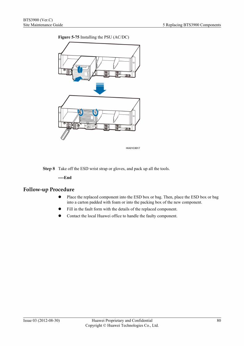
Figure 5-75 Installing the PSU (AC/DC)
Step 8 Take off the ESD wrist strap or gloves, and pack up all the tools.
----End
Follow-up Procedurel Place the replaced component into the ESD box or bag. Then, place the ESD box or bag
into a carton padded with foam or into the packing box of the new component.l Fill in the fault form with the details of the replaced component.l Contact the local Huawei office to handle the faulty component.
BTS3900 (Ver.C)Site Maintenance Guide 5 Replacing BTS3900 Components
Issue 03 (2012-08-30) Huawei Proprietary and ConfidentialCopyright © Huawei Technologies Co., Ltd.
80