Embed Size (px)
DESCRIPTION
Bsc6900 Umts Lmt User Guide(v900r017c10_02)(PDF)-En
Citation preview

BSC6900 UMTS
V900R017C10
LMT User Guide
Issue 02
Date 2015-05-08
HUAWEI TECHNOLOGIES CO., LTD.

Copyright © Huawei Technologies Co., Ltd. 2015. All rights reserved.
No part of this document may be reproduced or transmitted in any form or by any means without prior writtenconsent of Huawei Technologies Co., Ltd. Trademarks and Permissions
and other Huawei trademarks are trademarks of Huawei Technologies Co., Ltd.All other trademarks and trade names mentioned in this document are the property of their respective holders. NoticeThe purchased products, services and features are stipulated by the contract made between Huawei and thecustomer. All or part of the products, services and features described in this document may not be within thepurchase scope or the usage scope. Unless otherwise specified in the contract, all statements, information,and recommendations in this document are provided "AS IS" without warranties, guarantees or representationsof any kind, either express or implied.
The information in this document is subject to change without notice. Every effort has been made in thepreparation of this document to ensure accuracy of the contents, but all statements, information, andrecommendations in this document do not constitute a warranty of any kind, express or implied.
Huawei Technologies Co., Ltd.Address: Huawei Industrial Base
Bantian, LonggangShenzhen 518129People's Republic of China
Website: http://www.huawei.com
Email: [email protected]
Issue 02 (2015-05-08) Huawei Proprietary and ConfidentialCopyright © Huawei Technologies Co., Ltd.
i

About This Document
OverviewThis document describes the functions and relevant components of the BSC6900 LocalMaintenance Terminal (LMT). It also provides instructions for performing basic operation andmaintenance (OM) tasks of theBSC6900.
Product VersionsThe following table lists the product version and the solution version related to this document.
Product Name Product Version Solution Version
BSC6900 V900R017C10 RAN17.1
Intended AudienceThis document is intended for:
l Network engineersl System engineersl Field engineers
Organization1 Change History
This section provides information about the changes in different document versions. There aretwo types of changes, including function changes and editorial changes. Function changes referto changes in functions of a specific product version. Editorial changes refer to changes inwording or addition of information that was not described in the earlier version.
2 Introduction to LMT
The Local Maintenance Terminal (LMT) is a web-based application that provides a graphicaluser interface (GUI) to simplify operation and maintenance of the BSC6900. Using the LMT,
BSC6900 UMTSLMT User Guide About This Document
Issue 02 (2015-05-08) Huawei Proprietary and ConfidentialCopyright © Huawei Technologies Co., Ltd.
ii

you can manage alarms, view message tracing results, monitor performance, and maintaindevices. You can also run man-machine language (MML) commands and view command resultson the LMT.
3 Operation Rights Management
This chapter describes principles of managing operation rights, user accounts, and commandgroups.
4 Running MML Commands
This chapter describes how to run MML commands on the LMT for operation and maintenanceof the BSC6900.
5 Alarm/Event Management
This section describes how to use the LMT to manage BSC6900 alarms/events. Alarm/eventmanagement helps you analyze alarms/events efficiently, thereby facilitating troubleshooting.
6 Log Management
This section describes how to use the LMT to manage the BSC6900 logs, which can be savedin .txt and .csv files. Only user admin, ADMINISTRATOR-level users, and authorizedCUSTOM-level users can manage the logs.
7 Trace Management
This chapter describes how to manage message tracing on the BSC6900. A maximum of 64 tracetasks can be started simultaneously on the same LMT, and a maximum of 6 trace tasks can bestarted simultaneously for the same parameter of a trace item. When OMU boards perform anactive/standby switchover, monitoring cannot be restarted until 30 minutes after the switchover.
8 Performance Monitoring
This chapter describes how to monitorBSC6900 performance. A maximum of 64 monitoringtasks can be started simultaneously on the LMT. If OMU boards are switched over, performancemonitoring can be restarted 30 minutes after the switchover.
9 Device Panel
This chapter describes how to manage the BSC6900 using the device and emulation panels. Youcan use these panels to query information about boards, ports, links, and alarms.
10 FMA
This function helps users handle network faults. It includes the following functions: FaultDiagnosis, Hierarchical Delimitation and Information Collection. The fault diagnosis andhierarchical delimitation functions analyze faults only within eight hours from the faultrectification to the current time.
11 BSC Maintenance
This chapter describes how to maintain BSC equipment, back up and restore data, and implementfast fault diagnosis.
12 FAQ
This chapter describes some frequently asked questions (FAQs) and the corresponding solutions.
BSC6900 UMTSLMT User Guide About This Document
Issue 02 (2015-05-08) Huawei Proprietary and ConfidentialCopyright © Huawei Technologies Co., Ltd.
iii
ConventionsSymbol Conventions
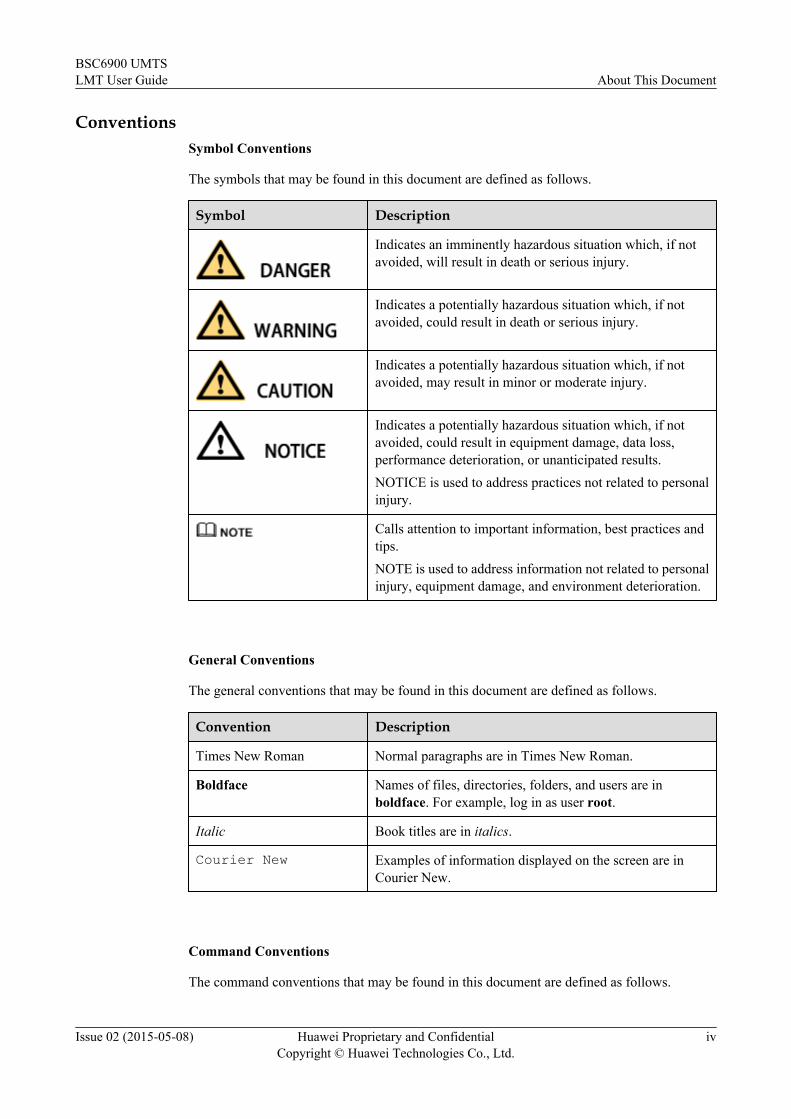
The symbols that may be found in this document are defined as follows.
Symbol Description
Indicates an imminently hazardous situation which, if notavoided, will result in death or serious injury.
Indicates a potentially hazardous situation which, if notavoided, could result in death or serious injury.
Indicates a potentially hazardous situation which, if notavoided, may result in minor or moderate injury.
Indicates a potentially hazardous situation which, if notavoided, could result in equipment damage, data loss,performance deterioration, or unanticipated results.NOTICE is used to address practices not related to personalinjury.
Calls attention to important information, best practices andtips.NOTE is used to address information not related to personalinjury, equipment damage, and environment deterioration.
General Conventions
The general conventions that may be found in this document are defined as follows.
Convention Description
Times New Roman Normal paragraphs are in Times New Roman.
Boldface Names of files, directories, folders, and users are inboldface. For example, log in as user root.
Italic Book titles are in italics.
Courier New Examples of information displayed on the screen are inCourier New.
Command Conventions
The command conventions that may be found in this document are defined as follows.
BSC6900 UMTSLMT User Guide About This Document
Issue 02 (2015-05-08) Huawei Proprietary and ConfidentialCopyright © Huawei Technologies Co., Ltd.
iv

Convention Description
Boldface The keywords of a command line are in boldface.
Italic Command arguments are in italics.
[ ] Items (keywords or arguments) in brackets [ ] are optional.
{ x | y | ... } Optional items are grouped in braces and separated byvertical bars. One item is selected.
[ x | y | ... ] Optional items are grouped in brackets and separated byvertical bars. One item is selected or no item is selected.
{ x | y | ... }* Optional items are grouped in braces and separated byvertical bars. A minimum of one item or a maximum of allitems can be selected.
[ x | y | ... ]* Optional items are grouped in brackets and separated byvertical bars. Several items or no item can be selected.
GUI Conventions
The GUI conventions that may be found in this document are defined as follows.
Convention Description
Boldface Buttons, menus, parameters, tabs, window, and dialog titlesare in boldface. For example, click OK.
> Multi-level menus are in boldface and separated by the ">"signs. For example, choose File > Create > Folder.
Keyboard Operations
The keyboard operations that may be found in this document are defined as follows.
Format Description
Key Press the key. For example, press Enter and press Tab.
Key 1+Key 2 Press the keys concurrently. For example, pressing Ctrl+Alt+A means the three keys should be pressed concurrently.
Key 1, Key 2 Press the keys in turn. For example, pressing Alt, A meansthe two keys should be pressed in turn.
Mouse Operations
The mouse operations that may be found in this document are defined as follows.
BSC6900 UMTSLMT User Guide About This Document
Issue 02 (2015-05-08) Huawei Proprietary and ConfidentialCopyright © Huawei Technologies Co., Ltd.
v

Action Description
Click Select and release the primary mouse button without movingthe pointer.
Double-click Press the primary mouse button twice continuously andquickly without moving the pointer.
Drag Press and hold the primary mouse button and move thepointer to a certain position.
BSC6900 UMTSLMT User Guide About This Document
Issue 02 (2015-05-08) Huawei Proprietary and ConfidentialCopyright © Huawei Technologies Co., Ltd.
vi

Contents
About This Document.....................................................................................................................ii
1 Change History..............................................................................................................................1
2 Introduction to LMT.....................................................................................................................42.1 Configuration Requirements of the LMT PC.................................................................................................................62.2 Logging In to and Logging Out of the LMT..................................................................................................................82.3 Components of the LMT Main Page............................................................................................................................122.4 Obtaining Documentation Packages.............................................................................................................................152.5 File Manager.................................................................................................................................................................162.6 FTP Server....................................................................................................................................................................192.7 User-defined Command Group....................................................................................................................................212.8 LMT Software..............................................................................................................................................................232.8.1 Installing LMT Offline Tools....................................................................................................................................232.8.2 LMT Offline MML....................................................................................................................................................252.8.3 FTP Client..................................................................................................................................................................292.8.4 Convert Management System....................................................................................................................................312.8.5 Performance Browser Tool........................................................................................................................................322.8.6 TrafficRecording Review Tool..................................................................................................................................33
3 Operation Rights Management................................................................................................353.1 Concepts Related to Operation Rights Management....................................................................................................363.1.1 Principles of Operation Rights Management.............................................................................................................363.1.2 User Passwords..........................................................................................................................................................363.1.3 Command Groups......................................................................................................................................................373.1.4 User Types.................................................................................................................................................................383.1.5 Operation Rights........................................................................................................................................................383.1.6 Operation Time Limits..............................................................................................................................................393.2 Management of User Accounts....................................................................................................................................403.2.1 Creating an External User Account...........................................................................................................................403.2.2 Modifying an External User Account........................................................................................................................413.2.3 Deleting an External User Account...........................................................................................................................413.3 Management of User Passwords...................................................................................................................................423.3.1 Defining Login Password Policies............................................................................................................................42
BSC6900 UMTSLMT User Guide Contents
Issue 02 (2015-05-08) Huawei Proprietary and ConfidentialCopyright © Huawei Technologies Co., Ltd.
vii

3.3.2 Querying Login Password Policies............................................................................................................................423.3.3 Changing the Password of the Active User Account................................................................................................423.3.4 Changing the Password of an External User Account...............................................................................................433.4 Management of Command Groups...............................................................................................................................433.4.1 Querying a Command Group....................................................................................................................................433.4.2 Renaming Command Groups....................................................................................................................................433.4.3 Changing Commands in a Command Group.............................................................................................................44
4 Running MML Commands........................................................................................................454.1 Concepts Related to MML Commands........................................................................................................................474.1.1 Introduction to MML Commands..............................................................................................................................474.1.2 Components of the MML Command Window..........................................................................................................484.1.3 Data Configuration Rights.........................................................................................................................................504.1.4 Data Configuration Rollback.....................................................................................................................................504.2 Running a Single MML Command..............................................................................................................................514.3 Batch Processing of MML Commands........................................................................................................................524.3.1 Immediate Batch Processing of MML Commands...................................................................................................534.3.2 Scheduled Batch Processing of MML Commands....................................................................................................544.3.3 Syntax Check.............................................................................................................................................................554.4 Setting MML Parameters..............................................................................................................................................564.5 Querying Data Configuration Modes...........................................................................................................................574.6 Querying Data Configuration Rights............................................................................................................................584.7 Obtaining Data Configuration Rights...........................................................................................................................584.8 Undoing/Redoing a Single Data Configuration Action................................................................................................594.9 Undoing/Redoing Multiple Data Configuration Actions.............................................................................................60
5 Alarm/Event Management.........................................................................................................625.1 Concepts Related to Alarm Management.....................................................................................................................635.1.1 Alarm Type................................................................................................................................................................635.1.2 Alarm Severity...........................................................................................................................................................645.1.3 Alarm-Event Type.....................................................................................................................................................645.1.4 Alarm Flag.................................................................................................................................................................655.1.5 Alarm Box.................................................................................................................................................................665.2 Managing Alarm Logs..................................................................................................................................................675.2.1 Setting Storage Limitations of Alarm Logs...............................................................................................................675.2.2 Querying Storage Limitations of Alarm Logs...........................................................................................................685.3 Managing Alarm Masking Conditions.........................................................................................................................685.3.1 Creating an Alarm Masking Condition.....................................................................................................................685.3.2 Deleting an Alarm Masking Condition.....................................................................................................................695.3.3 Querying an Alarm Masking Condition....................................................................................................................695.4 Managing the Alarm Masking Switch of Derived Alarms...........................................................................................695.4.1 Enabling/Disabling the Alarm Masking Switch of Derived Alarms.........................................................................705.4.2 Querying the Alarm Masking Switch of Derived Alarms.........................................................................................70
BSC6900 UMTSLMT User Guide Contents
Issue 02 (2015-05-08) Huawei Proprietary and ConfidentialCopyright © Huawei Technologies Co., Ltd.
viii

5.5 Monitoring Alarms.......................................................................................................................................................705.5.1 Browsing Alarms/Events...........................................................................................................................................705.5.2 Querying Alarm/Event Logs.....................................................................................................................................715.5.3 Querying Suggestions on Alarm/Event Handling.....................................................................................................725.5.4 Querying Alarm/Event Configuration.......................................................................................................................735.5.5 Filtering Alarms/Events.............................................................................................................................................745.5.6 Setting Display Attributes for Alarms/Events...........................................................................................................745.5.7 Manually Clearing an Alarm/Event...........................................................................................................................775.5.8 Deleting Alarms/Events.............................................................................................................................................775.5.9 Refreshing the Alarm/Event Window.......................................................................................................................785.6 Managing the Alarm Box.............................................................................................................................................785.6.1 Querying Alarm Box Information.............................................................................................................................795.6.2 Querying the Number of Alarms of a Specific Severity............................................................................................795.6.3 Performing Operations on the Alarm Box.................................................................................................................795.6.4 Querying the Alarm Suppression Level of the Alarm Box.......................................................................................80
6 Log Management.........................................................................................................................816.1 Logs..............................................................................................................................................................................826.2 Setting Log Storage Limitations...................................................................................................................................826.3 Querying Operation/Security Logs...............................................................................................................................826.4 Obtaining Operation/Security Logs..............................................................................................................................836.5 Obtaining Running Logs..............................................................................................................................................846.6 Collecting Logs.............................................................................................................................................................85
7 Trace Management......................................................................................................................907.1 Concepts.......................................................................................................................................................................917.1.1 Tracing Principles......................................................................................................................................................917.1.2 Management of Tracing Operation Rights................................................................................................................927.1.3 Tracing Mode............................................................................................................................................................927.1.4 Tracing Specifications...............................................................................................................................................927.2 Basic Tracing Operations.............................................................................................................................................937.2.1 Browsing Traced Messages Online...........................................................................................................................937.2.2 Viewing the Interpretation of Traced Messages........................................................................................................957.2.3 Saving Traced Messages...........................................................................................................................................957.2.4 Browsing Traced Messages Offline..........................................................................................................................977.2.5 Managing Tracing Tasks...........................................................................................................................................987.2.6 Managing the Trace File............................................................................................................................................987.3 Device Commissioning.................................................................................................................................................997.3.1 Tracing OS Messages................................................................................................................................................997.3.2 Emergency Diagnosis..............................................................................................................................................1007.3.3 Capturing Packets....................................................................................................................................................1017.3.4 AC Tracing..............................................................................................................................................................1067.3.5 DHCP Tracing.........................................................................................................................................................107
BSC6900 UMTSLMT User Guide Contents
Issue 02 (2015-05-08) Huawei Proprietary and ConfidentialCopyright © Huawei Technologies Co., Ltd.
ix

7.4 UMTS Services...........................................................................................................................................................1097.4.1 Tracing Messages on the Iu Interface......................................................................................................................1097.4.2 Tracing Messages on the Iupc Interface..................................................................................................................1117.4.3 Tracing Messages on the Iur Interface.....................................................................................................................1137.4.4 Tracing Messages on the Iub Interface....................................................................................................................1157.4.5 Tracing Messages on the Uu Interface....................................................................................................................1177.4.6 Tracing MNCDT Messages.....................................................................................................................................1197.4.7 Message Settings.....................................................................................................................................................1217.4.8 Tracing UE Messages..............................................................................................................................................1227.4.9 Tracing Cell Messages.............................................................................................................................................1317.4.10 Tracing IOS Messages...........................................................................................................................................1347.4.11 Tracing Iur-p Messages.........................................................................................................................................1437.4.12 Tracing Messages on the Sr Interface....................................................................................................................145
8 Performance Monitoring..........................................................................................................1478.1 Concepts.....................................................................................................................................................................1488.1.1 Monitoring Principles..............................................................................................................................................1488.1.2 Operation Rights Control.........................................................................................................................................1498.2 General Operations.....................................................................................................................................................1508.2.1 Browsing the Monitoring Results Online................................................................................................................1508.2.2 Setting Chart Display Mode....................................................................................................................................1508.2.3 Saving Monitoring Data..........................................................................................................................................1518.2.4 Offline Browsing Monitoring Data.........................................................................................................................1518.3 Common Monitoring..................................................................................................................................................1528.3.1 Monitoring Board CPU/DSP Usage........................................................................................................................1528.3.2 Monitoring Transmission Resources.......................................................................................................................1538.3.3 Monitoring BERS....................................................................................................................................................1588.3.4 Monitoring BER......................................................................................................................................................1598.3.5 Monitoring Link Performance.................................................................................................................................1598.4 UMTS Monitoring......................................................................................................................................................1738.4.1 Monitoring Connection Performance......................................................................................................................1738.4.2 Monitoring Cell Performance..................................................................................................................................1848.4.3 Monitoring System Resources.................................................................................................................................1958.4.4 Monitoring Iur-p Delay...........................................................................................................................................195
9 Device Panel...............................................................................................................................1979.1 Device Panel Operations............................................................................................................................................1989.1.1 Introduction to the Device Panel.............................................................................................................................1989.1.2 Starting the Device Panel........................................................................................................................................1989.1.3 Querying the Status of an E1/T1 Port......................................................................................................................1999.1.4 Querying the CPU/DSP Usage................................................................................................................................1999.1.5 Querying BSC Board Clock Status.........................................................................................................................2009.1.6 Querying the BSC Board Information.....................................................................................................................201
BSC6900 UMTSLMT User Guide Contents
Issue 02 (2015-05-08) Huawei Proprietary and ConfidentialCopyright © Huawei Technologies Co., Ltd.
x

9.1.7 Resetting a BSC Board............................................................................................................................................2029.1.8 Switching Over BSC Boards...................................................................................................................................2039.1.9 Querying the BSC Board Alarm..............................................................................................................................2059.2 Emulation Panel Operations.......................................................................................................................................2059.2.1 Introduction to the Emulation Panel........................................................................................................................2059.2.2 Starting the Emulation Panel...................................................................................................................................2069.2.3 Querying the Status of an E1/T1 Port......................................................................................................................2079.2.4 Querying the CPU/DSP Usage................................................................................................................................2089.2.5 Querying BSC Board Clock Status.........................................................................................................................2089.2.6 Querying the BSC Board Information.....................................................................................................................2099.2.7 Resetting a BSC Board............................................................................................................................................2109.2.8 Switching Over BSC Boards...................................................................................................................................2129.2.9 Querying the BSC Board Alarm..............................................................................................................................2139.2.10 Querying the FE/GE Port Status............................................................................................................................2149.2.11 Querying the Optical Port Status...........................................................................................................................2149.2.12 Querying the DPU DSP Status..............................................................................................................................2159.2.13 Querying Alarm LED Information........................................................................................................................215
10 FMA............................................................................................................................................21710.1 Fault Overview.........................................................................................................................................................21910.2 Fault Diagnosis.........................................................................................................................................................22110.3 Hierarchical Delimitation.........................................................................................................................................23010.4 Recovery Confirmation............................................................................................................................................23310.5 Information Collection.............................................................................................................................................233
11 BSC Maintenance....................................................................................................................23611.1 Backing Up Data......................................................................................................................................................23711.2 Restoring Data..........................................................................................................................................................23811.3 Batch Configuration.................................................................................................................................................239
12 FAQ............................................................................................................................................24112.1 Browser-related FAQs..............................................................................................................................................24212.1.1 Slow Responses in the Firefox Browser................................................................................................................24212.1.2 LMT Colors Cannot Be Displayed........................................................................................................................24212.1.3 Verification Code Cannot Be Displayed on the LMT Login Page........................................................................24212.1.4 No Response When Clicking the Menu Bar on the LMT.....................................................................................24312.1.5 How to Set the Browser Under Citrix Farm Networking......................................................................................24412.1.6 Unable to Log In To LMT Because IE Default Security Level Is Too High........................................................24812.1.7 Unable to Download or Install the Java or Flash Plug-in and Two File Manager Windows Displayed Windows IE8or Any Later Version Is Used...........................................................................................................................................25512.1.8 The Error "Certificate Invalid" Is Displayed During an HTTPS Login................................................................25612.1.9 The Error 'Mismatched Address' Is Displayed During an HTTPS Login.............................................................26512.1.10 File Manager Functions are Improperly..............................................................................................................267
BSC6900 UMTSLMT User Guide Contents
Issue 02 (2015-05-08) Huawei Proprietary and ConfidentialCopyright © Huawei Technologies Co., Ltd.
xi

12.1.11 Message 'Class doesn't support Automation' Displayed in an IE Browser.........................................................26912.1.12 Error Message"This user session already exists" Upon Login to LMT..............................................................27012.1.13 The "Are You Sure You Want to Quit the Page" Dialog Box Is Displayed.......................................................27112.1.14 Unclear Grids in the Tables in the MML Online Help........................................................................................27112.1.15 The "App Center" Web Page Is Automatically Displayed When Firefox Is Used to Browse the LMT.............27212.1.16 "Permission Denied" or "Access Denied" is Displayed When IE Is Used to Browse the LMT.........................27212.1.17 MML Command Failed to Be Executed or No Response to Tracing Tasks After the Browser Is Upgraded to IE8..........................................................................................................................................................................................27412.1.18 Settings on the LMT Failing to Take Effective...................................................................................................27512.1.19 LMT Login Window Being Stopped by the Browser.........................................................................................27612.1.20 The LMT login page of a host NE or built-in NE fails to be opened..................................................................27612.2 Java-related FAQs....................................................................................................................................................27812.2.1 Help for Installing and Using the Java Plug-in......................................................................................................27812.2.2 LMT Fails to Function Properly When Error Occurs in Mixed Code Security Verification of JRE....................27912.2.3 Tracing and Monitoring Functions Cannot Be Used.............................................................................................28112.2.4 Chinese Characters Displayed in the Tracing and Monitoring Windows.............................................................28512.2.5 LMT Fails to Function Properly during the tracing/monitoring/batch processing................................................28712.2.6 Interfaces for Performing Tracing or Monitoring Tasks Blinking........................................................................29012.2.7 Java Installation Fails............................................................................................................................................29012.2.8 Changing Settings for the Next-Generation Java Plug-in Fails.............................................................................29012.2.9 How to Handle a Web Page Error or Java Error Displayed on the LMT..............................................................29412.2.10 Displaying the Java Security Warning................................................................................................................29612.2.11 Failure in Verifying the Verification Code During the Login to the LMT.........................................................29612.2.12 The Application Blocked by Security Settings Dialog Box Is Displayed When Batch Processing, Tracing,Monitoring, or Device Maintenance Is Enabled...............................................................................................................29812.2.13 What Do I Do If A Message Your Java version is out of date Is Displayed?.....................................................29912.3 Other FAQs...............................................................................................................................................................29912.3.1 Installing OS Patches.............................................................................................................................................29912.3.2 Changing the Computer Time During the LMT Use Prohibited...........................................................................30112.3.3 Corrupted Characters Appearing When the csv File Is Opened in UTF-8 Coding...............................................30112.3.4 Maximum Number of LMT Clients That Can Be Started on One PC Simultaneously........................................30412.3.5 Any Further Operation Performed When Some LMT Web Pages Fail to Update Causes the Web Pages to TurnBlank.................................................................................................................................................................................30512.3.6 Configuring the HTTPS Login Mode....................................................................................................................30512.3.7 Unable to Save Tracking and Monitoring Data.....................................................................................................30612.3.8 BTS Nodes Cannot Be Displayed Under Device Navigation Tree.......................................................................30712.3.9 Alarm/Event Function Becomes Unavailable.......................................................................................................30812.3.10 LMT Login Web Page Cannot Be Opened with the PC OMU Installed............................................................30912.3.11 Slow Response During an LMT Login................................................................................................................31012.3.12 Batch Execution of MML Commands Fails Because Some MML Commands Contain Invisible Carriage Returnsor Line Feeds....................................................................................................................................................................31112.3.13 How to Handle Shortcut Key Invalidation..........................................................................................................311
BSC6900 UMTSLMT User Guide Contents
Issue 02 (2015-05-08) Huawei Proprietary and ConfidentialCopyright © Huawei Technologies Co., Ltd.
xii

12.3.14 Tracing File Not Being Uploaded to the Specified Directory.............................................................................31212.3.15 Error Dialog Box Displayed When Online Help Is Opened................................................................................31212.3.16 Garbled Characters Displayed in the Chinese Names of Files in the File Manager and These Files Failing to BeRemoved...........................................................................................................................................................................312
BSC6900 UMTSLMT User Guide Contents
Issue 02 (2015-05-08) Huawei Proprietary and ConfidentialCopyright © Huawei Technologies Co., Ltd.
xiii

1 Change History
This section provides information about the changes in different document versions. There aretwo types of changes, including function changes and editorial changes. Function changes referto changes in functions of a specific product version. Editorial changes refer to changes inwording or addition of information that was not described in the earlier version.
02 (2015-05-08)This issue includes the following changes.
Change Type Change Description
Functionchange
Added
None.
Modified
Added descriptions of the Working directory setting on the FTPserver. For details, see FTP Server.Added descriptions of user name, password, and port settings. Fordetails, see Logging In to and Logging Out of the LMT.Modified the specifications of the number of real-time monitoringtasks. For details, see Browsing the Monitoring ResultsOnline.
Deleted
None.
Editorialchange
None.
01 (2015-03-25)This issue includes the following changes.
BSC6900 UMTSLMT User Guide 1 Change History
Issue 02 (2015-05-08) Huawei Proprietary and ConfidentialCopyright © Huawei Technologies Co., Ltd.
1

Change Type Change Description
Functionchange
Added None.
Modified
Optimized descriptions about the FMA function to make thedescriptions clearer and more user-friendly. For details, see thefollowing chapters.l FMAl Fault Overviewl Fault Diagnosisl Hierarchical Delimitationl Information Collection
Deleted
None.
Editorialchange
None.
Draft A (2015-01-15)Compared with Issue 04 (2014-12-30) of V900R016C00, this issue includes the followingchanges.
Change Type Change Description
Functionchange
Added None.
BSC6900 UMTSLMT User Guide 1 Change History
Issue 02 (2015-05-08) Huawei Proprietary and ConfidentialCopyright © Huawei Technologies Co., Ltd.
2

Change Type Change Description
Modified
l Modified the recommended Java JRE version. For details, seeConfiguration Requirements of the LMT PC.
l Added the precautions for logging in to the LMT using theU2000 proxy. For details, see Logging In to and Logging Outof the LMT.
l Added descriptions of FTP permissions and protocol typesupported by the FTP server. For details, see FTP Server.
l Added descriptions of right control. For details, seeManagement of Tracing Operation Rights.
l Added log descriptions. For details, see Collecting Logs.l Added packet parameter descriptions. For details, see
Capturing Packets.l Added descriptions of the fault information collection period.
For details, see Information Collection.l Modified descriptions of supported board types. For details,
see Resetting a BSC Board.l Added the solution to garbled characters displayed in
Office2007 and later versions. For details, see CorruptedCharacters Appearing When the csv File Is Opened inUTF-8 Coding.
l Added the solution to the unavailable alarm function. Fordetails, see Alarm/Event Function Becomes Unavailable.
Deleted
None.
Editorialchange
None.
BSC6900 UMTSLMT User Guide 1 Change History
Issue 02 (2015-05-08) Huawei Proprietary and ConfidentialCopyright © Huawei Technologies Co., Ltd.
3

2 Introduction to LMT
About This Chapter
The Local Maintenance Terminal (LMT) is a web-based application that provides a graphicaluser interface (GUI) to simplify operation and maintenance of the BSC6900. Using the LMT,you can manage alarms, view message tracing results, monitor performance, and maintaindevices. You can also run man-machine language (MML) commands and view command resultson the LMT.
2.1 Configuration Requirements of the LMT PCThe computer on which the LMT is running is called the LMT PC. The LMT PC must meetcertain requirements of hardware, software, connection ports, and communication capability.
2.2 Logging In to and Logging Out of the LMTThis section describes how to log in to the LMT for operations and how to log out of it after theoperations are complete.
2.3 Components of the LMT Main PageYou can log in to the LMT using a web browser to perform operation and maintenance (O&M)operations on the BSC6900. This section describes the main page of the LMT.
2.4 Obtaining Documentation PackagesThis section describes how to query and obtain documentation packages of the correspondingproduct version.
2.5 File ManagerThe File Manager, a component of the LMT application, enables you to upload files from theLMT to the OMU and download files from the OMU to the LMT. For example, you can use theFile Manager to obtain logs and upload data configuration files.
2.6 FTP ServerThe FTP server, a component of the LMT Offline Tools, is used for uploading and downloadingsoftware and license files.
2.7 User-defined Command GroupThe User-defined Command Group is used to add commands to a specified command group sothat an admin user can add operation rights for rights-limited users.
2.8 LMT Software
BSC6900 UMTSLMT User Guide 2 Introduction to LMT
Issue 02 (2015-05-08) Huawei Proprietary and ConfidentialCopyright © Huawei Technologies Co., Ltd.
4

The Local Maintenance Terminal (LMT) software consists of the FTP Client, FTP Server, LMTOffline Tools, Convert Management System, Performance Browser Tool, and TrafficRecordingReview Tool.
BSC6900 UMTSLMT User Guide 2 Introduction to LMT
Issue 02 (2015-05-08) Huawei Proprietary and ConfidentialCopyright © Huawei Technologies Co., Ltd.
5

2.1 Configuration Requirements of the LMT PCThe computer on which the LMT is running is called the LMT PC. The LMT PC must meetcertain requirements of hardware, software, connection ports, and communication capability.
Hardware RequirementsTable 2-1 describes the hardware requirements of the LMT PC.
Table 2-1 Hardware requirements of the LMT PC
Item Quantity RecommendedConfiguration
MinimumConfiguration
CPU 1 2.8 GHz or above 866 MHz
RAM 1 1 GB 512 MB
Hard disk 1 80 GB 10 GB
Display resolution - 1024 x 768 orabove
1024 x 768
CD drive 1 - -
Ethernet adapter 1 10/100 Mbit/s 10/100 Mbit/s
Other devices 5 x 1 Keyboard, mouse,modem, audiocard, and speaker
Keyboard andmouse
Software RequirementsTable 2-2 describes the software requirements of the LMT PC.
Table 2-2 Software requirements of the LMT PC
Item Recommended Configuration
Operating system Windows Vista/7, Windows Server 2003/2008NOTE
If the LMT PC runs an operating system other than these ones,compatibility issues occur. As a result, some functions of the LMT,such as the File Manager function, may fail.
Default language of theoperating system
Simplified Chinese or English
BSC6900 UMTSLMT User Guide 2 Introduction to LMT
Issue 02 (2015-05-08) Huawei Proprietary and ConfidentialCopyright © Huawei Technologies Co., Ltd.
6

Item Recommended Configuration
Web browser Internet Explorer (IE) 8, 9 or 10 (IE 8 recommended);FireFox 10.X, 17.X and 24.X.NOTE
l Set the security level of the Web browser to medium or low.Otherwise, the LMT menus cannot be viewed.
l If IE8 or a later version is used, choose Tools > CompatibilityView Settings. In the displayed Compatibility View Settingsdialog box, select Display all websites in CompatibilityView.
l If the Firefox browser is used, set the attribute ofdom.disable_window_flip by performing the followingoperations: Open the Firefox browser and enter about:config inthe address bar. Search dom.disable_window_flip in Search anddouble-click dom.disable_window_flip to set the value to false.Then, restart the brwoser. The default value ofdom.disable_window_flip is true.
Java plug-in called JavaPlatform Standard EditionRuntime Environment (JRE)
JRE 1.7.0.65 is recommended. Versions between JRE 1.7.0.0and JRE 1.7.0.45 are not supported. Note that JRE 1.7.0.0 isnot supported but JRE 1.7.0.45 is supported.NOTE
You can download the recommended JRE 1.7.0.65 version in theLMT login window. To obtain other JRE versions, visit the officialwebsite of Java.
After installing the JRE 1.7.0.65 version, modify default settings ofJava by following the steps provided in section 12.2.1 Help forInstalling and Using the Java Plug-in.
Flash plug-in called AdobeFlash Player
Flash Player 11.1.102 is recommended.NOTE
You can download the plug-in in the LMT login window.
NOTICEl You are advised to run the LMT on a PC with the recommended configurations to ensure
stable operation.l The LMT in the current version is compatible only with 32-bit operating systems and 32-bit
web browsers.l When using the LMT, ensure that the IE window is zoomed at 100% level. Otherwise, the
layout of the LMT graphical user interface (GUI) may be abnormal. To check whether theIE window is zoomed at 100% level, view the scaling icon at the lower right corner of theIE window.
Requirements of Connection PortsIf a firewall is deployed between a PC and the LMT, before you use the PC to visit the LMTthrough the Web, enable ports 80, 20, 21, and 443 of the firewall.
BSC6900 UMTSLMT User Guide 2 Introduction to LMT
Issue 02 (2015-05-08) Huawei Proprietary and ConfidentialCopyright © Huawei Technologies Co., Ltd.
7

NOTE
l Port 80 is the default Hypertext Transfer Protocol (HTTP) port, which is used for Web page browsing.
l Ports 20 and 21 are File Transfer Protocol (FTP) ports.
l Port 443 is the default Hypertext Transfer Protocol Secure (HTTPS) port, which is used for HTTPSlogin mode.
Communication Capability Requirements
The LMT PC must support Transmission Control Protocol/Internet Protocol (TCP/IP) and meetthe requirements of effective bandwidth. Table 2-3 describes the effective bandwidthrequirements of the LMT PC.
Table 2-3 Effective bandwidth requirements of the LMT PC
Item Protocol RecommendedConfiguration
MinimumConfiguration
Requirements ofeffective bandwidth
HTTP 2 Mbit/s or higher 512 Kbit/s
NOTE
l The speed of web page browsing speed is highly dependent on bandwidth. An LMT PC with therecommended configuration can speed up browsing, thereby improving your browsing experience. Ifyou use an LMT with the minimum configuration, you can use all LMT functions. The browsing speed,however, will be relatively slow.
l Effective bandwidth indicates the bandwidth available for the LMT. If many programs compete withthe LMT for bandwidth resources, a serious delay occurs despite a bandwidth of 2 Mbit/s.
2.2 Logging In to and Logging Out of the LMTThis section describes how to log in to the LMT for operations and how to log out of it after theoperations are complete.
Context
l You have installed the JAVA Platform Standard Edition Runtime Environment (JRE)program before using the LMT. If no JRE plug-in is installed, a message is displayed whenyou log in to the LMT, prompting you to install the plug-in. Follow the instructions to installthe plug-in. If the JRE plug-in on the LMT PC is not the latest version, a message isdisplayed, prompting you to upgrade the plug-in version. In this case, you are advised touninstall the existing JRE plug-in and then install a new version. If you cannot log in to theLMT after you upgrade the JRE program, restart the web browser and retry.
l If the Java Update Needed popup is displayed when you log in to the LMT, select Update(recommended) to install the latest version.
l A maximum of 32 local users and EMS users can log in to the LMT.
BSC6900 UMTSLMT User Guide 2 Introduction to LMT
Issue 02 (2015-05-08) Huawei Proprietary and ConfidentialCopyright © Huawei Technologies Co., Ltd.
8

CAUTIONWhen the LMT is running, do not modify the system time and time zone. Otherwise, severeerrors may occur in the system. Close the LMT window before you modify the system time andtime zone.
NOTICEl Do not use refresh the browser on the LMT. Refreshing the main page, you will be logged
out of the LMT. Refreshing the tracing or monitoring page, a message indicating a scripterror will be displayed.
l If you log in to the LMT through the IE browser, do not modify any file folder properties.Otherwise, the IE browser is automatically refreshed, and error occurs on the LMT.
l Before logging in to the LMT through the IE browser, enable the IE browser to support HTTP1.1 as follows: In the IE browser, choose Tools > Internet Options > Advanced > HTTP1.1 Setting and select Use HTTP 1.1. If the IE browser is configured with login to the LMTthrough a proxy server, select Use HTTP 1.1 through proxy connection.
l Before logging in to the LMT in the Internet Explorer (IE) browser, perform the followingoperations:l Choose Tools > Internet Options in the IE browser and click the Privacy tab in the
Internet Options dialog box. On the Privacy tab page, move the slider in the Settingsfield to the middle until Medium is displayed on the right of the slider. Then, clickSites. The Per Site Privacy Actions dialog box is displayed. In the Address of Website text box, enter the IP address of each website that is allowed to use cookies, and clickAllow.
l You are also advised to perform the following operations: Choose Tools > InternetOptions in the IE browser and click the General tab in the Internet Options dialog box.Clear the Delete browsing history on exit check box on the General tab page.
l If AVG Internet Security is installed on an LMT PC, the web shield function must be disabled.Otherwise, a dialog box will be displayed, showing "Disconnected. Please log in again."
l The default policy to log in to the LMT can be specified by the WebLMT Login Policyparameter in the SET WEBLOGINPOLICY command. The parameter can be set to any ofthe following values. (1) COMPATIBLE(Compatible): Either HTTP or HTTPS can beused to log in to the LMT. (2) HTTPS_ONLY(Https_only): Only HTTPS can be used tolog in to the LMT. (3) LOGIN_HTTPS_ONLY(Login_https_only): When HTTP is usedto log in to the LMT, HTTP is changed to HTTPS before login, then HTTPS returns to HTTPafter login. Data over HTTP is transmitted in plaintext and prone to disclosure. Therefore,the value HTTPS_ONLY(Https_only) is recommended.
l If WebLMT Login Policy is set to HTTPS_ONLY(Https_only) and the LMT login policyset on the U2000 GUI is HTTP, the U2000 will fail to log in to the LMT using the proxyserver.
BSC6900 UMTSLMT User Guide 2 Introduction to LMT
Issue 02 (2015-05-08) Huawei Proprietary and ConfidentialCopyright © Huawei Technologies Co., Ltd.
9

Procedure
Step 1 Enter the LMT login page by using one of the following modes:
Mode ModeDescription
Operation
Mode 1: directconnection
The LMT directlyconnects to theOMU without usingany proxy server.
Type the external virtual IP address of the OMU inthe Address bar of the IE browser. Press Enter onthe keyboard, or click Go next to the Address bar toenter the login window of the BSC6900.NOTE
If another proxy server is already set, you need to addOMU_IP to the IP addresses that do not use the proxyserver under Exceptions. Set the IP addresses underExceptions by using the following method: ChooseTool > Internet Options on the tool bar of the IE browser.In the Connection tab page, click LAN Settings. In thedisplayed window, click Advanced. In the displayedProxy Settings window, specify an IP address that doesnot use the proxy server under Exceptions. For example,OMU_IP or U2000_IP.
Mode 2:connectionthrough theU2000 that isconfigured asthe proxy server
The LMT connectsto the OMU throughthe U2000 that isconfigured as theproxy server for thebrowser.NOTE
This mode isrecommended whenthe U2000 proxyserver needs to beused to connect tothe OMU.
1. You can set the U2000 proxy server in thebrowser by using the following method: ChooseTool > Internet Options on the tool bar of thebrowser. In the Connection tab page, click LANSettings. Then specify the IP address and portnumber of the U2000 server in the Proxy serverarea. The default port number is 8080.NOTE
After the IP address and port No. of the U2000 proxyserver are specified, you need to select the Use the sameproxy server for all protocols option.
2. Type the external virtual IP address of the OMUin the Address bar of the browser. Press Enter onthe keyboard, or click Go next to the Address bar toenter the login window of the BSC6900.
Mode 3:connectionthrough theU2000 withboth IPaddressesentered
The LMT connectsto the OMU throughthe U2000 with IPaddresses of bothU2000 and OMUentered in thebrowser.NOTE
This mode is usedonly when theexplorer isconfigured with aproxy server, whichis not the U2000 andcannot be changed.
Type "U2000_IP/OMU_IP/" (for example,10.141.130.146/10.141.151.208/) or "http://U2000_IP/OMU_IP/login.html" in the Address barof the IE browser. Press Enter on the keyboard, orclick Go next to the Address bar to enter the loginwindow of the BSC6900. Note that "/" must beincluded in "U2000_IP/OMU_IP/" behind"OMU_IP." If another proxy server is already set,you need to add U2000_IP to the IP addresses thatdo not use the proxy server under Exceptions.NOTE
OMU_IP indicates the external virtual IP address of theOMU and U2000_IP indicates the IP address of the U2000server.
BSC6900 UMTSLMT User Guide 2 Introduction to LMT
Issue 02 (2015-05-08) Huawei Proprietary and ConfidentialCopyright © Huawei Technologies Co., Ltd.
10

NOTE
l When you are logging in to the LMT using the second or third method, settings on the U2000 and on theNE side must be consistent with the setting mapping listed in the following table. Otherwise, the login fails.
l You can run the LST WEBLOGINPOLICY command to query the policy for login to LMT and datatransmission.
l For details about how to set the policy for logging in to the LMT on the U2000 GUI, see section SettingWeb LMT Options in U2000 Data Management User Guide.
U2000 Security Connection Mode Policy for Login to LMT and DataTransmission
Common Mode Only COMPATIBLE(Both HTTP andHTTPS) can be selected.
SSL Mode Either COMPATIBLE(Both HTTP andHTTPS) or HTTPS(HTTPS Only) can beselected.
Common Mode and SSL Mode COMPATIBLE(Both HTTP andHTTPS), HTTPS(HTTPS Only), orLOGINHTTPS(HTTPS for Login Only)can be selected.
Step 2 Specify User Name, Password, and Verification Code.l Set User Type to Local or EMS.l If User Type is set to EMS, the user name and password need to be authorized by the U2000.
The default password for users emscomm and emscommneteco is ei*b+@b#6Nh(tS1j.l If port 8080 is used as the U2000 proxy port, enter the user name and password of the proxy
server when you open the LMT mainpage, Trace, Monitor, Batch, or Device Maintenancetab page. The default user name and password of the proxy server are proxyuser andChangeme_123, respectively.
l If the Verification Code is illegible, click Refresh for a new code.l It is recommended that you change the password at your first login and then change the
password every three months.
Step 3 Click Login.
NOTE
l Before logging in to the BSC6900 as an EMS user, you need to set up a connection between theBSC6900 and the U2000 server.
l If the login fails, click Reset. Specify User Name, Password, and Verification Code again to log in.If the login fails again, check whether the connection between the LMT and the OMU is normal.
Step 4 Optional: To lock the LMT window, click Lock in the top right corner of the LMT main page.
Step 5 To exit the LMT, click Logout in the top right corner of the LMT main page.
NOTE
After logout, the login interface for User type of Local is displayed. On this login interface, if you wantto re-log in to the LMT on the EMS, you must set User type to EMS.
BSC6900 UMTSLMT User Guide 2 Introduction to LMT
Issue 02 (2015-05-08) Huawei Proprietary and ConfidentialCopyright © Huawei Technologies Co., Ltd.
11

NOTE
l HTTPS is the default mode. You can log in to the LMT through the HTTP Secure (HTTPS) mode. Basedon HTTP, HTTPS introduces SSL or TLS to ensure security.
l Before logging in to the LMT through HTTPS, configure the HTTPS login mode and certificate files byreferring to 12.3.6 Configuring the HTTPS Login Mode.
l In HTTPS mode, if you need to connect to the OMU with the U2000 as the proxy server, you are advisedto adopt mode 2. Visiting the OMU by adopting mode 3 takes four times the time taken by adopting mode2.
l To log in to the LMT through HTTPS, enter https://the external virtual IP address of the OMU, forexample, https://10.141.115.219, in the Address bar of the browser.
l Correct errors displayed during the login by referring to 12.1.8 The Error "Certificate Invalid" IsDisplayed During an HTTPS Login and 12.1.9 The Error 'Mismatched Address' Is Displayed Duringan HTTPS Login.
l After entering the HTTPS login page, which is the same as the HTTP login page, perform the same operationsfor a login.
----End
2.3 Components of the LMT Main PageYou can log in to the LMT using a web browser to perform operation and maintenance (O&M)operations on the BSC6900. This section describes the main page of the LMT.
GUI
Figure 2-1 shows the LMT main page.
Figure 2-1 LMT main page
Table 2-4 describes the components of the LMT main page.
Table 2-4 Components of the LMT main page
Component Description
Workspace Provides the view of LMT function icons.
BSC6900 UMTSLMT User Guide 2 Introduction to LMT
Issue 02 (2015-05-08) Huawei Proprietary and ConfidentialCopyright © Huawei Technologies Co., Ltd.
12

Component Description
Alarm/Event You can query active alarms, alarm logs, and alarm configurationon this tab page. For details, see 5 Alarm/Event Management.
Batch You can run man-machine language (MML) commands in batcheson this tab page. For details, see 4.3 Batch Processing of MMLCommands.
Trace You can manage message tracing tasks on this tab page. For details,see 7 Trace Management.
Monitor You can monitor performance data on this tab page. For details, see8 Performance Monitoring.
Device Maintenance You can maintain the device panel on this tab page. For details, see9 Device Panel.
FMA You can use this function to handle network faults. It includes thefollowing functions: 10.2 Fault Diagnosis, 10.3 HierarchicalDelimitation and 10.5 Information Collection.
MML You can run MML commands on this tab page. For details, see4.1.2 Components of the MML Command Window.
Progress You can view the progress of a task on this tab page. eGBTS doesnot support this function.NOTE
To display the Progress tab page, click Progress on the toolbar. Then,double-click an entry to view the detailed information in the displayedProgress Management dialog box.
FTP Tool You can click it to download the executable application fileSFTPServer.exe. For details, see 2.8.3 FTP Client and 2.6 FTPServer.
Password You can click it to change the password of the current user. Afterchanging the password, use the new password when logging in tothe LMT again.
User-definedCommand Group
You can click it to add commands to a specified command groupso that an admin user can add operation rights for rights-limitedusers. For details, see 2.7 User-defined Command Group.
ObtainDocumentation List
You can click it to obtain the documentation packages of thecorresponding product versions. For details, see 2.4 ObtainingDocumentation Packages.
BSC6900 UMTSLMT User Guide 2 Introduction to LMT
Issue 02 (2015-05-08) Huawei Proprietary and ConfidentialCopyright © Huawei Technologies Co., Ltd.
13

Component Description
System Settings You can click it to modify the language, auto lock time, and pathfor saving result files.l Language Setting: You can select a language as required. After
setting a language successfully, you can enter texts in theselected language on the LMT. The system language of theLMT, however, does not change.
l Auto Lock Time(s): You can specify a time period as required.If there are no mouse or keyboard operations during thespecified time period, the LMT automatically goes to the lockedpage. The setting prevents unauthorized users from using others'accounts to perform unauthorized configuration andmaintenance.
l Result File Save Path: You can specify a path for savingoperation result files. The default path is C:\Web LMT\MBSC\output.
File Manager You can click it to upload files from the LMT to the OMU anddownload files from the OMU to the LMT. For details, see 2.5 FileManager.
About You can click it to display the current version of the LMT.
Lock You can click it to lock the current operation page for securitypurposes.NOTE
l After you click Lock on the toolbar, the LMT is locked.
l You can click in the blank area on the web page or press Enter, typethe password, and then click OK or press Enter to log in to the LMTworkspace again.
Logout You can click it to log out the current user without exiting from theLMT. Logout of one user facilitates login of another user.
Online HelpThe LMT provides the following two types of online help:
l Online help systeml MML help
Table 2-5 describes the contents and startup method of the LMT online help.
BSC6900 UMTSLMT User Guide 2 Introduction to LMT
Issue 02 (2015-05-08) Huawei Proprietary and ConfidentialCopyright © Huawei Technologies Co., Ltd.
14

Table 2-5 Description of LMT online help
Name Content Startup Method
Onlinehelpsystem
Provides thefollowinginformation:l LMT online
helpl Alarm
referencel Event
reference
If the Microsoft Internet Explorer is used:l On the LMT main page, press F1 or click Help to display
online help information.l In a displayed dialog box on the LMT, press F1 to display
help information about the dialog box.If the FireFox Explorer is used, press Help on the LMT mainpage to display online help information.
MMLhelp
Provides thefollowinginformationabout each MMLcommand:l Command
functionl Notel Parameterl Examplel Output
description(for querycommandsonly)
Type an MML command in the Command Input field. PressEnter or click Assist, and then click the Help Informationtab. Help information about the command is displayed on theHelp Information tab page.
2.4 Obtaining Documentation PackagesThis section describes how to query and obtain documentation packages of the correspondingproduct version.
Startup Method
On the toolbar of the LMT, click Obtain Documentation List.
GUIl Library Name: Name of a documentation package of the current product version.
l Product Version: Current product version number.
l Library Version: Version number of the documentation package of the current productversion.
l Available at support.huawei.com:
BSC6900 UMTSLMT User Guide 2 Introduction to LMT
Issue 02 (2015-05-08) Huawei Proprietary and ConfidentialCopyright © Huawei Technologies Co., Ltd.
15

– Yes indicates that the documentation package has been released globally, and you canobtain it from http://support.huawei.com.
– No indicates that the documentation package has not been released at http://support.huawei.com and you can contact Huawei engineers to obtain it.
FunctionYou can use either of the following methods to download documentation packages:
l Search for required documentation packages at http://support.huawei.com and downloadthem.
l In the Obtain Documentation List dialog box, click Export. Then, double-click theexported .hdxi file, search for required documentation packages at http://support.huawei.com, and download them.
NOTE
Before using this function, ensure that:
l You have obtained the account information for visiting http://support.huawei.com and can visitthe website successfully.
l (For initial use only) You have downloaded the HedEx Lite from the homepage of http://support.huawei.com to your PC and the HedEx Lite is running properly.
2.5 File ManagerThe File Manager, a component of the LMT application, enables you to upload files from theLMT to the OMU and download files from the OMU to the LMT. For example, you can use theFile Manager to obtain logs and upload data configuration files.
Startup MethodOn the toolbar of the LMT, click File Manager.
NOTE
Users' operation rights to the File Manager depend on their rights settings. For descriptions of the operationrights, see 3.1.5 Operation Rights.
l ADMINISTRATOR-level and admin-level users have full operation rights to the File Manager.
l Users at other levels can only use the File Manager to download files. They are not authorized to upload ordelete files.
GUIFigure 2-2 shows the window of the File Manager.
BSC6900 UMTSLMT User Guide 2 Introduction to LMT
Issue 02 (2015-05-08) Huawei Proprietary and ConfidentialCopyright © Huawei Technologies Co., Ltd.
16

Figure 2-2 File Manager window
Table 2-6 describes the components of the File Manager window.
Table 2-6 Components of the File Manager window
Number Component Description
1 Path switch area Directly navigates to a file folder or file.
2 File navigation tree Displays files on the OMU in a navigation tree.
3 File list Provides detailed information about files on theOMU.
4 File processing area Provides buttons for processing files.
5 Task list Displays task processing information about files.
Path Switch Area
This area is used to directly navigate to a file folder or file. You can type the path of a requiredfile or file folder in the Rapid Positioning field, and press Enter or click Go to navigate to therequired path.
NOTE
l You can only type a path under the root directory on the File Manager server (for example, /bam/common/log).
l A slash (/) in front of the root directory is optional.
File Navigation Tree
This area displays all directories that users can view and process on the server. When you right-click on a selected folder, a shortcut menu containing the following choices is displayed:
l Refresh Whole Folder Tree:
BSC6900 UMTSLMT User Guide 2 Introduction to LMT
Issue 02 (2015-05-08) Huawei Proprietary and ConfidentialCopyright © Huawei Technologies Co., Ltd.
17

Choose Refresh Whole Folder Tree to refresh the navigation tree so that it displays thelatest directory organizations.
l Set Search Criteria:When you choose Set Search Criteria, the Set Search Criteria dialog box is displayed,as shown in Figure 2-3. Select required search criteria, enter details about the selectedsearch criteria, and click Confirm.
Figure 2-3 Set Search Criteria dialog box
– Modified time: You can specify a time from the year 2000 to 2038. If both Start
time and End time are set, End time must be later than Start time.– Files can be searched by File name. The file name has a maximum of 50 bytes containing
only English letters, numbers, dots, and underscores.
NOTE
l For easy differentiation, the icon of the folder for which the search criteria has been set is
displayed as .
l After the search criteria are applied, only files meeting the search criteria under the folder aredisplayed in the File Manager.
l The search criteria take effect only for the current folder, not for its sub-folders.
l If no search criteria are selected, after you click Confirm or Delete Search Criteria, all fileswill be displayed.
l Delete Search Criteria: Choose Delete Search Criteria to delete the search criteria setfor a folder.
File ListThis area displays files in a selected folder.
NOTE
Only files meeting specific search criteria are displayed under a folder that is configured with search criteria.
You can select a file, right-click it, and choose Refresh, Upload, Download, or Delete fromthe shortcut menu.
File Processing AreaThis area provides the following file processing buttons.
BSC6900 UMTSLMT User Guide 2 Introduction to LMT
Issue 02 (2015-05-08) Huawei Proprietary and ConfidentialCopyright © Huawei Technologies Co., Ltd.
18

l Refresh:
Refreshes the list of files under the current folder.
l Upload:
Uploads a selected file from the LMT PC to the OMU.
l Download:
Downloads a selected file from the OMU to the LMT PC. If the directory is specified beforethe download, the selected file is downloaded to the preset directory.
l Delete:
Deletes a selected file.
l Directory:
Changes the target folder for saving a downloaded file. If the directory is specified beforethe download, the selected file is downloaded to the preset directory.
NOTE
If a target directory has been specified and the File Manager has been running before the target directory isspecified, the target directory for saving downloaded files does not change.
When the bandwidth is 2 Mbit/s, you are advised to concurrently download a maximum of 100 files and uploada maximum of 10 files.
Task List
This area displays information about current tasks. You can perform the following operationson the tasks:
l Clear Finished Task:
Right-click the blank area in the task list and choose Clear Finished Task from the shortcutmenu to clear all finished tasks from the task list.
l Clear Current Task:
Select a task, right-click it, and choose Clear Current Task from the shortcut menu toremove the task from the task list.
l Pause Current Task:
Select an ongoing upload/download task in the task list, right-click it, and choose PauseCurrent Task from the shortcut menu to suspend the current upload/download task.
l Continue Current Task:
Select a suspended upload/download task in the task list, right-click it, and chooseContinue Current Task from the shortcut menu to resume the upload/download task.
l Set Display Columns:
Right-click the blank area in the task list, choose Set Display Columns from the shortcutmenu, and select information to display in the submenu.
2.6 FTP ServerThe FTP server, a component of the LMT Offline Tools, is used for uploading and downloadingsoftware and license files.
BSC6900 UMTSLMT User Guide 2 Introduction to LMT
Issue 02 (2015-05-08) Huawei Proprietary and ConfidentialCopyright © Huawei Technologies Co., Ltd.
19

Startup Method
To start the FTP server, perform the following operations:
l Click FTP Tool on the Toolbar of the LMT to download the executable application fileSFTPServer.exe. Then, double-click the executable file to start the FTP server.
NOTE
l If the FTP server is started for the first time, an FTP password config dialog box is displayed, promptingyou to modify the password of the FTP server. In the dialog box, enter the initial password hwbs@com,and enter and confirm a new password.
l Users who log in to the LMT through a proxy server cannot use the FTP server.
l When FTP server uses encrypted transmission, it supports TLSV1.0, TLSV1.1, and TLSV1.2 protocol types.If these protocol types are not specified as the SSL protocol type, the FTP client cannot be properly connectedto the FTP server.
GUI
Figure 2-4 shows the FTP server configuration dialog box.
Figure 2-4 FTP server configuration
Table 2-7 describes the components of the FTP server configuration dialog box.
Table 2-7 Components of the FTP server configuration dialog box
Component Description
User name Specifies the user name for logging in to the FTP server. By default,the user name is admin.An operator account added by running theADD OP command has FTP permissions.
Password Specifies the user name for logging in to the FTP server. By default,the password is hwbs@com.
BSC6900 UMTSLMT User Guide 2 Introduction to LMT
Issue 02 (2015-05-08) Huawei Proprietary and ConfidentialCopyright © Huawei Technologies Co., Ltd.
20

Component Description
Working directory Specifies the working directory of the FTP server.NOTE
When using the FTP client, you are only allowed to access files under thedirectory.
When setting Working directory, ensure that no sensitive information issaved in the specified directory or the parent path of the FTP server installationdirectory is not specified as Working directory.
Port number Specifies the number of the port used by the FTP server to lawfullyintercept the information on the network.NOTE
To query the port number, run the LST FTPSSRV command and obtain thesetting for the Command Port of FTPS Server. If an incorrect port numberis used, the LMT cannot be connected to the FTP server.
Thread number Specifies the number of clients that can be connected to the FTPserver concurrently.
FTP Permissions
Local operators have FTP permissions.
l Administrator-level operators: read and write permissions of log file directories and datafile directories and read permission of software files;
l Operator-level operators: read permissions of log file directories, data file directories, andsoftware file directories;
l Common-operator-level operators: read permissions of log file directories and data filedirectories;
l Guest-level operators: read permission of data file directories;
l Custom-level operators: FTP permissions of guest-level operators and permissions ofMML command directories.
2.7 User-defined Command GroupThe User-defined Command Group is used to add commands to a specified command group sothat an admin user can add operation rights for rights-limited users.
Startup Method
On the toolbar of the LMT, click User-defined Command Group, as shown in Figure 2-5.
Figure 2-5 Starting the User-defined Command Group
BSC6900 UMTSLMT User Guide 2 Introduction to LMT
Issue 02 (2015-05-08) Huawei Proprietary and ConfidentialCopyright © Huawei Technologies Co., Ltd.
21

NOTE
Only the admin, ADMINISTRATOR-level, and authorized CUSTOM-level users are allowed to perform thisoperation.
If an authority-limited user performs this operation, an error message will be displayed, indicating an operationfailure.
GUI
Figure 2-6 shows the User-defined Command Group dialog box.
Figure 2-6 User-defined Command Group dialog box
Table 2-8 describes the components of the User-defined Command Group dialog box.
Table 2-8 Components of the User-defined Command Group dialog box
No. Component Description
1 Command groupselection area
Used to select a command group ranging from G_15to G_31.
2 Authorization itemarea
Displays all MML commands and encapsulated GUIcommands.NOTE
All items under *GUI Authorization Items are markedwith * to distinguish them from MML commands.
BSC6900 UMTSLMT User Guide 2 Introduction to LMT
Issue 02 (2015-05-08) Huawei Proprietary and ConfidentialCopyright © Huawei Technologies Co., Ltd.
22

No. Component Description
3 Button for addingauthorization items
Used to add the selected commands in the left paneto the right pane.NOTE
The command hierarchy in the right pane is the same as thatin the left pane.
To improve operation efficiency, you are advised to add lessthan 1024 commands at a time.
4 Button for deletingauthorization items
Deletes the selected commands from the right pane.
5 Options for displayingor hiding authorizationitems
Display authorization items of MML commands.:Displays or hides authorization items of MMLcommands.Display authorization items of the GUI function.:Displays or hides authorization items of MMLcommands.
6 Authorization itemaddition area
Displays the commands to be added to the currentcommand group.
7 Apply or Cancelbutton
Apply: Adds all the commands in the right pane tothe current command group.Cancel: Abandons previous operations on the currentdialog box and closes it.
2.8 LMT SoftwareThe Local Maintenance Terminal (LMT) software consists of the FTP Client, FTP Server, LMTOffline Tools, Convert Management System, Performance Browser Tool, and TrafficRecordingReview Tool.
2.8.1 Installing LMT Offline ToolsThis section describes how to install the LMT Offline Tools on the LMT PC.
Prerequisitesl A valid serial number for the LMT software has been obtained.l The PC for installing the LMT Offline Tools complies with the specifications described in
2.1 Configuration Requirements of the LMT PC.l When the LMT Offline Tools of the current version have been installed:
– If the LMT Offline Tools of a later version is required, install it directly.
– If the LMT Offline Tools of an earlier version is required, uninstall the current version,install the earlier version, and reinstall the current version.
These operations do not apply to patch versions of the same R version.
BSC6900 UMTSLMT User Guide 2 Introduction to LMT
Issue 02 (2015-05-08) Huawei Proprietary and ConfidentialCopyright © Huawei Technologies Co., Ltd.
23

Procedurel Using an installation CD-ROM
1. Log in to the LMT PC as an administrator.2. Insert the installation CD-ROM into the CD-ROM drive.
– The setup program runs automatically.– If the setup program fails to run automatically, double-click setup.bat or
setup.vbs in the installation directory of the CD-ROM.3. Select an installation language, and click OK. The HUAWEI Local Maintenance
Terminal is displayed.4. Click Next. A dialog box is displayed, prompting you to read the copyright notice.5. Read the software certificate declarations. If you accept the agreement terms, select
I accept these terms, and click Next. A dialog box is displayed, prompting you tospecify the installation path. If you do not accept the agreement terms, click Cancelto quit the installation.
6. Use the default installation path or specify a custom installation path, and clickNext.
NOTE
The default installation path is D:\HW LMT.
l If the LMT of another version or network element (NE) has been installed, the installationpath is that of the original LMT software and cannot be changed.
l To change the installation path, you must uninstall the existing LMT software.
If the LMT software is running, a Warning dialog box is displayed. Click Yes to enable thesystem to automatically exit the LMT. If you click No, stop the LMT manually.
7. Select the components to be installed and click Next. You are advised to select allcomponents. A dialog box is displayed for entering the CD-KEY.
8. Enter the CD-KEY and click Next. A dialog box is displayed, prompting you toconfirm the installation.
9. Confirm the installation information and click Next. A dialog box is displayed,displaying the file copy progress.When all required files are copied, a dialog box is displayed, displaying the progressof component initialization. When all the programs are installed, a dialog box isdisplayed, indicating that the installation is complete.
10. Click Finish.
NOTE
When the installation is complete, the LMT Service Manager starts automatically.
l Using the installation package of the LMT Offline ToolsContact Huawei engineers to obtain the installation package of the LMT Offline Tools fromhttp://support.huawei.com/carrier/#click=main3 and enter BSC6900 in the searchwindow. Then, download the required software version.
After downloading the LMT Offline Tools, use Hash values to check the integrity of theLMT Offline Tools by performing the following steps:
1. Download the Hash compressed package ("Product Version Number Hash List.rar")from the path for obtaining the installation package of the LMT Offline Tools.Decompress the Hash compressed package to obtain the Product Version Number
BSC6900 UMTSLMT User Guide 2 Introduction to LMT
Issue 02 (2015-05-08) Huawei Proprietary and ConfidentialCopyright © Huawei Technologies Co., Ltd.
24

Hash List.mht file. Then, open this file to obtain the Hash value for the installationpackage of the LMT Offline Tools. Obtain the Hash value from the SHA-256 column,as shown in Figure 2-7.
Figure 2-7 Hash value for the installation package of the LMT Offline Tools
2. Contact Huawei engineers to obtain the Hash value calculation tool from http://
support.huawei.com/carrier/#click=main3 and enter hashmyfiles in the searchwindow. Then, download the Hash value calculation tool hashmyfiles-1.8.5.rar. Ifthe language of the displayed window is not in the target language, select the targetlanguage in the upper plane.
3. Decompress hashmyfiles-1.8.5.rar to obtain HashMyFiles.exe, runHashMyFiles.exe, and choose file > Add Files. In the displayed dialog box, selectthe installation package of the LMT Offline Tools. The calculated Hash value isdisplayed in the SHA-256 column, as shown in Figure 2-8.
Figure 2-8 Hash value calculated by the Hash value calculation tool
4. Compare the Hash values obtained in Step 1 and Step 3. If the Hash values are the
same, the installation package of the LMT Offline Tools is complete and you cancontinue subsequent operations. If the Hash values are different, contact Huaweiengineers.
----End
2.8.2 LMT Offline MMLThe LMT offline MML tool, a component of the LMT Offline Tools, enables users to use a webbrowser to perform the following offline operations: use MML functions, view MMLcommands, prepare MML scripts, and view LMT Online Help of the required version.
Introduction to the LMT Offline MML ServerThis section describes how to start the LMT offline MML server and the dialog box of the LMToffline MML server.
Startup MethodTo start the LMT offline MML server, choose Start > All Programs > HUAWEI LocalMaintenance Terminal > WebLMT OffLine MML on an LMT PC.
BSC6900 UMTSLMT User Guide 2 Introduction to LMT
Issue 02 (2015-05-08) Huawei Proprietary and ConfidentialCopyright © Huawei Technologies Co., Ltd.
25

GUIFigure 2-9 shows the dialog box of the LMT offline MML server.
NOTE
If the LMT offline MML server has been started and minimized, double-click the icon on the systemtray of the LMT PC to display the dialog box of the LMT offline MML server.
Figure 2-9 WebServer dialog box
Table 2-9 describes the components of the WebServer dialog box.
Table 2-9 Description of the LMT offline MML server
Component Description
Routine tab page Displays the status of the LMT offline MML server.NOTE
l Click Hide to minimize the LMT offline MML server to the system trayof the LMT PC.
l Click Stop to stop the LMT offline MML server.
l Click Start to start the LMT offline MML server.
l Click Open Browser to display the login window of the LMT offlineMML tool.
Config tab page Configures the server port.
About tab page Displays information about the LMT offline MML tool.
Logging In to and Out of the LMT Offline MML ToolThis section describes how to log in to the LMT offline MML tool and how to exit from it.
BSC6900 UMTSLMT User Guide 2 Introduction to LMT
Issue 02 (2015-05-08) Huawei Proprietary and ConfidentialCopyright © Huawei Technologies Co., Ltd.
26

PrerequisitesThe LMT offline MML server has been started.
Procedure
Step 1 Install and start the LMT offline MML tool on the LMT PC.
Step 2 Enter http://127.0.0.1:Port into the address bar of the web browser. The login window of theLMT offline MML tool is displayed.
NOTE
l Port specifies the port number of the LMT offline MML server. The default port number is 810.
l You can change the default port number on the Config tab page of the server. The new port numbertakes effect only after the LMT offline server is restarted.
Step 3 Specify OMType, Version, and Pattern in the login window and click Login.
NOTE
l To switch display language between English and Chinese, click the language-switching button at thetop right corner of the login window.
l To restore the default setting used during installation, click Reset.
Step 4 To exit from the LMT offline MML tool, click Logout at the top right corner of the LMT mainpage.
----End
Introduction to the LMT Offline MML WindowWhen you use a web browser to log in to the LMT offline MML, you can view MMLs, makeMML scripts, and obtain the LMT online help. This section describes the LMT offline MMLwindow.
GUIFigure 2-10 shows the LMT offline MML window.
BSC6900 UMTSLMT User Guide 2 Introduction to LMT
Issue 02 (2015-05-08) Huawei Proprietary and ConfidentialCopyright © Huawei Technologies Co., Ltd.
27

Figure 2-10 LMT offline MML window
Table 2-10 describes the components of the LMT offline MML window.
Table 2-10 Components of the LMT offline MML window
Component Description
Navigation Tree Displays all MML commands. When you double-click an MMLcommand, the MML command is displayed in the CommandInput field.
Search Uses keywords to search for MML commands.
Operation Record tabpage
Displays commands that have been run.NOTE
The Send Time displayed in the operation record is the system time of theLMT PC.
Help Information tabpage
Displays help information about MML commands.
Manual editing area Displays manually input MML commands and their parameters.
History Commandfield
Displays all commands executed during the current login andrelevant parameters.
Command Input field Displays all the MML commands available on the system in thedrop-down list. You can select an MML command from the drop-down list or enter an MML command.
Parameter area Displays parameters of a selected or an input command. Beforerunning the command, set parameters for it. Parameters in red aremandatory and those in black are optional.
BSC6900 UMTSLMT User Guide 2 Introduction to LMT
Issue 02 (2015-05-08) Huawei Proprietary and ConfidentialCopyright © Huawei Technologies Co., Ltd.
28
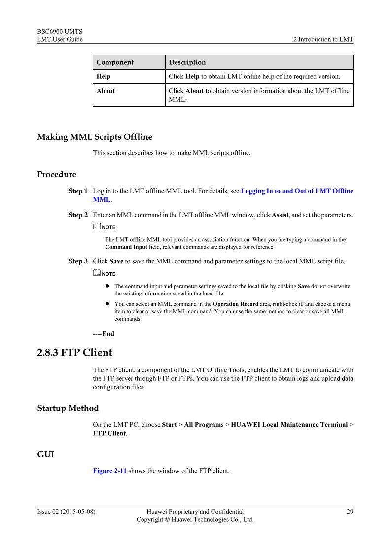
Component Description
Help Click Help to obtain LMT online help of the required version.
About Click About to obtain version information about the LMT offlineMML.
Making MML Scripts Offline
This section describes how to make MML scripts offline.
Procedure
Step 1 Log in to the LMT offline MML tool. For details, see Logging In to and Out of LMT OfflineMML.
Step 2 Enter an MML command in the LMT offline MML window, click Assist, and set the parameters.
NOTE
The LMT offline MML tool provides an association function. When you are typing a command in theCommand Input field, relevant commands are displayed for reference.
Step 3 Click Save to save the MML command and parameter settings to the local MML script file.
NOTE
l The command input and parameter settings saved to the local file by clicking Save do not overwritethe existing information saved in the local file.
l You can select an MML command in the Operation Record area, right-click it, and choose a menuitem to clear or save the MML command. You can use the same method to clear or save all MMLcommands.
----End
2.8.3 FTP ClientThe FTP client, a component of the LMT Offline Tools, enables the LMT to communicate withthe FTP server through FTP or FTPs. You can use the FTP client to obtain logs and upload dataconfiguration files.
Startup Method
On the LMT PC, choose Start > All Programs > HUAWEI Local Maintenance Terminal >FTP Client.
GUI
Figure 2-11 shows the window of the FTP client.
BSC6900 UMTSLMT User Guide 2 Introduction to LMT
Issue 02 (2015-05-08) Huawei Proprietary and ConfidentialCopyright © Huawei Technologies Co., Ltd.
29

Figure 2-11 FTP Client window
Table 2-11 describes the components of the FTP Client window.
Table 2-11 Components of the FTP Client window
Number Component Description
1 Menu bar Provides entries for system operations.
2 Toolbar Provides the shortcut icons for system operations.
3 Server input area Includes the server name, user name, password, portnumber, and mode.NOTE
To query the port number, run the LST FTPSSRVcommand and obtain the setting for the Command Port ofFTPS Server. If an incorrect port number is used, the LMTcannot be connected to the FTP server.
4 Local directory listwindow
Displays the directory structure of the currentcomputer.
5 Server file list window Lists the files and file folders stored in the connectedFTP server.
6 Local file list window Lists the files and file folders stored in the currentcomputer.
7 Prompt informationwindow
Displays information, such as the connection statusof the FTP server and the operation descriptions.
BSC6900 UMTSLMT User Guide 2 Introduction to LMT
Issue 02 (2015-05-08) Huawei Proprietary and ConfidentialCopyright © Huawei Technologies Co., Ltd.
30

2.8.4 Convert Management SystemThe Convert Management System is a component of the LMT Offline Tools. It enablescommunication between the OMU and the alarm box and is used to transfer the alarminformation, alarm box control information, and alarm box status information. To connect theLMT to the alarm box, the Convert Management System must be started. The ConvertManagement System uses the Ethernet port to communicate with the OMU and the serial portto communicate with the alarm box.
FunctionThe Convert Management System provides the following functions:l Forwards alarm operation instructions from the LMT.l Forwards alarm information to the alarm box.l Detects the real-time status of the connection between the LMT and the OMU and that
between the LMT and the serial port of the alarm box, and reports alarms if any.
Startup MethodNOTE
If Microsoft Visual C++ 2005 SP1 Redistributable Package (X86) is not installed on the LMT PC, theConvert Management System cannot start. Download this package from www.microsoft.com.
On the LMT PC, choose Start > All Programs > HUAWEI Local Maintenance Terminal >Convert Management System.
GUIFigure 2-12 shows the window of the Convert Management System.
Figure 2-12 Convert Management System window
BSC6900 UMTSLMT User Guide 2 Introduction to LMT
Issue 02 (2015-05-08) Huawei Proprietary and ConfidentialCopyright © Huawei Technologies Co., Ltd.
31

Table 2-12 describes the components of the Convert Management System window.
Table 2-12 Components of the Convert Management System window
Number Component Description
1 Menu bar Provides entries for system operations.
2 Toolbar Provides the shortcut icons for system operations.
3 Information outputwindow
Displays the real-time output of the ConvertManagement System.
2.8.5 Performance Browser ToolThe Performance Browser Tool, a component of the LMT Offline Tools, is used to parsedescriptive performance files in the OMU.
Startup MethodOn the LMT PC, choose Start > All Programs > HUAWEI Local Maintenance Terminal >Performance Browser Tool.
GUIFigure 2-13 shows the window of the Performance Browse Tool.
Figure 2-13 Performance Browse Tool window
BSC6900 UMTSLMT User Guide 2 Introduction to LMT
Issue 02 (2015-05-08) Huawei Proprietary and ConfidentialCopyright © Huawei Technologies Co., Ltd.
32

The Table 2-13 describes the components of the Performance Browse Tool window.
Table 2-13 Components of the Performance Browse Tool window
Number Component Description
1 Menu bar Provides entries for system operations.You can click Help to obtain information about howto use the tool.
2 Toolbar Provides the shortcut icons for system operations.
3 Measurementstatistics window
Provides statistical measurement files in a treestructure.
4 Detailed informationwindow
Displays the detailed information about a selectedperformance counter file.
2.8.6 TrafficRecording Review ToolThe TrafficRecording Review Tool, a component of the LMT Offline Tools, is used to reviewtrace and monitor data.
Startup MethodOn the LMT PC, choose Start > All Programs > Huawei Local Maintenance Terminal >TrafficRecording Review Tool.
GUIFigure 2-14 shows the window of the TrafficRecording Review Tool.
BSC6900 UMTSLMT User Guide 2 Introduction to LMT
Issue 02 (2015-05-08) Huawei Proprietary and ConfidentialCopyright © Huawei Technologies Co., Ltd.
33

Figure 2-14 TrafficReview window
Table 2-14 describes the components of the TrafficReview window.
Table 2-14 Components of the TrafficReview window
Number Component Description
1 Menu bar Provides entries for system operations.
2 Toolbar Provides the shortcut icons for system operations.
3 Service data retrievalwindow
Displays trace and monitor tasks.
BSC6900 UMTSLMT User Guide 2 Introduction to LMT
Issue 02 (2015-05-08) Huawei Proprietary and ConfidentialCopyright © Huawei Technologies Co., Ltd.
34

3 Operation Rights Management
About This Chapter
This chapter describes principles of managing operation rights, user accounts, and commandgroups.
3.1 Concepts Related to Operation Rights ManagementThis section describes concepts related to operation rights management, including principles ofoperation rights management, command groups, user types, operation rights, user passwords,and operation time limits.
3.2 Management of User AccountsThis section describes how to create, modify, and delete external user accounts on theBSC6900 LMT.
3.3 Management of User PasswordsThis section describes how to define and query login password policies, change the passwordof an active user, or change the password of an external user account.
3.4 Management of Command GroupsThis section describes how to query and rename command groups and how to change commandsin a command group.
BSC6900 UMTSLMT User Guide 3 Operation Rights Management
Issue 02 (2015-05-08) Huawei Proprietary and ConfidentialCopyright © Huawei Technologies Co., Ltd.
35

3.1 Concepts Related to Operation Rights ManagementThis section describes concepts related to operation rights management, including principles ofoperation rights management, command groups, user types, operation rights, user passwords,and operation time limits.
3.1.1 Principles of Operation Rights ManagementThis section describes principles of managing the operation rights of the BSC6900 LMT in termsof user identities, operation rights, and operation time limits.
The operation and maintenance (O&M) subsystem of the BSC6900 allows multiple users toperform operations concurrently. For system security reasons, the following aspect of operationrights must be managed and controlled:
l User identities:
A user must enter a correct user name and password to log in to the system.
l User rights:
Users of different levels are permitted to use different command groups for GUI or MMLcommand operations.
l Operation time limits:
An operation limit specifies the times when a user is permitted to perform operations.
3.1.2 User PasswordsThis section describes user passwords of the BSC6900 LMT. It includes definitions, the defaultpassword, initial password settings, and permissions required to change passwords.
Definition of User Passwords
To ensure system security, each user account is password protected. A user must enter a validuser name and correct password to log in to the LMT and then the OMU.
ADMINISTRATOR-level users can set password complexity. For details, see Setting PasswordPolicies.
Default Password
The default password for user admin is mbsc@com.
Initial Password Setting
The password of user admin is set during the installation of the OMU software. User admin,ADMINISTRATOR-level users, and authorized CUSTOM-level users can create external useraccounts and set passwords for these accounts.
BSC6900 UMTSLMT User Guide 3 Operation Rights Management
Issue 02 (2015-05-08) Huawei Proprietary and ConfidentialCopyright © Huawei Technologies Co., Ltd.
36

Permissions to Change Passwords
All users can change their own passwords. User admin, ADMINISTRATOR-level users, andauthorized CUSTOM-level users can change the passwords of all external user accounts. Tochange the password of user admin, run the MOD OP command on the U2000.
For details, see 3.3.3 Changing the Password of the Active User Account and 3.3.4 Changingthe Password of an External User Account.
3.1.3 Command GroupsThe BSC6900 provides 15 command groups (G_0 to G_14) with different functions.
Table 3-1 describes these command groups.
Table 3-1 Command groups
Command Group Function
G_0 Used to query system information, such as user groups, commandgroups, logs, Network Time Protocol (NTP), elementmanagement system (EMS), and time zone.
G_1 Used to manage system information, such as user groups, timezone, Daylight Saving Time (DST), and batch configuration.
G_2 Used to query configuration information. These commandsusually start with LST.
G_3 Used to configure data, for example, to configure data for a newlyadded board.
G_4 Used to query alarm information.
G_5 Used to manage alarms, for example, to manually clear alarms orto set alarm severity.
G_6 Used to query performance statistics, for example, to query aperformance statistical file or task file.
G_7 Used to manage performance, for example, to activate aperformance task file or to upload a performance statistical file.
G_8 Used to query equipment information, such as equipment status.These commands usually start with DSP.
G_9 Used to manage equipment, for example, to reset, block,unblock, or switch over boards.
G_10 Used to trace or monitor the signaling flows on the control planeand the user plane, for example, to query the trace tasks or tocreate/delete/start a trace task.
G_11 Used to modify settings of integrated equipment panels.
G_12 Used to manage software, for example, to manage patches.
BSC6900 UMTSLMT User Guide 3 Operation Rights Management
Issue 02 (2015-05-08) Huawei Proprietary and ConfidentialCopyright © Huawei Technologies Co., Ltd.
37

Command Group Function
G_13 Used to query base station information, such as attributes andboards.
G_14 Used to manage base stations, for example, to manage basestation software or to reset base stations.
For operations related to these command groups, see 3.4 Management of CommandGroups.
3.1.4 User TypesYou can log in to the BSC6900 LMT as a Local user or an EMS user.l Local users:
Managed independently by the BSC6900 LMT. You can log in to the BSC6900 when youare installing the BSC6900 system or when the OMU is disconnected from the U2000. Useradmin is a default local user.
l EMS users:Managed by the U2000. They are created, modified, authenticated, and authorized by theU2000. Only authorized EMS users can log in to the BSC6900 using the LMT. ForBSC6900 operations, authorized EMS users can also log in to the U2000 server throughthe U2000 client.
3.1.5 Operation RightsThis section describes operation rights of the admin account and external user accounts of theBSC6900 LMT.
Built-In Administrator AccountUser admin is a built-in administrator account, also termed super administrator. The passwordof this user is set during the installation of the OMU.
The admin account is an administrator-level account and cannot be modified or deleted.
External User AccountsThere are five types of external user accounts. Each type of external user accounts is granteddifferent operation rights, which are described in Table 3-2.
BSC6900 UMTSLMT User Guide 3 Operation Rights Management
Issue 02 (2015-05-08) Huawei Proprietary and ConfidentialCopyright © Huawei Technologies Co., Ltd.
38
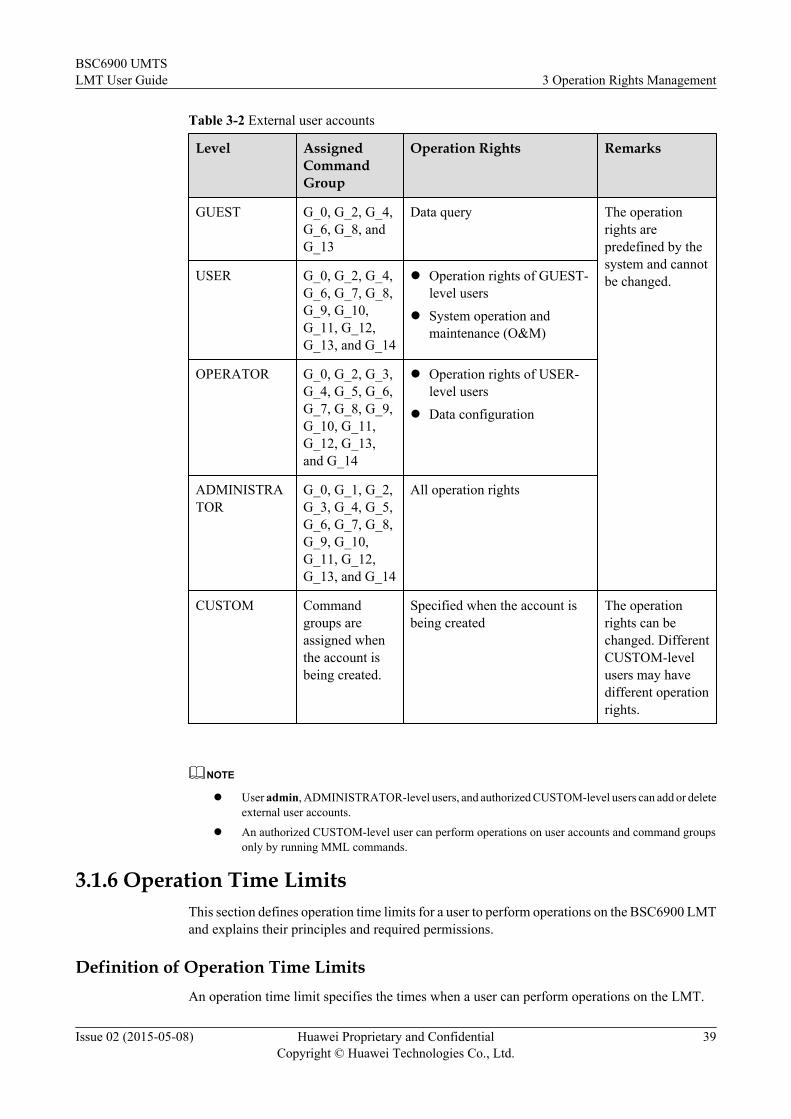
Table 3-2 External user accounts
Level AssignedCommandGroup
Operation Rights Remarks
GUEST G_0, G_2, G_4,G_6, G_8, andG_13
Data query The operationrights arepredefined by thesystem and cannotbe changed.USER G_0, G_2, G_4,
G_6, G_7, G_8,G_9, G_10,G_11, G_12,G_13, and G_14
l Operation rights of GUEST-level users
l System operation andmaintenance (O&M)
OPERATOR G_0, G_2, G_3,G_4, G_5, G_6,G_7, G_8, G_9,G_10, G_11,G_12, G_13,and G_14
l Operation rights of USER-level users
l Data configuration
ADMINISTRATOR
G_0, G_1, G_2,G_3, G_4, G_5,G_6, G_7, G_8,G_9, G_10,G_11, G_12,G_13, and G_14
All operation rights
CUSTOM Commandgroups areassigned whenthe account isbeing created.
Specified when the account isbeing created
The operationrights can bechanged. DifferentCUSTOM-levelusers may havedifferent operationrights.
NOTE
l User admin, ADMINISTRATOR-level users, and authorized CUSTOM-level users can add or deleteexternal user accounts.
l An authorized CUSTOM-level user can perform operations on user accounts and command groupsonly by running MML commands.
3.1.6 Operation Time LimitsThis section defines operation time limits for a user to perform operations on the BSC6900 LMTand explains their principles and required permissions.
Definition of Operation Time LimitsAn operation time limit specifies the times when a user can perform operations on the LMT.
BSC6900 UMTSLMT User Guide 3 Operation Rights Management
Issue 02 (2015-05-08) Huawei Proprietary and ConfidentialCopyright © Huawei Technologies Co., Ltd.
39

l No operation limits are imposed on user admin. User admin can perform operations onthe LMT at any time.
l An operation time limit can be set for an external user account when the account is beingcreated. If no time limits are set for the account, the account can perform operations on theLMT at any time.
Principle of Operation Time Limits
An operation time limit is defined by date, day, and time.
Table 3-3 provides some examples of operation time limits.
Table 3-3 Examples of operation time limits
SN Date Day Time Permitted Operation Time
1 2013-02-01to2014-02-01
Monday toFriday
8:00:00 to18:00:00
8:00:00 to 18:00:00 on Mondaythrough Friday from 2013-02-01to 2014-02-01
2 - Saturday andSunday
- Any time on Saturdays andSundays
3 - - - No operation time limits areimposed on the user. A user withthis setting can perform operationson the LMT at any time.
Permissions to Set Operation Time Limits
User admin, ADMINISTRATOR-level users, and authorized CUSTOM-level users can set orchange operation time limits of all external user accounts.
3.2 Management of User AccountsThis section describes how to create, modify, and delete external user accounts on theBSC6900 LMT.
3.2.1 Creating an External User AccountThis section describes how to create an external user account. You are required to set a password,a user type, an operation time limit, and command groups (for CUSTOM-level users only) forthe new user account. Only user admin, ADMINISTRATOR-level users, and some CUSTOM-level users are authorized to create external user accounts.
PrerequisitesYou have logged in to the LMT with an authorized account.
BSC6900 UMTSLMT User Guide 3 Operation Rights Management
Issue 02 (2015-05-08) Huawei Proprietary and ConfidentialCopyright © Huawei Technologies Co., Ltd.
40

Procedure
Step 1 Run the ADD OP command to create an external user account.
NOTICEThe new external user account must be different from any of the existing user accounts.
----End
3.2.2 Modifying an External User AccountThis section describes how to modify the attributes of an external user account, including theuser name, user password, user level, operation rights, and operation time limit. The newpassword takes effect at the next login. Modifications of other attributes take effect immediately.Only user admin, ADMINISTRATOR-level users, and some CUSTOM-level users areauthorized to modify external user accounts.
PrerequisitesYou have logged in to the LMT with an authorized account.
Procedure
Step 1 Run the MOD OP command to modify the attributes of an external user account.
----End
3.2.3 Deleting an External User AccountThis section describes how to delete an external user account. Only user admin,ADMINISTRATOR-level users, and some CUSTOM-level users are authorized to deleteexternal user accounts.
Context
NOTICEUser admin is the permanent built-in user account and cannot be deleted.
Procedure
Step 1 Run the RMV OP command to delete an external user account.
----End
BSC6900 UMTSLMT User Guide 3 Operation Rights Management
Issue 02 (2015-05-08) Huawei Proprietary and ConfidentialCopyright © Huawei Technologies Co., Ltd.
41

3.3 Management of User PasswordsThis section describes how to define and query login password policies, change the passwordof an active user, or change the password of an external user account.
3.3.1 Defining Login Password PoliciesThis section describes how to define policies for setting login passwords. Login passwordpolicies set restrictions on the minimum length and complexity of a password. OnlyADMINISTRATOR-level users can define policies for setting login passwords.
PrerequisitesYou have logged in to the LMT with an authorized account.
Procedure
Step 1 Run the SET PWDPOLICY command to define policies for setting login passwords.
----End
3.3.2 Querying Login Password PoliciesThis section describes how to query policies for setting login passwords.
PrerequisitesYou have logged in to the LMT.
Procedure
Step 1 Run the LST PWDPOLICY command to query policies for setting login passwords.
----End
3.3.3 Changing the Password of the Active User AccountThis section describes how to change the password of the active user account. The new passwordtakes effect at the next login.
PrerequisitesYou have logged in to the LMT with an authorized account.
Procedure
Step 1 On the toolbar of the LMT main page, click Password. The Password dialog box is displayed.
Step 2 In the displayed Password dialog box, enter the current password in the Old Password field,enter the new password in the New Password and Confirm Password fields, and click OK.
BSC6900 UMTSLMT User Guide 3 Operation Rights Management
Issue 02 (2015-05-08) Huawei Proprietary and ConfidentialCopyright © Huawei Technologies Co., Ltd.
42

NOTE
You are advised to change the password at your first login and then change the password every three months.
----End
3.3.4 Changing the Password of an External User AccountThis section describes how to change the password of an external user account. Only useradmin, ADMINISTRATOR-level users, and authorized CUSTOM-level users can change thepassword of an external user account.
PrerequisitesYou have logged in to the LMT with an authorized account.
Procedure
Step 1 Run the MOD OP command to change the password of an external user account.
----End
3.4 Management of Command GroupsThis section describes how to query and rename command groups and how to change commandsin a command group.
3.4.1 Querying a Command GroupThere are 16 command groups G_0 to G_14 and G_NICThere are 13 command groups G_0 toG_12. Only the admin, ADMINISTRATOR-level, and authorized CUSTOM-level users canquery the information about the command groups.
PrerequisitesYou have logged in to the LMT with an account authorized for this operation.
Procedure
Step 1 Run the LST CCG to query the command groups.
----End
3.4.2 Renaming Command GroupsThis section describes how to rename command groups. Only user admin, ADMINISTRATOR-level users, and authorized CUSTOM-level users can rename command groups.
PrerequisitesYou have logged in to the LMT with an authorized account.
BSC6900 UMTSLMT User Guide 3 Operation Rights Management
Issue 02 (2015-05-08) Huawei Proprietary and ConfidentialCopyright © Huawei Technologies Co., Ltd.
43

Procedure
Step 1 Run the LST CCGN command to query the name of a command group.
Step 2 Run the SET CCGN command to rename the command group.
----End
3.4.3 Changing Commands in a Command GroupThis section describes how to change commands in a command group. Only user admin,ADMINISTRATOR-level users, and authorized CUSTOM-level users can change commandsin a command group.
PrerequisitesYou have logged in to the LMT with an authorized account.
Procedurel Run the ADD CCG command to add commands to a command group.l Run the RMV CCG command to remove commands from a command group.
----End
BSC6900 UMTSLMT User Guide 3 Operation Rights Management
Issue 02 (2015-05-08) Huawei Proprietary and ConfidentialCopyright © Huawei Technologies Co., Ltd.
44

4 Running MML Commands
About This Chapter
This chapter describes how to run MML commands on the LMT for operation and maintenanceof the BSC6900.
4.1 Concepts Related to MML CommandsThis section presents an introduction to MML commands, components of the MML commandwindow, data configuration rights, and configuration rollback.
4.2 Running a Single MML CommandThis section describes how to run a single MML command for routine configuration andmaintenance.
4.3 Batch Processing of MML CommandsThis section describes how to run multiple MML commands simultaneously. Batch processingof MML commands allows you to use a function or perform an operation by running a preparedgroup of MML commands all at the same time.
4.4 Setting MML ParametersThis section describes how to set the MML parameters as required.
4.5 Querying Data Configuration ModesThis section describes how to query the data configuration mode of a subrack. The dataconfiguration mode can be effective or non-effective.
4.6 Querying Data Configuration RightsThis section describes how to query the status of data configuration rights.
4.7 Obtaining Data Configuration RightsThis section describes how to obtain exclusive data configuration rights when you plan toperform data configuration, undo/redo operations on the BSC6900, or perform batch dataconfiguration without being affected by other users. Only the U2000 users and users of thefollowing types can obtain these data configuration rights: admin, ADMINISTRATOR-levelusers, OPERATOR-level users, and CUSTOM-level users entitled to use command group G_3(used for data configuration).
4.8 Undoing/Redoing a Single Data Configuration ActionThis section describes how to undo and redo a single data configuration action.
BSC6900 UMTSLMT User Guide 4 Running MML Commands
Issue 02 (2015-05-08) Huawei Proprietary and ConfidentialCopyright © Huawei Technologies Co., Ltd.
45

4.9 Undoing/Redoing Multiple Data Configuration ActionsThis section describes how to undo and redo multiple data configuration actions at a time.
BSC6900 UMTSLMT User Guide 4 Running MML Commands
Issue 02 (2015-05-08) Huawei Proprietary and ConfidentialCopyright © Huawei Technologies Co., Ltd.
46

4.1 Concepts Related to MML CommandsThis section presents an introduction to MML commands, components of the MML commandwindow, data configuration rights, and configuration rollback.
4.1.1 Introduction to MML CommandsThis section describes MML commands used for operation and maintenance of the BSC6900.
An MML command consists of two parts, an action and an object. For example, ADD OP,wherein ADD is the action part and OP is the object part. Table 4-1 describes actions that canbe performed by MML commands.
Table 4-1 Actions of the MML commands
Action Description
ACT Activate
ADD Add
ADT Audit
BEG Begin
BKP Back up
BLK Block
CHK Check
CLR Clear
CMP Compare
COL Collect
CON Confirm
DEA Deactivate
DLD Download
DSP List
EST Establish
EXP Export
FMT Format
FOC Obtain
HO Hand over
BSC6900 UMTSLMT User Guide 4 Running MML Commands
Issue 02 (2015-05-08) Huawei Proprietary and ConfidentialCopyright © Huawei Technologies Co., Ltd.
47

Action Description
INH Inhibit
INS Install
LCK Lock
LOD Load
LOP Loopback test
LST List
MOD Modify
PING Ping
REL Release
REQ Request
RUN Run
RMV Remove
RST Reset
SET Set
STR Start/Open
STP Stop/Close
STA Collect statistics
SWP Swap
SYN Synchronize
TRC Trace
UBL Unblock
UIN Uninhibit
ULD Upload
ULK Unlock
4.1.2 Components of the MML Command WindowThis section describes the components of the MML command window.
Figure 4-1 shows the MML command window.
BSC6900 UMTSLMT User Guide 4 Running MML Commands
Issue 02 (2015-05-08) Huawei Proprietary and ConfidentialCopyright © Huawei Technologies Co., Ltd.
48

Figure 4-1 MML command window
Table 4-2 describes the components of the MML command window.
Table 4-2 MML command window
Number Component Description
1 CommonMaintenance (Alt+C) tab page
Displays system responses, such as command results.You can save command results and automatically scrollthrough the command results by clicking Save Resultsand Auto Scroll, respectively. You can also clear allcommand results by clicking Clear All.NOTE
l The time information displayed at the beginning ofcommand results is the system time of the OMU.
l When you click Save Results, command results of onlyselected MML commands are saved.
2 Operation Record(Alt+R) tab page
Displays commands that have been run.NOTE
The Send Time in an operation record is the system time of theLMT PC.
3 Help Information(Alt+N) tab page
Displays the help information of MML commands.
4 Manual editing area Displays manually input MML commands and theirparameters.
BSC6900 UMTSLMT User Guide 4 Running MML Commands
Issue 02 (2015-05-08) Huawei Proprietary and ConfidentialCopyright © Huawei Technologies Co., Ltd.
49

Number Component Description
5 History Commandfield
Displays all commands executed during the current loginand relevant parameters.
6 Command Inputfield
Displays all the MML commands available on the systemin the drop-down list. You can select an MML commandfrom the drop-down list or enter an MML command.
7 Parameter area Displays parameters of a selected or an input command.Before running the command, set parameters for it.Parameters in red are mandatory. Those in black areoptional.
NOTE
For details of MML commands and parameters, see the MML help.
4.1.3 Data Configuration RightsTo avoid data conflict, the OMU manages data configuration rights to allow only one user toperform BSC6900 data configuration through the LMT or the U2000 at any time.
The OMU manages data configuration rights as follows:
l By default, all users have data configuration rights.
l When a user runs the LCK CMCTRL command, data configuration rights are exclusiveto this user.
l When the user runs the ULK CMCTRL command, data configuration rights becomeavailable to all users.
l If a user occupies exclusive data configuration rights for a long time but does not configuredata, administrators can run the FOC CMCTRL command to forcibly release the dataconfiguration rights to all users.
l If a user who had exclusive data configuration rights exits from the LMT, the dataconfiguration rights will be automatically made available to all users.
4.1.4 Data Configuration RollbackIf a data configuration operation fails to achieve the expected result or even causes equipmentor network problems, you can roll back the configuration to restore the system to a previousconfiguration status. The data configuration rollback function ensures that the operating of theBSC6900 is restored to normal as soon as possible.
Definition of Data Configuration Rollback
During data configuration, a rollback point is used to mark a data configuration status. You canrun the ADD ROLLBACKPOINT command to manually configure rollback points.
When data configuration rollback is required, you can select a rollback point to restore the systemto a specific configuration status as required.
BSC6900 UMTSLMT User Guide 4 Running MML Commands
Issue 02 (2015-05-08) Huawei Proprietary and ConfidentialCopyright © Huawei Technologies Co., Ltd.
50

Operations of Data Configuration Rollback
NOTICEA user cannot perform data configuration rollback in any of the following cases:l The user does not obtain the data configuration rights because another user who has
occupied exclusive data configuration rights does not release the data configuration rightsby running the ULK CMCTRL command.
l The quick configuration mode has been enabled by running the SET QUICKCFGcommand.
l Batch configuration is performed by running the RUN BATCHFILE command.
The following data configuration rollback operations are available:l Undo a single configuration action:
This operation is performed to undo a previous configuration action. Up to 10 of the mostrecent effective configuration actions can be undone.
l Redo a single configuration action:This operation is performed to redo a previously undone configuration action. Up to 10 ofthe most recent effective configuration actions can be redone.
l Undo multiple configuration actions:This operation is performed to simultaneously undo multiple configuration actions thathave taken effect. After the undo operation, the system is restored to the configuration statusat a specified rollback point.
l Redo multiple configuration actions:This operation is performed to simultaneously redo multiple configuration actions that havebeen undone. After the redo operation, the system is restored based on either theconfiguration status at the specified rollback point or the final configuration status frombefore undoing the configurations.
4.2 Running a Single MML CommandThis section describes how to run a single MML command for routine configuration andmaintenance.
PrerequisitesYou have logged in to the LMT.
ContextTo run an MML command, you can:l Enter an MML command in the Command Input field.l Select a previously executed command from the History Command drop-down list.l Select an MML command from the MML Command navigation tree.
BSC6900 UMTSLMT User Guide 4 Running MML Commands
Issue 02 (2015-05-08) Huawei Proprietary and ConfidentialCopyright © Huawei Technologies Co., Ltd.
51

l Copy an MML command script to the Manual Editing area.
Procedurel Entering an MML command in the Command Input field
1. Enter an MML command in the Command Input field. When you are entering acommand, related commands are displayed in a drop-down list. You can select therequired command from the drop-down list.
2. Press Enter or click Assist to display parameters associated with the command.
3. Specify parameter values.
4. Press F9 or click Exec to run the command. The command result is displayed on theCommon Maintenance tab page.
l Selecting a previously executed command from the History Command drop-down list
1. Select a previously executed command from the drop-down list of history commands.(Press F7 or click to select the previous command. Press F8 or click toselect the next command.)
2. (Optional) Change parameter values in the command parameter area.
3. Press F9 or click Exec to run the command. The command result is displayed on theCommon Maintenance tab page.
l Selecting an MML command from the MML Command navigation tree
1. Double-click an MML command in the MML Command navigation tree.
2. Specify parameter values.
3. Press F9 or click Exec to run the command. The command result is displayed on theCommon Maintenance tab page.
NOTE
l Parameters in red are mandatory. Those in black are optional.
l To obtain general information about a parameter, place the cursor on the input box for theparameter.
l If the execution of a command fails, the command result displayed on the CommonMaintenance tab page is in red.
l Copying an MML command script to the Manual Edit area
1. Copy an MML command script with required parameter values and paste it to theManual Edit area.
2. Press F9 or click Exec to run the command. The command result is displayed on theCommon Maintenance tab page.
----End
4.3 Batch Processing of MML CommandsThis section describes how to run multiple MML commands simultaneously. Batch processingof MML commands allows you to use a function or perform an operation by running a preparedgroup of MML commands all at the same time.
BSC6900 UMTSLMT User Guide 4 Running MML Commands
Issue 02 (2015-05-08) Huawei Proprietary and ConfidentialCopyright © Huawei Technologies Co., Ltd.
52

Context
A batch file (also called data script file) is a plain text file, which contains a group of commandscripts used for conducting a specific task. The command scripts in a batch file are executed insequence.
The following two batch processing modes are available:
l Immediate batch processing:
A batch file is run immediately.
l Scheduled batch processing:
A batch file is automatically run at a specific time set by users in advance.
NOTE
When the LMT locks its operation screen, the following commands will fail:
l ADD OP, RMV OP, and MOD OP
l SET OPLOCK
l SET OPSW
l SET PWDPOLICY
l ULK USR
l SET WEBLOGINPOLICY
4.3.1 Immediate Batch Processing of MML CommandsThis section describes how to enable the system to immediately run a group of MML commandsin a batch file simultaneously.
Prerequisitesl You have logged in to the LMT.
l You have obtained the required data configuration rights. For details, see 4.7 ObtainingData Configuration Rights.
Procedure
Step 1 On the LMT main page, click Batch. The Batch tab page is displayed.
Step 2 In the editing area, click New and enter the MML commands to be executed at a time, or clickOpen... to select the prepared batch file.
NOTE
If an encrypted .ecf file is selected, enter the password of the file to import the file for batch processing.
Step 3 Click Settings to set parameters.
Step 4 Click Go to run the commands.
NOTE
You can set Execution Type. By default, Prompt when an error occurs is selected. You are advised to retainthe default setting.
----End
BSC6900 UMTSLMT User Guide 4 Running MML Commands
Issue 02 (2015-05-08) Huawei Proprietary and ConfidentialCopyright © Huawei Technologies Co., Ltd.
53

4.3.2 Scheduled Batch Processing of MML CommandsThis section describes how to enable the system to automatically run a batch of MML commandsin a batch file at a moment of a day specified by an operator in advance.
Prerequisitesl You have logged in to the LMT.
l You have obtained FTP user name and password.
l You have obtained the data configuration rights. For details, see 4.7 Obtaining DataConfiguration Rights.
Procedure
Step 1 Edit a batch file.
1. Click Batch on the LMT main page. The Batch tab page is displayed.
2. Click New and type a batch of MML commands in the input box.
3. Click Save to save the edited batch file.
Step 2 Upload the MML command script file to the /ftp directory in the OMU active work area. Assumethat the MML command script file BATCHFILE.txt saved in disk D is uploaded to the /bam/version_a/ftp directory in the OMU active work area. When the active workspace of the OMUis version_a, the following path changes into version_a. When the active workspace of theOMU is version_b, the following path changes into version_b accordingly. There are thefollowing two upload ways:
l Through File Manager on the LMT
1. Start File Manager by referring to File Manager.
2. Choose Root > bam > version_a > ftp in the left area of the displayed window tonavigate to the ftp directory. Then click Upload.
3. In the displayed Select Upload File dialog box, select the BATCHFILE.txt file savedin local disk D and click Open to upload the file.
l Through command lines
1. On a local LMT PC, choose Start > Run, enter cmd, and click OK.
2. Type the d: command and press Enter to switch the local disk to disk D.
3. Enter the ftp IP address command to apply for connection to the OMU. IP address isthe IP address of the OMU.
4. Enter the FTP user name and password. If the authentication passes, an FTP connectionis established between the local PC and the OMU.
NOTE
The FTP user name must be the fixed value FtpUsr. The FTP password was set during installation ofproduct software. You can run the MOD FTPPWD command to change the password.
5. Enter the cd /bam/version_a/ftp command to switch to the directory of OMU activework area.
6. Enter the put BATCHFILE.txt command to upload the file.
7. Enter the quit command to disconnect FTP connection when the file upload is complete.
BSC6900 UMTSLMT User Guide 4 Running MML Commands
Issue 02 (2015-05-08) Huawei Proprietary and ConfidentialCopyright © Huawei Technologies Co., Ltd.
54

Step 3 Add scheduled batch processing tasks by running the ADD SCHTSK and ADD SUBTSKcommands.
NOTE
l Add scheduled batch processing tasks ADD SCHTSK: ID=1, TSKN="batch"; ADD SUBTSK: ID=1, TSKN="batch", SUBID=2, SCMD="RUN BATCHFILE: SRCF=\"BATCHFILE.txt\", TYPE=ALL_END_RETURN, RSTF=\"result_add.txt\"", FREQ=ONTIME, SD=2010&08&30, TM=09&56;
l BATCHFILE.txt is the name of a batch file that needs to be run at a scheduled time and saved in the ftpdirectory of the OMU active work area; result_add.txt is the name of the result file.
----End
4.3.3 Syntax CheckThis section describes how to check the syntax of MML commands before running a group ofMML commands. This function helps locate incorrect MML commands, thereby improvingmaintenance efficiency.
Prerequisitesl You have logged in to the LMT.l A batch file is available.
ContextThe syntax check can locate the following errors:
l Missing colonl Missing semicolonl Incorrect MML commandl No authority to execute a correct MML commandl Redundant parametersl Incorrect parameters
Procedure
Step 1 Click New to create a batch file and input MML commands in the manual editing area.
NOTE
You can click Open... to open a prepared batch file.
If an encrypted .ecf file is selected, enter the password of the file to import the file for batch processing.
Step 2 Click Analyze Syntax to check the syntax of the batch file.
BSC6900 UMTSLMT User Guide 4 Running MML Commands
Issue 02 (2015-05-08) Huawei Proprietary and ConfidentialCopyright © Huawei Technologies Co., Ltd.
55

NOTE
l If no errors occur, the Information dialog box is displayed, indicating that no syntactical errors occur.If an error occurs, the Result dialog box is displayed, indicating a line number for locating the errorand error reasons for correcting the error.
l To go to the command line with a syntactical error, double-click the information in the Result dialogbox.
l After Analyze Syntax is executed, a mark is displayed in front of a command line with syntactical
errors in the batch file. If you move the mouse to the mark in front of a command line, errorinformation is displayed.
l To check a single MML command line for syntactical errors in a batch file, select a single MMLcommand line, right-click it, and choose Analyze Current Line from the shortcut menu.
Step 3 In the Result dialog box, click Save As... to save the result.
Step 4 Click Close.
----End
Follow-up ProcedureTo clear all syntactical analysis marks in a batch file, right-click in the batch file and chooseClear Analyze Mark from the shortcut menu.
4.4 Setting MML ParametersThis section describes how to set the MML parameters as required.
Procedure
Step 1 On the Common Maintenance tab page in the MML window, click Settings. The Settingsdialog box is displayed, as shown in Figure 4-2.
Figure 4-2 Setting MML Parameters
BSC6900 UMTSLMT User Guide 4 Running MML Commands
Issue 02 (2015-05-08) Huawei Proprietary and ConfidentialCopyright © Huawei Technologies Co., Ltd.
56

Step 2 Set parameters as required.
Step 3 Click OK to save the settings.
NOTE
The parameter settings in System and MML Command are stored on the server and client, respectively.Therefore, after the BSC resets or restarts, the parameter setting in System is restored to the default value butthe parameter settings in MML Command remain unchanged.
----End
4.5 Querying Data Configuration ModesThis section describes how to query the data configuration mode of a subrack. The dataconfiguration mode can be effective or non-effective.
Prerequisites
You have logged in to the LMT.
Context
When a subrack is in effective mode, data configured for the subrack takes effect immediately.
When a subrack is in non-effective mode:
l Data configured for the subrack takes effect only for the OMU, not on the subrack.
To make the data configuration take effect on the subrack, perform the followingoperations: Run the SET CFGDATAEFFECTIVE command to set the data configurationmode to effective mode, run the FMT DATA command to generate the data configurationfile for the subrack, and then run the RST SUBRACK command to reset the subrack. Inthis way, the subrack can load the data configuration from the OMU so that the data takeseffect on the subrack.
l You cannot query, compare, or perform CRC check on the host and OMU data. In addition,
l You cannot configure the host data of the subrack.
When all subracks are in non-effective mode, license verification is not performed. When asubrack attempts to switch the data configuration mode from the non-effective mode to theeffective mode, the OMU checks whether the data configuration exceeds the limitations of thelicense. If the data configuration exceeds the limitations of the license, the mode switching willfail.
When the OMU is newly installed, subrack 0 is in non-effective mode by default. When a subrackis newly added, it is in non-effective mode by default.
NOTE
You can use menus or MML commands to query the data configuration mode.
Procedurel Using menus
BSC6900 UMTSLMT User Guide 4 Running MML Commands
Issue 02 (2015-05-08) Huawei Proprietary and ConfidentialCopyright © Huawei Technologies Co., Ltd.
57

1. On the LMT main page, check the configuration mode of a subrack from the drop-down list on the tool bar, as shown in Figure 4-3.
Figure 4-3 Data configuration mode
l Using MML commands
1. Run the LST CFGMODE command to query the current data configuration mode.
----End
4.6 Querying Data Configuration RightsThis section describes how to query the status of data configuration rights.
Prerequisites
You have logged in to the LMT.
Context
You can use menus or MML commands to query the status of data configuration rights.
Procedurel Using menus
1. Check the status of data configuration rights displayed at the top right corner of theLMT main page.
l Using MML commands
1. Run the LST CMCTRL command to query the status of data configuration rights.
----End
4.7 Obtaining Data Configuration RightsThis section describes how to obtain exclusive data configuration rights when you plan toperform data configuration, undo/redo operations on the BSC6900, or perform batch dataconfiguration without being affected by other users. Only the U2000 users and users of thefollowing types can obtain these data configuration rights: admin, ADMINISTRATOR-levelusers, OPERATOR-level users, and CUSTOM-level users entitled to use command group G_3(used for data configuration).
BSC6900 UMTSLMT User Guide 4 Running MML Commands
Issue 02 (2015-05-08) Huawei Proprietary and ConfidentialCopyright © Huawei Technologies Co., Ltd.
58

Prerequisitesl You have logged in to the LMT.
Contextl By default, all users have data configuration rights. They can use the LMT or U2000 to
configure data for the BSC6900.l Only one user can use the data configuration rights at any given time. You can run the
LCK CMCTRL command to obtain exclusive data configuration rights.l After the data configuration is complete, you can run the ULK CMCTRL command to
made the data configuration rights available to all users so that another user can run theLCK CMCTRL command obtain exclusive data configuration rights.
l If a user who had exclusive data configuration rights exits from the LMT, the dataconfiguration rights will be automatically made available to all users. In this case, anotheruser can also run the LCK CMCTRL command to obtain exclusive data configurationrights.
Procedure
Step 1 Check whether the data configuration rights are available. For details, see 4.6 Querying DataConfiguration Rights.l If no user has exclusive data configuration rights, go to Step 2.l If a user has exclusive data configuration rights, once that user releases those configuration
rights, go to Step 2.
Step 2 Run the LCK CMCTRL command to obtain the data configuration rights.
NOTE
If an LMT user has exclusive data configuration rights of the BSC6900, other LMT users cannot obtainthe data configuration rights. In this case, user admin or ADMINISTRATOR-level users can run theFOC CMCTRL command to forcibly release the locked data configuration rights.
----End
4.8 Undoing/Redoing a Single Data Configuration ActionThis section describes how to undo and redo a single data configuration action.
Prerequisitesl You have logged in to the LMT.l You have obtained data configuration rights by running the LCK CMCTRL command.l The quick configuration mode has been disabled by running the SET QUICKCFG
command.l No batch commands have been executed.
Contextl You can undo or redo a data configuration action to fine-tune data configuration. These
operations, however, can decrease the efficiency of running MML commands. Therefore,
BSC6900 UMTSLMT User Guide 4 Running MML Commands
Issue 02 (2015-05-08) Huawei Proprietary and ConfidentialCopyright © Huawei Technologies Co., Ltd.
59

when the quick configuration mode is enabled or when batch MML commands are running,do not undo or redo data configuration actions.
l To prevent data conflicts, a user can undo or redo a data configuration action only if theuser has obtained exclusive data configuration rights.
l Certain MML commands cannot be undone or redone. If you run such an MML command,the Undo and Redo buttons on the top of the LMT window becomes unavailable andconfiguration actions performed before running the MML command also cannot be undoneor redone. For a list of MML commands that can be undone or redone, see the descriptionof the ADD ROLLBACKPOINT command.
l The most recent 10 effective single configuration actions can be undone one at a time.Likewise, the 10 most recent undone operations can be redone in the same manner.
Procedurel Undoing a single configuration action
1. Use either of the following methods to undo the latest configuration action:
– On the toolbar of the LMT, click Undo.
– Run the BEG UNDO command.
2. To undo multiple configuration actions, repeat Step 1.
l Redoing a single configuration action
1. Use either of the following methods to redo an undone action:
– On the toolbar of the LMT, click Redo.
– Run the BEG REDO command.
2. To redo multiple configuration actions, repeat Step 1.
----End
4.9 Undoing/Redoing Multiple Data Configuration ActionsThis section describes how to undo and redo multiple data configuration actions at a time.
Prerequisitesl You have logged in to the LMT.
l You have obtained data configuration rights by running the LCK CMCTRL command.
l The quick configuration mode has been disabled by running the SET QUICKCFGcommand.
l No batch commands have been performed.
Contextl You can undo or redo multiple data configuration actions simultaneously to fine-tune data
configuration. These operations, however, can decrease the efficiency of running MMLcommands. Therefore, when the quick configuration mode is enabled or when batch MMLcommands are running, do not undo or redo multiple data configuration actions.
BSC6900 UMTSLMT User Guide 4 Running MML Commands
Issue 02 (2015-05-08) Huawei Proprietary and ConfidentialCopyright © Huawei Technologies Co., Ltd.
60

l To prevent data conflicts, a user can undo or redo multiple data configuration actionsimultaneously only if the user has exclusive data configuration rights.
l Certain MML commands do not support undoing or redoing multiple data configurationactions at a time. If you run such MML commands, the rollback point specified by runningthe ADD ROLLBACKPOINT command will become invalid and undoing multiple dataconfiguration actions at a time will fail. Therefore, before running such MML commands,remove the configured rollback point. For a list of MML commands that support undoingor redoing multiple configuration actions, see the description of the ADDROLLBACKPOINT command.
l Multiple configuration actions can be undone simultaneously. After a multiple undooperation is applied, the system is restored based on the configuration status from aspecified rollback point.
l Multiple configuration actions can be redone simultaneously. After the multiple actionshave been redone, the system is restored based on either the configuration status at thespecified rollback point or the final configuration status from before undoing theconfiguration actions.
NOTE
An initial rollback point is the first rollback point set by a user. The final rollback point is automaticallyset to the latest configuration command successfully executed. The LMT allows you to undo a maximumof 10,000 configuration commands from the initial rollback point to the final rollback point at a time. Ifthere are more than 10,000 commands from the initial rollback point to the final rollback point, the undoingoperation will fail and the LMT will display a failure message.
A user who has obtained the data configuration rights can set a maximum of five rollback points. If theuser releases the data configuration rights, the active workspace of the OMU will clear the informationabout the rollback stack and rollback points.
Procedure
Step 1 To undo/redo multiple data configuration actions simultaneously, before running configurationcommands, run the ADD ROLLBACKPOINT command to set rollback points as required.
Step 2 Run the BEG ROLLBACK command to restore the system to the configuration status at aspecified rollback point.
Step 3 Run the BEG FORWARD command to restore the system to the final configuration statusbefore undoing the configurations.
----End
BSC6900 UMTSLMT User Guide 4 Running MML Commands
Issue 02 (2015-05-08) Huawei Proprietary and ConfidentialCopyright © Huawei Technologies Co., Ltd.
61

5 Alarm/Event Management
About This Chapter
This section describes how to use the LMT to manage BSC6900 alarms/events. Alarm/eventmanagement helps you analyze alarms/events efficiently, thereby facilitating troubleshooting.
5.1 Concepts Related to Alarm ManagementThis section describes basic concepts related to alarm management, including the alarm type,alarm severity, alarm-managed objects, and alarm box.
5.2 Managing Alarm LogsAlarm logs are used to record alarm details. They are collected by the OMU and stored in theOMU database. To minimize storage requirements on the hard drive of the OMU, limitationsmust be imposed on the number and the storage duration of alarm logs.
5.3 Managing Alarm Masking ConditionsAlarms that meet alarm masking conditions are not reported to the LMT or U2000. These alarmscannot be queried on the LMT or U2000 but are still saved on the OMU. This section describeshow to manage alarm masking conditions.
5.4 Managing the Alarm Masking Switch of Derived AlarmsWhen a fault occurs, beside a fault alarm, some related alarms may be generated. These alarmsare termed derived alarms. The BSC6900 can mask derived alarms. By default, derived alarmsare not reported to the LMT. Unless otherwise specified, derived alarms are not stored on theOMU and cannot be queried.
5.5 Monitoring AlarmsThis section describes how to use the LMT to monitor alarm information in real time. The alarminformation is displayed in the Alarm Browse window on the LMT.
5.6 Managing the Alarm BoxThe BSC6900 uses Huawei universal alarm box to provide audible and visual indications whenan alarm is reported. The alarm box notifies maintenance engineers of alarms in time, therebyfacilitating operation and maintenance.
BSC6900 UMTSLMT User Guide 5 Alarm/Event Management
Issue 02 (2015-05-08) Huawei Proprietary and ConfidentialCopyright © Huawei Technologies Co., Ltd.
62

5.1 Concepts Related to Alarm ManagementThis section describes basic concepts related to alarm management, including the alarm type,alarm severity, alarm-managed objects, and alarm box.
5.1.1 Alarm TypeThe alarms in the BSC6900 system can be classified into fault alarms and event alarms.
Table 5-1 describes the two alarm types.
Table 5-1 Fault alarms and event alarms
Alarm Type Description
Fault alarm Fault alarms are caused by hardware faults or failures of major functions,for example, board fault or link fault. Fault alarms are of higher severitythan event alarms and are classified into active and cleared alarmsaccording to the fault status.
Event alarm Event alarms record predefined events occurring during the operation ofthe system. An event alarm reflects the system condition (for example,congestion) at a specific time, which is not necessarily a fault. Some eventalarms are generated repeatedly and regularly.
According to fault status, fault alarms are classified into:
l Cleared alarms:
If a fault has been rectified, the corresponding alarm becomes a cleared alarm.
l Active alarms:
If a fault has not been rectified, the corresponding alarm is an active alarm.
For example, when congestion occurs in a cell, the system reports a fault alarm of cellcongestion. Before the congestion is relieved, the alarm remains active. After the congestion isrelieved, the alarm becomes a cleared alarm.
NOTE
l Cleared alarms are stored in the OMU database and can be queried.
l In engineering and maintenance scenarios, such as site deployment, equipment commissioning,upgrades, capacity expansion, swapping, and cutover, a large number of alarms are reported in a shortperiod of time. Due to the absence of the mechanism for handling such alarms, the alarm burst makesit hard for users to identify real fault alarms, thereby disturbing network monitoring. To solve thisproblem, Huawei puts forward the concept of "maintenance mode alarms". Alarms triggered byengineering and maintenance operations are considered as maintenance mode alarms and handled ina special way. This mechanism streamlines alarm management and facilitates operation andmaintenance.
BSC6900 UMTSLMT User Guide 5 Alarm/Event Management
Issue 02 (2015-05-08) Huawei Proprietary and ConfidentialCopyright © Huawei Technologies Co., Ltd.
63

5.1.2 Alarm SeverityFour alarm severities are available for fault alarms and event alarms of the BSC6900: critical,major, minor, and warning.
Table 5-2 describes the four alarm severities.
Table 5-2 Alarm severities
Alarm Severity Definition HandlingRequirement
Critical Alarms of this severity are triggered by faults thataffect services provided by the system and mustbe handled immediately even during non-working hours. For example, some devices breakdown or some resources become unavailable.
Handle the faultsimmediately toavoid serviceoutage.
Major Alarms of this severity are triggered by faults thataffect the Quality of Service (QoS) and must behandled. For example, the performance of somedevices or resources deteriorates.
Handle the faults intime. to avoidfailures of majorfunctions.
Minor Alarms of this severity are triggered by faults thatare not serious enough to affect the QoS. Thesealarms can be handled as required or furtherobserved to prevent them from becoming critical.For example, you need to clear obsolete historicalalarms regularly.
Identify and rectifypotential faults intime.
Warning Alarms of this severity are triggered by faults thatare potential threats to the system services. Thesealarms need to be handled according to specificsituations. For example, the OMU startup alarmis a warning.
Learn the operatingstatus of the systemfrom warning alarmsand resolveproblems asrequired.
5.1.3 Alarm-Event TypeAlarms can be classified into 15 types based on event types.
l Power:
Alarms related to the power system
l Environment:
Alarms related to equipment room environment, such as temperature, humidity, and doorsensor
l Signaling:
Alarms related to the signaling system
l Trunk:
BSC6900 UMTSLMT User Guide 5 Alarm/Event Management
Issue 02 (2015-05-08) Huawei Proprietary and ConfidentialCopyright © Huawei Technologies Co., Ltd.
64

Alarms related to the trunk system, including trunk circuits and trunk boards
l Hardware:
Alarms related to board hardware, such as clock and CPU
l Software:
Alarms related to software
l Running:
Alarms generated during the operation of the BSC
l Communication:
Alarms related to the communication system, such as alarms between the BSC6900 hostand the OMU
l QoS:
Alarms related to QoS
l Integrity:
Alarms generated when information is repeated, lost, distorted, disordered, or unexpected
l Operational:
Alarms related to refusal of operations that are generated when a service is refused orunavailable, or when an operation procedure is improper
l Physical:
Alarms related to cable interference or detection of invasion
l Security:
Alarms related to violation of security such as failed authentication, breach ofconfidentiality, failed non-repudiation, and unauthorized visit
l Time domain:
Alarms related to timeout such as information delay and password expiration
l Processing error:
Alarms caused by other abnormal conditions
5.1.4 Alarm FlagThis describes theBSC6900 alarm flags, including: to-alarm-box flag, shield flag, modificationflag, and alarm cleared flag.
To-Alarm-Box Flag
The to-alarm-box flag controls whether alarms are reported to the alarm box. This flag can beset to either of the following values:
l Report
When alarms are generated, they are reported to the alarm box, which provides audible andvisual indications for the alarms.
l Not report
When alarms are generated or when the alarm status changes, the alarms and the changeof alarm status are not reported to the alarm box.
BSC6900 UMTSLMT User Guide 5 Alarm/Event Management
Issue 02 (2015-05-08) Huawei Proprietary and ConfidentialCopyright © Huawei Technologies Co., Ltd.
65

NOTE
The to-alarm-box flag is applicable only to fault alarms. Event alarms are not reported to the alarm box.
Whether an alarm is reported to the alarm box depends on the to-alarm-box flag of the alarmand the alarm suppression level of the alarm box. Alarms are reported to the alarm box onlywhen the to-alarm-box flag is set to Report and the alarm severity is higher than or equal to thealarm suppression level of the alarm box.
Shield Flag
The shield flag controls whether alarms are suppressed as required. This flag can be set to eitherof the following values:
l ShieldedA board does not report alarms whose shield flags are set to Shield to the elementmanagement system (EMS) or the alarm box. The OMU does not save the logs of suchalarms.
l UnshieldedA board reports alarms whose shield flags are set to Unshield to the EMS or the alarm box.The OMU saves the logs of such alarms.
Modification Flag
The modification flag records the modification status of alarm configurations. This flag can beset to either of the following values:
l ModifiedWhen the configuration of an alarm is modified using a modification command, themodification flag is set to Modified.
l UnmodifiedWhen an alarm uses its default configuration or is restored to its default configuration, themodification flag is set to Unmodified.
Alarm Cleared Flag
The alarm cleared flag specifies whether a fault alarm is cleared. This flag can be set to eitherof the following values:
l Not ClearedThe fault alarm has not been cleared.
l ClearedThe fault alarm has been cleared and a clear alarm has been received.
5.1.5 Alarm BoxBSC6900 uses Huawei universal alarm box, which provides audible and visual indications forthe BSC6900 alarms. The alarm box is optional and the BSC6900 can be equipped with onlyone alarm box. For details, see the documents delivered with the alarm box.
Figure 5-1 shows the alarm box.
BSC6900 UMTSLMT User Guide 5 Alarm/Event Management
Issue 02 (2015-05-08) Huawei Proprietary and ConfidentialCopyright © Huawei Technologies Co., Ltd.
66

Figure 5-1 Alarm box
When the BSC6900 reports a fault alarm to the LMT, the alarm box is activated to provideaudible and visual indications based on the alarm severity. When the LMT receives the faultalarm, the alarm box generates a sound. The sound stops when the alarm is cleared. You canalso use the LMT to manually stop the sound.
NOTE
The alarm box does not provide any indication for event alarms.
5.2 Managing Alarm LogsAlarm logs are used to record alarm details. They are collected by the OMU and stored in theOMU database. To minimize storage requirements on the hard drive of the OMU, limitationsmust be imposed on the number and the storage duration of alarm logs.
5.2.1 Setting Storage Limitations of Alarm LogsThis section describes how to set the maximum number of alarm logs that can be stored in theOMU database and the maximum storage duration. Only user admin, OPERATOR-level users,ADMINISTRATOR-level users, and authorized CUSTOM-level users can perform thisoperation.
PrerequisitesYou have logged in to the LMT with an authorized account.
BSC6900 UMTSLMT User Guide 5 Alarm/Event Management
Issue 02 (2015-05-08) Huawei Proprietary and ConfidentialCopyright © Huawei Technologies Co., Ltd.
67

Procedure
Step 1 Run the SET ALMCAPACITY command to set the maximum number of alarm logs that canbe stored in the OMU database and the maximum storage duration.
----End
5.2.2 Querying Storage Limitations of Alarm LogsThis section describes how to query the maximum number of alarm logs that can be stored inthe OMU database and the maximum storage duration.
Prerequisites
You have logged in to the LMT with an authorized account.
Procedure
Step 1 Run the LST ALMCAPACITY command to query the maximum number of alarm logs thatcan be stored in the OMU database and the maximum storage duration.
----End
5.3 Managing Alarm Masking ConditionsAlarms that meet alarm masking conditions are not reported to the LMT or U2000. These alarmscannot be queried on the LMT or U2000 but are still saved on the OMU. This section describeshow to manage alarm masking conditions.
5.3.1 Creating an Alarm Masking ConditionThis section describes how to create an alarm masking condition. Only user admin,OPERATOR-level users, ADMINISTRATOR-level users, and authorized CUSTOM-levelusers can perform this operation.
Prerequisites
You have logged in to the LMT with an authorized account.
Procedure
Step 1 Run the ADD OBJALMSHLD command to create an alarm masking condition. The alarmmasking condition successfully created takes effect immediately.
NOTE
l The name of a new alarm masking condition must be unique. Otherwise, the alarm masking conditioncannot be created.
l A maximum of 100 alarm masking conditions can be created for each BSC6900.
BSC6900 UMTSLMT User Guide 5 Alarm/Event Management
Issue 02 (2015-05-08) Huawei Proprietary and ConfidentialCopyright © Huawei Technologies Co., Ltd.
68

Step 2 Run the LST OBJALMSHLD command and enter required parameters to query whether thealarm masking condition is successfully created.
----End
5.3.2 Deleting an Alarm Masking ConditionIf you do not want to mask an alarm generated by the BSC6900, delete all alarm maskingconditions related to this alarm. Only user admin, OPERATOR-level users,ADMINISTRATOR-level users, and authorized CUSTOM-level users can perform thisoperation.
PrerequisitesYou have logged in to the LMT with an authorized account.
Procedure
Step 1 Run the LST OBJALMSHLD command to check whether the alarm masking condition to bedeleted exists.
If... Then...
The alarm masking condition exists, Go to Step 2.
The alarm masking condition does not exist, No further action is required.
Step 2 Run the RMV OBJALMSHLD command, specify Object Type, and set other parameters asrequired to delete an alarm masking condition.
----End
5.3.3 Querying an Alarm Masking ConditionThis section describes how to query a specific alarm masking condition.
PrerequisitesYou have logged in to the LMT.
Procedure
Step 1 Run the LST OBJALMSHLD command and specify Query Mode to query an alarm maskingcondition.
----End
5.4 Managing the Alarm Masking Switch of Derived AlarmsWhen a fault occurs, beside a fault alarm, some related alarms may be generated. These alarmsare termed derived alarms. The BSC6900 can mask derived alarms. By default, derived alarms
BSC6900 UMTSLMT User Guide 5 Alarm/Event Management
Issue 02 (2015-05-08) Huawei Proprietary and ConfidentialCopyright © Huawei Technologies Co., Ltd.
69

are not reported to the LMT. Unless otherwise specified, derived alarms are not stored on theOMU and cannot be queried.
5.4.1 Enabling/Disabling the Alarm Masking Switch of DerivedAlarms
This section describes how to enable and disable the alarm masking switch of the BSC6900derived alarms. You can enable the alarm masking switch by setting it to ON and disable thealarm masking switch by setting it to OFF. Only user admin, OPERATOR-level users,ADMINISTRATOR-level users, and authorized CUSTOM-level users can perform thisoperation.
Prerequisitesl You have logged in to the LMT with an authorized account.l You have obtained the data configuration rights (see 4.7 Obtaining Data Configuration
Rights).
Procedure
Step 1 Run the SET ALMML command to enable or disable the alarm masking switch of derivedalarms.
----End
5.4.2 Querying the Alarm Masking Switch of Derived AlarmsThis section describes how to query the alarm masking switch of the BSC6900 derived alarms.
PrerequisitesYou have logged in to the LMT.
Procedure
Step 1 Run the LST ALMML command to query the alarm masking switch of derived alarms.
----End
5.5 Monitoring AlarmsThis section describes how to use the LMT to monitor alarm information in real time. The alarminformation is displayed in the Alarm Browse window on the LMT.
5.5.1 Browsing Alarms/EventsThis section describes how to use the LMT to browse fault alarms and event alarms. Fault alarmsand event alarms are displayed on the Browse Alarm/Event tab page of the Alarm/Eventwindow. By browsing alarm information, you can learn the operating status of the system in realtime.
BSC6900 UMTSLMT User Guide 5 Alarm/Event Management
Issue 02 (2015-05-08) Huawei Proprietary and ConfidentialCopyright © Huawei Technologies Co., Ltd.
70

Prerequisites
You have logged in to the LMT.
Procedure
Step 1 On the LMT main page, click Alarm/Event. The Browse Alarm/Event tab page is displayed.The Normal Alarm, Event, and Maintenance mode alarm tab pages are displayed under theBrowse Alarm/Event tab.
Step 2 Browse alarms on the Browse Alarm/Event tab page.
Step 3 To view details of an alarm, double-click it. The Detail dialog box is displayed, presentingdetailed information about the alarm.
Step 4 To save an alarm record, select the alarm record, right-click it, and choose Save Selected fromthe shortcut menu. To save all alarm records, right-click any place in the area where alarms aredisplayed and choose Save All from the shortcut menu; or click Save All.
NOTE
You can drag rows on the Browse Alarm/Event tab page to rearrange the row order. Within a Cookievalidity period, the row order on the Browse Alarm/Event tab page is the same as the row order when youclosed the tab page last time.
----End
5.5.2 Querying Alarm/Event LogsThis section describes how to query alarm and event logs from the OMU database. By viewingalarm and event logs, you can learn the past operating status of the system.
Prerequisites
You have logged in to the LMT.
Context
You can set the following query criteria:
l Alarm type
l Alarm severity
l Alarm time
l Filtering criteria
l Maintenance mode flag
l Number of logs to be queried
l Cleared time
l NodeB type
l Alarm-managed objects
l Alarm ID
l Alarm serial No.
BSC6900 UMTSLMT User Guide 5 Alarm/Event Management
Issue 02 (2015-05-08) Huawei Proprietary and ConfidentialCopyright © Huawei Technologies Co., Ltd.
71

Procedurel Using menus
1. On the LMT main page, click Alarm/Event. The Browse Alarm/Event tab page isdisplayed.
2. On the Query Alarm/Event Log tab page, click Query Settings. The QuerySettings dialog box is displayed.
3. Set query criteria as required. To reset the query criteria, click Reset. To reset onlythe NodeB type, select Filter By NodeB.
NOTE
After performing query by Filter By NodeB, you can click Filter to reset query criteria.
4. Click Query. The query result is displayed in the Result area.
5. To view details of an alarm, double-click it. The Detail dialog box is displayed,presenting detailed information about the alarm.
6. To save an alarm record, select the alarm record, right-click it, and choose SaveSelected from the shortcut menu. To save all alarm records, right-click any place inthe area where alarms are displayed and choose Save All from the shortcut menu; orclick Save All.
NOTE
You can drag rows on the Query Alarm/Event Log tab page to rearrange the row order. Withina Cookie validity period, the row order on the Query Alarm/Event Log tab page is the sameas the row order when you closed the tab page last time.
l Using MML commands
1. Run the LST ALMLOG command to query alarm logs.
----End
5.5.3 Querying Suggestions on Alarm/Event HandlingThis section describes how to query suggestions on handling an alarm.
Prerequisites
You have logged in to the LMT.
ContextThe LMT provides the following help information about alarms:
l Alarm/event description
l Impact on the system
l System actions
l Handling suggestions
Procedure
Step 1 On the Alarm/Event tab page, double-click an alarm on the Browse Alarm/Event or QueryAlarm/Event Log tab page. The Detail dialog box is displayed.
BSC6900 UMTSLMT User Guide 5 Alarm/Event Management
Issue 02 (2015-05-08) Huawei Proprietary and ConfidentialCopyright © Huawei Technologies Co., Ltd.
72

Step 2 In the Detail dialog box, click Solution.... The online help window is displayed.
NOTE
You can also select an alarm, right-click it, and choose Solution from the shortcut menu to view the onlinehelp of this alarm.
Step 3 View the handling suggestions or other required information in the online help.
Step 4 To exit from the online help, close the online help window.
----End
5.5.4 Querying Alarm/Event ConfigurationThis section describes how to query alarm/event configuration.
Prerequisites
You have logged in to the LMT.
Context
You can set the following query criteria:
l ID:
Specifies Start ID and End ID of alarms/events whose configuration information is to bequeried.
l Severity:
Specifies the alarm severity of alarms/events whose configuration information is to bequeried.
l Modification Flag:
Specifies the modification flag of alarms/events whose configuration information is to bequeried. If All is selected, configuration information of alarms/events whose ModificationFlag is set to Unmodified or Modified is displayed in the query result.
l Shield Flag:
Specifies the shield flag of alarms/events whose configuration information is to be queried.If All is selected, configuration information of alarms/events whose Shield Flag is set toShielded or Unshielded is displayed in the query result.
l To Alarm Box Flag:
Specifies the to-alarm-box flag of alarms/events whose configuration information is to bequeried. If All is selected, configuration information of alarms/events whose To AlarmBox Flag is set to Report or Not Report is displayed in the query result.
l Return Amount:
Specifies the number of alarms whose configuration information is to be queried.
Procedure
Step 1 On the LMT main page, click Alarm/Event. The Alarm/Event tab page is displayed.
BSC6900 UMTSLMT User Guide 5 Alarm/Event Management
Issue 02 (2015-05-08) Huawei Proprietary and ConfidentialCopyright © Huawei Technologies Co., Ltd.
73

Step 2 Click the Query Alarm/Event Configuration tab and click Query Settings. The QuerySettings dialog box is displayed.
Step 3 Set query criteria as required.
Step 4 Click Query. The query result is displayed in the Result area.
NOTE
To modify the configuration of an alarm, select an alarm and click Modify Configuration, or right-clickthe alarm in the Result area and choose Modify Configuration from the shortcut menu.
----End
5.5.5 Filtering Alarms/EventsThis section describes how to filter alarms according to specified filtering criteria, such as sitesand alarm types. Alarms filtered out are still reported to the LMT and saved on the OMU, butnot displayed on the Browse Alarm/Event tab page.
Prerequisites
You have logged in to the LMT.
Procedure
Step 1 On the LMT main page, click Alarm/Event. The Alarm/Event tab page is displayed.
Step 2 On the Browse Alarm/Event tab page, click Filter Settings. The Filter Settings dialog box isdisplayed.
Step 3 In the Filter Settings dialog box, specify filtering criteria, such as Alarm Source and AlarmID. Then, click OK. Alarms meeting the specified criteria are displayed.
NOTE
l You can select BSC and NodeB for Alarm Source Type. When you select NodeB for Alarm SourceType, alarms related to the NodeB are displayed in the filtering result. These alarms are not generated bythe NodeB but the RNC.
l When you specify Alarm Source Type, all alarm sources of the selected type are displayed in the alarmsource type area.
l You can manually type an alarm source in Selected Source.
l You can manually type an alarm source in Selected Source after specifying Alarm Source Type.Association display is supported in the input box under Selected Source. For example, if you type 3, allalarm sources of the source type starting with 3 are displayed in the box under Selected Source.
----End
5.5.6 Setting Display Attributes for Alarms/EventsThis section describes how to set display attributes for alarms/events in the Setting dialog box.After you set the display attributes, the settings take effect on alarms/events on the followingtab pages: Browse Alarm/Event, Query Alarm/Event Log, and Query Alarm/EventConfiguration.
BSC6900 UMTSLMT User Guide 5 Alarm/Event Management
Issue 02 (2015-05-08) Huawei Proprietary and ConfidentialCopyright © Huawei Technologies Co., Ltd.
74

Prerequisites
You have logged in to the LMT.
Context
You can set the following display attributes for alarms/events:
l Colors
l Table columns
l Display tips
Procedure
Step 1 On the LMT main page, click Alarm/Event. The Alarm/Event tab page is displayed.
Step 2 Click Settings on the upper right of the Alarm/Event tab page. The Settings dialog box isdisplayed.
Step 3 In the Settings dialog box, set Color, Table Columns, Auto-deletion, and Tips.
l Color:
You can set background colors for the following alarm/event types: Critical, Major,Minor, Warning, and Cleared.
l Auto-deletion:
You can select Enable auto-deletion and specify the period for automatic deletion of clearedalarms.
l Tips:
Two options are available: Enable and Disable. If you select Enable, details about an alarm/event are displayed when you put the cursor on the alarm/event. If you select Disable, detailsabout an alarm/event are displayed only when you double-click the alarm/event.
l Table Columns:
You can specify the information to be displayed in the alarm/event table. The following tabledescribes all fields for an alarm.
FieldName
Description
Serial No. Specifies the alarm generating sequence. This field identifies an alarmrecord in an alarm log.
ID Specifies the alarm ID. For a product, this field identifies an alarm.
Name Specifies the alarm name. For a product, this field identifies an alarm andhas a one-to-one mapping relationship with the alarm ID.
Severity Specifies the severity of the alarm on services.
Event Type Specifies the event type of the alarm.
AlarmSource
Specifies the network element that generates the alarm.
BSC6900 UMTSLMT User Guide 5 Alarm/Event Management
Issue 02 (2015-05-08) Huawei Proprietary and ConfidentialCopyright © Huawei Technologies Co., Ltd.
75

FieldName
Description
Type Specifies that the alarm is an Alarm or Event.
Maintenance Mode Flag
Specifies whether the alarm is triggered by maintenance and engineeringoperations, such as capacity expansion or upgrades.
Raised Time Specifies the time when the alarm is generated.
ChangedTime
Specifies the time when Severity of the alarm or Serial No. of the rootalarm is changed.
ClearedTime
Specifies the time when the alarm is cleared.
Common Specifies whether the alarm is generated by a common component.NOTE
A multi-mode product comprises common components, such as power supply andtemperature control devices. Alarms generated by these common components aretermed common alarms.
Special Info Specifies whether special information is reported.
LocationInfo
Specifies information required for locating faults.
Root CSN Specifies the serial number of the root alarm.
ClearedType
Specifies the way in which the alarm is cleared. Alarms can be cleared inany of the following ways:l Normal clear:
Alarms are normally cleared.l Reset clear:
After the system is restarted, alarms are automatically cleared.l Manual clear:
Alarms are manually cleared.l Configuration clear:
After the configuration of a board is deleted, alarms related to the boardare automatically cleared.
l Correlation clear:After receiving the root alarm of an active alarm, the fault managementsystem reports the root alarm and automatically clears the active alarm.
l Override clear:Earliest alarms are removed to free disk space. If some earliest alarmsare still active, they are automatically cleared.
l State switchover clear:If a device switches from one state to another, the active alarm reportedby the device in the former state is automatically cleared. The device inthe latter state reports the alarm again.
BSC6900 UMTSLMT User Guide 5 Alarm/Event Management
Issue 02 (2015-05-08) Huawei Proprietary and ConfidentialCopyright © Huawei Technologies Co., Ltd.
76

FieldName
Description
Sync SerialNo.
Specifies the sequence for sending alarm report messages. Thesynchronization serial number ensures data synchronization between theelement management system (EMS) and network elements (NEs). Thealarm generating message and alarm clearing message have differentsynchronization serial numbers.
----End
5.5.7 Manually Clearing an Alarm/EventWhen an alarm can be neglected or the fault triggering the alarm has been rectified, you canmanually clear the alarm. This section describes how to clear an alarm/event. Only useradmin, OPERATOR-level users, ADMINISTRATOR-level users, and authorized CUSTOM-level users can perform this operation.
Prerequisites
You have logged in to the LMT with an authorized account.
Context
You can clear an alarm/event using menus or MML commands.
Procedurel Using menus
1. On the LMT main page, click Alarm/Event and select an active alarm to be clearedon the Browse Alarm/Event or Query Alarm/Event Log tab page. Click ClearAlarm. The Confirm dialog box is displayed.
2. Click OK in the Confirm dialog box. Manually cleared is displayed in the ClearedType column.
NOTE
You can also right-click an alarm to be cleared and choose Clear Alarm from the shortcut menu.
l Using MML commands
1. Run the RMV ALMFLT command to manually clear an alarm.
----End
5.5.8 Deleting Alarms/EventsThis section describes how to delete cleared alarms/events.
Prerequisites
You have logged in to the LMT.
BSC6900 UMTSLMT User Guide 5 Alarm/Event Management
Issue 02 (2015-05-08) Huawei Proprietary and ConfidentialCopyright © Huawei Technologies Co., Ltd.
77

Procedure
Step 1 On the Browse Alarm/Event or Query Alarm/Event Log tab page under the Alarm/Eventtab, click Delete Selected Cleared Alarms or Delete All Cleared Alarms to delete the alarms/events as required. Table 5-3 describes the functions of the buttons.
Table 5-3 Functions of the buttons
Button Description
Delete Selected ClearedAlarms
Deletes cleared alarms that are selected in the active window. Thisbutton is available on the Browse Alarm/Event and QueryAlarm/Event Log tab pages.
Delete All ClearedAlarms
Deletes all cleared alarms that are displayed in the active window.This button is available on the Browse Alarm/Event and QueryAlarm/Event Log tab pages.
----End
5.5.9 Refreshing the Alarm/Event WindowThis section describes how to manually refresh the alarm/event window to obtain the latest alarminformation.
Prerequisites
You have logged in to the LMT.
Procedure
Step 1 On the Browse Alarm/Event or Query Alarm/Event Log tab page under the Alarm/Eventtab, click Refresh or choose Refresh from the shortcut menu.
NOTE
l On the Browse Alarm/Event tab page, alarm information is updated in real time. Cleared alarms aredisplayed in gray and newly generated alarms are added to the top of the alarm list. When you manuallyrefresh the tab page, cleared alarms are removed from the Browse Alarm/Event tab page.
l On the Query Alarm/Event Log tab page, alarm information is not updated in real time. When youmanually refresh the tab page, the query result on the tab page is updated according to the previouslyset query criteria.
----End
5.6 Managing the Alarm BoxThe BSC6900 uses Huawei universal alarm box to provide audible and visual indications whenan alarm is reported. The alarm box notifies maintenance engineers of alarms in time, therebyfacilitating operation and maintenance.
BSC6900 UMTSLMT User Guide 5 Alarm/Event Management
Issue 02 (2015-05-08) Huawei Proprietary and ConfidentialCopyright © Huawei Technologies Co., Ltd.
78

5.6.1 Querying Alarm Box InformationThis section describes how to query the version information of the alarm box and active alarmsthat drive the alarm box.
Prerequisitesl You have logged in to the LMT.
l The BSC6900 has been connected to the alarm box.
l The Convert Management System has been started and can communicate with the OMUproperly.
Procedurel Run the LST BOXVER command to query the version information of the alarm box.
l Run the LST BOXALM command to query active alarms that drive the alarm box.
----End
5.6.2 Querying the Number of Alarms of a Specific SeverityThis section describes how to query the number of alarms of a specific severity.
Prerequisitesl You have logged in to the LMT.
l The BSC6900 has been connected to the alarm box.
l The Convert Management System has been started and can communicate with the OMUproperly.
Context
When the BSC6900 reports one or more fault alarms of the same severity to the LMT, the LEDcorresponding to the severity flashes on the alarm box. Users, however, cannot identify thenumber of alarms of the severity from the flashing LED.
Procedure
Step 1 Run the LST BOXLGT command to query the number of the alarms of a specific severity.
----End
5.6.3 Performing Operations on the Alarm BoxThis section describes how to reset the alarm box, turn off the alarm LEDs, and stop the alarmsound.
Prerequisitesl You have logged in to the LMT.
l The BSC6900 has been connected to the alarm box.
BSC6900 UMTSLMT User Guide 5 Alarm/Event Management
Issue 02 (2015-05-08) Huawei Proprietary and ConfidentialCopyright © Huawei Technologies Co., Ltd.
79

l The Convert Management System has been started and can communicate with the OMUproperly.
Procedurel Run the RST ALMBOX command to reset the alarm box.l Run the CLR BOXLGT to manually turn off the alarm LEDs.l Run the STP BOXSND command to stop the alarm sound.
----End
5.6.4 Querying the Alarm Suppression Level of the Alarm BoxThis section describes how to query and set the alarm suppression level of the alarm box. Onlyalarms of a severity equal to or higher than the alarm suppression level are reported to the alarmbox.
Prerequisitesl You have logged in to the LMT.l The BSC6900 has been connected to the alarm box.
ContextOnly user admin, OPERATOR-level users, ADMINISTRATOR-level users, and authorizedCUSTOM-level users are authorized to set the alarm suppression level.
Procedurel Run the LST ALMSCRN command to query the alarm suppression of the alarm box.l Run the SET ALMSCRN command to set the alarm suppression of the alarm box.
----End
BSC6900 UMTSLMT User Guide 5 Alarm/Event Management
Issue 02 (2015-05-08) Huawei Proprietary and ConfidentialCopyright © Huawei Technologies Co., Ltd.
80

6 Log Management
About This Chapter
This section describes how to use the LMT to manage the BSC6900 logs, which can be savedin .txt and .csv files. Only user admin, ADMINISTRATOR-level users, and authorizedCUSTOM-level users can manage the logs.
6.1 LogsLogs are classified into operation logs, security logs, and running logs.
6.2 Setting Log Storage LimitationsThis section describes how to set storage limitations on operation logs and security logs, suchas the maximum storage duration and the maximum number of records. If some operation logsand security logs are stored for a period longer than the maximum storage duration, the OMUdatabase automatically deletes these logs. If the number of records stored exceeds the allowedmaximum value, the OMU database automatically deletes the earliest records.
6.3 Querying Operation/Security LogsThis section describes how to query operation and security logs of the BSC6900 from the OMUdatabase.
6.4 Obtaining Operation/Security LogsThis section describes how to export operation logs and security logs from the OMU to thedirectory OMU active workspace installation directory\ftp\operator_log\exp_log and use theFile Manager or FTP Client tool to download the logs to the LMT PC.
6.5 Obtaining Running LogsThis section describes how to upload running logs to the directory bam\common\fam\famlogand use the File Manager or FTP Client to download the running logs to the LMT PC.
6.6 Collecting LogsThis section describes how to collect logs for fault analysis. There are several types of logs, suchas host logs, OMU logs, database logs, system event logs, operation logs, OMU installation logs,remote upgrade logs, security logs, and alarm logs.
BSC6900 UMTSLMT User Guide 6 Log Management
Issue 02 (2015-05-08) Huawei Proprietary and ConfidentialCopyright © Huawei Technologies Co., Ltd.
81

6.1 LogsLogs are classified into operation logs, security logs, and running logs.
Operation LogsOperation logs record the information about operations on the BSC6900 in real time and aresaved on the OMU database.
The operation logs are used to analyze the association between device faults and operations.
Security LogsSecurity logs record information about security events occurring on network elements (NEs) orthe element management system (EMS).
The security logs are used to audit and trace security events, such as login, logout, andauthorization.
Running LogsRunning logs record the operating information of the BSC6900 host in real time.
The running logs are used for fault location, routine inspection, and device monitoring.
6.2 Setting Log Storage LimitationsThis section describes how to set storage limitations on operation logs and security logs, suchas the maximum storage duration and the maximum number of records. If some operation logsand security logs are stored for a period longer than the maximum storage duration, the OMUdatabase automatically deletes these logs. If the number of records stored exceeds the allowedmaximum value, the OMU database automatically deletes the earliest records.
Procedure
Step 1 Run the SET LOGLIMIT command and specify Time Limit, Counts Limit, and Log Type.Run the LST LOGLIMIT command to query the storage limitations. For storage limitationson other logs, see "OMU Folder Size List" in OMU Administration Guide.
----End
6.3 Querying Operation/Security LogsThis section describes how to query operation and security logs of the BSC6900 from the OMUdatabase.
Procedure
Step 1 Run the LST OPTLOG command and set query criteria as required to query operation logs.
BSC6900 UMTSLMT User Guide 6 Log Management
Issue 02 (2015-05-08) Huawei Proprietary and ConfidentialCopyright © Huawei Technologies Co., Ltd.
82

NOTE
If no query criteria are set, the LMT displays the latest 64 operation records.
Step 2 Run the LST SECLOG command and set query criteria as required to query security logs.
NOTE
If no query criteria are set, the LMT displays the security logs generated on the current day.
----End
6.4 Obtaining Operation/Security LogsThis section describes how to export operation logs and security logs from the OMU to thedirectory OMU active workspace installation directory\ftp\operator_log\exp_log and use theFile Manager or FTP Client tool to download the logs to the LMT PC.
Prerequisitesl You have logged in to the LMT with an ADMINISTRATOR-level account authorized to
perform this operation.
l You are authorized to download files from the OMU to the LMT PC.
Procedurel Using the File Manager
1. Run the EXP LOG command, set Log Type to OPTLOG(Operation Log) orSECLOG(SECURITY LOG), and set other parameters as required.
NOTE
The default path for saving the exported log is OMU active workspace installation directory\ftp\operator_log\exp_log on the active workspace of the OMU.
2. On the LMT main page, click File Manager to start the File Manager.
3. In the File Navigation Area, type OMU active workspace installation directory\ftp. In the File List Area, select the operation log exported in Step 1. Then, clickDownload to download the log to the LMT PC.
l Using the FTP Client
1. Run the EXP LOG command, set Log Type to OPTLOG(Operation Log) orSECLOG(SECURITY LOG), and set other parameters as required.
NOTE
The default path for saving the exported log is OMU active workspace installation directory\FTPon the OMU active workspace.
2. Choose Start > All Programs > Huawei Local Maintenance Terminal > FTPClient. The FTP Client is started.
3. In the server entry bar on the FTP Client, enter the external virtual IP address of theOMU, the FTP user name, and the password.
NOTE
The FTP user name and password are set when the OMU is being installed. By default, theFTP user name is FtpUsr.
BSC6900 UMTSLMT User Guide 6 Log Management
Issue 02 (2015-05-08) Huawei Proprietary and ConfidentialCopyright © Huawei Technologies Co., Ltd.
83

4. Click Enter to connect to the OMU. The connection status is displayed in theConnection tips pane.
5. When the connection is successful, double-click OMU active workspace installationdirectory\ftp in the server file list. Files in the directory are displayed in the serverfile list pane.
6. Double-click the file to download it to the LMT PC.
7. When the file is successfully downloaded, choose System > Exit on the FTP Clientor close the FTP Client window to exit from the FTP Client.
----End
6.5 Obtaining Running LogsThis section describes how to upload running logs to the directory bam\common\fam\famlogand use the File Manager or FTP Client to download the running logs to the LMT PC.
Contextl Running logs are named in the format BSCID_subrack number/Log/yyyy/mm/dd/hh/
mm/ss.zip. For example, if a running log of Extended Processing Subrack (EPS) 3 isuploaded to the OMU of BSC 1 at 17:19:47 of November 7, 2011, the log is namedBSC0001_03Log20111107171947.zip. BSC0001_03Log20111107171947.zip indicatesthat the log has been successfully uploaded and compressed.BSC0001_03Log20111107171947.tmp indicates that the log is being uploaded.
l By default, running logs are uploaded to and saved in the directory bam\common\fam\famlog on the OMU.
Procedurel Using the File Manager
1. Run the ULD LOGTOOMU command and enter the number of the subrack whoserunning log is to be uploaded to the OMU.
2. On the LMT main page, click File Manager to start the File Manager.
3. In the File Navigation Area, double-click bam\common\fam\famlog. In the FileList Area, select the running log uploaded in Step 1. Then, click Download todownload the log to the LMT PC.
l Using the FTP Client
1. Run the ULD LOGTOOMU command and enter the subrack number to upload thecorresponding running log to the OMU.
2. Choose Start > All Programs > Huawei Local Maintenance Terminal > FTPClient. The FTP Client is started.
3. In the server entry bar on the FTP Client, enter the external virtual IP address of theOMU, the FTP user name, and the password.
NOTE
The FTP user name and password are set when the OMU is being installed. By default, theFTP user name is FtpUsr.
BSC6900 UMTSLMT User Guide 6 Log Management
Issue 02 (2015-05-08) Huawei Proprietary and ConfidentialCopyright © Huawei Technologies Co., Ltd.
84

4. Click Enter to connect to the OMU. The connection status is displayed in theConnection tips pane.
5. When the connection is set up successfully, double-click bam\common\fam\famlog in the server file list. Files in the path are displayed in the server file list pane.
6. Double-click the running log to download it to the LMT PC.7. When the running log is successfully downloaded, choose System > Exit or close the
FTP Client window to exit from the FTP Client.
----End
6.6 Collecting LogsThis section describes how to collect logs for fault analysis. There are several types of logs, suchas host logs, OMU logs, database logs, system event logs, operation logs, OMU installation logs,remote upgrade logs, security logs, and alarm logs.
Procedure
Step 1 Run the COL LOG command and set parameters as required to collect logs. For moredescription about logs, see Table 6-1.
NOTE
l The path for saving logs depends on the active workspace of the OMU. When the active workspace of theOMU is version_a, the path for saving logs is version_a. When the active workspace of the OMU isversion_b, the path for saving logs is version_b.
l Log files that are not compressed into the BZ2 format in the OMU active workspace installation directory\common\fam\famlog and the OMU active workspace installation directory\common\fam\famlogfmtdirectories will not be collected.
Table 6-1 Description about logs
Type File Path Description
PFM_NOM_RESULT(Normal Performance ResultFile)
/bam/version_a/ftp/COLLOGINFO/PFM-LOG/
Records normal-periodtraffic statistics that an NEreports to the U2000.Used for analyzing trafficstatistics.
PFM_RESULT(Performance Result File)
/bam/version_a/ftp/COLLOGINFO/PFM-LOG/
Records traffic statistics thatan NE reports to the U2000.Used for analyzing trafficstatistics.
HOST_PFM_RESULT(Performance Result Filefrom Host)
/bam/version_a/ftp/COLLOGINFO/PFM-LOG/
Records traffic statistics thatboards report to the OMU.Used for analyzing trafficstatistics.
BSC6900 UMTSLMT User Guide 6 Log Management
Issue 02 (2015-05-08) Huawei Proprietary and ConfidentialCopyright © Huawei Technologies Co., Ltd.
85

Type File Path Description
ACTIVE_DEF_MEAS_FILE(Active DefaultMeasurement Task File)
/bam/version_a/ftp/COLLOGINFO/PFM-LOG/
Specifies the active trafficstatistic definition file thatthe U2000 delivers to NEs.Used for analyzing trafficstatistics.
STANDBY_DEF_MEAS_FILE(Standby DefaultMeasurement Task File)
/bam/version_a/ftp/COLLOGINFO/PFM-LOG/
Specifies the standby trafficstatistic definition file thatthe U2000 delivers to NEs.Used for analyzing trafficstatistics.
PFM_SWITCHS(SwitchInformation forPerformance)
/ Records reservedenumerated values.
HISTORY_ALARM(History Alarm File)
/bam/version_a/ftp/COLLOGINFO/ALM-LOG/
Records alarms and eventsreported by all NEs.Used for analyzing alarmsand events.
HISTORY_FAULT(HistoryFault File)
/bam/version_a/ftp/COLLOGINFO/ALM-LOG/
Records faults reported by allNEs.Used for analyzing alarmsand events.
ALM_SYSTEM_CFG(TheConfigured Information ofAlarm)
/bam/version_a/ftp/COLLOGINFO/ALM-LOG/
Records the configurationinformation related to alarmmanagement.Used for analyzing alarmsand events.
SECURITY_LOG(SecurityLogs)
/bam/version_a/ftp/COLLOGINFO/SEC-LOG/
Specifies security logs of anNE.Used for analyzing security-related operations on the NE.
OPT_LOG(Operation Logs) /bam/version_a/ftp/COLLOGINFO/OPT-LOG/
Records operation logs of anNE.Used for analyzing useroperations on the NE.
BSC6900 UMTSLMT User Guide 6 Log Management
Issue 02 (2015-05-08) Huawei Proprietary and ConfidentialCopyright © Huawei Technologies Co., Ltd.
86

Type File Path Description
OMU_LOG(The LogInformation of OMU)
l Independent Mode: /bam/version_a/ftp/COLLOGINFO/SINGLE-BAM/
l Active/Standby Mode
– Active OMU/bam/version_a/ftp/COLLOGINFO/Active-BAM/
– Standby OMU/bam/version_a/ftp/COLLOGINFO/STANDBY-BAM/
Records all running logs andstatus information of theOMU board.Used for analyzing OMUfaults and status.
OMU_SIM_LOG(TheSimple Log of OMU)
l Independent Mode: /bam/version_a/ftp/COLLOGINFO/SINGLE-SIM-BAM/
l Active/Standby Mode
– Active OMU/bam/version_a/ftp/COLLOGINFO/Active-SIM-BAM/
– Standby OMU/bam/version_a/ftp/COLLOGINFO/STANDBY-SIM-BAM/
Records the running logs andstatus information of theOMU board, exceptinformation about scheduledtasks and the standbyworkspace.
BSC_CFG_MML(The DataConfigure File of the BSC)
/bam/version_a/ftp/COLLOGINFO/CFG-LOG/ExportCfgmml/
Records the BSCconfiguration data.Used for configuration datarestoration.
CELL_BASIC_INFO(TheBasic Information of Cells)
/bam/version_a/ftp/COLLOGINFO/CFG-LOG/CellBasicInfo/
Records the basicinformation of cells under aBSC.Used for checking themapping relationshipsbetween cell IDs and internalcell IDs.
BSC_SERIES_NO(TheSeries No. of the BSC)
/bam/version_a/ftp/COLLOGINFO/CFG-LOG/
Records the EquipmentSerial Number (ESN) of aBSC.Used for checking the licensevalidity.
BSC6900 UMTSLMT User Guide 6 Log Management
Issue 02 (2015-05-08) Huawei Proprietary and ConfidentialCopyright © Huawei Technologies Co., Ltd.
87

Type File Path Description
DB_BAK(The Backup Fileof the Database)
/bam/version_a/ftp/COLLOGINFO/CFG-LOG/MysqlDbBak/
Records backed up OMUdatabase information.Used for data restoration.
DEBUG_LOG(TheCommon Debug Log)
/bam/common/fam/famlogfmt/
Records software runningerrors.Used for analyzing softwaredefects.
SDBG_LOG(The ChannelFault Log)
/bam/common/fam/famlogfmt/
Records channel faults.
LAST_WORD(The LastWord Log)
/bam/common/fam Records the log informationgenerated before unexpectedboard resetting.Used for locating causes ofunexpected board resetting.
DSP_DEBUG_LOG(TheDebug Log of DSP)
/bam/common/fam/famlogfmt/
Records DSP debug logs.Used for locating DSP faults.
HOST_LOG(The RunningLog of the Host)
/bam/common/fam/famlog/ Records host operation logs.
3G_CHR_LOG(The CHRLog for UMTS)
/bam/common/fam/famlogfmt/
Records call faults, exceptcall access failures and calldrops.Used for locating causes ofsoft handover, hardhandover, relocation, or cellupdate failures.
BSC_INFO(The BasicInformation of the BSC)
/bam/version_a/ftp/COLLOGINFO/BSC-LOG/
Records the BSC softwarepatch information, and thebar code, softwareinformation, hardwareinformation, loadinginformation, and license ofeach board.Used for checking whetherthe software versions, data,and licenses of boards arecorrect.
BIOS_LOG(BIOS Log) /bam/common/fam/famlogfmt/
Records errors that occurduring the BIOS systemrunning.Used for locating BIOSfaults.
BSC6900 UMTSLMT User Guide 6 Log Management
Issue 02 (2015-05-08) Huawei Proprietary and ConfidentialCopyright © Huawei Technologies Co., Ltd.
88

Type File Path Description
CALLFAULT_LOG(CALLFAULT Log)
/bam/common/fam/famlogfmt/
Records call access failuresand call drops.Used for locating causes ofcall access failures and calldrops.
PCHR_LOG(PCHR Log) /bam/common/fam/famlogfmt/pchr
Records detailed informationof each call, including serviceaccess, call release,handover, DCCC, and signalquality.Used for analyzingperformance and used as areference for handlingsubscriber complaints.
SYSFAULT_LOG(SYSFAULT Log)
/bam/common/fam/famlogfmt/sysfault/
Records severe software/hardware faults such asresource leakages and devicefaults.Used for checking networkhealth status.
----End
BSC6900 UMTSLMT User Guide 6 Log Management
Issue 02 (2015-05-08) Huawei Proprietary and ConfidentialCopyright © Huawei Technologies Co., Ltd.
89

7 Trace Management
About This Chapter
This chapter describes how to manage message tracing on the BSC6900. A maximum of 64 tracetasks can be started simultaneously on the same LMT, and a maximum of 6 trace tasks can bestarted simultaneously for the same parameter of a trace item. When OMU boards perform anactive/standby switchover, monitoring cannot be restarted until 30 minutes after the switchover.
7.1 ConceptsThis chapter describes tracing principles, tracing modes, and required operation rights. Do notstart excessive tracing tasks in heavy traffic scenarios, because starting excessive tracing tasksslows the LMT responses. In this case, set Trace Mode to Save To OMU before starting atracing task.
7.2 Basic Tracing OperationsThe basic operations of message tracing apply to all BSC6900 message tracing tasks.
7.3 Device CommissioningThis section describes how to perform routine device commissioning.
7.4 UMTS ServicesThis section describes how to perform tracing tasks related to UMTS services.
BSC6900 UMTSLMT User Guide 7 Trace Management
Issue 02 (2015-05-08) Huawei Proprietary and ConfidentialCopyright © Huawei Technologies Co., Ltd.
90

7.1 ConceptsThis chapter describes tracing principles, tracing modes, and required operation rights. Do notstart excessive tracing tasks in heavy traffic scenarios, because starting excessive tracing tasksslows the LMT responses. In this case, set Trace Mode to Save To OMU before starting atracing task.
7.1.1 Tracing PrinciplesThis describes the principles of message tracing. It also describes how to create and close amessage tracing task and how the service module of a board reports traced messages to the LMT.
Principles of Message Tracing
Figure 7-1 shows the principles of message tracing.
Figure 7-1 Principles of message tracing
Internal Procedure for Creating a Tracing Task1. When you create a tracing task on the LMT, the LMT sends a binary command to the OMU
to create the task.
2. The OMU assigns an ID to the task and forwards the command to the debugging moduleof the specified board.
3. After receiving the command, the debugging module records the filter parameters of thetrace data in the filter table and notifies the service module.
4. The service module updates the local filter table according to the message from thedebugging module.
Internal Procedure for Closing a Tracing Task1. When you close a tracing task on the LMT, the LMT sends a binary command to the OMU
to delete the task.
2. The OMU forwards the command to the specified board according to the task ID.
3. The debugging module and service module delete the task from the filter table.
BSC6900 UMTSLMT User Guide 7 Trace Management
Issue 02 (2015-05-08) Huawei Proprietary and ConfidentialCopyright © Huawei Technologies Co., Ltd.
91

Internal Procedure for the Service Module to Report Traced Messages to the LMT1. The service module compares the collected messages against the local filter table and
reports the qualified messages to the OMU.
2. The OMU forwards the traced messages to the LMT that creates the task according to thetask ID.
3. The LMT parses the messages and displays them on the tracing window.
7.1.2 Management of Tracing Operation RightsYou must have the required rights to perform message tracing operations.
The users at the following levels can perform the tracing tasks online: admin, USER,OPERATOR, ADMINISTRATOR, and CUSTOM entitled to use command group G_10.
That is, only the GUEST-level users and CUSTOM-level users that are not entitled to usecommand group G_10 cannot perform tracing tasks online.
NOTE
Group G_10 consists of binary commands for creating tracing and monitoring tasks.
7.1.3 Tracing ModeThe tracing mode decides where the signaling tracing results are stored.
Interface signaling tracing modes are as follows:
l Report And Not Show
This is an instant tracing mode. The tracing results are sent from the OMU to the LMT PC.In this tracing mode, you can select Save File to save the tracing result file to the LMT PCin .tmf format.
l Report And Show
This is an instant tracing mode. The tracing results are sent from the OMU to the LMT PC.In this tracing mode, you can select Save File to save the tracing result file to the LMT PCin .tmf format. The LMT parses the tracing result file and displays the analysis results inthe window.
l Save to OMU
You can set Trace Period (OMU Time) for a tracing task in this mode. The tracing starttime and tracing end time refer to the time on the OMU. The tracing end time must be laterthan the tracing start time. The tracing result file is saved on the OMU in .zip format andis not sent to the LMT PC. The default save path is \bam\common\fam\trace.
l Report File
The tracing result file is temporarily saved on the OMU in .zip format. Then, it is transferredto the specified directory on the LMT PC through the FTP server.
7.1.4 Tracing SpecificationsThis section describes the tracing specifications.
l A maximum of 64 trace tasks can be started simultaneously on the same LMT.
BSC6900 UMTSLMT User Guide 7 Trace Management
Issue 02 (2015-05-08) Huawei Proprietary and ConfidentialCopyright © Huawei Technologies Co., Ltd.
92

l Do not start excessive tracing tasks in heavy traffic scenarios, because starting excessivetracing tasks slows the LMT responses. In this case, set Trace Mode to Save To OMUbefore starting a tracing task.
l The following table lists the maximum number of tracing tasks that can be simultaneouslystarted for each type.
Trace Type Specifications
Iu Interface Trace 6
Iupc Interface Trace 6
Iur Interface Trace 6
Iub Interface Trace 6
Uu Interface Trace 6
MNCDT Trace 3
Iur-p Trace 6
Cell Trace 6
IOS Trace 2NOTE
All tasks targets a maximum of 100 calls.
UE Trace 12NOTE
A maximum of six tasks in the debug mode can be performedsimultaneously.
Sr Interface Trace 6
7.2 Basic Tracing OperationsThe basic operations of message tracing apply to all BSC6900 message tracing tasks.
7.2.1 Browsing Traced Messages OnlineThis section describes how to browse traced messages online in a message browser after a tracingtask is created.
Prerequisitesl A tracing task is successfully created.l Traced messages are reported.
BSC6900 UMTSLMT User Guide 7 Trace Management
Issue 02 (2015-05-08) Huawei Proprietary and ConfidentialCopyright © Huawei Technologies Co., Ltd.
93

Contextl By default, each message browser is displayed in maximized mode. To compare results
displayed in multiple message browsers, set Layout to Cascade, Tile Horizontal or TileVertical.
Each of the windows is configured with a default minimum width when multiple windowsare tiled vertically. This ensures clear comparison. With this configuration, a maximum ofsix windows can be displayed in a monitor with the resolution of 1280x1024. Otherwindows are hidden behind the displayed windows.
The cascaded or tiled window arrangements take effect only at every setting of Layout toCascade, Tile Horizontal, or Tile Vertical. After such a setting, a new message browserwill still be displayed in maximized mode.
l A maximum of 2000 messages can be displayed in a message browser. Newly tracedmessages will replace old ones if 2000 messages are already displayed in a messagebrowser.
Procedure
Step 1 Browse or view traced messages in a message browser in real time. Right-click in the messagebrowser and choose an item from the shortcut menu to perform the associated operation asdescribed in Table 7-1.
Table 7-1 Operations available when browsing traced messages online
Shortcut Description
Stop Trace Task Suspend the tracing task.
Restart Trace Task Resume the suspended tracing task.
Save All Messages... Save all traced messages displayed in the message browser.
Save Selected Messages... Save the selected messages.
Auto Scroll Enable messages in the message browser to automaticallyrefresh themselves in real time and scroll upward.
Clear Messages Clear all displayed messages from the message browserwithout affecting the saved messages.
Property... Query properties of the tracing task.
Step 2 To view details of a message, double-click it. The Message Browser window is displayed,showing details of the message.
NOTE
During multi-user tracing or inter-RNC tracing, the display order of messages traced in real time may beinaccurate because those messages are reported by multiple nodes in the system at the same time. You can clickthe Time column to sort the messages by the time when the RNC receives the messages.
----End
BSC6900 UMTSLMT User Guide 7 Trace Management
Issue 02 (2015-05-08) Huawei Proprietary and ConfidentialCopyright © Huawei Technologies Co., Ltd.
94

7.2.2 Viewing the Interpretation of Traced MessagesThis section describes how to view the interpretation of a traced message.
Prerequisitesl A tracing task is successfully created.l Traced messages are reported.
ContextTo view detailed description of TXT (Command Code) messages, right-click in the blank areaon the right part of the window and choose Update Text from the shortcut menu. The textmessages update once each time users choose Update Text. They do not automatically update.
Procedure
Step 1 In the message browse window, double-click the trace message.
Step 2 The Message Browser window is displayed, showing the details and meaning of the messagein protocol translation format, as shown in Figure 7-2.
Figure 7-2 Message Explanation
----End
7.2.3 Saving Traced MessagesThis section describes how to save traced messages in a file to a local PC.
BSC6900 UMTSLMT User Guide 7 Trace Management
Issue 02 (2015-05-08) Huawei Proprietary and ConfidentialCopyright © Huawei Technologies Co., Ltd.
95

Prerequisitesl A tracing task is started.
l Traced messages are reported.
Context
The name of the file containing saved messages cannot exceed 100 characters, including the filename extension.
The traced results can be saved either automatically or manually.
Procedurel Automatic saving of traced messages
Select Save File when creating a tracing task. All traced messages to be displayed in themessage browser will be automatically saved in .tmf format.
The default save path is C:\Web LMT\MBSC\output\trace\tmfFile on the local PC.
NOTE
l The LMT saves every 5,000 messages in a file. Messages starting from 5,001 are saved in anotherfile with a serial number and the serial number is increased by one for every subsequent 5,000messages. For example, the 5001st to 10000th messages traced on the interface are saved in file'sname_1.tmf format by default. YYYY, MM, DD, HH, MM, and SS represent the year, month,day, hour, minute, and second, respectively.
l The file saving messages traced by a UE tracing task is named in a different way from the filesaving messages traced by other types of tracing task. The least significant four digits of thetraced number (IMSI, TMSI, IMEI, or MSISDN) are saved in the file name. If there are fewerthan four digits, use the digits in the file name without adding more digits to reach four digits.For example, if the least significant four digits of a UE IMSI are 1234, messages traced by a UEtracing task of this UE are saved in a file named UE_YYYY-MM-DD-HH-MM-SS-1234_Serialnumber.tmf.
l You can use the Traffic Recording Review Tool to browse messages saved in .tmf format offline.For details, see 7.2.4 Browsing Traced Messages Offline.
l Manual saving of traced messages
When a tracing task is running, you can manually save all or some of the messages in themessage browser in .tmf, .txt, or .csv format.
1. To save all messages, right-click in the message browser and choose Save AllMessages from the shortcut menu. To save only the selected messages displayed inthe message browser, select the messages you wish to save, right-click, and chooseSave Selected Messages from the shortcut menu. The Save dialog box is displayed.
2. Enter a file name, and specify the file type and save path.
The default save path is C:\Web LMT\MBSC\output\trace\tmfFile. The default filename is in IP address_Tracing type_YYYY-MM-DD-HH-MM-SS.tmf format.
3. Click Save to save the file in the specified path.
----End
BSC6900 UMTSLMT User Guide 7 Trace Management
Issue 02 (2015-05-08) Huawei Proprietary and ConfidentialCopyright © Huawei Technologies Co., Ltd.
96

7.2.4 Browsing Traced Messages OfflineThis section describes how to use the Traffic Recording Review Tool to browse offline the tracedmessages that are saved in .tmf format.
Prerequisites
The traced messages are saved in .tmf format.
Context
You can find the .txt or .csv files in the saved directory. Double-click them to view the tracedmessages.
Procedure
Step 1 Choose Start > > All Programs > > Huawei Local Maintenance Terminal > >TrafficRecording Review Tool.
Step 2 The Open dialog box is displayed, prompting you to select the target file. Browse to the folderwhere the trace files are saved, and select the target file.
Step 3 Click Open or double-click the file. The contents of the file are displayed in theTrafficRecording Review Tool window.
NOTE
The time format is YYYY-MM-DD HH:MM:SS(Tick). The unit of Tick is 10 ms.
Step 4 Browse the messages or double-click a specific one to read the details.
Step 5 To view the contents of more files, choose File > > Open. In the Open dialog box, select andopen files to view the traced messages that are saved in the files.
Step 6 You can further perform the following operations by right-clicking in the TrafficRecordingReview Tool window.
If... Then...
You choose Save All Messages from theshortcut menu,
All the messages are saved in the windowin .tmf or .txt format.
You choose Save Selected Messages fromthe shortcut menu,
The selected messages are saved in .tmf or .txtformat.
You choose Filter By Byte from the shortcutmenu,
Set the filter to selectively display theinformation.
You choose Filter By Column from theshortcut menu,
Filter the information by column toselectively display the information.
You choose Find from the shortcut menu, Locate the message that you want.
BSC6900 UMTSLMT User Guide 7 Trace Management
Issue 02 (2015-05-08) Huawei Proprietary and ConfidentialCopyright © Huawei Technologies Co., Ltd.
97

NOTE
During multi-user tracing or inter-RNC tracing, the order in which messages traced in real time are displayedmay be inaccurate because those messages are reported by multiple nodes in the system at the same time. Youcan click the Time column to sort the messages by the time when the RNC receives the messages.
----End
7.2.5 Managing Tracing TasksThis section describes how to manage tracing tasks.
Prerequisitesl A tracing task is successfully created.
l Trace messages are reported.
Procedurel Through menu operations
1. Click Trace on the LMT main page. The Trace tab page is displayed.
2. On the Trace Navigation Tree pane, choose the Manage Trace Task. The ManageTrace Task dialog box is displayed.
3. In the displayed Manage Trace Task tab page, set the parameters as required, andclick Query to query the information about the trace tasks.
4. To stop, restart, or delete a trace task, select the target task listed in the Result area,and then click Stop, Restart, or Delete, respectively.
NOTE
l The tasks whose Trace Mode is Report Messages listed in the query result can only bedeleted on the LMT where it was started.
l If Trace Mode is set to Save to OMU, you can specify the tracing start time and tracingend time. After the duration is specified, the tracing tasks in this duration will be displayedin the area below. You do not need to set Time Settings in other trace modes.
l The tasks whose Create Type is Net Create listed in the query result are created by theOMU according to the command from the BSC. Such tasks can only be deleted by theadmin or ADMINISTRATOR-level users.
l Through MML commands
1. Run the LST TRCTASK command to query the trace tasks.
----End
7.2.6 Managing the Trace FileThis section describes how to query the trace files on the OMU and upload the trace files ontothe local PC as required.
Prerequisitesl A tracing task is successfully created.
l Traced messages are reported.
BSC6900 UMTSLMT User Guide 7 Trace Management
Issue 02 (2015-05-08) Huawei Proprietary and ConfidentialCopyright © Huawei Technologies Co., Ltd.
98

Procedurel Through menu operations
1. Click Trace on the LMT main page. The Trace tab page is displayed.
2. On the Trace Navigation Tree pane, choose the Manage Trace File node. TheManage Trace File dialog box is displayed.
3. In the displayed Manage Trace File dialog box, set the parameters in the SearchConfigure area, and then click Query to view the information about the trace filessaved on the OMU.
4. To upload a trace file to the local PC, select the target file listed in the Result area,set the parameters in the Upload configure area, and then click Upload.
l Through MML commands
1. Run the LST TRCRST command to query the trace files.
----End
7.3 Device CommissioningThis section describes how to perform routine device commissioning.
7.3.1 Tracing OS MessagesThis section describes how to trace messages between the exchange module of the OMU andinternal modules of a board or between internal modules of different boards.
Context
This task can be performed to trace the sent and received messages between two modules ormessages sent from and received by the same module.
NOTICEOnly ADMINISTRATOR-level users are authorized for performing Tracing OS Messagesbecause it involves private information of users.
Procedure
Step 1 Click Trace on the LMT main page. The Trace tab page is displayed.
Step 2 On the Trace Navigation Tree pane, choose Trace > > Device Commissioning. Double-clickOS Trace.
Step 3 In the OS Trace dialog box, set the parameters as required, and click Submit. The trace datapane displays the traced message flow.
BSC6900 UMTSLMT User Guide 7 Trace Management
Issue 02 (2015-05-08) Huawei Proprietary and ConfidentialCopyright © Huawei Technologies Co., Ltd.
99

Parameter Description
Trace Type Trace object.
SenderParameterReceiverParameter
When tracing the messages exchanged between the OMU and other boards,you must set IP Type to OMU rather than Specified IP.IP Type cannot be set to OMU for the sender and the receiversimultaneously, that is, the messages exchanged between the internalmodules of an OMU cannot be traced.
Trace Reason l Reason of starting this tracing task.l Pressing the Enter key is not supported. Letters, digits, spaces and the
following special characters are supported: ! @ # $ % ^ & * ( ) _ + - =` ~ : " , . | \ < > ? / { } [ ]
Trace Mode See 7.1.3 Tracing Mode.
Save File See 7.2.3 Saving Traced Messages.
----End
7.3.2 Emergency DiagnosisThis section describes how to redirect the messages printed through the serial port of a specifiedsubsystem to the message browse window of the LMT.
Context
NOTICEOnly ADMINISTRATOR-level users are authorized for performing Emergency Diagnosis.
Procedure
Step 1 Click Trace on the LMT main page. The Trace tab page is displayed.
Step 2 On the Trace Navigation Tree pane, choose Trace > > Device Commissioning. Double-clickEmergency Diagnosis.
Step 3 In the Emergency Diagnosis dialog box, set the parameters as required, and click Submit. Thetrace data pane displays the traced message flow.
l Reason of starting this tracing task.
l Pressing the Enter key is not supported. Letters, digits, spaces and the following specialcharacters are supported: ! @ # $ % ^ & * ( ) _ + - = ` ~ : " , . | \ < > ? / { } [ ]
----End
BSC6900 UMTSLMT User Guide 7 Trace Management
Issue 02 (2015-05-08) Huawei Proprietary and ConfidentialCopyright © Huawei Technologies Co., Ltd.
100

7.3.3 Capturing PacketsThis section describes how to capture packets and locate transmission channel disconnectionsand packet losses by analyzing packet headers.
PrerequisitesThe communication between the LMT and the BSC is normal.
Contextl The following problems can be located by capturing packets:
– The base station controller does not receive the packet.
– After entering the interface board, the packet is discarded by the board without beingsent to other boards in the system.
– The packet is sent to non-interface boards, which then discard the packet.l When packets are discarded between two boards or connection cannot be established
between two boards, you can check whether the correct packets are sent to and received byinterface boards and other boards in the system by capturing backplane packets. Then youcan quickly locate the problem, which may be in an interface board or any other board inthe system.
l The following types of packet capturing are supported:
– Panel Ethernet packet capturing
– Backplane Ethernet packet capturing
– Panel Ethernet + backplane Ethernet packet capturingl Only one packet tracing task can be started for each interface board at a time. Tracing of
multiple interface boards can be started simultaneously.l Only the header of the user plane packet (not including the payload of the packet) can be
captured.
Procedure
Step 1 Click Trace on the LMT main page. The Trace tab is displayed.
Step 2 In the Trace Navigation Tree pane, choose Trace Management > Device Commissioning >Packet Capture. The Packet Capture dialog box is displayed.
Step 3 In the Packet Capture dialog box, set parameters as required.
Step 4 Click Submit, to start capturing packets. For the specific capturing duration, see the value ofTrace Time (OMU time) in the Packet Capture interface.
NOTE
l Panel Ethernet packet capture and backplane Ethernet packet capture can be supported simultaneously. Ifyou only need to capture the panel Ethernet packet, set PortType(Inner) to Inner Invalid or set PortType(Outer) to Outer Invalid.
l To capture panel Ethernet packets, set PortType (Outer) to Ethernet Frame, and set the parameters in theOuter tab.
l To capture panel Ethernet packets, set PortType (Inner) to Ethernet Frame, and set the parameters in theInner tab.
BSC6900 UMTSLMT User Guide 7 Trace Management
Issue 02 (2015-05-08) Huawei Proprietary and ConfidentialCopyright © Huawei Technologies Co., Ltd.
101

l Basic Mode: just enter the basic parameters (subrack number and physical slot number) tostart the packet capturing function. Therefore, this is defined as the basic mode. Under thebasic mode, only Panel Ethernet packet capturing is supported, and backplane Ethernetpacket capturing is not supported.
Table 7-2 Basic Mode
InterfaceParameter
Description
Trace Reason l Reason of starting this tracing task.l Pressing the Enter key is not supported. Letters, digits, spaces and
the following special characters are supported: ! @ # $ % ^ & *( ) _ + - = ` ~ : " , . | \ < > ? / { } [ ]
Subrack No Indicates the number of the subrack which houses the interface board.
Physical Slot No Indicates the number of the physical slot which houses the interfaceboard.
Port No Indicates the number of the port on the interface board panel.
Scene Select Indicates the scene under which packets are captured are differentiatedby protocol type. For descriptions about protocol types, see Table7-3.
Intercept Length Each Ethernet frame captured (especially for long packets) is reducedto the "Intercept length" of the packet, the rest of which is notsubmitted. If the captured packet is shorter than the "Intercept length",the actual length captured prevails.
VLAN Tag Indicates whether the data packet carries a VLAN ID.Tagged: The data packet carries a VLAN ID.Untagged: The data packet does not carry a VLAN ID.Tagged&Untagged: The data packet carries or does not carry aVLAN ID.For the FG2a and GOUa, VLAN Tag can be set only to Tagged orUntagged. That is, you cannot capture packets with VLAN IDs andthose with no VLAN IDs at the same time.
Trace Time Start Time: The start time and end time of the trace task.Trace Time (minute): Duration of the tracing task in minutes.
Table 7-3 Protocol Types
Protocol Types Description
All Packets All packets on the specified port
BSC6900 UMTSLMT User Guide 7 Trace Management
Issue 02 (2015-05-08) Huawei Proprietary and ConfidentialCopyright © Huawei Technologies Co., Ltd.
102

Protocol Types Description
DHCP Packet IP packets whose protocol type is UDP.The destination port number of DHCP request packets must be 67.The destination port number of Dynamic Host Configuration Protocol(DHCP) response packets (not using relay) must be 68.The destination port number of DHCP response (using relay) packetsmust be 67.
IP Address-Specified Packet
All IP packets whose local and peer IP addresses are specified
802.3ah/LACPPacket
All slow protocol packets, including 802.3ah packets and LACPpackets
ARP Packet IP packets whose protocol type is Address Resolution Protocol (ARP),including all request packets and response packets
ICMP Packet IP packets whose protocol type is Internet Control Message Protocol(ICMP)
BFD Packet IP packets whose protocol type is UDPThe UDP destination port number must be 3784.
IPPM Packet IP packets whose protocol type is UDPThe UDP destination port number must be 65020.
TCP Packet Packets whose protocol type is Transmission Control Protocol (TCP),including O&M packets of the NodeB and TWAMP packets
GTPU ControlPacket
IP packets whose protocol type is UDPThe UDP destination port number must be 2152.
GTPU DataPacket
IP packets whose protocol type is UDPIP packets whose protocol type is UDP The UDP destination portnumber must be 2152.
802.1ag Packet Packets whose protocol type is 802.1ag CFM
PTRAU Packet Packets whose protocol type is Packet Transcoder and Rate AdapterUnit (PTRAU)
RTP Packet Packets whose protocol type is Real-Time Transport Protocol (RTP)
UMTS RTPPacket
Packets whose protocol type is UMTS Real-Time Transport Protocol(RTP). To capture these packets, set Peer IP Address to an appropriatevalue.
UMTS IUUPPacket
Packets whose protocol type is UMTS Iu User Plane. To capture thesepackets, set Peer IP Address to an appropriate value.
UMTS FPPacket
Packets whose protocol type is UMTS Frame Protocol. To capturethese packets, set Peer IP Address to an appropriate value.
BSC6900 UMTSLMT User Guide 7 Trace Management
Issue 02 (2015-05-08) Huawei Proprietary and ConfidentialCopyright © Huawei Technologies Co., Ltd.
103

Protocol Types Description
UMTS PDCPPacket
Packets whose protocol type is UMTS Packet Data ConvergenceProtocol. To capture these packets, set Peer IP Address to anappropriate value.
UMTS IURCFPPacket
Packets whose protocol type is UMTS IUR Common Frame Protocol.To capture these packets, set Peer IP Address to an appropriate value.
l Advanced Mode: In addition to the basic parameters (subrack number and physical slot
number), several other parameters are required to start the packet capturing function, whichis defined as the advanced mode. The advanced mode supports panel Ethernet packetcapturing, backplane Ethernet packet capturing and panel Ethernet + backplane Ethernetpacket capturing.
Table 7-4 Advanced Mode
InterfaceParameter
Description
PortType (Outer) Indicates capturing of packets at the port of the interface board panel.Outer Intercept length: Each Ethernet frame captured (especially forlong packets) is reduced to the "Intercept Length" of the packet, the restof which is not submitted. If the captured packet is shorter than the"Intercept Length", the actual length captured prevails.
Outer PortNumber
Indicates the number of the port on the interface board panel.
Outer TraceDirection
l In: tracing packets entering the port of the interface board panel fromthe outside.
l Out: tracing packets sent from the port of the interface board panel.l Both: tracing packets in the two directions simultaneously.
Outer Peer MACAddress
Specifies the peer MAC address of the Ethernet frame to be captured.This is the destination MAC address of the packet when "Out" is selectedfor the "outer trace direction"; or the source MAC address when "In" isselected for the "outer trace direction".If left blank, it indicates capturing of all packets at the peer MAC address.
Outer Local IPAddress
Specifies the local IP address of the IP packet to be captured.This is the source IP address of the packet when the "Out" is selected forthe "outer trace direction"; or the destination IP address when the "In" isselected for the "outer trace direction".If left blank, it indicates capturing of all packets at the local IP address.
BSC6900 UMTSLMT User Guide 7 Trace Management
Issue 02 (2015-05-08) Huawei Proprietary and ConfidentialCopyright © Huawei Technologies Co., Ltd.
104

InterfaceParameter
Description
Outer Peer IPAddress
Specifies the peer IP address of the IP packet to be captured.This is the destination IP address of the packet when the "Out" is selectedfor the "outer trace direction"; or the source IP address when the "In" isselected for the "outer trace direction".If left blank, it indicates capturing of all packets at the peer IP address.
Local UserDatagramProtocol (UDP)Port No
Specifies the local User Datagram Protocol (UDP) port number of the IPpacket to be captured.This is the source User Datagram Protocol (UDP) port number of thepacket when the "Out" is selected for the "outer trace direction"; or thedestination User Datagram Protocol (UDP) port number when the "In"is selected for the "outer trace direction".If left blank, it indicates capturing of all packets at the local UserDatagram Protocol (UDP) port.
Peer UserDatagramProtocol (UDP)Port No
Specifies the peer User Datagram Protocol (UDP) port number of the IPpacket to be captured.This is the destination User Datagram Protocol (UDP) port number ofthe packet when the "Out" is selected for the "outer trace direction"; orthe source User Datagram Protocol (UDP) port number when the "In" isselected for the "outer trace direction".If left blank, it indicates capturing of all packets at the peer UserDatagram Protocol (UDP) port.
PortType (Inner) Indicates capturing of packets at the port of the interface boardbackplane.Inner Intercept length: Each Ethernet frame captured (especially forlong packets) is reduced to the "Intercept length" of the packet, the restof which is not submitted. If the captured packet is shorter than the"Intercept length", the actual length captured prevails.
Inner PortNumber
The number of the port on the interface board backplane.
Inner TraceDirection
l In: tracing the packets entering the interface board backplane fromthe SCU board.
l Out: tracing packets sent from the interface board backplane to theSCU board.
l Both: tracing packets in the two directions simultaneously.
Inner Peer MACAddress
Specifies the peer MAC address of the Ethernet frame to be captured.This is the destination MAC address of the packet when the "Out" isselected for the "inner trace direction"; or the source MAC address whenthe "In" is selected for the "inner trace direction".If left blank, it indicates capturing of all packets at the peer MAC address.
BSC6900 UMTSLMT User Guide 7 Trace Management
Issue 02 (2015-05-08) Huawei Proprietary and ConfidentialCopyright © Huawei Technologies Co., Ltd.
105

----End
Follow-up Procedurel You can manage packet capture in Manage Trace File on the Trace tab. You can query,
stop, delete or restart a packet capture task.
l After packet capturing is complete, packet capturing log files (for example, /bam/common/fam/trace/16778026_ packet capturing _20120927_201909.log.zip) are created and savedon the OMU.
NOTE
Packet capturing results are generated after the task is complete.
7.3.4 AC TracingThis section describes how to trace signaling messages over the interface between the basestation controller and access controller (AC).
Procedure
Step 1 Click Trace on the LMT main page. The Trace tab page is displayed.
Step 2 In the Trace Navigation Tree, choose Trace > > Device Commissioning and double-clickAC Trace. The AC Trace dialog box is displayed, as shown in Figure 7-3.
Figure 7-3 AC tracing
BSC6900 UMTSLMT User Guide 7 Trace Management
Issue 02 (2015-05-08) Huawei Proprietary and ConfidentialCopyright © Huawei Technologies Co., Ltd.
106

Step 3 In the AC Trace dialog box, set parameters as required and click Submit.
Table 7-5 Parameter Description
Parameter Description
AC Index (0-9) AC index, which uniquely identifies an AC and can be queried byrunning the LST ACADDR command.
Trace Reason l Reason of starting this tracing task.l Pressing the Enter key is not supported. Letters, digits, spaces and
the following special characters are supported: ! @ # $ % ^ &* ( ) _ + - = ` ~ : " , . | \ < > ? / { } [ ]
Trace Mode See 7.1.3 Tracing Mode.
Save File See 7.2.3 Saving Traced Messages.
----End
7.3.5 DHCP TracingThis section describes how to trace DHCP packets.
Procedure
Step 1 Click Trace on the LMT main page. The Trace tab page is displayed.
Step 2 In the Trace Navigation Tree, choose Trace > > Device Commissioning and double-clickDHCP Trace. The DHCP Trace dialog box is displayed, as shown in Figure 7-4.
BSC6900 UMTSLMT User Guide 7 Trace Management
Issue 02 (2015-05-08) Huawei Proprietary and ConfidentialCopyright © Huawei Technologies Co., Ltd.
107
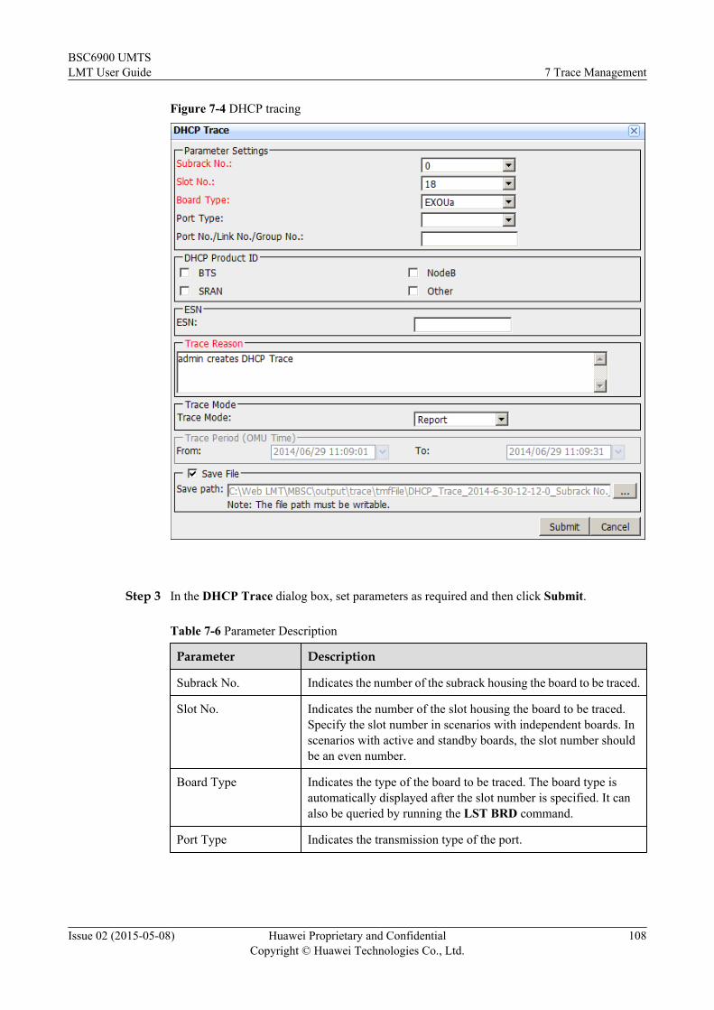
Figure 7-4 DHCP tracing
Step 3 In the DHCP Trace dialog box, set parameters as required and then click Submit.
Table 7-6 Parameter Description
Parameter Description
Subrack No. Indicates the number of the subrack housing the board to be traced.
Slot No. Indicates the number of the slot housing the board to be traced.Specify the slot number in scenarios with independent boards. Inscenarios with active and standby boards, the slot number shouldbe an even number.
Board Type Indicates the type of the board to be traced. The board type isautomatically displayed after the slot number is specified. It canalso be queried by running the LST BRD command.
Port Type Indicates the transmission type of the port.
BSC6900 UMTSLMT User Guide 7 Trace Management
Issue 02 (2015-05-08) Huawei Proprietary and ConfidentialCopyright © Huawei Technologies Co., Ltd.
108

Parameter Description
Port No./Link No./Group No.
Indicates the number of the port, link, or port group to be traced. Ifthis field is not specified, the entire board will be traced. It isrecommended that users should not specify this field.
DHCP Product ID Indicates the type of base station to be traced. There are fouroptions: BTS, NodeB, SRAN, and Other.l BTS: indicates the GSM base station.l NodeB: indicates the UMTS base station.l SRAN: indicates the SRAN base station.
NOTETo trace SRAN base station, select NodeB and SRAN.
l Other: indicates other base stations.
ESN Indicates the electronic serial number. At least one ESN is carriedin DHCP packets. If two ESNs are carried, one is a main ESN andthe other is an optional ESN. If an optional ESN is typed in thisfield, DHCP packets carrying this ESN will be traced. However,the main ESN is always displayed on the dll parsing interface. Ifthis field is left blank, all DHCP packets will be traced.
Trace Reason l Reason of starting this tracing task.l Pressing the Enter key is not supported. Letters, digits, spaces
and the following special characters are supported: ! @ # $ %^ & * ( ) _ + - = ` ~ : " , . | \ < > ? / { } [ ]
Trace Mode See 7.1.3 Tracing Mode.
Save File See 7.2.3 Saving Traced Messages.
----End
7.4 UMTS ServicesThis section describes how to perform tracing tasks related to UMTS services.
7.4.1 Tracing Messages on the Iu InterfaceThis section describes how to trace the signaling messages over the Iu interface, including theconnection-oriented messages and the connectionless messages. You can perform this task toidentify the failure cause in the following procedures: RAB assignment, RAB release, paging,Iu release, security mode control, initial UE message, and relocation.
ProcedureStep 1 Click Trace on the LMT main page. The Trace tab page is displayed.
Step 2 Under Trace Navigation Tree, choose Trace > UMTS Services > Iu Interface Trace. TheIu Interface Trace dialog box is displayed, as shown in Figure 7-5.
BSC6900 UMTSLMT User Guide 7 Trace Management
Issue 02 (2015-05-08) Huawei Proprietary and ConfidentialCopyright © Huawei Technologies Co., Ltd.
109

Figure 7-5 Message tracing on the Iu interface
Step 3 In the Iu Interface Trace dialog box, set parameters and click Submit.
Table 7-7 Parameter Description
Parameter Description
Basic RNC ID indicates the RNC ID of the cell to be traced. To queryit, run the LST URNCBASIC command.
DPCConfiguration
can be set to All DPC or Specified DPC. If SpecifiedDPC is selected, DPC(HEX) needs to be specified.
Trace Type Trace Type.
Trace Reason l Reason of starting this tracing task.l Pressing the Enter key is not supported. Letters,
digits, spaces and the following special characters aresupported: ! @ # $ % ^ & * ( ) _ + - = ` ~ : " , . | \< > ? / { } [ ]
Trace Mode See 7.1.3 Tracing Mode.
Save File See 7.2.3 Saving Traced Messages.
BSC6900 UMTSLMT User Guide 7 Trace Management
Issue 02 (2015-05-08) Huawei Proprietary and ConfidentialCopyright © Huawei Technologies Co., Ltd.
110

Parameter Description
MTP3 MTP3 Trace Type Set this parameter to Specified Link or Link Set. If thisparameter is set to Link Set, a large number of messagesare traced.
Signaling Link SetIndex
Index of an MTP3 signaling link set, which can bequeried by running the LST MTP3LKS command.
Signaling LinkCode
Index of an MTP3 link in the specified link set, whichcan be queried by running the LST MTP3LNKcommand.
SAAL SAAL Link ID indicates the number of an SAAL link. To query it, runthe LST SAALLNK command.
SCTP SCTP Link ID indicates the number of an SCTP link. To query it, runthe LST SCTPLNK command.
M3UA M3UA TraceType
Set this parameter to Specified Link or Link Set. If thisparameter is set to Link Set, a large number of messagesare traced.
Signaling Link SetIndex
indicates the number of an M3UA link set. To query it,run the LST M3LKS command.
Signaling Link ID indicates the number of an M3UA link. To query it, runthe LST M3LNK command.
----End
7.4.2 Tracing Messages on the Iupc InterfaceThis section describes how to trace the signaling messages over the Iupc (Iu Position Calculation)interface, including the connection-oriented messages. You can perform this task to identify thecause of the failure in the following scenarios: PCAP Position Initiations, PCAP PositionActivation.
Procedure
Step 1 Click Trace on the LMT main page. The Trace tab page is displayed.
Step 2 On the Trace Navigation Tree pane, choose Trace > UMTS Services > Iupc InterfaceTrace. The Iupc Interface Trace dialog box is displayed, as shown in Figure 7-6.
BSC6900 UMTSLMT User Guide 7 Trace Management
Issue 02 (2015-05-08) Huawei Proprietary and ConfidentialCopyright © Huawei Technologies Co., Ltd.
111

Figure 7-6 Message tracing on the Iupc interface
Step 3 In the Iupc Interface Trace dialog box, set parameters and click Submit.
Table 7-8 Iupc Interface Trace Tab
Parameter Description
Basic RNC ID indicates the RNC ID of the cell to be traced. Toquery it, run the LST URNCBASIC command.
DPCConfiguration
can be set to All DPC or Specified DPC. IfSpecified DPC is selected, DPC(HEX) needs to bespecified.
Trace Type Trace Type
Trace Reason l Reason of starting this tracing task.l Pressing the Enter key is not supported. Letters,
digits, spaces and the following specialcharacters are supported: ! @ # $ % ^ & * ( ) _+ - = ` ~ : " , . | \ < > ? / { } [ ]
Trace Mode See 7.1.3 Tracing Mode.
Save File See 7.2.3 Saving Traced Messages.
BSC6900 UMTSLMT User Guide 7 Trace Management
Issue 02 (2015-05-08) Huawei Proprietary and ConfidentialCopyright © Huawei Technologies Co., Ltd.
112

Parameter Description
SCTP SCTP Link ID indicates the number of an SCTP link. To query it,run the LST SCTPLNK command.
M3UA M3UA TraceType
Set this parameter to Specified Link or Link Set. Ifthis parameter is set to Link Set, a large number ofmessages are traced.
Signaling LinkSet Index
indicates the number of an M3UA link set. To queryit, run the LST M3LKS command.
Signaling Link ID indicates the number of an M3UA link. To query it,run the LST M3LNK command.
----End
ResultNOTE
In the message browse window of Iupc Interface Tracing, the number in the Information Source columnrepresents the DPC of the neighboring RNC. You can query more information about the DPC by runningthe command LST N7DPC.
7.4.3 Tracing Messages on the Iur InterfaceThis section describes how to trace the signaling messages over the Iur interface, including theconnection-oriented messages and the connectionless messages. You can perform this task toidentify the failure cause in the following procedures on the Iur interface: radio link setup, radiolink addition, radio link deletion, resource release on common transport channel, DL powercontrol, and paging.
Procedure
Step 1 Click Trace on the LMT main page. The Trace tab page is displayed.
Step 2 Under Trace Navigation Tree, choose Trace > UMTS Services > Iur Interface Trace. TheIur Interface Trace dialog box is displayed, as shown in Figure 7-7.
BSC6900 UMTSLMT User Guide 7 Trace Management
Issue 02 (2015-05-08) Huawei Proprietary and ConfidentialCopyright © Huawei Technologies Co., Ltd.
113

Figure 7-7 Message tracing on the Iur interface
Step 3 In the Iur Interface Trace dialog box, set parameters and Click Sumit.
Table 7-9 Parameter Description
Parameter Description
Basic RNC ID indicates the RNC ID of the cell to be traced. To query it,run the LST URNCBASIC command.
DPCConfiguration
can be set to All DPC or Specified DPC. If SpecifiedDPC is selected, DPC(HEX) needs to be specified.
Trace Type Trace Type.
Trace Reason l Reason of starting this tracing task.l Pressing the Enter key is not supported. Letters, digits,
spaces and the following special characters aresupported: ! @ # $ % ^ & * ( ) _ + - = ` ~ : " , . | \ < >? / { } [ ]
Trace Mode See 7.1.3 Tracing Mode.
BSC6900 UMTSLMT User Guide 7 Trace Management
Issue 02 (2015-05-08) Huawei Proprietary and ConfidentialCopyright © Huawei Technologies Co., Ltd.
114

Parameter Description
Save File See 7.2.3 Saving Traced Messages.
IUR IUR_GInMbsc
In the IUR tab page, if you select IUR_G, the Iur-g interfacemessages between BSC6900s or in a BSC6900 are traced.If you select InMbsc, the Iur-g interface messages betweenthe GSM and UMTS in a BSC6900 are traced.
MTP3 MTP3 TraceType
Set this parameter to Specified Link or Link Set. If thisparameter is set to Link Set, a large number of messages aretraced.
SignalingLink SetIndex
Index of an MTP3 signaling link set, which can be queriedby running the LST MTP3LKS command.
SignalingLink Code
Index of an MTP3 link in the specified link set, which canbe queried by running the LST MTP3LNK command.
SAAL SAAL LinkID
indicates the number of an SAAL link. To query it, run theLST SAALLNK command.
SCTP SCTP LinkID
indicates the number of an SCTP link. To query it, run theLST SCTPLNK command.
M3UA M3UA TraceType
Set this parameter to Specified Link or Link Set. If thisparameter is set to Link Set, a large number of messages aretraced.
SignalingLink SetIndex
indicates the number of an M3UA link set. To query it, runthe LST M3LKS command.
SignalingLink ID
indicates the number of an M3UA link. To query it, run theLST M3LNK command.
----End
7.4.4 Tracing Messages on the Iub InterfaceThis section describes how to trace the signaling messages over the Iub interface, that is, theNodeB Application Part (NBAP) messages. You can perform this task to identify the failurecause in the following procedures on the Iub interface: radio link setup, radio linkreconfiguration, resource audit, cell setup, cell reconfiguration, common transport channel setup,and system information update.
Procedure
Step 1 Click Trace on the LMT main page. The Trace tab page is displayed.
Step 2 Under Trace Navigation Tree, choose Trace > UMTS Services > Iub Interface Trace. TheIub Interface Trace dialog box is displayed, as shown in Figure 7-8.
BSC6900 UMTSLMT User Guide 7 Trace Management
Issue 02 (2015-05-08) Huawei Proprietary and ConfidentialCopyright © Huawei Technologies Co., Ltd.
115

Figure 7-8 Message tracing on the Iub interface
Step 3 In the Iub Interface Trace dialog box, set parameters and Click Submit.
Table 7-10 Parameter Description
Parameter Description
Basic RNC ID indicates the RNC ID of the cell to be traced. To query it, runthe LST URNCBASIC command.
NodeB TraceType
l All NodeB: traces NodeB Application Part (NBAP)messages of all NodeBs.
l All Ports of a NodeB: traces NBAP messages of aspecified NodeB on all ports. Both NodeB Control Ports(NCPs) and Communication Control Ports (CCPs) are tobe traced.
l Specified Port of a NodeB: traces NBAP messages of aspecified NodeB on a specified type of port. Either NCPsor CCPs are to be traced.
Trace Type Trace Type
BSC6900 UMTSLMT User Guide 7 Trace Management
Issue 02 (2015-05-08) Huawei Proprietary and ConfidentialCopyright © Huawei Technologies Co., Ltd.
116

Parameter Description
Trace Reason l Reason of starting this tracing task.l Pressing the Enter key is not supported. Letters, digits,
spaces and the following special characters aresupported: ! @ # $ % ^ & * ( ) _ + - = ` ~ : " , . | \ < > ?/ { } [ ]
Trace Mode See 7.1.3 Tracing Mode.
Save File See 7.2.3 Saving Traced Messages.
SAAL SAAL Link ID indicates the number of an SAAL link. To query it, run theLST SAALLNK command.
SCTP SCTP Link ID indicates the number of an SCTP link. To query it, run theLST SCTPLNK command.
SCTPSRV
SCTPSRV ID SCTP Signaling Server ID
Peer IP Address Peer IP address
Peer Port Peer Port No.
----End
7.4.5 Tracing Messages on the Uu InterfaceThis section describes how to trace all or specified types of signaling messages in a specifiedcell over the Uu interface. You can perform this task to identify the failure cause in the followingprocedures: RRC connection setup, radio bearer setup, physical channel reconfiguration, andcell update.
Procedure
Step 1 Click Trace on the LMT main page. The Trace tab page is displayed.
Step 2 Under Trace Navigation Tree, choose Trace > UMTS Services > Uu Interface Trace. TheUu Interface Trace dialog box is displayed, as shown in Figure 7-9.
BSC6900 UMTSLMT User Guide 7 Trace Management
Issue 02 (2015-05-08) Huawei Proprietary and ConfidentialCopyright © Huawei Technologies Co., Ltd.
117

Figure 7-9 Message tracing on the Uu interface
Step 3 In the Uu Interface Trace dialog box, set the parameters as required. Then Click Submit.
Table 7-11 Parameter Description
Parameter Description
RNC ID indicates the RNC ID of the cell to be traced. To query it, run the LSTURNCBASIC command.
Cell Config needs to be set to the ID of the cell sending and receiving messages.The parameter can be queried by running the LST UCELL command.
Trace Reason l Reason of starting this tracing task.l Pressing the Enter key is not supported. Letters, digits, spaces and
the following special characters are supported: ! @ # $ % ^ & *( ) _ + - = ` ~ : " , . | \ < > ? / { } [ ]
Trace Mode See 7.1.3 Tracing Mode.
Save File See 7.2.3 Saving Traced Messages.
BSC6900 UMTSLMT User Guide 7 Trace Management
Issue 02 (2015-05-08) Huawei Proprietary and ConfidentialCopyright © Huawei Technologies Co., Ltd.
118

----End
7.4.6 Tracing MNCDT MessagesThis section describes how to detect missing neighboring cell relationship of a cell. Using theMissing Neighbor Cell Detect Trace (MNCDT) function, you can detect missing neighboringcell relationship. MNCDT consists of intra-frequency, inter-frequency, and inter-RAT MNCDT,which are independent of each other.
PrerequisitesThe parameter switch for detecting missing neighboring cell relationship is set to ON. The settingcan be queried by running the LST UNCELLDETECTSWITCH command.
Procedure
Step 1 Click Trace on the LMT main page. The Trace tab page is displayed.
Step 2 Under Trace Navigation Tree, choose Trace > UMTS Services > MNCDT Trace. TheMNCDT Trace dialog box is displayed, as shown in Figure 7-10.
Figure 7-10 MNCDT message tracing
Step 3 Set parameters in the MNCDT Trace dialog box and then click Submit.
BSC6900 UMTSLMT User Guide 7 Trace Management
Issue 02 (2015-05-08) Huawei Proprietary and ConfidentialCopyright © Huawei Technologies Co., Ltd.
119

Table 7-12 Parameter Description
Parameter Description
Basic RNC ID indicates the RNC ID of the cell to be traced. To query it,run the LST URNCBASIC command.
DetectionType
includes Intra-frequency, Inter-frequency, and Inter-RAT.
Trace Reason l Reason of starting this tracing task.l Pressing the Enter key is not supported. Letters, digits,
spaces and the following special characters aresupported: ! @ # $ % ^ & * ( ) _ + - = ` ~ : " , . | \ < >? / { } [ ]
Trace Mode See 7.1.3 Tracing Mode.
Save File See 7.2.3 Saving Traced Messages.
Inter-frequency
UplinkUARFCN
indicates the uplink UTRA Absolute Radio FrequencyChannel Number (UARFCN) of the cell to be traced fordetecting missing neighboring relationship.
DownlinkUARFCN
indicates the downlink UARFCN of the cell to be traced fordetecting missing neighboring relationship.
Start ofPrimaryScramblingCode
indicates the minimum scrambling code for an MNCDTtask.
End ofPrimaryScramblingCode
indicates the maximum scrambling code for an MNCDTtask. End of Primary Scrambling Code must be not lessthan Start of Primary Scrambling Code.
Inter-RAT Start of NCC indicates the start of the Network Color Code (NCC) for thecell to be traced for detecting missing neighboring cellrelationship. The parameter value ranges from 0 to 7.
End of NCC indicates the end of the NCC for the cell to be traced fordetecting missing neighboring cell relationship. Theparameter value ranges from 0 to 7. End of NCC must begreater than or equal to Start of NCC.
Start of BCC indicates the start of the Base Transceiver Station ColorCode (BCC) for the cell to be traced for detecting missingneighboring cell relationship. The parameter value rangesfrom 0 to 7.
End of BCC indicates the end of the BCC for the cell to be traced fordetecting missing neighboring cell relationship. Theparameter value ranges from 0 to 7. End of BCC must begreater than or equal to Start of BCC.
BSC6900 UMTSLMT User Guide 7 Trace Management
Issue 02 (2015-05-08) Huawei Proprietary and ConfidentialCopyright © Huawei Technologies Co., Ltd.
120

Parameter Description
BandIndicator
Indicates the band to which the overlapping UARFCNsbetween bands DCS1800 and PCS1900 are attributed. It canbe set either DCS1800 or PCS1900 if the neighbor cell is notDCS1800 or PCS1900 cell.
Start ofBCCHARFCN
indicates the minimum Absolute Radio Frequency ChannelNumber (ARFCN) for an MNCDT task.
End of BCCHARFCN
indicates the maximum ARFCN for an MNCDT task.
----End
7.4.7 Message SettingsClicking this node in the navigation tree enables users to select messages that need to be tracedduring UE tracing, cell tracing, and IOS tracing. Tracing these messages in real time on the LMTfacilitates debugging and problem analysis.
Message Name Description
UI_FAM_UT_CELL_INFO
Selecting it enables the LMT to display values of received totalwideband power (RTWP) and transmitted carrier power (TCP) in acell. Analysis of these values helps users to determine whether anadmission request is denied because of heavy load and insufficientresources on the Uu interface.
UI_FAM_UT_CTRL_TBL
Selecting it enables the LMT to display mapping between UE IDs ofthe UE and internal units of the RNC.
UI_FAM_UT_GTPU_DATA_FWD_MSG
Selecting it enables the LMT to display statistics on packets receivedand sent at the GPRS Tunneling Protocol for User Plane (GTPU)layer.
UI_FAM_UT_INTRA_MSG
Selecting it enables the LMT to display communication messagesbetween internal units of the RNC.
UI_FAM_UT_L2_TXT_FWD_MSG
Selecting it enables the LMT to display real-time information suchas the RLC state, FP synchronization information, and informationabout HS-DSCH capacity allocation.
UI_FAM_UT_PRINT_INFO
Selecting it enables the LMT to display real-time log information,including text messages. The text messages can be of the TXT orTXT (Command Code) type.
UI_FAM_UT_REAL_TIME_INFO
Selecting it enables the LMT to display real-time information suchas information about cell admission and cell load control.
BSC6900 UMTSLMT User Guide 7 Trace Management
Issue 02 (2015-05-08) Huawei Proprietary and ConfidentialCopyright © Huawei Technologies Co., Ltd.
121

Message Name Description
UI_FAM_UT_RPRT_CELL_EVENT_INFO
Selecting it enables the LMT to display the number of UEs in a celland the propagation delay from the NodeB to the UEs.
UI_FAM_UT_STANDARD_MSG
Selecting it enables the LMT to display UE messages traced onstandard interfaces.
UI_FAM_UT_STATE_TRANS
Selecting it enables the LMT to trace state transitions of the UE.
7.4.8 Tracing UE MessagesThis section describes how to trace UE messages. You can perform this task to analyze the callprocedure failure cause.
Contextl As private information of users is revealed during the tracing, only G1 command group
users (ADMINISTRATOR and CUSTOM users with G1 command group permission) areallowed to perform UE tracing task.
l There is no way to avoid that some user data such as International Mobile SubscriberIdentity (IMSI) will be used during problem location and resolution. This function providesan anonymous data processing method. You are recommended to comply with local lawswhen executing the task and take ample measures to fully protect user data, such as enablingthe anonymous function and deleting the folder that saves trace records after you finishprocessing data.
l When entering IMSI, check whether IMSI data to be entered must be anonymous by runningthe LST USERIDANONSWITCH command and querying User Identity AnonymitySwitch.
– If User Identity Anonymity Switch is ON, the anonymous policy is enabled, andanonymous IMSI data must be entered in IMSI. The anonymous IMSI data is the IMSIdata encrypted by the HMACUtil using the cipher key.
– If User Identity Anonymity Switch is OFF, the anonymous policy is disabled, and userIMSI data is directly entered in IMSI.
NOTE
l Change the anonymous policy and cipher key on the U2000 by choosing Trace and Maintenance >Signaling Trace > Anonymous Policy Management > Anonymous Cypher Key Management(application style) or Trace and Maintenance > Monitor > Signaling Trace > Anonymous PolicyManagement > Anonymous Cypher Key Management (traditional style). For details, see U2000Fault Management User Guide.
l If you change the anonymous policy or cipher key of a started tracing task, you need to restart thetracing task. Otherwise, the tracing task becomes invalid.
l For details about how to obtain the HMACUtil, contact Huawei technical support.
BSC6900 UMTSLMT User Guide 7 Trace Management
Issue 02 (2015-05-08) Huawei Proprietary and ConfidentialCopyright © Huawei Technologies Co., Ltd.
122

Procedure
Step 1 Click Trace on the LMT main page. The Trace tab page is displayed.
Step 2 Under Trace Navigation Tree, choose Trace > UMTS Services > UE Trace. The UE Tracedialog box is displayed, as shown in Figure 7-11.
Figure 7-11 UE message tracing
Step 3 In the displayed UE Trace dialog box, set the parameters as required. Then Click Submit.
Table 7-13 UE Tab Parameter Description
Parameter Description
RNC ID indicates the RNC ID of the cell to be traced. To query it, run the LSTURNCBASIC command.
BSC6900 UMTSLMT User Guide 7 Trace Management
Issue 02 (2015-05-08) Huawei Proprietary and ConfidentialCopyright © Huawei Technologies Co., Ltd.
123

Parameter Description
IMSI/MSISDN/IMEI/TMSI/P-TMSI
Identifying the UE to be traced. Choosing to trace the UE by the TMSI, youneed to specify LAC, MCC, and MNC. Choosing to trace the UE by the P-TMSI, you need to specify LAC, RAC, MCC, and MNC.l If you trace a UE by specifying the IMSI and the IMSI is carried in the
RRC CONNECTION REQUEST message sent by the UE for networkaccess, the UE tracing task traces all the messages that are sent after theRRC CONNECTION REQUEST message.
l Assume that you trace a UE by specifying the IMSI and the IMSI is notcarried in the RRC CONNECTION REQUEST message but only carriedin the RANAP COMMON ID message. If CDT_MSG_FULL_TRACEis set to ON, the UE tracing task traces the messages that are sent afterthe RANAP COMMON ID message, and the messages sent before theRANAP COMMON ID message are buffered and reported. IfCDT_MSG_FULL_TRACE is set to OFF, the messages sent before theRANAP COMMON ID message are discarded instead.
TRACE RRCPROCEDURE
Indicating whether to trace messages on the standard interface during anRRC connection setup process when the international mobile subscriberidentity (IMSI) is specified. When this switch is turned on, users withspecified IMSIs cannot trace messages on the standard interface until asecond RRC connection setup process.
BSC6900 UMTSLMT User Guide 7 Trace Management
Issue 02 (2015-05-08) Huawei Proprietary and ConfidentialCopyright © Huawei Technologies Co., Ltd.
124

Parameter Description
Trace ConfigTemplate
Commonly used tracing items are combined to form various templates, sothat users can start a tracing task conveniently. Following describe themeanings of various parameters in different templates:l User-defined Mode: Users can set parameters on each tab page in the
UE Trace dialog box.l Standard UE CDT Trace Method: When this template is selected, all
standard signaling messages on the IUR, IUB, IU, IUPC, and UU tabpages are traced. Debug Mode is unavailable.
l UE CDT Trace Method (Debug + Internal Event): When this templateis selected, the following messages are traced: all standard signalingmessages on the IUR, IUB, IU, IUPC, and UU tab pages and InternalEvent on the Other1 tab page.
l UE CDT Trace Method (Debug + Internal Event + L2 Statistics):When this template is selected, the following messages are traced: allstandard signaling messages on the IUR, IUB, IU, IUPC, and UU tabpages, Internal Event on the Other1 tab page, and Layer 2 datatransfer periodic report on the Other tab page.
l UE CDT Trace Method (Debug + Internal Event + L2 Statistics +SRB): When this template is selected, the following messages are traced:all standard signaling messages on the IUR, IUB, IU, IUPC, and UU tabpages, Internal Event on the Other1 tab page, Layer 2 data transferperiodic report on the Other tab page, and L2 SRB Data Report.
l UE CDT Trace Method (Debug + Internal Event + L2 Statistics +SRB + TRB): When this template is selected, the following messagesare traced: all standard signaling messages on the IUR, IUB, IU,IUPC, and UU tab pages, Internal Event on the Other1 tab page, Layer2 data transfer periodic report on the Other tab page, L2 SRB DataReport, L2 TRB packet header report (Iub interface), and L2 TRBpacket header report (Iu interface).
l UE CDT Trace Method (Debug + Internal Event + L2 Statistics +SRB + TRB + MOS): When this template is selected, the followingmessages are traced: all standard signaling messages on the IUR, IUB,IU, IUPC, and UU tab pages, Internal Event on the Other1 tab page,Layer 2 data transfer periodic report on the Other tab page, L2 SRBData Report, L2 TRB packet header report (Iub interface), L2 TRBpacket header report (Iu interface), and Voice Analysis.
Debug Mode indicates a maintenance mode used for tracing communication messagesbetween units of the RNC. Tracing tasks configured on Other, Other1, andBind tab pages take effect only when Debug Mode is selected.For use of it, contact Huawei technical support personnel.
Trace Reason l Reason of starting this tracing task.l Pressing the Enter key is not supported. Letters, digits, spaces and the
following special characters are supported: ! @ # $ % ^ & * ( ) _ + - =` ~ : " , . | \ < > ? / { } [ ]
BSC6900 UMTSLMT User Guide 7 Trace Management
Issue 02 (2015-05-08) Huawei Proprietary and ConfidentialCopyright © Huawei Technologies Co., Ltd.
125
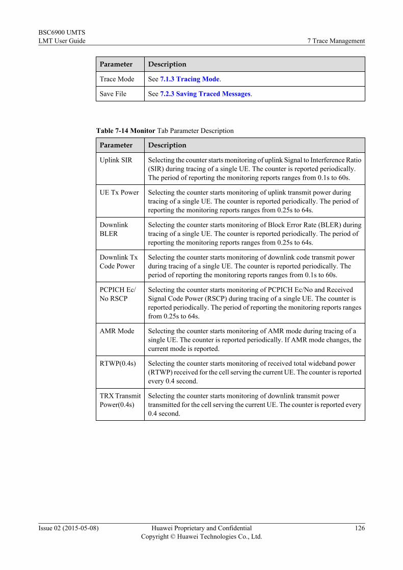
Parameter Description
Trace Mode See 7.1.3 Tracing Mode.
Save File See 7.2.3 Saving Traced Messages.
Table 7-14 Monitor Tab Parameter Description
Parameter Description
Uplink SIR Selecting the counter starts monitoring of uplink Signal to Interference Ratio(SIR) during tracing of a single UE. The counter is reported periodically.The period of reporting the monitoring reports ranges from 0.1s to 60s.
UE Tx Power Selecting the counter starts monitoring of uplink transmit power duringtracing of a single UE. The counter is reported periodically. The period ofreporting the monitoring reports ranges from 0.25s to 64s.
DownlinkBLER
Selecting the counter starts monitoring of Block Error Rate (BLER) duringtracing of a single UE. The counter is reported periodically. The period ofreporting the monitoring reports ranges from 0.25s to 64s.
Downlink TxCode Power
Selecting the counter starts monitoring of downlink code transmit powerduring tracing of a single UE. The counter is reported periodically. Theperiod of reporting the monitoring reports ranges from 0.1s to 60s.
PCPICH Ec/No RSCP
Selecting the counter starts monitoring of PCPICH Ec/No and ReceivedSignal Code Power (RSCP) during tracing of a single UE. The counter isreported periodically. The period of reporting the monitoring reports rangesfrom 0.25s to 64s.
AMR Mode Selecting the counter starts monitoring of AMR mode during tracing of asingle UE. The counter is reported periodically. If AMR mode changes, thecurrent mode is reported.
RTWP(0.4s) Selecting the counter starts monitoring of received total wideband power(RTWP) received for the cell serving the current UE. The counter is reportedevery 0.4 second.
TRX TransmitPower(0.4s)
Selecting the counter starts monitoring of downlink transmit powertransmitted for the cell serving the current UE. The counter is reported every0.4 second.
BSC6900 UMTSLMT User Guide 7 Trace Management
Issue 02 (2015-05-08) Huawei Proprietary and ConfidentialCopyright © Huawei Technologies Co., Ltd.
126

Table 7-15 Other Tab Parameter Description
Parameter Description
Layer 2 DataTransferPeriodicReport
Selecting it enables statistics on packets received and sent at layer 2 to beperiodically reported to the LMT.
TransportData PeriodicReport
Selecting it enables statistics on packets received and sent by interfaceboards to be periodically reported to the LMT. Analysis of these statisticshelps users to determine whether a fault occurs on the RNC side.
Report Period Indicates the period for reporting Layer 2 data transfer periodic report.
L2 DataReport
Includes parameters that enable statistics on packets received and sent atlayer 2 to be reported to the LMT.l L2 SRB Data Report: enables packets received in the UL and sent in
the DL on the control plane at the Frame Protocol (FP) layer to be reportedto the LMT in messages.
l Report Time(s): indicates the period for reporting L2 Data Report.l L2 TRB Packet Header Report (Iub Interface): Selecting it enables
frame headers received in the UL or sent in the DL on the user plane atthe FP layer to be reported to the LMT.
l L2 TRB Packet Header Report (Iu Interface): Selecting it enablespacket TCP/IP headers sent in the UL or received in the DL on the userplane at the RLC layer to be reported to the LMT.
l TCP Proxy Data Report: After the TCP proxy function is enabled, theTCP/IP headers of the following TCP packets are reported to the LMT:
– In the downlink, user-plane TCP packets that are received from theserver and transmitted to the UE at the PDCP layer.
– In the uplink, user-plane TCP packets that are received from the UEand transmitted to the server at the PDCP layer.
When RNC in Pool is used for user-plane load-sharing, Report File isrecommended if the user selects L2 TRB packet header report (Iubinterface) or L2 TRB packet header report (Iu interface) on the Othertab page. After the user selects Report File, the user needs to configure theFTP server and ensure that the FTP server connects to the master RNC andoverflow RNC. The tracing results generated by the master RNC are savedon the OMU of the master RNC and the tracing results generated by theoverflow RNC are saved on the OMU of the overflow RNC. You can usethe FTP server to upload the tracing results on the OMU to the directoryspecified by Upload Path.NOTE
You can run the MML command LST UPOOLLOADSHAREPARA to query thevalue of UP Load Sharing Policy. If the value of this parameter is UP_SHARE, RNCin Pool is used for user-plane load-sharing.
BSC6900 UMTSLMT User Guide 7 Trace Management
Issue 02 (2015-05-08) Huawei Proprietary and ConfidentialCopyright © Huawei Technologies Co., Ltd.
127
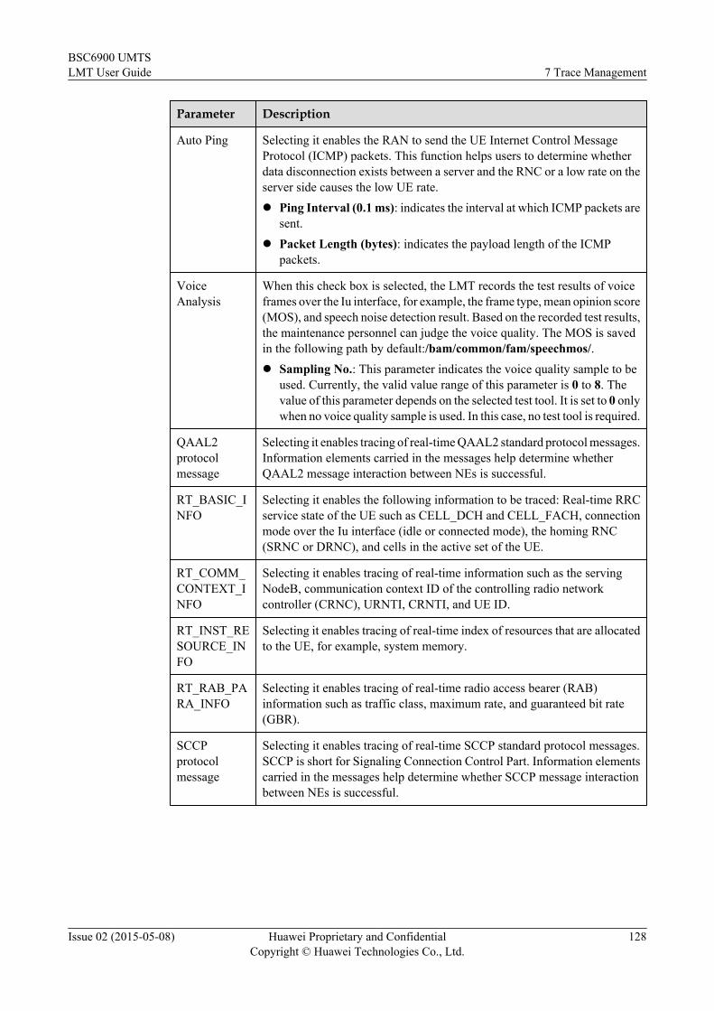
Parameter Description
Auto Ping Selecting it enables the RAN to send the UE Internet Control MessageProtocol (ICMP) packets. This function helps users to determine whetherdata disconnection exists between a server and the RNC or a low rate on theserver side causes the low UE rate.l Ping Interval (0.1 ms): indicates the interval at which ICMP packets are
sent.l Packet Length (bytes): indicates the payload length of the ICMP
packets.
VoiceAnalysis
When this check box is selected, the LMT records the test results of voiceframes over the Iu interface, for example, the frame type, mean opinion score(MOS), and speech noise detection result. Based on the recorded test results,the maintenance personnel can judge the voice quality. The MOS is savedin the following path by default:/bam/common/fam/speechmos/.l Sampling No.: This parameter indicates the voice quality sample to be
used. Currently, the valid value range of this parameter is 0 to 8. Thevalue of this parameter depends on the selected test tool. It is set to 0 onlywhen no voice quality sample is used. In this case, no test tool is required.
QAAL2protocolmessage
Selecting it enables tracing of real-time QAAL2 standard protocol messages.Information elements carried in the messages help determine whetherQAAL2 message interaction between NEs is successful.
RT_BASIC_INFO
Selecting it enables the following information to be traced: Real-time RRCservice state of the UE such as CELL_DCH and CELL_FACH, connectionmode over the Iu interface (idle or connected mode), the homing RNC(SRNC or DRNC), and cells in the active set of the UE.
RT_COMM_CONTEXT_INFO
Selecting it enables tracing of real-time information such as the servingNodeB, communication context ID of the controlling radio networkcontroller (CRNC), URNTI, CRNTI, and UE ID.
RT_INST_RESOURCE_INFO
Selecting it enables tracing of real-time index of resources that are allocatedto the UE, for example, system memory.
RT_RAB_PARA_INFO
Selecting it enables tracing of real-time radio access bearer (RAB)information such as traffic class, maximum rate, and guaranteed bit rate(GBR).
SCCPprotocolmessage
Selecting it enables tracing of real-time SCCP standard protocol messages.SCCP is short for Signaling Connection Control Part. Information elementscarried in the messages help determine whether SCCP message interactionbetween NEs is successful.
BSC6900 UMTSLMT User Guide 7 Trace Management
Issue 02 (2015-05-08) Huawei Proprietary and ConfidentialCopyright © Huawei Technologies Co., Ltd.
128

Table 7-16 Other1 Tab Parameter Description
Parameter Description
FP PM Report Selecting it enables transmission statistics at the FP layer to be reported tothe LMT.
IUUP UplinkLoop
Selecting it enables Iu user plane (IuUP) data that would be transmitted tothe CN to be transmitted in the downlink direction. This function is used forisolating other network elements during problem analysis, which facilitateslocation of speech quality problems.NOTE
When this operation is performed, the traced user can only hear the voice of itself ratherthan that of the peer end.
IUUPDownlinkLoop
Selecting it enables IuUP data received from the CN to be returned to theCN. This function is used for isolating other network elements duringproblem analysis, which facilitates location of speech quality problems.NOTE
When this operation is performed, the peer end can only hear the voice of itself ratherthan that of the traced user.
PDCP Trace Selecting it enables information about Packet Data Convergence Protocol(PDCP) header compression to be reported to the LMT.
FP Trace Selecting it enables control frames on the IuUP or at the FP layer to bereported to the LMT.
L2 FLProtocolTrace Report
Selecting it enables protocol parameters on the user plane to be reported tothe LMT.
TCP ProxyProtocolTrace Report
When the TCP proxy function is enabled, protocol parameters about user-plane TCP packets can be reported to the LMT.
BSC6900 UMTSLMT User Guide 7 Trace Management
Issue 02 (2015-05-08) Huawei Proprietary and ConfidentialCopyright © Huawei Technologies Co., Ltd.
129

Parameter Description
Flow Trace Selecting it enables specified data flow of the UE on the interface board tobe reported in packets to the LMT. If RNC data flow is blocked, the problemmay lie in the RNC, the interface board, or the peer end. You can use thisfunction to exclude some problems.l Flow Trace Interface Type: indicates the interface to have its data flow
traced.l Flow Trace Bearer Type: indicates the channel to have its data flow
traced.l Flow Trace Service Type: indicates the service to have its data flow
traced.l RearPanel trace: traces data flow sent or received on the backplane of
the interface board.l FrontPanel trace: traces data flow sent or received on the panel of the
interface board.NOTICE
Note that selecting Rear panel trace or Front panel trace may lead to flow control,so exercise caution in this selection.
TCP ProxyFunctionConfig
Selecting it configures the single-user TCP proxy function.l TCP Proxy Function Config Type: It can be set to DL TCP Proxy
Enable or TCP Proxy Disable.
– DL TCP Proxy Enable: Enables the single-user downlink TCPproxy function.
– TCP Proxy Disable: Disables the single-user TCP proxy function.
Bind: Binding the UE to a DSP or path or transmission resource pool. This helps users todetermine whether a DSP or path fault exists.
Table 7-17 Bind Tab Parameter Description
Parameter Description
DSP l Subrack No.: indicates the number of the subrack corresponding to theDSP.
l Slot No.: indicates the number of the slot corresponding to the DSP.l DSP No.: indicates the number of the DSP.
Iub l Path ANI No.: indicates the Adjacent Node Identifier (ANI)corresponding to the Iub path.
l Type: indicates the transport type of the Iub path.l Path ID: indicates the number of the Iub path.l CID/UDP PORT(I1,I2,I3...): indicates the bound channel identifier
(CID) on the Iub path in ATM transmission mode or the number of thebound User Datagram Protocol (UDP) port in IP transmission mode.
BSC6900 UMTSLMT User Guide 7 Trace Management
Issue 02 (2015-05-08) Huawei Proprietary and ConfidentialCopyright © Huawei Technologies Co., Ltd.
130

Parameter Description
Iucs l Path ANI No.: indicates the ANI corresponding to the Iu-CS path.l Type: indicates the transport type of the Iu-CS path.l Path ID: indicates the number of the Iu-CS path.l CID/UDP PORT(I1,I2,I3...): indicates the bound CID on the Iu-CS path
in ATM transmission mode or the number of the bound UDP port in IPtransmission mode.
Iur l Path ANI No.: indicates the ANI corresponding to the Iur path.l Type: indicates the transport type of the Iur path.l Path ID: indicates the number of the Iur path.l CID/UDP PORT(I1,I2,I3...): indicates the bound CID on the Iur path
in ATM transmission mode or the number of the bound UDP port in IPtransmission mode.
Iups l Path ANI No.: indicates the ANI corresponding to the Iu-PS path.l Type: indicates the transport type of the Iu-PS path.l Path ID: indicates the number of the Iu-PS path.
NODE l Node ID/External Node ID: indicates the ID of the bound physical node.
----End
7.4.9 Tracing Cell MessagesThis section describes how to trace cell messages. The tracing results of the cell messages providereference for troubleshooting common channel faults when the access success rate is low or zeroin the cell. The UE statistics can be displayed in the tracing result if required.
Procedure
Step 1 Click Trace on the LMT main page. The Trace tab page is displayed.
Step 2 Under Trace Navigation Tree, choose Trace > UMTS Services > Cell Trace. The CellTrace dialog box is displayed, as shown in Figure 7-12.
BSC6900 UMTSLMT User Guide 7 Trace Management
Issue 02 (2015-05-08) Huawei Proprietary and ConfidentialCopyright © Huawei Technologies Co., Ltd.
131

Figure 7-12 Cell message tracing
Step 3 Set parameters in the Cell Trace dialog box and then click Submit.
Table 7-18 Cell Trace Tab Parameter Description
Parameter Description
RNC ID indicates the RNC ID of the cell to be traced. To query it, run theLST URNCBASIC command.
Cell ID indicates the index of a cell.
User Volume/Propagation Delay
indicates the event to be traced, either the USER_VOLUME eventor the PROPAGATION_DELAY event. If you select the Uservolume event, some custom messages reflecting statistics about UEsin a cell will be reported. The value ranges from 1000 to 10000 givenin 10 ms. If you select the Propagation delay event, propagationdelay in messages will be reported. The value ranges from 1 to 80.
Debug Mode indicates a maintenance mode used for tracing communicationmessages between units of the RNC. Tracing tasks configured onOther and Bind tab pages take effect only when Debug Mode isselected.For use of it, contact Huawei technical support personnel.
BSC6900 UMTSLMT User Guide 7 Trace Management
Issue 02 (2015-05-08) Huawei Proprietary and ConfidentialCopyright © Huawei Technologies Co., Ltd.
132
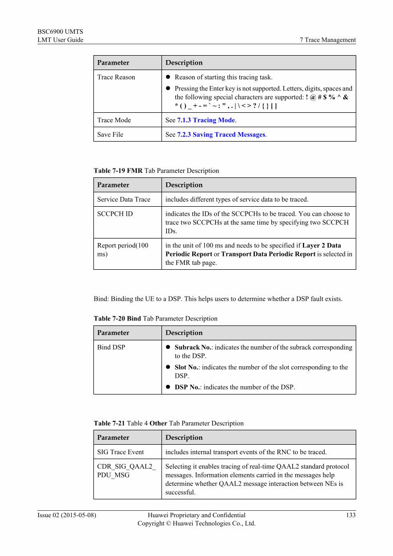
Parameter Description
Trace Reason l Reason of starting this tracing task.l Pressing the Enter key is not supported. Letters, digits, spaces and
the following special characters are supported: ! @ # $ % ^ &* ( ) _ + - = ` ~ : " , . | \ < > ? / { } [ ]
Trace Mode See 7.1.3 Tracing Mode.
Save File See 7.2.3 Saving Traced Messages.
Table 7-19 FMR Tab Parameter Description
Parameter Description
Service Data Trace includes different types of service data to be traced.
SCCPCH ID indicates the IDs of the SCCPCHs to be traced. You can choose totrace two SCCPCHs at the same time by specifying two SCCPCHIDs.
Report period(100ms)
in the unit of 100 ms and needs to be specified if Layer 2 DataPeriodic Report or Transport Data Periodic Report is selected inthe FMR tab page.
Bind: Binding the UE to a DSP. This helps users to determine whether a DSP fault exists.
Table 7-20 Bind Tab Parameter Description
Parameter Description
Bind DSP l Subrack No.: indicates the number of the subrack correspondingto the DSP.
l Slot No.: indicates the number of the slot corresponding to theDSP.
l DSP No.: indicates the number of the DSP.
Table 7-21 Table 4 Other Tab Parameter Description
Parameter Description
SIG Trace Event includes internal transport events of the RNC to be traced.
CDR_SIG_QAAL2_PDU_MSG
Selecting it enables tracing of real-time QAAL2 standard protocolmessages. Information elements carried in the messages helpdetermine whether QAAL2 message interaction between NEs issuccessful.
BSC6900 UMTSLMT User Guide 7 Trace Management
Issue 02 (2015-05-08) Huawei Proprietary and ConfidentialCopyright © Huawei Technologies Co., Ltd.
133

Parameter Description
CELL_SIG_AL_STREAMING_RDPT
Selecting it enables specified data flow of the cell on the interfaceboard to be reported to the LMT.l Transport Channel Type: indicates the type of transport
channel to have its data flow traced.l SCCPCH ID: indicates the ID of the Secondary Common
Control Physical Channel (S-CCPCH).
----End
7.4.10 Tracing IOS MessagesThis section describes how to trace a number of calls that meet the sampling criteria within aspecified range of cells. When creating the task, you can specify the number of calls to be tracedand specify messages to be traced by selecting the event type.
Context
NOTICEThe IOS tracing task involves a large amount of trace information, which affects the systemoperation. Therefore, the maximum number of simultaneously traced calls set in the Max callssimultaneously traced area in the IOS dialog box should not be too high. In addition, you areadvised not to trace all events at a time. Furthermore, you should minimize the frequencies ofperforming this task and the number of tasks performed simultaneously.
l You need to specify the number of successive calls to be traced, tracing cell range, samplingcriteria, and tracing time. The calls that meet the sampling criteria are traced within thespecified tracing time.
– When creating a new call tracing task, you can define the sampling criteria by settingthe RAB parameter constraints and the RRC Est Cause. Once the call meets the criteria,the tracing of the call is not stopped even if the RAB parameters of the RRCestablishment cause are changed during the call. If the initial settings of the RABparameters or the RRC establishment cause value of a call does not meet the criteria,the BSC6900 does not trace the call even if these parameters are modified to meet thecriteria during the call.
– You can specify the message types to be traced by selecting the event types.
Assume that the specified number of continuous calls is N. If N calls are already being traced,the system does not trace any newly accessed calls. If the number becomes less than N becauseof the termination of a traced call, the system automatically traces a new call.
If multiple IOS tracing tasks with the same parameter settings are started, one task can trace anddisplay the tracing messages of only one user, because each user is traced by a specific tracingtask.
BSC6900 UMTSLMT User Guide 7 Trace Management
Issue 02 (2015-05-08) Huawei Proprietary and ConfidentialCopyright © Huawei Technologies Co., Ltd.
134

Procedure
Step 1 Click Trace on the LMT main page. The Trace tab page is displayed.
Step 2 Under Trace Navigation Tree, choose Trace > UMTS Services > IOS Trace. The IOSTrace dialog box is displayed, as shown in Figure 7-13.
Figure 7-13 IOS message tracing
Step 3 In the displayed IOS Trace dialog box, set parameters and filter traced messages in other tabpages. Then click Submit.
Table 7-22 Basic Tab Parameter Description
Parameter Description
RNC ID RNC ID of the cell to be traced. To query it, run the LSTURNCBASIC command.
Call Count maximum number of calls that can be traced simultaneously after atracing task is started. The value ranges from 1 to 30.
BSC6900 UMTSLMT User Guide 7 Trace Management
Issue 02 (2015-05-08) Huawei Proprietary and ConfidentialCopyright © Huawei Technologies Co., Ltd.
135

Parameter Description
Cell ID You can type the ID of one cell or IDs of multiple cells.
VIP IMSI Run the ADD UVIPIMSI command to add the VIP IMSI.
Trace only inter-subsystem users
When this switch is turned on, only users with control plane load sharingare traced.
IMEI TAC(TAC1,TAC2,...TAC8)
IMEI TAC of the user to be traced. You can enter a maximum of eightIMEI TACs. An IMEI TAC can be a decimal number of 1 to 8 digits.IMEI is short for international mobile equipment identity and TAC isshort for type allocation code.NOTE
This parameter is valid only when the IMEI query function is enabled on the CNor RNC side.
To enable the IMEI query function on the RNC side, run the following commandSET URRCTRLSWITCH:SET URRCTRLSWITCH: PROCESSSWITCH2=RNC_CS_QUERY_UE_IMEI_SWITCH-1&RNC_PS_QUERY_UE_IMEI_SWITCH-1, PROCESSSWITCH4=SEND_MSG_NULL_SWITCH-1;
Event Type Types of event to be traced. The event types classify all messages relatedto calls. You can select or clear all event types by clicking Select All orClear All. You can restore the setting to the original one by clickingReset.
BSC6900 UMTSLMT User Guide 7 Trace Management
Issue 02 (2015-05-08) Huawei Proprietary and ConfidentialCopyright © Huawei Technologies Co., Ltd.
136

Parameter Description
Trace ConfigTemplate
Commonly used tracing items are combined to form various templates,so that users can start a tracing task conveniently. Following describe themeanings of various parameters in different templates:l User-defined Mode: Users can set parameters on each tab page in
the IOS Trace dialog box.l Standard IOS Trace Method: When this template is selected, all
standard signaling messages generated by RRC Est Cause on theRRC tab page are traced. Debug Mode is unavailable.
l IOS Trace Method (Debug + Internal Event): When this templateis selected, the following messages are traced: all standard signalingmessages generated by RRC Est Cause on the RRC tab page andInternal Event on the Other1 tab page.
l IOS Trace Method (Debug + Internal Event + L2 Statistics):When this template is selected, the following messages are traced: allstandard signaling messages generated by RRC Est Cause on theRRC tab page, Internal Event on the Other1 tab page, and Layer 2data transfer periodic report on the Other tab page.
l IOS Trace Method (Debug + Internal Event + L2 Statistics +SRB): When this template is selected, the following messages aretraced: all standard signaling messages generated by RRC EstCause on the RRC tab page, Internal Event on the Other1 tab page,Layer 2 data transfer periodic report on the Other tab page, andL2 SRB Data Report.
l IOS Trace Method (Debug + Internal Event + L2 Statistics + SRB+ TRB): When this template is selected, the following messages aretraced: all standard signaling messages generated by RRC EstCause on the RRC tab page, Internal Event on the Other1 tab page,Layer 2 data transfer periodic report on the Other tab page, L2SRB Data Report, L2 TRB packet header report (Iub interface),and L2 TRB packet header report (Iu interface).
Debug Mode maintenance mode used for tracing communication messages betweenunits of the RNC. Tracing tasks configured on Other, Other1, andBind tab pages take effect only when Debug Mode is selected.For use of it, contact Huawei technical support personnel.
Trace Reason l Reason of starting this tracing task.l Pressing the Enter key is not supported. Letters, digits, spaces and the
following special characters are supported: ! @ # $ % ^ & * ( ) _ +- = ` ~ : " , . | \ < > ? / { } [ ]
Trace Mode See 7.1.3 Tracing Mode.
Save File See 7.2.3 Saving Traced Messages.
BSC6900 UMTSLMT User Guide 7 Trace Management
Issue 02 (2015-05-08) Huawei Proprietary and ConfidentialCopyright © Huawei Technologies Co., Ltd.
137

Table 7-23 MM Tab Parameter Description
Parameter Description
CELL CHANGEORDER
CELL CHANGE ORDER: Traced messages of the cell change orderprocedure.
INTER RATHANDOVER IN
Traced messages of the incoming inter-RAT handover procedure.
INTER RATHANDOVEROUT
Traced messages of the outgoing inter-RAT handover procedure throughrelocation.
LOCATIONUPDATE
Traced messages of the location area update procedure.
ROUT AREAUPDATE
Traced messages of the routing area update procedure.
PCH CELLUPDATE
Traced messages of the cell update procedure for UEs in the CELL_PCHand URA_PCH states.
RAB tab page:l If the BSC6900 receives an RAB ASSIGNMENT REQUEST message of a call that matches
the specified RAB parameters in the specified cell, the call is traced. If a call sets up multipleRAB links, the call is traced if one of the RAB links meets the specified RAB parameters.
Table 7-24 RRC Tab Parameter Description
Parameter Description
RRC includes the RRC establishment cause. If the BSC6900 receives anRRC_CONN_REQ message of a call that matches the specified RRCestablishment cause in the specified cell, the call is traced.
RRC(ms) Period of reporting measurement results of PCPICH Ec/No and ReceivedSignal Code Power (RSCP) when forward power control tracing isselected or PCPICH Ec/No RSCP in the Monitor tab page is selected forIOS tracing
UE Internal RRC(ms)
Period of reporting measurement results of UE transmit power whenforward power control tracing is selected or UE Tx Power in the Monitortab page is selected for IOS tracing.
UE Quality RRC(ms)
Period of reporting measurement results of downlink Block Error Rate(BLER) when forward power control tracing is selected or DownlinkBLER in the Monitor tab page is selected for IOS tracing.
NBAP Common(ms)
Period of reporting results of cell common measurement that is selectedin the Monitor tab page of IOS Trace.
BSC6900 UMTSLMT User Guide 7 Trace Management
Issue 02 (2015-05-08) Huawei Proprietary and ConfidentialCopyright © Huawei Technologies Co., Ltd.
138

Parameter Description
NBAP Special(ms)
Period of reporting measurement results of downlink code transmitpower in the SRNC cell when forward power control tracing is selectedor Downlink Tx Code Power in the Monitor tab page is selected for IOStracing.
RNSAP Special(ms)
Period of reporting measurement results of downlink code transmitpower in the DRNC cell when forward power control tracing is selectedor Downlink Tx Code Power in the Monitor tab page is selected for IOStracing.
RRC LocatedType
UE locating method used during IOS tracing.
RRC LocatedCycle (ms)
Period for reporting UE locating results during IOS tracing.
RTT SpecialNBAP(ms)
Period of reporting results of Round Trip Time (RTT) measurement inthe SRNC cell when forward power control tracing is selected or theMonitor tab page is configured for IOS tracing.
RRC Est Cause Call establishment causes and filters UEs to be traced in the cell basedon the call establishment causes.
Monitor tab page: includes performance counters to be monitored during tracing of a single UE
Table 7-25 Monitor Tab Parameter Description
Parameter Description
Uplink SIR Selecting the counter starts monitoring of uplink Signal to InterferenceRatio (SIR) during tracing of a single UE. The counter is reportedperiodically. The period of reporting the monitoring reports ranges from0.1s to 60s.
Uplink Tx Power Selecting the counter starts monitoring of uplink transmit power duringtracing of a single UE. The counter is reported periodically. The periodof reporting the monitoring reports ranges from 0.25s to 64s.
Downlink BLER Selecting the counter starts monitoring of Block Error Rate (BLER)during tracing of a single UE. The counter is reported periodically. Theperiod of reporting the monitoring reports ranges from 0.25s to 64s.
Downlink TxCode Power
Selecting the counter starts monitoring of downlink code transmit powerduring tracing of a single UE. The counter is reported periodically. Theperiod of reporting the monitoring reports ranges from 0.1s to 60s.
PCPICH Ec/NoRSCP
Selecting the counter starts monitoring of PCPICH Ec/No and ReceivedSignal Code Power (RSCP) during tracing of a single UE. The counteris reported periodically. The period of reporting the monitoring reportsranges from 0.25s to 64s.
BSC6900 UMTSLMT User Guide 7 Trace Management
Issue 02 (2015-05-08) Huawei Proprietary and ConfidentialCopyright © Huawei Technologies Co., Ltd.
139

Parameter Description
AMR Mode Selecting the counter starts monitoring of AMR mode during tracing ofa single UE. The counter is reported periodically. If AMR mode changes,the current mode is reported.
RTWP(0.4s) Selecting the counter starts monitoring of received total wideband power(RTWP) received for the cell serving the current UE. The counter isreported every 0.4 second.
TRX TransmitPower(0.4s)
Selecting the counter starts monitoring of downlink transmit powertransmitted for the cell serving the current UE. The counter is reportedevery 0.4 second.
Table 7-26 Other Tab Parameter Description
Parameter Description
Layer 2 DataTransfer PeriodicReport
To enable statistics on packets received and sent at layer 2 to beperiodically reported to the LMT, specify the parameter value.
BSC6900 UMTSLMT User Guide 7 Trace Management
Issue 02 (2015-05-08) Huawei Proprietary and ConfidentialCopyright © Huawei Technologies Co., Ltd.
140

Parameter Description
L2 Data Report includes parameters that enable statistics on packets received and sent atlayer 2 to be reported to the LMT.l L2 SRB Data Report: enables packets received in the UL and sent
in the DL on the control plane at the Frame Protocol (FP) layer to bereported to the LMT in messages.
l Report Time(s): period for reporting L2 Data Report.l L2 TRB Packet Header Report (Iub Interface): Selecting it enables
frame headers received in the UL or sent in the DL on the user planeat the FP layer to be reported to the LMT.
l L2 TRB Packet Header Report (Iu Interface): Selecting it enablespacket TCP/IP headers sent in the UL or received in the DL on theuser plane at the RLC layer to be reported to the LMT.
l TCP Proxy Data Report: After the TCP proxy function is enabled,the TCP/IP headers of the following TCP packets are reported to theLMT:
– In the downlink, user-plane TCP packets that are received fromthe server and transmitted to the UE at the PDCP layer.
– In the uplink, user-plane TCP packets that are received from theUE and transmitted to the server at the PDCP layer.
When RNC in Pool is used for user-plane load-sharing, Report File isrecommended if the user selects L2 TRB packet header report (Iubinterface) or L2 TRB packet header report (Iu interface) on theOther tab page. After the user selects Report File, the user needs toconfigure the FTP server and ensure that the FTP server connects to themaster RNC and overflow RNC. The tracing results generated by themaster RNC are saved on the OMU of the master RNC and the tracingresults generated by the overflow RNC are saved on the OMU of theoverflow RNC. You can use the FTP server to upload the tracing resultson the OMU to the directory specified by Upload Path.NOTE
You can run the MML command LST UPOOLLOADSHAREPARA to querythe value of UP Load Sharing Policy. If the value of this parameter isUP_SHARE, RNC in Pool is used for user-plane load-sharing.
QAAL2_protocol_message
Selecting it enables tracing of real-time QAAL2 standard protocolmessages. Information elements carried in the messages help determinewhether QAAL2 message interaction between NEs is successful.
RT_BASIC_INFO
Selecting it enables the following information to be traced: Real-timeRRC service state of the UE such as CELL_DCH and CELL_FACH,connection mode over the Iu interface (idle or connected mode), thehoming RNC (SRNC or DRNC), and cells in the active set of the UE.
RT_COMM_CONTEXT_INFO
Selecting it enables tracing of real-time information such as the servingNodeB, communication context ID of the controlling radio networkcontroller (CRNC), URNTI, CRNTI, and UE ID.
BSC6900 UMTSLMT User Guide 7 Trace Management
Issue 02 (2015-05-08) Huawei Proprietary and ConfidentialCopyright © Huawei Technologies Co., Ltd.
141

Parameter Description
RT_INST_RESOURCE_INFO
Selecting it enables tracing of real-time index of resources that areallocated to the UE, for example, system memory.
RT_RAB_PARA_INFO
Selecting it enables tracing of real-time radio access bearer (RAB)information such as traffic class, maximum rate, and guaranteed bit rate(GBR).
SCCP protocolmessage
Selecting it enables tracing of real-time SCCP standard protocolmessages. SCCP is short for Signaling Connection Control Part.Information elements carried in the messages help determine whetherSCCP message interaction between NEs is successful.
Table 7-27 Other1 Tab Parameter Description
Parameter Description
Internal Event Selecting it enables tracing of internal events, communication messagesbetween RNC units.
FP PM Report Selecting it enables transmission statistics at the FP layer to be reportedto the LMT.
IUUP UplinkLoop
Selecting it enables Iu user plane (IuUP) data that would be transmittedto the CN to be transmitted in the downlink direction. This function isused for isolating other network elements during problem analysis, whichfacilitates location of speech quality problems.NOTE
When this operation is performed, the traced user can only hear the voice of itselfrather than that of the peer end.
IUUP DownlinkLoop
Selecting it enables IuUP data received from the CN to be returned to theCN. This function is used for isolating other network elements duringproblem analysis, which facilitates location of speech quality problems.NOTE
When this operation is performed, the peer end can only hear the voice of itselfrather than that of the traced user.
FP Trace Selecting it enables control frames on the IuUP or at the FP layer to bereported to the LMT.
BSC6900 UMTSLMT User Guide 7 Trace Management
Issue 02 (2015-05-08) Huawei Proprietary and ConfidentialCopyright © Huawei Technologies Co., Ltd.
142

Table 7-28 Bind Tab Parameter Description
Parameter Description
Iub Path l Path ANI No.: Adjacent Node Identifier (ANI) corresponding to theIub path.
l Path Type: Transport type of the Iub path.l Path ID: ID of an Iub path.l CID/UDP PORT(I1,I2,I3...): Bound channel identifier (CID) on the
Iub path in ATM transmission mode or the number of the bound UserDatagram Protocol (UDP) port in IP transmission mode.
Iucs Path l Path ANI No.: ANI corresponding to the Iu-CS path.l Path Type: Transport type of the Iu-CS path.l Path ID: ID of an Iu-CS path.l CID/UDP PORT(I1,I2,I3...): Bound CID on the Iu-CS path in ATM
transmission mode or the number of the bound UDP port in IPtransmission mode.
Iur Path l Path ANI No.: ANI corresponding to the Iur path.l Path Type: Transport type of the Iur path.l Path ID: ID of an Iur path.l CID/UDP PORT(I1,I2,I3...): Bound CID on the Iur path in ATM
transmission mode or the number of the bound UDP port in IPtransmission mode.
Iups GTPU l Path ANI No.: ANI corresponding to the Iu-PS GTPU.l IP Pool IP Address: IP pool IP address corresponding to the Iu-PS
GTPU.l Path ID: Path ID of the Iu-PS GTPU.l Path Type: Path type of the Iu-PS GTPU.
----End
7.4.11 Tracing Iur-p MessagesThis task traces messages over the Iur-p interface in a resource pool. The task can be started tolocate faults when the load sharing fails, the load is unbalanced, or RNCs cannot communicatewith each other in a resource pool.
Context
Physical RNCs of logical RNC communicate with each other through the Iurp interface.
Procedure
Step 1 ClickTraceon the LMT main page. The Trace tab page is displayed.
BSC6900 UMTSLMT User Guide 7 Trace Management
Issue 02 (2015-05-08) Huawei Proprietary and ConfidentialCopyright © Huawei Technologies Co., Ltd.
143

Step 2 Under Trace Navigation Tree, choose Trace > UMTS Services > Iur-p Trace. The Iur-pTrace dialog box is displayed, as shown in Figure 7-14.
Figure 7-14 Iur-p message trace
Step 3 In the displayed Iur-p Trace dialog box, set the parameters as required. Click Submit.
Table 7-29 Tab Parameter Description
Parameter Description
Basic ExternalNodeConfiguration
You can select All External Node or Specified External Node.When you select Specified External Node, you need to typeSpecified External Node.
TraceType
You can select IURP or IURPLNK.
TraceReason
l Reason of starting this tracing task.l Pressing the Enter key is not supported. Letters, digits, spaces
and the following special characters are supported: ! @ # $ %^ & * ( ) _ + - = ` ~ : " , . | \ < > ? / { } [ ]
TraceMode
See 7.1.3 Tracing Mode.
Save File See 7.2.3 Saving Traced Messages.
IURP FrameType
You can select All, Control Frame, Data Frame or OM Frame.
BSC6900 UMTSLMT User Guide 7 Trace Management
Issue 02 (2015-05-08) Huawei Proprietary and ConfidentialCopyright © Huawei Technologies Co., Ltd.
144
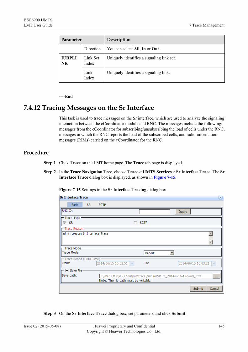
Parameter Description
Direction You can select All, In or Out.
IURPLINK
Link SetIndex
Uniquely identifies a signaling link set.
LinkIndex
Uniquely identifies a signaling link.
----End
7.4.12 Tracing Messages on the Sr InterfaceThis task is used to trace messages on the Sr interface, which are used to analyze the signalinginteraction between the eCoordinator module and RNC. The messages include the following:messages from the eCoordinator for subscribing/unsubscribing the load of cells under the RNC,messages in which the RNC reports the load of the subscribed cells, and radio informationmessages (RIMs) carried on the eCoordinator for the RNC.
Procedure
Step 1 Click Trace on the LMT home page. The Trace tab page is displayed.
Step 2 In the Trace Navigation Tree, choose Trace > UMTS Services > Sr Interface Trace. The SrInterface Trace dialog box is displayed, as shown in Figure 7-15.
Figure 7-15 Settings in the Sr Interface Tracing dialog box
Step 3 On the Sr Interface Trace dialog box, set parameters and click Submit.
BSC6900 UMTSLMT User Guide 7 Trace Management
Issue 02 (2015-05-08) Huawei Proprietary and ConfidentialCopyright © Huawei Technologies Co., Ltd.
145

Table 7-30 Parameter Description
Parameter Description
Basic RNC ID indicates the RNC ID of the cell to be traced. To query it, run theLST URNCBASIC command.
Trace Type You can select SR or SCTP.
TraceReason
l Reason of starting this tracing task.l Pressing the Enter key is not supported. Letters, digits, spaces
and the following special characters are supported: ! @ # $% ^ & * ( ) _ + - = ` ~ : " , . | \ < > ? / { } [ ]
Trace Mode See 7.1.3 Tracing Mode.
Save File See 7.2.3 Saving Traced Messages.
SCTP SCTP LinkID
indicates the number of an SCTP link. To query it, run the LSTSCTPLNK command.
----End
BSC6900 UMTSLMT User Guide 7 Trace Management
Issue 02 (2015-05-08) Huawei Proprietary and ConfidentialCopyright © Huawei Technologies Co., Ltd.
146

8 Performance Monitoring
About This Chapter
This chapter describes how to monitorBSC6900 performance. A maximum of 64 monitoringtasks can be started simultaneously on the LMT. If OMU boards are switched over, performancemonitoring can be restarted 30 minutes after the switchover.
8.1 ConceptsThis section describes the concepts related toBSC6900 performance monitoring, monitoringprinciples, and monitoring rights management.
8.2 General OperationsThis section describes the general operations applicable to all performance monitoring tasksperformed on the BSC6900.
8.3 Common MonitoringThis section describes common performance monitoring.
8.4 UMTS MonitoringThis section describes performance monitoring of UMTS services.
BSC6900 UMTSLMT User Guide 8 Performance Monitoring
Issue 02 (2015-05-08) Huawei Proprietary and ConfidentialCopyright © Huawei Technologies Co., Ltd.
147

8.1 ConceptsThis section describes the concepts related toBSC6900 performance monitoring, monitoringprinciples, and monitoring rights management.
8.1.1 Monitoring PrinciplesThis section describes the principles of real-time performance monitoring, including theprinciples of CPU usage monitoring and real-time performance monitoring.
Principles of CPU Usage MonitoringFigure 8-1 displays the principles of CPU usage monitoring.
Figure 8-1 CPU usage monitoring
The process for monitoring CPU usage is as follows:
1. When you use the LMT to create a task for monitoring CPU usage, the LMT periodicallysends a binary command to the OMU maintenance module to query CPU usage.
2. The OMU sends the corresponding command to the configuration and maintenance moduleof a specified board.
3. The board collects data according to the commands and reports it to the OMU.4. The OMU forwards the data to the LMT.5. The BSC supports CPU usage monitoring by subrack No. or by slot No.
Principles of Real-time Performance MonitoringFigure 8-2 shows the principles of other real-time performance monitoring, which are similarto the principles of message tracing.
BSC6900 UMTSLMT User Guide 8 Performance Monitoring
Issue 02 (2015-05-08) Huawei Proprietary and ConfidentialCopyright © Huawei Technologies Co., Ltd.
148

Figure 8-2 Real-time performance monitoring
The process when the LMT creates a real-time monitoring task, other than CPU usagemonitoring, is as follows:
1. The LMT sends a binary command to the OMU to create the task.
2. The OMU assigns a task ID to the task and sends the command to the debugging moduleof a specified board.
3. Upon receiving the command, the debugging module records the filter parameters in thefilter table and notifies the service module of the information.
4. The service module updates the local filter table in accordance with the messages from thedebugging module.
The process when the LMT stops a real-time monitoring task is as follows:
1. When you stop a monitoring task on the LMT, the LMT sends a binary command to theOMU to delete the task.
2. The OMU sends the command to the specified board based on the task ID.
3. The debugging module and service module delete the task from the filter table.
The process when the LMT reports real-time monitoring data is as follows:
1. The service module compares the collected data with data in the local filter table. If thedata is the same, the service module reports the collected data to the OMU.
2. Upon receiving the data, The OMU forwards it to the LMT that creates the task based onthe task ID.
3. The LMT displays the data in a chart or a list.
8.1.2 Operation Rights ControlOnly authorized users can perform real-time monitoring on the BSC6900.
Only the admin, common—operator-level, operator-level, administrator-level, and G_10-authorized custom-level users can perform this operation on BSC. Guest-level users and G_10-unauthorized custom-level users can only perform CPU usage monitoring.
NOTE
Group G_10 consists of binary commands used for tracing and monitoring.
BSC6900 UMTSLMT User Guide 8 Performance Monitoring
Issue 02 (2015-05-08) Huawei Proprietary and ConfidentialCopyright © Huawei Technologies Co., Ltd.
149

8.2 General OperationsThis section describes the general operations applicable to all performance monitoring tasksperformed on the BSC6900.
8.2.1 Browsing the Monitoring Results OnlineThis describes how to browse online and query the monitoring results that are dynamicallydisplayed in the real-time performance monitoring window.
Prerequisitesl A performance monitoring task has been started.l Monitoring data has been reported.
Procedurel Right-click on the Chart tab page in the real-time performance monitoring window. Then,
you can perform the following operations by selecting an appropriate option from theshortcut menu:– Auto Scroll– Show Grid– Switch Display Mode
NOTE
When the number of real-time monitoring tasks is greater than 60, right-click on the Chart tab pageand choose Switch Display Mode from the shortcut menu:
l If the bar chart has been displayed, you can switch it to the sequence diagram.
l If the sequence diagram has been displayed, you cannot switch it to the bar chart.
– Auto Adjustl Right-click on the List tab page in the real-time performance monitoring window. Then,
you can perform the following operation by selecting an appropriate option from theshortcut menu:
Setting auto scrolll Right-click on the task information pane at the bottom of the real-time performance
monitoring window. Then, you can perform the following operations by selecting anappropriate option from the shortcut menu:– Add Task or Delete Task– Stop Task or Restart Task– List Detailed Task Info
----End
8.2.2 Setting Chart Display ModeThis section describes how to set the chart display mode in the real-time performance monitoringwindow after you create and start a monitoring task. On the lower part of the Chart tab page in
BSC6900 UMTSLMT User Guide 8 Performance Monitoring
Issue 02 (2015-05-08) Huawei Proprietary and ConfidentialCopyright © Huawei Technologies Co., Ltd.
150

the window, you can set the chart display properties, such as the line color, line type, and linewidth.
Prerequisitesl A performance monitoring task has been started.
l Monitoring data has been reported.
Procedure
Step 1 In the task information pane of the real-time performance monitoring window, click LineColor, Line Type, or Line Width.
Step 2 Select the required properties from the drop-down lists.
NOTE
l The chart display attribute settings apply only to the current monitoring task.
l You can set the chart display mode If data is displayed on the List tab page but no chart is displayedon the Chart tab page during the real-time monitoring.
----End
8.2.3 Saving Monitoring DataThis section describes how to save the monitoring data as local files.
Prerequisitesl A performance monitoring task has been started.
l Monitoring data has been reported.
Procedure
Step 1 When you create a monitoring task, select the Save File check box and specify the save path.By default, the Save File check box is selected and the save path is C:/Web LMT/MBSC/output/monitor.
----End
8.2.4 Offline Browsing Monitoring DataThis section describes how to offline browse CPU usage monitoring data files and erroredsecond monitoring data files using the traffic recording review tool.
Prerequisites
The monitoring data has been saved as files.
Procedure
Step 1 Choose Start > All Programs > Huawei Local Maintenance Terminal > TrafficRecordingReview Tool.
BSC6900 UMTSLMT User Guide 8 Performance Monitoring
Issue 02 (2015-05-08) Huawei Proprietary and ConfidentialCopyright © Huawei Technologies Co., Ltd.
151

Step 2 Open save path of monitoring data files. The default save path is C:/Web LMT/MBSC/output/monitor. Select the file to be browsed.
Step 3 Click Open or double-click the file. The TrafficRecording Review Tool window is displayed,showing the monitoring data in a chart or a table.
Step 4 Click the List or Chart tab to view the data in different modes.
Step 5 To view other files, choose File > Open. In the Open dialog box, select and open the target filesto browse them.
----End
8.3 Common MonitoringThis section describes common performance monitoring.
8.3.1 Monitoring Board CPU/DSP UsageThis section describes how to query the CPU/DSP usage of a board.
Prerequisites
The board to be monitored is running properly.
Context
The OMU and SAU boards do not support this function.
NOTICEThis function increases the CPU usage. Therefore, if the CPU usage reaches 80% or higher, setthe monitoring period to 5s.
Procedure
Step 1 On the LMT main page, click Monitor. The Monitor tab page is displayed.
Step 2 On the Monitor Navigation Tree pane, choose Monitor > Common Monitoring > CPU/DSPUsage Monitoring. The CPU/DSP Usage Monitoring dialog box is displayed.
Step 3 In the CPU/DSP Usage Monitoring dialog box, set parameters according to actual situations,and click Submit.
l NE Time displayed in the status bar may be different from the actual NE time, but thedifference does not affect services.
----End
BSC6900 UMTSLMT User Guide 8 Performance Monitoring
Issue 02 (2015-05-08) Huawei Proprietary and ConfidentialCopyright © Huawei Technologies Co., Ltd.
152

8.3.2 Monitoring Transmission ResourcesThis section describes how to monitor the transmission resources on the Iub interface.
PrerequisitesThe board under monitoring is functional.
Procedure
Step 1 Click Monitor on the LMT main page. The Monitor tab page is displayed.
Step 2 On the Monitor Navigation Tree pane, choose Monitor > Common Monitoring > TransportResource Real-Time Monitoring. The Transport Resource Real-Time Monitoring dialogbox is displayed.
Step 3 In the Transport Resource Real-Time Monitoring dialog box, set the parameters as required,and click Submit.l Statistic Period(s): Specifies the duration of the measurement period for monitoring.l Transport Object Type: Specifies the type of the transport object to be monitored. It can
be set to IP Logic Port, Physical Port. For detailed settings, see Table 8-1.
Table 8-1 Detailed settings of Transport Object Type
Transport Object Type Description
IP Logic Port Indicates the number of the IP logical port.Logic Port No. must be specified.l Logic Port No.: Indicates the logical
port number. To query the logical portnumber, run the LSTIPLOGICPORT command.
BSC6900 UMTSLMT User Guide 8 Performance Monitoring
Issue 02 (2015-05-08) Huawei Proprietary and ConfidentialCopyright © Huawei Technologies Co., Ltd.
153

Transport Object Type Description
Physical Port Indicates the number of the physical port.Physical Port Type must be specified.l MP Group: Indicates the number of the
physical port carrying an MP link in theMP group. To query MP Group, run theLST MPGRP command.
l PPP Link: Indicates the number of thephysical port carrying the PPP link. Toquery PPP Link, run the LSTPPPLNK command.
l FRA Link: Indicates the number of thephysical port carrying the FRA link. Toquery FRA Link, run the LSTFRALNK command.
l IMA Group: Indicates the number ofthe physical port number carrying anIMA link in the IMP group. To queryIMA Group, run the LST IMAGRPcommand.
l UNI Link: Indicates the number of thephysical port carrying the UNI link. Toquery UNI Link, run the LSTUNILNK command.
l Subrack No.: Indicates the number of the subrack where the transport object to be monitored
is located.l Slot No.: Indicates the number of the slot where the transport object to be monitored is
located.l OP Index No.: Indicates the monitored operator of the transport object.l Statistic Type: Indicates the statistic type displayed in the monitoring report. It can be set
to Bandwidth(Original) or Bandwidth(Statistic). Then, you can select Uplink orDownlink to view the uplink or downlink statistics. If you have selected Bandwidth(Original), the bandwidths allocated to different services are displayed. If you have selectedBandwidth(Statistic), the total bandwidth used by all services is displayed.
– Bandwidth(Original): Displays the actual bandwidths allocated to different serviceswhen the UE is performing a voice service or data service. Table 8-2 shows the relatedstatistic items.
– Bandwidth(Statistic): Displays the total bandwidths of those allocated to differentservices. Table 8-3 shows the related statistic items.
– Uplink/Downlink: Displays the statistics of the bandwidths in the uplink or downlink.
BSC6900 UMTSLMT User Guide 8 Performance Monitoring
Issue 02 (2015-05-08) Huawei Proprietary and ConfidentialCopyright © Huawei Technologies Co., Ltd.
154

Table 8-2 Bandwidth(Original)
Statistic Item(Original)
Description
Admitted Bandwidth(3G Total)
Admitted bandwidth for 3G services at the transport layer on theuser plane. The admitted bandwidth consists of bandwidth used forsetting up the common channel and bandwidth for guaranteed bitrate (GBR). When calculating the bandwidth for GBR, bandwidthat the radio layer needs to be converted to that at the transport layer.
OLC Clear Threshold Overload control (OLC) end threshold. It equals configuredbandwidth minus overload congestion clear remain bandwidth.To query the configured bandwidth, run the DSPIPLOGICPORT command.To query the overload congestion clear remain bandwidth, run theADD TRMLOADTH command. Note that when Thresholdtype is set to PERCENTAGE(Percentage), the overloadcongestion clear remain bandwidth equals the configuredbandwidth multiplied by the overload congestion clear remainratio.
OLC Threshold OLC start threshold. It equals configured bandwidth minusoverload congestion remain bandwidth.To query the configured bandwidth, run the DSPIPLOGICPORT command.To query the overload congestion remain bandwidth, run the ADDTRMLOADTH command. Note that when Threshold type is setto PERCENTAGE(Percentage), the overload congestion remainbandwidth equals the configured bandwidth multiplied by thecongestion remain ratio.
Available Bandwidth Bandwidth available currently. It equals Total Bandwidth minusAdmitted Bandwidth(3G Total) minus Admitted Bandwidth(2G Total) minus signaling bandwidth. Admitted Bandwidth(2GTotal) is valid when 2G and 3G services share the same port.To query the signaling bandwidth, run the DSPIPLOGICPORT command. The signaling bandwidth cannot bequeried when Transport Object Type is set to Physical Port.
Reserved Thresholdfor Handover
Threshold for reserving bandwidth for handovers. It equalsconfigured bandwidth minus handover reserved bandwidth.To query the configured bandwidth, run the DSPIPLOGICPORT command.To query the handover reserved bandwidth, run the ADDTRMLOADTH command. Note that when Threshold type is setto PERCENTAGE(Percentage), the handover reservedbandwidth equals the configured bandwidth multiplied by thehandover reserved ratio.
RealTimeFluxBw Real-time traffic on a port.
BSC6900 UMTSLMT User Guide 8 Performance Monitoring
Issue 02 (2015-05-08) Huawei Proprietary and ConfidentialCopyright © Huawei Technologies Co., Ltd.
155

Statistic Item(Original)
Description
Realtime Bandwidth Bandwidth detected on a port.
RealTimeQueueFlux Real-time traffic in the service queues on a port.
Congestion ClearThreshold
Congestion end threshold. It equals configured bandwidth minuscongestion clear remain bandwidth.To query the configured bandwidth, run the DSPIPLOGICPORT command.To query the congestion clear remain bandwidth, run the ADDTRMLOADTH command. Note that when Threshold type is setto PERCENTAGE(Percentage), the congestion clear remainbandwidth equals the configured bandwidth multiplied by thecongestion clear remain ratio.
Congestion Threshold Congestion start threshold. It equals configured bandwidth minuscongestion remain bandwidth.To query the configured bandwidth, run the DSPIPLOGICPORT command.To query the congestion remain bandwidth, run the ADDTRMLOADTH command. Note that when Threshold type is setto PERCENTAGE(Percentage), congestion remain bandwidthequals the configured bandwidth multiplied by congestion remainratio.
Total Bandwidth When Auto adjust bandwidth switch is set to OFF(OFF) in theADD IPLOGICPORT command, Total Bandwidth equalsconfigured bandwidth. To query configured bandwidth, run theDSP IPLOGICPORT command. When Auto adjust bandwidthswitch is set to ON(ON), Total Bandwidth fluctuates betweenMax bandwidth [64kbps] and Min bandwidth [64kbps] basedon transmission quality indicated by IPPM detection.
Table 8-3 Statistic Item(Statistic)
Statistic Item(Statistic)
Description
Admitted Bandwidth(3G Total)
Admitted bandwidth for 3G services at the transport layer on theuser plane. The admitted bandwidth consists of bandwidth used forsetting up the common channel and bandwidth for guaranteed bitrate (GBR). When calculating the bandwidth for GBR, bandwidthat the radio layer needs to be converted to that at the transport layer.
BSC6900 UMTSLMT User Guide 8 Performance Monitoring
Issue 02 (2015-05-08) Huawei Proprietary and ConfidentialCopyright © Huawei Technologies Co., Ltd.
156

Statistic Item(Statistic)
Description
Available Bandwidth Bandwidth available currently. It equals Total Bandwidth minusAdmitted Bandwidth(3G Total) minus Admitted Bandwidth(2G Total) minus signaling bandwidth. Admitted Bandwidth(2GTotal) is valid when 2G and 3G services share the same port.To query the signaling bandwidth, run the DSPIPLOGICPORT command. The signaling bandwidth cannot bequeried when Transport Object Type is set to Physical Port.
Congestion ClearThreshold
Congestion end threshold. It equals configured bandwidth minuscongestion clear remain bandwidth.To query the configured bandwidth, run the DSPIPLOGICPORT command.To query the congestion clear remain bandwidth, run the ADDTRMLOADTH command. Note that when Threshold type is setto PERCENTAGE(Percentage), the congestion clear remainbandwidth equals the configured bandwidth multiplied by thecongestion clear remain ratio.
Congestion Threshold Congestion start threshold. It equals configured bandwidth minuscongestion remain bandwidth.To query the configured bandwidth, run the DSPIPLOGICPORT command.To query the congestion remain bandwidth, run the ADDTRMLOADTH command. Note that when Threshold type is setto PERCENTAGE(Percentage), the congestion remainbandwidth equals the configured bandwidth multiplied by thecongestion remain ratio.
OLC Clear Threshold OLC end threshold. It equals configured bandwidth minusoverload congestion clear remain bandwidth.To query the configured bandwidth, run the DSPIPLOGICPORT command.To query the overload congestion clear remain bandwidth, run theADD TRMLOADTH command. Note that when Thresholdtype is set to PERCENTAGE(Percentage), the overloadcongestion clear remain bandwidth equals the configuredbandwidth multiplied by the overload congestion clear remainratio.
BSC6900 UMTSLMT User Guide 8 Performance Monitoring
Issue 02 (2015-05-08) Huawei Proprietary and ConfidentialCopyright © Huawei Technologies Co., Ltd.
157

Statistic Item(Statistic)
Description
OLC Threshold Overload control (OLC) start threshold. It equals configuredbandwidth minus overload congestion remain bandwidth.To query the configured bandwidth, run the DSPIPLOGICPORT command.To query the overload congestion remain bandwidth, run the ADDTRMLOADTH command. Note that when Threshold type is setto PERCENTAGE(Percentage), the overload congestion remainbandwidth equals the configured bandwidth multiplied by thecongestion remain ratio.
Realtime Bandwidth Bandwidth detected on a port.
RealTimeQueueFlux Real-time traffic in the service queues on a port.
Reserved Thresholdfor Handover
Threshold for reserving bandwidth for handovers. It equalsconfigured bandwidth minus handover reserved bandwidth.To query the configured bandwidth, run the DSPIPLOGICPORT command.To query the handover reserved bandwidth, run the ADDTRMLOADTH command. Note that when Threshold type is setto PERCENTAGE(Percentage), the handover reservedbandwidth equals the configured bandwidth multiplied by thehandover reserved ratio.
Total Bandwidth When Auto adjust bandwidth switch is set to OFF(OFF) in theADD IPLOGICPORT command, Total Bandwidth equalsconfigured bandwidth. To query configured bandwidth, run theDSP IPLOGICPORT command. When Auto adjust bandwidthswitch is set to ON(ON), Total Bandwidth fluctuates betweenMax bandwidth [64kbps] and Min bandwidth [64kbps] basedon transmission quality indicated by IPPM detection.
----End
8.3.3 Monitoring BERSThis section describes how to monitor errored second (ES)of an E1/T1 port to monitortransmission quality of the link corresponding to a port. If any bit errors occur on the E1/T1 port,this function helps users obtain data, such as ES, severely errored second (SES), unavailablesecond (UAS), errored frames, CRC errors, bit error rate (calculated by CRC errors). Based onthe data and performance of the peer device, you can evaluate the transport network status andidentify the causes for the errors. The AEUa, AOUc, PEUa, PEUc, POUc board supports thisfunction.
Procedure
Step 1 On the LMT main page, click Monitor. The Monitor tab page is displayed.
BSC6900 UMTSLMT User Guide 8 Performance Monitoring
Issue 02 (2015-05-08) Huawei Proprietary and ConfidentialCopyright © Huawei Technologies Co., Ltd.
158

Step 2 On the Monitor Navigation Tree pane, choose Monitor > Common Monitoring > BERSMonitoring. The BERS Monitoring dialog box is displayed.
Step 3 In the BERS Monitoring dialog box, set parameters according to actual situations, and clickSubmit.
----End
8.3.4 Monitoring BERThis section describes how to monitor bit error rate (BER). The BER is used to evaluate transportnetwork quality. The AEUa, AOUc, PEUa, PEUc, POUc, POUa, AOUa board supports thisfunction.
Contextl Using this function interrupts IMA groups, UNI links, fractional ATM links, fractional
IMA links, MP groups, or PPP links carried on a board. As a result, services on thecorresponding port are interrupted.
l Before monitoring the BER, configure the local loopback or remote loopback, or use aloopback connector to short-circuit the TX end and the RX end.
l BER monitoring test and loopback test cannot be performed simultaneously because theresult and principles of these tests are the same.
l Only one BER monitoring test can be started for a board at a time.
Procedure
Step 1 On the LMT main page, click Monitor. The Monitor tab page is displayed.
Step 2 On the Monitor Navigation Tree pane, choose Monitor > Common Monitoring > BERMonitoring. The BER Monitoring dialog box is displayed.
Step 3 In the BER Monitoring dialog box, set parameters according to actual situations, and clickSubmit.
----End
8.3.5 Monitoring Link PerformanceThis section describes how to monitor link performance. A maximum of six monitoring taskscan be started simultaneously on the LMT. One monitoring task corresponds to one task window.When six tasks have started, you must close one task window before starting a new task.
Reference for Performance MonitoringThis section describes the parameters used for performance monitoring.
MonitorItem
Parameter Description
IMA Group IMA Group No. Indicates the number of the IMA group. To query theIMA group, run the LST IMAGRP command.
BSC6900 UMTSLMT User Guide 8 Performance Monitoring
Issue 02 (2015-05-08) Huawei Proprietary and ConfidentialCopyright © Huawei Technologies Co., Ltd.
159

MonitorItem
Parameter Description
UNI link UNI Link No. Indicates the number of the UNI link. To query the UNIlink, run the LST UNILNK command.
FractionalATM Link
FRAC Link No. Indicates the number of the fractional ATM link. Toquery the number of the fractional ATM link, run theLST FRALNK command and set Link type toFRAATM.
SAAL Link SAAL Link No. Indicates the number of the SAAL link. To query theSAAL link, run the LST SAALLNK command.
IPOA PVC IP AddressPing Peer IPAddress
Indicates the local and peer IP addresses of the IPOAPCV. To query these IP addresses, run the LSTIPOAPVC command.
AAL2 Path Adjacent Node IDAAL2 PATHSymbol
Indicates the ID of the adjacent node to an AAL2 pathand the AAL2 path symbol. To query the adjacent nodeID and the AAL2 path symbol, run the LSTAAL2PATH command.
FE/GE FE/GE Port No. Indicates the number of the FE/GE port. To query thenumber of the FE/GE port, run the LST ETHPORTcommand.
PPP Link PPP Link No. Indicates the number of the PPP link. To query the PPPlink, run the LST PPPLNK command.
MLPPPGroup
MLPPP GroupNo.
Indicates the number of the MLPPP group. To querythe number of the MLPPP group, run the LSTMPGRP command.
SCTP Link SCTP Link No. Indicates the number of the SCTP link. To query theSCTP link, run the LST SCTPLNK command.
IP Path Adjacent Node IDIP PATH Symbol
Indicates the number of the adjacent node of the IPpath. To query the adjacent node of the IP path, run theLST IPPATH command.
Logical Port Port No. Indicates the number of a logical port. To query theATM logical port, run the LST ATMLOGICPORTcommand.To query the IP logical port, run the LSTIPLOGICPORT command.
OAM NodeB ID Indicates the NodeB ID. To query the NodeB ID, runthe LST UNODEB command.
BSC6900 UMTSLMT User Guide 8 Performance Monitoring
Issue 02 (2015-05-08) Huawei Proprietary and ConfidentialCopyright © Huawei Technologies Co., Ltd.
160
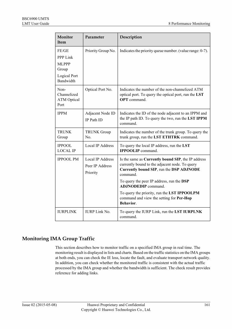
MonitorItem
Parameter Description
FE/GEPPP LinkMLPPPGroupLogical PortBandwidth
Priority Group No. Indicates the priority queue number. (value range: 0-7).
Non-ChannelizedATM OpticalPort
Optical Port No. Indicates the number of the non-channelized ATMoptical port. To query the optical port, run the LSTOPT command.
IPPM Adjacent Node IDIP Path ID
Indicates the ID of the node adjacent to an IPPM andthe IP path ID. To query the two, run the LST IPPMcommand.
TRUNKGroup
TRUNK GroupNo.
Indicates the number of the trunk group. To query thetrunk group, run the LST ETHTRK command.
IPPOOLLOCAL IP
Local IP Address To query the local IP address, run the LSTIPPOOLIP command.
IPPOOL PM Local IP AddressPeer IP AddressPriority
Is the same as Currently bound SIP, the IP addresscurrently bound to the adjacent node. To queryCurrently bound SIP, run the DSP ADJNODEcommand.To query the peer IP address, run the DSPADJNODEDIP command.To query the priority, run the LST IPPOOLPMcommand and view the setting for Per-HopBehavior.
IURPLINK IURP Link No. To query the IURP Link, run the LST IURPLNKcommand.
Monitoring IMA Group TrafficThis section describes how to monitor traffic on a specified IMA group in real time. Themonitoring result is displayed in lists and charts. Based on the traffic statistics on the IMA groupsat both ends, you can check the IE loss, locate the fault, and evaluate transport network quality.In addition, you can check whether the monitored traffic is consistent with the actual trafficprocessed by the IMA group and whether the bandwidth is sufficient. The check result providesreference for adding links.
BSC6900 UMTSLMT User Guide 8 Performance Monitoring
Issue 02 (2015-05-08) Huawei Proprietary and ConfidentialCopyright © Huawei Technologies Co., Ltd.
161

Context
NOTICEThe IMA group must be successfully set up and connected to the peer link before this task isperformed. This task is stopped if the monitored IMA group is deleted.
Procedure
Step 1 On the LMT main page, click Monitor. The Monitor tab page is displayed.
Step 2 On the Monitor Navigation Tree pane, choose Monitor > Common Monitoring > LinkPerformance Monitoring. The Link Performance Monitoring dialog box is displayed.
Step 3 In the Link Performance Monitoring dialog box, set Monitor Item to IMA Group and setother parameters according to actual situations. Then, click Submit.
----End
Monitoring UNI Link Traffic
This section describes how to monitor traffic on a specified UNI link in real time. The monitoringresult is displayed in lists and charts. Based on the traffic statistics on the UNI links at both ends,you can check the IE loss, locate the fault, and evaluate transport network quality. In addition,you can check whether the monitored traffic is consistent with the actual traffic processed bythe UNI link and whether the bandwidth is sufficient. The check result provides reference forchanging the link configuration mode. For example, change the link configuration mode to theIMA mode to support more traffic.
Context
NOTICEThe UNI link must be successfully set up and connected to the peer link before this task isperformed. This task is stopped if the monitored link is deleted.
Procedure
Step 1 On the LMT main page, click Monitor. The Monitor tab page is displayed.
Step 2 On the Monitor Navigation Tree pane, choose Monitor > Common Monitoring > LinkPerformance Monitoring. The Link Performance Monitoring dialog box is displayed.
Step 3 In the Link Performance Monitoring dialog box, set Monitor Item to UNI Link and set otherparameters according to actual situations. Then, click Submit.
----End
BSC6900 UMTSLMT User Guide 8 Performance Monitoring
Issue 02 (2015-05-08) Huawei Proprietary and ConfidentialCopyright © Huawei Technologies Co., Ltd.
162

Monitoring Fractional ATM Link Traffic
This section describes how to monitor traffic on a specified fractional ATM link in real time.The monitoring result is displayed in lists and charts. Based on the traffic statistics on thefractional ATM links at both ends, you can check the IE loss, locate the fault, and evaluatetransport network quality. In addition, you can check whether the monitored traffic is consistentwith the actual traffic processed by the link and whether the bandwidth is sufficient. The checkresult provides reference for changing the link configuration mode. For example, change thelink configuration mode to the IMA mode.
Context
NOTICEThe fractional ATM link must be successfully set up and connected to the peer link before thistask is performed. This task is stopped if the monitored link is deleted.
Procedure
Step 1 On the LMT main page, click Monitor. The Monitor tab page is displayed.
Step 2 On the Monitor Navigation Tree pane, choose Monitor > Common Monitoring > LinkPerformance Monitoring. The Link Performance Monitoring dialog box is displayed.
Step 3 In the Link Performance Monitoring dialog box, set Monitor Item to Fractional ATMLink and set other parameters according to actual situations. Then, click Submit.
----End
Monitoring SAAL Link Traffic
This section describes how to monitor traffic on a specified SAAL link in real time. Themonitoring result is displayed in lists and charts. Based on the TX/RX statistics on the SAALlinks to a subsystem, you can check the packet loss, locate the SAAL disconnection orintermittent disconnection. In addition, you can observe the link traffic and check whether linkcongestion occurs based on the configured link bandwidth.
Context
NOTICEThe SAAL must be successfully set up and connected to the peer link before this task isperformed. This task is stopped if the monitored link is deleted.
BSC6900 UMTSLMT User Guide 8 Performance Monitoring
Issue 02 (2015-05-08) Huawei Proprietary and ConfidentialCopyright © Huawei Technologies Co., Ltd.
163

Procedure
Step 1 On the LMT main page, click Monitor. The Monitor tab page is displayed.
Step 2 On the Monitor Navigation Tree pane, choose Monitor > Common Monitoring > LinkPerformance Monitoring. The Link Performance Monitoring dialog box is displayed.
Step 3 In the Link Performance Monitoring dialog box, set Monitor Item to SAAL Link and setother parameters according to actual situations. Then, click Submit.
----End
Monitoring IPOA PVC Link Traffic
This section describes how to monitor traffic on a specified IPOA PVC link in real time. Themonitoring result is displayed in lists and charts. If the IPOA PVC link works as an OML forthe ATM-based base station, this function helps you locate base station startup and load problemsand helps you observe the traffic and bandwidth utilization. If the IPoA PVC link works as anIP path over the Iu-PS interface, this function helps you observe the link traffic and locateconnection and congestion problems of upper-layer links.
Context
NOTICEThe IPOA PVC link must be successfully set up and connected to the peer link before this taskis performed. This task is stopped if the monitored link is deleted.
Procedure
Step 1 On the LMT main page, click Monitor. The Monitor tab page is displayed.
Step 2 On the Monitor Navigation Tree pane, choose Monitor > Common Monitoring > LinkPerformance Monitoring. The Link Performance Monitoring dialog box is displayed.
Step 3 In the Link Performance Monitoring dialog box, set Monitor Item to IPOA PVC and setother parameters according to actual situations. Then, click Submit.
----End
Monitoring AAL2 Path Traffic
This section describes how to monitor traffic on a specified AAL2 path in real time. Themonitoring result is displayed in lists and charts. Based on the layer-2 TX/RX statistics in theCDT data, you can check the packet loss and evaluate the traffic condition. In addition, you canobserve the link traffic and check whether link congestion occurs based on the configured linkbandwidth.
BSC6900 UMTSLMT User Guide 8 Performance Monitoring
Issue 02 (2015-05-08) Huawei Proprietary and ConfidentialCopyright © Huawei Technologies Co., Ltd.
164

Context
NOTICEThe AAL2 path must be successfully set up and connected to the peer link before this task isperformed. This task is stopped if the monitored link is deleted.
Procedure
Step 1 On the LMT main page, click Monitor. The Monitor tab page is displayed.
Step 2 On the Monitor Navigation Tree pane, choose Monitor > Common Monitoring > LinkPerformance Monitoring. The Link Performance Monitoring dialog box is displayed.
Step 3 In the Link Performance Monitoring dialog box, set Monitor Item to AAL2 Path and setother parameters according to actual situations. Then, click Submit.
----End
Monitoring FE/GE Port Traffic
This section describes how to monitor traffic on a specified FE/GE port in real time. Themonitoring result is displayed in lists and charts. Based on the traffic statistics on the FE/GEport, you can check the packet loss, locate the fault, and evaluate transport network quality. Inaddition, you can check whether the monitored traffic is consistent with the actual traffic on theport, check the port utilization, and check whether the bandwidth is sufficient. The check resultprovides reference for migrating services to prevent congestion.
Context
NOTICEThe FE/GE port must be successfully configured and connected to the peer port before this taskis performed. This task is stopped if the monitored link is deleted.
For FG2c, GOUc, GOUe boards, if the physical port carries a logical port and Monitor Typeis set to QoS for this task, the queue statistics of the physical port does not include the servicedata traffic on the logical port but includes only the service data traffic on the physical port.
Procedure
Step 1 On the LMT main page, click Monitor. The Monitor tab page is displayed.
Step 2 On the Monitor Navigation Tree pane, choose Monitor > Common Monitoring > LinkPerformance Monitoring. The Link Performance Monitoring dialog box is displayed.
BSC6900 UMTSLMT User Guide 8 Performance Monitoring
Issue 02 (2015-05-08) Huawei Proprietary and ConfidentialCopyright © Huawei Technologies Co., Ltd.
165

Step 3 In the Link Performance Monitoring dialog box, set Monitor Item to FE/GE and set otherparameters according to actual situations. Then, click Submit.
----End
Monitoring PPP Link TrafficThis section describes how to monitor traffic on a specified PPP link in real time. The monitoringresult is displayed in lists and charts. Based on the traffic statistics on the PPP links at both ends,you can check the packet loss, locate the fault, and evaluate transport network quality. In addition,you can check whether the monitored traffic is consistent with the actual traffic processed bythe link and whether the link bandwidth is sufficient. The check result provides reference foradding PPP links or changing the link configuration mode to MLPPP.
Context
NOTICEThe PPP link must be successfully set up and connected to the peer link before this task isperformed. This task is stopped if the monitored link is deleted.
For POUc boards, if the physical port carries a logical port and Monitor Type is set to QoS forthis task, the queue statistics of the physical port does not include the service data traffic on thelogical port but includes only the service data traffic on the physical port.
Procedure
Step 1 On the LMT main page, click Monitor. The Monitor tab page is displayed.
Step 2 On the Monitor Navigation Tree pane, choose Monitor > Common Monitoring > LinkPerformance Monitoring. The Link Performance Monitoring dialog box is displayed.
Step 3 In the Link Performance Monitoring dialog box, set Monitor Item to PPP Link and set otherparameters according to actual situations. Then, click Submit.
----End
Monitoring MLPPP Group TrafficThis section describes how to monitor traffic on a specified MLPPP group in real time. Themonitoring result is displayed in lists and charts. Based on the statistics on MLPPP groups atboth ends, you can check the packet loss, locate the fault, and evaluate transport network quality.In addition, you can check whether the monitored traffic is consistent with the actual trafficprocessed by the MLPPP group and whether the bandwidth is sufficient. The check resultprovides reference for adding links.
BSC6900 UMTSLMT User Guide 8 Performance Monitoring
Issue 02 (2015-05-08) Huawei Proprietary and ConfidentialCopyright © Huawei Technologies Co., Ltd.
166

Context
NOTICEThe MLPPP group must be successfully configured and connected to the peer link before thistask is performed. This task is stopped if the monitored MLPPP link group is deleted.
For POUc boards, if the physical port carries a logical port and Monitor Type is set to QoS forthis task, the queue statistics of the physical port does not include the service data traffic on thelogical port but includes only the service data traffic on the physical port.
Procedure
Step 1 On the LMT main page, click Monitor. The Monitor tab page is displayed.
Step 2 On the Monitor Navigation Tree pane, choose Monitor > Common Monitoring > LinkPerformance Monitoring. The Link Performance Monitoring dialog box is displayed.
Step 3 In the Link Performance Monitoring dialog box, set Monitor Item to MLPPP Group andset other parameters according to actual situations. Then, click Submit.
----End
Monitoring SCTP Link TrafficThis section describes how to monitor data packet traffic on a specified SCTP link in real time.The monitoring result is displayed in lists and charts. Based on the monitored traffic, you cancheck the packet loss, locate SCTP link intermittent disconnection, and check whether linkcongestion occurs.
Context
NOTICEThe SCTP link must be successfully set up and connected to the peer link before this task isperformed. This task is stopped if the monitored link is deleted.
Procedure
Step 1 On the LMT main page, click Monitor. The Monitor tab page is displayed.
Step 2 On the Monitor Navigation Tree pane, choose Monitor > Common Monitoring > LinkPerformance Monitoring. The Link Performance Monitoring dialog box is displayed.
Step 3 In the Link Performance Monitoring dialog box, set Monitor Item to SCTP Link and setother parameters according to actual situations. Then, click Submit.
----End
BSC6900 UMTSLMT User Guide 8 Performance Monitoring
Issue 02 (2015-05-08) Huawei Proprietary and ConfidentialCopyright © Huawei Technologies Co., Ltd.
167

Monitoring IP Path Traffic
This section describes how to monitor IP traffic on a specified IP path over an interface boardin real time. The monitoring result is displayed in lists and charts. Based on the layer-2 statisticsin the CDT data, you can check the packet loss and user data traffic. In addition, you can observelink traffic and check whether link congestion occurs.
Context
NOTICEThe IP path must be successfully set up and connected to the peer link before this task isperformed. This task is stopped if the monitored link is deleted.
Procedure
Step 1 On the LMT main page, click Monitor. The Monitor tab page is displayed.
Step 2 On the Monitor Navigation Tree pane, choose Monitor > Common Monitoring > LinkPerformance Monitoring. The Link Performance Monitoring dialog box is displayed.
Step 3 In the Link Performance Monitoring dialog box, set Monitor Item to IP Path and set otherparameters according to actual situations. Then, click Submit.
----End
Monitoring Logical Port Traffic
This section describes how to monitor traffic on a specified logical port. You can set MonitorType to Port or QoS for this function. If Monitor Type is set to Port, the real-time traffic isshown in the monitoring result. If Monitor Type is set to QoS, the QoS-specific TX traffic onthe logical port is shown in the monitoring result. Based on the traffic statistics on the logicalport, you can check the packet loss on the logical port and locate the fault. In addition, you cancheck whether the monitored traffic is consistent with the actual traffic on the port, check theport utilization, and check whether the bandwidth is sufficient. The check result providesreference for increasing the bandwidth configured on the logical port.
Procedure
Step 1 On the LMT main page, click Monitor. The Monitor tab page is displayed.
Step 2 On the Monitor Navigation Tree pane, choose Monitor > Common Monitoring > LinkPerformance Monitoring. The Link Performance Monitoring dialog box is displayed.
Step 3 In the Link Performance Monitoring dialog box, set Monitor Item to Logical Port and setother parameters according to actual situations. Then, click Submit.
----End
BSC6900 UMTSLMT User Guide 8 Performance Monitoring
Issue 02 (2015-05-08) Huawei Proprietary and ConfidentialCopyright © Huawei Technologies Co., Ltd.
168

Monitoring OAM Channel TrafficThis section describes how to monitor RX and TX IP traffic on a specified operation,administration, and maintenance (OAM) channel over an interface board in a NodeB. Themonitoring result is displayed in lists and charts. You can perform this function to observe thetraffic and bandwidth usage when the NodeB is loading data. Therefore, this function helpslocate the fault in the NodeB startup and data loading processes.
Procedure
Step 1 On the LMT main page, click Monitor. The Monitor tab page is displayed.
Step 2 On the Monitor Navigation Tree pane, choose Monitor > Common Monitoring > LinkPerformance Monitoring. The Link Performance Monitoring dialog box is displayed.
Step 3 In the Link Performance Monitoring dialog box, set Monitor Item to OAM and set otherparameters according to actual situations. Then, click Submit.
----End
Monitoring Logical Port BandwidthThis section describes how to monitor the bandwidth changes in a logical port after the dynamicbandwidth adjustment. The monitoring result is displayed in lists and charts. This task supportsIP pool performance monitoring (PM) function so that you can observe the bandwidth changesafter dynamic adjustment. In this way, you can check whether the bandwidth is adjusted properly.
Procedure
Step 1 On the LMT main page, click Monitor. The Monitor tab page is displayed.
Step 2 On the Monitor Navigation Tree pane, choose Monitor > Common Monitoring > LinkPerformance Monitoring. The Link Performance Monitoring dialog box is displayed.
Step 3 In the Link Performance Monitoring dialog box, set Monitor Item to Logic PortBandwidth and set other parameters according to actual situations. Then, click Submit.
----End
Monitoring Traffic on Non-Channelized ATM Optical PortThis section describes how to monitor traffic on a specified non-channelized ATM optical portin real time. The monitoring result is displayed in lists and charts. Based on the traffic statisticson the non-channelized ATM optical ports at both ends, you can check the IE loss, locate thefault, and evaluate transport network quality. In addition, you can check whether the monitoredtraffic is consistent with the actual traffic on the port and whether the bandwidth is sufficient.The check result provides reference for increasing the bandwidth.
BSC6900 UMTSLMT User Guide 8 Performance Monitoring
Issue 02 (2015-05-08) Huawei Proprietary and ConfidentialCopyright © Huawei Technologies Co., Ltd.
169

Context
NOTICEThe specified non-channelized ATM optical port must be connected to the peer port using links.
Procedure
Step 1 On the LMT main page, click Monitor. The Monitor tab page is displayed.
Step 2 On the Monitor Navigation Tree pane, choose Monitor > Common Monitoring > LinkPerformance Monitoring. The Link Performance Monitoring dialog box is displayed.
Step 3 In the Link Performance Monitoring dialog box, set Monitor Item to Non-ChannelizedATM Optical Port and set other parameters according to actual situations. Then, clickSubmit.
----End
Monitoring IP Pool PM Link TrafficThis section describes how to monitor PM link traffic in a specified IP pool in real time. Themonitoring result is displayed in lists and charts. Based on the PM link traffic statistics on theIP pool at the TX and RX ends, you can check the packet loss and locate transmissiondisconnection or intermittent disconnection in IP pool networking mode. In addition, you canobserve PM link traffic and check whether link congestion occurs.
Context
NOTICEThe PM link to be monitored in the IP pool must be activated.
Procedure
Step 1 On the LMT main page, click Monitor. The Monitor tab page is displayed.
Step 2 On the Monitor Navigation Tree pane, choose Monitor > Common Monitoring > LinkPerformance Monitoring. The Link Performance Monitoring dialog box is displayed.
Step 3 In the Link Performance Monitoring dialog box, set Monitor Item to IPPOOL PM and setother parameters according to actual situations. Then, click Submit.
----End
Monitoring Trunk Group TrafficThis section describes how to monitor traffic on a specified trunk group in real time. Themonitoring result is displayed in lists and charts. Based on the traffic statistics of the trunk groups
BSC6900 UMTSLMT User Guide 8 Performance Monitoring
Issue 02 (2015-05-08) Huawei Proprietary and ConfidentialCopyright © Huawei Technologies Co., Ltd.
170
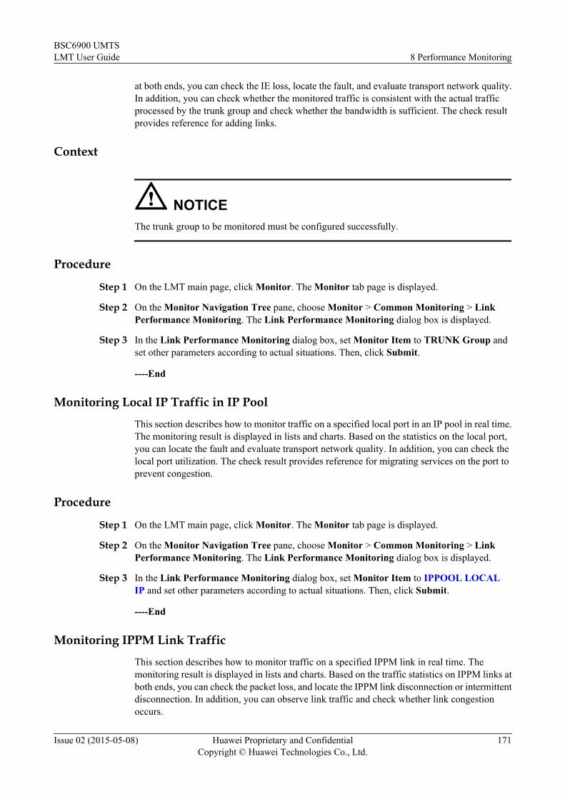
at both ends, you can check the IE loss, locate the fault, and evaluate transport network quality.In addition, you can check whether the monitored traffic is consistent with the actual trafficprocessed by the trunk group and check whether the bandwidth is sufficient. The check resultprovides reference for adding links.
Context
NOTICEThe trunk group to be monitored must be configured successfully.
Procedure
Step 1 On the LMT main page, click Monitor. The Monitor tab page is displayed.
Step 2 On the Monitor Navigation Tree pane, choose Monitor > Common Monitoring > LinkPerformance Monitoring. The Link Performance Monitoring dialog box is displayed.
Step 3 In the Link Performance Monitoring dialog box, set Monitor Item to TRUNK Group andset other parameters according to actual situations. Then, click Submit.
----End
Monitoring Local IP Traffic in IP Pool
This section describes how to monitor traffic on a specified local port in an IP pool in real time.The monitoring result is displayed in lists and charts. Based on the statistics on the local port,you can locate the fault and evaluate transport network quality. In addition, you can check thelocal port utilization. The check result provides reference for migrating services on the port toprevent congestion.
Procedure
Step 1 On the LMT main page, click Monitor. The Monitor tab page is displayed.
Step 2 On the Monitor Navigation Tree pane, choose Monitor > Common Monitoring > LinkPerformance Monitoring. The Link Performance Monitoring dialog box is displayed.
Step 3 In the Link Performance Monitoring dialog box, set Monitor Item to IPPOOL LOCALIP and set other parameters according to actual situations. Then, click Submit.
----End
Monitoring IPPM Link Traffic
This section describes how to monitor traffic on a specified IPPM link in real time. Themonitoring result is displayed in lists and charts. Based on the traffic statistics on IPPM links atboth ends, you can check the packet loss, and locate the IPPM link disconnection or intermittentdisconnection. In addition, you can observe link traffic and check whether link congestionoccurs.
BSC6900 UMTSLMT User Guide 8 Performance Monitoring
Issue 02 (2015-05-08) Huawei Proprietary and ConfidentialCopyright © Huawei Technologies Co., Ltd.
171

Context
NOTICEThe IPPM link to be monitored has been activated.
Procedure
Step 1 On the LMT main page, click Monitor. The Monitor tab page is displayed.
Step 2 On the Monitor Navigation Tree pane, choose Monitor > Common Monitoring > LinkPerformance Monitoring. The Link Performance Monitoring dialog box is displayed.
Step 3 In the Link Performance Monitoring dialog box, set Monitor Item to IPPM and set otherparameters according to actual situations. Then, click Submit.
----End
Monitoring Iur-p Link Traffic
This section describes how to monitor traffic on a specified Iur-p link in real time. The monitoringresult is displayed in lists and charts. Based on the traffic statistics on the Iur-p link, you cancheck the packet loss, locate the fault, and evaluate transport network quality. In addition, youcan check the link traffic. The check result provides reference for adding links to the Iur-pinterface to prevent congestion.
Context
NOTICEThe Iur-p link must be configured and connected to the peer port before this task is performed.This task is stopped if the monitored link is deleted.
Procedure
Step 1 On the LMT main page, click Monitor. The Monitor tab page is displayed.
Step 2 On the Monitor Navigation Tree pane, choose Monitor > Common Monitoring > LinkPerformance Monitoring. The Link Performance Monitoring dialog box is displayed.
Step 3 In the Link Performance Monitoring dialog box, set Monitor Item to IURPLNK and setother parameters according to actual situations. Then, click Submit.
----End
BSC6900 UMTSLMT User Guide 8 Performance Monitoring
Issue 02 (2015-05-08) Huawei Proprietary and ConfidentialCopyright © Huawei Technologies Co., Ltd.
172

8.4 UMTS MonitoringThis section describes performance monitoring of UMTS services.
8.4.1 Monitoring Connection PerformanceThis section describes how to monitor performance of physical connections of UEs during acall. A maximum of six monitoring tasks can be started simultaneously for a monitoring item.
Monitoring P-CPICH Ec/No and RSCPThis section describes how to monitor the P-CPICH Ec/No and RSCP of a cell in the active setin real time. Based on the number of cells in the active set and signal strength of each cell, youcan learn about whether the current connection is at the edge or the center of the cell.
Contextl There is no way to avoid that some user data such as International Mobile Subscriber
Identity (IMSI) will be used during problem location and resolution. This function providesan anonymous data processing method. You are recommended to comply with local lawswhen executing the task and take ample measures to fully protect user data, such as enablingthe anonymous function and deleting the folder that saves trace records after you finishprocessing data.
l When entering IMSI, check whether IMSI data to be entered must be anonymous by runningthe LST USERIDANONSWITCH command and querying User Identity AnonymitySwitch.
– If User Identity Anonymity Switch is ON, the anonymous policy is enabled, andanonymous IMSI data must be entered in IMSI. The anonymous IMSI data is the IMSIdata encrypted by the HMACUtil using the cipher key.
– If User Identity Anonymity Switch is OFF, the anonymous policy is disabled, and userIMSI data is directly entered in IMSI.
NOTE
l Change the anonymous policy and cipher key on the U2000 by choosing Trace and Maintenance >Signaling Trace > Anonymous Policy Management > Anonymous Cypher Key Management(application style) or Trace and Maintenance > Monitor > Signaling Trace > Anonymous PolicyManagement > Anonymous Cypher Key Management (traditional style). For details, see U2000Fault Management User Guide.
l If you change the anonymous policy or cipher key of a started tracing task, you need to restart thetracing task. Otherwise, the tracing task becomes invalid.
l For details about how to obtain the HMACUtil, contact Huawei technical support.
BSC6900 UMTSLMT User Guide 8 Performance Monitoring
Issue 02 (2015-05-08) Huawei Proprietary and ConfidentialCopyright © Huawei Technologies Co., Ltd.
173

NOTICEBefore running this monitoring task, perform either of the following operations:
l Run SET UCORRMALGOSWITCH to set Handover algorithm switch. Ensure thatSOFT_HANDOVER_SWITCH is selected for this parameter.
l Run MOD UCELLMEAS to set Intra-freq Meas Ctrl Info Ind to REQUIRE.
NOTE
l This task is used only to monitor connections on dedicated channels. An ongoing task is stopped if themonitored connection is released or relocated from the dedicated channel to a common channel. Thetask is restarted if the monitored connection is relocated from the common channel to a dedicatedchannel.
l This task is used only to monitor the real-time data of the cells in the active set. The data of other cellsis not reported. Therefore, the monitoring results reflect the changes in the number of cells in the activeset in real time.
l A maximum of three cells in the active set can be monitored in a task.
Procedure
Step 1 On the LMT main page, click Monitor. The Monitor tab page is displayed.
Step 2 On the Monitor Navigation Tree pane, choose Monitor > UMTS Monitoring > ConnectionPerformance Monitoring. The Connection Performance Monitoring dialog box is displayed.
Step 3 In the Connection Performance Monitoring dialog box, set Monitor Item to PCPICH Ec/No RSCP and set other parameters according to actual situations. Then, click Submit.
NOTE
After the monitoring task is started, a real-time monitoring window is displayed. The task name is displayed inthe title bar of the window and the monitoring result is displayed in lists and charts.
In the chart, the X-coordinate represents the hour: minute: second. The Y-coordinate represents the reported P-CPICH Ec/No (unit: dB) and RSCP (unit: dBm).
l RSCP refers to the received signal code power measured on a P-CPICH. The reference point for RSCPmeasurement is at the antenna connector of a UE. If the P-CPICH uses transmit diversity, you need tomeasure the RSCP of each antenna and sum up all of the RSCP values to obtain the total RSCP of the P-CPICH.
l Ec/No refers to the ratio of received energy per chip to noise spectral density. Like RSCP/RSSI, Ec/No isalso measured on the P-CPICH. The reference point for Ec/No measurement is also at the antenna connectorof the UE. If the P-CPICH uses transmit diversity, you need to measure the Ec/No of each antenna and sumup all of the Ec/No values to obtain the total Ec/No of the P-CPICH.
----End
Monitoring SIR Values of the Uplink RLSs
This section describes how to monitor the signal-to-interference ratio (SIR) values of the uplinkradio link sets (RLSs) used by a UE in real time. By performing this task, you can learn aboutthe uplink radio link quality and quality variations.
BSC6900 UMTSLMT User Guide 8 Performance Monitoring
Issue 02 (2015-05-08) Huawei Proprietary and ConfidentialCopyright © Huawei Technologies Co., Ltd.
174
ContextNOTE
A task can be started for a UE. The monitoring result includes the number of cells in the active set and thesignal strength of each cell. Based on the monitoring result, you can know whether the current connectionis at the edge or the center of the cell.
Procedure
Step 1 On the LMT main page, click Monitor. The Monitor tab page is displayed.
Step 2 On the Monitor Navigation Tree pane, choose Monitor > UMTS Monitoring > ConnectionPerformance Monitoring. The Connection Performance Monitoring dialog box is displayed.
Step 3 In the Connection Performance Monitoring dialog box, set Monitor Item to UL SIR and setother parameters according to actual situations. Then, click Submit.
NOTE
After the monitoring task is started, a real-time monitoring window is displayed. The task name is displayed inthe title bar of the window and the monitoring result is displayed in lists and charts. The monitoring result canreflect the changes in the number of the RLSs in real time.
In the chart, the X-coordinate represents the hour: minute: second. The Y-coordinate represents the reportedSIR of the UL RLSs (unit: dB).
The SIR is calculated using the formula (RSCP/ISCP) x SF, where:
l RSCP is short for Received Signal Code Power and reflects the received power on one code.
l ISCP is short for Interference Signal Code Power and reflects interference to the received signal. Only thenon-orthogonal interference is measured for ISCP.
l SF is short for the spreading factor of a DPCCH.
This task is performed on the DPCCH after radio links are combined on the NodeB. In compressed mode, theSIR is not measured during the transmit intervals. The NodeB reports the measured uplink SIR values to theBSC6900.
----End
Monitoring the Outer Loop Power Control
This section describes how to monitor parameter values during outer loop power control. Basedon the current service type, the parameters include Number of Total Blocks, Number of ErrorBlocks, OLPC UL BLER, OLPC UL BER, OLPC BER Filter, OLPC SIR Target, OLPCSIR Target High Precision, E-DCH Average Transmission Number, Total Number ofTransmission Times, Total Number of Discarded PDUs, Total Number of PDUs, and E-DCH Residual BLER.
Procedure
Step 1 On the LMT main page, click Monitor. The Monitor tab page is displayed.
Step 2 On the Monitor Navigation Tree pane, choose Monitor > UMTS Monitoring > ConnectionPerformance Monitoring. The Connection Performance Monitoring dialog box is displayed.
Step 3 In the Connection Performance Monitoring dialog box, set Monitor Item to OLPC and setother parameters according to actual situations. Then, click Submit.
BSC6900 UMTSLMT User Guide 8 Performance Monitoring
Issue 02 (2015-05-08) Huawei Proprietary and ConfidentialCopyright © Huawei Technologies Co., Ltd.
175

NOTE
If Monitor Period(s) is set to OLPC, the monitor period is set to the value specified by the OLPC adjustmentperiod parameter in the ADD UTYPRABOLPC or MOD UTYPRABOLPC command.
After the monitoring task is started, a real-time monitoring window is displayed. The task name is displayed inthe title bar of the window and the monitoring result is displayed in lists and charts. In charts, the X-coordinaterepresents the hour: minute: second. Two charts are used to describe five monitoring items.
l The first chart shows the output interface of the OLPC SIR target value, OLPC UL BLER, and OLPC ULBER. The left Y coordinate represents OLPC SIR Target (range: -10 to 18; unit: dB). The right Y coordinaterepresents OLPC UL BLER (range: 0 to 1; unit: none) and OLPC UL BER (range: 0 to 1; unit: none).
l The second chart shows the output interface of E-DCH Average Transmission Number and E-DCHResidual BLER. The left Y coordinate represents E-DCH Average Transmission Number (default valuerange: 0 to 16; unit: none). The coordinate value range can be dynamically adjusted based on the actualvalue. The right Y coordinate represents E-DCH Residual BLER (range: 0 to 1; unit: none).
----End
Monitoring the SIR Error Values of UL RLSsThis section describes how to monitor the SIR error values of radio link sets (RLSs) of the currentconnection in real time. By performing this task, you can observe whether the SIR can keep upwith the variation of the target values and estimate the UL inner loop power control function. Ifthe SIR error values change all the time but are approximate to 0 dB, the UL inner loop powercontrol converges. Otherwise, the UL inner loop power control does not converge.
ContextThis task is used only to monitor connections on dedicated channels. An ongoing task is stoppedif the monitored connection is released or relocated from the dedicated channel to a commonchannel. The task is restarted if the monitored connection is relocated from the common channelto a dedicated channel.
Procedure
Step 1 On the LMT main page, click Monitor. The Monitor tab page is displayed.
Step 2 On the Monitor Navigation Tree pane, choose Monitor > UMTS Monitoring > ConnectionPerformance Monitoring. The Connection Performance Monitoring dialog box is displayed.
Step 3 In the Connection Performance Monitoring dialog box, set Monitor Item to UL SIRError and set other parameters according to actual situations. Then, click Submit.
BSC6900 UMTSLMT User Guide 8 Performance Monitoring
Issue 02 (2015-05-08) Huawei Proprietary and ConfidentialCopyright © Huawei Technologies Co., Ltd.
176

NOTE
After the monitoring task is started, a real-time monitoring window is displayed. The task name is displayed inthe title bar of the window and the monitoring result is displayed in lists and charts.
In charts, the X-coordinate represents the hour: minute: second. The Y-coordinate represents the reported SIRerror values (SIRerror) of the UL RLSs.
l SIRerror (unit: dB) is reported from the NodeB to the BSC6900. The formula is as follows: SIRerror = SIR -SIRtarget_ave.
l Where, SIRtarget_ave represents the average of SIRtarget within a period that is equal to the time for calculatingthe SIR in the preceding formula for calculating SIRerror.
l In compressed mode, SIRtarget equals to SIRcm_target. The SIRtarget_ave is not calculated during transmissionintervals. The average of SIRtarget is an arithmetical average. The unit of SIRtarget_ave is dB.
----End
Monitoring DL Code TX Power
This section describes how to monitor the DL code TX power of each radio link of the currentconnection in real time. By performing this task, you can analyze the DL power consumption.If the DL code TX power increases and even approximates to the maximum value configuredin the signaling message, DL quality deteriorates.
Context
This task is used only to monitor connections on dedicated channels. An ongoing task is stoppedif the monitored connection is released or relocated from the dedicated channel to a commonchannel. The task is restarted if the monitored connection is relocated from the common channelto a dedicated channel.
Procedure
Step 1 On the LMT main page, click Monitor. The Monitor tab page is displayed.
Step 2 On the Monitor Navigation Tree pane, choose Monitor > UMTS Monitoring > ConnectionPerformance Monitoring. The Connection Performance Monitoring dialog box is displayed.
Step 3 In the Connection Performance Monitoring dialog box, set Monitor Item to DL Tx CodePower and set other parameters according to actual situations. Then, click Submit.
NOTE
After the monitoring task is started, a real-time monitoring window is displayed. The task name is displayed inthe title bar of the window and the monitoring result is displayed in lists and charts. The monitoring resultsreflect the changes in the number of the radio links involved in the current connection in real time.
In charts, the X-coordinate represents the hour: minute: second. The Y-coordinate represents the reported DLcode TX power (unit: dBm).
Code TX power refers to the NodeB TX power on one channelization code that is on one given scrambling codeon one given carrier. The DL code TX power can be measured on the DPCCH of any radio link outgoing fromthe UTRAN and indicates the pilot bit power of the DPCCH.
In compressed mode, the TX power measurement should cover all timeslots, including those during the transmitintervals. The reference point for measurement is at the antenna connector. If transmit diversity is used, the DLcode TX power is the total of the code TX powers of all antennas.
----End
BSC6900 UMTSLMT User Guide 8 Performance Monitoring
Issue 02 (2015-05-08) Huawei Proprietary and ConfidentialCopyright © Huawei Technologies Co., Ltd.
177

Monitoring UE TX Power
This section describes how to monitor the TX power of a UE. By performing this task, you cananalyze the UL radio link quality. If the UE TX power increases and even reaches the limit ofthe UE capability, the UL radio link quality deteriorates.
Context
UE TX power refers to the transmit power of a UE on a carrier. The reference point formeasurement of the UE TX power is at the antenna connector of the UE.
This task is used only to monitor connections on dedicated channels. An ongoing task is stoppedif the monitored connection is released or relocated from the dedicated channel to a commonchannel. The task is restarted if the monitored connection is relocated from the common channelto a dedicated channel.
Procedure
Step 1 On the LMT main page, click Monitor. The Monitor tab page is displayed.
Step 2 On the Monitor Navigation Tree pane, choose Monitor > UMTS Monitoring > ConnectionPerformance Monitoring. The Connection Performance Monitoring dialog box is displayed.
Step 3 In the Connection Performance Monitoring dialog box, set Monitor Item to UE Tx Powerand set other parameters according to actual situations. Then, click Submit.
NOTE
After the monitoring task is started, a real-time monitoring window is displayed. The task name is displayed inthe title bar of the window and the monitoring result is displayed in lists and charts.
In charts, the X-coordinate represents the hour: minute: second. The Y-coordinate represents the reported UETX power (unit: dBm).
----End
Monitoring UL Traffic Volume
This section describes how to monitor the UL traffic volume, that is, the buffered data volumeat the UE side, on the current connection in real time. By performing this task, you can analyzetransmission performance of UL traffic volume. The UL traffic volume on transport channelsis measured by the UE and reported to the BSC6900.
Context
Traffic volume refers to the Buffer Occupy (BO) value. BO is the number of data bytes to betransmitted or retransmitted from the RLC entity on a logical channel. If RLC is in AM mode,the BO value includes the control Protocol Data Unit (PDU) and the PDU outside the transmitwindow, excluding the PDUs for which no ACK is received.
This task can be used to monitor the connections of PS interactive and background services oncommon channels or dedicated channels. As specified in protocols, UEs cannot report the ULtraffic volume of HSUPA services to the RNC. Therefore, the UL traffic volume is not displayedin the LMT monitoring window.
BSC6900 UMTSLMT User Guide 8 Performance Monitoring
Issue 02 (2015-05-08) Huawei Proprietary and ConfidentialCopyright © Huawei Technologies Co., Ltd.
178

Procedure
Step 1 On the LMT main page, click Monitor. The Monitor tab page is displayed.
Step 2 On the Monitor Navigation Tree pane, choose Monitor > UMTS Monitoring > ConnectionPerformance Monitoring. The Connection Performance Monitoring dialog box is displayed.
Step 3 In the Connection Performance Monitoring dialog box, set Monitor Item to UL TrafficVol and set other parameters according to actual situations. Then. click Submit.
NOTE
After the monitoring task is started, a real-time monitoring window is displayed. The task name is displayed inthe title bar of the window and the monitoring result is displayed in lists and charts.
In charts, the X-coordinate represents the hour: minute: second. The Y-coordinate represents the reported ULtraffic volume on the UL physical channel (unit: byte).
----End
Monitoring DL Traffic Volume
This section describes how to monitor DL traffic volume, that is, the buffered data volume onthe MSC side, on the current connection in real time. By performing this task, you can analyzetransmission performance of DL traffic volume. The DL traffic volume on transport channelsis measured on the BSC6900.
Context
Traffic volume refers to the Buffer Occupy (BO) value. BO is the number of data bytes to betransmitted or retransmitted from the RLC entity on a logical channel. If RLC is in AM mode,the BO value includes the control Protocol Data Unit (PDU) and the PDU outside the transmitwindow, excluding the PDUs for which no ACK is received.
This task can be used to monitor the connections of PS interactive and background services oncommon channels or dedicated channels.
Procedure
Step 1 On the LMT main page, click Monitor. The Monitor tab page is displayed.
Step 2 On the Monitor Navigation Tree pane, choose Monitor > UMTS Monitoring > ConnectionPerformance Monitoring. The Connection Performance Monitoring dialog box is displayed.
Step 3 In the Connection Performance Monitoring dialog box, set Monitor Item to DL TrafficVol and set other parameters according to actual situations. Then, click Submit.
NOTE
After the monitoring task is started, a real-time monitoring window is displayed. The task name is displayed inthe title bar of the window and the monitoring result is displayed in lists and charts.
In charts, the X-coordinate represents the hour: minute: second. The Y-coordinate represents the reported DLtraffic volume (unit: byte).
----End
BSC6900 UMTSLMT User Guide 8 Performance Monitoring
Issue 02 (2015-05-08) Huawei Proprietary and ConfidentialCopyright © Huawei Technologies Co., Ltd.
179

Monitoring UL Throughput and Bandwidth
This section describes how to monitor rate variations on the UL transport access stratum andnon-access stratum of the current connection in real time. By performing this task, you cananalyze dynamic channel configuration and service source rate variations.
Context
Throughput refers to the amount of data transmitted on a transport channel in units of time andis measured on the MAC-d. Bandwidth refers to the maximum rate calculated based on the RLCpayload. The bandwidth changes during RB reconfiguration. The throughput measurementinvolves RLC headers, and therefore the measured peak throughput is greater than thebandwidth.
This task can be used to monitor the connections of PS interactive and background services oncommon channels or dedicated channels.
Procedure
Step 1 On the LMT main page, click Monitor. The Monitor tab page is displayed.
Step 2 On the Monitor Navigation Tree pane, choose Monitor > UMTS Monitoring > ConnectionPerformance Monitoring. The Connection Performance Monitoring dialog box is displayed.
Step 3 In the Connection Performance Monitoring dialog box, set Monitor Item to UL ThroughputBandwidth and set other parameters according to actual situations. Then, click Submit.
NOTE
After the monitoring task is started, a real-time monitoring window is displayed. The task name is displayed inthe title bar of the window and the monitoring result is displayed in lists and charts.
In charts, the X-coordinate represents the hour: minute: second. The Y-coordinate represents the reported ULthroughput and UL bandwidth (unit: bit/s).
l Observe the variations of the UL throughput and bandwidth during verification of dynamic channelconfigurations. If the UL bandwidth varies with the UL throughput, dynamic channel configuration isnormal.
l If dynamic channel configuration is not used, observe the variation of UL throughput to verify service sourcerate variations.
----End
Monitoring DL Throughput and Bandwidth
This section describes how to monitor rate variations on the DL transport access stratum andnon-access stratum of the current connection in real time. By performing this task, you cananalyze dynamic channel configuration and service source rate variations.
Context
Throughput refers to the amount of data transmitted on a transport channel in units of time andis measured on the MAC-d. Bandwidth refers to the maximum rate calculated based on the RLCpayload. The bandwidth changes during RB reconfiguration. The throughput measurementinvolves RLC headers, and therefore the measured peak throughput is greater than thebandwidth.
BSC6900 UMTSLMT User Guide 8 Performance Monitoring
Issue 02 (2015-05-08) Huawei Proprietary and ConfidentialCopyright © Huawei Technologies Co., Ltd.
180

This task can be used to monitor the connections of PS interactive and background services oncommon channels or dedicated channels.
Procedure
Step 1 On the LMT main page, click Monitor. The Monitor tab page is displayed.
Step 2 On the Monitor Navigation Tree pane, choose Monitor > UMTS Monitoring > ConnectionPerformance Monitoring. The Connection Performance Monitoring dialog box is displayed.
Step 3 In the Connection Performance Monitoring dialog box, set Monitor Item to DL ThroughputBandwidth and set other parameters according to actual situations. Then, click Submit.
NOTE
After the monitoring task is started, a real-time monitoring window is displayed. The task name is displayed inthe title bar of the window and the monitoring result is displayed in lists and charts.
In charts, the X-coordinate represents the hour: minute: second. The Y-coordinate represents the reported DLthroughput and DL bandwidth (unit: bit/s).
l Observe the variations of the DL throughput and bandwidth during verification of dynamic channelconfigurations. If the DL bandwidth varies with the DL throughput, dynamic channel configuration isnormal.
l If dynamic channel configuration is not used, observe the variation of DL throughput to verify service sourcerate variations.
----End
Monitoring Handover Delay
This section describes how to monitor the handover delay.
Context
Handover delay refers to the time taken by each handover. During this period of time, theBSC6900 makes a handover decision, initiates the handover (including the soft handover andthe hard handover), and completes the handover.
This task is used only to monitor the handover delay of a UE in the CELL_DCH state. An ongoingtask is stopped if the UE transits from the CELL_DCH state to the CELL_FACH state or idlemode. The task is restarted if the UE transits from the CELL_FACH state or idle mode back tothe CELL_DCH state.
A maximum of five tasks can be simultaneously started on the LMT. This task can monitor thedelay of an intra-frequency or inter-frequency handover but not an inter-RAT handover.
Procedure
Step 1 On the LMT main page, click Monitor. The Monitor tab page is displayed.
Step 2 On the Monitor Navigation Tree pane, choose Monitor > UMTS Monitoring > ConnectionPerformance Monitoring. The Connection Performance Monitoring dialog box is displayed.
Step 3 In the Connection Performance Monitoring dialog box, set Monitor Item to HandoverDelay and set other parameters according to actual situations. Then, click Submit.
BSC6900 UMTSLMT User Guide 8 Performance Monitoring
Issue 02 (2015-05-08) Huawei Proprietary and ConfidentialCopyright © Huawei Technologies Co., Ltd.
181

MonitoringResults
Description
HO Delay(ms) Time taken by a handover
HO Interval(ms) Difference between the end time of the preceding handover and theend time of the current handover
NOTE
After the monitoring task is started, a real-time monitoring window is displayed. The task name is displayed inthe title bar of the window and the monitoring result is displayed in lists and charts.
In charts, the X-coordinate represents the hour: minute: second. The Y-coordinate represents handover delayand interval (unit: ms).
----End
Monitoring DL Transport Channel BLERThis section describes how to monitor block error rate (BLER) variations on all transportchannels. By performing this task, you can analyze the DL radio link quality. If the BLER ofthe DL transport channel increases, the DL radio link quality deteriorates. If the BLER decreases,the DL radio link quality improves.
ContextThe BLER of the DL transport channel is measured on the UE and used for outer loop powercontrol.
This task is used only to monitor connections on dedicated channels. An ongoing task is stoppedif the monitored connection is released or relocated from the dedicated channel to a commonchannel. The task is restarted if the monitored connection is relocated from the common channelto a dedicated channel.
Procedure
Step 1 On the LMT main page, click Monitor. The Monitor tab page is displayed.
Step 2 On the Monitor Navigation Tree pane, choose Monitor > UMTS Monitoring > ConnectionPerformance Monitoring. The Connection Performance Monitoring dialog box is displayed.
Step 3 In the Connection Performance Monitoring dialog box, set Monitor Item to DL BLER andset other parameters according to actual situations. Then, click Submit.
NOTE
After the monitoring task is started, a real-time monitoring window is displayed. The task name is displayed inthe title bar of the window and the monitoring result is displayed in lists and charts. The monitoring resultsreflect the changes in the number of traffic transport channels in real time. The number of signaling transportchannels is always 1.
In charts, the X-coordinate represents the hour: minute: second. The Y-coordinate represents the reported BLERof the DL transport channel (unit: %).
----End
BSC6900 UMTSLMT User Guide 8 Performance Monitoring
Issue 02 (2015-05-08) Huawei Proprietary and ConfidentialCopyright © Huawei Technologies Co., Ltd.
182

Monitoring AMR ModeThis section describes how to monitor the variation in the configured AMR rate in real time.
ContextThis task can be started only if the traced UE is processing AMR services.
The narrowband AMR has eight available rates, that is, eight AMR modes: 12.2 kbit/s, 10.2 kbit/s, 7.95 kbit/s, 7.4 kbit/s, 6.7 kbit/s, 5.9 kbit/s, 5.15 kbit/s, and 4.75 kbit/s.
The wideband AMR has nine available rates, that is, nine AMR modes: 23.85 kbit/s, 23.05 kbit/s, 19.85 kbit/s, 18.25 kbit/s, 15.85 kbit/s, 14.25 kbit/s, 12.65 kbit/s, 8.85 kbit/s, and 6.60 kbit/s.
Procedure
Step 1 On the LMT main page, click Monitor. The Monitor tab page is displayed.
Step 2 On the Monitor Navigation Tree pane, choose Monitor > UMTS Monitoring > ConnectionPerformance Monitoring. The Connection Performance Monitoring dialog box is displayed.
Step 3 In the Connection Performance Monitoring dialog box, set Monitor Item to AMR Mode andset other parameters according to actual situations. Then, click Submit.
NOTE
After the monitoring task is started, a real-time monitoring window is displayed. The task name is displayed inthe title bar of the window and the monitoring result is displayed in lists and charts.
In charts, the X-coordinate represents the hour: minute: second. The Y-coordinate represents the maximumAMR rate in the uplink and downlink (unit: kbit/s).
----End
Monitoring AMR EVQIThis section describes how to monitor the UL and DL enhanced-VQI (EVQI) of the ongoingwideband or narrowband AMR services. The monitoring results are used to analyze the UL andDL voice quality of these services. If the UL or DL EVQI value of AMR services increases, theUL or DL voice quality improves. If the UL or DL EVQI value of AMR services decreases, theUL or DL voice quality deteriorates. This monitoring task can be started only if the traced UEis processing AMR services.
BSC6900 UMTSLMT User Guide 8 Performance Monitoring
Issue 02 (2015-05-08) Huawei Proprietary and ConfidentialCopyright © Huawei Technologies Co., Ltd.
183
ContextNOTE
Perform the following operations before stating this monitoring task.
l Run the SET URRCTRLSWITCH command with PROCESSSWITCH5 set toUL_EVQI_SWITCH-1 or DL_EVQI_SWITCH-1.
l Run the SET UEVQIPARA command with EVQIUplinkPeriod set to an appropriate value. Run thecommand SET UMRCTRL command with MrDlBlerPeriod set to an appropriate value. IfUL_EVQI_SWITCH and DL_EVQI_SWITCH are set to 1 simultaneously, the EVQIs are reported at theinterval specified by EVQIUplinkPeriod.
l Run the SET UMRCTRL command with MrRprtCfgSwitch and MrDlBlerPeriod set toMR_DL_BLER_MEAS_SWITCH_7-1 and D4, respectively. The DL EVQI evaluation depends on theBLER measurement on the UE side. Therefore, enable the BLER measurement when monitoring thedownlink EVQI. However, the BLER measurement will be temporarily stopped when some tracing ormonitoring tasks, such as UE transmit power tracing or Ec/No tracing under UE tracing and UE transmitpower monitoring under connection performance monitoring, are started. In this case, you can enable theDL transport channel BLER monitoring under connection performance monitoring to measure the BLER.
Procedure
Step 1 On the LMT main page, click Monitor. The Monitor tab page is displayed.
Step 2 On the Monitor Navigation Tree pane, choose Monitor > UMTS Monitoring > ConnectionPerformance Monitoring. The Connection Performance Monitoring dialog box is displayed.
Step 3 In the Link Performance Monitoring dialog box, set Monitor Item to AMR EVQI and setother parameters according to actual situations. Then, click Submit.
NOTE
After the monitoring task is started, a real-time monitoring window is displayed. The task name is displayedin the title bar of the window and the monitoring result is displayed in lists and charts.
In charts, the X-coordinate represents the hour:minute:second. The Y-coordinate represents the maximumUL and DL data rates of AMR services (unit: kbit/s).
As specified in protocols, The EVQI value ranges from 0 to 5. In the performance monitoring window ofthe LMT, the EVQI value is 100 times the actual value (ranging from 0 to 500).
----End
8.4.2 Monitoring Cell PerformanceThis section describes how to monitor cell performance, such as common measurement valuesand number of UEs on common channels. A maximum of six tasks can be simultaneously startedfor a monitoring item.
Monitoring Cell P-CPICH TX Power
This section describes how to monitor the PCPICH TX power of a specified cell. By performingthis task, you can observe and determine whether the power is normal.
Context
You can run the LST UPCPICH command to query the automatic adjustment range of the P-CPICH TX power. The power is abnormal if it is beyond the range.
BSC6900 UMTSLMT User Guide 8 Performance Monitoring
Issue 02 (2015-05-08) Huawei Proprietary and ConfidentialCopyright © Huawei Technologies Co., Ltd.
184

Procedure
Step 1 On the LMT main page, click Monitor. The Monitor tab page is displayed.
Step 2 On the Monitor Navigation Tree pane, choose Monitor > UMTS Monitoring > CellPerformance Monitoring. The Cell Performance Monitoring dialog box is displayed.
Step 3 In the Cell Performance Monitoring dialog box, set Monitor Item to PCPICH TxPower andset other parameters according to actual situations. Then, click Submit.
NOTE
After the monitoring task is started, a real-time monitoring window is displayed. The task name is displayed inthe title bar of the window and the monitoring result is displayed in lists and charts.
In charts, the X-coordinate represents the hour: minute: second. The Y-coordinate represents the P-CPICH power(unit: dBm).
----End
Monitoring Cell UL RTWPThis section describes how to monitor the UL received total wideband power (RTWP) in aspecified cell. By performing this task, you can observe the UL load in real time. The UL RTWPis measured and reported by the NodeB.
ContextThe CAC procedure measures the UL load based on the UL load factor. The UL load factor iscalculated using the following formula: UL load factor = 1 - Cell background noise/UL RTWP).The cell background noise is a constant and set using the ADD UCELLCAC or MODUCELLCAC command. Therefore, the UL RTWP can also be used to measure the relative ULload of the cell.
Procedure
Step 1 On the LMT main page, click Monitor. The Monitor tab page is displayed.
Step 2 On the Monitor Navigation Tree pane, choose Monitor > UMTS Monitoring > CellPerformance Monitoring. The Cell Performance Monitoring dialog box is displayed.
Step 3 In the Cell Performance Monitoring dialog box, set Monitor Item to RTWP and set otherparameters according to actual situations. Then, click Submit.
NOTE
After the monitoring task is started, a real-time monitoring window is displayed. The task name is displayed inthe title bar of the window and the monitoring result is displayed in lists and charts.
In charts, the X-coordinate represents hour: minute: second. The Y-coordinate represents the cell UL RTWP(unit: dBm).
----End
Monitoring DL Carrier TX Power in a CellThis section describes how to monitor the DL carrier transmit (TX) power of a specified cell.By performing this task, you can observe the DL load in real time. The DL TX power of a cellis measured and reported by the NodeB.
BSC6900 UMTSLMT User Guide 8 Performance Monitoring
Issue 02 (2015-05-08) Huawei Proprietary and ConfidentialCopyright © Huawei Technologies Co., Ltd.
185

Context
The CAC procedure uses the ratio of the DL carrier TX power to the maximum TX power ofthe cell to measure the cell DL load. When setting up a cell, you can run ADDUCELLSETUP to set the maximum TX power. After the cell is set up, you can run MODUCELL to modify it.
Procedure
Step 1 On the LMT main page, click Monitor. The Monitor tab page is displayed.
Step 2 On the Monitor Navigation Tree pane, choose Monitor > UMTS Monitoring > CellPerformance Monitoring. The Cell Performance Monitoring dialog box is displayed.
Step 3 In the Cell Performance Monitoring dialog box, set Monitor Item to Cell DL Carrier TXPower and set other parameters according to actual situations. Then, click Submit.
NOTE
After the monitoring task is started, a real-time monitoring window is displayed. The task name is displayed inthe title bar of the window and the monitoring result is displayed in lists and charts.
In charts, the X-coordinate represents the hour: minute: second. The Y-coordinate represents the ratio of the DLcarrier TX power to the maximum TX power of the cell (unit: %).
----End
Monitoring Number of UEs in a Cell
This section describes how to monitor the number of UEs on common channels, dedicatedchannels, HSDPA channels, and HSUPA channels in a specified cell. By performing this task,you can learn about UE distribution in cells.
Procedure
Step 1 On the LMT main page, click Monitor. The Monitor tab page is displayed.
Step 2 On the Monitor Navigation Tree pane, choose Monitor > UMTS Monitoring > CellPerformance Monitoring. The Cell Performance Monitoring dialog box is displayed.
Step 3 In the Cell Performance Monitoring dialog box, set Monitor Item to Cell User Number andset other parameters according to actual situations. Then, click Submit.
NOTE
After the monitoring task is started, a real-time monitoring window is displayed. The task name is displayed inthe title bar of the window and the monitoring result is displayed in lists and charts.
In charts, the X-coordinate represents the hour: minute: second. The Y-coordinate represents the number of UEsin a cell.
----End
Monitoring Node Synchronization
This section describes how to monitor the time difference between RNC Frame Number (RFN)and NodeB Frame Number (BFN) of a specified cell and the time taken for node synchronization.
BSC6900 UMTSLMT User Guide 8 Performance Monitoring
Issue 02 (2015-05-08) Huawei Proprietary and ConfidentialCopyright © Huawei Technologies Co., Ltd.
186

By performing this task, you can observe the drift between the RFN and BFN in real time. If thedifference between RFN and BFN varies too rapidly, transmission problems occur between theBSC6900 and the NodeB.
Procedure
Step 1 On the LMT main page, click Monitor. The Monitor tab page is displayed.
Step 2 On the Monitor Navigation Tree pane, choose Monitor > UMTS Monitoring > CellPerformance Monitoring. The Cell Performance Monitoring dialog box is displayed.
Step 3 In the Cell Performance Monitoring dialog box, set Monitor Item to Node Sync and set otherparameters according to actual situations. Then, click Submit.
NOTE
After the monitoring task is started, a real-time monitoring window is displayed. The task name is displayed inthe title bar of the window and the monitoring result is displayed in lists and charts.
In charts, the X-coordinate represents the hour: minute: second. The Y-coordinate represents the time differencebetween RFN and BFN and the time taken by the NodeB to complete node synchronization (unit: ms).
----End
Monitoring UL CAC
This section describes how to monitor the UL call admission control (CAC) procedure of aspecified cell. By performing this task, you can observe the variation in the predicted values andmeasured values of the UL load and determine the prediction accuracy of the UL CAC algorithm.The monitoring results are periodically reported and reported in real time when UEs access thecell.
Context
The methods for measuring the cell load vary with CAC algorithms (CAC algorithm 1 and CACalgorithm 2). You can run the MOD UCELLALGOSWITCH command to set the UL CACalgorithm of a cell and run the LST UCELLALGOSWITCH command to query the UL CACalgorithm of a cell.
l CAC algorithm 1 uses the UL load factor to measure the UL load. The UL load factor iscalculated using the following formula: UL load factor = 1 - Cell background noise/ULRTWP). You can run the command ADD UCELLCAC or MOD UCELLCAC to set thecell background noise.
l CAC algorithm 2 uses the ratio of the current number of UL equivalent UEs to the maximumnumber of UL equivalent UEs to measure the cell load. By default, algorithm 2 is used.
Procedure
Step 1 On the LMT main page, click Monitor. The Monitor tab page is displayed.
Step 2 On the Monitor Navigation Tree pane, choose Monitor > UMTS Monitoring > CellPerformance Monitoring. The Cell Performance Monitoring dialog box is displayed.
Step 3 In the Cell Performance Monitoring dialog box, set Monitor Item to UL CAC Monitor andset other parameters according to actual situations. Then, click Submit.
BSC6900 UMTSLMT User Guide 8 Performance Monitoring
Issue 02 (2015-05-08) Huawei Proprietary and ConfidentialCopyright © Huawei Technologies Co., Ltd.
187

NOTE
After the monitoring task is started, a real-time monitoring window is displayed. The task name is displayed inthe title bar of the window and the monitoring result is displayed in lists and charts.
In charts, the X-coordinate represents the hour: minute: second. The Y-coordinate represents the predicted valuesand measured values of the load (unit: %).
----End
Monitoring DL CAC
This section describes how to monitor the DL call admission control (CAC) procedure of aspecified cell. By performing this task, you can observe the variation in the predicted values andmeasured values of the DL load and determine the prediction accuracy of the DL CAC algorithm.The monitoring results are periodically reported and reported in real time when UEs access thecell.
Context
The methods for measuring the cell load vary with CAC algorithms (CAC algorithm 1 and CACalgorithm 2). You can run the MOD UCELLALGOSWITCH command to set the DL CACalgorithm of a cell and run the LST UCELLALGOSWITCH command to query the DL CACalgorithm of a cell.
l CAC algorithm 1 uses the ratio of the DL carrier TX power to the maximum TX power ofthe cell to measure the DL load of the cell. By default, algorithm 1 is used. The maximumTX power is a constant and set using the ADD UCELLSETUP command.
l CAC algorithm 2 uses the ratio of the current number of DL equivalent UEs to the maximumnumber of DL equivalent UEs.
Procedure
Step 1 On the LMT main page, click Monitor. The Monitor tab page is displayed.
Step 2 On the Monitor Navigation Tree pane, choose Monitor > UMTS Monitoring > CellPerformance Monitoring. The Cell Performance Monitoring dialog box is displayed.
Step 3 In the Cell Performance Monitoring dialog box, set Monitor Item to DL CAC Monitor andset other parameters according to actual situations. Then, click Submit.
NOTE
After the monitoring task is started, a real-time monitoring window is displayed. The task name is displayed inthe title bar of the window and the monitoring result is displayed in lists and charts.
In charts, the X-coordinate represents the hour: minute: second. The Y-coordinate represents the predicted valuesand measured values of the load (unit: %).
----End
Monitoring the Number of UL Equivalent UEs
This section describes how to monitor the number of UL equivalent UEs in a specified cell. Byperforming this task, you can observe the variation in the number of UL equivalent UEs. Themonitoring results are periodically reported and reported in real time when UEs access the cell.
BSC6900 UMTSLMT User Guide 8 Performance Monitoring
Issue 02 (2015-05-08) Huawei Proprietary and ConfidentialCopyright © Huawei Technologies Co., Ltd.
188

Procedure
Step 1 On the LMT main page, click Monitor. The Monitor tab page is displayed.
Step 2 On the Monitor Navigation Tree pane, choose Monitor > UMTS Monitoring > CellPerformance Monitoring. The Cell Performance Monitoring dialog box is displayed.
Step 3 In the Cell Performance Monitoring dialog box, set Monitor Item to UL Total EquivalentUser Number and set other parameters according to actual situations. Then, click Submit.
NOTE
After the monitoring task is started, a real-time monitoring window is displayed. The task name is displayed inthe title bar of the window and the monitoring result is displayed in lists and charts.
In charts, the X-coordinate represents the hour: minute: second. The Y-coordinate represents the predicted andmeasured number of UL equivalent UEs.
----End
Monitoring the Number of DL Equivalent UEs
This section describes how to monitor the number of DL equivalent UEs in a specified cell. Byperforming this task, you can observe the variation in the number of DL equivalent UEs. Themonitoring results are periodically reported and reported in real time when UEs access the cell.
Procedure
Step 1 On the LMT main page, click Monitor. The Monitor tab page is displayed.
Step 2 On the Monitor Navigation Tree pane, choose Monitor > UMTS Monitoring > CellPerformance Monitoring. The Cell Performance Monitoring dialog box is displayed.
Step 3 In the Cell Performance Monitoring dialog box, set Monitor Item to DL Total EquivalentUser Number and set other parameters according to actual situations. Then, click Submit.
NOTE
After the monitoring task is started, a real-time monitoring window is displayed. The task name is displayed inthe title bar of the window and the monitoring result is displayed in lists and charts.
In charts, the X-coordinate represents the hour: minute: second. The Y-coordinate represents the predicted andmeasured number of DL equivalent UEs.
----End
Monitoring the Cell Code Tree
This section describes how to monitor the DL channel OVSF code tree of a specified cell. Byperforming this task, you can observe the code usage in real time.
Procedure
Step 1 On the LMT main page, click Monitor on the LMT main page. The Monitor tab page isdisplayed.
Step 2 On the Monitor Navigation Tree pane, choose Monitor > UMTS Monitoring > CellPerformance Monitoring. The Cell Performance Monitoring dialog box is displayed.
BSC6900 UMTSLMT User Guide 8 Performance Monitoring
Issue 02 (2015-05-08) Huawei Proprietary and ConfidentialCopyright © Huawei Technologies Co., Ltd.
189

Step 3 In the Cell Performance Monitoring dialog box, set Monitor Item to Cell Code TreeMonitor and set other parameters according to actual situations. Then, click Submit.
NOTE
A monitoring window is displayed, showing the real-time monitoring results in chart. The task name is indicatedin the title bar of the window.
----End
Monitoring the Minimum Power Required for the HS-DSCHThis section describes how to monitor the minimum power required for the HS-DSCH in aspecified cell. By performing this task, you can observe the ratio of the minimum required powerto the maximum TX power on the HS-DSCH in the cell.
ContextNOTE
When this task is performed, if HSDPA_GBP_MEAS is set to 0 for the cell, the minimum power requiredfor the HS-DSCH is not reported. HSDPA_GBP_MEAS specifies whether to perform an HSDPA GBRmeasurement.
Run the LST UCELLALGOSWITCH command to query the value of HSDPA GBP MeasAlgorithm. If the value is OFF, run the MOD UCELLALGOSWITCH command to set it to 1.
Procedure
Step 1 On the LMT main page, click Monitor. The Monitor tab page is displayed.
Step 2 On the Monitor Navigation Tree pane, choose Monitor > UMTS Monitoring > CellPerformance Monitoring. The Cell Performance Monitoring dialog box is displayed.
Step 3 In the Cell Performance Monitoring dialog box, set Monitor Item to HS-DSCH Min PowerRequirement and set other parameters according to actual situations. Then, click Submit.
NOTE
After the monitoring task is started, a real-time monitoring window is displayed. The task name is displayed inthe title bar of the window and the monitoring result is displayed in lists and charts.
In charts, the X-coordinate represents the hour: minute: second. The Y-coordinate represents the ratio of therequired power to the maximum TX power of the cell (unit: ‰).
----End
Monitoring the HS-DSCH Bit RateThis section describes how to monitor the HS-DSCH bit rate of a specified cell. By performingthis task, you can observe the variation in the HS-DSCH transmission rate in real time.
ContextNOTE
When this task is performed, if HSDPA GBP Meas Algorithm is set to 0, the HS-DSCH bit rate of thecell is not reported. HSDPA GBP Meas Algorithm specifies whether to perform an HSDPA PBRmeasurement.
Run the LST UCELLALGOSWITCH command to query the value of HSDPA GBP MeasAlgorithm. If the value is OFF, run the MOD UCELLALGOSWITCH command to set it to 1.
BSC6900 UMTSLMT User Guide 8 Performance Monitoring
Issue 02 (2015-05-08) Huawei Proprietary and ConfidentialCopyright © Huawei Technologies Co., Ltd.
190

Procedure
Step 1 On the LMT main page, click Monitor. The Monitor tab page is displayed.
Step 2 On the Monitor Navigation Tree pane, choose Monitor > UMTS Monitoring > CellPerformance Monitoring. The Cell Performance Monitoring dialog box is displayed.
Step 3 In the Cell Performance Monitoring dialog box, set Monitor Item to HS-DSCH ProvidedBitrate and set other parameters according to actual situations. Then, click Submit.
NOTE
After the monitoring task is started, a real-time monitoring window is displayed. The task name is displayed inthe title bar of the window and the monitoring result is displayed in lists and charts.
In charts, the X-coordinate represents the hour: minute: second. The Y-coordinate represents the bit rate (unit:bit/s).
----End
Monitoring the E-DCH Bit RateThis section describes how to monitor the bit rate on an enhanced dedicated channel (E-DCH)for HSUPA services. By performing this task, you can observe the variation in the E-DCHtransmission rate in real time.
ContextNOTE
When this task is performed, if HSUPA GBP Meas Algorithm is set to 0, the E-DCH bit rate of the cellis not reported. HSUPA GBP Meas Algorithm specifies whether to perform an HSUPA PBRmeasurement.
Run the LST UCELLALGOSWITCH command to query the value of HSUPA GBP MeasAlgorithm. If the value is OFF, run the MOD UCELLALGOSWITCH command to set it to 1.
Procedure
Step 1 On the LMT main page, click Monitor. The Monitor tab page is displayed.
Step 2 On the Monitor Navigation Tree pane, choose Monitor > UMTS Monitoring > CellPerformance Monitoring. The Cell Performance Monitoring dialog box is displayed.
Step 3 In the Cell Performance Monitoring dialog box, set Monitor Item to E-DCH ProvidedBitrate and set other parameters according to actual situations. Then, click Submit.
NOTE
After the monitoring task is started, a real-time monitoring window is displayed. The task name is displayed inthe title bar of the window and the monitoring result is displayed in lists and charts.
In charts, the X-coordinate represents the hour: minute: second. The Y-coordinate represents the bit rate (unit:bit/s).
----End
Monitoring Cell UL ThroughputThis section describes how to monitor the UL throughput of a cell. Throughput refers to themaximum rate that a device can reach without discarding frames.
BSC6900 UMTSLMT User Guide 8 Performance Monitoring
Issue 02 (2015-05-08) Huawei Proprietary and ConfidentialCopyright © Huawei Technologies Co., Ltd.
191

Procedure
Step 1 On the LMT main page, click Monitor. The Monitor tab page is displayed.
Step 2 On the Monitor Navigation Tree pane, choose Monitor > UMTS Monitoring > CellPerformance Monitoring. The Cell Performance Monitoring dialog box is displayed.
Step 3 In the Connection Performance Monitoring dialog box, set Monitor Item to Cell ULThroughput and set other parameters according to actual situations. Then, click Submit.
NOTE
After the monitoring task is started, a real-time monitoring window is displayed. The task name is displayed inthe title bar of the window and the monitoring result is displayed in lists and charts.
In charts, the X-coordinate represents the hour: minute: second. The Y-coordinate represents the UL throughputof the cell.
----End
Monitoring Cell DL Throughput
This section describes how to monitor the DL throughput of a cell. Throughput refers to themaximum rate that a device can reach without discarding frames.
Procedure
Step 1 On the LMT main page, click Monitor on the LMT main page. The Monitor tab page isdisplayed.
Step 2 On the Monitor Navigation Tree pane, choose Monitor > UMTS Monitoring > CellPerformance Monitoring. The Cell Performance Monitoring dialog box is displayed.
Step 3 In the Connection Performance Monitoring dialog box, set Monitor Item to Cell DLThroughput and set other parameters according to actual situations. Then, click Submit.
NOTE
After the monitoring task is started, a real-time monitoring window is displayed. The task name is displayed inthe title bar of the window and the monitoring result is displayed in lists and charts.
In charts, the X-coordinate represents the hour: minute: second. The Y-coordinate represents the DL throughputof the cell.
----End
Monitoring the Number of ACK Messages per Second in a Cell
This section describes how to monitor the number of ACK messages that are sent from the AICHto UEs on the RACH and E-RACH in a specified cell. By performing this task, you can observerandom access times in the cell in real time.
Context
The number of ACK messages is reported to the RNC through common measurement messagesover the Iub interface.
BSC6900 UMTSLMT User Guide 8 Performance Monitoring
Issue 02 (2015-05-08) Huawei Proprietary and ConfidentialCopyright © Huawei Technologies Co., Ltd.
192

Procedure
Step 1 On the LMT main page, click Monitor. The Monitor tab page is displayed.
Step 2 On the Monitor Navigation Tree pane, choose Monitor > UMTS Monitoring > CellPerformance Monitoring. The Cell Performance Monitoring dialog box is displayed.
Step 3 In the Cell Performance Monitoring dialog box, set Monitor Item to Number ofacknowledged random access and set other parameters according to actual situations. and thenclick Submit.
NOTE
l You can run the ADD UCELLALGOSWITCH and MOD UCELLALGOSWITCH commands toset whether to report the number of ACK messages per second in a cell. This function is disabled bydefault.
l You can run the SET ULDM command to set the report interval and filter window size.
l After the monitoring task is started, a real-time monitoring window is displayed. The task name isdisplayed in the title bar of the window and the monitoring result is displayed in lists and charts. Incharts, the X-coordinate represents hour: minute: second. The Y-coordinate represents the number ofACK messages per second in a cell.
----End
Monitoring Cell Credit
This section describes how to monitor the credit conditions of a local cell, a local cell group,and a NodeB. By performing this task, the BSC6900 determines whether a UE can access thenetwork.
Procedure
Step 1 On the LMT main page, click Monitor. The Monitor tab page is displayed.
Step 2 On the Monitor Navigation Tree pane, choose Monitor > UMTS Monitoring > CellPerformance Monitoring. The Cell Performance Monitoring dialog box is displayed.
Step 3 In the Cell Performance Monitoring dialog box, set Monitor Item to Cell Credit and set otherparameters according to actual situations. Then, click Submit.
----End
Result
The following table lists the items shown in the monitoring result.
NOTE
When the CE Overbooking feature is enabled, the RNC performs admission control based on the values ofAdjusted UL Local Cell Group Credit usage (Permillage) and Adjusted UL NodeB Credit used. Thefollowing items are not involved in admission control: UL local cell Credit used, UL local cell group Creditused, and UL NodeB Credit used.
Monitoring Item Description
DL local cell total Credit Downlink credit capability of a local cell. The NodeBreports the item value to the RNC using a message.
BSC6900 UMTSLMT User Guide 8 Performance Monitoring
Issue 02 (2015-05-08) Huawei Proprietary and ConfidentialCopyright © Huawei Technologies Co., Ltd.
193

Monitoring Item Description
UL local cell total Credit Uplink credit capability of a local cell. The NodeB reportsthe item value to the RNC using a message.
DL local cell group total Credit Downlink credit capability of a local cell group. The NodeBreports the item value to the RNC using a message.
UL local cell group total Credit Uplink credit capability of a local cell group. The NodeBreports the item value to the RNC using a message.
DL NodeB total Credit Downlink credit capability of a NodeB. The NodeB reportsthe item value to the RNC using a message.
UL NodeB total Credit Uplink credit capability of a NodeB. The NodeB reports theitem value to the RNC using a message.
DL local cell Credit used Downlink credit used by a local cell, that is, the totaldownlink credit used by all UEs in the local cell.
UL local cell Credit used Uplink credit used by a local cell, that is, the total uplinkcredit used by all UEs in the local cell.
DL local cell group Credit used Downlink credit used by a local cell group, that is, the totaldownlink credit used by all UEs in the local cell group.
UL local cell group Credit used Uplink credit used by a local cell group, that is, the totaluplink credit used by all UEs in the local cell group.
DL NodeB Credit used Downlink credit used by a NodeB, that is, the total downlinkcredit used by all UEs served by the NodeB.
UL NodeB Credit used Uplink credit used by a NodeB, that is, the total uplink creditused by all UEs served by the NodeB.
Adjusted UL Local Cell GroupCredit usage (Permillage)
The NodeB reports the actually used uplink credit of a localcell group per second. The RNC divides this value by thevalue of UL local cell group total Credit and converts thespecific value into a permillage.
Adjusted UL NodeB Creditused
Uplink credit actually used by a NodeB. The NodeB reportsthe item value to the RNC per second.
After the monitoring task is started, a real-time monitoring window is displayed. The task nameis displayed in the title bar of the window and the monitoring result is displayed in lists andcharts.
In charts, the X-coordinate represents the hour: minute: second. The Y-coordinate representsthe values of Local Cell Credit and Local Cell Group/NodeB Total Credit of the cell.
Monitoring the FDPCH SYMBOLThis section describes how to monitor the F-DPCH SYMBOL usage, including the F-DPCHcode, SYMBOL No., and timeslot format corresponding to the occupied SYMBOL.
BSC6900 UMTSLMT User Guide 8 Performance Monitoring
Issue 02 (2015-05-08) Huawei Proprietary and ConfidentialCopyright © Huawei Technologies Co., Ltd.
194

Context
The F-DPCH carries the Transport Power Control (TPC) information of HSDPA services anduses the spreading factor SF256.
Procedure
Step 1 On the LMT main page, click Monitor. The Monitor tab page is displayed.
Step 2 On the Monitor Navigation Tree pane, choose Monitor > UMTS Monitoring > CellPerformance Monitoring. The Cell Performance Monitoring dialog box is displayed.
Step 3 In the Cell Performance Monitoring dialog box, set Monitor Item to FDPCH SYMBOLmonitoring and set other parameters according to actual situations. Then, click Submit.
NOTE
After the monitoring task is started, a real-time monitoring window is displayed. The task name is displayed inthe title bar of the window and the monitoring result is displayed in lists and charts.
l In the FDPCH SYMBOL monitoring window, you can view the usage of the SYMBOL corresponding tothe F-DPCH code. The numbers in the grids indicate the timeslot formats.
----End
8.4.3 Monitoring System ResourcesThis section describes how to monitor the licensed Erlang value and the PS user plane throughputof the system in real time.
Procedure
Step 1 On the LMT main page, click Monitor. The Monitor tab page is displayed.
Step 2 On the Monitor Navigation Tree pane, choose Monitor > UMTS Monitoring > SystemResource Monitoring. The System Resource Monitoring dialog box is displayed.
Step 3 In the System Resource Monitoring dialog box, set the parameters according to actualsituations, and click Submit.
NOTE
After the monitoring task is started, a real-time monitoring window is displayed. The task name and relatedparameters are displayed in the title bar of the window and the monitoring result is displayed in lists and charts.
In charts, the X-coordinate represents the hour: minute: second. The Y-coordinate represents the usage of thelicense. (Unit: Erl and kbit/s)
----End
8.4.4 Monitoring Iur-p DelayThis section describes how to monitor and specify the delay of an Iur-p link between two externalnodes. By performing this task, you can observe and determine whether the Iur—p link delay isnormal in real time.
BSC6900 UMTSLMT User Guide 8 Performance Monitoring
Issue 02 (2015-05-08) Huawei Proprietary and ConfidentialCopyright © Huawei Technologies Co., Ltd.
195

Contextl When RNC in Pool Load Sharing is enabled, the Iur-p one-way transmission delay must
be less than or equal to 10 ms.l When RNC in Pool Node Redundancy is enabled, the Iur-p one-way transmission delay
must be less than or equal to 100 ms.l If the delay exceeds either of the preceding values, the Iur-p delay is too large.
Procedure
Step 1 On the LMT main page, click Monitor. The Monitor tab page is displayed.
Step 2 On the Monitor Navigation Tree pane, choose Monitor > UMTS Monitoring > Iur-pMonitoring. The Iur-p Monitoring dialog box is displayed.
Step 3 In the Iur-p Monitoring dialog box, set the parameters according to actual situations, and clickSubmit.
NOTE
After the monitoring task is started, a real-time monitoring window is displayed. The task name and relatedparameters are displayed in the title bar of the window and the monitoring result is displayed in lists and charts.
In charts, the X-coordinate represents the hour: minute: second. The Y-coordinate represents the Iur- delay.(Unit: 0.125 ms)
----End
BSC6900 UMTSLMT User Guide 8 Performance Monitoring
Issue 02 (2015-05-08) Huawei Proprietary and ConfidentialCopyright © Huawei Technologies Co., Ltd.
196

9 Device Panel
About This Chapter
This chapter describes how to manage the BSC6900 using the device and emulation panels. Youcan use these panels to query information about boards, ports, links, and alarms.
9.1 Device Panel OperationsThis section describes device panel operations of the BSC6900, including how to start and usethe device panel and how to query the board status.
9.2 Emulation Panel OperationsThis section describes the operations of the BSC6900 emulation panel. By performing this task,you can learn about how to start and use it, and how to query the board status.
BSC6900 UMTSLMT User Guide 9 Device Panel
Issue 02 (2015-05-08) Huawei Proprietary and ConfidentialCopyright © Huawei Technologies Co., Ltd.
197

9.1 Device Panel OperationsThis section describes device panel operations of the BSC6900, including how to start and usethe device panel and how to query the board status.
9.1.1 Introduction to the Device PanelIn addition to MML commands, the LMT provides the graphical device panel to help usersmaintain devices. The eGBTS does not support this function.
The device panel is automatically refreshed to show board status in real time. You can learnabout the board status based on the board indicator color and active alarm indicators.
On the device panel, you can right-click a board in position and choose any option from theshortcut menu to perform operations, such as querying the board status.
Figure 9-1 Device Panel
Alarm indicators indicate the board alarm status, and board indicator colors indicate the boardrunning status. For details, see the descriptions shown in the right side of the device pane.
l If the tab page under Device Maintenance is not in full view, click . The drop-downlist is displayed. Select the required item from the drop-down list to view the correspondingtab page.
l You can right-click the peripheral frame of a rack, and choose Refresh Shelf from theshortcut menu to refresh the rack.
l If you select Show logical function under the color descriptions of the board, the logicfunctions of boards are displayed on the device panel.
9.1.2 Starting the Device PanelThis section describes how to start the device panel.
BSC6900 UMTSLMT User Guide 9 Device Panel
Issue 02 (2015-05-08) Huawei Proprietary and ConfidentialCopyright © Huawei Technologies Co., Ltd.
198

Procedure
Step 1 On the LMT main page, click Device Maintenance. The Device Maintenance tab page isdisplayed. The device panel is displayed in the BSC Device Panel tab page.
----End
9.1.3 Querying the Status of an E1/T1 PortThis section describes how to query the status of an E1/T1 port.
Prerequisitesl You have logged in to the LMT.l The boards are in position.
Procedure
Step 1 Start the BSC device panel (see 9.1.2 Starting the Device Panel) or start the emulation panel(see 9.2.2 Starting the Emulation Panel).
Step 2 On the device panel or emulation panel, right-click the E1/T1 interface board to be queried, andchoose Query E1/T1 Port Status from the shortcut menu. The Query E1/T1 Port Status dialogbox is displayed, showing detailed information about the E1/T1 port.
----End
9.1.4 Querying the CPU/DSP UsageThis section describes how to query the CPU/DSP usage of a board.
Prerequisitesl The boards are in position.
ContextThe OMU and SAU do not support this operation.
You can query the CPU/DSP usage using menus or MML commands.
Procedurel Using menus
1. Start the BSC device panel (see 9.1.2 Starting the Device Panel) or start the emulationpanel (see 9.2.2 Starting the Emulation Panel).
2. Right-click a board in position in the device panel or emulation panel, and chooseCPU/DSP Usage Query from the shortcut menu. The CPU/DSP Usage window isdisplayed, showing the real-time CPU/DSP usage.
l Using MML commands1. Run the DSP CPUUSAGE command to query the CPU/DSP usage.
----End
BSC6900 UMTSLMT User Guide 9 Device Panel
Issue 02 (2015-05-08) Huawei Proprietary and ConfidentialCopyright © Huawei Technologies Co., Ltd.
199

9.1.5 Querying BSC Board Clock StatusThis section describes how to query the clock status of a BSC board.
ContextYou can query the clock status of a BSC board using menus or MML commands.
Procedurel Using menus (1)
1. Open the device panel (see 9.1.2 Starting the Device Panel) or open the emulationpanel (see 9.2.2 Starting the Emulation Panel).
2. Right-click a board in position in the device panel or emulation panel, and chooseQuery BSC Board Clock Status from the shortcut menu. The Query BSC BoardClock Status dialog box is displayed.
3. In the Query BSC Board Clock Status dialog box, set the parameters according toactual situations, and click Query.
l Using menus (2)1. On the LMT main page, click Device Maintenance. The Device Maintenance tab
page is displayed.2. On the BSC Maintenance tab page, choose BSC Maintenance > Maintain Device
> Query BSC Board Clock Status. The Query BSC Board Clock Status dialogbox is displayed.
3. In the Query BSC Board Clock Status dialog box, set the parameters according toactual situations, and click Query. The query result is displayed, as shown in Figure1.
Figure 9-2 Query results of BSC Board Clock Status
BSC6900 UMTSLMT User Guide 9 Device Panel
Issue 02 (2015-05-08) Huawei Proprietary and ConfidentialCopyright © Huawei Technologies Co., Ltd.
200

l Using MML commands1. Run the DSP CLK command to query the board clock status.
----End
9.1.6 Querying the BSC Board InformationThis section describes how to query the status of a BSC board.
Prerequisitesl The boards are in position.
ContextYou can query the status of a board using menus or MML commands.
Procedurel Using menus (1)
1. Start the device panel (see 9.1.2 Starting the Device Panel) or start the emulationpanel (see 9.2.2 Starting the Emulation Panel).
2. Right-click a board in position in the device panel or emulation panel, and chooseQuery BSC Board Information from the shortcut menu. The Query BSC BoardInformation dialog box is displayed, showing the detailed board information.
l Using menus (2)1. On the LMT main page, click Device Maintenance. The Device Maintenance tab
page is displayed.2. On the BSC Maintenance tab page, choose BSC Maintenance > Maintain Device
> Query BSC Board Information. The Query BSC Board Information dialog boxis displayed.
3. In the Query BSC Board Information dialog box, set the parameters according toactual situations, and click Query. The query result is displayed, as shown in Figure1.
Figure 9-3 Query results of board status
BSC6900 UMTSLMT User Guide 9 Device Panel
Issue 02 (2015-05-08) Huawei Proprietary and ConfidentialCopyright © Huawei Technologies Co., Ltd.
201

l Using MML commands1. Run the DSP BRD command to query the board information.
----End
9.1.7 Resetting a BSC BoardThis section describes how to reset a boardthe CPU on an SPUa/SPUb/SPUc board, and the DSPon a DPU board. The admin, administrator-level, operator-level, user-level, and authorizedcustom-level users can perform this operation.
Prerequisitesl The boards are in position.
Context
NOTICEl If the standby board is not available or is faulty, resetting the board will interrupt the ongoing
services. Therefore, perform this operation with caution.
l Resetting the board may affect the ongoing services. Therefore, you are advised to performthis operation during off-peak hours, for example, in the early morning.
l Resetting the BoardBoard reset is mandatory during software upgrade and software loading. Board reset willreload the programs and data files. If the active board resets and the standby board is runningproperly, services processed by the active board will be switched over to the standby board,and then the standby board (the original active board) resets after the switchover. If anSCUa/SCUb board resets while its standby board is not available or is faulty, the entiresubrack resets.
l Resetting the CPUAn SPUa board has four CPUs numbered from 0 to 3. An SPUb/SPUc board has four CPUsnumbered from 0 to 3. Other types of boards have one CPU each. SPUb/SPUc boardssupport resetting only CPU O. If you reset any CPU on the SPUa or SPUb/SPUc board,the board will reset.
l Resetting the DSPDSPs can be reset separately:
– A DPUb board has 22 DSPs numbered from 0 to 21.
– A DPUe board has 28 DSPs numbered from 0 to 27.
– A DEUa board has 48 DSPs numbered from 0 to 47.
Procedurel Using menus (1)
BSC6900 UMTSLMT User Guide 9 Device Panel
Issue 02 (2015-05-08) Huawei Proprietary and ConfidentialCopyright © Huawei Technologies Co., Ltd.
202

1. Start the device panel (see 9.1.2 Starting the Device Panel) or start the emulationpanel (see 9.2.2 Starting the Emulation Panel).
2. Right-click a board in position in the device panel or emulation panel, and chooseReset BSC Board from the shortcut menu.
3. In the Reset BSC Board dialog box, set the parameters according to actual situations,and click Reset.
l Using menus (2)
1. On the LMT main page, click Device Maintenance. The Device Maintenance tabpage is displayed.
2. On the BSC Maintenance tab page, choose BSC Maintenance > Maintain Device> Reset BSC Board. The Reset BSC Board dialog box is displayed.
3. In the Reset BSC Board dialog box, set the parameters according to actual situations,and click Reset to reset the board. The operation result is displayed, as shown inFigure 1.
Figure 9-4 Resetting a board
l Using MML commands
1. Run the RST BRD command to reset a board.
----End
9.1.8 Switching Over BSC BoardsThis section describes how to switch over boards. When the active board is faulty, you can switchall services from the active board to the standby board to ensure the normal system operation.The admin, administrator-level, operator-level, user-level, and authorized custom-level userscan perform this operation.
BSC6900 UMTSLMT User Guide 9 Device Panel
Issue 02 (2015-05-08) Huawei Proprietary and ConfidentialCopyright © Huawei Technologies Co., Ltd.
203

Prerequisitesl Before you perform a board switchover, ensure that the standby board is available and
properly running without any critical or major alarms.
Context
NOTICEl If the board switchover fails, the board configuration data is not lost but services on the board
will be interrupted. Therefore, perform this task with caution.l Board switchover may affect the ongoing services. Therefore, you are advised to perform
the switchover during off-peak hours, for example, in the early morning.l All boards configured in active/standby mode support switchover operations. Only the active
board can initiate the switchover, except the OMU board. The OMUU board supportsswitchover initiated by the standby board.
You can switch over a board using menus or MML commands.
Procedurel Using menus (1)
1. Start the device panel (see 9.1.2 Starting the Device Panel) or start the emulationpanel (see 9.2.2 Starting the Emulation Panel).
2. Right-click a board in position in the device panel or emulation panel, and chooseSwitch BSC Board from the shortcut menu.
3. In the Switch BSC Board dialog box, set the parameters as required, and then clickSwitch to switch over the boards.
l Using menus (2)1. On the LMT main page, click Device Maintenance. The Device Maintenance tab
page is displayed.2. On the BSC Maintenance tab page, choose BSC Maintenance > Maintain Device
> Switch BSC Board. The Switch BSC Board dialog box is displayed.3. In the Switch BSC Board dialog box, set the parameters according to actual situations,
and click Switch to switch over the boards. The operation result is displayed, as shownin Figure 1.
BSC6900 UMTSLMT User Guide 9 Device Panel
Issue 02 (2015-05-08) Huawei Proprietary and ConfidentialCopyright © Huawei Technologies Co., Ltd.
204

Figure 9-5 Switching over boards
l Using MML commands
1. Run the SWP BRD command to switch over boards.
----End
9.1.9 Querying the BSC Board AlarmThis section describes how to query the board alarm.
Prerequisitesl The boards are in position.
Procedure
Step 1 Start the device panel (see 9.1.2 Starting the Device Panel) or start the emulation panel (see9.2.2 Starting the Emulation Panel).
Step 2 Right-click a board in position in the device panel or the emulation panel, and choose QueryBoard Alarm from the shortcut menu. The alarm information is displayed.
----End
9.2 Emulation Panel OperationsThis section describes the operations of the BSC6900 emulation panel. By performing this task,you can learn about how to start and use it, and how to query the board status.
9.2.1 Introduction to the Emulation PanelThe LMT provides the emulation panel for each subrack. The emulation panel has the sameports as those of the real subrack and helps you learn about the board port status.
BSC6900 UMTSLMT User Guide 9 Device Panel
Issue 02 (2015-05-08) Huawei Proprietary and ConfidentialCopyright © Huawei Technologies Co., Ltd.
205

The emulation panel displays the operating status of the ports on each board and provides right-click menus, as shown in Figure 9-6.
Figure 9-6 Emulation panel
The emulation panel provides the following functions:
l Displays the operating status of the device.
l Provides right-click menus for users to query the board status and port status.
l Uses the mark b to show which board is used by the built-in NE.
l Uses the Tip window to show the information about built-in NE that occupies resourcesof boards marked with b.
9.2.2 Starting the Emulation PanelThis section describes how to start the emulation panel.
Procedure
Step 1 On the LMT main page, click Device Maintenance. The Device Maintenance tab page isdisplayed.
BSC6900 UMTSLMT User Guide 9 Device Panel
Issue 02 (2015-05-08) Huawei Proprietary and ConfidentialCopyright © Huawei Technologies Co., Ltd.
206

Step 2 Click BSC6900 under Device Navigation Tree. The BSC Device Panel is displayed on theright pane.
Step 3 Select the corresponding rack and double-click the peripheral of the subrack to view theemulation panel of a subrack, as shown in Figure 9-7.
Figure 9-7 Subrack peripheral
----End
9.2.3 Querying the Status of an E1/T1 PortThis section describes how to query the status of an E1/T1 port.
Prerequisitesl You have logged in to the LMT.l The boards are in position.
Procedure
Step 1 Start the BSC device panel (see 9.1.2 Starting the Device Panel) or start the emulation panel(see 9.2.2 Starting the Emulation Panel).
Step 2 On the device panel or emulation panel, right-click the E1/T1 interface board to be queried, andchoose Query E1/T1 Port Status from the shortcut menu. The Query E1/T1 Port Status dialogbox is displayed, showing detailed information about the E1/T1 port.
----End
BSC6900 UMTSLMT User Guide 9 Device Panel
Issue 02 (2015-05-08) Huawei Proprietary and ConfidentialCopyright © Huawei Technologies Co., Ltd.
207

9.2.4 Querying the CPU/DSP UsageThis section describes how to query the CPU/DSP usage of a board.
Prerequisitesl The boards are in position.
Context
The OMU and SAU do not support this operation.
You can query the CPU/DSP usage using menus or MML commands.
Procedurel Using menus
1. Start the BSC device panel (see 9.1.2 Starting the Device Panel) or start the emulationpanel (see 9.2.2 Starting the Emulation Panel).
2. Right-click a board in position in the device panel or emulation panel, and chooseCPU/DSP Usage Query from the shortcut menu. The CPU/DSP Usage window isdisplayed, showing the real-time CPU/DSP usage.
l Using MML commands
1. Run the DSP CPUUSAGE command to query the CPU/DSP usage.
----End
9.2.5 Querying BSC Board Clock StatusThis section describes how to query the clock status of a BSC board.
Context
You can query the clock status of a BSC board using menus or MML commands.
Procedurel Using menus (1)
1. Open the device panel (see 9.1.2 Starting the Device Panel) or open the emulationpanel (see 9.2.2 Starting the Emulation Panel).
2. Right-click a board in position in the device panel or emulation panel, and chooseQuery BSC Board Clock Status from the shortcut menu. The Query BSC BoardClock Status dialog box is displayed.
3. In the Query BSC Board Clock Status dialog box, set the parameters according toactual situations, and click Query.
l Using menus (2)
1. On the LMT main page, click Device Maintenance. The Device Maintenance tabpage is displayed.
BSC6900 UMTSLMT User Guide 9 Device Panel
Issue 02 (2015-05-08) Huawei Proprietary and ConfidentialCopyright © Huawei Technologies Co., Ltd.
208

2. On the BSC Maintenance tab page, choose BSC Maintenance > Maintain Device> Query BSC Board Clock Status. The Query BSC Board Clock Status dialogbox is displayed.
3. In the Query BSC Board Clock Status dialog box, set the parameters according toactual situations, and click Query. The query result is displayed, as shown in Figure1.
Figure 9-8 Query results of BSC Board Clock Status
l Using MML commands
1. Run the DSP CLK command to query the board clock status.
----End
9.2.6 Querying the BSC Board InformationThis section describes how to query the status of a BSC board.
Prerequisitesl The boards are in position.
Context
You can query the status of a board using menus or MML commands.
Procedurel Using menus (1)
1. Start the device panel (see 9.1.2 Starting the Device Panel) or start the emulationpanel (see 9.2.2 Starting the Emulation Panel).
BSC6900 UMTSLMT User Guide 9 Device Panel
Issue 02 (2015-05-08) Huawei Proprietary and ConfidentialCopyright © Huawei Technologies Co., Ltd.
209

2. Right-click a board in position in the device panel or emulation panel, and chooseQuery BSC Board Information from the shortcut menu. The Query BSC BoardInformation dialog box is displayed, showing the detailed board information.
l Using menus (2)1. On the LMT main page, click Device Maintenance. The Device Maintenance tab
page is displayed.2. On the BSC Maintenance tab page, choose BSC Maintenance > Maintain Device
> Query BSC Board Information. The Query BSC Board Information dialog boxis displayed.
3. In the Query BSC Board Information dialog box, set the parameters according toactual situations, and click Query. The query result is displayed, as shown in Figure1.
Figure 9-9 Query results of board status
l Using MML commands
1. Run the DSP BRD command to query the board information.
----End
9.2.7 Resetting a BSC BoardThis section describes how to reset a boardthe CPU on an SPUa/SPUb/SPUc board, and the DSPon a DPU board. The admin, administrator-level, operator-level, user-level, and authorizedcustom-level users can perform this operation.
Prerequisitesl The boards are in position.
BSC6900 UMTSLMT User Guide 9 Device Panel
Issue 02 (2015-05-08) Huawei Proprietary and ConfidentialCopyright © Huawei Technologies Co., Ltd.
210

Context
NOTICEl If the standby board is not available or is faulty, resetting the board will interrupt the ongoing
services. Therefore, perform this operation with caution.
l Resetting the board may affect the ongoing services. Therefore, you are advised to performthis operation during off-peak hours, for example, in the early morning.
l Resetting the BoardBoard reset is mandatory during software upgrade and software loading. Board reset willreload the programs and data files. If the active board resets and the standby board is runningproperly, services processed by the active board will be switched over to the standby board,and then the standby board (the original active board) resets after the switchover. If anSCUa/SCUb board resets while its standby board is not available or is faulty, the entiresubrack resets.
l Resetting the CPUAn SPUa board has four CPUs numbered from 0 to 3. An SPUb/SPUc board has four CPUsnumbered from 0 to 3. Other types of boards have one CPU each. SPUb/SPUc boardssupport resetting only CPU O. If you reset any CPU on the SPUa or SPUb/SPUc board,the board will reset.
l Resetting the DSPDSPs can be reset separately:
– A DPUb board has 22 DSPs numbered from 0 to 21.
– A DPUe board has 28 DSPs numbered from 0 to 27.
– A DEUa board has 48 DSPs numbered from 0 to 47.
Procedurel Using menus (1)
1. Start the device panel (see 9.1.2 Starting the Device Panel) or start the emulationpanel (see 9.2.2 Starting the Emulation Panel).
2. Right-click a board in position in the device panel or emulation panel, and chooseReset BSC Board from the shortcut menu.
3. In the Reset BSC Board dialog box, set the parameters according to actual situations,and click Reset.
l Using menus (2)1. On the LMT main page, click Device Maintenance. The Device Maintenance tab
page is displayed.2. On the BSC Maintenance tab page, choose BSC Maintenance > Maintain Device
> Reset BSC Board. The Reset BSC Board dialog box is displayed.3. In the Reset BSC Board dialog box, set the parameters according to actual situations,
and click Reset to reset the board. The operation result is displayed, as shown inFigure 1.
BSC6900 UMTSLMT User Guide 9 Device Panel
Issue 02 (2015-05-08) Huawei Proprietary and ConfidentialCopyright © Huawei Technologies Co., Ltd.
211

Figure 9-10 Resetting a board
l Using MML commands
1. Run the RST BRD command to reset a board.
----End
9.2.8 Switching Over BSC BoardsThis section describes how to switch over boards. When the active board is faulty, you can switchall services from the active board to the standby board to ensure the normal system operation.The admin, administrator-level, operator-level, user-level, and authorized custom-level userscan perform this operation.
Prerequisitesl Before you perform a board switchover, ensure that the standby board is available and
properly running without any critical or major alarms.
Context
NOTICEl If the board switchover fails, the board configuration data is not lost but services on the board
will be interrupted. Therefore, perform this task with caution.l Board switchover may affect the ongoing services. Therefore, you are advised to perform
the switchover during off-peak hours, for example, in the early morning.l All boards configured in active/standby mode support switchover operations. Only the active
board can initiate the switchover, except the OMU board. The OMUU board supportsswitchover initiated by the standby board.
BSC6900 UMTSLMT User Guide 9 Device Panel
Issue 02 (2015-05-08) Huawei Proprietary and ConfidentialCopyright © Huawei Technologies Co., Ltd.
212

You can switch over a board using menus or MML commands.
Procedurel Using menus (1)
1. Start the device panel (see 9.1.2 Starting the Device Panel) or start the emulationpanel (see 9.2.2 Starting the Emulation Panel).
2. Right-click a board in position in the device panel or emulation panel, and chooseSwitch BSC Board from the shortcut menu.
3. In the Switch BSC Board dialog box, set the parameters as required, and then clickSwitch to switch over the boards.
l Using menus (2)
1. On the LMT main page, click Device Maintenance. The Device Maintenance tabpage is displayed.
2. On the BSC Maintenance tab page, choose BSC Maintenance > Maintain Device> Switch BSC Board. The Switch BSC Board dialog box is displayed.
3. In the Switch BSC Board dialog box, set the parameters according to actual situations,and click Switch to switch over the boards. The operation result is displayed, as shownin Figure 1.
Figure 9-11 Switching over boards
l Using MML commands
1. Run the SWP BRD command to switch over boards.
----End
9.2.9 Querying the BSC Board AlarmThis section describes how to query the board alarm.
BSC6900 UMTSLMT User Guide 9 Device Panel
Issue 02 (2015-05-08) Huawei Proprietary and ConfidentialCopyright © Huawei Technologies Co., Ltd.
213

Prerequisitesl The boards are in position.
Procedure
Step 1 Start the device panel (see 9.1.2 Starting the Device Panel) or start the emulation panel (see9.2.2 Starting the Emulation Panel).
Step 2 Right-click a board in position in the device panel or the emulation panel, and choose QueryBoard Alarm from the shortcut menu. The alarm information is displayed.
----End
9.2.10 Querying the FE/GE Port StatusThis section describes how to query the FE/GE port status.
Prerequisitesl You have logged in to the LMT.
l The boards are in position.
Context
You can query the FE/GE port status using menus or MML commands.
Procedurel Using menus
1. Start the emulation panel (see 9.2.2 Starting the Emulation Panel).
2. On the emulation panel of the subrack, right-click the FE/GE port to be queried, andchoose Display Ethernet Port Status from the shortcut menu. The Display EthernetPort Status window is displayed, showing the FE/GE port status.
l Using MML commands
– Run the DSP ETHPORT to query the FE/GE port status of interface boards.
– Run the DSP GEPORT command to query the GE port status of SCU boards.
----End
9.2.11 Querying the Optical Port StatusThis section describes how to query the optical port status. AOUa/AOUc/POUa/POUc/UOIa/UOIc boards support this function.
Prerequisitesl You have logged in to the LMT.
l The boards are in position.
BSC6900 UMTSLMT User Guide 9 Device Panel
Issue 02 (2015-05-08) Huawei Proprietary and ConfidentialCopyright © Huawei Technologies Co., Ltd.
214

Context
You can query the optical port status using menus or using MML commands.
Procedurel Using menus
1. Start the emulation panel (see 9.2.2 Starting the Emulation Panel).2. On the emulation panel, right-click the optical port to be queried, and choose Query
Optical Port Status and Performance from the shortcut menu. In the Query OpticalPort Status and Performance window, set parameters according to actual situations,and click Submit to query the optical port status.
l Using MML commands
1. Run the DSP OPT to query the optical port status.
----End
9.2.12 Querying the DPU DSP StatusThis section describes how to query the DPU DSP status.
Prerequisitesl You have logged in to the LMT.
l The board has been installed in a specified slot.
Context
You can query the DPU DSP status using menus or MML commands.
Procedurel Using menus
1. Start the emulation panel (see 9.2.2 Starting the Emulation Panel).2. On the emulation panel, right-click the required DSP, and choose Query DSP
Status from the shortcut menu. The displayed Query DSP Status window shows theDSP status.
l Using MML commands
1. Run the DSP DSP command to query the DPU DSP status.
----End
9.2.13 Querying Alarm LED InformationThis section describes how to query the detailed information about alarms indicated by an alarmLED.
Prerequisitesl You have logged in to the LMT.
BSC6900 UMTSLMT User Guide 9 Device Panel
Issue 02 (2015-05-08) Huawei Proprietary and ConfidentialCopyright © Huawei Technologies Co., Ltd.
215

l The boards are in position.
Procedure
Step 1 Start the emulation panel (see 9.2.2 Starting the Emulation Panel).
Step 2 On the emulation panel, right-click the alarm LED to be queried, and choose Query AlarmIndicator Info from the shortcut menu. The Query Alarm Indicator Info window is displayed,showing the detailed information about alarms indicated by the alarm LED.
----End
BSC6900 UMTSLMT User Guide 9 Device Panel
Issue 02 (2015-05-08) Huawei Proprietary and ConfidentialCopyright © Huawei Technologies Co., Ltd.
216
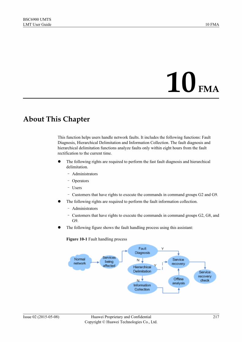
10 FMA
About This Chapter
This function helps users handle network faults. It includes the following functions: FaultDiagnosis, Hierarchical Delimitation and Information Collection. The fault diagnosis andhierarchical delimitation functions analyze faults only within eight hours from the faultrectification to the current time.
l The following rights are required to perform the fast fault diagnosis and hierarchicaldelimitation.– Administrators– Operators– Users– Customers that have rights to execute the commands in command groups G2 and G9.
l The following rights are required to perform the fault information collection.– Administrators– Customers that have rights to execute the commands in command groups G2, G8, and
G9.l The following figure shows the fault handling process using this assistant:
Figure 10-1 Fault handling process
BSC6900 UMTSLMT User Guide 10 FMA
Issue 02 (2015-05-08) Huawei Proprietary and ConfidentialCopyright © Huawei Technologies Co., Ltd.
217

– Determine whether services are affected.
– Use the fault diagnosis function to identify partial of the faults.
– Use the hierarchical delimitation function to analyze faults that cannot be fast identified.
– Use the information collection function to collect logs of faults that cannot be identifiedby the preceding two methods, and use the offline analysis tool to analyze these faults.
– Rectify the faults.
– Check that services are recovered.
NOTE
l Information Collection can be simultaneously executed with Fault Diagnosis or HierarchicalDelimitation. However, Fault Diagnosis and Hierarchical Delimitation cannot be executedsimultaneously. When Information Collection is executed, do not run the COL LOG command.
l Only one Web LMT can perform an online FMA function at a time.
l This function does not support the analysis of an eGBTS.
10.1 Fault OverviewFault overview provides visualized illustration of operating status and fault information ofRNC network.
10.2 Fault DiagnosisThis function is used to quickly diagnose common network faults, thereby helping users identifythe faulty NE or board. This function can be used when faults occur and persist at a site and sitemaintenance personnel cannot directly use the counters, alarms, and logs for fault analysis.
10.3 Hierarchical DelimitationThis function is used to analyze faults. When faults cannot be identified using fault diagnosis,this function can be used.
10.4 Recovery ConfirmationAfter service recovery solutions are implemented, onsite O&M engineers can view on the faultsummary page the operating status of the GSM and UMTS networks to check whether a faulthas been rectified. For details, see Fault Overview.
10.5 Information CollectionThis function can be used to quickly and accurately collect onsite information, therebyshortening the event recovery period.
BSC6900 UMTSLMT User Guide 10 FMA
Issue 02 (2015-05-08) Huawei Proprietary and ConfidentialCopyright © Huawei Technologies Co., Ltd.
218

10.1 Fault OverviewFault overview provides visualized illustration of operating status and fault information ofRNC network.
ContextThis function allows field O&M engineers to quickly obtain fault information and start faulttroubleshooting when a network fault occurs.
Procedure
Step 1 On the LMT main page, click FMA. The FMA tab page is displayed.
Step 2 In the Fault Overview window, wait for viewing the KPI trend.
----End
ResultSuccessful operationl The KPI trend chart is displayed in the Fault Overview window.
Table 10-1 Information that O&M engineers can obtain using the fault overview function
Category Details
UMTS KPI l Trends in the RRCl Trends in the CS RABl Trends in the PS RABl Trends in CS Erlangl Trends in PS throughputl Trends in the CS call dropsl Trends in the PS call dropsl Trends in paging
BSC6900 UMTSLMT User Guide 10 FMA
Issue 02 (2015-05-08) Huawei Proprietary and ConfidentialCopyright © Huawei Technologies Co., Ltd.
219

Category Details
KPI trend chart l KPI and counter change trend chart thatcontains three curves illustrating KPI andcounter changes in the latest eight hours,in the same hours on the day before, andin the same hours on the same day lastweek, respectively. The X-coordinaterepresents the measurement time(expressed in the form of HH:MM). TheY-coordinate represents the counter valuein units of each counter or the KPI valuein percentages.NOTE
Performance measurement has two states inshort measurement periods: ENABLED andDISABLED. If no counters are measured,performance measurement is DISABLED.
l When fault diagnosis is used to collectperformance data, performance datagenerated during a sampling period is notavailable if the current measurement stateis different from that used in the samplingperiod.For example, if the measurement state wasDISABLED last Wednesday andchanged to ENABLED this Monday, onlytwo curves illustrating KPI and counterchanges in the latest eight hours of thisWednesday and in the same hours of thisTuesday are displayed on the trend chart,with the one for the KPI and counterchanges in the latest eight hours of lastWednesday missing.
KPI trend value l Automatically displays the KPI value orcounter value corresponding to a point onthe KPI and counter change trend curveswhen you move the mouse pointer to thatpoint.
l Provides KPI filtering on the right of thefault summary interface to allow viewingthe change trend of the selected KPI.
Unsuccessful operationl A dialog box is displayed with the failure cause.
BSC6900 UMTSLMT User Guide 10 FMA
Issue 02 (2015-05-08) Huawei Proprietary and ConfidentialCopyright © Huawei Technologies Co., Ltd.
220

10.2 Fault DiagnosisThis function is used to quickly diagnose common network faults, thereby helping users identifythe faulty NE or board. This function can be used when faults occur and persist at a site and sitemaintenance personnel cannot directly use the counters, alarms, and logs for fault analysis.
Context
According to the diagnosis rules, this function comprehensively analyzes the counters, alarm,and logs related to the fault and provides analysis reports to users. It helps users perform recoveryoperations, thereby shortening the fault recovery period.
l This function is implemented on the OMU and can be used with tracing and monitoringfunctions on the LMT.
l This function is stopped when more than 95% of OMU memory is occupied and thisfunction occupies more than 200 MB OMU memory.
l When the OMU CPU usage reaches 100%, the operating systems schedules processes onthe OMU by priority. The initial priority of the fault analysis task using the fault diagnosingfunction is set to low. When the CPU usage of this task is lower than the minimum threshold(10%), increase its priority. When the CPU usage of this task is higher than the minimumthreshold (10%), decrease its priority.
NOTE
When a fault occurs, it is recommended that you use this function to analyze the fault and then run the COLLOG command to collect logs.
Procedure
Step 1 Optional: Run the SET FMATH command to set the fault diagnosis threshold.
NOTE
When the default fault diagnosis threshold is not used, run the SET FMATH command to set the threshold.
To query the specified fault diagnosis threshold, run the LST FMATH command.
Step 2 On the LMT main page, click FMA. The FMA tab page is displayed.
Step 3 Select the fault scenarios requiring fault management on the Fault Diagnosis tab page.
Step 4 Click Start and wait for the diagnosis report.
NOTE
A folder named by the operation date and time is generated in the bam/version_x/ftp/fma_data/FaultDiagnosis directory each time this function is implemented, for example, /bam/version_x/ftp/fma_data/FaultDiagnosis /201501010101. This folder contains four sub-folders which are described in the followingtable.
Sub-Folder Description
alarm_data Contains the active alarms and cleared alarms for thelast 24 hours.
opt_data Contains the operation data for the last 24 hours.
BSC6900 UMTSLMT User Guide 10 FMA
Issue 02 (2015-05-08) Huawei Proprietary and ConfidentialCopyright © Huawei Technologies Co., Ltd.
221

Sub-Folder Description
report Contains the analysis report generated using the faultdiagnosis function.
stat_data Contains the performance data for the last 8 hours,the corresponding 8 hours in the yesterday, and thecorresponding 8 hours 7 days ago.
All historical folders are stored in the bam/version_x/ftp/fma_data/FaultDiagnosis directory. The maximumsize of these folders is 500 MB. If the size exceeds 500 MB, the system deletes the earliest folder. Therefore,you must save required historical analysis results in a timely manner.
Table 10-2 UMTS fault analysis scenario options
Scenario Options Items
KPI RRC Success Rate The number of RRCconnection setup requests is0.
The RRC connection setupsuccess rate is abnormal.
The number of RRCconnection setup requestsdecreases significantly.
CS RAB Setup Success Rate The initial directtransmission flow controlrate of CS services isabnormal.
The Iu-CS SCCP setupsuccess rate is abnormal.
The CS security modesuccess rate is abnormal.
The location update successrate is abnormal.
The CS service rejection rateis abnormal.
The CS service redirectionrate in a multi-operator corenetwork (MOCN) isabnormal.
The number of successful CSRAB setups is 0.
BSC6900 UMTSLMT User Guide 10 FMA
Issue 02 (2015-05-08) Huawei Proprietary and ConfidentialCopyright © Huawei Technologies Co., Ltd.
222

Scenario Options Items
The CS RAB setup successrate is abnormal.
The number of CS RABsetup requests decreasessignificantly.
CS Service Drop Rate The CS service drop rate isabnormal.
PS RAB Setup Success Rate The initial directtransmission flow controlrate of PS services isabnormal.
The Iu-PS SCCP setupsuccess rate is abnormal.
The PS security modesuccess rate is abnormal.
The RA update success rate isabnormal.
The PS service rejection rateis abnormal.
The attach success rate isabnormal.
The PDP context activationsuccess rate is abnormal.
The PS service redirectionrate in a multi-operator corenetwork (MOCN) isabnormal.
The number of successful PSRAB setups is 0.
The PS RAB setup successrate is abnormal.
The number of PS RAB setuprequests decreasessignificantly.
PS Service Drop Rate The PS service drop rate isabnormal.
Paging The paging success rate isabnormal.
BSC6900 UMTSLMT User Guide 10 FMA
Issue 02 (2015-05-08) Huawei Proprietary and ConfidentialCopyright © Huawei Technologies Co., Ltd.
223

Scenario Options Items
Traffic PS throughput The PS throughput decreasessignificantly.
CS Erlang The CS Erlang decreasessignificantly.
Transmission Site Break Down A large number of cells areunavailable.
Others Equipment health check Health check on the interfaceboards
Health check on the user-plane boards and subsystems
Health check on the control-plane boards and subsystems
Analysis on systemconfiguration errors
Control-plan Iu-CS and Iu-PS interface status check
Iur-p interface status check
Flow control of the board
RNC in Pool Load Sharing The number of RRCconnection setup requests ofthe overflow RNC is 0.
The RRC connection setupsuccess rate of the overflowRNC is abnormal.
The number of successful CSRAB setups of the overflowRNC is 0.
The CS RAB setup successrate of the overflow RNC isabnormal.
The CS service drop rate ofthe overflow RNC isabnormal.
The number of successful PSRAB setups of the overflowRNC is 0.
BSC6900 UMTSLMT User Guide 10 FMA
Issue 02 (2015-05-08) Huawei Proprietary and ConfidentialCopyright © Huawei Technologies Co., Ltd.
224

Scenario Options Items
The PS RAB setup successrate of the overflow RNC isabnormal.
The PS service drop rate ofthe overflow RNC isabnormal.
The CS Erlang of overflowRNC decreases significantly.
The PS throughput ofoverflow RNC decreasessignificantly.
RNC in Pool can be used in different scenarios. The system automatically determines theapplication scenario based on the load sharing type, redundancy type, and host status, as shownin Table 10-3. You can query the load sharing type by running the LST URNCBASIC commandand query the host status by running the DSP UHOSTRNC command.
Table 10-3 RNC in Pool fault analysis scenario options
ScenarioOptions
RNC in Pool LoadSharing
RNC in PoolRedundancy
RNC in Pool Load Sharingand Redundancy
LoadSharingType=MASTER
LoadSharingType=OVERFLOW
HostStatus=MASTER
HostStatus=BACKUP
LoadSharingType=MASTER andHostStatus=MASTER
LoadSharingType=OVERFLOWandHostStatus=BACKUP
LoadSharingType=OVERFLOWandHostStatus=MASTER
RRCconnection setup
√ × √ × √ × √
CSservicesetup
√ × √ × √ × √
CS calldrop
√ × √ × √ × √
BSC6900 UMTSLMT User Guide 10 FMA
Issue 02 (2015-05-08) Huawei Proprietary and ConfidentialCopyright © Huawei Technologies Co., Ltd.
225
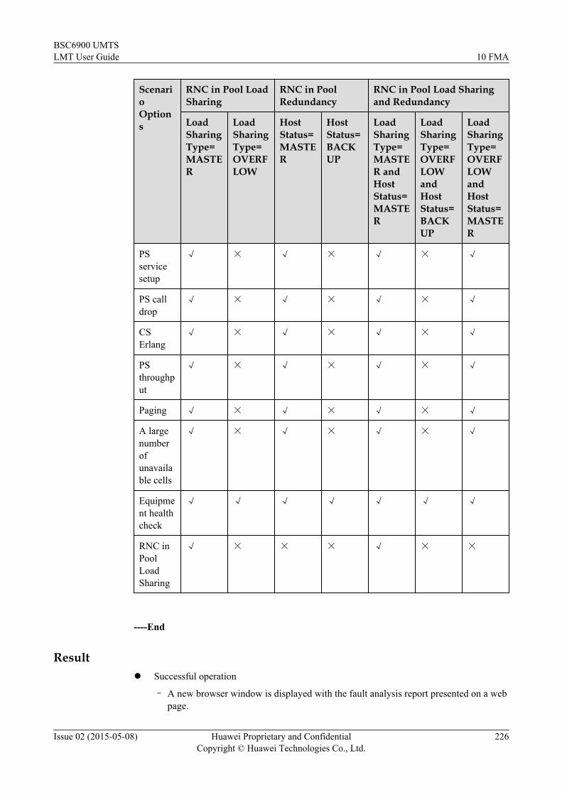
ScenarioOptions
RNC in Pool LoadSharing
RNC in PoolRedundancy
RNC in Pool Load Sharingand Redundancy
LoadSharingType=MASTER
LoadSharingType=OVERFLOW
HostStatus=MASTER
HostStatus=BACKUP
LoadSharingType=MASTER andHostStatus=MASTER
LoadSharingType=OVERFLOWandHostStatus=BACKUP
LoadSharingType=OVERFLOWandHostStatus=MASTER
PSservicesetup
√ × √ × √ × √
PS calldrop
√ × √ × √ × √
CSErlang
√ × √ × √ × √
PSthroughput
√ × √ × √ × √
Paging √ × √ × √ × √
A largenumberofunavailable cells
√ × √ × √ × √
Equipment healthcheck
√ √ √ √ √ √ √
RNC inPoolLoadSharing
√ × × × √ × ×
----End
Resultl Successful operation
– A new browser window is displayed with the fault analysis report presented on a webpage.
BSC6900 UMTSLMT User Guide 10 FMA
Issue 02 (2015-05-08) Huawei Proprietary and ConfidentialCopyright © Huawei Technologies Co., Ltd.
226

Table 10-4 Button Functions
Button Name Description
Save Report When using the IE browser, click this button to save thediagnosis report as an html page. On the saved html page,the log GUI does not provide the query or filtering function.When using the FireFox browser, there will be no SaveReport button and you can use the save function of thebrowser itself to save the diagnosis report.
Download SourceData
Download the original data of the diagnosis report that isgenerated by the NE.
A fault diagnosis report covers the following:
Table 10-5 Contents of the diagnosis report
Item Description
RNC Basic Information Containing RNC in Pool networking information andRNC basic configuration information, such as RNCID, RNC name, transmission modes over the Iub, Iur,Iu-CS, and Iu-PS interfaces, and the load-sharing typeof RNC in Pool
BSC6900 UMTSLMT User Guide 10 FMA
Issue 02 (2015-05-08) Huawei Proprietary and ConfidentialCopyright © Huawei Technologies Co., Ltd.
227

Item Description
KPI Trend l Containing KPI and alarm trend figures. RRCTrend, CS RAB Trend, PS RAB Trend, CS ErlangTrend, PS Throughput Trend, CS Call Drop Trend,PS Call Drop Trend, Iu-CS SCCP Trend, Iu-PSSCCP Trend, Active alarms on the Iu-CS/Iu-PS/Iur-p interface, RNC Alarm Quantity Trend andAlarms of last 24 hours are included.
l Containing three curves illustrating KPI andcounter changes that occurred during the eighthours of today, yesterday, and last week,respectively. The X-coordinate representshour:minute, the Y-coordinate represents thecounter value in the unit of the correspondingcounter or the KPI value in percentages.
l Containing the threshold used in the rules of thefault management assistant analysis. You can setthe threshold value by running the MML commandSET FMATH.
NOTEPerformance measurement has two states in shortmeasurement periods: ENABLED and DISABLED. If nocounters are measured, performance measurement is inDISABLED state.
When the Fault Management Assistant function for rapidfault diagnosis is enabled to analyze performance statistics,performance statistics during a sampling period of eighthours cannot be obtained if the measurement states aredifferent in a short measurement period during the samplingperiod and in the current short period. For example, if themeasurement state was DISABLED during a samplingperiod last Wednesday and the measurement state changedto ENABLED on this Monday, only two curves illustratingKPI and counter changes that occurred during the same eighthours of this Tuesday and Wednesday are displayed in theKPI and counter change trend chart of this Wednesday.
BSC6900 UMTSLMT User Guide 10 FMA
Issue 02 (2015-05-08) Huawei Proprietary and ConfidentialCopyright © Huawei Technologies Co., Ltd.
228

Item Description
FMA DashBoard l The dashboard function supports associationanalysis and graphical user interface (GUI) displayof KPI trend measured 8 hours before the rapidfault diagnosis function starts and alarms and keyoperation logs generated 24 hours before the rapidfault diagnosis function starts. This functiondisplays the KPI trend and associates KPI trend,alarms, and operation logs by time points so thatthe faults are located quickly and services arerestored in a short period of time.
– KPI and counter change trend chart: A line isdisplayed for each KPI or counter indicating itschange trend in the last 8 hours. The X axis, leftY axis, and right Y axis indicate the time,number, and ratio, respectively.
– Operation log: The executed MML commandsare displayed from the earliest one. Informationsuch as the executed MML commands,operating time, and execution results aredisplayed.
– Alarm log: Alarms are displayed from theearliest one. Information such as alarm ID,alarm report time, and location information aredisplayed.NOTE
When you enter the time to query alarms:
l If the entered time is the same as Alarm raisedtime of a single alarm in alarm logs, informationabout the alarm will be contained in queryresults.
l If the entered time is the same as Alarm raisedtime of multiple alarms, information about thefirst alarm generated at the time will becontained in query results.
l If the entered time is different from Alarmraised time of all alarms in alarm logs,information about alarms generated at the mostapproximate time to the entered time will becontained in query results.
l In the change trend chart, click a certain time, andalarms and operation logs generated at this timewill be displayed. Click an alarm or an operationlog, and the KPIs for the corresponding time willbe displayed. Double-click an alarm log to openthe Detail info of alarm log dialog box. In thedisplayed dialog box, click Solution to view thealarm handling suggestion described in the alarmreference.
BSC6900 UMTSLMT User Guide 10 FMA
Issue 02 (2015-05-08) Huawei Proprietary and ConfidentialCopyright © Huawei Technologies Co., Ltd.
229

Item Description
l The dashboard function has two startup modes.
– In the Scenario Options dialog box, clickDashboard without selecting the faultscenario.
– In the Scenario Options dialog box, select thefault scenario and click Start. Compared withthe first startup mode, the fault analysis reportis displayed in addition to the KPI trend andFMA dashboard.
Fault analysis report Includes the fault description, diagnose result, andrecommend option in the fault diagnosis scenarioselected by a user. For details about fault diagnosisscenarios, see Table 1.
Operation logs of last 24hours
Running the MML command EXP LOG to export theoperation log.
– Query historical records of analysis reports.
– Click the Query Result button to list the latest 200 alarm logs around the specifiedquery time on the current page. The latest one alarm log is highlighted.
– If the report.xml file in not stored under the bam/version_x/ftp/fma_data/FaultDiagnosis/report directory, a dialog box indicating that the file is not found isdisplayed.
l Unsuccessful operation
– A dialog box is displayed with the failure cause.
10.3 Hierarchical DelimitationThis function is used to analyze faults. When faults cannot be identified using fault diagnosis,this function can be used.
ContextThis function decomposes faults based on standard protocol layers from the KPIs of the faultynetwork, until the smallest identifiable objects are obtained. The counters, alarms, status, andoperations of these objects are displayed and identified to provide a fault analysis report forusers.
Procedure
Step 1 On the LMT main page, click FMA. The FMA window is displayed.
Step 2 On the FMA tab page, click Hierarchical Delimitation. The Hierarchical Delimitation tabpage is displayed.
Step 3 Set parameters on the Hierarchical Delimitation tab page.
BSC6900 UMTSLMT User Guide 10 FMA
Issue 02 (2015-05-08) Huawei Proprietary and ConfidentialCopyright © Huawei Technologies Co., Ltd.
230

Step 4 Click Analyze and wait for the fault analysis report.
Table 10-6 GUI parameter description
Parameter Description
Select the KPIitems
Set this parameter based on the abnormal KPIs by observing the KPItrend curve.
History Analyze In the drop-down list, select the time of saving historical analysis reports,and click Query.
----End
Resultl Successful operation
– A new browser window is displayed with the fault analysis report presented on a webpage.
Table 10-7 Button Functions
Button Name Description
Save Report When using the IE browser, click this button to save thediagnosis report as an html page. On the saved html page,the log GUI does not provide the query or filtering function.When using the FireFox browser, there will be no SaveReport button and you can use the save function of thebrowser itself to save the diagnosis report.
Download SourceData
Download the original data of the diagnosis report that isgenerated by the NE.
The following table lists information in a fault analysis report.
BSC6900 UMTSLMT User Guide 10 FMA
Issue 02 (2015-05-08) Huawei Proprietary and ConfidentialCopyright © Huawei Technologies Co., Ltd.
231

Table 10-8 Information in a fault analysis report
Item Description
Fault cells Cells that are affected by faults.l Cell ID: ID of the problematic celll Failure rate: Proportion of the number of failures in a
problematic cell to that in an RNC related to a specificcounter
l Fault counter: Proportion of the number of failures in aproblematic cell to the number of attempts in this cellrelated to a specific counter
l Attempt number: Number of attempts in this cell relatedto a specific counter
l NodeB name: Name of the NodeB to which theproblematic cell belongs
l INT board: Interface board where the problematic cell isconfigured
l Subsystem: Subsystem where the problematic cell isconfigured
BSC6900 UMTSLMT User Guide 10 FMA
Issue 02 (2015-05-08) Huawei Proprietary and ConfidentialCopyright © Huawei Technologies Co., Ltd.
232

Item Description
Scenario selection The smallest identifiable objects obtained after faults aredecomposed based on standard protocol layers. The faultobject can be selected on the left, and the corresponding KPIand alarm is displayed on the right. The fault object isdisplayed below.l The interface between BSC and BSS
– Control plane
– Wireless layer object, such as NBAP protocol.
– Transmission layer object, such as SCTPLINKand ETHPORT.
– Device layer object, such as INT board andcontrol plane subsystem.
– User plane
– Wireless layer object, such as Abis protocol.
– Transmission layer object, such as ETHPORT.
– Device layer object, such as INT board.l The interface between BSC and CN
– Control plane
– Wireless layer object, such as RANAP protocol.
– Transmission layer object, such asMTP3LINK,SCTPLINK and ETHPORT.
– Device layer object, such as INT board andcontrol plane subsystem.
– User plane
– Wireless layer object, such as IUUP and GTPU.
– Transmission layer object, such as ETHPORT.
– Device layer object, such as INT board.
l Unsuccessful operation
– A dialog box is displayed with the failure cause.
10.4 Recovery ConfirmationAfter service recovery solutions are implemented, onsite O&M engineers can view on the faultsummary page the operating status of the GSM and UMTS networks to check whether a faulthas been rectified. For details, see Fault Overview.
10.5 Information CollectionThis function can be used to quickly and accurately collect onsite information, therebyshortening the event recovery period.
BSC6900 UMTSLMT User Guide 10 FMA
Issue 02 (2015-05-08) Huawei Proprietary and ConfidentialCopyright © Huawei Technologies Co., Ltd.
233

Context
When faults occur, the information needs to be collected at the site. However, there are varioustypes of BSC logs, and the procedure for collecting these logs is complex. In this situation, it iseasy to make mistakes in collecting logs, which leads to repeated collection of logs at the siteand prolongs fault troubleshooting. This function is introduced to simplify the procedure forcollecting logs.
NOTE
This function can be enabled only by the system administrator admin and an administrator-level, operator-level,or user-level account.
Procedure
Step 1 Information Quick-Collection
1. On the LMT main page, click FMA. The FMA window is displayed.
2. On the FMA tab page, click Information Collection. The Information Collection tabpage is displayed.
3. Set parameters on the Information Quick-Collection tab page. Specify Failure Time andFile Path.
4. Click Collection to start collecting fault information.
NOTE
After you click Collection, the progress bar may fail to show the progress, and this status lasts forseveral minutes.
Table 10-9 GUI parameter description
GUI Parameter Description
Failure Time Time when a fault occurs. You can obtain the failure time pointwithin the counter measurement period (15 minutes) after theinflection point of the abnormal KPI in the FMA maininterface.
File Path Save path of log files to be collected
Result Information about collected log files, such as the file name,save path, and file size.
Subrack Number of the subrack.
First ProgressSecond Progress
Log file collection progress.Second batch of log files start to be collected only after theconnection of the first batch completes. Log files are collectedin two batches so that the first logs can be viewed while thesecond batch is being collected for fast troubleshooting.
Fault information can be collected in one-click mode. The collection consists of twobatches.
BSC6900 UMTSLMT User Guide 10 FMA
Issue 02 (2015-05-08) Huawei Proprietary and ConfidentialCopyright © Huawei Technologies Co., Ltd.
234

l In the first batch, this function collects operation logs, historical alarm files (12 hours),BSC data configuration files, and UKPI snapshot generated when the problem occurs.
l In the second batch, this function collects performance counter result file (6 hours),historical alarm files (7 days), 3G CHR log file, common debug log file (15 min), callfault log files generated when the problem occurs.
NOTE
The time in the brackets following the collected files indicates the time during which the files are collectedin the specific fault diagnosis scenario. For example, historical alarm files (12 hours) indicates historicalalarm files collected for 12 hours including the time when the fault occurs.
----End
Resultl Quickly collecting information
After the collection is complete, the collected data can be obtained from the directoryspecified by the user. Each batch of data is automatically saved in a sub directory of thespecified directory. For example, the directory specified by the user is E:\DATA, the firstand second batches of collected data will be saved in E:\DATA\BATCH1_YYYYMMDDHHMMSS and E:\DATA\BATCH2_YYYYMMDDHHMMSS, respectively. YYYYMMDDHHMMSS indicatesthe time when data collection starts. The letters stand for Year, Month, Date, Hour, Minute,and Second, respectively. In this manner, even if the whole data collection is incomplete,the data collection progress can be viewed according to the progress bar and the filecollection progress in the Result box, and the collected data can be obtained andretransmitted. This improves the data collection efficiency.
l Collecting customized informationAfter the collection is complete, the collected data can be obtained from the directoryspecified by the user. Data collected each time is automatically saved in a sub directory ofthe specified directory. For example, the directory specified by the user is E:\DATA, datacollected each time will be saved in E:\DATA\COLDAT_YYYYMMDDHHMMSS.YYYYMMDDHHMMSS indicates the time when data collection starts. The letters standfor Year, Month, Date, Hour, Minute, and Second, respectively.
BSC6900 UMTSLMT User Guide 10 FMA
Issue 02 (2015-05-08) Huawei Proprietary and ConfidentialCopyright © Huawei Technologies Co., Ltd.
235

11 BSC Maintenance
About This Chapter
This chapter describes how to maintain BSC equipment, back up and restore data, and implementfast fault diagnosis.
11.1 Backing Up DataThis section describes how to back up system data on the OMU. The system data includesconfiguration data, alarm configuration data, and counter configuration data.
11.2 Restoring DataThis section describes how to restore configuration data on the OMU.
11.3 Batch ConfigurationThis section describes how to browse and deliver batch configuration script files. Such files canbe generated by the CME or manually generated by operators. Such files can be in the .xml, .ecf,or .txt format, but only files in the .xml and .ecf formats can be browsed.
BSC6900 UMTSLMT User Guide 11 BSC Maintenance
Issue 02 (2015-05-08) Huawei Proprietary and ConfidentialCopyright © Huawei Technologies Co., Ltd.
236

11.1 Backing Up DataThis section describes how to back up system data on the OMU. The system data includesconfiguration data, alarm configuration data, and counter configuration data.
Contextl When the database system crashes or an upgrade fails, start the tool used for backing up
and restoring system data in the mbsc\bam\common\services\omu_backup_linkerdirectory. With the latest backup data, you can recover the system.
l If you need to recover only OMU configuration data, run the RTR DB command and selectthe corresponding data backup file for data recovery.
Procedurel Using menus
1. On the LMT main page, click Device Maintenance. The Device Maintenance tabpage is displayed.
2. In the Device Navigation Tree, right-click BSC and choose Backup Data from theshort-cut menu. The Backup Data dialog box is displayed with information aboutbackup files saved in the OMU active workspace installation directory\data\backup directory.
3. In the Backup Data dialog box, click Backup to back up system data on the OMU.
NOTE
l A dialog box is displayed by clicking Backup Data, informing the user of whether to encryptthe file before backing up it. If you select Yes, enter a password.
l The default save path of backup files is OMU active workspace installation directory\data\backup. If this save path does not exist, it will be created automatically.
l If the name of a backup file is not typed, the file is named BKPDB_#_*.bak automatically.Here, "#" stands for the detailed version information of the working OMU and "*" stands forthe current system time when the backup is performed. When the number of backup files in thebackup directory exceeds 30, the earliest backup file is automatically deleted.
l The following special characters are forbidden in the file name: \\ / : * ? \" < > | ( ) & $ , %%+++ = ; blank character
l Backup files cannot be saved in a network path, for example, \\10.161.162.25.
l No space is allowed in the file name or the saving directory. For example, "BK2009 09 08.bak"is an illegal file name.
4. In the Backup Data dialog box, select a backup file and click Download to downloadthe backup file to a local path on the LMT PC.
NOTE
Click Refresh to refresh backup files saved in the OMU active workspace installation directory\data\backup directory in the Backup Data dialog box.
l Using MML commands1. Run the LST BKPFILE command to query data backup files saved in the OMU
active workspace installation directory\data\backup directory.2. Run the BKP DB command to back up system data on the OMU.
----End
BSC6900 UMTSLMT User Guide 11 BSC Maintenance
Issue 02 (2015-05-08) Huawei Proprietary and ConfidentialCopyright © Huawei Technologies Co., Ltd.
237
11.2 Restoring DataThis section describes how to restore configuration data on the OMU.
Context
NOTICEl Restore data with caution because data restore will overwrite OMU data.l Versions of data backup files must be the same as the OMU version.l Alarm information and operation logs are not restored. Their data remains unchanged.l After restoring OMU data, run the RST BSC command to reset the BSC.
Procedurel Using menus
1. On the LMT main page, click Device Maintenance. The Device Maintenance tabpage is displayed.
2. Under Device Navigation Tree, right-click the BSC node and choose RestoreData from the short-cut menu. The Restore Data dialog box is displayed withinformation about data backup files saved in the OMU active workspace installationdirectory\data\backup directory.
3. Optional: In the displayed Restore Data dialog box, click Upload to upload a backupfile on the LMT PC to the OMU.
NOTE
Click Refresh to refresh backup files saved in the OMU active workspace installation directory\data\backup directory in the Restore Data dialog box.
4. In the Restore Data dialog box, click Restore Data to restore configuration data onthe OMU.
NOTE
If an .ecf encrypted file is selected after you click Restore Data, enter a password to restore thebackup file.
l Using MML commands1. Run the LST BKPFILE command to query data backup files saved in the OMU
active workspace installation directory\data\backup directory.2. Run the RTR DB command to restore configuration data on the OMU.
----End
BSC6900 UMTSLMT User Guide 11 BSC Maintenance
Issue 02 (2015-05-08) Huawei Proprietary and ConfidentialCopyright © Huawei Technologies Co., Ltd.
238

11.3 Batch ConfigurationThis section describes how to browse and deliver batch configuration script files. Such files canbe generated by the CME or manually generated by operators. Such files can be in the .xml, .ecf,or .txt format, but only files in the .xml and .ecf formats can be browsed.
Prerequisitesl You have logged in to the LMT.
l The LMT properly communicates with the BSC.
Contextl Batch configuration is based on the functions of the CME script executor and aims at
quickly validating and browsing patch configuration files.
l Batch configuration includes the Preactivate, Activate and Browse functions.
– Preactivate is used to check whether the data in the configuration scripts is valid andwhether the data conflicts with that on the live network before data activation. Thishelps users rectify script problems in advance and prevents activation failures.
– Activate includes the check functions of Preactivate. It is also used to validateconfiguration scripts on the NE.
– You can browse, modify, and save the batch configuration files in the XML Browsearea. The execution results of the batch configuration files are also displayed in thisarea.
l Compared with batch processing, batch configuration can validate configuration scripts ina shorter time. The validating speed of batch configuration is the same as that of the RUNBATCHFILE command.
l During batch configuration, the BSC is managed independently and the MML commandsfrom other LMT cannot be executed.
Procedure
Step 1 On the LMT main page, click Device Maintenance. The Device Maintenance tab page isdisplayed.
Step 2 In the Device Navigation Tree, right-click BSC and choose Batch Configuration from theshort-cut menu. The Batch Configuration dialog box is displayed.
Step 3 In the Batch Configuration dialog box, select a batch configuration script file.
NOTE
If an .ecf file is selected, enter a password to import files for batch configuration.
Step 4 Click Activate or Preactivate and wait until the configuration command takes effect on theBSC.
----End
BSC6900 UMTSLMT User Guide 11 BSC Maintenance
Issue 02 (2015-05-08) Huawei Proprietary and ConfidentialCopyright © Huawei Technologies Co., Ltd.
239

Resultl Successful operation:
– The progress of the activation and pre-activation related commands are displayed in theprogress bar.
– The execution results of the batch configuration files are displayed in the message area.l Failed operation: The failure cause is displayed in the message area.
BSC6900 UMTSLMT User Guide 11 BSC Maintenance
Issue 02 (2015-05-08) Huawei Proprietary and ConfidentialCopyright © Huawei Technologies Co., Ltd.
240

12 FAQ
About This Chapter
This chapter describes some frequently asked questions (FAQs) and the corresponding solutions.
12.1 Browser-related FAQsThis section describes browser setting-related common problems that hinder the normal use ofthe LMT and corresponding handling procedures.
12.2 Java-related FAQsThis section describes Java-related common problems that hinder the normal use of the LMTand corresponding handling procedures.
12.3 Other FAQsThis section describes common problems, except Java- or browser setting-related problems, thathinder the normal use of the LMT and corresponding handling procedures.
BSC6900 UMTSLMT User Guide 12 FAQ
Issue 02 (2015-05-08) Huawei Proprietary and ConfidentialCopyright © Huawei Technologies Co., Ltd.
241

12.1 Browser-related FAQsThis section describes browser setting-related common problems that hinder the normal use ofthe LMT and corresponding handling procedures.
12.1.1 Slow Responses in the Firefox BrowserRunning in the Firefox browser, the LMT gives slow responses. For example, it takes about 30seconds to maximize the window of a trace task in the Trace tab page. In this case, check whetherthe add-on extension Live Margins is installed.
ProcedureStep 1 Start the Firefox, choose Tool > Add-ons. The Add-ons window is displayed.
Step 2 In the Extensions tab page, select Live Margins, and click Disable. The message "RestartFirefox to complete your changes" is prompted.
Step 3 Click Restart Firefox to validate the changes.
----End
12.1.2 LMT Colors Cannot Be DisplayedWhen the LMT is started in the IE browser, the colors are not properly displayed. For example,the colors indicating the status of the boards and alarms are not displayed, or the backgroundcolor of the LMT is not differentiated from that of the IE browser. In this case, check the colorsettings of the browser.
ProcedureStep 1 Choose Tool > Internet Options on the tool bar of the IE browser. The Internet Options dialog
box is displayed.
Step 2 On the General tab page, click Accessibility. The Accessibility dialog box is displayed.
Step 3 In the Formatting area, deselect Ignore colors specified on Web pages, and then click OK.
Step 4 In the Internet Options dialog box, click OK to exit the dialog box.
----End
12.1.3 Verification Code Cannot Be Displayed on the LMT LoginPage
The verification code cannot be displayed when you try to log in to the LMT using an InternetExplorer (IE) browser in Windows Server 2008 or Windows Vista. When this problem occurs,check the settings related to the protected mode of the browser.
ContextIf the protected mode is enabled for the IE browser in Windows Server 2008 or Windows Vista,many security restrictions are imposed. For example, JavaScript and Applet cannot be run.
BSC6900 UMTSLMT User Guide 12 FAQ
Issue 02 (2015-05-08) Huawei Proprietary and ConfidentialCopyright © Huawei Technologies Co., Ltd.
242

Therefore, you must disable the protected mode. Otherwise, the LMT web page cannot bedisplayed.
Procedure
Step 1 Enter the external virtual IP address of the OMU in the address box of the IE browser. PressEnter on the keyboard, or click Go next to the address bar to display the login window of theBSC6900.
Step 2 Check whether "Internet | Protected Mode: Off" is displayed in the bottom right corner of thewindow.
l If yes, the task is complete.
l If no, go to Step 3.
Step 3 Choose Tool > Internet Options on the tool bar of the IE browser. The Internet Options dialogbox is displayed.
Step 4 On the Security tab page, select Trusted sites in the Select a Web content zone to specify itssecurity settings area.
Step 5 Clear Enable Protected Mode in the Security level for this zone area. Click Sites. The Trustedsites dialog box is displayed.
Step 6 Type the external virtual IP address of the OMU in the Add this website to the zone text box,and then click Add. The external virtual IP address of the OMU is added to the Trusted siteslist.
NOTE
If the U2000 proxy server is used for the login to the LMT, add the IP address of the U2000 to the Trustedsites list.
Step 7 In the Internet Options dialog box, click OK to exit the dialog box.
NOTE
Restart the browser to validate the modifications.
If IE9 is used, in addition to the previous settings, choose Tools > Compatibility View Settings. In thedisplayed Compatibility View Settings dialog box, select Display all websites in Compatibility View.
----End
12.1.4 No Response When Clicking the Menu Bar on the LMTWhen you browse the LMT web page, there is no response or a script error dialog box isdisplayed. To be specific, when you click the menu bar or buttons or right-click the web page,there is no response or a dialog box is displayed, indicating a script error, for example,Permission Denied or Access Denied. In this case, check the proxy settings in the browser.
Context
Do not modify the settings of the browser when you have logged in to the LMT. Before you login to the LMT, set the proxy server when necessary.
BSC6900 UMTSLMT User Guide 12 FAQ
Issue 02 (2015-05-08) Huawei Proprietary and ConfidentialCopyright © Huawei Technologies Co., Ltd.
243

Procedurel IE
1. Choose Tool > Internet Options on the tool bar of the IE browser. The InternetOptions dialog box is displayed.
2. On the Connections tab page, click LAN Settings. The Local Area Network (LAN)Settings dialog box is displayed.
3. In the Proxy server area, select Use a proxy server for your LAN (These settingswill not apply to dial-up or VPN connections). Type the IP address and port numberof the proxy server in the corresponding text boxes, and then click Advanced. TheProxy settings dialog box is displayed.
4. In the Exceptions area, type the external virtual IP address of the OMU in the textbox, and then click OK. Close the Internet Options dialog box.
l Firefox
1. Choose Tools > Options on the tool bar of the Firefox browser. The Options dialogbox is displayed.
2. In the Options dialog box, click Advanced. On the Network tab page, clickSettings. The Connection Settings dialog box is displayed.
3. In the Connection Settings dialog box, select Manual proxy configuration. Typeserver address and port number in the HTTP proxy area. Then select Use this proxyserver for all protocols.
4. In the No Proxy for area, type the OMU external virtual IP address and click OK.Then close the Options dialog box.
----End
12.1.5 How to Set the Browser Under Citrix Farm NetworkingUnder Citrix farm networking, when you use the U2000 proxy server to log in to the LMT on aCitrix client, the LMT may be suspended, the verification code may be unavailable, orinitialization of the MML navigation tree may fail. When these problems occur, check thebrowser settings, including the setting of the browser proxy server and the HTTP 1.1 setting. Ifeither setting is wrong, reset it.
ContextYou can set the browser under Citrix farm networking in the following ways:
l Script setting: An automatic setting script is placed on the domain control server. After aCitrix user logs in to the server, the script automatically sets the browser.
l Manual setting: The browser is set manually.
The Citrix server works in the farm mode. In farm mode, the primary Citrix server and secondaryCitrix servers work in cooperation to achieve load balancing. When a Citrix user logs in to theCitrix server on a Citrix client, the server in use may vary. The proxy server of the browsertherefore may need to be set again and again. We therefore recommend setting the browser usingthe script. With the script, each time the user visits the server, automatic setting of the browseris performed.
The following procedure uses Internet Explorer (IE) as an example.
BSC6900 UMTSLMT User Guide 12 FAQ
Issue 02 (2015-05-08) Huawei Proprietary and ConfidentialCopyright © Huawei Technologies Co., Ltd.
244

Procedurel Script Setting
1. Prepare a script.Type the following script content in a notepad and save it as IE-unset.bat.@echo offsetlocal ENABLEDELAYEDEXPANSIONset uu="HKEY_CURRENT_USER\Software\Microsoft\Windows\CurrentVersion\Internet Settings"reg add %uu% /v EnableHttp1_1 /t REG_DWORD /d "1" /f >nulreg add %uu% /v ProxyHttp1.1 /t REG_DWORD /d "1" /f >nulsetlocal ENABLEDELAYEDEXPANSIONset uu="HKEY_CURRENT_USER\Software\Microsoft\Windows\CurrentVersion\Internet Settings"reg add %uu% /v ProxyServer /t REG_SZ /d "10.121.49.213:80" /f >nulreg add %uu% /v ProxyOverride /t REG_SZ /d "<local>" /f >nulreg add %uu% /v ProxyEnable /t REG_DWORD /d "1" /f >nul
NOTE
The IE-unset.bat script file implements automatic setting of the browser for the domain user.The domain user can change 10.121.49.213:80 in reg add %uu% /v ProxyServer /tREG_SZ /d "10.121.49.213:80" /f >nul in the script to the actual IP address of the proxyserver and the actual port number.
2. Log in to the primary or a secondary domain control server with the user name ofadministrator and place the IE-unset.bat file in the C:\WINDOWS\SYSVOL\sysvol\citrixtest.com\scripts path on the server.
NOTE
The default installation path on the domain control server is C:\WINDOWS\SYSVOL\sysvol\citrixtest.com\scripts. The path changes if you install the file elsewhere. Here,citrixtest.com is an example of the domain name. The actual domain name may be different.
3. For details about how to create a domain user, refer to the Citrix Access Solution UserGuide.
4. Apply the script to the domain user.Assume that there is a user named hong01 in the hongtest unit of the citrixtest.comdomain.
a. Start Active Directory Users and Computer and double-click hongtest in theleft-side pane. In the right-side pane, all users in the hongtest unit aredisplayed, as shown in Figure 12-1.
Figure 12-1 Active Directory Users and Computers
BSC6900 UMTSLMT User Guide 12 FAQ
Issue 02 (2015-05-08) Huawei Proprietary and ConfidentialCopyright © Huawei Technologies Co., Ltd.
245

b. In the right-side pane, right-click hong01. Choose Properties from the shortcut
menu. The hong01 Properties dialog box shown in Figure 12-2 is displayed.
Figure 12-2 Displayed hong01 Properties dialog box
c. In the hong01 Properties dialog box, click the Profile tab. Type IE-unset.bat
in Logon script, click Apply, and then click OK. Figure 12-3 shows thewindow.
BSC6900 UMTSLMT User Guide 12 FAQ
Issue 02 (2015-05-08) Huawei Proprietary and ConfidentialCopyright © Huawei Technologies Co., Ltd.
246

Figure 12-3 Applying the script in the hong01 Properties dialog box
l Manual Setting
1. Check the proxy server setting of the browser.
a. Choose Tools > Internet Options on the tool bar of the IE. The InternetOptions dialog box is displayed.
b. On the Connections tab page, click LAN Settings. The Local Area Network(LAN) Settings dialog box is displayed.
c. In the Proxy server area, select Use a proxy server for your LAN (Thesesettings will not apply to dial-up or VPN connections). Set Address of theproxy server to the IP address of the U2000 and Port to 80.
2. Check HTTP 1.1 settings of the browser.
a. Choose Tools > Internet Options on the tool bar of the IE. The InternetOptions dialog box is displayed.
b. On the Advanced tab page, select Use HTTP 1.1 through proxy connectionsunder HTTP 1.1 settings, click Apply, and then click OK. Figure 12-4 showsthe window.
BSC6900 UMTSLMT User Guide 12 FAQ
Issue 02 (2015-05-08) Huawei Proprietary and ConfidentialCopyright © Huawei Technologies Co., Ltd.
247

Figure 12-4 HTTP 1.1 settings
----End
12.1.6 Unable to Log In To LMT Because IE Default Security LevelIs Too High
In a Windows Server operating system (including Windows Server 2003 and Windows Server2008), the IE blocks Web programs of sites that are out of the trusted site list to improve systemsecurity. As a result, you may fail to log in to the LMT.
Contextl When you try to log in to the LMT by entering the IP address in the IE address bar, the
following web page will be displayed for your wanted page is out of the trusted site list.Therefore, you may fail to log in to the LMT.
BSC6900 UMTSLMT User Guide 12 FAQ
Issue 02 (2015-05-08) Huawei Proprietary and ConfidentialCopyright © Huawei Technologies Co., Ltd.
248

l According to the acceptable IE security level, there are the following two solutions:
– When lowering the IE security level on the Windows server is unacceptable, you canadd the LMT site to the trusted sites of the IE by using a configuration startup script.The system automatically loads the script and configures the IE after a Citrix user logsin.
– When lowering the IE security level on the Windows server is acceptable, you canremove the Windows component, Internet Explorer Enhanced Security Configuration.
Procedurel Setting a configuration startup script
1. Prepare a script.
Type the following script content in a notepad and save it as IE-unset.bat.
@echo offsetlocal ENABLEDELAYEDEXPANSIONset uu="HKEY_CURRENT_USER\Software\Microsoft\Windows\CurrentVersion\Internet Settings"reg add %uu% /v EnableHttp1_1 /t REG_DWORD /d "1" /f >nulreg add %uu% /v ProxyHttp1.1 /t REG_DWORD /d "1" /f >nulsetlocal ENABLEDELAYEDEXPANSIONset uu="HKEY_CURRENT_USER\Software\Microsoft\Windows\CurrentVersion\Internet Settings\ZoneMap\EscRanges\Trust"reg add %uu% /v :Range /t REG_SZ /d "10.141.149.193" /f >nulreg add %uu% /v http /t REG_DWORD /d "2" /f >nul
NOTE
l The IE-unset.bat script file implements automatic setting of IE trusted sites for Citrix domainusers.
l The domain user can change 10.141.149.193 in reg add %uu% /v :Range REG_SZ /d"10.141.149.193" /f >nul in the script to the IP address of the network element or the peer IPaddress of the network elements that need to be visited.
l If the user needs to set multi-network elements and the network elements don't exist in a samepeer IP address, multi-scripts need to be prepared and loaded separately.
l Trust in "HKEY_CURRENT_USER\Software\Microsoft\Windows\CurrentVersion\InternetSettings\ZoneMap\EscRanges\Trust" can be named as you wish.
2. Load the startup script.
– Script setting for a single Windows server
BSC6900 UMTSLMT User Guide 12 FAQ
Issue 02 (2015-05-08) Huawei Proprietary and ConfidentialCopyright © Huawei Technologies Co., Ltd.
249

a. Log in to the Windows server with the account of administrator. ChooseStart > Run.
b. Type gpedit.msc in the displayed dialog box. Then click OK. The GroupPolicy Object Editor dialog box is displayed.
c. In the Group Policy Object Editor dialog box shown in Figure 12-5, chooseUser Configuration > Windows Settings > Scripts(Logon/Logoff).
Figure 12-5 Script
d. Double-click Logon. The Logon Properties dialog box is displayed, as
shown in Figure 12-6. Click Show Files and copy the prepared script to thedisplayed directory. Then close the dialog box displaying the directory.
BSC6900 UMTSLMT User Guide 12 FAQ
Issue 02 (2015-05-08) Huawei Proprietary and ConfidentialCopyright © Huawei Technologies Co., Ltd.
250

Figure 12-6 Logon Properties
e. Click Add in the dialog box. The Add a Script dialog box is displayed, asshown in Figure 12-7.
Figure 12-7 Adding a script
f. In the Adding a script dialog box, click Browse to select the prepared scriptand click OK. Then close the dialog box.
BSC6900 UMTSLMT User Guide 12 FAQ
Issue 02 (2015-05-08) Huawei Proprietary and ConfidentialCopyright © Huawei Technologies Co., Ltd.
251

g. In the Logon Properties dialog box, click Apply and confirm to load theprepared script.
h. Restart the IE to validate the configuration.
NOTE
The users need to log in to the Citrix client to validate the configuration in the single Citrixnetwork.
– Script setting in a Citrix Farm network
a. Log in to the primary or secondary Citrix domain control server with theaccount of administrator. Choose Start > Programs > AdministrativeTools > Active Directory Users and Computer. Select an organization unitand then right-click Properties. Click the Group Policy tab page in thedisplayed dialog box and click New to create a group policy object.
NOTE
l If the organization unit has been set, the users which belong to the organization unitcan all succeed in logging in to the LMT.
l You can rename the group policy object.
b. Select the created group policy object and click Edit. In the displayed dialogbox shown in Figure 12-8, choose User Configuration > WindowsSettings > Scripts(Logon/Logoff).
Figure 12-8 Script
c. Double-click Logon. The Logon Properties dialog box is displayed, as
shown in Figure 12-9. Click Show Files and copy the prepared script to thedisplayed directory. Then close the dialog box displaying the directory.
BSC6900 UMTSLMT User Guide 12 FAQ
Issue 02 (2015-05-08) Huawei Proprietary and ConfidentialCopyright © Huawei Technologies Co., Ltd.
252

Figure 12-9 Logon
d. In the Logon Properties dialog box, click Add. The Add a Script dialogbox is displayed, as shown in Figure 12-10.
Figure 12-10 Adding a script
e. Click Browse to select the prepared script and click OK. Then close the dialogbox.
BSC6900 UMTSLMT User Guide 12 FAQ
Issue 02 (2015-05-08) Huawei Proprietary and ConfidentialCopyright © Huawei Technologies Co., Ltd.
253

f. In the Logon Properties dialog box, click Apply and confirm to load theprepared script.
l Removing Internet Explorer Enhanced Security Configuration1. Log in to the Windows server with the account of administrator. Choose Start >
Control Panel > Add or Remove Programs. Select Internet Explorer EnhancedSecurity Configuration in the displayed dialog box shown in Figure 12-11.
Figure 12-11 Windows components wizard
2. In the Windows Components Wizard dialog box, click Details, and deselect For
administrator groups and For all other user groups, as shown in Figure 12-12.
BSC6900 UMTSLMT User Guide 12 FAQ
Issue 02 (2015-05-08) Huawei Proprietary and ConfidentialCopyright © Huawei Technologies Co., Ltd.
254

Figure 12-12 Internet Explorer Enhanced Security Configuration
3. Click OK and then click Next to remove Internet Explorer Enhanced Security
Configuration. After the removal is complete, click Finish.4. Restart the IE to validate the configuration.
----End
12.1.7 Unable to Download or Install the Java or Flash Plug-in andTwo File Manager Windows Displayed Windows IE8 or Any LaterVersion Is Used
If users log in to the LMT in IE8 or later versions, an error message displays when they aredownloading or installing a Java or Flash plug-in, or two file manager windows are displayed.To solve the problem, disable SmartScreen Filter of IE8.
ContextSmartScreen Filter is a new function of IE8 and later versions. It prevents users from visitingphishing websites and prevents plug-ins from being installed automatically.
SmartScreen Filter causes an error message to be displayed when users are downloading theJava or Flash plug-in during login to the LMT.
In addition, two file manager windows displays after clicking File Manager.
BSC6900 UMTSLMT User Guide 12 FAQ
Issue 02 (2015-05-08) Huawei Proprietary and ConfidentialCopyright © Huawei Technologies Co., Ltd.
255

Procedure
Step 1 On the menu bar of the IE browser, choose Safety > SmartScreen Filter > Turn OffSmartScreen Filter.
Step 2 In the displayed Microsoft SmartScreen Filter dialog box, select Turn off SmartScreenFilter and click OK to turn off the SmartScreen filter.
----End
12.1.8 The Error "Certificate Invalid" Is Displayed During anHTTPS Login
The LMT certificate and the certificate used to access the LMT through the U2000 proxy withdual IP addresses are not granted by any commercial organization. Therefore, they are not trustedby a browser such as IE by default. In such a scenario, the SSL certificate negotiation isperformed when you visit the LMT in HTTPS mode. If the organization for issuing the currentcertificate is not in the default trust list of Microsoft, the Certificate Invalid error is displayedon the browser. This error does not impair the LMT functions. This section describes how tocorrect the error Certificate Invalid displayed during a login to the LMT through HTTPS. Tocorrect this error, add the root certificate of the certificate in use to the Trusted RootCertification Authorities list.
Contextl Using an IE browser
1. After https://the external virtual IP address of the OMU, for example, https://10.141.115.219, is entered in the Address bar of the browser, the There is a problemwith this website's security certificate dialog box or Security Alert dialog box isdisplayed, as shown in Figure 12-13 and Figure 12-14.
Figure 12-13 Dialog box showing "There is a problem with this website's securitycertificate" (IE7 or later versions)
BSC6900 UMTSLMT User Guide 12 FAQ
Issue 02 (2015-05-08) Huawei Proprietary and ConfidentialCopyright © Huawei Technologies Co., Ltd.
256

Figure 12-14 Dialog box showing "Security Alert"(IE6)
2. Click Continue to this webpage(not recommended) in the There is a problem with
this website's security certificate dialog box or Yes in the Security Alert dialog boxto enter the LMT login page. In the Address bar of the browser, the CertificateError message is shown.
3. After clicking Certificate Error, the Certificate Invalid dialog box is shown.l Using a Firefox browser
1. After https://the external virtual IP address of the OMU, for example, https://10.141.115.219, is entered in the Address bar of the browser, the This Connection isUntrusted dialog box, as shown in Figure 12-15. (The following figure usesFirefox3.0 as an example. The dialog box varies with browser versions but has thesame information.)
BSC6900 UMTSLMT User Guide 12 FAQ
Issue 02 (2015-05-08) Huawei Proprietary and ConfidentialCopyright © Huawei Technologies Co., Ltd.
257

Figure 12-15 Dialog box showing "This Connection is Untrusted"
l Connection Through the U2000
1. After connecting through the U2000 with both IP addresses, the Certificate Invaliddialog box is shown.
Procedure
Step 1 Using an IE browserIn the Certificate Invalid dialog box, click View certificates to view the current certificate. Ifthe certificate displays Issued to: MBSC Certificate and Issued by: Huawei WirelessNetwork Product CA, as shown in Figure 12-16, perform the following steps:
BSC6900 UMTSLMT User Guide 12 FAQ
Issue 02 (2015-05-08) Huawei Proprietary and ConfidentialCopyright © Huawei Technologies Co., Ltd.
258

Figure 12-16 MBSC Certificate
1. On the login interface, click Download CA Certificate. In the displayed dialog box, click
Save. After the download is complete, the ca.zip file is saved.2. Decompress the ca.zip file.
NOTE
The ca.zip file is decompressed into two files: ne.cer and oss.cer. The ne.cer file is the root certificateof Huawei certificate predefined for the LMT and the oss.cer file is the root certificate predefinedfor the U2000 proxy server.
BSC6900 UMTSLMT User Guide 12 FAQ
Issue 02 (2015-05-08) Huawei Proprietary and ConfidentialCopyright © Huawei Technologies Co., Ltd.
259

3. Double-click ne.cer or oss.cer, then a Certificates dialog box is displayed. Click InstallCertificate, then a Certificate Import Wizard dialog box is displayed.
4. Click Next, choose the Place all certificates in the following store option button, andclick Browse.
A Select Certificate Store dialog box is displayed.5. Choose Trusted Root Certification Authorities and click OK.6. Click Next, then click Finish and confirm that the ne.cer file has been imported.7. Repeat steps 3 to 6 to import the oss.cer file.
Step 2 Using an IE browserIn the Certificate Invalid dialog box, click View certificates to view the current certificate. Ifthe certificate displays Issued to: server and Issued by: hwca, as shown in Figure 12-17,perform the following steps:
BSC6900 UMTSLMT User Guide 12 FAQ
Issue 02 (2015-05-08) Huawei Proprietary and ConfidentialCopyright © Huawei Technologies Co., Ltd.
260

Figure 12-17 Server Certificate
1. Click Install Certificate and Next. A dialog box shown in Figure 12-18 is displayed.
BSC6900 UMTSLMT User Guide 12 FAQ
Issue 02 (2015-05-08) Huawei Proprietary and ConfidentialCopyright © Huawei Technologies Co., Ltd.
261

Figure 12-18 Certificate Import Wizard dialog box
2. In the Certificate Import Wizard dialog box, select Place all certificates in the followingstore and click Browse. In the displayed dialog box, select Trusted Root CertificationAuthorities and click OK.
3. In the Certificate Import Wizard dialog box, click Next, Finish, and OK.
4. Restart the browser so that the reconfiguration can take effect.
Step 3 Using an IE browserIn the Certificate Invalid dialog box, click View certificates. If the displayed information aboutthe current certificate is different from the information in the preceding conditions, import theroot certificate of the current certificate. Perform the following steps:
1. Obtain the root certificate from the organization issuing the current certificate.
2. In the menu of the IE browser, choose Tools > Internet Options > Content tab and clickCertificate on this tab page, the Certificate dialog box is displayed.
3. In the Certificates > Personal tab, and click Import on this tab page, the CertificateImport Wizard dialog box is displayed.
4. In the displayed Certificate Import Wizard dialog box, click Next to import the certificatefile. Then click Next, choose Place all certificates in the following store, and then clickBrowse. Choose Trusted Root Certification Authorities and click Next to import thecertificate file.
5. Restart the browser to make the reconfiguration takes effect.
Step 4 Using a Firefox browser
1. Click Add Exception shown in Figure 12-15. The Add Security Exception dialog box isdisplayed, as shown in Figure 12-19.
BSC6900 UMTSLMT User Guide 12 FAQ
Issue 02 (2015-05-08) Huawei Proprietary and ConfidentialCopyright © Huawei Technologies Co., Ltd.
262

Figure 12-19 Add Security Exception dialog box
2. Click Confirm Security Exception. After the website is added as a security exception, no
security error will be displayed during a login to the LMT using Firefox.3. Restart the browser to make the reconfiguration takes effect.
Step 5 Connection Through the U2000The certification path of the U2000 is shown as Figure 12-20.
BSC6900 UMTSLMT User Guide 12 FAQ
Issue 02 (2015-05-08) Huawei Proprietary and ConfidentialCopyright © Huawei Technologies Co., Ltd.
263

Figure 12-20 Certification Path of the U2000
1. Choose General > Install Certificate in the Certificate dialog box. And Certificate
Import Wizard dialog box is displayed.2. Click Next in the Certificate Import Wizard dialog box and Certificate Store dialog box
is displayed. Then choose Place all Certificates in the following store.3. Click Browse, the Select Certificate Store dialog box is displayed. Then choose Trusted
Root Certification Authorities.4. Click OK, the Completing the Certificate Import Wizard dialog box is displayed.5. Click Finish, the Security Warning dialog box is displayed.
BSC6900 UMTSLMT User Guide 12 FAQ
Issue 02 (2015-05-08) Huawei Proprietary and ConfidentialCopyright © Huawei Technologies Co., Ltd.
264

6. Choose Yes in the Security Warning dialog box. The import was successful message isdisplayed. Then click OK.
7. Restart the browser to make the reconfiguration takes effect.
----End
12.1.9 The Error 'Mismatched Address' Is Displayed During anHTTPS Login
A user uses an IP address rather than a domain name to access the LMT. Therefore, theMismatched Address error is displayed on the browser during an HTTPS login. This error doesnot impair the LMT functions. This section describes how to correct the error "MismatchedAddress" displayed during a login to the LMT through HTTPS. To correct this error, deselectthe Warn about certificate address mismatch* option.
Context1. Enter https://the external virtual IP address of the OMU, for example, https://
10.141.115.219, in the Address bar of the browser. The There is a problem with thiswebsite's security certificate or Security Alert dialog box is displayed, as shown inFigure 12-21 and Figure 12-22.
Figure 12-21 Dialog box showing "There is a problem with this website's securitycertificate"(IE7 or later versions)
BSC6900 UMTSLMT User Guide 12 FAQ
Issue 02 (2015-05-08) Huawei Proprietary and ConfidentialCopyright © Huawei Technologies Co., Ltd.
265

Figure 12-22 Dialog box showing "Security Alert"(IE6)
2. Click Continue to this webpage(not recommended) in the There is a problem with this
website's security certificate dialog box or Yes in the Security Alert dialog box to enterthe LMT login page. In the Address bar of the browser, an Certificate Errormessage is shown.
3. Click Certificate Error. The Mismatched Address error dialog box is displayed.
Procedure
Step 1 Choose Tools > Internet Options on the Menu bar of the browser. Click the Advanced tab inthe displayed dialog box shown in Figure 12-23.
BSC6900 UMTSLMT User Guide 12 FAQ
Issue 02 (2015-05-08) Huawei Proprietary and ConfidentialCopyright © Huawei Technologies Co., Ltd.
266

Figure 12-23 Internet Options dialog box
Step 2 In the Internet Options dialog box, deselect Warn about certificate address mismatch* andclick OK.
NOTE
The reconfiguration takes effect after the browser is restarted.
----End
12.1.10 File Manager Functions are ImproperlyWhen the file manager functions improperly or cannot be used, perform the followingoperations:
Procedurel If you use HTTPS to log in to the LMT, check that Do not save encrypted pages to
disk is cleared. Selecting this security option causes the file manager to be unavailable.Therefore, clear this option as follows:
BSC6900 UMTSLMT User Guide 12 FAQ
Issue 02 (2015-05-08) Huawei Proprietary and ConfidentialCopyright © Huawei Technologies Co., Ltd.
267

1. Open the Internet Options dialog box, click the Advanced tab, and clear Do not saveencrypted pages to disk. Figure 12-24 shows the dialog box.
Figure 12-24 Internet Options dialog box
l Check that temporary Java files are saved on the computer. If they are not, the file manager
functions improperly. Perform the following operations:1. Open Control Panel in the Windows operating system and double-click Java. The
Java Control Panel dialog box is displayed.2. In the displayed Java Control Panel dialog box, click Setting. The Temporary Files
Settings dialog box is displayed. Select Keep temporary files on my computershown in Figure 12-25.
BSC6900 UMTSLMT User Guide 12 FAQ
Issue 02 (2015-05-08) Huawei Proprietary and ConfidentialCopyright © Huawei Technologies Co., Ltd.
268

Figure 12-25 Temporary Files Settings dialog box
l Check whether the browser agency has been set. If yes, eliminate the setting.
Using IE browser1. Choose Tools > Internet Options. The Internet Options dialog box is displayed.2. In the displayed Internet Options dialog box, choose Connections > LAN
settings.3. In the displayed Local Area Network(LAN) Settings dialog box, deselect Use a
proxy server for your LAN(These settings will not apply to dial-up or VPNconnections) and Bypass proxy server for local addresses.
4. Click OK. The setting is complete.Using FireFox browser1. Choose Options > Advanced > Network > Settings. The Connection Settings dialog
box is displayed.2. In the displayed Connection Settings dialog box, select No proxy.3. Click OK. The setting is complete.
l If the file manager fails to be opened and the message Fail to parse response is displayed,check whether the file names or folder names under the /mbsc directory contain invalidcharacters. If there are invalid characters, rename the files or folders.
----End
12.1.11 Message 'Class doesn't support Automation' Displayed inan IE Browser
After clicking Login in an Internet Explorer (IE) browser, you find a blank window displayedand login unable to continue. In the bottom left corner of the IE browser, a yellow error icon is
BSC6900 UMTSLMT User Guide 12 FAQ
Issue 02 (2015-05-08) Huawei Proprietary and ConfidentialCopyright © Huawei Technologies Co., Ltd.
269

displayed. The icon says "Class doesn't support Automation". To solve the problem, performthe following steps:
Contextl This problem occurs because some registration components are missing from the IE
browser. To solve this problem, register the following components again:
– msscript.ocx
– dispex.dll
– vbscript.dll
– scrrun.dll
– urlmon.dll
Procedure
Step 1 In Windows, choose StartRun and enter RegSvr32 msscript.ocx. To register the othercomponents again, replace the typed component in italics.
Step 2 After registering all the components again, clear the cache memory of the IE browser.
Step 3 Log in to the LMT again.
----End
12.1.12 Error Message"This user session already exists" Upon Loginto LMT
The interface displays an error message "This user session already exists" upon login to LMT.Solve the problem by using the method described in the procedure part.
Context
To enhance system security, the client browser uses Cookie to store the session information ofusers who have successfully logged in. Due to the session Cookie mechanism, the userencounters the following problems when using LMT:
l Problem 1: For the same NE, the user desires to log in to multiple LMTs. After successfullylogging in to the first LMT, the user logs in to the second LMT of the NE, and the interfacedisplays "this user session already exists". This is because all browser windows opened bythe same user share the same session under the session sharing mechanism of IE8 or IE9and Firefox enabled by default. As a result, when the user attempts to repeatedly log in tothe LMTs of the same NE, the system determines a repeated login of the same user session.For the IE6/7 browser in which each browser window uses independent sessions, thisproblem does not arise.
l Problem 2: The LMT interface displays the error "this user session already exists", whilethe user has not carried out the operation described in Problem 1. This is because theprevious session information remains valid due to an abnormal exit from LMT. As a result,the LMT determines a repeated login attempt when the same user tries to login to the LMT.This problem arises when the browser automatically recovers from breaking down during
BSC6900 UMTSLMT User Guide 12 FAQ
Issue 02 (2015-05-08) Huawei Proprietary and ConfidentialCopyright © Huawei Technologies Co., Ltd.
270

use of the LMT, or when the pop-up LMT window is blocked by the browser pop-up blockerenabled.
Procedurel For Problem 1, the following method is used:
1. In the menu bar of the IE browser, click File > New Session, to start a new IE browserwindow and log in to the LMT.
NOTE
This method applies only to the IE8 or IE9 browser, not Firefox. Users of the Firefox browser canlog in to only one LMT of a single NE.
l For Problem 2, the following method is used:1. The IE6/7 browser user needs to close the browser window of the current LMT login
interface, and the IE8/9 and Firefox users need to close all opened browser windowsto invalidate the old sessions.
2. If the pop-up blocker is enabled for the browser, disable it.3. Restart the browser and log in to LMT.
----End
12.1.13 The "Are You Sure You Want to Quit the Page" Dialog BoxIs Displayed
After successful login to the LMT in the IE8 or IE9 browser, the "are you sure you want to quitthe page?" dialog box is displayed when the alarm feature is enabled. Solve the problem by usingthe method described in the procedure part.
Procedure
Step 1 Open the Internet Explorer, and then choose Tools > Internet Options from the menu bar. TheInternet Options dialog box is displayed. Click Advanced, and uncheck Automatic Recoveryfrom Page Layout Error.
Step 2 Restart the browser and log in to LMT again.
----End
12.1.14 Unclear Grids in the Tables in the MML Online HelpThe grids in the tables are not clear in MML online help when users log in to the LMT by somecomputers. To solve the problem, perform the following steps.
ContextThe grids in the tables are not clear in MML online help, as shown in Figure 12-26.
BSC6900 UMTSLMT User Guide 12 FAQ
Issue 02 (2015-05-08) Huawei Proprietary and ConfidentialCopyright © Huawei Technologies Co., Ltd.
271

Figure 12-26 Unclear Grids in the Tables in the MML Online Help
Procedure
Step 1 In the menu of the IE browser, choose Tools > Compatibility View Settings. In the displayedCompatibility View Settings dialog box, select Display all websites in Compatibility View.
Step 2 Restart the browser and log in to the LMT to check the MML online help. The problem is solved.
----End
12.1.15 The "App Center" Web Page Is Automatically DisplayedWhen Firefox Is Used to Browse the LMT
When you use Firefox to browse the LMT, if you press F1 or click FTP Tool on the LMT webpage, the App Center web page is automatically displayed. In this case, disable the AppCenter on the Add-ons Manager page.
Procedure
Step 1 On the Firefox browser, choose Tools > Add-ons. The Add-ons Manager page is displayed.
Step 2 On the Extensions tab page, locate App Center and click Disable. The App Center willbe disabled if you restart Firebox message is displayed.
Step 3 Click Restart now. The settings will take effect after the restart.
----End
12.1.16 "Permission Denied" or "Access Denied" is Displayed WhenIE Is Used to Browse the LMT
When you log in to the LMT through IE, a Permission Denied or Access Denied message isdisplayed.
BSC6900 UMTSLMT User Guide 12 FAQ
Issue 02 (2015-05-08) Huawei Proprietary and ConfidentialCopyright © Huawei Technologies Co., Ltd.
272

Prerequisites
The LMT cannot be visited due to errors in IE. An error message is displayed in the status bar,as shown in Figure 1.
Figure 12-27 Error message in IE
Double-click the error message. A Permission Denied or Access Denied message is displayed.
Context
The causes are as follows:
l The IE settings are modified when you log in to the LMT through IE, such as the settingsof the proxy. In this case, the access rights to the LMT page files are changed, leading toaccess failures.
l Automatic configuration in the Local Area Network (LAN) Settings dialog box isenabled, as shown in Figure 2. If Automatic configuration is enabled, some uniformresource locators (URLs) will be allocated to other security domains. Different securitydomains have different restrictions on access rights. As a result, access failures occur.
Figure 12-28 Automatic configuration enabled
BSC6900 UMTSLMT User Guide 12 FAQ
Issue 02 (2015-05-08) Huawei Proprietary and ConfidentialCopyright © Huawei Technologies Co., Ltd.
273

Procedurel Method 1: Don't modify IE settings when you log in to the LMT through IE.
l Method 2: Log out of the LMT when the Permission Denied or Access Denied messageis displayed. Restart IE and log in to the LMT again.
----End
12.1.17 MML Command Failed to Be Executed or No Response toTracing Tasks After the Browser Is Upgraded to IE8
After the browser is upgraded from IE6 to IE8, some cache files cannot be removed. As a result,the system displays a Please check the MML macro configure file! message when an MMLcommand is executed, or there is no response after tracing tasks are created. To solve thisproblem, you need to manually remove cache files and cookies.
Context
l When MML commands are executed, the system displays a Please check the MML macroconfigure file! message, as shown in Figure 12-29.
Figure 12-29 System message "Please check the MML macro configure file!"
l There is no response after tracing tasks are created.
Procedure
Step 1 On the menu bar of the IE browser, choose Tool > Internet Options. The Internet Optionsdialog box is displayed.
Step 2 Click General > Browsing history and click Delete. The Delete Browsing History dialog boxis displayed.
Step 3 In the Delete Browsing History dialog box, deselect the Preserve Favorites website data.
Step 4 Select Cookies and Temporary Internet files, and then click Delete and close the DeleteBrowsing History dialog box.
Step 5 Click the General tab and click Setting in Browsing history. The Temporary Internet Filesand History Settings dialog box is displayed.
BSC6900 UMTSLMT User Guide 12 FAQ
Issue 02 (2015-05-08) Huawei Proprietary and ConfidentialCopyright © Huawei Technologies Co., Ltd.
274

Step 6 Click View files in the Temporary Internet Files and History Settings dialog box, remove alldisplayed files, and close the Internet Options dialog box.
----End
12.1.18 Settings on the LMT Failing to Take EffectiveAfter a successful login to the LMT, the previous settings, such as system settings, do not takeeffect. To solve this problem, perform the following steps:
Procedure
Step 1 To clear the cache and cookies in the browser, perform the steps shown in the following table.
Browser Type Handling Procedure
Firefox 1. Open the Firefox browser, and chooseTools > Clear Private Data from themenu bar.
2. In the displayed Clear Private Datadialog box, select the Cache, Cookies,and Offline Website Datacheck boxes,and click Clear Private Data Now.
Internet Explorer 7 1. Open the Internet Explorer, and chooseTools > Internet Options from the menubar. The Internet Options dialog box isdisplayed.
2. On the General tab page, click Delete.The Delete Browsing History dialog boxis displayed.
3. To delete the files, click Delete Files andthen click OK in the displayed dialog box.To delete the cookies, click DeleteCookies and then click OK in thedisplayed dialog box.
4. In the Delete Browsing History dialogbox, click OK and close the InternetOptions dialog box.
BSC6900 UMTSLMT User Guide 12 FAQ
Issue 02 (2015-05-08) Huawei Proprietary and ConfidentialCopyright © Huawei Technologies Co., Ltd.
275

Browser Type Handling Procedure
Internet Explorer 8 or 9 1. Open the Internet Explorer, and chooseTools > Internet Options from the menubar. The Internet Options dialog box isdisplayed.
2. On the General tab page, click Delete.The Delete Browsing History dialog boxis displayed.
3. Clear the Preserve Favorites websitedata check box and select the Cookiesand Temporary Internet files checkboxes. Then, click Delete and close theInternet Options dialog box.
----End
12.1.19 LMT Login Window Being Stopped by the BrowserThe LMT login window is stopped by the browse, and the login stills fails even though the userselects Allow popups. To solve the problem, perform the following steps:
Procedurel IE browser
1. Choose Tool > Internet Options on the tool bar of the IE browser. The InternetOptions dialog box is displayed.
2. On the Privacy tab page, clear Turn on Pop-up Blocker in the Pop-up Blocker pane.Or, select Turn on Pop-up Blocker, and click Settings to add allowed websites.
3. Click OK. Close the browser and log in to the LMT again.
l FireFox browser
1. Choose Tool > Options on the tool bar of the FireFox browser. The Options dialogbox is displayed.
2. On the Content tab page, clear Block popup windows. Or, select Turn on Pop-upBlocker, and click Exceptions to add allowed websites.
3. Click OK. Close the browser and log in to the LMT again.
----End
12.1.20 The LMT login page of a host NE or built-in NE fails to beopened
If a user visits the LMT through a browser, the LMT login page is being loaded for a long periodof time after the user clicks the icon of the host NE or built-in NE. When the preceding problemoccurs, perform the following operations.
BSC6900 UMTSLMT User Guide 12 FAQ
Issue 02 (2015-05-08) Huawei Proprietary and ConfidentialCopyright © Huawei Technologies Co., Ltd.
276

Procedurel To clear the cache and cookies in the browser, perform the steps shown in the following
table.
Browser Type Handling Procedure
Firefox 1. Open the Firefox browser, and chooseTools > Clear Private Data from themenu bar.
2. In the displayed Clear Private Datadialog box, select the Cache, Cookies,and Offline Website Datacheck boxes,and click Clear Private Data Now.
3. The operations take effect after thebrowser restarts.
Internet Explorer 7 1. Open the Internet Explorer, and chooseTools > Internet Options from themenu bar. The Internet Options dialogbox is displayed.
2. On the General tab page, click Delete.The Delete Browsing History dialogbox is displayed.
3. To delete the files, click Delete Filesand then click OK in the displayeddialog box. To delete the cookies, clickDelete Cookies and then click OK inthe displayed dialog box.
4. In the Delete Browsing History dialogbox, click OK and close the InternetOptions dialog box.
5. The operations take effect after thebrowser restarts.
Internet Explorer 8 or 9 1. Open the Internet Explorer, and chooseTools > Internet Options from themenu bar. The Internet Options dialogbox is displayed.
2. On the General tab page, click Delete.The Delete Browsing History dialogbox is displayed.
3. Clear the Preserve Favorites websitedata check box and select theCookies and Temporary Internetfiles check boxes. Then, click Deleteand close the Internet Options dialogbox.
4. The operations take effect after thebrowser restarts.
BSC6900 UMTSLMT User Guide 12 FAQ
Issue 02 (2015-05-08) Huawei Proprietary and ConfidentialCopyright © Huawei Technologies Co., Ltd.
277

----End
12.2 Java-related FAQsThis section describes Java-related common problems that hinder the normal use of the LMTand corresponding handling procedures.
12.2.1 Help for Installing and Using the Java Plug-inThe Java plug-in used by LMT modules, including Batch, Trace, Monitor, and DeviceMaintenance, is the Java runtime environment(JRE). You need to install the Java plug-in beforeusing these modules. You can try the following methods to solve problems about installing orusing Java plug-in.
ContextWhen a user logs in to the LMT, it checks the version of the installed java plug-in. The followingproblems may occur when a user logs in to or use the LMT:
1. A tooltip with the message "java plug-in is not found" is displayed on the login interface.
2. A tooltip with the message "please download and install the recommended Java plug-in"is displayed on the login interface.
3. LMT modules, including Batch, Trace, Monitor, and Device Maintenance, cannot be usedeven after the java plug-in of a recommend version is installed.
Procedurel For the first problem, perform the following steps to check whether the java plug-in is
successfully installed:
1. On the windows system, click StartRun, enter CMD in the text box, and press theEnter key. Enter java -version in the run window and press the Enter key to view thecurrent java plug-in version.
NOTE
You can log in to the LMT even if the Java plug-in is not installed, but LMT modules, includingBatch, Trace, Monitor, and Device Maintenance cannot be used. You can obtain the Java plug-infrom the official website of Java.
2. If Java plug-ins of multiple versions are installed on the computer, the current activeJava plug-in version can be viewed on the Java control panel. Select ControlPanelJava, and click the Java icon to display the Java control panel. Select theJava tab page, click View, and click the User tab page in the displayed window toview and select the Java plug-in version.
NOTE
You may view the Java plug-in version on the Java control panel even when this plug-in has beenuninstalled. Therefore, ensure that the selected Java plug-in version is available.
When Java plug-ins of more than one version are installed on the computer, they may beincompatible. You are advised to uninstall the java plug-ins of versions that are not required and usethe recommend version. You can install or uninstall Java plug-ins on the Windows control panel.
BSC6900 UMTSLMT User Guide 12 FAQ
Issue 02 (2015-05-08) Huawei Proprietary and ConfidentialCopyright © Huawei Technologies Co., Ltd.
278

3. If the Java plug-in is successfully installed and you are using the IE browser, you canignore the tooltips and continue using the LMT. You can also try to clear the tooltipsusing the following methods:– If you are using IE browser, choose ToolsManage Add-ons. In the displayed
window, click Toolbars and Extensions, select All add-ons in the Show combobox and ensure that the plug-ins Deployment Toolkit and isInstalled Class areenabled.
– If you are using Firefox browser, open the Add-ons window, select the Pluginstab page, and ensure that the installed Java plug-in is enabled.
– Restart the browser, and log in to the LMT again.NOTE
If the Java plug-in is enabled in the IE browser and the tooltips still exist, choose ToolsInternetOptions , select the Advanced tab page, and click Reset.
l The second problem indicates that you have installed a Java plug-in not supported by theLMT. You can continue using the LMT, but some modules, including Batch, Trace,Monitor, and Device Maintenance, may become abnormal. You are advised to install theJava plug-in of a recommended version.
NOTE
The Java plug-in of version 1.7.0.65 is recommended for the SRAN10.0 LMT. The SRAN10.0 LMT alsosupports JRE 1.6. If the SRAN7.0, SRAN8.0, SRAN9.0, and SRAN10.0 LMTs are used simultaneously,JRE 1.6.0.27 is recommended.When a Java plug-in of a later version has been installed, a java plug-in of an earlier version installedafterward will not be activated. Tooltips with the message "please download and install the recommendedJava plug-in" will also be displayed on the login interface even if the earlier version is supported by theLMT. If you need to activate the Java plug-in version of the earlier version, first uninstall the one of thelater version.
l As for the third problem, the Java applet is forbidden by default because the security isenhanced in JRE 1.7. Some tooltips will also be displayed before the applet is executed.You can try the following methods to solve this problem:– Click the Java icon in the Windows control panel and select the Security tab page in
the Java control panel. Set Security Level to Medium or add the current website toException Site List.
– If JRE 1.6 and JRE 1.7 are installed simultaneously on the computer. A dialog box maybe displayed for selecting the appropriate Java plug-in version to execute the applet.
– If the Application Blocked by Security Settings dialog box is displayed, or an errormessage is displayed on the LMT interface, you can reconfigure Java security level orException Site List.
– When other exceptions occur, you can try to delete temporary java files. Open the JavaControl Panel dialog box, select the General tab page, and click Settings. TheTemporary Files Settings dialog box is displayed. Close all running LMT windowsand click Delete Files.
----End
12.2.2 LMT Fails to Function Properly When Error Occurs in MixedCode Security Verification of JRE
This section describes how to solve the problem that the LMT does not respond or respondsincorrectly when users perform a function on the LMT.
BSC6900 UMTSLMT User Guide 12 FAQ
Issue 02 (2015-05-08) Huawei Proprietary and ConfidentialCopyright © Huawei Technologies Co., Ltd.
279

Prerequisites
The LMT does not respond or responds incorrectly when users manage progress, process MMLcommands in batches, trace messages, or perform monitoring. Viewing the displayed messageon the Java control panel, users find that the following error is reported:
java.lang.SecurityException: class "com.swimap.lmt.util.mml.MMLHandler"'s signer information does not match signer information of other classes in the same package at java.lang.ClassLoader.checkCerts(ClassLoader.java:807) at java.lang.ClassLoader.preDefineClass(ClassLoader.java:488) .......
Context
Java Runtime Environment (JRE for short) is a compulsory third-party component for the LMTto run. Mixed code security verification is introduced in version 1.6.0_19 of JRE. With thefunction, codes are verified. If codes are found to be untrustable, four operation options displayedin Figure 12-30 are provided. Changing the default option as described below solves the previousproblem.
Figure 12-30 Java control panel
BSC6900 UMTSLMT User Guide 12 FAQ
Issue 02 (2015-05-08) Huawei Proprietary and ConfidentialCopyright © Huawei Technologies Co., Ltd.
280

Procedure
Step 1 Open Control Panel in the operating system and double-click JAVA. The Java ControlPanel dialog box is displayed.
Step 2 In the Advanced tab page, choose Security > Mixed code (sandboxed vs. trusted) securityverification and click Disable verification (not recommended).
Step 3 Click OK to save the new setting.
----End
12.2.3 Tracing and Monitoring Functions Cannot Be UsedTracing and monitoring functions cannot be used after a successful login to the LMT. Solve thisproblem by using the following methods.
ContextWhen a tracing or monitoring function is performed on the LMT, an error message "Error. Clickfor details" is displayed and the Application Error dialog box is displayed, as shown in Figure12-31.
Figure 12-31 Application Error
After clicking Details, detailed error information is displayed. You need to correct the errorbased on the error type as follows:l If the "java.lang.ClassNotFoundException" error is displayed, perform steps 1 and 2.
BSC6900 UMTSLMT User Guide 12 FAQ
Issue 02 (2015-05-08) Huawei Proprietary and ConfidentialCopyright © Huawei Technologies Co., Ltd.
281

l If the "java.lang.NullPointerException" error is displayed, perform steps 2.l If the "netscape.javascript.JSException" error is displayed, perform step 3.
l If this problem occurs in Citrix Farm networking, you need to perform related steps on theCitrix Farm server rather than on the local PC. If you have no permission to log in to theCitrix Farm server, you cannot directly access Windows Control Panel on the Citrix Farmserver. To access it, right-click the Java icon on Windows system tray on the local PC andchoose Open Control Panel from the short-cut menu. The following figure shows thewindow:
l If this problem cannot be solved by performing the following steps, uninstall and reinstallJava.
l This problem is caused by a Java defect. For details about this defect, visit http://bugs.sun.com/bugdatabase/view_bug.do?bug_id=6967414.
Procedure
Step 1 Enable the next-generation Java plug-in again.1. Open Control Panel in the Windows operating system and double-click Java. The Java
Control Panel dialog box is displayed. In the Java Control Panel dialog box, click theAdvanced tab, clear Enable the next-generation Java Plug-in (requires browserrestart) under Java Plug-in and click OK.
2. Select Enable the next-generation Java Plug-in (requires browser restart) by referringto step a and click OK. Figure 12-32 shows the window.
BSC6900 UMTSLMT User Guide 12 FAQ
Issue 02 (2015-05-08) Huawei Proprietary and ConfidentialCopyright © Huawei Technologies Co., Ltd.
282

Figure 12-32 Enabling the next-generation Java plug-in
3. Restart the browser to enable the new setting to take effect.
Step 2 Delete temporary Java files.1. If this problem persists after performing step 1, delete temporary Java files.2. Open Control Panel in the Windows operating system and double-click Java. The Java
Control Panel dialog box is displayed.3. In the displayed Java Control Panel dialog box, click Setting. The Temporary Files
Settings dialog box is displayed. Check the amount of disk space set for storing temporaryfiles, as shown in Figure 12-33.
BSC6900 UMTSLMT User Guide 12 FAQ
Issue 02 (2015-05-08) Huawei Proprietary and ConfidentialCopyright © Huawei Technologies Co., Ltd.
283

Figure 12-33 Checking the amount of disk space set for storing temporary files
4. Check the amount of disk space used for storing temporary Java files in the directory where
temporary Java files are saved. The part marked in red frame in Figure 12-34 shows thedirectory. This amount is greater than the preset one.
Figure 12-34 Directory where temporary Java files are saved
BSC6900 UMTSLMT User Guide 12 FAQ
Issue 02 (2015-05-08) Huawei Proprietary and ConfidentialCopyright © Huawei Technologies Co., Ltd.
284

5. Delete folders in this directory manually or by clicking Delete Files shown in the figure
above.
NOTE
Before deleting folders in this directory, close all running LMT clients.
6. Log in to the LMT again to check whether this problem is solved.
Step 3 Install Windows operating system patch KB960714.1. 12.3.1 Installing OS Patches
----End
12.2.4 Chinese Characters Displayed in the Tracing and MonitoringWindows
When users successfully log in to the LMT after an upgrade, they can see Chinese characters inthe tracing and monitoring windows and in the saved files. To solve this problem, perform thefollowing steps:
Procedure
Step 1 Close all browsers that are opened at the moment.
Step 2 Clear temporary Java files.1. If this problem persists after performing step 1, delete temporary Java files.2. Open Control Panel in the Windows operating system and double-click Java. The Java
Control Panel dialog box is displayed.3. In the displayed Java Control Panel dialog box, click Setting. The Temporary Files
Settings dialog box is displayed. Check the amount of disk space set for storing temporaryfiles, as shown in Figure 12-35.
BSC6900 UMTSLMT User Guide 12 FAQ
Issue 02 (2015-05-08) Huawei Proprietary and ConfidentialCopyright © Huawei Technologies Co., Ltd.
285
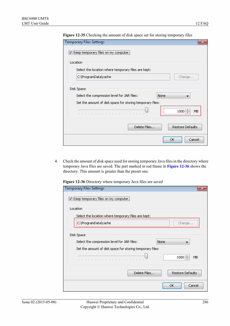
Figure 12-35 Checking the amount of disk space set for storing temporary files
4. Check the amount of disk space used for storing temporary Java files in the directory where
temporary Java files are saved. The part marked in red frame in Figure 12-36 shows thedirectory. This amount is greater than the preset one.
Figure 12-36 Directory where temporary Java files are saved
BSC6900 UMTSLMT User Guide 12 FAQ
Issue 02 (2015-05-08) Huawei Proprietary and ConfidentialCopyright © Huawei Technologies Co., Ltd.
286

5. Delete folders in this directory manually or by clicking Delete Files shown in the figure
above.
NOTE
Before deleting folders in this directory, close all running LMT clients.
6. Log in to the LMT again to check whether this problem is solved.
----End
12.2.5 LMT Fails to Function Properly during the tracing/monitoring/batch processing
After you log in to the LMT and perform operations on it for a while, batch processing operationsmay suddenly fail without any error messages. Alternatively, after a tracing or monitoring taskis created, the task page is not opened. There is no response or any error message. The NE tasklist shows that this task has been successfully created. There is no response when you clicksaving files in the tracing or monitoring interface. There is no detailed parsing information whenyou double-click a tracing or monitoring message. There is no response when you right-clickthe window for displaying tracing or monitoring results. There is no response when you right-click the window for displaying tracing or monitoring results and choose Save All Messagesand Save Selected Messages from the shortcut menu. If you open a new browser and log in tothe LMT again, the task nevertheless can be successfully created. If either of the previousproblems occurs, perform the following operations:
Procedure
Step 1 Open Control Panel in the Windows operating system and double-click Java. The JavaControl Panel dialog box is displayed.
Step 2 In the displayed Java Control Panel dialog box, click the Advanced tab, choose SecurityMixedcode (sandboxed vs. trusted) security verification, and select Disable verification (notrecommended). Figure 12-37 shows the dialog box.
BSC6900 UMTSLMT User Guide 12 FAQ
Issue 02 (2015-05-08) Huawei Proprietary and ConfidentialCopyright © Huawei Technologies Co., Ltd.
287

Figure 12-37 Java Control Panel dialog box
Step 3 Close all opened browsers and delete Java temporary files. To delete Java temporary files,perform the following operations:1. Open Control Panel in the Windows operating system and double-click Java. The Java
Control Panel dialog box is displayed, as shown in Figure 12-38.
BSC6900 UMTSLMT User Guide 12 FAQ
Issue 02 (2015-05-08) Huawei Proprietary and ConfidentialCopyright © Huawei Technologies Co., Ltd.
288

Figure 12-38 Java Control Panel dialog box
2. In the Java Control Panel dialog box, click Settings. The Temporary Files Settings
dialog box is displayed, as shown in Figure 12-39.
Figure 12-39 Temporary Files Settings dialog box
BSC6900 UMTSLMT User Guide 12 FAQ
Issue 02 (2015-05-08) Huawei Proprietary and ConfidentialCopyright © Huawei Technologies Co., Ltd.
289

3. In the Temporary Files Settings dialog box, click Delete Files to delete Java temporary
files and click OK.
Step 4 Log in to the LMT again.
----End
12.2.6 Interfaces for Performing Tracing or Monitoring TasksBlinking
Interfaces for performing tracing or monitoring tasks blink.
ContextJava Applet in the IE browser is incompatible with HTML elements when they are stackedtogether. As a result, interfaces (stacked in the Java Applet) for performing tracing andmonitoring tasks blink. This problem does not affect the function but deteriorates userexperience.
Procedurel To avoid this problem, use the following methods:
1. This problem occurs only on the IE browser. Use the Firefox browser to avoid thisproblem.
2. This problem occurs only on Java later than the version of 1.6.21. Visitwww.oracle.com and download Java SE Runtime Environment 6u21 or an earlierversion to avoid this problem.
----End
12.2.7 Java Installation FailsDuring Java installation, the message "Error 25099, Unzipping core files failed." is displayed.To solve the problem, perform the following steps:
Procedure
Step 1 Delete all files in the Java installation path. The default installation path is C:\Program Files\Java\jre6\.
Step 2 If step 1 fails because files are locked or in use, restart the system and repeat step 1.
Step 3 Reinstall Java.
----End
12.2.8 Changing Settings for the Next-Generation Java Plug-in FailsWhen changing settings for Enable the next-generation Java Plug-in, you are prompted witha message indicating that the changing fails because one or more browsers are running. As amatter of fact, no browser is running. The following figure shows the message: To solve theproblem, perform the following steps.
BSC6900 UMTSLMT User Guide 12 FAQ
Issue 02 (2015-05-08) Huawei Proprietary and ConfidentialCopyright © Huawei Technologies Co., Ltd.
290

ContextChanging Settings for Next-Generation Java Plug-in Fails, the error message is shown inFigure 12-40.
Figure 12-40 Unable to change Java Plug-in settings
This problem is caused by a Java defect. The setting changing fails not because browsers arerunning but because the user has no permission to perform the operation.
To change the settings, the user must belong to the Power Users group or have more rights.
Perform the following steps to grant the user more rights.
Procedure
Step 1 Log in to the operating system (OS) using an administrator-level account authorized for theadministrator's operations. Right-click My computer and choose Manage from the shortcutmenu.
Step 2 In the Computer Management window, choose System toolsLocal Users andGroupsGroups and double-click Power Users in the right pane of the window, as shown in thefollowing figure:
BSC6900 UMTSLMT User Guide 12 FAQ
Issue 02 (2015-05-08) Huawei Proprietary and ConfidentialCopyright © Huawei Technologies Co., Ltd.
291

Step 3 In the displayed window, click Add, add the user account to the Power Users group, and clickOK, as shown in the following figures:
BSC6900 UMTSLMT User Guide 12 FAQ
Issue 02 (2015-05-08) Huawei Proprietary and ConfidentialCopyright © Huawei Technologies Co., Ltd.
292

Step 4 Use an administrator-level account to delete the Windows folder in C:\Documents and Settings\User account\Local Settings\Application Data\Microsoft\Windows shown in the followingfigure:
BSC6900 UMTSLMT User Guide 12 FAQ
Issue 02 (2015-05-08) Huawei Proprietary and ConfidentialCopyright © Huawei Technologies Co., Ltd.
293

Step 5 Use the user account to log in the OS again after the previous steps are complete. The useraccount now has permission to change settings for Enable the next-generation Java Plug-in.
NOTE
After changing the settings, you can restore the user rights. To restore the user rights, log in to OS using anadministrator-level account again and remove the user account from the Power Users group by referring to steps1 through 3. The change of the user rights does not affect settings for Enable the next-generation Java Plug-in.
----End
12.2.9 How to Handle a Web Page Error or Java Error Displayed onthe LMT
Any of the following occurs during the login to the LMT: the controller version displayed onthe LMT is not the actual version after a controller upgrade or rollback. The error messageProblems with this Web page might prevent it from being displayed properly orfunctioning properly . A Java error message is displayed. A JavaScript error message isdisplayed on the status bar in the browser. In other words, an exclamation mark is displayed atthe bottom left corner of the status bar.
ContextWhen the browser cache or Java Applet cache is insufficient, any of the following cases willresult in the inconsistency between the LMT displayed in the browser and the actual LMT.l After a controller version upgrade or rollback, the browser fails to obtain the new Javascript,
JAR files, and other files from the LMT server. As a result, the browser uses the precedingfiles saved before the controller version upgrade or rollback.
l The preceding files are damaged during the use of the LMT.
Procedurel To clear the cache and cookies in the browser, perform the steps shown in the following
table.
Browser Type Handling Procedure
Firefox 1. Open the Firefox browser, and chooseTools > Clear Private Data from themenu bar.
2. In the displayed Clear Private Datadialog box, select the Cache, Cookies,and Offline Website Datacheck boxes,and click Clear Private Data Now.
3. The operations take effect after thebrowser restarts.
BSC6900 UMTSLMT User Guide 12 FAQ
Issue 02 (2015-05-08) Huawei Proprietary and ConfidentialCopyright © Huawei Technologies Co., Ltd.
294

Browser Type Handling Procedure
Internet Explorer 7 1. Open the Internet Explorer, and chooseTools > Internet Options from themenu bar. The Internet Options dialogbox is displayed.
2. On the General tab page, click Delete.The Delete Browsing History dialogbox is displayed.
3. To delete the files, click Delete Filesand then click OK in the displayeddialog box. To delete the cookies, clickDelete Cookies and then click OK inthe displayed dialog box.
4. In the Delete Browsing History dialogbox, click OK and close the InternetOptions dialog box.
5. The operations take effect after thebrowser restarts.
Internet Explorer 8 or 9 1. Open the Internet Explorer, and chooseTools > Internet Options from themenu bar. The Internet Options dialogbox is displayed.
2. On the General tab page, click Delete.The Delete Browsing History dialogbox is displayed.
3. Clear the Preserve Favorites websitedata check box and select theCookies and Temporary Internetfiles check boxes. Then, click Deleteand close the Internet Options dialogbox.
4. The operations take effect after thebrowser restarts.
l To clear the Java Applet, perform the following steps.
CAUTIONBefore you clear the Java Applet, exit the LMT. Otherwise, some loaded data will be lostand unexpected errors will occur.
1. Choose Start > Control Panel. The Control Panel is displayed.2. Double-click Java in the displayed window. The JAVA Control Panel is displayed.
BSC6900 UMTSLMT User Guide 12 FAQ
Issue 02 (2015-05-08) Huawei Proprietary and ConfidentialCopyright © Huawei Technologies Co., Ltd.
295

3. On the General tab page, click Settings. The Temporary Files Settings dialog boxis displayed.
4. Click Delete Files. In the displayed Delete Temporary Files dialog box, select theApplications and Applets and Trace and Log Files check boxes, and click OK.
5. In Java Control Panel, click OK.6. The operations take effect after the browser restarts.
----End
12.2.10 Displaying the Java Security WarningThe Java security warning is displayed during the use of the progress management, batchprocessing, tracing, or monitoring function on the LMT. Solve this problem by using thefollowing methods.
Procedure
Step 1 The error message Are you sure you want to continue this operation? The connection to thewebsite is unreliable. is displayed in the Security Warning dialog box.
The certificate for system check is a general certificate. It is the same on all Huawei MBSCsand the certificate issuer is MBSC Certificate. However, the device IP address is allocated bythe network. Therefore, the certificate issuer is inconsistent with the equipment ID. As a result,the error message is displayed.
This problem is riskless and can be ignored. You can click Continue to proceed with thesubsequent operations. If this problem needs to be resolved, enable the PKI system to allocateunique certificates to all MBSCs by IP addresses.
Step 2 The error message Do you want to run this application? is displayed in the SecurityWarning dialog box.
The Web LMT is a terminal software and does not contain any key information. In addition, theJar package execution requires OM identity authentication on the NE. Therefore, this problemis riskless and can be ignored.l For Java 1.6, click Always trust content from this publisher. and click Run.l For Java 1.7, click I accept the risk and want to run this application. and click Show
Options. Then, click Always trust content from this publisher. and click Run.
----End
12.2.11 Failure in Verifying the Verification Code During the Loginto the LMT
The verification code needs to be entered when a user logs in to the LMT. However, the message"Enter a correct verification code" is displayed even though the user enters the correctverification code for many times. To solve this problem, perform the following steps:
Procedurel To clear the cache and cookies in the browser, perform the steps shown in the following
table.
BSC6900 UMTSLMT User Guide 12 FAQ
Issue 02 (2015-05-08) Huawei Proprietary and ConfidentialCopyright © Huawei Technologies Co., Ltd.
296

Browser Type Handling Procedure
Firefox 1. Open the Firefox browser, and chooseTools > Clear Private Data from themenu bar.
2. In the displayed Clear Private Datadialog box, select the Cache, Cookies,and Offline Website Datacheck boxes,and click Clear Private Data Now.
3. The operations take effect after thebrowser restarts.
Internet Explorer 7 1. Open the Internet Explorer, and chooseTools > Internet Options from themenu bar. The Internet Options dialogbox is displayed.
2. On the General tab page, click Delete.The Delete Browsing History dialogbox is displayed.
3. To delete the files, click Delete Filesand then click OK in the displayeddialog box. To delete the cookies, clickDelete Cookies and then click OK inthe displayed dialog box.
4. In the Delete Browsing History dialogbox, click OK and close the InternetOptions dialog box.
5. The operations take effect after thebrowser restarts.
Internet Explorer 8 or 9 1. Open the Internet Explorer, and chooseTools > Internet Options from themenu bar. The Internet Options dialogbox is displayed.
2. On the General tab page, click Delete.The Delete Browsing History dialogbox is displayed.
3. Clear the Preserve Favorites websitedata check box and select theCookies and Temporary Internetfiles check boxes. Then, click Deleteand close the Internet Options dialogbox.
4. The operations take effect after thebrowser restarts.
l To clear the Java Applet, perform the following steps.
BSC6900 UMTSLMT User Guide 12 FAQ
Issue 02 (2015-05-08) Huawei Proprietary and ConfidentialCopyright © Huawei Technologies Co., Ltd.
297

CAUTIONBefore you clear the Java Applet, exit the LMT. Otherwise, some loaded data will be lostand unexpected errors will occur.
1. Choose Start > Control Panel. The Control Panel is displayed.
2. Double-click Java in the displayed window. The JAVA Control Panel is displayed.
3. On the General tab page, click Settings. The Temporary Files Settings dialog boxis displayed.
4. Click Delete Files. In the displayed Delete Temporary Files dialog box, select theApplications and Applets and Trace and Log Files check boxes, and click OK.
5. In Java Control Panel, click OK.
6. The operations take effect after the browser restarts.
----End
12.2.12 The Application Blocked by Security Settings Dialog Box IsDisplayed When Batch Processing, Tracing, Monitoring, or DeviceMaintenance Is Enabled
After the JRE is installed or upgraded, the Application Blocked by Security Settings dialogbox is displayed when the tab page related to batch processing, tracing, monitoring, or devicemaintenance is open. Click OK, and the The application cannot be run dialog box is displayed,indicating that the batch processing, tracing, monitoring, or device maintenance function isunavailable.
Context
A function is introduced to the JRE later than Java 1.7. 10 to control when and how to rununtrusted Java applications contained in a web page. The untrusted Java application refers to anapplication with digital signature applied by an unknown issuer or without a certificate issuedby a trusted certificate authority. The default security level is set to High, indicating that theuntrusted Java applications will be blocked.
Procedure
Step 1 Reconfigure the Java security level or add Exception Site List.
l On the Control Panel page, click Java. In the displayed Java Control Panel dialog box,click Security. On the displayed Security tab page, select Enable Java content in thebrowser, set Security Level to Medium, and then click Apply.
l Alternatively, click Edit Site List on the Security tab page in the Java Control Panel dialogbox to add the sites accessing the LMT to the site list. If this method is used, the Java securitylevel does not need to be reconfigured. For the sites added in the site list, mark whether theaccess to the LMT through HTTPS or HTTP. For example, https://10.20.198.33 or http://10.30.192.60.
Step 2 Specify Enable the next-generation Java Plug-in(requires browser restart).
BSC6900 UMTSLMT User Guide 12 FAQ
Issue 02 (2015-05-08) Huawei Proprietary and ConfidentialCopyright © Huawei Technologies Co., Ltd.
298

1. In the Java Control Panel dialog box, click Advanced. On the displayed Advanced tabpage, select Java Plug-in, clear Enable the next-generation Java Plug-in(requiresbrowser restart), and then click OK.
2. Select Enable the next-generation Java Plug-in(requires browser restart) according tooperations in step 2.a, and click OK.
3. Restart the browser to make the settings take effect.
Step 3 Delete temporary Java files.
1. In the Java Control Panel dialog box, click General. On the displayed General tab page,click Settings. The Temporary Files Settings dialog box is displayed.
2. Close all running LMT windows and click Delete Files.
Step 4 Log in to the LMT again. When enabling any of the batch processing, tracing, monitoring, anddevice maintenance functions, select I accept the risk and want run this application on thedisplayed do you want run this application? dialog box and click Run. If the Do you want tocontinue? dialog box is displayed, click Continue.
----End
12.2.13 What Do I Do If A Message Your Java version is out of dateIs Displayed?
If you are prompted with the message that Your Java version is out of date when logging in tothe WebLMT, follow instructions provided in this session.
Context
The JRE installed on the computer is not of the latest version and an upgrade to the latest versionis recommended by Java. To continue to use the WebLMT and update the JRE later, it is goodpractice to perform the procedure described below.
Procedure
Step 1 In the Your Java version is out of date dialog box, select the Do not ask again until the nextupdate is available check box.
Step 2 Click Later.
----End
12.3 Other FAQsThis section describes common problems, except Java- or browser setting-related problems, thathinder the normal use of the LMT and corresponding handling procedures.
12.3.1 Installing OS PatchesIn a Microsoft Windows operating system (OS), you need to install patch KB944338, KB938397or KB960714 if the OS and IE are in a certain version.
BSC6900 UMTSLMT User Guide 12 FAQ
Issue 02 (2015-05-08) Huawei Proprietary and ConfidentialCopyright © Huawei Technologies Co., Ltd.
299

Contextl Patch KB960714 solves the problem of Java console output error. Therefore, the Java
application can be loaded successfully on the LMT.
l Patch KB944338 improves the performance of the LMT by increasing the speed of visitinga web page. Therefore, the LMT running rate can be increased.
l If Windows 7 operating system is used, Windows patches do not need to be installed.
Procedure
Step 1 In the Windows OS, open the Control Panel window. Double-click the Add or RemovePrograms icon.
Step 2 In the displayed Add or Remove Programs window, select Show updates. Check whetherpatches KB944338, KB938397 and KB960714 are present in the list of Currently installedprograms.
l If the patches are present, the task is complete.
l If the patches are not present, go to Step 3.
Step 3 Determine whether a Windows patch needs to be installed according to the OS version and IEversion.
l Patch KB960714 needs to be installed when the OS version and IE version are combined inthe following ways:
OS Version IE Version
Windows 2000 SP4 IE5/IE6 SP1
Windows XP SP3 IE6/IE7
Windows Server 2003 SP1/SP2 IE6/IE7
Windows Vista IE7
l Patch KB944338 needs to be installed when the OS version is Windows 2000 SP4 orWindows Server 2003 SP1/SP2.
l When the Windows 2003 operating system is used, the service pack KB938397 needs to beinstalled. This service pack ensures that the Windows 2003 operating system supports theSHA256 algorithm. After the service pack is installed, the LMT can work properly.
l When the Windows 2008 OS and Internet Explorer 7 or later are used, the OS patch doesnot need to be installed.
NOTE
l To download patch KB944338 or KB960714, go to http://www.microsoft.com/downloads.
l To download patch KB938397, go to http://support.microsoft.com/?kbid=938397.
l Download a suitable patch according to the OS version and IE version.
----End
BSC6900 UMTSLMT User Guide 12 FAQ
Issue 02 (2015-05-08) Huawei Proprietary and ConfidentialCopyright © Huawei Technologies Co., Ltd.
300

12.3.2 Changing the Computer Time During the LMT UseProhibited
Changing the computer time during the LMT use is prohibited. Changing the computer timecauses some functions of the LMT to stop functioning normally. For example, the OMU timefails to refresh normally; tracing data and monitoring data fail to refresh normally; progressmanagement fails to refresh normally.
12.3.3 Corrupted Characters Appearing When the csv File IsOpened in UTF-8 Coding
If a csv file in UTF-8 coding is saved on the LMT with non-English characters in it and the csvfile is opened in the Excel format by using the regular method, all the non-English charactersare displayed as corrupted characters. In this case, open the csv file by using the import methodin Excel.
Procedurel If the Excel version is earlier than Office 2007, perform the following operations:
1. On the menu bar of Excel, choose Data > Import External Data > Import Data.Then the Select Data Source dialog box is displayed. Figure 12-41 shows the dialogbox.
Figure 12-41 Operation interface for importing data in Excel
2. In the Select Data Source dialog box, select the csv file in UTF-8 coding. Then the
Text Import Wizard - Step 1 of 3 dialog box is displayed. Figure 12-42 shows thedialog box. Select 65001:Unicode(UTF-8) in File origin.
BSC6900 UMTSLMT User Guide 12 FAQ
Issue 02 (2015-05-08) Huawei Proprietary and ConfidentialCopyright © Huawei Technologies Co., Ltd.
301

Figure 12-42 Text import wizard-step 1
3. Click Next. Then the Text Import Wizard - Step 2 of 3 dialog box is displayed.
Figure 12-43 shows the dialog box. Select Comma under Delimiters.
Figure 12-43 Text import wizard-step 2
4. Click Finish. Then the Import Data dialog box is displayed. Figure 12-44 shows the
dialog box.
BSC6900 UMTSLMT User Guide 12 FAQ
Issue 02 (2015-05-08) Huawei Proprietary and ConfidentialCopyright © Huawei Technologies Co., Ltd.
302

Figure 12-44 Interface after data importation is finished
5. Click OK. Then the file is displayed properly.
l If the Excel version is Office 2007 or later, perform the following operations:
1. On the menu bar of Excel, choose Data > From Text. Then the Import Text Filedialog box is displayed. Figure 12-41 shows the dialog box.
Figure 12-45 Operation interface for importing data in Excel
2. In the Import Text File dialog box, select the csv file in UTF-8 coding. Then theText Import Wizard - Step 1 of 3 dialog box is displayed. Figure 12-42 shows thedialog box. Select 936:Chinese Simplified(GB2312) in File origin.
Figure 12-46 Text import wizard-step 1
3. Click Next. Then the Text Import Wizard - Step 2 of 3 dialog box is displayed.Figure 12-43 shows the dialog box. Select Comma under Delimiters.
BSC6900 UMTSLMT User Guide 12 FAQ
Issue 02 (2015-05-08) Huawei Proprietary and ConfidentialCopyright © Huawei Technologies Co., Ltd.
303

Figure 12-47 Text import wizard-step 2
4. Click Finish. Then the Import Data dialog box is displayed. Figure 12-44 shows the
dialog box.
Figure 12-48 Interface after data importation is finished
5. Click OK. Then the file is displayed properly.
----End
12.3.4 Maximum Number of LMT Clients That Can Be Started onOne PC Simultaneously
You can have multiple LMT clients started on one PC. Starting too many LMT clientssimultaneously, however, affects maintenance performance. As being limited by the PC memoryand maximum number of dialog boxes that can be opened on the IE browser, a PC does notsupport 32 LMT clients to be started simultaneously.
In normal maintenance, the maximum number of LMT clients that can be simultaneously startedon one PC is as follows:
BSC6900 UMTSLMT User Guide 12 FAQ
Issue 02 (2015-05-08) Huawei Proprietary and ConfidentialCopyright © Huawei Technologies Co., Ltd.
304

l One PC with 2 GB memory or larger supports 16 LMT clients to be started simultaneously.
l One PC with 1 GB memory supports 8 LMT clients to be started simultaneously.
l One PC with 512 MB memory supports 4 LMT clients to be started simultaneously.
12.3.5 Any Further Operation Performed When Some LMT WebPages Fail to Update Causes the Web Pages to Turn Blank
Some LMT Web pages fail to update when batch processing, tracing, or monitoring is in use.Any further operation causes the Web pages to turn blank. If you restart the function, the Webpage returns to normal. To prevent this problem, perform the following operations to add anenvironment variable.
Procedure
Step 1 On the LMT PC, select My Computer and right-click Properties from the shortcut menu. TheSystem Properties dialog box is displayed.
Step 2 In the System Properties dialog box, click the Advanced tab and click EnvironmentVariables. The Environment Variables dialog box is displayed.
Step 3 In the Environment Variables dialog box, click New. The New User Variable dialog box isdisplayed.
Step 4 In the New User Variable dialog box, set Variable name toJPI_PLUGIN2_NO_HEARTBEAT and Variable value to 1. Then click OK.
Step 5 In the Environment Variables dialog box, click OK.
Step 6 In the System Properties dialog box, click OK to finish adding the environment variable.
----End
12.3.6 Configuring the HTTPS Login ModeThis section describes how to configure the HTTPS login mode and a security certificate. Userscan log in to the LMT through either HTTP or HTTPS. The login mode is configurable.
Prerequisitesl You have logged in to the LMT using a Built-In Administrator Account or External
User Accounts.
Context
HTTPS is Hypertext Transfer Protocol Secure. Based on HTTP, HTTPS introduces SSL (orTLS) to ensure transmission security. To put it simply, HTTPS is a combination of HTTP andSSL. To enter the HTTPS login mode, enter https://Website to be visited + Port No in the Addressbar of the browser. The default port No. is 443. Use the default port No. to enter the LMT loginpage.
BSC6900 UMTSLMT User Guide 12 FAQ
Issue 02 (2015-05-08) Huawei Proprietary and ConfidentialCopyright © Huawei Technologies Co., Ltd.
305

Procedure
Step 1 Change the login mode
1. Log in to the LMT through HTTPS.2. Run the MML command SET WEBLOGINPOLICY. In this step, set POLICY to
HTTPS.
Step 2 Run the MML command RST OMUMODULE to restart the LMT so that the change take effect.In this step, set TG to ACTIVE and MNAME to weblmt.
NOTICE1. Running this command disconnects all online users from the LMT.2. Normally, the restart is complete within 5 seconds. After the restart is complete, the change
take effect when users log in to the LMT again.
----End
12.3.7 Unable to Save Tracking and Monitoring DataWhen a tracking or monitoring task (such as the UE tracking task) is running on the LMT, it ispossible that the vast amounts of tracking or monitoring data cannot be saved even with sufficienthard disk space. Solve the problem by using the method described in the procedure part.
ContextThis problem arises when the operating system enables the system recovery function thatmonitors changes of the files on the hard disk and consumes some hard disk space. Withinsufficient hard disk space, the system displays "Insufficient hard disk space", and if a trackingor monitoring task is running on the LMT, it is likely that the tracking or monitoring data cannotbe saved.
Procedure
Step 1 Log in to the operating system (OS) using an administrator-level account authorized for theadministrator's operations. Right-click My computer and choose Properties.
Step 2 In the "System Properties" window, click System Recovery, select Disable System Recoveryon All Drivers, and click Submit, as shown in Figure 12-49.
BSC6900 UMTSLMT User Guide 12 FAQ
Issue 02 (2015-05-08) Huawei Proprietary and ConfidentialCopyright © Huawei Technologies Co., Ltd.
306

Figure 12-49 System properties dialog box
----End
12.3.8 BTS Nodes Cannot Be Displayed Under Device NavigationTree
After a successful login to the LMT, you may find that BTS nodes cannot be displayed underDevice Navigation Tree. After upgrading the browser, you find that the nodes can be displayednormally. This problem occurs because data under Device Navigation Tree on the LMT iscompressed whereas Internet Explorer 6 SP2 does not support compression of chunked data.Solve this problem by using either of the following methods.
ContextBTS nodes cannot be displayed under Device Navigation Tree, as shown in Figure 12-50.
BSC6900 UMTSLMT User Guide 12 FAQ
Issue 02 (2015-05-08) Huawei Proprietary and ConfidentialCopyright © Huawei Technologies Co., Ltd.
307

Figure 12-50 BTS nodes cannot be displayed
Procedurel Method 1: For the operating system Windows XP Service Pack 2 or 3, install the KB982381
patch. To download this patch, visit http://www.microsoft.com/downloads.
l Method 2: Upgrade the browser. You are advised to upgrade it to Internet Explorer 8.
----End
12.3.9 Alarm/Event Function Becomes UnavailableWhen starting or using the Alarm/Event function after a successful login to the LMT, the pagemay become white with an exclamation mark displayed in the center. The exclamation mark iscircled in gray, as shown in the following figure: Solve this problem by using the followingmethods.
Context
The page of alarm/event function become white, as shown in Figure 12-51.
Figure 12-51 Alarm/Event Function
BSC6900 UMTSLMT User Guide 12 FAQ
Issue 02 (2015-05-08) Huawei Proprietary and ConfidentialCopyright © Huawei Technologies Co., Ltd.
308
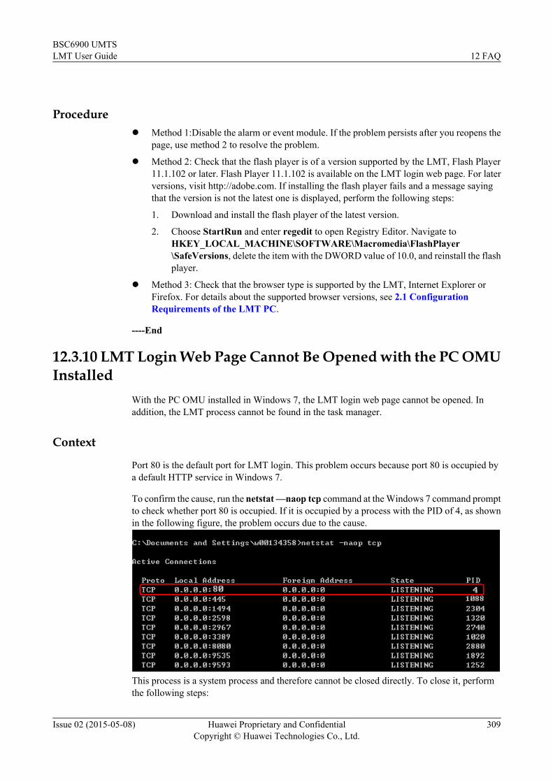
Procedurel Method 1:Disable the alarm or event module. If the problem persists after you reopens the
page, use method 2 to resolve the problem.
l Method 2: Check that the flash player is of a version supported by the LMT, Flash Player11.1.102 or later. Flash Player 11.1.102 is available on the LMT login web page. For laterversions, visit http://adobe.com. If installing the flash player fails and a message sayingthat the version is not the latest one is displayed, perform the following steps:
1. Download and install the flash player of the latest version.
2. Choose StartRun and enter regedit to open Registry Editor. Navigate toHKEY_LOCAL_MACHINE\SOFTWARE\Macromedia\FlashPlayer\SafeVersions, delete the item with the DWORD value of 10.0, and reinstall the flashplayer.
l Method 3: Check that the browser type is supported by the LMT, Internet Explorer orFirefox. For details about the supported browser versions, see 2.1 ConfigurationRequirements of the LMT PC.
----End
12.3.10 LMT Login Web Page Cannot Be Opened with the PC OMUInstalled
With the PC OMU installed in Windows 7, the LMT login web page cannot be opened. Inaddition, the LMT process cannot be found in the task manager.
Context
Port 80 is the default port for LMT login. This problem occurs because port 80 is occupied bya default HTTP service in Windows 7.
To confirm the cause, run the netstat —naop tcp command at the Windows 7 command promptto check whether port 80 is occupied. If it is occupied by a process with the PID of 4, as shownin the following figure, the problem occurs due to the cause.
This process is a system process and therefore cannot be closed directly. To close it, performthe following steps:
BSC6900 UMTSLMT User Guide 12 FAQ
Issue 02 (2015-05-08) Huawei Proprietary and ConfidentialCopyright © Huawei Technologies Co., Ltd.
309

ProcedureStep 1 In Windows, choose StartRun and enter regedit to open Registry Editor.
Step 2 Navigate to HKEY_LOCAL_MACHINE\SYSTEM\CurrentControlSet\Services\HTTP.
Step 3 Change the DWORD value of Start to 0.
Step 4 Restart the PC and log in to the LMT again.
----End
12.3.11 Slow Response During an LMT LoginThe LMT responses slowly when the users are trying to log in to the LMT. To solve the problem,perform the following steps:
ProcedureStep 1 In the Windows 2003 and Windows XP operating system (OS), choose Start > Control
Panel, and then click Add/Remove Programs, the Windows Components Wizard dialog boxis displayed.
Step 2 In the Windows Components Wizard dialog box, deselect Upload Root Certificates, as shownin the following figure. Then click Next to complete the modification.
----End
BSC6900 UMTSLMT User Guide 12 FAQ
Issue 02 (2015-05-08) Huawei Proprietary and ConfidentialCopyright © Huawei Technologies Co., Ltd.
310

12.3.12 Batch Execution of MML Commands Fails Because SomeMML Commands Contain Invisible Carriage Returns or Line Feeds
After line feeds (LF) are deleted from MML command scripts copied to Batch, commandexecution fails.
ContextCopy the MML commands failing to be executed to an UltraEdit file. It is found that these MML
commands are displayed in two lines. In UltraEdit, click to view these MML commandsin the binary format. A redundant carriage return (CR) 0x0D stays at the LF location of the MMLcommand each. See Figure 12-52.
Figure 12-52 Viewing an MML command in the binary format using UltraEdit
In the Windows operating system (OS), the CR 0x0D and LF 0x0A must be used pairwise. Theunpaired CRs or LFs cannot be deleted. As a result, the MML commands fail to be executed.
Procedure
Step 1 Copy the MML commands failing to the executed to an UltraEdit or notepad file and delete allLFs and CRs. Then, copy these commands back to Batch and execute them again.
----End
12.3.13 How to Handle Shortcut Key InvalidationShortcut keys are defined on the LMT. When logging in to the LMT through a web page, youmay fail to use the corresponding function by pressing a shortcut key. In this case, the shortcutkey becomes invalid. For example, you cannot stop pinging by pressing Ctrl+Q in the MMLCommand window. This is because the same shortcut key is preferentially used by anotherrunning program on the PC, which leads to a shortcut key conflict.
Procedure
Step 1 Check all running programs on the PC. Find the program using the same shortcut key settingsas the LMT.
BSC6900 UMTSLMT User Guide 12 FAQ
Issue 02 (2015-05-08) Huawei Proprietary and ConfidentialCopyright © Huawei Technologies Co., Ltd.
311

Step 2 Modify the program shortcut key settings which are the same as those on the LMT or stop theprogram when you use the LMT.
----End
12.3.14 Tracing File Not Being Uploaded to the Specified DirectoryIf you close the UE Trace or IOS Trace dialog box during the UE tracing or IOS tracing, thetracing result file being generated cannot be uploaded to the specified directory. This problemoccurs in the following scenario: In the UE Trace or IOS Trace dialog box, Debug is selectedand Trace Mode is set to Report File. To solve the problem, perform the steps in Procedure.
Context
A tracing task may generate multiple tracing files, which depends on the traced messages.
If you close the trace dialog box, the last tracing file cannot be uploaded to the specified directory.The last tracing file refers to the one being generated. The generated tracing files can be uploaded.
Procedure
Step 1 In the Trace Navigation Tree, double-click Manage Trace Task. The Manage Trace Tasktab page is displayed.
Step 2 Query the UE tracing or IOS tracing task being performed, select a task, and click Delete. Thepreceding settings enable the tracing result file being generated to be uploaded to the specifieddirectory.
----End
12.3.15 Error Dialog Box Displayed When Online Help Is OpenedWhen Online Help is opened on the LMT, a dialog box is displayed with the followinginformation: An error on this web page disables the proper running of the web page. As a result,Online Help cannot be used. To solve the problem, perform the following steps:
Procedure
Step 1 1. Uninstall the Google chrome frame plug-in.
Step 2 2. Clear the IE browser cache.
Step 3 3. Log in to the LMT again
----End
12.3.16 Garbled Characters Displayed in the Chinese Names of Filesin the File Manager and These Files Failing to Be Removed
When users view the files on the OMU using the LMT file manager, they can see garbledcharacters in the Chinese names of the files, and the files cannot be removed. To solve thisproblem, perform the following steps:
BSC6900 UMTSLMT User Guide 12 FAQ
Issue 02 (2015-05-08) Huawei Proprietary and ConfidentialCopyright © Huawei Technologies Co., Ltd.
312

Procedure
Step 1 1. Use a third-party tool, such as the FileZilla, to upload a file to the OMU. Before uploadingthis file, specify the file name using the gb2312 coding and save the file. In this way, the filemanager can manage this file.
Set the FileZilla as follows: Choose FileSite Manager. A Site Management dialog box isdisplayed. Select the corresponding site from My Sites. On the Charset tab page, select Usecustom charset, set Encoding to gb2312, and click Connect. The encoding is modified. Then,upload the file.
Step 2 On the LMT, click System Settings. Select Chinese in Language, and click OK. Open the filemanager to view the file, and you can see a normally displayed file name. The file can be removednow.
----End
BSC6900 UMTSLMT User Guide 12 FAQ
Issue 02 (2015-05-08) Huawei Proprietary and ConfidentialCopyright © Huawei Technologies Co., Ltd.
313