Embed Size (px)
DESCRIPTION
Huawei BSC Configuration guide
Citation preview

BSC6900 GSM
Data Configuration
www.huawei.com
Copyright © 2010 Huawei Technologies Co., Ltd. All rights reserved.

Learning Guide
� Before learn this course, you should have:
� Learned BSC6900 Hardware System Structure
Copyright © 2012 Huawei Technologies Co., Ltd. All rights reserved. Page1
References
� BSC6900 Commissioning Guide
� BSC6900 Initial Configuration Guide
Copyright © 2012 Huawei Technologies Co., Ltd. All rights reserved. Page2

Objectives
� Upon completion of this course, you will be able to:
� Detail the Procedure of BSC6900 Data Configuration
� Perform Global Data Configuration
� Perform Equipment Data Configuration
Copyright © 2012 Huawei Technologies Co., Ltd. All rights reserved. Page3
� Perform Interface Configuration
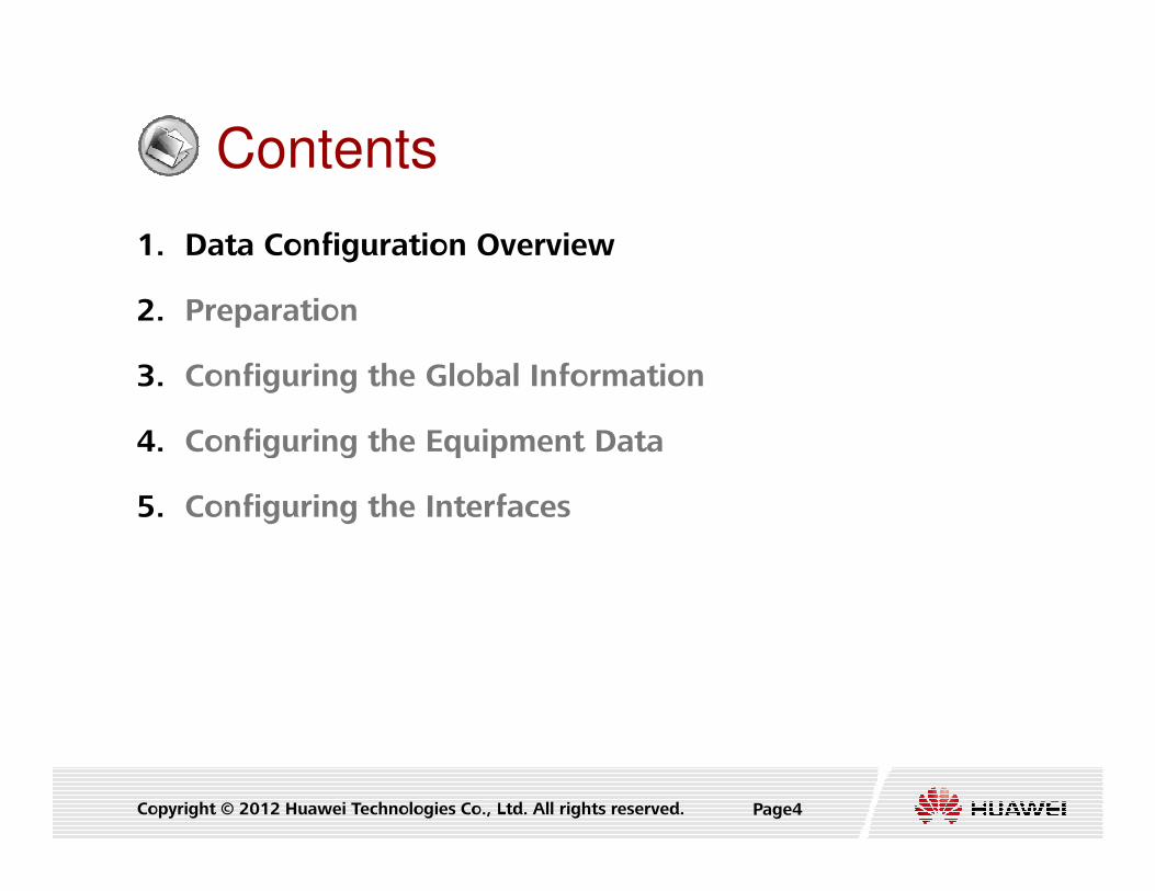
Contents
1. Data Configuration Overview
2. Preparation
3. Configuring the Global Information
4. Configuring the Equipment Data
Copyright © 2012 Huawei Technologies Co., Ltd. All rights reserved. Page4
4. Configuring the Equipment Data
5. Configuring the Interfaces

Data Configuration Overview
� Configuration Tools
� Web LMT (Local Maintenance Terminal)
� Based on MML (Man Machine Language)
� CME (Configuration Management Express)
� Based on GUI (Graphic User Interface)
Copyright © 2012 Huawei Technologies Co., Ltd. All rights reserved. Page5
� LMT Execution Modes
� Batch mode
� multiple MML commands in a script
� Single Command Mode
� one command at a time and carry it out directly

Data Configuration Procedure
Configuring the Global Information
Preparation
Copyright © 2012 Huawei Technologies Co., Ltd. All rights reserved. Page6
LOAD
Configuring the Equipment Data
Configuring the Interfaces

Contents
1. Data Configuration Overview
2. Preparation
3. Configuring the Global Information
4. Configuring the Equipment Data
Copyright © 2012 Huawei Technologies Co., Ltd. All rights reserved. Page7
4. Configuring the Equipment Data
5. Configuring the Interfaces

Preparation
� Data Configuration Right Management
� Forcibly Obtain CM Control Right (FOC CMCTRL)
� Request the CMC right (REQ CMCTRL)
� BSC6900 controls whether LMT or M2000 has the permission
to configure the data at a moment to avoid the data conflict
Copyright © 2012 Huawei Technologies Co., Ltd. All rights reserved. Page8
to configure the data at a moment to avoid the data conflict
� Set CM Control enable switch (SET CMCTRLSW)
� Check the status of CMC (LST CMCTRL)
� Lock the CMC right (LCK CMCTRL)
� Unlock the CMC right (ULK CMCTRL)

Preparation
� Data Configuration Mode
� Set Offline State (SET CFGDATAINEFFECTIVE)
Copyright © 2012 Huawei Technologies Co., Ltd. All rights reserved. Page9
� Set Online State (SET CFGDATAEFFECTIVE)

Preparation
� Data Initialization (RST DATA)
� RST DATA will remove all configuration data in BAM
Data in BAMData in BAM
Copyright © 2012 Huawei Technologies Co., Ltd. All rights reserved. Page10
RST DATA
Data in BAMData in BAM
(OMUa)(OMUa)
Data in FAMData in FAM
(Other Boards)(Other Boards)

Contents
1. Data Configuration Overview
2. Preparation
3. Configuring the Global Information
4. Configuring the Equipment Data
Configuring the Global Information
Preparation
Configuring the Equipment Data
Copyright © 2012 Huawei Technologies Co., Ltd. All rights reserved. Page11
4. Configuring the Equipment Data
5. Configuring the Interfaces
LOAD
Configuring the Equipment Data
Configuring the Interfaces

Global Data configuration
� Configuring the Basic Data
� Configuring the OPC (Original Signaling Point Code)
� Configuring the DPC (Destination Signaling Point Code)
� Configuring the M3UA Local and Destination Entities
Basic Data OPC DPC M3UA Entities
Copyright © 2012 Huawei Technologies Co., Ltd. All rights reserved. Page12
� Configuring the M3UA Local and Destination Entities
� This section describes how to configure the local and
destination M3UA entities. You need to configure the M3UA
entities when the IP-based networking is used.

Configuring the Basic Data
� Add GSM BSC Basic Information (SET BSCBASIC)
� Area Code: Local area code, for example, 021 for Shanghai.
� CC: Country code, for example, 86 for China
� Interface Tag : Phase tag for GSM protocols supported by the A,
Basic Data OPC DPC M3UA Entities
Copyright © 2012 Huawei Technologies Co., Ltd. All rights reserved. Page13
Um, Abis interface
� Support TFO Codec Optimize: Whether to enable the tandem free
operation (TFO) Codec optimizing function
� Support High Frequency Band : DCS1800, PCS1900
� Service Mode: Service mode of the BSC6900, Actual Value Range:
SEPARATE, TOGETHER

Configuring the Basic Data
� Add GSM Operator (ADD GCNOPERATOR)
� Operator Type: Primary operator or secondary operator
� Each BSC6900 must be configured with one and only one primary
operator. In the case of RAN Sharing, a maximum of fifteen
secondary operators can be configured.
Basic Data OPC DPC M3UA Entities
Copyright © 2012 Huawei Technologies Co., Ltd. All rights reserved. Page14
secondary operators can be configured.
� Actual Value Range: PRIM, SEC
� Operator Index
� Operator Name
� MCC: Mobile Country Code
� MNC: Mobile Network Code
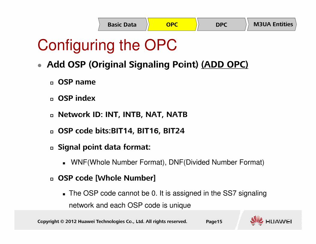
Configuring the OPC � Add OSP (Original Signaling Point) (ADD OPC)
� OSP name
� OSP index
� Network ID: INT, INTB, NAT, NATB
Basic Data OPC DPC M3UA Entities
Copyright © 2012 Huawei Technologies Co., Ltd. All rights reserved. Page15
� OSP code bits:BIT14, BIT16, BIT24
� Signal point data format:
� WNF(Whole Number Format), DNF(Divided Number Format)
� OSP code [Whole Number]
� The OSP code cannot be 0. It is assigned in the SS7 signaling
network and each OSP code is unique

Configuring the DPC � Add DSP (ADD N7DPC)
� DSP name
� DSP index
� OSP index
Basic Data OPC DPC M3UA Entities
Copyright © 2012 Huawei Technologies Co., Ltd. All rights reserved. Page16
� Signal point data format
� DSP code [Whole Number]
� DSP type
� Signaling route mask: Signaling route load sharing.
� In the value, the number of 1s (represented by n) determines the
maximum number (2) of routes for the load sharing.

Configuring the M3UA Local Entities
� Add M3UA Local Entity (ADD M3LE)
� Local entity No.
� OSP index
� Local entity type
Basic Data OPC DPC M3UA Entities
Copyright © 2012 Huawei Technologies Co., Ltd. All rights reserved. Page17
� M3UA_ASP, M3UA_IPSP
� Local entity name
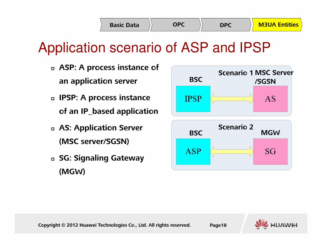
Application scenario of ASP and IPSP
� ASP: A process instance of
an application server
� IPSP: A process instance
of an IP_based application
AS: Application Server
Scenario 1
Scenario 2
BSCMSC Server
/SGSN
Basic Data OPC DPC M3UA Entities
Copyright © 2012 Huawei Technologies Co., Ltd. All rights reserved. Page18
� AS: Application Server
(MSC server/SGSN)
� SG: Signaling Gateway
(MGW)
Scenario 2BSC MGW

Configuring the M3UA Destination Entities
� Add M3UA Destination Entity (ADD M3DE)
� Destination entity No.
� Local entity No.
� DSP index
Basic Data OPC DPC M3UA Entities
Copyright © 2012 Huawei Technologies Co., Ltd. All rights reserved. Page19
� Destination entity type
� M3UA_SGP(M3UA SGP), M3UA_IPSP(M3UA IPSP),
M3UA_SS7SP(M3UA SS7SP), M3UA_SP(M3UA SP)
� Destination entity name

Contents
1. Data Configuration Overview
2. Preparation
3. Configuring the Global Information
4. Configuring the Equipment Data
Configuring the Global Information
Preparation
Configuring the Equipment Data
Copyright © 2012 Huawei Technologies Co., Ltd. All rights reserved. Page20
4. Configuring the Equipment Data
5. Configuring the Interfaces
LOAD
Configuring the Equipment Data
Configuring the Interfaces

Equipment Data Configuration
� Configuring the System Information
� Configuring a Cabinet
� Configuring a Subrack
� Configuring a Board
System Hardware Clocks EMS
Copyright © 2012 Huawei Technologies Co., Ltd. All rights reserved. Page21
� Configuring a Board
� Configuring the Clocks
� Configuring the Time
� Configuring the IP Address of the EMS Server

Configuring the System Information � Set Base Station Controller System Information (SET SYS)
(Optional)
� System description
� NE Name
System Hardware Clocks EMS
Copyright © 2012 Huawei Technologies Co., Ltd. All rights reserved. Page22
� Contact mode of the manufacturer
� System Location
� System services

Configuring a Cabinet & Subrack
� Add Cabinet (ADD CAB)
� Use this command to add an EPR or TCR.
� Cabinet No.
� Is remote cabinet :Yes/No
System Hardware Clocks EMS
Copyright © 2012 Huawei Technologies Co., Ltd. All rights reserved. Page23
� Add Service Processing Subrack (ADD SUBRACK)
� Subrack No.
� Subrack name
� Connect power monitoring board: Yes/No
� Subrack Type: EPS, TCS

Open SCUa Ports
� Open SCUa Ports (SET SCUPORT)
� After a subrack is added, run this command to enable the
corresponding port on the SCU board in the main subrack.
� Subrack No
System Hardware Clocks EMS
Copyright © 2012 Huawei Technologies Co., Ltd. All rights reserved. Page24
� Port No
� Port Switch: Close, Open
� If the SCUa ports are closed, the MAC switching couldn’t be
implemented between subracks. So we should use this
command to open the SCUa ports

Configuring a Board
� Add Board (ADD BRD)
� This command can be used by all types of boards except the
SCUa, GCUa, and GCGa
� Subrack No.
System Hardware Clocks EMS
Copyright © 2012 Huawei Technologies Co., Ltd. All rights reserved. Page25
� Board Class : INT, DPU, XPU, OMU, SAU, TNU
� Board Type
� Slot No.
� Backup: Whether to configure the backup board

� Add Board (ADD BRD)
� Logical Function Type: OAM, TDM_Switching, GCP, RGCP,
MCP, GTC, GPCU, IP, FR, HDLC, TDM, GbIP, Abis_TDM,
Ater_TDM, Pb_TDM, A_TDM, Abis_IP, SAU
Configuring a Board
System Hardware Clocks EMS
Copyright © 2012 Huawei Technologies Co., Ltd. All rights reserved. Page26
� TC board: Whether it is configured inside the TCS
� MPU Subrack No.
� MPU Slot No.

Configuring the Clocks
� Set Board Clock Source (SET CLK)
� Set the clock source data on the interface board in the MPS or EPS
subrack
� Add Clock Source (ADD CLKSRC)
� BITS,8k,GPS,Line clock
System Hardware Clocks EMS
Copyright © 2012 Huawei Technologies Co., Ltd. All rights reserved. Page27
� BITS,8k,GPS,Line clock
� Set Clock Working Mode (SET CLKMODE)
� Set the working modes of clock sources: manual /auto /free
� Set Clock Board Type (SET CLKTYPE)
� Set the type of a clock board: GCUa /GCGa

Configuring the Time
� Set Information About Time Zone and Daylight Saving
Time (SET TZ)
� Set the time zone and daylight saving time to ensure a
correct local time for the current system
System Hardware Clocks EMS
Copyright © 2012 Huawei Technologies Co., Ltd. All rights reserved. Page28
� Add SNTP Server for the Network Element (ADD
SNTPSRVINFO)
� Add the information of the SNTP server connected to the
network element

Configuring the IP Address of the EMS Server
� Add IP Address For EMS (Element Management System)
(ADD EMSIP)
� EMS IP Address: IP address of the NE management system
� Subnet Mask
System Hardware Clocks EMS
Copyright © 2012 Huawei Technologies Co., Ltd. All rights reserved. Page29
� OMU External Network Virtual IP
� OMU External Network Mask

Contents
1. Data Configuration Overview
2. Preparation
3. Configuring the Global Information
4. Configuring the Equipment Data
Configuring the Global Information
Preparation
Configuring the Equipment Data
Copyright © 2012 Huawei Technologies Co., Ltd. All rights reserved. Page30
4. Configuring the Equipment Data
5. Configuring the Interfaces
LOAD
Configuring the Equipment Data
Configuring the Interfaces

Contents� 5. Interface Data Configuration
� Ater Interface Data Configuration (over TDM)
� A Interface Data Configuration (over IP)
� A Interface Data Configuration (over TDM)
A Interface Data Configuration (over Transmission Resource
Copyright © 2012 Huawei Technologies Co., Ltd. All rights reserved. Page31
� A Interface Data Configuration (over Transmission Resource
Pool)
� Gb Interface Data Configuration (over IP)
� Gb Interface Data Configuration (over FR)
� Pb Interface Data Configuration (only Outer PCU need
configure)
� Iur-g Interface Data Configuration (only interface between
BSSs or between a BSS and a RNS need configure)

Ater Connection Path Configuration� Add Ater connection path (ADD ATERCONPATH)
� Ater connection path index
� BM subrack No.
� BM slot No.
Path OML SL
Copyright © 2012 Huawei Technologies Co., Ltd. All rights reserved. Page32
� TC subrack No.
� TC slot No.
� TC port No.

� Add Ater OML (ADD ATEROML) (Only for remote TCS)
� Ater OML Index
� Ater Connection Path Index: Select Ater connection path
that the OML is located at
Ater OML Configuration
Path OML SL
Copyright © 2012 Huawei Technologies Co., Ltd. All rights reserved. Page33
� Timeslot Mask : Select the timeslots configured for the OML
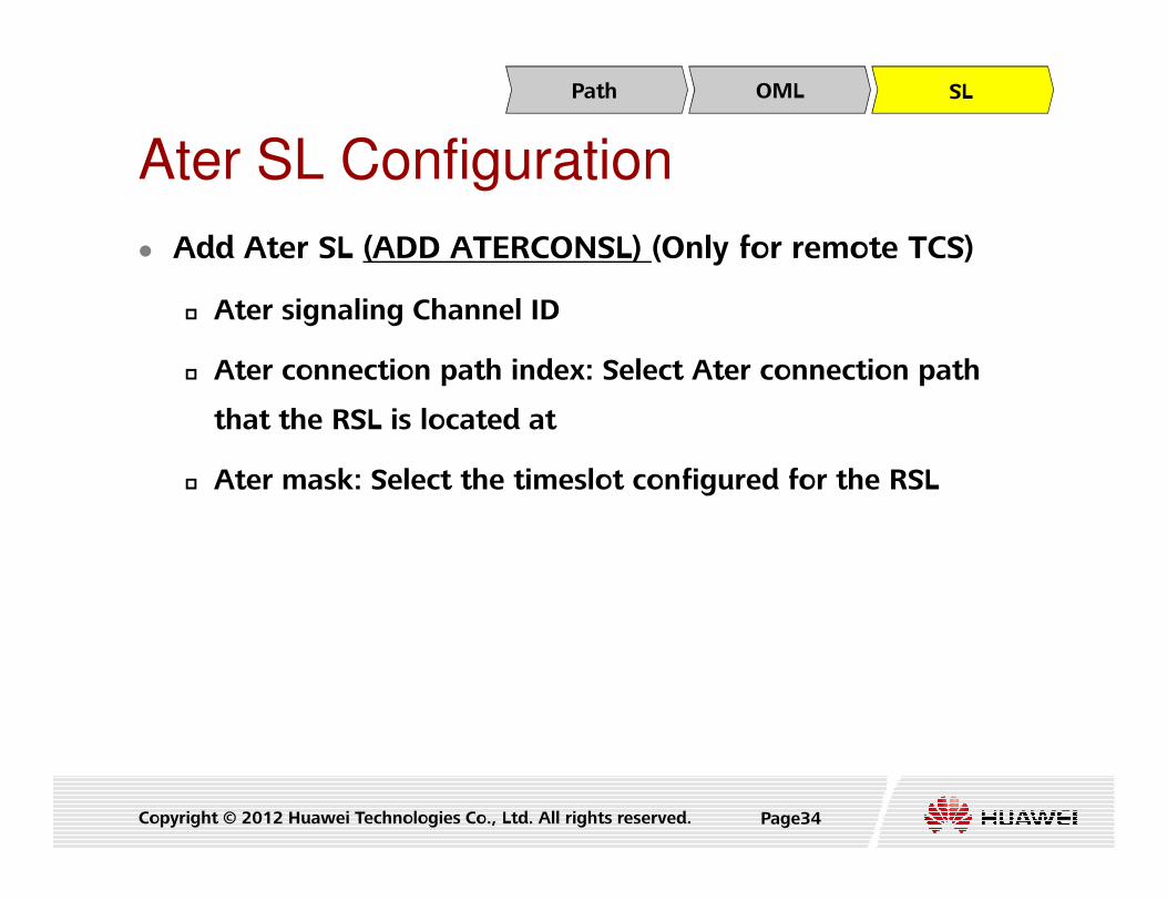
� Add Ater SL (ADD ATERCONSL) (Only for remote TCS)
� Ater signaling Channel ID
� Ater connection path index: Select Ater connection path
that the RSL is located at
Ater SL Configuration
Path OML SL
Copyright © 2012 Huawei Technologies Co., Ltd. All rights reserved. Page34
� Ater mask: Select the timeslot configured for the RSL

Contents� 5. Interface Data Configuration
� Ater Interface Data Configuration (over TDM)
� A Interface Data Configuration (over IP)
� A Interface Data Configuration (over TDM)
A Interface Data Configuration (over Transmission Resource
Copyright © 2012 Huawei Technologies Co., Ltd. All rights reserved. Page35
� A Interface Data Configuration (over Transmission Resource
Pool)
� Gb Interface Data Configuration (over IP)
� Gb Interface Data Configuration (over FR)
� Pb Interface Data Configuration (only Outer PCU need
configure)
� Iur-g Interface Data Configuration (only interface between
BSSs or between a BSS and a RNS need configure)

Protocol stack of A Interface over
IP� Signaling plane adopts M3UA/SCTP/IP protocol stack.
� User plane adopts RTP/UDP/IP protocol stack.
SCTP
M3UA
SCCP
DTAPBSSMAP
M3UA
SCCP
DTAP BSSMAP
BSC MSC ServerA Interface
Copyright © 2012 Huawei Technologies Co., Ltd. All rights reserved. Page36
Layer1
MTP
SCCP
DTAP BSSMAP
MSC
Layer1
MTP
SCCP
DTAP BSSMAP
A over TDM
A InterfaceBSC
MAC/PPP
IP
SCTP
MAC/PPP
IP
SCTP
Signaling plane of A over IP
MAC/PPP
IP
UDP
RTP
Voice
MAC/PPP
IP
UDP
RTP
Voice
MGW
User plane of A over IP
BSC A Interface

IP over Ethernet networking
IP over Ethernet Networking (Layer 2)
Copyright © 2012 Huawei Technologies Co., Ltd. All rights reserved. Page37
IP over Ethernet Networking (Layer 3)

A Interface Data Configuration (Over IP)
� Configuration Procedure
� Configuring GSM CN
Node
� Configuring Physical
Layer
BSC
Data Link Control plane MappingUser PlanePHY LayerGCNNODE
Copyright © 2012 Huawei Technologies Co., Ltd. All rights reserved. Page38
Layer
� Configuring Data Link
Layer
� Configuring Control
Plane
� Configuring the
Mapping Between
Service Types and
Transmission Resources
DPU

� Add GSM CN Node (ADD GCNNODE)
� CN node index
� DSP index
� DPC group index: Index of a DPC group
GSM CN Node Configuration (Over IP)
Data Link Control planePHY LayerGCNNODE MappingUser Plane
Copyright © 2012 Huawei Technologies Co., Ltd. All rights reserved. Page39
� Operator name
� MSC ID
� Bearer for A Interface User Plane: IP
� Report BSS Transmission Capability: YES

Configuring the Physical Layer and Data Link Layer
for the FG2a/FG2c/FG2d/GOUa/GOUc/GOUd Board
� Set attributes of the Ethernet port (SET ETHPORT)
� Subrack No.
� Slot No.
� Board type
Data Link Control planePHY LayerGCNNODE MappingUser Plane
Copyright © 2012 Huawei Technologies Co., Ltd. All rights reserved. Page40
� Port No.
� 0~7(FG2a), 0~1(GOUa), 0~11(FG2c), 0~3(GOUc)
� Auto negotiation
� ENABLE, DISABLE

� Add a standby Ethernet port (ADD ETHREDPORT)
(Optional)
� Subrack No.
� Main Board Logic slot No.
Configuring the Physical Layer and Data Link
Layer for the
FG2a/FG2c/FG2d/GOUa/GOUc/GOUd Board
Data Link Control planePHY LayerGCNNODE MappingUser Plane
Copyright © 2012 Huawei Technologies Co., Ltd. All rights reserved. Page41
� Port No.
� 0~7(FG2a), 0~1(GOUa), 0~11(FG2c), 0~3(GOUc)

� Add IP address of the Ethernet port (ADD ETHIP) ( in link
non-aggregation mode)
� Subrack No.
� Slot No.
Configuring the Physical Layer and Data Link
Layer for the
FG2a/FG2c/FG2d/GOUa/GOUc/GOUd Board
Data Link Control planePHY LayerGCNNODE MappingUser Plane
Copyright © 2012 Huawei Technologies Co., Ltd. All rights reserved. Page42
� Port No.
� IP address index
� Local IP address
� Subnet mask

� Add a link aggregation group (ADD ETHTRK) ( in link
aggregation mode)
� Subrack No.
� Slot No.
Configuring the Physical Layer and Data Link
Layer for the
FG2a/FG2c/FG2d/GOUa/GOUc/GOUd Board
Data Link Control planePHY LayerGCNNODE MappingUser Plane
Copyright © 2012 Huawei Technologies Co., Ltd. All rights reserved. Page43
� Trunk No.: Aggregation group number
� Aggregation mode
� When this parameter is set to static aggregation, the LACP
protocol is activated; otherwise, the LACP protocol is deactivated.
� Value Range: STATIC_LACP, MANUAL_AGGREGATION
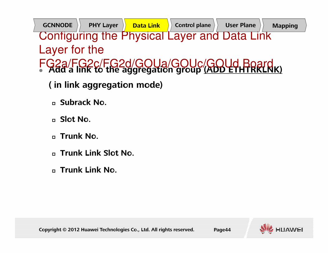
� Add a link to the aggregation group (ADD ETHTRKLNK)
( in link aggregation mode)
� Subrack No.
� Slot No.
Configuring the Physical Layer and Data Link
Layer for the
FG2a/FG2c/FG2d/GOUa/GOUc/GOUd Board
Data Link Control planePHY LayerGCNNODE MappingUser Plane
Copyright © 2012 Huawei Technologies Co., Ltd. All rights reserved. Page44
� Trunk No.
� Trunk Link Slot No.
� Trunk Link No.

� Add the IP address of the link aggregation group (ADD
ETHTRKIP) ( in link aggregation mode)
� Subrack No.
� Slot No.
Configuring the Physical Layer and Data Link
Layer for the
FG2a/FG2c/FG2d/GOUa/GOUc/GOUd Board
Data Link Control planePHY LayerGCNNODE MappingUser Plane
Copyright © 2012 Huawei Technologies Co., Ltd. All rights reserved. Page45
� Trunk No.
� IP address index
� Local IP address
� Subnet mask

� Add the device IP address of the board in case of layer 3
networking (ADD DEVIP) (Optional)
� Subrack No.
� Slot No.
Configuring the Physical Layer and Data Link
Layer for the
FG2a/FG2c/FG2d/GOUa/GOUc/GOUd Board
Data Link Control planePHY LayerGCNNODE MappingUser Plane
Copyright © 2012 Huawei Technologies Co., Ltd. All rights reserved. Page46
� Device IP address type: LOGIC_IP(Logical IP Address),
IPOA_CLIENT_IP(IPOA Client IP Address
� Boards in IP transmission mode can be configured with the DEVIP only in
the type of "LOGIC_IP".
� Boards in ATM transmission mode can be configured with the DEVIP only in
the type of "IPOA Client IP Address".
� IP address

A Interface Physical Layer and Data
Link Layer Configuration (Over IP)
Board Physical layer Data link layer
POU
SET E1T1
SET OPT
SET COPTLNK
ADD PPPLNK or
ADD MPGRP ADD MPLNK
Data Link Control planePHY LayerGCNNODE MappingUser Plane
Copyright © 2012 Huawei Technologies Co., Ltd. All rights reserved. Page47
SET COPTLNK
PEU SET E1T1ADD PPPLNK or
ADD MPGRP ADD MPLNK
FG2SET ETHPORT
ADD ETHIP/ADD DEVIP
ADD ETHTRK,
ADD ETHTRKLNK, ADD
ETHTRKIP
GOUSET ETHPORT
ADD ETHIP/ADD DEVIP
ADD ETHTRK,
ADD ETHTRKLNK, ADD
ETHTRKIP

Configuring the Control Plane of the A Interface (over IP)� Add SCTP Signalling Link (ADD SCTPLNK)
� Signalling link mode :Server/Client
� Server mode: BSC6900 starts the listening and waits for the peer
to send the SCTP-INIT message.
Client mode: BSC6900 actively sends the SCTP-INIT message.
Data Link Control planePHY LayerGCNNODE MappingUser Plane
Copyright © 2012 Huawei Technologies Co., Ltd. All rights reserved. Page48
� Client mode: BSC6900 actively sends the SCTP-INIT message.
� Application type :NBAP, M3UA, BBAP
� The upper layer application type of A interface is M3UA.
� Local/Destination SCTP port No.
� First local/destination IP address
� Second local/destination IP address

Configuring the Control Plane of the A Interface (over IP)� Add M3UA link set (ADD M3LKS)
� Signalling link set index
� Destination entity No.
� M3UA signaling link name
Data Link Control planePHY LayerGCNNODE MappingUser Plane
Copyright © 2012 Huawei Technologies Co., Ltd. All rights reserved. Page49
� Add an M3UA route (ADD M3RT)
� Destination entity No
� Signalling link set index
� M3UA route name

Configuring the Control Plane of the A Interface (over IP)
� Add M3UA link (ADD M3LNK)
� SCTP link No.
� M3UA Signaling link name
Add an adjacent node (ADD ADJNODE)
Data Link Control planePHY LayerGCNNODE MappingUser Plane
Copyright © 2012 Huawei Technologies Co., Ltd. All rights reserved. Page50
� Add an adjacent node (ADD ADJNODE)
� Adjacent Node ID
� Adjacent Node Name
� Adjacent Node Type

Configuring the User Plane of the A Interface (over IP)
� Add an IP path (ADD IPPATH)
� Adjacent Node ID
� IP path ID
Interface Type
Data Link Control plane MappingUser PlanePHY LayerGCNNODE
Copyright © 2012 Huawei Technologies Co., Ltd. All rights reserved. Page51
� Interface Type
� Forward Bandwidth
� Backward Bandwidth
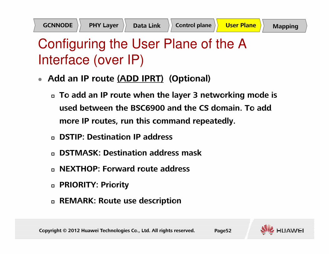
Configuring the User Plane of the A Interface (over IP)
� Add an IP route (ADD IPRT) (Optional)
� To add an IP route when the layer 3 networking mode is
used between the BSC6900 and the CS domain. To add
more IP routes, run this command repeatedly.
Data Link Control planePHY LayerGCNNODE MappingUser Plane
Copyright © 2012 Huawei Technologies Co., Ltd. All rights reserved. Page52
� DSTIP: Destination IP address
� DSTMASK: Destination address mask
� NEXTHOP: Forward route address
� PRIORITY: Priority
� REMARK: Route use description

Configuring the User Plane of the A Interface (over IP)
� Set TC DSP Resource Type (SET TCTYPE)
� The TC resource type can be set only when the
DPUb/DPUc/DPUf board is configured in the MPS/EPS subrack
and the logical function type is GTC.
Data Link Control planePHY LayerGCNNODE MappingUser Plane
Copyright © 2012 Huawei Technologies Co., Ltd. All rights reserved.
and the logical function type is GTC.
� DSP No.: Number of a DSP in the DPU board.
� The number of a DSP in the DPUf board ranges from 0 to 47.
� The number of a DSP in the DPUb/DPUc board ranges from 0 to 21.
� The type of TC resource: GTC/UTC/ITC
Page53

Configuring the Mapping Between Service Types and Transmission Resources for the Adjacent Node
� Add Transport Resource Mapping (ADD TRMMAP)
� Add a transport resource mapping
� Add Factor Table (ADD TRMFACTOR)
Data Link Control plane MappingUser PlanePHY LayerGCNNODE
Copyright © 2012 Huawei Technologies Co., Ltd. All rights reserved. Page54
� Add an activation factor table
� Add Node Mapping (ADD ADJMAP)
� Add the TRM mapping to an adjacent node and to add the
mapping from interface transmission type to TRMMAP
index and factor index
Contents� 5. Interface Data Configuration
� Ater Interface Data Configuration (over TDM)
� A Interface Data Configuration (over IP)
� A Interface Data Configuration (over TDM)
� A Interface Data Configuration (over Transmission Resource
Copyright © 2012 Huawei Technologies Co., Ltd. All rights reserved. Page55
� A Interface Data Configuration (over Transmission Resource
Pool)
� Gb Interface Data Configuration (over IP)
� Gb Interface Data Configuration (over FR)
� Pb Interface Data Configuration (only Outer PCU need
configure)
� Iur-g Interface Data Configuration (only interface between
BSSs or between a BSS and a RNS need configure)

� Add GSM CN Node (ADD GCNNODE)
� CN node index
� DSP index
� DPC group index: Index of a DPC group
GSM CN Node Configuration (Over
TDM)
E1/T1 MTP3LKS MTP3LNK MTP3RTGCNNODE
Copyright © 2012 Huawei Technologies Co., Ltd. All rights reserved. Page56
� When multiple DPCs or one DPC serves as a logical entity, this
logical entity is called a DPC group. When the MSC pool function
is activated, the user plane resources on the A interface are
shared among the MSCs in the pool, and thus load balancing is
achieved
� Operator name
� MSC ID

� Add A interface E1/T1 (ADD AE1T1)
� Subrack No.
� Slot No.
� Port No.
A Interface E1T1 Configuration (Over TDM)
E1/T1 MTP3LKS MTP3LNK MTP3RTGCNNODE
Copyright © 2012 Huawei Technologies Co., Ltd. All rights reserved. Page57
� DPC group index
� OPC index
� Timeslot type: Set all timeslots to CIC or NULL
� BSC flag: Main BSC or subsidiary BSC
� Start CIC: The start CIC No. of the E1/T1

� Add MTP3 link set (ADD MTP3LKS)
� Signaling link set index: To identify an signaling link set
uniquely
� DSP index
A MTP3 Link Set Configuration (Over TDM)
E1/T1 MTP3LKS MTP3LNK MTP3RTGCNNODE
Copyright © 2012 Huawei Technologies Co., Ltd. All rights reserved. Page58
� Signaling link mask: Indicates link load sharing.
� In the value, the number of 1s (represented by n) determines the
maximum number (2^n) of links for the load sharing.
� Signaling link set name

� Add MTP3 links (ADD MTP3LNK)
� Signaling link set index
� Signaling link code
� Link bearer type
� MTP2: indicates that the lower layer link bearer is the MTP2 used in TDM scenario
A MTP3 Link Configuration (Over TDM)
E1/T1 MTP3LKS MTP3LNK MTP3RTGCNNODE
Copyright © 2012 Huawei Technologies Co., Ltd. All rights reserved. Page59
� MTP2: indicates that the lower layer link bearer is the MTP2 used in TDM scenario
� SAAL: indicates that the lower layer link bearer is the M3UA used in SAAL scenario
� TC mode: To specify the mode of TC
� MTP2 Link No.: the A interface E1 No. bearing this signaling link
� A interface timeslot mask
� Link Rate Type: 64kbps or 2Mbps
� Signaling Link Name

� Add MTP3 routing information (ADD MTP3RT)
� DSP index
� Signaling link set index: To identify an signaling link set
uniquely
A MTP3 Routing Configuration (Over TDM)
E1/T1 MTP3LKS MTP3LNK MTP3RTGCNNODE
Copyright © 2012 Huawei Technologies Co., Ltd. All rights reserved. Page60
� Signaling route name

Contents� 5. Interface Data Configuration
� Ater Interface Data Configuration (over TDM)
� A Interface Data Configuration (over IP)
� A Interface Data Configuration (over TDM)
� A Interface Data Configuration (over Transmission
Copyright © 2012 Huawei Technologies Co., Ltd. All rights reserved. Page61Page61
� A Interface Data Configuration (over Transmission
Resource Pool)
� Gb Interface Data Configuration (over IP)
� Gb Interface Data Configuration (over FR)
� Pb Interface Data Configuration (only Outer PCU need
configure)
� Iur-g Interface Data Configuration (only interface between
BSSs or between a BSS and a RNS need configure)

GCNNODE Data Link Control plane MappingUser PlanePHY LayerTransmission
Resource Pool
� Add GSM CN Node (ADD GCNNODE)
� CN node index
� DSP index
� DPC group index: Index of a DPC group
GSM CN Node Configuration
Copyright © 2012 Huawei Technologies Co., Ltd. All rights reserved. Page62
� Operator name
� MSC ID
� Bearer for A Interface User Plane: IP
� Report BSS Transmission Capability: YES

Configuring the Physical Layer and Data Link Layer
for the FG2c/FG2d/GOUc/GOUd Board
� Set attributes of the Ethernet port (SET ETHPORT)
� Subrack No.
� Slot No.
� Board type
GCNNODE Data Link Control plane MappingUser PlanePHY LayerTransmission
Resource Pool
Copyright © 2012 Huawei Technologies Co., Ltd. All rights reserved. Page63
� Port No.
� 0~7(FG2a), 0~1(GOUa), 0~11(FG2c), 0~3(GOUc)
� Auto negotiation
� ENABLE, DISABLE

Configuring the Physical Layer and Data Link Layer
for the FG2c/FG2d/GOUc/GOUd Board
� Add a standby Ethernet port (ADD ETHREDPORT)
(Optional)
� Subrack No.
� Main Board Logic slot No.
GCNNODE Data Link Control plane MappingUser PlanePHY LayerTransmission
Resource Pool
Copyright © 2012 Huawei Technologies Co., Ltd. All rights reserved. Page64
� Port No.
� 0~7(FG2a), 0~1(GOUa), 0~11(FG2c), 0~3(GOUc)

� Add IP address of the Ethernet port (ADD ETHIP) ( in link
non-aggregation mode)
� Subrack No.
� Slot No.
Configuring the Physical Layer and Data Link Layer
for the FG2c/FG2d/GOUc/GOUd Board
GCNNODE Data Link Control plane MappingUser PlanePHY LayerTransmission
Resource Pool
Copyright © 2012 Huawei Technologies Co., Ltd. All rights reserved. Page65
� Port No.
� IP address index
� Local IP address
� Subnet mask

� Add a link aggregation group (ADD ETHTRK) ( in link
aggregation mode)
� Subrack No.
� Slot No.
Configuring the Physical Layer and Data Link Layer
for the FG2c/FG2d/GOUc/GOUd Board
GCNNODE Data Link Control plane MappingUser PlanePHY LayerTransmission
Resource Pool
Copyright © 2012 Huawei Technologies Co., Ltd. All rights reserved. Page66
� Trunk No.: Aggregation group number
� Aggregation mode
� When this parameter is set to static aggregation, the LACP
protocol is activated; otherwise, the LACP protocol is deactivated.
� Value Range: STATIC_LACP, MANUAL_AGGREGATION

� Add a link to the aggregation group (ADD ETHTRKLNK)
( in link aggregation mode)
� Subrack No.
� Slot No.
Configuring the Physical Layer and Data Link Layer
for the FG2c/FG2d/GOUc/GOUd Board
GCNNODE Data Link Control plane MappingUser PlanePHY LayerTransmission
Resource Pool
Copyright © 2012 Huawei Technologies Co., Ltd. All rights reserved. Page67
� Trunk No.
� Trunk Link Slot No.
� Trunk Link No.

� Add the IP address of the link aggregation group (ADD
ETHTRKIP) ( in link aggregation mode)
� Subrack No.
� Slot No.
Configuring the Physical Layer and Data Link Layer
for the FG2c/FG2d/GOUc/GOUd Board
GCNNODE Data Link Control plane MappingUser PlanePHY LayerTransmission
Resource Pool
Copyright © 2012 Huawei Technologies Co., Ltd. All rights reserved. Page68
� Trunk No.
� IP address index
� Local IP address
� Subnet mask

� Add the the mapping between IP addresses and VLAN IDs
(ADD VANID) (in multiple VLAN gateways mode)
� Subrack No.
� Slot No.
Configuring the Physical Layer and Data Link Layer
for the FG2c/FG2d/GOUc/GOUd Board
GCNNODE Data Link Control plane MappingUser PlanePHY LayerTransmission
Resource Pool
Copyright © 2012 Huawei Technologies Co., Ltd. All rights reserved. Page69
� Next Hop IP address
� VLAN ID.

� Add the device IP address of the board in case of layer 3
networking (ADD DEVIP)
� Subrack No.
� Slot No.
Configuring the Physical Layer and Data Link Layer
for the FG2c/FG2d/GOUc/GOUd Board
GCNNODE Data Link Control plane MappingUser PlanePHY LayerTransmission
Resource Pool
Copyright © 2012 Huawei Technologies Co., Ltd. All rights reserved. Page70
� Device IP address type: LOGIC_IP(Logical IP Address),
IPOA_CLIENT_IP(IPOA Client IP Address
� Boards in IP transmission mode can be configured with the DEVIP only in
the type of "LOGIC_IP".
� Boards in ATM transmission mode can be configured with the DEVIP only in
the type of "IPOA Client IP Address".
� IP address.

� Add a policy-based IP route based on the source IP
address(ADD SRCIPRT)
� Subrack No.
� Slot No.
Configuring the Transmission Resource Pool
GCNNODE Data Link Control plane MappingUser PlanePHY LayerTransmission
Resource Pool
Copyright © 2012 Huawei Technologies Co., Ltd. All rights reserved. Page71
� IP TYPE.
� Source IP address.
� Forward route address.
� Standby Next hop switch.
� Standby next hop.
� Purpose description.

� Add a policy-based IP route based on the source IP
address(ADD SRCIPRT)
� Subrack No.
� Slot No.
Configuring the Transmission Resource Pool
GCNNODE Data Link Control plane MappingUser PlanePHY LayerTransmission
Resource Pool
Copyright © 2012 Huawei Technologies Co., Ltd. All rights reserved. Page72
� IP TYPE.
� Source IP address.
� Forward route address.
� Standby Next hop switch.
� Standby next hop.
� Purpose description.

� Add the transmission resource pool(ADD IPPOOL)
� Transmission Resource Pool Index
� Transmission Resource Pool Name
Configuring the Transmission Resource Pool
GCNNODE Data Link Control plane MappingUser PlanePHY LayerTransmission
Resource Pool
Copyright © 2012 Huawei Technologies Co., Ltd. All rights reserved. Page73

� Add an IP address to the transmission resource pool
(ADD IPPOOLIP)
� Transmission Resource Pool Index
Subrack No.
Configuring the Transmission Resource Pool
GCNNODE Data Link Control plane MappingUser PlanePHY LayerTransmission
Resource Pool
Copyright © 2012 Huawei Technologies Co., Ltd. All rights reserved. Page74
� Subrack No.
� Slot No.
� IP Address in Transmission Resource Pool

Configuring the Control Plane of the A Interface
(over Transmission Resource Pool)� Add SCTP Signalling Link (ADD SCTPLNK)
� Signalling link mode :Server/Client
� Server mode: BSC6900 starts the listening and waits for the peer
to send the SCTP-INIT message.
Client mode: BSC6900 actively sends the SCTP-INIT message.
GCNNODE Data Link Control plane MappingUser PlanePHY LayerTransmission
Resource Pool
Copyright © 2012 Huawei Technologies Co., Ltd. All rights reserved. Page75
� Client mode: BSC6900 actively sends the SCTP-INIT message.
� Application type :NBAP, M3UA, BBAP
� The upper layer application type of A interface is M3UA.
� Local/Destination SCTP port No.
� First local/destination IP address
� Second local/destination IP address

� Add M3UA link set (ADD M3LKS)
� Signalling link set index
� Destination entity No.
� M3UA signaling link name
Configuring the Control Plane of the A Interface
(over Transmission Resource Pool)
GCNNODE Data Link Control plane MappingUser PlanePHY LayerTransmission
Resource Pool
Copyright © 2012 Huawei Technologies Co., Ltd. All rights reserved. Page76
� Add an M3UA route (ADD M3RT)
� Destination entity No
� Signalling link set index
� M3UA route name

� Add M3UA link (ADD M3LNK)
� SCTP link No.
� M3UA Signaling link name
Configuring the Control Plane of the A Interface
(over Transmission Resource Pool)
GCNNODE Data Link Control plane MappingUser PlanePHY LayerTransmission
Resource Pool
Copyright © 2012 Huawei Technologies Co., Ltd. All rights reserved. Page77

� Add an adjacent node (ADD ADJNODE)
� Adjacent Node ID
� Adjacent Node Name
Adjacent Node Type
Configuring the User Plane of the A Interface
(over Transmission Resource Pool)
GCNNODE Data Link Control plane MappingUser PlanePHY LayerTransmission
Resource Pool
Copyright © 2012 Huawei Technologies Co., Ltd. All rights reserved. Page78
� Adjacent Node Type
Configuring the User Plane of the A Interface
(over Transmission Resource Pool)
GCNNODE Data Link Control plane MappingUser PlanePHY LayerTransmission
Resource Pool
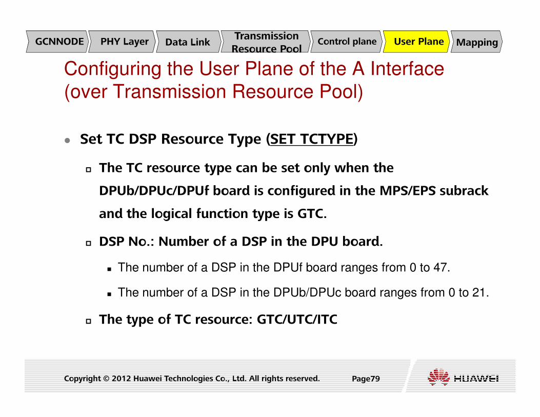
� Set TC DSP Resource Type (SET TCTYPE)
� The TC resource type can be set only when the
DPUb/DPUc/DPUf board is configured in the MPS/EPS subrack
and the logical function type is GTC.
Copyright © 2012 Huawei Technologies Co., Ltd. All rights reserved.
and the logical function type is GTC.
� DSP No.: Number of a DSP in the DPU board.
� The number of a DSP in the DPUf board ranges from 0 to 47.
� The number of a DSP in the DPUb/DPUc board ranges from 0 to 21.
� The type of TC resource: GTC/UTC/ITC
Page79

Configuring the Mapping Between Service Types and Transmission Resources for the Adjacent Node
� Add Transport Resource Mapping (ADD TRMMAP)
� Add a transport resource mapping
� Add Factor Table (ADD TRMFACTOR)
GCNNODE Data Link Control plane MappingUser PlanePHY LayerTransmission
Resource Pool
Copyright © 2012 Huawei Technologies Co., Ltd. All rights reserved. Page80
� Add an activation factor table
� Add Node Mapping (ADD ADJMAP)
� Add the TRM mapping to an adjacent node and to add the
mapping from interface transmission type to TRMMAP
index and factor index

Contents� 5. Interface Data Configuration
� Ater Interface Data Configuration (over TDM)
� A Interface Data Configuration (over IP)
� A Interface Data Configuration (over TDM)
� A Interface Data Configuration (over Transmission Resource
Copyright © 2012 Huawei Technologies Co., Ltd. All rights reserved. Page81Page81
� A Interface Data Configuration (over Transmission Resource
Pool)
� Gb Interface Data Configuration (over IP)
� Gb Interface Data Configuration (over FR)
� Pb Interface Data Configuration (only Outer PCU need
configure)
� Iur-g Interface Data Configuration (only interface between
BSSs or between a BSS and a RNS need configure)

Configuration Procedure (Gb over IP)
Configuring the Physical Layer and Data Link Layer
Set the PCU type
Add an SGSN node
ADD ETHIPADD ETHREDPORT(Optional)
ADD DEVIP(Optional)ADD IPRT(Optional)
Copyright © 2012 Huawei Technologies Co., Ltd. All rights reserved.
Add an NSE
Configure an NSVL
Add a PTPBVC
Page82
ADD NSVLLOCAL ADD NSVLREMOTE(Optional)

Configuring the Gb Interface (over IP)
� Set the PCU type (SET BSCPCUTYPE)
� Type : Inner
� Add an SGSN node (ADD SGSNNODE)
� OPNAME: Name of the operator. This parameter uniquely
NSVL PTPBVCNSEBasic
Copyright © 2012 Huawei Technologies Co., Ltd. All rights reserved. Page83
OPNAME: Name of the operator. This parameter uniquely
identifies an operator
� CNID : Identifies a node of SGSN with the operator name
uniquely
� Add an NSE (ADD NSE)
� Subnet protocol type : Gb over IP
� Configuring Physical Layer and Data Link Layer

Configuring the Gb Interface (over IP)
� Add an local NSVL (ADD NSVLLOCAL)
� Local IP Address
� Local UDP Port No. : UDP port number of the local NSVL
� When Subnet Protocol Type of NSE is "Gb over IP" and
Subnetwork Configure Mode is "Static", the setting of this
NSVL PTPBVCNSEBasic
Copyright © 2012 Huawei Technologies Co., Ltd. All rights reserved. Page84
Subnetwork Configure Mode is "Static", the setting of this
parameter must be consistent with the setting at the SGSN side.
� Value Range: 1214~2001, 2005~3783, 3786~4783, 4785~65000
� Subrack No.
� Slot No.

Configuring the Gb Interface (over
IP)� Add an remote NSVL (ADD NSVLREMOTE) (Optional)
� If the NSE is in static configuration mode, run this
command to add an NSVL on the SGSN side.
� Remote IP Address
Remote UDP Port No.: UDP port number of the remote
NSVL PTPBVCNSEBasic
Copyright © 2012 Huawei Technologies Co., Ltd. All rights reserved.
� Remote UDP Port No.: UDP port number of the remote
NSVL.
� The setting of this parameter must be consistent with the setting
at the SGSN side.
� Value Range: 0~65535
Page85

Configuring the Gb Interface (over IP)
� Add a PTPBVC (ADD PTPBVC)
� NSE Identifier
� PTP BVC Identifier
� Index Type
NSVL PTPBVCNSEBasic
Copyright © 2012 Huawei Technologies Co., Ltd. All rights reserved. Page86
� Index Type
� Cell Index
� Cell Name

Contents� 5. Interface Data Configuration
� Ater Interface Data Configuration (over TDM)
� A Interface Data Configuration (over IP)
� A Interface Data Configuration (over TDM)
� A Interface Data Configuration (over Transmission Resource
Copyright © 2012 Huawei Technologies Co., Ltd. All rights reserved. Page87Page87
� A Interface Data Configuration (over Transmission Resource
Pool)
� Gb Interface Data Configuration (over IP)
� Gb Interface Data Configuration (over FR)
� Pb Interface Data Configuration (only Outer PCU need
configure)
� Iur-g Interface Data Configuration (only interface between
BSSs or between a BSS and a RNS need configure)

Protocol Stack of the Gb Interface
BSSGP
LLC
BSSGPRLC
Relayrelay
Copyright © 2012 Huawei Technologies Co., Ltd. All rights reserved. Page88
BSS SGSN
BSSGP BSSGP
L1bis
NetworkService
RLC
MAC
GSM RF L1bis
NetworkService
Gb

� 本页有备注
Copyright © 2012 Huawei Technologies Co., Ltd. All rights reserved. Page89

Components of Gb Interface
BC(BCID)
data
PVC(DLCI)
Copyright © 2012 Huawei Technologies Co., Ltd. All rights reserved. Page90
BC(BCID)PVC(DLCI)
data

NS Basic Concept
� BC (Bearer Channel)
� Consist of one group of time slots in one E1
� DLCI (Data Link Connection Identifier)
� The identifier of PVC having end-to-end significance across
Copyright © 2012 Huawei Technologies Co., Ltd. All rights reserved. Page91
the Gb interface
� NSVC (Network Service Virtual Connection)
� Provide end-to-end communication between the BSS and
SGSN irrespective of the exact configuration of the Gb
interface
� NSE (NS entity)
� Responsible for management of all of NSVC

Sub-Network Service Functions
� The Sub-Network Service functions of the Network
Service shall provide access to the intermediate network
(or to the peer entity in case of direct point-to-point
configuration) and shall provide NS-VCs between NS peer
entities
Copyright © 2012 Huawei Technologies Co., Ltd. All rights reserved. Page92
FR Network
SGSN
DTE
DTEDTE
DCE
Gb Gb
Gb
BSS
entities

NS Load-sharing
NS Layer
ms#1ms#2
cell
SGSN BSS
BSSGP LayerBVC1 BVC2
BVC1 BVC2
NSE1NSE3 NSE3
Two users in the same cell
Copyright © 2012 Huawei Technologies Co., Ltd. All rights reserved. Page93
NSVC channel=10 DLCI=259
NSVC channel=20 DLCI=16
NS LayerNSE1NSE1NSE2
NSE2
NSE3 NSE3

BSSGP Virtual Connections
� BVC provide communication paths between BSSGP entities.
Each BVC is used in the transport of BSSGP PDUs between the
following entities:
� peer point-to-point (PTP) functional entities
peer point-to-multipoint(PTM) functional entities
Copyright © 2012 Huawei Technologies Co., Ltd. All rights reserved. Page94
� peer point-to-multipoint(PTM) functional entities
� peer signalling functional entities
� BVCI (BSSGP Virtual Connection Identifier)
� The BVCI is used to enable the lower network service layer to
efficiently route the BSSGP PDU to the peer entity
� PCU creates a BVC for each cell and assigns a BVCI for it , and then
sends them to SGSN via procedure, on which SGSN can create a
cell list

Cell1 Cell2
The Difference btw. PTP BVC and
SIG BVCSIG BVC
PTP BVC
Cell1 Cell2
Copyright © 2012 Huawei Technologies Co., Ltd. All rights reserved. Page95
NSE NSE
NSVC1
NSVC2
Signaling
User data

Relations between the Objects to
be Configured
Copyright © 2012 Huawei Technologies Co., Ltd. All rights reserved. Page96

Configuration Procedure (Gb over FR)
Set the PCU type
Add an SGSN node
Add an NSE
SET BSCPCUTYPE
ADD SGSNNODE
ADD NSE
Copyright © 2012 Huawei Technologies Co., Ltd. All rights reserved.
Add an NSE
Add a BC
Add an NSVC
Add a PTPBVC
Page97
ADD NSE
ADD BC
ADD NSVC
ADD PTPBVC

Configuring the Gb Interface (over FR)
� Set the PCU type (SET BSCPCUTYPE)
� Type : Inner
� Add an SGSN node (ADD SGSNNODE)
� OPNAME: Name of the operator. This parameter uniquely
BC NSVC PTPBVCNSEBasic
Copyright © 2012 Huawei Technologies Co., Ltd. All rights reserved. Page98
OPNAME: Name of the operator. This parameter uniquely
identifies an operator
� CNID : Identifies a node of SGSN with the operator name
uniquely

Configuring the Gb Interface (over FR)
� Add an NSE (ADD NSE)
� NSEI: Identifies a unique NSE
� SRN: Subrack number of the XPU bound to the NSE
� SN: Slot number of the XPU bound to the NSE
BC NSVC PTPBVCNSEBasic
Copyright © 2012 Huawei Technologies Co., Ltd. All rights reserved. Page99
� Subnet protocol type : Gb over FR
� OPNAME: Name of the operator. This parameter uniquely
identifies an operator
� CNID : Identifies a node of SGSN with the operator name
uniquely

Configuring the Gb Interface (over FR)
� Add a BC (ADD BC)
� Subrack No.
� Slot No.
� Port No.
BC NSVC PTPBVCNSEBasic
Copyright © 2012 Huawei Technologies Co., Ltd. All rights reserved. Page100
� BC Identifier
� Bearing timeslot

Configuring the Gb Interface (over FR)
� Add an NSVC (ADD NSVC)
� NSVCIDX: NSVC index, identifies a unique NSVC
� NSVCI: NSVC ID, identifies a unique NSVC. This ID must be
negotiated with the peer SGSN
BC NSVC PTPBVCNSEBasic
Copyright © 2012 Huawei Technologies Co., Ltd. All rights reserved. Page101
� NSEI: Identifies a unique NSE
� SRN: Number of the subrack
� SN: Number of the slot
� BCID: Identifies one BC at the same port
� DLCI: ID of the data link connection of the NSVC

Configuring the Gb Interface (over FR)
� Add a PTPBVC (ADD PTPBVC)
� NSE Identifier
� PTP BVC Identifier
� Index Type
BC NSVC PTPBVCNSEBasic
Copyright © 2012 Huawei Technologies Co., Ltd. All rights reserved. Page102
� Index Type
� Cell Index
� Cell Name

Contents� 5. Interface Data Configuration
� Ater Interface Data Configuration (over TDM)
� A Interface Data Configuration (over IP)
� A Interface Data Configuration (over TDM)
� A Interface Data Configuration (over Transmission Resource
Copyright © 2012 Huawei Technologies Co., Ltd. All rights reserved. Page103Page103
� A Interface Data Configuration (over Transmission Resource
Pool)
� Gb Interface Data Configuration (over IP)
� Gb Interface Data Configuration (over FR)
� Pb Interface Data Configuration (only Outer PCU need
configure)
� Iur-g Interface Data Configuration (only interface between
BSSs or between a BSS and a RNS need configure)

Configuring the Pb Interface
� Set the PCU type (SET BSCPCUTYPE)
� Type : Outer
� Add a PCU (ADD PCU)
� PCU Name
PB SLPB E1/T1Basic
Copyright © 2012 Huawei Technologies Co., Ltd. All rights reserved. Page104
PCU Name
� PCU No.
� Operator Name

Configuring the Pb Interface
� Set the Pb interface E1/T1s (ADD PBE1T1)
� Subrack No.
� Slot No.
� Port No.
PB SLPB E1/T1Basic
Copyright © 2012 Huawei Technologies Co., Ltd. All rights reserved. Page105
� PCU No.
� Start PCIC: The value of Start PCIC must be the multiple of
128

Configuring the Pb Interface
� Set the Pb interface signaling link (ADD PBSL)
� Subrack No.
� Slot No.
� Port No.
PB SLPB E1/T1Basic
Copyright © 2012 Huawei Technologies Co., Ltd. All rights reserved. Page106
� Timeslot No.

Contents� 5. Interface Data Configuration
� Ater Interface Data Configuration (over TDM)
� A Interface Data Configuration (over IP)
� A Interface Data Configuration (over TDM)
� A Interface Data Configuration (over Transmission Resource
Copyright © 2012 Huawei Technologies Co., Ltd. All rights reserved. Page107Page107
� A Interface Data Configuration (over Transmission Resource
Pool)
� Gb Interface Data Configuration (over IP)
� Gb Interface Data Configuration (over FR)
� Pb Interface Data Configuration (only Outer PCU need
configure)
� Iur-g Interface Data Configuration (only interface between
BSSs or between a BSS and a RNS need configure)

Configuring the Iur-g Interface
� Add SCTP Signalling Link (ADD SCTPLNK)
� Signalling link mode :Server/Client
� Server mode: BSC6900 starts the listening and waits for the peer
to send the SCTP-INIT message.
Client mode: BSC6900 actively sends the SCTP-INIT message.
interface
data
external
3G cell
Iur-g
connection
adjacent
RNCneighboring 3G
cell
Copyright © 2012 Huawei Technologies Co., Ltd. All rights reserved. Page108
� Client mode: BSC6900 actively sends the SCTP-INIT message.
� Application type :NBAP, M3UA, BBAP
� The upper layer application type of A interface is M3UA.
� Local/Destination SCTP port No.
� First local/destination IP address
� Second local/destination IP address

� Add M3UA link set (ADD M3LKS)
� Signalling link set index
� Destination entity No.
� M3UA signaling link name
Configuring the Iur-g Interface
interface
data
external
3G cell
Iur-g
connection
adjacent
RNCneighboring 3G
cell
Copyright © 2012 Huawei Technologies Co., Ltd. All rights reserved. Page109
� Add an M3UA route (ADD M3RT)
� Destination entity No
� Signalling link set index
� M3UA route name

� Add M3UA link (ADD M3LNK)
� SCTP link No.
� M3UA Signaling link name
Configuring the Iur-g Interface
interface
data
external
3G cell
Iur-g
connection
adjacent
RNCneighboring 3G
cell
Copyright © 2012 Huawei Technologies Co., Ltd. All rights reserved. Page110

� Configure an adjacent RNC for the BSC(ADD GNRNC)
� Co-MBSC:NO
� Allow Common Measurement at Iur-g:NO
SupptCellLis:YES
Configuring the Iur-g Interface
interface
data
external
3G cell
Iur-g
connection
adjacent
RNCneighboring 3G
cell
Copyright © 2012 Huawei Technologies Co., Ltd. All rights reserved. Page111
� SupptCellLis:YES
� Allow Info Exchange at Iur-g:YES

� Configure an external 3G cell (ADD GEXT3GCELL)
� Cell Index
� Cell Name
RNC ID
Configuring the Iur-g Interface
interface
data
external
3G cell
Iur-g
connection
adjacent
RNCneighboring 3G
cell
Copyright © 2012 Huawei Technologies Co., Ltd. All rights reserved. Page112
� RNC ID
� Neighboring RNC Index

� Configure a neighboring 3G cell (ADD G3GNCELL)
� Index Type
� Source Cell Index
Neighbor Cell Index
Configuring the Iur-g Interface
interface
data
external
3G cell
Iur-g
connection
adjacent
RNCneighboring 3G
cell
Copyright © 2012 Huawei Technologies Co., Ltd. All rights reserved. Page113
� Neighbor Cell Index
� RSCP Offset
� Ec/No Offset

� Add an Iur-g connection(ADD GIURGCONN)
� Neighboring RNC Index
� Connection Type:EXTERNAL
Subrack No.
Configuring the Iur-g Interface
interface
data
external
3G cell
Iur-g
connection
adjacent
RNCneighboring 3G
cell
Copyright © 2012 Huawei Technologies Co., Ltd. All rights reserved. Page114
� Subrack No.
� Slot No.
� Subsystem No.
� Peer Subrack No.
� Peer Slot No.
� Peer Subsystem No.

Summary
� We have configured the finished the BSC6900(GO) data
configuration, including: global data configuration,
equipment data configuration, interfaces data
configuration and clock cata configuration.
Copyright © 2012 Huawei Technologies Co., Ltd. All rights reserved. Page115

Thank youwww.huawei.comwww.huawei.com