Embed Size (px)
Citation preview
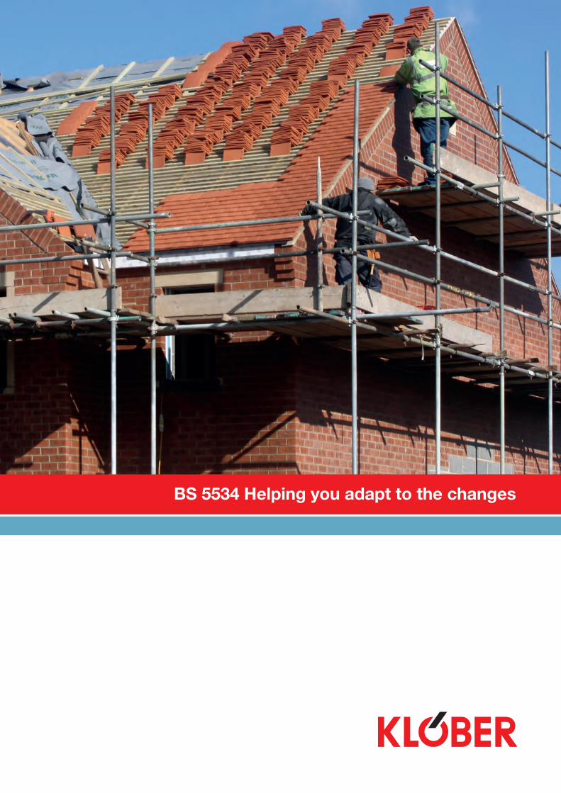
BS 5534 Helping you adapt to the changes
Technical Support t: 01332 81350 e: [email protected] www.klober.co.uk 2
Introduction
Helping you adapt to the changes
Klober realises how important the changes in BS 5534 are to you, and we’re here to help. We can offer the products, technical support and training to give you total peace of mind to make the transition smoothly.
The aim of this guide is to give you a brief insight into how the new standard will affect the way you install pitched roofs from March 2015.
Why the new standard was needed
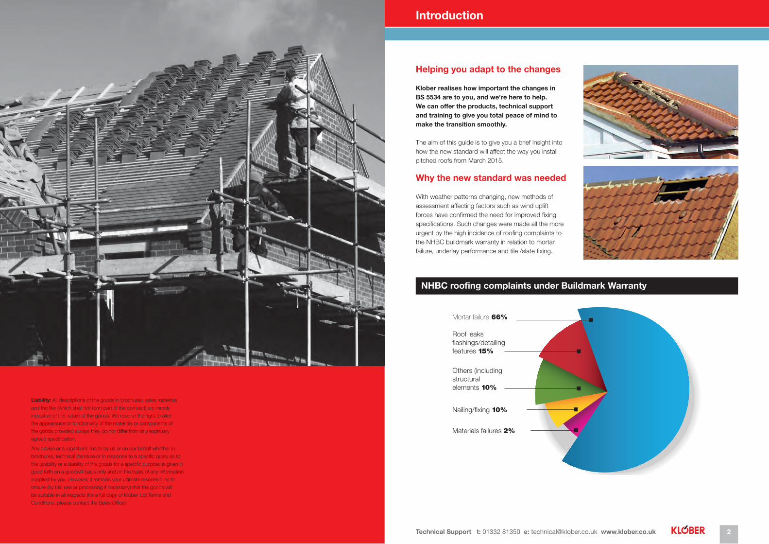
With weather patterns changing, new methods of assessment affecting factors such as wind uplift forces have confirmed the need for improved fixing specifications. Such changes were made all the more urgent by the high incidence of roofing complaints to the NHBC buildmark warranty in relation to mortar failure, underlay performance and tile /slate fixing.
Mortar failure 66%
Roof leaks flashings/detailing features 15%
Others (including structural elements 10%
Nailing/fixing 10%
Materials failures 2%
NHBC roofing complaints under Buildmark Warranty
Liability: All descriptions of the goods in brochures, sales materials
and the like (which shall not form part of the contract) are merely
indicative of the nature of the goods. We reserve the right to alter
the appearance or functionality of the materials or components of
the goods provided always they do not differ from any expressly
agreed specification.
Any advice or suggestions made by us or on our behalf whether in
brochures, technical literature or in response to a specific query as to
the usability or suitability of the goods for a specific purpose is given in
good faith on a goodwill basis only and on the basis of any information
supplied by you. However, it remains your ultimate responsibility to
ensure (by trial use or processing if necessary) that the goods will
be suitable in all respects (for a full copy of Klober Ltd Terms and
Conditions, please contact the Sales Office)
BS 5534 Helping you adapt to the changes Technical Support t: 01332 81350 e: [email protected] www.klober.co.uk3 4
Main areas of change How can Klober help?
Fixings
Fixing strength and spacingThe new method of wind speed calculation, in line with Euro-codes, has shown that some current fixing practices for roof tiles are not adequate to withstand loads placed on them. Emphasis is placed on the fact that tile clips must be of sufficient strength while the requirement for spacing of fixings with single lap tiles has been changed. Manufacturers are able to provide fixing specifications for the new requirements and we would advise contractors to follow them as they often take into account factors specific to a project and its location.
Centre-nailed and hook-fixed slates have been shown to offer sufficient resistance with existing fixing requirements, though in exposed areas it is advisable to ask the manufacturer for a fixing specification. Though current fixings for plain tiles are thought to be adequate too, a specification may require closer spacings.
Fully fixed roofs (single lap)One element of the Standard which will impact heavily on contractors is the need to fix every single lap tile with either a clip or nail. Whether for new build or refurbishment, it is also important to clip tile and slate vents. All perimeter courses should also be twice fixed.
Where the new BS 5534 wind zone map and/or a manufacturer specification indicates that a building will be subject to high winds, nailing alone may not be enough. Nail fixings may be weakened by the continued effect of uplift forces to the point where they fail. The new calculation method should always relate to individual buildings to determine whether nails, clips or both are needed.
Other areas
Underlay testing and limitationsDocumented evidence has confirmed that the effect of ‘ballooning’ between rafters as a result of incorrect drape of the underlay can create sufficient uplift to displace unfixed tiles or slates. A test method has been developed to determine the zonal limitation of an underlay and the manufacturer must show what this is on product wrappers. There are 5 wind zones and such labelling, in conjunction with manufacturer specifications, will at least prevent underlays being used in situations for which they are not fit for purpose.
Underlay drape/water ingress Lighter underlays are difficult to drape correctly and this causes a tendency to make the drape too tight. This can cause water to track back rafters and seep through nail holes. BS 5534 recommends a nominal 10mm drape between rafters, rather than a range of 10-25mm, to provide a drainage path for moisture and prevent excessive wind uplift. Sheet sarking or sarking boards on which underlay is laid can be used with slates and tiles.
MortarFollowing a consistently high number of mortar failure claims the NHBC have already made clear that it considered dry fixing of ridges and hips to be best practice. Changes in construction techniques had also exposed mortar’s inflexibility so BS 5534 has confirmed that mortar fixing alone is no longer adequate. Though mortar will of course continue to be used, ridges and hips must be installed with additional mechanical fixings.
BattensProblems with undersizing of battens have been highlighted in the Standard so battens must now be clearly and indelibly marked to show the supplier name, timber type, origin and and BS 5534 compliance.
1. Underlays
The standard carries considerable implications for manufacturers as well as contractors, particularly in relation to underlays. This follows an increasing number of problems with lightweight membranes ‘ballooning’. Klober provides a simple solution: we have a range of underlays that can be used throughout the uk.
A new wind zone map of the UK is included in BS 5534, determined by meteorological factors rather than geographical boundaries. Underlay manufacturers are now required to provide information on individual wrappers to show a product’s zonal limitations.
A test for upward deflection has been established so labelling will at last provide a means of comparison for the dozens of products available. Many have the support of BBA certification but this has caused confusion as it has masked variations in product quality. The new Standard should, therefore, prevent inadequate underlays being sold purely on price against materials which are genuinely fit for purpose.
Among air-open underlays, BRE tests have confirmed that Klober Permo® air exceeds the minimum wind uplift resistance of 1600 pa and can be used in all zones on open rafters at a 345mm batten gauge (with Permo TR tape in Zones 4-5 instead of the additional fly batten which is otherwise required).
Permo forte SK2, a 4-layer vapour permeable underlay with a double-sided integral tape, also provides an extremely high level of wind uplift resistance. It creates a strong, airtight seal, avoiding the need to use separate airtightness tape or overlap battens.
Underlays with a wind uplift resistance at a 250mm batten gauge that meet the minimum design wind pressure of 820 N/m² for zone 1 are deemed to satisfy requirements for use at a 100mm batten gauge in all wind zones, and so testing at a 100mm batten gauge is not required.
Sarking is not fully airtight but care must be taken to choose OSB, plywood, chipboard etc for warm-roof design and not square edge, butt-jointed planks which aren’t airtight. The same underlays can also be used where slates are nailed directly onto sarking boards.
For contractors the situation is straightforward:Many underlays in everyday use have BBA Certification but offer a very low standard of performance in relation to wind uplift. Just check the zonal map to ensure the product offered by your merchant is suitable and ask the underlay manufacturer for a fixing spec if the roof is complex or the project location is of concern.
BS 5534 Helping you adapt to the changes Technical Support t: 01332 81350 e: [email protected] www.klober.co.uk5 6
How can Klober help? Wind Factors
2. Dry Fixing
The new code of practice states that mortar alone can’t be used to fix ridges, hips, verges and valleys. So, even if mortar is used, mechanical fixing is essential. Klober’s dry fix products provide a simple solution to overcome mortar-associated problems. All have been designed for universal use and ease of fitting.
Benefits of Klober Dry-fix• Products provide a safe, secure and weathertight
solution and a consistent standard of fixing every time• Fixing can be done in bad weather because of the
absence of mortar• Fixing is fast and simple without the mess,
inconvenience and risks associated with mixing, carrying and using mortar
• No specialist skills or tools are required• Dry fixing not only often proves highly cost-effective
but provides a consistent appearance with no long-term maintenance requirements
Dry Ridge & HipProducts such as Roll-Fix® has been designed to be universally compatible with tiles and slates from all of the well-known manufacturers. They can be used with half and third-round ridges and hips as well as angle ridges to produce a neat roof line combined, where necessary, with high level ventilation.
Dry VergeThe Klober Uni-Click Dry Verge and Contract Dry Verge are designed to provide a secure, mortar-free method of fixing concrete verges. The neat interlocking design provides a consistent appearance requiring no maintenance.
Dry ValleyKlober’s GRP Valley Troughs provide a robust, durable and lightweight alternative to lead and zinc.
3. Technical Support and Training
We realise the impact of continual changes in industry working practices and standards on your business. Keeping up with all the information is becoming increasingly difficult. Our aim at Klober is to take the lead in the industry by providing you with all the information, training and advice you need. So, whatever new regulations are introduced you can trust Klober to be able to help you in any way you need.
Importantly, Klober is one of 24 roofing product manufacturers working alongside the NFRC to provide free training for contractors on changes that BS 5534 has brought about. Courses are available to any companies but are free to NFRC members who also receive a copy of the new Standard.
A CPD will be available incorporating BS5534, please contact us for further information. Our technical team is of course always available to provide advice and support.
Wind Speed and Altitude
BS 5534 recommendations relate to the structural stability of a roof covering and have been updated to reflect improved knowledge, particularly of extreme weather conditions. Calculations for structural design are expressed in terms of Eurocodes which were also more stringent and up to date than the former edition of BS 5534. A new wind uplift resistance test for underlays gives figures related to batten gauge and location. Why? Because though we know that wind speeds increase as we get higher above sea level (around 10% with every 100 metres), wind pressure increases by around twice as much. BS 5534’s recommendations are only for buildings up to just 100 metres above sea level and it’s worth bearing in mind that large areas of Birmingham are higher than this, while much of Sheffield is at over 300 metres.
BS 5534 lists wind uplift resistance factors which make it really simple to calculate the uplift pressure on a chosen building. As an example, let’s assume we have a building which is 250m above sea level. First, take the height of your building less what BS 5534 covers as standard (100 metres) i.e. 250 – 100 = 150, and multiply that by the factor given in BS 5534 (in this case 0.2). Your additional wind uplift is therefore 150 x 0.2 - an additional 30%. The actual pressure that this equates to can then be worked out according to certain other factors in the Standard. If we take a building with a well sealed ceiling, the figure to use would be 1600 plus 30% which equals 2080 Pascals (the unit of pressure). Note: Underlay performance, as we have seen, is determined by wind zones on a BS 5534 map but care should be taken when accepting many manufacturers’ data because tests were carried out in-house with only a check of the equipment used rather than how the ultimate results were arrived at. Klober underlays were all checked independently by the BRE.
BS 5534 Helping you adapt to the changes Technical Support t: 01332 81350 e: [email protected] www.klober.co.uk7 8
Klober Underlays: Wind Uplift Resistance
PERMO® ECOVENT NG SK2
Product Identification
Permo® 1.5m x 50m KU0039-2-11-15ecovent NG SK2 1.1m x 50m KU0039-2-11
Batten Declared wind ZoneGauge uplift resistance PD (Pa) Suitability
< 345mm >1808 pa 1 to 5
< 250mm >1808 pa 1 to 5
< 100mm >1808 pa 1 to 5
PERMO® FORTE
Product Identification
Permo® forte 1.5m x 50m KU0044-07-1 1.1m x 50m KU0044-07-05-1 Batten Fixing Declared wind ZoneGauge Method uplift resistance Suitability PD (Pa)
< 345mm Fly Batten >1507 pa 1 to 4 Permo® TR >2234 pa 1 to 5 plus tape
< 250mm Fly Batten >2901 pa 1 to 5 Permo® TR >2234 pa 1 to 5 plus tape
< 100mm Fly Batten 2091 pa 1 to 5 Permo® TR >2234 pa 1 to 5 plus tape
SEPA® LIGHT
Product Identification
Sepa® Light 1m x 45m KU979145-1 Batten Fixing Declared wind ZoneGauge Method uplift resistance Suitability PD (Pa)
< 345mm Fly Batten >1092 pa 1 to 2 Permo® TR >2329 pa 1 to 5 plus tape
< 250mm Fly Batten >2675 pa 1 to 5 Permo® TR >2329 pa 1 to 5 plus tape
< 100mm Fly Batten >2675 pa 1 to 5 Permo® TR >2329 pa 1 to 5 plus tape
PERMO® ECOVENT NG
Product Identification
Permo® ecovent NG 1.5m x 50m KU0039-2-15 1.1m x 50m KU0039-2 Batten Fixing Declared wind ZoneGauge Method uplift resistance Suitability PD (Pa)
< 345mm Fly Batten >1140 pa 1 to 2 Permo® TR >1600 pa 1 to 5 plus tape
< 250mm Fly Batten >2334 pa 1 to 5 Permo® TR >1834 pa 1 to 5 plus tape
< 100mm Fly Batten >2334 pa 1 to 5 Permo® TR >1830 pa 1 to 5 plus tape
PERMO® AIR
Product Identification
Permo® air 1.5m x 50m KU0045-15 1m x 50m KU0045-1 Batten Fixing Declared wind ZoneGauge Method uplift resistance Suitability PD (Pa)
< 345mm Fly Batten >1190 pa 1 to 3 Permo® TR >2080 pa 1 to 5 plus tape
< 250mm Fly Batten >2064 pa 1 to 5 Permo® TR >2080 pa 1 to 5 plus tape
< 100mm Fly Batten >2064 pa 1 to 5 Permo® TR >2080 pa 1 to 5 plus tape
PERMO® LIGHT
Product Identification
Permo® light 1.5m x 50m KU0043-04-1 1.1m x 50m KU0043-04-05-1 Batten Fixing Declared wind ZoneGauge Method uplift resistance Suitability PD (Pa)
< 345mm Fly Batten >1217 pa 1 to 3 Permo® TR >1884 pa 1 to 5 plus tape
< 250mm Fly Batten >2542 pa 1 to 5 Permo® TR >1884 pa 1 to 5 plus tape
< 100mm Fly Batten >2542 pa 1 to 5 Permo® TR >1884 pa 1 to 5 plus tape
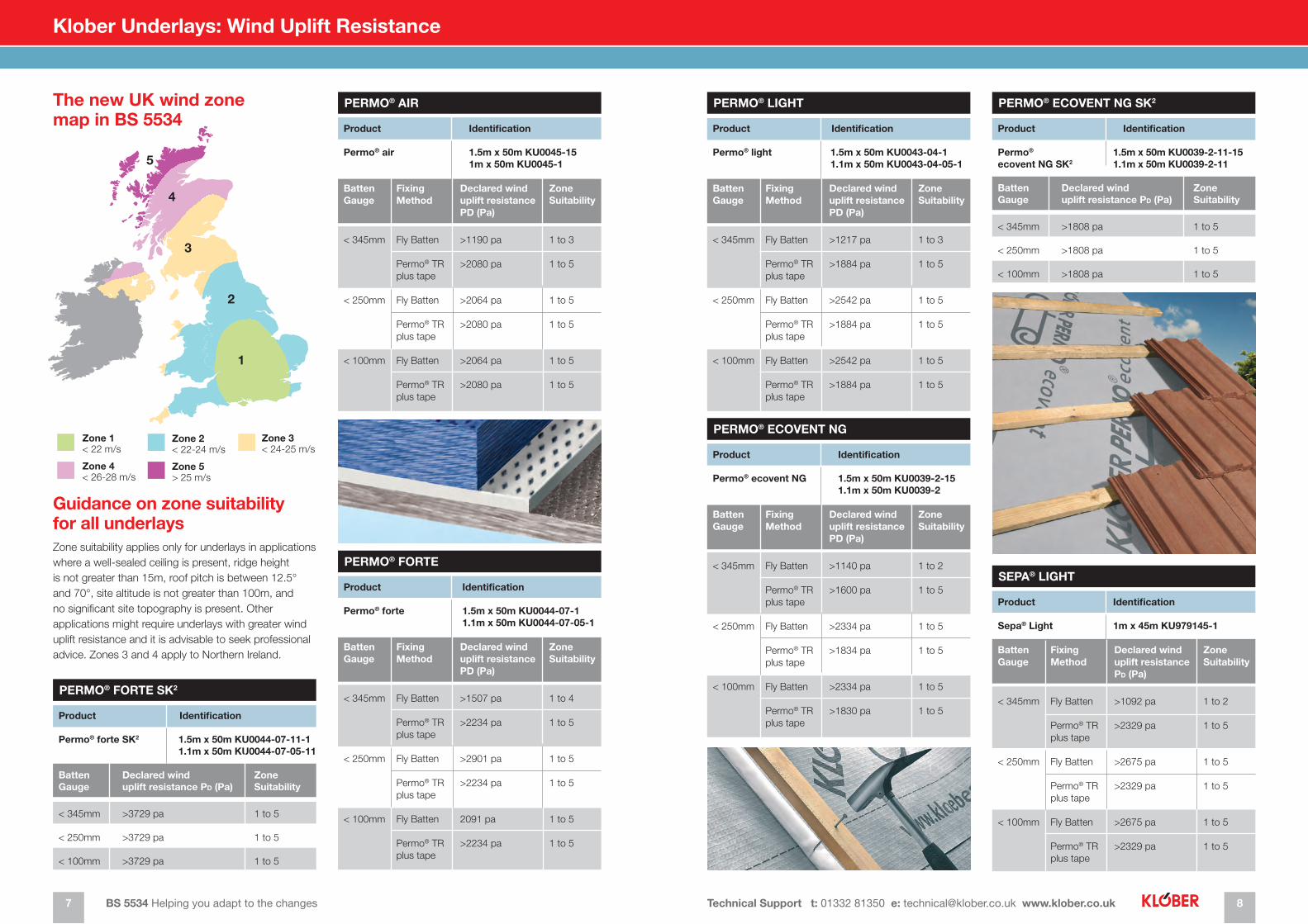
Guidance on zone suitability for all underlaysZone suitability applies only for underlays in applications where a well-sealed ceiling is present, ridge height is not greater than 15m, roof pitch is between 12.5° and 70°, site altitude is not greater than 100m, and no significant site topography is present. Other applications might require underlays with greater wind uplift resistance and it is advisable to seek professional advice. Zones 3 and 4 apply to Northern Ireland.
The new UK wind zone map in BS 5534
1
2
3
4
5
Zone 1< 22 m/s
Zone 2< 22-24 m/s
Zone 4< 26-28 m/s
Zone 3< 24-25 m/s
Zone 5> 25 m/s
PERMO® FORTE SK2
Product Identification
Permo® forte SK2 1.5m x 50m KU0044-07-11-1 1.1m x 50m KU0044-07-05-11
Batten Declared wind ZoneGauge uplift resistance PD (Pa) Suitability
< 345mm >3729 pa 1 to 5
< 250mm >3729 pa 1 to 5
< 100mm >3729 pa 1 to 5
BS 5534 Helping you adapt to the changes Technical Support t: 01332 81350 e: [email protected] www.klober.co.uk9 10
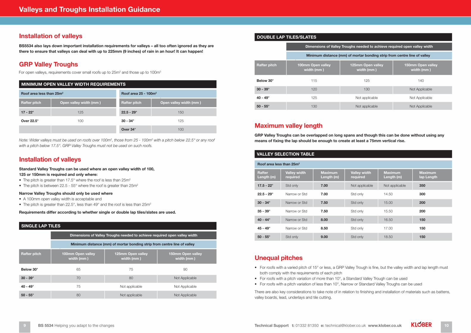
Installation of valleys
Installation of valleys
Unequal pitches
Maximum valley length
BS5534 also lays down important installation requirements for valleys – all too often ignored as they are there to ensure that valleys can deal with up to 225mm (9 inches) of rain in an hour! It can happen!
Standard Valley Troughs can be used where an open valley width of 100, 125 or 150mm is required and only where: • The pitch is greater than 17.5° where the roof is less than 25m2
• The pitch is between 22.5 - 55° where the roof is greater than 25m2
Narrow Valley Troughs should only be used where • A 100mm open valley width is acceptable and • The pitch is greater than 22.5°, less than 49° and the roof is less than 25m2
Requirements differ according to whether single or double lap tiles/slates are used.
• For roofs with a varied pitch of 15° or less, a GRP Valley Trough is fine, but the valley width and lap length must both comply with the requirements of each pitch
• For roofs with a pitch variation of more than 10°, a Standard Valley Trough can be used• For roofs with a pitch variation of less than 10°, Narrow or Standard Valley Troughs can be used
There are also key considerations to take note of in relation to finishing and installation of materials such as battens, valley boards, lead, underlays and tile cutting.
GRP Valley Troughs can be overlapped on long spans and though this can be done without using any means of fixing the lap should be enough to create at least a 75mm vertical rise.
GRP Valley TroughsFor open valleys, requirements cover small roofs up to 25m2 and those up to 100m2
Note: Wider valleys must be used on roofs over 100m2, those from 25 - 100m2 with a pitch below 22.5° or any roof with a pitch below 17.5°. GRP Valley Troughs must not be used on such roofs.
MINIMUM OPEN VALLEY WIDTH REQUIREMENTS
SINGLE LAP TILES
DOUBLE LAP TILES/SLATES
VALLEY SELECTION TABLE
Roof area less than 25m2
Rafter pitch Open valley width (mm )
17 - 22° 125
Over 22.5° 100
Minimum distance (mm) of mortar bonding strip from centre line of valley
Rafter pitch 100mm Open valley 125mm Open valley 150mm Open valley width (mm ) width (mm ) width (mm )
Below 30° 65 75 90
30 - 39° 70 80 Not Applicable
40 - 49° 75 Not applicable Not Applicable
50 - 55° 80 Not applicable Not Applicable
Minimum distance (mm) of mortar bonding strip from centre line of valley
Rafter pitch 100mm Open valley 125mm Open valley 150mm Open valley width (mm ) width (mm ) width (mm )
Below 30° 115 125 140
30 - 39° 120 130 Not Applicable
40 - 49° 125 Not applicable Not Applicable
50 - 55° 130 Not applicable Not Applicable
Roof area 25 - 100m2
Rafter pitch Open valley width (mm )
22.5 - 29° 150
30 - 34° 125
Over 34° 100
Dimensions of Valley Troughs needed to achieve required open valley width
Dimensions of Valley Troughs needed to achieve required open valley width
Roof area less than 25m2
Rafter Valley width Maximum Valley width Maximum Maximum Length (m) required Length (m) required Length (m) lap Length
17.5 - 22° Std only 7.00 Not applicable Not applicable 350
22.5 - 29° Narrow or Std 7.00 Std only 14.50 300
30 - 34° Narrow or Std 7.50 Std only 15.00 200
35 - 39° Narrow or Std 7.50 Std only 15.50 200
40 - 44° Narrow or Std 8.00 Std only 16.50 150
45 - 49° Narrow or Std 8.50 Std only 17.00 150
50 - 55° Std only 9.00 Std only 18.50 150
Valleys and Troughs Installation Guidance
Klober Limited Technical Support t: 01332 81350 e: [email protected] www.klober.co.uk
Recommendations as to methods, use of materials and construction details are based on the accumulated experience and knowledge of Klober and are given in good faith as a general guide and service to designers, contractors, merchants, roofers and manufacturers.
All products are sold subject to Klober’s ‘Conditions of Sale’, copies of which are available on request.
Klober’s policy of continuing development may mean that the products supplied could differ slightly from those described in this brochure.
Certification All of Klober’s products conform to the relevant Building Regulations and British Standards and, where appropriate, are BBA, BRE, IAB and CE certified.
Guarantee All products supplied by Klober Ltd are covered by a 10 year guarantee against manufacturing defect. Products are not covered for colour stability, poor workmanship or incorrect installation.
All products should be installed as per our literature/fixing instructions and/or guidelines set out in regulations and British Standards such as BS5534, BS5250 and our BBA/BRE/IAB certificates.