Embed Size (px)
Citation preview
Brocade® FCX 624/648, ICX™ 6610, ICX 6450, ICX 6650, ICX 7750 and SX 800/1600 Series
FIPS 140-2 Non-Proprietary Security Policy
Level 2 with Design Assurance Level 3 Validation
Document Version 1.0
June 30, 2014

Copyright Brocade Communications 2014. May be reproduced only in its original entirety [without revision].

Brocade® FCX 624/648, ICX™ 6610, ICX 6450, ICX 6650, ICX 7750 and SX 800/1600 Series
2
Revision History
Revision Date Revision Summary of Changes
06/30/14 1.0 Initial draft version
3
1 Introduction
The Brocade FastIron SX and Brocade FCX switches are part of Brocade’s FastIron L2/L3 switch family. They are designed for medium to large enterprise backbones. The FastIron SX series chassis devices are modular switches that provide the enterprise network with a complete end-to-end Enterprise LAN solution, ranging from the wiring closet to the LAN backbone. The FCX series is an access layer Gigabit Ethernet switch designed from the ground up for the enterprise data center environment. When these switches are stacked, they appear as one switch, reducing management up to 8 times.
Brocade ICX 6610 series stackable switches are part of Brocade’s ICX 6610 product family. They are designed for medium to large enterprise backbones. The ICX 6610 series is an access layer Gigabit Ethernet switch designed from the ground up for the enterprise data center environment.
Brocade ICX 6450 switches provide enterprise-class stackable LAN switching solutions to meet the growing demands of campus networks. Designed for small to medium-size enterprises, branch offices, and distributed campuses, these intelligent, scalable edge switches deliver enterprise-class functionality without compromising performance and reliability.
The Brocade ICX 6650 Switch is a compact Ethernet switch that delivers industry-leading 10/40 GbE density, unmatched price/performance, and seamless scalability for the ultimate investment protection. Designed for demanding data center Top-of-Rack (ToR) environments and campus LAN aggregation deployments requiring cost-effective connectivity, the Brocade ICX 6650 offers flexible Ports on Demand (PoD) licensing for non- disruptive pay-as-you-grow scalability.
The Brocade ICX 7750 is a 10/40 GbE Ethernet switch delivering a chassis experience for campus LAN aggregation and core. It offers unprecedented port density and chassis-level performance, availability, and scalability. The ICX 7750 distributed chassis technology enables scale-out networking and its true hybrid-port mode OpenFlow provides a migration path to SDN.
2 Overview
The FIPS 140-2 validation includes the forty- one (41) hardware devices running the firmware version presented in Table 1. Table 2, Table 5, Table 6, Table 7, Table 9 and Table 10 list the devices included in this evaluation. Table 2 lists the six (6) Brocade FCX 624 series and FCX 648 series devices, referred collectively for the remainder of this document as FCX 624/648 device (cryptographic module, or simply the module). Each FCX 624/648 device is a fixed-port switch, which is a multi-chip standalone cryptographic module. The power supplies, fan tray assemblies and 2X10G Ethernet uplink module (FCX-2XG) are part of the cryptographic boundary and can be replaced in the field. An unpopulated FCX-2XG slot is covered by an opaque bezel which is part of the cryptographic boundary. For each module to operate in a FIPS Approved mode of operation, the tamper evident seals, supplied in FIPS Kit (Part Number: XBR-000195) must be installed, as defined in Appendix A.
Table 5 lists the ten (10) Brocade ICX 6610 series devices, referred collectively for the remainder of this document as ICX 6610 device (cryptographic module, or simply the module). Each ICX 6610 device is a fixed- port switch, which is a multi-chip standalone cryptographic module. The installed fans either use a push or pull configuration to move the air between the back and front of the device. Each model is orderable with either fan trays or power supply side intake (-I) or power supply side exhaust (-E) airflow, therefore two SKUs per module are listed in Table 5. The power supplies and fan tray assemblies are part of the cryptographic boundary and can be replaced in the field. Unpopulated power supplies and fan trays are covered by opaque bezels, which are part of the cryptographic boundary when the secondary redundant power supplies and/or fans trays are not used. The cryptographic boundary for each ICX 6610 device is represented by the opaque enclosure (including the power supply, fan tray and bezels) with removable cover. For each module to operate in a FIPS Approved mode of operation, the tamper evident seals, supplied in FIPS Kit (Part Number: XBR- 000195) must be installed, as defined in Appendix A.
Table 6 lists the five (5) Brocade ICX 6450 series devices, referred collectively for the remainder of this document as ICX 6450 device (cryptographic module, or simply the module). Each ICX 6450 device is a fixed- port switch, which is a multi-chip standalone cryptographic module. The power supplies and fan tray assemblies are part of the cryptographic boundary and cannot be replaced in the field. The cryptographic

4
boundary for each ICX 6450 device is represented by the opaque enclosure (including the power supply, fan tray and bezels) with removable cover. For each module to operate in a FIPS Approved mode of operation, the tamper evident seals, supplied in FIPS Kit (Part Number: XBR-000195) must be installed, as defined in Appendix A.
Table 7 lists the ten (10) Brocade ICX 6650 series devices, referred collectively for the remainder of this document as ICX 6650 device (cryptographic module, or simply the module). Each ICX 6650 device is a fixed- port switch, which is a multi-chip standalone cryptographic module. The installed fans either use a push or pull configuration to move the air between the back and front of the device. Each model is orderable with either fan trays or power supply side intake (-I) or power supply side exhaust (-E) airflow, therefore two SKUs per module is listed in Table 7. The power supplies and fan tray assemblies are part of the cryptographic boundary and can be replaced in the field. Unpopulated power supplies and fan trays are covered by opaque bezels, which are part of the cryptographic boundary when the secondary redundant power supplies and/or fans trays are not used. The cryptographic boundary for each ICX 6650 device is represented by the opaque enclosure (including the power supply, fan tray and bezels) with removable cover. For each module to operate in a FIPS approved mode of operation, the tamper evident seals, supplied in FIPS Kit (Part Number: XBR- 000195) must be installed, as defined in Appendix A. Table 9 lists the Brocade ICX 7750 series devices, referred collectively for the remainder of this document as ICX 7750 device (cryptographic module, or simply the module). Each ICX 7750 device is a fixed-port switch, which is a multi-chip standalone cryptographic module. The installed fans either use a push or pull configuration to move the air between the back and front of the device. Each model is orderable with either fan trays or power supply side intake (-I) or power supply side exhaust (-E) airflow. The power supplies and fan tray assemblies are part of the cryptographic boundary and can be replaced in the field. Unpopulated power supplies and fan trays are covered by opaque bezels, which are part of the cryptographic boundary when the secondary redundant power supplies and/or fans trays are not used. The cryptographic boundary for each ICX 7750 device is represented by the opaque enclosure (including the power supply, fan tray and bezels) with removable cover. For each module to operate in a FIPS approved mode of operation, the tamper evident seals, supplied in FIPS Kit (Part Number: XBR-000195) must be installed, as defined in Appendix A.
Table 10 lists the FastIron SX 800 and two (2) SX 1600 series devices, referred collectively for the remainder of this document as SX 800/1600 device (cryptographic module, or simply the module). Each SX 800/1600 device is a chassis based switch, which is a multi-chip standalone cryptographic module. The field replaceable power supplies are not part of the cryptographic boundary. The fan tray assemblies are part of the cryptographic boundary and can be replaced in the field. Unpopulated management module, switch fabric module and port blade modules slots are covered by opaque bezels. The cryptographic boundary for each SX 800/1600 device is represented by the opaque enclosure (including the management modules, switch fabric modules, fan trays and bezels) with removable cover. For each module to operate in a FIPS approved mode of operation, the tamper evident seals, supplied in FIPS Kit (Part Number: XBR-000195) must be installed, as defined in Appendix A.
3 FastIron Firmware
The ICX 6610 series (listed in Table 5 ICX 6610 Switch Family Part Numbers) runs the same firmware version that includes the cryptographic functionality described under Section 11. The “–I” and “–E” designations in Table 5 define the airflow direction as either intake or exhaust. The “-24” and “-48” designations in Table 5 define the port count, and the designator “P” following the port count indicate PoE+ ports; the designator “F” indicate Small Form-Factor Pluggable (SFP) ports. Otherwise, devices with similar SKUs are identical.
Table 1 Firmware Version
Firmware Version
IronWare R08.0.10
5
4 Brocade FCX 624 and FCX 648 Series
Table 2 FCX Part Numbers
SKU MFG Part Number Brief Description
FCX624S 80-1002388-08 24-Port 1GbE, 2X16G stackable switch
FCX624S-HPOE-ADV 80-1002715-08 24-Port 1GbE, HPOE, 2X16G stackable, ADV L3 switch
FCX624S-F-ADV 80-1002727-07 24-Port, FE/GE SFP, 2X16G stackable, ADV L3 switch
FCX648S 80-1002392-08 48-Port 1GbE, 2X16 stackable switch
FCX648S-HPOE 80-1002391-10 48-Port 1GbE, HPOE, 2x16G stackable switch
FCX648S-HPOE-ADV 80-1002716-10 48-Port 1GbE, HPOE, 2x16G stackable, ADV L3 switch
XBR-000195
N/A
FIPS Kit containing tamper evident labels to be affixed to the module per Appendix A: Tamper Label Application in this document. All SKUs listed above utilize this kit to satisfy the physical security requirements
Table 3 FCX 624 and FCX 628 Optional Component Part Numbers
SKU MFG Part Number Brief Description
FCX-2XG 80-1002399-01 XFP Module,Uplink,2X10G,FCX
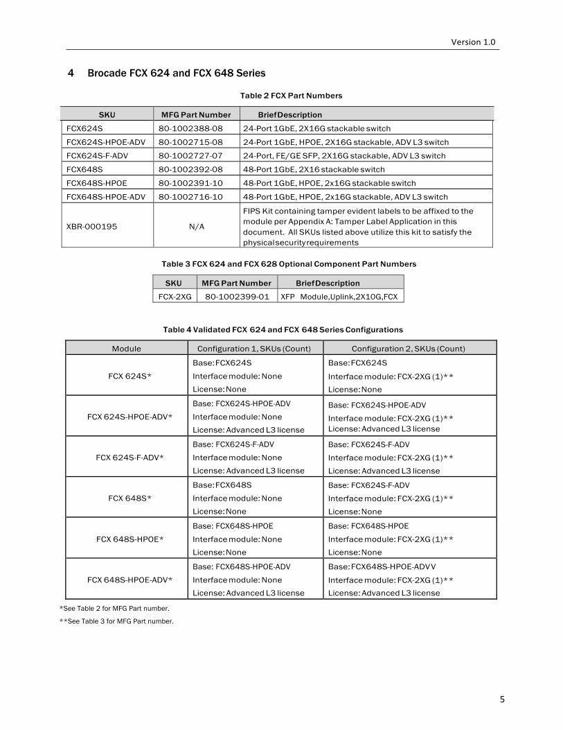
Table 4 Validated FCX 624 and FCX 648 Series Configurations
Module Configuration 1, SKUs (Count) Configuration 2, SKUs (Count)
FCX 624S*
Base: FCX624S
Interface module: None License: None
Base: FCX624S
Interface module: FCX-2XG (1)** License: None
FCX 624S-HPOE-ADV*
Base: FCX624S-HPOE-ADV
Interface module: None License: Advanced L3 license
Base: FCX624S-HPOE-ADV
Interface module: FCX-2XG (1)** License: Advanced L3 license
FCX 624S-F-ADV*
Base: FCX624S-F-ADV
Interface module: None License: Advanced L3 license
Base: FCX624S-F-ADV
Interface module: FCX-2XG (1)** License: Advanced L3 license
FCX 648S*
Base: FCX648S
Interface module: None License: None
Base: FCX624S-F-ADV
Interface module: FCX-2XG (1)** License: None
FCX 648S-HPOE*
Base: FCX648S-HPOE
Interface module: None License: None
Base: FCX648S-HPOE
Interface module: FCX-2XG (1)** License: None
FCX 648S-HPOE-ADV*
Base: FCX648S-HPOE-ADV
Interface module: None License: Advanced L3 license
Base: FCX648S-HPOE-ADV V
Interface module: FCX-2XG (1)** License: Advanced L3 license
*See Table 2 for MFG Part number.
**See Table 3 for MFG Part number.
6
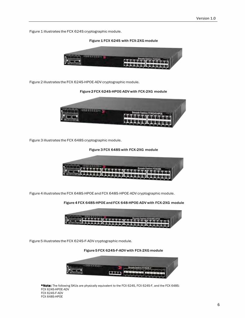
Figure 1 illustrates the FCX 624S cryptographic module.
Figure 1 FCX 624S with FCX-2XG module
Figure 2 illustrates the FCX 624S-HPOE-ADV cryptographic module.
Figure 2 FCX 624S-HPOE-ADV with FCX-2XG module
Figure 3 illustrates the FCX 648S cryptographic module.
Figure 3 FCX 648S with FCX-2XG module
Figure 4 illustrates the FCX 648S-HPOE and FCX 648S-HPOE-ADV cryptographic module.
Figure 4 FCX 648S-HPOE and FCX 648-HPOE-ADV with FCX-2XG module
Figure 5 illustrates the FCX 624S-F-ADV cryptographic module.
Figure 5 FCX 624S-F-ADV with FCX-2XG module
*Note: The following SKUs are physically equivalent to the FCX 624S, FCX 624S-F, and the FCX 648S: FCX 624S-HPOE-ADV FCX 624S-F-ADV FCX 648S-HPOE

7
FCX 648S-HPOE-ADV
7
5 ICX 6610 Series
Table 5 ICX 6610 Switch Family Part Numbers of Validated Cryptographic Modules
SKU MFG Part Number Brief Description
ICX6610-24F-I
80-1005350-04
Stackable switch with 24 100/1000 Mbps Small Form-Factor Pluggable (SFP) ports, power supply side intake airflow (“-I” in the SKU)
ICX6610-24F-E
80-1005345-04
Stackable switch with 24 100/1000 Mbps Small Form-Factor Pluggable (SFP) ports, power supply side exhaust airflow (“-E” in the SKU)
ICX6610-24-I
80-1005348-05 Stackable switch with 24 10/100/1000 Mbps RJ-45 ports,
power supply side intake airflow (“-I” in the SKU) ICX6610-24-E
80-1005343-05 Stackable switch with 24 10/100/1000 Mbps RJ-45 ports,
power supply side exhaust airflow (“-E” in the SKU) ICX6610-24P-I
80-1005349-06 Stackable switch with 24 10/100/1000 Mbps RJ-45 PoE+ ports,
power supply side intake airflow (“-I” in the SKU) ICX6610-24P-E
80-1005344-06
Stackable switch with 24 10/100/1000 Mbps RJ-45 PoE+ ports, power supply side exhaust airflow (“-E” in the SKU)
ICX6610-48-I
80-1005351-05 Stackable switch with 48 10/100/1000 Mbps RJ-45 ports,
power supply side intake airflow (“-I” in the SKU) ICX6610-48-E
80-1005346-05 Stackable switch with 48 10/100/1000 Mbps RJ-45 ports,
power supply side exhaust airflow (“-E” in the SKU) ICX6610-48P-I
80-1005352-06 Stackable switch with 24 10/100/1000 Mbps RJ-45 PoE+ ports,
power supply side intake airflow (“-I” in the SKU) ICX6610-48P-E
80-1005347-06
Stackable switch with 24 10/100/1000 Mbps RJ-45 PoE+ ports, power supply side exhaust airflow (“-E” in the SKU)
XBR-000195
N/A
FIPS Kit containing tamper evident labels to be affixed to the module per Appendix A: Tamper Label Application in this document. All SKUs listed above utilize this kit to satisfy the physical security requirements
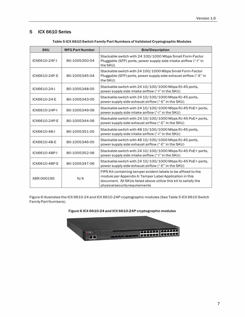
Figure 6 illustrates the ICX 6610-24 and ICX 6610-24P cryptographic modules (See Table 5 ICX 6610 Switch Family Part Numbers).
Figure 6 ICX 6610-24 and ICX 6610-24P cryptographic modules
8
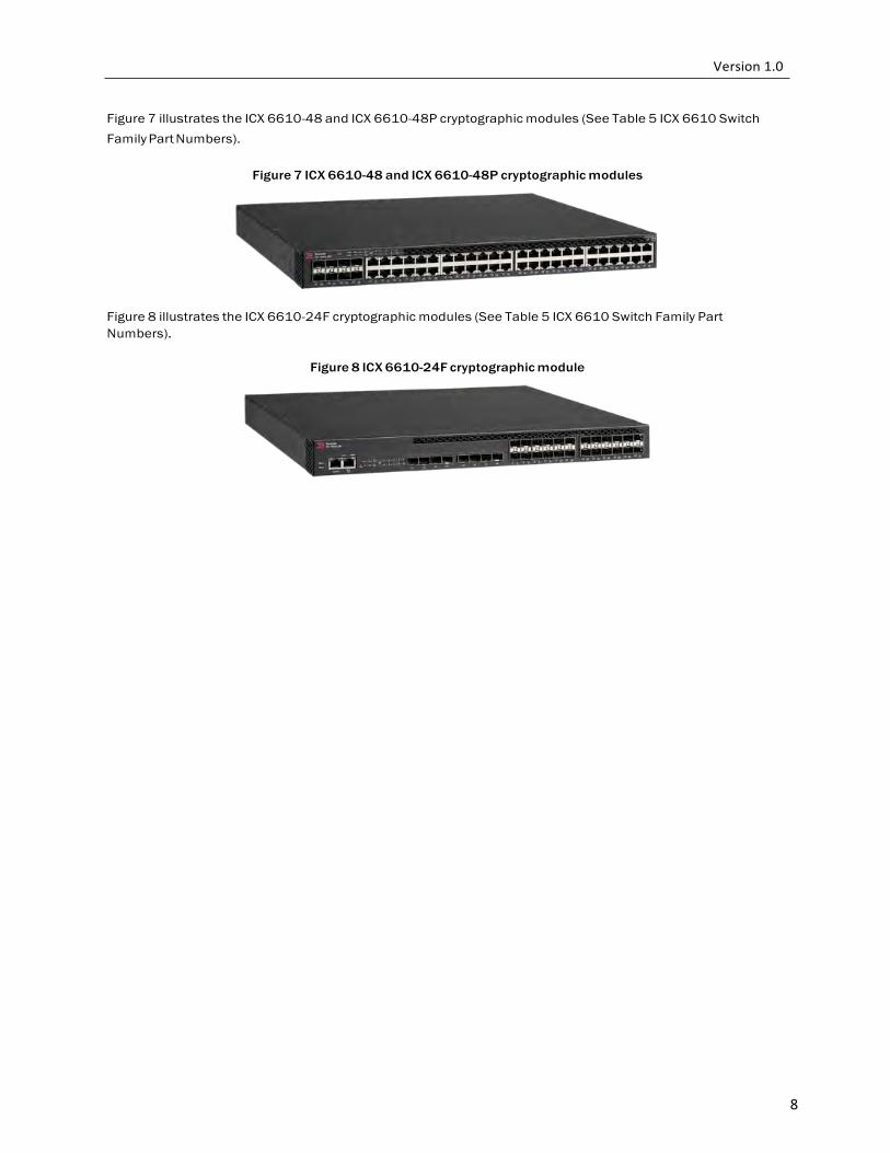
Figure 7 illustrates the ICX 6610-48 and ICX 6610-48P cryptographic modules (See Table 5 ICX 6610 Switch Family Part Numbers).
Figure 7 ICX 6610-48 and ICX 6610-48P cryptographic modules
Figure 8 illustrates the ICX 6610-24F cryptographic modules (See Table 5 ICX 6610 Switch Family Part Numbers).
Figure 8 ICX 6610-24F cryptographic module
9
6 ICX 6450 Series
Table 6 ICX 6450 Switch Family Part Numbers of Validated Cryptographic Modules
SKU MFG Part Number Brief Description
ICX6450-24
80-1005997-03 24-port 1G Switch, 2x1G SFP+ (upgradable to 10G) & 2x1G/10G SFP+ Uplink/Stacking Ports
ICX6450-24P
80-1005996-04 24-port 1G Switch PoE+ 390W, 2x1G SFP+ (upgradable
to 10G) & 2x1G/10G SFP+ Uplink/Stacking Ports
ICX6450-48
80-1005999-04 48-port 1G Switch, 2x1G SFP+ (upgradable to 10G) & 2x1G/10G SFP+ Uplink/Stacking Ports
ICX6450-48P
80-1005998-04 48-port 1G Switch PoE+ 780W, 2x1G SFP+ (upgradable
to 10G) & 2x1G/10G SFP+ Uplink/Stacking Ports
ICX6450-C12-PD
80-1007578-01 12-port 1G Compact Switch (4 PoE+), 2X100M/1G SFP, 2X100M/1G Copper Uplinks, Fanless, Layer 3
XBR-000195
N/A
FIPS Kit containing tamper evident labels to be affixed to the module per Appendix A: Tamper Label Application in this document. All SKUs listed above utilize this kit to satisfy the physical security requirements
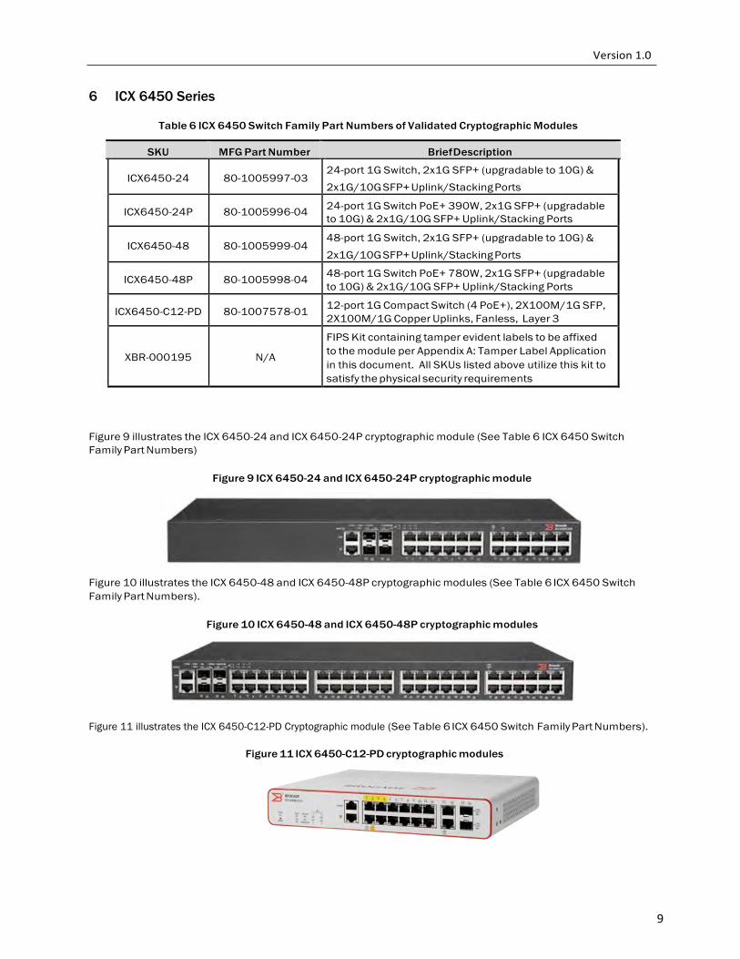
Figure 9 illustrates the ICX 6450-24 and ICX 6450-24P cryptographic module (See Table 6 ICX 6450 Switch Family Part Numbers)
Figure 9 ICX 6450-24 and ICX 6450-24P cryptographic module
Figure 10 illustrates the ICX 6450-48 and ICX 6450-48P cryptographic modules (See Table 6 ICX 6450 Switch Family Part Numbers).
Figure 10 ICX 6450-48 and ICX 6450-48P cryptographic modules
Figure 11 illustrates the ICX 6450-C12-PD Cryptographic module (See Table 6 ICX 6450 Switch Family Part Numbers).
Figure 11 ICX 6450-C12-PD cryptographic modules
10
7 ICX 6650 Series
Table 7 ICX 6650 Switch Family Part Numbers of Validated Cryptographic Modules
SKU MFG Part Number Brief Description
ICX6650-32-E-ADV
80-1007115-02
Brocade ICX 6650 with 32 10GbE SFP+ ports enabled. Includes two 250W AC power supplies and two fan units with exhaust airflow.
ICX6650-32-I-ADV
80-1007116-02
Brocade ICX 6650 with 32 10GbE SFP+ ports enabled. Includes two 250W AC power supplies and two fan units with intake airflow.
ICX6650-40-E-ADV
80-1007179-03
Brocade ICX 6650 with 32 10GbE SFP+ ports enabled and POD license for 8 10GbE SFP+ ports. Includes two 250W AC power supplies and two fan units with exhaust airflow.
ICX6650-40-I-ADV
80-1007181-03
Brocade ICX 6650 with 32 10GbE SFP+ ports enabled and POD license for 8 10GbE SFP+ ports. Includes two 250W AC power supplies and two fan units with intake airflow.
ICX6650-48-E-ADV
80-1007180-03
Brocade ICX 6650 with 32 10GbE SFP+ ports enabled and POD license for 16 10GbE SFP+ ports. Includes two 250W AC power supplies and two fan units with exhaust airflow.
ICX6650-48-I-ADV
80-1007182-03
Brocade ICX 6650 with 32 10GbE SFP+ ports enabled and POD license for 16 10GbE SFP+ ports. Includes two 250W AC power supplies and two fan units with intake airflow.
ICX6650-56-E-ADV
80-1007117-03
Brocade ICX 6650 with 32 10GbE SFP+ ports enabled and POD license for 24 10GbE SFP+ ports. Includes two 250W AC power supplies and two fan units with exhaust airflow.
ICX6650-56-I-ADV
80-1007118-03
Brocade ICX 6650 with 32 10GbE SFP+ ports enabled and POD license for 24 10GbE SFP+ ports. Includes two 250W AC power supplies and two fan units with intake airflow.
ICX6650-80-E-ADV
80-1007119-03
Brocade ICX 6650 with 32 10GbE SFP+ ports enabled, POD licenses for 24 10GbE SFP+ ports, and for 6 QSPF+ ports (24x10GbE, and 4 x40GbE). Includes two 250W AC power supplies and two fan units with exhaust airflow.
ICX6650-80-I-ADV
80-1007120-03
Brocade ICX 6650 with 32 10GbE SFP+ ports enabled, POD licenses for 24 10GbE SFP+ ports, and for 6 QSPF+ ports (24x10GbE, and 4 x40GbE). Includes two 250W AC power supplies and two fan units with intake airflow.
XBR-000195
N/A
FIPS Kit containing tamper evident labels to be affixed to the module per Appendix A: Tamper Label Application in this document. All SKUs listed above utilize this kit to satisfy the physical security requirements.
11
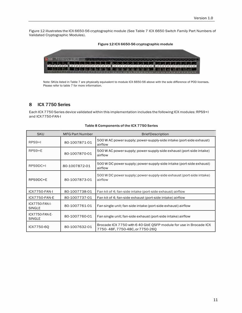
Figure 12 illustrates the ICX 6650-56 cryptographic module (See Table 7 ICX 6650 Switch Family Part Numbers of Validated Cryptographic Modules).
Figure 12 ICX 6650-56 cryptographic module
Note: SKUs listed in Table 7 are physically equivalent to module ICX 6650-56 above with the sole difference of POD licenses. Please refer to table 7 for more information.
8 ICX 7750 Series
Each ICX 7750 Series device validated within this implementation includes the following ICX modules: RPS9+I and ICX 7750-FAN-I
Table 8 Components of the ICX 7750 Series
SKU MFG Part Number Brief Description
RPS9+I
80-1007871-01 500 W AC power supply; power-supply-side intake (port-side exhaust) airflow
RPS9+E 80-1007870-01
500 W AC power supply; power-supply-side exhaust (port-side intake) airflow
RPS9DC+I
80-1007872-01
500 W DC power supply; power-supply-side intake (port-side exhaust) airflow
RPS9DC+E
80-1007873-01
500 W DC power supply; power-supply-side exhaust (port-side intake) airflow
ICX7750-FAN-I 80-1007738-01 Fan kit of 4; fan-side intake (port-side exhaust) airflow
ICX7750-FAN-E 80-1007737-01 Fan kit of 4; fan-side exhaust (port-side intake) airflow
ICX7750-FAN-I- SINGLE
80-1007761-01
Fan single unit; fan-side intake (port-side exhaust) airflow
ICX7750-FAN-E- SINGLE
80-1007760-01
Fan single unit; fan-side exhaust (port-side intake) airflow
ICX7750-6Q
80-1007632-01 Brocade ICX 7750 with 6 40 GbE QSFP module for use in Brocade ICX
7750- 48F, 7750-48C, or 7750-26Q
12
Table 9 ICX 7750 Switch Family Part Numbers of Validated Cryptographic Modules
SKU MFG Part Number Brief Description
ICX7750-48F
80-1007607-01
Brocade ICX 7750 with 48 1/10 GbE SFP+ ports, 6 40 GbE QSFP ports and modular interface slot. No power supplies or fan units (need to be ordered separately).
ICX7750-48C
80-1007608-01
Brocade ICX 7750 with 48 1/10 GbE RJ-45 10GBASE-T ports, 6 40 GbE QSFP ports and modular interface slot. No power supplies or fan units (need to be ordered separately).
ICX7750-26Q
80-1007609-01
Brocade ICX 7750 with 26 40 GbE QSFP ports and modular interface slot. No power supplies or fan units (need to be ordered separately).
XBR-000195
N/A
FIPS Kit containing tamper evident labels to be affixed to the module per Appendix A: Tamper Label Application in this document. All SKUs listed above utilize this kit to satisfy the physical security requirements
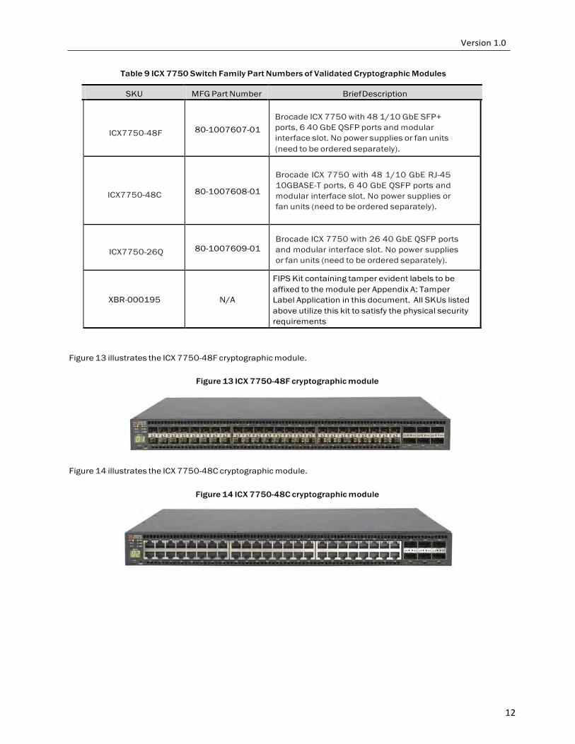
Figure 13 illustrates the ICX 7750-48F cryptographic module.
Figure 13 ICX 7750-48F cryptographic module
Figure 14 illustrates the ICX 7750-48C cryptographic module.
Figure 14 ICX 7750-48C cryptographic module
13
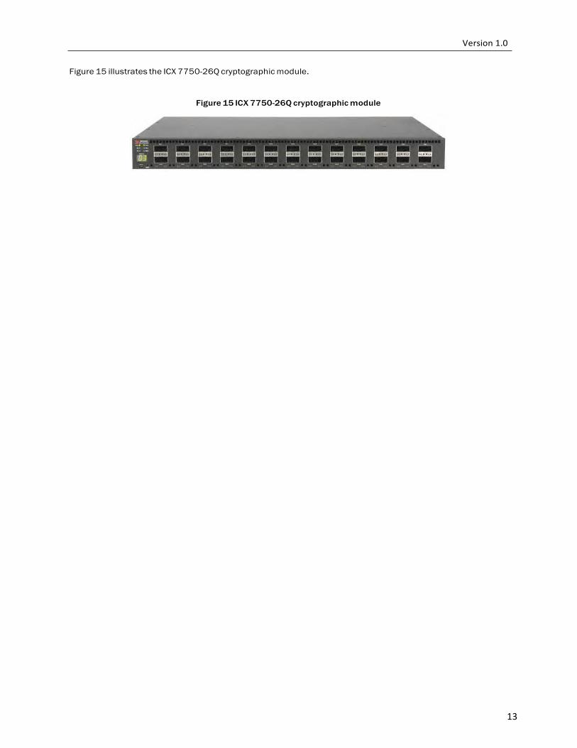
Figure 15 illustrates the ICX 7750-26Q cryptographic module.
Figure 15 ICX 7750-26Q cryptographic module
14
9 SX 800 and SX 1600 Series
Each FI-SX800-S, FI-SX1600-AC and FI-SX1600-DC device validated within this implementation includes the following SX modules: SX-FISF and SX-FIZMR or SX-FI2XGMR6
Table 10 FastIron SX Part Numbers
SKU MFG Part Number Brief Description
FI-SX800-S 80-1003050-03, 80-1007143-03 FastIron SX 800 CHASSIS
FI-SX1600-AC 80-1002764-02, 80-1007137-02 FastIron SX 1600, 16 slot, 2 SX-FISF, 2 AC Power Supplies
FI-SX1600-DC 80-1003005-02, 80-1007138-02 FastIron SX 1600, 16 slot, 2 SX-FISF, 2 DC Power Supplies
Table 11 Components of the SX 800 and SX 1600
SKU MFG Part Number Brief Description
SX-FISF 80-1002957-03 Switch Fabric module for the FI SX 800 & FI SX 1600
SX-FI-2XGMR-XL- PREM6
80-1007349-01
FISX 2PRT G3 10GE XL MGMT MOD PREM
SX-FI-2XGMR-XL 80-1006607-01 FI SX 2PRT G3 10GE XL MGMT MOD
SX-FI-ZMR-XL 80-1006486-02 FastIron SX XL management module, No 10G ports
SX-FI-ZMR-XL-PREM6
80-1007350-02 FastIron SX XL management module, No 10G ports, support for IPv4 and Ipv6 routing, SW-SX-FIL3U-6-IPV6 license
SX-ACPWR-SYS 80-1003883-02 FSX AC 90-240 VAC SYSTEM POWER SUPPLY
SX-DCPWR-SYS 80-1003886-02 FSX DC SYSTEM POWER SUPPLY
N/A 11456-005 SHEET METAL, FAB, LINE CARD SLOT BLANK, S
N/A 11457-006 SHEET METAL, FAB, MGMT BLANK, SDX, RoHS
N/A 18072-004 SHEET METAL ASSY, PU BLANK, SX/SDX
Table 12 Validated SX 800 Series Configurations
Module Configuration 1, SKUs (Count) Configuration 2, SKUs (Count)
SX 800***
(with AC power)
Base: FI-SX800-S*
Management module: SX-FI-ZMR-
XL (2) or SX-FI-2XGMR-XL (2)**
Switch Fabric: SX-FISF (2)**
License: None Power Supply: SX-ACPWR-SYS (1)**
Base: FI-SX800-S*
Management module: SX-FI-ZMR-XL-PREM6 (2) or
SX-FI-2XGMR-Xl-PREM6 (2)**
Switch Fabric: SX-FISF (2)**
License:SW-SX-FIL3U-6-IPV6 Power Supply: SX-ACPWR-SYS (1)**
SX 800***
(with DC power)
Base: FI-SX800-S*
Management module: SX-FI-ZMR-XL (2) or SX-FI-2XGMR-XL (2)**
Switch Fabric: SX-FISF (2)**
License: None Power Supply: SX-DCPWR-SYS (1)**
Base: FI-SX800-S*
Management module: SX-FI-ZMR-XL-PREM6 (2) or SX-FI-2XGMR-Xl-PREM6 (2)**
Switch Fabric: SX-FISF (2)**
License:SW-SX-FIL3U-6-IPV6 Power Supply: SX-DCPWR-SYS (1)**
*See Table 10 for MFG Part numbers. **See Table 11 for MFG Part numbers. ***Any unused and open slots must be covered using filler panels, located in Table 11 (Part Numbers 11456-005, 11457-006 or 18072-004)
15
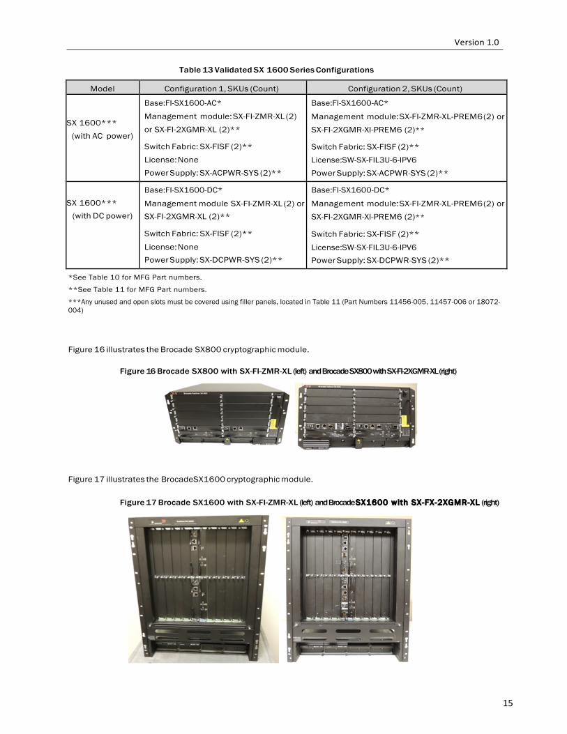
Table 13 Validated SX 1600 Series Configurations
Model Configuration 1, SKUs (Count) Configuration 2, SKUs (Count)
SX 1600***
(with AC power)
Base:FI-SX1600-AC*
Management module: SX-FI-ZMR-XL (2) or SX-FI-2XGMR-XL (2)**
Switch Fabric: SX-FISF (2)** License: None Power Supply: SX-ACPWR-SYS (2)**
Base:FI-SX1600-AC*
Management module: SX-FI-ZMR-XL-PREM6 (2) or SX-FI-2XGMR-Xl-PREM6 (2)**
Switch Fabric: SX-FISF (2)** License:SW-SX-FIL3U-6-IPV6 Power Supply: SX-ACPWR-SYS (2)**
SX 1600***
(with DC power)
Base:FI-SX1600-DC*
Management module SX-FI-ZMR-XL (2) or SX-FI-2XGMR-XL (2)**
Switch Fabric: SX-FISF (2)**
License: None Power Supply: SX-DCPWR-SYS (2)**
Base:FI-SX1600-DC*
Management module: SX-FI-ZMR-XL-PREM6 (2) or SX-FI-2XGMR-Xl-PREM6 (2)**
Switch Fabric: SX-FISF (2)**
License:SW-SX-FIL3U-6-IPV6 Power Supply: SX-DCPWR-SYS (2)**
*See Table 10 for MFG Part numbers.
**See Table 11 for MFG Part numbers.
***Any unused and open slots must be covered using filler panels, located in Table 11 (Part Numbers 11456-005, 11457-006 or 18072-004)
Figure 16 illustrates the Brocade SX800 cryptographic module.
Figure 16 Brocade SX800 with SX-FI-ZMR-XL (left) and Brocade SX800 with SX-FI-2XGMR-XL (right)
Figure 17 illustrates the BrocadeSX1600 cryptographic module.
Figure 17 Brocade SX1600 with SX-FI-ZMR-XL (left) and Brocade SX1600 with SX-FX-2XGMR-XL (right)
16
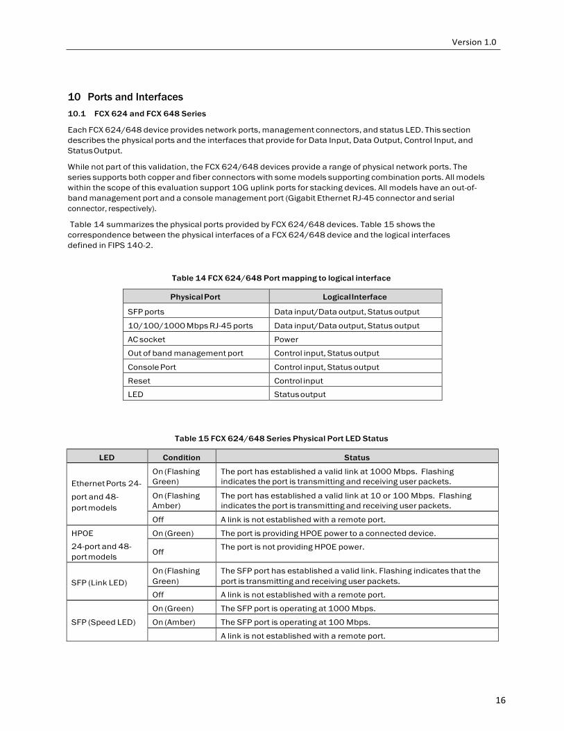
10 Ports and Interfaces
10.1 FCX 624 and FCX 648 Series
Each FCX 624/648 device provides network ports, management connectors, and status LED. This section describes the physical ports and the interfaces that provide for Data Input, Data Output, Control Input, and Status Output.
While not part of this validation, the FCX 624/648 devices provide a range of physical network ports. The series supports both copper and fiber connectors with some models supporting combination ports. All models within the scope of this evaluation support 10G uplink ports for stacking devices. All models have an out-of- band management port and a console management port (Gigabit Ethernet RJ-45 connector and serial connector, respectively).
Table 14 summarizes the physical ports provided by FCX 624/648 devices. Table 15 shows the
correspondence between the physical interfaces of a FCX 624/648 device and the logical interfaces defined in FIPS 140-2.
Table 14 FCX 624/648 Port mapping to logical interface
Physical Port Logical Interface
SFP ports Data input/Data output, Status output
10/100/1000 Mbps RJ-45 ports Data input/Data output, Status output
AC socket Power
Out of band management port Control input, Status output
Console Port Control input, Status output
Reset Control input
LED Status output
Table 15 FCX 624/648 Series Physical Port LED Status
LED Condition Status
Ethernet Ports 24-
port and 48- port models
On (Flashing Green)
The port has established a valid link at 1000 Mbps. Flashing indicates the port is transmitting and receiving user packets.
On (Flashing Amber)
The port has established a valid link at 10 or 100 Mbps. Flashing indicates the port is transmitting and receiving user packets.
Off A link is not established with a remote port.
HPOE 24-port and 48- port models
On (Green) The port is providing HPOE power to a connected device.
Off The port is not providing HPOE power.
SFP (Link LED) On (Flashing Green)
The SFP port has established a valid link. Flashing indicates that the port is transmitting and receiving user packets.
Off A link is not established with a remote port.
SFP (Speed LED)
On (Green) The SFP port is operating at 1000 Mbps.
On (Amber) The SFP port is operating at 100 Mbps. A link is not established with a remote port.
17
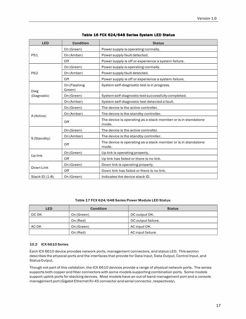
Table 16 FCX 624/648 Series System LED Status
LED Condition Status
PS1
On (Green) Power supply is operating normally.
On (Amber) Power supply fault detected.
Off Power supply is off or experience a system failure.
PS2
On (Green) Power supply is operating normally.
On (Amber) Power supply fault detected.
Off Power supply is off or experience a system failure.
Diag (Diagnostic)
On (Flashing Green)
System self-diagnostic test is in progress.
On (Green) System self-diagnostic test successfully completed.
On (Amber) System self-diagnostic test detected a fault.
A (Active)
On (Green) The device is the active controller.
On (Amber) The device is the standby controller.
Off The device is operating as a stack member or is in standalone mode.
S (Standby)
On (Green) The device is the active controller.
On (Amber) The device is the standby controller.
Off The device is operating as a stack member or is in standalone mode.
Up link
On (Green) Up link is operating properly.
Off Up link has failed or there is no link.
Down Link On (Green) Down link is operating properly.
Off Down link has failed or there is no link.
Stack ID (1-8) On (Green) Indicates the device stack ID.
Table 17 FCX 624/648 Series Power Module LED Status
LED Condition Status
DC OK On (Green) DC output OK. On (Red) DC output failure.
AC OK On (Green) AC input OK. On (Red) AC input failure.
10.2 ICX 6610 Series
Each ICX 6610 device provides network ports, management connectors, and status LED. This section describes the physical ports and the interfaces that provide for Data Input, Data Output, Control Input, and Status Output.
Though not part of this validation, the ICX 6610 devices provide a range of physical network ports. The series supports both copper and fiber connectors with some models supporting combination ports. Some models support uplink ports for stacking devices. Most models have an out-of-band management port and a console management port (Gigabit Ethernet RJ-45 connector and serial connector, respectively).
18
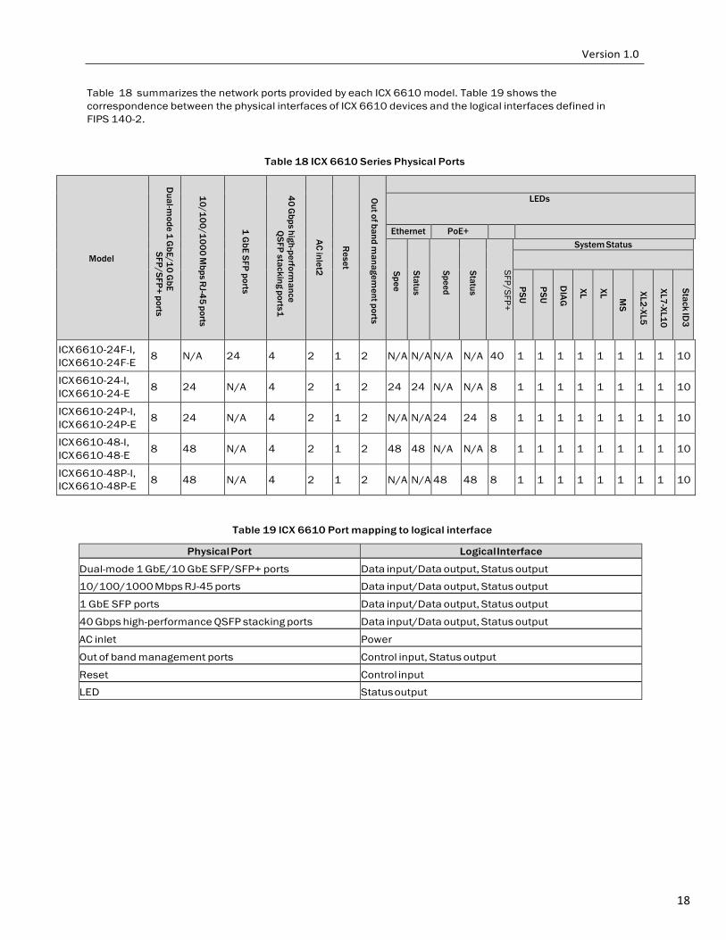
Table 18 summarizes the network ports provided by each ICX 6610 model. Table 19 shows the correspondence between the physical interfaces of ICX 6610 devices and the logical interfaces defined in FIPS 140-2.
Table 18 ICX 6610 Series Physical Ports
Model
Dual-m
ode 1 GbE/10 G
bE SFP/SFP+ ports
10/100/1000 M
bps RJ-45 ports
1 G
bE SFP ports
40 G
bps high-performance
QSFP stacking ports1
AC inlet2
R
eset
Out of band m
anagement ports
LEDs
Ethernet PoE+
SFP/SFP +
Spee
Status
Speed
Status
SFP/SFP+
System Status
PSU
PSU
DIAG
XL
XL MS
XL2-XL5
XL7-XL10
Stack ID3
ICX 6610-24F-I, ICX 6610-24F-E
8
N/A
24
4
2
1
2
N/A
N/A
N/A
N/A
40
1
1
1
1
1
1
1
1
10
ICX 6610-24-I, ICX 6610-24-E
8
24
N/A
4
2
1
2
24
24
N/A
N/A
8
1
1
1
1
1
1
1
1
10
ICX 6610-24P-I, ICX 6610-24P-E
8
24
N/A
4
2
1
2
N/A
N/A
24
24
8
1
1
1
1
1
1
1
1
10
ICX 6610-48-I, ICX 6610-48-E
8
48
N/A
4
2
1
2
48
48
N/A
N/A
8
1
1
1
1
1
1
1
1
10
ICX 6610-48P-I, ICX 6610-48P-E
8
48
N/A
4
2
1
2
N/A
N/A
48
48
8
1
1
1
1
1
1
1
1
10
Table 19 ICX 6610 Port mapping to logical interface
Physical Port Logical Interface
Dual-mode 1 GbE/10 GbE SFP/SFP+ ports Data input/Data output, Status output
10/100/1000 Mbps RJ-45 ports Data input/Data output, Status output
1 GbE SFP ports Data input/Data output, Status output
40 Gbps high-performance QSFP stacking ports Data input/Data output, Status output
AC inlet Power
Out of band management ports Control input, Status output
Reset Control input
LED Status output
19
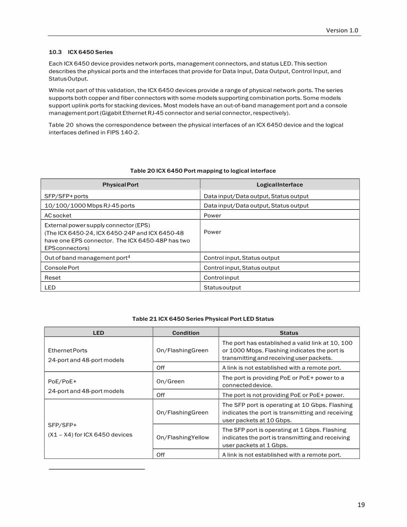
10.3 ICX 6450 Series
Each ICX 6450 device provides network ports, management connectors, and status LED. This section describes the physical ports and the interfaces that provide for Data Input, Data Output, Control Input, and Status Output.
While not part of this validation, the ICX 6450 devices provide a range of physical network ports. The series supports both copper and fiber connectors with some models supporting combination ports. Some models support uplink ports for stacking devices. Most models have an out-of-band management port and a console management port (Gigabit Ethernet RJ-45 connector and serial connector, respectively).
Table 20 shows the correspondence between the physical interfaces of an ICX 6450 device and the logical interfaces defined in FIPS 140-2.
Table 20 ICX 6450 Port mapping to logical interface
Physical Port Logical Interface
SFP/SFP+ ports Data input/Data output, Status output 10/100/1000 Mbps RJ-45 ports Data input/Data output, Status output
AC socket Power
External power supply connector (EPS) (The ICX 6450-24, ICX 6450-24P and ICX 6450-48 have one EPS connector. The ICX 6450-48P has two EPS connectors)
Power
Out of band management port4 Control input, Status output
Console Port Control input, Status output
Reset Control input
LED Status output
Table 21 ICX 6450 Series Physical Port LED Status
LED Condition Status
Ethernet Ports
24-port and 48-port models
On/Flashing Green
The port has established a valid link at 10, 100 or 1000 Mbps. Flashing indicates the port is transmitting and receiving user packets.
Off A link is not established with a remote port.
PoE/PoE+
24-port and 48-port models
On/Green The port is providing PoE or PoE+ power to a
connected device.
Off The port is not providing PoE or PoE+ power.
SFP/SFP+
(X1 – X4) for ICX 6450 devices
On/Flashing Green
The SFP port is operating at 10 Gbps. Flashing indicates the port is transmitting and receiving user packets at 10 Gbps.
On/Flashing Yellow
The SFP port is operating at 1 Gbps. Flashing indicates the port is transmitting and receiving user packets at 1 Gbps.
Off A link is not established with a remote port.
20
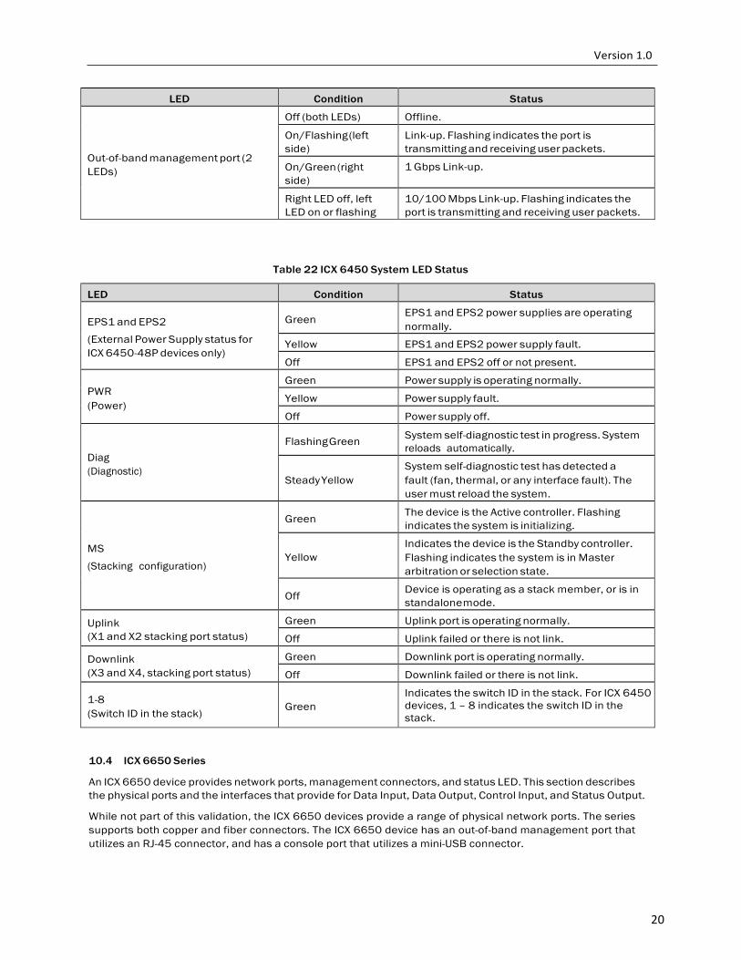
LED Condition Status
Out-of-band management port (2 LEDs)
Off (both LEDs) Offline.
On/Flashing (left side)
Link-up. Flashing indicates the port is transmitting and receiving user packets.
On/Green (right side)
1 Gbps Link-up.
Right LED off, left LED on or flashing
10/100 Mbps Link-up. Flashing indicates the port is transmitting and receiving user packets.
Table 22 ICX 6450 System LED Status
LED Condition Status
EPS1 and EPS2
(External Power Supply status for ICX 6450-48P devices only)
Green
EPS1 and EPS2 power supplies are operating normally.
Yellow EPS1 and EPS2 power supply fault.
Off EPS1 and EPS2 off or not present.
PWR (Power)
Green Power supply is operating normally.
Yellow Power supply fault.
Off Power supply off.
Diag (Diagnostic)
Flashing Green System self-diagnostic test in progress. System
reloads automatically.
Steady Yellow
System self-diagnostic test has detected a fault (fan, thermal, or any interface fault). The user must reload the system.
MS
(Stacking configuration)
Green The device is the Active controller. Flashing
indicates the system is initializing.
Yellow
Indicates the device is the Standby controller. Flashing indicates the system is in Master arbitration or selection state.
Off Device is operating as a stack member, or is in
standalone mode.
Uplink (X1 and X2 stacking port status)
Green Uplink port is operating normally.
Off Uplink failed or there is not link.
Downlink (X3 and X4, stacking port status)
Green Downlink port is operating normally.
Off Downlink failed or there is not link.
1-8 (Switch ID in the stack)
Green
Indicates the switch ID in the stack. For ICX 6450 devices, 1 – 8 indicates the switch ID in the stack.
10.4 ICX 6650 Series
An ICX 6650 device provides network ports, management connectors, and status LED. This section describes the physical ports and the interfaces that provide for Data Input, Data Output, Control Input, and Status Output.
While not part of this validation, the ICX 6650 devices provide a range of physical network ports. The series supports both copper and fiber connectors. The ICX 6650 device has an out-of-band management port that utilizes an RJ-45 connector, and has a console port that utilizes a mini-USB connector.
21
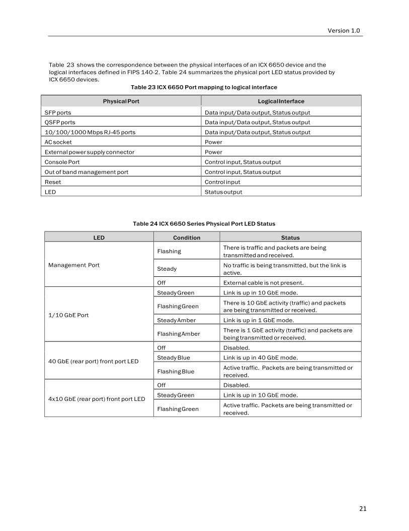
Table 23 shows the correspondence between the physical interfaces of an ICX 6650 device and the logical interfaces defined in FIPS 140-2. Table 24 summarizes the physical port LED status provided by ICX 6650 devices.
Table 23 ICX 6650 Port mapping to logical interface
Physical Port Logical Interface
SFP ports Data input/Data output, Status output
QSFP ports Data input/Data output, Status output
10/100/1000 Mbps RJ-45 ports Data input/Data output, Status output
AC socket Power
External power supply connector Power
Console Port Control input, Status output
Out of band management port Control input, Status output
Reset Control input
LED Status output
Table 24 ICX 6650 Series Physical Port LED Status
LED Condition Status
Management Port
Flashing There is traffic and packets are being
transmitted and received.
Steady No traffic is being transmitted, but the link is active.
Off External cable is not present.
1/10 GbE Port
Steady Green Link is up in 10 GbE mode.
Flashing Green There is 10 GbE activity (traffic) and packets are being transmitted or received.
Steady Amber Link is up in 1 GbE mode.
Flashing Amber There is 1 GbE activity (traffic) and packets are being transmitted or received.
40 GbE (rear port) front port LED
Off Disabled.
Steady Blue Link is up in 40 GbE mode.
Flashing Blue Active traffic. Packets are being transmitted or received.
4x10 GbE (rear port) front port LED
Off Disabled.
Steady Green Link is up in 10 GbE mode.
Flashing Green Active traffic. Packets are being transmitted or received.
22
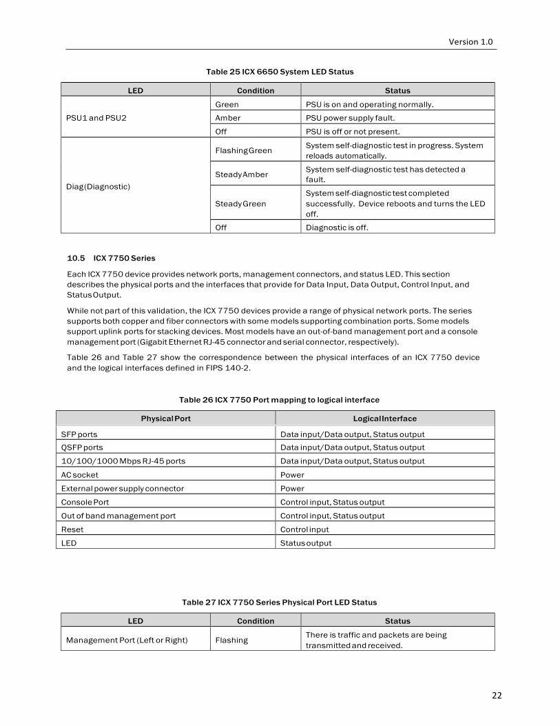
Table 25 ICX 6650 System LED Status
LED Condition Status
PSU1 and PSU2
Green PSU is on and operating normally.
Amber PSU power supply fault.
Off PSU is off or not present.
Diag (Diagnostic)
Flashing Green System self-diagnostic test in progress. System
reloads automatically.
Steady Amber System self-diagnostic test has detected a fault.
Steady Green
System self-diagnostic test completed successfully. Device reboots and turns the LED off.
Off Diagnostic is off.
10.5 ICX 7750 Series
Each ICX 7750 device provides network ports, management connectors, and status LED. This section describes the physical ports and the interfaces that provide for Data Input, Data Output, Control Input, and Status Output.
While not part of this validation, the ICX 7750 devices provide a range of physical network ports. The series supports both copper and fiber connectors with some models supporting combination ports. Some models support uplink ports for stacking devices. Most models have an out-of-band management port and a console management port (Gigabit Ethernet RJ-45 connector and serial connector, respectively).
Table 26 and Table 27 show the correspondence between the physical interfaces of an ICX 7750 device and the logical interfaces defined in FIPS 140-2.
Table 26 ICX 7750 Port mapping to logical interface
Physical Port Logical Interface
SFP ports Data input/Data output, Status output QSFP ports Data input/Data output, Status output
10/100/1000 Mbps RJ-45 ports Data input/Data output, Status output
AC socket Power
External power supply connector Power
Console Port Control input, Status output
Out of band management port Control input, Status output
Reset Control input
LED Status output
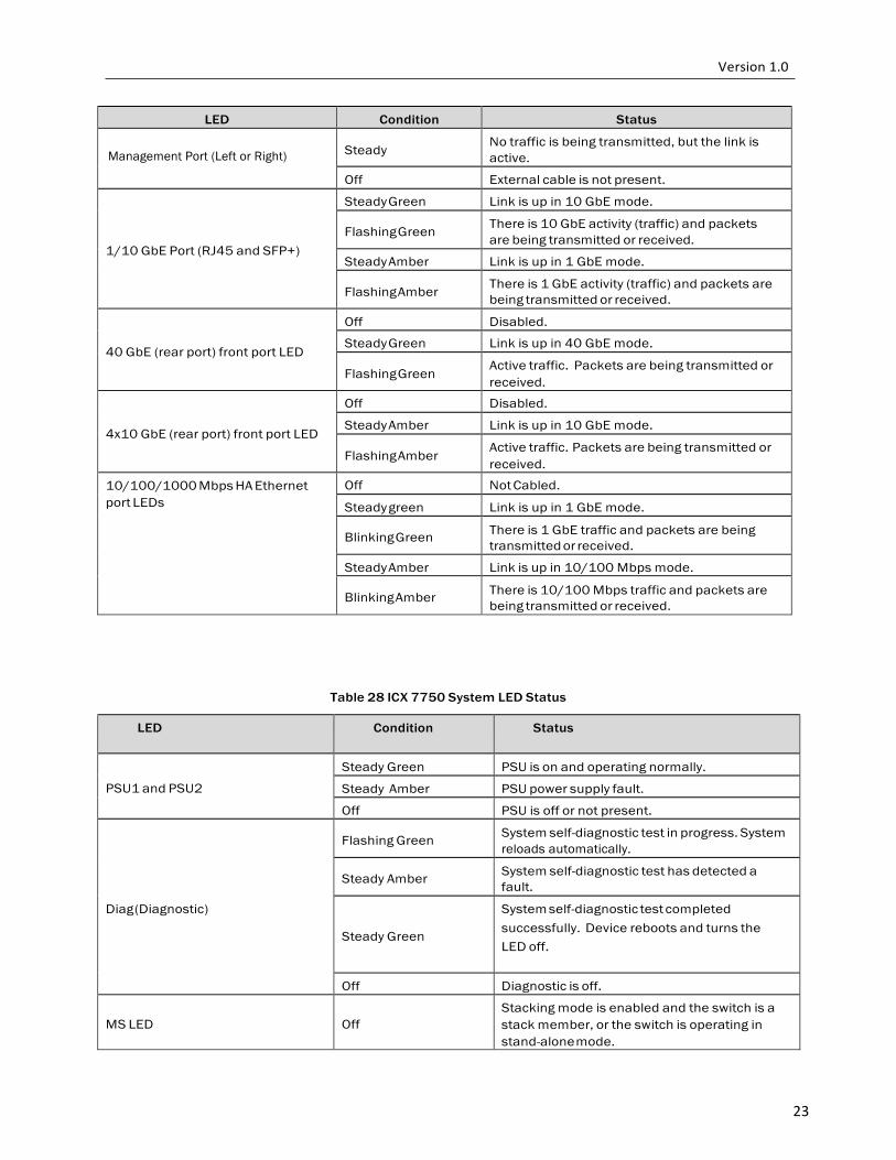
Table 27 ICX 7750 Series Physical Port LED Status
LED Condition Status
Management Port (Left or Right)
Flashing There is traffic and packets are being transmitted and received.
23
LED Condition Status Management Port (Left or Right)
Steady
No traffic is being transmitted, but the link is active.
Off External cable is not present.
1/10 GbE Port (RJ45 and SFP+)
Steady Green Link is up in 10 GbE mode.
Flashing Green There is 10 GbE activity (traffic) and packets are being transmitted or received.
Steady Amber Link is up in 1 GbE mode.
Flashing Amber There is 1 GbE activity (traffic) and packets are being transmitted or received.
40 GbE (rear port) front port LED
Off Disabled.
Steady Green Link is up in 40 GbE mode.
Flashing Green Active traffic. Packets are being transmitted or received.
4x10 GbE (rear port) front port LED
Off Disabled.
Steady Amber Link is up in 10 GbE mode.
Flashing Amber Active traffic. Packets are being transmitted or received.
10/100/1000 Mbps HA Ethernet port LEDs
Off Not Cabled.
Steady green Link is up in 1 GbE mode.
Blinking Green There is 1 GbE traffic and packets are being transmitted or received.
Steady Amber Link is up in 10/100 Mbps mode.
Blinking Amber There is 10/100 Mbps traffic and packets are being transmitted or received.
Table 28 ICX 7750 System LED Status
LED Condition Status
PSU1 and PSU2
Steady Green PSU is on and operating normally.
Steady Amber PSU power supply fault.
Off PSU is off or not present.
Diag (Diagnostic)
Flashing Green System self-diagnostic test in progress. System
reloads automatically.
Steady Amber System self-diagnostic test has detected a fault.
Steady Green
System self-diagnostic test completed successfully. Device reboots and turns the LED off.
Off Diagnostic is off.
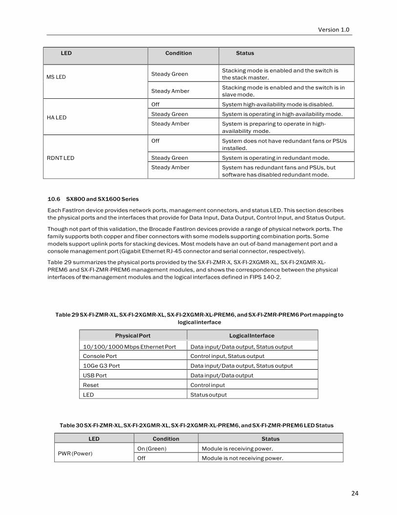
MS LED
Off
Stacking mode is enabled and the switch is a stack member, or the switch is operating in stand-alone mode.
24
LED Condition Status
MS LED
Steady Green Stacking mode is enabled and the switch is
the stack master.
Steady Amber Stacking mode is enabled and the switch is in slave mode.
HA LED
Off System high-availability mode is disabled.
Steady Green System is operating in high-availability mode.
Steady Amber System is preparing to operate in high- availability mode.
RDNT LED
Off System does not have redundant fans or PSUs installed.
Steady Green System is operating in redundant mode.
Steady Amber System has redundant fans and PSUs, but software has disabled redundant mode.
10.6 SX800 and SX1600 Series
Each FastIron device provides network ports, management connectors, and status LED. This section describes the physical ports and the interfaces that provide for Data Input, Data Output, Control Input, and Status Output.
Though not part of this validation, the Brocade FastIron devices provide a range of physical network ports. The family supports both copper and fiber connectors with some models supporting combination ports. Some models support uplink ports for stacking devices. Most models have an out-of-band management port and a console management port (Gigabit Ethernet RJ-45 connector and serial connector, respectively).
Table 29 summarizes the physical ports provided by the SX-FI-ZMR-X, SX-FI-2XGMR-XL, SX-FI-2XGMR-XL-PREM6 and SX-FI-ZMR-PREM6 management modules, and shows the correspondence between the physical interfaces of the management modules and the logical interfaces defined in FIPS 140-2.
Table 29 SX-FI-ZMR-XL, SX-FI-2XGMR-XL, SX-FI-2XGMR-XL-PREM6, and SX-FI-ZMR-PREM6 Port mapping to logical interface
Physical Port Logical Interface
10/100/1000 Mbps Ethernet Port Data input/Data output, Status output Console Port Control input, Status output
10Ge G3 Port Data input/Data output, Status output
USB Port Data input/Data output
Reset Control input
LED Status output
Table 30 SX-FI-ZMR-XL, SX-FI-2XGMR-XL, SX-FI-2XGMR-XL-PREM6, and SX-FI-ZMR-PREM6 LED Status
LED Condition Status
PWR (Power) On (Green) Module is receiving power.
Off Module is not receiving power.
25
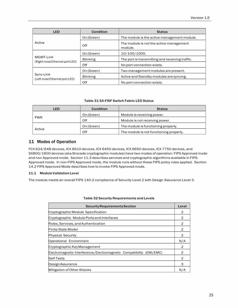
LED Condition Status
Active On (Green) The module is the active management module.
Off The module is not the active management
module.
MGMT-Link (Right-most Ethernet port LED)
On (Green) 10/100/1000.
Blinking The port is transmitting and receiving traffic.
Off No port connection exists.
Sync-Link (Left-most Ethernet port LED)
On (Green) Two management modules are present.
Blinking Active and Standby modules are syncing.
Off No port connection exists.
Table 31 SX-FISF Switch Fabric LED Status
LED Condition Status
PWR On (Green) Module is receiving power.
Off Module is not receiving power.
Active On (Green) The module is functioning properly.
Off The module is not functioning properly.
11 Modes of Operation
FCX 624/648 devices, ICX 6610 devices, ICX 6450 devices, ICX 6650 devices, ICX 7750 devices, and SX800/1600 devices (aka Brocade cryptographic modules) have two modes of operation: FIPS Approved mode and non-Approved mode. Section 11.3 describes services and cryptographic algorithms available in FIPS- Approved mode. In non-FIPS Approved mode, the module runs without these FIPS policy rules applied. Section 14.2 FIPS Approved Mode describes how to invoke FIPS Approved mode.
11.1 Module Validation Level
The module meets an overall FIPS 140-2 compliance of Security Level 2 with Design Assurance Level 3.
Table 32 Security Requirements and Levels
Security Requirements Section Level
Cryptographic Module Specification 2
Cryptographic Module Ports and Interfaces 2
Roles, Services, and Authentication 2
Finite State Model 2
Physical Security 2
Operational Environment N/A
Cryptographic Key Management 2
Electromagnetic Interference/Electromagnetic Compatibility (EMI/EMC) 2
Self-Tests 2
Design Assurance 3
Mitigation of Other Attacks N/A
26
11.2 Roles
In FIPS Approved mode, Brocade cryptographic modules support three roles: Crypto Officer, Port Configuration Administrator, and User:
1. Crypto Officer Role (Super User): The Crypto Officer Role on the device in FIPS Approved mode is
equivalent to the administrator role super-user in non-FIPS mode the Crypto Officer Role has complete access to the system. The Crypto Officer is the only role that can perform firmware loading.
2. Port Configuration Administrator Role (Port Configuration): The Port Configuration Administrator Role on
the device in FIPS Approved mode is equivalent to the port-config, a port configuration user in non- FIPS Approved mode. Hence, the Port Configuration Administrator Role has read-and-write access for specific ports but not for global (system-wide) parameters.
3. User Role (Read Only): The User Role on the device in FIPS Approved mode has read-only privileges and no configuration mode access (user).
The User role has read-only access to the cryptographic module while the Crypto Officer role has access to all device commands. Brocade cryptographic modules do not have a maintenance interface or maintenance role.
Section 12.2 describes the authentication policy for user roles.
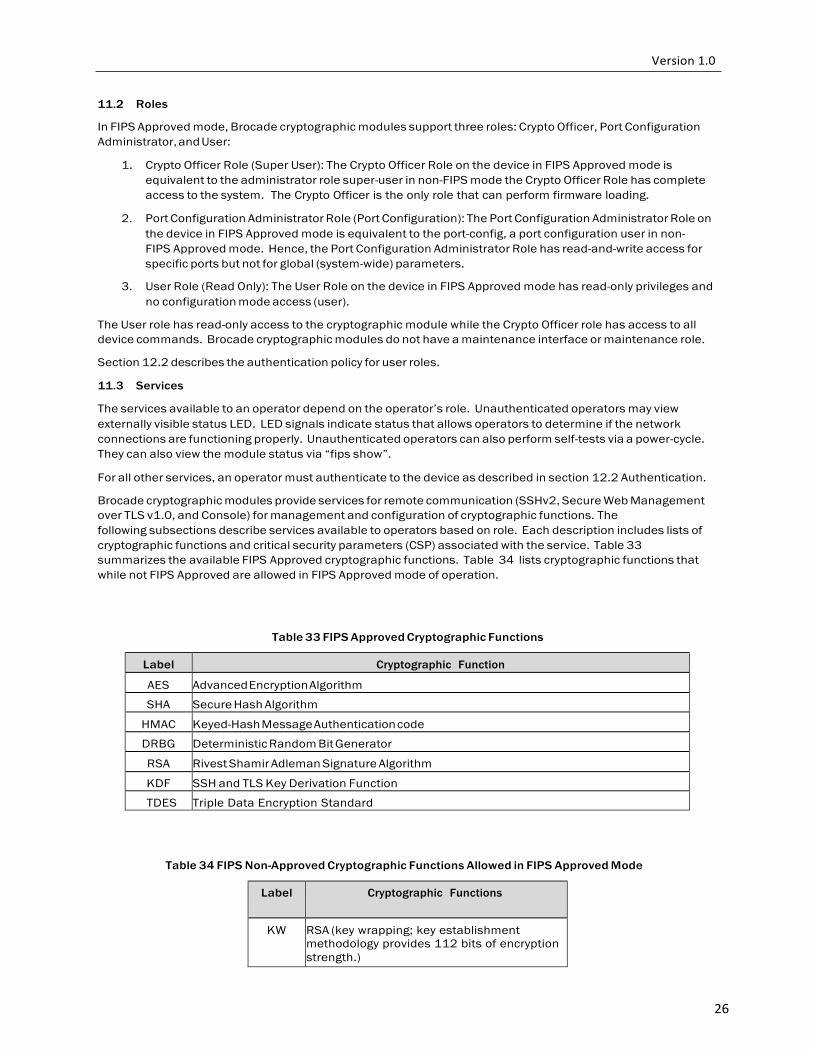
11.3 Services
The services available to an operator depend on the operator’s role. Unauthenticated operators may view externally visible status LED. LED signals indicate status that allows operators to determine if the network connections are functioning properly. Unauthenticated operators can also perform self-tests via a power-cycle. They can also view the module status via “fips show”.
For all other services, an operator must authenticate to the device as described in section 12.2 Authentication.
Brocade cryptographic modules provide services for remote communication (SSHv2, Secure Web Management over TLS v1.0, and Console) for management and configuration of cryptographic functions. The following subsections describe services available to operators based on role. Each description includes lists of cryptographic functions and critical security parameters (CSP) associated with the service. Table 33 summarizes the available FIPS Approved cryptographic functions. Table 34 lists cryptographic functions that while not FIPS Approved are allowed in FIPS Approved mode of operation.
Table 33 FIPS Approved Cryptographic Functions
Label Cryptographic Function
AES Advanced Encryption Algorithm
SHA Secure Hash Algorithm
HMAC Keyed-Hash Message Authentication code
DRBG Deterministic Random Bit Generator
RSA Rivest Shamir Adleman Signature Algorithm
KDF SSH and TLS Key Derivation Function
TDES Triple Data Encryption Standard
Table 34 FIPS Non-Approved Cryptographic Functions Allowed in FIPS Approved Mode
Label Cryptographic Functions
KW RSA (key wrapping; key establishment methodology provides 112 bits of encryption strength.)
27
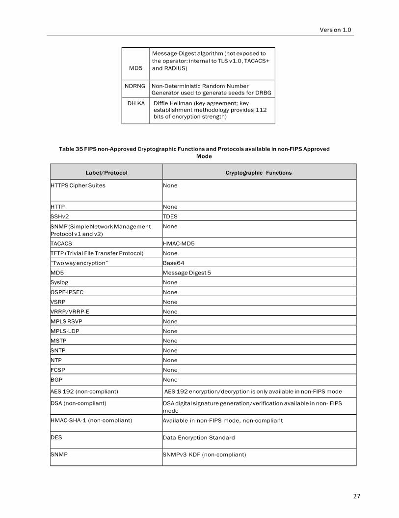
MD5
Message-Digest algorithm (not exposed to the operator: internal to TLS v1.0, TACACS+ and RADIUS)
NDRNG Non-Deterministic Random Number Generator used to generate seeds for DRBG
DH KA Diffie Hellman (key agreement; key establishment methodology provides 112 bits of encryption strength)
Table 35 FIPS non-Approved Cryptographic Functions and Protocols available in non-FIPS Approved Mode
Label/Protocol
Cryptographic Functions
HTTPS Cipher Suites None
HTTP None
SSHv2 TDES
SNMP (Simple Network Management Protocol v1 and v2)
None
TACACS HMAC-MD5
TFTP (Trivial File Transfer Protocol) None
“Two way encryption” Base64
MD5 Message Digest 5
Syslog None
OSPF-IPSEC None
VSRP None
VRRP/VRRP-E None
MPLS RSVP None
MPLS-LDP None
MSTP None
SNTP None
NTP None
FCSP None
BGP None
AES 192 (non-compliant) AES 192 encryption/decryption is only available in non-FIPS mode
DSA (non-compliant) DSA digital signature generation/verification available in non- FIPS mode
HMAC-SHA-1 (non-compliant) Available in non-FIPS mode, non-compliant
DES Data Encryption Standard
SNMP SNMPv3 KDF (non-compliant)

28
11.4 User Role Services
11.4.1 SSH
This service provides a secure session between a Brocade cryptographic module and an SSH client using SSHv2 protocol. Brocade cryptographic modules authenticate an SSH client and provides an encrypted communication channel. An operator may use an SSH session for managing the device via the command line interface.
Brocade cryptographic modules support three kinds of SSH client authentication: password, client public key and keyboard interactive. For password authentication, an operator attempting to establish an SSH session provides a password through the SSH client. The Brocade cryptographic module authenticates operator with passwords stored on the device, on a TACACS+ server, or on a RADIUS server. Section 12.2 Authentication provides authentication details.
The keyboard interactive (KI) authentication goes one step ahead. It allows multiple challenges to be issued by the Brocade cryptographic module, using the backend RADIUS or TACACS+ server, to the SSH client. Only after the SSH client responds correctly to the challenges, will the SSH client get authenticated and proper access is given to the Brocade cryptographic module.
SSH supports Diffie-Hellman (DH) to configure the modulus size on the SSH server for the purpose of key- exchange.
The following encryption algorithms are available for negotiation during the key exchange with an SSH client: (aes128-cbc) AES with a 128-bit key and (aes256-cbc) AES with a 256-bit key
All secure hashing is done with SHA 256.
The following MAC algorithms are available for negotiation during the key exchange with an SSH client: (hmac- sha1) HMAC-SHA1 (digest length = key length = 20 bytes)
In User role access, the client is given access to three commands: e n a b le , e x it and t e r m i n a l. The e n a b le command allows user to re-authenticate using a different role. If the role is the same, based on the credentials given during the e n a b le command, the user has access to a small subset of commands that can perform p in g , tr a ce r o u t e , outbound telnet client in addition to s h ow commands.
11.4.2 HTTPS
This service provides a graphical user interface for managing a Brocade cryptographic module over a secure communication channel. Using a web browser, an operator connects to a designated management port on a Brocade cryptographic module. The device negotiates a TLS connection with the browser and authenticates the operator. The device uses HTTP over TLS with cipher suites TLS_RSA_WITH_AES_128_CBC_SHA, TLS_RSA_WITH_AES_256_CBC_SHA. Brocade switches have the ability to generate RSA 2048 certificates signed with SHA 256.
In User role, after successful login, the default HTML page is the same for any role. The user can surf to any page after clicking on any URL. However, this user will not be allowed to make any modifications. If the user presses the ‘Modify’ button within any page, he will be challenged to re-enter his credentials. The challenge dialog box will not be closed without proper access credentials of the Crypto Officer. After default three attempts, the page ‘Protected Object’ is displayed, in effect disallowing any changes from the web.

29
11.4.3 Console
Console connection occurs via a directly connected RS-232 serial cable. Once authenticated as the User, the module provides console commands to display information about a Brocade cryptographic module and perform basic tasks (such as pings). The User role has read-only privileges and no configuration mode access. The list of commands available are the same as the list mentioned in the SSH service.
11.5 Port Configuration Administrator Role Services
11.5.1 SSH This service is described in Section 11.4.1 above.
The Port Configuration Administrator will have seven commands, which allows this user to run show commands, run ping or trace route. The enable command allows the user to re-authenticate as described in Section 11.4.1. Within the configuration mode, this role provides access to all the port configuration commands, e.g. all sub-commands within “interface eth 1/1” command. This operator can transfer and store firmware images and configuration files between the network and the system, and review the configuration.
11.5.2 HTTPS
This service is described in Section 11.4.2 above.
Like the User role, this user will get to view all the web pages. In addition, this operator will be allowed to modify any configuration that is related to an interface. For example, the Configuration->Port page will allow this operator to make changes to individual port properties within the page.
11.5.3 Console
This service is described in Section 11.4.3 above. Console access as the Port Configuration Administrator provides an operator with the same capabilities as User Console commands plus configuration commands associated with a network port on the device. EXEC commands. The list of commands available are the same as those mentioned in the SSH service.
11.6 Crypto Officer Role Services
11.6.1 SSH
In addition to the two methods of authentication, password and keyboard interactive, described in Section 11.4.1, SSH service in this role supports RSA public key authentication, in which the device stores a collection of client public keys. Only clients with a private key that corresponds to one of the stored public keys can gain access to the device using SSH. After a client’s public key is found to match one of the stored public keys, the device will give Crypto Officer access to the entire module.
The Crypto Officer can perform configuration changes to the module. This role has full read and write access to the Brocade cryptographic module.
When firmware download is desired, the Crypto Officer shall download firmware download in the primary image and secondary image.
The Crypto Officer can perform zeroization by invoking the firmware command “fips zeroize all” or session termination.
11.6.2 SCP
This is a secure copy service. The service supports both outbound and inbound copies of configuration, binary images, or files. Binary files can be copied and installed similar to TFTP operation (that is, upload from device to host and download from host to device, respectively). SCP automatically uses the authentication methods, encryption algorithm, and MAC algorithm configured for SSH. For example, if password authentication is enabled for SSH, the user is prompted for a user name and password before SCP allows a file to be
30
transferred. One use of SCP on Brocade cryptographic modules is to copy user digital certificates and host public-private key pairs to the device in support of HTTPS. Other use could be to copy configuration to/from the cryptographic module.
11.6.3 HTTPS This service is described in section 11.4.2 HTTPS.
In addition to Port Configuration Administrator-role capabilities, the Crypto Officer has complete access to all the web pages and is allowed to make configuration updates through the web pages that support configuration changes. 11.6.4 Console
Logging in through the CLI service is described in Section 11.4.3 above. Console commands provide an authenticated Crypto Officer complete access to all the commands within the Brocade cryptographic module. This operator can enable, disable and perform status checks. This operator can also enable any service by configuring the corresponding command. For example, to turn on SSH service, the operator creates a pair of RSA host keys, to configure the authentication scheme for SSH access; afterwards the operator may securely import additional pairs of RSA host keys as needed over a secured SSH connection. To enable the Web Management service, the operator would securely import a pair of RSA host keys and a digital certificate using corresponding commands (over a secured SSH connection), and enable the HTTPS server.
NOTICE: The cryptographic module “does not” support DSA key generation in FIPS mode.
12 Policies
12.1 Security Rules
The Brocade cryptographic module’s design corresponds to the cryptographic module’s security rules. This section documents the security rules enforced by the cryptographic module to implement the FIPS 140-2 Level 2 security requirements. After configuring a FastIron device to operate in FIPS Approved mode, the Crypto Officer must execute the “fips self-tests” command to validate the integrity of the firmware installed on the device. If an error is detected during the self-test, the error must be corrected prior to rebooting the device.
1) The cryptographic module provides role-based authentication.
2) Until the module is placed in a valid role, the operator does not have access to any Critical Security Parameters (CSP).
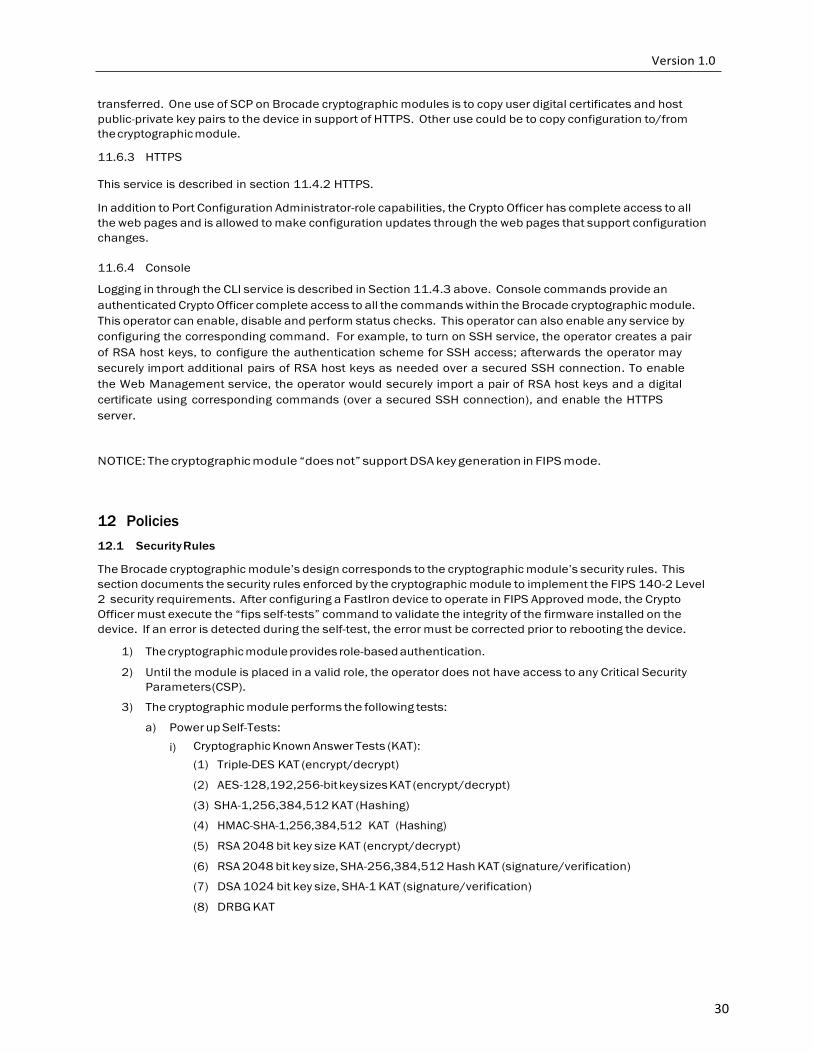
3) The cryptographic module performs the following tests:
a) Power up Self-Tests:
i) Cryptographic Known Answer Tests (KAT): (1) Triple-DES KAT (encrypt/decrypt)
(2) AES-128,192,256-bit key sizes KAT (encrypt/decrypt)
(3) SHA-1,256,384,512 KAT (Hashing)
(4) HMAC-SHA-1,256,384,512 KAT (Hashing)
(5) RSA 2048 bit key size KAT (encrypt/decrypt)
(6) RSA 2048 bit key size, SHA-256,384,512 Hash KAT (signature/verification)
(7) DSA 1024 bit key size, SHA-1 KAT (signature/verification)
(8) DRBG KAT

31
(9) SP800-135 TLS KDF KAT
(10) SP800-135 SSH KDF KAT
ii) Firmware Integrity Test (CRC 32)
iii) If the module does not detect an error during the Power on Self-Test (POST), at the conclusion of the test, the console displays the message shown below.
C r y p t o m o d u l e in it ia l iz a t io n an d K n o w n An s w e r Tes t ( K A T ) P a sse d .
iv) If the module detects an error during the POST, at the conclusion of the test, the console displays the message shown below. After displaying the failure message, the module reboots.
C r y p t o M o d u le F a i le d < R e a s o n S t r i n g >
b) Conditional Self-Tests:
i) Continuous Random Number Generator (RNG) test – performed on NDRNG
ii) Continuous Random Number Generator test – performed on DRBG.
iii) RSA 2048 SHA-256 Pairwise Consistency Test (Sign/Verify).
iv) RSA 2048 SHA-256 Pairwise Consistency Test (Encrypt/Decrypt).
v) Firmware Load Test: RSA 2048 bit, SHA-256 Signature Verification.
NOTICE: The module supports a pairwise consistency test for RSA key generation.
vi) Bypass Test: N/A.
vii) Manual Key Entry Test: N/A.
4) At any time the cryptographic module is in an idle state, the operator can command the module to perform the power-up self-test by executing the “fips self-tests” command.
5) Data output to services defined in Section 11.3 Services is inhibited during key generation, self-tests, zeroization, and error states.
6) Status information does not contain CSPs or sensitive data that if used could compromise the module.
12.1.1 FIPS Fatal Cryptographic Module Failure.
When POST is successful, the following messages will be displayed on the console:
Running fips Power on Self tests and Software/Firmware Integrity Test
fips Power on Self tests and Software/Firmware Integrity tests successful
Running continuous drbg check
Running continuous drbg check successful
Running Pairwise consistency check
RSA key pair generation succeeded
Pairwise consistency check successful
Crypto module initialization and Known Answer Test (KAT) Passed.
In order to operate a Brocade cryptographic module securely, an operator should be aware of the following rules for FIPS Approved mode of operation:
External communication channels / ports shall not be available before initialization of a Brocade cryptographic module.
Brocade cryptographic modules shall use a FIPS Approved random number generator implementing Algorithm CTR_DRBG based on hash functions.
Brocade cryptographic modules shall ensure the random number seed and seed key input do not have the same value. The devices shall generate seed keys and shall not accept a seed key entered manually.
Brocade cryptographic modules shall use FIPS Approved key generation methods:
1. RSA public and private keys in accordance with [RSA PKCS #1, ANSI X9.31]

32
Brocade cryptographic modules shall test prime numbers generated for RSA keys using Miller-Rabin test. See [RSA PKCS #1, ANSI X9.31]
Brocade cryptographic modules shall use Approved key establishment techniques:
1. Diffie-Hellman
2. RSA Key Wrapping
Brocade cryptographic modules shall restrict key entry and key generation to authenticated roles.
Brocade cryptographic modules shall not display plaintext secret or private keys. The device shall display “…” in place of plaintext keys.
Brocade cryptographic modules shall use automated methods to realize session keys for SSHv2 and HTTPS.
12.2 Authentication
Brocade cryptographic modules support role-based authentication. A device can perform authentication and authorization (that is, role selection) using TACACS+, RADIUS and local configuration database. Moreover, Brocade cryptographic modules support multiple authentication methods for each service.
To implement one or more authentication methods for securing access to the device, an operator in the Crypto Officer role configures authentication-method lists that set the order in which a device consults authentication methods. In an authentication-method list, an operator specifies an access method (Console, SSH, Web) and the order in which the device tries one or more of the following authentication methods:
1. Line password authentication,
2. Enable password authentication,
3. Local user authentication,
4. RADIUS authentication with exec authorization and command authorization, and
5. TACACS+ authentication with exec authorization and command authorization
When a list is configured, the device attempts the first method listed to provide authentication. If that method is not available, (for example, the device cannot reach a TACACS+ server) the device tries the next method until a method in the list is available or all methods have been tried.
Brocade cryptographic modules allow multiple concurrent operators through SSH and the console, only limited by the system resources.
12.2.1 Line Authentication Method
The line method uses the Telnet password to authenticate an operator.
To use line authentication, a Crypto Officer must set the Telnet password. Please note that when operating in FIPS mode, Telnet is disabled and Line Authentication is not available.
12.2.2 Enable Authentication Method
The enable method uses a password corresponding to each role to authenticate an operator. An operator must enter the read-only password to select the User role. An operator enters the port-config password to the Port Configuration Administrator role. An operator enters the super-user password to select the Crypto Officer Role.
To use enable authentication, a Crypto Officer must set the password for each privilege level.
12.2.3 Local Authentication Method
The local method uses a password associated with a user name to authenticate an operator. An operator enters a user name and corresponding password. Brocade cryptographic modules assign the role associated with the user name to the operator when authentication is successful.

33
To use local authentication, a Crypto Officer must define user accounts. The definition includes a user name, password, and privilege level (which determines role).
12.2.4 RADIUS Authentication Method
The RADIUS method uses one or more RADIUS servers to verify user names and passwords. Brocade cryptographic modules prompt an operator for user name and password. The device sends the user name and password to the RADIUS server. Upon successful authentication, the RADIUS server returns the operator’s privilege level, which determines the operator’s role. If a RADIUS server does not respond, a Brocade cryptographic module will send the user name and password information to the next configured RADIUS server.
Brocade cryptographic modules support additional command authorization with RADIUS authentication. The following events occur when RADIUS command authorization takes place.
1. A user previously authenticated by a RADIUS server enters a command on a Brocade cryptographic module.
2. A Brocade cryptographic module looks at its configuration to see if the command is at a privilege level that requires RADIUS command authorization.
3. If the command belongs to a privilege level that requires authorization, the Brocade cryptographic
modules looks at the list of commands returned to it when RADIUS server authenticated the user.
NOTE: After RADIUS authentication takes place, the command list resides on the Brocade cryptographic module. The device does not consult the RADIUS server again once the operator has been authenticated. This means that any changes made to the operator’s command list on the RADIUS server are not reflected until the next time the RADIUS server authenticates the operator, and the server sends a new command list to the Brocade cryptographic module.
To use RADIUS authentication, a Crypto Officer must configure RADIUS server settings along with authentication and authorization settings.
12.2.5 TACACS+ Authentication Method
The TACACS+ method uses one or more TACACS+ servers to verify user names and passwords. For TACACS+ authentication, Brocade cryptographic modules prompt an operator for a user name, which the device uses to get a password prompt from the TACACS+ server. The operator enters a password, which the device relays to the server for validation. Upon successful authentication, the TACACS+ server supports both exec and command authorization similar to RADIUS authorization described above.
To use TACACS+ authentication, a Crypto Officer must configure TACACS+ server settings along with authentication and authorization settings.
12.2.6 Strength of Authentication
Brocade cryptographic modules minimize the likelihood that a random authentication attempt will succeed. The module supports minimum 7 character passwords selected from the following character set: digits (Qty. 10), lowercase (Qty. 26) and uppercase (26) letters, and punctuation marks (18) in passwords. Therefore the probability of a random attempted is 1/ 80^7 which is less than 1/1,000,000.
The module enforces a one second delay for each attempted password verification, therefore maximum of 60 attempts per minute, thus the probability of multiple consecutive attempts within a one minute period is 60/80^7 which is less than 1/100,000.
The probability of a successful random guess of a RADIUS or TACACS+ password during a one-minute period is less than 3 in 1,000,000 as the authentication message needs to go to the server from the switch and then the response needs to come back to the switch.
Table 36 summarizes the access operators in each role have to critical security parameters. The table entries have the following meanings:
1. r – operator can read the value of the item,
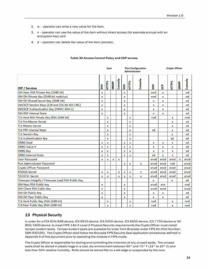
34
2. w – operator can write a new value for the item,
3. x – operator can use the value of the item without direct access (for example encrypt with an encryption key), and
4. d – operator can delete the value of the item (zeroize).
Table 36 Access Control Policy and CSP access
User Port Configuration Crypto Officer Administrator
13 Physical Security
In order for a FCX 624/648 device, ICX 6610 device, ICX 6450 device, ICX 6650 device, ICX 7750 device or SX 800/1600 device to meet FIPS 140-2 Level 2 Physical Security requirements the Crypto Officer must install tamper evident seals. Tamper evident seals are available for order from Brocade under FIPS Kit (Part Number: XBR-000195). The Crypto Officer shall follow the Brocade FIPS Security Seal application procedures defined in Appendix A of this document prior to operating the module in FIPS mode.
The Crypto Officer is responsible for storing and controlling the inventory of any unused seals. The unused seals shall be stored in plastic bags in a cool, dry environment between 60° and 70° F (15° to 20° C) and less than 50% relative humidity. Rolls should be stored flat on a slit edge or suspended by the core.
35
The Crypto Officer shall maintain a serial number inventory of all used and unused tamper evident seals. The Crypto Officer shall periodically monitor the state of all applied seals for evidence of tampering. A seal serial number mismatch, a seal placement change, a checkerboard destruct pattern that appears in peeled film and adhesive residue on the substrate are evidence of tampering. The security officer shall periodically view each applied seal under a UV light to verify the presence of a UV wallpaper pattern. The lack of a wallpaper pattern is evidence of tampering. The Crypto Officer is responsible for returning a module to a FIPS approved state after any intentional or unintentional reconfiguration of the physical security measures.
Please refer to Appendix A of this Security Policy document for specific tamper evident seal application instructions.
14 Mode Status
Brocade cryptographic modules provide the f i ps sh ow command to display status information about the device’s FIPS mode. This information includes the status of administrative commands for security policy, the status of security policy enforcement, and security policy settings. The fips enable command changes the status of administrative commands; see also section 14.1 FIPS Approved Mode.
The following example shows the output of the fips show command before an operator enters a fips enable command. Administrative commands for security policy are unavailable (administrative status is off) and the device is not enforcing a security policy (operational status is off).
FIPS mode: Administrative Status: OFF, Operational Status: OFF
The following example shows the output of the fips show command after an operator enters the fips enable command. Administrative commands for security policy are available (administrative status is on) but the device is not enforcing a security policy yet (operational status is off). The command displays the security policy settings.
1. FIPS mode: Administrative Status: ON, Operational Status: OFF
a. Some shared secrets inherited from non-Approved mode may not be fips compliant and has to be zeroized. The system needs to be reloaded to operate in FIPS mode.
2. System Specific:
a. OS monitor mode access: Disabled
3. Management Protocol Specific:
a. Telnet server: Disabled
b. TFTP Client: Disabled
c. HTTPS SSL 3.0: Disabled
d. SNMP Access to security objects: Disabled
4. Critical Security Parameter Updates across FIPS Boundary:
a. Protocol shared secret and host passwords: Clear
b. SSH RSA Host Keys: Clear
c. HTTPS RSA Host Keys and Signature: Clear
The following example shows the output of the fips show command after the device reloads successfully in the default strict FIPS mode. Administrative commands for security policy are available (administrative status is on) and the device is enforcing a security policy (operational status is on). The command displays the policy settings.
1. FIPS mode: Administrative Status: ON, Operational Status: ON
2. System Specific:
a. OS monitor mode access: Disabled

36
3. Management Protocol Specific:
a. Telnet server: Disabled
b. TFTP Client: Disabled
c. HTTPS SSL 3.0: Disabled
d. SNMP Access to security objects: Disabled
4. Critical Security Parameter Updates across FIPS Boundary:
a. Protocol shared secret and host passwords: Clear
b. SSH RSA Host Keys: Clear
c. HTTPS RSA Host Keys and Signature: Clear
14.1 FIPS Approved Mode
This section describes FIPS Approved mode of operation and the sequence of actions that place a Brocade cryptographic module in FIPS Approved mode. The first action is to apply tamper evident seals to the chassis at the locations specified in the Appendix A of this document.
FIPS Approved mode disables the following:
1. Telnet access including the telnet server command
2. Command ip ssh scp disable
3. TFTP access
4. SNMP access to CSP MIB objects
5. Access to all commands within the monitor mode
6. HTTP access including the web-management http command
7. Port 280
8. HTTPS SSL 3.0 access Command web-management allow-no-password
Entering FIPS Approved mode also clears:
1. Protocol shared secret and host passwords
2. SSH RSA host keys
3. HTTPS RSA host keys and certificate
FIPS Approved mode enables:
1. SCP
2. HTTPS TLS version 1.0 and greater
37
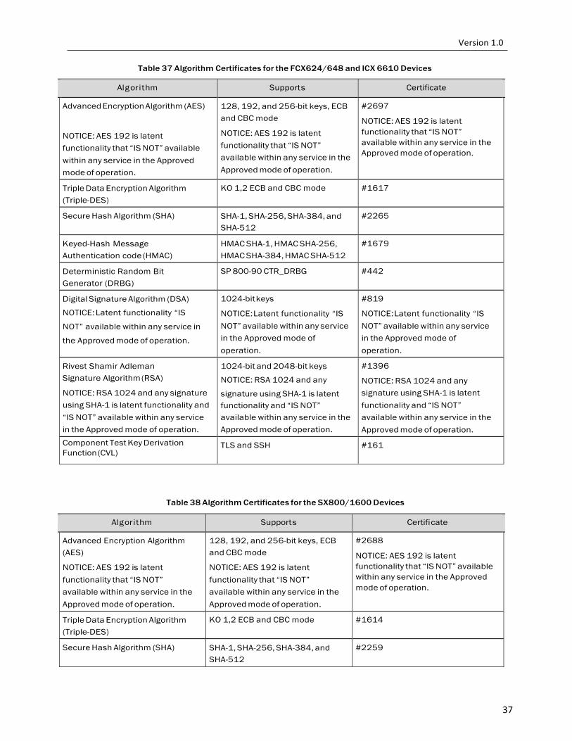
Table 37 Algorithm Certificates for the FCX624/648 and ICX 6610 Devices
Algorithm Supports Certificate
Advanced Encryption Algorithm (AES) NOTICE: AES 192 is latent functionality that “IS NOT” available within any service in the Approved mode of operation.
128, 192, and 256-bit keys, ECB and CBC mode
NOTICE: AES 192 is latent functionality that “IS NOT” available within any service in the Approved mode of operation.
#2697
NOTICE: AES 192 is latent functionality that “IS NOT” available within any service in the Approved mode of operation.
Triple Data Encryption Algorithm (Triple-DES)
KO 1,2 ECB and CBC mode #1617
Secure Hash Algorithm (SHA) SHA-1, SHA-256, SHA-384, and SHA-512
#2265
Keyed-Hash Message Authentication code (HMAC)
HMAC SHA-1, HMAC SHA-256, HMAC SHA-384, HMAC SHA-512
#1679
Deterministic Random Bit Generator (DRBG)
SP 800-90 CTR_DRBG #442
Digital Signature Algorithm (DSA)
NOTICE: Latent functionality “IS
NOT” available within any service in
the Approved mode of operation.
1024-bit keys
NOTICE: Latent functionality “IS NOT” available within any service in the Approved mode of operation.
#819
NOTICE: Latent functionality “IS NOT” available within any service in the Approved mode of operation.
Rivest Shamir Adleman Signature Algorithm (RSA)
NOTICE: RSA 1024 and any signature using SHA-1 is latent functionality and “IS NOT” available within any service in the Approved mode of operation.
1024-bit and 2048-bit keys
NOTICE: RSA 1024 and any
signature using SHA-1 is latent functionality and “IS NOT” available within any service in the Approved mode of operation.
#1396
NOTICE: RSA 1024 and any signature using SHA-1 is latent functionality and “IS NOT” available within any service in the Approved mode of operation.
Component Test Key Derivation Function (CVL)
TLS and SSH #161
Table 38 Algorithm Certificates for the SX800/1600 Devices
Algorithm Supports Certificate
Advanced Encryption Algorithm (AES)
NOTICE: AES 192 is latent functionality that “IS NOT” available within any service in the Approved mode of operation.
128, 192, and 256-bit keys, ECB and CBC mode
NOTICE: AES 192 is latent functionality that “IS NOT” available within any service in the Approved mode of operation.
#2688
NOTICE: AES 192 is latent functionality that “IS NOT” available within any service in the Approved mode of operation.
Triple Data Encryption Algorithm (Triple-DES)
KO 1,2 ECB and CBC mode #1614
Secure Hash Algorithm (SHA) SHA-1, SHA-256, SHA-384, and SHA-512
#2259
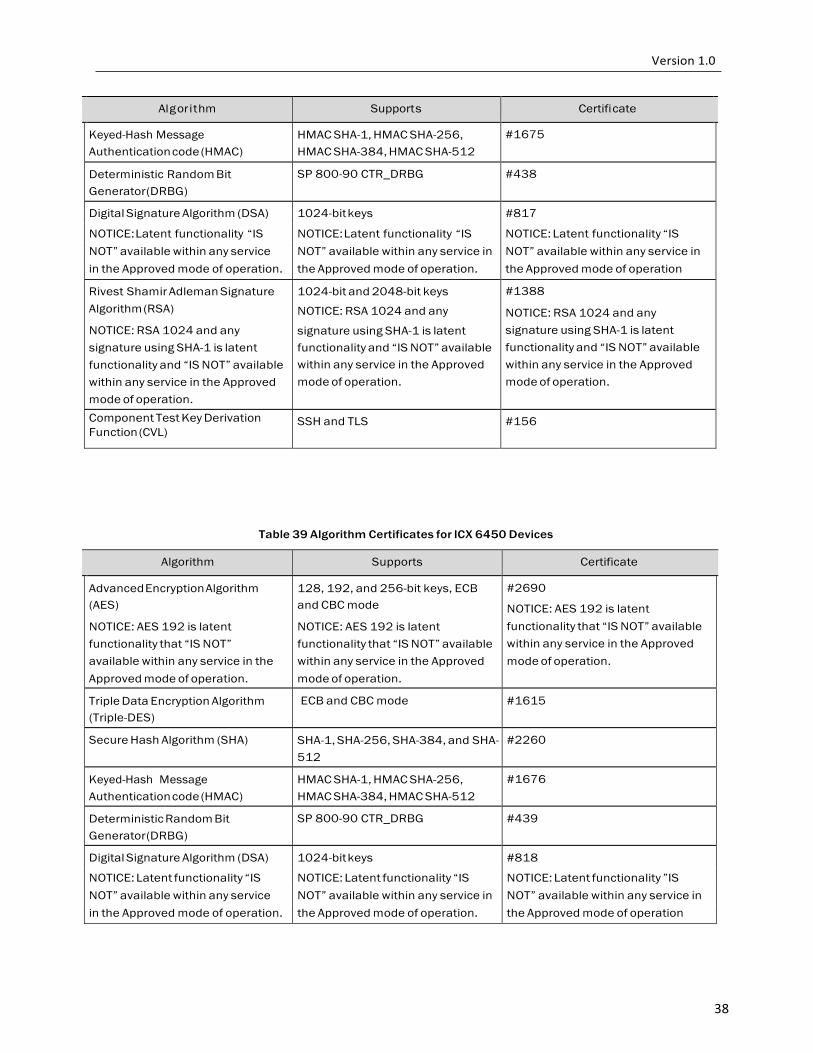
38
Algorithm Supports Certificate
Keyed-Hash Message Authentication code (HMAC)
HMAC SHA-1, HMAC SHA-256, HMAC SHA-384, HMAC SHA-512
#1675
Deterministic Random Bit Generator (DRBG)
SP 800-90 CTR_DRBG #438
Digital Signature Algorithm (DSA) 1024-bit keys #817
NOTICE: Latent functionality “IS NOTICE: Latent functionality “IS NOTICE: Latent functionality “IS NOT” available within any service NOT” available within any service in NOT” available within any service in in the Approved mode of operation. the Approved mode of operation. the Approved mode of operation
Rivest Shamir Adleman Signature Algorithm (RSA)
NOTICE: RSA 1024 and any signature using SHA-1 is latent functionality and “IS NOT” available within any service in the Approved mode of operation.
1024-bit and 2048-bit keys
NOTICE: RSA 1024 and any
signature using SHA-1 is latent functionality and “IS NOT” available within any service in the Approved mode of operation.
#1388
NOTICE: RSA 1024 and any signature using SHA-1 is latent functionality and “IS NOT” available within any service in the Approved mode of operation.
Component Test Key Derivation Function (CVL)
SSH and TLS #156
Table 39 Algorithm Certificates for ICX 6450 Devices
Algorithm Supports Certificate
Advanced Encryption Algorithm (AES)
NOTICE: AES 192 is latent functionality that “IS NOT” available within any service in the Approved mode of operation.
128, 192, and 256-bit keys, ECB and CBC mode
NOTICE: AES 192 is latent functionality that “IS NOT” available within any service in the Approved mode of operation.
#2690
NOTICE: AES 192 is latent functionality that “IS NOT” available within any service in the Approved mode of operation.
Triple Data Encryption Algorithm (Triple-DES)
ECB and CBC mode #1615
Secure Hash Algorithm (SHA) SHA-1, SHA-256, SHA-384, and SHA- 512
#2260
Keyed-Hash Message Authentication code (HMAC)
HMAC SHA-1, HMAC SHA-256, HMAC SHA-384, HMAC SHA-512
#1676
Deterministic Random Bit Generator (DRBG)
SP 800-90 CTR_DRBG #439
Digital Signature Algorithm (DSA) 1024-bit keys #818
NOTICE: Latent functionality “IS NOTICE: Latent functionality “IS NOTICE: Latent functionality ”IS NOT” available within any service NOT” available within any service in NOT” available within any service in in the Approved mode of operation. the Approved mode of operation. the Approved mode of operation
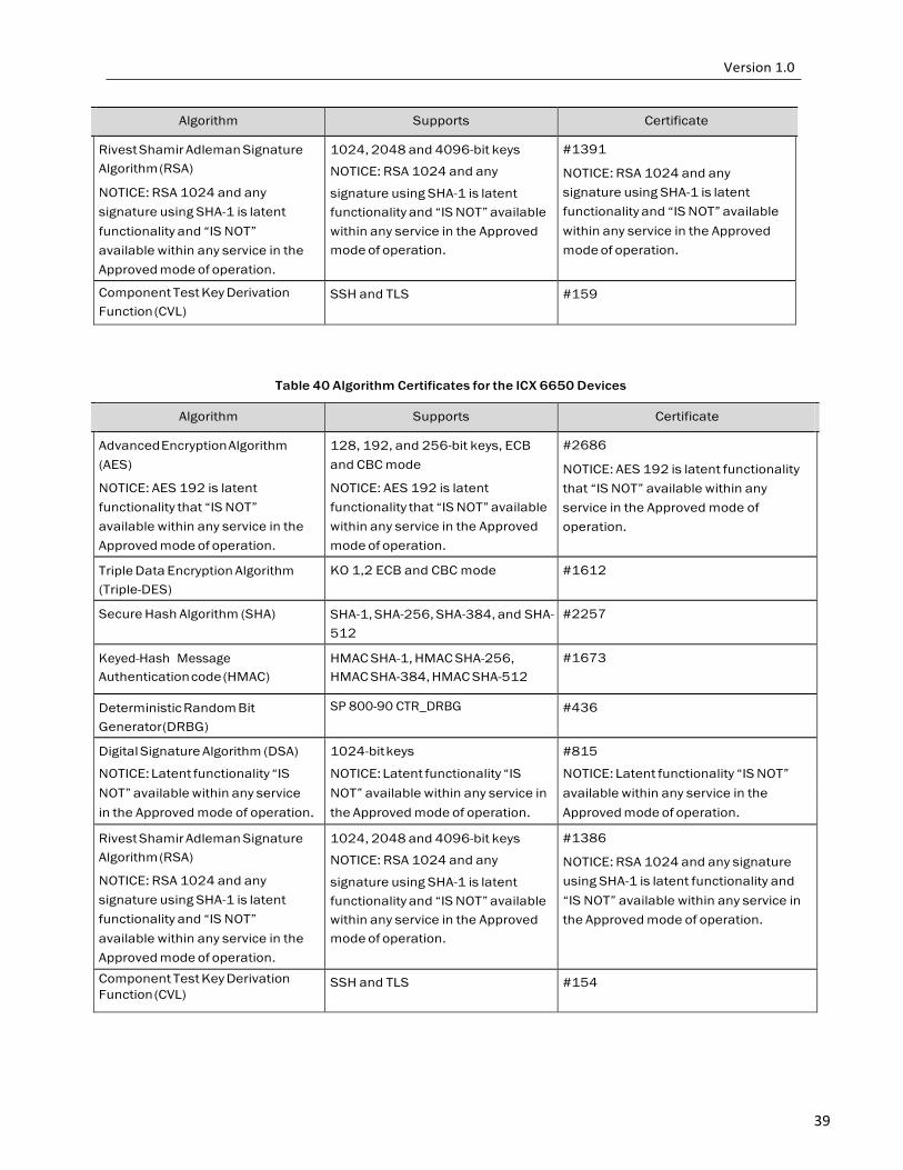
39
Algorithm Supports Certificate
Rivest Shamir Adleman Signature Algorithm (RSA)
NOTICE: RSA 1024 and any signature using SHA-1 is latent functionality and “IS NOT” available within any service in the Approved mode of operation.
1024, 2048 and 4096-bit keys
NOTICE: RSA 1024 and any
signature using SHA-1 is latent functionality and “IS NOT” available within any service in the Approved mode of operation.
#1391
NOTICE: RSA 1024 and any signature using SHA-1 is latent functionality and “IS NOT” available within any service in the Approved mode of operation.
Component Test Key Derivation Function (CVL)
SSH and TLS #159
Table 40 Algorithm Certificates for the ICX 6650 Devices
Algorithm Supports Certificate
Advanced Encryption Algorithm (AES)
NOTICE: AES 192 is latent functionality that “IS NOT” available within any service in the Approved mode of operation.
128, 192, and 256-bit keys, ECB and CBC mode
NOTICE: AES 192 is latent functionality that “IS NOT” available within any service in the Approved mode of operation.
#2686 NOTICE: AES 192 is latent functionality that “IS NOT” available within any service in the Approved mode of operation.
Triple Data Encryption Algorithm (Triple-DES)
KO 1,2 ECB and CBC mode #1612
Secure Hash Algorithm (SHA) SHA-1, SHA-256, SHA-384, and SHA- 512
#2257
Keyed-Hash Message Authentication code (HMAC)
HMAC SHA-1, HMAC SHA-256, HMAC SHA-384, HMAC SHA-512
#1673
Deterministic Random Bit Generator (DRBG)
SP 800-90 CTR_DRBG #436
Digital Signature Algorithm (DSA) 1024-bit keys #815
NOTICE: Latent functionality “IS NOTICE: Latent functionality “IS NOTICE: Latent functionality “IS NOT” NOT” available within any service NOT” available within any service in available within any service in the in the Approved mode of operation. the Approved mode of operation. Approved mode of operation.
Rivest Shamir Adleman Signature Algorithm (RSA)
NOTICE: RSA 1024 and any signature using SHA-1 is latent functionality and “IS NOT” available within any service in the Approved mode of operation.
1024, 2048 and 4096-bit keys
NOTICE: RSA 1024 and any
signature using SHA-1 is latent functionality and “IS NOT” available within any service in the Approved mode of operation.
#1386
NOTICE: RSA 1024 and any signature using SHA-1 is latent functionality and “IS NOT” available within any service in the Approved mode of operation.
Component Test Key Derivation Function (CVL)
SSH and TLS #154
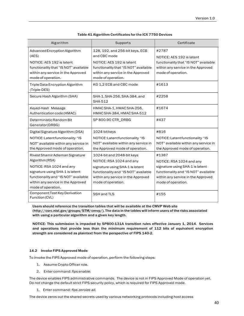
40
Table 41 Algorithm Certificates for the ICX 7750 Devices
Algorithm Supports Certificate
Advanced Encryption Algorithm (AES)
NOTICE: AES 192 is latent functionality that “IS NOT” available within any service in the Approved mode of operation.
128, 192, and 256-bit keys, ECB and CBC mode
NOTICE: AES 192 is latent functionality that “IS NOT” available within any service in the Approved mode of operation.
#2787 NOTICE: AES 192 is latent functionality that “IS NOT” available within any service in the Approved mode of operation.
Triple Data Encryption Algorithm (Triple-DES)
KO 1,2 ECB and CBC mode #1613
Secure Hash Algorithm (SHA) SHA-1, SHA-256, SHA-384, and SHA-512
#2258
Keyed-Hash Message Authentication code (HMAC)
HMAC SHA-1, HMAC SHA-256, HMAC SHA-384, HMAC SHA-512
#1674
Deterministic Random Bit Generator (DRBG)
SP 800-90 CTR_DRBG #437
Digital Signature Algorithm (DSA)
NOTICE: Latent functionality “IS NOT” available within any service in the Approved mode of operation.
1024-bit keys
NOTICE: Latent functionality “IS NOT” available within any service in the Approved mode of operation.
#816
NOTICE: Latent functionality “IS NOT” available within any service in the Approved mode of operation.
Rivest Shamir Adleman Signature Algorithm (RSA)
NOTICE: RSA 1024 and any signature using SHA-1 is latent functionality and “IS NOT” available within any service in the Approved mode of operation.
1024-bit and 2048-bit keys
NOTICE: RSA 1024 and any
signature using SHA-1 is latent functionality and “IS NOT” available within any service in the Approved mode of operation.
#1387
NOTICE: RSA 1024 and any signature using SHA-1 is latent functionality and “IS NOT” available within any service in the Approved mode of operation.
Component Test Key Derivation Function (CVL)
SSH and TLS #155
Users should reference the transition tables that will be available at the CMVP Web site (http://csrc.nist.gov/groups/STM/cmvp/). The data in the tables will inform users of the risks associated with using a particular algorithm and a given key length.
NOTICE: This submission is impacted by SP800-131A transition rules effective January 1, 2014. Services and operations that provide less than the minimum requirement of 112 bits of equivalent encryption strength are considered as plaintext from the perspective of FIPS 140-2.
14.2 Invoke FIPS Approved Mode
To invoke the FIPS Approved mode of operation, perform the following steps:
1. Assume Crypto Officer role.
2. Enter command: fips enable.
The device enables FIPS administrative commands. The device is not in FIPS Approved Mode of operation yet. Do not change the default strict FIPS security policy, which is required for FIPS Approved mode.
1. Enter command: fips zeroize all.
The device zeros out the shared secrets used by various networking protocols including host access

41
passwords, SSH host keys, and HTTPS host keys with the digital signature.
1. Enter command no web-management hp-top-tools in order to turn off access by HP ProCurve Manager via port 280.
2. Save the running configuration: write memory.
3. The device saves the running configuration as the startup configuration.
4. Reload the device (Notice: Do not press B as the module is reloading).
The device resets and begins operation in FIPS Approved mode.
1. Enter command: fips show
The device displays the FIPS-related status, which should confirm the security policy is the default security policy.
2. Inspect the physical security of the module, including placement of tamper evident labels according to
Appendix A.

42
15 Glossary
Term/Acronym Description
AES Advanced Encryption Standard
CBC Cipher-Block Chaining
CLI Command Line Interface
CSP Critical Security Parameter
DES Data Encryption Standard
DH Diffie-Hellman
DRBG Deterministic Random Bit Generator
DSA Digital Signature Algorithm
ECB Electronic Codebook mode
FI FastIron
GbE Gigabit Ethernet
HMAC Keyed-Hash Message Authentication Code
KDF Key Derivation Function
LED Light-Emitting Diode
LP Line Processor
Mbps Megabits per second
MP Management Processor
NDRNG Non-Deterministic Random Number Generator
NI NetIron
OC Optical Carrier
POE Power over Ethernet
POE+ High Power over Ethernet
PRF Pseudo-random function
RADIUS Remote Authentication Dial in User Service
RSA Rivest Shamir Adleman
SCP Secure Copy
SFM Switch Fabric Module
SHA Secure Hash Algorithm
SNMP Simple Network Management Protocol
SSH Secure Shell
TACACS+ Terminal Access Control Access-Control System
TDEA Triple-DES Encryption Algorithm
TFTP Trivial File Transfer Protocol
TLS Transport Layer Security

43
16 References
[FIPS 186-2+] Federal Information Processing Standards Publication 186-2 (+Change Notice), Digital Signature Standard (DSS), 27 January 2000
[RSA PKCS #1] PKCS #1: RSA Cryptography Specifications Version 2.1
[SP800-90] National Institute of Standards and Technology Special Publication 800-90,
Recommendation for Random Number Generation Using Deterministic Random Bit Generators (Revised), March 2007
[ANSI X9.31] ANSI X9.31:1998 Digital Signatures Using Reversible Public Key Cryptography for the Financial Services Industry

44
Appendix A: Tamper Label Application
The FIPS Kit (Part Number: XBR-000195) contains the following items:
1. Tamper Evident Security Seals
a. Count 120
b. Checkerboard destruct pattern with ultraviolet visible “Secure” image
Use 99% isopropyl or ethyl alcohol to clean the surface area at each tamper evident seal placement location. Cleaning alcohol is not provided in the kit. However, cleaning alcohol is readily available for purchase from a chemical supply company. Prior to applying a new seal to an area, that shows seal residue, use consumer strength adhesive remove to remove the seal residue. Then use additional alcohol to clean off any residual adhesive remover before applying a new seal.
The Cryptographic Officer is responsible for securing and having control of any unused seals at all times.
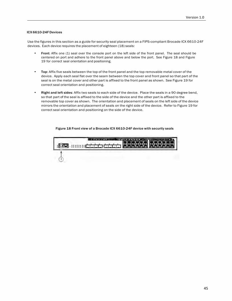
45
ICX 6610-24F Devices
Use the figures in this section as a guide for security seal placement on a FIPS-compliant Brocade ICX 6610-24F devices. Each device requires the placement of eighteen (18) seals:
• Front: Affix one (1) seal over the console port on the left side of the front panel. The seal should be
centered on port and adhere to the front panel above and below the port. See Figure 18 and Figure 19 for correct seal orientation and positioning.
• Top: Affix five seals between the top of the front panel and the top removable metal cover of the
device. Apply each seal flat over the seam between the top cover and front panel so that part of the seal is on the metal cover and other part is affixed to the front panel as shown. See Figure 19 for correct seal orientation and positioning.
• Right and left sides: Affix two seals to each side of the device. Place the seals in a 90 degree bend,
so that part of the seal is affixed to the side of the device and the other part is affixed to the removable top cover as shown. The orientation and placement of seals on the left side of the device mirrors the orientation and placement of seals on the right side of the device. Refer to Figure 19 for correct seal orientation and positioning on the side of the device.
Figure 18 Front view of a Brocade ICX 6610-24F device with security seals
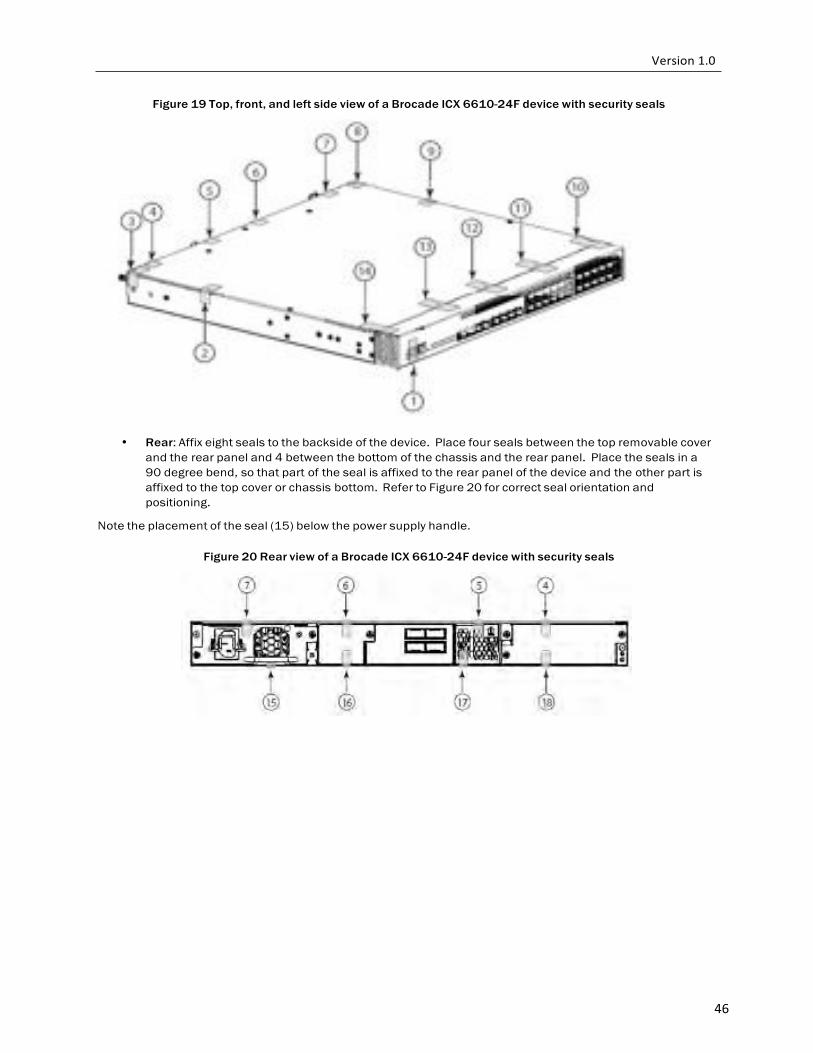
46
Figure 19 Top, front, and left side view of a Brocade ICX 6610-24F device with security seals
• Rear: Affix eight seals to the backside of the device. Place four seals between the top removable cover and the rear panel and 4 between the bottom of the chassis and the rear panel. Place the seals in a 90 degree bend, so that part of the seal is affixed to the rear panel of the device and the other part is affixed to the top cover or chassis bottom. Refer to Figure 20 for correct seal orientation and positioning.
Note the placement of the seal (15) below the power supply handle.
Figure 20 Rear view of a Brocade ICX 6610-24F device with security seals
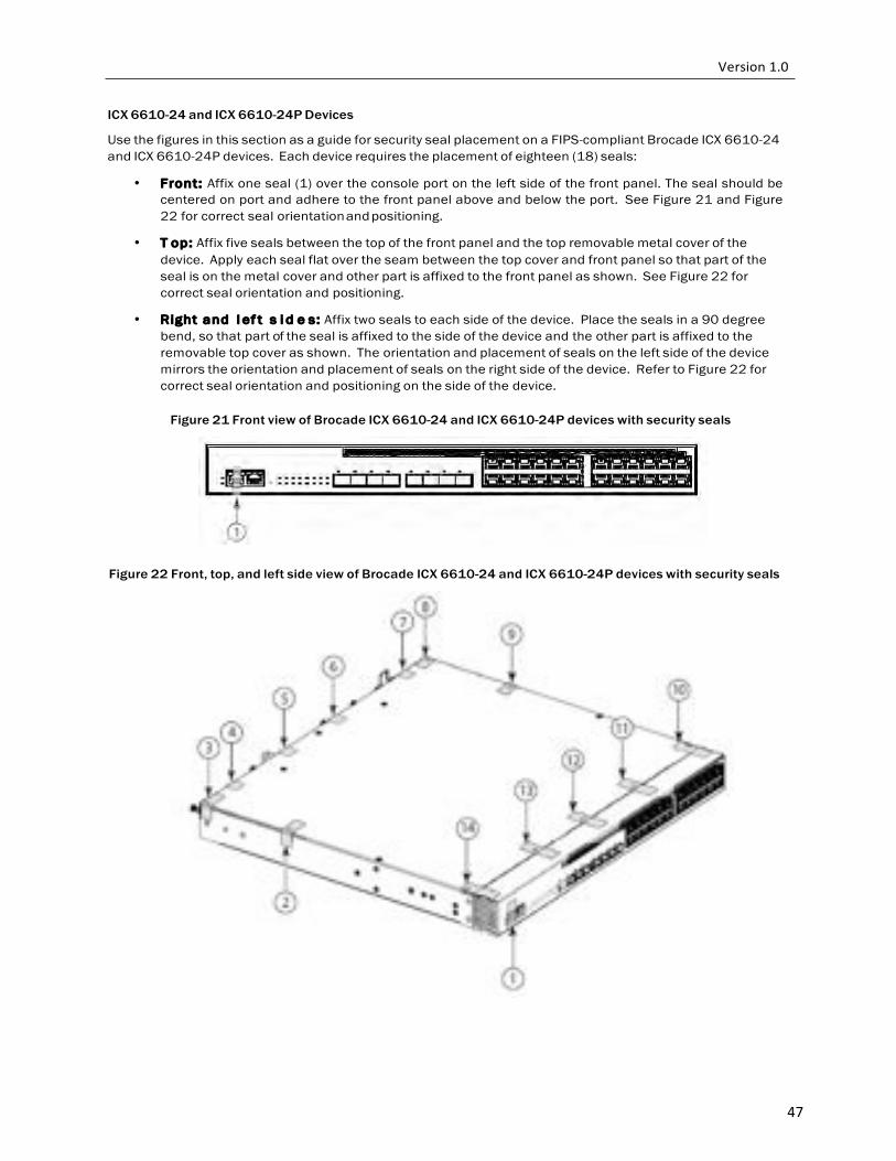
47
ICX 6610-24 and ICX 6610-24P Devices
Use the figures in this section as a guide for security seal placement on a FIPS-compliant Brocade ICX 6610-24 and ICX 6610-24P devices. Each device requires the placement of eighteen (18) seals:
• Front: Affix one seal (1) over the console port on the left side of the front panel. The seal should be centered on port and adhere to the front panel above and below the port. See Figure 21 and Figure 22 for correct seal orientation and positioning.
• T op: Affix five seals between the top of the front panel and the top removable metal cover of the device. Apply each seal flat over the seam between the top cover and front panel so that part of the seal is on the metal cover and other part is affixed to the front panel as shown. See Figure 22 for correct seal orientation and positioning.
• Right and l ef t s i d e s: Affix two seals to each side of the device. Place the seals in a 90 degree bend, so that part of the seal is affixed to the side of the device and the other part is affixed to the removable top cover as shown. The orientation and placement of seals on the left side of the device mirrors the orientation and placement of seals on the right side of the device. Refer to Figure 22 for correct seal orientation and positioning on the side of the device.
Figure 21 Front view of Brocade ICX 6610-24 and ICX 6610-24P devices with security seals
Figure 22 Front, top, and left side view of Brocade ICX 6610-24 and ICX 6610-24P devices with security seals
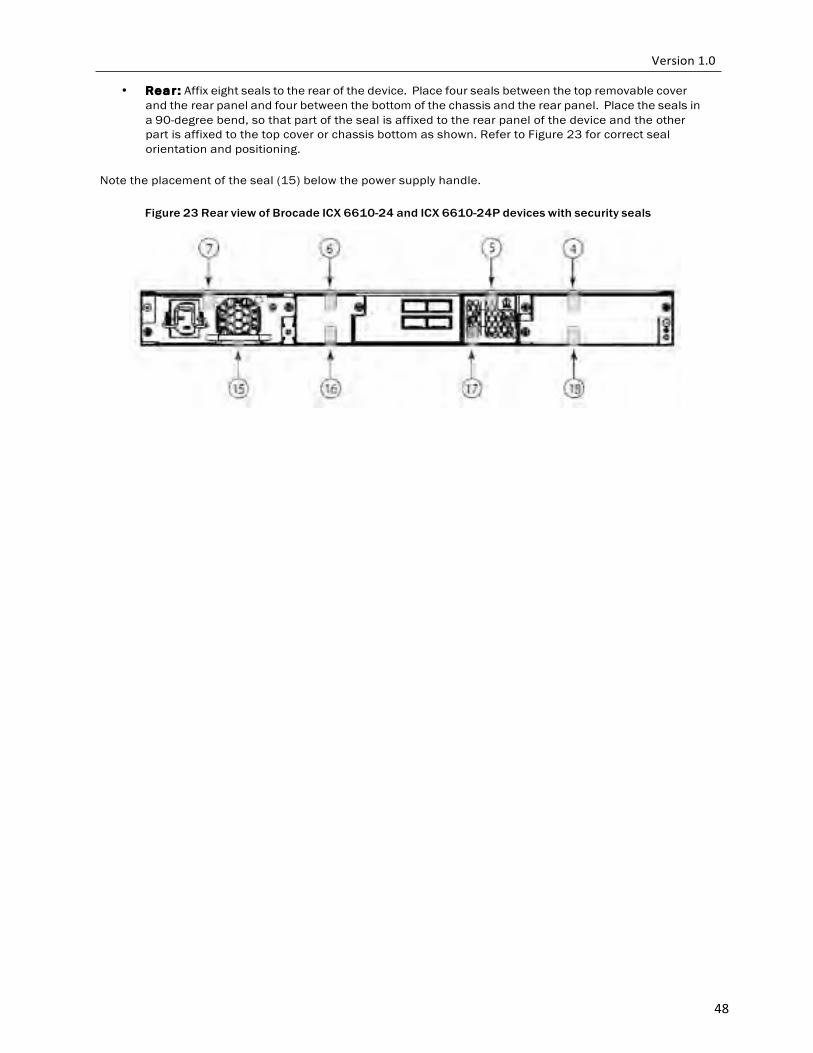
48
• Re a r : Affix eight seals to the rear of the device. Place four seals between the top removable cover and the rear panel and four between the bottom of the chassis and the rear panel. Place the seals in a 90-degree bend, so that part of the seal is affixed to the rear panel of the device and the other part is affixed to the top cover or chassis bottom as shown. Refer to Figure 23 for correct seal orientation and positioning.
Note the placement of the seal (15) below the power supply handle.
Figure 23 Rear view of Brocade ICX 6610-24 and ICX 6610-24P devices with security seals
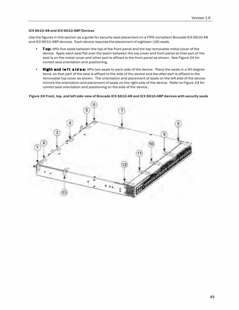
49
ICX 6610-48 and ICX 6610-48P Devices
Use the figures in this section as a guide for security seal placement on a FIPS-compliant Brocade ICX 6610-48 and ICX 6610-48P devices. Each device requires the placement of eighteen (18) seals.
• T op: Affix five seals between the top of the front panel and the top removable metal cover of the device. Apply each seal flat over the seam between the top cover and front panel so that part of the seal is on the metal cover and other part is affixed to the front panel as shown. See Figure 24 for correct seal orientation and positioning.
• Right and l e f t s i d e s: Affix two seals to each side of the device. Place the seals in a 90-degree bend, so that part of the seal is affixed to the side of the device and the other part is affixed to the removable top cover as shown. The orientation and placement of seals on the left side of the device mirrors the orientation and placement of seals on the right side of the device. Refer to Figure 24 for correct seal orientation and positioning on the side of the device.
Figure 24 Front, top, and left side view of Brocade ICX 6610-48 and ICX 6610-48P devices with security seals
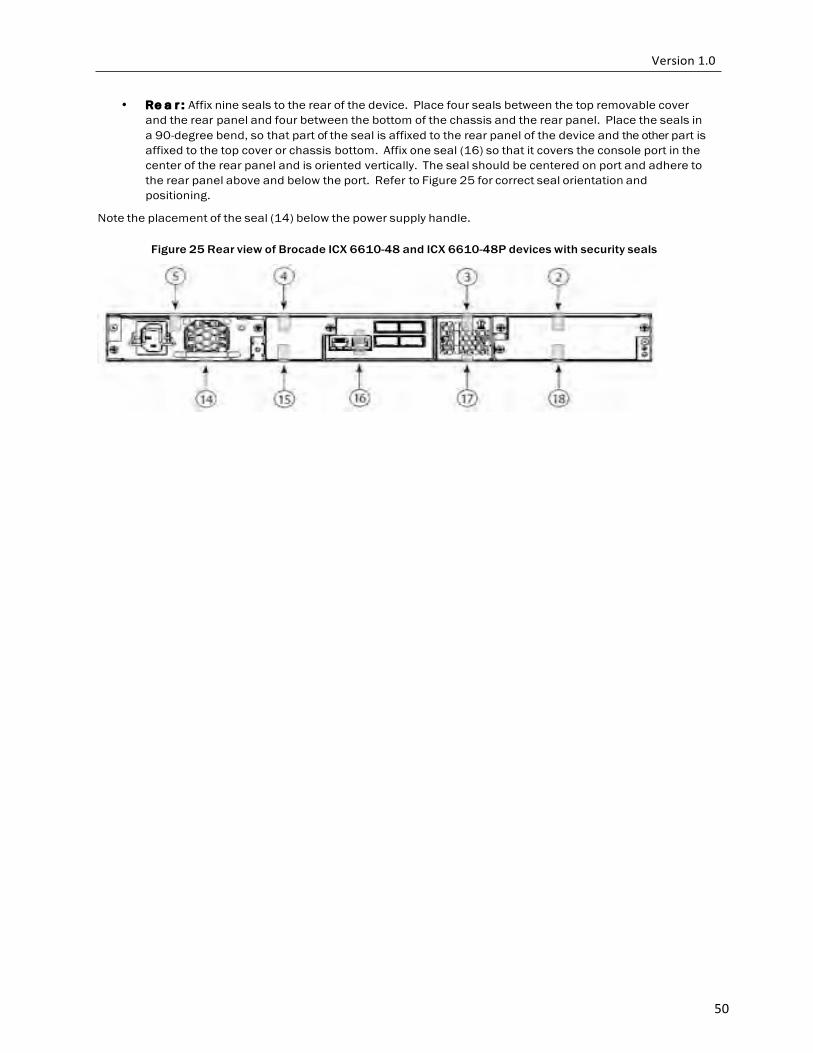
50
• Re a r : Affix nine seals to the rear of the device. Place four seals between the top removable cover and the rear panel and four between the bottom of the chassis and the rear panel. Place the seals in a 90-degree bend, so that part of the seal is affixed to the rear panel of the device and the other part is affixed to the top cover or chassis bottom. Affix one seal (16) so that it covers the console port in the center of the rear panel and is oriented vertically. The seal should be centered on port and adhere to the rear panel above and below the port. Refer to Figure 25 for correct seal orientation and positioning.
Note the placement of the seal (14) below the power supply handle.
Figure 25 Rear view of Brocade ICX 6610-48 and ICX 6610-48P devices with security seals

51
FCX 624S-F-ADV, Brocade FCX 624S and Brocade FCX 624S-HPOE-ADV devices
Use the figures in this section as a guide for security seal placement on the following Brocade FastIron devices:
• Brocade FCX 624S-F-ADV
• Brocade FCX 624S
• Brocade FCX 624S-HPOE-ADV
Note: The following SKUs are physically equivalent to the FCX 624S, FCX 624S-F, and the FCX 648S: FCX 624S-HPOE-ADV FCX 624S-F-ADV
FCX 648S-HPOE FCX 648S-HPOE-ADV The connectors on the faceplates of your particular device might vary from the connectors shown on the figures, but the placement of the seals will be the same. Figure 26 and Figure 27 display a Brocade FCX 624S with seals as a model for the seal placement on the Brocade FCX 624S-F-ADV, FCX 624S and FCX 624S-HPOE- ADV. Each of these devices requires the placement of Fourteen (14) seals:
• T o p: Affix 4 total seals to the top panel of the device. Affix two seals so that they cover the left and
right front most screws on the top panel of the device. Affix two seals so that they cover the two screws adjacent to the front most screws on the top panel. See Figure 26 for correct seal orientation and positioning.
• Ri g h t and l e f t s i d e s: Affix 4 total seals to the left and right sides of the device--two seals on the
right side and two seals on the left side. Each seal should cover two holes on either side of the first vent section. See Figure 26 for correct seal orientation and positioning on the right side of the device. The orientation and placement of seals on the left side mirrors the orientation and placement of seals on the right side of the device (visible in Figure 26).
• Fr on t : Affix one seal horizontally aligned with half affixed to the front panel and half affixed to the
bottom panel. You must bend this seal to place it correctly. See Figure 26 for correct seal orientation and positioning. Affix one seal over the console port covering it and adhering it on the left side. See Figure 26 for correct seal orientation and positioning.
• Rear : Affix 4 total seals to the rear panel of the device. Affix one seal from the rear
panel to the bottom panel and three seals from the rear panel to the top panel. You must bend these seals to place them correctly. See Figure 27 for correct seal orientation and positioning.
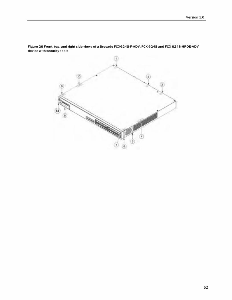
52
Figure 26 Front, top, and right side views of a Brocade FCX624S-F-ADV, FCX 624S and FCX 624S-HPOE-ADV device with security seals
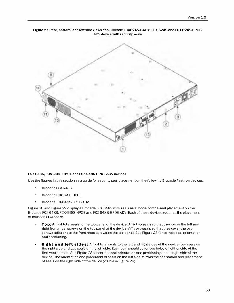
53
Figure 27 Rear, bottom, and left side views of a Brocade FCX624S-F-ADV, FCX 624S and FCX 624S-HPOE- ADV device with security seals
FCX 648S, FCX 648S-HPOE and FCX 648S-HPOE-ADV devices
Use the figures in this section as a guide for security seal placement on the following Brocade FastIron devices:
• Brocade FCX 648S
• Brocade FCX 648S-HPOE
• Brocade FCX 648S-HPOE-ADV
Figure 28 and Figure 29 display a Brocade FCX 648S with seals as a model for the seal placement on the Brocade FCX 648S, FCX 648S-HPOE and FCX 648S-HPOE-ADV. Each of these devices requires the placement of fourteen (14) seals:
• T o p : Affix 4 total seals to the top panel of the device. Affix two seals so that they cover the left and
right front most screws on the top panel of the device. Affix two seals so that they cover the two screws adjacent to the front most screws on the top panel. See Figure 28 for correct seal orientation and positioning.
• Ri g h t a n d l e f t s i d e s : Affix 4 total seals to the left and right sides of the device--two seals on
the right side and two seals on the left side. Each seal should cover two holes on either side of the first vent section. See Figure 28 for correct seal orientation and positioning on the right side of the device. The orientation and placement of seals on the left side mirrors the orientation and placement of seals on the right side of the device (visible in Figure 28).
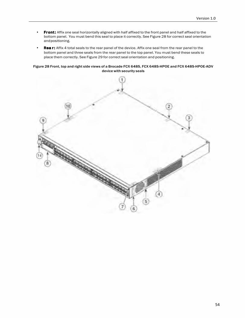
54
• Fr ont : Affix one seal horizontally aligned with half affixed to the front panel and half affixed to the bottom panel. You must bend this seal to place it correctly. See Figure 28 for correct seal orientation and positioning.
• Rea r : Affix 4 total seals to the rear panel of the device. Affix one seal from the rear panel to the
bottom panel and three seals from the rear panel to the top panel. You must bend these seals to place them correctly. See Figure 29 for correct seal orientation and positioning.
Figure 28 Front, top and right side views of a Brocade FCX 648S, FCX 648S-HPOE and FCX 648S-HPOE-ADV
device with security seals
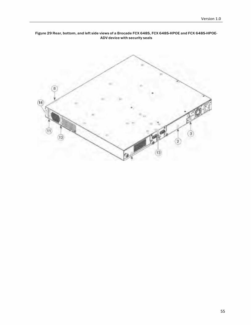
55
Figure 29 Rear, bottom, and left side views of a Brocade FCX 648S, FCX 648S-HPOE and FCX 648S-HPOE- ADV device with security seals
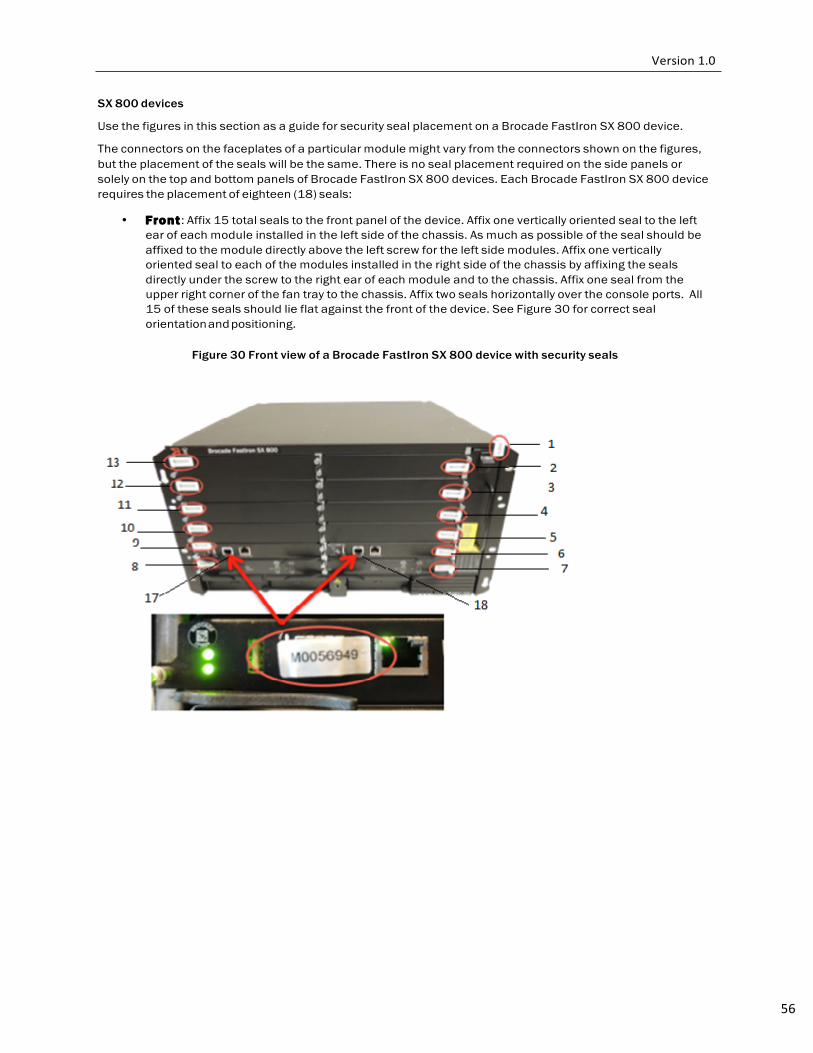
56
SX 800 devices
Use the figures in this section as a guide for security seal placement on a Brocade FastIron SX 800 device.
The connectors on the faceplates of a particular module might vary from the connectors shown on the figures, but the placement of the seals will be the same. There is no seal placement required on the side panels or solely on the top and bottom panels of Brocade FastIron SX 800 devices. Each Brocade FastIron SX 800 device requires the placement of eighteen (18) seals:
• Front : Affix 15 total seals to the front panel of the device. Affix one vertically oriented seal to the left
ear of each module installed in the left side of the chassis. As much as possible of the seal should be affixed to the module directly above the left screw for the left side modules. Affix one vertically oriented seal to each of the modules installed in the right side of the chassis by affixing the seals directly under the screw to the right ear of each module and to the chassis. Affix one seal from the upper right corner of the fan tray to the chassis. Affix two seals horizontally over the console ports. All 15 of these seals should lie flat against the front of the device. See Figure 30 for correct seal orientation and positioning.
Figure 30 Front view of a Brocade FastIron SX 800 device with security seals
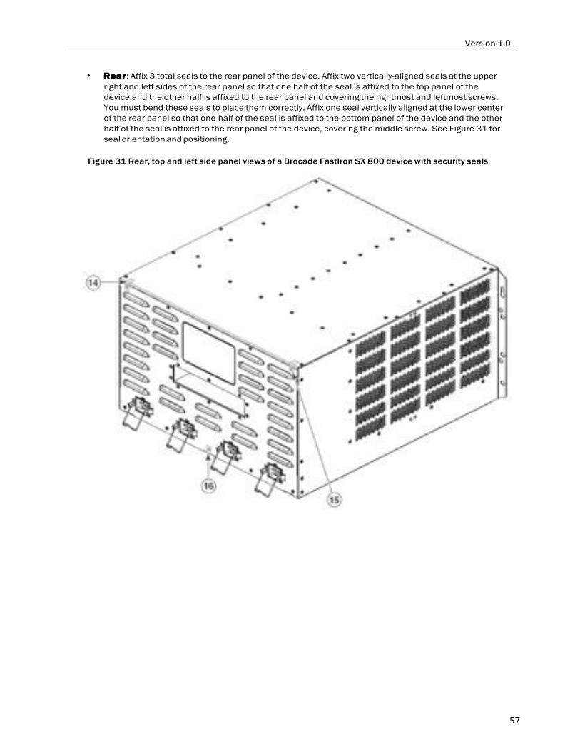
57
• Rear : Affix 3 total seals to the rear panel of the device. Affix two vertically-aligned seals at the upper right and left sides of the rear panel so that one half of the seal is affixed to the top panel of the device and the other half is affixed to the rear panel and covering the rightmost and leftmost screws. You must bend these seals to place them correctly. Affix one seal vertically aligned at the lower center of the rear panel so that one-half of the seal is affixed to the bottom panel of the device and the other half of the seal is affixed to the rear panel of the device, covering the middle screw. See Figure 31 for seal orientation and positioning.
Figure 31 Rear, top and left side panel views of a Brocade FastIron SX 800 device with security seals
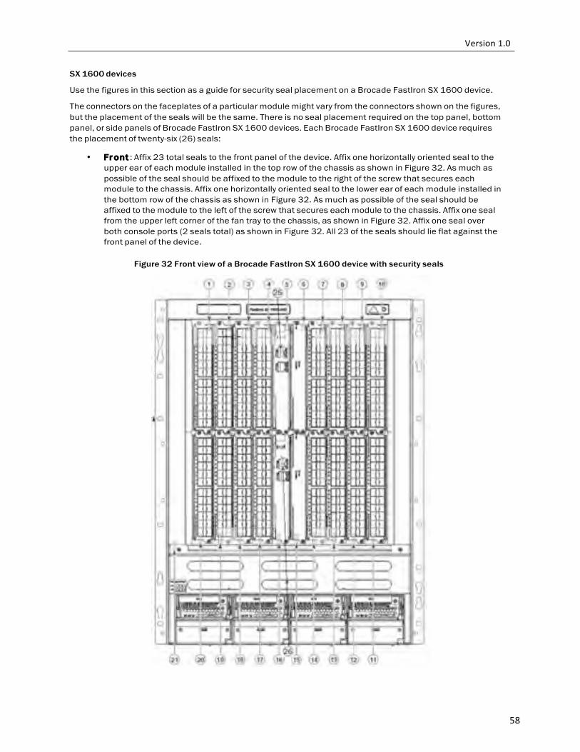
58
SX 1600 devices
Use the figures in this section as a guide for security seal placement on a Brocade FastIron SX 1600 device.
The connectors on the faceplates of a particular module might vary from the connectors shown on the figures, but the placement of the seals will be the same. There is no seal placement required on the top panel, bottom panel, or side panels of Brocade FastIron SX 1600 devices. Each Brocade FastIron SX 1600 device requires the placement of twenty-six (26) seals:
• Fr ont : Affix 23 total seals to the front panel of the device. Affix one horizontally oriented seal to the
upper ear of each module installed in the top row of the chassis as shown in Figure 32. As much as possible of the seal should be affixed to the module to the right of the screw that secures each module to the chassis. Affix one horizontally oriented seal to the lower ear of each module installed in the bottom row of the chassis as shown in Figure 32. As much as possible of the seal should be affixed to the module to the left of the screw that secures each module to the chassis. Affix one seal from the upper left corner of the fan tray to the chassis, as shown in Figure 32. Affix one seal over both console ports (2 seals total) as shown in Figure 32. All 23 of the seals should lie flat against the front panel of the device.
Figure 32 Front view of a Brocade FastIron SX 1600 device with security seals
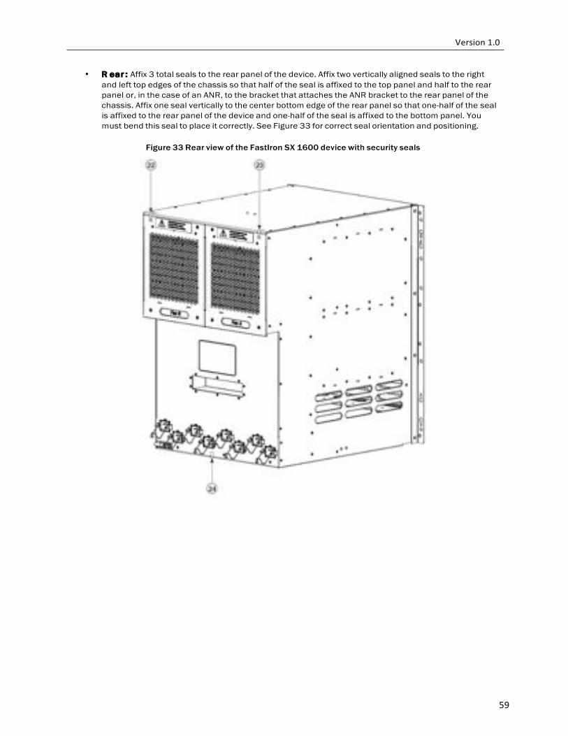
59
• R ear : Affix 3 total seals to the rear panel of the device. Affix two vertically aligned seals to the right and left top edges of the chassis so that half of the seal is affixed to the top panel and half to the rear panel or, in the case of an ANR, to the bracket that attaches the ANR bracket to the rear panel of the chassis. Affix one seal vertically to the center bottom edge of the rear panel so that one-half of the seal is affixed to the rear panel of the device and one-half of the seal is affixed to the bottom panel. You must bend this seal to place it correctly. See Figure 33 for correct seal orientation and positioning.
Figure 33 Rear view of the FastIron SX 1600 device with security seals
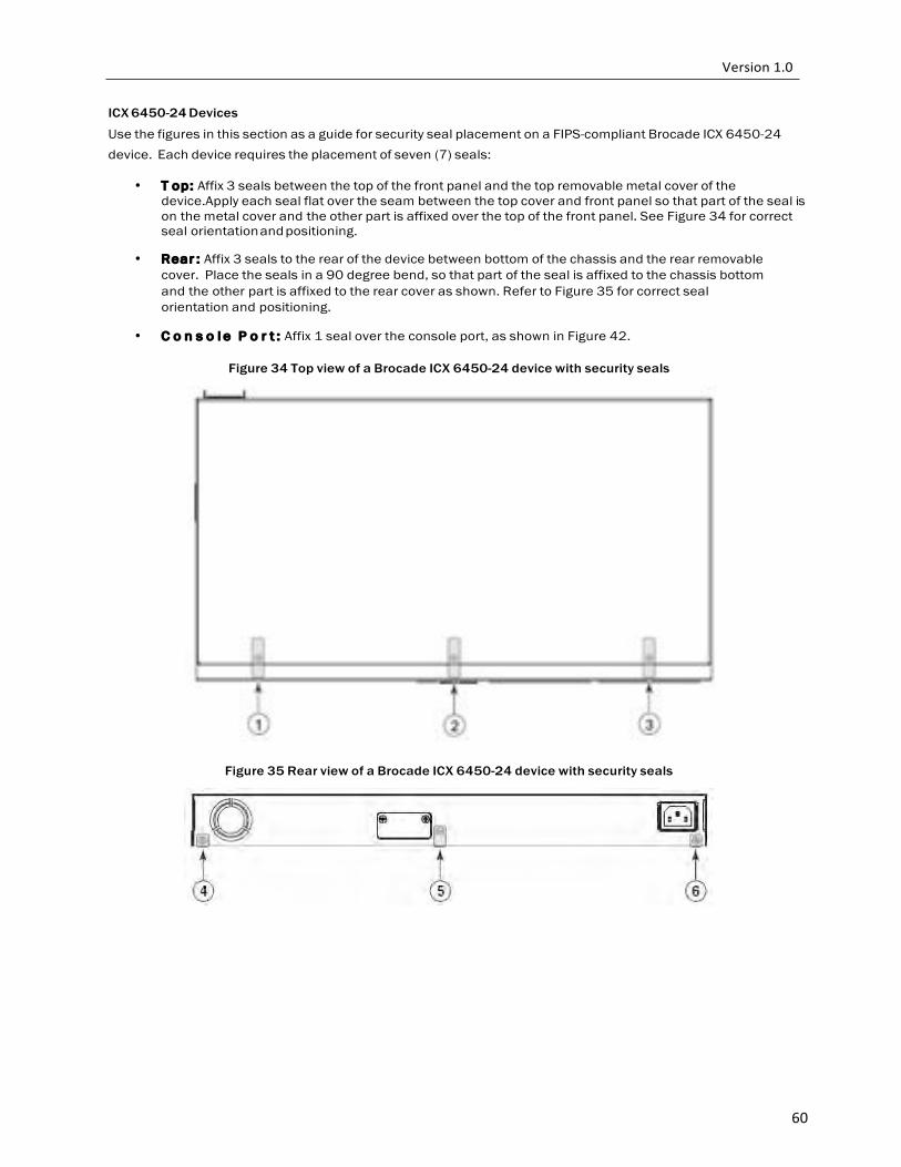
60
ICX 6450-24 Devices
Use the figures in this section as a guide for security seal placement on a FIPS-compliant Brocade ICX 6450-24 device. Each device requires the placement of seven (7) seals:
• T op: Affix 3 seals between the top of the front panel and the top removable metal cover of the device.Apply each seal flat over the seam between the top cover and front panel so that part of the seal is on the metal cover and the other part is affixed over the top of the front panel. See Figure 34 for correct seal orientation and positioning.
• Rear : Affix 3 seals to the rear of the device between bottom of the chassis and the rear removable
cover. Place the seals in a 90 degree bend, so that part of the seal is affixed to the chassis bottom and the other part is affixed to the rear cover as shown. Refer to Figure 35 for correct seal orientation and positioning.
• C o n s o l e P o r t : Affix 1 seal over the console port, as shown in Figure 42.
Figure 34 Top view of a Brocade ICX 6450-24 device with security seals
Figure 35 Rear view of a Brocade ICX 6450-24 device with security seals
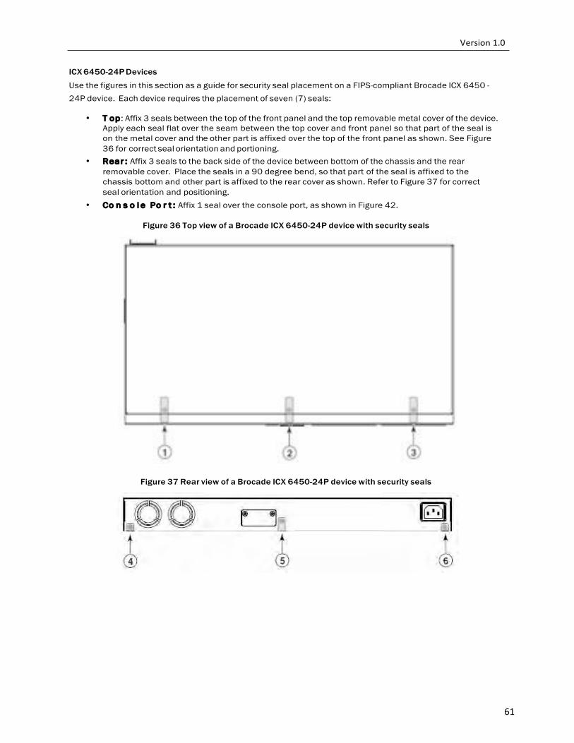
61
ICX 6450-24P Devices
Use the figures in this section as a guide for security seal placement on a FIPS-compliant Brocade ICX 6450 - 24P device. Each device requires the placement of seven (7) seals:
• T op: Affix 3 seals between the top of the front panel and the top removable metal cover of the device. Apply each seal flat over the seam between the top cover and front panel so that part of the seal is on the metal cover and the other part is affixed over the top of the front panel as shown. See Figure 36 for correct seal orientation and portioning.
• Rear : Affix 3 seals to the back side of the device between bottom of the chassis and the rear removable cover. Place the seals in a 90 degree bend, so that part of the seal is affixed to the chassis bottom and other part is affixed to the rear cover as shown. Refer to Figure 37 for correct seal orientation and positioning.
• Co n s o l e Po r t : Affix 1 seal over the console port, as shown in Figure 42.
Figure 36 Top view of a Brocade ICX 6450-24P device with security seals
Figure 37 Rear view of a Brocade ICX 6450-24P device with security seals
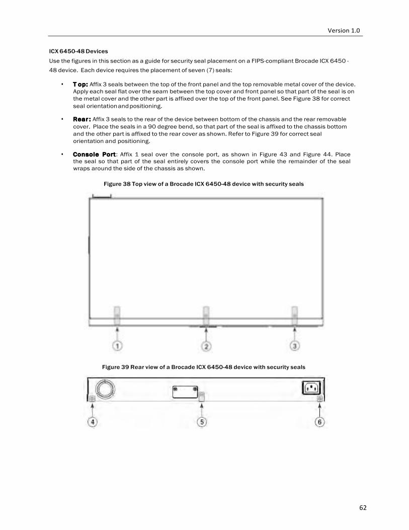
62
ICX 6450-48 Devices
Use the figures in this section as a guide for security seal placement on a FIPS-compliant Brocade ICX 6450 - 48 device. Each device requires the placement of seven (7) seals:
• T op: Affix 3 seals between the top of the front panel and the top removable metal cover of the device. Apply each seal flat over the seam between the top cover and front panel so that part of the seal is on the metal cover and the other part is affixed over the top of the front panel. See Figure 38 for correct seal orientation and positioning.
• Rear : Affix 3 seals to the rear of the device between bottom of the chassis and the rear removable
cover. Place the seals in a 90 degree bend, so that part of the seal is affixed to the chassis bottom and the other part is affixed to the rear cover as shown. Refer to Figure 39 for correct seal orientation and positioning.
• Console Port: Affix 1 seal over the console port, as shown in Figure 43 and Figure 44. Place
the seal so that part of the seal entirely covers the console port while the remainder of the seal wraps around the side of the chassis as shown.
Figure 38 Top view of a Brocade ICX 6450-48 device with security seals
Figure 39 Rear view of a Brocade ICX 6450-48 device with security seals
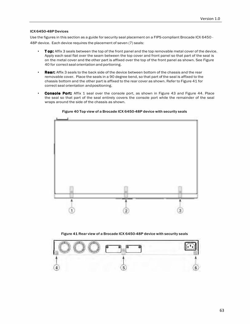
63
ICX 6450-48P Devices
Use the figures in this section as a guide for security seal placement on a FIPS-compliant Brocade ICX 6450 - 48P device. Each device requires the placement of seven (7) seals:
• T op: Affix 3 seals between the top of the front panel and the top removable metal cover of the device.
Apply each seal flat over the seam between the top cover and front panel so that part of the seal is on the metal cover and the other part is affixed over the top of the front panel as shown. See Figure 40 for correct seal orientation and portioning.
• Rear: Affix 3 seals to the back side of the device between bottom of the chassis and the rear
removable cover. Place the seals in a 90 degree bend, so that part of the seal is affixed to the chassis bottom and the other part is affixed to the rear cover as shown. Refer to Figure 41 for correct seal orientation and positioning.
• Console Port: Affix 1 seal over the console port, as shown in Figure 43 and Figure 44. Place
the seal so that part of the seal entirely covers the console port while the remainder of the seal wraps around the side of the chassis as shown.
Figure 40 Top view of a Brocade ICX 6450-48P device with security seals
Figure 41 Rear view of a Brocade ICX 6450-48P device with security seals
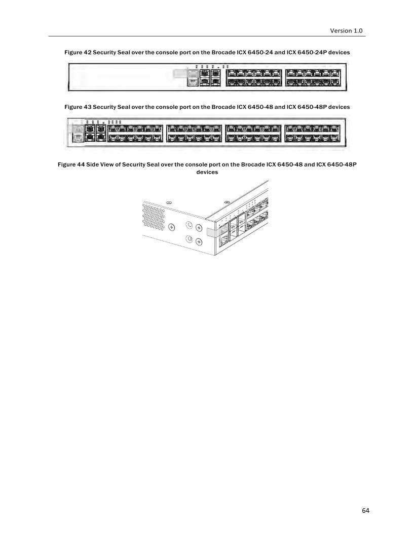
64
Figure 42 Security Seal over the console port on the Brocade ICX 6450-24 and ICX 6450-24P devices
Figure 43 Security Seal over the console port on the Brocade ICX 6450-48 and ICX 6450-48P devices
Figure 44 Side View of Security Seal over the console port on the Brocade ICX 6450-48 and ICX 6450-48P devices

65
ICX 6450-C12-PD Devices Use the figures in this section as a guide for security seal placement on a FIPS-compliant Brocade ICX 6450 - CP12-PD device. Each device requires the placement of sixteen (16) seals:
• Fr ont: Affix a seal, at seal locations 1 and 2, which wraps from the front panel to the side panel on the
left and right side, respectively. Each seal must bridge the seam between the front panel and the side panel. See Figure 45 and Figure 46 for the correct seal orientation and portioning. Affix one seal over the console port. Three (3) seals are required to complete this step of the procedure.
• Ri g h t : Affix a seal at locations 10, 11, and 12 on the right side of the module, as seen in Figure 46.
Three (3) seals are required to complete this step of the procedure.
• Lef t : Affix a seal at locations 14, 15, and 16 on the left side of the module, as seen in Figure 48. Three (3) seals are required to complete this step of the procedure.
• Ba c k : Affix a seal at location 13, as seen in Figure 48. Three (3) seals are required to complete this
step of the procedure.
• Bo t t om: Affix a seal, at seal locations 3 through 8, which covers the screws that attach the bottom panel to the chassis to chassis cover. Each seal must bridge the seam between the bottom panel and the chassis cover. See Figure 47 for the correct seal orientation and portioning. Six (6) seals are required to complete this step of the procedure.
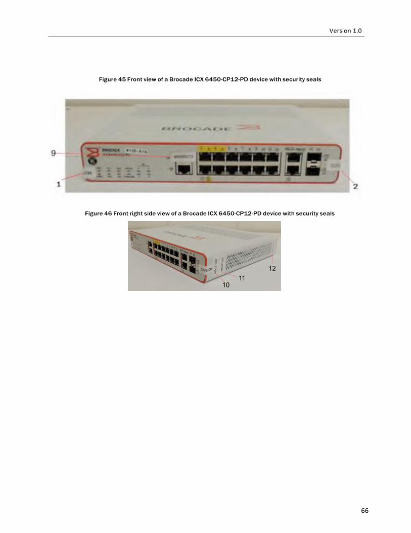
66
Figure 45 Front view of a Brocade ICX 6450-CP12-PD device with security seals
Figure 46 Front right side view of a Brocade ICX 6450-CP12-PD device with security seals
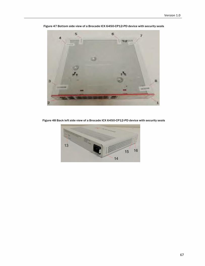
67
Figure 47 Bottom side view of a Brocade ICX 6450-CP12-PD device with security seals
Figure 48 Back left side view of a Brocade ICX 6450-CP12-PD device with security seals
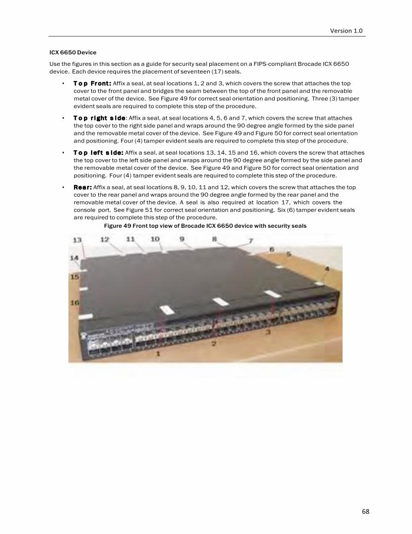
68
ICX 6650 Device
Use the figures in this section as a guide for security seal placement on a FIPS-compliant Brocade ICX 6650 device. Each device requires the placement of seventeen (17) seals.
• T o p Fr ont : Affix a seal, at seal locations 1, 2 and 3, which covers the screw that attaches the top cover to the front panel and bridges the seam between the top of the front panel and the removable metal cover of the device. See Figure 49 for correct seal orientation and positioning. Three (3) tamper evident seals are required to complete this step of the procedure.
• T o p r i ght s i de: Affix a seal, at seal locations 4, 5, 6 and 7, which covers the screw that attaches
the top cover to the right side panel and wraps around the 90 degree angle formed by the side panel and the removable metal cover of the device. See Figure 49 and Figure 50 for correct seal orientation and positioning. Four (4) tamper evident seals are required to complete this step of the procedure.
• T o p l ef t s i de: Affix a seal, at seal locations 13, 14, 15 and 16, which covers the screw that attaches
the top cover to the left side panel and wraps around the 90 degree angle formed by the side panel and the removable metal cover of the device. See Figure 49 and Figure 50 for correct seal orientation and positioning. Four (4) tamper evident seals are required to complete this step of the procedure.
• Re a r : Affix a seal, at seal locations 8, 9, 10, 11 and 12, which covers the screw that attaches the top
cover to the rear panel and wraps around the 90 degree angle formed by the rear panel and the removable metal cover of the device. A seal is also required at location 17, which covers the console port. See Figure 51 for correct seal orientation and positioning. Six (6) tamper evident seals are required to complete this step of the procedure.
Figure 49 Front top view of Brocade ICX 6650 device with security seals
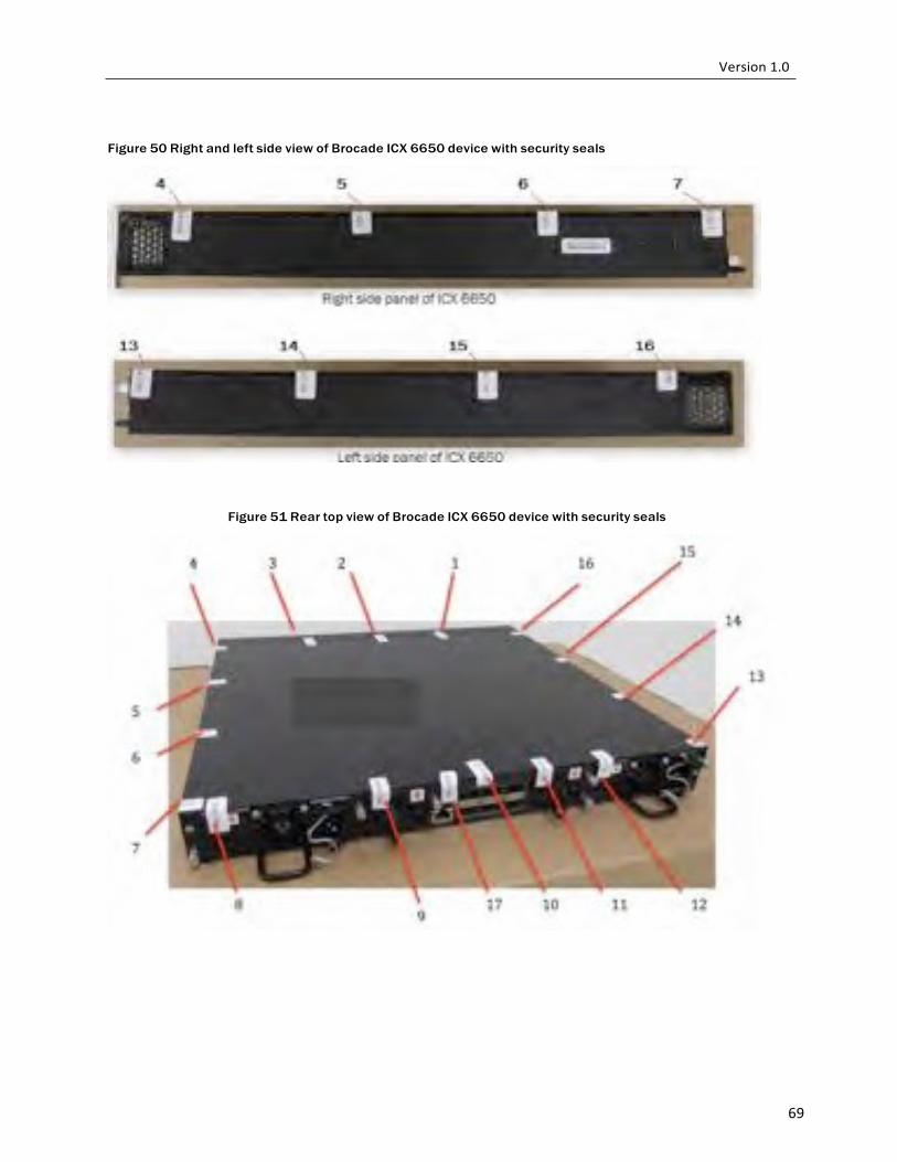
69
Figure 50 Right and left side view of Brocade ICX 6650 device with security seals
Figure 51 Rear top view of Brocade ICX 6650 device with security seals
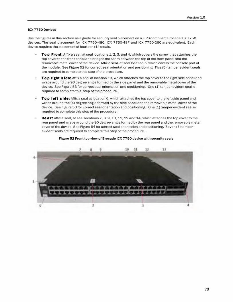
70
ICX 7750 Devices
Use the figures in this section as a guide for security seal placement on a FIPS-compliant Brocade ICX 7750 devices. The seal placement for ICX 7750-48C, ICX 7750-48F and ICX 7750-26Q are equivalent. Each device requires the placement of fourteen (14) seals.
• T o p Fr ont: Affix a seal, at seal locations 1, 2, 3, and 4, which covers the screw that attaches the
top cover to the front panel and bridges the seam between the top of the front panel and the removable metal cover of the device. Affix a seal, at seal location 5, which covers the console port of the module. See Figure 52 for correct seal orientation and positioning. Five (5) tamper evident seals are required to complete this step of the procedure.
• T o p r ight s i de: Affix a seal at location 13, which attaches the top cover to the right side panel and wraps around the 90 degree angle formed by the side panel and the removable metal cover of the device. See Figure 53 for correct seal orientation and positioning. One (1) tamper evident seal is required to complete this step of the procedure.
• T o p l ef t s i de: Affix a seal at location 6, which attaches the top cover to the left side panel and
wraps around the 90 degree angle formed by the side panel and the removable metal cover of the device. See Figure 53 for correct seal orientation and positioning. One (1) tamper evident seal is required to complete this step of the procedure.
• Re a r : Affix a seal, at seal locations 7, 8, 9, 10, 11, 12 and 14, which attaches the top cover to the rear panel and wraps around the 90 degree angle formed by the rear panel and the removable metal cover of the device. See Figure 54 for correct seal orientation and positioning. Seven (7) tamper evident seals are required to complete this step of the procedure.
Figure 52 Front top view of Brocade ICX 7750 device with security seals
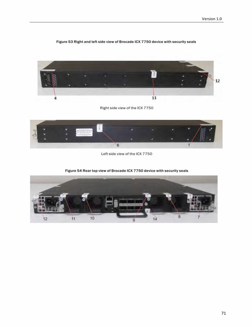
71
Figure 53 Right and left side view of Brocade ICX 7750 device with security seals
Right side view of the ICX 7750
Left side view of the ICX 7750
Figure 54 Rear top view of Brocade ICX 7750 device with security seals