Embed Size (px)
Citation preview
824
ISBN: 978-93-80689-28-9
Brittle Machining Issues in Single Point Diamond Turning of Aspheric Infra-Red
Optics
RamaGopal V Sarepaka*, Rakesh Singh Panwar, Siva Sakthibalan, SomaiahDudala, D RajendraKotaria
Optics & Allied Engg. Pvt. Ltd., Bommasandra Industrial Area, Bengaluru-560099, India
Abstract
The demands on advanced strategic instrumentation have propelled precision IR optical system developers to target near theoretical
performance, under system budgets of weight, volume and foot-prints. These requirements can be met only by using aspheric profiles to
compactize IR system and to compensate for wavefront aberrations caused by spherical surfaces.
In last few years, Single Point Diamond Turning (SPDT) has become the workhorse for aspheric profile generation, due to its
deterministic ultra-high-precision deliverance criteria. SPDT offers both opportunities and challenges for IR optical system developers of
all streams. The benefits include compact systems with desired resolution and image quality. But the SPDT fabrication poses severe
operational hurdles to overcome. The brittle nature of the IR materials to be processed presents further difficulties, while meeting the
desired surface quality criteria.
The major aspects of SPDT of IR Systems (while maintaining desired surface quality criteria) include: material characteristics, machining
parametric optimization, selection of suitable diamond tool geometries, monitoring of progressive diamond tool wear, effect of tool wear
on surface quality, profile errors due to thermal energy generated during SPDT, profile error compensation, optimal machining
conditions, work-piece handling (pre – during-post SPDT) and machining protocols.
In this presentation we discuss briefly some of these concerns. We conclude with empirical guidelines for ductile regime machining of
brittle IR materials and pointers for probable deterministic processing of IR optics.
Keywords: Single point diamond turning, brittle machining, aspheric surface fabrication and characterization, ductile regime machining,
thermal diffusivity, profile error compensation.
1. INTRODUCTION
Brittle materials such as Silicon, Germanium, Ceramics and
glass are widely used in semiconductor, optical, electronics and
various other fields. The desired surface quality and finish in
these applications are very stringent. Conventional Grinding
and Polishing processes deliver Silicon surfaces within tight
tolerances. Since grinding is a random & uncontrolled material
removal process, brittle fracture and Sub-Surface Damage
(SSD) are inevitable. These surfaces post-grinding cannot be
directly used for precision applications. The post grinding-
polishing process makes the surface highly finished, but this
process is complicated, time consuming and is nondeterministic
in terms of processing Vs. final surface quality.
Single Point Diamond Turning (SPDT) technology is of great
importance for the fabrication of precision parts in various
industrial sectors, such as optics, clean energy, information and
communication technology, and others. It is capable of
achieving a super smooth surface of not only the machinable
metals but also the brittle materials, which is free from the
conventional time consuming polishing. The brittle materials,
however, are difficult to be machined due to their low fracture
toughness and high hardness. Such properties tend to bring in
some unwanted fractures, which finally results in a damaged or
nontransparent surface. Hence, to achieve a crack-free surface,
the top surface layer of brittle materials must be removed in
ductile mode. To achieve a smooth surface of brittle materials
also relies on machining environment, diamond tool
performance, process parameters, tool geometry, cutting edge
radius, as well as the properties of workpiece materials [1].
* Author for communication: [email protected]
Many non-ferrous materials such as aluminum, copper, electro-
less nickel lend themselves nicely to diamond turning.
Additionally, several polymers and crystals are also suitable for
diamond turning. The crystalline materials that can be diamond
turned are: germanium, zinc selenide, lithium niobate and
silicon.
2. SPDT ISSUES OF IR MATERIALS:
The brittle nature of the IR materials such as Silicon,
Germanium, Ceramics lend to a host of fabrication issues in
terms of tooling, machining, tooling, thermal expansion, tool
wear, progressively degrading surface quality with tool wear
and increasing developmental costs. On the other hand, the
surface quality and finish requirements for their applications are
very stringent. Compared with the traditional grinding and
polishing process, the nano-scale material removal by SPDT is
gaining popularity to generate precision optical lenses and
mirrors [1] as per the applications. To counter the brittle nature
of these materials, suitable ductile regime machining is
prescribed to control the profile quality within the allowed
tolerances of surface form, figure and finish.
2.1. Thermal Issues in SPDT of Brittle Materials
A large majority of the IR materials are not good thermal
conductors. As with the plastic materials, the residual thermal
energy plays a major role in the development of precision
components with brittle materials as well. In case of polymers,
the surface profile alone was a major obstacle to deal with.
During the tool – work-piece interaction during SPDT, material
removal takes place by shearing of the top layer of work-piece
material. This interaction gives rise to a significant amount of
thermal energy.

825
The amount of heat thus generated will increase with increasing
of machining cycles. As these materials are good thermal
conductors, the heat generated in SPDT is barely dissipated by
radiation and conduction, and the residual heat is trapped within
the component. The SPDT generated surfaces have a grating-
like pattern which may give rise to a rain-bow type dispersive
pattern on the diamond turned surface, due to inappropriate
machining coupled with the remnants of the coolant in the
grating pattern (Figure 1). Judicious selection of machining
parameters and a suitable coolant will greatly reduce the grating
like pattern generally seen on SPDT generated surfaces. To
minimize these dispersive patterns, a sublimating-type alcohol-
based coolant projected on to the tool-job interface with cold
jets of compressed air (in mist form) is used.
Figure 1: SPDT generated Si aspheric surface with improperly
selected machining parameters & thermal ‘hot zones’
Figure 2: SPDT generated Si aspheric surface with Improved
surface due to better machining parametric matrix, yet with
thermal ‘hot zones’ (seen as differently hued color zones)
Figure 1 depicts a regular case of SPDT operation of silicon
aspheric surface. For these brittle materials, the first step of
SDPT operations is to explore and decide on an optimal
machining parametric combination. In Figure 1 the colored star-
like visuals clearly indicate that the spindle speed and feed are
not optimally selected and suffer the effects of tool wear as
well.
In Figure 2, this situation is somewhat improved, by deploying
right combination of machining parameters. Additionally, in
both figures, one can see the differently colored ‘hot zones’ due
to non-uniform distribution of heat generated and trapped
“within” the work-piece.
However, with these materials, their optical properties will also
undergo significant changes due to the thermal energy trapped
in these components. In our studies, it is noted that the precision
silicon, germanium components during SPDT suffered with
non-uniform distribution of the residual thermal energy. This
gives rise to possible change in the refractive index of the
material, which alters the ray path during the refraction (Figure
2). The challenge here is not only to predict it’s orientation but
also to control it.
A preventive method to deal with this problem is to re-organize
the machining philosophy. It is seen that, in case of spherical
surfaces, repeated cycles of shaping, rough grinding and fine
grinding result in excessive sub-surface damage (SSD). SSD
also, due to the trauma caused in the sub-cutaneous layers of
the precision components, may result in altered ray path in the
components. The SSD can be reduced only by a well-planned
polishing process, wherein the top most layers of the
component are gradually removed, without a. altering the
component shape (form), b. further adding to the residual figure
error and c. by effectively reducing the roughness (better
finish), while not further damaging the layers just below the top
surface. e just below t shape) of the component However, in the
case of aspheric profiles, the multiplicity of machining cycles
will result not only in SSD, but also give rise to ‘hot zones’ /
‘hotspots’ in the material, with potential refractive changes and
altered ray-path than the intended one.
Only way to deal reduce these ‘hot zones’ / ‘hot spots’ is reduce
the amount of machining. However, to compensate for the
profile error, one needs repeated fine machining cycles. There
is this dilemma of how many cycles are needed to correct the
profile error, while controlling the count of ‘hot spots’ in the
material. This calls for a hybrid approach of grinding-polishing
and precision diamond turning, with judicious mix of dual
processing cycles.
2.2. Diamond Tool Geometry –Tool Wear
SPDT of brittle materials is saddled with excessive diamond
tool wear and increased tooling costs. We have conducted a
typical diamond tool wear study to present the tool wear
progression in the SPDT of an optical grade flat Si disc of
50mm diameter 50 mm and 15 mm thickness. For this study,
we selected anon-controlled waviness single-crystalline natural
diamond of -30° rake angle,15° clearance angle and with 0.5
mm tool nose radius (Contour make). The geometry impacts
both wear of tool and quality of SPDT surface significantly.
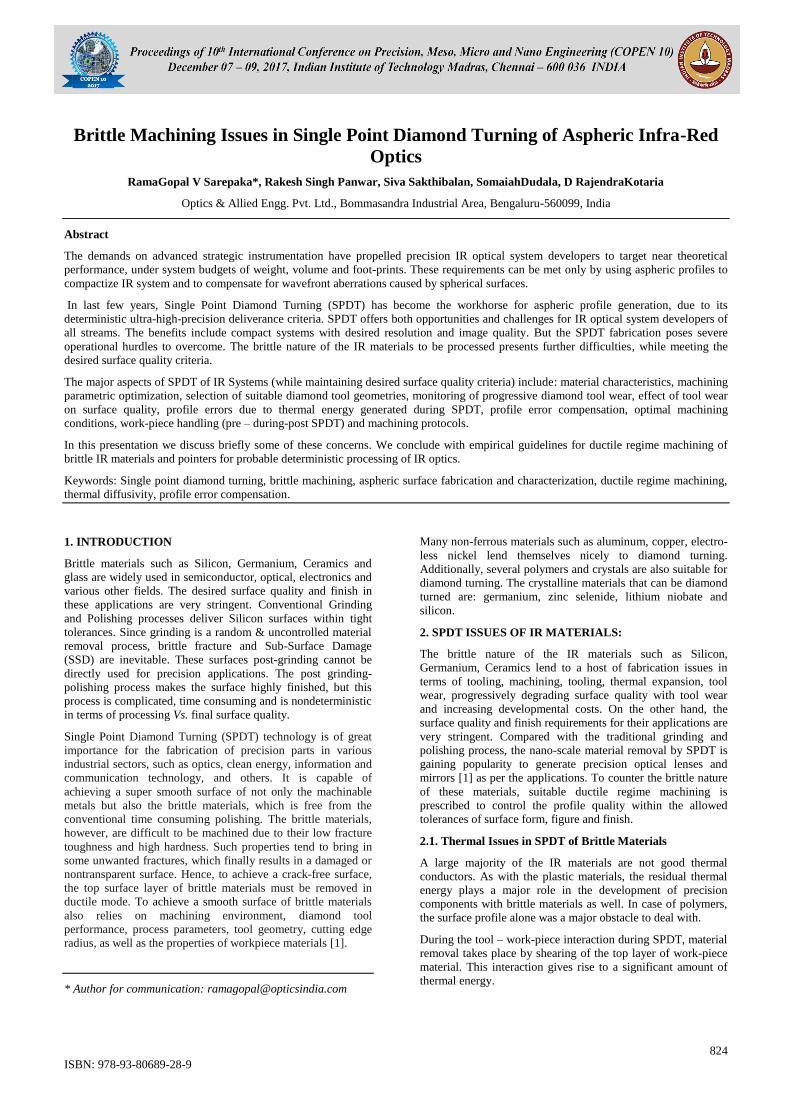
Figure 3: Un-Used Diamond Tool
Our study started with an unused diamond tool (Figures 3& 4).
We measured its wear in terms of its geometry departure from
its prescription. Figure 5 shows the departure in geometry /
wear of an unused tool. Then we started a series of iterative
SPDT operations to remove a calibrated amount of Si material
in each machining cycle with a well-chosen matrix of
machining parameters.
826
Figure 4: Nose of Un-Used Diamond Tool
Figure5: Geometry of Un-Used Diamond Tool
Figure6: Waviness (3.8 μm) of Un-Used Diamond Tool)
Figure 7: Roughness (Ra: 15 nm) - SPDT by Un-Used Diamond
Tool
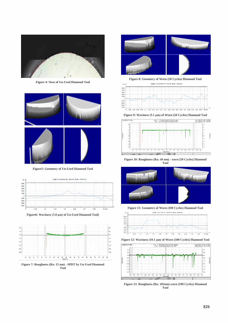
Figure 8: Geometry of Worn (50 Cycles) Diamond Tool
Figure 9: Waviness (5.1 μm) of Worn (50 Cycles) Diamond Tool
Figure 10: Roughness (Ra: 44 nm) - worn (50 Cycles) Diamond
Tool
Figure 11: Geometry of Worn (100 Cycles) Diamond Tool
Figure 12: Waviness (10.1 μm) of Worn (100 Cycles) Diamond Tool
Figure 13: Roughness (Ra: 102nm) worn (100 Cycles) Diamond
Tool
827
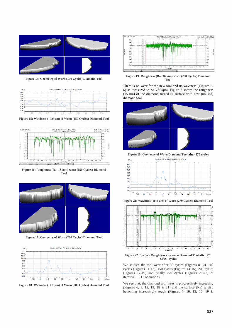
Figure 14: Geometry of Worn (150 Cycles) Diamond Tool
Figure 15: Waviness (10.6 μm) of Worn (150 Cycles) Diamond Tool
Figure 16: Roughness (Ra: 131nm) worn (150 Cycles) Diamond
Tool
Figure 17: Geometry of Worn (200 Cycles) Diamond Tool
Figure 18: Waviness (12.2 μm) of Worn (200 Cycles) Diamond Tool
Figure 19: Roughness (Ra: 168nm) worn (200 Cycles) Diamond
Tool
There is no wear for the new tool and its waviness (Figures 5-
6) as measured to be 3.803μm. Figure 7 shows the roughness
(15 nm) of the diamond turned Si surface with new (unused)
diamond tool.
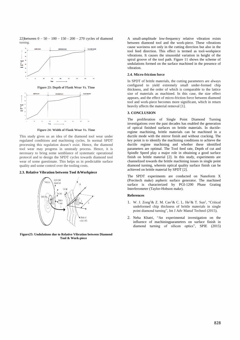
Figure 20: Geometry of Worn Diamond Tool after 270 cycles
Figure 21: Waviness (15.8 μm) of Worn (270 Cycles) Diamond Tool
Figure 22: Surface Roughness - by worn Diamond Tool after 270
SPDT cycles
We studied the tool wear after 50 cycles (Figures 8-10), 100
cycles (Figures 11-13), 150 cycles (Figures 14-16), 200 cycles
(Figures 17-19) and finally 270 cycles (Figures 20-22) of
iterative SPDT operations.
We see that, the diamond tool wear is progressively increasing
(Figures 6, 9, 12, 15, 18 & 21) and the surface (Ra) is also
becoming increasingly rough (Figures 7, 10, 13, 16, 19 &
828
22)between 0 – 50 – 100 – 150 - 200 – 270 cycles of diamond turning.
Figure 23: Depth of Flank Wear Vs. Time
Figure 24: Width of Flank Wear Vs. Time
This study gives us an idea of the diamond tool wear under
regulated conditions and machining cycles. In normal SPDT
processing this regulation doesn’t exist. Hence, the diamond
tool wear may progress in unsteady process. Hence, it is
necessary to bring some semblance of systematic operational
protocol and to design the SPDT cycles towards diamond tool
wear of some guestimate. This helps us in predictable surface
quality and some control over the tooling costs.
2.3. Relative Vibration between Tool &Workpiece
Figure25: Undulations due to Relative Vibration between Diamond
Tool & Work-piece
A small-amplitude low-frequency relative vibration exists
between diamond tool and the work-piece. These vibrations
cause waviness not only in the cutting direction but also in the
tool feed direction. This effect is termed as tool-workpiece
vibrations. It causes the sinusoidal variation in height of the
spiral groove of the tool path. Figure 11 shows the scheme of
undulations formed on the surface machined in the presence of
vibration.
2.4. Micro-friction force
In SPDT of brittle materials, the cutting parameters are always
configured to yield extremely small under-formed chip
thickness, and the order of which is comparable to the lattice
size of materials as machined. In this case, the size effect
appears, and the effect of micro-friction force between diamond
tool and work-piece becomes more significant, which in return
heavily affects the material removal [1].
3. CONCLUSION
The proliferation of Single Point Diamond Turning
investigations over the past decades has enabled the generation
of optical finished surfaces on brittle materials. In ductile-
regime machining, brittle materials can be machined in a
ductile mode with the mirror finish and without cracking. The
key point is to identify the machining conditions to achieve the
ductile regime machining and whether these identified
parameters are optimal. The Tool feed rate, Depth of cut and
Spindle Speed play a major role in obtaining a good surface
finish on brittle material [2]. In this study, experiments are
channelized towards the brittle machining issues in single point
diamond turning, wherein optical quality surface finish can be
achieved on brittle material by SPDT [2].
The SPDT experiments are conducted on Nanoform X
(Precitech make) aspheric surface generator. The machined
surface is characterized by PGI-1200 Phase Grating
Interferometer (Taylor-Hobson make).
References
1. W. J. Zong1& Z. M. Cao1& C. L. He1& T. Sun1, “Critical
undeformed chip thickness of brittle materials in single
point diamond turning”, Int J Adv Manuf Technol (2015).
2. Neha Khatri, “An experimental investigation on the
influence of machiningparameters on surface finish in
diamond turning of silicon optics”, SPIE (2015)