Embed Size (px)
Citation preview

Vol.:(0123456789)1 3
Applied Physics A (2019) 125:176 https://doi.org/10.1007/s00339-019-2436-9
Effect of dynamic adjustment of diamond tools on nano-cutting behavior of single-crystal silicon
Ming Hai Wang1 · Si Yao You1 · Fu Ning Wang1 · Qi Liu1
Received: 31 October 2018 / Accepted: 23 January 2019 / Published online: 8 February 2019 © The Author(s) 2019
AbstractA new method for adjusting the tool rake and flank angles by changing the position of the tools was used to dynamic explore the nano-cutting behavior of single-crystal silicon using MD simulation. Simulations under the same cutting conditions were carried out using a tool swinging to six different rake angles of − 10°, − 15°, − 20°, − 25°, − 30°, − 35°, and − 45°. The advantages of Tersoff potential function are discussed in comparison with those of using SW potential function. The coordination number, von Mises stress, hydrostatic stress, system temperature, potential energy and cutting force during the nano-cutting process are studied. The results of a statistical study reveal that the coordination numbers of silicon atoms showed a minimum value and the highest average hydrostatic stress at − 25° adjustment angle. Besides, the maximum system potential energy and temperature is also obtained at an adjustment angle of − 25° after − 20° (it can be defined as a larger adjustment angle after − 15°). In addition, the results also point out that the highest average tangential force was observed at − 25°, which is different from the previous researches.
1 Introduction
Single-crystal silicon is considered an ideal material in optoelectronics, infrared optics, microelectronics, and micro-electro-mechanical systems (MEMS) [1, 2] due to its low mass density, high refractive index, and low thermal expansion coefficient. With the rapid development of these industries in recent years, the demand for silicon materi-als has grown exponentially. Single-point diamond turn-ing (SPDT) [3, 4] is an effective ultra-precision machining method compared with the traditional processing technolo-gies of silicon, such as grinding and polishing [5]. However, single-crystal silicon is of prominent anisotropy in mechani-cal and physical properties, and obvious differences appear in its surface quality on the circumferential surface of the processed surface in different crystallographic directions of the same crystal plane. SPDT of single-crystal silicon is inherently a complex process that includes brittle fracture, ductile deformation, phase transformation, critical cutting thickness, optimal tool geometry, and surface anisotropy. The tool geometry of diamond tool is also a critical aspect
that influences the surface integrity of SPDT and needs to be in controlled.
A comprehensive understanding of silicon-machining mode and tool geometry is imperative to achieve cost-effec-tive and efficient SPDT. The previous studies reveal that ductile mode machining of silicon exploiting HPPT can be achieved by careful selection of cutting parameters and tool geometry. From the tool geometry perspective, negative rake angle tools were found to generate the compressive stress field during the machining process is beneficial to suppress the generation and expansion of microcracks and the high hydrostatic pressure required for structural transformation of silicon ensuing brittle to ductile transition (BDT) [6, 7]. Zhao et al. [8] revealed that using diamond tools with rake angles plays an important role affecting the degree of anisot-ropy in the research of ultra-precision machining of potas-sium dihydrogen phosphate. Using 0° rake angle to − 20° rake angle tools, they observed that the variation of cutting force caused by anisotropy is reduced from 13.9 to 10.23% and the fluctuation of surface roughness is still above 30%. Blake and Scattergood [3, 4] observed that the increase of critical chip thickness was also claimed to increase with an increase in negative rake angle of the tool and an increase of critical chip thickness from 0° to − 10° rake angle and found a sharp increase in critical chip thickness at − 30° rake. They performed SPDT of silicon and germanium using
* Ming Hai Wang [email protected]
1 College of Mechanical and Electrical Engineering, Shenyang Aerospace University, Shenyang 110136, China

M. H. Wang et al.
1 3
176 Page 2 of 13
diamond tools with rake angles of 0°, − 10°, and − 30°. During the single-point diamond turning of ⟨110⟩ crystallo-graphic direction of silicon (111) crystal plane, Leung et al. [6] found that visible differences occurred from − 15° to − 25° rake angles and higher machining quality was also achieved. Yan et al. [9] observed an increase of critical chip thickness from 0° to − 40° rake angle tools. Fang et al. [10] suggested the importance of effective rake angle in associa-tion with cutting edge radius and depth of cut. Mir et al. [11] found that ductile mode machining can still be achieved with the required hydrostatic pressure is maintained for HPPT of silicon during machining and this performance was found highly dependent on rake angles.
Due to the limitation of the existing observation tech-nology, it is currently impossible to reveal the nano-cutting behavior of single-crystal silicon from the perspective of the atom. Only the macroscopic experimental results can be used to analyze the wear of the diamond tool. The timescales used in these experiments are too long to directly observe the atomic scale in the femtosecond-to-picosecond time range. As a powerful complement to experimental research, molecular dynamics simulation methods have been success-fully applied to the study of the nano-cutting behavior of single-crystal silicon. Komanduri et al. [12] simulated the nano-cutting of single-crystal aluminum with a diamond tool and analyzed the impact of anisotropy on material removal and subsurface deformation mechanisms. In addition, Lai et al. [13, 14] studied that the anisotropic behaviors in single-crystal germanium (a brittle material) exhibited dur-ing nano-cutting and nano-indentation. Goel et al. [15–17] simulated the process of nanometric cutting of single-crystal silicon and silicon carbide by a diamond tool. In addition, they also described the application of molecular dynamics methods in the processing of brittle materials such as silicon and germanium. Wang et al. [18] simulated the nanometric cutting process of single-crystal silicon in six combinations of crystal planes and crystal directions. Results obtained among the six crystal directions, the (100) [0 − 10] direc-tion is the best, and the (110) [00 − 1] direction is the worst for ductile cutting.
Previous studies have provided many valuable insights into only the influence of tool rake angles on the machining behavior of single-crystal silicon. They controlled a single variable and changed the rake angles of tool separately to keep the tool flank angles consistent. This requires diamond tools of different geometries during the experiment, which greatly increases the amount and cost of the experiment. Therefore, this paper proposes a method of single-crystal silicon processing by adjusting the tool swing to different cutting angles.
Hence, the main purpose of this paper is to carry out MD simulations to investigate the ultra-precision machin-ing and reveal the cutting behavior when the diamond tool
is oscillated and adjusted to different cutting angles. The remainder of this paper is arranged as follows. In the second section, the construction of simulation models with different cutting angles and the selection of cutting parameters are introduced. In the third section, a comparison between seven different adjustment angles in nano-cutting has been made in terms of coordination number (CN), von Mises stress, hydrostatic stress, system temperature, potential energy, and cutting force. Finally, main interesting findings are summa-rized in the last section.
2 MD simulation model
2.1 New improved cutting model
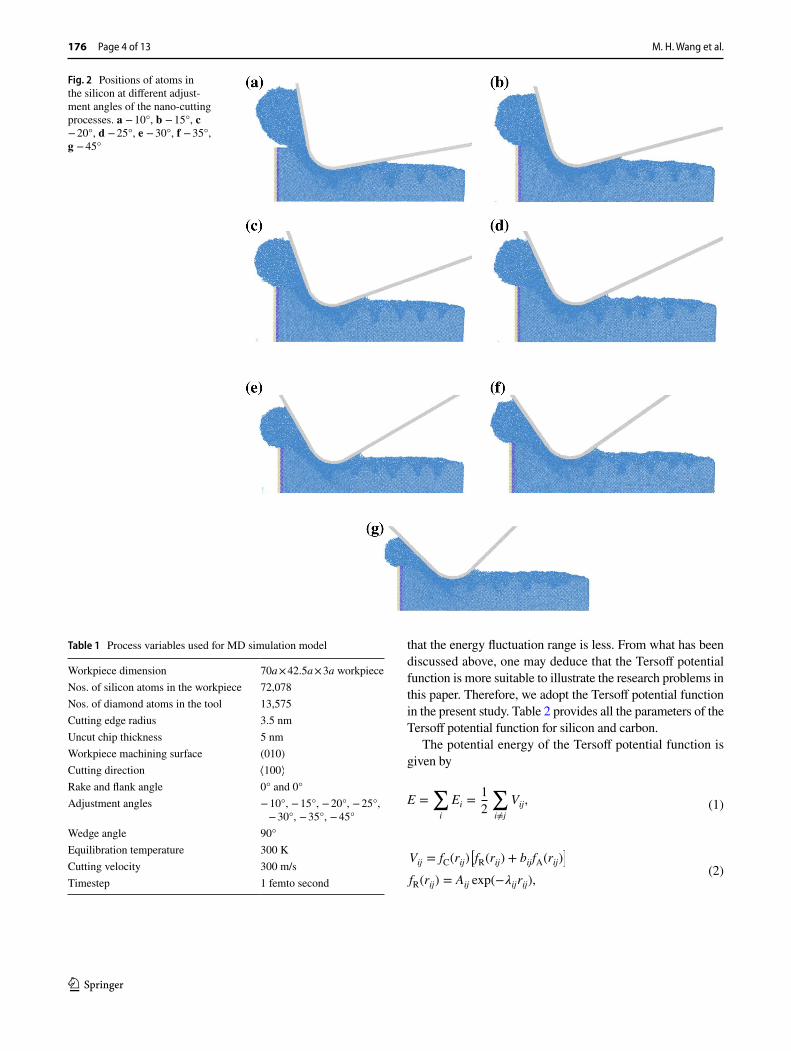
Figure 1 illustrates the schematic diagrams of new two-dimensional MD nano-cutting simulation model. The model involves a single-crystal silicon workpiece and a diamond tool. It can be seen from Fig. 1 that using a diamond tool with one geometry and parameter to complete seven cuts. Rotate to − 10°, − 15°, − 20°, − 25°, − 30°, − 35°, and − 45° centering on the center of the circle, where tool edge radius is located. It is worth noting that the tiny center was not set as the center of the circle. The reason is lack of sufficient precision in the actual machining process. However, it is necessary to ensure that other parameters such as depth of cut are constant, and the cutting level is nanometer, so this can only be done to control the single variable. The cut-ting image when the tool is adjusted to − 10°, − 15°, − 20°, − 25°, − 30°, − 35°, and − 45° is shown in Fig. 2. The cutting process under different cutting rake angle and flank angle conditions caused by the adjustment of the tool position can be clearly observed. The experiment shows that the hardness of silicon is 9.3 GPa [19] and that of diamond is 78.96 GPa [20] and the focus of this simulation is on single-crystal sili-con workpieces. Therefore, the diamond tool is assumed as an ideal rigid body [21] without any deformation and wear in the cutting process. The geometry of the tool is made up of rake angle, edge radius, and flank angle and the extra carbon atoms inside the tool were removed to save time in the simulation. The tool thickness is 1b and width is 3b with the rake face and the flank face of the tool is perpendicular to each other (wedge angle is 90°). The rake and flank angles of the tool are both 0°, and the cutting angles are determined by the tool swing adjustment. The atomic number of the tool is 13575, where b is the lattice constant of diamond (b = 0.35656 nm).
The dimension of single-crystal silicon workpiece is 70a × 42.5a × 3a along the X, Y, and Z directions, consisting of 72,078 atoms, where a is lattice constant of single-crystal silicon (a = 0.5431 nm). The atoms of workpiece were allo-cated into one of the three different zones: Newton layer

Effect of dynamic adjustment of diamond tools on nano-cutting behavior of single-crystal…
1 3
Page 3 of 13 176
atoms, thermostat layer atoms, and boundary layer atoms. The role of the boundary layer is to prevent the workpiece from moving rigidly during the cutting process. The function of the thermostat layer is to absorb the heat from the Newton layer by adjusting the atomic velocity, so that the tempera-ture of the Newton layer is not too high. The atoms in the Newton layer and the thermostat layer satisfy the classical Newtonian motion law. Table 1 provides the computational parameters, detailed configuration of the workpiece, and cutting tool which can be used for replication of simulation results.
MD simulation model was built using the periodic bound-ary condition along the Z direction and shrink-wrapped boundary condition along the X and Y directions. The atoms in the thermostat layers were updated using a micro-canon-ical (NVE) [22] ensemble, instead of a canonical (NVT) [23] ensemble. The MD simulation model was equilibrated to 300 K under the micro-canonical (NVE) ensemble and the integration method of the atoms was applied to Veloc-ity Verlet [24]. The molecular dynamics software used is LAMMPS (large-scale atomic/molecular massively parallel simulator), which is a kind of MD software developed by Sandia National Laboratories, was adopted to simulate the nano-cutting process of silicon [25, 26]. Visual molecular dynamics (VMD) [27] along with OVITO [28] were used to visualise and analyze the atomistic simulation data.
2.2 Selection of potential energy function
To give a good approximation, it is important to select an appropriate potential function. There are two kinds of atoms
in the MD simulation model of cutting process, which are carbon and silicon atoms. Therefore, there are three differ-ent atomic interactions between each other: (1) the inter-action between monocrystalline silicon atoms (Si–Si); (2) the interaction between carbon atoms (C–C); and (3) the interaction between single-crystal silicon atoms and carbon atoms (Si–C). During simulation, the three kinds of potential energy functions for the interaction between silicon and car-bon, which are Morse potential [29], SW potential [30], and Tersoff potential [31, 32]. The Morse potential is a two-body potential, and the SW potential and the Tersoff potential are three-body potential. The SW potential function has a more excellent effect in describing the properties of a hard and brittle material such as single-crystal silicon or germanium. The Tersoff potential function works better when describing the interaction between materials.
We evaluated the employability of the two potentials for comparative analysis. Figure 3 shows the comparison of the cutting force changes under two different potential functions. The comparison of a and b shows that the values of Tersoff potential function and SW potential function was also obtained by fitting the Displacement–force curves to straight lines in the strain range of 300 nN and 500 nN. At the same time, Figs. 4 and 5 illustrate the temperature and potential energy varia-tions of the system under different potential functions dur-ing the cutting process. Under the SW potential function, the temperature and potential energy variations’ range were found the larger range of variation, and the reciprocating fluctua-tion was the same trend; the temperature and potential energy changes of the Tersoff potential function were not obvious, and were also be observed basically no large fluctuation, indicating
Fig. 1 Molecular dynamics simulation model of single-crystal silicon and one diamond tool adjusted to seven cutting angles
M. H. Wang et al.
1 3
176 Page 4 of 13
that the energy fluctuation range is less. From what has been discussed above, one may deduce that the Tersoff potential function is more suitable to illustrate the research problems in this paper. Therefore, we adopt the Tersoff potential function in the present study. Table 2 provides all the parameters of the Tersoff potential function for silicon and carbon.
The potential energy of the Tersoff potential function is given by
(1)E =∑i
Ei =1
2
∑i≠j
Vij,
(2)Vij = fC(rij)
[fR(rij) + bijfA(rij)
]
fR(rij) = Aij exp(−�ijrij),
Fig. 2 Positions of atoms in the silicon at different adjust-ment angles of the nano-cutting processes. a − 10°, b − 15°, c − 20°, d − 25°, e − 30°, f − 35°, g − 45°
Table 1 Process variables used for MD simulation model
Workpiece dimension 70a × 42.5a × 3a workpieceNos. of silicon atoms in the workpiece 72,078Nos. of diamond atoms in the tool 13,575Cutting edge radius 3.5 nmUncut chip thickness 5 nmWorkpiece machining surface (010)Cutting direction ⟨100⟩Rake and flank angle 0° and 0°Adjustment angles − 10°, − 15°, − 20°, − 25°,
− 30°, − 35°, − 45°Wedge angle 90°Equilibration temperature 300 KCutting velocity 300 m/sTimestep 1 femto second

Effect of dynamic adjustment of diamond tools on nano-cutting behavior of single-crystal…
1 3
Page 5 of 13 176
where E is the total energy, Vij describes the energy between two atoms (i and j), (i, j, and k) label the atoms of the system,
(3)
fA(rij) = −Bij exp(−𝜇ijrij)
fC(rij) =
⎧⎪⎪⎨⎪⎪⎩
1
1
2+
1
2cos
�𝜋rij − Rij
Sij − Rij
�
0
⎫⎪⎪⎬⎪⎪⎭
rij < Rij
Sij > rij > Rij
rij > Sij
,
(4)bij = �ij
(1 + �ni
i�niij
)−1∕2ni
(5)
�ij =∑k≠i,j
fC(rik)�ikg(�ijk)
g(�ijk) = 1 +c2i
d2i
−c2i[
d2i+ hi − cos �ijk
] ,
Fig. 3 Cutting force curve under two potential functions. a Tersoff, b SW
Fig. 4 Temperature comparison chart under two potential functions
Fig. 5 Potential energy comparison chart under two potential functions

M. H. Wang et al.
1 3
176 Page 6 of 13
fR is a repulsive pair potential, fA is an attractive pair poten-tial, fC is a smooth length of the i–j bond, bij is the bond-order term, �ij counts the number of other bonds to atom i besides the i–j bond, and �ijk is the bond angle between the bonds i–j and i–k.
Although Morse potential is two-body potential, it can describe the interactions between carbon and silicon atoms more accurately as follows:
where D represents the cohesion energy and α represents modulus of elasticity, and r0 represents the equilibrium distance between atoms. D = 0.435 eV , � = 46.487 nm−1 , r0 = 0.19475 nm.
3 Results and discussion
3.1 Coordination analysis
As an investigation into the phase transformation [33] of silicon atoms in the cutting processes, the coordination
(6)U(rij) = D[e−2�(rij−r0) − 2e−�(rij−r0)
],
number (CN) of the atoms is calculated. Under continuous contact loading, silicon under the tool undergoes displace-ment phase transformations. Alpha-silicon (Si-I, brittle) [34] transforms to beta-silicon (Si-II, metallic, and ductile) [35] when the hydrostatic pressure reaches 10–13 GPa. The bond angle, bond length, and physical properties of the new phase have changed dramatically. As shown in Fig. 6, the silicon atom in the diamond cubic structure with a coordination number of four represents single-crys-tal silicon (Si-I, Si-XII, and Si-III), and the silicon atoms in the body-centered tetragonal structure with coordina-tion numbers of five and six are, respectively, bct5-Si and β-tinSi in MD simulations of nano-cutting [21, 36].
The variation in the coordination numbers of the silicon atoms under the seven different adjustment cutting angles at grinding distance of 30 nm is shown in Fig. 7a–g. Clearly, there is a significant increase in the number of atoms with five and six coordination atoms and appears around the dia-mond tool during the seven different cutting processes. It can be seen that the chip formation zone consists of the silicon atoms with the coordination numbers of five and six. This indicates that the phase transformation from c-Si to bct5-Si and β-tinSi occurs in the chip formation zone. The silicon atoms in the model are colored according to the difference in coordination numbers. It can be seen from the figure that as the tool adjustment angle increases, the amount of chips is significantly reduced, which indicates that there is a larger material removal rate as the angle increases.
To further investigate the subsurface deformation mech-anism in workpiece during the seven different machining processes, a statistic analysis of coordination number of the silicon atoms is given. It is evident from Fig. 8a that the number of atoms with five- and six-coordinated atoms ver-sus different adjustment cutting angles for the seven simula-tions is displayed, respectively, when the tool is machined to 12,900 steps. It is seen that although the cutting angle is linearly increased, the number of five-coordinated and six-coordinated atoms decreases, as the adjustment cutting angle increases. The five and six coordinations are consistent
Table 2 Tersoff potential parameters
Si–Si C–C
A 1830.8 1544.8B 471.18 389.63D 0.15 0.15R 2.85 1.95S 3 2.1c 100,390 19,981d 16.217 7.034h − 0.59825 − 0.33953n 0.78734 0.99054� 2.4799 3.4653� 1.7322 2.3064� 1.1 × 10⁻⁶ 4.1612 × 10⁻⁶
Fig. 6 Atomic structure diagram

Effect of dynamic adjustment of diamond tools on nano-cutting behavior of single-crystal…
1 3
Page 7 of 13 176
with the theoretical coordination number of an atoms in the bct5-Si and β-tinSi phase. Moreover, the reduction trend is non-linear and obtains the smallest coordination number at
− 25°. It can also be seen from the figure that in the case of small adjustment cutting angles, the silicon atoms of the five and six coordination numbers decrease rapidly. When the adjustment cutting angles are greater than − 25°, the ampli-tude is far less than the former, even if the five and six coor-dination silicon atoms are on the rise. In the case of merely adjusting the rake angle of the tool, the number of silicon atoms with coordination numbers of five and six decreases, as the negative rake angle of the tool increases, which is different from the previous studies. This indicates that the lowest subsurface damage is shown when the tool is adjusted to − 25°, under the negative rake angle cutting condition. The total phase transformation atomic number histogram of the different adjustment angles shown in Fig. 8b shows that the total number of phase transformation atoms decreases, as the tool negative rake angle adjustment angle increases. This just means that the increased tool negative rake angle adjustment angle tip cutting can produce a better subsurface.
3.2 Stress analysis
The evolution of microstructure is closely related to atomic stress in nano-cutting. The distribution characteristics of stress can effectively strengthen the understanding of the relationship between microstructure evolution and mechan-ics. Hydrostatic stress [37] during the nano-cutting process can be expressed as
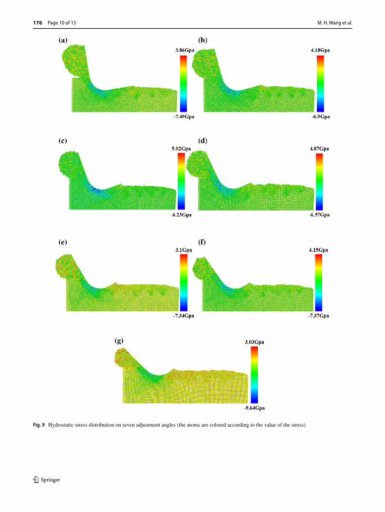
The hydrostatic stress distributions of workpieces for seven adjustment angles are illustrated in Fig. 9a–g. Interest-ingly, high hydrostatic stress occurs in front of and beneath the tool edge under these seven adjustment angles. It is noted that the phase transformation silicon atoms (five coordinated and six coordinated) are also mostly located in this region and the difference is also presented, which reveals that the evolution of crystalline phases is consistent with the distri-bution of hydrostatic stress. It can be seen intuitively from the figure that a significant difference between − 20° and − 25° in distribution of hydrostatic stress under the linear increase of the adjustment angle. A maximum hydrostatic stress of 3.59 GPa at − 25° is calculated and is shown in Fig. 10a. Hydrostatic stress is a quantity associated with volume change leading to classic thermo dynamic phase transitions in continuous matter, whereas von Mises stress
(7)�hydro = (1∕3)(�xx + �yy + �zz).
[38] measures shear deformation that governs shape change usually by the activation of defect transport mechanisms. Von Mises stress can be expressed as
Figure 10b shows the average von Mises stress of seven different adjustment angles. It is clear that the average von Mises stress of − 25° adjustment angle being 1.94 GPa. It can be observed that the overall trend of average hydrostatic stress at these angles declined, but there has also been an inflection point at − 25°. A larger negative rake angle had greater hydrostatic stress in the previous study. However, according to the analysis in the previous section, the increas-ing angles of adjustment and the difference formed at − 25° contradict previous research. The difference formed at − 25° in this study indicates that there must be other factors that cause this difference, in addition to the influence of the rake angle of the tool. The following sections will give an analy-sis and research for this difference.
3.3 Temperature and potential energy
The temperature–displacement curves for seven different adjustment angles are shown in Fig. 11. It can be seen from Fig. 11 that as the adjustment angle changes constantly, the system temperatures are different. It can be roughly seen that the temperature of the system has a decreasing trend with the increase of the negative adjustment angle of the tool. Furthermore, it is clearly found that the temperature of − 25° adjustment angle is higher than at − 20°. A large amount of the energy and cutting heat released from the frictional contact between workpiece and tool in conventional machin-ing operations. When the tool swings at a small adjustment angle, the tool flank face is almost completely in contact with the workpiece, which accelerates the friction between the machined surface and the flank face. As the adjustment angle becomes larger, the tool is more inclined. The fric-tion between the flank face and the machined surface and the contact area are reduced, this leads to a reduction in the temperature of the system. Under normal circumstances, as the rake angle of the tool increases, the system temperature should be lower and lower according to the previous reason-ing. However, the trend at − 25° higher than − 20° indicates that there are other factors besides the friction of the tool and the machined surface and the size of the contact area.
In the nano-cutting process, the single-crystal silicon undergoes a phase transformation under the extrusion of the tool, and the phase transformation of silicon below the lowest point of the cutting edge of the tool produces severe plastic deformation. The deformation accumulated in the
(8)�von =
√3(�2xy+ �2
yz+ �2
xz
)+ (1∕2)
[(�xx − �yy
)2+(�xx − �zz
)2+(�zz − �yy
)2].

M. H. Wang et al.
1 3
176 Page 8 of 13

Effect of dynamic adjustment of diamond tools on nano-cutting behavior of single-crystal…
1 3
Page 9 of 13 176
deformed lattice can be gradually released along the flank face, becoming a cutting heat, after the phase transforma-tion of silicon passes through the chip edge. Since the gap between the flank face and the machined surface varies from − 10° to − 20° is small. Therefore, the cutting heat cannot be released instantaneously, and will be gradually absorbed by the inside of the tool in a short time. The temperature of the system is not greatly affected. When the tool is adjusted to − 25°, the heat of cutting generated cannot be completely absorbed by the inside of the tool in a short time due to the increase of the gap. At the same time, the increased flank angle shortens the contact time between the tool and the machined surface and the contact area is reduced. In this case, the amount of heat absorbed is reduced, which causes the temperature of the machined surface and the flank face to rise and the system temperature to increase. Since it is only a small part of the contact between the flank face and the machined surface of the tool, it has little effect on the system temperature. When the adjustment angle is increased again, the gap between the flank face and the machined surface is very large at this time, and most of the generated heat of cutting is directly excluded along the flank face.
Potential energy [39] is the energy of a system as a result of the atomic position or the particle arrangement of the system, which marks the stability of the system in energy. The potential energy versus the machining distance for seven different adjustment angles is also plotted, as shown in Fig. 12. Obviously, the potential energy of seven different adjustment angles increases with the increase of machining distance. However, it is noted here that different adjustment
angles show different system potentials and significant dif-ferences at − 25°. It can be seen that when the negative angle is greater than − 20°, the maximum system potential energy is obtained at an adjustment angle of − 25°. In a small angle range (− 10°, − 15°), the trend of the system potential energy decreases with the increase of the negative angle. This means that the workpiece undergoes different degrees of deformation when a tool swings to a different angles and specificity at − 25°.
3.4 Cutting force
The change in temperature can cause varies in the structure of silicon atoms on the machined surface and results in the reduction of hardness of it, so the physical and chemical properties of diamonds also change and thus cause phase transformation. The increase in temperature causes the sili-con material to soften and directly causes a reduction in cutting force. Cutting force [40] measurement is an impor-tant indicator of nano-cutting behavior. Figure 13 represents average tangential forces (X) and normal forces (Y) calcu-lated with respect to seven different adjustment angles. It can be seen that the adjustment of the tool angle has little effect on the normal force, because the structure of the tool has not changed. As the variation of the tangential force correspond-ing to different adjustment angles, we can clearly see that the tangential force of − 20° is higher than − 25°. However, it is noted here that the tangential forces before − 25° increase more slowly than the rate of decline after − 25°. In addi-tion, a comparison of different adjustment angles indicates that the slope of the curve after − 25° is higher than the slope before − 25°. This means that the − 25° adjustment angle is a special value again. Different from the previous researches, the tangential forces of the tool with different rake angles change little and are much larger than the normal
Fig. 7 Cross-sectional view of the atomic positions for differ-ent adjustment angles. a − 10°, b − 15°, c − 20°, d − 25°, e − 30°, f − 35°, and g − 45°. Atoms are colored according to coordination number (CN)
◂
Fig. 8 Number of atoms with five-coordinate and six-coordinate nearest neighbors against seven adjustment angles and total phase transforma-tion atom numbers corresponding to different adjustment angles, respectively
M. H. Wang et al.
1 3
176 Page 10 of 13
Fig. 9 Hydrostatic stress distribution on seven adjustment angles (the atoms are colored according to the value of the stress)

Effect of dynamic adjustment of diamond tools on nano-cutting behavior of single-crystal…
1 3
Page 11 of 13 176
forces. This paper is just the opposite, the reason is tool of the previous study is not set to rigid body, and it is not necessary to consider the influence of carbon atom numbers and deformation of the tool on the cutting force. Although this study is closely related to the angle, the difference is that the simultaneous change of the rake and flank angles of tool change the contact area between the tool and machined surface. The number of interacting carbon atoms is different, so the cutting force will naturally differ.
4 Conclusions
MD simulations have been used to study the effect of dynamic adjustment of the cutting angles on the nano-cutting behavior of single-crystal silicon. Adjust the tool to − 10°, − 15°, − 20°, − 25°, − 30°, − 35°, and − 45° without
Fig. 10 Average hydrostatic stress and von Mises stress curve under seven adjustment angles
Fig. 11 Temperatures of system after the tool has adjusted to seven different cutting angles and advanced by 35 nm
Fig. 12 Variation of potential energy of system under the seven adjustment angles cutting
Fig. 13 Variation of tangential forces and normal forces when the tool is adjusted to seven different angles

M. H. Wang et al.
1 3
176 Page 12 of 13
changing the geometry of the tool. Accordingly, the follow-ing conclusions can be drawn:
1. With the uniform adjustment of the cutting rake angles, the silicon atoms of the 5 and 6 coordination numbers showed a non-linear trend, showing a significant differ-ence and a minimum value at − 25°. This indicates that the lowest subsurface damage is shown when the tool is adjusted to − 25°.
2. The average hydrostatic stress for − 25° adjustment angle is larger than that for other angles. Although the average von Mises stress of seven different adjustment angles shows an overall downward trend, an inflection point still occurred at − 25°.
3. As the tool swings, its rake and flank angles change at the same time. In a larger angular range (except − 10°, − 15°), when adjusted to − 25°, the flank temperature is high and the system temperature increases. This is because the cutting heat generated during the cutting process cannot be absorbed by the inside of the tool in time. The increased flank angle shortens the contact time and contact area between the tool and the machined sur-face. This causes an increase in the temperature of the system. The maximum system potential energy is also obtained at an adjustment angle of − 25°.
4. The highest average tangential force was observed at − 25°. The adjustment of the tool angle has little effect on the normal force and the average normal force is much larger than the tangential force, which is different from previous research.
Open Access This article is distributed under the terms of the Crea-tive Commons Attribution 4.0 International License (http://creat iveco mmons .org/licen ses/by/4.0/), which permits unrestricted use, distribu-tion, and reproduction in any medium, provided you give appropriate credit to the original author(s) and the source, provide a link to the Creative Commons license, and indicate if changes were made.
References
1. W.J. Zong, T. Sun, D. Li, K. Cheng, Y.C. Liang, XPS analysis of the groove wearing marks on flank face of diamond tool in nanometric cutting of silicon wafer. Int. J. Mach. Tool Manuf. 48, 1678–1687 (2008)
2. L. Zhang, H.W. Zhao, Z.C. Ma, H. Huang, C.L. Shi, W.S. Zhang, A study on phase transformation of monocrystalline silicon due to ultra-precision polishing by molecular dynamics simulation. AIP Adv. 2, 042116–042127 (2012)
3. P.N. Blake, T. Bifano, R.O. Scattergood, Precision machining of ceramic materials. Am. Ceram. Soc. Bull. 67(6), 1038–1044 (1988)
4. P.N. Blake, R.O. Scattergood, Ductile-regime machining of ger-manium and silicon. J. Am. Ceram. Soc. 73(4), 946–957 (1990)
5. H. Kim, E. Kim, B. Song, Diamond turning of large off-axis aspheric mirrors using a fast tool servo with on-machine meas-urement. J. Mater. Process. Technol. 146(3), 349–355 (2004)
6. T.P. Leung, W.B. Lee, X.M. Lu, Diamond turning of silicon sub-strates in ductile-regime. J. Mater. Process. Technol. 73(1–3), 42–48 (1998)
7. C.L. Chao, K.J. Ma, D.S. Liu, C.Y. Bai, T.L. Shy, Ductile behav-iour in single point diamond-turning of single-crystal silicon. J. Mater. Process. Technol. 127(2), 187–190 (2002)
8. Q. Zhao, Y. Wang, G. Yu et al., Investigation of anisotropic mech-anisms in ultra-precision diamond machining of KDP crystal. J. Mater. Process. Technol. 209(8), 4169–4177 (2009)
9. J. Yan, K. Syoji, T. Kuriyagawa, H. Suzuki, Ductile regime turning at large tool feed. J. Mater. Process. Technol. 121(2–3), 363–372 (2002)
10. F.Z. Fang, V.C. Venkatesh, Diamond cutting of silicon with nano-metric finish. CIRP Ann. Manuf. Technol. 47(1), 45–49 (1998)
11. A. Mir, X. Luo, K. Cheng, A. Cox, Investigation of influence of tool rake angle in single point diamond turning of silicon. Int. J. Adv. Manuf. Technol. 94, 2343–2355 (2018)
12. R. Komanduri, N. Chandrasekaran, L.M. Raff, MD simulation of nanometric cutting of single crystal aluminum—effect of crystal orientation and direction of cutting. Wear 242(1), 60–88 (2000)
13. M. Lai, X.D. Zhang, F.Z. Fang, Y.F. Wang, M. Feng, W.H. Tian, Study on nanometric cutting of germanium by molecular dynam-ics simulation. Nanoscale Res. Lett. 8(1), 1–10 (2013)
14. M. Lai, X.D. Zhang, F.Z. Fang, Nanoindentation-induced phase transformation and structural deformation of monocrystalline germanium: a molecular dynamics simulation investigation. Nanoscale Res. Lett. 8(1), 1–9 (2013)
15. S. Goel, X. Luo, R.L. Reuben, Molecular dynamics simulation model for the quantitative assessment of tool wear during single point diamond turning of cubic silicon carbide. Comput. Mater. Sci. 51, 402–408 (2011)
16. S. Goel, X. Luo, R.L. Reuben, Wear mechanism of diamond tools against single crystal silicon in single point diamond turning pro-cess. Tribol. Int. 57, 272–281 (2013)
17. S. Goel, X. Luo, R.L. Reuben, H. Pen, Influence of temperature and crystal orientation on tool wear during single point diamond turning of silicon. Wear 25, 65–72 (2012)
18. Z. Wang, J. Chen, G. Wang, Q. Bai, Y. Liang, Anisotropy of single-crystal silicon in nanometric cutting. Nanoscale Res. Lett. (2017). https ://doi.org/10.1186/s1167 1-017-2046-4
19. B.R. Lawn, A.G. Evans, D.B. Marshall, Elastic/plastic indenta-tion damage in ceramics: the median/radial crack system. J. Am. Ceram. Soc. 63, 574 (1980)
20. C. Francois, Materials Handbook, A Concise Desktop Reference (Springer, Berlin, 2000), p. 348
21. J.C. Rozzi, F.E. Pfefferkorn, F.P. Incropera et al., Transient, three-dimensional heat transfer model for the laser assisted machining of silicon nitride: I. Comparison of predictions with measured surface temperature histories. Int. J. Heat Mass Transf. 43(8), 1409–1424 (2000)
22. S. Goel, W. Bin Rashid, X. Luo, A. Agrawal, V.K. Jain, A theoreti-cal assessment of surface defect machining and hot machining of nanocrystalline silicon carbide, J. Manuf. Sci. Eng. 136 (2014)
23. K.Y. Fung, C.Y. Tang, C.F. Cheung, Molecular dynamics analysis of the effect of surface flaws of diamond tools on tool wear in nanometric cutting. Comput. Mater. Sci. 1, 60–70 (2017)
24. W. Zhi-Guo, Z. Peng et al., Effect of C–C bond breakage on dia-mond tool wear in nanometric cutting of silicon. Interdiscip. Phys. Relat. Areas Sci Technol. 64(19), 198104 (2015)
25. S. Plimpton, Fast parallel algorithms for short-range molecular dynamics. J. Comput. Phys. 117, 1–19 (1995)
26. LAMMPS Molecular Dynamics Simulator (2011). http://lammp s.sandi a.gov. Accessed 2011

Effect of dynamic adjustment of diamond tools on nano-cutting behavior of single-crystal…
1 3
Page 13 of 13 176
27. W. Humphrey, A. Dalke, K. Schulten, VMD: visual molecular dynamics. J. Mol. Graph. (1996) 33–38
28. A. Stukowski, Visualization and analysis of atomistic simulation data with OVITO—the Open Visualization Tool. Model. Simul. Mater. Sci. Eng. 2010;18(1):015012
29. M.B. Cai, X.P. Li, M. Rahman, Characteristics of “dynamic hard particles” in nanoscale ductile mode cutting of monocrystalline silicon with diamond tools in relation to tool. Wear 263(7–12), 1459–1466 (2007)
30. L. Pizzagalli, J. Godet, J. Guenole, S. Brochard, E. Holmstrom, K. Nordlund, T. Albaret, A new parametrization of the Still-inger–Weber potential for an improved description of defects and plasticity of silicon. J. Phys. Condens. Matter (2013). https ://doi.org/10.1088/0953-8984/25/5/05580 1
31. J. Tersoff, Modeling solid-state chemistry: interatomic poten-tials for multi-component systems. Phys. Rev. B 39(8), 5566 (1989)
32. J. Tersoff. Erratum, Modeling solid-state chemistry: interatomic potentials for multicomponent systems. Phys. Rev. B 41(5), 3248 (1990)
33. H.S. Nalwa, Handbook of Surfaces and Interfaces of Materials: Surface and Interface Phenomena (Academic Press, New York, 2001)
34. V. Domnich, Y. Gogotsi, S. Dub, Effect of phase transformations on the shape of the unloading curve in the nanoindentation of silicon. Appl. Phys. Lett. 76, 2214–2216 (2000)
35. Y.H. Lin, T.C. Chen, A molecular dynamics study of phase trans-formations in mono-crystalline Si under nanoindentation. Appl. Phys. A 92, 571–578 (2008)
36. L. Zhang, H. Zhao, Y. Yang et al., Evaluation of repeated single-point diamond turning on the deformation behavior of monocrys-talline silicon via molecular dynamic simulations. Appl. Phys. A 116(1), 141–150 (2014)
37. K. Mylvaganam, L.C. Zhang, P. Eyben et al., Evolution of meta-stable phases in silicon during nanoindentation: mechanism anal-ysis and experimental verification. Nanotechnology 20, 305705 (2009)
38. G.L.W. Cross, Silicon nanoparticles: isolation leads to change. Nat. Nanotechnol. 6, 467–468 (2011)
39. L. Zhang, H. Zhao, Y. Yang et al., Evaluation of repeated single-point diamond turning on the deformation behavior of monocrys-talline silicon via molecular dynamic simulations. Appl. Phys. A 116, 141–150 (2014)
40. C. Wamg, K. Cheng, N. Nelson, W. Sawangsri, R. Rakowski, Cut-ting force-based analysis and correlative observations on the tool wear in diamond turning of single crystal silicon. Inst. Mech. Eng. (2014). https ://doi.org/10.1177/09544 05414 54331 6
Publisher’s Note Springer Nature remains neutral with regard to jurisdictional claims in published maps and institutional affiliations.