Embed Size (px)
Citation preview
British Columbia Carpenter Apprenticeship Program
Level 3 Line B
7960003566
Use Construction Drawings and SpecificationsCompetency B-1

OrderingCrown Publications, Queen’s PrinterPO Box 9452 Stn Prov Govt563 Superior St. 2nd FlrVictoria, B.C. V8W 9V7
Phone: 1 800 663-6105Fax: 250 387-1120Email: [email protected]: www.crownpub.bc.ca
Copyright © 2013 Industry Training AuthorityThis publication may not be reproduced in any form without permission by the Industry Training Authority.Contact Director, Crown Publications, Queen’s Printer at 250 356-6876.

SAFETY ADVISORYPlease note that it is always the responsibility of any person using these materials to inform him/herself about the Occupational Health and Safety Regulation pertaining to his/her work. The references to WorkSafeBC safety regulations contained within these materials do not / may not reflect the most recent Occupational Health and Safety Regulation (the current Standards and Regulation in BC can be obtained on the following website: http://www.worksafebc.com).
BC Carpenter apprentiCeship program—LeveL 3 1
Competency B-1Use Construction Drawings and Specifications
ContentsObjectives . . . . . . . . . . . . . . . . . . . . . . . . . . . . . . . . . . . . . . . . . . . . . . . . . . . . . . . . . . . . . . . . . . . . . . . . . . . . . . 2
Learning Task 1: Use Architectural Drawings . . . . . . . . . . . . . . . . . . . . . . . . . . . . . . . . . . . . . . . . . . . . . . . . . . 3
Self Test 1 . . . . . . . . . . . . . . . . . . . . . . . . . . . . . . . . . . . . . . . . . . . . . . . . . . . . . . . . . . . . . . . . . . . . . . . . . . . . . 11
Learning Task 2: Use Schedules . . . . . . . . . . . . . . . . . . . . . . . . . . . . . . . . . . . . . . . . . . . . . . . . . . . . . . . . . . . 13
Self Test 2 . . . . . . . . . . . . . . . . . . . . . . . . . . . . . . . . . . . . . . . . . . . . . . . . . . . . . . . . . . . . . . . . . . . . . . . . . . . . . 19
Learning Task 3: Use Shop Drawings and Reflected Ceiling Plans . . . . . . . . . . . . . . . . . . . . . . . . . . . . . . . . 21
Self Test 3 . . . . . . . . . . . . . . . . . . . . . . . . . . . . . . . . . . . . . . . . . . . . . . . . . . . . . . . . . . . . . . . . . . . . . . . . . . . . . 26
Learning Task 4: Interpret Elevation and Section Drawings . . . . . . . . . . . . . . . . . . . . . . . . . . . . . . . . . . . . . 27
Self Test 4 . . . . . . . . . . . . . . . . . . . . . . . . . . . . . . . . . . . . . . . . . . . . . . . . . . . . . . . . . . . . . . . . . . . . . . . . . . . . . 36
2 BC Carpenter apprentiCeship program—LeveL 3
Competency B-1Use Construction Drawings and Specifications
Construction drawings are the guide to the construction of a building—they are the way that the designer describes how to build the building to meet the specifications of the owner. Construction drawings can be very complicated, containing hundreds of sheets. To be able to construct the building the carpenter must be able to extract specific information and measurements from the drawings.
Specifications are typically in a booklet form and cover the brand, model, or other identifiers for the materials used for a specific building project. Where conflicts occur between specifications and drawings, the specifications normally outrank the drawings.
ObjectivesWhen you have completed the Learning Tasks in this Competency, you should be able to:
• describe schedules and detail drawings
• use schedules and detail drawings
• interpret interior and exterior elevations
CompetenciesWritten: “Read construction drawings”
You will be tested on your knowledge of construction drawings and contract documents.
practical: You will be required to extract specific information from construction drawings.
BC Carpenter apprentiCeship program—LeveL 3 3
Notes
CompetenCy B-1 Learning task 1
Learning Task 1Use Architectural Drawings
Buildings are designed for their use and their occupancy. The BC Building Code (BCBC) requires that the following building types must be designed by a registered professional (Architect or Engineer):
• large buildings over 600 m2 in floor area
• buildings more than three storeys in height
• buildings with assembly, care, or detention type occupancies
• high hazard factories
These buildings fall under Part 3 of the Building Code. A registered professional must verify through field reviews that the work was completed properly.
Commercial and Larger BuildingsNormally, architects design buildings in accordance to Part 3 of the Building Code and the architect may employ a registered professional engineer to do the structural design using Part 4. The architect may also employ other professionals to design the electrical, plumbing, and heating systems. Usually, the architect or an engineer will act as the project manager during the construction process.
Larger buildings are usually broken down into the following drawings to make them easier to read and more applicable to those using them:
• structural drawings
• architectural drawings
• electrical drawings
• mechanical drawings
Carpenters typically use the structural and architectural drawings.
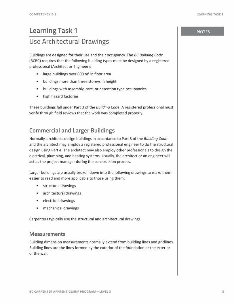
MeasurementsBuilding dimension measurements normally extend from building lines and gridlines. Building lines are the lines formed by the exterior of the foundation or the exterior of the wall.
Notes
4 BC Carpenter apprentiCeship program—LeveL 3
Learning task 1 CompetenCy B-1
Larger projects will have a series of gridlines. Gridlines are lettered in one direction and numbered in the other direction. Gridlines are often centered to major building components, such as beams and columns. Gridlines do not change from drawing to drawing or from floor to floor, and are used for layout purposes. The location of a pad footing may be given as being centered 150 mm south of gridline G and 200 mm east of gridline 3. An example of gridline use is shown in Figure 1.
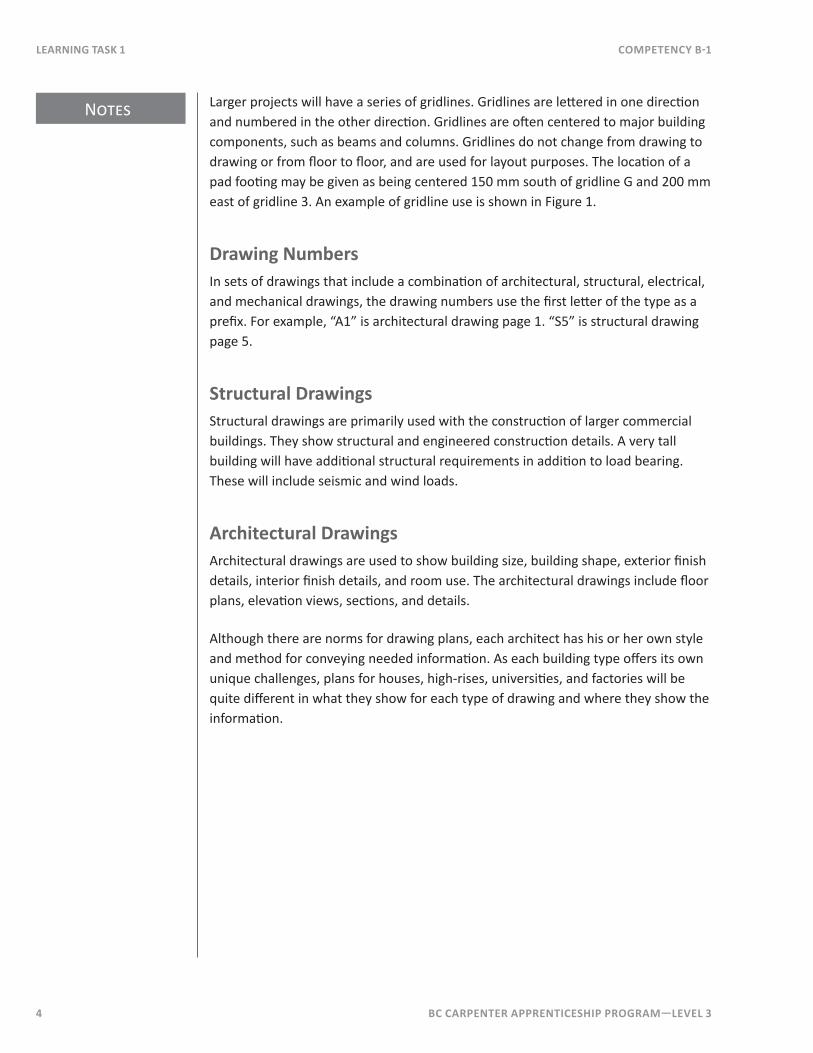
Drawing NumbersIn sets of drawings that include a combination of architectural, structural, electrical, and mechanical drawings, the drawing numbers use the first letter of the type as a prefix. For example, “A1” is architectural drawing page 1. “S5” is structural drawing page 5.
structural DrawingsStructural drawings are primarily used with the construction of larger commercial buildings. They show structural and engineered construction details. A very tall building will have additional structural requirements in addition to load bearing. These will include seismic and wind loads.
architectural DrawingsArchitectural drawings are used to show building size, building shape, exterior finish details, interior finish details, and room use. The architectural drawings include floor plans, elevation views, sections, and details.
Although there are norms for drawing plans, each architect has his or her own style and method for conveying needed information. As each building type offers its own unique challenges, plans for houses, high-rises, universities, and factories will be quite different in what they show for each type of drawing and where they show the information.
BC Carpenter apprentiCeship program—LeveL 3 5
Notes
CompetenCy B-1 Learning task 1
The Building Code specifies that the following must be shown in architectural drawings and drawings for heating, ventilation, and air conditioning systems:
• the name, type, and location of the building
• the name of the owner
• the name of the architect
• the name of the engineer or designer
• the north point
• the dimensions and height of all rooms
• the intended use of all rooms
• the details or description of the wall, roof, ceiling, and floor construction, including insulation
• the details or description of the windows and outside doors, including the size, hardware, weatherstripping, storm sashes, sills, and storm doors
• the size and continuity of all pipes, ducts, shafts, flues, and fire dampers
• the location, size, capacity, and type of all principal units of equipment
• the size, shape, and height of all chimneys and gas vents
• the size and location of all combustion air and ventilation openings
• the location and fire-resistance rating of required fire separations
It doesn’t state which of the above details are to be shown on floor plans, elevations, or cross sections. It only requires the information be shown to demonstrate that the plans are in conformance with the Building Code .
The following sections on floor plans, elevations, and cross sections present what is usually shown on these types of drawings, but this may vary considerably between different sets of plans.
Floor plansIn a set of construction drawings, the floor plans are near the beginning because they provide the reference for most of the construction information in the drawings. When looking at floor plans, you’re looking down on the building from overhead—floor plans are schematic drawings, where symbols are used to indicate the building components.
The following drawing excerpts are from plans produced by Garyali Architect Inc. of Victoria, BC for the Vancouver Island University’s Cowichan Campus (Figures 1 to 4).
6 BC Carpenter apprentiCeship program—LeveL 3
Learning task 1 CompetenCy B-1
CORRIDOR 135A
GROUP STUDY 124
GROUP STUDY 122 2a
3
ELEC
. 1
33C
OM
M.
134
Whiteboard
DVPscreen
Gallery / Verandah
SEE
DRA
WIN
G 2
/A2.
1
FO
R CO
NTI
NU
ATIO
N
Acid neutralizer
UP
D.F.
1 2 3 4 5 6 7
9
Wall line above
2
Cpt.
F.D.
F.D.
Wall
4
4
8
CL column
CL column
2aCL
CL
columnCL
2a
Conc. pad
8 9 10 11
A
B
C
Whiteboard Whiteboard
Whiteboard
LCD
scr
een
LCD
scr
een
Instructor station Instructor station
5
Concrete Stair 2.1:23 Risers at 17420 Treads at 2852 landings
20
A6.2
DVPscreen
HDCP. button
8000 8000 6500
3485
875
900
1520
3010
500
1150
550
1150
1550
945
1630
580
2100
800
1970
1970
500
900
1540
2550
410
950
810
500
7000
500
2500
2500
2340
1150
2500
6000
1525
450
900
3425
410
7000
6100
1635
2600
1580
2615
410
2501850
3100
520
500
2000
900
1950
2150
860
2510
1365
4400
1300 2100
4400
W.R
.W
.R.
10a
A6.4
1830
cle
ar
1850 clear
13a
A6.4
STORAGE 132ASTORAGE131 120
INFORMATION TECHNOLOGYSERVICE 132
CORRIDOR 100.05
CO
RRID
OR
100
.06
24 S COMPUTER 12524 S COMPUTER 130
CORRIDOR 140ACO
RRID
OR
136
2.1STAIR
WC - M 137
WC - F142
3 3
2
2
2 2
2 1
1 1
400
1995
200100
5b
1
2
2
6
830
2a
2
6
2a
2a
off mat
Cpt.
Cpt.
Plc.
Plc.
Plc.
Plc.
Cpt.
Plc.
Plc.
Plc.Plc.
Plc.
Plc.
Recessed walk off mat
Plc.
Plc.
Plc.
Plc.
Plc.
Plc.
1a
1
1
1
1630
715
6
A7.3
14 sim.
715
6
A7.3
14
15
14
A7.1
16
See dwg. 1/A7.3 for Int. Elevs.
See dwg. 1/A7.3 for Int. Elevs.
1819
17
A7.1
See dwg. 16/A7.3 for Int. Elevs.
See dwg. 17/A7.3 for Int. Elevs.
5b
5b
20
A7.121
A7.122
1330 1330
1675
167516
5517
60
2000 1000 2500 2215
2350
1655
1760
2545
200200
190
1150
13652055
1310
G2 G2
G2 G2G2 G2
G2G2
G1
G1
2100 1630
1475
500
2900990
60
2090 2000
1810 1810 1810 3065
CL CL CL CL CLwindow window window window door
3
A4.3
1
A4.3
2
A4.2
4
A4.3
6
A4.3
150
650
1900
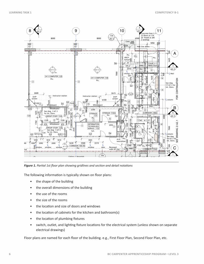
Figure 1. Partial 1st floor plan showing gridlines and section and detail notations
The following information is typically shown on floor plans:
• the shape of the building
• the overall dimensions of the building
• the use of the rooms
• the size of the rooms
• the location and size of doors and windows
• the location of cabinets for the kitchen and bathroom(s)
• the location of plumbing fixtures
• switch, outlet, and lighting fixture locations for the electrical system (unless shown on separate electrical drawings)
Floor plans are named for each floor of the building. e.g., First Floor Plan, Second Floor Plan, etc.
BC Carpenter apprentiCeship program—LeveL 3 7
CompetenCy B-1 Learning task 1
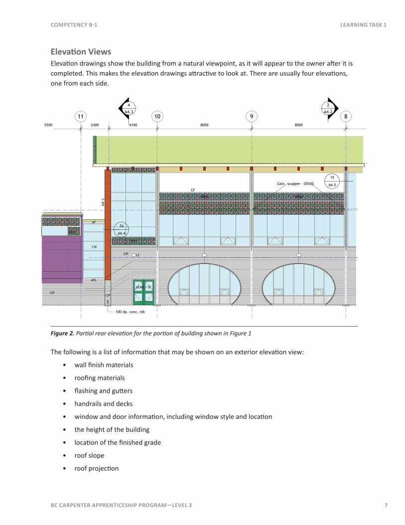
elevation viewsElevation drawings show the building from a natural viewpoint, as it will appear to the owner after it is completed. This makes the elevation drawings attractive to look at. There are usually four elevations, one from each side.
SP#2
11 10 9 8
2
A4.2
4
A4.3
CIP
CIP LF
AFL
SP#1
SP#1
CW
AF
AEWS / SF
AW-2
5500 2400 4100 8000 8000
2a
A6.4
Galv. scupper - 05500.
CF
SP#2
15
A6.5
CIP
100 dp. conc. nib
Figure 2. Partial rear elevation for the portion of building shown in Figure 1
The following is a list of information that may be shown on an exterior elevation view:
• wall finish materials
• roofing materials
• flashing and gutters
• handrails and decks
• window and door information, including window style and location
• the height of the building
• location of the finished grade
• roof slope
• roof projection
Notes
8 BC Carpenter apprentiCeship program—LeveL 3
Learning task 1 CompetenCy B-1
naming elevation viewsElevations are named for the compass direction that the wall faces, for example, a “South Elevation” faces south. An alternate way of naming elevation drawings is to name them by how the building is oriented to the street: Front Elevation, Rear Elevation, Right Elevation, or Left Elevation. The Front Elevation faces the street and the Left and Right elevations are left and right as the building is viewed from the street.
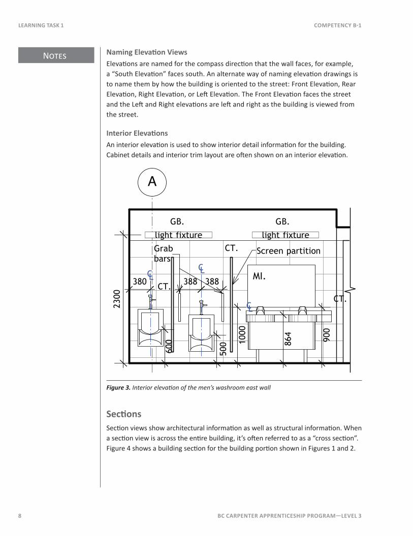
interior elevationsAn interior elevation is used to show interior detail information for the building. Cabinet details and interior trim layout are often shown on an interior elevation.
MI.
A
CT.
CT.
CT.
500
CLCL 388380
light fixture
2300
1000
CL
864
light fixture
Grab bars
GB. GB.
388
600
Screen partition
900
Figure 3. Interior elevation of the men’s washroom east wall
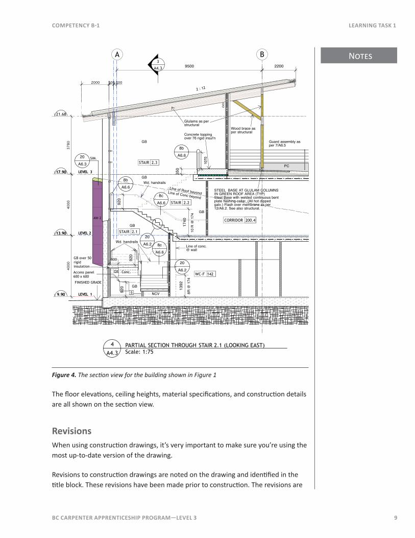
sectionsSection views show architectural information as well as structural information. When a section view is across the entire building, it’s often referred to as a “cross section”. Figure 4 shows a building section for the building portion shown in Figures 1 and 2.
BC Carpenter apprentiCeship program—LeveL 3 9
Notes
CompetenCy B-1 Learning task 1
13.90 LEVEL 2
9.90 LEVEL 1
17.90 LEVEL 3
4000
21.68
3780
13.90 LEVEL 2
9.90 LEVEL 1
17.90 LEVEL 3
4000
1740
10 R
@ 1
74
GB
CORRIDOR 200.4
A B
2 : 12
3002000
STAIR 2.2
WC-F 142
STAIR 2.3
STAIR 2.1
1392
8R @
174
Line of Roof beyond
920
AW-2
PARTIAL SECTION THROUGH STAIR 2.1 (LOOKING EAST)Scale: 1:75
4
A4.3
Line of conc.@ wall
3
A4.3
20
A6.2
20
A6.2
FINISHED GRADE
20
A6.3SIM.
Wood brace as per structural
9500
Concrete topping over 76 rigid insul'n
350
STEEL BASE AT GLULAM COLUMNS IN GREEN ROOF AREA (TYP)Steel Base with welded continuous bent plate flashing collar. (All hot dipped galv.) Flash over membrane as per 12/A6.2. See also structural.
2200
Glulams as per structural
PC
Guard assembly as per 7/A6.5
NCV5
Conc. Access panel 600 x 600
1070
GB
600
GB
GB over 50rigid insulation
920
920
GB
Line of Conc beyond
GB
8b
A6.6
Wd. handrails
Wd. handrails
8c
A6.6
8b
A6.6
8c
A6.6
GB
200
Figure 4. The section view for the building shown in Figure 1
The floor elevations, ceiling heights, material specifications, and construction details are all shown on the section view.
revisionsWhen using construction drawings, it’s very important to make sure you’re using the most up-to-date version of the drawing.
Revisions to construction drawings are noted on the drawing and identified in the title block. These revisions have been made prior to construction. The revisions are
Notes
10 BC Carpenter apprentiCeship program—LeveL 3
Learning task 1 CompetenCy B-1
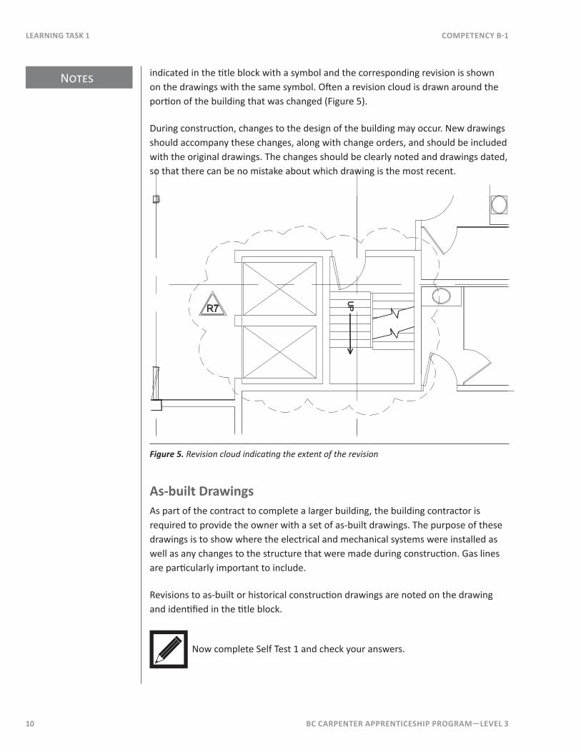
indicated in the title block with a symbol and the corresponding revision is shown on the drawings with the same symbol. Often a revision cloud is drawn around the portion of the building that was changed (Figure 5).
During construction, changes to the design of the building may occur. New drawings should accompany these changes, along with change orders, and should be included with the original drawings. The changes should be clearly noted and drawings dated, so that there can be no mistake about which drawing is the most recent.
UPR7
Figure 5. Revision cloud indicating the extent of the revision
as-built DrawingsAs part of the contract to complete a larger building, the building contractor is required to provide the owner with a set of as-built drawings. The purpose of these drawings is to show where the electrical and mechanical systems were installed as well as any changes to the structure that were made during construction. Gas lines are particularly important to include.
Revisions to as-built or historical construction drawings are noted on the drawing and identified in the title block.
Now complete Self Test 1 and check your answers.
BC Carpenter apprentiCeship program—LeveL 3 11
CompetenCy B-1 Learning task 1
Self Test 1
1. Name the two basic design considerations of buildings as found in the Building Code .
2 . What type of architectural information is shown on floor plans?
3 . What type of architectural information is shown on elevation views?
4. What types of architectural information are shown on section views?
5. Explain what an as-built drawing is.
6 . What is a revision cloud?
12 BC Carpenter apprentiCeship program—LeveL 3
Learning task 1 CompetenCy B-1
Use Figures 1 to 4 to answer the following:
7 . What are gridlines 8, 9, A, and B centered on?
8. What is the spacing between gridlines 8, 9, and 10?
9. What is the spacing between gridlines 10 and 11?
10. What is the spacing between gridlines A and B?
11. What is the distance from the centre-line of the urinal to the centre-line of the grab bars?
12. What is the height of the vanity countertop?
BC Carpenter apprentiCeship program—LeveL 3 13
CompetenCy B-1 Learning task 2
Learning Task 2Use Schedules
Schedules or legends are used to provide detailed information about specific building components, especially those that are repeated several times throughout the building. It’s more efficient to lay out the specifications for each door, window, room, or wall once in a schedule as opposed to multiple times on the drawings. Drawings can be overwhelmed with information making them difficult to read. It’s easier when the information that’s needed can be put in a schedule or a legend.
For example, a schedule or legend is used in commercial construction where there may be many components that are the same size and specification. A symbol or notation is used on the drawings to indicate the component and to refer back to the schedule or legend to find its description.
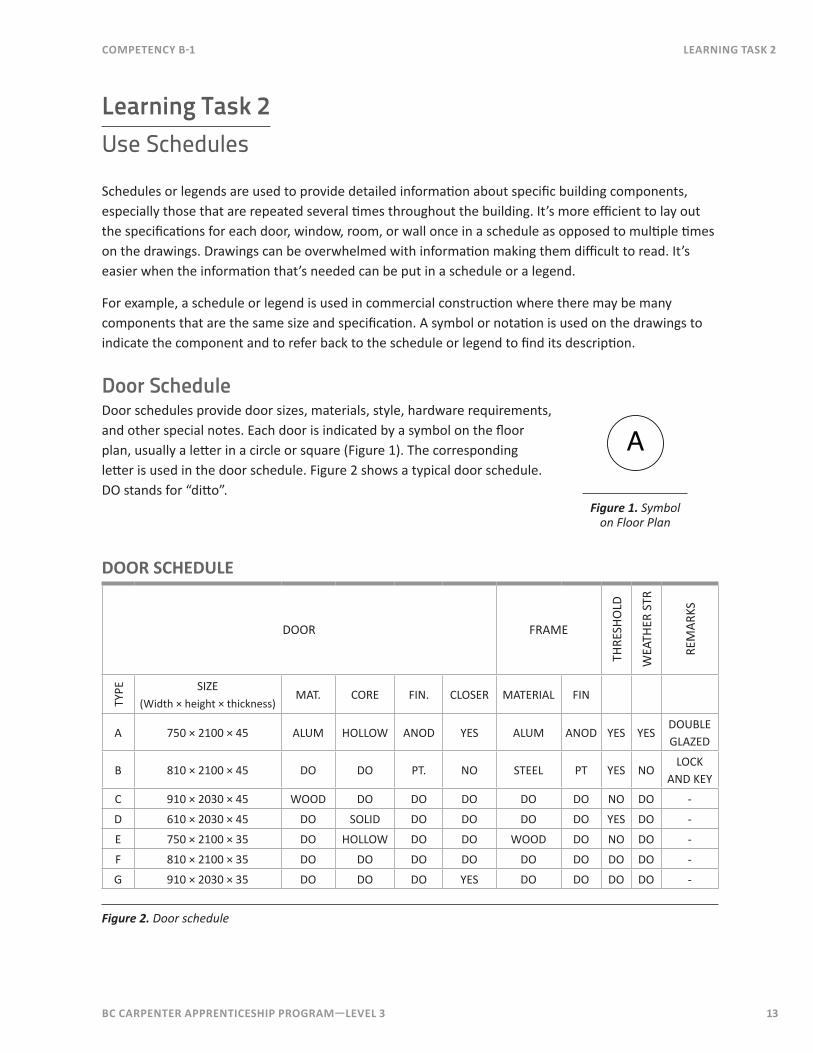
Door ScheduleDoor schedules provide door sizes, materials, style, hardware requirements, and other special notes. Each door is indicated by a symbol on the floor plan, usually a letter in a circle or square (Figure 1). The corresponding letter is used in the door schedule. Figure 2 shows a typical door schedule. DO stands for “ditto”.
A
Figure 1. Symbol on Floor Plan
Door sCheDULe
DOOR FRAMETH
RESH
OLD
WEA
THER
STR
REM
ARKS
TYPE SIZE
(Width × height × thickness)MAT. CORE FIN. CLOSER MATERIAL FIN
A 750 × 2100 × 45 ALUM HOLLOW ANOD YES ALUM ANOD YES YESDOUBLE GLAZED
B 810 × 2100 × 45 DO DO PT. NO STEEL PT YES NOLOCK
AND KEY
C 910 × 2030 × 45 WOOD DO DO DO DO DO NO DO -
D 610 × 2030 × 45 DO SOLID DO DO DO DO YES DO -
E 750 × 2100 × 35 DO HOLLOW DO DO WOOD DO NO DO -
F 810 × 2100 × 35 DO DO DO DO DO DO DO DO -
G 910 × 2030 × 35 DO DO DO YES DO DO DO DO -
Figure 2. Door schedule
14 BC Carpenter apprentiCeship program—LeveL 3
Learning task 2 CompetenCy B-1
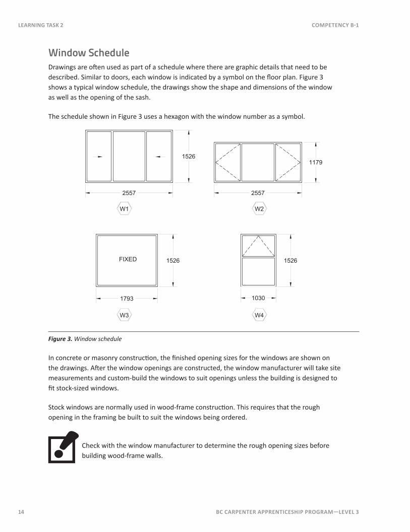
Window ScheduleDrawings are often used as part of a schedule where there are graphic details that need to be described. Similar to doors, each window is indicated by a symbol on the floor plan. Figure 3 shows a typical window schedule, the drawings show the shape and dimensions of the window as well as the opening of the sash.
The schedule shown in Figure 3 uses a hexagon with the window number as a symbol.
W1
2557 2557
11791526
1526 1526
1793 1030
FIXED
W2
W4W3
Figure 3. Window schedule
In concrete or masonry construction, the finished opening sizes for the windows are shown on the drawings. After the window openings are constructed, the window manufacturer will take site measurements and custom-build the windows to suit openings unless the building is designed to fit stock-sized windows.
Stock windows are normally used in wood-frame construction. This requires that the rough opening in the framing be built to suit the windows being ordered.
Check with the window manufacturer to determine the rough opening sizes before building wood-frame walls.
BC Carpenter apprentiCeship program—LeveL 3 15
CompetenCy B-1 Learning task 2
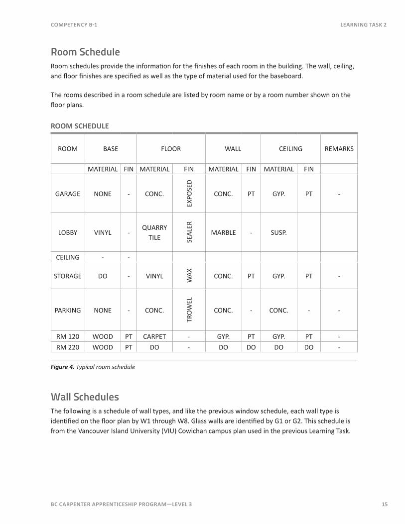
Room ScheduleRoom schedules provide the information for the finishes of each room in the building. The wall, ceiling, and floor finishes are specified as well as the type of material used for the baseboard.
The rooms described in a room schedule are listed by room name or by a room number shown on the floor plans.
room sCheDULe
ROOM BASE FLOOR WALL CEILING REMARKS
MATERIAL FIN MATERIAL FIN MATERIAL FIN MATERIAL FIN
GARAGE NONE - CONC.EX
POSE
DCONC. PT GYP. PT -
LOBBY VINYL -QUARRY
TILE SEAL
ER
MARBLE - SUSP.
CEILING - -
STORAGE DO - VINYL WAX CONC. PT GYP. PT -
PARKING NONE - CONC.
TRO
WEL
CONC. - CONC. - -
RM 120 WOOD PT CARPET - GYP. PT GYP. PT -RM 220 WOOD PT DO - DO DO DO DO -
Figure 4. Typical room schedule
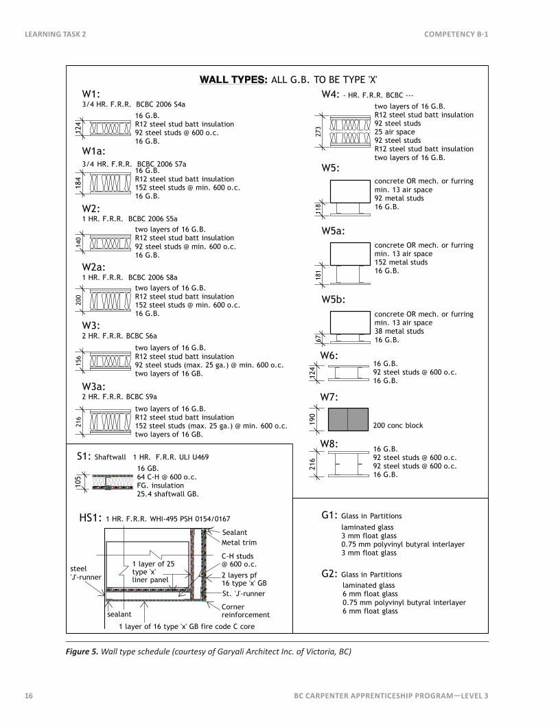
Wall SchedulesThe following is a schedule of wall types, and like the previous window schedule, each wall type is identified on the floor plan by W1 through W8. Glass walls are identified by G1 or G2. This schedule is from the Vancouver Island University (VIU) Cowichan campus plan used in the previous Learning Task.
16 BC Carpenter apprentiCeship program—LeveL 3
Learning task 2 CompetenCy B-1
WALL TYPES: ALL G.B. TO BE TYPE 'X'12
4
W1: 3/4 HR. F.R.R. BCBC 2006 S4a
16 G.B.R12 steel stud batt insulation92 steel studs @ 600 o.c.16 G.B.
140
W2:1 HR. F.R.R. BCBC 2006 S5a
156
W3:2 HR. F.R.R. BCBC S6a
273
W4: - HR. F.R.R. BCBC ---
118
W5:
G1: Glass in Partitions
G2: Glass in Partitions
184
W1a: 3/4 HR. F.R.R. BCBC 2006 S7a
16 G.B.R12 steel stud batt insulation152 steel studs @ min. 600 o.c.16 G.B.
two layers of 16 G.B.R12 steel stud batt insulation92 steel studs @ min. 600 o.c.16 G.B.
200
W2a:1 HR. F.R.R. BCBC 2006 S8a
two layers of 16 G.B.R12 steel stud batt insulation152 steel studs @ min. 600 o.c.16 G.B.
two layers of 16 G.B.R12 steel stud batt insulation92 steel studs (max. 25 ga.) @ min. 600 o.c.two layers of 16 GB.
216
W3a:2 HR. F.R.R. BCBC S9a
two layers of 16 G.B.R12 steel stud batt insulation152 steel studs (max. 25 ga.) @ min. 600 o.c.two layers of 16 GB.
two layers of 16 G.B. R12 steel stud batt insulation92 steel studs25 air space92 steel studsR12 steel stud batt insulationtwo layers of 16 G.B.
concrete OR mech. or furringmin. 13 air space92 metal studs16 G.B.
181
W5a:concrete OR mech. or furringmin. 13 air space152 metal studs16 G.B.
laminated glass3 mm float glass0.75 mm polyvinyl butyral interlayer3 mm float glass
laminated glass6 mm float glass0.75 mm polyvinyl butyral interlayer6 mm float glass
105
S1: Shaftwall 1 HR. F.R.R. ULI U469
16 GB.64 C-H @ 600 o.c.FG. insulation25.4 shaftwall GB.
HS1: 1 HR. F.R.R. WHI-495 PSH 0154/0167
steel'J'-runner
1 layer of 16 type 'x' GB fire code C core
1 layer of 25type 'x' liner panel
St. 'J'-runner
SealantMetal trim
Corner reinforcement
C-H studs @ 600 o.c.
2 layers pf 16 type 'x' GB
sealant
67
W5b:concrete OR mech. or furringmin. 13 air space38 metal studs16 G.B.
124
W6: 16 G.B.92 steel studs @ 600 o.c.16 G.B.
200 conc block
W7:
190
216
W8: 16 G.B.92 steel studs @ 600 o.c.92 steel studs @ 600 o.c.16 G.B.
Figure 5. Wall type schedule (courtesy of Garyali Architect Inc. of Victoria, BC)
BC Carpenter apprentiCeship program—LeveL 3 17
Notes
CompetenCy B-1 Learning task 2
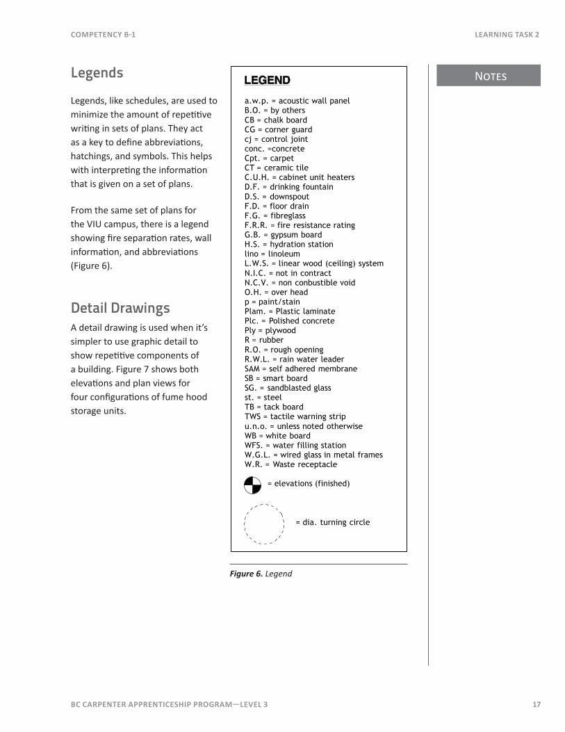
Legends
Legends, like schedules, are used to minimize the amount of repetitive writing in sets of plans. They act as a key to define abbreviations, hatchings, and symbols. This helps with interpreting the information that is given on a set of plans.
From the same set of plans for the VIU campus, there is a legend showing fire separation rates, wall information, and abbreviations (Figure 6).
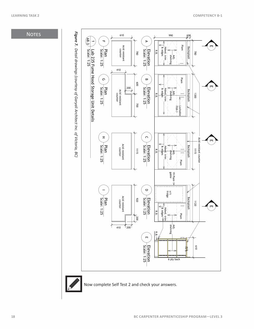
Detail DrawingsA detail drawing is used when it’s simpler to use graphic detail to show repetitive components of a building. Figure 7 shows both elevations and plan views for four configurations of fume hood storage units.
a.w.p. = acoustic wall panelB.O. = by othersCB = chalk boardCG = corner guardcj = control jointconc. =concreteCpt. = carpetCT = ceramic tileC.U.H. = cabinet unit heatersD.F. = drinking fountainD.S. = downspoutF.D. = floor drainF.G. = fibreglassF.R.R. = fire resistance ratingG.B. = gypsum boardH.S. = hydration stationlino = linoleumL.W.S. = linear wood (ceiling) systemN.I.C. = not in contractN.C.V. = non conbustible voidO.H. = over headp = paint/stainPlam. = Plastic laminatePlc. = Polished concrete Ply = plywoodR = rubberR.O. = rough openingR.W.L. = rain water leaderSAM = self adhered membraneSB = smart boardSG. = sandblasted glassst. = steelTB = tack boardTWS = tactile warning stripu.n.o. = unless noted otherwiseWB = white boardWFS. = water filling stationW.G.L. = wired glass in metal framesW.R. = Waste receptacle
= elevations (finished)
LEGEND
= dia. turning circle
Figure 6. Legend
Notes
18 BC Carpenter apprentiCeship program—LeveL 3
Learning task 2 CompetenCy B-1
610
6 ply back
Adj.
shelving
R.B.
990
u/cfridge
Acid resistant counter
R.B.R.B.
R.B.
Adj.
shelvingA
dj. shelving
Adj.
shelving PlamPlam
PlamPlam
Hdw
d. trim &
edgesH
dwd. trim
& edges
Hdw
d. trim &
edgesH
dwd. trim
& edges
R.B.
BacksplashBacksplash
BacksplashBacksplash
100
25
7801300
11151120
Lab 235 Fume H
ood Storage Unit D
etailsScale: 1:25
1A8.3
ElevationScale: 1:25
AElevationScale: 1:25
BElevationScale: 1:25
CElevationScale: 1:25
DElevationScale: 1:25
E
EE
EE
19 Plam gable
200410
920200
1115600
700
200
410
780
Acid resistantcounter
Acid resistantcounter
Acid resistantcounter
Acid resistantcounter
PlanScale: 1:25
FPlanScale: 1:25
GPlanScale: 1:25
HPlanScale: 1:25
I
610
Lockable (typ.)
Figure 7. Detail drawings (courtesy of Garyali Architect Inc. of Victoria, BC)
Now complete Self Test 2 and check your answers.
BC Carpenter apprentiCeship program—LeveL 3 19
CompetenCy B-1 Learning task 2
Self Test 2
1. When are schedules used on construction drawings?
2 . When are drawings used as part of a schedule?
3 . What type of construction would use schedules as part of the drawings?
4. List two types of building components that can be described in a schedule other than doors, windows, or rooms.
5. In what type of construction are the window rough openings shown on the drawings?
6 . What must be done prior to framing window openings in a wood-frame building?
7 . What additional information can be found in a window schedule other than the size of the window?
8. What is the height of a door that is listed as a “920 × 1020 × 45”?
9. What is a legend?
10. What thickness and type of drywall is required for a W2 wall (use Figures 5 and 6)?
11. What thickness of float glass used in a G1 wall?
12. What does 9.90 stand for?

20 BC Carpenter apprentiCeship program—LeveL 3
BC Carpenter apprentiCeship program—LeveL 3 21
Notes
CompetenCy B-1 Learning task 3
Learning Task 3Use Shop Drawings and Reflected Ceiling Plans
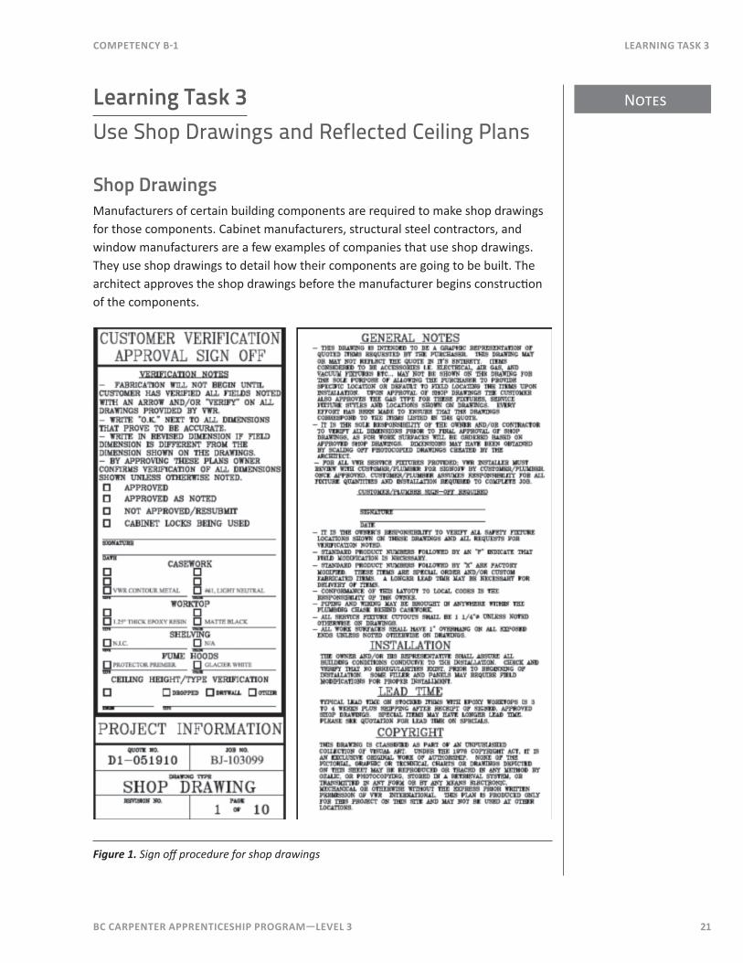
Shop DrawingsManufacturers of certain building components are required to make shop drawings for those components. Cabinet manufacturers, structural steel contractors, and window manufacturers are a few examples of companies that use shop drawings. They use shop drawings to detail how their components are going to be built. The architect approves the shop drawings before the manufacturer begins construction of the components.
Figure 1. Sign off procedure for shop drawings
Notes
22 BC Carpenter apprentiCeship program—LeveL 3
Learning task 3 CompetenCy B-1
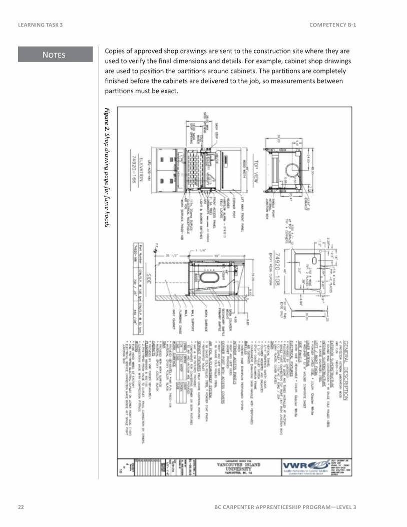
Copies of approved shop drawings are sent to the construction site where they are used to verify the final dimensions and details. For example, cabinet shop drawings are used to position the partitions around cabinets. The partitions are completely finished before the cabinets are delivered to the job, so measurements between partitions must be exact.
Figure 2. Shop drawing page for fum
e hoods
BC Carpenter apprentiCeship program—LeveL 3 23
CompetenCy B-1 Learning task 3
specialtiesSpecialty items are often accompanied by shop drawings. Specialty items include vaults, fixtures, rolling window shutters, hoists, and loading docks. These special items all need specific allowances made for them in the construction of the building and the approved shop drawings must be followed carefully.
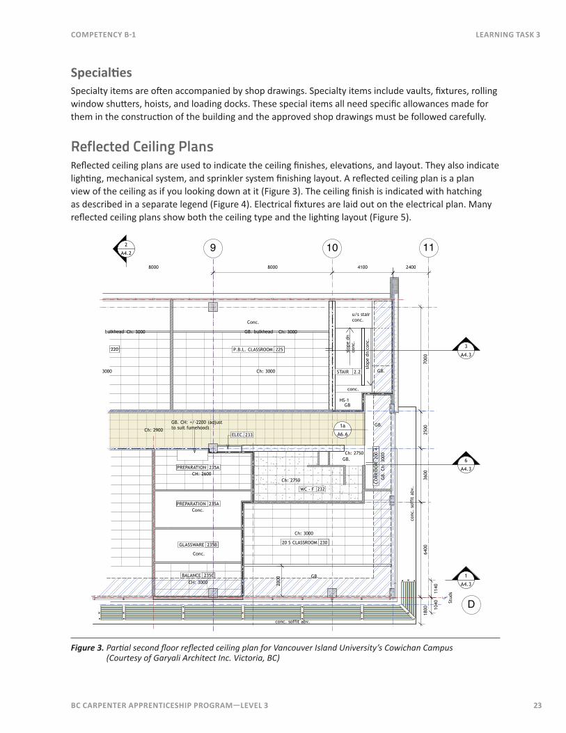
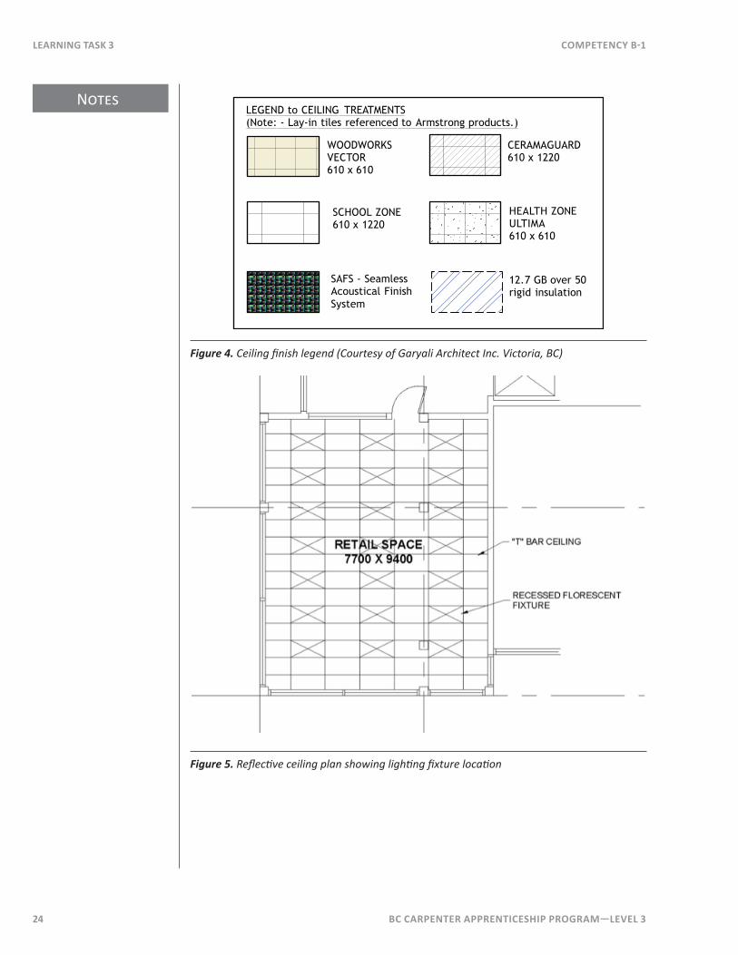
Reflected Ceiling PlansReflected ceiling plans are used to indicate the ceiling finishes, elevations, and layout. They also indicate lighting, mechanical system, and sprinkler system finishing layout. A reflected ceiling plan is a plan view of the ceiling as if you looking down at it (Figure 3). The ceiling finish is indicated with hatching as described in a separate legend (Figure 4). Electrical fixtures are laid out on the electrical plan. Many reflected ceiling plans show both the ceiling type and the lighting layout (Figure 5).
8000 8000 4100
3600
6400
2500
7000
Ch: 2900
Conc.
Conc.
CH: 2600
GB.
2000
Ch: 2750 GB.
Ch:
300
0
Ch: 3000
CH: 3000
u/s stairconc.
slop
e dn
conc
.
conc.
WC - F 232
PREPARATION 235A
BALANCE 235C
GLASSWARE 235B 20 S CLASSROOM 230
220 P.B.L. CLASSROOM 225
CO
RRID
OR
200
.42.2STAIR
ELEC. 233
GB.
3
A4.3
1
A4.3
2
A4.2
6
A4.3
2400
PREPARATION 235A
GB.
9 10 11
D
1800
conc. soffit abv.
conc
. so
ffit
abv
.
HS-1
Ch: 2750
GB. CH: +/-2200 (adjust to suit fumehood) 1a
A6.6
bulkhead GB. bulkhead
Conc.
3000
Ch: 3000
Ch: 3000
Ch: 3000
GB.
GB
slop
e dn
con
c.
1140
1040 St
uds
C L
Figure 3. Partial second floor reflected ceiling plan for Vancouver Island University’s Cowichan Campus (Courtesy of Garyali Architect Inc. Victoria, BC)
Notes
24 BC Carpenter apprentiCeship program—LeveL 3
Learning task 3 CompetenCy B-1
WOODWORKSVECTOR610 x 610
SCHOOL ZONE610 x 1220
CERAMAGUARD610 x 1220
HEALTH ZONEULTIMA610 x 610
LEGEND to CEILING TREATMENTS(Note: - Lay-in tiles referenced to Armstrong products.)
SAFS - Seamless Acoustical Finish System
12.7 GB over 50 rigid insulation
Figure 4. Ceiling fi nish legend (Courtesy of Garyali Architect Inc. Victoria, BC)
Figure 5. Refl ecti ve ceiling plan showing lighti ng fi xture locati on

BC Carpenter apprentiCeship program—LeveL 3 25
Notes
CompetenCy B-1 Learning task 3
Hardware and FittingsDoor, window, and other hardware come with installation instructions and details. Although not part of the construction drawings, these details are necessary to correctly install the hardware.
Save the instructions for hardware installation and store them with the documents for the building, they may be required for warranty, maintenance, or renovations at a later date.
Now complete Self Test 3 and check your answers.
26 BC Carpenter apprentiCeship program—LeveL 3
Learning task 3 CompetenCy B-1
Self Test 3
1. List three types of information that will typically be shown on reflected ceiling plans.
2 . What should be done with the instructions for installing the panic hardware on the entrance doors of a building after the hardware has been installed?
3 . List four different specialty items that will usually have shop drawings with them.
4. Who draws the shop drawings?
5. What is done with the shop drawings after they are drawn?
6 . Why does a carpenter use shop drawings?
7 . What type of ceiling finish does this symbol represent? Is it used in the reflective ceiling shown in Figure 3?
8. What is the lead time for stocked items with epoxy worktops (Figure 1)?
BC Carpenter apprentiCeship program—LeveL 3 27
Notes
CompetenCy B-1 Learning task 4
Learning Task 4Interpret Elevation and Section DrawingsThe bulk of information for most construction projects will be shown on floor plans, foundation plans, and cross sections. Where additional details need to be shown, elevation drawings and section detail drawings are used.
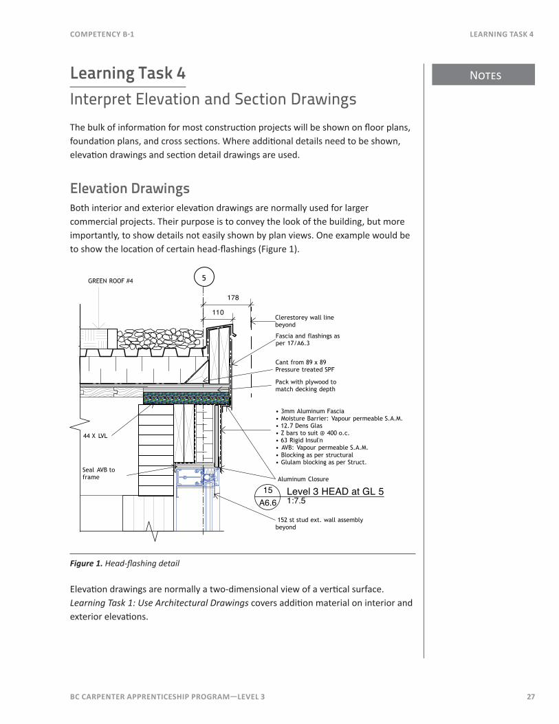
Elevation DrawingsBoth interior and exterior elevation drawings are normally used for larger commercial projects. Their purpose is to convey the look of the building, but more importantly, to show details not easily shown by plan views. One example would be to show the location of certain head-flashings (Figure 1).
178
Level 3 HEAD at GL 51:7.5
15A6.6
5
110
Fascia and flashings as per 17/A6.3
Seal AVB to frame
Cant from 89 x 89 Pressure treated SPF
44 X LVL
Clerestorey wall line beyond
Pack with plywood to match decking depth
• 3mm Aluminum Fascia• Moisture Barrier: Vapour permeable S.A.M.• 12.7 Dens Glas• Z bars to suit @ 400 o.c.• 63 Rigid Insul'n• AVB: Vapour permeable S.A.M.• Blocking as per structural• Glulam blocking as per Struct.
Aluminum Closure
152 st stud ext. wall assembly beyond
GREEN ROOF #4
Figure 1. Head-flashing detail
Elevation drawings are normally a two-dimensional view of a vertical surface. Learning Task 1: Use Architectural Drawings covers addition material on interior and exterior elevations.
Notes
28 BC Carpenter apprentiCeship program—LeveL 3
Learning task 4 CompetenCy B-1
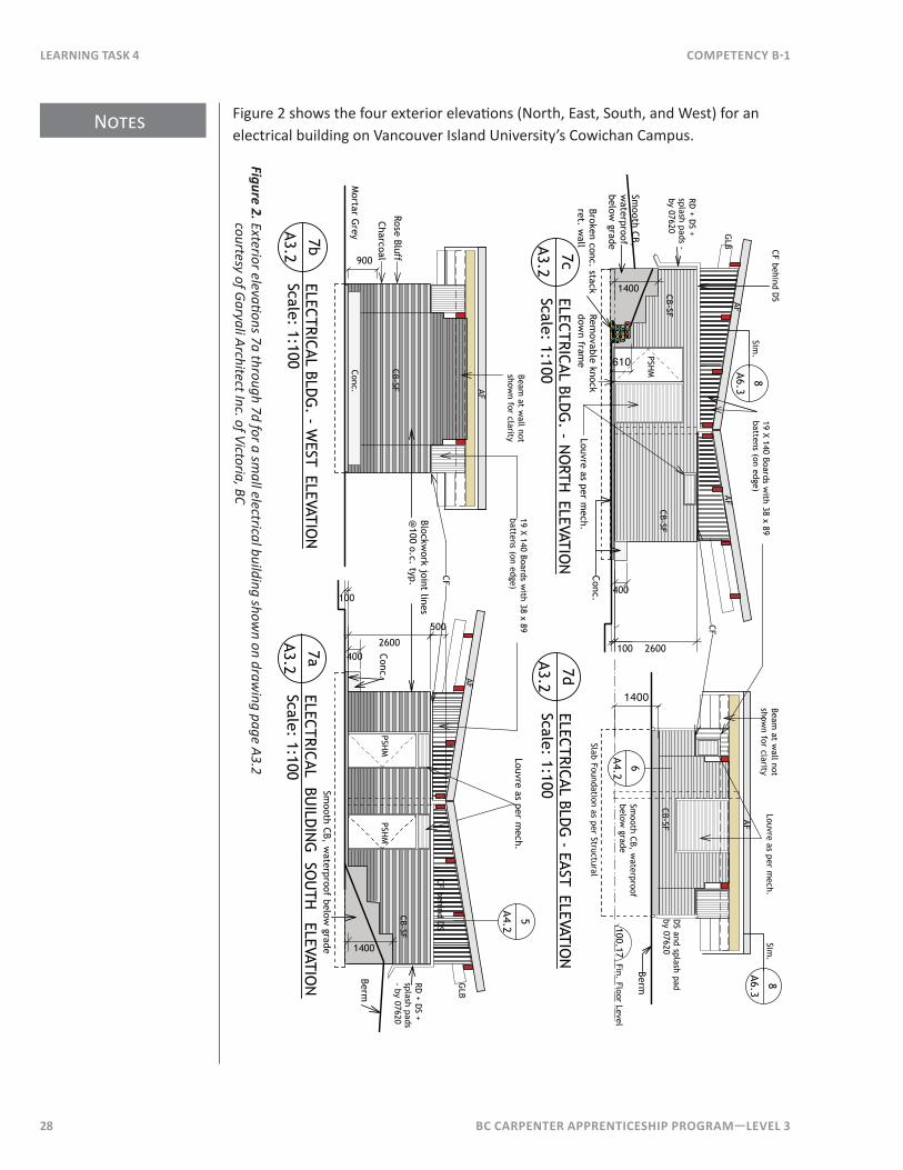
Figure 2 shows the four exterior elevations (North, East, South, and West) for an electrical building on Vancouver Island University’s Cowichan Campus.
RD + D
S + splash pads - by 07620
100 2600
GLB
CB-SF
400
Conc.
CF behind DS
1400
19 X 140 Boards with 38 x 89
battens (on edge)
100ELECTRICAL BU
ILDIN
G SO
UTH ELEVATIO
NScale: 1:100
7a
A3.2ELECTRICAL BLD
G. - W
EST ELEVATION
Scale: 1:1007b
A3.2
ELECTRICAL BLDG
- EAST ELEVATION
Scale: 1:1007d
A3.2ELECTRICAL BLD
G. - N
ORTH
ELEVATION
Scale: 1:1007c
A3.2
2600
GLB
CB-SF
Berm
Smooth CB, w
aterproof below grade
PSHM
PSHM
PSHM
400
Conc.
Smooth CB, w
aterproof below
grade
DS and splash pad
by 07620
Smooth CB,
waterproof
below grade
Blockwork joint lines
@100 o.c. typ.
CB-SF
RD + D
S + splash pads - by 07620
CB-SF
CF
CF
AF
CB-SF
Louvre as per mech.
Removable knock
down fram
eLouvre as per m
ech.
1400
5
A4.2
CF behind DS
Louvre as per mech.
19 X 140 Boards with 38 x 89
battens (on edge)Beam
at wall not
shown for clarity
Beam at w
all not show
n for clarity
Broken conc. stack ret. w
allSlab Foundation as per Structural
610
100.17Fin. Floor Level
1400
Berm
AFAF
AFAF
AF
500
6
A4.2
8
A6.3Sim
.8
A6.3Sim
.
900
Charcoal
Rose Bluff
Mortar G
reyC
onc.
Figure 2. Exterior elevations 7a through 7d for a small electrical building show
n on drawing page A3.2
courtesy of Garyali Architect Inc. of Victoria, BC
BC Carpenter apprentiCeship program—LeveL 3 29
Notes
CompetenCy B-1 Learning task 4
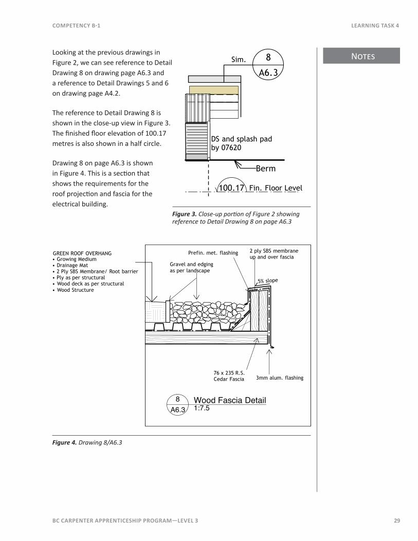
Looking at the previous drawings in Figure 2, we can see reference to Detail Drawing 8 on drawing page A6.3 and a reference to Detail Drawings 5 and 6 on drawing page A4.2.
The reference to Detail Drawing 8 is shown in the close-up view in Figure 3. The finished floor elevation of 100.17 metres is also shown in a half circle.
Drawing 8 on page A6.3 is shown in Figure 4. This is a section that shows the requirements for the roof projection and fascia for the electrical building.
DS and splash pad by 07620
100.17 Fin. Floor Level
Berm
8
A6.3Sim.
Figure 3. Close-up portion of Figure 2 showing reference to Detail Drawing 8 on page A6.3
Wood Fascia Detail1:7.5
8A6.3
3mm alum. flashing
Prefin. met. flashing
Gravel and edging as per landscape
2 ply SBS membrane up and over fascia
76 x 235 R.S.Cedar Fascia
GREEN ROOF OVERHANG• Growing Medium• Drainage Mat• 2 Ply SBS Membrane/ Root barrier• Ply as per structural• Wood deck as per structural• Wood Structure
5% slope
Figure 4. Drawing 8/A6.3
Notes
30 BC Carpenter apprentiCeship program—LeveL 3
Learning task 4 CompetenCy B-1
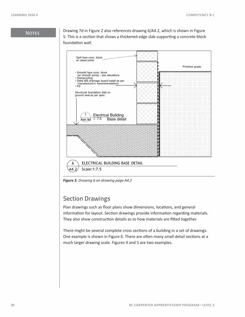
Drawing 7d in Figure 2 also references drawing 6/A4.2, which is shown in Figure 5. This is a section that shows a thickened edge slab supporting a concrete block foundation wall.
Finished grade
Electrical Building1: 7.5
1Ask 9d
Split face conc. blockw/ raked joints
• Smooth face conc. block (w/ smooth joints) - see elevations• Damproofing• Delta MS drainage board-install as per manufacturer's recommendations• Fill
Structural foundation slab on ground seal as per spec.
Base detail
ELECTRICAL BUILDING BASE DETAIL
Scale:1:7.5
6
A4.2
Figure 5. Drawing 6 on drawing page A4.2
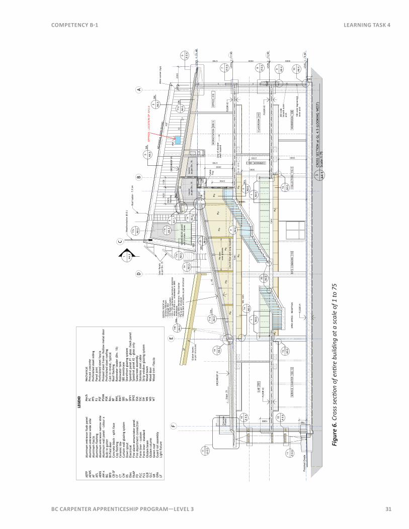
Section DrawingsPlan drawings such as floor plans show dimensions, locations, and general information for layout. Section drawings provide information regarding materials. They also show construction details as to how materials are fitted together.
There might be several complete cross sections of a building in a set of drawings. One example is shown in Figure 6. There are often many small detail sections at a much larger drawing scale. Figures 4 and 5 are two examples.
BC Carpenter apprentiCeship program—LeveL 3 31
CompetenCy B-1 Learning task 4
LEG
END
AEFP
Alum
inum
ent
ranc
e fl
ush
pane
lAE
WS
Alum
inum
ent
ranc
e w
ide
stile
AFAl
umin
um f
asci
aAF
LAl
umin
um f
lash
ing
AEN
SAl
umin
um e
ntra
nce
narr
ow s
tile
AW-x
Alum
inum
wal
l pan
el -
col
our
xBG
Built
-in
gutt
erBF
DBi
-Fol
d do
orCB
-SF
Conc
rete
blo
ck -
spl
it f
ace
CFCa
p fl
ashi
ngCT
Ce
ram
ic t
ileC
WCu
rtai
n w
all g
lazi
ng s
yste
mD
SD
own
spou
tEl
ecEl
ectr
ical
FAA
PFi
re a
larm
ann
unci
ator
pan
elFD
Fire
dep
artm
ent
conn
ecti
onFL
CFo
rm li
ner
- cu
stom
FLS
Form
line
r -
stan
dard
GLB
Glu
lam
bea
mG
LCG
lula
m c
olum
nG
RG
reen
roo
fG
RAG
uard
rai
l ass
embl
yLF
Ligh
t fi
xtur
e
Mec
hM
echa
nica
lPC
Prec
ast
conc
rete
PFS
Pref
inis
hed
stee
l sid
ing
PJPa
nel j
oint
PSF
Pref
inis
hed
stee
l fas
cia
PSH
MPr
esse
d st
eel f
ram
e /h
ollo
w m
etal
doo
rPS
RPr
efin
ishe
d st
eel r
oofi
ngRe
v.Ca
st-i
n re
veal
, ty
pica
lRF
Roof
fla
shin
gRW
LRa
inw
ater
lead
er (
Div
. 15
)RW
TRa
inw
ater
tan
kSB
S SB
S m
embr
ane
SFSt
oref
ront
gla
zing
sys
tem
SP#1
Span
drel
pan
el #
1 -
glas
s /b
ack
pane
lSP
#2Sp
andr
el p
anel
#2
- gl
ass
only
SSA
Suns
cree
n as
sem
bly
SSC
Stai
nles
s st
eel c
able
SWSt
rip
win
dow
gla
zing
sys
tem
WB
Woo
d be
amW
DW
ood
door
WT
Woo
d tr
im /
fasc
ia
Con
cret
ePl
ante
r
LEVE
L 4 3780
A
LEVE
L 3
BD
MEC
HAN
ICAL
RO
OM
BEY
ON
D
500
2 :
10
1100
1820
2000
C
400
CRO
SS S
ECTI
ON
at
GL
4.5
(LO
OKI
NG
WES
T)Sc
ale:
1:75
3
A4.1
13.9
0LE
VEL
2
9.90
LEVE
L 1
17.9
0
40004000
3000
21.6
8
OPE
N O
FFIC
E -
RECE
PTIO
NW
ORK
ROO
M 1
08SE
RVIC
E CO
UN
TER
100
.12
CO
LLEC
TIO
N 1
10.1
CLA
SSRO
OM
210
CORRIDOR 200.3
LAB
250
2200
3000
500
Fini
shed
Gra
de
Louv
reas
per
Div
. 15
Seal
ed d
oubl
e gl
azed
unit
in a
lum
. fr
ames
5
A6.2
5
A6.2
11a
A6.2
15 A6.2
1
A4.3
Sola
r Pa
nels
as p
er D
iv.
15
Louv
reas
per
Div
. 15
300
wid
e Sm
ooth
out
er
arch
100
wid
e Se
gmen
ted
inne
r ar
ch
9
A6.4
Line
of
elev
ator
sh
aft
beyo
nd
2
12
7601000
Line
of
floo
r an
d ra
mp
beyo
nd
16 A 6.
5
16 A 6.
5
11 A 6.
5
11 A 6.
410 A6
.4
Roof
lad
der
- T.
P.#4
5
A 6.
4
7
A 6.
4
8
A 6.
4
Sim
.
AF
Glu
lam
bea
ms
as p
er s
truc
tura
lPS
F
PSF
PSF
SIM
.
SIM
.
5
A6.2
SIM
.
11a
A6.2
GRE
ENRO
OF
#5
Wea
ther
stat
ion
(B.O
.)
GRE
ENRO
OF
#1
Slop
e 2
%
FLO
OR
#2
FLO
OR
#1
FLO
OR
#2
FLO
OR
#2
GR
EEN
RO
OF
#4• G
row
ing
Med
ium
• Dra
inag
e M
at• 1
00 R
igid
insu
latio
n• 1
25 x
125
per
fora
ted
alum
inum
rete
ntio
n
stri
ps @
600
o.c
., em
bedd
ed in
SBS
mem
bran
e• 2
ply
SBS
Mem
bran
e / R
oot b
arrie
r• P
ly a
s pe
r stru
ctur
al•
Woo
d de
ck a
nd b
eam
s as
per
stru
ctur
al
17c
A6.2
17b
A6.2
17a
A6.2
14 A6.2
7/8
A6.3
Sim
.SI
M.
Mit
re c
orne
r (t
yp)
14 A6.4
INFO
CO
MM
ON
S 1
10
Cab
le Tr
ay
Spri
nkle
r
line
beam
w
/ G
B
WO
RK
STAT
ION
300
.5O
FFIC
E 3
10
20 A6.2
2
A6.6
2
A6.6
Sim
.
1
A6.6
1
A6.6
1a A6.6
Ply
Ply
Con
cC
onc
1a A6.6
Con
c.
Ply.
Ply.
Ply.
Wd.
tri
m1a A6
.1
Ply.
Ply.
EF
5
A4.1
2
12
Alum
. fl
ashi
ng
13900
Ply.
APPR
OX.
LO
CAT
ION
OF
AHU
-4
19x
trim
over
glu
lam
s
Ply.
Ply.
3780
3000
2200
Figu
re 6
. Cro
ss se
ction
of e
ntire
bui
ldin
g at
a sc
ale
of 1
to 7
5
Notes
32 BC Carpenter apprentiCeship program—LeveL 3
Learning task 4 CompetenCy B-1
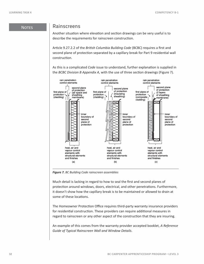
RainscreensAnother situation where elevation and section drawings can be very useful is to describe the requirements for rainscreen construction.
Article 9.27.2.2 of the British Columbia Building Code (BCBC) requires a first and second plane of protection separated by a capillary break for Part 9 residential wall construction.
As this is a complicated Code issue to understand, further explanation is supplied in the BCBC Division B Appendix A, with the use of three section drawings (Figure 7).
second planeof protection(air space andsheathingmembrane)
innerboundary ofsecondplane ofprotection
heat, air andvapour controlelements withstructural elementsand finishes
(a)
second planeof protection(insulatingsheathing)
innerboundary ofsecondplane ofprotection
heat, air andvapour controlelements withstructural elementsand finishes
(b)
second planeof protection (2 layersof sheathingmembrane)
innerboundary ofsecondplane ofprotection
heat, air andvapour controlelements withstructural elementsand finishes
(c)
rain penetrationcontrol elements
rain penetrationcontrol elements
rain penetrationcontrol elements
first plane ofprotection(cladding)
first plane ofprotection(cladding)
first plane ofprotection(compositecladding)
Figure 7. BC Building Code rainscreen assemblies
Much detail is lacking in regard to how to seal the first and second planes of protection around windows, doors, electrical, and other penetrations. Furthermore, it doesn’t show how the capillary break is to be maintained or allowed to drain at some of these locations.
The Homeowner Protection Office requires third-party warranty insurance providers for residential construction. These providers can require additional measures in regard to rainscreen or any other aspect of the construction that they are insuring.
An example of this comes from the warranty provider accepted booklet, A Reference Guide of Typical Rainscreen Wall and Window Details .
BC Carpenter apprentiCeship program—LeveL 3 33
Notes
CompetenCy B-1 Learning task 4
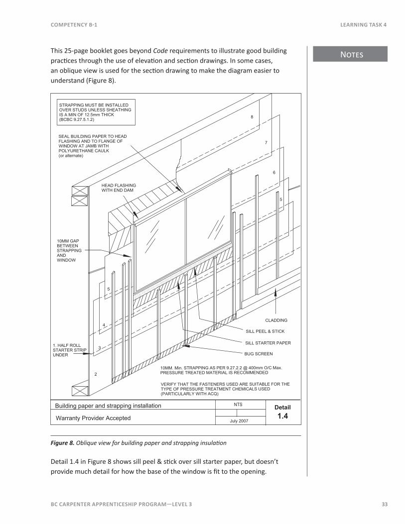
This 25-page booklet goes beyond Code requirements to illustrate good building practices through the use of elevation and section drawings. In some cases, an oblique view is used for the section drawing to make the diagram easier to understand (Figure 8).
Building paper and strapping installation
2
3
4
5
10MM GAPBETWEENSTRAPPINGANDWINDOW
1. HALF ROLLSTARTER STRIPUNDER
Warranty Provider Accepted
NTS
5
6
7
8
Detail1.4
CLADDING
July 2007
SILL PEEL & STICK
SILL STARTER PAPER
BUG SCREEN
10MM. Min. STRAPPING AS PER 9.27.2.2 @ 400mm O/C Max.PRESSURE TREATED MATERIAL IS RECOMMENDED
VERIFY THAT THE FASTENERS USED ARE SUITABLE FOR THETYPE OF PRESSURE TREATMENT CHEMICALS USED(PARTICULARLY WITH ACQ)
HEAD FLASHINGWITH END DAM
SEAL BUILDING PAPER TO HEADFLASHING AND TO FLANGE OFWINDOW AT JAMB WITHPOLYURETHANE CAULK(or alternate)
STRAPPING MUST BE INSTALLEDOVER STUDS UNLESS SHEATHINGIS A MIN OF 12.5mm THICK(BCBC 9.27.5.1.2)
Figure 8. Oblique view for building paper and strapping insulation
Detail 1.4 in Figure 8 shows sill peel & stick over sill starter paper, but doesn’t provide much detail for how the base of the window is fit to the opening.
Notes
34 BC Carpenter apprentiCeship program—LeveL 3
Learning task 4 CompetenCy B-1
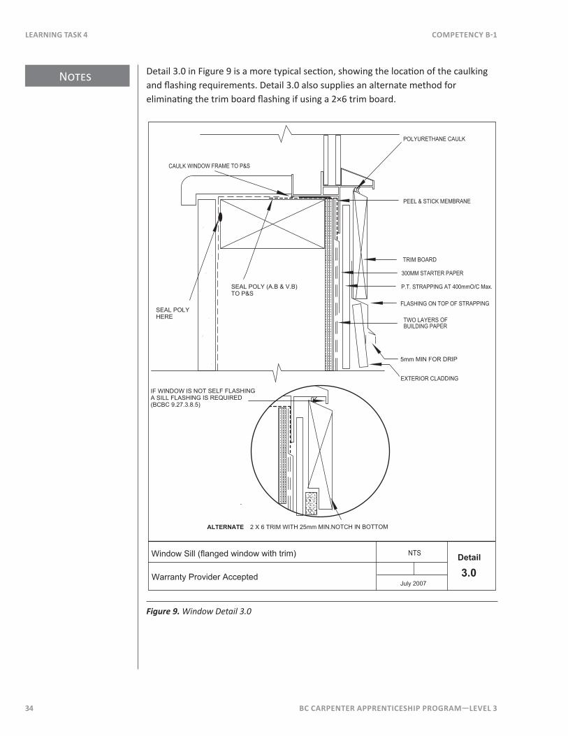
Detail 3.0 in Figure 9 is a more typical section, showing the location of the caulking and flashing requirements. Detail 3.0 also supplies an alternate method for eliminating the trim board flashing if using a 2×6 trim board.
NTSWindow Sill (flanged window with trim)
Warranty Provider Accepted 3.0Detail
TWO LAYERS OFBUILDING PAPER
POLYURETHANE CAULK
CAULK WINDOW FRAME TO P&S
PEEL & STICK MEMBRANE
TRIM BOARD
300MM STARTER PAPER
P.T. STRAPPING AT 400mmO/C Max.
FLASHING ON TOP OF STRAPPING
SEAL POLY (A.B & V.B)TO P&S
July 2007
SEAL POLYHERE
2 X 6 TRIM WITH 25mm MIN.NOTCH IN BOTTOMALTERNATE
EXTERIOR CLADDING
5mm MIN FOR DRIP
IF WINDOW IS NOT SELF FLASHINGA SILL FLASHING IS REQUIRED(BCBC 9.27.3.8.5)
Figure 9. Window Detail 3.0
BC Carpenter apprentiCeship program—LeveL 3 35
Notes
CompetenCy B-1 Learning task 4
110°
75MM
25MM
NTS
D
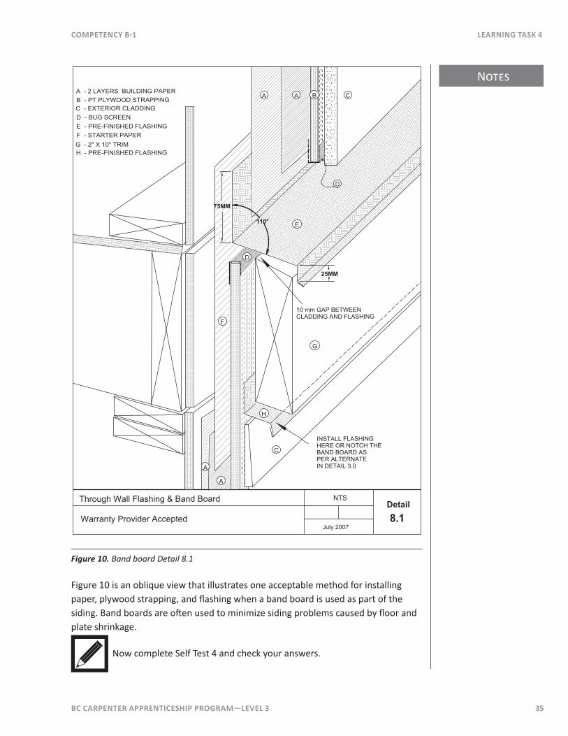
A - 2 LAYERS BUILDING PAPERB - PT PLYWOOD STRAPPINGC - EXTERIOR CLADDINGD - BUG SCREENE - PRE-FINISHED FLASHINGF - STARTER PAPERG - 2" X 10" TRIMH - PRE-FINISHED FLASHING
A
F
H
E
8.1Detail
July 2007
Through Wall Flashing & Band Board
Warranty Provider Accepted
A
A B C
D
C
A
INSTALL FLASHINGHERE OR NOTCH THEBAND BOARD ASPER ALTERNATEIN DETAIL 3.0
G
10 mm GAP BETWEENCLADDING AND FLASHING
Figure 10. Band board Detail 8.1
Figure 10 is an oblique view that illustrates one acceptable method for installing paper, plywood strapping, and flashing when a band board is used as part of the siding. Band boards are often used to minimize siding problems caused by floor and plate shrinkage.
Now complete Self Test 4 and check your answers.
36 BC Carpenter apprentiCeship program—LeveL 3
Learning task 4 CompetenCy B-1
Self Test 4Reference Figures 2 – 5 when answering questions 1 – 7:
1. How high above the floor level is the concrete block foundation wall on the east side of the building?
2 . What style of door frame is used for the building?
3 . What do the roof leaders (downspouts) drain into or onto?
4. What type of construction is the siding above the 2600 mm level?
5. What is used between the ground and the concrete block foundation wall?
6 . What is the fascia size and what top slope is used?
7 . Figure 6 is drawn to a 1 in 75 scale (1:75). What scales are Figures 4 and 5 drawn to?
Reference Figure 7 when answering questions 8 – 9:
8. What are the “rain penetration control elements” referred to in Figure 7?
BC Carpenter apprentiCeship program—LeveL 3 37
CompetenCy B-1 Learning task 4
9. How many methods are shown for the second plane of protection?
Reference Figures 8 – 10 when answering questions 10 – 12:
10. What is the maximum on-centre spacing for the vertical strapping?
11. What type of fasteners must be used for the vertical strapping?
12. What is required at the bottom of the capillary break when strapping is used?
13. What alternative can be used instead of flashing under sill trim board at the bottom of a window?
14. Why are band boards used?

38 BC Carpenter apprentiCeship program—LeveL 3