Embed Size (px)
Citation preview
Proceedings of the 2001 American Society for Engineering Education Annual Conference & Exposition Copyright 2001, American Society for Engineering Education
Session 2525
Bringing Reality to the Classroom: Two “Hands On” Labs for Use with a Machine Design Course
Gregory Branch*, Vipin Kumar, and Margaret Wheeler
University of Washington, Seattle, WA
Abstract The criteria for choosing a material for a given design may involve not only mechanical properties, but also secondary properties such as surface finish, tolerances and geometry. Two laboratories were developed and implemented in the traditional course on design of mechanical elements. The choice of the content of these labs is based on the authors’ combined 35 year industrial experience. In industry they saw that new engineers often had not learned the fundamental considerations in choosing an appropriate material or shape in their designs. This paper provides all necessary details to recreate these labs and discusses two years of instructional experience obtained under NSF-ECSEL sponsorship. LAB 1- Choosing from Commonly Stocked Materials This lab addresses the different materials stocked in lengths, such as steel or aluminum bar, pipe, structural shapes, or rectangular tube. It provides a hands on view of the material obtained from four processes: Hot Rolling (HR), Cold Rolling or Cold Drawing a.k.a. Cold Finished (CF), Extrusion, and Roll Forming. The students learn how each process affects geometry, strength, stiffness, tolerances, finish, etc. The students will run their own concrete demonstration of the difference between stiffness and strength. LAB 2 – Torsional Properties of Shapes and Materials This lab focuses on the importance of material type and shape in torsion. For instance the students quantify how much stiffer a tube is in torsion than an “open” shape of similar dimensions. By manually twisting the shapes mounted in a jig and taking measurements, the students reinforce the analytical concepts previously learned. The students will “feel” the meaning of “torsional rigidity” by comparing the same shape in HR low carbon steel, CF low carbon steel, and aluminum.
* Contacting author, [email protected]
Page 6.246.1
Proceedings of the 2001 American Society for Engineering Education Annual Conference & Exposition Copyright 2001, American Society for Engineering Education
I. Introduction During the authors’ extended industrial careers they gained a detailed view of what specific skills engineers need. Repeatedly they saw that graduate mechanical engineers did not understand how the most common stock material was manufactured and specified, nor how the production method and specification greatly affected the finished raw material’s strength, appearance, tolerances, availability, etc.. For example, a majority of recent graduates could not even tell the difference between pipe and tube, nor between HR and CF steel stock. A second very common gap observed in new engineers’ understanding was in how to analyze strength and stiffness under a torsional load. In fact, the authors have seen many designs fail (including one of their own.) due to lack of understanding of how material shape affects torsional stiffness and strength. For instance one author has seen more than one beam of channel or “I” beam fail due to a torsional load which was ignored in the design. Another very common misunderstanding is in the difference between stiffness and strength. Several informal surveys among Machine Design students (who had already had both lower division Strength of Material and Materials classes) showed that half to three-fourths of the students did not understand the difference between strength and stiffness before taking these labs! Both labs address these differences. Test results after the labs showed almost all had learned the concept. Although additional class time is taken, the authors feel, based on their experience, that the investment is a good one. Much educational theory supports the concept that labs used in conjunction with the lecture raise the learning level and retention. First of all, the labs were designed to allow for all four Kolb learning styles as well as many of the Felder-Silverman learning style classifications Felder, 1996). The Kolb classification is made up of two dimensions creating four quadrants commonly called
1. Divergers (using concrete and sensory info combined with reflective observations) 2. Assimilators (Abstract conceptual thinkers combined with reflective observations) 3. Convergers (Reflective observers doing active experiments ) 4. Accommadators ( Active experimenters using their concrete experiences )
According to Felder, the Felder-Silverman learning style model “classifies students as: ♦ Sensing learners (concrete, practical…) or intuitive (conceptual, innovative…); ♦ Visual learners (prefer visual representations…pictures, diagrams, flowcharts) or verbal
learners (prefer written and spoken explanations); ♦ Inductive learners (prefer presentations that proceed from specific to the general) or
deductive learners (prefer presentations that go from the general to the specific); ♦ Active learners (learn by trying things out, working with others) or reflective learners (learn
by thinking things through, working alone); ♦ Sequential learners (linear, orderly…) or global learners (holistic, systems thinkers).” The labs obviously provide concrete examples that give the student multi-sensory input including not only visual but also kinesthetic and tactile senses. The labs as designed require the students to work in small groups during the experimentation phase. The testing and measurements
Page 6.246.2
Proceedings of the 2001 American Society for Engineering Education Annual Conference & Exposition Copyright 2001, American Society for Engineering Education
required forced the students to be active learners. Since they are working in groups of 3 to 5 students, they are able to support each other, sharing their strengths and learning styles. When these labs have been run in the past, a collaborative buzz fills the room. By requiring written reports for both labs, the students have to reflect on their tests and observations. The writing required is “expressive,” requiring students to think through the problems presented. According to Julie Sharp, “… engineering educators can use writing-to-learn assignments to help students learn technical material,” (Sharp, 1997). The labs are designed to run in conjunction with a corresponding lecture covering the abstract concepts of the two subjects, and thus the abstract learners are covered. The labs give specific examples of general concepts and if the concepts are covered both before and after the lab (either by a “preview” or by a “review”) then both inductive learners and deductive learners are satisfied. Support for using labs and written reports can be found in McKeachie’s classic text, Teaching Tips (McKeachie 1994); “…learning depends heavily on the learner’s activity- thinking about and elaborating on new knowledge. .. Now we think of knowledge as being stored in structures such as networks with linked concepts, facts, and principles. The lecture thus needs to build a bridge between what is in the students’ minds and the structure in the subject matter. Metaphors, examples, and demonstrations are the elements of the bridge,” (Mckeachie, 1994). Later McKeachie says “From the standpoint of theory, the activity of the student, the sensorimotor nature of the experience, and the individualization of laboratory instruction should contribute positively to learning.” A note about the lectures required is appropriate; Many Machine Design texts leave one or both of these labs’ subject areas out of their coverage. Last year, one of this paper’s authors surveyed the coverage of torsion loads by six common Machine Design Texts. He rated only three of the six as giving complete torsional coverage, one as giving inadequate partial coverage, and two as totally inadequate, covering only round cross sections in torsion. The same survey found the coverage of the most commonly used material choices (stock lengths of various metal shapes) varied widely. Thus depending on the text used, a lecture covering the commercial manufacturing of the metal shapes and another lecture covering the theory of torsional loads for non-round cross sections may have to be provided by the professor. If the course text does not cover the material, then in order to cover either “on line” information or handouts will have to be provided by the professor as well in order to fill the needs of the “assimilator” learners. The fact that these popular Texts made such a poor showing confirms what the authors had observed; the subjects are not well learned by graduate mechanical engineers. Another senior design professor a t the University of Washington upon seeing the torsional lab, recounted a story of his own. Years before he had run into a torsional problem when working with a group of senior students on their senior project and had had trouble even finding how to analyze the problem. Another example came from an “older” student who had been working a number of
Page 6.246.3
Proceedings of the 2001 American Society for Engineering Education Annual Conference & Exposition Copyright 2001, American Society for Engineering Education
years as a design engineer and was taking Machine Design in his effort to earn a B.Sc. in mechanical engineering . He recounted to one of the authors how he had just recently had his own design of a car mounted bicycle rack fail upon construction because he had not yet learned the torsional concepts presented in the lab. II. Lab Objectives LAB 1— Choosing from Commonly Stocked Materials After completing this lab, the student should be able to specify metal stock based on alloy chemistry as well as the manufacturing process used to produce the material. This lab concerns itself with the different stock material shapes (material stocked in lengths that is typically cut to make a part or a component) and not with castings or forgings. The students’ objective should be to gain an overview of four processes; 1. Hot Rolling (HR) —typically steel (HRS.) 2. Cold Rolling or Drawing “Cold” --typically steel (CFS = “Cold Finished Steel) 3. Extrusion—typically aluminum but also steel, stainless, etc 4. Roll forming—typically cold, They should learn the limitations or effects each process has on shape, geometry, static and fatigue strength, stiffness, tolerances, surface finish, minimum quantities per order, etc. They should learn how to visually identify the resultant material as well as “call out” or specify their choice in commonly accepted terms. The students get to handle, see, and measure rod, shafting, round tube, pipe, rectangular tube, solid rectangular bar, and structural shapes. They also get to compare the manufacturing tolerances and specifications to what they see and measure. They are not expected to memorize the manufacturing tolerances, but rather learn the concept that nominal size will never be the real size. Furthermore, they should learn that the nominal “call out size” may not be the nominal manufactured size for pipe and structural shapes. (Note that nominal has two different meanings here.) They also compare the stiffness of aluminum, HR and CF steel by measuring the deflection of three cantilevers of the same geometry. By writing a report summarizing their findings and observations they gain report writing experience. LAB 2 – Torsional Properties of Shapes and Materials: The purpose is to gain an appreciation and understanding of the importance of material type and material shapes in torsion. For instance, the students will quantify how much better a tube is in torsion than an “open” shape of similar dimensions. By actually using their hands to twist the shapes the students internalize the importance of shape in design. The students will compare a HR steel flat bar to a thicker HR steel flat bar and learn how important the thickness of the bar is to both stiffness and strength. They will learn how to compute stiffness of open shapes such as channels in torsion. The students will gain an appreciation of the meaning of torsional rigidity by comparing the same shape in HR mild steel, CF mild steel, and aluminum. This comparison will help them learn the difference between rigidity (torsional stiffness) and strength since the HR and CF have very different strengths yet have the same stiffness. This point will again be brought home by the comparison of the aluminum to the HR steel since conversely they have
Page 6.246.4
Proceedings of the 2001 American Society for Engineering Education Annual Conference & Exposition Copyright 2001, American Society for Engineering Education
very different stiffness, but similar strengths. The students will verify many of the equations for torsional stiffness they have been studying and learn how to calculate torsional shear stress. The intent of each lab is to create a “marker event” in the students memories. Wankat and Oreovicz wrote about “Marker Events” in the February 2000 Prism Online; “When thinking back on our past, we often have deeper memories of planned events-whether they be weddings, graduations or birthday parties [or planned Labs]—that serve as important milestones in our development. You, the professor can provide your students with such a ‘marker event’ to help them remember your class long after….” During these labs many students showed great surprise to see the deflections caused by putting the same weight on the three cantilevers of the same geometry. All the students were surprised by manually twisting the open section and similar sized closed tube (the ¾ inch size tube tested is more than 100 times stiffer than the slit open sample). The authors believe these students experienced such a “marker event.” III. Lab Formats LAB 1 – Choosing Materials in Mechanical Design Providing a one hour lecture before the lab coupled with the additional hour during the first hour or so of the lab will provide the necessary background to the subject. (As discussed previously, much of the lecture information may not be found in the standard Machine Design Texts. What the professor’s lecture needs to cover will be apparent from reading the Lab Questionnaire included later) Then the students divide into Teams of three to five. Material samples, each a few inches to a foot long are laid out on tables grouped by one of six types. Every piece is keyed to a Lab Questionnaire. That is, each piece in a group has a group number and code letter. The handout lists each sample piece by group type, each letter key and gives that sample specific material and manufacturing method. The six groups are: 1. Flat or Bar Stock (HR bar, CF bar, and Slit HR Strip) 2. Pipe and Round Tube (Pipe with and without tapered threads and fittings, heavy wall
mechanical tube) 3. Square and Rectangular Steel Tube (several wall thicknesses and sizes) 4. Round Solid Rod and Shafting (HR, CF low carbon steel, centerless ground shafting) 5. Wide Flange and I beams (HR and possibly Aluminum) 6. “Angle Iron,” Hot Rolled Steel Shapes and Extruded Aluminum Shapes (Such as sharp
corner aluminum angle, HR angle, channel, complex extruded shapes) Then the students in teams inspect a material group and answer the questions asked in the Lab Questionnaire. The Questionnaire directs their attention to specific measurements to take and features to inspect. The students spend about three or four minutes per sample and make notes. After each sample in a group has been inspected, the Team moves on to another Material Group. The Team members collaborate and usually answer their own questions within the group. This will probably take about 1.5 hours. During the next week or so, the students individually write a report that answers all the questions. The authors recommend that during the next lecture after the lab, a short recap discussion of the lab, and possibly a “minute paper” to provide the thinking
Page 6.246.5
Proceedings of the 2001 American Society for Engineering Education Annual Conference & Exposition Copyright 2001, American Society for Engineering Education
time after the physical activity to satisfy those students who need the activity first before the theory. This provides a total of 2 to 3 hours of lecture. After the follow up lecture, the written assignment is due and this meets the learning style criteria previously given. The above format was reached by trial and error using the students feedback as a guide. The students feedback was totally consistent with the KOLB styles—some students liked the lecture before the hands on part, some students wanted the lecture after the lab. A confirmation of the validity of this approach can be found in the “Handbook for Teachers in Universities and Colleges,” wherein the author recommends for teaching small groups the following (Newble 1989): ♦ A set of prepared problems ♦ A group large enough to be divided for part of the time into subgroups of about four students
each. ♦ Subgroups working for about half the time on the problems. ♦ A brief report on the work of each group ♦ Class discussion based on the groups report The only discrepancy from our lab’s format is that we had each individual write their own report. Either approach has validity and usefulness. Sometimes in our labs we had group reports and sometimes we had individual reports. If they wanted to, the students still worked together when they wrote their individual reports and so the individual report format could be fit to a wider range of learning styles. Using group reports requires less time by the students and graders and so can reduce the total time invested. LAB 2 – Torsional Properties of Shapes and Materials. The format of Lab Two is similar to the Choosing Materials Lab. The main difference is in the use of the six different torsion jigs. The six jigs may be duplicated for larger classes. The authors have run close to 50 students with two sets of six jigs (12 total). The jigs are equipped with the following test specimens: 1. 1/8 x 1 flat HR steel 2. 1/8 x 1 flat CF steel 3. 1/8 x 1 flat 6061-T6 aluminum 4. 3/16 x 1 flat HR steel 5. .75 x .75 x .060” aluminum square tube 6. .75 x .75 x .060” aluminum square tube modified by machining a .25” wide slot along one
entire side so as to form an open “C” channel almost identical to the square tube. The jigs allow the teams to measure the torque and angular deflection of each sample using simple readily available tools. After the initial lecture(s) requiring one to two hours including a sample calculation, the class is again divided into teams of three to five students. The teams rotate from jig to jig until they have made the required measurements on each jig. It is ideal to
Page 6.246.6
Proceedings of the 2001 American Society for Engineering Education Annual Conference & Exposition Copyright 2001, American Society for Engineering Education
have no more than five teams per six jigs so that waiting time for a slower group to complete is minimized. The jig is illustrated and the equipment detailed later. A one hour lecture preceding the lab work is recommended to cover the basic torsional formulas used. The lab with six kinds of jig samples will take 2 to 2.5 hours for the students complete all their measurements. A follow up review and discussion may only need to be a half hour long. IV. Handouts for the Labs LAB 1 – Choosing Materials in Mechanical Design The handout given to each student for the Choosing Materials Lab includes manufacturing tolerances, partial ASTM specifications, pages from steel supply catalogs such as Tull-Ryerson Steel, and web sites to find additional information. This handout will have to be adjusted to match the material samples which are chosen for the lab. Except for the cantilever beam samples, our samples came from the scrap and “shorts” of two university shops. The lab handout included catalog pages, AISC Steel handbook pages, and commercial summaries of ASTM specifications, etc. See Figure-1 in the Appendix for details. LAB 2 – Torsional Properties of Shapes and Materials. If the text used in your course includes formulas for calculating torsional shear stress and angular deflection for rectangles (flats) and rectangular tubes plus an open section “C” channel. then no other handout is required. However, the authors wanted to supply more general information on torsional loads for their students’ future work. The Handout used gives the students formulas for calculating maximum shear stress and angular deflection for a given torsional load for nine common shapes. See Fig-2 in the Appendix for details.
Page 6.246.7
Proceedings of the 2001 American Society for Engineering Education Annual Conference & Exposition Copyright 2001, American Society for Engineering Education
V. Lab Equipment and Materials Required Both labs are best run in a room with benches and not individual desks. The benches allow easy material sample display in groups. The benches also allow the cantilever beams to be clamped to side by side and the weight(s) hung from their end. Benches are definitely required for the Torsion Lab since the jigs need to be clamped to the bench top to facilitate applying a torque to the sample. LAB 1 – Choosing Materials in Mechanical Design The reader will have to read the Lab Questionnaire and find small samples, each several inches long to fit each category. In order to make the stiffness test, at least four clamps are recommended. One clamp for each of the three cantilevers plus one more for a reference sample. The reference is not loaded and remains straight allowing for deflection measurement with a tape measure of the other three samples. Three identical weights are also recommended although it is possible to do the experiment with only one weight. The use of three weights allows for simultaneous viewing of the three deflections. This shows the flexibility of the aluminum versus the steel and also the same deflection of the HR versus CF. The cantilever beam samples are:
♦ 1/8” x 1” x 22” long Aluminum 6061-T6 ♦ 1/8” x 1” x 22” long HR 1018 steel flat bar (flat HR slit strip may be substituted) ♦ 1/8” x 1” x 22” long CF 1018 steel flat bar
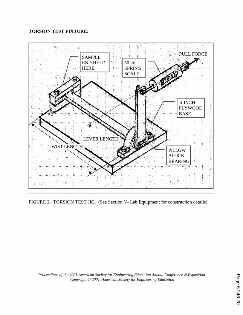
Each sample had a 3/8” diameter hole located 3/8” from one end to allow for hanging a 3.0 lbf. weight from the hole. The other end is clamped to a table with 19” overhang. LAB 2 – Torsional Properties of Shapes and Materials. One or two clamps are needed for each jig. The jigs are clamped to a table. An angle finder/protractor such as a Craftsman catalog # 39840 is needed. This angle finder has a gravity pointer and a 360 degree dial set in a magnetic base. The base rotates and the pointer points down due to gravity. Similar angle finders can be found in Home Depot and welding supply houses. A regular protractor is not suitable unless a reference pointer is added to the jig. In addition a 0-50 lbf. spring scale is required. The least expensive source for these is the fishing department of a sporting goods store. The jigs are designed so the maximum force required to get significant deflection (10 to 40 degrees) is less than 40 lbf. The total hardware cost for six jigs, six scales, and six angle finders is less than $300. The following drawing shows the jig details. Note that with 40 or 50 lbf. applied to the spring scale, it is possible to yield all but the square tube in torsion. This is desirable in that some of the students will yield their samples and thus get to see and feel an example of yielding. The Torsional Lab Instructions cover this point carefully. If the samples are not badly distorted they can simply be straightened. Even so, the jigs should be designed for easy sample replacement as well, to allow for the over zealous student. The authors’ jig used a bolted clamp to fix one end of the sample to the base. The pillow block bearings are used to keep the friction lowIt may be necessary to lightly file or sand the edge of
Page 6.246.8
Proceedings of the 2001 American Society for Engineering Education Annual Conference & Exposition Copyright 2001, American Society for Engineering Education
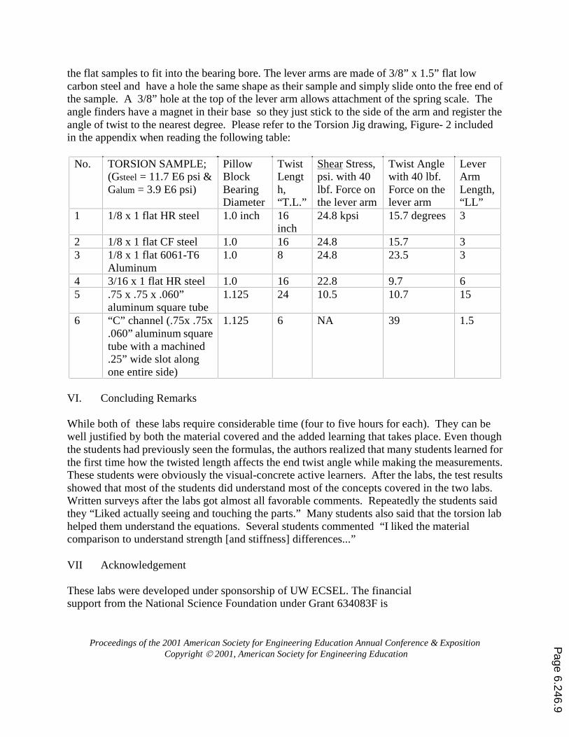
the flat samples to fit into the bearing bore. The lever arms are made of 3/8” x 1.5” flat low carbon steel and have a hole the same shape as their sample and simply slide onto the free end of the sample. A 3/8” hole at the top of the lever arm allows attachment of the spring scale. The angle finders have a magnet in their base so they just stick to the side of the arm and register the angle of twist to the nearest degree. Please refer to the Torsion Jig drawing, Figure- 2 included in the appendix when reading the following table:
No. TORSION SAMPLE; (Gsteel = 11.7 E6 psi & Galum = 3.9 E6 psi)
Pillow Block Bearing Diameter
Twist Length, “T.L.”
Shear Stress, psi. with 40 lbf. Force on the lever arm
Twist Angle with 40 lbf. Force on the lever arm
Lever Arm Length, “LL”
1 1/8 x 1 flat HR steel 1.0 inch 16 inch
24.8 kpsi 15.7 degrees 3
2 1/8 x 1 flat CF steel 1.0 16 24.8 15.7 3 3 1/8 x 1 flat 6061-T6
Aluminum 1.0 8 24.8 23.5 3
4 3/16 x 1 flat HR steel 1.0 16 22.8 9.7 6 5 .75 x .75 x .060”
aluminum square tube 1.125 24 10.5 10.7 15
6 “C” channel (.75x .75x .060” aluminum square tube with a machined .25” wide slot along one entire side)
1.125 6 NA 39 1.5
VI. Concluding Remarks While both of these labs require considerable time (four to five hours for each). They can be well justified by both the material covered and the added learning that takes place. Even though the students had previously seen the formulas, the authors realized that many students learned for the first time how the twisted length affects the end twist angle while making the measurements. These students were obviously the visual-concrete active learners. After the labs, the test results showed that most of the students did understand most of the concepts covered in the two labs. Written surveys after the labs got almost all favorable comments. Repeatedly the students said they “Liked actually seeing and touching the parts.” Many students also said that the torsion lab helped them understand the equations. Several students commented “I liked the material comparison to understand strength [and stiffness] differences...” VII Acknowledgement These labs were developed under sponsorship of UW ECSEL. The financial support from the National Science Foundation under Grant 634083F is
Page 6.246.9
Proceedings of the 2001 American Society for Engineering Education Annual Conference & Exposition Copyright 2001, American Society for Engineering Education
gratefully acknowledged. Bibliography 1. McKeachie, Wilbert J. et al, Teaching Tips, 9th Ed, D. C. Heath and Company, 1994 2. Newble, David, & Cannon, Robert, A handbook for Teachers in Universities and Colleges, Martin’s of Berwick, Berwick on Tweed, Great Britain, 1989. 3. Wankat, Phillip and Oreovicz, Frank, “Memories are Made of This,” ASEE, Prism Online, Feb 2000. 4. Sharp, Julie; Harb, John; Terry, Ronald, “Combining Kolb Learning Styles and Writing to Learn in Engineering Classes” ASEE Journal of Engineering Education, April 1997 5. Felder, Richard M., “Matters of Style,” ASEE Prism, Dec 1996. GREGORY BRANCH Gregory Branch is currently a Research Engineer at University of Washington, Seattle, Mechanical Engineering Dept. He received his M.S. there winter 2001. He spent 25 years designing numerous machines for food processing and packaging and for harvesting and growing row crop vegetables. He is a registered Mechanical Engineer in California, has won two national design contests, and holds five patents. VIPIN KUMAR Vipin Kumar joined the faculty of Mechanical Engineering at University of Washington, Seattle in 1988 after completing a Ph.D. in Mechanical Engineering at Massachusetts Institute of Technology. Prior to that he worked 10 years in the field of piping systems. He is a registered Professional Engineer in the State of Rhode Island. For the past three years he has led the Learning by Design part of the University of Washington ECSEL project. MARGARET WHEELER Margaret Wheeler holds a B.A. in history from Dartmouth College and is currently in the MSME degree program at the University of Washington, Seattle. Her research focus is in renewable energy technologies. Her other strong interest is in the development of effective teaching methods as applied to undergraduate engineering courses. VII Appendix – Authors’ actual Lab Instructions and Questionnaire Both the Materials Lab Questionnaire and the Torsional Lab instructions may be modified to suit your local requirements. Figure -1 is included as an aid in developing a suitable handout.
������������ ��������������������������� PURPOSE SPECIFYING METAL: IT IS NOT JUST A MATERIAL CHOICE, IT’S A MANUFACTURING PROCESS CHOICE TOO. This lab is concerned with the different stock material shapes (that is, material stocked in lengths that are typically cut to length to make a part or a component) and not with castings or forgings. Your objective is to gain an overview of four processes:
Page 6.246.10
Proceedings of the 2001 American Society for Engineering Education Annual Conference & Exposition Copyright 2001, American Society for Engineering Education
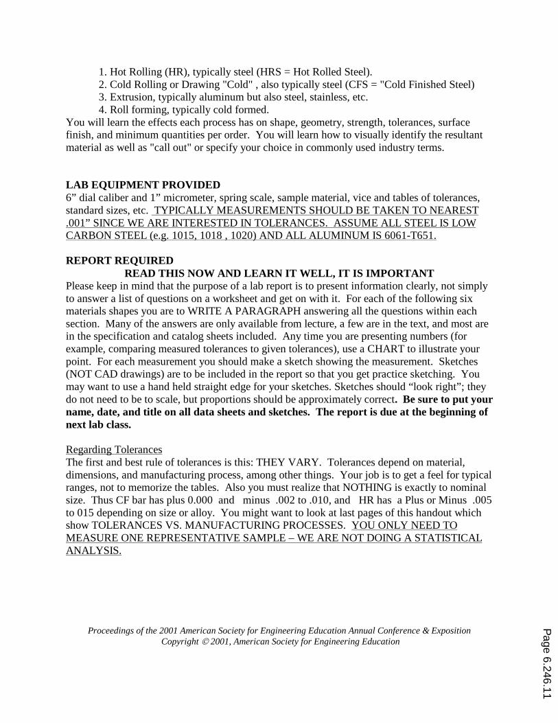
1. Hot Rolling (HR), typically steel (HRS = Hot Rolled Steel). 2. Cold Rolling or Drawing "Cold" , also typically steel (CFS = "Cold Finished Steel) 3. Extrusion, typically aluminum but also steel, stainless, etc. 4. Roll forming, typically cold formed.
You will learn the effects each process has on shape, geometry, strength, tolerances, surface finish, and minimum quantities per order. You will learn how to visually identify the resultant material as well as "call out" or specify your choice in commonly used industry terms. LAB EQUIPMENT PROVIDED 6” dial caliber and 1” micrometer, spring scale, sample material, vice and tables of tolerances, standard sizes, etc. TYPICALLY MEASUREMENTS SHOULD BE TAKEN TO NEAREST .001” SINCE WE ARE INTERESTED IN TOLERANCES. ASSUME ALL STEEL IS LOW CARBON STEEL (e.g. 1015, 1018 , 1020) AND ALL ALUMINUM IS 6061-T651. REPORT REQUIRED
READ THIS NOW AND LEARN IT WELL, IT IS IMPORTANT Please keep in mind that the purpose of a lab report is to present information clearly, not simply to answer a list of questions on a worksheet and get on with it. For each of the following six materials shapes you are to WRITE A PARAGRAPH answering all the questions within each section. Many of the answers are only available from lecture, a few are in the text, and most are in the specification and catalog sheets included. Any time you are presenting numbers (for example, comparing measured tolerances to given tolerances), use a CHART to illustrate your point. For each measurement you should make a sketch showing the measurement. Sketches (NOT CAD drawings) are to be included in the report so that you get practice sketching. You may want to use a hand held straight edge for your sketches. Sketches should “look right”; they do not need to be to scale, but proportions should be approximately correct. Be sure to put your name, date, and title on all data sheets and sketches. The report is due at the beginning of next lab class. Regarding Tolerances The first and best rule of tolerances is this: THEY VARY. Tolerances depend on material, dimensions, and manufacturing process, among other things. Your job is to get a feel for typical ranges, not to memorize the tables. Also you must realize that NOTHING is exactly to nominal size. Thus CF bar has plus 0.000 and minus .002 to .010, and HR has a Plus or Minus .005 to 015 depending on size or alloy. You might want to look at last pages of this handout which show TOLERANCES VS. MANUFACTURING PROCESSES. YOU ONLY NEED TO MEASURE ONE REPRESENTATIVE SAMPLE – WE ARE NOT DOING A STATISTICAL ANALYSIS.
Page 6.246.11
Proceedings of the 2001 American Society for Engineering Education Annual Conference & Exposition Copyright 2001, American Society for Engineering Education
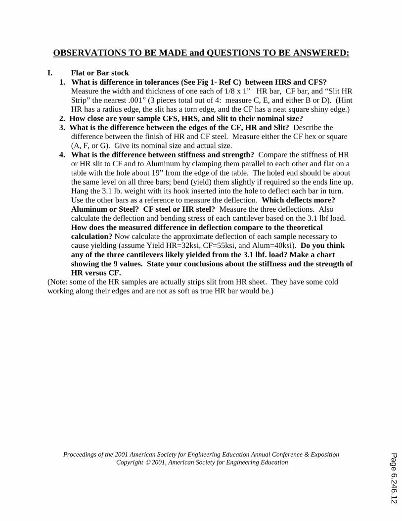
OBSERVATIONS TO BE MADE and QUESTIONS TO BE ANSWERED: I. Flat or Bar stock
1. What is difference in tolerances (See Fig 1- Ref C) between HRS and CFS? Measure the width and thickness of one each of 1/8 x 1” HR bar, CF bar, and “Slit HR Strip” the nearest .001” (3 pieces total out of 4: measure C, E, and either B or D). (Hint HR has a radius edge, the slit has a torn edge, and the CF has a neat square shiny edge.)
2. How close are your sample CFS, HRS, and Slit to their nominal size? 3. What is the difference between the edges of the CF, HR and Slit? Describe the
difference between the finish of HR and CF steel. Measure either the CF hex or square (A, F, or G). Give its nominal size and actual size.
4. What is the difference between stiffness and strength? Compare the stiffness of HR or HR slit to CF and to Aluminum by clamping them parallel to each other and flat on a table with the hole about 19” from the edge of the table. The holed end should be about the same level on all three bars; bend (yield) them slightly if required so the ends line up. Hang the 3.1 lb. weight with its hook inserted into the hole to deflect each bar in turn. Use the other bars as a reference to measure the deflection. Which deflects more? Aluminum or Steel? CF steel or HR steel? Measure the three deflections. Also calculate the deflection and bending stress of each cantilever based on the 3.1 lbf load. How does the measured difference in deflection compare to the theoretical calculation? Now calculate the approximate deflection of each sample necessary to cause yielding (assume Yield HR=32ksi, CF=55ksi, and Alum=40ksi). Do you think any of the three cantilevers likely yielded from the 3.1 lbf. load? Make a chart showing the 9 values. State your conclusions about the stiffness and the strength of HR versus CF.
(Note: some of the HR samples are actually strips slit from HR sheet. They have some cold working along their edges and are not as soft as true HR bar would be.)
Page 6.246.12
Proceedings of the 2001 American Society for Engineering Education Annual Conference & Exposition Copyright 2001, American Society for Engineering Education
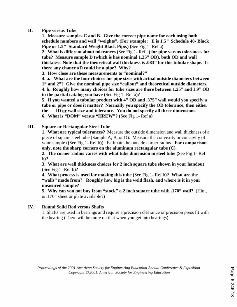
II. Pipe versus Tube 1. Measure samples C and B. Give the correct pipe name for each using both schedule numbers and wall “weights”. (For example: E is 1.5 ” Schedule 40- Black Pipe or 1.5” -Standard Weight Black Pipe.) (See Fig 1- Ref a) 2. What is different about tolerances (See Fig 1- Ref a) for pipe versus tolerances for tube? Measure sample D (which is has nominal 1.25” OD), both OD and wall thickness. Note that the theoretical wall thickness is .083” for this tubular shape. Is there any chance #D could be a pipe? Why? 3. How close are these measurements to “nominal?” 4. a. What are the four choices for pipe sizes with actual outside diameters between 1” and 2”? Give the nominal pipe size “callout” and theoretical outside diameters. 4. b. Roughly how many choices for tube sizes are there between 1.25” and 1.9” OD in the partial catalog you have (See Fig 1- Ref a)? 5. If you wanted a tubular product with 4” OD and .375” wall would you specify a tube or pipe or does it matter? Normally you specify the OD tolerance, then either the ID or wall size and tolerance. You do not specify all three dimensions. 6. What is “DOM” versus “HREW”? (See Fig 1- Ref a)
III. Square or Rectangular Steel Tube
1. What are typical tolerances? Measure the outside dimension and wall thickness of a piece of square steel tube (Sample A, B, or D). Measure the convexity or concavity of your sample ((See Fig 1- Ref b)). Estimate the outside corner radius. For comparison only, note the sharp corners on the aluminum rectangular tube (C). 2. The corner radius varies with what tube dimension in steel tube (See Fig 1- Ref b)? 3. What are wall thickness choices for 2 inch square tube shown in your handout (See Fig 1- Ref b)? 4. What process is used for making this tube (See Fig 1- Ref b)? What are the “walls” made from? Roughly how big is the weld flash, and where is it in your measured sample? 5. Why can you not buy from “stock” a 2 inch square tube with .170” wall? (Hint, is .170” sheet or plate available?)
IV. Round Solid Rod versus Shafts
1. Shafts are used in bearings and require a precision clearance or precision press fit with the bearing (There will be more on that when you get into bearings).
Page 6.246.13
Proceedings of the 2001 American Society for Engineering Education Annual Conference & Exposition Copyright 2001, American Society for Engineering Education
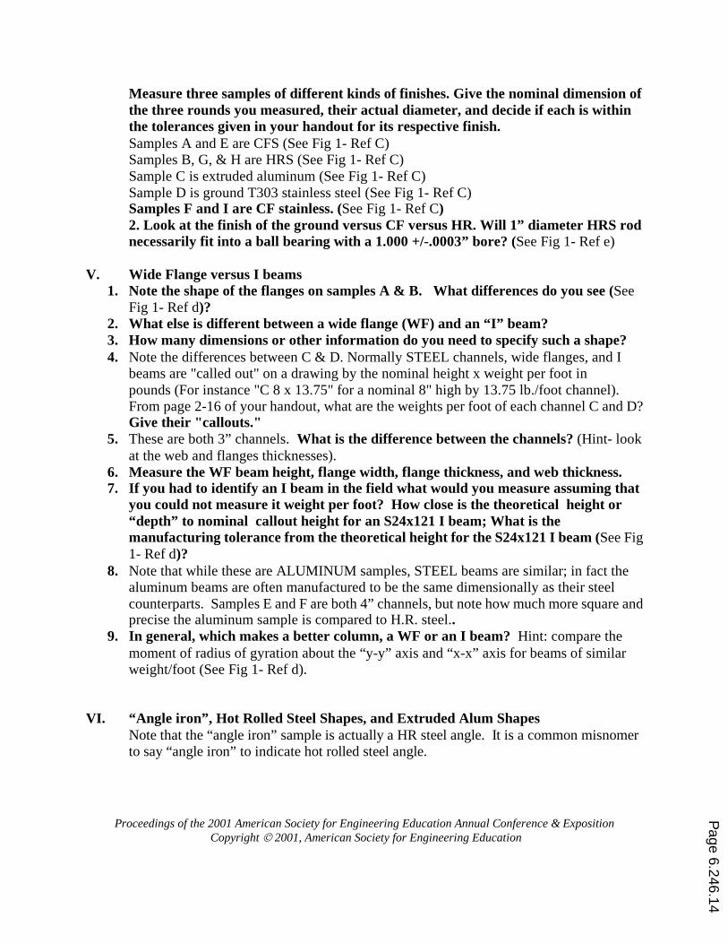
Measure three samples of different kinds of finishes. Give the nominal dimension of the three rounds you measured, their actual diameter, and decide if each is within the tolerances given in your handout for its respective finish. Samples A and E are CFS (See Fig 1- Ref C) Samples B, G, & H are HRS (See Fig 1- Ref C) Sample C is extruded aluminum (See Fig 1- Ref C) Sample D is ground T303 stainless steel (See Fig 1- Ref C) Samples F and I are CF stainless. (See Fig 1- Ref C) 2. Look at the finish of the ground versus CF versus HR. Will 1” diameter HRS rod necessarily fit into a ball bearing with a 1.000 +/-.0003” bore? (See Fig 1- Ref e)
V. Wide Flange versus I beams
1. Note the shape of the flanges on samples A & B. What differences do you see (See Fig 1- Ref d)?
2. What else is different between a wide flange (WF) and an “I” beam? 3. How many dimensions or other information do you need to specify such a shape? 4. Note the differences between C & D. Normally STEEL channels, wide flanges, and I
beams are "called out" on a drawing by the nominal height x weight per foot in pounds (For instance "C 8 x 13.75" for a nominal 8" high by 13.75 lb./foot channel). From page 2-16 of your handout, what are the weights per foot of each channel C and D? Give their "callouts."
5. These are both 3” channels. What is the difference between the channels? (Hint- look at the web and flanges thicknesses).
6. Measure the WF beam height, flange width, flange thickness, and web thickness. 7. If you had to identify an I beam in the field what would you measure assuming that
you could not measure it weight per foot? How close is the theoretical height or “depth” to nominal callout height for an S24x121 I beam; What is the manufacturing tolerance from the theoretical height for the S24x121 I beam (See Fig 1- Ref d)?
8. Note that while these are ALUMINUM samples, STEEL beams are similar; in fact the aluminum beams are often manufactured to be the same dimensionally as their steel counterparts. Samples E and F are both 4” channels, but note how much more square and precise the aluminum sample is compared to H.R. steel..
9. In general, which makes a better column, a WF or an I beam? Hint: compare the moment of radius of gyration about the “y-y” axis and “x-x” axis for beams of similar weight/foot (See Fig 1- Ref d).
VI. “Angle iron”, Hot Rolled Steel Shapes, and Extruded Alum Shapes Note that the “angle iron” sample is actually a HR steel angle. It is a common misnomer to say “angle iron” to indicate hot rolled steel angle.
Page 6.246.14
Proceedings of the 2001 American Society for Engineering Education Annual Conference & Exposition Copyright 2001, American Society for Engineering Education
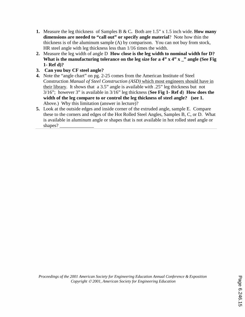
1. Measure the leg thickness of Samples B & C. Both are 1.5” x 1.5 inch wide. How many dimensions are needed to “call out” or specify angle material? Note how thin the thickness is of the aluminum sample (A) by comparison. You can not buy from stock, HR steel angle with leg thickness less than 1/16 times the width.
2. Measure the leg width of angle D How close is the leg width to nominal width for D? What is the manufacturing tolerance on the leg size for a 4” x 4” x _” angle (See Fig 1- Ref d)?
3. Can you buy CF steel angle? 4. Note the “angle chart” on pg. 2-25 comes from the American Institute of Steel
Construction Manual of Steel Construction (ASD) which most engineers should have in their library. It shows that a 3.5” angle is available with .25” leg thickness but not 3/16”; however 3” is available in 3/16” leg thickness (See Fig 1- Ref d) How does the width of the leg compare to or control the leg thickness of steel angle? (see 1. Above.) Why this limitation (answer in lecture)?
5. Look at the outside edges and inside corner of the extruded angle, sample E. Compare these to the corners and edges of the Hot Rolled Steel Angles, Samples B, C, or D. What is available in aluminum angle or shapes that is not available in hot rolled steel angle or shapes? ______________
Page 6.246.15
Proceedings of the 2001 American Society for Engineering Education Annual Conference & Exposition Copyright 2001, American Society for Engineering Education
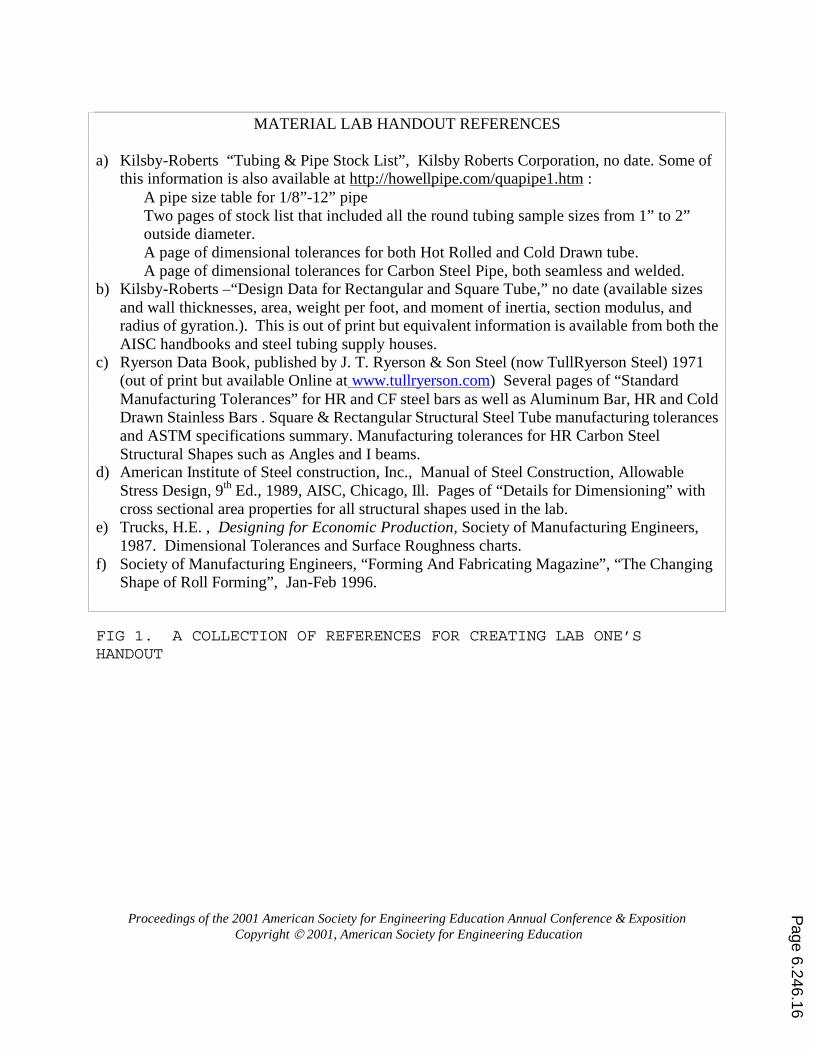
MATERIAL LAB HANDOUT REFERENCES
a) Kilsby-Roberts “Tubing & Pipe Stock List”, Kilsby Roberts Corporation, no date. Some of this information is also available at http://howellpipe.com/quapipe1.htm :
A pipe size table for 1/8”-12” pipe Two pages of stock list that included all the round tubing sample sizes from 1” to 2” outside diameter. A page of dimensional tolerances for both Hot Rolled and Cold Drawn tube. A page of dimensional tolerances for Carbon Steel Pipe, both seamless and welded. b) Kilsby-Roberts –“Design Data for Rectangular and Square Tube,” no date (available sizes
and wall thicknesses, area, weight per foot, and moment of inertia, section modulus, and radius of gyration.). This is out of print but equivalent information is available from both the AISC handbooks and steel tubing supply houses.
c) Ryerson Data Book, published by J. T. Ryerson & Son Steel (now TullRyerson Steel) 1971 (out of print but available Online at www.tullryerson.com) Several pages of “Standard Manufacturing Tolerances” for HR and CF steel bars as well as Aluminum Bar, HR and Cold Drawn Stainless Bars . Square & Rectangular Structural Steel Tube manufacturing tolerances and ASTM specifications summary. Manufacturing tolerances for HR Carbon Steel Structural Shapes such as Angles and I beams.
d) American Institute of Steel construction, Inc., Manual of Steel Construction, Allowable Stress Design, 9th Ed., 1989, AISC, Chicago, Ill. Pages of “Details for Dimensioning” with cross sectional area properties for all structural shapes used in the lab.
e) Trucks, H.E. , Designing for Economic Production, Society of Manufacturing Engineers, 1987. Dimensional Tolerances and Surface Roughness charts.
f) Society of Manufacturing Engineers, “Forming And Fabricating Magazine”, “The Changing Shape of Roll Forming”, Jan-Feb 1996.
FIG 1. A COLLECTION OF REFERENCES FOR CREATING LAB ONE’S HANDOUT
Page 6.246.16
Proceedings of the 2001 American Society for Engineering Education Annual Conference & Exposition Copyright 2001, American Society for Engineering Education
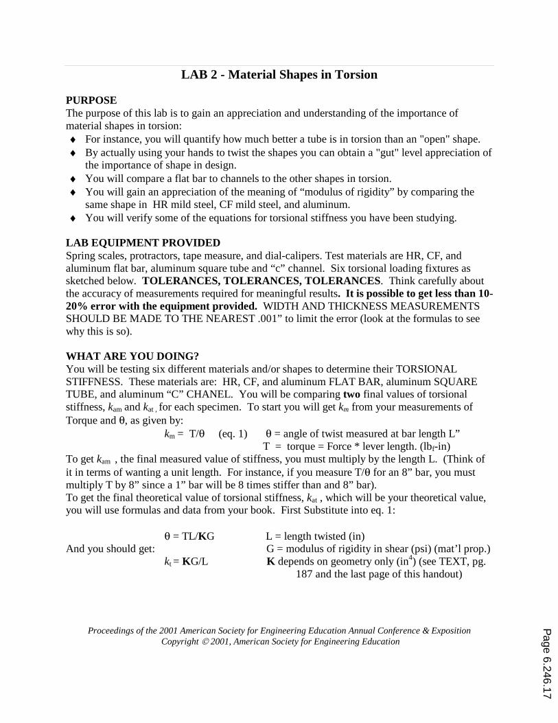
LAB 2 - Material Shapes in Torsion PURPOSE The purpose of this lab is to gain an appreciation and understanding of the importance of material shapes in torsion: ♦ For instance, you will quantify how much better a tube is in torsion than an "open" shape. ♦ By actually using your hands to twist the shapes you can obtain a "gut" level appreciation of
the importance of shape in design. ♦ You will compare a flat bar to channels to the other shapes in torsion. ♦ You will gain an appreciation of the meaning of “modulus of rigidity” by comparing the
same shape in HR mild steel, CF mild steel, and aluminum. ♦ You will verify some of the equations for torsional stiffness you have been studying.
LAB EQUIPMENT PROVIDED Spring scales, protractors, tape measure, and dial-calipers. Test materials are HR, CF, and aluminum flat bar, aluminum square tube and “c” channel. Six torsional loading fixtures as sketched below. TOLERANCES, TOLERANCES, TOLERANCES. Think carefully about the accuracy of measurements required for meaningful results. It is possible to get less than 10-20% error with the equipment provided. WIDTH AND THICKNESS MEASUREMENTS SHOULD BE MADE TO THE NEAREST .001” to limit the error (look at the formulas to see why this is so). WHAT ARE YOU DOING? You will be testing six different materials and/or shapes to determine their TORSIONAL STIFFNESS. These materials are: HR, CF, and aluminum FLAT BAR, aluminum SQUARE TUBE, and aluminum “C” CHANEL. You will be comparing two final values of torsional stiffness, kam and kat , for each specimen. To start you will get km from your measurements of Torque and θ, as given by:
km = T/θ (eq. 1) θ = angle of twist measured at bar length L” T = torque = Force * lever length. (lbf-in)
To get kam , the final measured value of stiffness, you must multiply by the length L. (Think of it in terms of wanting a unit length. For instance, if you measure T/θ for an 8” bar, you must multiply T by 8” since a 1” bar will be 8 times stiffer than and 8” bar). To get the final theoretical value of torsional stiffness, kat , which will be your theoretical value, you will use formulas and data from your book. First Substitute into eq. 1: θ = TL/KG L = length twisted (in) And you should get: G = modulus of rigidity in shear (psi) (mat’l prop.)
kt = KG/L K depends on geometry only (in4) (see TEXT, pg. 187 and the last page of this handout)
Page 6.246.17
Proceedings of the 2001 American Society for Engineering Education Annual Conference & Exposition Copyright 2001, American Society for Engineering Education
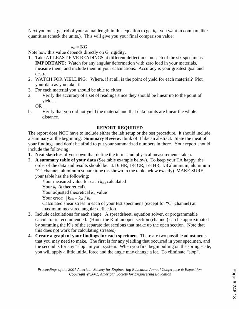
Next you must get rid of your actual length in this equation to get kat; you want to compare like quantities (check the units.). This will give you your final comparison value: kat = KG Note how this value depends directly on G, rigidity. 1. Take AT LEAST FIVE READINGS at different deflections on each of the six specimens.
IMPORTANT: Watch for any angular deformation with zero load in your materials, measure them, and include them in your calculations. Accuracy is your greatest goal and desire.
2. WATCH FOR YIELDING. Where, if at all, is the point of yield for each material? Plot your data as you take it.
3. For each material you should be able to either: a. Verify the accuracy of a set of readings since they should be linear up to the point of
yield… OR
b. Verify that you did not yield the material and that data points are linear the whole distance.
REPORT REQUIRED
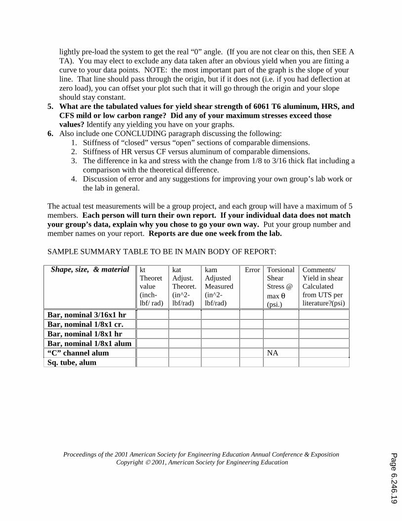
The report does NOT have to include either the lab setup or the test procedure. It should include a summary at the beginning. Summary Review: think of it like an abstract. State the meat of your findings, and don’t be afraid to put your summarized numbers in there. Your report should include the following: 1. Neat sketches of your own that define the terms and physical measurements taken. 2. A summary table of your data (See table example below). To keep your TA happy, the
order of the data and results should be: 3/16 HR, 1/8 CR, 1/8 HR, 1/8 aluminum, aluminum “C” channel, aluminum square tube (as shown in the table below exactly). MAKE SURE your table has the following:
Your measured value for each kam�calculated Your kt (k theoretical). Your adjusted theoretical kat value Your error: | kam – kat |/ kat Calculated shear stress in each of your test specimens (except for “C” channel) at maximum measured angular deflection.
3. Include calculations for each shape. A spreadsheet, equation solver, or programmable calculator is recommended. (Hint: the K of an open section (channel) can be approximated by summing the K’s of the separate flat sections that make up the open section. Note that this does not work for calculating stresses)
4. Create a graph of your findings for each specimen. There are two possible adjustments that you may need to make. The first is for any yielding that occurred in your specimen, and the second is for any “slop” in your system. When you first begin pulling on the spring scale, you will apply a little initial force and the angle may change a lot. To eliminate “slop”,
Page 6.246.18
Proceedings of the 2001 American Society for Engineering Education Annual Conference & Exposition Copyright 2001, American Society for Engineering Education
lightly pre-load the system to get the real “0” angle. (If you are not clear on this, then SEE A TA). You may elect to exclude any data taken after an obvious yield when you are fitting a curve to your data points. NOTE: the most important part of the graph is the slope of your line. That line should pass through the origin, but if it does not (i.e. if you had deflection at zero load), you can offset your plot such that it will go through the origin and your slope should stay constant.
5. What are the tabulated values for yield shear strength of 6061 T6 aluminum, HRS, and CFS mild or low carbon range? Did any of your maximum stresses exceed those values? Identify any yielding you have on your graphs.
6. Also include one CONCLUDING paragraph discussing the following: 1. Stiffness of “closed” versus “open” sections of comparable dimensions. 2. Stiffness of HR versus CF versus aluminum of comparable dimensions. 3. The difference in ka and stress with the change from 1/8 to 3/16 thick flat including a
comparison with the theoretical difference. 4. Discussion of error and any suggestions for improving your own group’s lab work or
the lab in general.
The actual test measurements will be a group project, and each group will have a maximum of 5 members. Each person will turn their own report. If your individual data does not match your group’s data, explain why you chose to go your own way. Put your group number and member names on your report. Reports are due one week from the lab. SAMPLE SUMMARY TABLE TO BE IN MAIN BODY OF REPORT: Shape, size, & material kt
Theoret value (inch-lbf/ rad)
kat Adjust. Theoret. (in^2- lbf/rad)
kam Adjusted Measured (in^2-lbf/rad)
Error Torsional Shear Stress @ max θ (psi.)
Comments/ Yield in shear Calculated from UTS per literature?(psi)
Bar, nominal 3/16x1 hr Bar, nominal 1/8x1 cr. Bar, nominal 1/8x1 hr Bar, nominal 1/8x1 alum “C” channel alum NA Sq. tube, alum
Page 6.246.19
Proceedings of the 2001 American Society for Engineering Education Annual Conference & Exposition Copyright 2001, American Society for Engineering Education
TORSION TEST FIXTURE: FIGURE 2. TORSION TEST JIG. (See Section V- Lab Equipment for construction details)
TWIST LENGTH
LEVER LENGTH
¾ INCH PLYWOOD BASE
PILLOW BLOCK BEARING
SAMPLE END HELD HERE
PULL FORCE
50 lbf SPRING SCALE
Page 6.246.20
Proceedings of the 2001 American Society for Engineering Education Annual Conference & Exposition Copyright 2001, American Society for Engineering Education
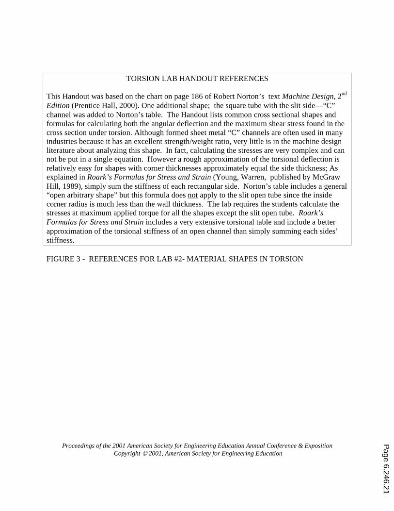
TORSION LAB HANDOUT REFERENCES
This Handout was based on the chart on page 186 of Robert Norton’s text Machine Design, 2nd Edition (Prentice Hall, 2000). One additional shape; the square tube with the slit side—“C” channel was added to Norton’s table. The Handout lists common cross sectional shapes and formulas for calculating both the angular deflection and the maximum shear stress found in the cross section under torsion. Although formed sheet metal “C” channels are often used in many industries because it has an excellent strength/weight ratio, very little is in the machine design literature about analyzing this shape. In fact, calculating the stresses are very complex and can not be put in a single equation. However a rough approximation of the torsional deflection is relatively easy for shapes with corner thicknesses approximately equal the side thickness; As explained in Roark’s Formulas for Stress and Strain (Young, Warren, published by McGraw Hill, 1989), simply sum the stiffness of each rectangular side. Norton’s table includes a general “open arbitrary shape” but this formula does not apply to the slit open tube since the inside corner radius is much less than the wall thickness. The lab requires the students calculate the stresses at maximum applied torque for all the shapes except the slit open tube. Roark’s Formulas for Stress and Strain includes a very extensive torsional table and include a better approximation of the torsional stiffness of an open channel than simply summing each sides’ stiffness. FIGURE 3 - REFERENCES FOR LAB #2- MATERIAL SHAPES IN TORSION
Page 6.246.21