Embed Size (px)
Citation preview
1
Bridgelux® Gen 7 V18 Array SeriesProduct Data Sheet DS102
Introduction
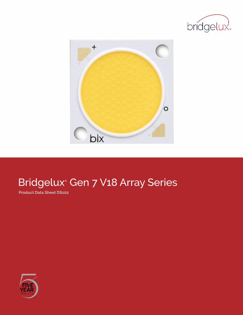
The V Series™ LED Array products deliver high quality light in a compact and cost-effective solid-state lighting package. These chip on board (CoB) arrays can be efficiently driven at twice the nominal drive current, enabling design flexibility not previously possible. This high flux density light source is designed to support a wide range of high quality, low cost directional luminaires and replacement lamps for commercial and residential applications.
The V18 LED Array is available in a variety of electrical, CCT and CRI combinations providing substantial design flexibility and energy efficiencies.
Lighting system designs incorporating these LED arrays deliver increased system level efficacy and longer service life. Typical applications include, replacement lamps, and task, accent, spot, track, wide area, security, wall pack and down lights.
Bridgelux Décor Series is our state of the art color line designed specifically for premium applications, producing unmatched LED light quality with brilliant color-rendering options and offer pleasing and inspiring lighting palettes. Bridgelux Décor Series color points are available on Vero® SE Series, Vero® Series, V Series™ and H Series™.
Décor Series Class A is based on human response testing, providing color points with a combined GAI and CRI metric.
Décor Series™ Ultra products provide a high CRI of 97 and a minimum R9 value of 93, which emphasizes the reds and color tones to which the human eye is most receptive - perfect for the most luxurious retail shops and world renowned museums. Décor Series Ultra is designed as a replacement for halogen lamps.
Décor Series™ Food products offer color points developed to address the unique requirements of the food, grocery, and restaurant industries. Highlighting the distinctive colors and nuanced patterns found in meats and breads, the Décor Series Food products are a must have for any butcher counter or bakery.
Décor Series™ Street and Landmark is designed to be a direct replacement for high pressure sodium lamps.
Décor Series™ Showcase is the optimal solution for replacing ceramic metal halide lamps, incorporating the same pure white light with enhanced spectrum coverage and higher efficacy.
V S
erie
s
Features
• Efficacy of 160 lm/W typical
• Compact high flux density light source
• Uniform high quality illumination
• Minimum 65, 70, 80, 90 and 95 CRI options
• Streamlined thermal path
• ENERGY STAR® / ANSI compliant color binning structure with 2, 3 and 4 SDCM options
• More energy efficient than incandescent, halogen and fluorescent lamps
• Low voltage DC operation
• Instant light with unlimited dimming
• Vf bin code backside marking
Benefits
• Enhanced optical control
• Clean white light without pixilation
• High quality true color reproduction
• Significantly reduced thermal resistance and increased operating temperatures
• Uniform consistent white light
• Lower operating costs
• Easy to use with daylight and motion detectors to enable increased energy savings
• Reduced maintenance costs
• Environmentally friendly, no disposal issue
1
Contents
Product Feature Map 2
Product Nomenclature 2
Product Selection Guide 3
Performance at Commonly Used Drive Currents 7
Electrical Characteristics 12
Eye Safety 13
Absolute Maximum Ratings 14
Performance Curves 15
Typical Radiation Pattern 18
Typical Color Spectrum 19
Mechanical Dimensions 20
Color Binning Information 21
Packaging and Labeling 22
Design Resources 24
Precautions 24
Disclaimers 24
About Bridgelux 25
2
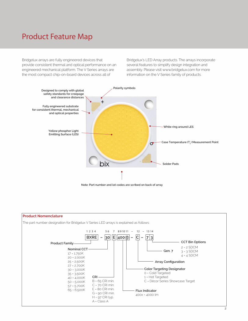
Product Feature Map
Product Nomenclature
The part number designation for Bridgelux V Series LED arrays is explained as follows:
1 2 3 4 5 6 7 8 9 10 11 – 12 – 13 14
Product Family CCT Bin Options
2 = 2 SDCM3 = 3 SDCM4 = 4 SDCM
CRIB = 65 CRI min.C = 70 CRI min.E = 80 CRI min. G = 90 CRI min.H = 97 CRI typ.A = Class A
Array Configuration
17 = 1,750K20 = 2,000K25 = 2,500K27 = 2,700K30 = 3,000K35 = 3,500K40 = 4,000K50 = 5,000K57 = 5,700K65 = 6,500K
BXRE – 30 E 400 0 – C – 7 3
Color Targeting Designator0 = Cold Targeted1 = Hot TargetedC = Décor Series Showcase Target
Gen. 7Nominal CCT
Flux Indicator400x = 4000 lm
Bridgelux arrays are fully engineered devices that provide consistent thermal and optical performance on an engineered mechanical platform. The V Series arrays are the most compact chip-on-board devices across all of
Bridgelux’s LED Array products. The arrays incorporate several features to simplify design integration and assembly. Please visit www.bridgelux.com for more information on the V Series family of products.
Fully engineered substrate for consistent thermal, mechanical
and optical properties
Yellow phosphor Light Emitting Surface (LES)
Note: Part number and lot codes are scribed on back of array
Polarity symbols
Solder Pads
White ring around LES
Case Temperature (Tc) Measurement Point
Designed to comply with global safety standards for creepage
and clearance distances
3
Product Selection Guide
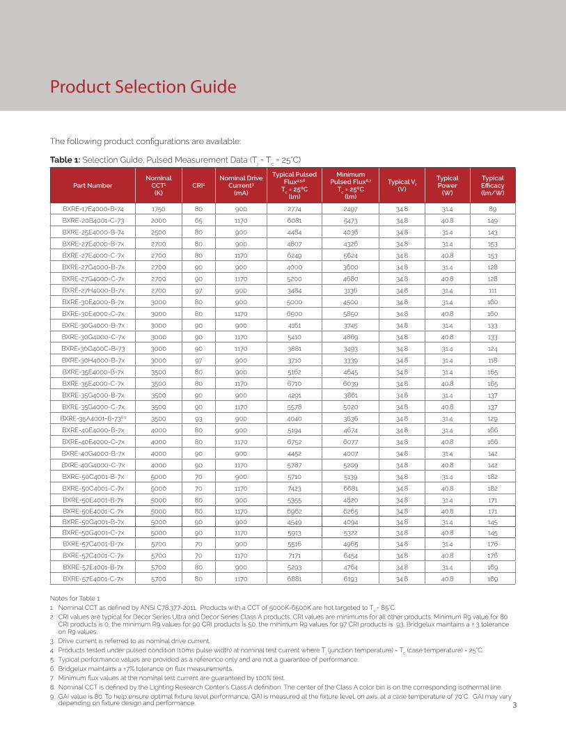
The following product configurations are available:
Table 1: Selection Guide, Pulsed Measurement Data (Tj = Tc = 25°C)
Part NumberNominal
CCT1
(K)CRI2
Nominal Drive Current3
(mA)
Typical Pulsed Flux4,5,6
Tc = 25ºC(lm)
Minimum Pulsed Flux6,7
Tc = 25ºC(lm)
Typical Vf (V)
Typical Power
(W)
Typical Efficacy (lm/W)
BXRE-17E4000-B-74 1750 80 900 2774 2497 34.8 31.4 89
BXRE-20B4001-C-73 2000 65 1170 6081 5473 34.8 40.8 149
BXRE-25E4000-B-74 2500 80 900 4484 4036 34.8 31.4 143
BXRE-27E4000-B-7x 2700 80 900 4807 4326 34.8 31.4 153
BXRE-27E4000-C-7x 2700 80 1170 6249 5624 34.8 40.8 153
BXRE-27G4000-B-7x 2700 90 900 4000 3600 34.8 31.4 128
BXRE-27G4000-C-7x 2700 90 1170 5200 4680 34.8 40.8 128
BXRE-27H4000-B-7x 2700 97 900 3484 3136 34.8 31.4 111
BXRE-30E4000-B-7x 3000 80 900 5000 4500 34.8 31.4 160
BXRE-30E4000-C-7x 3000 80 1170 6500 5850 34.8 40.8 160
BXRE-30G4000-B-7x 3000 90 900 4161 3745 34.8 31.4 133
BXRE-30G4000-C-7x 3000 90 1170 5410 4869 34.8 40.8 133
BXRE-30G400C-B-73 3000 90 1170 3881 3493 34.8 31.4 124
BXRE-30H4000-B-7x 3000 97 900 3710 3339 34.8 31.4 118
BXRE-35E4000-B-7x 3500 80 900 5162 4645 34.8 31.4 165
BXRE-35E4000-C-7x 3500 80 1170 6710 6039 34.8 40.8 165
BXRE-35G4000-B-7x 3500 90 900 4291 3861 34.8 31.4 137
BXRE-35G4000-C-7x 3500 90 1170 5578 5020 34.8 40.8 137
BXRE-35A4001-B-738,9 3500 93 900 4040 3636 34.8 31.4 129
BXRE-40E4000-B-7x 4000 80 900 5194 4674 34.8 31.4 166
BXRE-40E4000-C-7x 4000 80 1170 6752 6077 34.8 40.8 166
BXRE-40G4000-B-7x 4000 90 900 4452 4007 34.8 31.4 142
BXRE-40G4000-C-7x 4000 90 1170 5787 5209 34.8 40.8 142
BXRE-50C4001-B-7x 5000 70 900 5710 5139 34.8 31.4 182
BXRE-50C4001-C-7x 5000 70 1170 7423 6681 34.8 40.8 182
BXRE-50E4001-B-7x 5000 80 900 5355 4820 34.8 31.4 171
BXRE-50E4001-C-7x 5000 80 1170 6962 6265 34.8 40.8 171
BXRE-50G4001-B-7x 5000 90 900 4549 4094 34.8 31.4 145
BXRE-50G4001-C-7x 5000 90 1170 5913 5322 34.8 40.8 145
BXRE-57C4001-B-7x 5700 70 900 5516 4965 34.8 31.4 176
BXRE-57C4001-C-7x 5700 70 1170 7171 6454 34.8 40.8 176
BXRE-57E4001-B-7x 5700 80 900 5293 4764 34.8 31.4 169
BXRE-57E4001-C-7x 5700 80 1170 6881 6193 34.8 40.8 169
Notes for Table 1:1. Nominal CCT as defined by ANSI C78.377-2011. Products with a CCT of 5000K-6500K are hot targeted to Tc = 85°C.2. CRI values are typical for Decor Series Ultra and Decor Series Class A products. CRI values are minimums for all other products. Minimum R9 value for 80
CRI products is 0, the minimum R9 values for 90 CRI products is 50, the minimum R9 values for 97 CRI products is 93. Bridgelux maintains a ± 3 tolerance on R9 values.
3. Drive current is referred to as nominal drive current. 4. Products tested under pulsed condition (10ms pulse width) at nominal test current where Tj (junction temperature) = Tc (case temperature) = 25°C. 5. Typical performance values are provided as a reference only and are not a guarantee of performance. 6. Bridgelux maintains a ±7% tolerance on flux measurements. 7. Minimum flux values at the nominal test current are guaranteed by 100% test. 8. Nominal CCT is defined by the Lighting Research Center’s Class A definition. The center of the Class A color bin is on the corresponding isothermal line.9. GAI value is 80. To help ensure optimal fixture level performance, GAI is measured at the fixture level, on axis, at a case temperature of 70°C. GAI may vary
depending on fixture design and performance.
4
Product Selection Guide
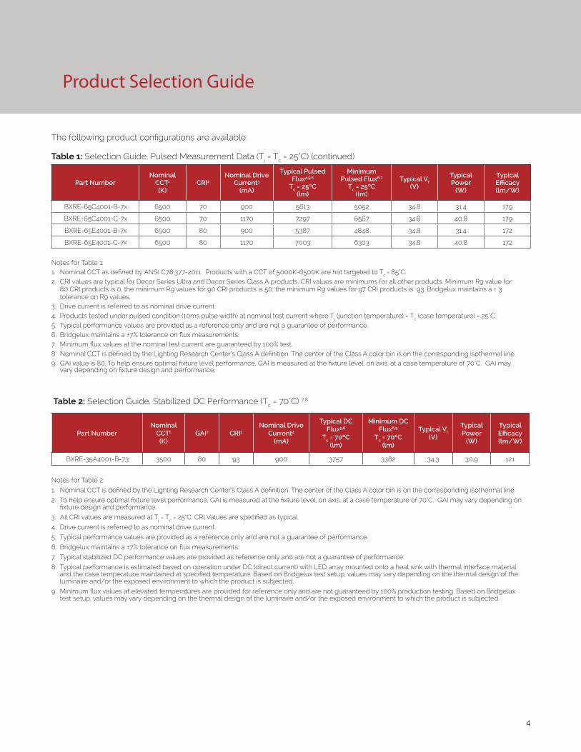
Table 2: Selection Guide, Stabilized DC Performance (Tc = 70°C) 7,8
Part NumberNominal
CCT1 (K)
GAI2 CRI3 Nominal Drive
Current4 (mA)
Typical DC Flux5,6
Tc = 70ºC(lm)
Minimum DC Flux6,9
Tc = 70ºC(lm)
Typical Vf (V)
Typical Power
(W)
Typical Efficacy (lm/W)
BXRE-35A4001-B-73 3500 80 93 900 3757 3382 34.3 30.9 121
Notes for Table 2:
1. Nominal CCT is defined by the Lighting Research Center’s Class A definition. The center of the Class A color bin is on the corresponding isothermal line.
2. To help ensure optimal fixture level performance, GAI is measured at the fixture level, on axis, at a case temperature of 70°C. GAI may vary depending on fixture design and performance.
3. All CRI values are measured at Tj = Tc = 25°C. CRI Values are specified as typical.
4. Drive current is referred to as nominal drive current.
5. Typical performance values are provided as a reference only and are not a guarantee of performance.
6. Bridgelux maintains a ±7% tolerance on flux measurements.
7. Typical stabilized DC performance values are provided as reference only and are not a guarantee of performance.
8. Typical performance is estimated based on operation under DC (direct current) with LED array mounted onto a heat sink with thermal interface material and the case temperature maintained at specified temperature. Based on Bridgelux test setup, values may vary depending on the thermal design of the luminaire and/or the exposed environment to which the product is subjected.
9. Minimum flux values at elevated temperatures are provided for reference only and are not guaranteed by 100% production testing. Based on Bridgelux test setup, values may vary depending on the thermal design of the luminaire and/or the exposed environment to which the product is subjected.
The following product configurations are available:
Table 1: Selection Guide, Pulsed Measurement Data (Tj = Tc = 25°C) (continued)
Part NumberNominal
CCT1
(K)CRI2
Nominal Drive Current3
(mA)
Typical Pulsed Flux4,5,6
Tc = 25ºC(lm)
Minimum Pulsed Flux6,7
Tc = 25ºC(lm)
Typical Vf (V)
Typical Power
(W)
Typical Efficacy (lm/W)
BXRE-65C4001-B-7x 6500 70 900 5613 5052 34.8 31.4 179
BXRE-65C4001-C-7x 6500 70 1170 7297 6567 34.8 40.8 179
BXRE-65E4001-B-7x 6500 80 900 5387 4848 34.8 31.4 172
BXRE-65E4001-C-7x 6500 80 1170 7003 6303 34.8 40.8 172
Notes for Table 1:1. Nominal CCT as defined by ANSI C78.377-2011. Products with a CCT of 5000K-6500K are hot targeted to Tc = 85°C.2. CRI values are typical for Decor Series Ultra and Decor Series Class A products. CRI values are minimums for all other products. Minimum R9 value for
80 CRI products is 0, the minimum R9 values for 90 CRI products is 50, the minimum R9 values for 97 CRI products is 93. Bridgelux maintains a ± 3 tolerance on R9 values.
3. Drive current is referred to as nominal drive current. 4. Products tested under pulsed condition (10ms pulse width) at nominal test current where Tj (junction temperature) = Tc (case temperature) = 25°C. 5. Typical performance values are provided as a reference only and are not a guarantee of performance. 6. Bridgelux maintains a ±7% tolerance on flux measurements. 7. Minimum flux values at the nominal test current are guaranteed by 100% test. 8. Nominal CCT is defined by the Lighting Research Center’s Class A definition. The center of the Class A color bin is on the corresponding isothermal line.9. GAI value is 80. To help ensure optimal fixture level performance, GAI is measured at the fixture level, on axis, at a case temperature of 70°C. GAI may
vary depending on fixture design and performance.
5
Product Selection Guide
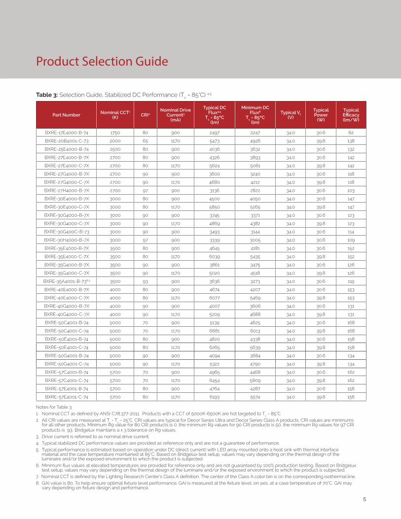
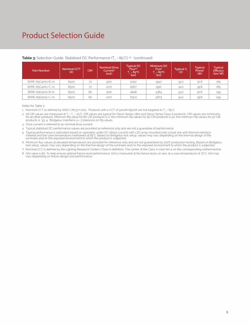
Table 3: Selection Guide, Stabilized DC Performance (Tc = 85°C) 4,5
Notes for Table 3:1. Nominal CCT as defined by ANSI C78.377-2011. Products with a CCT of 5000K-6500K are hot targeted to Tc = 85°C. 2. All CRI values are measured at Tj = Tc = 25°C. CRI values are typical for Decor Series Ultra and Decor Series Class A products. CRI values are minimums
for all other products. Minimum R9 value for 80 CRI products is 0, the minimum R9 values for 90 CRI products is 50, the minimum R9 values for 97 CRI products is 93. Bridgelux maintains a ± 3 tolerance on R9 values.
3. Drive current is referred to as nominal drive current. 4. Typical stabilized DC performance values are provided as reference only and are not a guarantee of performance. 5. Typical performance is estimated based on operation under DC (direct current) with LED array mounted onto a heat sink with thermal interface
material and the case temperature maintained at 85°C. Based on Bridgelux test setup, values may vary depending on the thermal design of the luminaire and/or the exposed environment to which the product is subjected.
6. Minimum flux values at elevated temperatures are provided for reference only and are not guaranteed by 100% production testing. Based on Bridgelux test setup, values may vary depending on the thermal design of the luminaire and/or the exposed environment to which the product is subjected.
7. Nominal CCT is defined by the Lighting Research Center’s Class A definition. The center of the Class A color bin is on the corresponding isothermal line.8. GAI value is 80. To help ensure optimal fixture level performance, GAI is measured at the fixture level, on axis, at a case temperature of 70°C. GAI may
vary depending on fixture design and performance.
Part Number Nominal CCT1 (K) CRI2
Nominal Drive Current3
(mA)
Typical DC Flux4,5
Tc = 85ºC(lm)
Minimum DC Flux6
Tc = 85ºC(lm)
Typical Vf (V)
Typical Power
(W)
Typical Efficacy (lm/W)
BXRE-17E4000-B-74 1750 80 900 2497 2247 34.0 30.6 82
BXRE-20B4001-C-73 2000 65 1170 5473 4926 34.0 39.8 138
BXRE-25E4000-B-74 2500 80 900 4036 3632 34.0 30.6 132
BXRE-27E4000-B-7X 2700 80 900 4326 3893 34.0 30.6 142
BXRE-27E4000-C-7X 2700 80 1170 5624 5061 34.0 39.8 142
BXRE-27G4000-B-7X 2700 90 900 3600 3240 34.0 30.6 118
BXRE-27G4000-C-7X 2700 90 1170 4680 4212 34.0 39.8 118
BXRE-27H4000-B-7X 2700 97 900 3136 2822 34.0 30.6 103
BXRE-30E4000-B-7X 3000 80 900 4500 4050 34.0 30.6 147
BXRE-30E4000-C-7X 3000 80 1170 5850 5265 34.0 39.8 147
BXRE-30G4000-B-7X 3000 90 900 3745 3371 34.0 30.6 123
BXRE-30G4000-C-7X 3000 90 1170 4869 4382 34.0 39.8 123
BXRE-30G400C-B-73 3000 90 900 3493 3144 34.0 30.6 114
BXRE-30H4000-B-7X 3000 97 900 3339 3005 34.0 30.6 109
BXRE-35E4000-B-7X 3500 80 900 4645 4181 34.0 30.6 152
BXRE-35E4000-C-7X 3500 80 1170 6039 5435 34.0 39.8 152
BXRE-35G4000-B-7X 3500 90 900 3861 3475 34.0 30.6 126
BXRE-35G4000-C-7X 3500 90 1170 5020 4518 34.0 39.8 126
BXRE-35A4001-B-738,9 3500 93 900 3636 3273 34.0 30.6 119
BXRE-40E4000-B-7X 4000 80 900 4674 4207 34.0 30.6 153
BXRE-40E4000-C-7X 4000 80 1170 6077 5469 34.0 39.8 153
BXRE-40G4000-B-7X 4000 90 900 4007 3606 34.0 30.6 131
BXRE-40G4000-C-7X 4000 90 1170 5209 4688 34.0 39.8 131
BXRE-50C4001-B-74 5000 70 900 5139 4625 34.0 30.6 168
BXRE-50C4001-C-74 5000 70 1170 6681 6013 34.0 39.8 168
BXRE-50E4001-B-74 5000 80 900 4820 4338 34.0 30.6 158
BXRE-50E4001-C-74 5000 80 1170 6265 5639 34.0 39.8 158
BXRE-50G4001-B-74 5000 90 900 4094 3684 34.0 30.6 134
BXRE-50G4001-C-74 5000 90 1170 5322 4790 34.0 39.8 134
BXRE-57C4001-B-74 5700 70 900 4965 4468 34.0 30.6 162
BXRE-57C4001-C-74 5700 70 1170 6454 5809 34.0 39.8 162
BXRE-57E4001-B-74 5700 80 900 4764 4287 34.0 30.6 156
BXRE-57E4001-C-74 5700 80 1170 6193 5574 34.0 39.8 156
6
Product Selection Guide
Table 3: Selection Guide, Stabilized DC Performance (Tc = 85°C) 4,5 (continued)
Part Number Nominal CCT1 (K) CRI2
Nominal Drive Current3
(mA)
Typical DC Flux4,5
Tc = 85ºC(lm)
Minimum DC Flux6
Tc = 85ºC(lm)
Typical Vf (V)
Typical Power
(W)
Typical Efficacy (lm/W)
BXRE-65C4001-B-7x 6500 70 900 5052 4547 34.0 30.6 165
BXRE-65C4001-C-7x 6500 70 1170 6567 5911 34.0 39.8 165
BXRE-65E4001-B-7x 6500 80 900 4848 4364 34.0 30.6 159
BXRE-65E4001-C-7x 6500 80 1170 6303 5673 34.0 39.8 159
Notes for Table 3:1. Nominal CCT as defined by ANSI C78.377-2011. Products with a CCT of 5000K-6500K are hot targeted to Tc = 85°C. 2. All CRI values are measured at Tj = Tc = 25°C. CRI values are typical for Decor Series Ultra and Decor Series Class A products. CRI values are minimums
for all other products. Minimum R9 value for 80 CRI products is 0, the minimum R9 values for 90 CRI products is 50, the minimum R9 values for 97 CRI products is 93. 4. Bridgelux maintains a ± 3 tolerance on R9 values.
3. Drive current is referred to as nominal drive current. 4. Typical stabilized DC performance values are provided as reference only and are not a guarantee of performance. 5. Typical performance is estimated based on operation under DC (direct current) with LED array mounted onto a heat sink with thermal interface
material and the case temperature maintained at 85°C. Based on Bridgelux test setup, values may vary depending on the thermal design of the luminaire and/or the exposed environment to which the product is subjected.
6. Minimum flux values at elevated temperatures are provided for reference only and are not guaranteed by 100% production testing. Based on Bridgelux test setup, values may vary depending on the thermal design of the luminaire and/or the exposed environment to which the product is subjected.
7. Nominal CCT is defined by the Lighting Research Center’s Class A definition. The center of the Class A color bin is on the corresponding isothermal line.8. GAI value is 80. To help ensure optimal fixture level performance, GAI is measured at the fixture level, on axis, at a case temperature of 70°C. GAI may
vary depending on fixture design and performance.
7
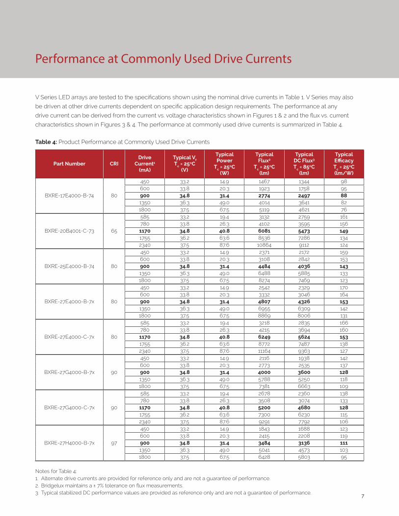
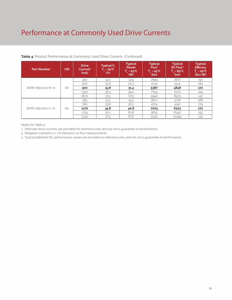
Performance at Commonly Used Drive Currents
V Series LED arrays are tested to the specifications shown using the nominal drive currents in Table 1. V Series may also
be driven at other drive currents dependent on specific application design requirements. The performance at any
drive current can be derived from the current vs. voltage characteristics shown in Figures 1 & 2 and the flux vs. current
characteristics shown in Figures 3 & 4. The performance at commonly used drive currents is summarized in Table 4.
Table 4: Product Performance at Commonly Used Drive Currents
Part Number CRIDrive
Current1
(mA)
Typical Vf Tc = 25ºC
(V)
Typical Power
Tc = 25ºC(W)
Typical Flux2
Tc = 25ºC(lm)
Typical DC Flux3 Tc = 85ºC
(lm)
Typical Efficacy Tc = 25ºC(lm/W)
BXRE-17E4000-B-74 80
450 33.2 14.9 1467 1344 98600 33.8 20.3 1923 1758 95900 34.8 31.4 2774 2497 881350 36.3 49.0 4014 3641 821800 37.5 67.5 5119 4621 76
BXRE-20B4001-C-73 65
585 33.2 19.4 3132 2759 161780 33.8 26.3 4102 3595 1561170 34.8 40.8 6081 5473 1491755 36.2 63.6 8536 7286 1342340 37.5 87.6 10864 9112 124
BXRE-25E4000-B-74 80
450 33.2 14.9 2371 2172 159600 33.8 20.3 3108 2842 153900 34.8 31.4 4484 4036 1431350 36.3 49.0 6488 5885 1331800 37.5 67.5 8274 7469 123
BXRE-27E4000-B-7x 80
450 33.2 14.9 2542 2329 170600 33.8 20.3 3332 3046 164900 34.8 31.4 4807 4326 1531350 36.3 49.0 6955 6309 1421800 37.5 67.5 8869 8006 131
BXRE-27E4000-C-7x 80
585 33.2 19.4 3218 2835 166780 33.8 26.3 4215 3694 1601170 34.8 40.8 6249 5624 1531755 36.2 63.6 8772 7487 1382340 37.5 87.6 11164 9363 127
BXRE-27G4000-B-7x 90
450 33.2 14.9 2116 1938 142600 33.8 20.3 2773 2535 137900 34.8 31.4 4000 3600 1281350 36.3 49.0 5788 5250 1181800 37.5 67.5 7381 6663 109
BXRE-27G4000-C-7x 90
585 33.2 19.4 2678 2360 138780 33.8 26.3 3508 3074 1331170 34.8 40.8 5200 4680 1281755 36.2 63.6 7300 6230 1152340 37.5 87.6 9291 7792 106
BXRE-27H4000-B-7x 97
450 33.2 14.9 1843 1688 123600 33.8 20.3 2415 2208 119900 34.8 31.4 3484 3136 1111350 36.3 49.0 5041 4573 1031800 37.5 67.5 6428 5803 95
Notes for Table 4:1. Alternate drive currents are provided for reference only and are not a guarantee of performance.2. Bridgelux maintains a ± 7% tolerance on flux measurements.3. Typical stabilized DC performance values are provided as reference only and are not a guarantee of performance.
8
Performance at Commonly Used Drive Currents
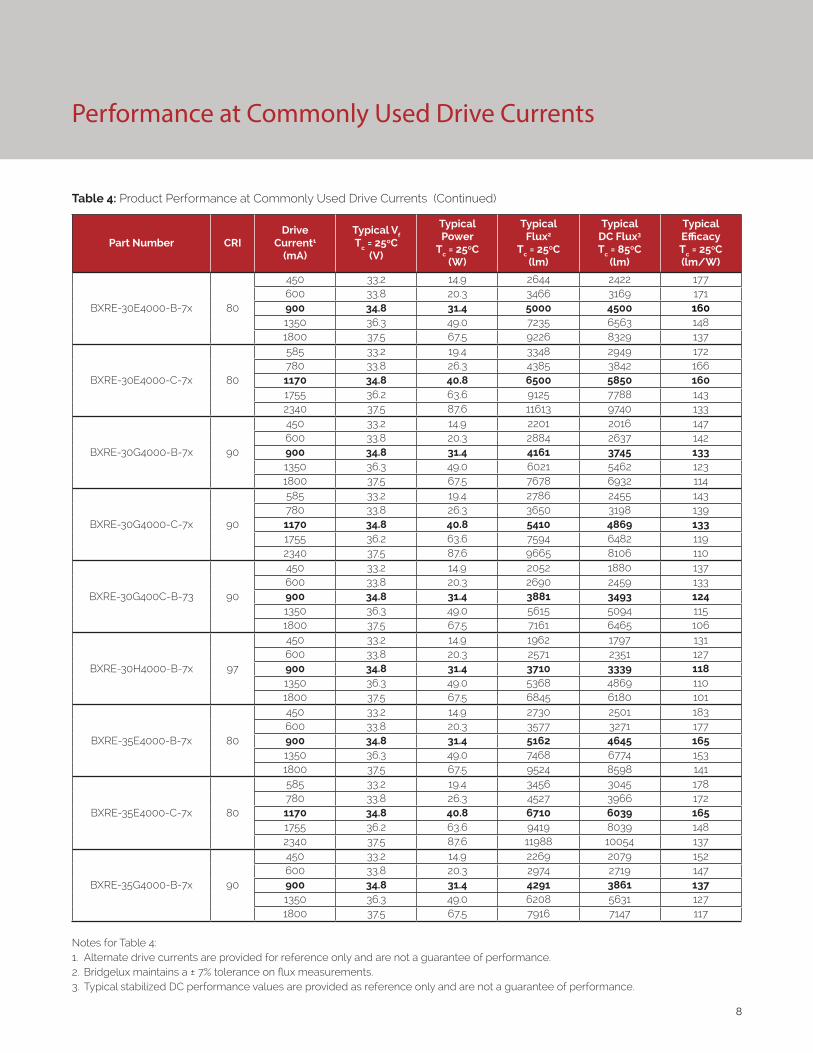
Table 4: Product Performance at Commonly Used Drive Currents (Continued)
Part Number CRIDrive
Current1
(mA)
Typical Vf Tc = 25ºC
(V)
Typical Power
Tc = 25ºC(W)
Typical Flux2
Tc = 25ºC(lm)
Typical DC Flux3 Tc = 85ºC
(lm)
Typical Efficacy Tc = 25ºC(lm/W)
BXRE-30E4000-B-7x 80
450 33.2 14.9 2644 2422 177600 33.8 20.3 3466 3169 171900 34.8 31.4 5000 4500 1601350 36.3 49.0 7235 6563 1481800 37.5 67.5 9226 8329 137
BXRE-30E4000-C-7x 80
585 33.2 19.4 3348 2949 172780 33.8 26.3 4385 3842 1661170 34.8 40.8 6500 5850 1601755 36.2 63.6 9125 7788 1432340 37.5 87.6 11613 9740 133
BXRE-30G4000-B-7x 90
450 33.2 14.9 2201 2016 147600 33.8 20.3 2884 2637 142900 34.8 31.4 4161 3745 1331350 36.3 49.0 6021 5462 1231800 37.5 67.5 7678 6932 114
BXRE-30G4000-C-7x 90
585 33.2 19.4 2786 2455 143780 33.8 26.3 3650 3198 1391170 34.8 40.8 5410 4869 1331755 36.2 63.6 7594 6482 1192340 37.5 87.6 9665 8106 110
BXRE-30G400C-B-73 90
450 33.2 14.9 2052 1880 137600 33.8 20.3 2690 2459 133900 34.8 31.4 3881 3493 1241350 36.3 49.0 5615 5094 1151800 37.5 67.5 7161 6465 106
BXRE-30H4000-B-7x 97
450 33.2 14.9 1962 1797 131600 33.8 20.3 2571 2351 127900 34.8 31.4 3710 3339 1181350 36.3 49.0 5368 4869 1101800 37.5 67.5 6845 6180 101
BXRE-35E4000-B-7x 80
450 33.2 14.9 2730 2501 183600 33.8 20.3 3577 3271 177900 34.8 31.4 5162 4645 1651350 36.3 49.0 7468 6774 1531800 37.5 67.5 9524 8598 141
BXRE-35E4000-C-7x 80
585 33.2 19.4 3456 3045 178780 33.8 26.3 4527 3966 1721170 34.8 40.8 6710 6039 1651755 36.2 63.6 9419 8039 1482340 37.5 87.6 11988 10054 137
BXRE-35G4000-B-7x 90
450 33.2 14.9 2269 2079 152600 33.8 20.3 2974 2719 147900 34.8 31.4 4291 3861 1371350 36.3 49.0 6208 5631 1271800 37.5 67.5 7916 7147 117
Notes for Table 4:1. Alternate drive currents are provided for reference only and are not a guarantee of performance.2. Bridgelux maintains a ± 7% tolerance on flux measurements.3. Typical stabilized DC performance values are provided as reference only and are not a guarantee of performance.

9
Table 4: Product Performance at Commonly Used Drive Currents (Continued)
Part Number CRIDrive
Current1
(mA)
Typical Vf Tc = 25ºC
(V)
Typical Power
Tc = 25ºC(W)
Typical Flux2
Tc = 25ºC(lm)
Typical DC Flux3 Tc = 85ºC
(lm)
Typical Efficacy Tc = 25ºC(lm/W)
BXRE-35G4000-C-7x 90
585 33.2 19.4 2873 2531 148780 33.8 26.3 3763 3297 1431170 34.8 40.8 5578 5020 1371755 36.2 63.6 7830 6683 1232340 37.5 87.6 9965 8358 114
BXRE-35A4001-B-73 93
450 33.2 14.9 2137 1957 143600 33.8 20.3 2800 2560 138900 34.8 31.4 4040 3636 1291350 36.3 49.0 5846 5303 1191800 37.5 67.5 7455 6730 110
BXRE-40E4000-B-7x 80
450 33.2 14.9 2747 2516 184600 33.8 20.3 3600 3291 178900 34.8 31.4 5194 4674 1661350 36.3 49.0 7515 6817 1531800 37.5 67.5 9583 8651 142
BXRE-40E4000-C-7x 80
585 33.2 19.4 3478 3064 179780 33.8 26.3 4555 3991 1731170 34.8 40.8 6752 6077 1661755 36.2 63.6 9478 8089 1492340 37.5 87.6 12063 10117 138
BXRE-40G4000-B-7x 90
450 33.2 14.9 2354 2157 158600 33.8 20.3 3086 2821 152900 34.8 31.4 4452 4007 1421350 36.3 49.0 6441 5843 1321800 37.5 67.5 8214 7415 122
BXRE-40G4000-C-7x 90
585 33.2 19.4 2981 2626 153780 33.8 26.3 3904 3421 1481170 34.8 40.8 5787 5209 1421755 36.2 63.6 8124 6934 1282340 37.5 87.6 10340 8672 118
BXRE-50C4001-B-7x 70
450 33.2 14.9 3020 2766 202600 33.8 20.3 3958 3618 195900 34.8 31.4 5710 5139 1821350 36.3 49.0 8261 7494 1691800 37.5 67.5 10535 9511 156
BXRE-50C4001-C-7x 70
585 33.2 19.4 3823 3368 197780 33.8 26.3 5007 4388 1901170 34.8 40.8 7423 6681 1821755 36.2 63.6 10420 8893 1642340 37.5 87.6 13262 11123 151
BXRE-50E4001-B-7x 80
450 33.2 14.9 2832 2594 190600 33.8 20.3 3712 3394 183900 34.8 31.4 5355 4820 1711350 36.3 49.0 7748 7028 1581800 37.5 67.5 9881 8920 146
Notes for Table 4:1. Alternate drive currents are provided for reference only and are not a guarantee of performance.2. Bridgelux maintains a ± 7% tolerance on flux measurements.3. Typical stabilized DC performance values are provided as reference only and are not a guarantee of performance.
Performance at Commonly Used Drive Currents
10
Performance at Commonly Used Drive Currents
Table 4: Product Performance at Commonly Used Drive Currents (Continued)
Part Number CRIDrive
Current1
(mA)
Typical Vf Tc = 25ºC
(V)
Typical Power
Tc = 25ºC(W)
Typical Flux2
Tc = 25ºC(lm)
Typical DC Flux3 Tc = 85ºC
(lm)
Typical Efficacy Tc = 25ºC(lm/W)
BXRE-50E4001-C-7x 80
585 33.2 19.4 3586 3159 185780 33.8 26.3 4696 4115 1781170 34.8 40.8 6962 6265 1711755 36.2 63.6 9773 8341 1542340 37.5 87.6 12437 10431 142
BXRE-50G4001-B-7x 90
450 33.2 14.9 2406 2204 161600 33.8 20.3 3153 2882 156900 34.8 31.4 4549 4094 1451350 36.3 49.0 6581 5970 1341800 37.5 67.5 8393 7577 124
BXRE-50G4001-C-7x 90
585 33.2 19.4 3046 2683 157780 33.8 26.3 3989 3495 1511170 34.8 40.8 5913 5322 1451755 36.2 63.6 8301 7085 1312340 37.5 87.6 10564 8860 121
BXRE-57C4001-B-7x 70
450 33.2 14.9 2917 2672 195600 33.8 20.3 3823 3496 189900 34.8 31.4 5516 4965 1761350 36.3 49.0 7981 7240 1631800 37.5 67.5 10178 9189 151
BXRE-57C4001-C-7x 70
585 33.2 19.4 3694 3254 190780 33.8 26.3 4838 4239 1841170 34.8 40.8 7171 6454 1761755 36.2 63.6 10067 8592 1582340 37.5 87.6 12812 10746 146
BXRE-57E4001-B-7x 80
450 33.2 14.9 2799 2564 187600 33.8 20.3 3669 3354 181900 34.8 31.4 5293 4764 1691350 36.3 49.0 7658 6947 1561800 37.5 67.5 9766 8817 145
BXRE-57E4001-C-7x 80
585 33.2 19.4 3544 3122 182780 33.8 26.3 4642 4067 1761170 34.8 40.8 6881 6193 1691755 36.2 63.6 9660 8244 1522340 37.5 87.6 12293 10311 140
BXRE-65C4001-B-7x 70
450 33.2 14.9 2969 2719 199600 33.8 20.3 3890 3557 192900 34.8 31.4 5613 5052 1791350 36.3 49.0 8121 7367 1661800 37.5 67.5 10357 9350 153
BXRE-65C4001-C-7x 70
585 33.2 19.4 3759 3311 194780 33.8 26.3 4923 4313 1871170 34.8 40.8 7297 6567 1791755 36.2 63.6 10244 8743 1612340 37.5 87.6 13037 10934 149
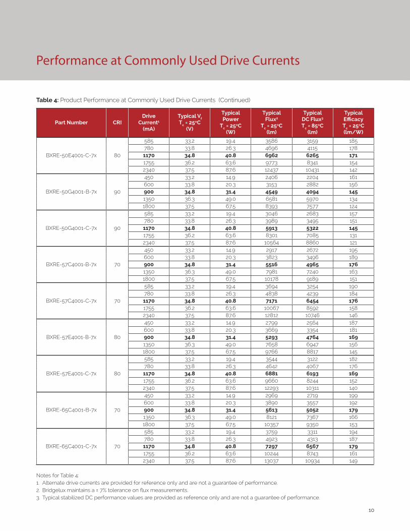
Notes for Table 4:1. Alternate drive currents are provided for reference only and are not a guarantee of performance.2. Bridgelux maintains a ± 7% tolerance on flux measurements.3. Typical stabilized DC performance values are provided as reference only and are not a guarantee of performance.
11
Performance at Commonly Used Drive Currents
Table 4: Product Performance at Commonly Used Drive Currents (Continued)
Part Number CRIDrive
Current1
(mA)
Typical Vf Tc = 25ºC
(V)
Typical Power
Tc = 25ºC(W)
Typical Flux2
Tc = 25ºC(lm)
Typical DC Flux3 Tc = 85ºC
(lm)
Typical Efficacy Tc = 25ºC(lm/W)
BXRE-65E4001-B-7x 80
450 33.2 14.9 2849 2610 191600 33.8 20.3 3734 3414 184900 34.8 31.4 5387 4848 1721350 36.3 49.0 7794 7070 1591800 37.5 67.5 9940 8973 147
BXRE-65E4001-C-7x 80
585 33.2 19.4 3607 3178 186780 33.8 26.3 4724 4140 1791170 34.8 40.8 7003 6303 1721755 36.2 63.6 9831 8390 1552340 37.5 87.6 12512 10494 143
Notes for Table 4:1. Alternate drive currents are provided for reference only and are not a guarantee of performance.2. Bridgelux maintains a ± 7% tolerance on flux measurements.3. Typical stabilized DC performance values are provided as reference only and are not a guarantee of performance.
12
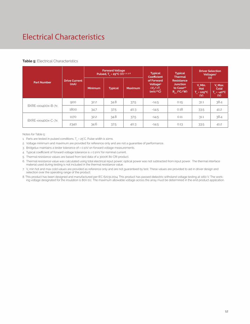
Electrical Characteristics
Table 5: Electrical Characteristics
Part NumberDrive Current
(mA)
Forward VoltagePulsed, Tc = 25ºC (V) 1, 2, 3, 8 Typical
Coefficient of Forward
Voltage4 ∆Vf/∆Tc
(mV/ºC)
Typical Thermal
Resistance Junction to Case5,6
Rj-c (ºC/W)
Driver Selection Voltages7
(V)
Minimum Typical MaximumVf Min.
Hot Tc = 105ºC
(V)
Vf Max. Cold
Tc = -40ºC (V)
BXRE-xxx400x-B-7x900 32.2 34.8 37.5 -14.5 0.15 31.1 38.4
1800 34.7 37.5 40.3 -14.5 0.18 33.5 41.2
BXRE-xxx400x-C-7x1170 32.2 34.8 37.5 -14.5 0.11 31.1 38.4
2340 34.6 37.5 40.3 -14.5 0.13 33.5 41.2
Notes for Table 5:
1. Parts are tested in pulsed conditions, Tc = 25°C. Pulse width is 10ms.
2. Voltage minimum and maximum are provided for reference only and are not a guarantee of performance.
3. Bridgelux maintains a tester tolerance of ± 0.10V on forward voltage measurements.
4. Typical coefficient of forward voltage tolerance is ± 0.1mV for nominal current.
5. Thermal resistance values are based from test data of a 3000K 80 CRI product.
6. Thermal resistance value was calculated using total electrical input power; optical power was not subtracted from input power. The thermal interface material used during testing is not included in the thermal resistance value.
7. Vf min hot and max cold values are provided as reference only and are not guaranteed by test. These values are provided to aid in driver design and selection over the operating range of the product.
8. This product has been designed and manufactured per IEC 62031:2014. This product has passed dielectric withstand voltage testing at 1160 V. The work-ing voltage designated for the insulation is 80V d.c. The maximum allowable voltage across the array must be determined in the end product application.
13
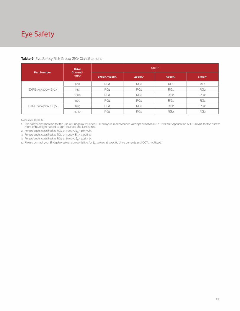
Eye Safety
Table 6: Eye Safety Risk Group (RG) Classifications
Part NumberDrive
Current 5
(mA)
CCT1,5
2700K/3000K 4000K2 5000K3 6500K4
BXRE-xxx400x-B-7x
900 RG1 RG1 RG1 RG1
1350 RG1 RG1 RG1 RG2
1800 RG1 RG1 RG2 RG2
BXRE-xxx400x-C-7x
1170 RG1 RG1 RG1 RG1
1755 RG1 RG1 RG2 RG2
2340 RG1 RG1 RG2 RG2
Notes for Table 6:1. Eye safety classification for the use of Bridgelux V Series LED arrays is in accordance with specification IEC/TR 62778: Application of IEC 62471 for the assess-
ment of blue light hazard to light sources and luminaires.2. For products classified as RG2 at 4000K, Ethr= 1847.5 lx.3. For products classified as RG2 at 5000K Ethr= 1315.8 lx.4. For products classified as RG2 at 6500K, Ethr= 1124.5 lx.5. Please contact your Bridgelux sales representative for Ethr values at specific drive currents and CCTs not listed.
14
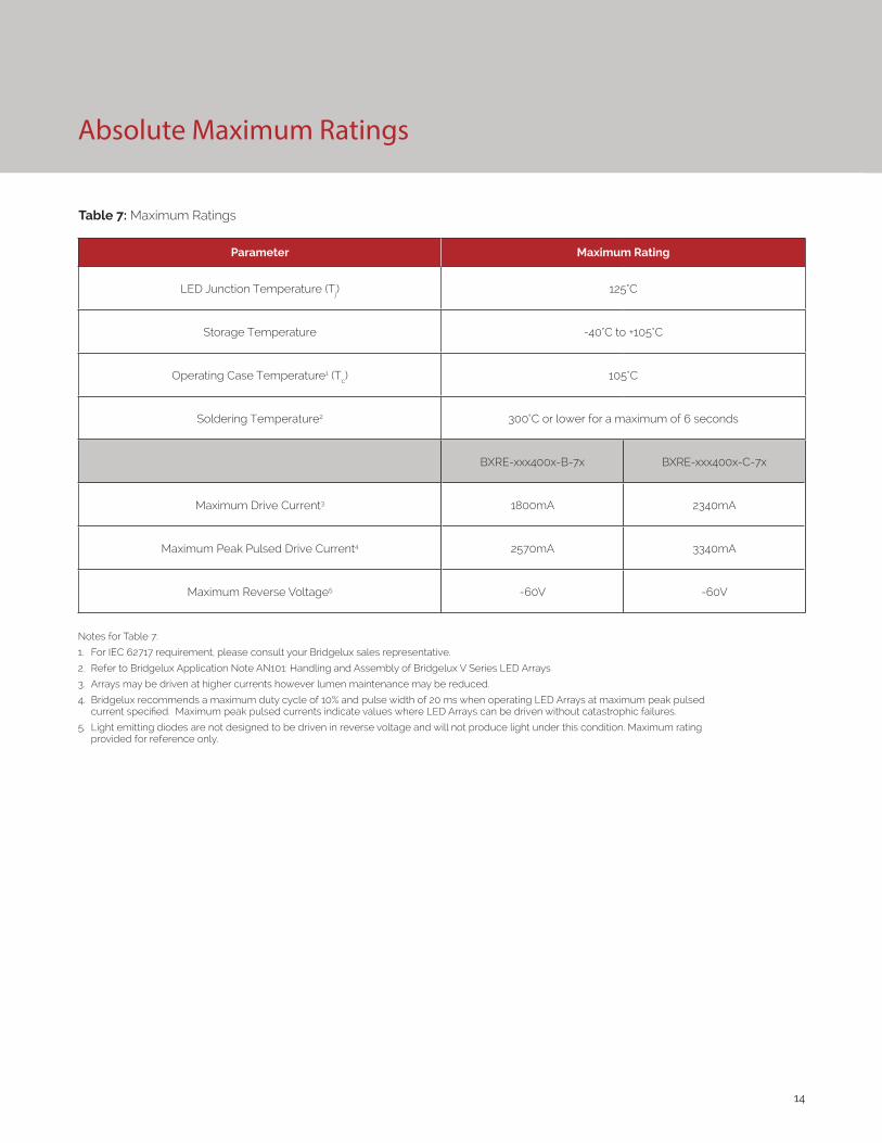
Absolute Maximum Ratings
Parameter Maximum Rating
LED Junction Temperature (Tj) 125°C
Storage Temperature -40°C to +105°C
Operating Case Temperature1 (Tc) 105°C
Soldering Temperature2 300°C or lower for a maximum of 6 seconds
BXRE-xxx400x-B-7x BXRE-xxx400x-C-7x
Maximum Drive Current3 1800mA 2340mA
Maximum Peak Pulsed Drive Current4 2570mA 3340mA
Maximum Reverse Voltage5 -60V -60V
Notes for Table 7:
1. For IEC 62717 requirement, please consult your Bridgelux sales representative.
2. Refer to Bridgelux Application Note AN101: Handling and Assembly of Bridgelux V Series LED Arrays
3. Arrays may be driven at higher currents however lumen maintenance may be reduced.
4. Bridgelux recommends a maximum duty cycle of 10% and pulse width of 20 ms when operating LED Arrays at maximum peak pulsed current specified. Maximum peak pulsed currents indicate values where LED Arrays can be driven without catastrophic failures.
5. Light emitting diodes are not designed to be driven in reverse voltage and will not produce light under this condition. Maximum rating provided for reference only.
Table 7: Maximum Ratings
15
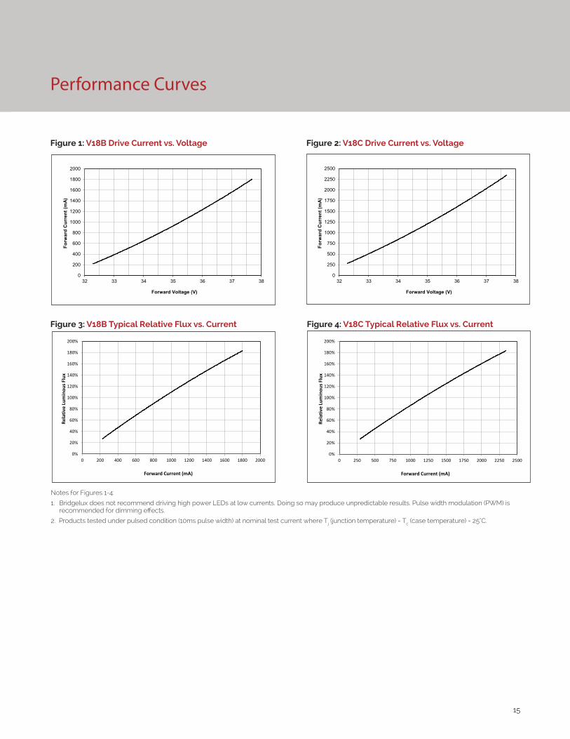
Performance Curves
Figure 3: V18B Typical Relative Flux vs. Current Figure 4: V18C Typical Relative Flux vs. Current
Notes for Figures 1-4:
1. Bridgelux does not recommend driving high power LEDs at low currents. Doing so may produce unpredictable results. Pulse width modulation (PWM) is recommended for dimming effects.
2. Products tested under pulsed condition (10ms pulse width) at nominal test current where Tj (junction temperature) = Tc (case temperature) = 25°C.
Figure 1: V18B Drive Current vs. Voltage Figure 2: V18C Drive Current vs. Voltage
0
200
400
600
800
1000
1200
1400
1600
1800
2000
32 33 34 35 36 37 38
Forw
ard
Cur
rent
(mA)
Forward Voltage (V)
0
250
500
750
1000
1250
1500
1750
2000
2250
2500
32 33 34 35 36 37 38
Forw
ard
Cur
rent
(mA)
Forward Voltage (V)
0%
20%
40%
60%
80%
100%
120%
140%
160%
180%
200%
0 200 400 600 800 1000 1200 1400 1600 1800 2000
Rela
tive
Lum
inou
s Flu
x
Forward Current (mA)
0%
20%
40%
60%
80%
100%
120%
140%
160%
180%
200%
0 250 500 750 1000 1250 1500 1750 2000 2250 2500
Rela
tive
Lum
inou
s Flu
x
Forward Current (mA)
16
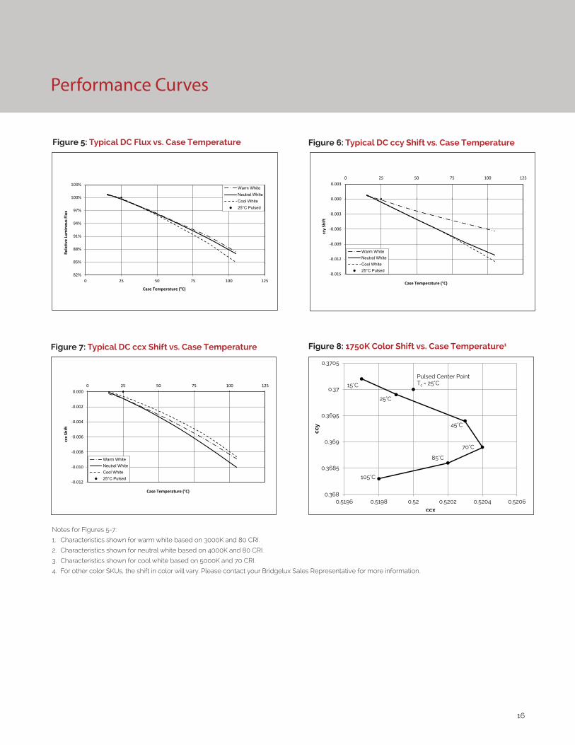
Performance Curves
Figure 5: Typical DC Flux vs. Case Temperature
82%
85%
88%
91%
94%
97%
100%
103%
0 25 50 75 100 125
Rela
tive
Lum
inou
s Flu
x
Case Temperature (°C)
Warm WhiteNeutral WhiteCool White25°C Pulsed
Notes for Figures 5-7:
1. Characteristics shown for warm white based on 3000K and 80 CRI.
2. Characteristics shown for neutral white based on 4000K and 80 CRI.
3. Characteristics shown for cool white based on 5000K and 70 CRI.
4. For other color SKUs, the shift in color will vary. Please contact your Bridgelux Sales Representative for more information.
Figure 7: Typical DC ccx Shift vs. Case Temperature
Figure 6: Typical DC ccy Shift vs. Case Temperature
-0.012
-0.010
-0.008
-0.006
-0.004
-0.002
0.0000 25 50 75 100 125
ccx
Shift
Case Temperature (°C)
Warm WhiteNeutral WhiteCool White25°C Pulsed
-0.015
-0.012
-0.009
-0.006
-0.003
0.000
0.0030 25 50 75 100 125
ccy
Shift
Case Temperature (°C)
Warm WhiteNeutral WhiteCool White25°C Pulsed
Figure 8: 1750K Color Shift vs. Case Temperature1
0.368
0.3685
0.369
0.3695
0.37
0.3705
0.5196 0.5198 0.52 0.5202 0.5204 0.5206
ccy
ccx
15°C
25°C
45°C
70°C
85°C
105°C
Pulsed Center Point Tc = 25°C
17
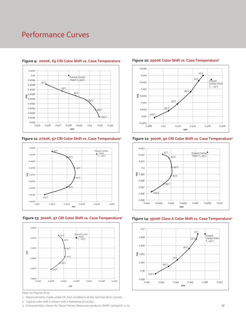
Performance Curves
Figure 11: 2700K, 97 CRI Color Shift vs. Case Temperature1
Figure 13: 3000K, 97 CRI Color Shift vs. Case Temperature1 Figure 14: 3500K Class A Color Shift vs. Case Temperature1
Note for Figures 8-14:
1. Measurements made under DC test conditions at the nominal drive current.
2. Typical color shift is shown with a tolerance of ±0.002.3. Characteristics shown for Decor Series Showcase products, BXRE-30G400C-x-73
Figure 10: 2500K Color Shift vs. Case Temperature1
0.4105
0.411
0.4115
0.412
0.4125
0.413
0.4135
0.414
0.4145
0.468 0.47 0.472 0.474 0.476 0.478
ccy
ccx
15°C
25°C
45°C
70°C
85°C
105°C
Pulsed Center Point Tc = 25°C
15°C
25°C
45°C
65°C
85°C
105°C
Pulsed Center Point
Tc = 25°C
0.4030
0.4040
0.4050
0.4060
0.4070
0.4080
0.4090
0.4100
0.4110
0.457 0.4572 0.4574 0.4576 0.4578 0.458
ccy
ccx
15°C
25°C
45°C
70°C
85°C
105°C
Pulsed Center Point
Tc = 25°C
0.3950
0.3970
0.3990
0.4010
0.4030
0.4050
0.4323 0.4328 0.4333 0.4338 0.4343 0.4348 0.4353
ccy
ccx
0.358
0.36
0.362
0.364
0.366
0.368
0.37
0.392 0.393 0.394 0.395 0.396 0.397
ccy
ccx
PulsedCenter Point Tc=25°C
15°C
45°C
85°C
105°C
70°C
25°C
Figure 12: 3000K, 90 CRI Color Shift vs. Case Temperature3
Figure 9: 2000K, 65 CRI Color Shift vs. Case Temperature
105°C
85°C
65°C
45°C
25°C
15°C
Pulsed Center Point Tc=25°C
0.409
0.4091
0.4092
0.4093
0.4094
0.4095
0.4096
0.4097
0.4098
0.4099
0.41
0.4101
0.525 0.526 0.527 0.528 0.529 0.53 0.531 0.532
ccy
ccx
Pulsed Center Point Tc=25°C
15°C
25°C
45°C
65°C
85°C
105°C
0.395
0.396
0.397
0.398
0.399
0.4
0.401
0.402
0.403
0.444 0.4445 0.445 0.4455 0.446 0.4465 0.447
ccy
ccx
18
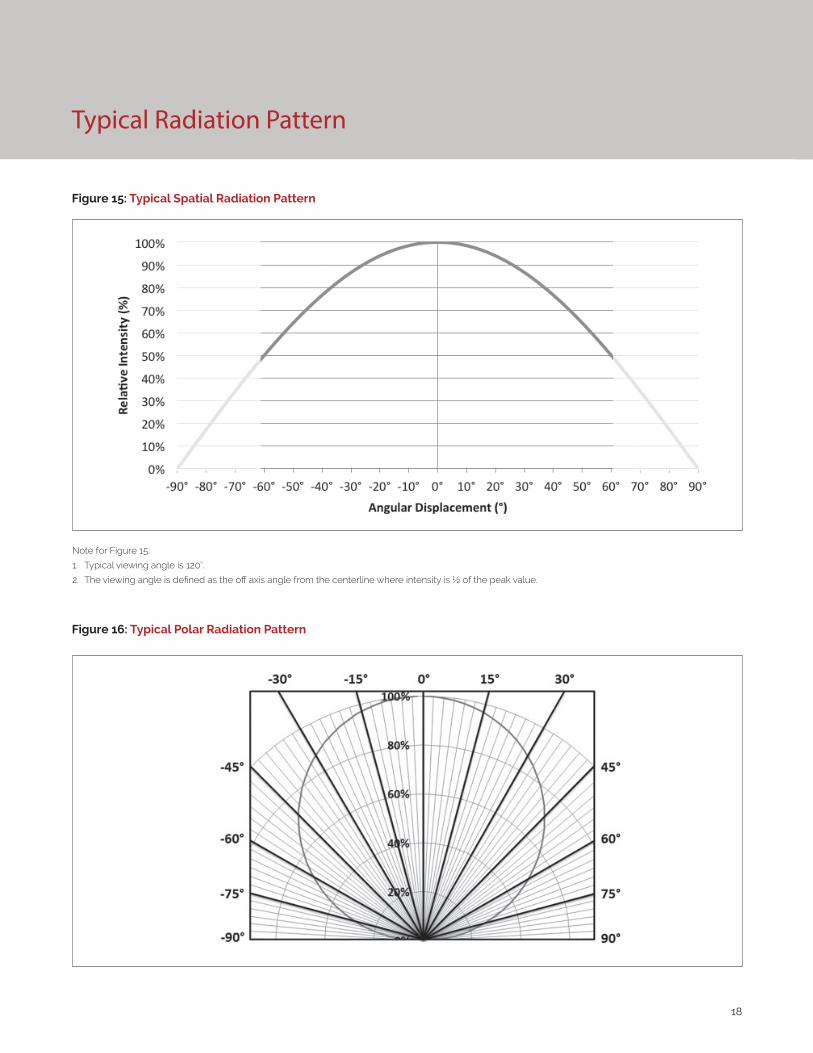
Typical Radiation Pattern
Figure 15: Typical Spatial Radiation Pattern
Figure 16: Typical Polar Radiation Pattern
Note for Figure 15:
1. Typical viewing angle is 120⁰.
2. The viewing angle is defined as the off axis angle from the centerline where intensity is ½ of the peak value.
19
Typical Color Spectrum
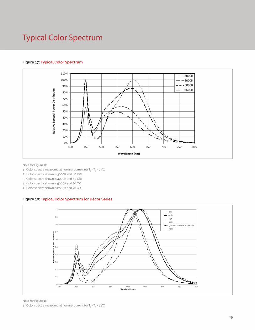
Figure 17: Typical Color Spectrum
Note for Figure 17:
1. Color spectra measured at nominal current for Tj = Tc = 25°C.
2. Color spectra shown is 3000K and 80 CRI.
3. Color spectra shown is 4000K and 80 CRI.
4. Color spectra shown is 5000K and 70 CRI.
4. Color spectra shown is 6500K and 70 CRI.
0%
10%
20%
30%
40%
50%
60%
70%
80%
90%
100%
110%
400 450 500 550 600 650 700 750 800
Rela
tive
Spec
tral
Pow
er D
istr
ibut
ion
Wavelength (nm)
3000K4000K5000K6500K
Figure 18: Typical Color Spectrum for Décor Series
Note for Figure 18:
1. Color spectra measured at nominal current for Tj = Tc = 25°C.
0
0.1
0.2
0.3
0.4
0.5
0.6
0.7
0.8
0.9
1
400 450 500 550 600 650 700 750 800
Re
lati
ve S
pe
ctra
l Po
we
r D
istr
ibu
tio
n
Wavelength (nm)
17E
20B
25E
27H
30G (Décor Series Showcase)
30H
20
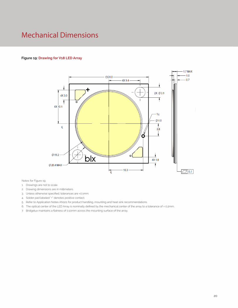
Mechanical Dimensions
Figure 19: Drawing for V18 LED Array
Notes for Figure 19;
1. Drawings are not to scale.
2. Drawing dimensions are in millimeters.
3. Unless otherwise specified, tolerances are ±0.1mm.
4. Solder pad labeled “+” denotes positive contact.
5. Refer to Application Notes AN101 for product handling, mounting and heat sink recommendations.
6. The optical center of the LED Array is nominally defined by the mechanical center of the array to a tolerance of ± 0.2mm.
7. Bridgelux maintains a flatness of 0.10mm across the mounting surface of the array.
21
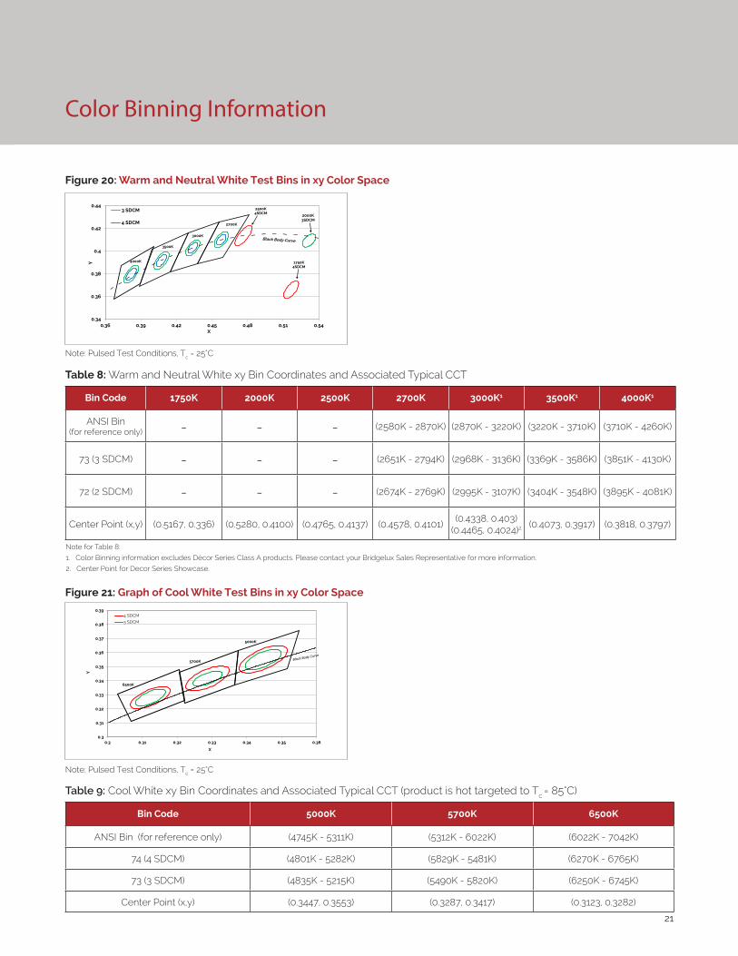
Figure 20: Warm and Neutral White Test Bins in xy Color Space
Figure 21: Graph of Cool White Test Bins in xy Color Space
Color Binning Information
Bin Code 1750K 2000K 2500K 2700K 3000K1 3500K1 4000K1
ANSI Bin(for reference only) - - - (2580K - 2870K) (2870K - 3220K) (3220K - 3710K) (3710K - 4260K)
73 (3 SDCM) - - - (2651K - 2794K) (2968K - 3136K) (3369K - 3586K) (3851K - 4130K)
72 (2 SDCM) - - - (2674K - 2769K) (2995K - 3107K) (3404K - 3548K) (3895K - 4081K)
Center Point (x,y) (0.5167, 0.336) (0.5280, 0.4100) (0.4765, 0.4137) (0.4578, 0.4101)(0.4338, 0.403)
(0.4465, 0.4024)2 (0.4073, 0.3917) (0.3818, 0.3797)
Table 8: Warm and Neutral White xy Bin Coordinates and Associated Typical CCT
Bin Code 5000K 5700K 6500K
ANSI Bin (for reference only) (4745K - 5311K) (5312K - 6022K) (6022K - 7042K)
74 (4 SDCM) (4801K - 5282K) (5829K - 5481K) (6270K - 6765K)
73 (3 SDCM) (4835K - 5215K) (5490K - 5820K) (6250K - 6745K)
Center Point (x,y) (0.3447, 0.3553) (0.3287, 0.3417) (0.3123, 0.3282)
Table 9: Cool White xy Bin Coordinates and Associated Typical CCT (product is hot targeted to Tc = 85°C)
Note: Pulsed Test Conditions, Tc = 25°C
Note: Pulsed Test Conditions, Tc = 25°C
Note for Table 8:
1. Color Binning information excludes Décor Series Class A products. Please contact your Bridgelux Sales Representative for more information.
2. Center Point for Decor Series Showcase.
0.34
0.36
0.38
0.4
0.42
0.44
0.36 0.39 0.42 0.45 0.48 0.51 0.54
Y
X
3 SDCM
4 SDCM
3500K
2500K4SDCM
1750K4SDCM
2000K3SDCM
2700K
3000K
4000K
0.3
0.31
0.32
0.33
0.34
0.35
0.36
0.37
0.38
0.39
0.3 0.31 0.32 0.33 0.34 0.35 0.36
Y
X
4 SDCM
3 SDCM
6500K
5700K
5000K
22
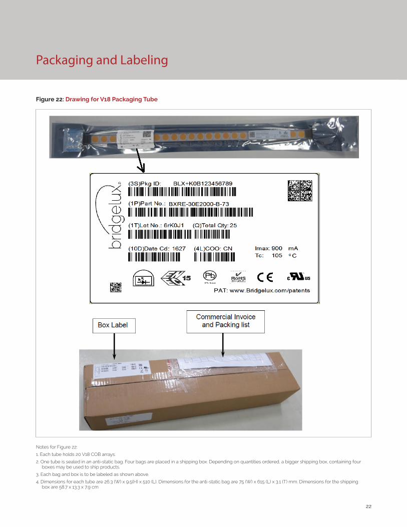
Packaging and Labeling
Figure 22: Drawing for V18 Packaging Tube
Notes for Figure 22:
1. Each tube holds 20 V18 COB arrays.
2. One tube is sealed in an anti-static bag. Four bags are placed in a shipping box. Depending on quantities ordered, a bigger shipping box, containing four boxes may be used to ship products.
3. Each bag and box is to be labeled as shown above.
4. Dimensions for each tube are 26.3 (W) x 9.5(H) x 510 (L). Dimensions for the anti-static bag are 75 (W) x 615 (L) x 3.1 (T) mm. Dimensions for the shipping box are 58.7 x 13.3 x 7.9 cm
23
Packaging and Labeling
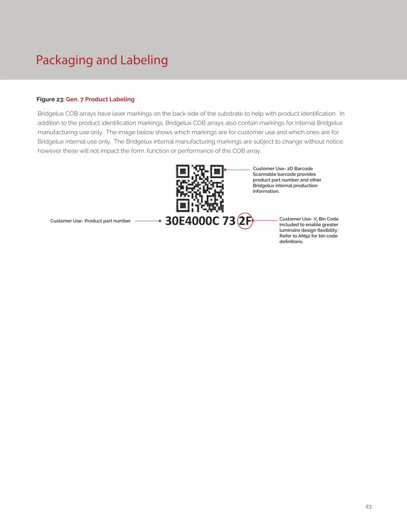
Figure 23: Gen. 7 Product Labeling
Bridgelux COB arrays have laser markings on the back side of the substrate to help with product identification. In
addition to the product identification markings, Bridgelux COB arrays also contain markings for internal Bridgelux
manufacturing use only. The image below shows which markings are for customer use and which ones are for
Bridgelux internal use only. The Bridgelux internal manufacturing markings are subject to change without notice,
however these will not impact the form, function or performance of the COB array.
Customer Use- 2D Barcode Scannable barcode provides product part number and other Bridgelux internal production information.
Customer Use- Product part number 30E4000C 73 2F Customer Use- Vf Bin Code included to enable greater luminaire design flexibility. Refer to AN92 for bin code definitions.
24
Design Resources
Disclaimers
Precautions
Application Notes
Bridgelux has developed a comprehensive set of application notes and design resources to assist customers in successfully designing with the V Series product family of LED array products. For all available application notes visit www.bridgelux.com.
Optical Source Models
Optical source models and ray set files are available for all Bridgelux products. For a list of available formats, visit www.bridgelux.com.
MINOR PRODUCT CHANGE POLICY
The rigorous qualification testing on products offered by Bridgelux provides performance assurance. Slight cosmetic changes that do not affect form, fit, or function may occur as Bridgelux continues product optimization.
CAUTION: CHEMICAL EXPOSURE HAZARD
Exposure to some chemicals commonly used in luminaire manufacturing and assembly can cause damage to the LED array. Please consult Bridgelux Application Note AN101 for additional information.
CAUTION: RISK OF BURN
Do not touch the V Series LED array during operation. Allow the array to cool for a sufficient period of time before handling. The V Series LED array may reach elevated temperatures such that could burn skin when touched.
3D CAD Models
Three dimensional CAD models depicting the product outline of all Bridgelux V Series LED arrays are available in both IGS and STEP formats. Please contact your Bridgelux sales representative for assistance.
LM80
LM80 testing has been completed and the LM80 report is now available. Please contact your Bridgelux sales representative for LM-80 report.
STANDARD TEST CONDITIONS
Unless otherwise stated, array testing is performed at the nominal drive current.
CAUTION
CONTACT WITH LIGHT EMITTING SURFACE (LES)
Avoid any contact with the LES. Do not touch the LES of the LED array or apply stress to the LES (yellow phosphor resin area). Contact may cause damage to the LED array.
Optics and reflectors must not be mounted in contact with the LES (yellow phosphor resin area).
25
About Bridgelux: We Build Light That Transforms
© 2016-2017 Bridgelux, Inc. All rights reserved 2016. Product specifications are subject to change without notice. Bridgelux, the Bridgelux stylized logo design and Vero are registered trademarks, and Decor Series is a trademark of Bridgelux, Inc. All other trademarks are the property of their respective owners.
Bridgelux Gen 7 V18 Array Series Product Data Sheet DS102 Rev. K (12/2017)
46430 Fremont Boulevard
Fremont, CA 94538
Tel (925) 583-8400
www.bridgelux.com
At Bridgelux, we help companies, industries and people experience the power and possibility of light. Since 2002, we’ve designed LED solutions that are high performing, energy efficient, cost effective and easy to integrate. Our focus is on light’s impact on human behavior, deliver-ing products that create better environments, experiences and returns—both experiential and financial. And our patented technology drives new platforms for commercial and industrial luminaires.
For more information about the company, please visit bridgelux.comtwitter.com/Bridgeluxfacebook.com/Bridgeluxyoutube.com/user/Bridgeluxlinkedin.com/company/bridgelux-inc-_2WeChat ID: BridgeluxInChina