Embed Size (px)
Citation preview
OREGON DEPARTMENT OF TRANSPORTATION
Bridge CAD Manual
Bridge CAD Manual – May 2019 Oregon Department of Transportation
2-1
Contents
PURPOSE 3
1 COMPUTER AIDED DRAFTING (CAD) 3 1.1 Standard File Format 3 1.2 Directory Setup 3 1.3 CAD Files 3 1.3.1 Overview: Drawings Start to Finish 3 1.3.2 What Bridge Headquarters Needs At Completion of a Design Project 4 1.3.3.1 Example Drawings 4 1.3.3.2 Standard Details 4 1.3.4 File Naming Conventions 5 1.3.5 MicroStation Models 5 1.4 Cell Libraries 5 1.5 Task Menus 5 1.6 Seed Files 6 1.7 Drawing Scale 6 1.7 Drawing Scale – (continued) 6
2 DETAILING 7 2.1 Text 7 2.2 Line Work and Levels 7 2.3 Dimensioning 7 2.4 Concrete 9 2.5 Structural Steel 9 2.6 Reinforcing Steel 10 2.7 Bar Length Labeling 10
3 DRAWING BORDERS 11
4 TITLE BLOCK INFORMATION - See Contract Plans Manual (CPM) 11 4.1 Request for Drawing Numbers 11 4.2 Title Block 11
5 LEAD CAD TECH DUTIES ON LARGE PROJECTS 13
6 TYPE, SIZE AND LOCATION PLAN AND ELEVATION 13 6.1 Plan 13 6.1 Plan – (continued) 14 6.2 Location Map 15 6.3 Clearance Diagrams 16
7 FINAL PLANS 16 7.1 Layout for Large Projects 16 7.2 Final Plans, General 16 7.3 Plan and Elevation 18 7.3.1 Plan 18 7.3.2 Elevation 18 7.3.3 Hydraulic Data 19 7.3.4 General Notes 19 7.3.5 Gradeline and Superelevation Diagrams 19 7.3.6 Military Loading 20 7.3.7 Utilities and Right-of-Way 20 7.3.8 Railroad Clearance Diagram 20
Bridge CAD Manual – May 2019 Oregon Department of Transportation
2-2
7.3.9 Construction Clearance Diagram 21 7.4 Geotechnical Data Sheet 21 7.5 Footing Plan 21 7.6 Deck Plan 22 7.7 Superstructure Details 23 7.7.1 Superstructure Sections 23 7.7.3 Diaphragm and Crossbeam Details 24 7.7.4 Longitudinal Girder Elevation Views 24 7.8 Bent Details 25 7.8.1 Plan View 25 7.8.2 Elevation 25 7.8.3 Footing Plan 25 7.8.4 Details 25 7.9 Miscellaneous Details 25 7.10 Plans "Not for Construction – Informational Dwgs." 26 7.11 Revisions to Drawings 26 7.11.1 As Constructed Drawings 27
8 PRINTING 28 8.1 Digital Plans 28 8.2 Bridge Data System (BDS) 29 8.2.1 Digitally Signed Final Plans and As Constructed Milestones 29
9 TRANSFER OF ELECTRONIC FILES TO OUTSIDE OF ODOT 29
10 ARCHIVING CAD FILES 29
A APPENDICES 30
A1 CAD Files 30
A2 Line Work and Levels 31
A3 Deck Plan 37
Bridge CAD Manual – May 2019 Oregon Department of Transportation
2-3
PURPOSE
The purpose of the Bridge CAD Manual (BCM) is to provide direction regarding the use of the drawing standards for Bridge Section plan sheets and supplemental to the ODOT Contract Plans Manual(CPM). Where the two manuals are in conflict, the BCM will take precedence. (Use of the term “CAD Tech” refers to the Computer Aided Drafting Technician.) 1 COMPUTER AIDED DRAFTING (CAD)
1.1 Standard File Format
See Contract Plans Manual.
1.2 Directory Setup
All users will create CAD files and do their work in ProjectWise (maintenance projects pending entry into ProjectWise) according to the Contract Plans Manual and ODOT ProjectWise User Manual (External users: ProjectWise External User Manual). Bridge Standard Drawings and Standard Detail Drawings files are available in DGN and PDF format. Also you will find Discontinued Drawing Index and Standard Drawings Reports (SDR).
1.3 CAD Files
1.3.1 Overview: Drawings Start to Finish
1. CAD files created and maintained in ProjectWise (maintenance projects pending entry into ProjectWise).
2. The design offices are responsible for obtaining the structure numbers and drawing numbers from
the Bridge Data System (BDS) and calculation book numbers from headquarters Bridge Section in Salem.
3. One 11” x 17” PDF file per sheet is created with appropriate bridge and drawing numbers.
4. PDF documents are added to the appropriate location in ProjectWise and digitally signed for the
Office of Pre-Letting (OPL). See the CPM for details.
5. Upon completion of the contract plans for bidding, the design office will convert the PDF files to TIF files (400 dpi) and upload the images into BDS.
6. When construction is complete, the Project manager will send As Constructed comments to the
original design office for review by the Engineer of Record (EOR).
7. The Design office adds as constructed comments electronically. Once As Constructed comments are completed, new TIF images are created and uploaded into BDS. See Section 7.11.1 As Constructed Drawings for procedure.
8. Original digitally signed PDF, DGN and all other related documents will remain in ProjectWise
with the project documents.
Bridge CAD Manual – May 2019 Oregon Department of Transportation
2-4
1.3.2 What Bridge Headquarters Needs At Completion of a Design Project
State Owned Structures • 11” x 17” digitally signed PDF files are included as part of the PS&E submittal package
provided to the ODOT Office of Pre-Letting. The PDF files from OPL will be used for the project advertisement and bidding process.
• See Section 7.11.1 As Constructed Drawings for information on completing this task. • Load rating of As Constructed bridge per Load Rating Guidelines. Due to the document
naming restrictions of the load rating software, this will be done outside of ProjectWise. The documents will then be combined in a .zip file and loaded into ProjectWise with the rest of the project documents.
• CAD Files in MicroStation format. All plan sheet files in the 2_Plan_Sheets folder in ProjectWise need to contain only contract plans drawings used to print the PDF drawings. All documents must be named in accordance with the ProjectWise naming conventions.
• Consultants – Files need to be handed off to Bridge Headquarters or the responsible Region, who will then load them into ProjectWise.
• Documents will remain in ProjectWise. Other State and Local Agency Structures
• 11” x 17” PDF prints of signed drawings or digitally signed PDF files are included as part of the PS&E submittal package provided to the ODOT Office of Pre-Letting. The PDF files from OPL will be used for the project advertisement and bidding process.
• Original signed documents may be kept by the owner of the structure. • See Section 7.11.1 As Constructed Drawings for complete information on completing this
task. A PDF of drawings with As Constructed comments added is sent to ODOT Bridge Headquarters in Salem.
• Load rating of As Constructed bridges per Load Rating Guidelines.
1.3.3.1 Example Drawings
Example drawings of repair/retrofit and different structure types are available on the ODOT FTP site.
1.3.3.2 Standard Details
A Standard Detail is a commonly used drawing that is inserted into a plan sheet is stamped by the EOR. Requests for Bridge Standard Details should be submitted to Bridge CAD Standards.
Bridge CAD Manual – May 2019 Oregon Department of Transportation
2-5
1.3.4 File Naming Conventions
Use the ProjectWise document naming tool. Files for plan sheets will reside in the 2_Plan_Sheets folder and use the naming convention appropriate to the section of the plans in which they reside (J for bridges, K for ITS, etc.). For other files, see chart below.
Structure Type* ProjectWise Origin ID ProjectWise Folder Bridge, culvert 20 ft. and
greater, culvert not intended for water (e.g. cattle pass, equipment pass, wildlife pass, or
trail)
BR Structures
Tunnel, viaduct, building, misc. structure STR
Traffic, Geotechnical, Hydraulic, ITS
Use origin ID corresponding to the type
of structure
Locate in folder corresponding to the type of structure**
*See design manuals for detailed structure definitions: Bridge Design Manual, Geotechnical Design Manual, Hydraulics Manual,Traffic Structures Design Manual. **Add <BDS no. #####> to the ProjectWise document description and enter it in the Structure # attribute.
1.3.5 MicroStation Models
Each sheet will be in its own file however base CAD files may contain multiple models.
1.4 Cell Libraries
For internal users MicroStation cell libraries reside on the server plus a personal cell library, for location see below. Bridge Section Standard Cell Library Location on server = \\SCDATA3\ODOT_Space\V8i\Standards\cell Personal Cell Library Location on server = ODOT_DATA\USERCFG\Cell\PersonalCellLibraryName.cel Registration Seal Cell Library This library shall be maintained by the Senior CAD Tech responsible for bridge drawings in each Region for their Professional Engineers. Use the templates available in “ODOT_Seals.cel” for the various seals.
1.5 Task Menus
Custom Tasks A Task or tool can be created in MicroStation using tools provided in MicroStation.
Bridge CAD Manual – May 2019 Oregon Department of Transportation
2-6
1.6 Seed Files
When creating a new file, the system copies a seed file to create a new file. Seed files are set up with the appropriate ODOT MicroStation preferences. For internal users: ODOT Seed Files Location on server = ODOT_SPACE\Standards\Seed
For external users seed files are acquired via the ODOT Workspace.
1.7 Drawing Scale
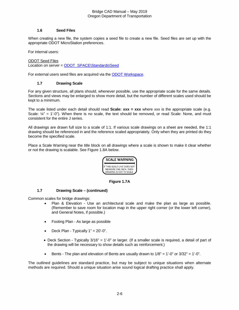
For any given structure, all plans should, whenever possible, use the appropriate scale for the same details. Sections and views may be enlarged to show more detail, but the number of different scales used should be kept to a minimum. The scale listed under each detail should read Scale: xxx = xxx where xxx is the appropriate scale (e.g. Scale: ¼” = 1’-0”). When there is no scale, the text should be removed, or read Scale: None, and must consistent for the entire J series. All drawings are drawn full size to a scale of 1:1. If various scale drawings on a sheet are needed, the 1:1 drawing should be referenced in and the reference scaled appropriately. Only when they are printed do they become the specified scale. Place a Scale Warning near the title block on all drawings where a scale is shown to make it clear whether or not the drawing is scalable. See Figure 1.8A below.
Figure 1.7A
1.7 Drawing Scale – (continued)
Common scales for bridge drawings: • Plan & Elevation - Use an architectural scale and make the plan as large as possible.
(Remember to save room for location map in the upper right corner (or the lower left corner), and General Notes, if possible.)
• Footing Plan - As large as possible
• Deck Plan - Typically 1” = 20’-0”.
• Deck Section - Typically 3/16” = 1’-0” or larger. (If a smaller scale is required, a detail of part of
the drawing will be necessary to show details such as reinforcement.)
• Bents - The plan and elevation of Bents are usually drawn to 1/8” = 1’-0” or 3/32” = 1’-0”. The outlined guidelines are standard practice, but may be subject to unique situations when alternate methods are required. Should a unique situation arise sound logical drafting practice shall apply.
Bridge CAD Manual – May 2019 Oregon Department of Transportation
2-7
2 DETAILING
2.1 Text
See Appendix A3 Line Work and Levels for Bridge Standard Symbols for MicroStation. For accepted abbreviations to use see Contract Plans Manual. Orient text to be read from the bottom or right edge of the sheet, except alignment labels such as major stations and alignment points which are in the direction of increasing stations per the Contract Plans Manual.
2.2 Line Work and Levels
See Appendix A2 Line Work and Levels for Bridge Standard Symbols for MicroStation for levels and designated line weights. The ODOT plans task menu sets the appropriate line symbology for given levels. Use line weights with appropriate gradations of width to give line contrast.
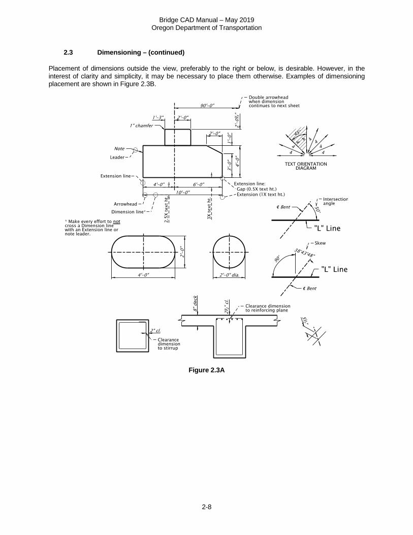
2.3 Dimensioning
Avoid duplication and unnecessary dimensions. Place all dimension figures above the dimension line and so they are read from the bottom or the right edge of the sheet, as shown in Figure 2.3A. In general, consider the precision of detail dimensions and the normal construction tolerances to which it is being constructed. General plan and detail dimensioning precision should not be more than the following:
• Structural Steel to 1/16”
• Welds to 1/16”
• Concrete to 1/8”
• Camber Diagrams to 1/8”
• If a series of dimensions (i.e. girder, pile or rail post spacing) do not add up to the exact overall dimension, use a plus or minus (±) following the series dimension (e.g. 25 girder spaces @ 9’-3 1/8”± = 231’-7”).
Dimensions 12” or more are to be dimensioned in feet and inches (i.e. 1’-0”), unless the item dimensioned is conventionally designated in inches (e.g. 16” dia. pipe or #4 @ 18”). In dimensions more than one foot, fractions less than 1” are to be proceeded by 0 (e.g. 3’-0 1/8”). Intersection angles should be dimensioned as the acute angle centerline of roadway and centerline of bent or railroad. Where the intersection is on a curve or spiral, measure the angle from the local tangent to the curve or spiral at the point of intersection and add the words “tan-tan”.
Bridge CAD Manual – May 2019 Oregon Department of Transportation
2-8
2.3 Dimensioning – (continued)
Placement of dimensions outside the view, preferably to the right or below, is desirable. However, in the interest of clarity and simplicity, it may be necessary to place them otherwise. Examples of dimensioning placement are shown in Figure 2.3B.
Figure 2.3A
Bridge CAD Manual – May 2019 Oregon Department of Transportation
2-9
2.4 Concrete
See Example Drawings.
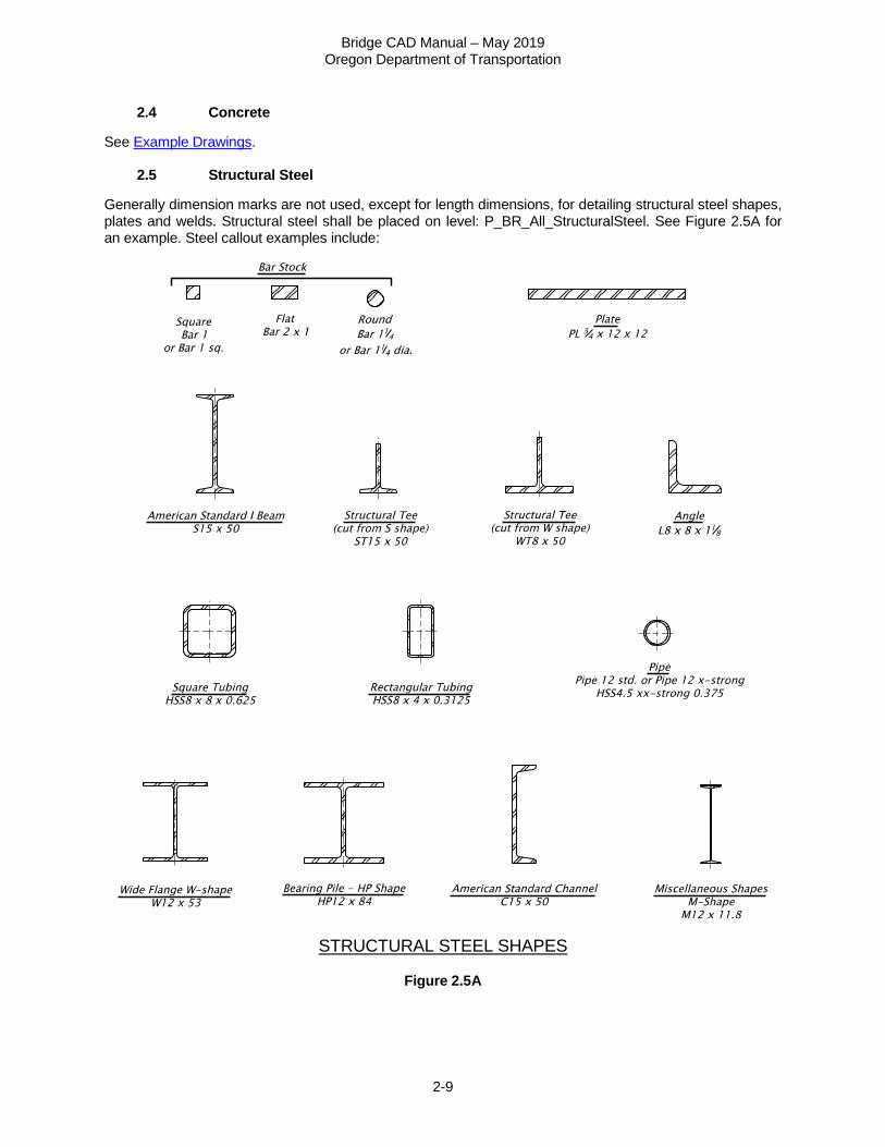
2.5 Structural Steel
Generally dimension marks are not used, except for length dimensions, for detailing structural steel shapes, plates and welds. Structural steel shall be placed on level: P_BR_All_StructuralSteel. See Figure 2.5A for an example. Steel callout examples include:
STRUCTURAL STEEL SHAPES
Figure 2.5A
Bridge CAD Manual – May 2019 Oregon Department of Transportation
2-10
2.5 Structural Steel – (continued)
See Example Drawings.
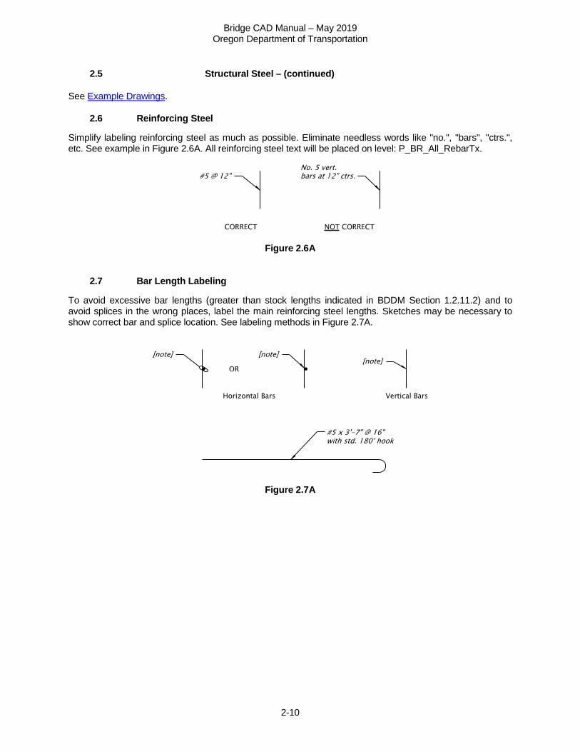
2.6 Reinforcing Steel
Simplify labeling reinforcing steel as much as possible. Eliminate needless words like "no.", "bars", "ctrs.", etc. See example in Figure 2.6A. All reinforcing steel text will be placed on level: P_BR_All_RebarTx.
Figure 2.6A
2.7 Bar Length Labeling
To avoid excessive bar lengths (greater than stock lengths indicated in BDDM Section 1.2.11.2) and to avoid splices in the wrong places, label the main reinforcing steel lengths. Sketches may be necessary to show correct bar and splice location. See labeling methods in Figure 2.7A.
Figure 2.7A
Bridge CAD Manual – May 2019 Oregon Department of Transportation
2-11
3 DRAWING BORDERS
When bridge data is represented on a Roadway Typical Section or ADA Detail sheet, confirm that “Structural Details Checked” requiring the bridge designer’s initials is on the upper left corner of the border. 4 TITLE BLOCK INFORMATION - SEE CONTRACT PLANS MANUAL (CPM)
4.1 Request for Drawing Numbers
Request drawing numbers through the project lead CAD Tech and they will access Bridge Data System (BDS) for drawing numbers. See Section 2.8.2, Bridge Data System (BDS). If the project does not merit a lead CAD Tech, then each CAD Tech has access to obtain drawing numbers through the BDS system. The Structural CAD Tech will get drawing numbers for the structure Geotechnical Data Sheets. This will hopefully keep drawing numbers consecutive for the structure although this is not always possible. To reduce the possibility of getting drawing numbers that are not used, the CAD Tech should work with the Designer to make sure all information is covered before requesting drawing numbers.
4.2 Title Block
See the Contract Plans Manual (CPM) for information on filling out the common sections of the title block and for examples. STRUCTURE NO. Box: A structure number can be obtained by using Bridge Data System (BDS). See Section 2.8.2, Bridge Data System (BDS). See the Bridge Numbering Rules. When a project has multiple structures, you may have a detail sheet that applies to more than one structure. For those sheets, enter “See above” in the structure number box and list above the title block the numbers and corresponding names of all of the structures where they apply. If the detail sheet applies to more than five structures, refer to the Structure Index sheet, entering “See index, sht. J##”. In the ProjectWise metadata for the document, list all structure numbers, as applicable, separated by a semi-colon with no spaces. For the purpose of obtaining drawing numbers in BDS, the drawing(s) will be included for one of the structures and the drawing number entered in the “Accompanied by” tab for all of the remaining applicable structures. Structure number is not required on non-public pedestrian structures. For county owned structures, the County’s Structure No. is placed immediately above the BDS structure no. to provide maintenance cross referencing. If the County’s Structure No. is not already cross- referenced in the job record or our files, it may be obtained from the Bridge Operations Managing Engineer. For bridge replacements, place the existing structure number note (text available in bridge.cel) just above the title block (e.g. “Replaces existing structure no. #####”).
Bridge CAD Manual – May 2019 Oregon Department of Transportation
2-12
BDS DWG. NO. Box: The drawing number can be obtained from the BDS. See BDS Request Form for requesting drawing numbers. Drawing numbers not required on non-public pedestrian structures. For Standard Detail project specific sheets change the standard detail title block to the project title block and request a new drawing number. CALC. BOOK NO. Box: See BDDM Section 3, 3.10. HWY./M.P. Box: Put the ODOT highway number and milepoint of the center of the bridge. If the sheet applies to multiple structures, enter “Various” for the highway number and/or milepoint, as appropriate. COUNTY Box: Put the name of the county where the bridge is located. If the sheet applies to multiple structures, enter “Various” for the county, as appropriate. DATE Box: This shows the date that the final PDFs were printed and as close as possible to the date they are signed. Structure Name Area: This is the name of the structure as it appears in BDS. See also the Bridge Log for existing structures. See the Bridge Naming Rules. If the sheet applies to multiple structures, type “VARIOUS STRUCTURES” in the structure name area and in the ProjectWise metadata for the document and list the structure numbers and names above the title block. Drawing Description Box: Be descriptive, for example do not call out “PARTIAL DECK PLAN” four times, instead use “DECK PLAN – Span 1”, “DECK PLAN – Span 2”, “DECK PLAN – Span 3”, “DECK PLAN – Span 4”. This way someone looking for a particular drawing in BDS will know which drawing at a glance. Accompanied by Dwgs. Box (place on the first sheet for each structure): List the remaining drawings for this structure (e.g. J##-J##, J##) followed by any standard drawings to which reference has been made anywhere in the plans for this structure. Locate the “Accompanied by Dwgs.” box next to the title block. Accompanied by drawings are only shown on the first sheet for each structure. For the following sheets, add “For Accompanied by drawings, see sht. J##” above the title block (text available in bridge.cel).The box outline may be made larger or smaller to accommodate the list of drawings. Not for Construction – Informational Dwgs. Box: If there are applicable existing drawings, list them in the “Not for Construction – Informational Dwgs.” box and place it below the “Accompanied By Dwgs.” box on the first sheet for each structure. For the following sheets, add “For Informational drawings, see sht. J##” above the title block (text available in bridge.cel). The box outline may be made larger or smaller to accommodate the list of drawings. See Section 7.10 Plans "Not for Construction - Informational Drawings"
Bridge CAD Manual – May 2019 Oregon Department of Transportation
2-13
5 LEAD CAD TECH DUTIES ON LARGE PROJECTS
Large projects, with multiple or complex structures usually involve multiple CAD Techs. These projects are completed more efficiently and with better consistency with a Lead CAD Tech helping the Design Team Supervisor manage and organize the efforts of the design team. These Lead CAD Techs also benefit by gaining experience in project management and coordinating the efforts of other Designers and CAD Techs. The following guidelines should be reviewed and agreed to by the Designer and CAD Tech:
• Get involved early to be knowledgeable about the overall project and deadline requirements. • Make early estimates of time and number of sheets required. • Be available to do TS&L sketches and drawings as needed. • Coordinate and communicate with other CAD Techs. • Monitor drafting progress and request help as needed to meet project deadlines. • Review drafting for completeness and consistency. • Manage bridge plans in the project print set file. • Attend project team meetings along with other CAD Techs involved. • Stay informed of project status regarding schedules and deadlines.
6 TYPE, SIZE AND LOCATION PLAN AND ELEVATION
The Type, Size and Location (TS&L)CAD files are modified and used for subsequent milestones. See QC Checklist Bridge TSL-CADD for the list of elements needed for TS&L drawings.
6.1 Plan
This is a plan view, generated from a 3D bridge model as available, showing the Roadway horizontal alignment and all major dimensions of the structure: total length, span lengths, rail pay limits, and numbers with type of construction (e.g., RCBG), bent numbers and stations (increasing from left to right on the sheet), roadway width and out-to-out transverse dimensions. Show retaining walls, wingwalls, abutments, existing utilities, right-of-way lines (see Section 7.3.7), catch basins, drains and where they drain to, and access manholes for utilities on box girders. Data from other disciplines are referenced in MicroStation and not copied. Plan is normally drawn to a 1”=10’ or 1”=20’ scale. Reference all dimensioning to the line described by the alignment data (e.g., "L" line or "C" line, etc.). If necessary, a structure layout line/chord may be used for girder layout. The layout line must be located in reference to the roadway alignment either on the plan or in a diagram. Do not use a separate, "structure centerline".
Bridge CAD Manual – May 2019 Oregon Department of Transportation
2-14
6.1 Plan – (continued)
To avoid confusion on new multi-span structures, whether they are technically abutments, bents or piers, call all supports "bents". Bents are to be numbered consecutively, in the direction of increasing project alignment stationing. If there is no alignment for the project and milepoints must be used instead of stationing, number the bents consecutively in the direction of increasing milepoints. For existing structures, add the note: “Bents are numbered in the direction of increasing stations and may not correspond with previous project plans.” near the plan view title. Replace the term “stations” with “milepoints” in the note, as required. Show existing structures or other structures which will be in place during the construction of a structure and, if necessary, locate by dimensions. Show enough of adjacent bridges as is necessary for context. Note existing structures and utilities to be moved or relocated, and who is responsible for the work. Show temporary structures which are to be removed or used in the performance of the contract. This sheet typically contains the following: (if possible, place Type, Size and Location information on one drawing. Place Staging and Typical Section on the second drawing, when two drawings are needed)
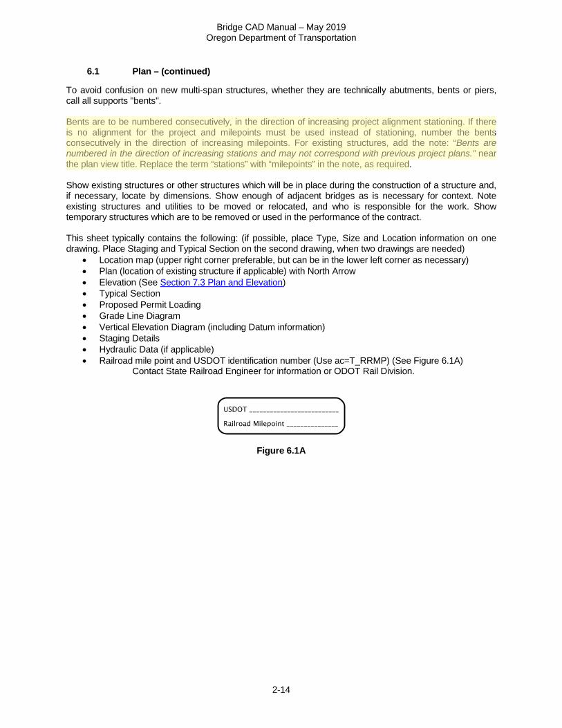
• Location map (upper right corner preferable, but can be in the lower left corner as necessary) • Plan (location of existing structure if applicable) with North Arrow • Elevation (See Section 7.3 Plan and Elevation) • Typical Section • Proposed Permit Loading • Grade Line Diagram • Vertical Elevation Diagram (including Datum information) • Staging Details • Hydraulic Data (if applicable) • Railroad mile point and USDOT identification number (Use ac=T_RRMP) (See Figure 6.1A)
Contact State Railroad Engineer for information or ODOT Rail Division.
Figure 6.1A
Bridge CAD Manual – May 2019 Oregon Department of Transportation
2-15
6.2 Location Map
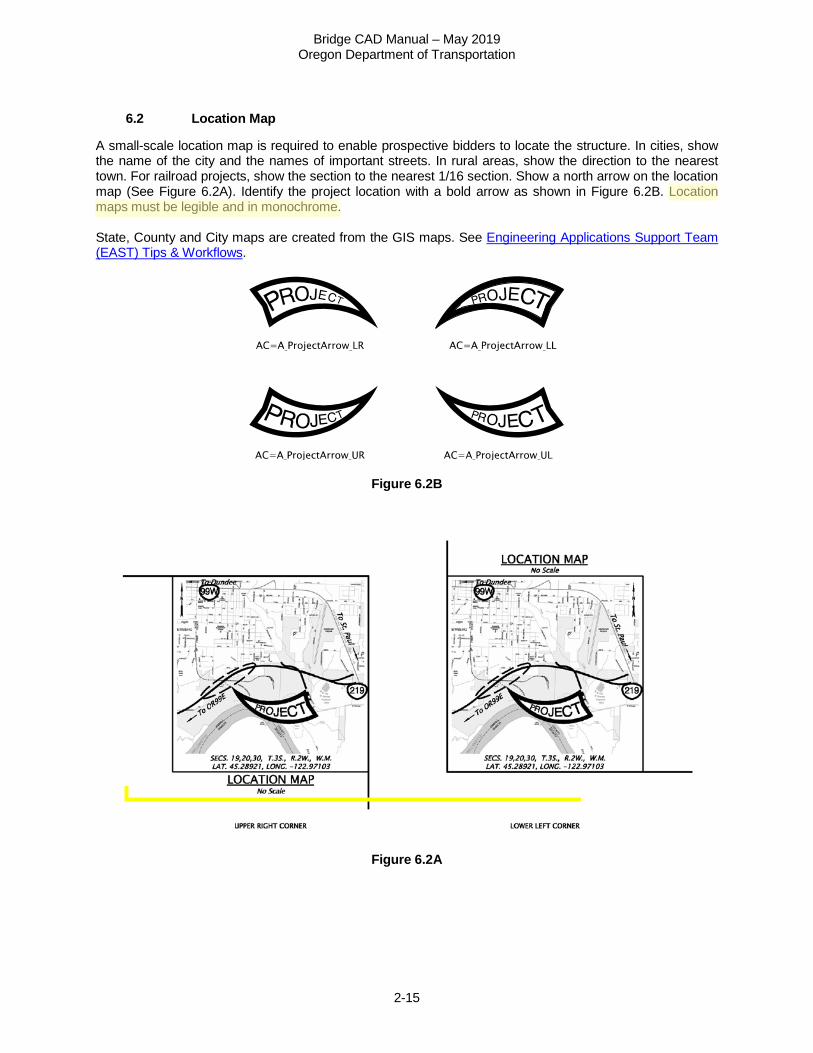
A small-scale location map is required to enable prospective bidders to locate the structure. In cities, show the name of the city and the names of important streets. In rural areas, show the direction to the nearest town. For railroad projects, show the section to the nearest 1/16 section. Show a north arrow on the location map (See Figure 6.2A). Identify the project location with a bold arrow as shown in Figure 6.2B. Location maps must be legible and in monochrome. State, County and City maps are created from the GIS maps. See Engineering Applications Support Team (EAST) Tips & Workflows.
Figure 6.2B
Figure 6.2A
Bridge CAD Manual – May 2019 Oregon Department of Transportation
2-16
6.3 Clearance Diagrams
Show vertical clearances at the critical points over railroads, streets, roads and/or highways. Where construction are to be over traffic and a railroad show a construction clearance diagram indicating both horizontal and vertical minimum clearances. Indicate the support condition at each end of each span, "fixed", "expansion", "pinned". Show existing and future ground lines at centerline, left and right. Show fill areas hatched and label as fill. 7 FINAL PLANS
7.1 Layout for Large Projects
A Structure Layout and Index Sheet is provided when there are multiple structures are under the same contract. On this sheet, a map showing the locations of the structures and the structure drawings are listed with their sheet and drawing numbers and structure numbers followed by the standard drawings needed for the project. See CPM for sheet numbering. When construction requires excavation adjacent to a railroad, show a Railroad Shoring Requirement Diagram. Limits of excavation and shoring requirements are referenced in BDDM 3.14.11.3. Details which are repeated several times or which require a note which is larger than can readily be placed close to the item detailed can be called out by a number in a circle. A corresponding number and circle along with the note can then be placed elsewhere on the sheet. Typical Detail References are shown in the Appendix A4 Deck Plan.
7.2 Final Plans, General
A set of drawings for a structure should contain all the information necessary for the layout and construction of that structure. Clear and complete plans form the basis for fair bidding. Details not properly covered can lead to high bid prices or extra work orders and price agreements during construction. See the QC Checklist Bridge Advance Plans- CADD, which includes Final Plans checklist for Designers and CAD Techs. The use of notes, such as "Bent 3 similar", may be a good practice to save detailing, but use only if it is strictly true or if any differences are clearly noted. Before detailing is begun, there needs to be good communication between the Designer and the CAD Tech to determine the number of sheets which will be required and what views and details are to be shown on each sheet. Lay out sheets to ensure sufficient room for unanticipated details, which may be required later. Take care at this time to ensure the information is presented in a clear and logical manner.
Bridge CAD Manual – May 2019 Oregon Department of Transportation
2-17
7.2 Final Plans, General – (continued) Sheet order
• General Layout and Index (Required only if project has multiple structures) • Live Load Design Criteria (Usually included with the General Notes, but can be a separate sheet for
multiple structures) • Plan and Elevation
o Location Map o Hydraulic Data table (If required) o General Notes (if space does not allow them to be placed on Plan and Elevation drawing) o Grade Line Diagram o Super Elevation Diagram o Clearance Diagrams o Construction Sequence o Railroad Data
• Geotechnical Data Sheet • Stage Construction Details (if required) • Footing Plan
o Pile Tip and/or Splice Details • Deck Plan
o Detail Reference Numbers • Typical Deck Section
o Diaphragm Beam Details (If required) • Steel Frame Plan and Details • Longitudinal Girder Elevations
o Camber Diagram o Post-tensioning Details o Girder Schedule
• Bent - Plan, Elevation and Typical Section (Bents should be placed in numerical order) o Spiral Splice / Termination Details
• Wingwall Details (Wingwall details follow bent required for, if both then place after last Bent) • Miscellaneous Details
o Bearing Details o Excavation and Backfill Details o Pour Schedule o Concrete Finish Diagram o Special rail, fencing, etc. details
• Cathodic Protection Details • Temporary Work Bridge Details
Each structure is unique and will require its own special details, so this is only a general listing of drawings that may be included in a set of contract plans.
Bridge CAD Manual – May 2019 Oregon Department of Transportation
2-18
7.3 Plan and Elevation
See Section 2.6 TYPE, SIZE AND LOCATION PLAN AND ELEVATION.
7.3.1 Plan
Space limitations on the Plan and Elevation sheet may require that the footing plan and/or the grade line diagrams, General Notes, and other miscellaneous information be located on the second or third sheet of the set. Placement closer to the front of the set is more desirable. Do not place on Geotechnical Data Sheet. Show existing utilities, whether relocation is necessary, and the responsible entity for relocation. Bridge rail pay limits is moved to the Deck Plan, if a separate deck plan is used.
7.3.2 Elevation
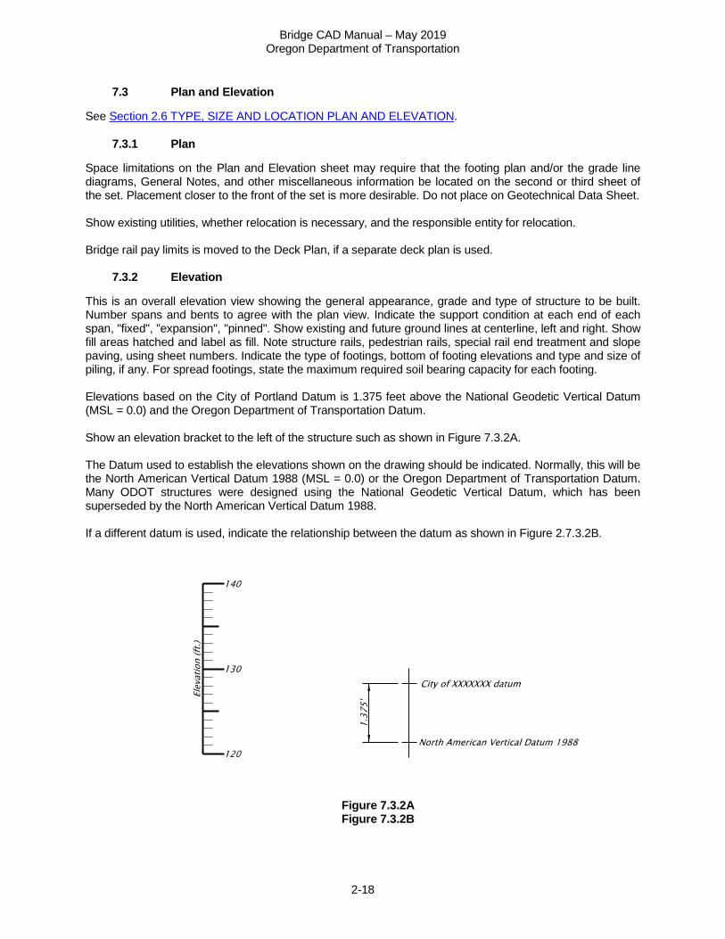
This is an overall elevation view showing the general appearance, grade and type of structure to be built. Number spans and bents to agree with the plan view. Indicate the support condition at each end of each span, "fixed", "expansion", "pinned". Show existing and future ground lines at centerline, left and right. Show fill areas hatched and label as fill. Note structure rails, pedestrian rails, special rail end treatment and slope paving, using sheet numbers. Indicate the type of footings, bottom of footing elevations and type and size of piling, if any. For spread footings, state the maximum required soil bearing capacity for each footing. Elevations based on the City of Portland Datum is 1.375 feet above the National Geodetic Vertical Datum (MSL = 0.0) and the Oregon Department of Transportation Datum. Show an elevation bracket to the left of the structure such as shown in Figure 7.3.2A. The Datum used to establish the elevations shown on the drawing should be indicated. Normally, this will be the North American Vertical Datum 1988 (MSL = 0.0) or the Oregon Department of Transportation Datum. Many ODOT structures were designed using the National Geodetic Vertical Datum, which has been superseded by the North American Vertical Datum 1988. If a different datum is used, indicate the relationship between the datum as shown in Figure 2.7.3.2B.
Figure 7.3.2A Figure 7.3.2B
Bridge CAD Manual – May 2019 Oregon Department of Transportation
2-19
7.3.3 Hydraulic Data
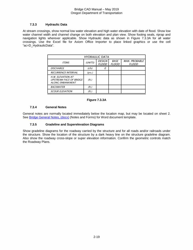
At stream crossings, show normal low water elevation and high water elevation with date of flood. Show low water channel width and channel change on both elevation and plan view. Show footing seals, riprap and navigation lights wherever applicable. Show Hydraulic data as shown in Figure 7.3.3A for all water crossings. Use the Excel file for Axiom Office Importer to place linked graphics or use the cell “ac=D_HydraulicData”.
Figure 7.3.3A
7.3.4 General Notes
General notes are normally located immediately below the location map, but may be located on sheet 2. See Bridge General Notes, (docx) (Notes and Forms) for Word document template.
7.3.5 Gradeline and Superelevation Diagrams
Show gradeline diagrams for the roadway carried by the structure and for all roads and/or railroads under the structure. Show the location of the structure by a dark heavy line on the structure gradeline diagram. Also show the roadway cross-slope or super elevation information. Confirm the geometric controls match the Roadway Plans.
Bridge CAD Manual – May 2019 Oregon Department of Transportation
2-20
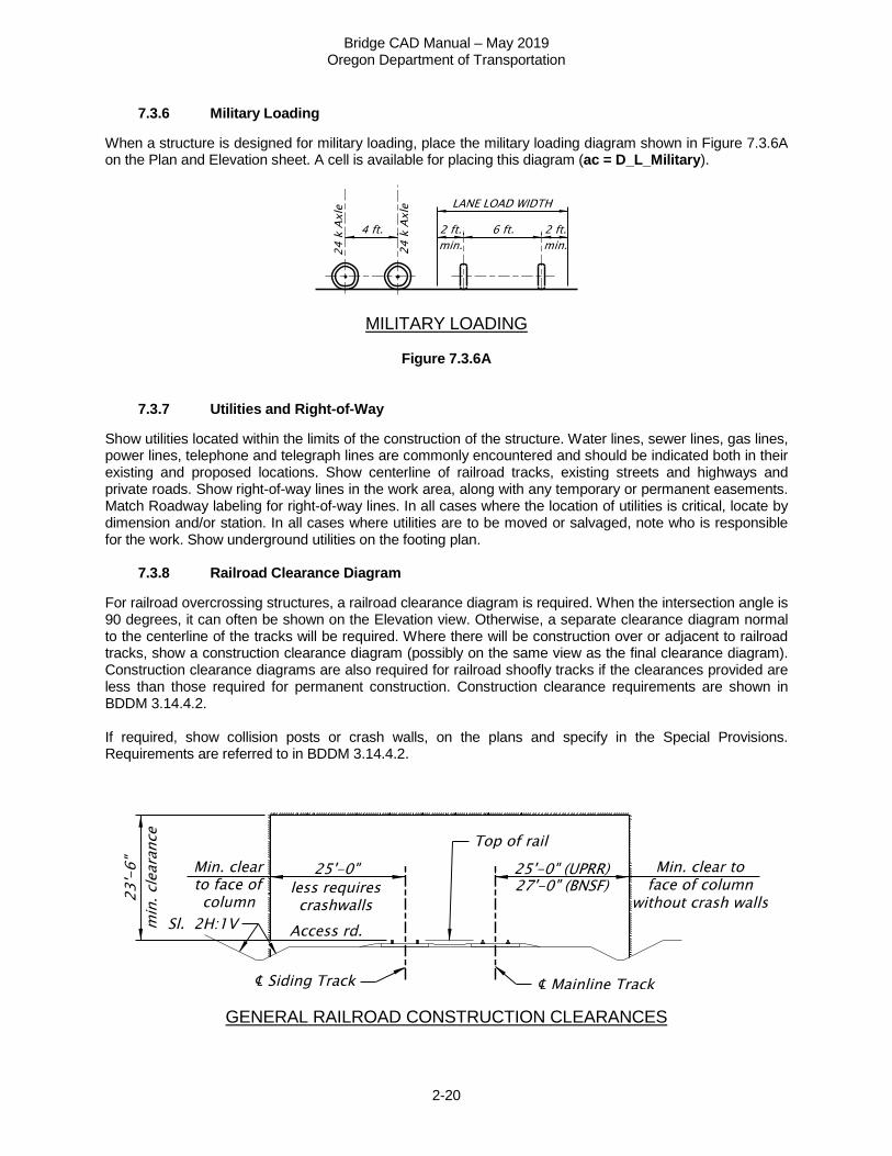
7.3.6 Military Loading
When a structure is designed for military loading, place the military loading diagram shown in Figure 7.3.6A on the Plan and Elevation sheet. A cell is available for placing this diagram (ac = D_L_Military).
MILITARY LOADING
Figure 7.3.6A
7.3.7 Utilities and Right-of-Way
Show utilities located within the limits of the construction of the structure. Water lines, sewer lines, gas lines, power lines, telephone and telegraph lines are commonly encountered and should be indicated both in their existing and proposed locations. Show centerline of railroad tracks, existing streets and highways and private roads. Show right-of-way lines in the work area, along with any temporary or permanent easements. Match Roadway labeling for right-of-way lines. In all cases where the location of utilities is critical, locate by dimension and/or station. In all cases where utilities are to be moved or salvaged, note who is responsible for the work. Show underground utilities on the footing plan.
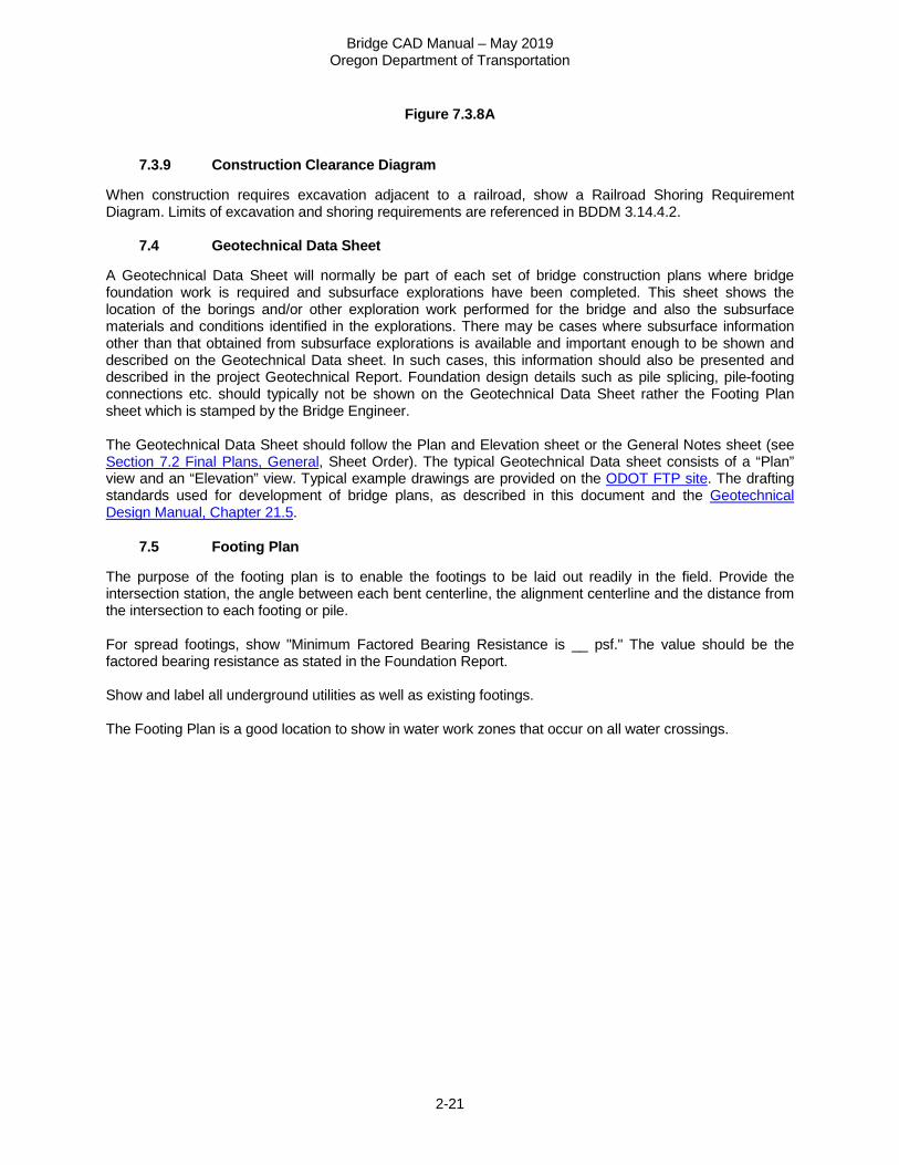
7.3.8 Railroad Clearance Diagram
For railroad overcrossing structures, a railroad clearance diagram is required. When the intersection angle is 90 degrees, it can often be shown on the Elevation view. Otherwise, a separate clearance diagram normal to the centerline of the tracks will be required. Where there will be construction over or adjacent to railroad tracks, show a construction clearance diagram (possibly on the same view as the final clearance diagram). Construction clearance diagrams are also required for railroad shoofly tracks if the clearances provided are less than those required for permanent construction. Construction clearance requirements are shown in BDDM 3.14.4.2. If required, show collision posts or crash walls, on the plans and specify in the Special Provisions. Requirements are referred to in BDDM 3.14.4.2.
GENERAL RAILROAD CONSTRUCTION CLEARANCES
Bridge CAD Manual – May 2019 Oregon Department of Transportation
2-21
Figure 7.3.8A
7.3.9 Construction Clearance Diagram
When construction requires excavation adjacent to a railroad, show a Railroad Shoring Requirement Diagram. Limits of excavation and shoring requirements are referenced in BDDM 3.14.4.2.
7.4 Geotechnical Data Sheet
A Geotechnical Data Sheet will normally be part of each set of bridge construction plans where bridge foundation work is required and subsurface explorations have been completed. This sheet shows the location of the borings and/or other exploration work performed for the bridge and also the subsurface materials and conditions identified in the explorations. There may be cases where subsurface information other than that obtained from subsurface explorations is available and important enough to be shown and described on the Geotechnical Data sheet. In such cases, this information should also be presented and described in the project Geotechnical Report. Foundation design details such as pile splicing, pile-footing connections etc. should typically not be shown on the Geotechnical Data Sheet rather the Footing Plan sheet which is stamped by the Bridge Engineer. The Geotechnical Data Sheet should follow the Plan and Elevation sheet or the General Notes sheet (see Section 7.2 Final Plans, General, Sheet Order). The typical Geotechnical Data sheet consists of a “Plan” view and an “Elevation” view. Typical example drawings are provided on the ODOT FTP site. The drafting standards used for development of bridge plans, as described in this document and the Geotechnical Design Manual, Chapter 21.5.
7.5 Footing Plan
The purpose of the footing plan is to enable the footings to be laid out readily in the field. Provide the intersection station, the angle between each bent centerline, the alignment centerline and the distance from the intersection to each footing or pile. For spread footings, show "Minimum Factored Bearing Resistance is __ psf." The value should be the factored bearing resistance as stated in the Foundation Report. Show and label all underground utilities as well as existing footings. The Footing Plan is a good location to show in water work zones that occur on all water crossings.
Bridge CAD Manual – May 2019 Oregon Department of Transportation
2-22
7.6 Deck Plan
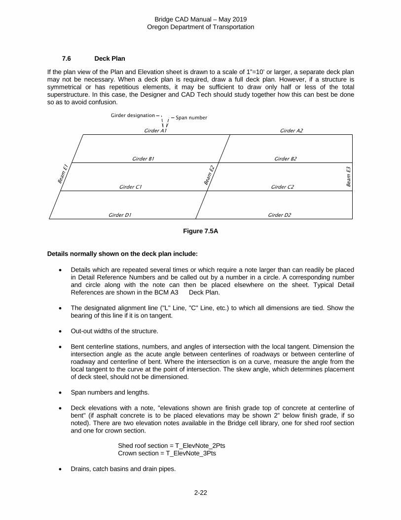
If the plan view of the Plan and Elevation sheet is drawn to a scale of 1”=10’ or larger, a separate deck plan may not be necessary. When a deck plan is required, draw a full deck plan. However, if a structure is symmetrical or has repetitious elements, it may be sufficient to draw only half or less of the total superstructure. In this case, the Designer and CAD Tech should study together how this can best be done so as to avoid confusion.
Figure 7.5A Details normally shown on the deck plan include:
• Details which are repeated several times or which require a note larger than can readily be placed in Detail Reference Numbers and be called out by a number in a circle. A corresponding number and circle along with the note can then be placed elsewhere on the sheet. Typical Detail References are shown in the BCM A3 Deck Plan.
• The designated alignment line ("L" Line, "C" Line, etc.) to which all dimensions are tied. Show the
bearing of this line if it is on tangent.
• Out-out widths of the structure.
• Bent centerline stations, numbers, and angles of intersection with the local tangent. Dimension the intersection angle as the acute angle between centerlines of roadways or between centerline of roadway and centerline of bent. Where the intersection is on a curve, measure the angle from the local tangent to the curve at the point of intersection. The skew angle, which determines placement of deck steel, should not be dimensioned.
• Span numbers and lengths.
• Deck elevations with a note, "elevations shown are finish grade top of concrete at centerline of
bent" (if asphalt concrete is to be placed elevations may be shown 2” below finish grade, if so noted). There are two elevation notes available in the Bridge cell library, one for shed roof section and one for crown section.
Shed roof section = T_ElevNote_2Pts Crown section = T_ElevNote_3Pts
• Drains, catch basins and drain pipes.
Bridge CAD Manual – May 2019 Oregon Department of Transportation
2-23
7.6 Deck Plan – (continued)
• Rail post spacing, rail splices and locations of preformed expansion joint filler in concrete curbs or parapets and rail pay limits.
• Light posts and electrical conduit and fixtures.
• Deck steel placement if not parallel to bents.
• The location of utility lines carried in the structure, pipe hangers, concrete deck inserts, and the
name of the owner, who will furnish the materials, and who will do the work.
• Access manholes, crawl holes and drain holes in diaphragms. Drain holes and access holes in the bottom slabs of box girders. Vent holes in top of stems.
• The centerlines of all longitudinal girders, crossbeams and diaphragms. The distances between the
centerlines of longitudinal girders along the centerline of the bent are normally shown here. If this proves too involved to do on the deck plan, it can be done on a plan view of the bent, in which case it would appear with the bent details.
• Girders usually identified by a single letter and a span number for the girders that are not identical.
See Figure 7.5A
• Lateral bracing for steel structures indicated by a single line. Its size may be called out here.
• The width of the stems of poured-in-place concrete girders. This may be done by a "cut away" view showing the typical dimensions of each type of girder used.
• Protective screening
• Earthquake restraint
• Expansion joints
• End panels
• Label Bridge ID Marker location and show corresponding marker information table. If space is not
available for the table, it may be placed on another sheet and referenced to by the marker location note.
7.7 Superstructure Details
7.7.1 Superstructure Sections
A "Typical Deck Section" is a transverse cross-section of the superstructure showing the deck, girders, curbs and railing or parapets, if any. Required dimensions include the out-out width of the structure, roadway width, girder spacing, the location of these with respect to the designated alignment centerline and the deck thickness, reinforcement bends and bar spacing and clearances.
Bridge CAD Manual – May 2019 Oregon Department of Transportation
2-24
7.7.2 Superstructure Sections – (continued)
A separate deck section is required for each type of construction used. Additional sections may be required if the roadway width or number of size of girders changes. Half sections may be used for symmetrical superstructures. On wide superstructures with many identical girders at equal spaces, a portion of the width may be omitted to save space and detailing. The number, size and spacing of deck reinforcing bars should be listed adjacent to the deck section. A note should refer to rail drawing(s) for additional reinforcement at rails. For conventionally reinforced continuous concrete structures, the location of the main longitudinal bars can be called out by letter on typical sections (or half-sections) of the superstructure at midspan and near interior supports. These bars can then be listed in a table showing the letter designation, number required, size and length, and the distance to some control point. These sections can also be used as typical deck sections (see above). Separate sections of individual girder stems are often shown to call out such details as the shape and dimensions of vertical stirrups and the location of temperature reinforcement.
7.7.3 Diaphragm and Crossbeam Details
Diaphragm beams for concrete girder structures are usually shown in elevation on the typical deck section. Details required include reinforcing bars and the size and location of utility holes. Crawl holes and drain holes through the diaphragm must be shown for box girders. Show a section through the diaphragm beam showing dimensions and reinforcing bars on the same sheet. Show crossbeams and end beams for concrete structures on the bent drawings.
7.7.4 Longitudinal Girder Elevation Views
The elevation view of a cast-in-place concrete girder should show the total length, the lengths between centerlines of bents or bearings, location of diaphragm beams, haunch dimensions (vertical), stirrup spacing, girder end condition and longitudinal reinforcing bar location. For post-tensioned concrete box girders, place a diagram showing the path of the post-tensioning center of gravity above the longitudinal girder elevation. For steel girders, standard precast prestressed concrete girders and the tensioning details of post-tensioned box girders, there are file drawings which can be completed to cover most of the required details. Use these if possible. If not, use them as patterns for the manner of presenting information. For all structures which make use of prefabricated girders, provide a note saying, "All dimensions shown are horizontal and must be corrected for slope." This note appears on the standard steel girder and prestressed girder sheets and need not be repeated. Plate diaphragms and crossbeams for steel structures must be detailed separately. So far as possible, girder details should be completed on each sheet for the spans shown there. Place notes referring to common details which appear on other sheets immediately above the title block. Camber diagrams - required for all structures. Place a note by the camber diagram as to the assumptions on which it is based.
Bridge CAD Manual – May 2019 Oregon Department of Transportation
2-25
7.8 Bent Details
7.8.1 Plan View
Provide a plan view of the bent. If it is necessary to show more detail for the arrangement of girders or to show features at the deck level which influence the details of the substructure. Show drains, special reinforcement at joints, et cetera, in this view. On some bents, a plan at the bearing level is necessary to show the arrangement of bearing devices and anchor bolts.
7.8.2 Elevation
Provide an elevation view showing the dimensions and reinforcement of columns, web walls, caps, crossbeams, etc. Indicate the location of utility holes. Show the vertical dimensions of the footings or pile caps, and the elevations of the bottoms of the footings or pile caps, on this view. If the footings or pile caps are sloped, show the elevations at each end.
7.8.3 Footing Plan
Provide a footing plan showing the size and reinforcement of footings (and seals) and the size and locations of piles, if any. Show the location of the footings with respect to the designated alignment line and the intersection angle of the footing centerline with that line. Show sectional views of columns or shafts with dimensions and reinforcement in this view or elsewhere on this sheet.
7.8.4 Details
Show reinforcing and dimensions of crossbeams, caps, wingwalls and web walls in cross-section views. Call out all reinforcing steel by size, length and spacing. Clarify stirrup and hoop details by separate diagrams, if necessary. The following procedures which reduce the amount of detailing may be used if they do not reduce the clarity of the plans. Draw similar bents, footings or crossbeams only once and double dimension or make a table of varying dimensions. If possible, bent details should be complete on any sheet for the bents shown there. Place notes referring to common details which appear on other sheets immediately above the title block, and reference individual details to their location.
7.9 Miscellaneous Details
Include in each set of drawings such miscellaneous details as are required for the completion of the project. These would include the following:
• Concrete pour schedules. • Bearing devices – show details of bearing devices and their material called out. List the location and
number required for each type or size of bearing. • Steel girder details - framing and bracing, splices, etc. • Deck joint details - armored corners, paving dams, joint seals, etc. • Electrical and lighting details. • Signing or signal support details. • Pile details - tip reinforcement, encasement, etc. • Median details - barrier rail, longitudinal joint, etc. • Shoring plan and Falsework diagram and lighting. • Surface finish diagram.
Bridge CAD Manual – May 2019 Oregon Department of Transportation
2-26
7.10 Plans "Not for Construction – Informational Dwgs."
Existing drawings need to be accessible to the Project Manager’s office and Contractors working on a certain project. When plans of an existing structure are needed to supplement the contract drawings, they are not included in the contract plan set, but are with the other supporting documents. See Section 4.2 Title Block.
7.11 Revisions to Drawings
Note any Revisions to drawings under the following conditions:
• Final drawings which have been sent to prospective bidders (generally, any time after the Engineer of Record has signed them).
• Final drawings which are part of an active construction project (i.e., a construction project that is under contract)
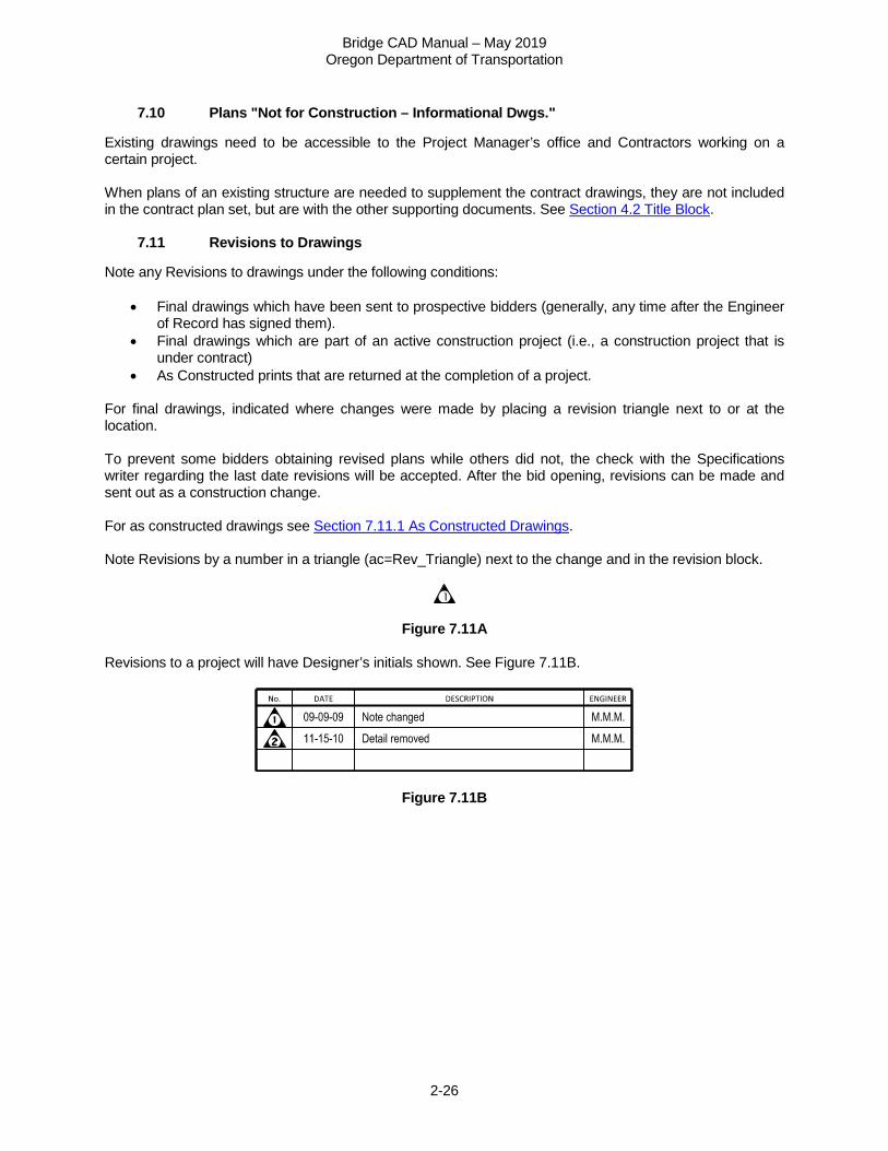
• As Constructed prints that are returned at the completion of a project. For final drawings, indicated where changes were made by placing a revision triangle next to or at the location. To prevent some bidders obtaining revised plans while others did not, the check with the Specifications writer regarding the last date revisions will be accepted. After the bid opening, revisions can be made and sent out as a construction change. For as constructed drawings see Section 7.11.1 As Constructed Drawings. Note Revisions by a number in a triangle (ac=Rev_Triangle) next to the change and in the revision block.
Figure 7.11A Revisions to a project will have Designer’s initials shown. See Figure 7.11B.
Figure 7.11B
Bridge CAD Manual – May 2019 Oregon Department of Transportation
2-27
7.11.1 As Constructed Drawings
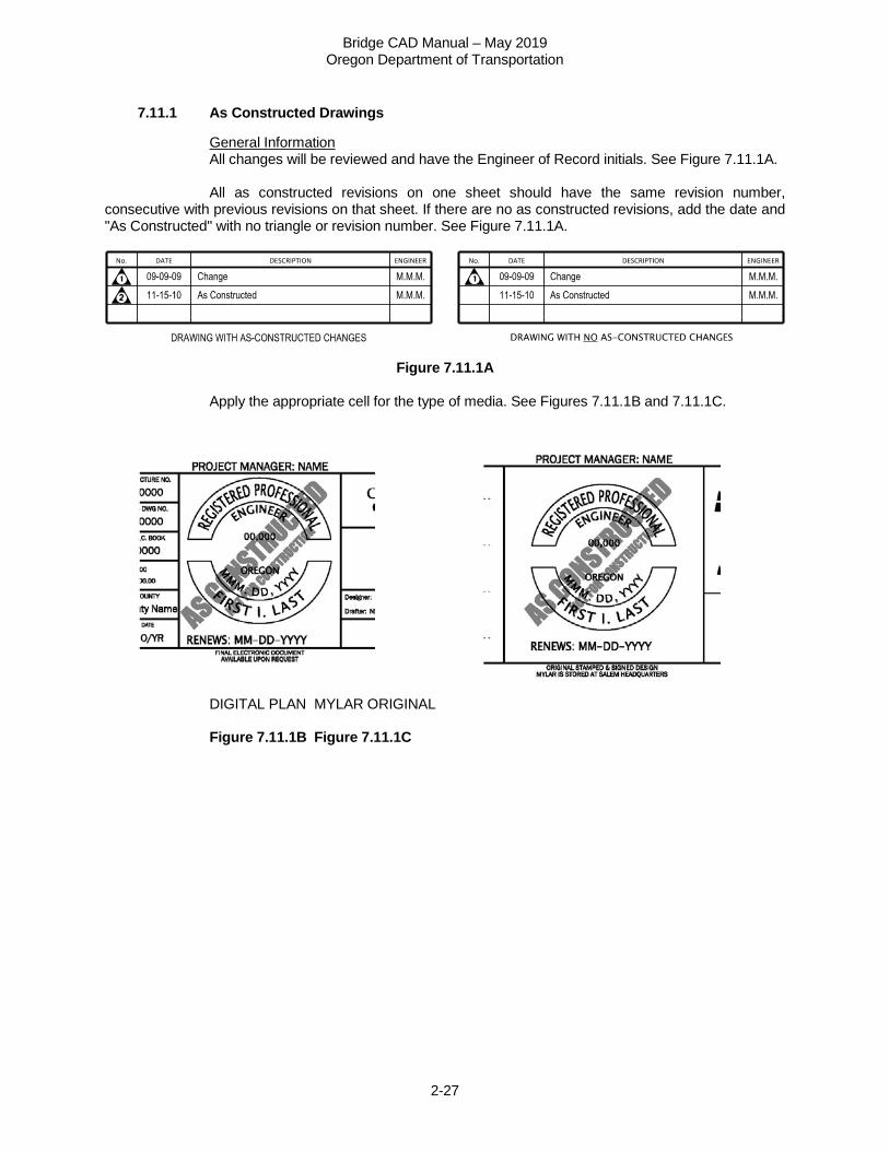
General Information All changes will be reviewed and have the Engineer of Record initials. See Figure 7.11.1A. All as constructed revisions on one sheet should have the same revision number, consecutive with previous revisions on that sheet. If there are no as constructed revisions, add the date and "As Constructed" with no triangle or revision number. See Figure 7.11.1A.
Figure 7.11.1A Apply the appropriate cell for the type of media. See Figures 7.11.1B and 7.11.1C.
DIGITAL PLAN MYLAR ORIGINAL Figure 7.11.1B Figure 7.11.1C
Bridge CAD Manual – May 2019 Oregon Department of Transportation
2-28
7.11.1 As Constructed Drawings – (continued)
The Project Manager’s office will send As Constructed mark-ups to the design office where the design was created within six months after second notice (Second Notification is the actual date on which the Agency determines that all On-Site Work, including Change Order Work and Extra Work, has been satisfactorily completed). Within six months after receiving mark-ups from the Project Manager, send completed As Constructed comments from original design office to Headquarters in Salem. See what is required in the last section “At completion of As Constructed Process” for more details. Bridge Inspectors are required to complete the first structure inspection within 90 days after second notice. MicroStation files will reside in the design office until completion of As Constructed comments. Design office adds As Constructed comments to the original CAD file. Include a revision mark shown next to the change. Place all As Constructed comments on levels “E_ODOT_AsConstruct_General” and “E_ODOT_AsConstruct”_Tx”. Symbology for As Constructed lines will be the same as original line work for a given element, except that the color will be CO=31 (RGB: 54, 255, 255). At completion of adding As Constructed comments to the MicroStation files, create a tif file for BDS. For those with access to BDS, replace the design image in BDS with the new As Constructed image. For those without access, send the PDF file to the Region Design office where the project was located and the lead CAD Tech will add the As Constructed images to BDS. Once As Constructed comments are complete, the Region Design office will upload the new tif file into the Bridge Data System (BDS). MicroStation files will be archived in the Engineering archives by the Region Design office. Tif file sizes should be under or around 1mb. Once BDS has been updated, send an email to Region Bridge inspector stating that the files have been updated for given structure. Consultants send MicroStation files and tif images to the Region office they are working for. 8 PRINTING
8.1 Digital Plans
Milestones prior to PS&E (Plans, Specifications, & Estimate) Plans may be a combined PDF. PS&E Plans must be one sheet per PDF to accommodate digital signature. After PS&E PDFs are created, the Designer will apply their digital signature using the text “Digitally Signed”, with the date/time setting turned on, to their seal. See Digital Signatures web page for guidance on creating and applying a digital signature.
Bridge CAD Manual – May 2019 Oregon Department of Transportation
2-29
8.2 Bridge Data System (BDS)
For proper naming of structures, see the Structure Naming Rules. IMPORTANT! Before changing the name of a structure in BDS, copy the previous name to the Alias Name section in the Alias/Near tab. The structure name should be consistent with the information in BDS, the Bridge Log and BrM. If the name is changed as a result of the updated naming rules, please notify the Standards Unit, Lead Bridge CAD Standards Specialist. Reminder: The Bridge Section requires a minimum of a PDF of the As Constructed plans to add to BDS. To get access to BDS, contact the ODOT Computer Support Desk at 503-986-3800.
8.2.1 Digitally Signed Final Plans and As Constructed Milestones
Convert the digitally signed PDFs to 400 dpi TIF files and place them in the reprographics directory \\scdata\brdgshar\bridge\Reprographics using the drawing number as the file name. Once these files have been placed in this directory, the Bridge Section will load the drawings into the Bridge Data System (BDS). See Section 7.11.1 As Constructed Drawings for As Constructed drawing information. 9 TRANSFER OF ELECTRONIC FILES TO OUTSIDE OF ODOT
Within ProjectWise, version (or copy) the file to maintain a “snapshot” of the file prior to transfer and have it moved to the appropriate 0_Temp folder (if the file was copied, move the original so links are maintained). Then move it to the appropriate new ProjectWise location. The preferred method of sending large files outside of ODOT is MOVEit. Below are links to information about using MOVEit.
Internal Users MOVEit External Users MOVEit
The emailing of files is discouraged, because CAD file sizes can be quite large. 10 ARCHIVING CAD FILES
Projects in ProjectWise are to remain in ProjectWise. Copying data in ProjectWise should be avoided. Projects outside of ProjectWise follow the Engineering Archives instructions. It is the Structural CAD Tech’s responsibility to see that CAD files are archived. Remember to do this in a timely manner, so that everyone can find the files they need. When files are retrieved from the Engineering Archives directory for another project, remember to rename these files.
Bridge CAD Manual – May 2019 Oregon Department of Transportation
2-30
A APPENDICES
A1 CAD FILES
Retrofit / Repair Bridges Replacement Bridges
FRP Strengthening General Drawings – All Bridges Plan 1 of 3 TSL - Plan and Elevation
Girder Elevation 2 of 3 TSL - Staging and Typical Section Girder Details 3 of 3 General Notes 1 of 1
Footing Plan 1 of 1 Crack Repair Geotechnical Data 1 of 1
Crack Repair Details 1of 1 Piles / Drilled Shafts
Internal Anchor Strengthening H-Pile Details 1 of 1 Plan 1 of 3 Pipe Pile Details 1 of 1
Stage Construction Details 2 of 3 Drilled Shaft Details 1 of 1 Details 3 of 3
PS Girder Structure Crossbeam Strengthening External PT Plan and Elevation 1 of 1
Plan and Elevation 1 of 3 Stage Construction 1 of 2 Top Bracket Details 2 of 3 Stage Construction 2 of 2
Bottom Bracket Details 3 of 3 End Bent Details 1 of 2 End Bent Details 2 of 2
Cap Beam Strengthening – Internal Shear Anchor Wingwall Details 1 of 1 Plan and Elevation 1 of 2 Bent - Plan and Elevation 1 of 2
Internal Shear Anchor 2 of 2 Bent Details 2 of 2 Deck Section sheet 1 of 1
Retrofit / Repair Std. Details Diaphragm Beam Detail 1 of 1 Access Hole Detail 1 of 2 Deck Plan 1 of 1 Access Hole Detail 2 of 2
Steel Plate Girder Structure Cap Beam – Concrete Encasement Plan and Elevation 1 of 1 Concrete Encasement Details 1 of 1 Plan and Elevation 1 of 1
Construction Sequence 1 of 1 Cap Beam Strengthening – Exposed External Stirrups
End Bent Details 1 of 2
Exposed External Stirrup Details End Bent Details 2 of 2 Wingwall details 1 of 1
Barrier Replacement Bent - Plan and Elevation 1 of 2 Plan and Stage Construction 1 of 2 Bent Details 2 of 2
Rail Details 2 of 2 Typical Section 1 of 1 Deck Plan 1 of 1
Drain Plug Deck Pouring Sequence 1 of 1 Details 1 of 1 Field Splice Details 1 of 2
Rail Retrofit PS Slab Structure
Thrie Beam Rail Retrofit 1 of 2 Plan and Elevation 1 of 1 Thrie Beam Rail Retrofit 2 of 2 Stage Construction 1 of 1
End Bent Details (short) 1 of 2 End Bent Details (tall) 2 of 2 Wingwall Details 1 of 1 Bent – Plan and Elevation 1 of 2 Bent Details 2 of 2 Deck Section 1 of 1
Bridge CAD Manual – May 2019 Oregon Department of Transportation
2-31
Deck Plan 1 of 2 A2 LINE WORK AND LEVELS
Existing Levels Level Name Level Description Color Linestyle Weight
E_BR_ALL_Patterns All patterns used on bridge drawings 0 1 0 E_BR_SUB_General Bridge substructure features 0 2 0 E_BR_SUB_Footing Footings 1 2 0
E_BR_SUB_Tx Bridge substructure text 4 0 2 E_BR_SUPER_General Bridge superstructure features 1 2 0 E_BR_SUPER_Beams Girders or beams 1 2 0
E_BR_SUPER_Tx Bridge superstructure text 4 0 2 E_ODOT_ASCONSTRUCT_GENERAL As Constructed lines ** ** **
E_ODOT_ASCONSTRUCT_Tx As Constructed text ** ** **
**Match symbolgy of what your recreating, only thing that
changes is level
Superstructure Levels Level Name Level Description Color Linestyle Weight
P_BR_SUPER_Girder Girder (longitudinal) object lines 10 0 3 P_BR_SUPER_GirderHidden Girder (longitudinal) hidden lines 10 3 0
P_BR_SUPER_GirderCL Girder (longitudinal) center lines 10 7 0 P_BR_SUPER_Beam Beam (transverse) object lines 4 0 3
P_BR_SUPER_BeamHidden Beam (transverse) hidden lines 4 3 0 P_BR_SUPER_BeamCL Beam (transverse) center lines 4 7 0
P_BR_SUPER_Girder/BeamTx Girder and Beam text 20 0 2 P_BR_SUPER_Deck Deck object lines 1 0 3
P_BR_SUPER_DeckHidden Deck hidden lines 1 3 1 P_BR_SUPER_DeckCL Deck center lines 1 7 2 P_BR_SUPER_DeckTx Deck and End panel text 17 0 2
P_BR_SUPER_Rail Rail object lines 2 0 3 P_BR_SUPER_RailHidden Rail hidden lines 2 3 1
P_BR_SUPER_RailCL Rail center lines 2 7 2 P_BR_SUPER_RailTx Rail text 18 0 2 P_BR_SUPER_Fence Fence object lines 2 0 3
P_BR_SUPER_FenceHidden Fence hidden lines 2 3 1 P_BR_SUPER_FenceCL Fence center lines 2 7 2 P_BR_SUPER_FenceTx Fence Text 18 0 2 P_BR_SUPER_EndPanel End Panel lines 1 0 1
P_BR_SUPER_EndPanelHidden End Panel hidden lines 1 3 1
Bridge CAD Manual – May 2019 Oregon Department of Transportation
2-32
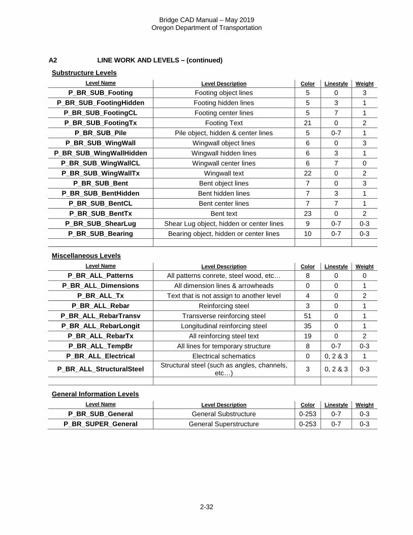
A2 LINE WORK AND LEVELS – (continued)
Substructure Levels Level Name Level Description Color Linestyle Weight
P_BR_SUB_Footing Footing object lines 5 0 3 P_BR_SUB_FootingHidden Footing hidden lines 5 3 1
P_BR_SUB_FootingCL Footing center lines 5 7 1 P_BR_SUB_FootingTx Footing Text 21 0 2
P_BR_SUB_Pile Pile object, hidden & center lines 5 0-7 1 P_BR_SUB_WingWall Wingwall object lines 6 0 3
P_BR_SUB_WingWallHidden Wingwall hidden lines 6 3 1 P_BR_SUB_WingWallCL Wingwall center lines 6 7 0 P_BR_SUB_WingWallTx Wingwall text 22 0 2
P_BR_SUB_Bent Bent object lines 7 0 3 P_BR_SUB_BentHidden Bent hidden lines 7 3 1
P_BR_SUB_BentCL Bent center lines 7 7 1 P_BR_SUB_BentTx Bent text 23 0 2
P_BR_SUB_ShearLug Shear Lug object, hidden or center lines 9 0-7 0-3 P_BR_SUB_Bearing Bearing object, hidden or center lines 10 0-7 0-3
Miscellaneous Levels Level Name Level Description Color Linestyle Weight
P_BR_ALL_Patterns All patterns conrete, steel wood, etc… 8 0 0 P_BR_ALL_Dimensions All dimension lines & arrowheads 0 0 1
P_BR_ALL_Tx Text that is not assign to another level 4 0 2 P_BR_ALL_Rebar Reinforcing steel 3 0 1
P_BR_ALL_RebarTransv Transverse reinforcing steel 51 0 1 P_BR_ALL_RebarLongit Longitudinal reinforcing steel 35 0 1
P_BR_ALL_RebarTx All reinforcing steel text 19 0 2 P_BR_ALL_TempBr All lines for temporary structure 8 0-7 0-3
P_BR_ALL_Electrical Electrical schematics 0 0, 2 & 3 1
P_BR_ALL_StructuralSteel Structural steel (such as angles, channels, etc…) 3 0, 2 & 3 0-3
General Information Levels Level Name Level Description Color Linestyle Weight
P_BR_SUB_General General Substructure 0-253 0-7 0-3 P_BR_SUPER_General General Superstructure 0-253 0-7 0-3
Bridge CAD Manual – May 2019 Oregon Department of Transportation
2-33
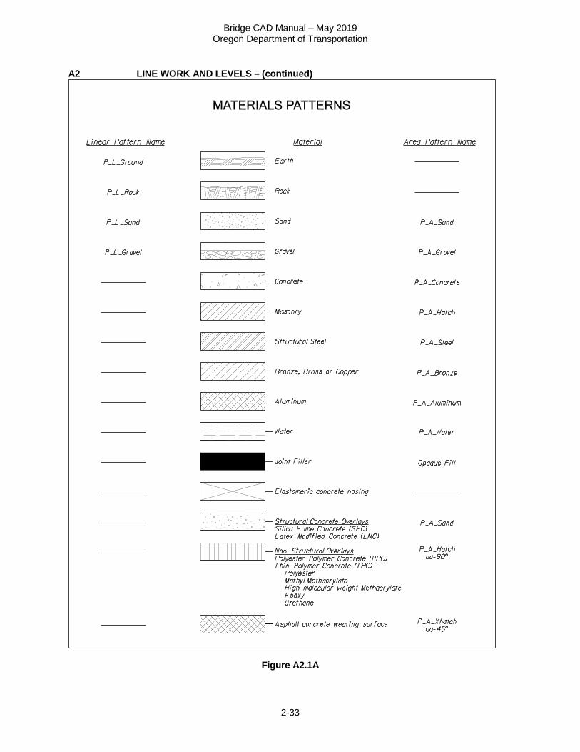
A2 LINE WORK AND LEVELS – (continued)
Figure A2.1A
Bridge CAD Manual – May 2019 Oregon Department of Transportation
2-34
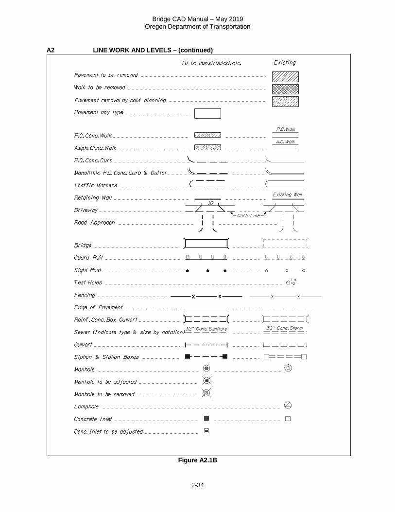
A2 LINE WORK AND LEVELS – (continued)
Figure A2.1B
Bridge CAD Manual – May 2019 Oregon Department of Transportation
2-35
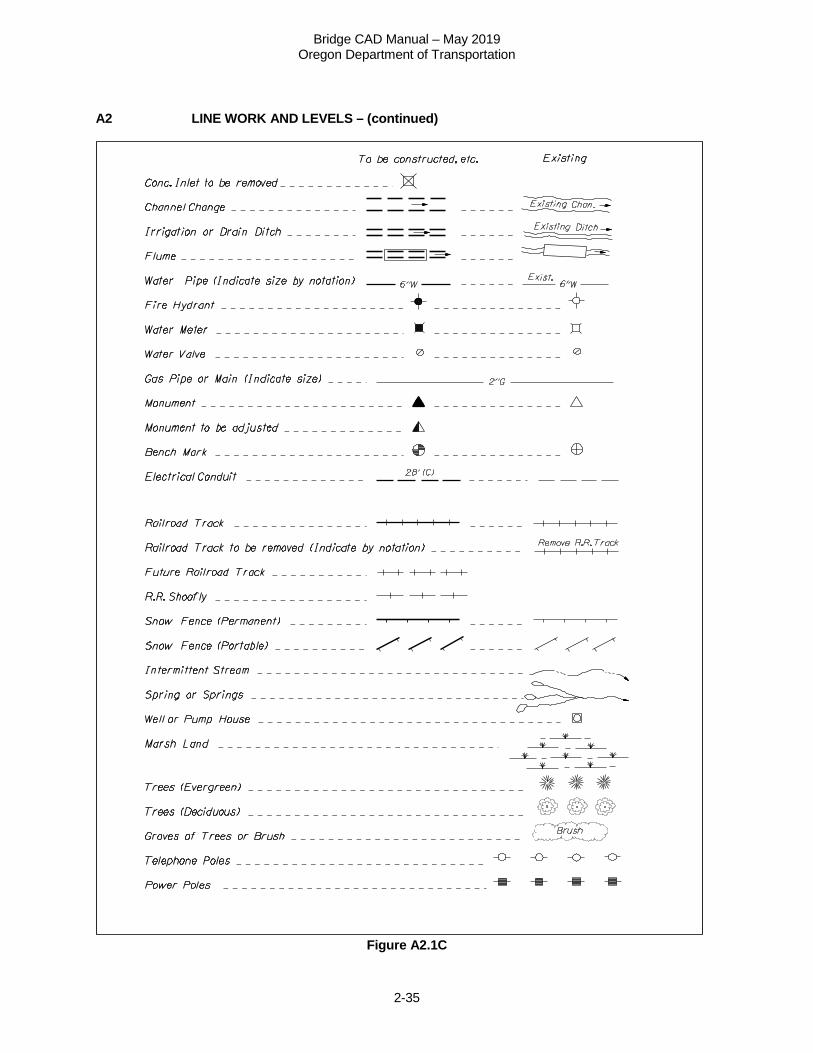
A2 LINE WORK AND LEVELS – (continued)
Figure A2.1C
Bridge CAD Manual – May 2019 Oregon Department of Transportation
2-36
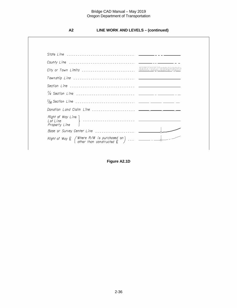
A2 LINE WORK AND LEVELS – (continued)
Figure A2.1D
Bridge CAD Manual – May 2019 Oregon Department of Transportation
2-37
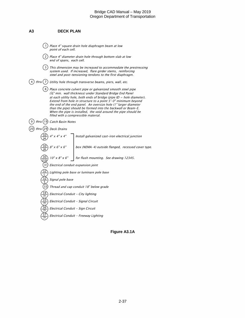
A3 DECK PLAN
Figure A3.1A
Bridge CAD Manual – May 2019 Oregon Department of Transportation
2-38
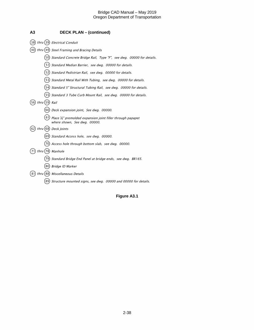
A3 DECK PLAN – (continued)
Figure A3.1


![Background – Operators (1D) · Background (1D) Operators 4 Young Won Lim 3/28/18 zip function zip :: [a] -> [b] -> [(a,b)] zip (a:as) (b:bs) = (a,b) : zip as bs zip _ _ = [] Prelude>](https://img.pdfslide.us/doc/110x75/5f7d53a36176442cad227c24/background-a-operators-1d-background-1d-operators-4-young-won-lim-32818.jpg)