Embed Size (px)
Citation preview
SFILE
- .MC-TR-88-Il1
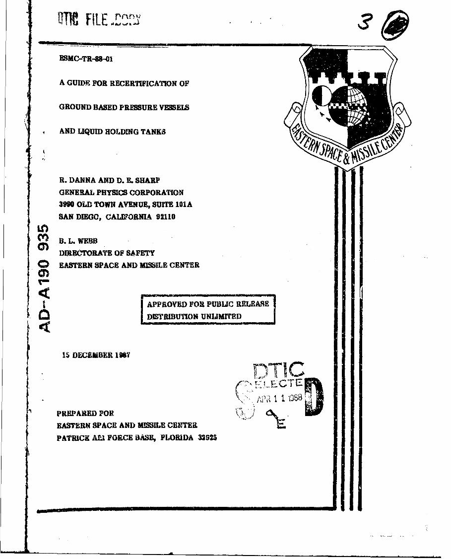
A GUIDE. FOR RECERTIFICATION OF
GROUND BASED PRESSURE VESSELS
AND LIQUID HOLDING TANKS
R. DANNA AND D. E. SHARP
GENERAL PHYSICS CORPORATION
390 OLD TOWN AVENUE, SUITE 1O1A
SAN DIEGO, CALIFORNLA 92110Ln
B. L. WEBB
DmIRORAM' OF SAFETY
o EASTERN SPACE AND MMILE CENTER
cy:
APPOVDFOR PUBuUC RMAEM
DID1RIBUTIION UNJMrrEDI
15 OECEMOER 191
PREPARED FOR
RATERN SPACE AND MWSSILE CENTER
PATRICK ALI FORCE BASE, FLORIDA 32925
S....... IINCLASSIF!EDSECURITY CLASSIFICATION OF THIS PAGE
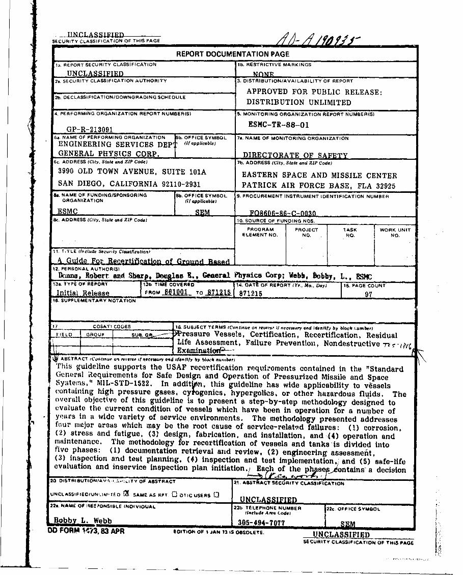
REPORT DOCUMENTATION PAGEla. REPORT SECURITY CLASSIFICATION 11•. REsTRIcTIVE MARKINGS
SUNCLASSIFIED Nf•NR2.. SECURITY CLASSIFICATION AUTHORITY "' 3. DiSTRIBUTION/AVAILABILiTY OF REPO'I•T '
2b. OECLASSlFICATION/DOWNGRADIN'GSCHEOULE APPROVED FOR PUBLIC RELEASE:
DISTRIBUTION UNLIMITED4. PERFORM'ING ORGANIZAT|ON REPORT NUMBER(S) 51 MONITOR•NG ORGA•IIZATION REPORT I•'UMBERiS)
ESNC-TR-88-O1GP-R-213091
6*. NAME OF PERFOR'I•ING' (3RGANIZATION Eb. OFFIC•SYMBOL 71I. NAME OF MONITORING'ORGANIZATION
ENGINEERING SERVICES DEP" (ifapplicgb|e)
GENERAL PHYsIcs CORP. DIRECTORATE OF SAFETY6¢. ADDRESS (City, Slate cad ZIP Code) 7b. ADDRESS (City, State and ZIP Code)
3990 OLD TOWN AVENUE, SUITE 101A EASTERN SPACE AND MISSILE CENTER
SAN DIEGO, CALIFORNIA 92110-2931 PATRICK AIR FORCE BASE, FLA 3292588. NAME O; FUNDING•SPONSORING i 1 8b. OFFI•I•= SYMBOL 9, PROCUREMENT INS'T'RUMENT 'DENTIFICATI'ON NUMBER --
ORGAN I ZAT I ON (If applicabbt)
ESMC ... , i SEM FOR606-SF;-C-00:•08€. ADDRESS (City, Slate •td ZIP Code@ 10, SOURCE OF FUNDING NOS. ,, , . •
PROGRAM PROJECT 1ASK WOR•oyNIT llELEMENT NO. NO. . . NO.
i i L=
11. T ,TLE ill, elude t•ecutfty Clw•{f|cotio•t|
&C•de F• Reco.•_tj•cation of Ground Ba•ed .. ..... 0L H
•2. PERSONAL AUTHOR(3) •1j
•nna, Robert sad S•_p. __l•s•lss •., •r,1 Physics Corp; Webb, bobby, L..•-" w L,
13• TYP• OF REPORT 13b TIME COVERED 14, OAT• OF REPORT (Yr., •(o,, Day) 15. PAGE COUNT
Initial ]•elease. •ROM• I TO• I• 871215 97 "16. SUPPLEMENTARY NOTATION ' ..... " •
.•l•l _ J. _ I I . I I . L im
!l't CO•ATI CO•JES 18, SUBJECT TI•RMS tContinue On r• r(=,- if fleCtildPy 0rid id/ntiity by b(ofk t;t•mblrr) I
r,•u [ •,oup__ su•,o•.J-•:!>Pressure Vessels, Certification, Recerttfication, Residual JSL ... . Life Asse• nt, Failure Prevention, Nondestructive •€•t¥•
&BSTRACT l•'•,|#nut o,! r•clrl• I/' •4'CtM•ry oqd ¢d#• @(ly •y b#,J•..i rtu.,b¢tr•Thi• guideline supports the USAF recertification reqt.iromonts contained in the "StandardGcn(n, al Requirements for Safe Design and Operation of Pressurized Missile and SpaceSy:;tems," MIL-STD-1522. In addit•n, this guideline has wide applicability to v•sselscontaining high pressure gases, cyfogenics, hypergolics, or other hazardous fluids. The
ov,,nfll objective of this guideline is to present a step-by-step methodology designed toevaluate the current condition of vessels which have been in operation for a number ofyears in a wide variety of service environments. The methodology presented addressesfour mvjor areas which may be the root cause of service-relat•,d failures: (!) corrosion.(2) stress and fatigue, (3• design, fabrication, and installation, and (4) operation andmaintenance. The methodology for recertification of vessels and tanks'is divided intofive phases: (I) documentation retrieval a.d review, (2) engineering assessmeiit,(3) inspection and test planning, (•) inspection and test implementationi and (5) safe-lifeevaluation and inservice inspection plan initiation./ Eagh of the ph•se•;.eontainsa decision
:)O DISTI•II•UTION.•AV,•*t.•,.•':t.ITY Of= ABSTRACT " •L AE.•T•A•-V SECURITV Ct.AS31Fi•CAl"IO'N' .. ...
UNCLASSIFIEOIUN'.Ikt, I't•O {• SAME AS BPT. • OTl(•. USF. R• •]
-• " I .... . . . .. . . . . . . ... ...... . .. U N C L A S S IF IE D .... .. .. . . .. ....... T . . ....
;•2•. NAME Of ItlE•';•ONSIBLF. INDIVIDUAL 22b TELEPHONE NUMBER i 2,• OFFIC• SYMBOL i
tlxrlude A•ea (.od•i !•_•Bobby: L. •Webb I lII I Ill II I I I J I' I" 305-494-707"/- - . .... ...... .| .... . SA'aI•tM :
UNCLAI• (F ..... I II I {.•iOD FORM 1."-73, 83 APR •ovo• o•, •AN • ,S o•so•E _ IEDI;-
UNCLASSIFIEDSECURITY CLASSIFICATION OF THIS PAGE
11. TITLE(Continued)
Pressure Vessels and Liquid Holding Tanks (UNCLASSIFIED).
19. ABSTRACT (Continued)
logic and a total of 53 specific activities involved in the recertification process. Eachactivity includes a purpose, description, specific steps, major obstacles, major decisions,input, output, and sample references. The methodology is designed to be flexible, thus,allowing its use on both well-documented and maintained vessels, as well as thosevessels lacking design documentation or operating history.
I
UNCLASSIFIOD i tUCU~iiTY CLASSPICATION OP TwiS PAfl !
COMMENT FORM
TITLE: A Guide for Recertiflcation of Ground Based Pressoee Vessels and
Liquid Holding Tanks
Publiction: EBMC-TR-88-01 Revisoui 0 (Initial Release)
1. USAF solicits your comments concerning this guideline so that its usefulness may
be improved in later editions. Send any comments to the following address:
Directorate of Safety
Attn. B.L. Webb
Eastern Space and Missile Center (AFSC)
Patrick Air Force Base, Florida 32925
2. Comments are solicited in the following areas:
a. Is the guideline adequate to support development of a recertification
program?
b. What improvements would make the guideline more adequate?
c. Are there any general comments concerning the guideline?
3. Please note any specific errors which have been discovered. Include the pagenumber for reference. ,,,. For _
J, 11, "L'v•ioat , n~ !
{ Av olla ty /- .
A-1
ACKNOWLIDGMMMTS
The program described in this report was developed and implemented by the
Engineering Services Department of General Physics Corporation, in conjunction with the
Directorate of Safety, Eastern Space and Missile Center (ESMC), at the Cape Canaveral
Air Force Station and Patrick Air Force Base. We would like to extend our appreciation
to NASA Kennedy Space Center for their identification of the need for this program at
the Eastern Test Range. We would like to thank the key members of the General Physics
project team for their work on the project and input to this report. They include R.L.
Fischer, C.R. Harley, C.E. Ludwick, Z.P. Quandt, and S.P. Shores. We would also like to
thank the ESMC Directorate of Safety for their support, especially L.J. Ullian and P.D.
Taddie for their direction and constructive input on this manuscript and project.
iv
A GUIDE FOR RECERTIFICATION OF GROUND
BASED PRESSURE VESSELS AND LIQUID HOLDING TANKS
CONTENTS PAGE
Report Documentation Page ...................... .................
Comment Form .................................................... iii
Acknowledgments .................................................. iv
Table of Contents ................................................ v
List of Figures ..................................................... ix
1.0 INTRODUCTION TO THE CERTIFICATION/RECERTIFICATION
PROGRAM
1.1 Background .................................................... 1
1.2 Overview of the Program ........................................ 3
2.0 DEFINITIONS
2.1 Certification ................................................. 10
2.2 Derated Vessel ........................ ....................... 10
2.3 Design Pressure ....................................... 10
2.4 Fail-Safe .................................. .............. . 10
2.5 Hydrostatic Test ........................................... 10
2.6 Inservice Inspection ........................ .................. 10
2.7 Liquid Holding Tank ........................ .. .. ........... . 11
2.8 Maximum Allowable Working Pressure (MAWP)..o................. 11
2.9 Major Inspections o..................... . ... .. ........... 11
2.10 Major Inspection Interval ...... o.. o.. o.. ................. .112.11 Maximum Operating Pressure (MOP) ...... ............ ........ . o11
2.12 Pneumatic Test .......................... . .............. 11213 Pressure Vessel........................................... 1
2.14 Recertification ........... o.. o.. o o . ........ o ......... . .. ... 12
2.15 Recertification Period ............................. o ........... 12
2.16 Routine Inspections ........... o ..... o ...... ................... . 12
2.17 Routine Inspections Intervals ................................... 12
• *" V
THIS DOCUMENT CONTAINEDBLANK PAGES THAT HAVE
BEEN DELETED
CONTENTS PAGES2.18 Safe-Life .. ... ..... .. ... ... .. . .. .... 12
3.0 FORMAT OF PHASES AND ACrIVrI=. ............................... 13
4.0 PROGRAM ACTIVrrI= ................. ............................. 22
4.1 Phase 1 Docummentatiou Retrieval and Review .................... 23
101 Perform Survery of Vessel ...................................... 23
102 Retrieve and Review Operations Documentation ................... 24103 Retrieve and Review Maintenance Documentation ................. 25
104 Retrieve and Review Engineering Documentation .................. 26
(Coded Vessels)105 Retrieve and Review Engineering Documentation .................. 27
(Non-Coded Vessels)
106 Establish Configuration Baseline File for Vessel ................... 28
4.2 IPlae L-b Eniering Aueutmuat ............................... 31
201 Assess Vessel Configuration and Operation Using .................. 31
Agency Requirements
202 Calculate Vessel MAWP Using ASME Boiler end ................... 32
Pressure Vessel Code Section VIII, Division 1203 Assess Vessel MAWP Using ASME Boiler and ..................... 33
Pressure Vessel Code Section VIII, Division 2
204 Derate Vessel to Calculated MAWP .............................. 34205 Evaluate Overpressuritation Protection Usng ..................... 35
ASME and Agency Requirements
206 Adjust Relief Valves to Acceptable Setting ........................ 36
207 Review and Access Fabrication (Materials and ................. 37
Welding) vs. Lessonts Learned
208 Evaluate Susceptibility of Metal to Corrosion ..................... 38
209 Review History of Cyclic Operation or Extraordinary ............. 39
Transients
vi
CONTENTS PAGE
210 List Discrepancies and Concerns from Reviews, ...................... 40
Evaluations or Assessments
211 Retain Concerns in Files for Reference ............................. 41
212 Establish List of Discrepancies by Priority ........................... 42
(Immediate, Short-term, Long-term)
213 Address Concerns with Immediate Priority ........................... 43
214 Remove from Service and Establish "Return to ......................... 44
Service" Plan (as applicable)
215 Address Concerns with Short- and Long-term Priority ................. 45
216 Establish Engineering and/or Inspection/Test ........................ 46
Objectives
217 Perform Additional Engineering Analysis (as ................. . ..... 47
applicable)
4.3 Phase IM Inspection/Test Plan ..................................... 51
301 Define Inspection and Testing Requirements to Resolve ............... 51
Concerns
302 Conduct Field Inspection Verification ............................... 52
303 Develop Inspection and Test Procedures and Acceptance .............. 53
Criteria
304 Develop Work Packuges ............................ , ............... 54
4.4 Plxse tV.- Inspection/Test Wl~etmetation ...... ..................... 55
101 Perform Inspections and Tests ..................................... 55
402 Characterize and Analyze Discontinuitics ........................... 56
403 Perfkvm Engineering Analysis to Determine Disposition ............... 57
404 Perfowm Follow-up Engineering and Specify Additional ................ 58
InspecticrLs and Tests
405 Remove from Service and Finalize Disposition ....................... 59
4.5 Phas V:. Fi,,l Evaluation and MIl iaitiaon.. .............. ........... 63
vii
CONTENTS PAGE
501 Determine the Number of Stress Cycles Per Year .................... 63
Experienced by and Expected for the Vessel
502 Perform Detailed Safe-Life Analysis ................................ 64
503 Perform Simplified Safe-Life Analysis .............................. 65
504 Develop Destructive Test Plan to Provide Detailed Input .............. 66
for Fatigue Analysis or Fracture Mechanics Analysis
505 Perform Detailed Fatigue Analysis or Fracture Mechanics ............. 67
Analysis and Safe-Life Analysis
506 Perform Engineering Analysis to Determine Disposition ............... 68
507 Remove From Service and Finalize Disposition ....................... 69
508 Derate to MOP +10% and Adjust Relief Devices ...................... 70
509 Calculate Remaining Safe-Life Based on Corrosion ................... 71
Rate
510 Perform Engineering Analysis to Estimate ........................... 72
Corrosion Damage and Remaining Safe-Life
511 Calculate Remaining Safe-Life Based Creep Rate .................... 73
512 Perform Engineering Analysis to Creep Damage ...................... 74
and Remaining Safe-Life
513 Calculate Safe-Life Based on Additional Failure ...................... 75
Mode
514 Compare Safe-Life as Predicted by Failure ........................... 76
Mechanisms
515 Choose Most Limiting Safe-Life .......................... . ...... 77
516 Define Recertification Period Equal to 20 years ...................... 78
517 Define Recertification Period Equal to Remaining .................... 79
Safe-Life
518 Develop Inservice Inspection Plan Based on ......................... 80
Recertification Period
519 Resolve AUl Outstanding Concerns and Establish ...................... 81
MAWP and Service Restrictions
520 Establish Overpressurization Protection Requirements ................ 82
521 Establish Date for Next Recertification and Initiate .................. 43
ISI
viii
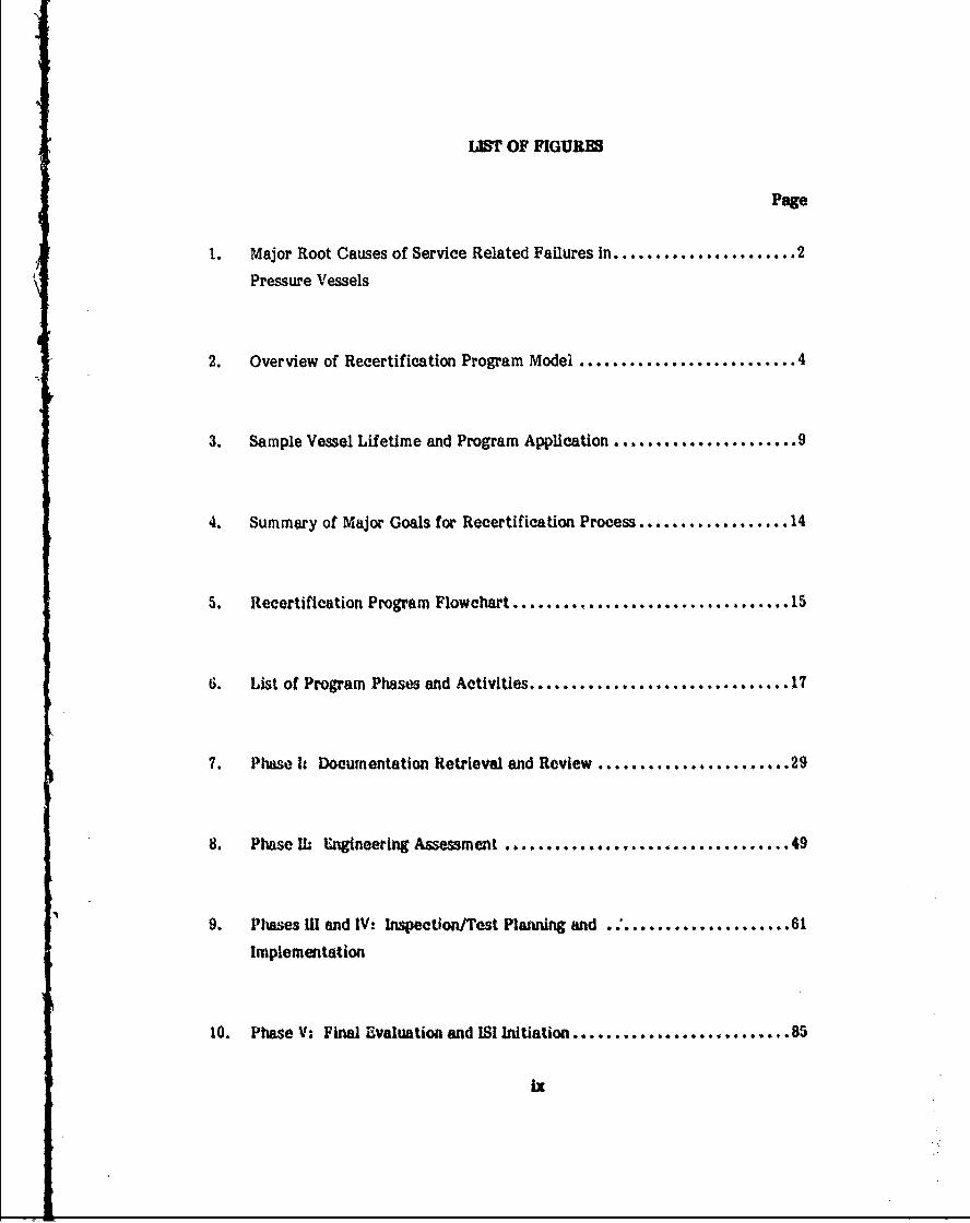
LIST OF FIGURES
Page
1. Major Root Causes of Service Related Failures in ...................... 2
Pressure Vessels
2. Overview of Recertification Program Model .......................... 4
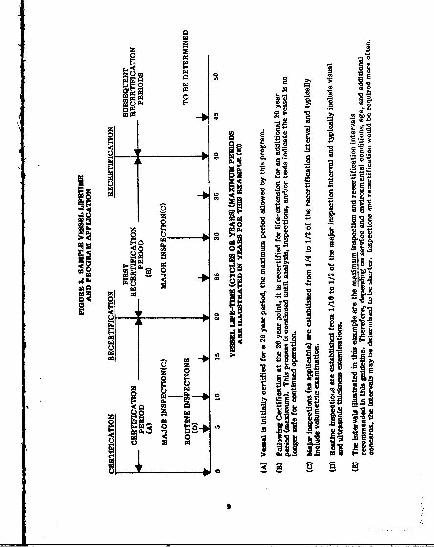
3. Sample Vessel Lifetime and Program Application ..................... 9
4. Summary of Major Goals for Recertification Process .................. 14
5. Recertification Program Flowchart ................................. 15
6. List of Program Phases and Activities ............................ .. 17
7. Phase i Documentation Retrieval and Review ..................... 29
8. Phase lb Engineering Assessment ........... ....................... 49
9. Phases-ll and IV- InWpctlon/Test Planningand .................... 61
Implementation
10. Phase V: Final Evaluation and ISI nitiation ......................... 85
ix
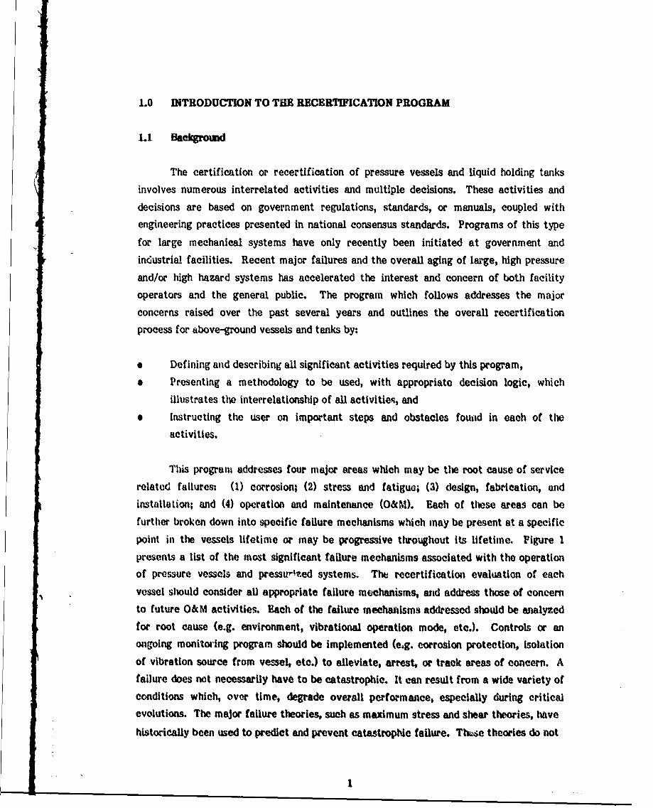
1.0 INTRODUCTION TO THE RECERTIFICATION PROGRAM
1.1 Backgroimd
The certification or recertification of pressure vessels and liquid holding tanks
involves numerous interrelated activities and multiple decisions. These activities and
decisions are based on government regulations, standards, or manuals, coupled with
engineering practices presented in national consensus standards. Programs of this type
for large mechanical systems have only recently been initiated at government and
industrial facilities. Recent major failures and the overall aging of large, high pressure
and/or high hazard systems has accelerated the interest and concern of both facility
operators and the general public. The program which follows addresses the major
concerns raised over the past several years and outlines the overall recertification
process for above-ground vessels and tanks by-
* Defining and describing all significant activities required by this program,
& Presenting a methodology to be used, with appropriate decision logic, which
illustrates the interrelationship of all activities, and
* Instructing the user on important steps and obstacles fouitd in each of the
activities.
This program addresses four major areas which may be the root cause of service
related failuresi (1) corrosion; (2) stress and fatigue; (3) design, fabrication, and
installation; and (4) operation and maintenance (O&M). Each of these areas can be
further brokon down into specific failure mechanisms which may be present at a specific
point in the vessels lifetime or may be progressive throughout its lifetime. Figure 1
presents a list of the most significant failure mechanisms associated with the operation
of pressure vessels and pressu-tved systems. The recertification evaluation of each
vessel should consider all appropriate failure mechanisms, and address those of concern
to future O&M activities. Each of the failure mechanisms addressed should be analyzed
for root cause (e.g. environment, vibrational operation mode, etc.). Controls or an
ongoing monitoring program should be implemented (e~g. corrosion protection, isolation
of vibration source from vessel, etc.) to alleviate, arrest, or track areas of concern. A
failure does not necessarily have to be catastrophic. It can result from a wide variety of
conditions which, over time, degrade overall performance, especially during critical
evolutions. The major failure theories, such as maximum stress and shear theories, have
historically been used to predict and prevent catastrophic failure. Thle theories do not
]1
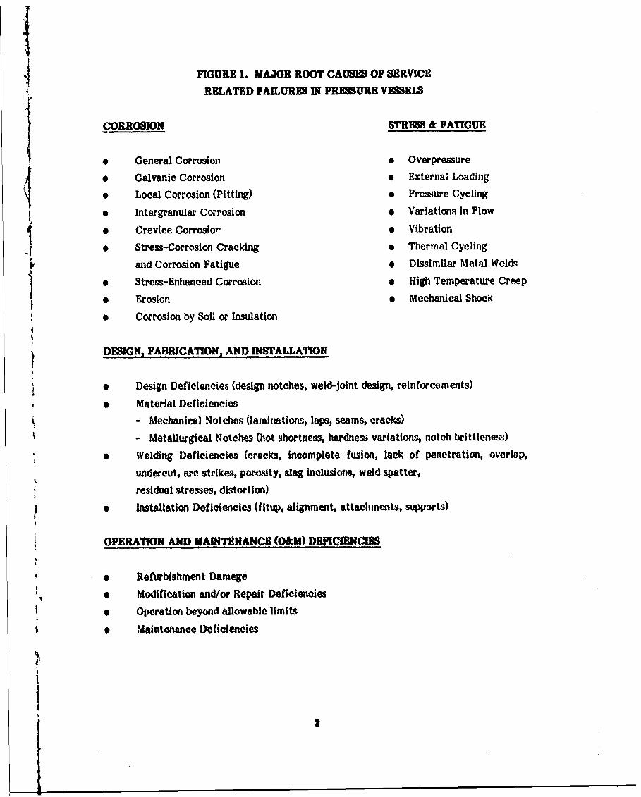
FIGURE 1. MAJOR ROOT CAUSES OF SERVICE
RELATED FAILURES IN PRESURE VEELS,
CORROSION STRES & FATIGUE
* General Corrosion * Overpressure
* Galvanic Corrosion * External Loading
0 Local Corrosion (Pitting) * Pressure Cycling
* Intergranular Corrosion 0 Variations in Flow
0 Crevice Corroslor * Vibration
0 Stress-Corrosion Cracking * Thermal Cycling
and Corrosion Fatigue e Dissimilar Metal Welds
0 Stress-Enhanced Corrosion * High Temperature Creep
* Erosion * Mechanical Shock
• Corrosion by Soil or Insulation
DE SGN, FABRICATION, AND INSTALLATION
0 Design Deficiencies (design notches, weld-joint design, reinforcements)
• Material Deficiencies
- Mechanical Notches (laminations, laps, seams, cracks)
- Metallurgical Notches (hot shortness, hardness variations, notch brittleness)
0 Welding Deficiencies (cracks, incomplete fusion, lack of penetration, overlap,
undercut, are strikes, porosity, slag inclusions, weld spatter,
residual stresses, distortion)
6 Installation Deficiencies (titup, alignment, attachiments, supports)I
OPERATiON AND MA ,TERANCE (O&M) DEFICIRNGI
. Refurbishment Damage
, • Modification and/or Repair Deficiencies
0 Operation beyond allowable limits
0 Maintenance Deficiencies
)I
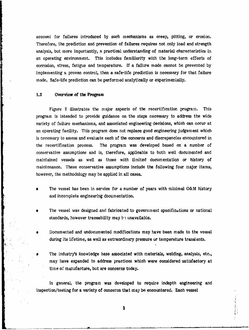
account for failures introduced by such mechanisms as creep, pitting, or erosion.
Therefore, the prediction and prevention of failures requires not only load and strength
analysis, but more importantly, a practical understanding of material characteristics in
an operating environment. This includes familiarity with the long-term effects of
corrosion, stress, fatigue and temperature. If a failure mode cannot be prevented by
implementing a proven control, then a safe-life prediction is necessary for that failure
mode. Safe-life prediction can be performed analytically or experimentally.
1.2 Overview of the Program
Figure 2 illustrates the major aspects of the recertification program. This
program is intended to provide guidance on the steps necessary to address the wide
variety of failure mechanisms, and associated engineering decisions, which can occur at
an operating facility. This program does not replace good engineering judgement which
is necessary to assess and evaluate each of the concerns and discrepancies encountered in
the recertification process. The program was developed based on a number of
conservative assumptions and is, therefore, applicable to both well documented and
maintained vessels as well as those with limited documentation or history of
maintenance. These conservative assumptions include the following four major items,
however, the methodology may be applied in all cases.
* The vessel has been in service for a number of years with minimal O&M history
and incomplete engineering documentation.
0 The vessel was designed and fabricated to government specificutions or national
standards, however traceability may b-i unavailable.
0 Documented and undocumented modifications may have been made to the vessel
during its lifetime, as well as extraordinary pressure or temperature transients.
The industry's knowledge base associated with materials, welding, analysis, etc.,
may have expanded to address practices which were considered satisfactory at
time ol manufacture, but are concerns today.
In general, the program was developed to require indepth engineering and
inspection/testing for a variety of concerns that may be encountered. Each vessel
a{

FICJRE 2. OVERVIEW OF RECERTIFICAION
PROGRAM MODEL
PERPOSM PRELIMINARY OPftRATINS.MAINTENANCE. AND EHOINZIUOi
DO*I•UE3NTATION R"TRINVAL, REVIL•W
AND ASSESSMENT
LIST C3C1tNS ASSOCIATED WITHOPE0RATIONIS, MAINTX4ACB On
INOIkfEERINO AS REFLECTED IN AJSESSMINT
PERFORM PRELIMINARY ENOINERUINGASSESSMENT USING AGENCY REQUIREMENTS
AND/OR NATIONAL STANDARDS
LIST DISCREPA.CIES IfIWW ACIUAL00" O1G0RATION AND •URREN U3QUIRz-
LMENTS OR STANDARDS
S lINSPECT'IOI/T28ST PLAN TO AVORI~mIIIJ
CONCEZNS AND DISCRUPANCIES
CO NUCT INSPECTIOHS AND TETS. ANDEVALUATE RESULTS
RISOLVE klLXMS AND IOLLON-U•P WITHADSITIONAL INSPRCTIOM4/1T3ITS, JODIPI-
CATION, RE11JRBhIBHRM, 2M,1 AS WlCZSSARY
, UTIMATS 3MAIKINa LIFE ErTABLISsot¢-.ODm1 ISiERVICs INSP&CTIOi/TEST
PROQURM AND CONFIGURAT ION &MAMAOUSIW FILES
IwLvEwl l921RVIC II UPUIIwUIO PIc1tAND UTAILIII RESlR•FTICLTIOU IIrEEVAL
4
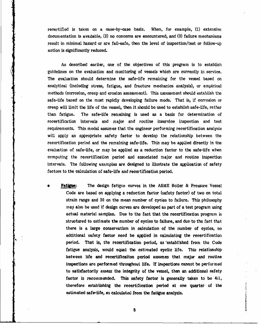
recertified is taken on a case-by-case basis. When, for example, (1) extensive
documentation is available, (2) no concerns are encountered, and (3) failure mechanisms
result in minimal hazard or are fail-safe, then the level of inspection/test or follow-up
action is significantly reduced.
As described earlier, one of the objectives of this program is to establish
guidelines on the evaluation and monitoring of vessels which are currently in service.
The evaluation should determine the safe-life remaining for the vessel based on
analytical (including stress, fatigue, and fracture mechanics analysis), or empirical
methods (corrosion, creep and erosion assessment). This &ssessment should establish the
safe-life based on the most rapidly developing failure mode. That is, if corrosion or
creep will limit the life of the vessel, then it should be used to establish safe-life, rather
than fatigue. The safe-life remaining is used as a basis for determination of
recertification intervals and major and routine inservice inspection and test
requirements. This model assumes that the engineer performing recertification analysis
will apply an appropriate safety factor to develop the relationship between the
recertification period and the remaining safe-life. This may be appiied directly in the
evaluation of safe-life, or may be applied as a reduction factor to the safe-life when
computing the recertification period and associated major and routine inspection
intervals. The following examples are designed to illustrate the application of safety
factors to the calculation of safe-life and recertification period.
* Fatigk : The design fatigue curves in the ASME Boiler & Pressure Vessel
Code are based on applying a reduction factor (safety factor) of two on total
strain range and 20 on the mean number of cycles to failure. This philosophy
may also be used If design curves are developed as part of a test program using
actual material samples. Due to the fact that the recertification program is
structured to estimate the number of cycles to failure, and due to the fact thatthere is a large conservatism in calculation of the number of cycles, no
additional safety factor need be applied in calculating the recertification
period. That is, the recertification period, as 'establ'shed from thi Code
fatigue analysis, would equal the estimated cyclic life. This relationship
between life and recertificaiton period assumes that major and routine
inspections are performed throughout life. If inspections cannot be performed
to satisfactorily assess the integrity of the vessel, then an additional safety
factor is recommended. This safety factor is generally taken to be 4:1,
therefore establishing the recertification period at one quarter of the
estimated safe-life, as calculatetl from the fatigue analysis.
6ILf
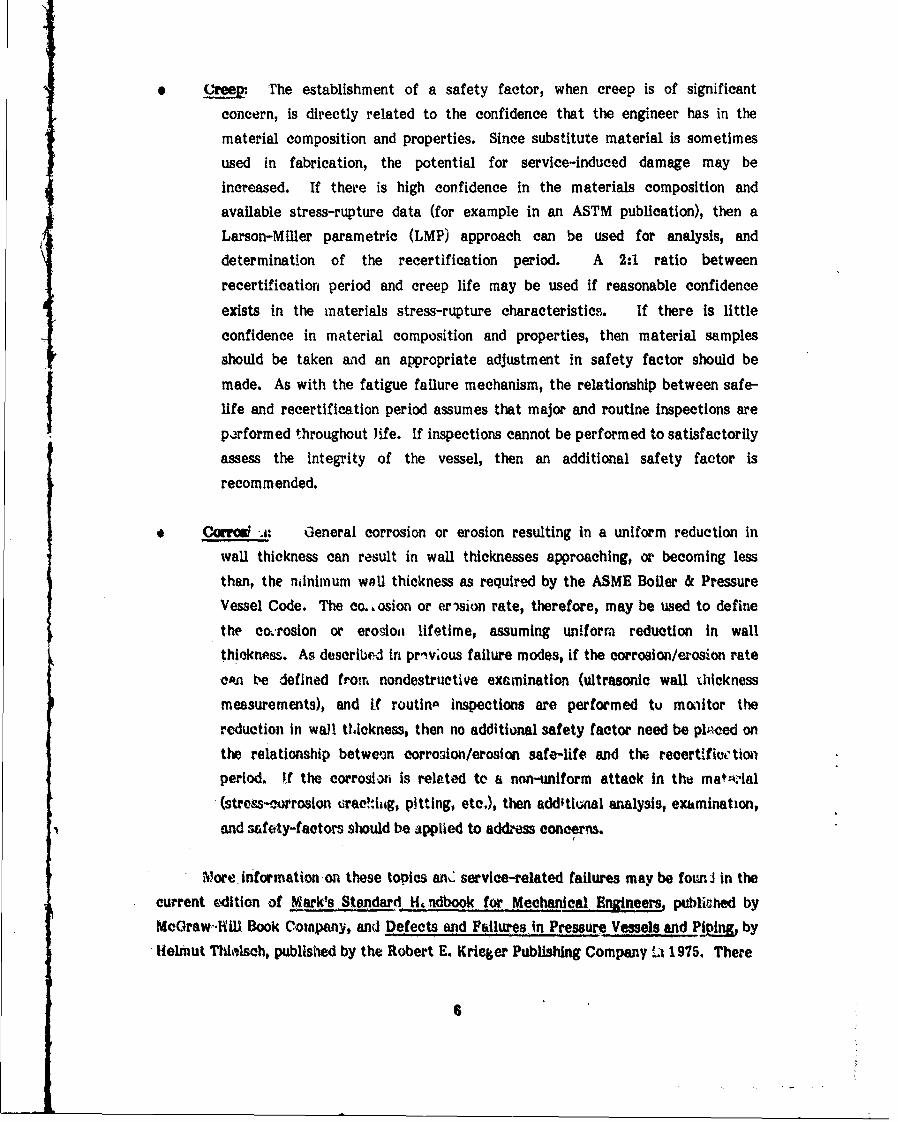
0 Uree- The establishment of a safety factor, when creep is of significant
concern, is directly related to the confidence that the engineer has in the
material composition and properties. Since substitute material is sometimes
used in fabrication, the potential for service-induced damage may be
increased. If there is high confidence in the materials composition and
available stress-rupture data (for example in an ASTM publication), then a
Larson-Miller parametric (LMP) approach can be used for analysis, and
determination of the recertification period. A 2:1 ratio between
recertification period and creep life may be used if reasonable confidence
exists in the materials stress-rupture characteristics. If there is little
confidence in material composition and properties, then material samples
should be taken a'nd an appropriate adjustment in safety factor should be
made. As with the fatigue failure mechanism, the relationship between safe-
life and recertification period assumes that major and routine inspections are
pýrformed throughout Wife. If inspections cannot be performed to satisfactorily
assess the integrity of the vessel, then an additional safety factor is
recommended.
• •CrrW .a: General corrosion or erosion resulting in a uniform reduction in
wall thickness can result in wall thicknesses approaching, or becoming less
than, the minimum well thickness as required by the ASME Boiler & Pressure
Vessel Code. The co.,osion or ersion rate, therefore, may be used to define
the co;rosion or erosioa lifetime, assuming uniform reduction in wallthickness. As described In privious failure modes, if the corrosion/erosion rate
Cesm be defined from nondestructive examination (ultrasonic wall thickness
measurements), and if routin, inspections are performed tu monitor the
reduction In wall thiokness, then no additional safety factor need be pliced on
the relationship between corrosion/erosion safe-life and the recertifi•ction
period. If the corroslati is related to a non-uniform attack in the mat÷ial
(stress-corrosion urach:ig, pitting, etc..), then additiwal analysis, examination,
and safety-factors should be applied to addrs concerns.
SWore information on these topics an, service-related failures may be fotn I in the
current edition of Mark's Standard H, ndbook for Mechanical Engineers- published by
McGraw-Hilll Book Company, and Defects and Failures In Pressure Vessels and P!ipn by
Helinut Tthilsch, published by the Robert E. Krieger Publishing Company Li 1975. There
S
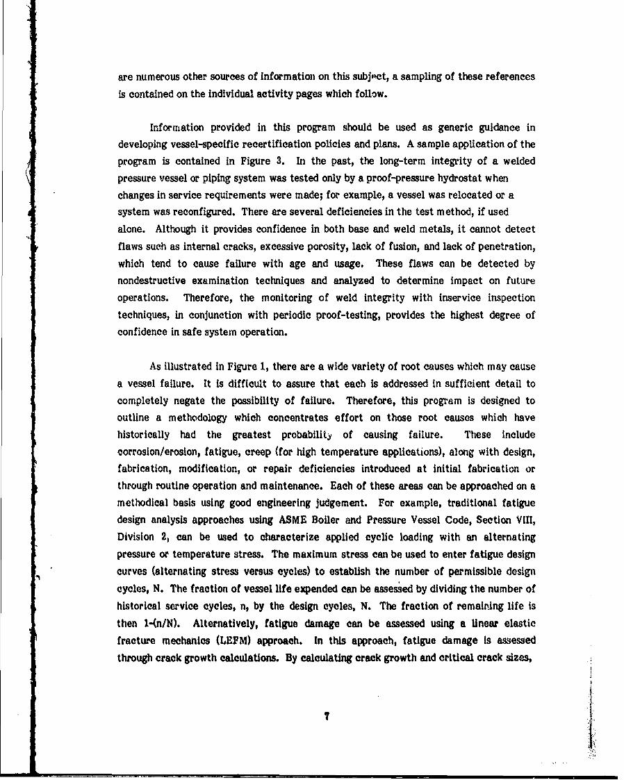
are numerous other sources of information on this subject, a sampling of these references
is contained on the individual activity pages which follow.
Information provided in this program should be used as generic guidance in
developing vessel-specific recertification policies and plans. A sample application of the
program is contained in Figure 3. In the past, the long-term integrity of a welded
pressure vessel or piping system was tested only by a proof-pressure hydrostat when
changes in service requirements were made; for example, a vessel was relocated or a
system was reconfigured. There are several deficiencies in the test method, if used
alone. Although it provides confidence in both base and weld metals, it cannot detect
flaws such as internal cracks, excessive porosity, lack of fusion, and lack of penetration,
which tend to cause failure with age and usage. These flaws can be detected by
nondestructive examination techniques and analyzed to determine impact on future
operations. Therefore, the monitoring of weld integrity with inservice inspection
techniques, in conjunction with periodic proof-testing, provides the highest degree of
confidence in safe system operation.
As illustrated in Figure 1, there are a wide variety of root causes which may cause
a vessel failure. It is difficult to assure that each is addressed in sufficient detail to
completely negate the possibility of failure. Therefore, this program is designed to
outline a methodology which concentrates effort on those root causes which have
historically had the greatest probability of causing failure. These include
corrosion/erosion, fatigue, creep (for high temperature applications), along with design,
fabrication, modification, or repair deficiencies introduced at initial fabrication or
through routine operation and maintenance. Each of these areas can be approached on a
methodical basis using good engineering judgement. For example, traditional fatigue
design analysis approaches using ASME Boiler and Pressure Vessel Code, Section VIII,
Division 2, can be used to characterize applied cyclic loading with an alternating
pressure or temperature stress. The maximum stress can be used to enter fatigue design
curves (alternating stress versus cycles) to establish the number of permissible design
cycles, N. The fraction of vessel life expended can be assessed by dividing the number of
historical service cycles, n, by the design cycles, N. The fraction of remairing life is
then l-(n/N). Alternatively, fatigue damage can be assessed using a linear elastic
fracture mechanics (LEPM) approach. In this approach, fatigue damage Is assessed
through crack growth calculations. By calculating crack growth and critical crack sizes,
1' ji
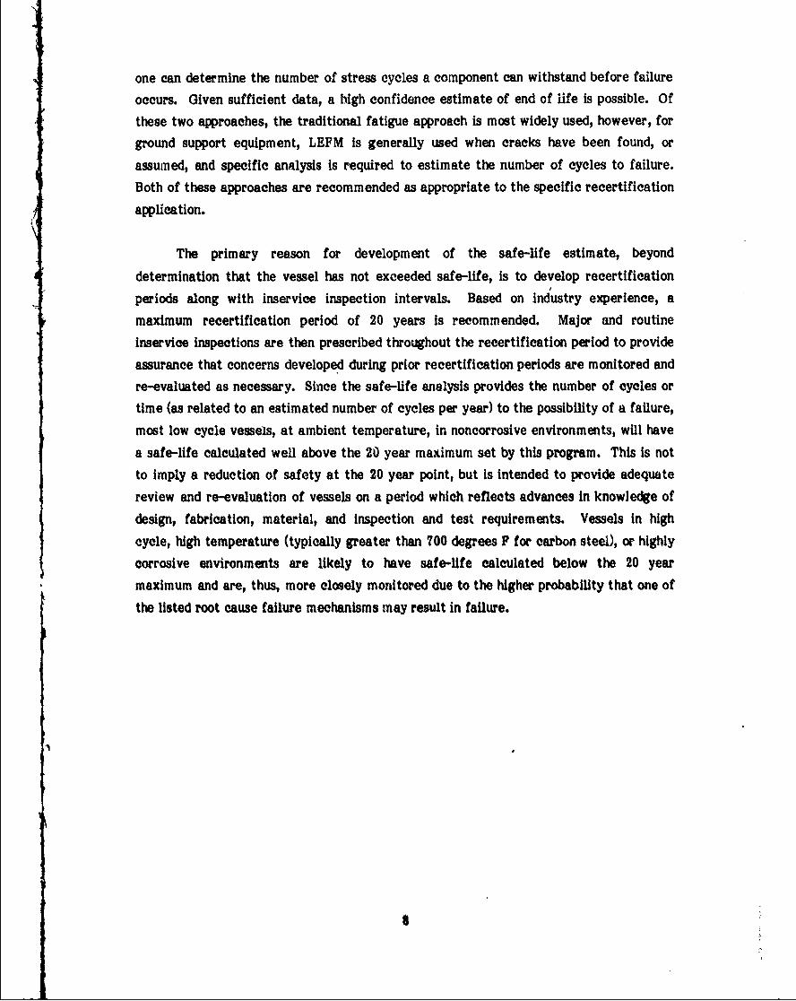
one can determine the number of stress cycles a component can withstand before failure
occurs. Given sufficient data, a high confidence estimate of end of life is possible. Of
these two approaches, the traditional fatigue approach is most widely used, however, for
ground support equipment, LEFM is generally used when cracks have been found, or
assumed, and specific analysis is required to estimate the number of cycles to failure.
Both of these approaches are recommended as appropriate to the specific recertification
application.
The primary reason for development of the safe-life estimate, beyond
determination that the vessel has not exceeded safe-life, is to develop recertification
periods along with inservice inspection intervals. Based on industry experience, a
maximum recertification period of 20 years is recommended. Major and routine
inservice inspections are then prescribed throughout the recertification period to provide
assurance that concerns developed during prior recertification periods are monitored and
re-evaluated as necessary. Since the safe-life analysis provides the number of cycles or
time (as related to an estimated number of cycles per year) to the possibility of a failure,
most low cycle vessels, at ambient temperature, in noncorrosive environments, will have
a safe-life calculated well above the 20 year maximum set by this program. This Is not
to imply a reduction of safety at the 20 year point, but is intended to provide adequate
review and re-evaluation of vessels on a period which reflects advances in knowJedge of
design, fabrication, material, and inspection and test requirements. Vessels in high
cycle, high temperature (typically greater than 700 degrees F for carbon steel), or highly
corrosive environments are likely to have safe-life calculated below the 20 year
maximum and are, thus, more closely monitored due to the higher probability that one of
the listed root cause failure mechanisms may result in failure.
8
2
00
E- =a 4
00
00
z4C-2l
zC~
Si lookO
lia 00 8 - b
104 9 a
'.41
'.4
2
0 0~ 41
0
'4d
Pio ~up,
2.0 DEFINrTONS
2.1 Cedfication
Documentation qualifying a vessel to operate in its particular service environment
within specific operational parameters, including maximum allowable working pressure
and temperature limitations.
2.2 Demted Vesel
A pressure vessel qualified to operate at a lesser maximum allowable working
pressure (MAWP) and/or temperature limit, as defined from recertification analysis
and/or testing.
23 Deen Premsrn
The pressure used in the design of a vessel for the purpose of determining the
minimum permissible thickness or physical characteristics of the different parts of the
vessel. (When applicable, static head shall be added to the design pressure to determine
the thickness of any specific part of the vessel).
2.4 Pail-Safe
The ability to substain a failure without causing loss of vehicle systems or loss of
personnel capability.
2.5 Hydrbutatc Test
The test of a pressure vessel during which the vessel is filled with a liquid and
pressurized to a designated level in a manner prescribed in the applicable code or
standard.
2.6 kuvlee hieemtk
Visual and/or nondestructive examination of a vessel during its service life.
10
2.7 Liquid Holding Tank
A low pressure or atmospheric storage tank containing materials which could
produce a personnel, equipment or environmental hazard if released, including
hypergolics, hydrocarbon fuels, and other related substances.
2.8 Maximum Allowable Woridng Premwre (MAWP)
The maximum gage pressure permissible at the top of a completed vessel in its
operating position at its design temperature. This pressure is based on calculations for
every element of the vessel using nominal thicknesses exclusive of allcwances for
corrosion and thickness required for loadings other than pressure. It is the basis for
pressure setting of the pressure relieving devices protecting the vessel
2.9 Major Inupections
A nondestructive examination which assesses the volumetric integrity of the
vessel. This may include radiography, ultrasonic, or acoustic emissions examination.
Proof testing may be used as an alternative.
2.10 Major tion Interval
Typically prescribed at intervals of one quarter to one half of the recertification
period, depending on service conditions and failure modes. Major inspection intervals are
prescribed as part of recertification analysis.
2.11 Maxmum Operating Presure (MOP)
The maximum pressure at the top of a pressure vessel at which it normally
operates. It shall not exceed the maximum allowable working pressure and it is usualiy
kept at a suitable level below the setting of the pressure relieving devices to prevent
their frequent opening.
2.12 Pneumatic Tat
A test of a pressure vessel in which a gas is Introduced and pressurized to ft
designated level in a manner prescribed in an applicable code or standard.
11 .i
2.13 Pressure Vessel
Any container used for the containment of pressure, either Internal or external.
2.14 Reeertification
The procedure (appropriate analysis, inspections, tests and documentation) which
qualifies a previously certified vessel to continue or be returned to operations at a
designated pressure. Recertification should include a requirement for periodic proof
pressure testing.
2.15 Rewertification Period
The interval of time a vessel is permitted to operate between scheduled
recertifications. The maximum Recertification Period is established at 20 years, not to
exceed the safe-life, for this program.
2.16 Routine Impections
Visual and nondestructive examinations which assess the overall condition of thevessel. This may include visual external examinations and ultrasonic wall thickness
measurements to detect corrosion, erosion, deformations, or other general features
Indicating possible loss of integrity. Follow-up inspections may be required.
2.17 Routine tibo a Interels
Typically prescribed at intervals of one tenth to one half of the major inspectioninterval, depending on service conditions. Routine inspection intervals are prescribed as
part of recertification analysis.
Li2 safe-we
The period during which a vessel is predicted not to fail in the expected operating
environment.
12
3.0 FORMAT OF PHASES AND ACT-YIVrI
The recertification process is divided into five phases, each of which addresses a
major goal for the program. Figure 4 summarizes each of the phases and its associated
major goal. The five phases are further divided into activities, each of which addresses a
unique aspect of the process. The activities are the primary building blocks of the
program, and as such are interrelated to the major decision-making logic, as presented in
Figure 5. Figure 5 presents all five phases and all activities showing the
interrelationships of the decision making process. In turn, each activity will involve
separate steps and additional decisions to implement the entire program.
Each activity is presented or, a separate numbered sheet, with each sheet containing
detailing information on the necessary steps to complete the activity. The first digit in
the identification number corresponds to the number of the phase, with the second two
digits designating a unique activity number. Following each group of activities
associated with a particular phase is a phased flowchart illustrating the interrelationships
of the activities and decision points. A complete list of all phases and activities is
contained in Figure 6.
13
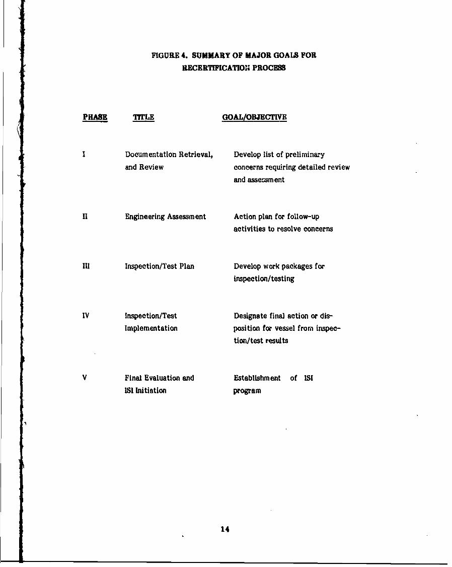
FIGURE 4. SUMMARY OF MAJOR GOAIS FOR
RECERTIFICATION PROCESS
PHASE 1Im GO E
I Documentation Retrieval, Develop list of preliminary
and Review concerns requiring detailed review
and assecsm ent
II Engineering Assessment Action plan for follow-up
activities to resolve concerns
IU Inspection/Test Plan Develop work packages for
inspection/testing
IV Inspection/Test Designate final action or dis-
Implementation position for vessel from inspec-
tion/test results
V Final Evaluation and Establishment of ISI
INl Initiation program
14
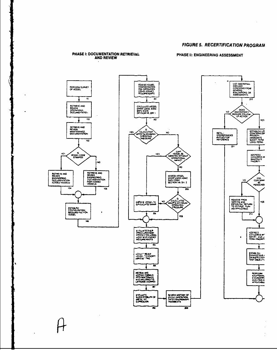
FIGURE5. RECERTIFICATION PROGRAM
PHASE 1: DOCUMENTATION RETRIEVAL PHASE II: ENGINEERING ASSESSMENTAND REVIEW
k.'..'.''.'..'. S E$ S E• LLIST DtSC PEPAN.AS5ESSVESAND
PERFORM SURVEY CO NFIOURATION COES ANDol: VESSEL AND OPERATION REVIEWS.
USING AGENCY EVION$.REQUIREMENTS E SSMENT S
IS.. SSENT
RETRIEVE AND CIA,,;LATE VIESSELREVIEW MAWIYUSNG ASMEOPERATIONS DE UO D PANCYEDOCUMEPTATIOI,
SvAIV ON DE R FL
102 2Q YE
RETRIEVE ANDREVIEW IS ESTASUSH USMAAINTENANCE YES CALCULATES' NO RE71A.; CONCERtSovDOCUMENTATION LtAWP >UMAXIUYIIA ICEACISPIOPIETING IN FILES "A (OMUEDIATE""R " " "Re REFERENCE SOR¶I.ERU
m3 LONG-TERM)
CAW,.YES VESSE.L ID"VESSE DE••ll~tct
l'|kogl$ *0 E IMTNO&IT
40 ~~IhPAC? cE-
No
11147Mv "mM ~*~ A
iONCONO(O stct~ vw O
~tIto
C-A-(I
4 4ATC y. AhOUT5IE ul*0l*V'
I'-l.9ft¶"1Yt
ONPSIS4
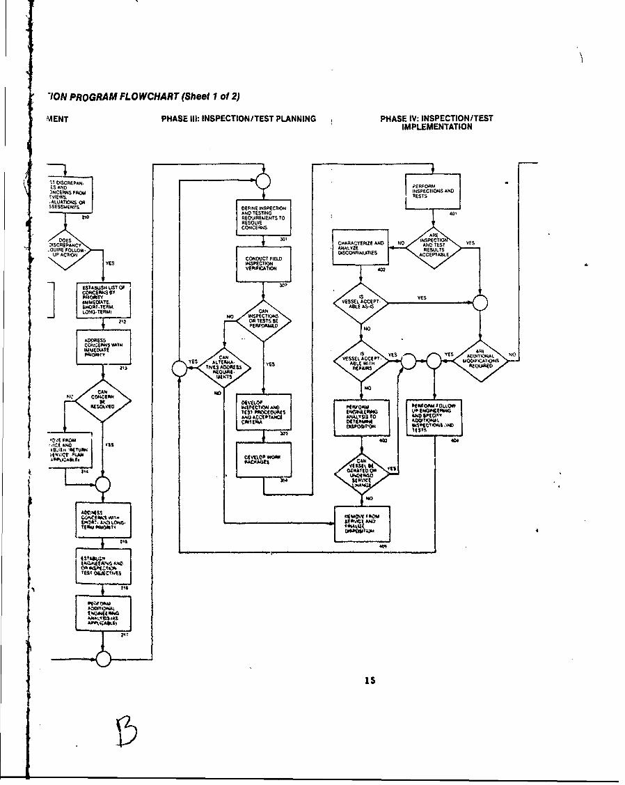
-ION PROGRAM FLOWCHART (Sheet 1 of 2)
-MENT PHASE III: INSPECTION/TEST PLANNING PHASE IV: INSPECTION/TESTIMPLEMENTATION
ST D4SCREPAN.ES ANDPEFR)NCERNSFM INSECORSAN=VIEWS.TES;ALUATIONS ORSSESSWENTS DEFINE INSPECTIONAND TESTINGO0
REQUIREMENTS TORESOLVECONCERNS
DOESINPCDISCREPANCY CAATRZ N O ADTS
-QUIRE FOLLOW-.EUTUP ACTION ~~~~~CONDUCT FIELDDICNNUTE CPA&Y ES INSPECTION
VEftFICATION 4
C'ONCERNS BYrONMEDIATE. ESLACP
10NO.TERU) CAN
Olt 7IsS SE
CONCSPN$ VATIWMPEDIATI
YES *.LT(IRNA. AIA WITHS
Z13 Yr~~~MA~ m tS gi I
CAN N
Nc CONCIERN6
ILPEV1004CTONAIIC PEAFwookuUOMO~W
pvt *T*4IW1AIi
vi4 IfO 11t~4F. 4w?
PAis.~
W E-t LAN
lI4~RNO*?i ~AFiO
AK 4
tsis

FIGURE S. RECERTIFICA TION PROGRAM F
DETERMINE THENUMBER OF STRESSCYCLES PER YEAREXPERIENCL-O ByAND EXV-'•CTEO FORTHE VESSE-L
PERFOR A DETAILED PEROR
SDIRPE IDSAE
SAFELIFEANALSISIFE ANALYSIS
502 503
isDEVELOP DESTRUC. ,
REMAINNG NO TIVE TEST PLAN TOSAE-IFEG PROVIDE DETAILED
>0INPUT FOR FATIGUE
ANALYSIS
504
YE PEFOMD ETAILE D DEFLAE TEVCES
FATIGUE ANALYSIS,0%ADAUS
ANALYSIS H RLE EIE
IisPERFORMNO MAEIL YES EM I NO ENGINEERING
CROIN0 DETERMINE
'• DISPOSITION
YES
ENGINEERINGYEANALYSIS TO DRTDO
€ ESTIMATE CANECORROSION N O RRODERGDAMAGE AND R=ATE BE N
REMAINING SAFE- RDCEDCAGLIFE
t REMOVE FROMDERATE VESSEL TO CALCULATE SERICANADI,
MOP - 104o AND REMAININGSAFE, DISPOSITIONADJST,$ RELIEF LIFE BASED ONDEVICES CORROSION RATE }
YYES
is VESSEL SCE NO iREMAINING NO DENA~TERDO EAN
R•PS•t
C
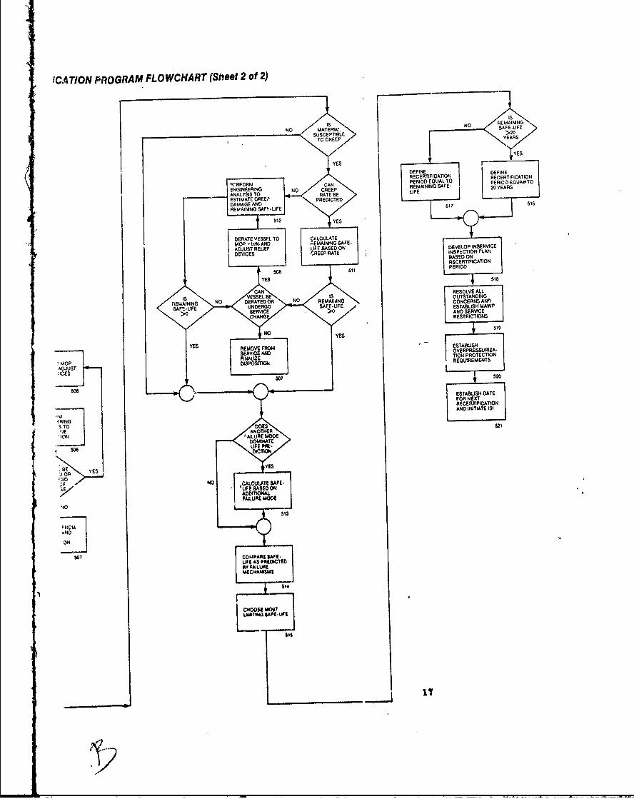
ICATION PROGRAM FLOWCHART (Sheet 2 of 2)
IIs
is ~NO M
NO MATERIM.
SUSCEPTIBLE>2TO CREEPYER
YYES
YEES R R
SI
"I-M A-IN G N O E R A E D O N O R E A E IN R E T F CA T O N C R EC1RN SIC A T IO
DEFINE
DEFINE
GNFINE
SATOAY ESST
AMAG ANCTRE
RERAERE TOVES.LT
DOMIFATE
LY6
0I• 1N [ D VL O P 0NSE RlC
MAINING SAF 2 YE
INEEN YESRE 2YER
NCA L CULSTO RAAE BAED LI
DESTIMAES CA 'RE DICRTED|IS PC INPA
DAAE AND 517
REAIIN RECETFFIATFO
MOOIVURE MOv E
ADJUT R F, IFE ASE ON EVEOPUTSTANDING
DEIE REMP ATEIN I ,CTONCERN LANt
RVJE ASNEDC
TMONPROTCTIO
SAND INHTOATE
O~t
RECERTIFICATION
S' ~ f YE SI[ SIB
CA N *'TLO' AL
nEAIIN VESSEL NOUl ISI A
CHANG RESTRICTIONS
YES5*5 ESABIS
OVERPRESURL A
TI PR
FIN PROTE
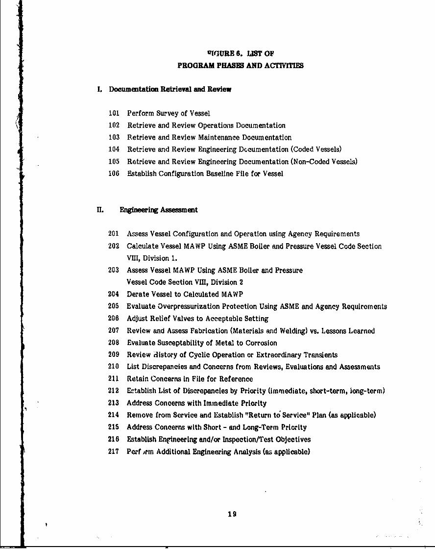
VIGURE 6. LIST OF
PROGRAM PHASES AND ACT"II
I. Docuemntation Retrieval and Review
101 Perform Survey of Vessel
102 Retrieve and Review Operations Documentation
103 Retrieve and Review Maintenance Documentation
104 Retrieve and Review Engineering Documentation (Coded Vessels)
105 Retrieve and Review Engineering Documentation (Non-Coded Vessels)
106 Establish Configuration Baseline File for Vessel
1. Engineering Amessment
201 Assess Vessel Configuration and Operation using Agency Requirements
202 Calculate Vessel MAWP Using ASME Boiler and Pressure Vessel Code Section
VUI, Division 1.203 Assess Vessel MAWP Using ASME Boiler and Pressure
Vessel Code Section VIII, Division 2
204 Derate Vessel to Calculated MAWP205 Evaluate Overpressurizatlon Protection Using ASME and Agency Requirements
206 Adjust Relief Valves to Acceptable Setting
207 Review and Assess Fabrication (Materials and Welding) vs. Lessons Learned
208 Evaluate Susceptability of Metal to Corrosion209 Review dlstory of Cyclic Operation or Extraordinary Transients
210 List Discrepancies and Concerns from Reviews, Evaluations and Assessments211 Retain Concerns in File for Reference
212 Ectablish List of Discrepancies by Priority (immediate, short-term, long-term)
213 Address Concerns with Immediate Priority
214 Remove from Service and Establish "Return to Service" Plan (as applicable)
215 Address Concerns with Short - and Long-Term Priority
216 Establish Engineering and/or Inspection/Test Objectives
217 Perf ,rm Additional Engineering Analysis (as applicable)
19
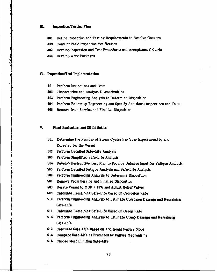
II. Iropectin/Testing Plan
301 Define Inspection and Testing Requirements to Resolve Concerns
302 Conduct Field Inspection Verification
303 Develop Inspection and Test Procedures and Acceptance Criteria
304 Develop Work Packages
IV. knpection/Test Implementation
401 Perform Inspections and Tests
402 Characterize and Analyze Discontinuities
403 Perform Engineering Analysis to Determine Disposition
404 Perform Follow-up Engineering and Specify Additional Inspections and Tests
405 Remove from Service and Finalize Disposition
V. Final Evaluation and 181 Initiation
501 Determine the Number of Stress Cycles Per Year Experienced by and
Expected for the Vessel
502 Perform Detailed Safe-Life Analysis
503 Perform Simplified Safe-Life Analysis
504 Develop Destructive Test Plan to Provide Detailed Input for Fatigue Analysis
505 Perform Detailed Fatigue Analysis and Safe-Life Analysis
506 Perform Engineering Analysis to Determine Disposition
507 Remove From Service and Finalize Disposition
503 Derate Vessel to MOP + 10% and Adjust Relief Valves
509 Calculate Remaining Safe-Life Based on Corrosion Rate
510 Perform Engineering Analysis to Estimate Corrosion Damage and Remaining
Safe-Life
511 Calculate Remaining Safe-Life Based on Creep Rate
512 Perform Engineering Analysis to Estimate Creep Damage and Remaining
Safe-Life
513 Calmulate Safe-Life Based on Additional Failure Mode
514 Compare Safe-Life as Predicted by Failure Mechanisms
515 Choose Most Limiting Safe-Life
20
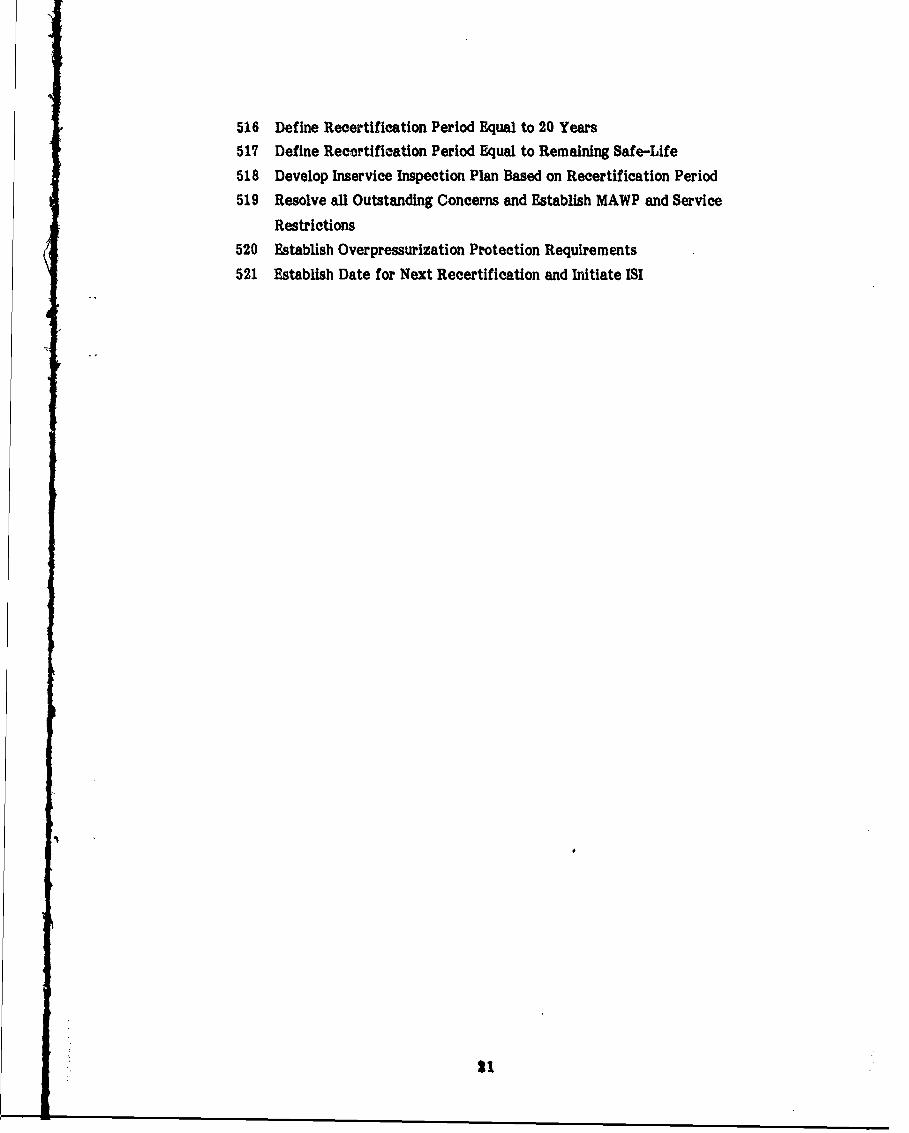
516 Define Recertification Period Equal to 20 Years
517 Define Recertification Period Equal to Remaining Safe-Life
518 Develop Inservice Inspection Plan Based on Recertification Period
519 Resolve all Outstanding Concerns and Establish MAWP and Service
Restrictions
520 Establish Overpressurization Protection Requirements
521 Establish Date for Next Recertification and Initiate ISI
ii
RECERTIFICATION GUIDEACfIVITV
PHASE: I4 Documentation Retrieval, Review and Assessment
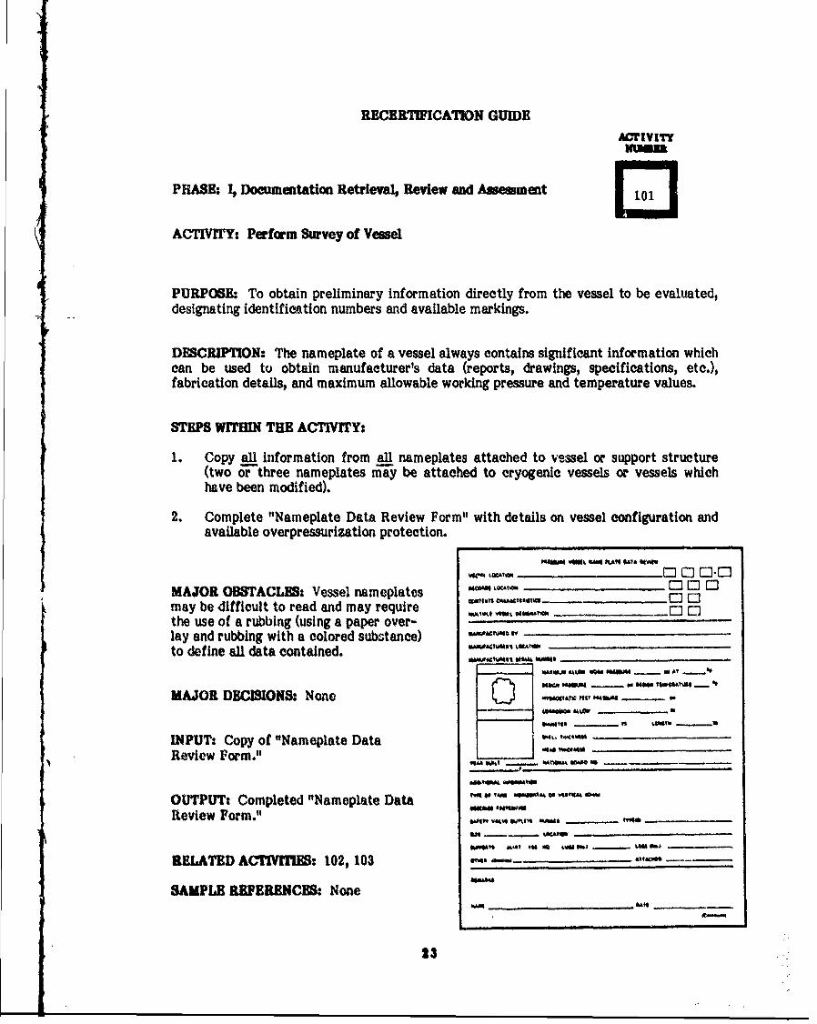
ACTIVITY: Perform Survey of Vessel
PURPOSE- To obtain preliminary information directly from the vessel to be evaluated,designating identification numbers and available markings.
DESCRIPTION: The nameplate of a vessel always contains significant information whichcan be used to obtain manufacturer's data (reports, drawings, specifications, etc.),fabrication details, and maximum allowable working pressure and temperature values.
STEPS WITHIN THE ACTIVITY:
1. Copy all information from all nameplates attached to vessel or support structure(two or three nameplates may be attached to cryogenic vessels or vessels whichhave been modified).
2. Complete "Nameplate Data Review Form" with details on vessel configuration andavailable overpressurization protection.
WL ir .M_ _ _ I_ ___ I I_ II
MAJOR OBSTACLES: Vessel nameplates " , Louie* EC3] rCmay be difficult to read and may require ,Ow% ,,.&_ 0 E3
the use of a rubbing (using a paper over- .. .. ....lay and rubbing with a colored substance)to define all data contained.
id~ae•',£U UMM4 M44 - -- £-
Me M ,1 - U Mofm f4t-4 _ •
MAJOR DECISION& None .,"."., _9__6,,
INPUT: Copy of "Nameplate Data 04L -AReview Form ." ---- ""-
OUTPUT: Completed "Nameplate Data of TAM "'Review Form." Wnt. a~&
_ _• thulotw ..
RELAATED AC VTIYIM: 102, 103 , -"
SAMPLE REFERENCES: None234 ,,_,_, ,_._._____
233
RECERTIFICATION GUIDE
ACrIVIVY
PHASE: I, Domentation Retrieval Review and Amm ument
ACTIVTrY: Retrieve and Review of Operations Documentation
PURPOSE To establish operating history for the vessel including cycling frequenciesand normal operating pressure, temperature and conditions.
DECRIPTIMN: The accumulation of operating history for the vessel is used in both theengineering evaluation and establishment of NDE for assessment of the vessels structuralintegrity.
WTRPS WITHIN THE ACTIVrTY:
1. Discuss operating history with operational, maintenance, and engineering staff,document results of conversation(s).
2. Review operating logs and operating procedures, obtain copies If available.3. Document any unusual or abnormal transients in pressure, temperature, vibration,
etc.4. Key areas to address with operating personnel include:
* Operation exceeding the design parameters (typically temperature and/orpressure)
* Expected service (eg., increasing cycling duty, new applications, commodities,configurations)
* Failure history
MAJOR OmTACLUM Detailed operating histories for vessels are not often obtainable,on-site staff is typically only swmce of historical information.
MAJOR DECEION& Assess the credibility and accuracy of operating histories obtainedfrom personnel interviews.
INPUTs Operating lop, procedures, or historical documentation from cognizant site
personnel
OUIUT: Summary of operating history.
RELATED ACTIVr: 101
SANPL BI REBP NCU None
24
RECERTIFICATION GUIDE
ACTiIVITYmammammmm
PHAS: I, Documentation Retrieval, Review and Asms ment QACTIVrIY. Retrieve and Review of Maintenance Documentation
PURPOSE: To establish maintenance history for the vessel including history ofrefurbishment, inspections and tests, repairs, modifications, and problem reports.
DSCBIP'l'ON: The accumulation of maintenance history for the vessel is used todocument modifications and repairs which may have been made in the past, includingrepairs due to previous unsatisfactory inspection or test results.
STEPS WITHIN THE ACTIVITY:1. Obtain and review maintenance/repair log, if available.
2. Review work orders for maintenance activities, document normal andrepair/modification activities.
3. Discuss maintenance history with cognizant personnel with emphasis onmodifications, repairs, Inspections/tests, and routine inspections/tests ofoverpressurization protection devices, document conversations.
MAJOR OBSTACLES: Detailed maintenance histories for vessels are not often easilyobtainable, review of work orders may be time consuming, requiring on-site staffsupport.
MAJOR DECISIONS& Assess the credibility and accuracy of operating histories obtainedfrom personnel interviews.
INPUT: Maintenance logs, work orders, or historical documentation from cognizant sitepersonnel.
OUTPUT: Summary of maintenance history.
RELATED ACTIVmlIM 101, 102
SAMPLE DEFERENCM: National Board Inspection Code, ANSINB-23
25
RECERTIFICATION GUIDE
AL'TIVITY
PHASE& I Documentation Retrieval Review and Asssment
ACTIVITY: Retrieve and Review of Engineering Documentation(Coded VemwW
PURPOSE- To establish original engineering design specification and configuration,along with code of record (code or standard title, year, edition, addenda, applicable codecases, etc.) and history of modifications and repairs including specifications, records, ordrawings.
DESCRIPTION: The accumulation of the original manufacturer's data report, designand/or construction drawings, engineering specifications, design calculations, andmodification/repair drawings assists the certification/recertification team throughoutthe project.
STEPS WITIN THE ACTIVrTY:
1. Using the manufacturer's serial number, obtain specifications, drawings, andcalculations from site files (user organization, civil engineering or real propertyoffice, or other cognizant organization) or from original manufacturer.
2. Obtain original manufacturer's data report from site files, original manufacturer orNational Board of Boiler and Pressure Vessel Inspectors (with N.B. number).
3. Obtain drawings and/or specifications for modifications/repaiis.
MAJOR OBSTACLES: Many organizations may be required to be contacted to obtainsufficient documentation; cost may be incurred to obtain data reports, drawings, etc.
MAJOR DECISION& Extent of search for documentation, a balance between cost, time,and probability of obtaining documentation must be assessed.
[NPUTt Serial number, National Board number, facility number or other identificationnumber from nameplate.
OUTPUT: Copies of drawings, specifications, data reports, calculations, and other
engineering documentation.
RELATED ACTIVfrI: 101
SAMPLE REFERENCENC (1) National Board Inspection Code, ANSI/NB-23(2) ASME Boiler & Pressure Vessel Code, Section VI1I,Divisions 1 and 2
26
RECERTIFICATION GUIDEACIIVITYumna
PHASE: I, Documentation Retrieval Review and Assessment 0ACTIVITY: Retrieve and Review of Engineering Documentation(Non-Coded Vesels)
PURPOSE- To establish original engineering design specification and configuration,along with history of modifications and repairs, including specifications, records, ordrawings.
DESCRIPTION: Typically the primary source of documentation on non-coded vessels isthe original design specification and manufacturer's drawings, additional information maybe available if the original specification required its development and transmittal withthe vessel.
STEPS WITHIN THE ACTIVrrY:
1. Using nameplate data, review site files (user organization, civil engineering andreal property office, or other cognizant organization) to obtain specification,original drawings, and other information as available.
2. Contact original manufacturer using serial number and obtain original drawings,calculations, and associated documentation, as available.
MAJOR OBSTACLBS: Information on non-coded vessels may be more limited than codedvessels; the level of available documentation is directly related to original requirementsin specification.
MAJOR DECISIONS: Extent of search for documentation, a balance between cost, time,and probability of obtaining documentation must be assessed.
INPUT: Serial number, original contract or Job number.
OUTPUT: Copies of drawings, specifications, calculations, and other engineering
documentation.
RELATED ACTIrlvrS. 101
SAMPLE REFERENCES: None
"27
RECERTIFICATION GUIDE
ACTIVITYN~tlel
PHASE: 1, Douentation Retrieval Review and Assessment
ACTIVITY: Establish Configuration Baseline File for VesseL
PURPOSE: To establish a baseline file for current vessel configuration along withdocumented historical engineering, operations and maintenance information.
DESCRIPTION: All vessel Information is assembled and assessed for completeness andconsistency, missing or inconsistent information is summarized for emphasis in follow upactivities.
STEPS WrrHIN THE ACTIVrIY:
1. Compare current configuration with original documentation, along with record ofmodifications end repairs, to assess consistency; note discrepancies.
2. Note significant operational or maintenance activities which could have resulted inexcessive stresses (both residual or cyclic).
MAJOR OUSTACIES Much information may be missing for adequate assessment.
MAJOR DECISIONS A preliminary list of concerns must be established based ondocumentation contained in baseline file.
INPUT: Engineering, operational, maintenance documentation.
OUTPUTs List of preliminary concerns requiring detailed review and assessment.
RELATED AC1IVIrU: 102, 103, 104, 105
SAMPLE REFERBNCES: Air Force Regulation 65-3, "Configuration Management".
28
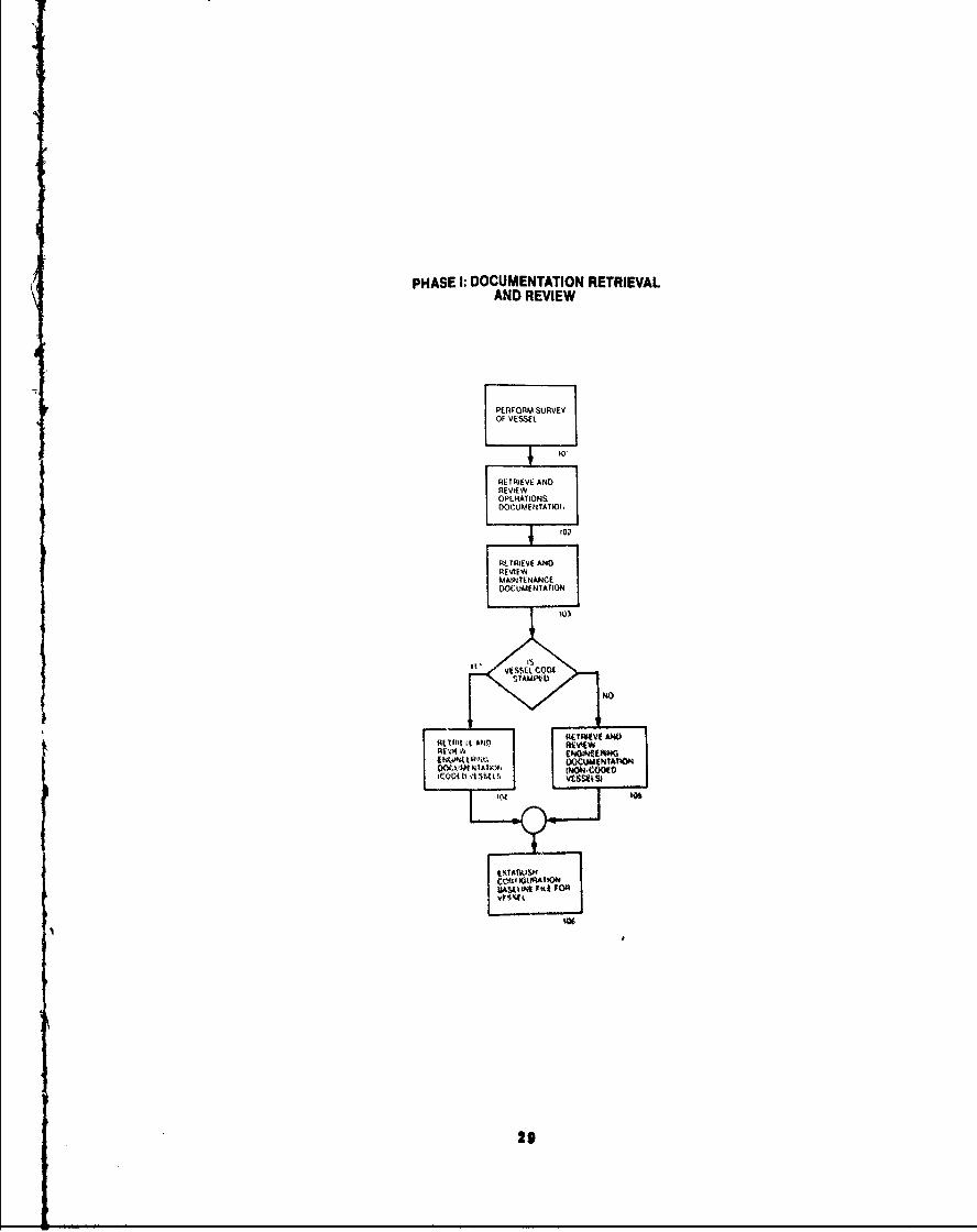
PHASE I: DOCUMENTATION RETRIEVALAND REVIEW
PERFORM SURVEY
OF VESSEL
Sto*RETRIEVE AND
REVIEWOPERATIONSDOCUMENTATI0,
Rt TRIEVE ANDREVIEWMAINTENANCE
DOCUMLENTATION
Is
VEu co
J R~v•' i M No
3to&
RECERTIFICATION GUIDE
ACTIVITY
PHASE: H. Engineering Assessment E ]ACTIVITY: Assess Vessel Configuration andOperation using Agency Requirements
PURPOSE: To evaluate the current vessel configuration against current Agencyrequirements stated in applicable regulations, military standards, and manuals.
DESCRIPTION: A comparison is made between current vessel configuration andrequirements in regulations (e.g. ESMC regulation 127-1), military standards (e.g. MIL-STD-1522), Air Force Manuals (e.g. AFM 88 Series), and associated documents, todetermine compliance.
STEPS WITHIN THE ACTIVITY:
1. Using a checklist of requirements for all applicable Agency regulations, standards,and manuals, evaluate compliance of current pressure/cryogenic vesselconfiguration.
2. Organize discrepancies under (1) immediate safety concerns, (2) ordinary safetyconcerns and (3) configuration management (CM) concerns. Document alldiscrepancies.
3. Immediately report safety concerns of an imminent nature to the operational staffand the safety office; report other safety concerns to the safety office as quicktyas practical, all other concerns over configuration management are reported duringroutine briefings. "Out of service" vessels to be returned to an operational statusrequires special safety office attention and approval.
MAJOR OWTACLES• None
MAJOR DECIMION& Immediate action on imminent -safety eoncerns.
INPUT: Copies of all Agency requirements for Pressure Vessels.
OUTPUT: List of Agency requirements discrepaneies.
RELATED ACTlVr=-.: 202
SAMPLE REiERENCES:1. ESMC Regulation 127-I, "Range Safety Manual"2. TO 00-25-2233. MIL.-STD-1522 (current revision), "Standard General Requirements for Safe Deq4gn
and Operation of Prezsurized Missile and Space Systems."4. Air Force Manual, AFM 88 Series, "Facility Design and Planning."
31
RECERTIFICATION GUIDEMaURn
PHASE: II, Engineering Assemmmte
ACTIVITY: Assam Vessel MAWP using ASMEBoller & Pressure Vessiel Code, Sewtion VII,Division I
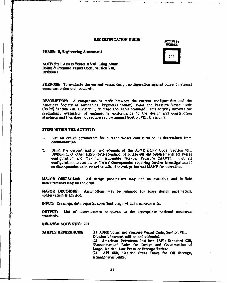
PURPOSE: To evaluate the current vessel design configuration against current nationalconsensus codes and standards.
DESCRIPTION: A comparison is made between the current configuration and theAmerican Society of Mechanical Engineers (ASME) Boiler and Pressure Vessel Code(B&PV) Section VIll, Division 1, or other applicable standard. This activity involves thepreliminary evaluation of engineering conformance to the design and constructionstandards and thus does not require review against Section Vill, Division 2.
STEPS WITHIN THE ACTIVITY:
1. List aU design parameters for current vessel configuration as determined fromdocumentation.
2. Using the current edition and addenda of the, ASME B&PV Code, Section V1I1,Division 1, or other appropriate standard, caleulate current requirements for vesselconfiguration and Maxinium Allowable Working Pressure (MAWP). List allconfiguration, material, or MAWP discrepancies requiring further investigation; ifno discrepancies exist report details of investigation and MAWP for operation.
MAJOR OBSTACLN& All design parameters may not be available and in-fieldmeasurements may be required.
MAJOR DECSIONS: Assumptions may be required for some design parameters,conservatism is advi6ed.
INPUT: Drawings, data reports, specifications, in-field measurements.
OUTPUT: List of discrepancies compared to the appropriate national consensusstandards.
RMATED ACM'IvrnM 201
SAMPLE RVPBRENCE (1) ASME Boiler and Pressure Vessel Code, Settion ViiI,Division I (current edition and addenda).(2) American Petroleum Institute (API) Standard 620"tRecommended Rules for Design and Construction ofLarge, Welded, Low Pressut-e Storage Tanks."(3) API 650, "Welded Steel Tanks for Oil Storage,Atmospheric Tanks."
32
RECERTIFICATION GUIDE
ACrIVITY
PHASE: 1, Engineering AssessmeMt
ACTIVITY: Assess Vessel MAWP using ASME Boiler- and Presure Vessel Code, Section VI1, Division 2
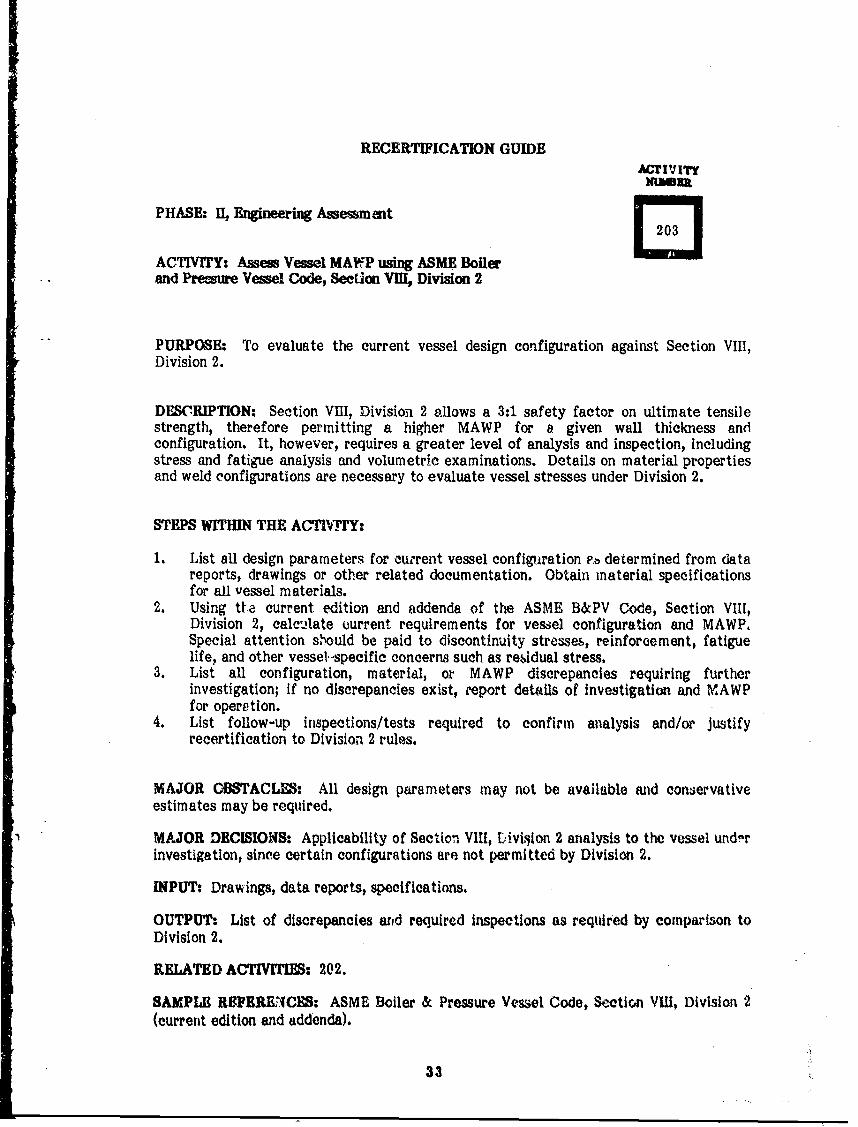
PURPOSE: To evaluate the current vessel design configuration against Section VIII,Division 2.
DESCRIPTION: Section VIII, Division 2 allows a 3:1 safety factor on ultimate tensilestrength, therefore permitting a higher MAWP for a given wall thickness andconfiguration. It, however, requires a greater level of analysis and inspection, includingstress and fatigue analysis and volumetric examinations. Details on material propertiesand weld configurations are necessary to evaluate vessel stresses under Division 2.
STEPS WITHIN THE ACTIVTrY:
1. List all design parameters for current vessel configuration ez determined from datareports, drawings or other related documentation. Obtain material specificationsfor all vessel materials.
2. Using tf.e current edition and addenda of the ASME B&PV Code, Section VIII,Division 2, calc.'late current requirements for vessel configuration and MAWP,Special attention should be paid to discontinuity stresses, reinforcement, fatiguelife, and other vessel specific concerns such as residual stress.
3. List all configuration, material, or MAWP discrepancies requiring furtherinvestigation; if no discrepancies exist, report details of investigation and MAWPfor operption.
4. List follow-up inspections/tests required to confirm analysis and/or justifyrecertification to Division 2 rules.
MAJOR OBSTACLES: All design parameters may not be available and conservativeestimates may be required.
MAJOR DECISIONS: Applicability of Section VIII, Uivi.5ion 2 analysis to the vessel undr
investigation, since certain configurations are not permitted by Division 2.
INPUT: Drawings, data reports, specifications.
OUTPUT: List of discrepancies arid required inspections as required by comparison toDivision 2.
RELATED ACTIVrFIES: 202.
SAMPLE REFERE3,CES: ASME Boiler & Pressure Vessel Code, Secticon VIII, Division 2(current edition and addenda).
33
RECERTIFICATION GUIDE ACTIrTy
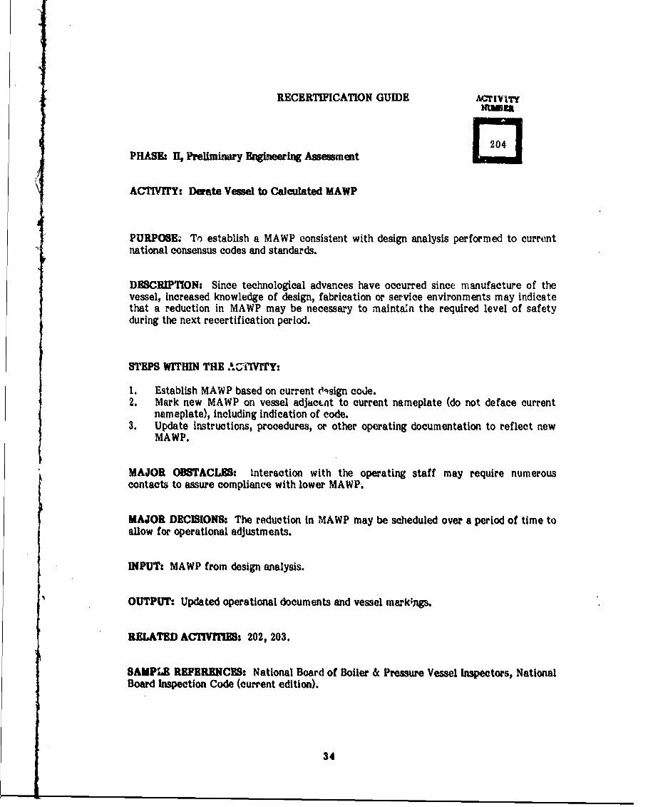
PHASE: H, Preliminary Engineering Assessment EACTIVITY: Derate Vessel to Calculated MAWP
PURPOSE; To establish a MAWP consistent with design analysis performed to currentnational consensus codes and standards.
DESCRIPTION: Since technological advances have occurred since manufacture of thevessel, Increased knowledge of design, fabrication or service environments may indicatethat a reduction in MAWP may be necessary to maintan the required level of safetyduring the next recertification period.
STEPS WITHIN THE AC7lVlTY:
1. Establish MAWP based on current &-sign code.2. Mark new MAWP on vessel adjacnt to current nameplate (do not deface current
nameplate), including indication of code.3. Update instructions, procedures, or other operating documentation to reflect new
MAWP.
MAJOR OI1STACI,: interaction with the operating staff may require numerouscontacts to assure compliance with lower MAWP.
MAJOR DECISION& The reduction in MAWP may be scheduled over a period of time toallow for operational adjustments.
INPUT: MAWP from design analysis.
OUTPUT: Updated operational documents and vessel mnarkings.
RELATED ACTIVrIIES: 202, 203.
SAMPLE REFERENCES: National Board of Boiler & Pressure Vessel Inspectors, NationalBoard Inspection Code (current edition).
34
RECERTIFICATION GUIDE
ACTIVITY
NtiaR
PHASE: H, Engineering Assessment
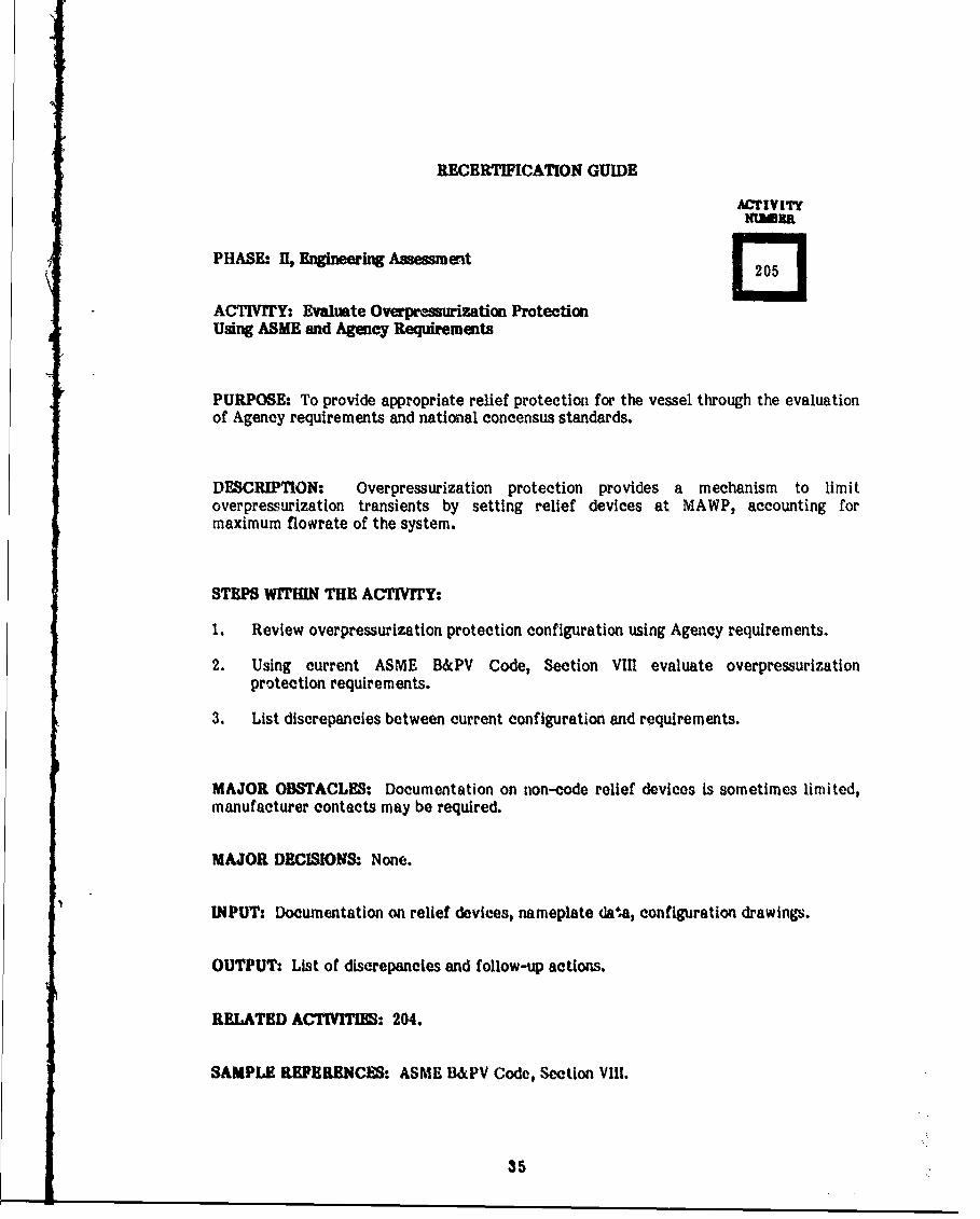
ACTIVITY: Evaluate Overpressurization ProtectionUsing ASME and Agency Requirements
PURPOSE: To provide appropriate relief protection for the vessel through the evaluationof Agency requirements and national concensus standards.
DESCRIPTION: Overpressurization protection provides a mechanism to limitoverpressurization transients by setting relief devices at MAWP, accounting formaximum flowrate of the system.
STEPS WITHIN THE ACTIVITY:
1. Review overpressurization protection configuration using Agency requirements.
2. Using current ASME B&PV Code, Section VIII evaluate overpressurizationprotection requirements.
3. List discrepancies between current configuration and requirements,
MAJOR OBSTACLES: Documentation on non-code relief devices is sometimes limited,manufacturer contacts may be required.
MAJOR DECISIONS: None.
INPUT: Documentation on relief devices, nameplate data, configuration drawings.
OUTPUT: List of discrepancies and follow-up actions.
RELATED ACTIVITIES: 204.
SAMPLE REFERENCES: ASME B&PV Code, Section VIII.
35
RECERTIFICATION GUIDE
ACTIVITY
PHASE: 1I, Engineering Assessment
ACTIVITY: Adjust Relief Valves to AcceptableSetting
PURPOSE: To establish overpressurization protection for the vessel.
DESCRIPTION: The maximum primary relief protection should be set no higher thanMAWP, recognizing that MOP will be established below this value to prevent inadvertantactuation of relief devices.
STEPS WITHIN THE ACTIVITY:
1. Reset primary relief device to a maximum of MAWP, documenting change inprocedures, instructions, and other operating documentation.
MAJOR OBSTACLES: Interaction with the operating staff may require numerouscontacts to assure compliance with MAWP relief setting.
MAJOR DECISIONS: None.
INPUT: MAWP from vessel calculations.
OUTPUT: Documentation on relief setting.
RELATED ACTIVITIE& 205.
SAMPLE REPERENCES: ASMi. Boiler & Pressure Vessel Code, Section VIII.
36
RECERTIFICATION GUIDE
PHASE- II, Engineering Assessment [ACTIVITY: Review and Assess Fabrication(Materials and Welding) vs. Lessons Learned
, PURPOSE: To evaluate the vessels original fabrication (materials and welding)requirements against current practice.
DESCRIPTION: Since many vessels used by government and industry were manufacturedfrom 20 to 40 years ago, materials and welding considerations may have changed due toincreased understanding or as a result of failures.
STEPS WITHIN THE ACTIVITY:
1. Determine whether material specification for base metal is approved by ASME orthe American Society for Testing and Materials (ASTM) and whether changes haveoccured since original manufacture due to changes in technology.
2. Determine if concerns have been raised over the use of the material (e.g. T-1 Steel)since original manufacture.
3. Determine if concerns have been raised over the welding techniques used infabrication.
4. List concerns uncovered in investigation.
MAJOR OBSTACLES: Contact is required with ASME and/or ASTM.
MAJOR DECISION&- Evaluation of material differences.
INPUT: Drawings, specifications, data reports, etc.
OUTPUT: List of material/welding discrepancies/concerns.
RELATED ACTIVITIES: 201, 202, 203
SAMPLE REFERENCES:1. ASME Boiler & Pressure Vessel Code, Section Ii, Material Specifications.2. ASTM Material Specifications.3. American Welding Society (AWS) Material Specifications.4. ASME Boiler and Pressure Vessel Code, Section VIII, Divisions I and 2.
37

ACTIV ITYNutmilt
RECERTIFICATION GUIDE
PHASE: 1, Engineering Amessmnt 0ACTIVITY: Evaluate Susceptibility of Metalto Corrucion
PURPOSE: To evaluate the susceptibility of a metal to corrosion in its operatingenvironment including general corrosion, galvanic corrosion, local corrosion (pitting),intergranular corrosion, crevice corrosion, stress corrosion, or corrosion by soil orinsulation.
DESCRPTION: The susceptibility of a metal to corrosion in a particular environmentshould be evaluated based on past history. If corrosion is a suspected potential failuremode, no exposed defects should be regarded as acceptable and consideration should begiven as to the inherent suitability of the material for the application. Upon review ofspecific material susceptibility and environmental conditions experienced,recommendations should be made to assess material condition by appropriate NDEtechnique.
STEPS WITHIN THE ACTIVIrY:1. Determine the metal characteristics and history associated with corrosion
susceptibility.2. Review previous maintenance, inspection, and test records for evidence of
corrosion, with attention to local corrosion, intergranular corrosion, crevicecorrosion, and stress corrosion.
3. Determine if stress corrosion fracture toughness data (KISCC) for material exists intechnical literature.
4. Evaluate potential corrosion susceptibility of metal in operating environment,specify additional inspections and tests as necessary to investigate areas in whichdeleterious combinatons of high tensile stress, environment, and metalcharacteristics exist.
MAJOR OBSTACLES: The susceptibility of corrosion, and in particular stress corrosion,may or may not be anticipated by test/experiments using the same metal andenvironment. In-field inspections must be made to confirm concerns when history ofsusceptibility exists.
MAJOR DECMION&: Extent of follow-up NDE when corrosion is suspected.
INPUT: Previous historical data and operations and maintenance documentation.
OUTPUT: When appropriate, detailed NDE recommendations to evaluate the locationand extent of corrosion damage.
RELATED A('I'IYrIfl: None.
SAMPLE REFERENCES:1. Corrosion Source Book, S.K. Coburn, ed, National Association of Corrosion
Engineers and Ameriean Society for Metals, 1984.2. Hydrogen Embrittlement and Stress Corrosion Cracking, R. Gibala and R.F.
Hehemann, ed, American Society for Metals, 1984.3. Corrosion and Corrosion Protection Handbook, P.A. Schweitzer, Ed, Marcel Dekker,
Inc., 1983.4. Various military handbooks, manuals from NASA centers such as MSFC and KSC,
and other associated military documents.
38

ArIVITyRECERTIFICATION GUIDE uIVIBT
pMMX
PHASE: II, Engineering Assessment QACTIVITY: Review History of Cyclic Operationor Extrao•dinary Transients
PURPOSE: To evaluate operating conditions to determine potential of excessive stressor fatigue during lifetime.
DESCRIPTION: There are a number of failure modes associated with stress and fatiguewhich should be considered including: overpressure, external loading, pressure cycling(both high and low), variations in flow, vibration, thermal cycling, dissimilar metalswelds, and high temperature creep. Each should be reviewed on a case-by-case basis forapplication to the vessel under consideration.
STEPS WITUIN THE ACTIVITY:
1. Determine the operating conditions for the vessel (e.g. approximate number oflifetime pressure and temperature cyles; history of overpressure; history ofsignificant flow transients; vibration, especially vessels associated with rotatingmachinery; creep, especially in operating temperatures above 700°F; and dissimilarmetal welds).
2. Develop list of concerns associated with any of these possible failure mechanisms.
3. Evaluate potential for failure and develop NDE plan to further investigate potentialareas for failure initiation.
MAJOR OSTACLES: Collection of Idstorica! information.
MAJOR DECISIONS: Establishmest of cotswervative estimates on historical operatingenvironment may be required wheii minimal data is available.
INPUT: Summary of operating history, irluding review of maintenance history to assessrecovery from extr.ordlnary Lran-ient- or abnormal operation.
OUTPUT: Recom.,aendations on further analysis, NDE, or destructive testing.
RELATED ACMWITIES: 102, 103.
SAMPLE REP NCESt
1. Defects and Failures in Pressure Vessels and Pipings, H. Thielsch, R.E. KrugerPutlishing Co., Now York, 1975.
2. Metals Handbook. Volume H, Failure Analysis end Prevention, American Society forMetals 1986.
39
RECERTIFICATION GUIDE
AJIIVITY
PHASE: I, Engineerin Amemmmt f lACTIVMY: List Discrepaneies and Conerns
from Reviews, Evaluations and Auemments
PURPOSE: To compile a list of discrepancies which resulted from all previous activities.
DESCRIPTION: An extensive review has been conducted, potentially resulting in severalmajor and numerous minor discrepancies. A compilation is required to assist in settingpriorities on the resolution• of the discrepancies.
STEPS WITHIN THE ACTIVITY:
1. Review all information developed in previous activities.
2. Group discrepancies of a similar nature.
MAJOR OBSTABLKS; None.
MAJOR DECISION& None.
INPUT: Reports from previous activities.
OUTPUT: List of discrepancies and concerns.
RELATED ACTIVfTI, 100 and 200 series.
SAMPLE REFRERRN None.
40
RECERTIFICATION GUIDEACTIVIT!
PHASE- I4 Engineering Assement EACTIVIY: Retain Coneerns in File fir Referenee
PURPOSE: To document those discrepancies which do not require follow-up action.
DESCRIION: The establishment of a file on each vessel requires that all
documentation generated as part of the recertification process be included.
STEPS WITHINl THE ACTIVITY:
1. Summarize discrepancies which do not require follow-up action and file in vessel
documentation.
MAJOR OBSTACLES: None.
MAJOR DECISIONS: None.
INPUT: Reports from previous activities.
OUTPUT: Output for file.
RELATED ACT( rrIrS: 210.
SAMPLE REFERENCES: None.
41

ACFIHVITY
RECERTIFICATION GUIDE
PHASE: I, Engineering Assessment
ACTIVITY: Establish List of Discrepancies by Priority(Immediate, Short Term, Long Term)
PURPOSE: To evaluate discrepancies found In previous activities and establish a prioritylist for follow-up action to resolve concerns.
DESCRIPTION: The engineering assessment has resulted in a list of concerns requiringfollow-up engineering analysis, inspection/tests, modifications/corrective action, ordestructive examination. Attention should be placed first on those discrepancies of animmediate (less than one week) safety concern. These would be followed bydiscrepancies which may be addressed over a short-term (one week to three months) orlong-term (four months to several years). Immediate safety concerns may includeconcerns found during any of the phases of this program. For example, thedocumentation review may find components undersized (e.g., a water fitting in a highpressure gas system); the system walkdown may find relief protection isolated from thesystem; or the engineering assessment may find a component or vessel to be significantlyunder designed. Each of these situations may require immediate notification of safetyand operational personnel to correct safety concern. Generally, a short-term concernmay be found during any of the phases of the program; however, it does not involve asafety issue which may endanger life or property if not immediately acted upon.Examples may include significant deviation between documentation and actualconfiguration; concerns associated with material compatibility; or concerns associatedwith adequacy of supports or attachments. Short-term concerns may require follow-upengineering analysis, inspection or testing and informing of safety or operationalpersonnel. Long-term concerns are typically associated with minor discrepanciesbetween documentation and actual configuration, minor engineering concerns, or otherdiscrepancies not expected to have a safety impact on personnel or the facility. It shouldbe evident that the evaluation and resolution of concerns depends on engineering,operational, and safety organizations cooperation and timely addressing of both safetyand non-safety related matters.
STEPS WITHIN THE ACTIVITY:1. List concerns requiring follow-up action along with required actions and objectives.2. Develop a plan to address each concern in appropriate order, as required by
engineering and operational constraints. The plan should include a summary of theconcerns, objectives to be met to resolve concerns, responsible organizations,schedule, and milestones.
3. Resolve problems between safety, operational, and engineering constraints,implement plan addressing concerns.
MAJOR OBSTACLE& Coordination will be required with operational staff to determineschedules.
MAJOR DECESION& Resolution of immediate and short term concerns will have thehighest priority and thus decisions on safety and operational impact must take place.
INPUT: Previous analysis and list of concerns.OUTPUT: Action plan for follow-up activities.
RRLATED AC[Irir1M 210.SAMPUM REPERUNCES: None.
41
RECERTIFICATION GUIDE ACrVITY
PHASE: U, Engineering Assessment QACTIVITY: Address Concerns with Immediate Priority
PURPOSE: To resolve immediate safety concerns to satisfactorily protect personnel andequipment.
DESCRIPTION: A number of concerns raised during the engineering assessment mayrequire immediate attention due to safety issues such as pressure/temperature ratings,relief device setting, support requirements, or material/fabrication discrepancies. Suchconcerns which may result in immediate safety hazard should be addressed as soon aspracticable or actions taken to alleviate the possibility of personnel injury or equipmentdamage if failure were to occur. Analysis may be immediately required to addressengineering concerns (fatigue, fracture properties), material (corrosion, erosion), orfabrication (welding or base metal defects).
STEPS WITHIN THE ACTIVITY;
I. Address each concern of immediate priority.
2. Resolve concern or implement action to prevent personnel injury or equipmentdamage.
3. Report results to cognizant safety and operational personnel.
MAJOR OBSTACLES: None.
MAJOR DECISIONS: None,
INPUT: List of concerns requiring immediate attention.
OUTPUT: List of actions required to resolve concern.
RELATED ACTIVITIES: 212.
SAMPLE REFERENCES: None.
43
RECERTIFICATION GUIDEACTIV I'c
PHASE: IU, Engineerirg AssessmentACTIVITY: Remove from Service and Establish"Return to Service" Plan (as applicable)
PURPOSE: To remove from service those vessels with unresolved major safety concernsand establish (as applicable) a plan to resolve concerns and return vessel to service.
DESCRIPTION: A vessel may require removal from service tc resolve safety concernswhich cannot be addressed while in service or appears to present a safety hazard whichcannot be addressed through restriction of access or modification of operation. If avessel must be removed from service, a "return to service" plan should be developed toaddress the concerns and attempt to return the vessel to operational service. If concernscannot be resolved, then the vessel should be permanently removed from service.
STEPS WITHIN THE ACTIVITY:
1. Working with operating staff and under cognizance of safety representative,remove vessel from service.
2. Develop plan to resolve concerns and develop tentative schedule for return toservice. The plan and schedule, as a minimum, should include: (1) list of concernsand plan of action necessary to address each concern, (2) milestones and schedule tomeet operational requirements, (3) decision points at which approvals should beobtained to proceed (i.e., decision points associated with major expenditures forinspection/testing or repair/modifications), (4) items which may delay or cancel thereturn to service plan, and (5) points of contact for management and coordinationof the program.
MAJOR OBSTACLES: Close interaction between operating and safety personnel isnecessary.
MAJOR DECISION& None.
INPUT: List of concerns requiring resolution.
OUTPUT: "Return to Service" Plan.
RELATED ACTImM- None.
SAMPLIE RRERENCL¶. None.
44
RECERTIFICATION GUIDE ALrxVITr
PHASE: H, Engineering Assessment [ JACTIVITY: Address Coneermns with Short and LongTerm Priority
PURPOSE: To address routine safety concerns and configuration management concernsraised during the engineering assessment.
DESCRIPTION:* A number of concerns raised during the engineering assessment mayinvolve routine safety issues (such as labelling of commodities or other items which doesnot immediately present a hazard to personnel or equipment) or configurationmanagement issues (such as inaccurate drawings, tagging, or other documentation).Other short- or long-term engineering, material or fabrication concerns should beaddressed in appropriate depth to assist in selection of required NDE and/or decisions onfollow-up actions.
STEPS WITHIN THE ACTIVITY:
1. Using priorities, establish list of concerns in order of required resolution.
2. Address each concern.
3. Report results to cognizant safety and operational personnel.
MAJOR OBSTACLES: None.
MAJOR DECSIONS: Order in which concerns are addressed and timellinss of resolutions.
INPUT: Analysis from previous enginaering assessments.
OUTPUT: Required actions to resolve concerns.
RELATED ACTIVITIMS: 200 series.
SAMPLE RE1ERENCESk None.
A•rIVITYRECERTIFICATION GUIDE Numen
PHASE: %, Enineering Assessmnent
ACTIVY: Establish Engineering and/orInipetion/Test Objectives
PURPOSE: To develop objectives for follow-up engineering analysis or inspection/tests.
DESCRIPTION: The resolution of concerns or the confirmation of engineeringassumptions forms the basis of the establishment of the objectives for follow-upengineering or inspection/tests. The objectives include a summary of the informationrequired to be obtained from follow-up actions. As a minimum, the objectives shouldinclude confirmation of wall thickness for all plates, nozzles, etc.; overall configuration;repairs or modifications; and overpressurization protection. In addition, if concernsinclude material corrosion or incompatibility, special in.pections should be designed toconfirm problems or the lack of problems. Follow-up engineering (stress analysis, fatigue(pressure, temperature) analysis, or fracture mechanics analysis) may also be required.Follow-up inspections may include evaluation of volumetric integrity of the fullpenetration welds, including heat affected zones, evaluation of partial penetrationsupport or attachment welds (volumetric or surface examination), or the implementationof proof teating or cryogenic - shook testing (for cyrogenic liquid vessels). Theobjectives developed should include criteria for successful resolution of concerns, that is,minimum wall thickness, code/standard acceptance criteria for nondestructiveexamination, etc.
STEPS WITWIN THE ACTIVITY:
1. Using engineering assessments, list of '-nv-a.,s and engineering assumptions,develop objectives for follow-up actions.
2. Assure objectives include criteria for resolution of concerns.
MAJOR OBSTACLIf Noixe.
MAJOR DECIRION& None.
INPUT: Engineering assessments.
OUTPUT: Objectives for follow-up action.
RELATED ACTWtflM: 100 and 200 series.
SAkPLE RRPERENCE. None.
46
RECERTIFICATION GUIDE ACrIvrrI
PHASE: U, Engineering Assessment
ACTIVITY: Perform Additional Engineering Analysis
PURPOSE: To perform additional engineering analysis (as applicable) to address anyissues raised as part of assessment of engineering concerns prior to developinginspection/test plan.
DESCRIPTION: Additional issues may be raised as part of the assessment of immediate,short - and long-term concerns. These issues may require additional engineering analysisprior to the establishment of the inspection/test plan. The engineering analysis should beperformed prior to this plan development when conclusions could impact requiredinspections or tests.
STEPS WITHIN THE ACTIVITY:
1. Define additional reqtired engineering analysis.
2. Perform that analysis required prior to development of inspection/test plan. Thisrny require finite element analysis of critical welds (head to shell, nozzle ot head)or other penetrations; evaluation of material properties or welding procedures; orother associated fabrication concerns.
3. Schedule additional analysis, as necessary.
MAJOR OBSTACLES: None.
MAJOR DECISIONS: None.
INPUT: Engineering assessments.
OUTPUT: List of unresolved concerns.
RELATED ACTIVITIE: 200 series.
SAMPLE REFERENCES: None.
47
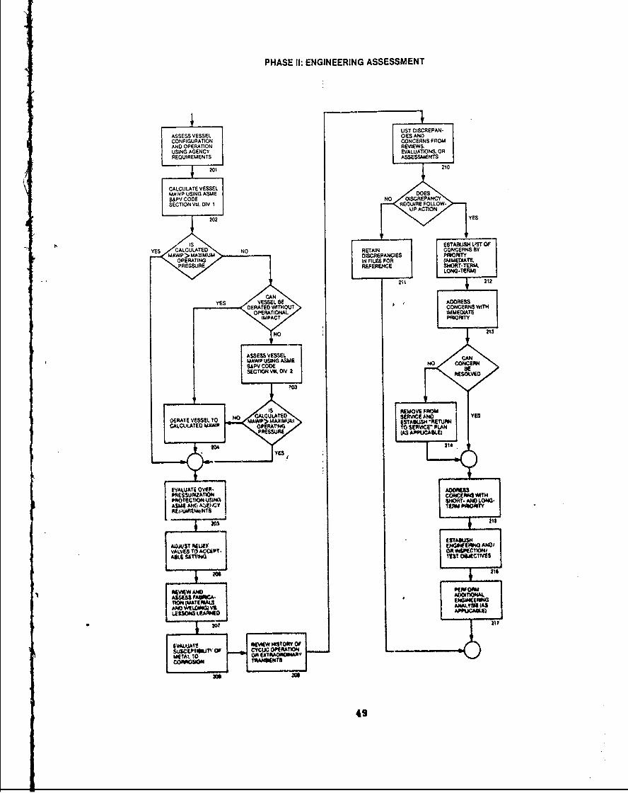
PHASE I1: ENGINEERING ASSESSMENT
LIST DISCREPAN-
ASSESS VESSEL CIES ANDCONFIGURATION CONCERNS FnOMANO OPERATION REVIEWS.USING AGENCY EVALUATIONS. ORREQUIREMENTS ASSESSMENTS
20121
CALCULATE VESSELMA',P USING ASME DE
NO RETAIN COICERNS BYYES CALC MULA N0,SCREPANCIES PRIORITY
OEAIGIN FILES FOR (IMEDIATE.
PESSURAE REERNC HOTNIEM
$IOFII LONG-TERM)
211 212
YES VESE BE ADDRESS I
•0ERATE0 WITHOUT CONCERNS WtTWOPERATIONAL/ IMME•DIATE
hEYAT W Q Vm t.:
440
I • no• t co~• Wno
m 214
RECERTIFICATION GUIDEACrIVITy
NMERlPHASE: I, Ilmpection/Testing Plan
ACTIVITY: Define Inspection and Testing Requirementsto Resolve Concerns
PURPOSE: To develop inspection/test requirements to confirm design parameters andresolve preliminary engineering or fabrication concerns.
DESCRIPTION: Inspection/test requirements included a basic group of inspections/teststo confirm design parameters and additional tests/inspections to resolve concerns.Optimizing information obtained from additional inspections/tests is necessary tominimize impact on facility operation. The more confidence the engineer has wth thereview of preliminary documentation and engineering analysis, the less inspections/testswould be required. Typical inspections include radiography, ultrasonics, magneticparticle, and liquid penetrant exams. Other specialized exams such as acousticemissions, eddy current, and leak testing may be prescribed on a case by case basis.Proof tests using hydrostatics or pneumatics should also be prescribed. If pneumaticsproof tests are used, additional care should be taken to assure safety of personnel andequipment.
STEPS WITHIN THE ACTIVITY:
1. Define extent of internal and/or external visual inspections.2. Define extent and location for ultrasonic thickness examinations.3. Define proof test pressure/temperature requirements and restrictions.4. Define extent and location for additional Inspection testing required to resolve
concerns (e.g. surface or volumetric exams).5. Develop acceptance criteria as appropriate to analysis and code/standard
requirements from previous activities.
MAJOR OBSTACLES: Operational constraints may limit access.
MAJOR DECISIONS: Selection of appropriate examinations and tests.
INPUT: List of discrepancies requiring follow up action.
OUTPUT: Inspection/test requirements.
RELATED AC,'IVnIT : 302
SAMPLE REPERENCES:1. ASME Boiler & Pressure Vessel Code, Section V and VIII, Divisions I and 2.2. National Board Inspection Code, ANSI/NB-233. Compressed Gas Association Standards C-6, "Standards for Visual Inspection of
Compressed Gas Cylinders;" G-5.1 and 5.2 on Gaseous and Liquid Hydrogen; andS-1.2 on Safety Relief Device Standards.
RECERTIFICATION GUIDE ACTIVITY
PHASE: 1I, hmpection/Testing Plan
ACTIVITY: CcAedt Field VerificAtion of Impectability
PURPOSE: To determine if required inspections/tests will require special or temporarymodifications to configuration or operation.
DESCRIPTION: Many pressure vessels were not manufactured to be inspected/testedafter installation, therefore special steps may be required to obtain results. Manypressure vessels were fabricated with: (1) attachments welded over full penetrationwelds, (2) attachments positioned which prevent easy access to welds, (3) nonremovableinsulation covering exterior or interior surfaces, (4) vessels located in close proximitywith other vessels or piping/components as to prevent access to surfaces, and (5) vesselslocated in restricted confinements such as small rooms or spill preventioncontainments. Many of these items may prevent resolution of concerns requiring thedevelopment of alternate approaches. Alternate approaches may include substitution ofone NDE technique for another, replacement of proof tests for NDE or substitution ofvolumnetrics for surface exams.
STEPS WITHIN THE ACTIVITY:
1. Walk down vessel with inspection/test requirements to determine (a) any accesslimitations, (b) operational limitations, (c) configuration limitations, (d) otherlimitations.
2. List recommendations on (a) alternate inspections/tests, (b) special or temporarymodifications.
MAJOR OBSTACLE& None
MAJOR DECSION& In-field assessment of alternatives or special requirements.
INPUT: Inspection/test requirements from Activity 301.
OUTPUT: Inspection/test requirements with recommendations on special or temporarymodifications.
RELATED ACTIVfTE: 301
SAMPLE REFBRENCES: None
52
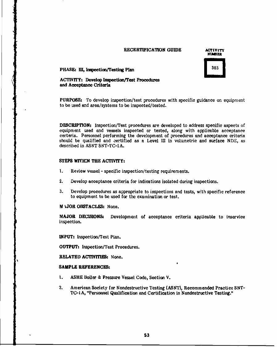
RECERTIFICATION GUIDE ACrIIVTYNUMORR
PHASE: II, Inspection/Testing Plan
ACTIVITY: Develop Inspection/Test Proceduresand Acceptance Criteria
PURPOSE: To develop inspection/test procedures with specific guidance on equipmentto be used and area/systems to be inspected/tested.
DESCRIPTION: Inspection/Test procedures are developed to address specific aspects ofequipment used and vessels inspected or tested, along with applicable acceptancecerteria. Personnel performing the development of procedures and acceptance criteriashould be qualified and certified as a Level IlI in volumetric and surface NDE, asdescribed in ASNT SNT-TC-1A.
STEPS WITEHN THE ACTIVITY:
1. Review vessel - specific inspection/testing requirements.
2. Develop acceptance criteria for indications isolated during inspections.
3. Develop procedures as appropriate to inspections and tests, wth specific referenceto equipment to be used for the examination or test.
M WJOR OBSTACLES- None.
MAJOR DECISIONS: Development of acceptance criteria applicable to Inserviceinspection.
INPUT: Inspection/Test Plan.
OUTPUT: Inspection/Test Procedures.
RELATED ACTlVIvr=: None.
SAMPLE REFERENCES:
1. ASME Boiler & Pressure Vessel Code, Section V.
2. American Society for Nondestructive Testing (ASNT), Recommended Practice SNT-TC-l A, "Personnel Qualification and Certification in Nondestructive Testing."
53
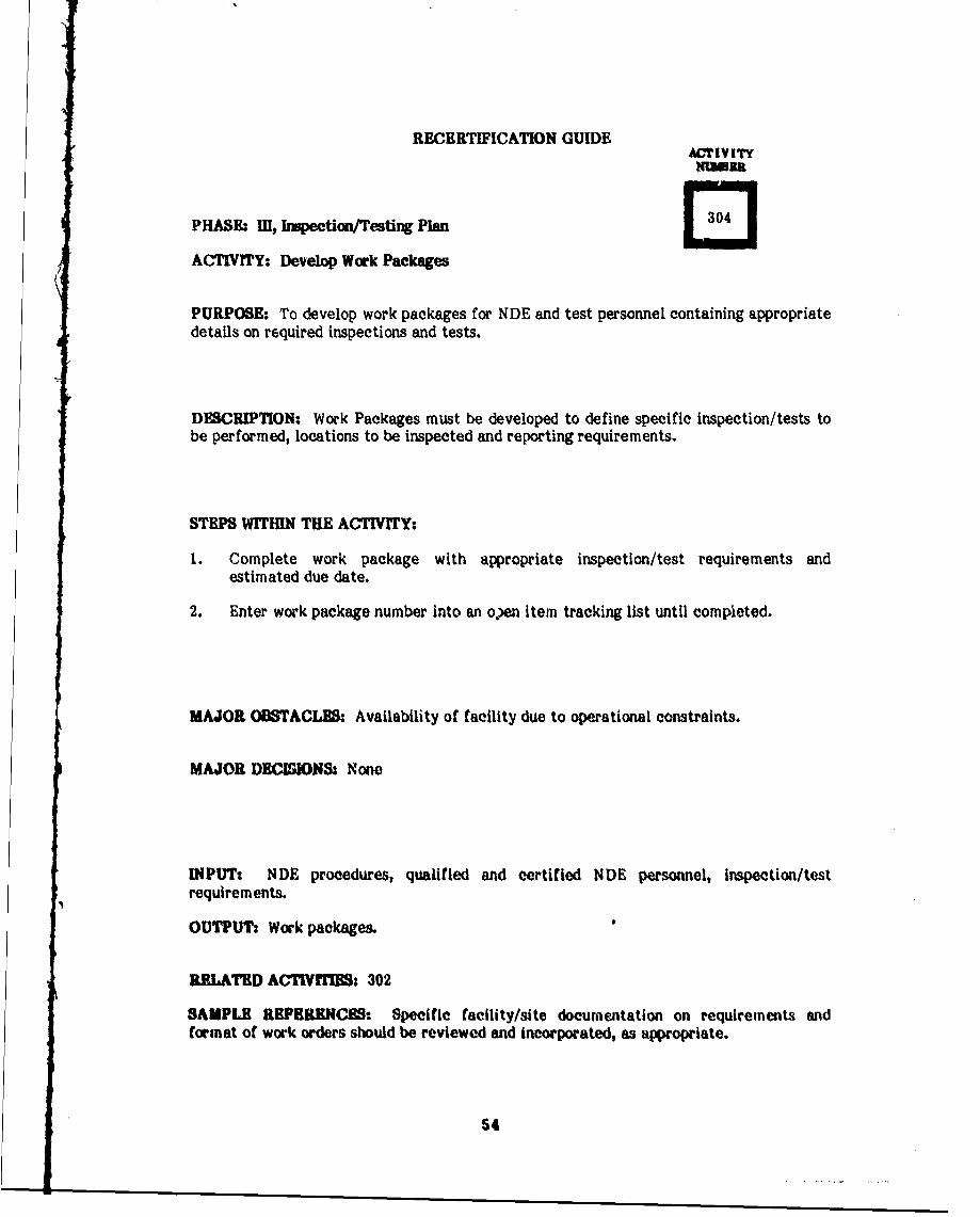
RECERTIFICATION GUIDEACTIVITY
PHASE: HI, Inspectio/Testing Plan JACTIVITY: Develop Work Packages
PURPOSE: To develop work packages for NDE and test personnel containing appropriatedetails on required inspections and tests.
DESCRIPTION: Work Packages must be developed to define specific inspection/tests tobe performed, locations to be inspected and reporting requirements.
STEPS WITHIN THE ACTIVITY:
1. Complete work package with appropriate inspection/test requirements andestimated due date.
2. Enter work package number into an o,)en item tracking list until completed.
MAJOR OBSTACLE& Availability of facility due to operational constraints.
MAJOR DECIMOK& None
INPUT: NDE procedures, qualified and certified NDE personnel, inspection/testrequirements.
OUTPUT: Work packages.
RELATED ACTIVfTI=: 302
SAMPLE RBPBRfENCE: Specific facility/site documentation on requirements andformat of work orders should be reviewed and incorporated, as appropriate.
54
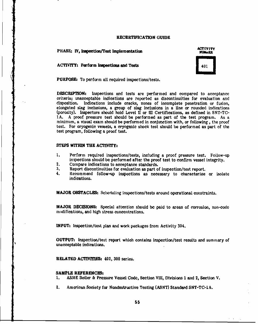
RECERTIFICATION GUIDE
hCrIV tTYPHASE: IV, Inspeetion/Test Implementation NtM.Bm
ACTIVITY: Perfrm Inspections and Tests QPURPOSE- To perform all required inspections/tests.
DESCRIPTION: Inspections and tests are performed and compared to acceptancecriteria; unacceptable indications are reported as discontinuities for evaluation anddisposition. Indications include cracks, zones of incomplete penetration or fusion,elongated slag inclusions, a group of slag inclusions in a line or rounded indications(porosity). Inspectors should hold Level II or III Certifications, as defined in SNT-TC-IA. A proof pressure test should be performed as part of the test program. As aminimum, a visual exam should be performed in conjunction with, or following, the prooftest. For cryogenic vessels, a cryogenic shock test should be performed as part of thetest program, following a proof test.
STEPS WITHIN THE ACTIVITY:
1. Perform required inspections/tests, including a proof pressure test. Follow-upinspections should be performed after the proof test to confirm vessel integrity.
2. Compare Indications to acceptance standards.3. Report discontinuities for evaluation as part of inspection/test report.4. Recommend follow-up inspections as necessary to characterize or isolate
indications.
MAJOR O&STACLES: Scheduling inspections/tests around operational constraints.
MAJOR DECISIONS- Special attention should be paid to areas of corrosion, non-codemodifications, and high stress concentrations.
INPUT: Inspection/test plan and work packages from Activity 304.
OUTPUT: Inspection/test report which contains inspection/test results and summary ofunacceptable indications.
RELATED ACTIVITIES: 402, 300 series.
SAMPLE REFERENCEt:1. ASME Boiler & Pressure Vessel Code, Section VIII, Divisions I and 2, Section V.
2. American Society for Nondestructive Testing (ASNT) Standard SNT-TC-l A.
55
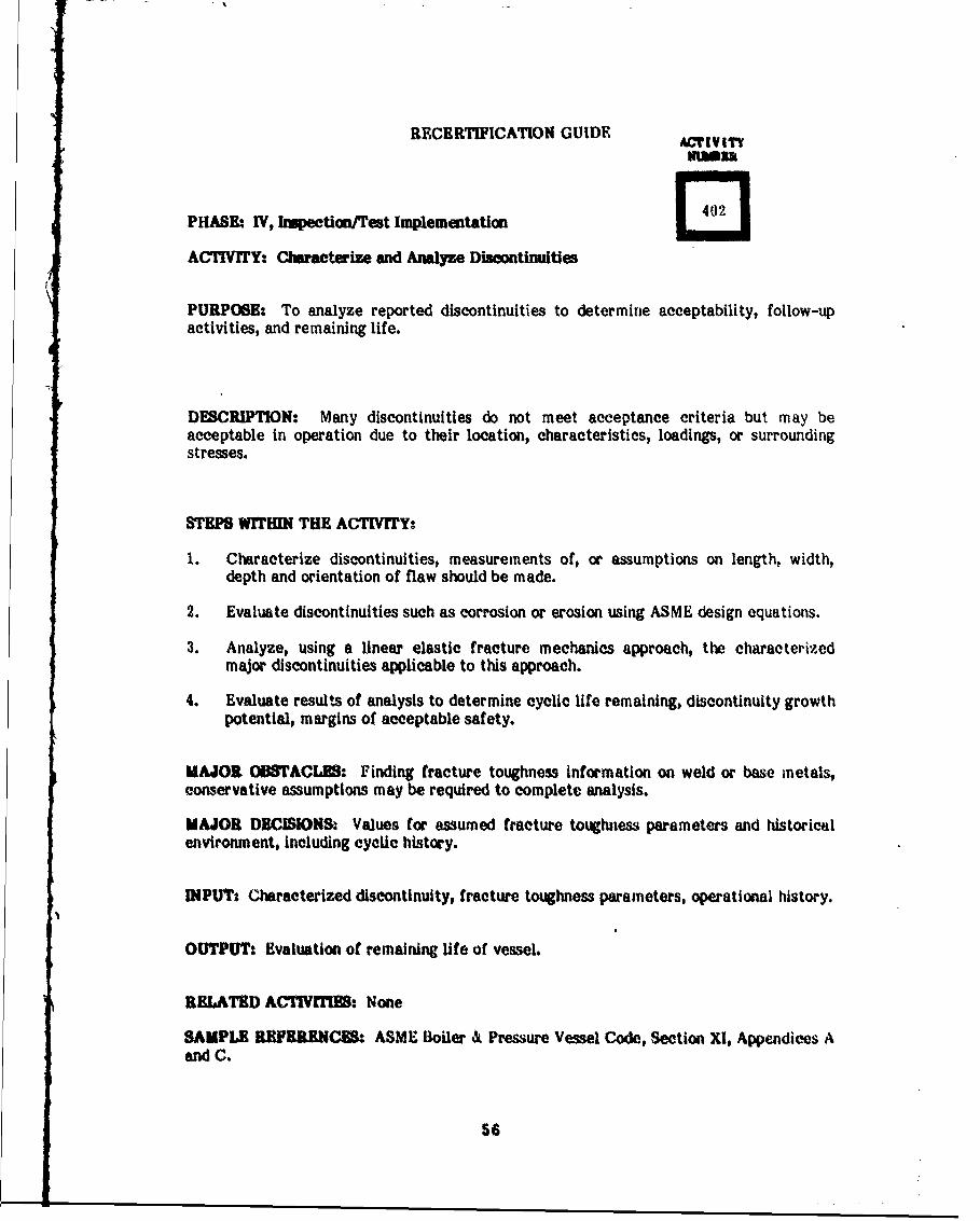
RECERTWFICATION GUIDEMen
PHASE: IV, Iweetion/Test Implementation
ACTIVITY: Chuaraterize and Analyze Disontinultes
PURPOSE: To analyze reported discontinuities to determine acceptability, follow-upactivities, and remaining life.
DESCRIPTION: Many discontinuities do not meet acceptance criteria but may beacceptable in operation due to their location, characteristics, loadings, or surroundingstresses.
STEPS WITHIN THE ACTIVITY:
1. Characterize discontinuities, measurements of, or assumptions on length, width,
depth and orientation of flaw should be made.
2. Evaluate discontinuities such as corrosion or erosion using ASME design equations.
3. Analyze, using a linear elastic fracture mechanics approach, the characterizedmajor discontinuities applicable to this approach.
4. Evaluate results of analysis to determine cyclic life remaining, discontinuity growthpotential, margins of acceptable safety.
MAJOR O68IACIS: Finding fracture toughness information on weld or base metals,conservative assumptions may be required to complete analysis.
MAJOR DECISWoN& Values for assumed fracture toughness parameters and historicalenvironment, including cyclic history.
INPUT: Characterized discontinuity, fracture toughness parameters, operational history.
OUTPUT: Evaluation of remaining life of vessel.
RELATED AC-WrlIf : None
SAMPLE REFERENCM: ASME Boiler & Pressure Vessel Code, Section XI, Appendices Aand C.
56
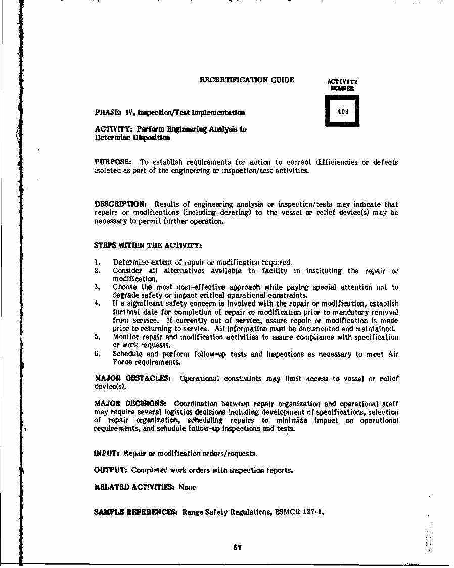
RECERTIFICATION GUIDE ACrIVITYmien
PHASE: IV, Inspection/Test Implementation 9ACTIVITY: Perform Engineering Analysis toDetermine Disposition
PURPOSE: To establish requirements for action to correct difficiencies or defectsisolated as part of the engineering or inspection/test activities.
DESCRIPTION: Results of engineering analysis or inspection/tests may indicate thatrepairs or modifications (including derating) to the vessel or relief device(s) may benecessary to permit further operation.
STEPS WITHIN THE ACTIVITY:
1. Determine extent of repair or modification required.2. Consider all alternatives available to facility in instituting the repair or
modification.3. Choose the most cost-effective approach while paying special attention not to
degrade safety or impact critical operational constraints.4. If a significant safety concern is involved with the repair or modification, establish
furthest date for completion of repair or modification prior to mandatory removalfrom service. If currently out of service, assure repair or modification is madeprior to returning to service. All information must be documented and maintained.
5. Monitor repair and modification activities to assure compliance with specificationor work requests.
6. Schedule and perform follow-up tests and inspections as necessary to meet AirForce requirements.
MAJOR OBSTACLES: Operational constraints may limit access to vessel or reliefdevice(s).
MAJOR DECISIONS Coordination between repair organization and operational staffmay require several logistics decisions including development of specifications, selectionof repair organization, scheduling repairs to minimize impact on operationalrequirements, and schedule follow-up inspections and tests.
INPUT: Itepair or modification orders/requests.
OUTPUT: Completed work orders with inspection reports.
RELATED AC`*!VrFiF: None
SAMPLE RBEFER CELC Range Safety Regulations, ESMCR 127-1.
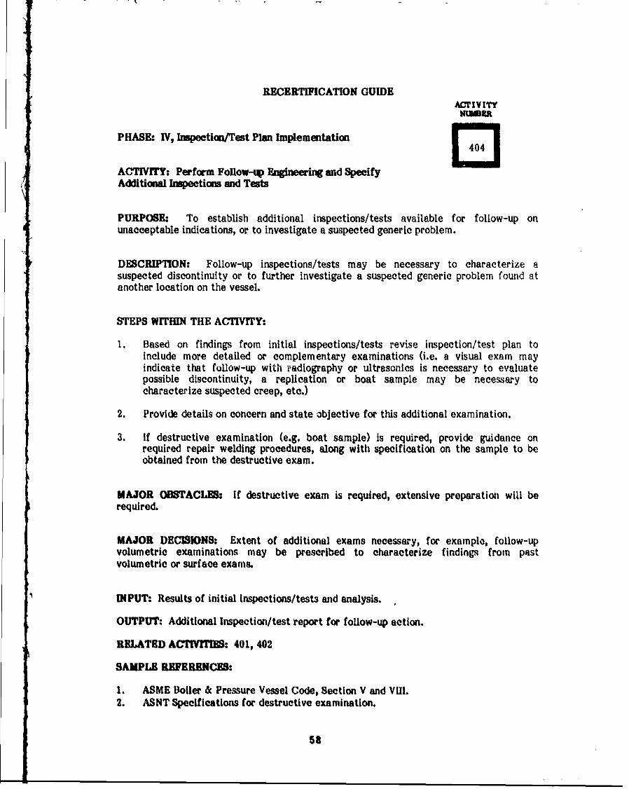
RECERTIFICATION GUIDEACrIVITY
PHASE: IV, Inspection/Test Plan Implementation [ JACTIVITY: Perform Follow-up Engineering and SpecifyAdditional Inspections and Tests
PURPOSE: To establish additional inspections/tests available for follow-up onunacceptable indications, or to investigate a suspected generic problem.
DESCRIPTION- Follow-up inspections/tests may be necessary to characterize asuspected discontinuity or to further investigate a suspected generic problem found atanother location on the vessel.
STEPS WITHIN THE ACTIVITY:
I. Based on findings from initial inspections/tests revise inspection/test plan toinclude more detailed or complementary examinations (i.e. a visual exam mayindicate that follow-up with radiography or ultrasonics is necessary to evaluatepossible discontinuity, a replication or boat sample may be necessary tocharacterize suspected creep, etc.)
2. Provide details on concern and state objective for this additional examination.
3. If destructive examination (e.g. boat sample) is required, provide guidance onrequired repair welding procedures, along with specification on the sample to beobtained from the destructive exam.
MAJOR OBSTACLE& If destructive exam is required, extensive preparation will berequired.
MAJOR DECISION8: Extent of additional exams necessary, for example, follow-upvolumetric examinations may be prescribed to characterize findings from pastvolumetric or surface exams.
INPUT: Results of initial inspections/tests and analysis.
OUTPUT: Additional Inspection/test report for follow-up action.
RELATED ACTIfrl=L: 401, 402
SAMPLE REFERRECBS:
1. ASME Boiler & Pressure Vessel Code, Section V and VIII.2. ASNT Specifications for destructive examination.
58
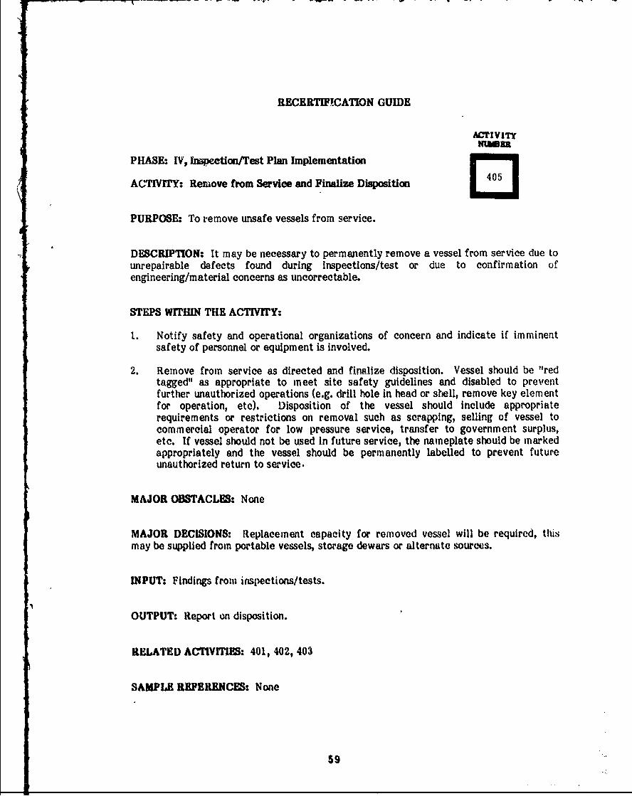
RECERTIFICATION GUIDE
Acriv lrrNtlMIMa
PHASE: IV, Inspection/Test Plan Implementation
A(CTIVITY: Remove from Service and Finalize Disposition
PURPOSE: To remove unsafe vessels from service.
DESCRIPTION: It may be necessary to permanently remove a vessel from service due tounrepairable defects found during inspections/test or due to confirmation ofengineering/material concerns as uncorrectable.
STEPS WITHIN THE ACTIVITY:
1. Notify safety and operational organizations of concern and indicate if imminentsafety of personnel or equipment is involved.
2. Remove from service as directed and finalize disposition. Vessel should be "redtagged" as appropriate to meet site safety guidelines and disabled to preventfurther unauthorized operations (e.g. drill hole in head or shell, remove key elementfor operation, etc). Disposition of the vessel should include appropriaterequirements or restrictions on removal such as scrapping, selling of vessel tocommercial operator for low pressure service, transfer to government surplus,etc. If vessel should not be used In future service, the nameplate should be markedappropriately and the vessel should be permanently labelled to prevent futureunauthorized return to service.
MAJOR OBSTACLES: None
MAJOR DECISIONS: Replacement capacity for removed vessel will be required, thismay be supplied from portable vessels, storage dewars or alternate sources.
INPUT: Findings from ins••ections/tests.
OUTPUT: Report on disposition.
RELATED ACTIVITIES: 401,402, 403
SAMPLE REFERENCE& None
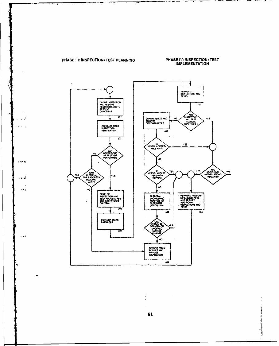
PHASE III: INSPECTION/TEST PLANNING PHASE IV: INSPECTION/TESTIMPLEMENTATION
pIeRiORWIINSPECTIONS ANDTESTS
DEFINE INSPECTIONAND TESTING 401REQUIREMENTS TORESOLVECONCERNS
301CHARACTERLZE AND NO A ES
• ' " 'ANALYE RESULTS
CONOUCT FIELD 0 ONTINUITS LCEPTABLE
VEFAFICATION
NO I•¢nSCTONS
Os TYES
CAN
YEOR TESTS SE
NO NO
C TAN tA| O E YSE ANANO ALCCEPW4, I ANA!.YS4 TO AN! SPCIFY
YESE~A ALITA- ,nuk , OO1TI
4 Tis A~oons RIPM"QAI
t~oc~it"A otytftalli nnIn
WOS!T106O SN
"673
ava~op wI0ACKAW CAu""j
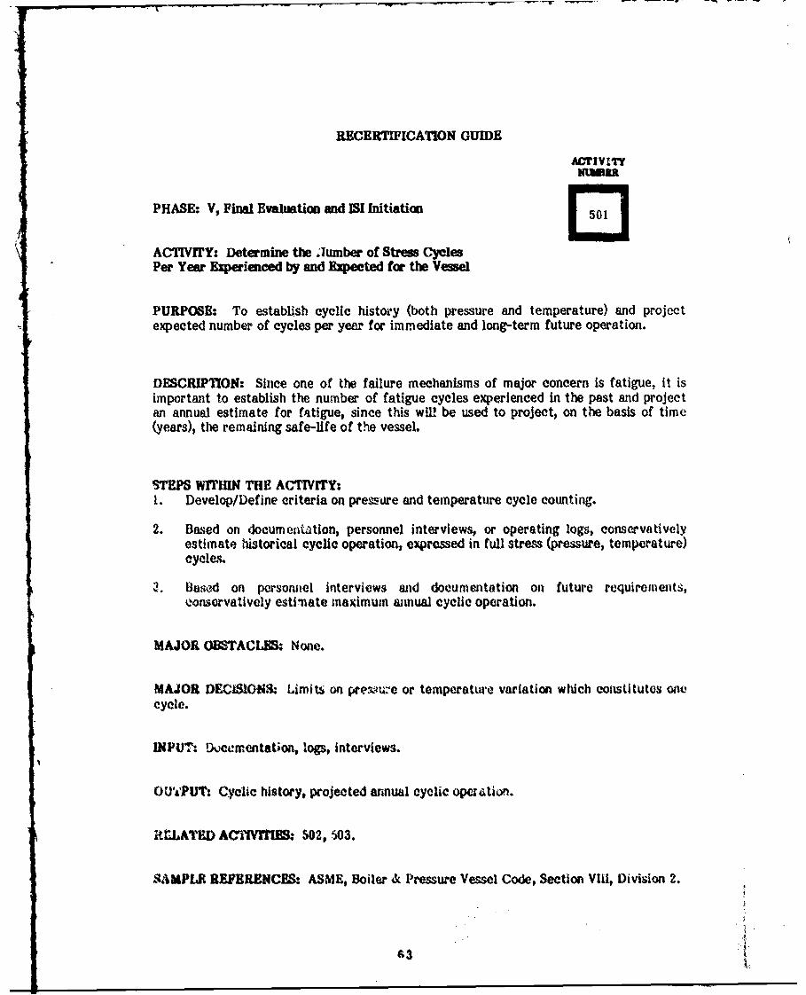
RECERTIFICATION GUIDEACrIVETY
PHASE: V, Final Evaluation and ISI Initiation
ACTIVITY: Determine the lumber of Stress CyclesPer Year Experienced by and Expected for the Vesel
PURPOSE: To establish cyclic history (both pressure and temperature) and projectexpected number of cycles per year for immediate and long-term future operation.
DESCRIPTION: Since one of the failure mechanisms of major concern is fatigue, it isimportant to establish the number of fatigue cycles experienced in the past and projectan annual estimate for fatigue, since this will be used to project, on the basis of time(years), the remaining safe-life of the vessel.
STEPS WITHIN THE ACTIVITY:I. Develop/Define criteria on premure and temperature cycle counting.
2. Based on documeniation, personnel Interviews, or operating logs, conservativelyestimate historical cyclic operation, expressed in full stress (pressure, temperature)cycles.
. hBased on persomiel interviews and documentation on future requirements,eonservatively estiiate maximum annual cyclic operation.
MAJOR OBSTACLES None.
MAJOR DECIGkONS Limits on pree•u-e or temperature variation which contistutes onecycle.
INPUT. Ducementation, lop, interviews.
OU'tPUT: Cyclic history, projected annual cyclic opetion.
IRELATED ACi'WVrT1ES 502, W03.
SAMPLR REFERENCES: ASME, Boiler & Pressure Vessel Code, Section VI11, Division 2.
•3 'I
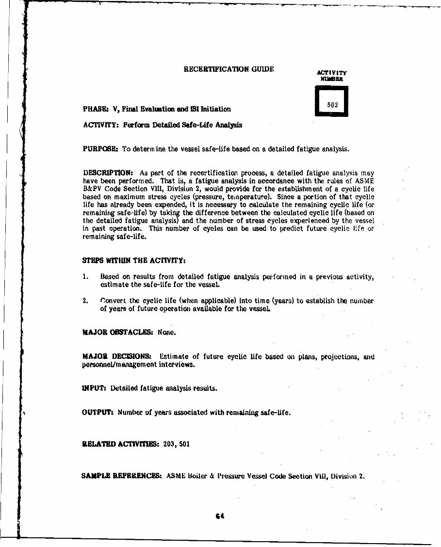
RECERTIFICATION GUIDE
PHAS& V, Final Evaluation and 1I8 Initiation [ACTIVITY: Perform Detailed Safe-Life Analysis
PURPOSE: To determine the vessel safe-life based on a detailed fatigue analysis.
DESCRIPTION: As part of the recertification process, a detailed fatigue analysis mayhave been performed. That is, a fatigue analysis in accordance with the rules of ASMEB&PV Code Section VIII, Division 2, would provide for the establishment of a cyclic lifebased on maximum stress cycles (pressure, teinperature). Since a portion of that cycliclife has already been expended, it is necessary to calculate the remaining cyclic life (orremaining safe-life) by taking the difference between the calculated cyclic life (based onthe detailed fatigue analysis) and the number of stress cycles experienced by the vesselin past operation. This number of cycles can be used to predict future cyclic life orremaining safe-life.
STEPS WITHIN THE ACnIVITY:
1. Based on results from detailed fatigue analysis performed in a previous activity,estimate the safe-life for the vessel
2. Convert the cyclic life (when applicable) into time (years) to establish the numberof years of future operation available for the vessel.
MAJOR OWI'ACLES& None.
MAJOR DEMIONS; Estimate of future cyclic, life based on plans, projectin4ns amdpersonnel/m anagement interviews.
INPUT: Detailed fatigue analysis results.
OUTPUT% Number of years associated with remaining safe-life.
RELATED ACTIVf=: 203, 501
SAMPLE RIUERENC(S: ASME Boiler & Ptrssure Vessel Code Section VWl, Divisimi 2.
64
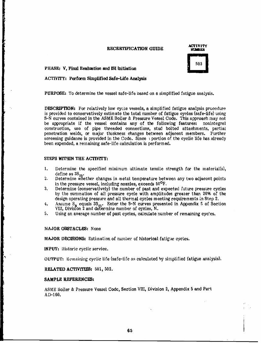
ACTIVITYRECERTIFICATION GUIDE imzMO
PHASE: V, Final Evaluation and ISI Initiation EACTIVITY: Perform Simplified Safe-Life Analysis
PURPOSE: To determine the vessel safe-life oased on a simplified fatigue analysis.
DESCRIPTION: For relatively low cycle vessels, a simplified fatigue analysis procedureis provided to conservatively estimate the total number of fatigue cycles (safe-life) usingS-N curves contained in the ASME Boiler & Pressure Vessel Code. This approach may notbe appropriate if the vessel contains any of the following features: nonintegralconstruction, use of pipe threaded connections, stud bolted attachments, partialpenetration welds, or major thickness changes between adjacent members. Furtherscreening guidance is provided in the Code. Since i portion of the cyclic life has alreadybeen expended, a remaining safe-life calculation is performed.
STEPS WITHIN THE ACTIVITY:
1. Determine the specified minimum ultimate tensile strength for the material(s),define as 3S_.
2. Determine w ether changes in metal temperature between any two adjacent pointsin the pressure vessel, including nozzles, exceeds 500 F.
3. Determine (conservatively) the number of past and expected future pressure cyclesby the summation of all pressure cycle with amplitudes greater than 20% of thedesign operating pressure and all thermal cycles meeting requirements in Step 2.
4. Assume S equals 3S3. Enter the S-N curves presented in Appendix 5 of SectionVIII, Divison 2 and determine number of cycles, N.
5. Using an average number of past cycles, calculate number of remaining cyeces.
MAJOR OBSTACLES: None
MAJOR DECISIONS: Estimation of number of historical fatipe cycles.
INPUT: lHistoric cyclic service.
OUTPUT: Remaining cyclic life (safe-life as calculated hy simplified fatigue analysis).
RELATED ACTIVITIES: 501, 502.
SAMPLE REFERENCES:
ASME Boiler & Pressure Vessel Code, Section VIII, Division 2, Appendix 5 mid PartAD-160.
65
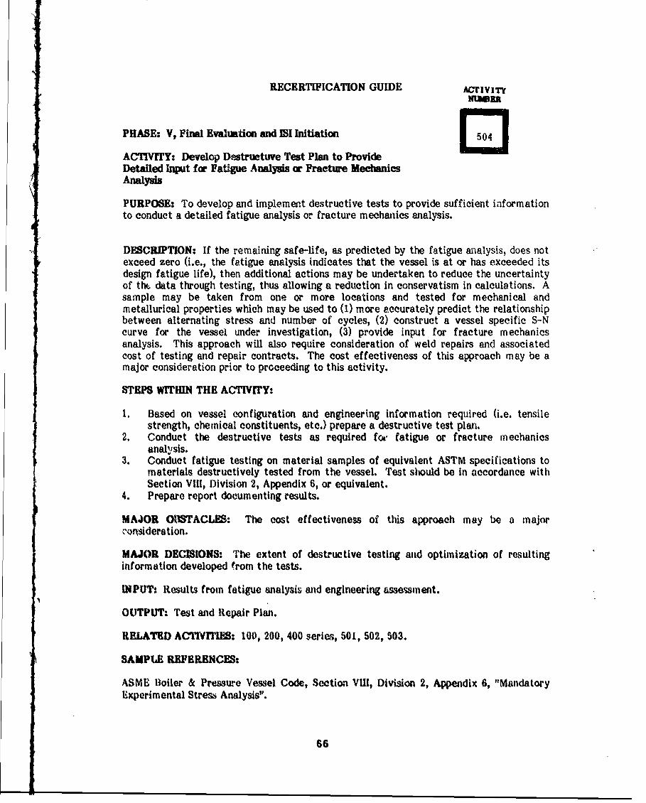
RECERTIFICATION GUIDE ACrI•ITY
PHASE: V, Final Evalumtion and SI Initiation 9ACTIVITY: Develop Destruetuve Test Plan to ProvideDetailed Input for Fatigue Analysis or Fracture MechanicsAnalydsi
PURPOSE: To develop and implement destructive tests to provide sufficient informationto conduct a detailed fatigue analysis or fracture mechanics analysis.
DESCRIPTION: If the remaining safe-life, as predicted by the fatigue analysis, does notexceed zero (i.e., the fatigue analysis indicates that the vessel is at or has exceeded itsdesign fatigue life), then additional actions may be undertaken to reduce the uncertaintyof tht data through testing, thus allowing a reduction in conservatism in calculations. Asample may be taken from one or more locations and tested for mechanical andmetallurical properties which may be used to (1) more accurately predict the relationshipbetween alternating stress and number of cycles, (2) construct a vessel specific S-Ncurve for the vessel under investigation, (3) provide input for fracture mechanicsanalysis. This approach will also require consideration of weld repairs and associatedcost of testing and repair contracts. The cost effectiveness of this approach may be amajor consideration prior to proceeding to this activity.
STEPS WITHIN THE ACTIVITY:
1. Based on vessel configuration and engineering information required (i.e. tensilestrength, chemical constituents, etc.) prepare a destructive test plan.
2. Conduct the destructive tests as required for fatigue or fracture mechanicsanalysis.
3. Conduct fatigue testing on material samples of equivalent ASTM specifications tomaterials destructively tested from the vessel. Test should be In accordance withSection VIII, Division 2, Appendix 6, or equivalent.
4. Prepare report documenting results.
MAJOR OtWTACLS: The cost effectiveness of this approach may be a major-'Qnsideration,
MAJOR DECISIONS: The extent of destructive testing and optimization of resultinginformation developed from the tests.
INPUT: Results from fatigue analysis and engineering assessment.
OUTPUT: Test and Repair Plan.
RELATED ACTIVITIB& 100, 200, 400 series, 501, 502, 503.
SAMPLE REFERENCE&:
ASME Boiler & Pressure Vessel Code, Section VIII, Division 2, Appendix 6, "MandatoryExperimental Stress Analysis".
66
RECERTIFICATION GUIDE ArVITY"'-MER
PHASE: V, Final Evaluation and ISI Initiation QACTIVITY: Perform Detailed Fatigue Analysis orFracture Mechanics Analysis and Safe-Life Analysis
PURPOSE: To perform a fatigue analysis or fracture mechanics analysis based on resultsof destructive tests, fatigue (cyclic loading) teLts, or proof pressure test.
DESCRIPTION: The data developed as part of the destructive testing is used to developvessel (material) specific S-N curves or are used in conjunction with curves in SectionVIII, Division 2, Appendix 5. The approach is similar to that presented in Activity 502.As an alternative, a fracture mechanics analysis may be performed using the results ofthe proof pressure test as the basis of an analysis of remaining cyclic life.
STEPS WITHIN THE ACTIVITY:
t. Using minimum ultimate tensile strength and chemical constituents, determineASTM specification, and using S-N curves of Appendix 5, determine fatigue life andremaining safe-life (as determined from fatigue analysis).
2. If strain and cyclic measurements were made as part of destructive test program,develop stress range versus number of cycle graph for the vessel material assuminga 2:1 reduction factor on strain range or 20:1 on mean number of cycles to failure,whichever gives the lower trend. Determine the design fatigue life.
3. Using results of proof pressure test (i.e. the percent of overpressure), a fracturemechanics analysis may be performed as an alternative to the fatigue analysis toestimate remaining cyclic life.
4. Calculate the remaining safe-life based on fatigue analysis or fracture mechanicsanalysis.
MAJOR OBSTACLES: If fracture mechanics approach is used, material properties.
MAJOR DECISIONS: None
INPUT: Data from destructive testing.
OUTPUT: Renai ning safe-life.
RELATED ACTIVITIES: 504.
SAMPLE REFERENCES:
Manson, S.S., "Fatigue: A Complex Subject-Some Simple Approximations," E xperiinentailMechan.cs VoL 5, No. 7, pp. 193-226, July, 1965.
67
ACrVITY
RECERTIFICATION GUIDE
PHASE: V, Final Evaluation and II Initiation
ACTIVITY: Perfirm Engineering Analysis toDetermine Disposition
PURPOSE: To evaluate ontions available for vessel operation if, under currentconditions, vessel exceeds design fatigue life.
DESCRIPTION: Following detailed testing and additional fatigue analysis, a vessel maycontinue to indicate a current cyclic life In excess of desigpn fatigue life. Determinationof operation at reduced safety factors, with operational constraints, or combinations ofthe two, may be appropriate. In addition, operation at lower stress levels (i.e., lowerMAWP) may be applicable to extend fatigue life. All of these options should beconsidered and evaluated.
STEPS WITHIN THE ACTIVITY:I. Consider alternatives to removal from service (i.e., reduction of safety factors with
operational constraints, reduced MAWP, etc.)
2. Evaluate operational requirements and alternatives.
3. Based on previous steps, estimate cost of alternatives with consideration of thefollowing:
a. A reduction of safety factor to 3:1 or below may require facilitymodification to establish safe distances between vessel and personnel orequipment, or erection of barriers based on energy release calculationassuming vessel failure.
b. A reduction in MAWP may not meet operational requirements for pressure orstorage volume and thus require addition of capacity through procurement ofstationary vessels or mobile storage vessels.
C. Operational constraints may unacceptably impact facility schedules orvehicle/laboratory requirements and musL be addressed from cost ofoperational changes, schedule adjustments, or other consideration.
4. Recommendations should be established based on safety, cost, schedule andoperational constraints for review by safety and management personneL
MAJOR OBSTACLES: Rteduced safety factors may not be allowed by operations orsafety representatives.
MAJOR DECISIONS: Establishment of recommendations by priority for review andevaluation by management.
INPUT: Engineering analysis and testing resulLs.
OUTPUT: Disposition options,
RELATED ACTIVITI•S: 200 series, 501, 504, 505.
SAMPLE REPERENCESt Site/facility policy documents.
68
RECERTIFICATION GUIDE AMrIVITY
PHASE: V, Final Evaluation and ISI Initiation. QACTIVITY: Remove from Service and Finalize Disposition
PURPOSE: To remove unsafe vessels from service.
DESCRIPTION: It may be necessary to permanently remove a vessel from service due tounrepairable defects found during inspections/test or due to confirmation ofengineering/material concerns as uncorrectable.
STEPS WITHIN THE ACTIVITY:
1. Notify safety and operational organizations of concern and indicate if imminentsafety of personnel or equipment is involved.
2. Remove from service as directed and finalize disposition. Vessel should be "redtagged" as appropriate to meet site safety guidelines and disabled to preventfurther unauthorized operations (e.g. drill hole in head or shell, remove key elementfor operation, etc.). Disposition of the vessel should include appropriaterequirements or restrictions on removal such as scrapping, selling of vessel tocommercial operator for low pressure service, transfer to government surplus,etc. If vessel should not be used in future service, the nameplate should be markedappr priaieiy and the ",.qel should be permanently labelled to prevent futureuiauthorized return to service.
MA)OR OBSTACLXS: None.
MAJOR DECISIONS: ReplaceineNt capacity for removed vessel will be required, thisimay be supplied from portable vessels, storage dewars or alternate sources.
INPUT: Findings from inspections/tests.
OUTPUT: Report on disposition.
RELATEG ACTIVrIIES: 405, 506.
SAMPLE REFERENCES: None.
69
RECERTIFICATION GUIWEACTIVITY
PHASE: V, Final Evaluation and II Initiation
ACTIVITY: Derate Vessel to MOP +10% and AdJustRelief Valves.
PURPOSE: To establish a MAWP consistent with MOP requirements for the operatingfacility.
DESCRIPTION: If the remaining safe-life is determined to be less than required, thestress levels in the vessel may be reduced, thus reducing the maximum alternating stress(from S-N curves) and therefore providing the possibility for extended fatigue life. Thisis also true for safe-life as determined by other failure mechanisms Including corrosionand creep. The maximum increase in life is associated with reducing MAWP to MOP plusa margin to allow for variability in relief device setting. An average value of 10% waschosen, however, the investigator may adjust this to actual available information.
STEPS WITHIN THE ACTIVITY:
1. Determine MOP.
2. Establish margin between MOP and MAWP.
3. Establish derated MAWP at MOP + margin, 10% can be used in initial calculationsto determine extended life.
4. Derate vessel to new MAWP and adjust relief valves at no higher than MAWP.
MAJOR OBSTACLES: None.
MAJOR DECISIONS: Maximum Operating Pressure requirements for facility.
INPUT: MOP.
OUTPUT: MAWP.
RELATED ACTIVrI'ES: 506.
SAMPLE REFERENCES: None.
T0
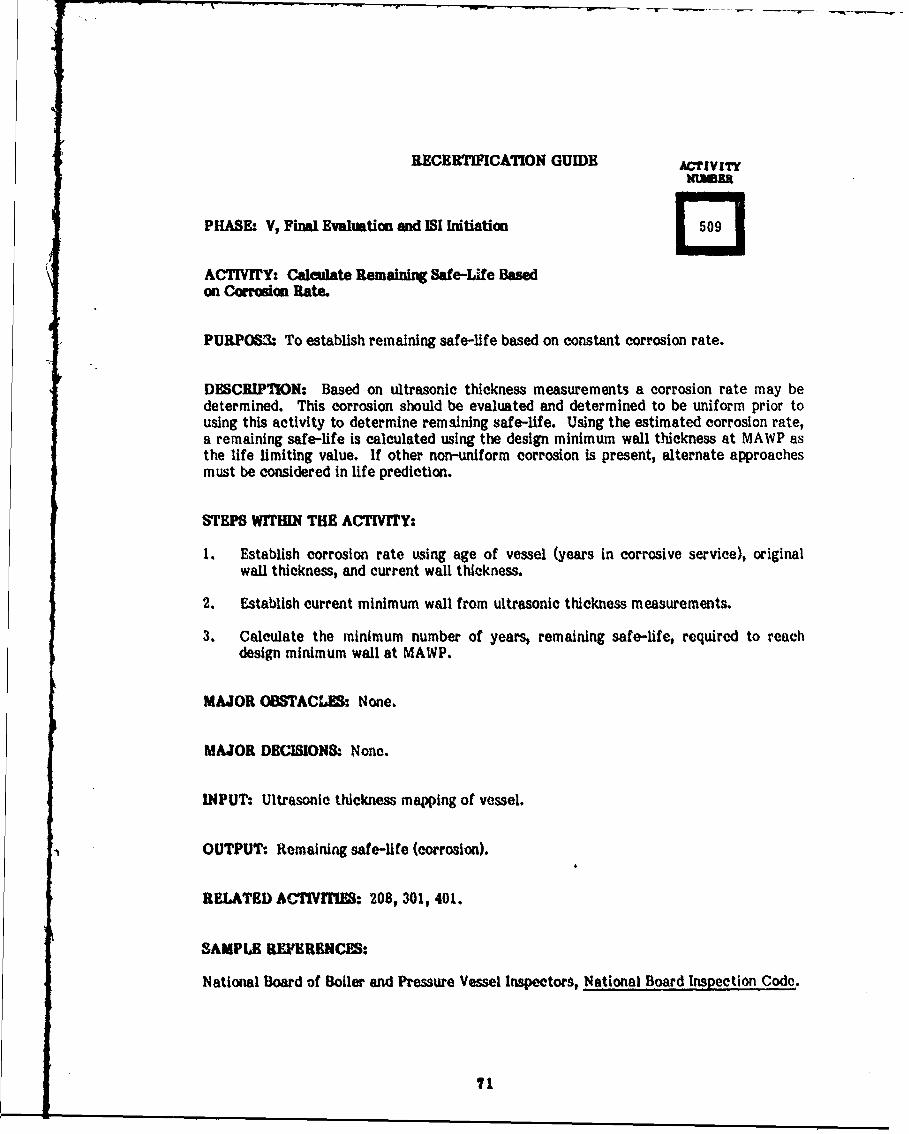
RECERTIFICATION GUIDE AzV'rITY
PHASE: V, Final Evaluation and 15I Initiation QACTIVITY: Calculate Remaining Safe-Life Basedon Corrosion Rate.
PURPOS3: To establish remaining safe-life based on constant corrosion rate.
DESCRIPTION: Based on ultrasonic thickness measurements a corrosion rate may bedetermined. This corrosion should be evaluated and determined to be uniform prior tousing this activity to determine remaining safe-life. Using the estimated corrosion rate,a remaining safe-life is calculated using the design minimum wall thickness at MAWP asthe life limiting value. If other non-uniform corrosion is present, alternate approachesmust be considered in life prediction.
STEPS WITHIN THE ACTIVITY:
1. Establish corrosion rate using age of vessel (years in corrosive service), originalwall thickness, and current wall thickness.
2. Establish current minimum wall from ultrasonic thickness measurements,
3. Calculate the minimum number of years, remaining safe-life, required to reachdesign minimum wall at MAWP.
MAJOR OBSTACLES: None.
MAJOR DECISIONS& None.
INPUT: Ultrasonic thickness mapping of vessel.
OUTPUT: Remaining safe-life (corrosion).
RELATED ACTIVITIES: 208, 301, 401.
SAMPLE REFERENCES:
National Board of Boiler and Pressure Vessel Inspectors, National Board Inspection Code.
71
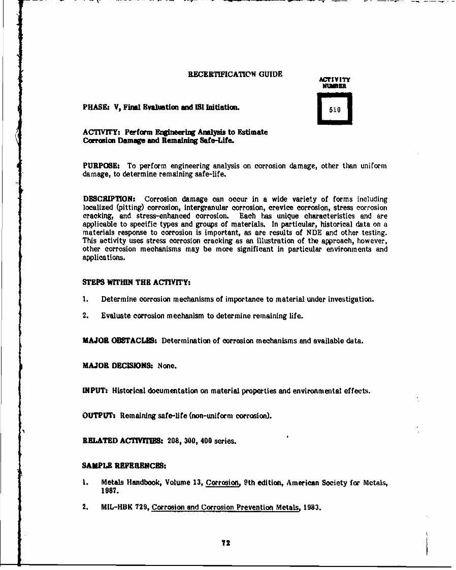
RECERTIFICATION GUIDE A*CiVITY
PHASE: V, Final Evaluation and ISI Initiation.
ACTIVrFY: Perform Engineering Analysis to EstimateCorrosion Damage and Remaining Safe-Life.
PURPOSE: To perform engineering analysis on corrosion damage, other than uniformdamage, to determine remaining safe-life.
DBSCRIPTION: Corrosion damage can occur in a wide variety of forms includinglocalized (pitting) corrosion, intergranular corrosion, crevice corrosion, stress corrosioncracking, and stress-enhanced corrosion. Each has unique characteristics and areapplicable to specific types and groups of materials. In particular, historical data on amaterials response to corrosion is important, as are results of NDE and other testing.This activity uses stress corrosion cracking as an illustration of the approach, however,other corrosion mechanisms may be more significant in particular environments andapplications.
STEPS WITHIN THE ACTIVITY:
1. Determine corrosion mechanisms of importance to material under investigation.
2. Evaluate corrosion mechanism to determine remaining life.
MAJOR OBSTACLES: Determination of corrosion mechanisms and available data.
MAJOR DECISIONS: None.
INPUT: Historical documentation on material properties and environmental effects.
OUTPUT: Remaining safe-life (non-uniform corrosion).
RELATED ACTW&M• 208, 300, 400 series.
SAMPLE REFRIUINCEm:
1. Metals Handbook, Volume 13, Corrosion, 9th edition, American Society for Metals,1987.
2. MIL-HBK 729, Corrosion and Corrosion Prevention Metals, 1983.
T2
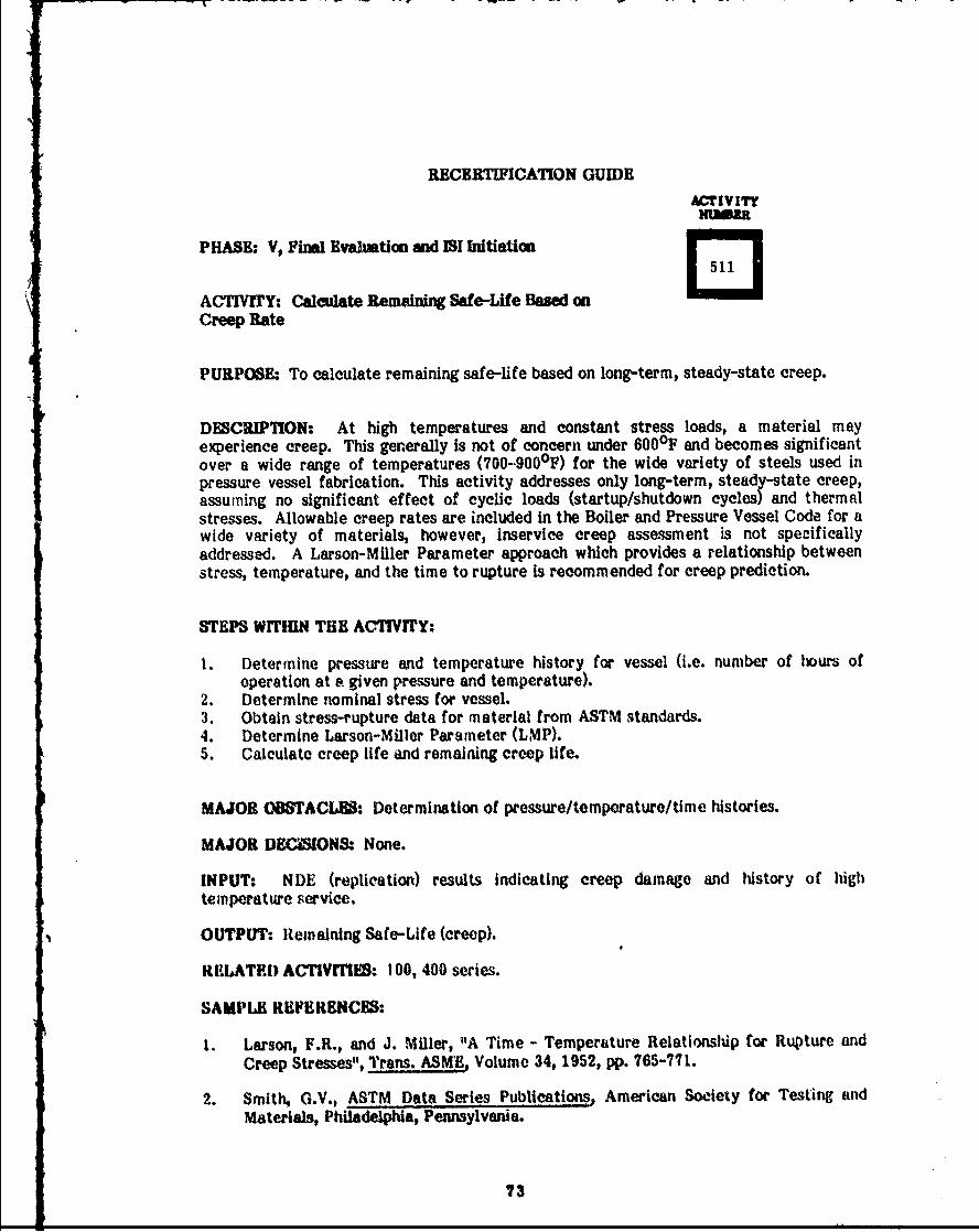
RECERTIFICATION GUIDE
ACTIVITY
PHASE: V, Final Evalatlmon and !IS Initiation
ACTIVITY: Calculate Remaining Safe-Life Based onCreep Rate
PURPOSE: To calculate remaining safe-life based on long-term, steady-state creep.
DESCRIPTION: At high temperatures and constant stress loads, a material mayexperience creep. This generally is not of concern under 600°F and becomes significantover a wide range of temperatures (700-.900 0F) for the wide variety of steels used inpressure vessel fabrication. This activity addresses only long-term, steady-state creep,assuming no significant effect of cyclic loads (startup/shutdown cycles) and thermalstresses. Allowable creep rates are included in the Boiler and Pressure Vessel Code for awide variety of materials, however, inservice creep assessment is not spezificallyaddressed. A Larson-Miller Parameter approach which provides a relationship betweenstress, temperature, and the time to rupture is recommended for creep prediction.
STEPS WITHIN THE ACTIVITY:
I. Determine pressure and temperature history for vessel (i.e. number of hours ofoperation at a given pressure and temperature).
2. Determine nominal stress for vessel.3. Obtain stress-rupture data for material from ASTM standards.4. Determine Larson-Miller Parameter (LMP).5. Calculate creep life and remaining creep life.
MAJOR OBSTACLiI Determination of pressure/temperature/time histories.
MAJOR DECISIONS: None.
INPUT: NDE (replication) results indicating creep damage and history of hightemperature service.
OUTPUT: Remaining Safe-Life (creep).
RELATEI) AC ITiSm : 100, 400 series.
SAMPLE REFERENCES:
I. Larson, F.R., and J. Miller, "A Time - Temperature Relationship for Rupture andCreep Stresses", Trans. ASMN, Volume 34, 1952, pp. 765-771.
2. Smith, G.V., ASTM Data Series Publications. American Society for Testing andMaterials, PhUadelphia,-Pennsylvania.
73
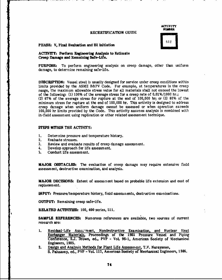
ACrIVITY
RECERTIFICATION GUIDE
PHASE: V, Final Evaluation and ISI Initiation
ACTIVITY: Perform Engineering Analysis to EstimateCreep Damage and Remaining Safe-Life.
PURPOSE: To perform engineering analysis on creep damage, other than uniformdamage, to determine remaining safe-life.
DESCRIPTION: Vessel steel is usually designed for service under creep conditions withinlimits provided by the ASME B&PV Code. For example, at temperatures in the creeprange, the maximum allowable stress value for all materials shall not exceed the lowestof the following: (1) 100% of the average stress for a creep rate of 0.01%/1000 hr.;(2) 67% of the average stress for rupture at the end of 100,000 hr; or (3) 80% of theminimum stress for rupture at the end of 100,000 hr. This activity is designed to addresscreep damage when uniform damage cannot be assessed or when operation exceeds100,000 hr limits provided by the Code. This activity assumes analysis is combined within-field assessment using replication or other related assessment technique.
STEPS WITHIN THE ACTIVITY:
1. Determine pressure and temperature history.2. Evaluate stresses.3. Review and evaluate results of creep damage assessment.4. Develop approach for life assessment.5. Conduct life assessment.
MAJOR OU3TACLES: The evaluation of creep damage may require extensive fieldassessment, destructive examination, and analysis.
MAJOR DECISMWN& Extent of assessnent based on probable life extension mnd cost of
replacement.
INPUT: Pressure/temperature history, field assessments, destructive examinations.
OUTPUTs Remaining creep safe-life.
RELATED ACTWITIM- 100, 400 series, 511.
SAMPLE REFERENCM: Numerous references are available, two sources of currentresearch are:
1. Residual-Life Assesyment, Nondestrwctive Examination, and Nuclear HeatExchanger Materials Proceedings of the 1985 Pressure Vessel and PipingConferenee, S.J. Brown, ed., PVP - Vol. 98-1, American Soolety of MechanicalEngineers, 1985.
2. Desig and Analysis Methods for Plant Life Assessment, T.V. Narayanan,S. Palusamy, ed., PVP - Vol. 112, American Society of Mechanical Engineers, 1986.
74

RECERTIFICATION GUIDEACTIVITY
PHASE: V, Final Evaluation and ISI Initiation QACTIVITY: Calculate Safe-Life Based on AdditionalFailure Mode
PURPOSE: To assess remaining safe-life if an additional unaddressed failure mode existswhich may control remaining life.
DESCRIPTION: If a failure mode likely to control the remaining life was not included inthe assessment of fatigue; corrosion; or creep life, then a separate assessment isnecessary. This may be associated with erosion, mechanical shock, unusual loadings orconfigurations, or other unaddressed mechanisms. The evaluation of erosion is similar innature to that of uniform corrosion in that detection and monitoring is associated withwail thickness measurements or internal visual examinations and prediction is associatedwith the estimation of past history. Other failure mechanisms such as shock or unusualor non-routine loadings are more difficult to historically evaluate or estimate futureimpact. This activity must be applied on a case-by-case basis and is typically used whenfailures have occurred in the vessel under consideration, or a similar vessel of similarrmaterial properties or configuration.
STEPS WITHIN THE ACTIVrTY:
1. From previous reviews and analysis, determine whether an unaddressed failuremechanism which may control safe-life exists.
2. Assess impact on remaining safe-life.
3. DOtermnine remaining safe-life.
MAJOR OWffACLES: Obtaining sufficient documentation amd data to perform analysis,.
MAJOR DECl81ONS& None.
INPUT: Concerns from previous activities.
OUTPUT: Remaining safe-life for additiotal failure mode.
REILATlD ACTIviES: 100, 200, and 500 series.
SAMPLE REFEfEENC•: None.
75
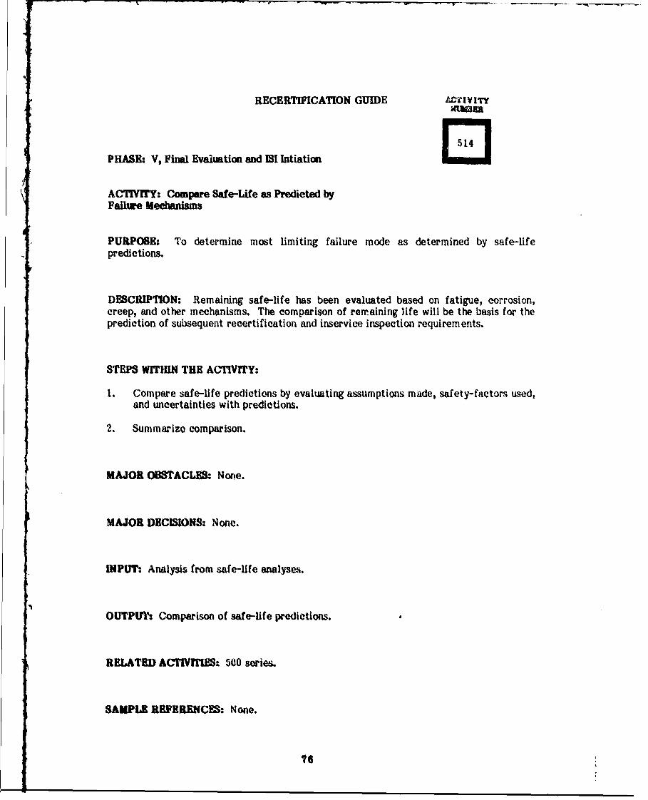
RECERTIFICATION GUIDE A-C'IV ITY
PHASE: V, Final Evaluation and 181 Intiation E 1ACTIVITY: Compare Safe-Life as Predicted byFailure Mechanisms
PURPOSE: To determine most limiting failure mode as determined by safe-lifepredictions.
DESCRIPTION: Remaining safe-life has been evaluated based on fatigue, corrosion,creep, and other mechanisms. The comparison of remaining life will be the basis for theprediction of subsequent recertification and inservice inspection requirements.
STEPS WITHIN THE ACTIVITY:
1. Compare safe-life predictions by evaluating assumptions made, safety-factors used,and uncertainties with predictions.
2. Summarize comparison.
MAJOR OBSTACLE& None.
MAJOR DECISION& None.
INPITI Analysis from safe-life analyses.
OUTPUT': Comparison of safe-life predictions.
RELATED ACI[VITIEk 500 series.
SAMPLE REFERENCES: None.
'16
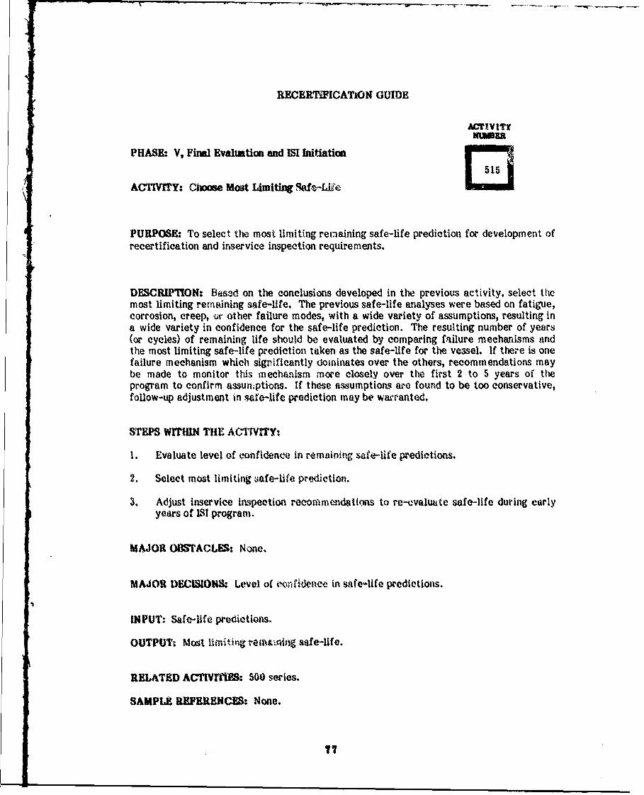
RECERTiFICATION GUIDE
AMcrVITY
PHASE V, Final Evaluation and ISI Initiation
ACTIVITY: Choose Most Limiting S.Waf0-Liie 0PURPOSE: To select the most limiting remaining safe-life prediction for development ofrecertification and inservice inspection requirements.
DESCRIPTION: Based on the conclusions developed in the previous activity, select themost limiting remaining safe-life. The previous safe-life analyses were based on fatigue,corrosion, creep, -ur other failure modes, with a wide variety of assumptions, resulting ina wide variety in confidence for the safe-life prediction. The resulting number of years(or cycles) of remaining life should be evaluated by comparing failure mechanisms andthe most limiting safe-life prediction taken as the safe-life for the vessel. If there is onefailure mechanism which sigrificantly dominates over the others, recommendations maybe made to monitor this mechanism more closely over the first 2 to 5 years of theprogram to confirm assumptions. If these assumptions are found to be too conservative,follow-up adjustment in safe-life prediction may be warranted.
STEPS WITHIN THE AC'iWrITY:
1. Evaluate level of confidence in remaining safe-life predictions.
2. Select most limiting tafe-life prediction.
3. Adjust inservice imspection recommendatit:ns to re-evaluate safe-life during earlyyears of ISW program.
MAJOR OBSTACLES: None.
MAJOR DWLSION& Level of tinfiewe in wife-life predictions.
INPUT: Safe-life predictions.OUTPUT• Mas. ib~dtg teiu~. aafe-life.
RELATED ACTIVITIES: 500 series.
SAMPLE REFPRENCES: None.
1/7
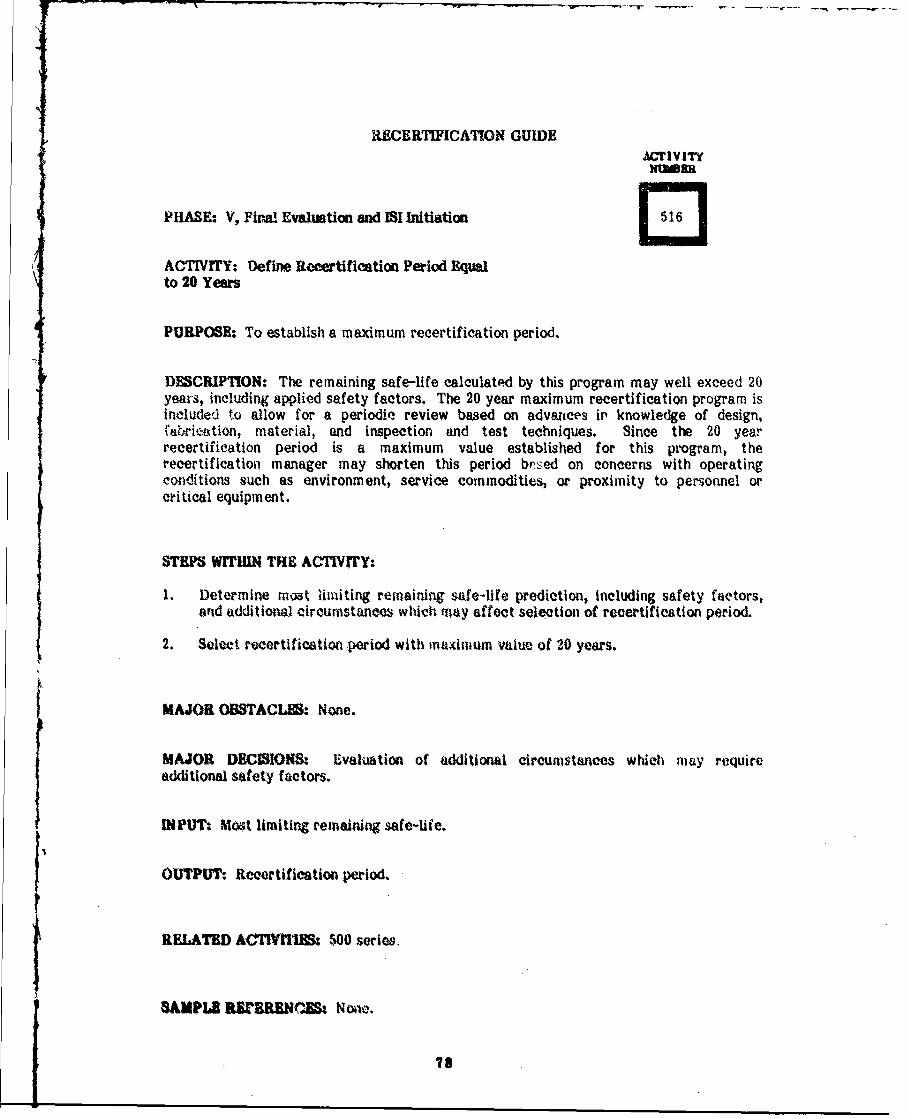
REICERTIFICATION GUIDEAcriv ITY
PHASE: V, Firns Evaluation and ISI Initiation E JACTIVITY: Define Recertification Period Equalto 20 Years
PURPOSE: To establish a maximum recertification period.
DESCRIPTION: The remaining safe-life calculated by this program may well exceed 20years, including applied safety factors. The 20 year maximum recertification program isincluded to allow for a periodic review based on advances ip knowledge of design,f'abriation, material, and inspection and test techniques. Since the 20 yearrecertification period is a maximum value established for this program, therecertifieation manager may shorten this period brsed on concerns with operatingconditions such as environment, service commodities, or proximity to personnel oreritieal equipment.
STEPS WITHIN TfHE ACTIVITY:
1. Determine mot limiting remaining safe-life prediction, including safety factors,and additional circumstances which may affect selection of recertification period.
2. Select recertification period with maximum value of 20 years.
MAJOR OBSTACLES: None.
MAJOR DECISION& Evaluation of additional circumstances which may requireadditional safety factors.
INPUT- MNot limiting remaining safe-life.
OUTPUT: Recertification period.
RELATED ACflVflg& 500 series.
SAMPL• RW- R ,mfm None.
78
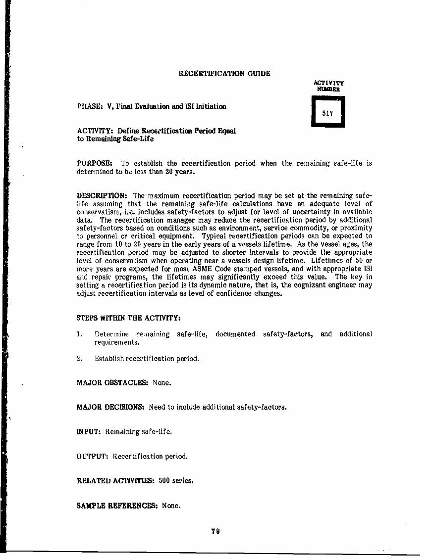
RECERTIFICATION GUIDEACTIVITY
PHASE: V, Final Evaluation and 1SI Initiation
ACTIVITY: Define Recertification Period Equalto Remaining Safe-Life
PURPOSE: To establish the recertification period when the remaining safe-life isdetermined to be less than 20 years.
DESCRIPTION: The maximum recertification period may be set at the remaining safe-life assuming that the remaining safe-life calculations have an adequate level ofconservatism, i.e. includes safety-factors to adjust for level of uncertainty in availabledata. The recertification manager may reduce the recertification period by additionalsafety-factors based on conditions such as environment, service commodity, or proximityto personnel or critical equipment. Typical recertification periods can be expected torange from 10 to 20 years in the early years of a vessels lifetime. As the vessel ages, therecertification period may be adjusted to shorter intervals to provide the appropriatelevel of conservatism when operating near a vessels design lifetime. Lifetimes of 50 ormore years are expected for most ASME Code stamped vessels, and with appropriate ISIand repair programs, the lifetimes may significantly exceed this value. The key insetting a recertification period is its dynamic nature, that is, the cognizant engineer mayadjust recertification intervals as level of confidence changes.
STEPS WITHIN THE ACTIVITY:
1. Determine remaining safe-life, documented safety-factors, and additionalrequirem ents.
2. Establish recertification period.
MAJOR OBSTACLES: None.
MAJOR DECISIONS: Need to include additional safety-factors.
INPUT: Remaining safe-life.
OUTPUT: Recertification period.
RELATED ACTIVITIES: 500 series.
SAMPLE REFERENCES: None.
79
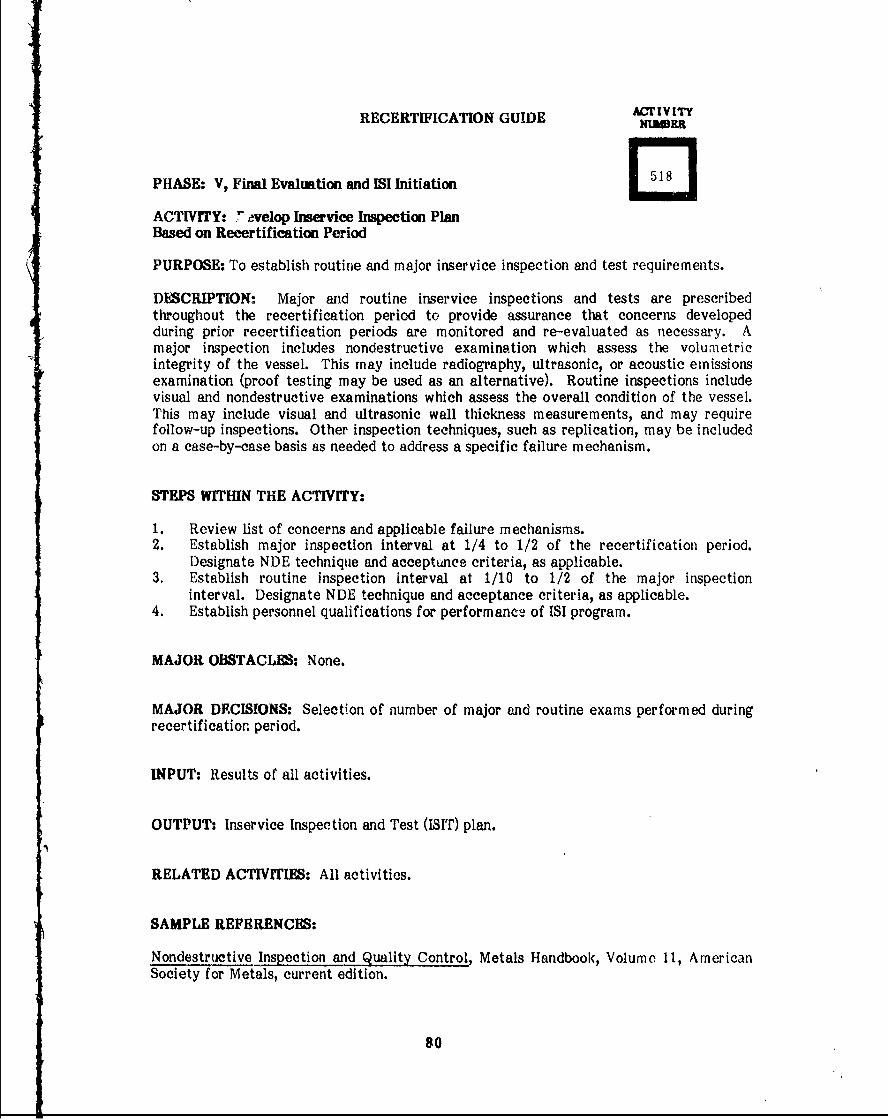
RECERTIFICATION GUIDE AMTY
PHASE: V, Final Evaluation and ISI Initiation QACTIVITY: ." -velop Inservice Inspection PlanBased on Recertification Period
PURPOSE: To establish routine and major inservice inspection and test requirements.
DESCRIPTION: Major and routine inservice inspections and tests are prescribedthroughout the recertification period to provide assurance that concerns developedduring prior recertification periods are monitored and re-evaluated as necessary. Amajor inspection includes nondestructive examination which assess the volumetricintegrity of the vessel. This may include radiography, ultrasonic, or acoustic emissionsexamination (proof testing may be used as an alternative). Routine inspections includevisual and nondestructive examinations which assess the overall condition of the vessel.This may include visual and ultrasonic wall thickness measurements, and may requirefollow-up inspections. Other inspection techniques, such as replication, may be includedon a case-by-case basis as needed to address a specific failure mechanism.
STEPS WITHIN THE ACTIVITY:
1. Review list of concerns and applicable failure mechanisms.2. Establish major inspection interval at 1/4 to 1/2 of the recertification period.
Designate NDE technique and acceptance criteria, as applicable.3. Establish routine inspection interval at 1/10 to 1/2 of the major inspection
interval. Designate NDE technique and acceptance criteria, as applicable.4. Establish personnel qualifications for performance of ISI program.
MAJOR OBSTACLES: None.
MAJOR DECISIONS: Selection of number of major and routine exams performed duringrecertification period.
INPUT: Results of all activities.
OUTPUT: Inservice Inspection and Test (ISIT) plan.
RELATED ACTIVITIES: All activities.
SAMPLE REFERENCES:
Nondestructive Inspection and Quality Control, Metals Handbook, Volume 11, AmericanSociety for Metals, current edition.
80
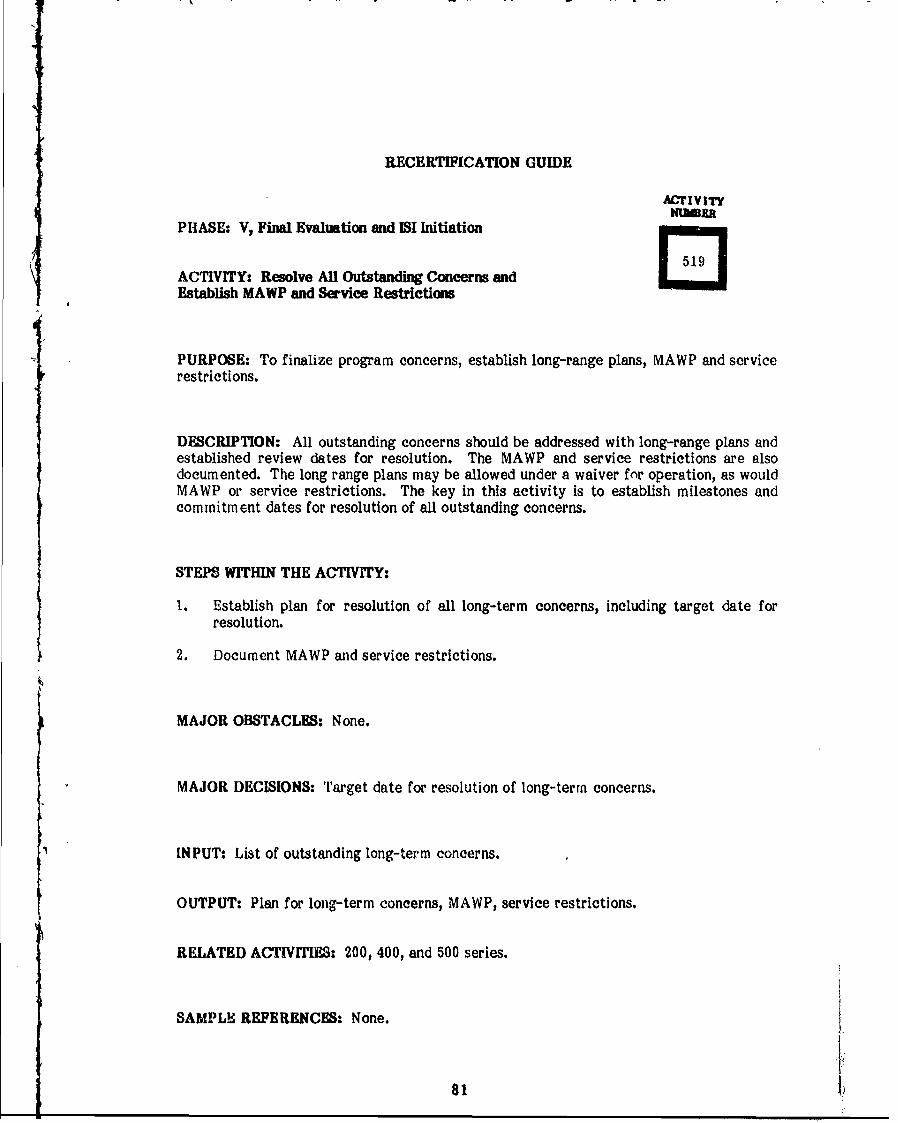
RECERTIFICATION GUIDE
ACrIVITY
PHASE: V, Final Evaluation and ISI Initiation
ACTIVITY: Resolve All Outstanding Concerns and 0Establish MAWP and Service Restrictions
PURPOSE: To finalize program concerns, establish long-range plans, MAWP and servicerestrictions.
DESCRIPTION: All outstanding concerns should be addressed with long-range plans andestablished review dates for resolution. The MAWP and service restrictions are alsodocumented. The long range plans may be allowed under a waiver for operation, as wouldMAWP or service restrictions. The key in this activity is to establish milestones andcommitment dates for resolution of all outstanding concerns.
STEPS WITHIN THE ACTIVITY:
1. Establish plan for resolution of all long-term concerns, including target date forresolution.
2. Document MAWP and service restrictions.
MAJOR OBSTACLIE: None.
MAJOR DECISIONS: Target date for resolution of long-term concerns.
INPUT: List of outstanding long-term concerns.
OUTPUT: Plan for long-term concerns, MAWP, service restrictions.
RELATED ACTIVITIIE: 200, 400, and 500 series.
SAMPLE REFERENCES: None.
81
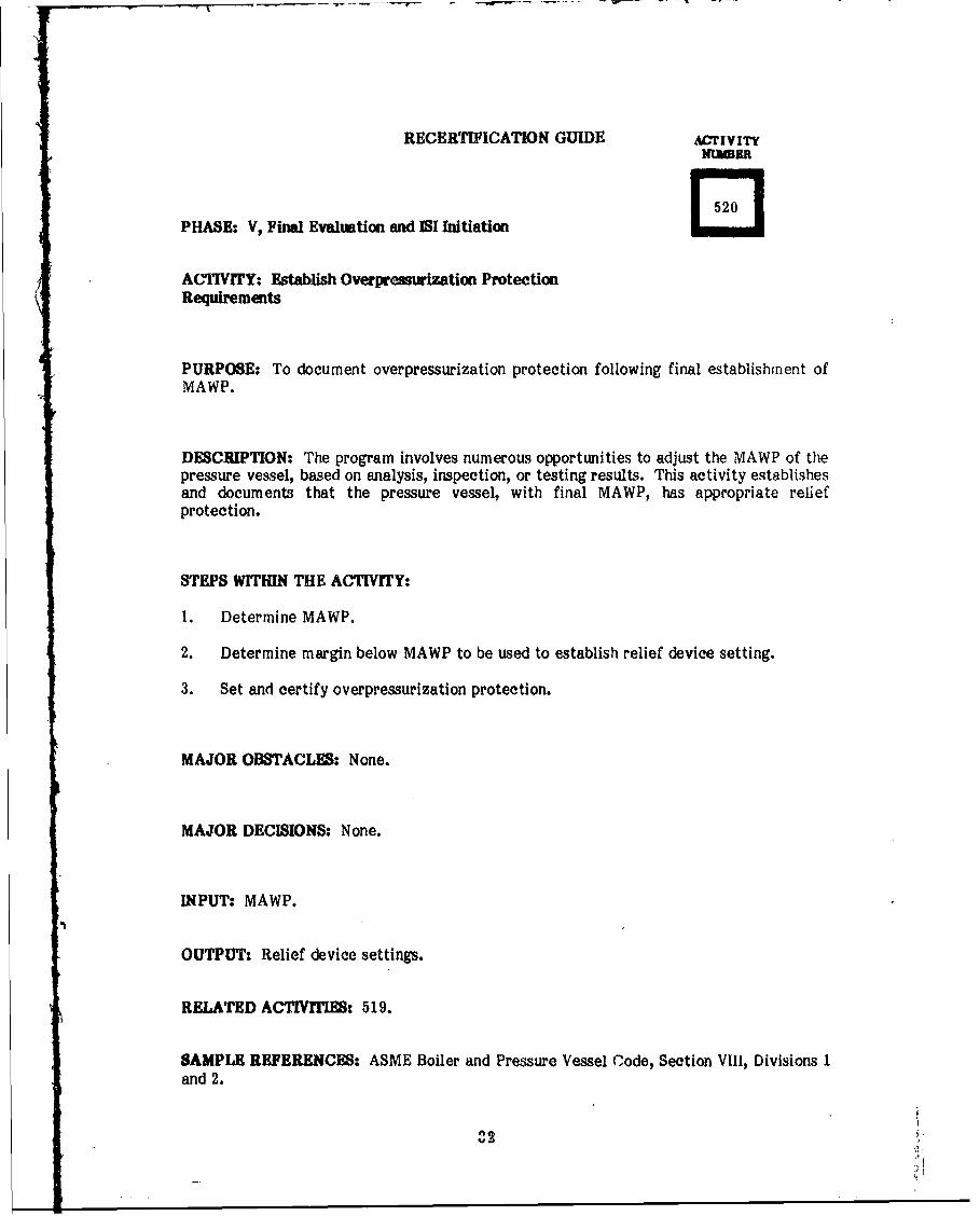
RECERTIFICATION GUIDE AHrivIrv
PHASE: V, Final Evaluation and II Initiation 0ACIITVTY: Establish Overpremurization ProtectionRequirements
PURPOSE: To document overpressurization protection following final establishment ofMAWP.
DESCRIPTION: The program involves numerous opportunities to adjust the MAWP of thepressure vessel, based on analysis, inspection, or testing results. This activity establishesand documents that the pressure vessel, with final MAWP, has appropriate reliefprotection.
STEPS WITHIN THE ACTIVITY:
1. Determine MAWP.
2. Determine margin below MAWP to be used to establish relief device setting.
3. Set and certify overpressurization protection.
MAJOR OBSTACLES: None.
MAJOR DECISIONS: None.
INPUT: MAWP.
OUTPUT: Relief device settings.
RELATED ACTIVITIES: 519.
SAMPLE REFERENCES: ASME Boiler and Pressure Vessel Code, Section VIII, Divisions 1and 2.
32
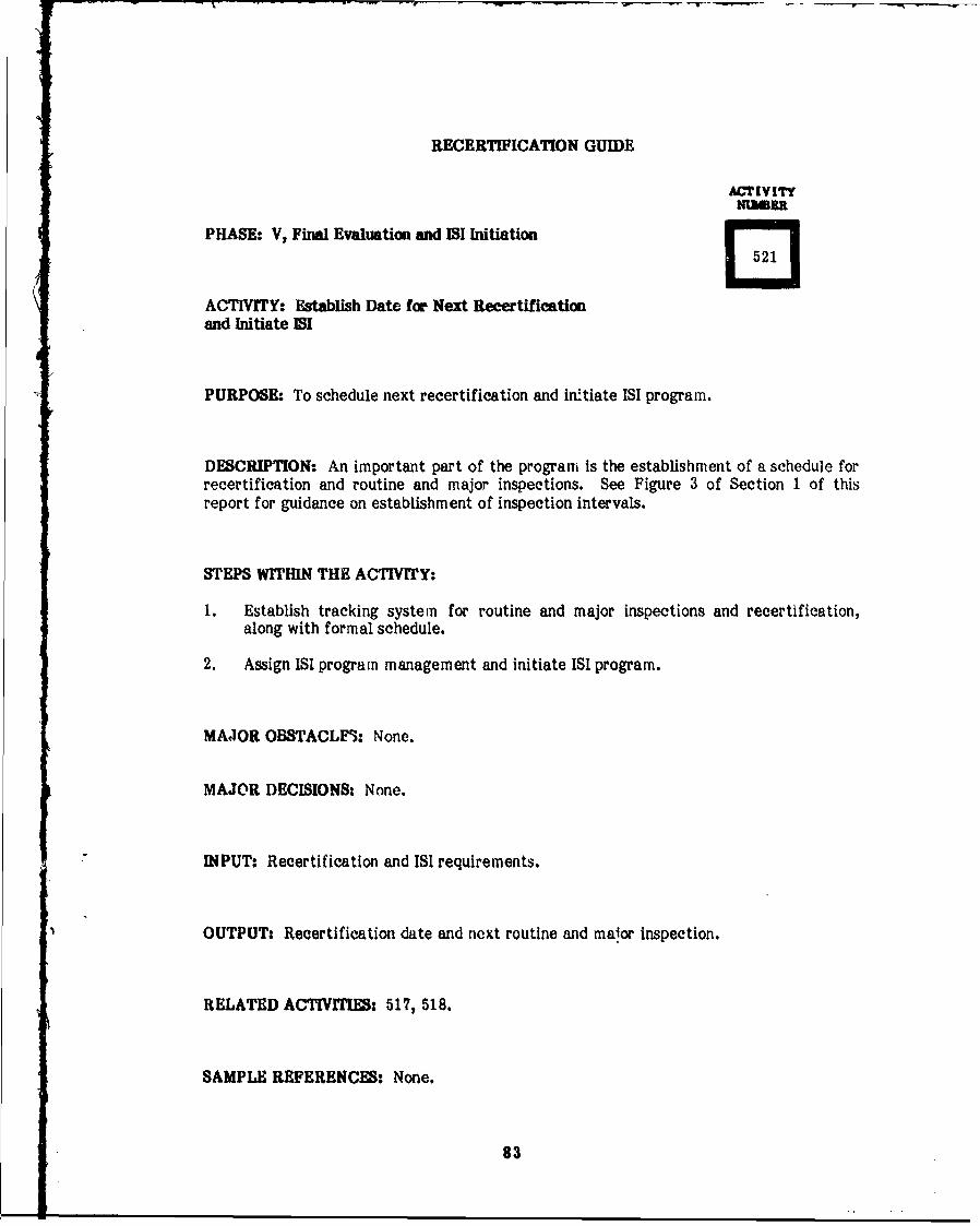
RECERTIFICATION GUIDE
ACT-IVITY
Nmaa
PHASE: V, Final Evaluation and ISI Initiation
ACTIVITY: Establish Date for Next Recertificationand Initiate ISI
PURPOSE: To schedule next recertification and initiate ISI program.
DESCRIPTION: An important part of the program is the establishment of a schedule forrecertification and routine and major inspections. See Figure 3 of Section 1 of thisreport for guidance on establishment of inspection intervals.
STEPS WITHIN THE ACTIVITY:
1. Establish tracking system for routine and major inspections and recertification,along with formal schedule.
2. Assign IS! program management and initiate IS! program.
MAJOR OBSTACLF%: None.
MAJOR DECISIONS: None.
INPUT: Recertification and ISI requirements.
OUTPUT: Recertification date and next routine and maior inspection.
RELATED ACTIVITIES: 517, 518.
SAMPLE REFERENCES: None.
83
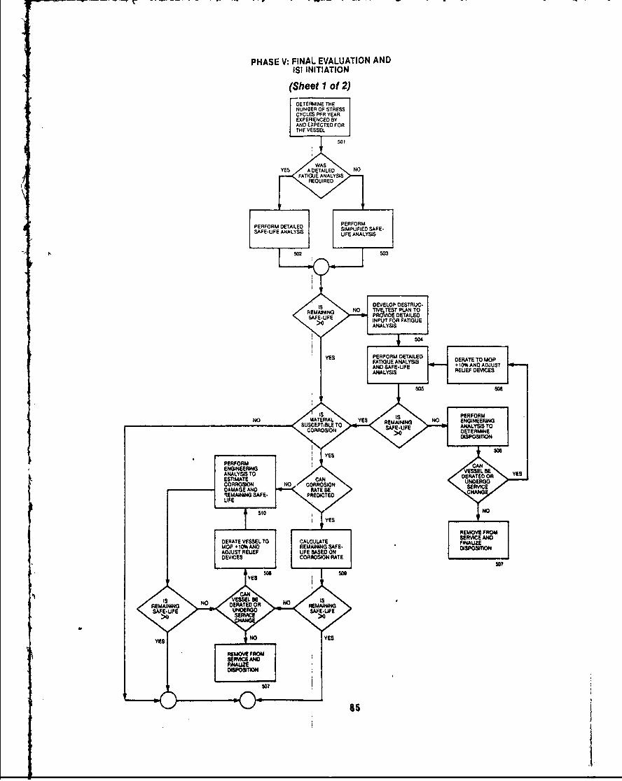
PHASE V: FINAL EVALUATION ANDISI INITIATION
(Sheet 1 of 2)DETERMINE THENUMBER OF STRESSCYCLES PER YEAREXPERIENCED BYAND EXPECTED FORTHE VESSEL
501
YES A DETAILED N
>0 NPERF ORFARMUFATIGUENALYSYSI
PERFORM DETAILED PE RMPE RF
SAFE-UAFE ANALYSAS SIYPSIFIER SAOE
LIE ANDLYSIS .IE1% N WIs.
EEVELOP OESTRUCDMOPAININGNMATRVGTEST PLAN TO
A UTE REIE LI•• EOVIE DETAILE
DEVCE CINPUTO PORTEGU
\/ IANALYSIS
850
FATIGUE ANALYSIS OERATE To MOPAND SAFEFIFE + 10% AND ADJUSTANALYSIS RELIEF DEVIC.ES
iI
NO MTERIL YE isPERFORMSUCETBuToEAIIG N ENGINEERMG
CORRSIONSAFEUFEANALYSIS TOC0RRO>0 D ETERMINE
SPERFORM CA
ANALYSIS TO MLB
CORROSION No CROIN UNEG
LIFIE
0AMAGE ANO PT E<
YE NOO YE
REMOM FROM
DERATE VESSIL TO CALCULATE FERINAL ANE
MOP + to% AND REMAINING ,SAFE- FINALIZEOADJUST RELIF LIFE SAUED ONDIPSTODEVICES CORROIO RATE
CNO
YES NO YES
S' REMOV11FROM
SER, MA.D01"OTION
507i
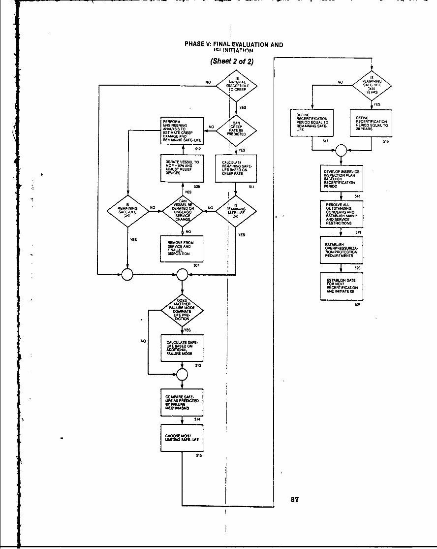
PHASE V: FINAL EVALUATION ANDIr-1 INITIAMfN
(Sheet 2 of 2)
is
0 PERFORMA NRUL O REMAIININGSUCEOIL SAFE-LtFE
!0 CREEP>20YEARS
DEFINE DFN
YYESENGINEERING NO CREEP REMAINING SAFE- PERIOD EQUAL TO|ANALYSIS TOIRATE
BE LIFE
20 YEARS
ESTIMATE CREEP PSE
REMAINING SAFE.JFE 517 516
_ 12 ___MAGEAN_______ES ES
OERATE VESSEL TO CALCULATEYE
MOP -10% AND R IE W/ININ G SAFE-
ADJUST RE LIEF LIF E BASED ON DEVELOP INSERVICE
i•DEVICE
$ CREEP RATE INSPECTION PLAN
•{
&AGED ON
511 PERIO
is ESSEL E isRESOLVE ALLREANN O DRTDO O REMAINING OUTSTANDING
SAFELIF UNDRGOSAFEUFEC0ONCERNS
AND
0 SEVC >0
ESTABULIS MAWP
CHANGAND SERVICERESTRICTIONS
YES REMOVIEFROM ESEA 5S 9
S ERVICE ANDETALS
FINAL~IZE
OVERPqES$URkZA-
•,• TION
ION PROTECTION
DISOSIIONRtEQUIRE'MENTS
ESTABLISH DATEFOR NEXTRECERTIFICATIONAND INTLATIE I
ADOESNAFAILURE MODE
LIFE A PRE-1TE
DOMOST
LMIFE SA.UD ON
AWTK)8AL