Embed Size (px)
Citation preview


blank page

TERMS AND CONDITIONS
Disclaimer
This Scheme Document is the property of BRE Global Limited (“Global”) and is made publicly available, and free of charge, for information purposes only. Any testing, assessment, certification or approval activities relating to this Scheme Document ("the Activities”) must be conducted in accordance with Global’s approved processes, where the Activities are undertaken by authorised employees, agents and associates of Building Research Establishment Limited (“BRE”), Global or approved Activities providers. Please email [email protected] if you wish to receive further information as to how to become an approved Activities provider. For the avoidance of doubt, anyone wishing to use or reproduce this Scheme Document to offer testing, assessment, certification or approval services, must apply to Global for the right to offer such services. Global accepts no responsibility for any unauthorised use or distribution by others of this Scheme Document and may take legal action where unauthorised use is discovered.
Copyright
Save where Global has acknowledged third party-owned sources, the copyright in this Scheme Document is owned by Global. The Scheme Document may be downloaded and reproduced only where:
– the reproduction is for academic and other non-commercial purposes;– the Scheme Document is reproduced in full; and – Global’s copyright in the Scheme Document is acknowledged.
Any other use of the Scheme Document shall be subject to specific agreements with Global.
Trade Marks
“BRE”, “BRE Global”, “BREEAM”, “SMARTWaste" and “SABRE” are all trademarks, whether registered or unregistered, and are owned by either BRE or Global, and may not be used without written permission from BRE or BRE Global Limited.
© BRE Global Ltd 2018
BREEAM UK New Construction 2018 TERMS AND CONDITIONS
Technical Manual: Version: SD5078 - Issue: 2.0 - Issue Date: 03/12/2018 i

AcknowledgementsThis manual has been made possible through the continued efforts of many dedicated BRE Group staff members, the BRE Global Limited Governing Body, the BRE Global Limited Standing Panel of Experts, BREEAM Assessors and those who have responded to our consultation calls and meetings or provided feedback in other ways. BRE Global Limited also extends its gratitude to those who support BREEAM by continuing to specify and apply the method and contribute towards a sustainable built environment.
Uncontrolled copy if printed. Valid on day of printing only
© BRE Global Ltd 2018
Acknowledgements BREEAM UK New Construction 2018
ii Technical Manual: Version: SD5078 - Issue: 2.0 - Issue Date: 03/12/2018

Table of contents
TERMS AND CONDITIONS i
Acknowledgements ii
Table of contents iii
List of tables vi
List of figures ix
What the new icons mean 1
About BRE Global Limited 4
About this Scheme Document 5
Introduction to BREEAM 6
BREEAM UK New Construction 9
Scope of the BREEAM UK New Construction 2018 scheme version 15
Scoring and rating BREEAM-assessed buildings 23
BREEAM rating benchmarks 24
Minimum standards 26
BREEAM assessment issues and credits 27
Calculating a building's BREEAM rating 28
The BREEAM evidential requirements 29
Management 35
Man 01 Project brief and design 37
Man 02 Life cycle cost and service life planning 45
Man 03 Responsible construction practices 50
Man 04 Commissioning and handover 60
Man 05 Aftercare 66
Health and Wellbeing 72
Hea 01 Visual comfort 74
Hea 02 Indoor air quality 90
Hea 03 Safe containment in laboratories 101
Hea 04 Thermal comfort 102
Hea 05 Acoustic performance 108
Hea 06 Security 117
Hea 07 Safe and healthy surroundings 122
Energy 126
Ene 01 Reduction of energy use and carbon emissions 128
Ene 02 Energy monitoring 140
Ene 03 External lighting 148
BREEAM UK New Construction 2018 Table of contents
Technical Manual: Version: SD5078 - Issue: 2.0 - Issue Date: 03/12/2018 iii

Ene 04 Low carbon design 151
Ene 05 Energy efficient cold storage 159
Ene 06 Energy efficient transportation systems 163
Ene 07 Energy efficient laboratory systems 167
Ene 08 Energy efficient equipment 172
Transport 178
Tra 01 Transport assessment and travel plan 179
Tra 02 Sustainable transport measures 186
Water 200
Wat 01 Water consumption 202
Wat 02 Water monitoring 212
Wat 03 Water leak detection 216
Wat 04 Water efficient equipment 219
Materials 221
Mat 01 Environmental impacts from construction products - Building life cycle assessment (LCA) 223
Mat 02 Environmental impacts from construction products - Environmental Product Declarations (EPD) 236
Mat 03 Responsible sourcing of construction products 239
Mat 04 Insulation 247
Mat 05 Designing for durability and resilience 248
Mat 06 Material efficiency 253
Waste 257
Wst 01 Construction waste management 259
Wst 02 Use of recycled and sustainably sourced aggregates 267
Wst 03 Operational waste 275
Wst 04 Speculative finishes (Offices only) 280
Wst 05 Adaptation to climate change 282
Wst 06 Design for disassembly and adaptability 288
Land Use and Ecology 293
LE 01 Site selection 295
LE 02 Identifying and understanding the risks and opportunities for the project 299
LE 03 Managing negative impacts on ecology 307
LE 04 Change and enhancement of ecological value 311
LE 05 Long term ecology management and maintenance 315
Pollution 319
Pol 01 Impact of refrigerants 321
Pol 02 Local air quality 328
Table of contents BREEAM UK New Construction 2018
iv Technical Manual: Version: SD5078 - Issue: 2.0 - Issue Date: 03/12/2018

Pol 03 Flood and surface water management 333
Pol 04 Reduction of night time light pollution 347
Pol 05 Reduction of noise pollution 350
Innovation 353
Inn 01 Innovation 354
Appendices 357
Appendix A – Healthcare building types 358
Appendix B – Education building types 359
Appendix C – Multi-residential building types 360
Appendix D – Shell only and Shell and core project assessments 361
Appendix E – Simple building assessments 366
Appendix F – Examples of BREEAM UK New Construction certificates 370
BREEAM UK New Construction 2018 – Schedule of changes to the scheme document 372
References 379
BREEAM UK New Construction 2018 Table of contents
Technical Manual: Version: SD5078 - Issue: 2.0 - Issue Date: 03/12/2018 v

List of tablesTable 1.1 Icons representing the four BREEAM New Construction assessment types are used to
summarise the category weightings and assessment issue credits available. 1
Table 2.1 BREEAM UK New Construction 2018 environmental sections and assessment issues 9
Table 2.2 Non-domestic building types covered under BREEAM UK New Construction 2018 15
Table 2.3 BREEAM rating benchmarks 24
Table 2.4 BREEAM Environmental section weightings 24
Table 2.5 Minimum BREEAM standards by rating level 26
Table 2.6 Example BREEAM score and rating calculation 28
Table 2.7 Minimum standards for a BREEAM Very Good rating 28
Table 2.8 BREEAM evidence principles 31
Table 2.9 General evidence types 32
Table 4.1 Responsible construction management items 52
Table 5.1 Minimum values of average daylight factor required 75
Table 5.2 Daylighting uniformity criteria 76
Table 5.3 Space type and illuminance requirements - both criteria (average illuminance and minimum point illuminance) should be met. 77
Table 5.4 Additional alternative route for healthcare building types only 78
Table 5.5 Reflectance for maximum room depths and window head heights 78
Table 5.6 View out building-specific requirements. 79
Table 5.7 Internal and external lighting building-specific requirements. 80
Table 5.8 Exemplary level values of average daylight factor required. 81
Table 5.9 Exemplary level illuminance value requirements. Both criteria (average illuminance and minimum point illuminance) should be met. 82
Table 5.10 Recommended number of grid points 84
Table 5.11 : Emission criteria by product type 92
Table 5.12 : Exemplary level emission criteria by product type 94
Table 5.13 Maximum TVOC content for paints and coatings 97
Table 5.14 BREEAM acoustic criteria for education buildings 109
Table 5.15 BREEAM acoustic criteria for healthcare buildings 110
Table 5.16 BREEAM acoustic criteria for office buildings 111
Table 5.17 BREEAM acoustic criteria for law court buildings 111
Table 5.18 BREEAM acoustic criteria for Industrial, Retail, Prisons and Other building types 112
Table 5.19 BREEAM acoustic criteria for Residential institutions (short term and long terms stay) 113
Table 6.1 Ene 01 EPR NC benchmark scale 129
Table 6.2 Exemplary performance credits 130
List of tables BREEAM UK New Construction 2018
vi Technical Manual: Version: SD5078 - Issue: 2.0 - Issue Date: 03/12/2018

Table 6.3 Modelling the 'standard' and 'proposed' building to account for passive deign measures 153
Table 6.4 Best practice energy efficient measures in laboratories 169
Table 6.5 Significant contributors to unregulated energy consumption, for a number of different building types or functions, and the solutions deemed to comply 173
Table 7.1 Amenities in proximity to the site 180
Table 7.2 Default hours of operation by building type for a typical day 181
Table 7.3 Credits available relating to the AI of the site and the number of points achieved 187
Table 7.4 Sustainable public, private and active transport measures 187
Table 7.5 Cycle storage criteria for each building type (option 7). 189
Table 7.6 Amenities applicable for option 9 and 10 for different Building Groups (BG). 191
Table 7.7 Default occupancy rates by building type 197
Table 8.1 BREEAM Credits available for percentage improvement over baseline building water consumption 203
Table 8.2 : BREEAM credits based on overall performance level. 205
Table 8.3 Water efficient consumption levels by component type 206
Table 8.4 Data requirements for each domestic component type 207
Table 9.1 Superstructure – In-scope (criteria 1 to 5) 231
Table 9.2 Substructure and hard landscaping – In-scope (applicable to criteria 6 and 7) 232
Table 9.3 Core building Services – In-scope (applicable to criteria 8 and 9) 232
Table 9.4 LCA Quality requirements 232
Table 9.5 Superstructure – Out of scope 233
Table 9.6 Substructure and hard landscaping – Out of scope 234
Table 9.7 Core building Services – Out of scope 234
Table 9.8 EPD points for different types of EPD 237
Table 9.9 Material classification 238
Table 9.10 BREEAM credits available for each scope level and percentage of points achieved 241
Table 9.11 Mat 03 Scope levels 242
Table 9.12 BREEAM Location/use categories 243
Table 9.13 Material categories 243
Table 9.14 Relevant industry durability or quality standards and design guides 250
Table 9.15 Material efficiency strategy 254
Table 10.1 Construction waste resource efficiency benchmarks 260
Table 10.2 Diversion from landfill benchmarks 261
Table 10.3 Construction waste groups 265
Table 10.4 Credits available relating to the Project Sustainable Aggregate points 268
Table 10.5 Aggregate uses 268
Table 10.6 Aggregate types 269
BREEAM UK New Construction 2018 List of tables
Technical Manual: Version: SD5078 - Issue: 2.0 - Issue Date: 03/12/2018 vii

Table 10.7 Region of source (quarry or marine dredge site) 270
Table 10.8 Aggregate regional abiotic depletion potential 272
Table 10.9 Social cost of transport 273
Table 10.10 Carbon footprint 273
Table 10.11 Criterion 5 requirements 283
Table 10.12 Climate change adaptation strategy appraisal examples 286
Table 10.13 Design measures allowing future adaptation 291
Table 10.14 Examples of design measures and aspects to consider regarding future disassembly 291
Table 11.1 Credits awarded by ecological assessment route 300
Table 11.2 Credits awarded according to assessment route 308
Table 11.3 Credits awarded by ecological assessment route 312
Table 11.4 Credits awarded by ecological assessment route 316
Table 12.1 Default system operational design life values 324
Table 12.2 Default values for DELC calculation when manufacturer's figures are not available 324
Table 12.3 List of some common refrigerant types with low GWP 327
Table 12.4 Maximum NOₓ emission levels by appliance type, fuel and location 329
Table 12.5 Maximum particulate matter and volatile organic compound emissions for appliances using biomass, solid fuel and wood pellets 329
Table 12.6 Definition of flood zones by country 344
Table B.1 Typical facilities and services 358
Table E.1 BREEAM UK New Construction 2018 assessment issues: shell only and shell and core project applicability 363
Table F.1 BREEAM UK New Construction 2018issue applicability for Simple building assessments 367
List of tables BREEAM UK New Construction 2018
viii Technical Manual: Version: SD5078 - Issue: 2.0 - Issue Date: 03/12/2018

List of figuresFigure 2.1 The BREEAM Certification mark 8
Figure 2.2 BREEAM assessment and certification stages and the Royal Institute of British Architects (RIBA) Outline Plan of Work 2013 11
BREEAM UK New Construction 2018 List of figures
Technical Manual: Version: SD5078 - Issue: 2.0 - Issue Date: 03/12/2018 ix

BREEAM UK New Construction 2018 What the new icons mean
What the new icons meanIcons have been designed to visually represent some of the information in the manual to assist your understanding. These are colour coded to align with the BREEAM category colours.
Table 1.1 Icons representing the four BREEAM New Construction assessment types are used to summarise the category weightings and assessment issue credits available.
BREEAM assessment types Category weightings Assessment issue credits Fully-fitted
Simple building
Shell and core
Shell only
Category weightings
Within each category summary page, the four icons show the weighting for each assessment type. For example, if the weighting for fully fitted assessment is 15% then the icon will contain the figure 15%.
Technical Manual: Version: SD5078 - Issue: 2.0 - Issue Date: 03/12/2018 Page 1 of 387

What the new icons mean BREEAM UK New Construction 2018
Assessment issue credits
For each assessment issue, the icons represent the four assessment types and the number of credits available for that issue. For example, if two credits are available for a Simple building (SB) assessment, the SB icon will contain the number 2.
Where exemplary credits are available for an assessment issue, these are shown as a star in the top right hand corner of the assessment issue icons. The number of exemplary credits is shown within the star.
Where there are exemplary credits available
Two exemplary credits are available
The combined icon would look like this
Minimum standard
One of six minimum standard icons is shown along with the assessment issue credit icon. The minimum standard star cluster indicates which BREEAM rating the assessment issue minimum standard applies to.
Ratings with a minimum standard Icon
No Minimum standard
Outstanding
Excellent and Outstanding
Very good, Excellent and Outstanding
Good, Very good, Excellent and Outstanding
Pass, Good, Very good, Excellent and Outstanding
Page 2 of 387 Technical Manual: Version: SD5078 - Issue: 2.0 - Issue Date: 03/12/2018

BREEAM UK New Construction 2018 What the new icons mean
Togglers and thumbnails have been used in the online manual to hide or reveal more information to the user. Access
more information using or
Technical Manual: Version: SD5078 - Issue: 2.0 - Issue Date: 03/12/2018 Page 3 of 387

About BRE Global Limited BREEAM UK New Construction 2018
About BRE Global LimitedBRE Global Limited (part of the BRE (Building Research Establishment) Group) is an independent third party approvals body offering certification of fire, security, and sustainability products and services to an international market.
BRE Global Limited’s mission is to 'Protect People, Property and the Planet'.
We aim to achieve this by:
1. Researching and writing standards 2. Testing and certification in the areas of fire, electronics, security and sustainability 3. Developing world-leading sustainability assessment methods 4. Undertaking research and consultancy for clients and regulators 5. Promulgating standards and knowledge throughout the industry through publications and events 6. Developing and delivering training
BRE Global Limited’s product testing and approvals are carried out by recognised experts in our world renowned testing laboratories.
BRE Global Limited is custodian of a number of world-leading brands including:
1. Building Research Establishment's Environmental Assessment Method (BREEAM) - the world’s leading environmental assessment method for buildings
2. Loss Prevention Certification Board (LPCB) for approval of fire and security products and services.
BRE Global Limited is a trading subsidiary of the BRE Trust, the registered research and education charity which owns the BRE Group.
BRE Global Limited, Bucknalls Lane, Watford, Hertfordshire, WD25 9XX
T +44 (0)333 321 8811 F +44 (0)1923 664 910
www.breglobal.com;www.greenbooklive.com
Page 4 of 387 Technical Manual: Version: SD5078 - Issue: 2.0 - Issue Date: 03/12/2018

BREEAM UK New Construction 2018 About this Scheme Document
About this Scheme DocumentThis document is the technical manual for the BREEAM UK New Construction 2018 Scheme. It describes an environmental performance standard against which new, non-domestic buildings in the UK can be assessed and achieve a BREEAM New Construction rating.
The Scheme Document and the information detailed within is intended for use by trained, qualified and licensed BREEAM UK Assessors in accordance with the procedural and operational requirements of BREEAM (as described in the BREEAM and CSH: Operational Guidance, SD5070) under the terms and conditions of a BREEAM UK licence. This document should be used by non-BREEAM UK Assessors for reference purposes only.
Changes to this BREEAM Scheme Document
This Scheme Document is subject to revision and can be re-issued from time-to-time by BRE Global Limited. A schedule of the publication date for each issue of this document is provided below.
Scheme Doc. Issue no. Date of issue
SD5078 2.0 (current) 03/12/2018
SD5078 1.2 14/08/2018
SD5078 1.1 (Withdrawn) 31/07/2018
SD5078 1.0 07/03/2018
Technical Manual: Version: SD5078 - Issue: 2.0 - Issue Date: 03/12/2018 Page 5 of 387

Introduction to BREEAM BREEAM UK New Construction 2018
Introduction to BREEAMBREEAM is the world’s first and leading sustainability assessment and certification scheme for the built environment. It is an international standard that is locally adapted, operated and applied through a network of scheme operators, assessors and industry professionals.
Through its application, BREEAM recognises and reflects the value in higher performing assets and aims to inspire and empower change by rewarding and motivating sustainability across the life cycle of master-planning projects, infrastructure and buildings.
Launched in 1990, to date, BREEAM has been used to certify over 590,000 assessments of buildings across the building life cycle and is being applied in over 78 countries.
BREEAM aim and objectives
BREEAM assesses, encourages and rewards environmental, social and economic sustainability throughout the built environment. The BREEAM schemes:
– encourage continuous performance improvement and innovation by setting and assessing against a broad range of scientifically rigorous requirements that go beyond current regulations and practice,
– empower those who own, commission, deliver, manage or use buildings, infrastructure or communities to achieve their sustainability aspirations,
– build confidence and value by providing independent certification that demonstrates the wider benefits to individuals, business, society and the environment.
Objectives of BREEAM UK New Construction
– To provide market recognition of buildings with a low environmental impact– To ensure best environmental practice is incorporated in the planning, design, construction and operation of
buildings and the wider built environment.– To challenge the market to provide innovative, cost effective solutions that minimise the environmental impact
of buildings.– To allow organisations to demonstrate progress towards corporate environmental objectives.
BREEAM is developed and operated to meet the following underlying principles:
– Ensure environmental quality through an accessible, holistic and balanced measure of environmental impacts.– Use quantified measures for determining environmental quality.– Adopt a flexible approach that encourages and rewards positive outcomes, avoiding prescribed solutions.– Use robust science and best practice as the basis for quantifying and calibrating a cost effective and rigorous
performance standard for defining environmental quality.– Integrate building professionals in the development and operational processes to ensure wide understanding
and accessibility.– Adopt third party certification to ensure independence, credibility and consistency of the label.– Adopt existing industry tools, practices and other standards wherever possible to support developments in
policy and technology, build on existing skills and understanding and minimise costs.– Align technically and operationally with relevant international standards, including the suite of standards on the
‘Sustainability of Construction Works’ prepared by the European Committee for Standardisation Technical Committee CEN/TC 350, as well as other international initiatives that promote harmonisation in the assessment of sustainability performance of built environment assets across their life cycle.
– Engage with a representative range of stakeholders to inform ongoing development in accordance with the underlying principles and the pace of change in performance standards (accounting for policy, regulation and market capability).
The aims, objectives and principles of BREEAM are embodied within a Core Standard (Process, Science and Technical) owned and managed by BRE Global Limited. This Core Standard is applied to cover aspects of the built environment
Page 6 of 387 Technical Manual: Version: SD5078 - Issue: 2.0 - Issue Date: 03/12/2018

BREEAM UK New Construction 2018 Introduction to BREEAM
life through a suite of BREEAM Schemes. Locally developed and operated versions of the schemes are used in other countries by organisations known as National Scheme Operators (NSOs).
All NSOs are required to maintain scheme operations to internationally agreed standards and seek accreditation from a national accreditation body to demonstrate competence, impartiality and performance capability.
For a full list of BREEAM National Scheme Operators and Schemes visit www.breeam.com.
The UK BREEAM Schemes
BRE Global Limited is the scheme operator of BREEAM in the UK. We develop and operate a number of BREEAM versions, each designed to assess the sustainability performance of buildings, projects or assets at various stages in the life cycle, and these include:
– BREEAM Communities for the master-planning of a larger community of buildings– BREEAM New Construction: Buildings for new build, domestic and non-domestic buildings– BREEAM New Construction: Infrastructure for new build infrastructure projects– BREEAM In-Use for existing non-domestic buildings in-use– BREEAM Refurbishment and Fit Out for domestic and non-domestic building fit-outs and refurbishments
Trust in the Mark
It is important that developers and their customers can have trust in the integrity and rigour of BREEAM. As a formal third party certification scheme, robustness and fairness are key aspects that underpin the method. BREEAM provides confidence in two ways:
1. Creation and operation of the Mark
The credibility and consistency of the BREEAM assessment and rating is a fundamental part of the scheme. As the UK’s leading building science centre, BRE is owned by the BRE Trust, a registered charity that works to improve the quality and sustainability of our buildings and built environment for the wider public benefit. BRE promotes best practice and develops knowledge and understanding throughout the sector and is independent from those interest groups involved in the design and construction of new buildings.
BRE is highly respected as a world leading authority in building performance research, testing, evaluation, standard setting and certification with over 90 years of experience operating both within the UK and internationally. The science-based content and independent application in accordance with recognised international Standards(4) underpin both the creation and operation of BREEAM. BRE Global, the BRE’s certification body and operators of BREEAM, is accredited by the United Kingdom Accreditation Service (UKAS) against these standards to ensure independence, competence and impartiality.
A key aspect of this impartiality is the open and accountable governance structure. The operation of BREEAM (as with all our assurance activities) is overseen by an independent Governing Body and a broad cross-industry Standing Panel who provide peer and market review as well as technical and operational oversight of our activities. The Governing Body represents a breadth of stakeholder interests to ensure, among other things, that BRE Global acts in a manner that is beyond reproach, operates our processes correctly, treats our customers fairly and is always acting for the public good.
2. Process of certification
Independence is a key feature of BREEAM as it provides confidence to the consumer. Assessors are trained and licensed by BRE to undertake the BREEAM assessment and determine a rating. To view a current list of BREEAM Assessors visit www.greenbooklive.com
The BREEAM Assessor will evaluate the design, specification and construction of a new development using the criteria and methodologies defined in this technical manual and it’s supporting assessment tools.
Once an assessment is complete and has achieved a positive outcome in the BRE Global quality assurance procedure, a certificate will be issued. The certificate provides formal verification that the BREEAM Assessor has
Technical Manual: Version: SD5078 - Issue: 2.0 - Issue Date: 03/12/2018 Page 7 of 387

Introduction to BREEAM BREEAM UK New Construction 2018
completed their assessment in accordance with the requirements of the scheme and its quality standards. In turn providing confidence to any interested party or stakeholder in the BREEAM rating and performance of the new development.
Anyone wishing to verify a certified assessment and rating of a new development against BREEAM can do so by either checking its BREEAM certificate, see examples in Appendix F – Examples of BREEAM UK New Construction certificates on page 370, which will contain the scheme’s certification mark (see Figure 2.1 below), or by searching the project listings on Green Book Live www.greenbooklive.com.
Figure 2.1 The BREEAM Certification mark
All NSOs are required to maintain scheme operations to internationally agreed standards and seek accreditation from a national accreditation body to demonstrate competence, impartiality and performance capability.
Page 8 of 387 Technical Manual: Version: SD5078 - Issue: 2.0 - Issue Date: 03/12/2018

BREEAM UK New Construction 2018 BREEAM UK New Construction
BREEAM UK New ConstructionThe BREEAM UK New Construction scheme is a performance-based assessment method and certification scheme for new buildings.
The primary aim of BREEAM UK New Construction is to mitigate the life cycle impacts of new buildings on the environment in a robust and cost-effective manner. This is achieved through integration and use of the scheme by clients and their project teams at key stages in the design and construction process.
Clients can measure, evaluate and reflect the performance of their new building against best practice in an independent and robust manner.
Performance is quantified by individual measures and associated criteria stretching across a range of environmental issues and expressed as a single certified BREEAM rating, i.e. the label.
Table 2.1 BREEAM UK New Construction 2018 environmental sections and assessment issuesManagement Health and Wellbeing
– Man 01 Project brief and design– Man 02 Life cycle cost and service life planning– Man 03 Responsible construction practices– Man 04 Commissioning and handover– Man 05 Aftercare
– Hea 01 Visual comfort– Hea 02 Indoor air quality– Hea 04 Thermal comfort– Hea 05 Acoustic performance– Hea 06 Security – Hea 07 Safe and healthy surroundings
Energy Transport
– Ene 01 Reduction of energy use and carbon emissions
– Ene 02 Energy monitoring – Ene 03 External lighting– Ene 04 Low carbon design– Ene 05 Energy efficient cold storage– Ene 06 Energy efficient transportation systems– Ene 07 Energy efficient laboratory systems – Ene 08 Energy efficient equipment
– Tra 01 Transport assessment and travel plan– Tra 02 Sustainable transport measures
Water Materials
– Wat 01 Water consumption– Wat 02 Water monitoring– Wat 03 Water leak detection– Wat 04 Water efficient equipment
– Mat 01 Environmental impacts from construction products - Building life cycle assessment (LCA)
– Mat 02 Environmental impacts from construction products - Environmental Product Declarations (EPD)
– Mat 03 Responsible sourcing of construction products
– Mat 05 Designing for durability and resilience– Mat 06 Material efficiency
Waste Land Use and Ecology
– Wst 01 Construction waste management– Wst 02 Use of recycled and sustainably sourced
aggregates– Wst 03 Operational waste– Wst 04 Speculative finishes (Offices only)– Wst 05 Adaptation to climate change– Wst 06 Design for disassembly and adaptability
– LE 01 Site selection– LE 02 Identifying and understanding the risks and
opportunities for the project– LE 03 Managing negative impacts on ecology– LE 04 Change and enhancement of ecological
value– LE 05 Long term ecology management and
maintenance
Pollution Innovation
– Pol 01 Impact of refrigerants– Pol 02 Local air quality– Pol 03 Flood and surface water management– Pol 04 Reduction of night time light pollution – Pol 05 Reduction of noise pollution
– Inn 01 Innovation
Technical Manual: Version: SD5078 - Issue: 2.0 - Issue Date: 03/12/2018 Page 9 of 387

When and how to engage with the BREEAM UK New Construction scheme BREEAM UK New Construction 2018
When and how to engage with the BREEAM UK New Construction scheme
Early engagement with the BREEAM UK New Construction scheme and appointment of a licensed BREEAM Assessor is important to achieve optimal integration of the methodology into the new-build procurement process. At this early stage, the performance of the building and the desired BREEAM rating can be achieved while there is greater flexibility and choice in design solutions and spending decisions.
Figure 2.2 on the facing page shows the link between the BREEAM UK New Construction assessment and certification stages and the RIBA Outline Plan of Work 2013.
Clients can use this to understand when they should ideally engage with BREEAM and appoint a BREEAM Advisory Professional and BREEAM Assessor.
Up to date listings of licensed BREEAM UK New Construction Assessors and BREEAM Advisory Professionals are available at www.greenbooklive.com.
BREEAM primarily reflects the overall performance of the building rather than just the opportunities or limitations placed on specific stakeholders involved in the process. In the case of new builds, this means that the client, design team, principal contractor and BREEAM Assessor, as well as other specialist disciplines, have an important role to play throughout the procurement process, if the desired performance level is to be achieved and reflected through the certified BREEAM rating.
Orientating the brief towards BREEAM needs to come first and foremost from the client. BRE recommends that clients and their project teams engage with a licensed BREEAM Assessor and BREEAM Advisory Professional no later than the Preparation and Brief stage (RIBA Stage 1 or equivalent) and ideally sooner. This will ensure that realistic targets are set and can be met, appropriate responsibilities can be defined and understood and low or no cost solutions to environmental impacts can be sought and applied wherever possible.
Page 10 of 387 Technical Manual: Version: SD5078 - Issue: 2.0 - Issue Date: 03/12/2018

BREEAM UK New Construction 2018 When and how to engage with the BREEAM UK New Construction scheme
Figure 2.2 BREEAM assessment and certification stages and the Royal Institute of British Architects (RIBA) Outline Plan of Work 2013
Plan of Work for BREEAM
Work sponsored by the UK Government to support the use of building information modelling (BIM) introduced an agreed pan-industry protocol, the Digital Plan of Work (DPoW). The DPoW is applicable to all construction disciplines: infrastructure, buildings etc., and is a framework that enables the deliverables required at each stage of a construction project, from developing the strategy through to managing the asset, to be defined. There is little difference between the DPoW and more familiar RIBA Plan of Works 2013 (RIBAPoW), and while rapid adoption of
Technical Manual: Version: SD5078 - Issue: 2.0 - Issue Date: 03/12/2018 Page 11 of 387

When and how to engage with the BREEAM UK New Construction scheme BREEAM UK New Construction 2018
the DPoW is occurring, particularly for projects that may not be architecture led, primary reference in the new version of the UK New Construction scheme continues to be the RIBAPoW.
Page 12 of 387 Technical Manual: Version: SD5078 - Issue: 2.0 - Issue Date: 03/12/2018

BREEAM UK New Construction 2018 How to use the BREEAM UK New Construction 2018
How to use the BREEAM UK New Construction 2018
This technical document has been created to:
1. Enable licensed BREEAM Assessors to complete BREEAM assessments and determine a rating 2. Enable BRE Global Ltd to complete quality assurance evaluation of a BREEAM Assessor's assessment and
make a certification decision 3. Aid BREEAM Advisory Professionals (AP) to undertake project team facilitation, in defining, monitoring and
successfully achieving the desired BREEAM rating 4. Act as a reference for clients and members of the project team whose proposed building is being BREEAM-
assessed
The document has six parts:
1. Introduction to BREEAM on page 6 2. Scope of the BREEAM UK New Construction 2018 scheme version on page 15 3. Scoring and rating BREEAM-assessed buildings on page 23, including minimum standards 4. The BREEAM evidential requirements on page 29 5. BREEAM categories 6. Appendices on page 357 (A–F).
The Scope section describes the types of buildings and stages of assessment that this version of the BREEAM UK New Construction scheme can be applied to. Appendices A to F provide additional scoping guidance for specific building and project types. The Scope section can be used by clients and BREEAM Assessors to check whether this is the correct BREEAM scheme to use for their project.
The Scoring and rating section illustrates how a building’s assessed performance is measured and rated. It outlines the rating level benchmarks, the minimum standards for each rating level and the environmental section weightings. It also includes a description of the BREEAM assessment issues and ‘credits’, including ‘Innovation credits’, and how performance against these is calculated and expressed as a BREEAM rating.
The BREEAM evidential requirements section provides guidance to assessors and project teams on the various types and forms of evidence required by the BREEAM Assessor to demonstrate compliance with assessment criteria. This includes a description of why BREEAM requires an auditable trail of evidence, a table of general types of information produced during a building project, and therefore typically required and used as evidence of compliance, and guidance on the differing forms of evidence that can be used and at what stages of the assessment, such as letters of commitment.
The BREEAM categories section includes the assessment issues, categorised in 10 environmental sections. Each issue defines a level of performance (the assessment criteria) against which the assessed building demonstrates compliance (using appropriate project information, i.e. evidence) in order to achieve BREEAM credits.
The majority of BREEAM issues and credits are tradable so a client and their project team can pick and choose which ones to target to build their BREEAM score and achieve the desired rating. Several assessment issues have minimum standards, meaning that specific credits or criteria must be achieved for a particular BREEAM rating (BREEAM minimum standards are identified in the Scoring and rating BREEAM-assessed buildings section).
Each BREEAM issue is structured as follows:
1. Issue information: contains the assessment issue reference, title, number of credits available(1)and whether the issue forms part of the BREEAM minimum standards
2. Aim:outlines the objective of the issue and the impact it measures or mitigates 3. Value and context: outlines the key value of the issue and summarises beneficial outcomes resulting from
compliance with the issue criteria
1 For some assessment issues the number of credits available will vary by building type. Furthermore, some issues
may not be applicable to certain building types or buildings which do not contain a particular function or area, e.g. a
laboratory.
Technical Manual: Version: SD5078 - Issue: 2.0 - Issue Date: 03/12/2018 Page 13 of 387

How to use the BREEAM UK New Construction 2018 BREEAM UK New Construction 2018
4. Assessment scope: indicates how to apply the issue for different types of assessment and project-specific circumstances
5. Assessment criteria: identifies how many parts for the issue and the number of credits associated with those parts. It states each of the requirements of the issue and in effect the means by which the issue aim is achieved and the value is realised by the project's compliance. Where the building complies with all the relevant criteria, as determined by the licensed BREEAM Assessor, the requisite number of credits can be awarded. Some issues also have Exemplary level criteria with additional exemplary credits available where a building demonstrates that it meets these criteria (refer to Innovation on page 353 for more details). Up to a maximum of 10 Innovation credits are available
6. Methodology: includes a description of any methodology used to determine the number of credits achieved for a given level of building performance. It includes, for example, calculation procedures or guidance on how to relate non-BREEAM schemes, standards or qualifications referenced to the assessment criteria
7. Evidence: describes the types of project information that the design team or client must provide to the licensed BREEAM Assessor to enable verification of the building’s performance against the assessment criteria and justification of credits awarded. The BREEAM evidence requirements section provides further guidance on evidential requirements
8. Definitions: includes any definition of terms used in the assessment issue 9. Checklists and tables: contains any checklists and useful tables
10. Additional information: contains any further information relevant to the application of the assessment criteria, or sources of additional information that may be of use in addressing the issue
The Appendices provide supporting information relevant to either the scope of the BREEAM UK New Construction 2018 or its assessment criteria.
Compliance Notes, which provide information on how to determine compliance for specific BREEAM issues, are published on the Knowledge Base at kb.breeam.com. Each compliance note in the Knowledge Base has a title and unique reference number, which can be quoted in BREEAM reports.
Page 14 of 387 Technical Manual: Version: SD5078 - Issue: 2.0 - Issue Date: 03/12/2018

BREEAM UK New Construction 2018 Scope of the BREEAM UK New Construction 2018 scheme version
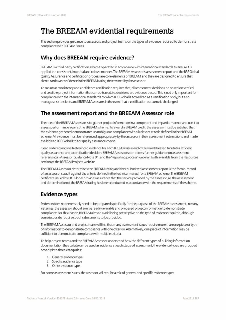
Scope of the BREEAM UK New Construction 2018 scheme versionThe BREEAM UK New Construction 2018 scheme can be used to assess the environmental life cycle impacts of new non-domestic buildings at the design and construction stages. ‘New Construction’ is defined as development that results in a new standalone structure, or new extension to an existing structure, which will come into operation or use for the first time upon completion of the works.
This BREEAM UK New Construction 2018 scheme version is applicable to new non-domestic buildings in the United Kingdom only.
Type of buildings that can be assessed using the BREEAM UK New Construction 2018 scheme version
The non-domestic building types which can be assessed and rated using this scheme version are outlined in Table 2.2 below. Additional guidance for some of the building types listed is also provided in the appendices (refer to the footnotes).
Table 2.2 Non-domestic building types covered under BREEAM UK New Construction 2018
Building type Description
Commercial
Office – General office buildings– Offices with research and development areas (i.e. category 1 labs only)
Industrial – Industrial unit – warehouse storage or distribution– Industrial unit – process, manufacturing or vehicle servicing
Retail – Shop or shopping centre– Retail park or warehouse– ‘Over the counter’ service provider, e.g. financial, estate and employment
agencies and betting offices– Showroom– Restaurant, café and drinking establishment– Hot food takeaway
Public (non-housing)
Education(1) – Preschool– Schools and sixth form colleges– Further education or vocational colleges– Higher education institutions
Healthcare(2) – Teaching or specialist hospitals– General acute hospitals– Community and mental health hospitals– GP surgeries– Health centres and clinics
Prison(3) – High security prison– Standard secured prison
1 For schools, further and higher educational building types, see also Appendix B – Education building types on
page 359.
2 For healthcare building types, see also Appendix A – Healthcare building types on page 358.
3 The prisons category includes any building type that is part of a prison establishment, including residential blocks
or a hybrid of building types.
Technical Manual: Version: SD5078 - Issue: 2.0 - Issue Date: 03/12/2018 Page 15 of 387

Scope of the BREEAM UK New Construction 2018 scheme version BREEAM UK New Construction 2018
Building type Description
– Young offender institution and juvenile prisons– Local prison– Holding centre
Law Court – Law courts– Crown and criminal courts– County courts– Magistrates' courts– Civil justice centres– Family courts– Youth courts– Combined courts
Multi-residential accommodation or supported living facility(1)
Residential institution (long term stay)
– Residential care home– Sheltered accommodation– Residential college or school (halls of residence)– Local authority secure residential accommodation– Military barracks
Other
Residential institution (short term stay)
– Hotel, hostel, boarding and guest house– Secure training centre– Residential training centre
Non-residential institution – Art gallery, museum– Library– Day centre, hall, civic or community centre– Place of worship
Assembly and leisure – Cinema– Theatre, music or concert hall– Exhibition or conference hall– Indoor or outdoor sports, fitness and recreation centre (with or without pool)
Other – transportation hub (coach or bus station and above ground rail station)– Research and development (category 2 or 3 laboratories - non-higher
education)– Crèche– Fire stations– Visitor centres
Bespoke Building types that are not listed in this table must undergo a scoping and tailoring exercise to facilitate an assessment and rating. For an individual project this involves BRE Global selecting appropriate issues from the existing pool of assessment issues to provide criteria against which the building can be assessed. This is sometimes known as a ‘bespoke’ assessment. Further guidance on the ‘bespoke’ process can be found in BREEAM Bespoke Process Guidance Note GN23.
Mixed use developments and building types
Developments with a number of separate buildings of differing functional types, or a single building with different functions, e.g. office and retail or retail and GP surgery, will require an assessment and therefore BREEAM rating and certificate for each individual building in the development or each functional use within a single building.
1 For multi-residential building types, see also Appendix C – Multi-residential building types on page 360 for further
detail of scope
Page 16 of 387 Technical Manual: Version: SD5078 - Issue: 2.0 - Issue Date: 03/12/2018

BREEAM UK New Construction 2018 Scope of the BREEAM UK New Construction 2018 scheme version
This is necessary as BREEAM defines criteria and benchmarks for some assessment issues according to building type, function and use. To maintain comparability and consistency of the assessment and BREEAM rating, a separate registration, assessment score and rating are therefore required for each building type function or use in the development.
Licensed Assessors will find further guidance on how to define mixed use developments for the purpose of an assessment in Guidance Note GN10 – Mixed use developments and similar buildings (or units).
BREEAM UK New Construction 2018 assessment types
A number of assessment types are defined and can be applied to assess and rate the performance of a new building. These are:
– Fully fitted (applicable to all buildings apart from those defined as a 'simple' building)– Fully fitted – 'simple' building (see Appendix E – Simple building assessments on page 366)– Shell and core (see Appendix D – Shell only and Shell and core project assessments on page 361)– Shell only (see Appendix D – Shell only and Shell and core project assessments on page 361)
The assessment criteria for these options are identified in each assessment issue in this technical manual. The assessor in collaboration with the client and design team should determine which assessment type is relevant for their project and assess the criteria accordingly.
Similar building types (or units) on the same site
A number of separate but similar buildings, or individual units within a larger building development can be assessed and rated with one BREEAM assessment. Further guidance on applying BREEAM in this way can be found in Guidance Note GN10 – Mixed use developments and similar buildings (or units).
Part new-build, part refurbishment projects
For developments that are a mix of new-build and refurbishment of existing spaces the choice of scheme selection and application is determined according to the scope of the new-build and refurbishment works.
For smaller projects, where the total development area is less than 1000m², a single BREEAM assessment can be undertaken to cover both the new-build and refurbished areas. The choice of BREEAM New Construction or BREEAM Refurbishment and Fit-out scheme should be based on whichever (new-build or refurbishment) constitutes the majority of the assessed floor area.
For larger projects a single New Construction assessment can be undertaken, though the refurbished areas have to comply with assessment criteria designed for new builds which can be more challenging in some instances. If the development is predominantly a refurbishment with new-build extension then the BREEAM Refurbishment and Fit-out scheme may be the most appropriate as it contains thresholds under which a single Refurbishment and Fit-out assessment can be completed.
Where none of the above options are deemed suitable for the project there are two further options:
Option 1: Separate BREEAM New Construction and BREEAM Refurbishment and Fit-out assessments
Under option 1, two separate BREEAM assessments would be conducted with a BREEAM New Construction assessment undertaken on the new extension and a BREEAM Refurbishment and Fit-out assessment undertaken on the existing building refurbishment or fit-out. Two separate certificates and ratings can be obtained to indicate the performance of both the new extension and existing building refurbishment or fit-out.
Option 2: Bespoke BREEAM combined New Construction and Refurbishment and Fit-out assessment
Under option 2, BRE Global will produce a Bespoke criteria appendix document which will determine, for specific BREEAM issues, which issues and assessment criteria are applicable to the part new-build part refurbishment project. It will refer to both the BREEAM UK Refurbishment and Fit Out manual and the BREEAM UK New Construction manuals. A bespoke Scoring and Reporting tool will also be produced for the project.
In determining the appropriate option for a part new-build part refurbishment project, the BREEAM Assessor should review the scope of the proposed works, and in particular, consider the scope of the refurbished elements,
Technical Manual: Version: SD5078 - Issue: 2.0 - Issue Date: 03/12/2018 Page 17 of 387

Scope of the BREEAM UK New Construction 2018 scheme version BREEAM UK New Construction 2018
e.g. whether it is a major refurbishment, will there be a significant change of use and will the building's thermal and structural elements remain unchanged? Using this information the assessor should advise the client on the most suitable BREEAM version or scheme for maximising the building's environmental performance.
Page 18 of 387 Technical Manual: Version: SD5078 - Issue: 2.0 - Issue Date: 03/12/2018

BREEAM UK New Construction 2018 Building life cycle stages covered by the BREEAM UK New Construction 2018
scheme version
Building life cycle stages covered by the BREEAM UK New Construction 2018 scheme version
This BREEAM UK New Construction Scheme can be used to assess and rate the environmental impacts arising from a newly constructed building development (including external site areas), at the following life cycle stages:
1. New Build Design Stage (DS) (optional) – leading to an Interim BREEAM rating and certificate of assessment 2. New Build post-construction Stage (PCS) – leading to a Final BREEAM rating and certificate of assessment 3. New Build Post-occupancy stage (POS) (optional) - leading to a certification relating to robust best practice,
to meet design aspirations, in the following areas: a. post occupancy handover and commissioning processes b. performance monitoring c. actions undertaken post occupancy to understand and manage the actual performance of the building.
Design Stage (DS)
The DS assessment and interim BREEAM rating is optional and can be used to demonstrate the proposed new building’s performance at the design stage of the life cycle. It is strongly recommended that assessment and certification should occur prior to the beginning of operations on site. The BREEAM rating at this stage is labelled as ‘interim’ because it does not represent the building’s final, new construction BREEAM performance.
To complete an assessment at this stage the design must be advanced to a point where the relevant design information is available to enable the BREEAM Assessor to evaluate and verify the building’s performance against the criteria defined in this Scheme Document. The interim DS assessment will therefore be completed and certified at the scheme design or detailed design stages.
Post-construction Stage (PCS)
The PCS assessment and BREEAM rating is a mandatory certification stage that can be used to demonstrate the final ‘as-built’ performance of the building at the new construction stage of the life cycle. A final PCS assessment is completed and certified after practical completion of the building works.
There are two approaches to assessment at the PCS:
1. A post-construction review (PCR) based on a completed interim design stage assessment 2. A standalone post-construction assessment (PCA)
A PCR serves to confirm the assessment of a the building’s ‘as-built’ performance and rating and where appropriate that it is in accordance with the assessment certified at the interim design stage. Where an interim DS assessment has not been carried out and a BREEAM assessment and rating is required, a full post-construction stage assessment can be conducted.
Post-occupancy Stage (POS)
The POS is an optional third stage of assessment under the UK New Construction scheme. This stage confirms the process of monitoring, reviewing and reporting on the performance of the building once occupied. It is carried out a minimum of 12 months after occupation and would normally be before a period of two years has lapsed from the date of ‘full’ occupation (defined as occupation of approximately 80% of the occupiable space in the building). This will focus on best practice project commissioning and handover and post-occupation support and aims to help the Design Team, Facilities Manager and building owner understand the actual performance of the building and optimise this in line with design expectations. The assessment will review post occupancy monitoring processes and identify where there are deficiencies to rectify or opportunities to take. The POS is only applicable to fully fitted and shell and core assessments, it is not available for shell only assessments.
The POS will also entail a review of commitments made at the post-construction stage within the UK New Construction scheme.
Technical Manual: Version: SD5078 - Issue: 2.0 - Issue Date: 03/12/2018 Page 19 of 387

Building life cycle stages covered by the BREEAM UK New Construction 2018
scheme version
BREEAM UK New Construction 2018
In order to complete the POS, various issues in the UK New Construction scheme need to be achieved at the post construction stage, as follows:
1. Ene 01 Reduction of energy use and carbon emissions on page 128 (the four credits for Prediction of operational energy consumption)
2. Ene 02 Energy monitoring on page 140 (two credits) 3. Wat 02 Water monitoring on page 212 (one credit)
For these issues, evidence must be collated after the building has been handed over to demonstrate compliance at the POS. Evidence requirements are detailed in the individual assessment issues.
Additional credits are available within the UK New Construction scheme (Ene 01) where a contractual commitment is made to complete and achieve certification at the POS.
There are optional issues which if sought at the PCS, can be reviewed at the POS as follows:
1. Man 05 Aftercare on page 66 (three credits) 2. Health and Wellbeing on page 72 3. Wat 01 Water consumption on page 202 4. LE 05 Long term ecology management and maintenance on page 315 (up to two credits)
The POS can provide an interim step between the UK New Construction Post Construction assessment and assessment in occupation under BREEAM In-Use. It provides a more realistic view of building performance and occupation patterns than is possible at the new construction stage and so, helps to ensure that the building performs as expected.
Page 20 of 387 Technical Manual: Version: SD5078 - Issue: 2.0 - Issue Date: 03/12/2018

BREEAM UK New Construction 2018 Buildings types not covered under the BREEAM UK New Construction 2018
scheme version
Buildings types not covered under the BREEAM UK New Construction 2018 scheme version
Building types not listed in Scope of the BREEAM UK New Construction 2018 scheme version - Table 2.2 on page 15will fall into one of two categories: those where a current but separate BREEAM UK New Construction scheme technical manual exists and those which currently do not have an existing and current technical manual.
Other current BREEAM New Construction schemes
Data Centres
A BREEAM UK New Construction scheme 2010 version and technical manual for Data Centres (SD5068) should be used for the assessment and certification of data centres in the UK.
Other building types not defined
If your building type is not defined in the scope of this manual, it can still be assessed using BREEAM UK New Construction scheme. Such building types are assessed using a bespoke set of UK New Construction assessment criteria. Licensed BREEAM Assessors and clients should refer to Guidance note GN23 for information on how to proceed.
Technical Manual: Version: SD5078 - Issue: 2.0 - Issue Date: 03/12/2018 Page 21 of 387

Building life cycle stages not covered by the BREEAM UK New Construction
2018 scheme version
BREEAM UK New Construction 2018
Building life cycle stages not covered by the BREEAM UK New Construction 2018 scheme version
The BREEAM UK New Construction scheme is not designed to assess the environmental impacts of buildings at the following life cycle stages:
1. Existing building major and minor refurbishments and fit-outs (See scope of BREEAM UK Refurbishment and Fit-out scheme)
2. Existing building in operation or existing unoccupied building (BREEAM In-Use scheme) 3. Existing building de-construction (no BREEAM scheme for this life cycle stage at present) 4. Infrastructure projects (BREEAM infrastructure pilot scheme)
Page 22 of 387 Technical Manual: Version: SD5078 - Issue: 2.0 - Issue Date: 03/12/2018

BREEAM UK New Construction 2018 Scoring and rating BREEAM-assessed buildings
Scoring and rating BREEAM-assessed buildings
Technical Manual: Version: SD5078 - Issue: 2.0 - Issue Date: 03/12/2018 Page 23 of 387

BREEAM rating benchmarks BREEAM UK New Construction 2018
BREEAM rating benchmarksThere are a number of elements that determine the overall performance of a new construction project assessed using BREEAM. They are:
1. The BREEAM rating level benchmarks 2. The minimum BREEAM standards 3. The environmental section weightings 4. The BREEAM assessment issues and credits
The next sections summarise how these elements combine to produce a BREEAM rating for a new building and are followed by a description and example calculation of a rating.
BREEAM rating benchmarks for projects assessed using the 2018 version of BREEAM UK New Construction are:
Table 2.3 BREEAM rating benchmarksBREEAM Rating % score
Outstanding ≥ 85
Excellent ≥ 70
Very good ≥ 55
Good ≥ 45
Pass ≥ 30
Unclassified < 30
BREEAM rating benchmarks enable a client and all other stakeholders to compare the performance of a newly constructed building with other BREEAM rated buildings, and the typical sustainability performance of a stock of new non-domestic buildings in the UK.
In this respect each BREEAM rating broadly represents performance equivalent to:
1. Outstanding: Less than the top 1% of UK new non-domestic buildings (innovator) 2. Excellent: Top 10% of UK new non-domestic buildings (best practice) 3. Very Good: Top 25% of UK new non-domestic buildings (advanced good practice) 4. Good: Top 50% of UK new non-domestic buildings (intermediate good practice) 5. Pass: Top 75% of UK new non-domestic buildings (standard good practice)
An unclassified BREEAM rating represents performance that is non-compliant with BREEAM, in terms of failing to meet either the BREEAM minimum standards of performance for key environmental issues or the overall threshold score required to achieve at least a Pass rating.
BREEAM category weightings
Category weightings are fundamental to any building environmental assessment method providing a means of defining and ranking the relative impact of environmental issues. BREEAM uses an explicit weighting system to determine the overall BREEAM score.
This weighting system is defined in greater detail within the BRE Global Core Process Standard (BES 5301) and its supporting procedural documents. The process for defining the weightings is set out in a briefing available on the BREEAM website. These form part of the over-arching BREEAM Standard and the Code for a Sustainable Built Environment.
Table 2.4 BREEAM Environmental section weightingsEnvironmental section Weighting
Fully fitted out Simple building Shell and core only Shell only
Management 11% 7.5% 11% 12%
Health and Wellbeing 14% 16.5% 8% 7%
Energy 16% 11.5% 14% 9.5%
Page 24 of 387 Technical Manual: Version: SD5078 - Issue: 2.0 - Issue Date: 03/12/2018

BREEAM UK New Construction 2018 BREEAM rating benchmarks
Environmental section Weighting
Fully fitted out Simple building Shell and core only Shell only
Transport 10% 11.5% 11.5% 14.5%
Water 7% 7.5% 7% 2%
Materials 15% 17.5% 17.5% 22%
Waste 6% 7% 7% 8%
Land Use and Ecology 13% 15% 15% 19%
Pollution 8% 6% 9% 6%
Total 100% 100% 100% 100%
Innovation (additional) 10% 10% 10% 10%
Technical Manual: Version: SD5078 - Issue: 2.0 - Issue Date: 03/12/2018 Page 25 of 387

Minimum standards BREEAM UK New Construction 2018
Minimum standardsTo ensure performance against fundamental environmental issues is not overlooked in pursuit of a particular rating, BREEAM sets minimum standards of performance in key areas, e.g. energy, water, waste etc. The majority of BREEAM credits can, however, be traded, so non-compliance in one area can be offset through compliance in another to achieve the target BREEAM rating.
The minimum acceptable levels of performance for each rating are summaries in Table 2.5 below.
To achieve a particular BREEAM rating, the minimum overall percentage score must be achieved as well as the minimum standards detailed in Table 2.5 below.
Table 2.5 Minimum BREEAM standards by rating level Minimum standards by BREEAM rating level
BREEAM issue Pass Good Very Good Excellent Outstanding
Man 03 Responsible construction practices
None None None One credit (responsible construction management)
Two credits (responsible construction management)
Man 04 Commissioning and handover
None None One credit (commissioning-test schedule and responsibilities)
One credit (commissioning-test schedule and responsibilities)
One credit (commissioning-test schedule and responsibilities)
Man 04 Commissioning and handover
None None Criterion 11 (Building User Guide)
Criterion 11 (Building User Guide)
Criterion 11 (Building User Guide)
Man 05 Aftercare
None None None One credit ( commissioning-implementation)
One credit ( commissioning-implementation)
Ene 01 Reduction of energy use and carbon emissions
None None None Four credits (Energy performance)
Six credits (Energy performance) and Four credits (Energy modelling and reporting)
Ene 02 Energy monitoring
None None One credit(First sub-metering credit)
One credit(First sub-metering credit)
One credit(First sub-metering credit)
Wat 01 Water consumption
None One credit One credit One credit Two credits
Wat 02 Water monitoring
None Criterion 1 only
Criterion 1 only Criterion 1 only Criterion 1 only
Mat 03 Responsible sourcing of construction products
Criterion 1 only
Criterion 1 only
Criterion 1 only Criterion 1 only Criterion 1 only
Wst 01 Construction waste management
None None None None One credit
Wst 03 Operational waste
None None None One credit One credit
Page 26 of 387 Technical Manual: Version: SD5078 - Issue: 2.0 - Issue Date: 03/12/2018

BREEAM UK New Construction 2018 BREEAM assessment issues and credits
BREEAM assessment issues and creditsBREEAM UK New Construction consists of individual assessment issues across nine environmental categories, plus a tenth ‘innovation’ category. Each assessment issue addresses a specific building related environmental impact or issue and is assigned a number of credits.
BREEAM credits are awarded where a development meets the best practice performance levels defined for an assessment issue, i.e. the impact has been mitigated. For example, in the case of the health and wellbeing section, a specific building occupant-related issue has been addressed, e.g. thermal comfort.
The number of credits available for an individual assessment issue will vary and generally reflect the importance of mitigating the impact of the assessment issue. In most cases, where there are multiple credits available, the number awarded is based on a sliding scale or benchmark, where progressively higher standards of building performance are rewarded with a higher number of credits.
In addition to the category section score, overall score and BREEAM rating, verified performance against individual assessment issues also provides users with a credible set of key building performance indicators for a range of embodied, operational and construction-phase building impacts. It is therefore possible to use the method to define performance levels in support of specific organisational policy objectives for individual environmental issues as well as using BREEAM to define overall targets. However, be aware that design flexibility and project cost implications can occur if design targets are set using individual issues and credit levels.
‘Credits’ for innovation
BREEAM seeks to support innovation within the construction industry and its supply chain. One way it does this is through the availability of additional credits to recognise sustainability-related benefits or performance levels not currently recognised by standard BREEAM assessment issues and criteria. This rewards developments that go beyond best practice in a particular aspect of sustainability, i.e. demonstrated innovation.
Awarding credits for innovation enables clients and design teams to boost their building’s BREEAM performance, and also helps to support the market for new innovative technologies, and design or construction practices.
Two ways in which BREEAM awards innovation credits:
1. By meeting exemplary performance criteria defined within an existing BREEAM issue, i.e. going beyond the standard BREEAM assessment criteria
2. By the project’s licensed BREEAM Assessor applying to BRE Global to have a particular building technology or feature, design or construction method or process recognised as ‘innovative’. If the application is successful and subsequently compliance is verified, an ‘innovation credit’ can be awarded
Each innovation credit achieved adds 1% to a building's overall score. The maximum number of ’innovation credits’ that can be awarded for any one building is 10; therefore the maximum additional score available for ‘innovation’ is 10%.
Innovation credits can be awarded regardless of the building’s final BREEAM rating, i.e. they can be awarded at any BREEAM rating level. Refer to Inn 01 Innovation on page 354 for more detail.
Technical Manual: Version: SD5078 - Issue: 2.0 - Issue Date: 03/12/2018 Page 27 of 387

Calculating a building's BREEAM rating BREEAM UK New Construction 2018
Calculating a building's BREEAM ratingA BREEAM Assessor must determine the BREEAM rating using the appropriate assessment tools and calculators and only a certified assessment can claim a BREEAM Rating. An indication of performance against the BREEAM scheme can be determined by anyone using a BREEAM Pre-Assessment Estimator available from the BREEAM website www.breeam.com.
The process of determining a BREEAM rating and an example calculation, see Table 2.6 below
1. For each of BREEAM’s nine categories the number of credits awarded is determined by the BREEAM Assessor according to the number of credits available when the criteria of each assessment issue have been met (as detailed in the technical sections of this document).
2. The percentage of available credits achieved is calculated for each section. 3. The percentage of credits achieved in each section is multiplied by the corresponding weighting for each
section to give the overall environmental category score. 4. The section scores are added together to give the overall BREEAM score. 5. The overall score is compared with the BREEAM rating benchmark levels and, provided all minimum
standards have been met, the relevant BREEAM rating is achieved. 6. An additional 1% can be added to the final BREEAM score for each innovation credit achieved (up to a
maximum of 10% with the total BREEAM score capped at 100%).
Table 2.6 Example BREEAM score and rating calculationBREEAM section Credits
achievedCredits available
% of credits achieved
Category weighting (fully-
fitted)
Section score (%)
Management 14 21 66.67 0.11 7.33
Health and Wellbeing
12 22 54.55 0.14 7.64
Energy 15 31 48.39 0.16 7.74
Transport 8 12 66.67 0.10 6.67
Water 4 10 40.00 0.07 2.80
Materials 8 14 57.14 0.15 8.57
Waste 3 6 50.00 0.06 3.00
Land Use and Ecology
5 10 50.00 0.13 6.50
Pollution 8 12 66.67 0.08 5.33
Innovation 2 10 20.00 0.10 2.00
Final BREEAM score 57.58%
BREEAM Rating VERY GOOD
Table 2.7 Minimum standards for a BREEAM Very Good ratingMinimum standards for BREEAM ‘Very Good’ rating Achieved?
Man 04 Commissioning and handover on page 60 Y
Ene 02 Energy monitoring on page 140 Y
Wat 01 Water consumption on page 202 Y
Wat 02 Water monitoring on page 212 Y
Mat 03 Responsible sourcing of construction products on page 239 Y
Page 28 of 387 Technical Manual: Version: SD5078 - Issue: 2.0 - Issue Date: 03/12/2018
BREEAM UK New Construction 2018 The BREEAM evidential requirements
The BREEAM evidential requirementsThis section provides guidance to assessors and project teams on the types of evidence required to demonstrate compliance with BREEAM issues.
Why does BREEAM require evidence?
BREEAM is a third party certification scheme operated in accordance with international standards to ensure it is applied in a consistent, impartial and robust manner. The BREEAM Assessor's assessment report and the BRE Global Quality Assurance and certification process are core elements of BREEAM, and they are designed to ensure that clients can have confidence in the BREEAM rating determined by the assessor.
To maintain consistency and confidence certification requires that, all assessment decisions be based on verified and credible project information that can be traced, i.e. decisions are evidence based. This is not only important for compliance with the international standards to which BRE Global is accredited as a certification body, but also manages risk to clients and BREEAM Assessors in the event that a certification outcome is challenged.
The assessment report and the BREEAM Assessor role
The role of the BREEAM Assessor is to gather project information in a competent and impartial manner and use it to assess performance against the BREEAM scheme. To award a BREEAM credit, the assessor must be satisfied that the evidence gathered demonstrates unambiguous compliance with all relevant criteria defined in the BREEAM scheme. All evidence must be referenced appropriately by the assessor in their assessment submissions and made available to BRE Global Ltd for quality assurance checks.
Clear, ordered and well referenced evidence for each BREEAM issue and criterion addressed facilitates efficient quality assurance and a certification decision. BREEAM Assessors can access further guidance on assessment referencing in Assessor Guidance Note 01, and the 'Reporting process' webinar, both available from the Resources section of the BREEAM Projects website.
The BREEAM Assessor determines the BREEAM rating and their submitted assessment report is the formal record of an assessor’s audit against the criteria defined in the technical manual for a BREEAM scheme. The BREEAM certificate issued by BRE Global provides assurance that the service provided by the assessor, i.e. the assessment and determination of the BREEAM rating has been conducted in accordance with the requirements of the scheme.
Evidence types
Evidence does not necessarily need to be prepared specifically for the purpose of the BREEAM assessment. In many instances, the assessor should source readily available and prepared project information to demonstrate compliance. For this reason, BREEAM aims to avoid being prescriptive on the type of evidence required, although some issues do require specific documents to be provided.
The BREEAM Assessor and project team will find that many assessment issues require more than one piece or type of information to demonstrate compliance with one criterion. Alternatively, one piece of information may be sufficient to demonstrate compliance with multiple criteria.
To help project teams and the BREEAM Assessor understand how the different types of building information documentation they collate can be used as evidence at each stage of assessment, the evidence types are grouped broadly into three categories:
1. General evidence type 2. Specific evidence type 3. Other evidence type.
For some assessment issues, the assessor will require a mix of general and specific evidence types.
Technical Manual: Version: SD5078 - Issue: 2.0 - Issue Date: 03/12/2018 Page 29 of 387

The BREEAM evidential requirements BREEAM UK New Construction 2018
General evidence includes a broad list of defined building information commonly produced for a building project. One or more pieces of this type of information can be used to demonstrate compliance for one or more of the assessment issues and criteria, as deemed appropriate by the BREEAM Assessor for the stage of assessment.
General BREEAM evidence types are listed in Table 2.9 on page 32, and not specifically in the Evidence section within each BREEAM issue. Not all general evidence types will be appropriate for all assessment issues and it is the responsibility of the assessor to ensure that the evidence specifically demonstrates compliance and is fully referenced in the assessment submission.
Specific evidence is particular building information that must be provided to verify compliance with the relevant criteria for the BREEAM credit sought. In all cases this is the only type of evidence acceptable to BRE Global Ltd for that particular issue or criterion. If the specific evidence is not provided and referenced appropriately in the assessment submission, the Quality Assurance audit will identify it is a non-conformity and a certification decision will be delayed until such time as the non-conformity is addressed. An example of specific evidence is a copy of the Building Regulations output document from the approved software for BREEAM issue Ene 01 which is listed in the evidence table for this issue.
When required, specific evidence is defined and listed in the Evidence section of the assessment issue for both interim and final stages of assessment. Specific evidence required to demonstrate compliance with particular criteria is listed but this evidence alone may not be sufficient to demonstrate full compliance. Additional general evidence types may also be required. For example for Mat 01: to demonstrate compliance with criteria 1–5 at the design stage, a copy of the Mat 01 Calculator tool is listed in the ‘Evidence’ table. However, in addition to the Mat 01 Calculator tool, further evidence is required to demonstrate how the inputs for this tool have been determined, i.e. general evidence types such as building specifications or drawings etc., confirming the material specifications to be used. Not all BREEAM issues have specific evidence requirements.
Other types of evidence provided by a client or design team not listed in Table 2.9 on page 32 or the ‘Evidence’ section for each issue, can still be used. To avoid non-conformities and delays in certification, other types of evidence must be credible, robust and traceable to the same assurance level as, or better than, specified or general evidence types defined in the technical manual. If in doubt, BRE should be contacted prior to awarding credits and referencing such evidence in the submission for QA and certification decision.
Written commitments at the interim stage of assessment – Design stage
At the interim design stage of assessment, letters or emails to demonstrate intent to comply with BREEAM criteria can be used, provided they meet the requirements for communication records. Such evidence must make clear the actions that will be undertaken and evidence that will be provided, i.e. the commitment to ensure the project's compliance, particularly at the final stage of assessment e. The party who makes the commitment must be clearly aware of the actions and evidence that needs to be undertaken and supplied to demonstrate compliance with BREEAM at the final stage of assessment. For example, in many circumstances it would not be acceptable for the design team to simply copy and paste the BREEAM criteria into a written commitment (BREEAM criteria do not generally prescribe solutions). The commitment should specifically detail how criteria are to be achieved (the solution) in the context of the assessment, and often copying and pasting the BREEAM criteria will not provide this detail. This therefore does not demonstrate the degree of confidence in the solution necessary for certification.
While letters of commitment can play a role in demonstrating compliance, they are not a replacement for more formal and established types of project information. The assessor must not award credits where they have a reason to doubt the validity or intent of written commitments, or where it is not unreasonable to expect formal design or specification information to be available to confirm compliance.
Written commitments at the final stage of assessment – Post-construction
Two types of assessment can be carried out at the post-construction stage, a post-construction review of a design stage assessment, or a post-construction assessment where no design stage assessment has been carried out. The 'Final post-construction stage' column of the evidence table in each issue assumes that a design stage assessment
Page 30 of 387 Technical Manual: Version: SD5078 - Issue: 2.0 - Issue Date: 03/12/2018

BREEAM UK New Construction 2018 The BREEAM evidential requirements
has been completed and certified. Where a design stage assessment has not been completed, the assessor will need to review both the 'Interim design stage' and 'Final post-construction stage' evidence listed in the evidence table and ensure sufficient evidence is submitted with the assessment to demonstrate compliance with the criteria.
Evidence supplied at the post-construction stage must reflect the completed building and must therefore demonstrate what has actually been implemented. For example, if sub-meters have been specified at the design stage, evidence at the post-construction stage would need to demonstrate that these have actually been installed. Appropriate evidence may be a site inspection report with supporting photographs or as-built drawings showing the location of the sub-meters.
Letters of commitment cannot be used to demonstrate compliance at the final, post-construction stage of assessment. The only exception to this is where the criteria require an action to take place after handover and possibly during the initial stages of building operation, i.e. after completion of the post-construction stage of assessment. An example could be a written commitment from the building owner or occupier making a commitment to conduct post occupancy evaluation.
Evidence principles that BREEAM Assessors and the BRE Global Ltd Quality Assurance work to
Where specific evidence is in the ‘evidence’ table within each assessment issue, this must be sourced and verified by the BREEAM Assessor.
Where no specific evidence is listed, this means there are potentially a number of different types of ‘general’ project information, as per Table 2.9 on the next page that the BREEAM Assessor can source and use to demonstrate compliance.
To determine whether general evidence types are appropriate for an assessment issue, the BREEAM Assessor must consider the BREEAM evidence principles see Table 2.8 below. Where the ‘general evidence types’ meet the principles outlined in Table 2.8 below and the guidance provided in the ‘robustness of evidence’ section, where appropriate, such evidence is admissible for the assessment and the BRE Global Quality Assurance audit.
These principles are not listed in a hierarchical order and are all equally important when considering which evidence type to assess, reference and submit.
Table 2.8 BREEAM evidence principles
Principle Objective A question to ask to check
1 - Evidence for all criteria and all credits sought
Evidence demonstrates that ALL relevant criteria and sub-criteria are achieved for each credit sought and where relevant, is provided to support compliance notes, definitions etc.Where the assessor or design team deem specific criteria not relevant to the assessment, a full justification should be collated and then submitted as a technical query for review by BRE Global Ltd.
Completeness Are all criteria covered? Have all relevant compliance notes and definitions been addressed?
2 - Unambiguous assessment
The assessment demonstrates unambiguous compliance and the evidence supports this assessment.Evidence (and supporting notes) clearly demonstrate to a third party reviewer that the criteria have been met.
Independent review compatibility
Would a third party (e.g. BRE Global Ltd) come to the same assessment
decision as me based on the evidence submitted?
3 - Robust
Always ensure the Evidence type selected is robust and relevant to the stage of assessment. Evidence selected contains all relevant basic
Proof that evidence is robust and from
Using an assessor's judgement, is the evidence robust enough to
Technical Manual: Version: SD5078 - Issue: 2.0 - Issue Date: 03/12/2018 Page 31 of 387

The BREEAM evidential requirements BREEAM UK New Construction 2018
Principle Objective A question to ask to check
information along with robust constituent parts that are needed. (see Robustness of evidence below for further details on both of the above).
a reliable source demonstrate compliance with the criterion? Does the evidence contain all the relevant basic information?
Does it provide a fully auditable trail of compliance?
4 - Use existing evidence
Use existing project information to demonstrate compliance. In most cases evidence should not need to be ‘created’ for BREEAM compliance purposes.
Minimises evidence and reduces time and cost of compliance
Does an existing type of project information robustly demonstrate compliance for the credits sought?
Robustness of evidence
Robust evidence provides confirmation that the assessment has been carried out correctly and the building complies with the criteria for the BREEAM credits sought. The assessor should consider the following when gathering project information and evaluating whether the evidence provided is as ‘robust’ as possible:
– Is there more than one piece of evidence that could be used to demonstrate compliance?– Is the chosen evidence robust and appropriate to demonstrate that a particular criterion has been achieved?
Any evidence submitted for a BREEAM assessment must be robust in terms of its source and its traceability. The minimum information the assessor must expect to see when certain types of evidence are submitted is:
Communication records: Any communication records used as evidence must provide clear confirmation of the site name, author’s identity and role, the date and recipients identity.
Formal letters of correspondence:On company or organisation headed note-paper with a signature(electronic signatures are acceptable). Ideally letters should be a secured document. (Please see sections relating to written commitment for further information.)
Meeting minutes: Include date, location and attendee information (names, organisations and roles), along with a record of the meeting and agreed actions.
Drawings: All drawings have the building or site name, phase (if applicable), title of drawing, date, revision number and a scale.
Specification: A specification clearly relates to the project under assessment, and it has a date and revision number. Where sections of a specification are provided the assessor should reference the extract and as a minimum submit the front page of the specification detailing the project name, revision number and date.
Site inspection report: A site inspection report includes the building or site name, date, author and summary text to detail what was witnessed, and to confirm compliance. Photographic evidence can be used to support the text in the report.
For other types of evidence not listed, the assessor should use this minimum information list as a guide to suitable evidence. As a minimum the evidence used to assess compliance must contain key information such as the project name, the author, date, revision numbers etc.
Table 2.9 General evidence types
Ref Document or evidence type
Description and notes
E1 As constructed information
Information produced at the end of a project to represent what has been constructed. This will comprise a mix of ‘as-built’ information or drawings and surveys from specialist subcontractors and the ‘final construction issue’ from design team members.
E2 Building The BIM (or BIM files) used for the project containing relevant information or
Page 32 of 387 Technical Manual: Version: SD5078 - Issue: 2.0 - Issue Date: 03/12/2018

BREEAM UK New Construction 2018 The BREEAM evidential requirements
Ref Document or evidence type
Description and notes
information model (BIM)
evidence of compliance.
E3 BRE Global correspondence reference number
For example, the reference number for a BRE Global response to an assessor's technical query.
E4 BREEAM Assessor’s site inspection report
A formal report based on the BREEAM Assessor's own survey of the site or building to confirm compliance with BREEAM criteria. An assessor’s site inspection report will be distinct from their formal BREEAM assessment report, serving as a form of evidence of compliance in its own right, and it may include photographs taken by the assessor as part of the survey.
E5 Building contracts The building contract (or excerpts or clauses from it) between the client and the contractor for the construction of the project. In some instances, the building contract may contain design duties for specialist subcontractors or design team members.
E6 Certificates of compliance (third party)
Examples include ISO 14001, BES 6001, FSC (Forest Stewardship Council), EPC (environmental profile certificate), EPD (environmental product declaration), Considerate Constructors etc.
E7 Communication records
Formal communication records between or from relevant project stakeholders or other third parties confirming an appointment, action or outcome. This may be in the form of a letter, meeting minutes, email correspondence, publication or another form of media (see also additional guidance on following pages).
E8 Communication strategy
The strategy that sets out when the project team will meet, how they will communicate effectively and the protocols for issuing information between the various parties, both informally and at information exchanges.
E9 Computer aided modelling results and outputs
Examples include thermal modelling, flooding, life cycle assessment, life cycle costing, ventilation modelling etc.
E10 Construction specification
The specification for the project or building.(1)
E11 Construction stage data and information
For example, purchase orders, metering data, log books, commissioning records, reports etc.
E12 Contractual tree A diagram that clarifies the contractual relationship between the client and the parties undertaking the roles required on a project.
E13 Cost information Project costs, including the cost estimate and life cycle costs.
E14 Design drawings(2) Developed Design and Technical Design, including the coordinated architectural, structural and building services design, site plans, drainage designs.
E15 Design programme
A programme setting out the strategic dates in relation to the design process. It is aligned with the Project Programme but is strategic in its nature, due to the iterative nature of the design process, particularly in the early stages.
E16 Design responsibility matrix
A matrix that sets out who is responsible for designing each aspect of the project and when. This document sets out the extent of any performance-specified design.
1 For the purpose of BREEAM the specific clause of the specification must be referenced within the report.
2 Evidence in the form of design drawings must be presented in a clear, professional working format with clearly
identified legends indicating revision number, date, title, owner etc. (where appropriate).
Technical Manual: Version: SD5078 - Issue: 2.0 - Issue Date: 03/12/2018 Page 33 of 387

The BREEAM evidential requirements BREEAM UK New Construction 2018
Ref Document or evidence type
Description and notes
E17 Feasibility study Studies undertaken to test the feasibility of the Initial Project Brief for the site or in a specific context and to consider how site-wide issues will be addressed.
E18 Final project brief The Initial Project Brief amended so that it is aligned with the Concept Design and any briefing decisions made during this stage.
E19 Other third party information
For example, maps, public transportation timetables, product data or details, manufacturers’ literature, government or EU standards or codes, EU labelling.
E20 Professional services contract
An agreement to provide professional or consulting services such as designing, feasibility studies, or legal or technical advice.
E21 Professional specialist reports
Professional reports resulting from specialist surveys, studies or test results, e.g. contaminated land, ecology, flood risk assessment, surface water run-off report, site investigation, acoustics, indoor air quality plan, low and zero carbon technologies study, transportation analysis, commissioning reports, passive design analysis report, free cooling analysis report, life cycle assessment, landscape and habitat management plan etc.
E22 Project Execution or Quality Plan
The Project Execution Plan is produced in collaboration with the project lead and lead designer, with contributions from other designers and members of the project team. The Project Execution Plan sets out the processes and protocols to be used to develop the design.
E23 Project programme
The overall period for the briefing, design, construction and post-completion activities of a project.
E24 Project roles table A table that sets out the roles required on a project as well as defining the stages during which those roles are required and the parties responsible for carrying out the roles.
E25 Project strategy The strategies developed in parallel with the Concept Design to support the design and, in certain instances, to respond to the Final Project Brief as it is concluded. Examples include strategies for sustainability, acoustics, handover, maintenance and operational, fire engineering, building control, technology, health and safety, construction, travel plan, sustainable procurement plan.
E26 Risk assessment The risk assessment considers the various design risks and other risks on a project and how each risk will be managed and the party responsible for managing each risk.
E27 Schedule of services
A list of specific services and tasks to be undertaken by a party involved in the project which is incorporated into their professional services contract.
E28 Strategic or initial project brief
The brief prepared following discussions with the client to ascertain the project objectives, the client’s business case and, in certain instances, in response to site feasibility studies.
Page 34 of 387 Technical Manual: Version: SD5078 - Issue: 2.0 - Issue Date: 03/12/2018

BREEAM UK New Construction 2018 Management
Management
Fully fitted Simple building Shell & core Shell only
Summary
This category encourages the adoption of sustainable management practices in connection with design, construction, commissioning, handover and aftercare. This ensures that robust sustainability objectives are set and followed through into the operation of the building. Issues in this section focus on embedding sustainability through the key stages of design, procurement and initial occupation, from the initial project brief stage to the appropriate provision of aftercare.
Assessment timeline
To assist with optimising project sustainability performance, the assessment timeline outlines the stage at which credits should be addressed. Ideally these should be considered by the design team, planner, contractors, owners, occupiers and other members of the project team to achieve the highest possible BREEAM rating at the minimum cost.
If BREEAM advice is taken on too late within the design and construction phases a number of BREEAM credits may not be achieved or only at additional cost or disruption.
Category summary table Man 01 Project brief and design 4 credits
11% 7.5% 11% 12%
Technical Manual: Version: SD5078 - Issue: 2.0 - Issue Date: 03/12/2018 Page 35 of 387

Management BREEAM UK New Construction 2018
– Encouraging an integrated design process and considering BREEAM performance targets early to influence decision-making and optimise building performance, while avoiding unnecessary costs.
Man 02 Life cycle cost and service life planning 4 credits
– Promoting the business case for sustainable buildings through the enhanced understanding of capital cost.– Improving design, specification, maintenance and operation, by encouraging the use of life cycle costing.
Man 03 Responsible construction practices 6 credits
– Encouraging construction sites to be managed in an environmentally and socially considerate and responsible manner.
– Monitoring to encourage continuous improvements and utility consumption reduction. Man 04 Commissioning and handover 4 credits
– Encouraging a well-managed handover and commissioning process, which will ensure building services and fabric defects are identified and rectified.
– Ensuring that the building responds to the needs of the occupants. Man 05 Aftercare 3 credits
– Encouraging aftercare support during the first year of the building operation, to ensure the building operates in accordance with the design intent and in response to the building occupants’ needs.
Page 36 of 387 Technical Manual: Version: SD5078 - Issue: 2.0 - Issue Date: 03/12/2018

BREEAM UK New Construction 2018 Man 01 Project brief and design
Man 01 Project brief and design
Fully fitted Simple building Shell & core Shell only No Minimum standards
Aim
To optimise final building design through recognising and encouraging an integrated design process and robust stakeholder engagement.
Value
– Identify variation in stakeholder needs, so maximising benefits and acceptability of the project in operation to users and those affected by it.
– Enhanced project team integration and efficiency.– Helping to achieve project targets and maximise opportunities for project performance.– Minimise risks to project performance, delays and cost arising as a result of ongoing design development and
project changes.– Help to meet performance expectations in operation and so minimise the risks of a performance gap.
Context
Early stakeholder engagement ensures that key project stakeholders are identified and engaged to determine end user requirements and operational adaptability, allowing them to be taken into account throughout the project.
Research(1) highlights that when project stakeholders are not satisfied with the project management quality of the final project, the project team will need to adjust the scope, time and cost to meet stakeholder requirements and expectations on quality issues.
Adopting integrated design and engagement processes has been demonstrated to result in improved operational performance, greater project efficiencies, and reduced risks to performance, time and cost.
Following an integrated design process, maximises the opportunities for performance and minimises risks of design conflicts appearing later on in a project when risks to time and cost are higher.
Assessment scope
Fully fitted
Simple building Shell and core
Shell only
Applicable Assessment criteria All 1–6 All All
Assessment type specific notes
None 8–9 (One exemplary credit)10–11 (One exemplary credit)
None None
4 2 4 4
Technical Manual: Version: SD5078 - Issue: 2.0 - Issue Date: 03/12/2018 Page 37 of 387

Man 01 Project brief and design BREEAM UK New Construction 2018
Specific notes
Assessment type specific
None
Building type specific
1.0 Education, Healthcare, Law courts and Major transportation hub building types See criterion 7 on the facing page.
Assessment criteria
This issue is split into three parts:
– Project delivery planning (one credit)– Stakeholder consultation (one credit)– BREEAM Advisory Professional (AP) (two credits).
One credit - Project delivery planning1 Prior to completion of the Concept Design, the project delivery stakeholders (see Definitions on page 41) meet
to identify and define for each key phase of project delivery:
1.a Roles
1.b Responsibilities
1.c Contributions.
2 Consider each one of the following items when defining roles, responsibilities and contributions for each key phase of the project:
2.a End user requirements
2.b Aims of the design and design strategy
2.c Particular installation and construction requirements or limitations
2.d Occupiers' budget and technical expertise in maintaining any proposed systems
2.e Maintainability and adaptability of the proposals
2.f Operational energy (see Assessment scope on page 128)
2.g Requirements for the production of project and end user documentation
2.h Requirements for commissioning, training and aftercare support.
Where the building occupants are not known, the list of considerations above still applies. The appropriate project delivery stakeholder considers each item, based on likely scenarios of building occupancy.
3 The project team demonstrates how the project delivery stakeholders' contributions and the consultation process outcomes influence the following:
3.a Initial Project Brief
3.b Project Execution Plan (see Definitions on page 41)
3.c Communication Strategy (see Definitions on page 41)
3.d Concept Design.
One credit - Stakeholder consultation (interested parties)4 Prior to completion of the Concept Design, the design team consult with all interested parties (see Definitions
Page 38 of 387 Technical Manual: Version: SD5078 - Issue: 2.0 - Issue Date: 03/12/2018

BREEAM UK New Construction 2018 Man 01 Project brief and design
on page 41) on matters that cover the minimum consultation content (see Methodology on the next page).
5 Demonstrate how the stakeholder contributions and consultation exercise outcomes influence the Initial Project Brief and Concept Design.
6 Prior to completion of the detailed design (RIBA Stage 4, Technical Design or equivalent), all interested parties (see Definitions on page 41) give and receive consultation feedback.
Additionally for Education, Healthcare, Law courts and Major transportation hub building types only:7 An independent party (see Definitions on page 41) carries out the consultation exercise. The Design Quality
Indicator (DQI) and the Achieving Excellence Design Evaluation Toolkit (AEDET) could be used as methods to assess the design quality of buildings.
Prerequisite for BREEAM Advisory Professional credits (Concept and Developed Design)8 The project team, including the client, formally agree strategic performance targets (see Definitions on
page 41) early in the design process, see Definitions on page 41, (with the support of the BREEAM AP where appointed).
One credit - BREEAM AP (Concept Design)9 Involve a BREEAM AP in the project at an appropriate time and level to:
9.a Work with the project team, including the client, to consider the links between BREEAM issues and assist them in maximising the project’s overall performance against BREEAM, from their appointment and throughout Concept Design.
9.b Monitor progress against the performance targets (see Definitions on page 41) agreed under criterion 8 above throughout all stages after their appointment where decisions critically impact BREEAM performance.
9.c Proactively identify risks and opportunities related to the achievement of the targets agreed under criterion 8 above.
9.d Provide feedback to the project team as appropriate, to support them in taking corrective actions and achieving their agreed performance targets.
9.e Monitor and, where relevant, coordinate the generation of appropriate evidence by the project team.
One credit - BREEAM AP (Developed Design)10 Criteria 8 and 9 above are achieved.
11 Involve the BREEAM AP in the project at an appropriate time and level to:
11.a Work with the project team, including the client, to consider the links between BREEAM issues and to assist them in maximising the project’s overall performance against BREEAM throughout Developed Design.
11.b Monitor progress against the performance targets agreed under criterion 8 above throughout all stages where decisions critically impact the specification and tendering process and the BREEAM performance.
11.c Proactively identify risks and opportunities related to the achievement of the targets agreed under criterion 8 above.
11.d Provide feedback to the project team as appropriate, to support them in taking corrective actions and achieving their agreed performance targets.
11.e Monitor and, where relevant, coordinate the generation of appropriate evidence by the project team.
Technical Manual: Version: SD5078 - Issue: 2.0 - Issue Date: 03/12/2018 Page 39 of 387

Man 01 Project brief and design BREEAM UK New Construction 2018
Methodology
Minimum consultation contentThe minimum consultation content (see criterion 4 on page 38) of the consultation plan is dependent on the building, but typically includes:
1. Functionality, build quality and impact (including aesthetics). 2. Provision of appropriate internal and external facilities (for future building occupants and visitors or users). 3. Management and operational implications. 4. Maintenance resources implications. 5. Impacts on the local community, e.g. local traffic or transportation impact. 6. Opportunities for shared use of facilities and infrastructure with the community or appropriate
stakeholders. 7. Compliance with statutory (national or local) consultation requirements. 8. Energy use and sustainability measures. 9. Implementing principles and processes that deliver an inclusive and accessible design.
In the case of educational building types, minimum content also includes:
10. How the building or grounds could best be designed to facilitate learning and provide a range of social spaces appropriate to the needs of a diverse range of pupils, students and other users, including people of all abilities.
In the case of building types containing technical areas or functions, e.g. laboratories, workshops etc., minimum content also includes:
11. The end users' broad requirements for such facilities, including appropriate sizing, optimisation and integration of equipment and systems.
In the case of transportation hubs, minimum content also includes:
12. How to ensure a smooth, safe and secure transition between different modes of transport (air, rail, road, bike and pedestrian, recognising the diversity of user needs including people of all ages and abilities).
Monitoring progress and providing feedback In order to monitor progress and provide feedback, the BREEAM AP must attend key meetings (see Definitions on the facing page) with the project team during the Concept Design, Developed Design and Technical Design stages, as defined by the RIBA Plan of Work 2013 (2).
The role of the BREEAM AP The AP does not have to be the same person throughout the process. However, they need to keep records of targets, reasons behind decisions, risks etc. and make sure these are handed over if a new AP joins the team.
Early in the design process The project team, including the client, agree performance targets early enough to enable a smooth process without posing unnecessary barriers to achievements of criteria at a later stage. This is to ensure the performance targets will have an influence throughout the project, including prior to planning approval.
Evidence
Criteria Interim design stage Final post-construction stage
All One or more of the appropriate evidence types listed in The BREEAM evidential requirements on page 29 can be used to demonstrate compliance with these criteria.
4, 6 Consultation plan setting out the process and scope of the consultation.
As per interim design stage.
8–11 See Additional information on page 43. As per interim design stage.
Page 40 of 387 Technical Manual: Version: SD5078 - Issue: 2.0 - Issue Date: 03/12/2018

BREEAM UK New Construction 2018 Man 01 Project brief and design
Definitions
BREEAM Advisory Professional (Concept and Developed Design)
The definition of the BREEAM Advisory Professional and information on their qualifications and training are
provided in the document ‘BREEAM Professional - A Guide to Understanding their Roles’.
Communication strategy
The RIBA Plan of Work 2013 defines the Communication Strategy as the strategy that sets out when the project
team will meet, how they will communicate effectively and the protocols for issuing information between the
various parties, both informally and at Information Exchanges.
Concept design
The objective at this stage is to develop outline proposals including site and spatial planning, building form,
structural and building services strategies, outline specifications, preliminary cost budgets including relevant
project strategies which support or influence the design programme and the ability to comply with BREEAM
requirements as the project progresses.
Activities can include: preparing the sustainability strategy, maintenance and operational strategy, handover
strategies, carrying out risk assessments, reviewing the project programme, considering construction logistics to
ensure efficiency, developing health and safety strategy, undertaking any third party consultations as required,
and any research and development aspects.
Consultation feedback
This feedback focuses on the stakeholders' suggestions, comments, recommendations and the consultation
outcomes. It includes how the suggestions and outcomes influenced, or resulted in, modifications to the
proposed design and building operation or use.
Developed Design
The objective at this stage is to develop detailed design proposals for built form, layout, constructional and
structural design, building services systems, specifications, and cost information based on the concept design and
project strategies. Activities can include: reviewing and updating the sustainability strategy, maintenance and
operational strategy, handover strategies, risk assessments, construction logistics, health and safety strategies,
undertaking any third party consultations as required, and concluding any research and development aspects in
accordance with the design.
Formally agreed
The term 'formally agreed' relates to performance targets. Examples of formal agreements include a contract or
letters of appointment with the architect and with other relevant project team members.
Independent party
A third party or a person or body internal to a party involved (parties involved are typically a supplier (1st party) or
purchaser (2nd party)), who shall not be involved in the issue in question, and shall not have conflicts of interests
resulting from their position. To comply with the criterion relating to the use of an independent party, the client or
design team needs to demonstrate either:
1. They have used a party independent of the design process to conduct the necessary consultation exercise; OR
2. If the consultation is to be carried out by an organisation involved with the design of the building, e.g. the project architect, then they must present the assessor with evidence that robustly demonstrates the
Technical Manual: Version: SD5078 - Issue: 2.0 - Issue Date: 03/12/2018 Page 41 of 387

Man 01 Project brief and design BREEAM UK New Construction 2018
independence of the consultation process. BREEAM has not attempted to define what form this evidence must take; the onus is on the design team or relevant individual to clearly demonstrate to the BREEAM Assessor a credible level of independence.
Interested parties
See criterion 6 on page 39.
This includes but is not limited to:
1. Actual or intended building users (if known) including facilities management staff or those responsible for the day-to-day operation of the building and grounds.
2. Representative consultation group from the existing community (if the building is a new development in an existing community) or for a community still under construction.
3. Existing partnerships and networks that have knowledge of, and experience of working on, existing buildings of the same type.
4. Potential users of any shared facilities, e.g. operators of clubs and community groups.AND the following where relevant:
5. In educational building types, representatives of local education authorities, board of governors etc. 6. Local or national historic or heritage groups (over and above any requirements relating to statutory
consultees). 7. Specialist service and maintenance contractors or representatives where the building function has
particular technical requirements in complex environments, e.g. buildings containing laboratories. 8. For stations, passenger focus groups, train and station operations groups.
Key meetings with the project team and stakeholders
Key meetings are defined as those where fundamental decisions that influence or affect the building’s proposed
design and its construction are discussed and made. These decisions are also expected to have a direct and
significant impact on the building’s sustainability credentials and performance. These meetings might include:
1. Representatives of the client or developer 2. The principal contractor 3. The architect 4. Structural engineers 5. Building services engineers 6. Cost consultants 7. Environmental consultants 8. Project management consultants 9. Access and inclusive design consultant.
Depending on the project stage and the procurement route or ownership, other relevant parties might be
consulted. This could include the developer, the asset manager and leasing agent.
Key phases
The key phases of project delivery are: – Concept Design– Developed Design – Construction– Commissioning and Handover– In-Use occupation.
Performance targets
Performance targets refer to the BREEAM rating and minimum standards required. Where appropriate,
performance targets can be related to individual BREEAM credits. However, performance targets may also involve
other targets related to issues covered in BREEAM assessments, e.g. energy, health and wellbeing.
Project delivery stakeholders
The purpose of criterion 1 on page 38 is to reflect the need to consider the input of all major project stakeholders
from the earliest practical stage, to ensure smooth and successful delivery of the project's sustainability objectives.
Page 42 of 387 Technical Manual: Version: SD5078 - Issue: 2.0 - Issue Date: 03/12/2018

BREEAM UK New Construction 2018 Man 01 Project brief and design
Project delivery stakeholders include the client, the building occupier (where known), the design team and the
principal contractor. Contractors' involvement ensures their input in terms of formulating sustainable design
solutions, commenting or inputting on the practicality and buildability of (one or more) design solutions and their
impact on programming, cost etc. BREEAM recognises that traditionally for some projects, the contractor for the
works is not appointed at the early project stages and therefore compliance with this criterion would not be
possible. In these instances, to ensure the aim of the criteria is upheld, the criterion is met if a suitably experienced
person with substantial construction or contracting experience in projects similar to the proposed works is
involved prior to appointment of the contractor. A suitably experienced person could be a contractor appointed
as a consultant for this stage or a construction project manager.
Project Execution Plan
The RIBA Plan of Work 2013 defines a Project Execution Plan as a plan produced in collaboration between the
project lead and lead designer, with contributions from other designers and members of the project team. The
Project Execution Plan sets out the processes and protocols to be used to develop the design. It is sometimes
referred to as a 'project quality plan'.
Project team
The composition of the project team may change through the duration of a project and may include several
members. This includes but is not limited to the client, the design teams, contractors etc.
Strategic performance targets
Strategic performance targets are set early in the design process. They cover generally the same areas as those
identified in 'performance targets' (see Definitions on page 41), however they can be set at a more strategic level,
defining aspirations and project performance objectives more broadly compared with the performance targets.
Third party
A person or body that is recognised as being independent of the parties involved (parties involved are typically a
supplier (1st party) or purchaser (2nd party)), as concerns the issue in question.
Additional information
BREEAM Advisory Professional and existing Accredited Professionals and Site Sustainability ManagersTransition arrangement are in place to allow ongoing recognition of BREEAM Accredited Processionals and Site Sustainability Managers listed as of March 2018. Details of these arrangements can be obtained by contacting BREEAM.
Examples of evidenceExamples of evidence that could be used to demonstrate compliance with some of the requirements of the BREEAM AP related criteria include, but are not limited to the following:
– Meetings minutes, communication records, formal notes of conversations and other statements reporting on discussions related to performance targets and maximising performance
– Risks and opportunities documentation.
The value of the BREEAM APThe BREEAM AP can be called on and provide ‘scheme-related’ expertise to design teams, specifiers, constructors and other key stakeholders. This will inform decision-making and therefore identify opportunities to maximise performance and work towards a targeted rating in the most cost-effective, timely and solutions-orientated way.
Technical Manual: Version: SD5078 - Issue: 2.0 - Issue Date: 03/12/2018 Page 43 of 387

Man 01 Project brief and design BREEAM UK New Construction 2018
An AP can work for a construction organisation frequently undertaking BREEAM-related work. Moreover, the BREEAM AP can be the same person as the BREEAM Assessor. This allows flexibility and versatility of their role.
Cost efficiencies are expected where the appointed licensed assessor also acts as the BREEAM AP for a project.
In either case, an efficient AP will coordinate with the BREEAM Assessor to ensure an efficient and smooth assessment process, aiming to maximise the performance of the assessed project.
Soft Landings FrameworkA framework written and produced by Usable Buildings Trust (UBT) and Building Services Research and Information Association (BSRIA)(3) that seeks to promote improved briefing, design, handover and building performance in-use. Embedding the principles of this framework within a project should ensure that the evidence is available to demonstrate compliance with particular aspects of the criteria under this BREEAM issue. Please also note that BSRIA has produced a BREEAM New Construction or Soft Landings interpretation note(4) for clients and design teams.
The Government Soft Landings (GSL) is a version of the Soft Landings concept tailored for use on public sector related projects to link in with the work of the UK government’s Building Information Modelling Task Group. It is expected to be mandated alongside building information modelling (BIM) Level 2 and is to be implemented by central government departments. It should be noted that the GSL programme will become compulsory for local government developments. Further information is available from: www.bimtaskgroup.org.
Page 44 of 387 Technical Manual: Version: SD5078 - Issue: 2.0 - Issue Date: 03/12/2018

BREEAM UK New Construction 2018 Man 02 Life cycle cost and service life planning
Man 02 Life cycle cost and service life planning
Fully fitted Simple building Shell & core Shell only No Minimum standards
Aim
To promote the business case for sustainable buildings and to deliver whole life value by encouraging the use of life cycle costing to improve design, specification, through-life maintenance and operation.
Value
– Provide greater confidence in future operational and maintenance costs.– Focus design decision-making on whole life costs throughout the project.– Facilitate robust funding proposals and help to make the business case for projects.– Increase long term asset value.– Support potential tenants by providing credible information on the maintenance and operational costs of a
building when choosing a property.– Capital cost reporting provides invaluable feedback into the design process improving future design decisions
and helping to reinforce the business case for more sustainable buildings.
Context
Property procurement decisions are predominantly made on the basis of upfront capital cost and a lack of understanding of operational factors affecting cost, performance and satisfaction. Life cycle costing (LCC) is well established in many sectors as a means of improving the consideration of operational and maintenance factors throughout the procurement process. It is becoming part of UK government policy for public sector procurement, as emphasised in the UK Construction 2025(5) strategy document. This is related to great financial and time-related benefits: the construction industry and UK government jointly aspire to achieve a 33% reduction in both the initial cost of construction and the life cycle cost of assets.
Assessment scope
Fully fitted Simple building Shell and core Shell only
Applicable assessment criteria All 6 All All
Assessment type specific notes None None see ref 1.0 see ref 1.0
Specific notes
Assessment type specific
1.0 Component level LCC plan must include all component types installed by the developer.
4 1 4 4
Technical Manual: Version: SD5078 - Issue: 2.0 - Issue Date: 03/12/2018 Page 45 of 387

Man 02 Life cycle cost and service life planning BREEAM UK New Construction 2018
Building type specific
2.0 Law court buildings Responsibility for complying rests with any or all of the project team and is likely to vary depending on the procurement route used. The project team includes the Ministry of Justice.
Assessment criteria
This issue is split into three parts:
– Elemental life cycle cost (LCC) (two credits)– Component level life options appraisal (one credit)– Capital cost reporting (one credit).
Credits for each one of the three parts are awarded independently from one another.
Two credits - Elemental LCC1 A competent person (see Definitions on the facing page) carries out an outline, entire asset LCC plan at Process
Stage 2 (equivalent to Concept Design - RIBA Stage 2) together with any design options appraisals in line with 'Standardised method of life cycle costing for construction procurement' PD 156865: 2008(6).
2 The elemental LCC plan:
2.a Provides an indication of future replacement costs over a period of analysis as required by the client (e.g. 20, 30, 50 or 60 years);
2.b Includes service life, maintenance and operation cost estimates.
The study period should ideally be agreed by the client, in line with the design life expectancy of the building. However, where the life expectancy of the building is not yet formally agreed (due to being at very early design stages), the default design life of 60 years should be used for modelling purposes (in line with the UK default).
3 Demonstrate, using appropriate examples provided by the design team, how the elemental LCC plan has been used to influence building and systems design and specification to minimise life cycle costs and maximise critical value.
One credit - Component level LCC options appraisal4 A competent person develops a component level LCC options appraisal by the end of Process Stage 4
(equivalent to Technical Design – RIBA Stage 4) in line with PD 156865: 2008. The component level LCC includes (where present):
4.a Envelope, e.g. cladding, windows, or roofing
4.b Services, e.g. heat source, cooling source, or controls
4.c Finishes, e.g. walls, floors or ceilings
4.d External spaces, e.g. alternative hard landscaping, boundary protection.
The Component level LCC option appraisal should review all of the above component types (where present). However, you do not need to consider every single example cited under each component; only a selection of those most likely to draw valued comparisons. This is to ensure that a wide range of options are considered and help focus the analysis on components which would benefit the most from appraisal.
5 Demonstrate, using appropriate examples provided by the design team, how the component level LCC options appraisal has been used to influence building and systems design and specification to minimise life cycle costs and maximise critical value.
One credit - Capital cost reporting6 Report the capital cost for the building in pounds per square metre of gross internal floor area (£k/m²) as part
of the submission to BRE. See also Methodology on the facing page and Additional information on page 48.
Page 46 of 387 Technical Manual: Version: SD5078 - Issue: 2.0 - Issue Date: 03/12/2018

BREEAM UK New Construction 2018 Man 02 Life cycle cost and service life planning
Methodology
Appropriate LCC examplesThe options selected to minimise life cycle costs and maximise critical value, shall be appropriate in terms of their relative impact on project costs, future building maintenance burden and size (volume or area) and the project stage of the project (see criteria 3 and 5 on the previous page).
At stage 2, when considering the outputs from the elemental LCC plan, examples could be in the form of elemental appraisals (where appropriate), evolutions in concept design to reduce maintenance or replacement costs or contracts for further elemental analysis.
At stage 4, when considering the outputs from the component level option analysis, examples are likely to be in the form of component specifications coupled with justifications for their selection (i.e. how they reduce life cycle costs or maximise critical value).
BSRIA Guide BG 67/2016 provides examples on identifying alternative solutions, calculating their life cycle costs and interpreting the results.
The professional guidance note by RICS on LCC(7) defines LCC and whole life costing service for both new construction works and for the refurbishment of existing assets.
Capital cost reportingAt design stage, if the final information is not available, award the credit if the client provides the predicted capital
cost, including contingencies, and commits to providing this information for the final assessment stage. At the final
stage, if the final capital cost is not known, provide the client's or cost consultant's best estimate.
This data will be anonymised and used to inform future BREEAM performance benchmarking.
Pre-defined specifications Where the building is constructed to a pre-defined standard specification, use the LCC elemental plan for this specification to help demonstrate compliance.
Evidence
Criteria Interim design stage Final post-construction stage
All One or more of the appropriate evidence types listed in The BREEAM evidential requirements on page 29 can be used to demonstrate compliance with these criteria.
1, 2 and 3 Elemental LCC plan. As per interim design stage.
4 and 5 Component level LCC options appraisal plan.
As per interim design stage.
6 Predicted capital costs via BREEAM Projects.
Capital costs via BREEAM Projects.
Definitions
Capital cost
The capital cost for the building includes the expenses related to the initial construction of the building: – Construction, including preparatory works, materials, equipment and labour– Site management– Construction financing– Insurance and taxes during construction– Inspection and testing
Costs related to land procurement, clearance, design, statutory approvals and post occupancy aftercare are not
Technical Manual: Version: SD5078 - Issue: 2.0 - Issue Date: 03/12/2018 Page 47 of 387

Man 02 Life cycle cost and service life planning BREEAM UK New Construction 2018
included.
Competent person
An individual who has acquired substantial expertise or a recognised qualification for undertaking life cycle costing
studies and is not professionally connected to a single manufacturer.
Component level LCC options appraisal
A component level LCC options appraisal is commonly used for cost planning specification choices of systems or
component levels during design development. Component level LCC options appraisal for service life planning
requires the environment of the building and other local conditions to be identified and the fundamental
requirements to be met in planning the service life of the building. Decisions should be made on:– the likely design life of the building (rather than the contractual design life)– minimum functional performance criteria for each component over the building’s design life– components that must be repairable, maintainable or replaceable within the design life of the building. Only
the key differentiators between components and systems need to be comparatively modelled.
Elemental LCC plan
This is commonly used for developing solutions at project level during options appraisals. Costs are normally at
building elemental level on the entire asset. Information may be a mix of typical benchmark costs for key elements,
comparative cost modelling or approximate estimates. It is expressed as cost per square metre of gross internal
floor area (GIFA) and presented for elemental analysis, aligned to the level of capital cost plans.
LCC
The cost of an asset or its parts throughout its life cycle, while fulfilling the performance requirements; a
methodology for systematic economic evaluation of life cycle costs over a period of analysis, as defined in the
agreed scope.
Additional information
BSRIA Guide BG 67/2016BSRIA Guide BG 67/2016(8) on Life Cycle Costing presents a practical approach LCC for the construction and operation of buildings and is compatible with the parts of ISO 15686 that provide recommendations for life cycle costing.
This document can be used as guidance illustrating the principles of LCC. It provides examples of considering alternative solutions, calculating and fine-tuning life cycle costs, as well as interpreting the results of this analysis.
Capital cost reporting The lack of data related to capital and life cycle costs and benefits arising from more sustainable building design presents a major barrier to the uptake of more sustainable solutions. This part of the issue seeks to encourage the sharing of data to break down these barriers and to ensure that BREEAM continues to encourage cost-effective and financially beneficial solutions. This information is collected to assist research into the cost and savings of developing sustainable or BREEAM-assessed buildings, to inform the business case for sustainability and the ongoing development of BREEAM. All data submitted will be treated as confidential and will only be used anonymously.
When to undertake LCCLCC is relevant throughout the constructed asset’s life cycle, in particular during the project planning, design and construction and also during the in-use phases. For further information please refer to guide PD 156865: 2008.
Standardised method for life cycle costing (SMLCC) for constructionThe guide PD 156865: 2008 describes the SMLCC for construction procurement. The objectives of this guide are to provide:
Page 48 of 387 Technical Manual: Version: SD5078 - Issue: 2.0 - Issue Date: 03/12/2018

BREEAM UK New Construction 2018 Man 02 Life cycle cost and service life planning
1. A UK standard cost data structure for LCC, which aligns with BS ISO 15686-5 and with the Building Cost Information Service (BCIS) Standard Form of Capital Cost Analysis (SFCA) and industry recognised occupancy cost codes. (Refer to Annexes A, B and C) (www.rics.org).
2. LCC practitioners with a standardised method of applying LCC, applicable to the UK construction industry and to the key stages of the procurement process.
3. Process mapping the LCC stages – to help structure how to plan, generate, and interpret and present the results for a variety of different purposes and levels of life cycle cost planning.
4. Instructions on how to define the client’s specific requirements for LCC and the required outputs and forms of reporting – and to decide on which method of economic evaluation to apply.
5. Simplification and demystification – by providing practical guidance, instructions and definitions, together with informative worked examples on how to undertake LCC (for construction).
6. An industry accepted methodology, to facilitate a more accurate, consistent and robust application of LCC estimation and options appraisals, thereby creating a more effective and robust basis for LCC analysis and benchmarking. The guide PD 156865: 2008 also seeks to help eliminate confusion over scoping and terminology and to address concerns over the uncertainty and risks that are undermining confidence in life cycle costs used for construction procurement. For further information, please refer to PD 156865: 2008.
Technical Manual: Version: SD5078 - Issue: 2.0 - Issue Date: 03/12/2018 Page 49 of 387

Man 03 Responsible construction practices BREEAM UK New Construction 2018
Man 03 Responsible construction practices
Fully fitted Simple building Shell & core Shell only Minimum standards
Aim
To recognise and encourage construction sites which are managed in an environmentally and socially considerate, responsible and accountable manner.
Value
– Prevent risks and liabilities arising from pollution to the surrounding areas during construction activities.– Improve the safety of vehicle deliveries to and around a site.– Improve on-site and off-site health and safety, including road safety.– Improve project efficiency and understanding of construction performance through continuous construction
progress monitoring.– Improve understanding of construction impacts and resources helping to enhance resource efficiency on
current and future projects.
Context
Adoption of more responsible construction practices can lead to a wide range of environmental, social and financial benefits.
Building construction activities create many local ground, water and air quality pollution risks affecting workers on site as well as others in the surrounding area. These can lead to significant liabilities on contractors and their clients. Preventing pollution during construction is hence a major priority.
The health and safety of the site operatives is a major concern within the construction sector. Within the UK construction sector, 43 workers were fatally injured in 2015/16 and 66,000 non-fatal workplace injuries were reported. Mental health is also a major cause of sickness and lost productivity in the construction sector with a CIOB survey indicating almost a third of respondents felt that stress at work was impacting on their health and wellbeing. In addition to the human cost of unaddressed mental health issues, there is also a financial one; absences due to sickness costing British businesses £26bn a year in lost productivity. Construction also impacts on health and safety off site: approximately 19% of cyclist and 15% of pedestrian fatalities in the UK(9) involve large goods vehicles over 3.5 tonnes, many of which are related to construction traffic.
Monitoring health and safety procedures, resources, construction progress and site conditions is valuable in informing construction practices and maximising project performance.
Assessment scope
Fully fitted Simple building Shell and core Shell only
Applicable assessment criteria All 1–4, 7–18 All All
6 4 6 6
Page 50 of 387 Technical Manual: Version: SD5078 - Issue: 2.0 - Issue Date: 03/12/2018

BREEAM UK New Construction 2018 Man 03 Responsible construction practices
Fully fitted Simple building Shell and core Shell only
Assessment type specific notes None 19–22 (1 exemplary credit)23 (1 exemplary credit)20.b see ref 1.0
None None
Specific notes
Assessment type specific
1.0 As a minimum, construction waste transportation covers inert materials, metals and mixed waste groups.
Building type specific
None
Assessment criteria
This issue is split into four parts:
– Environmental management (one credit)– BREEAM Advisory Professional (AP) (site) (one credit)– Responsible construction management (up to two credits)– Monitoring of construction site impacts (up to two credits).
Prerequisite - Legally harvested and traded timber1 All timber and timber-based products used during the construction process of the project are legally harvested
and traded timber (see Definitions on page 56).
For other materials there are no prerequisite requirements at this stage.
Prerequisite - For Healthcare NHS buildings only:2 To award any of the available credits for this issue, any party who at any stage manages the construction site
(e.g. the principal contractor, the demolition contractor) operates an Environmental Management System (EMS) (see requirements of criterion 3 below).
One credit – Environmental management3 All parties who at any stage manage the construction site (e.g. the principal contractor, the demolition
contractor) operate an EMS covering their main operations.
The EMS must:
3.a Be third party certified, to ISO 14001: 2015(10), EMAS (EU Eco-Management and Audit Scheme) or equivalent standard;
OR
3.b In compliance with BS 8555: 2016(11) have:
3.b.i Appropriate structure
3.b.ii Reached implementation stage phase four ‘implementation and operation of the environmental management system’
3.b.iii Completed defined phase audits one to four.
4 All parties who at any point manage the construction site (e.g. the principal contractor, the demolition contractor) implement best practice pollution prevention policies and procedures on site in accordance with Working at construction and demolition sites: PPG6, Pollution Prevention Guidelines(12).
Technical Manual: Version: SD5078 - Issue: 2.0 - Issue Date: 03/12/2018 Page 51 of 387

Man 03 Responsible construction practices BREEAM UK New Construction 2018
One credit – BREEAM AP (site)
Prerequisite for the BREEAM AP credit5 The client and the contractor formally agree performance targets.
One credit – BREEAM AP (site)6 Involve a BREEAM AP in the project at an appropriate time and level to:
6.a Work with the project team, including the client, to consider the links between BREEAM issues and assist them in achieving and if possible going beyond the design intent, to maximise the project’s performance against the agreed performance targets throughout the Construction, Handover and Close Out stages.
6.b Monitor construction progress against the performance targets agreed under criterion 5 above throughout all stages where decisions critically impact BREEAM performance.
6.c Proactively identify risks and opportunities related to the procurement and construction process and the achievement of the targets agreed under criterion 5 above.
6.d Provide feedback to the constructors and the project team as appropriate, to support them in taking corrective actions and achieving their agreed performance targets.
6.e Monitor and, where relevant, coordinate the generation of appropriate evidence by the project team and the provision to the assessor.
Up to two credits - Responsible construction management
One credit7 Achieve items listed as required for one credit in this table.
Table 4.1 Responsible construction management itemsRef. Criteria Required for
one credit
Risk evaluation and implementation
The principal contractor evaluates the risks (on site and off site), plans and implements actions to minimise the identified risks, covering the following, where appropriate:
Vehicle movement
a Manage the construction site entrance to minimise the impacts (e.g. safety, disruption) arising from vehicles approaching and leaving the development footprint.
ü
b Ensure the development footprint is accessible for delivery vehicles fitted with safety features (e.g. side under run protection) to remove or limit the need for on-street loading or unloading. Where on-street loading is unavoidable, this should be appropriately managed.
c Identify access routes to the development footprint, including for heavy vehicles to minimise traffic disruption and safety risks to others.
Pollution management
d Minimise the risks of air, land and water pollution. ü
e Minimise the risks of nuisance from vibration, light and noise pollution.
Tidiness
f Practices ensure the development footprint is safe, clean and organised at all times. This includes, but is not limited to, facilities, materials and waste storage.
ü
g Ensure clear and safe access in and around the buildings at the point of handover.
ü
Health and wellbeing
h Provide processes and equipment required to respond to medical emergencies.
ü
Page 52 of 387 Technical Manual: Version: SD5078 - Issue: 2.0 - Issue Date: 03/12/2018

BREEAM UK New Construction 2018 Man 03 Responsible construction practices
Ref. Criteria Required for one credit
i The principal contractor identifies and implements initiatives to promote and maintain the health and wellbeing of all site operatives within the development footprint. This can be via site facilities, site management arrangements, staff policies etc.
j Establish management practices and facilities encouraging equality, fair treatment and respect of all site operatives.
ü
k Provide secure, clean and organised facilities (e.g. changing and storage facilities) for site operatives within the development footprint.
Security processes
l Minimise risks of the site becoming a focus for antisocial behaviour in the local community (e.g. robust perimeter fencing, CCTV, avoid creating dark corners etc.).
Training, awareness and feedback
See Definitions on page 56.The principal contractor is responsible for ensuring:
m Aspects of the construction process that might impact the community are communicated regularly, ensuring that nuisance and intrusion are minimised.
n Ensure ongoing training is provided, and up to date, for personnel and visitors (covering items a to l, as appropriate.)
ü
o The principal contractor ensures that site operatives are trained for the tasks they are undertaking (including any site-specific considerations).
ü
p The fleet operators (see Definitions on page 56), undertakes driver training and awareness to promote safety within the development footprint and off site.
Monitoring and reporting
The principal contractor ensures:
q The fleet operators, captures and investigates any road accidents, incidents and near misses and reports them back to the principal contractor. The principal contractor analyses these items.
r All visitor, workforce and community accidents, incidents and near misses are recorded and action is taken to reduce the likelihood of them reoccurring.
ü
s Processes are in place to facilitate collecting and recording feedback from the community and to address any concerns related to the development footprint.
Two credits 8 Achieve criterion 7 on the previous page.
9 Achieve six additional items in the above table.
Up to two credits - Monitoring of construction site impacts10 Assign responsibility to an individual for monitoring, recording and reporting energy use, water consumption
and transportation data (where measured) resulting from all on-site construction processes (and dedicated off-site manufacturing) throughout the build programme. To ensure the robust collection of information, this individual must have the appropriate authority and responsibility to request and access the data required. Where appointed, the BREEAM AP could perform this role.
First monitoring credit - Utility consumption
Energy consumption11 Achieve criterion 10.
Technical Manual: Version: SD5078 - Issue: 2.0 - Issue Date: 03/12/2018 Page 53 of 387

Man 03 Responsible construction practices BREEAM UK New Construction 2018
12 Set targets for the site energy consumption in kWh (and where relevant, litres of fuel used) as a result of the use of construction plant, equipment (mobile and fixed) and site accommodation.
13 Monitor and record data for the energy consumption described in criterion 12.
14 Report the total carbon dioxide emissions (total kgCO₂/project value) from the construction process via BREEAM Projects (for the purposes of potential future BREEAM performance benchmarking).
Water consumption15 Achieve criterion 10.
16 Set targets for the potable water consumption (m³) arising from the use of construction plant, equipment (mobile and fixed) and site accommodation.
17 Monitor and record data for the potable water consumption described in criterion 16.
18 Use the collated data to report the total net water consumption (m³), i.e. consumption minus any recycled water use from the construction process via BREEAM Projects (for the purposes of potential future BREEAM performance benchmarking).
Second monitoring credit - transportation of construction materials and waste19 Achieve criterion 10.
20 Set targets for transportation movements and impacts resulting from delivery of the majority of construction materials to site and construction waste from site. As a minimum cover:
20.a transportation of materials from the point of supply to the building site, including any transport, intermediate storage and point of supply (see Definitions on page 56). Monitor as a minimum:
20.a.i Materials used in major building elements (i.e. those defined in BREEAM issue Mat 01 Environmental impacts from construction products - Building life cycle assessment (LCA) on page 223).
20.a.ii Ground works and landscaping materials.
20.b transportation of construction waste from the construction gate to waste disposal processing or recovery centre gate. This monitoring must cover the construction waste groups outlined in the project's resource management plan.
21 Monitor and record data for the transportation movements as described in criterion 20 above.
22 Using the collated data, report separately for materials and waste, the total transport-related carbon dioxide emissions (kgCO₂-eq), plus total distance travelled (km) via BREEAM Projects (for the purposes of potential future BREEAM performance benchmarking).
Exemplary level criteria: one creditTo achieve an exemplary performance credit:
23 Achieve all items in Table 4.1 on page 52.
Methodology
The role of the BREEAM APThe AP does not have to be the same person throughout the process. However, they need to keep records of targets, reasons behind decisions, risks etc. and make sure these are handed over if a new AP joins the team.
BREEAM AP monitoring construction progressTo monitor construction progress against the agreed performance targets (see criterion 6.b on page 52), the BREEAM AP should ideally be site based or visit the site regularly to carry out spot checks and may advise actions to be taken to address shortcomings in compliance. The BREEAM AP should monitor site activities with sufficient frequency to identify risks of non-compliance.
In this context, visits should occur at key stages of the construction process, at times where:
Page 54 of 387 Technical Manual: Version: SD5078 - Issue: 2.0 - Issue Date: 03/12/2018

BREEAM UK New Construction 2018 Man 03 Responsible construction practices
– works can be observed before they are covered up or new works or trades start.– there are significant risks of conflicts or errors occurring.– timing is critical for demonstrating compliance.– key evidence is required to be produced at specific times. This includes, but is not limited to, photographic
evidence, delivery notes and other documentary evidence.– different trades and systems come together and one could harm the integrity or compliance of another
system's performance against BREEAM requirements.
Responsible construction managementWhen demonstrating compliance with the responsible construction management criteria it may be possible to use BREEAM recognised responsible construction management schemes to support in this process. See definitions for further information.
Calculating total transport-related carbon dioxide emissions (kgCO₂-eq)Fuel and vehicle-distance conversion factors(13) published by the Department for Environment Food and Rural Affairs (Defra) shall be used to calculate the carbon dioxide emissions from modes of transportation for which carbon conversion factors are available(14). For other modes of transport (freight, rail, sea tanker, cargo ship, planes) refer to the Defra carbon factors for freighting goods. The first of the methodologies below that is practical to implement must be followed for each vehicle type:
1. If data are available on the amount of fuel consumed, then multiply this by the fuel emission factor to calculate the emissions produced.
2. If data are available on the cost of the fuel consumed, then divide this by the price (specific supplier’s price where possible, historic average otherwise) to give the amount of fuel consumed, which can then be used to calculate the emissions produced (via method 1).
3. If data are available on the distance travelled, vehicle loading and fuel efficiency of the vehicle at that loading, then divide the distance by the efficiency to give an estimate of the amount of fuel consumed, which can then be used to calculate the emissions produced (via method 1).
4. If data are available on the distance travelled and fuel efficiency of the vehicle at average loading, then divide the distance by the efficiency to give an estimate of the amount of fuel consumed, which can then be used to calculate the emissions produced (via method 1).
5. If data are available on the distance travelled and vehicle loading, then multiply the distance by the distance emission factor appropriate for the vehicle type and loading to calculate an estimate of the emissions produced.
6. If data are available only on the distance travelled, then multiply the distance by the distance emission factor appropriate for the vehicle type at average loading to calculate an estimate of the emissions produced.
Scope of the responsible construction management issueThis issue includes demolition and construction activities on site, from the beginning of demolition to the completion of the construction. When ownership of a site is taken on by the developer or owner following completion of demolition works, those works can be excluded from the scope of the responsible construction management issue.
Training For the purposes of this BREEAM issue, training can be teaching, or developing in oneself or others, any skills and knowledge (e.g. manual handling, safe working practices, regulations, project management, vocational skills, site supervision) that relate to specific useful competencies.
Training includes, but is not limited to the following:
1. Formal external training. 2. On site learning from trained or experienced people. 3. Provision of training material or instructions for carrying out tasks.
Responsible construction managementIdentify responsibilities for project team members reporting and monitoring on items required within Table 4.1 on page 52.
Site monitoring and visits shall occur at stages where:
– significant health and safety risks or errors are likely to occur.– timing is critical for demonstrating compliance with the criteria of this issue.
Technical Manual: Version: SD5078 - Issue: 2.0 - Issue Date: 03/12/2018 Page 55 of 387

Man 03 Responsible construction practices BREEAM UK New Construction 2018
– key evidence is required to be produced at specific times. This includes, but is not limited to photographic evidence, delivery notes and other documentary evidence.
Evidence
Criteria Interim design stage Final post-construction stage
All One or more of the appropriate evidence types listed in The BREEAM evidential requirements on page 29 can be used to demonstrate compliance with these criteria.
1 Refer to generic evidence requirement above.
Where certified materials were used, copies of all relevant certificates or chain of custody evidence.
3 Refer to generic evidence requirement above.
A copy of the principal contractors EMS/EMAS certificate or for BS 8555, evidence of their status, e.g. a copy of their phase 4 audit.
Refer to generic evidence requirement above.
Scheme certificate and compliance report.
5–10 See Additional information on page 58. As per interim design stage.
Definitions
Construction process
The construction process includes the enabling works, assembly, installation and dis-assembly activities necessary
for servicing the construction and completion of a new building.
Dedicated off-site manufacturing or fabrication
Production of a component or material carried out in an off-site manufacturing or processing facility specifically
set up for the development project.
Development footprint
The development footprint includes any land used for buildings, hardstanding, landscaping, site access or where
construction work is carried out (or land is being disturbed in any other way), plus a 3 m boundary in every
direction around these areas. It also includes any areas used for temporary site storage and buildings. If it is not
known exactly where buildings, hardstanding, site access, temporary storage and buildings will be located, it must
be assumed that the development footprint is the entire development site.
Fleet operator
A fleet operator is responsible for groups of motor vehicles owned or leased by a business, government agency
or other organisation rather than by an individual or family.
Transportation to the project is likely to be by several fleet operators many of which will not be under the control
of the constructor. The criteria relate to all fleet operators nonetheless.
Legally harvested and traded timber
BREEAM follows the UK government's definition of legally sourced timber, as outlined in the Central Point of
Timber (CPET) 5th Edition of the UK Government Timber Procurement Policy (TPP)
(www.gov.uk/government/uploads). At the time of writing, the policy requires all timber and wood-based
products to be covered by at least one of the following (but the webpage below should be checked for changes):
Page 56 of 387 Technical Manual: Version: SD5078 - Issue: 2.0 - Issue Date: 03/12/2018

BREEAM UK New Construction 2018 Man 03 Responsible construction practices
1. Third party, independent forest certification schemes–Category A (e.g. FSC or PEFC) 2. Evidence on a case-by-case basis in line with the Framework for Evaluating Category B evidence–Category
B.For the avoidance of doubt, 100% of the timber and timber-based products must be compliant. Further
information on the UK Government's TPP and compliant responsible sourcing certification schemes is available
from the CPET website www.gov.uk/guidance/.
Reused timber formwork automatically complies. Reusable timber formwork itself does not automatically
comply. All timber used in the manufacturing of the formwork must be covered by a responsible sourcing
certification scheme (RSCS) recognised by BREEAM. See Guidance Note 18 for the BREEAM recognised RSCS
schemes.
Performance targets
Performance targets refer to the BREEAM rating and minimum standards required. Where appropriate,
performance targets can be related to individual BREEAM credits.
However, performance targets may also involve other targets related to issues covered in BREEAM
assessments, e.g. energy, health and wellbeing.
BREEAM Recognised responsible construction management schemes
These are third party schemes evaluated by BRE Global for recognition under BREEAM. Refer to Guidance Note 33
available on the BREEAM website for further guidance on recognised schemes and the way in which they support
compliance with these BREEAM criteria.
This is a list of existing schemes that we are currently aware of that may support the achievement of the
responsible construction management criteria:
Considerate Constructors Scheme
The Considerate Constructors Scheme (CCS) is a national initiative set up by the UK construction industry to
improve its image. The scheme is a self-financing, independent organisation owned by the Construction Umbrella
Bodies (Holdings) Ltd (made up of the Construction Products Association and the Construction Industry Council).
Sites and companies that register with the scheme sign up and are monitored against a Code of Considerate
Practice, designed to encourage best practice beyond statutory requirements.
Fleet Operator Recognition Scheme
The Fleet Operator Recognition Scheme (FORS) is a voluntary accreditation scheme that promotes best practice
for commercial vehicle operators. FORS encompasses all aspects of safety, efficiency, and environmental
protection by encouraging and training fleet operators to measure, monitor and improve performance. FORS
provides accreditation pathways for operators of any type, and for those organisations that award contracts
and specify transport requirements
Point of supply
For the purposes of this issue, point of supply is the point of origin for the product supplied to the site. This may
be the factory gate or the distribution centre, depending on the product type.
The factory gate is defined as the product manufacturer gate (i.e. where manufacture and pre-assembly finishes
and the material is in its final product form). Examples might include:
1. steel, concrete or glass manufacturers for cladding, windows and beams etc. 2. quarry gate for aggregate and sand 3. concrete plant for concrete 4. saw mill and timber processing plant for timber.
Technical Manual: Version: SD5078 - Issue: 2.0 - Issue Date: 03/12/2018 Page 57 of 387

Man 03 Responsible construction practices BREEAM UK New Construction 2018
Project team
The composition of the project team may change through the duration of a project and may include several
members. This includes but is not limited to the client, the design teams, contractors etc.
Formally agreed
The term 'formally agreed' relates to performance targets. Examples of formal agreements include a contract or
letters of appointment with the architect and with other relevant project team members.
Additional information
Examples of evidence for BREEAM AP criteriaExamples of evidence that could be used to demonstrate compliance with some of the requirements of the BREEAM AP related criteria include, but are not limited to the following:
– Meetings minutes, communication records, formal notes of conversations and other statements reporting on discussions related to performance targets and maximising performance.
– Risks and opportunities documentation.
Examples of evidence for responsible construction managementExamples of evidence that satisfy criteria 7 to 9 on page 53 include, but are not limited to the following:
– Company’s policy and procedure documents (including environmental management, pollution prevention, security)
– Construction logistics plan – Responsibility matrix – Training records – Photographic evidence – Records of communication with the neighbouring community (e.g. letters, newsletters and campaigns)– Contracts or formal agreements – Reporting documents and logs – Reporting procedures – Records of improvements and of no complaints– Lessons learned– Evidence produced by third party schemes (e.g. CCS monitor’s report, FORS, CLOCS, Yellow Jacket
documentation).
CO₂-eq reporting protocolsAt time of publication, the following guidance is available for CO₂-eq measuring protocols.
1. Encord: www.encord.org. 2. Greenhouse Gas Protocol: www.ghgprotocol.org. 3. Defra guidance for business: www.gov.uk/guidance/measuring-and-reporting-environmental-impacts-
guidance-for-businesses.
Tools for monitoring and targeting construction site impactsBRE’s online environmental reporting tool, SMARTWaste, enables users to capture, monitor and target a project's on-site energy consumption and produce a CO₂ footprint, water consumption and responsible sourcing of timber. transportation and CCS data can also be collected. The system can be used as a tool to help meet the criteria of this issue and as a source of evidence for demonstrating compliance. It is available through the SMARTWaste membership scheme by developing tailor-made versions of SMARTWaste. More details on the tool and membership are available at www.smartwaste.co.uk.
BREEAM Advisory Professional and existing Accredited Professionals and Site Sustainability ManagersTransition arrangement are in place to allow ongoing recognition of BREEAM Accredited Processionals and Site Sustainability Managers listed as of March 2018. Details of these arrangements can be obtained by contacting BREEAM.
Page 58 of 387 Technical Manual: Version: SD5078 - Issue: 2.0 - Issue Date: 03/12/2018

BREEAM UK New Construction 2018 Man 03 Responsible construction practices
The value of the BREEAM APThe BREEAM AP can be called on and provide ‘scheme-related’ expertise to design teams, specifiers, constructors and other key stakeholders. This will inform decision-making and therefore identify opportunities to maximise performance and work towards a targeted rating in the most cost-effective, timely and solutions-orientated way.
An AP can work for a construction organisation frequently undertaking BREEAM-related work. Moreover, the BREEAM AP can be the same person as the BREEAM Assessor. This allows flexibility and versatility of their role.
Cost efficiencies are expected where the appointed licensed assessor also acts as the BREEAM AP for a project.
In either case, an efficient AP will coordinate with the BREEAM Assessor to ensure an efficient and smooth assessment process, aiming to maximise the performance of the assessed project.
Tools and schemes for responsible construction managementThere are several tools and schemes which can contribute to achieving this credit, see Guidance Note GN33 for more information.
Technical Manual: Version: SD5078 - Issue: 2.0 - Issue Date: 03/12/2018 Page 59 of 387

Man 04 Commissioning and handover BREEAM UK New Construction 2018
Man 04 Commissioning and handover
Fully fitted Simple building Shell & core Shell only Minimum standards
Aim
To encourage a properly planned handover and commissioning process that reflects the needs of the building occupants.
Value
– Improve actual building performance by ensuring systems are adequately commissioned prior to and following handover.
– Reduce the gap between predicted design performance and as-built actual performance.– Improve occupant comfort conditions and meet end user requirements, therefore boosting satisfaction and
productivity.– Reduce operation and maintenance costs through robust and efficient maintenance schedules, increased
systems’ lifetime and well trained operational and maintenance staff.– Allow facilities managers and building owners to better understand the functionality of the building and how to
ensure it continues to perform at optimum levels.
Context
Targets regarding building energy performance are increasingly challenging. The first difficulty is around making sure that the building performs in practice as expected in terms of energy consumption and performance. The second aspect, directly linked to the first one, is related to achieving thermal comfort and high satisfaction levels for building occupants.
There are many reasons for this, including the following(15):
– High energy performance is often associated to complicated energy systems, which need extended commissioning processes in place in order to ensure they operate as intended.
– Design solutions are often difficult to manage in practice and building occupants and managers do not have enough information or understanding to allow them to operate the buildings as expected.
Assessment scope
Fully fitted Simple building Shell and core Shell only
Applicable assessment criteria All 2–5, 11–12 All 9 and 10
Assessment type specific notes None None see ref 1.0 and 1.1 see ref 1.1
4 2 4 1
Page 60 of 387 Technical Manual: Version: SD5078 - Issue: 2.0 - Issue Date: 03/12/2018

BREEAM UK New Construction 2018 Man 04 Commissioning and handover
Specific notes
Assessment type specific
1.0 Commissioning testing schedule and responsibilities and design and preparation is applicable according to the scope of services being specified or installed.
1.1 The guides and training schedules include, as far as possible, all relevant sections regarding the services and fabric installed. On completion of works the building owner, agent or user hands it over to the fit-out contractor, who can then complete the relevant sections based on the fit-out strategy.
Building type specific
None
Assessment criteria
This issue is split into four parts:
– Commissioning - testing schedule and responsibilities (one credit)– Commissioning - design and preparation (one credit)– Testing and inspecting building fabric (one credit)– Handover (one credit).
One credit - Commissioning - testing schedule and responsibilities1 Prepare a schedule of commissioning and testing. The schedule identifies and includes a suitable timescale for
commissioning and re-commissioning of all complex and non-complex building services and control systems and for testing and inspecting building fabric.
2 The schedule identifies the appropriate standards for all commissioning activities to be conducted, where applicable, in accordance with:
2.a Current Building Regulations
2.b BSRIA guidelines(16)
2.c CIBSE guidelines(17)
2.d Other appropriate standards (see Methodology on the next page).
Exclude from the assessment any process or manufacture-related equipment specified as part of the project. However, include such equipment in cases where they form an integral part of the building HVAC services, such as some heat recovery systems.
3 Where a building management system (BMS) is specified:
3.a Carry out commissioning of air and water systems when all control devices are installed, wired and functional
3.b Include physical measurements of room temperatures, off-coil temperatures and other key parameters, as appropriate, in commissioning results
3.c The BMS or controls installation should be running in auto with satisfactory internal conditions prior to handover
3.d All BMS schematics and graphics (if BMS is present) are fully installed and functional to user interface prior to handover
3.e Fully train the occupier or facilities team in the operation of the system.
Technical Manual: Version: SD5078 - Issue: 2.0 - Issue Date: 03/12/2018 Page 61 of 387

Man 04 Commissioning and handover BREEAM UK New Construction 2018
4 Appoint an appropriate project team member to monitor and programme pre-commissioning, commissioning and testing. Where necessary include re-commissioning activities on behalf of the client.
5 The principal contractor accounts for the commissioning and testing programme, responsibilities and criteria within their budget and the main programme of works. Allow the required time to complete all commissioning and testing activities prior to handover.
One credit - Commissioning - design and preparation6 Achieve criteria 1 to 5.
7 During the design stage, the client or the principal contractor appoints an appropriate project team member (see criterion 4), provided they are not involved in the general installation works for the building services systems, with responsibility for:
7.a Undertaking design reviews and giving advice on suitability for ease of commissioning.
7.b Providing commissioning management input to construction programming and during installation stages.
7.c Management of commissioning, performance testing and handover or post-handover stages.
For buildings with complex building services and systems, this role needs to be carried out by a specialist commissioning manager (see Definitions on page 64).
One credit - Testing and inspecting building fabric8 Achieve criteria 1 to 5.
9 Complete post-construction testing and inspection to quality-assure the integrity of the building fabric, including continuity of insulation, avoidance of thermal bridging and air leakage paths (this is through airtightness testing and a thermographic survey). A suitably qualified professional (see Definitions on page 64) undertakes the survey and testing in accordance with the appropriate standard.
10 Rectify any defects identified during post-construction testing and inspection prior to building handover and close out. Any remedial work must meet the required performance characteristics for the building or element as defined at the design stage (see Methodology below).
One credit - Handover11 Prior to handover, develop two building user guides (see Methodology below) for the following users:
11.a A non-technical user guide for distribution to the building occupiers.
11.b A technical user guide for the premises facilities managers.
A draft copy is developed and discussed with users first (where the building occupants are known) to ensure the guide is most appropriate and useful to potential users.
12 Prepare two training schedules timed appropriately around handover and proposed occupation plans for the following users:
12.a A non-technical training schedule for the building occupiers.
12.b A technical training schedule for the premises facilities managers.
Methodology
Building user guidesThe building user guides shall be building-specific or site-specific guidance. The purpose of the guides is to help building users access, understand and operate the building efficiently and in accordance with the original design intent. The content of the guides is specific to the building type and end users, but broadly should include information on the following:
Page 62 of 387 Technical Manual: Version: SD5078 - Issue: 2.0 - Issue Date: 03/12/2018

BREEAM UK New Construction 2018 Man 04 Commissioning and handover
– Overview of the building and its environmental strategy, e.g. energy, water or waste efficiency policy or strategy, and how users should engage with and deliver the policy or strategy.
– Provision of, and access to, shared facilities.– Safety and emergency information or instructions.– Building-related operational procedures specific to building type or operation, e.g. laboratories.– Building-related incident reporting and feedback arrangements.– Provision of and access to transportation facilities, e.g. public transport, cyclist facilities, pedestrian routes etc.– Provision of and access to local amenities.– Links, references and relevant contact details.
Additionally, for the non-technical building user guide for building occupiers:
– Building services overview and access to building occupant controls, e.g. where to find them, what they control, how to operate effectively and efficiently etc.
– Pre-arrival information for visitors, e.g. access and security procedures or provisions.
Additionally, for the technical building user guide for facilities managers:
– Building services overview and access to facilities management controls, e.g. where to find them, what they control, how to operate effectively and efficiently etc.
– Refit, refurbishment and maintenance arrangements or considerations– Building related training information or links.
The building user guide for building occupiers shall be written in plain English and provide easily accessible and understandable information relevant to the building’s staff (or where relevant residents) and to other building users, e.g. visitors or community users.
The building user guide for facilities managers can use more technical language if appropriate and provide understandable information relevant to the professionals managing the building facilities. This guide could be part of the operations and maintenance (O&M) manual.
There is no requirement on the format the building user guide should take.
Commissioning - testing schedule and responsibilities: other appropriate standardsAppropriate standards for completion of criterion 2.d on page 61 include the following:
Building fabric
1. BS EN 13187: 1999 Thermal performance of buildings. Qualitative detection of thermal irregularities in building envelopes. Infrared method(18).
2. BS EN ISO 9972: 2015 Thermal performance of buildings – Determination of air permeability of buildings – Fan pressurisation method(19).
Commercial refrigeration
1. Guide to Good Commercial Refrigeration Practice, Part 5 Commissioning(20). 2. GPG 347 Installation and Commissioning of refrigeration systems(21).
Fume cupboards and microbiological safety cabinetsFume cupboards and microbiological safety cabinets shall be designed, installed, commissioned and maintained in accordance with manufacturer's instructions, the current British, European or ISO standards for the devices.
Thermographic survey
ScopeThe thermographic survey must cover 100% of the treated spaces, unless it is a large complex building (see below). Ensure that all elements of the building fabric that enclose an internal heated or conditioned (treated) zone of the building are tested. This includes internal walls separating treated and untreated zones.
Large complex buildingsIn the case of large complex buildings, it may be impractical for the thermographic survey and airtightness testing to cover 100% of the building. Where a complete thermographic survey is deemed impractical by a Level 2 qualified thermographic surveyor, the guidance in airtightness standard TSL2(22) should be followed on the extent of the survey and testing. This could include airports, large hospitals and high-rise buildings.
Technical Manual: Version: SD5078 - Issue: 2.0 - Issue Date: 03/12/2018 Page 63 of 387

Man 04 Commissioning and handover BREEAM UK New Construction 2018
Remediation workAny remediation work undertaken, resulting from a thermographic survey and airtightness test of the building, should be robust and durable, i.e. the remedial work must have the same performance characteristics and life expectancy of the surrounding elements.
Training scheduleThe training schedules shall include the following as a minimum:
– The building’s design intent.
Additionally, for the building occupiers’ training schedule:
– Introduction to the non-technical building user guide for building occupiers and other relevant building documentation.
Additionally, for the facilities managers’ training schedule:
– The available aftercare provision and aftercare team main contacts, including any scheduled commissioning and post occupancy evaluation.
– Introduction to, and demonstration of, installed systems and key features, particularly building management systems, controls and their interfaces.
– Introduction to the technical building user guide for facilities managers’ and other relevant building documentation, e.g. design data, technical guides, maintenance strategy, operations and maintenance (O&M) manual, commissioning records, log book etc.
– Maintenance requirements, including any maintenance contracts and regimes in place.
Evidence
Criteria Interim design stage Final post-construction stage
All One or more of the appropriate evidence types listed in The BREEAM evidential requirements on page 29 can be used to demonstrate compliance with these criteria.
9 and 10 Refer to generic evidence requirement above.
Thermographic survey and Level 2 thermography certificate.
11 and 12 Refer to generic evidence requirement above.
Building user guide.
Definitions
Complex systems
These include, but are not limited to, air-conditioning, comfort cooling, mechanical ventilation, displacement
ventilation, complex passive ventilation, BMS, renewable energy sources, microbiological safety cabinets and fume
cupboards, cold storage enclosures and refrigeration plant.
Specialist commissioning managers
The specialist commissioning manager is a specialist contractor rather than a general sub- contractor, able to
independently verify the work carried out by the project team members installing the systems. The specialist
commissioning manager can be appointed by the client or the contractor to perform the tasks described under
the relevant criteria for buildings with complex building services and systems and defined in their contract. The
specialist commissioning manager shall be a professional who, in the opinion of the assessor, has experience or
qualifications that enable them to undertake the responsibilities described in this issue. As an example,
membership to the Commissioning Specialists Association (CSA) is a relevant qualification.
Page 64 of 387 Technical Manual: Version: SD5078 - Issue: 2.0 - Issue Date: 03/12/2018

BREEAM UK New Construction 2018 Man 04 Commissioning and handover
Suitably Qualified Professionals - thermographic survey and airtightness testing
Thermography surveys and airtightness testing are to be undertaken by suitably qualified professionals in
accordance with the appropriate standards, as follows:
1. Airtightness testing: by professionals with membership of Air Tightness Testing and Measurement Association (ATTMA) or Independent Air Tightness Testing Scheme (IATS) attained at organisational level.
2. Thermographic survey: by professionals holding a valid Category 2, e.g. PCN (Personnel Certification in Non-Destructive Testing) or QCF (Ofqual's Qualification and Credit Framework) or RQF (Regulated Qualifications Framework) Level 4, e.g. ABBE (Awarding Body for the Built Environment), certificate in thermography (as defined by the UKTA (UK Thermography Authority) website). Where a Category 2 or Level 4 thermographer is not available, the survey may be undertaken by a Category 1 thermographer and then the images interpreted by a Category 2 or Level 4 thermographer.
Thermal bridging assessments
It is good practice to carry out thermal bridging assessments at the design stage. This is encouraged through
building regulations for energy conservation by allowing the use of actual values in the energy calculation, which
could make a significant improvement over using the default values in the National Calculation Methodology.
This is reflected in Ene 01 Reduction of energy use and carbon emissions on page 128, so no additional credit is
offered within this issue for thermal bridging assessments. However, good thermal bridging design and
assessment will contribute to successful building fabric testing results and the associated credit.
Additional information
Useful guidance– Hawkins G. Commissioning Job Book - A framework for managing the commissioning process (BG 11/2010).
BSRIA; 2010. – Parsloe C. Commissioning Water Systems (BG 2/2010). BSRIA; 2010.– Brown R, Parsloe C. Pre-Commission Cleaning of Pipework Systems (BG 29/2012). BSRIA; 2012.– CIBSE. CCB Commissioning Code B: Boilers. CIBSE; 2002. – CIBSE. CCC Commissioning Code C: Automatic Controls. CIBSE; 2001. – CIBSE. CCL Commissioning Code L: Lighting. CIBSE; 2003. – CIBSE. CCM Commissioning Code M: Commissioning Management. CIBSE; 2003. – CIBSE. CCR Commissioning Code R: Refrigerating Systems. CIBSE; 2002. – CIBSE. CCW Commissioning Code W: Water Distribution Systems. CIBSE; 2010. – Parsloe C. Commissioning Air Systems (BG 49/2015). BSRIA; 2015. – Measuring air permeability of building envelopes (non-dwellings), Technical standard Level 2 (TSL2). The Air
Tightness Testing and Measurement Association (ATTMA). October 2010.
Technical Manual: Version: SD5078 - Issue: 2.0 - Issue Date: 03/12/2018 Page 65 of 387

Man 05 Aftercare BREEAM UK New Construction 2018
Man 05 Aftercare
Fully fitted Simple building Shell & core Shell only Minimum standards
Aim
To ensure the building operates in accordance with the design intent and operational demands, through providing aftercare to the building owner and occupants during the first year of occupation.
Value
– Improve building performance by continuing to monitor and commission the building in early stages of occupation.
– Reduce the gap between predicted design and as-built actual energy and environmental performance.– Improve occupant comfort and indoor environmental conditions to meet end user requirements and maximise
occupant health and wellbeing.– Increase occupant satisfaction.– Improve learning from actual building performance to inform future procurement, design, construction and
management practices as well as enhance asset value and satisfaction.
Context
Buildings seldom perform in operation as they were predicted to do during design. This is caused by a variety of factors, but deficiencies in operational management and a lack of user understanding play a significant part in this.
A lack of communication between building designers, installers and those who will operate them is a major factor. Improved ongoing commissioning practices can help considerably in allowing for this transfer of knowledge and understanding as well as ironing out teething problems in the building and its systems as occupants begin to settle in.
Post-Occupancy Evaluation (POE) is increasingly recognised as a valuable means of gaining understanding of how a building is working for those that live and work in it. POE is becoming mandatory on many public sector projects but is valuable in all sectors as poor building performance can impact on running costs, occupant wellbeing and business efficiency. A POE can help to identify teething problems and gaps in building operation understanding, and can help share lessons for the benefit of future new-build or refurbishment projects, thereby improving our understanding of how buildings are actually used and operated in practice.
Assessment scope
Fully fitted Simple building Shell and core Shell only
Applicable assessment criteria All All Not applicable Not applicable
Assessment type specific notes None None None None
3 3 Not applicable Not applicable
Page 66 of 387 Technical Manual: Version: SD5078 - Issue: 2.0 - Issue Date: 03/12/2018

BREEAM UK New Construction 2018 Man 05 Aftercare
Specific notes
Assessment type specific
None
Building type specific
None
Assessment criteria
This issue is split into three parts:
– Aftercare support (one credit)– Commissioning - implementation (one credit)– Post-Occupancy Evaluation (POE) (one credit).
One credit - Aftercare support1 Provide aftercare support to the building occupiers through having in place operational infrastructure and
resources. This includes as a minimum:
1.a A meeting between the aftercare support team or individual, and the building occupier or management team (prior to initial occupation, or as soon as possible thereafter) to:
1.a.i Introduce the aftercare support available, including the content of the building user guide (where it exists) and training schedule.
1.a.ii Present key information about features of the building including the design intent and how to use the building to ensure it operates as efficiently and effectively as possible.
1.b On-site facilities management training including:
1.b.i a walkabout of the building
AND
1.b.ii introduction to and familiarisation with the building systems, their controls and how to operate them in accordance with the design intent and operational demands.
1.c Provide initial aftercare support for at least the first month of building occupation, e.g. weekly attendance on-site, to support building users and management (the level of frequency will depend on the complexity of the building and building operations).
1.d Provide longer term aftercare support for occupiers for at least the first 12 months from occupation, e.g. a helpline, nominated individual or other appropriate system to support building users and management.
2 Establish operational infrastructure and resources to coordinate the collection and monitoring of energy and water consumption data for a minimum of 12 months, once the building is substantially occupied. This facilitates analysis of discrepancies between actual and predicted performance, with a view to adjusting systems and user behaviours accordingly.
One credit - Commissioning - implementation3 Complete the following commissioning activities over a minimum 12-month period, once the building
becomes substantially occupied:
3.a Complex systems: The specialist commissioning manager will:
3.a.i Identify changes made by the owner or operator that might have caused impaired or improved performance.
Technical Manual: Version: SD5078 - Issue: 2.0 - Issue Date: 03/12/2018 Page 67 of 387

Man 05 Aftercare BREEAM UK New Construction 2018
3.a.ii Test all building services under full load conditions, i.e. heating equipment in mid-winter, cooling and ventilation equipment in mid-summer and under part load conditions (spring and autumn).
3.a.iii Where applicable, carry out testing during periods of extreme (high or low) occupancy.
3.a.iv Interview building occupants (where they are affected by the complex services) to identify problems or concerns regarding the effectiveness of the systems.
3.a.v Produce monthly reports comparing sub-metered energy performance to the predicted one (see Ene 01 Reduction of energy use and carbon emissions on page 128).
3.a.vi Identify inefficiencies and areas in need of improvement.
3.a.vii Re-commission systems (following any work needed to serve revised loads), and incorporate any revisions in operating procedures into the operations and maintenance (O&M) manuals.
3.b Simple systems (naturally ventilated): The external consultant, aftercare team or facilities manager will:
3.b.i Review thermal comfort, ventilation, and lighting, at three, six and nine month intervals after initial occupation, either by measurement or occupant feedback.
3.b.ii Identify deficiencies and areas in need of improvement.
3.b.iii Re-commission systems and incorporate any relevant revisions in operating procedures into the O&M manuals.
One credit - Post-occupancy evaluation (POE)4 The client or building occupier commits to carry out a POE exercise (see Definitions on the facing page) one year
after the building is substantially occupied. This gains comprehensive in-use performance feedback (see criterion 5.b.v below) and identifies gaps between design intent and in-use performance. The aim is to highlight any improvements or interventions that need to be made and to inform operational processes.
5 An independent party (see Definitions on the facing page) carries out the POE covering:
5.a A review of the design intent and construction process (review of design, procurement, construction and handover processes).
5.b Feedback from a wide range of building users including facilities management on the design and environmental conditions of the building covering:
5.b.i Internal environmental conditions (light, noise, temperature, air quality)
5.b.ii Control, operation and maintenance
5.b.iii Facilities and amenities
5.b.iv Access and layout
5.b.v Energy and water consumption (see criterion 2 and Methodology below)
5.b.vi Other relevant issues, where appropriate (see Definitions on the facing page)
6 The independent party provides a report with lessons learned to the client and building occupiers.
7 The client or building occupier commits funds to pay for the POE in advance. This requires an independent party to be appointed to carry out the POE as described in criterion 5. Evidence of the appointment of the independent party and schedule of responsibilities which fulfils the BREEAM criteria are acceptable to demonstrate compliance.
Methodology
Data collection and provision
Collection and monitoring of energy and water consumption dataThis function (see criteria 2 and 5.b.v above) can be coordinated or carried out by:
Page 68 of 387 Technical Manual: Version: SD5078 - Issue: 2.0 - Issue Date: 03/12/2018

BREEAM UK New Construction 2018 Man 05 Aftercare
a dedicated aftercare team
OR
by the building owner or occupier's estates or facilities management team, where the building occupier is known and able to confirm compliance based on their existing or proposed operations for the building.
Provision of annual energy and water consumption One way of demonstrating compliance with this criterion is for the client or end user (see criterion 4) to register and therefore commit the building for assessment under the relevant part of the BREEAM In-Use scheme.
Evidence
Criteria Interim design stage Final post-construction stage
All One or more of the appropriate evidence types listed in The BREEAM evidential requirements on page 29 can be used to demonstrate compliance with these criteria.
1 Refer to generic evidence requirement above.
Contract to provide compliant aftercare support and training.
2 Refer to generic evidence requirement above.
Commissioning records, reports and letter of appointment.
4 Refer to generic evidence requirement above.
Where the criteria require the commissioning activities to be completed over a minimum 12-month period following (substantial) building occupation, it is accepted that completed records may not be available at the time of final certification. In such cases, evidence of the appointment of a commissioning manager and schedule of commissioning responsibilities which fulfils the BREEAM criteria are acceptable to demonstrate compliance.
Definitions
Complex systems
These include, but are not limited to, air-conditioning, comfort cooling, mechanical ventilation, displacement
ventilation, complex passive ventilation, BMS, renewable energy sources, microbiological safety cabinets and fume
cupboards, cold storage enclosures and refrigeration plant.
Independent party
A third party or a person or body internal to a party involved (parties involved are typically a supplier (1st party) or
purchaser (2nd party)), who shall not be involved in the issue in question, and shall not have conflicts of interests
resulting from their position. To comply with the criterion relating to the use of an independent party, the client or
design team needs to demonstrate either:
1. They have used a party independent of the design process to conduct the necessary consultation exercise; OR
2. If the consultation is to be carried out by an organisation involved with the design of the building, e.g. the project architect, then they must present the assessor with evidence that robustly demonstrates the independence of the consultation process. BREEAM has not attempted to define what form this evidence must take; the onus is on the design team or relevant individual to clearly demonstrate to the BREEAM Assessor a credible level of independence.
Technical Manual: Version: SD5078 - Issue: 2.0 - Issue Date: 03/12/2018 Page 69 of 387

Man 05 Aftercare BREEAM UK New Construction 2018
Other relevant issues
Other relevant issues include the following:– Health, safety and wellbeing– Building user information including training for building users and operators– Value for money, achievement of business objectives– Sector–specific issues, such as impacts on absenteeism in offices, infection rates in healthcare facilities, pupil
performance in schools etc.– Sustainability performance (performance of any sustainable features or technologies, e.g. materials,
renewable energy, rainwater harvesting etc.).
Post-Occupancy Evaluation (POE)
POE is also known as Building Performance Evaluation (BPE).
The POE is used to improve the building operation, occupants' comfort and other areas based on its outcomes.
Therefore, the POE provides suggestions on potential improvements, including, but not limited to the following:– Re-commissioning activities– Measures that maintain or improve end users’ comfort and productivity– Health and safety
A POE can also be used as part of the stakeholder consultation at the briefing stage for a new building or the
refurbishment of an existing one, in cases where the building occupants are the same. This can be achieved
through the use of a questionnaire or workshops to highlight lessons from the old or existing building that could
be taken into account in the design of the new project.
POE methodologies
Any POE or BPE methodology that fulfils the criteria can be used. Further guidance on POE can be found in the
following resources:– BCO guide to Post-Occupancy Evaluation, British Council for Offices (BCO), 2007(23)
– BRE’s Design Quality Method (DQM) is a tried and tested, independent, post occupancy evaluation (POE) method used by all UK auditing authorities, and many funding bodies. Further information can be found at www.bre.co.uk.
– BRE Digest 478, Building performance feedback: getting started(24).– Guide to Post Occupancy Evaluation: Report and Toolkit(25).– The Building Use Studies (BUS) methodology is an occupant satisfaction survey that will fulfil part of the POE
credit requirement, occupant feedback stage: www.busmethodology.org.uk/.– The Design Quality Indicator (DQI) is a method to assess the design quality of buildings. DQI is a process that
actively involves a wide group of stakeholders in the design of building. It is delivered though a facilitated workshop that enables representatives from both the demand and supply side to work together to achieve the best outcome. Completion of the DQI Stage 5, In-use stage workshop could fulfil part of the POE credit requirement, the occupant feedback stage. See www.dqi.org.uk.
– BSRIA Guide to Building Performance Evaluation in Non-Domestic Buildings (26) is a general introduction to BPE, and explains why it is important and how it can be carried out.
Specialist commissioning managers
The specialist commissioning manager is a specialist contractor rather than a general sub- contractor, able to
independently verify the work carried out by the project team members installing the systems. The specialist
commissioning manager can be appointed by the client or the contractor to perform the tasks described under
the relevant criteria for buildings with complex building services and systems and defined in their contract. The
specialist commissioning manager shall be a professional who, in the opinion of the assessor, has experience or
qualifications that enable them to undertake the responsibilities described in this issue. As an example,
membership to the Commissioning Specialists Association (CSA) is a relevant qualification.
Page 70 of 387 Technical Manual: Version: SD5078 - Issue: 2.0 - Issue Date: 03/12/2018

BREEAM UK New Construction 2018 Man 05 Aftercare
Substantially occupied
For the purposes of this BREEAM issue, a building is considered as substantially occupied when approximately
80% of each building function area is occupied.
Third party
A person or body that is recognised as being independent of the parties involved (parties involved are typically a
supplier (1st party) or purchaser (2nd party)), as concerns the issue in question.
Additional information
Absence of predicted performance dataWhere building occupiers do not have predicted performance models, it may be more appropriate to benchmark actual building performance data with other sources of Building Performance Evaluation Data and benchmarks. Sources of benchmarking information can be found in the following documents here:
Building performance benchmarks can be found in CIBSE Guidance including:
– CIBSE Guide F: Energy Efficiency in Buildings(27).– CIBSE TM46: Energy Benchmarks(28).– CIBSE TM47: Operational Ratings and Display Energy Certificates(29).
Actual building performance data can also be found here: – CarbonBuzz: www.carbonbuzz.org.– Technology Strategy Board Building Performance Evaluation: connect.innovateuk.org.– Centre for Sustainable Energy, Display Energy Certificate Data: www.cse.org.uk.
Actual vs predicted performanceIn most cases it is not feasible to accurately compare predicted vs actual performance due to variances in the assumptions used in the predicted vs actual models. Figures reported via the Carbon Buzz website show that on average, buildings consume between 1.5 and 2.5 times the predicted values. When comparing predicted with actual, an analysis should be carried out to understand why there may be discrepancies in performance. These discrepancies can be due to reasons including:
– Predicted energy consumption is normally based upon building regulation compliance models which only focus on ‘regulated’ energy use, therefore additional unregulated energy use may not have been modelled in the design prediction model.
– There may be extended use due to extra occupancy and operating hours, which is not accounted for in predicted models.
– Inefficiencies from poor control, bad commissioning or poor maintenance– Additional special functions such as cafeteria, server rooms etc. are not accounted for in the predicted model.– Variances in actual occupant behaviour that vary from the predicted one, such as use of small power and
lighting.
CIBSE TM54(30) provides guidance on how to improve the accuracy of the model for operational energy use of buildings at the design stage. The Carbon Trust guidance, Closing the gap: Lessons learned on realising the potential of low carbon building design(31), also provides additional guidance on this issue.
Technical Manual: Version: SD5078 - Issue: 2.0 - Issue Date: 03/12/2018 Page 71 of 387

Health and Wellbeing BREEAM UK New Construction 2018
Health and Wellbeing
Fully fitted Simple building Shell & core Shell only
Summary
This category encourages the increased health, wellbeing and safety of building users. Issues within this category reward building design and specification decisions that create a healthy, safe and comfortable internal and external environment.
Assessment timeline
To assist with optimising project sustainability performance, the assessment timeline outlines the stage at which credits should be addressed. Ideally these should be considered by the design team, planner, contractors, owners, occupiers and other members of the project team to achieve the highest possible BREEAM rating at the minimum cost.
If BREEAM advice is taken on too late within the design and construction phases a number of BREEAM credits may not be achieved or only at additional cost or disruption.
Hea 01 Visual comfort Up to 6 credits
– Providing occupants with the conditions that facilitate good visual comfort by designing out the potential for glare, achieving good practice daylight factors and having an adequate view out.
– Designing internal and external lighting systems to provide appropriate illuminance (lux) levels, thereby giving a more comfortable environment for occupants Internal lighting is zoned to allow for occupant control.
Hea 02 Indoor air quality 4 credits
– Facilitating good indoor air quality by considering indoor air pollution early in the design process so that a mitigation strategy can be put in place.
– Managing harmful emissions from construction products by specifying finishes and products that have been tested in accordance with the appropriate standards.
– Specifying an appropriate ventilation strategy that maintains good indoor air quality. Hea 04 Thermal comfort 3 credits
14% 16.5% 8% 7%
Page 72 of 387 Technical Manual: Version: SD5078 - Issue: 2.0 - Issue Date: 03/12/2018

BREEAM UK New Construction 2018 Health and Wellbeing
– Thermal modelling informs the building design to provide a comfortable thermal environment that considers current climatic conditions, and projected climate change scenario conditions.
– Giving occupants control over their environment through appropriate temperature control strategies and thermal zoning.
Hea 05 Acoustic performance Up to 4 credits
– Enabling occupants to experience best practice acoustic performance levels appropriate to the functional activities in occupied spaces.
Hea 06 Security 1 credit
– Designing the building to consider and take into account security needs to ensure occupants safety and wellbeing.
Hea 07 Safe and healthy surroundings 2 credits
– Providing external site areas that are safe for occupant use. – Enhancing the wellbeing of building users by giving access to an outdoor space.
Technical Manual: Version: SD5078 - Issue: 2.0 - Issue Date: 03/12/2018 Page 73 of 387

Hea 01 Visual comfort BREEAM UK New Construction 2018
Hea 01 Visual comfort
Fully-fitted Simple building Shell and core Shell only No minimum standards
Aim
To encourage best practice in visual performance and comfort by ensuring daylighting, artificial lighting and occupant controls are considered.
Value
– Support building occupier health, mental wellbeing and productivity.– Help to provide a connection to nature by maximising natural daylight and encouraging an external view out.– Help to reduce energy costs and environmental impact by reducing the need for artificial light.
Context
Visual comfort is an important part of ensuring building occupant health, comfort and wellbeing. Reducing glare that can cause discomfort and distraction, and enabling occupant lighting control, the building can increase productivity of its users. By reducing the impacts of glare that can cause discomfort and distraction, and enabling occupants to have a level of control over their visual environment, the building can increase productivity of its users. Maximising exposure to natural daylight and providing an external view out provides users with a connection to nature. This can in turn support mental wellbeing, for example by improving people’s mood and reducing the symptoms of depression. Increasing the level of daylight within the building also reduces the need for artificial lighting, which can reduce operational costs and environmental impacts of the building. Further to this, naturally lit environments increase occupant productivity and support the regulation of circadian rhythms.
Assessment scope
Fully fitted
Simple building
Shell and core Shell only
Applicable assessment criteria
All All 4, 5–6, 9–10, and 14
4, 5–6, 9–10, and 14
Assessment type specific notes
None None See ref 1.0 See ref 1.0
Specific notes
Assessment type specific
1.0 View out
up to 6 up to 6 up to 5 up to 5
Page 74 of 387 Technical Manual: Version: SD5078 - Issue: 2.0 - Issue Date: 03/12/2018

BREEAM UK New Construction 2018 Hea 01 Visual comfort
Assessment type specific
If it is not possible to confirm which areas of the building will contain workstations, benches or desks, all areas of the building designed for or likely to be occupied by workstations, benches or desks must comply with the relevant criteria.
Building type specific
2.0 Prison buildingsThe criteria for zoning of lighting control are excluded for assessments of prison buildings.
Assessment criteria
This issue is split into four parts:
– Control of glare from sunlight (one credit)– Daylighting (up to two credits - building type dependent)– View out (one credit all buildings, two credits healthcare buildings with inpatient areas)– Internal and external lighting levels, zoning and control (one credit).
One credit - Control of glare from sunlight 1 Identify areas at risk of glare using a glare control assessment. The glare control assessment also justifies any
areas deemed not at risk of glare.
2 Where risk has been identified within a relevant building area (Definitions on page 85), a glare control strategy is used to design out the potential for glare.
3 The glare control strategy does not increase energy consumption used for lighting. This is achieved by:
3.a Maximising daylight levels in all weather, cloudy or sunny AND
3.b Ensuring the use or location of shading does not conflict with the operation of lighting control systems.
Up to two credits - Daylighting (building type dependent)4 Daylighting criteria have been met using either of the following options:
4.a The relevant building areas meet good practice daylight factors and other criteria as outlined in Table 5.1 below and Table 5.2 on the next page OR
4.b The relevant building areas meet good practice average and minimum point daylight illuminance criteria as outlined in Table 5.3 on page 77.
Additional alternative route for healthcare building types only:
4.c The relevant building areas meet the median daylight factors and minimum daylight factors in Table 5.4 on page 78 (see Methodology on page 83).
Table 5.1 Minimum values of average daylight factor requiredBuilding or area type Credits Average
daylight factor required
Minimum area (m²) to comply
Other requirements
Education buildings
Preschools, schools, further education occupied spaces
2 2% 80% EITHER (a) OR {(b) and (c)} in Table 5.2
Higher education occupied spaces
1 2% 60%
2 2% 80%
Healthcare buildings
Technical Manual: Version: SD5078 - Issue: 2.0 - Issue Date: 03/12/2018 Page 75 of 387

Hea 01 Visual comfort BREEAM UK New Construction 2018
Building or area type Credits Average daylight factor required
Minimum area (m²) to comply
Other requirements
Staff and public areas 1 2% 80% EITHER (a) OR {(b) and (c)} in Table 5.2Occupied patient’s areas (dayrooms,
wards) and consulting rooms2% 80%
Staff and public areas 2 2% 80% EITHER (a) OR {(b) and (c)} in Table 5.2Occupied patient areas (dayrooms,
wards) and consulting rooms3% 80%
Multi-residential buildings
Kitchen 2 2% 80% EITHER (a) OR {(b) and (c)} in Table 5.2Living rooms, dining rooms, studies
(including home office)2 % 80%
Non-residential or communal occupied spaces
2% 80%
Retail buildings
Sales areas 1 - 35% Point daylight factors of 2% or more
Other occupied areas 1 2% 80% EITHER (a) OR {(b) and (c)} in Table 5.2
Prison buildings
Cells and custody cells 2 1.5% 80% N/A
Internal association or atrium area 3% 80% EITHER a uniformity ratio of at least 0.7 OR a minimum point daylight factor of 2.1%
Patient care spaces 3% 80% EITHER (a) OR {(b) and (c)} in Table 5.2
Teaching, lecture and seminar spaces 2% 80% EITHER (a) OR {(b) and (c)} in Table 5.2
Office Buildings
All occupied spaces, unless indicated in Daylighting - relevant building areas on page 86
2 2% 80% EITHER (a) or {(b) and (c)} in Table 5.2
Crèche buildings
All occupied spaces, unless indicated in Daylighting - relevant building areas on page 86
2 2% 80% EITHER (a) or {(b) and (c)} in Table 5.2
Courts, Industrial and Other building types
All occupied spaces unless indicated in Daylighting - relevant building areas on page 86
1 2% 80% EITHER (a) or {(b) and (c)} in Table 5.2
Table 5.2 Daylighting uniformity criteriaRef Criteria
(a) A uniformity ratio of at least 0.3. Or, a minimum point daylight factor of at least 0.3 times the relevant average daylight factor value in Table 5.1 on the previous page. Spaces with glazed roofs, such as atria, must achieve a uniformity ratio of at least 0.7. Or, a minimum point daylight factor of at least 0.7 times the relevant average daylight factor value in Table 5.1 on the previous page.
(b) At least 80% of the room has a view of sky from desk or table top height (0.85m in multi-residential
Page 76 of 387 Technical Manual: Version: SD5078 - Issue: 2.0 - Issue Date: 03/12/2018

BREEAM UK New Construction 2018 Hea 01 Visual comfort
Ref Criteria
buildings, 0.7m in other buildings).
(c) The room depth criterion d/w +d/HW < 2/(1-RB) is satisfiedwhere:d = room depthw = room widthHW = window head height from floor levelRB = average reflectance of surfaces in the rear half of the room.Table 5.5 on the next page gives maximum room depths in metres for different room widths and window head heights of side-lit rooms.
Table 5.3 Space type and illuminance requirements - both criteria (average illuminance and minimum point illuminance) should be met.
Area type Credits Minimum area to comply
Average daylight illuminance (averaged over entire space)
Minimum daylight illuminance at worst lit point
Education buildings
Preschools, schools, further education - occupied spaces
2 80% At least 300 lux for 2000 hours per year or more
At least 90 lux for 2000 hours per year or moreHigher education - occupied
spaces 1 60%
OR Higher education - occupied spaces
2 80%
Healthcare buildings
Staff and public areas 1 80% At least 300 lux for 2000 hours per year or more
At least 90 lux for 2000 hours per year or more
Occupied patients areas (dayrooms, wards) and consulting rooms
80% At least 300 lux for 2000 hours per year or more
At least 90 lux for 2000 hours per year or more
Staff and public areas 2 80% At least 300 lux for 2650 hours per year or more
At least 90 lux for 2650 hours per year or more
Occupied patients areas (dayrooms, wards) and consulting rooms
80% At least 300 lux for 2650 hours per year or more
At least 90 lux for 2650 hours per year or more
Multi-residential buildings
Kitchen 2 100% At least 100 lux for 3450 hours per year or more
At least 30 lux for 3450 hours per year or more
Living rooms, dining rooms, studies (including home offices)
At least 100 lux for 3450 hours per year or more
At least 30 lux for 3450 hours per year or more
Non-residential or communal occupied spaces
80% At least 200 lux for 2650 hours per year or more
At least 60 lux for 2650 hours per year or more
Retail buildings
Sales areas 1 35% At least 200 lux point daylight illuminances for 2650 hours per year or more
Other occupied areas 1 80% At least 200 lux for 2650 hours per year or more
At least 60 lux for 2650 hours per year or more
Prison buildings
Technical Manual: Version: SD5078 - Issue: 2.0 - Issue Date: 03/12/2018 Page 77 of 387

Hea 01 Visual comfort BREEAM UK New Construction 2018
Area type Credits Minimum area to comply
Average daylight illuminance (averaged over entire space)
Minimum daylight illuminance at worst lit point
Cells and custody cells 2 80% At least 100 lux for 3150 hours per year or more
N/A
Internal association or atrium 80% At least 300 lux for 2650 hours per year or more
At least 210 lux for 2650 hours per year
Patient care spaces 80% At least 300 lux for 2650 hours per year or more
At least 210 lux for 2650 hours per year or more
Teaching, lecture and seminar spaces
80% At least 300 lux for 2000 hours per year or more
At least 90 lux for 2000 hours per year or more
Office buildings
All occupied spaces, unless indicated in Daylighting - relevant building areas on page 86
2 80% At least 300 lux for 2000 hours per year or more
At least 90 lux for 2000 hours per year or more
Crèche buildings
All occupied spaces, unless indicated in Daylighting - relevant building areas on page 86
2 80% At least 300 lux for 2000 hours per year or more
At least 90 lux for 2000 hours per year or more
Courts, Industrial and all Other building types
All occupied spaces, unless indicated in Daylighting - relevant building areas on page 86
1 80% At least 300 lux for 2000 hours per year or more
At least 90 lux for 2000 hours per year or more
Table 5.4 Additional alternative route for healthcare building types only
Healthcare Buildings Credits Median daylight factor
Minimum daylight factor
Minimum area to comply
Staff and public areas 1 2% 0.6% 80%
Occupied patients areas (dayrooms, wards) and consulting rooms
2% 0.6%
Staff and public areas 2 2% 0.6% 80%
Occupied patients areas (dayrooms, wards) and consulting rooms
3% 0.9%
Reflectance for maximum room depths and window head heightsThe table below gives maximum room depths in metres for different room widths and window head heights of side-lit rooms.
Table 5.5 Reflectance for maximum room depths and window head heightsReflectance (RB) 0.4 0.5 0.6
Room width (m) 3 10 3 10 3 10
Window head height (m)
2.5 4.5 6.7 5.4 8.0 6.8 10.0
3.0 5.0 7.7 6.0 9.2 7.5 11.5
3.5 5.4 8.6 6.5 10.4 8.1 13.0
One credit - View out5 95% of the floor area in 95% of spaces for each relevant building area provides an adequate view out (see
Page 78 of 387 Technical Manual: Version: SD5078 - Issue: 2.0 - Issue Date: 03/12/2018

BREEAM UK New Construction 2018 Hea 01 Visual comfort
Adequate view out on page 85).
6 In addition, the building type criteria in Table 5.6 below are applicable to view out criteria.
Table 5.6 View out building-specific requirements.Building type View out requirements
Prison buildings Cells An adequate view out from a normal standing or sitting position. The distance between each window and nearest external solid object (i.e. buildings, screens, walls or fences) is ≥ 10m.Where existing features prevent compliance with this criteria in less than 20% of the cells within the building, the credit can still be awarded.Patient-occupied spaces See healthcare requirements for these spaces.
Multi-residential buildings
Self-contained flats - living roomsSheltered housing - communal lounges, individual bedrooms and bedsits All positions within relevant areas are to be within 5m of a wall which has a window or permanent opening providing an adequate view out. The window or opening must be ≥ 20% of the surrounding wall area.
Healthcare buildings with inpatient areas (one additional credit)
Patient-occupied spaces, e.g. wards and dayrooms As criteria 5 and 6 for the relevant building areas PLUS the distance between the wall with the window or opening and nearest external solid object (e.g. buildings, screens, walls or fences) is ≥ 10m.
One credit - Internal and external lighting levels, zoning and control
Internal lighting7 Internal lighting in all relevant areas of the building is designed to provide illuminance (lux) levels and colouring
rendering index in accordance with the SLL Code for Lighting 2012(32) and any other relevant industry standard. Internal lighting should be appropriate to the tasks undertaken, accounting for building user concentration and comfort levels.
8 For areas where computer screens are regularly used, the lighting design complies with CIBSE Lighting Guide 7(33) sections 2.4, 2.13 to 2.15, 2.20, and 6.10 to 6.20. This gives recommendations highlighting:
8.a Limits to the luminance of the luminaires to avoid screen reflections. (Manufacturers’ data for the luminaires should be sought to confirm this.)
8.b Any area where a surface is used to reflect light in to a space, such as uplighting, the recommendations refer to the luminance of the lit ceiling rather than the luminaire; a design team calculation is usually required to demonstrate this.
8.c Recommendations for direct lighting, ceiling illuminance, and average wall illuminance.
External lighting9 All external lighting located within the construction zone is specified in accordance with BS 5489-1:2013 Code
for the practice for the design of road lighting. Lighting of roads and public amenity areas(34) and BS EN 12464-2:2014(35) Light and lighting - Lighting of work places - Part 2: Outdoor work places. External lighting should provide illuminance levels that enable users to perform outdoor visual tasks efficiently and accurately, especially during the night.
10 Where no external light fittings are specified (either separate from or mounted on the external building façade or roof), the criteria relating to external lighting do not apply and the credit can be awarded on the basis of compliance with criteria 7–8.c above.
Zoning and occupant control11 Internal lighting is zoned to allow for occupant control. Zoning is in accordance with the criteria below for
relevant areas present within the building:
11.a In office areas, zones of no more than four workplaces
11.b Workstations adjacent to windows or atria and other building areas separately zoned and controlled
Technical Manual: Version: SD5078 - Issue: 2.0 - Issue Date: 03/12/2018 Page 79 of 387

Hea 01 Visual comfort BREEAM UK New Construction 2018
11.c Seminar and lecture rooms: zoned for presentation and audience areas
11.d Library spaces: separate zoning of stacks, reading and counter areas
11.e Teaching space or demonstration area
11.f Whiteboard or display screen
11.g Auditoria: zoning of seating areas, circulation space and lectern area
11.h Dining, restaurant, café areas: separate zoning of servery and seating or dining areas
11.i Retail: separate zoning of display and counter areas
11.j Bar areas: separate zoning of bar and seating areas
11.k Wards or bedded areas: zoned lighting control for individual bed spaces and control for staff over groups of bed spaces
11.l Treatment areas, dayrooms, waiting areas: zoning of seating and activity areas and circulation space with controls accessible to staff.
12 Areas used for teaching, seminar or lecture purposes have lighting controls provided in accordance with CIBSE Lighting Guide 5(36).
13 In addition, the building type criteria in Table 5.7 below (where relevant).
Table 5.7 Internal and external lighting building-specific requirements.Building type Internal and external lighting requirements
Education buildings Manual lighting controls are easily accessible for the teacher while teaching and on entering or leaving the teaching space. Manual lighting controls need only be provided for staff, not the children.
Prison buildings Cells Lit to a maintained illuminance of 200 lux at table top level. In addition there must be the facility (using, for example, dimming, step switching or separate task and general lighting) for the occupant of the cell to select a lower level of general lighting if required.Exercise yards Lit to a maintained illuminance of at least 10 lux. However, if such spaces are, or will be, used as sports facilities they must be lit to a maintained illuminance of 100 lux.
Court buildings Separate zoning is also provided for the following areas (as a minimum): 1. Judge's or magistrate's bench 2. Dock 3. Jury area 4. Public seating area.
Lighting control of the zones in the above spaces, and the court as a whole, cater for the following settings:
1. Full lighting (to allow cleaning etc.) 2. Normal lighting (for court sessions) 3. Dimmed (for the purpose of showing audio-visual evidence, but allowing
enough light for note taking).
Small spaces (less than 40m²)
Buildings consisting entirely of small rooms or spaces (less than 40m²) which do not require any subdivision of lighting zones or control will meet the zoning criteria by default.
Lighting zoning and control - auditoria spaces
The controls specified will depend on the size and use of the space but a typical auditorium or lecture theatre with stepped seating and a formal lectern, demonstration or performance area would typically be expected to have lighting controls as follows:
1. Full normal lighting (to allow for entry, exit, cleaning etc.) 2. Demonstration area lighting off and audience area lighting reduced to a
low level (for the purpose of line slide projection, but allowing enough light
Page 80 of 387 Technical Manual: Version: SD5078 - Issue: 2.0 - Issue Date: 03/12/2018

BREEAM UK New Construction 2018 Hea 01 Visual comfort
Building type Internal and external lighting requirements
for the audience to take notes) 3. All lighting off (for the projection of tone slides, colour slides, and for the
purposes of visual demonstrations or performances) 4. Separate localised lectern lighting.
Internal areas excluded from the lighting zone requirements
The following internal areas are excluded from the lighting zone requirements: 1. Media and arts production spaces 2. Sports facilities (exercise spaces only, including hydrotherapy and
physiotherapy areas).
Exemplary level criteria
Exemplary level criteria - DaylightingTo achieve an exemplary performance credit for daylighting:
14 Daylighting criteria have been met using either of the following options:
14.a Relevant building areas meet exemplary daylight factors and the relevant criteria in Table 5.8 below.
14.b Relevant building areas meet exemplary average and minimum point daylight illuminance criteria in Table 5.9 on the next page.
Exemplary level criteria - Internal and external lighting levels, zoning and controlTo achieve an exemplary performance credit for Internal and external lighting levels, zoning and control:
15 Lighting in each zone can be manually dimmed by occupants down to 20% of the maximum light output using dimmer switches positioned in accessible locations. Dimming and control gear should avoid flicker and noise.
Table 5.8 Exemplary level values of average daylight factor required.Area type Credits Average
daylight factor required
Minimum area (m²) to comply
Other requirements
All building types The criteria outlined in Table 5.1 on page 75 and Table 5.2 on page 76 concerning uniformity ratio (a), view of sky (b) or room depth criterion (c) are met where they are used to demonstrate compliance.
All building types (excluding retail – see below)
Functions as identified in the standard criteria (multi-storey buildings)
1 3% 80% Where used, a minimum point daylight factor of 1.2% OR 2.1% for spaces with glazed roofs, such as atria
Functions as identified in the standard criteria (single storey buildings)
4% 80% Where used, a minimum point daylight factor of 1.6% OR 2.8% for spaces with glazed roofs, such as atria
Prisons and court cells 2% 80% N/A
Prison internal association or atrium area
5% 80% A uniformity ratio of at least 0.7 or a minimum point daylight factor of 3.5%
Retail
Sales areas 1 N/A 50% A minimum point daylight factor of 2% must be achieved in the compliant areas. Assess total sales areas without rounding up to the nearest room.
Technical Manual: Version: SD5078 - Issue: 2.0 - Issue Date: 03/12/2018 Page 81 of 387

Hea 01 Visual comfort BREEAM UK New Construction 2018
Area type Credits Average daylight factor required
Minimum area (m²) to comply
Other requirements
Common areas and offices (multi-storey buildings)
3% 80% Where used, a minimum point daylight factor of 1.2% OR 2.1% for spaces with glazed roofs, such as atria
Common areas and offices (single storey buildings)
4% 80% Where used, a minimum point daylight factor of 1.6% OR 2.8% for spaces with glazed roofs, such as atria
Table 5.9 Exemplary level illuminance value requirements. Both criteria (average illuminance and minimum point illuminance) should be met.
Area type Credits Minimum area to comply
Average daylight illuminance (averaged over entire space)
Minimum daylight illuminance at worst lit point
All building types (excluding retail – see below)
Multi-storey buildingsOccupied spaces(unless indicated below)
1 80% At least 300 lux for 2650 hours per year or more
At least 90 lux for 2650 hours per year or more
Single storey buildings Occupied spaces (unless indicated below)
80% At least 300 lux for 3000 hours per year or more
At least 120 lux for 3000 hours per year or more;or in spaces with glazed roofs (such as atria),at least 210 lux for 3000 hours per year or more
Prisons and courts buildings Cells and custody cells
80% At least 100 lux for 3450 hours per year or more
N/A
Prison buildingsInternal association or atrium areas
80% At least 300 lux for 3250 hours per year or more
At least 210 lux for 3250 hours per year or more
Retail
Retail buildingsSales areas
1 50% At least 300 lux point daylight illuminances for 2000 hours per year or more
Retail buildingsOther occupied areas
80% Select relevant criteria above for occupied spaces dependent on whether you are assessing a multi-storey or single storey building.
Page 82 of 387 Technical Manual: Version: SD5078 - Issue: 2.0 - Issue Date: 03/12/2018

BREEAM UK New Construction 2018 Hea 01 Visual comfort
Methodology
Glare control
Glare control assessmentA glare control assessment is used to determine the areas of the building that are at risk of glare, including a demonstration of the building areas not at risk. This can be achieved through a survey of or modelling of the relationship between sunlight and the building. Design studies can be used to demonstrate that glare cannot reach the eyes of building occupants, or the computer screens they are using, during occupied hours.
Where compliant shading measures are specified for all relevant building areas regardless of the risk of glare, a glare control assessment will not be necessary. The glare control strategy should demonstrate building design measures are specified for all relevant building areas, while also complying with criteria 3–3.b on page 75.
Assessing compliant forms of glare controlControl of glare from the sun is required in spaces with computer workstations such as offices, laboratories, study bedrooms, libraries, control rooms and reception desks. It is also required in spaces where people have to spend time in fixed locations such as classrooms, hospital wards, court rooms and factory production lines.
Compliant shading measures for meeting glare control criteria can include:
– building-integrated measures (e.g. overhangs or fins)– occupant-controlled devices such as opaque Venetian or close weave fabric blinds, (where the openness factor
of blinds is 1% or less, and where the fabric light transmittance value is < 0.1 (10%))– external shading or brise soleil.
or a combination of the above.
Glare control must provide shading from both high level summer and low level winter sun. Design studies can be used to demonstrate the sunlight is prevented from reaching the eyes of building occupants, or the computer screens they are using, during occupied hours.
Curtains (where used without other forms of shading) do not meet the criteria for the glare control credit. This is because they do not provide sufficient control to optimise daylight in to the space. A such, the use of curtains to control glare is likely to cause occupants to rely more on artificial lighting.
Applicability of Glare control from sunlightThe ‘Control of glare from sunlight’ criteria are applicable to all spaces that meet the ‘Glare control: relevant building areas’ definition. This includes reception and atrium spaces where these spaces meet this definition. Where an atrium space does not meet the definition of ‘Glare control: relevant building areas’ it does not need to comply with the criteria. However, the risk of glare must be considered for any relevant building areas that connect off the atrium space. This is because sunlight could pass through the atrium causing discomfort for users of other relevant building areas that connect to the atrium space. Where this is the case, building design measures or the provision of shading will be required to enable glare to be controlled or eliminated.
Daylight issue calculations
Calculating the percentage of assessed areaThe percentage of the total floor area of all relevant rooms must comply where the criteria specify that a percentage of floor area must have adequate daylight illuminance. For example, six relevant rooms each have a floor area of 150m² making a total relevant floor area of 900m²; 80% of this floor area must meet the criterion, so 720m² must comply. This is the equivalent to 4.8 rooms. The number of rooms must always be rounded up so, in this example, five rooms must comply to achieve the credit.
Using the point daylight factor to determine compliance for retail sales areas, the minimum percentage area is based on the total floor area being assessed. Individual 'rooms' or sub-areas do not need to meet the minimum thresholds. This allows for typical building form restrictions and layout configurations for these types of spaces.
Spaces whose size is substantially larger should meet the average daylight factor requirement on their own. In these cases, the percentage requirement is still applicable to the floor area of the remaining rooms
Technical Manual: Version: SD5078 - Issue: 2.0 - Issue Date: 03/12/2018 Page 83 of 387

Hea 01 Visual comfort BREEAM UK New Construction 2018
External obstructionsIn calculating minimum and average daylight factors and daylight illuminances, external obstructions should be taken into account to include future buildings that have received planning permission. For illuminance calculations, the reflectance of external obstructions should be taken as 0.2 unless on-site measurements of external reflectance have been made.
Dirt factorsDaylight calculations should include a maintenance factor for dirt on the windows, as given in BS 8206 Part 2, appendix A1.3(37).
Borrowed lightFor areas where borrowed light is used to demonstrate compliance with daylighting criteria, calculations or results from appropriate lighting design software must be provided to demonstrate that such areas meet the BREEAM criteria (if the light from these sources is required in order for the room to comply). Examples of borrowed light include: light shelves, clerestory glazing, sun pipes or internal translucent or transparent partitions (such as those using frosted glass).
Room depth criteria - rooms lit from two opposite sides or via rooflights For rooms lit by windows on two opposite sides, the maximum room depth that can be satisfactorily illuminated by daylight is twice the limiting room depth (d) (measured from window wall to window wall; CIBSE Lighting Guide LG10.) The reflectance of the imaginary internal wall should be taken as 1.
The room depth criteria cannot be used where the lighting strategy relies on rooflights. In such areas either appropriate software has to be used to calculate the uniformity ratio or, in the case of a regular array of rooflights across the whole of the space, Figure 2.11 (page 17) within CIBSE Lighting Guide 'LG10: Daylighting - a guide for designers' can be used to determine the uniformity ratio.
Uniformity ratio calculationThe uniformity ratio calculation, minimum point daylight factor and minimum daylight illuminance can exclude areas within 0.5m of walls. Areas within 0.5m are not regarded as part of the working plane for this purpose, although they are included in the average daylight factor and average daylight illuminance calculations.
View of sky calculationTo comply with the view of sky criterion (ref (b) in Table 5.2 on page 76), at least 80% of the room that complies with the average daylight factor requirement must receive direct light from the sky, i.e. it is permissible for up to 20% of the room not to meet the view of sky requirement and still achieve a compliant room.
Alternative route for healthcare buildingsThis is intended for use where part of a space requires daylight and other parts may not. Examples could include ward areas opening off a central circulation spine, or seating areas leading off corridors. In these circumstances, it is possible to calculate the median daylight factor in the part of the space that does require daylight.
Further guidance is given in the definition of daylighting relevant building areas. Where the whole of a space requires daylight this route is not applicable.
For the calculation of median daylight factor a grid of points is set up in the area requiring daylight on the working plane. Daylight factor is calculated at each point. The median daylight factor is then the daylight factor exceeded at over 50% of the points in that area. The spacing of grid points should not be greater than that given in section 4.4 of BS EN 12464-1 Light and lighting - Lighting of work places- Part 1: Indoor work places(38). Table 5.10 below gives the recommended number of grid points in each linear dimension. For example, a space 5m x 5m would have 8 x 8 = 64 grid.
In the calculations for the median daylight factor the areas within the space which are permanently occupied should be used; this may exclude areas close to the walls unless work stations, beds or seating areas are located there.
Table 5.10 Recommended number of grid pointsLength of the area (m) Maximum distance between grid points (m) Minimum number of grid points
0.4 0.15 3
0.6 0.2 3
Page 84 of 387 Technical Manual: Version: SD5078 - Issue: 2.0 - Issue Date: 03/12/2018

BREEAM UK New Construction 2018 Hea 01 Visual comfort
Length of the area (m) Maximum distance between grid points (m) Minimum number of grid points
1 0.2 5
2 0.3 6
5 0.6 8
10 1 10
25 2 12
50 3 17
100 5 20
The median daylight factor in an area is the daylight factor exceeded over 50% of the working plane in that area.
View outOf all the spaces within relevant building areas, 95% of these spaces must comply with the criteria. For example, if a project had 20 spaces in a relevant building area, 19 of these spaces would need to demonstrate that, independently, 95% of their floor area was within 8m of an external wall that has a window or opening that provides an adequate view out.
Internal and external lighting levels, zoning and control
Occupancy or workstation layoutThe limit of four workspaces is indicative of the required standard but is not a fixed requirement. Where there is justification for this to be increased to fit with the adopted lighting strategy, this may be accepted provided that the assessor is satisfied that the aim of this criterion is upheld, i.e. that there is suitable zoning or control of lighting to enable a reasonable degree of occupant control over lighting in their personal work area. The relevant design team member, e.g. lighting consultant, should set out how this is to be achieved in such an instance.
Where occupancy or workstation layout is not known, lighting control can be zoned on the basis of 40m² grids, i.e. an assumption of 1 person or workspace per 10m².
Evidence
Criteria Interim design stage Final post-construction stage
All One or more of the appropriate evidence types listed in The BREEAM evidential requirements on page 29 can be used to demonstrate compliance with these criteria.
4–4.c Daylighting calculations. Refer to generic evidence requirement above.
Definitions
Accessible locations
An accessible location for dimming switches is a location that can be easily accessed by all of the building users in
that zone. Alternatively, all building users could be given access to remote controls or computer software that
controls the lighting.
Adequate view out
Where relevant building areas are within 8m of an external wall which has a window or permanent opening, and
the window or opening is ≥20% of the surrounding wall area. Where the room depth is greater than 8m, the
percentage of window or opening must instead be the same as, or greater than, the values in Table 1.0 BS8206:
Part 2. The view out must be a view of a landscape or buildings (rather than just the sky) at seated eye level (1.2–
1.3m) within the relevant building areas and should ideally be through an external window. A view into an internal
courtyard or atrium will comply provided the distance from the opening to the back wall of the courtyard or
Technical Manual: Version: SD5078 - Issue: 2.0 - Issue Date: 03/12/2018 Page 85 of 387

Hea 01 Visual comfort BREEAM UK New Construction 2018
atrium is at least 10m (therefore allowing enough distance for the eyes to refocus). The view cannot be an internal
view across the room, as this is likely to become obstructed by partitions, filing cabinets etc. In addition to this, an
external view out can offer positive effects on health and wellbeing that cannot be offered by an internal view.
Average daylight factor
The average daylight factor is the average indoor illuminance (from daylight) on the working plane within a room.
This is expressed as a percentage of the simultaneous outdoor illuminance on a horizontal plane under an
unobstructed CIE Standard Overcast Sky(39).
Clinical areas
Areas of the building in which medical functions are carried out that require specific restricted environmental
conditions such as humidity, daylighting, temperature etc. (e.g. X-ray, operating department, delivery room etc.).
Computer simulation
Software tools that can be used to model more complex room geometries for daylighting.
Construction zone
For the purpose of this BREEAM issue, the construction zone is defined as the site which is being developed for the
BREEAM-assessed building. This includes the external site areas that fall within the scope of the new works.
Daylight factor
The daylight factor is defined as the ratio of the illuminance at a point on a given plane due to the light received
directly or indirectly from a sky assumed or known luminance distribution, to the illuminance on a horizontal plane
due to an unobstructed hemisphere of this sky, excluding the contribution of direct sunlight to both illuminances.
Daylighting - relevant building areas
For the purpose of BREEAM, this is defined as areas within the building where good daylighting is considered to
be of benefit to the building users (typically those areas occupied continuously for 30 minutes or more). This
includes the following (where occupied continuously for 30 minutes or more) specifically stated because they are
often omitted:
1. Sports hall exercise spaces 2. Laboratory areas unless the type of research that will be carried out requires strictly controlled
environmental conditions, such as the exclusion of natural light at all times. 3. Self-contained flats 4. Kitchen and catering areas 5. General communal areas 6. Small offices (including those within multi-residential buildings) 7. Meeting rooms (including those within multi-residential buildings) 8. Leisure areas 9. Any area that may involve close up work.
However, this excludes the following (where present):
1. Media, arts production, SEN sensory spaces, x-ray rooms and other areas requiring strictly controlled acoustic or lighting conditions
2. Clinical areas with controlled environmental conditions, e.g. operating theatres, delivery rooms or pathology. However, BREEAM strongly advises that the benefits from daylighting and view out are seriously considered when designing areas of critical and intensive care in healthcare buildings.
3. Holding areas and custody cells where security issues conflict with the BREEAM daylighting requirements 4. Custody cells in courts, where privacy is a functional or operational requirement.
Glare
The CIBSE SLL Code for Lighting (2012) defines glare as the condition of vision in which there is discomfort or a
reduction in the ability to see details or objects, caused by an unsuitable distribution or range of luminance, or to
Page 86 of 387 Technical Manual: Version: SD5078 - Issue: 2.0 - Issue Date: 03/12/2018

BREEAM UK New Construction 2018 Hea 01 Visual comfort
extreme contrasts.
Glare control - relevant building areas
For glare control include areas of the building where lighting and resultant glare could be problematic for users,
e.g. those areas that have been designed to contain or use workstations, projector screens etc. and sports halls.
Spaces in the categories described above, for which daylight and view out are excluded, should not be assessed
against the glare control criteria.
Illuminance
The amount of light falling on a surface per unit area, measured in lux.
Internal and external lighting
Where no external light fittings are specified (either separate from or mounted on the external building façade or
roof), the criteria relating to external lighting do not apply. The credit can be awarded on the basis of compliance
with the internal lighting criteria. The following internal areas are excluded from the lighting zone requirements:
1. Media and arts production spaces 2. Sports facilities (exercise spaces only, including hydrotherapy and physiotherapy areas).
Lighting zoning
For rooms or spaces not listed within 11 on page 79, the assessor can exercise an element of judgement when
determining whether the specification is appropriate for the space given its end use, and the aim and criteria of
this BREEAM issue.
Occupied space
A room or space within the assessed building that is likely to be occupied for 30 minutes or more by a building
user. Please note there is a specific, unrelated, definition of 'unoccupied' with reference to acoustic testing and
measurement and this should not be confused with the definition used here.
Patient areas
Areas of the building used mainly by inpatients (e.g. wards, dayrooms etc.).
Point daylight factor
A point daylight factor is expressed as a percentage based on the ratio of the daylight illuminance at a specific
point on the working plane within a room compared with the illuminance on an outdoor unobstructed horizontal
plane. An overcast sky is assumed by the ‘CIE (Commission Internationale de l’Eclairage) overcast sky’. For points on
the working plane: – Minimum point daylight factor is the lowest value daylight factor at a point that is not within 0.5m of a wall.– Minimum illuminance is illuminance at the worst lit point that is not within 0.5m of a wall.– These points usually occur close to a rear corner of the room. Computer simulations are the most appropriate
tools to allow for point daylight factors and illuminances to be calculated.
Public areas
Within a healthcare building type, this includes areas of the building designed for public use where no medical
functions are carried out (e.g. reception, retail unit, waiting areas).
Separate zoning control
Light switches or controls for a particular area or zone of the building that can be accessed and operated by the
individuals occupying that area or zone. Such controls will be located within, or within the vicinity of, the zone or
area they control.
Technical Manual: Version: SD5078 - Issue: 2.0 - Issue Date: 03/12/2018 Page 87 of 387

Hea 01 Visual comfort BREEAM UK New Construction 2018
Staff areas
Areas of the building used mainly by staff (e.g. offices, meeting rooms, staff rooms) and medical areas where
patients are admitted but that do not require restricted environmental conditions (e.g. consulting rooms,
physiotherapy etc.).
Surrounding wall area
Surrounding wall area refers to the area (in m²) of the internal wall on which the window or opening is located,
including the area of the window or opening itself.
Uniformity
The uniformity is the ratio between the minimum illuminance (from daylight) on the working plane within a room
(or minimum daylight factor) and the average illuminance (from daylight) on the same working plane (or average
daylight factor).
View of sky and no-sky line
Areas of the working plane have a view of sky when they receive direct light from the sky, i.e. when the sky can be
seen from working plane height. The no-sky line divides those areas of the working plane, which can receive direct
skylight, from those that cannot.
View out - relevant building areas
BREEAM defines relevant building areas requiring a view out to include areas of the building where:
1. There are or will be workstations or benches or desks for building users. 2. Close work will be undertaken or visual aids will be used.
Excluded areas for each of these might include:
1. Nurse bases where they are located centrally in a ward or patient area in order to enable patient observation.
2. Courts and interview rooms where compliance is not possible due to security or privacy criteria. 3. Prison staff areas containing workstations that for security or observational purposes must be located
centrally within the building. 4. Any clinical areas where the control of environmental or operational conditions prevents such spaces
from providing a view out. 5. Conference rooms, lecture theatres, sports halls, acute SEN and also any spaces where the exclusion or
limitation of natural light is a functional requirement, e.g. laboratories, media spaces etc. 6. Isolated work station for intermittent, short term work, e.g. work station within a server room.
Working plane
CIBSE LG10(40) defines the working plane as the horizontal, vertical or inclined plane in which a visual task lies. The
working plane is normally taken as 0.7m above the floor for offices and 0.85m for industry.
Additional information
Internal and external lighting levels, zoning and control
Relevant industry standards for lighting designFor preschools, schools and sixth form colleges, the following can be considered a relevant industry standard for lighting design:
– Building Bulletin 90: ‘Lighting Design for Schools’(41)
For care homes housing people with dementia the following standard can be used instead of the SLL Code for Lighting:
– Design Lighting for People with Dementia, University of Stirling, Stirling, 2013.
Page 88 of 387 Technical Manual: Version: SD5078 - Issue: 2.0 - Issue Date: 03/12/2018

BREEAM UK New Construction 2018 Hea 01 Visual comfort
For multi-residential buildings, CIBSE SLL LG9(42) can be considered as a relevant standard in addition to, or instead of SLL Code for Lighting 2012
Illuminance levels specified in the SLL Code for Lighting, 2012 align with BS EN 12464-1(43).
BREEAM has not attempted to list all appropriate industry standards. Any recognised collaborative industry or sector best practice standard or guidance that sets levels appropriate to the tasks undertaken, accounting for building user concentration and comfort levels, can be considered an appropriate industry standard for the purposes of this BREEAM issue.
Technical Manual: Version: SD5078 - Issue: 2.0 - Issue Date: 03/12/2018 Page 89 of 387
Hea 02 Indoor air quality BREEAM UK New Construction 2018
Hea 02 Indoor air quality
Fully fitted Simple building Shell & core Shell only No minimum standards
Aim
To encourage and support healthy internal environments with good indoor air quality.
Value
– Reduce the potential for indoor air pollution from a variety of pollution sources.– Support the physical health of building occupants by reducing the risk of health concerns associated with indoor
air pollution. – Support building occupant comfort and productivity.
Context
It is widely accepted that the quality of the indoor environment can impact occupant health. Poor indoor air quality can have a range of negative impacts on the physical health of building occupants. These effects can include immediate impacts such as eye, nose and throat irritation, headaches, dizziness and fatigue, while also contributing to long-term health issues such as asthma, respiratory diseases, heart disease and cancer.
Further to this, through the Control of Substances Hazardous to Health (COSHH) Regulations (2002)(44), in workplaces employers are required to control any substance in the workplace that may be hazardous to health.
As a result, measures need to be taken to ensure the internal environment maintains good air quality and reduces the presence of common indoor air pollutants such as carbon dioxide, nitrogen dioxide, and volatile organic compounds.
The quality of the indoor environment is a complex combination of both externally and internally generated pollutants, which may be compounded by occupant behaviour.
Producing a project-specific indoor air quality plan leads to building design, specification of products and installation of ventilation systems that will minimise indoor air pollution.
Assessment scope
Fully fitted Simple building Shell and core Shell only
Applicable assessment criteria All 1, 2.a–2.b, 3, 4 and 11 1, 2.a Not applicable
Assessment type specific notes None None see ref 1.0 None
up to 4 up to 3 1 Not applicable
Page 90 of 387 Technical Manual: Version: SD5078 - Issue: 2.0 - Issue Date: 03/12/2018

BREEAM UK New Construction 2018 Hea 02 Indoor air quality
Specific notes
Assessment type specific
1.0 VentilationIf ventilation systems are not within the remit of the shell and core developer, compliance can be demonstrated through the building servicing strategy where this is predetermined by the built form or core services provision.
Building type specific
2.0 IndustrialIf the industrial building does not contain an office or other occupied areas, this issue is not applicable. .
Assessment criteria
This issue is split into four parts:
– Indoor air quality (prerequisite)– Ventilation (one credit)– Emissions from construction products (up to two credits)– Post-construction indoor air quality measurement (one credit).
Prerequisite - Indoor air quality (IAQ) plan1 A site-specific indoor air quality plan has been produced and implemented in accordance with the guidance in
Guidance Note GN06. The objective of the plan is to facilitate a process that leads to design, specification and installation decisions and actions that minimise indoor air pollution during occupation of the building. The indoor air quality plan must consider the following:
1.a Removal of contaminant sources
1.b Dilution and control of contaminant sources:
1.b.i Where present, consideration is given to the air quality requirements of specialist areas such as laboratories
1.c Procedures for pre-occupancy flush out
1.d Third party testing and analysis
1.e Maintaining good indoor air quality in-use.
One credit - Ventilation2 The building has been designed to minimise the indoor concentration and recirculation of pollutants in the
building as follows:
2.a Provide fresh air into the building in accordance with the criteria of the relevant standard for ventilation
2.b Ventilation pathways are designed to minimise the ingress and build-up of air pollutants inside the building (see Methodology on page 95)
2.c Where present, HVAC systems must incorporate suitable filtration to minimise external air pollution, as defined in BS EN 16798-3:2017(45). The specified filters should achieve supply air classification of at least SUP 2.
2.d Areas of the building subject to large and unpredictable or variable occupancy patterns have carbon dioxide (CO₂) or air quality sensors specified and:
Technical Manual: Version: SD5078 - Issue: 2.0 - Issue Date: 03/12/2018 Page 91 of 387

Hea 02 Indoor air quality BREEAM UK New Construction 2018
2.d.i In mechanically ventilated buildings or spaces: sensors are linked to the mechanical ventilation system and provide demand-controlled ventilation to the space
2.d.ii In naturally ventilated buildings or spaces: sensors either have the ability to alert the building owner or manager when CO₂ levels exceed the recommended set point, or are linked to controls with the ability to adjust the quantity of fresh air, i.e. automatic opening windows or roof vents
2.e For naturally ventilated or mixed mode buildings, the design demonstrates that the ventilation strategy provides adequate cross flow of air to maintain the required thermal comfort conditions and ventilation rates in accordance with CIBSE AM10(46).
Up to two credits - Emissions from construction products
One credit3 Three out of the five product types meet the emission limits, testing requirements and any additional
requirements listed in Table 5.11 below. Where wood-based products are not one of three selected product types, all wood-based products used for internal fixtures and fittings must be tested and classified as formaldehyde E1 class as a minimum.
Two Credits4 All of the product types listed meet the emission limits, testing requirements and any additional requirements
listed in Table 5.11 below.
Table 5.11 : Emission criteria by product typeEmission limit* Testing
requirement Additional requirements
Formaldehyde Total volatile organic compounds (TVOC)
Category 1A and 1B carcinogens
Interior paints and coatings
≤ 0.06 mg/m³ ≤ 1.0 mg/m³ ≤ 0.001 mg/m³ EN 16402 (47)
orISO 16000-9 (48)
orEN 16516 (49)
orCDPH Standard Method v1.1 (50)
Meet TVOC content limits (See Table 5.13 on page 97) Paints used in wet areas (e.g. bathrooms, kitchens, utility rooms) should protect against mould growth (See Methodology on page 95).
Wood-based products(including wood flooring)
≤ 0.06 mg/m³ (Non-MDF)≤ 0.08 mg/m³
(MDF)
≤ 1.0 mg/m³ ≤ 0.001 mg/m³ ISO 16000-9orEN 16516orCDPH Standard Method v1.1orEN 717-1 (formaldehyde emissions only) (51)
N/A
Flooring materials (including floor levelling compounds and resin flooring)
≤ 0.06 mg/m³ ≤ 1.0 mg/m³ ≤ 0.001 mg/m³ ISO 10580(52)
orISO 16000-9orEN 16516or
N/A
Page 92 of 387 Technical Manual: Version: SD5078 - Issue: 2.0 - Issue Date: 03/12/2018

BREEAM UK New Construction 2018 Hea 02 Indoor air quality
Emission limit* Testing requirement
Additional requirements
Formaldehyde Total volatile organic compounds (TVOC)
Category 1A and 1B carcinogens
CDPH Standard Method v1.1
Ceiling, wall, and acoustic and thermal insulation materials
≤ 0.06 mg/m³ ≤ 1.0 mg/m³ ≤ 0.001 mg/m³ ISO 16000-9 or EN 16516 or CDPH Standard Method v1.1
N/A
Interior adhesives and sealants (including flooring adhesives)
≤ 0.06 mg/m³ ≤ 1.0 mg/m³ ≤ 0.001 mg/m³ EN 13999 (Parts 1-4) (53)(54)(55)
(56)
orISO 16000-9 orEN 16516orCDPH Standard Method v1.1
N/A
^ The emission limits in this table apply to the finished product, i.e. after any coating or other treatment process has been applied. * Compliance with emission limits shall be demonstrated after 28 days in an emission test chamber or earlier as stipulated by the relevant testing requirements standard. The emission rate obtained from the chamber test method must be extrapolated to predict what the concentration would be in the air of the theoretical model or reference room (as detailed in the respective testing standard) and this extrapolated concentration compared with the emission limit in this table. # Where test results for a product exceed the TVOC emission limit, compliance with the above requirements can still be achieved where the test results demonstrate an R-value ≤ 1 after 28 days
One credit - Post-construction indoor air quality measurement5 The formaldehyde concentration in indoor air is measured post construction (but pre-occupancy) and does not
exceed 100µg/m³ averaged over 30 minutes (World Health Organization guidelines for indoor air quality: Selected pollutants, 2010(57)).
6 The formaldehyde sampling and analysis is performed in accordance with ISO 16000-2(58) and ISO 16000-3(59).
7 The total volatile organic compound (TVOC) concentration in indoor air is measured post construction (but pre-occupancy) and does not exceed 500µg/m³over 8 hours.
8 The TVOC sampling and analysis is performed in accordance with ISO 16000-5(60) and ISO 16000-6(61) or ISO 16017-1(62).
9 Where levels are found to exceed these limits, the project team confirms the measures that have, or will be, undertaken in accordance with the IAQ plan, to reduce the TVOC and formaldehyde levels to within the above limits.
10 The measured concentration levels of formaldehyde (µg/m³) and TVOC (µg/m³) are reported, via the BREEAM Scoring and Reporting Tool.
Exemplary level criteria
Minimising sources of air pollution - Emissions from construction productsTo achieve one exemplary performance credit:
Technical Manual: Version: SD5078 - Issue: 2.0 - Issue Date: 03/12/2018 Page 93 of 387

Hea 02 Indoor air quality BREEAM UK New Construction 2018
One credit11 Three of the product types listed meet the emission limits, testing requirements and any additional
requirements listed in Table 5.12 below. Where wood-based products are not one of the three selected product types, all wood-based products used for internal fixtures and fittings must be tested and classified as formaldehyde E1 class as a minimum.
Table 5.12 : Exemplary level emission criteria by product typeFormaldehyde Total
volatile organic compounds (TVOC)#
Total semi-volatile organic compounds (TSVOC)
Category 1A and 1B carcinogens
Testing requirement
Interior paints and coatings
≤ 0.01 mg/m³ ≤ 0.3 mg/m³ ≤ 0.1 mg/m³ ≤ 0.001 mg/m³ EN 16402 orISO 16000-9orEN 16516orCDPH Standard Method v1.1
Additional requirements
Meet VOC content limits (Table 5.13 on page 97).Paints used in wet areas (e.g. bathrooms, kitchens, utility rooms) should protect against mould growth (see Methodology on the facing page).
Wood-based products including wood flooring
≤ 0.02 mg/m³ ≤ 0.3 mg/m³ ≤ 0.1 mg/m³ ≤ 0.001 mg/m³ ISO 16000-9 orEN 16516orCDPH Standard Method v1.1orEN 717-1 (formaldehyde emissions only)
Flooring materials (including floor levelling compounds and resin flooring)
≤ 0.01 mg/m³ ≤ 0.3 mg/m³ ≤ 0.1 mg/m³ ≤ 0.001 mg/m³ ISO 10580orISO 16000-9 orEN 16516orCDPH Standard Method v1.1
Ceiling, wall, and acoustic and thermal insulation materials
≤ 0.01 mg/m³ ≤ 0.3 mg/m³ ≤ 0.1 mg/m³ ≤ 0.001 mg/m³ ISO 10580orISO 16000-9 orEN 16516orCDPH Standard Method v1.1
Interior adhesives and sealants (including flooring adhesives)
≤ 0.01 mg/m³ ≤ 0.3 mg/m³ ≤ 0.1 mg/m³ ≤ 0.001 mg/m³ EN 13999 (Parts 1-4)orISO 16000-9 orEN 16516orCDPH Standard Method v1.1
Page 94 of 387 Technical Manual: Version: SD5078 - Issue: 2.0 - Issue Date: 03/12/2018

BREEAM UK New Construction 2018 Hea 02 Indoor air quality
Formaldehyde Total volatile organic compounds (TVOC)#
Total semi-volatile organic compounds (TSVOC)
Category 1A and 1B carcinogens
Testing requirement
The emission limits in this table apply to the finished product, i.e. after any coating or other treatment process has been applied. * Compliance with emission limits shall be demonstrated after 28 days in an emission test chamber or earlier as stipulated by the relevant testing requirements standard. The emission rate obtained from the chamber test method must be extrapolated to predict what the concentration would be in the air of the theoretical model or reference room (as detailed in the respective testing standard) and this extrapolated concentration compared with the emission limit in this table.# Where test results for a product exceed the TVOC emission limit, compliance with the above requirements can still be achieved where the test results demonstrate an R-value ≤ 1 after 28 days.
Methodology
VentilationThe design of air-conditioned and mixed mode buildings should minimise the build-up of air pollutants. Locations of ventilation intakes and airflow pathways should be designed in accordance with any or a combination of the following methods:
1. Locating the building's air intakes and exhausts, in relation to each other and sources of external pollution, in accordance with the following best practice as appropriate:
a. PD CEN/TR 16798-4:2017(63)
b. BRE FB 30 Ventilation for healthy buildings: Reducing the impact of urban air pollution (2011)(64)
c. BRE IP 9/14 Locating ventilation inlets to reduce ingress of external pollutants into buildings(65), as appropriate
d. CIBSE TM21(66). 2. Pollutant dispersion modelling can be used to inform the location of the building's air intakes and exhausts
in relation to each other and sources of external pollution. This can be achieved using either wind tunnel modelling or numerical modelling. Pollutant dispersion modelling in urban areas is complex, so it is important that the person carrying out the modelling is a competent individual (See Definitions on page 98).
3. Positioning the building's air intakes and exhausts at least 10m of horizontal distance apart. Positioning intakes at least 10m horizontal distance from sources of external pollution (including the location of air exhausts from other buildings). The building's air intakes and exhausts should be located to reduce the risk of the intake air being contaminated by the exhausts. Exhausts or other pollutant sources should not be discharged into enclosed spaces, such as courtyards, in which intakes are also located.
Where significant levels of gaseous pollutants such as nitrogen dioxide are identified in the outdoor air, as in an Air Quality Management Area (AQMA), the use of appropriate gas phase filtration in the building ventilation system should be considered.
Design teams must ensure that filter performance is appropriate for the pollutant conditions experienced at the site.
The design of naturally ventilated buildings should minimise the build-up of air pollutants. Ventilation intakes and airflow pathways should be designed using the following methods:
– Following guidance given in:– BRE FB 30 Ventilation for healthy buildings: Reducing the impact of urban air pollution (2011), – BRE IP 9/14 Locating ventilation inlets to reduce ingress of external pollutants into buildings (2014), and, – CIBSE TM21 Minimising pollutants at air intakes (1999), as appropriate.
These give guidance on ventilation strategies, and the optimum location of ventilation inlets, openable windows, and trickle and background ventilators to reduce ingress of external pollutants into buildings.
– Positioning openable windows/ and background ventilators over at least 10m of horizontal distance from sources of external pollution (including the location of any building-related air exhausts).
Technical Manual: Version: SD5078 - Issue: 2.0 - Issue Date: 03/12/2018 Page 95 of 387

Hea 02 Indoor air quality BREEAM UK New Construction 2018
Sampling and analysis of indoor air and analysis of emissions from construction products
Accreditation of organisations performing sampling or laboratory analysisAll organisations used for sampling and analysis of indoor air or for analysis of emissions from construction products must be accredited to ISO/IEC 17025(67) with specific accreditation covering:
– Sampling: Pumped sampling for formaldehyde in air; Pumped sampling for VOCs in air
– Chemical analysis: Determination of formaldehyde; Determination of VOCs.
Sampling and chemical analysis of indoor air can be performed by separate organisations, but both must be accredited.
Emissions from construction products
Scope of assessment of emissions from construction productsThe scope of the VOC credit issues does not extend to furnishings, e.g. desks or shelving, it focuses on the key internal finishes and fittings integral to the building.
Only products that are installed or applied in parts of the building where their emissions are likely to affect indoor air quality need to be assessed. For the purposes of this issue, this means any product installed or applied:
– Inside of the inner surface of the building's infiltration– Inside of the vapour or waterproof membrane or– Inside of the inner surface of the building envelope's interior facing thermal insulation layer, where present.
Inherently non-VOC emitting products do not need to be assessed and can be deemed fully compliant with the criteria. Examples of non-VOC emitting products include:
– Brick– Natural stone– Concrete– Ceramic tile– Glass– Metal surfaces etc.
This is unless organic-based coatings, binders, or sealants are used in their production or finishes.
When assessing paints used in wet areas, evidence must be provided to show that the paints protect against mould growth. Evidence could include appropriate test results (e.g. fungal or algal resistance testing) or manufacturer’s product information or declaration. There are European standard tests which could be used: EN 15457(68) and EN 15458(69).
Products specified for specialist applications or providing a specific function may be exempted from meeting the emission limits in Table 5.11 on page 92 and Table 5.12 on page 94 where it can be demonstrated that there are no alternative products available that can perform the function and meet the emission limits.
Guidance Note (GN22) available from the BREEAM website provides a list of approved alternative schemes recognised by BREEAM and that can be used to demonstrate compliance for the VOC emission levels. If assessors, clients or scheme operators wish to seek recognition of other schemes not currently listed, please contact the BREEAM office ([email protected]) for details of the application process.
Page 96 of 387 Technical Manual: Version: SD5078 - Issue: 2.0 - Issue Date: 03/12/2018

BREEAM UK New Construction 2018 Hea 02 Indoor air quality
Table 5.13 Maximum TVOC content for paints and coatingsProduct category Free TVOC content of
ready-to-use product (g/l)
Testing requirements
Interior matt walls and ceilings (Gloss <25@60°) 10 ISO 11890-2(70)
or ISO 17895(71)
or Calculation based on the ingredients and raw materials
Interior glossy walls and ceilings (Gloss >25@60°) 40
Interior trim and cladding paints for wood and metal 90
Interior trim varnishes and wood stains, including opaque wood stains
65
Interior minimal build wood stains 50
Primers 15
Binding primers 15
One-pack performance coatings 100
Two-pack reactive performance coatings for specific end use such as floors
80
Multi-coloured coatings 80
Decorative effect coatings 80
Number of products to complyFor compliance with the first credit and exemplary level credit for Emissions from constructions products, where four product types are specified within the building, the requirements remain the same and three out of the four must comply with the criteria for emissions from construction products.
Where three or fewer product types are specified within the building, the number of product types that need to be assessed for the emissions criteria reduces proportionally as follows;
Where three product types are present, two must comply.
Where two or fewer product types are present, one must comply.
For the second credit, all of the products that are specified need to comply. For example, if only four product types were specified then all of these would need to comply to achieve the second credit.
Self-declaration of emission levels from construction productsManufacturers' self-declaration of emission levels from construction products is acceptable in the form of technical specification sheets or manufacturers' literature provided the testing has been performed by an accredited laboratory in accordance with the above. OR, where the manufacturer declares that the product contains no formaldehyde or VOCs.
Testing requirements for emission limitsThe testing requirements for emission limits are based on the use of standardised emission test chamber methods. Perforator, flask, desiccator and other extraction-based test methods are specifically excluded. Compliance with these requirements may be met using alternative standards, where these stipulate emission test chamber methods similar to those in the standards listed in Table 5.11 on page 92 and Table 5.12 on page 94. BREEAM Assessors must submit details of any alternative standards to BRE Global for approval prior to awarding any credits for this issue.
Post-construction indoor air quality measurementThe measurement of formaldehyde and TVOC must be made in accordance with the relevant standards (as listed in the criteria). ISO 16000-2(72) and ISO 16000-5 provide guidance on sampling strategies for formaldehyde and VOCs, respectively. Sampling should be performed in rooms that will be occupied for long periods of time such as bedrooms, living rooms, classrooms, offices, etc. A representative number of rooms should be sampled, rather than every room in the building. For example, in an office building, sampling of one cellular or single occupancy office should suffice to assess the indoor air quality for that type of habitable space in the building (assuming the other cellular offices have the same materials specification and ventilation strategy). In larger rooms, such as open-plan office areas, additional sampling locations may be required in order to understand the homogeneity of the indoor environment.
Technical Manual: Version: SD5078 - Issue: 2.0 - Issue Date: 03/12/2018 Page 97 of 387

Hea 02 Indoor air quality BREEAM UK New Construction 2018
Uncertainties in sampling and analysis are inevitable and unavoidable, therefore it is recommended that replicate samples are taken at each sampling location (ideally a minimum of three samples for each measurement parameter). Before sampling, naturally ventilated rooms should be intensively ventilated for 15 minutes and then outer doors and windows closed for at least 8 hours (e.g. overnight) before sampling begins with the room still closed off. For mechanically ventilated rooms, the ventilation system should be running under standard operating conditions for at least for 3 hours before sampling begins. Sampling locations should be at least 1m to 2m from a wall and at a height of between 1m to 1.5m.
This information is provided to assist project teams and BREEAM Assessors on the appropriate scope of post-construction indoor air quality measurement, and, as such, is intended as guidance only and not a compliance requirement. The sampling strategy should be determined based on the advice of the appropriate person appointed to conduct the testing.
Evidence
Criteria Interim design stage Final post-construction stage
All One or more of the appropriate evidence types listed in The BREEAM evidential requirements on page 29 can be used to demonstrate compliance with these criteria.
Definitions
Areas with a large and unpredictable occupancy
The following are examples of these types of space: – Auditoria– Gyms– Retail stores or malls– Cinemas– Waiting rooms.
Where the assessed building does not have any areas deemed to be large with an unpredictable pattern of
occupancy, the criterion does not apply.
Category 1A and 1B carcinogens
Carcinogenic compounds detectable by the VOC emission testing requirements in Table 5.11 on page 92 and
Table 5.12 on page 94 and that are classified as category 1A or 1B carcinogens in Annex VI to Regulation (EC) No.
1272/2008 on classification, labelling and packaging of substances and mixtures(73), which are listed as
carcinogenic VOCs in Annex H of EN 16516(74).
Clinical areas
Areas of the building in which medical functions are carried out that require specific restricted environmental
conditions such as humidity, daylighting, temperature etc. (e.g. X-ray, operating department, delivery room etc.).
Competent individual - wind tunnel modelling
An individual with one or more of the following qualifications and experience can be considered to be a
'competent individual' for the purpose of carrying out wind tunnel modelling: – Holds a degree or equivalent qualification in a relevant engineering field (mechanical, chemical), physics,
mathematics, or meteorology, AND holds a membership to an appropriate professional body.– Has a minimum of three years relevant experience.
Such experience must clearly demonstrate a practical understanding and experience of wind tunnel modelling
and factors affecting outdoor pollutant dispersion in relation to ventilation and the built environment.
Page 98 of 387 Technical Manual: Version: SD5078 - Issue: 2.0 - Issue Date: 03/12/2018

BREEAM UK New Construction 2018 Hea 02 Indoor air quality
Competent individual - numerical modelling
An individual with one or more of the following qualifications and experience can be considered to be a
'competent individual' for the purpose of carrying out numerical modelling: – Holds a degree or equivalent qualification in a relevant engineering field (mechanical, chemical), physics,
mathematics, meteorology, environmental sciences, environmental engineering or a related environmental discipline, AND holds a membership to an appropriate professional body,
– Demonstrated ability to interpret environmental guidelines, policies, plans and legislative requirements.
Numerical modelling
Numerical modelling is a computer-based stimulation method for modelling pollutant dispersion and air quality in
the outdoor environment. Various numerical models are commercially available which may be used to investigate
the location of ventilation intakes and exhausts. Such as those based on empirical methods and computational
fluid dynamics (CFD).
Occupied space
A room or space within the assessed building that is likely to be occupied for 30 minutes or more by a building
user. Please note there is a specific, unrelated, definition of 'unoccupied' with reference to acoustic testing and
measurement and this should not be confused with the definition used here.
However for the purpose of this issue, the definition excludes the following:
1. Atria or concourses 2. Entrance halls or reception areas 3. Ancillary space, e.g. circulation areas, storerooms and plant rooms.
Openable window area
The openable window area is defined as the geometric free ventilation area created when a ventilation opening,
e.g. window, is open to its normal operational fully designed extent for ventilation purposes (i.e. this excludes
open areas created when reversible windows are opened for cleaning etc.). It is not the glazed area of a façade or
the glazed area of the part of the window that is openable (unless it opens fully).
R-value
Sum of all Ri values. Ri is the ratio Ci or LCIi, where Ci is the mass concentration of the individual VOC i. in the air of the
reference room, and LCIi is the LCI value of VOC i. The LCI value is the ‘Lowest Concentration of Interest’, which is the
substance-specific value for health-related evaluation of the emission from construction products as agreed by
the EU-LCI Working Group (https://ec.europa.eu/growth/sectors/construction/eu-lci_en).
Relevant standards (ventilation)
– Education buildings: Building Bulletin 101(75) or BS EN 13779 (excluding naturally ventilated buildings), whichever requires the higher performance.
– Clinical areas with controlled environmental conditions: HTM 03-01 Specialised ventilation for healthcare premises (England, Wales and Northern Ireland)(76) SHTM 03-01 Ventilation for healthcare premises Part A: Design and Validation (Scotland)(77) or BS ISO 17772-1:2017(78) (excluding naturally ventilated buildings), whichever requires the higher performance.
– All other buildings: BS ISO 17772-1:2017 or, for naturally ventilated buildings, CIBSE AM10.
Sources of external pollution
This includes but is not limited to the following:
1. Highways and the main access roads on the assessed site 2. Car parks, delivery and vehicle waiting bays 3. Other building exhausts, including from building services plant industrial or agricultural processes.
Common pollutants discharged from these sources are covered by the UK Air Quality Strategy and include:
benzene, 1,3-butadiene, carbon monoxide, lead, nitrogen dioxide, ozone, particles (PM10, PM2.5), polycyclic
Technical Manual: Version: SD5078 - Issue: 2.0 - Issue Date: 03/12/2018 Page 99 of 387

Hea 02 Indoor air quality BREEAM UK New Construction 2018
aromatic hydrocarbons and sulfur dioxide and those from all types of industrial processes covered by the Health
and Safety Executive (HSE).
Service and access roads with restricted and infrequent access (for example roads used only for waste collection)
are unlikely to represent a significant source of external pollution. These roads can therefore be excluded from the
criteria of this issue. This does not include vehicle pick-up, drop-off or waiting bays.
Total semi-volatile organic compound (TSVOC)
Sum of the concentrations of identified and unidentified volatile organic compounds eluting between n-
hexadecane (excluded) and n-docosane (included) on a gas chromatographic column specified as a 5% phenyl/
95% methyl polysiloxane capillary column.
Total volatile organic compound (TVOC)
Sum of the concentrations of identified and unidentified volatile organic compounds eluting between and
including n-hexane and n-hexadecane on a gas chromatographic column specified as a 5% phenyl/ 95% methyl
polysiloxane capillary column.
Wind tunnel modelling
Wind tunnel modelling is a versatile physical technique which allows a large number of variables (for example
building design, intake and exhaust positions, local pollutant sources, wind speed and direction), to be
investigated for complex urban areas. In particular, wind tunnel modelling provides reliable and detailed data,
both visual and quantitative, on outdoor pollution distribution. This enables effective siting of intakes and exhausts
for both mechanically and naturally ventilated buildings.
Additional information
None.
Page 100 of 387 Technical Manual: Version: SD5078 - Issue: 2.0 - Issue Date: 03/12/2018

BREEAM UK New Construction 2018 Hea 03 Safe containment in laboratories
Hea 03 Safe containment in laboratories
This is no longer assessed as a separate issue within BREEAM UK New Construction 2018.
Technical Manual: Version: SD5078 - Issue: 2.0 - Issue Date: 03/12/2018 Page 101 of 387

Hea 04 Thermal comfort BREEAM UK New Construction 2018
Hea 04 Thermal comfort
Fully fitted Simple building Shell & core Shell only No minimum standards
Aim
To ensure the building is capable of providing an appropriate level of thermal comfort.
Value
– Reduce the risk to occupier comfort, health and wellbeing from extreme or unacceptable winter and summer indoor temperatures.
– Provide future proofing of the building to maximise its ability to provide adequate thermal comfort for projected climate change scenarios
– Reduce the impact on costs and the environment through wasted heat, or from the specification of complex and costly systems such as air-conditioning.
Context
Research has shown that extreme temperatures are associated with an increased risk of illness, and have an immediate effect on health and wellbeing. It is also recognised that measures taken to improve energy efficiency, such as increased airtightness, thermal insulation levels etc. have the potential to result in more instances of overheating in summer. With a changing climate, both under and overheating are an increasing problem in the buildings. Effective temperature regulation is therefore an integral part of ensuring a healthy and comfortable internal environment. Achieving thermal comfort is dependent on the building being designed to allow for seasonal changes and occupier preferences.
However it is also important to consider future temperatures which are expected throughout the lifetime of the building, so as to ensure future thermal comfort. The use of robust thermal modelling supports an energy efficient design while also ensuring environmental comfort in-use.
Designing the building with thermal zones and controls ensures building user comfort by enabling a level of occupant control Modelling with consideration of a range of projected climate change environment allows future-proofing of the building for projected climate conditions.
Assessment scope
Fully fitted Simple building Shell and core Shell only
Applicable assessment criteria All All 1–8 Not applicable
Assessment type specific notes None see ref 1.0 see ref 1.1 None
3 3 2 Not applicable
Page 102 of 387 Technical Manual: Version: SD5078 - Issue: 2.0 - Issue Date: 03/12/2018

BREEAM UK New Construction 2018 Hea 04 Thermal comfort
Specific notes
Assessment type specific
1.0 Thermal modellingDynamic thermal modelling is not a requirement to achieve the credits but may be preferable as it can provide more accurate analysis results. Assessment criterion 2 already clarifies use of an alternative less complex means of modelling, which must be in accordance with CIBSE AM11.2
1.1 Thermal modellingThermal modelling assumptions must be reasonable and represent typical use patterns and loads given the parameters and function of the building. Thermal modelling may need to be completed on the basis of a typical notional layout.
Building type specific
2.0 IndustrialThis issue is not applicable to industrial units that only contain an operational or storage area and are without office space or other occupied spaces.
Assessment criteria
This issue is split into three parts:
– Thermal modelling (one credit) – Design for future thermal comfort (one credit) – Thermal zoning and controls (one credit).
One credit - Thermal modelling1 Thermal modelling has been carried out using software in accordance with CIBSE AM11(79) Building Energy and
Performance Modelling.
2 The software used to carry out the simulation at the detailed design stage provides full dynamic thermal analysis. For smaller and more basic building designs with less complex heating or cooling systems, an alternative less complex means of analysis may be appropriate (such methodologies must still be in accordance with CIBSE AM11).
3 The modelling demonstrates that:
3.a For air-conditioned buildings, summer and winter operative temperature ranges in occupied spaces are in accordance with the criteria set out in CIBSE Guide A Environmental design(80), Table 1.5; or other appropriate industry standard (where this sets a higher or more appropriate requirement or level for the building type).
3.b For naturally ventilated buildings:
3.b.i Winter operative temperature ranges in occupied spaces are in accordance with the criteria set out in CIBSE Guide A Environmental design, Table 1.5. Or other appropriate industry standard (where this sets a higher or more appropriate requirement or level for the building type).
3.b.ii The building is designed to limit the risk of overheating, in accordance with the adaptive comfort methodology outlined in either of the following standards as appropriate; CIBSE TM52: The limits of thermal comfort: avoiding overheating in European buildings(81) or CIBSE TM59: Design methodology for the assessment of overheating risk in homes(82).
4 For air-conditioned buildings, the PMV (predicted mean vote) and PPD (predicted percentage of dissatisfied) indices based on the above modelling are reported via the BREEAM assessment scoring and reporting tool.
Technical Manual: Version: SD5078 - Issue: 2.0 - Issue Date: 03/12/2018 Page 103 of 387

Hea 04 Thermal comfort BREEAM UK New Construction 2018
One credit - Design for future thermal comfort5 Criteria 1 to 4 are achieved.
6 The thermal modelling demonstrates that the relevant requirements set out in criterion 3 on the previous page are achieved for a projected climate change environment (see Definitions on the facing page).
7 Where criterion 6 above is not met, the project team demonstrates how the building has been adapted, or designed to be easily adapted in future using passive design solutions in order to subsequently meet the requirements under criterion 6 above.
8 For air-conditioned buildings, the PMV and PPD indices based on the above modelling are reported via the BREEAM assessment scoring and reporting tool.
One credit - Thermal zoning and controls9 Criteria 1 on the previous page to 4 on the previous page are achieved.
10 The thermal modelling analysis (criteria1 on the previous page to 4 on the previous page) has informed the temperature control strategy for the building and its users.
11 The strategy for proposed heating or cooling systems demonstrates that it has addressed the following:
11.a Zones within the building, and how the building services could efficiently and appropriately heat or cool these areas. For example consider the different requirements for the central core of a building compared with the external perimeter adjacent to the windows.
11.b The degree of occupant control required for these zones. This is based on discussions with the end user (or alternatively building type or use specific design guidance, case studies, feedback) and considers:
11.b.i User knowledge of building services.
11.b.ii Occupancy type, patterns and room functions (and therefore appropriate level of control required).
11.b.iii How the user is likely to operate or interact with the systems, e.g. are they likely to open windows, access thermostatic radiator valves (TRV) on radiators, change air-conditioning settings etc.
11.b.iv The user expectations (this may differ in the summer and winter) and degree of individual control (i.e. obtaining the balance between occupant preferences, for example some occupants like fresh air and others dislike draughts).
11.c How the proposed systems will interact with each other (where there is more than one system) and how this may affect the thermal comfort of the building occupants.
11.d The need or otherwise for an accessible building user actuated manual override for any automatic systems.
Methodology
Thermal comfort strategies
Thermal comfort strategy - occupancy patternsWhere the number of building occupants is unknown, e.g. speculative developments (or shell and core), the default occupancy rates given in CIBSE Guide A can be used to determine a default number of users. Where the typical use patterns are also unknown, Tra 01 Transport assessment and travel plan on page 179 can be used to determine the typical opening hours of different building types. The design team need to justify or validate the occupancy number and use patterns applied in the thermal model.
Thermal comfort strategy for less complex heating or cooling systems For buildings with less complex heating or cooling systems the thermal comfort strategy need only comply with criterion 11.a above and criterion 11.b above.
Compliance can be demonstrated where zoning allows separate occupant control (within the occupied space) of each perimeter area (i.e. within 7m of each external wall) and the central zone (i.e. over 7m from the external walls).
Page 104 of 387 Technical Manual: Version: SD5078 - Issue: 2.0 - Issue Date: 03/12/2018
BREEAM UK New Construction 2018 Hea 04 Thermal comfort
For example, adequate TRVs placed in zones around the building perimeter, and the provision of local occupant controls to internal areas, such as fan coil units.
The distance requirement for smaller buildings is approximate; however, the assessor must use sound judgement considering the aims of this issue, before accepting solutions that do not strictly meet the above criteria.
Examples of potentially compliant heating control measures can be found in Technology Guide CTG065 Heating control(83).
Evidence
Criteria Interim design stage Final post construction stage
All One or more of the appropriate evidence types listed in The BREEAM evidential requirements on page 29 can be used to demonstrate compliance with these criteria.
Definitions
ClassCool
A tool developed by the Department for Children, Schools and Families (DCSF, formerly DfES (Department for
Education and Skills) which provides a simplified method of assessing the extent of classroom overheating.
ClassCool may not be appropriate for other spaces, such as libraries and halls, and other means of assessing
overheating will be required, www.gov.uk.
Clinical areas
Areas of the building in which medical functions are carried out that require specific restricted environmental
conditions such as humidity, daylighting, temperature etc. (e.g. X-ray, operating department, delivery room etc.).
Occupied space
A room or space within the assessed building that is likely to be occupied for 30 minutes or more by a building
user. Please note there is a specific, unrelated, definition of 'unoccupied' with reference to acoustic testing and
measurement and this should not be confused with the definition used here.
However for the purpose of this issue, the definition excludes the following:
1. atria or concourses 2. entrance halls or reception areas 3. ancillary space, e.g. circulation areas, storerooms and plant rooms.
Patient areas
Areas of the building used mainly by inpatients (e.g. wards, dayrooms etc.).
Passive design
Passive design uses layout, fabric and form to reduce or remove mechanical cooling, heating, ventilation and
lighting demand. Examples of passive design include: – optimising spatial planning and orientation to control solar gains and maximise daylighting, – manipulating the building form and fabric to facilitate natural ventilation strategies and– making effective use of thermal mass to help reduce peak internal temperatures.
Predicted mean vote (PMV)
The PMV is an index that predicts the mean votes of a large group of persons on the seven-point thermal
sensation scale based on the heat balance of the human body. Thermal balance is obtained when the internal heat
production in the body is equal to the loss of heat to the environment.
Technical Manual: Version: SD5078 - Issue: 2.0 - Issue Date: 03/12/2018 Page 105 of 387

Hea 04 Thermal comfort BREEAM UK New Construction 2018
Predicted percentage dissatisfied (PPD)
The PPD is an index that establishes a quantitative prediction of the percentage of thermally dissatisfied people
who feel too cool or too warm. For the purposes of ISO 7730(84), thermally dissatisfied people are those who will
feel hot, warm, cool or cold.
Projected climate change environment
Dynamic thermal simulation software packages provide the facility for building designs to be assessed under
external climatic conditions specific to geographic location. Industry standard weather data for the UK is available
in the form of Test Reference Years (TRYs) and Design Summer Years (DSYs) provided by CIBSE (2016)
(https://www.cibse.org/weatherdata). This weather data enables thermal analysis of building designs under
current climatic conditions, yet no account is taken of the projected variations in weather data that will occur
during the building's life cycle as a result of climate change. The following probabilistic DSY weather data files
should be used to establish the projected climate change environment against which the design is evaluated:
Naturally ventilated buildings
– Time period: 2050s– Emissions scenario: Medium (A1B)– 50th percentile DSY 2 and DSY 3
Mechanically ventilated or mixed mode buildings
– Time period: 2020s– Emissions scenario: High (A1F1)– 50th percentile DSY 2 and DSY 3
The above weather files represent the minimum requirements to perform thermal modelling under a climate
change scenario and subsequently demonstrate compliance. Where design teams feel that added consideration
of building occupant risk or sensitivity to overheating is necessary, weather files can be used that exceed the
minimum requirements outlined above. The time periods indicated above have been selected to represent the
building services life cycle likely to be present in each building services strategy type. A shorter time period is
chosen for mechanically ventilated or mixed mode building types due to consideration of mechanical servicing
equipment life span (before major upgrade or replacement is required), and to avoid over-specification of plant
which could lead to inefficient operation.
Separate occupant control
Responsive heating or cooling controls for a particular area or zone of the building that can be accessed and
operated by the individuals occupying that area or zone. Such controls will be located within, or within the vicinity
of, the zone or area they control.
Thermal comfort
In BS EN ISO 7730:2005: Ergonomics of the thermal environment. Analytical determination and interpretation of
thermal comfort, thermal comfort is defined using the calculation of PMV and PPD indices and local thermal
comfort criteria. It is also defined as ‘that condition of mind which expresses satisfaction with the thermal
environment.’ The term ‘thermal comfort’ describes a person’s psychological state of mind and is usually referred
to in terms of whether someone is feeling too hot or too cold. Thermal comfort is difficult to define because it
needs to account for a range of environmental and personal factors in order to establish what makes people feel
comfortable. HSE considers 80% of occupants as a reasonable limit for the minimum number of people who
should be thermally comfortable in an environment. The purpose of this issue is to encourage appropriate and
robust consideration of thermal comfort issues, and specification of appropriate occupant controls to ensure
both maximum flexibility of the space and thermal comfort for the majority of building occupants.
Page 106 of 387 Technical Manual: Version: SD5078 - Issue: 2.0 - Issue Date: 03/12/2018

BREEAM UK New Construction 2018 Hea 04 Thermal comfort
Thermal dynamic analysis
Thermal comfort analysis tools can be subdivided into a number of methods of increasing complexity. The most
complex of these and the one that provides greatest confidence in results is the full dynamic model. This type of
model enables annual heating or cooling loads, overheating risks and control strategies to be assessed.
Additional information
CIBSE Guide A and BS EN ISO 7730:2005The assessment criteria for this issue require compliance with the operative room temperature ranges set out in CIBSE Guide A, Table 1.5. This table includes recommended summer and winter comfort criteria (temperature ranges) for a number of specific building applications.
The operative room temperature ranges provided in CIBSE Guide A have been derived in accordance with the heat balance model for thermal comfort (PMV and PPD) as detailed in BS EN ISO 7730.
The CIBSE Guide A operative temperature ranges correspond to a PMV of ±0.25 which sits between the Category A and Category B requirements listed in Annex A, Table A.1 of EN ISO 7730. Compliance with the CIBSE Guide A criteria will therefore effectively also demonstrate compliance with the Category B requirements set out in EN ISO 7730.
Healthcare building typesThe appropriate industry standard for healthcare is Health Technical Memorandum 03-01 Specialised ventilation for healthcare premises(85). Thermal comfort levels in patient and clinical areas must be in accordance with the temperature ranges set out in HTM 03-01, Appendix 2. Furthermore, internal summer temperatures must not exceed 28 ºC dry bulb for more than 50 hours per year (as defined in HTM 03-01, paragraph 2.15). Other occupied spaces not covered in HTM 03-01 Appendix 2 should be in accordance with CIBSE Guide A Environmental Design.
Education building types (Schools only)As an alternative to CIBSE TM52, an appropriate industry standard for schools is Building Bulletin 101, Ventilation of school buildings (April 2014)(86). For schools with a straightforward servicing strategy, ClassCool is considered a suitable alternative to an AM11 full dynamic model.
Appropriate industry standardsBREEAM has not attempted to list all appropriate industry standards. Any recognised collaborative industry or sector best practice standard or guidance that sets thermal performance levels, in terms of thermal comfort and design temperature, can be considered an appropriate industry standard for the purposes of this BREEAM issue. CIBSE Guide A (Table 1.5) includes recommended summer and winter comfort.
Technical Manual: Version: SD5078 - Issue: 2.0 - Issue Date: 03/12/2018 Page 107 of 387

Hea 05 Acoustic performance BREEAM UK New Construction 2018
Hea 05 Acoustic performance
Fully fitted Simple building Shell & core Shell only No minimum standards
Aim
To ensure the building is capable of providing an appropriate acoustic environment to provide comfort for building users.
Value
– Minimise disturbances to building occupants from noise transition between spaces.– Enhance productivity by providing appropriate acoustic environment for the different functions of various
buildings and spaces.
Context
Noise within buildings can come from various sources, including building systems, occupants, equipment and external sources. Excessive noise can have a range of adverse effects on building users including inconvenience and annoyance, loss of concentration, decreased productivity and sleep disturbance. Therefore, the management of noise within a building is important to maximise occupant comfort, occupant efficiency and to provide privacy. As a result, building acoustics are an important consideration in the design, operation and construction of buildings. Building acoustics should allow rooms to be used as intended, without compromising sound-sensitive spaces or activities. Designing to building type specific acoustic performance standards for sound insulation, indoor ambient noise levels and reverberation times, supports acoustic comfort for building occupants.
Assessment scope
Fully fitted
Simple building
Shell and core Shell only
Applicable assessment criteria
All All 1.b only, or 2or 3.b on page 113 only (see ref 2.0)
1.b only, or 2or 3.b on page 113 only (see ref 2.0)
Assessment type specific notes
None None see ref 1.0 and 1.1 see ref 1.0 and 1.1
up to 4 up to 4 1 1
Page 108 of 387 Technical Manual: Version: SD5078 - Issue: 2.0 - Issue Date: 03/12/2018

BREEAM UK New Construction 2018 Hea 05 Acoustic performance
Specific notes
Assessment type specific
1.0 Alternative means of compliance The basic built form has a large impact on the acoustic performance of the building and would be outside the control of the tenant. A suitably qualified acoustician (SQA) must carry out a quantifiable assessment of the specification of the build form, construction and any external factors likely to affect the indoor ambient noise levels. The SQA must then confirm the developer's works will enable a future tenant utilising a typical fit-out and specification to meet the levels required to demonstrate compliance.
1.1 Bespoke performance requirements When assessing criteria 2 below for a shell and core or shell only building, only Indoor ambient noise level below should be assessed.
Building type specific
2.0 Residential institutions (short term and long term stay)When assessing a shell and core or shell only residential institution, only Indoor ambient noise level below should be assessed.
Assessment criteria
This issue is split into two parts:
– Acoustic performance (up to three credits for all building types, except Residential institutions (short term and long term stay)
– Acoustic performance for Residential institutions (short term and long term stay) (up to four credits available).
The following is required to demonstrate compliance:
Up to three credits - Acoustic performance For all building types, except Residential institutions (short term and long term stay), which have four credits available below.
1 The building meets the appropriate acoustic performance standards and testing requirements defined in the relevant table below. These tables define criteria for the acoustic principles of:
1.a Sound insulation
1.b Indoor ambient noise level
1.c Room acoustics.
OR
2 A suitably qualified acoustician (SQA) is appointed to define a bespoke set of performance requirements for all function areas in the building. The bespoke performance requirements use the three acoustic principles defined in criterion Hea 05 Acoustic performance - Criterion 1 above, setting out the performance requirements for each and the testing regime required.
Table 5.14 BREEAM acoustic criteria for education buildingsEducation buildings (three credits)
First credit - Sound insulation
Criteria Achieve the performance standards set out in Section 1 of Building Bulletin 93: Acoustic design of schools: performance standards, February 2015 (BB93)(87) relating to airborne sound insulation between spaces and impact sound insulation of floors.
Testing A programme of pre-completion acoustic testing is carried out by a compliant test body
Technical Manual: Version: SD5078 - Issue: 2.0 - Issue Date: 03/12/2018 Page 109 of 387

Hea 05 Acoustic performance BREEAM UK New Construction 2018
Education buildings (three credits)
requirement in accordance with the BB93 requirements and the Association of Noise Consultants (ANC) Good Practice Guide, Acoustic testing of Schools(88).
Second credit - Indoor ambient noise levels
Criteria Achieve the indoor ambient noise level standards set out within Section 1 of BB93 for all room types.
Testing requirement
A programme of acoustic measurements is carried out by a compliant test body in accordance with the ANC Good Practice Guide, Acoustic testing of schools.
Third credit - Room acoustics
Criteria Room acoustics (Control of reverberation, sound absorption and speech transmission index (STI)):Teaching and study spaces achieve the requirements relating to reverberation time for teaching and study spaces set out within Section 1 of BB93.Open plan teaching spaces achieve the performance requirements relating to reverberation time and STI set out within Section 1 of BB93.Corridor and stairwells, for those that give direct access to teaching and study spaces, achieve the performance requirements relating to sound absorption.
Testing requirement
Teaching and study spaces: A programme of acoustic measurements is carried out by a compliant test body in accordance with the requirements of BB93 and ANC Good Practice Guide, Acoustic testing of schools.Open plan teaching spaces: A programme of acoustic measurements of reverberation time is carried out within open plan teaching spaces. The measurement is carried out by a compliant test body in accordance with the requirements of BB93 and ANC Good Practice Guide, Acoustic testing of schools. STI testing is not required. To demonstrate compliance the SQA shall undertake measurements of reverberation times to compare against the STI model. The SQA should provide a report confirming that the surface finishes and distribution of sound absorption within the completed space is in line with the design intent implemented within the STI model. Where significant changes or differences are observed, the SQA shall re-model the space accordingly to demonstrate that the STI measurement is met by the completed spaces.Corridors and stairwells: Installation of a specification compliant with the BB93 criteria demonstrates compliance. A site inspection by the developer or SQA is required to confirm that a compliant specification has been installed.
Table 5.15 BREEAM acoustic criteria for healthcare buildingsHealthcare buildings (three credits)
First credit - Sound insulation
Criteria Achieve the airborne sound insulation performance standards set out in Section 2 of HTM 08-01: Acoustic design requirements, 2013(89) determined according to the privacy requirements using both Table 3 and Table 4 from HTM 08-01. The weighted standardised impact sound pressure level (L’nT,w) must not exceed 65 dB for floors over noise-sensitive rooms, following the guidance in HTM 08-01. For assessments in Scotland, see also Country-specific guidance on page 116.
Testing requirement
A programme of pre-completion acoustic testing is carried out by a compliant test body in accordance with the requirements of Section 7 of HTM 08-01. For assessments in Scotland, see also Country-specific guidance on page 116
Second credits - Indoor ambient noise levels
Criteria The indoor ambient noise requirements for noise intrusion from external sources in Table 1 of HTM 08-01 are not exceeded. The values for internal noise from mechanical and electrical services in Table 2 of HTM 08-01 are not exceeded. For assessments in Scotland, see also Country-specific guidance on page 116.
Testing A programme of acoustic measurements is carried out by a compliant test body in
Page 110 of 387 Technical Manual: Version: SD5078 - Issue: 2.0 - Issue Date: 03/12/2018

BREEAM UK New Construction 2018 Hea 05 Acoustic performance
Healthcare buildings (three credits)
requirement accordance with the Section 7 of HTM 08-01:Acoustics.. For assessments in Scotland, see also Country-specific guidance on page 116.
Third credit - Room acoustics
Criteria Acoustic environment (Control of reverberation and sound absorption):Achieve the requirements relating to sound absorption set out in Section 2 of HTM 08-01. For assessments in Scotland, see also Country-specific guidance on page 116.
Testing Requirement
Installation of a specification compliant with the HTM08-01 criteria demonstrates compliance. A site inspection by the developer or SQA is required to confirm that a compliant specification has been installed.
Table 5.16 BREEAM acoustic criteria for office buildingsOffice buildings (three credits)
First credit - Sound insulation
Criteria The sound insulation between rooms and other occupied areas complies with the performance criteria given in Section 7 of BS 8233:2014(90). This should be based on the layout and function of the different spaces within the building.
Testing requirement
A programme of pre-completion acoustic testing is carried out by a compliant test body in accordance with the acoustic testing and measurement procedures outlined in Methodology on page 113 section of this BREEAM issue.
Notes If testing is to be carried out where the office is not yet furnished, then section 7.5 of BS 8233:2014 should be referred to when determining the performance criteria. Where the office is to be furnished at the time testing is carried out, then refer to section 7.7.6 of BS 8233:2014 for the relevant performance criteria.
Second credit - Indoor ambient noise levels
Criteria Achieve indoor ambient noise levels that comply with the design ranges given in Section 7 of BS 8233:2014.
Testing requirement
A programme of acoustic measurements is carried out by a compliant test body in accordance with the acoustic testing and measurement procedures outlined in Methodology on page 113.
Third credit - Room acoustics
Criteria Acoustic environment (control of reverberation and sound absorption):Achieve the requirements relating to sound absorption and reverberation times, where applicable, set out in Section 7 of BS 8233:2014.
Testing Requirement
A programme of acoustic measurements is carried out by a compliant test body in accordance with the acoustic testing and measurement procedures outlined in Methodology on page 113. For spaces where the acoustic environment is controlled through the use of defined amounts of sound absorption, installation of a specification compliant with the BS 8233:2014 criteria demonstrates compliance. A site inspection by the developer or SQA is required to confirm that a compliant specification has been installed.
Table 5.17 BREEAM acoustic criteria for law court buildingsLaw court buildings (three credits)
First credit - Sound insulation
Criteria The sound insulation between acoustically sensitive rooms and other occupied areas complies with the performance targets given in Section 28 of Court Service Design Guide (CSDG), HMCS, 2010(91).
Testing requirement
A programme of pre-completion acoustic testing is carried out by a compliant test body in accordance with the requirements of Section 28 of the CSDG and ‘Calculation Procedures’ where applicable. For assessments in Scotland, see also Country-specific guidance on page 116.
Technical Manual: Version: SD5078 - Issue: 2.0 - Issue Date: 03/12/2018 Page 111 of 387

Hea 05 Acoustic performance BREEAM UK New Construction 2018
Law court buildings (three credits)
Second credit - Indoor ambient noise levels
Criteria Achieve indoor ambient noise levels that comply with the requirements of Section 28 of the CSDG. For assessments in Scotland, see also Country-specific guidance on page 116.
Testing requirement
A programme of acoustic measurements is carried out by a compliant test body in accordance with Section 28 of the CSDG. For assessments in Scotland, see also Country-specific guidance on page 116.
Third credit - Room acoustics
Criteria Acoustic environment (Control of reverberation and sound absorption):Achieve the requirements relating to sound absorption and reverberation times, where applicable, set out in Section 28 of the CSDG. For assessments in Scotland, see also Country-specific guidance on page 116.
Testing requirement
A programme of acoustic measurements is carried out by a compliant test body in accordance with Section 28 of the CSDG and ‘Calculation Procedures’ where applicable. For assessments in Scotland, see also Country-specific guidance on page 116.
Table 5.18 BREEAM acoustic criteria for Industrial, Retail, Prisons and Other building types Industrial, Retail, Prisons and Other building types (three credits)
First credit-Sound insulation
All room functions
Criteria The sound insulation between rooms and other occupied areas complies with the performance criteria given in Section 7 of BS 8233:2014. Alternatively, propose performance standard based on demonstrably best practice.
Testing requirement
A programme of pre-completion acoustic testing is carried out by a compliant test body in accordance with the acoustic testing and measurement procedures outlined in the Methodology on the facing page section of this BREEAM issue.
Rooms with specific functions
Educational space (teaching and lecture spaces) refer to Table 5.14 on page 109Medical treatment rooms refer to Table 5.15 on page 110
Second credit – Indoor ambient noise levels
Criteria Achieve indoor ambient noise levels that comply with the design ranges given in Section 7 of BS 8233:2014.
Testing requirement
A programme of pre-completion acoustic testing is carried out by a compliant test body in accordance with the acoustic testing and measurement procedures outlined in the Methodology on the facing page section of this BREEAM Issue.
Rooms with specific functions
Education space (teaching and learning spaces) refer to Table 5.14 on page 109Medical treatment rooms refer to Table 5.15 on page 110
Third credit - Room acoustics
Criteria Achieve the requirements relating to sound absorption and reverberation times, where applicable, set out in Section 7 of BS 8233:2014
Testing requirement
A programme of pre-completion acoustic testing is carried out by a compliant test body in accordance with the acoustic testing and measurement procedures outlined in the Methodology on the facing page section of this BREEAM issue. For spaces where the acoustic environment is controlled through the use of defined amounts of sound absorption, installation of a specification compliant with the BS 8233:2014 criteria demonstrates compliance. A site inspection by the developer or SQA is required to confirm that a compliant specification has been installed.
Rooms with specific functions
Educational space (teaching and learning spaces) refer to Table 5.14 on page 109Medical treatment rooms refer to Table 5.15 on page 110
Up to four credits - Acoustic performance for Residential institutions (short term and long term stay)3 The building meets the appropriate acoustic performance standards and testing requirements defined in the
relevant table below. These tables define criteria for the acoustic principles of:
Page 112 of 387 Technical Manual: Version: SD5078 - Issue: 2.0 - Issue Date: 03/12/2018

BREEAM UK New Construction 2018 Hea 05 Acoustic performance
3.a Sound insulation
3.b Indoor ambient noise level
3.c Room acoustics.
Table 5.19 BREEAM acoustic criteria for Residential institutions (short term and long terms stay)Residential institutions (short term and long terms stay) – up to four credits
First & second credit - Sound insulation
Criteria One credit Airborne sound insulation values are at least 3 dB higher and impact sound insulation values are at least 3 dB lower than the performance standards in the relevant building regulations or standards.Two creditsAirborne sound insulation values are at least 5 dB higher and impact sound insulation values are at least 5 dB lower than the performance standards in the relevant building regulations or standards.
Testing requirement
A programme of pre-completion testing is carried out by a compliant test body based on the normal programme of testing described in the relevant building regulations or standards for every group or sub-group of dwellings (houses, flats or rooms for residential purposes) and this must demonstrate that the performance standards detailed within this table are achieved.
Third credit - Indoor ambient noise levels
Criteria Achieve indoor ambient noise levels that comply with the design ranges given in Section 7 of BS 8233:2014
Testing requirement
A programme of pre-completion acoustic testing is carried out by a compliant test body in accordance with the acoustic testing and measurement procedures outlined in Methodology below.
Fourth credit - Room acoustics
Criteria Achieve the requirements relating to sound absorption within residential spaces and within the common spaces of the building described in the relevant building regulations or building standards national guidance.
Testing requirement
Installation of a specification compliant with the relevant building described in the relevant building regulations or building standards national guidance demonstrates compliance. A site inspection by the developer or SQA is required to confirm that a compliant specification has been installed.
Methodology
Testing, measurement and calculation proceduresWhere specific guidance on number of testing locations, measurement methods and calculation is not stated in the criteria tables above for the relevant building type, or within the relevant standard or guidance referenced, the following procedures can be followed by the acoustician when measuring or calculating the levels required to demonstrate compliance with this BREEAM issue.
Measurements of sound insulation (airborne and impact) should be made in accordance with the relevant part of BS EN ISO 16283(92) series, or the successor to these standards. Measurements should be conducted between one in four pairs of adjacent rooms (or teaching spaces) of each room type or performance requirements category and construction type. Measurements of reverberation time should be made in accordance with the engineering grade (or better) requirements of BS EN ISO 3382-2:2008(93) and conducted within one in four rooms (or teaching spaces) of each room type of performance requirement category and construction type.
For measurements of ambient noise, when no specific guidance is available, the following procedures should be used:
1. Noise from both internal sources (e.g. mechanical ventilation systems, plant noise, noise-making systems) and external sources (e.g. traffic noise transmitted via the building façade) should be included. Also, where
Technical Manual: Version: SD5078 - Issue: 2.0 - Issue Date: 03/12/2018 Page 113 of 387

Hea 05 Acoustic performance BREEAM UK New Construction 2018
windows are openable as part of the ventilation strategy, these should be assumed to be open for the purposes of calculations and measurements. If openable windows are present but do not form part of the background or permanent ventilation strategy, then these should be assumed to be closed for the purposes of calculations and measurements.
2. Noise from occupants and office equipment (e.g. computers) should not be included in the measurements. 3. Unless otherwise stated in the referenced document, a rate of testing of at least one in ten rooms or spaces
of each performance level shall be subject to on-site performance testing. 4. Measurements should be made in at least four rooms in which noise levels can be expected to be greatest
either because they are on the noisiest façade or because they are on a naturally ventilated façade. 5. Where different ventilation strategies are used, measurements should be conducted in rooms utilising each
strategy. Otherwise, measurements should be made in rooms on the noisiest façade. 6. T in LAeq,T is taken as the duration of the normal working day (typically 8 hours between 09.00 and 17.00). 7. Measurements need not be made over a period of 8 hours if a shorter measurement period would be
suitably representative. In this case, measurements should be made when external noise levels are representative of normal conditions throughout the day.
8. Measurement periods less than 30 minutes may give representative values for indoor ambient noise levels and may be utilised where this is the case. However measurement periods shorter than 5 minutes should not be used.
9. Measurements should be taken in a minimum of three locations in rooms at a height of 1.2m above the floor level and at least 1m away from any surface.
10. The measured level of ambient noise should be used to determine compliance with the criteria for acoustically sensitive rooms. If at the time of acoustic commissioning it is not possible to measure ambient noise levels in the absence of construction or other extraneous noise sources that will not be present when the building is complete, then, for mechanical services the lower level of 35 dB, LAeq or the lowest design limit for the acoustically sensitive space should be used.
The above is intended as guidance for undertaking acoustic testing or measurement to demonstrate compliance with the performance requirements in BREEAM. If the acoustician has felt it necessary to deviate from the above procedures, they should provide a reason for doing so and confirm that the alternative procedures are adequate for demonstrating that the building meets the acoustic performance requirements.
Residential institutions (short term and long term stay)Multi-residential and other residential institutions often contain a mixture of non-residential areas such as offices, small retail outlets, meeting rooms etc. and residential areas, e.g. self-contained dwellings or rooms for residential purposes. Where less than 5% of the assessed building's floor area is ‘non-residential’, these areas do not need to be assessed, only residential spaces are assessed against the residential criteria in Table 5.19 on the previous page. Where more than 5% of the assessed building's floor area includes areas other than for residential purposes, the 'non-residential' areas must meet the relevant criteria for their function for sound insulation, indoor ambient noise levels and room acoustics, as set out in the criteria for Table 5.18 on page 112 for 'other buildings' as well as the self-contained dwellings or rooms for residential purposes. Only include occupied spaces covered by the Other buildings criteria in the calculation for the percentage of ‘non-residential’ floor area.
Remedial worksWhere a programme of pre-completion testing identifies that spaces do not meet the standards, remedial works must be carried out. The remedial works should occur prior to handover and occupation and the spaces re-tested to ensure compliance. Remedial works must be carried out to all affected and potentially affected areas, including rooms or spaces of a similar construction and performance requirement that were previously untested. The test report, or covering correspondence, should include a clear statement that the testing is in accordance with the required standard (where specified) or the BREEAM criteria and include the relevant pass or fail criteria.
Evidence
Criteria Interim design stage Final post construction stage
All One or more of the appropriate evidence types listed in The BREEAM evidential requirements on page 29 can be used to demonstrate compliance with these criteria.
Page 114 of 387 Technical Manual: Version: SD5078 - Issue: 2.0 - Issue Date: 03/12/2018

BREEAM UK New Construction 2018 Hea 05 Acoustic performance
Definitions
Compliant test body
A compliant test body is defined as:
1. Organisations having United Kingdom Accreditation Scheme (UKAS) accreditation to the appropriate scope (for, e.g. to BS EN ISO/IEC 17025(94)), or who are accredited by a member of the International Accreditation Forum (IAF - www.iaf.nu) to the appropriate scope OR
2. Organisations or individuals registered with the ANC Registration Scheme OR 3. Companies or individuals that have been declared competent by an organisation who can provide
evidence that they follow the relevant principles of BS EN ISO/IEC 17024 (Conformity assessment - General requirements for bodies operating certification of persons)(95) in relation to BREEAM requirements.
Groups and sub-groups
As defined in the Building Regulations for England and Wales Approved Document E: Resistance to the passage of
sound, section 1 (paragraphs 1.11–1.17). For example, flats and study bedrooms are usually considered as two
separate groups, and if there are significant differences in construction type then the groups will need to be
broken down into sub-groups. In addition to this, where there are steps or staggers greater than 300 mm
between dwellings, dwellings without steps or staggers should be treated as a different sub-group to those with
steps or staggers. This is because the presence of steps or staggers is likely to improve performance.
Habitable rooms
For the purpose of this issue, habitable rooms include any room where individuals will sit or lie down and require a
reasonably quiet environment in which to concentrate or rest. Such rooms are bedrooms, living rooms, dining
rooms, studies as well as kitchen-dining and kitchen-living rooms.
Multiple occupancy offices
Office space that is not cellular in nature, i.e. it is open plan, and designed to accommodate more than two desk
spaces or workstations.
Occupied spaces
A room or space within the assessed building that is likely to be occupied for 30 minutes or more by a building
user. For this issue, there is a specific, unrelated, definition of 'unoccupied' with reference to acoustic testing and
measurement.
Room acoustics
This describes how sound behaves in an enclosed space in terms of the reverberation time (or degree of echo),
overall noise levels and speech intelligibility. Room acoustics are influenced by room geometry and distribution of
acoustic absorption either through the general room finishes or through the introduction of sound absorbing
products.
Suitably qualified acoustician (SQA)
An individual achieving all the following items can be considered to be 'suitably qualified' for the purposes of a
BREEAM assessment:
1. Has a minimum of three years relevant experience (within the last five years). Such experience must clearly demonstrate a practical understanding of factors affecting acoustics in relation to construction and the built environment; including, acting in an advisory capacity to provide recommendations for suitable acoustic performance levels and mitigation measures.
Technical Manual: Version: SD5078 - Issue: 2.0 - Issue Date: 03/12/2018 Page 115 of 387

Hea 05 Acoustic performance BREEAM UK New Construction 2018
2. An individual who holds a recognised acoustic qualification and membership of an appropriate professional body. The primary professional body for acoustics in the UK is the Institute of Acoustics.
Where an SQA is verifying the acoustic measurements or calculations carried out by another acoustician who does
not meet the SQA requirements, they must, as a minimum, have read and reviewed the report and confirm in
writing that they have found it to:
1. Represent sound industry practice 2. Be appropriate given the building being assessed and scope of works proposed 3. Avoid invalid, biased and exaggerated recommendations.
Additionally, written confirmation from the third party verifier that they comply with the definition of an SQA is
required.
Additional information
Law Court buildingsThe CSDG, HMCS, 2010 has been withdrawn and has not been replaced. However, CSDG is still considered to represent best practice standards and should be applied. Alternative equivalent standards can be used where necessary provided justification is given.
Country-specific guidanceThe following standards or building regulations etc. are relevant for the assessment of the issue.
England For multi-residential assessments, where the criteria refer to the performance standards in building regulations, in England, this is referring to Approved Document E 2003 edition, with amendments 2004,2013 and 2015 – Resistance to the passage of sound(96).
Northern Ireland For multi-residential assessments, where the criteria refer to the performance standards in building regulations, in Northern Ireland, this is referring to - DOE Technical Booklet G - Sound 2012
Scotland For healthcare buildings, where the criteria refer to the use of HTM 08-01, assessments in Scotland should use SHTM 08-01(97).
For Law Courts buildings, where the criteria refer to the use of Section 28 of CSDG, HMCS, 2010-assessments in Scotland should refer to ETS-01 Courtroom technology and spatial requirements design guide 2011(98) and ETS-03 Estates technical standard environmental performance, design guide 2011(99).
For multi-residential assessments, where the criteria refer to the performance standards in building regulations, in Scotland, this is referring to Technical Handbook 2016- Domestic: Section 5. Noise.
Wales For multi-residential assessments, where the criteria refer to the performance standards in building regulations, in Wales, this is referring to Approved Document E 2003 edition, with amendments 2004 and 2010 – Resistance to the passage of sound.
Noise rating (NR) curvesNoise assessments based on NR curves are often used by building services consultants to predict internal noise levels due to mechanical ventilation systems. However, the BREEAM requirement uses the indoor ambient noise level, LAeq,T which includes external noise transmitted via the façade as well as internal noise such as that from mechanical ventilation systems. In the absence of strong low frequency noise, LAeq,T can be estimated from the NR value using the following formula: LAeq,T≈ NR + 6 dB. Therefore, if the NR value is known, but not the sound pressure levels in the individual frequency bands, an estimate for the indoor ambient noise level LAeq,T can still be determined from the NR value for the building services noise. The LAeq,T for the external noise transmitted via the façade must then be combined with the LAeq,T for the building services.
Page 116 of 387 Technical Manual: Version: SD5078 - Issue: 2.0 - Issue Date: 03/12/2018

BREEAM UK New Construction 2018 Hea 06 Security
Hea 06 Security
Fully fitted Simple building Shell & core Shell only No minimum standards
Aim
To encourage the planning and implementation of effective measures that provide an appropriate level of security to the building and site.
Value
– Encourage the development and implementation of project specific security measures.– Improve the understanding of security risks to enable more considered specification of additional measures.– Reduce the risk of crime to both people and property.– Improve the health and wellbeing of the building occupiers by limiting stress from the fear of crime.
Context
Feelings of safety and security are essential to successful, sustainable communities. Freedom from crime and the fear of crime has a major impact on quality of life, and therefore effects the wellbeing and productivity of building occupants.
Security risks are dependent on the context of a building and, as a result, need to be specifically determined based on a number of variables including function and location. In addition to this, security risks are not static and can change over time. Therefore consultation with the appropriate professionals is essential in determining the necessary security measures for any development.
Through consultation with a suitably qualified security specialist (SQSS), site-specific recommendations can be made to improve the security of the site. This creates a safer and more secure environment that reduces the fear of and risk of crime. This supports the physical and mental wellbeing of building users, and the protection of property and business.
Assessment scope
Fully fitted Simple building Shell and core Shell only
Applicable assessment criteria All All All All
Assessment type specific notes None None see ref 1.0 see ref 1.0
1 1 1 1
Technical Manual: Version: SD5078 - Issue: 2.0 - Issue Date: 03/12/2018 Page 117 of 387

Hea 06 Security BREEAM UK New Construction 2018
Specific notes
Assessment type specific
1.0 Speculative projectIf the SQSS is unable to make complete recommendations due to the speculative nature of the assessment, then the credit may still be available. The SQSS must confirm that they have addressed all parts of the project where it is feasible to do so, based on the information available to them at the time of assessment. In relation to the influence of the occupiers on security, the SQSS shall clearly document their assumptions in the SNA.
Building type specific
2.0 Prison buildingsIn the case of an assessment of a prison building or development, the security criteria apply only to publicly accessible buildings and car parking areas outside of the secure perimeter zone (but still on the wider prison site). This could include visitor reception or waiting buildings, facilities or estates offices, storage buildings and visitor or staff parking. Security relating to secure prison buildings and their related site layout falls outside the scope of BREEAM.
Assessment criteria
This issue has one part:
– Security of site and building (one credit).
The following is required to demonstrate compliance for:
One credit - Security of site and building1 A Suitably Qualified Security Specialist (SQSS) conducts an evidence-based Security Needs Assessment (SNA)
during or prior to Concept Design (RIBA Stage 2 or equivalent). The purpose of the SNA will be to identify attributes of the proposal, site and surroundings which may influence the approach to security for the development .
2 The SQSS develops a set of security controls and recommendations for incorporation into the proposals. Those controls and recommendations shall directly relate to the threats and assets identified in the preceding SNA.
3 The controls and recommendations shall be incorporated into proposals and implemented in the as-built development. Any deviation from those controls and recommendations shall be justified and agreed with the SQSS.
Exemplary level criteriaTo achieve an exemplary performance credit:
4 A compliant risk based security rating scheme has been used. The performance against the scheme has been confirmed by independent assessment and verification.
Methodology
Timing of consultationWhere an SQSS was consulted at a later stage than RIBA stage 2, this credit may still be achievable. Provided all other compliance requirements are met, the credit can still be awarded where the SQSS confirms that the implementation of security measures has not been restricted or impaired, or are not possible as a result of their later involvement (i.e. everything that would or could have been recommended can still be implemented).
Page 118 of 387 Technical Manual: Version: SD5078 - Issue: 2.0 - Issue Date: 03/12/2018

BREEAM UK New Construction 2018 Hea 06 Security
Scope of security controls and recommendationsThe scope of the recommended security controls may consider the following:
– Design and layout (e.g. crime prevention through environmental design)– Physical security (e.g. tested and certified security products)– Technological security (e.g. Tested and certified alarms, automatic access control systems, CCTV). It may be
necessary to also consider building and security systems’ ability to resist cyber-related attack. This will be dependent on the types of systems to be incorporated into the project
Evidence
Criteria Interim design stage Final post-construction stage
All One or more of the appropriate evidence types listed in The BREEAM evidential requirements on page 29 can be used to demonstrate compliance with these criteria.
Definitions
Architectural Liaison Officer (ALO)
An ALO is the same as the Crime Prevention Design Advisor and is the title given to the same role in some police
forces: www.securedbydesign.com
Counter Terrorism Security Advisor (CTSA)
CTSA's receive specialist training allowing them to identify and assess sites within their police force area that are
deemed critical and may be vulnerable to terrorist or extremist attack. They then devise appropriate security plans
to minimise impact on that site and the surrounding community. They also have responsibility for the protection
afforded to crowded places (areas which by virtue of their crowd density may be liable to terrorist attack).
Crime Prevention Design Advisor (CPDA)
A CPDA is a specialist crime prevention officer, trained at the Home Office Crime Reduction College, who deals
with crime risk and designing out crime advice for the built environment. In addition to physical security measures
the officer will consider defensible space, access, crime and movement generators, all of which can contribute to a
reduction in crime and disorder.
In most cases it is likely that an assessment carried out in accordance with the relevant Secured by Design (SBD)
design guides (relevant to the building or development type www.securedbydesign.com) will cover the items
listed above. Wherever possible, duplication should be avoided and so where existing schemes such as SBD cover
the required information there would be no need for a separate report to be created specifically for the purpose
of the BREEAM assessment. In all instances the assessor should review the evidence supplied, and ensure that the
points listed have been covered.
Peer review
A process employed by a professional body to demonstrate that potential or current full members maintain a
standard of knowledge and experience required to ensure compliance with a code of conduct and professional
ethics.
SABRE
SABRE is a security assessment and certification scheme for buildings and built infrastructure assets operated and
maintained by BRE Global (bregroup.com/sabre/). The scheme provides facility owners, occupiers and interested
parties with:
Technical Manual: Version: SD5078 - Issue: 2.0 - Issue Date: 03/12/2018 Page 119 of 387

Hea 06 Security BREEAM UK New Construction 2018
1. an independently assessed security risk management rating for a facility (SABRE Assurance Rating); and 2. the ability to measure, compare and evaluate the security performance of a facility against a range of
credible security threats.SABRE has a star-based rating system, with ratings subject to certain minimum criteria and the achievement of
issues. The scheme offers: – Recognition of good practice– A credible security label for buildings and infrastructure– Demand for secure buildings– Quantifiable reduction in security risks– Better informed security investment decisions– Improved value for money.
Secured by Design (SBD)
SBD is a crime prevention initiative operated by the police services of the United Kingdom, which aims to utilise
design principles and products in the built environment that reduce the risk of crime by combining minimum
standards of physical security and proven principles of natural surveillance and defensible space. SBD is
administered by Police Crime Prevention Initiatives (PCPI) which is owned by the London Mayor's Office for Policing
Crime Prevention Initiatives (MOPAC) on behalf of the UK police service, and has the support of the National Police
Chiefs Council and Police Scotland.
Security needs assessment (SNA)
The project and site-specific assessment of security needs, including:
1. A visual audit of the site and surroundings, identifying environmental cues and features pertinent to the security of the proposed development.
2. Formal consultation with relevant stakeholders, including the local ALO, CPDA and CTSA (as applicable), in order to obtain a summary of crime and disorder issues in the immediate vicinity of the proposed development.
3. Identify risks specific to the proposed, likely or potential use of the buildings. 4. Identify risks specific to the proposed, likely or potential user groups of the buildings. 5. Identify any detrimental effects the development may have on the existing community.
The purpose of the assessment is to inform stakeholder decision-making and allow the identification and
evaluation of security recommendations and solutions.
The Safer Parking Scheme
An initiative of the Association of Chief Police Officers aimed at reducing crime and the fear of crime in parking
facilities. Safer parking status, Park Mark®, is awarded to parking facilities that have met the criteria of a risk
assessment conducted by the Police. The scheme is managed by the British Parking Association (BPA) and
supported by the Home Office and Scottish Executive.
Suitably qualified security specialist (SQSS)
An individual achieving 1–3 or 4 of the following can be considered to be suitably qualified for the purposes of
compliance with BREEAM:
1. Minimum of three years' experience in a relevant security profession (in the last five years). This experience must clearly demonstrate a practical understanding of factors affecting security in relation to construction and the built environment, relevant to the type and scale of the project being undertaken.
2. Holds a qualification relevant to security. 3. Maintains a full membership to a relevant professional body, institute or certification scheme that has a
professional code of conduct, to which members adhere. 4. A specialist registered with a BREEAM recognised third party licensing or registration scheme for security
specialists. An SQSS may be any practising security professional (e.g. a private security consultant or advisor, an ALO, CPDA,
CTSA, or an individual associated with the client team), however they must demonstrate that they hold the
Page 120 of 387 Technical Manual: Version: SD5078 - Issue: 2.0 - Issue Date: 03/12/2018

BREEAM UK New Construction 2018 Hea 06 Security
experience, qualifications and memberships required by the SQSS criteria.
When appointing the SQSS, consideration should be given to the appropriateness of the individual to carry out the
task assigned. The SQSS should be able to demonstrate that they have experience dealing with similar projects
with equal security levels and similar risks. The following are currently recognised as a third party licensing or
registration schemes for an SQSS– SABRE
Any licensing or registration scheme for security specialists that wishes to apply to be recognised by BREEAM
should contact BRE Global.
Security rating scheme
A security assessment method for buildings, led by an independent assessor, which grades security performance
against a defined standard at design, shell and core, and post-construction stages. Through certification the
system shall recognise and reward: – Adoption of industry best practice, tools and standards, – A systematic and risk-based approach to security, – An appropriate and proportionate response to security needs, – Innovation in security risk assessment– Engagement of competent persons for the process of identifying security needs, security planning and
design, and the implementation of security controls. The following are currently recognised as a compliant risk based security rating schemes: – SABRE
Additional information
The following is a list of existing schemes that may support the SQSS when developing the recommendations or solutions addressing the issues raised in the SNA (criteria 1 and 2 on page 118):
– Secured by Design, Design Guides (relevant to the building or development type)– Safer Parking Scheme*– SABRE.
*The Safer Parking Scheme is only applicable to schemes where the primary function of the site is for parking of vehicles, or to parking areas serving the prevailing site uses.
Achieving the exemplary level criteria automatically demonstrates compliance with the Security of site and building criteria. Therefore, where the exemplary level credit is achieved, the Security of site and building credit of Hea 06 is also achieved.
Useful referencesIn addition to the SBD Schools guidance, Managing school facilities, Guide 4 Improving security in schools, published by the Department for Education and Employment (1996)(100), offers guidance on how to improve the security of school premises.
Technical Manual: Version: SD5078 - Issue: 2.0 - Issue Date: 03/12/2018 Page 121 of 387

Hea 07 Safe and healthy surroundings BREEAM UK New Construction 2018
Hea 07 Safe and healthy surroundings
Fully fitted Simple building Shell & core Shell only No minimum standards
Aim
To encourage the provision of safe access around the site and outdoor space that enhances the wellbeing of building users.
Value
– Ensure safe access to and safe movement around the site.– Facilitate the activities that can have physical, mental and social benefits for occupants aiding staff retention.– Add to the desirability of the building helping to increase its value and appeal to occupants and neighbours.
Context
The external environment of a building plays an important role in the health and wellbeing of building users, and the overall appeal of the building. Safe access to the building, and safe movement around the site are important considerations to ensure the health, safety and general wellbeing of the building and site users.
The provision of green recreational space provides numerous benefits to building occupants, and the building’s value. It brings an element of biophilia to a building by supporting human interaction with the natural environment. Further to this, green recreational space can promote healthy lifestyles by promoting exercise and reducing stress levels. As a result it is increasingly acknowledged within Corporate Social Responsibility. UK Government policy also recognises the benefits of green recreational space to the health and wellbeing of people, but also the indirect benefits such as alleviating flood risk. Furthermore, the health benefits of recreational space are beginning to be recognised by organisations such as the NHS. Including such a space in development increases the desirability of the building, thus improving its value.
Assessment scope
Fully fitted Simple building Shell and core Shell only
Applicable assessment criteria All All All All
Assessment type specific notes None None None None
Specific notes
Assessment type specific
None
2 2 2 2
Page 122 of 387 Technical Manual: Version: SD5078 - Issue: 2.0 - Issue Date: 03/12/2018

BREEAM UK New Construction 2018 Hea 07 Safe and healthy surroundings
Building type specific
None
Assessment criteria
This issue is split into two parts:
– Safe access (one credit)– Outside space (one credit).
One credit - Safe accessWhere external site areas form part of the assessed development the following apply:
1 Dedicated and safe cycle paths are provided from the site entrance to any cycle storage, and connect to off-site cycle paths where applicable.
2 Dedicated and safe footpaths are provided on and around the site providing suitable links for the following:
2.a The site entrance to the building entrance
2.b Car parks (where present) to the building entrance
2.c The building to outdoor space
2.d Connecting to off-site paths where applicable.
3 Pedestrian drop-off areas are designed off, or adjoining to, the access road and should provide direct access to other footpaths.
Where vehicle delivery access and drop-off areas form part of the assessed development, the following apply:
4 Delivery areas are not accessed through general parking areas and do not cross or share the following:
4.a pedestrian and cyclist paths
4.b outside amenity areas accessible to building users and general public.
5 There is a dedicated parking or waiting area for goods vehicles with appropriate separation from the manoeuvring area and staff and visitor car parking.
6 Parking and turning areas are designed for simple manoeuvring according to the type of delivery vehicle likely to access the site, thus avoiding the need for repeated shunting.
One credit - Outside space7 There is an outside space providing building users with an external amenity area.
Methodology
Applicability of issueThe safe access criteria apply only to developments that have areas external to the assessed building and within the boundary of the assessed development (regardless or not of whether that external area is or will be the responsibility of the future building occupant). This includes external parking areas. If the assessed building does not have any external areas and access to the building is direct from the public highway or footpath, then the criteria concerning safe access are not applicable and the credit can be awarded by default.
Where the assessed building has no external areas but does have a covered parking facility, and cyclists, pedestrians or delivery vehicles access the building via this area, then the relevant safe access criteria apply and this area must be assessed against those criteria.
Technical Manual: Version: SD5078 - Issue: 2.0 - Issue Date: 03/12/2018 Page 123 of 387

Hea 07 Safe and healthy surroundings BREEAM UK New Construction 2018
Where it is not practical to provide dedicated footpaths from each parking space within a car park, it is expected that design teams take every practical measure to ensure the safety of pedestrians. In general terms, as a minimum, a safe pedestrian route should be provided from the pedestrian exit of the car park to the building entrance. For larger car parks it would be beneficial to provide footpaths at regular intervals across it, to aid safe access from the car to the building entrance and the design team should demonstrate that they have achieved this as far as is practical.
Criteria 4 on the previous page and 5 on the previous page (delivery access through general parking areas) can be relaxed for smaller sites if it can be confirmed that the building is of an operational type and size which is likely to mean all deliveries to the building will be made by small vans and not heavy goods vehicles. Where dedicated delivery access and drop-off areas do not form part of the assessed development, these criteria and criteria 7 on the previous page are not applicable.
The outdoor space criteria apply to all assessments. Where it is not possible to provide outdoor space, due to statutory requirements, or other issues outside of the control of the developer, then these criteria will be filtered out.
Where both the safe access and outside space criteria are deemed not applicable to the project (in accordance with the above), the issue will be filtered out.
Appropriate size of outside spaceWhen determining the appropriate size of the outside space, the building type, function, shift patterns and occupancy numbers should be considered.
Evidence
Criteria Interim design stage Final post-construction stage
All One or more of the appropriate evidence types listed in The BREEAM evidential requirements on page 29 can be used to demonstrate compliance with these criteria.
Definitions
Dedicated and safe cycle lanes
Marked-out and clearly signed routes to accommodate building users arriving on and travelling through the
assessed site on a bicycle. They must also have the following features:
1. Adequate external lighting in accordance with BS 5489-1:2013(101) Lighting of roads and public amenity areas.
2. Appropriate sized, designed and constructed. The following publications offer guidance on how to demonstrate this: a. Local transport Note 2/08 Cycle infrastructure design, Department of Transport, 2008(102). b. Sustrans design guidance (www.sustrans.org.uk), specifically the Sustrans design manual handbook
for cycle-friendly design(103).
Dedicated and safe footpaths
Marked-out and clearly signed routes to accommodate building users arriving on and travelling through the
assessed site on foot. They must also have the following features:
1. Dedicated pedestrian crossing points are provided where needed to allow pedestrians to cross vehicle access routes
2. Appropriate traffic calming measures are in place to slow traffic at any crossing points 3. Developments with high numbers of visitors provide signposting to other local amenities and public
transport nodes off site (where existing) 4. Adequate external lighting in accordance with BS 5489-1:2013 Lighting of roads and public amenity
areas.
Page 124 of 387 Technical Manual: Version: SD5078 - Issue: 2.0 - Issue Date: 03/12/2018

BREEAM UK New Construction 2018 Hea 07 Safe and healthy surroundings
Dedicated pedestrian crossing
Dedicated infrastructure or road markings and signage or instructions that enables a pedestrian to safely cross a
vehicle carriageway on the assessed site and continue their journey to or from the building. Such a crossing must
be fit for purpose, in that it will be appropriate for the width of the road, level of traffic and pedestrian use specific
to the site. It will also act to alert drivers of vehicles using the carriageway to the potential presence of pedestrians
in the carriageway, by ensuring they can be clearly seen and requiring the driver of the vehicle to give way to the
pedestrian.
External site areas
Areas external to the assessed building, but within the development’s site boundary, which contain vehicle or
pedestrian access roads and pathways to the building, parking, unloading and drop-off areas.
Outside space
The space is of an appropriate size to provide enough amenity for the predicted number of building users during
coffee or lunch breaks to gather, socialise, relax and connect with the natural environment. The space is
predominantly intended for building staff, but can be used by other building users where relevant and beneficial
to the building users. The outside space must: – be an outdoor landscaped area, for example a garden, balcony or terrace; the majority of the space should be
open to the sky – have appropriate seating areas and be non-smoking, – be located to ensure it is accessible to all building users and avoids areas that will have disturbances from
sources of noise (e.g. building services, car parks, busy roads, delivery areas etc.).
Additional information
The Metric Handbook(104) contains details of typical delivery or freight vehicle sizes and turning circles.
Technical Manual: Version: SD5078 - Issue: 2.0 - Issue Date: 03/12/2018 Page 125 of 387

Energy BREEAM UK New Construction 2018
Energy
Fully fitted Simple building Shell & core Shell only
Summary
This category encourages the specification and design of energy efficient building solutions, systems and equipment that support the sustainable use and management of energy during the building’s operation. Issues in this section assess measures to improve the inherent energy efficiency of the building, encourage the reduction of carbon emissions and support efficient management throughout the operational phase of the building’s life.
Assessment timeline
To assist with optimising project sustainability performance, the assessment timeline outlines the stage at which credits should be addressed. Ideally these should be considered by the design team, planner, contractors, owners, occupiers and other members of the project team to achieve the highest possible BREEAM rating at the minimum cost.
If BREEAM advice is taken on too late within the design and construction phases a number of BREEAM credits may not be achieved or only at additional cost or disruption.
Ene 01 Reduction of energy use and carbon emissions 13 credits
– Encouraging the design of energy efficient buildings with energy performance above national building regulations.
– Encouraging the accurate modelling of operational energy consumption. Ene 02 Energy monitoring 2 credits
16% 11.5% 14% 9.5%
Page 126 of 387 Technical Manual: Version: SD5078 - Issue: 2.0 - Issue Date: 03/12/2018

BREEAM UK New Construction 2018 Energy
– Helping to identify and reduce high energy demands where possible by accurate measurement of the energy consumption of the building by end use.
Ene 03 External lighting 1 credit
– Reducing the building's energy consumption through the specification of energy efficient external lighting. Ene 04 Low carbon design 3 credits
– Reducing the building's energy consumption through the adoption of passive design solutions, free cooling and low or zero carbon (LZC) energy sources.
Ene 05 Energy efficient cold storage 2 credits
– Reducing the building's operational greenhouse gas emissions (CO₂-eq) through the design, installation and commissioning of energy efficient refrigeration systems.
Ene 06 Energy efficient transportation systems 3 credits
– Reducing the building's energy consumption by specifying the optimum number and size of energy efficient transportation systems.
Ene 07 Energy efficient laboratory systems 5 credits
– Reducing the building's operational greenhouse gas emissions (CO₂-eq) by specifying best practice energy efficient laboratory equipment.
Ene 08 Energy efficient equipment 2 credits
– Demonstrating a meaningful reduction in the total unregulated energy demand of the building by using energy efficient equipment.
Technical Manual: Version: SD5078 - Issue: 2.0 - Issue Date: 03/12/2018 Page 127 of 387

Ene 01 Reduction of energy use and carbon emissions BREEAM UK New Construction 2018
Ene 01 Reduction of energy use and carbon emissions
Fully fitted Simple building Shell & core Shell only Minimum standards
Aim
To minimise operational energy demand, primary energy consumption and CO₂ emissions.
Value
– Reduce operational energy consumption and associated carbon emissions.– Promote energy performance beyond regulatory requirements including recognition of net zero carbon
solutions in line with World Green Building Council (WGBC) policy.– Encourage consideration of operational aspects in determining optimal energy strategy.– Provide a route to verification of building performance post occupation.– Help reducing the performance gap between predicted and actual performance.– The energy model can be used to provide energy use data and explore energy savings.
Context
Emissions from buildings account for 37% of total UK greenhouse gas emissions. These are made up of 45% direct emissions due to the burning of fossil fuels for heat, and 55% indirect emissions related to electricity use(105). Factors such as the thermal insulation, air permeability, shading and glazing areas should be carefully considered early as they can be used to reduce heating, cooling and lighting demands. Systems efficiency and carbon intensity of the selected energy source are also important and all are included in the BREEAM assessment.
Detailed and accurate energy modelling can take into account factors like occupancy, weather scenarios and management of building services as well as any contributions from renewable and low carbon technologies. More detailed modelling helps the design teams predict the expected energy performance and take appropriate actions to reduce the performance gap where they are involved post occupation. Actual usage patterns are changing over time and it is possible that predicted energy consumption will not be that close to the actual energy consumption. However, with the use of accurate modelling any areas of difference can be identified and appropriate actions can be taken to optimise energy performance.
Assessment scope
Fully fitted
Simple building Shell and core Shell only
Applicable assessment criteria
All All All 1
Assessment type specific None 2–5 (two exemplary credits) See ref. 1.1 and See ref.
13 9 13 9
Page 128 of 387 Technical Manual: Version: SD5078 - Issue: 2.0 - Issue Date: 03/12/2018

BREEAM UK New Construction 2018 Ene 01 Reduction of energy use and carbon emissions
Fully fitted
Simple building Shell and core Shell only
notes 6–9 (up to three exemplary credits)10–12 (two exemplary credits)See ref. 1.0 (for criteria 2–5 only)
1.2 1.3
Specific notes
Assessment type specific
1.0 Depending on the building type, the assessor should use their discretion to define the best approach to undertake additional energy modelling for generating predicted energy consumption targets by end use.
1.1 For the energy modelling, if the building services efficiencies and performance specifications are not known (i.e. they are not within the remit of the shell and core developer and will be provided as part of the fit-out works), services complying with the minimum energy efficiency standards or backstop levels required by the relevant national building regulations should be used.
1.2 For the energy modelling, the design team can use the performance specifications confirmed within a green fit-out agreement that is contractually required from the tenants in their fit-out works. This rule applies only to those areas of the building that the scope of the green fit-out agreement covers. Speculative areas of the assessed building not fitted out or covered by the scope of such an agreement must follow note 1.1.
1.3 Calculate an Energy Performance Ratio just for the building’s heating and cooling energy demand only (EPR ED). Compare the EPR ED achieved with the Energy Performance Ratio for New Construction (EPRNC) benchmark scale and award the corresponding number of BREEAM credits.
Building type specific
None
Assessment criteria
This issue is split into three parts:
– Energy performance (nine credits)– Prediction of operational energy consumption (four credits)– Exemplary level criteria (five credits)
Up to nine credits - Energy performance1 Calculate an Energy Performance Ratio for New Construction (EPR NC). Compare the EPR NC achieved with the
benchmarks in Table 6.1 below and award the corresponding number of BREEAM credits.
Table 6.1 Ene 01 EPR NC benchmark scale Minimum standards
BREEAM credits
EPR NC Rating Minimum requirements
1 0.1 Requires a performance improvement progressively better than the relevant national building regulations compliant standard (see Energy performance on page 131).
2 0.2
3 0.3
4 0.4 Excellent Requires 4 credits to be achieved (equivalent to an EPRNC of at least 0.4).5 0.5
Technical Manual: Version: SD5078 - Issue: 2.0 - Issue Date: 03/12/2018 Page 129 of 387

Ene 01 Reduction of energy use and carbon emissions BREEAM UK New Construction 2018
Minimum standards
BREEAM credits
EPR NC Rating Minimum requirements
6 0.6 Outstanding Requires 6 credits to be achieved (equivalent to an EPRNC of at least 0.6) and 4 credits for Energy modelling and reporting.
7 0.7
8 0.8
9 0.9 AND zero net regulated CO₂-eq emissions*.
*Zero net regulated CO₂-eq emissions are only required to achieve the maximum number of credits (9). There is no additional CO₂-eq minimum requirement for any BREEAM rating.
A description of how the EPR NC is calculated from a building's modelled operational energy performance, primary energy consumption and CO₂-eq emissions is provided in Energy performance on the facing page.
Four credits - Prediction of operational energy consumption2 Involve relevant members of the design team in an energy design workshop focusing on operational energy
performance (see Methodology on the facing page).
3 Undertake additional energy modelling during the design and post-construction stage to generate predicted operational energy consumption figures (see Prediction of operational energy consumption on page 133).
4 Report predicted energy consumption targets by end use, design assumptions and input data (with justifications).
5 Carry out a risk assessment to highlight any significant design, technical, and process risks that should be monitored and managed throughout the construction and commissioning process.
Exemplary level criteria
Up to two credits - Beyond zero net regulated carbon6 The building achieves an EPR NC ≥ 0.9 and zero net regulated CO₂-eq emissions (see Definitions on page 135).
7 Energy generation from on-site and near-site LZC sources is sufficient to offset carbon emissions from regulated energy use plus a percentage of emissions from unregulated energy use.
8 Award the exemplary credits based on the percentage of additional emissions from unregulated energy that are offset by LZC sources (see Table 6.2 below).
Three credits - Carbon negative9 The building is deemed carbon negative where > 100% (see Table 6.2 below) of carbon emissions from
unregulated (and regulated) energy use are offset by energy generated from on-site and near-site LZC sources (see Definitions on page 135).
Table 6.2 Exemplary performance credits Exemplary performance credits Equivalent % criteria
1 10%
2 50%
3 > 100%
Two credits – Post-occupancy stage10 Achieve maximum available credits in Ene 02 Energy monitoring on page 140. In addition, preschools, primary
schools, law courts, prisons and multi-residential buildings must meet the requirements of the second credit for sub-metering of high energy load and tenancy areas.
11 The client or building occupier commits funds to pay for the post occupancy stage. This requires an assessor to be appointed and to report on the actual energy consumption compared with the targets set in criterion 4 above.
12 The energy model (criterion 3 above) is:
Page 130 of 387 Technical Manual: Version: SD5078 - Issue: 2.0 - Issue Date: 03/12/2018

BREEAM UK New Construction 2018 Ene 01 Reduction of energy use and carbon emissions
12.a Submitted to BRE and
12.b Retained by the building owner.
Methodology
Energy performanceThe methodology for the EPR NC calculation considers three metrics of modelled building performance when determining the number of credits achieved for this issue. The three metrics are:
1. The building’s heating and cooling energy demand 2. The building's primary energy consumption 3. The total resulting CO₂-eq emissions.
These three metrics for the actual modelled building performance are compared against the relevant national building regulations compliant standard (i.e. a baseline) and each is expressed as a percentage improvement. The percentage improvements are then compared against modelled building stock and translated into a ratio of performance for each metric. These ratios are weighted for each metric and added together to determine the overall Energy Performance Ratio (EPR NC).
The calculation is determined using the following performance data:
1. Building floor area (m²) 2. Notional building heating and cooling energy demand (mJ/m²) 3. Actual building heating and cooling energy demand (mJ/m²) 4. Notional building primary energy consumption (kWh/m²) 5. Actual building primary energy consumption (kWh/m²) 6. Target Emission Rate (TER) (kg CO₂-eq/m²) 7. Building Emission Rate (BER) (kg CO₂-eq/m²).
The performance data are extracted from annual energy modelling of the building’s specified or designed regulated fixed building services and fabric, as undertaken by an accredited energy assessor or a member of the design team using approved building energy calculation software. ‘As designed’ BRUKLs that aren’t generated by an accredited energy assessor can be accepted provided they are the final version submitted to Building Control.
The necessary energy modelling data required to determine building performance is sourced from National Calculation Method compliant energy modelling software, used by the design team to demonstrate building regulation compliance. These data are then entered into the BREEAM Ene 01 calculator to determine the EPR NC and number of credits achieved. The Ene 01 calculator is within the BREEAM assessment scoring and reporting tool, in the Assessment issue scoring tab, Energy section.
The four countries of the UK have their own building regulations for energy and while they use the same methodology and approved calculation software, each has different definitions of the notional building and sets different requirements for regulatory compliance, i.e. baseline performance. This is accounted for in the BREEAM NC 2018 Ene 01 methodology through the ‘translator curves’ defined for each country. Therefore, the EPR NC and the BREEAM credits are determined by comparing the assessed building's modelled operational energy performance relative to the regulatory baseline for the country in which the building is located.
The following lists the building regulations used to define each country’s BREEAM ‘translator curve’ to benchmark building energy performance relative to a regulatory baseline and to award credits.
ScotlandTechnical Handbook 2016 Non-Domestic - Energy(106).
Northern IrelandTechnical Booklet F2 2012 Conservation of fuel and power in buildings other than dwellings(107).
EnglandApproved Document Part L2A 2010 Conservation of fuel and power in new buildings other than dwellings, 2013 edition with 2016 amendments - for use in England(108).
Wales
Technical Manual: Version: SD5078 - Issue: 2.0 - Issue Date: 03/12/2018 Page 131 of 387

Ene 01 Reduction of energy use and carbon emissions BREEAM UK New Construction 2018
Approved Document Part L2A 2010 Conservation of fuel and power, New buildings other than dwellings, 2014 edition incorporating 2016 amendments - for use in Wales(109).
The methodology is described in greater detail in Guidance Note provided on the BREEAM website.
Building regulations classifications for multi-residential buildingsMulti-residential buildings that can be assessed under BREEAM UK New Construction 2018 will be classified under either the non-dwelling version of the relevant building regulations or a combination of the non-dwelling and dwelling versions of the building regulations. For England, Wales and Northern Ireland, areas classified under their relevant building regulations documents, Approved Documents (AD) Part L2A and the NI Technical Handbook F2, are classed as ‘buildings other than dwellings’. However this does also include ‘rooms for residential purposes’ (see below). Areas classified as Part L1A or Technical Handbook F1 are ‘self-contained dwellings’. The Part L/Technical Handbook F classification impacts this BREEAM issue in that areas classified as Part L2A/F2 must be assessed using SBEM and areas classified as Part L1A/F1 must be assessed using SAP. For Scotland, see the General section and Appendix A of the Technical Handbook Non-Domestic for definitions of domestic and non-domestic buildings.
Room for residential purposesThe building regulations for Wales, Northern Ireland and England give the following definition:
Room for residential purposes means a room, or suite of rooms, which is not a dwelling-house or a flat and which is used by one or more persons to live and sleep and includes a room in a hostel, a hotel, a boarding house, a hall of residence or a residential home but does not include a room in a hospital, or other similar establishment, used for patient accommodation.
Guidance for assessing Ene 01 performance in buildings that contain residential areas
Guidance for assessing performance where the building has been modelled using SAP onlyThe relevant data must be sourced from the SAP data sheet from the approved software (provided by the Accredited energy assessor or a member of the design team). This data must first be entered into the 'Ene 01 Supplementary Calculator for Multi-Residential Buildings Using SAP'. The calculator converts the data into the outputs outlined in Energy performance on the previous page. Once converted by the Ene 01 Supplementary Calculator, the outputs should be entered into BREEAM’s Ene 01 Calculator in the BREEAM Assessment Scoring and Reporting tool. This calculator will then confirm the Energy Performance Ratio (EPR NC) and number of BREEAM credits achieved.
The Ene 01 Supplementary Calculator for Multi-Residential Buildings Using SAP describes in detail what data to source from the SAP data sheets.
Guidance for assessing performance where the building has been modelled using SAP and SBEM Where the building has been classified under both the non-dwelling and the dwelling regulations, because it contains both residential and non-residential areas, two sets of energy performance data will be required: one set from SBEM for the non-domestic areas; and one from SAP for the self-contained dwellings.
The relevant SAP data must first be entered into the 'Ene 01 Supplementary Calculator for Multi-Residential Buildings Using SAP'. This calculator converts the data into the outputs outlined in Energy performance on the previous page. This converted SAP data along with the relevant outputs from SBEM must then be added to BREEAM’s Ene 01 Calculator in the BREEAM Assessment Scoring and Reporting Tool. This calculator will then confirm the Energy Performance Ratio (EPR NC) and number of BREEAM credits achieved.
Where both SBEM and SAP outputs are used, the total credits achieved are determined by area weighting the credits achieved for the domestic and non-domestic parts of the building. The area weighted totals are then added together and rounded down to the nearest whole credit. The same method of area weighting is applied to the percentage improvement on the building's Target Emission Rate. The area weighted credits and percentage improvement are the totals used to determine compliance with BREEAM’s Ene 01 minimum standards.
Guidance for assessing performance where the building has new-build and refurbished areasAs part of the bespoke criteria development for Ene 01 issue, we allow the new-build to be assessed against the New Construction scheme and the refurbishment against the Refurbishment and Fit-out scheme. The tool performs an area-weighted average score.
Page 132 of 387 Technical Manual: Version: SD5078 - Issue: 2.0 - Issue Date: 03/12/2018

BREEAM UK New Construction 2018 Ene 01 Reduction of energy use and carbon emissions
Renewable and low carbon installationsAny low or zero carbon technologies installed in the assessed building can be used to offset emissions arising from regulated and, in the case of exemplary credits, unregulated energy consumption. The LZC technology can be installed on site or near site where a private wire arrangement is in place (see Definitions on page 135).
Extensions to existing buildingsIf assessing a new extension to an existing building, the energy modelling must be based on the building fabric of the new extension and the building services plant installed that will service the new extension (either existing or new).
The energy modelling does not have to consider the existing building fabric where this will not form part of the scope of the BREEAM assessment. Nor does it have to consider existing building services where they are not supplying services (heating, cooling or ventilation) to the new extension being assessed.
Building assessed as part of a larger developmentIf the assessed building is part of a larger development and there are existing or new LZC sources which serve other buildings, then the amount of LZC energy generation should be allocated to buildings based on their energy consumption. However, LZC energy generation from existing LZC sources that has already been allocated to show compliance with buildings regulations must be excluded from consideration to avoid double counting.
Prediction of operational energy consumptionThe Energy Prediction and Post-occupancy guidance defines a methodology to use for design stage energy modelling and subsequent in-use validation in order to obtain the Ene 01 credits. The aim of the methodology is to incentivise better understanding of energy modelling techniques and reward more accurate predictions of energy use at early stages to support better design and construction of new buildings.
The suitably qualified energy modeller must model several scenarios creating a range of predicted consumptions, informed by a risk assessment of the building energy uses.
These scenarios will consider:
– Weather– Operating hours for systems– Occupancy hours– Management factors.
The intention is to provide consistency with existing industry standard guidance where possible. Wherever appropriate, the BREEAM methodology refers to existing documents for compatibility with current industry standard methodologies. For more information please refer to the 'Energy Prediction and Post-occupancy' guidance provided on the BREEAM website.
Estimating unregulated energy demand for building systems or processesWhere Prediction of operational energy consumption credits have been sought, and operational energy modelling has been carried out (3 on page 130), the output of this modelling should be used to estimate the unregulated energy demand.
Where such outputs are not available, the following guidance applies:
At present there is no standard or national calculation methodology for modelling unregulated energy demands in a building. To demonstrate compliance with the ‘exemplary level criteria’ the building’s modelled operational ‘regulated’ energy consumption may be used as a proxy for its unregulated energy demand, i.e. unregulated energy equals 100% of regulated energy. While not accurate, this approach enables BREEAM to assess and award credits for buildings that meet a proportion of its unregulated energy demand via on-site or near-site renewable energy sources. Where unregulated energy demand for the building can be accurately predicted, this data can be used to determine the percentage of unregulated energy demand met via renewable energy sources. Unregulated energy demand can be estimated on the basis of metered data from a similar or the same building type with the same unregulated system or process loads or by using the methodology described in CIBSE TM54 'Evaluating operational energy performance of buildings at the design stage, 2013 (110).
Energy design workshop focusing on operational energy performanceThe workshop should establish the levels of risk pertaining to the operational energy performance of the building. It
Technical Manual: Version: SD5078 - Issue: 2.0 - Issue Date: 03/12/2018 Page 133 of 387

Ene 01 Reduction of energy use and carbon emissions BREEAM UK New Construction 2018
should consider how the energy performance of the building will be affected by future weather patterns, changes of use and variations in the expected usage of the building and consider the resilience of building systems.
The outcomes of the workshop should be used to inform improvements to the design of the building and to the operational, maintenance and handover strategies. The energy performance risk assessment should inform the scenarios that are to be modelled.
Post-occupancy stageWhere the exemplary credits are achieved and the post occupancy stage will be followed, the building owner will need to:
– Report energy consumption for the first 12 months of normal occupancy for all relevant end uses– Report energy consumption for the first 12 months, broken down into monthly intervals, for all relevant end
uses (see Assessment scope on page 66) – Compare reported energy consumption figures with targets set in criterion 4 on page 130– Identify causes of discrepancies and the remediation actions required.
More information on the post occupancy stage is provided in Scope of the BREEAM UK New Construction 2018 scheme version on page 15.
Evidence
Criteria Interim design stage Final post-construction stage
2–12 One or more of the appropriate evidence types listed in The BREEAM evidential requirements on page 29 can be used to demonstrate compliance with these criteria.
1 A copy of the building regulations output document from the approved software. The output documents must be based on the design stage of analysis.A copy of the building regulations output document from the design stage SAP calculations (where relevant for multi-residential buildings).
As per interim design stage., but with the output documents from the approved software reflecting performance at the as-built stage of analysis. This must account for any changes to the specification during construction and the measured air leakage rate, ductwork leakage and fan performances (as required by building regulations).
2 Workshop minutes, agreed outcomes. As per interim design stage.
3–5 Predicted energy consumption values, design assumptions, input data and risk assessments reported as detailed in the Energy Prediction and Post-occupancy guidance available from the BREEAM website. Confirmation of suitably qualified energy modeller’s qualifications and experience.
As per interim design stage.Where changes to design assumptions and input data have occurred at post-construction stage, the energy modelling should be re-run to take into account those changes.
6–9 As above, plus evidence confirming: 1. The total carbon neutral energy
generation (kWh/yr) 2. The source of the carbon neutral
energy 3. Calculated estimate of energy
consumption from unregulated systems or process (kWh/yr) (only required if confirming zero regulated carbon or carbon negative exemplary credits)
4. Calculated estimate of exported energy surplus (only required if
As required above and As per interim design stage.
Page 134 of 387 Technical Manual: Version: SD5078 - Issue: 2.0 - Issue Date: 03/12/2018

BREEAM UK New Construction 2018 Ene 01 Reduction of energy use and carbon emissions
Criteria Interim design stage Final post-construction stage
confirming carbon negative status).
10–12 The client’s commitment to proceed to the post occupancy stage and report the energy consumption.
As per interim design stage.
Definitions
Accredited energy assessor
A person registered with an accredited energy assessment scheme provider. The scheme provider will be
licensed by the relevant government department to accredit competent persons in the energy assessment of
non-domestic or domestic buildings for the purposes of demonstrating compliance with the building regulations
in the country of origin. The energy assessor should be appropriately accredited for the building being assessed.
For a full list of approved accreditation schemes or organisations for energy assessors and links to registers of
accredited energy assessors visit:
1. Wales: https://www.ndepcregister.com (non-domestic), www.epcregister.com (domestic) 2. Scotland: www.gov.scot 3. Northern Ireland: www.epbniregisternd.com (non-domestic), www.epbniregister.com (domestic) 4. England: www.ndepcregister.com (non-domestic), www.epcregister.com (domestic)
Only individuals that appear on the Department for Communities and Local Government (DCLG) register for
England and Wales, the Department of Finance register for Northern Ireland and the Scottish Government register
are qualified as accredited energy assessors.
Approved building energy calculation software
Software approved for the purpose of demonstrating compliance with the energy efficiency and carbon
emission requirements of the building regulations (and in turn compliance with the EPBD recast 2012(111)). The
definition includes the SBEM and its interface iSBEM, as well as third party software approved by the relevant
government department.
A list of approved software for non-domestic buildings is as follows:
1. Scotland: www.gov.scot 2. Wales, Northern Ireland and England: www.ncm.bre.co.uk/.
Approved building energy calculation software will provide the data required for calculating the EPR NC and
BREEAM Ene 01 credits. Note that for dwellings (where relevant to the assessment of multi-residential buildings),
the UK Government’s SAP may be used. The current version is SAP 2012 version 9.92 (October 2013).
Building Emission Rate (BER)
The building CO₂-eq emission rate expressed as carbon dioxide emissions per square metre per year (kg CO₂-
eq/m²/year). The BER is calculated in accordance with the National Calculation Methodology (NCM) and the
Simplified Buildings Energy Model (SBEM).
Building regulations
Building regulations set standards for the design and construction of buildings to ensure the safety and health of
people in or about those buildings. They also include requirements to ensure that fuel and power is conserved
and facilities are provided for people, including those with disabilities, to access and move around inside buildings.
In Scotland, they also aim to secure the welfare and convenience of persons in or about buildings and to further
Technical Manual: Version: SD5078 - Issue: 2.0 - Issue Date: 03/12/2018 Page 135 of 387

Ene 01 Reduction of energy use and carbon emissions BREEAM UK New Construction 2018
the achievement of sustainable development. See Energy performance on page 131 for details of the relevant
documents for each country.
Carbon negative building
A carbon negative building or site is one that generates a surplus to its own energy demand (i.e. an excess of
renewable or carbon neutral energy) and exports that surplus via the national grid to meet other, off-site energy
demands. In other words it is a net exporter of zero carbon energy. Surplus in this respect means the building or
site generates more energy via renewable or carbon neutral sources than it needs to meet its own regulated and
unregulated energy needs. Any surplus must be exported through the national grid. This definition of carbon
negative focuses only on energy and carbon dioxide emissions resulting from the operational stage of the
building life cycle (as this is the stated aim of this assessment issue). It does not take into account the embodied
carbon, in terms of carbon fixing or emissions resulting from the manufacture or disposal of building materials
and components (these impacts or benefits are dealt with in Mat 01 Environmental impacts from construction
products - Building life cycle assessment (LCA) on page 223).
Carbon neutral
Through a transparent process of calculating building operational emissions, carbon neutral means that by
reducing those emissions and offsetting residual emissions, net carbon emissions equal zero. This includes carbon
emissions from both regulated and unregulated energy consuming plant and systems.
Controlled service or fitting
The building regulations for energy performance of buildings define this as a service or fitting in relation to which
the building regulations impose a requirement.
Dwelling Emission Rate (DER)
The DER is the estimated carbon dioxide emissions per square metre per year (kg CO₂-eq/m²/year) for the
dwelling as designed. It accounts for energy used in heating, fixed cooling, hot water and lighting. It is the
equivalent of the BER for dwellings.
Dynamic simulation model (DSM)
A software tool that models energy inputs and outputs for different types of buildings over time. In certain
situations, SBEM will not be sophisticated enough to provide an accurate assessment of a building’s energy
efficiency. In these cases UK Government-approved proprietary dynamic simulation models may be used.
Energy demand
The building energy provided for end uses in the building such as space heating, hot water, space cooling, lighting,
fan power and pump power. Energy demands are the same as room loads. One of the outputs from the building
regulations output document is for heating and cooling energy demand only, not for any other building energy
uses. Heating and cooling energy demands are influenced by factors including building fabric heat loss, air
permeability, glazing and shading.
Energy Performance Ratio for New Constructions (EPR NC)
This is a metric that is unique to BREEAM and calculated by the BREEAM Ene 01 Calculator within the BREEAM
Assessment Scoring and Reporting tool, using modelled outputs from the approved building energy calculation
software. It is a ratio that defines the performance of a BREEAM-assessed building in terms of its regulated
operational heating and cooling energy demand, primary energy consumption and CO₂-eq emissions. This
measure of performance is used to determine the number of Ene 01 credits a building achieves in the BREEAM
assessment.
Page 136 of 387 Technical Manual: Version: SD5078 - Issue: 2.0 - Issue Date: 03/12/2018

BREEAM UK New Construction 2018 Ene 01 Reduction of energy use and carbon emissions
A description of how the EPR NC is defined and calculated is summarised in Energy performance on page 131 and
outlined in greater detail in Guidance Note available from the BREEAM website..
Fixed building service
The building regulations for energy performance of buildings define this as any part of, or any controls associated
with:
1. Fixed internal or external lighting systems but does not include emergency escape lighting or specialist process lighting OR
2. Fixed systems for heating, hot water service, air-conditioning or mechanical ventilation.
Green fit-out agreement
A formal contractually binding agreement between a building developer or owner and their tenants. As such, a
green fit-out agreement (or ‘green’ clauses or sections in a lease agreement) can be used as evidence
demonstrating compliance with the relevant BREEAM issue criteria at the interim design and final post-
construction stages of assessment. The agreement should make specific reference to the specification
requirements or levels claimed, and as defined by BREEAM in this technical manual, where credits are awarded.
BREEAM aims to encourage a mutually beneficial relationship between the shell and core developer or owner of a
building and its future tenants so that the fully fitted operational building achieves performance against the
highest possible environmental standards. In order to achieve this, BREEAM encourages and rewards the use of
formal legally binding green fit-out agreements between a developer or owner and their tenant. Where a legally
binding green fit-out agreement is provided as evidence and it commits the tenant’s fit-out to meet the criteria of
this BREEAM issue, credits are available to be awarded.
Minimum energy efficiency standards
Minimum energy efficiency standards are the minimum acceptable values for each type of service required by the
building regulations for Wales, Northern Ireland and England, as set out in the Non-Domestic Building Services
Compliance Guide. They are called 'minimum acceptable standards' in the Technical Booklet F2 for Northern
Ireland. They are called 'limiting services efficiencies' in Part L2A for England.
Low and zero carbon (LZC) technologies
A low and zero carbon technology provides a source of energy generation from renewable energy sources or
from a low carbon source such as combined heat and power (CHP) or ground source heat pumps (GSHP).
National Calculation Method (NCM)
The NCM enables quantification of building operational energy consumption and CO₂-eq emissions resulting
from regulated building services, systems and fabric performance. The NCM is the methodology used for
demonstrating compliance with the European Union Energy Performance of Buildings Directive (EPBD) 2012
(recast). Building energy modelling compliant with the NCM can be carried out using approved software. The full
details are described in the NCM Modelling Guide for the relevant country:
1. Scotland: NCM Modelling Guide (2015)(112)www.gov.scot/ 2. Northern Ireland: NCM Modelling Guide (2010) (113), www.ncm.bre.co.uk 3. England and Wales: NCM Modelling Guide (2013), www.ncm.bre.co.uk.
Use whichever building regulations are relevant for the assessed building.
Near-site LZC
A LZC source of energy generation located near to the site of the assessed building. The source is most likely to be
providing energy for all or part of a local community of buildings, including the assessed building, e.g.
Technical Manual: Version: SD5078 - Issue: 2.0 - Issue Date: 03/12/2018 Page 137 of 387

Ene 01 Reduction of energy use and carbon emissions BREEAM UK New Construction 2018
decentralised energy generation linked to a community heat network or renewable electricity sources connected
via a private wire arrangement.
Notional building
A hypothetical building of the same size, shape, orientation and shading as the actual building, with the same
activities, zoning and system types and exposed to the same weather data, but with pre-defined specified
properties for the building fabric, fittings and services. The notional building is concurrent with the national
building regulations for Wales 2014, Northern Ireland 2012 and England 2013. For Scotland 2013, the ‘notional’
building is generated based upon a building designed to meet the 2002 standards and a percentage
improvement is applied to define the compliant building target carbon dioxide emission rate (TER).
On-site LZC
A LZC source of energy generation which is located on the same site as the assessed building.
Primary energy
Energy from fossil fuel and renewable sources that has not undergone any conversion or transformation process.
Primary energy consumption
This measures the primary energy content of delivered fuel or other energy sources. It takes account of the energy
associated with fuel production, energy transformation (e.g., electricity generation) and distribution processes,
including losses, in addition to the inherent energy content of the fuel or energy source.
Private wire arrangement
In the context of BREEAM for low or zero carbon technology installations, a private wire arrangement is where any
electricity generated, on or in the vicinity of, the site is fed directly to the building being assessed, by dedicated
power supplies. If electricity is generated which is surplus to the instantaneous demand of the building, this
electricity may be fed back to the national grid. The carbon benefit associated with any electricity fed into the grid
in this manner can only be allocated against an individual installation or building. In cases where a building is
supplied by a communal installation, no carbon benefit can be allocated to buildings which are not connected to
the communal installation.
Regulated energy
Building energy consumption resulting from the specification of controlled, fixed building services and fittings,
including space heating and cooling, hot water, ventilation and lighting.
Standard Assessment Procedure (SAP) for Energy Rating of Dwellings
The UK Government’s approved methodology for assessing the energy performance of new dwellings. The
current version is SAP 2012 version 9.92. The procedure accounts for energy used in: – Space heating and cooling– Hot water– Fixed lighting– Mechanical ventilation.
Suitably qualified energy modeller
An individual who: – Holds a degree or equivalent qualification in building services or a sustainability related subject – Has a practical experience of conducting energy modelling and has appropriate knowledge of the tool being
used, e.g. has attended training by independent providers.– Is a member of a professional body such as CIBSE.
Page 138 of 387 Technical Manual: Version: SD5078 - Issue: 2.0 - Issue Date: 03/12/2018

BREEAM UK New Construction 2018 Ene 01 Reduction of energy use and carbon emissions
The Simplified Building Energy Model (SBEM)
SBEM is software developed for DCLG by BRE. SBEM is a computer program that provides an analysis of a
building’s energy consumption. It calculates monthly energy use and carbon dioxide emissions of a building
(excluding dwellings) based on a description of the building geometry, construction, use and HVAC and lighting
equipment. SBEM is accompanied by a basic user interface, iSBEM. There also exists alternative approved software
‘front-end’ interfaces for SBEM.
Target Emission Rate (TER)
The target emission rate is the minimum energy performance requirement (required by building regulations) for a
new non-domestic building (kg CO₂-eq/m²/year). The TER is calculated in accordance with NCM and SBEM. For
dwellings, the TER is calculated using the SAP methodology according to the requirements defined in the building
regulations for dwellings. The TER is expressed in terms of the mass of CO₂-eq emitted per year per square metre
of total useful floor area of the building (kg CO₂-eq/m²/year).
Unregulated energy
Building energy consumption resulting from a system or process that is not ‘controlled’, i.e. energy consumption
from systems in the building on which building regulations do not impose a requirement. For example, this may
include energy consumption from systems integral to the building and its operation, e.g. lifts, escalators,
refrigeration systems and ducted fume cupboards; or energy consumption from operational-related equipment,
e.g. computers, servers, printers, photocopiers, laptops, mobile fume cupboards, cooking, audio-visual
equipment and other appliances.
Zero net regulated carbon emissions
The annual building net regulated CO₂-eq emissions (kgCO₂-eq/yr) arising as a result of annual energy
consumption from fixed building services and of requirements imposed on such systems by building regulations.
Fixed building services include space heating and cooling, domestic hot water, ventilation and lighting systems,
also referred to as controlled services and fittings. The building energy modelling can take account of
contributions of energy generated from on-site and near-site renewable and low carbon installations when
aiming to achieve a zero regulated carbon status. Energy generated and supplied from off-site renewable and
low carbon installations cannot be used to meet this definition.
Additional information
Energy model submitted to BREThe energy model will be submitted to BRE to assist with the quality assurance of the post occupancy stage and the ongoing development of BREEAM. All data submitted will be treated as confidential and will only be used anonymously.
Technical Manual: Version: SD5078 - Issue: 2.0 - Issue Date: 03/12/2018 Page 139 of 387

Ene 02 Energy monitoring BREEAM UK New Construction 2018
Ene 02 Energy monitoring
Fully fitted Simple building Shell & core Shell only Minimum standards
Aim
To encourage the installation of energy sub-metering to facilitate the monitoring of operational energy consumption. To enable managers and consultants post-handover to compare actual performance with targets in order to inform ongoing management and help in reducing the performance gap.
Value
– Allow managers and occupants to monitor operational energy consumption by fuel and by end-use categories to identify poor performance and changes in consumption patterns.
– Allow owners, managers and occupiers to take steps to minimise the performance gap between predicted and actual energy consumption.
– Allow the management of energy costs and identification of areas of inefficient operation, system deficiencies and building management issues.
– Allow comparison between the performance of new and existing building properties.
Context
‘You can’t manage what you do not measure’ — through detailed energy metering and monitoring, owners and facilities managers are able to understand how their building is performing in greater detail and take steps to improve deficiencies. Poor energy monitoring and management is the biggest single contributor to higher than expected energy use in operational buildings and can present major opportunities to reduce energy consumption. Appropriate actions such as changing practices and procedures, cutting wastage and managing energy use can reduce operating costs, energy consumption and carbon emissions. Appropriate strategies for metering can also ensure the building owner is better informed of the usage figures for the building to optimise energy supply contracts and renegotiate new ones(114) as well as managing facilities management contractors and comparing performance across a property portfolio.
Assessment scope
Fully fitted
Simple building
Shell and core Shell only
Applicable assessment criteria
All All All None
Assessment type specific notes
None See ref. 1.0 See ref. 1.1 (for criteria 4 and 5 only)
None
2 2 2 Not applicable
Page 140 of 387 Technical Manual: Version: SD5078 - Issue: 2.0 - Issue Date: 03/12/2018

BREEAM UK New Construction 2018 Ene 02 Energy monitoring
Specific notes
Assessment type specific
1.0 Depending on the building type, the assessor should use their discretion to identify which end-use categories (where present) should be sub-metered.
1.1 Sub-metering of high energy load and tenancy areas credit Criteria 4 and 5 on the next pageMeters must be installed on the energy supply to each separate tenanted unit or floor plate within the assessed development.
Building type specific
2.0 The first credit is applicable to all building types. The second credit is not applicable to preschools, primary schools, law courts, prisons and multi-residential buildings, unless the post-occupancy stage Ene 01 credits are targeted.
Assessment criteria
This issue is split into two parts:
– Sub-metering of end-use categories (one credit)– Sub-metering of high energy load and tenancy areas (one credit)
One credit - Sub-metering of end-use categories 1 Install energy metering systems so that at least 90% of the estimated annual energy consumption of each fuel
is assigned to the end-use categories (see Methodology on the next page).
2 Meter the energy consumption in buildings according to the total useful floor area:
2.a If the area is greater than 1,000m², by end-use category with an appropriate energy monitoring and management system.
2.b If the area is less than 1,000m², use either:
2.b.i an energy monitoring and management system or
2.b.ii separate accessible energy sub-meters with pulsed or other open protocol communication outputs, for future connection to an energy monitoring and management system (see Definitions on page 145).
3 Building users can identify the energy consuming end uses, for example through labelling or data outputs.
One credit - Sub-metering of high energy load and tenancy areas4 Monitor a significant majority of the energy supply with:
4.a An accessible energy monitoring and management system for:
4.a.i tenanted areas or
4.a.ii relevant function areas or departments in single occupancy buildings.
OR
4.b Separate accessible energy sub-meters with pulsed or other open protocol communication outputs for future connection to an energy monitoring and management system for:
4.b.i tenanted areas or
4.b.ii relevant function areas or departments in single occupancy buildings.
Technical Manual: Version: SD5078 - Issue: 2.0 - Issue Date: 03/12/2018 Page 141 of 387

Ene 02 Energy monitoring BREEAM UK New Construction 2018
5 Sub-meter per floor plate in large single occupancy or single-tenancy buildings with one homogeneous function, for example hotel bedrooms, offices.
Methodology
Metering strategyDetailed guidance on how to develop an appropriate metering strategy for the energy criteria of a new building is available in CIBSE TM39 Building energy metering(115).
Estimating the annual energy consumption of each end useWhere the total consumption of any single end-use category (or a combination of end-use categories added together) is estimated to account for less than 10% of the annual energy consumption for a given fuel type, it is not necessary for this end use to be sub-metered. In this instance, the design team should demonstrate that the respective end use is expected to account for less than 10% of the annual energy consumption for the fuel type. Where a given end use will clearly account for less than 10% of the total annual energy consumption for the fuel type in question, a simple hand calculation or use of benchmark data to demonstrate this is acceptable.
Estimating the total annual energy consumptionWhere it is unclear whether an end use would account for 10% of the annual energy consumption for a given fuel type or not, more detailed calculations should be provided. The total annual energy consumption should be estimated using a method that estimates actual energy consumption. The energy consumption for each end use may be estimated by using methods described in CIBSE TM54: Evaluating operational energy performance of buildings at the design stage(116), using actual operational inputs (rather than those used for building regulations calculations). The weather data used should be the average current weather data for the local area. The data on water consumption from the Wat 01 Water consumption on page 202 issue may be used as inputs for evaluating the energy use of domestic hot water.
Combining end-use categories for metering purposes
Lighting and small powerCriterion 4.
Due to traditional distribution methods, it can be difficult to sub-meter separately and cost-effectively lighting and small power. Lighting and small power can be combined for metering purposes, as long as sub-metering is provided for each floor plate.
Heating and hot waterCriterion 4.
Space heating and domestic hot water may be combined with a single heat or gas meter per tenanted area or function area or department. This is acceptable where a common plant provides more than one building service (e.g. a boiler provides both hot water and space heating, or a reversible heat pump provides space heating and space cooling) and it is impractical to meter end uses separately.
Modular boiler systemsCriterion 1.
Modular boiler systems can be monitored as a whole.
Small function areas or departmentsCriterion 4.
For a building consisting of a number of small function areas or departments, sub-metering the heating, hot water and combined electricity energy uses is sufficient to achieve this credit. Individual electricity energy uses within each unit do not need to be sub-metered. For the purpose of this BREEAM issue, a small function area or department is defined as less than 200m².
Relevant function areas or departmentsCriteria 4.a.ii on the previous page and 4.b.ii on the previous page.
Page 142 of 387 Technical Manual: Version: SD5078 - Issue: 2.0 - Issue Date: 03/12/2018

BREEAM UK New Construction 2018 Ene 02 Energy monitoring
Office buildings
1. Office areas (metering by floor plate) 2. Catering
Retail buildings
1. Sales area 2. Storage and warehouse 3. Cold storage 4. Offices 5. Catering 6. Tenant units
Industrial units
1. Office areas 2. Operational area 3. Ancillary areas (e.g. canteens etc.)
Hotel buildings
1. Office areas 2. Catering (e.g. kitchen, restaurant) 3. Conference suites 4. Swimming pool or leisure facilities 5. Hotel bedrooms metered per floor, core, floor plate in a strategy that would provide a benefit to the
facilities management
It is acceptable for the electric heating system to be combined with lighting and small power for metering purposes, as long as sub-metering is provided for each floor, core or floor plate. The benefit to the facilities management can be measured by carrying out a comparison with similar building areas where it would be possible to identify any unusual or excessive energy consumption.
Education buildings
1. Kitchens (excluding small staff kitchens and food technology rooms) 2. Computer suites 3. Workshops 4. Lecture halls 5. Conference rooms 6. Drama studios 7. Swimming pools 8. Sports halls 9. Process areas
10. Laboratories 11. High containment suites within laboratories 12. Controlled environment chambers 13. Animal accommodation areas 14. Data centres 15. IT work and study rooms, including IT-equipped library space and any space with provision of more than
one computer terminal per 5m²
Individual sub-metering of standard classrooms or seminar rooms is not required.
Hospitals and other healthcare facilities
1. Operating departments 2. Imaging departments 3. Radiotherapy departments 4. Pathology departments 5. Dialysis departments 6. Medical physics facilities 7. Mortuary and post mortem departments 8. Rehabilitation when including hydrotherapy pools 9. Central sterile supplies departments (or equivalent)
10. Process areas (e.g. commercial-scale kitchens and laundries)
Technical Manual: Version: SD5078 - Issue: 2.0 - Issue Date: 03/12/2018 Page 143 of 387

Ene 02 Energy monitoring BREEAM UK New Construction 2018
11. IT rooms 12. Pharmacy departments 13. Laboratories 14. Tenancy areas (e.g. catering, retail, laundry)
In small healthcare buildings (< 999m²) with no high energy load areas (as defined above), a single meter per floor plate is sufficient to achieve this credit. Individual areas within each floor plate do not need to be sub-metered.
Other buildingsOther types of single occupancy buildings should use the above lists of function areas as a guide to the level of sub-metering provision required to comply. The above should consider that the aim of the credit is to encourage the installation of energy sub-metering that facilitates the monitoring of in-use energy consumption (in this case by area).
Extensions to existing buildingsIf assessing a new extension to an existing building, the criteria only apply to the new extension. In this case, energy services supplying energy to the end-use categories from the existing building shall, as a minimum, be metered by fuel at the entry points to the extension. However, the best practice approach would usually be to ensure that the energy metering covers the entire building.
Buildings situated on campus developmentsCriterion 4.
The systems must be monitored using either an appropriate energy monitoring and management system or another automated control system, e.g. outstations linked to a central computer, for monitoring energy consumption. The criteria only apply to the assessed building. Where energy services are supplied from an existing building on the campus, they shall be metered by fuel at the entry points to the assessed building. Provision of a pulsed or other open protocol communication output is not sufficient to award the credit for these building types.
Small tenanted office, industrial or retail unitsCriterion 4.
A single meter per unit for electricity and another for heating is sufficient to achieve this credit. Individual areas within each unit do not need to be sub-metered. For the purpose of this BREEAM issue, a small unit is defined as less than 200m².
Large office, industrial or retail unitsCriterion 4.
For a development consisting of one or more larger units (i.e. greater than 200m²), sufficient sub-metering to allow for monitoring of the relevant function areas or departments within the unit must be specified, in addition to metering of the unit as a whole.
Healthcare Criterion 4.
Large-scale medical equipment or systems can be excluded (although it is recommended that sub-metering is considered in such instances).
Multi-residential accommodation or residential institutionsAn electric heating system can be combined with lighting and small power, as long as sub-metering is provided for each floor plate or other appropriate sub-division.
Self-contained dwellings with individual utility metersIf self-contained dwellings covered by the assessment have their own individual energy supply and utility meter (e.g. gas or electricity), this supply can be excluded from the scope of this issue. All shared energy supplies and communal areas are still included in the assessment. For example, if self-contained flats in an assisted living development have individual gas supplies with their own utility meter, this supply will be excluded from the assessment. However, the
Page 144 of 387 Technical Manual: Version: SD5078 - Issue: 2.0 - Issue Date: 03/12/2018

BREEAM UK New Construction 2018 Ene 02 Energy monitoring
lighting and small power comes from a shared distribution board on each floor, in which case this shared supply will need to be sub-metered in accordance with the criteria.
Evidence
Criteria Interim design stage Final post-construction stage
All One or more of the appropriate evidence types listed in The BREEAM evidential requirements on page 29 can be used to demonstrate compliance with these criteria.
Definitions
Accessible meters
Energy meters located in an area of the building that allows for easy access to facilitate regular monitoring and
readings by the building occupant or facilities manager. Typically this will be the plant room, main distribution
room or control room (where a building energy management system (BEMS) is installed).
Building users
The building users are those responsible for monitoring the building's energy consumption (tenants, facility
managers, building owner).
Common areas
Developments that have several tenant units, particularly large retail developments, may also share common
facilities and access that is not owned or controlled by any one individual tenant, but used by all. Common areas
are typically managed and maintained by the development’s owner, i.e. landlord or their managing agent.
Examples of common areas include an atrium, stairwells, main entrance foyers or reception, and external areas,
e.g. parking.
End-use categories
End-use categories include:
1. Space heating 2. Domestic hot water heating 3. Humidification* 4. Cooling* 5. Ventilation, i.e. fans (major)* 6. Pumps 7. Lighting 8. Small power 9. Renewable or low carbon systems (separately)
10. Controls 11. Other major energy consuming systems or plant, where appropriate. Depending on the building type,
this might include for example: plant used for swimming or hydrotherapy pools; other sports and leisure facilities; kitchen plant or catering equipment; office equipment; cold storage plant; laboratory plant; sterile services equipment; transportation systems (e.g. lifts and escalators); drama studios and theatres with large lighting rigs; telecommunications; dedicated computer room or suite; server rooms; dealing rooms; covered car parks; ovens or furnaces; and floodlighting. See also CIBSE TM39: Building energy metering for further information.
The systems indicated by * must not be present where a BREEAM New Construction Simple Building assessment is
being carried out.
Technical Manual: Version: SD5078 - Issue: 2.0 - Issue Date: 03/12/2018 Page 145 of 387

Ene 02 Energy monitoring BREEAM UK New Construction 2018
Energy monitoring and management system
Examples include automatic meter reading systems and building energy management systems (BEMS). Automatic
monitoring and targeting) is an example of a management tool that includes automatic meter reading and data
management.
Energy supply
All types of energy supplied to a building area (function area, department, tenancy or unit) within the boundary of
the assessed development. These types of energy include electricity, gas, heat or other forms of energy or fuel
that are consumed in each relevant area.
Energy meters
Energy meters measure the amount of energy used on a circuit where energy is flowing. Primary meters measure
the main incoming energy and are used for billing by the utility supplier. They include the principal smart and
advanced utility meters to a site for electricity and gas.
Sub-meters are the second tier including heat and steam meters and secondary meters installed to measure
consumption by specific items of plant or equipment, or to discrete physical areas, e.g. individual buildings, floors
in a multi-storey building, tenanted areas, function areas.
Major fans
Major fans typically include fans in air handling units. Where multiple fans are within an air handling unit, they can be
metered as one unit. Small fans such as individual extract fans for single rooms, such as kitchen, bathroom and
toilet areas, are not required to be included where they only account for a small proportion of the total annual
energy use.
Modular boiler systems
A modular boiler system consists of a series of boilers that are linked together to meet a variety of heating
demands. They are generally composed of several identical boiler units, sometimes stacked, although a mix of
condensing and conventional boilers could be used. They operate in increments of capacity, each at around their
full capacity and their peak efficiency, so that the overall part load efficiency is greater than it would be for a single
boiler.
Significant majority
A significant majority of the energy supply to the tenanted areas or departments covers most of the energy uses
but does not have to include very small ones. As a guide, energy uses that cumulatively make up less than 10% of
the energy supply for that area may be excluded.
Sub-meter outputs
Examples include pulsed outputs and other open protocol communication outputs, such as Modbus.
Additional information
Building regulations requirementsThe building regulations for energy use in all four countries of the UK require energy meters to be provided to allow the use of fuel and power consumption to be monitored. The building regulations of Wales, Northern Ireland and England also require energy meters to be provided that enable at least 90% of the estimated annual energy consumption of each fuel to be assigned to the various end-use categories (heating, lighting etc.) with separate monitoring of any renewable systems. Buildings with a total floor area greater than 1,000m² are also required to have automatic meter reading and data collection facilities. This has to be considered for larger buildings in Scotland. The Scotland building regulations recommend that solid mineral fuel or biomass use is recorded, where
Page 146 of 387 Technical Manual: Version: SD5078 - Issue: 2.0 - Issue Date: 03/12/2018

BREEAM UK New Construction 2018 Ene 02 Energy monitoring
applicable, and they require separate monitoring of low carbon equipment, including combined heat and power installations. The metering provisions are required to be designed to facilitate the benchmarking of energy performance as set out in CIBSE TM46 Energy benchmarks(117).
Technical Manual: Version: SD5078 - Issue: 2.0 - Issue Date: 03/12/2018 Page 147 of 387

Ene 03 External lighting BREEAM UK New Construction 2018
Ene 03 External lighting
Fully fitted Simple building Shell & core Shell only No minimum standards
Aim
To reduce energy consumption through the specification of energy efficient light fittings for external areas of the development.
Value
– Reduce the energy consumption, associated with external light fittings left on during the day and when no one is present, thereby reducing CO₂ emissions and operating costs.
– Reduce the dependence on external lighting, where possible.
Context
External lighting is often necessary to provide a sense of security at night and clear, safe and attractive access to people, and to contribute to the regeneration of urban areas(118). External light fittings can often result in relatively high energy usage as a result of poor specification of fittings and controls as well as inadequate maintenance. External lighting fittings with the highest luminous efficacy and their efficient utilisation can reduce the energy consumption and associated costs attributed to essential external lighting while providing a pleasant and safe environment.
Assessment scope
Fully fitted Simple building Shell and core Shell only
Applicable assessment criteria All All All All
Assessment type specific notes None None None None
Specific notes
Assessment type specific
None
Building type specific
2.0 Prisons and other secured buildingsThe criteria apply only to general external lighting, e.g. way-finding, car parking, decorative, signage, landscape, storage areas etc. Lighting specified for specific security purposes within secured buildings, such as prisons, can be excluded from the assessment of this issue.
1 1 1 1
Page 148 of 387 Technical Manual: Version: SD5078 - Issue: 2.0 - Issue Date: 03/12/2018

BREEAM UK New Construction 2018 Ene 03 External lighting
Assessment criteria
One credit1 No external lighting (which includes lighting on the building, at entrances and signs).
OR
2 External light fittings within the construction zone with:
2.a Average initial luminous efficacy of not less than 70 luminaire lumens per circuit Watt
2.b Automatic control to prevent operation during daylight hours
2.c Presence detection in areas of intermittent pedestrian traffic.
Methodology
Average initial luminous efficacy of the external light fittingsThe individual luminous fluxes of all luminaires within the construction zone are summed (in lumens), then divided by the total circuit Watts for all the luminaires.
For lamps other than LED lamps, the luminous flux of a luminaire using those lamps can be determined by multiplying the sum of the luminous fluxes produced by all the lamps in the luminaire by the light output ratio of the luminaire (as confirmed by the luminaire manufacturer).LED lamps are typically integral to the luminaire (LED luminaires). As such, the manufacturers' literature will
encompass both lamp and luminaire as a whole.
Single building assessments on larger developments or campuses and extensions to existing buildingsIf the assessed building is part of a larger development containing common areas and other buildings, or is a new extension to an existing building, the external lighting criteria apply only to external new and existing lighting within the construction zone of the assessed building.
Different types of external lighting and exceptions to the criteria
Temporary lighting, decorative lighting and floodlightingTemporary lighting such as theatrical, stage or local display installations can be excluded from the assessment of this issue. Decorative lighting and floodlighting must however be assessed for this issue.
Emergency lightingEmergency light fittings, including security lighting, that are also used for normal operation are assessed for this issue. Non-maintained lighting which only activates in an emergency can be excluded from the assessment of this issue.
Evidence
Criteria Interim design stage Interim post-construction stage
All One or more of the appropriate evidence types listed in The BREEAM evidential requirements on page 29 can be used to demonstrate compliance with these criteria.
Technical Manual: Version: SD5078 - Issue: 2.0 - Issue Date: 03/12/2018 Page 149 of 387

Ene 03 External lighting BREEAM UK New Construction 2018
Definitions
Areas of intermittent pedestrian traffic
An area can be considered to have intermittent pedestrian traffic where a pedestrian is in or approaching the
space less than two-thirds of the time during the period when the lighting, without presence detection, would be
switched on.
Automatic control
An automatic external lighting control system prevents operation during daylight hours through either a time
switch or a daylight sensor (a manually switched lighting circuit with daylight sensor or time switch override is also
acceptable). In addition to the above, the system should provide presence detection in areas of intermittent
traffic. For external lighting not fitted with presence detectors, time switches must provide automatic switch off
of lighting after a specified curfew hour, except in cases where there is a specific requirement for lighting to be left
on all night.
Construction zone
For the purpose of this issue, the construction zone is defined as the site which is being developed for the
BREEAM-assessed building and its external site areas, i.e. the scope of the new works.
Daylight sensor
A type of sensor that detects daylight and switches lighting on at dusk and off at dawn.
Luminous efficacy in luminaire lumens per circuit Watt
The ratio between the luminous flux produced by an entire luminaire (light fitting) (in lumens) and the total power
consumed by the lamps and the control gear contained within the luminaire (Watts).
Presence detector
A sensor that can turn lighting on when a presence is detected in the scanned area, and off after a pre-set time
when no presence is detected. Presence detectors must be compatible with the lamp type used as very frequent
switching can reduce the life of some lamp types.
In certain circumstances other forms of presence-related control could be used, provided that they switch off the
lighting when nobody is in the space. Examples could include absence detection, where people switch on the
lighting using a push button or similar control but switching off is done automatically; and key control in secure
areas, where people use a swipe card or type a code on entering a space, and the lighting then comes on and
remains on until they leave. Presence related controls need careful design and commissioning to ensure that
people cannot be left in the dark while still in the outdoor space.
Time switch
A switch with an inbuilt clock which will allow lighting to be switched on and off at programmed times.
Additional information
None.
Page 150 of 387 Technical Manual: Version: SD5078 - Issue: 2.0 - Issue Date: 03/12/2018

BREEAM UK New Construction 2018 Ene 04 Low carbon design
Ene 04 Low carbon design
Fully fitted Simple building Shell & core Shell only No minimum standards
Aim
To encourage the adoption of design measures, which reduce building energy consumption and associated carbon emissions and minimise reliance on active building services systems.
Value
– Maximise the financial and environmental benefits of adopting passive and other low carbon solutions throughout the design process.
– Encourage the use of free heating and cooling strategies, to reduce the building’s energy demands and eliminate or reduce the use of active cooling.
– Ensure that the most appropriate low and zero carbon technologies (LZC) are adopted for the project.– Promote innovation to deliver practical and cost-effective low carbon building design.
Context
Factors such as the building massing, layout, orientation, fabric design, daylighting provision, ventilation strategies and thermal mass will significantly affect the heat gains and losses in a building. Air-conditioning is a high energy user and can conflict with more biophilic approaches to health and wellbeing. It should be avoided or minimised where possible as its adoption will typically increase operational energy costs by around 50% to the running costs of the building(119). The range of low and zero carbon technologies that supply electricity and heat is growing rapidly, and capital and operating costs are decreasing with economies of scale. This often makes them a cost-effective solution for achieving a reduction in operational CO₂ emissions.
Assessment scope
Fully fitted Simple building Shell and core Shell only
Applicable assessment criteria All All All All
Assessment type specific notes None See ref. 1.0 and 1.1 None See ref. 1.2–1.4
Specific notes
Assessment type specific
1.0 Microgeneration technologiesOn-site LZC technologies are only acceptable where the proposed solution can be classified as a microgeneration technology. The requirements for classification as a microgeneration technology
3 3 3 3
Technical Manual: Version: SD5078 - Issue: 2.0 - Issue Date: 03/12/2018 Page 151 of 387

Ene 04 Low carbon design BREEAM UK New Construction 2018
Assessment type specific
are described in Recognised local LZC technologies on page 155.
1.1 Low and zero carbon feasibility studyCriteria 9– 12A simplified version of a LZC feasibility study will be acceptable when assessing a Simple building. Items 9 and 10 listed in Low and zero carbon feasibility study on page 154 are not applicable.
1.2 Passive design analysisCriteria 1– 5 - Criterion 1 on page 103 is not applicable to Shell only assessments. However, to achieve the Ene 04 Passive design analysis credit, compliance with criteria 1, 2 and 3.b.ii on page 103 in Assessment scope on page 102 must be demonstrated.
1.3 Free coolingCriteria 5– 8Only free cooling options 1 to 3 listed in Free cooling analysis on page 154 are applicable.
1.4 Low and zero carbon feasibility studyCriterion 9: The LZC feasibility study must be completed as part of the Shell only design, based on the expected building use and loads specified in the design brief, or where these are not specified, for likely scenarios.Criterion 12: The built form should allow for the future installation of the most cost-effective LZC options.
Building type specific
2.0 Schools: information communication technology (ICT) classroomsWith respect to the free cooling credit, it is possible for ICT classrooms to be designed to avoid the use of active cooling. Hence, they are not exempt from the requirements of this issue. If active cooling is used to treat these spaces, it would not be possible to achieve the free cooling credit within this BREEAM issue.
Assessment criteria
This issue is split into two parts:
– Passive design (two credits)– Low and zero carbon technologies (one credit).
Two credits - Passive design
One credit - Passive design analysis1 Achieve the first credit Hea 04 Thermal comfort: One credit - Thermal modelling on page 103 to demonstrate
that the building design delivers appropriate thermal comfort levels in occupied spaces.
2 The project team analyses the proposed building design and development during Concept Design to identify opportunities for the implementation of passive design measures (see Passive design analysis on the facing page).
3 Implement passive design measures to reduce the total heating, cooling, mechanical ventilation, lighting loads and energy consumption in line with the passive design analysis findings.
4 Quantify the reduced total energy demand and carbon dioxide (CO₂-eq) emissions resulting from the passive design measures.
One credit - Free cooling5 Achieve the passive design analysis credit.
6 Include a free cooling analysis (see Free cooling analysis on page 154) in the passive design analysis carried out under criterion 2.
7 Identify opportunities for the implementation of free cooling solutions.
Page 152 of 387 Technical Manual: Version: SD5078 - Issue: 2.0 - Issue Date: 03/12/2018

BREEAM UK New Construction 2018 Ene 04 Low carbon design
8 The building is naturally ventilated or uses any combination of the free cooling strategies listed in Free cooling analysis on the next page.
One credit - Low and zero carbon technologies
One credit - Low and zero carbon feasibility study9 An energy specialist (see Definitions on page 157) completes a feasibility study (see Low and zero carbon
feasibility study on the next page) by the end of Concept Design.
10 Establish the most appropriate recognised local (on-site or near-site) low and zero carbon (LZC) energy sources for the building or development (see Scope of LZC systems and how they are assessed on page 155), based on the feasibility study.
11 Specify local LZC technologies for the building or development in line with the feasibility study recommendations.
12 Quantify the reduced regulated carbon dioxide (CO₂-eq) emissions resulting from the feasibility study.
Methodology
Passive design analysisAs a minimum, the passive design analysis should cover:
1. Site location 2. Site weather 3. Microclimate 4. Building layout 5. Building orientation 6. Building form 7. Building fabric 8. Thermal mass or other fabric thermal storage 9. Building occupancy type
10. Daylighting strategy 11. Ventilation strategy 12. Adaptation to climate change
Any savings resulting from the incorporation of passive design measures should be demonstrated by comparing the energy demand and CO₂-eq emissions for the building with and without the proposed passive design measures adopted, as identified in the passive design analysis.
To enable a baseline for comparison to be established, a ‘standard building’ should be modelled with fabric performance equivalent to that of the local building regulations notional building (or for Scotland, an equivalent compliant building) and without the passive design measures (where feasible, i.e. building orientation is likely to be fixed). The glazing areas specified in the 'standard building' should be the same as those required by the Building Regulations Notional building.
This ‘standard building’ should be modelled as equivalent to the proposed building with the exception of any changes to account for passive design measures and fabric performance as seen in the table below.
Table 6.3 Modelling the 'standard' and 'proposed' building to account for passive deign measuresMeasure 'Standard Building' 'Proposed Building'
External shading devices As notional As designed
Fabric performance As notional As designed
Fabric proportions (i.e. window size, location)
As notional As designed
Thermal Mass As notional As designed
Daylighting As notional As designed
Ventilation As notional As designed
Technical Manual: Version: SD5078 - Issue: 2.0 - Issue Date: 03/12/2018 Page 153 of 387

Ene 04 Low carbon design BREEAM UK New Construction 2018
Any savings in energy demand or CO₂-eq emissions should then be calculated by comparing the respective Building Emission Rate (BER) outputs from two building models representing the ‘proposed building’ specification (fixed at a point as agreed by the project team and assessor), and the ‘standard building’ specification.
These calculations should be carried out by a building services engineer who is a member of the Chartered Institute of Building Services Engineers (CIBSE) or by an accredited energy assessor (see Definitions on page 157).
Free cooling analysisThe free cooling analysis should demonstrate consideration of the following technologies:
1. Night time cooling (which could include the use of a high exposed thermal mass) 2. Ground coupled air cooling 3. Displacement ventilation (not linked to any active cooling system) 4. Ground water cooling 5. Surface water cooling 6. Evaporative cooling, direct or indirect 7. Desiccant dehumidification and evaporative cooling, using waste heat 8. Absorption cooling, using waste heat.
The free cooling should apply to all occupied spaces in the building. Small IT rooms and lift motor rooms are excluded.
It should be demonstrated that the free cooling can meet the building's cooling demand. The calculation methods should take into account the passive design measures included in the analysis and should be carried out by a building services engineer who is a member of the Chartered Institute of Building Services Engineers (CIBSE) or by an accredited energy assessor. Where the free cooling approaches chosen cannot be adequately modelled by these methods, the use of any alternative methods should be justified by the building services engineer or accredited energy assessor, demonstrating that these methods are appropriate.
Low and zero carbon feasibility studyThe low and zero carbon feasibility study should cover as a minimum:
1. Energy generated from LZC energy source per year 2. Carbon dioxide savings from LZC energy source per year 3. Life cycle cost of the potential specification, accounting for payback 4. Local planning criteria, including land use and noise 5. Feasibility of exporting heat or electricity from the system 6. Any available grants 7. All technologies appropriate to the site and energy demand of the development 8. Reasons for excluding other technologies 9. If appropriate:
a. The building is connected to an existing local community CHP system or b. the building is connected to an existing source of waste heat or power OR c. a building or site CHP system is specified with the potential to export excess heat or power via a local
community energy scheme or d. a source of waste heat or power is specified with the potential to export excess heat or power via a local
community energy scheme 10. Energy storage.
The reduction in regulated carbon dioxide (CO₂-eq) emissions can be demonstrated by comparing regulated carbon dioxide (CO₂-eq) emissions with LZC technologies to the actual building-regulated emissions without LZCs. When the CO₂-eq savings are compared for different technologies, they may be estimated separately from the building energy model where appropriate, e.g. by using manufacturers' data, simple hand calculations or spreadsheets. For the specified technologies, any CO₂-eq savings are estimated using dynamic simulation modelling. The energy supply used for the base case is mains gas and grid electricity. If mains gas is not available on site, then oil may be used instead. The base case includes any passive design or free cooling measures adopted for the first two credits. The actual building energy demands are calculated as for the passive design analysis. The carbon dioxide emissions factors used for the building regulations calculations are then applied.
Page 154 of 387 Technical Manual: Version: SD5078 - Issue: 2.0 - Issue Date: 03/12/2018

BREEAM UK New Construction 2018 Ene 04 Low carbon design
Scope of LZC systems and how they are assessed
Recognised local LZC technologiesTechnologies eligible to contribute to achieving the criteria must produce energy from renewable sources and meet all other ancillary requirements as defined by Directive 2009/28/EC(120).
The following requirements must also be met:
1. There must be a direct supply of energy produced to the building under assessment. 2. Technologies under 50 kWe or 45 kWth must be certified by a Microgeneration Certification Scheme (MCS),
or equivalent, and installed by MCS (or equivalent) certified installers. 3. Combined heat and power (CHP) schemes above 50 kWe must be certified under the CHPQA standard.
CHP schemes fuelled by mains gas are eligible to contribute to performance against this issue. 4. Heat pumps can only be considered as a renewable technology when used in heating mode. Refer to
Annex VI of Directive 2009/28/EC for more detail on accounting for energy from heat pumps. 5. Where MCS or CHPQA certification is not available, the design team must investigate the availability of
alternative accreditation schemes in line with the Directives listed above, or an equivalent country or regional directive or standard. Where an accreditation scheme exists, it should be used for the purpose of verifying compliance of the specified LZC technology. If no accreditation scheme exists in the country, the design team must demonstrate they have investigated the competence of the installer selected and are confident that they have the skill and competence to install the LZC technology appropriately.
Novel LZC technology not listedOther systems may be acceptable as part of a LZC strategy under this issue but are not currently included as LZC technologies in any of the approved building energy calculation software packages. Acceptability will be dependent on the nature of the system proposed and the carbon benefits achieved. The BREEAM Assessor must confirm acceptability with BRE before an assessment is submitted. The calculation procedure for the new LZC technology should be submitted for consideration as a 'novel technology' to be included in the 'SBEM-Q' innovation process (see Additional information on page 158).
The novel technology would only be acceptable for the LZC credit if:
1. It is already demonstrably modelled in one of the approved dynamic simulation compliance tools OR 2. The calculation procedure has been accepted by the SBEM-Q process and integrated into the SBEM tool OR 3. It has been applied for and is in the process of being accepted for SBEM-Q.
For one-off LZC technology designs, where it is not viable to obtain SBEM-Q approval, an application for a BREEAM approved innovation credit can be submitted to BRE.
LZC technology already available on siteFor developments where there is an existing LZC energy source that can supply a compliant percentage of energy to the assessed building, a feasibility study will still have to be carried out to demonstrate that the existing technology is the most appropriate for the assessed building or development. The study should seek to identify any other options to supply a higher proportion of the building's energy demand in addition to that supplied by the existing source. In order to be compliant, the LZC energy source must continue to provide low carbon energy to existing buildings and provide additional low carbon energy to the new building.
Waste heat from a building- related operational processWaste heat from an operational process that takes place within the assessed building (or on the assessed site) can be considered as ‘low carbon’ for the purpose of this BREEAM issue. This is on the condition that the generation of the heat from the process is integral to the assessed building. Examples of operational processes and functions include manufacturing processes, high temperature oven or kiln, compressors serving process plant, micro-brewery, crematorium, testing and commissioning boilers for training or manufacture, and data centres. It does not include waste heat from IT or server rooms, which could be used as part of conventional heat recovery measures.
Community and near-site schemesThis BREEAM issue seeks to encourage the installation of on-site and near-site LZC technologies. ‘Local’ does not have to mean on site; community schemes (near site) can be used as a means of demonstrating compliance.
Waste heat from incinerationWaste heat from an incineration plant can only be considered as low carbon for the purpose of this BREEAM issue under the following circumstances:
Technical Manual: Version: SD5078 - Issue: 2.0 - Issue Date: 03/12/2018 Page 155 of 387

Ene 04 Low carbon design BREEAM UK New Construction 2018
1. All other LZC technologies have been considered and discounted in the feasibility study and, EITHER 2. The local authority or region in which the incineration plant is located is demonstrably meeting its annual
waste reuse and recycling targets and waste management policies OR 3. There is a near-site or on-site facility connected to the building, via a private wire arrangement, which is
demonstrably removing reusable and recyclable waste material prior to incineration.
Biofuels
First generation biofuelsBREEAM does not recognise or reward building systems fuelled by first generation biofuels manufactured from feedstocks, e.g. biofuels manufactured from sugars, seeds, grain, animal fats etc. where these are grown or farmed for the purposes of biofuel production. This is due to the current uncertainty over their impact on biodiversity, global food production and greenhouse gas savings, plus the ease of interchangeability between fossil fuels. BREEAM may recognise systems using second generation biofuels (see Definitions on the facing page) or biofuels manufactured from biodegradable waste materials, e.g. biogas, waste vegetable oil, or locally and sustainably sourced solid biofuels, e.g. woodchip and wood pellets, where these are not interchangeable with fossil fuels or first generation biofuels.
Second generation biofuels and biofuels from waste streamsBREEAM recognises that biofuels produced from biomass which is a byproduct of other processes may provide a more sustainable alternative to fossil fuels. Typically, these use waste feedstock consisting of residual non-food parts of current food crops, industry waste such as woodchips, other waste vegetable matter and waste fish oil from sustainable fish stocks to produce biofuel. Such biofuels will, in principle, be recognised by BREEAM for the purposes of defining low and zero carbon technologies. However due to the emerging nature of such technologies, full details would be required for review by BRE Global prior to confirmation of acceptability, including the following:
1. Type, provenance and sustainability of the biomass feedstock 2. Avoidance or minimisation of fossil fuel use in extracting the biofuel 3. Minimising fossil fuel use in transporting the biomass or biofuel 4. Presence of a supply agreement and a robust supply chain 5. Compatibility of the biofuel with the specified boiler or plant and manufacturer’s warranty issues.
The use of other recycled or waste-derived biofuels such as waste oil from catering may also be recognised by BREEAM subject to the above criteria. For smaller scale applications, the assessor will also need to demonstrate that the biofuel is locally sourced. BREEAM does not qualify the term ‘locally sourced’ or specify a minimum supply contract. However the assessor must determine and demonstrate that these are reasonable for the particular application.
Evidence
Criteria Interim design stage Final post-construction stage
All One or more of the appropriate evidence types listed in The BREEAM evidential requirements on page 29 can be used to demonstrate compliance with these criteria.
4 Results from a dynamic simulation model demonstrating the reduced energy demand and CO₂-eq emissions from the specified passive design measures.
As per interim design stage.
8 Results from a dynamic simulation model and other used methods demonstrating that the free cooling strategy can meet the building's cooling demand.
As per interim design stage.
12 Results from a dynamic simulation model demonstrating reductions in CO₂-eq emissions from the specified low and zero carbon technology.
As per interim design stage.
Page 156 of 387 Technical Manual: Version: SD5078 - Issue: 2.0 - Issue Date: 03/12/2018

BREEAM UK New Construction 2018 Ene 04 Low carbon design
Definitions
Approved building energy calculation software
Software approved for the purpose of demonstrating compliance with the energy efficiency and carbon
emission requirements of the building regulations (and in turn compliance with the EPBD recast 2012(121)). The
definition includes the SBEM and its interface iSBEM, as well as third party software approved by the relevant
government department.
A list of approved software for non-domestic buildings is as follows:
1. Scotland: www.gov.scot 2. Wales, Northern Ireland and England: www.ncm.bre.co.uk/.
Approved building energy calculation software will provide the data required for calculating the EPR NC and
BREEAM Ene 01 credits. Note that for dwellings (where relevant to the assessment of multi-residential buildings),
the UK Government’s SAP may be used. The current version is SAP 2012 version 9.92 (October 2013).
Energy specialist
An individual who has acquired substantial expertise or a recognised qualification for undertaking assessments,
designs and installations of low and zero carbon solutions in the commercial buildings sector, and is not
professionally connected to a single low and zero carbon technology or manufacturer.
First and second generation biofuels
First generation biofuels are fuels made from sugar, starch, vegetable oil, or animal fats using conventional
technology. Second generation biofuels are fuels from lignocellulosic biomass feedstock using advanced technical
processes(122). Common first generation biofuels include vegetable oil, biodiesel and bioalcohols.
Free cooling
The ability of the building to provide cooling to the internal occupied areas without the need to rely on energy
consuming mechanical cooling. Free cooling is an enhanced passive design method that requires engineering
design and modelling to demonstrate its effectiveness. Other similar methods include enhanced passive
ventilation and enhanced daylighting.
Microgeneration Certification Scheme (MCS)
The MCS is an independent scheme that certifies microgeneration products and installers in accordance with
consistent standards. It is designed to evaluate microgeneration products and installers against robust criteria,
and provides consumers with an independent indication of the reliability of products, assurance that the
installation will be carried out to the appropriate standard and a route for complaints should there be any issues.
The MCS is a United Kingdom Accreditation Service (UKAS) accredited certification scheme covering all
microgeneration products and services. It has support from the Department of Energy and Climate Change
(DECC), industry and non-governmental groups as a prime method for making a substantial contribution to
cutting the UK’s dependency on fossil fuels and carbon dioxide emissions.
Near-site LZC
A LZC source of energy generation located near to the site of the assessed building. The source is most likely to be
providing energy for all or part of a local community of buildings, including the assessed building, e.g.
decentralised energy generation linked to a community heat network or renewable electricity sources connected
via a private wire arrangement.
Technical Manual: Version: SD5078 - Issue: 2.0 - Issue Date: 03/12/2018 Page 157 of 387
Ene 04 Low carbon design BREEAM UK New Construction 2018
On-site LZC
A LZC source of energy generation which is located on the same site as the assessed building.
Payback period
The period of time needed for a financial return on an investment to equal the sum of the original investment.
Additional information
Free cooling aimThe aim of the free cooling credit is to remove the need for active cooling throughout the building. The implementation of free cooling technologies results in the reduction of energy consumption associated with the building's cooling. It can also make the building much simpler to operate and maintain than one with active cooling.
Novel low and zero carbon (LZC) technologies - SBEM-QIn order to deal with the integration of new technologies into SBEM, a new procedure has been established which mirrors the SAP Appendix Q approach to some extent. Appendix Q provides a means whereby validated individual branded product performance information can be accessed and used as an adjunct to the SAP calculation. A product’s performance information is determined by testing against a specification that has been agreed by DECC’s NCM contractor, the relevant manufacturers and industry sector representatives. Product data are listed in the SAP Appendix Q database (at: www.ncm-pcdb.org.uk/sap). By following the ‘Innovation' path from that website, manufacturers can apply for novel LZC technologies to be validated under the so-called ‘SBEM-Q’ procedure and then integrated as part of an amendment to the SBEM calculation.
LZC feasibility study in building regulationsThe EPBD (recast) 2012 (Directive 2010/31/EU), requires that all member states have a methodology for calculating the energy performance of buildings and that the feasibility of high efficiency alternative systems is considered before construction starts, including energy from renewable sources, cogeneration, district heating and cooling and heat pumps (Article 6). This requirement has been included in the building regulations for England (amendment Regulation 25A, 2013), Scotland (June 2016) and Wales (Regulation 25A 2014). The LZC feasibility study in BREEAM is intended to encourage the study to be done early in the project (i.e. not just before construction starts) so that the most appropriate solutions can be adopted. Also, this credit does not permit technologies that are not best practice or sustainable, or cannot be modelled with a robust method.
Passive design aimUnlike Assessment scope on page 128 (which is focused on demonstrable and robust performance improvement), Ene 04 - Low carbon design aims to encourage project teams to consider a particular design approach. The passive design analysis credit is intended to encourage project teams to proactively consider the ways in which the building could benefit from, and adopt, passive design measures (such as those listed in Passive design analysis on page 153).
Page 158 of 387 Technical Manual: Version: SD5078 - Issue: 2.0 - Issue Date: 03/12/2018

BREEAM UK New Construction 2018 Ene 05 Energy efficient cold storage
Ene 05 Energy efficient cold storage
Fully fitted Simple building Shell & core Shell only No minimum standards
Aim
To encourage the installation of energy efficient refrigeration systems, in order to reduce operational greenhouse gas emissions resulting from the system's energy use.
Value
– Promote the design installation of energy efficient refrigeration system, controls and components in accordance with best practice industry standards.
– Ensure that the commissioning of the refrigeration plant is properly planned and will result in the system performing as designed, thereby promoting an optimal performance.
– Encourage the installation of refrigeration systems that demonstrate savings in indirect greenhouse gas emissions.
Context
About 15% of the world’s electricity is used to drive refrigerating and air-conditioning systems(123). Therefore, refrigeration accounts for significant energy consumption in certain sectors, such as retail and industrial. Improving the efficiency of the refrigeration plant can result in less waste of valuable energy resources, less impact to global warming, less likelihood of breakdown and significant running cost savings. Through proper operation, maintenance and re-commissioning, cost savings of up to 50% and improved reliability can be achieved(124).
Assessment scope
Fully fitted Simple building Shell and core Shell only
Applicable assessment criteria All None All None
Assessment type specific notes See ref. 1.0 None See ref. 1.0 None
Specific notes
Assessment type specific
1.0 Where cold storage systems are specified or installed, all assessment criteria relevant to the building type and function apply.
Building type specific
None
2 Not applicable 2 Not applicable
Technical Manual: Version: SD5078 - Issue: 2.0 - Issue Date: 03/12/2018 Page 159 of 387

Ene 05 Energy efficient cold storage BREEAM UK New Construction 2018
Assessment criteria
This issue is split into two parts:
– Refrigeration energy consumption (one credit)– Indirect greenhouse gas emissions (one credit)
One credit - Refrigeration energy consumption1 Design, install and commission the refrigeration system:
1.a In accordance with the Code of Conduct for carbon reduction in the refrigeration retail sector(125) (see Additional information on page 162) and BS EN 378-2:2016(126).
1.b Using robust and tested refrigeration systems or components included on the Enhanced Capital Allowance (ECA) Energy Technology Product List (ETPL)(127) or an equivalent list (see Components on the ECA Energy Technology Product List on the facing page for a list of components).
2 Commission the refrigeration plant in compliance with the commissioning criteria in BREEAM issue Man 04 Commissioning and handover on page 60.
One credit - Indirect greenhouse gas emissions3 Achieve criteria 1 and 2.
4 Demonstrate a saving in indirect greenhouse gas emissions (CO₂-eq) from the installed refrigeration system over the course of its operational life.
Methodology
Scope of Ene 05 issueThis issue is applicable only in instances where commercial or industrial sized refrigeration and storage systems are specified, for example:
1. Storage and refrigeration of food in supermarkets 2. Cold storage facilities in industrial, laboratory, healthcare and other buildings.
The criteria do not apply to:
1. Domestic-scale refrigeration or 2. Refrigeration for kitchen and catering facilities where these are self-contained units not connected to
building cooling systems.
These types of installation are covered within BREEAM issue Ene 08 Energy efficient equipment on page 172. If the building contains no refrigeration systems or only refrigeration systems that are standalone, i.e. are not integral to the building and served by the building services, this issue is not applicable to the assessment. The scope of this issue covers freezer or cold storage rooms which are integral to the building and served by the building’s own refrigeration systems.
Calculating indirect greenhouse gas emissions (eq.)The indirect emissions must be calculated in accordance with the procedures in BS EN 378-1:2016(128) Refrigerating system and heat pumps safety and environmental requirements, Annex B. Further detail on applying this method to calculate the indirect emissions are available in the Guideline methods of calculating Total Equivalent Warming Impact (TEWI)(129) published by the British Refrigeration Association (BRA).
Calculations must be carried out by an appropriately qualified professional (e.g. a building services engineer), including calculations to justify the assumptions made and methodologies for savings in indirect greenhouse emissions.
Page 160 of 387 Technical Manual: Version: SD5078 - Issue: 2.0 - Issue Date: 03/12/2018

BREEAM UK New Construction 2018 Ene 05 Energy efficient cold storage
The Carbon Trust Refrigeration Road MapThe Carbon Trust Refrigeration Road Map(130) introduces the main energy saving opportunities for refrigeration use in the retail sector and defines a ‘baseline supermarket’. The savings in indirect greenhouse gas emissions can be demonstrated through specification of technologies described in CO₂-eq emissions saving options available when designing a new store or retail concept that delivers savings in comparison with the 'baseline' building.
Many of the technologies outlined in the Road Map are appropriate to non-food applications and therefore to non-retail building types that specify or install cold storage refrigeration systems. If the ‘baseline supermarket’ does not provide an appropriate benchmark for achieving the second credit, the design team can still comply with the criteria by demonstrating a reduction in indirect greenhouse gas emissions (CO₂-eq) against an alternative baseline. The design team must confirm details of the alternative baseline system used, and demonstrate that it is based on a typical installation or technology for that building type. The systems being compared must have the same duty and service conditions and include the relevant consumption from the refrigeration system's ancillary equipment.
Components on the ECA Energy Technology Product ListWhere specified as part of the refrigeration system, products used for the following components must be listed on the ECA Energy Technology Product List (or equivalent list):
1. Air-cooled condensing units 2. Automatic air purgers 3. Cellar cooling equipment 4. Commercial service cabinets (cold food storage) 5. Curtains, blinds, sliding doors and covers for refrigerated display cabinets 6. Evaporative condensers 7. Forced air pre-coolers 8. Refrigerated display cabinets 9. Refrigeration compressors
10. Refrigeration system controls.
Extensions to existing buildingsIf assessing a new extension to an existing building and there is cold storage plant in the existing building that will serve the new extension, then this plant must meet the criteria in order to achieve any available credits.
Evidence
Criteria Interim design stage Final post-construction stage
All One or more of the appropriate evidence types listed in The BREEAM evidential requirements on page 29 can be used to demonstrate compliance with these criteria.
2 Refer to generic evidence requirement above.
Refrigeration plant commissioning record.
Definitions
ECA Energy Technology Product List (ETPL)
The ETPL is part of the UK Government's Enhanced Capital Allowance Scheme, a key part of its programme to
manage climate change. The scheme provides a tax incentive to encourage investment in low carbon energy
saving equipment that meets published energy efficiency criteria. The Energy Technology List (ETL) details the
criteria for each type of technology, and lists those products in each category that meet them: etl.beis.gov.uk
Indirect operational greenhouse gas emissions
These are the indirect greenhouse gas emissions that result from the production of energy used to power the
refrigeration system's cooling plant. This includes the emissions from the production of grid electricity or an on-
site source of energy generation, e.g. gas CHP. In the case of refrigeration systems, the term ‘direct greenhouse
Technical Manual: Version: SD5078 - Issue: 2.0 - Issue Date: 03/12/2018 Page 161 of 387

Ene 05 Energy efficient cold storage BREEAM UK New Construction 2018
gas emissions’ is also used; this refers to the emissions that occur as a direct result of leakage of refrigerant from
the system.
The impacts of direct greenhouse gas emissions from refrigeration systems are dealt with in the BREEAM issue Pol
01 Impact of refrigerants on page 321. Therefore, only indirect emissions resulting from the energy consumption
of the system are covered in this issue.
Additional information
Code of conduct for carbon reduction in the retail refrigeration sectorThe code of conduct has been developed by the Carbon Trust, in partnership with the Institute of Refrigeration and the British Refrigeration Association (BRA). The code is intended to compliment the Carbon Trust Refrigeration Road Map.
Page 162 of 387 Technical Manual: Version: SD5078 - Issue: 2.0 - Issue Date: 03/12/2018

BREEAM UK New Construction 2018 Ene 06 Energy efficient transportation systems
Ene 06 Energy efficient transportation systems
Fully fitted Simple building Shell & core Shell only No minimum standards
Aim
To encourage the specification of energy efficient transportation systems within buildings.
Value
– Ensure that transportation types and arrangement systems are best suited to usage patterns and demand.– Promote the use of energy efficient features, in line with best industry practice guidelines.– Maximise the benefit and satisfaction from using transportation systems.
Context
Although issues such as safety, space restrictions and users’ comfort are prioritised by lift and escalator manufacturers, energy efficiency of transportation systems has been an increasing concern in the last decades. An increase in lift and escalator provision is expected in the near future due to the need for convenience and comfort, the growing ageing population and the urbanisation effect. The energy consumption of lifts and escalators is approximately 5% of the overall consumption of a building(131). The design and specification of energy efficient transportation technologies has become one of the key interests of manufacturers, and as such drives competition on the market and helps customers save energy and operational costs.
Assessment scope
Fully fitted Simple building Shell and core Shell only
Applicable assessment criteria All 1–3 All None
Assessment type specific notes None None None None
Specific notes
Assessment type specific
None
Building type specific
None
3 2 3 Not applicable
Technical Manual: Version: SD5078 - Issue: 2.0 - Issue Date: 03/12/2018 Page 163 of 387
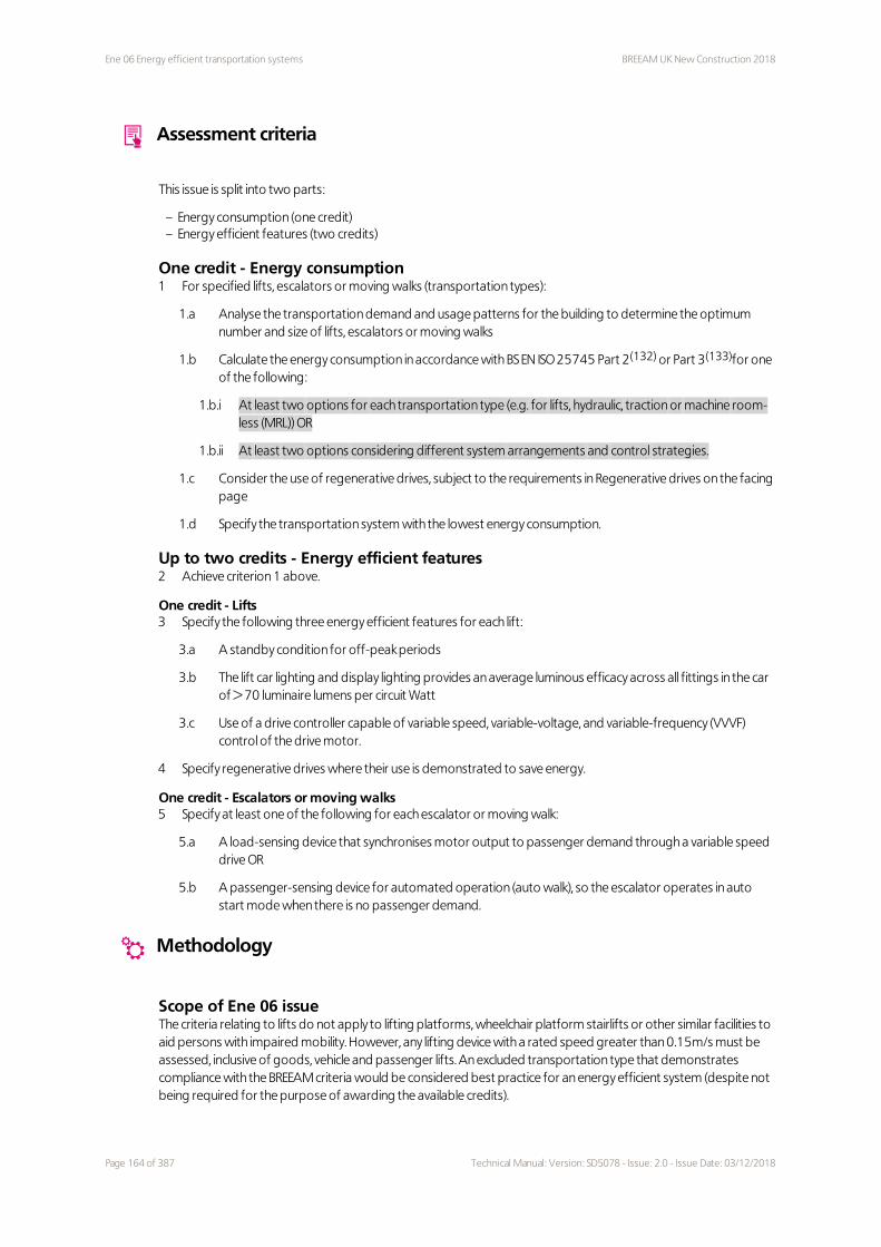
Ene 06 Energy efficient transportation systems BREEAM UK New Construction 2018
Assessment criteria
This issue is split into two parts:
– Energy consumption (one credit)– Energy efficient features (two credits)
One credit - Energy consumption1 For specified lifts, escalators or moving walks (transportation types):
1.a Analyse the transportation demand and usage patterns for the building to determine the optimum number and size of lifts, escalators or moving walks
1.b Calculate the energy consumption in accordance with BS EN ISO 25745 Part 2(132) or Part 3(133)for one of the following:
1.b.i At least two options for each transportation type (e.g. for lifts, hydraulic, traction or machine room-less (MRL)) OR
1.b.ii At least two options considering different system arrangements and control strategies.
1.c Consider the use of regenerative drives, subject to the requirements in Regenerative drives on the facing page
1.d Specify the transportation system with the lowest energy consumption.
Up to two credits - Energy efficient features2 Achieve criterion 1 above.
One credit - Lifts3 Specify the following three energy efficient features for each lift:
3.a A standby condition for off-peak periods
3.b The lift car lighting and display lighting provides an average luminous efficacy across all fittings in the car of > 70 luminaire lumens per circuit Watt
3.c Use of a drive controller capable of variable speed, variable-voltage, and variable-frequency (VVVF) control of the drive motor.
4 Specify regenerative drives where their use is demonstrated to save energy.
One credit - Escalators or moving walks5 Specify at least one of the following for each escalator or moving walk:
5.a A load-sensing device that synchronises motor output to passenger demand through a variable speed drive OR
5.b A passenger-sensing device for automated operation (auto walk), so the escalator operates in auto start mode when there is no passenger demand.
Methodology
Scope of Ene 06 issueThe criteria relating to lifts do not apply to lifting platforms, wheelchair platform stairlifts or other similar facilities to aid persons with impaired mobility. However, any lifting device with a rated speed greater than 0.15m/s must be assessed, inclusive of goods, vehicle and passenger lifts. An excluded transportation type that demonstrates compliance with the BREEAM criteria would be considered best practice for an energy efficient system (despite not being required for the purpose of awarding the available credits).
Page 164 of 387 Technical Manual: Version: SD5078 - Issue: 2.0 - Issue Date: 03/12/2018

BREEAM UK New Construction 2018 Ene 06 Energy efficient transportation systems
Transport analysisThe transport analysis (criterion 1.a on the previous page) can be in the form of a written statement justifying the lift selection for the following conditions:
– where a single lift is provided in a low rise building for the purpose of providing disabled access only– or where a goods lift is selected based on the size of the goods it is intended to carry.
Regenerative drivesA regenerative drive should only be considered where it produces an energy saving greater than the additional standby energy used to support the drives. Regenerative drives will typically be appropriate for lifts with high travel and high intensity use.
Building has no lifts, escalators or moving walks, or has only one of the transportation systemsThis issue will not be assessed where a building contains no lifts, escalators or moving walks. Where only either lifts, escalators or moving walks are present, only one credit is available for the Energy efficient features credit. Where both lifts and escalators or moving walks are present, then two credits are available.
Extensions to existing buildingsIf assessing a new extension to an existing building, lifts present in the existing building fall outside the Ene 06 scope and do not need to be assessed. The above applies only where the lifts are not being renewed or undergoing a major refurbishment.
Evidence
Criteria Interim design stage Final post-construction stage
All One or more of the appropriate evidence types listed in The BREEAM evidential requirements on page 29 can be used to demonstrate compliance with these criteria
Definitions
Auto start condition - escalators and moving walks
A condition when the escalator or moving walk is stationary and powered up and ready to start initiated by
passenger detection (from BS EN ISO 25745-3:2015).
Fit for purpose
A system strategy that is appropriate and well suited for its designated role or use.
Idle condition
A condition when a lift is stationary at a floor following a run before the standby mode is entered (from BS EN ISO
25745-1: 2012(134)).
Lift car lighting
The level of lift car lighting is determined by the relevant standards. For example, BS EN 81-20:2014(135) requires
at least 100 lux on the control devices and at 1m above the floor at any point not less than 100mm from any wall.
Machine room-less lift (MRL)
All equipment is contained in the lift well, not in a separate machine room.
Standby condition - lifts
A condition when a lift is stationary at a floor and may have reduced the power consumption to a lower level set
for that particular lift (from BS EN ISO 25745-1: 2012). For example, the power side of the lift controller and other
Technical Manual: Version: SD5078 - Issue: 2.0 - Issue Date: 03/12/2018 Page 165 of 387

Ene 06 Energy efficient transportation systems BREEAM UK New Construction 2018
operating equipment such as lift car lighting, user displays and ventilation fans switch off when the lift has been
idle for a prescribed length of time. The period between when a lift was last used and when a standby condition is
entered is defined in BS EN ISO 25745-1 as 5 minutes.
Additional information
BS EN ISO 25745 - Energy performance of lifts, escalators and moving walksBS EN ISO 25745 consists of three parts, under the general title Energy performance of lifts, escalators and moving walks:
– Part 1: Energy measurement and verification– Part 2: Energy calculation and classification for lifts (elevators)– Part 3: Energy calculation and classification for escalators and moving walks.
In Part 1, it has been estimated that approximately 5% of a building’s total energy consumption can be attributed to the operation of lifts and a large proportion of this can be attributed to standby mode in many situations. BS EN ISO 25745 Parts 2 and 3 have been prepared in response to the rapidly increasing need to ensure and to support the efficient and effective use of energy, providing:
1. A method to estimate energy consumption on a daily and an annual basis for lifts, escalators and moving walks
2. A method for energy classification of new, existing or modernised lifts, escalators and moving walks 3. Guidelines for reducing energy consumption that can be used to support building environmental and
energy classification systems.
Page 166 of 387 Technical Manual: Version: SD5078 - Issue: 2.0 - Issue Date: 03/12/2018

BREEAM UK New Construction 2018 Ene 07 Energy efficient laboratory systems
Ene 07 Energy efficient laboratory systems
Fully fitted Simple building Shell & core Shell only No minimum standards
Aim
To encourage laboratory areas that are designed to minimise their operational energy consumption and associated CO₂ emissions.
Value
– Encourage effective communication between the client and the design team to identify the occupant requirements and performance criteria.
– Reduced capital and operating costs as a result of appropriate sizing and specification of equipment and adoption of best practice design principles.
– Ensure that energy efficiency measures do not affect the health and safety of the occupants.
Context
Laboratory facilities are required to comply with regulations and other standards for safety and various environmental conditions such temperature and air quality. Compared with an office building, the average laboratory consumes ten times more energy per square feet, with some labs using as much as 100 times more energy(136). Therefore, energy efficient measures can result in significantly reduced energy costs and waste, improved systems efficiency, and long-term sustainability.
Assessment scope
Fully fitted Simple building Shell and core Shell only
Applicable assessment criteria All None None None
Assessment type specific notes None None None None
Specific notes
Assessment type specific
None
Building type specific
2.0 Further education, higher education, offices This issue is applicable only to further education, higher education, offices with research and development areas, and other buildings with research and development facilities that contain
5 Not applicable Not applicable Not applicable
Technical Manual: Version: SD5078 - Issue: 2.0 - Issue Date: 03/12/2018 Page 167 of 387

Ene 07 Energy efficient laboratory systems BREEAM UK New Construction 2018
Building type specific
laboratory space and containment devices or areas. This issue is not applicable for school buildings (primary and secondary level).
Assessment criteria
This issue is split into two parts:
– Design specification (one credit)– Best practice energy efficient measures (up to four credits) - building type dependent.
One credit - Design specification1 Engage with the client during the preparation of the initial project brief to determine occupant requirements
and define laboratory performance criteria. Performance criteria will include, but not be limited to:
1.a Description of purpose
1.b Occupant or process activities
1.c Containment requirements and standards
1.d Interaction between systems
1.e Flexibility and adaptability of laboratory facilities.
1.f Any other specific requirements (for example, requirements relevant to ventilation, heating or cooling).
2 Size the services system equipment (including ventilation supply and extract) correctly (see Definitions on page 170).
3 Demonstrate the minimised energy demand of the laboratory facilities resulting from the achievement of the defined design performance criteria.
Laboratory containment devices and containment areas (criteria only applicable to buildings containing these facilities)4 For ducted fume cupboards specified:
4.a Demonstrate that the average design air flow rate is no greater than 0.16m³/s per linear metre (internal width) of fume cupboard workspace
4.b Measure the volume flow rate in the exhaust duct (at the boundary of the laboratory) to take account of reductions in (inward) volume flow rate from fume cupboard leakage
4.c Demonstrate that a reduction in air flow does not compromise the defined performance criteria and does not increase the health and safety risk to future building occupants.
Up to four credits - Best practice energy efficient measuresIf the laboratory area accounts for at least 10% of the total building floor area (see Definitions on page 170):
5 Achieve criteria 1 to 4 above (or criteria 1 to 3 above where there are no ducted fume cupboards).
6 Design, specify and install laboratory plant and systems to promote energy efficiency. Demonstrate compliance with items in Table 6.4 on the facing page (see 6.a and 6.b for credits available).
6.a Up to 2 credits: laboratory areas (see Definitions on page 170) account for at least 10% (but less than 25%) of the total building floor area OR
6.b Up to 4 credits: laboratory areas account for 25% or more of the total building floor area.
7 Demonstrate by calculations or modelling that the chosen measures have a reasonably significant effect on the total energy consumption of the laboratory, i.e. 2% reduction or greater.
Page 168 of 387 Technical Manual: Version: SD5078 - Issue: 2.0 - Issue Date: 03/12/2018

BREEAM UK New Construction 2018 Ene 07 Energy efficient laboratory systems
8 Demonstrate that the energy efficient measures specified do not compromise the defined performance criteria, and do not increase the health and safety risk to future building occupants.
Table 6.4 Best practice energy efficient measures in laboratoriesItem description Credits 1
Fume cupboard volume flow rates (further reduction)
An average design air flow rate of < 0.12m³/s per linear metre (internal width) of fume cupboard workspace.
0.5
Grouping or isolation of high filtration or ventilation activities
Minimisation of room air change rates and overall facility ventilation flows by grouping together or isolating activities and equipment with high filtration or ventilation requirements.
0.5
Energy recovery - heat
Heat recovery from exhaust air (where there is no risk of cross-contamination) or via refrigerant or water cooling systems.
0.5
Energy recovery - cooling
Cooling recovery via exhaust air heat exchangers (where there is no risk of cross-contamination) or via refrigerant or water cooling systems.
0.5
Grouping of cooling loads
Grouping of cooling loads to enable supply efficiencies and thermal transfer.
0.5
Free cooling
Specification of free cooling coils in chillers or dry air coolers related to laboratory-specific activities.
0.5
Load responsiveness
Effective matching of supply with demand through modularity, variable speed drives and pumps, and other mechanisms.
0.5
Clean rooms
Specification of particle monitoring systems, linked to airflow controls. 0.5
Diversity
Achievement of high levels of diversity in central plant sizing and laboratory duct sizing, where compatible with safety.
0.5
Room air changes rates
Reducing air change rates by matching ventilation airflows to environmental needs and demands of containment devices.
0.5
Fan power
Specification and achievement of best practice fan power figures (as shown below) for all air handling units, laboratory extract systems, local extract ventilation, containment area extracts (where applicable) and fume cupboard extracts (where applicable).
1
Laboratory system Best practice specific fan power(W/(L/s))
General laboratory supply air handling unit (AHU) with heating and cooling 1.5
General laboratory extract systems 1.2
Laboratory local extract ventilation – ducted 1.0
Containment area extract, without high efficiency particulate absorption (HEPA) filtration
1.5
Containment area extract, with HEPA filtration 2.5
Fume cupboard extract 1.5
Only whole credits can be awarded in BREEAM. Therefore to achieve a credit for items with partial credits, the laboratory must comply with at least two of the items. In an instance where, for example, three and half credits are achieved this would need to be rounded down to three credits.
Technical Manual: Version: SD5078 - Issue: 2.0 - Issue Date: 03/12/2018 Page 169 of 387

Ene 07 Energy efficient laboratory systems BREEAM UK New Construction 2018
Methodology
Applicable standardsThe guidance within G9 Fume Cupboards in Schools(137) (Building Bulletin 88(138) can be used for assessments in Northern Ireland) should be followed. Where containment devices present in a school or sixth form college assessment are of a specialist nature more typical of a commercial or research laboratory, BRE should be contacted for further guidance.
Evidence
Criteria Interim design stage Final post-construction stage
All One or more of the appropriate evidence types listed in The BREEAM evidential requirements on page 29 can be used to demonstrate compliance with these criteria.
Definitions
Laboratory areas
Laboratory areas are defined as highly serviced (temperature, ventilation, humidity or containment controlled)
spaces where physical, biological or chemical processing or testing is carried out. Such areas will have inherently
high energy demands. In order to maintain controlled conditions to enable experiments and to comply with
health and safety standards, typically laboratories:
1. Contain various exhaust and containment devices (such as fume cupboards and microbiological safety cabinets)
2. Are heavily serviced to circulate air and to supply heating, cooling, humidity, and clean air 3. Often require 24-hour access and failsafe redundant backup systems and uninterrupted power supply or
emergency power to enable irreplaceable experiments.Therefore, for the purpose of assessing this BREEAM issue, the definition of laboratory areas excludes any
laboratory support areas such as:
1. Write up or offices 2. Meeting rooms 3. Storage 4. Ancillary and other support areas with lower servicing requirements.
Teaching and other laboratories or workshops with a limited number of fume cupboards or other containment
devices or no energy-intensive process equipment specified are excluded, unless the design team can provide
evidence that their consumption is at least 50% higher than a typical office due to the laboratory process-related
activities. Benchmarks for general offices can be found in Table 1 in CIBSE TM46(139) Energy benchmarks. Typically,
in buildings where 40% of the floor area is laboratory related, only 10% will actually constitute laboratory areas as
per the BREEAM definition. Different types of laboratories have different requirements for heating, ventilation and
air-conditioning, plug load equipment, and access. This can lead to enormous variations in energy and water
requirements. The main types of laboratories include:
1. Wet laboratories - where chemicals, drugs or other material, or biological matter are tested and analysed requiring water, direct ventilation and specialised piped utilities. They typically include chemical science laboratories. These laboratories require specially designed facilities.
2. Dry laboratories - contain dry stored materials, electronics or large instruments with few piped services. They typically include engineering or analytical laboratories that may require accurate temperature and humidity control, dust control and clean power.
Page 170 of 387 Technical Manual: Version: SD5078 - Issue: 2.0 - Issue Date: 03/12/2018

BREEAM UK New Construction 2018 Ene 07 Energy efficient laboratory systems
3. Microbiological or clinical laboratories - often involve working with infectious agents. They typically require higher levels of primary containment and multiple secondary barriers including specialised ventilation systems to ensure directional air flow, air treatment systems to decontaminate or remove agents from exhaust air, controlled access zones, airlocks as laboratory entrances, or separate buildings or modules to isolate the laboratory.
4. In vivo laboratories - these require highly controlled environments for the care and maintenance of flora and fauna. The facilities are complex and expensive to build and operate. Tight environmental control over the facility is required to avoid the introduction of contaminants or pathogens, prevent the possibility of infectious outbreaks, and avoid the transmission of odours.
5. Teaching laboratories - unique to academic institutes, they require space for teaching equipment, storage space for student belongings and less instrumentation than research labs.
6. Clean rooms - this refers to a controlled environment (air quality, temperature and humidity) which prevents contamination and regulates environmental conditions, to facilitate accurate research and production needs. They are typically used in UK universities for nanotechnology, medical and pharmaceutical research or studies, and microelectronics applications.
Right-sizing
Right-sizing principles encourage the use of better estimates in equipment loads from which services equipment
is sized in comparison to traditional methods of estimates based on ‘rated’ data obtained from manufacturers’
literature or design assumptions from previous projects. This can result in construction cost savings in addition to
life cycle cost benefits, while taking account of the need for appropriate contingency.
Additional information
Synergy with BREEAM issue Ene 01 Reduction of energy use and carbon emissionsThis BREEAM issue has been developed to recognise improvements made to new laboratory areas or buildings that are not currently fully recognised in the National Calculation Methodology, which is used to assess and award credits in Ene 01 Reduction of energy use and carbon emissions on page 128 .
Technical Manual: Version: SD5078 - Issue: 2.0 - Issue Date: 03/12/2018 Page 171 of 387

Ene 08 Energy efficient equipment BREEAM UK New Construction 2018
Ene 08 Energy efficient equipment
Fully fitted Simple building Shell & core Shell only No minimum standards
Aim
To encourage installation of energy efficient equipment to ensure optimum performance and energy savings in operation.
Value
– Reduce unregulated energy consumption loads based on the building’s usage and occupants patterns.– Promote a better understanding of unregulated energy consumption for the significantly consuming systems,
thereby reducing the performance gap.
Context
The current building regulations do not account for all energy uses in buildings and aim to address regulated energy consumption. Unregulated sources of energy consumption such as swimming pools, server rooms, commercial and domestic-scale appliances, are rarely considered and modelled at the design stage. However, they can have significant impact on the energy use. In an office building for instance, they typically account for more than 30% of the energy consumption(140). It is important to encourage solutions that result in unregulated energy reduction, which is variable between different building types and ignored by current regulatory standards.
Assessment scope
Fully fitted Simple building Shell and core Shell only
Applicable assessment criteria All All None None
Assessment type specific notes 1.0 See ref. 1.0 and 2.0 None None
Specific notes
Assessment type specific
1.0 Where there are no systems specified that contribute to the unregulated energy load, this issue is not applicable.
2.0 - Criterion 1 on the facing page and 2: Swimming pool criteria from Table 6.5 on the facing page are not applicable. All other criteria relevant to the building type and function apply.
Building type specific
2.0 Healthcare
2 2 Not applicable Not applicable
Page 172 of 387 Technical Manual: Version: SD5078 - Issue: 2.0 - Issue Date: 03/12/2018

BREEAM UK New Construction 2018 Ene 08 Energy efficient equipment
Building type specific
All medical equipment is exempt from complying with the criteria.
2.1 Multi-residentialDomestic-scale appliances (individual and communal facilities) below item 5b is only applicable to multi-residential assessments.
Assessment criteria
Two credits1 Identify the building's unregulated energy consuming loads. Estimate their contribution to the total annual
unregulated energy consumption of the building, assuming a typical or standard specification.
2 Identify the systems or processes that use a significant proportion of the total annual unregulated energy consumption of the building.
3 Demonstrate a meaningful reduction in the total annual unregulated energy consumption of the building. Table 6.5 below lists some examples of significant contributors to unregulated energy consumption, and the associated criteria. If additional significant contributors, not listed in the table, will be specified, the design team should justify how a meaningful reduction will be achieved for these contributors.
Table 6.5 Significant contributors to unregulated energy consumption, for a number of different building types or functions, and the solutions deemed to comply
Significant contributors
Swimming pool
1. Specify automatic or semi-automatic pool covers, or ‘liquid’ pool covers with an automatic dosing system to ALL pools, including spa pools and hot tubs.
2. The covers envelop the entire pool surface when fully extended. 3. Control the air temperature in the pool hall so that it is 1°C above the water temperature.
Laundry facilities with commercial-sized appliances
Demonstrate at least one of the following for commercial-sized appliances: 1. Specification of heat recovery from waste water. 2. Use of greywater for part of the washing process. This may be recycled from the final rinse and used
for the next pre-wash. 3. The commercial or industrial sized machines are identified as eligible for the UK’s Enhanced Capital
Allowance Scheme for water(141).
Data centres
1. Design is in accordance with the ‘Best practices for the EU Code of Conduct on Data Centres’(142) principles with the data centre achieving at least the ‘Expected minimum practice’ level (as defined in the Code of Conduct).
2. Temperature set points are not less than 24°C, as measured at the inlet of the equipment in the rack.
IT-intensive operating areas
1. Specify a natural ventilation and cooling strategy as standard. Use forced ventilation only when the internal temperature exceeds 20°C and active cooling only when the internal temperature exceeds 22°C.
2. Specify a mechanism to achieve automatic power-down of equipment when not in use, including overnight.
Domestic-scale appliances (individual and communal facilities)
Any white goods, available to purchase from the developer, must achieve the following ratings (or better) under the EU Energy Efficiency Labelling Scheme:
1. Fridges, fridge-freezers: A+ rating 2. Washing machines: A++ rating 3. Dishwashers: A+ rating 4. Washer-dryers: A rating 5. Tumble dryers:
a. A rating OR
Technical Manual: Version: SD5078 - Issue: 2.0 - Issue Date: 03/12/2018 Page 173 of 387

Ene 08 Energy efficient equipment BREEAM UK New Construction 2018
Significant contributors
b. For multi-residential assessments only, provide an adequate internal or external space capable of holding drying lines as specified in Drying lines below section.
Healthcare
Carry out a life cycle costing analysis for at least two options in accordance with HTM 07-02, Part B, Chapter 1(143). Inform and specify large-scale equipment (where present, see Definitions on page 176) and sets of electrical equipment (where numbering more than 50) based on the life cycle costing analysis.
Kitchen and catering facilities
Incorporate at least two-thirds of the energy efficiency measures outlined in the 'section summary' boxes of each of the following sections of CIBSE Guide TM50(144) (except as specified):
1. Section 8 - Drainage and kitchen waste removal 2. Section 9 - Energy controls - specifically controls relevant to appliances 3. Section 11 - Appliance specification - excluding fabrication or utensil specifications 4. Section 12 - Refrigeration 5. Section 13 - Warewashing: dishwashers and glasswashers 6. Section 14 - Cooking appliance selection 7. Section 15 - Water temperatures, taps, faucets and water-saving controls.
Refrigeration (see Refrigeration equipment on the facing page) for kitchen and catering facilities should be assessed here, not in Ene 05 Energy efficient cold storage on page 159.
Methodology
Estimating annual unregulated energy consumptionA method should be used that estimates actual energy use, based on expected equipment loads and hours of operation. The energy uses may be estimated by using simple hand calculations, or benchmark data, or by the methods described in CIBSE TM54: Evaluating operational energy performance of buildings at the design stage(145).
Estimating a significant proportion of annual unregulated energy consumptionThis methodology is used to estimate which energy uses make up a significant proportion of the unregulated energy uses which means that detailed calculations are not required. The approach should focus on identifying the larger energy uses that should be included and the small energy uses that can be excluded. As a guide, energy uses making up at least 90% of the estimated total annual energy consumption should typically be included (this is a statutory requirement in Wales, Northern Ireland and England – see - Additional information on page 146).
A meaningful reduction in unregulated energy demandBREEAM does not specify a level or percentage that defines a meaningful reduction in unregulated energy demand. The project team must justify how they have determined or judged a meaningful reduction from the unregulated energy demand and the assessor must be satisfied that this is an appropriate justification.
Domestic-scale appliances
Drying linesDomestic-scale appliances (individual and communal facilities) requires the provision of an adequate internal or external secure space with posts and footings, or fixings capable of holding:
1. For self-contained dwellings: a. One to two bedrooms: 4m+ of drying line b. Three or more bedrooms: 6m+ of drying line.
2. For individual bedrooms: a. Two metres or more of drying line per bedroom for developments with up to 30 individual bedrooms,
plus b. One metre of additional drying line for each bedroom over the 30 individual bedroom threshold.
Adequate internal drying spaceA heated space with adequate, controlled ventilation, complying with the national building regulations relevant to the location of the building (rooms that commonly meet these requirements are a bathroom or utility room)
Page 174 of 387 Technical Manual: Version: SD5078 - Issue: 2.0 - Issue Date: 03/12/2018

BREEAM UK New Construction 2018 Ene 08 Energy efficient equipment
OR
An unheated outbuilding, where calculations by an appropriate Member of the Chartered Institute of Building
Services Engineers (CIBSE) or an equivalent professional demonstrate that ventilation in the space is adequate to
allow drying in normal climatic conditions and to prevent condensation and mould growth. The fixing or fitting
needs to be a permanent feature of the room. Internal drying spaces in the following rooms do not comply:
1. Living rooms 2. Kitchens 3. Dining rooms 4. Main halls 5. Bedrooms.
Excluded building typesThis criterion does not apply to multi-residential assessments of supported living facilities (for safety reasons, to minimise ligature risk to particular residents). It is also not applicable to projects where occupancy is transient, such as hotel or hostel type developments, but does apply to long term residential buildings.
Refrigeration equipmentSection 12 - Refrigeration from Kitchen and catering facilities on the previous page apply to the following refrigeration equipment (where present):
1. Air-cooled condensing units 2. Cellar cooling 3. Commercial service cabinets 4. Curtains or blinds for refrigerated display cabinets 5. Refrigeration compressors 6. Refrigeration system controls 7. Refrigerated display cabinets.
Cold storageThe criteria do apply to commercial kitchen refrigeration but not to other commercial or industrial sized refrigeration and storage systems. These systems are covered within the scope of Ene 05 Energy efficient cold storage on page 159 and should be removed from the list of unregulated loads with respect to this issue.
Lifts, escalators and moving walksThis issue does not apply to lifts, escalators and moving walkways. These systems are covered within the scope of Ene 06 Energy efficient transportation systems on page 163 and should be removed from the list of unregulated loads with respect to this issue.
Laboratory systemsThis issue does not apply to laboratory ducted fume cupboards. These systems are covered within the scope of Ene
07 Energy efficient laboratory systems on page 167 and should be removed from the list of unregulated loads with
respect to this issue.
Reuse of equipmentReuse of electrical equipment does not comply by default, as it may not be the most energy efficient option. However, the credit could be awarded if either of the following criteria is demonstrated:
1. The existing electrical appliances meet the criteria for inclusion on the Enhanced Capital Allowance Scheme Energy Technology Product List(146).
2. Reusing the old equipment would, over the course of its life, be a more energy efficient option than specifying new equipment.
Technical Manual: Version: SD5078 - Issue: 2.0 - Issue Date: 03/12/2018 Page 175 of 387

Ene 08 Energy efficient equipment BREEAM UK New Construction 2018
Evidence
Criteria Interim design stage Final post-construction stage
All One or more of the appropriate evidence types listed in The BREEAM evidential requirements on page 29 can be used to demonstrate compliance with these criteria.
Definitions
Data centre
For the purpose of this BREEAM issue, the term ‘data centres’ includes all buildings, facilities and rooms which
contain enterprise servers, server communication equipment, cooling equipment and power equipment, and may
provide some form of data service (e.g. large-scale mission critical facilities all the way down to small server rooms
located in office buildings).
Healthcare large-scale equipment
This includes commercial-scale catering and laundry equipment and all other equipment with connected electrical
loads in excess of 10 kW rated input power.
IT-intensive areas
These include computer areas where more than one computer per 5m² is provided, e.g. IT areas in training suites,
design studios, libraries, and other areas with a high density of computing devices.
Regulated energy
Building energy consumption resulting from the specification of controlled, fixed building services and fittings,
including space heating and cooling, hot water, ventilation and lighting.
Secure space
For self-contained dwellings this can be defined as an enclosed space only accessible to the residents of the
dwelling. For buildings with a communal drying space it is an enclosed space with a secure entrance, accessible to
the residents of the building only.
Unregulated energy
Building energy consumption resulting from a system or process that is not ‘controlled’, i.e. energy consumption
from systems in the building on which the building regulations do not impose a requirement. This may include
energy consumption from operational-related equipment, e.g. computers, servers, printers, laptops, mobile
fume cupboards, cooking, audio-visual equipment and other appliances etc.
Unlike the definition for Ene 01 Reduction of energy use and carbon emissions, for this issue, it does not include
energy consumption from systems integral to the building and its operation (e.g. commercial or industrial
refrigeration systems; lifts, escalators and other transportation systems; and ducted fume cupboards) because
they are already assessed separately in issues Ene 05, Ene 06 and Ene 07 respectively.
White goods
Domestic appliances, for example, washing machines, fridges, freezers, fridge-freezers, tumble dryers, washer-
dryers.
Page 176 of 387 Technical Manual: Version: SD5078 - Issue: 2.0 - Issue Date: 03/12/2018

BREEAM UK New Construction 2018 Ene 08 Energy efficient equipment
Additional information
Ventilation - Building regulations See Domestic-scale appliances (individual and communal facilities), Table 6.5 on page 173, item 5b
The following lists the building regulations relevant for the assessment of this issue specific to the UK countries:
– Wales - Approved Document F Ventilation 2010 (England and Wales)(147)
– Scotland - Technical Handbook 2016 - Domestic Section 3 Environment(148)
– Northern Ireland - Technical Booklet K Ventilation 2012(149)
– England - Approved Document F Ventilation 2010 edition (incorporating 2010 and 2013 amendments, England and Wales)(150).
Technical Manual: Version: SD5078 - Issue: 2.0 - Issue Date: 03/12/2018 Page 177 of 387

Transport BREEAM UK New Construction 2018
Transport
Fully fitted Simple building Shell & core Shell only
Summary
This category encourages provision of and improved access to local amenities and to sustainable means of transport, i.e. public transport and other alternative transport solutions for building users. The aim is to reward locations and solutions that support reductions in car journeys and, therefore, congestion and CO₂ emissions over the life of the building.
Assessment timeline
To assist with optimising project sustainability performance, the assessment timeline outlines the stage at which credits should be addressed. Ideally these should be considered by the design team, planner, contractors, owners, occupiers and other members of the project team to achieve the highest possible BREEAM rating at the minimum cost.
If BREEAM advice is taken on too late within the design and construction phases a number of BREEAM credits may not be achieved or only at additional cost or disruption.
Tra 01 Transport assessment and travel plan 2 credits
– Recognising developments in proximity to good public transport networks, thereby helping to reduce transport-related pollution and congestion.
Tra 02 Sustainable transport measures 10 credits
– Recognising developments in close proximity of, and accessible to, local amenities which are likely to be frequently required and used by building occupants.
10% 11.5% 11.5% 14.5%
Page 178 of 387 Technical Manual: Version: SD5078 - Issue: 2.0 - Issue Date: 03/12/2018

BREEAM UK New Construction 2018 Tra 01 Transport assessment and travel plan
Tra 01 Transport assessment and travel plan
Fully fitted Simple building Shell & core Shell only No minimum standards
Aim
To reward awareness of existing local transport and identify improvements to make it more sustainable.
Value
– Promote the development of an initial transport assessment for the site.– Promote the implementation of travel solutions that are relevant to the challenges and opportunities of a
specific site.– Raise awareness, understanding and accessibility of travel options, and local amenities, allowing for affordable
access to services.– Encourage more sustainable transport and movement of people and goods, to and around the site.– Encourage designers to account for the travel needs of future occupants, thereby allowing for better
management in operation.– Reduce congestion and improve safety on the site and local roads.– Increase attractiveness of the site to potential users.
Context
The National Planning Practice Guidance indicates that travel plans should be considered in parallel to development proposals and that they should be integrated into the design of a new site.
Based on evidence of the anticipated transport impacts of new developments, Travel Plans are a long term management strategy for implementing the mitigating measures addressed by the Transport Assessments or Statements(151).
They intend to promote sustainable and active travel. Their purpose is to deliver transport and transport-related benefits to the development itself and the wider community. As they include a package of actions designed to address the needs of the users in that local area, effective but unpopular solutions, such as parking restrictions, can be combined with popular but expensive solutions, such as bus subsidies, to ensure that the negative impacts are neutralised by the benefits.
The transport tools proposed by the Travel Plan are user-focused and ensure the increase and improvement of travel choices to the users, cost savings and improved company image and staff health and wellbeing.
Assessment scope
Fully fitted Simple building Shell and core Shell only
Applicable Assessment criteria All All All All
Assessment type specific notes None None None None
2 2 2 2
Technical Manual: Version: SD5078 - Issue: 2.0 - Issue Date: 03/12/2018 Page 179 of 387

Tra 01 Transport assessment and travel plan BREEAM UK New Construction 2018
Specific notes
Assessment type specific
None
Building type specific
None
Assessment criteria
Two credits – Transport assessment and Travel plan1 No later than Concept Design stage, undertake a site-specific transport assessment (or develop a travel
statement) and draft travel plan, which can demonstrably be used to influence the site layout and built form; see Methodology on the facing page.
2 The site-specific travel assessment (or statement) shall cover as a minimum:
2.a If relevant, travel patterns and attitudes of existing building or site users towards cycling, walking and public transport, to identify relevant constraints and opportunities.
2.b Predicted travel patterns and transport impact of future building or site users.
2.c Current local environment for pedestrians and cyclists, accounting for any age-related requirements of occupants and visitors.
2.d Reporting of the number and type of existing accessible amenities, see Table 7.1 below, within 500m of the site.
2.e Disabled access accounting for varying levels and types of disability, including visual impairment.
2.f Calculation of the existing public transport Accessibility Index (AI), see Methodology on the facing page.
2.g Current facilities for cyclists.
3 Following a transport assessment (in accordance with the requirements set out in criteria 2), develop a site-specific travel plan that provides a long term management strategy which encourages more sustainable travel. The travel plan includes measures to increase or improve more sustainable modes of transport and movement of people and goods during the building's operation see Methodology on the facing page.
4 If the occupier is known, involve them in the development of the travel plan.
5 Demonstrate that the travel plan will be implemented and supported by the building's management in operation.
Table 7.1 Amenities in proximity to the siteAmenities
Appropriate food outlet
Access to cash
Access to an outdoor open space (public or private, suitably sized and accessible to building users)
Access to a recreation or leisure facility for fitness or sports
Publicly available postal facility
Community facility
Over the counter services associated with a pharmacy
Public sector GP surgery or general medical centre
Childcare facility or school
Page 180 of 387 Technical Manual: Version: SD5078 - Issue: 2.0 - Issue Date: 03/12/2018

BREEAM UK New Construction 2018 Tra 01 Transport assessment and travel plan
Table 7.2 Default hours of operation by building type for a typical dayBuilding type Default hours
Commercial 08.00–19.00
Preschool, school, sixth form college
07.30–10.00,15.00–17.30
Further and Higher Education 08.00–19.00
Healthcare 07.00–20.00 (encompassing visiting hours and the typical daytime shift pattern)
Retail: Shopping centre 09.00–19.00
Retail: Supermarket 08.00–22.00
Retail: Service provider 08.00–18.00
Retail: Convenience store 07.00–22.00
Retail: DIY or retail park 08.00–20.00
Retail: shop 08.30–17.30
Multi-residential accommodation
08.00–19.00
Court 08.00–19.00
Prison 07.00–20:00(encompassing visiting hours and the typical daytime shift pattern)
Other buildings 08.00–19.00Or use any of the above hours, as appropriate to the building type.
24 hour use building 07.00–20.00
Methodology
Transport assessment or statementA transport assessment is required where a proposed development is likely to have transport and related environmental impacts. The study area for a transport assessment should be determined in discussions between the developer and appropriate authorities.
A transport statement is required if the proposed development is unlikely to have a significant impact on local transport networks or related environmental impacts. A transport statement can demonstrate compliance with BREEAM if relatively low numbers of trips or traffic flows, with minor transport impacts, are expected from the proposed development.
For further guidance refer to www.gov.uk/government/publications/guidance-on-transport-assessment.
Calculation of the public transport Accessibility Index (AI) 1. Collate the following information to determine the public transport Accessibility Index (AI) of the assessed
building: a. Distance (m) from the main building entrance to each compliant public transport node b. Public transport types serving the compliant node, e.g. bus or rail c. Average number of services stopping per hour at each compliant node during the operating hours of the
building for a typical day (see Table 7.2 above). 2. Use the BREEAM Accessibility Index tool to calculate the AI.
Calculating the average number of servicesFor the AI calculation, the frequency of public transport is the average number of services per hour. This average is calculated by determining the number of services stopping at the node (during the peak arrival and departure times for the building or the building's typical day’s operating hours, see definition of 'operating hours') divided by the number of hours within that period. For example, the average number of services for a building that operates between 08:00–19:00 hrs (11 hours) within proximity of a bus stop with 35 stopping services during this period is 3.2 (equivalent to an average service frequency of approximately 20 minutes).
Technical Manual: Version: SD5078 - Issue: 2.0 - Issue Date: 03/12/2018 Page 181 of 387

Tra 01 Transport assessment and travel plan BREEAM UK New Construction 2018
Multiple servicesServices that operate from more than one node within proximity of the building, the same bus serving two separate bus stops, must be considered only once, at the node in closest proximity to the building. Different services at the same node count as separate services.
Bi-directional routesRoutes will be bi-directional; however, for the purpose of calculating the index, consider only the direction with the highest frequency (in accordance with the PTAL methodology).
Campus or campus-style developments - entrance to consider when calculating the AIThe main entrance, (see Definitions on the facing page) to the campus, e.g. further or higher education sites, can be used to determine the distance to a compliant node if 80% or more of the buildings are within 1000m of this entrance.
If the site has more than one main entrance, either entrance can be used for the calculation.
Where less than 80% of the buildings are within 1000m of the campus’ main entrance, the assessed building’s main entrance must be used to determine the distance to a compliant node. This aims to encourage the location of public transport nodes inside or on the periphery of large campuses.
Buildings in Greater LondonThe transport for London Planning Information Database allows users to search for a specific London location by street name, coordinates or postcode and then calculate the Accessibility Index (AI) for that location. The Total AI is confirmed for the Point of Interest (POI) within the summary report, which can be downloaded and used as evidence of compliance for the assessed building. See tfl.gov.uk.
Operating hours in a typical dayA typical day represents the period when travel to and from the building by its users and visitors will be at its highest. For most buildings this should be taken as a mid-week day. In choosing a typical day the assessor should check that timetabled information for that day is, within reason, representative of the public transport provision for the entire operating week (excluding Sundays).
BREEAM considers a building’s accessibility to be defined by how readily the public transport network can be used by the majority of building users travelling to and from the building. In most cases the normal operating hours of the building can be used. Where shift patterns see the majority of building users (over 80%) arriving or leaving during a certain period, for example an office building where the majority of office workers arrive between 8.00–10.00, that period can be used as an alternative to the operating hours of the building. This accounts for some building types that operate a 24-hour day and on a shift work basis. During typically deemed unsociable hours, where there is little if any public transport operating, such periods do not need to be accounted for in the assessment of this issue. Where the assessed building operates on a 24-hour basis or the operating hours are unknown at the time of assessment, use Table 7.2 on the previous page.
Travel plan measuresAs a minimum, the following measures shall be considered when developing the travel plan:
– Negotiation with local bus, train or tram companies an increase in the local service provision for the development (see Tra 02 Sustainable transport measures: option 2)
– Provision of a public transport information system in a publicly accessible area (see Tra 02 Sustainable transport measures: option 3)
– Provision of electric recharging stations (see Tra 02 Sustainable transport measures: option 4)– Provision of parking priority spaces for car sharers (see Tra 02 Sustainable transport measures: option 5)– Consultation with the local authority on the state of the local cycling network and on improvements (see Tra 02
Sustainable transport measures: option 6)– Provision of dedicated and convenient cycle storage(see Tra 02 Sustainable transport measures: option 7)– Provision of cyclists’ facilities (see Tra 02 Sustainable transport measures: option 8)– Lighting, landscaping and shelter to create pleasant pedestrian and public transport waiting areas– Restrictions or charging for car parking– Pedestrian and cyclist friendly (for all types of user regardless of the level of mobility or visual impairment) with
the provision of cycle lanes, safe crossing points, direct routes, appropriate tactile surfaces, good lighting and signposting to other amenities, public transport nodes and adjoining off-site pedestrian and cycle routes
– Provision of suitable taxi drop-off or waiting areas
Page 182 of 387 Technical Manual: Version: SD5078 - Issue: 2.0 - Issue Date: 03/12/2018

BREEAM UK New Construction 2018 Tra 01 Transport assessment and travel plan
– Ensure rural buildings have appropriate access to transport to serve the local community adequately (where procured to do so, e.g. community centre).
Evidence
Criteria Interim design stage Final post-construction stage
All One or more of the appropriate evidence types listed in The BREEAM evidential requirements on page 29 can be used to demonstrate compliance with these criteria
Definitions
Accessibility Index (AI)
An indicator of the accessibility and density of the public transport network at a point of interest (the BREEAM-
assessed building). The index is influenced by the proximity and diversity of the public transport network and the
frequency of services at the accessible nodes. The greater the number of compliant nodes, services and their
proximity to the building, the higher the AI.
The methodology for calculating the AI uses transport for London’s Public Transport Accessibility Level (PTAL)
method, itself based on a methodology developed in 1992 by the London Borough of Hammersmith and
Fulham. For a detailed description of the PTAL methodology see transport for London’s 'Assessing transport
connectivity in London’ guidance document published in 2015.
Accessible amenities
Amenities (as listed) that are accessible via safe pedestrian routes, e.g. pavements, paths and safe crossing points
or, where provided, dedicated pedestrian crossing points. The distance should not be measured in a straight line
‘as the crow flies', but along the actual route.
Appropriate food outlet
Access to a food supply that is affordable to the majority of the building users as well as being appropriate for
their day-to-day needs. For example, a small office building with a small shop selling sandwiches or snacks, or a
multi-residential building with a restaurant in the local area.
Building users
This refers, as appropriate to building type, to the following:
1. Staff (commuter journeys and business travel) 2. Pupils and students 3. Visitors 4. Patients 5. Customers 6. Community users 7. Personnel who make deliveries and collections to and from the development 8. Contractors or service providers, who regularly work at and access the building or development 9. Residents of multi-residential buildings.
BREEAM Tra 01 Calculator tool
A spreadsheet-based calculator used to determine the AI for the assessed building.
Childcare or school
To provide child support for potential building users. For example, a nursery, childminding facilities or a school
local to the development.
Technical Manual: Version: SD5078 - Issue: 2.0 - Issue Date: 03/12/2018 Page 183 of 387

Tra 01 Transport assessment and travel plan BREEAM UK New Construction 2018
Community facility
An internal space that will facilitate community activities for the assessed building and its users. For example, for a
multi-residential building this could be a community hall or, for an office building, a public house.
Compliant transport node
A compliant node includes any bus service with a stop within 650m and any railway station within 1000m of the
assessed building’s main entrance, measured via a safe pedestrian route (not ‘as the crow flies’), but along the
actual route. The service stopping at each node must provide transport from, or onward travel to, either an urban
centre, major transport node or a community focal point, e.g. doctor’s surgery, library, school or village centre.
Only local services should be assessed and any national public transport services should be excluded from the
analysis, unless such a service can be said to provide a local commuter service. Prisons and MOD sites: The distance
requirement for a compliant node for buildings on these sites is 1000m for both bus and rail.
Main building entrance
The main building entrance is the entrance to the assessed building which is directly connected to the main
building reception, circulation routes, lifts or stairs, and is available to the majority of the building’s staff and visitors
on arrival. It is not the site entrance (unless the site entrance is also the building entrance, e.g. building with a
boundary on a public highway). For prison or MOD site assessments, the main entrance should be taken as the
gatehouse entrance.
Outdoor open space (public or private, suitably sized and accessible to building users)
A space that enables building users to take a break from internal building activities. For example, an office building
with space to sit outside for lunch. The space must be suitably sized for the building users associated with the
project and not form part of the public highway.
Recreation or leisure facility
A facility that allows building users to exercise and maintain a healthy lifestyle. For example, a local leisure centre,
tennis courts, on-site gym or, for a school, a local playground.
Rural location
A rural location is defined in this context as a site clearly not within or on the boundary of a small, medium or large
urban cover. An urban cover will have a population of 3000 people or more, located within a tract of continuously
built-up urban land extending 20 hectares or more. The definition of rural includes village locations, green field
sites or small urban centres with a population of less than 3000 people within a tract of land no greater than 20
hectares. Such locations will most likely be on a local bus route to larger urban areas or other local towns and may
have local shops and other facilities. This classification is based on the Department of Transport National Travel
Survey definition, which specifies urban areas based on the extent of urban development indicated on Ordnance
Survey maps.
Rural location-sensitive buildings
This definition includes any of the building types with a demonstrable social or economic need from a rural
population for the service provided by the new building, such that it is not feasible to locate it at an alternative site.
Examples of building types that may fall into this category:
1. Offices where providing services to the local community 2. Industrial where providing services to the local community 3. Retail where providing services to the local community 4. Preschool, primary and secondary school 5. GP surgery.
Page 184 of 387 Technical Manual: Version: SD5078 - Issue: 2.0 - Issue Date: 03/12/2018

BREEAM UK New Construction 2018 Tra 01 Transport assessment and travel plan
Travel plan
A travel plan is a strategy for managing all travel and transport within an organisation. It contains both physical
and behavioural measures aimed at increasing travel choices, through the use of sustainable modes of transport
to a site or development.
Additional information
None.
Technical Manual: Version: SD5078 - Issue: 2.0 - Issue Date: 03/12/2018 Page 185 of 387

Tra 02 Sustainable transport measures BREEAM UK New Construction 2018
Tra 02 Sustainable transport measures
Fully fitted Simple building Shell & core Shell only No minimum standards
Aim
To maximise the potential for local public, private and active transport through provision of sustainable transport measures appropriate to the site.
Value
– Encourage improvement of public transport provision.– Reduce building users' carbon footprint and associated negative environmental impacts, improving local air
quality and reducing local congestion.– Encourage reliance on active travel and engagement with local authorities.– Promote provision of electric car recharging stations and reduced reliance on cars.– Increase provision of local amenities.
Context
Cities around the world are actively looking at ways of improving quality of life, air quality, congestion, etc. The use of private cars is a key area that is being looked at. This is resulting in the consideration of increasingly stringent controls of private car use and the dependency on them.
Transport accounts for around a quarter of UK greenhouse gas emissions, significantly affecting air quality at the roadside(152). Public transport offers a route to addressing transport-related greenhouse gas emissions. The emissions from trains and buses can be up to eight times lower than car travel.
The National Planning Policy Framework places significant emphasis on sustainable transport options, stating that planning should “make the fullest possible use of public transport, walking and cycling, and focus significant development in locations which are or can be made sustainable”.
Air pollution is estimated to cause 29,000 deaths each year and reduces life expectancy by 6 months on average in the UK, at a cost of £16 billion per year(153). It also damages plants and animals, affecting biodiversity and crop yields.
By reducing air pollution levels, the burden of disease from stroke, heart disease, lung cancer and both chronic and acute respiratory diseases, including asthma, can be lessened.
While the role of strategic policies is key, the need to address these issues with careful planning and design remains key to the creation of urban environments that are healthier and more pleasant to live.
10 10 10 10
Page 186 of 387 Technical Manual: Version: SD5078 - Issue: 2.0 - Issue Date: 03/12/2018

BREEAM UK New Construction 2018 Tra 02 Sustainable transport measures
Assessment scope
Fully fitted Simple building Shell and core Shell only
Applicable Assessment criteria All All All All
Assessment type specific notes None None None None
Specific notes
Assessment type specific
None
Building type specific
None
Assessment criteria
Prerequisite1 Achieve criteria 3-5 in the Tra 01 Transport assessment and travel plan on page 179 credit.
10 credits – Transport options implementation2 Identify the sustainable transport measures, see Table 7.4 below.
3 Award credits according to the existing Accessible Index (AI) of the project, and the total number of points achieved for the options implemented, see Table 7.3 below.
Table 7.3 Credits available relating to the AI of the site and the number of points achievedAI < 25 points AI ≥ 25 & < 40 (urban centre) points AI of ≥ 40 points Credits
1 1 1
2 1 2
3 2 3
4 2 4
5 3 5
6 4 3 6
7 5 7
8 6 4 8
9 7 5 9
10 8 6 10
Table 7.4 Sustainable public, private and active transport measuresSustainable transport measures
Assessment option
Public transport measures Applicable building types
Points
1 1. The existing AI calculated in Tra 01 achieves the following:≥ 4 for prison or MOD sites, rural location sensitive
buildings, and other building group 3 ≥ 8 for all other building types
All 1
2 2. Demonstrate an increase over the existing Accessibility Index through negotiation with local bus, train or tram
All 2
Technical Manual: Version: SD5078 - Issue: 2.0 - Issue Date: 03/12/2018 Page 187 of 387

Tra 02 Sustainable transport measures BREEAM UK New Construction 2018
Sustainable transport measures
companies to increase the frequency of the local service provision for the development;
OR
3. Demonstrate an increase over the existing Accessibility Index. This could be through provision of a diverted bus route, a new or enhanced bus stop, or other similar solutions.
OR
3
4. Provide a dedicated service, such as a bus route or service (See Definitions on page 194).
3
3 5. Provide a public transport information system in a publicly accessible area, to allow building users access to up-to-date information on the available public transport and transport infrastructure. This may include signposting to public transport, cycling, walking infrastructure or local amenities.
All 1
Assessment option
Private transport measures Applicable building types
Points
4 6. Provide electric recharging stations of a minimum of 3kW for at least 10% of the total car parking capacity for the development.
All 1
5 7. Set up a car sharing group or facility to facilitate and encourage building users to car share.
8. Raise awareness of the sharing scheme with marketing and communication materials.
9. Provide priority spaces for car sharers for at least 5% of the total car parking capacity for the development.
10. Locate priority parking spaces nearest the development entrance used by the sharing scheme participants.
All 1
Assessment option
Active travel measures Applicable building types
Points
6 11. During preparation of the brief, the design team consults with the local authority (LA) on the state of the local cycling network and public accessible pedestrian routes, to focus on whichever the LA deems most relevant to the project, and how to improve it.
12. Agree and implement one proposition chosen with the local authority. The proposition supported by the development is additional to existing local plans and has a significant impact on the local cycling network or on pedestrian routes open to the public.
All 2
7 13. Install compliant cycle storage spaces to meet the minimum levels set out in Table 7.5 on the facing page.
All 1
8 14. Option 7 has been achieved. 15. Provide at least two compliant cyclists' facilities for the
building users, (including pupils where appropriate to the building type) – see Definitions on page 194 for the scope of each compliant facility: – Showers– Changing facilities – Lockers – Drying spaces.
All 1
Page 188 of 387 Technical Manual: Version: SD5078 - Issue: 2.0 - Issue Date: 03/12/2018

BREEAM UK New Construction 2018 Tra 02 Sustainable transport measures
Sustainable transport measures
9 Existing amenities:
16. At least three existing accessible amenities are present, see Table 7.6 on page 191, where relevant for a Building Group.
All 1
10 Enhanced amenities:
17. Ensure a minimum of one new accessible amenity, in accordance with Table 7.6 on page 191, for the relevant Building Group, is provided.
OR
2
18. Ensure more than one new accessible amenity, in accordance with Table 7.6 on page 191 for the relevant Building Group, is provided.
3
Assessment option
Alternative transport measures Applicable building types
Points
11 19. Implement one site-specific improvement measure, not covered by the options already listed in this issue, in line with the recommendations of the travel plan. Submit this for review by BRE.
All 1-3
Table 7.5 Cycle storage criteria for each building type (option 7). Building type Number
of spaces
Unit of measure
Notes
Commercial
Offices, Industrial 1 10 staff None.
Retail
Large retail 1 10 staff Use the maximum number of staff at any one time or shift. Provide staff spaces in addition to customer spaces. Separate spaces are encouraged but not essential as long as there is a minimum of 10 customer cycle spaces. Any retail development with at least 50 customer cycle storage spaces is compliant regardless of the number of parking spaces.
1 20 public car parking spaces
The requirement for staff spaces would still need to be fully met.
Small retail 4 Total Spaces are publicly accessible within proximity of a main building entrance. Compliant cyclists facilities are needed for staff only.
Education
Preschool or crèche
1 10 staff None.
Primary school 5 Per form or class in year group
This is based on one year group, not per year group. For example, a primary school that has three classes per year group would provide a total of 15 compliant cycle storages spaces for the whole school. If the number of forms or classes varies between year groups, base the calculation on the greatest number of classes or forms'.
Secondary schools and sixth form, further
1 10 staff and pupils and
FE and HE: student numbers account for both under- and post-graduates, as well as PhD students and post-doctorates.Use the sliding scale of compliance to determine the number
Technical Manual: Version: SD5078 - Issue: 2.0 - Issue Date: 03/12/2018 Page 189 of 387

Tra 02 Sustainable transport measures BREEAM UK New Construction 2018
Building type Number of spaces
Unit of measure
Notes
and higher education (FE and HE)
students in total
of cycle spaces if there are more than 200 building users.
Healthcare
All healthcare building types
1 10 staff Use the largest unit of measure for the building type, e.g. use beds for a hospital, use consulting rooms for a GP surgery. A minimum of four compliant cycle storage spaces is required.
1 2 consulting rooms OR 10 beds
Special healthcare building types, e.g. chemotherapy outpatient centre or maternity ward—for such building types, given the nature of the building function, the cycle storage spaces for ‘2 consulting rooms OR 10 beds’ (i.e. those intended for patients and visitors), might be excluded, as it is unlikely that patients and accompanying visitors would be cycling to and from the centre.
Courts and prisons
Prison establishment located building
1 10 staff None.
Law court 1 10 building occupants (staff and visitors)
None.
Multi-residential
Student residences, key worker accommodation
1 10 staff A minimum of one compliant space is required.
1 2 residents
Sheltered housing, Care homes, Supported living facility
1 10 staff None
1 10 Visitors or beds
Other building transport types
Type A Use office buildings criteria. The unit of measure for visitors or beds does not apply to hotels.
Type B 1 10 staff None
1 10 visitors or beds
Type C 1 20 staff A reduction to the cyclist provision in rural locations has been accounted for in the unit of measure for this transport type. It should not therefore be applied again.
1 20 building visitors or beds
Transport hubs 1 10 public users
Apply the sliding scale (see Methodology on the facing page) to a maximum of 5000 daily public users. Public users are regular peak time users of the service who start or finish their public transport journey at the assessed building.
MOD non- 1 10 living- These criteria apply to MOD buildings where the majority of
Page 190 of 387 Technical Manual: Version: SD5078 - Issue: 2.0 - Issue Date: 03/12/2018

BREEAM UK New Construction 2018 Tra 02 Sustainable transport measures
Building type Number of spaces
Unit of measure
Notes
residential out personnel
personnel live off-site.
MOD residential 1 2 residents
None
Where the number of building users (based upon the unit of measure) exceeds 200, the sliding scale of compliance can be used to identify the appropriate number of cycle spaces required.
Table 7.6 Amenities applicable for option 9 and 10 for different Building Groups (BG).Criteria BG 1 BG 2 BG 3 BG 4 BG 5 BG 6
Proximity (metres) 500 500 500 500 500 500
Appropriate food outlet ✔ ✔ ✔ ✔ ✔ ✔
Access to cash ✔ ✔ ✔ ✔ ✔ ✔
Access to an outdoor open space (public or private, provided suitably sized and accessible to building users)
✔ ✔ ✔ ✔ ✔ ✔
Access to a recreation or leisure facility for fitness or sports
✔ ✔ ✔ ✔ ✔ ✔
Publicly available postal facility ✔ ✔ ✔ ✔ ✔ ✔
Community facility ✔ ✔ ✔ ✔ ✔
Over the counter services associated with a pharmacy
✔ ✔ ✔ ✔ ✔ ✔
Public sector GP surgery or general medical centre
✔ ✔ ✔
Child care facility or school ✔ ✔ ✔ ✔
Key:✔ - Amenity relevant to building type.
Building Types:BG 1: Offices, Retail, Industrial, Courts and PrisonsBG 2: Preschool, Schools, Sixth FormBG 3: Higher Education and Further Education BG 4: HealthcareBG 5: Multi-residential BG 6: Other building types
Methodology
Campus or campus-style developments - entrance to consider(options 1, 2, 9 and 10 in Table 7.4 on page 187)
The main entrance to the campus, e.g. further or higher education sites, can be used to determine the distance to amenities, if 80% or more of the buildings are within 1000m of this entrance.
If the site has more than one main entrance, either entrance can be used for the calculation.
Where less than 80% of the buildings are within 1000m of the campus' main entrance, the assessed building’s main entrance must be used to determine the distance to a compliant node. This aims to encourage the location of public transport nodes inside or on the periphery of the campuses.
Number of building occupants unknown(option 7 in Table 7.4 on page 187)
Technical Manual: Version: SD5078 - Issue: 2.0 - Issue Date: 03/12/2018 Page 191 of 387

Tra 02 Sustainable transport measures BREEAM UK New Construction 2018
If the number of building occupants commuting to the development cannot be confirmed, e.g. speculative developments, use the default occupancy rates given in Table 7.7 on page 197 to determine a default number of users. Alternatively, the number of building occupants in an existing development of similar type and size can be used (the assessor must justify or validate the number used in their certification report).
Rural locations(option 7 in Table 7.4 on page 187)
For sites in rural locations:
1. Where the distance to the nearest urban location is greater than 10 miles, the number of compliant cycle spaces can be reduced by 50%.
2. Where the distance to the nearest urban location is greater than 20 miles, the number of compliant cycle spaces can be reduced by 70%.
3. Where the distance to the nearest urban location is greater than 30 miles, the number of compliant cycle spaces can be reduced by 90%.
The reduction will also reduce the requirement for compliant showers and lockers by the same margin for most building types by default, since the calculation is based on the number of cycle storage spaces. Building types where the number of required showers or lockers is not based on cycle storage provision can reduce the actual requirement for compliant showers or lockers by 50%, 70% or 90% as appropriate. This reduction cannot be applied in addition to the 50% reduction due to the building's Public transport Accessibility level (as described in Methodology on the previous page).
Cycle spaces reduction(option 7 in Table 7.4 on page 187)
Sites where the existing AI indicated in option 1 is met, can reduce the number of compliant cycle spaces requirement by 50%.
This reduction cannot be combined with the sliding scale.
Cyclists’ facilities reduction (option 8 in Table 7.4 on page 187)
Sites where the existing AI indicated in option 1 is met, can reduce the number of compliant cyclists facilities requirement by 50%.
This reduction cannot be combined with the sliding scale.
Sliding scale of compliance(option 7 in Table 7.4 on page 187)
To recognise the increased confidence in availability that occurs where there is larger scale provision of facilities, it is acceptable to reduce the provision requirement for building users by increasing the standard unit of measure (defined in Table 7.5 on page 189):
1. For buildings with more than 200 users but less than or equal to 300, the unit of measure can be increased by a ratio of 1.5.
2. For buildings with more than 300 users but less than or equal to 400, the unit of measure can be increased by a ratio of 2.
3. For buildings with more than 400 users, the unit of measure can be increased by a ratio of 2.5.
The calculation starts from the first 200 building users, with no ratio, and keeps going considering the ratio only for the remaining building users.
For example, an office building with 800 users would be required to provide the following number of cycle storage spaces:
– 1–200 users @ 1 space per 10 users = 20 spaces – 201–300 users @ 1 space per 15 users (standard unit of measure x 1.5) = 7 spaces – 301–400 users @ 1 space per 20 users (standard unit of measure x 2) = 5 spaces
Page 192 of 387 Technical Manual: Version: SD5078 - Issue: 2.0 - Issue Date: 03/12/2018

BREEAM UK New Construction 2018 Tra 02 Sustainable transport measures
– 401+ users @ 1 space per 25 users (standard unit of measure x 2.5) = 16 spaces – Total compliant cycle storage spaces required = 48 spaces.
The sliding scale of compliance does not apply to the following building types: large retail, primary schools, multi-residential buildings and MOD residential buildings.
Minimum cycle storage provision(option 7 in Table 7.4 on page 187)
Where the calculated number of required cycle storage spaces is less than four, total provision should be based on the lower of the following:
– A minimum of four compliant storage spaces must be provided OR– One space per user (staff and where appropriate other user groups).
Provision of cycle storage and facilities on sites with multiple buildings(option 7 and 8 in Table 7.4 on page 187)
Where a new or infill building is constructed on an existing site, or multiple new buildings are to be constructed on the same site, compliance with this issue may be assessed based on the standalone building or on a site-wide basis. How this is determined depends on the configuration of the proposed cycle storage and cycle facilities, and the interpretation and justification of the assessor.
Standalone approach(option 7 and 8 in Table 7.4 on page 187)
Cycle storage and associated facilities for the assessed building only:
Cycle storage:– The number of cycle storage spaces is compliant based on the number of users in the assessed building. The
sliding scale of compliance can be used (where applicable) when determining the number of storage spaces required.
– All storage spaces provided must be BREEAM compliant and these must be located within or in close proximity to the assessed building.
– Access arrangements, demarcation and positioning clearly associates the cycle storage provided with the assessed building only, within or in close proximity to the assessed building.
– Access arrangements, demarcation and positioning clearly associates the cycle storage provided with the assessed building only.
Cyclists’ facilities:– All new and existing facilities may be included, provided they are BREEAM compliant.– Facilities should be located within the assessed building, or in an accessible adjacent building, for the sole use of
the assessed building’s users.
Site-wide approach(option 7 and 8 in Table 7.4 on page 187)
Cycle storage and associated facilities accessible to users of the entire site, or where there is a distinct group of local buildings within a site that would share facilities:
Cycle storage:– The number of cycle storage spaces is compliant based on the number of users on site or within a group of local
buildings. The sliding scale of compliance can be used (where applicable) when determining the number of storage spaces required.
– All new storage spaces must be BREEAM compliant. Existing storage spaces may also be counted provided they allow bikes to be easily stored and accessed with the ability to be locked securely against a fixed structure.
Cyclists’ facilities:– The number of compliant cyclists’ facilities is based on the number of users on site who would be able to use
these facilities.– Cyclists’ facilities may be located anywhere on site. However, the total route that cyclists must take to access the
nearest cycle storage, cyclists’ facilities and building entrances, must be no greater than 500m via a safe and
Technical Manual: Version: SD5078 - Issue: 2.0 - Issue Date: 03/12/2018 Page 193 of 387

Tra 02 Sustainable transport measures BREEAM UK New Construction 2018
convenient route, as measured from the first to the last point on the route. Where possible, different types of cyclists’ facilities should be grouped together in designated areas for ease of access and use.– All new and existing facilities may be included, provided they are BREEAM compliant and conform to the 500m
requirement above.
Combination of the two approaches(option 7 and 8 in Table 7.4 on page 187)
A mix of the two approaches can be applied where cycle storage is delivered as a site- wide approach and facilities are being met for the assessed building only. However, where the opposite is being proposed (i.e. storage spaces are provided only for the assessed building and facilities are provided on a site-wide basis); the number of compliant cyclists’ facilities must be based on the number of users on site and the facilities must be located in an accessible location in close proximity to the storage spaces.
Phased developments(option 7 in Table 7.4 on page 187)
Where cycle storage cannot be installed at construction stage, due to phasing or pending demolition works, compliance may still be demonstrated provided:
– Clarification and justification is given for why the storage is not currently available. – A written contractual agreement is in place to provide BREEAM compliant storage within a clear and justifiable
time scale taking into account any related works which would reasonably delay final installation of facilities relating to the development
– Alternative storage is provided in the meantime that allows bikes to be easily stored and removed, with the ability to be locked securely against a fixed structure.
The methodology above applies to cycle storage only, and cannot be applied to provision of cyclists’ facilities which must be assessed as normal.
Evidence
Criteria Interim design stage Final post construction stage
All One or more of the appropriate evidence types listed in The BREEAM evidential requirements on page 29 can be used to demonstrate compliance with these criteria
Definitions
Accessible amenities
Amenities (as listed) that are accessible via safe pedestrian routes, e.g. pavements, paths and safe crossing points
or, where provided, dedicated pedestrian crossing points. The distance should not be measured in a straight line,
‘as the crow flies’, but along the actual route.
Additional building transport type classifications
Other building transport type A: A building predominantly occupied by staff or employees with occasional
business related visitors. This includes residential buildings with transient visitors, e.g. hotels, hostels, training
centres where the visitor typically resides for less than one month.
Other building transport type B: A building occupied by a number of core staff or employees with a larger number
of consistently frequent visitors or users (either resident or non-resident). This includes secure accommodations.
Other building transport type C: As type B, but building transport types specifically required to be located rurally
as a result of their function, i.e. buildings which would never be located within an urban area, e.g. a National Park
visitor centre.
Page 194 of 387 Technical Manual: Version: SD5078 - Issue: 2.0 - Issue Date: 03/12/2018

BREEAM UK New Construction 2018 Tra 02 Sustainable transport measures
Appropriate food outlet
Access to a food supply that is affordable to the majority of the building users as well as being appropriate for
their day-to-day needs. For example, a small office building with a small shop selling sandwiches or snacks, or a
multi-residential building with a restaurant in the local area.
Child care or school
To provide child support for potential building users. For example, a nursery, child minding facilities or a school
local to the development.
Community facility
An internal space that will facilitate community activities for the assessed building and its users. For example, for a
multi-residential building this could be a community hall or, for an office building, a public house.
Compliant cycle storage spaces
Compliant cycle storage spaces are defined as those meeting the following: – Cycles can be secured within spaces in racks with overhead covering. The cycle racks are set in or fixed to a
permanent structure (building or hardstanding) or alternatively, may be located in a locked structure fixed to, or part of, a permanent structure with appropriate surveillance
– The distance between each cycle rack, and the cycle racks and other obstructions, e.g. a wall, allows appropriate access to the cycle storage space for easy storage and access to bikes
– The storage facility or entrance to the facility is in a prominent site location visible to potential users from either an occupied building or a main access to a building
– The cycle storage facility has adequate lighting; demonstrated by meeting the lighting criteria in BREEAM issue Assessment scope on page 74
– The lighting must be controlled to avoid out-of-hours use and operation during daylight hours, where there is sufficient daylight in or around the facility.
Compliant changing facilities
Compliant changing facilities are defined as those that meet the following: – Appropriately sized for the likely or required number of users. The assessor should use their judgement to
determine whether the changing area is appropriately sized given the number of cycle storage spaces or showers provided
– Account for privacy to allow cyclists of either gender to change in private – Changing areas must include adequate space and facilities to hang or store clothing and equipment while
changing or showering, e.g. bench seat or hooks– Toilet or shower cubicles cannot be counted as compliant changing facilities.
Compliant drying spaces
A compliant drying space is defined as a space that is specifically designed and designated for this purpose. It
should be provided with suitable finishes, adequate heating and ventilation and the facility to hang wet clothes
with sufficient air movement around them to dry effectively.
Examples of non-compliant spaces: – Plant rooms: these are not specifically designed for the purpose and their use as a drying space may create a
health and safety hazard;– Coat hooks in cloakrooms or staff changing areas: these are not specifically designed and are unlikely to
provide adequate ventilation or allow sufficient air movement to dry clothing effectively.
Compliant lockers
Compliant lockers are defined as those meeting the following: – The number of lockers is at least equal to the number of cycle spaces required– Lockers are in or adjacent to compliant changing rooms, where provided– The lockers are sized appropriately for the storage of a cyclists’ equipment.
Technical Manual: Version: SD5078 - Issue: 2.0 - Issue Date: 03/12/2018 Page 195 of 387

Tra 02 Sustainable transport measures BREEAM UK New Construction 2018
Compliant showers
Compliant showers are defined as those meeting the following: – Provision of one shower for every 10 cycle storage spaces, subject to a minimum provision of one shower– Any building providing eight showers or more complies regardless of the number of cycle storage spaces
provided– Both male and female users must be catered for, either separate showers within shared gender-specific
facilities (required provision split 50-50) or single shower cubicles and changing space for mixed use– The showers do not need to be dedicated to cyclists and can be those shared with other users or uses.
Dedicated service
The option of a dedicated bus service is available for any building type with a fixed shift pattern. Examples could
include schools, offices, retail, factories, prisons etc. The bus must provide transfer to the local population centre,
public transport interchange or be a door-to-door service. Use the distance from the main building entrance to
the drop-off and pick-up point (the transport node) of the service.
Large retail type
Includes large retail developments, such as shopping centres, retail parks and supermarkets, which typically will
have covered or uncovered parking, or external areas, and therefore scope to provide their own dedicated
cyclists’ facilities.
Small retail type
Includes smaller retail units or shops that may form part of a wider retail or business district, city or town centre, or
mixed use sites, and typically do not have the scope to provide their own dedicated cyclists’ facilities.
Outdoor space (public or private, suitably sized and accessible to building users)
A space that enables building users to take a break from internal building activities. For example, an office building
with space to sit outside for lunch. The space must be suitably sized for the building users associated with the
project and not form part of the public highway.
Recreation or leisure facility
A facility that allows building users to exercise and maintain a healthy lifestyle. For example, a local leisure centre,
tennis courts, an on-site gym or, for a school, a local playground.
Rural location
A rural location is defined in this context as a site clearly not within or on the boundary of a small, medium or large
urban cover. An urban cover will have a population of 3000 people or more, located within a tract of continuously
built-up urban land extending 20 hectares or more. The definition of rural includes village locations, green field
sites or small urban centres with a population of less than 3000 people within a tract of land no greater than 20
hectares. Such locations will most likely be on a local bus route to larger urban areas or other local towns and may
have local shops and other facilities. This classification is based on the Department of Transport National Travel
Survey definition, which specifies urban areas based on the extent of urban development indicated on Ordnance
Survey maps.
Rural location-sensitive buildings
This definition includes any of the building types with a demonstrable social or economic need from a rural
population for the service provided by the new building, such that it is not feasible to locate it at an alternative site.
Examples of building types that may fall into this category:
1. Offices where providing services to the local community 2. Industrial where providing services to the local community 3. Retail where providing services to the local community
Page 196 of 387 Technical Manual: Version: SD5078 - Issue: 2.0 - Issue Date: 03/12/2018

BREEAM UK New Construction 2018 Tra 02 Sustainable transport measures
4. Preschool, primary and secondary school 5. GP surgery.
Additional information
Table 7.7 Default occupancy rates by building typeBuilding type and function area Occupant density
Business
Office area (including reception areas) 0.111
Food preparation area (staffed) 0.108
Small workshop or category lab space 0.050
Industrial
Food preparation area 0.213
Industrial process area 0.050
Laboratory 0.050
Reception 0.110
Warehouse storage 0.050
Generic office area 0.108
Hospitals, care homes
Reception 0.152
Post mortem facility 0.050
Food preparation area 0.161
Physiotherapy studio 0.200
Bedroom unit 0.105
Laundry 0.117
24-hours consulting or treatment areas 0.105
Assembly areas or halls 1.000
Hydrotherapy pool hall 0.100
Industrial process area 0.124
Laboratory 0.080
Operating theatre 0.125
Classroom 1.000
Diagnostic imaging 0.100
Generic ward 0.175
Office and consulting area 0.195
Primary Healthcare
Reception 0.110
Office and consulting areas 0.082
Further and Higher Education
Residents Bedroom 0.120
Classroom 0.203
Food preparation area 0.096
Hall, lecture theatre or assembly area 0.202
Computer laboratory 0.231
Laboratory 0.106
Laundry 0.105
Reception 0.112
Workshop - small scale 0.068
Office and consulting areas 0.103
Technical Manual: Version: SD5078 - Issue: 2.0 - Issue Date: 03/12/2018 Page 197 of 387

Tra 02 Sustainable transport measures BREEAM UK New Construction 2018
Building type and function area Occupant density
Hotels
Bedroom 0.050
Food preparation area 0.108
Reception 0.105
Generic office area 0.106
Secure Residential Institution
Cell 0.190
Reception 0.121
Hall, lecture theatre or assembly area 0.183
Eating and drinking area 0.141
Workshop - small-scale 0.048
Laundry 0.086
Classroom 0.183
Office and consulting areas 0.093
Food preparation area 0.111
Libraries, Museums, Galleries
Reception 0.095
Food preparation area 0.176
Hall, lecture theatre or assembly area 0.150
Laboratory 0.098
Workshop - small-scale 0.062
Display and public areas 0.150
Generic office area 0.099
General Assembly and Leisure, Clubs, Theatres
Dry sports hall 0.047
Fitness studio 0.132
Fitness suite or gym 0.170
Food preparation area 0.131
Hall, lecture theatre or assembly area 0.175
Auditorium 0.341
Ice rink 0.225
Performance area (stage) 0.049
Public circulation areas 0.241
Reception 0.126
Sales area – general 0.102
Swimming pool 0.163
Workshop – small-scale 0.067
Generic office area 0.116
Community or Day Centres
Reception 0.108
Dry sports hall 0.047
Food preparation area 0.143
Workshop – small scale 0.064
Hall, lecture theatre or assembly area 0.169
Office and consulting areas 0.106
Other Spaces and Buildings
Data centre 0.096
Server room 0.096
Page 198 of 387 Technical Manual: Version: SD5078 - Issue: 2.0 - Issue Date: 03/12/2018

BREEAM UK New Construction 2018 Tra 02 Sustainable transport measures
Building type and function area Occupant density
Heavy plant room 0.096
1. The net floor area for each function must be multiplied by the equivalent occupant density to determine an overall occupancy for the function area.
2. Not all potential building areas are listed, only those required to reflect estimated building occupancy for the building type. For example, an office building may have a canteen but it will be the staff that predominantly use the canteen. The office staff numbers will be estimated using the default occupancy rate for the office area; therefore to include the canteen would result in double counting of occupancy.
3. If a building type is not listed, occupancy rates for a similar building type or function area may be used. 4. The above occupancy rates have been sourced from the activity database of the Simplified Building
Energy Model (SBEM), v.5.4a.
Technical Manual: Version: SD5078 - Issue: 2.0 - Issue Date: 03/12/2018 Page 199 of 387

Water BREEAM UK New Construction 2018
Water
Fully fitted Simple building Shell & core Shell only
Summary
This category encourages sustainable water use in the operation of the building and its site. Issues in this section focus on identifying means of reducing potable water consumption (internal and external) over the lifetime of the building and minimising losses through leakage.
Assessment timeline
To assist with optimising project sustainability performance, the assessment timeline outlines the stage at which credits should be addressed. Ideally these should be considered by the design team, planner, contractors, owners, occupiers and other members of the project team to achieve the highest possible BREEAM rating at the minimum cost.
If BREEAM advice is taken on too late within the design and construction phases a number of BREEAM credits may not be achieved or only at additional cost or disruption.
Wat 01 Water consumption 5 credits
– Reducing the demand for potable water through the provision of efficient sanitary fittings, rainwater collection and water recycling systems.
Wat 02 Water monitoring 1 credit
– Specification of water meters to allow for management and monitoring of water use in the building. This encourages reductions in water use by identifying areas of high usage and investigating potential causes.
Wat 03 Water leak detection 2 credits
– Reducing the unintended water consumption due to leaks by installing leak detection systems and flow control devices.
Wat 04 Water efficient equipment 1 credit
7% 7.5% 7% 2%
Page 200 of 387 Technical Manual: Version: SD5078 - Issue: 2.0 - Issue Date: 03/12/2018

BREEAM UK New Construction 2018 Water
– Reducing water consumption for non-domestic scale, non-sanitary water uses by specifying efficient systems and improving the design efficiency of any water-using processes.
Technical Manual: Version: SD5078 - Issue: 2.0 - Issue Date: 03/12/2018 Page 201 of 387

Wat 01 Water consumption BREEAM UK New Construction 2018
Wat 01 Water consumption
Fully fitted Simple building Shell & core Shell only Minimum standards
Aim
To reduce the consumption of potable water for sanitary use in new buildings through the use of water efficient components and water recycling systems.
Value
– Improving water efficiency and reducing cost related to water consumption in use.– Reducing potable water use so helping to conserve stretched water reserves at times of shortage.– Reducing water industry greenhouse gas emissions, pollution impacts and associated costs on a national level.
Context
In England(154) the average person uses about 150 litres of water a day for a range of uses including sanitation, where significant savings are possible. Given that climate projections forecast half as much rainfall in summer in the South East of England by 2080, it is important to build water efficiency in to our building stock and minimise the need for major infrastructure enhancements to meet these pressures as well as growing demands. Under these scenarios and with the expected high population growth, unless adaptation interventions are made, deficits are expected to be already widespread by the 2050s. The UK is expected to be in deficit by up to 16% of the total water demand in the 2050s and of up to 29% in the 2080s leading to major impacts on cost and resource levels(155).
Assessment scope
Fully fitted Simple building Shell and core Shell only
Applicable assessment criteria All All All None
Assessment type specific notes None None see ref 1.0 and 1.1 see ref 1.2
Specific notes
Assessment type specific
1.0 Components to be included as a minimum:– WCs– Wash-hand basin taps– Showers– Urinals– Kitchen taps: kitchenette
5 5 5 Not applicable
Page 202 of 387 Technical Manual: Version: SD5078 - Issue: 2.0 - Issue Date: 03/12/2018

BREEAM UK New Construction 2018 Wat 01 Water consumption
Assessment type specific
If the developer is not installing some of these, use the baseline values for any unknown components.All water-consuming components and greywater or rainwater systems specified and installed by the developer are assessed.Components not listed above and located within tenant areas that are not specified by the developer, but will be specified by the tenant, do not need to be assessed.In cases where the end client is known and they make a commitment to specify and install specific water-consuming components, assess the issue based on the relevant information.
1.1 Where components are not specified and installed by the developer but by the tenant, the minimum standard will not prevent the assessment from achieving a BREEAM rating.
1.2 Minimum standard is not applicable.
Building type specific
2.0 Healthcare Components in clinical areas may be omitted. Clinical areas refer to all areas with a scrub-up trough, clinical sink or clinical basin. This is not an exhaustive list and guidance should always be sought from the appropriate professional, to ascertain areas of exemption specific to infection control and other considerations. Appropriate professionals could include a health authorities infection control officer or a client infection control representative or equivalent.Although exempt, HTM 07-04(156) contains guidance on water savings from medical-related activities. Furthermore, in some cases, the use of water efficient fittings and appliances may not be appropriate to the needs of the patient, and inappropriate specification may adversely affect the incidence and propagation of infections. In such instances, the assessor will need to confirm with BRE Global whether components from the relevant building areas are exempt. The design team should also consult NHS guidelines concerning appropriate selection of sanitary fittings and fixtures and the control of legionella, including HTM 04-01(157).
2.1 Healthcare In cases where none of the water components and fittings can be assessed on the basis of clinical requirements, the minimum standard is not applicable.
Assessment criteria
Up to five credits1 Use the BREEAM Wat 01 calculator to assess the efficiency of the domestic water-consuming components.
2 Use the standard Wat 01 method (see Methodology on the next page) to compare the water consumption (litres/person/day) for the assessed building against a baseline performance. Award BREEAM credits based upon Table 8.1 below. Where it is not possible to use the standard method, complete the assessment using the alternative Wat 01 method (see Methodology on the next page).
Table 8.1 BREEAM Credits available for percentage improvement over baseline building water consumptionNo. of BREEAM credits % improvement
1 12.5%
2 25%
3 40%
4 50%
5 55%
1 Exemplary performance credit 65%
For some building types an alternative approach to compliance must be used to award credits (for further information please refer to Methodology on the next page and the BREEAM Wat 01 calculator).
3 If a greywater or rainwater system (see Definitions on page 210) is specified, use its yield in L/person/day to offset potable water demand from components.
4 If a greywater or rainwater system is specified and installed:
Technical Manual: Version: SD5078 - Issue: 2.0 - Issue Date: 03/12/2018 Page 203 of 387

Wat 01 Water consumption BREEAM UK New Construction 2018
4.a Greywater systems in compliance with BS 8525-1:2010 Greywater systems - Part 1 Code of Practice(158).
4.b Rainwater systems in compliance with BS EN 16941-1:2018(159).
Achieve - Criterion 6 on page 213, if you intend to pursue a post occupancy stage certification.
Additionally for Healthcare building types only:5 If applicable, the flushing control for each WC or urinal must be suitable for operation by patients with frail or
infirm hands or activated by electronic sensors (see 2.0 on the previous page).
Additionally for Prison building types only:6 Sanitary components specified within a prison cell have a volume controller specified on the individual fittings or
water supply to each cell (see Definitions on page 210).
Exemplary level criteriaTo achieve an exemplary performance credit:
7 Achieve criteria 1 to 4 on the previous page (and if applicable 5 or 6 above).
8 The water consumption (litres/person/day) for the assessed building achieves the 65% improvement described as exemplary performance in Table 8.1 on the previous page.
Methodology
Calculation of water efficiency performanceA non-domestic building’s water efficient performance is determined using the BREEAM Wat 01 calculator.
Include the efficiency of the following domestic-scale water-consuming components (where specified):
– WCs– Urinals– Taps (wash-hand basins and, where specified, kitchen taps and waste disposal unit)– Showers– Baths– Dishwashers (domestic and commercial-sized)– Washing machines (domestic and commercial or industrial sized).
The BREEAM Wat 01 calculator defines the building types and activity areas for which the above components must be assessed.
Use one of the following methods to determine the building's water efficient performance:
– Standard approach for common building types
OR
– Alternative method for other building types
Each method is summarised below.
Standard Wat 01 methodThis method uses the building's actual component specification and default usage patterns for the building type and its activity areas to determine water efficiency (measured in litres/person/day and m³/person/yr) for a building. The modelled output is compared with the output for a baseline component specification and the water demand saving determined as a percentage improvement. The percentage improvement determines the number of BREEAM credits achieved, see Table 8.1 on the previous page.
The baseline component specification is equivalent to the water efficiency of industry standard components (see Table 8.3 on page 206), steered by the minimum levels required by the Water Supply (Water Fittings) Regulations(160) and Part G of the Building Regulations(161). The BREEAM percentage improvement benchmarks are based on progressively more efficient standards and product market availability for water-consuming components. For the higher levels of performance, the specification of greywater and rainwater systems is required.
Page 204 of 387 Technical Manual: Version: SD5078 - Issue: 2.0 - Issue Date: 03/12/2018

BREEAM UK New Construction 2018 Wat 01 Water consumption
The standard approach is the default method for calculating the water efficiency of the assessed building. It is used for most of the common building types, where usage data are available. For building types where usage data are not available, the standard approach cannot be used. An alternative approach to compliance described below must be used instead. Refer to the BREEAM Wat 01 calculator for the building types which can currently be assessed using the standard approach.
Alternative Wat 01 methodWhere the standard approach cannot be used to determine the building's water consumption (litres/person/day), the assessment is completed on an elemental basis, as follows:
1. Use the list of applicable water-consuming components and determine those that are specified or present in the assessed building.
2. Use the actual specification for each component type to complete the 'Other building type calculator' worksheet of the BREEAM Wat 01 calculator. Table 8.3 on the next page defines the levels of performance for each component type. The volumes quoted are maximum values for each level but the greywater or rainwater system % is a minimum for the '% of WC or urinal flushing demand met using recycled non-potable water’.
3. Weightings applied in the calculator are: a. building type specific weightings to each component level to reflect its ‘in-use’ consumption relative to the
other components present. A component with high ‘in-use’ water consumption has a higher weighting than one with lower ‘in-use’ consumption and therefore makes a relatively larger contribution to the building’s overall level of performance.
b. derived from data on actual water consumption per day from non-domestic buildings, sourced from BNWAT22(162). These are in the BREEAM Wat 01 calculator.
4. Based upon the performance level of each component type and the component weighting, the calculator determines an overall level of performance and awards the relevant number of BREEAM credits, see Table 8.2 below:
Table 8.2 : BREEAM credits based on overall performance level. Greywater and rainwater level achieved (see Water efficient consumption levels by
component type on the next page)
- Level 4 Level 5
Overall component level
Baseline 0 credits 1 credit 2 credits
Level 1 1 credit 2 credits 3 credits
Level 2 2 credits 3 credits 4 credits
Level 3 or 4 3 credits 4 credits 5 credits
Level 5 4 credits 5 credits 5 credits
1. An exemplary performance credit is awarded where the component specification achieves level 5 and > 95% of WC or urinal flushing demand is met using recycled non-potable water.
2. Achieving a specific overall component level does not necessarily mean that an equivalent number of credits is awarded. The levels are not directly linked to the improvement percentages and the greywater and rainwater levels achieved also have an influence.
3. Due to the use of the weightings, the overall component level achieved is not necessarily a whole number. Where this is the case, the methodology always rounds down to the nearest component level and therefore BREEAM credits level, e.g. if the component specification achieved is 3.6 credits, the actual number of credits awarded is 3 credits (the methodology does not round up to 4 credits because the performance specification for 4 credits has not been achieved).
4. Where the assessed building development has multiple specifications for the same water-consuming component type, the number of fittings and component level achieved for each specification is entered in the 'Other building type calculator'. Using this information, the calculator determines the building’s aggregated performance level for that component type.
While attempts have been made to align the benchmarking of both the standard and alternative methodologies, performance is determined in different ways. The number of BREEAM credits awarded by each method could differ for the same water component specification. This could lead to variation in the credits achieved when applying
Technical Manual: Version: SD5078 - Issue: 2.0 - Issue Date: 03/12/2018 Page 205 of 387

Wat 01 Water consumption BREEAM UK New Construction 2018
BREEAM New Construction to a number of different building types that form a part of the same overall development.
Component typeTable 8.3 outlines the consumption performance levels, by component type, used in BREEAM. These levels of efficiency have been steered by a range of published sources of information(163) and reflect robust levels of typical, good, best and exemplary practice.
Table 8.3 Water efficient consumption levels by component typeComponent Performance levels (quoted numbers are minimum performance required to achieve
the level)
Base 1 2 3 4 5 Unit
WC 6 4.5 4 3.75 3.5 3 Effective flush volume (litres) (see Definitions on page 210)
Wash-hand basin taps
10 8 6 5 4 3 litres/min
Showers 12 10 8 6 5 3.50 litres/min
Baths 200 180 160 140 120 100 litres
Urinal (2 or more urinals)
7.50 6 3 1.50 0.75 0 litres/bowl/hour
Urinal (1 urinal only) 10 8 4 2 1 0 litres/bowl/hour
Greywater and rainwater system
0% 0% 0% 25% 50% 75% % of WC or urinal flushing demand met using recycled non-potable water
Kitchen tap: kitchenette
10 8 7 6 5 5 litres/min
Kitchen taps: restaurant (pre-rinse nozzles only)
10.30 9 8.30 7.30 6.30 6 litres/min
Domestic sized dishwashers
17 13 13 12 11 10 litres/cycle
Domestic sized washing machines
90 60 50 40 35 30 litres/use
Waste disposal unit 17 17 0 0 0 0 litres/min
Commercial sized dishwashers
8 7 6 5 4 3 litres/rack
Commercial or industrial sized washing machines
14 12 10 7.50 5 4.50 litres/kg
Specifying components for a building in accordance with the above levels might result in the corresponding number of BREEAM credits being achieved. However, the component specifications above are akin to thresholds between each level. Therefore caution should be exercised when defining a component specification for a BREEAM-assessed building using exactly the same levels as the threshold levels. It is recommended that, where Wat 01 credits are targeted, the performance of a particular building’s component specification is verified using the BREEAM Wat 01 calculator before committing to a particular specification and ordering or installing components. This will provide greater assurance that the component specification achieves the targeted number of BREEAM credits.
Water-consuming components - data requirementsFor each component type, the appropriate data will need to be collected from manufacturers’ product information to complete the assessment.
Page 206 of 387 Technical Manual: Version: SD5078 - Issue: 2.0 - Issue Date: 03/12/2018

BREEAM UK New Construction 2018 Wat 01 Water consumption
Table 8.4 Data requirements for each domestic component typeDomestic component
Data requirements
WCs Actual maximum or, where dual-flush, effective flush volume in litres/use.
Urinals Flush volume in litres/use for single-use flush urinals. For cistern-fed systems, the flushing frequency/hour and cistern capacity in litres.
Taps Flow rate of each tap, at full flow rate in litres per minute measured at a dynamic pressure: For high pressure (Type 1) taps 3 ± 0.2 bar (0.3 ± 0.02 MPa)ORFor low pressure (Type 2) taps 0.1 ± 0.02 bar (0.01 ± 0.002 MPa) (BS EN 200:2008, Sanitary tapware, Single taps and combination taps for supply systems of type 1 and 2. General technical specifications). This includes any reductions achieved with flow restrictions.
Showers Flow rate of each shower at the outlet using cold water (T 30 C̊), in litres per minute measured at a dynamic pressure:3 ± 0.2 bar (0.3 ± 0.02 MPa) for high pressure (Type 1) supply systems OR 0.1 ± 0.05 bar (0.01 ± 0.005 MPa) for low pressure (Type 2) supply systems (BS EN 1112:2008(164)).
Kitchen taps Maximum flow rate litres/minute.
Baths Capacity to overflow in litres. Taps on baths should not be included in the calculation, as the water consumption from bath taps is taken into account in the use factor for baths. The calculation of water consumption for baths assumes 40% of the capacity to the overflow. This is to reflect that:
1. Users tend not to fill the bath to overflow 2. The displacement effect the user has on the actual volume of water required for
a bath.
Dishwasher Litres/cycle for domestic applications or appliances or litres/rack for commercial applications or appliances.
Washing machine Litres/use for domestic applications (for a typical wash cycle) or appliances or litres/kg for commercial applications or appliances, e.g. in hotels.
Waste disposal unit
Flow rate in litres/minute.
Unspecified water-consuming componentsThe methodology for awarding credits for water efficiency compares the building's modelled water consumption performance against the performance of a baseline specification for the same component types. Therefore, where a component type is not specified it is not accounted for in the methodology, i.e. the component is excluded from both the proposed and baseline building. No benefit is gained in terms of BREEAM performance, by deciding not to specify a particular component. However, the methodology will reflect the reduction in overall water consumption (litres/person/day) for the building, as a result of not specifying a particular component.
Buildings with greywater or rainwater systemsThe following information is required where a greywater or rainwater system is specified:
Rainwater: in accordance with BS EN 16941-1:2018(165) ‘basic approach’:
1. Horizontal projection of the collection area (m²) 2. Surface yield co-efficient (%) 3. Hydraulic treatment efficiency co-efficient (%) 4. Annual rainfall (mm/year).
Rainwater: in accordance with BS EN 16941-1:2018 ‘detailed approach’:
1. Daily rainfall collection (litres).
Greywater: in accordance with BS 8525-1(166):
Technical Manual: Version: SD5078 - Issue: 2.0 - Issue Date: 03/12/2018 Page 207 of 387
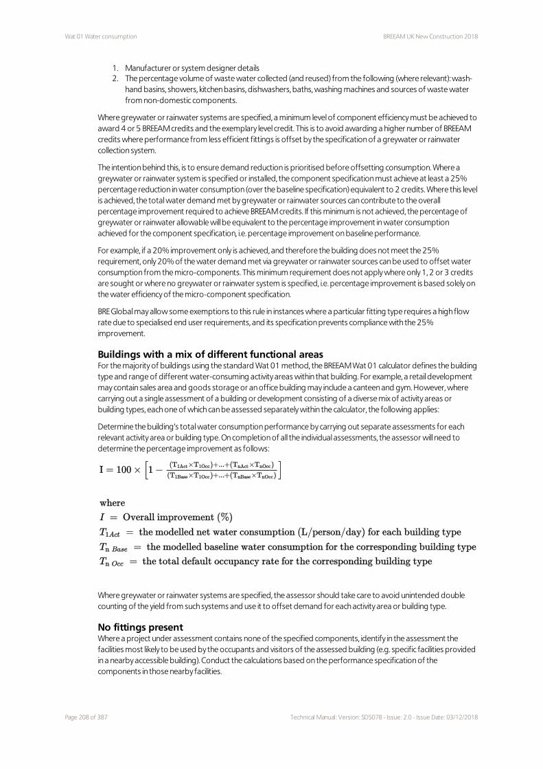
Wat 01 Water consumption BREEAM UK New Construction 2018
1. Manufacturer or system designer details 2. The percentage volume of waste water collected (and reused) from the following (where relevant): wash-
hand basins, showers, kitchen basins, dishwashers, baths, washing machines and sources of waste water from non-domestic components.
Where greywater or rainwater systems are specified, a minimum level of component efficiency must be achieved to award 4 or 5 BREEAM credits and the exemplary level credit. This is to avoid awarding a higher number of BREEAM credits where performance from less efficient fittings is offset by the specification of a greywater or rainwater collection system.
The intention behind this, is to ensure demand reduction is prioritised before offsetting consumption. Where a greywater or rainwater system is specified or installed, the component specification must achieve at least a 25% percentage reduction in water consumption (over the baseline specification) equivalent to 2 credits. Where this level is achieved, the total water demand met by greywater or rainwater sources can contribute to the overall percentage improvement required to achieve BREEAM credits. If this minimum is not achieved, the percentage of greywater or rainwater allowable will be equivalent to the percentage improvement in water consumption achieved for the component specification, i.e. percentage improvement on baseline performance.
For example, if a 20% improvement only is achieved, and therefore the building does not meet the 25% requirement, only 20% of the water demand met via greywater or rainwater sources can be used to offset water consumption from the micro-components. This minimum requirement does not apply where only 1, 2 or 3 credits are sought or where no greywater or rainwater system is specified, i.e. percentage improvement is based solely on the water efficiency of the micro-component specification.
BRE Global may allow some exemptions to this rule in instances where a particular fitting type requires a high flow rate due to specialised end user requirements, and its specification prevents compliance with the 25% improvement.
Buildings with a mix of different functional areasFor the majority of buildings using the standard Wat 01 method, the BREEAM Wat 01 calculator defines the building type and range of different water-consuming activity areas within that building. For example, a retail development may contain sales area and goods storage or an office building may include a canteen and gym. However, where carrying out a single assessment of a building or development consisting of a diverse mix of activity areas or building types, each one of which can be assessed separately within the calculator, the following applies:
Determine the building’s total water consumption performance by carrying out separate assessments for each relevant activity area or building type. On completion of all the individual assessments, the assessor will need to determine the percentage improvement as follows:
Where greywater or rainwater systems are specified, the assessor should take care to avoid unintended double counting of the yield from such systems and use it to offset demand for each activity area or building type.
No fittings presentWhere a project under assessment contains none of the specified components, identify in the assessment the facilities most likely to be used by the occupants and visitors of the assessed building (e.g. specific facilities provided in a nearby accessible building). Conduct the calculations based on the performance specification of the components in those nearby facilities.
Page 208 of 387 Technical Manual: Version: SD5078 - Issue: 2.0 - Issue Date: 03/12/2018

BREEAM UK New Construction 2018 Wat 01 Water consumption
This rule also applies where a project under assessment consists solely of an extension to an existing building, i.e. where the extended building contains no new sanitary facilities because there are facilities present within the existing building.
Water consumption calculation for push and automatic shut-off tapsFor input into the Wat 01 calculator, calculate the water consumption of push and automatic shut-off taps using the following steps:
Step 1: Calculate the water consumption per person per use.
If a tap runs for less than 20 seconds per activation, assume it will be activated twice per person for the timed duration. For example, for a tap with a flow rate of 9 litres/min and a 15 second usage duration, the water consumed per person would be: 9 x 15/60 x 2 = 4.5 litres/min.
If a tap runs for 20 seconds or more per activation, assume one activation per person for the timed duration. For example, for a tap with a flow rate of 9 litres/min and a 20 second usage duration, the water consumed per person would be: 9 x 20/60 x 1 = 3 litres/min.
Step 2: Multiply the water consumption figure per person by 1.5 and enter this figure into the calculator tool.
Multiplying by 1.5 adjusts the consumption figure to compensate for the typical non-timed tap use of 40 seconds that has already been taken into account in the tool. Taking the first example above, 4.5 litres/min multiplied by 1.5 gives 6.75 litres/min. When this is used in the tool as the flow rate specification, the consumption is 4.57 litres/person/day which more closely reflects the true level of water consumption for the push tap.
Flow rates for click taps presentThe flow rate for click taps shall be taken as the maximum flow rate, as quoted by the manufacturer, of the lower range before the water break or ‘click’.
Fixed water useThe BREEAM water efficiency calculation includes an allowance for fixed water use. This includes water consumption for vessel filling (for building users drinking water), cleaning in kitchens and food preparation in buildings with a catering facility. Fixed uses are included to provide greater accuracy in the reporting of the building’s overall estimated water consumption. As these uses are fixed for both actual and baseline building models, their totals do not influence the achievement of BREEAM credits.
Other permissible component demand for non-potable waterThis BREEAM issue focuses on the performance of the building's permanent domestic-scale water-consuming components. Where a greywater or rainwater system is specified, the yield from the system should be prioritised for such uses, i.e. WC or urinal flushing. However, where the building demonstrates that it has other consistent (i.e. daily) and equivalent levels of non-potable water demand, and such demands are intrinsic to the building’s operation, then it is permissible for the demand from these non-domestic uses to be counted, i.e. the demand for rainwater or greywater yield from such systems or components can be used as well as, or instead of, non-potable water demand from the building's WC or urinal components. Examples of consistent and intrinsic demands could include laundry use in hotels and multi-residential developments or horticultural uses in garden centres, botanical gardens and golf courses. Demand for general landscaping and ornamental planting irrigation are not considered as equivalent or intrinsic by BREEAM.
Other permissible sources of non-potable waterThe methodology allows for the collection and recycling of non-potable water from the relevant components listed in the criteria, i.e. taps, showers, baths; dishwashers or washing machines. In addition, where non-potable water is collected from a non-domestic component or source that is intrinsic to the building, then the amount collected can be accounted for in the methodology. This could include for example waste water from active hygiene flushing, i.e. a regular hygiene flushing programme to minimise poor water quality in a potable cold or hot water system. In order for the method to account for this total, the design team needs to confirm to the assessor the yield from the component or system (in litres) and the frequency of that yield (in days), i.e. if once a week, the frequency would be seven days.
Technical Manual: Version: SD5078 - Issue: 2.0 - Issue Date: 03/12/2018 Page 209 of 387

Wat 01 Water consumption BREEAM UK New Construction 2018
Evidence
Criteria Interim design stage Final post-construction stage
All One or more of the appropriate evidence types listed in The BREEAM evidential requirements on page 29 can be used to demonstrate compliance with these criteria.
1 A completed copy of the BREEAM Wat 01 calculator.
As per interim design stage.
1 Documentary evidence supporting the data used to complete the calculator tool.
As per interim design stage.
Definitions
BREEAM Wat 01 calculator for new non-domestic buildings
The BREEAM Wat 01 calculator is a tool for the assessment of water efficiency in most common types of new non-
domestic buildings. The calculator assesses the contribution that each domestic-scale water-consuming
component (as listed in the criteria) has on the building's total water consumption. The calculator is a compliance
tool and not a design tool for water demand and drainage systems. The tool uses default usage and occupancy
rates to provide a benchmark of the typical consumption based on the specified fittings (in litres/person/day and
m³/person/year) and their impact on the building's overall water efficiency. Due to the impacts and differences of
actual user behaviour and occupancy rates, the results of the method will not reflect directly the actual water use
during building operation. The results from the methodology should, therefore, not be used for the purpose of
comparison with or prediction of actual water consumption from a non-domestic building.
Clinical areas
Areas of the building in which medical functions are carried out that require specific restricted environmental
conditions such as humidity, daylighting, temperature etc. (e.g. X-ray, operating department, delivery room etc.).
Domestic-scale water-consuming components
Domestic-scale components include kitchen taps, wash-hand basin taps, baths, showers and dishwashers, WCs,
urinals, washing machines and waste disposal units. These components might consume potable or non-potable
water.
Water fittings used for a process-related function, e.g. laboratory or classroom taps, scrub-up taps, cleaners’ sinks
etc., should be excluded from the assessment of water consumption for sanitary use.
Effective flush volume
The effective flush volume of a single-flush WC is the volume of water used for one flush. The effective flush
volume of a dual-flush WC is the ratio of full flush to reduced flush. This is taken to be one full flush for every three
reduced flushes for non-domestic buildings and one full flush for every two reduced flushes in domestic
(residential) buildings or areas. The effective flush volume can therefore be calculated as follows, using a 6/4 litre
dual-flush volume WC as an example: – Non-domestic: {(6 litre x 1) + (4 litre x 3)}/4 = 4.5 litre effective flushing volume (for a 6/4 dual-flush WC)– Domestic: {(6 litre x 1) + (4 litre x 2)}/3 = 4.67 litre effective flushing volume (for a 6/4 dual-flush WC)
The different ratio between non-domestic and domestic buildings reflects the different patterns of user
behaviour between these building types.
Page 210 of 387 Technical Manual: Version: SD5078 - Issue: 2.0 - Issue Date: 03/12/2018

BREEAM UK New Construction 2018 Wat 01 Water consumption
Where buildings have both, domestic and non-domestic function areas, conduct the calculations accordingly for
the WCs specified in the relevant spaces. For example, in a hotel building, for WCs in hotel rooms use the 'domestic'
effective flush volume calculation and for WCs in staff areas use the 'non-domestic' calculation.
Greywater recycling
The appropriate collection, treatment and storage of domestic waste water (which is defined as that discharged
from kitchens, baths or showers, laundry rooms and similar) to meet a non-potable water demand in the building,
e.g. WC flushing, or other permissible non-potable use on the site of the assessed building.
Potable water
Water suitable for human consumption that meets the requirements of Section 67 (Standards of
Wholesomeness) of the Water Industry Act 1991(167) is referred to as 'wholesome water'.
Non-potable water
Any water other than potable water, also referred to as unwholesome water (BS 8525).
Rainwater recycling
The appropriate collection and storage of rainwater run-off from hard outdoor surfaces to meet a non-potable
water demand in the building, e.g. WC flushing, or other permissible non-potable use on the site of the assessed
building.
Volume controller
An automatic control device used to turn off the water supply once the maximum pre-set volume is reached
within a defined period.
Additional information
European Water Label Scheme: Water efficiency labelThe European Water Label is a scheme initiated by bathroom manufacturers across the globe and it provides a database of bathroom products of different levels of water efficiency. It includes products by multiple European bathroom manufacturers and can help project teams identify products appropriate for their specifications.
Useful guidanceThe following list of documents may be useful:
– BRE Global. SD129: Certification and listing of low flush WC appliances. 2008.– BS 6465-3:2006. Sanitary installations. Code of practice for the selection, installation and maintenance of
sanitary and associated appliances. BSI; 2006.– Communities and Local Government. Waterwise: Water efficiency calculator for new dwellings [Internet]. 2009.
Available from: www.waterwise.org.uk– Entec UK Limited. BD 2683: Assessing the costs and benefits of improvements to the water efficiency of new
non-household buildings - final research report. Department for Communities and Local Government; 2010.– Environment Agency. Conserving water in buildings: a practical guide. 2007.– Market Transformation Programme. BNWAT07: Baths - water efficiency performance tests (version 2.0). 2007.– Market Transformation Programme. BNWAT23: Reliability of information on water consumption of appliances
(version 1). 2007.– Market Transformation Programme. Sustainable products 2006: policy analysis and projections. Defra; 2006. – Waggett R, Arotsky C. CIRIA W10 Key Performance Indicators for water use in hotels. CIRIA; 2006.– Waggett R, Arotsky C. CIRIA W11 Key Performance Indicators for water use in offices. CIRIA; 2006.– Water UK. Waste macerators - the impact on sewers: 2009.– BRE Global. SD175: Certification and listing of water efficient baths. 2008.– Water efficient product labelling scheme: www.water-efficiencylabel.org.uk
Technical Manual: Version: SD5078 - Issue: 2.0 - Issue Date: 03/12/2018 Page 211 of 387

Wat 02 Water monitoring BREEAM UK New Construction 2018
Wat 02 Water monitoring
Fully fitted Simple building Shell & core Shell only Minimum standards
Aim
To reduce the consumption of potable water in new buildings through the effective management and monitoring of water consumption.
Value
– Increase awareness of water usage within the building.– Identify and monitor large water uses and changed consumption levels to improve management and
maintenance as well as to encourage reductions in unnecessary consumption.– Reduce costs related to water consumption.– Manage water demand for different building areas and uses.– Reduce the need for large-scale increases in water infrastructure in the future which are likely to increase costs
over time as well as impact on our rural and urban landscapes and communities.
Context
Due to increasing population densities and relatively high levels of water consumption, much of the UK is at risk of water shortages which are likely to increase over time as rainfall patterns due to climate change . Reducing water consumption in the UK is, therefore, crucial.
Sub-metering water consumption means that water consumption can be better accounted for. Large water consumers can be identified with the aim of encouraging the reduction in water use where practical. Moreover, changes in consumption can be identified and dealt with as appropriate, thereby minimising risks of systems failures which can have costly and disruptive consequences.
Assessment scope
Fully fitted Simple building Shell and core Shell only
Applicable assessment criteria All All All 1 and 3–5
Assessment type specific notes None None see ref 1.0 and 1.1 see ref 1.2
Specific notes
Assessment type specific
1.0 Demonstrate compliance with criterion 2 on the facing page for water-consuming plant or building areas identifiable by the developer. Do not assess water-consuming plant or building areas to be
1 1 1 1
Page 212 of 387 Technical Manual: Version: SD5078 - Issue: 2.0 - Issue Date: 03/12/2018

BREEAM UK New Construction 2018 Wat 02 Water monitoring
Assessment type specific
added or installed by the tenant. Where no water-consuming plants are installed by the developer, the credit is awarded based on the rest of the criteria.
1.1 Minimum standard is applicable, however the assessor may, for speculative assessments, subject to their justification and evidence from the design team, seek review by BRE.
1.2 Minimum standard is not applicable.
Building type specific
2.0 For healthcare buildings and sites with multiple departments, e.g. large health centres or acute hospitals, fit separate sub-meters on the supply to the following areas where present: – Staff and public areas – Clinical areas and wards – Letting areas: on the water supply to each tenant unit – Laundries – Main production kitchen – Hydrotherapy pools – Laboratories – Central sterile supply department (CSSD), hospital sterilisation and disinfection unit (HSDU),
pathology, pharmacy, mortuary and any other major process water use– Supplementary supply of water from a cold water tank.
Assessment criteria
One credit1 Specify a water meter on the mains water supply to each building. This includes instances where water is
supplied via a borehole or other private source.
2 For water-consuming plant or building areas consuming 10% or more of the building’s total water demand:
2.a Fit easily accessible sub-meters OR
2.b Install water monitoring equipment integral to the plant or area.
3 For each meter (main and sub):
3.a Install a pulsed or other open protocol communication output AND
3.b Connect it to an appropriate utility monitoring and management system, e.g. a building management system (BMS), for the monitoring of water consumption. If there is no BMS system in operation at Post-Construction stage, award credits provided that the system used enables connection when the BMS becomes operational.
4 In buildings with swimming pools, or large water tanks and aquariums, fit separate sub-meters on the water supply of the above and any associated changing facilities (toilets, showers etc.) irrespective of their water consumption levels.
5 In buildings containing laboratories, fit a separate water meter on the water supply to any process or cooling loop for ‘plumbed-in’ laboratory process equipment, irrespective of their water consumption levels.
Additionally for those pursuing a post occupancy stage certification:6 The water monitoring strategy used enables the identification of all water consumption for sanitary uses as
assessed under Wat 01 (litres/person/day), if a post occupancy stage certification is sought.
Methodology
Sites with multiple units or buildings.See criterion 2 above.
Technical Manual: Version: SD5078 - Issue: 2.0 - Issue Date: 03/12/2018 Page 213 of 387

Wat 02 Water monitoring BREEAM UK New Construction 2018
On sites with multiple units or buildings, e.g. shopping centres, industrial units, retail parks etc. fit separate sub-meters on the water supply to the following areas (where present):
– Each individual unit supplied with water – Common areas (covering the supply to toilet blocks) – Service areas (covering the supply to outlets within storage, delivery, waste disposal areas etc.) – Ancillary or separate buildings to the main development with water supply.
No water supply to the building or unit - Extensions to existing buildings.See criterion 2.a on the previous page
If no new water supply is installed, identify in the assessment the facilities most likely to be used by the occupants and visitors of the assessed building (e.g. specific facilities provided in a nearby accessible building). In this case, provide the following in this building:
1. A water meter for the mains water supply 2. Sub-meters for large water-consuming plant or facilities, e.g. evaporative cooling, swimming pool etc.
(where present).
The meters provided must have a pulsed output or connection to existing BMS in accordance with the assessment criteria.
No additional monitoring benefit from sub-metering.See criterion 2 on the previous page.
Where the assessor confirms there is no additional monitoring benefit resulting from the installation of sub-meters, the requirement does not apply in the following cases:
– The building has only one or two small sources of water demand (e.g. an office with sanitary fittings and a small kitchen).
– The building has two sources of water demand, one significantly larger than the other, and the water consumption for the larger demand is likely to mask the smaller one.
Evidence
Criteria Interim design stage Final post-construction stage
All One or more of the appropriate evidence types listed in The BREEAM evidential requirements on page 29 can be used to demonstrate compliance with these criteria.
Definitions
Clinical areas
Areas of the building in which medical functions are carried out that require specific restricted environmental
conditions such as humidity, daylighting, temperature etc. (e.g. X-ray, operating department, delivery room etc.).
Meter outputs
Examples include pulsed outputs and other open protocol communication outputs, such as Modbus.
Patient areas
Areas of the building used mainly by inpatients (e.g. wards, dayrooms etc.).
Staff areas
Areas of the building used mainly by staff (e.g. offices, meeting rooms, staff rooms) and medical areas where
patients are admitted but that do not require restricted environmental conditions (e.g. consulting rooms,
physiotherapy etc.).
Page 214 of 387 Technical Manual: Version: SD5078 - Issue: 2.0 - Issue Date: 03/12/2018

BREEAM UK New Construction 2018 Wat 02 Water monitoring
Utility monitoring and management system
Examples include automatic meter reading systems and building energy management systems. Automatic
monitoring and targeting is an example of a management tool that includes automatic meter reading and data
management.
Additional information
None.
Technical Manual: Version: SD5078 - Issue: 2.0 - Issue Date: 03/12/2018 Page 215 of 387

Wat 03 Water leak detection BREEAM UK New Construction 2018
Wat 03 Water leak detection
Fully fitted Simple building Shell & core Shell only No minimum standards
Aim
To reduce the consumption of potable water in new buildings through minimising wastage due to water leaks.
Value
– Reduce potable water wastage associated with leaks.– Minimise damage, costs and disruption arising from water leaks.– Reduce costs related to water consumption.
Context
Water leakage within customers’ properties represents 6% of the total public water supply in England and Wales(168). This is equivalent to 25% of the total water leakage, with the rest being attributed to water distribution systems of the supply companies. Water leaks in building systems are responsible for major damage to property resulting in major disruption and costs. It is, therefore, important to ensure that water leaks are detected and controlled on a building level as early as possible.
Assessment scope
Fully fitted Simple building Shell and core Shell only
Applicable assessment criteria All All All 1–2
Assessment type specific notes None see ref 1.0 and 1.1 see ref 1.2 None
Specific notes
Assessment type specific
1.0 As an alternative to criteria 1 and 2, install automatic excess flow valves at relevant locations to protect property from damage caused by leaking pipes or tanks.
1.1 An automatic excess flow valve acts as a flow switch (‘fuse’) to automatically stop the flow of water and prevent uncontrolled release when the flow of water exceeds a predetermined rate (such as may occur in the event of failure of water supply pipes and tanks).
1.2 Assess the water supplies to WC areas or facilities as per criterion 3 regardless of whether the WC areas or facilities are fitted out or not.
2 2 2 1
Page 216 of 387 Technical Manual: Version: SD5078 - Issue: 2.0 - Issue Date: 03/12/2018

BREEAM UK New Construction 2018 Wat 03 Water leak detection
Building type specific
2.0 Healthcare This issue does not apply to toilet facilities in clinical areas
2.1 Short and long term residential accommodation Flow control devices in WC areas or facilities are not required for facilities in residential areas of long-term residential accommodation. This is due to the fact that those occupants have a sense of ownership and would identify and report a potential leak. This applies to all of the following: ensuite facilities in individual bedrooms, a single bathroom shared between several individual bedrooms (e.g. in halls of residence), or one single bathroom in an independent dwelling (e.g. within a care home). The requirement for flow control devices still applies for the rest of the facilities within long-term residential accommodation. Where WC facilities are only provided within the residential areas of a long-term residential accommodation project (e.g. there is no staff WC), the credit is filtered out of the assessment. However, for short term accommodation, the credit still applies to buildings that have guest bedrooms with ensuite facilities, e.g. hotel rooms, and communal WC areas or facilities, e.g. communal WC facilities in hotels and hostels.
2.2 Short term stay residential institutions (such as hotels)Compliance with criterion 3 for WC facilities in hotel rooms can be achieved through providing the required flow control devices to groups of 10 rooms, rather than to each individual room.
Assessment criteria
This issue is split into two parts:
– Leak detection system (one credit)– Flow control devices (one credit)
One credit - Leak detection system1 Install a leak detection system capable of detecting a major water leak:
1.a On the utilities water supply within the buildings, to detect any major leaks within the buildings
AND
1.b Between the buildings and the utilities water supply, to detect any major leaks between the utilities supply and the buildings under assessment.
2 The leak detection system is:
2.a A permanent automated water leak detection system that alerts the building occupants to the leak OR an inbuilt automated diagnostic procedure for detecting leaks
2.b Activated when the flow of water passing through the water meter or data logger is at a flow rate above a pre-set maximum for a pre-set period of time. This usually involves installing a system which detects higher than normal flow rates at meters or sub-meters. It does not necessarily require a system that directly detects water leakage along part or the whole length of the water supply system
2.c Able to identify different flow and therefore leakage rates, e.g. continuous, high or low level, over set time periods. Although high and low level leakage rates are not specified, the leak detection equipment installed must have the flexibility to distinguish between different flow rates to enable it to be programmed to suit the building type and owner's or occupier's usage patterns.
2.d Programmable to suit the owner's or occupier's water consumption criteria
2.e Where applicable, designed to avoid false alarms caused by normal operation of large water-consuming plant such as chillers.
Where there is physically no space for a leak detection system between the utilities water meter and the building, alternative solutions can be used, provided that a major leak can still be detected.
One credit - Flow control devices3 Install flow control devices that regulate the water supply to each WC area or sanitary facility according to
Technical Manual: Version: SD5078 - Issue: 2.0 - Issue Date: 03/12/2018 Page 217 of 387

Wat 03 Water leak detection BREEAM UK New Construction 2018
demand, in order to minimise undetected wastage and leaks from sanitary fittings and supply pipework.
Methodology
No water supply to the building or unitWhere a project under assessment contains no installed fittings and therefore there is no water supply to the building, identify and assess the facilities most likely to be used by the occupants and visitors of the assessed building (e.g. specific facilities provided in a nearby accessible building).
Extensions to existing buildingsIf the water supply to the new extension is via the existing building then the water supply to the existing building must be assessed against the criteria of this issue.
Utilities water metersSee criterion 1 on the previous page.
Where there is a utilities water meter at the site or building boundary, it may be necessary to install a separate flow meter (or alternative measurement system) just after the utilities water meter to detect leaks. However, if the water utilities company agrees to some form of leak detection being installed on their meter, this would also be acceptable.
Evidence
Criteria Interim design stage Final post-construction stage
All One or more of the appropriate evidence types listed in The BREEAM evidential requirements on page 29 can be used to demonstrate compliance with these criteria.
Definitions
Clinical areas
Areas of the building in which medical functions are carried out that require specific restricted environmental
conditions such as humidity, daylighting, temperature etc. (e.g. X-ray, operating department, delivery room etc.).
WC areas or facilities
WC areas or facilities refer to the cold water supply to taps, WCs and urinals. The water supply system must not
allow the cold water to automatically switch off in the showers while the hot water is still running to avoid scalding
from hot water.
Additional information
None.
Page 218 of 387 Technical Manual: Version: SD5078 - Issue: 2.0 - Issue Date: 03/12/2018

BREEAM UK New Construction 2018 Wat 04 Water efficient equipment
Wat 04 Water efficient equipment
Fully fitted Simple building Shell & core Shell only No minimum standards
Aim
To reduce water consumption for uses not assessed under Wat 01 by encouraging specification of water efficient equipment.
Value
– Reduce potable water use in high consumption equipment and associated energy consumption.– Reduce costs related to water consumption and water heating.– Promote innovation and manufacture of more water efficient equipment.
Context
Water consumption associated with non-domestic scale, non-sanitary water uses can be very significant depending on the building type and relevant uses. Industrial processes and other project-specific processes do not always require water to be treated to potable quality. Therefore there is scope to adopt more imaginative solutions to meeting this demand through alternative sources, reuse or recycling solutions which are often project specific.
With the predicted higher climatic temperatures and drier summers, the need for irrigation is likely to increase in the UK, impacting on our ability as a society to provide adequate water supplies at a reasonable cost.
Therefore, there is a need to address these types of water uses, encouraging reductions in potable water consumption.
Assessment scope
Fully fitted Simple building
Shell and core Shell only
Applicable Assessment criteria All None All All
Assessment type specific notes
see ref 1.1
see ref 1.1 see ref 1.0 and 1.1
see ref 1.0 and 1.1
Specific notes
Assessment type specific
1.0 Where the only non-domestic scale, non-sanitary water demand comes from an irrigation system specified or installed by the developer, then use this system to assess compliance.
1.1 Where there are no water demands beyond those of Wat 01, the issue will be filtered out.
1 Not applicable 1 1
Technical Manual: Version: SD5078 - Issue: 2.0 - Issue Date: 03/12/2018 Page 219 of 387

Wat 04 Water efficient equipment BREEAM UK New Construction 2018
Building type specific
None
Assessment criteria
One credit1 Identify all water demands from uses other than those listed under - Calculation of water efficiency
performance on page 204 that could be realistically mitigated or reduced. Where there is no water demand from uses other than domestic-scale, sanitary use components in the building, this issue is not applicable.
2 Identify systems or processes to reduce the relevant water demand (criterion 1 above), and establish, through either good practice design or specification, a demonstrable reduction in the total water demand of the building.
Methodology
None.
Evidence
Criteria Interim design stage Final post-construction stage
All One or more of the appropriate evidence types listed in The BREEAM evidential requirements on page 29 can be used to demonstrate compliance with these criteria.
Definitions
Non-domestic scale, non-sanitary water uses
For the purposes of this BREEAM Issue, non-domestic scale, non- sanitary water uses refer to any building-
integrated water uses not assessed under Wat 01. This includes, but is not limited to the following: – Swimming pools– Recreational hot tubs and hydrotherapy pools– Equipment used for irrigation– Vehicle wash equipment– Project-specific industrial processes– Water filtration and treatment processes– Building services (e.g. cooling towers and humidification systems)
Vehicle wash
A commercial-scale automatic, semi-automatic or manual system for washing vehicles. This includes wheel and
chassis wash, fixed gantry and screen wash systems using brushes, spray or handheld jet hoses.
Additional information
None.
Page 220 of 387 Technical Manual: Version: SD5078 - Issue: 2.0 - Issue Date: 03/12/2018

BREEAM UK New Construction 2018 Materials
Materials
Fully fitted Simple building Shell & core Shell only
Summary
This category encourages decisions which reduce the environmental and social impact of construction products used on a project. It takes a ‘whole life cycle’ approach to construction product impacts, encouraging consideration of impacts during manufacture, design, procurement, installation, in-use and end-of-life. The issue focuses on construction product efficiency, environmental impact, responsible sourcing and product durability.
Assessment timeline
To assist with optimising project sustainability performance, the assessment timeline outlines the stage at which credits should be addressed. Ideally these should be considered by the design team, planner, contractors, owners, occupiers and other members of the project team to achieve the highest possible BREEAM rating at the minimum cost.
If BREEAM advice is taken on too late within the design and construction phases a number of BREEAM credits may not be achieved or only at additional cost or disruption.
Mat 01 Environmental impacts from construction products - Building life cycle assessment (LCA)
Up to 7 credits
– Reducing buildings’ environmental life cycle impacts through conducting Life Cycle Assessment and integrating
its outcomes in the design decision-making process. Mat 02 Environmental impacts from construction products - Environmental Product Declarations (EPD)
1 credit
– To encourage availability of robust and comparable data on the impacts of construction products by rewarding
the specification of products with environmental products declarations. Mat 03 Responsible sourcing of construction products 4 credits
15% 17.5% 17.5% 22%
Technical Manual: Version: SD5078 - Issue: 2.0 - Issue Date: 03/12/2018 Page 221 of 387

Materials BREEAM UK New Construction 2018
– Recognising and encouraging responsible sourcing of construction products. This includes the source of products and the intermediary companies processing and transporting the product to site.
Mat 05 Designing for durability and resilience 1 credit
– Increasing the lifespan of the building through designing for durability and protection from degradation and specifying appropriate construction products.
Mat 06 Material efficiency 1 credit
– Encouraging the reduction of environmental impacts through optimising the use of materials during all stages of the project.
Page 222 of 387 Technical Manual: Version: SD5078 - Issue: 2.0 - Issue Date: 03/12/2018

BREEAM UK New Construction 2018 Mat 01 Environmental impacts from construction products - Building life cycle
assessment (LCA)
Mat 01 Environmental impacts from construction products - Building life cycle assessment (LCA)
Fully fitted Simple building Shell & core Shell only No minimum standards
Aim
To reduce the burden on the environment from construction products by recognising and encouraging measures to optimise construction product consumption efficiency and the selection of products with a low environmental impact (including embodied carbon), over the life cycle of the building.
Value
– Help project teams to understand the overall environmental impact of the building design.– Ensure that all life cycle greenhouse gas emissions are taken into account in the design, not just operational
emissions.– Reduce the impact of the construction industry and construction product industries.– Assess the environmental impacts at the building level to provide flexibility when specifying construction
products, to take into account project-specific conditions and priorities.– Allow optimal solutions to be identified and adopted to reduce overall environmental impacts arising from
construction product use.
Context
The use of construction products leads to a wide range of environmental and social impacts across the life cycle through initial procurement, wastage, maintenance and replacement. Taken together, construction products make a highly significant contribution to the overall life cycle impacts of a building. In some cases they may even outweigh operational impacts (such as energy consumption).
The introduction of Part L into the building regulations has led to reductions in the operational energy consumption of buildings and these regulations are being progressively tightened As a result, greenhouse gas emissions from other aspects of buildings, such as embodied emissions, are becoming increasingly important in terms of reducing the overall emissions in terms of reducing the overall emissions that lead to climate change and arise from the procurement, maintenance and replacement of construction products over the building's lifetime.
In addition to climate change, there are several other embodied environmental impacts associated with construction products and the processes that occur during and after construction that should be considered during design, for example corporate social responsibility and other regulatory obligations.
Up to 7 Up to 7 Up to 7 Up to 7
Technical Manual: Version: SD5078 - Issue: 2.0 - Issue Date: 03/12/2018 Page 223 of 387

Mat 01 Environmental impacts from construction products - Building life cycle
assessment (LCA)
BREEAM UK New Construction 2018
Assessment scope
Fully fitted Simple building Shell and core Shell only
Applicable assessment criteria
All 3–9 and 15–18 All 1–7 and 10–18
Assessment type specific notes
See ref 1.1 and 1.2
See ref 1.0. 1.1 and 1,2
See ref 1.1 and 1.2
See ref 1.1 and 1.2
Specific notes
Assessment type specific
1.0 Simple buildingsAll criteria relevant to the building type and function apply except criteria 1 to 2 on the facing page.
1.1 Mixed use buildingsWhere a single building use type accounts for ≥ 50% of the net internal floor area, all criteria relevant to the building type and function apply. Where < 50%, all criteria relevant to the building type and function apply except criteria 1 to 2 on the facing page.
1.2 Part new build, part refurbishmentsAll criteria relevant to the building type and function apply except criteria 1 to 2 on the facing page.
Building type specific
None
Assessment criteria
Seven credits (see criteria 1 to 7) and three exemplary credits (see criteria 8 to 18) are available in this issue. Some credits require preceding criteria to be fulfilled first.
Credits for building Life Cycle Assessment (LCA) of the superstructure (criteria 1 to 5) are awarded as a combined total. Of these, credits for LCA benchmarking of the superstructure (criteria 1 to 2) are only applicable to office, industrial and retail buildings.
For other building types, the same number of credits are available for LCA options appraisal alone (criteria 3 to 5).
For comparison with the BREEAM LCA benchmark (criteria 1 to 2), the number of credits awarded depends on the environmental impacts of the building compared with the BREEAM LCA benchmark. For option appraisal (criteria 3 to 9), the number of credits depends on the number of design options included in the options appraisal.
Up to six credits – Superstructure (all building types)
Comparison with the BREEAM LCA benchmark during Concept Design (office, industrial and retail buildings only)Superstructure (office, industrial and retail buildings (except for Simple Buildings and where Notes 1.1 and 1.2 above apply))
1 During the Concept Design, demonstrate the environmental performance of the building as follows:
1.a Carry out a building LCA on of the superstructure design using either the BREEAM Simplified Building LCA tool or an IMPACT Compliant LCA tool according to the methodology (see Methodology on page 226).
1.b Submit the Mat 01/02 Results Submission Tool to BRE at the end of Concept Design, and before planning permission is applied for (that includes external material or product specifications).
Page 224 of 387 Technical Manual: Version: SD5078 - Issue: 2.0 - Issue Date: 03/12/2018

BREEAM UK New Construction 2018 Mat 01 Environmental impacts from construction products - Building life cycle
assessment (LCA)
Comparison with the BREEAM LCA benchmark during Technical Design (office, industrial and retail buildings only)2 During Technical Design, demonstrate the environmental performance of the building as follows:
2.a As criterion 1.a
2.b Submit the Mat 01/02 Results Submission Tool to BRE at the end of Technical Design.
Where a project has not achieved criterion 1, criterion 2 may still be achieved.
Option appraisal during Concept Design (all building types)3 For office, industrial and retail building types, achieve criterion 1 (except where Notes 1.0, 1.1 and 1.2 on the
previous page apply).
4 During Concept Design, identify opportunities for reducing environmental impacts as follows:
4.a Carry out building LCA options appraisal of 2 to 4 significantly different superstructure design options (applicable to the Concept Design stage, see Methodology on the next page).
4.b Use a building LCA tool that is recognised by BREEAM (as suitable for assessing superstructure during Concept Design) according to the methodology (see Methodology on the next page).
4.c For each design option, fulfil the same functional requirements specified by the client and all statutory requirements (to ensure functional equivalency).
4.d Integrate the LCA options appraisal activity within the wider design decision-making process. Record this in an options appraisal summary document.
4.e Record the following in the Mat 01/02 Results Submission Tool: The differences between the design options; the design option selected by the client to be progressed beyond Concept Design; the reasons for selecting it and the reasons for not selecting the other design options.
4.f Submit the Mat 01/02 Results Submission Tool to BRE at the end of Concept Design, and before planning permission is applied for (that includes external material or product specifications).
If the building LCA tool recognised by BREEAM and used for criteria 3 to 5 (and 6 to 9, if pursued) is not an IMPACT Compliant LCA tool and criteria 1 to 2 are applicable, then the BREEAM Simplified Building LCA tool (or an IMPACT Compliant LCA tool) shall be used for criteria 1 to 2.
Options appraisal during Technical Design (all building types)5 During Technical Design identify opportunities for reducing environmental impacts as follows:
5.a Carry out building LCA options appraisal of 2 to 3 significantly different superstructure design options (based on the selected Concept Design option and as applicable to the Technical Design stage, see Methodology on the next page).
5.b Use a building LCA tool that is recognised by BREEAM (as suitable for assessing superstructure during Technical Design) according to the methodology (see Methodology on the next page).
5.c As criteria 4.c to 4.e above. Where an options appraisal summary document was produced during Concept Design, update it to include the Technical Design options.
5.d Submit the Mat 01/02 Results Submission Tool to BRE at the end of Technical Design.
Where a project has not achieved criteria 3 and 4, criterion 5 may still be achieved.
One credit – Substructure and hard landscaping options appraisal during Concept Design (all building types)6 Criteria 3 and 4 are achieved.
7 During Concept Design identify opportunities for reducing environmental impacts as follows:
7.a Carry out building LCA options appraisal of a combined total of at least six significantly different substructure or hard landscaping design options (at least two shall be substructure and at least two shall be hard landscaping).
Technical Manual: Version: SD5078 - Issue: 2.0 - Issue Date: 03/12/2018 Page 225 of 387

Mat 01 Environmental impacts from construction products - Building life cycle
assessment (LCA)
BREEAM UK New Construction 2018
7.b Using a building LCA tool that is recognised by BREEAM (as suitable for assessing substructure and hard landscaping during Concept Design) according to the methodology (see Methodology below).
7.c As criteria 4.c to 4.f on the previous page.
Exemplary level criteriaTo achieve exemplary performance credits:
One credit – Core building services options appraisal during Concept Design (all building types)8 Criteria 3 to 4 are achieved.
9 During Concept Design identify opportunities for reducing environmental impacts as follows:
9.a Carry out building LCA options appraisal of at least 3 significantly different core building services design options.
9.b Use a building LCA tool that is recognised by BREEAM (as suitable for assessing core building services during Concept Design) according to the methodology (see Methodology below).
9.c As criteria 4.c to 4.f on the previous page.
One credit – LCA and LCC alignment (all building types)10 Achieve criteria 3 to 5.
11 Achieve Elemental LCC plan and Component Level LCC options appraisal credits (Man 02 Life cycle cost and service life planning on page 45).
12 Include design options appraised for criteria 3 to 4 (and 6 to 7 and 8 to 9, if pursued) during Concept Design in - The elemental LCC plan: on page 46.
13 Include the design options appraised for criterion 5 during Technical Design in the ‘Component level LCC option appraisal’ (in Man 02 Life cycle cost and service life planning on page 45).
14 Integrate the aligned LCA and LCC options appraisal activity within the wider design decision-making process. Record this in an options appraisal summary document including the relevant cost information from the ‘elemental LCC plan’ and ‘Component level LCC option appraisal’.
One credit – Third party verification (all building types)15 Criteria 1 to 7 (as applicable to the building type) are achieved.
16 A suitably qualified third party (see Definitions on page 228) either carries out the building LCA work or verifies the building LCA work (if by others), and produces a report describing how they have checked the building LCA work accurately represent the designs under consideration during Concept Design and Technical Design with reference to the requirements of criteria 1 to 7 (and 8 to 14 if pursued).
17 For each LCA option, itemise in the report the checks made by the suitably qualified third party including, as a minimum, the quality requirements shown in Table 9.4 on page 232.
18 Include details of the suitably qualified third party's relevant skills and experience and a declaration of their third party independence from the project client and design team in the report.
Methodology
Comparison with the BREEAM LCA benchmark and option appraisalCriteria 1 to 9.
One of the following two methods shall be used when undertaking comparison with the BREEAM LCA benchmark criteria or options appraisal criteria. The first method shall be used when using the BREEAM Simplified Building LCA Tool. The second method shall be used for IMPACT Compliant tools and all other building LCA tools recognised by BREEAM to provide a more robust and detailed analysis of life cycle impacts. More information on the BREEAM
Page 226 of 387 Technical Manual: Version: SD5078 - Issue: 2.0 - Issue Date: 03/12/2018

BREEAM UK New Construction 2018 Mat 01 Environmental impacts from construction products - Building life cycle
assessment (LCA)
Simplified Building LCA tool, IMPACT Compliant tools and other building LCA tools recognised by BREEAM can be found in the definitions.
Method using the BREEAM Simplified Building LCA ToolStep 1: Identify the elements that are present in the building and are in scope, based on Scope of assessment on page 231.
Step 2: In the BREEAM Simplified Building LCA tool, for the elements identified in step 1 only, select the elemental construction description that is the most similar to the actual elemental construction. If an element has more than one type of construction, then select an elemental construction for each type.
Step 3: For each of the elemental constructions, enter the total quantity in the building. Enter any further information required by the tool. Ensure that the quality requirements are adhered to (see Table 9.4 on page 232).
Step 4: A total BRE EN EcoPoint result is generated by the BREEAM Simplified Building LCA tool.
Step 5: Ensure the BREEAM Simplified Building LCA tool is saved in the correct location according to the instructions in the Mat 01/02 Results Submission Tool. The Mat 01/02 Results Submission Tool will calculate the credit award for the building.
Method using an IMPACT Compliant LCA tool or another building LCA tool recognised by BREEAMStep 1: Identify the elements that form the building and are in scope, based on Scope of assessment on page 231.
Step 2: Using a building LCA tool that is recognised by BREEAM (see The Mat 01/02 Results Submission Tool), produce a building LCA model. Ensure as a minimum that all the in-scope elements are included. Ensure that the quality requirements are adhered to (see Table 9.4 on page 232).
Step 3: Review and then export the LCA results 'option data file' according to the instructions provided by the tool, ensuring only the in-scope elements are included. Ensure the 'option data file' is saved in the correct location according to the instructions in the Mat 01/02 Results Submission Tool. Enter further information required by the Mat 01/02 Results Submission Tool. The Mat 01/02 Results Submission Tool will calculate the credit award for the building.
Significantly different design optionsSignificantly different design options are significantly different in terms of either the types of, or quantity of, construction products specified for one or more major elemental constructions that are within the scope of the assessment. This will depend on the stage of the assessment.
During Concept Design, different options are typically at the elemental construction level. Compare the options proposed with the following examples to determine if they can be considered significantly different for the Concept Design stage:
– For the majority of the element ‘1. External enclosing walls above ground floor level’, option ‘A’ has a timber cladding external finish and option ‘B’ has cement render (each will likely have different substrates accordingly).
– For element ‘2. Superstructure/1. Frame’, option ‘A’ is a concrete based frame and option ‘B’ is a steel based frame.
– For element ‘2. Superstructure/1. Frame’, option ‘A’ is a cast in-situ concrete based frame and option ‘B’ is a precast concrete based frame.
– For element ‘5. Central heating and cooling’, option ‘A’ is a refrigerant distribution based system and option ‘B’ is an air distribution based system.
During Technical Design, different options are typically at the product level (within elemental constructions established during Concept Design). Compare the options proposed with the following examples to determine if they can be considered significantly different for the Technical Design stage:
– For element ‘1. External enclosing walls above ground floor level’, where both options have cement render but ‘A’ is a different type of render from ‘B’.
– For element ‘3. Roof’, option ‘A’ has a one type of insulation and option ‘B’ has another type of insulation.
The Mat 01/02 Results Submission Tool contains functionality to assist in determining if the options are significantly different.
Technical Manual: Version: SD5078 - Issue: 2.0 - Issue Date: 03/12/2018 Page 227 of 387

Mat 01 Environmental impacts from construction products - Building life cycle
assessment (LCA)
BREEAM UK New Construction 2018
Evidence
Criteria Interim design stage Final post-construction stage
1–2 – The Mat 01/02 Results Submission Tool
As per interim design stage. (updated)
3–4 As criteria 1 to 2– The options appraisal summary
document– Evidence that the LCA options
appraisal summary document has been received by the design team and client (meeting minutes, letter of acknowledgement)
– Evidence of how the LCA design options have informed the design decision-making process (e.g. meeting minutes, documented design development showing how the LCA options have affected the design).
As per interim design stage.
5 – As criteria 3 to 4 (updated). As per interim design stage.
6–7 – As criteria 3 to 4. – The LCA options appraisal summary
document includes substructure and hard landscaping according to the criteria.
8–9 – As criteria 3 to 4– The LCA options appraisal summary
document includes core building services according to the criteria.
As per interim design stage.
10–14 – As criteria 5– The 'elemental LCC plan' and
'Component level LCC option appraisal; in issue Man 02 Life cycle cost and service life planning on page 45'.
As per interim design stage.
15–18 The third party’s report:– Verifying that building LCAs accurately
represent the designs under consideration.
– Itemising the findings of their verification checks.
– Evidence that the requirements of a Suitably qualified third party are fulfilled.
As per interim design stage.
Definitions
BREEAM LCA Benchmark
A BREEAM LCA benchmark is calculated by BREEAM to represent the average (mean) environmental impact of a
given building use type. It is intended for use as a performance comparator in BREEAM assessments.
Page 228 of 387 Technical Manual: Version: SD5078 - Issue: 2.0 - Issue Date: 03/12/2018

BREEAM UK New Construction 2018 Mat 01 Environmental impacts from construction products - Building life cycle
assessment (LCA)
A BREEAM LCA benchmark is expressed as a value in BRE EN EcoPoints per functional unit (e.g. 2.5 BRE EN EcoPoints
/ 1m2 (net internal area)). It is worked out by taking a sample of buildings of a given use type, dividing each
building’s total environmental impact (in BRE EN EcoPoints) by its functional quantity (e.g. total m2 of net internal
area), then working out the average of these results.
The functional unit used is determined by BREEAM according to the building use type.
BREEAM Simplified Building LCA Tool
The BREEAM Simplified Building LCA tool is an elemental construction level LCA tool that is free to use by BREEAM
Assessors and design team members working on a registered BREEAM assessment. The tool has been designed
to simplify LCA by reducing the information that needs to be entered by the user and the amount of time
required.
The accuracy of the results produced by the tool are appropriate for criteria 1 to 2. However, for criteria 3 to 4 the
results are less appropriate than the other LCA tools recognised by BREEAM. As such, the credits awarded for
criteria 3 to 4 when using this tool will have a credit cap.
BRE EN EcoPoints
BRE EN EcoPoints are an indicator that is made up of a broad set of individual environmental indicators which are
then combined into a single value. For more information about BRE EN EcoPoints, visit www.bre.co.uk or contact
BRE.
Building LCA tools recognised by BREEAM
Building LCA tools that have been technically evaluated by BRE are recognised as suitable for carrying out building
LCA on one or more of the credits in this issue (e.g. superstructure; substructure and hard landscaping; building
services). A list of recognised tools, and the credits they are considered suitable for, can be found in the Mat01/02
Results Submission Tool.
Building LCA tools that are recognised as having fewer environmental categories will have a credit cap (fewer
than: CO₂-eq AND either water or waste processing AND at least 2 other categories).
Where a project team is considering using a building LCA tool that is not listed in the Mat01 Results Submission
Tool, the assessor shall contact BRE as soon as possible to initiate the evaluation process in sufficient time to allow
for evaluation and approval prior to a final decision to use it on the project. The evaluation process will require the
involvement and issue of evidence by the tool owner. The fee sheet on the BREEAM Projects website provides
details of fees for LCA tool evaluations.
Core building services
Building services components or elements that are part of the building-wide system, rather than a specific tenant
or space.
Credit cap
The total number of credits that the tool can be awarded is less than the total number of credits available because
the tool is technically inferior to uncapped tools. For example, fewer environmental indicators are reported or the
requirements on data entered by the user are less detailed. The Mat 01/02 Results Submission Tool indicates
which tools have a credit cap.
Environmental Product Declaration (EPD)
An EPD compliant with BREEAM is an independently verified environmental label (i.e. ISO Type III label) according to
the requirements of ISO 14025.
Technical Manual: Version: SD5078 - Issue: 2.0 - Issue Date: 03/12/2018 Page 229 of 387

Mat 01 Environmental impacts from construction products - Building life cycle
assessment (LCA)
BREEAM UK New Construction 2018
Functional requirements
The functional requirements are normally determined by the project client during Preparation and Brief with the
help of the design team. They define the required functional properties such as the activities that the building will
be used for, usable floor area, design life, budget, sustainability targets etc. The functional requirements exclude
any requirements that only relate to visual or other non-functional preference.
If the client has not set formal functional requirements, the design team shall determine functional requirements
that reasonably serve the client’s needs as far as they are understood.
IMPACT
IMPACT is a specification and database for software developers to incorporate into their tools to enable
consistent LCA. IMPACT compliant tools work by allowing the user to attribute environmental information to
drawn or scheduled items. Further information about IMPACT is available from www.impactwba.com.
IMPACT Compliant LCA tool
An IMPACT Compliant tool is a tool that has been tested for compliance with the IMPACT specification, and is
listed here: www.impactwba.com.
Mat 01/02 Results Submission Tool
The Mat 01/02 Results Submission Tool provides a standardised way for BRE to collect information for this issue.
In addition, it (and the associated 'option data files') can be used by those who do not have access to the building
LCA tool to compare what is modelled with other sources of design information (bills of quantities, drawings,
specifications etc.), and see the breakdown of environmental impacts. In addition, the data in the tool may be used
by BRE for updating the BREEAM LCA benchmarks and for other research activities (in a way that is not attributable
to individual buildings).
New Rules of Measurement (NRM)
NRM provides a standard set of measurement rules and essential guidance for the cost management of
construction projects and maintenance works. For more information visit www.rics.org. IMPACT Compliant LCA
tools currently use NRM classification as a default.
Options appraisal summary document
The options appraisal summary document is produced by the design team after LCA options appraisal has been
completed to record: the options appraised by the design team and client; how the options appraisal process
was utilised to make better informed decisions; and the reasons for selecting or rejecting each option at Concept
Design and Technical Design.
It shall provide information on the environmental impacts of each design option along with the effect, if any, on
other relevant factors such as (but not necessarily limited to) capital cost and delivery times (life cycle cost
integration is rewarded by criteria 10 to 14 on page 226).
A single options appraisal summary document may be produced that covers all of the options undertaken at
Concept Design and Technical Design.
Suitably qualified third party
An individual who:– Is a third party– Has received training on using the building LCA tool that is recognised by the tool supplier, and has passed the
associated tests or exams (if any).– Has completed at least three different building LCAs for paying customers in the last two years.– Is able to interpret construction documentation (drawings, specifications, schedules etc.), which may be
evidenced by a suitable construction related qualification or relevant experience.
Page 230 of 387 Technical Manual: Version: SD5078 - Issue: 2.0 - Issue Date: 03/12/2018

BREEAM UK New Construction 2018 Mat 01 Environmental impacts from construction products - Building life cycle
assessment (LCA)
Third party“A person or body that is recognised as being independent of the parties involved, as concerns the issue in question” (BS EN 15804:2012+A1:2013(169)).
The parties involved are typically a supplier (first party, e.g. architect, engineer, LCA practitioner who provides design advice) and a purchaser (second party, e.g. the client).
A person from an organisation not otherwise involved in the project (apart from providing other verification type services e.g. BREEAM Assessment) is a third party, providing they do not provide advice to the project as this would compromise their impartiality when verifying.
Checklists and tables
Scope of assessmentThe following tables indicate the NRM level 3 sub-elements that shall be included in the scope of the building LCA. Inclusion of the in-scope sub-elements is necessary to ensure an appropriate level of comparability between assessments. All other sub-elements shall be ignored for the purposes of the BREEAM LCA. For tables showing sub-elements that shall be excluded see Out of scope elements on page 233 within ‘Additional information on page 233’.
If a sub-element is not present in the building, it does not need to be included. If a particular sub-element appears to be associated with more than one classification, the classification with the strongest association shall be used. If a particular sub-element appears to be associated with an in-scope classification and an out of scope classification, it shall be classified under the in-scope classification (and included in the assessment).
If the BREEAM Simplified Building LCA Tool is used, the constructions available in the tool may cover more than one scope item identified in the tables below. A completed BREEAM Simplified Building LCA Tool (that includes one or more constructions for each building element identified as present in the building) is compliant with these scope requirements.
In addition, the table shows the classification codes that shall be used in the Mat 01/02 Results Submission Tool, based on the RICS New Rules of Measurement (NRM) classification system. For example, the code for ‘Standard foundations’ is ‘1.1.1’.
Table 9.1 Superstructure – In-scope (criteria 1 to 5)Level 1 Group element Level 2 Element Level 3 Sub-element
2. Superstructure 1. Frame 1. Steel frames 2. Space decks 3. Concrete casings to steel frames 4. Concrete frames 5. Timber frames 6. Other frame systems
2. Upper floors 1. Floors
3. Roof 1. Roof structure 2. Roof coverings 3. Specialist roof systems
5. Rooflights, skylights and openings
4. Stairs and ramps 1. Stair or ramp structures
5. External walls 1. External enclosing walls above ground floor level
2. External enclosing walls below ground level
3. Solar or rain screening
6. Windows and external doors
1. External windows
7. Internal Walls and Partitions
1. Walls and partitions (Education only)
Technical Manual: Version: SD5078 - Issue: 2.0 - Issue Date: 03/12/2018 Page 231 of 387

Mat 01 Environmental impacts from construction products - Building life cycle
assessment (LCA)
BREEAM UK New Construction 2018
Table 9.2 Substructure and hard landscaping – In-scope (applicable to criteria 6 and 7)Level 1 Group element Level 2 Element Level 3 Sub-element
1. Substructure 1. Substructure 1. Standard foundations 2. Specialist foundation
systems 3. Lowest floor construction 4. Basement excavation 5. Basement retaining walls
8. External works* 2. Roads, paths and pavings 1. Roads, paths and pavings 2. Special surfacings and
pavings
*Include hard landscaping that is installed as part of the project under assessment and:– Is within a defined curtilage of the building– Or is clearly more associated with it (for example, an access road or car park that is intended to serve only
the building under assessment or the building and, to a lesser extent, other buildings).
Hard landscaping with no such distinction shall be excluded.
Table 9.3 Core building Services – In-scope (applicable to criteria 8 and 9)Level 1 Group element Level 2 Element Level 3 Sub-element
5. Services 5. Heat source 1. Heat source
6. Space heating and Air-conditioning
1. Central heating 2. Local heating 3. Central cooling 4. Local cooling 5. Central heating and
cooling 6. Local heating and
cooling 7. Central air- conditioning 8. Local air-conditioning
7. Ventilation 1. Central ventilation 2. Local ventilation 3. Smoke extract or control
9. Fuel installations and systems 1. Fuel storage 2. Fuel distribution systems
Quality requirementsThe LCA fulfils the following requirements.
Table 9.4 LCA Quality requirementsItem Concept Design Technical Design
Elemental construction quantities
± 10% of quantities shown in design documents at concept design stage.
± 10% of quantities shown in design documents at technical design stage.
LCA or EPD data type Generic or manufacturer-specific. Use the closest matching data in the tool.
Product quantities* (mass per unit of elemental construction)
Typical or generic values. Generic (non-project specific) elemental constructions may be used.
± 10% of quantities shown in design documents at technical design stage. All elemental constructions shall be created from individual products.
Product transportation distances*
Typical or generic values. Project-specific distances may be used where known.
Product service lives and site wastage*
A reasonable estimate for the actual installation scenario.
Page 232 of 387 Technical Manual: Version: SD5078 - Issue: 2.0 - Issue Date: 03/12/2018

BREEAM UK New Construction 2018 Mat 01 Environmental impacts from construction products - Building life cycle
assessment (LCA)
Item Concept Design Technical Design
Adhesives* Excluded if the adhesive is applied to less than 20% of the product's surface.
Minor fixings* (e.g. brackets, nails, screws), sealants and ironmongery items
Excluded
Study period* 60 years
Results reported via the Mat 01/02 Results Submission Tool
Results reported separately for each environmental indicator, for each BS EN 15978:2011(170) module as follows:– Stage A: A1, A2 and A3 (may be combined). A4 and A5 where possible in the
building LCA tool (see Building LCA tools recognised by BREEAM)– Stage B: Each module possible in the building LCA tool (see Building LCA tools
recognised by BREEAM on page 229)– Stage C: As stage B
* If the BREEAM Simplified Building LCA Tool is used, these items are fulfilled automatically.
Additional information
Out of scope elementsThe following tables indicates the building sub-elements that shall be excluded from the scope of the building LCA.
In addition, the table shows classification codes based on the RICS New Rules of Measurement (NRM) classification system. For example, the code for ‘Standard foundations’ is ‘1.1.1’.
Table 9.5 Superstructure – Out of scopeLevel 1 Group element Level 2 Element Level 3 Sub-element
2. Superstructure 2. Upper floors 2. Balconies
3. Roof 6. Roof features
4. Stairs and ramps 2. Stair or ramp finishes 3. Stair or ramp balustrades
and handrails 4. Ladders, chutes, slides
5. External walls 4. External soffits 5. Subsidiary walls,
balustrades, handrails, railings and proprietary balconies
6. Façade access or cleaning systems
6. Windows and external doors
2. External doors
7. Internal walls and partitions
2. Balustrades and handrails 3. Moveable room dividers 4. Cubicles
8. Internal doors 1. Internal doors
3. Internal finishes 1. Wall finishes 1. Finishes to walls
2. Floor finishes 1. Finishes to floors 2. Raised access floors
3. Ceiling finishes 1. Finishes to ceilings 2. False ceilings 3. Demountable suspended
ceilings
4. Fittings, furnishings and equipment
1. Fittings, furnishings and equipment
1. General fittings, furnishings and
Technical Manual: Version: SD5078 - Issue: 2.0 - Issue Date: 03/12/2018 Page 233 of 387

Mat 01 Environmental impacts from construction products - Building life cycle
assessment (LCA)
BREEAM UK New Construction 2018
Level 1 Group element Level 2 Element Level 3 Sub-element
equipment 2. Domestic kitchen fittings
and equipment 3. Special purpose fittings,
furnishings and equipment
4. Signs or Notices 5. Works of art 6. Equipment 7. Internal planting 8. Bird and vermin control
Table 9.6 Substructure and hard landscaping – Out of scopeLevel 1 Group element
Level 2 Element Level 3 Sub-element
8. External works
1. Site preparation works 1. Site clearance 2. Preparatory groundworks
3. Soft landscaping, planting and irrigation systems
1. Seeding and turfing 2. External planting 3. Irrigation systems
4. Fencing, railings and walls 1. Fencing and railings 2. Walls and screens 3. Retaining walls 4. Barriers and guardrails
5. External fixtures 1. Site or street furniture and equipment
2. Ornamental features
8. Minor building works and ancillary buildings
1. Minor building works 2. Ancillary buildings and
structures 3. Underpinning to external site
boundary walls
Table 9.7 Core building Services – Out of scopeLevel 1 Group element Level 2 Element Level 3 Sub-element
2. Superstructure 2. Upper floors 3. Drainage to balconies
3. Roof 4. Roof drainage
5. Services 1. Sanitary installations 1. Sanitary appliances 2. Sanitary ancillaries 3. Pods
2. Services equipment 1. Services equipment
3. Disposal installations 1. Foul drainage above ground 2. Chemical, toxic and industrial liquid
waste drainage 3. Refuse disposal
4. Water installations 1. Mains water supply 2. Cold water distribution 3. Hot water distribution 4. Local hot water 5. Steam and condensate distribution
7. Ventilation 2. Special ventilation
8. Electrical installations 1. Electrical mains and sub-mains distribution
2. Power installations 3. Lighting installations
Page 234 of 387 Technical Manual: Version: SD5078 - Issue: 2.0 - Issue Date: 03/12/2018

BREEAM UK New Construction 2018 Mat 01 Environmental impacts from construction products - Building life cycle
assessment (LCA)
Level 1 Group element Level 2 Element Level 3 Sub-element
4. Specialist lighting installations 5. Local electricity generation systems 6. Earthing and bonding systems
10. Lift and conveyor installations or systems
1. Lifts and enclosed hoists 2. Escalators 3. Moving pavements 4. Powered stairlifts 5. Conveyors 6. Dock levellers and scissor lifts 7. Cranes and unenclosed hoists 8. Car lifts, car stacking systems,
turntables and the like 9. Document handling systems
10. Other transportation systems
11. Fire and lightning protection
1. firefighting systems 2. Fire suppression systems 3. Lightning protection
12. Communication, security and control systems
1. Communication systems 2. Security systems 3. Central control or building
management systems
13. Special installations or systems
1. Specialist piped supply installations 2. Specialist refrigeration systems 3. Other specialist mechanical installations
or systems 4. Specialist electrical or electronic
installations systems 5. Water features
14. Builder’s work in connection with services
1. General builder’s work
8. External works 6. External drainage 1. Surface water and foul water drainage 2. Ancillary drainage systems 3. External chemical, toxic and industrial
liquid waste drainage 4. Land drainage
7. External services 1. Water mains supply 2. Electricity mains supply 3. External transformation devices 4. Electricity distribution to external plant
and equipment 5. Gas mains supply 6. Telecommunications and other
communication system connections 7. External fuel storage and piped
distribution systems 8. External security systems 9. Site or street lighting systems
10. Local or district heating installations 11. Builder’s work in connection with
external services
Technical Manual: Version: SD5078 - Issue: 2.0 - Issue Date: 03/12/2018 Page 235 of 387

Mat 02 Environmental impacts from construction products - Environmental
Product Declarations (EPD)
BREEAM UK New Construction 2018
Mat 02 Environmental impacts from construction products - Environmental Product Declarations (EPD)
Fully fitted Simple building Shell & core Shell only No minimum standards
Aim
To encourage availability of robust and comparable data on the impacts of construction products through the provision of EPD.
Value
– Improve the accuracy of building life cycle assessment (LCA).– Improve the availability if robust and comparable data for designers and specifiers to aid construction product
selection and specification.– Increase the consistency in the information requested from manufacturers.– Increase the uptake of EPD by construction product manufacturers.– Increase the accuracy and comparability of building level LCA so helping to reduce the overall life cycle impacts
arising from the building.
Context
A variety of construction product environmental claims are offered by manufacturers, other industry sources and in guidance, but the results presented are often inconsistent and therefore not suitable for making comparisons. In addition, even comparable information is difficult for a non-specialist to understand. Such information will often be biased towards presenting the benefits of a construction product and avoid or reduce the emphasis on negative impacts. This risks designers, clients and constructors being misled by the information provided, leading to incorrect decisions being taken that could result in increased environmental impacts. As a result, available information can often be misleading to designers and specifiers.
Specifiers can make better informed decisions using comparable EPD and generic LCA data in a recognised building LCA tool (see Mat 01 Environmental impacts from construction products - Building life cycle assessment (LCA) on page 223), that presents results at the building level and over the life cycle of the building.
Increasing numbers of EPD are being produced by construction product manufacturers. However, many construction products do not have an EPD, meaning generic LCA data must be used when carrying out a building LCA. While helpful in making basic construction product choices at the early design stage, this does not assist in specifying lower impact construction products during detailed design and construction stages. Further accuracy can be gained when carrying out LCA or specifying construction products by using EPD specific to a manufacturer’s product range or, better still, the specific construction product.
1 1 1 1
Page 236 of 387 Technical Manual: Version: SD5078 - Issue: 2.0 - Issue Date: 03/12/2018

BREEAM UK New Construction 2018 Mat 02 Environmental impacts from construction products - Environmental
Product Declarations (EPD)
Assessment scope
Fully fitted Simple building Shell and core Shell only
Applicable Assessment criteria All All All All
Assessment type specific notes None None None None
Specific notes
Assessment type specific
None
Building type specific
None
Assessment criteria
One credit - Specification of products with a recognised environmental product declaration (EPD)1 Specify construction products with EPD that achieve a total EPD points score of at least 20, according to the
Methodology below.
2 Enter the details of each EPD into the Mat 01/02 Results Submission Tool, including the material category classification. The Mat 01/02 Results Submission Tool will verify the EPD points score and credit award.
Methodology
Total EPD points score methodologyThe total EPD points score shall be calculated as follows:
1. For each EPD that is applicable to a specified construction product, use Table 9.8 below to find the EPD points score.
2. For each EPD, use Table 9.9 on the next page to find the applicable material classification (according to the construction product). If a product comprises more than one material, the material category classification representing the majority of the product (by volume) should be selected.
3. Add together the applicable EPD points for each material classification (an EPD can be counted in only one classification group).
4. If a material classification has a calculated score higher than 4 EPD points, reduce the score to 4. 5. Add together the EPD points calculated for each material classification to obtain the total EPD points score.
Table 9.8 EPD points for different types of EPDRecognised types of EPD Validity EPD
points
EPD applicable to more than one product in the same product category, and more than one manufacturer.
– EPD unexpired at the point of specification. – Product installed in the building by the end of
construction. – EPD issued or registered by an ISO 14025 compliant
0.5
Technical Manual: Version: SD5078 - Issue: 2.0 - Issue Date: 03/12/2018 Page 237 of 387

Mat 02 Environmental impacts from construction products - Environmental
Product Declarations (EPD)
BREEAM UK New Construction 2018
Recognised types of EPD Validity EPD points
programme operator.– For products covered by the Construction Product
Regulations, the EPD must have been generated using product category rules based on either BS EN 15804 or ISO 21930.
EPD applicable to more than one product in the same product category, and a single manufacturer.
0.75
EPD applicable to a single product*, and a single manufacturer (the product may be manufactured in more than one location)*Or variations of a single product that only differ in terms of colour or pattern.
1.5
Table 9.9 Material classificationMaterial category Uniclass equivalent code (for information)
Timber or timber-based P5
Concrete or cementitious P2*
Metal P4
Stone or aggregate P1, P3*
Clay-based P33
Gypsum P232
Glass P314
Plastic, polymer, resin, paint, chemicals and bituminous
P7, P34
Animal fibre or skin, cellulose fibre P6
Other
*Except subsets listed separately. For example, P2 generally relates to ‘2. Concrete or cementitious’ except for the subset P232 which relates to ‘6. Gypsum’.
Evidence
Criteria Interim design stage Final post-construction stage
All One or more of the appropriate evidence types listed in The BREEAM evidential requirements on page 29 can be used to demonstrate compliance with these criteria.
All The Mat 01/02 Results Submission tool As per interim design stage.
All Copies of EPD certificates As per interim design stage.
Definitions
Environmental Product Declaration (EPD)
An EPD compliant with BREEAM is an independently verified environmental label (i.e. ISO Type III label) according to
the requirements of ISO 14025.
Mat 01/02 Results Submission Tool
The Mat 01/02 Results Submission Tool provides a standardised way for BRE Global to collect information for this
issue.
Additional information
None.
Page 238 of 387 Technical Manual: Version: SD5078 - Issue: 2.0 - Issue Date: 03/12/2018

BREEAM UK New Construction 2018 Mat 03 Responsible sourcing of construction products
Mat 03 Responsible sourcing of construction products
Fully fitted Simple building Shell & core Shell only Minimum standards
Aim
To facilitate the selection of products that involve lower levels of negative environmental, economic and social impact across their supply chain including extraction, processing and manufacture.
Value
– Promote more economically, socially and environmentally responsible practices across the construction products, component manufacturing and supply sectors.
– Encourages the construction industry to identify risks and reduce the environmental, economic and social issues in the supply chain of construction products.
– Encourages the use and the improvement of credible and comparable schemes to evaluate the responsible sourcing of products.
Context
Most construction products involve long and complex supply chains that result in a wide range of impacts locally and globally. These might include environmental (e.g. toxicity or biodiversity), economic (e.g. corruption) or social (e.g. slave labour, equality) issues and can occur during the extraction, processing, manufacturing or supply chain stages. The increasing globalisation of supply chains increases the difficulty of tracing the supply chain and mitigating negative impacts caused by it.
Credible certification schemes exist to increase confidence to specifiers that risks are being minimised or avoided and their use ensures that specifiers are able to demonstrate the responsible nature of their selection decisions.
4 4 4 4
Technical Manual: Version: SD5078 - Issue: 2.0 - Issue Date: 03/12/2018 Page 239 of 387

Mat 03 Responsible sourcing of construction products BREEAM UK New Construction 2018
Assessment scope
Fully fitted Simple building Shell and core Shell only
Applicable Assessment criteria All All All All
Assessment type specific notes None None None see ref 1.0
Specific notes
Assessment type specific
1.0 For shell only assessments targeting the exemplary credit in this issue it is not required that any core building service elements are assessed as part of this issue. The credit can be awarded solely on achieving a score of ≥50%.
Building type specific
None
Assessment criteria
This issue is split into three parts:
– Legally harvested and traded timber (prerequisite)– Enabling sustainable procurement (one credit)– Measuring responsible sourcing (three credits)
Prerequisite - Legally harvested and traded timber1 All timber and timber-based products used on the project are legally harvested and traded timber as per the
UK Government's Timber Procurement Policy (TPP) (see Definitions on page 245).
Compliance with criterion 1 is a minimum requirement for achieving any BREEAM rating. There are no prerequisite requirements for other materials.
One credit - Enabling sustainable procurement2 A sustainable procurement plan must be used by the design team to guide specification towards sustainable
construction products. The plan must:
2.a Be in place before Concept Design.
2.b Include sustainability aims, objectives and strategic targets to guide procurement activities. Note: targets do not need to be achieved for the credit to be awarded but justification must be provided for targets that are not achieved.
2.c Include a requirement for assessing the potential to procure construction products locally. There must be a policy to procure construction products locally where possible.
2.d Include details of procedures in place to check and verify the effective implementation of the sustainable procurement plan.
In addition, if the plan is applied to several sites or adopted at an organisational level it must:
2.e Identify the risks and opportunities of procurement against a broad range of social, environmental and economic issues following the process set out in BS ISO 20400:2017(171).
Page 240 of 387 Technical Manual: Version: SD5078 - Issue: 2.0 - Issue Date: 03/12/2018

BREEAM UK New Construction 2018 Mat 03 Responsible sourcing of construction products
Up to three credits - Measuring responsible sourcing3 Use the Mat 03 calculator tool and methodology to determine the number of credits achieved for the
construction products specified or procured. Credits are awarded in proportion to the scope of the assessment and the number of points achieved, as set out in Table 9.10.
Table 9.10 BREEAM credits available for each scope level and percentage of points achievedCredits achieved Mat 03 minimum scope level % of available points
achieved
1 Superstructure ≥ 10%
2 As above, plus – Internal finishes– Substructure and hard landscaping
≥ 20%
3 ≥ 30%
1 exemplary performance credit
As above, plus core building services (n/a to shell only assessments)
≥ 50%
Methodology
Assessment processTo determine the number of credits that are achieved for the Responsible Sourcing of Construction Products, the Mat 03 calculator tool must be completed with all the relevant information. Each construction product must be entered in the tool individually (unless it is below the relevant cut-off threshold). There are two routes that may be used: Route 1 and Route 2 (see Definitions on page 245). Route 1 does not require quantities to be entered. Consequently it is less accurate and may result in a lower credit score than Route 2.
Where the quantity of a product has not been worked out, use Route 1. Where the quantity of a product has been worked out, use Route 2. It may be the case that across an assessment there will be a combination of routes for products. For example, Route 1 may be used for the ‘timber or timber-based’ category and Route 2 for the ‘metal’ category. Only one route may be used per materials category. Further guidance is provided in the Mat 03 calculator.
The following steps outline the process to be followed to determine the number of credits achieved for responsible sourcing.
Step 1: Collating information and entering it in the BREEAM UK Mat 03 tool.
For all routes, the BREEAM UK Mat 03 tool is used according to the following steps.
1. For each construction product in the building that is in the scope (see Table 9.11 on the next page):
Note: For route 1, steps 1.2 and 1.6 are optional. Steps 1.1 and 1.4 are optional for both routes 1 and 2.
Step 1.1: (Optional cut-off exclusion, if not being used go to step 1.2): Estimate if the quantity of the construction product is equal to or below the cut-off volume. If it is, the construction product may be optionally excluded.
Step 1.2 (Route 2 only): Estimate the quantity (mass or volume) of the product.
Step 1.3: Obtain the BREEAM recognised responsible sourcing certifications scheme (RSCS) certification or environmental management system (EMS) certification, if any (see Definitions on page 245). Compare the certification with Guidance Note 18 and obtain the RSCS point score. Where the construction product has no certification, is non-compliant with broken chain requirements (see Broken chain on page 244) or the certification type is not listed in Guidance Note 18, the score is zero. Where the construction product is a reused product, obtain the score from Guidance Note 18.
Technical Manual: Version: SD5078 - Issue: 2.0 - Issue Date: 03/12/2018 Page 241 of 387

Mat 03 Responsible sourcing of construction products BREEAM UK New Construction 2018
Identify the location/use category according to Table 9.12 on the facing page BREEAM Location/use categories and enter it into the tool.
If the construction product has a score above 0, complete the following in the tool: ‘Product name’, ‘Manufacturer’, ‘RSCS scheme’ and ‘Certification reference’. If not, the aforementioned columns need not be completed.
Step 1.4 (Optional, if not being followed go to step 1.5): Where a constituent product within the construction product has a better certification score than the construction product and it complies with the broken chain requirements, the following steps should be followed for the constituent product:
Step 1.4.1: Complete the following in the tool: ‘Product name’, ‘Manufacturer’, ‘RSCS scheme’ and ‘Certification reference’.
Step 1.4.2: In the tool, select the material category that represents the majority of the constituent product's volume.
Step 1.4.3 (Route 2 only): If the identified material category is following Route 2, enter the constituent product’s building-wide quantity for the location/use category into the tool.
Step 1.4.4: In the tool, enter the constituent product’s certification score identified in step 1.4 into the tool.
Step 1.5: In the tool, select the material category that represents the majority of the construction product’s volume (excluding quantities entered for step 1.4, if applicable).
Step 1.6 (Route 2 only): If the identified material category is following Route 2, enter the construction product’s building-wide quantity for the location/use category into the tool.
Step 1.7: In the tool, enter the construction product's certification score (from step 1.3) into the tool.
Step 2: BREEAM UK Scoring and Reporting tool
Step 2.1: Include the credit result produced by the BREEAM UK Mat 03 tool within the submission to BRE.
Scope of assessmentThe table below indicates the New Rules of Measurement (NRM) classifications that must be included in the scope of the assessment for each of the Mat 03 scope levels, which have been closely aligned with Mat 01. Including these elements (and only these) is necessary to ensure an appropriate level of comparability. All construction products that are installed as part of one or more of these building elements are in-scope and must be included in the BREEAM UK Mat 03 tool. Products used for temporary elements, for example wood used for site hoarding, are not in scope for Mat 03.
Table 9.11 Mat 03 Scope levelsMat 03 Scope levels In-scope (based on New Rules of Measurement (NRM) classification system)
Superstructure As - Table 9.1 on page 231
Internal finishes 2. Superstructure 4. Stairs and ramps
2. Stair or ramp finishes
8. Internal doors 1. Internal doors
Page 242 of 387 Technical Manual: Version: SD5078 - Issue: 2.0 - Issue Date: 03/12/2018

BREEAM UK New Construction 2018 Mat 03 Responsible sourcing of construction products
Mat 03 Scope levels In-scope (based on New Rules of Measurement (NRM) classification system)
3. Internal finishes 1. Wall finishes 1. Finishes to walls
2. Floor finishes 1. Finishes to floors2. Raised access floors
3. Ceiling finishes 1. Finishes to ceilings2. False ceilings3. Demountable suspended ceilings
Substructure and hard landscaping
As - Table 9.2 on page 232
Core building Services As - Table 9.3 on page 232
For each New Rules of Measurement (NRM) classification, the respective BREEAM Location/Use category for use in the BREEAM UK Mat 03 tool is provided in the table below.
Table 9.12 BREEAM Location/use categoriesNew Rules of Measurement (NRM) classification Equivalent BREEAM Location/use category
1.0 Substructure Structure primary & secondary
2.1 Frame Structure primary & secondary
2.2 Upper floors Floor (including floor finishes)
2.3 Roof Roof (including roof finishes)
2.4 Stairs and ramps Structure primary & secondary
2.5 External walls External wall (including finishes, e.g. cladding, lining, render)
2.6 Windows and external doors Door or window
2.7 Internal walls and partitions Internal partition or internal walls (including finishes)
2.8 Internal doors Door or window
3.1 Wall finishes Internal partition or internal walls (including finishes)
3.2 Floor finishes Floor (including floor finishes)
3.3 Ceiling finishes Ceiling (including ceiling finishes)
5.5.1 Heat source Building services
5.6 Space heating and air-conditioning Building services
5.7 Ventilation Building services
5.9 Fuel installations or systems Building services
8.2 Roads, paths and pavings Hard landscaping
Material CategoriesThe material categories, for use in the BREEAM UK Mat 03 tool, must be in accordance with Table 9.13. For each construction product, identify the closest matching category.
Table 9.13 Material categoriesMaterial categories
1. Timber or timber-based products 2. Concrete or cementitious 3. Metal 4. Stone or aggregate 5. Clay-based 6. Gypsum 7. Glass 8. Plastic, polymer, resin, paint, chemicals and bituminous 9. Animal fibre, skin, cellulose fibre
10. Other.
Approach to building servicesA simplified approach for building services construction products has been set out in Guidance Note GN24: Demonstrating Compliance with BREEAM Issue Mat 03.
Technical Manual: Version: SD5078 - Issue: 2.0 - Issue Date: 03/12/2018 Page 243 of 387

Mat 03 Responsible sourcing of construction products BREEAM UK New Construction 2018
Broken chainTo recognise responsible sourcing certification where it does exist in the supply chain, while reducing the risks associated with a broken chain, it is permissible to use the upstream certification score in the BREEAM UK Mat 03 tool where the downstream risk to responsible sourcing is considered to be low. Specifically, it is acceptable for the following types of organisations in the supply chain (that are downstream of the organisation with certification) not to have their own responsible sourcing certification:
– Organisations that only handle or transport
OR
– Organisations that only fabricate, assemble or install, and are using a recognised quality management system to ensure the mixing and substitution of the certified upstream source with uncertified sources has not occurred
AND (for both types of organisation)
– Are operating in a jurisdiction that can demonstrate relatively robust and well enforced environmental, social and economic controls. The following jurisdictions can be assumed to meet this requirement:
– States which are members of the EU– States that have declared adherence to the OECD Guidelines for Multinational Enterprises(172).
For more guidance on broken chains, see Guidance Note 24.
Cut-off thresholdsSee Step 1: Collating information and entering it in the BREEAM UK Mat 03 tool. on page 241. Any construction product in the following location/use categories which clearly accounts for less than the following volumes can be excluded from the assessment. The volume considered should be taken as the construction product's overall external dimensions, including any internal voids and air spaces.
Minor fixings (brackets, nails, screws etc.), adhesives, seals and ironmongery would normally fall below this threshold. See also Quantities precision.
– 'Internal partition and internal walls (including finishes)': Less than 0.33m³ per 1000m² of gross internal floor area (GIFA).
– 'Ceiling (including ceiling finishes)': Less than 0.33m³ per 1000m² of GIFA.– All other location/use categories: Less than 1m³ per 1000m² of GIFA.
Quantities precisionThe degree of tolerance accepted for estimating quantities is ± 20% of the final installed quantity. It is not necessary for the assessor to submit calculations in order to justify estimates. In particular, the cut-off estimation for many construction products (that are clearly below the cut-off) may be done without the need for any calculations at all.
Evidence
Criteria Interim design stage Final post-construction stage
All See The BREEAM evidential requirements on page 29 for a list of general evidence types that can be used to demonstrate compliance with the relevant criteria for this issue.
All Evidence of level of responsible sourcing achieved for each construction product. For example, certificates.
As per interim design stage.
All Completed copy of the Mat 03 Calculator tool. As per interim design stage.
All Evidence to show how the Mat 03 calculator tool has been completed.
As per interim design stage.
Page 244 of 387 Technical Manual: Version: SD5078 - Issue: 2.0 - Issue Date: 03/12/2018

BREEAM UK New Construction 2018 Mat 03 Responsible sourcing of construction products
Definitions
BREEAM Mat 03 calculator
A calculator tool used by the BREEAM Assessor to determine the number of BREEAM credits achieved for BREEAM
issue Mat 03.
BREEAM recognised responsible sourcing certification schemes (RSCSs)
These are third party schemes evaluated by BRE Global for recognition under BREEAM. Refer to Guidance Note 18
provided on the BREEAM website for information on the evaluation criteria and the process for the evaluation and
acceptance of schemes, including application and appeals.
Typically certificates are used to confirm compliance of construction products to the requirements. Where a valid
certificate is not available from the manufacturer claims may be confirmed via the relevant responsible sourcing
scheme provider. Many of the organisations who administer certification schemes will, via their website, list
companies and products that have been certified against their standards, including the scope of any such
certification.
Some schemes will provide downloadable copies of the relevant certificate which can in turn be used as evidence
of compliance for this BREEAM issue.
Constituent product
A manufacturer-specific product (i.e. with a manufacturer reference number) that is not specified by the designer
or selected by the constructor but is used in the manufacture of a specified product.
Construction product
A manufacturer-specific construction product (i.e. with a manufacturer reference number) that is specified by the
designer (e.g. architect, engineer, interior designer, quantity surveyor, landscape architect etc.) or selected by the
constructor (principle or sub-contractor), and installed on the project.
Legally harvested and traded timber
BREEAM follows the UK government's definition of legally sourced timber, as outlined in the Central Point of
Timber (CPET) 5th Edition of the UK Government Timber Procurement Policy (TPP)
(www.gov.uk/government/uploads). At the time of writing, the policy requires all timber and wood-based
products to be covered by at least one of the following (but the webpage below should be checked for changes):
1. Third party, independent forest certification schemes–Category A (e.g. FSC or PEFC) 2. Evidence on a case-by-case basis in line with the Framework for Evaluating Category B evidence–Category
B.For the avoidance of doubt, 100% of the timber and timber-based products must be compliant. Further
information on the UK Government's TPP and compliant responsible sourcing certification schemes is available
from the CPET website www.gov.uk/guidance/.
New rules of measurement (NRM)
NRM provides a standard set of measurement rules and essential guidance for the cost management of
construction projects and maintenance works. For more information visit: www.rics.org.
Responsible sourcing
The management and implementation of sustainable development principles in the provision, procurement and
traceability of construction products. In BREEAM, this is demonstrated through auditable third party certification
schemes. Refer to Guidance Note 18 available in the Resources section of the BREEAM website for an up-to-date
Technical Manual: Version: SD5078 - Issue: 2.0 - Issue Date: 03/12/2018 Page 245 of 387

Mat 03 Responsible sourcing of construction products BREEAM UK New Construction 2018
table of responsible sourcing certification schemes recognised by BRE Global Ltd for the purposes of a BREEAM
assessment.
Responsible sourcing certification scheme point scores
A graded scale to reflect the rigour of the certification scheme used to demonstrate responsible sourcing,
forming the basis for awarding credits in the BREEAM issue Mat 03. Refer to Guidance Note 18 available in the
Resources section of the BREEAM website for an up-to-date table of responsible sourcing certification schemes
recognised by BRE Global Ltd for the purposes of a BREEAM assessment.
Route 1
A route that does not require the quantities of each construction product to be entered into the BREEAM Mat 03
tool. This reduces the time taken to calculate the score achieved per construction product but, because the varying
quantities of each construction product in the building cannot be taken into account when the credit is calculated,
the lowest 'location/use' category score per materials category is used for the overall materials category score.
Route 2
A route that provides a more accurate measurement of the risks in the building design associated with
construction products by taking account of the quantity of each construction product with a location/use
category. It requires quantities to be entered into BREEAM Mat 03 tool rather than using the lowest 'location/use'
category score per material category. The improvement in rigour justifies Route 2 having the potential to produce
better scores than Route 1.
Sustainable procurement plan
A plan that sets out a clear framework for the responsible sourcing of construction products to guide
procurement throughout a project and by all involved in the specification and procurement of construction
products. The plan may be prepared and adopted at an organisational level or be site or project specific.
Additional information
None.
Page 246 of 387 Technical Manual: Version: SD5078 - Issue: 2.0 - Issue Date: 03/12/2018

BREEAM UK New Construction 2018 Mat 04 Insulation
Mat 04 Insulation
This is no longer assessed as a separate issue within BREEAM UK New Construction 2018.
Technical Manual: Version: SD5078 - Issue: 2.0 - Issue Date: 03/12/2018 Page 247 of 387

Mat 05 Designing for durability and resilience BREEAM UK New Construction 2018
Mat 05 Designing for durability and resilience
Fully-fitted Simple building Shell & core Shell only No minimum standards
Aim
To reduce the need to repair and replace materials resulting from damage to exposed elements of the building and landscape.
Value
– Avoid unnecessary cost and material use resulting from the need to repair and replace damaged elements as a result of operational wear and tear.
– Minimise costs and disruption resulting from environmental degradation to building elements as a result of avoidable weathering and changes to climatic conditions over time.
Context
Exposed elements of a building or landscaping are at risk of damage through impact or wear and tear. This can result in significant and unnecessary materials use and waste generation across the life of a building. This can be minimised by risk areas being identified and designed out, and suitable protection measures being provided. The inclusion of this issue within BREEAM highlights the need to consider future repairs and replacements, as well as their associated costs, when designing and specifying materials for a new building.
In addition climate change can significantly accelerate the deterioration of materials used in a building. It is therefore important to consider the impact of climate change and its associated environmental changes on the vulnerable elements within the built environment. Impacts of climate change can be mitigated by good design and specification so that stakeholders can have increased confidence in the durability of new buildings and their individual elements.
Assessment scope
Fully fitted Simple building Shell and core Shell only
Applicable assessment criteria All All All All
Assessment type specific notes None None None None
Specific notes
Assessment type specific
None
1 1 1 1
Page 248 of 387 Technical Manual: Version: SD5078 - Issue: 2.0 - Issue Date: 03/12/2018

BREEAM UK New Construction 2018 Mat 05 Designing for durability and resilience
Building type specific
None
Assessment criteria
One credit
Protecting vulnerable parts of the building from damage1 Protection measures are incorporated into the building's design and construction to reduce damage to the
building’s fabric or materials in case of accidental or malicious damage occurring. These measures must provide protection against:
1.a Negative impacts of high user numbers in relevant areas of the building (e.g. corridors, lifts, stairs, doors etc.).
1.b Damage from any vehicle or trolley movements within 1m of the internal building fabric in storage, delivery, corridor and kitchen areas.
1.c External building fabric damage by a vehicle. Protection where parking or manoeuvring areas are within 1 metre of the building façade and where delivery areas or routes are within 2 metres of the façade, i.e. specifying bollards or protection rails.
1.d Potential malicious damage to building materials and finishes, in public and common areas where appropriate.
Protecting exposed parts of the building from material degradation2 Key exposed building elements have been designed and specified to limit long and short term degradation
due to environmental factors. This can be demonstrated through one of the following:
2.a The element or product achieving an appropriate quality or durability standard or design guide, see Table 9.14 on the next page. If none are available, use BS 7543:2015(173) as the default appropriate standard
OR
2.b A detailed assessment of the element's resilience when exposed to the applicable material degradation and environmental factors.
3 Include convenient access to the roof and façade for cost-effective cleaning, replacement and repair in the building's design.
4 Design the roof and façade to prevent water damage, ingress and detrimental ponding.
Table 9.14 on the next page is a list of relevant industry durability and quality standards than can be used to achieve compliance.
Methodology
Examples of suitable durability measuresIn areas of higher risk, suitable durability and protection measures to vulnerable parts of the building can include:
1. Bollards, barriers or raised kerbs to delivery and vehicle drop-off areas 2. Robust external wall construction, up to 2m high 3. Corridor walls specified to Severe Duty (SD) as per BS 5234-2(174) and, for Healthcare buildings, Health
Technical Memorandum 56 - Partitions(175)(176). 4. Protection rails to walls of corridors 5. Kick plates or impact protection (e.g. trolleys) on doors 6. Hard-wearing and easily washable floor finishes in heavily used circulation areas (i.e. main entrance,
corridors, public areas etc.)
Technical Manual: Version: SD5078 - Issue: 2.0 - Issue Date: 03/12/2018 Page 249 of 387

Mat 05 Designing for durability and resilience BREEAM UK New Construction 2018
7. Door stoppers to prevent door handles damaging walls 8. Designing out the risk without the need for additional materials specification to protect vulnerable areas.
Designed to prevent water damageA common and potentially significantly damaging failure mechanism for external envelopes is water ingress or other type of water damage. The design team should demonstrate that they have carefully considered the drainage mechanisms of the façade and roof on a small and large scale to prevent staining, detrimental oxidation, ponding, rot, ingress, penetration or any other deleterious effect. This should take the form of a risk assessment, the complexity and detail of which is related to the complexity and innovative nature of the façade and roof. The final design should demonstrate that, where possible, these negative impacts have been avoided.
Durability or quality standards and design guides
Table 9.14 Relevant industry durability or quality standards and design guidesRelevant industry durability or quality standards and design guides
Timber
BS EN 350:2016. Durability of wood and wood-based products - Testing and classification of the durability to biological agents of wood and wood-based materials, BSI; 2016.WIS 4-28. Durability by design, TRADA; 2016WIS 2/3-60. Specifying timber exposed to weathering, TRADA; 2015 WIS 1-47. Timber external doors, TRADA; 2015 BS 8605-1:2014. External timber cladding - Method of specifying, BSI; 2014
Curtain walling
Standard for systemised building envelopes, Centre for Window and Cladding Technology; 2006 CWCT Curtain Wall Installation Handbook, Centre for Window and Cladding Technology; 2006 BS EN 13830:2015. Curtain walling - Product standard, BSI; 2015
Brickwork, blockwork
BDA Design Note 7 - Brickwork durability, Brick Development Association; 2011 Severely Exposed Brickwork, Brick Development Association; 2014 BS 8297-2017. (Design, manufacture and installation of architectural precast concrete cladding. Code of practice).The standard refers to EN 13369 (Common Rules for precast concrete products) on durability requirements and requires concrete cover to be in accordance to EN 1992-1-1 and BS 8500.BS 8500-1:2015 +A1:2016. Concrete – complementary British Standard to BS EN 2016 part 1: Method of specifying and guidance for the specifier andBS 8500-2:2015 +A1:2016. Concrete – complementary British Standard to BS EN 2016 part 2: Specification for constituent materials and concrete.
Roof elements
BR 504. Roofs and roofing: Performance, diagnosis, maintenance, repair and the avoidance of defects (Third Edition), BRE; 2009Profiled sheet roofing and cladding. The guide to design and best practice (4th edition), National Federation of Roofing Contractors; 2016Guidelines for the Design & Application of Green Roof Systems, CIBSE; 2013Single Ply: Design Guide 2016 Edition, Single Ply Roofing Association; 2016SPRA: Guidance and standardsLRWA: technical guidance notes
Metal cladding
Profiled sheet roofing and cladding. The guide to design and best practice (4th edition) National Federation of Roofing Contractors 2016Metal Fabrications: Design, Detailing and Installation Guide, Metal Cladding and Roofing Manufacturers Association; 2006
Glazing
BS EN 12488:2016. Glass in building - Glazing recommendations - Assembly principles for vertical and sloping glazing, BSI; 2016
Masonry
PD 6697:2010. Recommendations for the design of masonry structures to BS EN 1996-1-1 and BS EN 1996-2, BSI; 2010
Page 250 of 387 Technical Manual: Version: SD5078 - Issue: 2.0 - Issue Date: 03/12/2018

BREEAM UK New Construction 2018 Mat 05 Designing for durability and resilience
Relevant industry durability or quality standards and design guides
BS EN 1996-2:2006. Eurocode 6. Design of masonry structures. Design considerations, selection of materials and execution of masonry, BSI; 2006
Other useful standards or design guides
BR 292. Cracking in buildings (Second edition), BRE; 2016BRE Good Practice guidance's
If you would like an additional standard or design guide to be recognised, please submit your proposal as a technical query to [email protected].
Evidence
Criteria Interim design stage Final post-construction stage
All One or more of the appropriate evidence types listed in The BREEAM evidential requirements on page 29 can be used to demonstrate compliance with these criteria.
Definitions
Appropriate industry quality or durability standard
An established industry quality standard, certification or mark with testing procedures which demonstrate the
quality and durability of the product or element. Examples of relevant standards for various element types are
provided in Table 9.14 on the previous page. The use of relevant standards outside of the examples provided is
also a compliant route providing the standard is relevant for the element. It is the responsibility of the assessor to
confirm that the standard used is appropriate for the element or product it is applied to and increases its
durability.
Convenient access
Access to the roof and façade is safe and convenient for routine maintenance, cleaning and repair. A façade
access strategy designed in line with CIRIA guide C686 would be considered compliant. If access to the majority of
the façade requires contracting on a one-off basis an external firm with specialist equipment, or specialist access
professionals it would not generally be considered to be convenient.
Durability
Ability of a building and its parts to perform its required function over a period of time and under the influence of
degrading agents, without undue maintenance, repair, replacement or refurbishment.
Environmental factors
These are natural, man-made or induced external and internal conditions that can influence performance and use
of a building and its parts.
Key exposed building element
Key exposed building elements in the context of this issue are those adding up to at least 80% by area of each of
the following categories:
1. External walls and cladding 2. Roof or balconies 3. Glazing: windows, skylights 4. Hard landscaping
Technical Manual: Version: SD5078 - Issue: 2.0 - Issue Date: 03/12/2018 Page 251 of 387

Mat 05 Designing for durability and resilience BREEAM UK New Construction 2018
Malicious damage
For BREEAM purposes this is damage occurring due to intentional or irresponsible actions by users of the building
or the public.
BREEAM has not set specific examples, but the architect should use their professional judgment to define
vulnerable areas that need to be considered for criterion 1.d on page 249.
Material degradation
BS 15686-2:2012(177) defines this as; 'the process whereby an action on an item causes a deterioration of one or
more properties'. Note: Properties affected can be, for example, physical, mechanical or electrical.
New rules of measurement (NRM)
NRM provides a standard set of measurement rules and essential guidance for the cost management of
construction projects and maintenance works. For more information visit: www.rics.org.
Relevant industry durability design guide
An established industry design guide with the objective of improving the durability of the element. Examples of
relevant standards or guides for various element types are provided in Table 9.14 on page 250. The use of
relevant guides outside of the examples provided is also a compliant route providing the guide is relevant for the
element. It is the responsibility of the assessor to confirm that the guide used is appropriate for the element or
product it is applied to and increases its durability.
Additional information
BS 7543:2015: Guide to durability of buildings and building elements, products and componentsThis standard gives a useful overview of the field of durability and provides a process for predicting a materials service life. It provides useful guidance on the methodology for assessing and measuring durability and identifies common durability failures for typical construction materials. In addition, it lists some example predicted service lives for typical materials.
Page 252 of 387 Technical Manual: Version: SD5078 - Issue: 2.0 - Issue Date: 03/12/2018

BREEAM UK New Construction 2018 Mat 06 Material efficiency
Mat 06 Material efficiency
Fully-fitted Simple building Shell & core Shell only No minimum standards
Aim
To avoid unnecessary materials use arising from over specification without compromising structural stability, durability or the service life of the building.
Value
– Reduce cost as a result of a reduction of material use in building design.– Encourage the reuse of existing materials.– Encourage the use of materials with higher levels of recycled content.– Improve understanding of, and the performance of, alternative design and construction methods that result in
lower material usage and waste levels.
Context
The construction industry accounts for approximately 55% of the total annual material use and buildings contribute 50% of total emissions of CO₂-eq. They are also responsible for 30% of total UK water use and 35% of arising waste. The breakdown of global industrial carbon emissions shows that 55% comes from the manufacturing and processing of five stock materials: steel (25%), cement (19%), paper (4%), plastic and aluminium (3%).
Building standards and institutional requirements are often based on standardised, tried and tested design solutions which can result in significant over specification of elements and hence material use. Some of this is to allow for future flexibility in use that will never in reality be used and more is the result of conservative evaluation of risk.
Therefore, optimising material use in the context of a specific project is one of the key resource efficiency goals for any sustainability strategy. This can be achieved through careful consideration of current and future project demands to maximise the efficient use of materials, waste prevention and reduction, minimal damage to the environment and reduced depletion of natural resources.
Assessment scope
Fully fitted Simple building Shell and core Shell only
Applicable assessment criteria All All All All
Assessment type specific notes None None None None
1 1 1 1
Technical Manual: Version: SD5078 - Issue: 2.0 - Issue Date: 03/12/2018 Page 253 of 387

Mat 06 Material efficiency BREEAM UK New Construction 2018
Specific notes
Assessment type specific
None
Building type specific
None
Assessment criteria
One credit1 At the Preparation and Brief and Concept Design stages, set targets and report on opportunities and methods
to optimise the use of materials. These must be done for each of the following stages. See Table 9.15 below:
1.a Preparation and Brief
1.b Concept Design
1.c Developed Design
1.d Technical Design
1.e Construction.
2 Develop and record the implementation of material efficiency, see Table 9.15 below, during:
2.a Developed Design
2.b Technical Design
2.c Construction.
3 Report the targets and actual material efficiencies achieved.
Methodology
Material efficiencies
Table 9.15 Material efficiency strategyWork stages and efficiencies
Preparation and Brief
Objective To set requirements that inform decisions throughout the design and construction of the project.
Participants Client or client's agent with input from the design team if appointed.
Action Assess the site, the likely project scale, and the client's functional and aesthetic requirements to set material efficiency objectives for the project.
Evidence Dedicated report that sets out a clear framework to guide material efficiency activities throughout the design and construction of the project. The report should set out aims, objectives, targets, performance indicators, opportunities, constraints and responsibilities to guide material efficiency activities.
Concept Design
Objective Develop strategies to implement or action the materials efficiency requirements set under the Preparation and Brief stage.
Participants Design team including at least:
Page 254 of 387 Technical Manual: Version: SD5078 - Issue: 2.0 - Issue Date: 03/12/2018

BREEAM UK New Construction 2018 Mat 06 Material efficiency
Work stages and efficiencies
– Architect– Structural Engineer– Building Services Engineer
Action Hold workshops with the project team to identify design opportunities to reduce or optimise materials use through design, specification, construction techniques etc.
Evidence Minutes of the workshops held. Documentation demonstrating how the feedback from the workshop has been incorporated in the concept design of the project, for example: outline specification for materials selection, report on approximate predicted reductions in material quantities.
Developed Design and Technical Design
Objective Develop design proposals based on learning from the concept design.
Participants All relevant members of the design team.
Action Incorporate material efficiency measures and strategies identified in concept design into architectural, structural and building services design as appropriate. Review performance against previous stages and identify deviations.
Evidence Report on deviations from previous stages and additional actions to be taken. Documentation demonstrating the incorporation of the outcomes from the concept stage and additional actions, for example: design drawings or specifications demonstrating materials efficiency measures undertaken.
Construction
Objective Implement material efficiency measures in construction.
Participants Principal contractor.
Action Implement material efficiency measures and strategies identified in previous stages in building construction and identify deviations. Identify further efficiencies as appropriate for this stage.
Evidence Report on deviations from previous stages. Documented evidence of activity to further identify efficiencies at this stage, for example: meeting minutes, training events, waste reduction documentation etc.
This table is based on the principles set out in Parts 1 and 2 of the BS 8895(178)(179) series of standards, and provides examples of how material efficiency can be considered at each work stage. As a minimum, the measures listed under the 'evidence' column must be met to show compliance with the issue.
Evidence
Criteria Interim design stage Final post-construction stage
All One or more of the appropriate evidence types listed in The BREEAM evidential requirements on page 29 can be used to demonstrate compliance with these criteria.
Definitions
Appropriate and effective opportunities
Material efficiency measures which do not compromise the aesthetics, structural stability, durability or service life
of the building. The measures should also be implementable in practice and cost-effective.
Material efficiency
The process of designing a building to achieve its stated performance standards while reducing its embodied
impact by reducing the quantity of materials required to do so. This includes using fewer materials, reusing
existing demolition and strip-out materials and, where appropriate, procuring materials with higher levels of
recycled content. It may also include the adoption of alternative means of design and construction that result in
Technical Manual: Version: SD5078 - Issue: 2.0 - Issue Date: 03/12/2018 Page 255 of 387

Mat 06 Material efficiency BREEAM UK New Construction 2018
lower materials usage and lower wastage levels including off-site manufacturer or use of pre-assembled service
pods.
Additional information
Tools to guide material efficiency strategies The following provide frameworks for the consideration and review of resource efficiency in design and construction:
Examples of material efficiency opportunitiesExamples of suitable material efficiency design measures can include:
1. Increasing the utilisation factor of structural members 2. Designing to standard material dimensions to reduce off-cuts and waste on site 3. Removing redundant materials from the design 4. Using materials that can be recycled or reused at the end of their service life 5. Making use of recycled or reclaimed materials 6. Designing for deconstruction and material reuse 7. Using pre-fabricated elements where appropriate to reduce material waste 8. Consider using an ‘exposed thermal mass’ design strategy to reduce finishes 9. Avoiding over-specification of predicted loads
10. Using lightweight structural design strategies 11. Making use of bespoke structural elements where this will reduce overall material use 12. 'Rationalisation' of structural elements 13. Optimising the foundation design for embodied environmental impact.
BS 8895 Designing for material efficiency in building projects The standard outlines specific material efficiency processes, key tasks, team members and their responsibilities, and outputs specific to each work stage, along with supporting guidance and tools. This serves as a useful tool to assist the design team in developing and implementing material efficiency strategies for their developments.
– The standard comprises the following two parts: – Part 1: Code of practice for Strategic Definition and Preparation and Brief (published).– Part 2: Code of practice for concept and developed design (published).
WRAPDesigning out Waste: A design team guide for Buildings(180). This document outlines five principles of designing out waste and can be applied during design development, and prompts opportunities to investigate for material efficiency in design. Some key questions to consider are:
1. Can the design, form and layout be simplified without compromising the design concept? 2. Can the design be coordinated to avoid or minimise excess cutting and jointing of materials that generate
waste? 3. Is the building designed to standard material dimensions? 4. Can the range of materials required be standardised to encourage reuse of offcuts? 5. Is there repetition and coordination of the design, to reduce the number of variables and allow for
operational refinement (e.g. reusing formwork)?
Page 256 of 387 Technical Manual: Version: SD5078 - Issue: 2.0 - Issue Date: 03/12/2018

BREEAM UK New Construction 2018 Waste
Waste
Fully fitted Simple building Shell & core Shell only
Summary
This section encourages the reduction of waste from construction and throughout the lifetime of the building. It rewards sustainable waste management, as well as waste reporting, reduction and diversion from landfill during construction, but also encourages sustainable practices during the building operation. Finally, this section encourages waste minimisation through optimised design methods, which consider current and future needs, and respond to functional requirements and climate change adaptation. It includes recognition of measures to reduce future waste as a result of the need to alter the building in the light of future changes to climate.
Assessment timeline
To assist with optimising project sustainability performance, the assessment timeline outlines the stage at which credits should be addressed. Ideally these should be considered by the design team, planner, contractors, owners, occupiers and other members of the project team to achieve the highest possible BREEAM rating at the minimum cost.
If BREEAM advice is taken on too late within the design and construction phases a number of BREEAM credits may not be achieved or only at additional cost or disruption.
Wst 01 Construction waste management 5 credits
– Improving resource efficiency through developing a pre-demolition audit and a Resource Management Plan, maximising the recovery of material during demolition and diverting non-hazardous waste from landfill.
6% 7% 7% 8%
Technical Manual: Version: SD5078 - Issue: 2.0 - Issue Date: 03/12/2018 Page 257 of 387

Waste BREEAM UK New Construction 2018
Wst 02 Use of recycled and sustainably sourced aggregates 1 credit
– Encouraging the use of recycled or secondary aggregate or aggregate types with lower environmental impact to reduce waste and optimise material efficiency.
Wst 03 Operational waste 1 credit
– Encouraging the diversion of operational waste form landfill through the provision of space and facilities allowing the segregation and storage of recyclable waste.
Wst 04 Speculative finishes (Offices only) 1 credit
– Specification of floor and ceiling finishes only where agreed with the occupant or, for tenanted areas where the future occupant is unknown, installation in a show area only, to reduce wastage.
Wst 05 Adaptation to climate change 1 credit
– Encouraging consideration and implementation of measures to mitigate the impact of more extreme weather conditions arising from climate change over the lifespan of the building.
Wst 06 Design for disassembly and adaptability 2 credits
– Encouraging consideration and implementation of measures design options related to adaptability and disassembly, which can accommodate future changes to the use of the building and its systems over its lifespan.
Page 258 of 387 Technical Manual: Version: SD5078 - Issue: 2.0 - Issue Date: 03/12/2018

BREEAM UK New Construction 2018 Wst 01 Construction waste management
Wst 01 Construction waste management
Fully fitted Simple building Shell & core Shell only Minimum standards
Aim
To reduce construction waste by encouraging reuse, recovery and best practice waste management practices to minimise waste going to landfill.
Value
– Minimise cost and environmental damage resulting from waste going to landfill.– Maximise the recovery and reuse of construction materials to avoid unnecessary extraction and processing of
virgin materials, and associated vehicle movement.– Reduce construction costs resulting from wastage on site.
Context
One-third of all waste in the UK, i.e. 120 million tonnes of waste per year, is generated by the construction and demolition sector, which is the largest contributor of waste in the nation.
Best practice solutions include off-site construction, where construction waste can be halved, the adoption of waste management methods such as the waste hierarchy, and the implementation of the circular economy concept, which provides an alternative to a traditional linear economy (make, use, dispose). This approach is adopted by certain manufacturers that offer a 'take back' scheme and by design teams that use the concept of 'design for deconstruction'(181).
Reducing waste simultaneously reduces the environmental impact as well as the cost of the construction process. The true cost of waste encompasses the cost of the product or material that is wasted, the cost of handling waste and the cost of waste management. While there may be revenue associated with the recycling of certain material streams, typically construction sites have to pay for collection or processing of the waste. Legislation in this area has changed over time, however the benefit to the developer and the environment of avoiding unnecessary materials use and waste remain the same.
Assessment scope
Fully fitted Simple building Shell and core Shell only
Applicable assessment criteria 1–11 12–19 1–11 1–11
Assessment type specific notes see ref 1.0 see ref 1.0 see ref 1.0 see ref 1.0
5 5 5 5
Technical Manual: Version: SD5078 - Issue: 2.0 - Issue Date: 03/12/2018 Page 259 of 387

Wst 01 Construction waste management BREEAM UK New Construction 2018
Specific notes
Assessment type specific
1.0 Where, under the developer's ownership, no demolition will be undertaken to enable the assessed development, the pre-demolition audit credit is not applicable and therefore filtered out of the assessment.
Building type specific
None
Assessment criteria
This issue is split into three parts (four for Simple buildings):
– Pre-demolition audit (one credit)– Construction resource efficiency (three credits; one credit for Simple buildings)– Simple building - RMP measurements and reporting (two credits)– Diversion of resources from landfill (one credit).
One credit - Pre-demolition audit1 Complete a pre-demolition audit of any existing buildings, structures or hard surfaces being considered for
demolition. This must be used to determine whether refurbishment or reuse is feasible and, in the case of demolition, to maximise the recovery of material for subsequent high grade or value applications. The audit must cover the content of Pre-demolition audit scope on page 262 and:
1.a Be carried out at Concept Design stage (RIBA Stage 2) by a competent person (see Definitions on page 262) prior to strip-out or demolition works
1.b Guide the design, consider materials for reuse and set targets for waste management
1.c Engage all contractors in the process of maximising high grade reuse and recycling opportunities
2 Make reference to the audit in the resource management plan (RMP) (see Definitions on page 262).
3 Compare actual waste arisings and waste management routes used with those forecast and investigate significant deviations from planned targets.
Up to three credits - Construction resource efficiency4 Prepare a compliant Resource Management Plan (RMP) covering:
4.a Non-hazardous waste materials (from on-site construction and dedicated off-site manufacture or fabrication, see Definitions on page 262), including demolition and excavation waste
4.b Accurate data records on waste arisings and waste management routes.
5 Meet or improve upon the benchmarks in Table 10.1 for non-hazardous construction waste, excluding demolition and excavation waste.
Table 10.1 Construction waste resource efficiency benchmarksBREEAM credits Amount of waste generated per 100m² (gross internal floor area)
m³ (actual, not bulk volume) tonnes
One credit ≤ 13.3 ≤ 11.1
Two credits ≤ 7.5 ≤ 6.5
Three credits ≤ 3.4 ≤ 3.2
Exemplary level ≤ 1.6 ≤ 1.9
Page 260 of 387 Technical Manual: Version: SD5078 - Issue: 2.0 - Issue Date: 03/12/2018

BREEAM UK New Construction 2018 Wst 01 Construction waste management
One credit - Diversion of resources from landfill6 Meet, where applicable, the diversion from landfill benchmarks in Table 10.2 for non-hazardous construction
waste and demolition and excavation waste generated.
7 Sort waste materials into separate key waste groups as per Table 10.3 on page 265, either on-site or through a licensed contractor for recovery.
Table 10.2 Diversion from landfill benchmarksBREEAM credits Type of waste Volume Tonnage
One credit Non-demolition 70% 80%
Demolition 80% 90%
Excavation N/A N/A
Exemplary level Non-demolition 85% 90%
Demolition 85% 95%
Excavation 95% 95%
Exemplary level criteriaTo achieve an exemplary performance credit:8 Non-hazardous construction waste generated, excluding demolition and excavation waste, is less than or equal
to the exemplary level resource efficiency benchmarks (see Table 10.1).
9 The percentage of non-hazardous construction, demolition and excavation waste (if relevant) diverted from landfill meets or exceeds the exemplary level percentage benchmarks in Table 10.2.
10 All key waste groups in Table 10.3 for diversion from landfill are covered in the RMP.
11 Waste data obtained from licensed external waste contractors is reliable and verifiable, by using data from EA/SEPA/EA Wales/NIEA Waste Return Forms or from a PAS 402:2013 compliant company (see Definitions on the next page).
One credit - Simple buildings - Pre-demolition audit12 Meet compliance with criteria 1 and 2.
One credit - Simple buildings - Construction resource efficiency13 Produce a Resource Management Plan (RMP) with the aim of minimising and monitoring waste.
Two credits - Simple buildings - RMP measurements and reporting14 Meet compliance with criterion 13.
15 Waste management procedures recorded in the RMP and implemented. Measure and report:
15.a Construction waste generated by the project in m³ or tonnes per 100m² gross internal floor area, excluding demolition and excavation waste
15.b The proportion of construction waste diverted from landfill, i.e. reused, recycled or recovered.
One credit - Simple buildings - Diversion from landfill 16 Meet compliance with criteria 6 and 7.
Exemplary level criteria - Simple buildingsTo achieve an exemplary performance credit:
17 Achieve all construction resource efficiency credits applicable to the assessment type.
18 Record the source of the waste arisings of the non-hazardous construction waste measured or monitored by associating the waste with project work packages (see Methodology on the next page).
19 Meet or improve on the BREEAM exemplary level benchmark (Table 10.2 above) for the diversion from landfill of generated non-hazardous construction and demolition waste.
Technical Manual: Version: SD5078 - Issue: 2.0 - Issue Date: 03/12/2018 Page 261 of 387

Wst 01 Construction waste management BREEAM UK New Construction 2018
Methodology
Resource Management Plan recordsThe project materials waste arisings and waste management routes should be recorded for construction, demolition and excavation waste.
The performance benchmarks for the award of credits are based on non-hazardous materials and exclude hazardous waste, demolition waste, excavation waste, canteen waste, office waste and municipal waste.
Pre-demolition audit scopeThe pre-demolition audit must cover:
1. Identification and quantification of the key materials where present on the project (see Table 10.3 on page 265)
2. Potential applications and any related issues for the reuse and recycling of the key materials in accordance with the waste hierarchy
3. Opportunities for reuse and recycling within the same development 4. Identification of local reprocessors or recyclers for recycling of materials 5. Identification of overall recycling targets where appropriate 6. Identification of reuse targets where appropriate 7. Identification of overall landfill diversion rate for all key materials.
Work packagesFor the simple building exemplary criteria, the waste arisings need to be associated with the source of waste by project work packages. These work packages could include:
1. Asbestos removal 2. External and site works 3. Fixtures and fittings 4. Groundworks and excavation 5. Refurbishment 6. Remediation 7. Re-roofing 8. Services 9. Soft strip
10. Substructure 11. Superstructure.
Evidence
Criteria Interim design stage Final post-construction stage
All One or more of the appropriate evidence types listed in The BREEAM evidential requirements on page 29 can be used to demonstrate compliance with these criteria.
All A copy of the Resource Management Plan and, where relevant, pre-demolition audit.
As per interim design stage.
Definitions
Best practice construction waste management plan (see RMP and SWMP)
Best practice is a combination of commitments to:
1. Design out waste (materials optimisation) 2. Reduce waste generated on site
Page 262 of 387 Technical Manual: Version: SD5078 - Issue: 2.0 - Issue Date: 03/12/2018

BREEAM UK New Construction 2018 Wst 01 Construction waste management
3. Develop and implement procedures to sort and reuse and recycle construction and demolition waste on site and off site (as applicable)
4. Follow guidance from:– Defra (Department of Environment, Food and Rural Affairs)– BRE (Building Research Establishment Ltd)– Welsh Government– SEPA.
Dedicated off-site manufacturing or fabrication
Production of a component or material carried out in an off-site manufacturing or processing facility specifically
set up for the development project.
Diversion from landfill
Actions to avoid waste being disposed of in landfill include: – Reusing the material on site (in situ or for new applications)– Reusing the material on other sites– Community reuse and recycling– Salvaging or reclaiming the material for reuse– Returning material to the supplier via a ‘take-back’ scheme– Direct recycling of materials via a specialist material reprocessor or recycler– Recovery of the material from site by an approved waste management contractor and recycled or sent for
energy recovery– Utilising waste in exempt or permitted applications (not landfill).
PAS 402:2013
PAS 402:2013 is a specification for performance reporting that can be adopted by waste management
organisations. It is applicable to waste management organisations that process waste, e.g. a waste treatment
facility and not those operating solely as carriers or brokers. The specification provides the framework for the
demonstration of performance against key areas of delivery, including how waste management activities are
conducted, landfill diversion and materials recovery, assuring potential and existing customers of the service they
are procuring. It can provide clients such as government and local authorities with a framework for good practice
which they can specify.
For a company to be deemed PAS 402:2013 compliant, validation of compliance with the specification has to be
confirmed following inspection by a UKAS accredited body, in line with a relevant scheme, e.g. Green Compass.
Resource Management Plan (RMP)
A RMP aims to promote resource efficiency and to prevent illegal waste activities. Resource efficiency includes
minimising waste at source and ensuring that clients, designers and principal contractors assess the use, reuse
and recycling of materials and products on site and off site. A compliant RMP defines:
1. A target benchmark for resource efficiency, i.e. m³ of waste per 100m² or tonnes of waste per 100m²
2. Procedures and commitments to minimise non-hazardous waste in line with the target benchmark 3. Procedures to minimise hazardous waste; these are:
a. A waste-minimisation target and details of waste minimisation actions to be undertaken b. Procedures to estimate, monitor, measures and report on hazardous and non-hazardous site waste
and demolition waste, where relevant, arising from work carried out by the principal contractor and all subcontractors. Waste data obtained from licensed external waste contractors needs to be reliable and verifiable, e.g. using data from EA/SEPA/EA Wales/NIEA waste return forms or from a PAS402 compliant company
c. Monthly reporting of all construction waste data throughout the project checked against what would be expected based on the stage of the project, invoices, etc., to validate completeness of waste reporting data
d. Procedures to sort, reuse and recycle construction waste into defined waste groups, either on site or through a licensed external contractor
Technical Manual: Version: SD5078 - Issue: 2.0 - Issue Date: 03/12/2018 Page 263 of 387

Wst 01 Construction waste management BREEAM UK New Construction 2018
e. Procedures to review and update the plan f. The name or job title of the individual responsible for implementing the above.
Pre-demolition audit competent person
An individual who has appropriate knowledge of buildings, waste and options for reuse and recycling of different
waste streams. Ideally this would be a demolition contractor, but could also be the main contractor.
Site Waste Management Plan (SWMP)
Some locations may have a legal requirement, due to government requirements, to produce a Site Waste
Management Plan (SWMP) containing prescribed details. An SWMP is a form of resource management plan. To
achieve any of the construction waste management credits the assessed development, regardless of value or
locality, must have a BREEAM compliant Resource Management Plan that should be written in line with best
practice.
Waste hierarchy
The order of priority for the management of waste where waste generation could or does occur. This is listed in
descending order of environmental preference in The Waste (England and Wales) Regulation 2011(182) as: – Prevention: using material in design and manufacture, keeping products for longer, reuse, using less
hazardous materials– Preparing for reuse: checking, cleaning, repairing, refurbishment, whole items or spare parts– Recycling: turning waste into a new substance or produce. It includes composting if it meets quality protocols– Other recovery: includes anaerobic digestions, incineration with energy recovery, gasification and pyrolysis,
which produce energy (fuels, heat and power) and materials from waste– Disposal landfill and incineration without energy recovery.
Waste management routes
Description of how waste will be managed according to the waste hierarchy, e.g. reused, recycled, recovered and
disposed.
Waste minimisation
This term encompasses two elements of the waste hierarchy: – Waste reduction or prevention = using less material in design, manufacture and installation, keeping products
for longer, using no hazardous materials– Waste reduction or prevention = using less material in design, manufacture and installation, keeping products
for longer, using no hazardous materialsTypes of waste minimisation actions include:
1. Set and report against waste reduction targets 2. Design for standardisation of components 3. Avoid waste from excavation or groundworks and consider opportunities for zero cut and fill 4. Return packaging for reuse 5. Consider community reuse of surplus or offcuts 6. Include waste minimisation initiatives and targets in tenders or contracts and engage with the supply
chain 7. Consider use of BIM (Building Information Modelling) 8. Design for off-site or modular build 9. Design for flexibility, adaptability and future deconstruction
10. Design to use fewer materials 11. Use of reusable temporary elements such as shuttering and protection.
This list is not exhaustive and other waste minimisation actions can be taken.
Page 264 of 387 Technical Manual: Version: SD5078 - Issue: 2.0 - Issue Date: 03/12/2018

BREEAM UK New Construction 2018 Wst 01 Construction waste management
Additional information
Construction waste groups
Table 10.3 Construction waste groupsEuropean Waste Catalogue
Key group Examples
170102 Bricks Bricks
170101 Concrete Pipes, kerb stones, paving slabs, concrete rubble, precast and in situ
170604 Insulation Glass fibre, mineral wool, foamed plastic
1501 Packaging Paint pots, pallets, cardboard, cable drums, wrapping bands, polythene sheets
170201 Timber Softwood, hardwood, board products such as plywood, chipboard, medium density fibreboard (MDF)
1602 Electrical and electronic equipment
Electrical and electronic TVs, fridges, air-conditioning units, lamps equipment
1301 Oils Hydraulic oil, engine oil, lubricating oil
1703 Asphalt and tar Bitumen, coal tars, asphalt
170103 Tiles and ceramics Ceramic tiles, clay roof tiles, ceramic, sanitary ware
1701 Inert Mixed rubble or excavation material, glass
1704 Metals Radiators, cables, wires, bars, sheet
170802 Gypsum Plasterboard, plaster, fibre cement sheets
170101 Binders Render, cement, mortar
170203 Plastics Pipes, cladding, frames, non-packaging sheet
1705 Soils Soils, clays, sand, gravel, natural stone
Most relevant EWC
Liquids Non-hazardous paints, thinners, timber treatments
Most relevant EWC
Hazardous Defined in the Hazardous Waste List (HWL) of the European Waste Catalogue (EWC)
Most relevant EWC
Floor coverings (soft)
Carpets, vinyl flooring
Most relevant EWC
Architectural features
Roof tiles, reclaimed bricks, fireplaces
170904 (Mixed)
Mixed or other Efforts should be made to categorise waste into the above categories wherever possible.
BREEAM construction resource efficiency benchmarksThe resource efficiency benchmarks used in BREEAM have been derived using data collected from hundreds of real life projects using BRE's SMARTWaste system, from July 2008 to July 2016. The BREEAM credits are aligned to the benchmarks as follows:
1. One credit: Performance in the top 50% of projects (better than standard practice) 2. Two credits: Performance in the top 25% of projects (good practice) 3. Three credits: Performance in the top 10% of projects (best practice) 4. Exemplary level: Performance in the top 5% of projects (exemplary practice).
For more information see www.smartwaste.co.uk.
Technical Manual: Version: SD5078 - Issue: 2.0 - Issue Date: 03/12/2018 Page 265 of 387

Wst 01 Construction waste management BREEAM UK New Construction 2018
Why does BREEAM exclude demolition and excavation waste from the resource efficiency benchmarks?BREEAM does not include demolition and excavation (D&E) waste in its resource efficiency benchmark, despite it often being the largest tonnage of waste on-site, because the amount of D&E waste produced is site-dependent. Furthermore, it is not necessarily possible to reduce the amount of demolition waste (unless a decision is taken not to demolish in the first place).
Including D&E waste in an overall construction resource efficiency benchmark would:
1. Not encourage sites with unavoidably large amounts of D&E waste to focus on reducing waste arising from construction materials (which would have further knock-on environmental impacts); and
2. Make compliance with the benchmark more straightforward for sites with little or no D&E waste, which would weaken the drivers for reducing construction waste resulting from the specification and use of new building materials.
BREEAM aims to ensure that, where D&E waste is generated, it is diverted from landfill and where possible reused for high grade use on site to reduce the volume of new materials produced or required in the supply chain (which themselves may go on to generate additional waste). One credit and an exemplary level credit are available where it can be demonstrated that D&E waste has been diverted from landfill.
Tools for preparing, implementing and reviewing a RMPSMARTWaste® is a web-based membership tool allowing users to measure and monitor construction site impacts.
The tool can be used for:
– Preparing, implementing and reviewing SWMPs or RMPs– Online measuring and reporting on
– Waste (aligned to defined waste groups)– Site energy, fuel and water use– CO₂ production from energy usage– Procurement of certified or sustainable timber– transportation impacts from materials deliveries, waste removal and staff travel to and from the site– Pre-demolition versus post-demolition waste data
– Industry waste benchmarks.
This membership tool is frequently updated and offers the user flexibility, reporting and support. Templates are available to meet the latest BREEAM credits and can also be downloaded. More information is available at www.smartwaste.co.uk.
Other tools for preparing, implementing and reviewing a RMP may be available.
Page 266 of 387 Technical Manual: Version: SD5078 - Issue: 2.0 - Issue Date: 03/12/2018

BREEAM UK New Construction 2018 Wst 02 Use of recycled and sustainably sourced aggregates
Wst 02 Use of recycled and sustainably sourced aggregates
Fully fitted Simple building Shell & core Shell only No minimum standards
Aim
To encourage the use of more sustainably sourced aggregates, encourage reuse where appropriate and avoid waste and pollution arising from disposal of demolition and other forms of waste.
Value
– Encourages the specification of more sustainable aggregate sourcing options– Considers a broad range of factors influencing aggregates’ selection, i.e. regional aggregate availability,
environmental and social impacts of transportation and the overall carbon footprint
Context
The use of secondary and recycled aggregate in higher value situations should be rewarded as a means to discourage their devaluation as a material resource or their disposal to landfill.
Owing to the Aggregates Levy and the Landfill Tax, recent evidence indicates that the amount of aggregates being disposed of in landfill and being used as low grade fill has decreased markedly in recent years. However sourcing of aggregates remains an issue in terms of the range of environmental and social impacts that arise from the extraction and transport of aggregates in the UK.
Therefore, primary aggregates can still be considered a sustainable option, where locally sourced, sustainably transported and from a region where that aggregate type is abundant. In addition, the use of secondary aggregates resulting from other processes such as marine dredging can also be considered sustainable under certain circumstances.
Assessment scope
Fully fitted Simple building Shell and core Shell only
Applicable assessment criteria All All All All
Assessment type specific notes None None None None
Specific notes
Assessment type specific
None
1 1 1 1
Technical Manual: Version: SD5078 - Issue: 2.0 - Issue Date: 03/12/2018 Page 267 of 387

Wst 02 Use of recycled and sustainably sourced aggregates BREEAM UK New Construction 2018
Building type specific
None
Assessment criteria
Prerequisite1 If demolition occurs on site, to encourage the reuse of site-won material on site, complete a pre-demolition
audit of any existing buildings, structures or hard surfaces in accordance with - Criterion 1 on page 260 and - Criterion 2 on page 260.
One credit - Project Sustainable Aggregate Points2 Identify all aggregate uses and types on the project (see Table 10.5 below and Table 10.6 on the facing page
3 Determine the quantity in tonnes for each identified use and aggregate type.
4 Identify the region in which the aggregate source is located.
5 Calculate the distance in kilometres travelled by all aggregates by transport type.
6 Enter the information into the BREEAM Wst 02 calculator to calculate the Project Sustainable Aggregate points. The corresponding number of BREEAM credits will be awarded as shown in Table 10.4
Table 10.4 Credits available relating to the Project Sustainable Aggregate pointsProject Sustainable Aggregate Credits Project Sustainable Aggregate points
1 3.5–6
1 exemplary performance credit > 6
Exemplary level criteriaTo achieve an exemplary performance credit:
7 The Project Sustainable Aggregate Points score meets or exceeds the exemplary level performance benchmark in Table 10.4 above.
Methodology
Data requirementsInformation on the quantity, source and use of each type of aggregate used must be obtained and entered into the BREEAM Wst 02 calculator. This generates the Project Sustainable Aggregate point score, which determines the number of credits awarded.
The information required to calculate the Project Sustainable Aggregate Point score is specified below:
1. Identify all aggregate uses on the project (Table 10.5) and the aggregate type (Table 10.6 on the facing page).
Table 10.5 Aggregate uses Reference Conversions Potential
applications on project
Engineered fill
Aggregates compliant with Class 6 or Class 9 under the Specification for Highways Works (SHW) Series 600 Earthworks
Assume 1m³ of engineered fill is approximately 2.0 tonnes
Backfill to basement walls; Sub-base and base courses for hard landscape and local roads
Concrete 4mm–20mm aggregate produced in Assume 1m³ of concrete Foundations, frame,
Page 268 of 387 Technical Manual: Version: SD5078 - Issue: 2.0 - Issue Date: 03/12/2018

BREEAM UK New Construction 2018 Wst 02 Use of recycled and sustainably sourced aggregates
Reference Conversions Potential applications on project
coarse aggregate
accordance with EN 12620: Aggregates for concrete(183)
OrEN 13055 Lightweight aggregates Part 1(184)
requires 1 tonne of coarse aggregate (or 0.5 tonnes in the case of lightweight aggregate)
floors as ready-mix concrete or precast concrete
Concrete fine aggregate
0mm–4mm aggregate produced in accordance with EN 12620: Aggregates for concrete
Assume 1m³ of concrete requires 0.7 tonne of fine aggregate
Foundations, frame, floors as ready-mix concrete or precast concrete
Asphalt aggregate
Aggregates produced in accordance with EN 13043: Aggregates for bituminous mixtures and surface treatments for roads, airfields and other trafficked areas(185)
Assume 1m³ of asphalt requires approximately 2.1 tonnes of aggregate
Access roads and external circulation areas
Granular bedding for pipes
Aggregates produced in accordance with EN 13242: Aggregates for unbound and hydraulically bound materials for use in civil engineering work and road construction(186)
Assume 1m³ of pipe bedding is approximately 2.0 tonnes
Bedding for surface water drainage and sewage pipes installed in external areas
Granular bedding for hard landscape products
Aggregates produced in accordance with EN 13242: Aggregates for unbound and hydraulically bound materials for use in civil engineering work and road construction
Assume 1m³ of hard landscaping is approximately 2.0 tonnes
Bedding for concrete paving stones, natural stone or concrete blocks in external circulation areas
Hydraulically bound materials
Aggregates produced in accordance with EN 13242: Aggregates for unbound and hydraulically bound materials for use in civil engineering work and road construction
Assume 1m³ of hydraulically bound materials requires approximately 2.1 tonnes of aggregate
Piling mats; Sub-base and base courses for hard landscape and local roads;Utility trench reinstatement
Table 10.6 Aggregate typesAggregate types
Hard rock (including limestone and granite)
Land-based sand or gravel
Marine-dredged sand or gravel
Recycled
Secondary
2. Determine the quantity in tonnes for each identified use and aggregate type. Include all aggregates that represent at least 5% of the overall aggregate demand for the project. The conversions in Table 10.5 on the previous page can be applied at Design Stage where exact details of concrete mix designs and aggregate specifications are not yet known. Exact values must be reported at Post Construction.
3. Identify the region in which the aggregate source is located, according to the categories in Table 10.7 on the next page
4. Identify the distance in kilometres travelled by all aggregates by transport type from ‘aggregate gate’ to site.
5. Based on the above data inserted for all aggregates, the Wst 02 calculator will determine: a. Mineral resource depletion (kgSbeq) b. Social cost of transport (pence/tonne) c. Carbon footprint (kgCO₂-eq/tonne)
Technical Manual: Version: SD5078 - Issue: 2.0 - Issue Date: 03/12/2018 Page 269 of 387

Wst 02 Use of recycled and sustainably sourced aggregates BREEAM UK New Construction 2018
d. The corresponding Sustainable Aggregates Points per tonne e. The number of credits achieved, as per Table 10.4 on page 268
6. Enter the credit score into the BREEAM scoring and reporting tool.
On site recycled aggregates (see Recycled aggregates on the facing page) are those that come from materials from the same construction site. To recognise the environmental benefits of on-site aggregate sourcing, this type of aggregate will gain maximum ASP per tonne in this issue.
Off-site recycled aggregatesWhere off-site recycled aggregates from construction, demolition and excavation waste are used, they shall be produced according to the relevant quality protocol(187) or comply with the relevant BS or EN standards for aggregates in order to contribute to the project sustainable aggregate point score.
Aggregates in off-site manufactured applicationsWhere any of the listed applications have been manufactured off site, any aggregate present shall be included in the assessment of this issue.
Transport distance calculationWhere distribution is undertaken by road from the quarry or wharf, determine the likely road kilometres undertaken on strategic motorways, other motorways, main roads and secondary roads. For rail or water distribution, estimates can be made based on the equivalent distance that would be made by road. For asphalt and concrete, onward distribution from the batching facility must also be included.
Table 10.7 Region of source (quarry or marine dredge site)Aggregate types
North East South East
Yorkshire and Humber South West
North West North Wales
East Midlands South Wales
West Midlands Northern Ireland
East of England Scotland
London
Evidence
Criteria Interim design stage Final post-construction stage
All One or more of the appropriate evidence types listed in The BREEAM evidential requirements on page 29 can be used to demonstrate compliance with these criteria.
All A completed copy of the Wst 02 calculator.
As per interim design stage.
All Documentary evidence supporting the data used to complete the Calculator tool.
As per interim design stage.
Definitions
Air-cooled blast furnace slag (see secondary aggregates definition)
Air-cooled blast furnace slag is classified as a byproduct (rather than a waste) and can therefore be used as an
aggregate without the need for a quality protocol. The slag used must meet the requirements of the European
and BS Aggregates Standards that apply to the end-use application (e.g. bitumen bound, unbound etc.)
Page 270 of 387 Technical Manual: Version: SD5078 - Issue: 2.0 - Issue Date: 03/12/2018

BREEAM UK New Construction 2018 Wst 02 Use of recycled and sustainably sourced aggregates
Aggregate gate source
Consider the 'gate' as following: – Marine dredged aggregates: the wharf at which the aggregate is first landed;– Land-based resources: the quarry or recycling facility.
Main roads and secondary roads
Main roads refer to A-roads. Secondary roads should include all B-roads and other local roads.
Quality Protocol
The purpose of a Quality Protocol is to provide a uniform control process for producers, from which they can
reasonably state and demonstrate that their product has been fully recovered and is no longer a waste. It also
provides purchasers with a product quality managed to common standards, which increases confidence in
performance. Aggregates that do not meet the requirements of a Quality Protocol or relevant aggregate
standards will still be considered waste. Protocols exists for: – Aggregates produced from inert waste– Use of pulverised fuel ash (PFA) and furnace bottom ash (FBA) in bound applications.
Recycled aggregates
Recycled aggregates are those derived from reprocessing materials previously used in construction, e.g. crushed
concrete or masonry from construction and demolition waste material and recycled glass bottles.
Secondary aggregates
byproducts of industrial processes that can be processed to produce secondary aggregates. Secondary
aggregates are subdivided into manufactured and natural, depending on their source. Recognised non-
construction post-consumer or post-industrial byproducts include:
1. China clay waste (also known as Cornish granite, or stent) 2. byproducts of dredging for al purposes 3. Slate overburden 4. Lightweight aggregate manufactured from PFA 5. Ground granulated blast furnace slag (ggbfs) 6. Air-cooled blast furnace slag 7. Steel slag 8. Quarry overburden, or other material not subject to the Aggregates Levy 9. Furnace bottom ash (FBA)
10. Incinerator bottom ash 11. Foundry sands 12. Recycled glass 13. Recycled plastic 14. Spent oil shale 15. Colliery spoil 16. Municipal solid waste treatment residues.
PFA and ggbfs, used as a cement replacement, should not be included in these calculations.
Strategic motorways
In the UK these are:
M60, M25, M3 in Hampshire (junctions 9 to 14), M6 in the vicinity of Birmingham (junctions 4 to 10a), M6 in the
vicinity of Manchester (and junctions 15 to 21a), M62 in the vicinity of Rochdale (junctions 18 to 21), M62 in the
vicinity of Leeds (junctions 26 to 30), M42 in the vicinity of Solihull (junctions 3a to 7), M1 in the vicinity of
Northampton and Rugby (junctions 15 to 17), M1 in the vicinity of Nottingham and Sheffield (junctions 28 to 35a),
M4 in the vicinity of Slough (junction 4b to 7), M4 in the vicinity of Cardiff (junctions 30 to 33).
Technical Manual: Version: SD5078 - Issue: 2.0 - Issue Date: 03/12/2018 Page 271 of 387

Wst 02 Use of recycled and sustainably sourced aggregates BREEAM UK New Construction 2018
Additional information
Wst 02 calculatorThe Wst 02 calculator combines scores for regional mineral depletion, social cost of transport and carbon footprint. Each of these metrics has an equal weighting in the scoring tool, with a maximum score of 3 for each metric, giving a maximum Sustainable Aggregate Point score of 9.
– The regional mineral depletion is measured using the Abiotic Depletion Potential, which is determined by the aggregate type and the region where it is sourced.
– The social cost of transport reflects expenses to society that arise from additional congestion, respiratory disorders, accidents, noise, taxation and infrastructure maintenance associated with transport.
– The carbon footprint score is determined by the aggregate type, the transport mode and the distance travelled.
The data used to build the Wst 02 tool is based on extensive analysis of existing dataset and reference sources including: the Crown Estate, British Marine Aggregates Producers Association, Mineral Products Association, Department of the Environment, Food and Rural Affairs, WRAP, BRE, Environment Agency and Industry data from rail, aggregate and concrete industries.
Table 10.8, Table 10.9 on the facing page and Table 10.10 on the facing page summarise the datasets used by the Wst 02 tool.
Table 10.8 Aggregate regional abiotic depletion potentialRegion Regional abiotic depletion potential
Rock Land-based sand and gravel
Marine sand and gravel
Secondary and recycled materials
England
North East 8.9 x 10⁻⁶ 8.9 x 10⁻³ 3.2 x 10⁻⁶ 0
Yorkshire and Humber 9.2 x 10⁻⁹ 0 6.4 x 10⁻⁵ 0
North West 2.4 x 10⁻⁴ 0.017 2.1 x 10⁻⁵ 0
East Midlands 1.7 x 10⁻⁵ 4.0 x 10⁻⁴ 1.0 0
West Midlands 4.9 x 10⁻⁵ 2.5 x 10⁻⁴ 1.0 0
East of England 0.35 2.0 x 10⁻³ 5.2 x 10⁻⁶ 0
London 1 2.7 x 10⁻³ 2.0 x 10⁻⁷ 0
South East 1.7 x 10⁻⁴ 0.015 2.6 x 10⁻⁷ 0
South West 6.3 x 10⁻⁶ 0 0.014 0
Wales
North Wales 5.2 x 10⁻⁴ 6.3 x 10⁻³ 0.17 0
South Wales 0 0 3.5 x 10⁻⁶ 0
Scotland
Argyll and Bute, West Central A and B, South *
7.7 x 10⁻⁴ 9.3 x 10⁻² 0 0
Forth Valley and SES plan *
0 0 0
Highlands and Moray * 0 2.8 x 10⁻² 0
North East Scotland * 0 0 0
Orkney and Shetland * 0.33 1 minimal resource available
0
TAY plan * 3.0 x 10⁻³ 0 0
Page 272 of 387 Technical Manual: Version: SD5078 - Issue: 2.0 - Issue Date: 03/12/2018

BREEAM UK New Construction 2018 Wst 02 Use of recycled and sustainably sourced aggregates
Region Regional abiotic depletion potential
Rock Land-based sand and gravel
Marine sand and gravel
Secondary and recycled materials
Western Isles * 0 0 0
Northern Ireland
Northern Ireland 8.9 x 10⁻⁴ 0 1 0
*The following clarifies which local authorities are assumed to lie within each mineral planning zone for Scotland: Argyll and Bute, West Central A and B, South: Argyll and Bute; North, South and East Ayrshire; North and South Lanarkshire; East and West Dunbartonshire; Glasgow City; East Renfrewshire; Renfrewshire; Inverclyde and Dumfries and Galloway. Forth Valley and SES plan: Stirling; Falkirk; Fife (south); Clackmannanshire; City of Edinburgh; West, Mid-and East Lothian and Scottish borders. Highlands and Moray North East Scotland: Aberdeenshire and Aberdeen City. Orkney and Shetland TAY plan: Perth and Kinross; Angus and Fife (north) Western Isles
The calculator tool uses an ADP value of ‘0’ when the resource is not currently depleting and a value of ‘1’ when no reserves are available or are available but not currently utilised.
Table 10.9 Social cost of transportSocial cost (pence per tonne/km)
Motorway (strategic) 3.9
Motorway (other) 0.6
A-road 3. 6
Other road 10.2
Rail or water 0.2
UK quarries, concrete batching plants, precast concrete suppliers and asphalt plants that hold BES6001 certification can be found through GreenBookLive.
Table 10.10 Carbon footprintAggregate type Region kgCO₂-
eq/tonne
Quarried stone All 3.63
Sand and gravel All 3.43
Recycled aggregates All 4.65
Secondary aggregates All 3.82
Marine dredged long haul Yorkshire and Humber North EastEast of EnglandEast Midlands
9.118.937.729.11
Marine dredged sand or gravel LondonSouth EastNorth WestSouth WestNorth WalesSouth WalesWest MidlandsAll Scottish regions Northern Ireland
8.437.215.85.85.85.89.11N/AN/A
Distribution method
Technical Manual: Version: SD5078 - Issue: 2.0 - Issue Date: 03/12/2018 Page 273 of 387

Wst 02 Use of recycled and sustainably sourced aggregates BREEAM UK New Construction 2018
Aggregate type Region kgCO₂-eq/tonne
Road 0.07
Rail 0.011
Barge 0.008
Other aspects
Intermodal handling 0.15
Carbon penalty where recycled or secondary aggregates are used in ready-mix concrete
11.2
This does not represent the total carbon footprint of the concrete or asphalt product and should not be referenced as such.
Further guidanceThe Environment Agency publishes and updates Quality Protocols at www.environment-agency.gov.uk
Current guidance– The Quality Protocol for production of aggregates from inert waste, www.gov.uk/government/publications.– Steel slag, incinerator bottom ash aggregates and furnace bottom ash (from coal-fired power generation) are
not covered by the above Quality Protocol but are or will be covered by their own quality protocols.– BS EN 12620:2013. Aggregates for concrete. BSI; 2013.– BS EN 13139:2013. Aggregates for mortar. BSI; 2013.– BS EN 13450:2013. Aggregates for railway ballast. BSI; 2013.– BS EN 13242:2013. Aggregates for unbound and hydraulically bound materials for use in civil engineering work
and road construction. BSI; 2013.– BS EN 13383-1:2013. Armourstone. Specification. BSI; 2013(188).– BS EN 13108-1-8:2016. Bituminous mixtures. Material specifications. Asphalt concrete. BSI; 2006(189).– BS EN 450-1:2012. Fly ash for concrete. Definition, specifications and conformity criteria. BSI; 2012(190). – BS EN 14227-3-4:2013. Hydraulically bound mixtures. Specifications. Fly ash bound granular mixtures. BSI; 2013
(191). – BS EN 13055:2016. Lightweight aggregates. BSI; 2016. – BS EN 13285:2010. Unbound mixtures. Specifications. BSI; 2010(192). – Highways Agency. Specification for Highway Works - series 600. 2016(193).
Page 274 of 387 Technical Manual: Version: SD5078 - Issue: 2.0 - Issue Date: 03/12/2018

BREEAM UK New Construction 2018 Wst 03 Operational waste
Wst 03 Operational waste
Fully fitted Simple building Shell & core Shell only Minimum standards
Aim
To encourage the recycling of operational waste through the provision of dedicated storage facilities and space.
Value
– Help to meet corporate and statutory waste recycling targets.– Reduce environmental impacts and costs arising from the disposal of operational waste.– Ensure that occupants have the facilities to enable them to sort waste at source rather than paying for this to be
carried out off site.– Provide convenient and well integrated waste storage areas in suitable locations.
Context
It is a statutory requirement for local authorities and private sector organisations to meet higher recycling targets. The aim is to recycle, reuse and reprocess more waste into useful products and materials.
It is therefore important to provide sufficient storage areas within the building to reflect the recyclable waste streams that are generated and then collected by the local waste authority. This makes it as clear and convenient as possible for the building users to separate waste at source and encourage the reduction of waste to landfill.
Assessment scope
Fully fitted Simple building Shell and core Shell only
Applicable Assessment criteria All All 1–3 1–3
Assessment type specific notes None None None None
Specific notes
Assessment type specific
None
Building type specific
2.0 Small industrial units For an industrial building or development site consisting of a number of smaller units, each ≤ 200m² floor area, shared facilities that meet the above criteria for the building or site as a whole are
1 1 1 1
Technical Manual: Version: SD5078 - Issue: 2.0 - Issue Date: 03/12/2018 Page 275 of 387

Wst 03 Operational waste BREEAM UK New Construction 2018
Building type specific
sufficient to achieve this credit.
2.1 Shopping centres and retail parks For shopping centres and retail parks there must be adequate space to cater for each tenant and their potential recyclable waste volumes. Tenants that occupy a large proportion of the centre, i.e. ‘flagship tenants’, must have their own dedicated compliant facilities. For smaller non-flagship tenant units, compliant central or common facilities on site or dedicated spaces for individual units will meet the assessment criteria for this BREEAM issue.
2.2 Home composting information leaflet (multi-residential buildings) The leaflet must provide information on: – How composting works and why it is important– The materials that can be composted (e.g. raw vegetable peelings and fruit, shredded paper,
tea bags, etc.) – Details of the operation and management plan for the communal composting scheme.
Where a green or kitchen waste collection scheme is in operation, the information leaflet provided by the local authority is sufficient to meet the information leaflet criteria.
2.3 Multi-residential: supported living facilityWhere it is not possible to locate the recycling bins within a communal area accessible to residents for safety reasons (e.g. where the residents have mental health problems and free access to these facilities would pose significant risk of self-harm or harm to others), it is acceptable to locate them within a dedicated non-obtrusive position accessible to staff only, but in close proximity to the areas where recyclable waste material is generated.
2.4 Healthcare buildings and country-specific guidance In addition to the standard criteria, the waste facilities are compliant with the relevant NHS guidelines for that part of the UK.England Use HTM 07-01 (England version) where the criterion refers to the use of relevant NHS guidelines for the country.Northern Ireland Use HTM07-01 (Northern Ireland version) where the criterion refers to the use of relevant NHS guidelines for the country.Scotland Use SHTN3 NHS Scotland Waste Management guidance Part A-Best Practice Overview and Part B Waste Management Policy template where the criterion refers to the use of relevant NHS guidelines for the country.WalesUse WHTM07-01 Safe management of healthcare (Wales) where the criterion refers to the use of relevant NHS guidelines for the country.
Assessment criteria
One credit - Operational waste1 Provide a dedicated space for the segregation and storage of operational recyclable waste generated. The
space is:
1.a Clearly labelled, to assist with segregation, storage and collection of the recyclable waste streams
1.b Accessible to building occupants or facilities operators for the deposit of materials and collections by waste management contractors
1.c Of a capacity appropriate to the building type, size, number of units (if relevant) and predicted volumes of waste that will arise from daily or weekly operational activities and occupancy rates.
2 For consistent and large amounts of operational waste generated, provide:
2.a Static waste compactors or balers; situated in a service area or dedicated waste management space
Page 276 of 387 Technical Manual: Version: SD5078 - Issue: 2.0 - Issue Date: 03/12/2018

BREEAM UK New Construction 2018 Wst 03 Operational waste
2.b Vessels for composting suitable organic waste OR adequate spaces for storing segregated food waste and compostable organic material for collection and delivery to an alternative composting facility
2.c A water outlet provided adjacent to or within the facility for cleaning and hygiene purposes where organic waste is to be stored or composted on site.
Additionally for healthcare buildings only3 The specified or installed operational waste facilities are compliant with the relevant NHS guidelines for that
part of the UK.
Additionally for multi-residential buildings with self-contained dwellings or bedsits only4 Provide three internal storage containers for each dwelling or bedsit with:
4.a A minimum total capacity of 30 litres
4.b No individual container smaller than 7 litres
4.c All containers in a dedicated non-obstructive position
4.d Storage containers for recycling in addition to non-recyclable waste storage.
5 Provide home composting facilities and a home composting information leaflet within the kitchen area or communal space for each self-contained dwelling or bedsit.
Additionally for multi-residential buildings with individual bedrooms and communal facilities only6 Meet criteria 4.a and 4.b for self-contained dwellings or bedsits for every six bedrooms.
7 Locate recyclable storage in a dedicated, unobstructive position in communal kitchens or other appropriate communal space.
8 Provide home composting facilities and a home composting information leaflet within the kitchen area or communal space.
9 Provide a minimum of 10 litres of internal storage for compostable waste.
Methodology
Determining if the dedicated space compliesSee criteria 1 and 2
The design team demonstrates that the provision of waste management facilities for the assessed building is adequate given the building type, occupier (if known), operational function and likely waste streams and volumes to be generated.
Where it is not possible to determine what provision should be made, use the following guide for minimum storage space provision:
1. At least 2m² per 1000m² of net floor area for buildings < 5000m²
2. A minimum of 10m² for buildings ≥ 5000m²
3. An additional 2m² per 1000m² of net floor area where catering is provided (with an additional minimum of 10m² for buildings ≥ 5000m²).
The net floor area should be rounded up to the nearest 1000m².
General wasteThe storage area for recyclable materials must be in addition to areas and facilities provided for dealing with general waste and other waste management facilities, e.g. compactors, balers and composters.
Internal storage areasWhere the facilities are situated internally, vehicular gate heights and widths, manoeuvring and loading space must be sized to ensure ease of access for vehicles collecting recyclable materials.
Technical Manual: Version: SD5078 - Issue: 2.0 - Issue Date: 03/12/2018 Page 277 of 387

Wst 03 Operational waste BREEAM UK New Construction 2018
Evidence
Criteria Interim design stage Final post-construction stage
All One or more of the appropriate evidence types listed in The BREEAM evidential requirements on page 29 can be used to demonstrate compliance with these criteria.
Definitions
Accessible space
Accessible space is typically within 20m of a building entrance. Depending on the size of the building, site
restrictions or tenancy arrangements, it may not be possible for the facilities to be within 20m of a building
entrance. In such circumstances, judgement on whether the space is ‘accessible’ to the building occupants and
vehicle collection must be made.
Clinical waste
Waste-derived from medical practices and defined as bodily fluids and wastes, drugs and medical equipment,
and other waste which, unless rendered safe, may prove hazardous or infectious to persons coming into contact
with it.
Dedicated non-obstructive position
An easily accessible cupboard under the sink or any other cupboard in the kitchen, next to the storage or likely area
for storing non-recyclable waste, where practical. Where a kitchen cupboard location is not possible, the bins can
be located near to the kitchen, in a utility room or connected garage, for example.
Flagship or anchor tenant
The largest and primary tenant within a retail development, typically department store-type retailers.
Recyclable storage
The following footprint dimensions (informed by the Metric handbook: Planning and design data(194)) can act as
a guide when determining size and accessibility criteria for the recyclable storage space:
1. Compactor dimensions: about the size of one car parking bay, 4.8 x 2.4m 2. Skip: the footprint of an 8 and 12 cubic yard skip measures 3.4m x 1.8m, therefore allow a minimum of
2.0m width and 4.0m length or 8m² area for the storage and access of such containers 3. Wheeled bins: 360 litre = 0.86m x 0.62/660, L= 1.2m x 0.7m/1100, L = 1.28m x 0.98m 4. Roll-on-roll-off containers: allow a minimum of 6.1m x 2.4m 5. Vehicle access: the following are dimensions for lorry types that are typically used to collect waste.
Therefore gate height and widths should not be smaller than these measurements: a. Dustcart: medium capacity, length = 7.4m, height = 4m, width 3.1m b. Skip lorry: length = 7m, height = 3.35m, width 3.1m.
Consideration must also be given to any other types of vehicle requiring access to this area, e.g. lorries for roll-on
roll-off containers.
Individual recycling bins located at convenient locations throughout the building are necessary to maximise
recycling rates.
Waste compactor or baler
A machine that is designed to compress waste streams in order to improve storage and transport efficiency.
Page 278 of 387 Technical Manual: Version: SD5078 - Issue: 2.0 - Issue Date: 03/12/2018

BREEAM UK New Construction 2018 Wst 03 Operational waste
Additional information
None.
Technical Manual: Version: SD5078 - Issue: 2.0 - Issue Date: 03/12/2018 Page 279 of 387

Wst 04 Speculative finishes (Offices only) BREEAM UK New Construction 2018
Wst 04 Speculative finishes (Offices only)
Fully fitted Simple building Shell & core Shell only No minimum standards
Aim
To minimise the wastage associated with the installation of floor and ceiling finishes in lettable areas in speculative buildings where tenants have not been involved in their selection.
Value
– Reduce costs associated with the procurement, installation, removal and disposal of materials following letting of tenants' areas.
– Avoid environmental impacts associated with the disposal of speculative materials.– Promote responsible selection of floor and ceiling finishes and their maintenance during occupation and
operation, to avoid unnecessary costs, time and disruption.
Context
It is common practice for carpets and other floor finishes to be installed throughout office buildings built as speculative developments. However, once tenants occupy the buildings they often replace the floor finishes to suit their particular requirements, resulting in the original materials being wasted as it is rarely possible for them to be reused elsewhere. In a typical office development, floor finishes are responsible for approximately one-third of the total embodied impacts.
Assessment scope
Fully fitted Simple building Shell and core Shell only
Applicable assessment criteria All All All Not applicable
Assessment type specific notes See ref. 1.0 See ref. 1.0 See ref. 1.0 None
Specific notes
Assessment type specific
1.0 Where the developer has not specified or installed any floor or ceiling finishes, the requirements are met and the credit can be awarded.
Building type specific
2.0 Show area A show area can be either a floor plate or an individual office but must be less than 25% of the net lettable floor area to award this credit.
1 1 1 Not applicable
Page 280 of 387 Technical Manual: Version: SD5078 - Issue: 2.0 - Issue Date: 03/12/2018

BREEAM UK New Construction 2018 Wst 04 Speculative finishes (Offices only)
Assessment criteria
One credit - Speculative floor and ceiling finishes
Office building types only1 For tenanted areas, where the future occupant is not known and carpets or other floor or ceiling finishes are
installed, these must be limited to a show area only.
2 Only install floor and ceiling finishes selected by the known occupant of a development. Alternatively, where only ceiling finishes and no carpets are installed, the building owner confirms that the first tenants will not be permitted to make substantial alterations to the ceiling finishes.
Methodology
None.
Evidence
Criteria Interim design stage Final post-construction stage
All One or more of the appropriate evidence types listed in The BREEAM evidential requirements on page 29 can be used to demonstrate compliance with these criteria.
Definitions
None.
Additional information
None.
Technical Manual: Version: SD5078 - Issue: 2.0 - Issue Date: 03/12/2018 Page 281 of 387

Wst 05 Adaptation to climate change BREEAM UK New Construction 2018
Wst 05 Adaptation to climate change
Fully fitted Simple building Shell & core Shell only No minimum standards
Aim
To minimise the future need of carrying out works to adapt the building to take account of more extreme weather changes resulting from climate change and changing weather patterns.
Value
– Maximise asset resilience and value through consideration of the likely impacts of future climate change on the project.
– Reduce future risks to end user safety arising from extreme weather events and climate change.– Contribute to business continuity, planning in response to the risks of extreme weather events and climate
change.– Reduce the need for future adaptation, maintenance and disruption associated with responding to climate
change and extreme weather events.
Context
Annual average UK temperature was 0.9°C higher during the period 2005-2014 compared with 1961-1990. Moreover, sea levels around the UK have risen by 15-20 centimetres since 1900(195). These figures are forecast to continue to change as a result of climate change. At the same time, there are upward trends in rainfall across the UK. Higher levels of winter rainfall have been experienced often in increasingly heavy rainfall events leading to more flooding and damage to buildings and infrastructure. These patterns are consistent with projections of more and heavier rainfall for the UK in a warmer global atmosphere.
These changes increase health and safety risks to people and the built environment, increasing costs and disruption for repair and adaptation. The building stock will largely remain as it currently is for the next 50 to 60 years, given the relatively low levels of replacement that are likely to occur.
Therefore, there is a need for strategies to mitigate the impact of these events on our building stock overall and in particular to ensure that new buildings are designed and constructed to minimise future risks while avoiding over specification and resource use in the meantime.
Assessment scope
Fully fitted Simple building Shell and core Shell only
Applicable assessment criteria All All All 1–3
Assessment type specific notes None None None None
1 1 1 1
Page 282 of 387 Technical Manual: Version: SD5078 - Issue: 2.0 - Issue Date: 03/12/2018

BREEAM UK New Construction 2018 Wst 05 Adaptation to climate change
Specific notes
Assessment type specific
None
Building type specific
None
Assessment criteria
One credit - Resilience of structure, fabric, building services and renewables installation 1 Conduct a climate change adaptation strategy appraisal using:
1.a A systematic risk assessment to identify the impact of expected extreme weather conditions arising from climate change on the building over its projected life cycle. The assessment covers the installation of building services and renewable systems, as well as structural and fabric resilience aspects and includes (see Methodology on the next page):
1.a.i Hazard identification
1.a.ii Hazard assessment
1.a.iii Risk estimation
1.a.iv Risk evaluation
1.a.v Risk management.
2 Develop recommendations or solutions based on the climate change adaptation strategy appraisal, before or during Concept Design, that aim to mitigate the identified impact.
3 Provide an update during Technical Design demonstrating how the recommendations or solutions proposed at Concept Design have been implemented where practical and cost effective. Omissions have been justified in writing by the assessor.
Exemplary level criteria - Responding to climate changeAchievement of the following criteria demonstrates a holistic approach to the design and construction of the building's life cycle to mitigate against the impacts of climate change.
To achieve an exemplary performance credit:
4 Meet criteria 1 to 3 above.
5 Meet the criteria or achieve credits of the assessment issues given in Table 10.11 below.
Table 10.11 Criterion 5 requirementsIssue Requirements Link to Wst 05 issue
Hea 04 Thermal comfort Criterion 6 Prevent increasing risks of overheating.
Ene 01 Reduction of energy use and carbon emissions
A minimum of six credits
Maximise energy efficiency to tackle likely energy demand and minimise resultant carbon emissions.
Ene 04 Low carbon design The passive design analysis credit
Maximise opportunities to avoid unnecessary carbon emissions.
Wat 01 Water consumption A minimum of three credits
Minimise water demand in periods of drought.
Mat 05 Designing for Criteria 2–4 Avoid increased risks of deterioration and higher
Technical Manual: Version: SD5078 - Issue: 2.0 - Issue Date: 03/12/2018 Page 283 of 387
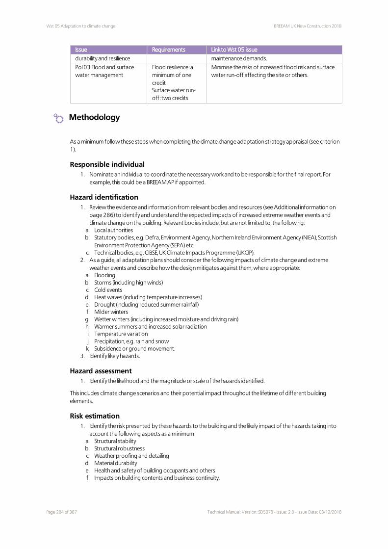
Wst 05 Adaptation to climate change BREEAM UK New Construction 2018
Issue Requirements Link to Wst 05 issue
durability and resilience maintenance demands.
Pol 03 Flood and surface water management
Flood resilience: a minimum of one creditSurface water run-off: two credits
Minimise the risks of increased flood risk and surface water run-off affecting the site or others.
Methodology
As a minimum follow these steps when completing the climate change adaptation strategy appraisal (see criterion 1).
Responsible individual 1. Nominate an individual to coordinate the necessary work and to be responsible for the final report. For
example, this could be a BREEAM AP if appointed.
Hazard identification 1. Review the evidence and information from relevant bodies and resources (see Additional information on
page 286) to identify and understand the expected impacts of increased extreme weather events and climate change on the building. Relevant bodies include, but are not limited to, the following:
a. Local authorities b. Statutory bodies, e.g. Defra, Environment Agency, Northern Ireland Environment Agency (NIEA), Scottish
Environment Protection Agency (SEPA) etc. c. Technical bodies, e.g. CIBSE, UK Climate Impacts Programme (UKCIP).
2. As a guide, all adaptation plans should consider the following impacts of climate change and extreme weather events and describe how the design mitigates against them, where appropriate:
a. Flooding b. Storms (including high winds) c. Cold events d. Heat waves (including temperature increases) e. Drought (including reduced summer rainfall) f. Milder winters g. Wetter winters (including increased moisture and driving rain) h. Warmer summers and increased solar radiation i. Temperature variation j. Precipitation, e.g. rain and snow k. Subsidence or ground movement.
3. Identify likely hazards.
Hazard assessment 1. Identify the likelihood and the magnitude or scale of the hazards identified.
This includes climate change scenarios and their potential impact throughout the lifetime of different building elements.
Risk estimation 1. Identify the risk presented by these hazards to the building and the likely impact of the hazards taking into
account the following aspects as a minimum: a. Structural stability b. Structural robustness c. Weather proofing and detailing d. Material durability e. Health and safety of building occupants and others f. Impacts on building contents and business continuity.
Page 284 of 387 Technical Manual: Version: SD5078 - Issue: 2.0 - Issue Date: 03/12/2018

BREEAM UK New Construction 2018 Wst 05 Adaptation to climate change
Risk evaluation 1. Evaluate the potential impact of these risks on the building. 2. Determine the tolerable risk threshold. 3. Check the sensitivity of the risk assessment (see Definitions below). 4. Identify areas where the risks are unacceptable to health and safety, life cycle assessment and financial
terms.
Risk management 1. Identify risk reduction measures. 2. Mitigate the hazards as far as is practically feasible. 3. Adapt the design and specification to incorporate the measures identified by the risk assessment in the
final design.
Evidence
Criteria Interim design stage Final post-construction stage
All One or more of the appropriate evidence types listed in The BREEAM evidential requirements on page 29 can be used to demonstrate compliance with these criteria.
Definitions
Durability
The ability to withstand wear, pressure or damage.
Hazard
A hazard is a situation or event which has the potential to cause harm. It may be an accidental or a malicious action,
insufficient strength or resistance, or excessive deviation from intended limits.
Resilience
The ability of a building or structural system or material to withstand an accidental or exceptional loading or other
incident without experiencing an undue degree of damage or decrease in performance, such that progressive
collapse, loss of performance or disproportionate degree of damage occurs.
Sensitivity of the risk assessment
Sensitivity analysis is a technique used to determine how changing the values of a variable will alter a dependent
variable under a given set of assumptions. Where several values could be changed to affect a dependent variable,
changes need to be made one at a time. For example, the use of different climate change scenarios would alter
the hazards of the development.
Structural and fabric resilience
BREEAM defines this as the ability of a structure to withstand an increased burden of weather, increased pressure
or hazards associated with climate change. Examples of increased pressures or hazards to be considered include
the impacts of climate change and extreme weather events described in the Methodology on the previous page
section under Hazard identification.
Systematic risk assessment
A structured approach to help professionals identify, evaluate and manage risk, where the reduction of the risks
identified is integral to the process. It includes:
Technical Manual: Version: SD5078 - Issue: 2.0 - Issue Date: 03/12/2018 Page 285 of 387

Wst 05 Adaptation to climate change BREEAM UK New Construction 2018
1. Identifying the hazards 2. Eliminating the hazards, as far as reasonably practicable 3. Reducing the risks from each hazard, as far as reasonably practicable 4. Developing the building design to be robust.
Additional information
Table 10.12 below is an example of a climate change adaptation strategy appraisal for a selection of building elements and climate change impacts. This example is not a complete appraisal, but illustrates some of the content that should be included in the appraisal.
Table 10.12 Climate change adaptation strategy appraisal examplesAppraisal examples
Hazard
Climate change hazard Flooding Cold events
Hazard assessment
Hazard scale High High
Building element Ground floor flooring material Façade finishing materials
Building element lifetime 10–15 years 10 years
Hazard likelihood High High
Impact magnitude Medium Medium
Risk
Risk estimation Flooring material becomes unusable and needs to be changed. Health risks associated with dampness; potential impact on business continuity
Façade finishing materials are not affected by cold, but are affected by snow, strong winds and rain
Risk evaluation Risk assessment sensitivity: flooding has a high likelihood under all scenarios. Health risks are beyond the tolerable risk threshold
Risk assessment sensitivity: flooding has a high likelihood under all scenarios. No health risks identified
Risk reduction measure Select a flood-resistant flooring material None
The following resources for climate change scenarios and impacts are available:
1. Relevant Intergovernmental Panel on Climate Change (IPCC) report on Impacts of climate change and adaptation(196)
2. UK climate change risk assessment(197)
3. Climate change impacts: www.climatejust.org.uk 4. Developing H++ climate change scenarios for heat waves, droughts, floods, windstorms and cold snaps
(198).The following resources for best practice design guidance are available:
5. The environmental design pocketbook(199)
6. Adaptation resources: www.climatejust.org.uk/resources 7. Adaptation or retrofitting(200)
8. Zero Carbon Hub: www.zerocarbonhub.org/full-lib 9. Design for climate change(201)
The book 'Design for climate change' describes buildings and issues as part of the Design for future climate, adapting buildings programme, the largest programme focusing on the climate change adaptation of buildings in the UK. This programme from the Technology Strategy Board (TSB) aims to improve the climate resilience of building projects. The book has guidance on construction, including structural stability.
10. The UKCIP Adaptation Wizard v 4.0 2013: www.ukcip.org.uk/wizard/about-the-wizard/ 11. Potential costs and benefits of adaptation options: A review of existing literature(202). This is a technical
paper by the United Nations Framework Convention on Climate Change (UNFCCC), which reviews methods
Page 286 of 387 Technical Manual: Version: SD5078 - Issue: 2.0 - Issue Date: 03/12/2018

BREEAM UK New Construction 2018 Wst 05 Adaptation to climate change
of costing adaptation options and assessing their benefits 12. National Adaptation Programme 2013(203)
The National Adaptation Programme report has been drawn up by the UK Government, industry and other non-government organisations working together. It contains a mix of policies and actions to help the UK to adapt successfully to future weather conditions, by dealing with the risks and making the most of the opportunities.
13. Potential implications of climate change in the built environment(204).
The BRE report 'Potential implications of climate change in the built environment', discusses climate change adaptation strategies, including some for structural resilience.
Technical Manual: Version: SD5078 - Issue: 2.0 - Issue Date: 03/12/2018 Page 287 of 387

Wst 06 Design for disassembly and adaptability BREEAM UK New Construction 2018
Wst 06 Design for disassembly and adaptability
Fully fitted Simple building Shell & core Shell only No minimum standards
Aim
To avoid unnecessary materials use, cost and disruption arising from the need for future adaptation works as a result of changing functional demands and to maximise the ability to reclaim and reuse materials at final demolition in line with the principles of a circular economy.
Value
– Reduce waste and cost associated with future refurbishment or fit-out works and ultimately in demolition.– Improve the ability to cost-effectively reuse and recycle materials.– Increase the lifetime value of materials and products.– Encourage consideration of circular economy principles during design and construction.– Reduce costs and disruption associated with the need for future adaptation, demolition and strip-out, thereby
reducing the associated waste and costs.
Context
The construction industry is responsible for approximately 60% of total UK materials use and one-third of all waste produced(205). At least 17 million tonnes of inert waste are produced by the UK construction industry(206). Typically buildings are stripped out or in many cases even demolished considerably earlier than their design life would predict or structural stability require. In most cases only high value materials are reclaimed or reused and many resources are either used for low grade uses, taken to landfill or, in some cases, even illegally dumped leading to increased environmental damage and costs to local authorities and society. This risk can be reduced by considering building adaptability and also future disassembly to allow easy material separation and reuse. This includes exposed and reversible connections, layer independence and standardisation which can facilitate disassembly.
Assessment scope
Fully fitted Simple building Shell and core Shell only
Applicable assessment criteria All All All All
Assessment type specific notes None None None None
Specific notes
Assessment type specific
None
2 2 2 2
Page 288 of 387 Technical Manual: Version: SD5078 - Issue: 2.0 - Issue Date: 03/12/2018

BREEAM UK New Construction 2018 Wst 06 Design for disassembly and adaptability
Building type specific
None
Assessment criteria
This issue is split into two parts:
– Design for disassembly and functional adaptability - recommendations (one credit)– Disassembly and functional adaptability - implementation (one credit)
One credit - Design for disassembly and functional adaptability - recommendations1 Conduct a study to explore the ease of disassembly and the functional adaptation potential of different design
scenarios (see Methodology below) by the end of Concept Design.
2 Develop recommendations or solutions (see Methodology below) based on the study (criterion 1 above), during or prior to Concept Design, that aim to enable and facilitate disassembly and functional adaptation.
One credit - Disassembly and functional adaptability – implementation3 Achieve criteria 1 and 2
4 Provide an update, during Technical Design, on:
4.a How the recommendations or solutions proposed by Concept Design have been implemented where practical and cost effective. Omissions have been justified in writing to the assessor.
4.b Changes to the recommendations and solutions during the development of the Technical Design.
5 Produce a building adaptability and disassembly guide to communicate the characteristics allowing functional adaptability and disassembly to prospective tenants.
Methodology
Functional adaptation strategy studyThe study must consider the following as a minimum:
– Feasibility: The likelihood to contain multiple or alternative building uses, area functions and different tenancies over the expected life cycle, e.g. related to the structural design of the building.
– Accessibility: Design aspects that facilitate the replacement of all major plant within the life of the building, e.g. panels in floors and walls that can be removed without affecting the structure, providing lifting beams and hoists. Accessibility also involves access to local services, such as local power, data infrastructure etc.
– Versatility: The degree of adaptability of the internal environment to accommodate changes in working practices.
– Adaptability: The potential of the building ventilation strategy to adapt to future building occupant needs and climatic scenarios.
– Convertibility: The degree of adaptability of the internal physical space and external shell to accommodate changes of in-use.
– Expandability: The potential for the building to be extended, horizontally or vertically.– 'Refurbishment potential': The potential for major refurbishment, including replacing the façade.
For additional guidance, see Table 10.13 on page 291.
Functional adaptation implementationThe implementation will be specific to the building and scope of the project, but information should be made available to the assessor covering:
– Options for multiple building uses and area functions based on design details, e.g. modularity.– Routes and methods for major plant replacement, e.g. networks and connections have flexibility and capacity for
expansion.
Technical Manual: Version: SD5078 - Issue: 2.0 - Issue Date: 03/12/2018 Page 289 of 387

Wst 06 Design for disassembly and adaptability BREEAM UK New Construction 2018
– Accessibility for local plant and service distribution routes, e.g. detailed information on building conduits and connections infrastructure.
– The potential for the building to be extended, horizontally or vertically.
Ease of disassemblyEase of disassembly is facilitated by principles allowing the building or parts of the building to be disassembled at the end of its life, or to be renovated rather than demolished, with individual components being used for other purposes. The study should consider the following as a minimum:
– Accessibility (see Functional adaptation strategy study on the previous page).
– Durability: use materials which require less frequent maintenance, repair or replacement, considering them within the context of the life span of the building.
– Exposed and reversible connections: making the connections more visible provides opportunities to optimise material and product reuse. Welded connections prohibit disassembly and it is preferable to use screws and bolts to allow for disassembly and material reuse.
– Layer independence: designing building systems and components in layers so that removal, adjustment or replacement of some elements is feasible, especially when different components have different life spans and maintenance needs.
– Avoidance of unnecessary toxic treatments and finishes. Some finishes can contaminate the substrate in a way that they are no longer reusable or recyclable. This should be avoided unless finishes serve a specific purpose.
– Standardisation can accommodate reuse and upgrading. It involves aspects such as dimensions, components, connections and modularity.
For additional information, see Table 10.14 on the facing page.
Evidence
Ref Interim design stage Final post-construction stage
All One or more of the appropriate evidence types listed in The BREEAM evidential requirements on page 29 can be used to demonstrate compliance with these criteria.
All Disassembly and functional adaptability study, implementation plan report, building adaptability and disassembly guide.
As per interim design stage.
BRE has avoided being overly prescriptive for this issue, recognising that this is a complex environmental and design issue where solutions and approaches are largely influenced by building specific factors. The evidence required to demonstrate compliance will vary according to the relevant stage. Some examples are:
– Concept Design: reports outlining the activity relating to functional adaptability and disassembly - ideas discussed, analysis and decisions taken
– Concept and Developed Design stages: drawings or building information model (BIM).– All stages: meeting notes, construction programme, responsibilities schedule-indicating parties consulted.
The BREEAM Assessor should use their judgement in determining whether the aim and intent of the credit has been met using appropriate project information to back their judgement. BRE Global will endorse the BREEAM Assessor's judgement through the Quality Assurance audit where a reasonable justification to award the credit on the basis of project team actions and proposed design solutions is evident.
Definitions
Building adaptability and disassembly guide
The guide can be in the form of an analogue document or an Asset Information Model from the Building
Information Model (BIM) created in accordance with PAS 1192 Part 2-2013(207) and PAS 1192 Part 3-2014(208). See the new ISO 20887 for information on what the guide could include.
Page 290 of 387 Technical Manual: Version: SD5078 - Issue: 2.0 - Issue Date: 03/12/2018

BREEAM UK New Construction 2018 Wst 06 Design for disassembly and adaptability
Building functional adaptability
Work to an existing building that responds to a required change of use or requirements and goes beyond
maintenance and repairs. These changes solve functional problems and could provide significant improvements.
The functional adaptation works could include alterations, conversions or extensions.
Functional adaptability
The ability of a building to be adapted for a change in operational requirements within the same building type or
for use as a different building type.
Additional information
The Health Technical Memorandum 07-07(209) includes guidance on future-proofing healthcare buildings.
A new ISO (20887) focusing on the ‘Design for disassembly and adaptability of buildings and civil engineering works’ is expected to be published.
Table 10.13 below provides examples of functional design measures that may be adopted for each assessment part when considering accessibility, spatial adaptability and expandability
Table 10.13 Design measures allowing future adaptation Accessibility Spatial adaptability Expandability
Fabric and structure: – External walls – Cladding– Ground and first
floor – Roof
Use of products or systems which allow easy replacements
Location of structural components within the floor space
Provision to add extensions or alterations to increase building capacity
Core and local services: – Mechanical and
electrical– Plumbing– Stairs and lifts– Fire
Inclusion of facilities management requirements and construction design management feedback for future operational needs.
Provision of capacity in infrastructure to enable future expansion and adaptation
Interior design: – Finishes– Floors – Interior walls – Connections
Use of products or systems which allow easy replacements.
– Layout in standardised grids
– Use of inherent finishes to allow replacement
– Use of standardised material sizes
– Identifying or recognising potential future functional requirements
– Efficient use of space to allow for any increase in occupancy
Table 10.14 below provides examples of considerations when designing for disassembly.
Table 10.14 Examples of design measures and aspects to consider regarding future disassemblyPrinciples for disassembly
Examples of design measures and aspects to consider
Durability – Durability of different building elements based on warranties and risk of being broken during disassembly
– Consider building elements within the context of the building life span and the building sector
– Use of temporary structures when a short life span is expected
Technical Manual: Version: SD5078 - Issue: 2.0 - Issue Date: 03/12/2018 Page 291 of 387

Wst 06 Design for disassembly and adaptability BREEAM UK New Construction 2018
Principles for disassembly
Examples of design measures and aspects to consider
Exposed and reversible connections
– Exposed and reversible connections facilitate disassembly – Consider space availability between building elements when aiming to
accommodate disassembly– Poured and welded connections are likely to harm components and prevent
disassembly
Layer independence Layers standing independently, especially when components have different lifespans. The following principal layers can be identified as follows: – Structure: foundation and load-bearing elements – Skin: exterior surfaces– Services – Space plan: the interior layout– Stuff: furnishings and carpets
Standardisation – Standard-size materials can accommodate multiple uses, reuse and upgrading – Standard types of connections can be separated and reused more easily– Modularity allows elements to be slotted together or taken apart to promote
disassembly and flexible environments
Page 292 of 387 Technical Manual: Version: SD5078 - Issue: 2.0 - Issue Date: 03/12/2018

BREEAM UK New Construction 2018 Land Use and Ecology
Land Use and Ecology
Fully fitted Simple building Shell & core Shell only
Summary
This category encourages sustainable land use, habitat protection and creation, and improvement of long term biodiversity for the building’s site and surrounding land. Issues in this section relate to the reuse of brownfield sites or those of low ecological value, mitigation and enhancement of ecology, and long term biodiversity management.
This category has two routes to demonstrate compliance, Route 1 is the Project team member, which provides a simplistic approach to assessing the ecological approach. Route 2 is the Ecologist route, a more detailed assessment of the ecological approach for the site. The credits available for each issue varies dependent on the chosen route, with greater credits available for following route 2.
Assessment timeline
To assist with optimising project sustainability performance, the assessment timeline outlines the stage at which credits should be addressed. Ideally these should be considered by the design team, planner, contractors, owners, occupiers and other members of the project team to achieve the highest possible BREEAM rating at the minimum cost.
If BREEAM advice is taken on too late within the design and construction phases a number of BREEAM credits may not be achieved or only at additional cost or disruption.
LE 01 Site selection 2 credits
– Recognising the reuse of previously developed and contaminated land where appropriate remediation has taken place.
LE 02 Identifying and understanding the risks and opportunities for the project
up to 2 credits
13% 15% 15% 19%
Technical Manual: Version: SD5078 - Issue: 2.0 - Issue Date: 03/12/2018 Page 293 of 387

Land Use and Ecology BREEAM UK New Construction 2018
– Identifying and understanding the ecological risks and opportunities associated with the site to inform the determination of the strategic outcome for the site.
LE 03 Managing negative impacts on ecology up to 3 credits
– Recognition of steps taken to avoid impacts on existing site ecology as far as possible. LE 04 Change and enhancement of ecological value up to 4 credits
– Recognition of steps taken to enhance site ecology. LE 05 Long term ecology management and maintenance up to 2 credits
– Encouraging the long term maintenance and management of ecology on site to ensure both new and existing ecological features continue to thrive.
Page 294 of 387 Technical Manual: Version: SD5078 - Issue: 2.0 - Issue Date: 03/12/2018

BREEAM UK New Construction 2018 LE 01 Site selection
LE 01 Site selection
Fully fitted Simple building Shell & core Shell only No minimum standards
Aim
To encourage the use of previously occupied or contaminated land and avoid land which has not been previously disturbed.
Value
– Avoid the use of greenfield land thereby reducing the environmental impact of the development.– Regeneration provides social and economic benefits to the development and the surrounding local community.– Remediation removes threats to health and safety, and enables land, to be improved that would otherwise be
left.
Context
Brownfield redevelopment not only cleans up environmental health hazards and eyesores, but also stimulates community regeneration, particularly when communities have an input into the consultation process. The reclamation and reuse of previously developed sites also aligns with UK Government policies to increase the uptake of brownfield land, and allows the preservation of existing biodiversity by reducing reliance on greenfield land.
Assessment scope
Fully fitted Simple building Shell and core Shell only
Applicable assessment criteria All All All All
Assessment type specific notes None None None None
Specific notes
Assessment type specific
None
Building type specific
2.0 Education (schools only) - Playing fieldsDevelopment of a playing field within the development footprint can be counted as development on previously occupied land only if an equivalent area of playing field is reinstated within one year of the completed construction works, and where such reinstatement will not encroach on land of high ecological value.
2 2 2 2
Technical Manual: Version: SD5078 - Issue: 2.0 - Issue Date: 03/12/2018 Page 295 of 387

LE 01 Site selection BREEAM UK New Construction 2018
Building type specific
2.1 PrisonsAll land within a secure perimeter fence on an existing prison site can be classified as previously occupied land. Therefore assessments of buildings located within this area will achieve the credit.If the secure perimeter fence of a prison is being extended to accommodate the proposed building, or the proposed building is located on a completely new site, then the building must comply with the assessment criteria defined above.
Assessment criteria
This issue is split into two parts:
– Previously occupied land (one credit)– Contaminated land (one credit)
One credit - Previously occupied land1 At least 75% of the proposed development’s footprint is on an area of land which has previously been
occupied (see Definitions on the facing page).
One credit - Contaminated land2 A contaminated land professional's site investigation, risk assessment and appraisal has deemed land within
the site to be affected by contamination. The site investigation, risk assessment and appraisal have identified:
2.a The degree of contamination
2.b The contaminant sources or types
2.c The options for remediating sources of contamination which present an unacceptable risk.
3 The client or principal contractor confirms that remediation of the site will be carried out in accordance with the remediation strategy and its implementation plan as recommended by the contaminated land professional (see Definitions on the facing page).
Methodology
Previously developed land - Infill sitesWhen assessing new buildings developed within the boundary of an existing site, they do not automatically comply with the reuse of land criteria. At least 75% of the land on which the new building will be sited must meet the definition of 'previously occupied' (for prisons, refer to Scope of the BREEAM UK New Construction 2018 scheme version on page 15).
Contaminated land - ScopeContaminated land that has been decontaminated solely for health and safety reasons, or for historic remediation (rather than for the specific purpose of redevelopment) is not within the scope of the assessment. The credit for use of contaminated land can only be awarded where remediation has taken place to enable development of the site for the assessed building, or a larger phased development that includes the assessed building.
Contaminated land - Large sites split into smaller plotsWhen assessing a large site that has been remediated and then packaged up into smaller plots of land for individual buildings (possibly as part of a phased development strategy), the credit can be awarded regardless of the plot location of the assessed building within the wider development plan. This is on the condition that the site could not have been developed without remediation work taking place.
Page 296 of 387 Technical Manual: Version: SD5078 - Issue: 2.0 - Issue Date: 03/12/2018

BREEAM UK New Construction 2018 LE 01 Site selection
Evidence
Criteria Interim design stage Final post-construction stage
All One or more of the appropriate evidence types listed in The BREEAM evidential requirements on page 29 can be used to demonstrate compliance with these criteria.
3 A copy of the remediation strategy and implementation plan.
Evidence to demonstrate the recommendations set out in the remediation strategy and implementation plan have been implemented.
Definitions
Contaminated land professional
An individual that holds a degree or equivalent qualification in chemistry, environmental science or management,
earth sciences, civil engineering, or a related subject, and has a minimum of three years relevant experience (within
the last five years) in site investigation, risk assessment and appraisal. Such experience must clearly demonstrate a
practical knowledge of site investigation methodologies and understanding of remediation techniques and
national legislation on the subject; as well as acting in an advisory capacity to provide recommendations for
remediation.
Development footprint
The development footprint includes any land used for buildings, hardstanding, landscaping, site access or where
construction work is carried out (or land is being disturbed in any other way), where features of ecological value
are being disturbed. It also includes any areas used for temporary site storage and buildings. If it is not known
exactly where buildings, hardstanding, site access, temporary storage and buildings will be located, it must be
assumed that the development footprint is the entire development site.
Land affected by contamination
Land that could not be legally or safely developed or built on to the proposed end use without the remediation of
the contamination. Contamination is defined as any substance or agent in, or on the ground within the
development footprint, which presents an unacceptable risk to human health, property or the environment. For
the purposes of BREEAM, substances or agents that could present unacceptable contamination risks are defined
as those that act as a barrier to the development of land, which could include certain plant species such as, but not
limited to, Japanese knotweed and giant hogweed.
Where asbestos is found to be present in the ground this is classed as contamination for the purposes of this
issue. If asbestos is present in existing building fabric, the site cannot be classified as contaminated land.
Previously occupied land
For the purposes of this issue BREEAM defines previously occupied land as that which is or was occupied by a
permanent structure, including any associated fixed surface infrastructure (the definition is based on the National
Planning Policy Framework(210) definition of previously developed land, with some further clarifications for items
3 and 4). The definition excludes:
1. Land that is or has been occupied by agricultural or forestry buildings. 2. Land that has been developed for minerals extraction or waste disposal by landfill purposes where
provision for restoration has been made through development control procedures. 3. Land in built-up areas such as parks, recreation grounds and allotments which, although they may feature
paths, pavilions and other buildings, have not been previously occupied.
Technical Manual: Version: SD5078 - Issue: 2.0 - Issue Date: 03/12/2018 Page 297 of 387

LE 01 Site selection BREEAM UK New Construction 2018
4. Land that was previously occupied but where the remains of the permanent structure or fixed surface structure have blended into the landscape in the process of time (to the extent that it can reasonably be considered as part of the natural surroundings), typically over a period of more than fifty years.
Proposed development
Any development (building, hard landscaping, car park and access roads) that falls within the boundary of the
assessed site.
Remediation
Any activity undertaken to prevent, minimise, remedy or mitigate the risk caused by contaminated land to human
health, the environment or local resources such as sources of potable water.
Additional information
None.
Page 298 of 387 Technical Manual: Version: SD5078 - Issue: 2.0 - Issue Date: 03/12/2018

BREEAM UK New Construction 2018 LE 02 Identifying and understanding the risks and opportunities for the project
LE 02 Identifying and understanding the risks and opportunities for the project
Fully fitted Simple building Shell & core Shell only No minimum standards
Aim
To determine the ecological baseline and zone of influence of the site and identify risks and opportunities for achieving optimum outcomes.
Value
– Demonstrate sound understanding and consideration of ecological value including ecosystem service provision, biodiversity and associated benefits.
– Avoid risks associated with the wider environment.– Provide the ability for construction works to be programmed successfully while minimising impacts on natural
assets.– Understand and maximise benefits (ecosystem benefits) associated with wellbeing, amenity and community
arising from the adoption of appropriate ecological design and management practices on a site and in its surroundings.
– Ensure an appropriate level of expertise is employed on the project to recognise both the level of risk and the opportunity to increase ecological value in a manner that takes account of project construction and operational viability.
Context
Conserving habitats and biodiversity is important for life on earth. It supports the variety of living organisms on the planet as well as the interdependence that exists between them. Development and landscape management can have a significant impact on the broader environment that it supports and can have a potentially positive impact on ecological value. Thus it is important to understand the existing value and condition of sites, where possible promote the use of land that has low value and strive to minimise damage where this is not practical. It is also important to make decisions and take actions that support and where possible enhance the ecological value of the site and surrounding areas.
Assessment scope
Fully fitted Simple building Shell and core Shell only
Applicable assessment criteria All All All All
Assessment type specific notes None None None None
Up to 2 Up to 2 Up to 2 Up to 2
Technical Manual: Version: SD5078 - Issue: 2.0 - Issue Date: 03/12/2018 Page 299 of 387

LE 02 Identifying and understanding the risks and opportunities for the project BREEAM UK New Construction 2018
Specific notes
Assessment type specific
None
Building type specific
None
Assessment criteria
This issue is split into two parts:
– Survey and evaluation– Determining the ecological outcomes for the site
Prerequisite - Assessment route selection1 An assessment route (see Definitions on page 304) for the project has been determined using BREEAM
Guidance Note GN34 BREEAM Ecological Risk Evaluation Checklist.
2 The client or contractor confirms compliance is monitored against all relevant UK and EU or international legislation relating to the ecology of the site.
Table 11.1 Credits awarded by ecological assessment route Project team member route
(Route 1)Ecologist route (Route 2)
Survey and evaluation 1 credit 1 credit
Determining the ecological outcomes for the site
1 credit
Exemplary criteria 1 credit 1 credit
Survey and evaluation
Route 13 Assessment route 1 can be used only when indicated by the results of the BREEAM Ecological Risk Evaluation
Checklist (see Methodology on the facing page).
Route 24 A Suitably Qualified Ecologist (SQE) is appointed at a project stage that ensures early involvement in site
configuration and, where necessary, can influence strategic planning decisions.
5 Prior to the completion of the Preparation and Brief project stage, an appropriate level of survey and evaluation (see Assessment route 2: For sites where complex ecological systems are likely to be present on the facing page) has been carried out to determine the ecological baseline of the site, taking account of the zone of influence to establish:
5.a Current and potential ecological value and condition of the site, and related areas within the zone of influence.
5.b Direct and indirect risks to current ecological value
5.c Capacity and feasibility for enhancement of the ecological value of the site and, where relevant, areas within the zone of influence.
6 Data are collated and shared with project team to inform the site preparation, design and construction works.
Page 300 of 387 Technical Manual: Version: SD5078 - Issue: 2.0 - Issue Date: 03/12/2018

BREEAM UK New Construction 2018 LE 02 Identifying and understanding the risks and opportunities for the project
Determining the ecological outcomes for the site (Routes 1 and 2)7 Survey and evaluation criteria relevant to the chosen route (criterion 3 or Criteria 4–6 on the previous page)
have been achieved.
8 During Concept Design, the project team liaise and collaborate with representative stakeholders to identify the optimal ecological outcome for the site. (For Route 1 assessments, see GN35. For Route 2 assessments, see Methodology below).
9 The ecological outcome for the site is determined by identifying, appraising and selecting specific solutions and measures. The solutions and measures must be identified sufficiently early in the project to influence key project planning decisions and must be done in accordance with the following hierarchy of action, which is dependant on the route being used :
Route 1 Route 2
1. Avoidance 2. Protection
1. Avoidance 2. Protection 3. Reduction or limitation of negative impacts 4. On site compensation and 5. Enhancement, considering the capacity and
feasibility within the site, or where viable, off-site.
10 The optimal ecological outcome for the site is selected after liaising with representative stakeholders and the project team.
Exemplary Level criteriaTo achieve one exemplary performance credit:
Determine the ecological outcomes for the site (sustainability-related activities)11 Achieve criteria 8 to 10 above.
12 When determining the optimal ecological outcome for the site consider, in addition to those outlined in criteria 8 to 10 above, the wider site sustainability-related activities and the potential for ecosystem service related benefits. SeeMethodology below for a list of the minimum areas for consideration.
13 Achieve the credits of the assessment issues outlined below:
13.a Assessment scope on page 122 - Both credits
13.b Assessment scope on page 333 - Achieve credits for 'Surface water run-off' and 'Minimising watercourse pollution'
13.c Assessment scope on page 350
Methodology
Assessment route 1: For sites where ecological opportunities and risks are limited in natureRefer to GN35 - BREEAM UK New Construction 2018 Ecology Assessment - Route 1 methodology for further guidance.
Assessment route 2: For sites where complex ecological systems are likely to be presentThe approach taken to the ecological assessment should be appropriate to the scope and scale of the project. This may result in some points listed as not being applicable or being interpreted and applied at a level that is appropriate for the scope of the project.
Survey and evaluationThe following must be considered as a minimum:
Technical Manual: Version: SD5078 - Issue: 2.0 - Issue Date: 03/12/2018 Page 301 of 387

LE 02 Identifying and understanding the risks and opportunities for the project BREEAM UK New Construction 2018
Survey
1. Determining the zone of influence for the site including neighbouring land and habitats 2. Current flora, fauna (including permanent and transient species) and habitat characteristics (including but
not limited to ecological features in or on built structures) 3. Habitat extent, quality, connectivity and fragmentation 4. Recent and historic site condition 5. Existing management and maintenance levels and arrangements 6. Existing ecological initiatives within the zone of influence 7. Identification of, and consultation with, relevant stakeholders impacted or affected by the site. 8. Local knowledge or sources of information.
Evaluation
1. Current value and condition of the site and, where relevant, the zone of influence in terms of: a. Features including habitats, species, food sources and connectivity b. Broader biodiversity and ecosystem services benefits or opportunities
2. Direct and indirect risks to current ecological value: a. Sensitive areas and features on or near the site b. Direct risks including those from, human activity (e.g. construction work), habitat fragmentation, and
potentially harmful species c. Indirect risks including water, noise and light pollution
3. Capacity and feasibility to enhance the ecological value 4. Habitat restoration and creation potential 5. Impact of the proposed design, construction works and operations on site.
There may be some projects where not all items listed above will be applicable or appropriate to the site. In these cases, the ecologist should justify why the items are considered not applicable.
Determining the ecological outcomes for the site – project team liaison and collaboration with relevant stakeholdersRelevant project team members liaise with each other at appropriate times to support optimisation of the ecological outcomes for the site. Project members would include, but are not limited to:
– The client, owner, occupier– Design, project, facilities team– Specialist consultants. Examples could include:
– Drainage engineer– Acoustic consultant– Landscape architect.
Where feasible, and where relevant project team members collaborate with relevant stakeholders at appropriate times to support optimisation of the ecological outcomes for the site. Relevant stakeholders may include, but are not limited to:
– – Local government and other statutory relevant organisations– Local community groups or organisations or charities. Examples could include:
– The Wildlife Trusts– Local, regional and or national fauna focused groups (e.g. Bug life, RSPB, Bat Conservation Trust etc.)
Coordination of the liaison and collaboration is likely to happen by a central project team member with an overview of the project, its members, specialist contractors etc. and has the ability to instruct the work associated with delivering the ecological outcome for the site selected.
Determining the ecological outcomes for the site – Considerations during liaison discussionsThis should consider the following as appropriate to the nature and scale of the project:
1. Ecological value and benefit offered (pre-, during and post-asset maintenance or project completion) 2. Biodiversity and ecosystem services benefits offered pre-, during and post-asset maintenance or project
completion 3. Local microclimatic conditions 4. Habitat extent, quality, connectivity and fragmentation 5. Opportunities to enhance the value of existing habitats and biodiversity, or to restore or create new, more
valuable ones
Page 302 of 387 Technical Manual: Version: SD5078 - Issue: 2.0 - Issue Date: 03/12/2018

BREEAM UK New Construction 2018 LE 02 Identifying and understanding the risks and opportunities for the project
6. Opportunities to align and integrate with existing ecological features and initiatives in the zone of influence 7. The viability of assessment requirements points 9 (hierarchy of actions list and capacity and feasibility for
enhancement).
Determining the ecological outcomes for the site – Identification and selection of solutions and measuresWhen determining the associated solutions for the site the following should be considered:
1. Ecological, biodiversity and ecosystem services benefits, accounting for: a. Local priorities. b. Long term viability of the outcome or option. c. Alignment with the sites function, amenity and value.
2. Practicality, including consideration of: a. Timing and duration of implementing and realising the outcome and associated options. b. Outline up-front and ongoing management and maintenance costs. c. Long term management and maintenance implications. d. Opportunities and barriers arising from management or procurement structures. e. Availability of appropriate skills, budgets and other resources at all stages.
Determining the ecological outcome for the site – wider site sustainability related activities and ecosystem service related benefitsOpportunities for integrating ecology with wider site sustainability-related activities and ecosystem service related benefits, including as a minimum:
1. Landscape: a. Landscape design b. Heritage and local character c. Green Infrastructure
2. Health and wellbeing: a. Recreational space (including growing space, community agriculture or horticultural and allotment
activities) b. Water quality measures c. Noise mitigation measures d. Air quality control measures e. Light pollution control measures
3. Resilience: a. Climate change mitigation b. Management of surface water run-off c. Flood risk management d. Climate-sensitive urban design (heat island effect, thermal mass, shading, biotic cooling etc.)
4. Infrastructure: a. Maximising the benefits of green infrastructure and optimising alignment with existing infrastructure on
the site and the zone of influence. 5. Community and end user involvement:
a. Life cycle costing and service life planning (where targeted under Man 02).
Evidence
Criteria Interim design stage Final post-construction stage
All One or more of the appropriate evidence types listed in The BREEAM evidential requirements on page 29 can be used to demonstrate compliance with these criteria.
Prerequisite - Assessment route selection
Completed Guidance Note 34: BREEAM, CEEQUAL and HQM Ecology Risk Evaluation Checklist.
As per interim design stage
5 A copy of the Ecological Survey and Evaluation document. Note: A phase 1 habitat assessment or other equivalent type of assessment can act as
As per interim design stage
Technical Manual: Version: SD5078 - Issue: 2.0 - Issue Date: 03/12/2018 Page 303 of 387

LE 02 Identifying and understanding the risks and opportunities for the project BREEAM UK New Construction 2018
Criteria Interim design stage Final post-construction stage
acceptable evidence as long as it can be shown that they cover the content of the assessment criteria.
Definitions
Assessment routes 1 and 2
Route 1: For sites where ecological opportunities and risks are limited in nature
This route is only appropriate where the level of ecological risk associated with the site is of a level that can
practically be understood and addressed by a project team member using general observation, non-specialist
knowledge and publicly available resources and information. This would be assessed by completing the Ecological
Risk Evaluation Checklist. A lower level of reward is available as this route does not involve the same level of input
and expertise that would be available when using a Suitably Qualified Ecologist.
Route 2: For sites where complex ecological systems are likely to be present
This is the more comprehensive route of assessment and therefore can achieve a higher level of reward than
Route 1. It must be conducted by a Suitably Qualified Ecologist (See Definitions). This route will be mandatory for
more sensitive sites and optional for those eligible for assessment under Route 1 . This would be assessed by
completing the Ecological Risk Evaluation Checklist.
Avoidance
Prevention of impacts occurring as a result of the project, having regard to predictions about potentially negative
environmental effects (e.g. project decisions about site location, design or timing of works).
Biodiversity
The variety of plant and animal life in the world or in a particular habit at the following levels of organisation:
landscape, ecosystem, habitat, community, species, population, individual, and the structural and functional
relationships within and between these.
Compensation
Measures taken to make up for the loss of, or permanent damage to, ecological features despite mitigation, e.g.
replacement habitat or improvements to existing habitats similar in terms of biological features and ecological
functions to that lost or damaged. Compensation can be provided either within or outside the project site, in line
with the following hierarchy: within site, adjacent to site and off site (offsetting) as a last resort.
Connectivity
The degree to which the configuration of habitats facilitates movement between and across resource patches.
Ecological baseline
The ecological baseline is the ecological value of the site before construction. It is used to compare performance
after construction, to determine if it is the same or significantly changed.
Ecological feature
Examples of ecological features include habitat, ecosystems and species.
Ecological value
The importance, worth, or usefulness of a species, habitat or ecosystem in terms of its impact on other species
and habitats, as well as the other environmental, social, cultural and economic value that can be delivered from
Page 304 of 387 Technical Manual: Version: SD5078 - Issue: 2.0 - Issue Date: 03/12/2018

BREEAM UK New Construction 2018 LE 02 Identifying and understanding the risks and opportunities for the project
species and habitats and their interactions (ecosystem services) specific to a geographical frame of reference.
Ecosystem
An ecosystem is a dynamic complex of plant, animal, and micro-organism communities, and the non-living
environment interacting as a functional unit. Ecosystems vary enormously in size; a temporary pond in a tree
hollow and an ocean basin can both be ecosystems.
Ecosystem services
Ecosystem services are the benefits people obtain from ecosystems. These include provisioning services such as
food and water; regulating services such as regulation of floods, drought, land degradation, and disease;
supporting services such as soil formation and nutrient cycling; economic value such as tourism, and cultural and
social services such as health and wellbeing, recreational, spiritual, religious and other non-material benefits.
Enhancement
Improved management of ecological features or provision of new ecological features, resulting in a net benefit to
biodiversity, which is unrelated to a negative impact or is ‘over and above’ that required to mitigate or
compensate for an impact.
Fragmentation
The breaking up of a habitat, ecosystem or land-use type into smaller parcels with a consequent impairment of
ecological function, connectivity and long-term viability.
Green infrastructure
Multi-functional space, urban and rural, that can form a network or be self-contained, which is capable of
delivering a wide range of environmental and quality of life benefits for local communities. It covers both ‘green’
and ‘blue’ (water environment) features of the natural and built environments. Examples include parks, open
spaces, playing fields, woodlands, wetlands, grasslands, river and canal corridors, allotments, private gardens and
living (green) roofs and façades.
Habitat
A place in which a particular plant or animal lives. It is often used in the wider sense referring to major assemblages
(a group of species found in the same location) of plants and animals found together.
Handover
For the purposes of the ecology-related issues in this category, handover refers to any point in a sites or
developments life cycle where ecological or landscape-related responsibilities, are passed from one organisation,
group or individual to another. This will include information or documentation, deemed to be crucial to the
successful attainment of ecological aims and objectives. Handover strategies should be designed to support
effective communication, monitoring and transition throughout the projects life cycle.
Landscape
An area, as perceived by people, whose visual features and character is of environmental, social and economic
value, usually as a result of the action and interaction of natural and human factors, e.g. aesthetic, heritage, scenic,
cultural and leisure benefits.
Relevant project team member
This covers members of the project team responsible for delivering the project. Where implementation activities
are taking place such as site preparation and construction works, the principal contractor would typically take
responsibility for the activities related to the BREEAM requirements.
Technical Manual: Version: SD5078 - Issue: 2.0 - Issue Date: 03/12/2018 Page 305 of 387

LE 02 Identifying and understanding the risks and opportunities for the project BREEAM UK New Construction 2018
Site
For the purposes of BREEAM the site is considered to be the land enclosed by the boundary of the BREEAM
assessment.
Suitably Qualified Ecologist (SQE)
An individual achieving all the following items can be considered to be 'suitably qualified' for the purposes of
compliance with BREEAM:
1. Holds a degree or equivalent qualification (e.g. N/SVQ level 5) in ecology or a related subject. 2. Is a practising ecologist, with a minimum of three years relevant experience (within the last five years). Such
experience must clearly demonstrate a practical understanding of factors affecting ecology in relation to construction and the built environment including: acting in an advisory capacity to provide recommendations for ecological protection, enhancement and mitigation measures. Examples of relevant experience are: ecological impact assessments, Preliminary Ecological Appraisals (PEA), Phase 2 habitat and fauna surveys, and habitat creation.
3. Is covered by a professional code of conduct and subject to peer review. Full members of the following organisations, who meet the above criteria, are deemed Suitably Qualified Ecologists for the purposes of BREEAM: a. Chartered Institute of Ecology and Environmental Management (CIEEM) b. Chartered Institution of Water and Environmental Management (CIWEM) c. Institute of Environmental Management and Assessment (IEMA) d. Landscape Institute (LI) e. The Institution of Environmental Sciences (IES).
Zone of influence
Areas of land or water bodies impacted by the site undergoing assessment. These areas can be adjacent to the
site or can be areas that are dependent on the site but not physically linked, including areas downstream from a
site. Areas within the zone of influence can be negatively affected by changes on an assessment site but they also
provide further opportunity to maximise enhancement activities.
Additional information
Assessment routesWhile many projects will require input from a suitability qualified ecologist to determine the best approach, the varied nature and scope of development sites means that some may not warrant this level of specialist input. BREEAM’s goal is to promote the consideration of ecological value and its resulting benefits on all sites. This is to increase the chance of positive benefits for the environment and for those who will occupy, interact with or otherwise be affected by the project. BREEAM has therefore developed assessment criteria that recognise meaningful actions taken involving levels of expertise that are appropriate to the specific project risks and the life cycle stage under assessment.
Page 306 of 387 Technical Manual: Version: SD5078 - Issue: 2.0 - Issue Date: 03/12/2018

BREEAM UK New Construction 2018 LE 03 Managing negative impacts on ecology
LE 03 Managing negative impacts on ecology
Fully fitted Simple building Shell & core Shell only No minimum standards
Aim
To avoid, or limit as far as possible, negative impacts on the ecology of the site and its zone of influence arising as a result of the project.
Value
– Minimise ecological damage on the site and where relevant in the zone of influence.– Help to conserve local natural ecosystems and maintain environmental assets for the community.– Supports activities to ensure that legislation, policy and guidance are followed for the good of the site, the zone
if influence and wider environment and to avoid legal issues.– Reduce the risk of local controversy over development and management strategies.
Context
Programming of works on a site is driven by many factors but can often have a negative impact on the ecology of a site or in the zone of influence. Many species are afforded legal protection. Damage can result in prosecution leading to corporate or personal fines, prison sentences and reputational damage. The replacement of lost habitats is not straightforward and takes time to be successful. It is, therefore, important to follow the hierarchy of avoid, protect, reduce or limit, compensate when making decisions about issues that have an impact on ecology, wherever possible limiting disruption and disturbance to local wildlife or ecological systems. Where disruption is likely to arise during construction works and operation of the asset, the focus should be on minimising disruption to maximise value and ensure that it is sustainable for the longer term.
Assessment scope
Fully fitted Simple building Shell and core Shell only
Applicable assessment criteria All All All All
Assessment type specific notes None None None None
Specific notes
Assessment type specific
None
Building type specific
None
Up to 3 Up to 3 Up to 3 Up to 3
Technical Manual: Version: SD5078 - Issue: 2.0 - Issue Date: 03/12/2018 Page 307 of 387

LE 03 Managing negative impacts on ecology BREEAM UK New Construction 2018
Assessment criteria
This issue is split into three parts:
– Identification and understanding the risks and opportunities for the site (prerequisite)– Planning, liaison and implementation (one credit)– Managing negative impacts of the project (up to two credits)
Prerequisite – Identification and understanding the risks and opportunities for the site1 LE 02 has been achieved.
Table 11.2 Credits awarded according to assessment route Project team member route
(Route 1)Ecologist Route (Route 2)
Planning, liaison and implementation
1 credit 1 credit
Managing negative impacts of the project (limitation or compensation)
1 credit 1 or 2 credits
One credit – Planning, liaison, implementation and data2 Roles and responsibilities for managing negative impacts on the ecology are clearly defined and allocated to
support successful delivery of project outcomes at an early enough stage to influence the Preparation and Brief or Concept Design.
3 The potential impact of site preparation and construction works on ecology are identified at an early project stage to optimise benefits and outputs.
4 The project team, liaising and collaborating with representative stakeholders and, taking into consideration data collated and shared, have proposed solutions and selected measures to be implemented during site preparation and construction works.
Up to two credits – Managing negative impacts of the project
Route 1 (one credit)5 Criteria 2 and 3 have been achieved.
6 Negative impacts from site preparation and construction works have been managed according to the hierarchy (see Methodology on the facing page) and no overall loss of ecological value has occurred.
Route 2 (up to two credits)7 Criteria 2-4 have been achieved.
8 Negative impacts from site preparation and construction works have been managed according to the hierarchy (see Assessment route 2: For sites where complex ecological systems are likely to be present on the facing page) and, either:
8.a No overall loss of ecological value has occurred (2 credits)
OR
8.b The loss of ecological value has been minimised (Minimising Loss) (1 credit)
Page 308 of 387 Technical Manual: Version: SD5078 - Issue: 2.0 - Issue Date: 03/12/2018

BREEAM UK New Construction 2018 LE 03 Managing negative impacts on ecology
Methodology
Assessment route 1: For sites with ecological opportunities and risks of a limited natureRefer to GN35 - BREEAM UK New Construction 2018 Ecology Assessment - Route 1 methodology, for further guidance.
Data collation and application throughout the project lifecycleIn addition to the data collated during LE 02, data collated during assessment of this issue should be shared with the project team to inform decisions relating to the site preparation, design or construction works.
Assessment route 2: For sites where complex ecological systems are likely to be presentThe approach to managing negative impacts from site preparation and construction works should be appropriate to the scope and scale of the project. This may mean that some of the points listed in the Methodology section may not be applicable or appropriate for the scope of a project.
Hierarchy for managing negative impacts on siteThe following hierarchy must be followed when managing negative impacts of the site preparation and construction works:
1. Avoidance of negative impacts of habitats and features of ecological value on the site. 2. If it is not possible for avoidance of negative impacts, protect habitats and features of ecological value from
damage in accordance with best practice guidelines during development works. 3. If it is not possible for avoidance of all negative impacts or to protect habitats and features of ecological
value, reduce, limit or control negative impacts as far as possible. 4. Where it is not possible for avoidance, protection, limitation or control of the negative impacts on features
of ecological value on site, compensation has taken place to ensure the existing ecological value is maintained during and after the project.
Data collation and application throughout the project lifecycleIn addition to the data collated during LE 02, data collated during assessment of this issue should be shared with the project team to inform decisions relating to the site preparation, design or construction works.
Planning, liaison, implementation and roles and responsibilitiesRelevant project team member ensures that clear roles and responsibilities are in place and are appropriate to the scale of the project. This should allow for the implementation of the solutions and measures, in line with the delivery of the assessment requirement for this issue, incorporating:
1. Responsibilities, relationships and management required for implementation, including clear ownership of each task
2. Allocation of roles and responsibilities and identification of when these apply 3. Allocation of resources (including financial, time, technical and skills) 4. Procedures to promote effective implementation, monitoring and feedback for continual improvement 5. Alignment with and, where relevant, integration into related activities and processes 6. Effective handover and collaborative activities where responsibility is transferred and shared, including
transition to long term management and maintenance arrangements.
Planning, liaison, implementation, and delivery considerationsRelevant project team member liaises and, where feasible, collaborates with relevant stakeholders at appropriate times to support optimisation of ecological outcome for the sites. ('For relevant stakeholders see - Determining the ecological outcomes for the site – project team liaison and collaboration with relevant stakeholders on page 302).
TimescalesImplementation of selected solutions and measures for the delivery of the ecological outcome for the sites in a technically robust focused, practical, feasible and cost-efficient way, including the following:
Technical Manual: Version: SD5078 - Issue: 2.0 - Issue Date: 03/12/2018 Page 309 of 387

LE 03 Managing negative impacts on ecology BREEAM UK New Construction 2018
Timescales for implementing solutions and measures should take into consideration, where relevant:
1. Which roles and responsibilities apply 2. Ecological seasonality 3. Alignment with existing and planned activities and processes 4. Project phasing, including existing planned activities and processes on or near the site, or in the wider local
area.
Contract requirements should focus on:
1. Reducing and managing potential knock-on impacts of works (e.g. pollution and disturbance) 2. Contractual and other handover project milestones 3. Long term management, maintenance and monitoring requirements and outline costs.
Collating evidenceGuidance Note 40: Ecology Assessment Reporting Template can be referred to and used to collate information and evidence for the assessment.
Evidence
Criteria Interim design stage Final post-construction stage
All One or more of the appropriate evidence types listed in The BREEAM evidential requirements on page 29 can be used to demonstrate compliance with these criteria.
Definitions
Ecological baseline
The ecological baseline is the ecological value of the site before construction. It is used to compare performance
after construction, to determine if it is the same or significantly changed.
No overall loss
There has been no overall loss of ecological value on the site as a result of activities to avoid, protect, reduce, limit,
control or compensate for impacts in line with the hierarchy set out in the assessment criteria in this issue. Where
statutory designated sites, irreplaceable habitats or legally protected species have been impacted, all statutory
requirements are met and are agreed with the relevant statutory bodies as necessary.
Refer to additional definitions within LE 02 where relevant.
Additional information
None.
Page 310 of 387 Technical Manual: Version: SD5078 - Issue: 2.0 - Issue Date: 03/12/2018

BREEAM UK New Construction 2018 LE 04 Change and enhancement of ecological value
LE 04 Change and enhancement of ecological value
Fully fitted Simple building Shell & core Shell only No minimum standards
Aim
To enhance the ecological value of the site and areas within its zone of influence in support of local, regional and national priorities.
Value
– Improve local biodiversity by increasing the quality, connectivity, density and coverage of natural green spaces:– Provide corridors for wildlife to survive and flourish– Introduce and reinforce local native flora or plant species– Contribute to the protection and restoration of biodiversity– Help to improve the health, wellbeing and potentially the productivity of occupants, users and neighbours
through the provision of recreational space and an increased connection between people and the natural environment (biophilia).
– Increase property values by increasing the amenity and desirability of living and working in the local area.– Raise awareness of the benefit of interacting with the natural environment.– Support local, national and international efforts to halt the loss of habitats and biodiversity by promoting net
gain where possible.
Context
Improving the ecological value of a site post-development through the introduction of appropriate flora and fauna the creation and enhancement of biodiversity (species and habitats) and wildlife corridors, can have major benefits on local, regional or national biodiversity. BREEAM focuses on rewarding enhancement of local biodiversity, on the site under development or, where that is not possible, within its zone of influence.
Assessment scope
Fully fitted Simple building Shell and core Shell only
Applicable assessment criteria All All All All
Assessment type specific notes None None None None
Specific notes
Assessment type specific
None
Up to 4 Up to 4 Up to 4 Up to 4
Technical Manual: Version: SD5078 - Issue: 2.0 - Issue Date: 03/12/2018 Page 311 of 387

LE 04 Change and enhancement of ecological value BREEAM UK New Construction 2018
Building type specific
None
Assessment criteria
This issue is split into three parts:
– Identifying and understanding the risks and opportunities for the site (prerequisite)– Planning, liaison, implementation and data collation (up to one credit)– Change and enhancement of ecology (up to three credits)
Prerequisite - Managing negative impacts on ecology1 Criteria 2-3 in LE 03 have been achieved.
2 The client or contractor confirms compliance is monitored against all relevant UK, EU or international legislation relating to the ecology of the site.
Table 11.3 Credits awarded by ecological assessment route Project team member route (Route 1) Ecologist route (Route 2)
Liaison, implementation and data N/A 1 credit
Change and enhancement of ecology 1 credit up to 3 credits
One credit - Change and enhancement of ecology
Route 13 The project team, liaising and collaborating with representative stakeholders and taking into consideration data
collated and shared, have implemented locally relevant ecological solutions and measures which enhance the site. The solutions and measures adopted are based on recommendations from recognised ‘local’ ecological expertise and specialist input and guidance.
One credit - Liaison, implementation and data collation
Route 2 4 The project team, liaising and collaborating with representative stakeholders (for relevant stakeholders see -
Determining the ecological outcomes for the site – project team liaison and collaboration with relevant stakeholders on page 302), and taking into consideration data collated and shared, have implemented the solutions and measures selected in a way that enhances ecological value in the following order:
4.a On site, and where this is not feasible,
4.b Off site within the zone of influence.
5 Data collated are provided to the local environmental records centres nearest to, or relevant for, the site.
Up to three credit - Change and enhancement of ecology
Route 26 Up to three credits are awarded based on the calculation of the change in ecological value occurring as a result
of the project. This must be calculated in accordance with the process set out in GN36 - BREEAM, CEEQUAL and HQM Ecology Calculation Methodology – Route 2. Credits are awarded as follows:
6.a Minimising loss of ecological value (one credit - percentage score of 75-94)
6.b No net loss of ecological value (two credits - percentage score of 95-104)
6.c Net gain of ecological value (three credits - percentage score of 105-109)
Exemplary Level criteriaTo achieve one exemplary performance credit:
Page 312 of 387 Technical Manual: Version: SD5078 - Issue: 2.0 - Issue Date: 03/12/2018

BREEAM UK New Construction 2018 LE 04 Change and enhancement of ecological value
7 The change in ecological value occurring is calculated in accordance with the process set out in GN36 - BREEAM, CEEQUAL and HQM Ecology Calculation Methodology – Route 2. The credit is awarded as follows:
7.a Significant net gain of ecological value (percentage score of 110 or above)
Methodology
Assessment route 1: For sites where ecological opportunities and risks are limited in natureRefer to GN35 - BREEAM UK New Construction 2018 Ecology Assessment - Route 1 methodology, for further guidance.
Data collation and application in throughout the project lifecycleIn addition to the data collated during LE 02, data collated during assessment of this issue should be shared with the project team to inform decisions relating to the site preparation, design or construction works.
Assessment Route 2: For sites where complex ecological systems are likely to be present
Determining the change in ecological value of the site using the full or simplified methodologyBREEAM’s Change in Ecological Value methodology builds on the existing ‘Defra biodiversity metric’ which is habitat based. The attributes used in the Defra biodiversity metric are the habitat types, their distinctiveness, condition and area / length throughout the assessed project life cycle. This methodology follows the Defra metrics principles to quantify the impact of a development in terms of ‘biodiversity units’.
The calculation methodology has two routes applicable depending on the scale and size of the project and distinctiveness of the habitats on the site.
There are two options as follows:
1. Full methodology - This must be used where the pre-development habitats are above the set size threshold of 0.05 hectares in total or include habitats that are assigned as high distinctiveness.
2. Simplified methodology - This can be used where the pre-development habitats are below the set size threshold and no habitats present that are assigned a high level of distinctiveness. Route 2 may be used where desired.
Both approaches calculate ecological value as biodiversity units, and account for linear and area based habitats separately.
Full details of the methodology and calculation procedure are documented in BREEAM Guidance Note 36: BREEAM, CEEQUAL and HQM Ecology Calculation Methodology - Route 2.
Enhancement of Ecological Value in addition to the calculator toolEnhancement of ecological value can take place through a variety of means including enhancement of biodiversity (habitats and species). Where the ecological enhancement recommended is not covered by BREEAM Change in Ecological Value Calculator, the ecologist report should clearly identify the enhancement options selected and implemented, outline why this was viable and meaningful solution, action, measure to enhance the ecological value of the site.
Data collation and application in throughout the project lifecycleIn addition to the data collated during LE 02, data collated during assessment of this issue should be shared with the project team to inform decisions relating to the site preparation, design or construction works.
Collating evidenceGuidance Note 40: Ecology Assessment Reporting Template can be referred to and used to collate information and evidence for the assessment.
Technical Manual: Version: SD5078 - Issue: 2.0 - Issue Date: 03/12/2018 Page 313 of 387

LE 04 Change and enhancement of ecological value BREEAM UK New Construction 2018
Evidence
Criteria Interim design stage Final post-construction stage
All One or more of the appropriate evidence types listed in The BREEAM evidential requirements on page 29 can be used to demonstrate compliance with these criteria.
6 Completed version of BREEAM Change in Ecological Value Calculator.
As per interim design stage.
Definitions
Refer to definitions within LE 02 where relevant.
Additional information
None.
Page 314 of 387 Technical Manual: Version: SD5078 - Issue: 2.0 - Issue Date: 03/12/2018

BREEAM UK New Construction 2018 LE 05 Long term ecology management and maintenance
LE 05 Long term ecology management and maintenance
Fully fitted Simple building Shell & core Shell only No minimum standards
Aim
To secure ongoing monitoring, management and maintenance of the site and, its habitats ecological features to ensure intended outcomes are realised for the long term.
Value
– Give assurance that expected benefits and outcomes will be achieved over the long term in a sustainable and efficient manner through sound, well planned and monitored management practices.
– Assist site owners, clients and occupiers with managing and improving site ecology for the long term or, where relevant, the zone of influence by developing a landscape and habitat management plan.
– Help to improve corporate and local image and demonstrate compliance with statutory requirements.– Improve social cohesion and the overall level of local positive environmental stewardship and awareness by
encouraging open and transparent management and maintenance arrangements which incorporate community involvement and education.
Context
Many well intentioned design aspirations are not realised in practice as sound management arrangements are not established and maintained during construction, handover and ongoing operation of a site. This is especially the case where responsibility is transferred during a project, e.g. from one project stage to the next.
An appropriate landscape and habitat management plan or similar covering the creation and aftercare of ecology on and near a site is essential to help to ensure the long term sustainability of ecology features, processes and actions undertaken. As well as maintaining related benefits that arise as a result of improved ecological value on the site and, by extension, its associated zone of influence.
For a long term management plan to be valuable, it must be based on a robust understanding of the baseline ecological value of the site, potential risks to features of ecological value and a clear understanding of actions to mitigate impacts and where feasible to enhance ecology.
Assessment scope
Fully fitted Simple building Shell and core Shell only
Applicable assessment criteria All All All All
Assessment type specific notes None None None None
Up to 2 Up to 2 Up to 2 Up to 2
Technical Manual: Version: SD5078 - Issue: 2.0 - Issue Date: 03/12/2018 Page 315 of 387

LE 05 Long term ecology management and maintenance BREEAM UK New Construction 2018
Specific notes
Assessment type specific
None
Building type specific
None
Assessment criteria
This issue is split into three parts:
– Roles and responsibilities, implementation and statutory obligations (prerequisite)– Planning, liaison, data, monitoring and review, management and maintenance – Landscape and management plan
Prerequisite - Roles and responsibilities, implementation, statutory obligations1 The client or contractor has confirmed that compliance is being monitored against all relevant UK, EU and
international standards relating to the ecology of the site.
2 The following must be achieved, according to the route being assessed:
2.a Route 1 - Criteria 2-3 in LE 03 have been achieved.
2.b Route 2 - Criteria 2-3 in LE 03 have been achieved, and at least one credit under LE 04 for 'Change and Enhancement of Ecology' has been awarded.
Table 11.4 Credits awarded by ecological assessment route Project team member
route (Route 1)Ecologist route (Route 2)
Planning, liaison, data, monitoring and review management and maintenance
1 credit 1 credit
Landscape and ecology management plan (or similar) development
1 credit
One credit - Planning, liaison, data, monitoring and review management and maintenance3 The project team liaise and collaborate with representative stakeholders (for relevant stakeholders see -
Determining the ecological outcomes for the site – project team liaison and collaboration with relevant stakeholders on page 302), taking into consideration data collated and shared, on solutions and measures implemented to:
3.a Monitor and review the effectiveness with which the plans for LE 03 & LE 04 are implemented
3.b develop and review management and maintenance solutions, actions or measures.
4 In support of the above and to help ensure their continued relevance over the period of the project the following should be considered:
4.a Monitoring and reporting of the ecological outcomes for site implemented at the design and construction stage
4.b Monitoring and reporting of outcomes and successes from the project
4.c Arrangements for the ongoing management of landscape and habitat connected to the project (on and, where relevant, off site)
Page 316 of 387 Technical Manual: Version: SD5078 - Issue: 2.0 - Issue Date: 03/12/2018

BREEAM UK New Construction 2018 LE 05 Long term ecology management and maintenance
4.d Maintaining the ecological value of the site and its relationship or connection to its zone of influence
4.e Maintaining the site in line with the any sustainability linked activities, e.g. ecosystems benefits (LE 02).
4.f Remedial or other management actions are carried out which relate to those identified in LE 02, LE 03 and LE 04.
5 As part of the tenant or building owner information supplied, include a section on Ecology and Biodiversity to inform the owner or occupant of local ecological features, value and biodiversity on or near the site.
One credit - Landscape and ecology management plan (or similar) development6 Landscape and ecology management plan, or equivalent, is developed in accordance with BS 42020:2013
Section 11.1(211) covering as a minimum the first five years after project completion and includes:
6.a Actions and responsibilities, prior to handover, to give to relevant individuals
6.b The ecological value and condition of the site over the development life.
6.c Identification of opportunities for ongoing alignment with activities external to the development project and which supports the aims of BREEAM's Strategic Ecology Framework
6.d Identification and guidance to trigger appropriate remedial actions to address previously unforeseen impacts
6.e Clearly defined and allocated roles and responsibilities.
7 The landscape and management plan or similar is updated as appropriate to support maintenance of the ecological value of the site.
Methodology
Assessment route 1: For sites where ecological opportunities and risks are limited in natureRefer to GN35 - BREEAM UK New Construction 2018 Ecology Assessment - Route 1 methodology, for further guidance.
Data collation and application throughout the project lifecycleIn addition to the data collated during LE 02, data collated during assessment of this issue should be shared with the project team to inform decisions relating to the site preparation, design or construction works.
Assessment Route 2: For sites where complex ecological systems are likely to be present
Tenant/occupier/building managerThis information pack should include the following content, as appropriate:
a. Details of the ecological value within the property boundary (e.g. public and private gardens, green roofs), common areas (e.g. communal garden), and the surrounding area (e.g. public recreational space).
b. The benefits of the ecological value to the occupants and the broader community. c. Guidance on how the occupants can make the most of the local ecology and contribute to its management,
(e.g. planting ecologically appropriate species in their property), as well as things that should be avoided doing (e.g. disrupting wildlife corridors);
d. Highlight relevant actions that can be taken to enhance value within the property that is owned or occupied to help ensure its ongoing management and maintenance.
e. Contact details for those responsible for the management and maintenance of the local ecology and sources of local information on biodiversity and ecological management including management companies and local wildlife trusts.
Data collation and application in throughout the project lifecycleIn addition to the data collated during LE 02, data collated during assessment of this issue should be shared with the project team to inform decisions relating to the site preparation, design or construction works.
Technical Manual: Version: SD5078 - Issue: 2.0 - Issue Date: 03/12/2018 Page 317 of 387

LE 05 Long term ecology management and maintenance BREEAM UK New Construction 2018
Evidence
Criteria Interim design stage Final post-construction stage
All One or more of the appropriate evidence types listed in The BREEAM evidential requirements on page 29 can be used to demonstrate compliance with these criteria.
Definitions
Refer to definitions within LE 02 where relevant..
Additional information
None.
Page 318 of 387 Technical Manual: Version: SD5078 - Issue: 2.0 - Issue Date: 03/12/2018

BREEAM UK New Construction 2018 Pollution
Pollution
Fully fitted Simple building Shell & core Shell only
Summary
This category addresses the prevention and control of pollution and surface water run-off associated with the building's location and use. Issues in this section aim to reduce the building's impact on surrounding communities and environments arising from light pollution, noise, flooding and emissions to air, land and water.
Assessment timeline
To assist with optimising project sustainability performance, the assessment timeline outlines the stage at which credits should be addressed. Ideally these should be considered by the design team, planner, contractors, owners, occupiers and other members of the project team to achieve the highest possible BREEAM rating at the minimum cost.
If BREEAM advice is taken on too late within the design and construction phases a number of BREEAM credits may not be achieved or only at additional cost or disruption.
Pol 01 Impact of refrigerants 3 credits
– Rewarding buildings that reduce the impact of refrigerant gas emissions. Pol 02 Local air quality Up to 2 credits
– Recognising buildings which limit their impact on local air quality, by consideration of the combustion plant and fuel used on site.
Pol 03 Flood and surface water management 5 credits
– Rewarding buildings and their sites that limit on-site and off-site local flooding and hence the damage this can cause.
Pol 04 Reduction of night time light pollution 1 credits
8% 6% 9% 6%
Technical Manual: Version: SD5078 - Issue: 2.0 - Issue Date: 03/12/2018 Page 319 of 387

Pollution BREEAM UK New Construction 2018
– Avoiding or reducing the impact of night time light pollution, through careful design and specification of light sources.
Pol 05 Reduction of noise pollution 1 credits
– Avoiding or reducing the impact of external noise from the building.
Page 320 of 387 Technical Manual: Version: SD5078 - Issue: 2.0 - Issue Date: 03/12/2018

BREEAM UK New Construction 2018 Pol 01 Impact of refrigerants
Pol 01 Impact of refrigerants
Fully fitted Simple building Shell & core Shell only No minimum standards
Aim
To reduce the level of greenhouse gas emissions arising from the leakage of refrigerants from building systems.
Value
– Increase system resilience and market value through the use of low impact refrigerants in buildings.– Minimising future liabilities and adaptation costs associated with changes to statutory requirements relating to
refrigerant use.– Limit the potential release and impact of refrigerant gases into the atmosphere.– Assist in meeting corporate social responsibility reporting targets relating to refrigerant use.
Context
The typical refrigerants used in building cooling systems are major greenhouse gases that are many times more potent than carbon dioxide in their contribution to global warming and climate change. Although released in much smaller quantities they are, never the less, a significant contributor to increasing global temperatures. As such, they are the focus of increasingly strict regulatory controls internationally and nationally. Worldwide agreements such as the 1992 United Nations Framework Convention on Climate Change (UNFCCC) and its extension the Kyoto Protocol commit signatories to reducing greenhouse gas emissions and banning the worst performing gases. The agreements seek to shift use to low impact refrigerants over time and so provide a timescale for the phasing out of more potent refrigerants because the use of the gases is widespread and key to industries across developed and developing countries.
BREEAM seeks to support this agenda and promote more rapid change by creating market value for developments with reduced impact refrigerants by limiting the volume or weight of gases used, their potential impact, and for specifying systems which detect and control leakage of gas to the atmosphere.
Assessment scope
Fully fitted Simple building Shell and core Shell only
Applicable Assessment criteria All Not applicable All Not applicable
Assessment type specific notes None None See ref 1.0 None
3 Not applicable 3 Not applicable
Technical Manual: Version: SD5078 - Issue: 2.0 - Issue Date: 03/12/2018 Page 321 of 387

Pol 01 Impact of refrigerants BREEAM UK New Construction 2018
Specific notes
Assessment type specific
1.0 If the building is designed to avoid the need for refrigerant-containing building services, so no refrigerant use will be specified for the fit-out, the available credits can be awarded by default.
Building type specific
None
Assessment criteria
This issue is split into two parts:
– Impact of refrigerants (two credits)– Leak detection (one credit)
Three credits - No refrigerant use1 No refrigerant use within the installed plant or systems.
OR alternatively, where the building does use refrigerants, the three credits can be awarded as follows:
Prerequisite2 All systems with electric compressors comply with the requirements of BS EN 378:2016(212) (parts 2 and 3).
Refrigeration systems containing ammonia comply with the Institute of Refrigeration Ammonia Refrigeration Systems code of practice(213).
Impact of refrigerant
Two credits3 The direct effect life cycle CO₂ equivalent emissions (DELC) of ≤100 CO₂-eq/kW. For systems which provide
cooling and heating, the worst performing output based on the lower of kW cooling output and kW heating output is used to complete the calculation. To calculate the DELC, refer to the relevant definitions in Methodology on the facing page and Additional information on page 326.
OR
4 All refrigerants used have a global warming potential (GWP) ≤10.
OR
One credit5 Systems using refrigerants have a DELC of ≤1000kgCO₂-eq/kW cooling and heating capacity.
One credit - Leak detection6 All systems are hermetically sealed or only use environmentally benign refrigerants (see Leak detection on
page 324 and Hermetically sealed systems on page 325).
OR
7 Where the systems are not hermetically sealed:
7.a Systems have:
7.a.i A permanent automated refrigerant leak detection system, that is robust and tested, and capable of continuously monitoring for leaks.
OR
7.a.ii An inbuilt automated diagnostic procedure for detecting leakage is enabled.
Page 322 of 387 Technical Manual: Version: SD5078 - Issue: 2.0 - Issue Date: 03/12/2018
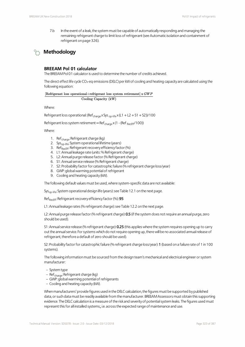
BREEAM UK New Construction 2018 Pol 01 Impact of refrigerants
7.b In the event of a leak, the system must be capable of automatically responding and managing the remaining refrigerant charge to limit loss of refrigerant (see Automatic isolation and containment of refrigerant on page 326).
Methodology
BREEAM Pol 01 calculatorThe BREEAM Pol 01 calculator is used to determine the number of credits achieved.
The direct effect life cycle CO₂-eq emissions (DELC) per kW of cooling and heating capacity are calculated using the following equation:
Where:
Refrigerant loss operational: (Refcharge x Sys op-life x (L1 + L2 + S1 + S2))/100
Refrigerant loss system retirement = Refcharge x (1 - (Ref RecEff/100))
Where:
1. Refcharge: Refrigerant charge (kg) 2. Sysop-life: System operational lifetime (years) 3. RefRecEff: Refrigerant recovery efficiency factor (%) 4. L1: Annual leakage rate (units: % Refrigerant charge) 5. L2: Annual purge release factor (% Refrigerant charge) 6. S1: Annual service release (% Refrigerant charge) 7. S2: Probability factor for catastrophic failure (% refrigerant charge loss/year) 8. GWP: global warming potential of refrigerant 9. Cooling and heating capacity (kW).
The following default values must be used, where system-specific data are not available:
Sysop-life: System operational design life (years): see Table 12.1 on the next page.
RefRecEff: Refrigerant recovery efficiency factor (%): 95
L1: Annual leakage rates (% refrigerant charge): see Table 12.2 on the next page.
L2: Annual purge release factor (% refrigerant charge): 0.5 (if the system does not require an annual purge, zero should be used).
S1: Annual service release (% refrigerant charge): 0.25 (this applies where the system requires opening up to carry out the annual service. For systems which do not require opening up, there will be no associated annual release of refrigerant, therefore a default of zero should be used).
S2: Probability factor for catastrophic failure (% refrigerant charge loss/year): 1 (based on a failure rate of 1 in 100 systems).
The following information must be sourced from the design team's mechanical and electrical engineer or system manufacturer:
– System type– Refcharge: Refrigerant charge (kg)– GWP: global warming potential of refrigerants– Cooling and heating capacity (kW).
When manufacturers' provide figures used in the DELC calculation, the figures must be supported by published data, or such data must be readily available from the manufacturer. BREEAM Assessors must obtain this supporting evidence. The DELC calculation is a measure of the risk and severity of potential system leaks. The figures used must represent this for all installed systems;, i.e. across the expected range of maintenance and use.
Technical Manual: Version: SD5078 - Issue: 2.0 - Issue Date: 03/12/2018 Page 323 of 387

Pol 01 Impact of refrigerants BREEAM UK New Construction 2018
Table 12.1 Default system operational design life valuesSystem type Default system operational design life values (years)
Small or medium capacity chillers 15
Large capacity chillers 20
Unitary split 15
Variable Refrigerant Flow (VRF) system 15
All other systems 10
Note: These figures are based on those reported in LOT 6 for air-conditioning units(214) and the British Refrigeration Association's (BRA) Guideline Methods of Calculating TEWI (Total Equivalent Warming Impact) (2006)(215).The following should be considered when determining whether the system specified is defined as small, medium or large: – Large capacity chiller: centrifugal compressor – Medium capacity chiller: scroll or screw compressor – Small capacity chiller: scroll compressor.
Table 12.2 Default values for DELC calculation when manufacturer's figures are not availableSystem type Annual leakage rate
(% of charge per annum)
Cold storage and display systems
Integral cabinets 3%
Split or condensing units 18%
Centralised 19%
Air-conditioning systems
Unitary split 15%
Small-scale chillers 10%
Medium or large chillers 5%
Heat pumps 6%
Note: These figures are based on those reported in LOT 6 for air-conditioning units and also Table 2 of the Market Transformation Programmes Briefing Note for Commercial Refrigeration no. 36, 'Direct Emission of Refrigerant Gases' (version 1.2)(216). The figures are based on the average of the leakage rates from the four separate studies reported in Table 2 (where a range is reported, the higher value was used).
Specification of multiple systemsWhere more than one air-conditioning or refrigeration system is installed in the building, the assessor must source the relevant technical data for each system and enter it into the Pol 01 calculator. The calculator will then determine the weighted average DELC for the building.
Leak detectionThe refrigerant leak detection criteria are applicable where any type of non-solid refrigerant is present, i.e. even if the refrigerant meets BREEAM's DELC CO₂-eq benchmarks. Exceptions to this are systems that use natural and environmentally benign refrigerants, such as air and water (e.g. lithium bromide or water absorption chillers) and installations of small multiple hermetically sealed systems. These types of system or refrigerants will achieve the leak detection credit by default. See criterion 6 on page 322.
District cooling systemsWhere a project is connected to a district cooling system which is outside the scope of the project or the wider development (e.g. phased developments), the system does not need to be included in the assessment. This is because the design team will not have control over the specification of the system. If the design team do have control over the specification of the system, then it must be assessed.
Page 324 of 387 Technical Manual: Version: SD5078 - Issue: 2.0 - Issue Date: 03/12/2018

BREEAM UK New Construction 2018 Pol 01 Impact of refrigerants
Evidence
Criteria Interim design stage Final post-construction stage
All One or more of the appropriate evidence types listed in The BREEAM evidential requirements on page 29 can be used to demonstrate compliance with these criteria.
3, 5 Completed copy of the Pol 01 Calculator tool.
As per interim design stage.
3, 5 Documentary evidence supporting the data used to complete the calculator tool.
As per interim design stage.
Definitions
Direct effect life cycle (DELC) carbon dioxide equivalent
A measure of the effect on global warming arising from emissions of refrigerant from the equipment to the
atmosphere over its lifetime (units: kgCO₂-eq). The calculation involves estimating the total refrigerant release over
the period of operation and subsequent conversion to an equivalent mass of carbon dioxide. Should the system
use several different refrigerants (e.g. a primary refrigerant and a secondary coolant) or a cascade system,
individual calculations are made for all refrigerants which contribute to the direct effect (see Methodology on
page 323 for a description of how DELC is calculated).
Hermetically sealed systems
Hermetically sealed plant (as defined in the F Gas regulations) can be awarded the Leak Detection credit by
default. The Regulations' definition of hermetically sealed plant only allows systems to have a tested leakage rate
of less than 3 grams per year. This results in the risk of a large refrigerant leak due to system failure being
minimised.
Global warming potential (GWP)
GWP is defined as the potential for global warming that a chemical has relative to 1 unit of carbon dioxide, the
primary greenhouse gas. In determining the GWP of the refrigerant, the Intergovernmental Panel on Climate
Change methodology using a 100-year integrated time horizon should be applied.
Refrigerant
There are three main types of refrigerants:
1. Hydrogenated fluorocarbon refrigerants (HFCs) are made up of hydrogen, fluorine and carbon. These do not use a chlorine atom (which is used in most refrigerants), which means they are one of the least damaging to the earth's ozone layer.
2. Hydrogenated chlorofluorocarbon refrigerants (HCFCs) are made up of hydrogen, chlorine, fluorine and carbon. These refrigerants contain minimal amounts of chlorine; they are not as detrimental to the environment as some other refrigerants.
3. Chlorofluorocarbon refrigerants (CFCs) contain chlorine, fluorine and carbon. These refrigerants carry high amounts of chlorine so they are known to be the most hazardous to the ozone layer.
The use of CFCs and HCFCs as refrigerants has been addressed under the Montreal Protocol. Phase-out
programmes have been agreed resulting in these substances no longer being used as refrigerants in all new
installations and most existing situations. The industry's favoured replacements are currently HFCs which are often
potent global warming contributors. The Kigali Amendment to the Montreal Protocol set a phase-out
programme. Hydrocarbons and ammonia-based refrigerants have low or zero GWP and are therefore preferred
Technical Manual: Version: SD5078 - Issue: 2.0 - Issue Date: 03/12/2018 Page 325 of 387

Pol 01 Impact of refrigerants BREEAM UK New Construction 2018
long term options. These are now widely available and are valid alternatives to HFCs in all buildings, provided
health and safety issues are fully addressed. The United Nations Environment Programme (UNEP) hosts a HCFC
help centre which contains information about the management and phase-out of HCFCs and alternatives to
HCFCs in the refrigeration and air-conditioning sector www.uneptie.org.
Refrigerant leak detection
An automated permanently installed multi-point sensing system, designed to continuously monitor the
atmosphere in the vicinity of refrigeration equipment. In the event of detection it can raise an alarm. The system
may be aspirated or have multiple-sensor heads linked to a central alarm unit or building management system
(BMS). Various sensor types are available including infra-red, semi-conductor or electro-chemical.
Refrigerant recovery
The process of removing refrigerant from a system and storing it in an airtight container.
Refrigerant pump down
The specification of automatic refrigerant pump down can further limit potential losses and damage to the
environment and have subsequent economic benefits to the building owner. Under the UK Environmental
Protection Act 1990 refrigerant and refrigerating system oil are classified as either controlled or hazardous
waste. It is an offence to discharge them to the environment, and there are procedures regarding transport,
storage, transfer of ownership and ultimate disposal. Article 16 of EC Regulation 2037/2000 specifies that used
CFCs and HCFCs must be recovered for destruction, recycling or reclamation.
Robust and tested refrigerant leak detection system
This is normally defined as systems included on the Enhanced Capital Allowance (ECA) Energy Technology Product
List(217) (or an equivalent list). Where the system does not fall within the above scope the design team must
demonstrate to the assessor that the system specified meets the principles of the scheme as far as is applicable.
Small-scale white goods
These are defined as domestic-scale white goods and include small individual display cabinets (e.g. drinks cabinets
in small retail shops).
Systems using refrigerants
The criteria of this issue apply to all building services installed in the building, regardless of the systems refrigerant
charge (kg). These services include, but are not limited to:– Comfort cooling or space heating (including assessment of refrigerants in heat pumps)– Cold storage, including commercial food and drink display cabinets but excluding small-scale white goods– Process-based cooling loads (e.g. servers and IT equipment).
Additional information
Automatic isolation and containment of refrigerantAn example of a system which would meet criterion 7.b could be one which initiates an automated shut down and pump down of the refrigerant into a separate storage tank.
Limiting loss of refrigerant in the event of a leakBREEAM has not set specific requirements or methods regarding the most appropriate way of limiting refrigerant loss. This will be different depending on the system type. Example methods are pump down, isolation or system shut-down, etc.
Page 326 of 387 Technical Manual: Version: SD5078 - Issue: 2.0 - Issue Date: 03/12/2018

BREEAM UK New Construction 2018 Pol 01 Impact of refrigerants
Common refrigerants
Table 12.3 List of some common refrigerant types with low GWPR-Number Chemical name GWP
100-yr
R-30 Dichloromethane 9
R-170 Ethane 3
R-290 Propane 3
R-600 Butane 3
R-600a Isobutane 3
R-702 Hydrogen 5.8
R-717 Ammonia 0
R-718 Water 0.2–0.2
R-729 Air (nitrogen, oxygen, argon) 1
R-744 Carbon dioxide 1
R1150 Ethylene 3
R-1234yf 2,3,3,3-Tetrafluoropropene 4
R-1270 Propylene 3
Sources: The United Nations Environment Programme '2010 Report of the Refrigeration, Air-conditioning and Heat Pumps Technical Options Committee' EN 378-1:2016+A2:2012 Refrigerating systems and heat pumps - Safety and environmental requirements. Part 1: Basic requirements, definitions, classification and selection criteria - Annex E.The Intergovernmental Panel on Climate Change' 5th Assessment Report, Chapter 8, 'Anthropogenic and Natural Radiative Forcing', 2013'Global environmental impacts of the hydrogen economy', Derwent et al, Int. J. Nuclear Hydrogen Production and Application, Vol. 1, No. 1, 2006
The formula used to calculate the DELC emissions in BREEAM is based on the total equivalent warming impact (TEWI) calculation method for new stationary refrigeration and air-conditioning systems. TEWI is a measure of the global warming impact of equipment that takes into account both direct emissions and indirect emissions produced through the energy consumed in operating the equipment. This BREEAM issue is concerned with direct emissions and the BREEAM energy section is concerned with indirect emissions.
Refer to BS EN 378-1(218) and the BRA's Guideline methods of calculating TEWI for further details. The BRA publication also includes sectorial release factors for new systems designed to best practice standards.
REAL ZeroThe refrigeration and air-conditioning sector supported by the Carbon Trust is working across all sectors of business and industry, to help achieve significant reductions in carbon emissions due to refrigerant leakage from installed systems. The Institute of Refrigeration led initiative, Real Zero, is building a clearer understanding of where and why leakage occurs as well as how to prevent it.
For further information including guidance notes, calculators, tools and case study information, visit: www.ior.org.uk and www.realskillseurope.eu.
Technical Manual: Version: SD5078 - Issue: 2.0 - Issue Date: 03/12/2018 Page 327 of 387

Pol 02 Local air quality BREEAM UK New Construction 2018
Pol 02 Local air quality
Fully fitted Simple building Shell & core Shell only No minimum standards
Aim
To contribute to a reduction in local air pollution through the use of low emission combustion appliances in the building.
Value
– Improved air quality for building occupants, visitors and neighbours leading to better health and wellbeing outcomes.
– Increased staff satisfaction and productivity.– Enhanced acceptability of a building locally, especially in areas with compromised air quality that have their
emissions even more tightly controlled.
Context
Poor air quality has a detrimental effect on humans, fauna and flora. Gases such as nitrous oxides (NOₓ) can react with other gases and environmental factors including sunlight to create substances that have a major impact on health and wellbeing. The resulting substances can be highly detrimental to human health. They can be carcinogenic, affect respiratory function (including asthma and other bronchial complaints), have a sensitising effect for allergy suffers and increase instances of heart disease. Legislation covering the UK sets maximum acceptable limits for measured air pollutants. Under this issue BREEAM seeks to limit emissions from developments in use that affect local air quality.
Assessment scope
Fully fitted Simple building Shell and core Shell only
Applicable assessment criteria All All All Not applicable
Assessment type specific notes None None None None
Specific notes
Assessment type specific
None
Building type specific
None
2 2 2 Not applicable
Page 328 of 387 Technical Manual: Version: SD5078 - Issue: 2.0 - Issue Date: 03/12/2018

BREEAM UK New Construction 2018 Pol 02 Local air quality
Assessment criteria
Up to two credits 1 All heating and hot water is supplied by non-combustion systems. For example, only powered by electricity.
OR alternatively;
2 Emissions from all installed combustion plant that provide space heating and domestic hot water do not exceed the levels set in Table 12.4 and Table 12.5 below.
Table 12.4 Maximum NOₓ emission levels by appliance type, fuel and locationAppliance type and unit Fuel 1 credit
(low pollution location)
1 credit (high pollution location)
2 credits (low pollution location)
2 credits (high pollution location)
Boiler (mg/kWh) Gas 27 27 24 24
Boiler (mg/kWh) Oil 73 56 67 50
Boiler (mg/m³) Biomass and solid fossil fuel
130 70
Cogeneration or heat pumps using external combustion (mg/kWh)
Gas 34 34 30 30
Cogeneration or heat pumps using external combustion (mg/kWh)
Oil 96 56 70 50
Cogeneration - using internal combustion engine (mg/kWh)
Gas 119
Cogeneration - using internal combustion engine (mg/kWh)
Oil 140
Local space heaters (mg/kWh)
Gas and oil 76
Closed fronted local space heaters (mg/m³)
Biomass, solid fuel and wood pellets
130
Table 12.5 Maximum particulate matter and volatile organic compound emissions for appliances using biomass, solid fuel and wood pellets
Appliance type and unit
Fuel 1 Credit (low pollution location)
1 Credit (high pollution location)
2 Credits (low pollution location)
2 Credits (high pollution location)
PM10 VOC PM10 VOC PM10 VOC PM10 VOC
Boiler (mg/m³) Biomass 14 7 6 7 11 5 4 5
Boiler (mg/m³) Solid fossil fuel
19 17
Closed face local space heater (mg/m³)
Wood pellets
26 26 20 20 22 22 10 10
Closed face local space heater (mg/m³)
Biomass and solid fuel
50 50 25 25
Technical Manual: Version: SD5078 - Issue: 2.0 - Issue Date: 03/12/2018 Page 329 of 387

Pol 02 Local air quality BREEAM UK New Construction 2018
Appliance type and unit
Fuel 1 Credit (low pollution location)
1 Credit (high pollution location)
2 Credits (low pollution location)
2 Credits (high pollution location)
PM10 VOC PM10 VOC PM10 VOC PM10 VOC
PM10 = particulate matter < 10 micrometres and VOC = volatile organic compounds.For the purposes of BREEAM, PM and VOC emissions are only relevant to the assessment of biomass and solid fuel fired technologies.
Methodology
Determining pollution locationAny developments where any portion of the site is within a local authority Air Quality Management Area (AQMA) are automatically considered to be in a high pollution location. For sites not within an AQMA, to identify whether the site is in a low or high pollution location go to uk-air.defra.gov.uk/data/gis-mapping and select the following options:.
– ‘Select data type’ as ‘Background’. – ‘Select a layer to view’ as ‘NOₓ(as NO₂) annual mean’. – ‘Select a year’ as 2015. – Use ‘Draw Area’ to draw a line around the site boundary for the development. – Use the ‘Max’ value displayed for the 'Area Selected' to determine whether the site is in a low or high pollution
area. – Take a screenshot which shows the area of the development and the max value, and retain for audit purposes. – ‘Select a layer to view’ as PM10. – Take a screenshot which shows the area of the development and the max PM10 for the area and retain for audit
purposes.
High pollution locationAny developments where any portion of the site is within a local authority AQMA are automatically considered to be in a high pollution location. For developments that are wholly outside of an AQMA, the following levels define high pollution locations:
– NOₓ > 15 µg/m³ averaged over a year – PM10 > 10 µg/m³ averaged over a year
Refer to Determining pollution location above to identify whether a site is in a low or high pollution location. Where the ambient emission level for any of the pollutants listed above exceeds the benchmarks, the development is considered to be in a high pollution area.
Low pollution locationAny location that does not meet the definition of a high pollution location.
Awarding creditsThe number of credits awarded to an appliance is determined by the emission level which gives the lowest number of credits for that appliance. If for example the NOₓ and PM10 requirements are achieved for the 1 credit (low pollution location) scale but VOC requirements are not then no credits can be awarded.
Back-up space or water heating systemsBack-up space or water heating systems can be excluded from assessment, provided they are excluded from SBEM or SAP calculations used to assess Ene 01 Reduction of energy use and carbon emissions on page 128. This is on the basis that these systems will only be used in an emergency so their impact will be limited.
If the systems are included in the Ene 01 calculations, then it must be assumed they will be used outside emergency situations, and as such they must meet the emission benchmarks for Pol 02 credits to be awarded.
Multiple systemsWhere multiple systems are specified or installed, credits are awarded based on the worst performing system.
Page 330 of 387 Technical Manual: Version: SD5078 - Issue: 2.0 - Issue Date: 03/12/2018

BREEAM UK New Construction 2018 Pol 02 Local air quality
Units of measure for emissionsThe measurements of emissions must be provided by the manufacturers, following the labelling requirements of the Ecodesign Directive 2009/125/EC (see Ecodesign Directive below). The directive comes into force in September 2018. This sets performance requirements for combustion-powered heating systems and requires manufacturers to publish the NOₓ, particulate matter and VOC emission levels for their products. BREEAM uses the same units of measure as the Directive. These are:
– NOₓ measured in mg/kWh fuel input (Gross Calorific Value (GCV)) for gas or oil appliances – Particulate matter and VOCs for all solid fuel or biomass boilers measured in mg/m³ 10% O₂ dry basis – Particulate matter and VOCs for all solid fuel or biomass local heaters measured in mg/m³ 13% O₂ dry basis.
Combustion appliances not listedNo credits may be awarded if any combustion appliances are not covered in Table 12.4 on page 329 and Table 12.5 on page 329.
New build extensions to existing buildingIf the heating or hot water demand for the new extension is being met by an existing system, then the emission levels for the existing system must be assessed against the criteria for this issue.
Open flueNo credits may be awarded for open flue heating or hot water systems.
District heatingWhere a project is connected to a district heating system which is outside the scope of the project or the wider development (e.g. phased developments), the system does not need to be included in the assessment. This is on the basis that the design team do not have control over the specification of the system. Where the design team do have control over the specification of the system, then it must be assessed.
Evidence
Criteria Interim design stage Final post-construction stage
All One or more of the appropriate evidence types listed in The BREEAM evidential requirements on page 29 can be used to demonstrate compliance with these criteria.
Definitions
Air quality management areas (AQMA)
Local authorities and boroughs monitor air quality (including nitrogen oxides and dioxide, particulate matter and
VOCs) comparing it to levels set by the Department of Food and Rural Affairs (Defra). Where any measured
pollutants breach these levels, the area is designated as an AQMA.
See www.uk-air.defra.gov.uk.
Additional information
Ecodesign DirectiveThe European Union’s Ecodesign Directive sets a framework for mandatory requirements for energy-using products. A number of separate commission regulations documents specify minimum emission levels for various emissions for different technologies. Where minimum emission levels have been set, the measured emission levels achieved must be included on the product label. These documents define both minimum and BAT (best available technology) levels for relevant emissions. BREEAM has used these levels as a basis for setting the benchmarks in Table 12.4 on page 329 and Table 12.5 on page 329. Regardless of the implementation date of the regulation
Technical Manual: Version: SD5078 - Issue: 2.0 - Issue Date: 03/12/2018 Page 331 of 387

Pol 02 Local air quality BREEAM UK New Construction 2018
covering the appliance, the relevant BREEAM benchmarks must be achieved to award credits.
The relevant EU Commission Regulation documents are listed below together with the relevant implementation dates:
– Commission Regulation (EU) No 813/2013 of 2 August 2013 implementing Directive 2009/125/EC of the European Parliament and of the Council with regard to ecodesign requirements for space heaters and combination heaters
– Commission Regulations (EU) No 814/2013 of 2 August 2013 implementing Directive 2009/125/EC of the European Parliament and of the Council with regard to ecodesign requirements for water heaters and hot water storage tanks
– Commission Regulation (EU) 2015/1185 of 24 April 2015 implementing Directive 2009/125/EC of the European Parliament and of the Council with regard to ecodesign requirements for solid fuel local space heaters
– Commission Regulation (EU) 2015/1188 of 28 April 2015 implementing Directive 2009/125/EC of the European Parliament and of the Council with regard to ecodesign requirements for local space heaters
– Commission Regulations (EU) No 2015/1189 of 28 April 2015 implementing Directive 2009/125/EC of the European Parliament and of the Council with regard to ecodesign requirements for solid fuel boilers
Market research shows that the benchmarks are achievable but in some cases are challenging and in high pollution areas only technologies and fuel types with lower emission levels are likely to achieve any credits. This has been done to incentivise the market to improve the performance of products.
Page 332 of 387 Technical Manual: Version: SD5078 - Issue: 2.0 - Issue Date: 03/12/2018

BREEAM UK New Construction 2018 Pol 03 Flood and surface water management
Pol 03 Flood and surface water management
Fully fitted Simple building Shell & core Shell only No minimum standards
Aim
To avoid, reduce and delay the discharge of rainfall to public sewers and watercourses, thereby minimising the risk and impact of localised flooding on-site and off-site, watercourse pollution and other environmental damage.
Value
– Incentivise site selection and development design that minimises the potential for flooding on and off site.– Limit the impact of development on off-site water management infrastructure, including the potential future
increase in rainwater from climate change.– Enhance the resilience of local drainage and flood prevention systems.– Minimise the release of waterborne pollutants off site.
Context
In the UK around 0.5 million homes, offices, factories and warehouses are considered to be at a significant risk of flooding, i.e. they have a greater than one in 75 chance per year of being flooded. Apart from the initial effects of being flooded, i.e. access and use of the building, once flood water is removed significant resources (man hours, time and cost) are usually required to clean, refit and re-open buildings for use.
This has major impacts on business continuity that can be costly and time-consuming to manage. With due consideration at an early stage of the location, design and specification of the development (including the building, curtilage and wider site) the risk of flooding, and impact if it is flooded, can be managed.
Assessment scope
Fully fitted Simple building Shell and core Shell only
Applicable assessment criteria 1–23 2–4, 17–26 1–23 1–23
Assessment type specific notes None 5–16 (1 exemplary credit) None None
Specific notes
Assessment type specific
None
Building type specific
None
5 5 5 5
Technical Manual: Version: SD5078 - Issue: 2.0 - Issue Date: 03/12/2018 Page 333 of 387

Pol 03 Flood and surface water management BREEAM UK New Construction 2018
Assessment criteria
This issue is split into three parts:
– Flood resilience (two credits)– Surface water run-off (two credits)– Minimising watercourse pollution (one credit)
Prerequisite1 An appropriate consultant is appointed to carry out and demonstrate the development's compliance with all
criteria.
Up to two credits - Flood resilience
Two credits - Low flood risk2 A site-specific flood risk assessment (FRA) confirms the development is in a flood zone that is defined as having
a low annual probability of flooding. The FRA takes all current and future sources of flooding into consideration (see Sources of flooding on page 336).
One credit - Medium or high flood risk3 A site-specific FRA confirms the development is in a flood zone that is defined as having a medium or high
annual probability of flooding and is not in a functional floodplain. The FRA must take all current and future sources of flooding into consideration (see Sources of flooding on page 336). For smaller sites refer to Level of detail required in the FRA for smaller sites on page 337, which overrides criterion 2 above.
4 To increase the resilience and resistance of the development to flooding, one of the following must be achieved:
4.a The ground level of the building and access to both the building and the site, are designed (or zoned) so they are at least 600 mm above the design flood level of the site's flood zone (see 600mm threshold on page 337).
4.b The final design of the building and the wider site reflects the recommendations made by an appropriate consultant in accordance with the hierarchy approach outlined in section 5 of BS 8533:2017 (219).
Two credits - Surface water run-off
Prerequisite for surface water run-off credits5 Surface water run-off design solutions must be bespoke, i.e. they must take account of the specific site
requirements and natural or man-made environment of and surrounding the site. The priority levels detailed in the Methodology must be followed, with justification given by the appropriate consultant where water is allowed to leave the site.
One credit - Surface Water Run-Off - Rate6 For brownfield sites, drainage measures are specified so that the peak rate of run-off from the site to the
watercourses (natural or municipal) shows a 30% improvement for the developed site compared with the pre-developed site. This should comply at the 1-year and 100-year return period events.
7 For Greenfield sites, drainage measures are specified so that the peak rate of run-off from the site to the watercourses (natural or municipal) is no greater for the developed site than it was for the pre-development site. This should comply at the 1-year and 100-year return period events.
8 Relevant maintenance agreements for the ownership, long term operation and maintenance of all specified Sustainable Drainage Systems (SuDS) are in place.
9 Calculations include an allowance for climate change. This should be made in accordance with current best practice planning guidance (see Definitions on page 339).
Page 334 of 387 Technical Manual: Version: SD5078 - Issue: 2.0 - Issue Date: 03/12/2018

BREEAM UK New Construction 2018 Pol 03 Flood and surface water management
One credit - Surface Water Run-Off - Volume10 Flooding of property will not occur in the event of local drainage system failure (caused either by extreme
rainfall or a lack of maintenance); AND
EITHER
11 Drainage design measures are specified so that the post-development run-off volume, over the development lifetime, is no greater than it would have been prior to the assessed site’s development. This must be for the 100-year 6-hour event, including an allowance for climate change (see criterion 15).
12 Any additional predicted volume of run-off for this event is prevented from leaving the site by using infiltration or other SuDS techniques.
OR (only where criteria 11 and 12 cannot be achieved):
13 Justification from the appropriate consultant indicating why the above criteria cannot be achieved, i.e. where infiltration or other SuDS techniques are not technically viable options.
14 Drainage design measures are specified so that the post-development peak rate of run-off is reduced to the limiting discharge. The limiting discharge is defined as the highest flow rate from the following options:
14.a The pre-development one-year peak flow rate
14.b The mean annual flow rate (Qbar)
14.c 2L/s/ha.
For the one-year peak flow rate, the one-year return period event criterion applies.
15 Relevant maintenance agreements for the ownership, long term operation and maintenance of all specified SuDS are in place.
16 For either option, above calculations must include an allowance for climate change; this should be made in accordance with current best practice planning guidance.
One credit - Minimising watercourse pollution17 There is no discharge from the developed site for rainfall up to 5 mm (confirmed by the appropriate
consultant).
18 Areas with a low risk source of watercourse pollution, an appropriate level of pollution prevention treatment is provided, using appropriate SuDS techniques.
19 Areas with a high risk of contamination or spillage of substances, such as petrol and oil, have separators (or an equivalent system) are installed in surface water drainage systems.
20 Chemical or liquid gas storage areas have a means of containment fitted to the site drainage system (i.e. shut-off valves). This is to prevent the escape of chemicals to natural watercourses in the event of a spillage or bunding failure.
21 All water pollution prevention systems have been designed and installed in accordance with the recommendations of documents such as the SuDS manual(220) and other relevant industry best practice. They must be bespoke solutions taking account of the specific site requirements and natural or man-made environment of and surrounding the site.
22 A comprehensive and up to date drainage plan of the site will be made available for the building or site occupiers.
23 Relevant maintenance agreements for the ownership, long term operation and maintenance of all specified SuDS must be in place.
24 All external storage and delivery areas are designed and detailed in accordance with the current best practice planning guidance.
Technical Manual: Version: SD5078 - Issue: 2.0 - Issue Date: 03/12/2018 Page 335 of 387

Pol 03 Flood and surface water management BREEAM UK New Construction 2018
Up to two credits - Simple buildings - Surface water run-off
Two creditsFor 'simple buildings', the criteria below should be applied to award one or two credits. Alternatively, two credits and an Exemplary credit is awarded where criteria 5–16 on the previous page are achieved.
25 Either 25.a below or 25.b below is met:
25.a There is a decrease in the impermeable area by 50% or more, from the pre-existing impermeable hard surfaces.
25.b All run-off from the roof, including new and existing parts of the building, has been managed on site using source control methods. This must be achieved for rainfall depths up to 5mm.
OR
One credit - Simple buildings - Surface water run-off26 Either 26.a below or 26.b below is met:
26.a There is no increase in the impermeable surfaces as a result of the new construction;
26.b If there is an increase in the impermeable surface as a result of the new construction then the following must be met:
26.b.i Hard standing areas: additional (or equivalent area of) hardstanding must be permeable or be provided with on-site SuDS to allow full infiltration of the additional volume. The permeable hardstanding must include all pavements and public rights of way, car parks, driveways and non-adoptable roads. Small garden paths which will drain onto a naturally permeable surface can be excluded.
26.b.ii Building (new-build or extension): for an increase in building footprint, extending onto any previously permeable surfaces, the additional run-off caused by the area of the new construction must be managed on site using an appropriate SuDS technique for rainfall depths up to 5mm.
Methodology
Applicable assessment criteriaNone of the credits can be awarded where the assessed development has proceeded against the recommendation of the statutory body on the basis that the flooding implications are too great. This includes recommendations given which cannot or are not statutorily enforced. Where the local authority (or other statutory body) has set more rigorous requirements than the criteria in this issue, they must be met in order to achieve the relevant credits.
Functional flood plainThe BREEAM credit for locating in a flood zone of ‘medium or high annual probability’ cannot be awarded where the building is located in the functional flood plain. This is defined in the current best practice national planning guidance for each country’. If the building assessed has been defined as a ‘water-compatible development’ by the local authority, confirmation must be provided by them of this designation and that they are satisfied with the proposals.
Contaminated sitesDrainage designs for sites must take into account legislation relating to contaminated sites. In many circumstances of contaminated land there may be opportunities for the installation of some SuDS techniques.
Sources of floodingThe FRA must detail the risk of flooding from the following sources:
1. Fluvial (rivers) 2. Tidal 3. Surface water: sheet run-off from adjacent land (urban or rural) 4. Groundwater: most common in low-lying areas underlain by permeable rock (aquifers)
Page 336 of 387 Technical Manual: Version: SD5078 - Issue: 2.0 - Issue Date: 03/12/2018

BREEAM UK New Construction 2018 Pol 03 Flood and surface water management
5. Sewers: combined, foul or surface water sewers 6. Reservoirs, canals and other artificial sources
Additional information on page 344 provides more detail on the above sources of flooding.
The content of the FRA should be based on historic trends and account for predicted changes to the climate which may impact on the flood risk to the site in future
600mm thresholdFor buildings located in medium and high risk flood zones it is accepted that areas of the car park and site access may be below the 600mm threshold and may therefore be allowed to flood. In such cases, the credit is still achievable provided safe access to the site and the ground floor of the building can be maintained, i.e. they are 600mm above the design flood level. This is to ensure the building and site do not become an ‘island’ in the event of a flood. Where the ground levels of the topography or infrastructure immediately adjacent to the site fall below the 600mm threshold, the credit can still be awarded. There must be no other practical solutions for access to the site above this level and the assessed building, and access to it, meet the assessment criteria. As much of the external site area as possible (or as required by an appropriate statutory body) should be designed at or above the threshold. For buildings located in medium or high flood risk zones, any areas used to store sensitive, historical, hazardous, valuable and perishable materials must be located above the 600mm threshold. Examples of these materials include radioactive materials, microbiological facilities, server rooms, libraries, etc.
Level of detail required in the FRA for smaller sitesFor smaller sites, e.g. less than 1 ha (10,000m²), the level of detail required in the FRA will depend on the size of the site and the arrangement of buildings on that site. For a small site with a relatively simple arrangement of buildings this might consist of a brief report. For larger sites with a higher density of buildings a more detailed assessment would be appropriate.
For small simple sites (2000m² and less), an acceptable FRA could be a brief report carried out by the contractor’s engineer confirming the risk of flooding. This must include the risk from all sources of flooding, and information obtained from the Environment Agency, water company or sewerage undertaker, other relevant statutory authorities, site investigation and local knowledge.
Sites with multiple buildingsWhere the assessed building is part of a larger development of buildings, there are a number of options for assessment of the surface water run-off credits:
1. The individual building and its associated hardstanding areas can be assessed independently where the run-off is being dealt with on a building-by-building basis (i.e. each building has its own dedicated sub-catchment that serves only that building).
2. When assessing the run-off from a number of buildings (including domestic and non-domestic buildings) the assessment must take into account the drainage from the local sub-catchment serving all those dwellings or buildings. Proportioning cannot be used to calculate the percentage of run-off discharging into the local sub-catchment resulting from just the assessed building.
3. The whole development can be assessed for compliance.
Whichever approach is taken to demonstrate compliance, it must be consistent when completing both the rate of run-off and volume of run-off calculations.
No change in impermeable areaWhere the man-made impermeable area draining to the watercourse (natural or municipal) has decreased or remains unchanged post-development, the volume of run-off requirements for the surface water run-off credits can be met by default. Volume calculations will not need to be provided. Instead, drawings clearly showing the impermeable areas of the site draining to the watercourse should be provided for the pre- and post-development scenarios. Figures must also be given (ideally on the drawings) to show a comparison between the areas of drained impermeable surfaces pre- and post-development. In this instance, it is still recommended that any opportunities identified to reduce surface water run-off are implemented.
Limiting flow-rate dischargeFor the surface water run-off credits, where the limiting discharge flow rate would require a flow rate of less than 5L/s at a discharge point, a flow rate of up to 5L/s may be used where required to reduce the risk of blockage.
Technical Manual: Version: SD5078 - Issue: 2.0 - Issue Date: 03/12/2018 Page 337 of 387

Pol 03 Flood and surface water management BREEAM UK New Construction 2018
Areas that are a source of pollutionFor the purpose of assessing the watercourse pollution credit, areas that presents a risk of watercourse pollution include areas for vehicle manoeuvring, car parks, waste disposal facilities, delivery and storage facilities or plant.
Suitable level of treatmentIn all cases the appropriate consultant should use their professional judgement to determine the most appropriate strategy for minimising watercourse pollution.
Roof plantRoof-top plant space must be considered where there is a risk from polluting substances such as petrol or oil. Refrigerants are not assessed under the pollution aspect of this issue, as the main risk of pollution is to air and not the watercourse.
Calculating peak rate of run-offKey publications that should be referred to for guidance on calculating the peak rate of run-off include:
1. The SuDS Manual 2. Rainfall run-off management for developments(221). 3. National planning policy guidance or statement for the specific country. 4. IH Report 124, Flood estimation for small catchments (Marshall and Bayliss, 1994)(222). 5. Flood estimation handbook (Centre for Ecology and Hydrology, 1999)(223).
Greenfield sitesThe calculation of greenfield run-off rates must be in accordance with IH Report 124, Flood estimation for small catchments. Reference to the Flood Estimation Handbook can be made, but only where this is considered appropriate.
Brownfield sitesThe calculation of brownfield run-off rates should be as follows:
– If the existing drainage is known then it should be modelled using best practice simulation modelling, to determine the one-year and 100-year peak flow rates at discharge points. This is without allowing surcharge of the system above cover levels to drive greater flow rates through the discharge points.
– If the system is not known, then the brownfield run-off should be calculated using the greenfield run-off models described above but with a Soil Type 5.
Surface water run-off managementWhen specifying and designing surface water run-off management, the appropriate consultant must follow the priority levels listed below (noting that level 1 has the highest priority). Justification must be provided for each level which does not contribute to managing surface water run-off. This has been set so the most appropriate water management solutions are used, prioritising water use in the development and infiltration over discharge. This is so that the volume of water that leaves the site is limited as far as practicable.
– Priority Level 1 Water is collected for use in the development (e.g. rainwater harvesting)– Priority Level 2 Water is infiltrated into the ground– Priority Level 3 Water is discharged to surface water body– Priority Level 4 Water is discharged to the drainage system– Priority Level 5 Water is discharged to a combined sewer
Limiting discharge rateThe limiting discharge for each discharge point should be calculated as the flow rates from the pre-developed site. The calculation includes the total flow rate from the total area of the site feeding into the discharge point and includes both BREEAM-assessed and non-BREEAM-assessed parts of the development, if applicable. The discharge point is defined as the point of discharge into the watercourse or sewers. This includes rivers, streams, ditches, drains, cuts, culverts, dykes, sluices, public sewers and passages through which water flows (see Definitions on the facing page). Where this calculation results in a peak flow rate of less than 5L/s, the limiting discharge rate may be increased up to a level of no more than 5L/s at the point of discharge from the site. This is to reduce the risk of blockage.
Page 338 of 387 Technical Manual: Version: SD5078 - Issue: 2.0 - Issue Date: 03/12/2018

BREEAM UK New Construction 2018 Pol 03 Flood and surface water management
For example, if the flow rate for the 1 year and 100 year events were 4L/s and 7L/s respectively, then the limiting discharges would be 5L/s and 7L/s. Similarly, if it was calculated to be 2L/s and 4L/s, then a maximum of 5L/s limiting discharge rate could be applied to both discharge points.
Sites should not be subdivided to enable higher overall limiting discharge rates to be claimed. It is recognised that some sites may require more than one discharge point as a result of the local topography or existing surrounding drainage infrastructure. In such cases, the limiting discharge flow rate may be increased to a level no more than 5L/s at each discharge point. The assessor should seek evidence that the number of discharge points is necessary due to topography or infrastructure limitations. Evidence may be in the form of a topographical map and an explanation from the appropriate consultant as to why multiple discharge points are required, stating that it is not feasible to have fewer discharge points.
100-year peak rate event: excess volume of run-offThe storage of excess flows from the 100-year event does not necessarily have to be contained within the drainage system or SuDS features (the features designed solely for the purpose of drainage). Where appropriate, storage of some or all of this volume can be achieved using temporary surface flooding of areas such as a playing field. Specific consideration should be given to overland flow routing. Overland flood flows and temporary storage of flood water on the surface must not be so frequent as to unreasonably inconvenience residents and other users.
Designing for exceedance guidanceCIRIA publication C635 (2006) Designing for exceedance in urban drainage-good practice (224) should be referred to for guidance.
Evidence
Criteria Interim design stage Final post-construction stage
All One or more of the appropriate evidence types listed in The BREEAM evidential requirements on page 29 can be used to demonstrate compliance with these criteria.
6-7 Calculation results for the pre-and post-development peak rate of run-off
Refer to generic evidence requirement above
10 Information showing the proposed drainage solution, system failure flood flow routes, potential flood ponding levels and ground floor levels
As per interim design stage.
11–14 Calculation results for the pre- and post-development volume of run-off
Refer to generic evidence requirement above
14 Calculation results for the limiting discharge
As per interim design stage.
8, 15, 23 No 'specific' evidence applies at Design Stage
Relevant maintenance agreements for the ownership, long term operation and maintenance of all specified SuDS.
25.b, 26.b.ii Calculation of the 5mm rainfall event from the relevant areas
Refer to generic evidence requirement above
Definitions
Adoptable highways
For the purposes of BREEAM, an ‘adoptable highway' is a highway that is the responsibility of the highways
authority in terms of installation and maintenance of surface water drainage. This drainage must only carry run-off
from the highway itself. This means that to fall under the definition of an adoptable highway the drainage
network must not be directly connected to any other upstream drainage network (e.g. from a private
development). Where drainage within the highway will carry run-off from both the highway and assessed
Technical Manual: Version: SD5078 - Issue: 2.0 - Issue Date: 03/12/2018 Page 339 of 387

Pol 03 Flood and surface water management BREEAM UK New Construction 2018
development, it is not regarded as an adoptable highway. In this instance the drainage design must take account
of the highway run-off.
Appropriate consultant
A consultant with qualifications and experience relevant to designing SuDS and flood prevention measures and
completing peak rate of run-off calculations. Where complex flooding calculations and prevention measures are
required, this must be a specialist hydrological engineer.
Appropriate statutory body
This refers to either the appropriate national body (i.e. The Environment Agency in England and Wales, the Rivers
Agency in Northern Ireland and the Scottish Environment Protection Agency in Scotland) or the relevant local
authority or internal drainage board.
Catchment
The area contributing surface water flow to a point on a drainage or water course. It can be divided into sub-
catchments.
Control devices
Any drainage structure or unit designed to control the run-off of storm water. Examples of SuDS control devices
are check dams within swales and basins, and combined weir or orifice controls for ponds. Examples of traditional
control devices are throttles constructed with pipes and vortex controls. The control devices must be capable of
regular inspection and maintenance, and the system should be failsafe so that upstream flooding does not result
from blockage or other malfunction. For guidance on control devices, refer to The SuDS manual (CIRIA C753,
2015) and other best practice guidelines.
Current best practice national planning guidance
Please refer to the guidance given in the following locations. It is the design team's responsibility to choose the
most appropriate guidance from the links below:– www.netregs.org.uk/environmental-topics/pollution-prevention-guidelines-ppgs-and-replacement-
series/guidance-for-pollution-prevention-gpps-full-list/– www.gov.uk/guidance/pollution-prevention-for-businesses– www.gov.uk/guidance/storing-oil-at-a-home-or-business
Design flood event
An historic or notional flood event of a given annual flood probability, against which the suitability of a proposed
development is assessed and mitigation measures, if any, are designed.
Design flood level
The maximum estimated water level during the design storm event. The design flood level for a site can be
determined through either known historical data or modelled for the specific site.
Design storm event
Historic or notional weather conditions of a given annual probability, against which the suitability of a proposed
development is assessed and mitigation measures, if any, are designed.
Discharge point
The discharge point is the point at which the run-off from the site leaves the site boundary and enters a
watercourse.
Page 340 of 387 Technical Manual: Version: SD5078 - Issue: 2.0 - Issue Date: 03/12/2018

BREEAM UK New Construction 2018 Pol 03 Flood and surface water management
Flood defences
Flood defences do not completely remove the risk of flooding, but they do reduce it. Building in areas where flood
defences are present (and appropriately designed to withstand a certain magnitude of flooding) is therefore
preferable to those built in medium- or high-risk areas without defences. However, for the purpose of this issue, it
is still preferable to build in areas of low risk than encourage development of new flood defences in areas with a
higher risk of flooding purely for the sake of new development.
Flood event
A flooding incident characterised by its peak level or flow, or by its level or flow hydrograph.
Flood probability
The estimated probability of a flood of given magnitude occurring or being exceeded in any specified time
period. For example, the 100-year flood has a 1% chance of occurring in any given year.
Flood risk
The combination of the flood probability and the magnitude of the potential consequences of the flood event.
Flood risk assessment
A study to assess the risk of a site flooding, and to assess the impact that any changes or development on the site
will have on flood risk to the site and elsewhere. A FRA should be prepared according to relevant planning policy
and technical guidance documents. The FRA must account for future climate change and detail any necessary
adaptation measures if required. Where more than five years have passed since the FRA was carried out, evidence
is required to demonstrate that the basis of the FRA has not changed in that time.
Flood storage
The temporary storage of excess run-off or river flow in ponds, basins, reservoirs or on the floodplain during a
flood event.
Flood zones
Flood zones are defined in the relevant planning, policy and technical guidance documents for each country in the
UK: Planning Practice Guidance - Flood Risk and Coastal Changes (England), TAN15 (Wales), SPP7 (Scotland), PPS15
(Northern Ireland). PPS15 does not categorise flood risk zones and there are no similar publicly available flood
maps covering Northern Ireland. Assessments in Northern Ireland will therefore need to rely on site-specific flood
risk assessments, or other relevant data or surveys, to determine the extent of flood risk for a specific
development, and use the same definitions as those outlined for England (Table 12.6 on page 344). The Northern
Ireland Department of Environment or Rivers Agency may offer further advice or recommendations in this respect
www.doeni.gov.uk and www.dardni.gov.uk.
While the definitions of flood zones and probabilities of flooding are generally the same throughout the UK, there
are some differences. The definitions are outlined in Table 12.6 on page 344.
Greenfield
A site which has either never been built on, or one which has remained undisturbed for five years or more.
Greenfield run-off rate
The rate of run-off that would occur from the site in its undeveloped and therefore undisturbed state.
Hard surfaces
These include roofs, car parks, access roads, pavements, delivery or service yards, and external hard landscaping.
Footpaths less than 1.5m wide which have free drainage to soft landscaped areas on both sides may be
Technical Manual: Version: SD5078 - Issue: 2.0 - Issue Date: 03/12/2018 Page 341 of 387

Pol 03 Flood and surface water management BREEAM UK New Construction 2018
excluded.
Infiltration
The passage of water into a permeable surface, such as soil, permeable paving, soakaways, etc.
Level of pollution prevention treatment
When used in the context of one, two or three levels of treatment for surface water, the treatment level should be
regarded as: the number of SuDS components in series through which run-off passes from the originating
surface on which rainfall fell, to the site discharge point. Where a SuDS component has more than one treatment
process, it might be considered to provide more than one level of treatment. In these circumstances advice should
be sought from the BREEAM office.
Limiting discharge
The limiting discharge is based upon the calculated pre-development flow rate at a discharge point.
Low risk areas (with respect to watercourse pollution)
Low risk areas can be defined as areas where the risk of contamination or spillage of substances such as petrol
and oil is reduced. For the purpose of this credit, roofs and small car parks may be considered as low risk areas.
Peak run-off rate (referred to as Qp [m³/sec])
This is the highest rate of flow from a defined catchment area assuming that rainfall is uniformly distributed over
the drainage area, considering the entire drainage area as a single unit and estimation of flow at the most
downstream point only.
Pre-development
The state of the site under assessment immediately prior to purchase of the site by the client or developer. Where
the client has owned or occupied the site for a number of years, this is the current state.
Qbar
An estimation of the mean annual flood flow rate from a catchment (see Report IH124 Flood estimations for
small catchments).
Rainwater discharge
This is the rainwater which flows from the development site to watercourses and sewers. It is also referred to as
run-off.
Run-off
This is usually rainwater, but can also be groundwater or overspill from sewers and other sources.
Sewerage undertaker
This is a Body, typically a water company, with statutory responsibility for sewerage and sewerage disposal and
also surface water from roofs and yards of premises.
Soakaways
A subsurface structure designed to promote the infiltration of surface water into the ground. As a general point,
soakaways may be shallow and broad (as in a blanket under permeable paving) or deeper structures. Deeper,
point source soakaways should be avoided for road and car park drainage, but shallow structures providing
infiltration in an extensive way (infiltration trenches and permeable paving) do not need oil separators.
Page 342 of 387 Technical Manual: Version: SD5078 - Issue: 2.0 - Issue Date: 03/12/2018

BREEAM UK New Construction 2018 Pol 03 Flood and surface water management
SuDS management train
An approach to drainage design that combines a sequence of appropriate surface water drainage structures
using SuDS systems. These manage the run-off to treat the flow, reduce run-off volume and restrain the run-off
rate in order to minimise man’s impact on the environment. Additional benefits associated with operation and
maintenance, ecology and amenity are aspects which are considered when designing a management system. The
management train incorporates a hierarchy of techniques:
1. Source control. Examples of SuDS techniques include: – Soakaways– Porous or pervious paving– Roof water directed to garden (rather than piped drains)– Rainwater reuse and harvesting– Green roofs– Other surface infiltration, attenuation and conveyance techniques that deal with run-off at source.
2. Site or local control. Examples of SuDS techniques include: – Swales– Pond– Infiltration basins– Detention basin– Larger soakaways– Pervious (porous or permeable) paving.
3. Regional control. Examples of techniques include: – Balancing ponds– Wetlands– Large detention basin.
SuDS techniques
One or more components built to manage surface water run-off to prevent flooding and pollution. For example
these include: wet ponds, infiltration basins, detention basins, swales, reed beds, pervious (porous or permeable)
paving, soakaways, rainwater harvesting, filter strips, filter drains and trenches with or without perforates pipes,
green roofs, and underground attenuation storage. For more information refer to The SuDS manual (CIRIA C753,
2015) and Guidance for the construction of SuDS (CIRIA C768)(225).
Surface water run-off
Water flow over the ground surface to a drainage system. This occurs if the ground is impermeable or saturated,
or if the rainfall is particularly intense.
Tidal estuary
A tidal estuary is defined as a semi-enclosed coastal body of water which has a free connection with the open sea
and within which seawater is measurably diluted with fresh water derived from land drainage. An estuary should
be unconstrained tidal waters, i.e. there should be no barriers or constricted shorelines that would restrict the free
flow of water into the open sea in any conditions. The impact on the total volume of run-off from the site (and
other sites which may in future discharge into the estuary) should be insignificant in terms of the overall water
levels in the estuary. Tidal rivers (i.e. where no or limited measurable seawater content is present during normal
tidal movements) cannot be included as part of the estuary for the purposes of BREEAM.
Treatment
Improving the quality of water by physical, chemical or biological means.
Types of oil separator
Class 1 Separators: These are designed to achieve a concentration of less than 5mg/l oil under standard test
conditions. They should be used when the separator is required to remove very small oil droplets, such as those
Technical Manual: Version: SD5078 - Issue: 2.0 - Issue Date: 03/12/2018 Page 343 of 387

Pol 03 Flood and surface water management BREEAM UK New Construction 2018
arising from car park run-off.
Class 2 Separators: These are designed to achieve a concentration of less than 100mg/l oil under standard test
conditions. They are suitable for dealing with discharges where a lower quality requirement applies or for
trapping large spillages. Both classes can be produced as ‘full retention’ or ‘bypass’ separators:
Full retention separators: These treat the flow that can be delivered by the drainage system, which is normally
equivalent to the flow generated by a rainfall intensity of 50mm/hr.
Bypass separators: These fully treat all flows generated by rainfall rates of up to 5mm/hr. Flows above this rate
are allowed to bypass the separator. These separators are used when it is an acceptable risk not to provide full
treatment for high flows.
Volume of run-off
The volume of run-off that is generated by rainfall occurring on the site. This is typically measured in cubic metres.
Additional predicted volume of run-off is the difference between the volumes of run-off pre- and post-
development.
Water-compatible development
These are developments which are either essential infrastructure or their uses are compatible with a flood plain.
For example docks, marinas and wharves, ship building and repair, water-based recreation etc. This designation is
made by local authorities.
Watercourses and sewers
A term that includes rivers, streams, ditches, drains, culverts, dykes, sluices, sewers and passages through which
water flows.
Additional information
This section will be revised when the national standards for sustainable drainage and associated regulations come into force.
Definition of flood zones by country
Table 12.6 Definition of flood zones by country Definition England Wales Scotland
Low annual probability of flooding
Zone 1Less than 1 in 1000 chance of river and sea flooding (< 0.1%).
Zone AConsidered to be at little or no risk.Zone BIf site levels are greater than the flood levels used to define adjacent extreme flood outline.
Little or no risk areaAs defined for England.
Medium annual probability of flooding
Zone 2Between 1 in 100 and 1 in 1000 chance of river flooding (1%–0.1%) and between a 1 in 200 and 1 in 1000 chance of sea flooding (0.5%–0.1%).
Zone BIf site levels are not greater than the flood levels used to define adjacent extreme flood outline.Zone CEqual to or greater* than 0.1% (river, tidal or coastal flooding).
Low to medium risk areaWatercourse, tidal or coastal flooding in the range 0.1%–0.5% (1:1000–1:200).
Page 344 of 387 Technical Manual: Version: SD5078 - Issue: 2.0 - Issue Date: 03/12/2018

BREEAM UK New Construction 2018 Pol 03 Flood and surface water management
Definition England Wales Scotland
* For the purposes of BREEAM assume upper probability of flooding no greater than that specified for England.
High annual probability of flooding
Zone 3a High probability1 in 100 or greater chance of river flooding (>1%) and a 1 in 200 or greater chance of flooding from the sea (>0.5%).Zone 3b The functional floodplainLand where water has to flow or be stored in times of flood.
Zone C1 and C2* For the purposes of BREEAM assume the same lower and upper probability of flooding as that specified for England.
Medium to high risk areasAnnual probability of watercourse, tidal or coastal flooding: greater than 0.5% (1:200).
Northern Ireland PPS15 does not categorise flood risk zones and there are no similar publicly available flood maps covering Northern Ireland. Assessments in NI will therefore need to rely on site-specific flood risk assessments, or other relevant data or surveys, to determine the extent of flood risk for a specific development, and use the same definitions as those outlined for England.The Northern Ireland Department of Environment or Rivers Agency may offer further advice or recommendations in this respect www.doeni.gov.uk and www.riversagencyni.gov.uk.
The above country-specific risk levels are based on flooding from rivers and the sea. Refer to Sources of flooding on page 336 which confirms the lists the sources of flooding that need to be taken into account when conducting a flood risk assessment for a particular site.
Sources of flooding and flood risk 1. Streams and rivers: Flooding that can take place from flows that are not contained within the channel due to
high levels of rainfall in the catchment. 2. Coastal or estuarine: Flooding that can occur from the sea due to a particularly high tide or surge, or a
combination of both. 3. Groundwater: Where the water table rises to such a height where flooding occurs. Most common in low-
lying areas underlain by permeable rock (aquifers), usually due to extended periods of wet weather. 4. Sewers and highway drains: Combined, foul or surface water sewers and highway drains that are
temporarily over-loaded due to excessive rainfall or due to blockage. 5. Surface water: The net rainfall falling on a surface (on or off the site) which acts as run-off which has not
infiltrated into the ground or entered into a drainage system. 6. Infrastructure failure: Canals, reservoirs, industrial processes, burst water mains, blocked sewers or failed
pumping stations.
SuDS - sustainable drainage systemsA sequence of management practices and control structures designed to drain surface water in a more sustainable fashion than some conventional techniques. Examples of SuDS devices include:
– Holding ponds– Swales– Reed beds– Permeable paving - in areas where local geological and hydrological conditions allow this to function, e.g. block
paved surface on a permeable sub-base over gravel bed to store the water and allow it to seep into the soil. For less permeable soils, the gravel layer might be deeper and the water taken to a soakaway although this is not an option in some areas
– Local or centralised soakaways either as full systems or as ‘overflow’ or ‘holding’ systems, in areas where local geological and hydrological conditions allow them to function
– Run-off from roofs collected for reuse– Run-off from roofs directed to a local soakaway or other holding facility such as tanks, ponds, swales etc.– Green roofs.
For more information refer to The SuDS Manual (CIRIA C753, 2015).
Technical Manual: Version: SD5078 - Issue: 2.0 - Issue Date: 03/12/2018 Page 345 of 387

Pol 03 Flood and surface water management BREEAM UK New Construction 2018
Contaminated sitesExamples of contamination legislation that should be considered includes: the Water Resources Act 1991, the Environmental Protection Act 1990, the Groundwater Directive (2006/118/EC) and, more recently the Groundwater (England and Wales) Regulations 2009. Where the site risk assessment confirms that infiltration SuDS techniques are not appropriate, SuDS techniques that do not allow infiltration, such as swales lined with an impermeable membrane, can be used.
It may be the case that only some areas of the site are contaminated and therefore infiltration SuDS techniques can be used elsewhere on the site. There may also be a requirement to remediate the contaminated soils, creating opportunities for the use of infiltration SuDS post-remediation.
Page 346 of 387 Technical Manual: Version: SD5078 - Issue: 2.0 - Issue Date: 03/12/2018

BREEAM UK New Construction 2018 Pol 04 Reduction of night time light pollution
Pol 04 Reduction of night time light pollution
Fully fitted Simple building Shell & core Shell only No minimum standards
Aim
To ensure that external lighting is concentrated in the appropriate areas and that upward lighting is minimised, thereby reducing unnecessary light pollution, energy consumption and nuisance to neighbouring properties.
Value
– Minimise nuisance to neighbouring properties due to lighting.– Maintain an adequate level of safety and security lighting on the site.– Reduce energy use by designing coverage and control systems that are appropriate for the development.
Context
The external lighting used by buildings can have a detrimental impact on the use and enjoyment of neighbouring properties, and on the mental and physical wellbeing of individuals in them. It also has a significant and often detrimental impact on local wildlife.
The design of lighting installations can reduce the impacts without limiting their functionality and there are a number of appropriate best practice standards for the design and control of such lighting installations that aim to minimise these detrimental impacts.
By limiting light pollution the impact and energy use of the building may be reduced making it more acceptable to local communities and reducing impacts on local wildlife.
Assessment scope
Fully fitted Simple building Shell and core Shell only
Applicable assessment criteria All All All All
Assessment type specific notes None None None None
Specific notes
Assessment type specific
None
Building type specific
None
1 1 1 1
Technical Manual: Version: SD5078 - Issue: 2.0 - Issue Date: 03/12/2018 Page 347 of 387

Pol 04 Reduction of night time light pollution BREEAM UK New Construction 2018
Assessment criteria
One credit1 External lighting pollution has been eliminated through effective design that removes the need for external
lighting. This does not adversely affect the safety and security of the site and its users.
OR alternatively, where the building does have external lighting, one credit can be awarded as follows:
2 The external lighting strategy has been designed in compliance with Table 2 (and its accompanying notes) of the Institution of Lighting Professionals (ILP) Guidance notes for the reduction of obtrusive light, 2011(226).
3 All external lighting (except for safety and security lighting) can be automatically switched off between 23:00 and 07:00.
4 If safety or security lighting is provided and will be used between 23:00 and 07:00, this part of the lighting system complies with the lower levels of lighting recommended during these hours in Table 2 of the ILP guidance notes.
5 Illuminated advertisements are designed in compliance with ILP PLG05 The Brightness of Illuminated Advertisements(227).
Methodology
Scope of assessmentWhere the assessment is of an individual building on an existing site then only those areas within the construction zone need to be assessed. Where the assessment is of a building that forms part of an entire new development, the criteria apply site-wide.
Lighting for security purposesWhere light fittings are specified to comply with specific security standards and these conflict with the BREEAM criteria, they can be excluded from the assessment of this issue. In these circumstances, the assessor must obtain evidence confirming the specific security standards and that they are applicable to the assessed development.
Illuminated advertisementsAll types of illuminated advertisement must meet the criteria, both self-illuminated and those illuminated by reflection from other sources.
External areas lit by internally mounted lightingFor the purposes of this credit, ‘external lighting’ includes both lighting mounted externally, and lighting mounted inside a building that is primarily intended to enhance its external appearance, or light external spaces, after dark.
Evidence
Criteria Interim design stage Final post-construction stage
All One or more of the appropriate evidence types listed in The BREEAM evidential requirements on page 29 can be used to demonstrate compliance with these criteria.
Page 348 of 387 Technical Manual: Version: SD5078 - Issue: 2.0 - Issue Date: 03/12/2018

BREEAM UK New Construction 2018 Pol 04 Reduction of night time light pollution
Definitions
Construction zone
For the purpose of this issue, the construction zone is defined as the site which is being developed for the
BREEAM-assessed building and its external site areas, i.e. the scope of the new works.
Additional information
The ILP Guidance notes for the Reduction of Obtrusive Light, 2011 are available free of charge from the ILP website www.theilp.org.uk.
Table 2 of the ILP guidance and its accompanying notes outlines four sets of recommendations:
1. Limits to the average upward light ratio of the luminaires, to restrict sky glow. 2. Limiting illuminance at the windows of nearby properties for which light trespass might be an issue. 3. Limiting the intensity of each light source in potentially obtrusive directions beyond the site boundaries. 4. Limiting the average luminance of the building if it is floodlit.
In each case the limiting values depend on the location of the site of the building (e.g. rural, urban or city centre). A calculation of illuminance (2) or intensity (3) is not required if all luminaires are cut-off types and angled so that light in potentially obtrusive directions is blocked.
Technical Manual: Version: SD5078 - Issue: 2.0 - Issue Date: 03/12/2018 Page 349 of 387

Pol 05 Reduction of noise pollution BREEAM UK New Construction 2018
Pol 05 Reduction of noise pollution
Fully fitted Simple building Shell & core Shell only No minimum standards
Aim
To reduce the likelihood of noise arising from fixed installations on the new development affecting nearby noise-sensitive buildings.
Value
– Minimise nuisance noise to neighbours and local wildlife.
Context
Excessive noise can have a detrimental effect on the use and enjoyment of private property such as dwellings and business premises. It can also cause disruption for wildlife. Noise can have a major impact on the mental and physical wellbeing of individuals within, and neighbouring, a building. Legislation is in place to control buildings and other noise-producing processes but these are typically enforced following complaints from neighbours, and improvements required as a result can be costly to make.
It is important to consider the noise that will be produced by developments at an early stage, plan the development in a way that minimises it, and seek to design and specify the building and its services in a way that limits its impact.
Assessment scope
Fully fitted Simple building Shell and core Shell only
Applicable assessment criteria All Not applicable All Not applicable
Assessment type specific notes None None None None
Specific notes
Assessment type specific
None
Building type specific
None
1 Not applicable 1 Not applicable
Page 350 of 387 Technical Manual: Version: SD5078 - Issue: 2.0 - Issue Date: 03/12/2018

BREEAM UK New Construction 2018 Pol 05 Reduction of noise pollution
Assessment criteria
One credit1 There are no noise-sensitive areas within the assessed building or within 800 m radius of the assessed site.
OR
2 Where there are noise-sensitive areas within the assessed building or noise-sensitive areas within 800 m radius of the assessed site, a noise impact assessment compliant with BS 4142:2014(228) is commissioned. Noise levels must be measured or determined for:
2.a Existing background noise levels:
2.a.i at the nearest or most exposed noise-sensitive development to the proposed assessed site
2.a.ii including existing plant on a building, where the assessed development is an extension to the building
2.b Noise rating level from the assessed building.
3 The noise impact assessment must be carried out by a suitably qualified acoustic consultant.
4 The noise level from the assessed building, as measured in the locality of the nearest or most exposed noise-sensitive development, must be at least 5dB lower than the background noise throughout the day and night.
5 If the noise sources from the assessed building are greater than the levels described in criterion 4, measures have been installed to attenuate the noise at its source to a level where it will comply with the criterion.
Methodology
Compliance at the design stageAt the design stage of assessment, where noise-sensitive areas or buildings are present, actual measurement is unlikely to be possible due to the planned but non-existent installation. In such situations, compliance can be demonstrated through the use of acousticians’ calculations or by scale model investigations.
For such cases, BS 4142 states ‘Determine the specific sound level by calculation alone if measurement is not practicable, for example if the source is not yet in operation. In such cases, report the method of calculation in detail and give the reason for using it’. Where prediction methods are not possible, measurement will be necessary using either a noise source similar to that proposed or measurement of the actual noise from the installation (once installed). Compliance with the latter approach requires a written commitment to appoint a suitably qualified acoustician to carry out the required measurements post-installation, and a further commitment to attenuate the noise source in compliance with criteria 4 above and 5 above (if proved necessary by the measurements).
Evidence
Criteria Interim design stage Final post-construction stage
All One or more of the appropriate evidence types listed in The BREEAM evidential requirements on page 29 can be used to demonstrate compliance with these criteria.
Definitions
Noise-sensitive area
Landscapes or buildings where the occupiers are likely to be sensitive to noise created by the new plant installed in
the assessed building, including:
Technical Manual: Version: SD5078 - Issue: 2.0 - Issue Date: 03/12/2018 Page 351 of 387

Pol 05 Reduction of noise pollution BREEAM UK New Construction 2018
1. Residential areas 2. Hospitals, health centres, care homes, doctor’s surgeries etc. 3. Schools, colleges and other teaching establishments 4. Libraries 5. Places of worship 6. Wildlife areas, historic landscapes, parks and gardens 7. Located in an Area of Outstanding Natural Beauty or near a Site of Special Scientific Interest 8. Any other development that can be considered noise-sensitive.
Not all of these locations will necessarily be sensitive at all times. The assessments should be carried out at times
which are relevant to the location use. For example, schools, libraries and doctor’s surgeries may not require a
night-time assessment of background noise if they are unoccupied at the time. When making the assessment
the SQA should make it clear during which periods the receptor is considered sensitive providing clear reasoning
and justification.
Suitably qualified acoustician (SQA)
An individual achieving all the following items can be considered to be 'suitably qualified' for the purposes of a
BREEAM assessment:
1. Has a minimum of three years relevant experience (within the last five years). Such experience must clearly demonstrate a practical understanding of factors affecting acoustics in relation to construction and the built environment; including, acting in an advisory capacity to provide recommendations for suitable acoustic performance levels and mitigation measures.
2. An individual who holds a recognised acoustic qualification and membership of an appropriate professional body. The primary professional body for acoustics in the UK is the Institute of Acoustics.
Where an SQA is verifying the acoustic measurements or calculations carried out by another acoustician who does
not meet the SQA requirements, they must, as a minimum, have read and reviewed the report and confirm in
writing that they have found it to:
1. Represent sound industry practice 2. Be appropriate given the building being assessed and scope of works proposed 3. Avoid invalid, biased and exaggerated recommendations.
Additionally, written confirmation from the third party verifier that they comply with the definition of an SQA is
required.
Additional information
Attenuating noise at its source BS 8233:2014(229) gives recommendations for the control of noise in and around buildings and may be a useful reference when considering control of noise from external plant.
See criteria 4 and 5 on the previous page.
Page 352 of 387 Technical Manual: Version: SD5078 - Issue: 2.0 - Issue Date: 03/12/2018

BREEAM UK New Construction 2018 Innovation
Innovation
Fully fitted Simple building Shell & core Shell only
Summary
The innovation category provides opportunities for exemplary performance and innovation to be recognised that are not included within, or go beyond, the requirements of the credit criteria. This includes exemplary performance credits, for cases where the building meets the exemplary performance levels of a particular issue. It also includes innovative products and processes for which an innovation credit can be claimed, where they have been approved by BRE Global Ltd.
The cost-saving benefits of innovation are fostered and facilitated by helping encourage, drive and publicise accelerated uptake of innovative measures. Inn 01 Innovation up to 2 credits
10% 10% 10% 10%
Technical Manual: Version: SD5078 - Issue: 2.0 - Issue Date: 03/12/2018 Page 353 of 387

Inn 01 Innovation BREEAM UK New Construction 2018
Inn 01 Innovation
Fully fitted Simple building Shell & core Shell only No minimum standards
Aim
To support innovation within the construction industry through the recognition of sustainability-related benefits which are not rewarded by standard BREEAM issues.
Value
– Test out new ideas which, if successful, could change the status quo of the industry.– Allow the industry to explore new opportunities and evolve its processes.
Context
Innovation creates a platform to encourage free thinking, for industry to push the boundaries of what is considered the norm, and propose new ideas and approaches which may change the way the industry works in future. Innovation allows the industry to grow and develop new ideas, and ultimately produce better buildings, more efficiently.
1 1 1 1
Page 354 of 387 Technical Manual: Version: SD5078 - Issue: 2.0 - Issue Date: 03/12/2018

BREEAM UK New Construction 2018 Inn 01 Innovation
Inn 01 Innovation
Assessment scope
Fully fitted
Simple building
Shell and core Shell only
Applicable assessment criteria
1.b1.n
All 1.b, 1.c and 1.e–1.n
1.b, 1.c, 1.e, 1.h-1.k, 1.m and 1.n
Assessment type specific notes
None None None None
Specific notes
Assessment type specific
None
Building type specific
None
Assessment criteria
Up to a maximum of 10 credits are available in aggregate from a combination of the following:
Exemplary level of performance in existing BREEAM issues1 Where the building demonstrates exemplary performance by meeting defined exemplary level performance
criteria in one or more of following BREEAM assessment issues:
1.a Man 01 Project brief and design (Simple buildings only)
1.b Man 03 Responsible construction practices
1.c Hea 01 Visual comfort
1.d Hea 02 Indoor air quality
1.e Hea 06 Security
1.f Ene 01 Reduction of energy use and carbon emissions
1.g Wat 01 Water consumption
1.h Mat 01 Environmental impacts from construction products - Building life cycle assessment (LCA)
1.i Mat 03 Responsible sourcing of construction products
1.j Wst 01 Construction waste management
1.k Wst 02 Use of recycled and sustainably sourced aggregates
1.l Wst 05 Adaptation to climate change
1.m LE 02 Identifying and understanding the risks and opportunities for the project
1.n LE 04 Change and enhancement of ecological value
1.o Pol 03 Flood and surface water management (Simple buildings only).
Technical Manual: Version: SD5078 - Issue: 2.0 - Issue Date: 03/12/2018 Page 355 of 387

Inn 01 Innovation BREEAM UK New Construction 2018
Please refer to the relevant BREEAM issue within this scheme document for details of the exemplary level performance assessment criteria.
Approved innovations2 One innovation credit can be awarded for each innovation application approved by BRE Global, where the
building complies with the criteria defined within an approved innovation application form.
Methodology
Exemplary level of performance in existing BREEAM issuesFor information on the methodology for exemplary level credits refer to the Methodology section of the relevant BREEAM issues.
Approved innovationsInnovation applications can be submitted to BRE Global by a licensed BREEAM Assessor using the formal Approved Innovation Application Form (available from the BREEAM website).
Evidence
Criteria Interim design stage Final post-construction stage
All One or more of the appropriate evidence types listed in The BREEAM evidential requirements on page 29 can be used to demonstrate compliance with these criteria.
1 As defined within existing BREEAM issues.
As defined within existing BREEAM issues.
2 A copy of the Approved Innovation Application Form AND A copy of the Innovation Application Report stating the application outcome as ‘approved’ANDRelevant documentary evidence demonstrating specification of the approved innovation.
As per interim design stage.AND Relevant documentary evidence confirming that the project has achieved or installed the approved innovation as described and quantified within the approved innovation application form.
Definitions
Approved innovation
Any new technology, design, construction, operation, maintenance or demolition method, or process that can be
shown to improve the sustainability performance of a building and is of demonstrable benefit to the wider
industry in a manner that is not covered elsewhere in BREEAM. In addition the innovation has been approved by
BRE Global in accordance with its published BREEAM Innovation credit procedures.
Additional information
Applying for innovation credits Refer to the BREEAM Innovation section documents available from the BREEAM website for more information on BREEAM Innovation credit eligibility criteria, application process, application fees and previously approved innovations.
Page 356 of 387 Technical Manual: Version: SD5078 - Issue: 2.0 - Issue Date: 03/12/2018

BREEAM UK New Construction 2018 Appendices
Appendices
Technical Manual: Version: SD5078 - Issue: 2.0 - Issue Date: 03/12/2018 Page 357 of 387

Appendices BREEAM UK New Construction 2018
Appendix A – Healthcare building typesBREEAM UK New Construction 2018 can be used to assess the following healthcare establishments:
1. Teaching or specialist hospitals 2. General acute hospitals 3. Community and mental health hospitals 4. GP surgeries 5. Health centres and clinics.
Typical facilities and services offered by and forming part of one of the healthcare buildings are described in Table B.1 below. If a healthcare development does not fit one of the building type descriptions, it can still be assessed if it falls within the building type category descriptions outlined in the scope section of this document. Where it does not fall into one of these categories, bespoke assessment criteria will be required to assess the project.
Table B.1 Typical facilities and servicesTypical descriptions
Facility Service
Teaching hospital,Specialist acute hospital
In patientHigh concentration of energy- intensive engineering services and specialist equipment
Diagnostic and treatment services for physical healthcare together with specialist services,consultant-led
General acute hospital
InpatientMedium concentration of energy- intensive engineering services and specialist equipment
Diagnostic and treatment services for physical healthcare,Consultant-led
Community hospital,Cottage hospital,Mental health hospital or unit,Learning disability unit
InpatientBasic engineering services and equipment
Limited diagnostic and treatment services for physical healthcareNurse- or GP-led,Care services for physical healthcare,Nurse- or GP-led,Mental health and learning disability services,Consultant- or nurse-led
GP surgery Non-inpatientUse typically 50–65 hours per weekBasic engineering services and equipment
Primary care consultationGP-led
Health centre or clinic
Non-inpatientUse typically 35–45 hours per weekBasic engineering services and equipment
Primary care and mental healthNurse, dental, visiting consultant or specialist
Other healthcare-associated building types
BREEAM New Construction can also be used to assess the following:
1. Ambulance trust buildings (‘Other buildings’ type) 2. Residential care homes and staff residential accommodation (Multi-residential accommodation building
type) 3. Non-patient building types, e.g. offices, laboratories, storage buildings (as listed in the table of building
types in the scope section).
Page 358 of 387 Technical Manual: Version: SD5078 - Issue: 2.0 - Issue Date: 03/12/2018

BREEAM UK New Construction 2018 Appendices
Appendix B – Education building typesBREEAM UK New Construction 2018 can be used to assess the following educational establishments:
1. Preschool, including; a. Nursery schools(230)
b. Children’s centres(231)
2. Schools, including; a. Primary schools b. Secondary schools (including those containing sixth form colleges) c. All age range schools (including education or teaching buildings at boarding schools) d. Academies e. Non-acute special educational needs (SEN) schools
3. Sixth form colleges 4. Further and higher education or vocational colleges and Institutions, including;
a. Teaching facility b. Learning Resource Centre c. Laboratory, workshop or studio d. Student union e. Mix of the above types.
All age range schools and academies
All age range schools and academies can typically be assessed using the guidance or criteria applicable to secondary schools. If the school contains functional or operational areas more akin to further or higher education buildings it is more appropriate to use the assessment criteria for further education colleges. If the needs of the accommodation and occupiers are similar to those of primary or early years, pupils use the assessment criteria for primary schools. The BREEAM Assessor should determine the most appropriate BREEAM criteria to apply in the assessment of the building.
Acute special educational needs (SEN) schools
Acute special educational needs (SEN) refers to children with severe disabilities or learning difficulties that prevent them from interpreting their surroundings without feeling anxious or distressed. These children can become easily distracted or over-stimulated. This group of pupils mainly include, children with behavioural, emotional or social difficulties (BEDS), and children with communication and interaction disability (autistic spectrum disorder (ASD)).
This scheme has not been specifically tailored to assess acute SEN schools. Assessment is still possible, except where highly specialised accommodation is provided. Acute SEN schools are defined as an 'Other' building type and BREEAM Assessors carrying out assessments on schools for pupils with such needs need to consider carefully all the BREEAM issues that might be affected by the need to provide special facilities for these building users, e.g. View out, Cyclist facilities, etc. Where criteria in this scheme document are not explicit for this building type, the assessor will need to decide which criteria are appropriate and apply them accordingly, seeking confirmation from BRE Global Ltd. on the application of alternative building criteria.
For more information on SEN refer to Building Bulletin 102 Designing for disabled children with special educational needs, published by the Department for Children Schools and Families (available from www.education.gov.uk)
Student residential accommodation
This scheme can be used to assess boarding school residential and halls of residence accommodation buildings. These types of building are classified as a multi-residential accommodation building type for a BREEAM assessment.
Technical Manual: Version: SD5078 - Issue: 2.0 - Issue Date: 03/12/2018 Page 359 of 387

Appendices BREEAM UK New Construction 2018
Appendix C – Multi-residential building typesBREEAM UK New Construction 2018 can be used to assess multi-occupancy residential buildings that are not suitable for assessment under the Home Quality Mark (HQM) in England, Wales and Scotland.
BREEAM UK New Construction 2018 can be used to assess the following types of multi-residential buildings:
1. Student halls of residence 2. Key worker accommodation 3. Care homes that do not contain extensive or specialist medical facilities (i.e. contain limited consulting rooms
and medical rooms) 4. Sheltered housing 5. Other multi-residential buildings which contain a mix of residential accommodation with communal areas
such as some military accommodation.
Care homes providing acute care
Care homes providing acute care would typically be assessed as either a ‘Healthcare’ or 'Other' building type. BREEAM Assessors carrying out assessments on these types of buildings will need to consider carefully all the BREEAM issues that might be affected by the need to provide special facilities for the building users. Where criteria in this scheme document are not explicit for this building type, the assessor will need to decide which criteria are appropriate and apply them accordingly, seeking confirmation from BRE Global Ltd. on the application of alternative building criteria if necessary.
BREEAM Multi-residential and the Home Quality Mark (HQM)
BREEAM New Construction for non-domestic buildings provides a whole building assessment methodology which can also be applied to a building containing self-contained dwellings and communal facilities.
Where both an HQM and a BREEAM assessment are required, to avoid duplication of effort, evidence collected for the purpose of an HQM assessment can be used towards demonstrating compliance with the equivalent BREEAM assessment criteria and vice versa.
Page 360 of 387 Technical Manual: Version: SD5078 - Issue: 2.0 - Issue Date: 03/12/2018

BREEAM UK New Construction 2018 Appendices
Appendix D – Shell only and Shell and core project assessmentsSpeculative or non-speculative shell only or shell and core new buildings can be assessed using the BREEAM UK New Construction 2018 scheme.
This section provides guidance to assessors and project teams on the application of BREEAM to shell only and shell and core projects.
A shell only or shell and core building project is defined as one where the developer’s scope of works is the design and construction of the base building only, leaving a range of construction and fit-out works to be completed before the building can be occupied. The project will have some or all of the following elements:
– the structure– building envelope– core building systems including building servicing strategy – installations (such as HVAC) or plant support for installation of such systems – fit-out of common areas.
Category A and B projects
Shell and core projects will often be fitted out to a 'Category A' standard, the scope of which varies between different developers, and may include in addition to the shell and core of the building: the provision of raised floors, suspended ceilings, extension of core services above ceilings across the lettable space, finishes to the internal face of external and core walls, and blinds. Upon completion, the whole building or space within the building is sold or let to be fitted out as appropriate for occupation. The new owners or tenants will fit-out the accommodation in accordance with their corporate and operational needs, often referred to as a 'Category B' fit-out. These terms widely used in the property sector are not used within BREEAM as the scope of works varies significantly between developers and as such makes them incomparable.
In these projects performance of the building and compliance with BREEAM is verified based on the developer’s scope of works. Two standard project-type options are defined with applicable assessment criteria. For projects that are in-scope for these standard options, assessment against some BREEAM issues will be excluded even where the issues are within the developer’s scope of works. This approach ensures clarity, consistency and comparability within the property market. Varying the criteria or issues based on each individual project's scope would make BREEAM ratings incomparable in terms of performance benchmarking and for promotional or publicity purposes.
Defining the project type
The scope of assessment and BREEAM certification labelling for a new construction project that is not fully fitted out can be categorised into one of the following types:
– Shell only assessment and certification– Shell and core assessment and certification.
Shell only assessment
This assessment and certification option is available where the developer’s scope of works covers new-build works to the fabric, substructure and superstructure of the building only, including:
– External walls, windows, doors (external), roof, core internal walls, structural floors– Hard and soft landscaping areas (where present and within the scope of works).
Shell and core assessment
This assessment and certification option is available where the developer's scope of works covers shell works, as described for Shell only, plus core building services. Core building services relates to the installation of central or
Technical Manual: Version: SD5078 - Issue: 2.0 - Issue Date: 03/12/2018 Page 361 of 387

Appendices BREEAM UK New Construction 2018
communal transportation systems, water systems, fit-out of common areas, central mechanical and electrical systems including HVAC, but without local fitting of systems within tenant areas. The systems will typically be centralised with capped off distribution to each tenanted area (for future connection as part of a tenant’s fit-out works). This does not include the full scope of a typical Category A fit-out, due to the fact that the specification of items such as ceiling finishes, raised floors and the zoning of local services above the lettable floor area and other Category A works are not typically finalised until the space undergoes final fit-out according to the tenant's specification and are liable to change. These items are, therefore, excluded from a Shell and core assessment.
The Shell only and Shell and core assessment options are available for all building types.
For these assessments, the scope of works being undertaken must be specified clearly and provided for the accurate certification of the project.
Assessing new-build Shell and core projects
In the main, the assessment process and application of a majority of the BREEAM assessment issues will be unaffected by the scope of the new-build shell only or Shell and core works. Most of the BREEAM criteria are concerned with impacts, processes and management procedures that occur with any new-build development, regardless of whether or not it is a fully fitted project. Several BREEAM issues and criteria are, however, tailored for the assessment of fitted out buildings, for example acoustic performance, and so additional guidance in the form of compliance notes is given in the assessment issues. These Shell only and Shell and core compliance notes confirm whether the assessment issue is applicable to the project and, where it does apply, how to assess it for the project.
Table E.1 on the facing page summarises the BREEAM UK New Construction 2018 assessment issues and their applicability to shell only and shell and core projects.
Shell only and Shell and core building assessments and minimum BREEAM standards
BREEAM standards remain applicable to Shell only and Shell and core building assessments for the developer's scope of works. The only exception is minimum standards for BREEAM issues, credits or criteria which are not assessed in a Shell only or Shell and core project (confirmed by the Compliance Note in the relevant issue).
Applicability of the Shell only and Shell and core assessment type to Simple buildings assessments
Shell only and Shell and core assessment criteria cannot be applied to Simple building assessments. For a project to be assessed as a Simple Building, it must be clear that the building can be classified as a ‘simple’. At the Shell only or Shell and core stage, it is not possible to determine whether a building will be ‘simple’ so these assessment options are not applicable to Simple building assessments.
BREEAM UK New Construction and the BREEAM UK Refurbishment and Fit-out scheme
The BREEAM UK New Construction and BREEAM UK Refurbishment and Fit-out schemes can be used to assess a fully fitted building where the construction works and finishing stages have been carried out separately. A Shell only or Shell and core project assessed under the BREEAM UK New Construction scheme can undergo a first fit-out (and subsequent fit-outs) assessed against the BREEAM UK Refurbishment and Fit-out scheme. illustrates the relationship between the UK New Construction and Refurbishment and Fit-out schemes.
Page 362 of 387 Technical Manual: Version: SD5078 - Issue: 2.0 - Issue Date: 03/12/2018

BREEAM UK New Construction 2018 Appendices
UK New Construction and the UK Refurbishment and Fit-out schemes and the assessment options
The scope of the BREEAM UK New Construction - Shell only and Shell and core assessment types - and BREEAM UK Refurbishment and Fit-out schemes have been defined using recognised industry definitions, such as the British Council for Offices definition of Category A and B fit-out as far as possible. However, in practice, there is no fixed industry standard definition of refurbishment and fit-out works, with a large degree of variability from project to project. Due to this variety and also the need to ensure a consistent definition is used for assessment comparability purposes, the BREEAM Refurbishment and Fit-out scheme has defined a number of optional assessment 'parts'. The scope for each of these assessment parts has largely been based upon setting boundaries around the key physical parameters of the building. Under that scheme, clients are able to seek assessment certification against any combination of parts according to the scope of their refurbishment and fit-out works, therefore providing a highly flexible scheme.
The scope of Part 1 of the BREEAM UK Refurbishment and Fit-out scheme aligns with the Shell only option of the BREEAM UK New Construction scheme. Parts 1 and 2 combined align with the Shell and core option of the BREEAM UK New Construction scheme. Parts 3 and 4 cover the scope of work that is covered under the tenant's fit-out works could be used to 'top up' a Shell and core assessment.
BREEAM UK Refurbishment and Fit-out scheme assessment types:
– Part 1 - Fabric and structure: external envelope including walls, roof, windows and floor– Part 2 - Core services: centralised mechanical and electrical plant including heating, cooling and ventilation – Part 3 - Local services: localised services including lighting, local heating, cooling and ventilation– Part 4 - Interior design: interior finishes, furniture, fittings and equipment
Further information on the BREEAM UK Refurbishment and Fit-out scheme can be found at www.breeam.com.
Table E.1 BREEAM UK New Construction 2018 assessment issues: shell only and shell and core project applicabilityRef Applicability
Shell only
Shell and core
Management
Man 01 Project brief and design Y Y
Man 02 Life cycle cost and service life planning Y Y
Man 03 Responsible construction practices Y Y
Man 04 Commissioning and handover N Y
Technical Manual: Version: SD5078 - Issue: 2.0 - Issue Date: 03/12/2018 Page 363 of 387

Appendices BREEAM UK New Construction 2018
Ref Applicability
Shell only
Shell and core
Man 05 Aftercare N N
Health and Wellbeing
Hea 01 Visual comfort Y Y
Hea 02 Indoor air quality Y Y
Hea 04 Thermal comfort N Y
Hea 05 Acoustic performance Y Y
Hea 06 Security Y Y
Hea 07 Safe and healthy surroundings Y Y
Energy
Ene 01 Reduction of energy use and carbon emissions Y Y
Ene 02 Energy monitoring N Y
Ene 03 External lighting Y Y
Ene 04 Low carbon design Y Y
Ene 05 Energy efficient cold storage N Y
Ene 06 Energy efficient transportation systems N Y
Ene 07 Energy efficient laboratory systems N N
Ene 08 Energy efficient equipment N N
Transport
Tra 01 Transport assessment and travel plan Y Y
Tra 02 Sustainable transport measures Y Y
Water
Wat 01 Water consumption N Y
Wat 02 Water monitoring Y Y
Wat 03 Water leak detection Y Y
Wat 04 Water efficient equipment Y Y
Materials
Mat 01 Environmental impacts from construction products - Building life cycle assessment (LCA)
Y Y
Mat 02 Environmental impacts from construction products - Environmental Product Declarations (EPD)
Y Y
Mat 03 Responsible sourcing of construction products Y Y
Mat 05 Designing for durability and resilience Y Y
Mat 06 Material efficiency Y Y
Waste
Wst 01 Construction waste management Y Y
Wst 02 Use of recycled and sustainably sourced aggregates Y Y
Wst 03 Operational waste Y Y
Wst 04 Speculative finishes (Offices only) N Y
Wst 05 Adaptation to climate change Y Y
Wst 06 Design for disassembly and adaptability Y Y
Land Use and Ecology
LE 01 Site selection Y Y
LE 02 Identifying and understanding the risks and opportunities for the project Y Y
LE 03 Managing negative impacts on ecology Y Y
LE 04 Change and enhancement of ecological value Y Y
LE 05 Long term ecology management and maintenance Y Y
Pollution
Page 364 of 387 Technical Manual: Version: SD5078 - Issue: 2.0 - Issue Date: 03/12/2018

BREEAM UK New Construction 2018 Appendices
Ref Applicability
Shell only
Shell and core
Pol 01 Impact of refrigerants N Y
Pol 02 Local air quality N Y
Pol 03 Flood and surface water management Y Y
Pol 04 Reduction of night time light pollution Y Y
Pol 05 Reduction of noise pollution N Y
Inn 01 Innovation
Technical Manual: Version: SD5078 - Issue: 2.0 - Issue Date: 03/12/2018 Page 365 of 387

Appendices BREEAM UK New Construction 2018
Appendix E – Simple building assessmentsThe BREEAM UK New Construction 2018 version can be applied to both complex and less complex building projects. This section provides guidance on its application to less complex projects, i.e. a Simple building assessment.
A Simple building is defined as having building services that are predominantly of limited capacity and local in their delivery, largely independent of other systems in the building fabric and without complex control systems.
If the building includes complex services, systems, functions or facilities including, but not limited to those listed below, it cannot be defined or assessed as a Simple building and a full BREEAM UK New Construction 2018 assessment should be carried out:
– Air-conditioning (with the exception of local split cooling systems, see Building Services section). – Full mechanical ventilation, displacement ventilation and complex passive ventilation (see Building Services section
for guidance on permitted systems)– Renewable energy sources, with the exception of on-site micro-generation technologies(232) or connection to
existing community or district heating or cooling systems.– Laboratories and buildings that contain either fume cupboards or safety cabinets or containment areas– Major water-consuming plant or functions such as swimming, hydrotherapy or research pools or vehicle wash
or irrigation systems– Cold storage plant and enclosures, with the exception of domestic-scale refrigeration– Escalators or travelling walkways.
This list is not exhaustive, but serves to indicate the types of services and systems likely to be present in a more complex building and unlikely to be present in a simple building. Examples of a Simple building could (depending on the remit of the works) include: office, educational and community buildings, GP surgeries, basic industrial units and extensions to existing buildings. The Assessor can seek assistance in classifying a project through BREEAM Technical Support by contacting [email protected].
The following section describes additional features a Simple building may have. These descriptions can be used to support the classification of a building of a BREEAM Simple building assessment.
Building services and systems
The following building services and systems can be assessed as a Simple building:
Heating
Space or hot water heating is provided by simple systems only, e.g. systems with total capacity of less than 100kW.
Cooling
Small systems, such as local split cooling systems to service single rooms or areas for occasional or seasonal use, with a total system capacity of less than 12kW(233) and a total collective refrigerant charge of less than 6kg.
Ventilation
1. Single-sided and cross ventilation using windows, rooflights or trickle vents. 2. Simple ‘bespoke’ passive solutions utilising wind-driven or stack ventilation where:
a. The system does not serve multiple rooms or levels b. The system does not use multiple (more than one) control dampers to control air flow c. The system uses local standalone controls only and is not linked to a building management system that
controls the whole building ventilation strategy 3. Standalone ‘off the shelf’ natural or assisted natural ventilation solutions where:
a. The system does not serve multiple rooms or levels b. The system uses local standalone controls only and is not linked to a building management system that
controls the whole building ventilation strategy c. The system utilises only basic components, e.g. low power fans, control dampers, filters.
Page 366 of 387 Technical Manual: Version: SD5078 - Issue: 2.0 - Issue Date: 03/12/2018

BREEAM UK New Construction 2018 Appendices
d. The product supplier or manufacturer does not recommend specialist commissioning, i.e. no special training is required to ensure the unit is commissioned correctly.
4. Local mechanical ventilation where: a. The system does not serve multiple rooms or levels b. The system uses local standalone controls only and is not linked to a building management system that
controls the whole building ventilation strategy c. The central fan or air-handling unit (AHU) utilises only basic components, e.g. fan, filter, basic air to air heat
recovery, and only requires a single phase electrical supply d. The system provides any form of heating, cooling or humidification to the supply air (except via basic air
to air heat recovery) e. The system does not comprise multiple duct work branches that require proportional balancing f. The system is not a Variable Air Volume (VAV) system, i.e. one which comprises variable performance fans
and complex control systems that would require specialist commissioning g. The central fan or AHU supplier or manufacturer does not recommend specialist commissioning, i.e. no
special training is required to ensure the unit is commissioned correctly
Additional requirements
Domestic-scale sanitary, kitchen and laundry facilities with only basic connections for hot and cold water provision and drainage.
Building services commissioning required will be limited in complexity.(234)
Typical profile of a Simple building
The cost and size of a Simple building will vary widely so the Assessor should use the complexity of the building function and its services to determine whether to assess it using the BREEAM Simple building criteria.
If a building does not meet the profile described above, but exhibits features which suggest it could be classified as a Simple building, review this guidance and highlight the areas for further consideration to BREEAM Technical Support by contacting [email protected] for further advice and classification.
Table F.1 below summarises the BREEAM UK New Construction 2018 assessment issues, credits and criteria applicable to a Simple building assessment '.
Table F.1 BREEAM UK New Construction 2018issue applicability for Simple building assessmentsIssue ID
Criteria applicability to Simple Buildings
Credits available Exemplary credits available
No change
Simplified N/A
Management
Man 01
✔ 2 2
Man 02
✔ 1 0
Man 03
✔ 4 2
Man 04
✔ 2 0
Man 05
✔ 3 0
Health and Wellbeing
Hea 01
✔ (3 to 5) building type dependent
1
Hea 02
✔ (2 to 3) building type dependent
2
Hea ✔ 3 0
Technical Manual: Version: SD5078 - Issue: 2.0 - Issue Date: 03/12/2018 Page 367 of 387

Appendices BREEAM UK New Construction 2018
Issue ID
Criteria applicability to Simple Buildings
Credits available Exemplary credits available
No change
Simplified N/A
04
Hea 05
✔ (up to 4) building type dependent
N/A
Hea 06
✔ 1 1
Hea 07
✔ 2 0
Energy
Ene 01 ✔ 9 7
Ene 02 ✔ (1 to 2) building type dependent
0
Ene 03 ✔ 1 0
Ene 04 ✔ 3 0
Ene 05 ✔ N/A N/A
Ene 06 ✔ 2 0
Ene 07 ✔ N/A N/A
Ene 08 ✔ 2 0
Transport
Tra 01 ✔ 0
Tra 02 ✔ 0
Water
Wat 01
✔ 5 1
Wat 02
✔ 1 0
Wat 03
✔ 2 0
Wat 04
✔ N/A N/A
Materials
Mat 01
✔ (Up to 7) building type dependent
3
Mat 02
✔ 1 0
Mat 03
✔ 4 1
Mat 05
✔ 1 0
Mat 06
✔ 1 0
Waste
Wst 01
✔ 5 1
Wst 02
✔ 1 1
Wst 03
✔ 1 0
Page 368 of 387 Technical Manual: Version: SD5078 - Issue: 2.0 - Issue Date: 03/12/2018

BREEAM UK New Construction 2018 Appendices
Issue ID
Criteria applicability to Simple Buildings
Credits available Exemplary credits available
No change
Simplified N/A
Wst 04
✔ 1 (offices only) 0
Wst 05
✔ 1 1
Wst 06
✔ 2 0
Land Use and Ecology
LE 01 ✔ 2 0
LE 02 ✔ Up to 2 1
LE 03 ✔ Up to 3 0
LE 04 ✔ Up to 4 1
LE 05 ✔ Up to 2 0
Pollution
Pol 01 ✔ N/A N/A
Pol 02 ✔ Up to 2 0
Pol 03 ✔ 5 1
Pol 04 ✔ 1 0
Pol 05 ✔ N/A N/A
Technical Manual: Version: SD5078 - Issue: 2.0 - Issue Date: 03/12/2018 Page 369 of 387

Appendices BREEAM UK New Construction 2018
Appendix F – Examples of BREEAM UK New Construction certificatesExamples of BREEAM UK New Construction certificates for the interim Design Stage and final post-construction Stage are provided below and on the facing page respectively.
Example of Interim Certificate at Design Stage
Page 370 of 387 Technical Manual: Version: SD5078 - Issue: 2.0 - Issue Date: 03/12/2018
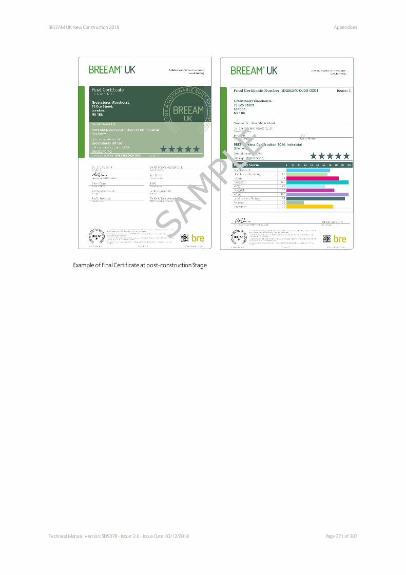
BREEAM UK New Construction 2018 Appendices
Example of Final Certificate at post-construction Stage
Technical Manual: Version: SD5078 - Issue: 2.0 - Issue Date: 03/12/2018 Page 371 of 387

BREEAM UK New Construction 2018 – Schedule of changes to the scheme
document
BREEAM UK New Construction 2018
BREEAM UK New Construction 2018 – Schedule of changes to the scheme documentThe manual may be revised and re-issued from time to time. A re-issue of a BREEAM scheme document (SD) version may be required for the following reasons:
1. To clarify: criteria; compliance notes; or schedule of evidence requirements 2. To update a reference or relevant definition 3. To update or amend calculation procedures 4. To amend the scope to allow for the inclusion of additional building types.
Scheme Doc. Issue no. Date of issue
SD5078 2.0 (current) 03/12/2018
SD5078 1.2 14/08/2018
SD5078 1.1 (Withdrawn) 31/07/2018
SD5078 1.0 07/03/2018
Key (Type of Change
A The 'A' signifies either: an addition, insertion, alteration or deletion to the scheme document which does not directly affect the assessment criteria, calculation procedures or schedule of evidence (and therefore assessment of a building).
C The 'C' signifies either: an addition, insertion, deletion or alteration to the scope, assessment criteria, compliance note, evidential requirements or relevant definitions.
Issue 2.0
Section Issue/section Identifier Type Specifics of change
All technical issues
All N/A A Minor corrections to text and formatting.
Management Man 04 Methodology A Additional text added to use consistent terminology.
Health and wellbeing
Hea 01 Criteria A Clarification of criterion 2.
Health and wellbeing
Hea 01 Criteria A Correction of listed criteria.
Health and wellbeing
Hea 02 Criteria C Amendment to the time -related requirement of the indoor air quality plan in criterion 1.
Health and wellbeing
Hea 02 Methodology A Deletion of reference to CN7.4.
Health and wellbeing
Hea 02 Methodology A Clarification text under subheading 'Number of products to comply'.
Health and wellbeing
Hea 02 Definitions A Update to standard.
Page 372 of 387 Technical Manual: Version: SD5078 - Issue: 2.0 - Issue Date: 03/12/2018

BREEAM UK New Construction 2018 BREEAM UK New Construction 2018 – Schedule of changes to the scheme
document
Section Issue/section Identifier Type Specifics of change
Health and wellbeing
Hea 04 Specific notes A Deletion of Specific Note 1.2.
Health and wellbeing
Hea 05 Criteria A Addition of missing text in table 5.19.
Health and wellbeing
Hea 05 Methodology A Correction of text under 'Residential institutions (short and long term stay)'.
Health and wellbeing
Hea 06 Additional information A Exemplary level text added.
Energy Ene 01 Criteria C Amendment to the time-related requirement of the energy design workshop in criterion 2.
Energy Ene 01 Criteria A Deletion of titles 'Prerequisite' and 'Four credits - energy modelling and reporting' for the 'Prediction of operational energy consumption' criteria.
Energy Ene 01 Methodology A Correction of 'Preliminary design workshop' to 'Energy design workshop'.
Energy Ene 02 Specific notes A Amendment to Specific Note 2.0.
Energy Ene 04 Methodology A Amendment to 'Passive design analysis'.
Energy Ene 06 Criteria A Amendments to criterion 1.
Transport Tra 01 Throughout issue C Amendments and clarifications throughout the issue.
Transport Tra 02 Criteria C Amendment to criterion 1.
Transport Tra 02 Criteria A Amended text in table 7.5
Transport Tra 02 Methodology A Correction of text under 'Sliding scale of compliance'.
Water Wat 01 Criteria A Update to standard for rainwater systems.
Water Wat 01 Methodology A Amendments to table 8.2.
Water Wat 01 Methodology C Amendments to 'Buildings with greywater or rainwater systems'.
Water Wat 04 Specific notes A New text detailing filtering of issue.
Water Wat 04 Criteria A Correction of hyperlink to Wat 01 table.
Materials Mat 01 Assessment scope A Corrections to criteria applicable to Simple Buildings.
Materials Mat 01 Methodology A Text amended to clarify the process.
Materials Mat 01 Methodology A Correction to 'Significantly different design options'.
Materials Mat 01 Definitions A New definition for 'BREEAM LCA Benchmark'. Reference to this now made
Technical Manual: Version: SD5078 - Issue: 2.0 - Issue Date: 03/12/2018 Page 373 of 387

BREEAM UK New Construction 2018 – Schedule of changes to the scheme
document
BREEAM UK New Construction 2018
Section Issue/section Identifier Type Specifics of change
throughout the issue.
Materials Mat 01 Definitions A Amended text for 'Mat 01/02 Results Submission Tool'.
Materials Mat 01 Definitions A Amended text for 'Suitably qualified third party'.
Materials Mat 01 Checklists and tables A Amendments to 'Quality requirements'.
Materials Mat 03 Specific notes A New Note for Simple Buildings.
Materials Mat 03 Criteria A Correction to title of table 9.10.
Materials Mat 03 Methodology A Clarification text to 'Scope of assessment' about temporary elements.
Materials Mat 03 Methodology A Clarification of the 'Broken chain' text.
Materials Mat 05 Criteria A Correction to table 9.14 reference.
Waste Wst 01 Specific notes A New Specific Note for sites where no demolition will be undertaken.
Waste Wst 01 Criteria C Criterion 1.d moved to become a separate requirement for the Pre-demolition audit credit.
Waste Wst 01 Criteria C Amendment to criterion 16, so that it is applicable to Simple Buildings.
Waste Wst 02 Methodology C Clarification to 'Data requirements'.
Land Use and Ecology
LE 02, 03, 04 and 05 Various sections A 'Relevant stakeholders' text added throughout these credit issues.
Land Use and Ecology
LE 03 Criteria C Correction to text referring to loss of ecological value.
Land Use and Ecology
LE 04 Evidence C Additional evidence requirement for criterion 6.
Land Use and Ecology
LE 05 Criteria C Correction of criteria for 'Landscape and ecology management plan (or similar) development'.
Pollution Pol 02 Criteria A Correction of benchmarks for oil-fueled boilers.
Pollution Pol 03 Definitions C Corrections to the following definitions:'Current best practice national planning guidance' and 'SuDS sustainable drainage systems'.
Page 374 of 387 Technical Manual: Version: SD5078 - Issue: 2.0 - Issue Date: 03/12/2018

BREEAM UK New Construction 2018 BREEAM UK New Construction 2018 – Schedule of changes to the scheme
document
Issue 1.2
Section Issue/section Identifier Type Specifics of change
Land Use and Ecology
LE 03 Assessment criteria C Clarification of the approach for awarding credits for 'Managing negative impacts of the project' without the need to achieve the percentage scores (outlined in GN36).
Land Use and Ecology
LE 04 Assessment criteria C Credit allocation clarified in accordance with the calculation methodology within GN36. Exemplary level credit added.
Innovation Inn 01 Assessment criteria A Included reference to exemplary level credit within LE 04.
Issue 1.1
Section Issue/section Identifier Type Specifics of change
All technical issues
All N/A A Minor corrections to text and formatting.
Scope Post-occupancy Stage (POS)
N/A A Updated information for Ene 01.
Scoring and rating BREEAM-assessed buildings
Calculating a building's BREEAM rating
Table 2.6 A Updated figures in the example BREEAM score and rating calculation.
Management Man 03 Additional information A Deletion of Additional Information for Constructing Excellence and reporting of construction site impacts.
Management Man 04 Overview A Correction of Shell Only icon. Only one credit is available.
Management Man 04 Definitions C Removal of requirement for UKAS accreditation for the definition of Suitably Qualified Professionals.
Health and wellbeing
Hea 01 Assessment criteria A Correction of title of last credit.
Health and wellbeing
Hea 01 Assessment criteria C Update to minimum values of average daylight factor for multi-residential developments.
Health and wellbeing
Hea 01 Assessment criteria C Update to criterion 5 to '95% of the floor area in 95% of spaces for each relevant building area provides an adequate view out'.
Health and wellbeing
Hea 01 Assessment criteria C Deletion of criterion 6. Text moved to Definition of 'Adequate view out'.
Health and wellbeing
Hea 01 Exemplary criteria A Adding titles for the two Exemplary credits.
Technical Manual: Version: SD5078 - Issue: 2.0 - Issue Date: 03/12/2018 Page 375 of 387

BREEAM UK New Construction 2018 – Schedule of changes to the scheme
document
BREEAM UK New Construction 2018
Section Issue/section Identifier Type Specifics of change
Health and wellbeing
Hea 01 Methodology A Amendment to text where occupancy or workstation layout not known to 'an assumption of 1 person or workspace per 10m²'.
Health and wellbeing
Hea 02 Icons A Correction to icon.
Health and wellbeing
Hea 02 Throughout C Update to standards for criterion 2c, 'Ventilation' in the Methodology, and 'Relevant Standards (ventilation)' in Definitions.
Health and wellbeing
Hea 05 Icons A Correction to icons.
Energy Ene 01 Assessment criteria C Update to the 'Post-occupancy stage' Exemplary credit. Listed building types now required to achieve the second Ene 02 credit.
Energy Ene 01 Methodology A Amendment to wording of 'Estimating unregulated energy demand for building systems or processes'.
Energy Ene 04
Throughout A Update to wording, to refer to 'low and zero carbon'.
Energy Ene 04 Assessment criteria A Amendment to criterion 1 to clarify it refers to Hea 04.
Energy Ene 06 Assessment criteria C Corrections to criterion 1.b.
Transport Tra 02 Assessment criteria A Correction to criterion 3 so that it refers to the 'existing Accessibility Index'.
Transport Tra 02 Assessment criteria A Correction to the column headings and format of table 7.3.
Transport Tra 02 Assessment criteria A Correction to key of table 7.6 for Multi-residential building types.
Transport Tra 02 Definitions A Amendment to definition for 'Rural location-sensitive buildings' to aid clarity.
Water Wat 03 Icons A Correction to Shell Only icon.
Water Wat 04 Assessment criteria A Correction to criterion 1 so that it refers to table 8.4.
Material Mat 01 Icons A Correction to Simple Building and Shell Only icons. Only two credits available for either.
Material Mat 01 Assessment criteria A Amendment to the 'Third Party Verification' Exemplary credit to aid clarity.
Material Mat 01 Definitions C Amendment to 'Third Party' Definition.
Material Mat 01 Definitions A Definition of 'Environmental product declaration' added.
Material Mat 05 Definitions A Definition of 'Material Efficiency' deleted.
Land Use and Ecology
LE 02 Assessment criteria C Correction to criterion 8. The optimal ecological outcome must be identified.
Page 376 of 387 Technical Manual: Version: SD5078 - Issue: 2.0 - Issue Date: 03/12/2018

BREEAM UK New Construction 2018 BREEAM UK New Construction 2018 – Schedule of changes to the scheme
document
Section Issue/section Identifier Type Specifics of change
Land Use and Ecology
LE 02 Assessment criteria C Correction to criterion 9. The hierarchy of action is different for Route 1 compared to Route 2.
Land Use and Ecology
LE 02 Methodology A Amendment to the title 'Determining the ecological outcomes for the site - Considerations during liaison discussions'. Correction to bullet point numbering.
Land Use and Ecology
LE 02 Methodology C Update to Route 1 so that it refers to Guidance Note 35.
Land Use and Ecology
LE 02 Evidence C Update to Evidential requirements for the Prerequisite and Criterion 5. Specific documents and checklists are required.
Land Use and Ecology
LE 02 Definitions A Definitions for 'Wildlife corridors' and 'Land-sea interface' deleted.
Land Use and Ecology
LE 03 Assessment criteria C Prerequisite amended. It is not required that UK and EU or international legislation related to ecology is confirmed as complied with.
Land Use and Ecology
LE 03 Assessment criteria A Rewording of criterion 5 to aid clarity.
Land Use and Ecology
LE 03 Assessment criteria C Amendments to criterion 6. Criteria 3 and 4 have to be achieved for Route 1. Requirement for 'no loss of ecological value has occurred' added.
Land Use and Ecology
LE 03 Assessment criteria C Amendments to criterion 7. Criteria 3 and 4 have to be achieved for Route 2. Guidance note 36 is referred to. Percentage scores for ecological value added to define 'no net loss' and 'minimised' loss of ecological value.
Land Use and Ecology
LE 03 Methodology C Amendment to Route 1 so that it refers to Guidance Note 35.
Land Use and Ecology
LE 03 Methodology C Amendments to Route 2. Hierarchy of actions added and 'Planning, liaison and implementation' text removed. Amendment of title of 'Liaison and collaboration' to 'Timescales', and amendment to content.
Land Use and Ecology
LE 03 Definitions C Definition for 'No overall loss' added.
Land Use and Ecology
LE 04 Assessment criteria C Criterion 1 corrected to requiring criteria 2 and 3 of LE 03 to have been achieved.
Land Use and Ecology
LE 04 Assessment criteria C Text of criterion 4 moved to be applicable to Route 2 assessments under 'Liaison, implementation and data collation'.
Technical Manual: Version: SD5078 - Issue: 2.0 - Issue Date: 03/12/2018 Page 377 of 387

BREEAM UK New Construction 2018 – Schedule of changes to the scheme
document
BREEAM UK New Construction 2018
Section Issue/section Identifier Type Specifics of change
Land Use and Ecology
LE 04 Assessment criteria C Criterion 6 amended to aid clarity. Percentage scores for ecological value added to define 'no net loss' and 'minimised' loss of ecological value.
Land Use and Ecology
LE 04 Methodology C Updates to Route 1 so that it refers to Guidance Note 35.
Land Use and Ecology
LE 04 Methodology A Updates to Route 2 to aid clarity.
Land Use and Ecology
LE 04 Definitions A Removal of 'Development footprint' Definition. This is defined in Guidance Note 36.
Land Use and Ecology
LE 05 Assessment criteria A Amendments to column titles in table 11.4.
Land Use and Ecology
LE 05 Assessment criteria C Prerequisite amended. Requirement for LE 04 to be achieved updated to criteria 3-4 of LE 03 for both Routes. For Route 2, at least one credit under LE 04 has been awarded.
Land Use and Ecology
LE 05 Assessment criteria A Criterion 3 amended to aid clarity.
Land Use and Ecology
LE 05 Assessment criteria C Criterion 6 amended to refer to the specific section of BS 42020:2013, and replacement of 'similar' with 'equivalent'.
Land Use and Ecology
LE 05 Assessment criteria C Criterion 7 moved to be relevant to the 'Planning, liaison, data, monitoring and review management and maintenance' credit.
Land Use and Ecology
LE 05 Methodology C Update to Route 1 so that it refers to Guidance Note 35.
Land Use and Ecology
LE 05 Methodology C Update to Route 2 to define the contents of the information pack for the 'tenant/occupier/building manager'.
Land Use and Ecology
LE 05 Methodology A Correction to 'Data collation and application throughout the project lifecycle' to refer to data collated during LE 02.
Pollution Pol 01 Specific notes A 'Untreated buildings' note deleted.
Pollution Pol 02 Assessment criteria A Update to criterion 2. Information regarding emission measurement moved to the Methodology.
Pollution Pol 02 Assessment criteria A Deletion of criterion 3.
Pollution Pol 02 Methodology A Update to 'Units of measure for emissions'. It refers to the requirements under the Ecodesign Directive.
Pollution Pol 03 Assessment criteria C Update to the 'Surface water run-off Rate' criteria. Brownfield sites need to show a 30% improvement. Greenfield sites need to show no greater peak rate of run-off.
Page 378 of 387 Technical Manual: Version: SD5078 - Issue: 2.0 - Issue Date: 03/12/2018

BREEAM UK New Construction 2018 References
References1 Heravitorbati A, Coffey V, Trigunarsyah B, Saghatforoush E. Evaluating the influences of stakeholder management
on construction project quality. In: Proceedings of first International Construction Business & Management
Symposium. University Teknologi Malaysia, Kuala Lumpur; 2011.
2 RIBA. RIBA Plan of Work. 2013.
3 Usable Buildings Trust. BSRIA BG 4/2009: The Soft Landings Framework, for better briefing, design, handover and
building performance in-use. BSRIA; 2009.
4 BSRIA. BSRIA BG 28/2011: BREEAM 2011 and Soft Landings, an interpretation note for clients and designers.
BSRIA; 2011.
5 HM Government. Construction 2025: Industrial Strategy: government and industry in partnership [Internet]. 2013.
Available from:www.gov.uk/government/uploads/system/uploads/attachment_data/file/210099/bis-13-955-
construction-2025-industrial-strategy.pdf
6 PD 156865: 2008. Standardized method of life cycle costing for construction procurement. A supplement to BS
ISO 15686-5. Buildings and constructed assets. Service life planning. Life cycle costing. London: BSI; 2008.
7 RICS. Life cycle costing - RICS professional guidance, UK. RICS; 2016.
8 Churcher D, Tse P. BG 67/2016: Life cycle costing. BSRIA; 2016.
9 CLOCS. Standard for construction logistics: Managing work related road risk [Internet]. 2015. Available from
www.clocs.org.uk/wp-content/uploads/2016/01/CLOCS-Standard-v2-DEC_2015-.pdf
10 ISO 14001: 2015. Environmental management systems - Requirements with guidance for use. ISO; 2015.
11 BS 8555: 2016. Environmental management systems. Guide to the phased implementation of an environmental
management system including the use of environmental performance evaluation. BSI; 2016.
12 Environment Agency, Northern Ireland Environment Agency, Scottish Environmental Protection Agency. Working
at construction and demolition sites: PPG6, Pollution Prevention Guidelines. Environment Agency; 2012.
13 Defra. Government conversion factors for company reporting: Greenhouse Gas Conversion Factor Repository
[Internet]. Defra; Available from: www.gov.uk/government/collections/government-conversion-factors-for-
company-reporting
14 Department for Environment Food and Rural Affairs. Guidance on measuring and reporting Greenhouse Gas
(GHG) emissions from freight transportation operations. Defra; 2014.
15 Usable Buildings Trust, Way M, Bunn R. BSRIA BG 54/2014 The Soft Landings Framework for better briefing,
design, handover and building performance in-use. 2014.
16 Wild J. Commissioning HVAC Systems: Guidance on the division of responsibilities (TM 1/88.1). BSRIA; 2002.
17 CIBSE. CCA Commissioning Code A: 1996 (2006) Air Distribution Systems. CIBSE; 2004.
18 BS EN 13187: 1999. Thermal performance of buildings. Qualitative detection of thermal irregularities in building
envelopes. Infrared method. BSI; 1999.
19 BS EN ISO 9972: 2015. Thermal performance of buildings. Determination of air permeability of buildings. Fan
pressurisation method. BSI; 2015.
20 British Refrigeration Association, Institute of Refrigeration. Guide to Good Commercial Refrigeration Practice,
Part 5 Commissioning. 2008.
21 Carbon Trust. Good Practice Guide 347: Installation and Commissioning of Refrigeration Systems. Carbon Trust;
2003.
22 The Air Tightness Testing and Measurement Association. Measuring air permeability of building envelopes (non-
dwellings), Technical standard Level 2 (TSL2). ATTMA; 2010.
23 British Council for Offices. BCO Guide to Post Occupancy Evaluation. BCO; 2007.
Technical Manual: Version: SD5078 - Issue: 2.0 - Issue Date: 03/12/2018 Page 379 of 387

References BREEAM UK New Construction 2018
24 Jaunzens D, Grigg P, Cohen R, Watson M, Picton E. BRE Digest 478 Building performance feedback: getting
started. BRE; 2003.
25 HEFCE, AUDE, University of Westminster. Guide to Post Occupancy Evaluation: Report and Toolkit. Higher
Education Funding Council for England; 2006.
26 Agha-Hossein M, Birchall S, Vatal S. BG 63/2015 BSRIA Guide to Building Performance Evaluation is a general
introduction to BPE. BSRIA; 2015.
27 CIBSE. GVF2012 Guide F: Energy Efficiency in Buildings (2012 with 2016 corrigendum). CIBSE; 2012.
28 CIBSE. TM46: Energy Benchmarks. CIBSE; 2008.
29 CIBSE. TM47: Operational Ratings & Display Energy Certificates. CIBSE; 2009.
30 CIBSE. TM54: Evaluating Operational Energy Performance of Buildings at the Design Stage. CIBSE; 2013.
31 Carbon Trust. CTG047 Closing the gap: Lessons learned on realising the potential of low carbon building design.
Carbon Trust; 2011.
32 CIBSE.SLL Code for lighting. 2012.
33 CIBSE. LG 7: Lighting Guide 07: Offices. 2015.
34 BS 5489-1: 2013 Code of practice for the design of road lighting - Lighting of roads and public amenity areas
BSI; 2013.
35 BS EN 12464-2:2014. Light and lighting. Lighting of work places - Outdoor work places. BSI; 2014.
36 CIBSE. LG 5: Lighting guide 05: Lighting for education. 2011.
37 BS8206-2:2008. Lighting for buildings. Code of practice for daylighting. Part 2 Appendix A1.3.
38 BSEN12464-1. Lighting and lighting- lighting for work places. Part 1: Indoor work places. 2011.
39 Commission Internationale de L’Eclairage (International Commission on Illumination). CIE Standard 011/E:2003
Spatial distribution of daylight - CIE standard overcast sky and clear sky. Vienna. CIE. 2003.
40 CIBSE. LG 10: Daylighting- a guide for designers. 2014.
41 Building Bulletin 90: lighting design for schools. 2014.
42 CIBSE. LG 9: Lighting Guide 09: Lighting for Communal Residential Buildings. 2013.
43 BSEN12464-1:2011. Light and lighting. Lighting for work places. Indoor work places. 2011.
44 Health and safety executive. Control of substances hazardous to health (COSHH). 2002.
45 BS EN 16798-3:2017. Energy performance of buildings. Ventilation for buildings. For non-residential buildings.
Performance requirements for ventilation and room-conditioning systems (Modules M5-1,M5-4). BSI; 2017.
46 CIBSE. AM10 Natural ventilation in non-domestic buildings. 2005.
47 BS EN 16402:2013. Paints and varnishes. Assessment of emissions of substances from coatings into indoor air -
Sampling, conditioning and testing. BSI; 2013.
48 BS ISO 160009:2006. Indoor air part 9: Determination of the emission of volatile organic compounds from
construction products and furnishing - Emission test chamber method. ISO; 2006.
49 EN 16516:2015. Construction products - Assessments of release of dangerous substances - Determination of
emissions into indoor air. BSI; 2015.
50 California Department of Public Health (CDPH). Standard method for the testing and evaluation of volatile
organic chemical emissions from indoor sources using environmental chambers. Version 1.1. 2010.
51 BS EN 717-1:2004. Wood-based panels. Determinations of formaldehyde release - Formaldehyde emission by
the chamber method. BSI; 2004.
52 ISO 10580:2010. Resilient, textile and laminate floor coverings- Test method for volatile organic compound
(VOC) emissions.
53 BS EN 13999-1:2013. Adhesives. Short term method for measuring the emission properties of low-solvent or
solvent-free adhesives after application - General procedure. BSI; 2013.
54 BS EN 13999-2:2013. Adhesives. Short term method for measuring the emission properties of low-solvent or
solvent-free adhesives after application - Determination of volatile organic compounds. BSI; 2013.
Page 380 of 387 Technical Manual: Version: SD5078 - Issue: 2.0 - Issue Date: 03/12/2018

BREEAM UK New Construction 2018 References
55 BS EN 13999-3:2007+A1:2009. Adhesives. Short term method for measuring the emission properties of low-
solvent or solvent-free adhesives after application - Determination of volatile aldehydes. BSI; 2007.
56 BS EN 13999-4:2007+A1:2009. Adhesives. Short term method for measuring the emission properties of low-
solvent or solvent-free adhesives after application - Determination of volatile diisocyanates. BSI; 2007.
57 WHO. Guidelines for indoor air quality: Selected pollutants. World Health Organisation; 2010.
58 BS EN ISO 16000-2:2006. Indoor air - Part 2: Sampling strategy for formaldehyde. ISO; 2006.
59 BS ISO 16000-3:2011. Indoor air - part 3: Determination of formaldehyde and other carbonyl compounds in
indoor air test and chamber air - active sampling method. ISO; 2011.
60 BS ISO 16000-5:2007. Indoor air - Part 5: Sampling strategy for volatile organic compounds (VOCs). ISO; 2007.
61 BS ISO 16000-6:2011. Indoor air - part 6: Determination of volatile organic compounds in indoor and test
chamber air by active sampling on Tenax TA sorbent, thermal desorption and gas chromatography using MS or MS-
FID. ISO; 2011.
62 BS EN ISO 16017-2:2003. Indoor, ambient and workplace air. Sampling and analysis of volatile organic
compounds by sorbent tube/thermal desorption/capillary gas chromatography - Diffusive sampling. ISO; 2003.
63 PD CEN/TR 16798-4:2017. Energy performance of buildings. Ventilation for buildings. Interpretation of the
requirements in EN 16798-3. For non-residential buildings. Performance requirements for ventilation and room-
conditioning systems(Modules M5-1, M5-4). BSI; 20017.
64 Kukadia V, Hall D. FB30: Ventilation for healthy buildings: reducing the impact of urban air pollution. BRE; 2011.
65 Cheng H, Kukadia V, Hall D. IP9/14: Locating ventilation inlets to reduce ingress of external pollutants into
buildings: A new methodology. BRE; 2014.
66 CIBSE. TM21: Minimising pollution at air intakes. 1999.
67 ISO/IEC 17025:2005. General requirements for the competence of testing and calibration laboratories. ISO;
2005.
68 BS EN 15457:2014. Paints and varnishes - Laboratory method for testing the efficacy of film preservatives in a
coating against fungi. BSI; 2014.
69 BS EN 15458:2014. Paints and varnishes - Laboratory method for testing the efficacy of film preservatives in a
coating against algae. BSI; 2014.
70 ISO 11890-2:2013. Paints and varnishes - Determination of volatile organic compound (VOC) content- Part 2:
Gas-chromatographic method. 2013.
71 ISO 17895:2005. Paints and varnishes- Determination of the volatile organic compound content of low-VOC
emulsion paints (in-can VOC). 2005.
72 ISO 16000-2:2006 Indoor air. Part 2: Sampling strategy for formaldehyde. International Organization for
Standardisation (ISO); 2006.
73 Regulation (EC) No 1272/2008 of the European Parliament and of the Council of 16 December 2008 on
classification, labelling and packaging of substances and mixtures, amending and repealing Directives 67/548/EEC
and 1999/45/EC, and amending Regulation (EC) No 1907/2006. European Union; 2008.
74 EN 16516:2015 Construction products - Assessment of release of dangerous substances - Determination of
emissions into indoor air. European Committee for Standardisation (CEN); 2015.
75 Building Bulletin 101: Guidelines on ventilation, thermal comfort and indoor air quality in schools; August 2018
76 HTM03-01: Specialised ventilation for Healthcare premises - Part A Design and Validation; 2007.
77 SHTM03-01: Ventilation for Healthcare premises - Part A Design and Validation; 2014.
78 ISO 17772-1:2017. Energy performance of buildings - Indoor environmental quality - Part 1: Indoor
environmental input parameters for the design and assessment of energy performance of buildings. ISO; 2017.
79 CIBSE. AM11 - Building performance modelling. 2015.
80 CIBSE. GVA/15 CIBSE Guide A: Environmental Design 2015. 8th Edition. 2015.
Technical Manual: Version: SD5078 - Issue: 2.0 - Issue Date: 03/12/2018 Page 381 of 387

References BREEAM UK New Construction 2018
81 CIBSE. TM52. The limits of therm comfort: avoiding overheating in European buildings. 2013.
82 CIBSE. TM59. Design methodology for the assessment of overheating risk in homes. 2017.
83 CTG065. Heating Control: Maximising comfort, minimising energy consumption. The Carbon Trust; 2011.
84 EN ISO 7730:2005. Ergonomics of the thermal environment - Analytical determination and interpretation of
thermal comfort using calculation of the PMV and PPD indices and local thermal comfort criteria. ISO; 2005.
85 HTM 03-01. Specialised ventilation for healthcare premises. Department of Health; 2007.
86 Education Funding Agency. Building Bulletin 101: Ventilation for school buildings. 2014.
87 Education Funding Agency. Building Bulletin 93: acoustic design of schools - performance standards. 2003.
88 ANC. ANC Good practice guide: Acoustics testing of schools. Version 1.2. 2011.
89 HTM 08-01. Health sector buildings: acoustic design requirements. Department of Health; 2013.
90 BS 8233:2014. Guidance on sound insulation and noise reduction for buildings. BSI; 2014.
91 Her Majesty’s Court Service HMCS. Court Service Design Guide (CSDG). 2010.
92 BS EN ISO 16283-1:2014. Acoustics. Field measurement of sound insulation in buildings and of building
elements. Airborne sound insulation. 2014.
93 BS EN ISO 3382-2:2008. Acoustics. Measurement of room acoustic parameters. Reverberation time in ordinary
rooms. 2008.
94 ISO/IEC 17025:2017 General requirements for the competence of testing and calibration laboratories. 2017.
95 ISO/IEC 17024:2012. Conformity assessment - General requirements for bodies operating certification of
persons. ISO; 2012.
96 HM Government. Approved document E. Resistance to the passage of sound. 2015.
97 SHTM 08-01. Specialist services Acoustics. NHS National Services Scotland; 2015.
98 ETS-01. Courtroom technology and spatial requirements: Design Guide. Scottish Court Service; 2011.
99 ETS-03. Estates technical standard environmental performance: Design Guide. Scottish Court Service; 2011.
100 Department for Education and Employment. Managing School Facilities, Guide 4 Improving Security in Schools.
1996.
101 BS 5489-1:2013. Code of practice for the design of road lighting - Lighting of roads and public amenity areas.
BSI; 2013.
102 Department for Transport. Local Transport Note 2/08. Cycle Infrastructure Design. 2008.
103 Sustrans. Sustrans design manual. Handbook for cycle-friendly design. 2014.
104 Adler D. Metric handbook Planning and design data. 5th Edition; 2015.
105 Committee on Climate Change. 2013 Progress Report to Parliament Committee on Climate Change. Meeting
carbon budgets. London, Committee on Climate Change; 2013.
106 Technical Handbook - Non-Domestic. Section 6 - Energy. Edinburgh, Scottish Government; 2016
107 Building Regulations (Northern Ireland) 2012. Technical Booklet F2 Conservation of fuel and power in buildings
other than dwellings. Department of Finance and Personnel; 2012.
108 The Building Regulations 2010. Part L2A Conservation of fuel and power in new buildings other than dwellings.
HM Government; 2013.
109 The Building Regulations 2010. Approved Document L2A New buildings other than dwellings. Welsh
Government; 2014.
110 CIBSE. TM54: Evaluating operational energy performance of buildings at the design stage. London, CIBSE; 2013.
111 Directive 2010/31/EU of the European Parliament and of the Council of 19 May 2010 on the energy
performance of buildings (recast)
112 National Calculation Methodology. Modelling Guide for Non-Domestic Buildings in Scotland. Edinburgh,
Scottish Government; 2015.
113 National Calculation Methodology. Modelling Guide (buildings other than dwellings) in England and Wales.
Watford, BRE; 2013.
Page 382 of 387 Technical Manual: Version: SD5078 - Issue: 2.0 - Issue Date: 03/12/2018

BREEAM UK New Construction 2018 References
114 Schneider Electric. Designing a metering system for small and medium sized buildings. London, Schneider
Electric; 2010.
115 CIBSE. TM39: Building Energy Metering. London, CIBSE; 2009.
116 CIBSE. TM54: Evaluating operational energy performance of buildings at the design stage. London, CIBSE; 2013.
117 CIBSE. TM46: Energy benchmarks. London, CIBSE; 2008.
118 CIBSE, The Society of Light and Lighting. Lighting Guide 6: The exterior environment. London, CIBSE; 2016.
119 CIBSE. Guide F: Energy efficiency of buildings. London, CIBSE; 2012.
120 Directive 2009/28/EC of the European Parliament and of the Council of 23 April 2009 on the promotion of the
use of energy from renewable sources and amending and subsequently repealing Directives 2001/77/EC and
2003/30/EC
121 Directive 2010/31/EU of the European Parliament and of the Council of 19 May 2010 on the energy
performance of buildings (recast)
122 United Nations. Sustainable Bioenergy: a framework for decision makers. New York City, NY, UN; 2007.
123 International Institute of Refrigeration. 17th Informatory Note on Refrigerating Technologies: How to improve
energy efficiency in refrigerating equipment. Paris, IIR; 2003.
124 The Carbon Trust. Refrigeration systems: Guide to key energy saving opportunities. London, Carbon Trust;
2011.
125 Institute of Refrigeration. Code of Conduct for carbon reduction in the retail refrigeration sector. London,
Carbon Trust; 2011.
126 BS EN 378-2:2016. Refrigerating systems and heat pumps. Safety and environmental requirements Part 2:
Design, construction, testing, marking and documentation. London, BSI; 2016.
127 Department of Energy and Climate Change. Enhanced capital allowance scheme: energy technology product
list. London, DECC; 2014.
128 BS EN 378-1:2016. Refrigerating systems and heat pumps. Safety and environmental requirements Part 1:
Basic requirements, definitions, classification and selection criteria. London, BSI; 2016.
129 British Refrigeration Association. Guideline methods of calculating TEWI. BRA Specification. Reading, BRA; 2006.
130 The Carbon Trust. CTG021. Refrigeration Road Map - An action plan for the retail sector. London, The Carbon
Trust; 2012, www.carbontrust.com
131 ISR, University of Coimbra. Intelligent Energy Europe E4 project. Energy efficient elevators and escalators.
Portugal, University of Coimbra; 2010.
132 BS EN ISO 25745-2:2015. Energy performance of lifts, escalators and moving walks. Energy calculation and
classification for lifts. London, BSI; 2015.
133 BS EN ISO 25745-3:2015. Energy performance of lifts, escalators and moving walks. Energy calculation and
classification of escalators and moving walks. London, BSI; 2015.
134 BS EN ISO 25745-1:2012. Energy performance of lifts, escalators and moving walks. Energy measurement and
verification. London, BSI; 2012.
135 BS EN 81-20:2014. Safety rules for the construction and installation of lifts. Lifts for the transportation of
persons and goods. Passenger and goods passenger lifts. London, BSI; 2014.
136 Schneider Electric. Four steps for improving energy efficiency in laboratories. Paris, Schneider Electric; 2013.
137 CLEAPSS. G9 Fume Cupboards in Schools. Revision of DfEE Building Bulletin 88. 2014.
138 The Department for Education and Employment (DfEE). Building Bulletin 88 Fume Cupboards in Schools
(Revision of Design Note 29). 1998.
139 CIBSE. TM46: Energy Benchmarks. London, CIBSE; 2008.
140 Design Buildings Wiki. Performance gap between building design and operation. 2010. For more information,
visit: Designing Buildings Wiki.
Technical Manual: Version: SD5078 - Issue: 2.0 - Issue Date: 03/12/2018 Page 383 of 387

References BREEAM UK New Construction 2018
141 HM Government. Enhanced Capital Allowance Scheme for water. London, Defra; 2014.
142 Acton M, Bertoldi P, Booth J, Flucker S, Newcombe L, Rouyer A. Best practice guidelines for the EU code of
conduct on data centre energy efficiency. Luxembourg, Publications Office of the European Union; 2017.
143 Short A, Guthrie P, Soulti E, Macmillan S. Health Technical Memorandum 07-02: EnCO₂de 2015- making energy
work in healthcare. Part B: Procurement and energy considerations for new and existing building facilities. London,
Department of Health; 2015.
144 CIBSE. TM50: Energy Efficiency in Commercial Kitchens. London, CIBSE; 2009.
145 CIBSE. TM54: Evaluating operational energy performance of buildings at the design stage. London, CIBSE; 2013.
146 Department of Energy and Climate Change. Enhanced capital allowance scheme: energy technology product
list. 2014. For more information, visit:etl.beis.gov.uk
147 The Building Regulations 2010. Approved Document F Ventilation. Welsh Government; 2010.
148 Technical Handbook - Domestic. Section 3 - Environment. Edinburgh, Scottish Government; 2016.
149 Building Regulations (Northern Ireland) 2012. Technical Booklet K Ventilation. Department of Finance and
Personnel; 2012.
150 The Building Regulations 2010. Approved Document F Ventilation. HM Government; 2010.
151 Department for Communities and Local Government. 2012. National Planning Policy Framework. 2012.
152 Department of Energy and Climate Change. 2015. 2013 UK Greenhouse Gas Emissions, Final Figures. 2015.
153 National Institute for Health and Care Excellence, "Guideline scope. Air pollution: outdoor air quality and health.
154 HM Government, Defra. Future Water: The Government’s water strategy for England [Internet]. The Stationery
Office; 2008. Available from: https://www.gov.uk/government/uploads/system/uploads/attachment_
data/file/69346/pb13562-future-water-080204.pdf
155 HR Wallingford. CCRA2: Updated projections for water availability for the UK Final Report [Internet]. 2015.
Available from: https://www.theccc.org.uk/wp-content/uploads/2015/09/CCRA-2-Updated-projections-of-
water-availability-for-the-UK.pdf
156 Department of Health. Health Technical Memorandum 07-04: Water management and water efficiency –
best practice advice for the healthcare sector. Crown copyright; 2013.
157 Department of Health. Health Technical Memorandum 04-01 Safe water in healthcare premises. Crown
copyright; 2016
158 BS 8525-1:2010. Greywater systems. Code of practice. BSI; 2010.
159 BS EN 16941-1:2018. On-site non-potable water systems. Systems for the use of rainwater. BSI; 2018
160 The Water Supply (Water Fittings) Regulations. 1999 No. 1148 1999.
161 HM Government. The Building Regulations 2010: Part G Sanitation, hot water safety and water efficiency
(2015 edition). 2015.
162 Market Transformation Programme. BNWAT22: BNWAT22: Domestic water consumption in domestic and
non-domestic properties (version 1.1). 2007.
163 Grant N, Thornton J. AECB Water Standards: Delivering buildings with excellent water and energy performance -
Volume 2: The water standards technical background report (version 1.0.0). 2009.
164 BS EN 1112:2008. Sanitary tapware. Shower outlets for sanitary tapware for water supply systems type 1 and
2. General technical specifications. BSI; 2008.
165 BS EN 16941-1:2018. On-site non-potable water systems. Systems for the use of rainwater. BSI; 2018.
166 BS 8525-1:2010. Greywater systems. Code of practice. BSI; 2010.
167 Great Britain, The Water Industry Act 1991. London: The Stationery Office
168 Department for Environment, Food and Rural Affairs. Future Water: The Government’s water strategy for
England [Internet]. The Stationery Office; 2008. Available from
Page 384 of 387 Technical Manual: Version: SD5078 - Issue: 2.0 - Issue Date: 03/12/2018

BREEAM UK New Construction 2018 References
www.gov.uk/government/uploads/system/uploads/attachment_data/file/69346/pb13562-future-water-
080204.pdf
169 BS EN 15804:2012+A1:2013. Sustainability of construction works. Environmental product declarations. Core
rules for the product category of construction products. BSI; 2013
170 BS EN 15978:2011. Sustainability of construction works. Assessment of environmental performance of buildings. Calculation method. BSI; 2011
171 BS ISO 20400:2017. Sustainable procurement. Guidance, BSI; 2017.
172 OECD Guidelines for Multinational Enterprises, OECD; 2008
173 BS 7543:2015. Guide to durability of buildings and building elements, products and components. BSI; 2015.
174 BS 5234-2:1992. Partitions (including matching linings). Specification for performance requirements for
strength and robustness including methods of test. BSI; 1992.
175 Ibid.
176 HTM 56 Partitions, third edition, Department of Health; 2005.
177 BS 15686-2:2012. Buildings and constructed assets. Service life planning. Service life prediction procedures. BSI;
2012.
178 BS 8895-1:2013. Designing for material efficiency in building projects - Part 1: Code of practice for Strategic
Definition and Preparation and Brief. BSI; 2013.
179 BS 8895-2:2015. Designing for material efficiency in building projects- Part 2: Code of practice for concept
design and developed design. BSI; 2015.
180 WRAP. Designing out Waste: A design team guide for Buildings.
181 UK Green Building Council. Waste. [Online]. [Cited:15 October 2015.] http://www.ukgbc.org/resources/key-
topics/circular-economy/waste
182 The Waste (England and Wales) Regulations 2011, Environmental Protection, England and Wales, Statutory
Instrument No. 988.
183 BS EN 12620:2013. Aggregates for concrete. BSI; 2013.
184 BS EN 13055:2016. Lightweight aggregates. BSI; 2016.
185 BS EN 13043:2013. Aggregates for bituminous mixtures and surface treatments for roads, airfields and other
trafficked areas. BSI; 2013.
186 BS EN 13242:2013. Aggregates for unbound and hydraulically bound materials for use in civil engineering
work and road construction. BSI; 2013.
187 ‘Quality Protocol: Aggregates from inert waste - End of waste criteria for the production of aggregates from
inert waste’, WRAP & Environment Agency, 2013.
188 BS EN 13383-1:2013. Armourstone. Specification. BSI; 2013.
189 BS EN 13108-1:2016. Bituminous mixtures. Material specifications. Asphalt concrete. BSI; 2006.
BS EN 13108-2:2016. Bituminous mixtures. Material specifications. Asphalt concrete for very thin layers (BBTM). BSI; 2016.
BS EN 13108-3:2016. Bituminous mixtures. Material specifications. Soft asphalt. BSI; 2016.
BS EN 13108-4:2016. Bituminous mixtures. Material specifications. Hot rolled asphalt. BSI; 2016.
BS EN 13108-5:2016. Bituminous mixtures. Material specifications. Stone mastic asphalt. BSI; 2016.
BS EN 13108-6:2016. Bituminous mixtures. Material specifications. Mastic asphalt. BSI; 2006.
BS EN 13108-7:2016. Bituminous mixtures. Material specifications. Porous asphalt. BSI; 2016.
BS EN 13108-8:2016. Bituminous mixtures. Material specifications. Reclaimed asphalt. BSI; 2016.
Technical Manual: Version: SD5078 - Issue: 2.0 - Issue Date: 03/12/2018 Page 385 of 387

References BREEAM UK New Construction 2018
190 BS EN 450-1:2012. Fly ash for concrete. Definition, specifications and conformity criteria. BSI; 2012.
191 BS EN 14227-3:2013. Hydraulically bound mixtures. Specifications. Fly ash bound granular mixtures. BSI; 2013.
BS EN 14227-4:2013. Hydraulically bound mixtures. Specifications. Fly ash for hydraulically bound mixtures. BSI; 2013.
192 BS EN 13285:2010. Unbound mixtures. Specifications. BSI; 2010.
193 Highways Agency. Specification for Highway Works - series 600. 2016.
194 Adler D. Metric handbook: Planning and design data. 5th Edition; 2015.
195 Committee on Climate Change. UK Climate Change Risk Assessment 2017: Synthesis report: priorities for the
next five years. 2016.
196 Barros VR, Field CB, Jon Dokken D, Mastrandrea MD, Mach KJ. Climate Change 2014: Impacts, Adaptation, and
Vulnerability. Part B: Regional Aspects. Contribution of Working Group II to the Fifth Assessment Report of the
Intergovernmental Panel on Climate Change. Cambridge University Press; 2014.
197 Humphrey K, Murphy J, Harris G, Brown S, Lowe J, McCarthy M, et al. UK Climate Change Risk Assessment
Evidence Report: Chapter 1, Introduction. London: Report prepared for the Adaptation Sub-Committee of the
Committee on Climate Change; 2016.
198 Met Office, University of Reading, CEH. Developing H++ climate change scenarios for heat waves, droughts,
floods, windstorms and cold snaps. 2015.
199 Pelsmakers S. The Environmental Design Pocketbook. second ed. RIBA Publishing; 2015.
200 Three Regions Climate Change Group. Your home in a changing climate: Retrofitting existing homes for climate
change impacts: Report for policy makers. Greater London Authority; 2008.
201 Gething B, Puckett K. Design for climate change. RIBA Publishing; 2013.
202 UNFCCC. Potential costs and benefits of adaptation options: A review of existing literature. 2009.
203 HM Government. The National Adaptation Programme: Making the country resilient to a changing climate. The
Stationery Office; 2013.
204 Graves HM, Phillipson MC. Potential implications of climate change in the built environment. BRE; 2000.
205 Cheshire D. Building revolutions: Applying the circular economy to the built environment. RIBA; 2016.
206 Adams K, Hobbs G, Yapp C. Dealing with difficult demolition wastes: A guide. IHS BRE Press; 2013.
207 PAS 1192-2:2013. Specification for information management for the capital and delivery phase of
construction projects using building information modelling. PAS; 2013.
208 PAS 1192-3:2014. Specification for information management for the operational phase of assets using
building information modelling. PAS; 2014.
209 Health Technical Memorandum 07-07: Sustainable health and social care buildings. Department of Health;
2013
210 National Planning Policy Framework. www.gov.uk/guidance/national-planning-policy-framework/annex-2-
glossary
211 BS 42020:2013 Biodiversity. Code of practice for planning and development, BSI 2013.
212 BS EN 378:2016. Refrigerating systems and heat pumps. Safety and environmental requirements. Operation,
maintenance, repair and recovery. BSI; 2016.
213 Institute of Refrigeration. Ammonia Refrigeration Systems Code of Practice. 2009.
214 Council Directive 1253/2014 of 7 July 2014 on implementing Directive 2009/125/EC of the European
Parliament and of the Council with regard to ecodesign requirements for ventilation units
215 British Refrigeration Association. Specification Guideline methods of calculating TEWI. 2006.
216 Market Transformation Programme. BNCR36: Direct Emission of Refrigerant Gases (Version 1.2). 2007.
Page 386 of 387 Technical Manual: Version: SD5078 - Issue: 2.0 - Issue Date: 03/12/2018

BREEAM UK New Construction 2018 References
217 Department of Energy and Climate Change. Enhanced Capital Allowance Scheme: Energy Technology Product
List. Department of Energy & Climate Change; 2014.
218 BS EN 378-1:2016. Refrigerating systems and heat pumps. Safety and environmental requirements. Basic
requirements, definitions. classification and selection criteria. BSI; 2016.
219 BS 8533:2017. Assessing and managing flood risk in development. Code of Practice. BSI; 2011.
220 CIRIA. The SuDS Manual (C753). CIRIA; 2015.
221 Environment Agency. Rainfall run-off management for developments. 2013.
222 Marshall D, Bayliss A. Flood estimation for small catchments. Institute of Hydrology; 1994.
223 Centre for Ecology and Hydrology. Flood estimation handbook. 1999.
224 CIRIA. Designing for exceedance in urban drainage - good practice C635. CIRIA; 2006.
225 CIRIA. Guidance for the construction of SuDS C768. CIRIA; 2017
226 Institution of Lighting Professionals. Guidance notes for the reduction of obtrusive light. GN01. 2011;
227 Institution of Lighting Professionals. The Brightness of illuminated advertisements. PLG05. 2015;
228 BS 4142:2014. Methods for rating and assessing industrial and commercial sound. BSI; 2014.
229 BS 8233:2014. Guidance on sound insulation and noise reduction for buildings. BSI; 2014.
230 Nursery school or education means full-time or part-time education suitable for children who have not attained
compulsory school age (whether provided at schools or elsewhere), i.e. facilities or buildings for the teaching of
children who are between the ages of two or three to five years old.
231 Children’s centres are multi-agency service hubs where young children and their families can receive early
education, full day childcare, parental support and child and family health services, such as access to health visitors
and health screening. Children’s centres will often be allied to a local primary school, on or adjacent to the school site.
232 Micro-generation is defined under the Energy Act 2004 as < 45KWth (micro-heat) and < 50KWe (micro-
electricity). Micro-generation can refer to community scale energy which may fall within these capacities
233 To refer to the total for more than one unit where applicable. Multi-split cooling systems and VRF systems
cannot be assessed under the Simple Buildings criteria
234 Typically, complex systems are systems that involve interaction between a number of components to ensure
proper operation. They will usually require specific knowledge and expertise to be designed and installed, and they
may depend on other systems such as control systems to work effectively
Technical Manual: Version: SD5078 - Issue: 2.0 - Issue Date: 03/12/2018 Page 387 of 387