Embed Size (px)
Citation preview
ENERGY /// POLYMERIC SURGE ARRESTRES IEC
BOWTHORPE EMPHigh Voltage Polymeric Surge Arrester (IEC)
Polymeric Surge Arresters IEC
ENERGY /// POLYMERIC SURGE ARRESTERS IEC
PAA PBA PCA
Maximum system voltage Um
kV 170 245 420
System voltage Us
kV 150 220 400
Nominal discharge current kA 10 10 10
High current impulse (4/10 µs) kA 100 100 100
Arrester class designation SL SL SM
Repetitive charge transfer rating Qrs
C 1.4 1.6 2.2
Rated thermal energy Wth
at Ur
kJ/kV 4.5 6.7 7.8
Rated short circuit current kA 40 65 65
Cantilever load
Specified long-term load (SLL) kNm 0.25 / 0.50 0.6 2.0
Specified short-term load (SSL) kNm 0.35 / 0.60 1.0 2.5
Qualification testing:
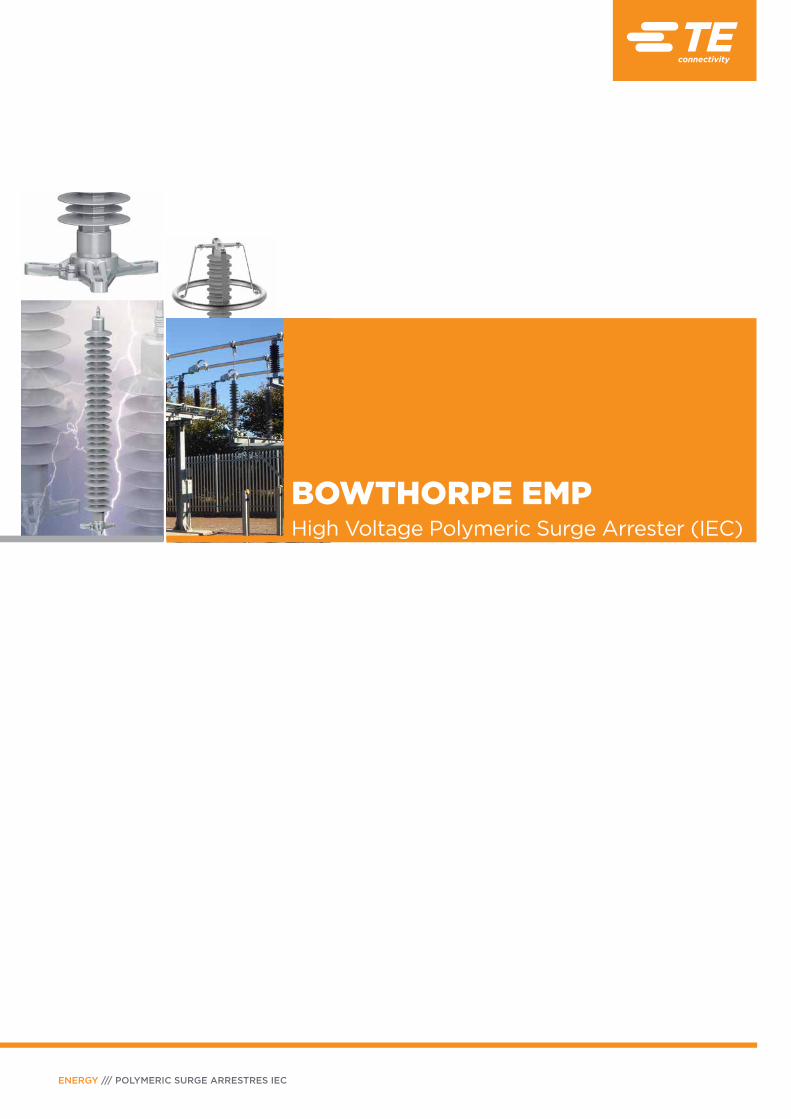
Decades of design and development experience have been used to produce today’s TE Connectivity HV surge arresters. The construction comprises of a number of ZnO elements, assembled within a open cage construction, which has a silicone rubber moulded shed profile chemically bonded to the surface of the core.
TE Connectivity HV surge arresters are designed and manufactured to the current IEC60099-4: 2014 standard and the following tests have been successfully performed.
• Test performed on metal oxide blocks:
• I EC clause 10.8.3 – Residual Voltage Test • IEC Clause 10.8.4 – Long Term Stability Test • IEC Clause 10.8.5 – Charge Transfer Test*• IEC Clause 10.8.7 – Operating Duty test • IEC Clause 10.8.8 – TOV Test • IEC Clause 10.8.15 – Dielectric strength of internal components
• Test performed on complete surge arresters:
• IEC Clause 10.8.6 – Cooling Test • IEC Clause 10.8.10 – Short Circuit Tests• IEC Clause 10.8.11 – Bending Moment Tests • IEC Clause 10.8.14 – RIV Tests • IEC Clause 10.8.17 – Weather Ageing Tests
• Insulation withstand tests on surge arrester housing: • IEC Clause 10.8.2 – Insulation tests include • Dry lightning impulse • Wet power frequency• Wet switching impulse
*New test introduced in the IEC60099-4: 2014 standard.
Aluminium
Fittings
Silicone
Rubber
Housing
Glass Fibre
Rods
Aluminium
Crimp
ZnO
Varistors
Aluminium
Heat Sink
GENERIC TECHNICAL DATA
Polymeric Surge Arresters IEC
PAGE 3
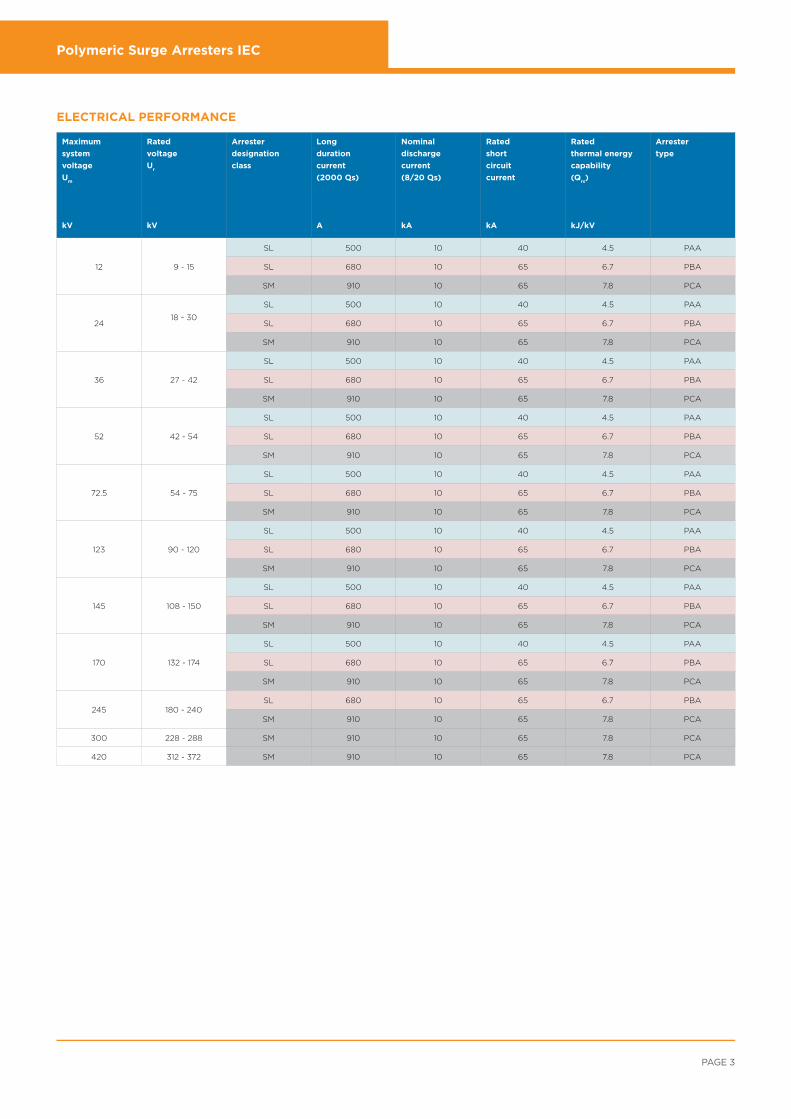
Maximum
system
voltage
Um
kV
Rated
voltage
Ur
kV
Arrester
designation
class
Long
duration
current
(2000 µs)
A
Nominal
discharge
current
(8/20 µs)
kA
Rated
short
circuit
current
kA
Rated
thermal energy
capability
(Qrs)
kJ/kV
Arrester
type
12 9 - 15
SL 500 10 40 4.5 PAA
SL 680 10 65 6.7 PBA
SM 910 10 65 7.8 PCA
2418 - 30
SL 500 10 40 4.5 PAA
SL 680 10 65 6.7 PBA
SM 910 10 65 7.8 PCA
36 27 - 42
SL 500 10 40 4.5 PAA
SL 680 10 65 6.7 PBA
SM 910 10 65 7.8 PCA
52 42 - 54
SL 500 10 40 4.5 PAA
SL 680 10 65 6.7 PBA
SM 910 10 65 7.8 PCA
72.5 54 - 75
SL 500 10 40 4.5 PAA
SL 680 10 65 6.7 PBA
SM 910 10 65 7.8 PCA
123 90 - 120
SL 500 10 40 4.5 PAA
SL 680 10 65 6.7 PBA
SM 910 10 65 7.8 PCA
145 108 - 150
SL 500 10 40 4.5 PAA
SL 680 10 65 6.7 PBA
SM 910 10 65 7.8 PCA
170 132 - 174
SL 500 10 40 4.5 PAA
SL 680 10 65 6.7 PBA
SM 910 10 65 7.8 PCA
245 180 - 240SL 680 10 65 6.7 PBA
SM 910 10 65 7.8 PCA
300 228 - 288 SM 910 10 65 7.8 PCA
420 312 - 372 SM 910 10 65 7.8 PCA
ELECTRICAL PERFORMANCE

Polymeric Surge Arresters IEC
ENERGY /// POLYMERIC SURGE ARRESTERS IEC
Maximum
System
Voltage
Um
kV
Rated
Voltage
Ur
kV
Continuous
Operating
Voltage
Uc
kV
Max. Ures tested with current wave Steep Lightning
Current Impulse
(1/20 µs)Switching Current Impulse (30/60 µs) Lightning Current Impulse (8/20 µs)
250 A
kV
500 A
kV
1000 A
kV
2000 A
kV
5 kA
kV
10 kA
kV
15 kA
kV
20 kA
kV
10 kA
kV
12 9 7.2 20.1 20.8 21.5 24.4 26.3 27.7 28.9 29.3
12 9.6 24.8 25.6 26.5 30.1 32.4 34.1 35.6 36.1
15 12.0 30.4 31.4 32.6 37.0 39.8 41.9 43.8 44.3
9/10 7.2 23.5 24.2 25.0 26.1 28.2 30.0 31.8 33.0 31.5
12 9.6 23.7 24.4 25.2 26.4 28.5 30.3 32.1 33.3 31.8
15 12.0 35.2 36.2 37.4 39.2 42.3 45.0 47.7 49.5 47.3
9/10 7.2 22.8 23.4 24.2 25.1 27.1 28.5 29.9 30.8 29.9
12 9.6 23.0 23.6 24.5 25.4 27.4 28.8 30.2 31.1 30.2
15 12.0 34.2 35.0 36.3 37.7 40.6 42.7 44.8 46.1 44.8
24 18 14.4 37.2 38.3 39.8 45.1 48.6 51.2 53.5 54.1
21 16.8 42.8 44.2 45.9 52.0 56.0 59.0 61.6 62.3
24 19.2 49.6 51.1 53.1 60.2 64.8 68.2 71.3 72.1
27 21.6 55.2 57.0 59.1 67.1 72.2 76.0 79.4 80.4
30 24.0 59.9 61.8 64.1 72.7 78.3 82.4 86.1 87.1
18 14.4 35.5 36.6 37.8 39.6 42.7 45.5 48.2 50.0 47.7
21 16.8 46.9 48.3 49.9 52.3 56.4 60.0 63.6 66.0 63.0
24 19.2 47.4 48.8 50.4 52.8 57.0 60.6 64.2 66.7 63.6
27 21.6 57.9 59.6 61.6 64.5 69.6 74.0 78.4 81.4 77.7
30 24.0 59.2 61.0 63.0 66.0 71.2 75.8 80.3 83.3 79.5
18 14.4 34.6 35.4 36.7 38.1 41.0 43.2 45.4 46.7 45.4
21 16.8 45.6 46.7 48.5 50.3 54.2 57.0 59.9 61.6 59.9
24 19.2 46.1 47.2 49.0 50.8 54.7 57.6 60.5 62.2 60.5
27 21.6 57.4 58.9 61.0 63.3 68.2 71.8 75.4 77.5 75.4
30 24.0 57.6 59.0 61.2 63.5 68.4 72.0 75.6 77.8 75.6
36 30 24.0 59.9 61.8 64.1 72.7 78.3 82.4 86.1 87.1
36 28.8 72.3 74.6 77.4 87.8 94.5 100 104 105
42 33.6 84.7 87.3 90.7 103 111 117 122 123
45 36.0 89.8 92.6 96.2 109 117 124 129 131
54 43.2 109 113 117 133 143 151 157 159
30 24.0 59.2 61.0 63.0 66.0 71.2 75.8 80.3 83.3 79.5
36 28.8 71.1 73.2 75.6 79.2 85.4 90.9 96.4 100 95.4
42 33.6 82.9 85.4 88.2 92.4 100 106 112 117 111
45 36.0 93.8 96.6 99.8 105 113 120 127 132 126
54 43.2 107 110 113 119 128 136 145 150 143
30 24.0 57.6 59.0 61.2 63.5 68.4 72.0 75.6 77.8 75.6
36 28.8 69.1 70.8 73.4 76.2 82.1 86.4 90.7 93.3 90.7
42 33.6 80.6 82.7 85.7 88.9 95.8 101 106 109 106
45 36.0 92.0 94.3 97.8 101 109 115 121 124 121
54 43.2 104 106 110 114 123 130 130 140 136
ELECTRICAL CHARACTERISTICS
Surge arresters with other characteristics are available on request

Polymeric Surge Arresters IEC
PAGE 5
TOV Capability
(with Wth
prior energy)
Creepage
length
mm
Overall
height
mm
Minimum
distance
between
phase
centres
mm
Minimum
distance
between
phase to
earth
mm
Cantilever
load
Weight
kg
Drawing
Reference
M7
Product
code
1 sec* Tr
10 sec* Tr
Specified
short-term
load (SSL)
kNm
Specified
long-term
load (SLL)
kNmkV kV
9.72 9.36 970 335 320 60 0.35 0.25 5.0 BOW-34-079 PAA1-9
12.9 12.5 970 335 320 60 0.35 0.25 5.0 BOW-34-079 PAA1-12
16.2 15.6 970 335 320 60 0.35 0.25 5.0 BOW-34-079 PAA1-15
10.3 9.8 1340 449 320 60 1.0 0.6 7.0 BOW-33-050 PBA1-9
13.7 13.1 1340 449 320 60 1.0 0.6 7.0 BOW-33-050 PBA1-12
17.1 16.4 1340 449 320 90 1.0 0.6 7.0 BOW-33-050 PBA1-15
10.4 12.2 1100 400 320 60 2.5 2.0 10.0 BOW-28-190 PCA1-9
13.8 13.1 1100 400 320 60 2.5 2.0 10.0 BOW-28-190 PCA1-12
17.3 16.4 1100 400 320 90 2.5 2.0 10.0 BOW-28-190 PCA1-15
19.4 18.7 970 335 320 90 0.35 0.25 5.0 BOW-34-079 PAA1-18
22.7 21.8 970 335 320 90 0.35 0.25 5.0 BOW-34-079 PAA1-21
25.9 25.0 970 335 320 120 0.35 0.25 5.0 BOW-34-080 PAA1-24
29.2 28.1 1125 375 320 120 0.35 0.25 5.5 BOW-34-080 PAA2-27
32.4 31.2 1125 375 320 160 0.35 0.25 5.5 BOW-34-080 PAA2-30
20.5 19.6 1340 449 320 90 1.0 0.6 7.0 BOW-33-050 PBA1-18
23.9 22.9 1340 449 320 160 1.0 0.6 7.0 BOW-33-050 PBA1-21
27.4 26.2 1340 449 320 160 1.0 0.6 7.0 BOW-33-050 PBA1-24
30.8 29.4 1340 449 320 220 1.0 0.6 7.0 BOW-33-050 PBA1-27
34.2 32.7 1340 449 320 220 1.0 0.6 7.0 BOW-33-050 PBA1-30
20.7 19.6 1100 400 320 90 2.5 2.0 10.0 BOW-28-190 PCA1-18
24.2 22.9 1100 400 320 120 2.5 2.0 10.0 BOW-28-190 PCA1-21
27.6 26.2 1100 400 320 120 2.5 2.0 10.0 BOW-28-190 PCA1-24
31.1 29.4 1100 400 320 160 2.5 2.0 10.0 BOW-28-190 PCA1-27
34.5 32.7 1100 400 320 160 2.5 2.0 10.0 BOW-28-190 PCA1-30
32.4 31.2 1125 375 320 160 0.35 0.25 5.5 BOW-34-080 PAA2-30
38.9 37.4 1125 375 320 160 0.35 0.25 5.5 BOW-34-080 PAA2-36
45.4 43.7 1125 375 320 220 0.35 0.25 5.5 BOW-34-080 PAA2-42
48.6 46.8 1125 375 320 220 0.35 0.25 5.5 BOW-34-080 PAA2-45
58.3 56.1 2250 608 389 270 0.35 0.25 8.5 BOW-34-081 PAA4-54
34.2 32.7 1340 449 320 220 1.0 0.6 7.0 BOW-33-050 PBA1-30
41.0 39.2 1340 449 348 220 1.0 0.6 7.0 BOW-33-050 PBA1-36
47.9 45.8 1340 449 398 270 1.0 0.6 7.0 BOW-33-050 PBA1-42
51.3 49.1 1948 604 398 320 1.0 0.6 10.0 BOW-33-051 PBA2-45
61.2 58.9 1948 604 558 480 1.0 0.6 10.0 BOW-33-051 PBA2-54
34.5 32.7 1100 400 320 160 2.5 2.0 10.0 BOW-28-190 PCA1-30
41.4 39.2 1100 400 360 220 2.5 2.0 10.0 BOW-28-190 PCA1-36
48.3 45.8 1100 400 410 220 2.5 2.0 10.0 BOW-28-190 PCA1-42
51.8 49.1 2250 590 410 320 2.5 2.0 15.0 BOW-28-191 PCA2E-45
62.1 58.9 2250 320 410 320 2.5 2.0 15.0 BOW-28-191 PCA2E-54
62.1 58.9 2250 590 410 320 2.5 2.0 15.0 BOW-28-191 PCA2E-54
MECHANICAL CHARACTERISTICS
* TOV curves are given on technical data sheets for selected surge arrester (on request)

Polymeric Surge Arresters IEC
ENERGY /// POLYMERIC SURGE ARRESTERS IEC
Polymeric Surge Arresters IEC
Maximum
System
Voltage
Um
kV
Rated
Voltage
Ur
kV
Continuous
Operating
Voltage
Uc
kV
Max. Ures tested with current wave Steep Lightning
Current Impulse
(1/20 µs)Switching Current Impulse (30/60 µs) Lightning Current Impulse (8/20 µs)
250 A
kV
500 A
kV
1000 A
kV
2000 A
kV
5 kA
kV
10 kA
kV
15 kA
kV
20 kA
kV
10 kA
kV
52 42 33.6 84.7 87.3 90.7 103 111 117 122 123
45 36.0 89.8 92.6 96.2 109 117 124 129 131
48 38.4 97.1 100 104 118 127 134 140 141
54 43.2 109 113 117 133 143 151 157 159
42 33.6 82.9 85.4 88.2 92.4 99.7 106 112 117 111
45 36.0 93.8 96.6 100 105 113 120 127 132 126
48 38.4 94.8 97.6 101 106 114 121 128 133 127
54 43.2 107 110 113 119 128 136 145 150 143
42 33.6 80.6 82.7 85.7 88.9 95.8 101 106 109 106
45 36.0 92.0 94.3 97.8 101 109 115 121 124 121
48 38.4 92.2 94.5 97.9 102 109 115 121 124 121
54 43.2 104 106 110 114 123 130 136 140 136
72.5 60 48.0 119 123 128 145 156 164 171 174
72 57.6 144 149 154 175 188 198 207 210
75 60.0 149 153 159 181 194 205 214 216
60 48.0 118 122 126 132 142 152 161 187 159
72 57.6 142 146 151 158 171 182 193 200 191
75 60.0 154 159 164 172 185 197 209 219 207
60 48.0 115 118 122 127 137 144 151 156 151
72 57.6 138 142 147 152 164 173 181 187 181
75 60.0 150 153 159 165 178 187 196 202 196
123 96 76.8 192 198 205 233 250 264 275 279
108 86.4 223 230 239 271 292 307 321 325
96 76.8 190 195 202 211 228 242 257 267 255
108 86.4 213 220 227 238 256 273 289 300 286
120 96.0 237 244 252 264 285 303 321 333 318
96 76.8 184 189 196 203 219 230 242 249 242
108 86.4 207 213 220 229 246 259 272 280 272
120 96.0 230 236 245 254 274 288 302 311 302
145 108 86.4 223 230 239 271 292 307 321 325
120 96.0 239 246 255 290 312 328 343 347
132 106 263 272 282 320 344 362 379 383
108 86.4 213 220 227 238 256 273 289 300 286
120 96.0 237 244 252 264 285 303 321 333 318
132 106 261 268 277 290 313 333 353 367 350
108 86.4 207 213 220 229 246 259 272 280 272
120 96.0 230 236 245 254 274 288 302 311 302
132 106 253 260 269 279 301 317 333 342 333
Surge arresters with other characteristics are available on request
ELECTRICAL CHARACTERISTICS

Polymeric Surge Arresters IEC
PAGE 7
Polymeric Surge Arresters IEC
TOV Capability
(with Wth
prior energy)
Creepage
length
mm
Overall
height
mm
Minimum
distance
between
phase
centres
mm
Minimum
distance
between
phase to
earth
mm
Cantilever
load
Weight
kg
Drawing
Reference
M7
Product
code
1 sec* Tr
10 sec* Tr
Specified
short-term
load (SSL)
kNm
Specified
long-term
load (SLL)
kNmkV kV
47.4 45.6 2250 608 320 220 0.60 0.50 8.5 BOW-34-081 PAA4-42
50.8 48.8 2250 608 320 220 0.60 0.50 8.5 BOW-34-081 PAA4-45
54.1 52.1 2250 608 320 220 0.60 0.50 8.5 BOW-34-081 PAA4-48
60.9 58.6 2250 608 339 270 0.60 0.50 8.5 BOW-34-081 PAA4-54
47.9 45.8 1340 449 348 270 1.0 0.6 7.0 BOW-33-050 PBA1-42
51.3 49.1 1948 604 398 320 1.0 0.6 10.0 BOW-33-051 PBA2-45
54.7 52.3 1948 604 398 320 1.0 0.6 10.0 BOW-33-051 PBA2-48
61.6 58.9 1948 604 558 480 1.0 0.6 10.0 BOW-33-051 PBA2-54
48.3 45.8 1100 400 360 270 2.5 2.0 10.0 BOW-28-190 PCA1-42
51.8 49.1 2250 590 410 320 2.5 2.0 15.0 BOW-28-191 PCA2E-45
55.2 52.3 2250 590 410 320 2.5 2.0 15.0 BOW-28-191 PCA2E-48
62.1 58.9 2250 590 410 320 2.5 2.0 15.0 BOW-28-191 PCA2E-54
64.8 62.4 2250 608 389 320 0.60 0.50 8.5 BOW-34-081 PAA4-60
77.8 74.9 2250 608 549 480 0.60 0.50 8.5 BOW-34-081 PAA4-72
81.0 78.0 2250 608 549 480 0.60 0.50 8.5 BOW-34-081 PAA4-75
68.4 65.4 1948 604 558 480 1.0 0.6 10.0 BOW-33-051 PBA2-60
82.1 78.5 3872 1096 708 480 1.0 0.6 18.5 BOW-33-052 PBA3-72
85.5 81.8 3872 1096 708 630 1.0 0.6 18.5 BOW-33-052 PBA3-75
69.0 65.4 2250 590 570 480 2.5 2.0 15.0 BOW-28-191 PCA2E-60
82.8 78.5 4500 1085 570 480 2.5 2.0 27.5 BOW-28-192 PCA3E-72
86.3 81.8 4500 1085 720 480 2.5 2.0 27.5 BOW-28-192 PCA3E-75
104 99.8 4500 1216 549 480 0.60 0.50 18.0 BOW-34-082 PAA44-96
117 112 4500 1216 699 630 0.60 0.50 18.0 BOW-34-082 PAA44-108
109 105 3872 1096 978 630 1.0 0.6 18.5 BOW-33-052 PBA3-96
123 118 3872 1096 978 900 1.0 0.6 18.5 BOW-33-052 PBA3-108
137 131 3872 1096 978 900 1.0 0.6 18.5 BOW-33-052 PBA3-120
110 105 4500 1085 720 630 2.5 2.0 27.5 BOW-28-192 PCA3E-96
124 118 4500 1085 990 900 2.5 2.0 27.5 BOW-28-192 PCA3E-108
138 131 4500 1085 990 900 2.5 2.0 27.5 BOW-28-192 PCA3E-120
117 112 4500 1216 699 630 0.60 0.50 18.0 BOW-34-082 PAA44-108
130 125 4500 1216 699 630 0.60 0.50 18.0 BOW-34-082 PAA44-120
143 137 4500 1216 969 900 0.60 0.50 18.0 BOW-34-082 PAA44-132
123 118 3872 1096 978 900 1.0 0.6 18.5 BOW-33-052 PBA3-108
137 131 3872 1096 978 900 1.0 0.6 18.5 BOW-33-052 PBA3-120
150 144 5212 1685 1178 900 1.0 0.6 26.5 BOW-33-053 PBA31-132
124 118 4500 1085 990 900 2.5 2.0 27.5 BOW-28-192 PCA3E-108
138 131 4500 1085 990 900 2.5 2.0 27.5 BOW-28-192 PCA3E-120
152 144 4500 1085 990 900 2.5 2.0 27.5 BOW-28-192 PCA3E-132
MECHANICAL CHARACTERISTICS
* TOV curves are given on technical data sheets for selected surge arrester (on request)
Polymeric Surge Arresters IEC
ENERGY /// POLYMERIC SURGE ARRESTERS IEC
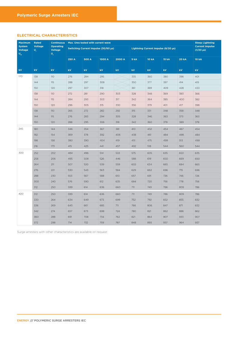
Maximum
System
Voltage
Um
kV
Rated
Voltage
Ur
kV
Continuous
Operating
Voltage
Uc
kV
Max. Ures tested with current wave Steep Lightning
Current Impulse
(1/20 µs)Switching Current Impulse (30/60 µs) Lightning Current Impulse (8/20 µs)
250 A
kV
500 A
kV
1000 A
kV
2000 A
kV
5 kA
kV
10 kA
kV
15 kA
kV
20 kA
kV
10 kA
kV
170 138 110 276 284 295 335 360 380 396 401
144 115 288 297 308 350 377 397 414 419
150 120 297 307 318 361 389 409 428 433
138 110 272 281 290 303 328 348 369 383 366
144 115 284 293 303 317 342 364 385 400 382
150 120 296 305 315 330 356 379 401 417 398
138 110 265 272 282 292 315 331 348 358 348
144 115 276 283 294 305 328 346 363 373 363
150 120 288 295 306 318 342 360 378 389 378
245 180 144 346 354 367 381 410 432 454 467 454
192 154 369 378 392 406 438 461 484 498 484
198 158 380 390 404 419 451 475 499 513 499
216 173 415 425 441 457 492 518 544 560 544
300 252 202 484 496 514 533 575 605 635 653 635
258 206 495 508 526 446 588 619 650 669 650
264 211 507 520 539 559 602 634 665 684 665
276 221 530 543 563 584 629 662 696 715 696
288 230 553 567 588 610 657 691 726 746 726
300 240 576 590 612 635 684 720 756 778 756
312 250 599 614 636 660 711 749 786 809 786
420 312 250 599 614 636 660 711 749 786 809 786
330 264 634 649 673 699 752 792 832 855 832
336 269 645 661 685 711 766 806 847 871 832
342 274 657 673 698 724 780 821 862 886 862
360 288 691 708 734 762 821 864 907 933 907
372 298 714 732 759 787 848 893 937 964 937
ELECTRICAL CHARACTERISTICS
Surge arresters with other characteristics are available on request
Polymeric Surge Arresters IEC
PAGE 9
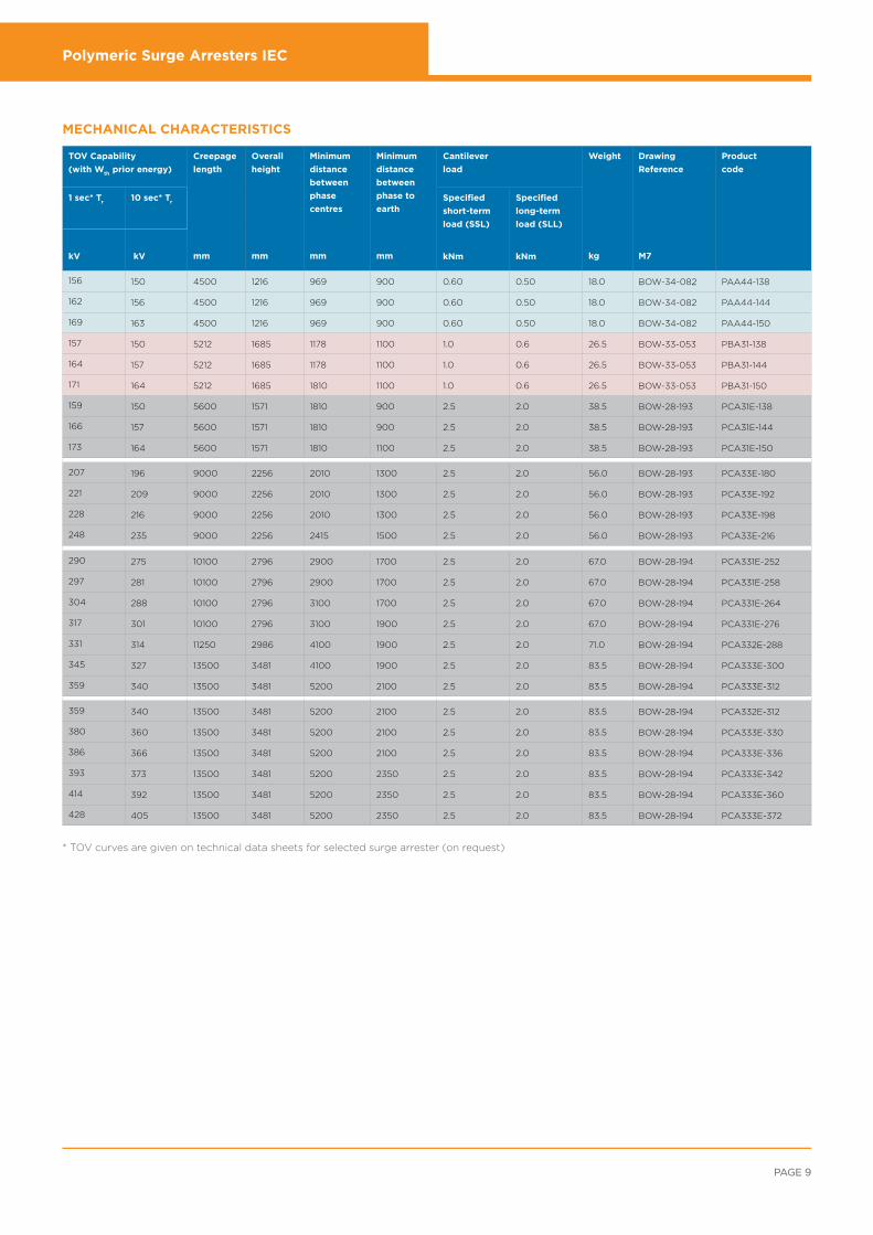
TOV Capability
(with Wth
prior energy)
Creepage
length
mm
Overall
height
mm
Minimum
distance
between
phase
centres
mm
Minimum
distance
between
phase to
earth
mm
Cantilever
load
Weight
kg
Drawing
Reference
M7
Product
code
1 sec* Tr
10 sec* Tr
Specified
short-term
load (SSL)
kNm
Specified
long-term
load (SLL)
kNmkV kV
156 150 4500 1216 969 900 0.60 0.50 18.0 BOW-34-082 PAA44-138
162 156 4500 1216 969 900 0.60 0.50 18.0 BOW-34-082 PAA44-144
169 163 4500 1216 969 900 0.60 0.50 18.0 BOW-34-082 PAA44-150
157 150 5212 1685 1178 1100 1.0 0.6 26.5 BOW-33-053 PBA31-138
164 157 5212 1685 1178 1100 1.0 0.6 26.5 BOW-33-053 PBA31-144
171 164 5212 1685 1810 1100 1.0 0.6 26.5 BOW-33-053 PBA31-150
159 150 5600 1571 1810 900 2.5 2.0 38.5 BOW-28-193 PCA31E-138
166 157 5600 1571 1810 900 2.5 2.0 38.5 BOW-28-193 PCA31E-144
173 164 5600 1571 1810 1100 2.5 2.0 38.5 BOW-28-193 PCA31E-150
207 196 9000 2256 2010 1300 2.5 2.0 56.0 BOW-28-193 PCA33E-180
221 209 9000 2256 2010 1300 2.5 2.0 56.0 BOW-28-193 PCA33E-192
228 216 9000 2256 2010 1300 2.5 2.0 56.0 BOW-28-193 PCA33E-198
248 235 9000 2256 2415 1500 2.5 2.0 56.0 BOW-28-193 PCA33E-216
290 275 10100 2796 2900 1700 2.5 2.0 67.0 BOW-28-194 PCA331E-252
297 281 10100 2796 2900 1700 2.5 2.0 67.0 BOW-28-194 PCA331E-258
304 288 10100 2796 3100 1700 2.5 2.0 67.0 BOW-28-194 PCA331E-264
317 301 10100 2796 3100 1900 2.5 2.0 67.0 BOW-28-194 PCA331E-276
331 314 11250 2986 4100 1900 2.5 2.0 71.0 BOW-28-194 PCA332E-288
345 327 13500 3481 4100 1900 2.5 2.0 83.5 BOW-28-194 PCA333E-300
359 340 13500 3481 5200 2100 2.5 2.0 83.5 BOW-28-194 PCA333E-312
359 340 13500 3481 5200 2100 2.5 2.0 83.5 BOW-28-194 PCA332E-312
380 360 13500 3481 5200 2100 2.5 2.0 83.5 BOW-28-194 PCA333E-330
386 366 13500 3481 5200 2100 2.5 2.0 83.5 BOW-28-194 PCA333E-336
393 373 13500 3481 5200 2350 2.5 2.0 83.5 BOW-28-194 PCA333E-342
414 392 13500 3481 5200 2350 2.5 2.0 83.5 BOW-28-194 PCA333E-360
428 405 13500 3481 5200 2350 2.5 2.0 83.5 BOW-28-194 PCA333E-372
MECHANICAL CHARACTERISTICS
* TOV curves are given on technical data sheets for selected surge arrester (on request)
Polymeric Surge Arresters IEC
ENERGY /// POLYMERIC SURGE ARRESTERS IEC
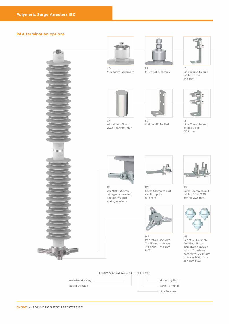
PAA termination options
L0M16 screw assembly
L1M16 stud assembly
L2Line Clamp to suit cables up to Ø16 mm
L214 Hole NEMA Pad
L5Line Clamp to suit cables up toØ35 mm
E12 x M10 x 20 mmhexagonal headed set screws and spring washers
E2 Earth Clamp to suit cables up to Ø16 mm
E5Earth Clamp to suit cables from Ø 16 mm to Ø35 mm
M7Pedestal Base with 3 x 15 mm slots on200 mm - 254 mm PCD
M8Set of 3 Ø89 x 76Polyfiber BaseInsulators suppliedwith M7 pedestalbase with 3 x 15 mm slots on 200 mm - 254 mm PCD
Example: PAA44 96 L0 E1 M7
Arrester Housing
Rated Voltage
Mounting Base
Earth Terminal
Line Terminal
L6Aluminium StemØ30 x 80 mm high
Polymeric Surge Arresters IEC
PAGE 11
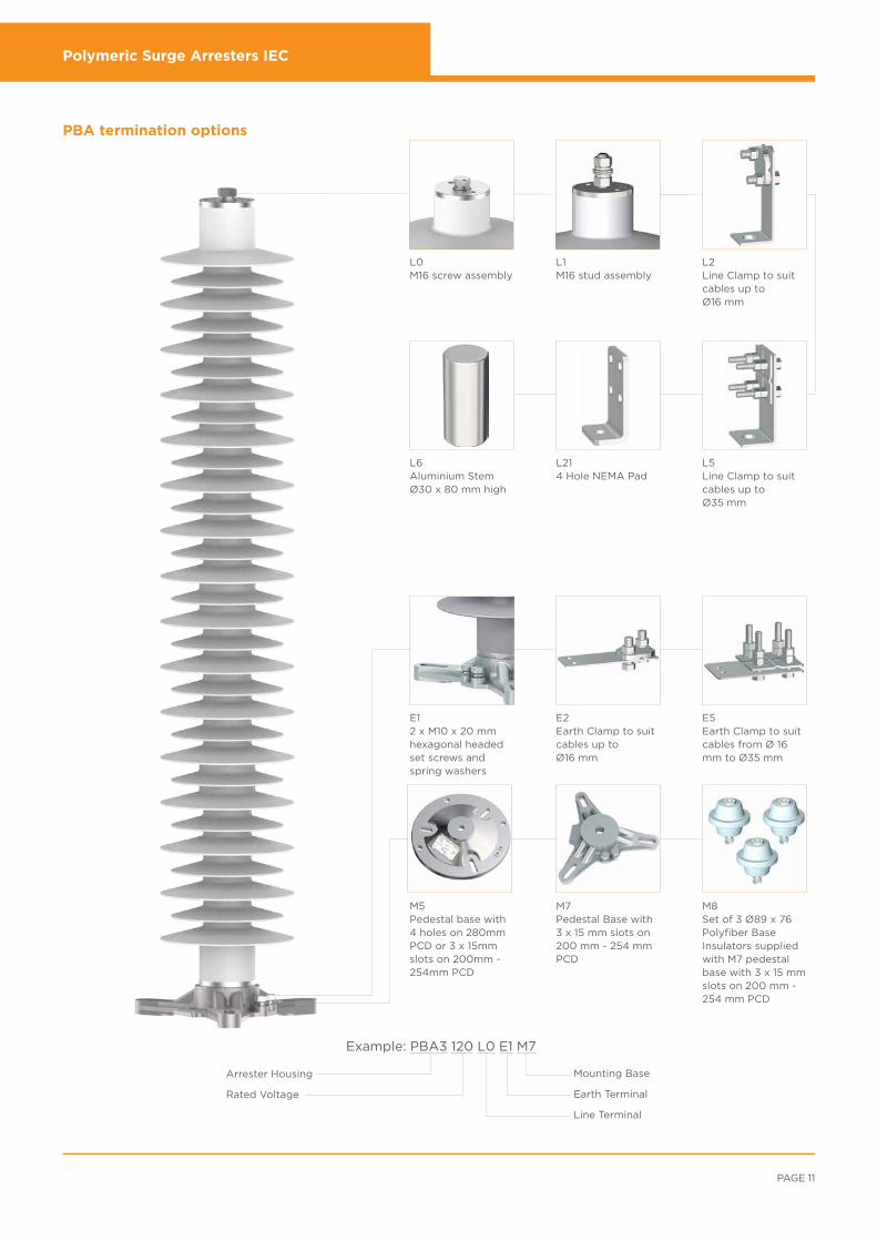
PBA termination options
L0M16 screw assembly
L1M16 stud assembly
L2Line Clamp to suit cables up to Ø16 mm
L214 Hole NEMA Pad
L5Line Clamp to suit cables up toØ35 mm
E12 x M10 x 20 mmhexagonal headed set screws and spring washers
E2 Earth Clamp to suit cables up to Ø16 mm
E5Earth Clamp to suit cables from Ø 16 mm to Ø35 mm
M7Pedestal Base with 3 x 15 mm slots on200 mm - 254 mm PCD
M8Set of 3 Ø89 x 76Polyfiber BaseInsulators suppliedwith M7 pedestalbase with 3 x 15 mm slots on 200 mm - 254 mm PCD
Example: PBA3 120 L0 E1 M7
Arrester Housing
Rated Voltage
Mounting Base
Earth Terminal
Line Terminal
L6Aluminium StemØ30 x 80 mm high
M5Pedestal base with 4 holes on 280mmPCD or 3 x 15mmslots on 200mm -254mm PCD
Polymeric Surge Arresters IEC
ENERGY /// POLYMERIC SURGE ARRESTERS IEC
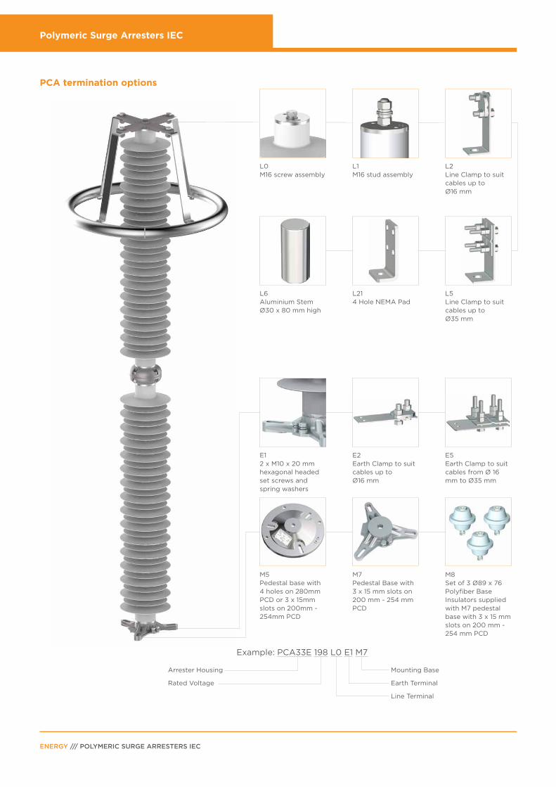
PCA termination options
L0M16 screw assembly
L1M16 stud assembly
L2Line Clamp to suit cables up to Ø16 mm
L214 Hole NEMA Pad
L5Line Clamp to suit cables up toØ35 mm
E12 x M10 x 20 mmhexagonal headed set screws and spring washers
E2 Earth Clamp to suit cables up to Ø16 mm
E5Earth Clamp to suit cables from Ø 16 mm to Ø35 mm
M7Pedestal Base with 3 x 15 mm slots on200 mm - 254 mm PCD
M8Set of 3 Ø89 x 76Polyfiber BaseInsulators suppliedwith M7 pedestalbase with 3 x 15 mm slots on 200 mm - 254 mm PCD
Example: PCA33E 198 L0 E1 M7
Arrester Housing
Rated Voltage
Mounting Base
Earth Terminal
Line Terminal
L6Aluminium StemØ30 x 80 mm high
M5Pedestal base with 4 holes on 280mmPCD or 3 x 15mmslots on 200mm -254mm PCD
Polymeric Surge Arresters IEC
PAGE 13
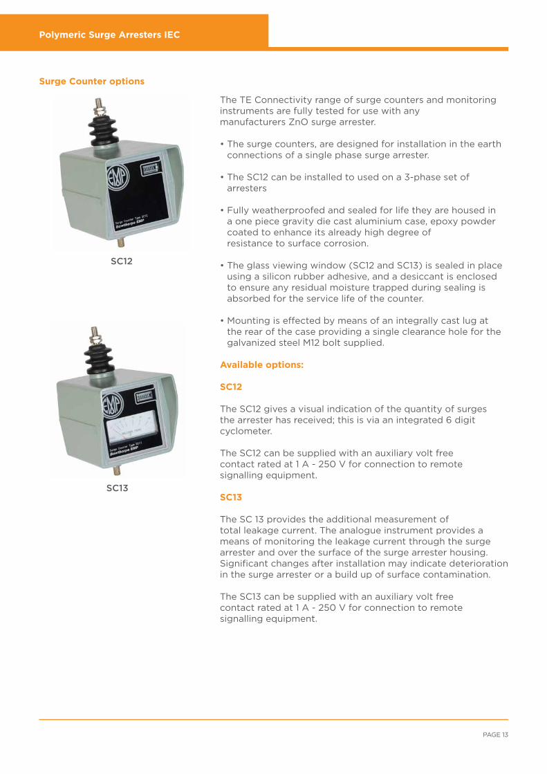
Surge Counter options
SC12
SC13
The TE Connectivity range of surge counters and monitoring instruments are fully tested for use with any manufacturers ZnO surge arrester.
• The surge counters, are designed for installation in the earth connections of a single phase surge arrester.
• The SC12 can be installed to used on a 3-phase set of
arresters
• Fully weatherproofed and sealed for life they are housed in a one piece gravity die cast aluminium case, epoxy powder coated to enhance its already high degree of resistance to surface corrosion.
• The glass viewing window (SC12 and SC13) is sealed in place
using a silicon rubber adhesive, and a desiccant is enclosed to ensure any residual moisture trapped during sealing is absorbed for the service life of the counter.
• Mounting is effected by means of an integrally cast lug at
the rear of the case providing a single clearance hole for the galvanized steel M12 bolt supplied.
Available options:
SC12
The SC12 gives a visual indication of the quantity of surges the arrester has received; this is via an integrated 6 digit cyclometer.
The SC12 can be supplied with an auxiliary volt free contact rated at 1 A - 250 V for connection to remote signalling equipment.
SC13
The SC 13 provides the additional measurement of total leakage current. The analogue instrument provides a means of monitoring the leakage current through the surge arrester and over the surface of the surge arrester housing. Significant changes after installation may indicate deterioration in the surge arrester or a build up of surface contamination.
The SC13 can be supplied with an auxiliary volt free contact rated at 1 A - 250 V for connection to remote signalling equipment.
Polymeric Surge Arresters IEC
ENERGY /// POLYMERIC SURGE ARRESTERS IEC
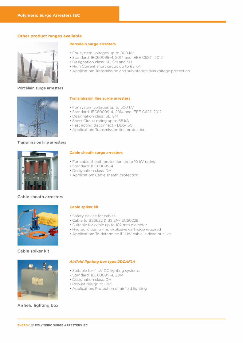
Other product ranges available
Porcelain surge arresters
• For system voltages up to 800 kV• Standard: IEC60099-4, 2014 and IEEE C62.11: 2012• Designation class: SL, SM and SH• High Current short circuit up to 65 kA• Application: Transmission and sub-station overvoltage protection
Transmission line surge arresters
• For system voltages up to 500 kV• Standard: IEC60099-4, 2014 and IEEE C62.11:2012• Designation class: SL, SM • Short Circuit rating up to 65 kA• Fast acting disconnect - DD5-130• Application: Transmission line protection
Cable sheath surge arresters
• For cable sheath protection up to 10 kV rating• Standard: IEC60099-4• Designation class: DH• Application: Cable sheath protection
Cable spiker kit
• Safety device for cables• Cable to BS6622 & BS EN/IEC60228• Suitable for cable up to 102 mm diameter• Hydraulic pump - no explosive cartridge required• Application: To determine if 11 kV cable is dead or alive
Airfield lighting box type 2DCAFL4
• Suitable for 4 kV DC lighting systems• Standard: IEC60099-4, 2014• Designation class: DH• Robust design to IP65• Application: Protection of airfield lighting
Porcelain surge arresters
Transmission line arresters
Cable sheath arresters
Cable spiker kit
Airfield lighting box

Polymeric Surge Arresters IEC
PAGE 15
Brighton High Power Laboratory
MARX impulse generator 1.65 MV 500 kV power transformer with PD testing
High energy surge arrester test system
HV varistor block ageing test system with AC and DC supply

te.com/energy
France: + 33 380 583 200
Germany: + 49 896 089 903
UK: + 44 8 708 707 500
Spain: + 34 916 630 400
Benelux: + 32 16 351 731
Denmark: + 45 43 480 424
Italy: + 39 333 2500 915
Poland and Baltics: + 48 224 576 753
Czech Republic: + 42 0 272 011 105
Sweden and Norway: + 46 850 725 000
Middle East: + 971 4 2 117 000
USA: + 1 800 327 6996
FOR MORE INFORMATION:
EMAIL: [email protected]
TE Technical Support Centers
TE Connectivity (NYSE: TEL) is a $12 billion global technology leader. Our connectivity and sensor solutions are essential in
today’s increasingly connected world. We collaborate with engineers to transform their concepts into creations – redefining
what’s possible using intelligent, efficient and high-performing TE products and solutions proven in harsh environments.
Our 72,000 people, including over 7,000 engineers, partner with customers in close to 150 countries across a wide range
of industries. We believe EVERY CONNECTION COUNTS – www.TE.com.
• Mining
• Nuclear power plants
• OEMs
• Overhead distribution
• Petrochemical plants
• Railways
• Street lighting
WHEREVER ELECTRICITY FLOWS, YOU’LL FIND TE ENERGY
• Substations
• Transmission lines
• Underground distribution
• Windfarms
• Solar
• Hydro-electric
te.com/energy© 2016 TE Connectivity Ltd. family of companies. All Rights Reserved. EPP-1955-7/16
Bowthorpe EMP, TE Connectivity and the TE connectivity (logo) are trademarks of the TE Connectivity Ltd. family of companies. Other logos, product and Company names mentioned herein may be trademarks of their respective owners. While TE has made every reasonable effort to ensure the accuracy of the information in this brochure, TE does not guarantee that it is error-free, nor does TE make any other representation, warranty or guarantee that the information is accurate, correct, reliable or current. TE reserves the right to make any adjustments to the information contained herein at any time without notice. TE expressly disclaims all implied warranties regarding the information contained herein, including, but not limited to, any implied warranties of merchantability or fitness for a particular purpose. The dimensions in this brochure are for reference purposes only and are subject to change without notice. Specifications are subject to change without notice. Consult TE for the latest dimensions and design specifications.
ENERGY /// POLYMERIC SURGE ARRESTERS IEC


![WELCOME []...Emp B = $2350 Emp C = $500 Emp C = $3500 Emp D = $1500 Lag Quarter Emp D = $500 Claim filed Emp D = $150 The claimant must have been paid sufficient …](https://img.pdfslide.us/doc/110x75/607bc797dd97122c8938e959/welcome-emp-b-2350-emp-c-500-emp-c-3500-emp-d-1500-lag-quarter.jpg)