Embed Size (px)
Citation preview
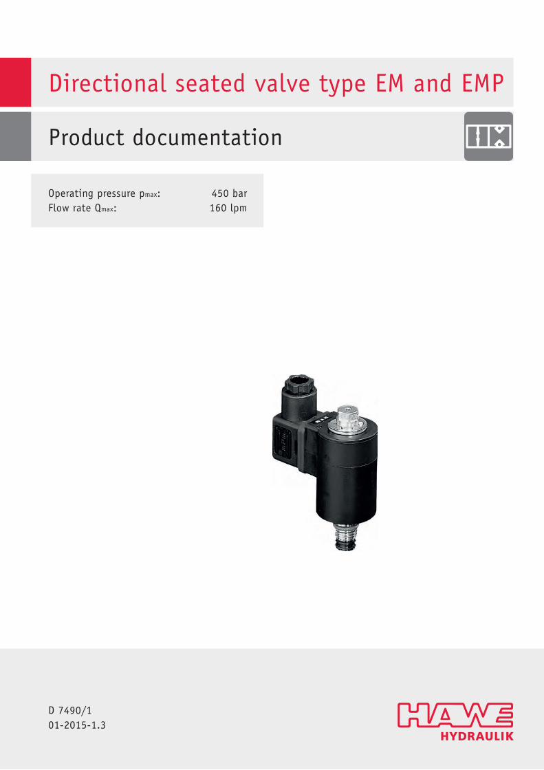
Directional seated valve type EM and EMP
Product documentation
D 7490/101-2015-1.3
Operating pressure pmax: 450 barFlow rate Qmax: 160 lpm
2/41 D 7490/1 - EM, EMP - 01-2015-1.3 © HAWE Hydraulik SE
© by HAWE Hydraulik SE.The reproduction and distribution of this document as well as the use and communication of its contents to others without explicitauthorisation is prohibited.Offenders will be held liable for the payment of damages.All rights reserved in the event of patent or utility model applications.Brand names, product names and trademarks are not specifically indicated. In particular with regard to registered and protected namesand trademarks, usage is subject to legal provisions.HAWE Hydraulik respects these legal provisions in all cases.Printing date / document generated on: 28.04.2017
© HAWE Hydraulik SE D 7490/1 - EM, EMP - 01-2015-1.3 3/41
Contents
1 Overview 2/2-way directional seated valves type EM and EMP............................................................................... 4
2 Available versions, main data............................................................................................................................. 52.1 directional seated valves, directional valve............................................................................................................. 52.2 Directional seated valve, soft-shift.........................................................................................................................72.3 Proportional directional seated valve, proportional throttle....................................................................................... 82.4 Single connection blocks.....................................................................................................................................112.4.1 Single connection blocks with and without drain valve........................................................................................... 112.4.2 Connection block with additional functions........................................................................................................... 132.5 Valve combinations.............................................................................................................................................162.5.1 Valve banks type BEM.........................................................................................................................................162.5.2 Valve bank type BEMD 21................................................................................................................................... 18
3 Parameters....................................................................................................................................................... 193.1 General............................................................................................................................................................. 193.2 Electrical data (type EM.. and EMP..).................................................................................................................... 23
4 Dimensions...................................................................................................................................................... 264.1 Valve and actuating solenoid............................................................................................................................... 264.2 Screw-in valve................................................................................................................................................... 284.3 Connection blocks.............................................................................................................................................. 314.4 Valve combination.............................................................................................................................................. 35
5 Assembly, operation and maintenance recommendations.....................................................................................365.1 Intended application.......................................................................................................................................... 365.2 Assembly information......................................................................................................................................... 375.2.1 Notes for initial operation...................................................................................................................................375.2.2 Creating the mounting hole................................................................................................................................. 375.3 Operating instructions.........................................................................................................................................385.4 Maintenance information..................................................................................................................................... 38
6 Other information.............................................................................................................................................396.1 Accessories, spare parts and separate components.................................................................................................. 396.1.1 Tapped plugs..................................................................................................................................................... 396.1.2 Sealing kits....................................................................................................................................................... 406.1.3 Additional components....................................................................................................................................... 40
4/41 D 7490/1 - EM, EMP - 01-2015-1.3 © HAWE Hydraulik SE
1 Overview 2/2-way directional seated valves type EM and EMP
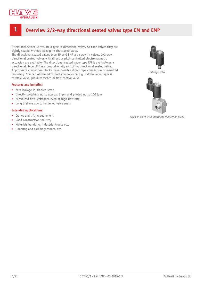
Directional seated valves are a type of directional valve. As cone valves they aretightly sealed without leakage in the closed state.The directional seated valves type EM and EMP are screw-in valves. 2/2-waydirectional seated valves with direct or pilot-controlled electromagneticactuation are available. The directional seated valve type EM is available as adirectional. Type EMP is a proportionally switching directional seated valve.Appropriate connection blocks make possible direct pipe connection or manifoldmounting. You can obtain additional components, e.g. a drain valve, bypassthrottle valve, pressure switch or ow control valve.
Features and benets:■ Zero leakage in blocked state■ Directly switching up to approx. 3 lpm and piloted up to 160 lpm■ Minimized ow resistance even at high ow rate■ Long lifetime due to hardened valve seats
Intended applications:■ Cranes and lifting equipment■ Road construction industry■ Materials handling, industrial trucks etc.■ Handling and assembly robots, etc.
Cartridge valve
Screw-in valve with individual connection block
© HAWE Hydraulik SE D 7490/1 - EM, EMP - 01-2015-1.3 5/41
2 Available versions, main data
2.1 directional seated valves, directional valve
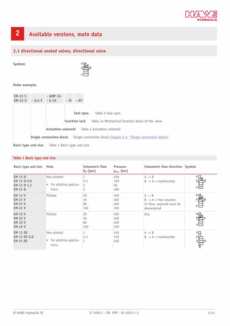
Symbol:
Order example:
EM 21 SEM 32 V - 3/4 F
- AMP 24- G 24 - M - AT
Seal spec. Table 5 Seal spec.
Function lock Table 1a Mechanical function block of the valve
Actuation solenoid Table 4 Actuation solenoid
Single connection block Single connection block Chapter 2.4, "Single connection blocks"
Basic type und size Table 1 Basic type und size
Table 1 Basic type and size
Basic type and size Note Volumetric owQP (lpm)
Pressurepmax (bar)
Volumetric ow direction Symbol
EM 11 DEM 11 D 0,8EM 11 D 1,2EM 21 D
Non-piloted
■ For piloting applica-tions
12.553
45015060400
A d BB d A = inadmissible
EM 11 VEM 21 VEM 31 VEM 41 V
Piloted 204080160
400400400350
A d BB d A = Free volumet-ric ow, solenoid must bedeenergized
EM 12 VEM 22 VEM 32 VEM 42 V
Piloted 204080160
400400400350
Any
EM 11 DSEM 11 DS 0,8EM 21 DS
Non-piloted
■ For piloting applica-tions
12.53
450150400
A d BB d A = inadmissible
6/41 D 7490/1 - EM, EMP - 01-2015-1.3 © HAWE Hydraulik SE
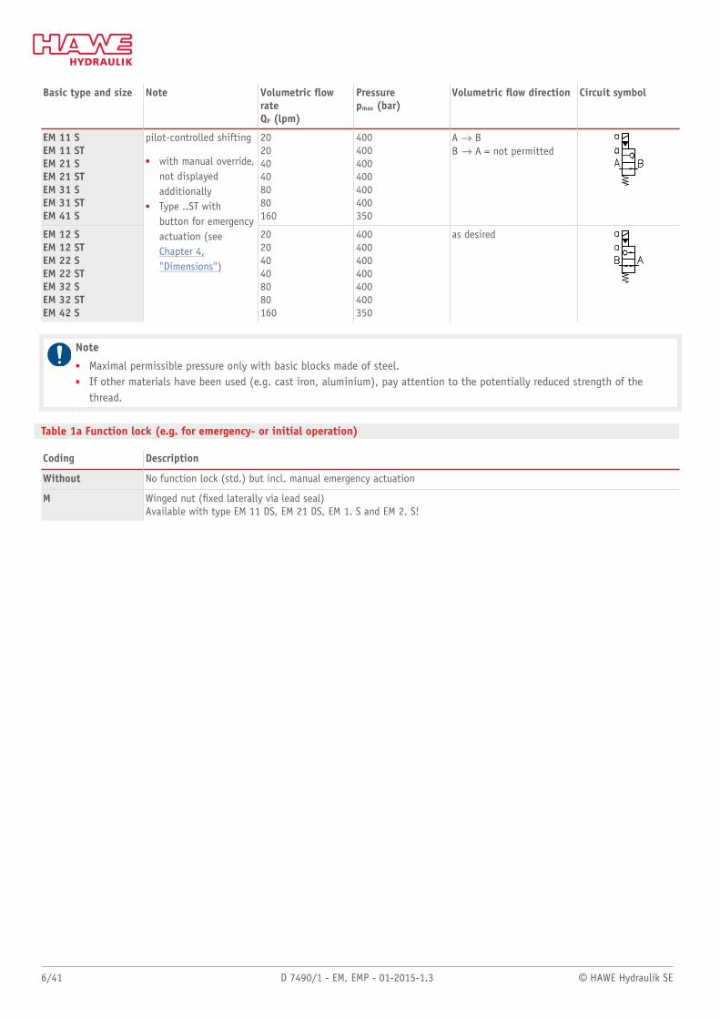
Basic type and size Note Volumetric owrateQP (lpm)
Pressurepmax (bar)
Volumetric ow direction Circuit symbol
EM 11 SEM 11 STEM 21 SEM 21 STEM 31 SEM 31 STEM 41 S
202040408080160
400400400400400400350
A d BB d A = not permitted
EM 12 SEM 12 STEM 22 SEM 22 STEM 32 SEM 32 STEM 42 S
pilot-controlled shifting
■ with manual override,not displayedadditionally
■ Type ..ST withbutton for emergencyactuation (seeChapter 4,"Dimensions")
202040408080160
400400400400400400350
as desired
Note■ Maximal permissible pressure only with basic blocks made of steel.■ If other materials have been used (e.g. cast iron, aluminium), pay attention to the potentially reduced strength of the
thread.
Table 1a Function lock (e.g. for emergency- or initial operation)
Coding Description
Without No function lock (std.) but incl. manual emergency actuation
M Winged nut (xed laterally via lead seal)Available with type EM 11 DS, EM 21 DS, EM 1. S and EM 2. S!
© HAWE Hydraulik SE D 7490/1 - EM, EMP - 01-2015-1.3 7/41
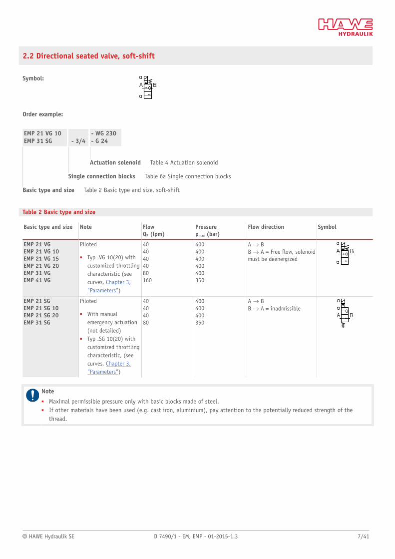
2.2 Directional seated valve, soft-shift
Symbol:
Order example:
EMP 21 VG 10EMP 31 SG - 3/4
- WG 230- G 24
Actuation solenoid Table 4 Actuation solenoid
Single connection blocks Table 6a Single connection blocks
Basic type and size Table 2 Basic type and size, soft-shift
Table 2 Basic type and size
Basic type and size Note FlowQP (lpm)
Pressurepmax (bar)
Flow direction Symbol
EMP 21 VGEMP 21 VG 10EMP 21 VG 15EMP 21 VG 20EMP 31 VGEMP 41 VG
Piloted
■ Typ .VG 10(20) withcustomized throttlingcharacteristic (seecurves, Chapter 3,"Parameters")
4040404080160
400400400400400350
A d BB d A = Free ow, solenoidmust be deenergized
EMP 21 SGEMP 21 SG 10EMP 21 SG 20EMP 31 SG
Piloted
■ With manualemergency actuation(not detailed)
■ Typ .SG 10(20) withcustomized throttlingcharacteristic, (seecurves, Chapter 3,"Parameters")
40404080
400400400350
A d BB d A = inadmissible
Note■ Maximal permissible pressure only with basic blocks made of steel.■ If other materials have been used (e.g. cast iron, aluminium), pay attention to the potentially reduced strength of the
thread.
8/41 D 7490/1 - EM, EMP - 01-2015-1.3 © HAWE Hydraulik SE
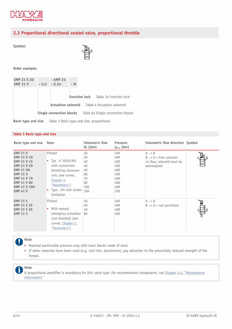
2.3 Proportional directional seated valve, proportional throttle
Symbol:
Order example:
EMP 21 S 20EMP 31 V - 1/4
- AMP 24- G 24 - M
Function lock Table 1a Function lock
Actuation solenoid Table 4 Actuation solenoid
Single connection blocks Table 6a Single connection blocks
Basic type and size Table 3 Basic type and size, proportional
Table 3 Basic type and size
Basic type and size Note Volumetric owQP (lpm)
Pressurepmax (bar)
Volumetric ow direction Symbol
EMP 21 VEMP 21 V 10EMP 21 V 15EMP 21 V 20EMP 21 VHEMP 31 VEMP 31 V 70EMP 31 V 80EMP 31 V 100EMP 41 V
Piloted
■ Typ ..V 10(20,80)with customizedthrottling character-istic (see curves,Chapter 3,"Parameters")
■ Type ..VH with strokelimitation
4040404040807080100160
400400400400400400400400400350
A d BB d A = Free volumet-ric ow, solenoid must bedeenergized
EMP 21 SEMP 21 S 10EMP 21 S 20EMP 31 S
Piloted
■ With manualemergency actuation(not detailed) (seecurves, Chapter 3,"Parameters")
40404080
400400400400
A d BB d A = not permitted
Note■ Maximal permissible pressure only with basic blocks made of steel.■ If other materials have been used (e.g. cast iron, aluminium), pay attention to the potentially reduced strength of the
thread.
NoteA proportional amplifier is mandatory for this valve type. For recommended components, see Chapter 5.4, "Maintenanceinformation"
© HAWE Hydraulik SE D 7490/1 - EM, EMP - 01-2015-1.3 9/41
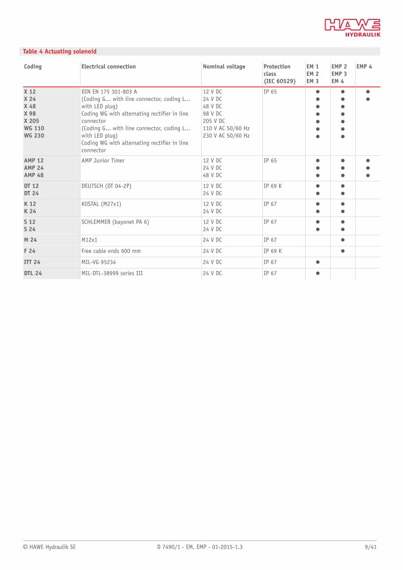
Table 4 Actuating solenoid
Coding Electrical connection Nominal voltage Protectionclass(IEC 60529)
EM 1EM 2EM 3
EMP 2EMP 3EM 4
EMP 4
X 12X 24X 48X 98X 205WG 110WG 230
DIN EN 175 301-803 A(Coding G... with line connector, coding L...with LED plug)Coding WG with alternating rectifier in lineconnector(Coding G... with line connector, coding L...with LED plug)Coding WG with alternating rectifier in lineconnector
12 V DC24 V DC48 V DC98 V DC205 V DC110 V AC 50/60 Hz230 V AC 50/60 Hz
IP 65 ooooooo
ooooooo
oo
AMP 12AMP 24AMP 48
AMP Junior Timer 12 V DC24 V DC48 V DC
IP 65 ooo
ooo
ooo
DT 12DT 24
DEUTSCH (DT 04-2P) 12 V DC24 V DC
IP 69 K oo
oo
K 12K 24
KOSTAL (M27x1) 12 V DC24 V DC
IP 67 oo
oo
S 12S 24
SCHLEMMER (bayonet PA 6) 12 V DC24 V DC
IP 67 oo
oo
M 24 M12x1 24 V DC IP 67 o
F 24 Free cable ends 600 mm 24 V DC IP 69 K o
ITT 24 MIL-VG 95234 24 V DC IP 67 o
DTL 24 MIL-DTL-38999 series III 24 V DC IP 67 o
10/41 D 7490/1 - EM, EMP - 01-2015-1.3 © HAWE Hydraulik SE
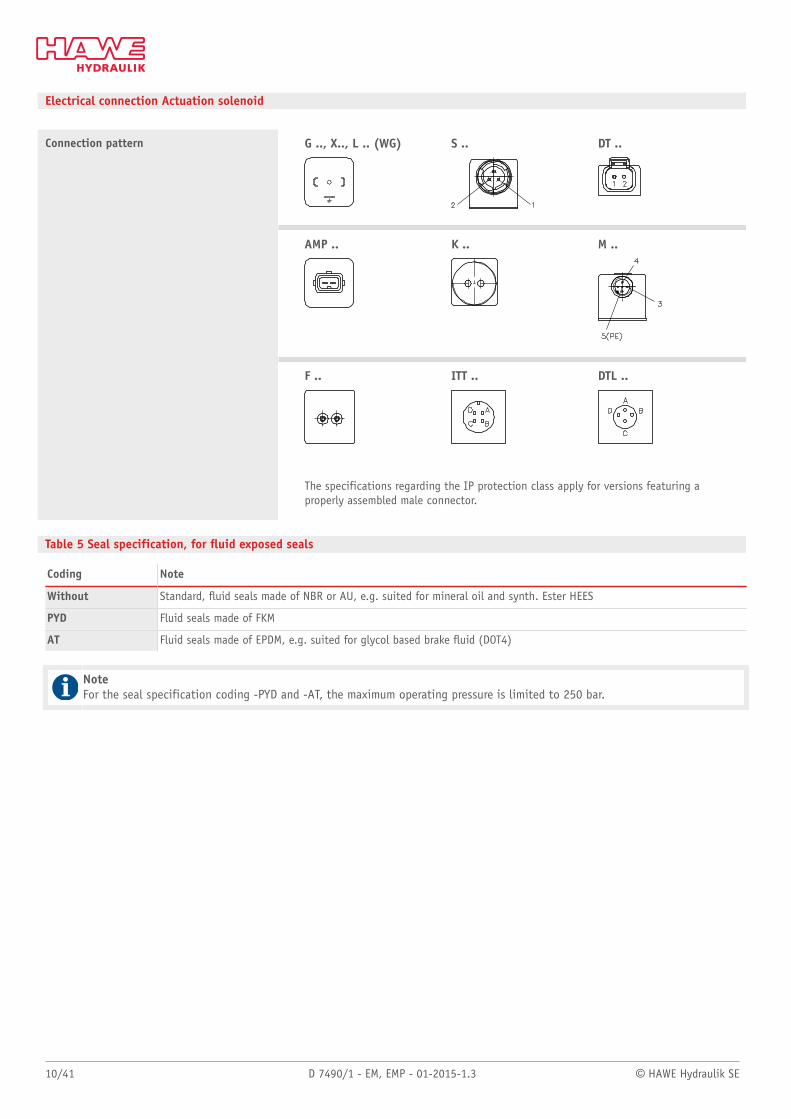
Electrical connection Actuation solenoid
G .., X.., L .. (WG) S .. DT ..
AMP .. K .. M ..
Connection pattern
F .. ITT .. DTL ..
The specifications regarding the IP protection class apply for versions featuring aproperly assembled male connector.
Table 5 Seal specification, for uid exposed seals
Coding Note
Without Standard, uid seals made of NBR or AU, e.g. suited for mineral oil and synth. Ester HEES
PYD Fluid seals made of FKM
AT Fluid seals made of EPDM, e.g. suited for glycol based brake uid (DOT4)
NoteFor the seal specification coding -PYD and -AT, the maximum operating pressure is limited to 250 bar.
© HAWE Hydraulik SE D 7490/1 - EM, EMP - 01-2015-1.3 11/41
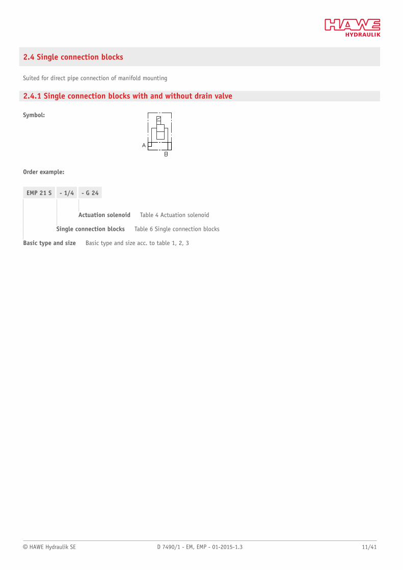
2.4 Single connection blocks
Suited for direct pipe connection of manifold mounting
2.4.1 Single connection blocks with and without drain valve
Symbol:
Order example:
EMP 21 S - 1/4 - G 24
Actuation solenoid Table 4 Actuation solenoid
Single connection blocks Table 6 Single connection blocks
Basic type and size Basic type and size acc. to table 1, 2, 3
12/41 D 7490/1 - EM, EMP - 01-2015-1.3 © HAWE Hydraulik SE
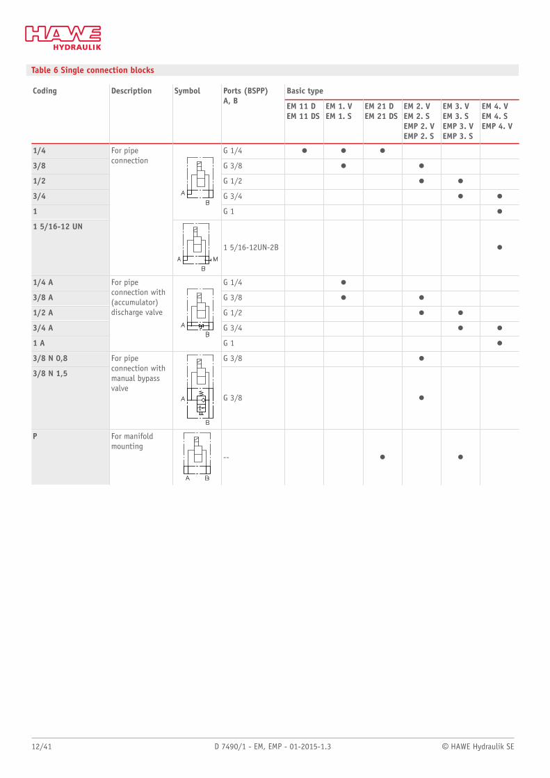
Table 6 Single connection blocks
Basic typeCoding Description Symbol Ports (BSPP)A, B
EM 11 DEM 11 DS
EM 1. VEM 1. S
EM 21 DEM 21 DS
EM 2. VEM 2. SEMP 2. VEMP 2. S
EM 3. VEM 3. SEMP 3. VEMP 3. S
EM 4. VEM 4. SEMP 4. V
1/4 G 1/4 o o o
3/8 G 3/8 o o
1/2 G 1/2 o o
3/4 G 3/4 o o
1 G 1 o
1 5/16-12 UN
For pipeconnection
1 5/16-12UN-2B o
1/4 A G 1/4 o
3/8 A G 3/8 o o
1/2 A G 1/2 o o
3/4 A G 3/4 o o
1 A
For pipeconnection with(accumulator)discharge valve
G 1 o
3/8 N 0,8 G 3/8 o
3/8 N 1,5
For pipeconnection withmanual bypassvalve
G 3/8 o
P For manifoldmounting
-- o o
© HAWE Hydraulik SE D 7490/1 - EM, EMP - 01-2015-1.3 13/41
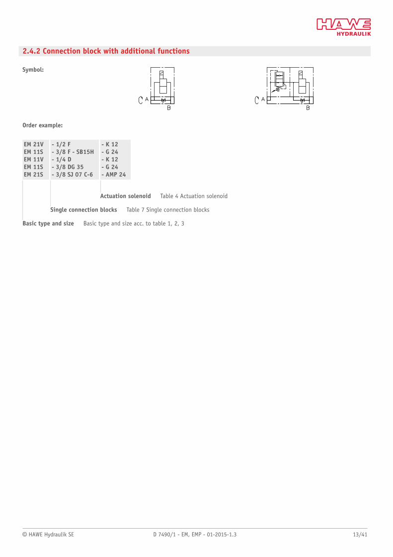
2.4.2 Connection block with additional functions
Symbol:
Order example:
EM 21VEM 11SEM 11VEM 11SEM 21S
- 1/2 F- 3/8 F - SB15H- 1/4 D- 3/8 DG 35- 3/8 SJ 07 C-6
- K 12- G 24- K 12- G 24- AMP 24
Actuation solenoid Table 4 Actuation solenoid
Single connection blocks Table 7 Single connection blocks
Basic type and size Basic type and size acc. to table 1, 2, 3
14/41 D 7490/1 - EM, EMP - 01-2015-1.3 © HAWE Hydraulik SE
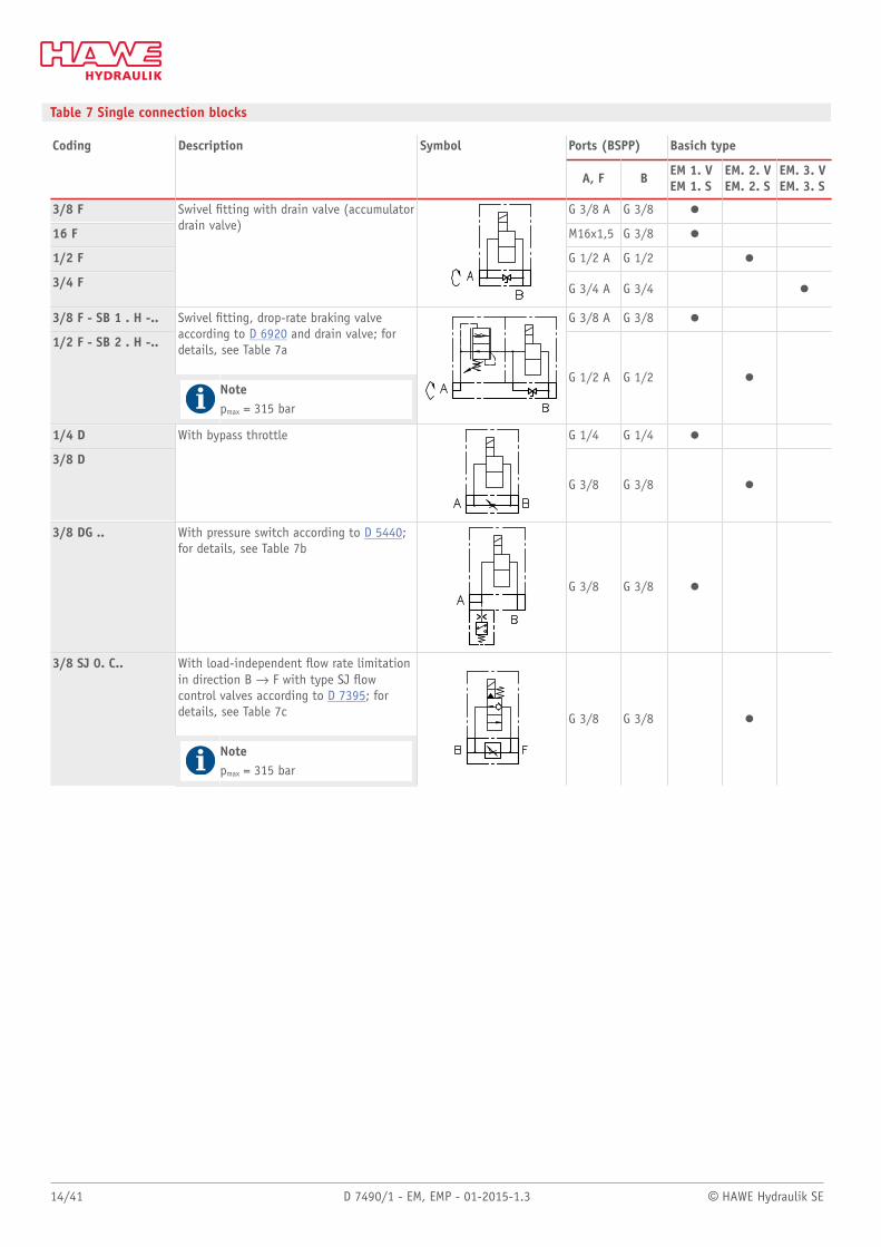
Table 7 Single connection blocks
Ports (BSPP) Basich typeCoding Description Symbol
A, F B EM 1. VEM 1. S
EM. 2. VEM. 2. S
EM. 3. VEM. 3. S
3/8 F G 3/8 A G 3/8 o
16 F M16x1,5 G 3/8 o
1/2 F G 1/2 A G 1/2 o
3/4 F
Swivel tting with drain valve (accumulatordrain valve)
G 3/4 A G 3/4 o
3/8 F - SB 1 . H -.. G 3/8 A G 3/8 o
1/2 F - SB 2 . H -..
Swivel tting, drop-rate braking valveaccording to D 6920 and drain valve; fordetails, see Table 7a
Notepmax = 315 bar
G 1/2 A G 1/2 o
1/4 D G 1/4 G 1/4 o
3/8 D
With bypass throttle
G 3/8 G 3/8 o
3/8 DG .. With pressure switch according to D 5440;for details, see Table 7b
G 3/8 G 3/8 o
3/8 SJ 0. C.. With load-independent ow rate limitationin direction B d F with type SJ owcontrol valves according to D 7395; fordetails, see Table 7c
Notepmax = 315 bar
G 3/8 G 3/8 o
© HAWE Hydraulik SE D 7490/1 - EM, EMP - 01-2015-1.3 15/41
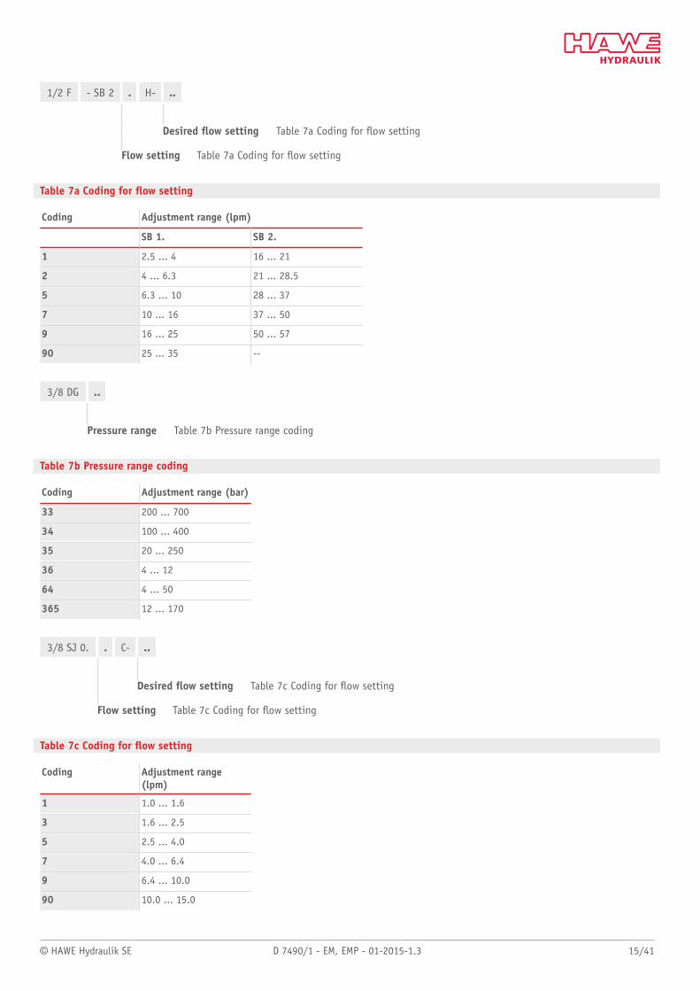
1/2 F - SB 2 . H- ..
Desired ow setting Table 7a Coding for ow setting
Flow setting Table 7a Coding for ow setting
Table 7a Coding for ow setting
Coding Adjustment range (lpm)
SB 1. SB 2.
1 2.5 ... 4 16 ... 21
2 4 ... 6.3 21 ... 28.5
5 6.3 ... 10 28 ... 37
7 10 ... 16 37 ... 50
9 16 ... 25 50 ... 57
90 25 ... 35 --
3/8 DG ..
Pressure range Table 7b Pressure range coding
Table 7b Pressure range coding
Coding Adjustment range (bar)
33 200 ... 700
34 100 ... 400
35 20 ... 250
36 4 ... 12
64 4 ... 50
365 12 ... 170
3/8 SJ 0. . C- ..
Desired ow setting Table 7c Coding for ow setting
Flow setting Table 7c Coding for ow setting
Table 7c Coding for ow setting
Coding Adjustment range(lpm)
1 1.0 ... 1.6
3 1.6 ... 2.5
5 2.5 ... 4.0
7 4.0 ... 6.4
9 6.4 ... 10.0
90 10.0 ... 15.0
16/41 D 7490/1 - EM, EMP - 01-2015-1.3 © HAWE Hydraulik SE
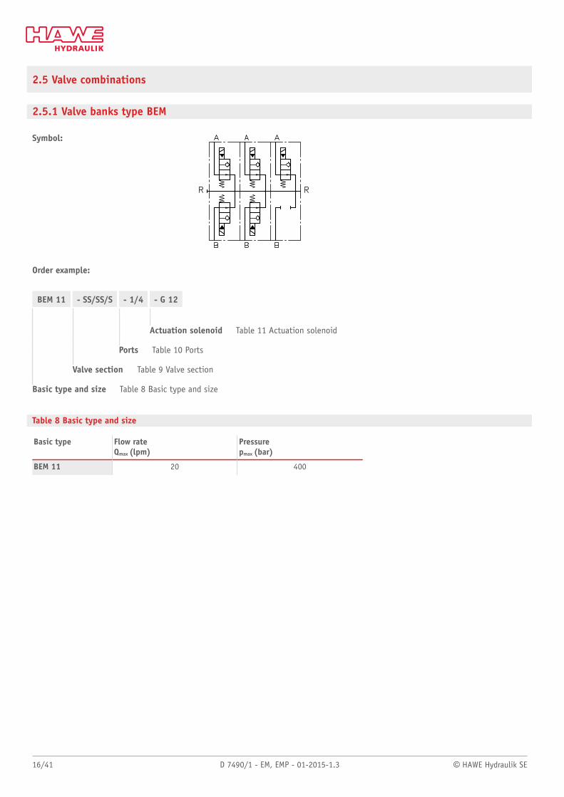
2.5 Valve combinations
2.5.1 Valve banks type BEM
Symbol:
Order example:
BEM 11 - SS/SS/S - 1/4 - G 12
Actuation solenoid Table 11 Actuation solenoid
Ports Table 10 Ports
Valve section Table 9 Valve section
Basic type and size Table 8 Basic type and size
Table 8 Basic type and size
Basic type Flow rateQmax (lpm)
Pressurepmax (bar)
BEM 11 20 400
© HAWE Hydraulik SE D 7490/1 - EM, EMP - 01-2015-1.3 17/41
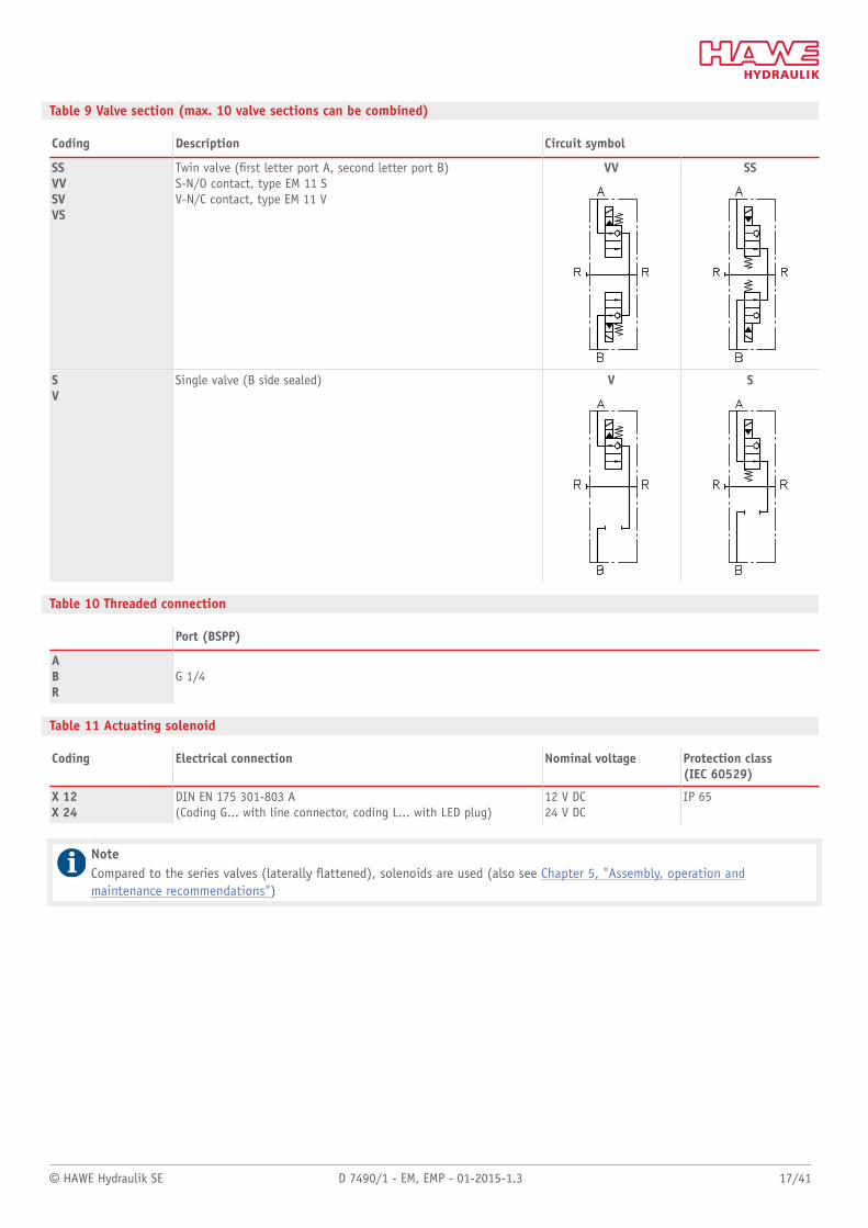
Table 9 Valve section (max. 10 valve sections can be combined)
Coding Description Circuit symbol
SSVVSVVS
Twin valve (rst letter port A, second letter port B)S-N/O contact, type EM 11 SV-N/C contact, type EM 11 V
VV SS
SV
Single valve (B side sealed) V S
Table 10 Threaded connection
Port (BSPP)
ABR
G 1/4
Table 11 Actuating solenoid
Coding Electrical connection Nominal voltage Protection class(IEC 60529)
X 12X 24
DIN EN 175 301-803 A(Coding G... with line connector, coding L... with LED plug)
12 V DC24 V DC
IP 65
NoteCompared to the series valves (laterally attened), solenoids are used (also see Chapter 5, "Assembly, operation andmaintenance recommendations")
18/41 D 7490/1 - EM, EMP - 01-2015-1.3 © HAWE Hydraulik SE
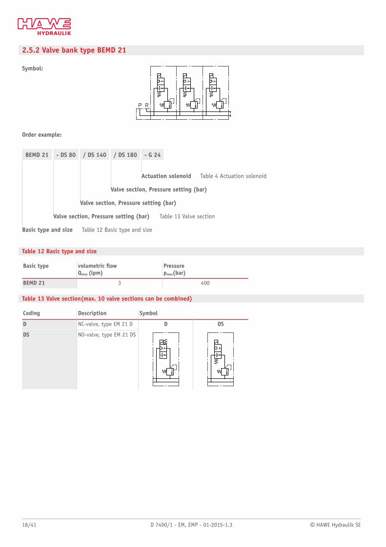
2.5.2 Valve bank type BEMD 21
Symbol:
Order example:
BEMD 21 - DS 80 / DS 140 / DS 180 - G 24
Actuation solenoid Table 4 Actuation solenoid
Valve section, Pressure setting (bar)
Valve section, Pressure setting (bar)
Valve section, Pressure setting (bar) Table 13 Valve section
Basic type and size Table 12 Basic type and size
Table 12 Basic type and size
Basic type volumetric owQmax (lpm)
Pressurepmax(bar)
BEMD 21 3 400
Table 13 Valve section(max. 10 valve sections can be combined)
Coding Description Symbol
D NC-valve, type EM 21 D
DS NO-valve, type EM 21 DS
D DS
© HAWE Hydraulik SE D 7490/1 - EM, EMP - 01-2015-1.3 19/41
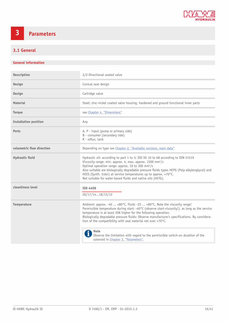
3 Parameters
3.1 General
General information
Description 2/2-Directional seated valve
Design Conical seat design
Design Cartridge valve
Material Steel; zinc-nickel coated valve housing, hardened and ground functional inner parts
Torque see Chapter 4, "Dimensions"
Installation position Any
Ports A, P - input (pump or primary side)B - consumer (secondary side)R - reux, tank
volumetric ow direction Depending on type see Chapter 2, "Available versions, main data"
Hydraulic uid Hydraulic oil: according to part 1 to 3; ISO VG 10 to 68 according to DIN 51519Viscosity range: min. approx. 4, max. approx. 1500 mm2/sOptimal operation range: approx. 10 to 300 mm2/sAlso suitable are biologically degradable pressure uids types HEPG (Poly-alkylenglycol) andHEES (Synth. Ester) at service temperatures up to approx. +70°C.Not suitable for water-based uids and native oils (HETG).
cleanliness level ISO 4406
20/17/14...18/15/12
Temperature Ambient: approx. -40 ... +80°C, Fluid: -25 ... +80°C, Note the viscosity range!Permissible temperature during start: -40°C (observe start-viscosity!), as long as the servicetemperature is at least 20K higher for the following operation.Biologically degradable pressure uids: Observe manufacturer's specifications. By considera-tion of the compatibility with seal material not over +70°C.
NoteObserve the limitation with regard to the permissible switch-on duration of thesolenoid in Chapter 3, "Parameters".
20/41 D 7490/1 - EM, EMP - 01-2015-1.3 © HAWE Hydraulik SE
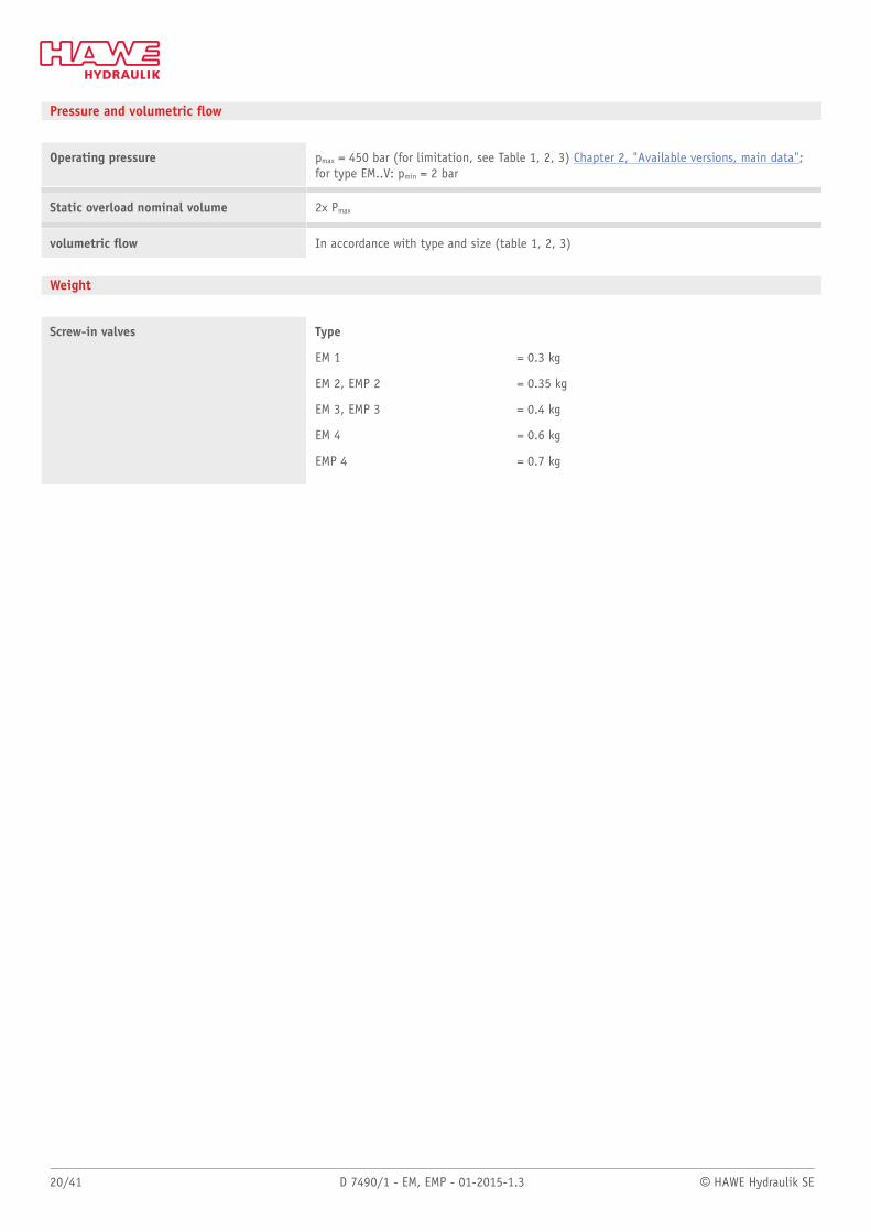
Pressure and volumetric ow
Operating pressure pmax = 450 bar (for limitation, see Table 1, 2, 3) Chapter 2, "Available versions, main data";for type EM..V: pmin = 2 bar
Static overload nominal volume 2x Pmax
volumetric ow In accordance with type and size (table 1, 2, 3)
Weight
Screw-in valves Type
EM 1 = 0.3 kg
EM 2, EMP 2 = 0.35 kg
EM 3, EMP 3 = 0.4 kg
EM 4 = 0.6 kg
EMP 4 = 0.7 kg
© HAWE Hydraulik SE D 7490/1 - EM, EMP - 01-2015-1.3 21/41
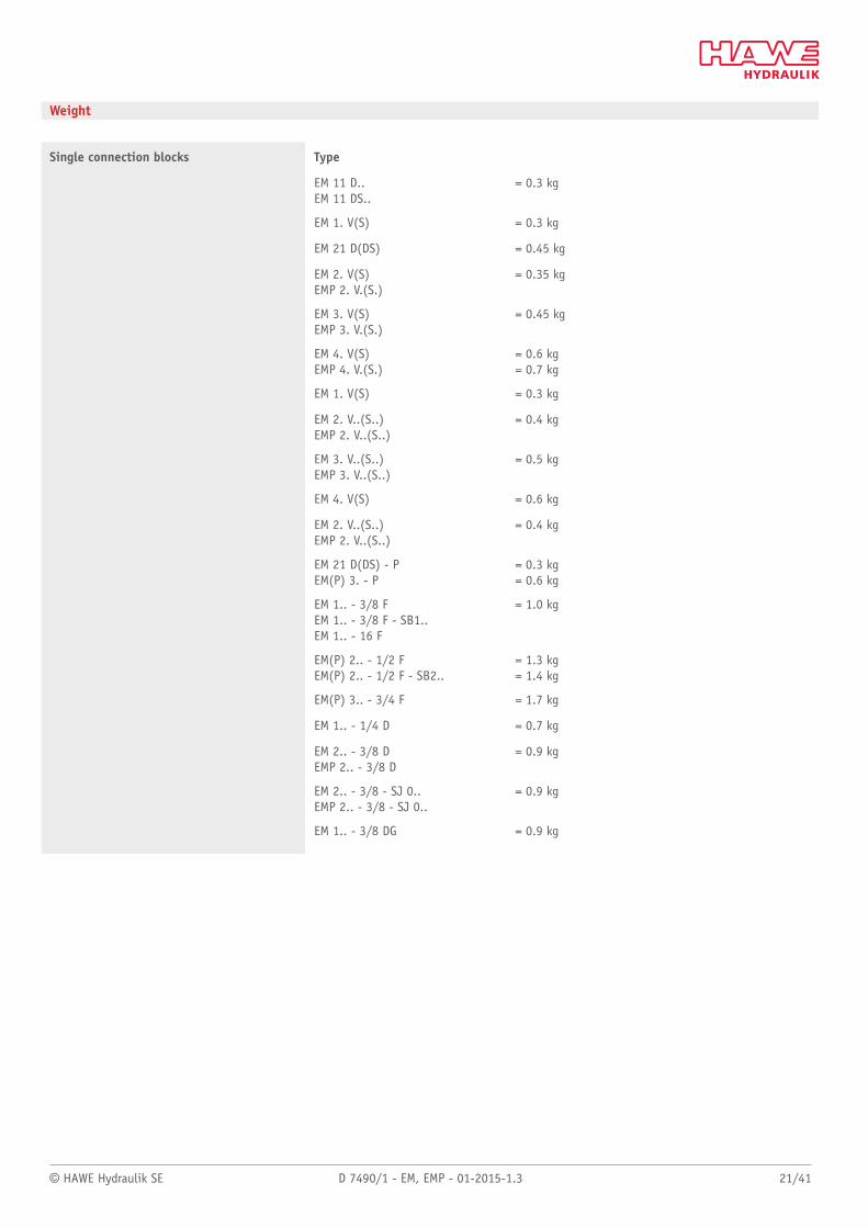
Weight
Single connection blocks Type
EM 11 D..EM 11 DS..
= 0.3 kg
EM 1. V(S) = 0.3 kg
EM 21 D(DS) = 0.45 kg
EM 2. V(S)EMP 2. V.(S.)
= 0.35 kg
EM 3. V(S)EMP 3. V.(S.)
= 0.45 kg
EM 4. V(S)EMP 4. V.(S.)
= 0.6 kg= 0.7 kg
EM 1. V(S) = 0.3 kg
EM 2. V..(S..)EMP 2. V..(S..)
= 0.4 kg
EM 3. V..(S..)EMP 3. V..(S..)
= 0.5 kg
EM 4. V(S) = 0.6 kg
EM 2. V..(S..)EMP 2. V..(S..)
= 0.4 kg
EM 21 D(DS) - PEM(P) 3. - P
= 0.3 kg= 0.6 kg
EM 1.. - 3/8 FEM 1.. - 3/8 F - SB1..EM 1.. - 16 F
= 1.0 kg
EM(P) 2.. - 1/2 FEM(P) 2.. - 1/2 F - SB2..
= 1.3 kg= 1.4 kg
EM(P) 3.. - 3/4 F = 1.7 kg
EM 1.. - 1/4 D = 0.7 kg
EM 2.. - 3/8 DEMP 2.. - 3/8 D
= 0.9 kg
EM 2.. - 3/8 - SJ 0..EMP 2.. - 3/8 - SJ 0..
= 0.9 kg
EM 1.. - 3/8 DG = 0.9 kg
22/41 D 7490/1 - EM, EMP - 01-2015-1.3 © HAWE Hydraulik SE
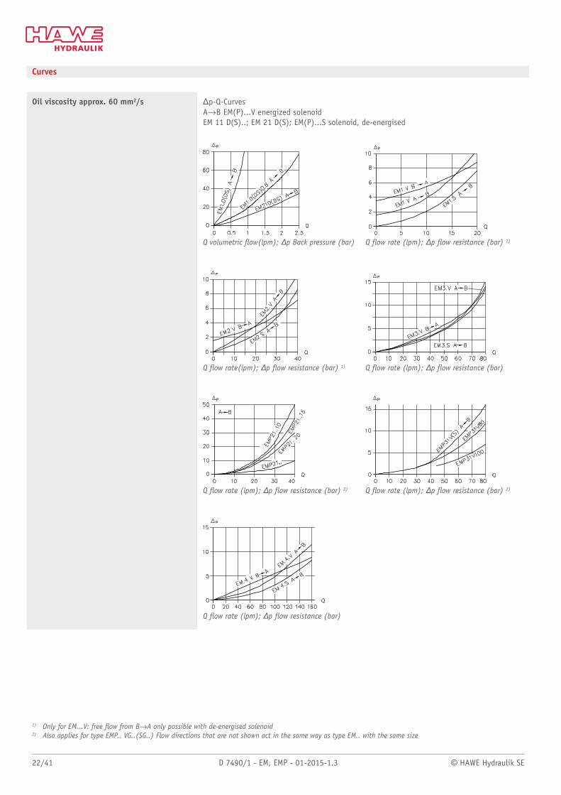
Curves
Oil viscosity approx. 60 mm2/s Δp-Q-CurvesAdB EM(P)...V energized solenoidEM 11 D(S)..; EM 21 D(S); EM(P)...S solenoid, de-energised
Q volumetric ow(lpm); Δp Back pressure (bar) Q ow rate (lpm); Δp ow resistance (bar) 1)
Q ow rate(lpm); Δp ow resistance (bar) 1) Q ow rate (lpm); Δp ow resistance (bar)
Q ow rate (lpm); Δp ow resistance (bar) 2) Q ow rate (lpm); Δp ow resistance (bar) 2)
Q ow rate (lpm); Δp ow resistance (bar)
1) Only for EM...V: free ow from BdA only possible with de-energised solenoid2) Also applies for type EMP.. VG..(SG..) Flow directions that are not shown act in the same way as type EM.. with the same size
© HAWE Hydraulik SE D 7490/1 - EM, EMP - 01-2015-1.3 23/41
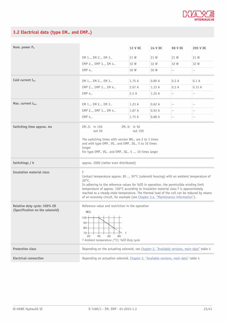
3.2 Electrical data (type EM.. and EMP..)
Nom. power PN 12 V DC 24 V DC 98 V DC 205 V DC
EM 1.., EM 2.., EM 3.. 21 W 21 W 21 W 21 W
EMP 2.., EMP 3.., EM 4.. 32 W 32 W 32 W 32 W
EMP 4.. 30 W 30 W -- --
Cold current I20 EM 1.., EM 2.., EM 3.. 1.75 A 0.89 A 0.2 A 0.1 A
EMP 2.., EMP 3.., EM 4.. 2.67 A 1.33 A 0.3 A 0.15 A
EMP 4.. 2.5 A 1.25 A -- --
Max. current lIim. EM 1.., EM 2.., EM 3.. 1.23 A 0.62 A -- --
EMP 2.., EMP 3.., EM 4.. 1.87 A 0.93 A -- --
EMP 4.. 1.75 A 0.88 A -- --
Switching time approx. ms EM..S: in 150out 50
EM..V: in 50out 150
The switching times with version WG.. are 2 to 3 timesand with type EMP.. VG.. and EMP.. SG.. 5 to 10 timeslongerFor type EMP.. VG.. and EMP.. SG.. 5 ... 10 times larger
Switchings / h approx. 2000 (rather even distributed)
Insulation material class FContact temperature approx. 85 ... 95°C (solenoid housing) with an ambient temperature of20°C.In adhering to the reference values for %ED in operation, the permissible winding limittemperature of approx. 150°C according to insulation material class F is approximatelyreached as a steady-state temperature. The thermal load of the coil can be reduced by meansof an economy circuit, for example (see Chapter 5.4, "Maintenance information").
Relative duty cycle: 100% ED(Specification on the solenoid)
Reference value and restriction in the operation
T Ambient temperature (°C); %ED Duty cycle
Protection class Depending on the actuating solenoid, see Chapter 2, "Available versions, main data" table 4
Electrical connection Depending on actuation solenoid, Chapter 2, "Available versions, main data" table 4
24/41 D 7490/1 - EM, EMP - 01-2015-1.3 © HAWE Hydraulik SE
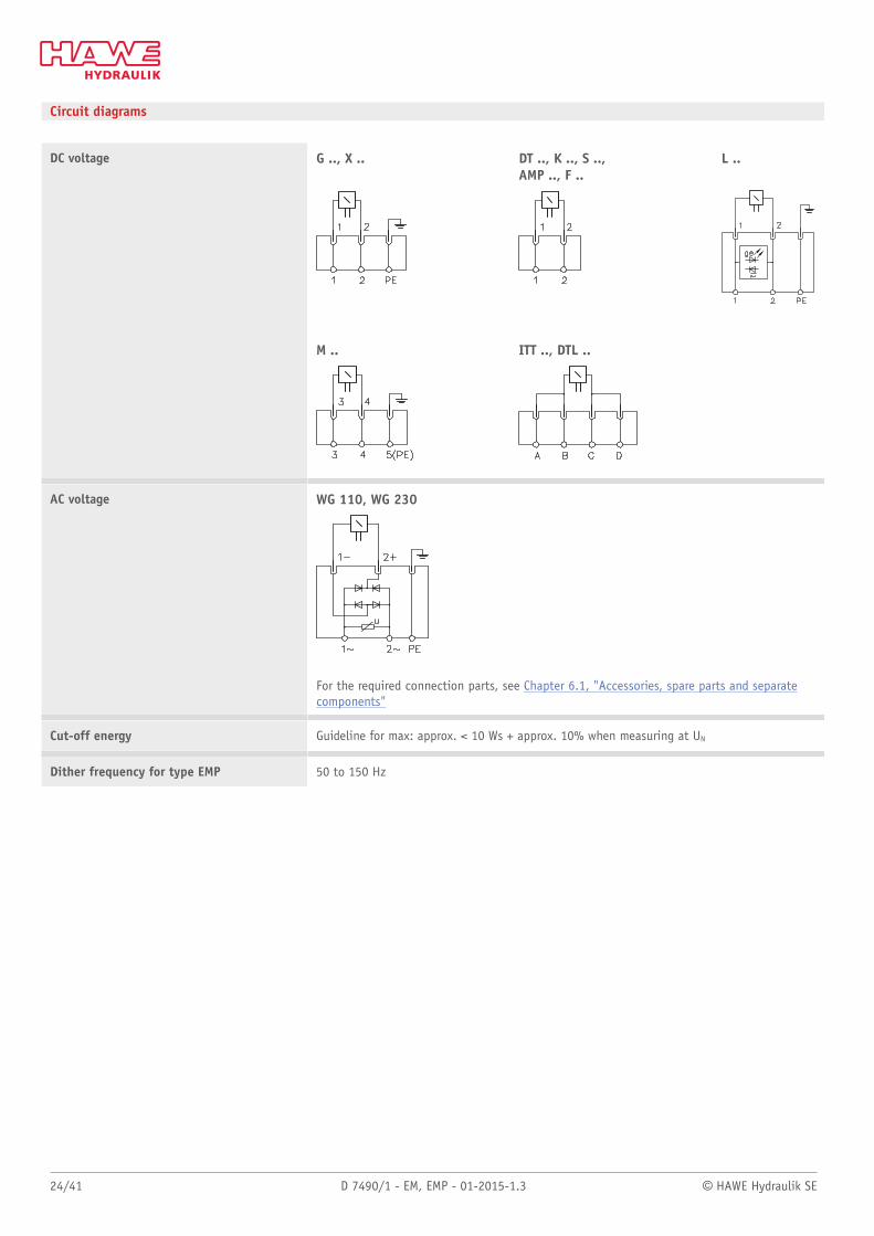
Circuit diagrams
DC voltage G .., X .. DT .., K .., S ..,AMP .., F ..
L ..
M .. ITT .., DTL ..
AC voltage WG 110, WG 230
For the required connection parts, see Chapter 6.1, "Accessories, spare parts and separatecomponents"
Cut-off energy Guideline for max: approx. < 10 Ws + approx. 10% when measuring at UN
Dither frequency for type EMP 50 to 150 Hz
© HAWE Hydraulik SE D 7490/1 - EM, EMP - 01-2015-1.3 25/41
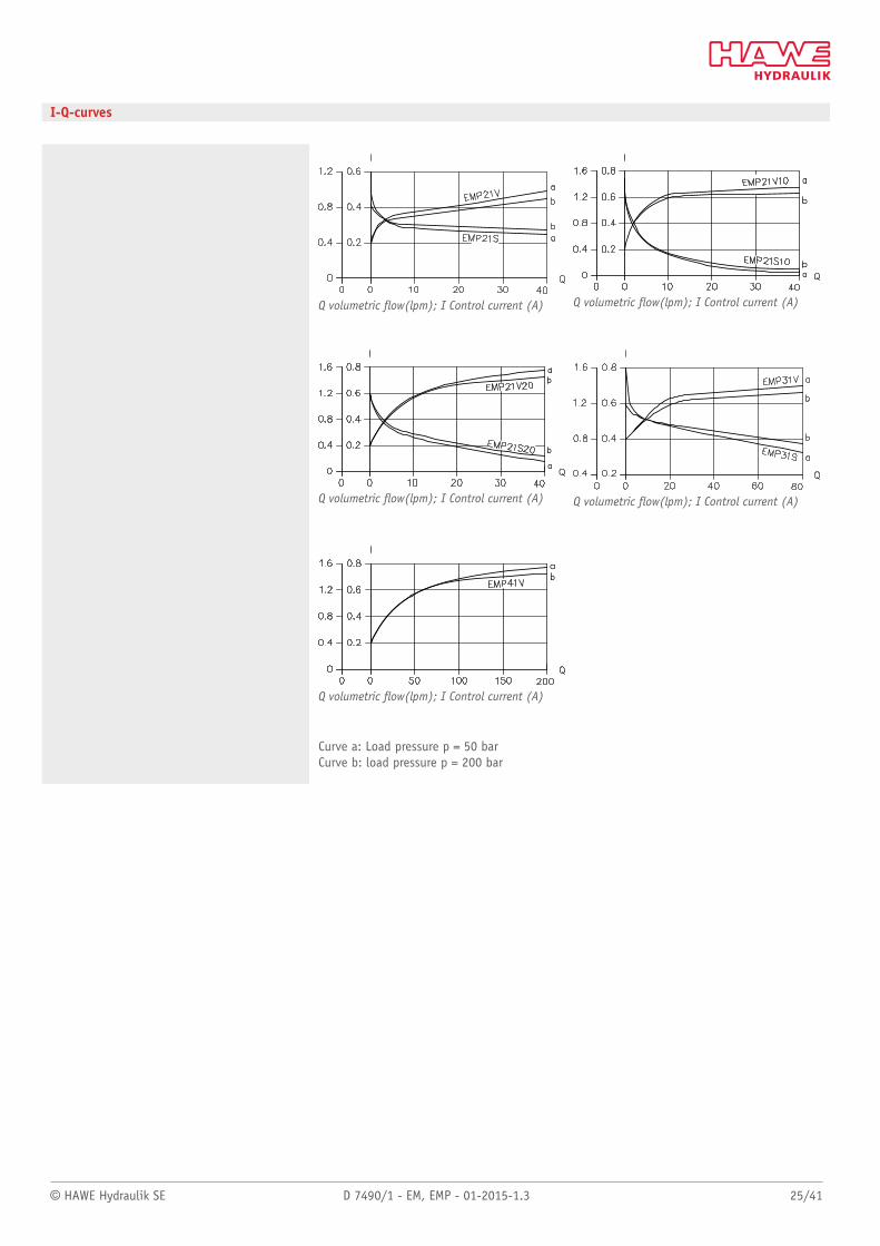
I-Q-curves
Q volumetric ow(lpm); I Control current (A) Q volumetric ow(lpm); I Control current (A)
Q volumetric ow(lpm); I Control current (A) Q volumetric ow(lpm); I Control current (A)
Q volumetric ow(lpm); I Control current (A)
Curve a: Load pressure p = 50 barCurve b: load pressure p = 200 bar
26/41 D 7490/1 - EM, EMP - 01-2015-1.3 © HAWE Hydraulik SE
4 Dimensions
All dimensions in mm, subject to change.
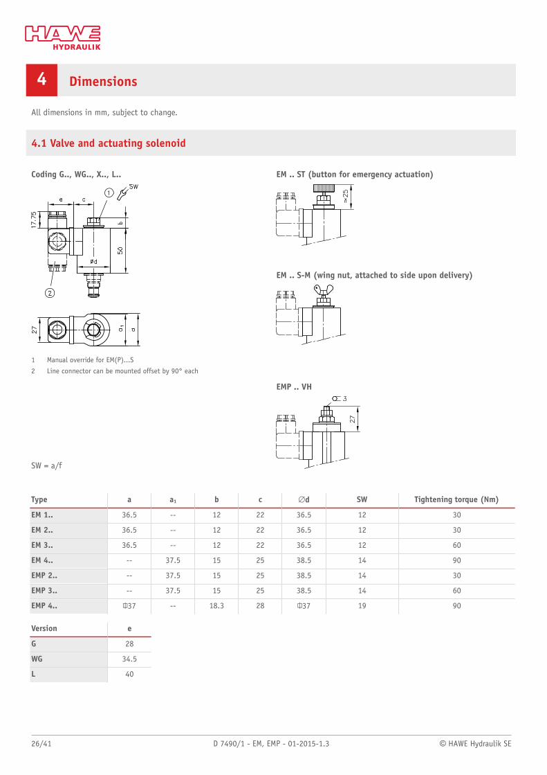
4.1 Valve and actuating solenoid
EM .. ST (button for emergency actuation)
EM .. S-M (wing nut, attached to side upon delivery)
Coding G.., WG.., X.., L..
1 Manual override for EM(P)...S
2 Line connector can be mounted offset by 90° each
SW = a/f
EMP .. VH
Type a a1 b c #d SW Tightening torque (Nm)
EM 1.. 36.5 -- 12 22 36.5 12 30
EM 2.. 36.5 -- 12 22 36.5 12 30
EM 3.. 36.5 -- 12 22 36.5 12 60
EM 4.. -- 37.5 15 25 38.5 14 90
EMP 2.. -- 37.5 15 25 38.5 14 30
EMP 3.. -- 37.5 15 25 38.5 14 60
EMP 4.. 037 -- 18.3 28 ”37 19 90
Version e
G 28
WG 34.5
L 40
© HAWE Hydraulik SE D 7490/1 - EM, EMP - 01-2015-1.3 27/41
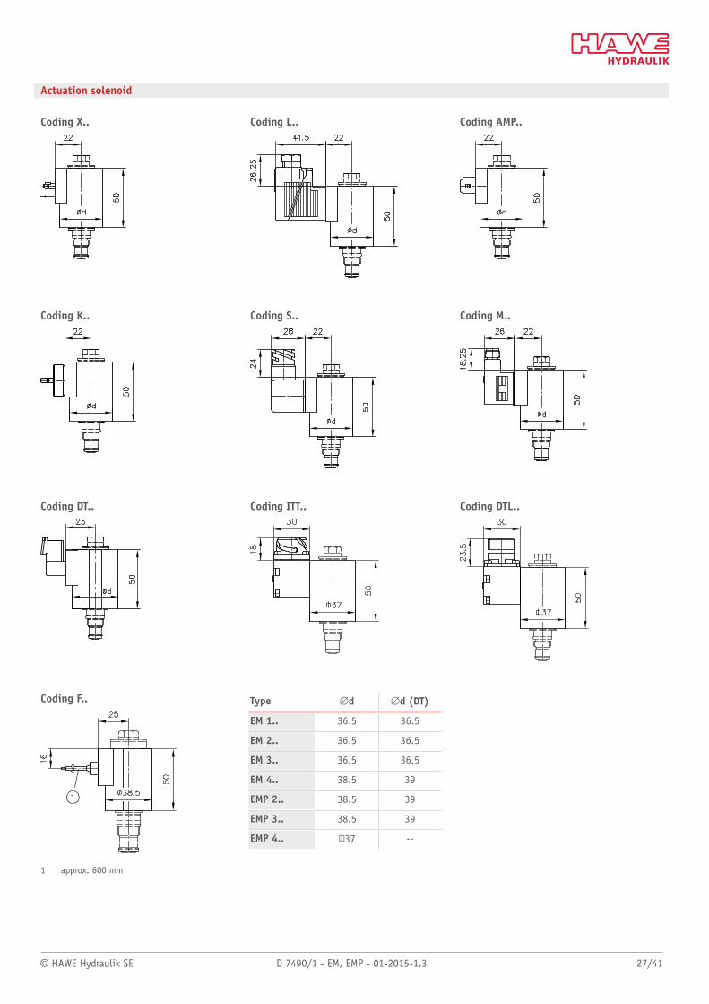
Actuation solenoid
Coding X.. Coding L.. Coding AMP..
Coding K.. Coding S.. Coding M..
Coding DT.. Coding ITT.. Coding DTL..
Coding F..
1 approx. 600 mm
Type #d #d (DT)
EM 1.. 36.5 36.5
EM 2.. 36.5 36.5
EM 3.. 36.5 36.5
EM 4.. 38.5 39
EMP 2.. 38.5 39
EMP 3.. 38.5 39
EMP 4.. 037 --
28/41 D 7490/1 - EM, EMP - 01-2015-1.3 © HAWE Hydraulik SE
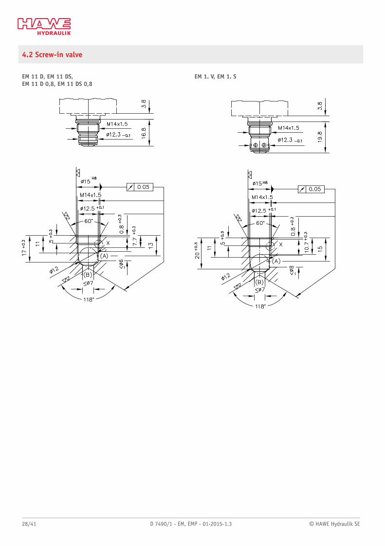
4.2 Screw-in valve
EM 11 D, EM 11 DS,EM 11 D 0,8, EM 11 DS 0,8
EM 1. V, EM 1. S
© HAWE Hydraulik SE D 7490/1 - EM, EMP - 01-2015-1.3 29/41
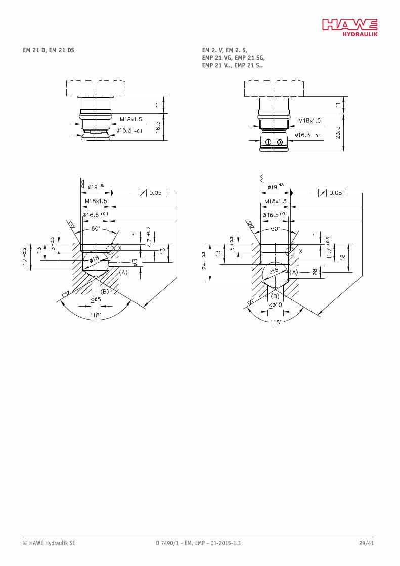
EM 21 D, EM 21 DS EM 2. V, EM 2. S,EMP 21 VG, EMP 21 SG,EMP 21 V.., EMP 21 S..
30/41 D 7490/1 - EM, EMP - 01-2015-1.3 © HAWE Hydraulik SE
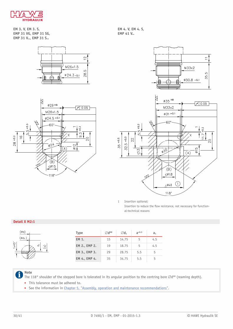
EM 3. V, EM 3. S,EMP 31 VG, EMP 31 SG,EMP 31 V.., EMP 31 S..
EM 4. V, EM 4. S, EMP 41 V..
1 Insertion optional:
Insertion to reduce the ow resistance, not necessary for function-
al-technical reasons
Detail X M2:1
Type #dH8 #d1 a+0.3 a1
EM 1. 15 14.75 5 4.5
EM 2., EMP 2. 19 18.75 5 4.5
EM 3., EMP 3. 29 28.75 5.5 5
EM 4., EMP 4. 35 34.75 5.5 5
NoteThe 118° shoulder of the stepped bore is tolerated in its angular position to the centring bore #dH8 (reaming depth).
■ This tolerance must be adhered to.■ See the information in Chapter 5, "Assembly, operation and maintenance recommendations".
© HAWE Hydraulik SE D 7490/1 - EM, EMP - 01-2015-1.3 31/41
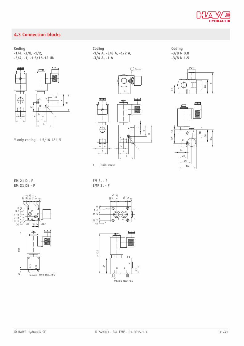
4.3 Connection blocks
Coding-1/4, -3/8, -1/2, -3/4, -1, -1 5/16-12 UN
1) only coding - 1 5/16-12 UN
Coding -1/4 A, -3/8 A, -1/2 A, -3/4 A, -1 A
1 Drain screw
Coding-3/8 N 0.8 -3/8 N 1.5
EM 21 D - P EM 21 DS - P
EM 3. - P EMP 3. - P
32/41 D 7490/1 - EM, EMP - 01-2015-1.3 © HAWE Hydraulik SE
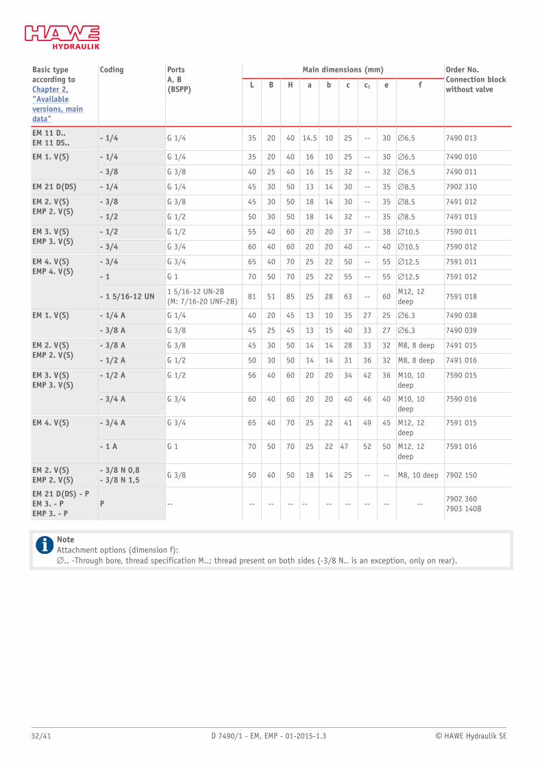
Main dimensions (mm)Basic typeaccording toChapter 2,"Availableversions, maindata"
Coding PortsA, B(BSPP) L B H a b c c1 e f
Order No.Connection blockwithout valve
EM 11 D..EM 11 DS.. - 1/4 G 1/4 35 20 40 14.5 10 25 -- 30 #6.5 7490 013
- 1/4 G 1/4 35 20 40 16 10 25 -- 30 #6.5 7490 010EM 1. V(S)
- 3/8 G 3/8 40 25 40 16 15 32 -- 32 #6.5 7490 011
EM 21 D(DS) - 1/4 G 1/4 45 30 50 13 14 30 -- 35 #8.5 7902 310
- 3/8 G 3/8 45 30 50 18 14 30 -- 35 #8.5 7491 012EM 2. V(S)EMP 2. V(S)
- 1/2 G 1/2 50 30 50 18 14 32 -- 35 #8.5 7491 013
- 1/2 G 1/2 55 40 60 20 20 37 -- 38 #10.5 7590 011EM 3. V(S)EMP 3. V(S)
- 3/4 G 3/4 60 40 60 20 20 40 -- 40 #10.5 7590 012
- 3/4 G 3/4 65 40 70 25 22 50 -- 55 #12.5 7591 011
- 1 G 1 70 50 70 25 22 55 -- 55 #12.5 7591 012
EM 4. V(S)EMP 4. V(S)
- 1 5/16-12 UN 1 5/16-12 UN-2B(M: 7/16-20 UNF-2B)
81 51 85 25 28 63 -- 60M12, 12deep
7591 018
- 1/4 A G 1/4 40 20 45 13 10 35 27 25 #6.3 7490 038EM 1. V(S)
- 3/8 A G 3/8 45 25 45 13 15 40 33 27 #6.3 7490 039
- 3/8 A G 3/8 45 30 50 14 14 28 33 32 M8, 8 deep 7491 015EM 2. V(S)EMP 2. V(S)
- 1/2 A G 1/2 50 30 50 14 14 31 36 32 M8, 8 deep 7491 016
- 1/2 A G 1/2 56 40 60 20 20 34 42 36 M10, 10deep
7590 015EM 3. V(S)EMP 3. V(S)
- 3/4 A G 3/4 60 40 60 20 20 40 46 40 M10, 10deep
7590 016
- 3/4 A G 3/4 65 40 70 25 22 41 49 45 M12, 12deep
7591 015EM 4. V(S)
- 1 A G 1 70 50 70 25 22 47 52 50 M12, 12deep
7591 016
EM 2. V(S)EMP 2. V(S)
- 3/8 N 0,8- 3/8 N 1,5 G 3/8 50 40 50 18 14 25 -- -- M8, 10 deep 7902 150
EM 21 D(DS) - PEM 3. - PEMP 3. - P
P -- -- -- -- -- -- -- -- -- --7902 3607903 140B
NoteAttachment options (dimension f):#.. -Through bore, thread specification M..; thread present on both sides (-3/8 N.. is an exception, only on rear).
© HAWE Hydraulik SE D 7490/1 - EM, EMP - 01-2015-1.3 33/41
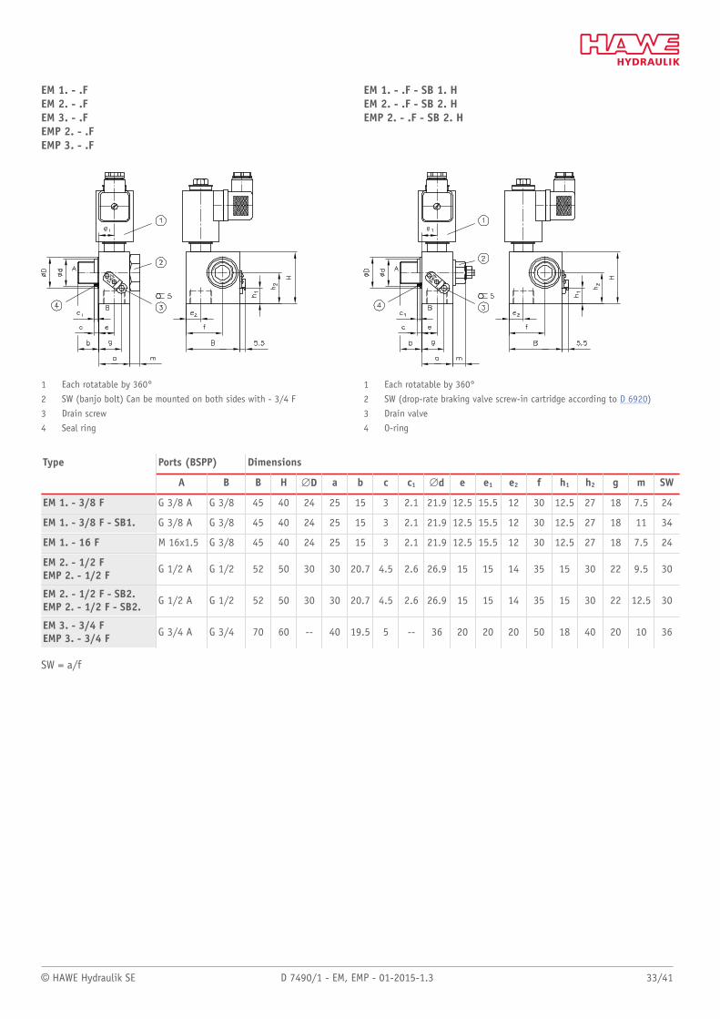
EM 1. - .FEM 2. - .FEM 3. - .FEMP 2. - .FEMP 3. - .F
1 Each rotatable by 360°
2 SW (banjo bolt) Can be mounted on both sides with - 3/4 F
3 Drain screw
4 Seal ring
EM 1. - .F - SB 1. HEM 2. - .F - SB 2. HEMP 2. - .F - SB 2. H
1 Each rotatable by 360°
2 SW (drop-rate braking valve screw-in cartridge according to D 6920)
3 Drain valve
4 O-ring
Ports (BSPP) DimensionsType
A B B H #D a b c c1 #d e e1 e2 f h1 h2 g m SW
EM 1. - 3/8 F G 3/8 A G 3/8 45 40 24 25 15 3 2.1 21.9 12.5 15.5 12 30 12.5 27 18 7.5 24
EM 1. - 3/8 F - SB1. G 3/8 A G 3/8 45 40 24 25 15 3 2.1 21.9 12.5 15.5 12 30 12.5 27 18 11 34
EM 1. - 16 F M 16x1.5 G 3/8 45 40 24 25 15 3 2.1 21.9 12.5 15.5 12 30 12.5 27 18 7.5 24
EM 2. - 1/2 FEMP 2. - 1/2 F G 1/2 A G 1/2 52 50 30 30 20.7 4.5 2.6 26.9 15 15 14 35 15 30 22 9.5 30
EM 2. - 1/2 F - SB2.EMP 2. - 1/2 F - SB2. G 1/2 A G 1/2 52 50 30 30 20.7 4.5 2.6 26.9 15 15 14 35 15 30 22 12.5 30
EM 3. - 3/4 FEMP 3. - 3/4 F G 3/4 A G 3/4 70 60 -- 40 19.5 5 -- 36 20 20 20 50 18 40 20 10 36
SW = a/f
34/41 D 7490/1 - EM, EMP - 01-2015-1.3 © HAWE Hydraulik SE
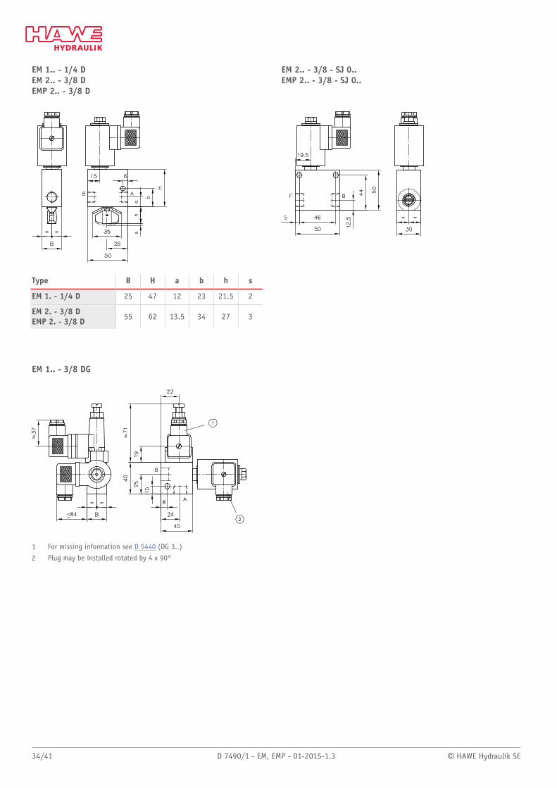
EM 1.. - 1/4 D EM 2.. - 3/8 D EMP 2.. - 3/8 D
Type B H a b h s
EM 1. - 1/4 D 25 47 12 23 21.5 2
EM 2. - 3/8 DEMP 2. - 3/8 D 55 62 13.5 34 27 3
EM 2.. - 3/8 - SJ 0.. EMP 2.. - 3/8 - SJ 0..
EM 1.. - 3/8 DG
1 For missing information see D 5440 (DG 3..)
2 Plug may be installed rotated by 4 x 90°
© HAWE Hydraulik SE D 7490/1 - EM, EMP - 01-2015-1.3 35/41
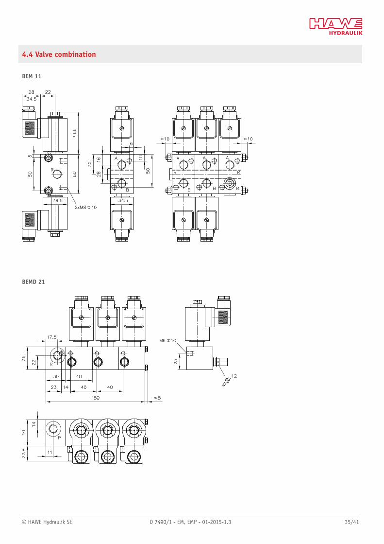
4.4 Valve combination
BEM 11
BEMD 21
36/41 D 7490/1 - EM, EMP - 01-2015-1.3 © HAWE Hydraulik SE
5 Assembly, operation and maintenance recommendations
5.1 Intended application
This valve is intended exclusively for hydraulic applications (uid engineering). The valve meets high technical safety standards andregulations for uid and electrical engineering.
The user must observe the safety measures and warnings in this documentation.
Essential requirements for the product to function correctly and safely:
– All information in this documentation must be observed. This applies in particular to all safety measures and warnings.– The product must only be assembled and put into operation by qualied personnel.– The product must only be operated within the specied technical parameters. The technical parameters are described in detail in this
documentation.– The operating and maintenance manual of the specic complete system must also always be observed.
If the product can no longer be operated safely:
Remove the product from operation and mark it accordingly. It is then not permitted to continue using or operating the product.
© HAWE Hydraulik SE D 7490/1 - EM, EMP - 01-2015-1.3 37/41
5.2 Assembly information
The product must only be installed in the complete system with standard connection components that comply with market requirements(screw ttings, hoses, pipes, etc.).
The hydraulic system must be shut down correctly prior to dismounting; this applies in particular to hydraulic systems with hydraulicaccumulators.
DangerRisk to life caused by sudden movement of the hydraulic drives when dismantled incorrectly!Risk of serious injury or death.
■ Depressurise the hydraulic system.■ Perform safety measures in preparation for maintenance.
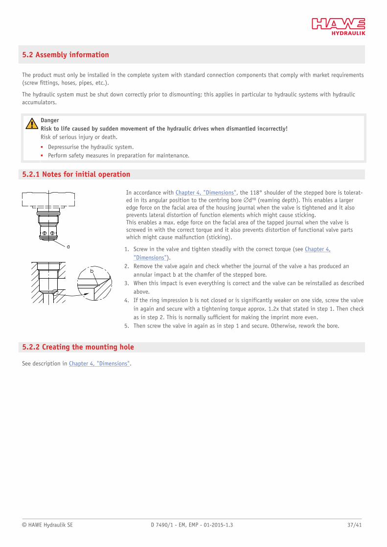
5.2.1 Notes for initial operation
In accordance with Chapter 4, "Dimensions", the 118° shoulder of the stepped bore is tolerat-ed in its angular position to the centring bore #dH8 (reaming depth). This enables a largeredge force on the facial area of the housing journal when the valve is tightened and it alsoprevents lateral distortion of function elements which might cause sticking.This enables a max. edge force on the facial area of the tapped journal when the valve isscrewed in with the correct torque and it also prevents distortion of functional valve partswhich might cause malfunction (sticking).
1. Screw in the valve and tighten steadily with the correct torque (see Chapter 4,"Dimensions").
2. Remove the valve again and check whether the journal of the valve a has produced anannular impact b at the chamfer of the stepped bore.
3. When this impact is even everything is correct and the valve can be reinstalled as describedabove.
4. If the ring impression b is not closed or is significantly weaker on one side, screw the valvein again and secure with a tightening torque approx. 1.2x that stated in step 1. Then checkas in step 2. This is normally sufcient for making the imprint more even.
5. Then screw the valve in again as in step 1 and secure. Otherwise, rework the bore.
5.2.2 Creating the mounting hole
See description in Chapter 4, "Dimensions".
38/41 D 7490/1 - EM, EMP - 01-2015-1.3 © HAWE Hydraulik SE
5.3 Operating instructions
Product configuration and setting the pressure and ow rate
The statements and technical parameters in this documentation must be strictly observed.The instructions for the complete technical system must also always be followed.
Note■ Read the documentation carefully before usage.■ The documentation must be accessible to the operating and maintenance staff at all times.■ Keep documentation up to date after every addition or update.
CautionRisk of injury on overloading components due to incorrect pressure settings!Risk of minor injury.
■ Always monitor the pressure gauge when setting and changing the pressure.
Purity and ltering of the hydraulic uid
Fine contamination can significantly impair the function of a hydraulic power pack. Contamination can cause irreparable damage.
Examples of ne contamination include:– Metal chips– Rubber particles from hoses and seals– Dirt due to assembly and maintenance– Mechanical debris– Chemical ageing of the hydraulic uid
NoteFresh hydraulic uid from the drum does not always have the highest degree of purity. Under some circumstances the freshhydraulic uid must be ltered before use.
Pay attention to the cleanliness level of the hydraulic uid in order to maintain faultless operation.(Also see cleanliness level in Chapter 3, "Parameters".)
5.4 Maintenance information
This product is largely maintenance-free.
Check that the product is securely fastened in the mounting hole at regular intervals, but at least once per year.
Conduct a visual inspection at regular intervals, but at least once per year, to check if the hydraulic connections are damaged. Ifexternal leakages are found, shut down and repair the system.
Clean the device surface of dust deposits and dirt at regular intervals, but at least once per year.
© HAWE Hydraulik SE D 7490/1 - EM, EMP - 01-2015-1.3 39/41
6 Other information
6.1 Accessories, spare parts and separate components
6.1.1 Tapped plugs
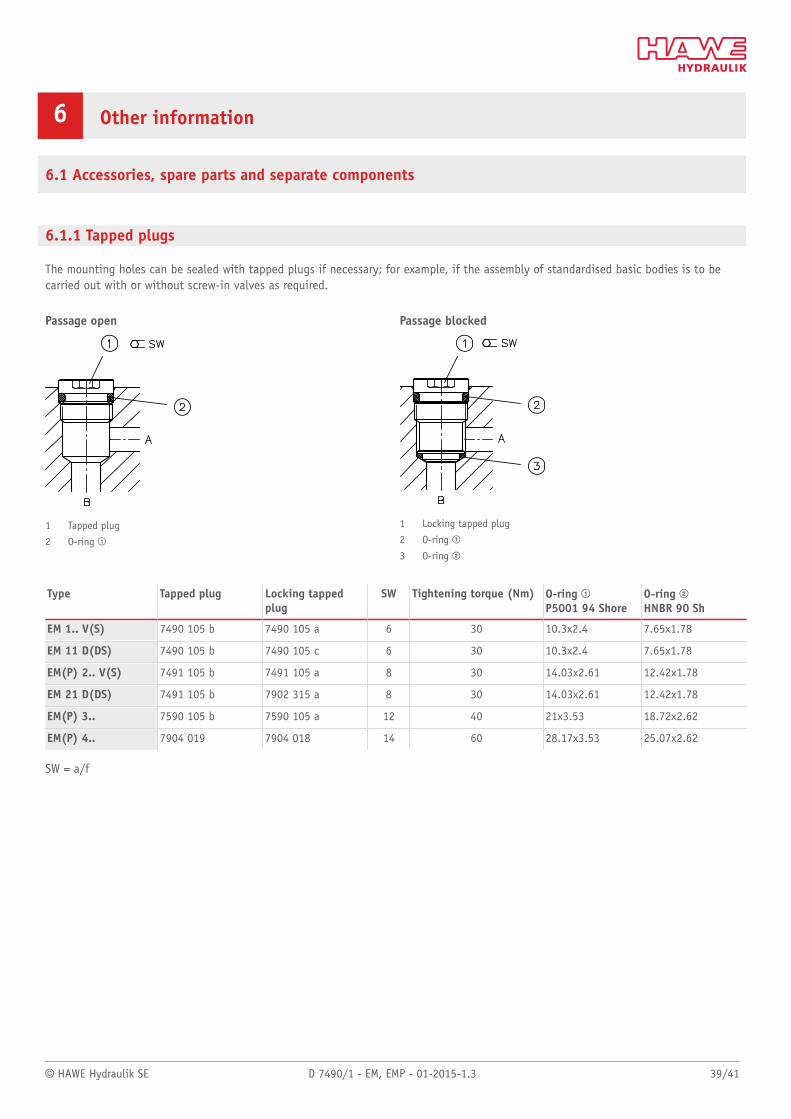
The mounting holes can be sealed with tapped plugs if necessary; for example, if the assembly of standardised basic bodies is to becarried out with or without screw-in valves as required.
Passage open
1 Tapped plug
2 O-ring ;
Passage blocked
1 Locking tapped plug
2 O-ring ;
3 O-ring <
Type Tapped plug Locking tappedplug
SW Tightening torque (Nm) O-ring ;P5001 94 Shore
O-ring <HNBR 90 Sh
EM 1.. V(S) 7490 105 b 7490 105 a 6 30 10.3x2.4 7.65x1.78
EM 11 D(DS) 7490 105 b 7490 105 c 6 30 10.3x2.4 7.65x1.78
EM(P) 2.. V(S) 7491 105 b 7491 105 a 8 30 14.03x2.61 12.42x1.78
EM 21 D(DS) 7491 105 b 7902 315 a 8 30 14.03x2.61 12.42x1.78
EM(P) 3.. 7590 105 b 7590 105 a 12 40 21x3.53 18.72x2.62
EM(P) 4.. 7904 019 7904 018 14 60 28.17x3.53 25.07x2.62
SW = a/f
40/41 D 7490/1 - EM, EMP - 01-2015-1.3 © HAWE Hydraulik SE
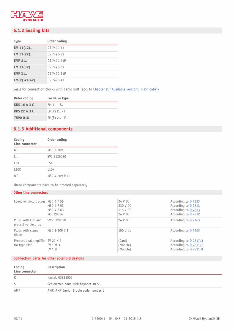
6.1.2 Sealing kits
Type Order coding
EM 11(12).. DS 7490-11
EM 21(22).. DS 7490-21
EMP 21.. DS 7490-21P
EM 31(32).. DS 7490-31
EMP 31.. DS 7490-31P
EM(P) 41(42).. DS 7490-41
Seals for connection blocks with banjo bolt (acc. to Chapter 2, "Available versions, main data")
Order coding For valve type
KDS 16 A 3 C EM 1.. - F..
KDS 22 A 3 C EM(P) 2.. - F..
7590 018 EM(P) 2.. - F..
6.1.3 Additional components
CodingLine connector
Order coding
G.. MSD 3-309
L.. SVS 3129020
L5K L5K
L10K L10K
WG.. MSD 4-209 P 10
These components have to be ordered separately!
Other line connectors
Economy circuit plugs MSD 4 P 55MSD 4 P 53MSD 4 P 63MSE 28026
24 V DC230 V DC115 V DC24 V DC
According to D 7833According to D 7813According to D 7813According to D 7832
Plugs with LED andprotective circuitry
SVS 3129020 24 V DC According to D 7163
Plugs with clampdiode
MSD 3-209 C 1 150 V DC According to D 7163
Proportional amplifierfor type EMP
EV 22 K 2EV 1 M 3EV 1 D
(Card)(Module)(Module)
According to D 7817/1According to D 7831/2According to D 7831 D
Connection parts for other solenoid designs
CodingLine connector
Description
K Kastel, 03888005
S Schlemmer, cone with bayonet 10 SL
AMP AMP, AMP Junior 2-pole code number 1
D 74
90/1
- E
M, EM
P -
01-2
015-
1.3
HAWE Hydraulik SEStreitfeldstraße 25 | 81673 München | Postfach 80 08 04 | 81608 München | GermanyTel +49 89 379100-1000 | Fax +49 89 379100-91000 | [email protected] | www.hawe.com
Further information
Additional versions■ Directional seated valve type BVE: D 7921■ Directional seated valve type BVG 1 and BVP 1: D 7765■ Directional seated valve type G, WG and others: D 7300