Embed Size (px)
Citation preview
Proceedings of the PRADS2013, pp. 724~730
20-25 October, 2013
CECO, Changwon City, Korea
- 724 -
Bossing Design for RoRo Ships Using a Fast RANSE-Approach Johannes Will1), Stefan Krüger1) and Florian Kluwe2)
1) University of Technology Hamburg (TUHH), Germany 2) Flensburger Schiffbau- Gesellschaft(FSG), Germany
Abstract
Viscous computations are usually rather time consuming not only in the flow simulation but also in the preprocessing, namely the geometry preparation. Especially the later is an exclusion criterion for the application of these methods during the early design process, connected with the pre-contract stage. In this stage hull forms variants might be developed faster than can be discretized and assessed with such tools. Only highly specialized tools in a streamlined process chain are capable to mend this handicap. Such a process chain is available at the participant institutes, where emphasis is given to efficient interfaces between tools. Additionally the condensed knowledge of viscous computation performed is provided in parameter recommendations for the case setup. This paper presents the results of a bossing design optimization of a fast RoRo vessel, which was executed during the early design phase of the project.
Keywords
RANS, Bossing Design, RoRo Ship, Early Design
Introduction
Most RoRo vessels are of twin screw design. To minimize the wave resistance of this kind of ships, the aftbody hull lines are often slender which leads to long shaft lines. Unfortunately, the suppliers of shaft lines are not able to produce shaft lines of sufficient length, which results in the situation that several shaft couplings are required. Based on whirling calculations, the position of the shaft line bearings are defined, and the last bearing in the hull - which serves also as stern tube seal - must be accessible for inspection. These boundary conditions make the hydrodynamic bossing design of these ships quite complex, as the shape of the bossing does not only
influence the resistance of the ship, but also the wake field. Inviscid CFD methods are usually applied during ship design to minimize the bare hull resistance of the ship, and many hull form variants are checked before the decision for the final hull form is made. Appendages are sometimes checked by viscous CFD methods, but not thoroughly designed by using such methods. The reason is that to investigate the flow around such kind of appendages, RANS- methods are required which are quite time consuming. This concerns not only the computation itself but also the attendant CAD form preparation and grid generation. In contrast to that especially during the early design stage, decisions have to be taken with short lead times.
The jointly developed ship design frame work E4 comprises highly specialized tools, which allows to export varying assemblies of hull forms and appendages in a suitable exchange format, which can be immediately used by the grid generator. The grid generation is done with a commercial grid generator, where all relevant setup is generated beforehand by the E4 framework to ensure an optimized grid according to computational effort and quality of the solution. For the RANSE computation an in house solver is used which is developed at the Institute of Fluid Dynamics and Ship Theory at TUHH. The process time for a case setup can thus be limited to a minimum.
The above mentioned process chain was used to optimize the bossing of a current RoRo project. The optimization was done iteratively: starting from a standard shape a new form was developed by evaluating the corresponding flow field. Care was taken that the new form should comply with the requirements of the already given shaft line set up. It was possible to develop a new bossing that fulfills both the demands of efficient installation and maintenance requirements as well as optimized hydrodynamical performance.
Johannes Will, Stefan Krüger and Florian Kluwe
- 725 -
Process Chain of the Fast RANSE-Approach
This section describes the process chain of the Fast RANSE–Approach that was implemented at the Institute of Ship Design and Ship safety (Krüger et al., 2009). Fig. 1 shows the work flow, which has five steps and forms one cycle of the optimization loop. Firstly a hull form has to be developed which fulfills the transport task as well as all other requirements. With a given hull form the volume mesh of the flow domain is created which meets the requirements of the flow phenomena to be investigated. In the case setup all required data for the flow solver is collected. Next the physical equations are solved and finally the results have to be analyzed. Between steps interfaces are needed that allow to move data from on step to another. Steps one and five require most of the human interaction and creative engineering work. Step four is entirely governed by the hard- and software capacities that can be provided. Steps two and three together with the interfaces have varying proportions of human and automated work and are apt to have a large proportion of resource wasting. In a streamlined process chain the interfaces are concerted and for steps two and three the required human interaction is reduced to a minimum. Additionally the knowledge for efficient grid generation and solver setup must be condensed and provided to other users. The individual steps of the process chain are further described below.
Geometry Preparation
The hull form is developed within the E4-Framework (Abels and Greitsch, 2010) as three dimensional free form. Individual parts of the body are described as meshes of parametric cubic splines grouped in frames and longlines (Söding, 1967). For better flexibility the hull is divided in the floating structure, superstructure and appendages, which are referred to as modules. The floating structure again is divided at the main frame in the forebody and aftbody module, and these can be developed individually. Combinations of fore– and aftbody modules can be combined together with appendages to hull forms that can be assessed with first principle methods. Modules are developed via a graphical interface which allows geometrical and topological changes to the mesh. Explicit knot movement, fairing in a quasi-traditional
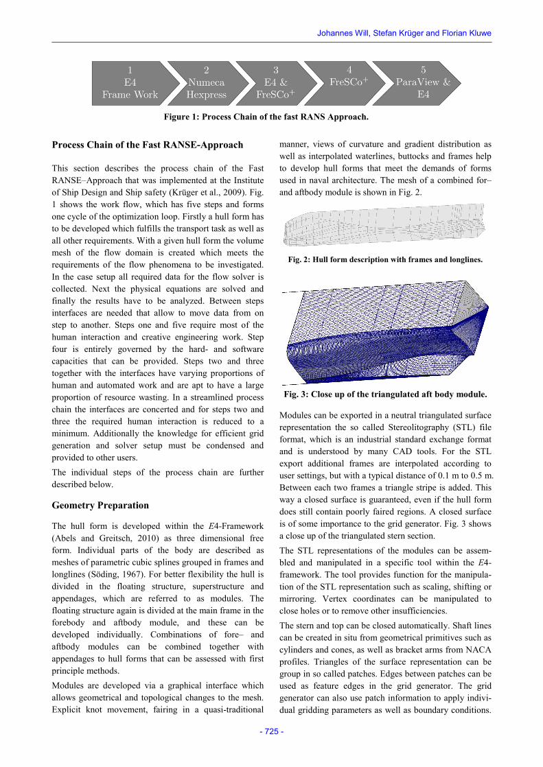
manner, views of curvature and gradient distribution as well as interpolated waterlines, buttocks and frames help to develop hull forms that meet the demands of forms used in naval architecture. The mesh of a combined for– and aftbody module is shown in Fig. 2.
Fig. 2: Hull form description with frames and longlines.
Fig. 3: Close up of the triangulated aft body module.
Modules can be exported in a neutral triangulated surface representation the so called Stereolitography (STL) file format, which is an industrial standard exchange format and is understood by many CAD tools. For the STL export additional frames are interpolated according to user settings, but with a typical distance of 0.1 m to 0.5 m. Between each two frames a triangle stripe is added. This way a closed surface is guaranteed, even if the hull form does still contain poorly faired regions. A closed surface is of some importance to the grid generator. Fig. 3 shows a close up of the triangulated stern section. The STL representations of the modules can be assem-bled and manipulated in a specific tool within the E4-framework. The tool provides function for the manipula-tion of the STL representation such as scaling, shifting or mirroring. Vertex coordinates can be manipulated to close holes or to remove other insufficiencies. The stern and top can be closed automatically. Shaft lines can be created in situ from geometrical primitives such as cylinders and cones, as well as bracket arms from NACA profiles. Triangles of the surface representation can be group in so called patches. Edges between patches can be used as feature edges in the grid generator. The grid generator can also use patch information to apply indivi-dual gridding parameters as well as boundary conditions.
Figure 1: Process Chain of the fast RANS Approach.
Bossing Design for Ro Ro Ships Using a Fast RANSE-Approach
- 726 -
Fig. 4 and Fig. 5 show the discrete floating body and bossing geometry. Fig. 6 shows the geometry of merged floating body and bossing. Individual parts can be stored in an internal file format and later be re-used for new configurations. This for example allows the recombi-nation of a bare hull with an alternative shaft line set up.
Fig. 4: Hull form with so called patches (triangle subsets) denoted by black lines (feature edges).
Fig. 5: Bossing with shaft line with patches denoted by black lines (feature edges)
Fig. 6: Close up of the aftbody with merged bossing and feature edges (black lines)
Mesh Generation
The mesh generation is done with the semi-automatic grid generator Hexpress. Hexpress creates unstructured non-conformal full hexahedral meshes (Numeca, 2013). Hexpress imports STL-files where additional information about triangle subsets –so called patches– can be provided. These patches can be used to appoint boundary conditions and specify grid parameters individually. The edges between subsets –so called feature edges– are maintained during the grid generation. The mesh generation is done in fife steps: initial mesh generation, adoption to geometry, snap to geometry, optimization and boundary layer insertion.
Set Up CFD-Model and Processing
For the viscous flow field computation the Finite-Volume Navier-Stokes solver FreSCo+ is used. FreSCo+ is jointly developed at the Institute of Fluid Dynamics and Shiptheory of the Hamburg University of Technology, Hamburg, Germany and the Hamburg Ship Model Basin (HSVA), Hamburg, Germany; (FreSCo+, 2013). For the turbulence-closure a statistical (RANS) model is used. For the case setup the generated volume grid has to be
converted into the native format of the solver. An input file has to be created which holds all settings required for the computation, such as boundary condition, turbulence settings, discretization schemes, output settings etc. FreSCo+ provides appropriate tools for the grid conver-sion and parallel distribution. The input files can be check for consistency. FreSCo+ allows the access to computed date sets via user coding. This way customized data sets can be export in suitable file formats for the post processing. All Computations are carried out on a 32-core AMD Opteron(TM) machine with a maximum clock time of 2.10 GHz and 64 GB RAM
Result Analysis
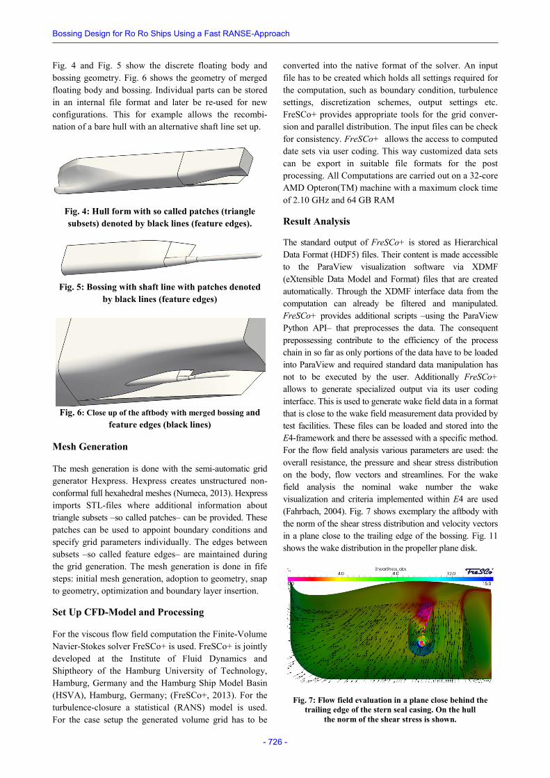
The standard output of FreSCo+ is stored as Hierarchical Data Format (HDF5) files. Their content is made accessible to the ParaView visualization software via XDMF (eXtensible Data Model and Format) files that are created automatically. Through the XDMF interface data from the computation can already be filtered and manipulated. FreSCo+ provides additional scripts –using the ParaView Python API– that preprocesses the data. The consequent prepossessing contribute to the efficiency of the process chain in so far as only portions of the data have to be loaded into ParaView and required standard data manipulation has not to be executed by the user. Additionally FreSCo+ allows to generate specialized output via its user coding interface. This is used to generate wake field data in a format that is close to the wake field measurement data provided by test facilities. These files can be loaded and stored into the E4-framework and there be assessed with a specific method. For the flow field analysis various parameters are used: the overall resistance, the pressure and shear stress distribution on the body, flow vectors and streamlines. For the wake field analysis the nominal wake number the wake visualization and criteria implemented within E4 are used (Fahrbach, 2004). Fig. 7 shows exemplary the aftbody with the norm of the shear stress distribution and velocity vectors in a plane close to the trailing edge of the bossing. Fig. 11 shows the wake distribution in the propeller plane disk.
Fig. 7: Flow field evaluation in a plane close behind the trailing edge of the stern seal casing. On the hull
the norm of the shear stress is shown.
Johannes Will, Stefan Krüger and Florian Kluwe
- 727 -
Reference Vessel
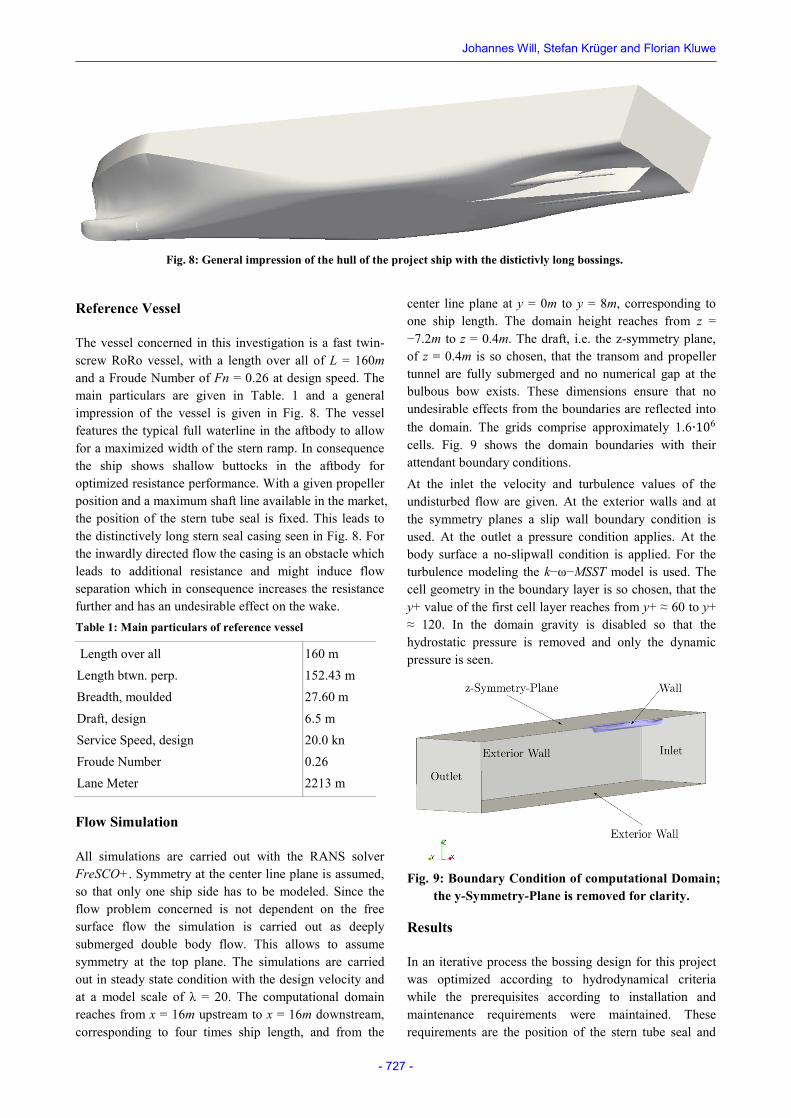
The vessel concerned in this investigation is a fast twin-screw RoRo vessel, with a length over all of L = 160m and a Froude Number of Fn = 0.26 at design speed. The main particulars are given in Table. 1 and a general impression of the vessel is given in Fig. 8. The vessel features the typical full waterline in the aftbody to allow for a maximized width of the stern ramp. In consequence the ship shows shallow buttocks in the aftbody for optimized resistance performance. With a given propeller position and a maximum shaft line available in the market, the position of the stern tube seal is fixed. This leads to the distinctively long stern seal casing seen in Fig. 8. For the inwardly directed flow the casing is an obstacle which leads to additional resistance and might induce flow separation which in consequence increases the resistance further and has an undesirable effect on the wake. Table 1: Main particulars of reference vessel
Length over all 160 m Length btwn. perp. 152.43 m Breadth, moulded 27.60 m Draft, design 6.5 m Service Speed, design 20.0 kn Froude Number 0.26 Lane Meter 2213 m
Flow Simulation
All simulations are carried out with the RANS solver FreSCO+. Symmetry at the center line plane is assumed, so that only one ship side has to be modeled. Since the flow problem concerned is not dependent on the free surface flow the simulation is carried out as deeply submerged double body flow. This allows to assume symmetry at the top plane. The simulations are carried out in steady state condition with the design velocity and at a model scale of λ = 20. The computational domain reaches from x = 16m upstream to x = 16m downstream, corresponding to four times ship length, and from the
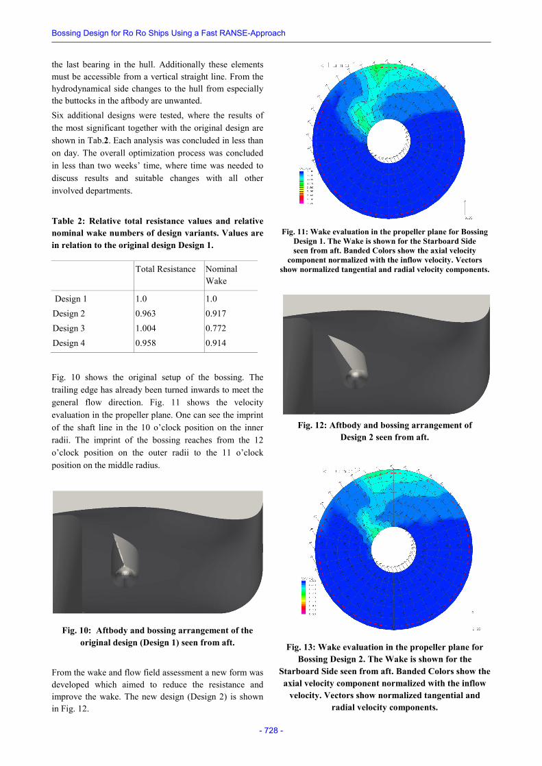
center line plane at y = 0m to y = 8m, corresponding to one ship length. The domain height reaches from z = −7.2m to z = 0.4m. The draft, i.e. the z-symmetry plane, of z = 0.4m is so chosen, that the transom and propeller tunnel are fully submerged and no numerical gap at the bulbous bow exists. These dimensions ensure that no undesirable effects from the boundaries are reflected into the domain. The grids comprise approximately 1.6∙106 cells. Fig. 9 shows the domain boundaries with their attendant boundary conditions. At the inlet the velocity and turbulence values of the undisturbed flow are given. At the exterior walls and at the symmetry planes a slip wall boundary condition is used. At the outlet a pressure condition applies. At the body surface a no-slipwall condition is applied. For the turbulence modeling the k−ω−MSST model is used. The cell geometry in the boundary layer is so chosen, that the y+ value of the first cell layer reaches from y+ ≈ 60 to y+ ≈ 120. In the domain gravity is disabled so that the hydrostatic pressure is removed and only the dynamic pressure is seen.
Fig. 9: Boundary Condition of computational Domain; the y-Symmetry-Plane is removed for clarity.
Results
In an iterative process the bossing design for this project was optimized according to hydrodynamical criteria while the prerequisites according to installation and maintenance requirements were maintained. These requirements are the position of the stern tube seal and
Fig. 8: General impression of the hull of the project ship with the distictivly long bossings.
Bossing Design for Ro Ro Ships Using a Fast RANSE-Approach
- 728 -
the last bearing in the hull. Additionally these elements must be accessible from a vertical straight line. From the hydrodynamical side changes to the hull from especially the buttocks in the aftbody are unwanted. Six additional designs were tested, where the results of the most significant together with the original design are shown in Tab.2. Each analysis was concluded in less than on day. The overall optimization process was concluded in less than two weeks’ time, where time was needed to discuss results and suitable changes with all other involved departments.
Table 2: Relative total resistance values and relative nominal wake numbers of design variants. Values are in relation to the original design Design 1.
Total Resistance Nominal Wake
Design 1 1.0 1.0 Design 2 0.963 0.917 Design 3 1.004 0.772 Design 4 0.958 0.914
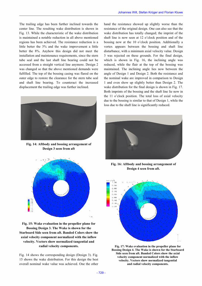
Fig. 10 shows the original setup of the bossing. The trailing edge has already been turned inwards to meet the general flow direction. Fig. 11 shows the velocity evaluation in the propeller plane. One can see the imprint of the shaft line in the 10 o’clock position on the inner radii. The imprint of the bossing reaches from the 12 o’clock position on the outer radii to the 11 o’clock position on the middle radius.
Fig. 10: Aftbody and bossing arrangement of the original design (Design 1) seen from aft.
From the wake and flow field assessment a new form was developed which aimed to reduce the resistance and improve the wake. The new design (Design 2) is shown in Fig. 12.
Fig. 11: Wake evaluation in the propeller plane for Bossing
Design 1. The Wake is shown for the Starboard Side seen from aft. Banded Colors show the axial velocity
component normalized with the inflow velocity. Vectors show normalized tangential and radial velocity components.
Fig. 12: Aftbody and bossing arrangement of
Design 2 seen from aft.
Fig. 13: Wake evaluation in the propeller plane for Bossing Design 2. The Wake is shown for the
Starboard Side seen from aft. Banded Colors show the axial velocity component normalized with the inflow
velocity. Vectors show normalized tangential and radial velocity components.
Johannes Will, Stefan Krüger and Florian Kluwe
- 729 -
The trailing edge has been further inclined towards the center line. The resulting wake distribution is shown in Fig. 13. While the characteristic of the wake distribution is maintained a notable reduction in all above mentioned regions has been achieved. The resistance reduction is a little better the 3% and the wake improvement a little better the 8%. Anyhow this design did not meet the installation and maintenance requirements, since the stern tube seal and the last shaft line bearing could not be accessed from a straight vertical line anymore. Design 2 was changed so that the above mentioned demands were fulfilled. The top of the bossing casing was flared on the outer edge to restore the clearance for the stern tube seal and shaft line bearing. To counteract the increased displacement the trailing edge was further inclined.
Fig. 14: Aftbody and bossing arrangement of
Design 3 seen from aft
Fig. 15: Wake evaluation in the propeller plane for Bossing Design 3. The Wake is shown for the
Starboard Side seen from aft. Banded Colors show the axial velocity component normalized with the inflow
velocity. Vectors show normalized tangential and radial velocity components.
Fig. 14 shows the corresponding design (Design 3). Fig. 15 shows the wake distribution. For this design the best overall nominal wake value was achieved. One the other
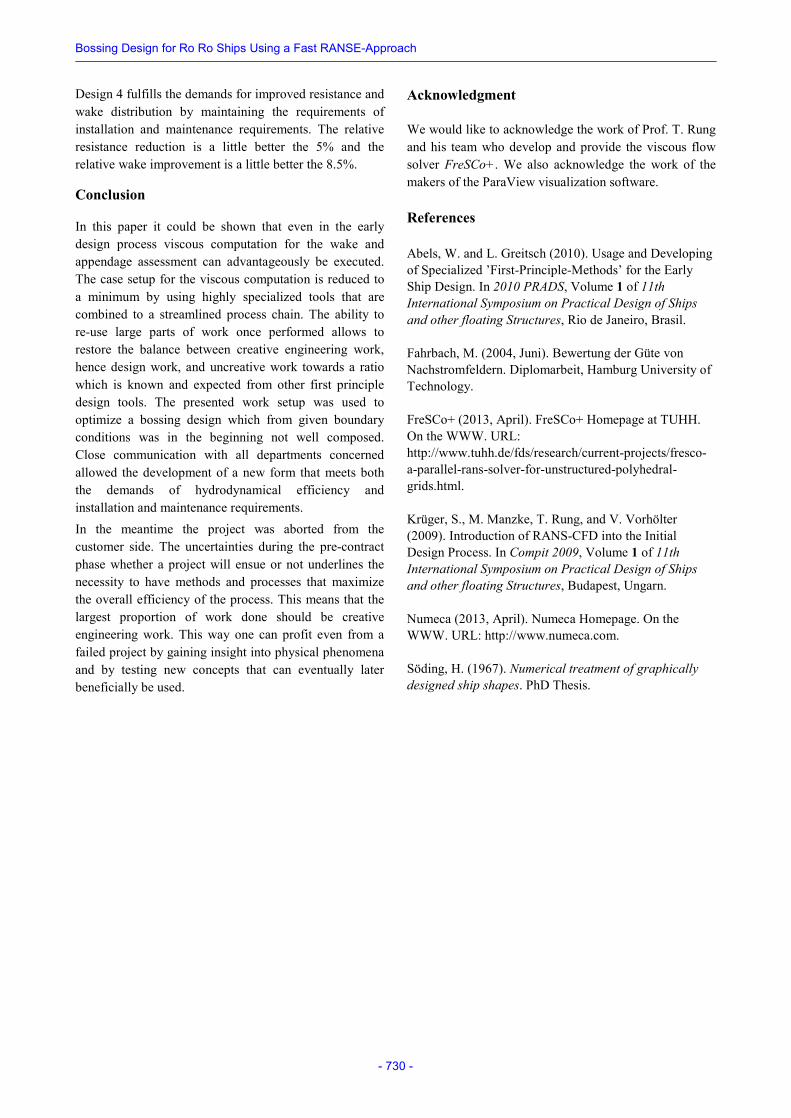
hand the resistance showed up slightly worse than the resistance of the original design. One can also see that the wake distribution has totally changed; the imprint of the shaft line is now seen at 12 o’clock position and of the bossing now at the 10 o’clock position. Additionally a vortex appears between the bossing and shaft line disturbance, with a minimum axial velocity value. Design 3 was rejected on these grounds. For the final design, which is shown in Fig. 16, the inclining angle was reduced, while the flair at the top of the bossing was maintained. The inclining angle lies now between the angle of Design 1 and Design 2. Both the resistance and the nominal wake are improved in comparison to Design 1 and even show up slightly better than Design 2. The wake distribution for the final design is shown in Fig. 17. Both imprints of the bossing and the shaft line lie now in the 11 o’clock position. The total loss of axial velocity due to the bossing is similar to that of Design 1, while the loss due to the shaft line is significantly reduced.
Fig. 16: Aftbody and bossing arrangement of
Design 4 seen from aft.
Fig. 17: Wake evaluation in the propeller plane for Bossing Design 4. The Wake is shown for the Starboard
Side seen from aft. Banded Colors show the axial velocity component normalized with the inflow velocity. Vectors show normalized tangential
and radial velocity components.
Bossing Design for Ro Ro Ships Using a Fast RANSE-Approach
- 730 -
Design 4 fulfills the demands for improved resistance and wake distribution by maintaining the requirements of installation and maintenance requirements. The relative resistance reduction is a little better the 5% and the relative wake improvement is a little better the 8.5%.
Conclusion
In this paper it could be shown that even in the early design process viscous computation for the wake and appendage assessment can advantageously be executed. The case setup for the viscous computation is reduced to a minimum by using highly specialized tools that are combined to a streamlined process chain. The ability to re-use large parts of work once performed allows to restore the balance between creative engineering work, hence design work, and uncreative work towards a ratio which is known and expected from other first principle design tools. The presented work setup was used to optimize a bossing design which from given boundary conditions was in the beginning not well composed. Close communication with all departments concerned allowed the development of a new form that meets both the demands of hydrodynamical efficiency and installation and maintenance requirements. In the meantime the project was aborted from the customer side. The uncertainties during the pre-contract phase whether a project will ensue or not underlines the necessity to have methods and processes that maximize the overall efficiency of the process. This means that the largest proportion of work done should be creative engineering work. This way one can profit even from a failed project by gaining insight into physical phenomena and by testing new concepts that can eventually later beneficially be used.
Acknowledgment
We would like to acknowledge the work of Prof. T. Rung and his team who develop and provide the viscous flow solver FreSCo+. We also acknowledge the work of the makers of the ParaView visualization software.
References
Abels, W. and L. Greitsch (2010). Usage and Developing of Specialized ’First-Principle-Methods’ for the Early Ship Design. In 2010 PRADS, Volume 1 of 11th International Symposium on Practical Design of Ships and other floating Structures, Rio de Janeiro, Brasil.
Fahrbach, M. (2004, Juni). Bewertung der Güte von Nachstromfeldern. Diplomarbeit, Hamburg University of Technology.
FreSCo+ (2013, April). FreSCo+ Homepage at TUHH. On the WWW. URL: http://www.tuhh.de/fds/research/current-projects/fresco-a-parallel-rans-solver-for-unstructured-polyhedral-grids.html.
Krüger, S., M. Manzke, T. Rung, and V. Vorhölter (2009). Introduction of RANS-CFD into the Initial Design Process. In Compit 2009, Volume 1 of 11th International Symposium on Practical Design of Ships and other floating Structures, Budapest, Ungarn.
Numeca (2013, April). Numeca Homepage. On the WWW. URL: http://www.numeca.com.
Söding, H. (1967). Numerical treatment of graphically designed ship shapes. PhD Thesis.