Embed Size (px)
Citation preview
,,Ikl_" '_
,l
17ADVANCED COMPOSITE STABILIZER
| FOR
| BOEING 737 AIRCRAFTIM
I18 JULY 1978
! "I._.;A-,..L-131t_.-' ": ,JVA_dC,J CGM_-uS[T}:; ,:;d'_-26915
, _,_J_L'teE.,.y 'i_ca'_z_al PX.ugE_.'_ 5cI_ Et, 19 Apr.,_= - Ib Jui. 1915 IJoe_n_] _,o_._e[ciai Alrpiaae JUCid- <
" : to., S_,,tt .e) l:,u _ _C ,C7/tlk" A,]I CS_L 11_ ..;3/,._. 1_7]1
FOURTH QUARTERLY TECHNICAL PROGRESS REPORT• , • 19 APRIL 1978 THROUGH 18 JULY 1978
PREPARED FOR:: NATIONAL AERONAUTICS AND SPACE ADMINISTRATION
_i LANGLEY RESEARCH CENTER
HAMPTON, VIRGINIA 23665
IN RESPONSE TO:
• CONTRACT NAS1-15025
_ DRL LINE ITEM NUMBER 018 i
I
1 P.O.BOX 1707 _ : ", _:_
8F._TTL|, W_t'l INGTONNl_bl '*. . -" ' * _"* ' _'
1984020846
https://ntrs.nasa.gov/search.jsp?R=19840020846 2018-05-06T01:53:23+00:00Z
o
/
Boeing Commercial!
/ Airplane Company• Contract NASI-15025
This Report is Submitted in ComplianceWith DRL Line Item Number 018
FOURTH QUARTERLY TECHNICAL PROGRESS REPORT
19 April 1978 through 18 July 1978
Supervised by: _. ........
O. [ Desper, JrProgram Administration and Data lianager
't !Approved by :
Engineering Design Manager!
• ,/-7---/"
( / . . .c_artyEngineering Technolog_ l,tanager
(
Approved by:V.S. ThompscOperations Technology Manager
/--" Approved by:
_ S.T. HarveyDirector of Advanced Composites Programs
I
O 'O
1984020846-002
!/_ , Boeing Commercial
" / Airplane CompanyContract NAS1-15025
(
FORENORD
E
This report was prepared by the Boeing Coaanercial Airplane Company, Renton,
Washington, under Contract NAS1-15025. It is the fourth quarterly technical
progress report covering work performed between 19 April 1978 and 18 duly 1978.
The program is sponsored by the National Aeronautics and Space Administration,
I Langley Research Center (NASA-LRC). Dr. H. A. Leybold Is the Project
Hanager for NASA-LRC.
( The following Boeing personnel are principal contributors to the program , ...
during the reporting period: G. Ohgi, Design; R. Johnson, Structural I:f
( Analysis; M. Garvey, Manufacturing Specialist; D. Grant, Production Hanager; [.i_-
L. D. Prltchett, Technical Operations Coordinator; and D. V. Chovil, Business
Support Manager.
(
(- PRECEDING PAGE BLANK NOT FILMED
Q :
................ . . , _ . , ,, ¢ m, = f;
"1984020846-003

BoeingComerc lAirplane Company
2 Contract NASl-15025
. SUMMARY
Activities related to development of an advanced composites stabilizer
for the Boeing 737 commercial transport are reported.
Activities include discussion of criteria and objectives, design loads,
the fatigue spectrum definition to be used for all spectrum fatigue
testing, fatigue analysis, manufacturing producibility studies, the
ancillary test program, quality assurance, and manufacturing development.
The fatigue load sequence was developed similarly to the European standard
" spectra, TWIST and FALSTAFF. Selection of a base mission for spectrum
definition was accomplished by reviewing the original 737 analyses, and
the I0 years of service history since the 737 was introduced into service.%
Design is proceeding with detailed design of graphite/epoxy components.
Produclbility studies on the rear spar/lug interface test section have
been completed, and include the spar detail bonding, machining, andf
drilling, and attachment of the titanium lugs. The program is progressing
as scheduled.
(
(
(_- PRECEDING PAGE BUAkq_ NO_ F_ME_
<
t
1984020846-004
V
C
Boeing CommercialAirplane CompanyContract NASI-15025
TABLE OF CONTENTS
Section Page
FOREWORD lii
SUMMARY v
LIST OF FIGURES AND TABLES viii
1.0 INTRODUCTION I-i
2.0 DESIGN AND ANALYSIS 2-1
2.1 DESIGN LOADS CRITERIA AND ANALYSIS 2-1
2.1.1 Criteria and Objectives 2-12.1.2 Design Loads 2-1
2.2 DESIGN STATUS 2-7
2.2.1 Stabilizer Box Assembly Provision 2-7
2.2.2 Stabilizer Box Access Provision i2-9
2.2.3 Corrosion Protection 2-10 :2.2.4 Skin Panel Stiffener Runout Detail 2-12 :
( 2.2.5 Rib Corner Detail 2-12 i"2.2.6 Production Drawing Preparation 2-15
2.3 ANALYSIS 2-16 t=
( 2.4 WEIGHT STATUS 2-25 I
3.0 DEVELOPMENTTEST PLAN AND STATUS 3-1 ]
3.l ANCILLARY TEST PROGRAM 3-1
4.0 OPERATIONS DEVELOPMENT 4-I
4.1 PRODUCIBILITY STUDIES 4-1
4.2 ANCILLARY TEST COMPONENT FABRICATION 4-3
4.2.1 Allowables and Environmental 4-74.2.2 Concept Verification 4-8t
4.3 QU_LIT_ ASSUrAnCE DEVELOPM_T 4-13
5.0 REFERENCES 5-I
APPENDIX A - ENGINEERING DRAWINGS A-I
PRECEDING PAGE BLANK NOTFU_m_
•_ vii _tbb
1984020846-005
Boeing Commercial )
Airplane CompanyContract NASI-15025
I
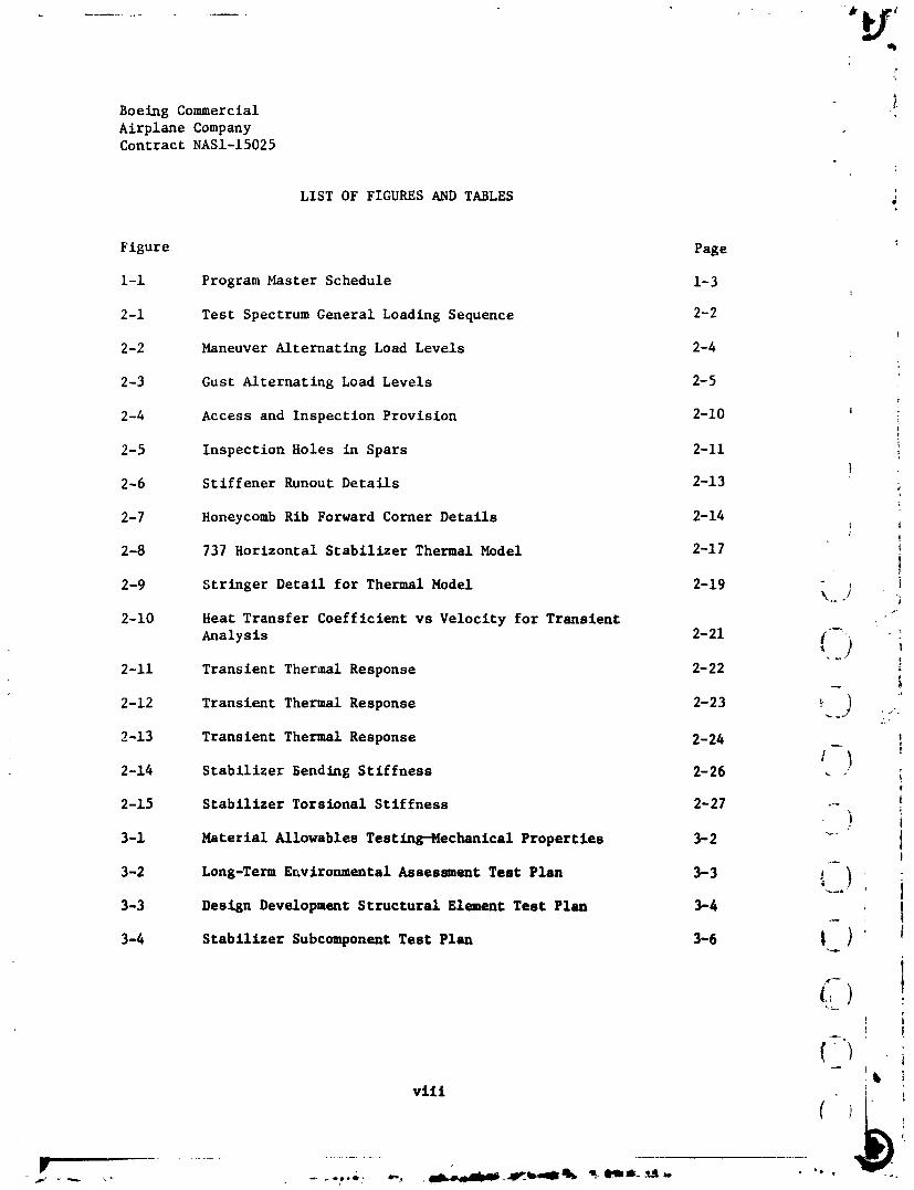
LIST OF FIGURES AND TABLES
Figure Page
I-i Program Master Schedule i-3
2-1 Test Spectrum General Loading Sequence 2-2
i
2-2 Maneuver Alternating Load Levels 2-4
2-3 Gust Alternating Load Levels 2-5
2-4 Access and Inspection Provision 2-10 ii
2-5 Inspection Holes in Spars 2-11
2-6 Stiffener Runout Details 2-13
2-7 Honeycomb Rib Forward Corner Details 2-14 !!
2-8 737 Horizontal Stabilizer Thermal Model 2-17 IiI
1
2-9 Stringer Detail for Thermal Model 2-19 \,_]
2-10 Heat Transfer Coefficient vs Velocity for Transient "_
Analysis 2-21 I'_% -:
2-11 Transient Thermal Response 2-22
.i
2-12 Transient Thermal Response 2-23 _ ) ;._
2-13 Transient Thermal Response 2-24 !
2-14 Stabilizer Bending Stiffness 2-26 . "!
!2-15 Stabilizer Torsional Stiffness 2-27 --
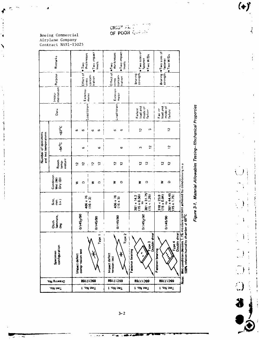
3-1 Material Allowables Testing--Mechanlcal Properties 3-2 _ II
3-2 Long-Term Environmental Assessment Test Plan 3-3 { ) if
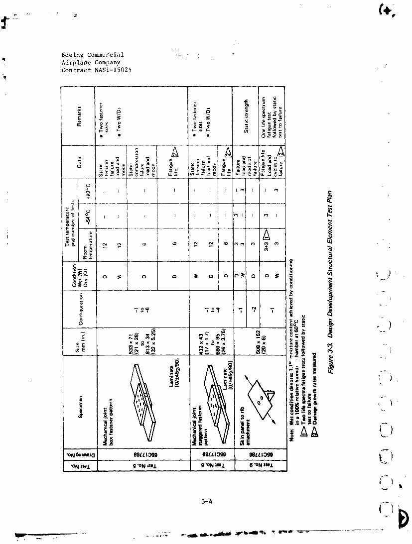
3-3 Desi8n DevelopmentStructuralElement Test Plan 3-4 _ I
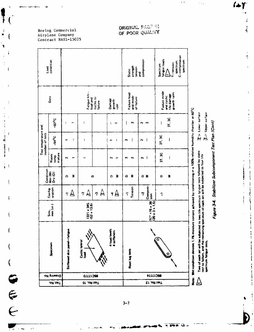
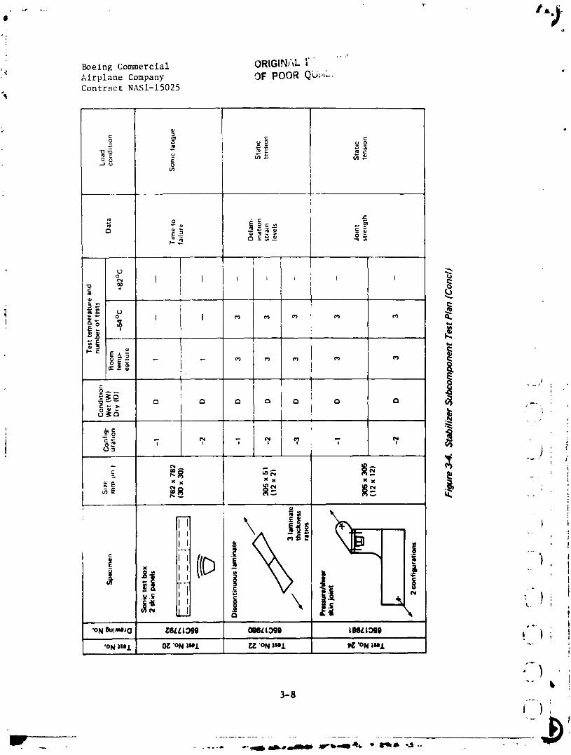
3-4 StabilizerSubcomponentTest Plan 3-6 i I ! I
'bviii i
1984020846-006
" Boeing Commercial
Airplane CompanyContract NASI-15025
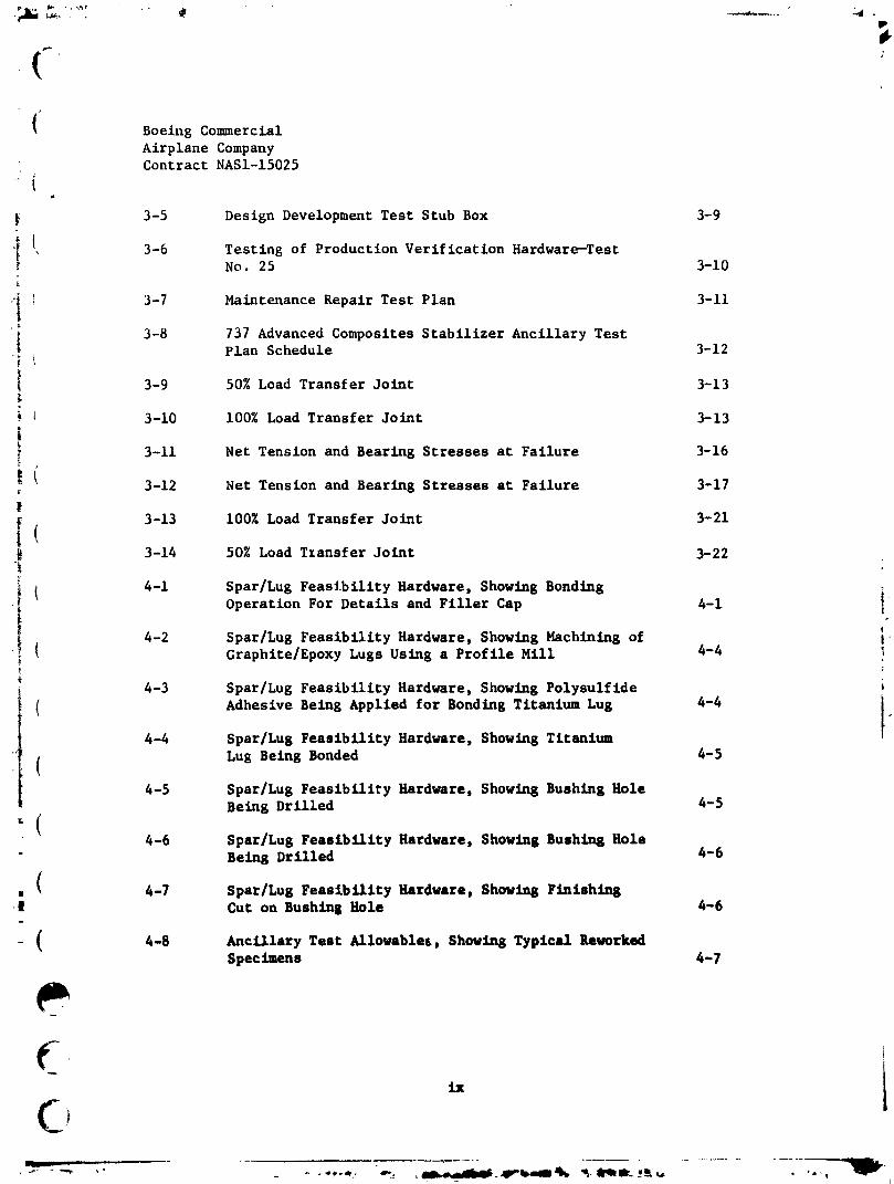
3-5 Design Development Test Stub Box 3-9
3-6 Testing of Production Verification Hardware-Testi No. 25 3-10i
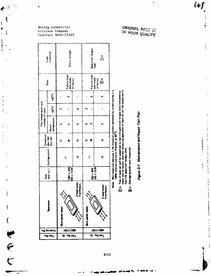
_! 3-7 Maintenance Repair Test Plan 3-11i
3-8 737 Advanced Composites Stabilizer Ancillary Test
._ Plan Schedule 3-12
3-9 50% Load Transfer Joint 3-13
3-I0 100% Load Transfer Joint 3-13i
! 3-11 Net Tension and Bearing Stresses at Failure 3-16
3-12 Net Tension and Bearing Stresses at Failure 3-17
!
i 3-13 100% Load Transfer Joint 3-21
(• 3-14 50% Load Tzansfer Joint 3-22
._ ( 4-1 Spar/Lug Feasibility Hardware, Showing Bonding iOperation For Details and Filler Cap 4-1 }
( 4-2 Spar/Lug Feasibility Hardware, Showing Machining of '.Graphite/Epoxy Lugs Using a Profile Mill 4-4 !I
4-3 Spar/Lug Feasibility Hardware, Showing Polysulfide i
( Adhesive Being Applied for Bonding Titanium Lug 4-4 i"
4-4 Spar/Lug Feasibility Hardware, Showing Titanium
" ( Lug Being Bonded 4-5
4-5 Spar/Lug Feasibility Hardware, Showing Bushing Hole
Being Drilled 4-5
,(4-6 Spar/Lug Feasibility Hardware, Showing Bushing Hole
" Being Drilled 4-6
. ( 4-7 Spar/Lug Feasibility Hardware, Showing Finishing_| Cut on Bushing Hole 4-6
- ( 4-8 Ancillary Test Allowablei, Showing Typical ReworkedSpecimens 4-7
i
- ix
L
1984020846-007

Boeing Commercial
Airplane CompanyContract NASI-15025
4-9 Spar Chord Crippling (Test No. 7), Showing Specimen
Ready for End Potting 4-9
4-10 Spar Chord Crippling (Test No. 7), Showing CompletedSpecimens 4-9
4-11 Spar Lug (Test No 12), Showing Specimens Ready forCure 4-10
4-12 Spar Lug (Test No. 12), Showing Peel Ply Being Removed
from Completed Detail Halves 4-10
4-13 Spar Lug (Test No. 12), Showing Completed Detail Halves
Bagged and Ready for Bonding 4-11
4-14 Spar Lug (Test No. 12), Showing Trimmed CompressionSpecimen 4-11 ._
I
4-15 Spar Lug (Test No. 12), Showing Trimmed Tension
Specimen 4-12 !
4-16 Spar Lug (Test No. 12), Showing Drilling oi Fastener IHoles 4-12 _ j
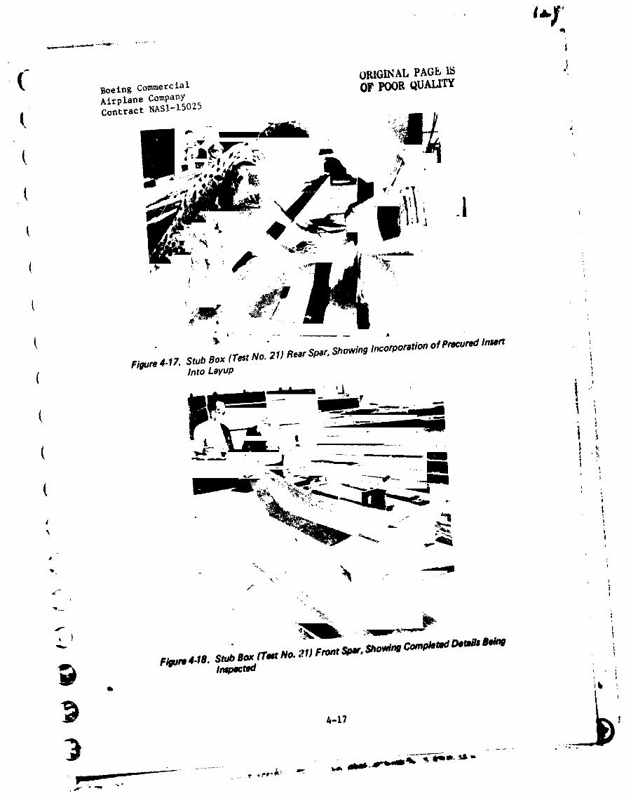
4-17 Stub Box (Test No. 21) Rear Spar, Showing Incorporation .-
of Precured Insert into Layup 4-17 !
4-18 Stub Box (Test No. 21) Front Spar, Showing Completed
Details Being Inspected 4-17 ' t ,_
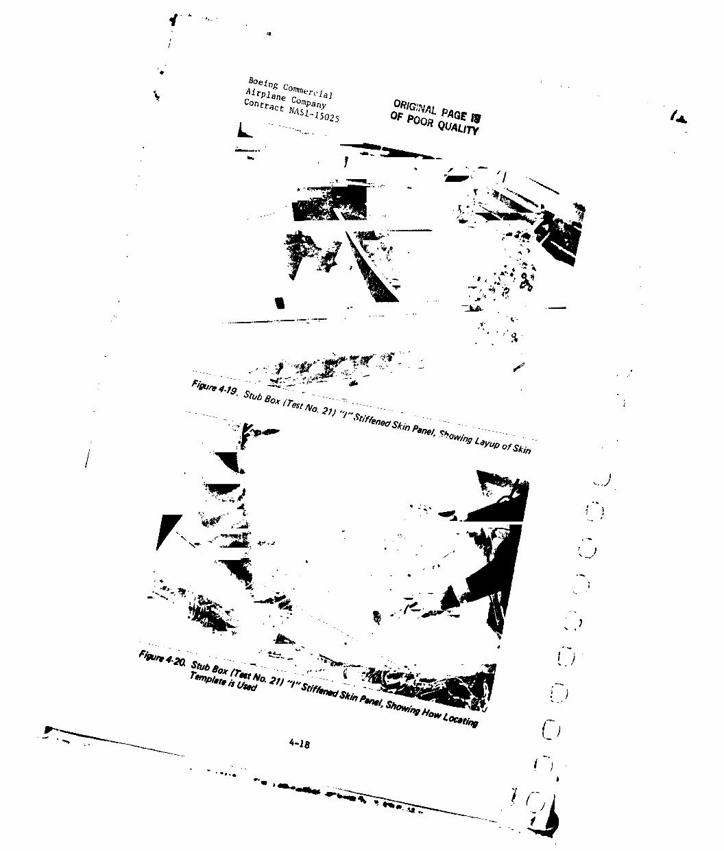
4-19 Stub Box (Test No. 21) "I" Stiffened Skin Panel, iShowing Layup of Skln 4-18 - ;
| i ,
4-20 Stub Box (Test No. 21) "I" Stiffened Skin Panel, }Showing How Locating Template is Used 4-18 !
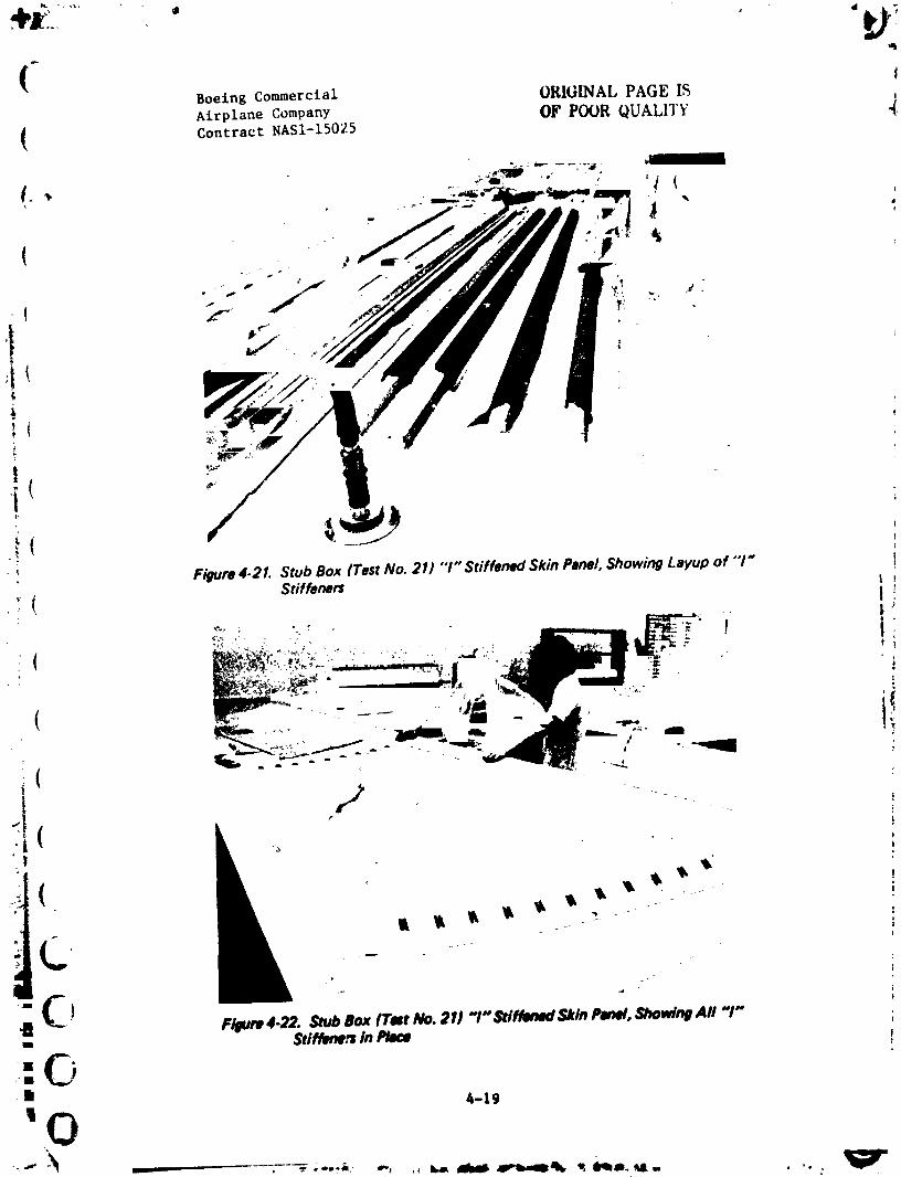
4-21 Stub Box (Test No. 21) "I" Stiffened Skin Panel, "_ i
Showing Layup of "I" Stiffeners 4-19 p
4-22 Stub Box (Test No. 21) "I" Stiffened Skln Panel, _ ) I
Showing All "I" Stiffeners in Place 4-19 "_ I
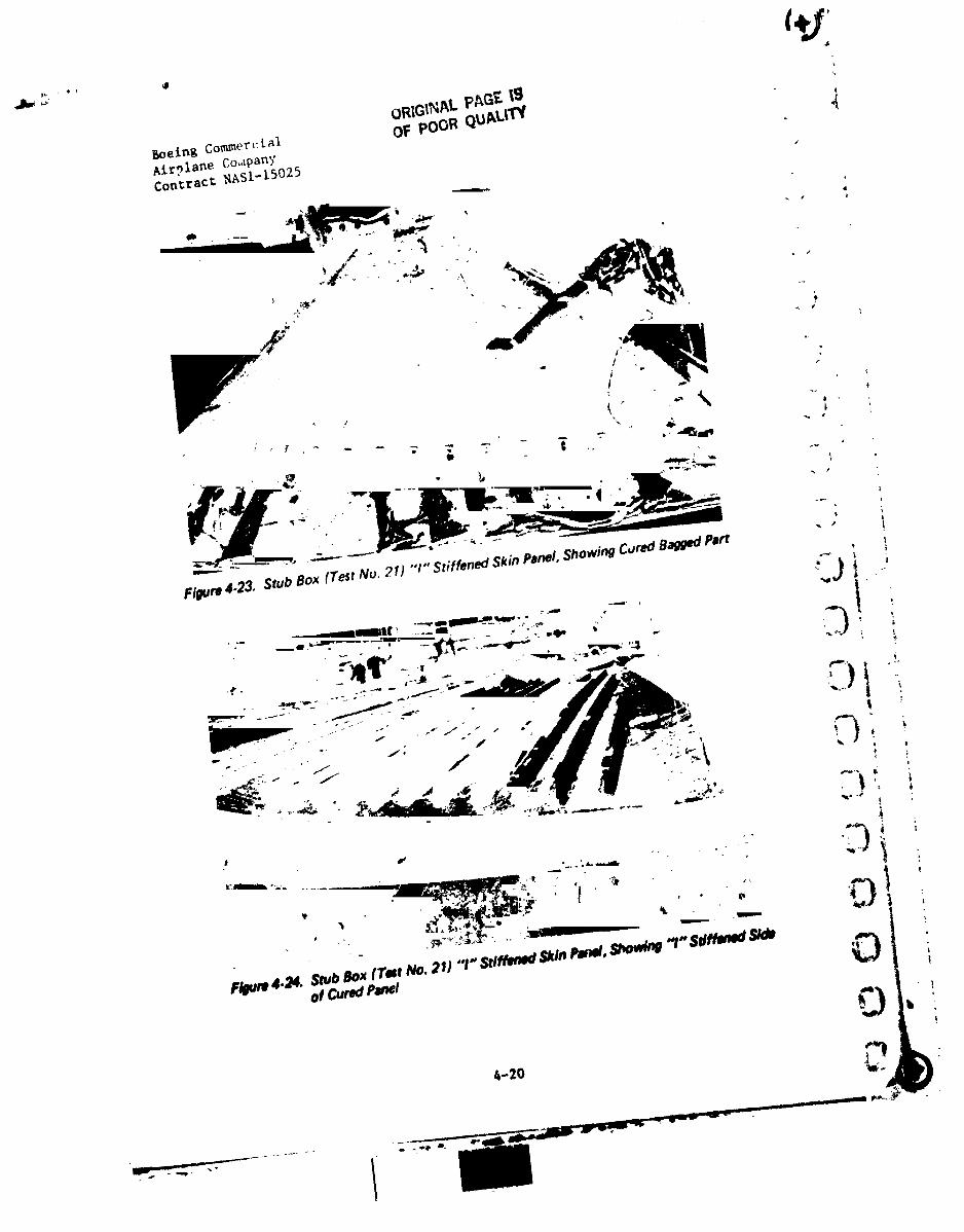
4-23 Stub Box (Test No. 21) "I" Stiffened Skin Panel, ; )Showing Cured Bagged Part 4-20 _... ;
I
1984020846-008
(j
Boeing Commercial
Airplane CompanyContract NASI-15025
i
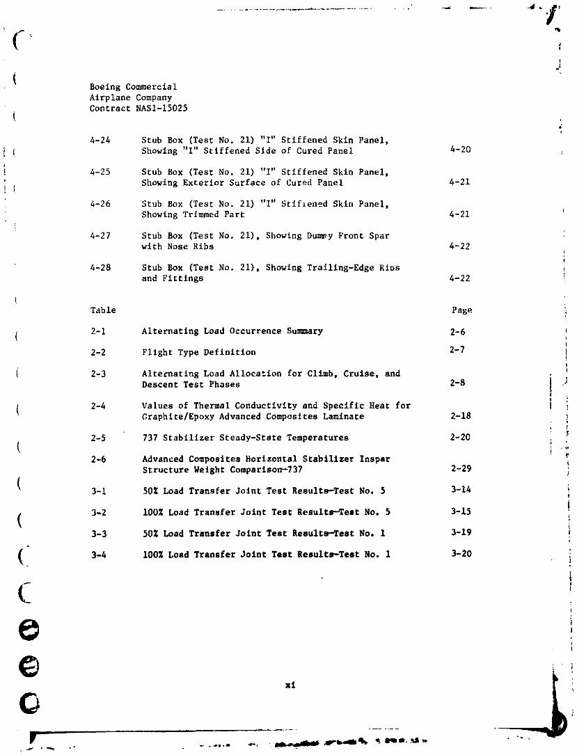
4-24 Stub Box (Test No. 21) "I" Stiffened Skin Panel,
Showing "I" Stiffened Side of Cured Panel 4-20
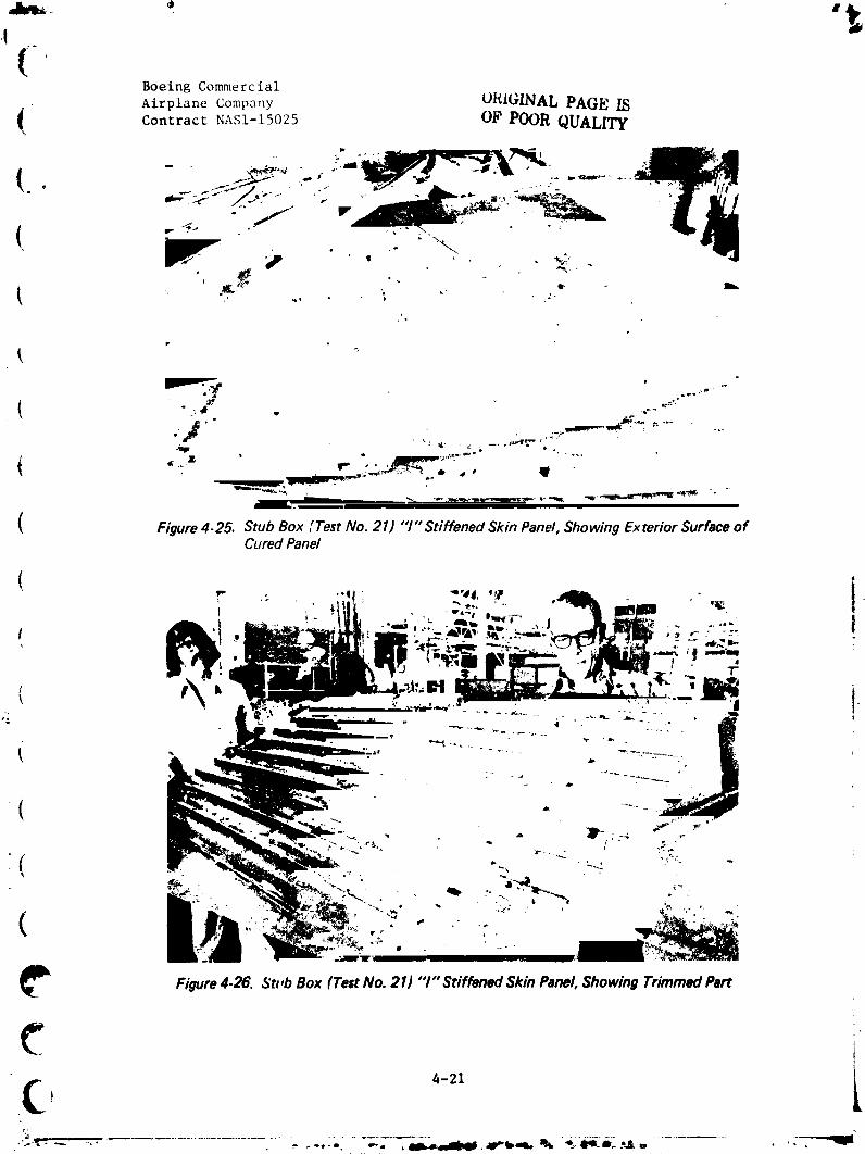
4-25 Stub Box (Test No. 21) "I" Stiffened Skin Panel,
i Showing Exterior Surface of Cured Panel 4-21
4-26 Stub Box (Test No. 21) "I" Stlf_ened Skin Panel,
Showing Trimmed Part 4-21
4-27 Stub Box (Test No. 21), Showing Dum_.yFront Sparwith Nose Ribs 4-22
4-28 Stub Box (Test No. 21), Showing Traillng-Edge RiDs
and Fittings 4-22
Table Page
( 2-1 Alternating Load Occurrence Summary 2-6 ,'
2-2 Flight Type Definition 2-7 !!
i 2-3 Alternating Load Allocation for Climb, Cruise, and
Descent Test Phases 2-8 i _J
( 2-4 Values of Thermal Conductivity and Specific Heat for J ,Graphite/Epoxy Advanced Composites Laminate 2-18
2-5 737 Stabilizer Steady-State Temperatures 2-20
2-6 Advanced Composites Horizontal Stabilizer Inspar iStructure Weight Comparison--737 2-29
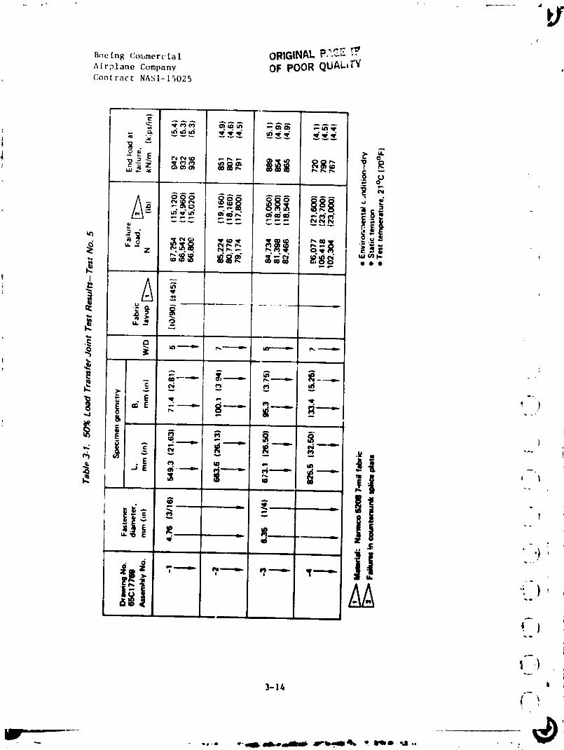
3-I 50% Load Transfer Joint Test Resultw-Test No. 5 3-14t
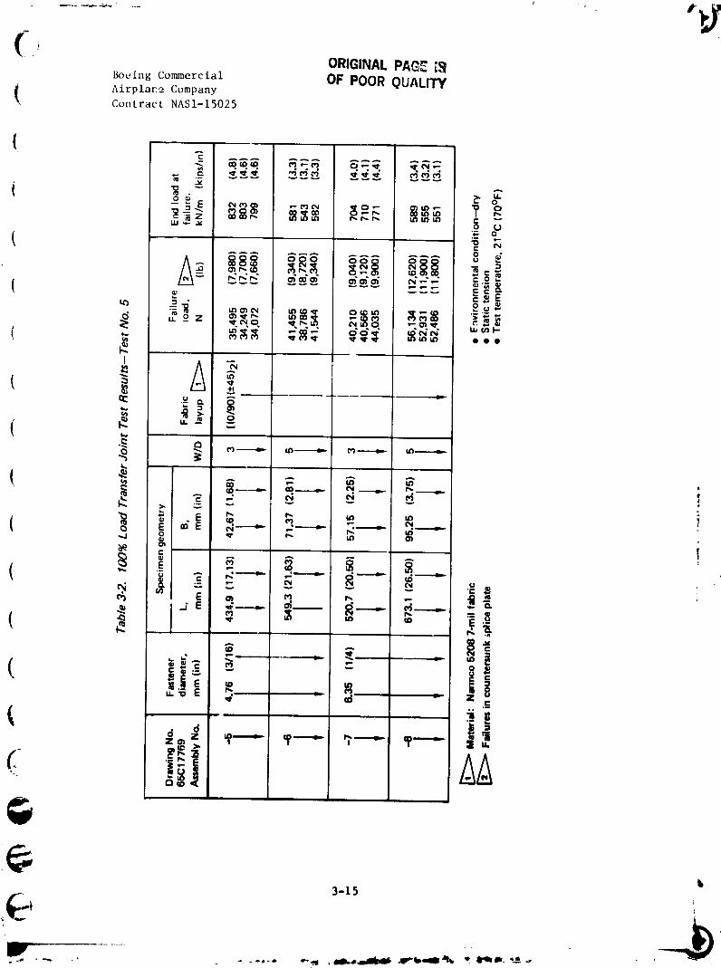
3-2 I00% Load Transfer Joint Test Results-Test No. 5 3-15 !
3-3 50% Load Transfer Joint Test Results-_est No. l 3-19 ,E
( •3-4 lOOg Load Transfer Joint Test Results--Test No. I 3-20 i
( ,!
!
i!
°-- it n
1984020846-009
q
q.
!
qL
_ Boeing Commercial
; _xrplane CompanyContract NASI-15025
t 'i6SECTION 1.0
!INTRODUCTION
lTile escalation of jet-fuel prices is causing a reassessment of technology i
concepts and trades used in designing and building commercial airplanes.t
Tile task is to incorporate fuel-saving concepts into commercial aircraft
design.
The potential weight savings and fuel reduction resulting from the use of
advanced composites in aircraft structure, especially primary structure,are significant. However, the lack of technical confidence and cost data
I
t
has delayed their use in commercial aircraft.
t
Hardware programs conducted in a production environment are required to !
{ establish and demonstrate the safety, operating-life characteristics, and [ -')
manafacturtng cost of advanced composite primary structures, t :
' i
Boeing's approach to the problem is to obtain reliable production, technical, _-
( and cost data bases by the integrr, tton of advanced composites technology ! "_development under NASA contracts, which, when combined with company effort, !
will accelerate the application of composites, Thls approach addresses
these data bases, and develops realistic production costs in 8 commrcial ,
transport manufacturing environmer'.. Program emphases are directed toward !
developing the information needed to obtain an early production com_itNnt
decision by amnage_ent, and will be conducted In a production envirommnt.
iPreliminary developuent8, a8 covered in the first quarterly report, were
!
devoted to conceivinS, developing, and analysin8 alternative deatSnt
J
i
f
? , ,
1984020846-010
q
!!
Boeing CommercialAirplane CompanyContract NAS1-15025
concepts, and the preparation of a technical plan to aid in selecting and
evaluating material, identifying ancillary structural development test
requirements, and defining full-scale ground-test and flight-test require-
ments necessary to obtain FAA certification.
The program was built on precontract design activities as well as contracted
design activities that consider:
i
• Program management and plans development!
• Establishing design c_lteria
• (',).t.ept.aland preliminary design )
• Manufacturing process development
• Haterial evaluatlon and selectlon i
• Verification test
• Detail design iy _
L
• FAA approval plan definition ",_)
This report describes work accomplished during the fourth 3-sonth period of
the contrat't. D_.slgn activities include discussion of the design loads,
the fatigue spectrum and analysis approach, design details, produclbillty !i )studies, and the ancillary test prograa. These activities are described
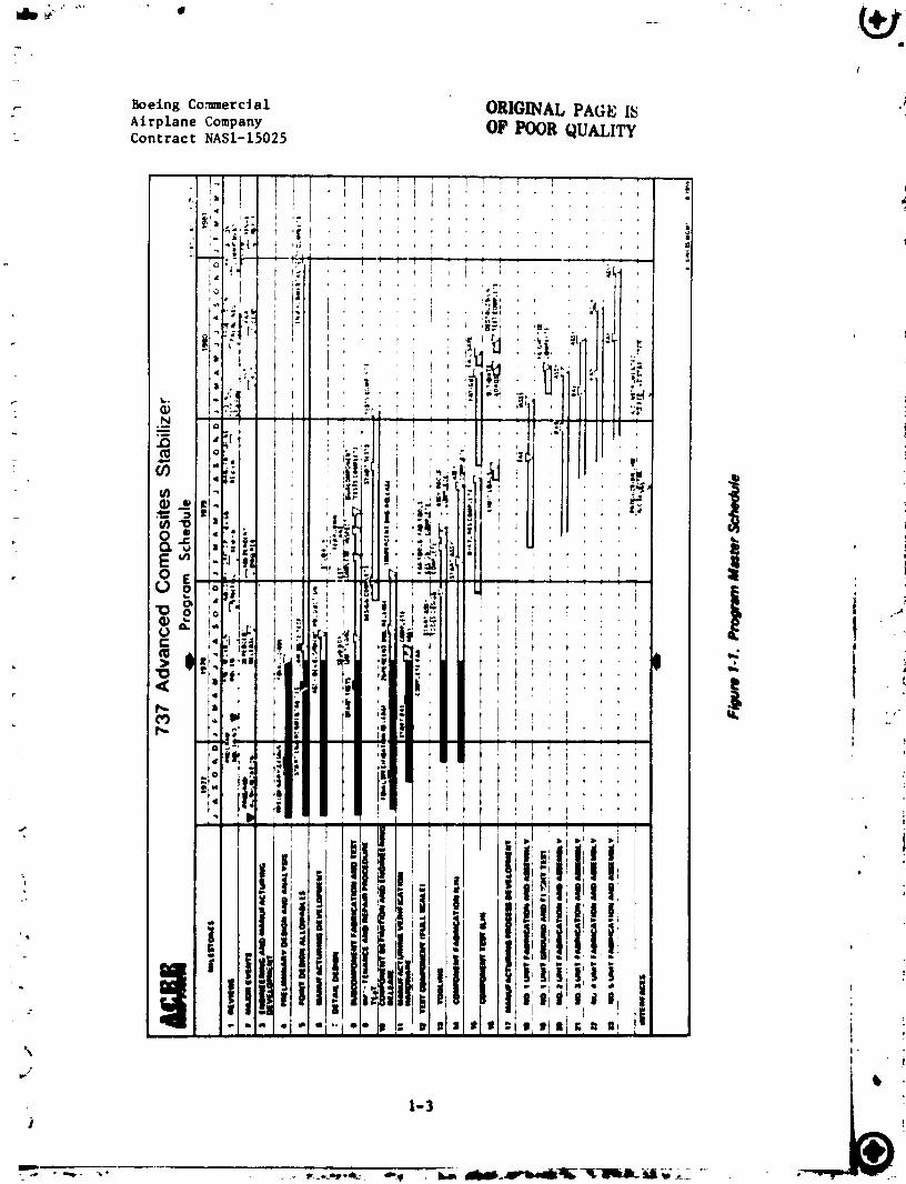
under the headings: Design end Analysis, Development Test Plan and Statue, { _ ,and Operations Development. The overall schedule status In summrtsed in -*
Figure 1-1. _
') i
!
t
,-2 C); ,
1984020846-011
/
r Boeing Commercial ORIGINALPAGE I_ "Airplane Company OlPPOOR QUALITYContract NASI-15025
(-
. Boeing Commerc fal
AtrpIane CompanyContract NAS1-15025
{" SECTION 2.0
EESIGN AND ANALYSIS
I 2.1 DESIGN LOADS CRITERIA AND ANALYSIS
I 2.1.1 Criteria and Objectives
Preliminary design criteria and objectives are being established for the
advanced com_.Ites horizontal stabilizer. A preliminary li_t of design
criteria and objective3 for this program, which are present!y being finalized,
( is presented in Reference I.
( 2.1.2 _D_s.lgnLoads
( Tile horizontal stabilizer w111 be substantiated for the highest loaded i|i_
model 737 airplane. Requirements of Federal Aviation Regulations (FAR) and
_oelng design specifications wlll be met.
(The three critical load cases tha_ are presently being used for prellmlnary 1t
( in Reference 1. Pressure logdings that are being used j_.design are presented
rfor local design and skin panel attachments are presented in Reference 2.
(The fatigue spectrum definition to be used for 811 epectrun fatigue testing
nag been defined. The load sequence has been developed similarly to the
European standard spectra TWIST and FALSTA/T (References 3 and 4), in which
flights of varying severity are applied with uors and let|or Zoad peaks in
C; Selection of 8 base mission for spectrum defintt/on vie 8ccemplished byreviewing the or/s/hal 737 futtSue analysis, and the 10 )'_,,ra of service
history since the 737 van introduced ant- service, Existing fleet service
2-1
GI I i I I • I __
"m98, 0208, (3-0"m3
I
Boeing Commercial 4
Airplane CompanyContract NAS1-15025
utilization data were investigated. Thls information indicated that pro-
jected flights in 20 years will number approximately 50,000, for the median
utilized aircraft. The average flight length of the median utilized aircraft
is between 463 and 741 km (250 and 400 nml). The 463-km (250-nmi) range
was selected as the base missio;_, based on the fact that metallic fatigue
damage per flight for the 737 spectrum has been shown to be constant between
the 463- and 741-km (250- and 400-nmi) missions.
The 463-km (250-nmi) flight profile defined in the existing 737 fatigue , ,
analysis consists of 24 segments, each with l-g gust and maneuver loads.
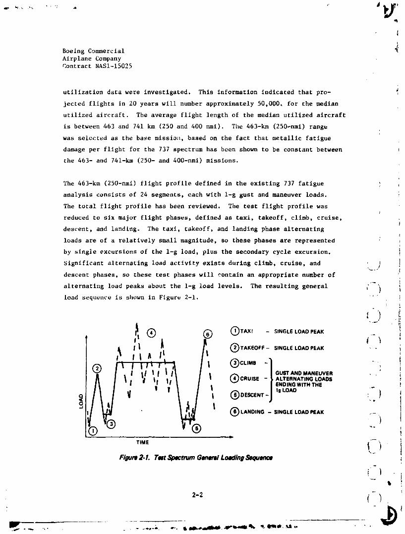
Tile total flight profile has been reviewed. The test flight profile was
reduced to six major flight phases, defined as taxi, takeoff, climb, cruise,
descent, and landing. The taxi, takeoff, and landing phase alternatingI
loads are of a relatively small magnitude, so these phases are represented :
by single excursions of the l-g load, plus the secondary cycle excursion. !
Significant alternating load activity exists during climb, cruise, and ! I
descent phases, so these test phases wlll contain an appropriate number of
alternating load peaks about the l-g load levels. The resulting general ( ) ,
load sequeuce is shown in Figure 2-1. "'"
® ® ®TAX,- __l + _ '11 J OrA':EOFF-SINGLELOADPEAK " - i
, t® ; t
,:" i°+-...ov. ..,X | I I ®CRUISE - ALTERNATING LOADS ,tl |1 ENDINGWITH THE i, v I , + '
t ®DE=mr-j,,_oAD : ) ,
l
T,._ t t iFillure2. L Test$,o_trum GeneralLoadln9Sequence i
_" t, i:
2-2 {-)i
._+-+-.+-+- ,_- + ..... ., ,,,., __+,,,lrb,,,milt,tl_ 't..l'_ii'_+'Ut..
1984020846-014
(-i
i_ Boeing Commercial ,_• _ Airplane CompanyContract NASI-15025
!, Prior to selecting the number and magnitude of alternating load peaks, the '
"_ importance of small-cycle omission and large-cycle truncation was investi-
gated. In previous graphite/epoxy fatigue testing, Schutz and Gerharz
(Reference 5) used an omission level of 6% of ultimate as a baseline, and
found that further omission resulted in life increase. Based on this, the
omission levels were set at 6% of ultimate for maneuver, and 3% of ultimate
i for gust. This resulted in an average of i0 maneuver and seven gust load
t.ycles per test flight, or an average of 20 load cycles per test flight,i{ including the secondary GAG cycles.t
i 'rr,mcation load levels were examined in accordance with the standard spectrum
i TWIST (Reference 3), which truncates at the load level exceeded i0 timest
per lifetime. Schutz and Gerharz showed that truncation of the highest
( test spectrum loads to 90% had virtually no effect on the fatigue life of
'| graphite/epoxy.
Based on this, truncation levels were conservatively set at the load exceeded '
five times per lifetime, which corresponds to approximately 90% of the load i
( exceeded once in two lifetimes. Therefore, based on the previously defined I
50,000 flights per lifetime the test spectrum will be constructed from
( lO,O00-flight blocks.
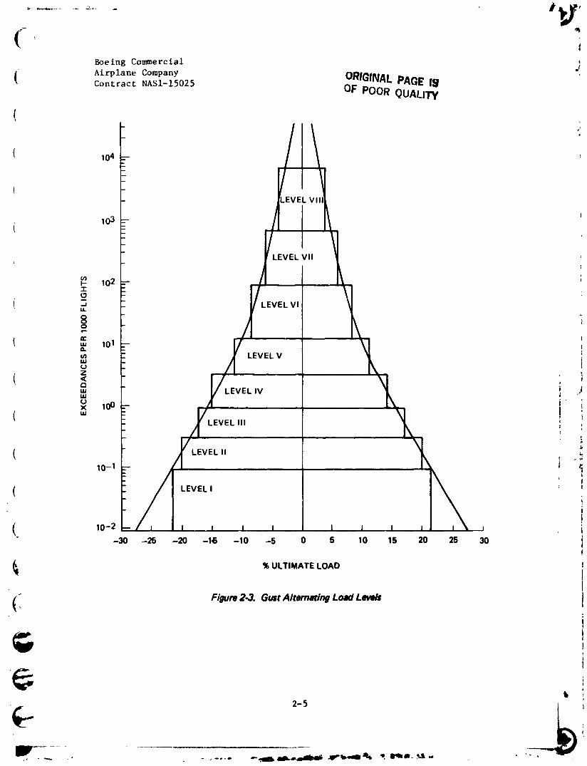
t[ Eight gust and eight maneuver alternating load levels were defined, resulting
in the stepped exceedance curves shown in Figures 2-2 and 2-3. Table 2-1i
lists the resulting occurrences of gust and maneuver incremental loads to i
8be applied in one 10,O00-fllght block. I
t
( ,Many of the alternating loads contained in the test spectrum occur less ithan once per flight, necessitating several test flight types with different l
! severities and frequencies. Test flight severity levels were defined in a
i
similar manner to those defined in TWIST, (Reference 3). Eight flightI
!
1l
1
] 984020846-0] 5

_r __ • ....
Boeing Commerclal O_,,E:...;,.,_-,,._._Airplane CompanyContract NASI-15025 OF POO_ Qj_Lii"(
d
105
104
103 LEVEL VII
(Boeing Commercial j
( Airplane Company ORIGrNALPAGE I,.9
Contract NA51-15025 OF POOR QUALITY
(
( lo4
.EVEL VII
103
Boeing ComerctalAirplane CompanyContract NAS1-15025
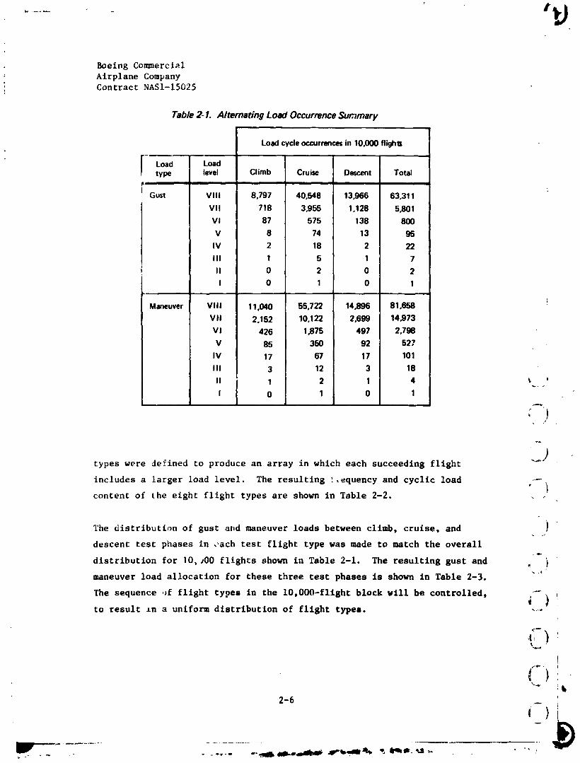
Table 2- I. Alternating Load Occurrence Summary
Load cycleoccurrencesin 10,000 flighlz
Load Loadtype level Climb Cruise Descent Total
L
Gust VIII 8,797 40,548 13,966 63,311
VII 718 3,955 1.128 5_01
VI 87 575 138 800
V 8 74 13 95
IV 2 18 2 22
III 1 5 1 7
II 0 2 0 2
I 0 1 0 1
Maneuver VIII 11,040 55,722 14_96 81,658
Vtl 2,152 10,122 2,699 14,973
V I 426 1_75 497 2.798
V 85 350 92 527
IV 17 67 17 101
III 3 12 3 18
II 1 2 1 4 _ '
I 0 1 0 1
types were defined to produce an array in which each succeeding flight
includes a larger load level. The resulting :,equency and cyclic loadi
content of the eight flight types are shown in Table 2-2.
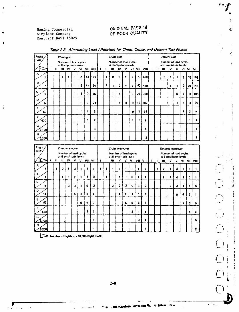
The distribution of gust attd maneuver loads between cllmb, cruise, and )
descent test phases in ,ach test fllght type was made to match the overallr_
distribution for I0, sO0 flights shown In Table 2-1. The resulting gust and _ i
maneuver load allocatlon for these three test phases is shown in Table 2-3.
The sequence ,Jr flight types in the 10.000-flight block will be controlled. _-
to result zn a uniform distribution of flight types. -_-
l
t )'_k
2-6 :
• ...... -".-10, _b.,,,_mJ_#, ._"b.-m °-, _ Ir__ _J_,. "" ,.
1984020846-018

...... '"iF• I
'! ( OR G;NLPA EBoeing Cor_erctal OF POOR QUALI'f_J
(_ Airplane CompanyContract NAS1-15025
ii _ Table 2-2. Flight Type Definition 2
.) Flight/ Number of gust load cycles Number of maneuver loadcycles Number "_,. type/ at 8 amplitude levels at 8 amplitude levels of load
j / Points in
_. / [_::_ I II III IV V VI VII VIII I II III IV V VI VII VIII flighti
1 1 2 6 14 112 766 1 3 5 2 7 3 2 3 1,866_a
_'_ 1 1 2 6 10 91 655 1 3 3 7 2 2 2 1,578i ,** I 1 2 2 39 468 2 8 7 3 I 5 1,084
1 1 2 14 166 4 12 8 6 7 448
. /_/_=_ 1 2 4 73 5 13 10 15 252
! _ , 3 ,s 38,0 86
_[ _ 16 38 42
4 8 30
_'_'_ Number of flights in a lO.O00-flight block !]
( J
2.2 DESIGN STATUS i5
( . ,
The design effort is proceeding with the detailed design of all graphite/ _
{ epoxy components, consisting of ribs, spars, skin panels, and trailing-edgebeams. Detailed design of interfacing nongraphlte/epoxy components, such
as the inboard gap covers, leading-edge ribs, and thermal expansion compensat-
ing linkage, is also progressing as scheduled, i
i
2.2.1 Stabilizer Box Assembly ProvisionI
The stabilizer box wlll be assembled with titanium mechanical fasteners. ITJtanlum Hi-Lok fasteners are used whenever possible, as these fasteners
'" have lower installation cost and weight than other competing fastener Ii
systems. These Hi-Lok fasteners wlll be used generally wlth corrosionl
resistant steel (cres) collars placed over cres washers, t
@ ,I1
2-7 I
it
-- i --~
- _. -.. _. • ,, .--. , __r__.aP Pb'amaJl_
1984020846-019
!
|
BoeingCommercial ORZGIf,'_.Lp,_,_*E_ _.' Air_lane Company OF POOR QUALITY
Contract NASI-15025
!
Table 2-3. Alternating Load Allocation for Climb, Cruise, and Descent Test Phases ,
Flight/ Chmb gust Cruisegust Descentgust
type/-- Nurr,uer of load cycles Number of load cycles Number of load cycle./ at 8 amplitude levels at 8 amplitude levels at 8 amplitude levels/ P,.,_
/ I[j._ I II III IV V VI VII VIII I II III IV V VI VII VIII I II III IV V VI VII VIII
_1 1 1 1 2 14 109 l 1 0 0 4 9 ?3 489 1 1 1 3 25 168
y, -1 1 2 11 91 1 1 0 4 6 60 419 1 1 2 20 145
C_ 1 1 3 65 1 1 1 0 28 300 0 1 8 103J __
1 0 24 1 0 0 10 107 ! 1 4 35• _ !
1 1 8 1 0 1 51 I 2 14 i
1 2 1 1 9 1 4
13 ,
0 I 5 I
" i1 2 1 I
L
B I
Fhght/] Climb maneuver Cruisemaneuver Descentmaneuver ]
_[:::: 4 load cycles Number load cycles Number ol load cycles
INumber of of
at 8 amplitude levels at 8 amplitude levels at 8 amplitude levels \ r_' j
I II III IV V Vl Vll VIII I II III IV V Vl VII VIII I II III IV V VI VII VIII ';• i
1 2 1 3 1 1 0 1 1 I 0 1 1 I 2 1 2 1 3 I 0 1 _ _t I
1 1 2 1 1 0 1 I 1 I 0 1 1 1 I 4 1 0 1
3 2 2 0 2 2 2 2 0 0 3 3 3 I 1 0 .,... "._
_14 5 3 3 4 4 2 1 1 2 5 4 2 1
6 4 7 5 0 3 8 7 3 0 "- i
3 2 3 1 4 4 4 ) iiGG _- -- '-.-. ' J
. 1 3 7 0 i
I 5 2 - IID:::::>Numberofe.ght,in,10.O00-,i_t_lock !I
')_ tt Ii
, i
Z-8
1984020846-020
(Boeing Commercial
Airplane CompanyContract NASI-15025
(Titanium bolts, with CRES nuts or nutplates, will be used whenever internal
( access is limited for Hi-Lok installation tools.
in assembling the stabilizer bo_ tile front and rear spars will be joinedinitially go tile ribs. Hi-Lok fasteners are generally used to join ribs to
spars.
The upper panel will be fitted to the substructure (spars and ribs), using
shims where they are required for proper fit, and then fastener holes will
be drilled to join the skin to the substructure. Next, the panel will be
I removed, and nutplates will be installed on tile substructure where internal
access to tlle stabilizer box is limited.
The lower panel will be fitted next, shimmed, and installed with Hi-Lok
fasteners.
(The upper panel is next refitted and installed with bolts. These bolts, I
#
( located on the outboard three-fourths of the stabilizer, will be installed !
usiilg nutplates. The remaining bolts on the inboard ar_a will be installed
with nuts and washers. Accessibility to these nuts will be provided through1
access holes in the spars and inboard closure rib. "i
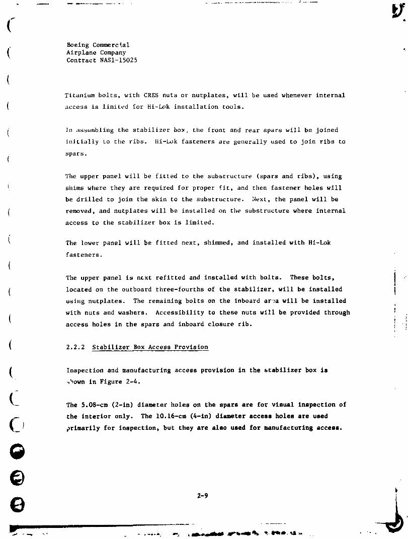
2.2.2 Stabilizer Box Access Provision
Inspection and manufacturing access provision in the stabilizer box is_own in Figure 2-4.
(-- The 5.08-cm (2-in) diameter holes on the spars are for visual inspection of
the interior only. The 10.16-cm (4-1n) diameter access holes are used
(_J prlmarily for inspection, but they are also used for manufacturing access.
@
IIIll
1984020846-021

t+
. Boeing Commercial
Airplane Company /
Contract NASI-15025
10.16cm1 10.16cm (4 in)
l.,yptCAL 5.08 cmI (4 in).---- (2in) I _ _v---"-" 10.16cm r
5.08 cm _ _ _--- _ _ 14in)
_ ., _ , _ , (4.._5.08 cm C C C I C 10.16cm(2 in) 6.08 cm I 10.16cm (4 in)
J (2in) ! '4in)TYPICAL - _
,i C = COVEREDHOLE:]T F/gum 24. Access and Inspection Provision
%__./
The large access holes provided on the z.board closure rib can be used for
visual inspection of the structurally important details at the inboard areas -
of the spars.
; t
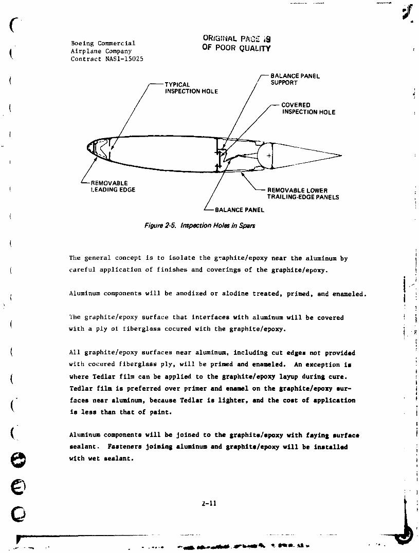
The holes in the rear spar at the elevator balance panel bays are provided _-.-/
with covers, as indicated in Figure 2-4. These covers prevent the unregu-
lated air pressure of the stabilizer box interior from disturbing elevator
balance pressures in the balance bays. A covered inspection hole is Illus-
trated in Figure 2-5.
2.2.3 Corrosion Protection i
Corrosion protection will be provided to each aluminum component near
graphltelepuxy structure, to mlnln_tze _he posslblllty of galvanlc corrosion. _,)
f
)
) i
2-10
't ,
1984020846-022
CORiG;NAL PA_ i_
Boeing Con_nerctal OF POOR QUALITYAirplane CompanyContract NASI-15025
/--- BALANCE PANEL
INSPECTION _,
! / /-- COVERED
t
t _MOVABLE
REMOVABLE LOWER
LEADING EDGE / TRAILING.EDGE PANELS/
BALANCE PANEL
Figure 2-5. Inspection Hole= in Spars
(
The general concept is to isolate the graphite/epoxy near the aluminum by
( careful application of finishes and coverings of the graphlte/epoxy.
i( Aluminum components will be anodized or alodlne treated, primed, and enameled.
'i
The graphlte/epoxy surface that interfaces with aluminum will be covered _ i
( with a ply ot fiberglass cocured with the graphite/epoxy, i "_
t
( All graphite/epoxy surfaces near aluminum, including cut edges not providedrt
with cocured fiberglass ply, will be primed and enameled. An exception ist
where Tedlar film can be applied to the graphite/epoxy layup during cure. tTedlar film is preferred over primer and enamel on the graphlte/epoxy 8ur- i
|
faces near aluminum, because Tedlar is 11ghter, and the coat of application• is less than that of paint. I
I
( .._ Aluminum components will be Joined to the graphlte/epoxy with fmylng Jurface I
sealant. Fasteners JolalnS aluminum and graphlte/epoxy will be installed .:
with wet sealant, i
i
W i ml I II I I ......................
1984020846-023

I 44, x_, _
!
J
Boeing Commercial
" Airplane CompanyContract NASI-15025
%
Where tllealuminum component is a removable part, the faylng surface sealant
will not be used. Fastener hole and countersunk surfaces will be alodlne-
treated, primed, and enameled.
The corrosion protection system used is identical to that used on the 727
adv;mced composites elevator, being developed under NASA Cor_tract NAS1-14952.
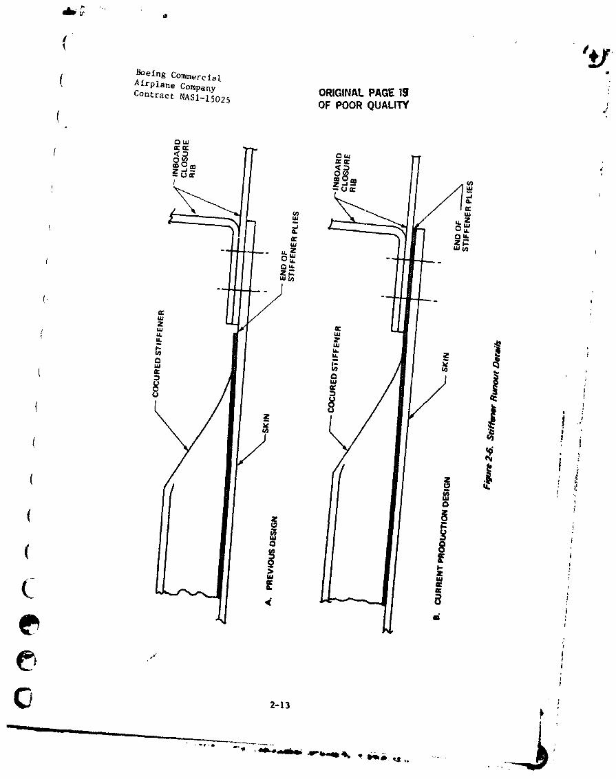
2.2.4 Skin Panel Stiffener Runout Detail
Panel stiffener inboard end runout detail has been changed as shown tnI ,i Figure 2-0.
The previous design required locating the ends of the stiffener pliesI
precisely on tile skin layup, to coordinate with the edge of the inboard
closure rib flange. The new design does not have this requirement, as the !
stiffener plies extend under the rib to the trimmed edge of the panel. "!t
" iJ
A concern over the possibility that the end-load transfer from the stiffener
to the skin, combined with the bending load from air pressure, could initiate
stringer delaminatton contributed to the decision to change this detail.
Filler plies will have to be added between the stiffener plies under the .__!
rib. The extended stiffener plies and the filler piles add 0.068 k8 (0.15 lb)2
to each skin panel. _ :t
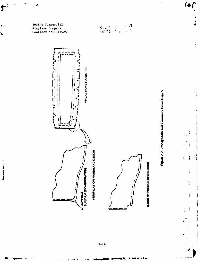
!2.2.5 Rib Corner Detail t i
The honeycomb rib design detail at the forward corners has been chanBed, as _ ,
shown in Figure 2-7, to facilitate manufacture, based on experienced 8ained -- ]I
I !
during fabrication of the verification herdware. The beelc problem i8 that ._
the graphlte/epoxy material tends to "bunch-up" at the corners, resulting _ ) iL
in thicker than desirable laminate in these areas. This thickness creates iI
fit-up problems at the front spar where flat, well-mttched interfaces ere _L, ) irequi red.
1
(-t _ '
2-12
i .
- i 1 .... - .... " _---11i___ _'- "--_- ....J
] 984020846-024
# ,'t
Boeing Corr.'nerota l
I_ AirplaneCompany ORIG|N_LPAG_ |g dContractNASI-1$025 OF POOR QUALITY
g.
goe Ins Coramerc ial . _ _Airplane Company C..'Contract NASI-15025 O,_ _....
-%
_q
Boeing Commercial a
• Airplane Company iContract NASI-15025
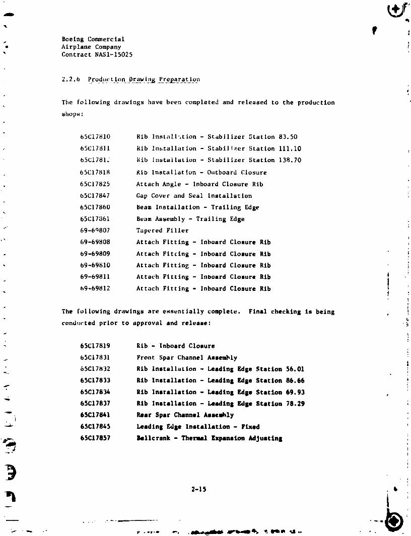
2.2.6 Pro,ductipn D_ra_win_ Pre2_a_ration
d
The following drawings have been completed and released to the production
shops :
65C17810 Rib Install:,tion - Stabilizer Station 83.50
65C17811 Rib Installation - Stabilizer Station 111.10
65C17812 Rib installation - Stabilizer Station 138.70
65C17818 Rib Installat!on - Outboard Closure
65C17825 Attach Angle - Inboard Closure Rib
65C17847 Gap Cover and Seal Installation
65C17860 Beam Installation - Trailing Edge
65C17861 Beam Assembly - Trailing Edge
69-6q807 Tapered Filler
69-69808 Attach Fitting - Inboard Closure RibJ
69-69809 Attach Fitting - Inboard Closure Rib i
69-69810 Attach Fitting - Inboard Closure Rib i
69-69811 Attach Fitting - Inboard Closure Rib i
69-69812 Attach Fitting - Inboard Closure Rib I :
w
The following drawings are essentially complete. Final checking is being _
condtwted prior to approval and release:
65C17819 Rib - Inboard Closure
65C17831 Front Spar Channel Assembly
65C17832 Rib installation - Leading Edge Station 56.01
65C17833 Rib Installation - Leading Edge Station 86.66 4
65C17834 lib Installation - Leading Edge Station 69.93
65C17837 Rib Installation - Leading Edge Station 78.29
"_'_ 65C17841 Rear Spar Channel /tm_mhly
C._ 65C17845 Leading Edge Installation - Fixed
:_._ 65C17857 gellcrank - Thermal Expansion Adjusting
1
. - . , _ 4_,-_. _ _m ..a,,
q984020846-027
Boeing Commercial _,Airplane CompanyContract NASI-15 "5
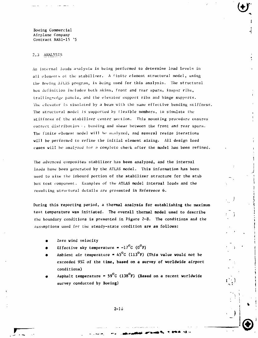
2.3 ANALYSIS
An internal loads analysis is being performed to determine load levels in
all elemt.nts of the stabilizer. A finite element structural model, using
the Boeing AI'LAS program, is being used for this analysis. The structural
box definition includes both skins, front and rear spars, inspar ribs,
trailing-edgL, panels, and the elevator support ribs and hinge supports.
'fh¢ elevator is simulated by a beam with the same effective bending stiffness.
The structural model is supported by flexible members, to simulate the
stiffness of the stabilizer center section. This mounting procedure ensures
correct distribution . , bending and shear between the front and rear spars.
The finite element model wilJ be m,alyzed, and several resize iterations
will be performed to refine the initial element sizing. All design load
cases will be analyzed for a complete check after the model has been refined.
The advenced composites stabilizer has been analyzed, and the internal I
loads have been generated by the ATLAS model. This information has been
used to size the inboard portion of the stabilizer structure for the stub _ :
box test component. Examples of the ATLAS model internal loads and the
resulting structural details are presented in Reference 6.
b
During this reporting period, a thermal analysis for establishing the maximum
test temperature was initiated. The overall thermal n_del used to describe ,* ,
the boundary conditions is presented in Figure 2-8. The conditions and the i
assumptions used for tile steady-state condition are as follows: !
• Zero wind velocity _ !
• Effective sky temperature = -17°C (O°F) " I
• Ambient air temperature = 45°C (l13°F) (This value would not be 1I
exceeded 95% of the time, based on a survey of worldwide airport _ I
condit ions)
• Asphalt temperature 59°C (138°F) (Based on a recent worldwideI .. !
1'survey conducted by Boeing) "_!
i
y
* i2-16
F
] 984020846-028

I
( 'Boeing Commercial
Airplane Compary e_._1_,_n__,_..-.""'_._
[ Contract NASl-15025 OF ?OOR QBALIT'_.
i
J
N
I[,_i
_ Z ,< ou N
" o :
_ !!i
•,<,,<!_li_ IJ _ _ %,,.\1 " " : ;
_"" _; -'%/7 I II "
t {
< .... _i/ i, /_ I ,!
• l_l I
" I
____ la _._J il ilil IL i , J. _ mII_lll_li_i_--q _ _i_" -i. : _ ......
1984020846-02
r •
w
Boeing Commercial OF PoOR QUALt_YAirplane CompanyContract NAS1-15025
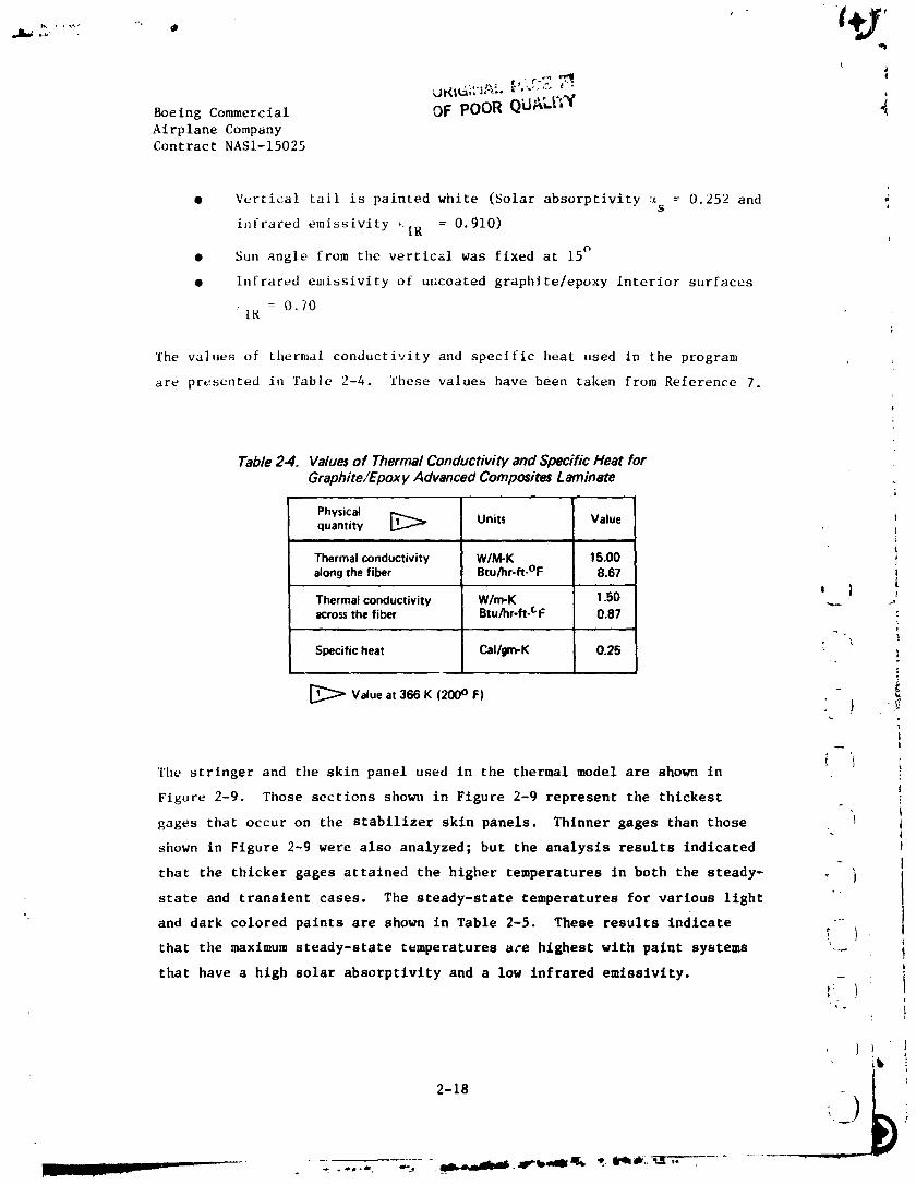
• Vertical tail is painted white (Solar absorptivity c_ = 0.252 andS
infrared emissivity _[R = 0.910)
• Sun angle from tile vertical was fixed at 15°
• Infrared emissivity of uncoated graphite/epoxy interior surfaces
= 0.70IR
i
The values of thermal conductivity and specific heat used in the program
are presented in Table 2-4. These values have been taken from Reference 7,
,=
Table 24. Va/ue# of Thermal Conductivity and Specific Heat for
Graphite�Epoxy Advanced Composites Laminate
Physicalquantity _ Units Value !
= i| i i ill t
Thermalconductivity W/M-K 15.00 !along the fiber Btu/hr-ft-°F 8.67
Thermal conductivity W/m-K 1.50 =-._ } _iacrossthe fiber Btu/hr-ft-CF 0,87
t
-'\ lSpecific heat Cal/gm-K 0.25 " ,!
Va,ueat386K2ooo - !
!
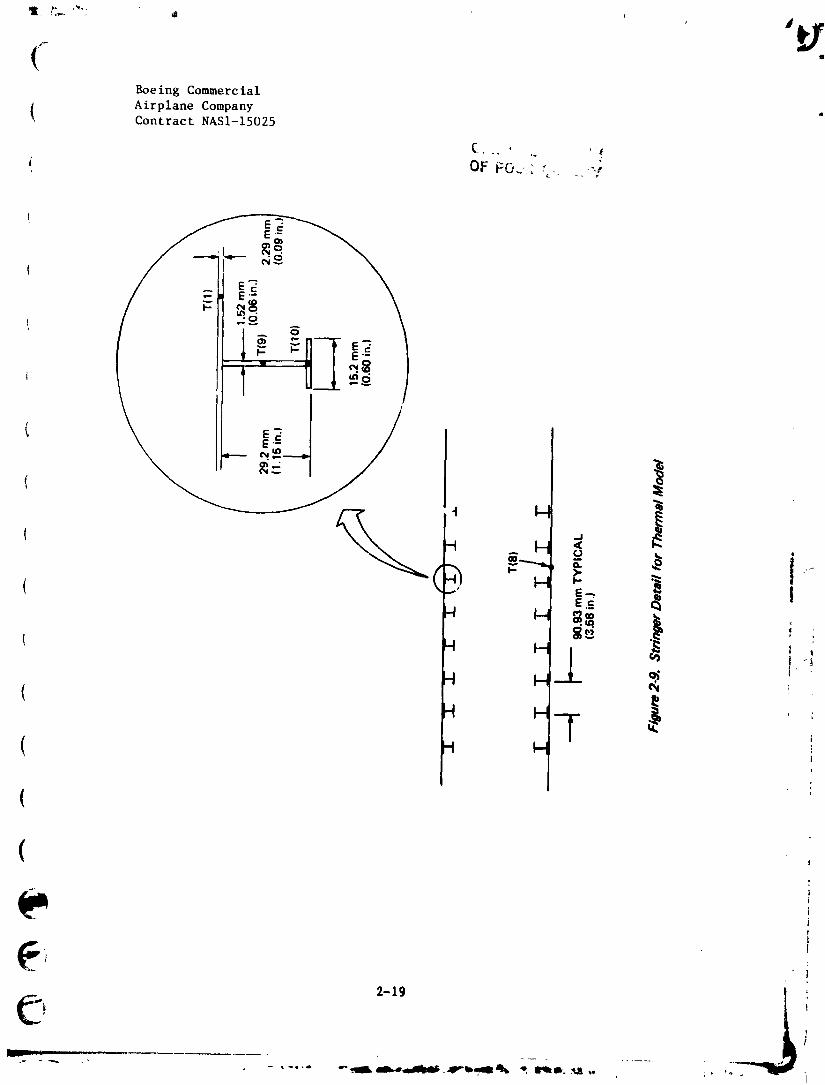
The stringer and the skin panel used in the thermal model are shown ini
Figure 2-9. Those sections shown in Figure 2-9 represent the thickest i
gages that occur on the stabilizer skin panels. Thinner gages than those '_ il
si]own in Figure 2-9 were also analyzed; but the analysis results indicated !i
that the thicker gages attained the higher temperatures in both the steady- _ } ]
state and transient cases. The steady-state temperatures for various light " I
and dark colored paints are shown in Table 2-5. These results Indicate _ 1
that the maximum steady-state temperatures a,'e highest wlth paint systems _'.-.- _|
that have a high solar absorptivity and a low Infrared emissivity.
- If
}t
2-18 _ i
...... ! I ' ..... - - .-,.-, _ _==_JM i-_''=''==k _ e_#_:_-
1984020846-030
Boeing Commercial
( Airplane Company• Contract NASI-15025
!
2-19
1984020846-031
• Boeing Cormere ial
Airplane ComFany
_ Contract NASI-15025
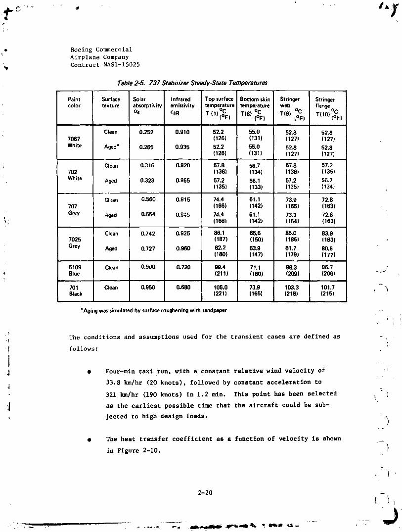
Table 2-5. 737 Stabidzer Steady-State Temperatures
Paint Surface Solar Infrared Topsurface Bottomskin Stringer Stringer
color texture absorpti_iw emissivity temperature temperature web °C flangeo°C °C T(9) T(IO) (_;F)°_s elR T (1) (OF) T(8) (OF) tOF)
i
Clean 0.252 0.910 52.2 55"0 52.8 52.87067 (126) (131) (127) (127)White Aged* 0.265 0.935 52.2 55.0 52.8 52.8
(126) (131) (127) (127)
Clean 0.316 0.920 57.8 _ 56.7 57.8 57.2702 (136) (134) (136) (135)
White Aged 0.323 0.955 57.2 56.1 57.2 56.7(135) (133) (135) (134)
CI.;an 0.560 0.915 74.4 61.1 73.9 72.8707 (166) (142) (165) (163)
Grey Aged 0.554 0.945 74.4 61.1 73.3 72.8(166) (142) (154) (163)
Clean 0.742 0.925 86.1 65.6 85.0 83.97025 (187) (150) (185) (183)Grey Aged 0.727 0.960 82.2 63.9 81.7 80.6
(180) (147) (179) (177)
5109 Clean 0.900 0.720 99.4 71.1 98.3 98.7 ,'_- Blue (211) (160) (209) (206) _-_
I -701 Clean 0.950 0.680 105.0 73.9 103.3 101.7 "_Black I (221) (165) (218) (215) _ ,I
*Agingwassimulatedbysurfacerougheningwithsandpaper
The conditions and assumptions used for the transient cases are defined as
_ follows:I ""
t
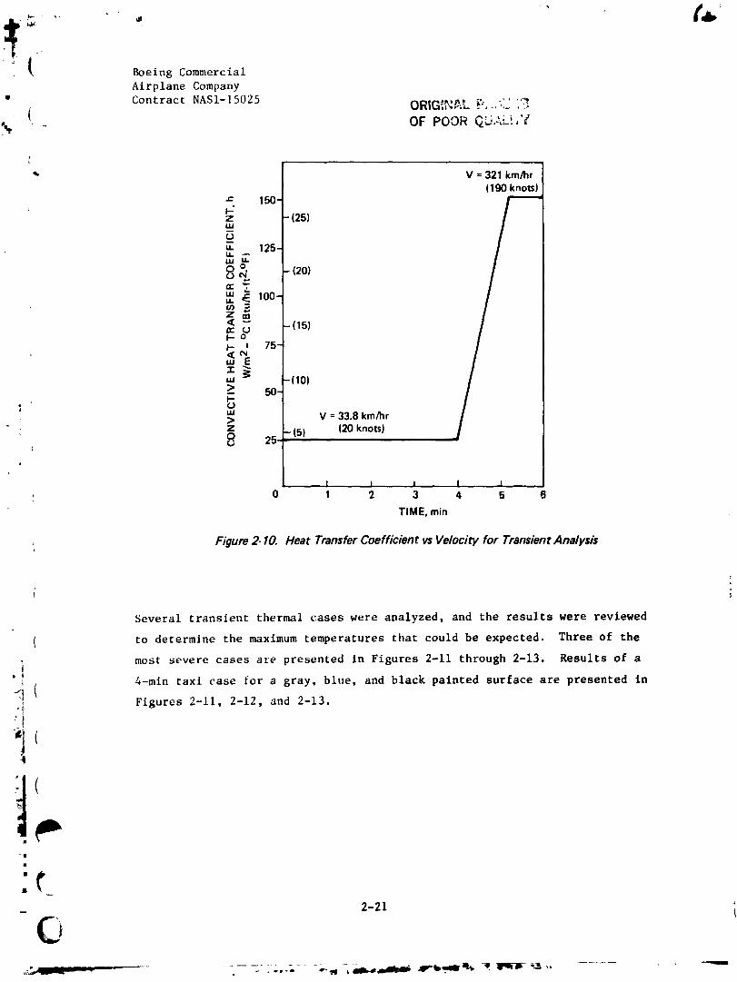
J • Four-min taxi run, wlth a constant relative wlnd velocity of "!
33.8 km/hr (20 knots), followed by constant acceleration to
321 km/hr (190 knots) in 1.2 mtn. This point has been selected i
:I as the earliest possible tlme that the aircraft could be sub-
jected to hlgh design loads. 't
• The heat transfer coefficient as a function of velocity is shown
in Figure 2-10. )
2-20
k
1984020846-032
Boeing Commercial
Airplane Company
• Contract NASI-15025 ._, _ .... ,:;ORIG_,,_=. _.. "._ '_"
% .. OF POOR _.D,:",L!,'="
1q', V = 321 km/hr |
(190 knots) /_- 150"
- 1251IJJ
" -- 125-
_" _" 1201
uJ _ 100-
LLOf)z,,¢ v (15),I,.. c.,,ii-.oe. , 75-
w (101--> 50-
Lu V = 33.8 km/hr: ;>, Z - (5) (20 knots)8 25
I, I I I I ,0 1 2 3 4 5 6
TIME, min
, Figure 2-10. Heat Transfer Coefficient vs Velocity for Transient Analysis
i
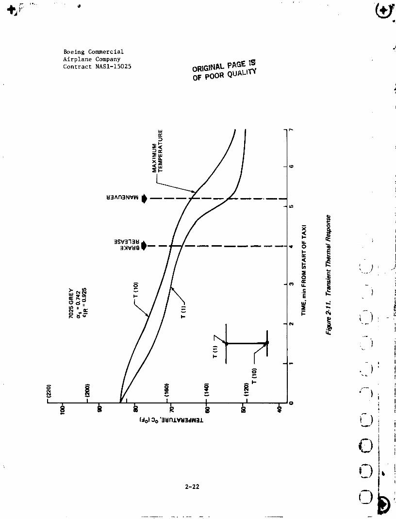
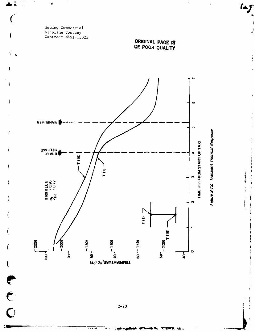
Several transient thermal cases were analyzed, and the results were reviewed
( to determine the maximum te_eratures that could be expected. Three of the
most severe cases are presented in Figures 2-11 through 2-13. Results of a
4-min taxi case for a gray, blue, and black painted surface are presented in
Figures 2-11, 2-12, and 2-13.
1
"1
2-21-
C,
1984020846-033
Boeing Commercial
Airplane Company
Contract NASI-15025 oR|G|N_ p_GE _
OF poOR QUALCI_'
F
(Boeing Commercial j.Airplane Company
Contract NASI-15025
ORIGINAL PAGE I_1OF. POOR QUALITY
(
t

i
4 Boeing Commercial OF " ..
Airplane Company O_ ',_'"_ • ' i
•_ Contract NASI- 15025
i
02-24
0
i 984020846-036
(3
Boeing Commercial j
I Airplane CompanyContract NASI-15025
{ Results of the transient thermal analysis are as follows:
I $ The stringer inner flange (T I0) does not cool as rapidly as the
skin
• '_rile paint system that attains the highest steady-state skin
temperature also has the highest (T i0) stringer flange temperature
at the end of the 1.2-min acceleration period
e For the 4-min taxi case for tileblack painted surface, the maximum
temperature of the stringer inner flange (T lO) is 77°C (170°F)
Based on results of this thermal analysis, the coupons and the subcom-
ponents in the ancillary test plan will be tested at 82°C (180°F). This test
temperature was selected because it was a representative maximum temperature ;
to cover the worst case of a dark-colored paint system.
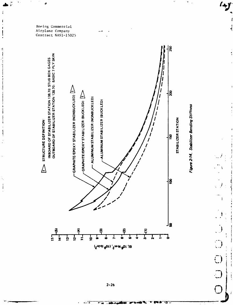
The analysis task of establishing the stabilizer stiffness to meet stability/ 'i
( control and flutter requirements is still proceeding. Figures 2-14 and Ii2-15 present the most recent stiffness calculations, based on the stub box
t skin gages (Test No. 21). The bending stiffness (El) curves have been '!!
modified from previously published curves, to reflect a refined analysis
( that accounts for material effectivity due to stabilizer sweep-back and _f_shear-lag. These curves also present a comparison between the buckled
aluminum and advanced composites skins. This information is presently i
( being evaluated by the Stability/Control and Flutter Technology groups. [
i( '.,. L2.4 WEIGHT STATUS I
i ?
The stabilizer skin panel weight distribution has been reevaluated by !
utilizing the stub box gages, Test gJo. 21, as being representative of the I
( production inboard section. Outboard of this •tub box, Stabilizer Station
|
ir
4.(2I 2-25
12,IIIiiii - - _ "
1984020846-037
i I
Boeing Commercial J.!Airplane Company _- ,
"I
l Cont racL NASI-15025
,D2-26 O
1984020846-038

(Boeing CommercialAirplane Company
( Contract NASI-15025
(I
[
ilut"ql liOi) 'i_._i IOl 'r9
2-27 i
1984020846-039
Boeing Con_merclal
Airplane Company
Contract NASI-15025
138.7C, the weight has been extrapolated using minimum gage. The evalua-
tion results in an increase to the skin panel weights, and a stabilizer
percentage weights savings decrease from 29% to 27%. See Table 2-_.
The stabilizer mass pro,,,._rtles for flutter and vibration analysis was
conducted using the abow_ skin panel gages.
t_valu,,tion of tile stub box drawlng_ is continuing, with o5% completion.
J )
I
I
i.!
OiD
2-28
0
"1984020846-040

._, , _i_
Boeing Commercial
! Airplane CompanyContract NASI-15025
i
!
, . ® i• " _i6 _ - "
! -
ooo o +
i
( ':
!J !'r11 ' i "
[I
._. 2-29
,: j
1984020846-041
_ {!
Boeing Commercial
.i '# ( Airplane CompanyContract NASI-15025
SECTION 3.0
DEVELOPMENT TEST PLAN AND STATUS
3.1 ANCILI,ARY TEST PR_)CRA/,I
During this reporting period, the following test programs have been defined,
and the drawings have been re]eased. The drawings are presented in Appendix A.!
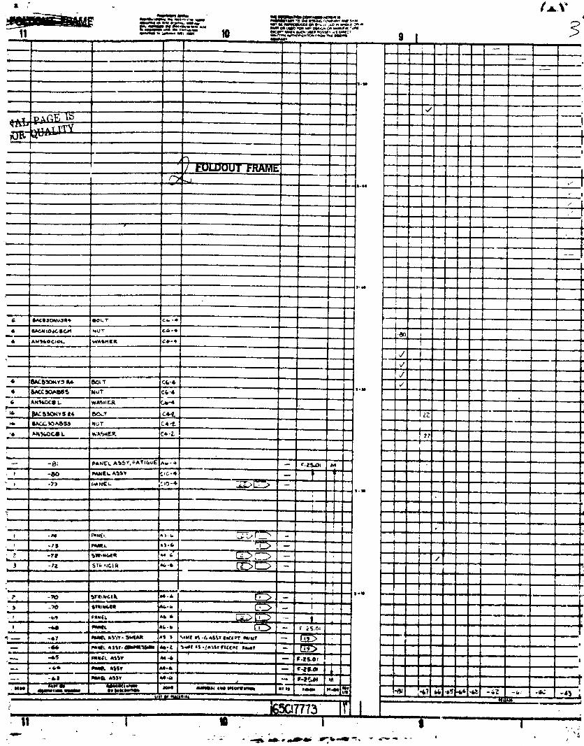
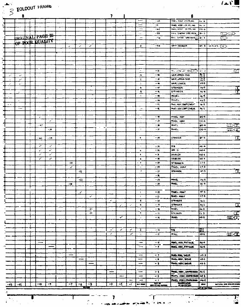
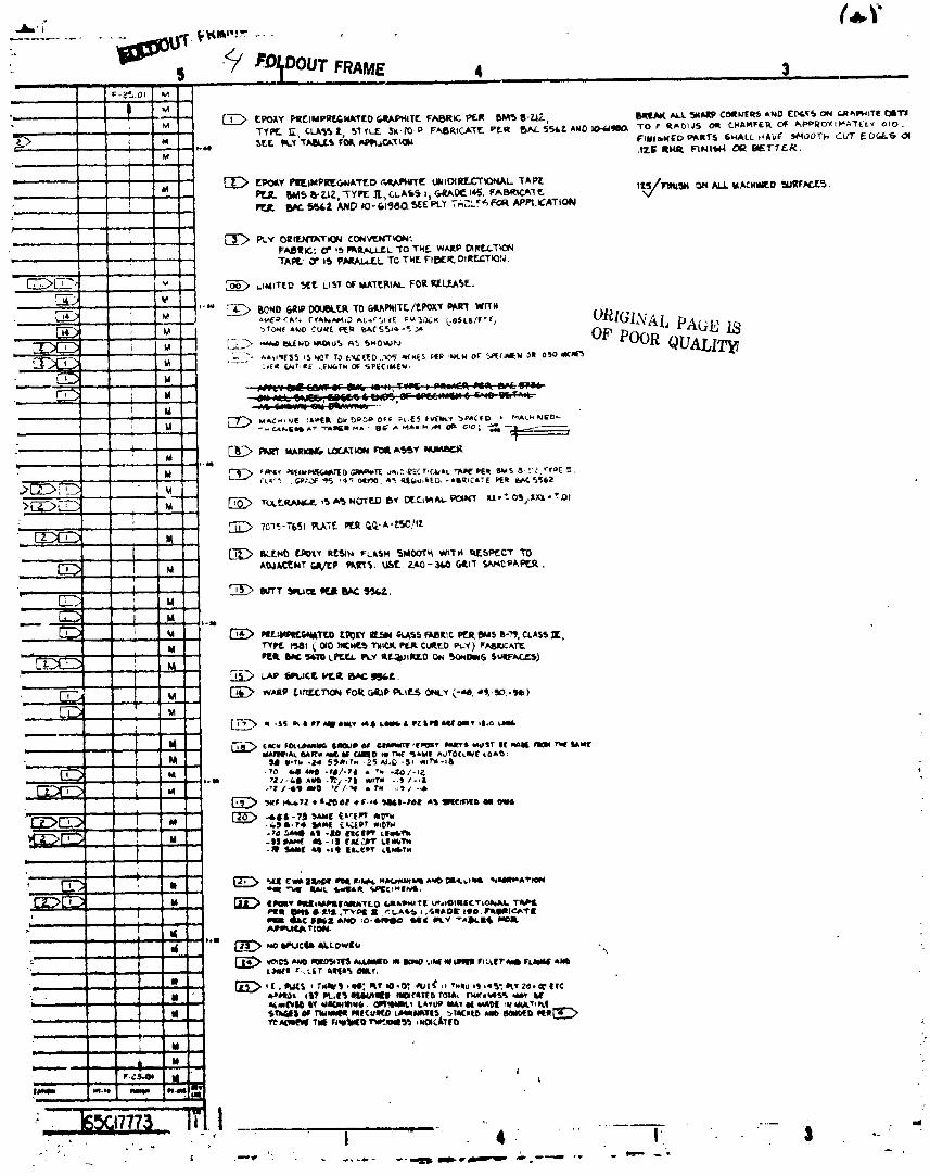
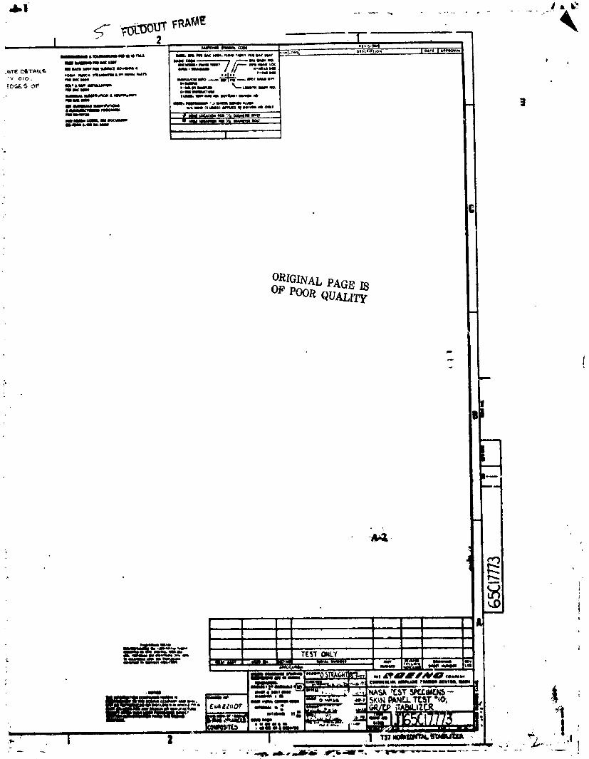
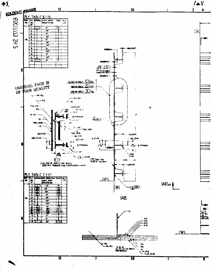
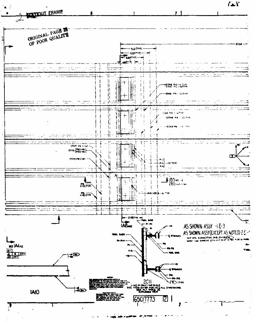
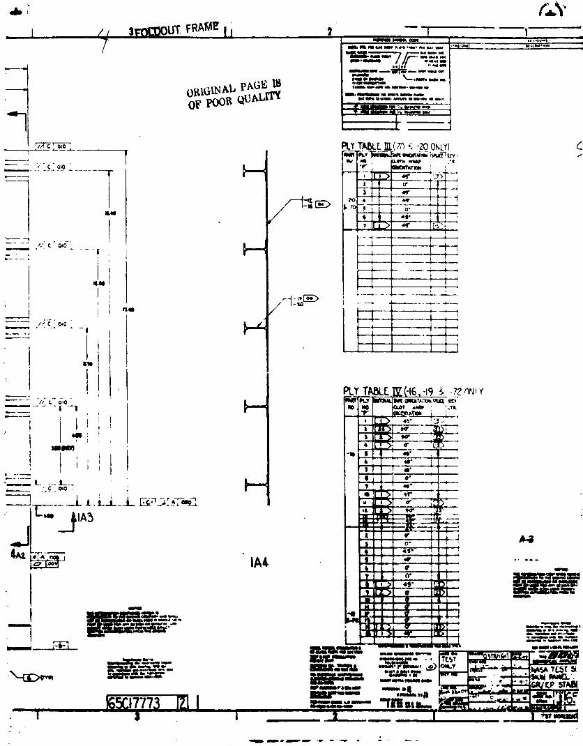
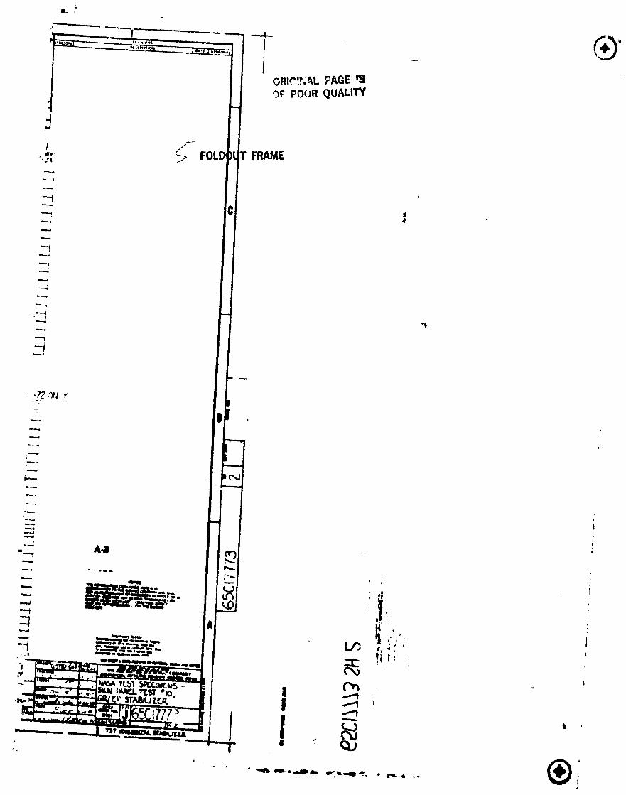
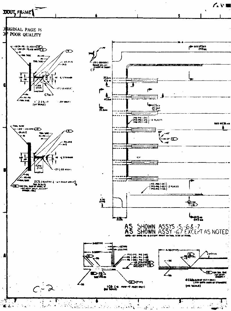
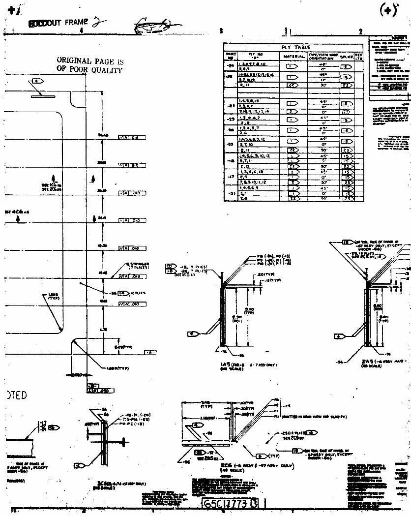
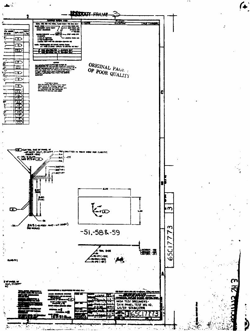
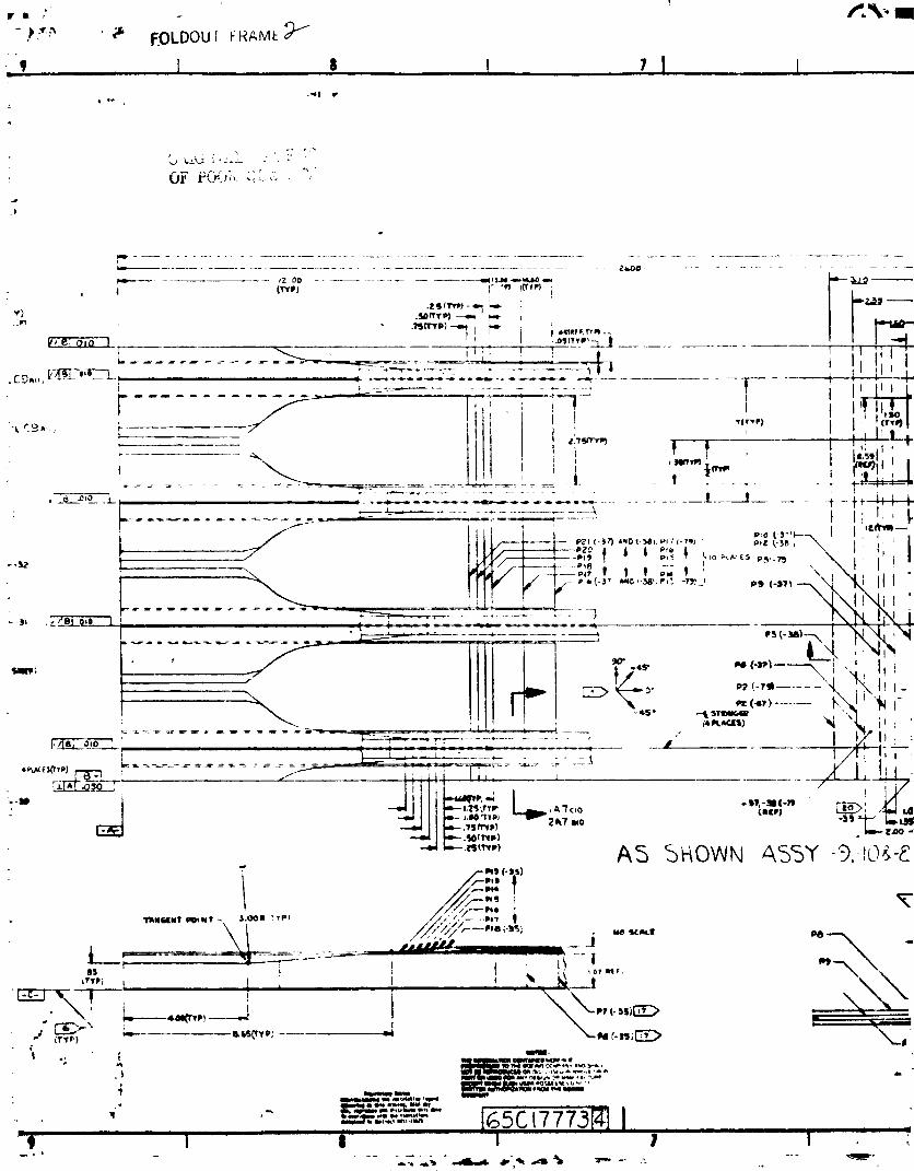
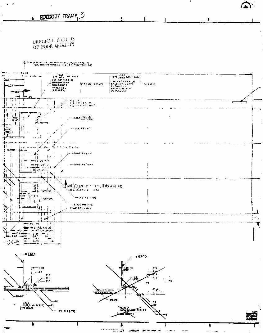
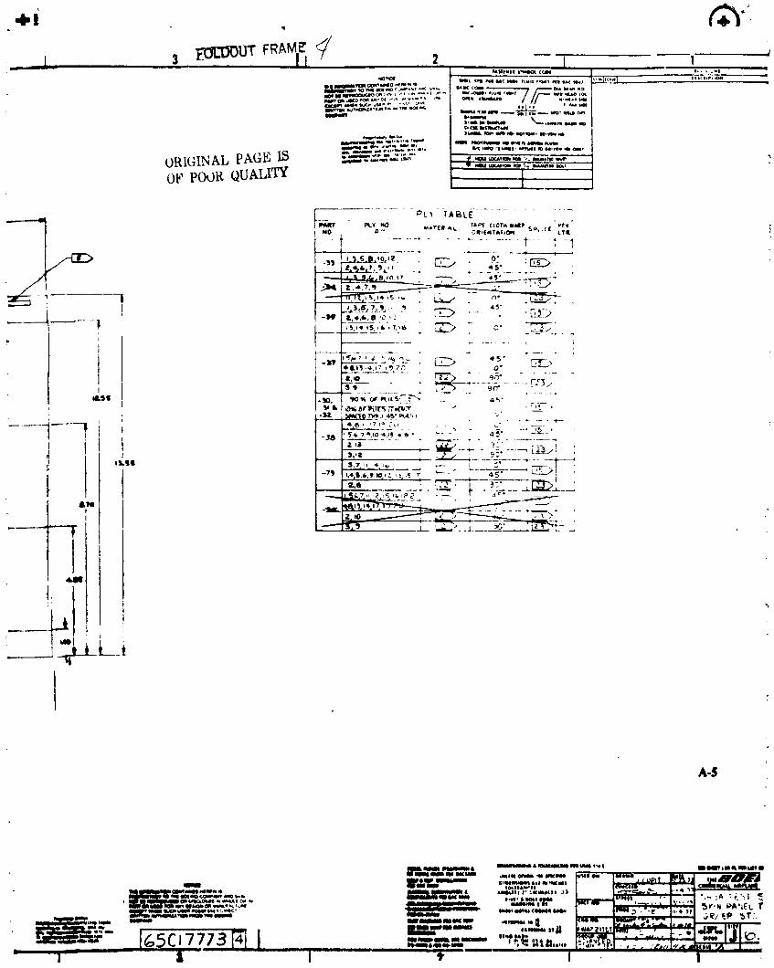
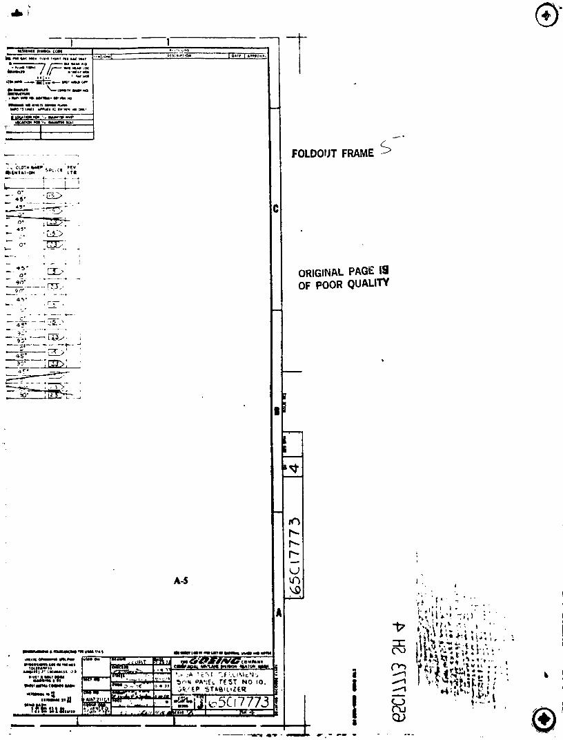
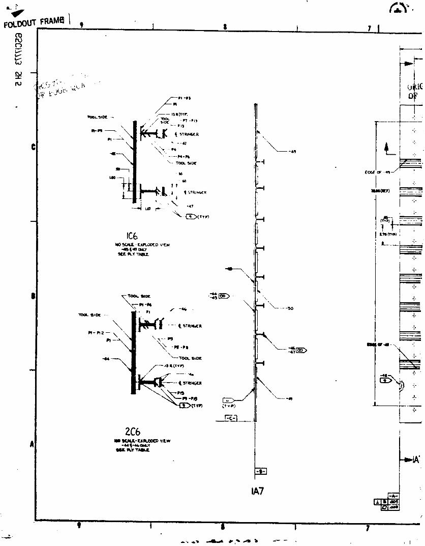
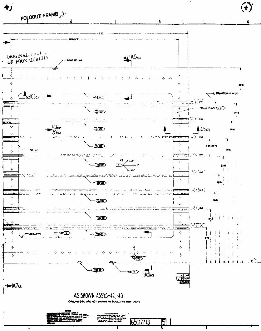
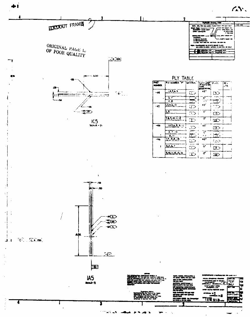
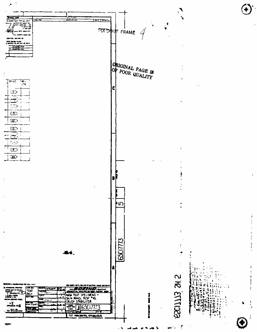
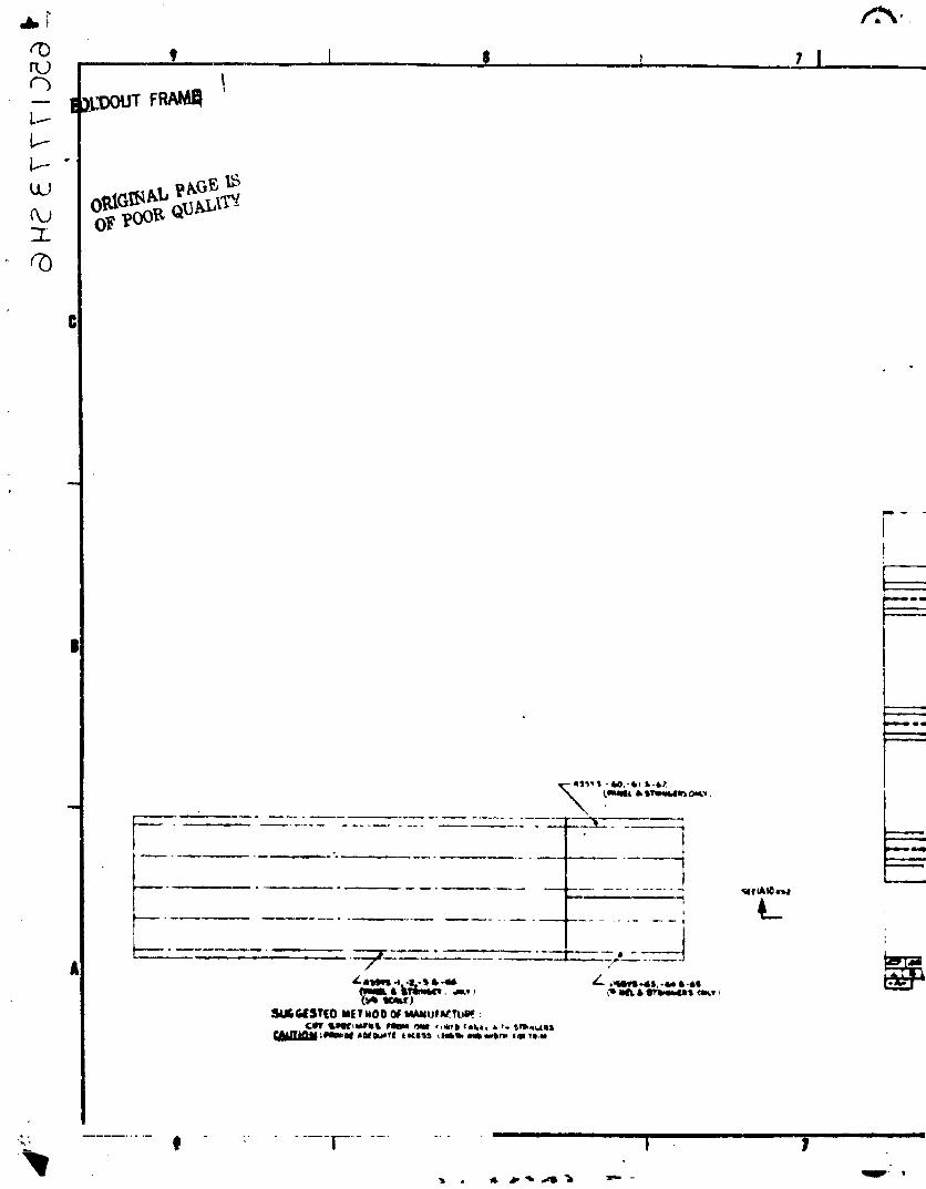
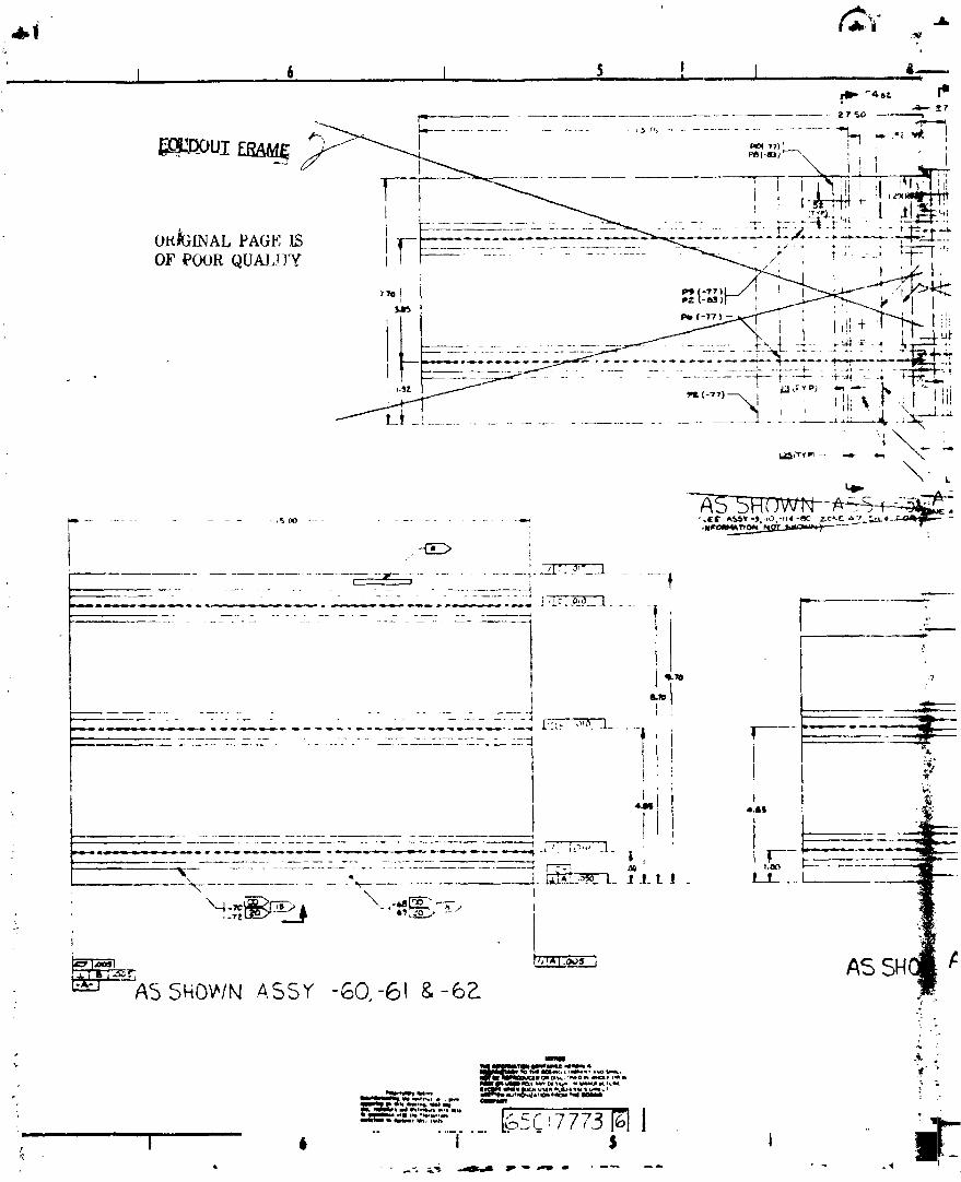
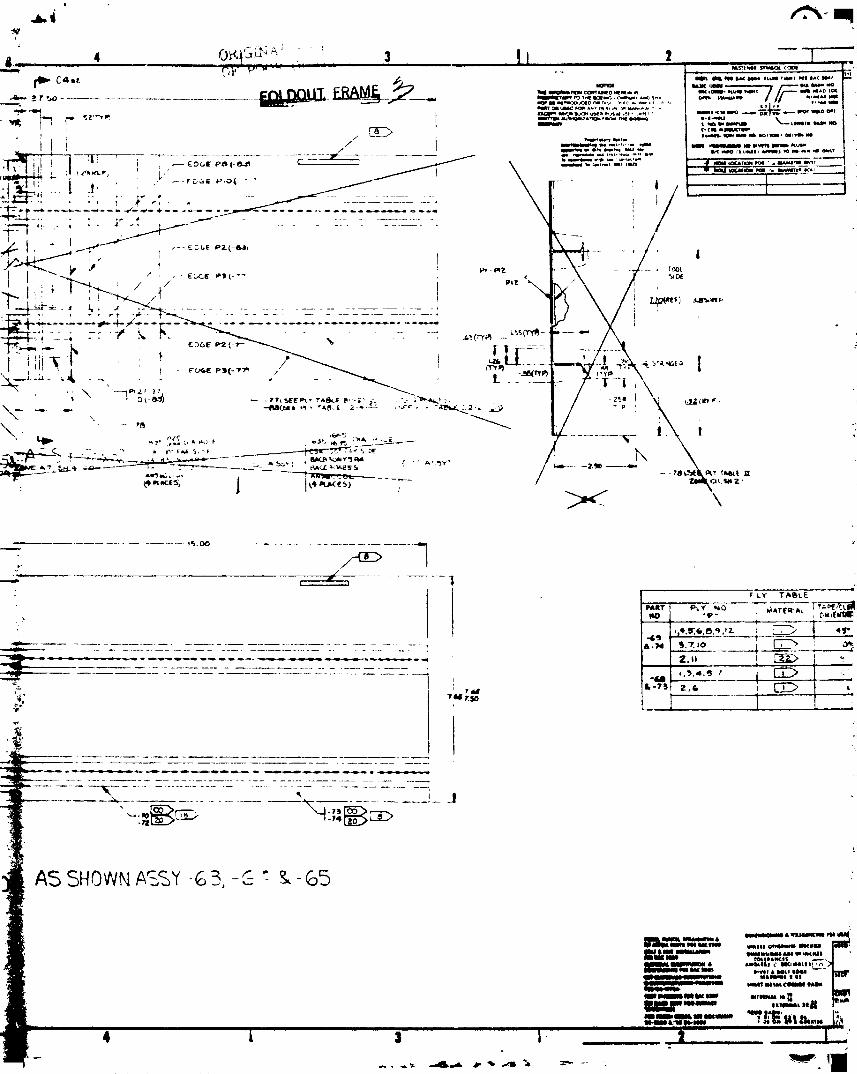
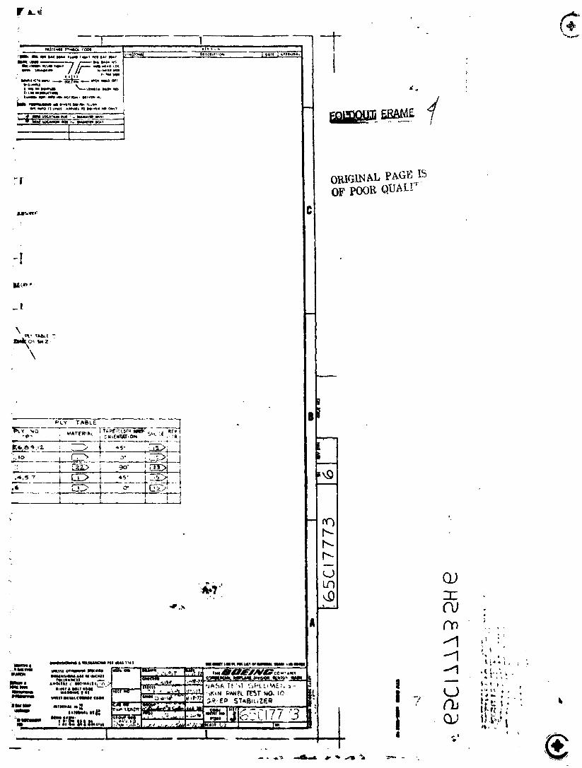
• Test No. I0 - Skin Panels - Drawing 6qC17773
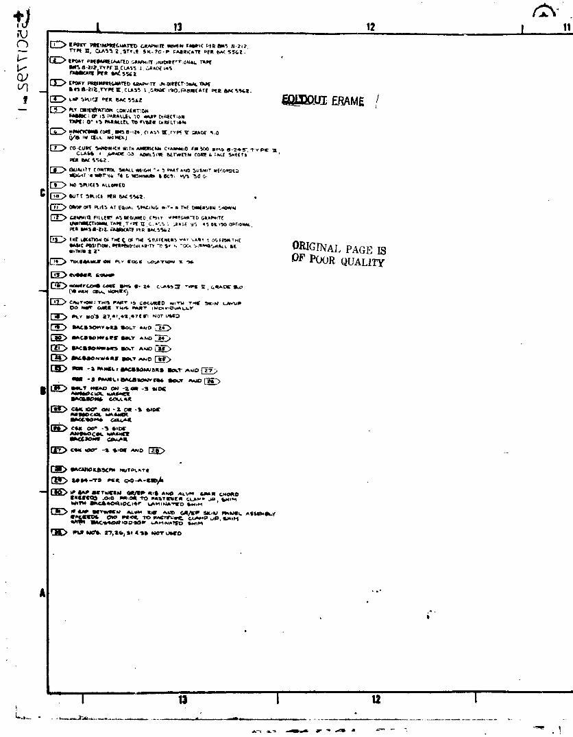
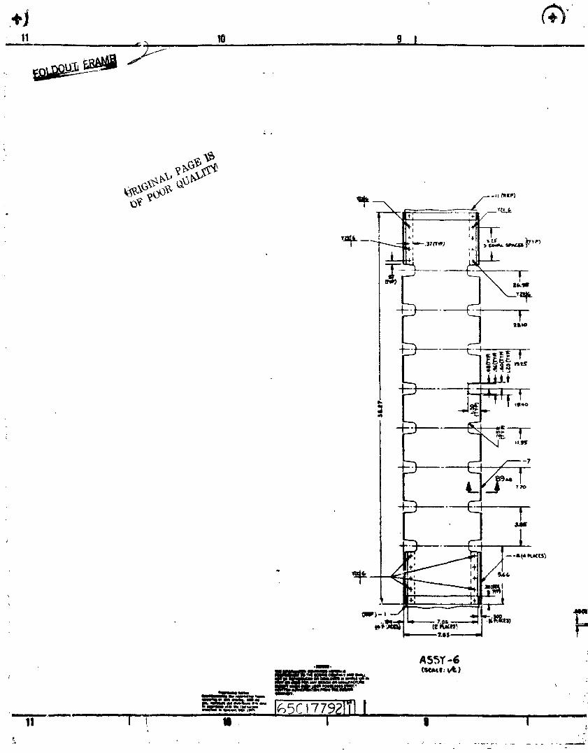
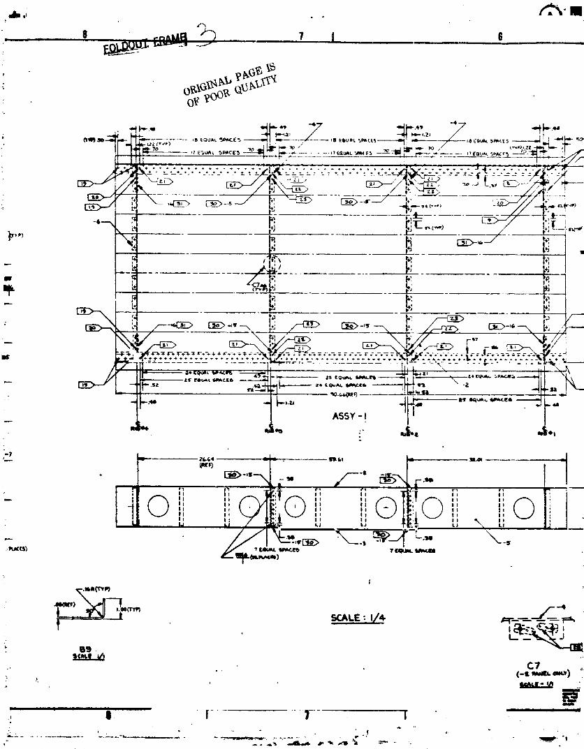
• Test No. 20 - Sonic Box - Drawing 65C17792
• Test No. 22 - Discontinuous Laminate - Drawing 65C17980 i
• Test No. 24 - Pressure/Shear Skin Rib Joint - Drawing 65C17981J
The ancillary test program has been revised to reflect the completion of
tile Test No. 10 drawings, and to include Test No. 22 and Test No. 24. The _:0_
revised test program is presented in Figures 3-1 through 3-7. The production _i
( verification hardware test program (see Figure 3-6) has been assigned as
Test No. 25. The ancillary test program schedule is shown in Figure 3-8.
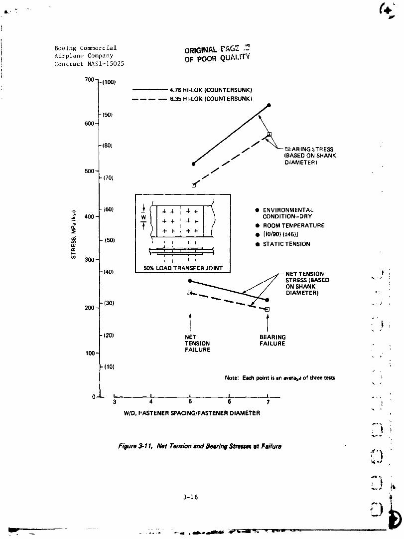
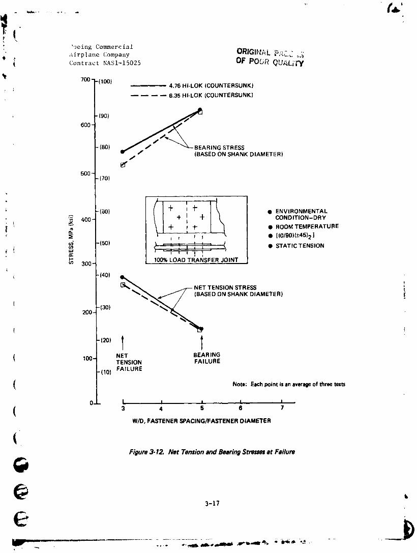
During this reporting period, 24 bolted joint specimens of Test No. 5 were
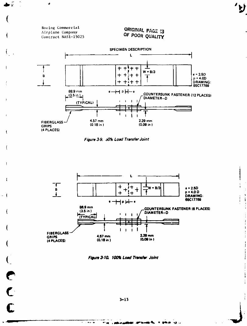
te_ted. The test specimens are defined in Figures 3-9 and 3-10. The test
results are presented in Tables 3-1 and 3-2. The net area stress and
I bearing stress that existed at the time of failure is plotted in Figures 3-II
and 3-12. These test results show that design bearing stresses are signifi-
cantly influenced by fastener spacing. This series of tests also included
(_ wet testing at room temperature. These specimens are presently undergoing" moisture conditioning, and will be tested when the required moisture content
C has been attained.
@
3-1 _t
' ''-- IHW _ = --._ ---- - .... o _ _mil..,o,imi_ .B_b'dimat_, _ dl,,9,a.-_ ,.
1984020846-042
CR;_F.i.AL '" "
'_ Boeing Commercial OF pOOR _' ...... _' _Airplane Company
"N Contract NASI-15025
• • @ • • • • •
5_ =- ="
• ,,= _ _ , --_ _ ,_
; 3 i 3 ,,_ ,."oE."_ _- ,
+ _i
' _=_= o I 1 .=a '.i
i I ! _'
I 1 - "_ •
_'_.
: _-_- _ "_ r4_ _.
o o._
..... _ _-
•oN Ilu!_e_(] , 89LLI.389 89LL_Jg, 89LLL_9 _ ,(. _ _,
"ONI,_J. • t "oN lsaj. I, "ONZse.I. I, "ONI_.L _,,,_ ;
3-2 B_
1984020846-043

(Boeing Con_nercial O_iGi_-,,';'._. !: ...... _ ,_I
! Airplane Company OF POOR _U_IL['I"YContract NASI-15025
_=_- .E_.== E..o=°
_='-o f-_ _o_o.._-
- > _
_o_ _o_. F _, -_ c
° _
o _
• " (_(_I
<
'oN llu!._m_O £OLLI.Ogg £OLL|QGg £0LL l,Ogg £OLL_:)g9
L
"ONlW.L I_"ON;,t_.l. I_"ONlU.L b "ON_.L le"ONI_.L
6 •3-3
!
+
1984020846-044
Boeing Commercial ,_,, •
Airplane Companyj;
Contract NASI-15025
- ___ _
--- _- _ -_ -_ _ _ -'_= _- _a -'_ - -
+ _.
_. cJ
;_ I I I I I I I m') I I e._ I
_ _i, • ¢'_ _ _ ,,I- ,
o g
° .,.- _
° a_ _-_ _____ __ .__._- .,,
- | _
"ON 6oM_J(] egl/._,I)g9 69LLL_g_ _IILLLOg9 _ )"oN 1_/ g 'o N _j. g "ONZm.L B "ON ll_J.
,1_
1984020846-045

•v ! r_
Boeing Commercial OR|C:£_. __
Airplane Company OF POOR _'J._.,i,'' i Contract NASI-15025
%
0
co
._" o E
_,. _ _.i.r.
._ _
,\ g- _
t =3 o
._ .._ .._
"ON§u!_uIJO _LL L:)g9 LBLLL_)g9 £LLLL_)g9
"ON_1 L_ "ON_.L L "ON_1 01."ON_1
3-5 :
....... ill I i_li ii ii illi ......
1984020846-046

<
,,'f
tBoeing Co_erciaiAirplane Company _ '_:_* "'" -Contract HAS1-15025
1
-_ _- O.,., O
t _i
O_ I I I I I I I _ I
_E E__,3_ _
m_® 8 i
_o _ :
._ O _
,II _2 '.. _ 1|
•ON8u!_e._a _.LLL_39 £LLLLOgll CLLLI_,I9 L } J'o N _S_.L 01. 'ON |_.L 0L "ON z_J. 01, 'ON I.lej. ,,. !
3-6
f -_),41_ i
1984020846-047
[" +: Boeing Con_nercial ORIGIIqAL F_.'r'.;S ;!]
_."{ Airplane Company OF POOR _u,_'_,,_ qContract NAS1-15025
"i
i '= iO +
e ..... tA,_
t* ,J
Boeing Commercial ORIGIN/_L['_ Airplane Company OF POOR _U_._-:
Contract NAS1-15025
Q
l ....'a _ _ _ o _ a _.
..... i
/
,_E Xx xx _ •
,, ^ - .. .,, _
"ONIk.q,_w,_O _6LLiO_9 O06Li_)g9 |_SL|OgO I' ) , 1
"ONZseJ, 0_ 'ON Zs_J, _ 'o N zsej. I_ "ON Ira1 "_- 't
3-8
"1984020846-049

Boeing Commercial
'e Airplane Company
I Contract NASI-15025 OR|G|N_L P._._E _,_
% OF POOR QUALITY
1984020846-050

q
BoeinR Commercial -I
Airplane Company OR|G|NA_ PAG_- _
Contract NASI-15025 OF POOR QUALITY
(+I'
!i Boeing Commercial OR/Q/NALPF,_, _:':,1I Airplane Company OF POOR QUAL_I_Contract NASI-15025
{ o "_.d _
_ 3E_ _
_ I r_ I I _ _ ri
'- i__Io _ (.,1
_
.._ .._ - _ _ _
II* )I
a I! '( ',
?
•oN Bu!_JO L|LLIOgl} L|LL|_gO (
"ONlle.I, gl "ONl.J. It _N .o r
3-11
i
1984020846-052

i Boeing Commercial ORIGINALPAe'__: AirplaneCompany OF POOR QU_LI17"
Contract NASI-15025
r_
-I:%
!
e'T
! , i
" ] i
! ) ;:1-12
1984020846-053
p_
Jb'__ * I
(Boeing Commercial ORfOINALPfiGE _3Airplane Company
{ Contract NASI-15025 OF POOR QUALITY.
1 SPECIMENDESCRIPTION
' tl Ill" I* _I ,o-,.oo"_"°_A__ I+ +.'**1 " I I IDRAWING:
, • ' ' 65C17769
88.9 mm e_l_-J p J-I---e
|_'5 i__ /'-DIAMETER-DCOUNTERSUNKFASTENER(12PLACES)
/L#----- I i ; I i *#
FIBERGLASSJ 4.57 mm 2.29 mmGRIPS (0.18 in) (0.09 in)
(4 PLACES)
Figure 3.$I. dO% Load Transfer Joint
i--_'-" 4 .+_'1" _ "B e- 2.SOB ;
( _.___ "P -I" p -4.0D- DRAWING: I _
e __._1 p _._ e 6ECIT?N i '_88.0 mm.... COUNTERSUNKFASTENER16PLACES)
, lapin )L.'"" __J I , , ,/DIAMETER-D_pir_-_ _ ' : '-Yl
( t ? ' " i ' -,ItFIBERGLASSj / I I I I JGRIPS 4.57 mm 2.29 mm
(4 PLACES) 10.111in) (O.OOin )7
I1
F/gum 3-IG I00_ Load Tnm¢fet Jo/nt- !
p ,I
i
3-13
c .j_r
--,_, _ -
"1984020846-054
t
Boc lng ('on,mere ta 1 oRIGINAL p.',CE _.-_Airplane Company OF POOR QUALIIWContract NAS1- t_025
i:I-14
1984020846-055
W
(iORIGINAL PAGE _l
Boeing Commercial OF POOR QUALITY
Airplan_ CompanyContract NASI-15025
IL-, ',
g
)
I Boeing Commercial PAGE -_ORIGINALAirplane Company
I Contract NASI-15025 OF POOR QUa.LIra"!
700"-1100 )
" 4.76 HI-LOK (COUNTERSUNK)
6.35 HI-LOK (COUNTERSUNK)
190)
600 -
/(80) / BEARING _TRESS
/ (BASED ON SHANK/ DIAMETER)
soo //
- (70)
I J_ 4- • ENVIRONMENTALCONDITION-DRY
400 4- + I 4- 4-=- T l • ROOM TEMPERATURE
-+- F , +-l-, • [(0/90)(_+45)]1501 i , , 0 I • STATICTENSION
UJ . _ = • •,[ - , o l " ,p b _ • 1 m •
300 ' I i ,
(40) 50% LOAD TRANSFER JOINT NET I"ENSION i
_.._ STRESS (BASED "_'"ON SHANK
[_.=_ _ _,,_ DIAMETER) ""200 (30) _._ -_ .- J
1201 NET BEARINGTENSION FAILURE
100- FAILURE
(10)
Note: Each point is an averse of three tests
0- I I I I I .,.3 4 5 6 7 i
W/D, FASTENER SPACING/FASTENER DIAMETER
qky"_,
Figure 3.11. Net Tensionand BearingStres_ st Failure
3-16
£)-- ,mr,,,i ...........
,,.-.- .,,. .._ . _,_---.-_.-,- ----,--,--.- _------Zi't"-"_'--"_- ,,r-._-_ _ _. . .........
1984020846-057
','Jeing Commercial
Airplane Company OR|G]f_[. _/_&_ i._{
') "_ OF POOR QUALI;"yContract NASI-15025
'_ 700 - -(100), 4.76 HI-LOK (COUNTERSUNK)
6.35 HI-LOK (COUNTERSUNK)
600 - "(90)
(80) _j/_.._ BEARING STRESS(BASED ON SHANK DIAMETER)f
500 -70)
(80) + ' _- • ENVIRONMENTAL+ @- CONDITION-DRY
_ 400-i ' + ) -I- • ROOM TEMPERATURE| __
) , ) l • [(0/90)(-+45)2]
--_ 50) • STATIC TENSIONuJ,,,..
300- 100% LOAD TRAI_ISFER JOINT
t 30) _'_200 -
T/ NET BEAR ING100-
TENSION FAILUREFAILURE
10)
Note: Eachpoint is of three testsan average
0 L, i _ i i
3 4 5 6 7W/D, FASTENER SPACING/FASTENER DIAMETER
(Figure3-12. Net TensionandBearingStressesat Failure
@ ,3-17
1984020846-058
q
Boeing Commercial .{_q• Airplane Company
Contract NAS[-15025
,/
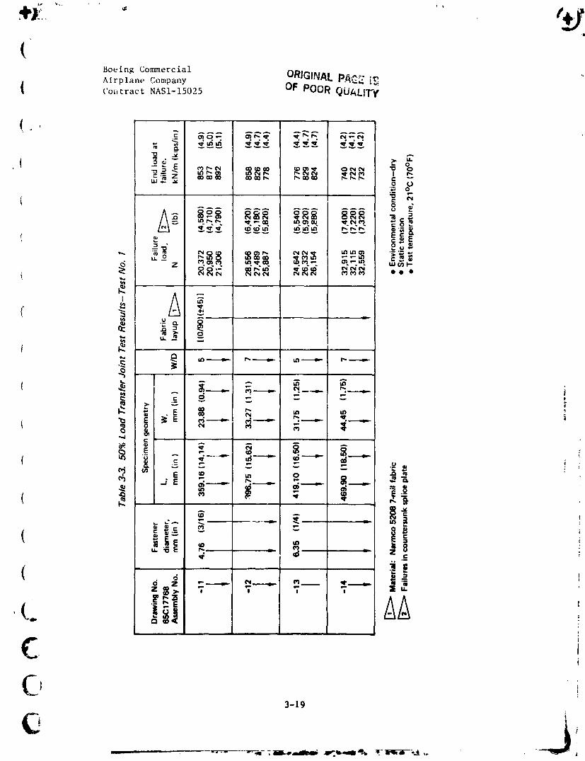
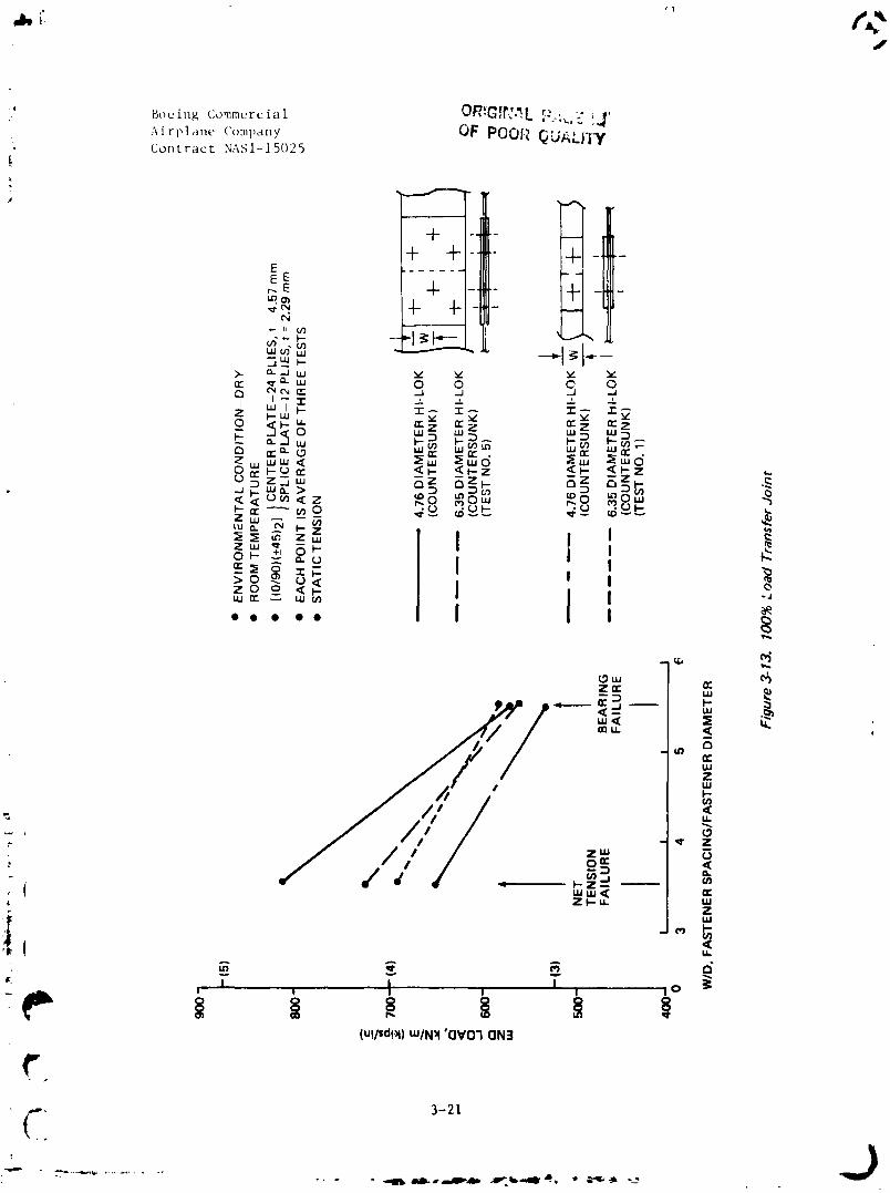
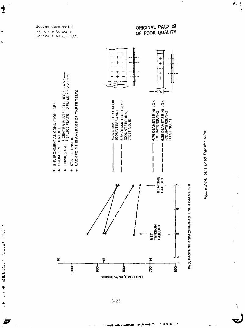
kesults for the Test No. 1 bolted joint tests presented i_l Reference 6,
and pr_.sent results from Test No. 5, have been evaluated by comparing the
loa,I/nml (load/in) capability for the single- and multiple-width fastener
joint_,. The test results from Reference 6 are presented in Tables 3-3
and 3-4, and tht'ae results are compared to the Test No. 5 results in
Figures 3-13 and 3-14. The comparison of both the 100% and 50% load trans-
fer joints indicates that tile single-width labtener joint is a reasonable
representation of a multiple-width fastener joint, for values of W/D where
bearing failure is the primary mode of failure.• i
\'
: I
I
G
: i
_j:, °
{Boeing Commercial ORIGINALPA.,.:..i_Airplane Company _"
{ ('or,tract NASI-15025 OF POOR QUALfTIf

{4_7"
4Boeing Co_ercial
/e
Airplane CompanyContract NASI-15025
J
• _
_° __'-Z _ _
C
o
"_ _---'-'_'l_ _ _'----'_
- _ ._
_i _--_ _ _ _
• Z c t
_)'
3-20
1984020846-061
JI, i'.J
CI 3-21_k
1984020846-062
#. L
"II
_,_,ei,_'Comm_rcidl ORIGINALPAGZ |¢J._irl,lun__• Co,npany OF POOR QUALITYContra'.'t NAS1-15025
+ �+..... 14_
EE E -'I"+ -I- -- -
f¢N
wen" w
>- _.._ w 0 0 0 0rY- ,_.m L_ _A .J ..; .--1C._ C'_ C-., r'r" _% , _, _,
I UJ I I-- v"_" hr" rr" er
0 ,_1-- u. w D '" "'B-- a-.J LU UJ UJ W_I_ _
'<I- I'-z <[I*-<_l-Zz w_ <_
,,,0.> _o,,, _8 _o_
_'" -- I I I_ m wZ _ c_OI-- _ I
z _ _-< Iuu _r _ u_w I -.I
•.... I I ,
/I I I ,,,v,. w
//I ]/ I/ , g_ Z
_, "'u_<Zt-U. u}
E
!i '", hU
-2." _1[
_, r , _ r , P I° g
II (u!/sd!_) mINX 'OVO1 QN_
3-22
1984020846-063
P
f
(Boeing Commercial
Airplane CompanyContract NASI-15025
l,SECTION 4.0
OPERATIONS DEVELOPMENT
This section discusses results of the manufacturing producibility studies,
ancillary test component fabrication and manufacturing, quality assurance
I development efforts, and verification hardware.
4.1 PRODUCIBILITY STUDIE___S
Tileproducibillty study on the rear spar/lug interface test section has
been completed.
The previous quarterly reports described the detail fabrication and Verifilm
process. This report includes the spar detail bonding, machining, and
drilling, and attachment of the titanium lugs.
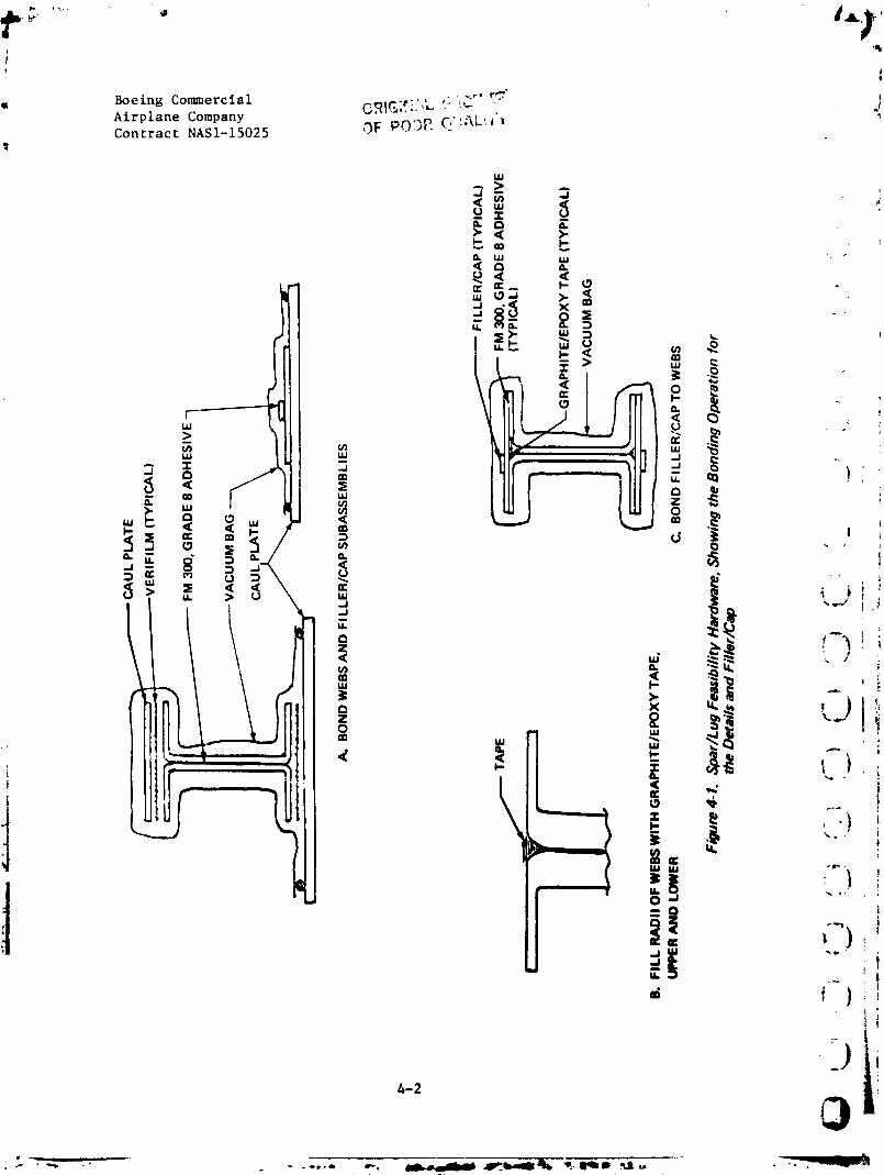
iThe bonding was accomplished in two operations as detailed in Figure 4-1. IDuring the first-stage bond, a layer of Verifilm was used between the
caul plates and web flanges, to minimize friction, and ensure good mating
!{ of the bonding surfaces. The graphite/epoxy Cape filler, applied to the
radii of the webs, and the filler/cap details were cocured in the final 1
stage. Envelope bagging was used for the final stage in order to avoidthe need for a recessed tool to accommodate the filler previously bonded
to the cap.
After bonding, the flanges of the spar were checked for flatness. It was
(_ determined that there was a downward bow up to 0.060 cm (0.024 in) in some
areas of the flanges. This bow generally extended from the flange tip to
C about 1.52-1.78 cm (0.06-0.70 in) inward. The bowing occurred as a result
@0
4-I
O '6
1984020846-064
(Boeing Commercial
Airplane CompanyContract NAS1-15025
(of bonding the two webs together, because the web bond surfaces were concave
iu the chordwise direction prior to bonding. This bowing will cause no
problt'm ill tile fabrication of tile verificatiou or production hardware.
{i)imt, nsional measurt.ments il_dicated that thickness can be controlled to
( dr:lwing tolerances. The spar measured 2.941 cm (1.158 in) at tile thickest
point of tile graphite/epoxy lug area. The feasibility spar was made in a
tema]_, aluminum tool with fixed legs. The verification arid production
hardware tooling will utilize a movable leg concept, to prevent the tool
legs frohl compressing against the webs during cure-cycle cooling. This
tool itlg concept is expected to reduce warpage in the chordwise direction.
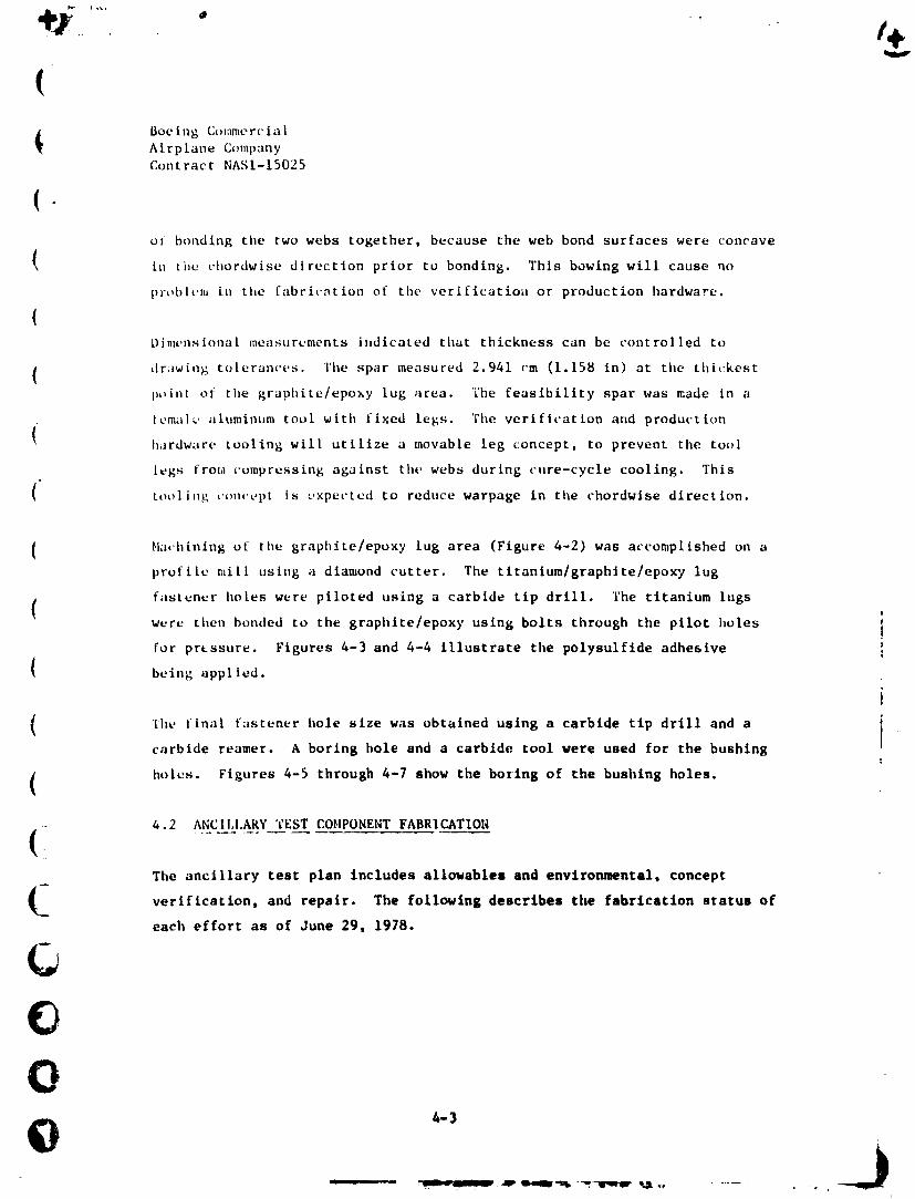
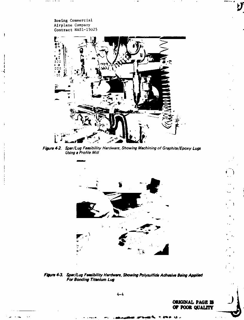
{ Ha,'hining of tile graphite/epoxy lug area (Figure 6-2) was accomplished on a
profile mill usittg a diamond cutter. The titanium�graphite�epoxy lug
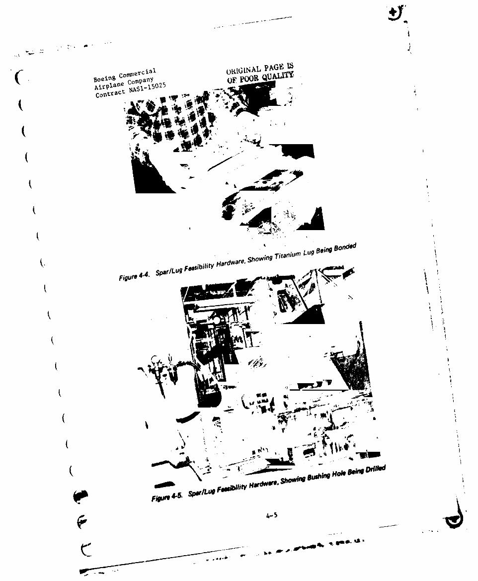
fastener holes were piloted using a carbide tip drill. The titanium lugsthen bonded to the graphite/epoxy using bolts through the pilot holes {
wereW
for prtssure. Figures 4-3 and 4-4 illustrate the polysulftde adhesive i
being applied.
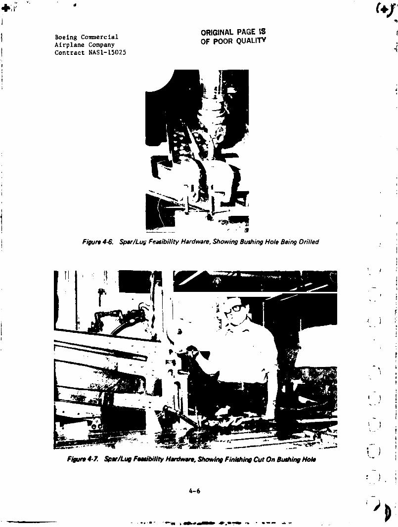
"i'hefinal fastener hole size was obtained using a carbide tip drill and a i]
carbide reamer. A boring hole and a carbide tool were used for the bushingt
holes. Figures 4-5 through 4-7 show the boring of the bushing holes.
(_ 4.2 ANC ILI.ARY 't'ESTCOMPONENT FABRICATION
The ancillary test plan includes allowables and environmental, concept
verification, and repair, following statusThe describes the fabrication of
each effort as of June 29, 1978.
C,()0
4.-3
i
1984020846-066
Boeing Commerc lal
Airplane CompanyContract NASI-15025
I
>i
,:I_ Q -\
I_ _'
._ ._ ,Figure 4-2. Spar/Lug Feasibility Hardware, Showing Machining of Graphite/Epoxy Lugs
t Using a Profile Mifli
_ ")
4 i ""
' 1
v
• • L
Pl_um 4¢_ $t_r/Lug Fe_il_'lity Hudwue, Showtng Polysulfide Adhedve Being AplMiedFor Bonding Timium Lug
4-4
ORJOi_d, P_l_
1984020846-067
,Ikli_
ORIGINALPAGEIS !Boeing Co_nerclal
Airplane Company OF POOR QUALITY! Contract NASI-15025
!F

i.J
|
Boeing Conuaercial ORIGINAL PAGE g3Airplane CompanyContruct NAS1-15025 O_ POOR QUALITY
4.2.i Allowables and Environmental
This part of tileancillary test program includes material allowables (Test
No. i), mechanical joints (Test No. 5), and environmental specimens (Test
( No. 4).
( The decal[ fabrication and assembly for the allowables (Test No. i), mechani-
cal joints (Test No, 5) and environmental specimens (Test No. 4) are complete.
(Specimens that were rejected because of tolerance problems related to
fiberglass grip ta_ bouding, prior to envelope bagging, were reworked
( rather than remade. Figure 4-8 shows typical reworked specimens.
(
1
" 1
t
? '_, ? 2 3 4 5 6 7 ._
Figure4-8. Ancillary TestAIIow=bles,ShowingTypicalReworkedSpecimens
_4P
Ib
E 4-7
1984020846-070
Boeing Commercial
Airplane Company
Contract NASI-15025
4.2.2 %.,,,ept .Verificati°n
fhi'; part of the ancillary test program includes spar chord crippling (;t-st
No. 7), skin-to-rib joints (Test No. 9), skin panel (Test No. 10), spar
shear web (Test No. i1), spar lug (Test No. 12), sonic test box (T_,st
No. ;I)), stub box (Test No. 21), discontinuous laminate critical strain
(Test No. 22), skin-panel-to-rib joint (Test No. 24), production-verification
(Test No. 25), and manufacturing feaoibility spar test coupons (Test _,o. 26).
The following describes the fabrication and assembly status:
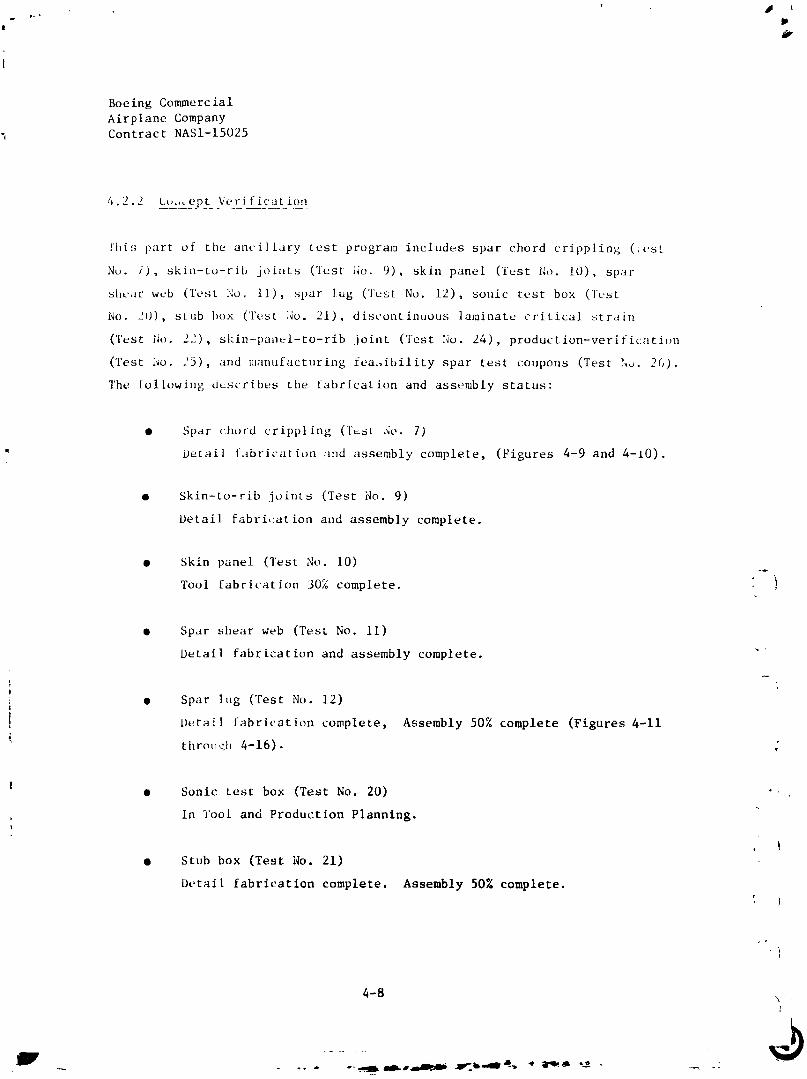
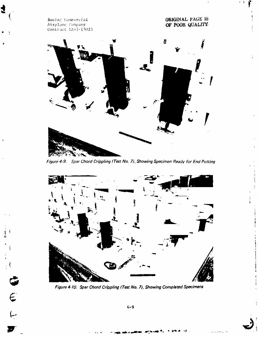
• Spar chord crippling (l'tst No. 7)
Detail fabrication and assembly complete, (Figures 4-9 and 4-10).
• Skin-to-rib joints (Test No. 9)
Detail fabri,:ation and assembly complete.
• Skin panel (Test No. 10)
Tool fabrication 30% complete. }
• Spar shear web (Test No. 11)
Detail fabrication and assembly complete. "
|
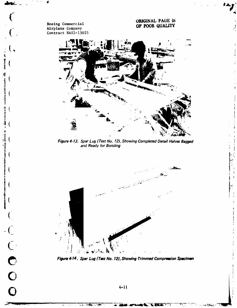
! • Spar lug ('rest No, 12)1
tDetail fabrication complete, Assembly 50% complete (Figures 4-ii
; t hrou _'h 4-16).
!• Sonic test box (Test No. 20) •
In 3'ool and Production Planning.
• Stub box (Test No. 21)
Dr,tail fabrication complete. Assembly 50% complete.
4-8 \
1984020846-071
,#\ J+oei,u: (:,,tm.,+.ruial ORIGINAL PAGE IS "
Airt, l+++.t+,.u_'u"+,t),_,',.y OF POOR QUALITY; ;Cont:-.ict NA_I-I_025
Figure 4,9. Spar Chord Crippling (Test No. 7), Showing Specimen Ready for End Potting
" +., l +_ "_-----" _
"_ }< ! - +_.. --" ,-.._ 1
+ fC"L
; +
_ - I|
Figure 4-10. Spar Chord Crippling (Test No. 7), Showing Completed Specimens
4-9
t
7-
] 984020846-072

'71Boeing Commercial ORIGINAL PAGE I_
Airplane Company OP POOR QUALITY
(_ ; Contract NASI-15025
• ( " i
( ,;?1 IJ_,.. .
[ F/gum 4-13. Spar Lug (Test No. 12), Showing Completed Detail HalvesBagged !
_i and Ready for Bonding :
• %t
' i
I
i_ ! ! ] f'_ ...-i :
F/gum 4.14. Spar Lug fTest No. I2), Showing Trimmed Compre_ion $1_ctmen ,_
@
0 '-** ji'1984020846-074

Boeing Co_mlercial ORIGINALPAGE 19Airplane Company
Contract NASl-15025 OF POOR QUALITY
"--. , ", ) "
.....,_,,,,_ _ .
J
Figure4.15. SparLug (TestNo. 12),ShowingTrimmed TensionSpecimen ___) '
I cal .... 0 " "
"_"_ Q' , ¢i ,, 0
tri_um4.I6. SparLu_ (TestNo. 12),_howin_Drlllin_ of Fawtlen_Holes
0
1984020846-075
_elng Co_ercial
'" _ AirplaneCompanyContract NASI-15025
• Oiscontinuous laminate critical strain (Test No. 22)
( In Tool and Production Planning.
• Skin-panel-to-rib joint (Test No. 24)
In Tool and Production Planning.
• Production-verification (Test No. 25)
In 1'ool and Production Planning.
• Hanufacturing feasibility spar test coupons (Test No. 26)
Planning complete. Test coupons and NDI rear spar standards
being cut.
4.3 _UALITY ASSURANCE DEVELOPMEN__T
|
This secti¢,n discusses tile evaluation of the preliminary NDI standards, and I
the fabrication of the production NDI standards. !i
I ZThe preliminary NDI standards have been completed. The NDI techniques
. evaluated were as follows: '
• X-ray
{ • Through-Transmisslon Ultrasonic
• Sondicator, I
Fokker Bond Tester
iI
. Details of the preliminary investigation will be provided in a later report
containing the production standards. In summary, all preliminary standard II
defects were detected by one or more NDI techniques. It is concluded that
( 'Through-Transmission Ultrasonic technique can be used to detect 0.64 x 0.64 cm
(0.25 x 0.25 in) defects in arts. X-ray inspection is recommended for I
radii areas. Initial results indicate that in-service inspection can be iI
conducted by the Sondlcator and/or the Fokker Bond Tester for laminated I
- structure, and by the Sondlcator for honeycomb structure. !
4-13 !
1984020846-076
J
I
Boeing Commercial
Airplane Company
Contract NASI-15025I
i
The production NDI standards are now being fabricated as Task III of Test
No. 25, productlon-verification. The production NDI standards will include
a section of the upper and lower skin panel, a section of two ribs (honeycomb
and laminate), a_ld a section of tile front spar. Preliminary tests indicated
that a section of the feasibility rear spar can be used for the rear spar
production standard.
4.4 VI'RIFICATION HARDWARE
The stub box (Test No. 21) is being used for the verification hardware.
'fhe stub box i_ a full-scale root section of the advanced composites 737
horizontal stabilizer. It consists of the structural box from the side-of-
body outboard to Station 152.45, including the trailing-edge structure and
closure rib.
During fabrication of the graphite/epoxy details for the verification _. jhardware (stub box, Test No. 21) the following problema were encountered
and resolved: _ }
• Rear Spar Fabrication ---|
Both details for the rear spar were rejected and scrapped because
of bagging problems that caused the bag to fall during cure, in }
addition to excessive detail resin bleed-out. 1
t
An investigation of the problem indicated the bag was bridged,
while the excessive resin bleed-out was caused by the numerous " } ipleats at the end of the part. -,- [
To ensure that these problems do not occur again, the following k ) .v
action was initiated:
• The area supervisor and manufacturing shop support personnel {'-, ) !!
will check all bags on complex parts to ensure they are not
! 1 'bridged.
4-14
".IlIII ................ _ •
] 984020846-077

f
Boeing Commercial
t. Airplane Company% Contract NASI-15025
!• Vacuum bag sealant will be used around the end of the part
,j, as a dam to eliminate the resin bleed-out. This new process-
ing procedure has been added to the Boeing Process Specifica-
tion BAC 5562.
• Rib Fabrication
The verification ribs have been rejected because of build-ups in
the corner areas. The drawing allows only overlap splices in the
corner areas, and Manufacturing concluded they cannot guarantee a
i rib without this build-up.
The verification rib build-ups will be removed by sanding, to
i eliminate any interference problems. However, the production
ribs will require a design change. Engineering will revlse the ,_
production drawings, to remove the corners and extend the Joggle
areas to obtain additional fastener edge margin lost from the
removal of the corner. The build-up areas and the current produc- ";I
tion design change were shown in Section 2.0 (see Figure 2-7).
• "I" Stiffened Skin Panel FabricationL1
!
Excessive warpage and porosity problems were encountered with the i
verification "I" stiffened skin panels. Both the upper and lower [
( skin panels warped in excess of 1.40 cm (0.55 in). It took approx- i.F i
imately 630 kg (1400 lb) pressure to bring the skin panels back
into contour. It was concluded that unbalanced "I" stiffeners are !large contributors to the warpage problem. Because warpage has I!
Ibeen a major problem with graphlte/epoxy, a Boelng-funded program Ion warpage has been initiated. This program will use a structure 'I
T
similar to the "I" stiffened panel for study purposes. !
+ 1t
1I
-( iI
+' i' i
++.+- -..-++ +" - .-..,,, --, ,aln...,++_Ik,IL.Ir'b-,ell'_,. +'_,_llqr'Ir--_i .......... +-.._ ++++_
1984020846-078
f /
Boeing Commercial
Airplane Company }Contract NASI-15025 . i
The upper "I" stiffened skin panel was rejected and scrapped
because of excess porosity on the tool surface. A review of the
problem indicated that the single fiberglass yarn used per the
sped'ifits|ion to evacuate the air was not sufficient. The speclfl-
cation has been revised to allow additional fiberglass yarns as )
the area of the panel increases. In an effort to correlate the
_ffect of porosity, Engineering wlll cut and tes_ specimens from I/
the scrapped panel.
iA second upper skin panel was fabricated, using additional fiber- . .
glass yarns between the layup and edge breather, and the porosity
problem was eliminated. However, the second upper skin panel did )
warp 1.40 cm (0.55 in) in tile spanwise direction.
iFigures 4-17 through 4-26 show fabrication of the rear spar, front _ •
spar, and "I" stiffened skin panel. --
All details have been fabricated and the sub box is presently being assembled, L"i
Figures 4-27 and 4-28 show the start of the stub box (Test No. 21) assembly. _ I
U
3
o
(-)4-16 •
1984020846-079
i,,.]'
("Boeing Commercial ORIGINAL PAGe, 15 jAirplane Company OI_ P(X)R QUALITY
Contract NASI-15025
( ,,...
Boeing Commercial ORIGINAL PAGE IS
Airplane Company OF POOR QUALITYContract NAS1-15025
(Boeing Commercial
- Airplane Company ORIGINAL PAGE IS
Contract NASI-15025 OF POOR QUALITY
r ,= _. "
' _
t _
( Figure 4-25. Stub Box [Test No. 21) "'1" Stiffened Skin Pane/, Showing Exterior Surface ofCured Pane/
• ,.'r,m_,_..,.,, -"_iI_ ! _
-(
# - ,
(
Figure 4.26. Stvb Box (Test No. 21) "'1" Stiffened Skin Panel, Showing Trimmed Part
C4-21
1984020846-084

Boeing Commercial ,;7 "" . . t._ )
Airplane Company 0_" _'L,L_-{ _%,_.L.rl_Contract NASI-15025
r ,,---_---_ .... _i----,.-II._, ' _ ; i/
II " ". t
Figure 4-27. Stub Box (Test No. 21J, Showing Dummy Front Spar with Aluminum Nose Ribs
. +j(
- Bueing CommercialAirplane CompanyContract NASI-15025
h"
SECTION 5.0
" REFERENCES
I. "Advanced Composite Stabilizer for i_oeing 737 Aircraft," First Quarterly
Tecbnica! Progress Report. ,ASA Contract NASI-15025, October 1977.
('2. "Advanced Composite Stabilizer for Boeing 737 Aircraft," Second Quarterly
Technical Progress Report• NASA Contract NASI-15025, January 1978.
3. "A Standardized Load Sequence for Flight Simulation Tests on Transport
• A_rcraft Wing Structure " NLR TR 73029 U, March 1973.
4. "Introduction to a Fighter Aircraft Loading Standard for Fatigue
Evaluation," NIR MP 75017 U, May 20, 1975.
(5 "Fatigue Strength of a Fiber Reinforced Material " D. Shutz and |_ _J
lz j.J. Gcrharz, June 29, 1977.
"Advanced Composite Stabilizer for Boeing 737 Aircraft," Third Quarterly
x Technical Progress Report, NASA Contract NASI-15025, April 1978. i "_
!
7. "Thermo Physical Properties of Selected Aerospace Materials," Y.S. {%
Toulouklan and C. Y. Ho (Editors), Purdue University, TEPIAC/CINDAS, i
1977. , i,
< ;
4- '' l
I
!
I
•O
5-1
i
1984020846-086

(Boeing Commercial
Airplane CompanyContract NASI-15025
APPENDIX A
ENGINEERING DRAWINGS
_ i.__!
t
' I
• !
!
A-!
"1984020846-087

I FOLDOOTFRAME 12 11
] 984020846-088
1984020846-091
�ð�¢"_;
I _.YTABLE]I {-t_)
_ i-r"l i i_['zI9 I _" 'i"--
L*II L _". i:
Tm O" :
I
L _ %
•-'_- @I-p_l,,,--- ahl. I
i
Pll -_, ,_/,-'r_I. - V'-p._ '
_,-----_ILl "'_'._ -----,_ _I]_D.... _: ,x. i_,qi,,_i -r . _ .-_-_-_ / '
111_ ';- F•Ill - - TOll. '_11_: ....
_t-._._-"' "L - " -_I __._,,..._ ,_,, _ -[_- .',,L___,. ------ .,- I,,
2-_- i
__ 'IE_B"-'I_c_> ..
_+_, , k.,
L,- a_ !
, _-- -__ _-_
"X_.._.,,, , \%.-",\
' I l'o" II ' ' ," _ '|
1984020846-093
, < _m_,,,Ou'l:_AMe S I T I !..... ii IL_ II I II I
iI _.. I_. _-."
@_.,,...-0_'?OU_' L _tfD@
I1":'._e__"_--'l i
T--r---qT--'--T ....... r T-r
I ! : T.,1T---'T.,"T* ' II li , - iri, _ t
I I I I '11111 I I j ' I/ leO(.t_ p,_._-,_rr_
, I t! .1111!l ltl!l _, ,,' , Illli+!lMi,it _J/-
.......... -:_-_--L-_ -,_:-__.Z_t_L_.-'_-. " _ ....... ;_;,,'_L . _--___7..... . -._.- -.:- _ _L z-___-_
II I_ ' ' "
I I t_ ,LJ'-iii',ji /
.......... -_ _ _, _ £ ......... , , , _ ............................
........ -----I -- -_--_T ,-_r-_---'_T-_ : T ' - " t "-'ii_ .............. '
_'_-'_ i i_ i_i _ I_------_, !' , !ii;?':-_--",_l,,-',,°"
l-_Dl'13r_ %,. _ _ i I I I ,
,, " I I, ' llli!; _[ _ I%.... -: ....... ::-...... ; .... :. -.-:--Tp-/._::----.--,.---_--:F-.-,.-::---_::.-"..- --:: ,. :-,;;- 3: :- -_ -7,; ...., :--i -
,- I I i_ _ _ J.__LL__L__ZL_ _.------..
1¥..'" .,/"I,,. ,.--_,\ II_-_" -'""'_ A_2SHOWNAs_X(b_cb°TASNOTED)'2_-'
• "m__.__
.... P_.. zc,l .,-r,c>,'1.,
_.i ..... t ....... I .... _ ....... i.......
1084020840-004

+ ..... ,.,-,,,urnI s I I 4 I_.,_,,]_.i_ _ ..........
IHi ILl} ........................
ORIGinAL PAGE I_I;)_POOR QUALITY _ ,s_o............
, /#'--+'t IbX_Wv__ f4"_ it.J.lIvvP) --_I , " I I,_C. r. _ _,l_'JS
• (}Q l'l.d_t%)
........... _T ................ r _-_-_.... ,'-- _ --t t- t: .........
-- : +_ ................,, , ..... / '" ,C,,," 0_-
,, Ilttlt +.... t l- ' . ...... ._:,--:....-+- ...................
t l 'P ........ i/" ¢ _ 010"
+'=,+: +iIt II i,+'._'iill',"-: ,-,,,.,,,, :"+ i
I ,_ Il -L_l_ +__:;..._'c'T.n. t. _ t '
ii" - __: ;:_"- --i;i i ! - +, ......... .,!c:-o,_
,I :IIII1-1--J,,ii_,+-_ _ _ _ , l
II IIIIII'_-_,:-_,,, _,',,) i._..,. I I_ _IIII--I-I_,,I , _ _ +t I, ,_!t__'t:!!: , ] 1-- -------_--:'--k.--- , -+.... +..... __ " ........
.......................... I_ - - [+ ........ " I
I................................... -[-. L--L - ++ _+.-; i + -. " ......... _......-J ' _ -- • i ; - ;'. , , . _-- : _ ,. .... _ t _L
................. " " " ' " _I_, 2 'I C o,O•............... .r--tI: ......, . _ _:.._.u.'; ..... _::........_ ......
\_"'X_-,, "- -I:_--'_ '""I_,.."-'" L L..
.-.,--.II +,--,.
lj .N,,_ ,.__.:. ;, ._.-_ - --_ :±:. _ . _--_'_ : _, , , ,
_ _ "_--"'--'-' ,___-_I,_ l.W ml:tr1-_)_ ._. _c.rv_
i
,' 6 'I $ I 41 I '
• • .+
'I+8402084+-0++
1984020846-096
III, ID, I lli 'Ntta N
m.'t"_it.t _...'Z._
" "_'_'_":"f.""" -'-"wt,z,r' _v" me 'Vltt_ ctORIGINAL ,! _,, __,.___.PAGE 15 - -J "'".... '
OF POOR QUALITY -i,L,., El::>_ _ '_'.__.,."i --_ _ !----_---c_> -.===-
;__x__. 1 , _ i _ !t I / -,._,...,,' _ = .,. . _ I .... .,' _ 'l=_,b.T _ i o. _ ___...._
: _ / / -,,':.---_-: _ _-_-..// / -- ,.,,..,., ........ --/ / / 1.6.I,G,_oG.IZ.i I I _ _i_" [,_ "l / i I l -.ill r_?,ll l I I ) o" ' F_-_
:--- , | l -- l/dAl'# '°' I L !Z.S I l_2) ' sO" iZ_$
I I 1i / t -iv it, _ 1 L, > o, i,_>
: _iliiinl I --" _ ;t*.s.c,._ I _ 4_- _I'_): ":- - . , 1 . 1 !-i',i o,o 1 I-5ii_# 1 [ ,) 7_- o' " {,s'7):
---i,._. _ - t I_i .__.._,',__._._,___n
I ! lll,,ll .......... \ -- ;iv_sve,_v.i.c_rri---.: - I _ _ _/.._-s.,.,,,, i _ mleil146)
/ ll_l_l -i8,. 9 l_,f$i ' --"-_M
. \i i t |i,o_ |__ >\1 I I AI ,-, 1 il_,,
_ ..... __.. / ---- .. I I \ ........ _'J z,__-" _ w _ . tMit_-I 1- llOllll} _lli
::)TED _ . " _*:: _., r--_,_ _,.._ r:,.,,
• ---.- • ..'i._--._,<,., • 1_ ..... fllll, /llI_> _---:_" " t\\--,., IIIIIX_-- ..,---..,.._>-
: _ " il " _ \ _--.,.-. --
. .: , , u___.. Ii_U_-_1 I" _ • i_.:-".,__:
1984020846-099
FRAM_
I1 l lo I I _ - -ii
cD
__L..-t.-"
\ Pl,p'J p?, P').l_'. LP'_
_ PD
,rVL_i,<,, +.-+•_ teasel iA7 (-e* As_ ' "
(m _..u)
x
_ Pl,_-I_, Pll, Pl& & PIT ¢-_7_
n -<")• I-I / _, ,_
I
"'I'M" 1,,,,,,.,,._+'_:-.,,,.-,o,,_,._,o_<, []c>,,,,,-.\Y+_'xLx__.i+''--'-+_ - + +.o
l k'-""+"_++'"__':X,_._
T_ _#,,.I,?_"+,,-,,+"t,, :- ,
F-T...._'-. _.+.+. ' -.-_ -tT_++ .-+:r----_--+-+ m
,_-- :_ .++,.o,,.,, I _ II._011
C9 "AS SHOWN- 30 ': +, i
,+ AS SHOWN-31,-37.OPPOSITE ":
+
1984020846-101
- tT':" i_ EOLDOUI FRAME
-9 , I s ,! 71 I,,,6| Ir
_!
e
In- -- - ? IB_I$O................
• , t (_*_ '1'""" 1°'') i
T) .SOrtvp) _ ' I',- = I
I i
c_,_,,, i_-'_'_'' --6-'_-L-, ,,. _---. -- ......... ,._--- I"• i _ _ T
I ..... '
""_ i,,_'/-l-v.-:_--;;,_ _ _ _,_,__ "_ .\', _.
.... _.._ __ _ "4", !_
.... '_'_ L_ _;
...e,l I I I _ =,tlO'lvPt -'-'m_...
-'_ I I I"-."_') _,,,,,o-"41 !"--_'*)""'-'"'" A5 5_OWt,,JA55¥ --9,-10_-_
," _- _q'_(-Is)
/-'" l//,-- P_ I_/__ , _.
//,,; / .... IN'_ l.,.,,,,,,,,,,.,,,, ... _.oo,_,,, //;,//__,,,_-,_ ., ,_,
...III i i
• '"'_i ! , ........ , I ,', i_ . \_'_
Illll-
" " =-'='='" I_SC,_,_I_l• :=-":_'_-""=" 177ii ii i
i ill[ ii LL I I I"9 ' I " 1 ; I
"1984020846-'102
6 _O(FRAMZz-"_ S . I 1 4 , t
ORK;_-b;At.. t' At; t. I5OF pOOR _L_'_L_`'_*Y
r..... 52 O0 _ti_ _Z_"
_j_ --.-w-._ C511 itM)"l_It %L_ C lk4C.i00+ I_AR + tDCLr +
" FP,,,m_J_ I /r _+£.¢5o_1,SS _AN'_OC oLA_*JIDOC G _ACN L03C 3C_ "_
I + I I + I ._S- --",) (+' + +++ tJ r It .r _ --¢ 4
I+ lt,_ ILl ,, i , "'. : + ---- + +,, + , , . ,+>_ + ' ++'
I" !,,,,,>1I - ' :.'+."4+_Lt__ e'_'+<_''• , L . _ ¢"
lll-sS , I Ill + l _ I i _ /" '
p_il + II' I : +l I J /
:.p,t.+,-_:--L-L.... __ :,,'++-+,......... ./.'+'hi: ................................... i---I+ + _ = -'" '#" +'"< "" +"': "+" '+"" _'_'I ,_#_--I+I-- / _'
I _ I, I,S, I il, ' _, , I/
_L_+____U/C:%, '+,..................
.IX, II +AI_" o,l"+, : ' ¼ "" _._<>,._..,,
_1 i I Ill I li ! -- I_0_'1[" I_ (-'?¢j) I i_ " ' ' F _ "+ ' I _" + _ e S ( -- +S '
it" i_ N r I , + .k+
._l+;-.+--IV+----i i i i " ,j.:-'+-(.........._i,i___! ,.o-_i-_:-_!-+.............+"_ ', P i 1lit hill_l AiO ill I 1 I7+ "01_1_ 1.00 l,,T/I.'- tilttli ;¢1 _li(ITil I + t" 14--- '_..-_-:+ _ ' t
_ j_ _._ -. 3..*s .... _ iit._'+ C..J_ F'--+'---'+-,+---'-"I
/ PIi & - I_0 , -i J__:,+\\i,< .+.; . ++`,.o.....".....
.Jl I II I I • II II .
6 I l I 4 1.kqllll. .......
1984020846-103
A-$
NIIP_41 m l_l &+|.*Z'[KMII ,)l [ _q ' . + .& T+,.t+_mmmm_ow_',m_,,m Immm ........ _ ".+ :A t+_'++|- _+ llI_Mmml++ .......... "+_'-g _'"'' ..... l+_,,',+l N __2".."
I..I,O,.-=,._+.----.', ........ I--'-- _ _5 .i . _. _r,m _'A'_EU rII fl++lli . + . " .... ;+] EP _T_'-
l,-__rJ'777_ _I I ...--.--. ._+:,,.. ++.,+\....+- -" _-- _.] ' | - '" I .... + --_
1984020846-104
- # i 3 II l --
_. I:,R,,,,M_9) . . ....... .,,,._<.,-i ,., . ,,,
ORIGINAL PAtx ,L'1_ : + .,,_,_. :.,,._,w,.,. . .
Ip Im I_tl_m _',,'o I_ ll_ v ,,,OF POORQU,'tLI'_y
| ,
|
N
; L
t
!
w J, t
t.OI "N
A! "
_ . •
1984020846-109
I,III_ Is qI
|
Pq_lb o9
.:i_ .......... _ _ ......... F .............. I ; ' I
•_, a. _,'.i, ..._ a_= - q_P'" '
"I08,¢0208,¢6-'I"I0
_.OO .... ..+..,
"++" _ ............. ]' t _r k'f T&_LE
- t -t_ "+'+'+ ? _ :_+_ + v &-?S 2,¢. _ L
"TIll _._ "
.+
7[ ORIG-IBALPAGE ISOF POOR QUALV
ji.a%;ettt_
-i
\
\
A ,**
t
"1984020846-'1 ]4
11 10 9 I- iii i ,
. .
: °
.l*
II _ IO I i
] 984020846-1 ] 5

1984020846-117
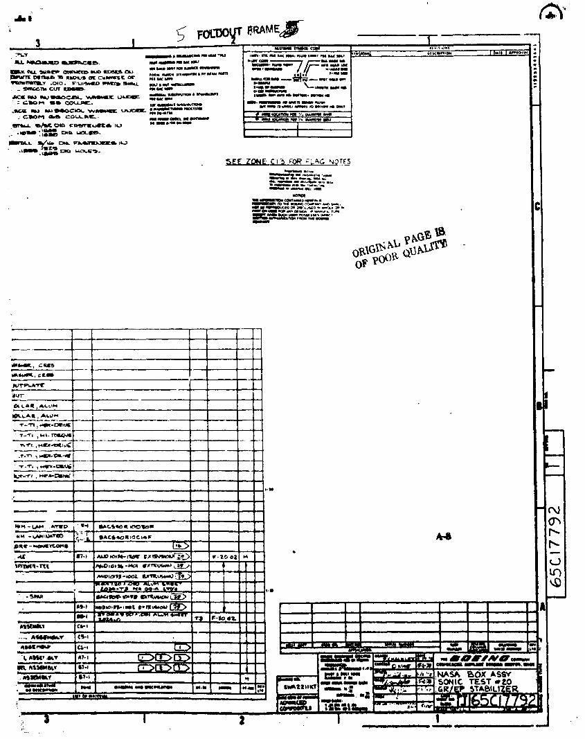
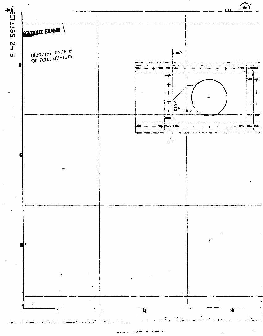
IoRIGINAL _"M;F, !_QF pOOR QUALITY ...: __m',
0 P _ ...........................
=____ .......................JT:_ -n •
P
!
-- . _ ,d.. t ==
AWg
• I
1984020846-119
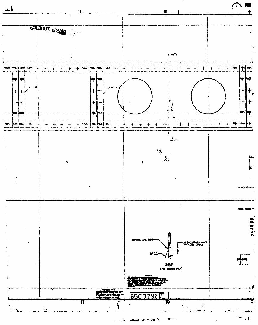
J.i II to Iill li • , i
1
- -!......2........................................
t
li4o
_ II"
• •
1984020846-120
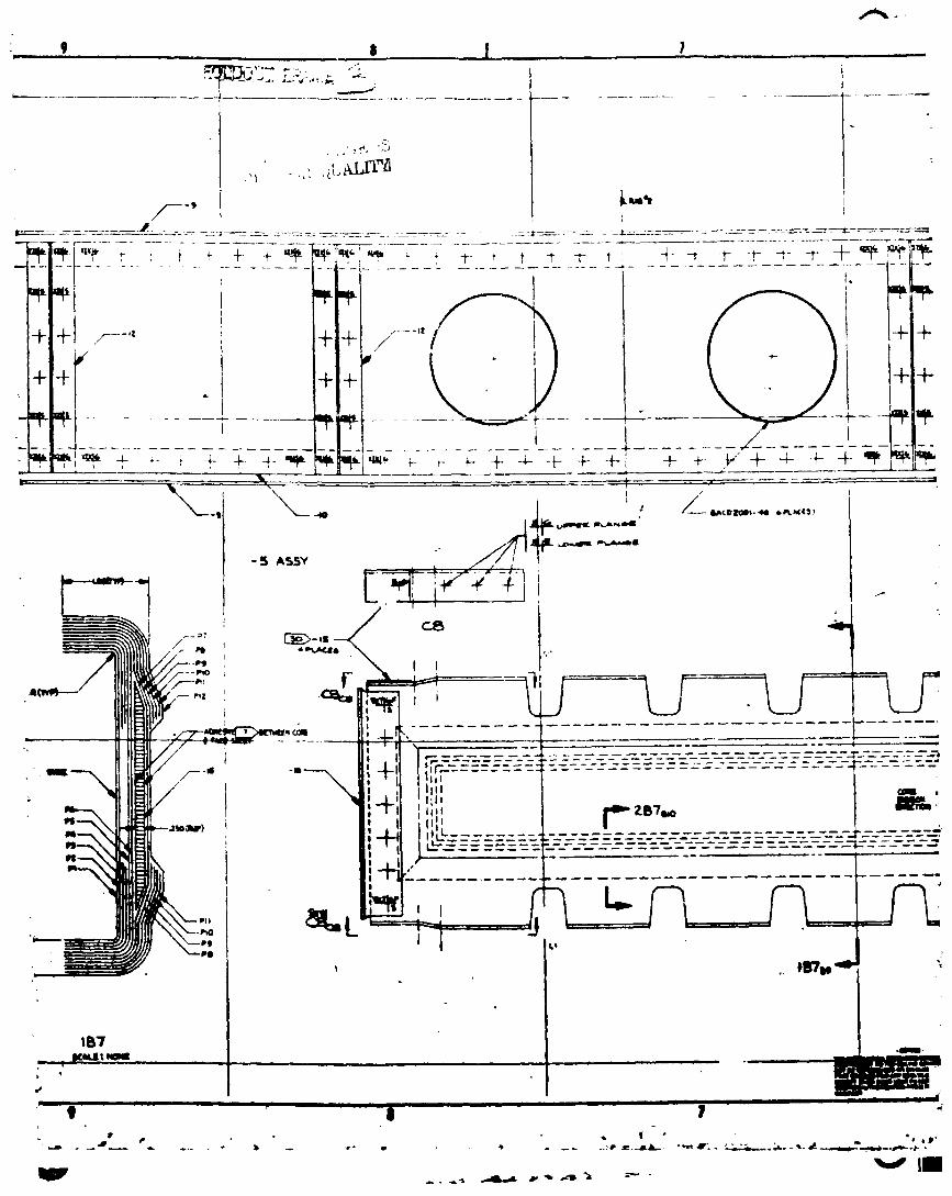
-, _ ....... s I 7 ... _
1t17
Iltl..I t,IIIIII = ..II J I III " - i
1984020846-121
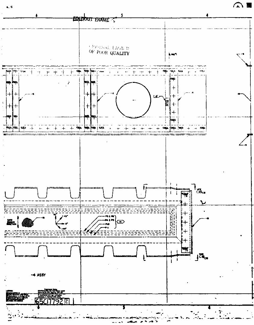
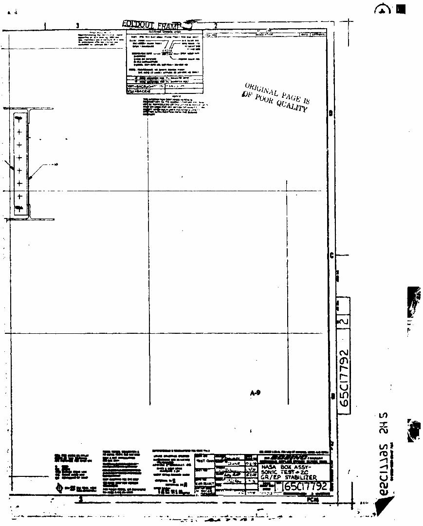
+
.to)
___._._._...__.___._!&tP...- _ "=_,.'w "-'- ... _+_ E"_r,%+_- | ,IIIIII i - IilNI I liJ_lilg_w lllO_l ;_-'+-;m" _._2....' ._.-- •It Illllllll_ll 11141llllll_lllll __ _ .... - _lll_./r..Jl" _llAlilUJl.K []
al, - +
......... + l _ _ - I If++ 411 ,.
1984020846-123
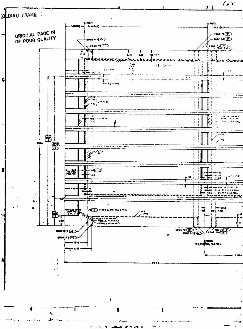
i - I II I
1984020846-124
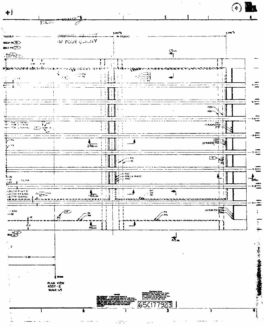
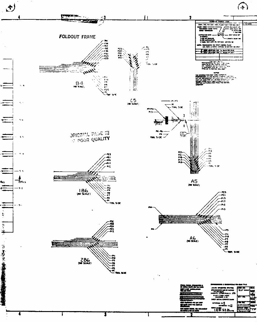
_-_ ....... ""'_', ._ !:= : I I_l I I
• L n n n _ -----_-""T"- "_ _= -'-'-_" K_P'_P_T _11
; 4 / 1l I ,__ _ ....
1984020846-126
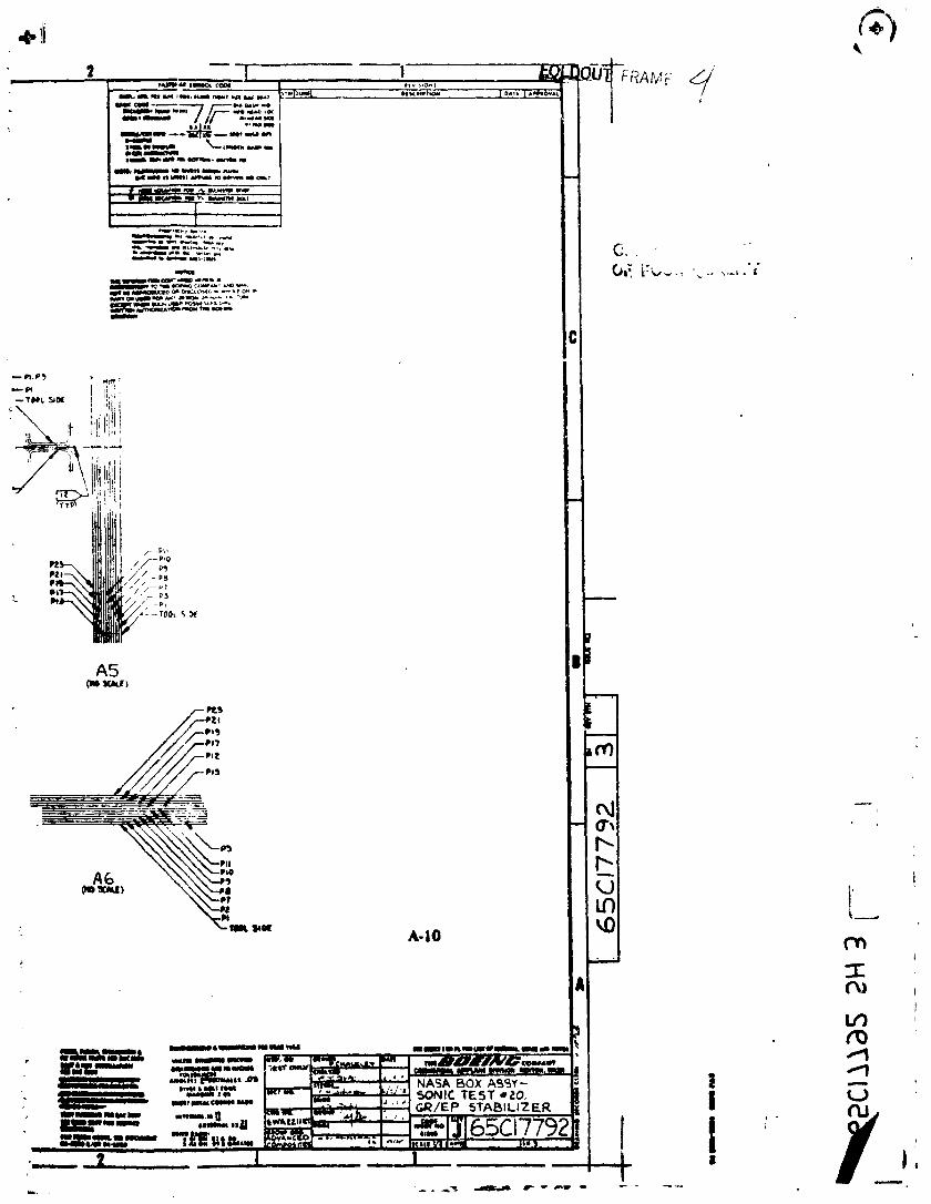
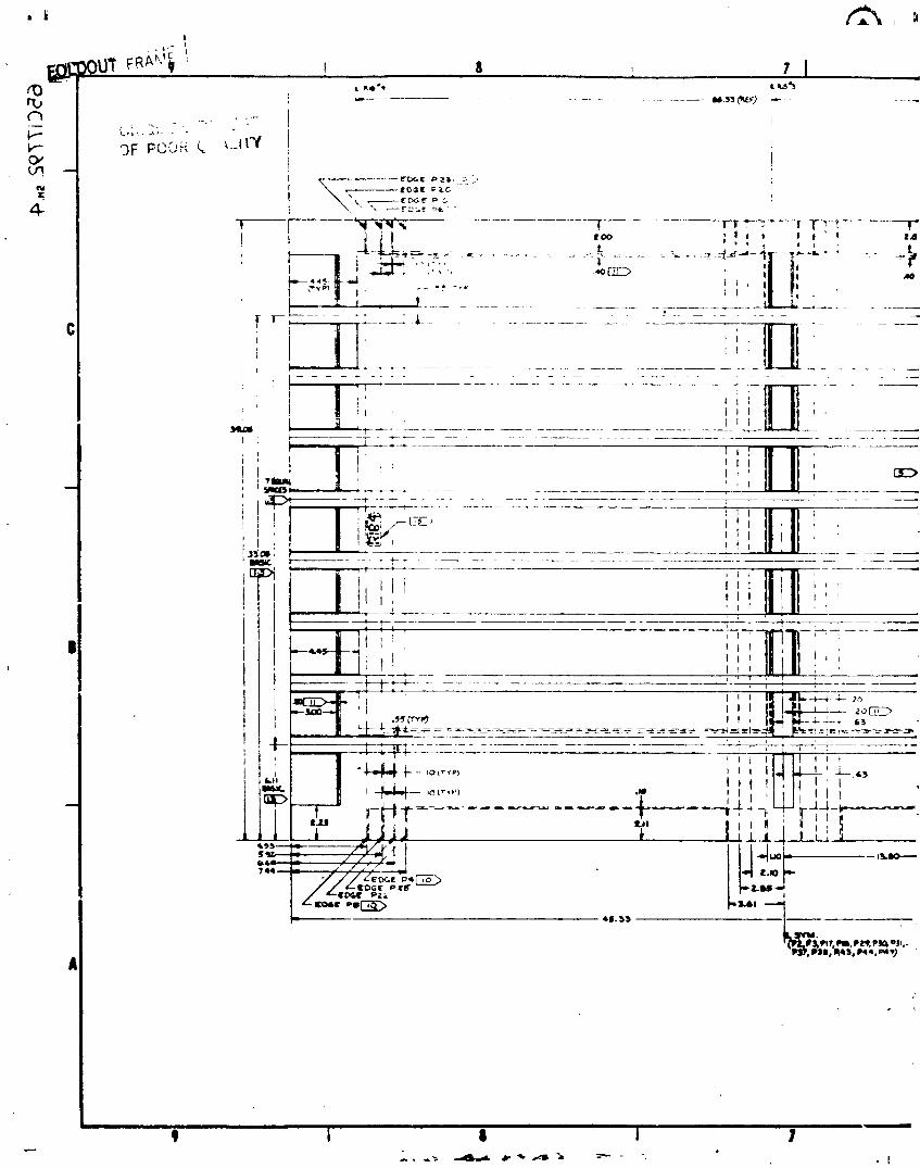
• ,k l'_ i tl
rta ............................... _+'(_+ + "
I..,,'" '-.''. +' "+OF PCO_-i k i._II'Y
0,'
: ,,y• " c+_-
...... _ _ i+._ t _ _ ' _ " !
p,! ! ,410
_' I l I I
, I i! ,++,*_ if+ .......
II ', , ; I l I
i
T-:----.-_----------:--.... - ...........
' I+°+++-'' "liii'+' : 22_ + _ ............... -- .....
i i',,,,,+'''++ !iii+'I -4i+-+'.++,,"_++' - , ,
I II-IP--_- +o+_",-
+, •�¬..................... ' I • •_', ..........
I i '', I],' ';' '"i I I._..L_L_'_t_+___._- TF--F-" FHT ............ _ , .+.. ,, -
_ i, t _i I JJ J + J_+U....._.+.....L__ .+__--_-----/'+/-P'_I 4.oU I I "_
_',.T_" i"//.]- .-'__
L"-"" "_ _,_ PI'IP._, PZ4',PIO+_I_,+PI'P+PII_, 1_45, P44, _q_)
A
I i i ii i ii i i •
9 i I I
• I
] 984020846-] 28

geL'_')l pl _ ,. ',_r/._6 1 S ] 4
........ _.sz_S_v) _ ---_'J'*-",_r_-_,_=-_--..
i/--[oc,__# .[_-. _gFPOOR QU_L/J'i,,'
(o_t*,_ p.4 CS.z£OC_ P,L1E_
9}i P_'O ,
"__ ....... - ......... ¢-+ ....... b_,
L .......... _ .........
' ____'__ ........ 1
'' _-_ ....1' ,,Lit ]I t 1 ......... ,
................................. - ........... k 5-4
.,-,o_ ,o_-_. , ;.jz L i ; [,t2- _-3 "_//1
(-_*. 3, P44, p49) J
_1',i VIEW
ASSYiCA, I._
._w_ • v_m_ m u_ _¢_mlq '_4u_'_q _ e_qe,_. w_uq
_-_'" .... - 77 rE1"1$iill _Cii_',_,_l _. i_r-,C.I _
_i . " _ _l,Jl,J%,# I _a'/...,..
:. I 6 4
1984020846-129
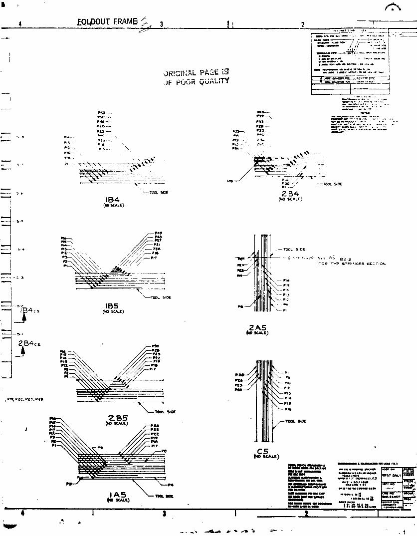
1984020846-130
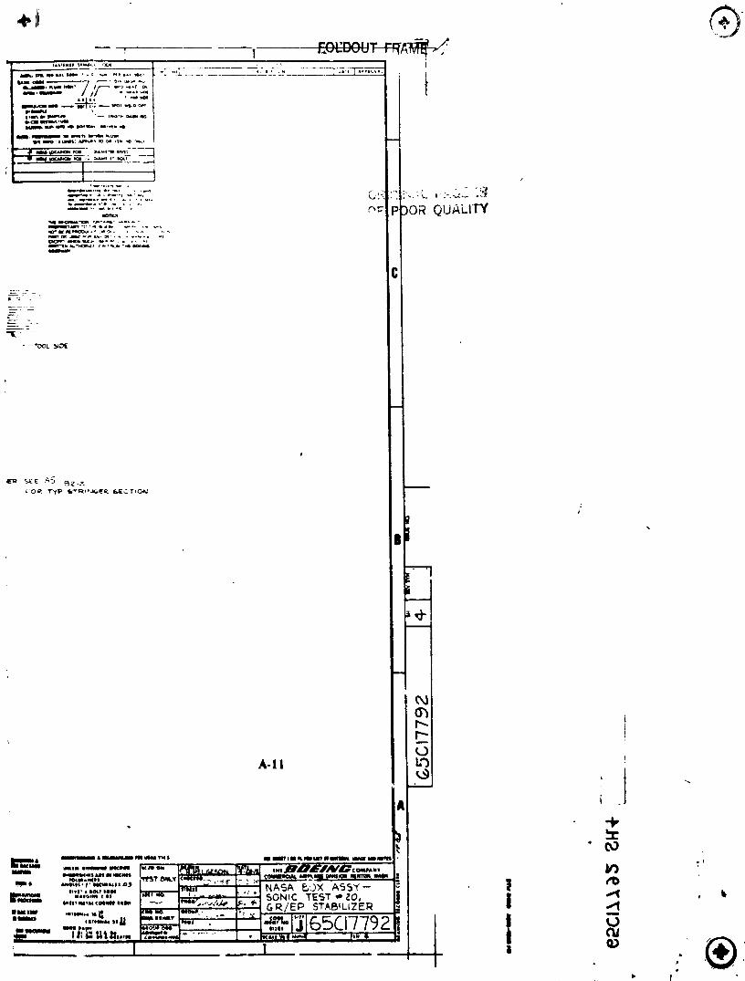
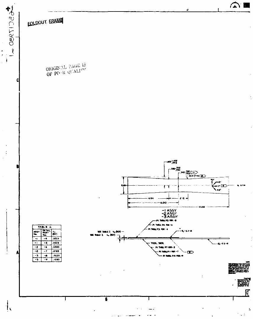
I
I
1984020846-132
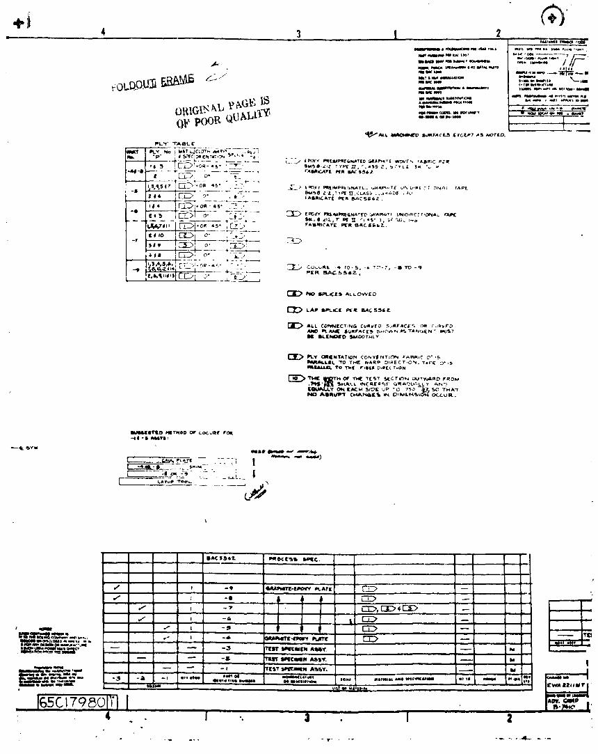
_li_O _I_THOO OF COCuRt r IrOl_
_- I ...... t.,_-:" . - "[__ :i _ .... ___ I
<.>_
,, , , ,IltAC II S Iz- lllll 0£ [1_,15 lllIC
,/ i -9 li41_lli_£-lli_ llCAT( " _
•_ , " E::IZ>,I_I:>_,E:i::;>"--" l, ..I
s _ _ I_. -.!l _ --
-- _ -3 r_ t_¢mlm Alli_. _ _,-- -_ 11sTI_cmEI,oASSet. " --
.... L ;_.:.__ - _ _, _,,,._.,,,. _-- Ill t It _ fill#| l I i iill I i_ll ltitf i_l II I lllllll ill b-_,_,_ ..,._, -_ a -' ,...... ..,, ,,,. ,-<"_,._" .... -.-...... ' ' ..... ill lit 1. _-- oil i NailO*_i _
l_c_?eol;'l I "-'--I*_. _ll, ip ,, ., 1 S-_ !'
i i i i ila_ i ii4 . I -. a . I 2
1984020846-133

-_'*'*°" ,OKit_Is.0_7_, ,,: A;.*'
i
A-12
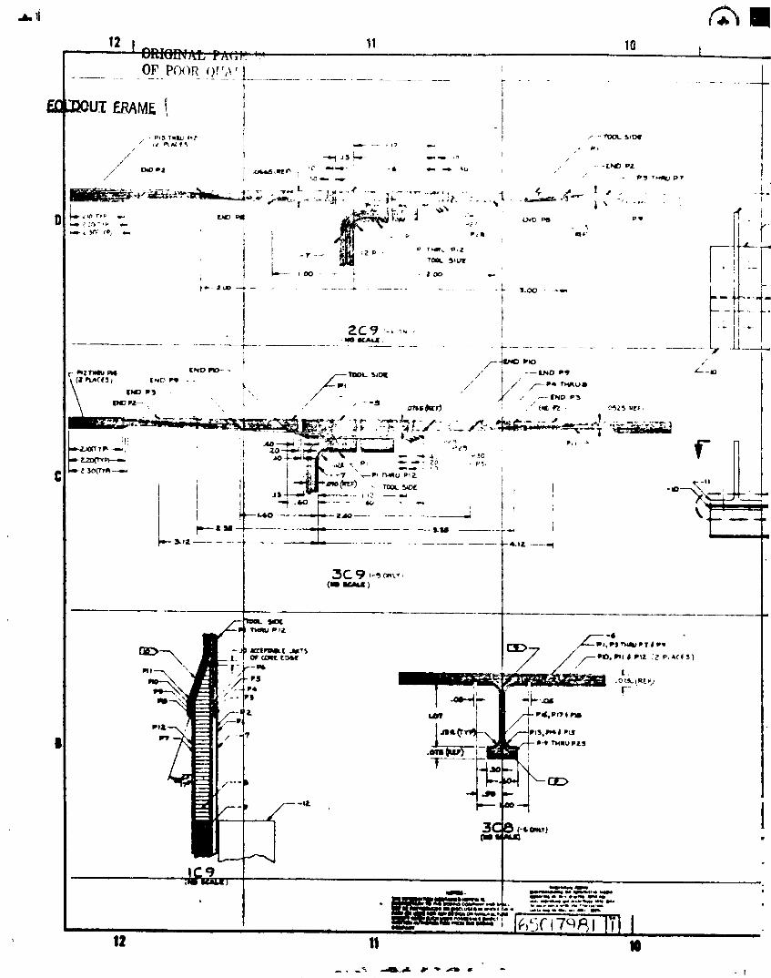
p,- lili)
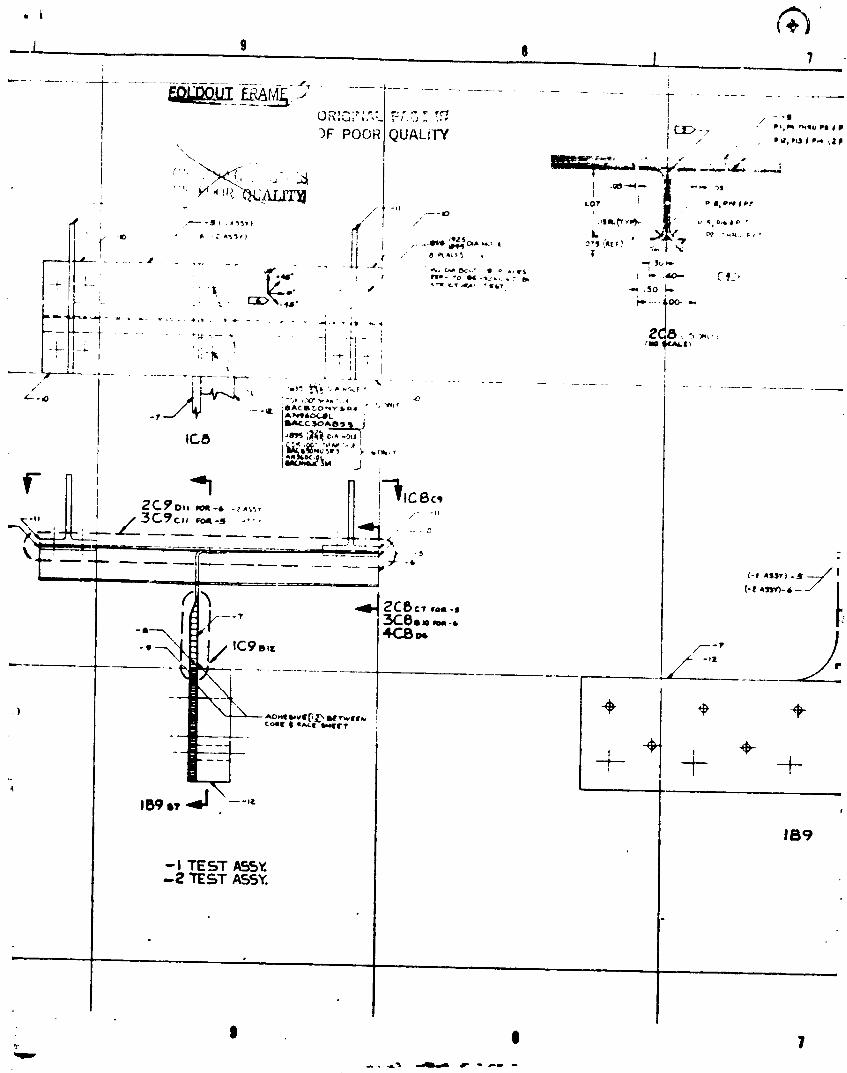
j ,, 9 e j "l
............. J+f .... _. ...............
_,o., .. . C..I_ _ 7
")FPOOR iQUALirY / ,,i,,_Id*-IZ*
' ' , ,..,,' I -_-"I-- --,- ">s
.>.e_.AI¢_ t , -,,*+,,,' ", ,i_ _ H Lo? ' .. _- -I¢ t "
I _-w.i t +_llll._ll __ p ,I o,lllp
,,-- II. • '_'il' i_ "M ri,, _ _ ,
I f ," 8 _*c_'_, |
---I "I'°:
t
t i i I +'.......... _ - ...... t! - _ _ I
I I i<
I .{ 'i, ......................•7---................. TT.... 1"_ ,.,.+ _.+ ..... ,,<_
;liA C ii_,0 i_iyilllll °
.iv IA_,_IC__lli. r
I,_ ',iii c,_.,_,I
i
r N i "_ n 'i,_,<,II l.f_.3C_)<,'_-" .... " 0
_._ -_:_-' "- +" 77-_':--- ...... -------" l-.+•r; -" : 7 _ - 7 7T;-_ ,-,.--.--<'""""--/
-9 oi_ -ii/ ,
l _.o,._ii,,,licr_ lti','_,ll,,.toll I i.,_x,-I It_ll'_P
+ , +---_ -t-IBgl+'ll --"_
IB9
-I TEST AS._•-_ "TEST ASSY.
I 11 1
1984020846-136
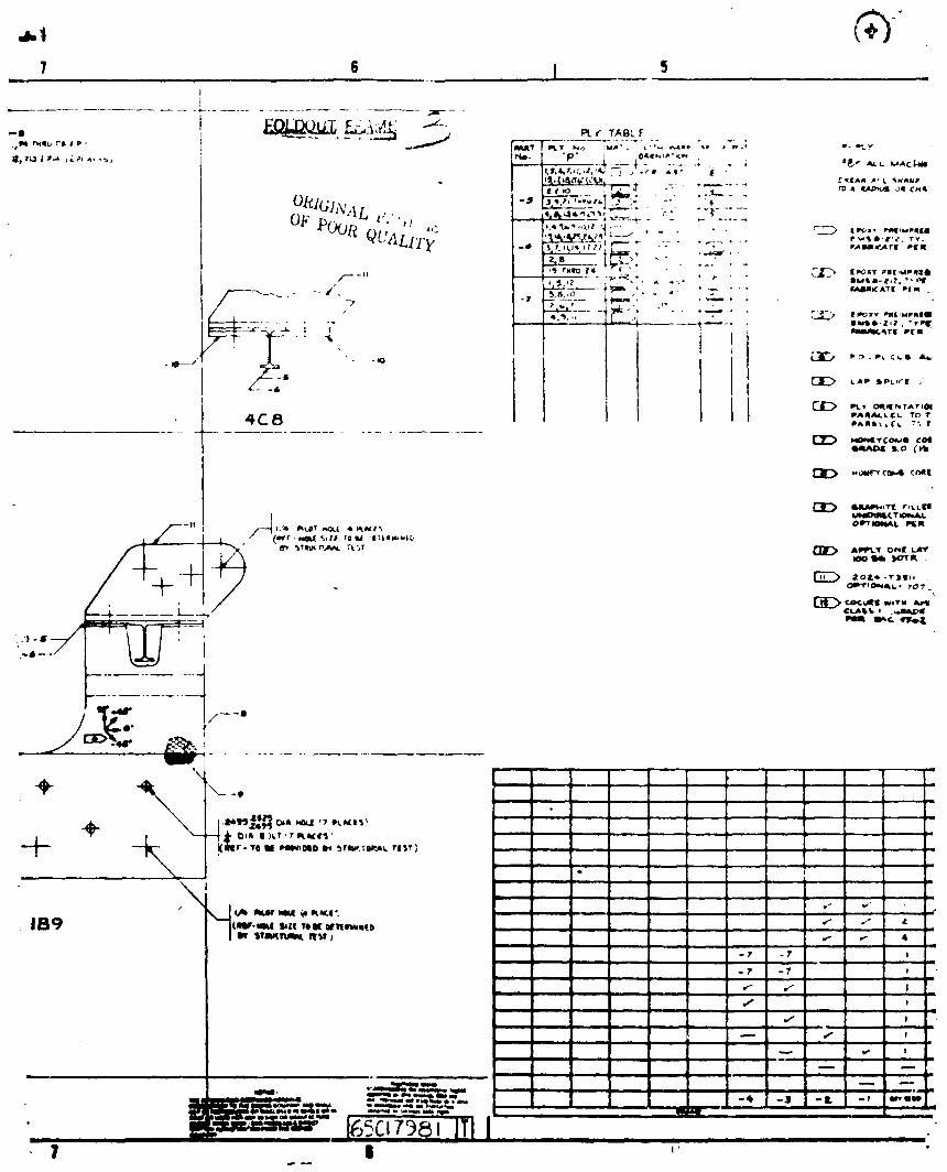
7..... s I

HIPW_L_TOf_d[ LJlrrl_ _ rI[_AR Ir_t,_(BOI'_OA_,E _P_P')r_11CN1"
,,, _ Im
m
A-I]m
+ - * ¢0_¢ , _ -- - L ' ' II - "r IIIQ _ I i50e I
, -. ,,, ,,_,,,c_. C:_C:_ [ ,_ _ ,,,,o,,.---
" I -- I TILT' IkPIClklllN i _# ; .... _-- u++_-- ---'_" Z_ .ao,-- - $ '1'_lT AI_+? ' ! _l_l.Ol.lmmm,.a I _ i.+,, i
' -- -- _ m,,m--,--,mP _tI[L TORI
9B4020B46- 3B
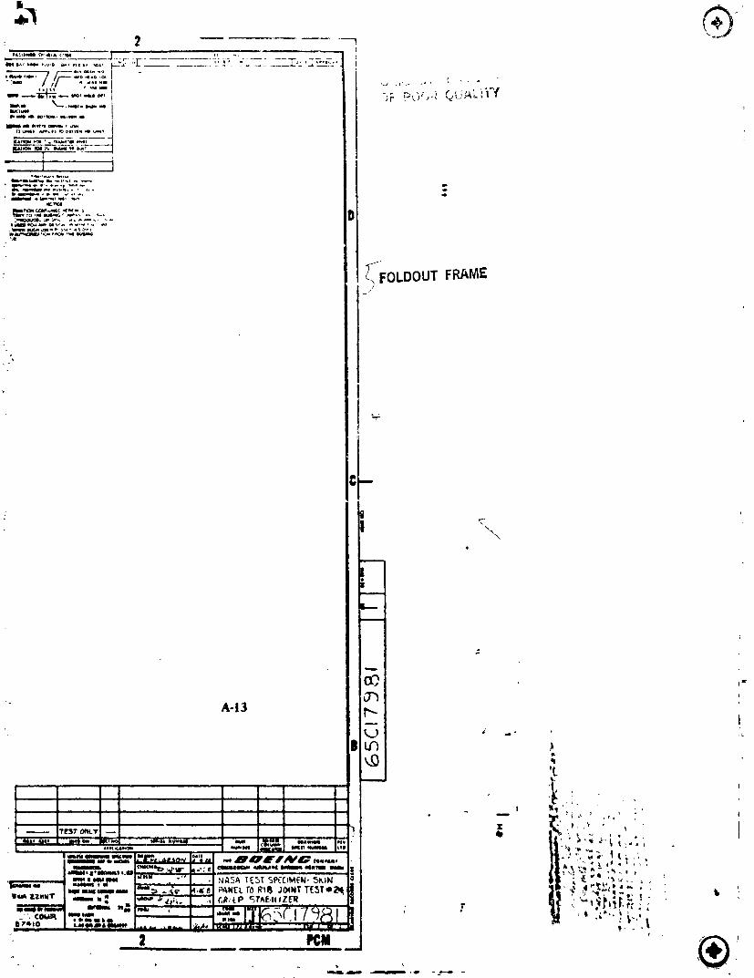
2
f,_ _'_:'/,_| -1I
_FoLDOUT FRAME
C i
\
i
A-13
l _'l'' _ . _ + " 'I
" l_m*_.,_, _,, _'" " i-'_'i. '_ " _ ( _ '
, ' m_n,o_ _u ., • NASA TESTSP(CIMEN-5_.IN ' ""'! PI:M _ +
i I i i i t i l
1984020846-139