Embed Size (px)
Citation preview
Initial Print Date: 07/10
Table of Contents
Subject Page
Introduction . . . . . . . . . . . . . . . . . . . . . . . . . . . . . . . . . . . . . . . . . . . . . . . . . .5Advantages of Bus Systems . . . . . . . . . . . . . . . . . . . . . . . . . . . . . . . . . . . . .6Types of Transmission . . . . . . . . . . . . . . . . . . . . . . . . . . . . . . . . . . . . . . . . . . .6
Analog Transmission . . . . . . . . . . . . . . . . . . . . . . . . . . . . . . . . . . . . . . . . .6Analog Signal . . . . . . . . . . . . . . . . . . . . . . . . . . . . . . . . . . . . . . . . . . . . . . . .7Digital Transmission . . . . . . . . . . . . . . . . . . . . . . . . . . . . . . . . . . . . . . . . . .7Binary Transmission . . . . . . . . . . . . . . . . . . . . . . . . . . . . . . . . . . . . . . . . . .8
Signal Level . . . . . . . . . . . . . . . . . . . . . . . . . . . . . . . . . . . . . . . . . . . . . . . . . . . .9Coded Representation . . . . . . . . . . . . . . . . . . . . . . . . . . . . . . . . . . . . . . . .9
Bit and Byte . . . . . . . . . . . . . . . . . . . . . . . . . . . . . . . . . . . . . . . . . . . . . . . . . .10Larger Units of Bytes . . . . . . . . . . . . . . . . . . . . . . . . . . . . . . . . . . . . . . . .10
Overview of Bus Systems . . . . . . . . . . . . . . . . . . . . . . . . . . . . . . . . . . . . .11Main Bus Systems . . . . . . . . . . . . . . . . . . . . . . . . . . . . . . . . . . . . . . . . . . . .11Sub-bus Systems . . . . . . . . . . . . . . . . . . . . . . . . . . . . . . . . . . . . . . . . . . . . .11
Main Bus Systems . . . . . . . . . . . . . . . . . . . . . . . . . . . . . . . . . . . . . . . . . . .13K-CAN . . . . . . . . . . . . . . . . . . . . . . . . . . . . . . . . . . . . . . . . . . . . . . . . . . . . . . .13
Advantages of CAN . . . . . . . . . . . . . . . . . . . . . . . . . . . . . . . . . . . . . . . . .14Terminating Resistor . . . . . . . . . . . . . . . . . . . . . . . . . . . . . . . . . . . . . . . .15
K-CAN 2 . . . . . . . . . . . . . . . . . . . . . . . . . . . . . . . . . . . . . . . . . . . . . . . . . . . . .18PT-CAN . . . . . . . . . . . . . . . . . . . . . . . . . . . . . . . . . . . . . . . . . . . . . . . . . . . . . .20PT-CAN 2 . . . . . . . . . . . . . . . . . . . . . . . . . . . . . . . . . . . . . . . . . . . . . . . . . . .21ICM-CAN . . . . . . . . . . . . . . . . . . . . . . . . . . . . . . . . . . . . . . . . . . . . . . . . . . . . .22FlexRay . . . . . . . . . . . . . . . . . . . . . . . . . . . . . . . . . . . . . . . . . . . . . . . . . . . . . .24
FlexRay in E7x Vehicles . . . . . . . . . . . . . . . . . . . . . . . . . . . . . . . . . . . . . .26Wake-up and Sleep Characteristics . . . . . . . . . . . . . . . . . . . . . . . .28Measurements on the FlexRay . . . . . . . . . . . . . . . . . . . . . . . . . . . .30
FlexRay - Application in F0x Vehicles . . . . . . . . . . . . . . . . . . . . . . . . . .31Properties of FlexRay . . . . . . . . . . . . . . . . . . . . . . . . . . . . . . . . . . . . . . . .32
Bus Topology . . . . . . . . . . . . . . . . . . . . . . . . . . . . . . . . . . . . . . . . . . .32FlexRay Bus Topology on F0x Vehicles . . . . . . . . . . . . . . . . . . . . . . . .35
Bus Termination . . . . . . . . . . . . . . . . . . . . . . . . . . . . . . . . . . . . . . . . .36Transmission Medium - Signal Properties . . . . . . . . . . . . . . . . . . .38
Deterministic Data Transmission . . . . . . . . . . . . . . . . . . . . . . . . . . . . . .40Bus Protocol . . . . . . . . . . . . . . . . . . . . . . . . . . . . . . . . . . . . . . . . . . . .41High Bandwidth . . . . . . . . . . . . . . . . . . . . . . . . . . . . . . . . . . . . . . . . .41Synchronization . . . . . . . . . . . . . . . . . . . . . . . . . . . . . . . . . . . . . . . . .41
Bus Systems
Revision Date: 09/11
Ethernet - Faster Programming Access . . . . . . . . . . . . . . . . . . . . . . . . . .42Ethernet in F0x Vehicles . . . . . . . . . . . . . . . . . . . . . . . . . . . . . . . . . . . . .42
Application . . . . . . . . . . . . . . . . . . . . . . . . . . . . . . . . . . . . . . . . . . . . .42Security . . . . . . . . . . . . . . . . . . . . . . . . . . . . . . . . . . . . . . . . . . . . . . . .42Features of Ethernet . . . . . . . . . . . . . . . . . . . . . . . . . . . . . . . . . . . . .43Functions of Ethernet . . . . . . . . . . . . . . . . . . . . . . . . . . . . . . . . . . . .43
Fiber Optic Bus Networks . . . . . . . . . . . . . . . . . . . . . . . . . . . . . . . . . . . . . .44Design . . . . . . . . . . . . . . . . . . . . . . . . . . . . . . . . . . . . . . . . . . . . . . . . . . . . .45Principle of Optical Transmission . . . . . . . . . . . . . . . . . . . . . . . . . . . . . .45Principle of Light Transmission . . . . . . . . . . . . . . . . . . . . . . . . . . . . . . .46Light Attenuation . . . . . . . . . . . . . . . . . . . . . . . . . . . . . . . . . . . . . . . . . . .47
Causes of Excessive Attenuation . . . . . . . . . . . . . . . . . . . . . . . . . .47Service Considerations . . . . . . . . . . . . . . . . . . . . . . . . . . . . . . . . . . . . . .49
Cable Repair . . . . . . . . . . . . . . . . . . . . . . . . . . . . . . . . . . . . . . . . . . . .50Fiber Optic Connectors . . . . . . . . . . . . . . . . . . . . . . . . . . . . . . . . . . .50
MOST . . . . . . . . . . . . . . . . . . . . . . . . . . . . . . . . . . . . . . . . . . . . . . . . . . . . . . .51MOST Design . . . . . . . . . . . . . . . . . . . . . . . . . . . . . . . . . . . . . . . . . . . . .52
Ring Structure . . . . . . . . . . . . . . . . . . . . . . . . . . . . . . . . . . . . . . . . . . .53Connection of Control Units . . . . . . . . . . . . . . . . . . . . . . . . . . . . . . . . . .55Fiber Optic Connector . . . . . . . . . . . . . . . . . . . . . . . . . . . . . . . . . . . . . . .56MOST Control Units and Light Direction . . . . . . . . . . . . . . . . . . . . . . .57
Light Direction . . . . . . . . . . . . . . . . . . . . . . . . . . . . . . . . . . . . . . . . . . .57Registration of control units in the MOST . . . . . . . . . . . . . . . . . . . . . .58Bandwidths . . . . . . . . . . . . . . . . . . . . . . . . . . . . . . . . . . . . . . . . . . . . . . . .59MOST Bus Diagnosis . . . . . . . . . . . . . . . . . . . . . . . . . . . . . . . . . . . . . . .60
Optical Wave Guide Communication Fault . . . . . . . . . . . . . . . . . .60Control Module Does Not Switch Off Light . . . . . . . . . . . . . . . . .61Network Wakeup Unsuccessful . . . . . . . . . . . . . . . . . . . . . . . . . . . .62Ring Break Diagnosis . . . . . . . . . . . . . . . . . . . . . . . . . . . . . . . . . . . .62Light Output Reduction . . . . . . . . . . . . . . . . . . . . . . . . . . . . . . . . . . .63Ring Break Test . . . . . . . . . . . . . . . . . . . . . . . . . . . . . . . . . . . . . . . . . .63Status Wakeup . . . . . . . . . . . . . . . . . . . . . . . . . . . . . . . . . . . . . . . . . .65
Sub-busSystems ............................................66K-Bus . . . . . . . . . . . . . . . . . . . . . . . . . . . . . . . . . . . . . . . . . . . . . . . . . . . . . . . .66LIN-Bus . . . . . . . . . . . . . . . . . . . . . . . . . . . . . . . . . . . . . . . . . . . . . . . . . . . . . .67
LIN V2.0 (or V2.1) . . . . . . . . . . . . . . . . . . . . . . . . . . . . . . . . . . . . . . . . . . .69D-Bus . . . . . . . . . . . . . . . . . . . . . . . . . . . . . . . . . . . . . . . . . . . . . . . . . . . . . . . .71D-CAN . . . . . . . . . . . . . . . . . . . . . . . . . . . . . . . . . . . . . . . . . . . . . . . . . . . . . . .71Bit-serial Data Interface . . . . . . . . . . . . . . . . . . . . . . . . . . . . . . . . . . . . . . . .73Local-CAN . . . . . . . . . . . . . . . . . . . . . . . . . . . . . . . . . . . . . . . . . . . . . . . . . . .73
Gateways ...................................................74Gateway Rules Based on the Example of a Train Station . . . . . . . . . . .75
Subject Page

BLANKPAGE
Subject Page
4Bus Systems
BusSystems
Model:All
Production:All
After completion of this module you will be able to:
• Describe the operation of a basic bus system.
• Understand how signals and sensor information are shared betweencontrol units in a bus system.
• Identify the different bus systems currently used in BMW Group vehicles.
• Understand how bus networking technology is applied in BMW vehicles.
• Understand diagnostic techniques.
Today's vehicles contain a wide variety of electronic devices and components. The totalnumber of electronic components in motor vehicles is sure to increase substantially inthe foreseeable future. Legislation as well as customers demand this continued develop-ment. Legislation is interested in improving the quality of exhaust emissions and reduc-ing fuel consumption. Customer requirements are focussed on improving driving com-fort and safety.
Control units that meet these requirements have long been utilized. Examples includecontrol units employed in the area of the digital motor electronics and airbag systems.
The complexity of the realized functions calls for data exchange between the controlunits. Conventionally, the data is transmitted via signal lines. However, in view of theincrease in complexity of the control unit functions, this type of data exchange can nowbe realized only with ever growing expenditure.
Originally autonomous processes of individual control units are being coupled to an everincreasing extent via bus systems. This means that the processes are distributed, imple-mented throughout the vehicle systems network and interact in co-ordinated functions.
The data exchange within the systems network is therefore constantly increasing. Thisdata exchange also enables many new functions, which benefit increased road safetyand enhanced driving comfort.
These requirements can no longer be realized with the previous vehicle electrical systems and networks.
The increasing use of electrical and electronic components in motor vehicles is limitedby various factors:
• Increasing scope of wiring/cabling
• Higher production costs
• Increased space requirement in the vehicle
• Component configurations that are difficult to manage
• Reduced reliability of overall system
Networks are used in the vehicle electrical system with the aim of minimizing these dis-advantages. These networks are referred to as bus systems.
Bus systems enable networking of the individual control units in the vehicle via "serialinterfaces". This provides various advantages that facilitate the use of the systems inmotor vehicles.
5Bus Systems
Introduction
AdvantagesofBusSystems
• Higher reliability of overall system
• Reduced extent of wiring/cabling
• Reduction in the number of individual cables
• Reduced cross sections of wiring harnesses
• Flexible installation of cables
• Multiple use of sensors
• Transmission of complex data possible
• Higher flexibility for system modifications
• Expansion of scope of data possible at any time
• Implementation of new functions for the customer
• Efficient diagnosis
• Lower hardware costs
TypesofTransmission
AnalogTransmission
The term analog comes from the Greek (analogos) and means corresponding to, analo-gous to.
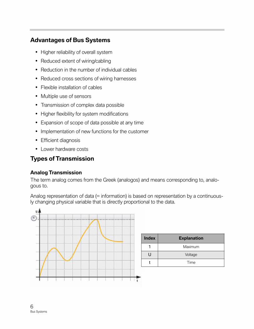
Analog representation of data (= information) is based on representation by a continuous-ly changing physical variable that is directly proportional to the data.
Index Explanation
1 Maximum
U Voltage
t Time
6Bus Systems
AnalogSignalA characteristic of an analog signal is that it can assume any value between 0% and100%. The signal is therefore infinitely variable.
Examples: Pointer measuring instruments, mercury thermometer, hands of a watch.
When listening to music, for example, the ear receives the analog signals (constantlychanging sound waves). This sound is represented in the same way in electrical devices(audio system, radio, telephone etc.) by means of continuously changing voltages.
However, when such an electrical signal is transferred from one device to another, theinformation arriving at the receiver is no longer exactly the same as what was sent bythe transmitter.
This is due to interference factors such as:
• Cable length
• Line resistance of the cable
• Radio waves
• Mobile radio signals
The analog transmission of information in vehicle applications is not feasible for safetyand reliability reasons. In addition, the changes in voltages would be much too small sothat reliable values could not be represented (ABS, airbag, engine management etc.).
DigitalTransmission
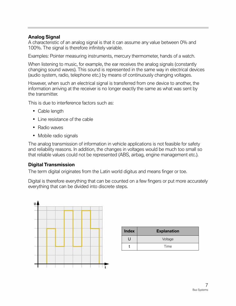
The term digital originates from the Latin world digitus and means finger or toe.
Digital is therefore everything that can be counted on a few fingers or put more accuratelyeverything that can be divided into discrete steps.
Index Explanation
U Voltage
t Time
7Bus Systems
Digital representation involves the representation of constantly changing variables innumerical form. Particularly in computers, all data are represented as a sequence ofzeros and ones (binary). Digital is therefore the opposite of analog.
Examples: Digital multimeter, digital clock, CD, DVD.
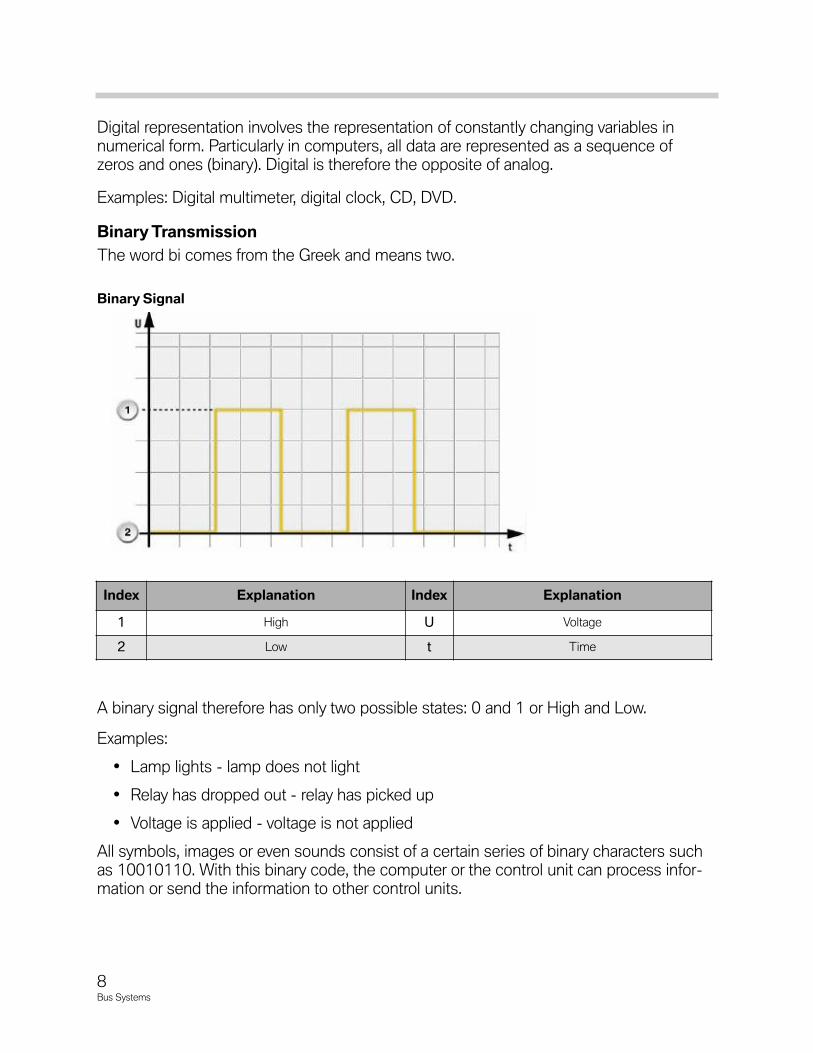
BinaryTransmission
The word bi comes from the Greek and means two.
A binary signal therefore has only two possible states: 0 and 1 or High and Low.
Examples:
• Lamp lights - lamp does not light
• Relay has dropped out - relay has picked up
• Voltage is applied - voltage is not applied
All symbols, images or even sounds consist of a certain series of binary characters suchas 10010110. With this binary code, the computer or the control unit can process infor-mation or send the information to other control units.
Index Explanation Index Explanation
1 High U Voltage
2 Low t Time
BinarySignal
8Bus Systems
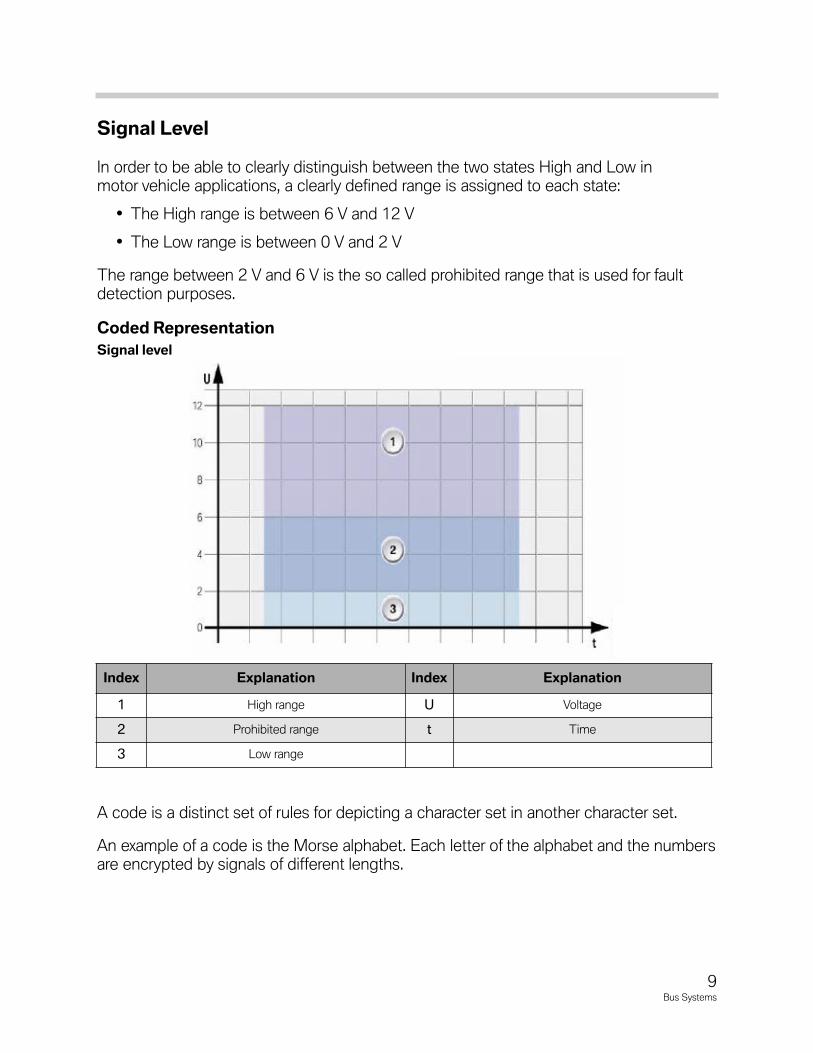
SignalLevel
In order to be able to clearly distinguish between the two states High and Low inmotor vehicle applications, a clearly defined range is assigned to each state:
• The High range is between 6 V and 12 V
• The Low range is between 0 V and 2 V
The range between 2 V and 6 V is the so called prohibited range that is used for faultdetection purposes.
CodedRepresentation
A code is a distinct set of rules for depicting a character set in another character set.
An example of a code is the Morse alphabet. Each letter of the alphabet and the numbersare encrypted by signals of different lengths.
Index Explanation Index Explanation
1 High range U Voltage
2 Prohibited range t Time
3 Low range
Signallevel
9Bus Systems
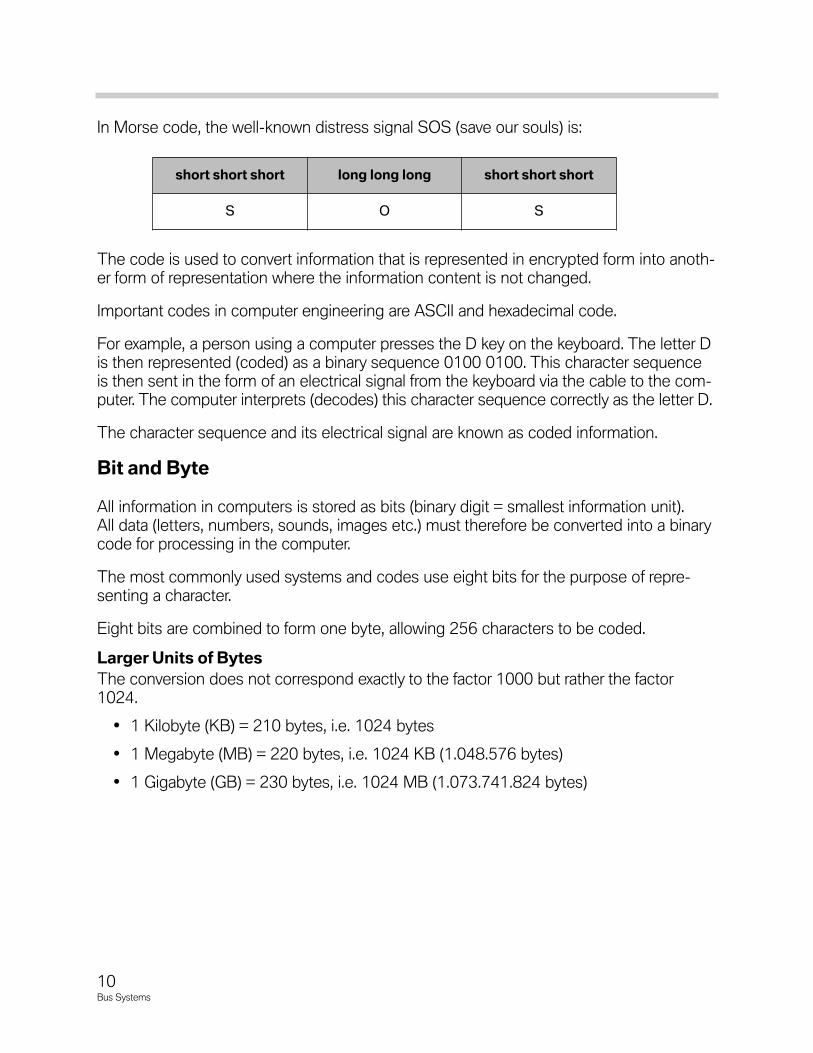
In Morse code, the well-known distress signal SOS (save our souls) is:
The code is used to convert information that is represented in encrypted form into anoth-er form of representation where the information content is not changed.
Important codes in computer engineering are ASCII and hexadecimal code.
For example, a person using a computer presses the D key on the keyboard. The letter Dis then represented (coded) as a binary sequence 0100 0100. This character sequenceis then sent in the form of an electrical signal from the keyboard via the cable to the com-puter. The computer interprets (decodes) this character sequence correctly as the letter D.
The character sequence and its electrical signal are known as coded information.
BitandByte
All information in computers is stored as bits (binary digit = smallest information unit).All data (letters, numbers, sounds, images etc.) must therefore be converted into a binarycode for processing in the computer.
The most commonly used systems and codes use eight bits for the purpose of repre-senting a character.
Eight bits are combined to form one byte, allowing 256 characters to be coded.
LargerUnitsofBytes
The conversion does not correspond exactly to the factor 1000 but rather the factor1024.
• 1 Kilobyte (KB) = 210 bytes, i.e. 1024 bytes
• 1 Megabyte (MB) = 220 bytes, i.e. 1024 KB (1.048.576 bytes)
• 1 Gigabyte (GB) = 230 bytes, i.e. 1024 MB (1.073.741.824 bytes)
shortshortshort longlonglong shortshortshort
S O S
10Bus Systems
In principle, a distinction is made between two groups of bus systems:
• Main bus systems
• Sub-bus systems
Main bus systems are responsible for cross system data exchange. Sub-bus systemsexchange data within the specific system. These systems are used to exchange relativelysmall quantities of data in specific systems.
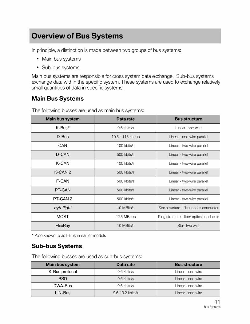
MainBusSystems
The following busses are used as main bus systems:
* Also known to as I-Bus in earlier models
Sub-busSystems
The following busses are used as sub-bus systems:
Mainbussystem Datarate Busstructure
K-Bus* 9.6 kbits/s Linear -one-wire
D-Bus 10.5 - 115 kbits/s Linear - one-wire parallel
CAN 100 kbits/s Linear - two-wire parallel
D-CAN 500 kbits/s Linear - two-wire parallel
K-CAN 100 kbits/s Linear - two-wire parallel
K-CAN 2 500 kbits/s Linear - two-wire parallel
F-CAN 500 kbits/s Linear - two-wire parallel
PT-CAN 500 kbits/s Linear - two-wire parallel
PT-CAN 2 500 kbits/s Linear - two-wire parallel
byteflight 10 MBits/s Star structure - fiber optics conductor
MOST 22.5 MBits/s Ring structure - fiber optics conductor
FlexRay 10 MBits/s Star- two wire
Mainbussystem Datarate Busstructure
K-Bus protocol 9.6 kbits/s Linear - one-wire
BSD 9.6 kbits/s Linear - one-wire
DWA-Bus 9.6 kbits/s Linear - one-wire
LIN-Bus 9.6-19.2 kbits/s Linear - one-wire
OverviewofBusSystems
11Bus Systems
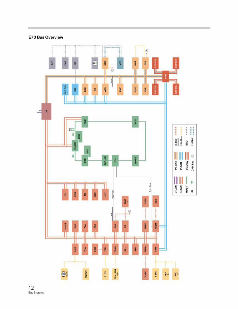
E70BusOverview
12Bus Systems
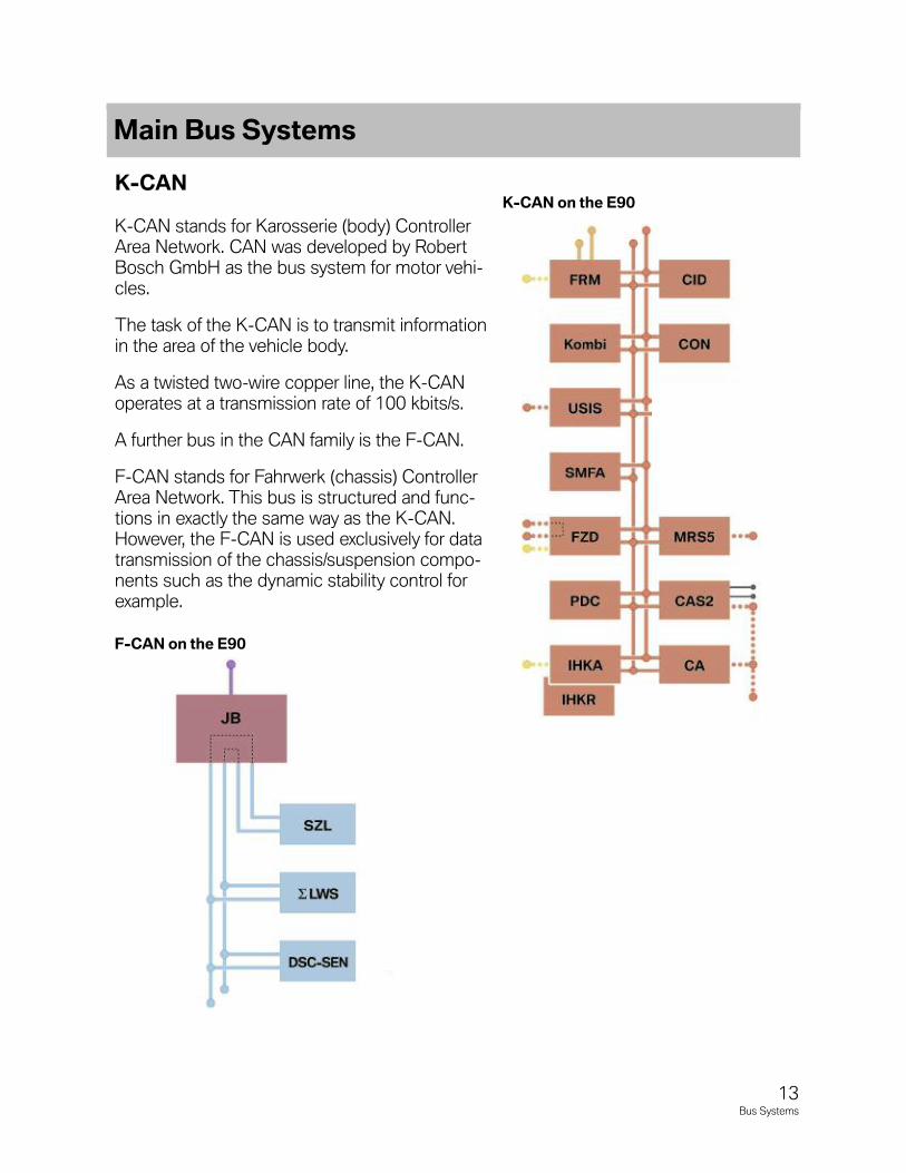
K-CAN
K-CAN stands for Karosserie (body) ControllerArea Network. CAN was developed by RobertBosch GmbH as the bus system for motor vehi-cles.
The task of the K-CAN is to transmit informationin the area of the vehicle body.
As a twisted two-wire copper line, the K-CANoperates at a transmission rate of 100 kbits/s.
A further bus in the CAN family is the F-CAN.
F-CAN stands for Fahrwerk (chassis) ControllerArea Network. This bus is structured and func-tions in exactly the same way as the K-CAN.However, the F-CAN is used exclusively for datatransmission of the chassis/suspension compo-nents such as the dynamic stability control forexample.
MainBusSystems
K-CANontheE90
F-CANontheE90
13Bus Systems
AdvantagesofCAN
The advantages of the CAN-Bus are:
• Higher data transmission speed compared to conventional wiring
• Improved electromagnetic compatibility (EMC)
• Improved emergency operation characteristics
The body controller area network, abbreviated K-CAN, is used in BMW vehicles to inter-link components of the comfort and body electronics such as lamp control, seat adjust-ment and air conditioning.
The transmission rate is 100 kbits/s.
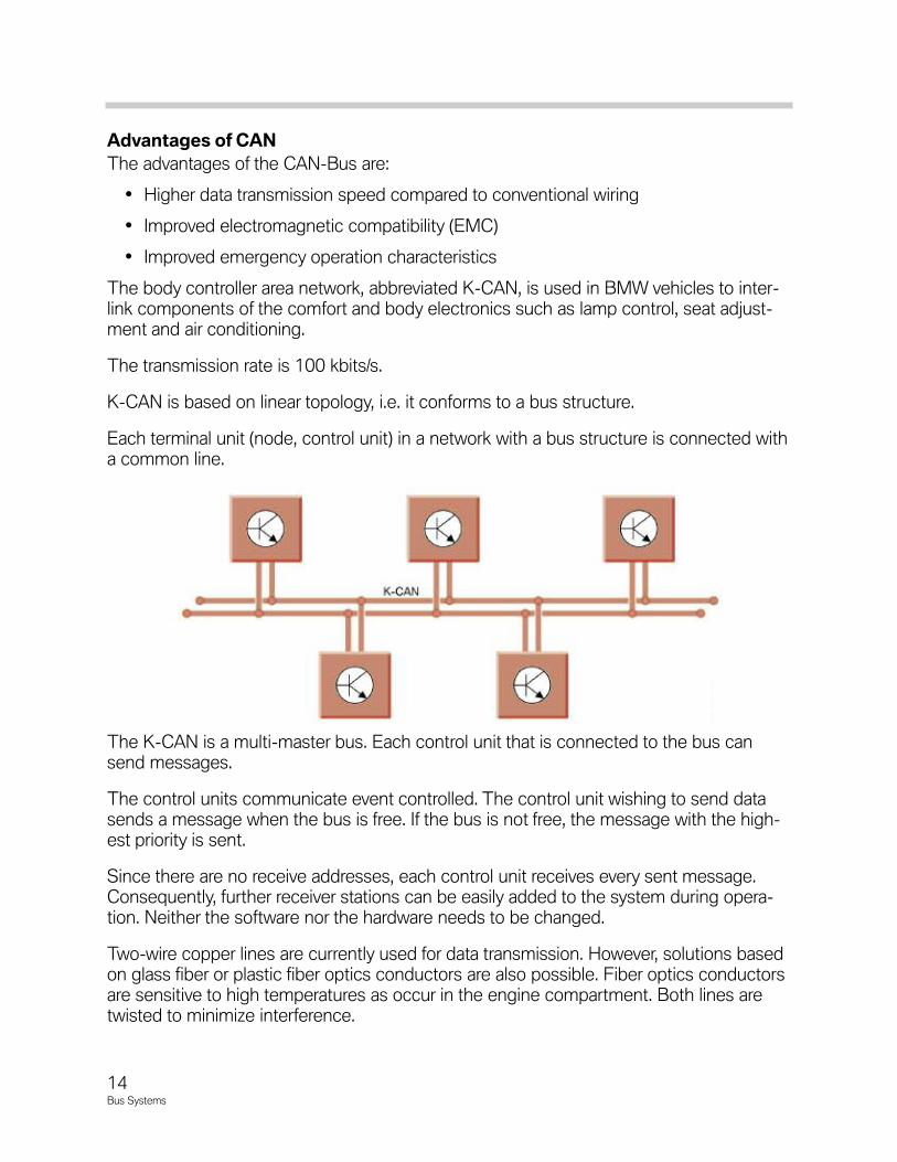
K-CAN is based on linear topology, i.e. it conforms to a bus structure.
Each terminal unit (node, control unit) in a network with a bus structure is connected witha common line.
The K-CAN is a multi-master bus. Each control unit that is connected to the bus cansend messages.
The control units communicate event controlled. The control unit wishing to send datasends a message when the bus is free. If the bus is not free, the message with the high-est priority is sent.
Since there are no receive addresses, each control unit receives every sent message.Consequently, further receiver stations can be easily added to the system during opera-tion. Neither the software nor the hardware needs to be changed.
Two-wire copper lines are currently used for data transmission. However, solutions basedon glass fiber or plastic fiber optics conductors are also possible. Fiber optics conductorsare sensitive to high temperatures as occur in the engine compartment. Both lines aretwisted to minimize interference.
14Bus Systems
The advantage of using two-wire lines is that it is possible to fall back on a one-wire linein the event of a fault.
Advantages:
• Easy to install
• Easy to expand
• Short lines
• Emergency operation on one line
Disadvantages:
• Network expansion limited
• Intricate access methods
TerminatingResistor
From an electrical point of view, a current carrying conductor always has an ohmic, induc-tive and capacitive resistance. When transmitting data from point "A" to point "B", thetotal sum of these resistances has an effect on data transmission. The higher the trans-mission frequency, the more effective the inductive and capacitive resistance. Ultimately,it is possible that a signal, which is no longer identifiable, is received at the end of thetransmission line. For this reason, the line is "adapted" by terminating resistors, ensuringthe original signal is retained.
Inductive resistance occurs, for example, as the result of the coil effect in the line.Capacitive resistance occurs, for example, by installing the line parallel to the vehicle body.
The terminating resistors used in a bus system vary.
They generally depend on the following parameters:
• Frequency of data transmission on the bus system
• Inductive or capacitive load on the transmission path
• Cable length for data transmission
The longer the line, the greater the inductive component of the line.
The control units are divided into basic control units that are always installed (e.g. instru-ment cluster in the E9x vehicles) and the remaining control units. The resistance valuedetermines this division.
Terminating resistors are used to ensure exact signal progression in the bus systems.These terminating resistors are located in the control units of the bus systems.
If the voltage level changes due to a defective terminating resistor. This change in voltageaffects the CAN system. Communication between the bus users no longer operates cor-rectly.
15Bus Systems
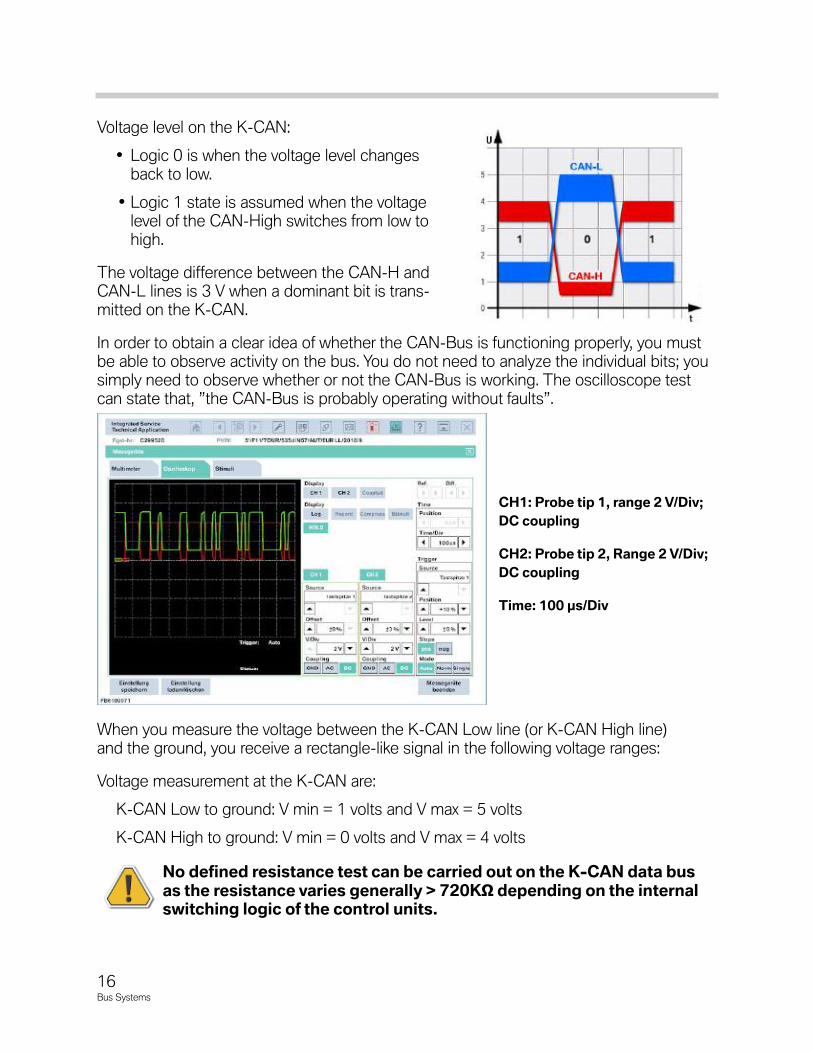
Voltage level on the K-CAN:
• Logic 0 is when the voltage level changesback to low.
• Logic 1 state is assumed when the voltagelevel of the CAN-High switches from low tohigh.
The voltage difference between the CAN-H andCAN-L lines is 3 V when a dominant bit is trans-mitted on the K-CAN.
In order to obtain a clear idea of whether the CAN-Bus is functioning properly, you mustbe able to observe activity on the bus. You do not need to analyze the individual bits; yousimply need to observe whether or not the CAN-Bus is working. The oscilloscope testcan state that, ”the CAN-Bus is probably operating without faults”.
When you measure the voltage between the K-CAN Low line (or K-CAN High line)and the ground, you receive a rectangle-like signal in the following voltage ranges:
Voltage measurement at the K-CAN are:
K-CAN Low to ground: V min = 1 volts and V max = 5 volts
K-CAN High to ground: V min = 0 volts and V max = 4 volts
NodefinedresistancetestcanbecarriedoutontheK-CANdatabusastheresistancevariesgenerally>720KΩ dependingontheinternalswitchinglogicofthecontrolunits.
CH1:Probetip1,range2V/Div;
DCcoupling
CH2:Probetip2,Range2V/Div;
DCcoupling
Time:100µs/Div
16Bus Systems
The K-CAN is operated as a one-wire bus if:
• There is a break in a CAN data line (core)
• There is a short to ground on a CAN data line (core)
• There is a short to the supply voltage UB+ on a CAN data line (core)
The bus systems used to date are also used in the F01/F02. The K-CAN is responsiblefor communication of the components with a low data transfer rate. The K-CAN is alsoconnected to the other bus systems via the central gateway module.
The K-CAN is set up as line topology. Some control units in the K-CAN have a LIN-Busas sub-bus. The K-CAN has a data transfer rate of 100 kBit/s and is designed as a twist-ed pair of wires. The K-CAN has the possibility to be operated as a single-wire bus in theevent of a fault.
The K-CAN control unit is wakened via the bus, without an additional wake-up line.The following is an example of the control units which are fitted in the K-CAN of anF01/F02:
• CID Central Information Display
• CON Controller
• EHC, Electronic Height Control
• FD Rear Display
• FD2 Rear Display 2
• FKA, rear heater / air-conditioning system
• HiFi, hi-fi amplifier
• HKL, luggage compartment lid lift
• HUD, Head-Up Display
• IHKA, integrated heater/air conditioning system*
• SMBF passenger seat module*
• SMBFH rear passenger seat module*
• SMFA driver seat module*
• SMBFH rear module on driver' seat side*
• TPMS, Tire Pressure Monitoring System
• TRSVC panoramic camera*
• VSW, video switch
• ZGM, central gateway module
17Bus Systems
K-CAN2
First introduced with BN2020 in the F01, the K-CAN 2 is responsible for communicationof the control units with a high data transfer rate. The K-CAN 2 is also connected to theother bus systems via the central gateway module (ZGM). A LIN-Bus as a sub-bus isconnected to all control units in the K-CAN 2.
The K-CAN 2 can be wakened via any of these sub busses, without an additional (hard-wire) wake-up line. This is represented by the “wake authorized” symbol next to all of thecontrol units of K-CAN 2 on the Bus Overview. (See bus chart below).
To provide a rapid start enable, the CAS has an additional redundant bus connection tothe DME. On this CAS-Bus, the data are transferred per K-Bus protocol.
The K-CAN 2 is similar to PT-CAN in that it has a data transfer rate of 500 kBit/s, it isdesigned as a twisted pair with a measured a resistance of 60 Ω .
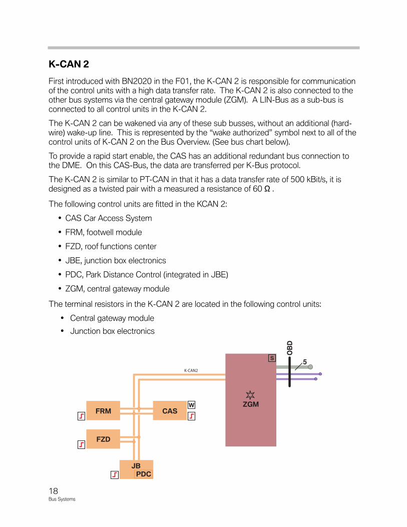
The following control units are fitted in the KCAN 2:
• CAS Car Access System
• FRM, footwell module
• FZD, roof functions center
• JBE, junction box electronics
• PDC, Park Distance Control (integrated in JBE)
• ZGM, central gateway module
The terminal resistors in the K-CAN 2 are located in the following control units:
• Central gateway module
• Junction box electronics
5
OBD
K-CAN2
FRM
FZD
JBPDC
CASZGM
S
W
18Bus Systems
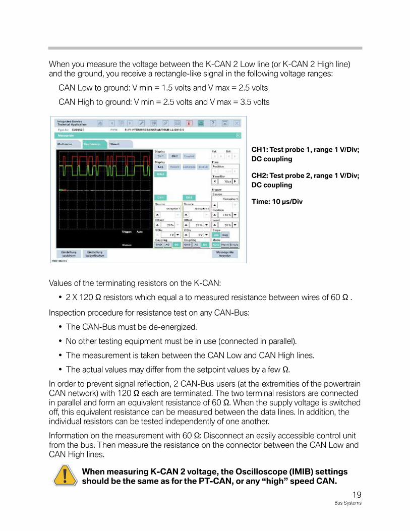
When you measure the voltage between the K-CAN 2 Low line (or K-CAN 2 High line)and the ground, you receive a rectangle-like signal in the following voltage ranges:
CAN Low to ground: V min = 1.5 volts and V max = 2.5 volts
CAN High to ground: V min = 2.5 volts and V max = 3.5 volts
Values of the terminating resistors on the K-CAN:
• 2 X 120 Ω resistors which equal a to measured resistance between wires of 60 Ω .
Inspection procedure for resistance test on any CAN-Bus:
• The CAN-Bus must be de-energized.
• No other testing equipment must be in use (connected in parallel).
• The measurement is taken between the CAN Low and CAN High lines.
• The actual values may differ from the setpoint values by a few Ω.
In order to prevent signal reflection, 2 CAN-Bus users (at the extremities of the powertrainCAN network) with 120 Ω each are terminated. The two terminal resistors are connectedin parallel and form an equivalent resistance of 60 Ω. When the supply voltage is switchedoff, this equivalent resistance can be measured between the data lines. In addition, theindividual resistors can be tested independently of one another.
Information on the measurement with 60 Ω: Disconnect an easily accessible control unitfrom the bus. Then measure the resistance on the connector between the CAN Low andCAN High lines.
WhenmeasuringK-CAN2voltage,theOscilloscope(IMIB)settingsshouldbethesameasforthePT-CAN,orany“high”speedCAN.
CH1:Testprobe1,range1V/Div;
DCcoupling
CH2:Testprobe2,range1V/Div;
DCcoupling
Time:10µs/Div
19Bus Systems
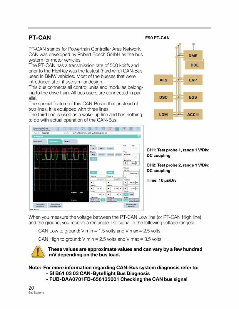
PT-CAN
PT-CAN stands for Powertrain Controller Area Network.CAN was developed by Robert Bosch GmbH as the bussystem for motor vehicles.The PT-CAN has a transmission rate of 500 kbit/s andprior to the FlexRay was the fastest (hard wire) CAN-Busused in BMW vehicles. Most of the busses that wereintroduced after it use similar design.This bus connects all control units and modules belong-ing to the drive train. All bus users are connected in par-allel.The special feature of this CAN-Bus is that, instead oftwo lines, it is equipped with three lines.The third line is used as a wake-up line and has nothingto do with actual operation of the CAN-Bus.
When you measure the voltage between the PT-CAN Low line (or PT-CAN High line)and the ground, you receive a rectangle-like signal in the following voltage ranges:
CAN Low to ground: V min = 1.5 volts and V max = 2.5 volts
CAN High to ground: V min = 2.5 volts and V max = 3.5 volts
ThesevaluesareapproximatevaluesandcanvarybyafewhundredmVdependingonthebusload.
Note:FormoreinformationregardingCAN-Bussystemdiagnosisreferto:
-SIB610303CAN-ByteflightBusDiagnosis
-FUB-DAA0701FB-656135001CheckingtheCANbussignal
E90PT-CAN
CH1:Testprobe1,range1V/Div;
DCcoupling
CH2:Testprobe2,range1V/Div;
DCcoupling
Time:10µs/Div
20Bus Systems
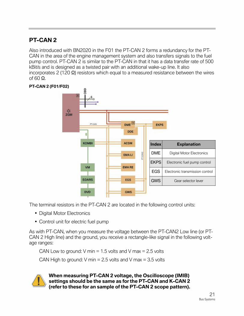
PT-CAN2
Also introduced with BN2020 in the F01 the PT-CAN 2 forms a redundancy for the PT-CAN in the area of the engine management system and also transfers signals to the fuelpump control. PT-CAN 2 is similar to the PT-CAN in that it has a data transfer rate of 500kBit/s and is designed as a twisted pair with an additional wake-up line. It alsoincorporates 2 (120 Ω) resistors which equal to a measured resistance between the wiresof 60 Ω.
The terminal resistors in the PT-CAN 2 are located in the following control units:
• Digital Motor Electronics
• Control unit for electric fuel pump
As with PT-CAN, when you measure the voltage between the PT-CAN2 Low line (or PT-CAN 2 High line) and the ground, you receive a rectangle-like signal in the following volt-age ranges:
CAN Low to ground: V min = 1.5 volts and V max = 2.5 volts
CAN High to ground: V min = 2.5 volts and V max = 3.5 volts
WhenmeasuringPT-CAN2voltage,theOscilloscope(IMIB)settingsshouldbethesameasforthePT-CANandK-CAN2(refertotheseforansampleofthePT-CAN2scopepattern).
PT-CAN2(F01/F02)
Index Explanation
DME Digital Motor Electronics
EKPS Electronic fuel pump control
EGS Electronic transmission control
GWS Gear selector lever
21Bus Systems
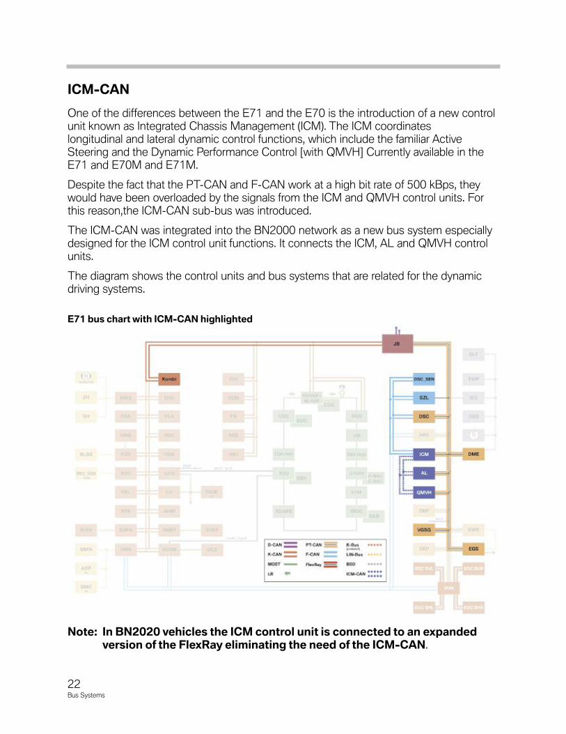
ICM-CAN
One of the differences between the E71 and the E70 is the introduction of a new controlunit known as Integrated Chassis Management (ICM). The ICM coordinates longitudinal and lateral dynamic control functions, which include the familiar Active Steering and the Dynamic Performance Control [with QMVH] Currently available in theE71 and E70M and E71M.
Despite the fact that the PT-CAN and F-CAN work at a high bit rate of 500 kBps, theywould have been overloaded by the signals from the ICM and QMVH control units. Forthis reason,the ICM-CAN sub-bus was introduced.
The ICM-CAN was integrated into the BN2000 network as a new bus system especiallydesigned for the ICM control unit functions. It connects the ICM, AL and QMVH controlunits.
The diagram shows the control units and bus systems that are related for the dynamic driving systems.
Note:InBN2020vehiclestheICMcontrolunitisconnectedtoanexpandedversionoftheFlexRayeliminatingtheneedoftheICM-CAN.
E71buschartwithICM-CANhighlighted
22Bus Systems
The ICM-CAN is a two-wire bus on which data is transmitted at 500 kBps. The two ter-minating resistors, each with 120 W, are located in the ICM and QMVH control units.
The ICM-CAN cabling in the vehicle varies considerably between the two variantswith/without Active Steering.
If Active Steering is fitted, the ICM-CAN is routed from the ICM control unit to the ALcontrol unit. The ICM-CAN is picked up in the AL control unit and forwarded to theQMVH control unit.
If Active Steering is not fitted, the ICM-CAN line is routed directly from the ICM controlunit to the QMVH control unit.
These control units use the ICM-CAN to exchange setpoint values and actual values,as well as status signals. These signals are only required locally for implementing theDynamic Performance Control and Active Steering functions.
In contrast, signals that the dynamic driving systems exchange with other control unitsare still transmitted via the PT-CAN. The PT-CAN is also the bus system via which theICM, AL and QMVH control units communicate with the diagnostic system.
The ICM control unit does not therefore perform the function of a diagnostics gateway.
As with PT-CAN and K-CAN2, when you measure the voltage between the ICM-CANLow line (or ICM-CAN High line) and the ground, you receive a rectangle-like signal inthe following voltage ranges:
CAN Low to ground: V min = 1.5 volts and V max = 2.5 volts
CAN High to ground: V min = 2.5 volts and V max = 3.5 volts
WhenmeasuringICM-CANvoltage,theOscilloscope(IMIB)settingsshouldbethesameasforthePT-CANandK-CAN2(refertotheseforansampleoftheICM-CANscopepattern).
23Bus Systems
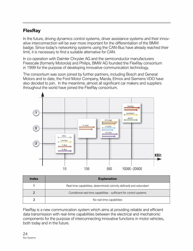
FlexRay
In the future, driving dynamics control systems, driver assistance systems and their innov-ative interconnection will be ever more important for the differentiation of the BMWbadge. Since today's networking systems using the CAN-Bus have already reached theirlimit, it is necessary to find a suitable alternative for CAN.
In co-operation with Daimler Chrysler AG and the semiconductor manufacturersFreescale (formerly Motorola) and Philips, BMW AG founded the FlexRay consortiumin 1999 for the purpose of developing innovative communication technology.
The consortium was soon joined by further partners, including Bosch and GeneralMotors and to date, the Ford Motor Company, Mazda, Elmos and Siemens VDO havealso decided to join. In the meantime, almost all significant car makers and suppliersthroughout the world have joined the FlexRay consortium.
FlexRay is a new communication system which aims at providing reliable and efficientdata transmission with real-time capabilities between the electrical and mechatroniccomponents for the purpose of interconnecting innovative functions in motor vehicles,both today and in the future.
Index Explanation
1 Real time capabilities, deterministic (strictly defined) and redundant
2 Conditional real time capabilities - sufficient for control systems
3 No real time capabilities
24Bus Systems
Development of the new FlexRay communication system was prompted by the evergrowing technological requirements placed on a communication system for interconnect-ing control units in motor vehicles and the realization that an open and standardized solu-tion was needed for infrastructure systems.
FlexRay provides an efficient protocol for real-time data transmission in distributed sys-tems as used in motor vehicles.
With a data transmission rate of 10 Mbits/s, the FlexRay is distinctly faster than the databuses used in the area of the chassis, drive train and suspension of today's motor vehicles.
In addition to the higher bandwidth, FlexRay supports deterministic data transmission andcan be configured such that reliable continued operation of remaining communicationsystems is enabled even in the event of individual components failing.
WhataretheadvantagesofFlexRay?
• High bandwidth (10 Mbits/s compared to 0.5 Mbits/s of the CAN)
• Deterministic (= real-time capabilities) data transmission
• Reliable data communication
• Supports system integration
• Standard in automotive industry
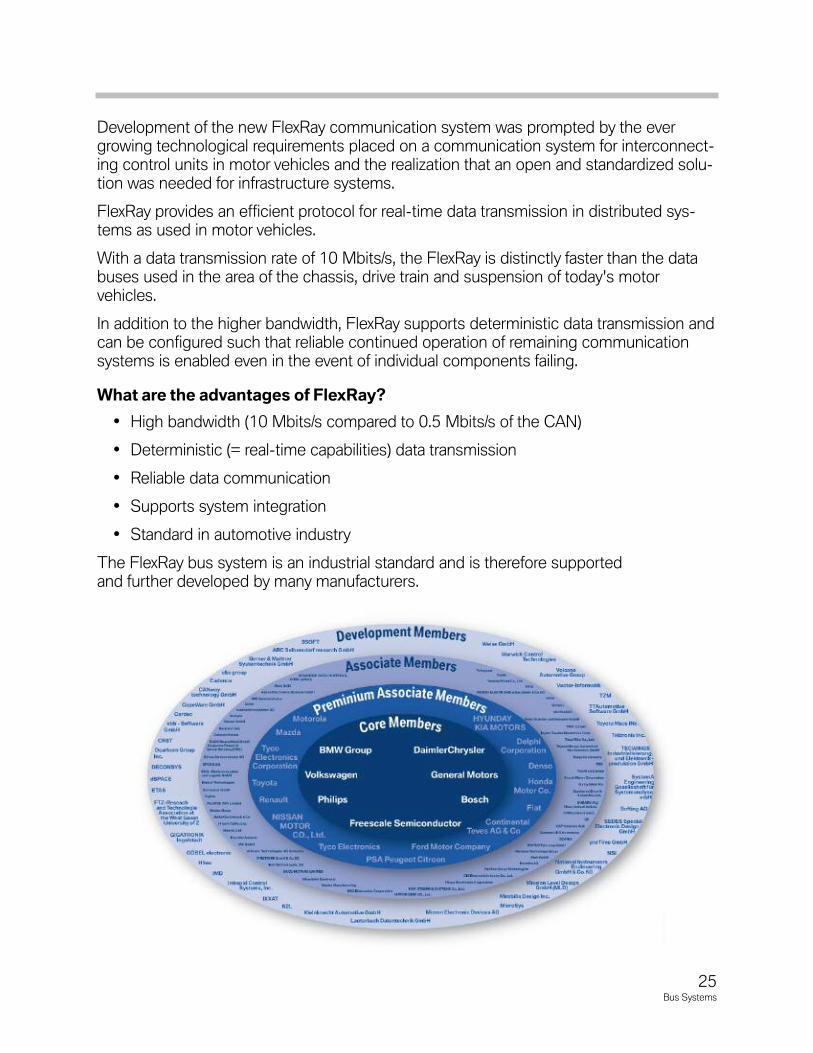
The FlexRay bus system is an industrial standard and is therefore supportedand further developed by many manufacturers.
25Bus Systems
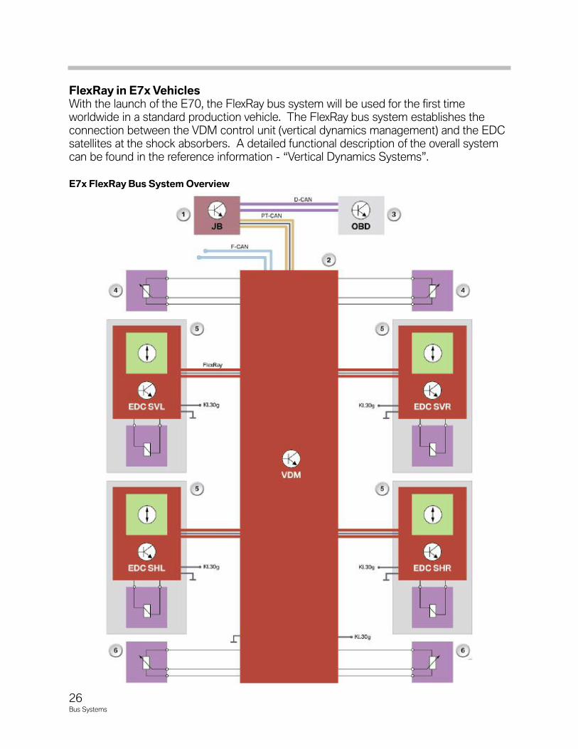
FlexRayinE7xVehiclesWith the launch of the E70, the FlexRay bus system will be used for the first time worldwide in a standard production vehicle. The FlexRay bus system establishes theconnection between the VDM control unit (vertical dynamics management) and the EDCsatellites at the shock absorbers. A detailed functional description of the overall systemcan be found in the reference information - “Vertical Dynamics Systems”.
E7xFlexRayBusSystemOverview
26Bus Systems
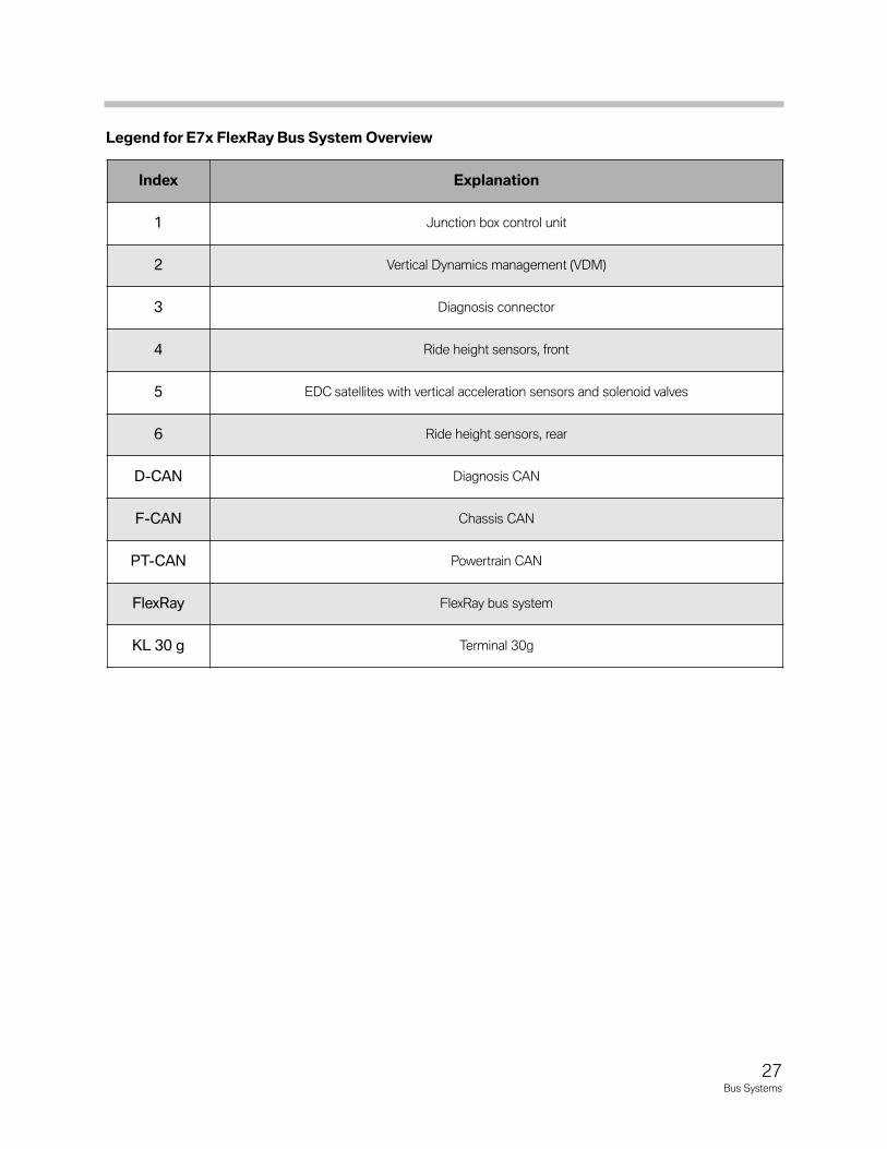
LegendforE7xFlexRayBusSystemOverview
Index Explanation
1 Junction box control unit
2 Vertical Dynamics management (VDM)
3 Diagnosis connector
4 Ride height sensors, front
5 EDC satellites with vertical acceleration sensors and solenoid valves
6 Ride height sensors, rear
D-CAN Diagnosis CAN
F-CAN Chassis CAN
PT-CAN Powertrain CAN
FlexRay FlexRay bus system
KL 30 g Terminal 30g
27Bus Systems
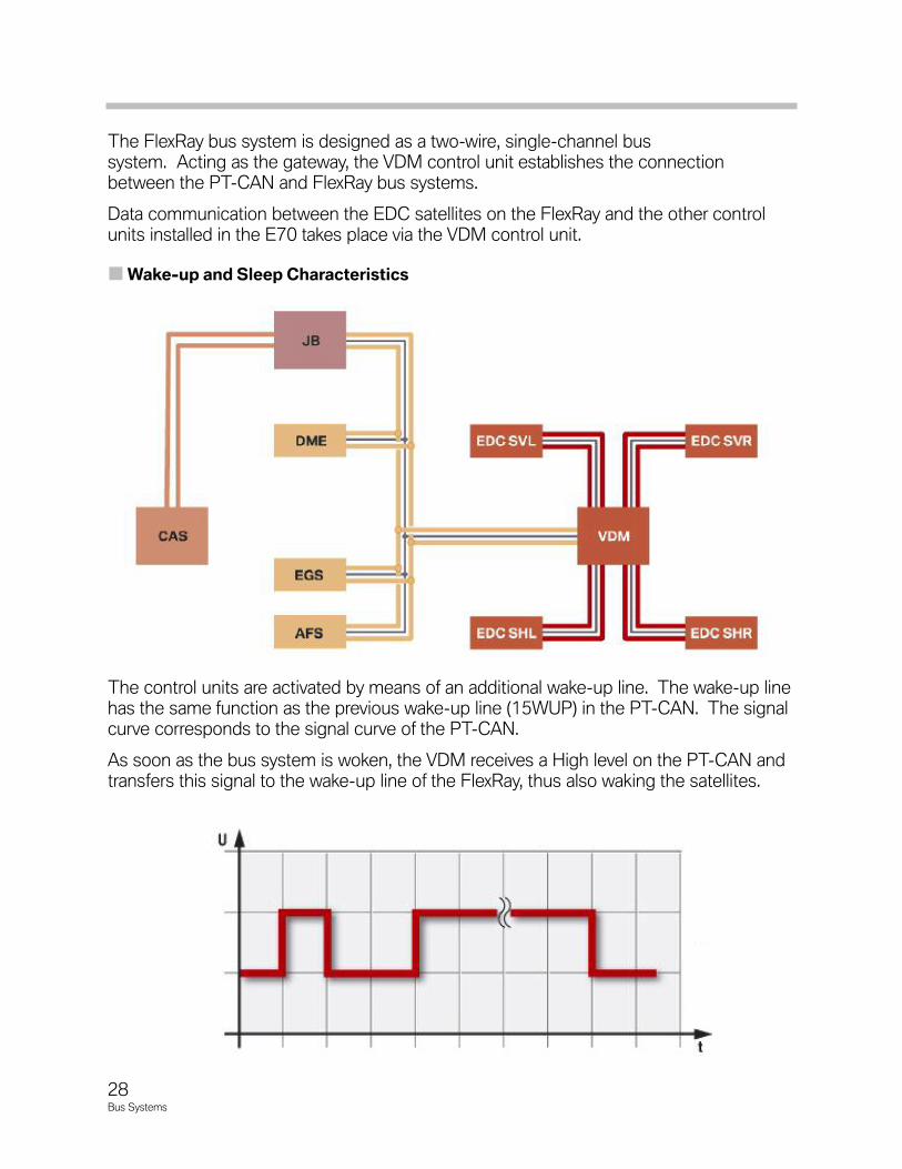
The FlexRay bus system is designed as a two-wire, single-channel bus system. Acting as the gateway, the VDM control unit establishes the connectionbetween the PT-CAN and FlexRay bus systems.
Data communication between the EDC satellites on the FlexRay and the other controlunits installed in the E70 takes place via the VDM control unit.
Wake-upandSleepCharacteristics
The control units are activated by means of an additional wake-up line. The wake-up linehas the same function as the previous wake-up line (15WUP) in the PT-CAN. The signalcurve corresponds to the signal curve of the PT-CAN.
As soon as the bus system is woken, the VDM receives a High level on the PT-CAN andtransfers this signal to the wake-up line of the FlexRay, thus also waking the satellites.
28Bus Systems
29Bus Systems
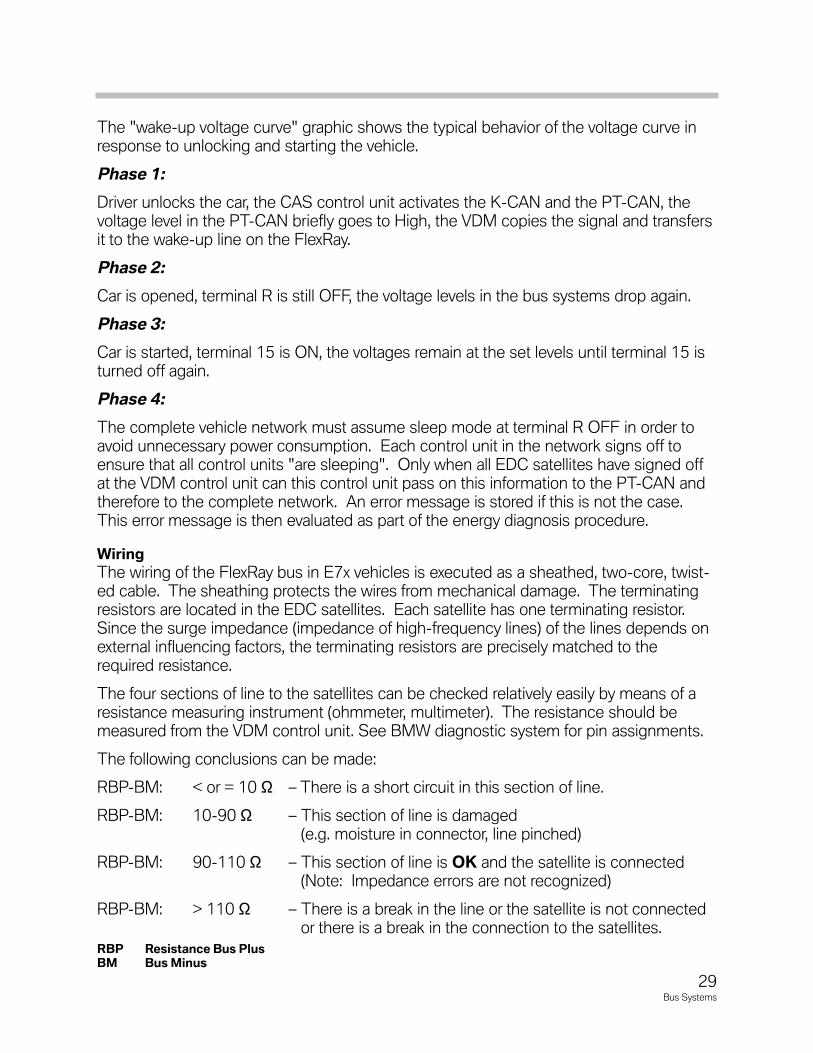
The "wake-up voltage curve" graphic shows the typical behavior of the voltage curve inresponse to unlocking and starting the vehicle.
Phase 1:
Driver unlocks the car, the CAS control unit activates the K-CAN and the PT-CAN, thevoltage level in the PT-CAN briefly goes to High, the VDM copies the signal and transfersit to the wake-up line on the FlexRay.
Phase 2:
Car is opened, terminal R is still OFF, the voltage levels in the bus systems drop again.
Phase 3:
Car is started, terminal 15 is ON, the voltages remain at the set levels until terminal 15 isturned off again.
Phase 4:
The complete vehicle network must assume sleep mode at terminal R OFF in order toavoid unnecessary power consumption. Each control unit in the network signs off toensure that all control units "are sleeping". Only when all EDC satellites have signed offat the VDM control unit can this control unit pass on this information to the PT-CAN andtherefore to the complete network. An error message is stored if this is not the case.This error message is then evaluated as part of the energy diagnosis procedure.
Wiring
The wiring of the FlexRay bus in E7x vehicles is executed as a sheathed, two-core, twist-ed cable. The sheathing protects the wires from mechanical damage. The terminatingresistors are located in the EDC satellites. Each satellite has one terminating resistor.Since the surge impedance (impedance of high-frequency lines) of the lines depends onexternal influencing factors, the terminating resistors are precisely matched to therequired resistance.
The four sections of line to the satellites can be checked relatively easily by means of aresistance measuring instrument (ohmmeter, multimeter). The resistance should bemeasured from the VDM control unit. See BMW diagnostic system for pin assignments.
The following conclusions can be made:
RBP-BM: < or = 10 Ω – There is a short circuit in this section of line.
RBP-BM: 10-90 Ω – This section of line is damaged(e.g. moisture in connector, line pinched)
RBP-BM: 90-110 Ω – This section of line is OK and the satellite is connected(Note: Impedance errors are not recognized)
RBP-BM: > 110 Ω – There is a break in the line or the satellite is not connectedor there is a break in the connection to the satellites.
RBP ResistanceBusPlusBM BusMinus
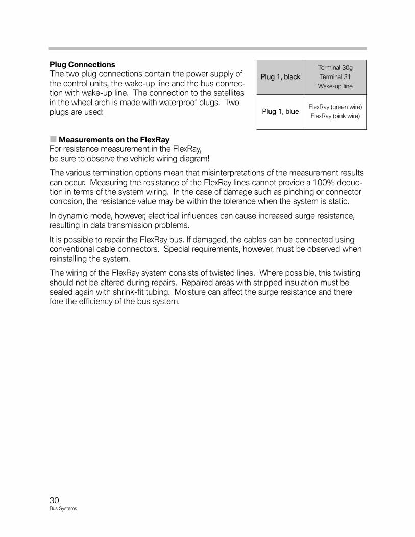
PlugConnections
The two plug connections contain the power supply ofthe control units, the wake-up line and the bus connec-tion with wake-up line. The connection to the satellitesin the wheel arch is made with waterproof plugs. Twoplugs are used:
MeasurementsontheFlexRay
For resistance measurement in the FlexRay,be sure to observe the vehicle wiring diagram!
The various termination options mean that misinterpretations of the measurement resultscan occur. Measuring the resistance of the FlexRay lines cannot provide a 100% deduc-tion in terms of the system wiring. In the case of damage such as pinching or connectorcorrosion, the resistance value may be within the tolerance when the system is static.
In dynamic mode, however, electrical influences can cause increased surge resistance,resulting in data transmission problems.
It is possible to repair the FlexRay bus. If damaged, the cables can be connected usingconventional cable connectors. Special requirements, however, must be observed whenreinstalling the system.
The wiring of the FlexRay system consists of twisted lines. Where possible, this twistingshould not be altered during repairs. Repaired areas with stripped insulation must besealed again with shrink-fit tubing. Moisture can affect the surge resistance and therefore the efficiency of the bus system.
Plug 1, black
Terminal 30g
Terminal 31
Wake-up line
Plug 1, blueFlexRay (green wire)
FlexRay (pink wire)
30Bus Systems
31Bus Systems
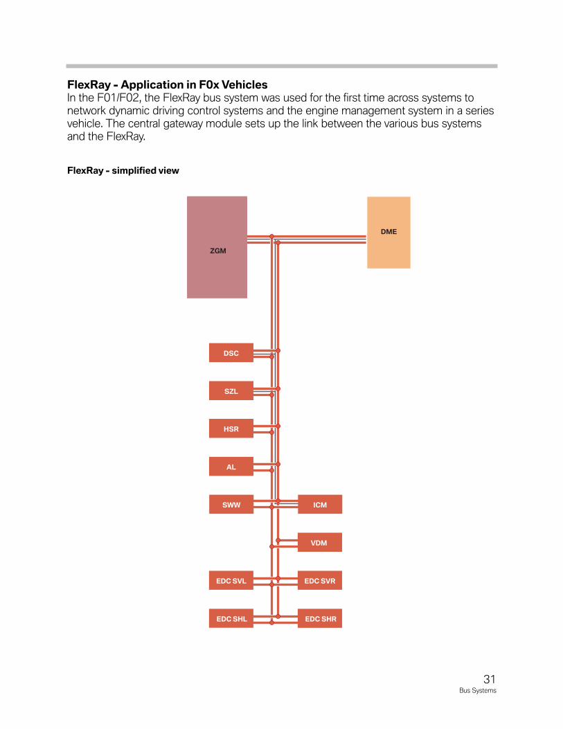
FlexRay-ApplicationinF0xVehiclesIn the F01/F02, the FlexRay bus system was used for the first time across systems tonetwork dynamic driving control systems and the engine management system in a seriesvehicle. The central gateway module sets up the link between the various bus systemsand the FlexRay.
FlexRay-simplifiedview
VDM
EDC SHR
EDC SVR
SWW ICM
EDC SVL
EDC SHL
AL
DME
ZGM
HSR
SZL
DSC
PropertiesofFlexRay
The most important properties of the FlexRay bus system are outlined in the following:
• Bus topology
• Transmission medium - signal properties
• Deterministic data transmission
• Bus protocol
BusTopology
The FlexRay bus system can be integrated in varioustopologies and versions in the vehicle.
The following topologies can be used:
• Line-based bus topology
• Point-to-point bus topology
• Mixed bus topology
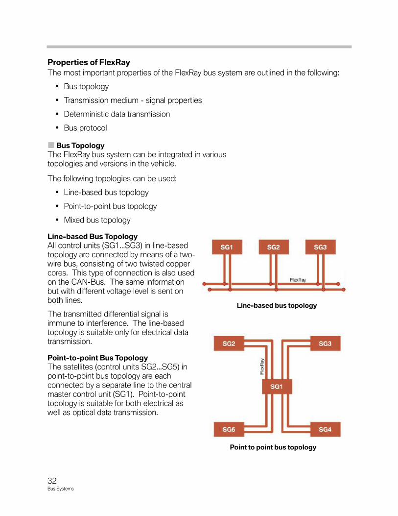
Line-basedBusTopology
All control units (SG1...SG3) in line-basedtopology are connected by means of a two-wire bus, consisting of two twisted coppercores. This type of connection is also usedon the CAN-Bus. The same informationbut with different voltage level is sent onboth lines.
The transmitted differential signal isimmune to interference. The line-basedtopology is suitable only for electrical datatransmission.
Point-to-pointBusTopology
The satellites (control units SG2...SG5) inpoint-to-point bus topology are each connected by a separate line to the centralmaster control unit (SG1). Point-to-pointtopology is suitable for both electrical aswell as optical data transmission.
32Bus Systems
Line-basedbustopology
Pointtopointbustopology
MixedBusTopology
Mixed bus topology caters for the use of different topologies in one bus system. Parts ofthe bus system are line-based while other parts are point-to-point.
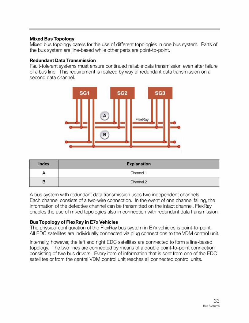
RedundantDataTransmission
Fault-tolerant systems must ensure continued reliable data transmission even after failureof a bus line. This requirement is realized by way of redundant data transmission on asecond data channel.
A bus system with redundant data transmission uses two independent channels. Each channel consists of a two-wire connection. In the event of one channel failing, theinformation of the defective channel can be transmitted on the intact channel. FlexRayenables the use of mixed topologies also in connection with redundant data transmission.
BusTopologyofFlexRayinE7xVehicles
The physical configuration of the FlexRay bus system in E7x vehicles is point-to-point. All EDC satellites are individually connected via plug connections to the VDM control unit.
Internally, however, the left and right EDC satellites are connected to form a line-basedtopology. The two lines are connected by means of a double point-to-point connectionconsisting of two bus drivers. Every item of information that is sent from one of the EDCsatellites or from the central VDM control unit reaches all connected control units.
33Bus Systems
Index Explanation
A Channel 1
B Channel 2
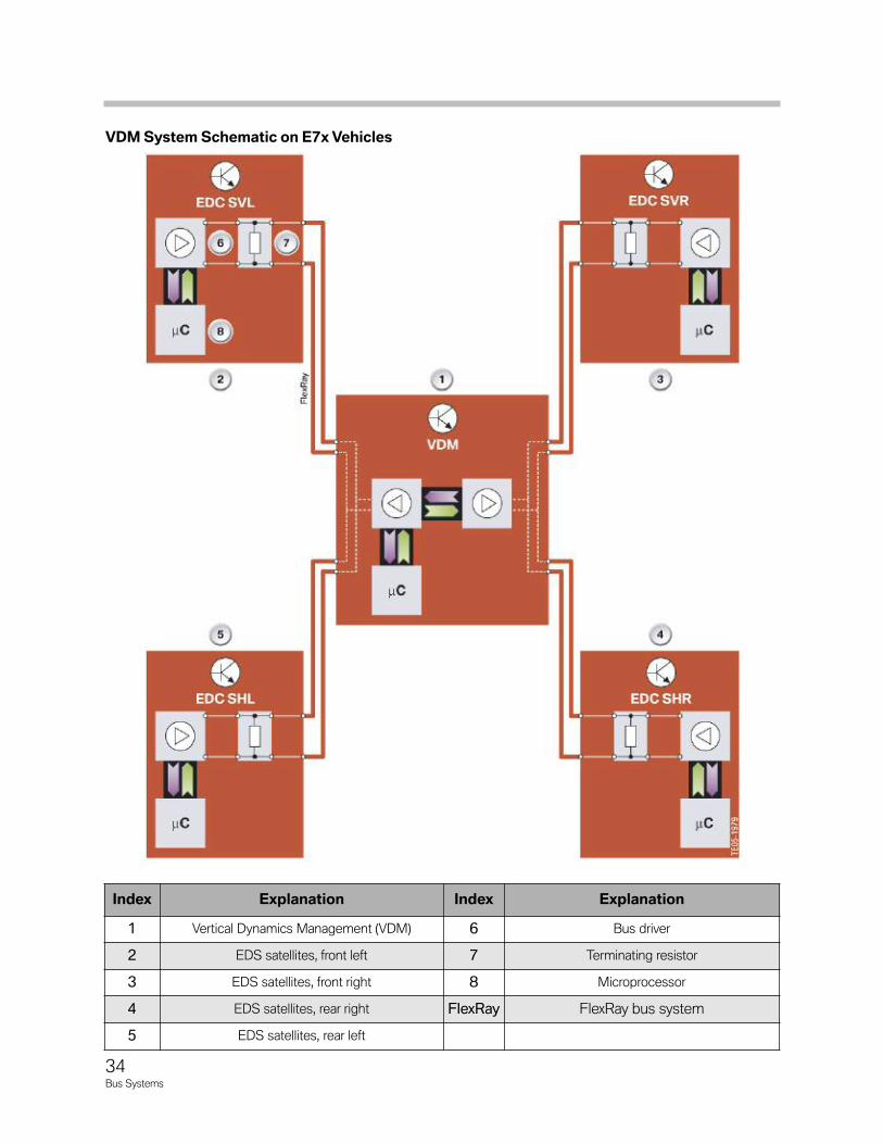
VDMSystemSchematiconE7xVehicles
34Bus Systems
Index Explanation Index Explanation
1 Vertical Dynamics Management (VDM) 6 Bus driver
2 EDS satellites, front left 7 Terminating resistor
3 EDS satellites, front right 8 Microprocessor
4 EDS satellites, rear right FlexRay FlexRay bus system
5 EDS satellites, rear left
35Bus Systems
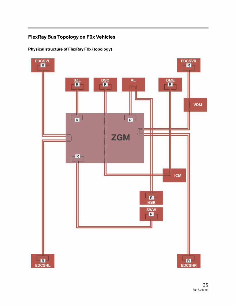
FlexRayBusTopologyonF0xVehicles
PhysicalstructureofFlexRayF0x(topology)
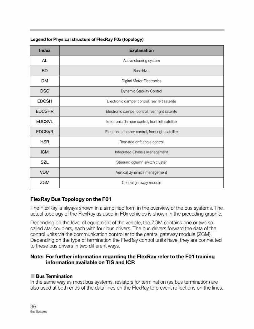
LegendforPhysicalstructureofFlexRayF0x(topology)
FlexRayBusTopologyontheF01
The FlexRay is always shown in a simplified form in the overview of the bus systems. Theactual topology of the FlexRay as used in F0x vehicles is shown in the preceding graphic.
Depending on the level of equipment of the vehicle, the ZGM contains one or two so-called star couplers, each with four bus drivers. The bus drivers forward the data of thecontrol units via the communication controller to the central gateway module (ZGM).Depending on the type of termination the FlexRay control units have, they are connectedto these bus drivers in two different ways.
Note:ForfurtherinformationregardingtheFlexRayrefertotheF01traininginformationavailableonTISandICP.
BusTermination
In the same way as most bus systems, resistors for termination (as bus termination) arealso used at both ends of the data lines on the FlexRay to prevent reflections on the lines.
Index Explanation
AL Active steering system
BD Bus driver
DM Digital Motor Electronics
DSC Dynamic Stability Control
EDCSH Electronic damper control, rear left satellite
EDCSHR Electronic damper control, rear right satellite
EDCSVL Electronic damper control, front left satellite
EDCSVR Electronic damper control, front right satellite
HSR Rear-axle drift angle control
ICM Integrated Chassis Management
SZL Steering column switch cluster
VDM Vertical dynamics management
ZGM Central gateway module
36Bus Systems
The value of these terminal resistors is determined from the data transfer rate and cablelengths. The terminal resistors are located in the control units.
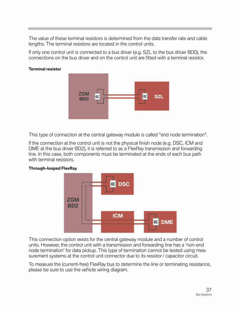
If only one control unit is connected to a bus driver (e.g. SZL to the bus driver BD0), theconnections on the bus driver and on the control unit are fitted with a terminal resistor.
This type of connection at the central gateway module is called "end node termination".
If the connection at the control unit is not the physical finish node (e.g. DSC, ICM andDME at the bus driver BD2), it is referred to as a FlexRay transmission and forwardingline. In this case, both components must be terminated at the ends of each bus pathwith terminal resistors.
This connection option exists for the central gateway module and a number of controlunits. However, the control unit with a transmission and forwarding line has a 'non-endnode termination' for data pickup. This type of termination cannot be tested using mea-surement systems at the control unit connector due to its resistor / capacitor circuit.
To measure the (current-free) FlexRay bus to determine the line or terminating resistance,please be sure to use the vehicle wiring diagram.
Terminalresistor
Through-loopedFlexRay
37Bus Systems
TransmissionMedium-SignalProperties
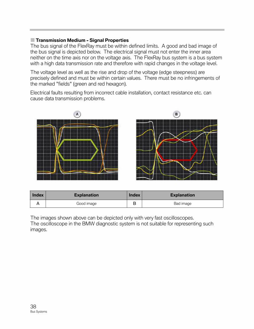
The bus signal of the FlexRay must be within defined limits. A good and bad image ofthe bus signal is depicted below. The electrical signal must not enter the inner area neither on the time axis nor on the voltage axis. The FlexRay bus system is a bus systemwith a high data transmission rate and therefore with rapid changes in the voltage level.
The voltage level as well as the rise and drop of the voltage (edge steepness) are precisely defined and must be within certain values. There must be no infringements ofthe marked "fields" (green and red hexagon).
Electrical faults resulting from incorrect cable installation, contact resistance etc. cancause data transmission problems.
The images shown above can be depicted only with very fast oscilloscopes. The oscilloscope in the BMW diagnostic system is not suitable for representing suchimages.
Index Explanation Index Explanation
A Good image B Bad image
38Bus Systems
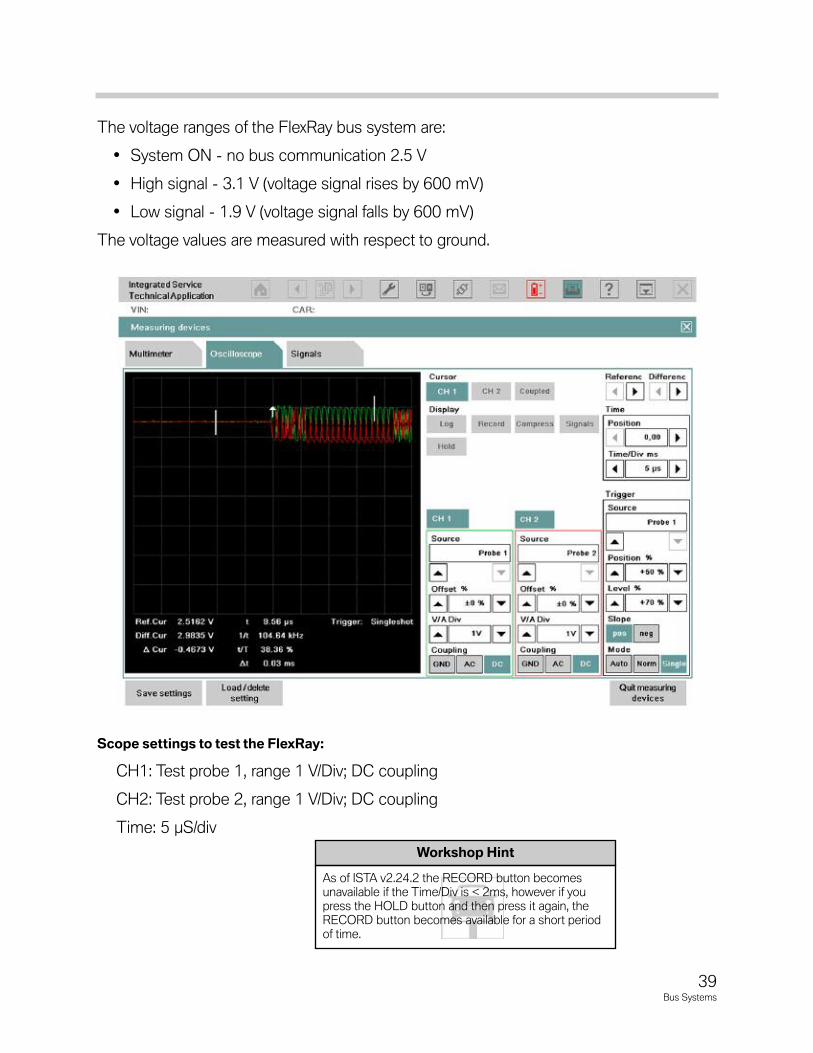
The voltage ranges of the FlexRay bus system are:
• System ON - no bus communication 2.5 V
• High signal - 3.1 V (voltage signal rises by 600 mV)
• Low signal - 1.9 V (voltage signal falls by 600 mV)
The voltage values are measured with respect to ground.
ScopesettingstotesttheFlexRay:
CH1: Test probe 1, range 1 V/Div; DC coupling
CH2: Test probe 2, range 1 V/Div; DC coupling
Time: 5 µS/div
39Bus Systems
Workshop Hint
As of ISTA v2.24.2 the RECORD button becomesunavailable if the Time/Div is < 2ms, however if youpress the HOLD button and then press it again, theRECORD button becomes available for a short periodof time.
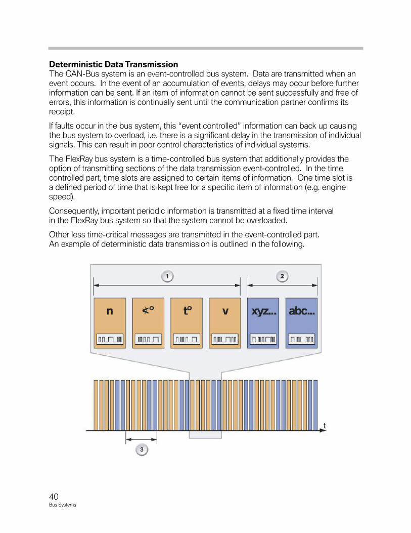
DeterministicDataTransmissionThe CAN-Bus system is an event-controlled bus system. Data are transmitted when anevent occurs. In the event of an accumulation of events, delays may occur before furtherinformation can be sent. If an item of information cannot be sent successfully and free oferrors, this information is continually sent until the communication partner confirms itsreceipt.
If faults occur in the bus system, this “event controlled” information can back up causingthe bus system to overload, i.e. there is a significant delay in the transmission of individualsignals. This can result in poor control characteristics of individual systems.
The FlexRay bus system is a time-controlled bus system that additionally provides theoption of transmitting sections of the data transmission event-controlled. In the time controlled part, time slots are assigned to certain items of information. One time slot isa defined period of time that is kept free for a specific item of information (e.g. enginespeed).
Consequently, important periodic information is transmitted at a fixed time intervalin the FlexRay bus system so that the system cannot be overloaded.
Other less time-critical messages are transmitted in the event-controlled part. An example of deterministic data transmission is outlined in the following.
40Bus Systems
BusProtocol
Deterministic data transmission ensures that each message in the time-controlled part istransmitted in real time. Real time means that the transmission takes place within adefined time.
Therefore, important bus messages are not sent too late due to overloading of the bussystem. If lost due to a temporary problem in the bus system (e.g. EMC problem) a message cannot be sent again. A current value is sent in the next assigned time slot.
HighBandwidth
The FlexRay bus system operates with a data transmission rate of 10 Mbits/s. This speed corresponds to 20 times the data transmission rate of the PT-CAN.
Synchronization
A common time base is necessary in order to ensure synchronous execution of individualfunctions in interconnected control units. Time matching must take place via the bussystem as all control units operate with their own clock generator.
The control units measure the time of certain synchronization bits, calculate the meanvalue and adapt their bus clock to this value. This system ensures that even minimal timedifferences do not cause transmission errors in the long term.
41Bus Systems
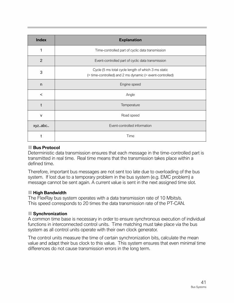
Index Explanation
1 Time-controlled part of cyclic data transmission
2 Event-controlled part of cyclic data transmission
3Cycle (5 ms total cycle length of which 3 ms static
(= time-controlled) and 2 ms dynamic (= event-controlled)
n Engine speed
< Angle
t Temperature
v Road speed
xyz..abc.. Event-controlled information
t Time
42Bus Systems
Ethernet-FasterProgrammingAccess
EthernetinF0xVehiclesEthernet is a manufacturer-neutral, cable-bound network technology. Most computernetworks nowadays are based on this data transfer technology.
The so-called Ethernet was developed more than 30 years ago. Since then, the datatransfer rates have multiplied. The IEEE 802.3u specification with 100 MBit/s data trans-fer rate is used in F0x vehicles. The IEEE 802.3xx is a standard for cable-bound net-works of the Institute of Electrical and Electronic Engineers. This specification is alsoknown as "Fast Ethernet".
The transfer protocols are the protocols TCP/IP (Transmission Control Protocol/ InternetProtocol) and UDP (User Datagram Protocol).
Application
The Ethernet in the diagnosis socket is only enabled when the BMW programming system (ICOM A) is connected. There is an activation bridge in the programming connector, between pins 8 and 16. This switches the power supply for the Ethernet controller in the central gateway module.
This means that Ethernet access to the central gateway module is disabled while thevehicle is being driven by the customer. The Ethernet connection between the informa-tion and communications systems is permanently enabled in the diagnosis socket inde-pendently of the activation bridge.
Security
Each participant in an Ethernet has an individually assigned identification number, anMAC address (Media Access Control). This address and the VIN (Vehicle IdentificationNumber) identifies the vehicle to the BMW programming system on connection setup.This prevents changes to the data records and stored values by third parties.
In the same way as in a computer network in the office, each device in a network mustreceive unique identification. This is why the central gateway module is assigned a so-called IP address by the programming system after connection setup.
The function of an IP address in a network corresponds to that of a telephone number inthe telephone network. This IP address is assigned per DHCP (Dynamic HostConfiguration Protocol). This is a method of automatic allocation for IP addresses to userdevices in a network.
FeaturesofEthernet
• Very high data rate of 100 MBit/s.
• System start time with connection setup and addressassignment under three seconds, sleeping under one second.
• System access only via BMW programming systems.
FunctionsofEthernet
• Faster programming of the vehicle in Service.
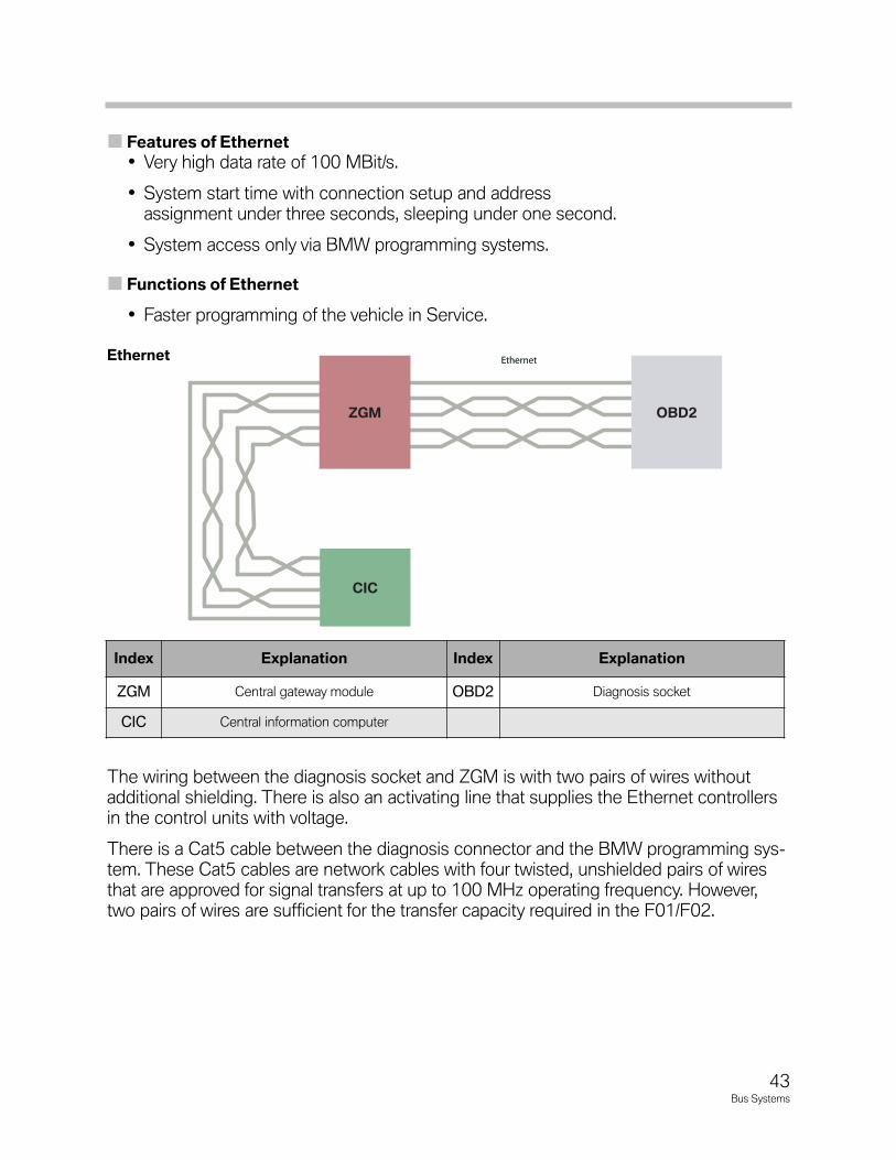
The wiring between the diagnosis socket and ZGM is with two pairs of wires withoutadditional shielding. There is also an activating line that supplies the Ethernet controllersin the control units with voltage.
There is a Cat5 cable between the diagnosis connector and the BMW programming sys-tem. These Cat5 cables are network cables with four twisted, unshielded pairs of wiresthat are approved for signal transfers at up to 100 MHz operating frequency. However,two pairs of wires are sufficient for the transfer capacity required in the F01/F02.
EthernetEthernet
CIC
OBD2ZGM
Index Explanation Index Explanation
ZGM Central gateway module OBD2 Diagnosis socket
CIC Central information computer
Ethernet
43Bus Systems
FiberOpticBusNetworks
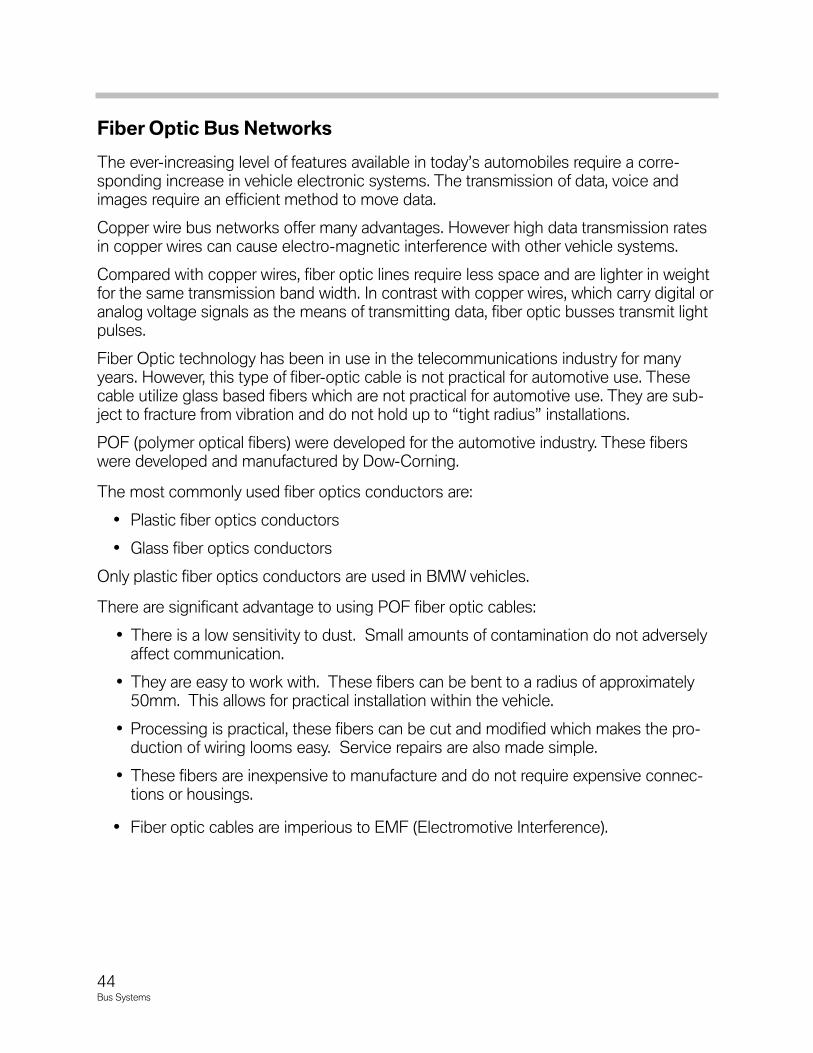
The ever-increasing level of features available in today’s automobiles require a corre-sponding increase in vehicle electronic systems. The transmission of data, voice andimages require an efficient method to move data.
Copper wire bus networks offer many advantages. However high data transmission ratesin copper wires can cause electro-magnetic interference with other vehicle systems.
Compared with copper wires, fiber optic lines require less space and are lighter in weightfor the same transmission band width. In contrast with copper wires, which carry digital oranalog voltage signals as the means of transmitting data, fiber optic busses transmit lightpulses.
Fiber Optic technology has been in use in the telecommunications industry for manyyears. However, this type of fiber-optic cable is not practical for automotive use. Thesecable utilize glass based fibers which are not practical for automotive use. They are sub-ject to fracture from vibration and do not hold up to “tight radius” installations.
POF (polymer optical fibers) were developed for the automotive industry. These fiberswere developed and manufactured by Dow-Corning.
The most commonly used fiber optics conductors are:
• Plastic fiber optics conductors
• Glass fiber optics conductors
Only plastic fiber optics conductors are used in BMW vehicles.
There are significant advantage to using POF fiber optic cables:
• There is a low sensitivity to dust. Small amounts of contamination do not adverselyaffect communication.
• They are easy to work with. These fibers can be bent to a radius of approximately50mm. This allows for practical installation within the vehicle.
• Processing is practical, these fibers can be cut and modified which makes the pro-duction of wiring looms easy. Service repairs are also made simple.
• These fibers are inexpensive to manufacture and do not require expensive connec-tions or housings.
• Fiber optic cables are imperious to EMF (Electromotive Interference).
44Bus Systems
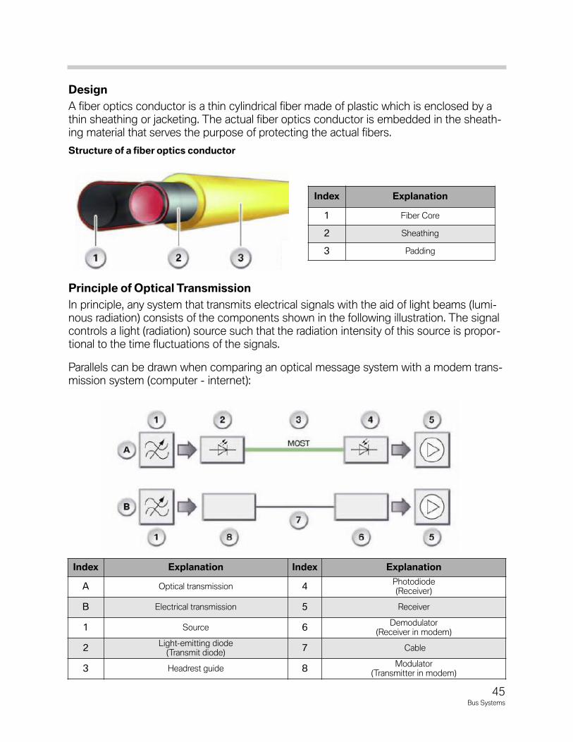
Design
A fiber optics conductor is a thin cylindrical fiber made of plastic which is enclosed by athin sheathing or jacketing. The actual fiber optics conductor is embedded in the sheath-ing material that serves the purpose of protecting the actual fibers.
PrincipleofOpticalTransmission
In principle, any system that transmits electrical signals with the aid of light beams (lumi-nous radiation) consists of the components shown in the following illustration. The signalcontrols a light (radiation) source such that the radiation intensity of this source is propor-tional to the time fluctuations of the signals.
Parallels can be drawn when comparing an optical message system with a modem trans-mission system (computer - internet):
Index Explanation Index Explanation
A Optical transmission 4Photodiode(Receiver)
B Electrical transmission 5 Receiver
1 Source 6Demodulator
(Receiver in modem)
2Light-emitting diode
(Transmit diode)7 Cable
3 Headrest guide 8Modulator
(Transmitter in modem)
Index Explanation
1 Fiber Core
2 Sheathing
3 Padding
Structureofafiberopticsconductor
45Bus Systems
The fiber optics conductor assumes the function of the transmission channel. The fiberoptics conductor is particularly insensitive to external electromagnetic influences.
Comparison of an optical message transmission system with a conventional messagesystem.
Modemtransmission:
As part of modem transmission, the modulator, the transmit part of the modem, convertsthe digital signals into analog signals. The analog signals are transmitted via the tele-phone network to the next computer.
The demodulator, the receive part of the modem, at this computer converts the analogsignals back to digital signals.
Opticaltransmission:
With optical message transmission, on the other hand, the digital signals are convertedinto optical signals by means of a light emitting diode (LED).
The optical signals are transmitted via fiber optics conductors to the next control unit.
The photodiode at this control unit converts the optical signals back to digital signals.
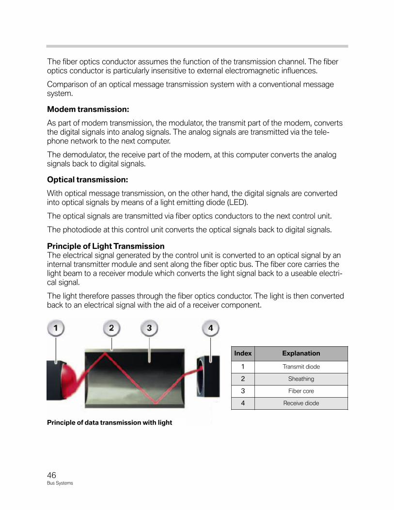
PrincipleofLightTransmissionThe electrical signal generated by the control unit is converted to an optical signal by aninternal transmitter module and sent along the fiber optic bus. The fiber core carries thelight beam to a receiver module which converts the light signal back to a useable electri-cal signal.
The light therefore passes through the fiber optics conductor. The light is then convertedback to an electrical signal with the aid of a receiver component.
Index Explanation
1 Transmit diode
2 Sheathing
3 Fiber core
4 Receive diode
Principleofdatatransmissionwithlight
46Bus Systems
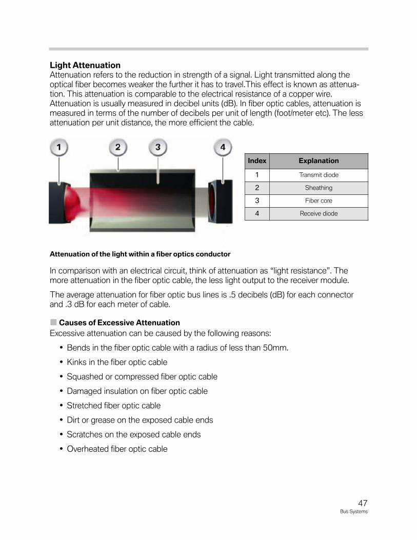
LightAttenuationAttenuation refers to the reduction in strength of a signal. Light transmitted along theoptical fiber becomes weaker the further it has to travel.This effect is known as attenua-tion. This attenuation is comparable to the electrical resistance of a copper wire.Attenuation is usually measured in decibel units (dB). In fiber optic cables, attenuation ismeasured in terms of the number of decibels per unit of length (foot/meter etc). The lessattenuation per unit distance, the more efficient the cable.
In comparison with an electrical circuit, think of attenuation as “light resistance”. Themore attenuation in the fiber optic cable, the less light output to the receiver module.
The average attenuation for fiber optic bus lines is .5 decibels (dB) for each connectorand .3 dB for each meter of cable.
CausesofExcessiveAttenuation
Excessive attenuation can be caused by the following reasons:
• Bends in the fiber optic cable with a radius of less than 50mm.
• Kinks in the fiber optic cable
• Squashed or compressed fiber optic cable
• Damaged insulation on fiber optic cable
• Stretched fiber optic cable
• Dirt or grease on the exposed cable ends
• Scratches on the exposed cable ends
• Overheated fiber optic cable
Index Explanation
1 Transmit diode
2 Sheathing
3 Fiber core
4 Receive diode
Attenuationofthelightwithinafiberopticsconductor
47Bus Systems
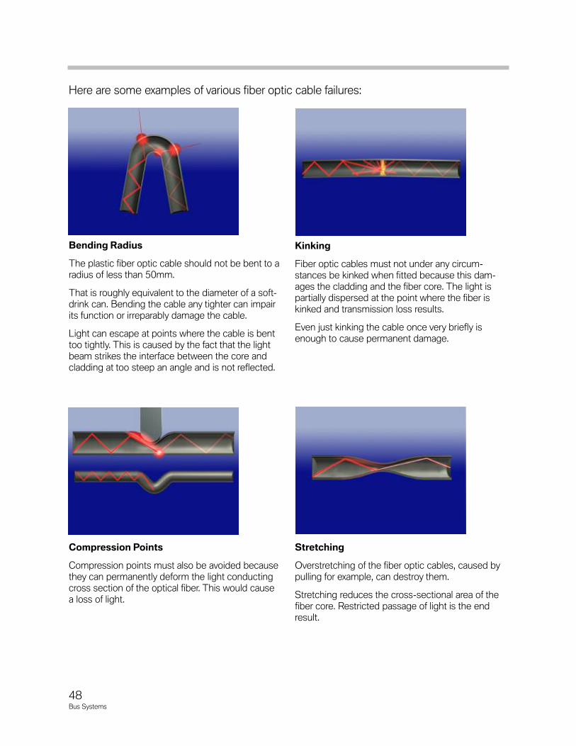
Here are some examples of various fiber optic cable failures:
Bending Radius
The plastic fiber optic cable should not be bent to aradius of less than 50mm.
That is roughly equivalent to the diameter of a soft-drink can. Bending the cable any tighter can impairits function or irreparably damage the cable.
Light can escape at points where the cable is benttoo tightly. This is caused by the fact that the lightbeam strikes the interface between the core andcladding at too steep an angle and is not reflected.
Compression Points
Compression points must also be avoided becausethey can permanently deform the light conductingcross section of the optical fiber. This would causea loss of light.
Stretching
Overstretching of the fiber optic cables, caused bypulling for example, can destroy them.
Stretching reduces the cross-sectional area of thefiber core. Restricted passage of light is the endresult.
Kinking
Fiber optic cables must not under any circum-stances be kinked when fitted because this dam-ages the cladding and the fiber core. The light ispartially dispersed at the point where the fiber iskinked and transmission loss results.
Even just kinking the cable once very briefly isenough to cause permanent damage.
48Bus Systems
ServiceConsiderations
Two optical bus systems for data transmission have been developed for BMW vehicles:MOST and byteflight.
The light length is 650 nm (red light).
Three different colors are used to differentiate between the fiber optics conductors forthe different bus systems:
• Yellow: byteflight
• Green: MOST
• Orange: Service repair line
During repair work, there are some things that need to be taken into account when work-ing with fiber optic cables. Any paintwork which requires the use of drying by heat, thetemperature should not exceed 85°C. This could case deformation of the fiber opticcable resulting in excessive attenuation.
Extreme care should be taken around fiber optic cables. Any wiring harness that containfiber optic cables should not be subjecting to stretching, pulling or any undue stress.
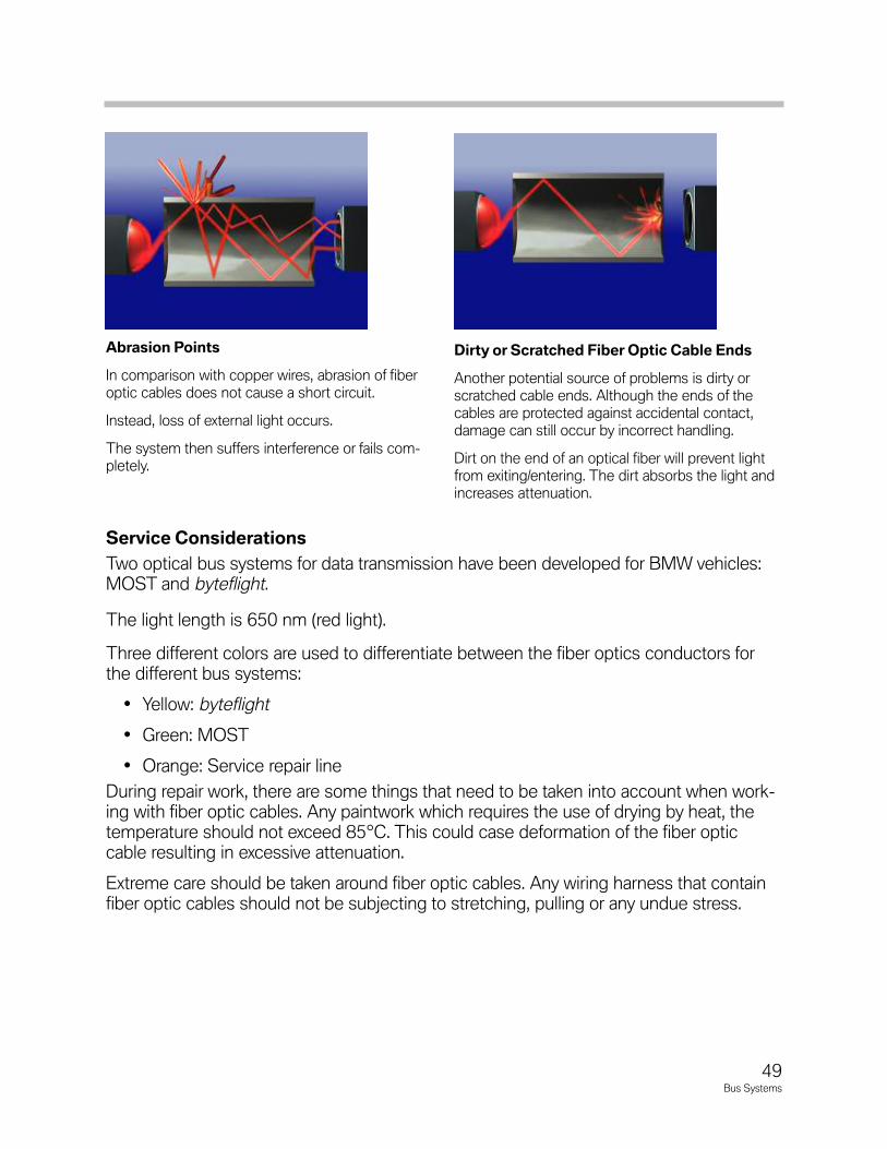
Abrasion Points
In comparison with copper wires, abrasion of fiberoptic cables does not cause a short circuit.
Instead, loss of external light occurs.
The system then suffers interference or fails com-pletely.
Dirty or Scratched Fiber Optic Cable Ends
Another potential source of problems is dirty orscratched cable ends. Although the ends of thecables are protected against accidental contact,damage can still occur by incorrect handling.
Dirt on the end of an optical fiber will prevent lightfrom exiting/entering. The dirt absorbs the light andincreases attenuation.
49Bus Systems
CableRepair
Repair cable are available for the fiber optics. The MOST bus which is normally green inthe vehicle is repair using a black or orange cable. The MOST bus allows for up to onesplice between control units.
Special crimping pliers are used to fit the sleeves correctly on the fiber optics conductors.
The exact procedure is described in the operating instructions for the crimping pliers.
The byteflight which is a safety critical network does not allow for any splices or repairsbetween control units. The entire defective optical cable must be replaced.
Replacement cables are orange or black.
Thefiberopticsconductorsinthebyteflight systemcanNOTberepaired.IncontrasttotheMOSTbuswhichalowsone(1)splicebetweencontrollers(whenusingtheproperpart#)adefectivebyteflight cablebetweencontrollersMUSTbecompletelyreplaced.
FiberOpticConnectors
There are slight differences between the connectors on the MOST and byteflight bus.The transmitter/receiver module on the MOST bus are set back into the control unithousing. This setup allows for the protection of the delicate fiber ends of the cable. Also,MOST cable connectors are marked 1 and 2. 1 is assigned to the incoming optical fiberand 2 is assigned to the outgoing optical fiber (see connection of control units for moreinformation).
Note:RefertotheMOSTBusDiagnosissectioninthistrainingmaterialformoreinformation.
50Bus Systems
51Bus Systems
MOST
MOST is a communications technology for multimedia applications that was speciallydeveloped for use in motor vehicles.
MOST stands for Media Oriented System Transport. The MOST bus is designedas an optical ring and uses light pulses for transmitting data.
MOST technology satisfies two important requirements:
1. The MOST bus can transfer control, audio and navigation data.
2. The MOST technology makes available a logic frame model forcontrolling the great variety and complexity of the data.
Multimedia components such as:
• Telephone
• Radio
• Television
• Navigation system
• CD changer
• Amplifier
• Multi-information display/on-board monitor
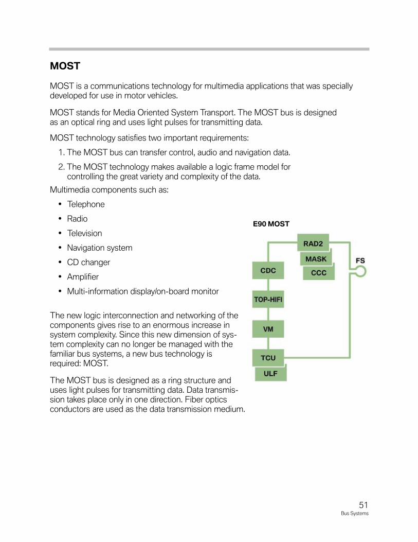
The new logic interconnection and networking of thecomponents gives rise to an enormous increase insystem complexity. Since this new dimension of sys-tem complexity can no longer be managed with thefamiliar bus systems, a new bus technology isrequired: MOST.
The MOST bus is designed as a ring structure anduses light pulses for transmitting data. Data transmis-sion takes place only in one direction. Fiber opticsconductors are used as the data transmission medium.
E90MOST
52Bus Systems
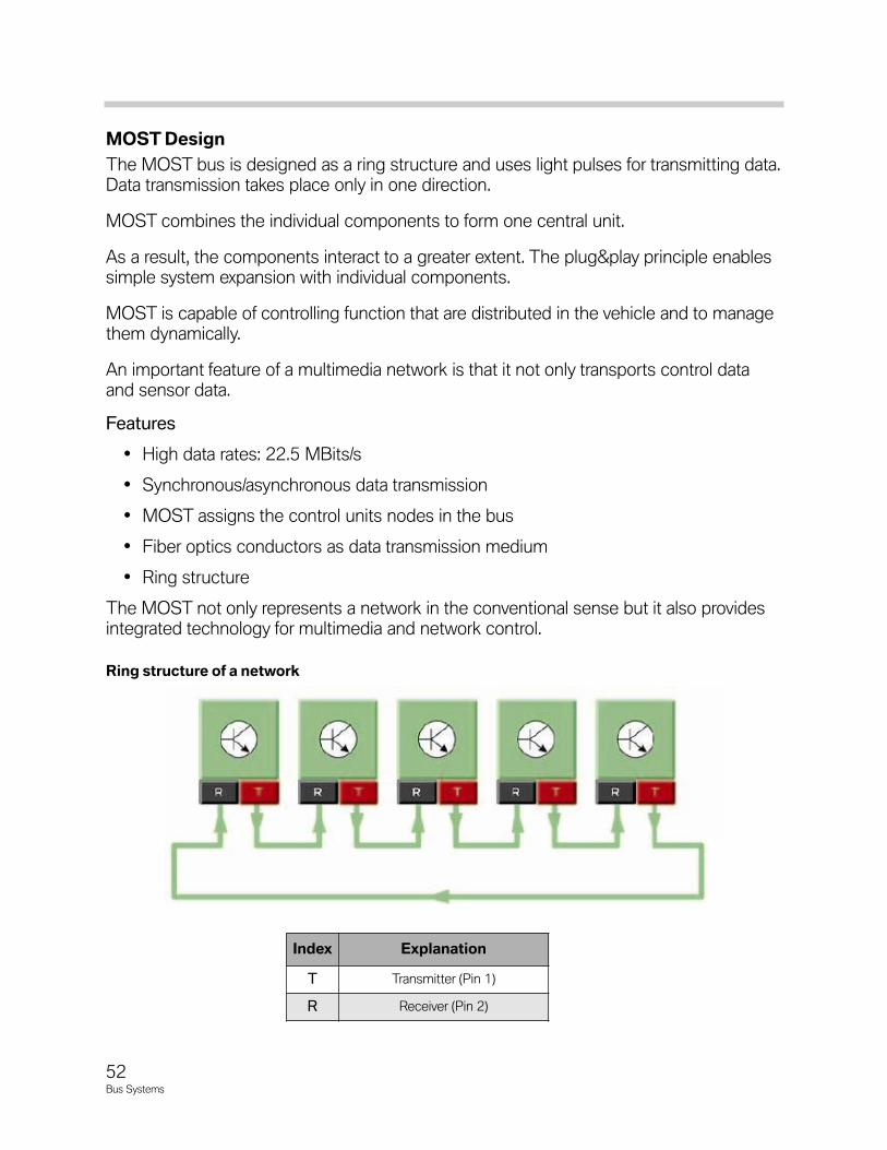
MOSTDesign
The MOST bus is designed as a ring structure and uses light pulses for transmitting data.Data transmission takes place only in one direction.
MOST combines the individual components to form one central unit.
As a result, the components interact to a greater extent. The plug&play principle enablessimple system expansion with individual components.
MOST is capable of controlling function that are distributed in the vehicle and to managethem dynamically.
An important feature of a multimedia network is that it not only transports control dataand sensor data.
Features
• High data rates: 22.5 MBits/s
• Synchronous/asynchronous data transmission
• MOST assigns the control units nodes in the bus
• Fiber optics conductors as data transmission medium
• Ring structure
The MOST not only represents a network in the conventional sense but it also providesintegrated technology for multimedia and network control.
Ringstructureofanetwork
Index Explanation
T Transmitter (Pin 1)
R Receiver (Pin 2)
53Bus Systems
RingStructure
Each terminal device (node, control unit) in a network with a ring structure is connectedby means of a cable ring.
A message indicating that transmission is possible circulates on the ring. This message isread and passed on by each node (control unit).
When a node wishes to send data, it changes the ready-to-send message to an "occu-pied" message. It then adds the address of the receiver, an error handling code and thedata.
To ensure the signal strength is retained, the node, through which the data packagepasses through, generates the data once again (repeater).
The node that is addressed as the receiver copies the data and forwards them in the cir-cuit. If the data reach the transmitter again, it removes the data from the ring and resetsthe ready-to-transmit message.
Specifically: The physical light direction runs from the master control unit (e.g. multi-audiosystem controller) to the fiber optics conductor connector and from here to the controlunits (e.g. CD-changer in the luggage compartment). The light then returns from the lastcontrol unit back via the flash connector to the master.
Advantages:
• Distributed control
• Large network expansion
Disadvantages:
• Intricate troubleshooting
• Malfunctions cause network failure
• Intricate and extensive wiring
Each MOST control unit can send data on the MOST bus. Only the master control unitcan initiate data exchange between the MOST bus and other bus systems.
In order to meet the various requirements of the different data transmission applications,each MOST message is divided into 3 parts:
• Control data: e.g. light intensity (luminosity) control
• Asynchronous data: e.g. navigation system, vector representation
• Synchronous data: e.g. audio and video signals
54Bus Systems
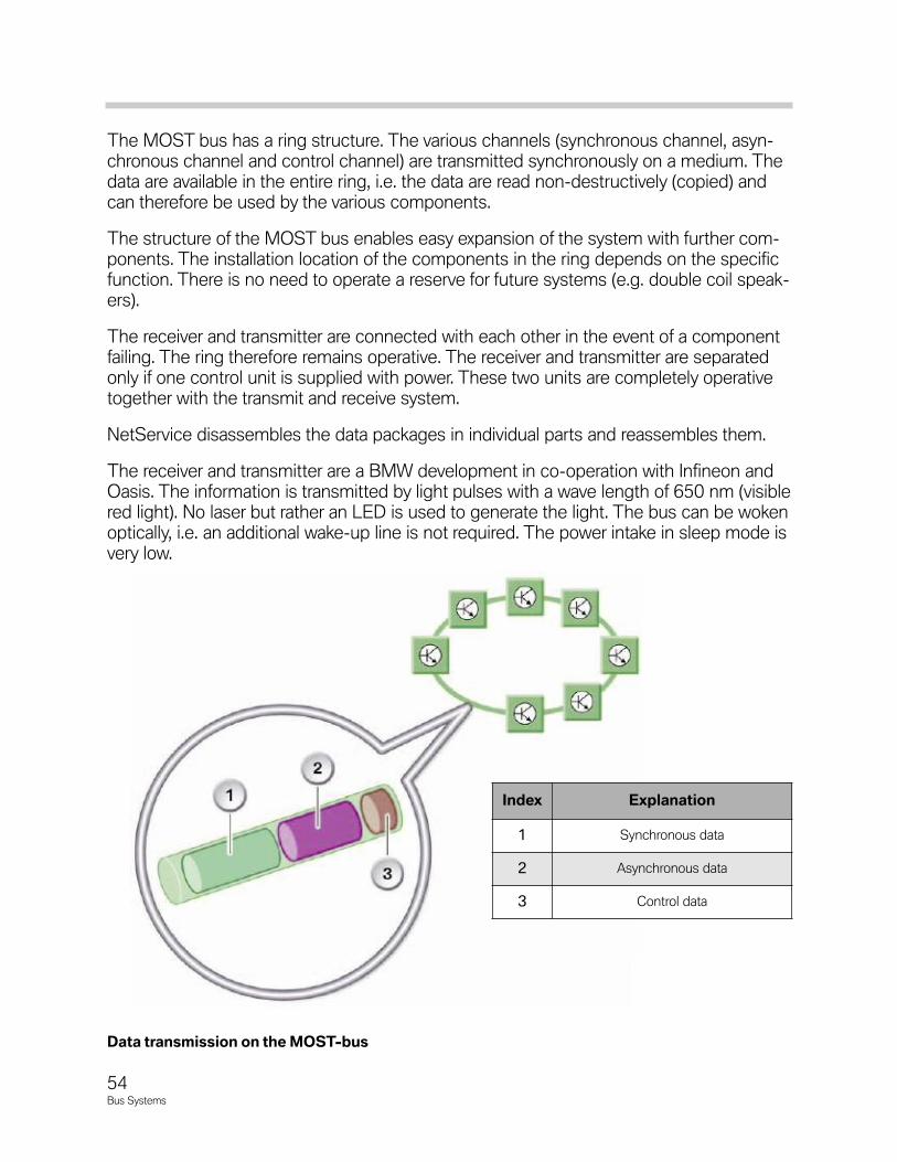
The MOST bus has a ring structure. The various channels (synchronous channel, asyn-chronous channel and control channel) are transmitted synchronously on a medium. Thedata are available in the entire ring, i.e. the data are read non-destructively (copied) andcan therefore be used by the various components.
The structure of the MOST bus enables easy expansion of the system with further com-ponents. The installation location of the components in the ring depends on the specificfunction. There is no need to operate a reserve for future systems (e.g. double coil speak-ers).
The receiver and transmitter are connected with each other in the event of a componentfailing. The ring therefore remains operative. The receiver and transmitter are separatedonly if one control unit is supplied with power. These two units are completely operativetogether with the transmit and receive system.
NetService disassembles the data packages in individual parts and reassembles them.
The receiver and transmitter are a BMW development in co-operation with Infineon andOasis. The information is transmitted by light pulses with a wave length of 650 nm (visiblered light). No laser but rather an LED is used to generate the light. The bus can be wokenoptically, i.e. an additional wake-up line is not required. The power intake in sleep mode isvery low.
Index Explanation
1 Synchronous data
2 Asynchronous data
3 Control data
DatatransmissionontheMOST-bus
55Bus Systems
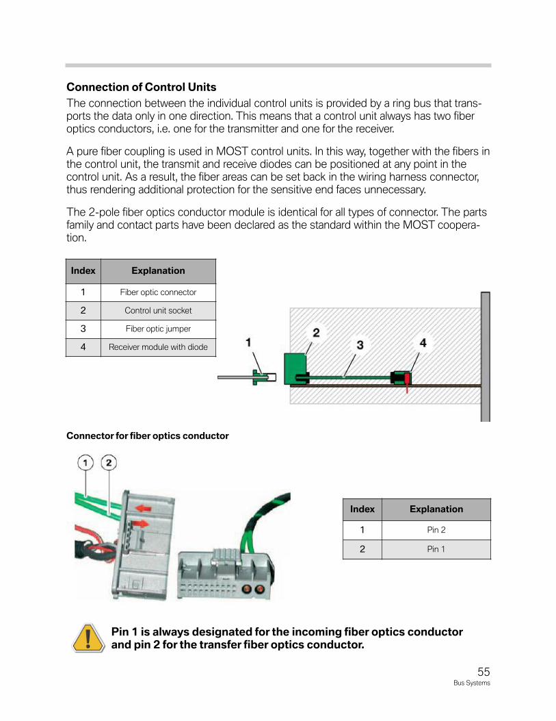
Connection of Control Units
The connection between the individual control units is provided by a ring bus that trans-ports the data only in one direction. This means that a control unit always has two fiberoptics conductors, i.e. one for the transmitter and one for the receiver.
A pure fiber coupling is used in MOST control units. In this way, together with the fibers inthe control unit, the transmit and receive diodes can be positioned at any point in thecontrol unit. As a result, the fiber areas can be set back in the wiring harness connector,thus rendering additional protection for the sensitive end faces unnecessary.
The 2-pole fiber optics conductor module is identical for all types of connector. The partsfamily and contact parts have been declared as the standard within the MOST coopera-tion.
Pin 1 is always designated for the incoming fiber optics conductorand pin 2 for the transfer fiber optics conductor.
Connector for fiber optics conductor
Index Explanation
1 Fiber optic connector
2 Control unit socket
3 Fiber optic jumper
4 Receiver module with diode
Index Explanation
1 Pin 2
2 Pin 1
56Bus Systems
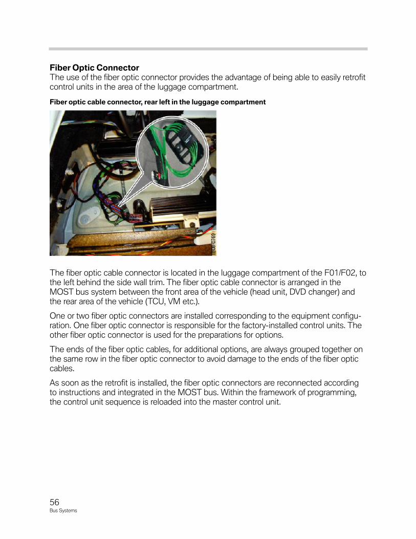
FiberOpticConnectorThe use of the fiber optic connector provides the advantage of being able to easily retrofitcontrol units in the area of the luggage compartment.
The fiber optic cable connector is located in the luggage compartment of the F01/F02, tothe left behind the side wall trim. The fiber optic cable connector is arranged in theMOST bus system between the front area of the vehicle (head unit, DVD changer) andthe rear area of the vehicle (TCU, VM etc.).
One or two fiber optic connectors are installed corresponding to the equipment configu-ration. One fiber optic connector is responsible for the factory-installed control units. Theother fiber optic connector is used for the preparations for options.
The ends of the fiber optic cables, for additional options, are always grouped together onthe same row in the fiber optic connector to avoid damage to the ends of the fiber opticcables.
As soon as the retrofit is installed, the fiber optic connectors are reconnected accordingto instructions and integrated in the MOST bus. Within the framework of programming,the control unit sequence is reloaded into the master control unit.
Fiberopticcableconnector,rearleftintheluggagecompartment
57Bus Systems
MOSTControlUnitsandLightDirection
In F0x vehicles the MOST bus is used for the components in information/communicationsystems. The Car Information Computer (CIC) is used as the master control unit. Otherbus users may be:
• DVD changer
• Instrument cluster
• Top-HiFi amplifier
• Satellite tuner SDARS (on early CIC cars)
• TCU/Combox
• Rear Seat Entertainment
• ULF-SBX high
TheMOSTprogrammingaccessusedinBN2000modelsisnolongerrequiredforBN2020F0xvehicles.TheprogrammingonthesevehiclesisdoneviatheEthernetaccesspoint.
LightDirection
Data are always sent in one direction on the MOST bus. Each control unit can send dataon the MOST bus.
The physical light direction runs from the master control unit (Car Information Computer)to the DVD changer, to the instrument cluster, to the central gateway module and fromthere to the fiber optic cable distributor. All the control units fitted in the rear end are con-nected at the fiber optic cable distributor. From the last control unit, the light returns tothe master control unit.
58Bus Systems
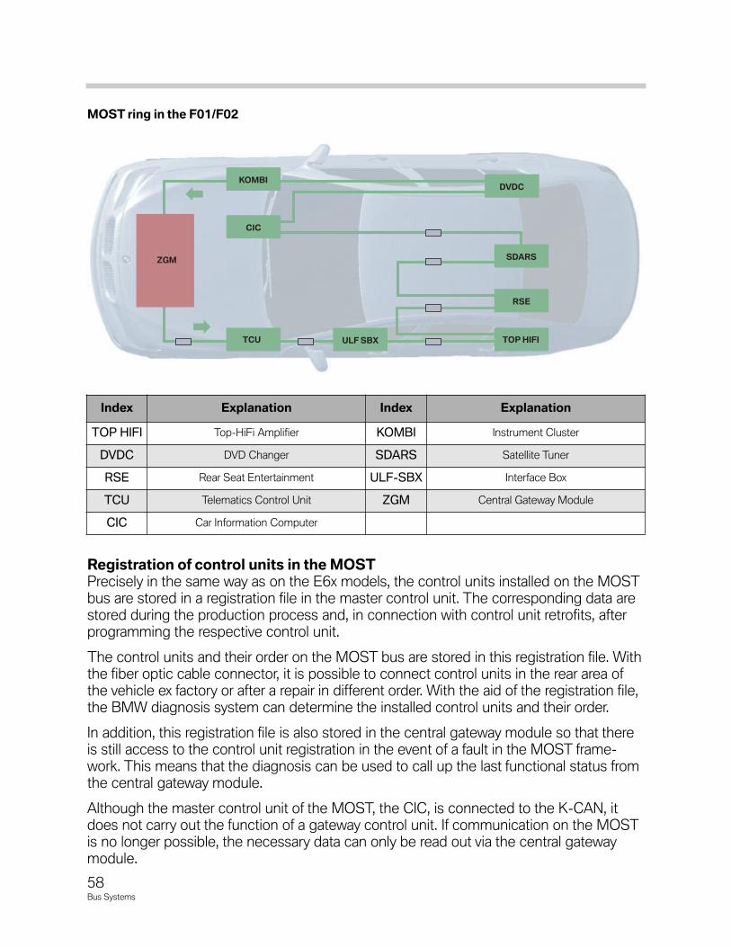
RegistrationofcontrolunitsintheMOSTPrecisely in the same way as on the E6x models, the control units installed on the MOSTbus are stored in a registration file in the master control unit. The corresponding data arestored during the production process and, in connection with control unit retrofits, afterprogramming the respective control unit.
The control units and their order on the MOST bus are stored in this registration file. Withthe fiber optic cable connector, it is possible to connect control units in the rear area ofthe vehicle ex factory or after a repair in different order. With the aid of the registration file,the BMW diagnosis system can determine the installed control units and their order.
In addition, this registration file is also stored in the central gateway module so that thereis still access to the control unit registration in the event of a fault in the MOST frame-work. This means that the diagnosis can be used to call up the last functional status fromthe central gateway module.
Although the master control unit of the MOST, the CIC, is connected to the K-CAN, itdoes not carry out the function of a gateway control unit. If communication on the MOSTis no longer possible, the necessary data can only be read out via the central gatewaymodule.
KOMBI
ULF SBX
CIC
SDARS
DVDC
TOP HIFITCU
RSE
ZGM
Index Explanation Index Explanation
TOP HIFI Top-HiFi Amplifier KOMBI Instrument Cluster
DVDC DVD Changer SDARS Satellite Tuner
RSE Rear Seat Entertainment ULF-SBX Interface Box
TCU Telematics Control Unit ZGM Central Gateway Module
CIC Car Information Computer
MOSTringintheF01/F02
59Bus Systems
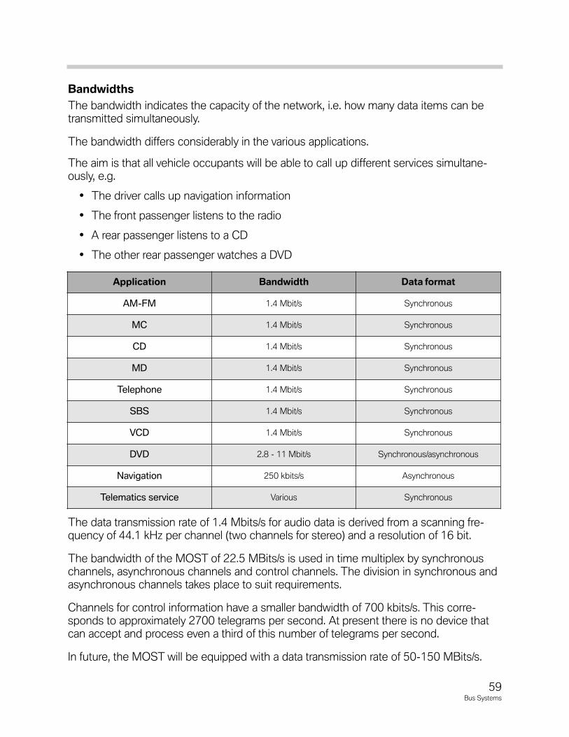
Bandwidths
The bandwidth indicates the capacity of the network, i.e. how many data items can betransmitted simultaneously.
The bandwidth differs considerably in the various applications.
The aim is that all vehicle occupants will be able to call up different services simultane-ously, e.g.
• The driver calls up navigation information
• The front passenger listens to the radio
• A rear passenger listens to a CD
• The other rear passenger watches a DVD
The data transmission rate of 1.4 Mbits/s for audio data is derived from a scanning fre-quency of 44.1 kHz per channel (two channels for stereo) and a resolution of 16 bit.
The bandwidth of the MOST of 22.5 MBits/s is used in time multiplex by synchronouschannels, asynchronous channels and control channels. The division in synchronous andasynchronous channels takes place to suit requirements.
Channels for control information have a smaller bandwidth of 700 kbits/s. This corre-sponds to approximately 2700 telegrams per second. At present there is no device thatcan accept and process even a third of this number of telegrams per second.
In future, the MOST will be equipped with a data transmission rate of 50-150 MBits/s.
Application Bandwidth Dataformat
AM-FM 1.4 Mbit/s Synchronous
MC 1.4 Mbit/s Synchronous
CD 1.4 Mbit/s Synchronous
MD 1.4 Mbit/s Synchronous
Telephone 1.4 Mbit/s Synchronous
SBS 1.4 Mbit/s Synchronous
VCD 1.4 Mbit/s Synchronous
DVD 2.8 - 11 Mbit/s Synchronous/asynchronous
Navigation 250 kbits/s Asynchronous
Telematics service Various Synchronous
60Bus Systems
MOSTBusDiagnosis
Due to the differences in the configuration of the MOST bus, diagnosis methods will dif-fer between models. However, there are many similarities and there are some basic ruleswhich apply to all MOST equipped vehicles.
It is important to remember that on the MOST network, messages can only be transmit-ted provided the bus ring is complete and fully functional. If there is a ring fault in theMOST network, the diagnostic system only communicates with the instrument clusterand the Control Display because both of these modules are directly connected to theK-CAN System Bus.
The fiber optic signals on the MOST network always travel in one direction and only inone direction. Signals always originate at the Control Display or the CIC (depending onthe model) and travel in and out of all the modules in the ring and back to the ControlDisplay or CIC.
The MOST bus allows intersystem fault memory entries in the individual control modules.A feature of the system faults is that faults may be entered in a control module althoughthe control module is OK. Conclusions may be drawn about the cause of the fault, usingthe fault information stored in all the control modules.
The possible system faults are:
• Optical wave guide communication fault
• A Control Module does not switch a light off (All MOST Control Modules)
• Network wake-up unsuccessful
• Ring fault diagnosis run
OpticalWaveGuideCommunicationFault
This fault indicates a problem with optical transmission. Insufficient light is being receivedby one of the modules in the ring. The loss of light may be caused by:
• Defective optical wave guide, Harness twisted too tightly (Min. bend radius 50mm.)
• Light output or reception sensitivity of a diode is too low
• Connector not installed correctly
• Voltage fluctuation while powering up a control module
If the fault is stored, the system triggers a reset and starts up again. The music isswitched off briefly and the display screen of the Control Display continues to operate.
To find the module responsible for the fault, the fault memory of the modules must beread in MOST ring order.
61Bus Systems
Fault lies between the module with the fault code (B) and the preceding module (A).
If the voltage has dipped below 9v, the fault may be incorrectly stored. If the voltage is lowperform the following test after connecting a battery charger.
1. Clear the fault memory in control module B.
2. Lower the light output in control module A.
3. Read out the fault memory in the MOST ring in order.
4. If control module B is again the first to store the fault, it can be assumed the fault liesbetween control modules A and B.
Then, check control modules A and B for loose connections and check the optical waveguide for kinks. If the visual inspection is OK, the fault can be located using the OPPStester on older vehicles or optionally performing the following tests.
• Remove the input optical wave guide from control module B and confirm the pres-ence of light. If light is present, install by-pass optical wave guide in place of controlmodule A, clear fault codes in module B and perform ring break test. If MOST net-work operates properly, then control module A is at fault and must be replaced. IfMOST network still has a fault, put module A back in the network and by-pass mod-ule B. Clear faults and again perform ring break test. If MOST network operates nowproblem is with control module B and it must be replaced.
• If light is not present at input of module B, perform by-pass of module A as above.
The possible fault scenarios are:
• Transmit diode in module A defective
• Receive diode in module B defective
• Optical wave guide fault between modules A and B
• Software error or fault in module A or B
ControlModuleDoesNotSwitchOffLight
When the MOST network is requested to sleep, the Control Display switches off the lightin the MOST ring. The lack of light input is a signal to the individual control modules toswitch off their light output and enter sleep mode.
If a control module does not switch off its light, all down stream control modules registerthe fault “A Control Module is not switching light off.”
62Bus Systems
Failureofacontrolmoduletoturnitslightoff,willcausetheMOSTnetworkNOTtoentersleepmode.IftheMOSTnetworkfailstosleep,therestofthecarwillnotbeabletoentersleepmode.Thiswillleadtobatterydischarge.
To diagnose, read out fault memory in MOST ring order.
The fault lies in the control module that precedes the module where the fault is firststored.
Always confirm the problem by first clearing the fault and performing the diagnosis a sec-ond time. If the same results occur, replace the defective control module.
NetworkWakeupUnsuccessful
This fault indicates a problem with the optical transmission. An insufficient volume of lightis coming through one position of the ring and may be caused by:
• Control Module is receiving no voltage
• Optical Wave Guide harness defective
• Optical Element in a control module defective (transmit or receive)
• Connector not installed correctly
A distinction must be made as to whether the fault is currently present or sporadic.
For faults currently present, run the Ring Break Diagnosis Test Plan.
For sporadic faults perform the Luminous Power Reduction Test Plan.
RingBreakDiagnosis
Reading out the fault memory of the Control Display (Gateway) after performing the RingFault Diagnostic, results in a fault of Ring Fault Diagnosis Carried Out being stored.
This fault memory is not a true fault memory entry, but only an output of additional infor-mation for relative node position.
63Bus Systems
LightOutputReduction
Reducingthelightoutputofindividualcontrolmodulesisaconvenientmethodofdeterminingtheareaofadefect.
• Switch on the radio.
• In Control Module functions, begin to activate luminous power reduction in the indi-vidual control module (In this test the light output of the selected control module isreduced for 5 seconds and then automatically reset to normal output).
• If the optical transmission for control module A to the next control module in the ring(control module B) is OK, a slight noise may occur when the light output is reduced,however the radio will continue to play.
• If the radio goes off and comes back on again(radio volume may be reduced) in 5 to10 seconds, the optical transmission between control modules A and B is defective.If the visual inspection is OK, the fault can be located using the OPPS tester oroptionally performing the following tests.
• Remove the input optical wave guide from control module B and confirm the pres-ence of light.
• If light is present, install by-pass optical wave guide in place of control module A,clear fault codes in module B. If MOST network operates properly, then control mod-ule A is at fault and must be replaced.
• If MOST network still has a fault, put module A back in the network and by-passmodule B. Clear faults.
• If MOST network operates now problem is with control module B and it must bereplaced.
• If light is not present at input of module B, perform ring break diagnostics.
RingBreakTest
If there is a break in the ring (a defect between two control modules) the following faultpatterns may occur:
• Transmit diode of the transmitting control module defective
• Power supply of the transmitting control module defective
• Internal control module fault of the transmitting control module
• Receiver diode of the receiving control module defective
• Power supply of the receiving control module defective
• Internal control module fault of the receiving control module
• Optical wave guide between transmitting and receiving control module defective
64Bus Systems
These faults may occur alone or in combination. To diagnose a ring break, the first step isto locate the two control modules between which the transmission failure has occurred.
This is accomplished with the ring break diagnostic function. Once the two control mod-ules have been identified and the diagnostics have been performed, remember to checkthe power supply and ground circuit of both modules before condemning a module.
PerformRingBreakTest
The ring break test mode is entered automatically when the power to all the modules inthe MOST network is switched off and then switched back on. The most effectivemethod of switching the power off and on is to disconnect the battery negative terminalfor 45 seconds. This time will allow the capacitors of all the control modules to dissipate.
When the battery is reconnected the control modules wake up and in MOST networkorder transmit a light signal to the next module. Each module checks to see if it hasreceived a light signal from the previous module. If the control module does NOT receivea light input signal it still transmits a signal to the next module. A relative node number of0 is stored in the control module that did not receive a signal but that transmitted one.
The MOST master control unit receives the light signal back and identifies which mod-ules responded.
Go to “Control Unit Functions” Control Display Gateway and read fault memory.
The MOST master control unit will display a relative node number. This number will indi-cate how many modules communicated after the module which set the relative nodenumber of 0.
To find the control module with the relative node number of 0, count from the input sideof the MOST master(counting the MOST master as 0) towards the control modules.
When arriving at the control module with the number as displayed as the relative nodenumber, the last known communicating module has been found.
Example:
While performing the ring break diagnostics on an E65 the Control Display has set a rela-tive node number of 2. Count the Control Display a 0, the Kombi will be 1 and the ASKwill be 2.
The ring break occurs between the ASK and the module which precedes it, the tele-phone module.
Whencountingcontrolmodules,themultimediachanger(ifequipped)andtheNavsystemmustbecountedastwocontrolmodules.
Note:MoredetailsontheringfaultdiagnosiscanbefoundinthefunctionaldescriptionMOSTbus:ringfaultdiagnosiscompletevehicle->Body->Busfunctions->MOSTfunctions->Ringfaultdiagnosis.
65Bus Systems
StatusWakeup
MOST control modules require high current during standby operation and must be dis-connected or put in sleep mode to prevent the vehicle battery from being discharged. Incase of a fault on the MOST network that continuously wakes up, the entire MOST buswill be woken up. The Control Display will wake up the CAN Bus and all the vehiclebusses will be woken up. This will lead to battery discharge.
It is of great benefit to know which module initiated the wake up call. In order to find outwhich MOST node woke up the MOST bus, the following procedure is performed - InControl Unit Functions, press “STATUSWAKEUP”
Three different response are possible:
• Control Module woke up
• Control Module woken up
• Control Module not initialized
The Control Module with the status “Control Module woke up” is the module that wokeup the rest of the MOST bus.
This diagnosis only informs which control module woke, not the reason for the wake up,diagnostic testing should be performed on the control module and related equipment.
FormoreinformationrefertothefollowingFUBs:
•FUB-FPA-CHA1003FP-656582005Faultprofiles,MOST
•FUB-DAA0302FB-656582004MOSTbus:Ringfaultdiagnosis
•FUB-BLB0704FB-657761055MOSTbus:Ringfaultdiagnosis
•FUB-DAA0701FB-656582003MOSTbus
•FUB-DAA0302FB-656582005MOSTbus:statuswake-up
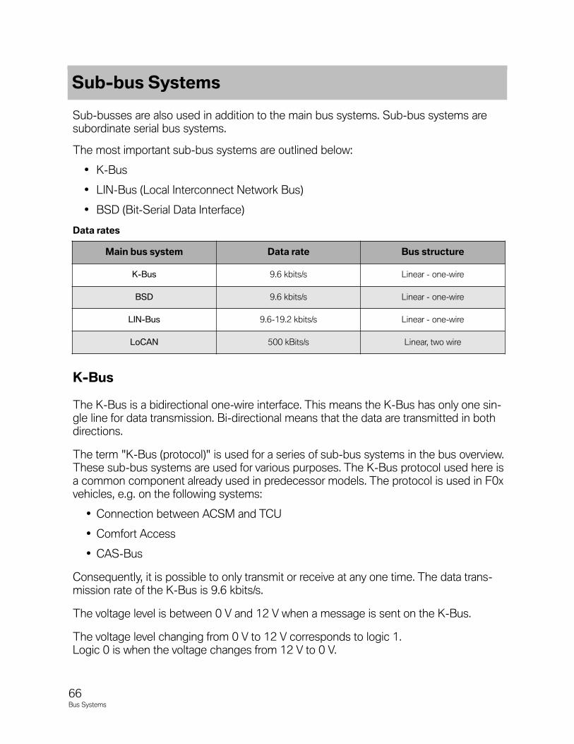
Sub-busses are also used in addition to the main bus systems. Sub-bus systems aresubordinate serial bus systems.
The most important sub-bus systems are outlined below:
• K-Bus
• LIN-Bus (Local Interconnect Network Bus)
• BSD (Bit-Serial Data Interface)
Datarates
K-Bus
The K-Bus is a bidirectional one-wire interface. This means the K-Bus has only one sin-gle line for data transmission. Bi-directional means that the data are transmitted in bothdirections.
The term "K-Bus (protocol)" is used for a series of sub-bus systems in the bus overview.These sub-bus systems are used for various purposes. The K-Bus protocol used here isa common component already used in predecessor models. The protocol is used in F0xvehicles, e.g. on the following systems:
• Connection between ACSM and TCU
• Comfort Access
• CAS-Bus
Consequently, it is possible to only transmit or receive at any one time. The data trans-mission rate of the K-Bus is 9.6 kbits/s.
The voltage level is between 0 V and 12 V when a message is sent on the K-Bus.
The voltage level changing from 0 V to 12 V corresponds to logic 1. Logic 0 is when the voltage changes from 12 V to 0 V.
Sub-busSystems
66Bus Systems
Mainbussystem Datarate Busstructure
K-Bus 9.6 kbits/s Linear - one-wire
BSD 9.6 kbits/s Linear - one-wire
LIN-Bus 9.6-19.2 kbits/s Linear - one-wire
LoCAN 500 kBits/s Linear, two wire
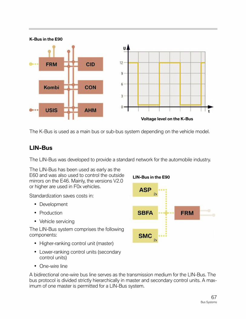
67Bus Systems
The K-Bus is used as a main bus or sub-bus system depending on the vehicle model.
LIN-Bus
The LIN-Bus was developed to provide a standard network for the automobile industry.
The LIN-Bus has been used as early as theE60 and was also used to control the outsidemirrors on the E46. Mainly, the versions V2.0or higher are used in F0x vehicles.
Standardization saves costs in:
• Development
• Production
• Vehicle servicing
The LIN-Bus system comprises the followingcomponents:
• Higher-ranking control unit (master)
• Lower-ranking control units (secondarycontrol units)
• One-wire line
A bidirectional one-wire bus line serves as the transmission medium for the LIN-Bus. Thebus protocol is divided strictly hierarchically in master and secondary control units. A max-imum of one master is permitted for a LIN-Bus system.
VoltagelevelontheK-Bus
LIN-BusintheE90
K-BusintheE90
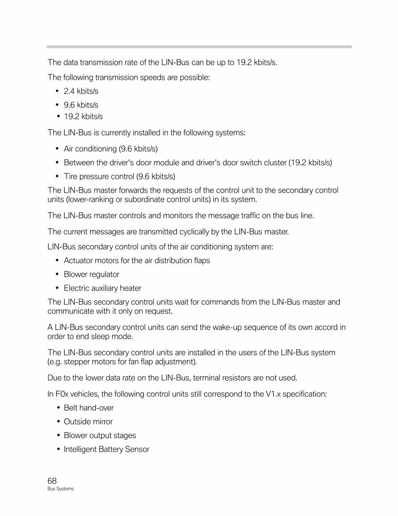
68Bus Systems
The data transmission rate of the LIN-Bus can be up to 19.2 kbits/s.
The following transmission speeds are possible:
• 2.4 kbits/s
• 9.6 kbits/s
• 19.2 kbits/s
The LIN-Bus is currently installed in the following systems:
• Air conditioning (9.6 kbits/s)
• Between the driver's door module and driver's door switch cluster (19.2 kbits/s)
• Tire pressure control (9.6 kbits/s)
The LIN-Bus master forwards the requests of the control unit to the secondary controlunits (lower-ranking or subordinate control units) in its system.
The LIN-Bus master controls and monitors the message traffic on the bus line.
The current messages are transmitted cyclically by the LIN-Bus master.
LIN-Bus secondary control units of the air conditioning system are:
• Actuator motors for the air distribution flaps
• Blower regulator
• Electric auxiliary heater
The LIN-Bus secondary control units wait for commands from the LIN-Bus master andcommunicate with it only on request.
A LIN-Bus secondary control units can send the wake-up sequence of its own accord inorder to end sleep mode.
The LIN-Bus secondary control units are installed in the users of the LIN-Bus system(e.g. stepper motors for fan flap adjustment).
Due to the lower data rate on the LIN-Bus, terminal resistors are not used.
In F0x vehicles, the following control units still correspond to the V1.x specification:
• Belt hand-over
• Outside mirror
• Blower output stages
• Intelligent Battery Sensor
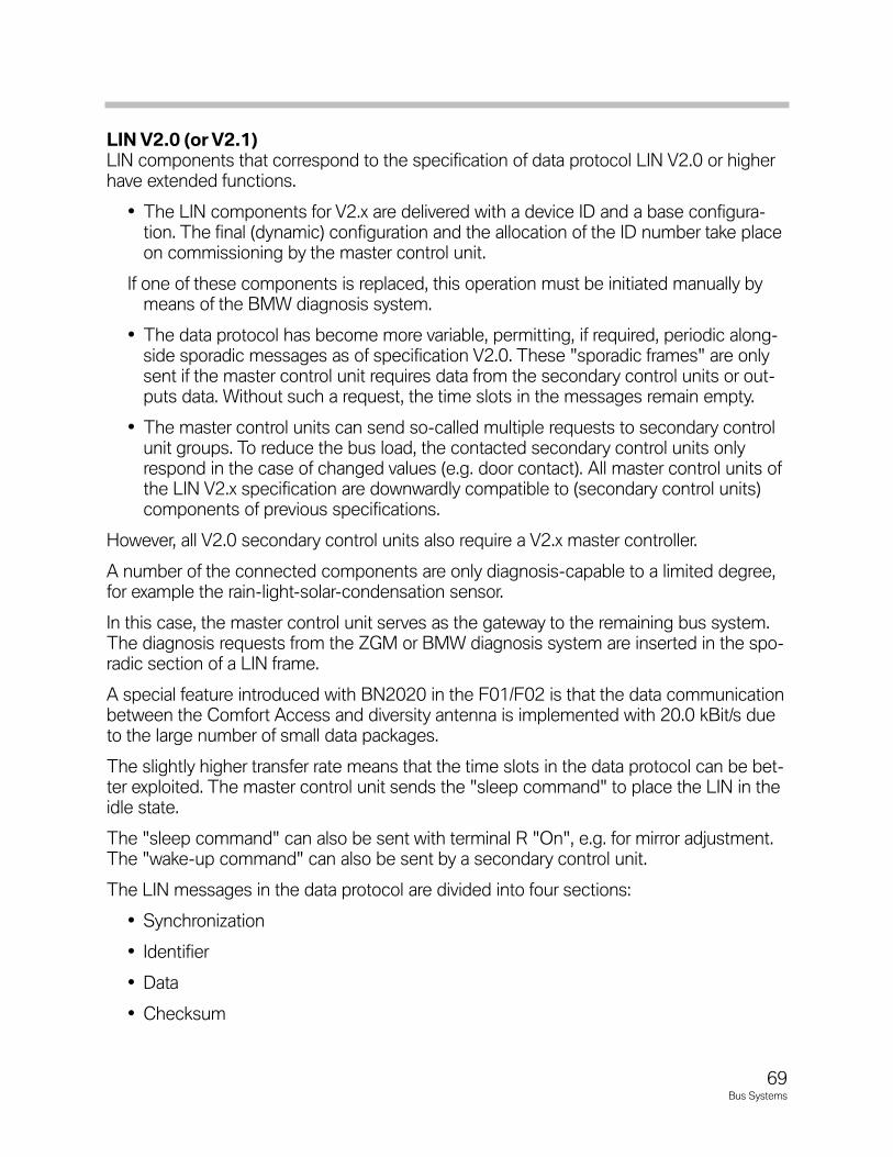
LINV2.0(orV2.1)LIN components that correspond to the specification of data protocol LIN V2.0 or higherhave extended functions.
• The LIN components for V2.x are delivered with a device ID and a base configura-tion. The final (dynamic) configuration and the allocation of the ID number take placeon commissioning by the master control unit.
If one of these components is replaced, this operation must be initiated manually bymeans of the BMW diagnosis system.
• The data protocol has become more variable, permitting, if required, periodic along-side sporadic messages as of specification V2.0. These "sporadic frames" are onlysent if the master control unit requires data from the secondary control units or out-puts data. Without such a request, the time slots in the messages remain empty.
• The master control units can send so-called multiple requests to secondary controlunit groups. To reduce the bus load, the contacted secondary control units onlyrespond in the case of changed values (e.g. door contact). All master control units ofthe LIN V2.x specification are downwardly compatible to (secondary control units)components of previous specifications.
However, all V2.0 secondary control units also require a V2.x master controller.
A number of the connected components are only diagnosis-capable to a limited degree,for example the rain-light-solar-condensation sensor.
In this case, the master control unit serves as the gateway to the remaining bus system.The diagnosis requests from the ZGM or BMW diagnosis system are inserted in the spo-radic section of a LIN frame.
A special feature introduced with BN2020 in the F01/F02 is that the data communicationbetween the Comfort Access and diversity antenna is implemented with 20.0 kBit/s dueto the large number of small data packages.
The slightly higher transfer rate means that the time slots in the data protocol can be bet-ter exploited. The master control unit sends the "sleep command" to place the LIN in theidle state.
The "sleep command" can also be sent with terminal R "On", e.g. for mirror adjustment.The "wake-up command" can also be sent by a secondary control unit.
The LIN messages in the data protocol are divided into four sections:
• Synchronization
• Identifier
• Data
• Checksum
69Bus Systems
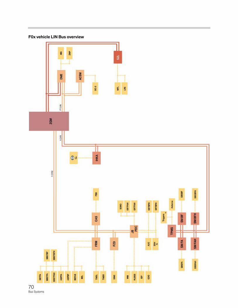
70Bus Systems
F0xvehicleLINBusoverview
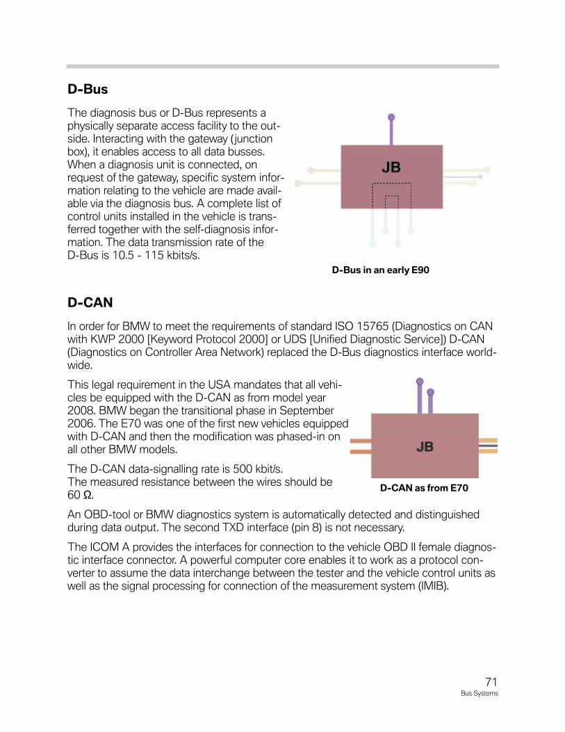
71Bus Systems
D-Bus
The diagnosis bus or D-Bus represents aphysically separate access facility to the out-side. Interacting with the gateway (junctionbox), it enables access to all data busses.When a diagnosis unit is connected, onrequest of the gateway, specific system infor-mation relating to the vehicle are made avail-able via the diagnosis bus. A complete list ofcontrol units installed in the vehicle is trans-ferred together with the self-diagnosis infor-mation. The data transmission rate of theD-Bus is 10.5 - 115 kbits/s.
D-CAN
In order for BMW to meet the requirements of standard ISO 15765 (Diagnostics on CANwith KWP 2000 [Keyword Protocol 2000] or UDS [Unified Diagnostic Service]) D-CAN(Diagnostics on Controller Area Network) replaced the D-Bus diagnostics interface world-wide.
This legal requirement in the USA mandates that all vehi-cles be equipped with the D-CAN as from model year2008. BMW began the transitional phase in September2006. The E70 was one of the first new vehicles equippedwith D-CAN and then the modification was phased-in onall other BMW models.
The D-CAN data-signalling rate is 500 kbit/s.The measured resistance between the wires should be60 Ω.Ω
An OBD-tool or BMW diagnostics system is automatically detected and distinguishedduring data output. The second TXD interface (pin 8) is not necessary.
The ICOM A provides the interfaces for connection to the vehicle OBD II female diagnos-tic interface connector. A powerful computer core enables it to work as a protocol con-verter to assume the data interchange between the tester and the vehicle control units aswell as the signal processing for connection of the measurement system (IMIB).
D-BusinanearlyE90
D-CANasfromE70
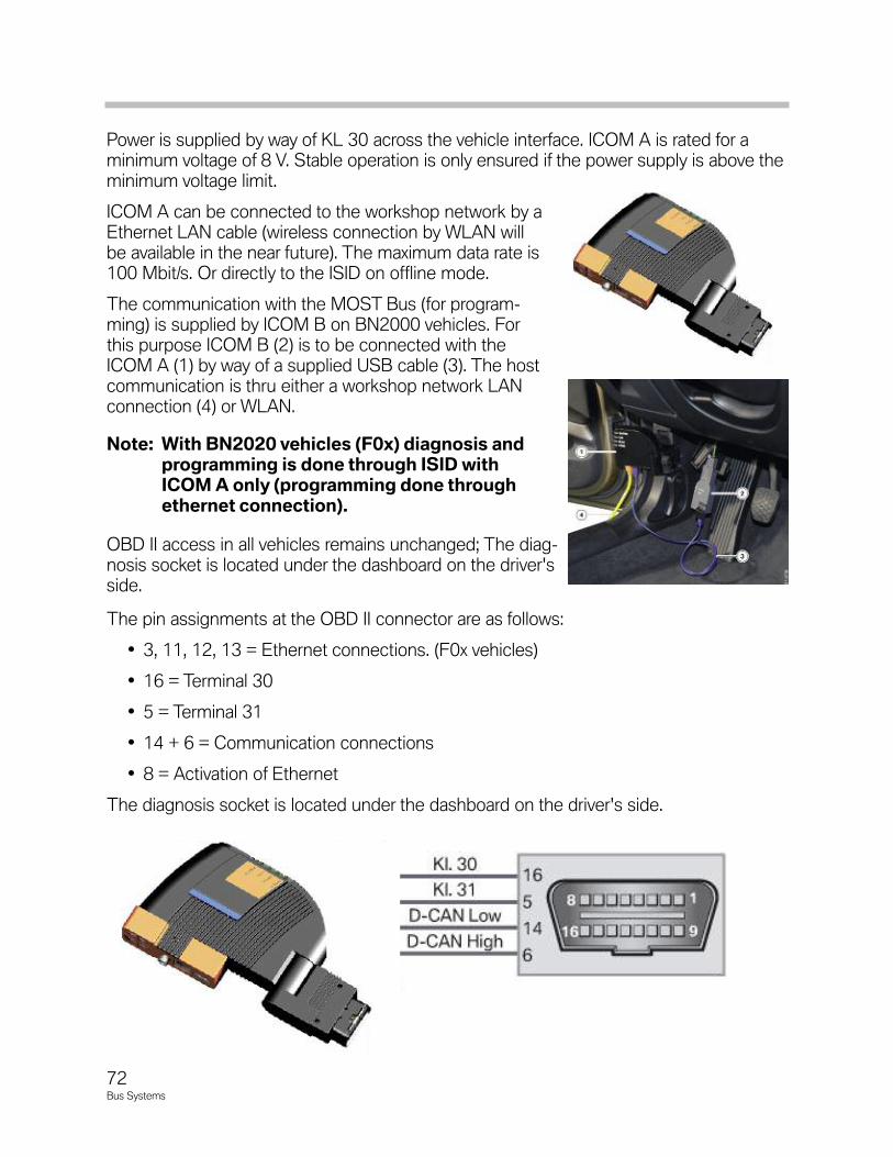
72Bus Systems
Power is supplied by way of KL 30 across the vehicle interface. ICOM A is rated for aminimum voltage of 8 V. Stable operation is only ensured if the power supply is above theminimum voltage limit.
ICOM A can be connected to the workshop network by aEthernet LAN cable (wireless connection by WLAN willbe available in the near future). The maximum data rate is100 Mbit/s. Or directly to the ISID on offline mode.
The communication with the MOST Bus (for program-ming) is supplied by ICOM B on BN2000 vehicles. Forthis purpose ICOM B (2) is to be connected with theICOM A (1) by way of a supplied USB cable (3). The hostcommunication is thru either a workshop network LAN connection (4) or WLAN.
Note:WithBN2020vehicles(F0x)diagnosisandprogrammingisdonethroughISIDwithICOMAonly(programmingdonethroughethernetconnection).
OBD II access in all vehicles remains unchanged; The diag-nosis socket is located under the dashboard on the driver'sside.
The pin assignments at the OBD II connector are as follows:
• 3, 11, 12, 13 = Ethernet connections. (F0x vehicles)
• 16 = Terminal 30
• 5 = Terminal 31
• 14 + 6 = Communication connections
• 8 = Activation of Ethernet
The diagnosis socket is located under the dashboard on the driver's side.
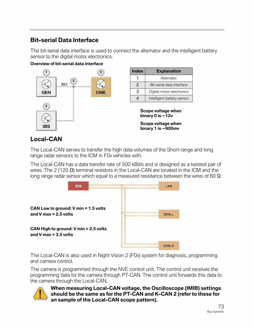
73Bus Systems
Bit-serialDataInterface
The bit-serial data interface is used to connect the alternator and the intelligent batterysensor to the digital motor electronics.
Local-CAN
The Local-CAN serves to transfer the high data volumes of the Short-range and longrange radar sensors to the ICM in F0x vehicles with.
The Local-CAN has a data transfer rate of 500 kBit/s and is designed as a twisted pair ofwires. The 2 (120 Ω) terminal resistors in the Local-CAN are located in the ICM and thelong range radar sensor which equal to a measured resistance between the wires of 60 Ω.
The Local-CAN is also used in Night Vision 2 (F0x) system for diagnosis, programmingand camera control.
The camera is programmed through the NVE control unit. The control unit receives theprogramming data for the camera through PT-CAN. The control unit forwards this data tothe camera through the Local-CAN.
When measuring Local-CAN voltage, the Oscilloscope (IMIB) settingsshould be the same as for the PT-CAN and K-CAN 2 (refer to these foran sample of the Local-CAN scope pattern).
Overviewofbit-serialdatainterface
CAN Low to ground: V min = 1.5 volts
and V max = 2.5 volts
CAN High to ground: V min = 2.5 volts
and V max = 3.5 volts
Scopevoltagewhenbinary0is~12v
Scopevoltagewhenbinary1is~900mv
Index Explanation
1 Alternator
2 Bit-serial data interface
3 Digital motor electronics
4 Intelligent battery sensor
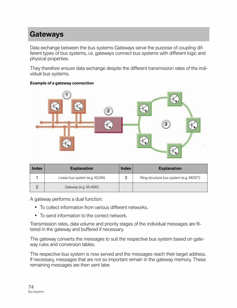
Data exchange between the bus systems Gateways serve the purpose of coupling dif-ferent types of bus systems, i.e. gateways connect bus systems with different logic andphysical properties.
They therefore ensure data exchange despite the different transmission rates of the indi-vidual bus systems.
A gateway performs a dual function:
• To collect information from various different networks.
• To send information to the correct network.
Transmission rates, data volume and priority stages of the individual messages are fil-tered in the gateway and buffered if necessary.
The gateway converts the messages to suit the respective bus system based on gate-way rules and conversion tables.
The respective bus system is now served and the messages reach their target address.If necessary, messages that are not so important remain in the gateway memory. Theseremaining messages are then sent later.
Gateways
74Bus Systems
Index Explanation Index Explanation
1 Linear bus system (e.g. KCAN) 3 Ring-structure bus system (e.g. MOST)
2 Gateway (e.g. M-ASK)
Exampleofagatewayconnection
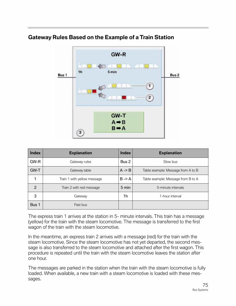
75Bus Systems
GatewayRulesBasedontheExampleofaTrainStation
The express train 1 arrives at the station in 5- minute intervals. This train has a message(yellow) for the train with the steam locomotive. The message is transferred to the firstwagon of the train with the steam locomotive.
In the meantime, an express train 2 arrives with a message (red) for the train with thesteam locomotive. Since the steam locomotive has not yet departed, the second mes-sage is also transferred to the steam locomotive and attached after the first wagon. Thisprocedure is repeated until the train with the steam locomotive leaves the station afterone hour.
The messages are parked in the station when the train with the steam locomotive is fullyloaded. When available, a new train with a steam locomotive is loaded with these mes-sages.
Index Explanation Index Explanation
GW-R Gateway rules Bus 2 Slow bus
GW-T Gateway table A -> B Table example: Message from A to B
1 Train 1 with yellow message B -> A Table example: Message from B to A
2 Train 2 with red message 5 min 5-minute intervals
3 Gateway 1h 1-hour interval
Bus 1 Fast bus

76Bus Systems
NOTESPAGE