Embed Size (px)
Citation preview
Filter SystemsFluid Condition Monitoring & Control
PN#02075860 / 04.15 / FSP1406-1622
PN#02075860 / 04.15 / FSP1406-1622
Components, Systems and Service. All from one Company.Our fluid engineering solutions are defined by the scope and complexity of our customers’ requirements.
Our products range from individually designed components in the fields of fluid engineering, hydraulics and electronics right up to complete systems for specific functions.
All components and systems are conceived and designed in-house. Experienced industrial and product specialists develop innovative products and efficient solutions for high-quality, cost-effective production. Throughout the globe, our production facilities share one common goal: quality. We take great pride in both our products and solutions.
Industries and Applications
Automotive Wind Power Offshore / Marine
Paper Industry
Mobile Hydraulics
Steel Industry Plastics Industry
Rolling Mill / Press
Power Industry
PN#02075860 / 04.15 / FSP1406-1622
Section:
Filter System Division 580 West Park Road Leetsdale, PA 15056 +1.724.318.1100 Internet: www.hydac-na.com Email: [email protected]
TABLE OF CONTENTS
NOTEInformation and related materials are subject to change without notice. This catalog, and all information and related materials it contains, are provided “as is.” HYDAC makes no representation or warranty whatsoever regarding the completeness, accuracy, “up-to-dateness”, or adequacy of, the HYDAC-NA domain and this catalog.
OverviewIntroduction - A2, Cost Savings Calculations - A3, ISO Cleanliness Levels - A4 A
Contamination MonitorsCS1000 - B2, HYTRAX-M - B6, HYTRAX-T - B8, CS2000 - B12, CSM1000 - B14, CSM2000 - B16, CSM-C - B18, FCU1000 - B20, FCU2000 - B22, MCS1000 - B26, AS1000 - B28, AS3000 - B30, SMU1200 - B32, FMS - B34, CTU1000 - B36, CTM-SC - B38, CTM-EB - B40, MM - B44, FAS - B45, FASH - B46
B
DiagnosticsHMG3010 - C2 C
Offline Filtration SystemsOF7 - D2, OFCD-BC - D4, OFCS/D - D6, OFCD-MV - D8, OFCD-HV - D10, OFS - D12, OFS-AM - D14, OF5HS/D - D16, OF5HD-HV - D18, OFAS/D - D20, LSN - D22, OFX - D24, OLF Compact - D28, OLF - D32, OLFP 1/3/6 - D36, NxTM TriMicron Element - D40, IXU1/4 - D42, MAFH-A - D46, MAFH-E - D50, FAM5 - D52, FAMH - D56, HTB - D60
D
Replacement ElementsPressure Elements - E2, Dimicron® Elements, Cartridge Elements, Spin-on Elements, Aquamicron® Elements, Betamicron®/Aquamicron® Elements, Betterfit® Interchange Elements - E4
E
Bulk Diesel FiltrationOverview - F2, ICF - F6, QCF - F10, BDS - F12, BDS2 - F14, BDF1/2 - F16, BDFC - F20, BDC - F22 F
Reference MaterialsViscosity Charts - G2 G
A2 PN#02075860 / 04.15 / FSP1406-1622
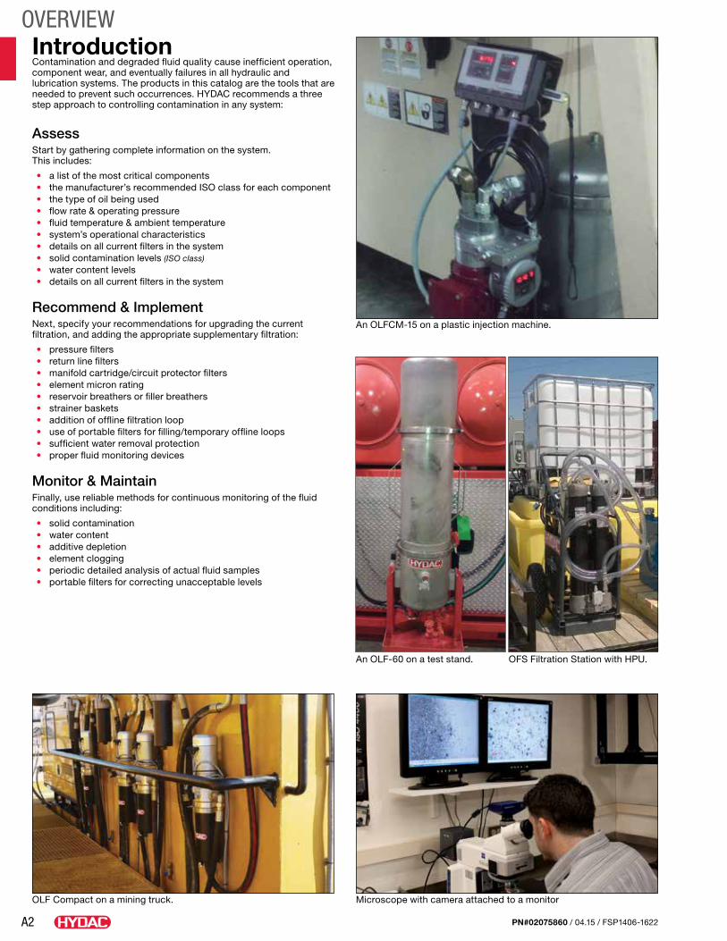
OVERVIEWIntroductionContamination and degraded fluid quality cause inefficient operation, component wear, and eventually failures in all hydraulic and lubrication systems. The products in this catalog are the tools that are needed to prevent such occurrences. HYDAC recommends a three step approach to controlling contamination in any system:
AssessStart by gathering complete information on the system. This includes:
• a list of the most critical components• the manufacturer’s recommended ISO class for each component• the type of oil being used• flow rate & operating pressure• fluid temperature & ambient temperature• system’s operational characteristics• details on all current filters in the system• solid contamination levels (ISO class)• water content levels• details on all current filters in the system
Recommend & ImplementNext, specify your recommendations for upgrading the current filtration, and adding the appropriate supplementary filtration:
• pressure filters• return line filters• manifold cartridge/circuit protector filters• element micron rating• reservoir breathers or filler breathers• strainer baskets• addition of offline filtration loop• use of portable filters for filling/temporary offline loops• sufficient water removal protection• proper fluid monitoring devices
Monitor & MaintainFinally, use reliable methods for continuous monitoring of the fluid conditions including:
• solid contamination• water content• additive depletion• element clogging• periodic detailed analysis of actual fluid samples• portable filters for correcting unacceptable levels
An OLF-60 on a test stand. OFS Filtration Station with HPU.
An OLFCM-15 on a plastic injection machine.
Microscope with camera attached to a monitorOLF Compact on a mining truck.
A3PN#02075860 / 04.15 / FSP1406-1622
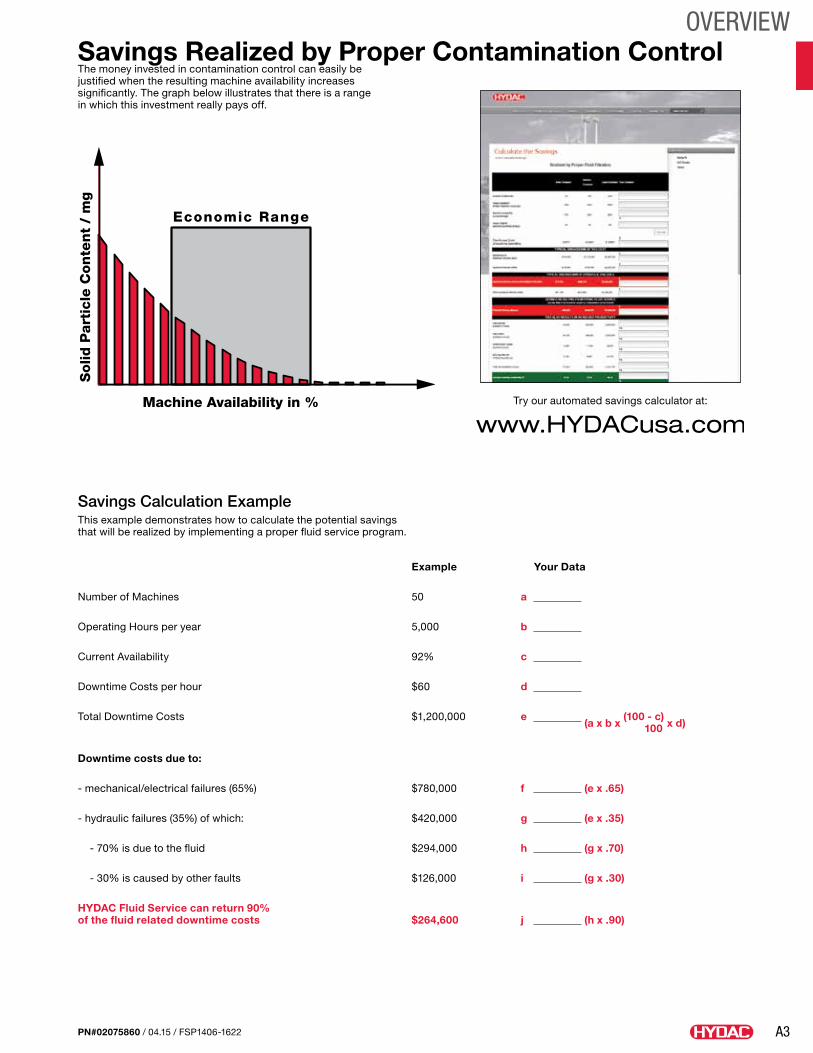
OVERVIEWSavings Realized by Proper Contamination ControlThe money invested in contamination control can easily be justified when the resulting machine availability increases significantly. The graph below illustrates that there is a range in which this investment really pays off.
Example Your Data
Number of Machines 50 a
Operating Hours per year 5,000 b
Current Availability 92% c
Downtime Costs per hour $60 d
Total Downtime Costs $1,200,000 e (a x b x
(100 - c) x d)
100
Downtime costs due to:
- mechanical/electrical failures (65%) $780,000 f (e x .65)
- hydraulic failures (35%) of which: $420,000 g (e x .35)
- 70% is due to the fluid $294,000 h (g x .70)
- 30% is caused by other faults $126,000 i (g x .30)
HYDAC Fluid Service can return 90% of the fluid related downtime costs $264,600 j (h x .90)
Savings Calculation ExampleThis example demonstrates how to calculate the potential savings that will be realized by implementing a proper fluid service program.
Try our automated savings calculator at:Machine Availability in %
Solid
Part
icle
Con
ten
t /
mg
Economic Range
A4 PN#02075860 / 04.15 / FSP1406-1622
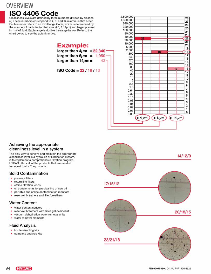
OVERVIEWISO 4406 CodeCleanliness levels are defined by three numbers divided by slashes (/.) These numbers correspond to 4, 6, and 14 micron, in that order. Each number refers to an ISO Range Code, which is determined by the number of particles for that size (4,6, & 14µm) and larger present in 1 ml of fluid. Each range is double the range below. Refer to the chart below to see the actual ranges.
Achieving the appropriate cleanliness level in a systemThe only way to achieve and maintain the appropriate cleanliness level in a hydraulic or lubrication system,is to implement a comprehensive filtration program.HYDAC offers all of the products that are needed to do just that! - They include:
Solid Contamination• pressure filters• return line filters• offline filtration loops• oil transfer units for precleaning of new oil• portable and online contamination monitors• reservoir breathers and filler/breathers
Water Content• water content sensors• reservoir breathers with silica gel desiccant• vacuum dehydration water removal units• water removal elements
Fluid Analysis• bottle sampling kits• complete analysis kits
23/21/18
17/15/12
20/18/15
14/12/9
A5PN#02075860 / 04.15 / FSP1406-1622
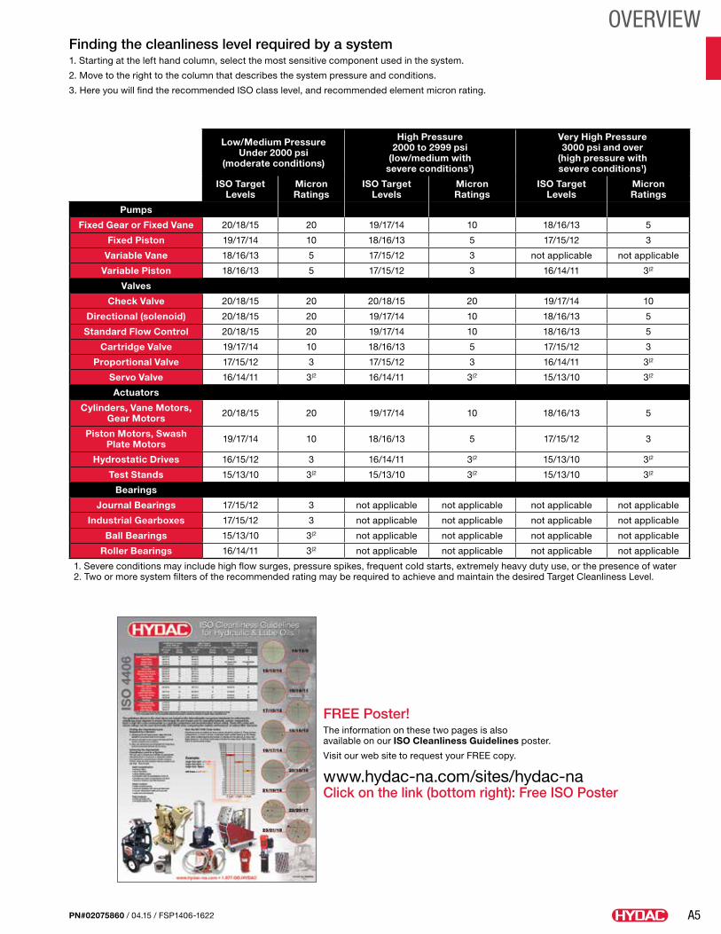
OVERVIEWFinding the cleanliness level required by a system1. Starting at the left hand column, select the most sensitive component used in the system.
2. Move to the right to the column that describes the system pressure and conditions.
3. Here you will find the recommended ISO class level, and recommended element micron rating.
FREE Poster!The information on these two pages is also available on our ISO Cleanliness Guidelines poster.
Visit our web site to request your FREE copy.
www.hydac-na.com/sites/hydac-naClick on the link (bottom right): Free ISO Poster
Low/Medium Pressure Under 2000 psi
(moderate conditions)
High Pressure 2000 to 2999 psi
(low/medium with severe conditions1)
Very High Pressure 3000 psi and over
(high pressure with severe conditions1)
ISO Target Levels
Micron Ratings
ISO Target Levels
Micron Ratings
ISO Target Levels
Micron Ratings
Pumps
Fixed Gear or Fixed Vane 20/18/15 20 19/17/14 10 18/16/13 5
Fixed Piston 19/17/14 10 18/16/13 5 17/15/12 3
Variable Vane 18/16/13 5 17/15/12 3 not applicable not applicable
Variable Piston 18/16/13 5 17/15/12 3 16/14/11 3(2
Valves
Check Valve 20/18/15 20 20/18/15 20 19/17/14 10
Directional (solenoid) 20/18/15 20 19/17/14 10 18/16/13 5
Standard Flow Control 20/18/15 20 19/17/14 10 18/16/13 5
Cartridge Valve 19/17/14 10 18/16/13 5 17/15/12 3
Proportional Valve 17/15/12 3 17/15/12 3 16/14/11 3(2
Servo Valve 16/14/11 3(2 16/14/11 3(2 15/13/10 3(2
Actuators
Cylinders, Vane Motors, Gear Motors 20/18/15 20 19/17/14 10 18/16/13 5
Piston Motors, Swash Plate Motors 19/17/14 10 18/16/13 5 17/15/12 3
Hydrostatic Drives 16/15/12 3 16/14/11 3(2 15/13/10 3(2
Test Stands 15/13/10 3(2 15/13/10 3(2 15/13/10 3(2
Bearings
Journal Bearings 17/15/12 3 not applicable not applicable not applicable not applicable
Industrial Gearboxes 17/15/12 3 not applicable not applicable not applicable not applicable
Ball Bearings 15/13/10 3(2 not applicable not applicable not applicable not applicable
Roller Bearings 16/14/11 3(2 not applicable not applicable not applicable not applicable
1. Severe conditions may include high flow surges, pressure spikes, frequent cold starts, extremely heavy duty use, or the presence of water2. Two or more system filters of the recommended rating may be required to achieve and maintain the desired Target Cleanliness Level.
A6 PN#02075860 / 04.15 / FSP1406-1622
OVERVIEWNotes
B1
CONTAMINATION MONITORS
PN#02075860 / 04.15 / FSP1406-1622
Contamination ManagementContamination management pertains to the analysis and optimization of processes with regard to the cleanliness of components, systems and the purity of the fluids used. Our fluid condition monitoring products include both in-line and offline sensors to measure contamination and/or water saturation levels of the hydraulic system. By implementing fluid condition monitors a major portion of particulate contamination introduced during manufacture and assembly can be removed. The result is cost savings by virtue of smaller performance deviations on test stands caused by the sudden clogging of particles in sensitive system components plus lower costs associated with warranty and non-warranty courtesy work.
B2
CONTAMINATION MONITORS
PN#02075860 / 04.15 / FSP1406-1622
Technical SpecificationsSelf-diagnosis Continuously with error
indication via status LEDMeasuring range
Display up to class ISO 7/6/5 to 28/27/26Calibration within the range ISO 13/11/10 to 23/21/18
Contamination code ISO 4406 : 1999SAE AS 4059 (D)
Operation pressure 5075 psi (350 bar) max (sensor only) 3500 psi (through manifold block)
Connectors (on CS1xxx unit) Inlet Outlet
Thread G 1/4, ISO 228 Thread G 1/4, ISO 228
Sensor flow rate 30 - 500 ml/minPermissible viscosity range 15 - 4635 SUS (1 - 1000 cSt)Fluid temperature range 32° to 185°F (0° to 85°C)Power supply voltage 9 - 36 VDC, residual ripple < 10%Power consumption 3 Watt maximumElectrical specification 4 to 20 mA output: 0 to 10 V output:
Max. 330 Ω Min. 820 Ω Max. current 1.5 A
Electrical outputs Analog Interfaces Limit Switching Output RS485
4 to 20 mA (max 330 Ω) 2 to 10 V (min 820 Ω) Passive, n-switching power MOSFET, max current 1.5A 2 conductor cable
Ambient temperature range -22° to 176°F (-30° to 80°C)Relative Humidity max. 95%, non-condensingSeal Material Hydraulic/Mineral Oil Phosphate Ester
Fluoro-elastomer (FPM)Ethylene Propylene (EPDM)
Electrical safety class III (low voltage protection)IP class IP67Weight 2.9 lbs. (1.3 kg)Mounting Position Recommended vertical with
direction of flow south to northWe do not guarantee the accuracy or completeness of this information. The information is based on average working condition. For exceptional operating conditions please contact our technical department. All details are subject to technical changes.
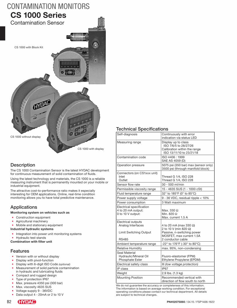
CS 1000 SeriesContamination Sensor
DescriptionThe CS 1000 Contamination Sensor is the latest HYDAC development for continuous measurement of solid contamination of fluids.
Using the latest technology and materials, the CS 1000 is a reliable measuring instrument that is permanently mounted on your mobile or industrial equipment.
The attractive cost-to-performance ratio makes it especially interesting for OEM applications. Online, real-time condition monitoring allows you to have total predictive maintenance.
ApplicationsMonitoring system on vehicles such as
• Construction equipment• Agricultural machinery• Mobile and stationary equipment
Industrial hydraulic systems
• Integration into power unit monitoring systems• Hydraulic test stands
Combination with filter unit
Features• Version with or without display• Display with pivot-function• Display with 6-digit ISO Code (optional)• Measurement of solid particle contamination
in hydraulic and lubricating fluids • Compact and rugged design• Type of protection IP67• Max. pressure 4350 psi (300 bar)• Max. viscosity 4635 SUS• Voltage supply 9 - 36VDC• Data output 4 - 20mA or 2 to 10 V
CS 1000 with display
CS 1000 without display
CS 1000 with Block Kit
B3
CONTAMINATION MONITORS
PN#02075860 / 04.15 / FSP1406-1622
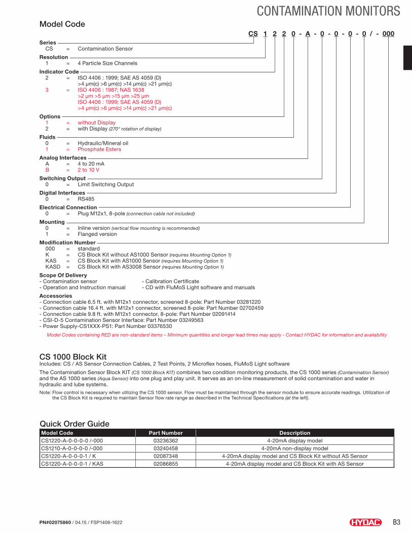
Model CodeCS 1 2 2 0 - A - 0 - 0 - 0 - 0 / - 000
Series CS = Contamination Sensor
Resolution 1 = 4 Particle Size Channels
Indicator Code 2 = ISO 4406 : 1999; SAE AS 4059 (D) >4 µm(c) >6 µm(c) >14 µm(c) >21 µm(c) 3 = ISO 4406 : 1987; NAS 1638 >2 µm >5 µm >15 µm >25 µm ISO 4406 : 1999; SAE AS 4059 (D) >4 µm(c) >6 µm(c) >14 µm(c) >21 µm(c)
Options 1 = without Display 2 = with Display (270° rotation of display)
Fluids 0 = Hydraulic/Mineral oil 1 = Phosphate Esters
Analog Interfaces A = 4 to 20 mA B = 2 to 10 V
Switching Output 0 = Limit Switching Output
Digital Interfaces 0 = RS485
Electrical Connection 0 = Plug M12x1, 8-pole (connection cable not included)
Mounting 0 = Inline version (vertical flow mounting is recommended) 1 = Flanged version
Modification Number 000 = standard K = CS Block Kit without AS1000 Sensor (requires Mounting Option 1) KAS = CS Block Kit with AS1000 Sensor (requires Mounting Option 1) KASD = CS Block Kit with AS3008 Sensor (requires Mounting Option 1)
Scope Of Delivery - Contamination sensor - Calibration Certificate - Operation and Instruction manual - CD with FluMoS Light software and manuals
Accessories - Connection cable 6.5 ft. with M12x1 connector, screened 8-pole: Part Number 03281220 - Connection cable 16.4 ft. with M12x1 connector, screened 8-pole: Part Number 02702459 - Connection cable 9.8 ft. with M12x1 connector, 8-pole: Part Number 02091414 - CSI-D-5 Contamination Sensor Interface: Part Number 03249563 - Power Supply-CS1XXX-PS1: Part Number 03376530
Model Codes containing RED are non-standard items – Minimum quantities and longer lead times may apply - Contact HYDAC for information and availability
Quick Order GuideModel Code Part Number DescriptionCS1220-A-0-0-0-0 /-000 03236362 4-20mA display modelCS1210-A-0-0-0-0 /-000 03240458 4-20mA non-display modelCS1220-A-0-0-0-1 / K 02087348 4-20mA display model and CS Block Kit without AS SensorCS1220-A-0-0-0-1 / KAS 02086855 4-20mA display model and CS Block Kit with AS Sensor
CS 1000 Block Kit Includes: CS / AS Sensor Connection Cables, 2 Test Points, 2 Microflex hoses, FluMoS Light software
The Contamination Sensor Block KIT (CS 1000 Block KIT) combines two condition monitoring products, the CS 1000 series (Contamination Sensor) and the AS 1000 series (Aqua Sensor) into one plug and play unit. It serves as an on-line measurement of solid contamination and water in hydraulic and lube systems.Note: Flow control is necessary when utilizing the CS 1000 sensor. Flow must be maintained through the sensor module to ensure accurate readings. Utilization of
the CS Block Kit is required to maintain Sensor flow rate range as described in the Technical Specifications (at the left).
B4
CONTAMINATION MONITORS
PN#02075860 / 04.15 / FSP1406-1622
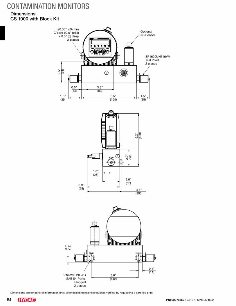
Dimensions CS 1000 with Block Kit
Dimensions are for general information only, all critical dimensions should be verified by requesting a certified print.
1.5”(39)
6.5”(165)
3.3”(83)
0.6”(14)
ø0.35” (ø9) thruC’bore ø0.6” (ø15)
x 0.3” (8) deep2 places
Optional AS Sensor
SP1620UN716VMTest Point2 places
1.5”(39)
2.5”
(64)
3.9”(98) 4.1”
(105)
2.0”(52)
1.0”(26)
2.0”
(52)
6.2”
(158
)
0.4”(11)
5.6”(142)
5/16-20 UNF-2BSAE S4 Ports
Plugged2 places
0.5”
(12)
B5
CONTAMINATION MONITORS
PN#02075860 / 04.15 / FSP1406-1622
Contamination Sensor CS
ISO SAE Flow Out Drive Temp
Esc o.k.
SP1
Status
SP2
Contamination Sensor CS
ISO SAE Flow Out Drive Temp
Esc o.k.
SP1
Status
SP2
Contamination Sensor CS
ISO SAE Flow Out Drive Temp
Esc o.k.
SP1
Status
SP2
180° 90°
Plug
O-Rings
Plug
4xM612/16
2.36”(60)
4xM612/16
0.79
”(2
0)A B
A BO-Ring
C D
INLET OUTLET
Connection Thread G 1/4”
3.94”(100)
2.36”(60)
1.57”(40)
3.94”(100)
0.59
”(1
5)0.
79”
(20)
0.59
”(1
5)
Flanged Version
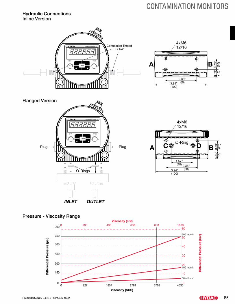
Pressure - Viscosity Range
Contamination Sensor CS
ISO SAE Flow Out Drive Temp
Esc o.k.
SP1
Status
SP2
Contamination Sensor CS
ISO SAE Flow Out Drive Temp
Esc o.k.
SP1
Status
SP2
Contamination Sensor CS
ISO SAE Flow Out Drive Temp
Esc o.k.
SP1
Status
SP2
180° 90°
Plug
O-Rings
Plug
4xM612/16
2.36”(60)
4xM612/16
0.79
”(2
0)A B
A BO-Ring
C D
INLET OUTLET
Connection Thread G 1/4”
3.94”(100)
2.36”(60)
1.57”(40)
3.94”(100)
0.59
”(1
5)0.
79”
(20)
0.59
”(1
5)
Diff
eren
tial P
ress
ure
(psi
)
Viscosity (SUS)
900
750
600
450
300
150
0
60
50
40
30
20
10
00 927 1854 2781 3708 4635
Viscosity (cSt)0 200 400 600 800 1000
Diff
eren
tial P
ress
ure
(bar
)300 ml/min
100 ml/min
30 ml/min
Diff
eren
tial P
ress
ure
(psi
)
Viscosity (SUS)
900
750
600
450
300
150
0
60
50
40
30
20
10
00 927 1854 2781 3708 4635
Viscosity (cSt)0 200 400 600 800 1000
Diff
eren
tial P
ress
ure
(bar
)~10 oz/min
~3 oz/min
~1 oz/min
Hydraulic Connections Inline Version
B6
LOW PRESSURE FILTERS
PN#02075860 / 04.15 / FSP1406-1622
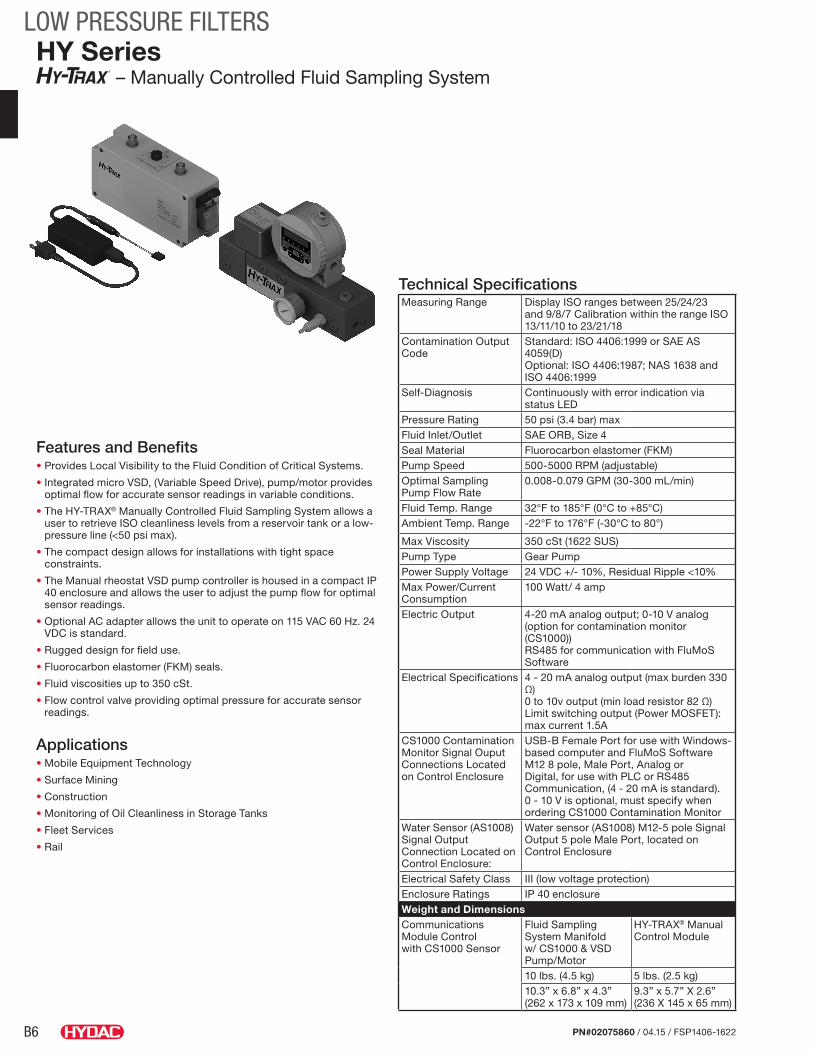
Features and Benefits• Provides Local Visibility to the Fluid Condition of Critical Systems.
• Integrated micro VSD, (Variable Speed Drive), pump/motor provides optimal flow for accurate sensor readings in variable conditions.
• The HY-TRAX® Manually Controlled Fluid Sampling System allows a user to retrieve ISO cleanliness levels from a reservoir tank or a low-pressure line (<50 psi max).
• The compact design allows for installations with tight space constraints.
• The Manual rheostat VSD pump controller is housed in a compact IP 40 enclosure and allows the user to adjust the pump flow for optimal sensor readings.
• Optional AC adapter allows the unit to operate on 115 VAC 60 Hz. 24 VDC is standard.
• Rugged design for field use.
• Fluorocarbon elastomer (FKM) seals.
• Fluid viscosities up to 350 cSt.
• Flow control valve providing optimal pressure for accurate sensor readings.
Applications• Mobile Equipment Technology
• Surface Mining
• Construction
• Monitoring of Oil Cleanliness in Storage Tanks
• Fleet Services
• Rail
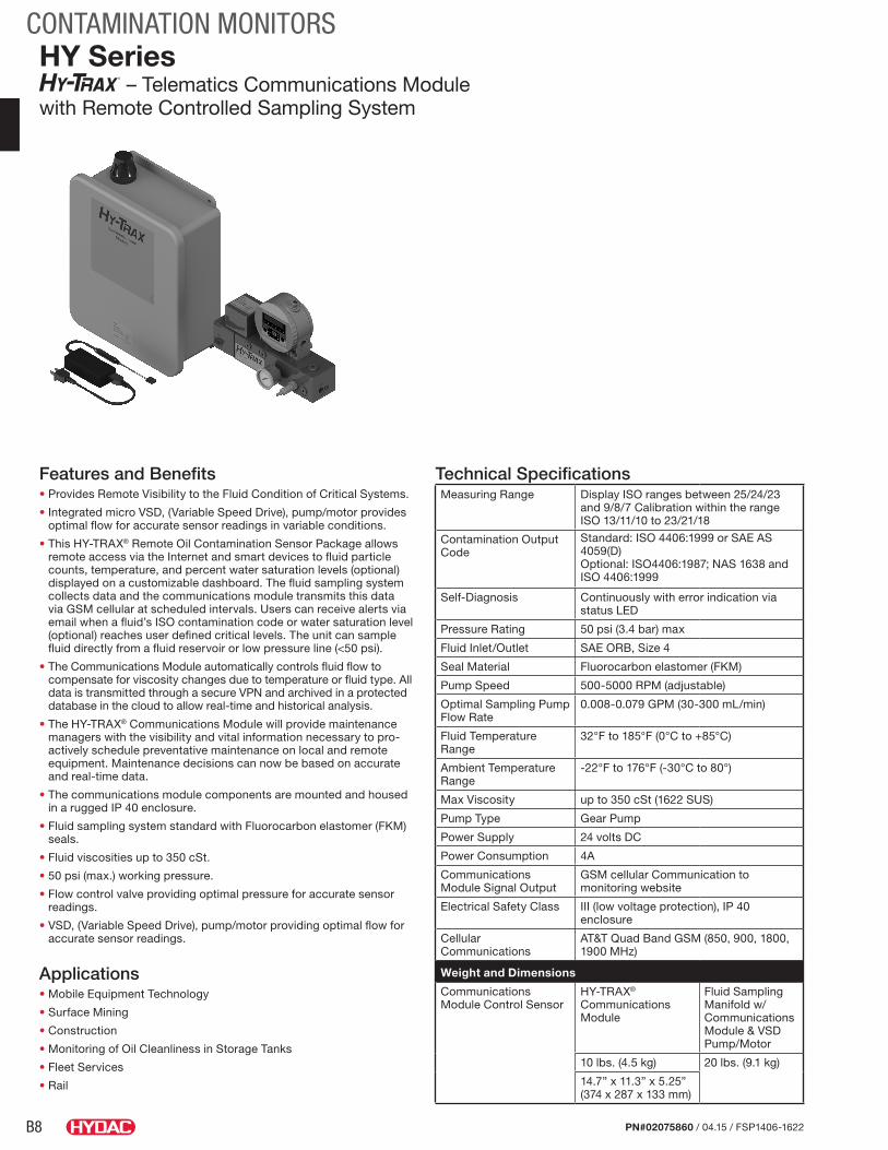
HY Series – Manually Controlled Fluid Sampling System
Technical SpecificationsMeasuring Range Display ISO ranges between 25/24/23
and 9/8/7 Calibration within the range ISO 13/11/10 to 23/21/18
Contamination Output Code
Standard: ISO 4406:1999 or SAE AS 4059(D) Optional: ISO 4406:1987; NAS 1638 and ISO 4406:1999
Self-Diagnosis Continuously with error indication via status LED
Pressure Rating 50 psi (3.4 bar) maxFluid Inlet/Outlet SAE ORB, Size 4Seal Material Fluorocarbon elastomer (FKM)Pump Speed 500-5000 RPM (adjustable)Optimal Sampling Pump Flow Rate
0.008-0.079 GPM (30-300 mL/min)
Fluid Temp. Range 32°F to 185°F (0°C to +85°C)Ambient Temp. Range -22°F to 176°F (-30°C to 80°)
Max Viscosity 350 cSt (1622 SUS)Pump Type Gear PumpPower Supply Voltage 24 VDC +/- 10%, Residual Ripple <10%Max Power/Current Consumption
100 Watt/ 4 amp
Electric Output 4-20 mA analog output; 0-10 V analog (option for contamination monitor (CS1000))RS485 for communication with FluMoS Software
Electrical Specifications 4 - 20 mA analog output (max burden 330 Ω)0 to 10v output (min load resistor 82 Ω)Limit switching output (Power MOSFET): max current 1.5A
CS1000 Contamination Monitor Signal Ouput Connections Located on Control Enclosure
USB-B Female Port for use with Windows-based computer and FluMoS SoftwareM12 8 pole, Male Port, Analog or Digital, for use with PLC or RS485 Communication, (4 - 20 mA is standard). 0 - 10 V is optional, must specify when ordering CS1000 Contamination Monitor
Water Sensor (AS1008) Signal Output Connection Located on Control Enclosure:
Water sensor (AS1008) M12-5 pole Signal Output 5 pole Male Port, located on Control Enclosure
Electrical Safety Class III (low voltage protection)Enclosure Ratings IP 40 enclosureWeight and DimensionsCommunications Module Control with CS1000 Sensor
Fluid Sampling System Manifold w/ CS1000 & VSD Pump/Motor
HY-TRAX® Manual Control Module
10 lbs. (4.5 kg) 5 lbs. (2.5 kg)10.3” x 6.8” x 4.3” (262 x 173 x 109 mm)
9.3” x 5.7” X 2.6” (236 X 145 x 65 mm)
B7
LOW PRESSURE FILTERS
PN#02075860 / 04.15 / FSP1406-1622
What’s Included• CS1000 Series Contamination Sensor
• Machined, 6061-T651 aluminum alloy manifold block with anodized surface treatment.
• Specially designed fitting for mating to pump/motor.
• Fluorocarbon elastomer (FKM) seals.
• Plugged water sensor port (G3/8)
• VSD (Variable Speed Drive) Motor Power Supply and Control Cable
• Water Sensor (AS3008) Power Supply and Signal Cable (only supplied with optional water sensor (AS3008))
• Contamination Monitor (CS1000) output signal, USB-B Female Port for use with Windows-Based Computer and FluMoS Software, located on Control Enclosure
• Contamination Monitor (CS1000), output signal, M12 8 pole, Male Port, located on Control Enclosure, for use with PLC or RS485 Communication, analog or digital, 4 - 20 mA is standard, 0 -10 V is optional
• Flow control valve
• VSD (Variable Speed Drive) pump/motor
• Manual rheostat pump controller
• IP 40 enclosure
• Side or Front Inlet/Outlet Porting (SAE Size 04 ORB)
• 24 VDC Power Supply (NC3MP Female Connector)
• Optional 115 VAC Power Supply with Cord
• Contamination Monitor (CS1000) Power and Signal Cable
• Water Sensor (AS3008) M12 5 pole Signal Output Connection, Male Port, located on Control Enclosure
• Contamination monitor (CS1000) power connection, female M12 8 pole located on control enclosure
• Water sensor (AS3008) power connection, M12 5 pole Female located on control enclosure
Model Code HY - 12 1 0 - - - P - Model HY = HY-TRAX System (includes 100 micron mesh strainer and pressure gauge in manifold block)
ISO Code Preference (omit) = Manifold supplied w/o CS1xx0 (customer will supply own manifold mount CS1xx0 with or without display) 12 = ISO Code >4/>6/>14 13 = ISO Code >2/>5/>15Display Options 1 = without display 2 = with display
Fluids 0 = Hydraulic/Mineral Oil
Analog Interfaces (omit) = 4 - 20 mA (Standard) S = 2 - 10V Analog Output
Water Sensor Option (omit) = No Water Sensor (None Standard) AS-D = with AS3008 Water Sensor
Control Options (omit) = Manually Controlled - Panel with Rheostat flow control and signal output (Standard)
Power Options (omit) = 24V DC (Standard) P = 115V AC
Air Suppression Loop (omit) = none L = Looped hose and fittings
B8
CONTAMINATION MONITORS
PN#02075860 / 04.15 / FSP1406-1622
Features and Benefits• Provides Remote Visibility to the Fluid Condition of Critical Systems.
• Integrated micro VSD, (Variable Speed Drive), pump/motor provides optimal flow for accurate sensor readings in variable conditions.
• This HY-TRAX® Remote Oil Contamination Sensor Package allows remote access via the Internet and smart devices to fluid particle counts, temperature, and percent water saturation levels (optional) displayed on a customizable dashboard. The fluid sampling system collects data and the communications module transmits this data via GSM cellular at scheduled intervals. Users can receive alerts via email when a fluid’s ISO contamination code or water saturation level (optional) reaches user defined critical levels. The unit can sample fluid directly from a fluid reservoir or low pressure line (<50 psi).
• The Communications Module automatically controls fluid flow to compensate for viscosity changes due to temperature or fluid type. All data is transmitted through a secure VPN and archived in a protected database in the cloud to allow real-time and historical analysis.
• The HY-TRAX® Communications Module will provide maintenance managers with the visibility and vital information necessary to pro-actively schedule preventative maintenance on local and remote equipment. Maintenance decisions can now be based on accurate and real-time data.
• The communications module components are mounted and housed in a rugged IP 40 enclosure.
• Fluid sampling system standard with Fluorocarbon elastomer (FKM) seals.
• Fluid viscosities up to 350 cSt.
• 50 psi (max.) working pressure.
• Flow control valve providing optimal pressure for accurate sensor readings.
• VSD, (Variable Speed Drive), pump/motor providing optimal flow for accurate sensor readings.
Applications• Mobile Equipment Technology
• Surface Mining
• Construction
• Monitoring of Oil Cleanliness in Storage Tanks
• Fleet Services
• Rail
HY Series – Telematics Communications Module
with Remote Controlled Sampling System
Technical SpecificationsMeasuring Range Display ISO ranges between 25/24/23
and 9/8/7 Calibration within the range ISO 13/11/10 to 23/21/18
Contamination Output Code
Standard: ISO 4406:1999 or SAE AS 4059(D) Optional: ISO4406:1987; NAS 1638 and ISO 4406:1999
Self-Diagnosis Continuously with error indication via status LED
Pressure Rating 50 psi (3.4 bar) max
Fluid Inlet/Outlet SAE ORB, Size 4
Seal Material Fluorocarbon elastomer (FKM)
Pump Speed 500-5000 RPM (adjustable)
Optimal Sampling Pump Flow Rate
0.008-0.079 GPM (30-300 mL/min)
Fluid Temperature Range
32°F to 185°F (0°C to +85°C)
Ambient Temperature Range
-22°F to 176°F (-30°C to 80°)
Max Viscosity up to 350 cSt (1622 SUS)
Pump Type Gear Pump
Power Supply 24 volts DC
Power Consumption 4A
Communications Module Signal Output
GSM cellular Communication to monitoring website
Electrical Safety Class III (low voltage protection), IP 40 enclosure
Cellular Communications
AT&T Quad Band GSM (850, 900, 1800, 1900 MHz)
Weight and Dimensions
Communications Module Control Sensor
HY-TRAX® Communications Module
Fluid Sampling Manifold w/ Communications Module & VSD Pump/Motor
10 lbs. (4.5 kg) 20 lbs. (9.1 kg)
14.7” x 11.3” x 5.25” (374 x 287 x 133 mm)
B9
CONTAMINATION MONITORS
PN#02075860 / 04.15 / FSP1406-1622
What’s Included• CS1000 Series Contamination Sensor
• Flow Control Valve
• GSM cellular communications
• VSD pump/motor
• Machined, 6061-T651 aluminum alloy manifold block with anodized surface treatment
• CS1000 Series Contamination Sensor (CS1000) Communications/Power Cable
• Specially designed fitting for mating to pump/motor
• Plugged water sensor port (G3/8)
• IP 40 enclosure
• Water sensor (optional)
• 24 volts DC standard with optional 115 VAC Power Supply
• Optional Water Sensor (AS3008) Communication/Power Cable
• Side or Front Inlet/Outlet Porting (SAE Size 04 ORB)
Model Code HY - 12 1 0 - - A - - Model HY = HY-TRAX System (includes 100 micron mesh strainer and pressure gauge in manifold block)
ISO Code Preference (omit) = Manifold supplied w/o CS1xx0 (customer will supply own manifold mount CS1xx0 with or without display) 12 = ISO Code >4/>6/>14 13 = ISO Code >2/>5/>15Display Options 1 = without display 2 = with display
Fluids 0 = Hydraulic/Mineral Oil
Analog Interfaces (omit) = 4- 20 mA (Standard)
Water Sensor Option (omit) = No Water Sensor (None Standard) AS-D = with AS3008 Water Sensor
Control Options A = Telematic Communications Module with Dashboard Data Display (GSM Cellular)
Power Options (omit) = 24V DC (Standard) P = 115V AC
Air Suppression Loop (omit) = none L = Looped hose and fittings
B10
CONTAMINATION MONITORS
PN#02075860 / 04.15 / FSP1406-1622
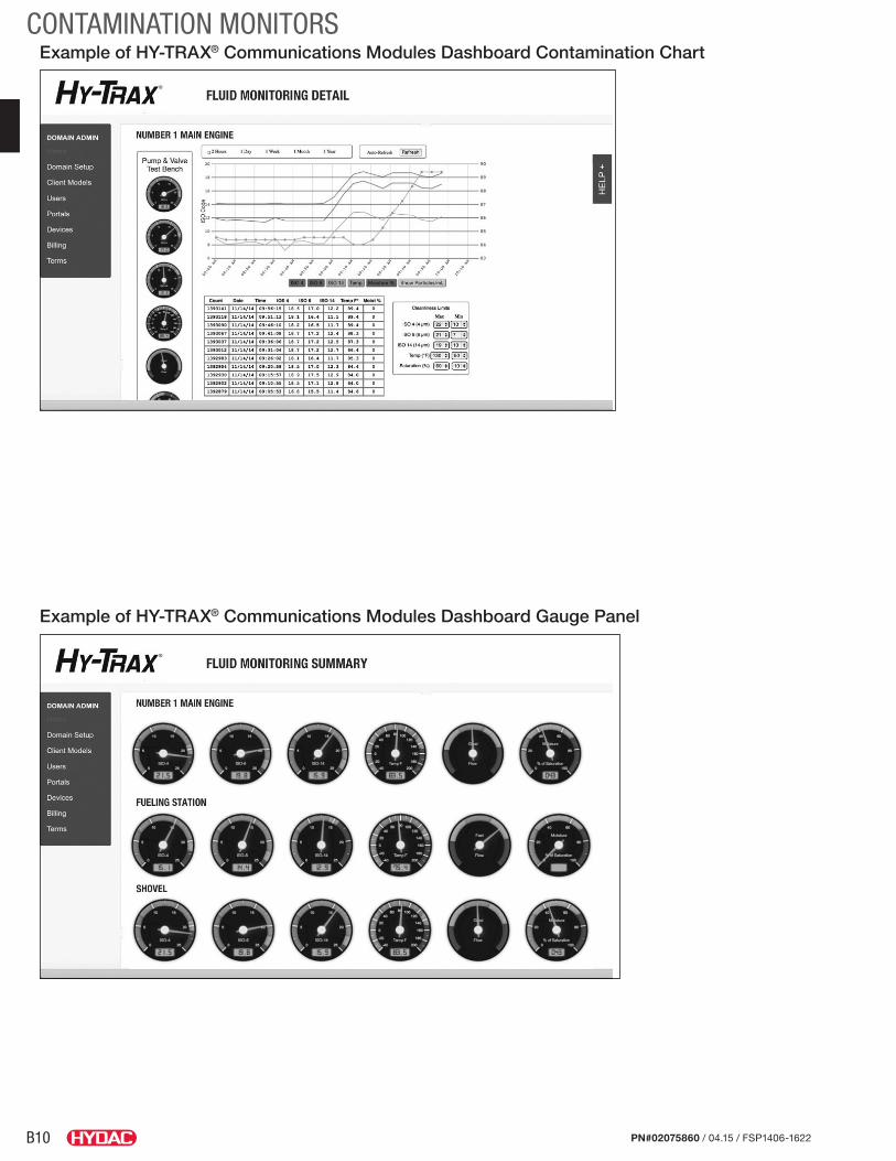
Example of HY-TRAX® Communications Modules Dashboard Contamination Chart
Example of HY-TRAX® Communications Modules Dashboard Gauge Panel
B11
CONTAMINATION MONITORS
PN#02075860 / 04.15 / FSP1406-1622
Notes
B12
CONTAMINATION MONITORS
PN#02075860 / 04.15 / FSP1406-1622
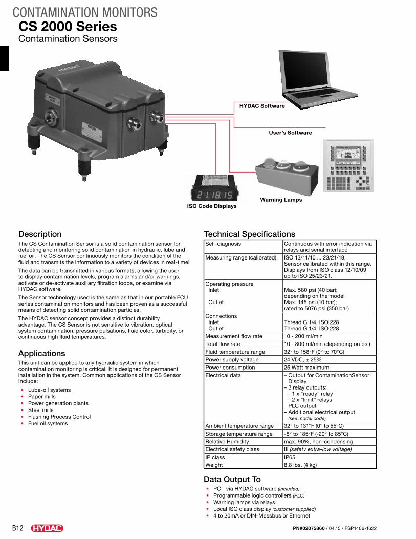
DescriptionThe CS Contamination Sensor is a solid contamination sensor for detecting and monitoring solid contamination in hydraulic, lube and fuel oil. The CS Sensor continuously monitors the condition of the fluid and transmits the information to a variety of devices in real-time!
The data can be transmitted in various formats, allowing the user to display contamination levels, program alarms and/or warnings, activate or de-activate auxiliary filtration loops, or examine via HYDAC software.
The Sensor technology used is the same as that in our portable FCU series contamination monitors and has been proven as a successful means of detecting solid contamination particles.
The HYDAC sensor concept provides a distinct durability advantage. The CS Sensor is not sensitive to vibration, optical system contamination, pressure pulsations, fluid color, turbidity, or continuous high fluid temperatures.
ApplicationsThis unit can be applied to any hydraulic system in which contamination monitoring is critical. It is designed for permanent installation in the system. Common applications of the CS Sensor Include:
• Lube-oil systems• Paper mills• Power generation plants• Steel mills• Flushing Process Control• Fuel oil systems
Technical SpecificationsSelf-diagnosis Continuous with error indication via
relays and serial interfaceMeasuring range (calibrated) ISO 13/11/10 ... 23/21/18.
Sensor calibrated within this range.Displays from ISO class 12/10/09up to ISO 25/23/21.
Operating pressure Inlet Outlet
Max. 580 psi (40 bar); depending on the modelMax. 145 psi (10 bar); rated to 5076 psi (350 bar)
Connections Inlet Outlet
Thread G 1/4, ISO 228 Thread G 1/4, ISO 228
Measurement flow rate 10 - 200 ml/minTotal flow rate 10 - 800 ml/min (depending on psi)Fluid temperature range 32° to 158°F (0° to 70°C)Power supply voltage 24 VDC, ± 25%Power consumption 25 Watt maximumElectrical data – Output for ContaminationSensor
Display– 3 relay outputs:
- 1 x “ready” relay - 2 x “limit” relays
– PLC output– Additional electrical output
(see model code)
Ambient temperature range 32° to 131°F (0° to 55°C)Storage temperature range -8° to 185°F (-20° to 85°C)Relative Humidity max. 90%, non-condensingElectrical safety class III (safety extra-low voltage)IP class IP65Weight 8.8 lbs. (4 kg)
Data Output To• PC - via HYDAC software (included)• Programmable logic controllers (PLC)• Warning lamps via relays• Local ISO class display (customer supplied)• 4 to 20mA or DIN-Messbus or Ethernet
CS 2000 SeriesContamination Sensors
HYDAC Software
User’s Software
Warning LampsISO Code Displays
B13
CONTAMINATION MONITORS
PN#02075860 / 04.15 / FSP1406-1622
4.13”(105)
0.98”(25)
0.59”(15)
6.81”(173)
1.38”(35)
0.87”(22)
Power Signal
M6
1.5”(38)
1/4” BSPPINLET
1/4” BSPPOUTLET
7.64”(194)
8.23”(209)
5.28”(134)
2.56”(65)
Model CodeCS 21 3 0 - 1 - U / - 1 - 2
Series CS = Contamination Sensor
Model 21 = 3 digit ISO 4406 Code (>2/>5/>15) 22 = 3 digit ISO 4406 Code (>4/>6/>14)
Enclosure 3 = Stationary
Fluids 0 = Standard mineral fluids and mineral based synthetics 1 = Phosphate esters (e.g. Skydrol, Hyjet)
Modification Number 1 = Standard
Supply Voltage U = 24 VDC
Pressure Range 1, 2, 3, 4 - See Pressure / Viscosity Range chart
Output 0 = RS232 (DIN-66348 protocol) (enables easy communication with Hydac FluMoS Software) 1 = 4 - 20 mA 2 = RS485 (DIN-66348 protocol) 5 = Ethernet* For pressures above 560 psi - Reduce the pressure to between 280 and 560 psi. Please contact HYDAC for details.
Model Codes containing RED are non-standard items – Minimum quantities and longer lead times may apply - Contact HYDAC for information and availability
Dimensions
Pressure / Viscosity Range
Dimensions are for general information only, all critical dimensions should be verified by requesting a certified print.
Viscosity (SUS)
Pre
ssur
e p
si)
00
72
145
217
290
362
435
507
580
232 463 695 927 1158 1390 1622 1854 2085 2317 3244 4171 5098 6025 6952 7879 8806 9270
B14
CONTAMINATION MONITORS
PN#02075860 / 04.15 / FSP1406-1622
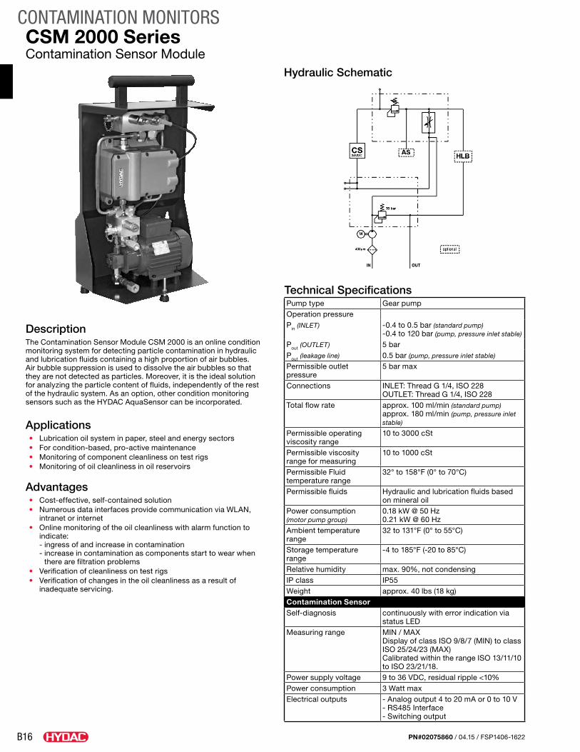
Technical SpecificationsPump type Gear pumpOperation pressurePin (INLET) -0.4 to 0.5 bar (standard pump)
-0.4 to 120 bar (pump, pressure inlet stable)
Pout (OUTLET) 5 barPout (leakage line) 0.5 bar (pump, pressure inlet stable)
Permissible outlet pressure
5 bar max
Connections INLET: Thread G 1/4, ISO 228 OUTLET: Thread G 1/4, ISO 228
Total flow rate approx. 100 ml/min (standard pump) approx. 180 ml/min (pump, pressure inlet stable)
Permissible operating viscosity range
10 to 3000 cSt
Permissible viscosity range for measuring
10 to 1000 cSt
Permissible Fluid temperature range
32° to 158°F (0° to 70°C)
Permissible fluids Hydraulic and lubrication fluids based on mineral oil
Power consumption (motor pump group)
0.18 kW @ 50 Hz 0.21 kW @ 60 Hz
Ambient temperature range
32 to 131°F (0° to 55°C)
Storage temperature range
-4 to 185°F(-20 to 85°C)
Relative humidity max. 90%, not condensingIP class IP55Weight approx. 40 lbs (18 kg)Contamination SensorSelf-diagnosis continuously with error indication via
status LEDMeasuring range MIN / MAX
Display of class ISO 9/8/7 (MIN) to classISO 25/24/23 (MAX)Calibrated within the range ISO 13/11/10 to ISO 23/21/18.
Power supply voltage 9 to 36 VDC, residual ripple <10%Power consumption 3 Watt maxElectrical outputs - Analog output 4 to 20 mA or 0 to 10 V
- RS485 Interface - Switching output
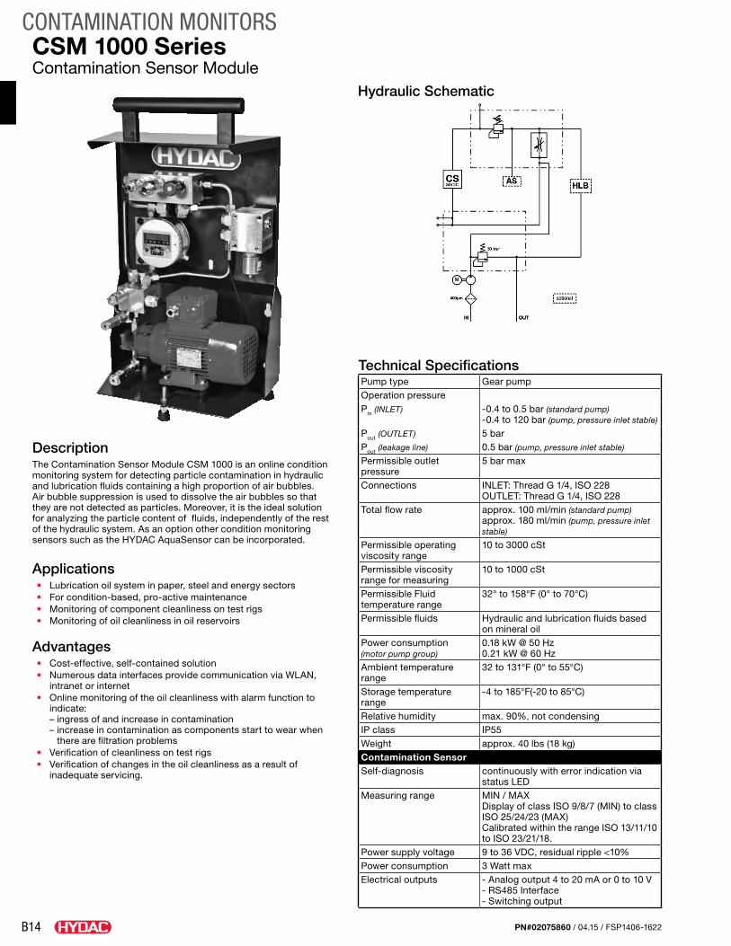
CSM 1000 SeriesContamination Sensor Module
DescriptionThe Contamination Sensor Module CSM 1000 is an online condition monitoring system for detecting particle contamination in hydraulic and lubrication fluids containing a high proportion of air bubbles. Air bubble suppression is used to dissolve the air bubbles so that they are not detected as particles. Moreover, it is the ideal solution for analyzing the particle content of fluids, independently of the rest of the hydraulic system. As an option other condition monitoring sensors such as the HYDAC AquaSensor can be incorporated.
Applications• Lubrication oil system in paper, steel and energy sectors• For condition-based, pro-active maintenance• Monitoring of component cleanliness on test rigs• Monitoring of oil cleanliness in oil reservoirs
Advantages• Cost-effective, self-contained solution• Numerous data interfaces provide communication via WLAN,
intranet or internet• Online monitoring of the oil cleanliness with alarm function to
indicate: – ingress of and increase in contamination – increase in contamination as components start to wear when
there are filtration problems• Verification of cleanliness on test rigs• Verification of changes in the oil cleanliness as a result of
inadequate servicing.
Hydraulic Schematic
B15
CONTAMINATION MONITORS
PN#02075860 / 04.15 / FSP1406-1622
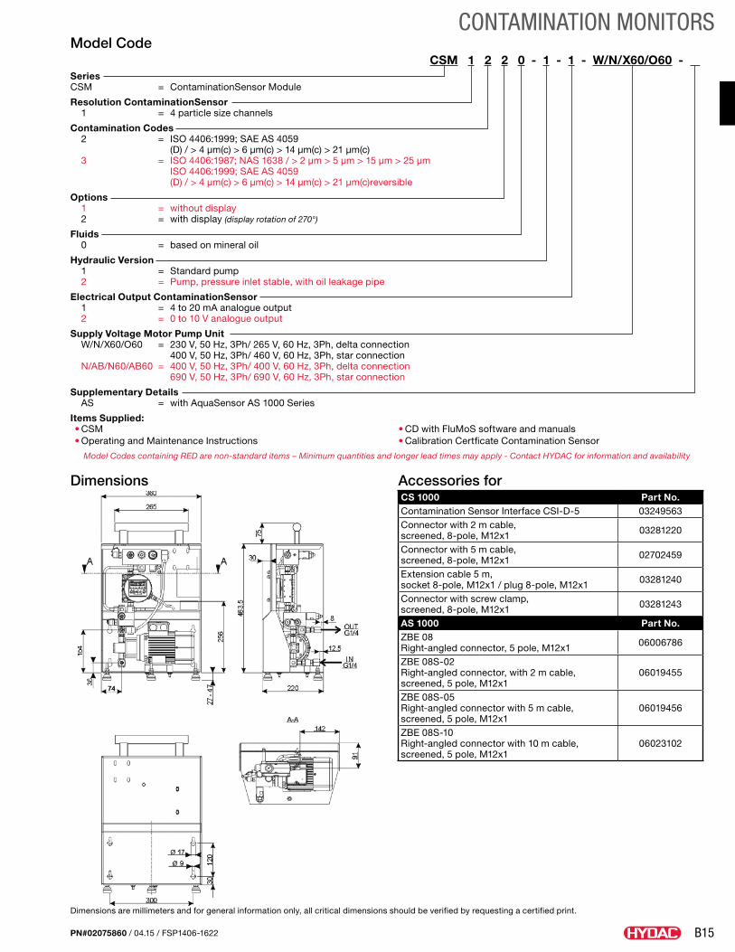
Model CodeCSM 1 2 2 0 - 1 - 1 - W/N/X60/O60 - .
Series CSM = ContaminationSensor Module
Resolution ContaminationSensor 1 = 4 particle size channels
Contamination Codes 2 = ISO 4406:1999; SAE AS 4059
(D) / > 4 μm(c) > 6 μm(c) > 14 μm(c) > 21 μm(c) 3 = ISO 4406:1987; NAS 1638 / > 2 μm > 5 μm > 15 μm > 25 μm
ISO 4406:1999; SAE AS 4059 (D) / > 4 μm(c) > 6 μm(c) > 14 μm(c) > 21 μm(c)reversible
Options 1 = without display 2 = with display (display rotation of 270°)
Fluids 0 = based on mineral oil
Hydraulic Version 1 = Standard pump 2 = Pump, pressure inlet stable, with oil leakage pipe
Electrical Output ContaminationSensor 1 = 4 to 20 mA analogue output 2 = 0 to 10 V analogue output
Supply Voltage Motor Pump Unit W/N/X60/O60 = 230 V, 50 Hz, 3Ph/ 265 V, 60 Hz, 3Ph, delta connection 400 V, 50 Hz, 3Ph/ 460 V, 60 Hz, 3Ph, star connection N/AB/N60/AB60 = 400 V, 50 Hz, 3Ph/ 400 V, 60 Hz, 3Ph, delta connection 690 V, 50 Hz, 3Ph/ 690 V, 60 Hz, 3Ph, star connection
Supplementary Details AS = with AquaSensor AS 1000 Series
Items Supplied:• CSM• Operating and Maintenance Instructions
• CD with FluMoS software and manuals• Calibration Certficate Contamination Sensor
Dimensions
Dimensions are millimeters and for general information only, all critical dimensions should be verified by requesting a certified print.
Accessories forCS 1000 Part No. Contamination Sensor Interface CSI-D-5 03249563Connector with 2 m cable, screened, 8-pole, M12x1 03281220
Connector with 5 m cable, screened, 8-pole, M12x1 02702459
Extension cable 5 m, socket 8-pole, M12x1 / plug 8-pole, M12x1 03281240
Connector with screw clamp, screened, 8-pole, M12x1 03281243
AS 1000 Part No.ZBE 08 Right-angled connector, 5 pole, M12x1 06006786
ZBE 08S-02 Right-angled connector, with 2 m cable, screened, 5 pole, M12x1
06019455
ZBE 08S-05 Right-angled connector with 5 m cable, screened, 5 pole, M12x1
06019456
ZBE 08S-10 Right-angled connector with 10 m cable, screened, 5 pole, M12x1
06023102
Model Codes containing RED are non-standard items – Minimum quantities and longer lead times may apply - Contact HYDAC for information and availability
B16
CONTAMINATION MONITORS
PN#02075860 / 04.15 / FSP1406-1622
Technical SpecificationsPump type Gear pumpOperation pressurePin (INLET) -0.4 to 0.5 bar (standard pump)
-0.4 to 120 bar (pump, pressure inlet stable)
Pout (OUTLET) 5 barPout (leakage line) 0.5 bar (pump, pressure inlet stable)
Permissible outlet pressure
5 bar max
Connections INLET: Thread G 1/4, ISO 228 OUTLET: Thread G 1/4, ISO 228
Total flow rate approx. 100 ml/min (standard pump) approx. 180 ml/min (pump, pressure inlet stable)
Permissible operating viscosity range
10 to 3000 cSt
Permissible viscosity range for measuring
10 to 1000 cSt
Permissible Fluid temperature range
32° to 158°F (0° to 70°C)
Permissible fluids Hydraulic and lubrication fluids based on mineral oil
Power consumption (motor pump group)
0.18 kW @ 50 Hz 0.21 kW @ 60 Hz
Ambient temperature range
32 to 131°F (0° to 55°C)
Storage temperature range
-4 to 185°F (-20 to 85°C)
Relative humidity max. 90%, not condensingIP class IP55Weight approx. 40 lbs (18 kg)Contamination SensorSelf-diagnosis continuously with error indication via
status LEDMeasuring range MIN / MAX
Display of class ISO 9/8/7 (MIN) to class ISO 25/24/23 (MAX) Calibrated within the range ISO 13/11/10 to ISO 23/21/18.
Power supply voltage 9 to 36 VDC, residual ripple <10%Power consumption 3 Watt maxElectrical outputs - Analog output 4 to 20 mA or 0 to 10 V
- RS485 Interface - Switching output
CSM 2000 SeriesContamination Sensor Module
DescriptionThe Contamination Sensor Module CSM 2000 is an online condition monitoring system for detecting particle contamination in hydraulic and lubrication fluids containing a high proportion of air bubbles. Air bubble suppression is used to dissolve the air bubbles so that they are not detected as particles. Moreover, it is the ideal solution for analyzing the particle content of fluids, independently of the rest of the hydraulic system. As an option, other condition monitoring sensors such as the HYDAC AquaSensor can be incorporated.
Applications• Lubrication oil system in paper, steel and energy sectors• For condition-based, pro-active maintenance• Monitoring of component cleanliness on test rigs• Monitoring of oil cleanliness in oil reservoirs
Advantages• Cost-effective, self-contained solution• Numerous data interfaces provide communication via WLAN,
intranet or internet• Online monitoring of the oil cleanliness with alarm function to
indicate: - ingress of and increase in contamination - increase in contamination as components start to wear when
there are filtration problems• Verification of cleanliness on test rigs• Verification of changes in the oil cleanliness as a result of
inadequate servicing.
Hydraulic Schematic
B17
CONTAMINATION MONITORS
PN#02075860 / 04.15 / FSP1406-1622
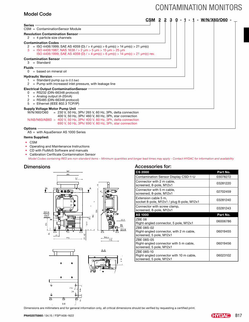
Model CodeCSM 2 2 3 0 - 1 - 1 - W/N/X60/O60 - .
Series CSM = ContaminationSensor Module
Resolution Contamination Sensor 2 = 4 particle size channels
Contamination Codes 2 = ISO 4406:1999; SAE AS 4059 (D) / > 4 μm(c) > 6 μm(c) > 14 μm(c) > 21 μm(c) 3 = ISO 4406:1987; NAS 1638 / > 2 μm > 5 μm > 15 μm > 25 μm
ISO 4406:1999; SAE AS 4059 (D) / > 4 μm(c) > 6 μm(c) > 14 μm(c) > 21 μm(c) rev.
Contamination Sensor 3 = Standard
Fluids 0 = based on mineral oil
Hydraulic Version 1 = Standard pump (up to 0.5 bar) 2 = Pump with increased inlet pressure, with leakage line
Electrical Output ContaminationSensor 0 = RS232 (DIN-66348 protocol) 1 = Analog output (4-20mA) 2 = RS485 (DIN-66348 protocol) 5 = Ethernet (IEEE 802.3 TCP/IP)
Supply Voltage Motor Pump Unit W/N/X60/O60 = 230 V, 50 Hz, 3Ph/ 265 V, 60 Hz, 3Ph, delta connection
400 V, 50 Hz, 3Ph/ 460 V, 60 Hz, 3Ph, star connection N/AB/N60/AB60 = 400 V, 50 Hz, 3Ph/ 400 V, 60 Hz, 3Ph, delta connection
690 V, 50 Hz, 3Ph/ 690 V, 60 Hz, 3Ph, star connection
Options AS = with AquaSensor AS 1000 Series
Items Supplied:
• CSM• Operating and Maintenance Instructions• CD with FluMoS Software and manuals• Calibration Certficate Contamination Sensor
Model Codes containing RED are non-standard items – Minimum quantities and longer lead times may apply - Contact HYDAC for information and availability
Dimensions
A-A
AA
G1/4OUT
G1/4
IN
Dimensions are millimeters and for general information only, all critical dimensions should be verified by requesting a certified print.
Accessories for:CS 2000 Part No. Contamination Sensor Display CSD-1-U 03078272Connector with 2 m cable, screened, 8-pole, M12x1 03281220
Connector with 5 m cable, screened, 8-pole, M12x1 02702459
Extension cable 5 m, socket 8-pole, M12x1 / plug 8-pole, M12x1 03281240
Connector with screw clamp, screened, 8-pole, M12x1 03281243
AS 1000 Part No.ZBE 08 Right-angled connector, 5 pole, M12x1 06006786
ZBE 08S-02 Right-angled connector, with 2 m cable, screened, 5 pole, M12x1
06019455
ZBE 08S-05 Right-angled connector with 5 m cable, screened, 5 pole, M12x1
06019456
ZBE 08S-10 Right-angled connector with 10 m cable, screened, 5 pole, M12x1
06023102
B18
CONTAMINATION MONITORS
PN#02075860 / 04.15 / FSP1406-1622
Technical SpecificationsGeneral SpecificationsMeasured variables Contamination ISO 4406, SAE AS
4059, NAS 1638Water content Level of saturation Temperature °F (°C)
Measurement ranges Contamination ISO 9/8/7 - ISO 25/24/23
Water content 0 to 100 %Temperature -25 to 100 °C
Calibration accuracy Contamination ± ½ ISO-Code in calibrated range of ISO 13/11/10 - ISO 23/21/18
Water content ± max. 2% (Full scale)Temperature ± max. 2% (Full scale)
Display/remote control/data storage
SMU 1200 Series Sensor Monitoring Unit sold separately.
Ambient temp. range 32 to 131°F (0 to 55 °C)Storage temp. range -4 to 185°F (-20 to 85 °C)Relative humidity Max. 90%, non-condensingWeight when empty ≈ 25 kgProtection class IP 54Hydraulic SpecificationsOperating mode Pressurized operation
up to 80 bar primary pressureNominal operating mode Continuous operation S1 (24/7)Operating pressure PIN (INLET) -0.4 - 80 bar
POUT (OUTLET) 80 bar POUT (LECKAGE) 0.5 bar
Total flow rate ≈ 180 ml/minPermitted operating viscosity range 10 - 3000 cSt
Permitted measurement viscosity range 10 - 1000 cSt
Permitted temperature range of fluid
32 to 185°F (0 to 85 °C)
Seal material FPMPorts INLET
OUTLET LEAKAGE
G1/4 as per ISO 228 G1/4 as per ISO 228 G1/4 as per ISO 228
Suction strainer 400 µm, metal mesh filterSuction height max. 0.5 mElectrical SpecificationsConnection voltages 380 V, 50 Hz, 3 Ph (-10%/+10%)
400 V, 50 Hz, 3 Ph (-15%/+10%) 415 V, 50 Hz, 3 Ph (-10%/+6%)* 440 V, 60 Hz, 3 Ph (-10%/+10%) 460 V, 60 Hz, 3 Ph (-15%/+10%) *As per DIN EN 60204 connection voltage must be ±10% of nominal voltage.
Connection, male Supply-side Device-side
3 Ph + PE, CEE as per IEC309 Harting Han4A
Power supply Connection cable 10 m with main switch, device protection and phase sequence check
Power consumption < 200 Watt
CSM-C SeriesContamination Sensor Module Comfort Series
DescriptionThe CSM Comfort Contamination Sensor Module is the plug-and-work solution for permanently monitoring fluid status by measuring solid particle contamination and water saturation.
Designed for 24/7 operation, the CSM-C can be used for all hydraulic and lubrication applications. With its own integrated power supply and multi-voltage input, the CSM-C can be used in any hydraulic conditions.
The CSM-C must be placed directly on the measuring site; it can be easily connected to the customer controller (PLC) through its integrated analog output.
The SMU 1200 Sensor Monitoring Unit is designed to be used as a remote control and display accessory with reliable data storage that integrates perfectly into the housing on the CSM-C; it can also be conveniently positioned in the customer’s field of view using a 10-meter connecting cable.
Applications• Hydraulic and lubricating fluids• Continuous 24/7 operation
Advantages• Accessory to FCU 1000• Continuous measurement in lubricating fluids• Housing for use near the measuring site• Convenient display using SMU 1200
B19
CONTAMINATION MONITORS
PN#02075860 / 04.15 / FSP1406-1622
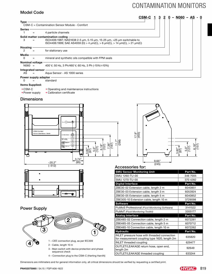
Model CodeCSM-C 1 3 2 0 – N060 – AS - 0.
Type CSM-C = Contamination Sensor Module - Comfort
Series 1 = 4 particle channels
Solid matter contamination coding 3 = ISO4406:1987; NAS1638 2-5 µm, 5-15 µm, 15-25 µm, >25 µm switchable to ISO4406:1999; SAE AS4059 (D) > 4 µm(C), > 6 µm(C), > 14 µm(C), > 21 µm(C)
Housing 2 = for stationary use
Media 0 = mineral and synthetic oils compatible with FPM seals
Nominal voltage N060 = 400 V, 50 Hz, 3 Ph/460 V, 60 Hz, 3 Ph (-15%/+10%)
Integrated sensor AS = Aqua Sensor - AS 1000 series
Power supply adapter 0 = standard
Items Supplied:
• CSM-C • Operating and maintenance instructions• Power supply • Calibration certificate
Dimensions
Power Supply
~20.2”(~512)
3.82
”(9
7) 5.0”
(127
)
6.18
”(1
57)
7.36
”(1
87)
3.74”(95)
11.7
”(2
98)
17.9
”(4
55)
9.65”(245)
3.82
”(9
7) 5.0”
(127
)
6.18
”(1
57)
Dimensions are millimeters and for general information only, all critical dimensions should be verified by requesting a certified print.
Accessories for:SMU Sensor Monitoring Unit Part No. SMU 1260-TU-00 346 7005SMU 1270-TU-00 370 4282Digital Interface Part No.ZBE30-02 Extension cable, length 2 m 6040851ZBE30-03 Extension cable, length 3 m 6053924ZBE30-05 Extension cable, length 5 m 6040852ZBE30S-10 Extension cable, length 10 m 3729098Software Part No.FluMoS Professional (Fluid Monitoring Software) 3141522FluMoT (Fluid Monitoring Toolkit) 3355177Analog Interface Part No.ZBE48S-02 Connection cable, length 2 m 6072261ZBE48S-05 Connection cable, length 5 m 6070712ZBE48S-10 Connection cable, length 10 m 6072262Hydraulic Part No.INLET pressure hose with threaded connection for measurement coupling type 1620, length 2m 635820
INLET threaded coupling 629477OUTLET/LEAKAGE return hose, open end, length 2m 92649
OUTLET/LEAKAGE threaded coupling 633244
4
3
2
11 – CEE connection plug, as per IEC309
2 - Cable, length 10 m
3 - Main switch with device protection and phase sequence check
4 – Connection plug to the CSM-C (Harting Han4A)
B20
CONTAMINATION MONITORS
PN#02075860 / 04.15 / FSP1406-1622
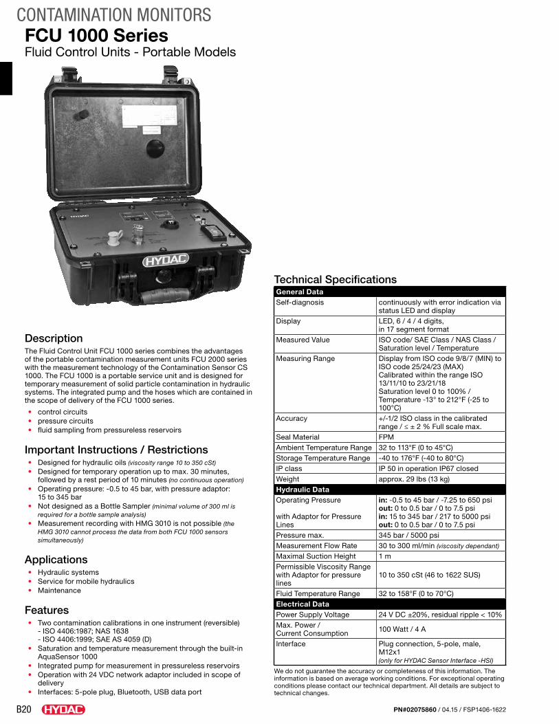
DescriptionThe Fluid Control Unit FCU 1000 series combines the advantages of the portable contamination measurement units FCU 2000 series with the measurement technology of the Contamination Sensor CS 1000. The FCU 1000 is a portable service unit and is designed for temporary measurement of solid particle contamination in hydraulic systems. The integrated pump and the hoses which are contained in the scope of delivery of the FCU 1000 series.
• control circuits• pressure circuits• fluid sampling from pressureless reservoirs
Important Instructions / Restrictions• Designed for hydraulic oils (viscosity range 10 to 350 cSt)• Designed for temporary operation up to max. 30 minutes,
followed by a rest period of 10 minutes (no continuous operation)• Operating pressure: -0.5 to 45 bar, with pressure adaptor:
15 to 345 bar• Not designed as a Bottle Sampler (minimal volume of 300 ml is
required for a bottle sample analysis)• Measurement recording with HMG 3010 is not possible (the
HMG 3010 cannot process the data from both FCU 1000 sensors simultaneously)
Applications• Hydraulic systems• Service for mobile hydraulics• Maintenance
Features• Two contamination calibrations in one instrument (reversible)
- ISO 4406:1987; NAS 1638 - ISO 4406:1999; SAE AS 4059 (D)
• Saturation and temperature measurement through the built-in AquaSensor 1000
• Integrated pump for measurement in pressureless reservoirs• Operation with 24 VDC network adaptor included in scope of
delivery• Interfaces: 5-pole plug, Bluetooth, USB data port
Technical SpecificationsGeneral DataSelf-diagnosis continuously with error indication via
status LED and displayDisplay LED, 6 / 4 / 4 digits,
in 17 segment formatMeasured Value ISO code/ SAE Class / NAS Class /
Saturation level / TemperatureMeasuring Range Display from ISO code 9/8/7 (MIN) to
ISO code 25/24/23 (MAX) Calibrated within the range ISO 13/11/10 to 23/21/18Saturation level 0 to 100% / Temperature -13° to 212°F (-25 to 100°C)
Accuracy +/-1/2 ISO class in the calibrated range / ≤ ± 2 % Full scale max.
Seal Material FPMAmbient Temperature Range 32 to 113°F (0 to 45°C)Storage Temperature Range -40 to 176°F (-40 to 80°C)IP class IP 50 in operation IP67 closedWeight approx. 29 lbs (13 kg)Hydraulic Data Operating Pressure
with Adaptor for Pressure Lines
in: -0.5 to 45 bar / -7.25 to 650 psi out: 0 to 0.5 bar / 0 to 7.5 psiin: 15 to 345 bar / 217 to 5000 psi out: 0 to 0.5 bar / 0 to 7.5 psi
Pressure max. 345 bar / 5000 psiMeasurement Flow Rate 30 to 300 ml/min (viscosity dependant)
Maximal Suction Height 1 mPermissible Viscosity Rangewith Adaptor for pressure lines
10 to 350 cSt (46 to 1622 SUS)
Fluid Temperature Range 32 to 158°F (0 to 70°C)Electrical DataPower Supply Voltage 24 V DC ±20%, residual ripple < 10%Max. Power / Current Consumption 100 Watt / 4 A
Interface Plug connection, 5-pole, male, M12x1(only for HYDAC Sensor Interface -HSI)
We do not guarantee the accuracy or completeness of this information. The information is based on average working conditions. For exceptional operating conditions please contact our technical department. All details are subject to technical changes.
FCU 1000 SeriesFluid Control Units - Portable Models
B21
CONTAMINATION MONITORS
PN#02075860 / 04.15 / FSP1406-1622
Model CodeFCU 1 3 1 0 - 4 - U - AS - 1
Series FCU = Fluid Control Unit
Model 1 = 1000 Series, 4 particle size channels
Contamination Code 2 = ISO 4406 : 1999, SAE AS 4059 (D) > 4 μm(c), >6 μm(c) and >14 μm(c) 3 = ISO 4406:1987; NAS 1638 / 2-5 μm, 5-15 μm, 15-25 μm, > 25 μm
reversible between
ISO 4406:1999; SAE AS 4059 (D) / > 4 μm(c)> 6 μm(c)> 14 μm(c)> 21 μm(c)
Housing 1 = for portable use (plastic case with appending bag for hoses and cables)
Fluids 0 = Mineral Oil, Synthetic Esters/PAO, Quintolubric, Cosmolubric (Consult factory for other fluid types.)
Options 4 = with Integrated Pump
Supply Voltage U = 24 V DC
Integrated Sensor Z = Without AS (only available with FCU1210 option) AS = AquaSensor (AS 1000 series)
Power Supply Adapter 1 = 100 to 240 V AC / 50/60 Hz / 1 Phase, (Europe, USA/Canada, UK, Australia, Japan)
Model Codes containing RED are non-standard items – Minimum quantities and longer lead times may apply - Contact HYDAC for information and availability
Scope of Delivery• Fluid Control Unit FCU 1000• Power supply AC adaptor with connecting cables to supply voltage for Europe, USA/Canada, UK, Australia, Japan• Adaptor for pressure lines• INLET pressure hose with screw connection for Test Point 1620, black, length = 2 m• INLET suction hose, open end, clear, length = 0.3 m• OUTLET return hose, open end, clear, length = 1 m• Operating and Maintenance Instructions / Calibration certificate• USB Memory Stick• CD with FluMoS Light Software and manuals
Accessories• Battery pack - P/N 03504605• Cable with universal plug (for cigarette lighter or socket from supply system on board), L = 10 m - P/N 03306236• Field Verification Start-up Kit - P/N 3443253• Field Verification Refill Kit - P/N 3443249
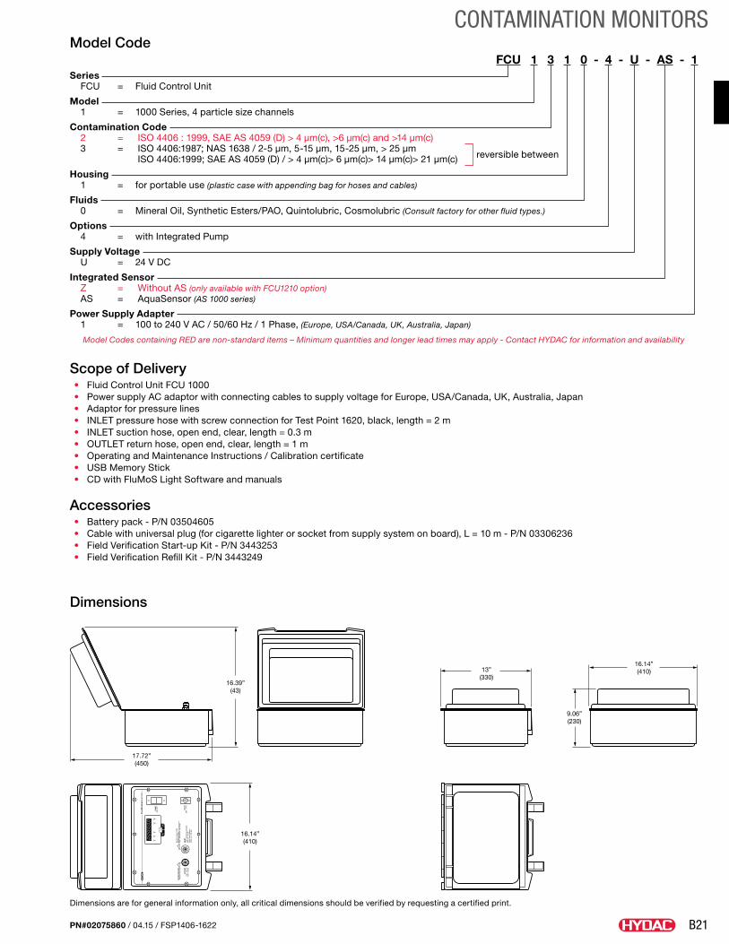
Dimensions
Flui
dCon
trol
Uni
t FC
U
ISO
SA
EFl
ow
Dri
veTe
mp
Sta
tus
DO
NO
T B
LOC
K!
Cau
tion
hot
fluid
OU
TLE
Tm
ax. 7
.5 p
sim
ax. 0
.5 b
ar
INLE
Tm
ax. o
per
atin
g p
ress
ure
650
psi
/ 4
5 b
arm
ax. i
nlet
pre
ssur
e:50
00 p
si /
245
bar
DC
IN24
V =
/ 4
A
PU
MP
ON
/O
FF
Suc
tion
cree
n in
sid
eM
iner
al o
il on
lym
ax.:
350m
m2/
s 16
22 S
US
16.39”(43)
17.72”(450)
16.14”(410)
13”(330)
16.14”(410)
9.06”(230)
Dimensions are for general information only, all critical dimensions should be verified by requesting a certified print.
B22
CONTAMINATION MONITORS
PN#02075860 / 04.15 / FSP1406-1622
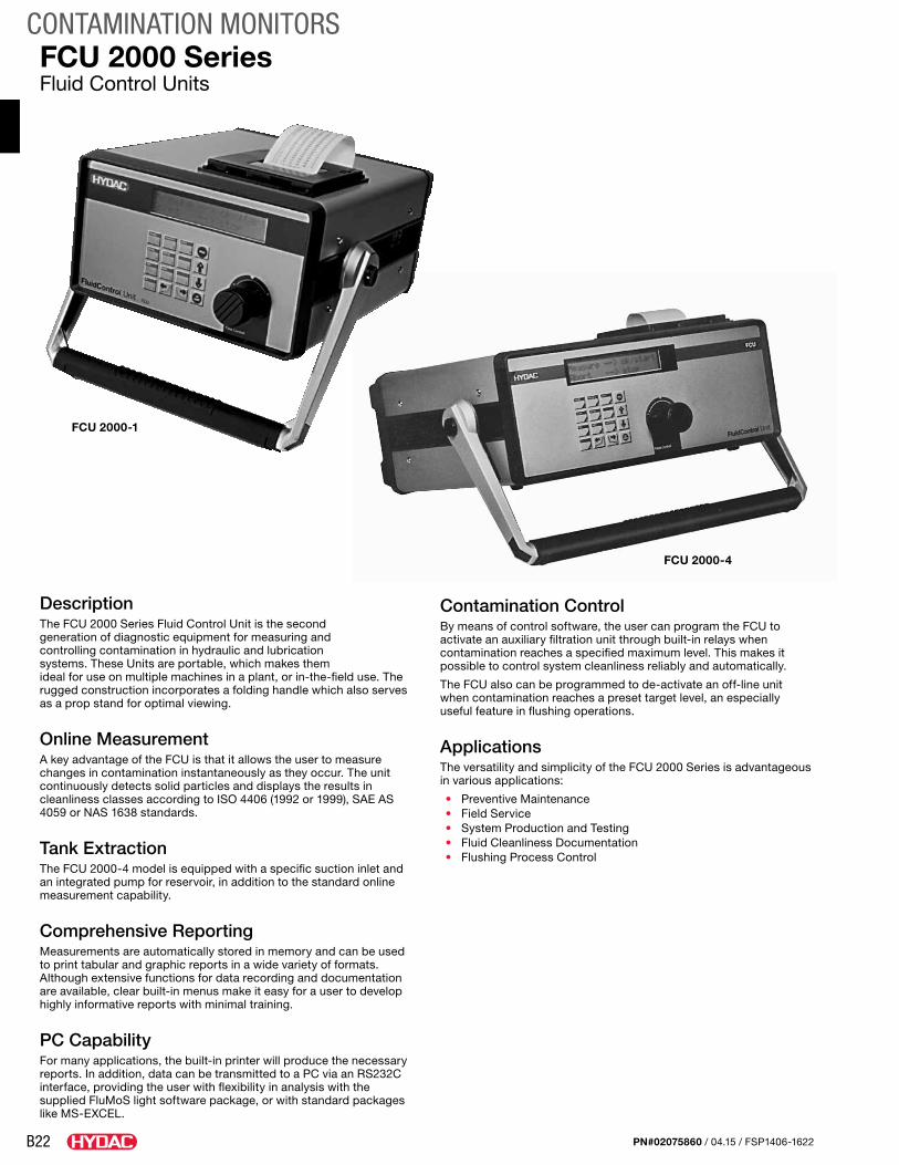
DescriptionThe FCU 2000 Series Fluid Control Unit is the second generation of diagnostic equipment for measuring and controlling contamination in hydraulic and lubrication systems. These Units are portable, which makes them ideal for use on multiple machines in a plant, or in-the-field use. The rugged construction incorporates a folding handle which also serves as a prop stand for optimal viewing.
Online MeasurementA key advantage of the FCU is that it allows the user to measure changes in contamination instantaneously as they occur. The unit continuously detects solid particles and displays the results in cleanliness classes according to ISO 4406 (1992 or 1999), SAE AS 4059 or NAS 1638 standards.
Tank ExtractionThe FCU 2000-4 model is equipped with a specific suction inlet and an integrated pump for reservoir, in addition to the standard online measurement capability.
Comprehensive ReportingMeasurements are automatically stored in memory and can be used to print tabular and graphic reports in a wide variety of formats. Although extensive functions for data recording and documentation are available, clear built-in menus make it easy for a user to develop highly informative reports with minimal training.
PC CapabilityFor many applications, the built-in printer will produce the necessary reports. In addition, data can be transmitted to a PC via an RS232C interface, providing the user with flexibility in analysis with the supplied FluMoS light software package, or with standard packages like MS-EXCEL.
Contamination ControlBy means of control software, the user can program the FCU to activate an auxiliary filtration unit through built-in relays when contamination reaches a specified maximum level. This makes it possible to control system cleanliness reliably and automatically.
The FCU also can be programmed to de-activate an off-line unit when contamination reaches a preset target level, an especially useful feature in flushing operations.
ApplicationsThe versatility and simplicity of the FCU 2000 Series is advantageous in various applications:
• Preventive Maintenance• Field Service• System Production and Testing• Fluid Cleanliness Documentation• Flushing Process Control
FCU 2000 SeriesFluid Control Units
FCU 2000-1
FCU 2000-4
B23
CONTAMINATION MONITORS
PN#02075860 / 04.15 / FSP1406-1622
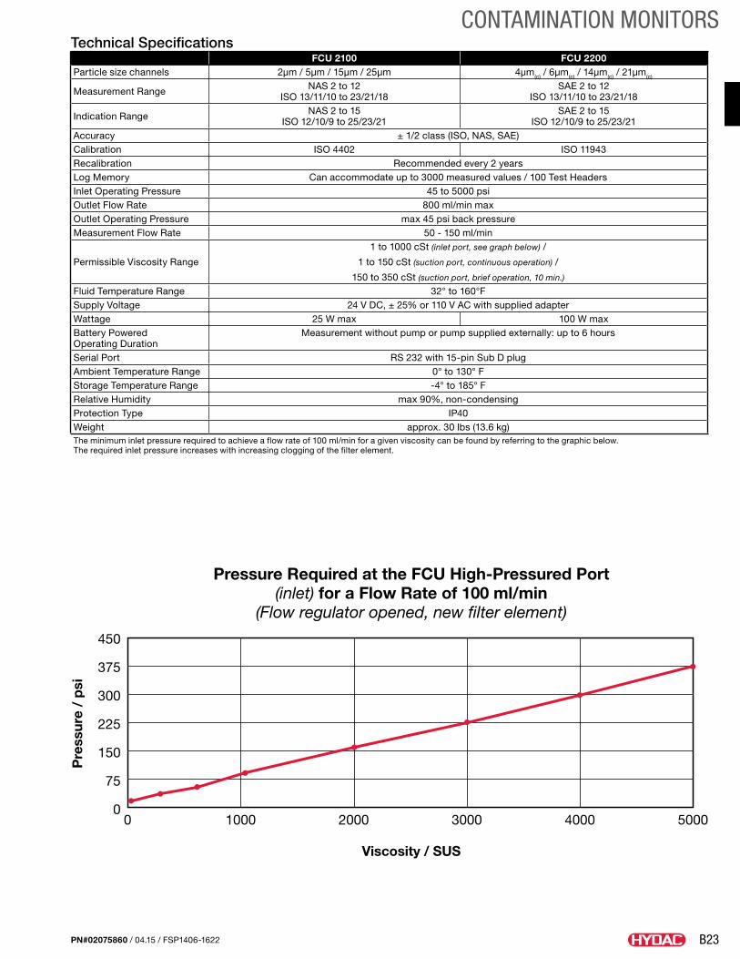
Technical SpecificationsFCU 2100 FCU 2200
Particle size channels 2µm / 5µm / 15µm / 25µm 4µm(c) / 6µm(c) / 14µm(c) / 21µm(c)
Measurement Range NAS 2 to 12 ISO 13/11/10 to 23/21/18
SAE 2 to 12 ISO 13/11/10 to 23/21/18
Indication Range NAS 2 to 15 ISO 12/10/9 to 25/23/21
SAE 2 to 15 ISO 12/10/9 to 25/23/21
Accuracy ± 1/2 class (ISO, NAS, SAE)Calibration ISO 4402 ISO 11943Recalibration Recommended every 2 yearsLog Memory Can accommodate up to 3000 measured values / 100 Test HeadersInlet Operating Pressure 45 to 5000 psiOutlet Flow Rate 800 ml/min maxOutlet Operating Pressure max 45 psi back pressureMeasurement Flow Rate 50 - 150 ml/min
Permissible Viscosity Range
1 to 1000 cSt (inlet port, see graph below) /
1 to 150 cSt (suction port, continuous operation) /
150 to 350 cSt (suction port, brief operation, 10 min.)
Fluid Temperature Range 32° to 160°FSupply Voltage 24 V DC, ± 25% or 110 V AC with supplied adapterWattage 25 W max 100 W maxBattery Powered Operating Duration
Measurement without pump or pump supplied externally: up to 6 hours
Serial Port RS 232 with 15-pin Sub D plugAmbient Temperature Range 0° to 130° FStorage Temperature Range -4° to 185° FRelative Humidity max 90%, non-condensingProtection Type IP40Weight approx. 30 lbs (13.6 kg)The minimum inlet pressure required to achieve a flow rate of 100 ml/min for a given viscosity can be found by referring to the graphic below. The required inlet pressure increases with increasing clogging of the filter element.
0
375
300
225
150
75
0
450
1000 2000 3000
Viscosity / SUS
Pressure Required at the FCU High-Pressured Port(inlet) for a Flow Rate of 100 ml/min
(Flow regulator opened, new filter element)
Pre
ssur
e /
psi
4000 5000
B24
CONTAMINATION MONITORS
PN#02075860 / 04.15 / FSP1406-1622
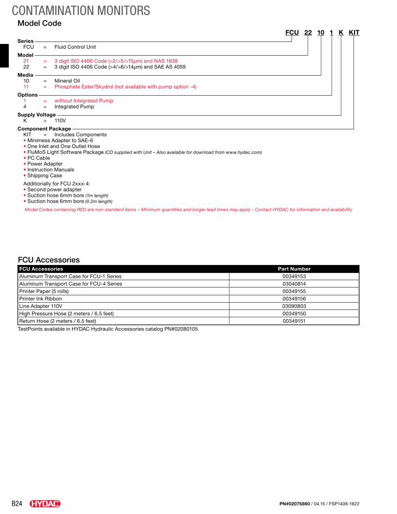
Model CodeFCU 22 10 1 K KIT
Series FCU = Fluid Control Unit
Model 21 = 3 digit ISO 4406 Code (>2/>5/>15µm) and NAS 1638 22 = 3 digit ISO 4406 Code (>4/>6/>14µm) and SAE AS 4059
Media 10 = Mineral Oil 11 = Phosphate Ester/Skydrol (not available with pump option -4)
Options 1 = without Integrated Pump 4 = Integrated Pump
Supply Voltage K = 110V
Component Package KIT = Includes Components • Minimess Adapter to SAE-6 • One Inlet and One Outlet Hose • FluMoS Light Software Package (CD supplied with Unit – Also available for download from www.hydac.com) • PC Cable • Power Adapter • Instruction Manuals • Shipping Case
Additionally for FCU 2xxx-4: • Second power adapter • Suction hose 6mm bore (1m length) • Suction hose 6mm bore (0.2m length)
Model Codes containing RED are non-standard items – Minimum quantities and longer lead times may apply - Contact HYDAC for information and availability
FCU AccessoriesFCU Accessories Part NumberAluminum Transport Case for FCU-1 Series 00349153Aluminum Transport Case for FCU-4 Series 03040814Printer Paper (5 rolls) 00349155Printer Ink Ribbon 00349156Line Adapter 110V 03090803High Pressure Hose (2 meters / 6.5 feet) 00349150Return Hose (2 meters / 6.5 feet) 00349151
TestPoints available in HYDAC Hydraulic Accessories catalog PN#02080105
B25
CONTAMINATION MONITORS
PN#02075860 / 04.15 / FSP1406-1622
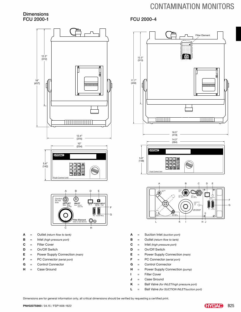
A = Outlet (return flow to tank)
B = Inlet (high pressure port)
C = Filter Cover
D = On/Off Switch
E = Power Supply Connection (main)
F = PC Connector (serial port)
G = Control Connector
H = Case Ground
A = Suction Inlet (suction port)
B = Outlet (return flow to tank)
C = Inlet (high pressure port)
D = On/Off Switch
E = Power Supply Connection (main)
F = PC Connector (serial port)
G = Control Connector
H = Power Supply Connection (pump)
I = Filter Cover
J = Case Ground
K = Ball Valve (for INLET/high pressure port)
L = Ball Valve (for SUCTION INLET/suction port)
Dimensions FCU 2000-1 FCU 2000-4
mode
7
memory
8
9
limits
4
setup
5 6
ISO
1
NAS
2 3
0
okstart
stop
-
+
+-
Flow ControlFluid Control Unit
14.3”(364)
5.8”(148)
16.5”(419)
Filter Element
12.3”(313)
17.7”(450)
OUTLETMax. 3barMax. 43 PSI
INLETMax. 350barMax. 5000 PSI
INLETMax. 350barMax. 5000 PSI
O / I
POWER INPUTPump24 V-2.3A
POWER INPUT24 V-/1A
Filter Element0060 D 005 BN/HC
PC CONTROL
A B C D E
F
G
HI JKL
CautionDo notlock
SUCTIONINLET
SUCTIONINLET
mode7
memory8print
9limits
4setup
5 6ISO
1NAS
2 30 ok
start
stop
-
+ +-
Flow Control
10”(254)
5.6”(142)
12.4”(315)
12.3”(312)
18”(457)
Fluid Control Unit
Caution!Do notlock OUTLET
Max. 3bar 43 PSI
INLETMax. 350bar 5000 PSI
O / IPOWER INPUT
24 V= / 1 A
Filter Element0060 D 005 BN/HC
PC CONTROL
A B
C
D E
F
G
H
Dimensions are for general information only, all critical dimensions should be verified by requesting a certified print.
B26
CONTAMINATION MONITORS
PN#02075860 / 04.15 / FSP1406-1622
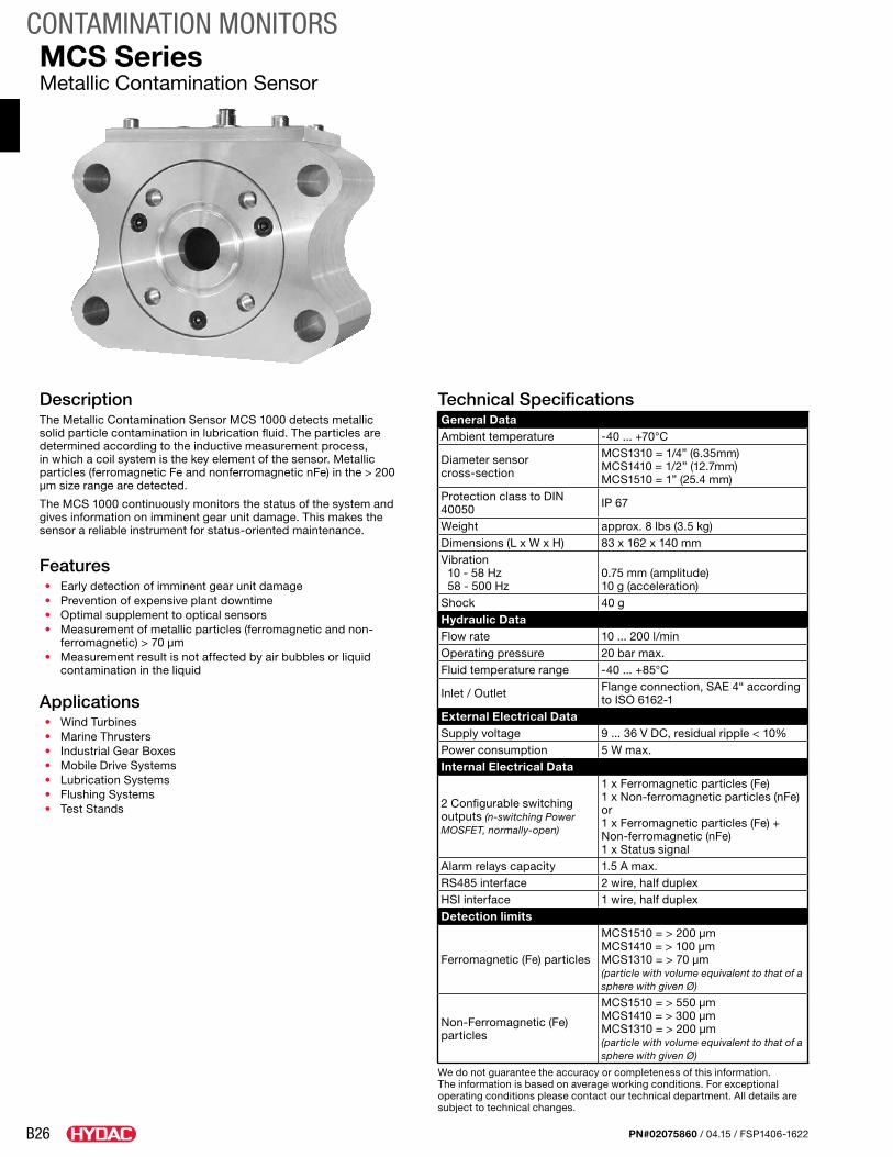
DescriptionThe Metallic Contamination Sensor MCS 1000 detects metallic solid particle contamination in lubrication fluid. The particles are determined according to the inductive measurement process, in which a coil system is the key element of the sensor. Metallic particles (ferromagnetic Fe and nonferromagnetic nFe) in the > 200 μm size range are detected.
The MCS 1000 continuously monitors the status of the system and gives information on imminent gear unit damage. This makes the sensor a reliable instrument for status-oriented maintenance.
Features• Early detection of imminent gear unit damage• Prevention of expensive plant downtime• Optimal supplement to optical sensors• Measurement of metallic particles (ferromagnetic and non-
ferromagnetic) > 70 μm• Measurement result is not affected by air bubbles or liquid
contamination in the liquid
Applications• Wind Turbines• Marine Thrusters• Industrial Gear Boxes• Mobile Drive Systems• Lubrication Systems• Flushing Systems• Test Stands
MCS SeriesMetallic Contamination Sensor
Technical SpecificationsGeneral DataAmbient temperature -40 ... +70°C
Diameter sensor cross-section
MCS1310 = 1/4” (6.35mm)MCS1410 = 1/2” (12.7mm)MCS1510 = 1” (25.4 mm)
Protection class to DIN 40050 IP 67
Weight approx. 8 lbs (3.5 kg)Dimensions (L x W x H) 83 x 162 x 140 mmVibration 10 - 58 Hz 58 - 500 Hz
0.75 mm (amplitude) 10 g (acceleration)
Shock 40 gHydraulic Data Flow rate 10 ... 200 l/minOperating pressure 20 bar max.Fluid temperature range -40 ... +85°C
Inlet / Outlet Flange connection, SAE 4“ according to ISO 6162-1
External Electrical DataSupply voltage 9 ... 36 V DC, residual ripple < 10%Power consumption 5 W max.Internal Electrical Data
2 Configurable switching outputs (n-switching Power MOSFET, normally-open)
1 x Ferromagnetic particles (Fe) 1 x Non-ferromagnetic particles (nFe)or1 x Ferromagnetic particles (Fe) + Non-ferromagnetic (nFe) 1 x Status signal
Alarm relays capacity 1.5 A max.RS485 interface 2 wire, half duplexHSI interface 1 wire, half duplexDetection limits
Ferromagnetic (Fe) particles
MCS1510 = > 200 μm MCS1410 = > 100 μm MCS1310 = > 70 μm (particle with volume equivalent to that of a sphere with given Ø)
Non-Ferromagnetic (Fe) particles
MCS1510 = > 550 μm MCS1410 = > 300 μm MCS1310 = > 200 μm(particle with volume equivalent to that of a sphere with given Ø)
We do not guarantee the accuracy or completeness of this information. The information is based on average working conditions. For exceptional operating conditions please contact our technical department. All details are subject to technical changes.

B27
CONTAMINATION MONITORS
PN#02075860 / 04.15 / FSP1406-1622
Model CodeMCS 1 5 1 0 - 5 - 0 / 000
Series MCS = Metallic Contamination Sensor
Model 1 = 1000 Series
Contamination Code 3 = particles > 70 um 4 = particles > 100 um 5 = particles > 200 μm
Options 1 = Standard
Fluids 0 = Mineral and synthetic oils (particulary used in wind power industry)
Hydraulic connection 1 = Flange Connection, SAE 1/2” according to ISO 6162-1 (only for MCS13xx) 2 = Flange Connection, SAE 3/4” according to ISO 6162-1 (only for MCS14xx) 5 = Flange connection, SAE 4“ according to ISO 6162-1 (only for MCS15xx)
Electrical Installation 0 = Standard
Modification number 000 = Standard
Scope of Delivery• MCS 1000• O-ring (47.22x3.53 NBR 70 Shore)• O-ring (110.72x3.53 NBR 70 Shore)• Operating and maintenance instructions
Accessories• SAE 4“ Flange adaptor set for pipe or hose connection, 42L according ISO 8431-1 Consisting of: 2x Flange adaptors, 2x O-rings, 8x Cylinder
screws, 8x Washers, 8x Spring washers, P/N: 3435426• Flange adaptor plate, SAE 4” – SAE 1½”, P/N: 3442518• Socket plug (female) with 2 m line, shielded, 8-pole, M12x1, P/N: 3281220• Socket plug (female) with 5 m line, shielded, 8-pole, M12x1, P/N: 02702459• Extension cable 5 m, Socket plug (female) 8-pole, M12x1 / Socket plug (male) 8-pole M12x1, P/N: 3281240• Socket plug with screw clamp, 8-pole, M12x1, P/N: 3281243
Dimensions
4x ø0.69”(17.5)
≈8.9
4”(≈
227)
5.2”
(132
)
3.06
”(7
7.8)
≈8.9
4”(≈
227)
5.2”
(132
)
1.65
” L
(42)
1.65
” L
(42)
3.06
”(7
7.8)
5.12”(130)6.38”(162)
0.12”(3.0)
3.27”(83)6.73”
(171)
4x ø0.69”(17.5)
5.12”(130)
6.38”(162)
Dimensions are for general information only, all critical dimensions should be verified by requesting a certified print.
Flange connection, SAE 4” according to ISO 6162-1 MCS with accessory flange adaptor set (optional)
B28
CONTAMINATION MONITORS
PN#02075860 / 04.15 / FSP1406-1622
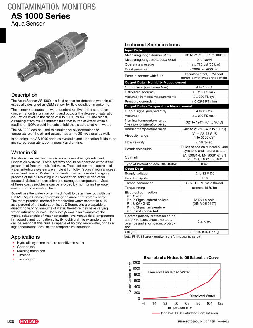
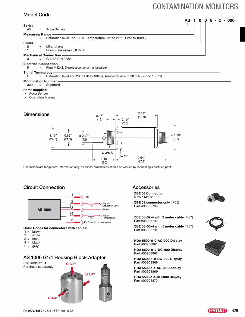
AS 1000 SeriesAqua Sensor
DescriptionThe Aqua Sensor AS 1000 is a fluid sensor for detecting water in oil, especially designed as OEM sensor for fluid condition monitoring.
The sensor measures the water content relative to the saturation concentration (saturation point) and outputs the degree of saturation (saturation level) in the range of 0 to 100% as a 4 - 20 mA signal. A reading of 0% would indicate fluid that is free of water, while a reading of 100% would indicate a fluid that is saturated with water.
The AS 1000 can be used to simultaneously determine the temperature of the oil and output it as a 4 to 20 mA signal as well.
In so doing, the AS 1000 enables hydraulic and lubrication fluids to be monitored accurately, continuously and on-line.
Water in OilIt is almost certain that there is water present in hydraulic and lubrication systems. These systems should be operated without the presence of free or emulsified water. The most common sources of water entering a system are ambient humidity, “splash” from process water, and new oil. Water contamination will accelerate the aging process of the oil resulting in oil oxidization, additive depletion, reduced lubrication, corrosion and damaged components. Most of these costly problems can be avoided by monitoring the water content of the operating fluids.
Sometimes the water content is difficult to determine, but with the HYDAC Aqua Sensor, determining the amount of water is easy! The most practical method for monitoring water content in oil is as a percent of the saturation level. Different oils are capable of dissolving varying amounts of water, therefore they have varying water saturation curves. The curve (below) is an example of the typical relationship of water saturation level versus fluid temperature in hydraulic and lubrication oils. By looking at the example graph it can be seen that this fluid is capable of holding more water, or has a higher saturation level, as the temperature increases.
Applications• Hydraulic systems that are sensitive to water• Gear boxes• Molding machines• Turbines• Transferrers
Technical SpecificationsInput DataMeasuring range (temperature) -13° to 212°F (-25° to 100°C)Measuring range (saturation level) 0 to 100%Operating pressure max. 725 psi (50 bar)Burst pressure > 9000 psi (630 bar)
Parts in contact with fluid Stainless steel, FPM seal, ceramic with evaporated metal
Output Data - Humidity MeasurementOutput level (saturation level) 4 to 20 mACalibrated accuracy ≤ ± 2% FS max.Accuracy in media measurements ≤ ± 3% FS typ.Pressure dependent + 0.02% FS / barOutput Data - Temperature MeasurementOutput signal (temperature) 4 to 20 mAAccuracy ≤ ± 2% FS max.Nominal temperature range (measuring saturation level) 32° to 194°F (0° to 90°C)
Ambient temperature range -40° to 212°F (-40° to 100°C)
Viscosity range 32 to 23175 SUS (1 to 5000 cSt)
Flow velocity < 16 ft/sec
Permissible fluids Fluids based on mineral oil and synthetic and natural esters
CE mark EN 50081-1, EN 50081-2, EN 50082-1, EN 61000-6-2
Type of Protection acc. DIN 40050 IP67Other DataSupply voltage 12 to 32 V DCResidual ripple ≤ 5%Thread connection G 3/8 BSPP male threadTorque rating approx. 18 ft/lbsElectrical connection Pin 1: +Ub Pin 2: Signal saturation level Pin 3: 0V / GND Pin 4: Signal temperature Pin 5: not connected
M12x1.5 pole (DIN VDE 0627)
Reverse polarity protection of the supply voltage, excess voltage, override and short circuit protec-tion
Standard
Weight approx. 5 oz (145 g)Note: FS (Full Scale) = relative to the full measuring range
1200
1000
800
600
400
200
01048668503214-4 122
Dissolved Water
Temperature in °F
Wat
er C
onte
nt in
PP
M
Free and Emulsified Water
Indicates 100% Saturation Concentration
Example of a Hydraulic Oil Saturation Curve
B29
CONTAMINATION MONITORS
PN#02075860 / 04.15 / FSP1406-1622
Saturation LevelSaturationPoint
Dis
solv
ed W
ater
Free
Wat
er
100%
75%
50%
25%
0%
SignalSaturation Level
SignalTemperature
RL
RL
1
5Pin 5 not to be connected
2
4
3Ground
+ Ub
AS 1000
ø 0.47”(12)
0.86”(21.9)
1.16”(29.5)
2.18”(55.3)
G 3/8 A
2.64”(67.1)
1.18”(30)
0.47”(12) 0.10”
(2.5)
ø 1.06”(27)
SW 27
Model CodeAS 1 0 0 8 - C - 000
Series AS = Aqua Sensor
Measuring Range 1 = Saturation level 0 to 100%; Temperature -13° to 212*F (-25° to 100°C)
Fluids 0 = Mineral oils 1 = Phosphate esters (HFD-R)
Mechanical Connection 0 = G 3/8A DIN 3852
Electrical Connection 8 = Plug M12x1, 5-pole (connector not included)
Signal Technology C = Saturation level 4 to 20 mA (0 to 100%), Temperature 4 to 20 mA (-25° to 100°C)
Modification Number 000 = Standard
Items supplied• Aqua Sensor• Operation Manual
AccessoriesZBE 08 Connector 5 Pole M12x1 90°
ZBE 08 connector only (IP65) Part #06006786
ZBE 08-02-4 with 2 meter cable (IP67) Part #06006792
ZBE 08-05-4 with 5 meter cable (IP67) Part #06006791
HDA 5500-0-0-AC-000 Display Part #00908861
HDA 5500-0-0-DC-000 Display Part #00908862
HDA 5500-1-0-DC-000 Display Part #00908868
HDA 5500-1-1-AC-000 Display Part #00908869
HDA 5500-1-1-DC-000 Display Part #00908870
Circuit Connection
Dimensions
Saturation LevelSaturationPoint
Dis
solv
ed W
ater
Free
Wat
er
100%
75%
50%
25%
0%
SignalSaturation Level
SignalTemperature
RL
RL
1
5Pin 5 not to be connected
2
4
3Ground
+ Ub
AS 1000
ø 0.47”(12)
0.86”(21.9)
1.16”(29.5)
2.18”(55.3)
G 3/8 A
2.64”(67.1)
1.18”(30)
0.47”(12) 0.10”
(2.5)
ø 1.06”(27)
SW 27
Color Codes for connectors with cables: 1 = brown 2 = white 3 = blue 4 = black 5 = gray
AS 1000 G1/4 Housing Block AdapterPart #03182134 Purchase separately
G 3/8”
G 1/4”
G 1/4”
Dimensions are for general information only, all critical dimensions should be verified by requesting a certified print.
B30
CONTAMINATION MONITORS
PN#02075860 / 04.15 / FSP1406-1622
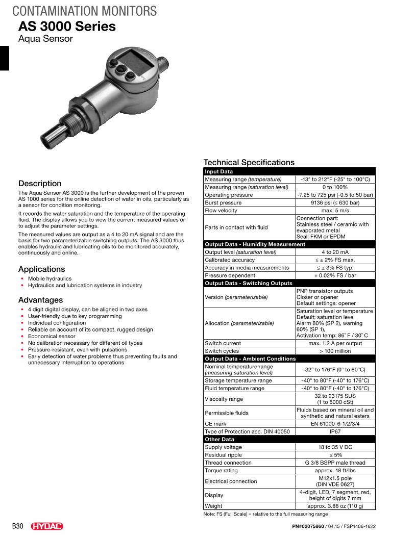
AS 3000 SeriesAqua Sensor
DescriptionThe Aqua Sensor AS 3000 is the further development of the proven AS 1000 series for the online detection of water in oils, particularly as a sensor for condition monitoring.
It records the water saturation and the temperature of the operating fluid. The display allows you to view the current measured values or to adjust the parameter settings.
The measured values are output as a 4 to 20 mA signal and are the basis for two parameterizable switching outputs. The AS 3000 thus enables hydraulic and lubricating oils to be monitored accurately, continuously and online.
Applications• Mobile hydraulics• Hydraulics and lubrication systems in industry
Advantages• 4 digit digital display, can be aligned in two axes• User-friendly due to key programming• Individual configuration• Reliable on account of its compact, rugged design• Economical sensor• No calibration necessary for different oil types• Pressure-resistant, even with pulsations• Early detection of water problems thus preventing faults and
unnecessary interruption to operations
Technical SpecificationsInput DataMeasuring range (temperature) -13° to 212°F (-25° to 100°C)Measuring range (saturation level) 0 to 100%Operating pressure -7.25 to 725 psi (-0.5 to 50 bar)Burst pressure 9136 psi (≤ 630 bar)Flow velocity max. 5 m/s
Parts in contact with fluid
Connection part:Stainless steel / ceramic with evaporated metal Seal: FKM or EPDM
Output Data - Humidity MeasurementOutput level (saturation level) 4 to 20 mACalibrated accuracy ≤ ± 2% FS max.Accuracy in media measurements ≤ ± 3% FS typ.Pressure dependent + 0.02% FS / barOutput Data - Switching Outputs
Version (parameterizable)PNP transistor outputsCloser or openerDefault settings: opener
Allocation (parameterizable)
Saturation level or temperatureDefault: saturation levelAlarm 80% (SP 2), warning 60% (SP 1),Activation temp: 86˚ F / 30˚ C
Switch current max. 1.2 A per outputSwitch cycles > 100 millionOutput Data - Ambient ConditionsNominal temperature range (measuring saturation level) 32° to 176°F (0° to 80°C)
Storage temperature range -40° to 80°F (-40° to 176°C)Fluid temperature range -40° to 80°F (-40° to 176°C)
Viscosity range 32 to 23175 SUS (1 to 5000 cSt)
Permissible fluids Fluids based on mineral oil and synthetic and natural esters
CE mark EN 61000-6-1/2/3/4Type of Protection acc. DIN 40050 IP67Other DataSupply voltage 18 to 35 V DCResidual ripple ≤ 5%Thread connection G 3/8 BSPP male threadTorque rating approx. 18 ft/lbs
Electrical connection M12x1.5 pole (DIN VDE 0627)
Display 4-digit, LED, 7 segment, red, height of digits 7 mm
Weight approx. 3.88 oz (110 g)Note: FS (Full Scale) = relative to the full measuring range
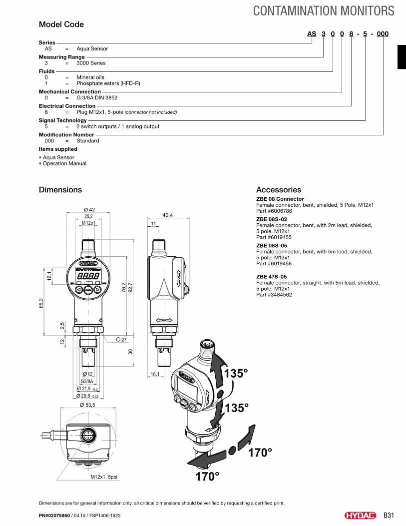
B31
CONTAMINATION MONITORS
PN#02075860 / 04.15 / FSP1406-1622
Model CodeAS 3 0 0 8 - 5 - 000
Series AS = Aqua Sensor
Measuring Range 3 = 3000 Series
Fluids 0 = Mineral oils 1 = Phosphate esters (HFD-R)
Mechanical Connection 0 = G 3/8A DIN 3852
Electrical Connection 8 = Plug M12x1, 5-pole (connector not included)
Signal Technology 5 = 2 switch outputs / 1 analog output
Modification Number 000 = Standard
Items supplied
• Aqua Sensor • Operation Manual
AccessoriesZBE 08 Connector Female connector, bent, shielded, 5 Pole, M12x1 Part #6006786
ZBE 08S-02 Female connector, bent, with 2m lead, shielded, 5 pole, M12x1 Part #6019455
ZBE 08S-05 Female connector, bent, with 5m lead, shielded, 5 pole, M12x1 Part #6019456
ZBE 47S-05 Female connector, straight, with 5m lead, shielded, 5 pole, M12x1 Part #3484562
Dimensions
Dimensions are for general information only, all critical dimensions should be verified by requesting a certified print.
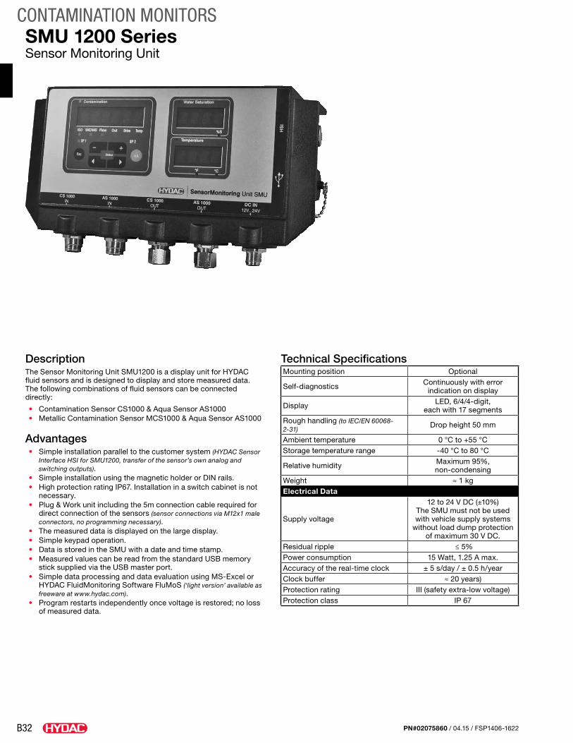
B32
CONTAMINATION MONITORS
PN#02075860 / 04.15 / FSP1406-1622
SMU 1200 SeriesSensor Monitoring Unit
DescriptionThe Sensor Monitoring Unit SMU1200 is a display unit for HYDAC fluid sensors and is designed to display and store measured data. The following combinations of fluid sensors can be connected directly:
• Contamination Sensor CS1000 & Aqua Sensor AS1000• Metallic Contamination Sensor MCS1000 & Aqua Sensor AS1000
Advantages• Simple installation parallel to the customer system (HYDAC Sensor
Interface HSI for SMU1200, transfer of the sensor’s own analog and switching outputs).
• Simple installation using the magnetic holder or DIN rails.• High protection rating IP67. Installation in a switch cabinet is not
necessary.• Plug & Work unit including the 5m connection cable required for
direct connection of the sensors (sensor connections via M12x1 male connectors, no programming necessary).
• The measured data is displayed on the large display.• Simple keypad operation.• Data is stored in the SMU with a date and time stamp.• Measured values can be read from the standard USB memory
stick supplied via the USB master port.• Simple data processing and data evaluation using MS-Excel or
HYDAC FluidMonitoring Software FluMoS (‘light version’ available as freeware at www.hydac.com).
• Program restarts independently once voltage is restored; no loss of measured data.
Technical SpecificationsMounting position Optional
Self-diagnostics Continuously with error indication on display
Display LED, 6/4/4-digit, each with 17 segments
Rough handling (to IEC/EN 60068-2-31)
Drop height 50 mm
Ambient temperature 0 °C to +55 °CStorage temperature range -40 °C to 80 °C
Relative humidity Maximum 95%, non-condensing
Weight ≈ 1 kgElectrical Data
Supply voltage
12 to 24 V DC (±10%)The SMU must not be used with vehicle supply systems
without load dump protection of maximum 30 V DC.
Residual ripple ≤ 5%Power consumption 15 Watt, 1.25 A max.Accuracy of the real-time clock ± 5 s/day / ± 0.5 h/yearClock buffer ≈ 20 years)Protection rating III (safety extra-low voltage)Protection class IP 67
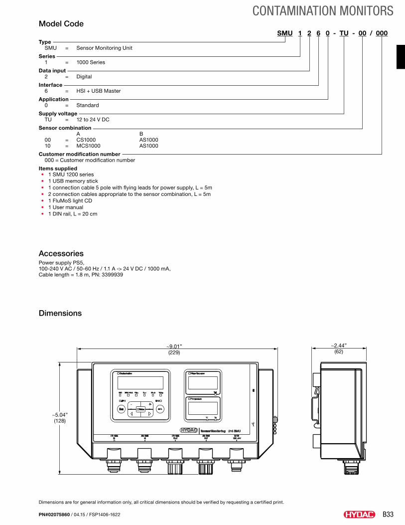
B33
CONTAMINATION MONITORS
PN#02075860 / 04.15 / FSP1406-1622
~9.01”(229)
~2.44”(62)
~5.04”(128)
Model CodeSMU 1 2 6 0 - TU - 00 / 000
Type SMU = Sensor Monitoring Unit
Series 1 = 1000 Series
Data input 2 = Digital
Interface 6 = HSI + USB Master
Application 0 = Standard
Supply voltage TU = 12 to 24 V DC
Sensor combination A B 00 = CS1000 AS1000 10 = MCS1000 AS1000
Customer modification number 000 = Customer modification number
Items supplied• 1 SMU 1200 series• 1 USB memory stick• 1 connection cable 5 pole with flying leads for power supply, L = 5m• 2 connection cables appropriate to the sensor combination, L = 5m• 1 FluMoS light CD• 1 User manual• 1 DIN rail, L = 20 cm
Accessories Power supply PS5, 100-240 V AC / 50-60 Hz / 1.1 A -> 24 V DC / 1000 mA, Cable length = 1.8 m, PN: 3399939
Dimensions
Dimensions are for general information only, all critical dimensions should be verified by requesting a certified print.
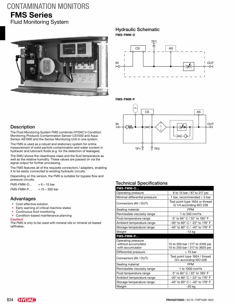
B34
CONTAMINATION MONITORS
PN#02075860 / 04.15 / FSP1406-1622
FMS SeriesFluid Monitoring System
DescriptionThe Fluid Monitoring System FMS combines HYDAC’s Condition Monitoring Products Contamination Sensor CS1000 and Aqua Sensor AS1000 and the Sensor Monitoring Unit in one system.
The FMS is used as a robust and stationary system for online measurement of solid particle contamination and water content in hydraulic and lubricant fluids (e.g. for the detection of leakages).
The SMU shows the cleanliness class and the fluid temperature as well as the relative humidity. These values are passed on via the signal output for further processing.
The FMS features all of the requisite connectors / adapters, enabling it to be easily connected to existing hydraulic circuits.
Depending on the version, the FMS is suitable for bypass flow and pressure circuits:
FMS-FMM-O… = 6 – 15 bar
FMS-FMM-P… = 15 – 300 bar
Advantages• Cost-effective solution• Early warning of critical machine states• Continuous fluid monitoring• Condition-based maintenance planning
Caution! The FMS is only to be used with mineral oils or mineral oil-based raffinates.
Technical SpecificationsFMS-FMM-O…Operating pressure 6 to 15 bar / 87 to 217 psiMinimal differential pressure 1 bar, recommended ≥ 3 bar
Connectors (IN / OUT) Test point type 1604 or thread G 1/4 according ISO 228
Sealing material FPMPermissible viscosity range 1 to 350 mm²/sFluid temperature range 0° to 85° C / 32° to 185° FAmbient temperature range -30° to 80° C / -22° to 176° FStorage temperature range -40° to 80° C / -40° to 176° FWeight ~13 kgFMS-FMM-P…Operating pressure without accumulator with accumulator
15 to 300 bar / 217 to 4350 psi15 to 250 bar / 217 to 3625 psi
Differential pressure > 15 bar
Connectors (IN / OUT) Test point type 1604 / thread G¼ according ISO 228
Sealing material FPMPermissible viscosity range 1 to 1000 mm²/sFluid temperature range 0° to 85° C / 32° to 185° FAmbient temperature range -30° to 80° C / -22° to 176° FStorage temperature range -40° to 80° C / -40° to 176° FWeight ~20 kg
Hydraulic SchematicFMS-FMM-O
IN OUT
AS
TP1
CS
IN OUT
AS
TP1 TP2
CS
FMS-FMM-P
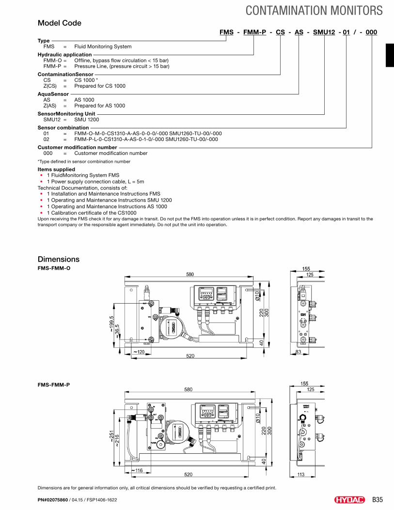
B35
CONTAMINATION MONITORS
PN#02075860 / 04.15 / FSP1406-1622
FMS Series Dimensions – FMS-FMM-O …
Dimensions – FMS-FMM-O …
Dimensions – FMS-FMM-P …
HYDAC FILTER SYSTEMS GMBH en Page 19 / 32
MoWa FMS 3520000 us 2010-05-25.doc 2010-05-25
FMS Series Dimensions – FMS-FMM-O …
Dimensions – FMS-FMM-O …
Dimensions – FMS-FMM-P …
HYDAC FILTER SYSTEMS GMBH en Page 19 / 32
MoWa FMS 3520000 us 2010-05-25.doc 2010-05-25
Model CodeFMS - FMM-P - CS - AS - SMU12 - 01 / - 000
Type FMS = Fluid Monitoring System
Hydraulic application FMM-O = Offline, bypass flow circulation < 15 bar) FMM-P = Pressure Line, (pressure circuit > 15 bar)
ContaminationSensor CS = CS 1000 * Z(CS) = Prepared for CS 1000
AquaSensor AS = AS 1000 Z(AS) = Prepared for AS 1000
SensorMonitoring Unit SMU12 = SMU 1200
Sensor combination 01 = FMM-O-M-0-CS1310-A-AS-0-0-0/-000 SMU1260-TU-00/-000 02 = FMM-P-L-0-CS1310-A-AS-0-1-0/-000 SMU1260-TU-00/-000
Customer modification number 000 = Customer modification number
*Type defined in sensor combination number
Items supplied• 1 FluidMonitoring System FMS• 1 Power supply connection cable, L = 5m
Technical Documentation, consists of:• 1 Installation and Maintenance Instructions FMS• 1 Operating and Maintenance Instructions SMU 1200• 1 Operating and Maintenance Instructions AS 1000• 1 Calibration certificate of the CS1000
Upon receiving the FMS check it for any damage in transit. Do not put the FMS into operation unless it is in perfect condition. Report any damages in transit to the transport company or the responsible agent immediately. Do not put the unit into operation.
DimensionsFMS-FMM-O
Dimensions are for general information only, all critical dimensions should be verified by requesting a certified print.
FMS-FMM-P
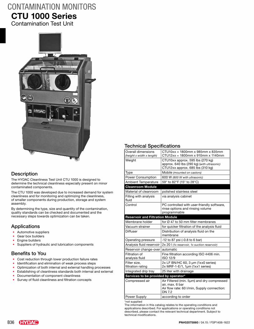
B36
CONTAMINATION MONITORS
PN#02075860 / 04.15 / FSP1406-1622
DescriptionThe HYDAC Cleanliness Test Unit CTU 1000 is designed to determine the technical cleanliness especially present on minor contaminated components.
The CTU 1000 was developed due to increased demand for system cleanliness and for monitoring and optimizing the cleanliness, of smaller components during production, storage and system assembly.
By determining the type, size and quantity of the contamination, quality standards can be checked and documented and the necessary steps towards optimization can be taken.
Applications• Automotive suppliers• Gear box builders• Engine builders• Suppliers of hydraulic and lubrication components
Benefits to You• Cost reduction through lower production failure rates• Identification and elimination of weak process steps• Optimization of both internal and external handling processes• Establishing of cleanliness standards both internal and external• Documentation of component cleanliness• Survey of fluid cleanliness and filtration concepts
CTU 1000 SeriesContamination Test Unit
Technical SpecificationsOverall dimensions (height x width x length)
CTU10xx = 1800mm x 985mm x 835mmCTU12xx = 1800mm x 910mm x 1140mm
Weight CTU10xx approx. 595 lbs (270 kg) approx. 640 lbs (290 kg) (with ultrasonic)CTU12xx approx. 685 lbs (310 kg)
Type Mobile (mounted on castors)
Power Consumption 600 W (800 W with ultrasonic)
Ambient Temperature 59° to 82°F (15° to 28°C)Cleanroom ModuleMaterial of cleanroom polished stainless steelFilling with analysis fluid
via analysis cabinet
Control PC controlled with user-friendly software, rinse options and rinsing volume programmable
Reservoir and Filtration ModuleMembrane holder for Ø 47 to 50 mm filter membranesVacuum strainer for quicker filtration of the analysis fluidDiffuser Distribution of analysis fluid on the
membraneOperating pressure -12 to 87 psi (-0.8 to 6 bar)Analysis fluid reservoir 2x 20 l (1x reservoir, 1x suction reservoir)
Reservoir change-over automaticFiltration of analysis fluid
Fine filtration according ISO 4406 min. ISO 12/9
Filter size, filtration rating
2x LF BN/HC 60, 3 μm (1xx0 series) 2x MRF-1-E/1, 1μm (1xx1 series)
Integrated drip tray 25 liter with drainageServices to be provided by operator*Compressed air Air Filtered (min. 5μm) and dry compressed
air, max. 6 bar Air flow rate: 60 l/min, Supply connection: DN 7.2
Power Supply according to order*not suppliedThe information in this catalog relates to the operating conditions and applications described. For applications or operating conditions not described, please contact the relevant technical department. Subject to technical modifications.
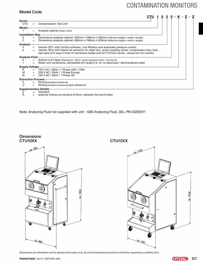
B37
CONTAMINATION MONITORS
PN#02075860 / 04.15 / FSP1406-1622
Model CodeCTU 1 0 3 0 - K - Z - Z
Series CTU = Contamination Test Unit
Model 1 = Analysis cabinet (clean room)
Installation Size 0 = Dimensions analysis cabinet: 300mm x 768mm x 365mm (effective height x width x length) 2 = Dimensions analysis cabinet: 460mm x 768mm x 650mm (effective height x width x length)
Analysis 3 = Version 2011 with ConTes software, 1um filtration and automatic pressure control 4 = Version 2014 with interior air extractor for clean box, quick coupling valves, compression door lock,
ball valve (2/3 way) in front of membrane holder and for CTU12xx series - swivel arm for monitor
Analysis Fluid 0 = Solvent A III Class (Flashpoint > 60°C, lower explosion limit > 0.6 Vol.%) 1 = Water with surfactants, admissible pH-range 6 to 10, no deionized / demineralized water
Supply Voltage K = 120 V AC / 60Hz / 1 Phase USA / CDN M = 230 V AC / 50Hz / 1 Phase Europe N = 240 V AC / 50Hz / 1 Phase UK
Extraction Process Z = Rinsing (medium pressure) U = Rinsing (medium pressure) plus ultrasonic
Supplementary Details Z = standard R = external rinsing connections Ø 6mm, between the hand holes
Dimensions are millimeters and for general information only, all critical dimensions should be verified by requesting a certified print.
Dimensions CTU10XX CTU12XX
Note: Analyzing Fluid not supplied with unit - G60 Analyzing Fluid, 30L; PN 03205511
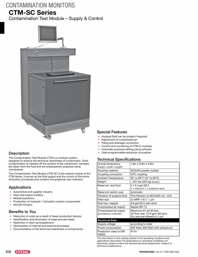
B38
CONTAMINATION MONITORS
PN#02075860 / 04.15 / FSP1406-1622
DescriptionThe Contamination Test Module CTM is a modular system designed to analyze the technical cleanliness of components. Solid contamination is washed off the surface of the component, samples are taken from the fluid and are subsequently analyzed using membranes.
The Contamination Test Module CTM-SC is the central module of the CTM series. It serves as the fluid supply and the control of the entire extraction processes and contains the graphical user interface.
Applications• Automotive and supplier industry• Gear and engine builders• Mobile hydraulics• Production of hydraulic / lubrication system components• Aircraft industry
Benefits to You• Reduction in costs as a result of fewer production failures• Identification and elimination of weak process steps• Reduction in start-up breakdowns• Optimization of internal and external processes• Documentation of the technical cleanliness of components
CTM-SC SeriesContamination Test Module – Supply & Control
Special Features• Analysis fluid can be pulsed if required• Adjustment of compressed air• Filling and drainage connection• Control and monitoring of CTM-E modules• Automatic pressure setting using software• User-programmable extraction procedure
Technical SpecificationsOverall dimensions (height x width x length)
1.8m x 0.9m x 0.8m
Housing material S235JR powder-coatedCoupling connection CPC couplingAmbient Temperature 59° to 82°F (15° to 28°C)Weight ≈ 551 lbs (250 kg) (empty)
Reservoir, test fluid 2 x 5.3 gal (20 l)(1 x reservoir, 1 x collection tank)
Reservoir switch-over AutomaticFiltration of analysis fluid Fine filtration to ISO4406 min. 12/9Filter size 2x MRF-1-E/1, 1 µmDrip tray, integral 6.6 gal (25 l) with drainCompressed air supply Nipple DN 7.2Compressed air supply (provided by customer)
Maximum 87 psi (6 bar), Air flow rate: 15.9 gpm (60 lpm) Dry and pre-filtered to 5 µm
Electrical DataSupply voltage according to orderPower consumption 600 Watt; 800 Watt with ultrasoundProtection class to DIN 40050
IP 54
The information in this catalog relates to the operating conditions and applications described. For applications or operating conditions not described, please contact the relevant technical department. Subject to technical modifications.
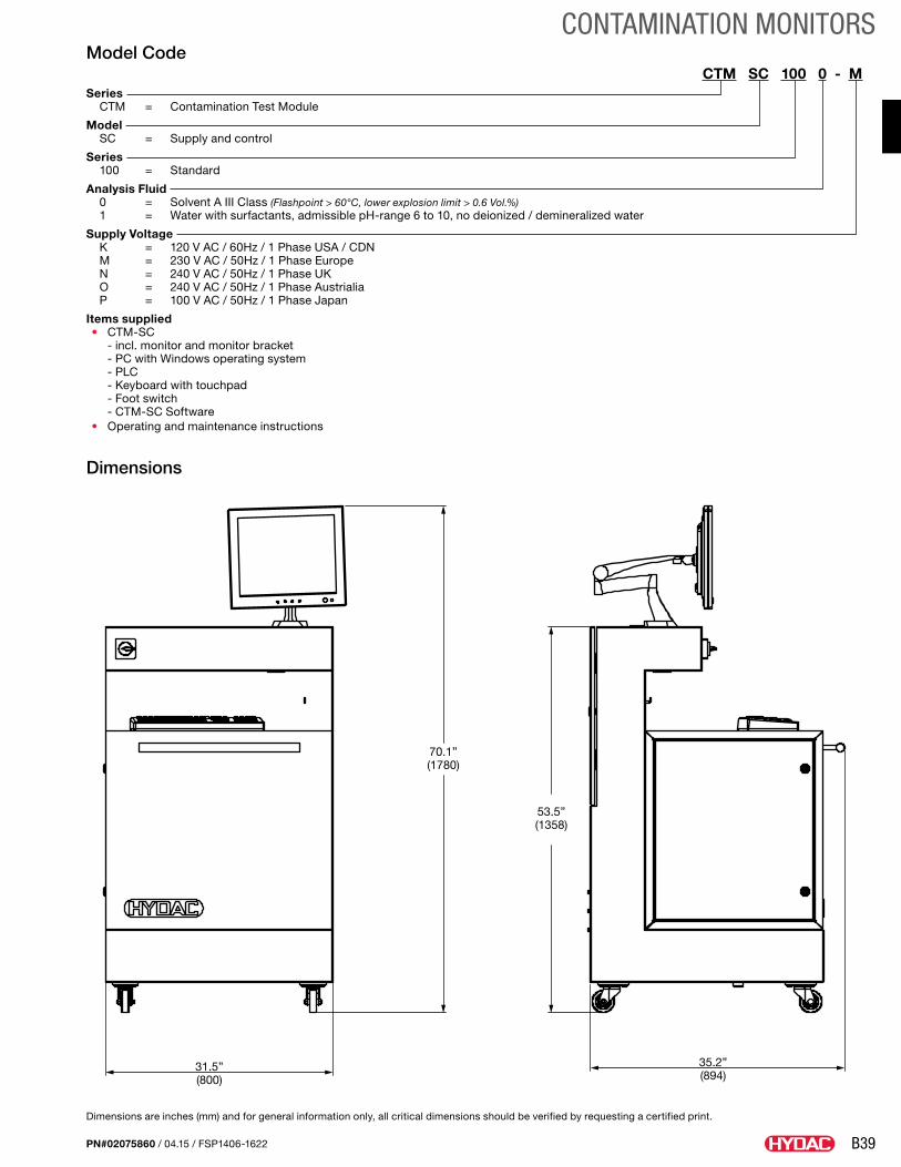
B39
CONTAMINATION MONITORS
PN#02075860 / 04.15 / FSP1406-1622
Model CodeCTM SC 100 0 - M
Series CTM = Contamination Test Module
Model SC = Supply and control
Series 100 = Standard
Analysis Fluid 0 = Solvent A III Class (Flashpoint > 60°C, lower explosion limit > 0.6 Vol.%) 1 = Water with surfactants, admissible pH-range 6 to 10, no deionized / demineralized water
Supply Voltage K = 120 V AC / 60Hz / 1 Phase USA / CDN M = 230 V AC / 50Hz / 1 Phase Europe N = 240 V AC / 50Hz / 1 Phase UK O = 240 V AC / 50Hz / 1 Phase Austrialia P = 100 V AC / 50Hz / 1 Phase Japan
Items supplied• CTM-SC
- incl. monitor and monitor bracket - PC with Windows operating system - PLC - Keyboard with touchpad - Foot switch - CTM-SC Software
• Operating and maintenance instructions
31.5”(800)
35.2”(894)
70.1”(1780)
53.5”(1358)
Dimensions are inches (mm) and for general information only, all critical dimensions should be verified by requesting a certified print.
Dimensions
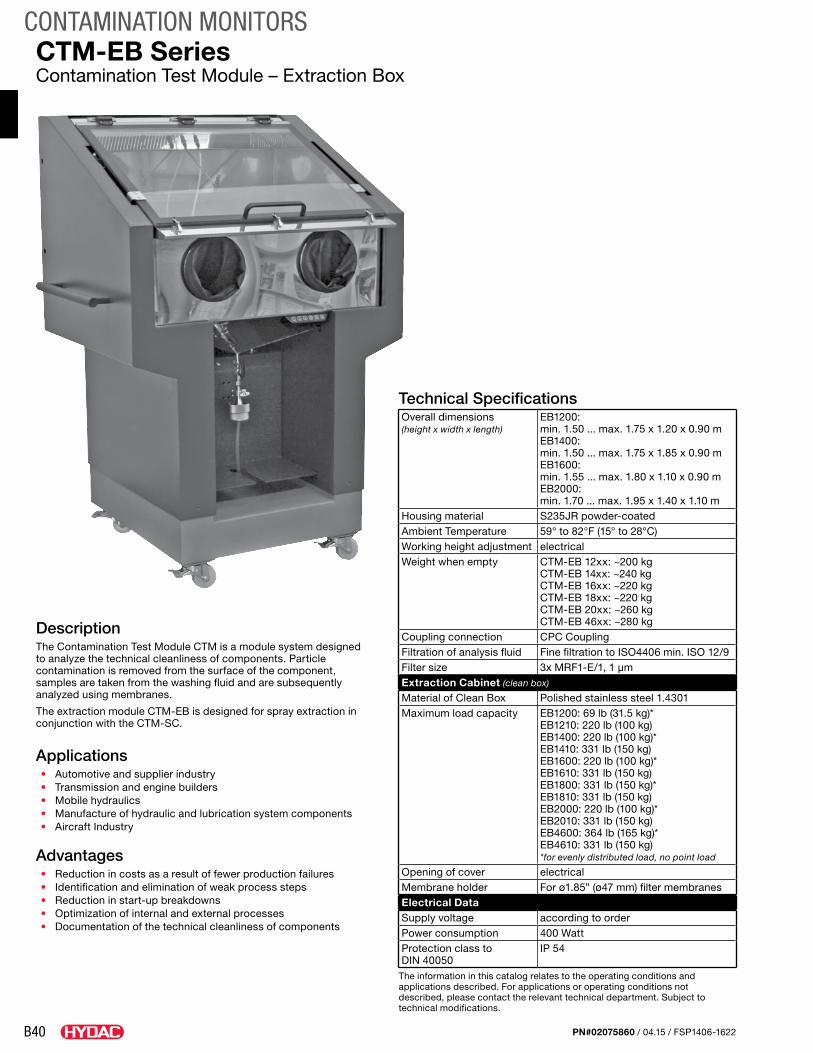
B40
CONTAMINATION MONITORS
PN#02075860 / 04.15 / FSP1406-1622
DescriptionThe Contamination Test Module CTM is a module system designed to analyze the technical cleanliness of components. Particle contamination is removed from the surface of the component, samples are taken from the washing fluid and are subsequently analyzed using membranes.
The extraction module CTM-EB is designed for spray extraction in conjunction with the CTM-SC.
Applications• Automotive and supplier industry• Transmission and engine builders• Mobile hydraulics• Manufacture of hydraulic and lubrication system components• Aircraft Industry
Advantages• Reduction in costs as a result of fewer production failures• Identification and elimination of weak process steps• Reduction in start-up breakdowns• Optimization of internal and external processes• Documentation of the technical cleanliness of components
CTM-EB SeriesContamination Test Module – Extraction Box
Technical SpecificationsOverall dimensions (height x width x length)
EB1200: min. 1.50 ... max. 1.75 x 1.20 x 0.90 mEB1400: min. 1.50 ... max. 1.75 x 1.85 x 0.90 mEB1600: min. 1.55 ... max. 1.80 x 1.10 x 0.90 mEB2000: min. 1.70 ... max. 1.95 x 1.40 x 1.10 m
Housing material S235JR powder-coatedAmbient Temperature 59° to 82°F (15° to 28°C)Working height adjustment electricalWeight when empty CTM-EB 12xx: ~200 kg
CTM-EB 14xx: ~240 kg CTM-EB 16xx: ~220 kg CTM-EB 18xx: ~220 kg CTM-EB 20xx: ~260 kg CTM-EB 46xx: ~280 kg
Coupling connection CPC CouplingFiltration of analysis fluid Fine filtration to ISO4406 min. ISO 12/9Filter size 3x MRF1-E/1, 1 µmExtraction Cabinet (clean box)
Material of Clean Box Polished stainless steel 1.4301Maximum load capacity EB1200: 69 lb (31.5 kg)*
EB1210: 220 lb (100 kg)EB1400: 220 lb (100 kg)*EB1410: 331 lb (150 kg)EB1600: 220 lb (100 kg)*EB1610: 331 lb (150 kg)EB1800: 331 lb (150 kg)*EB1810: 331 lb (150 kg)EB2000: 220 lb (100 kg)*EB2010: 331 lb (150 kg)EB4600: 364 lb (165 kg)*EB4610: 331 lb (150 kg)*for evenly distributed load, no point load
Opening of cover electricalMembrane holder For ø1.85” (ø47 mm) filter membranesElectrical DataSupply voltage according to orderPower consumption 400 WattProtection class to DIN 40050
IP 54
The information in this catalog relates to the operating conditions and applications described. For applications or operating conditions not described, please contact the relevant technical department. Subject to technical modifications.
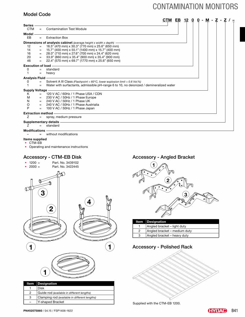
B41
CONTAMINATION MONITORS
PN#02075860 / 04.15 / FSP1406-1622
Model CodeCTM EB 12 0 0 - M - Z - Z / –
Series CTM = Contamination Test Module
Model EB = Extraction Box
Dimensions of analysis cabinet (average height x width x depth) 12 = 18.5” (470 mm) x 30.3” (770 mm) x 25.6” (650 mm) 14 = 15.7” (400 mm) x 55.1” (1400 mm) x 15.7” (400 mm) 16 = 28.0” (710 mm) x 27.6” (700 mm) x 24.4” (620 mm) 20 = 33.9” (860 mm) x 35.4” (900 mm) x 35.4” (900 mm) 46 = 22.4” (570 mm) x 69.7” (1770 mm) x 25.6” (650 mm)
Execution of load 0 = standard 1 = heavy
Analysis Fluid 0 = Solvent A III Class (Flashpoint > 60°C, lower explosion limit > 0.6 Vol.%) 1 = Water with surfactants, admissible pH-range 6 to 10, no deionized / demineralized water
Supply Voltage K = 120 V AC / 60Hz / 1 Phase USA / CDN M = 230 V AC / 50Hz / 1 Phase Europe N = 240 V AC / 50Hz / 1 Phase UK O = 240 V AC / 50Hz / 1 Phase Austrialia P = 100 V AC / 50Hz / 1 Phase Japan
Extraction method Z = spray, medium pressure
Supplementary details Z = standard
Modifications – = without modifications
Items supplied• CTM-EB• Operating and maintenance instructions
Item Designation1 Disk2 Guide rod (available in different lengths)
3 Clamping rod (available in different lengths)
– Y-shaped Bracket
Item Designation1 Angled bracket – light duty2 Angled bracket – medium duty3 Angled bracket – heavy duty
1 1
1
2
34
Accessory - CTM-EB Disk• 1200 = Part. No. 3439102• 2000 = Part. No. 3422445 1
2
3
Accessory - Angled Bracket
Accessory - Polished Rack
Supplied with the CTM-EB 1200.
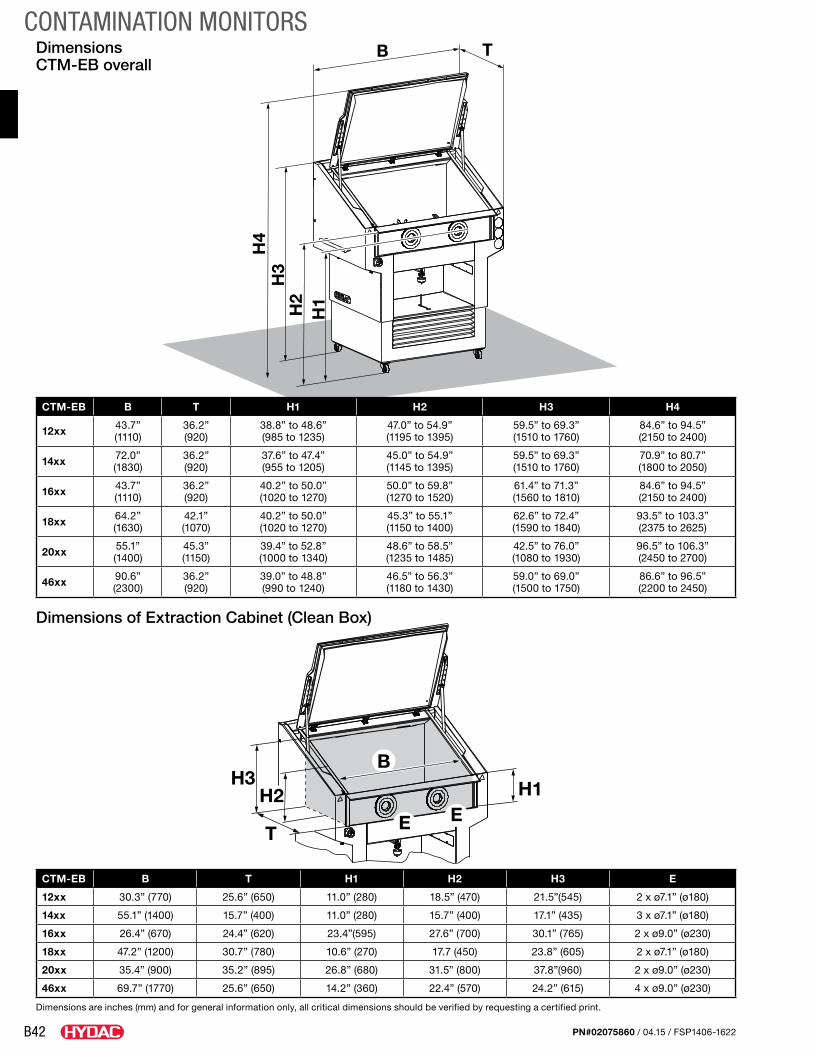
B42
CONTAMINATION MONITORS
PN#02075860 / 04.15 / FSP1406-1622
Dimensions CTM-EB overall
Dimensions are inches (mm) and for general information only, all critical dimensions should be verified by requesting a certified print.
CTM-EB B T H1 H2 H3 E
12xx 30.3” (770) 25.6” (650) 11.0” (280) 18.5” (470) 21.5”(545) 2 x ø7.1” (ø180)
14xx 55.1” (1400) 15.7” (400) 11.0” (280) 15.7” (400) 17.1” (435) 3 x ø7.1” (ø180)
16xx 26.4” (670) 24.4” (620) 23.4”(595) 27.6” (700) 30.1” (765) 2 x ø9.0” (ø230)
18xx 47.2” (1200) 30.7” (780) 10.6” (270) 17.7 (450) 23.8” (605) 2 x ø7.1” (ø180)
20xx 35.4” (900) 35.2” (895) 26.8” (680) 31.5” (800) 37.8”(960) 2 x ø9.0” (ø230)
46xx 69.7” (1770) 25.6” (650) 14.2” (360) 22.4” (570) 24.2” (615) 4 x ø9.0” (ø230)
H1H2
H3
H4
B T
H1H2H3
T
B
E E
Dimensions of Extraction Cabinet (Clean Box)
CTM-EB B T H1 H2 H3 H4
12xx 43.7”(1110)
36.2”(920)
38.8” to 48.6”(985 to 1235)
47.0” to 54.9”(1195 to 1395)
59.5” to 69.3”(1510 to 1760)
84.6” to 94.5”(2150 to 2400)
14xx 72.0”(1830)
36.2”(920)
37.6” to 47.4”(955 to 1205)
45.0” to 54.9”(1145 to 1395)
59.5” to 69.3”(1510 to 1760)
70.9” to 80.7”(1800 to 2050)
16xx 43.7”(1110)
36.2”(920)
40.2” to 50.0”(1020 to 1270)
50.0” to 59.8”(1270 to 1520)
61.4” to 71.3”(1560 to 1810)
84.6” to 94.5”(2150 to 2400)
18xx 64.2”(1630)
42.1”(1070)
40.2” to 50.0”(1020 to 1270)
45.3” to 55.1”(1150 to 1400)
62.6” to 72.4”(1590 to 1840)
93.5” to 103.3”(2375 to 2625)
20xx 55.1”(1400)
45.3”(1150)
39.4” to 52.8”(1000 to 1340)
48.6” to 58.5”(1235 to 1485)
42.5” to 76.0”(1080 to 1930)
96.5” to 106.3”(2450 to 2700)
46xx 90.6”(2300)
36.2”(920)
39.0” to 48.8”(990 to 1240)
46.5” to 56.3”(1180 to 1430)
59.0” to 69.0”(1500 to 1750)
86.6” to 96.5”(2200 to 2450)
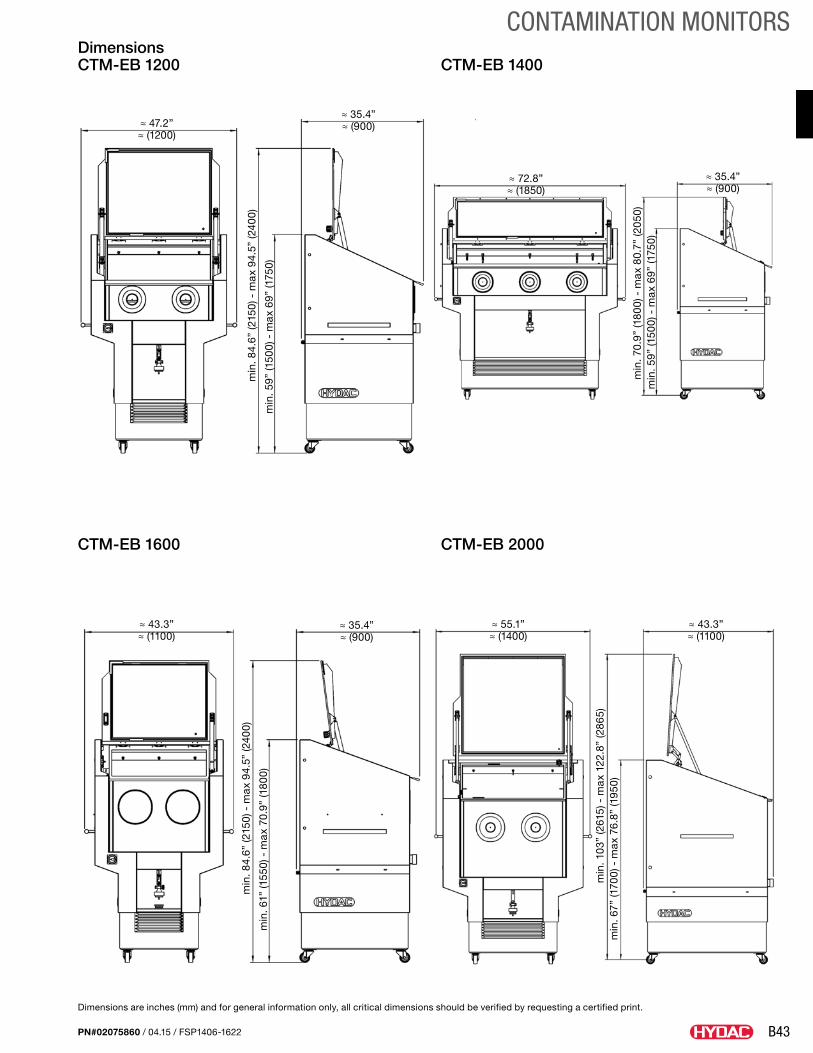
B43
CONTAMINATION MONITORS
PN#02075860 / 04.15 / FSP1406-1622
Dimensions CTM-EB 1200 CTM-EB 1400
CTM-EB 1600 CTM-EB 2000
≈ 47.2”≈ (1200)
≈ 35.4”≈ (900)
≈ 35.4”≈ (900)
≈ 35.4”≈ (900)
≈ 43.3”≈ (1100)
≈ 43.3”≈ (1100)
≈ 55.1”≈ (1400)
≈ 72.8”≈ (1850)
min
. 84.
6” (2
150)
- m
ax 9
4.5”
(240
0)m
in. 8
4.6”
(215
0) -
max
94.
5” (2
400)
min
. 103
” (2
615)
- m
ax 1
22.8
” (2
865)
min
. 70.
9” (1
800)
- m
ax 8
0.7”
(205
0)
min
. 59”
(150
0) -
max
69”
(175
0)m
in. 6
1” (1
550)
- m
ax 7
0.9”
(180
0)
min
. 67”
(170
0) -
max
76.
8” (1
950)
min
. 59”
(150
0) -
max
69”
(175
0)
Dimensions are inches (mm) and for general information only, all critical dimensions should be verified by requesting a certified print.
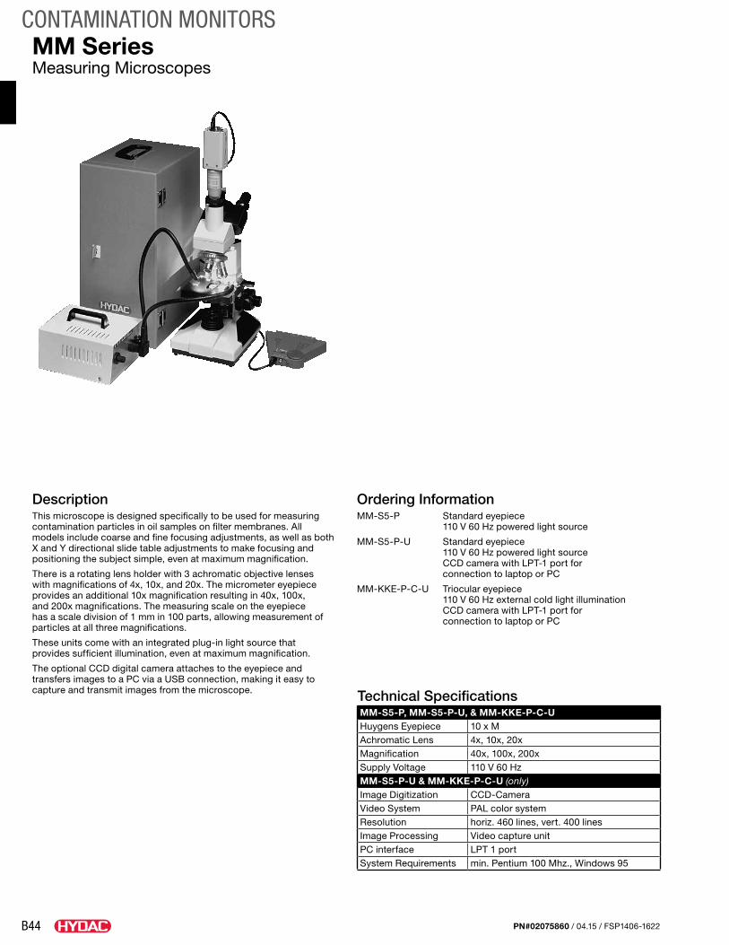
B44
CONTAMINATION MONITORS
PN#02075860 / 04.15 / FSP1406-1622
DescriptionThis microscope is designed specifically to be used for measuring contamination particles in oil samples on filter membranes. All models include coarse and fine focusing adjustments, as well as both X and Y directional slide table adjustments to make focusing and positioning the subject simple, even at maximum magnification.
There is a rotating lens holder with 3 achromatic objective lenses with magnifications of 4x, 10x, and 20x. The micrometer eyepiece provides an additional 10x magnification resulting in 40x, 100x, and 200x magnifications. The measuring scale on the eyepiece has a scale division of 1 mm in 100 parts, allowing measurement of particles at all three magnifications.
These units come with an integrated plug-in light source that provides sufficient illumination, even at maximum magnification.
The optional CCD digital camera attaches to the eyepiece and transfers images to a PC via a USB connection, making it easy to capture and transmit images from the microscope. Technical Specifications
MM-S5-P, MM-S5-P-U, & MM-KKE-P-C-UHuygens Eyepiece 10 x MAchromatic Lens 4x, 10x, 20xMagnification 40x, 100x, 200xSupply Voltage 110 V 60 HzMM-S5-P-U & MM-KKE-P-C-U (only)Image Digitization CCD-CameraVideo System PAL color systemResolution horiz. 460 lines, vert. 400 linesImage Processing Video capture unitPC interface LPT 1 portSystem Requirements min. Pentium 100 Mhz., Windows 95
MM SeriesMeasuring Microscopes
Ordering InformationMM-S5-P Standard eyepiece
110 V 60 Hz powered light source
MM-S5-P-U Standard eyepiece 110 V 60 Hz powered light source CCD camera with LPT-1 port for connection to laptop or PC
MM-KKE-P-C-U Triocular eyepiece 110 V 60 Hz external cold light illumination CCD camera with LPT-1 port for connection to laptop or PC
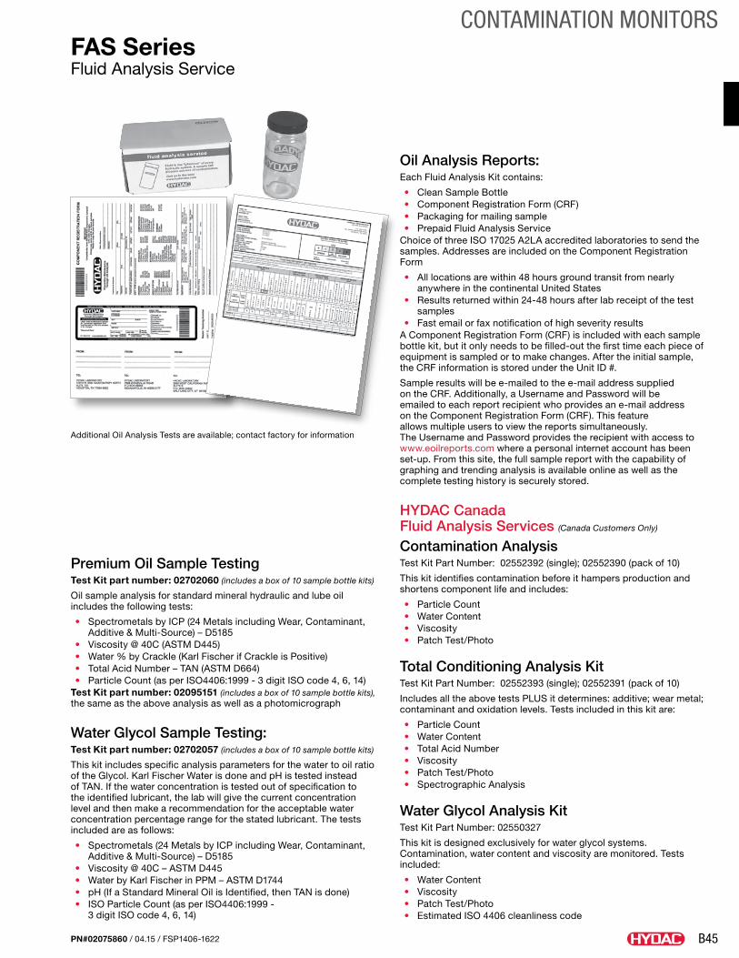
B45
CONTAMINATION MONITORS
PN#02075860 / 04.15 / FSP1406-1622
Premium Oil Sample TestingTest Kit part number: 02702060 (includes a box of 10 sample bottle kits)
Oil sample analysis for standard mineral hydraulic and lube oil includes the following tests:
• Spectrometals by ICP (24 Metals including Wear, Contaminant, Additive & Multi-Source) – D5185
• Viscosity @ 40C (ASTM D445) • Water % by Crackle (Karl Fischer if Crackle is Positive) • Total Acid Number – TAN (ASTM D664) • Particle Count (as per ISO4406:1999 - 3 digit ISO code 4, 6, 14)
Test Kit part number: 02095151 (includes a box of 10 sample bottle kits), the same as the above analysis as well as a photomicrograph
Water Glycol Sample Testing: Test Kit part number: 02702057 (includes a box of 10 sample bottle kits)
This kit includes specific analysis parameters for the water to oil ratio of the Glycol. Karl Fischer Water is done and pH is tested instead of TAN. If the water concentration is tested out of specification to the identified lubricant, the lab will give the current concentration level and then make a recommendation for the acceptable water concentration percentage range for the stated lubricant. The tests included are as follows:
• Spectrometals (24 Metals by ICP including Wear, Contaminant, Additive & Multi-Source) – D5185
• Viscosity @ 40C – ASTM D445• Water by Karl Fischer in PPM – ASTM D1744• pH (If a Standard Mineral Oil is Identified, then TAN is done)• ISO Particle Count (as per ISO4406:1999 -
3 digit ISO code 4, 6, 14)
FAS SeriesFluid Analysis Service
Oil Analysis Reports:Each Fluid Analysis Kit contains:
• Clean Sample Bottle• Component Registration Form (CRF)• Packaging for mailing sample• Prepaid Fluid Analysis Service
Choice of three ISO 17025 A2LA accredited laboratories to send the samples. Addresses are included on the Component Registration Form
• All locations are within 48 hours ground transit from nearly anywhere in the continental United States
• Results returned within 24-48 hours after lab receipt of the test samples
• Fast email or fax notification of high severity resultsA Component Registration Form (CRF) is included with each sample bottle kit, but it only needs to be filled-out the first time each piece of equipment is sampled or to make changes. After the initial sample, the CRF information is stored under the Unit ID #.
Sample results will be e-mailed to the e-mail address supplied on the CRF. Additionally, a Username and Password will be emailed to each report recipient who provides an e-mail address on the Component Registration Form (CRF). This feature allows multiple users to view the reports simultaneously. The Username and Password provides the recipient with access to www.eoilreports.com where a personal internet account has been set-up. From this site, the full sample report with the capability of graphing and trending analysis is available online as well as the complete testing history is securely stored.
HYDAC Canada Fluid Analysis Services (Canada Customers Only)
Contamination Analysis Test Kit Part Number: 02552392 (single); 02552390 (pack of 10)
This kit identifies contamination before it hampers production and shortens component life and includes:
• Particle Count• Water Content• Viscosity• Patch Test/Photo
Total Conditioning Analysis Kit Test Kit Part Number: 02552393 (single); 02552391 (pack of 10)
Includes all the above tests PLUS it determines: additive; wear metal; contaminant and oxidation levels. Tests included in this kit are:
• Particle Count• Water Content• Total Acid Number• Viscosity• Patch Test/Photo• Spectrographic Analysis
Water Glycol Analysis Kit Test Kit Part Number: 02550327
This kit is designed exclusively for water glycol systems. Contamination, water content and viscosity are monitored. Tests included:
• Water Content• Viscosity• Patch Test/Photo• Estimated ISO 4406 cleanliness code
Additional Oil Analysis Tests are available; contact factory for information
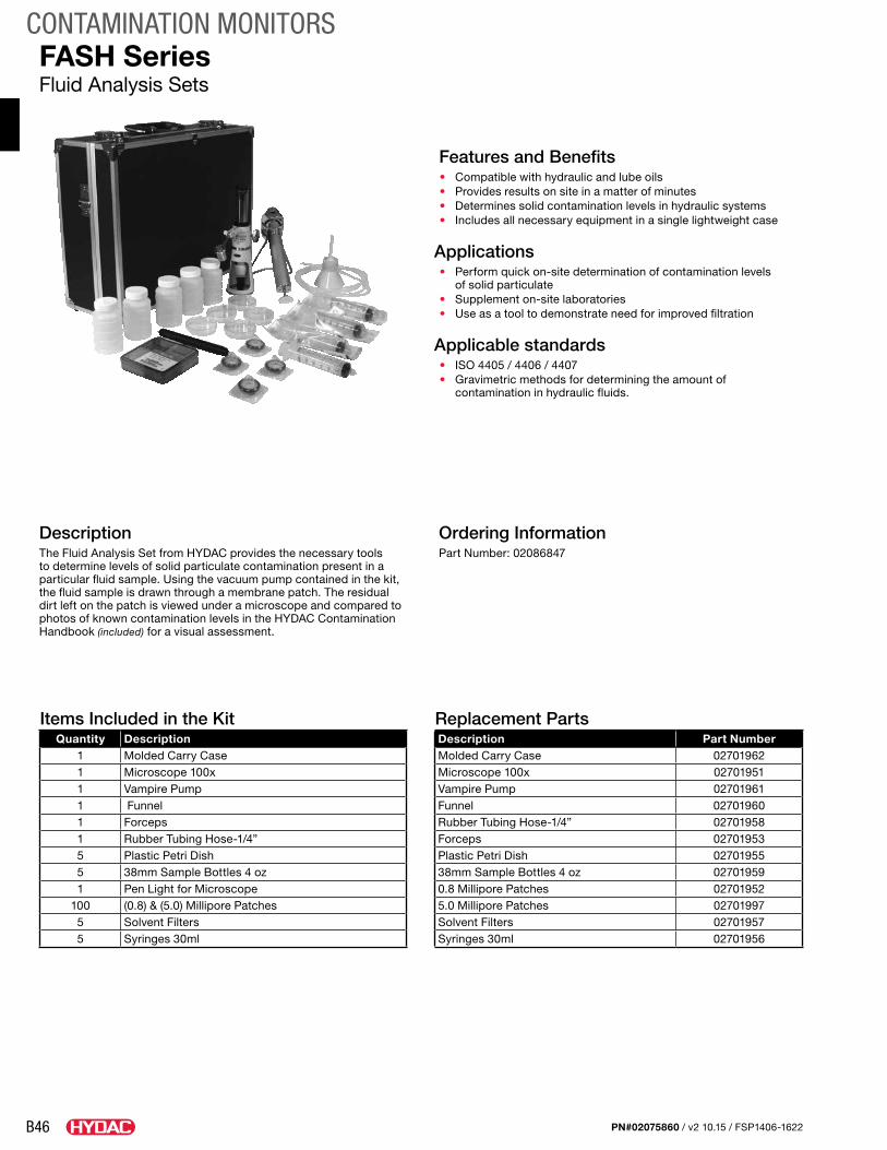
B46
CONTAMINATION MONITORS
PN#02075860 / v2 10.15 / FSP1406-1622
DescriptionThe Fluid Analysis Set from HYDAC provides the necessary tools to determine levels of solid particulate contamination present in a particular fluid sample. Using the vacuum pump contained in the kit, the fluid sample is drawn through a membrane patch. The residual dirt left on the patch is viewed under a microscope and compared to photos of known contamination levels in the HYDAC Contamination Handbook (included) for a visual assessment.
Replacement PartsDescription Part NumberMolded Carry Case 02701962Microscope 100x 02701951Vampire Pump 02701961Funnel 02701960Rubber Tubing Hose-1/4” 02701958Forceps 02701953Plastic Petri Dish 0270195538mm Sample Bottles 4 oz 027019590.8 Millipore Patches 027019525.0 Millipore Patches 02701997Solvent Filters 02701957Syringes 30ml 02701956
FASH SeriesFluid Analysis Sets
Items Included in the KitQuantity Description
1 Molded Carry Case1 Microscope 100x1 Vampire Pump1 Funnel1 Forceps1 Rubber Tubing Hose-1/4”5 Plastic Petri Dish 5 38mm Sample Bottles 4 oz 1 Pen Light for Microscope
100 (0.8) & (5.0) Millipore Patches 5 Solvent Filters 5 Syringes 30ml
Ordering InformationPart Number: 02086847
Features and Benefits • Compatible with hydraulic and lube oils • Provides results on site in a matter of minutes • Determines solid contamination levels in hydraulic systems• Includes all necessary equipment in a single lightweight case
Applications• Perform quick on-site determination of contamination levels
of solid particulate • Supplement on-site laboratories • Use as a tool to demonstrate need for improved filtration
Applicable standards• ISO 4405 / 4406 / 4407• Gravimetric methods for determining the amount of
contamination in hydraulic fluids.
C1
DIAGNOSTICS
PN#02075860 / 04.15 / FSP1406-1622
Diagnostic MonitoringThese units are designed for data capturing simple measurements (pressure, temperature, and flow rate) in hydraulic and pneumatic systems. Typical applications extend primarily to maintenance and servicing, troubleshooting and test stands, as well as, quality inspections.
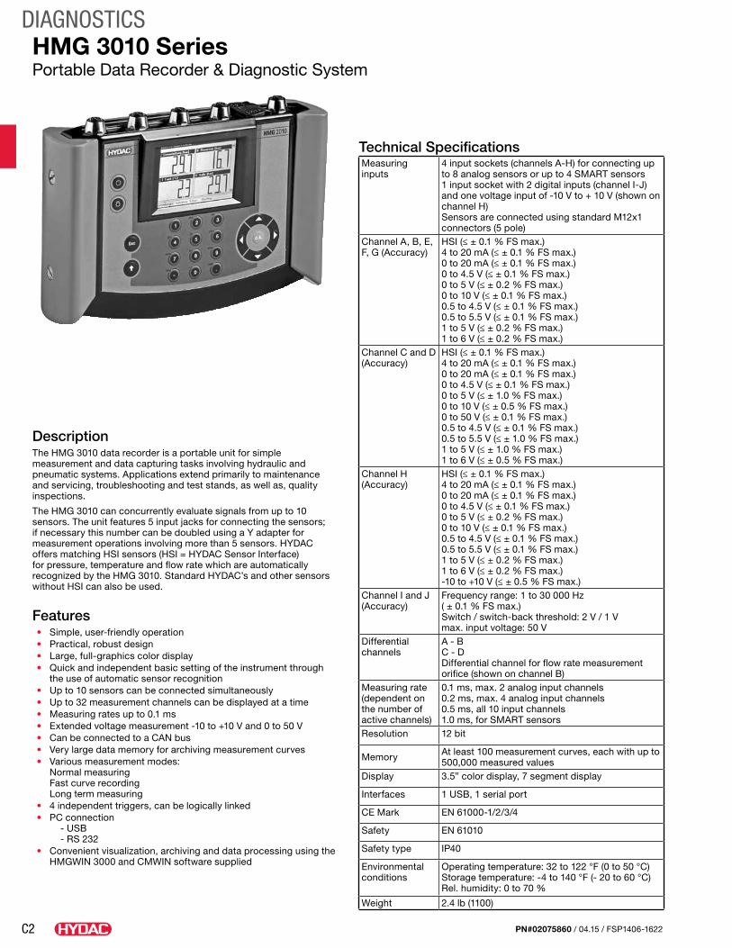
C2
DIAGNOSTICS
PN#02075860 / 04.15 / FSP1406-1622
DescriptionThe HMG 3010 data recorder is a portable unit for simple measurement and data capturing tasks involving hydraulic and pneumatic systems. Applications extend primarily to maintenance and servicing, troubleshooting and test stands, as well as, quality inspections.
The HMG 3010 can concurrently evaluate signals from up to 10 sensors. The unit features 5 input jacks for connecting the sensors; if necessary this number can be doubled using a Y adapter for measurement operations involving more than 5 sensors. HYDAC offers matching HSI sensors (HSI = HYDAC Sensor Interface) for pressure, temperature and flow rate which are automatically recognized by the HMG 3010. Standard HYDAC’s and other sensors without HSI can also be used.
Features• Simple, user-friendly operation• Practical, robust design• Large, full-graphics color display• Quick and independent basic setting of the instrument through
the use of automatic sensor recognition• Up to 10 sensors can be connected simultaneously• Up to 32 measurement channels can be displayed at a time• Measuring rates up to 0.1 ms• Extended voltage measurement -10 to +10 V and 0 to 50 V• Can be connected to a CAN bus• Very large data memory for archiving measurement curves• Various measurement modes:
Normal measuring Fast curve recording Long term measuring
• 4 independent triggers, can be logically linked• PC connection
- USB - RS 232
• Convenient visualization, archiving and data processing using the HMGWIN 3000 and CMWIN software supplied
HMG 3010 SeriesPortable Data Recorder & Diagnostic System
Technical SpecificationsMeasuring inputs
4 input sockets (channels A-H) for connecting up to 8 analog sensors or up to 4 SMART sensors 1 input socket with 2 digital inputs (channel I-J) and one voltage input of -10 V to + 10 V (shown on channel H)Sensors are connected using standard M12x1 connectors (5 pole)
Channel A, B, E, F, G (Accuracy)
HSI (≤ ± 0.1 % FS max.) 4 to 20 mA (≤ ± 0.1 % FS max.) 0 to 20 mA (≤ ± 0.1 % FS max.) 0 to 4.5 V (≤ ± 0.1 % FS max.) 0 to 5 V (≤ ± 0.2 % FS max.) 0 to 10 V (≤ ± 0.1 % FS max.) 0.5 to 4.5 V (≤ ± 0.1 % FS max.) 0.5 to 5.5 V (≤ ± 0.1 % FS max.) 1 to 5 V (≤ ± 0.2 % FS max.) 1 to 6 V (≤ ± 0.2 % FS max.)
Channel C and D (Accuracy)
HSI (≤ ± 0.1 % FS max.) 4 to 20 mA (≤ ± 0.1 % FS max.) 0 to 20 mA (≤ ± 0.1 % FS max.) 0 to 4.5 V (≤ ± 0.1 % FS max.) 0 to 5 V (≤ ± 1.0 % FS max.) 0 to 10 V (≤ ± 0.5 % FS max.) 0 to 50 V (≤ ± 0.1 % FS max.) 0.5 to 4.5 V (≤ ± 0.1 % FS max.) 0.5 to 5.5 V (≤ ± 1.0 % FS max.) 1 to 5 V (≤ ± 1.0 % FS max.) 1 to 6 V (≤ ± 0.5 % FS max.)
Channel H (Accuracy)
HSI (≤ ± 0.1 % FS max.) 4 to 20 mA (≤ ± 0.1 % FS max.) 0 to 20 mA (≤ ± 0.1 % FS max.) 0 to 4.5 V (≤ ± 0.1 % FS max.) 0 to 5 V (≤ ± 0.2 % FS max.) 0 to 10 V (≤ ± 0.1 % FS max.) 0.5 to 4.5 V (≤ ± 0.1 % FS max.) 0.5 to 5.5 V (≤ ± 0.1 % FS max.) 1 to 5 V (≤ ± 0.2 % FS max.) 1 to 6 V (≤ ± 0.2 % FS max.) -10 to +10 V (≤ ± 0.5 % FS max.)
Channel I and J (Accuracy)
Frequency range: 1 to 30 000 Hz ( ± 0.1 % FS max.) Switch / switch-back threshold: 2 V / 1 V max. input voltage: 50 V
Differential channels
A - B C - D Differential channel for flow rate measurement orifice (shown on channel B)
Measuring rate (dependent on the number of active channels)
0.1 ms, max. 2 analog input channels 0.2 ms, max. 4 analog input channels 0.5 ms, all 10 input channels 1.0 ms, for SMART sensors
Resolution 12 bit
Memory At least 100 measurement curves, each with up to 500,000 measured values
Display 3.5” color display, 7 segment display
Interfaces 1 USB, 1 serial port
CE Mark EN 61000-1/2/3/4
Safety EN 61010
Safety type IP40
Environmental conditions
Operating temperature: 32 to 122 °F (0 to 50 °C) Storage temperature: -4 to 140 °F (- 20 to 60 °C) Rel. humidity: 0 to 70 %
Weight 2.4 lb (1100)
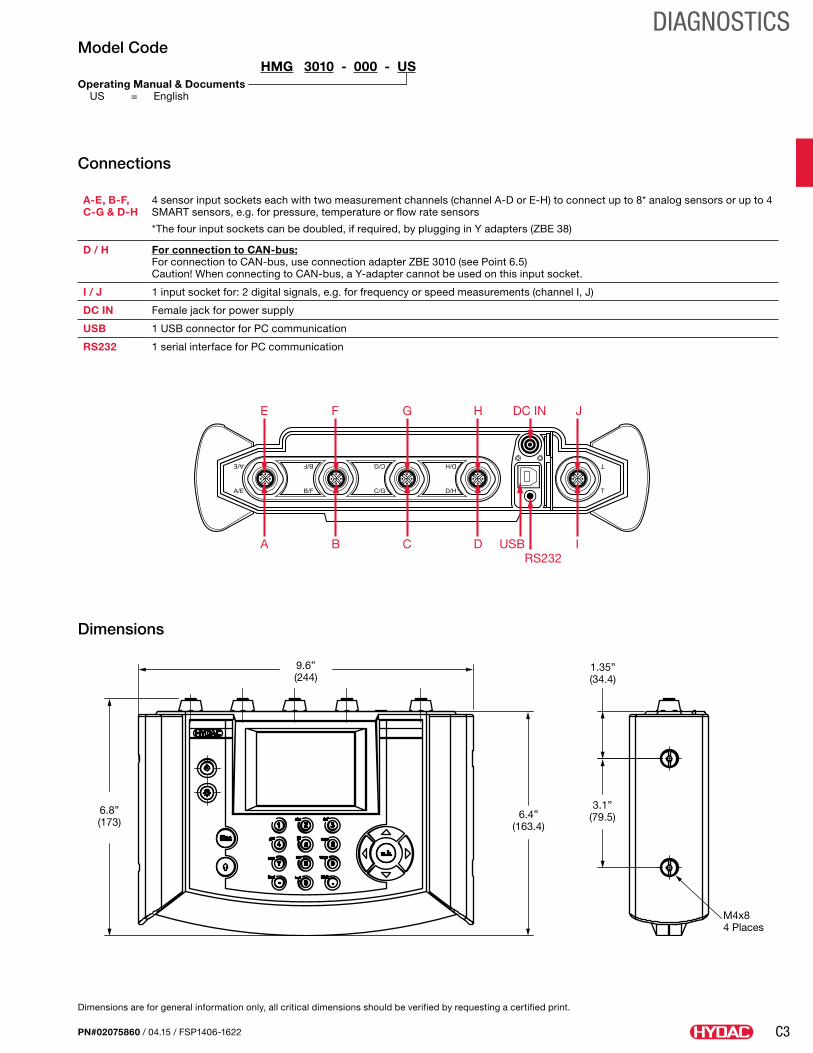
C3
DIAGNOSTICS
PN#02075860 / 04.15 / FSP1406-1622
Model CodeHMG 3010 - 000 - US
Operating Manual & Documents US = English
Connections
A-E, B-F, C-G & D-H
4 sensor input sockets each with two measurement channels (channel A-D or E-H) to connect up to 8* analog sensors or up to 4 SMART sensors, e.g. for pressure, temperature or flow rate sensors
* The four input sockets can be doubled, if required, by plugging in Y adapters (ZBE 38)
D / H For connection to CAN-bus: For connection to CAN-bus, use connection adapter ZBE 3010 (see Point 6.5) Caution! When connecting to CAN-bus, a Y-adapter cannot be used on this input socket.
I / J 1 input socket for: 2 digital signals, e.g. for frequency or speed measurements (channel I, J)
DC IN Female jack for power supply
USB 1 USB connector for PC communication
RS232 1 serial interface for PC communication
DC INHGFE J
USBRS232
DCBA I
Dimensions
6.4”(163.4)
6.8”(173)
9.6”(244)
1.35”(34.4)
3.1”(79.5)
M4x84 Places
Dimensions are for general information only, all critical dimensions should be verified by requesting a certified print.
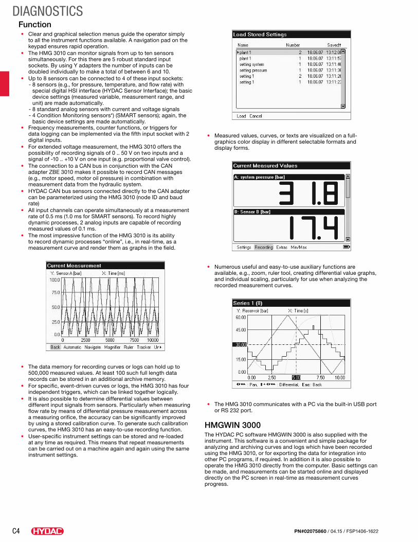
C4
DIAGNOSTICS
PN#02075860 / 04.15 / FSP1406-1622
Function• Clear and graphical selection menus guide the operator simply
to all the instrument functions available. A navigation pad on the keypad ensures rapid operation.
• The HMG 3010 can monitor signals from up to ten sensors simultaneously. For this there are 5 robust standard input sockets. By using Y adapters the number of inputs can be doubled individually to make a total of between 6 and 10.
• Up to 8 sensors can be connected to 4 of these input sockets: - 8 sensors (e.g., for pressure, temperature, and flow rate) with
special digital HSI interface (HYDAC Sensor Interface); the basic device settings (measured variable, measurement range, and unit) are made automatically.
- 8 standard analog sensors with current and voltage signals - 4 Condition Monitoring sensors*) (SMART sensors); again, the
basic device settings are made automatically.• Frequency measurements, counter functions, or triggers for
data logging can be implemented via the fifth input socket with 2 digital inputs.
• For extended voltage measurement, the HMG 3010 offers the possibility of recording signals of 0 .. 50 V on two inputs and a signal of -10 .. +10 V on one input (e.g. proportional valve control).
• The connection to a CAN bus in conjunction with the CAN adapter ZBE 3010 makes it possible to record CAN messages (e.g., motor speed, motor oil pressure) in combination with measurement data from the hydraulic system.
• HYDAC CAN bus sensors connected directly to the CAN adapter can be parameterized using the HMG 3010 (node ID and baud rate)
• All input channels can operate simultaneously at a measurement rate of 0.5 ms (1.0 ms for SMART sensors). To record highly dynamic processes, 2 analog inputs are capable of recording measured values of 0.1 ms.
• The most impressive function of the HMG 3010 is its ability to record dynamic processes “online”, i.e., in real-time, as a measurement curve and render them as graphs in the field.
• The data memory for recording curves or logs can hold up to 500,000 measured values. At least 100 such full length data records can be stored in an additional archive memory.
• For specific, event-driven curves or logs, the HMG 3010 has four independent triggers, which can be linked together logically.
• It is also possible to determine differential values between different input signals from sensors. Particularly when measuring flow rate by means of differential pressure measurement across a measuring orifice, the accuracy can be significantly improved by using a stored calibration curve. To generate such calibration curves, the HMG 3010 has an easy-to-use recording function.
• User-specific instrument settings can be stored and re-loaded at any time as required. This means that repeat measurements can be carried out on a machine again and again using the same instrument settings.
• Measured values, curves, or texts are visualized on a full-graphics color display in different selectable formats and display forms.
• Numerous useful and easy-to-use auxiliary functions are available, e.g., zoom, ruler tool, creating differential value graphs, and individual scaling, particularly for use when analyzing the recorded measurement curves.
• The HMG 3010 communicates with a PC via the built-in USB port or RS 232 port.
HMGWIN 3000The HYDAC PC software HMGWIN 3000 is also supplied with the instrument. This software is a convenient and simple package for analyzing and archiving curves and logs which have been recorded using the HMG 3010, or for exporting the data for integration into other PC programs, if required. In addition it is also possible to operate the HMG 3010 directly from the computer. Basic settings can be made, and measurements can be started online and displayed directly on the PC screen in real-time as measurement curves progress.
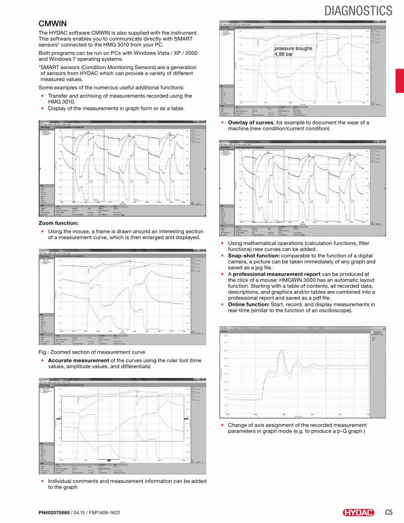
C5
DIAGNOSTICS
PN#02075860 / 04.15 / FSP1406-1622
CMWINThe HYDAC software CMWIN is also supplied with the instrument. This software enables you to communicate directly with SMART sensors* connected to the HMG 3010 from your PC.
Both programs can be run on PCs with Windows Vista / XP / 2000 and Windows 7 operating systems.
* SMART sensors (Condition Monitoring Sensors) are a generation of sensors from HYDAC which can provide a variety of different measured values.
Some examples of the numerous useful additional functions:
• Transfer and archiving of measurements recorded using the HMG 3010.
• Display of the measurements in graph form or as a table.
Zoom function:
• Using the mouse, a frame is drawn around an interesting section of a measurement curve, which is then enlarged and displayed.
Fig.: Zoomed section of measurement curve
• Accurate measurement of the curves using the ruler tool (time values, amplitude values, and differentials)
• Individual comments and measurement information can be added to the graph
• Overlay of curves, for example to document the wear of a machine (new condition/current condition)
• Using mathematical operations (calculation functions, filter functions) new curves can be added.
• Snap-shot function: comparable to the function of a digital camera, a picture can be taken immediately of any graph and saved as a jpg file.
• A professional measurement report can be produced at the click of a mouse: HMGWIN 3000 has an automatic layout function. Starting with a table of contents, all recorded data, descriptions, and graphics and/or tables are combined into a professional report and saved as a pdf file.
• Online function: Start, record, and display measurements in real-time (similar to the function of an oscilloscope).
• Change of axis assignment of the recorded measurement parameters in graph mode (e.g. to produce a p-Q graph )
C6
DIAGNOSTICS
PN#02075860 / 04.15 / FSP1406-1622
Diagnostic UnitModel Code Description Part No.HMG 3010-000-US Includes:
HMG 3010-000 with ManualBattery Set & Charging Unit HMGWIN & CMWIN software w/USB cable
922938
Pressure Transducer with HSI (HYDAC Sensor Interface)
Model Code Description Part No.HDA 4748-H-0009-000 -14.5 to 130.5 psi (-1 to 9 bar) 00909429HDA 4748-H-0016-000 0 to 230 psi (0 to 16 bar) 00909425HDA 4748-H-0060-000 0 to 870 psi (0 to 60 bar) 00909554HDA 4748-H-0100-000 0 to 1450 psi (0 to 100 bar) 00909426HDA 4748-H-0250-000 0 to 3625 psi (0 to 250 bar) 00909337HDA 4748-H-0400-000 0 to 5800 psi (0 to 400 bar) 00909427HDA 4748-H-0600-000 0 to 8700 psi (0 to 600 bar) 00909428HDA 4778-H-0135-000 -14.5 to 135.5 psi (-1 to 9.34 bar) 00920755HDA 4778-H-0150-000 0 to 150 psi (0 to 10 bar) 00920663HDA 4778-H-1500-000 0 to 1500 psi (0 to 103 bar) 00920757HDA 4778-H-3000-000 0 to 3000 psi (0 to 207 bar) 00920756HDA 4778-H-6000-000 0 to 6000 psi (0 to 413 bar) 00920664HDA 4778-H-9000-000 0 to 9000 psi (0 to 621 bar) 00920665
Flow Sensor with HSI (HYDAC Sensor Interface)
Model Code Description - g/min (l/min) Part No.AluminumEVS 3108-H-0020-000 0.26 to 5.28 (1.2 to 20) 00909405EVS 3108-H-0060-000 1.59 to 15.9 (6 to 60) 00909293EVS 3108-H-0300-000 3.96 to 79.3 (15 to 300) 00909404EVS 3108-H-0600-000 10.6 to 159 (40 to 600) 00909403Stainless SteelEVS 3118-H-0020-000 0.26 to 5.28 (1.2 to 20) 00909409EVS 3118-H-0060-000 1.59 to 15.9 (6 to 60) 00909406EVS 3118-H-0300-000 3.96 to 79.3 (15 to 300) 00909408EVS 3118-H-0600-000 10.6 to 159 (40 to 600) 00909407
Temperature Transducer with HSI (HYDAC Sensor Interface)
Model Code Description Part No.ETS 4148-H-006-000 -13° to 212°F (-25° to 100°C) 923398ETS 4578-H-000 -13° to 212°F (-25° to 100°C) 920662
Additional SensorsModel Code Description Part No.HDS 1000-002 RPM Sensor (plug M12x1) 2M
Includes HDS 1000 Reflector Set (part no. 00904812)
00909436
HDS 1000 Reflector Set
Reflective foil set 25 pieces 00904812
SSH 1000 Sensor simulator for 2 HSI (ideal for training purposes)
00909414
HYDAC HSI sensors are part of a new plug and play, self-identifying sensor line. HSI sensors must be used with the HMG 500 and facili-tate easy use with the HMG 3010. The HMG 3010 is capable of read-ing standard sensors as well as competitive models.
CAN adapter
• CAN adapter, required for CAN bus operation (ordered separately). ZBE 3010 CAN adapter for HMG 3010 Part no. 921238
• Additional accessories, such as electrical and mechanical connection adapters, power supplies, etc. can be found in the “Accessories - Service devices” catalog section
AccessoriesModel Code Description Part No.USB Cable Connection to PC 6040585ZBE 30-02 cable for M12x1 - 6’ 6040851ZBE 30-05 cable for M12x1 - 15’ 6040852ZBE 34 M12x1 / Binder adapter 3236597ZBE 35 M12x1 / Hirschmann adapter 3236601ZBE 36 AS 1000 (Aqua Sensor) Adapter 909737ZBE 38 M12 Y-adapter
(doubles the inputs)3224436
Hydraulic Adaptor Set (2 pieces each)
Adapter hose DN 2 / 1620/1620, 400mm and 1000 mm, pressure gauge connectors 1620 / G1/4, adapter 1615/1620, bulkhead couplings 1620/1620
903083
UVM 3000 Universal connection module for HMG 3010
909752
Bag with carry strap 909795Power Supply DC Charging unit for HMG 3010 6054296ZBE 31 Car Charger for HMG 3010 909739Pelican Case for HMG 3010 and accessories 2702730Aluminum Case for HMG 3010 and accessories 6042959
D1
OFFLINE FILTRATION SYSTEMS
PN#02075860 / 04.15 / FSP1406-1622
Offline Filtration SystemsToday’s hydraulic filter systems have seen a shift from reactionary to preventative, and even predictive maintenance. Total system contamination management begins with our Fluid Conditioning Products. These are hydraulic oil filter systems for removing contaminants and water from various types of hydraulic fluids. Our offline hydraulic oil filter systems include both mobile filtration carts with and without contamination monitoring units, stationary filtration systems from 1.3 gallon flow rates to customizable kidney loop systems up to 140 GPM. Our dewatering units, both vacuum dehydration and mass transfer systems offered and can remove both free and dissolved water from fluids for any reservoir size at various flow rates.
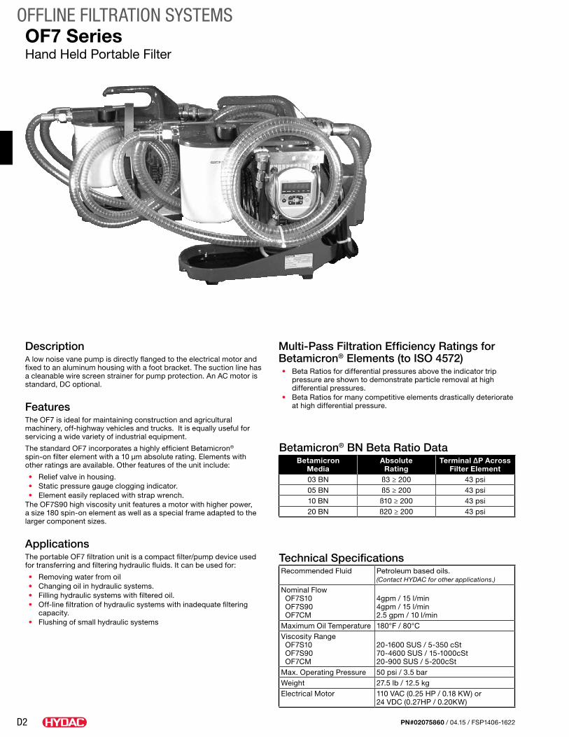
D2
OFFLINE FILTRATION SYSTEMS
PN#02075860 / 04.15 / FSP1406-1622
DescriptionA low noise vane pump is directly flanged to the electrical motor and fixed to an aluminum housing with a foot bracket. The suction line has a cleanable wire screen strainer for pump protection. An AC motor is standard, DC optional.
FeaturesThe OF7 is ideal for maintaining construction and agricultural machinery, off-highway vehicles and trucks. It is equally useful for servicing a wide variety of industrial equipment.
The standard OF7 incorporates a highly efficient Betamicron® spin-on filter element with a 10 µm absolute rating. Elements with other ratings are available. Other features of the unit include:
• Relief valve in housing.• Static pressure gauge clogging indicator.• Element easily replaced with strap wrench.
The OF7S90 high viscosity unit features a motor with higher power, a size 180 spin-on element as well as a special frame adapted to the larger component sizes.
Applications The portable OF7 filtration unit is a compact filter/pump device used for transferring and filtering hydraulic fluids. It can be used for:
• Removing water from oil• Changing oil in hydraulic systems.• Filling hydraulic systems with filtered oil.• Off-line filtration of hydraulic systems with inadequate filtering
capacity.• Flushing of small hydraulic systems
Technical SpecificationsRecommended Fluid Petroleum based oils.
(Contact HYDAC for other applications.)
Nominal Flow OF7S10 OF7S90 OF7CM
4gpm / 15 l/min4gpm / 15 l/min2.5 gpm / 10 l/min
Maximum Oil Temperature 180°F / 80°CViscosity Range OF7S10 OF7S90 OF7CM
20-1600 SUS / 5-350 cSt70-4600 SUS / 15-1000cSt20-900 SUS / 5-200cSt
Max. Operating Pressure 50 psi / 3.5 barWeight 27.5 lb / 12.5 kgElectrical Motor 110 VAC (0.25 HP / 0.18 KW) or
24 VDC (0.27HP / 0.20KW)
OF7 SeriesHand Held Portable Filter
Multi-Pass Filtration Efficiency Ratings for Betamicron® Elements (to ISO 4572)• Beta Ratios for differential pressures above the indicator trip
pressure are shown to demonstrate particle removal at high differential pressures.
• Beta Ratios for many competitive elements drastically deteriorate at high differential pressure.
Betamicron® BN Beta Ratio DataBetamicron
MediaAbsolute
RatingTerminal ∆P Across
Filter Element03 BN ß3 ≥ 200 43 psi05 BN ß5 ≥ 200 43 psi10 BN ß10 ≥ 200 43 psi20 BN ß20 ≥ 200 43 psi
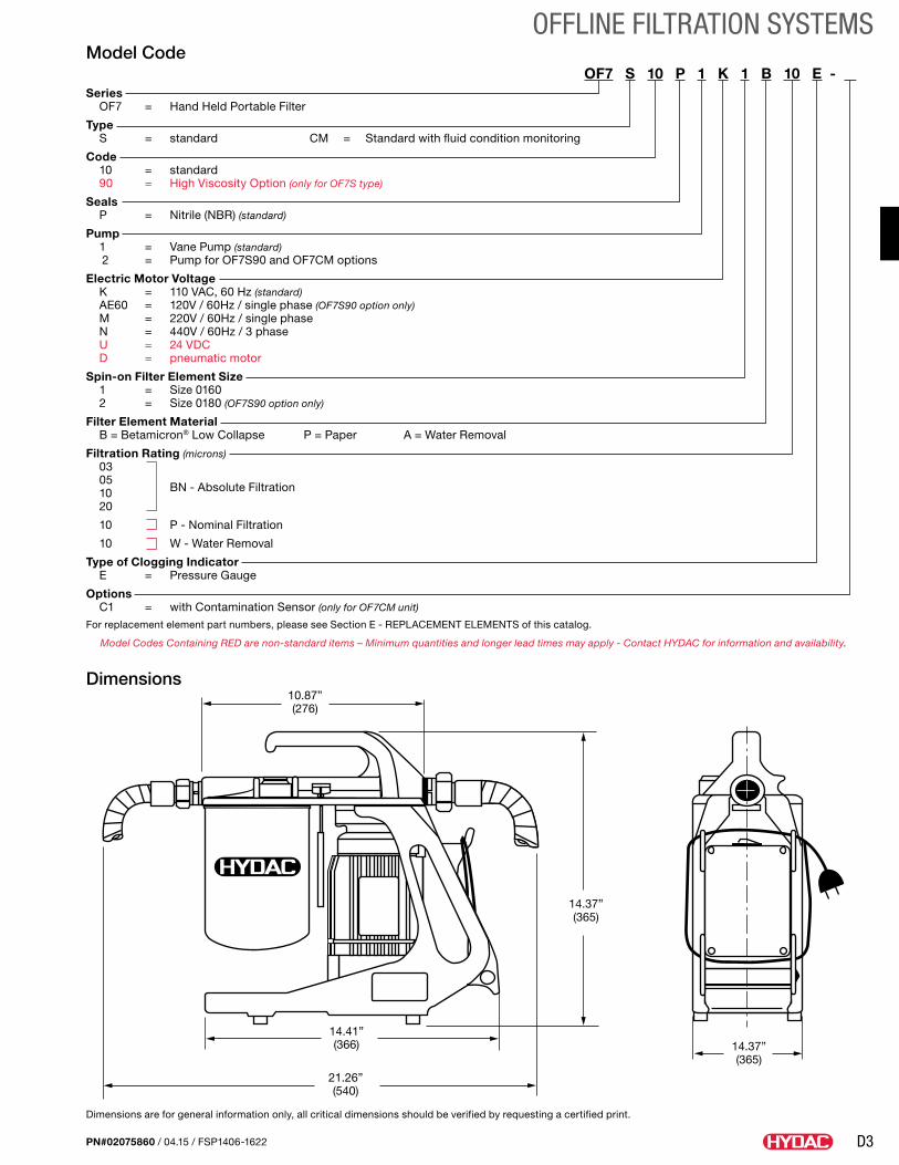
D3
OFFLINE FILTRATION SYSTEMS
PN#02075860 / 04.15 / FSP1406-1622
Model CodeOF7 S 10 P 1 K 1 B 10 E - .
Series OF7 = Hand Held Portable Filter
Type S = standard CM = Standard with fluid condition monitoring
Code 10 = standard 90 = High Viscosity Option (only for OF7S type)
Seals P = Nitrile (NBR) (standard)
Pump 1 = Vane Pump (standard) 2 = Pump for OF7S90 and OF7CM options
Electric Motor Voltage K = 110 VAC, 60 Hz (standard) AE60 = 120V / 60Hz / single phase (OF7S90 option only) M = 220V / 60Hz / single phase N = 440V / 60Hz / 3 phase U = 24 VDC D = pneumatic motor
Spin-on Filter Element Size 1 = Size 0160 2 = Size 0180 (OF7S90 option only)
Filter Element Material B = Betamicron® Low Collapse P = Paper A = Water Removal
Filtration Rating (microns) 03 05
BN - Absolute Filtration
10 20
10 P - Nominal Filtration
10 W - Water Removal
Type of Clogging Indicator E = Pressure Gauge
Options C1 = with Contamination Sensor (only for OF7CM unit)
For replacement element part numbers, please see Section E - REPLACEMENT ELEMENTS of this catalog.
Model Codes Containing RED are non-standard items – Minimum quantities and longer lead times may apply - Contact HYDAC for information and availability.
Dimensions10.87”(276)
14.37”(365)
14.41”(366)
21.26”(540)
14.37”(365)
Dimensions are for general information only, all critical dimensions should be verified by requesting a certified print.
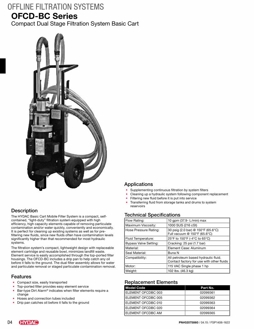
D4
OFFLINE FILTRATION SYSTEMS
PN#02075860 / 04.15 / FSP1406-1622
OFCD-BC SeriesCompact Dual Stage Filtration System Basic Cart
DescriptionThe HYDAC Basic Cart Mobile Filter System is a compact, self-contained, “light-duty” filtration system equipped with high efficiency, high capacity elements capable of removing particulate contamination and/or water quickly, conveniently and economically. It is perfect for cleaning up existing systems as well as for pre-filtering new fluids, since new fluids often have contamination levels significantly higher than that recommended for most hydraulic systems.
The filtration system’s compact, lightweight design with replaceable element cartridge and reusable bowl, minimizes landfill waste. Element service is easily accomplished through the top-ported filter housings. The OFCD-BC includes a drip pan to help catch any oil before it falls to the ground. The dual filter assembly allows for water and particulate removal or staged particulate contamination removal.
Features• Compact size, easily transported• Top-ported filter provides easy element service• Bar-type Dirt Alarm® indicates when filter elements require a
change• Hoses and connection tubes included• Drip pan catches oil before it falls to the ground
Applications• Supplementing continuous filtration by system filters• Cleaning up a hydraulic system following component replacement• Filtering new fluid before it is put into service• Transferring fluid from storage tanks and drums to system
reservoirs
Technical SpecificationsFlow Rating: 10 gpm (37.9- L/min) maxMaximum Viscosity: 1000 SUS (216 cSt)Hose Pressure Rating: 30 psig (2.0 bar) @ 150°F (65.6°C)
Full vacuum @ 150°F (65.6°C)Fluid Temperature: 25°F to 150°F (-4°C to 65°C)Bypass Valve Setting: Cracking: 25 psi (1.7 bar)Material: Element Case: AluminumSeal Material: Buna NCompatibility: All petroleum based hydraulic fluid.
Contact factory for use with other fluidsMotor: 115 VAC Single phase 1 hpWeight: 102 lbs. (46.3 kg)
Replacement ElementsModel Code Part No.ELEMENT OFCDBC 003 02099361
ELEMENT OFCDBC 005 02099362
ELEMENT OFCDBC 010 02099363
ELEMENT OFCDBC 020 02099364
ELEMENT OFCDBC AM 02099365
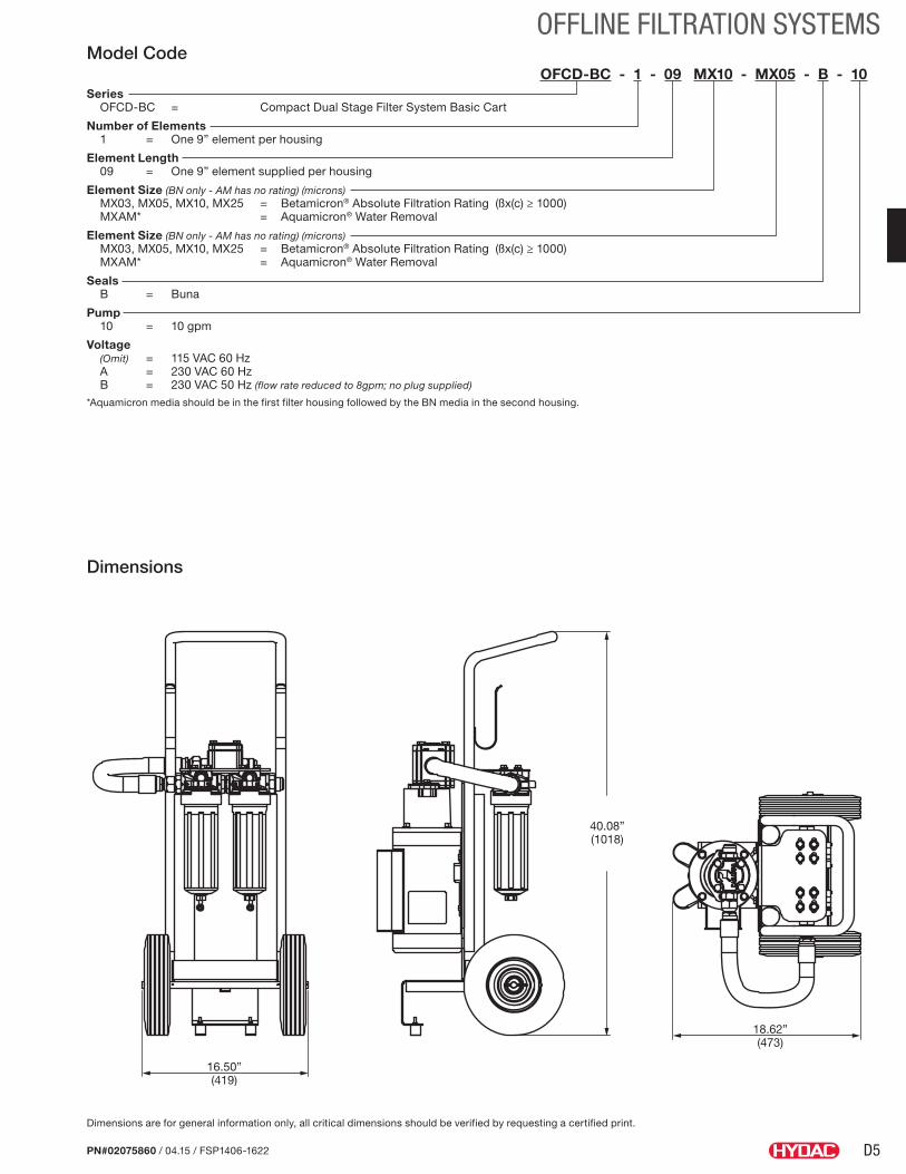
D5
OFFLINE FILTRATION SYSTEMS
PN#02075860 / 04.15 / FSP1406-1622
Model CodeOFCD-BC - 1 - 09 MX10 - MX05 - B - 10
Series OFCD-BC = Compact Dual Stage Filter System Basic Cart
Number of Elements 1 = One 9” element per housing
Element Length 09 = One 9” element supplied per housing
Element Size (BN only - AM has no rating) (microns) MX03, MX05, MX10, MX25 = Betamicron® Absolute Filtration Rating (ßx(c) ≥ 1000) MXAM* = Aquamicron® Water Removal
Element Size (BN only - AM has no rating) (microns) MX03, MX05, MX10, MX25 = Betamicron® Absolute Filtration Rating (ßx(c) ≥ 1000) MXAM* = Aquamicron® Water Removal
Seals B = Buna
Pump 10 = 10 gpm
Voltage (Omit) = 115 VAC 60 Hz A = 230 VAC 60 Hz B = 230 VAC 50 Hz (flow rate reduced to 8gpm; no plug supplied)
*Aquamicron media should be in the first filter housing followed by the BN media in the second housing.
16.50”(419)
18.62”(473)
40.08”(1018)
Dimensions
Dimensions are for general information only, all critical dimensions should be verified by requesting a certified print.
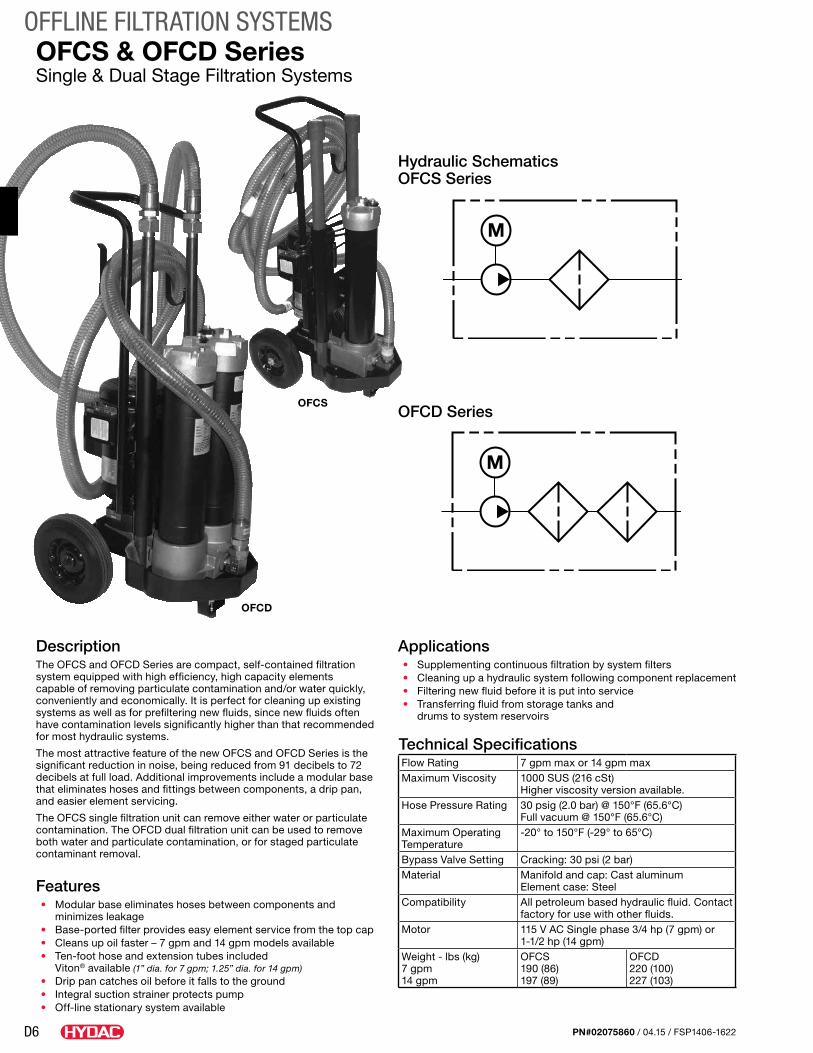
D6
OFFLINE FILTRATION SYSTEMS
PN#02075860 / 04.15 / FSP1406-1622
OFCS & OFCD SeriesSingle & Dual Stage Filtration Systems
DescriptionThe OFCS and OFCD Series are compact, self-contained filtration system equipped with high efficiency, high capacity elements capable of removing particulate contamination and/or water quickly, conveniently and economically. It is perfect for cleaning up existing systems as well as for prefiltering new fluids, since new fluids often have contamination levels significantly higher than that recommended for most hydraulic systems.
The most attractive feature of the new OFCS and OFCD Series is the significant reduction in noise, being reduced from 91 decibels to 72 decibels at full load. Additional improvements include a modular base that eliminates hoses and fittings between components, a drip pan, and easier element servicing.
The OFCS single filtration unit can remove either water or particulate contamination. The OFCD dual filtration unit can be used to remove both water and particulate contamination, or for staged particulate contaminant removal.
Features• Modular base eliminates hoses between components and
minimizes leakage• Base-ported filter provides easy element service from the top cap• Cleans up oil faster – 7 gpm and 14 gpm models available• Ten-foot hose and extension tubes included
Viton® available (1” dia. for 7 gpm; 1.25” dia. for 14 gpm)• Drip pan catches oil before it falls to the ground• Integral suction strainer protects pump• Off-line stationary system available
OFCS
OFCD
Applications• Supplementing continuous filtration by system filters• Cleaning up a hydraulic system following component replacement• Filtering new fluid before it is put into service• Transferring fluid from storage tanks and
drums to system reservoirs
Technical SpecificationsFlow Rating 7 gpm max or 14 gpm maxMaximum Viscosity 1000 SUS (216 cSt)
Higher viscosity version available. Hose Pressure Rating 30 psig (2.0 bar) @ 150°F (65.6°C)
Full vacuum @ 150°F (65.6°C)Maximum Operating Temperature
-20° to 150°F (-29° to 65°C)
Bypass Valve Setting Cracking: 30 psi (2 bar)Material Manifold and cap: Cast aluminum
Element case: SteelCompatibility All petroleum based hydraulic fluid. Contact
factory for use with other fluids.Motor 115 V AC Single phase 3/4 hp (7 gpm) or
1-1/2 hp (14 gpm)Weight - lbs (kg) 7 gpm 14 gpm
OFCS 190 (86) 197 (89)
OFCD 220 (100) 227 (103)
M
M
Hydraulic Schematics OFCS Series
OFCD Series
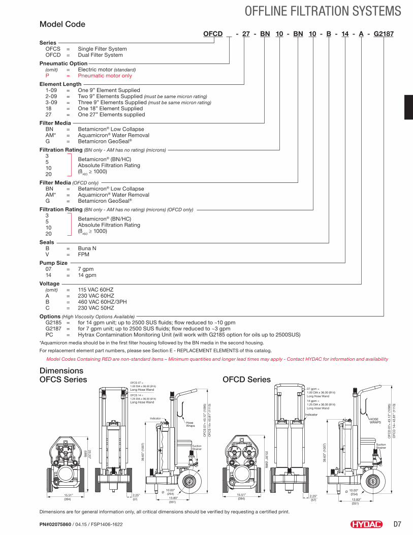
D7
OFFLINE FILTRATION SYSTEMS
PN#02075860 / 04.15 / FSP1406-1622
Model CodeOFCD - 27 - BN 10 - BN 10 - B - 14 - A - G2187.
Series OFCS = Single Filter System OFCD = Dual Filter System
Pneumatic Option (omit) = Electric motor (standard) P = Pneumatic motor only
Element Length 1-09 = One 9” Element Supplied 2-09 = Two 9” Elements Supplied (must be same micron rating) 3-09 = Three 9” Elements Supplied (must be same micron rating) 18 = One 18” Element Supplied 27 = One 27” Elements supplied
Filter Media BN = Betamicron® Low Collapse AM* = Aquamicron® Water Removal G = Betamicron GeoSeal®
Filtration Rating (BN only - AM has no rating) (microns) 3
Betamicron® (BN/HC)
5 Absolute Filtration Rating
10
(ßx(c) ≥ 1000)
20
Filter Media (OFCD only) BN = Betamicron® Low Collapse AM* = Aquamicron® Water Removal G = Betamicron GeoSeal®
Filtration Rating (BN only - AM has no rating) (microns) (OFCD only) 3
Betamicron® (BN/HC)
5 Absolute Filtration Rating
10
(ßx(c) ≥ 1000)
20
Seals B = Buna N V = FPM
Pump Size 07 = 7 gpm 14 = 14 gpm
Voltage (omit) = 115 VAC 60HZ A = 230 VAC 60HZ B = 460 VAC 60HZ/3PH C = 230 VAC 50HZ
Options (High Viscosity Options Available) G2185 = for 14 gpm unit; up to 2500 SUS fluids; flow reduced to ~10 gpm G2187 = for 7 gpm unit; up to 2500 SUS fluids; flow reduced to ~3 gpm PC = Hytrax Contamination Monitoring Unit (will work with G2185 option for oils up to 2500SUS)*Aquamicron media should be in the first filter housing followed by the BN media in the second housing.
For replacement element part numbers, please see Section E - REPLACEMENT ELEMENTS of this catalog.
Model Codes Containing RED are non-standard items – Minimum quantities and longer lead times may apply - Contact HYDAC for information and availability
13.83”(351)
39.6
3” (1
007)
2
OFC
D 0
7= 4
3.12
” (1
095)
OFC
D 1
4= 4
3.81
” (1
113)
HOSEWRAPS
Ø 10.00” (254)
SuctionStrainer
2.25”(57)
Indicator
07 gpm = 1.00 DIA x 36.00 (914)Long Hose Wand
14 gpm = 1.25 DIA x 36.00 (914)Long Hose Wand
23.20” (589)
15.51”(394)
OFC
S 0
7= 4
3.12
” (1
095)
OFC
S 1
4= 4
3.81
” (1
113)
15.51”(394)
HoseWraps
Indicator
SuctionStrainer
OFCS 07 = 1.00 DIA x 36.00 (914)Long Hose Wand
OFCS 14 = 1.25 DIA x 36.00 (914)Long Hose Wand
2.25”(57)
39.6
3” (1
007)
13.83”(351)
Ø10.00”(254)
23.20”(589)
Dimensions OFCS Series OFCD Series
Dimensions are for general information only, all critical dimensions should be verified by requesting a certified print.
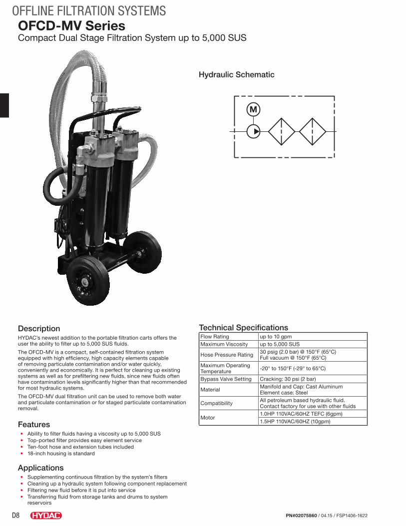
D8
OFFLINE FILTRATION SYSTEMS
PN#02075860 / 04.15 / FSP1406-1622
OFCD-MV SeriesCompact Dual Stage Filtration System up to 5,000 SUS
Hydraulic Schematic
DescriptionHYDAC’s newest addition to the portable filtration carts offers the user the ability to filter up to 5,000 SUS fluids.
The OFCD-MV is a compact, self-contained filtration system equipped with high efficiency, high capacity elements capable of removing particulate contamination and/or water quickly, conveniently and economically. It is perfect for cleaning up existing systems as well as for prefiltering new fluids, since new fluids often have contamination levels significantly higher than that recommended for most hydraulic systems.
The OFCD-MV dual filtration unit can be used to remove both water and particulate contamination or for staged particulate contamination removal.
Features• Ability to filter fluids having a viscosity up to 5,000 SUS• Top-ported filter provides easy element service• Ten-foot hose and extension tubes included• 18-inch housing is standard
Applications• Supplementing continuous filtration by the system’s filters• Cleaning up a hydraulic system following component replacement• Filtering new fluid before it is put into service• Transferring fluid from storage tanks and drums to system
reservoirs
Technical SpecificationsFlow Rating up to 10 gpmMaximum Viscosity up to 5,000 SUS
Hose Pressure Rating 30 psig (2.0 bar) @ 150°F (65°C)Full vacuum @ 150°F (65°C)
Maximum Operating Temperature -20° to 150°F (-29° to 65°C)
Bypass Valve Setting Cracking: 30 psi (2 bar)
Material Manifold and Cap: Cast AluminumElement case: Steel
Compatibility All petroleum based hydraulic fluid. Contact factory for use with other fluids
Motor1.0HP 110VAC/60HZ TEFC (6gpm)1.5HP 110VAC/60HZ (10gpm)
M
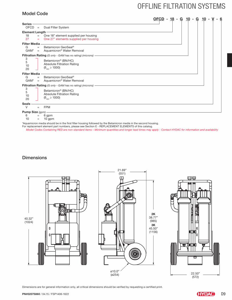
D9
OFFLINE FILTRATION SYSTEMS
PN#02075860 / 04.15 / FSP1406-1622
Model CodeOFCD - 18 - G 10 - G 10 - V - 6
Series OFCD = Dual Filter System
Element Length 18 = One 18” element supplied per housing 27 = One 27” elements supplied per housing
Filter Media G = Betamicron GeoSeal® GAM* = Aquamicron® Water Removal
Filtration Rating (G only - GAM has no rating) (microns) 3
Betamicron® (BN/HC)
5 Absolute Filtration Rating
10
(ßx(c) ≥ 1000)
20
Filter Media G = Betamicron GeoSeal® GAM* = Aquamicron® Water Removal
Filtration Rating (G only - GAM has no rating) (microns) 3
Betamicron® (BN/HC)
5 Absolute Filtration Rating
10
(ßx(c) ≥ 1000)
20
Seals V = FPM
Pump Size (gpm) 6 = 6 gpm 10 = 10 gpm*Aquamicron media should be in the first filter housing followed by the Betamicron media in the second housing.For replacement element part numbers, please see Section E - REPLACEMENT ELEMENTS of this catalog.
Model Codes Containing RED are non-standard items – Minimum quantities and longer lead times may apply - Contact HYDAC for information and availability
Dimensions
Dimensions are for general information only, all critical dimensions should be verified by requesting a certified print.
22.50”(572)
21.69”(551)
40.32”(1024)
2K38.77”(985)3K
45.50”(1156)
ø10.0”(ø254)
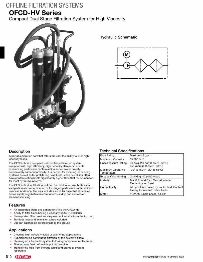
D10
OFFLINE FILTRATION SYSTEMS
PN#02075860 / 04.15 / FSP1406-1622
OFCD-HV SeriesCompact Dual Stage Filtration System for High Viscosity
Hydraulic Schematic
DescriptionA portable filtration cart that offers the user the ability to filter high viscosity fluids.
The OFCD-HV is a compact, self-contained filtration system equipped with high efficiency, high capacity elements capable of removing particulate contamination and/or water quickly, conveniently and economically. It is perfect for cleaning up existing systems as well as for prefiltering new fluids, since new fluids often have contamination levels significantly higher than that recommended for most hydraulic systems.
The OFCD-HV dual filtration unit can be used to remove both water and particulate contamination or for staged particulate contamination removal. Additional features include a modular base that eliminates hoses and fittings between components, a drip pan and easier element servicing.
Features• An integrated lifting eye option for lifting the OFCD-HV• Ability to filter fluids having a viscosity up to 15,000 SUS• Base-ported filter provides easy element service from the top cap• Ten-foot hose and extension tubes included• Dip pan catches oil before it falls to the ground
Applications• Cleaning high viscosity fluids used in Wind applications• Supplementing continuous filtration by the system’s filters• Cleaning up a hydraulic system following component replacement• Filtering new fluid before it is put into service• Transferring fluid from storage tanks and drums to system
reservoirs
Technical SpecificationsFlow Rating Maximum 3 gpmMaximum Viscosity 15,000 SUSHose Pressure Rating 30 psig (2.0 bar) @ 150°F (65°C)
Full vacuum @ 150°F (65°C)Maximum Operating Temperature
-20° to 150°F (-29° to 65°C)
Bypass Valve Setting Cracking: 40 psi (2.8 bar)Material Manifold and Cap: Cast Aluminum
Element case: SteelCompatibility All petroleum based hydraulic fluid. Contact
factory for use with other fluidsMotor 115V AC Single phase, 1.5 HP
M
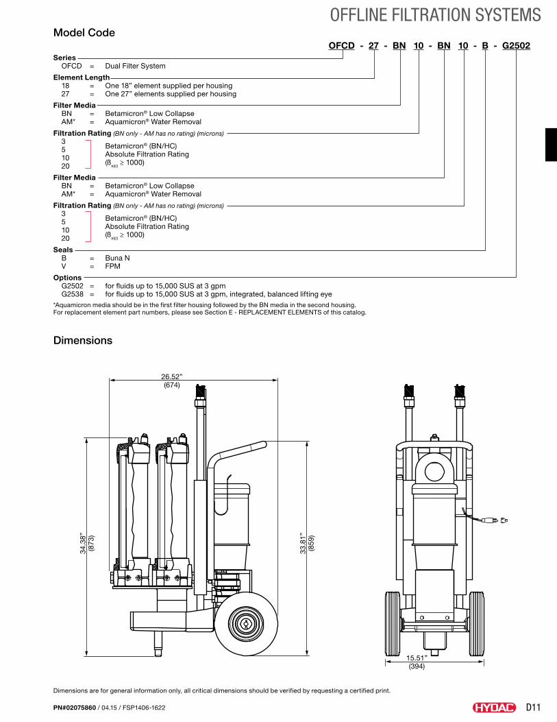
D11
OFFLINE FILTRATION SYSTEMS
PN#02075860 / 04.15 / FSP1406-1622
Dimensions
Model CodeOFCD - 27 - BN 10 - BN 10 - B - G2502.
Series OFCD = Dual Filter System
Element Length 18 = One 18” element supplied per housing 27 = One 27” elements supplied per housing
Filter Media BN = Betamicron® Low Collapse AM* = Aquamicron® Water Removal
Filtration Rating (BN only - AM has no rating) (microns) 3
Betamicron® (BN/HC)
5 Absolute Filtration Rating
10
(ßx(c) ≥ 1000)
20
Filter Media BN = Betamicron® Low Collapse AM* = Aquamicron® Water Removal
Filtration Rating (BN only - AM has no rating) (microns) 3
Betamicron® (BN/HC)
5 Absolute Filtration Rating
10
(ßx(c) ≥ 1000)
20
Seals B = Buna N V = FPM
Options G2502 = for fluids up to 15,000 SUS at 3 gpm G2538 = for fluids up to 15,000 SUS at 3 gpm, integrated, balanced lifting eye*Aquamicron media should be in the first filter housing followed by the BN media in the second housing.For replacement element part numbers, please see Section E - REPLACEMENT ELEMENTS of this catalog.
Dimensions are for general information only, all critical dimensions should be verified by requesting a certified print.
26.52”(674)
15.51”(394)
33.8
1”(8
59)
34.3
8”(8
73)
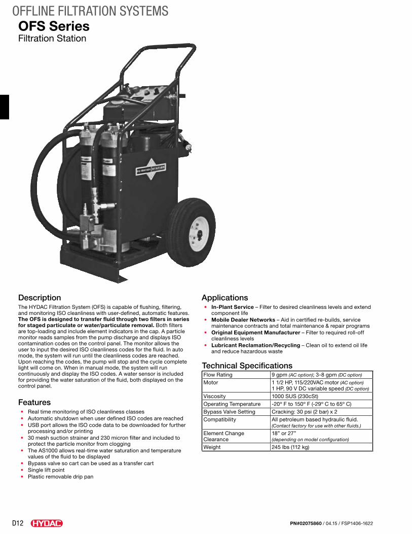
D12
OFFLINE FILTRATION SYSTEMS
PN#02075860 / 04.15 / FSP1406-1622
OFS SeriesFiltration Station
DescriptionThe HYDAC Filtration System (OFS) is capable of flushing, filtering, and monitoring ISO cleanliness with user-defined, automatic features. The OFS is designed to transfer fluid through two filters in series for staged particulate or water/particulate removal. Both filters are top-loading and include element indicators in the cap. A particle monitor reads samples from the pump discharge and displays ISO contamination codes on the control panel. The monitor allows the user to input the desired ISO cleanliness codes for the fluid. In auto mode, the system will run until the cleanliness codes are reached. Upon reaching the codes, the pump will stop and the cycle complete light will come on. When in manual mode, the system will run continuously and display the ISO codes. A water sensor is included for providing the water saturation of the fluid, both displayed on the control panel.
Features• Real time monitoring of ISO cleanliness classes• Automatic shutdown when user defined ISO codes are reached• USB port allows the ISO code data to be downloaded for further
processing and/or printing• 30 mesh suction strainer and 230 micron filter and included to
protect the particle monitor from clogging• The AS1000 allows real-time water saturation and temperature
values of the fluid to be displayed• Bypass valve so cart can be used as a transfer cart• Single lift point• Plastic removable drip pan
Applications• In-Plant Service – Filter to desired cleanliness levels and extend
component life• Mobile Dealer Networks – Aid in certified re-builds, service
maintenance contracts and total maintenance & repair programs• Original Equipment Manufacturer – Filter to required roll-off
cleanliness levels• Lubricant Reclamation/Recycling – Clean oil to extend oil life
and reduce hazardous waste
Technical SpecificationsFlow Rating 9 gpm (AC option); 3-8 gpm (DC option)
Motor 1 1/2 HP, 115/220VAC motor (AC option) 1 HP, 90 V DC variable speed (DC option)
Viscosity 1000 SUS (230cSt)Operating Temperature -20º F to 150º F (-29º C to 65º C)Bypass Valve Setting Cracking: 30 psi (2 bar) x 2Compatibility All petroleum based hydraulic fluid.
(Contact factory for use with other fluids.)
Element Change Clearance
18” or 27” (depending on model configuration)
Weight 245 lbs (112 kg)
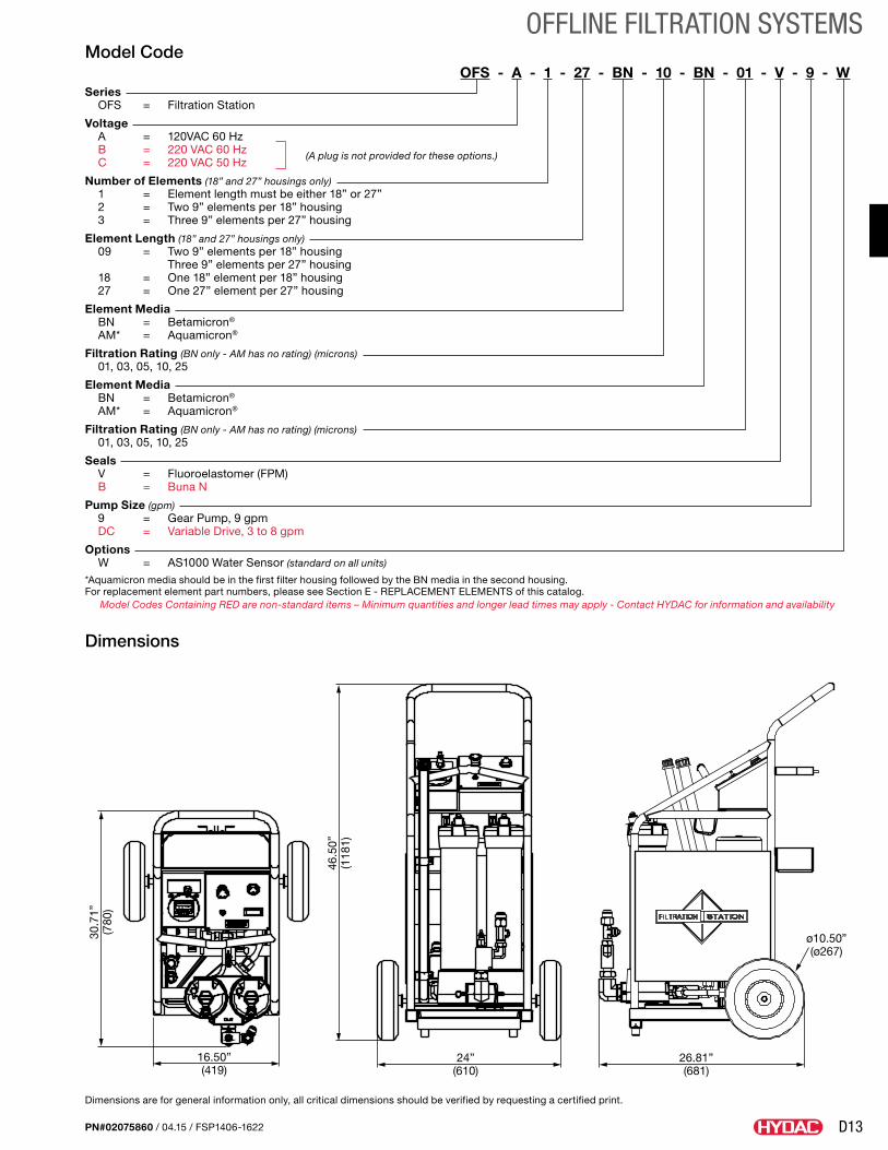
D13
OFFLINE FILTRATION SYSTEMS
PN#02075860 / 04.15 / FSP1406-1622
Dimensions are for general information only, all critical dimensions should be verified by requesting a certified print.
Model CodeOFS - A - 1 - 27 - BN - 10 - BN - 01 - V - 9 - W
Series OFS = Filtration Station
Voltage A = 120VAC 60 Hz B = 220 VAC 60 Hz (A plug is not provided for these options.) C = 220 VAC 50 Hz
Number of Elements (18” and 27” housings only) 1 = Element length must be either 18” or 27” 2 = Two 9” elements per 18” housing 3 = Three 9” elements per 27” housing
Element Length (18” and 27” housings only) 09 = Two 9” elements per 18” housing Three 9” elements per 27” housing 18 = One 18” element per 18” housing 27 = One 27” element per 27” housing
Element Media BN = Betamicron®
AM* = Aquamicron®
Filtration Rating (BN only - AM has no rating) (microns) 01, 03, 05, 10, 25
Element Media BN = Betamicron®
AM* = Aquamicron®
Filtration Rating (BN only - AM has no rating) (microns) 01, 03, 05, 10, 25
Seals V = Fluoroelastomer (FPM) B = Buna N
Pump Size (gpm) 9 = Gear Pump, 9 gpm DC = Variable Drive, 3 to 8 gpm
Options W = AS1000 Water Sensor (standard on all units)
*Aquamicron media should be in the first filter housing followed by the BN media in the second housing.For replacement element part numbers, please see Section E - REPLACEMENT ELEMENTS of this catalog.
Model Codes Containing RED are non-standard items – Minimum quantities and longer lead times may apply - Contact HYDAC for information and availability
30.7
1”(7
80)
16.50”(419)
46.5
0”(1
181)
24”(610)
26.81”(681)
ø10.50”(ø267)
Dimensions
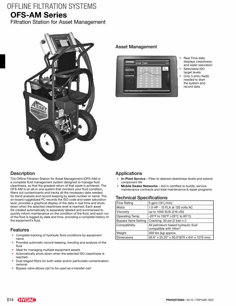
D14
OFFLINE FILTRATION SYSTEMS
PN#02075860 / 04.15 / FSP1406-1622
OFS-AM SeriesFiltration Station for Asset Management
DescriptionThe Offline Filtration Station for Asset Management (OFS-AM) is a complete fluid management system designed to manage fluid cleanliness, so that the greatest return of that asset is achieved. The OFS-AM is an all-in one system that monitors your fluid condition, filters out contaminants and tracks all the necessary data needed for trend analysis and record keeping by asset number or name. The on-board ruggedized PC records the ISO code and water saturation level, provides a graphical display of the data in real time and shuts down when the selected cleanliness level is reached. Each asset file created automatically is separately labeled and summarized to quickly inform maintenance on the condition of the fluid, and each run of the fluid is logged by date and time, providing a complete history of the equipment’s fluid.
Features• Complete tracking of hydraulic fluid conditions by equipment
name• Provides automatic record-keeping, trending and analysis of the
fluid• Ideal for managing multiple equipment assets• Automatically shuts down when the selected ISO cleanliness is
reached• Dual staged filters for both water and/or particulate contamination
removal• Bypass valve allows cart to be used as a transfer cart
Applications• In-Plant Service – Filter to desired cleanliness levels and extend
component life• Mobile Dealer Networks – Aid in certified re-builds, service
maintenance contracts and total maintenance & repair programs
Technical SpecificationsFlow Rating 5 gpm (19 L/min)Motor 1.5 HP - 15 FLA at 120 volts ACViscosity up to 1000 SUS (216 cSt)Operating Temp. -20°F to 150°F (-29°C to 65°C)Bypass Valve Setting Cracking: 30 psi (2 bar) x 2Compatibility All petroleum based hydraulic fluid
compatible with Viton®
Weight 200 lbs (kg) approx.Dimensions 26.6” x 25.25” x 50.0”(675 x 641 x 1270 mm)
Asset Management
• Real Time data displays cleanliness and water saturation
• Selectable ISO target levels
• Only 3 entry fields needed to start the system and record data
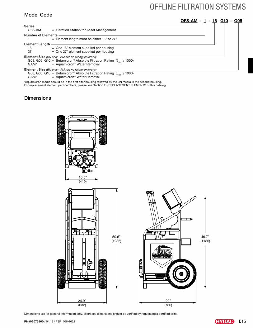
D15
OFFLINE FILTRATION SYSTEMS
PN#02075860 / 04.15 / FSP1406-1622
Model CodeOFS-AM - 1 - 18 G10 - G05
Series OFS-AM = Filtration Station for Asset Management
Number of Elements 1 = Element length must be either 18” or 27”
Element Length 18 = One 18” element supplied per housing 27 = One 27” element supplied per housing
Element Size (BN only - AM has no rating) (microns) G03, G05, G10 = Betamicron® Absolute Filtration Rating (ßx(c) ≥ 1000) GAM* = Aquamicron® Water Removal
Element Size (BN only - AM has no rating) (microns) G03, G05, G10 = Betamicron® Absolute Filtration Rating (ßx(c) ≥ 1000) GAM* = Aquamicron® Water Removal*Aquamicron media should be in the first filter housing followed by the BN media in the second housing.For replacement element part numbers, please see Section E - REPLACEMENT ELEMENTS of this catalog.
Dimensions are for general information only, all critical dimensions should be verified by requesting a certified print.
16.5”(419)
24.9”(632)
29”(736)
46.7”(1186)
50.6”(1285)
Dimensions
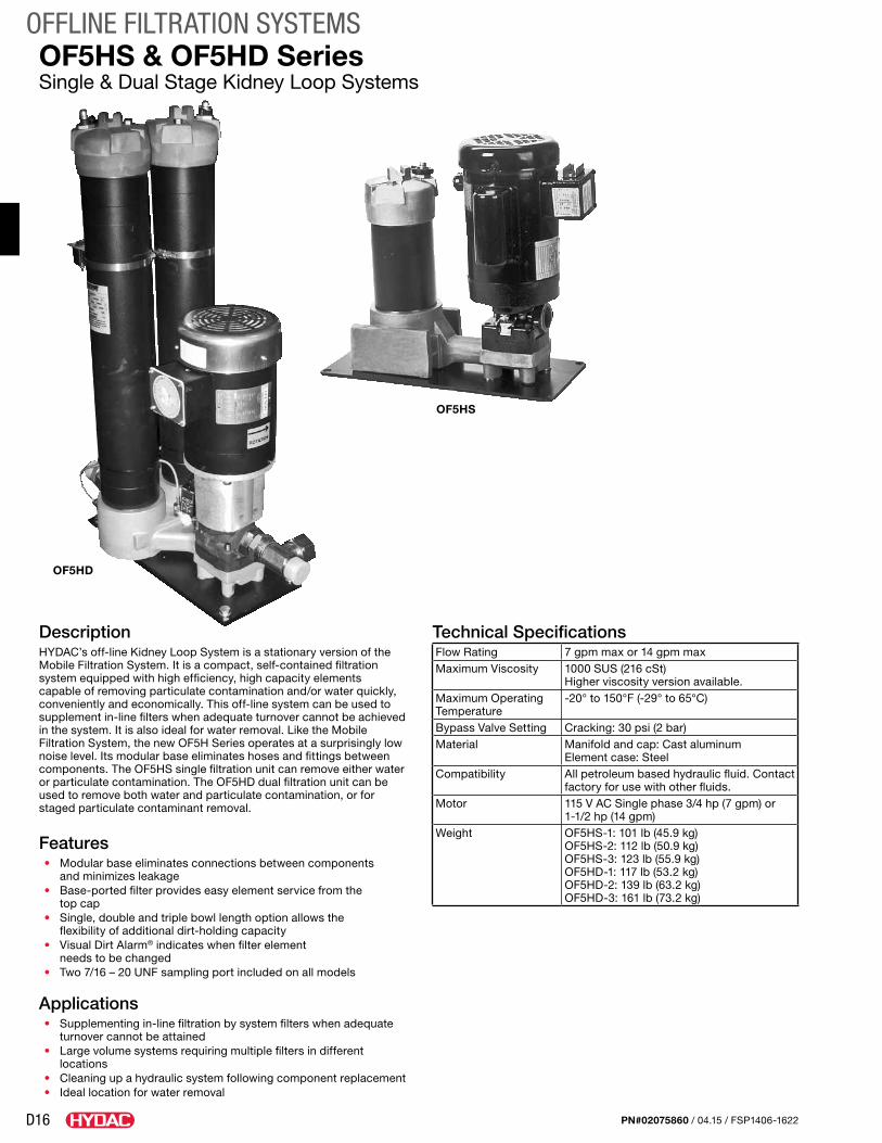
D16
OFFLINE FILTRATION SYSTEMS
PN#02075860 / 04.15 / FSP1406-1622
OF5HS & OF5HD SeriesSingle & Dual Stage Kidney Loop Systems
Technical SpecificationsFlow Rating 7 gpm max or 14 gpm maxMaximum Viscosity 1000 SUS (216 cSt)
Higher viscosity version available. Maximum Operating Temperature
-20° to 150°F (-29° to 65°C)
Bypass Valve Setting Cracking: 30 psi (2 bar)Material Manifold and cap: Cast aluminum
Element case: SteelCompatibility All petroleum based hydraulic fluid. Contact
factory for use with other fluids.Motor 115 V AC Single phase 3/4 hp (7 gpm) or
1-1/2 hp (14 gpm)Weight OF5HS-1: 101 lb (45.9 kg)
OF5HS-2: 112 lb (50.9 kg) OF5HS-3: 123 lb (55.9 kg)OF5HD-1: 117 lb (53.2 kg) OF5HD-2: 139 lb (63.2 kg) OF5HD-3: 161 lb (73.2 kg)
DescriptionHYDAC’s off-line Kidney Loop System is a stationary version of the Mobile Filtration System. It is a compact, self-contained filtration system equipped with high efficiency, high capacity elements capable of removing particulate contamination and/or water quickly, conveniently and economically. This off-line system can be used to supplement in-line filters when adequate turnover cannot be achieved in the system. It is also ideal for water removal. Like the Mobile Filtration System, the new OF5H Series operates at a surprisingly low noise level. Its modular base eliminates hoses and fittings between components. The OF5HS single filtration unit can remove either water or particulate contamination. The OF5HD dual filtration unit can be used to remove both water and particulate contamination, or for staged particulate contaminant removal.
Features• Modular base eliminates connections between components
and minimizes leakage• Base-ported filter provides easy element service from the
top cap• Single, double and triple bowl length option allows the
flexibility of additional dirt-holding capacity• Visual Dirt Alarm® indicates when filter element
needs to be changed• Two 7/16 – 20 UNF sampling port included on all models
Applications• Supplementing in-line filtration by system filters when adequate
turnover cannot be attained• Large volume systems requiring multiple filters in different
locations• Cleaning up a hydraulic system following component replacement• Ideal location for water removal
OF5HS
OF5HD
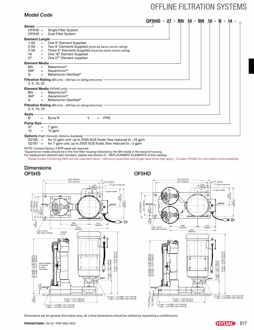
D17
OFFLINE FILTRATION SYSTEMS
PN#02075860 / 04.15 / FSP1406-1622
Dimensions are for general information only, all critical dimensions should be verified by requesting a certified print.
18.0” (457mm)
16.5” (419mm) 0.75” (19mm)
3.26”(83mm)
07 gpm model only
14 gpm model
5.56
”(1
41m
m)
9.15
”(2
32m
m)
INTLET
8.0”
(203
mm
)
6.5”
(165
mm
)
6.25
” (1
59m
m)
3.12
”(7
9mm
)
OUTLET
.75”
(19m
m)
ø.56” (14mm)Mtg. Hole (4 places)
8.69”(221mm)
5.73”(146mm)
17.54”(445mm)
ON
OF
F
07 g
pm
= 4
.26”
(108
mm
)14
gp
m =
4.6
8” (1
19m
m)
07 g
pm
= 1
6.58
” (4
21m
m)
14 g
pm
= 1
8.18
” (4
62m
m)
INLET
07 gpm = (-16 ORB) 1.312-12UN-2B14 gpm = (-20 ORB) 1.625-12UN-2B
OUTLET
07 gpm = (-16 ORB) 1.312-12UN-2B14 gpm = (-20 ORB) 1.625-12UN-2B
See nameplate for element re-order information
Indicatorin cap
07 gpm = 14.25” (362mm)14 gpm = 14.24” (362mm)
1k L
engt
h =
14.
95”
(380
mm
)2k
Len
gth
= 2
4.38
” (6
19m
m)
3k L
engt
h =
33.
76”
(858
mm
)1.
31”
(33m
m)
0.5”
(13m
m)
18.0” (457mm)
ø.56” (14mm)Mtg. Hole (4 places)
07 gpm = (-16 ORB) 1.312-12UN-2B14 gpm = (-20 ORB) 1.625-12UN-2B
07 gpm = (-16 ORB) 1.312-12UN-2B14 gpm = (-20 ORB) 1.625-12UN-2B07 gpm = 14.65” (372mm)
14 gpm = 14.64” (372mm)
07 g
pm
= 4
.26”
(108
mm
)14
gp
m =
4.6
8” (1
19m
m)
07 g
pm
= 1
6.58
” (4
21m
m)
14 g
pm
= 1
8.18
” (4
62m
m)
8.69”(221mm)
5.73”(146mm)
14.4”(366mm)
8.0”
(203
mm
)
6.5”
(165
mm
)
3.25
”(8
3mm
)1k
Len
gth
= 1
4.95
” (3
80m
m)
2k L
engt
h =
24.
38”
(619
mm
)3k
Len
gth
= 3
3.76
” (8
58m
m)
1.31
” (3
3mm
)
0.5”
(13m
m)
5.56
”(1
41m
m)
9.15
”(2
32m
m)
ON
OF
F
.75”
(19m
m)
OUTLET
OUTLET
INLET
INTLET
16.5” (419mm)
3.26”(83mm)
0.75” (19mm)
14 gpm model
07 gpm model only
Model CodeOF5HD - 27 - BN 10 - BN 10 - B - 14 - .
Series OF5HS = Single Filter System OF5HD = Dual Filter System
Element Length 1-09 = One 9” Element Supplied 2-09 = Two 9” Elements Supplied (must be same micron rating) 3-09 = Three 9” Elements Supplied (must be same micron rating) 18 = One 18” Element Supplied 27 = One 27” Element supplied
Element Media BN = Betamicron® AM* = Aquamicron® G = Betamicron GeoSeal®
Filtration Rating (BN only - AM has no rating) (microns) 3, 5, 10, 25
Element Media (OF5HD only) BN = Betamicron® AM* = Aquamicron® G = Betamicron GeoSeal®
Filtration Rating (BN only - AM has no rating) (microns) 3, 5, 10, 25
Seals B = Buna N V = FPM
Pump Size 07 = 7 gpm 14 = 14 gpm
Options (High Viscosity Options Available) G2185 = for 14 gpm unit; up to 2500 SUS fluids; flow reduced to ~10 gpm G2187 = for 7 gpm unit; up to 2500 SUS fluids; flow reduced to ~3 gpmNOTE: Contact factory if EPR seals are required.*Aquamicron media should be in the first filter housing followed by the BN media in the second housing.For replacement element part numbers, please see Section E - REPLACEMENT ELEMENTS of this catalog.
Model Codes Containing RED are non-standard items – Minimum quantities and longer lead times may apply - Contact HYDAC for information and availability.
DimensionsOF5HS OF5HD
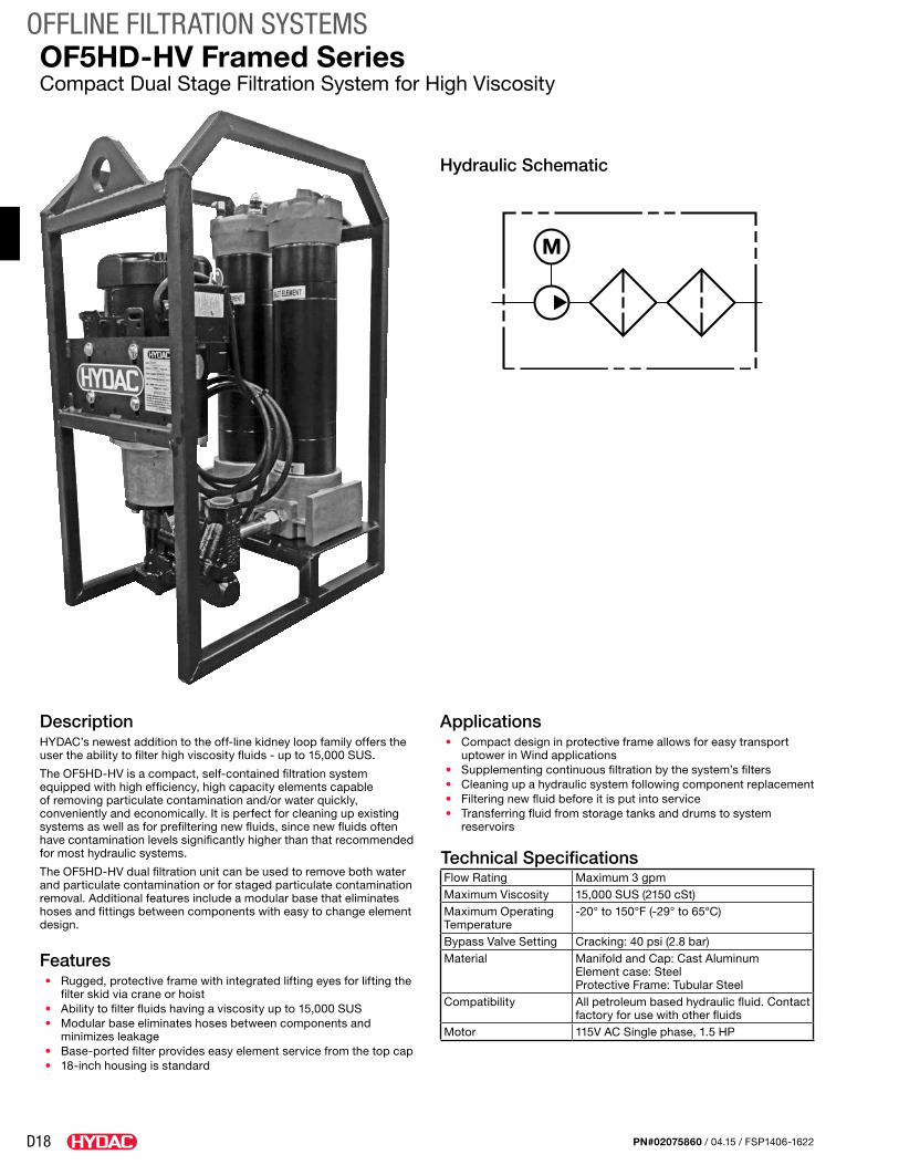
D18
OFFLINE FILTRATION SYSTEMS
PN#02075860 / 04.15 / FSP1406-1622
OF5HD-HV Framed SeriesCompact Dual Stage Filtration System for High Viscosity
DescriptionHYDAC’s newest addition to the off-line kidney loop family offers the user the ability to filter high viscosity fluids - up to 15,000 SUS.
The OF5HD-HV is a compact, self-contained filtration system equipped with high efficiency, high capacity elements capable of removing particulate contamination and/or water quickly, conveniently and economically. It is perfect for cleaning up existing systems as well as for prefiltering new fluids, since new fluids often have contamination levels significantly higher than that recommended for most hydraulic systems.
The OF5HD-HV dual filtration unit can be used to remove both water and particulate contamination or for staged particulate contamination removal. Additional features include a modular base that eliminates hoses and fittings between components with easy to change element design.
Features• Rugged, protective frame with integrated lifting eyes for lifting the
filter skid via crane or hoist• Ability to filter fluids having a viscosity up to 15,000 SUS• Modular base eliminates hoses between components and
minimizes leakage• Base-ported filter provides easy element service from the top cap• 18-inch housing is standard
Applications• Compact design in protective frame allows for easy transport
uptower in Wind applications• Supplementing continuous filtration by the system’s filters• Cleaning up a hydraulic system following component replacement• Filtering new fluid before it is put into service• Transferring fluid from storage tanks and drums to system
reservoirs
Technical SpecificationsFlow Rating Maximum 3 gpmMaximum Viscosity 15,000 SUS (2150 cSt)Maximum Operating Temperature
-20° to 150°F (-29° to 65°C)
Bypass Valve Setting Cracking: 40 psi (2.8 bar)Material Manifold and Cap: Cast Aluminum
Element case: SteelProtective Frame: Tubular Steel
Compatibility All petroleum based hydraulic fluid. Contact factory for use with other fluids
Motor 115V AC Single phase, 1.5 HP
M
Hydraulic Schematic
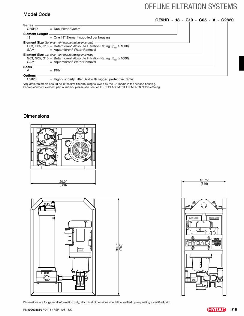
D19
OFFLINE FILTRATION SYSTEMS
PN#02075860 / 04.15 / FSP1406-1622
Dimensions are for general information only, all critical dimensions should be verified by requesting a certified print.
Model CodeOF5HD - 18 - G10 - G05 - V - G2820
Series OF5HD = Dual Filter System
Element Length 18 = One 18” Element supplied per housing
Element Size (BN only - AM has no rating) (microns) G03, G05, G10 = Betamicron® Absolute Filtration Rating (ßx(c) ≥ 1000) GAM* = Aquamicron® Water Removal
Element Size (BN only - AM has no rating) (microns) G03, G05, G10 = Betamicron® Absolute Filtration Rating (ßx(c) ≥ 1000) GAM* = Aquamicron® Water Removal
Seals V = FPM
Options G2820 = High Viscosity Filter Skid with rugged protective frame*Aquamicron media should be in the first filter housing followed by the BN media in the second housing.For replacement element part numbers, please see Section E - REPLACEMENT ELEMENTS of this catalog.
Dimensions
20.0”(508)
13.75”(349)
30.0
”(7
62)
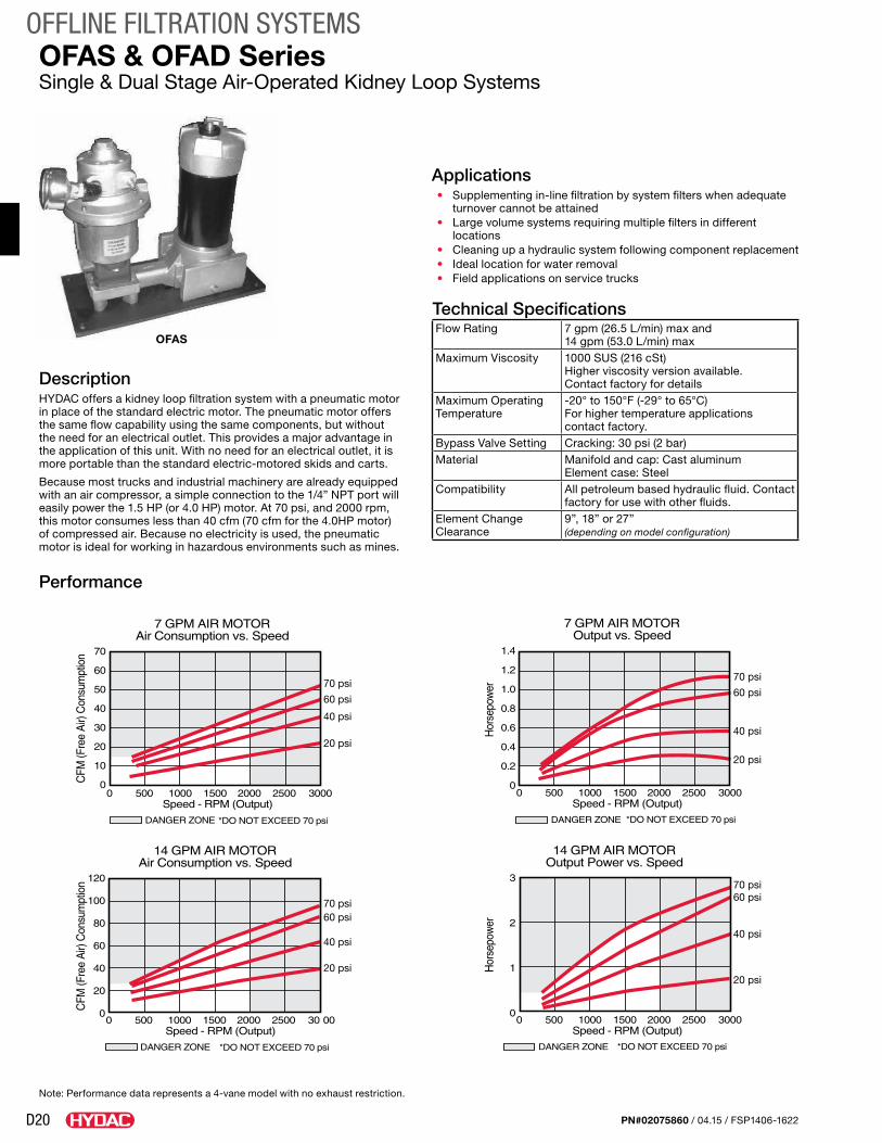
D20
OFFLINE FILTRATION SYSTEMS
PN#02075860 / 04.15 / FSP1406-1622
OFAS & OFAD SeriesSingle & Dual Stage Air-Operated Kidney Loop Systems
Applications• Supplementing in-line filtration by system filters when adequate
turnover cannot be attained• Large volume systems requiring multiple filters in different
locations• Cleaning up a hydraulic system following component replacement• Ideal location for water removal• Field applications on service trucks
Technical SpecificationsFlow Rating 7 gpm (26.5 L/min) max and
14 gpm (53.0 L/min) maxMaximum Viscosity 1000 SUS (216 cSt)
Higher viscosity version available. Contact factory for details
Maximum Operating Temperature
-20° to 150°F (-29° to 65°C) For higher temperature applications contact factory.
Bypass Valve Setting Cracking: 30 psi (2 bar)Material Manifold and cap: Cast aluminum
Element case: SteelCompatibility All petroleum based hydraulic fluid. Contact
factory for use with other fluids.Element Change Clearance
9”, 18” or 27” (depending on model configuration)
DescriptionHYDAC offers a kidney loop filtration system with a pneumatic motor in place of the standard electric motor. The pneumatic motor offers the same flow capability using the same components, but without the need for an electrical outlet. This provides a major advantage in the application of this unit. With no need for an electrical outlet, it is more portable than the standard electric-motored skids and carts.
Because most trucks and industrial machinery are already equipped with an air compressor, a simple connection to the 1/4” NPT port will easily power the 1.5 HP (or 4.0 HP) motor. At 70 psi, and 2000 rpm, this motor consumes less than 40 cfm (70 cfm for the 4.0HP motor) of compressed air. Because no electricity is used, the pneumatic motor is ideal for working in hazardous environments such as mines.
Performance
OFAS
70 psi
60 psi
40 psi
20 psi
70 psi60 psi
40 psi
20 psi
70 psi
60 psi
40 psi
20 psi
70 psi60 psi
40 psi
20 psi
Note: Performance data represents a 4-vane model with no exhaust restriction.
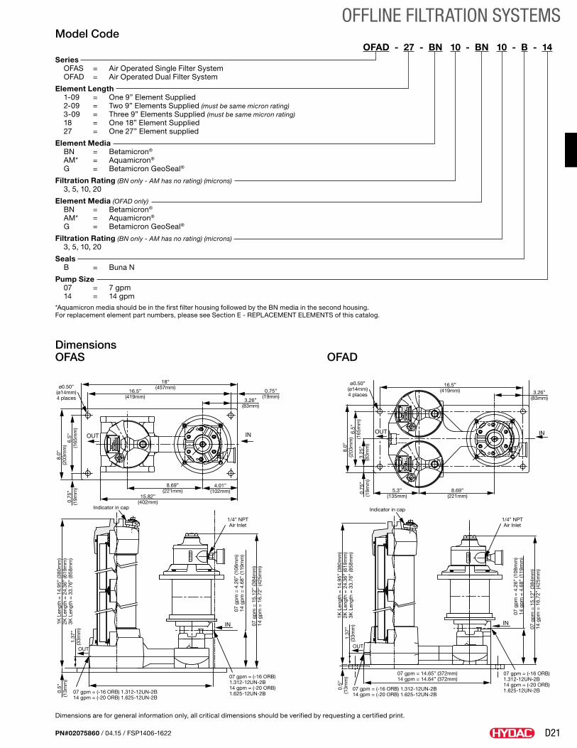
D21
OFFLINE FILTRATION SYSTEMS
PN#02075860 / 04.15 / FSP1406-1622
Dimensions are for general information only, all critical dimensions should be verified by requesting a certified print.
18”(457mm)
16.5”(419mm)
16.5”(419mm)
8.69”(221mm) 8.69”
(221mm)5.3”
(135mm)15.82”(402mm)
1/4” NPTAir Inlet
1/4” NPTAir Inlet
Indicator in cap Indicator in cap
07 gpm = 14.65” (372mm)14 gpm = 14.64” (372mm)
07 gpm = (-16 ORB) 1.312-12UN-2B14 gpm = (-20 ORB) 1.625-12UN-2B
OUT
07 gpm = (-16 ORB) 1.312-12UN-2B14 gpm = (-20 ORB) 1.625-12UN-2B
07 gpm = (-16 ORB) 1.312-12UN-2B14 gpm = (-20 ORB) 1.625-12UN-2B
07 gpm = (-16 ORB) 1.312-12UN-2B14 gpm = (-20 ORB) 1.625-12UN-2B
4.01”(102mm)
ø0.50”(ø14mm)4 places
ø0.50”(ø14mm)4 places
8.0”
(203
mm
)1K
Len
gth
= 1
4.95
” (3
80m
m)
2K L
engt
h =
24.
36”
(619
mm
)3K
Len
gth
= 3
3.76
” (8
58m
m)
1K L
engt
h =
14.
95”
(380
mm
)2K
Len
gth
= 2
4.36
” (6
19m
m)
3K L
engt
h =
33.
76”
(858
mm
)
0.5”
(13m
m)
1.37
”(3
3mm
)
OUT
1.37
”(3
3mm
)
0.5”
(13m
m)
07 g
pm
= 4
.26”
(108
mm
)14
gp
m =
4.6
8” (1
19m
m)
07 g
pm
= 1
5.12
” (3
84m
m)
14 g
pm
= 1
6.72
” (4
25m
m)
07 g
pm
= 4
.26”
(108
mm
)14
gp
m =
4.6
8” (1
19m
m)
07 g
pm
= 1
5.12
” (3
84m
m)
14 g
pm
= 1
6.72
” (4
25m
m)
0.75
”(1
9mm
)
0.75
”(1
9mm
)
6.5”
(165
mm
)
8.0”
(203
mm
)
3.25
”(8
3mm
)
6.5”
(165
mm
)
0.75”(19mm)
3.26”(83mm)
3.26”(83mm)
Model CodeOFAD - 27 - BN 10 - BN 10 - B - 14
Series OFAS = Air Operated Single Filter System OFAD = Air Operated Dual Filter System
Element Length 1-09 = One 9” Element Supplied 2-09 = Two 9” Elements Supplied (must be same micron rating) 3-09 = Three 9” Elements Supplied (must be same micron rating) 18 = One 18” Element Supplied 27 = One 27” Element supplied
Element Media BN = Betamicron® AM* = Aquamicron® G = Betamicron GeoSeal®
Filtration Rating (BN only - AM has no rating) (microns) 3, 5, 10, 20
Element Media (OFAD only) BN = Betamicron® AM* = Aquamicron® G = Betamicron GeoSeal®
Filtration Rating (BN only - AM has no rating) (microns) 3, 5, 10, 20
Seals B = Buna N
Pump Size 07 = 7 gpm 14 = 14 gpm*Aquamicron media should be in the first filter housing followed by the BN media in the second housing.For replacement element part numbers, please see Section E - REPLACEMENT ELEMENTS of this catalog.
Dimensions OFAS OFAD
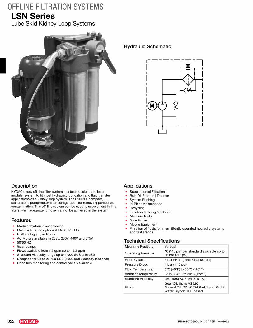
D22
OFFLINE FILTRATION SYSTEMS
PN#02075860 / 04.15 / FSP1406-1622
LSN SeriesLube Skid Kidney Loop Systems
DescriptionHYDAC’s new off-line filter system has been designed to be a modular system to fit most hydraulic, lubrication and fluid transfer applications as a kidney loop system. The LSN is a compact, stand-alone pump/motor/filter configuration for removing particulate contamination. This off-line system can be used to supplement in-line filters when adequate turnover cannot be achieved in the system.
Features• Modular hydraulic accessories• Multiple filtration options (FLND, LPF, LF)• Built in clogging indicator• AC Motors available in 208V, 230V, 460V and 575V• 50/60 HZ• Gear pumps• Flows available from 1.2 gpm up to 45.2 gpm• Standard Viscosity range up to 1,000 SUS (216 cSt)• Designed for up to 22,720 SUS (5000 cSt) viscosity (optional)• Condition monitoring and control panels available
Applications• Supplemental Filtration• Bulk Oil Storage | Transfer• System Flushing• In-Plant Maintenance• Recycling• Injection Molding Machines• Machine Tools• Gear Boxes• Mobile Equipment• Filtration of fluids for intermittently operated hydraulic systems
and test stands
Technical SpecificationsMounting Position: Vertical
Operating Pressure 10 (145 psi) bar standard available up to 15 bar (217 psi)
Filter Bypass: 3 bar (44 psi) and 6 bar (87 psi)Pressure Drop: 1 bar (14.5 psi)Fluid Temperature: 8°C (46°F) to 80°C (176°F)Ambient Temperature: -20°C (-4°F) to 50°C (122°F)Standard Viscosity: 250-1000 SUS (54-216 cSt)
FluidsGear Oil: Up to VG320 Mineral Oil: DIN 51524 Part 1 and Part 2 Water Glycol: HFC based
Hydraulic Schematic
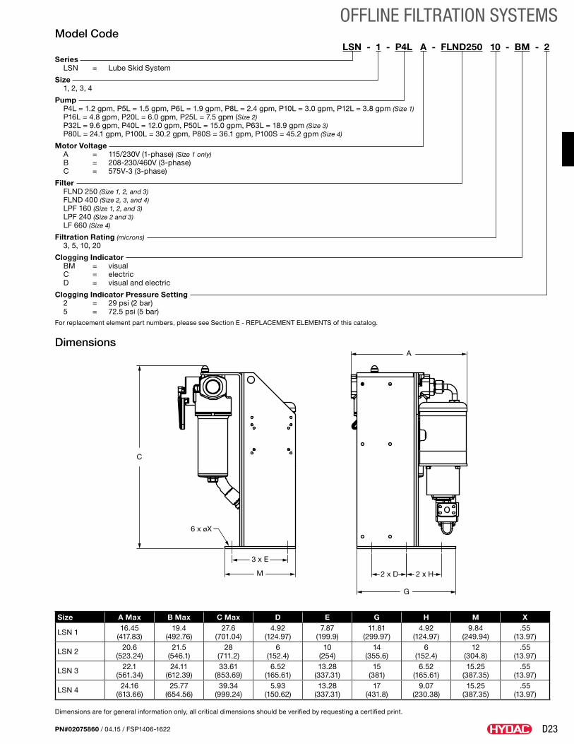
D23
OFFLINE FILTRATION SYSTEMS
PN#02075860 / 04.15 / FSP1406-1622
Dimensions are for general information only, all critical dimensions should be verified by requesting a certified print.
C
M
3 x E
6 x øX
2 x D 2 x H
G
A
Model CodeLSN - 1 - P4L A - FLND250 10 - BM - 2
Series LSN = Lube Skid System
Size 1, 2, 3, 4
Pump P4L = 1.2 gpm, P5L = 1.5 gpm, P6L = 1.9 gpm, P8L = 2.4 gpm, P10L = 3.0 gpm, P12L = 3.8 gpm (Size 1) P16L = 4.8 gpm, P20L = 6.0 gpm, P25L = 7.5 gpm (Size 2) P32L = 9.6 gpm, P40L = 12.0 gpm, P50L = 15.0 gpm, P63L = 18.9 gpm (Size 3) P80L = 24.1 gpm, P100L = 30.2 gpm, P80S = 36.1 gpm, P100S = 45.2 gpm (Size 4)
Motor Voltage A = 115/230V (1-phase) (Size 1 only) B = 208-230/460V (3-phase) C = 575V-3 (3-phase)
Filter FLND 250 (Size 1, 2, and 3) FLND 400 (Size 2, 3, and 4) LPF 160 (Size 1, 2, and 3) LPF 240 (Size 2 and 3) LF 660 (Size 4)
Filtration Rating (microns) 3, 5, 10, 20
Clogging Indicator BM = visual C = electric D = visual and electric
Clogging Indicator Pressure Setting 2 = 29 psi (2 bar) 5 = 72.5 psi (5 bar)For replacement element part numbers, please see Section E - REPLACEMENT ELEMENTS of this catalog.
Dimensions
Size A Max B Max C Max D E G H M X
LSN 1 16.45 (417.83)
19.4 (492.76)
27.6 (701.04)
4.92 (124.97)
7.87 (199.9)
11.81 (299.97)
4.92 (124.97)
9.84 (249.94)
.55 (13.97)
LSN 2 20.6(523.24)
21.5 (546.1)
28 (711.2)
6 (152.4)
10 (254)
14 (355.6)
6 (152.4)
12 (304.8)
.55 (13.97)
LSN 3 22.1(561.34)
24.11 (612.39)
33.61 (853.69)
6.52 (165.61)
13.28 (337.31)
15 (381)
6.52 (165.61)
15.25 (387.35)
.55 (13.97)
LSN 4 24.16(613.66)
25.77 (654.56)
39.34 (999.24)
5.93 (150.62)
13.28 (337.31)
17 (431.8)
9.07 (230.38)
15.25 (387.35)
.55 (13.97)
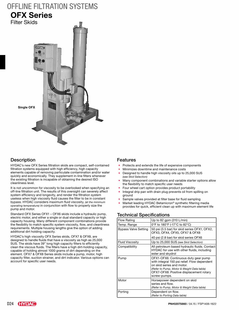
D24
OFFLINE FILTRATION SYSTEMS
PN#02075860 / 04.15 / FSP1406-1622
OFX SeriesFilter Skids
DescriptionHYDAC’s new OFX Series filtration skids are compact, self-contained filtration systems equipped with high efficiency, high capacity elements capable of removing particulate contamination and/or water quickly and economically. They supplement in-line filters whenever the existing filtration is incapable of obtaining the desired ISO cleanliness level.
It is not uncommon for viscosity to be overlooked when specifying an off-line filtration unit. The results of this oversight can severely affect system efficiency and longevity, and render the filtration system useless when high viscosity fluid causes the filter to be in constant bypass. HYDAC considers maximum fluid viscosity, (at the minimum operating temperature) in conjunction with flow to properly size the pump and motor.
Standard OFX Series OFX1 – OFX6 skids include a hydraulic pump, electric motor, and either a single or dual standard capacity or high capacity housing. Many different component combinations provide the flexibility to match specific system viscosity, flow, and cleanliness requirements. Multiple housing lengths give the option of adding additional dirt holding capacity.
HYDAC’s high viscosity OFX Series skids, OFX7 & OFX8, are designed to handle fluids that have a viscosity as high as 25,000 SUS. The skids have 39” long high capacity filters to efficiently clean the viscous fluids. The filters have a high dirt-holding capacity, capable of holding almost 1000 grams of dirt depending on the element. OFX7 & OFX8 Series skids include a pump, motor, high capacity filter, suction strainer, and dirt indicator. Various options can account for specific user needs.
Features• Protects and extends the life of expensive components• Minimizes downtime and maintenance costs• Designed to handle high viscosity oils up to 25,000 SUS
(see Skid Selection)• Many component combinations and variable starter options allow
the flexibility to match specific user needs• Four wheel cart option provides product portability• Integral drip pan with drain plug prevents oil from spilling on
ground• Sample valves provided at filter base for fluid sampling• Market leading HYDAC Betamicron® synthetic filtering media
provides for quick, efficient clean up with maximum element life
Technical SpecificationsFlow Rating Up to 82 gpm (310 L/min)Temp. Range 0°F to 180°F (-17°C to 82°C)Bypass Valve Setting 50 psi (3.5 bar) for skid series OFX1, OFX2,
OFX3, OFX4, OFX5, OFX7 & OFX8
40 psi (2.8 bar) for skid series OFX6Fluid Viscosity Up to 25,000 SUS (see Skid Selection)
Compatibility All petroleum based hydraulic fluids. Contact HYDAC for use with other fluids, including ester and skydrol
Pump OFX1-OFX6: Continuous duty gear pump with integral 150 psi relief. Flow dependent on skid series and motor. (Refer to Pump, Motor & Weight Data table) OFX7-OFX8: Positive displacement rotary screw-pumps.
Motor Horsepower dependent on skid series and flow. (Refer to Pump, Motor & Weight Data table)
Porting Dependent on flow. (Refer to Porting Data table)
Single OFX
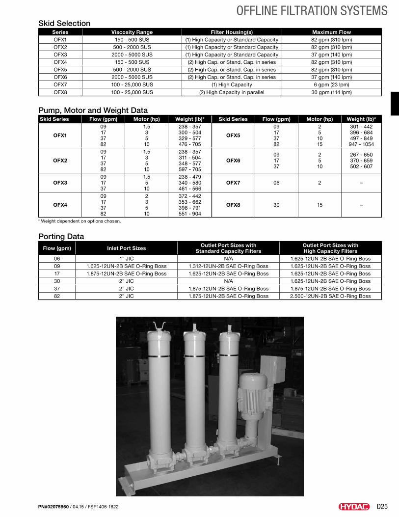
D25
OFFLINE FILTRATION SYSTEMS
PN#02075860 / 04.15 / FSP1406-1622
Skid SelectionSeries Viscosity Range Filter Housing(s) Maximum FlowOFX1 150 - 500 SUS (1) High Capacity or Standard Capacity 82 gpm (310 lpm)OFX2 500 - 2000 SUS (1) High Capacity or Standard Capacity 82 gpm (310 lpm)OFX3 2000 - 5000 SUS (1) High Capacity or Standard Capacity 37 gpm (140 lpm)OFX4 150 - 500 SUS (2) High Cap. or Stand. Cap. in series 82 gpm (310 lpm)OFX5 500 - 2000 SUS (2) High Cap. or Stand. Cap. in series 82 gpm (310 lpm)OFX6 2000 - 5000 SUS (2) High Cap. or Stand. Cap. in series 37 gpm (140 lpm)OFX7 100 - 25,000 SUS (1) High Capacity 6 gpm (23 lpm)
OFX8 100 - 25,000 SUS (2) High Capacity in parallel 30 gpm (114 lpm)
Pump, Motor and Weight DataSkid Series Flow (gpm) Motor (hp) Weight (lb)* Skid Series Flow (gpm) Motor (hp) Weight (lb)*
OFX1
09 17 37 82
1.5 3 5 10
238 - 357 300 - 504 329 - 577 476 - 705
OFX5
09 17 37 82
2 5 10 15
301 - 442 396 - 684 497 - 849 947 - 1054
OFX2
09 17 37 82
1.5 3 5 10
238 - 357 311 - 504 348 - 577 597 - 705
OFX609 17 37
2 5 10
267 - 650 370 - 659 502 - 607
OFX309 17 37
1.5 5 10
238 - 479 340 - 580 461 - 566
OFX7 06 2 –
OFX4
09 17 37 82
2 3 5 10
372 - 442 353 - 662 398 - 791 551 - 904
OFX8 30 15 –
* Weight dependent on options chosen.
Porting DataFlow (gpm) Inlet Port Sizes Outlet Port Sizes with
Standard Capacity FiltersOutlet Port Sizes with High Capacity Filters
06 1” JIC N/A 1.625-12UN-2B SAE O-Ring Boss09 1.625-12UN-2B SAE O-Ring Boss 1.312-12UN-2B SAE O-Ring Boss 1.625-12UN-2B SAE O-Ring Boss17 1.875-12UN-2B SAE O-Ring Boss 1.625-12UN-2B SAE O-Ring Boss 1.625-12UN-2B SAE O-Ring Boss30 2” JIC N/A 1.625-12UN-2B SAE O-Ring Boss37 2” JIC 1.875-12UN-2B SAE O-Ring Boss 1.875-12UN-2B SAE O-Ring Boss82 2” JIC 1.875-12UN-2B SAE O-Ring Boss 2.500-12UN-2B SAE O-Ring Boss
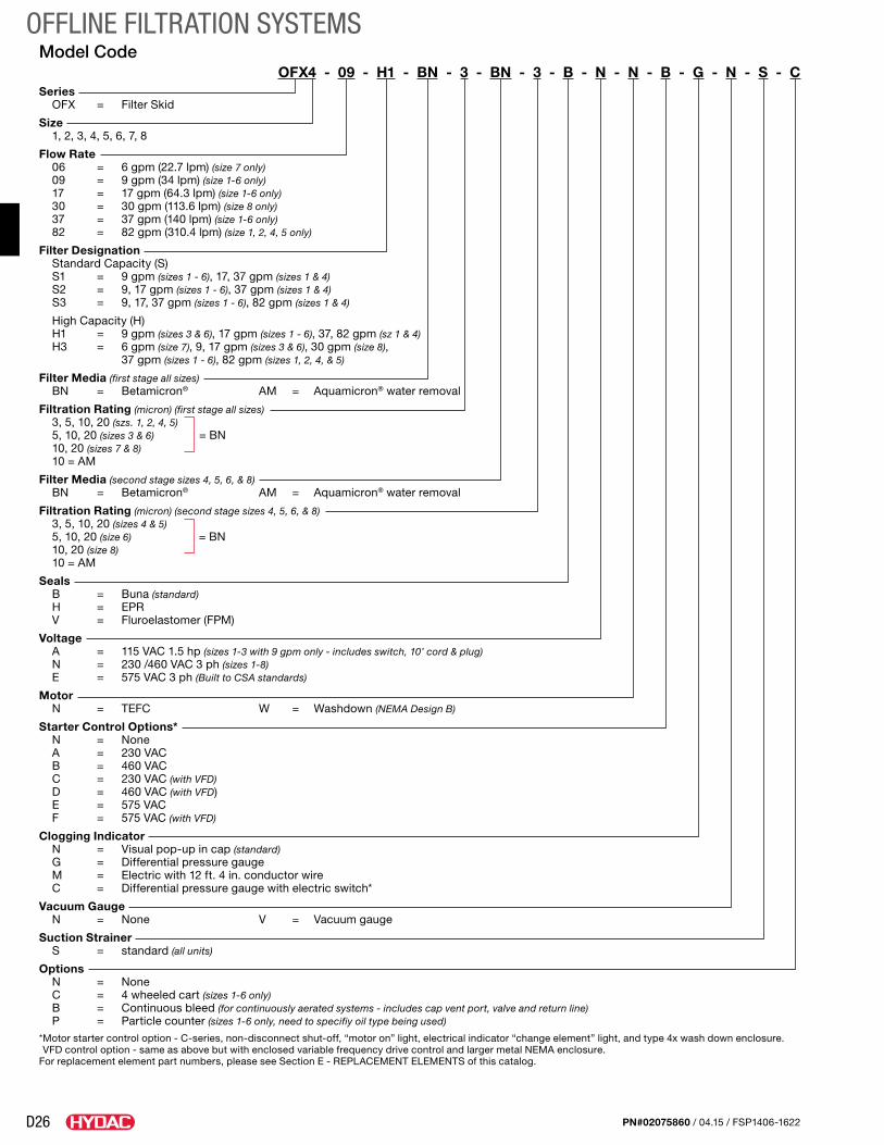
D26
OFFLINE FILTRATION SYSTEMS
PN#02075860 / 04.15 / FSP1406-1622
Model CodeOFX4 - 09 - H1 - BN - 3 - BN - 3 - B - N - N - B - G - N - S - C
Series OFX = Filter Skid
Size 1, 2, 3, 4, 5, 6, 7, 8
Flow Rate 06 = 6 gpm (22.7 lpm) (size 7 only) 09 = 9 gpm (34 lpm) (size 1-6 only) 17 = 17 gpm (64.3 lpm) (size 1-6 only) 30 = 30 gpm (113.6 lpm) (size 8 only) 37 = 37 gpm (140 lpm) (size 1-6 only) 82 = 82 gpm (310.4 lpm) (size 1, 2, 4, 5 only)
Filter Designation Standard Capacity (S) S1 = 9 gpm (sizes 1 - 6), 17, 37 gpm (sizes 1 & 4) S2 = 9, 17 gpm (sizes 1 - 6), 37 gpm (sizes 1 & 4) S3 = 9, 17, 37 gpm (sizes 1 - 6), 82 gpm (sizes 1 & 4)
High Capacity (H) H1 = 9 gpm (sizes 3 & 6), 17 gpm (sizes 1 - 6), 37, 82 gpm (sz 1 & 4) H3 = 6 gpm (size 7), 9, 17 gpm (sizes 3 & 6), 30 gpm (size 8),
37 gpm (sizes 1 - 6), 82 gpm (sizes 1, 2, 4, & 5)
Filter Media (first stage all sizes) BN = Betamicron® AM = Aquamicron® water removal
Filtration Rating (micron) (first stage all sizes) 3, 5, 10, 20 (szs. 1, 2, 4, 5) 5, 10, 20 (sizes 3 & 6) = BN 10, 20 (sizes 7 & 8) 10 = AM
Filter Media (second stage sizes 4, 5, 6, & 8) BN = Betamicron® AM = Aquamicron® water removal
Filtration Rating (micron) (second stage sizes 4, 5, 6, & 8) 3, 5, 10, 20 (sizes 4 & 5) 5, 10, 20 (size 6) = BN 10, 20 (size 8) 10 = AM
Seals B = Buna (standard) H = EPR V = Fluroelastomer (FPM)
Voltage A = 115 VAC 1.5 hp (sizes 1-3 with 9 gpm only - includes switch, 10’ cord & plug) N = 230 /460 VAC 3 ph (sizes 1-8) E = 575 VAC 3 ph (Built to CSA standards)
Motor N = TEFC W = Washdown (NEMA Design B)
Starter Control Options* N = None A = 230 VAC B = 460 VAC C = 230 VAC (with VFD) D = 460 VAC (with VFD) E = 575 VAC F = 575 VAC (with VFD)
Clogging Indicator N = Visual pop-up in cap (standard) G = Differential pressure gauge M = Electric with 12 ft. 4 in. conductor wire C = Differential pressure gauge with electric switch*
Vacuum Gauge N = None V = Vacuum gauge
Suction Strainer S = standard (all units)
Options N = None C = 4 wheeled cart (sizes 1-6 only) B = Continuous bleed (for continuously aerated systems - includes cap vent port, valve and return line) P = Particle counter (sizes 1-6 only, need to specifiy oil type being used)
* Motor starter control option - C-series, non-disconnect shut-off, “motor on” light, electrical indicator “change element” light, and type 4x wash down enclosure. VFD control option - same as above but with enclosed variable frequency drive control and larger metal NEMA enclosure.
For replacement element part numbers, please see Section E - REPLACEMENT ELEMENTS of this catalog.
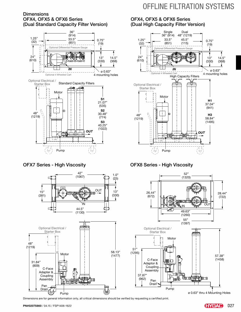
D27
OFFLINE FILTRATION SYSTEMS
PN#02075860 / 04.15 / FSP1406-1622
Dimensions OFX4, OFX5 & OFX6 Series OFX4, OFX5 & OFX6 Series (Dual Standard Capacity Filter Version) (Dual High Capacity Filter Version)
OFX7 Series - High Viscosity OFX8 Series - High Viscosity
Dimensions are for general information only, all critical dimensions should be verified by requesting a certified print.
S121.07”(535)
S230.48”(774)
S340.25”(1022)
Optional 4 Wheeled Cart
Optional Differential Pressure Gauge
Optional Electrical /Starter Box
Motor
36”(914)33.5”(851)
48”(1219)
Pump
OUT
IN
1.25”(32)
ø 0.63”4 mounting holes
0.75”(19)
13”(330)
14.5”(368)
24”(610)
Standard Capacity Filters
H137.04”(941)
H358.84”(1495)
Optional 4 Wheeled Cart
Optional Differential Pressure Gauge
Optional Electrical /Starter Box
Motor
Single36” (914)
33.5”(851)
Dual48” (1219)
45.5”(115)
48”(1219)
Pump
OUT
IN
1.25”(32)
ø 0.63”4 mounting holes
0.75”(19)
13”(330)
14.5”(368)
24”(610)
High Capacity Filters
42”(1067) 1.0”
(25)
13”(330)
15”(381)
OUT
IN
44.5”(1130)
58.13”(1477)
48”(1219)
31.84”(809)
Motor
C-FaceAdapter &Coupling
Assembly
PanDrain
Pump
Optional Electrical /Starter Box
52”(1320)
26.44”(672)
28.44”(722)
49.63”(1260)
55”(1397)
IN OUT
57.38”(1458)
51”(1295)
37.87”(962)
C-Face Adaptor &
CouplingAssembly
PanDrain
Pump
Motor
ø 0.63” thru 4 Mounting Holes
Optional Electrical /Starter Box
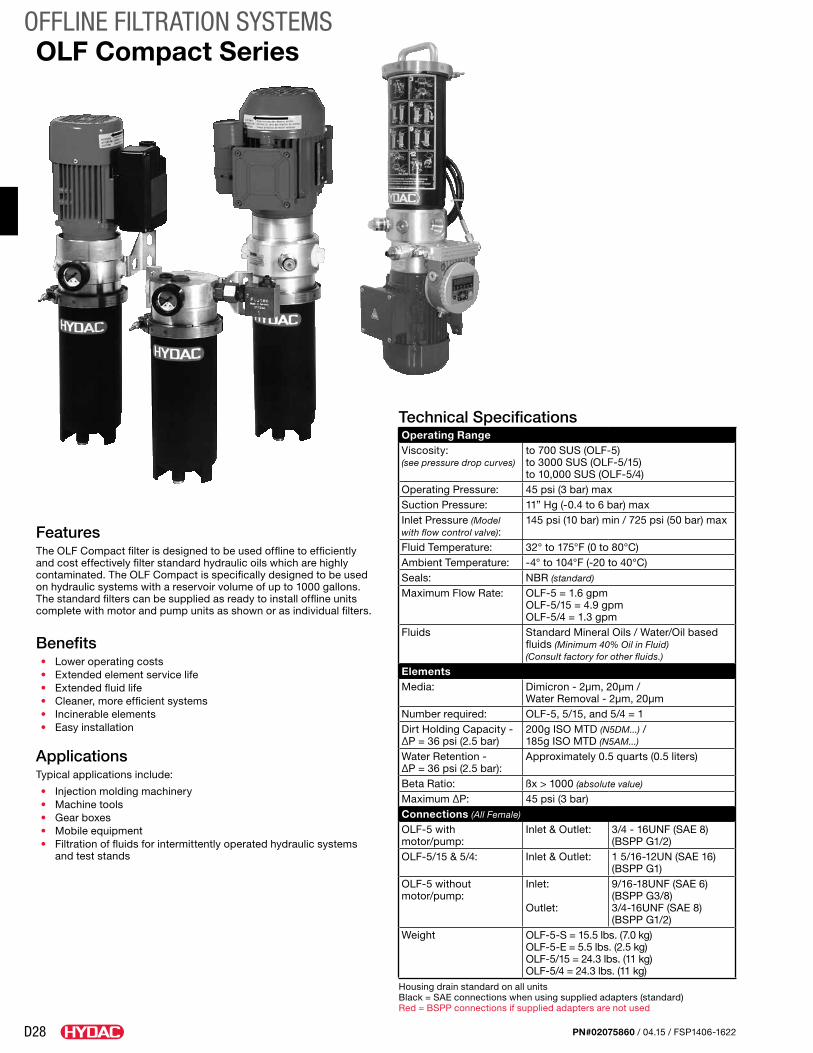
D28
OFFLINE FILTRATION SYSTEMS
PN#02075860 / 04.15 / FSP1406-1622
FeaturesThe OLF Compact filter is designed to be used offline to efficiently and cost effectively filter standard hydraulic oils which are highly contaminated. The OLF Compact is specifically designed to be used on hydraulic systems with a reservoir volume of up to 1000 gallons. The standard filters can be supplied as ready to install offline units complete with motor and pump units as shown or as individual filters.
Benefits• Lower operating costs• Extended element service life• Extended fluid life• Cleaner, more efficient systems• Incinerable elements• Easy installation
ApplicationsTypical applications include:
• Injection molding machinery• Machine tools• Gear boxes• Mobile equipment• Filtration of fluids for intermittently operated hydraulic systems
and test stands
Technical SpecificationsOperating RangeViscosity: (see pressure drop curves)
to 700 SUS (OLF-5) to 3000 SUS (OLF-5/15) to 10,000 SUS (OLF-5/4)
Operating Pressure: 45 psi (3 bar) maxSuction Pressure: 11” Hg (-0.4 to 6 bar) maxInlet Pressure (Model with flow control valve):
145 psi (10 bar) min / 725 psi (50 bar) max
Fluid Temperature: 32° to 175°F (0 to 80°C)Ambient Temperature: -4° to 104°F (-20 to 40°C)Seals: NBR (standard)
Maximum Flow Rate: OLF-5 = 1.6 gpm OLF-5/15 = 4.9 gpm OLF-5/4 = 1.3 gpm
Fluids Standard Mineral Oils / Water/Oil based fluids (Minimum 40% Oil in Fluid) (Consult factory for other fluids.)
ElementsMedia: Dimicron - 2µm, 20µm /
Water Removal - 2µm, 20µmNumber required: OLF-5, 5/15, and 5/4 = 1Dirt Holding Capacity - ∆P = 36 psi (2.5 bar)
200g ISO MTD (N5DM...) / 185g ISO MTD (N5AM...)
Water Retention - ∆P = 36 psi (2.5 bar):
Approximately 0.5 quarts (0.5 liters)
Beta Ratio: ßx > 1000 (absolute value)
Maximum ∆P: 45 psi (3 bar)Connections (All Female)
OLF-5 with motor/pump:
Inlet & Outlet: 3/4 - 16UNF (SAE 8) (BSPP G1/2)
OLF-5/15 & 5/4: Inlet & Outlet: 1 5/16-12UN (SAE 16) (BSPP G1)
OLF-5 without motor/pump:
Inlet:
Outlet:
9/16-18UNF (SAE 6) (BSPP G3/8)3/4-16UNF (SAE 8) (BSPP G1/2)
Weight OLF-5-S = 15.5 lbs. (7.0 kg) OLF-5-E = 5.5 lbs. (2.5 kg) OLF-5/15 = 24.3 lbs. (11 kg) OLF-5/4 = 24.3 lbs. (11 kg)
Housing drain standard on all unitsBlack = SAE connections when using supplied adapters (standard)Red = BSPP connections if supplied adapters are not used
OLF Compact Series
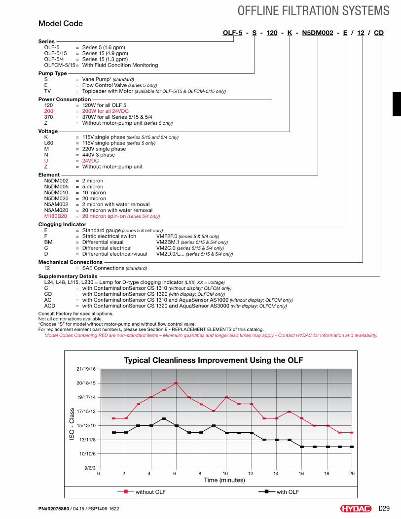
D29
OFFLINE FILTRATION SYSTEMS
PN#02075860 / 04.15 / FSP1406-1622
Model CodeOLF-5 - S - 120 - K - N5DM002 - E / 12 / CD
Series OLF-5 = Series 5 (1.6 gpm) OLF-5/15 = Series 15 (4.9 gpm) OLF-5/4 = Series 15 (1.3 gpm) OLFCM-5/15 = With Fluid Condition Monitoring
Pump Type S = Vane Pump* (standard) E = Flow Control Valve (series 5 only) TV = Toploader with Motor (available for OLF-5/15 & OLFCM-5/15 only)
Power Consumption 120 = 120W for all OLF 5 200 = 200W for all 24VDC 370 = 370W for all Series 5/15 & 5/4 Z = Without motor-pump unit (series 5 only)
Voltage K = 115V single phase (series 5/15 and 5/4 only) L60 = 115V single phase (series 5 only) M = 220V single phase N = 440V 3 phase U = 24VDC Z = Without motor-pump unit
Element N5DM002 = 2 micron N5DM005 = 5 micron N5DM010 = 10 micron N5DM020 = 20 micron N5AM002 = 2 micron with water removal N5AM020 = 20 micron with water removal M180B20 = 20 micron spin-on (series 5/4 only)
Clogging Indicator E = Standard gauge (series 5 & 5/4 only) F = Static electrical switch VMF2F.0 (series 5 & 5/4 only) BM = Differential visual VM2BM.1 (series 5/15 & 5/4 only) C = Differential electrical VM2C.0 (series 5/15 & 5/4 only) D = Differential electrical/visual VM2D.0/L... (series 5/15 & 5/4 only)
Mechanical Connections 12 = SAE Connections (standard)
Supplementary Details L24, L48, L115, L230 = Lamp for D-type clogging indicator (LXX, XX = voltage) C = with ContaminationSensor CS 1310 (without display; OLFCM only) CD = with ContaminationSensor CS 1320 (with display; OLFCM only) AC = with ContaminationSensor CS 1310 and AquaSensor AS1000 (without display; OLFCM only) ACD = with ContaminationSensor CS 1320 and AquaSensor AS3000 (with display; OLFCM only)
Consult Factory for special options. Not all combinations available. *Choose “S” for model without motor-pump and without flow control valve.For replacement element part numbers, please see Section E - REPLACEMENT ELEMENTS of this catalog.
Model Codes Containing RED are non-standard items – Minimum quantities and longer lead times may apply - Contact HYDAC for information and availability.
Typical Cleanliness Improvement Using the OLF
Time (minutes)
without OLF with OLF
ISO
- C
lass
21/19/16
20/18/15
19/17/14
17/15/12
15/13/10
13/11/8
10/10/6
9/6/30 2 4 6 8 10 12 14 16 18 20
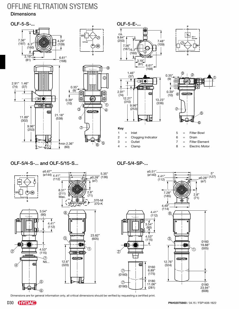
D30
OFFLINE FILTRATION SYSTEMS
PN#02075860 / 04.15 / FSP1406-1622
Key1 = Inlet 5 = Filter Bowl2 = Clogging Indicator 6 = Drain3 = Outlet 7 = Filter Element4 = Clamp 8 = Electric Motor
Dimensions
OLF-5-S-... OLF-5-E-...
OLF-5/4-S-... and OLF-5/15-S... OLF-5/4-SP-...
11.89”(302)
9.96”(253)
0.35”(9)
0.39”(10)
21.18”(538)
4
13
2
6
7
5
8
2.91”(74)
1.46”(37)
min 2.36”(60)
6.61”(168)
3.19”(81)
4.29”(109)
7.36”(187) 6.3”
(160)
12.6”(320)
23.82”(605)
2
6
5
ø5.67”(ø144) 5.35”
(136)4.41”(112) ø0.28”
(ø7)
2.8”(71)
370-M370-K
8.31”(211)Max.
1
3
8
7
3.54”(90)
4.41”(112)
4.53”(115)
4N5... 12.76”
(324)
016019.88”(505)
01606.89”(175)
018023.94”(608)
018011.06”(281)
2
ø5.51”(ø140) 5”
(127)4.41”(112) ø0.28”
(ø7)
2.8”(71)
7.28”(185)
4.49”(114)
1
3
8
7
7
3.54”(90)
4.41”(112)
4.53”(115)
(0160)
(0180)
12.21”(310)
9.96”(253)
0.35”(9)
0.39”(10)
13.23”(336)
4
13 2
6
75
2.91”(74)
1.46”(37)
7.36”(187)
ca. 9.84”(250)
6.3”(160)
6.61”(168)
3.19”(81)
7.48”(109)
P
S
3.5 bar
M
P
S
M
VA
P
S
po =3.5 bar
Dimensions are for general information only, all critical dimensions should be verified by requesting a certified print.
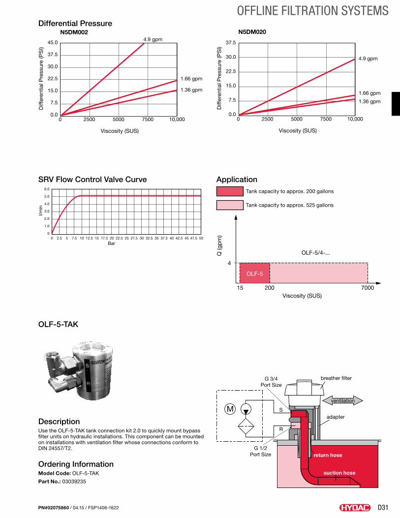
D31
OFFLINE FILTRATION SYSTEMS
PN#02075860 / 04.15 / FSP1406-1622
Differential Pressure
DescriptionUse the OLF-5-TAK tank connection kit 2.0 to quickly mount bypass filter units on hydraulic installations. This component can be mounted on installations with ventilation filter whose connections conform to DIN 24557/T2.
Ordering InformationModel Code: OLF-5-TAK
Part No.: 03039235
SRV Flow Control Valve Curve Application
OLF-5-TAK
N5DM002
Viscosity (SUS)
Diff
eren
tial P
ress
ure
(PS
I)45.0
4.9 gpm
1.66 gpm
1.36 gpm
37.5
30.0
22.5
15.0
7.5
0.00 2500 5000 7500 10,000
N5DM020
Viscosity (SUS)
Diff
eren
tial P
ress
ure
(PS
I)
4.9 gpm
1.66 gpm
1.36 gpm
37.5
30.0
22.5
15.0
7.5
0.00 2500 5000 7500 10,000
N5DM002
Viscosity (SUS)
Diff
eren
tial P
ress
ure
(PS
I)
45.04.9 gpm
1.66 gpm
1.36 gpm
37.5
30.0
22.5
15.0
7.5
0.00 2500 5000 7500 10,000
N5DM020
Viscosity (SUS)
Diff
eren
tial P
ress
ure
(PS
I)
4.9 gpm
1.66 gpm
1.36 gpm
37.5
30.0
22.5
15.0
7.5
0.00 2500 5000 7500 10,000
00 2.5 5 7.5 10 12.5 15 17.5 20 22.5 25 27.5 30 32.5 35 37.5 40 47.5 5042.5 45
1.0
2.0
3.0
4.0
5.0
6.0
Bar
l/min
OLF-5/4-...
OLF-5
Q (g
pm
)
Viscosity (SUS)15 200 7000
4
breather filterG 3/4Port Size
G 1/2Port Size
ventilation
S
R
adapter
return hose
suction hose
Tank capacity to approx. 200 gallons
Tank capacity to approx. 525 gallons
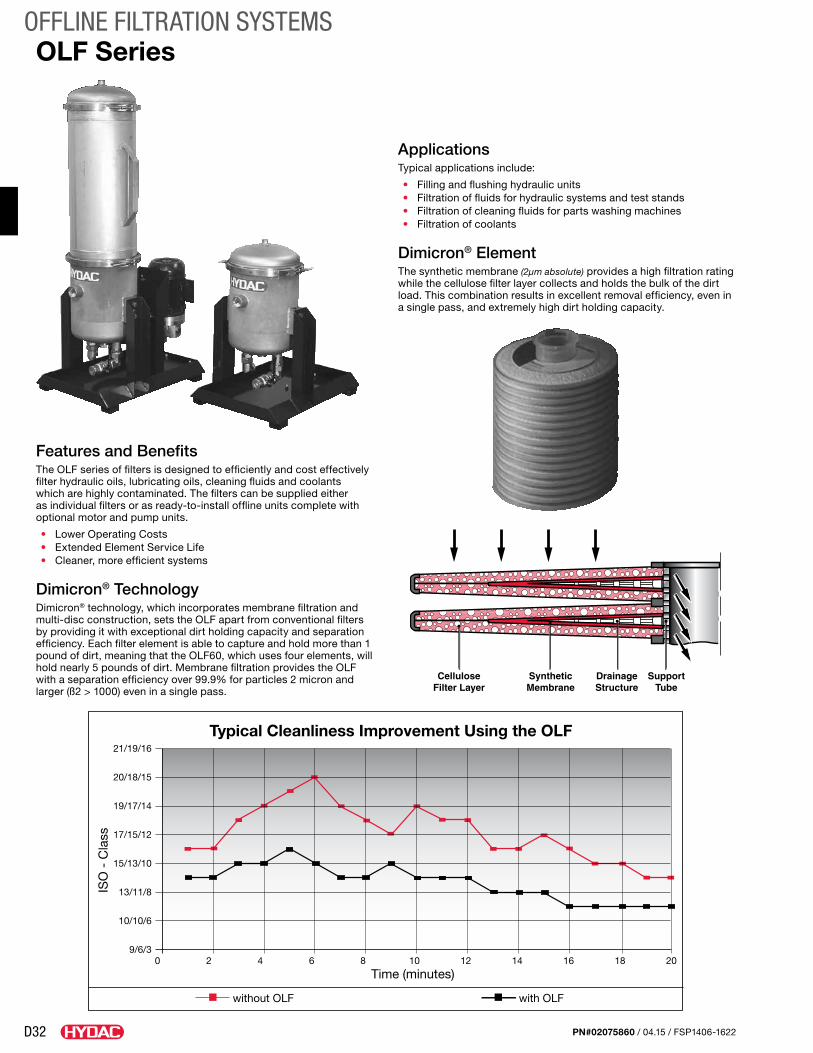
D32
OFFLINE FILTRATION SYSTEMS
PN#02075860 / 04.15 / FSP1406-1622
Features and BenefitsThe OLF series of filters is designed to efficiently and cost effectively filter hydraulic oils, lubricating oils, cleaning fluids and coolants which are highly contaminated. The filters can be supplied either as individual filters or as ready-to-install offline units complete with optional motor and pump units.
• Lower Operating Costs• Extended Element Service Life• Cleaner, more efficient systems
Dimicron® TechnologyDimicron® technology, which incorporates membrane filtration and multi-disc construction, sets the OLF apart from conventional filters by providing it with exceptional dirt holding capacity and separation efficiency. Each filter element is able to capture and hold more than 1 pound of dirt, meaning that the OLF60, which uses four elements, will hold nearly 5 pounds of dirt. Membrane filtration provides the OLF with a separation efficiency over 99.9% for particles 2 micron and larger (ß2 > 1000) even in a single pass.
ApplicationsTypical applications include:
• Filling and flushing hydraulic units• Filtration of fluids for hydraulic systems and test stands• Filtration of cleaning fluids for parts washing machines• Filtration of coolants
Dimicron® ElementThe synthetic membrane (2µm absolute) provides a high filtration rating while the cellulose filter layer collects and holds the bulk of the dirt load. This combination results in excellent removal efficiency, even in a single pass, and extremely high dirt holding capacity.
OLF Series
CelluloseFilter Layer
SyntheticMembrane
DrainageStructure
SupportTube
Typical Cleanliness Improvement Using the OLF
Time (minutes)
without OLF with OLF
ISO
- C
lass
21/19/16
20/18/15
19/17/14
17/15/12
15/13/10
13/11/8
10/10/6
9/6/30 2 4 6 8 10 12 14 16 18 20
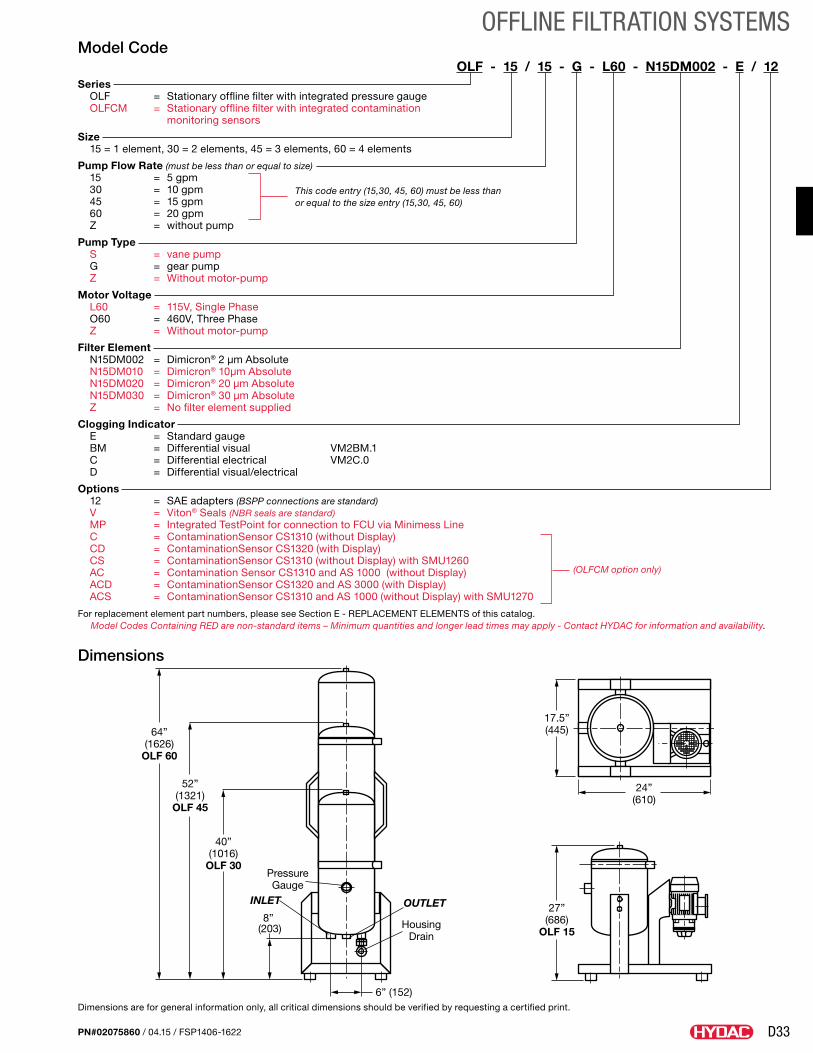
D33
OFFLINE FILTRATION SYSTEMS
PN#02075860 / 04.15 / FSP1406-1622
Model CodeOLF - 15 / 15 - G - L60 - N15DM002 - E / 12
Series OLF = Stationary offline filter with integrated pressure gauge OLFCM = Stationary offline filter with integrated contamination
monitoring sensors
Size 15 = 1 element, 30 = 2 elements, 45 = 3 elements, 60 = 4 elements
Pump Flow Rate (must be less than or equal to size) 15 = 5 gpm 30 = 10 gpm 45 = 15 gpm 60 = 20 gpm Z = without pump
Pump Type S = vane pump G = gear pump Z = Without motor-pump
Motor Voltage L60 = 115V, Single Phase O60 = 460V, Three Phase Z = Without motor-pump
Filter Element N15DM002 = Dimicron® 2 µm Absolute N15DM010 = Dimicron® 10µm Absolute N15DM020 = Dimicron® 20 µm Absolute N15DM030 = Dimicron® 30 µm Absolute Z = No filter element supplied
Clogging Indicator E = Standard gauge BM = Differential visual VM2BM.1 C = Differential electrical VM2C.0 D = Differential visual/electrical
Options 12 = SAE adapters (BSPP connections are standard) V = Viton® Seals (NBR seals are standard) MP = Integrated TestPoint for connection to FCU via Minimess Line C = ContaminationSensor CS1310 (without Display) CD = ContaminationSensor CS1320 (with Display) CS = ContaminationSensor CS1310 (without Display) with SMU1260 AC = Contamination Sensor CS1310 and AS 1000 (without Display) ACD = ContaminationSensor CS1320 and AS 3000 (with Display) ACS = ContaminationSensor CS1310 and AS 1000 (without Display) with SMU1270
For replacement element part numbers, please see Section E - REPLACEMENT ELEMENTS of this catalog.Model Codes Containing RED are non-standard items – Minimum quantities and longer lead times may apply - Contact HYDAC for information and availability.
Dimensions
17.5”(445)
27”(686)
OLF 15
64”(1626)
OLF 60
52”(1321)
OLF 45
40”(1016)
OLF 30
24”(610)
PressureGauge
INLET
HousingDrain
OUTLET8”
(203)
6” (152)Dimensions are for general information only, all critical dimensions should be verified by requesting a certified print.
This code entry (15,30, 45, 60) must be less than or equal to the size entry (15,30, 45, 60)
(OLFCM option only)
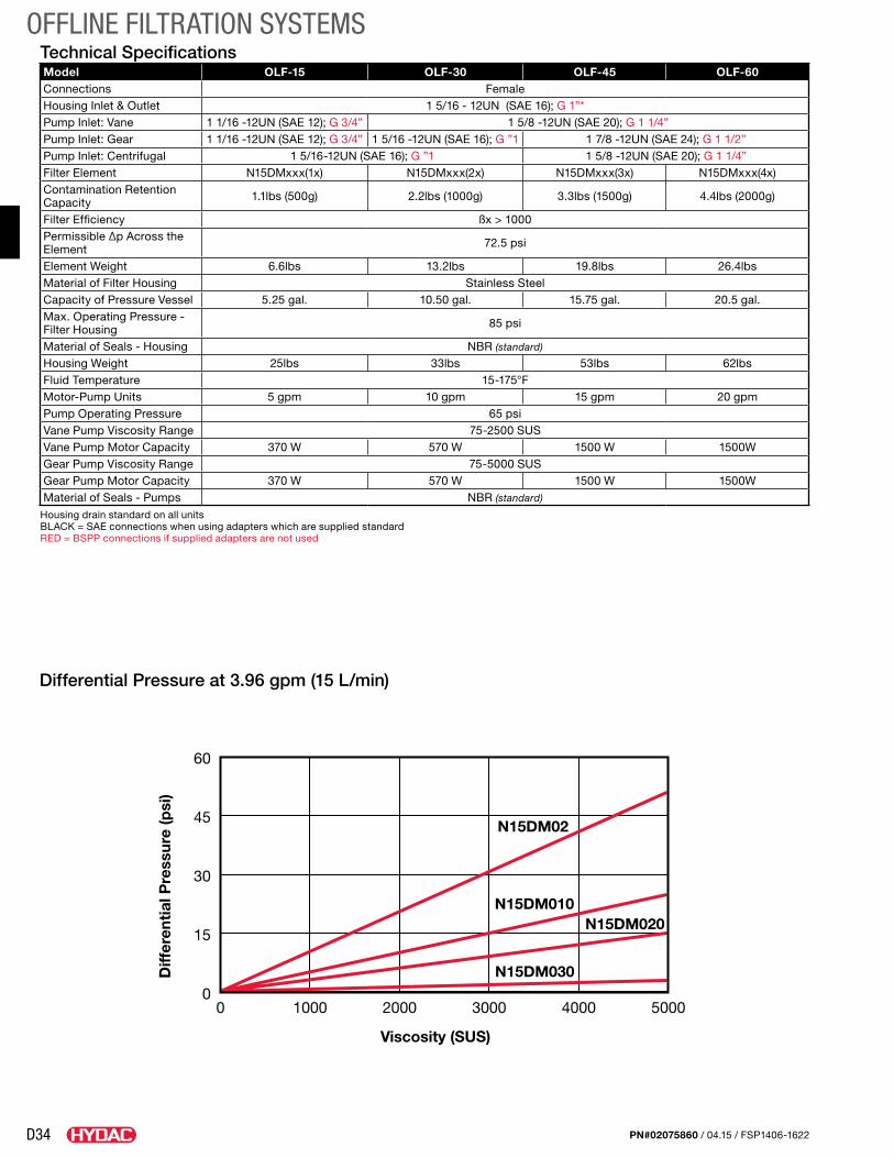
D34
OFFLINE FILTRATION SYSTEMS
PN#02075860 / 04.15 / FSP1406-1622
Technical SpecificationsModel OLF-15 OLF-30 OLF-45 OLF-60Connections FemaleHousing Inlet & Outlet 1 5/16 - 12UN (SAE 16); G 1”*Pump Inlet: Vane 1 1/16 -12UN (SAE 12); G 3/4” 1 5/8 -12UN (SAE 20); G 1 1/4”Pump Inlet: Gear 1 1/16 -12UN (SAE 12); G 3/4” 1 5/16 -12UN (SAE 16); G ”1 1 7/8 -12UN (SAE 24); G 1 1/2”Pump Inlet: Centrifugal 1 5/16-12UN (SAE 16); G ”1 1 5/8 -12UN (SAE 20); G 1 1/4”Filter Element N15DMxxx(1x) N15DMxxx(2x) N15DMxxx(3x) N15DMxxx(4x)Contamination Retention Capacity 1.1lbs (500g) 2.2lbs (1000g) 3.3lbs (1500g) 4.4lbs (2000g)
Filter Efficiency ßx > 1000Permissible ∆p Across the Element 72.5 psi
Element Weight 6.6lbs 13.2lbs 19.8lbs 26.4lbsMaterial of Filter Housing Stainless SteelCapacity of Pressure Vessel 5.25 gal. 10.50 gal. 15.75 gal. 20.5 gal.Max. Operating Pressure - Filter Housing 85 psi
Material of Seals - Housing NBR (standard)
Housing Weight 25lbs 33lbs 53lbs 62lbsFluid Temperature 15-175°FMotor-Pump Units 5 gpm 10 gpm 15 gpm 20 gpmPump Operating Pressure 65 psiVane Pump Viscosity Range 75-2500 SUSVane Pump Motor Capacity 370 W 570 W 1500 W 1500WGear Pump Viscosity Range 75-5000 SUSGear Pump Motor Capacity 370 W 570 W 1500 W 1500WMaterial of Seals - Pumps NBR (standard)
Housing drain standard on all unitsBLACK = SAE connections when using adapters which are supplied standardRED = BSPP connections if supplied adapters are not used
Differential Pressure at 3.96 gpm (15 L/min)
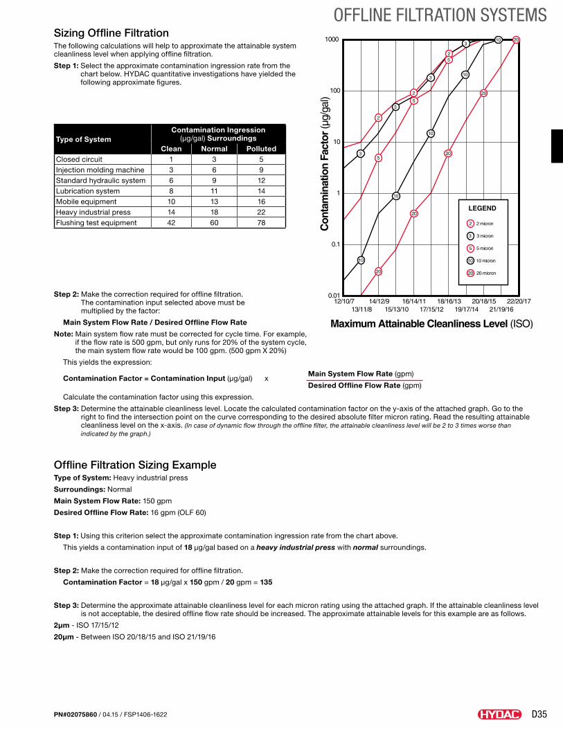
D35
OFFLINE FILTRATION SYSTEMS
PN#02075860 / 04.15 / FSP1406-1622
Sizing Offline FiltrationThe following calculations will help to approximate the attainable system cleanliness level when applying offline filtration.
Step 1: Select the approximate contamination ingression rate from the chart below. HYDAC quantitative investigations have yielded the following approximate figures.
Type of SystemContamination Ingression
(µg/gal) SurroundingsClean Normal Polluted
Closed circuit 1 3 5Injection molding machine 3 6 9Standard hydraulic system 6 9 12Lubrication system 8 11 14Mobile equipment 10 13 16Heavy industrial press 14 18 22Flushing test equipment 42 60 78
Step 2: Make the correction required for offline filtration. The contamination input selected above must be multiplied by the factor:
Main System Flow Rate / Desired Offline Flow Rate
Note: Main system flow rate must be corrected for cycle time. For example, if the flow rate is 500 gpm, but only runs for 20% of the system cycle, the main system flow rate would be 100 gpm. (500 gpm X 20%)
This yields the expression:
Contamination Factor = Contamination Input (µg/gal) x
Main System Flow Rate (gpm)
Desired Offline Flow Rate (gpm)
Calculate the contamination factor using this expression.
Step 3: Determine the attainable cleanliness level. Locate the calculated contamination factor on the y-axis of the attached graph. Go to the right to find the intersection point on the curve corresponding to the desired absolute filter micron rating. Read the resulting attainable cleanliness level on the x-axis. (In case of dynamic flow through the offline filter, the attainable cleanliness level will be 2 to 3 times worse than indicated by the graph.)
Offline Filtration Sizing ExampleType of System: Heavy industrial press
Surroundings: Normal
Main System Flow Rate: 150 gpm
Desired Offline Flow Rate: 16 gpm (OLF 60)
Step 1: Using this criterion select the approximate contamination ingression rate from the chart above.
This yields a contamination input of 18 µg/gal based on a heavy industrial press with normal surroundings.
Step 2: Make the correction required for offline filtration.
Contamination Factor = 18 µg/gal x 150 gpm / 20 gpm = 135
Step 3: Determine the approximate attainable cleanliness level for each micron rating using the attached graph. If the attainable cleanliness level is not acceptable, the desired offline flow rate should be increased. The approximate attainable levels for this example are as follows.
2µm - ISO 17/15/12
20µm - Between ISO 20/18/15 and ISO 21/19/16
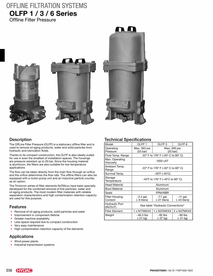
D36
OFFLINE FILTRATION SYSTEMS
PN#02075860 / 04.15 / FSP1406-1622
DescriptionThe OffLine Filter Pressure (OLFP) is a stationary offline filter and is used to remove oil aging products, water and solid particles from hydraulic and lubrication fluids.
Thanks to its compact construction, the OLFP is also ideally suited for use in even the smallest of installation spaces. The housings are pressure resistant up to 20 bar. Since the housing material is aluminium, the filters are also suitable for low-temperature applications
The flow can be taken directly from the main flow through an orifice and the orifice determines the flow rate. The offline filters can also be equipped with a motor-pump unit and an inductive particle counter, as an option.
The Trimicron series of filter elements NxTMxxx have been specially developed for the combined removal of fine particles, water and oil aging products. The most modern filter materials with reliable separation characteristics and high contamination retention capacity are used for this purpose.
Features• Removal of oil aging products, solid particles and water• Improvement in component lifetime• Greater machine availability• Less space required due to compact construction• Very easy maintenance• High contamination retention capacity of the elements
Applications• Wind power plants• Industrial transmission systems
OLFP 1 / 3 / 6 SeriesOffline Filter Pressure
Technical SpecificationsModel OLFP 1 OLFP 3 OLFP 6Operating Pressure
Max. 363 psi (25 bar)
Max. 290 psi (20 bar)
Fluid Temp. Range -22º F to 176º F (-30º C to 80º C)Max. Operating Viscosity 1000 cST
Ambient Temp. Range -22º F to 176º F (-30º C to 80º C)
Survival Temp. -40˚F (-40˚C)Storage Temperature -40˚F to 176º F (-40˚C to 80º C)
Head Material AluminumBowl Material AluminumSeals FPM/NBRFilter Housing Content
~2.4 gal. (~9 liters)
~7.1 gal. (~27 liters)
~11 gal. (~43 liters)
Hydraulic Port (IN/OUT) See table “Hydraulic Connections”
Filter Element 1 x N1TMXXX 1 x N3TMXXX 2 x N3TMXXXWeight ~46.3 lbs
(~21 kg)~82 lbs (~37 kg)
~90 lbs (~41 kg)
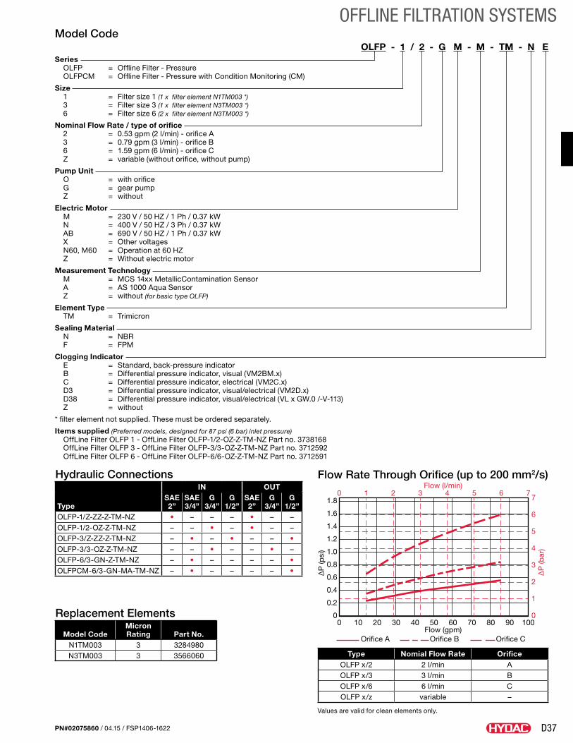
D37
OFFLINE FILTRATION SYSTEMS
PN#02075860 / 04.15 / FSP1406-1622
Model CodeOLFP - 1 / 2 - G M - M - TM - N E
Series OLFP = Offline Filter - Pressure OLFPCM = Offline Filter - Pressure with Condition Monitoring (CM)
Size 1 = Filter size 1 (1 x filter element N1TM003 *) 3 = Filter size 3 (1 x filter element N3TM003 *) 6 = Filter size 6 (2 x filter element N3TM003 *)
Nominal Flow Rate / type of orifice 2 = 0.53 gpm (2 l/min) - orifice A 3 = 0.79 gpm (3 l/min) - orifice B 6 = 1.59 gpm (6 l/min) - orifice C Z = variable (without orifice, without pump)
Pump Unit O = with orifice G = gear pump Z = without
Electric Motor M = 230 V / 50 HZ / 1 Ph / 0.37 kW N = 400 V / 50 HZ / 3 Ph / 0.37 kW AB = 690 V / 50 HZ / 1 Ph / 0.37 kW X = Other voltages N60, M60 = Operation at 60 HZ Z = Without electric motor
Measurement Technology M = MCS 14xx MetallicContamination Sensor A = AS 1000 Aqua Sensor Z = without (for basic type OLFP)
Element Type TM = Trimicron
Sealing Material N = NBR F = FPM
Clogging Indicator E = Standard, back-pressure indicator B = Differential pressure indicator, visual (VM2BM.x) C = Differential pressure indicator, electrical (VM2C.x) D3 = Differential pressure indicator, visual/electrical (VM2D.x) D38 = Differential pressure indicator, visual/electrical (VL x GW.0 /-V-113) Z = without
* filter element not supplied. These must be ordered separately.
Items supplied (Preferred models, designed for 87 psi (6 bar) inlet pressure) OffLine Filter OLFP 1 - OffLine Filter OLFP-1/2-OZ-Z-TM-NZ Part no. 3738168 OffLine Filter OLFP 3 - OffLine Filter OLFP-3/3-OZ-Z-TM-NZ Part no. 3712592 OffLine Filter OLFP 6 - OffLine Filter OLFP-6/6-OZ-Z-TM-NZ Part no. 3712591
Replacement Elements
Model CodeMicron Rating Part No.
N1TM003 3 3284980N3TM003 3 3566060 Type Nomial Flow Rate Orifice
OLFP x/2 2 l/min AOLFP x/3 3 l/min BOLFP x/6 6 l/min COLFP x/z variable –
Hydraulic Connections
Type
IN OUTSAE 2”
SAE 3/4”
G 3/4”
G 1/2”
SAE 2”
G 3/4”
G 1/2”
OLFP-1/Z-ZZ-Z-TM-NZ • – – – • – –OLFP-1/2-OZ-Z-TM-NZ – – • – • – –OLFP-3/Z-ZZ-Z-TM-NZ – • – • – – •OLFP-3/3-OZ-Z-TM-NZ – – • – – • –OLFP-6/3-GN-Z-TM-NZ – • – – – – •OLFPCM-6/3-GN-MA-TM-NZ – • – – – – •
0
0.2
0.4
0.6
0.8
1.0
1.2
1.4
1.6
1.8
0 10 20 30 40 50 60 70 80 90 1000
1
2
3
4
5
6
70 1 2 3 4 5 6 7
∆P
(psi
)
∆P
(bar
)
Orifice A Orifice B Orifice CFlow (gpm)
Flow (l/min)Flow Rate Through Orifice (up to 200 mm2/s)
Values are valid for clean elements only.
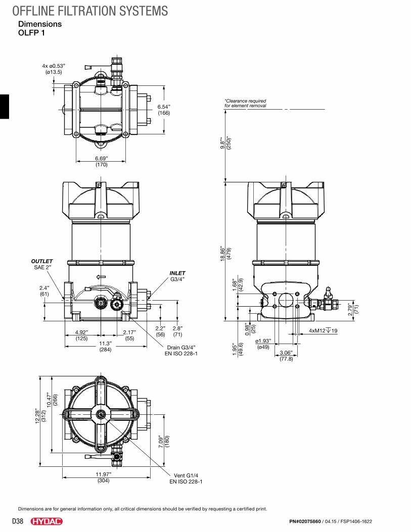
D38
OFFLINE FILTRATION SYSTEMS
PN#02075860 / 04.15 / FSP1406-1622
Dimensions OLFP 1
11.97”(304)
10.4
7”(2
66)
12.2
8”(3
12)
2.8”(71)
9.8”
*(2
50)*
Vent G1/4EN ISO 228-1
7.09
”(1
80)
Drain G3/4”EN ISO 228-1
INLETG3/4”
OUTLET SAE 2”
4.92”(125)
2.4”(61)
2.2”(56)
11.3”(284)
2.17”(55)
1.68
”(4
2.9)
3.06”(77.8)
1.95
”(4
9.6)
19
ø1.93”(ø49)
18.8
6”(4
79)
0.98
”(2
5)
4xM12
2.79
”(7
1)
6.54”(166)
6.69”(170)
4x ø0.53”(ø13.5)
*Clearance requiredfor element removal
Dimensions are for general information only, all critical dimensions should be verified by requesting a certified print.
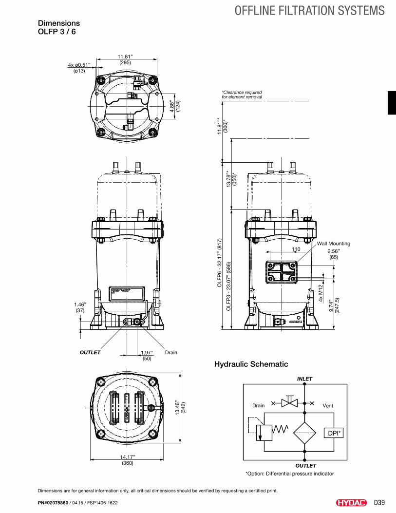
D39
OFFLINE FILTRATION SYSTEMS
PN#02075860 / 04.15 / FSP1406-1622
Dimensions OLFP 3 / 6
Hydraulic Schematic
14.17”(360)
OLF
P3
- 23
.07”
(586
)
OLF
P6
- 32
.17”
(817
)
13.7
8”*
(350
)*
11.8
1”*
(300
)*
11.61”(295)
4.88
”(1
24)
4x ø0.51”(ø13)
DrainOUTLET
1.46”(37)
1.97”(50)
13.4
6”(3
42)
Wall Mounting110 2.56”
(65)
9.74
”(2
47.5
)4x M
12
*Clearance requiredfor element removal
Dimensions are for general information only, all critical dimensions should be verified by requesting a certified print.
*Option: Differential pressure indicator
OUTLET
VentDrain
INLET
DPI*
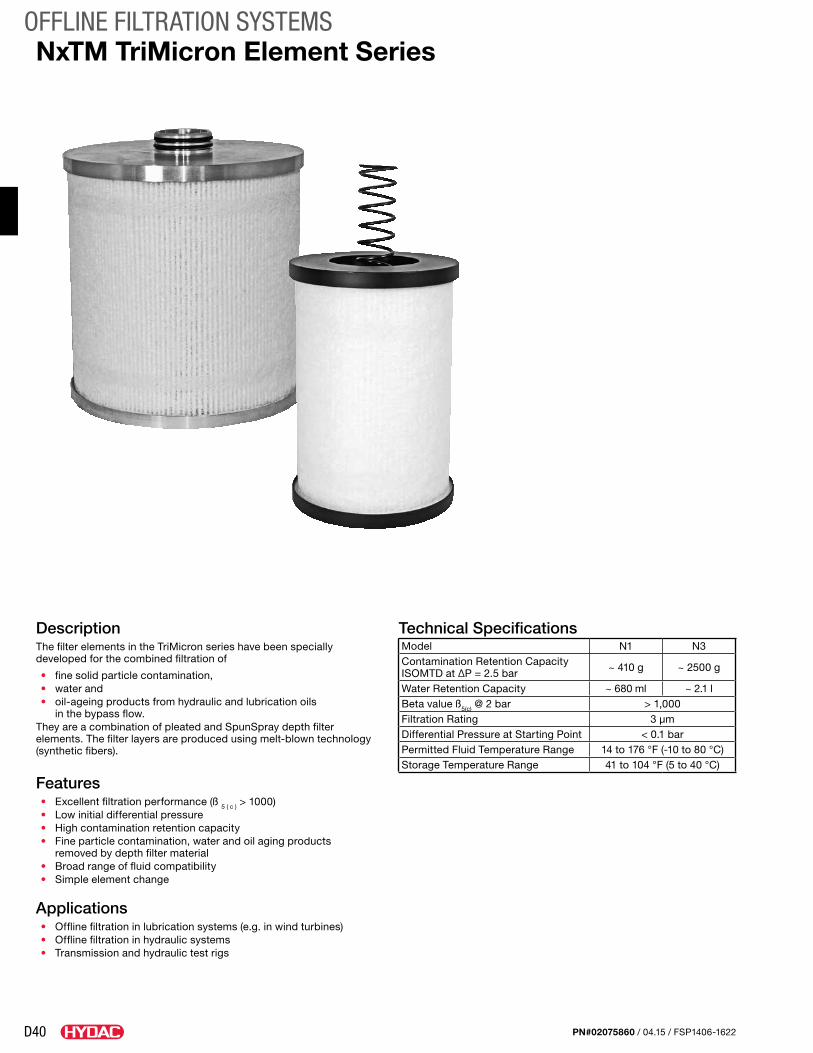
D40
OFFLINE FILTRATION SYSTEMS
PN#02075860 / 04.15 / FSP1406-1622
DescriptionThe filter elements in the TriMicron series have been specially developed for the combined filtration of
• fine solid particle contamination,• water and• oil-ageing products from hydraulic and lubrication oils
in the bypass flow.They are a combination of pleated and SpunSpray depth filter elements. The filter layers are produced using melt-blown technology (synthetic fibers).
Features• Excellent filtration performance (ß 5 ( c ) > 1000)• Low initial differential pressure• High contamination retention capacity• Fine particle contamination, water and oil aging products
removed by depth filter material• Broad range of fluid compatibility• Simple element change
Applications• Offline filtration in lubrication systems (e.g. in wind turbines)• Offline filtration in hydraulic systems• Transmission and hydraulic test rigs
NxTM TriMicron Element Series
Technical SpecificationsModel N1 N3Contamination Retention Capacity ISOMTD at ∆P = 2.5 bar ~ 410 g ~ 2500 g
Water Retention Capacity ~ 680 ml ~ 2.1 lBeta value ß5(c) @ 2 bar > 1,000Filtration Rating 3 μmDifferential Pressure at Starting Point < 0.1 barPermitted Fluid Temperature Range 14 to 176 °F (-10 to 80 °C)Storage Temperature Range 41 to 104 °F (5 to 40 °C)
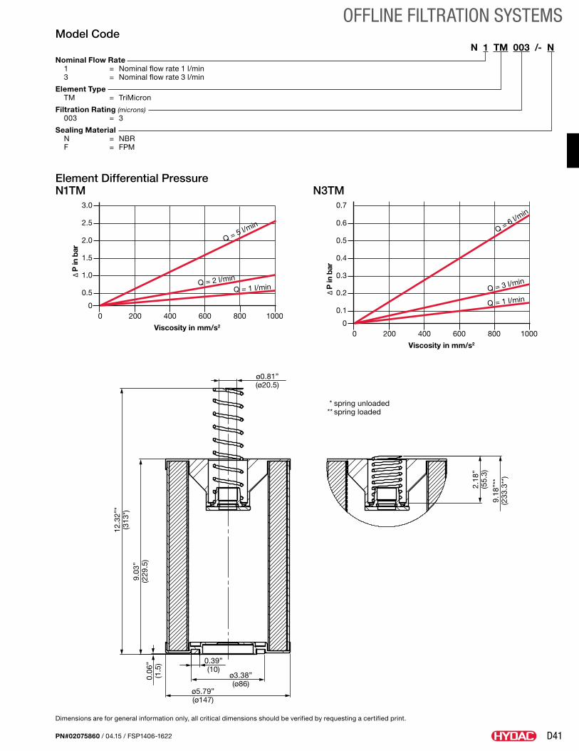
D41
OFFLINE FILTRATION SYSTEMS
PN#02075860 / 04.15 / FSP1406-1622
Model CodeN 1 TM 003 /- N
Nominal Flow Rate 1 = Nominal flow rate 1 l/min 3 = Nominal flow rate 3 l/min
Element Type TM = TriMicron
Filtration Rating (microns) 003 = 3
Sealing Material N = NBR F = FPM
Element Differential Pressure N1TM N3TM
9.18
”**
(233
.3**
)
2.18
”(5
5.3)
* spring unloaded** spring loaded
0.39”(10)
ø0.81”(ø20.5)
ø3.38”(ø86)
9.03
”(2
29.5
)
ø5.79”(ø147)
0.06
”(1
.5)
12.3
2”*
(313
*)
Dimensions are for general information only, all critical dimensions should be verified by requesting a certified print.
00
0.5
1.0
1.5
2.0
2.5
3.0
200 400 600 800 1000
Q = 5 l/min
Q = 2 l/min
Q = 1 l/min
Viscosity in mm/s2
00
0.1
0.2
0.3
0.4
0.5
0.6
0.7
200 400 600 800 1000
Q = 6 l/min
Q = 3 l/min
Q = 1 l/min
Viscosity in mm/s2
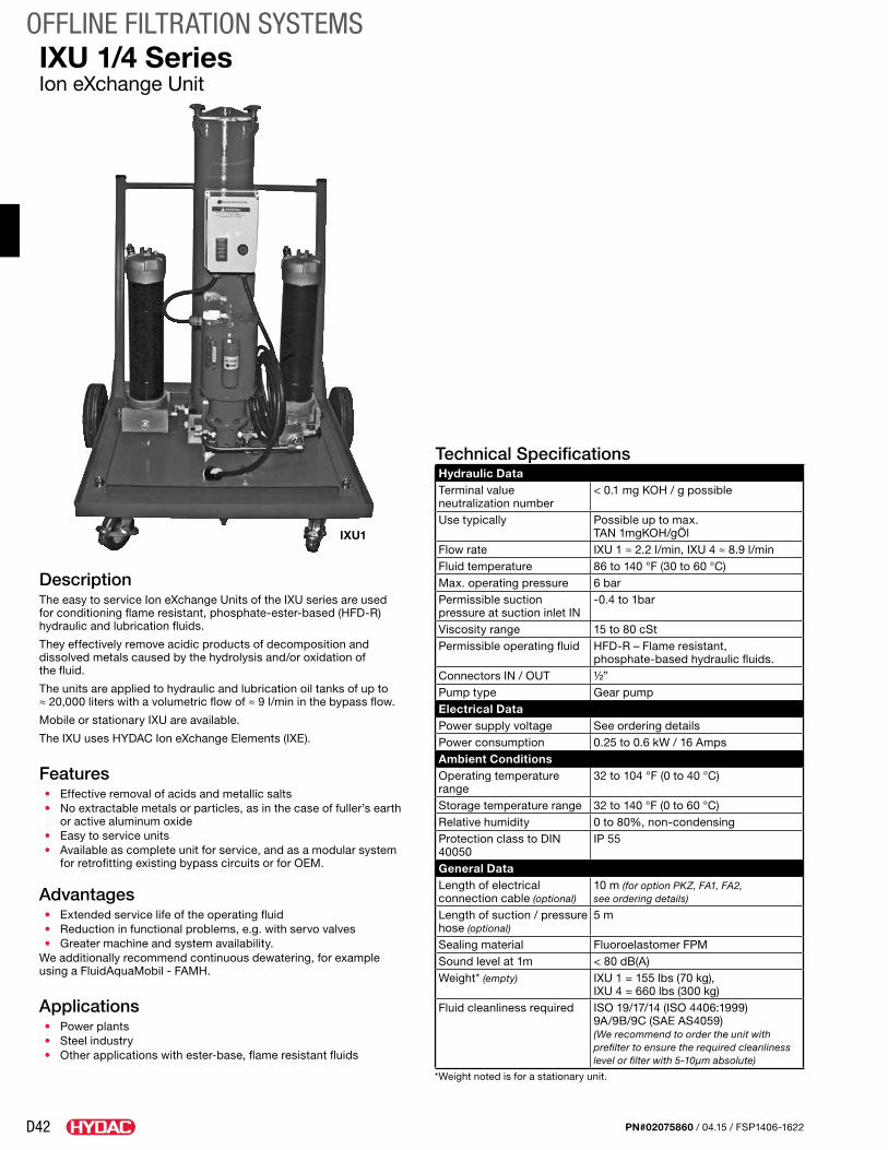
D42
OFFLINE FILTRATION SYSTEMS
PN#02075860 / 04.15 / FSP1406-1622
IXU 1/4 SeriesIon eXchange Unit
DescriptionThe easy to service Ion eXchange Units of the IXU series are used for conditioning flame resistant, phosphate-ester-based (HFD-R) hydraulic and lubrication fluids.
They effectively remove acidic products of decomposition and dissolved metals caused by the hydrolysis and/or oxidation of the fluid.
The units are applied to hydraulic and lubrication oil tanks of up to ≈ 20,000 liters with a volumetric flow of ≈ 9 l/min in the bypass flow.
Mobile or stationary IXU are available.
The IXU uses HYDAC Ion eXchange Elements (IXE).
Features• Effective removal of acids and metallic salts• No extractable metals or particles, as in the case of fuller’s earth
or active aluminum oxide• Easy to service units• Available as complete unit for service, and as a modular system
for retrofitting existing bypass circuits or for OEM.
Advantages• Extended service life of the operating fluid• Reduction in functional problems, e.g. with servo valves• Greater machine and system availability.
We additionally recommend continuous dewatering, for example using a FluidAquaMobil - FAMH.
Applications• Power plants• Steel industry• Other applications with ester-base, flame resistant fluids
Technical SpecificationsHydraulic DataTerminal value neutralization number
< 0.1 mg KOH / g possible
Use typically Possible up to max. TAN 1mgKOH/gÖl
Flow rate IXU 1 ≈ 2.2 l/min, IXU 4 ≈ 8.9 l/minFluid temperature 86 to 140 °F (30 to 60 °C)Max. operating pressure 6 barPermissible suction pressure at suction inlet IN
-0.4 to 1bar
Viscosity range 15 to 80 cStPermissible operating fluid HFD-R – Flame resistant,
phosphate-based hydraulic fluids.Connectors IN / OUT ½”Pump type Gear pumpElectrical DataPower supply voltage See ordering detailsPower consumption 0.25 to 0.6 kW / 16 AmpsAmbient ConditionsOperating temperature range
32 to 104 °F (0 to 40 °C)
Storage temperature range 32 to 140 °F (0 to 60 °C)Relative humidity 0 to 80%, non-condensingProtection class to DIN 40050
IP 55
General DataLength of electrical connection cable (optional)
10 m (for option PKZ, FA1, FA2, see ordering details)
Length of suction / pressure hose (optional)
5 m
Sealing material Fluoroelastomer FPMSound level at 1m < 80 dB(A)Weight* (empty) IXU 1 = 155 lbs (70 kg),
IXU 4 = 660 lbs (300 kg)Fluid cleanliness required ISO 19/17/14 (ISO 4406:1999)
9A/9B/9C (SAE AS4059) (We recommend to order the unit with prefilter to ensure the required cleanliness level or filter with 5-10μm absolute)
*Weight noted is for a stationary unit.
IXU1
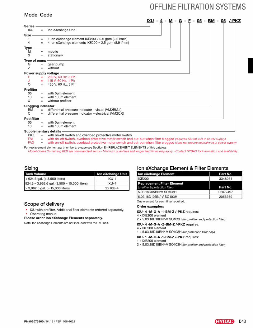
D43
OFFLINE FILTRATION SYSTEMS
PN#02075860 / 04.15 / FSP1406-1622
Model CodeIXU - 4 - M - G - F - 05 - BM - 05 /-PKZ.
Series IXU = Ion eXchange Unit
Size 1 = 1 Ion eXchange element IXE200 ≈ 0.5 gpm (2.2 l/min) 4 = 4 Ion eXchange elements IXE200 ≈ 2.5 gpm (8.9 l/min)
Type M = mobile S = stationary
Type of pump G = gear pump Z = without
Power supply voltage F = 230 V, 60 Hz, 3 Ph J = 115 V, 60 Hz, 1 Ph O = 460 V, 60 Hz, 3 Ph
Prefilter 05 = with 5µm element 10 = with 10µm element X = without prefilter
Clogging indicator BM = differential pressure indicator – visual (VM2BM.1) C = differential pressure indicator – electrical (VM2C.0)
Postfilter 05 = with 5µm element 10 = with 10µm element
Supplementary details PKZ = with on-off switch and overload protective motor switch FA1 = with on-off switch, overload protective motor switch and cut-out when filter clogged (requires neutral wire in power supply) FA2 = with on-off switch, overload protective motor switch and cut-out when filter clogged (does not require neutral wire in power supply)
For replacement element part numbers, please see Section E - REPLACEMENT ELEMENTS of this catalog.Model Codes Containing RED are non-standard items – Minimum quantities and longer lead times may apply - Contact HYDAC for information and availability.
SizingTank Volume Ion eXchange Unit< 924.6 gal. (< 3,500 liters) IXU-1924.6 – 3,962.6 gal. (3,500 – 15,000 liters) IXU-4> 3,962.6 gal. (> 15,000 liters) 2x IXU-4
Ion eXchange Element & Filter ElementsIon eXchange Element Part No.IXE200 3348961Replacement Filter Element (prefilter & protection filter) Part No.5.03.18D05BN/V SO103H 020774975.03.18D10BN/-V SO103H 2056369
One element for each filter required.
Order examples:
IXU- 4 -M-G-A -1-BM-Z /-PKZ requires: 4 x IXE200 element 2 x 5.03.18D10BN/-V SO103H (for prefilter and protection filter)
IXU- 4 -M-G-A -Z-BM-Z /-PKZ requires: 4 x IXE200 element 1 x 5.03.18D10BN/-V SO103H (for protection filter only)
IXU- 1 -M-G-A -1-BM-Z /-PKZ requires: 1 x IXE200 element 2 x 5.03.18D10BN/-V SO103H (for prefilter and protection filter)
Scope of delivery• IXU with prefilter. Additional filter elements ordered separately.• Operating manual
Please order Ion eXchange Elements separately.Note: Ion eXchange Elements are not included with the IXU unit.
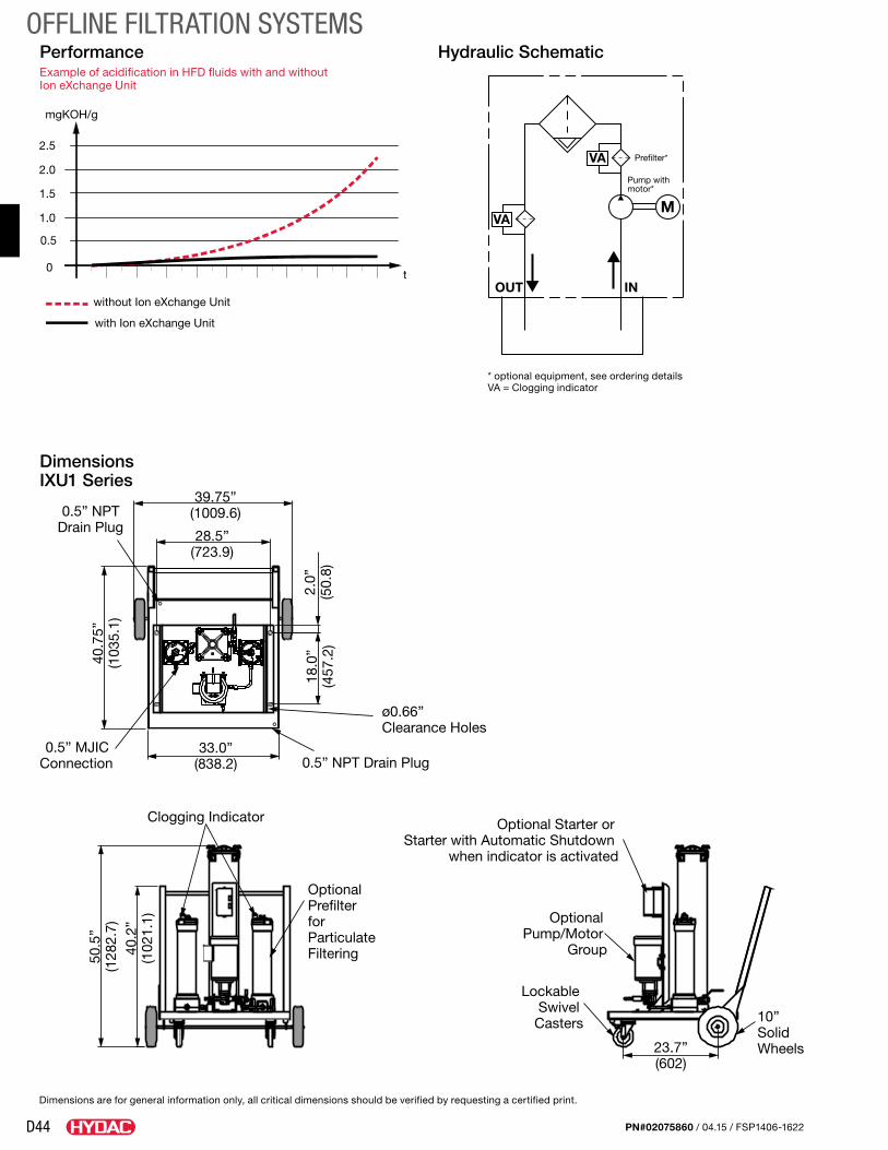
D44
OFFLINE FILTRATION SYSTEMS
PN#02075860 / 04.15 / FSP1406-1622
28.5”(723.9)
39.75”(1009.6)
33.0”(838.2)
40.7
5”(1
035.
1)
18.0
”(4
57.2
)
40.2
”(1
021.
1)
50.5
”(1
282.
7)
2.0”
(50.
8)
0.5” NPT Drain Plug
Clogging Indicator
Optional Prefilter for Particulate Filtering
10” Solid Wheels23.7”
(602)
Optional Starter or Starter with Automatic Shutdown
when indicator is activated
Optional Pump/Motor
Group
Lockable Swivel
Casters
0.5” MJIC Connection
0.5” NPT Drain Plug
ø0.66” Clearance Holes
Dimensions IXU1 Series
Dimensions are for general information only, all critical dimensions should be verified by requesting a certified print.
MVA
OUT IN
VA Prefilter*
Pump withmotor*
Hydraulic SchematicPerformanceExample of acidification in HFD fluids with and without Ion eXchange Unit
0.5
0
1.0
1.5
2.0
2.5
t
mgKOH/g
without Ion eXchange Unit
with Ion eXchange Unit
* optional equipment, see ordering detailsVA = Clogging indicator
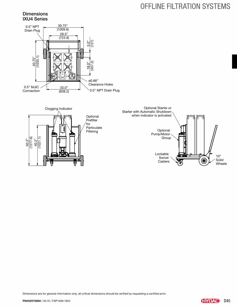
D45
OFFLINE FILTRATION SYSTEMS
PN#02075860 / 04.15 / FSP1406-1622
28.5”(723.9)
39.75”(1009.6)
40.7
5”(1
035.
1)
0.5” NPT Drain Plug
33.0”(838.2)
18.0
”(4
57.2
)5.
0”(1
27)
0.5” NPT Drain Plug0.5” MJIC
Connection
ø0.66” Clearance Holes
40.2
”(1
021.
1)
50.3
”(1
277.
6)
Clogging Indicator
Optional Prefilter for Particulate Filtering
10” Solid Wheels
Optional Starter orStarter with Automatic Shutdown
when indicator is activated
Optional Pump/Motor
Group
Lockable Swivel
Casters
Dimensions IXU4 Series
Dimensions are for general information only, all critical dimensions should be verified by requesting a certified print.
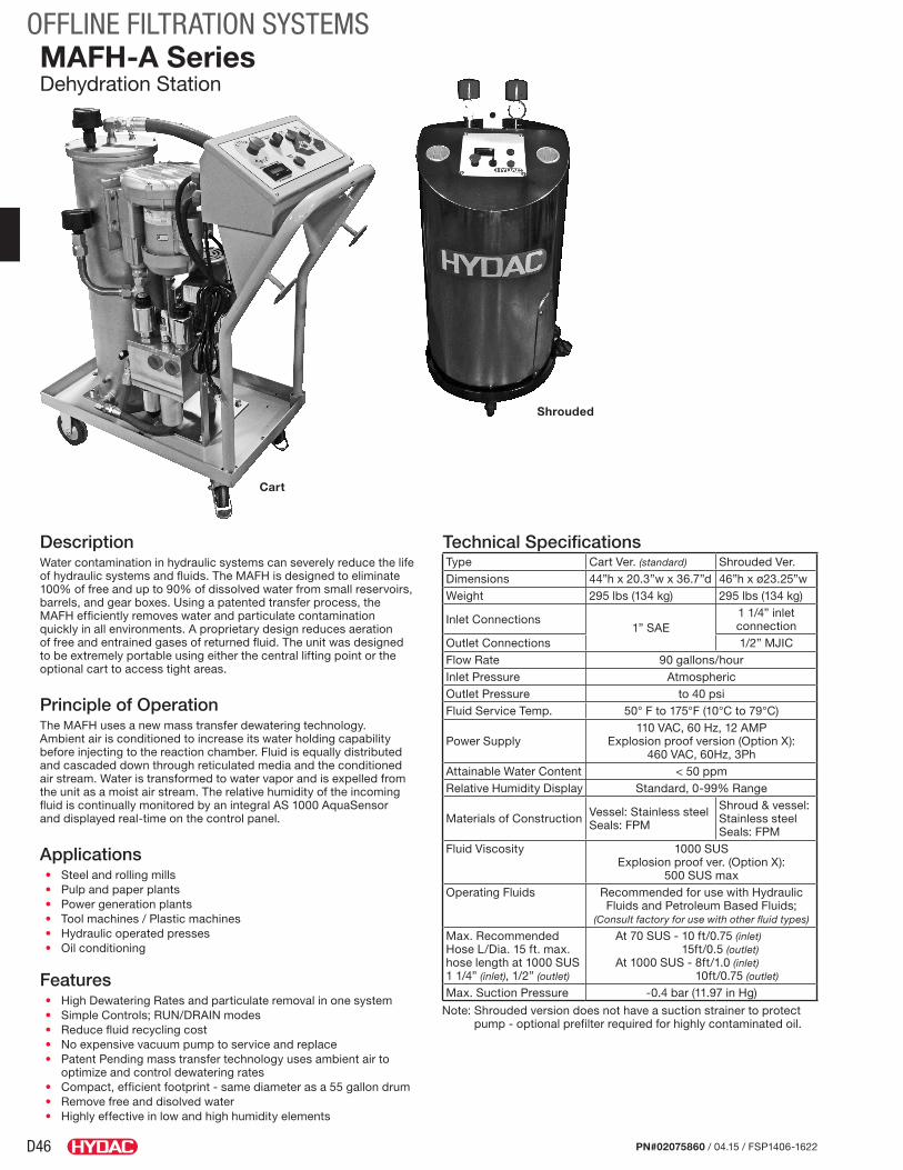
D46
OFFLINE FILTRATION SYSTEMS
PN#02075860 / 04.15 / FSP1406-1622
MAFH-A SeriesDehydration Station
DescriptionWater contamination in hydraulic systems can severely reduce the life of hydraulic systems and fluids. The MAFH is designed to eliminate 100% of free and up to 90% of dissolved water from small reservoirs, barrels, and gear boxes. Using a patented transfer process, the MAFH efficiently removes water and particulate contamination quickly in all environments. A proprietary design reduces aeration of free and entrained gases of returned fluid. The unit was designed to be extremely portable using either the central lifting point or the optional cart to access tight areas.
Principle of OperationThe MAFH uses a new mass transfer dewatering technology. Ambient air is conditioned to increase its water holding capability before injecting to the reaction chamber. Fluid is equally distributed and cascaded down through reticulated media and the conditioned air stream. Water is transformed to water vapor and is expelled from the unit as a moist air stream. The relative humidity of the incoming fluid is continually monitored by an integral AS 1000 AquaSensor and displayed real-time on the control panel.
Applications• Steel and rolling mills• Pulp and paper plants• Power generation plants• Tool machines / Plastic machines• Hydraulic operated presses• Oil conditioning
Features• High Dewatering Rates and particulate removal in one system • Simple Controls; RUN/DRAIN modes• Reduce fluid recycling cost• No expensive vacuum pump to service and replace• Patent Pending mass transfer technology uses ambient air to
optimize and control dewatering rates• Compact, efficient footprint - same diameter as a 55 gallon drum• Remove free and disolved water• Highly effective in low and high humidity elements
Technical SpecificationsType Cart Ver. (standard) Shrouded Ver.Dimensions 44”h x 20.3”w x 36.7”d 46”h x ø23.25”wWeight 295 lbs (134 kg) 295 lbs (134 kg)
Inlet Connections1” SAE
1 1/4” inlet connection
Outlet Connections 1/2” MJICFlow Rate 90 gallons/hourInlet Pressure AtmosphericOutlet Pressure to 40 psiFluid Service Temp. 50° F to 175°F (10°C to 79°C)
Power Supply110 VAC, 60 Hz, 12 AMP
Explosion proof version (Option X): 460 VAC, 60Hz, 3Ph
Attainable Water Content < 50 ppmRelative Humidity Display Standard, 0-99% Range
Materials of Construction Vessel: Stainless steel Seals: FPM
Shroud & vessel: Stainless steel Seals: FPM
Fluid Viscosity 1000 SUSExplosion proof ver. (Option X):
500 SUS maxOperating Fluids Recommended for use with Hydraulic
Fluids and Petroleum Based Fluids; (Consult factory for use with other fluid types)
Max. Recommended Hose L/Dia. 15 ft. max. hose length at 1000 SUS 1 1/4” (inlet), 1/2” (outlet)
At 70 SUS - 10 ft/0.75 (inlet) 15ft/0.5 (outlet)
At 1000 SUS - 8ft/1.0 (inlet) 10ft/0.75 (outlet)
Max. Suction Pressure -0.4 bar (11.97 in Hg)
Note: Shrouded version does not have a suction strainer to protect pump - optional prefilter required for highly contaminated oil.
Cart
Shrouded
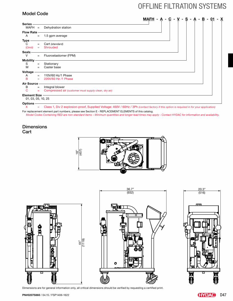
D47
OFFLINE FILTRATION SYSTEMS
PN#02075860 / 04.15 / FSP1406-1622
Model CodeMAFH - A - C - V - S - A - B - 01 - X
Series MAFH = Dehydration station
Flow Rate A = 1.5 gpm average
Type C = Cart (standard) (Omit) = Shrouded
Seals V = Fluoroelastomer (FPM)
Mobility S = Stationary M = Caster base
Voltage A = 110V/60 Hz/1 Phase B = 220V/60 Hz /1 Phase
Air Source B = Integral blower C = Compressed air (customer must supply clean, dry air)
Element Size 01, 03, 05, 10, 25
Options X = Class 1, Div 2 explosion-proof, Supplied Voltage: 460V / 60Hz / 3Ph (contact factory if this option is required in for your application)
For replacement element part numbers, please see Section E - REPLACEMENT ELEMENTS of this catalog.Model Codes Containing RED are non-standard items – Minimum quantities and longer lead times may apply - Contact HYDAC for information and availability.
Dimensions Cart
Dimensions are for general information only, all critical dimensions should be verified by requesting a certified print.
18”
(457
)44
”(1
118)
36.7”(932)
20.3”(516)
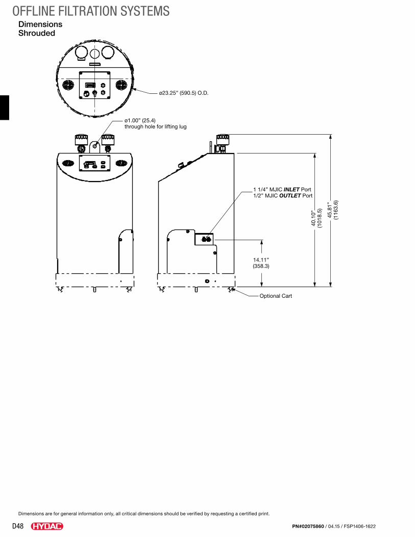
D48
OFFLINE FILTRATION SYSTEMS
PN#02075860 / 04.15 / FSP1406-1622
Dimensions Shrouded
ø1.00” (25.4) through hole for lifting lug
ø23.25” (590.5) O.D.
40.1
0”(1
018.
5)
14.11”(358.3)
45.8
1”(1
163.
6)
1 1/4” MJIC INLET Port1/2” MJIC OUTLET Port
Optional Cart
Dimensions are for general information only, all critical dimensions should be verified by requesting a certified print.
D49
OFFLINE FILTRATION SYSTEMS
PN#02075860 / 04.15 / FSP1406-1622
Notes
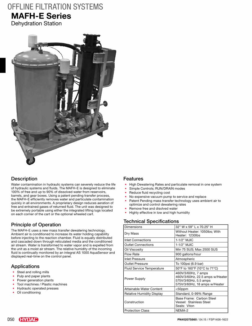
D50
OFFLINE FILTRATION SYSTEMS
PN#02075860 / 04.15 / FSP1406-1622
MAFH-E SeriesDehydration Station
DescriptionWater contamination in hydraulic systems can severely reduce the life of hydraulic systems and fluids. The MAFH-E is designed to eliminate 100% of free and up to 90% of dissolved water from reservoirs, barrels, and gear boxes. Using a patent pending transfer process, the MAFH-E efficiently removes water and particulate contamination quickly in all environments. A proprietary design reduces aeration of free and entrained gases of returned fluid. The unit was designed to be extremely portable using either the integrated lifting lugs located on each corner of the cart or the optional wheeled cart.
Principle of OperationThe MAFH-E uses a new mass transfer dewatering technology. Ambient air is conditioned to increase its water holding capability before injecting to the reaction chamber. Fluid is equally distributed and cascaded down through reticulated media and the conditioned air stream. Water is transformed to water vapor and is expelled from the unit as a moist air stream. The relative humidity of the incoming fluid is continually monitored by an integral AS 1000 AquaSensor and displayed real-time on the control panel.
Applications• Steel and rolling mills • Pulp and paper plants • Power generation plants • Tool machines / Plastic machines • Hydraulic operated presses • Oil conditioning
Features• High Dewatering Rates and particulate removal in one system • Simple Controls; RUN/DRAIN modes• Reduce fluid recycling cost• No expensive vacuum pump to service and replace• Patent Pending mass transfer technology uses ambient air to
optimize and control dewatering rates• Remove free and disolved water• Highly effective in low and high humidity
Technical SpecificationsDimensions 32” W x 59” L x 70.25” H
Dry Mass Without Heater: 1050lbs; With Heater: 1230lbs
Inlet Connections 1-1/2” MJIC Outlet Connections 1-1/2” MJIC Oil Viscosity Min 75 SUS; Max 2500 SUS Flow Rate 900 gallons/hour Inlet Pressure Atmospheric Outlet Pressure To 100psi (6.9 bar) Fluid Service Temperature 50°F to 160°F (10°C to 71°C)
Power Supply
460V/3/60Hz, 7 amps 460V/3/60Hz, 22.5 amps w/Heater 575V/3/60Hz, 5.5 amps 575V/3/60Hz, 18 amps w/Heater
Attainable Water Content <50ppm Relative Humidity Display Standard, 0-99% Range
Construction Base Frame: Carbon Steel Vessel: Stainless Steel Seals: Viton
Protection Class NEMA-2
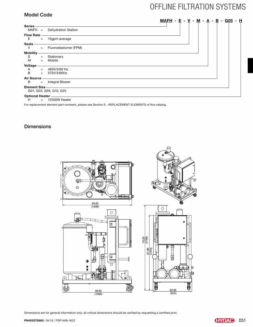
D51
OFFLINE FILTRATION SYSTEMS
PN#02075860 / 04.15 / FSP1406-1622
Dimensions are for general information only, all critical dimensions should be verified by requesting a certified print.
Model CodeMAFH - E - V - M - A - B - G05 - H
Series MAFH = Dehydration Station
Flow Rate E = 15gpm average
Seals V = Fluoroelastomer (FPM)
Mobility S = Stationary M = Mobile
Voltage A = 460V/3/60 Hz B = 575V/3/60Hz
Air Source B = Integral Blower
Element Size G01, G03, G05, G10, G25
Optional Heater H = 12500W HeaterFor replacement element part numbers, please see Section E - REPLACEMENT ELEMENTS of this catalog.
Dimensions
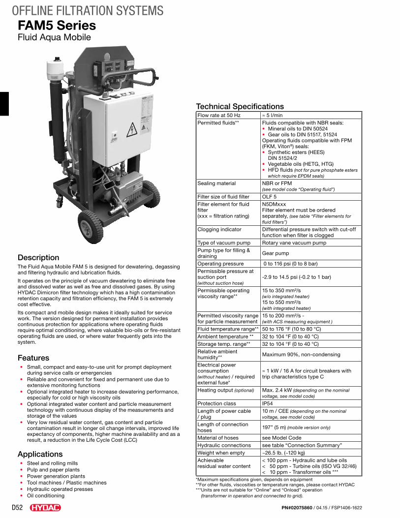
D52
OFFLINE FILTRATION SYSTEMS
PN#02075860 / 04.15 / FSP1406-1622
FAM5 SeriesFluid Aqua Mobile
DescriptionThe Fluid Aqua Mobile FAM 5 is designed for dewatering, degassing and filtering hydraulic and lubrication fluids.
It operates on the principle of vacuum dewatering to eliminate free and dissolved water as well as free and dissolved gases. By using HYDAC Dimicron filter technology which has a high contamination retention capacity and filtration efficiency, the FAM 5 is extremely cost effective.
Its compact and mobile design makes it ideally suited for service work. The version designed for permanent installation provides continuous protection for applications where operating fluids require optimal conditioning, where valuable bio-oils or fire-resistant operating fluids are used, or where water frequently gets into the system.
Features• Small, compact and easy-to-use unit for prompt deployment
during service calls or emergencies• Reliable and convenient for fixed and permanent use due to
extensive monitoring functions• Optional integrated heater to increase dewatering performance,
especially for cold or high viscosity oils• Optional integrated water content and particle measurement
technology with continuous display of the measurements and storage of the values
• Very low residual water content, gas content and particle contamination result in longer oil change intervals, improved life expectancy of components, higher machine availability and as a result, a reduction in the Life Cycle Cost (LCC)
Applications• Steel and rolling mills• Pulp and paper plants• Power generation plants• Tool machines / Plastic machines• Hydraulic operated presses• Oil conditioning
Technical SpecificationsFlow rate at 50 Hz ≈ 5 l/minPermitted fluids** Fluids compatible with NBR seals:
• Mineral oils to DIN 50524• Gear oils to DIN 51517, 51524Operating fluids compatible with FPM (FKM, Viton®) seals:• Synthetic esters (HEES)
DIN 51524/2• Vegetable oils (HETG, HTG) • HFD fluids (not for pure phosphate esters
which require EPDM seals)
Sealing material NBR or FPM(see model code “Operating fluid”)
Filter size of fluid filter OLF 5Filter element for fluid filter (xxx = filtration rating)
N5DMxxxFilter element must be ordered separately, (see table “Filter elements for fluid filters”)
Clogging indicator Differential pressure switch with cut-off function when filter is clogged
Type of vacuum pump Rotary vane vacuum pumpPump type for filling & draining Gear pump
Operating pressure 0 to 116 psi (0 to 8 bar)Permissible pressure at suction port (without suction hose)
-2.9 to 14.5 psi (-0.2 to 1 bar)
Permissible operating viscosity range**
15 to 350 mm²/s (w/o integrated heater)15 to 550 mm²/s (with integrated heater)
Permitted viscosity range for particle measurement
15 to 200 mm²/s - (with ACS measuring equipment )
Fluid temperature range** 50 to 176 °F (10 to 80 °C)Ambient temperature ** 32 to 104 °F (0 to 40 °C)Storage temp. range** 32 to 104 °F (0 to 40 °C)Relative ambient humidity** Maximum 90%, non-condensing
Electrical power consumption (without heater) / required external fuse*
≈ 1 kW / 16 A for circuit breakers with trip characteristics type C
Heating output (optional) Max. 2.4 kW (depending on the nominal voltage, see model code)
Protection class IP54Length of power cable / plug
10 m / CEE (depending on the nominal voltage, see model code)
Length of connection hoses 197” (5 m) (mobile version only)
Material of hoses see Model CodeHydraulic connections see table “Connection Summary”Weight when empty ~26.5 lb. (~120 kg)Achievable residual water content
< 100 ppm - Hydraulic and lube oils< 50 ppm - Turbine oils (ISO VG 32/46)< 10 ppm - Transformer oils ***
*Maximum specifications given, depends on equipment **For other fluids, viscosities or temperature ranges, please contact HYDAC *** Units are not suitable for “Online” and “Onload” operation
(transformer in operation and connected to grid).
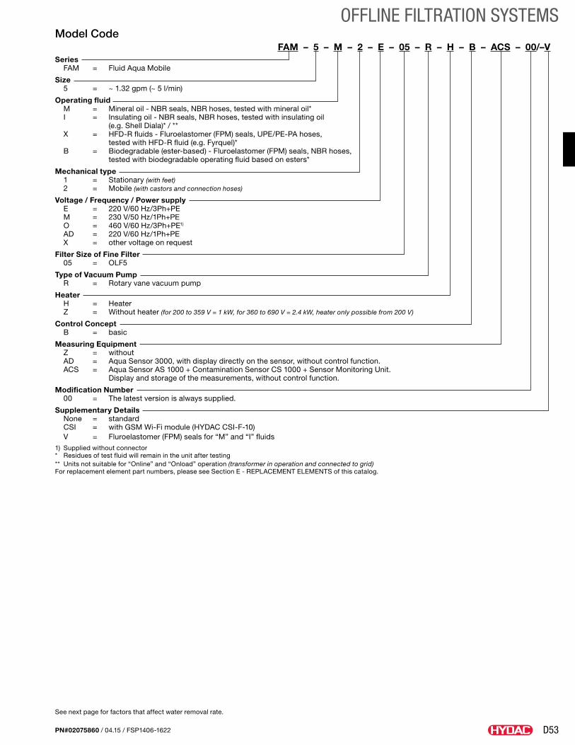
D53
OFFLINE FILTRATION SYSTEMS
PN#02075860 / 04.15 / FSP1406-1622
Model CodeFAM – 5 – M – 2 – E – 05 – R – H – B – ACS – 00/–V
Series FAM = Fluid Aqua Mobile
Size 5 = ~ 1.32 gpm (~ 5 l/min)
Operating fluid M = Mineral oil - NBR seals, NBR hoses, tested with mineral oil* I = Insulating oil - NBR seals, NBR hoses, tested with insulating oil (e.g. Shell Diala)* / ** X = HFD-R fluids - Fluroelastomer (FPM) seals, UPE/PE-PA hoses, tested with HFD-R fluid (e.g. Fyrquel)* B = Biodegradable (ester-based) - Fluroelastomer (FPM) seals, NBR hoses, tested with biodegradable operating fluid based on esters*
Mechanical type 1 = Stationary (with feet) 2 = Mobile (with castors and connection hoses)
Voltage / Frequency / Power supply E = 220 V/60 Hz/3Ph+PE M = 230 V/50 Hz/1Ph+PE O = 460 V/60 Hz/3Ph+PE1) AD = 220 V/60 Hz/1Ph+PE X = other voltage on request
Filter Size of Fine Filter 05 = OLF5
Type of Vacuum Pump R = Rotary vane vacuum pump
Heater H = Heater Z = Without heater (for 200 to 359 V = 1 kW, for 360 to 690 V = 2.4 kW, heater only possible from 200 V)
Control Concept B = basic
Measuring Equipment Z = without AD = Aqua Sensor 3000, with display directly on the sensor, without control function. ACS = Aqua Sensor AS 1000 + Contamination Sensor CS 1000 + Sensor Monitoring Unit. Display and storage of the measurements, without control function.
Modification Number 00 = The latest version is always supplied.
Supplementary Details None = standard CSI = with GSM Wi-Fi module (HYDAC CSI-F-10) V = Fluroelastomer (FPM) seals for “M” and “I” fluids1) Supplied without connector* Residues of test fluid will remain in the unit after testing** Units not suitable for “Online” and “Onload” operation (transformer in operation and connected to grid)For replacement element part numbers, please see Section E - REPLACEMENT ELEMENTS of this catalog.
See next page for factors that affect water removal rate.
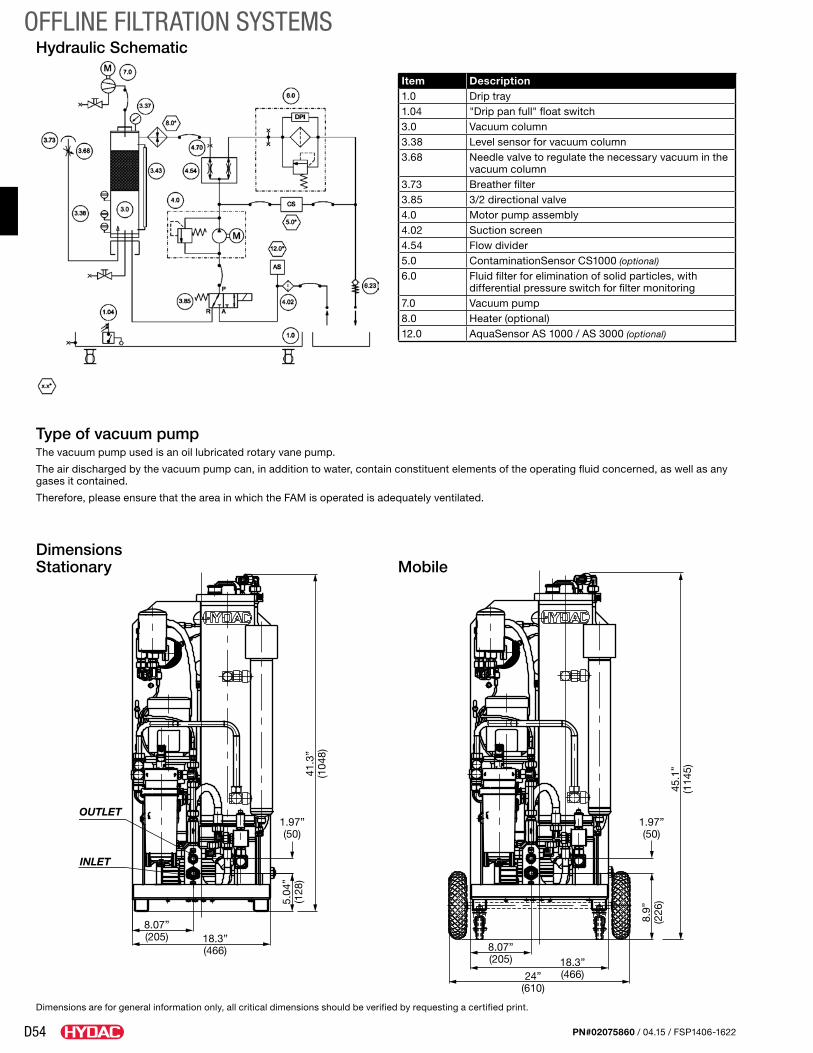
D54
OFFLINE FILTRATION SYSTEMS
PN#02075860 / 04.15 / FSP1406-1622
Dimensions Stationary
Mobile
Hydraulic Schematic
1.97”(50)
1.97”(50)
5.04
”(1
28)
8.07”(205) 18.3”
(466)
41.3
”(1
048)
8.9”
(226
)
18.3”(466)
8.07”(205)
24”(610)
45.1
”(1
145)
OUTLET
INLET
Type of vacuum pumpThe vacuum pump used is an oil lubricated rotary vane pump.
The air discharged by the vacuum pump can, in addition to water, contain constituent elements of the operating fluid concerned, as well as any gases it contained.
Therefore, please ensure that the area in which the FAM is operated is adequately ventilated.
Dimensions are for general information only, all critical dimensions should be verified by requesting a certified print.
Item Description1.0 Drip tray1.04 "Drip pan full" float switch3.0 Vacuum column3.38 Level sensor for vacuum column3.68 Needle valve to regulate the necessary vacuum in the
vacuum column3.73 Breather filter3.85 3/2 directional valve4.0 Motor pump assembly4.02 Suction screen4.54 Flow divider5.0 ContaminationSensor CS1000 (optional)
6.0 Fluid filter for elimination of solid particles, with differential pressure switch for filter monitoring
7.0 Vacuum pump8.0 Heater (optional)12.0 AquaSensor AS 1000 / AS 3000 (optional)
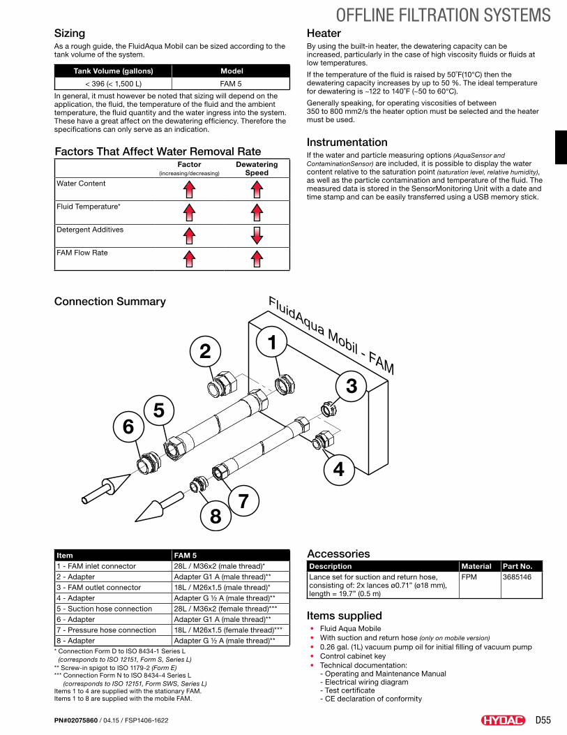
D55
OFFLINE FILTRATION SYSTEMS
PN#02075860 / 04.15 / FSP1406-1622
HeaterBy using the built-in heater, the dewatering capacity can be increased, particularly in the case of high viscosity fluids or fluids at low temperatures.
If the temperature of the fluid is raised by 50˚F(10°C) then the dewatering capacity increases by up to 50 %. The ideal temperature for dewatering is ~122 to 140˚F (~50 to 60°C).
Generally speaking, for operating viscosities of between 350 to 800 mm2/s the heater option must be selected and the heater must be used.
InstrumentationIf the water and particle measuring options (AquaSensor and ContaminationSensor) are included, it is possible to display the water content relative to the saturation point (saturation level, relative humidity), as well as the particle contamination and temperature of the fluid. The measured data is stored in the SensorMonitoring Unit with a date and time stamp and can be easily transferred using a USB memory stick.
SizingAs a rough guide, the FluidAqua Mobil can be sized according to the tank volume of the system.
Tank Volume (gallons) Model
< 396 (< 1,500 L) FAM 5
In general, it must however be noted that sizing will depend on the application, the fluid, the temperature of the fluid and the ambient temperature, the fluid quantity and the water ingress into the system. These have a great affect on the dewatering efficiency. Therefore the specifications can only serve as an indication.
Factors That Affect Water Removal RateFactor
(increasing/decreasing)
Dewatering Speed
Water Content
Fluid Temperature*
Detergent Additives
FAM Flow Rate
Item FAM 51 - FAM inlet connector 28L / M36x2 (male thread)*2 - Adapter Adapter G1 A (male thread)**3 - FAM outlet connector 18L / M26x1.5 (male thread)*4 - Adapter Adapter G ½ A (male thread)**5 - Suction hose connection 28L / M36x2 (female thread)***6 - Adapter Adapter G1 A (male thread)**7 - Pressure hose connection 18L / M26x1.5 (female thread)***8 - Adapter Adapter G ½ A (male thread)**
* Connection Form D to ISO 8434-1 Series L (corresponds to ISO 12151, Form S, Series L)
** Screw-in spigot to ISO 1179-2 (Form E) *** Connection Form N to ISO 8434-4 Series L
(corresponds to ISO 12151, Form SWS, Series L)Items 1 to 4 are supplied with the stationary FAM. Items 1 to 8 are supplied with the mobile FAM.
AccessoriesDescription Material Part No.Lance set for suction and return hose, consisting of: 2x lances ø0.71” (ø18 mm), length = 19.7” (0.5 m)
FPM 3685146
Items supplied• Fluid Aqua Mobile• With suction and return hose (only on mobile version)• 0.26 gal. (1L) vacuum pump oil for initial filling of vacuum pump • Control cabinet key• Technical documentation: - Operating and Maintenance Manual - Electrical wiring diagram - Test certificate - CE declaration of conformity
1
3
2
56
4
78
Connection Summary
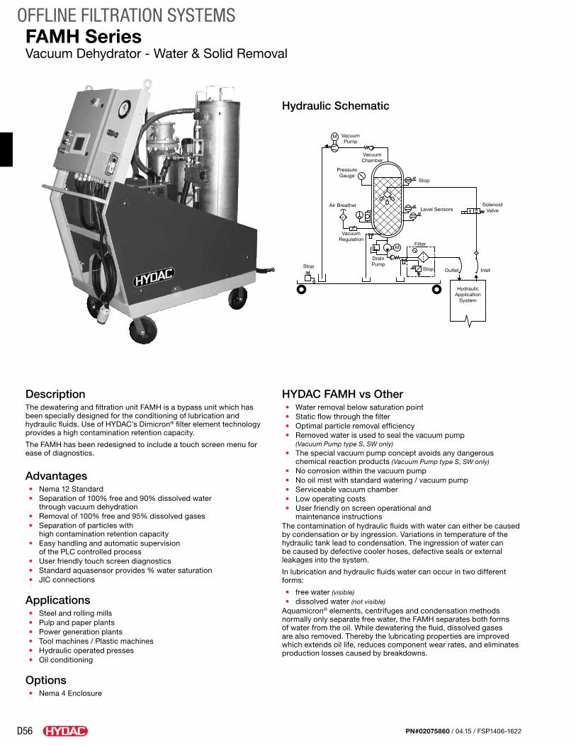
D56
OFFLINE FILTRATION SYSTEMS
PN#02075860 / 04.15 / FSP1406-1622
FAMH SeriesVacuum Dehydrator - Water & Solid Removal
DescriptionThe dewatering and filtration unit FAMH is a bypass unit which has been specially designed for the conditioning of lubrication and hydraulic fluids. Use of HYDAC’s Dimicron® filter element technology provides a high contamination retention capacity.
The FAMH has been redesigned to include a touch screen menu for ease of diagnostics.
Advantages• Nema 12 Standard• Separation of 100% free and 90% dissolved water
through vacuum dehydration• Removal of 100% free and 95% dissolved gases• Separation of particles with
high contamination retention capacity• Easy handling and automatic supervision
of the PLC controlled process• User friendly touch screen diagnostics• Standard aquasensor provides % water saturation• JIC connections
Applications• Steel and rolling mills• Pulp and paper plants• Power generation plants• Tool machines / Plastic machines• Hydraulic operated presses• Oil conditioning
Options• Nema 4 Enclosure
HYDAC FAMH vs Other• Water removal below saturation point• Static flow through the filter• Optimal particle removal efficiency• Removed water is used to seal the vacuum pump
(Vacuum Pump type S, SW only)• The special vacuum pump concept avoids any dangerous
chemical reaction products (Vacuum Pump type S, SW only)• No corrosion within the vacuum pump• No oil mist with standard watering / vacuum pump• Serviceable vacuum chamber• Low operating costs• User friendly on screen operational and
maintenance instructionsThe contamination of hydraulic fluids with water can either be caused by condensation or by ingression. Variations in temperature of the hydraulic tank lead to condensation. The ingression of water can be caused by defective cooler hoses, defective seals or external leakages into the system.
In lubrication and hydraulic fluids water can occur in two different forms:
• free water (visible)• dissolved water (not visible)
Aquamicron® elements, centrifuges and condensation methods normally only separate free water, the FAMH separates both forms of water from the oil. While dewatering the fluid, dissolved gases are also removed. Thereby the lubricating properties are improved which extends oil life, reduces component wear rates, and eliminates production losses caused by breakdowns.
M
M
HydraulicApplication
System
M
M
Filter
Level Sensors
Inlet
SolenoidValve
Stop
Stop Stop Outlet
Air Breather
VacuumRegulation
VacuumPump
VacuumChamber
PressureGauge
DrainPump
VacuumPump
Reactor
LevelSwitch
OptionalHeater
DrainPump
SolenoidControlValve
InletOutlet
AirInlet
VacuumAdjustment
Hydraulic Schematic
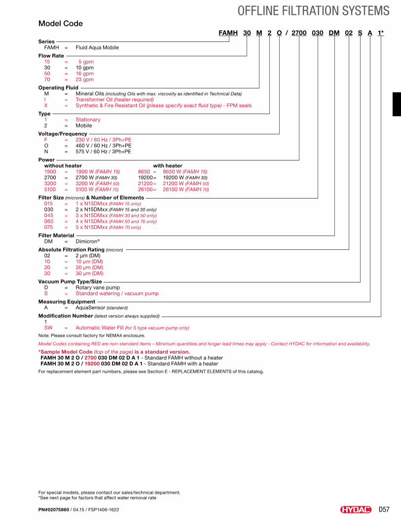
D57
OFFLINE FILTRATION SYSTEMS
PN#02075860 / 04.15 / FSP1406-1622
Model CodeFAMH 30 M 2 O / 2700 030 DM 02 S A 1*
Series FAMH = Fluid Aqua Mobile
Flow Rate 15 = 5 gpm 30 = 10 gpm 50 = 16 gpm 70 = 23 gpm
Operating Fluid M = Mineral Oils (including Oils with max. viscosity as identified in Technical Data) I = Transformer Oil (heater required) X = Synthetic & Fire Resistant Oil (please specify exact fluid type) - FPM seals
Type 1 = Stationary 2 = Mobile
Voltage/Frequency F = 230 V / 60 Hz / 3Ph+PE O = 460 V / 60 Hz / 3Ph+PE N = 575 V / 60 Hz / 3Ph+PE
Power without heater with heater 1900 = 1900 W (FAMH 15) 8650 = 8650 W (FAMH 15) 2700 = 2700 W (FAMH 30) 19200 = 19200 W (FAMH 30) 3200 = 3200 W (FAMH 50) 21200 = 21200 W (FAMH 50) 5100 = 5100 W (FAMH 70) 26100 = 26100 W (FAMH 70)
Filter Size (microns) & Number of Elements 015 = 1 x N15DMxx (FAMH 15 only) 030 = 2 x N15DMxx (FAMH 15 and 30 only) 045 = 3 x N15DMxx (FAMH 30 and 50 only) 060 = 4 x N15DMxx (FAMH 50 and 70 only) 075 = 5 x N15DMxx (FAMH 70 only)
Filter Material DM = Dimicron®
Absolute Filtration Rating (micron) 02 = 2 µm (DM) 10 = 10 µm (DM) 20 = 20 µm (DM) 30 = 30 µm (DM)
Vacuum Pump Type/Size D = Rotary vane pump S = Standard watering / vacuum pump
Measuring Equipment A = AquaSensor (standard)
Modification Number (latest version always supplied) 1 SW = Automatic Water Fill (for S type vacuum pump only)
Note: Please consult factory for NEMA4 enclosure.
Model Codes containing RED are non-standard items – Minimum quantities and longer lead times may apply - Contact HYDAC for information and availability.
* Sample Model Code (top of the page) is a standard version. FAMH 30 M 2 O / 2700 030 DM 02 D A 1 - Standard FAMH without a heater FAMH 30 M 2 O / 19200 030 DM 02 D A 1 - Standard FAMH with a heater
For replacement element part numbers, please see Section E - REPLACEMENT ELEMENTS of this catalog.
For special models, please contact our sales/technical department. *See next page for factors that affect water removal rate
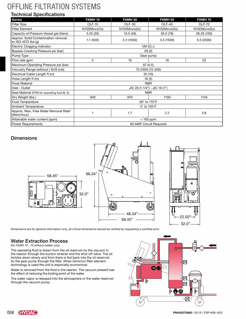
D58
OFFLINE FILTRATION SYSTEMS
PN#02075860 / 04.15 / FSP1406-1622
Water Extraction Process (for FAMH 15 - 70 without heater only)
The operating fluid is drawn from the oil reservoir by the vacuum in the reactor through the suction strainer and the shut-off valve. The oil trickles down slowly and from there is fed back into the oil reservoir by the gear pump through the filter. When Dimicron filter element technology is used the unit is especially economical.
Water is removed from the fluid in the reactor. The vacuum present has the effect of reducing the boiling point of the water.
The water vapor is released into the atmosphere or the water reservoir through the vacuum pump.
Dimensions
M
M
58.45”
32.0”
66.34”
48.34”
58.45”32.0”
22.02”
Series FAMH 15 FAMH 30 FAMH 50 FAMH 70Filter Size OLF-15 OLF-30 OLF-45 OLF-70Filter Element N15DMxxx(1x) N15DMxxx(2x) N15DMxxx(3x) N15DMxxx(5x)Capacity of Pressure Vessel gal (liters) 5.25 (20) 10.5 (40) 20.5 (78) 26.25 (100)Approx. Solid Contamination removal to ISO 4572 lbs (g) 1.1 (500) 2.2 (1000) 3.3 (1500) 5.5 (2500)
Electric Clogging Indicator VM 2C.xBypass Cracking Pressure psi (bar) 29 (2)Pump Type Gear pumpFlow rate gpm 5 10 16 23Maximum Operating Pressure psi (bar) 87 (4.5)Viscosity Range (without ) SUS (cst) 75-2500 (15-500)Electrical Cable Length ft (m) 32 (10)Hose Length ft (m) 16 (5)Hose Material NBRInlet - Outlet JIC 20 (1 1/4”) - JIC 16 (1”)Seal Material (FPM for operating fluid B, X) NBRDry Weight (lbs.) 940 970 1100 1145Fluid Temperature 50° to 175°FAmbient Temperature 5° to 105°FApprox. Max. Free Water Removal Rate* (liters/hour) 1 1.7 2.2 2.6
Attainable water content (ppm) < 100 ppmPower Requirements 60 AMP Circuit Required
Technical Specifications
Dimensions are for general information only, all critical dimensions should be verified by requesting a certified print.
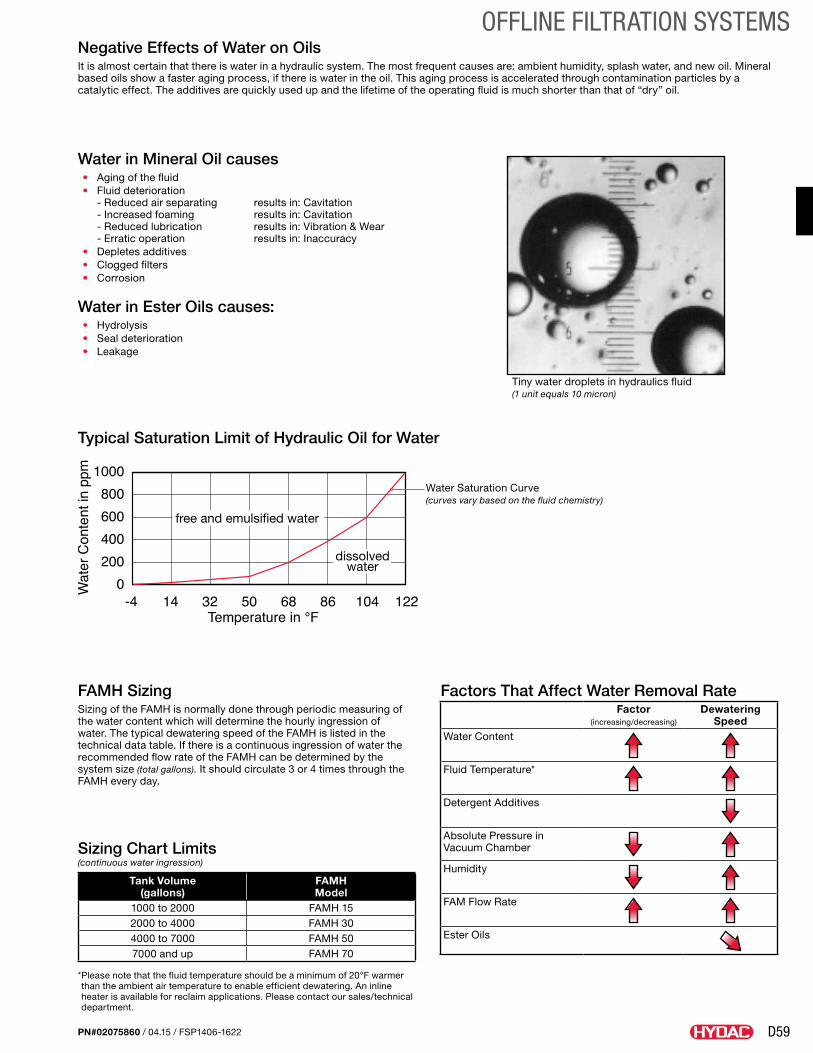
D59
OFFLINE FILTRATION SYSTEMS
PN#02075860 / 04.15 / FSP1406-1622
Water in Mineral Oil causes• Aging of the fluid• Fluid deterioration
- Reduced air separating results in: Cavitation - Increased foaming results in: Cavitation - Reduced lubrication results in: Vibration & Wear - Erratic operation results in: Inaccuracy
• Depletes additives• Clogged filters• Corrosion
Water in Ester Oils causes:• Hydrolysis• Seal deterioration• Leakage
Factors That Affect Water Removal RateFactor
(increasing/decreasing)
Dewatering Speed
Water Content
Fluid Temperature*
Detergent Additives
Absolute Pressure in Vacuum Chamber
Humidity
FAM Flow Rate
Ester Oils
Tank Volume (gallons)
FAMH Model
1000 to 2000 FAMH 152000 to 4000 FAMH 304000 to 7000 FAMH 507000 and up FAMH 70
* Please note that the fluid temperature should be a minimum of 20°F warmer than the ambient air temperature to enable efficient dewatering. An inline heater is available for reclaim applications. Please contact our sales/technical department.
Sizing Chart Limits (continuous water ingression)
FAMH SizingSizing of the FAMH is normally done through periodic measuring of the water content which will determine the hourly ingression of water. The typical dewatering speed of the FAMH is listed in the technical data table. If there is a continuous ingression of water the recommended flow rate of the FAMH can be determined by the system size (total gallons). It should circulate 3 or 4 times through the FAMH every day.
Negative Effects of Water on OilsIt is almost certain that there is water in a hydraulic system. The most frequent causes are: ambient humidity, splash water, and new oil. Mineral based oils show a faster aging process, if there is water in the oil. This aging process is accelerated through contamination particles by a catalytic effect. The additives are quickly used up and the lifetime of the operating fluid is much shorter than that of “dry” oil.
Tiny water droplets in hydraulics fluid(1 unit equals 10 micron)
free and emulsified water
dissolvedwater
Typical Saturation Limit of Hydraulic Oil for Water
Water Saturation Curve (curves vary based on the fluid chemistry)
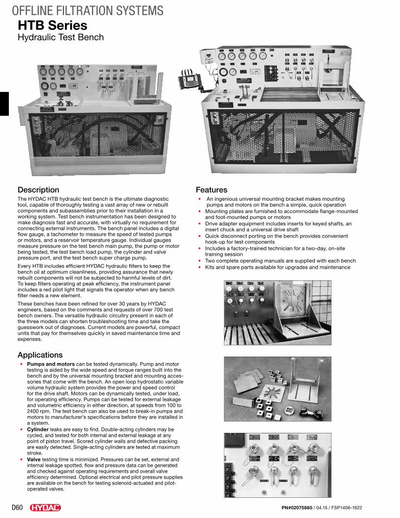
D60
OFFLINE FILTRATION SYSTEMS
PN#02075860 / 04.15 / FSP1406-1622
HTB SeriesHydraulic Test Bench
DescriptionThe HYDAC HTB hydraulic test bench is the ultimate diagnostic tool, capable of thoroughly testing a vast array of new or rebuilt compo nents and sub assemblies prior to their installation in a working system. Test bench instrumentation has been designed to make diagnosis fast and accurate, with virtually no require ment for connecting external instruments. The bench panel includes a digital flow gauge, a tachometer to measure the speed of tested pumps or motors, and a reservoir temperature gauge. Individual gauges measure pressure on the test bench main pump, the pump or motor being tested, the test bench load pump, the cylinder and valve pressure port, and the test bench super charge pump.
Every HTB includes efficient HYDAC hydraulic filters to keep the bench oil at optimum cleanliness, provid ing assurance that newly rebuilt components will not be subjected to harmful levels of dirt. To keep filters operating at peak efficiency, the instrument panel includes a red pilot light that signals the operator when any bench filter needs a new element.
These benches have been refined for over 30 years by HYDAC engineers, based on the comments and requests of over 700 test bench owners. The versatile hydraulic circuitry present in each of the three models can shorten troubleshooting time and take the guess work out of diagnoses. Current models are powerful, compact units that pay for themselves quickly in saved maintenance time and expenses.
Applications• Pumps and motors can be tested dynamically. Pump and motor
testing is aided by the wide speed and torque ranges built into the bench and by the uni versal mount ing bracket and mounting acces-sories that come with the bench. An open loop hydro static variable volume hydraulic system provides the power and speed control for the drive shaft. Motors can be dynamically tested, under load, for operating effi ciency. Pumps can be tested for external leakage and volumetric efficiency in either direction, at speeds from 100 to 2400 rpm. The test bench can also be used to break-in pumps and motors to manufac turer’s specifications before they are installed in a system.
• Cylinder leaks are easy to find. Double-acting cylinders may be cycled, and tested for both internal and external leak age at any point of piston travel. Scored cylinder walls and defec tive packing are easily detected. Single-acting cylinders are tested at maximum stroke.
• Valve testing time is minimized. Pressures can be set, external and internal leakage spotted, flow and pressure data can be generated and checked against operating require ments and overall valve efficiency determined. Optional electrical and pilot pressure supplies are available on the bench for testing solenoid-actuated and pilot-operated valves.
Features• An ingenious universal mounting bracket makes mounting
pumps and motors on the bench a simple, quick operation• Mounting plates are furnished to accommodate flange-mounted
and foot-mounted pumps or motors• Drive adapter equipment includes inserts for keyed shafts, an
insert chuck and a universal drive shaft• Quick disconnect porting on the bench provides convenient
hook-up for test components • Includes a factory-trained technician for a two-day, on-site
training session• Two complete operating manuals are supplied with each bench• Kits and spare parts available for upgrades and maintenance
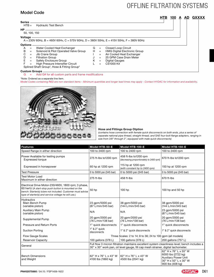
D61
OFFLINE FILTRATION SYSTEMS
PN#02075860 / 04.15 / FSP1406-1622
Features Model HTB-50-E Model HTB-100-E Model HTB-150-ESpeed Range in either direction 100 to 2400 rpm 100 to 2400 rpm 100 to 2400 rpm
Power Available for testing pumps Expressed torque 275 ft-lbs to1200 rpm 458 ft-lbs to1200 rpm
(decreasing proportionately to 2400 rpm) 670 ft-lbs to1200 rpm
Expressed in horsepower 60 hp at 1200 rpm 115 hp at 1200 rpm (with constant hp to 2400 rpm)
150 hp at 1200 rpm
Test Pressure 0 to 5000 psi (345 bar) 0 to 5000 psi (345 bar) 0 to 5000 psi (345 bar)
Test Motor Load Maximum in either direction 275 ft-lbs 458 ft-lbs 670 ft-lbs
Electrical Drive Motor-230/460V, 1800 rpm; 3 phase, 60 hertz (A start-stop push button is mounted on the bench: Starter(s) is/are not included. Customer must advise type of starter(s) and service voltage he will use.)
50 hp 100 hp 100 hp and 50 hp
Hydraulics Main Bench Pump (variable piston)
23 gpm/5000 psi (87 L/min/345 bar)
38 gpm/5000 psi (144 L/min/345 bar)
38 gpm/5000 psi (144 L/min/345 bar)
Auxiliary Main Pump (variable piston) N/A N/A 23 gpm/5000 psi
(87 L/min/345 bar)
Supplemental Pump 20 gpm/2000 psi (76 L/min/138 bar)
20 gpm/2000 psi (76 L/min/138 bar)
20 gpm/2000 psi (76 L/min/138 bar)
Pressure and Return Ports 1” quick disconnects 1” quick disconnects 1” quick disconnects
Suction Porting 1” & 2” quick disconnects 1” & 2” quick disconnects 1” & 2” quick disconnects
Flow Gauge Scales Three Scales: 2 to 14; 8 to 36; 24 to 100 gpm (all models) Reservoir Capacity 100 gallons (378 L) 100 gallons (378 L) 200 gallons (757 L)
General Full flow 3 micron filtration maintains excellent system cleanliness level; bench includes a 30” x 30” work pan, oil level gauge, fill cap mesh strainer, digital tachometer.
Bench Dimensions and Weight
62” H x 76” L x 43” W 4100 lbs (1860 kg)
62” H x 76” L x 43” W 4500 lbs (2041 kg)
62” H x 76” L x 55” W 6000 lbs (2722 kg) Auxiliary Power Unit 30” H x 50” L x 30” W 900 lbs (408 kg)
Model CodeHTB 100 A AD GXXXX
Series HTB = Hydraulic Test Bench
HP 50, 100, 150
Voltage A = 230V 60Hz, B = 460V 60Hv, C = 575V 60Hz, D = 380V 50Hz, E = 415V 50Hz, F = 380V 60Hz
Options A = Water Cooled Heat Exchanger G = Closed Loop Circuit B = Solenoid & Pilot Operated Valve Group H = HMG Digital Electronic Group C = Jib Crane Group I = Air Cooled Heat Exchanger D = Filtration Group J = 25 GPM Case Drain Meter E = Safety Enclosure Group K = Digital Gauges F = High Pressure Intensifier Circuit L = CS1000 Kit Splined Shaft Group*, Hose & Fitting Group*
Custom Groups G = Add G# for all custom parts and frame modifications*Note: Ordered as a separate line item.Model Codes containing RED are non-standard items – Minimum quantities and longer lead times may apply - Contact HYDAC for information and availability.
Hose and Fittings Group Otption (contains hose connection with female quick disconnects on both ends, plus a series of separate national pipe thread, straight thread, and SAE four-bolt flange adapters, ranging in size from 3/8” through 2”, equipped with male quick disconnects)
D62
OFFLINE FILTRATION SYSTEMS
PN#02075860 / 04.15 / FSP1406-1622
Notes
E1
REPLACEMENT ELEMENTS
PN#02075860 / 04.15 / FSP1406-1622
Replacement ElementsEach of our hydraulic filtration systems are equipped with high efficiency elements to remove solid particulates and/or water quickly and efficiently. A complete listing of the replacement elements used through-out the Filter Systems catalog can be found on the following pages.
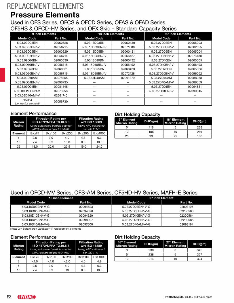
E2
REPLACEMENT ELEMENTS
PN#02075860 / 04.15 / FSP1406-1622
Used in OFS Series, OFCS & OFCD Series, OFAS & OFAD Series, OF5HS & OFCD-HV Series, and OFX Skid - Standard Capacity Series
9 inch Elements 18 inch Elements 27 inch ElementsModel Code Part No. Model Code Part No. Model Code Part No.
5.03.09D03BN 02060528 5.03.18D03BN 02060430 5.03.27D03BN 020650035.03.09D03BN/-V 02056713 5.03.18D03BN/-V 02071680 5.03.27D03BN/-V 02082855
5.03.09D05BN 02060529 5.03.18D05BN 02060431 5.03.27D05BN 020650045.03.09D05BN/-V 02056714 5.03.18D05BN/-V 02056457 5.03.27D05BN/-V 02073488
5.03.09D10BN 02060530 5.03.18D10BN 02060432 5.03.27D10BN 020650055.03.09D10BN/-V 02056715 5.03.18D10BN/-V 02056492 5.03.27D10BN/-V 02056493
5.03.09D20BN 02060531 5.03.18D25BN 02060433 5.03.27D20BN 020650065.03.09D20BN/-V 02056716 5.03.18D25BN/-V 02072428 5.03.27D20BN/-V 02096052
5.03.09D10AM 02075265 5.03.18D40AM 02091879 5.03.27D40AM 020883585.03.09D01BN/-V 02096735 — — 5.03.27D40AM/-V 02088359
5.03.09D01BN 02081446 — — 5.03.27D01BN 020945315.03.09D10BN/AM 02075258 — — 5.03.27D01BN/-V 020998455.03.09D40AM/-V 02561740 — — — —
HK/HJ (connector element)
02056730 — — — —
Used in OFCD-MV Series, OFS-AM Series, OF5HD-HV Series, MAFH-E Series18 inch Element 27 inch Element
Model Code Part No. Model Code Part No.5.03.18D03BN/-V-G 02094523 5.03.27D03BN/-V-G 020981955.03.18D05BN/-V-G 02094528 5.03.27D05BN/-V-G 022005835.03.18D10BN/-V-G 02094529 5.03.27D10BN/-V-G 022005845.03.18D25BN/-V-G 02098097 5.03.27D25BN/-V-G 022005855.03.18D10AM/-V-G 02097600 5.03.27D40AM/-V-G 02098194
Note: G = Betamicron GeoSeal® (r) replacement elements
Pressure Elements
Element Performance
Micron Rating
Filtration Rating per ISO 4572/NFPA T3.10.8.8
Using automated particle counter (APC) calibrated per ISO 4402
Filtration Rating wrt ISO 16889
Using APC calibrated per ISO 11171
Element Bx≥75 Bx≥100 Bx≥200 Bx≥200 Bx≥10005 2.5 3.0 4.0 4.8 6.310 7.4 8.2 10.0 8.0 10.025 18.0 20.0 22.5 19.0 24.0
Dirt Holding Capacity9” Element
Micron Rating DHC(gm) 18” Element Micron Rating DHC(gm)
5 119 5 23810 108 10 21625 93 25 186
Element Performance
Micron Rating
Filtration Rating per ISO 4572/NFPA T3.10.8.8
Using automated particle counter (APC) calibrated per ISO 4402
Filtration Rating wrt ISO 16889
Using APC calibrated per ISO 11171
Element Bx≥75 Bx≥100 Bx≥200 Bx≥200 Bx≥10003 <1.0 <1.0 <2.0 4.0 4.85 2.5 3.0 4.0 4.8 6.310 7.4 8.2 10 8.0 10.0
Dirt Holding Capacity18” Element
Micron Rating DHC(gm) 27” Element Micron Rating DHC(gm)
3 230 3 3455 238 5 35710 216 10 324
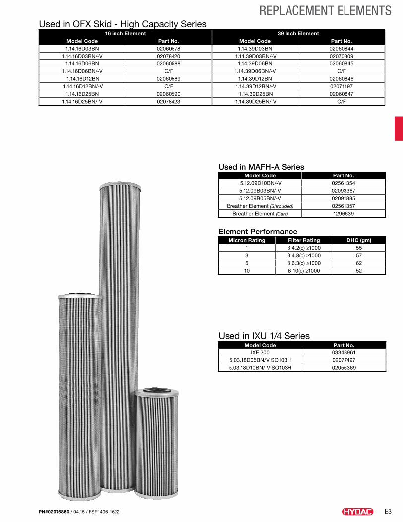
E3
REPLACEMENT ELEMENTS
PN#02075860 / 04.15 / FSP1406-1622
Used in OFX Skid - High Capacity Series16 inch Element 39 inch Element
Model Code Part No. Model Code Part No.1.14.16D03BN 02060578 1.14.39D03BN 02060844
1.14.16D03BN/-V 02078420 1.14.39D03BN/-V 020708091.14.16D06BN 02060588 1.14.39D06BN 02060845
1.14.16D06BN/-V C/F 1.14.39D06BN/-V C/F 1.14.16D12BN 02060589 1.14.39D12BN 02060846
1.14.16D12BN/-V C/F 1.14.39D12BN/-V 020711971.14.16D25BN 02060590 1.14.39D25BN 02060847
1.14.16D25BN/-V 02078423 1.14.39D25BN/-V C/F
Used in IXU 1/4 SeriesModel Code Part No.
IXE 200 033489615.03.18D05BN/V SO103H 020774975.03.18D10BN/-V SO103H 02056369
Used in MAFH-A SeriesModel Code Part No.
5.12.09D10BN/-V 025613545.12.09B03BN/-V 020933675.12.09B05BN/-V 02091885
Breather Element (Shrouded) 02561357Breather Element (Cart) 1296639
Element PerformanceMicron Rating Filter Rating DHC (gm)
1 ß 4.2(c) ≥1000 553 ß 4.8(c) ≥1000 575 ß 6.3(c) ≥1000 6210 ß 10(c) ≥1000 52
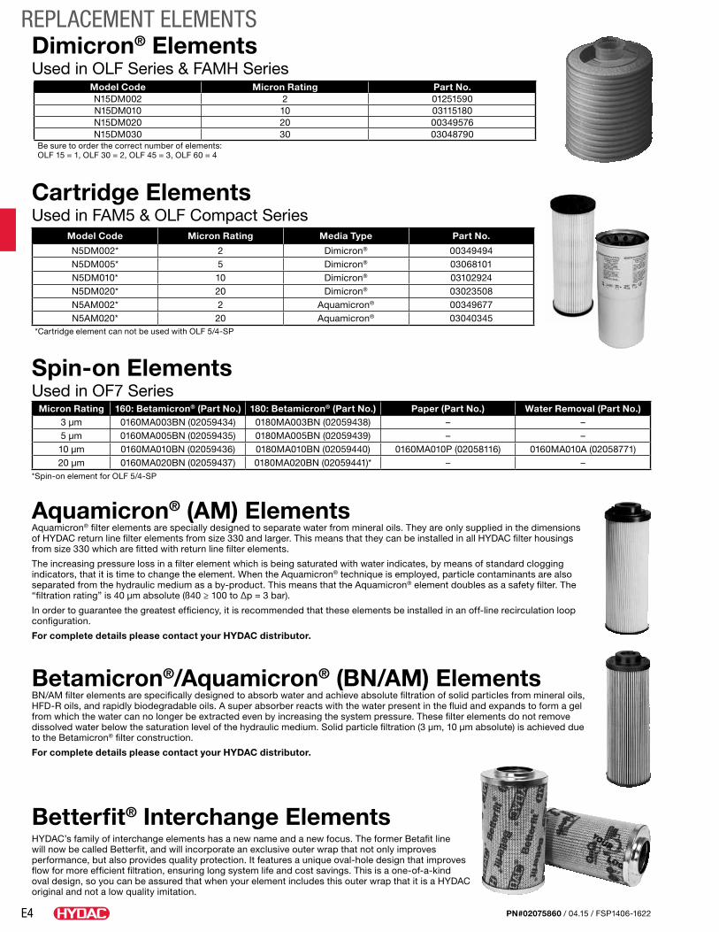
E4
REPLACEMENT ELEMENTS
PN#02075860 / 04.15 / FSP1406-1622
Micron Rating 160: Betamicron® (Part No.) 180: Betamicron® (Part No.) Paper (Part No.) Water Removal (Part No.)3 µm 0160MA003BN (02059434) 0180MA003BN (02059438) – –5 µm 0160MA005BN (02059435) 0180MA005BN (02059439) – –10 µm 0160MA010BN (02059436) 0180MA010BN (02059440) 0160MA010P (02058116) 0160MA010A (02058771)20 µm 0160MA020BN (02059437) 0180MA020BN (02059441)* – –
*Spin-on element for OLF 5/4-SP
Spin-on ElementsUsed in OF7 Series
Aquamicron® (AM) ElementsAquamicron® filter elements are specially designed to separate water from mineral oils. They are only supplied in the dimensions of HYDAC return line filter elements from size 330 and larger. This means that they can be installed in all HYDAC filter housings from size 330 which are fitted with return line filter elements.
The increasing pressure loss in a filter element which is being saturated with water indicates, by means of standard clogging indicators, that it is time to change the element. When the Aquamicron® technique is employed, particle contaminants are also separated from the hydraulic medium as a by-product. This means that the Aquamicron® element doubles as a safety filter. The “filtration rating” is 40 µm absolute (ß40 ≥ 100 to ∆p = 3 bar).
In order to guarantee the greatest efficiency, it is recommended that these elements be installed in an off-line recirculation loop configuration.
For complete details please contact your HYDAC distributor.
Betamicron®/Aquamicron® (BN/AM) ElementsBN/AM filter elements are specifically designed to absorb water and achieve absolute filtration of solid particles from mineral oils, HFD-R oils, and rapidly biodegradable oils. A super absorber reacts with the water present in the fluid and expands to form a gel from which the water can no longer be extracted even by increasing the system pressure. These filter elements do not remove dissolved water below the saturation level of the hydraulic medium. Solid particle filtration (3 µm, 10 µm absolute) is achieved due to the Betamicron® filter construction.
For complete details please contact your HYDAC distributor.
Betterfit® Interchange ElementsHYDAC’s family of interchange elements has a new name and a new focus. The former Betafit line will now be called Betterfit, and will incorporate an exclusive outer wrap that not only improves performance, but also provides quality protection. It features a unique oval-hole design that improves flow for more efficient filtration, ensuring long system life and cost savings. This is a one-of-a-kind oval design, so you can be assured that when your element includes this outer wrap that it is a HYDAC original and not a low quality imitation.
Model Code Micron Rating Media Type Part No.
N5DM002* 2 Dimicron® 00349494N5DM005* 5 Dimicron® 03068101N5DM010* 10 Dimicron® 03102924N5DM020* 20 Dimicron® 03023508N5AM002* 2 Aquamicron® 00349677N5AM020* 20 Aquamicron® 03040345
*Cartridge element can not be used with OLF 5/4-SP
Cartridge ElementsUsed in FAM5 & OLF Compact Series
Model Code Micron Rating Part No.N15DM002 2 01251590N15DM010 10 03115180N15DM020 20 00349576N15DM030 30 03048790
Be sure to order the correct number of elements:OLF 15 = 1, OLF 30 = 2, OLF 45 = 3, OLF 60 = 4
Dimicron® ElementsUsed in OLF Series & FAMH Series
F1
BULK DIESEL FILTRATION
PN#02075860 / 04.15 / FSP1406-1622
The New World of Advanced Diesel FiltrationIn the past, the cleanliness level of delivered diesel fuel was rarely questioned. Now however, the cleanliness mandates of Tier IV requirements (2 µm tolerances in 30,000 psi injection systems) dictates that close attention must be paid to these levels.
Historically, an engine with poor quality filtration would probably still run – maybe not efficiently, but it would run. The byproducts of poor filtration were black smoke and compromised horsepower. Today, Tier IV engines with poor quality fuel filtration will most likely suffer downtime due to failed injector(s), which equates to lost revenue. High quality filtration is no longer an option, but a requirement for the efficient operation of these new engines.
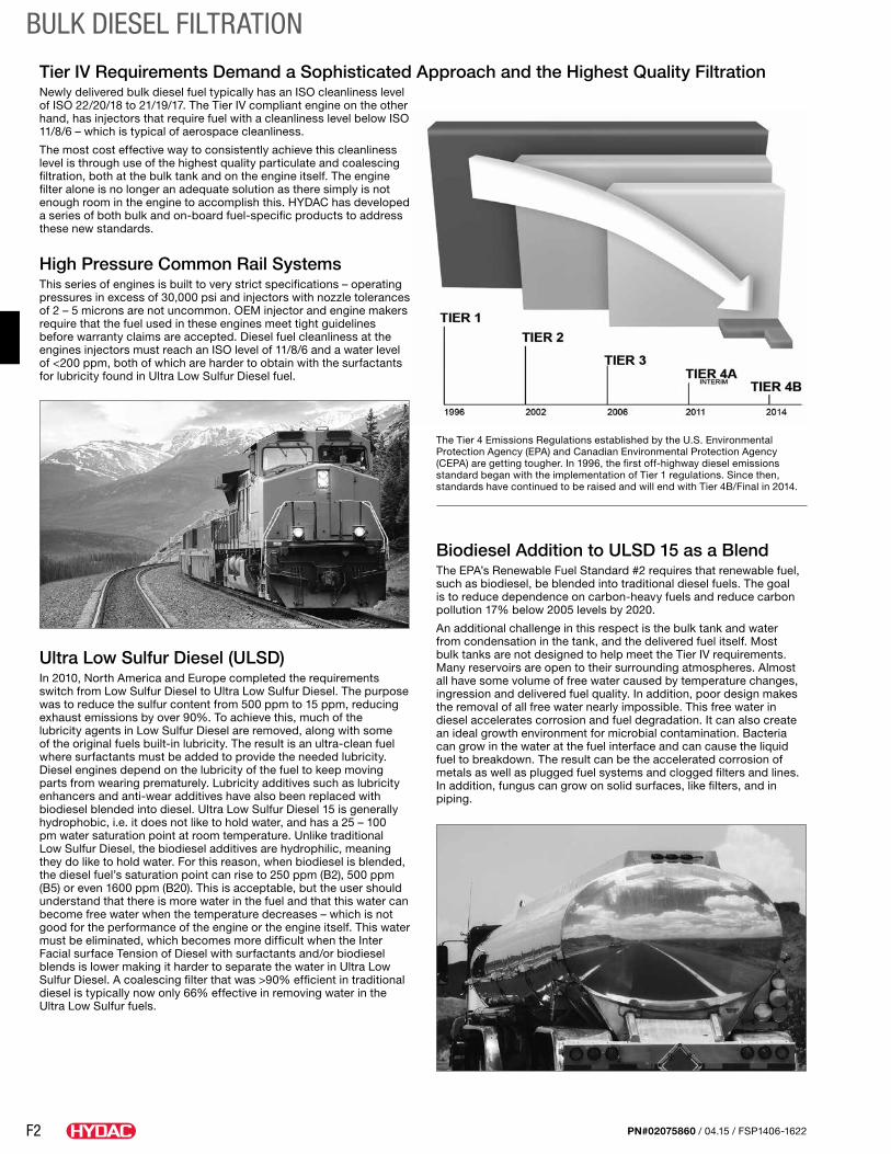
F2
BULK DIESEL FILTRATION
PN#02075860 / 04.15 / FSP1406-1622
Tier IV Requirements Demand a Sophisticated Approach and the Highest Quality FiltrationNewly delivered bulk diesel fuel typically has an ISO cleanliness level of ISO 22/20/18 to 21/19/17. The Tier IV compliant engine on the other hand, has injectors that require fuel with a cleanliness level below ISO 11/8/6 – which is typical of aerospace cleanliness.
The most cost effective way to consistently achieve this cleanliness level is through use of the highest quality particulate and coalescing filtration, both at the bulk tank and on the engine itself. The engine filter alone is no longer an adequate solution as there simply is not enough room in the engine to accomplish this. HYDAC has developed a series of both bulk and on-board fuel-specific products to address these new standards.
High Pressure Common Rail Systems This series of engines is built to very strict specifications – operating pressures in excess of 30,000 psi and injectors with nozzle tolerances of 2 – 5 microns are not uncommon. OEM injector and engine makers require that the fuel used in these engines meet tight guidelines before warranty claims are accepted. Diesel fuel cleanliness at the engines injectors must reach an ISO level of 11/8/6 and a water level of <200 ppm, both of which are harder to obtain with the surfactants for lubricity found in Ultra Low Sulfur Diesel fuel.
Ultra Low Sulfur Diesel (ULSD)In 2010, North America and Europe completed the requirements switch from Low Sulfur Diesel to Ultra Low Sulfur Diesel. The purpose was to reduce the sulfur content from 500 ppm to 15 ppm, reducing exhaust emissions by over 90%. To achieve this, much of the lubricity agents in Low Sulfur Diesel are removed, along with some of the original fuels built-in lubricity. The result is an ultra-clean fuel where surfactants must be added to provide the needed lubricity. Diesel engines depend on the lubricity of the fuel to keep moving parts from wearing prematurely. Lubricity additives such as lubricity enhancers and anti-wear additives have also been replaced with biodiesel blended into diesel. Ultra Low Sulfur Diesel 15 is generally hydrophobic, i.e. it does not like to hold water, and has a 25 – 100 pm water saturation point at room temperature. Unlike traditional Low Sulfur Diesel, the biodiesel additives are hydrophilic, meaning they do like to hold water. For this reason, when biodiesel is blended, the diesel fuel’s saturation point can rise to 250 ppm (B2), 500 ppm (B5) or even 1600 ppm (B20). This is acceptable, but the user should understand that there is more water in the fuel and that this water can become free water when the temperature decreases – which is not good for the performance of the engine or the engine itself. This water must be eliminated, which becomes more difficult when the Inter Facial surface Tension of Diesel with surfactants and/or biodiesel blends is lower making it harder to separate the water in Ultra Low Sulfur Diesel. A coalescing filter that was >90% efficient in traditional diesel is typically now only 66% effective in removing water in the Ultra Low Sulfur fuels.
Biodiesel Addition to ULSD 15 as a BlendThe EPA’s Renewable Fuel Standard #2 requires that renewable fuel, such as biodiesel, be blended into traditional diesel fuels. The goal is to reduce dependence on carbon-heavy fuels and reduce carbon pollution 17% below 2005 levels by 2020.
An additional challenge in this respect is the bulk tank and water from condensation in the tank, and the delivered fuel itself. Most bulk tanks are not designed to help meet the Tier IV requirements. Many reservoirs are open to their surrounding atmospheres. Almost all have some volume of free water caused by temperature changes, ingression and delivered fuel quality. In addition, poor design makes the removal of all free water nearly impossible. This free water in diesel accelerates corrosion and fuel degradation. It can also create an ideal growth environment for microbial contamination. Bacteria can grow in the water at the fuel interface and can cause the liquid fuel to breakdown. The result can be the accelerated corrosion of metals as well as plugged fuel systems and clogged filters and lines. In addition, fungus can grow on solid surfaces, like filters, and in piping.
The Tier 4 Emissions Regulations established by the U.S. Environmental Protection Agency (EPA) and Canadian Environmental Protection Agency (CEPA) are getting tougher. In 1996, the first off-highway diesel emissions standard began with the implementation of Tier 1 regulations. Since then, standards have continued to be raised and will end with Tier 4B/Final in 2014.
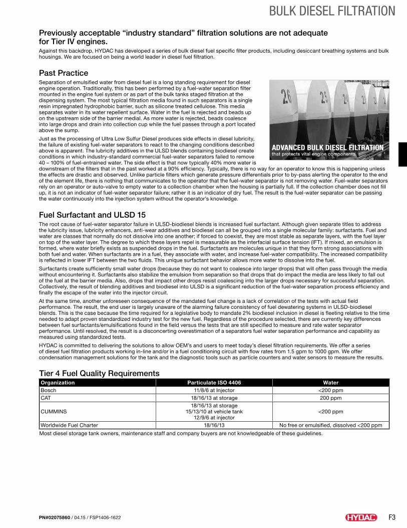
F3
BULK DIESEL FILTRATION
PN#02075860 / 04.15 / FSP1406-1622
Previously acceptable “industry standard” filtration solutions are not adequate for Tier IV engines. Against this backdrop, HYDAC has developed a series of bulk diesel fuel specific filter products, including desiccant breathing systems and bulk housings. We are focused on being a world leader in diesel fuel filtration.
Past PracticeSeparation of emulsified water from diesel fuel is a long standing requirement for diesel engine operation. Traditionally, this has been performed by a fuel-water separation filter mounted in the engine fuel system or as part of the bulk tanks staged filtration at the dispensing system. The most typical filtration media found in such separators is a single resin impregnated hydrophobic barrier, such as silicone treated cellulose. This media separates water in its water repellent surface. Water in the fuel is rejected and beads up on the upstream side of the barrier medial. As more water is rejected, beads coalesce into large drops and drain into collection cup while the fuel passes through a port located above the sump.
Just as the processing of Ultra Low Sulfur Diesel produces side effects in diesel lubricity, the failure of existing fuel-water separators to react to the changing conditions described above is apparent. The lubricity additives in the ULSD blends containing biodiesel create conditions in which industry-standard commercial fuel-water separators failed to remove 40 – 100% of fuel-entrained water. The side effect is that now typically 40% more water is downstream of the filters that in the past worked at a 90% efficiency. Typically, there is no way for an operator to know this is happening unless the effects are drastic and observed. Unlike particle filters which generate pressure differentials prior to by-pass alerting the operator to the end of the element life, there is nothing that communicates to the operator that the fuel-water separator is not removing water. Fuel-water separators rely on an operator or auto-valve to empty water to a collection chamber when the housing is partially full. If the collection chamber does not fill up, it is not an indicator of fuel-water separator failure; rather it is an indicator of dry fuel. The result is the fuel-water separator can be passing the water continuously into the injection system without the operator’s knowledge.
Fuel Surfactant and ULSD 15The root cause of fuel-water separator failure in ULSD-biodiesel blends is increased fuel surfactant. Although given separate titles to address the lubricity issue, lubricity enhancers, anti-wear additives and biodiesel can all be grouped into a single molecular family: surfactants. Fuel and water are classes that normally do not dissolve into one another; if forced to coexist, they are most stable as separate layers, with the fuel layer on top of the water layer. The degree to which these layers repel is measurable as the interfacial surface tension (IFT). If mixed, an emulsion is formed, where water briefly exists as suspended drops in the fuel. Surfactants are molecules unique in that they form strong associations with both fuel and water. When surfactants are in a fuel, they associate with water, and increase fuel-water compatibility. The increased compatibility is reflected in lower IFT between the two fluids. This unique surfactant behavior allows more water to dissolve into the fuel.
Surfactants create sufficiently small water drops (because they do not want to coalesce into larger drops) that will often pass through the media without encountering it. Surfactants also stabilize the emulsion from separation so that drops that do impact the media are less likely to fall out of the fuel at the barrier media. Also, drops that impact other drops resist coalescing into the larger drops necessary for successful separation. Collectively, the result of blending additives and biodiesel into ULSD is a significant reduction of the fuel-water separation process efficiency and finally the escape of the water into the injector circuit.
At the same time, another unforeseen consequence of the mandated fuel change is a lack of correlation of the tests with actual field performance. The result, the end user is largely unaware of the alarming failure consistency of fuel dewatering systems in ULSD-biodiesel blends. This is the case because the time required for a legislative body to mandate 2% biodiesel inclusion in diesel is fleeting relative to the time needed to adapt proven standardized industry test for the new fuel. Regardless of the procedure selected, there are currently key differences between fuel surfactants/emulsifications found in the field versus the tests that are still specified to measure and rate water separator performance. Until resolved, the result is a disconcerting overestimation of a separators fuel water separation performance and capability as measured using standardized tests.
HYDAC is committed to delivering the solutions to allow OEM’s and users to meet today’s diesel filtration requirements. We offer a series of diesel fuel filtration products working in-line and/or in a fuel conditioning circuit with flow rates from 1.5 gpm to 1000 gpm. We offer condensation management solutions for the tank and the diagnostic tools such as particle counters and water sensors to measure the results.
Tier 4 Fuel Quality RequirementsOrganization Particulate ISO 4406 WaterBosch 11/8/6 at Injector <200 ppmCAT 18/16/13 at storage 200 ppm
CUMMINS18/16/13 at storage
15/13/10 at vehicle tank 12/9/6 at injector
<200 ppm
Worldwide Fuel Charter 18/16/13 No free or emulsified, dissolved <200 ppm
Most diesel storage tank owners, maintenance staff and company buyers are not knowledgeable of these guidelines.
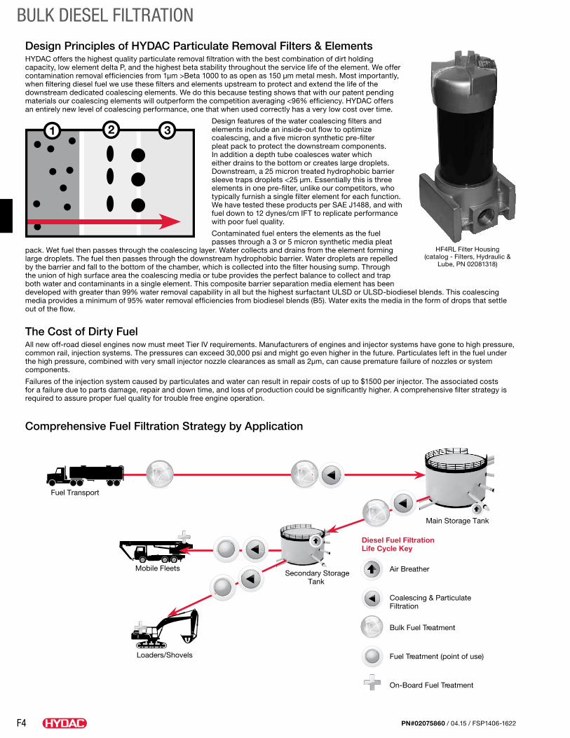
F4
BULK DIESEL FILTRATION
PN#02075860 / 04.15 / FSP1406-1622
Design Principles of HYDAC Particulate Removal Filters & Elements HYDAC offers the highest quality particulate removal filtration with the best combination of dirt holding capacity, low element delta P, and the highest beta stability throughout the service life of the element. We offer contamination removal efficiencies from 1µm >Beta 1000 to as open as 150 µm metal mesh. Most importantly, when filtering diesel fuel we use these filters and elements upstream to protect and extend the life of the downstream dedicated coalescing elements. We do this because testing shows that with our patent pending materials our coalescing elements will outperform the competition averaging <96% efficiency. HYDAC offers an entirely new level of coalescing performance, one that when used correctly has a very low cost over time.
Design features of the water coalescing filters and elements include an inside-out flow to optimize coalescing, and a five micron synthetic pre-filter pleat pack to protect the downstream components. In addition a depth tube coalesces water which either drains to the bottom or creates large droplets. Downstream, a 25 micron treated hydrophobic barrier sleeve traps droplets <25 µm. Essentially this is three elements in one pre-filter, unlike our competitors, who typically furnish a single filter element for each function. We have tested these products per SAE J1488, and with fuel down to 12 dynes/cm IFT to replicate performance with poor fuel quality.
Contaminated fuel enters the elements as the fuel passes through a 3 or 5 micron synthetic media pleat
pack. Wet fuel then passes through the coalescing layer. Water collects and drains from the element forming large droplets. The fuel then passes through the downstream hydrophobic barrier. Water droplets are repelled by the barrier and fall to the bottom of the chamber, which is collected into the filter housing sump. Through the union of high surface area the coalescing media or tube provides the perfect balance to collect and trap both water and contaminants in a single element. This composite barrier separation media element has been developed with greater than 99% water removal capability in all but the highest surfactant ULSD or ULSD-biodiesel blends. This coalescing media provides a minimum of 95% water removal efficiencies from biodiesel blends (B5). Water exits the media in the form of drops that settle out of the flow.
The Cost of Dirty FuelAll new off-road diesel engines now must meet Tier IV requirements. Manufacturers of engines and injector systems have gone to high pressure, common rail, injection systems. The pressures can exceed 30,000 psi and might go even higher in the future. Particulates left in the fuel under the high pressure, combined with very small injector nozzle clearances as small as 2µm, can cause premature failure of nozzles or system components.
Failures of the injection system caused by particulates and water can result in repair costs of up to $1500 per injector. The associated costs for a failure due to parts damage, repair and down time, and loss of production could be significantly higher. A comprehensive filter strategy is required to assure proper fuel quality for trouble free engine operation.
Comprehensive Fuel Filtration Strategy by Application
Fuel Transport
Mobile Fleets
Loaders/Shovels
Secondary StorageTank
Main Storage Tank
Air Breather
Coalescing & ParticulateFiltration
Bulk Fuel Treatment
Fuel Treatment (point of use)
On-Board Fuel Treatment
Diesel Fuel FiltrationLife Cycle Key
21 3
HF4RL Filter Housing (catalog - Filters, Hydraulic &
Lube, PN 02081318)
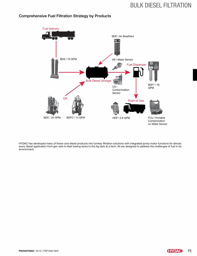
F5
BULK DIESEL FILTRATION
PN#02075860 / 04.15 / FSP1406-1622
Comprehensive Fuel Filtration Strategy by Products
Fuel Delivery
BDS | 70 GPM
BDC | 25 GPM BDFC | 14 GPM
OR
CS | Contamination Sensor
Bulk Diesel Storage
AS | Water Sensor
BDE | Air Breathers
Fuel Dispenser
BDF1 | 16 GPM
HDP | 2.6 GPM FCU | Portable Contamination w/ Water Sensor
Point of Use
HYDAC has developed many of these core diesel products into turnkey filtration solutions with integrated pump motor functions for almost every diesel application from gen sets to fleet fueling tanks to the Ag tank at a farm. All are designed to address the challenges of fuel in its environment.
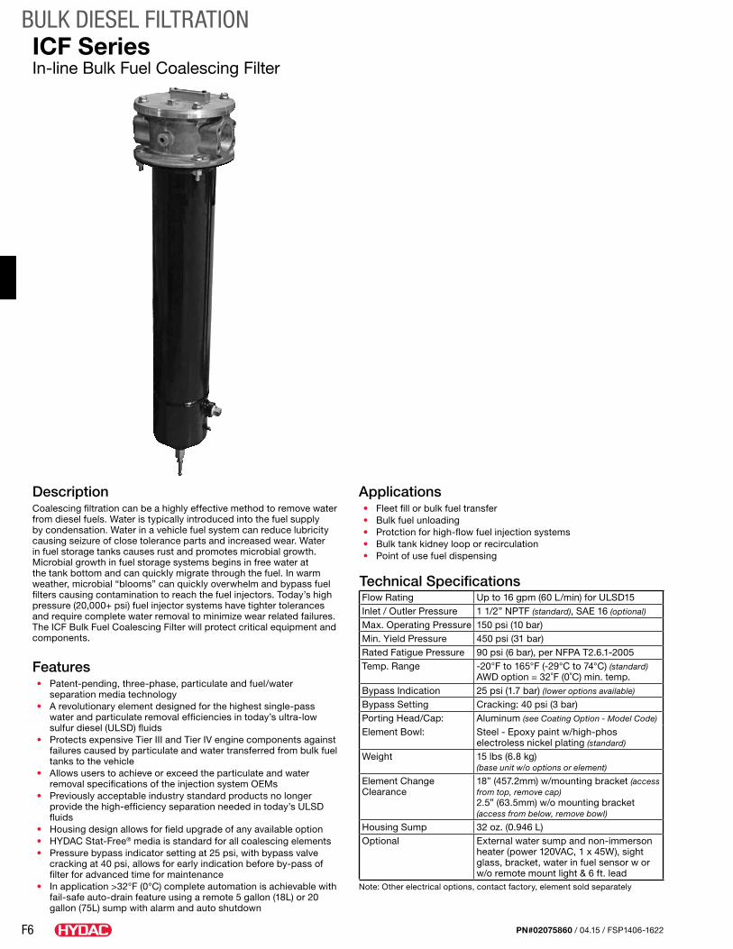
F6
BULK DIESEL FILTRATION
PN#02075860 / 04.15 / FSP1406-1622
DescriptionCoalescing filtration can be a highly effective method to remove water from diesel fuels. Water is typically introduced into the fuel supply by condensation. Water in a vehicle fuel system can reduce lubricity causing seizure of close tolerance parts and increased wear. Water in fuel storage tanks causes rust and promotes microbial growth. Microbial growth in fuel storage systems begins in free water at the tank bottom and can quickly migrate through the fuel. In warm weather, microbial “blooms” can quickly overwhelm and bypass fuel filters causing contamination to reach the fuel injectors. Today’s high pressure (20,000+ psi) fuel injector systems have tighter tolerances and require complete water removal to minimize wear related failures. The ICF Bulk Fuel Coalescing Filter will protect critical equipment and components.
Features• Patent-pending, three-phase, particulate and fuel/water
separation media technology• A revolutionary element designed for the highest single-pass
water and particulate removal efficiencies in today’s ultra-low sulfur diesel (ULSD) fluids
• Protects expensive Tier III and Tier IV engine components against failures caused by particulate and water transferred from bulk fuel tanks to the vehicle
• Allows users to achieve or exceed the particulate and water removal specifications of the injection system OEMs
• Previously acceptable industry standard products no longer provide the high-efficiency separation needed in today’s ULSD fluids
• Housing design allows for field upgrade of any available option• HYDAC Stat-Free® media is standard for all coalescing elements• Pressure bypass indicator setting at 25 psi, with bypass valve
cracking at 40 psi, allows for early indication before by-pass of filter for advanced time for maintenance
• In application >32°F (0°C) complete automation is achievable with fail-safe auto-drain feature using a remote 5 gallon (18L) or 20 gallon (75L) sump with alarm and auto shutdown
Applications• Fleet fill or bulk fuel transfer• Bulk fuel unloading• Protction for high-flow fuel injection systems• Bulk tank kidney loop or recirculation• Point of use fuel dispensing
Technical SpecificationsFlow Rating Up to 16 gpm (60 L/min) for ULSD15Inlet / Outler Pressure 1 1/2” NPTF (standard), SAE 16 (optional)
Max. Operating Pressure 150 psi (10 bar)Min. Yield Pressure 450 psi (31 bar)Rated Fatigue Pressure 90 psi (6 bar), per NFPA T2.6.1-2005Temp. Range -20°F to 165°F (-29°C to 74°C) (standard)
AWD option = 32˚F (0˚C) min. temp.Bypass Indication 25 psi (1.7 bar) (lower options available)
Bypass Setting Cracking: 40 psi (3 bar)Porting Head/Cap: Aluminum (see Coating Option - Model Code)
Element Bowl: Steel - Epoxy paint w/high-phos electroless nickel plating (standard)
Weight 15 lbs (6.8 kg) (base unit w/o options or element)
Element Change Clearance
18” (457.2mm) w/mounting bracket (access from top, remove cap)2.5” (63.5mm) w/o mounting bracket (access from below, remove bowl)
Housing Sump 32 oz. (0.946 L)Optional External water sump and non-immerson
heater (power 120VAC, 1 x 45W), sight glass, bracket, water in fuel sensor w or w/o remote mount light & 6 ft. lead
Note: Other electrical options, contact factory, element sold separately
ICF SeriesIn-line Bulk Fuel Coalescing Filter
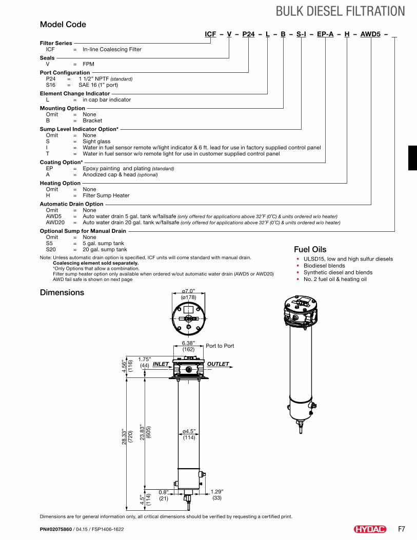
F7
BULK DIESEL FILTRATION
PN#02075860 / 04.15 / FSP1406-1622
Dimensions
Dimensions are for general information only, all critical dimensions should be verified by requesting a certified print.
Model CodeICF – V – P24 – L – B – S-I – EP-A – H – AWD5 – .
Filter Series ICF = In-line Coalescing Filter
Seals V = FPM
Port Configuration P24 = 1 1/2” NPTF (standard) S16 = SAE 16 (1” port)
Element Change Indicator L = in cap bar indicator
Mounting Option Omit = None B = Bracket
Sump Level Indicator Option* Omit = None S = Sight glass I = Water in fuel sensor remote w/light indicator & 6 ft. lead for use in factory supplied control panel T = Water in fuel sensor w/o remote light for use in customer supplied control panel
Coating Option* EP = Epoxy painting and plating (standard) A = Anodized cap & head (optional)
Heating Option Omit = None H = Filter Sump Heater
Automatic Drain Option Omit = None AWD5 = Auto water drain 5 gal. tank w/failsafe (only offered for applications above 32˚F (0˚C) & units ordered w/o heater) AWD20 = Auto water drain 20 gal. tank w/failsafe (only offered for applications above 32˚F (0˚C) & units ordered w/o heater)
Optional Sump for Manual Drain Omit = None S5 = 5 gal. sump tank S20 = 20 gal. sump tankNote: Unless automatic drain option is specified, ICF units will come standard with manual drain.
Coalescing element sold separately. *Only Options that allow a combination. Filter sump heater option only available when ordered w/out automatic water drain (AWD5 or AWD20) AWD fail safe is shown on next page
ø7.0”(ø178)
6.38”(162)
1.75”(44)
4.56
”(1
16)
ø4.5”(114)
0.8”(21)
1.29”(33)
28.3
3”(7
20)
23.8
3”(6
05)
4.5”
(114
)
INLET OUTLET
Port to Port
Fuel Oils• ULSD15, low and high sulfur diesels• Biodiesel blends• Synthetic diesel and blends• No. 2 fuel oil & heating oil
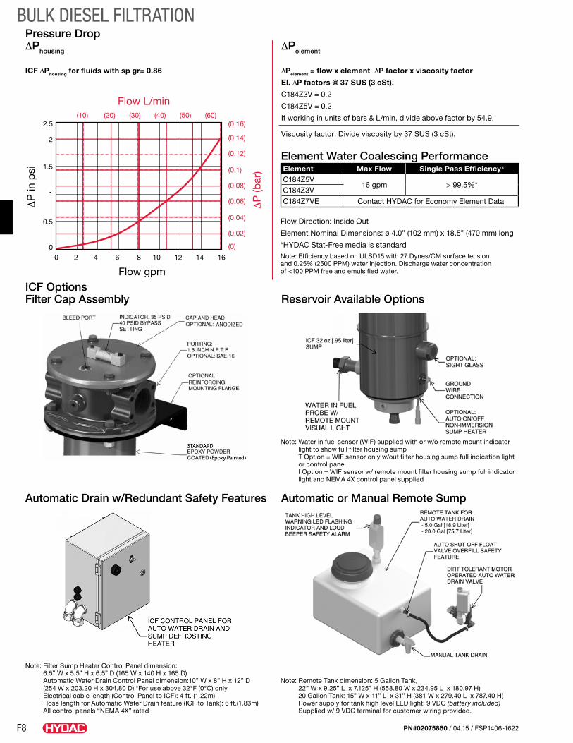
F8
BULK DIESEL FILTRATION
PN#02075860 / 04.15 / FSP1406-1622
Element Water Coalescing PerformanceElement Max Flow Single Pass Efficiency*C184Z5V
16 gpm > 99.5%*C184Z3V
C184Z7VE Contact HYDAC for Economy Element Data
Flow Direction: Inside Out
Element Nominal Dimensions: ø 4.0” (102 mm) x 18.5” (470 mm) long
*HYDAC Stat-Free media is standardNote: Efficiency based on ULSD15 with 27 Dynes/CM surface tension and 0.25% (2500 PPM) water injection. Discharge water concentration of <100 PPM free and emulsified water.
Pressure Drop ∆Phousing ∆Pelement
ICF ∆Phousing for fluids with sp gr= 0.86 ∆Pelement = flow x element ∆P factor x viscosity factor
El. ∆P factors @ 37 SUS (3 cSt).
C184Z3V = 0.2
C184Z5V = 0.2
If working in units of bars & L/min, divide above factor by 54.9.
Viscosity factor: Divide viscosity by 37 SUS (3 cSt).2.5
2
1.5
1
0.5
0 0 2 4 6 8 10 12 14 16
(10) (20) (30) (40) (50) (60)(0.16)
(0.14)
(0.12)
(0.1)
(0.08)
(0.06)
(0.04)
(0.02)
(0)
Flow L/min
ΔP
in p
si
Flow gpmΔ
P (b
ar)
ICF Options Filter Cap Assembly Reservoir Available Options
Automatic Drain w/Redundant Safety Features Automatic or Manual Remote Sump
Note: Water in fuel sensor (WIF) supplied with or w/o remote mount indicator light to show full filter housing sump T Option = WIF sensor only w/out filter housing sump full indication light or control panel I Option = WIF sensor w/ remote mount filter housing sump full indicator light and NEMA 4X control panel supplied
Note: Remote Tank dimension: 5 Gallon Tank, 22” W x 9.25” L x 7.125” H (558.80 W x 234.95 L x 180.97 H) 20 Gallon Tank: 15” W x 11” L x 31” H (381 W x 279.40 L x 787.40 H) Power supply for tank high level LED light: 9 VDC (battery included) Supplied w/ 9 VDC terminal for customer wiring provided.
Note: Filter Sump Heater Control Panel dimension: 6.5” W x 5.5” H x 6.5” D (165 W x 140 H x 165 D) Automatic Water Drain Control Panel dimension:10” W x 8” H x 12” D (254 W x 203.20 H x 304.80 D) *For use above 32°F (0°C) only Electrical cable length (Control Panel to ICF): 4 ft. (1.22m) Hose length for Automatic Water Drain feature (ICF to Tank): 6 ft.(1.83m) All control panels “NEMA 4X” rated
F9
BULK DIESEL FILTRATION
PN#02075860 / 04.15 / FSP1406-1622
Notes
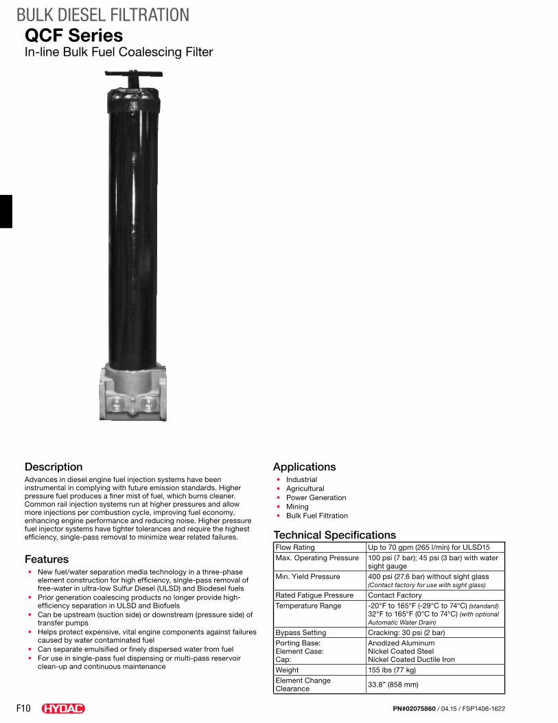
F10
BULK DIESEL FILTRATION
PN#02075860 / 04.15 / FSP1406-1622
DescriptionAdvances in diesel engine fuel injection systems have been instrumental in complying with future emission standards. Higher pressure fuel produces a finer mist of fuel, which burns cleaner. Common rail injection systems run at higher pressures and allow more injections per combustion cycle, improving fuel economy, enhancing engine performance and reducing noise. Higher pressure fuel injector systems have tighter tolerances and require the highest efficiency, single-pass removal to minimize wear related failures.
Features• New fuel/water separation media technology in a three-phase
element construction for high efficiency, single-pass removal of free-water in ultra-low Sulfur Diesel (ULSD) and Biodesel fuels
• Prior generation coalescing products no longer provide high-efficiency separation in ULSD and Biofuels
• Can be upstream (suction side) or downstream (pressure side) of transfer pumps
• Helps protect expensive, vital engine components against failures caused by water contaminated fuel
• Can separate emulsified or finely dispersed water from fuel• For use in single-pass fuel dispensing or multi-pass reservoir
clean-up and continuous maintenance
Applications• Industrial• Agricultural• Power Generation• Mining• Bulk Fuel Filtration
Technical SpecificationsFlow Rating Up to 70 gpm (265 l/min) for ULSD15Max. Operating Pressure 100 psi (7 bar); 45 psi (3 bar) with water
sight gaugeMin. Yield Pressure 400 psi (27.6 bar) without sight glass
(Contact factory for use with sight glass)
Rated Fatigue Pressure Contact FactoryTemperature Range -20°F to 165°F (-29°C to 74°C) (standard)
32°F to 165°F (0°C to 74°C) (with optional Automatic Water Drain)
Bypass Setting Cracking: 30 psi (2 bar)Porting Base: Element Case: Cap:
Anodized AluminumNickel Coated SteelNickel Coated Ductile Iron
Weight 155 lbs (77 kg)Element Change Clearance 33.8” (858 mm)
QCF SeriesIn-line Bulk Fuel Coalescing Filter
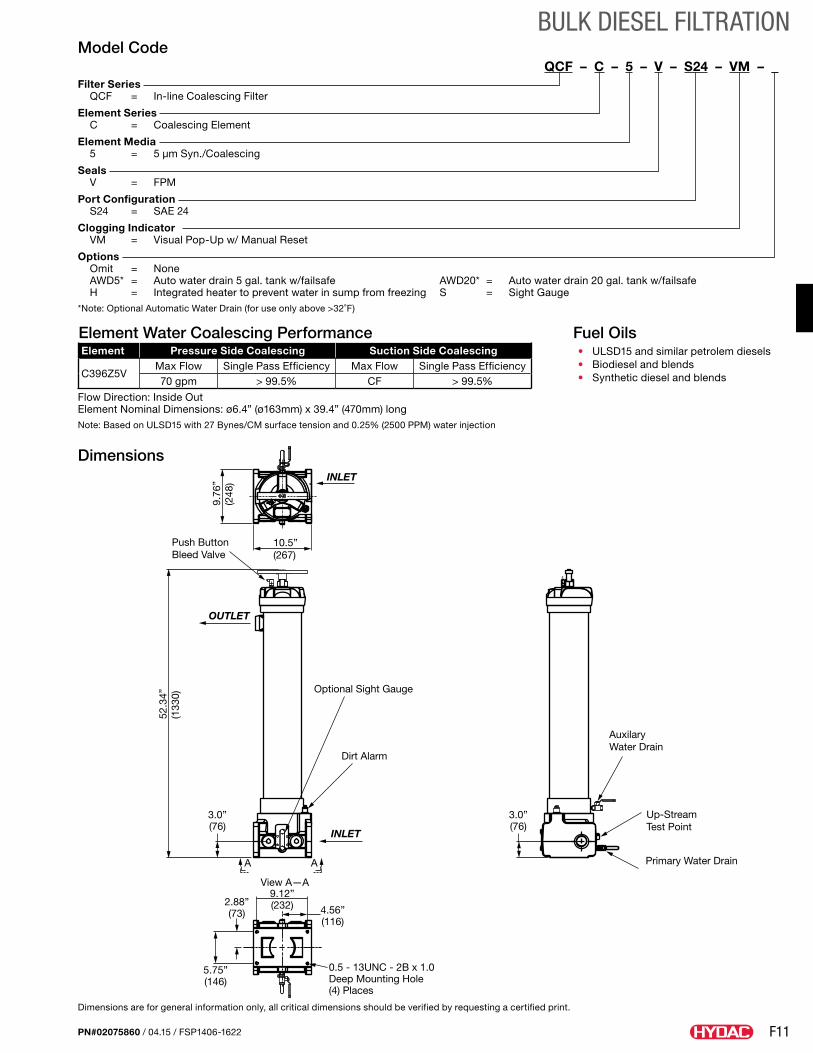
F11
BULK DIESEL FILTRATION
PN#02075860 / 04.15 / FSP1406-1622
Dimensions
Dimensions are for general information only, all critical dimensions should be verified by requesting a certified print.
Fuel Oils• ULSD15 and similar petrolem diesels• Biodiesel and blends• Synthetic diesel and blends
Model CodeQCF – C – 5 – V – S24 – VM – _
Filter Series QCF = In-line Coalescing Filter
Element Series C = Coalescing Element
Element Media 5 = 5 µm Syn./Coalescing
Seals V = FPM
Port Configuration S24 = SAE 24
Clogging Indicator VM = Visual Pop-Up w/ Manual Reset
Options Omit = None AWD5* = Auto water drain 5 gal. tank w/failsafe AWD20* = Auto water drain 20 gal. tank w/failsafe H = Integrated heater to prevent water in sump from freezing S = Sight Gauge*Note: Optional Automatic Water Drain (for use only above >32˚F)
Element Water Coalescing PerformanceElement Pressure Side Coalescing Suction Side Coalescing
C396Z5VMax Flow Single Pass Efficiency Max Flow Single Pass Efficiency70 gpm > 99.5% CF > 99.5%
Flow Direction: Inside Out Element Nominal Dimensions: ø6.4” (ø163mm) x 39.4” (470mm) longNote: Based on ULSD15 with 27 Bynes/CM surface tension and 0.25% (2500 PPM) water injection
Push ButtonBleed Valve
Optional Sight Gauge
Dirt Alarm
OUTLET
INLET
A A
52.3
4”(1
330)
9.76
”(2
48)
10.5”(267)
3.0”(76)
3.0”(76)
INLET
AuxilaryWater Drain
Up-StreamTest Point
Primary Water Drain
9.12”(232) 4.56”
(116)
2.88”(73)
5.75”(146)
0.5 - 13UNC - 2B x 1.0Deep Mounting Hole(4) Places
View A—A
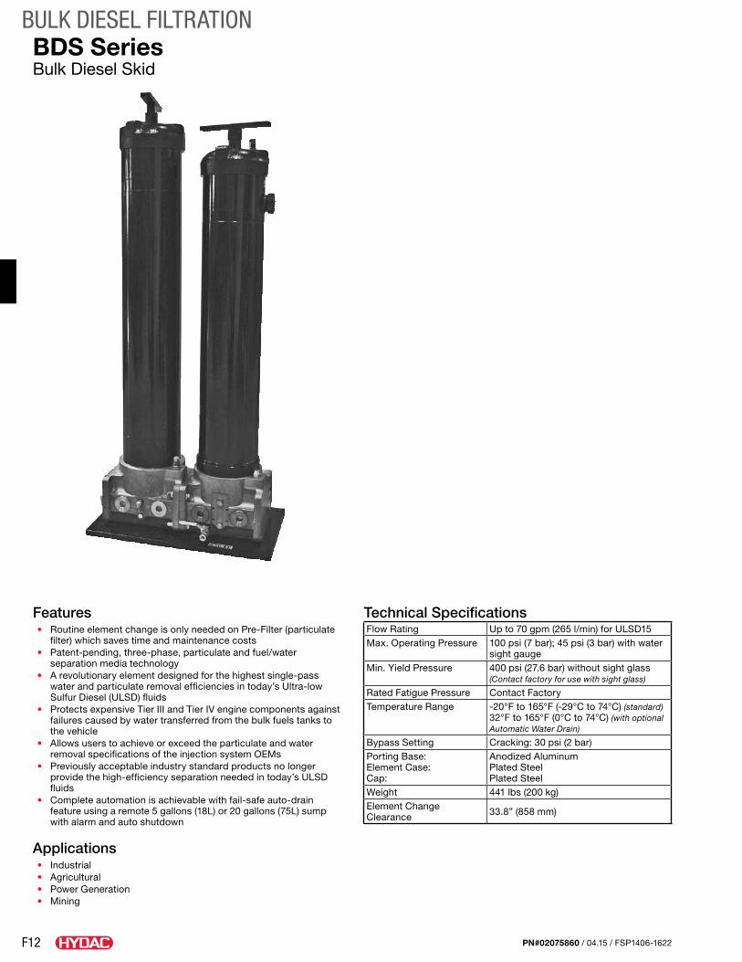
F12
BULK DIESEL FILTRATION
PN#02075860 / 04.15 / FSP1406-1622
Features• Routine element change is only needed on Pre-Filter (particulate
filter) which saves time and maintenance costs• Patent-pending, three-phase, particulate and fuel/water
separation media technology• A revolutionary element designed for the highest single-pass
water and particulate removal efficiencies in today’s Ultra-low Sulfur Diesel (ULSD) fluids
• Protects expensive Tier III and Tier IV engine components against failures caused by water transferred from the bulk fuels tanks to the vehicle
• Allows users to achieve or exceed the particulate and water removal specifications of the injection system OEMs
• Previously acceptable industry standard products no longer provide the high-efficiency separation needed in today’s ULSD fluids
• Complete automation is achievable with fail-safe auto-drain feature using a remote 5 gallons (18L) or 20 gallons (75L) sump with alarm and auto shutdown
Applications• Industrial• Agricultural• Power Generation• Mining
Technical SpecificationsFlow Rating Up to 70 gpm (265 l/min) for ULSD15Max. Operating Pressure 100 psi (7 bar); 45 psi (3 bar) with water
sight gaugeMin. Yield Pressure 400 psi (27.6 bar) without sight glass
(Contact factory for use with sight glass)
Rated Fatigue Pressure Contact FactoryTemperature Range -20°F to 165°F (-29°C to 74°C) (standard)
32°F to 165°F (0°C to 74°C) (with optional Automatic Water Drain)
Bypass Setting Cracking: 30 psi (2 bar)Porting Base: Element Case: Cap:
Anodized AluminumPlated SteelPlated Steel
Weight 441 lbs (200 kg)Element Change Clearance 33.8” (858 mm)
BDS SeriesBulk Diesel Skid
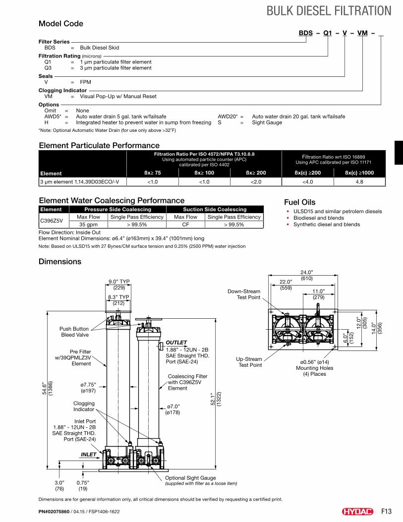
F13
BULK DIESEL FILTRATION
PN#02075860 / 04.15 / FSP1406-1622
Dimensions
Dimensions are for general information only, all critical dimensions should be verified by requesting a certified print.
Fuel Oils• ULSD15 and similar petrolem diesels• Biodiesel and blends• Synthetic diesel and blends
Model CodeBDS – Q1 – V – VM – .
Filter Series BDS = Bulk Diesel Skid
Filtration Rating (microns) Q1 = 1 µm particulate filter element Q3 = 3 µm particulate filter element
Seals V = FPM
Clogging Indicator VM = Visual Pop-Up w/ Manual Reset
Options Omit = None AWD5* = Auto water drain 5 gal. tank w/failsafe AWD20* = Auto water drain 20 gal. tank w/failsafe H = Integrated heater to prevent water in sump from freezing S = Sight Gauge*Note: Optional Automatic Water Drain (for use only above >32˚F)
Element Particulate Performance
Element
Filtration Ratio Per ISO 4572/NFPA T3.10.8.8 Using automated particle counter (APC)
calibrated per ISO 4402
Filtration Ratio wrt ISO 16889Using APC calibrated per ISO 11171
ßx≥ 75 ßx≥ 100 ßx≥ 200 ßx(c) ≥200 ßx(c) ≥1000
3 µm element 1.14.39D03ECO/-V <1.0 <1.0 <2.0 <4.0 4.8
Element Water Coalescing PerformanceElement Pressure Side Coalescing Suction Side Coalescing
C396Z5VMax Flow Single Pass Efficiency Max Flow Single Pass Efficiency35 gpm > 99.5% CF > 99.5%
Flow Direction: Inside Out Element Nominal Dimensions: ø6.4” (ø163mm) x 39.4” (1001mm) longNote: Based on ULSD15 with 27 Bynes/CM surface tension and 0.25% (2500 PPM) water injection
Optional Sight Gauge(supplied with filter as a loose item)
Clogging Indicator
Inlet Port1.88” - 12UN - 2BSAE Straight THD.
Port (SAE-24)
INLET
3.0”(76)
54.6
”(1
386)
0.75”(19)
52.1
”(1
322)
ø7.75”(ø197)
ø7.0”(ø178)
Coalescing Filterwith C396Z5VElement
Pre Filterw/39QPMLZ3V
Element
Push ButtonBleed Valve
OUTLET1.88” - 12UN - 2BSAE Straight THD.Port (SAE-24)
9.0” TYP(229)
8.3” TYP(212)
Down-StreamTest Point
Up-StreamTest Point ø0.56” (ø14)
Mounting Holes(4) Places
24.0”(610)
22.0”(559)
11.0”(279)
6.0”
(152
)12
.0”
(305
)
14.0
”(3
56)
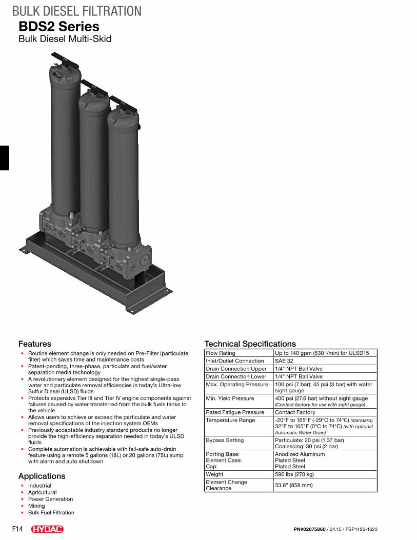
F14
BULK DIESEL FILTRATION
PN#02075860 / 04.15 / FSP1406-1622
Features• Routine element change is only needed on Pre-Filter (particulate
filter) which saves time and maintenance costs• Patent-pending, three-phase, particulate and fuel/water
separation media technology• A revolutionary element designed for the highest single-pass
water and particulate removal efficiencies in today’s Ultra-low Sulfur Diesel (ULSD) fluids
• Protects expensive Tier III and Tier IV engine components against failures caused by water transferred from the bulk fuels tanks to the vehicle
• Allows users to achieve or exceed the particulate and water removal specifications of the injection system OEMs
• Previously acceptable industry standard products no longer provide the high-efficiency separation needed in today’s ULSD fluids
• Complete automation is achievable with fail-safe auto-drain feature using a remote 5 gallons (18L) or 20 gallons (75L) sump with alarm and auto shutdown
Applications• Industrial• Agricultural• Power Generation• Mining• Bulk Fuel Filtration
Technical SpecificationsFlow Rating Up to 140 gpm (530 l/min) for ULSD15Inlet/Outlet Connection SAE 32Drain Connection Upper 1/4” NPT Ball ValveDrain Connection Lower 1/4” NPT Ball ValveMax. Operating Pressure 100 psi (7 bar); 45 psi (3 bar) with water
sight gaugeMin. Yield Pressure 400 psi (27.6 bar) without sight gauge
(Contact factory for use with sight gauge)
Rated Fatigue Pressure Contact FactoryTemperature Range -20°F to 165°F (-29°C to 74°C) (standard)
32°F to 165°F (0°C to 74°C) (with optional Automatic Water Drain)
Bypass Setting Particulate: 20 psi (1.37 bar) Coalescing: 30 psi (2 bar)
Porting Base: Element Case: Cap:
Anodized AluminumPlated SteelPlated Steel
Weight 596 lbs (270 kg)Element Change Clearance 33.8” (858 mm)
BDS2 SeriesBulk Diesel Multi-Skid
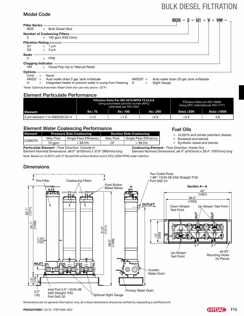
F15
BULK DIESEL FILTRATION
PN#02075860 / 04.15 / FSP1406-1622
Dimensions
Dimensions are for general information only, all critical dimensions should be verified by requesting a certified print.
Fuel Oils• ULSD15 and similar petrolem diesels• Biodiesel and blends• Synthetic diesel and blends
Model CodeBDS – 2 – Q1 – V – VM – .
Filter Series BDS = Bulk Diesel Skid
Number of Coalescing Filters 2 = 140 gpm (530 l/min)
Filtration Rating (microns) Q1 = 1 µm Q3 = 3 µm
Seals V = FPM
Clogging Indicator VM = Visual Pop-Up w/ Manual Reset
Options Omit = None AWD5* = Auto water drain 5 gal. tank w/failsafe AWD20* = Auto water drain 20 gal. tank w/failsafe H = Integrated heater to prevent water in sump from freezing S = Sight Gauge*Note: Optional Automatic Water Drain (for use only above >32˚F)
Element Particulate Performance
Element
Filtration Ratio Per ISO 4572/NFPA T3.10.8.8 Using automated particle counter (APC)
calibrated per ISO 4402
Filtration Ratio wrt ISO 16889Using APC calibrated per ISO 11171
ßx≥ 75 ßx≥ 100 ßx≥ 200 ßx(c) ≥200 ßx(c) ≥1000
3 µm element 1.14.39D03ECO/-V <1.0 <1.0 <2.0 <4.0 4.8
Element Water Coalescing PerformanceElement Pressure Side Coalescing Suction Side Coalescing
C396Z5VMax Flow Single Pass Efficiency Max Flow Single Pass Efficiency70 gpm > 99.5% CF > 99.5%
Particulate Element - Flow Direction: Outside In Coalescing Element - Flow Direction: Inside Out Element Nominal Dimensions: ø6.0” (ø150mm) x 37.8” (960mm) long Element Nominal Dimensions: ø6.4” (ø163mm) x 39.4” (1001mm) longNote: Based on ULSD15 with 27 Bynes/CM surface tension and 0.25% (2500 PPM) water injection
Two Outlet Ports1.88”-12UN-2B SAE Straight THD.Port SAE-24
Inlet Port 2.5”-12UN-2B SAE Straight THD. Port SAE-32 Optional Sight Gauge
Primary Water Drain
Up-StreamTest Point
Up-Stream Test Point
42”(1067)
39.5”(1003)
3.0”(76)
7.75”(197)
13”
(330
)
58.6
”(1
488)
51.6
”(1
311)
7.0”
(178
)
62.1
”(1
577)
55.1
”(1
400)
Down-StreamTest Point
ø0.63”Mounting Holes
(4) Places
AuxilaryWater Drain
Section A—APush ButtonBleed Valves
Pre-Filter Coalescing FiltersA A
OUTLET
OU
T
OU
T
INLET
IN
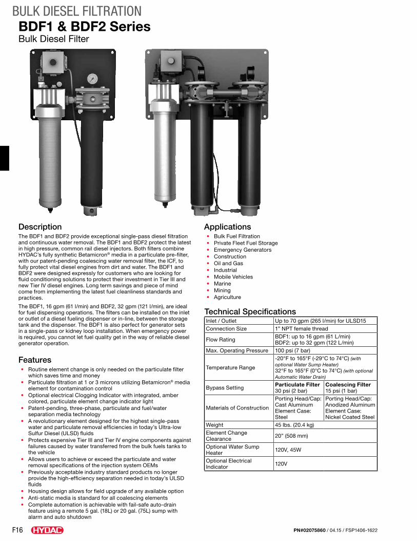
F16
BULK DIESEL FILTRATION
PN#02075860 / 04.15 / FSP1406-1622
DescriptionThe BDF1 and BDF2 provide exceptional single-pass diesel filtration and continuous water removal. The BDF1 and BDF2 protect the latest in high pressure, common rail diesel injectors. Both filters combine HYDAC’s fully synthetic Betamicron® media in a particulate pre-filter, with our patent-pending coalescing water removal filter, the ICF, to fully protect vital diesel engines from dirt and water. The BDF1 and BDF2 were designed expressly for customers who are looking for fluid conditioning solutions to protect their investment in Tier III and new Tier IV diesel engines. Long term savings and piece of mind come from implementing the latest fuel cleanliness standards and practices.
The BDF1, 16 gpm (61 l/min) and BDF2, 32 gpm (121 l/min), are ideal for fuel dispensing operations. The filters can be installed on the inlet or outlet of a diesel fueling dispenser or in-line, between the storage tank and the dispenser. The BDF1 is also perfect for generator sets in a single-pass or kidney loop installation. When emergency power is required, you cannot let fuel quality get in the way of reliable diesel generator operation.
Features• Routine element change is only needed on the particulate filter
which saves time and money • Particulate filtration at 1 or 3 microns utilizing Betamicron® media
element for contamination control • Optional electrical Clogging Indicator with integrated, amber
colored, particulate element change indicator light• Patent-pending, three-phase, particulate and fuel/water
separation media technology• A revolutionary element designed for the highest single-pass
water and particulate removal efficiencies in today’s Ultra-low Sulfur Diesel (ULSD) fluids
• Protects expensive Tier III and Tier IV engine components against failures caused by water transferred from the bulk fuels tanks to the vehicle
• Allows users to achieve or exceed the particulate and water removal specifications of the injection system OEMs
• Previously acceptable industry standard products no longer provide the high-efficiency separation needed in today’s ULSD fluids
• Housing design allows for field upgrade of any available option• Anti-static media is standard for all coalescing elements• Complete automation is achievable with fail-safe auto-drain
feature using a remote 5 gal. (18L) or 20 gal. (75L) sump with alarm and auto shutdown
Applications• Bulk Fuel Filtration• Private Fleet Fuel Storage• Emergency Generators• Construction• Oil and Gas• Industrial• Mobile Vehicles• Marine• Mining• Agriculture
Technical SpecificationsInlet / Outlet Up to 70 gpm (265 l/min) for ULSD15Connection Size 1” NPT female thread
Flow Rating BDF1: up to 16 gpm (61 L/min) BDF2: up to 32 gpm (122 L/min)
Max. Operating Pressure 100 psi (7 bar)
Temperature Range
-20°F to 165°F (-29°C to 74°C) (with optional Water Sump Heater) 32°F to 165°F (0°C to 74°C) (with optional Automatic Water Drain)
Bypass Setting Particulate Filter 30 psi (2 bar)
Coalescing Filter 15 psi (1 bar)
Materials of Construction
Porting Head/Cap: Cast Aluminum Element Case: Steel
Porting Head/Cap: Anodized Aluminum Element Case: Nickel Coated Steel
Weight 45 lbs. (20.4 kg)Element Change Clearance 20” (508 mm)
Optional Water Sump Heater 120V, 45W
Optional Electrical Indicator 120V
BDF1 & BDF2 SeriesBulk Diesel Filter
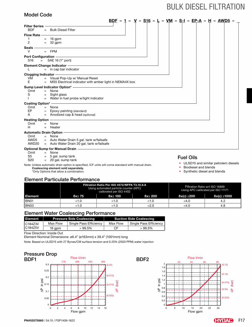
F17
BULK DIESEL FILTRATION
PN#02075860 / 04.15 / FSP1406-1622
Pressure Drop BDF1 BDF2
Element Particulate Performance
Element
Filtration Ratio Per ISO 4572/NFPA T3.10.8.8 Using automated particle counter (APC)
calibrated per ISO 4402
Filtration Ratio wrt ISO 16889Using APC calibrated per ISO 11171
ßx≥ 75 ßx≥ 100 ßx≥ 200 ßx(c) ≥200 ßx(c) ≥1000BN01 <1.0 <1.0 <1.0 <4.0 4.2BN03 <1.0 <1.0 <2.0 <4.0 4.8
Element Water Coalescing PerformanceElement Pressure Side Coalescing Suction Side Coalescing
C184Z3V C184Z5V
Max Flow Single Pass Efficiency Max Flow Single Pass Efficiency16 gpm > 99.5% CF > 99.5%
Flow Direction: Inside Out Element Nominal Dimensions: ø6.4” (ø163mm) x 39.4” (1001mm) longNote: Based on ULSD15 with 27 Bynes/CM surface tension and 0.25% (2500 PPM) water injection
Model CodeBDF – 1 – V – S16 – L – VM – S-I – EP-A – H – AWD5 – .
Filter Series BDF = Bulk Diesel Filter
Flow Rate 1 = 16 gpm 2 = 32 gpm
Seals V = FPM
Port Configuration S16 = SAE 16 (1” port)
Element Change Indicator L = in cap bar indicator
Clogging Indicator VM = Visual Pop-Up w/ Manual Reset E = MS5 Electrical indicator with amber light in NEMA4X box
Sump Level Indicator Option* Omit = None S = Sight glass I = Water in fuel probe w/light indicator
Coating Option* Omit = None EP = Epoxy painting (standard) A = Anodized cap & head (optional)
Heating Option Omit = None H = Heater
Automatic Drain Option Omit = None AWD5 = Auto Water Drain 5 gal. tank w/failsafe AWD20 = Auto Water Drain 20 gal. tank w/failsafe
Optional Sump for Manual Drain Omit = None S5 = 5 gal. sump tank S20 = 20 gal. sump tankNote: Unless automatic drain option is specified, ICF units will come standard with manual drain.
Coalescing element sold separately. *Only Options that allow a combination.
Fuel Oils• ULSD15 and similar petrolem diesels• Biodiesel and blends• Synthetic diesel and blends
0.3
0.25
0.2
0.15
0.1
0.05
00 2 4 6 8 10 12 14 16
(15) (30) (45) (60)(0.02)
(0.015)
(0.010)
(0.005)
∆P i
n p
si
Flow gpm
Flow l/min
∆P (
bar
)
∆P i
n p
si
Flow gpm
Flow l/min
∆P (
bar
)
2
1.8
1.6
1.4
1.2
1
0.8
0.6
0.4
0.2
00 5 10 15 20 25 30
(2) (4) (6) (8)(0.15)
(0.10)
(0.075)
(0.05)
(0.025)
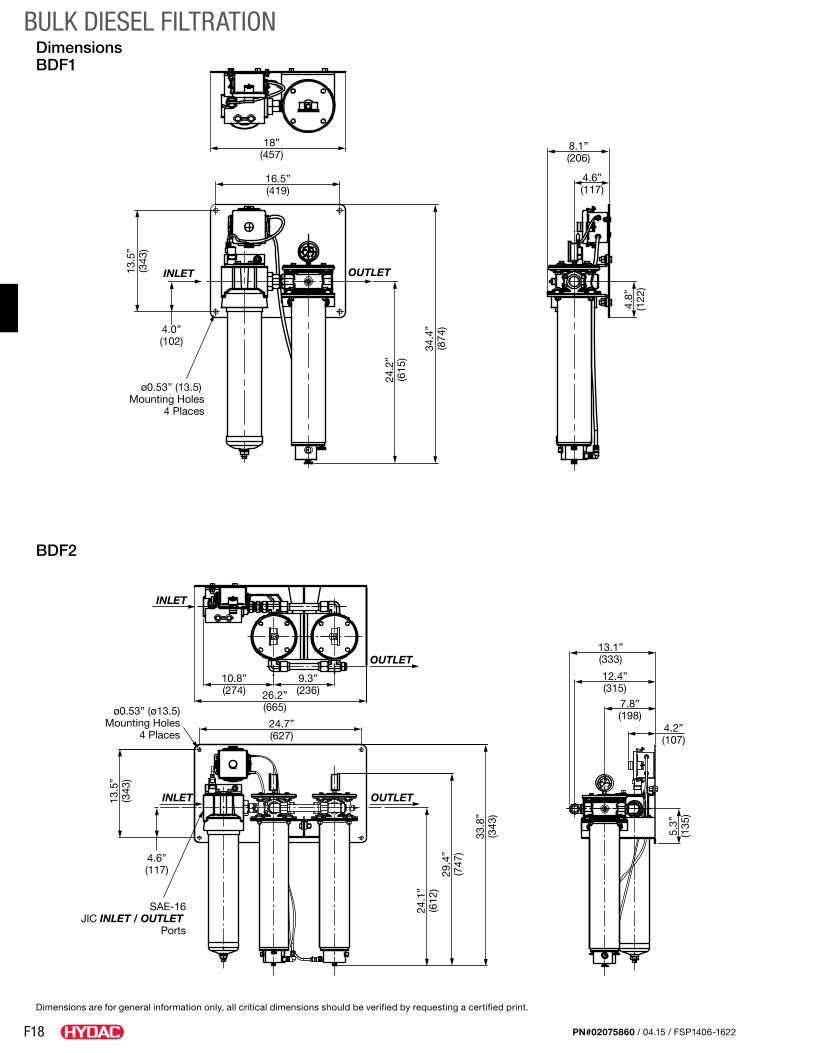
F18
BULK DIESEL FILTRATION
PN#02075860 / 04.15 / FSP1406-1622
Dimensions BDF1
BDF2
Dimensions are for general information only, all critical dimensions should be verified by requesting a certified print.
16.5”(419)
INLET OUTLET
4.0”(102)
ø0.53” (13.5) Mounting Holes
4 Places
4.6”(117)
8.1”(206)
13.5
”(3
43)
34.4
”(8
74)
4.8”
(122
)
24.2
”(6
15)
18”(457)
INLET
OUTLET
OUTLET
INLET
10.8”(274)
9.3”(236)26.2”
(665)
24.7”(627)
13.1”(333)
12.4”(315)
7.8”(198)
4.2”(107)
4.6”(117)
ø0.53” (ø13.5)Mounting Holes
4 Places
SAE-16JIC INLET / OUTLET
Ports
13.5
”(3
43)
24.1
”(6
12)
29.4
”(7
47)
33.8
”(3
43)
5.3”
(135
)

F19
BULK DIESEL FILTRATION
PN#02075860 / 04.15 / FSP1406-1622
Notes
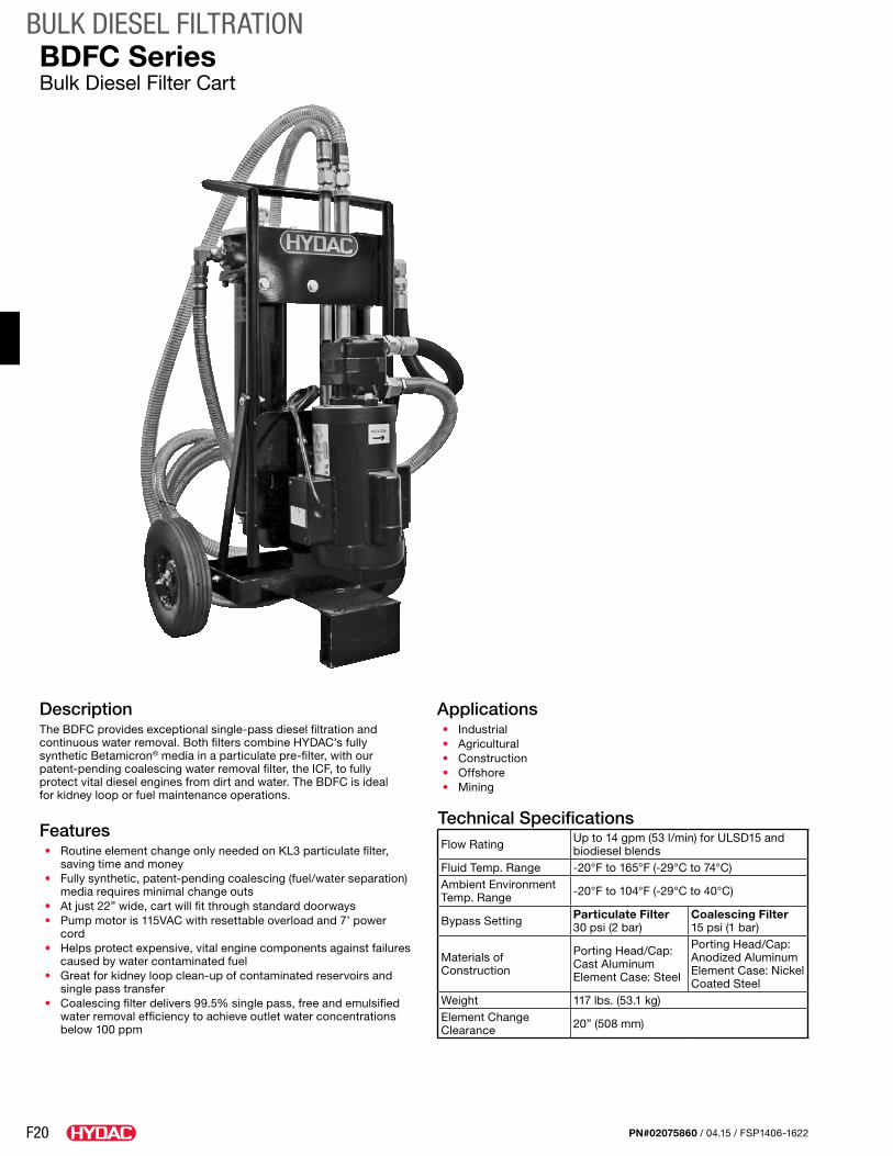
F20
BULK DIESEL FILTRATION
PN#02075860 / 04.15 / FSP1406-1622
DescriptionThe BDFC provides exceptional single-pass diesel filtration and continuous water removal. Both filters combine HYDAC’s fully synthetic Betamicron® media in a particulate pre-filter, with our patent-pending coalescing water removal filter, the ICF, to fully protect vital diesel engines from dirt and water. The BDFC is ideal for kidney loop or fuel maintenance operations.
Features• Routine element change only needed on KL3 particulate filter,
saving time and money • Fully synthetic, patent-pending coalescing (fuel/water separation)
media requires minimal change outs• At just 22” wide, cart will fit through standard doorways• Pump motor is 115VAC with resettable overload and 7’ power
cord• Helps protect expensive, vital engine components against failures
caused by water contaminated fuel• Great for kidney loop clean-up of contaminated reservoirs and
single pass transfer• Coalescing filter delivers 99.5% single pass, free and emulsified
water removal efficiency to achieve outlet water concentrations below 100 ppm
BDFC SeriesBulk Diesel Filter Cart
Applications• Industrial• Agricultural• Construction• Offshore• Mining
Technical SpecificationsFlow Rating Up to 14 gpm (53 l/min) for ULSD15 and
biodiesel blendsFluid Temp. Range -20°F to 165°F (-29°C to 74°C)Ambient Environment Temp. Range -20°F to 104°F (-29°C to 40°C)
Bypass Setting Particulate Filter 30 psi (2 bar)
Coalescing Filter 15 psi (1 bar)
Materials of Construction
Porting Head/Cap: Cast AluminumElement Case: Steel
Porting Head/Cap: Anodized AluminumElement Case: Nickel Coated Steel
Weight 117 lbs. (53.1 kg)Element Change Clearance 20” (508 mm)
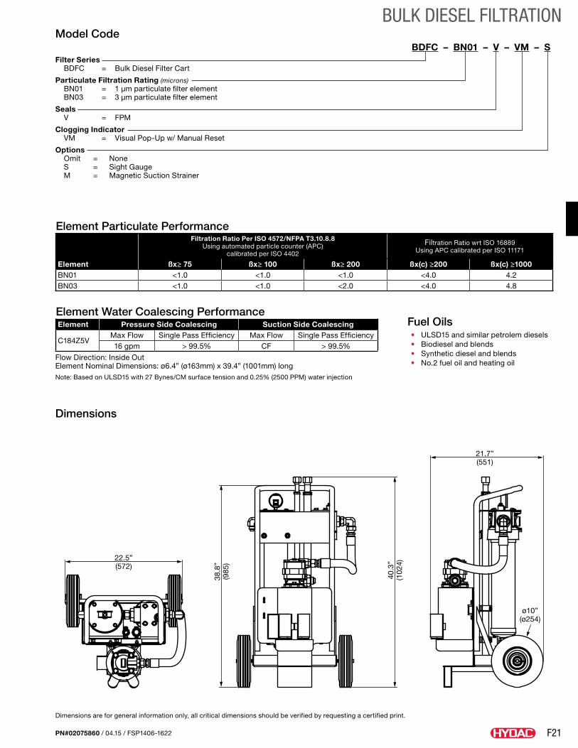
F21
BULK DIESEL FILTRATION
PN#02075860 / 04.15 / FSP1406-1622
Dimensions
Dimensions are for general information only, all critical dimensions should be verified by requesting a certified print.
Fuel Oils• ULSD15 and similar petrolem diesels• Biodiesel and blends• Synthetic diesel and blends• No.2 fuel oil and heating oil
Model CodeBDFC – BN01 – V – VM – S.
Filter Series BDFC = Bulk Diesel Filter Cart
Particulate Filtration Rating (microns) BN01 = 1 µm particulate filter element BN03 = 3 µm particulate filter element
Seals V = FPM
Clogging Indicator VM = Visual Pop-Up w/ Manual Reset
Options Omit = None S = Sight Gauge M = Magnetic Suction Strainer
22.5”(572)
38.8
”(9
85)
40.3
”(1
024)
ø10”(ø254)
21.7”(551)
Element Particulate Performance
Element
Filtration Ratio Per ISO 4572/NFPA T3.10.8.8 Using automated particle counter (APC)
calibrated per ISO 4402
Filtration Ratio wrt ISO 16889Using APC calibrated per ISO 11171
ßx≥ 75 ßx≥ 100 ßx≥ 200 ßx(c) ≥200 ßx(c) ≥1000BN01 <1.0 <1.0 <1.0 <4.0 4.2BN03 <1.0 <1.0 <2.0 <4.0 4.8
Element Water Coalescing PerformanceElement Pressure Side Coalescing Suction Side Coalescing
C184Z5VMax Flow Single Pass Efficiency Max Flow Single Pass Efficiency16 gpm > 99.5% CF > 99.5%
Flow Direction: Inside Out Element Nominal Dimensions: ø6.4” (ø163mm) x 39.4” (1001mm) longNote: Based on ULSD15 with 27 Bynes/CM surface tension and 0.25% (2500 PPM) water injection
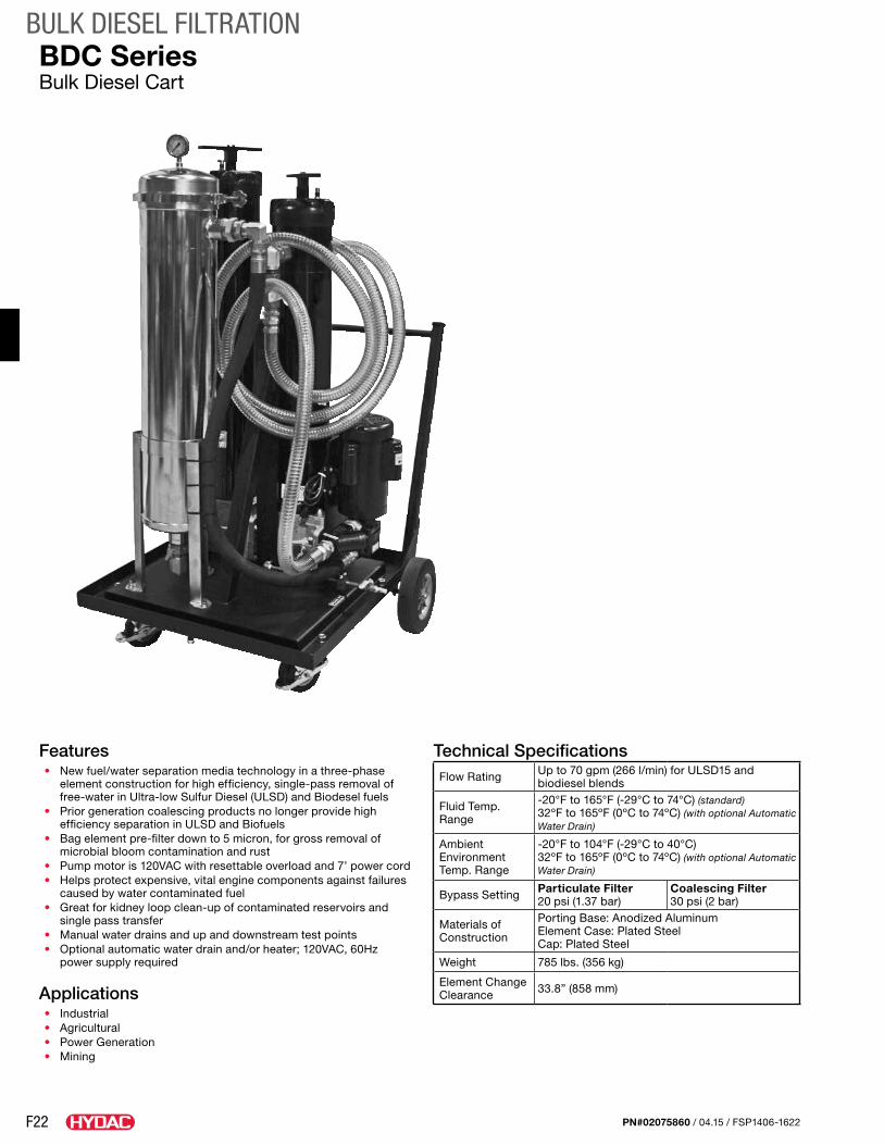
F22
BULK DIESEL FILTRATION
PN#02075860 / 04.15 / FSP1406-1622
Features• New fuel/water separation media technology in a three-phase
element construction for high efficiency, single-pass removal of free-water in Ultra-low Sulfur Diesel (ULSD) and Biodesel fuels
• Prior generation coalescing products no longer provide high efficiency separation in ULSD and Biofuels
• Bag element pre-filter down to 5 micron, for gross removal of microbial bloom contamination and rust
• Pump motor is 120VAC with resettable overload and 7’ power cord• Helps protect expensive, vital engine components against failures
caused by water contaminated fuel• Great for kidney loop clean-up of contaminated reservoirs and
single pass transfer• Manual water drains and up and downstream test points• Optional automatic water drain and/or heater; 120VAC, 60Hz
power supply required
Applications• Industrial• Agricultural• Power Generation• Mining
Technical SpecificationsFlow Rating Up to 70 gpm (266 l/min) for ULSD15 and
biodiesel blends
Fluid Temp. Range
-20°F to 165°F (-29°C to 74°C) (standard)32ºF to 165ºF (0ºC to 74ºC) (with optional Automatic Water Drain)
Ambient Environment Temp. Range
-20°F to 104°F (-29°C to 40°C)32ºF to 165ºF (0ºC to 74ºC) (with optional Automatic Water Drain)
Bypass Setting Particulate Filter 20 psi (1.37 bar)
Coalescing Filter 30 psi (2 bar)
Materials of Construction
Porting Base: Anodized AluminumElement Case: Plated Steel Cap: Plated Steel
Weight 785 lbs. (356 kg)
Element Change Clearance 33.8” (858 mm)
BDC SeriesBulk Diesel Cart
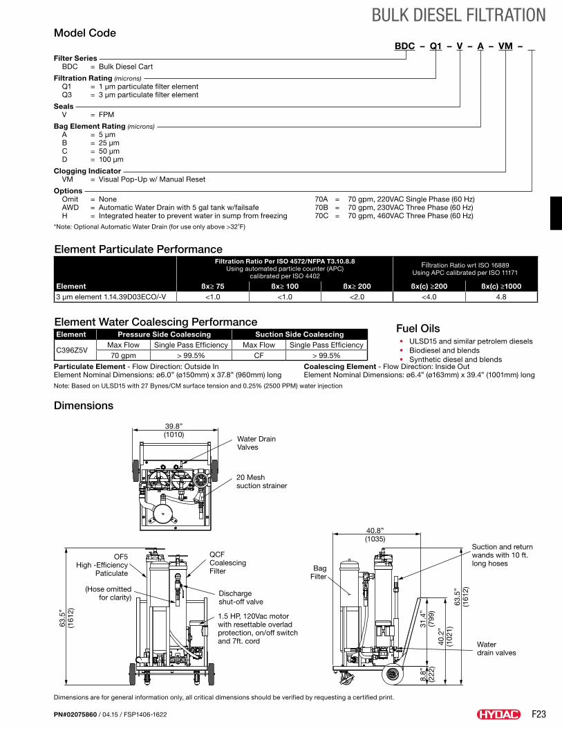
F23
BULK DIESEL FILTRATION
PN#02075860 / 04.15 / FSP1406-1622
Dimensions
Dimensions are for general information only, all critical dimensions should be verified by requesting a certified print.
39.8”(1010)
Water Drain Valves
20 Meshsuction strainer
OF5High -Efficiency
Paticulate
(Hose omittedfor clarity)
QCFCoalescingFilter Bag
Filter
Dischargeshut-off valve
1.5 HP, 120Vac motorwith resettable overladprotection, on/off switchand 7ft. cord
63.5
”(1
612)
40.8”(1035)
Suction and returnwands with 10 ft.long hoses
Water drain valves
63.5
”(1
612)
40.2
”(1
021)
31.4
”(7
99)
8.8”
(222
)
Fuel Oils• ULSD15 and similar petrolem diesels• Biodiesel and blends• Synthetic diesel and blends
Model CodeBDC – Q1 – V – A – VM – .
Filter Series BDC = Bulk Diesel Cart
Filtration Rating (microns) Q1 = 1 µm particulate filter element Q3 = 3 µm particulate filter element
Seals V = FPM
Bag Element Rating (microns) A = 5 µm B = 25 µm C = 50 µm D = 100 µm
Clogging Indicator VM = Visual Pop-Up w/ Manual Reset
Options Omit = None 70A = 70 gpm, 220VAC Single Phase (60 Hz) AWD = Automatic Water Drain with 5 gal tank w/failsafe 70B = 70 gpm, 230VAC Three Phase (60 Hz) H = Integrated heater to prevent water in sump from freezing 70C = 70 gpm, 460VAC Three Phase (60 Hz)*Note: Optional Automatic Water Drain (for use only above >32˚F)
Element Particulate Performance
Element
Filtration Ratio Per ISO 4572/NFPA T3.10.8.8 Using automated particle counter (APC)
calibrated per ISO 4402
Filtration Ratio wrt ISO 16889Using APC calibrated per ISO 11171
ßx≥ 75 ßx≥ 100 ßx≥ 200 ßx(c) ≥200 ßx(c) ≥10003 µm element 1.14.39D03ECO/-V <1.0 <1.0 <2.0 <4.0 4.8
Element Water Coalescing PerformanceElement Pressure Side Coalescing Suction Side Coalescing
C396Z5VMax Flow Single Pass Efficiency Max Flow Single Pass Efficiency70 gpm > 99.5% CF > 99.5%
Particulate Element - Flow Direction: Outside In Coalescing Element - Flow Direction: Inside Out Element Nominal Dimensions: ø6.0” (ø150mm) x 37.8” (960mm) long Element Nominal Dimensions: ø6.4” (ø163mm) x 39.4” (1001mm) longNote: Based on ULSD15 with 27 Bynes/CM surface tension and 0.25% (2500 PPM) water injection
F24
BULK DIESEL FILTRATION
PN#02075860 / 04.15 / FSP1406-1622
Notes
G1
REFERENCE MATERIAL
PN#02075860 / 04.15 / FSP1406-1622
Reference MaterialA quick reference of information and conversion charts to help guide you through this catalog.
Reference Materials
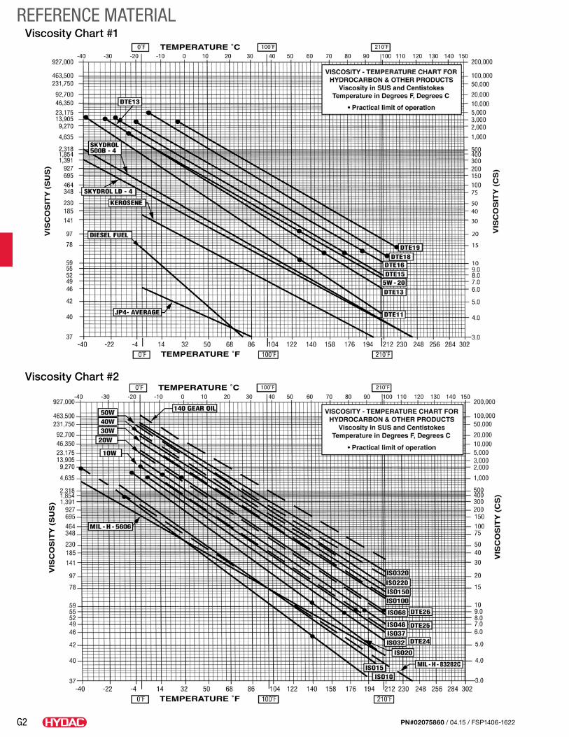
G2
REFERENCE MATERIAL
PN#02075860 / 04.15 / FSP1406-1622
Viscosity Chart #1
Viscosity Chart #2
PN#02075860 / 04.15 / FSP1406-1622
Overview BrochurePN02088157
Accessories CatalogPN02080105
Process Technology* Catalog (online only)
Various market and product brochures are also available for ordering.
Filters CatalogPN02081318
Standard Coolers Catalog - PN02085359
Mobile Valves CatalogPN02092408
Accumulators CatalogPN02068195
Filter Systems CatalogPN02075860
Hydraulic Cylinders Catalog (Release: TBD)
Compact Hydraulics Catalog - PN02087369
Electronics Catalog*(online only)
Control Technology* Catalog (online only)
HYDAC TECHNOLOGY CORPORATION HYDAC CORPORATION
2260 City Line Road Bethlehem, PA 18017
+1.610.266.0100
[email protected] www.hydacusa.com
*These catalogs are digital file versions only.
HYDAC literature is available for ordering via our website, www.hydacusa.com then click on the Downloads button to proceed with ordering printed copies *(digitial versons excluded) or email us at [email protected] using the appropriate Part Number (PN) and name. Other brochures, manuals and technical documents are also available when ordering from our website.
Global HeadquartersHYDAC INTERNATIONAL
GMBH
IndustriegebietD – 66280 Sulzbach/Saar
Germany
Tel.: +49 6897 509-01
Fax: +49 6897 509-577
Internet: www.hydac.comEmail: [email protected]
North America Locations USA www.HYDACusa.com
HYDAC TECHNOLOGY CORPORATION Filter Division2260 City Line Road Bethlehem, PA 18017+1.610.266.0100
HYDAC TECHNOLOGY CORPORATION Cooling System Division1051 Airlie Parkway Denver, NC 28037+1.610.266.0100
HYDAC TECHNOLOGY CORPORATION Accessory Division2204 Avenue C Bethlehem, PA 18017+1.610.266.0100
HYDAC TECHNOLOGY CORPORATION Cooling System Division - Industrial Office445 Windy Point Drive Glendale Heights, IL 60139+1.630.545.0800
HYDAC TECHNOLOGY CORPORATION Electronic Division Process Filter DivisionHYDAC CORPORATION Accumulator Division90 Southland Drive Bethlehem, PA 18017+1.610.266.0100
HYDAC TECHNOLOGY CORPORATION HYDAC CORPORATION Sales Office & Operations1718 Fry Road, Suite 100 Houston, TX 77084+1.281.579.8100
HYDAC TECHNOLOGY CORPORATION Filter System Division Process Filter Division580 West Park Road Leetsdale, PA 15056+1.724.318.1100
HYDAC TECHNOLOGY CORPORATION HYDAC CORPORATION NE Sales Office1660 Enterprise Parkway • Suite E Wooster, OH 44691+1.610.266.0100
HYDAC TECHNOLOGY CORPORATION Hydraulic Division - Compact Hydraulics450 Windy Point Drive Glendale Heights, IL 60139+1.630.545.0800
HYDAC TECHNOLOGY CORPORATION HYDAC CORPORATION SE Sales Office1051 Airlie Parkway Denver, NC 28037+1.610.266.0100
HYDAC TECHNOLOGY CORPORATION Mobile Hydraulic Division1660 Enterprise Parkway • Suite E Wooster, OH 44691+1.610.266.0100
HYDAC TECHNOLOGY CORPORATION HYDAC CORPORATION NW Sales Office1201 NE 144th St. Bldg. B, Suite 111 Vancouver, WA 98685+1.610.266.0100
HYDAC CYLINDERS LLC540 Carson Road North Birmingham, AL 35217+1.205.520.1220
Canada www.HYDAC.caHYDAC CORPORATION14 Federal Road Welland, Ontario, Canada L3B 3P2 +1.905.714.9322
HYDAC CORPORATION Sales Office101 - 18207 114 AVE W Edmonton, Alberta, Canada T5S 2P6+1.780.484.4228
HYDAC CORPORATION Sales OfficeMontreal, Québec, Canada J2M 1K9+1.877.539.3388
Mexico www.HYDACmex.comHYDAC INTERNATIONAL SA de CVCalle Alfredo A Nobel No 35 Col Puente de Vigas Tlalnepantla, Edo Mexico CP 54090 Mexico+011.52.55.4777.1262
PN#02075860 / 04.15 / FSP1406-1622© Copyright 2015 HYDAC TECHNOLOGY CORPORATION • Filter Systems Catalog