Embed Size (px)
Citation preview
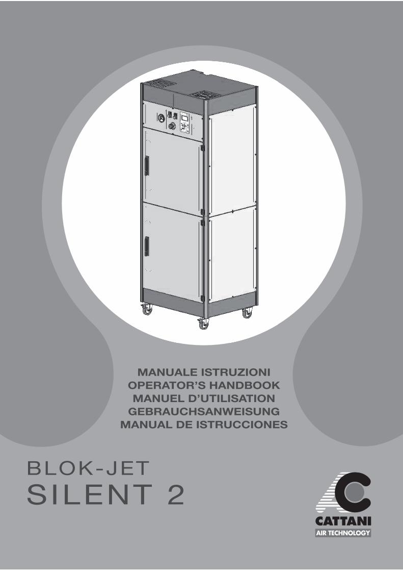
MANUALE ISTRUZIONI
OPERATOR’S HANDBOOK
MANUEL D’UTILISATION
GEBRAUCHSANWEISUNG
MANUAL DE ISTRUCCIONES
BLOK-JET
SILENT 2
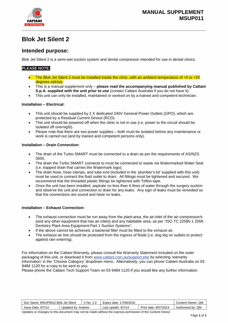
MANUAL SUPPLEMENT MSUP011
Doc Name: MSUP0012 Blok Jet Silent V.No: 1.0 Expiry date: 17/06/2016 Content Owner: QM
Issue Date: 9/7/14 Updated by: Andrew Last update: 9/7/14 Print date: 9/07/2014 Authorised by: QM
Updates or changes to this document may not be made without the express permission of the Content Owner. Page 1 of 1
Blok Jet Silent 2 Intended purpose: Blok Jet Silent 2 is a semi-wet suction system and dental compressor intended for use in dental clinics. PLEASE NOTE:
• The Blok Jet Silent 2 must be installed inside the clinic, with an ambient temperature of +5 to +25 degrees celcius.
• This is a manual supplement only – please read the accompanying manual published by Cattani S.p.A. supplied with the unit prior to use (contact Cattani Australia if you do not have it).
• This unit can only be installed, maintained or worked on by a trained and competent technician. Installation – Electrical:
• This unit should be supplied by 2 X dedicated 240V General Power Outlets (GPO), which are protected by a Residual Current Device (RCD).
• This unit should be powered off when the clinic is not in use (i.e. power to the circuit should be isolated off overnight).
• Please note that there are two power supplies – both must be isolated before any maintenance or work is carried out (and by trained and competent persons only).
Installation – Drain Connection:
• The drain of the Turbo SMART must be connected to a drain as per the requirements of AS/NZS 3500.
• The drain the Turbo SMART connects to must be connected to waste via Watermarked Water Seal (i.e. trapped drain that carries the Watermark logo).
• The drain hose, hose clamps, and tube end (included in the ‘plumber’s kit’ supplied with this unit) must be used to connect the fluid outlet to drain. All fittings must be tightened and secured. We recommend that the threaded plastic fittings be tightened with Teflon tape.
• Once the unit has been installed, aspirate no less than 6 litres of water through the surgery suction and observe the unit and connection to drain for any leaks. Any sign of leaks must be remedied so that the connections are sound and have no leaks.
Installation – Exhaust Connection:
• The exhaust connection must be run away from the plant-area, the air-inlet of the air-compressor/s (and any other equipment that has air inlets) and any habitable area, as per “ISO TC 22595-1 2006 Dentistry Plant Area Equipment Part 1 Suction Systems”.
• If the above cannot be achieved, a bacterial filter must be fitted to the exhaust air. • The exhaust air line should be protected from the ingress of fluids (i.e. dog leg on outlets to protect
against rain entering). For information on the Cattani Warranty, please consult the Warranty Statement included on the outer packaging of this unit, or download it from www.cattani.com.au/support.php by selecting ‘warranty information’ in the ‘Choose Category’ dropdown menu. Alternatively, you can phone Cattani Australia on 03 9484 1120 for a copy to be sent to you. Please phone the Cattani Tech Support Team on 03 9484 1120 if you would like any further information.
EN
GL
ISH
25
Contents
BLOK-JET
SILENT 2
General running data .............................................................................................................26
Warning symbols....................................................................................................................27
Assembly and commissioning ...............................................................................................28
How compressor works..........................................................................................................32
How aspirator works......r........................................................................................................33
Compressor ordinary maintenance.........................................................................................34
Compressor extraordinary maintenance.................................................................................35
Ordinary maintenance.............................................................................................................36
Extraordinary maintenance.....................................................................................................37
Instructions on adjusting and modifying certain parameters in the Turbo SMART menu......38
Alarm descriptions..................................................................................................................45
Important warnings.................................................................................................................46
Transport and storage.............................................................................................................46
Transport of used appliances.................................................................................................46
FGFGHFH FYIASFYASYFUI DGFGASFHGA
Alternating current IEC 417-532
Earthing IEC 417-532
Degree of protection against electric shock IEC 417-532-1
Open (disconnected from the main electrical supply) IEC 417-532
Open (connected to the main electrical supply) IEC 417-532
Ecte faciduis augiamcommod elis num veros dolobore dolendrem nos dionulla autpat blan volut vel dunt ad tet, commod esed tionse tet, consequis adit dolore euip essi.Si tis num dolore feugait praesequi bla cortisi eratism odolortie vendre magnUd dolorerostie.
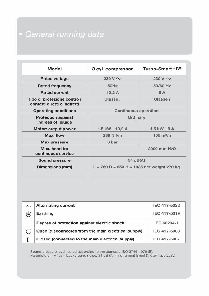
• General running data
Alternating current IEC 417-5032
Earthing IEC 417-5019
Degree of protection against electric shock IEC 60204-1
Open (disconnected from the main electrical supply) IEC 417-5008
Closed (connected to the main electrical supply) IEC 417-5007
Sound pressure level tested according to the standard ISO 3746-1979 (E).Parameters: r = 1,5 – background noise: 34 dB (A) – instrument Bruel & Kjær type 2232
Model 3 cyl. compressor Turbo-Smart “B”
Rated voltage 230 V 230 V
Rated frequency 50Hz 50/60 Hz
Rated current 10.2 A 9 A
Tipo di protezione contro i
contatti diretti e indiretti
Classe I Classe I
Operating conditions Continuous operation
Protection against
ingress of liquids
Ordinary
Motor: output power 1.5 kW - 10,2 A 1.5 kW - 9 A
Max. fl ow 238 N l/m 105 m³/h
Max pressure 8 bar
Max. head for
continuous service
2000 mm H2O
Sound pressure 54 dB(A)
Dimensions (mm) L = 760 D = 650 H = 1935 net weight 270 kg
EN
GL
ISH
27
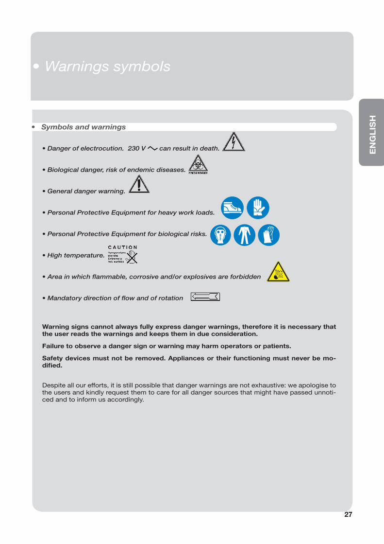
• Danger of electrocution. 230 V can result in death.
• Biological danger, risk of endemic diseases.
• General danger warning.
• Personal Protective Equipment for heavy work loads.
• Personal Protective Equipment for biological risks.
• High temperature.
• Area in which fl ammable, corrosive and/or explosives are forbidden
• Mandatory direction of fl ow and of rotation
• Symbols and warnings
Warning signs cannot always fully express danger warnings, therefore it is necessary that the user reads the warnings and keeps them in due consideration.
Failure to observe a danger sign or warning may harm operators or patients.
Safety devices must not be removed. Appliances or their functioning must never be mo-difi ed.
Despite all our efforts, it is still possible that danger warnings are not exhaustive: we apologise to the users and kindly request them to care for all danger sources that might have passed unnoti-ced and to inform us accordingly.
• Segnali ed avvisi
• Warnings symbols
28
• Montaggio e messa in funzione
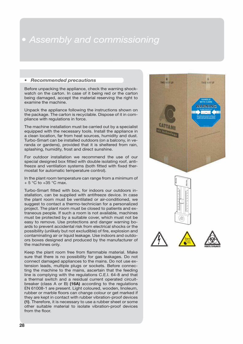
• Recommended precautions
Minim
a
Maxim
a
30
20
10
0
10
20
30
40
50
50
40
30
20
10
0
10
20
30
Before unpacking the appliance, check the warning shock-watch on the carton. In case of it being red or the carton being damaged, accept the material reserving the right to examine the machine.
Unpack the appliance following the instructions shown on the package. The carton is recyclable. Dispose of it in com-pliance with regulations in force.
The machine installation must be carried out by a specialist equipped with the necessary tools. Install the appliance in a clean location, far from heat sources, humidity and dust.Turbo-Smart can be installed outdoors (on a balcony, in ve-randa or gardens), provided that it is sheltered from rain, splashing, humidity, frost and direct sunshine.
For outdoor installation we recommend the use of our special designed box fi tted with double isolating roof, anti-freeze and ventilation systems (both fi tted with fi xed ther-mostat for automatic temperature control).
In the plant room temperature can range from a minimum of + 5 °C to +35 °C max.
Turbo-Smart fi tted with box, for indoors our outdoors in-stallation, can be supplied with antifreeze device. In case the plant room must be ventilated or air-conditioned, we suggest to contact a thermo-technician for a personalized project. The plant room must be closed to patients and ex-traneous people. If such a room is not available, machines must be protected by a suitable cover, which must not be easy to remove. Use protections and danger warning bo-ards to prevent accidental risk from electrical shocks or the possibility (unlikely but not excludible) of fi re, explosion and contaminating air or liquid leakage. Use indoors and outdo-ors boxes designed and produced by the manufacturer of the machines only.
Keep the plant room free from fl ammable material. Make sure that there is no possibility for gas leakages. Do not connect damaged appliances to the mains. Do not use ex-tension leads, multiple plugs or sockets. Before connec-ting the machine to the mains, ascertain that the feeding line is complying with the regulations C.E.I. 64-8 and that a thermal switch and a residual current operated circuit-breaker (class A or B) (16A) according to the regulations EN 61008-1 are present. Light coloured, wooden, linoleum, rubber or marble fl oors can change colour or get marked if they are kept in contact with rubber vibration-proof devices (1). Therefore, it is necessary to use a rubber sheet or some other suitable material to isolate vibration-proof devices from the fl oor.
HANDLEWITH CARE
WARNINGWARNINGSHOCKWATCH
R
RED INDICATES ROUGH HANDLINGIF RED, NOTE ON BILL OF LADINGINSPECTION MAY BE WARRANTED
MODEL L-55 (37g)
TOLL
FREE 1
-800
-527
-949
7
www.shockwatch.com
• Assembly and commissioning
EN
GL
ISH
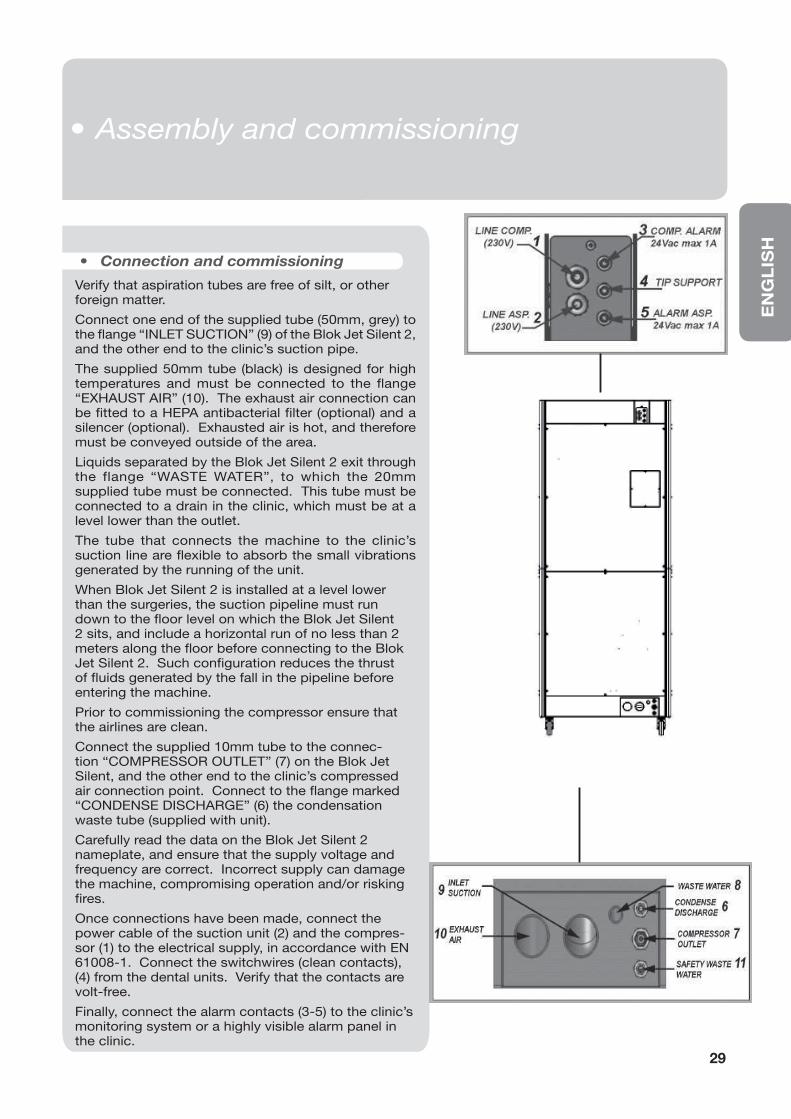
• Connection and commissioning
Verify that aspiration tubes are free of silt, or other foreign matter.
Connect one end of the supplied tube (50mm, grey) to the fl ange “INLET SUCTION” (9) of the Blok Jet Silent 2, and the other end to the clinic’s suction pipe.
The supplied 50mm tube (black) is designed for high temperatures and must be connected to the fl ange “EXHAUST AIR” (10). The exhaust air connection can be fi tted to a HEPA antibacterial fi lter (optional) and a silencer (optional). Exhausted air is hot, and therefore must be conveyed outside of the area.
Liquids separated by the Blok Jet Silent 2 exit through the flange “WASTE WATER”, to which the 20mm supplied tube must be connected. This tube must be connected to a drain in the clinic, which must be at a level lower than the outlet.
The tube that connects the machine to the clinic’s suction line are fl exible to absorb the small vibrations generated by the running of the unit.
When Blok Jet Silent 2 is installed at a level lower than the surgeries, the suction pipeline must run down to the fl oor level on which the Blok Jet Silent 2 sits, and include a horizontal run of no less than 2 meters along the fl oor before connecting to the Blok Jet Silent 2. Such confi guration reduces the thrust of fl uids generated by the fall in the pipeline before entering the machine.
Prior to commissioning the compressor ensure that the airlines are clean.
Connect the supplied 10mm tube to the connec-tion “COMPRESSOR OUTLET” (7) on the Blok Jet Silent, and the other end to the clinic’s compressed air connection point. Connect to the fl ange marked “CONDENSE DISCHARGE” (6) the condensation waste tube (supplied with unit).
Carefully read the data on the Blok Jet Silent 2 nameplate, and ensure that the supply voltage and frequency are correct. Incorrect supply can damage the machine, compromising operation and/or risking fi res.
Once connections have been made, connect the power cable of the suction unit (2) and the compres-sor (1) to the electrical supply, in accordance with EN 61008-1. Connect the switchwires (clean contacts), (4) from the dental units. Verify that the contacts are volt-free.
Finally, connect the alarm contacts (3-5) to the clinic’s monitoring system or a highly visible alarm panel in the clinic.
29
• Montaggio e messa in funzione• Assembly and commissioning
30
• Recommended Precautions
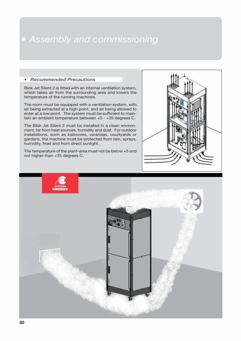
Blok Jet Silent 2 is fi tted with an internal ventilation system, which takes air from the surrounding area and lowers the temperature of the running machines.
The room must be equipped with a ventilation system, with air being extracted at a high point, and air being allowed to enter at a low point. The system must be suffi cient to main-tain an ambient temperature between +5 - +35 degrees C.
The Blok Jet Silent 2 must be installed in a clean environ-ment, far from heat sources, humidity and dust. For outdoor installations, such as balconies, verandas, courtyards or gardens, the machine must be protected from rain, sprays, humidity, frost and from direct sunlight.
The temperature of the plant-area must not be below +5 and not higher than +35 degrees C.
• Assembly and commissioning
EN
GL
ISH
31
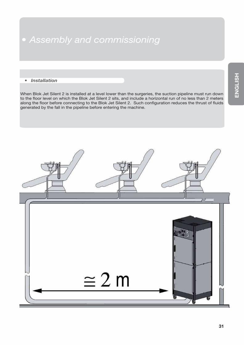
When Blok Jet Silent 2 is installed at a level lower than the surgeries, the suction pipeline must run down to the fl oor level on which the Blok Jet Silent 2 sits, and include a horizontal run of no less than 2 meters along the fl oor before connecting to the Blok Jet Silent 2. Such confi guration reduces the thrust of fl uids generated by the fall in the pipeline before entering the machine.
• Installation
• Montaggio e messa in funzione• Assembly and commissioning
Commissioning, testing and instruction to clinic staff.
Compressor Operation
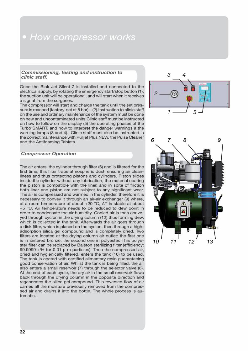
Once the Blok Jet Silent 2 is installed and connected to the electrical supply, by rotating the emergency start/stop button (1), the suction unit will be operational, and will start when it receives a signal from the surgeries.The compressor will start and charge the tank until the set pres-sure is reached (factory-set at 8 bar) – (2).Instruction to clinic staff on the use and ordinary maintenance of the system must be done on new and uncontaminated units.Clinic staff must be instructed on how to follow on the display (5) the operating phases of the Turbo SMART, and how to interpret the danger warnings a the warning lamps (3 and 4). Clinic staff must also be instructed in the correct maintenance with Pulijet Plus NEW, the Pulse Cleaner and the Antifoaming Tablets.
The air enters the cylinder through fi lter (6) and is fi ltered for the fi rst time; this fi lter traps atmospheric dust, ensuring air clean-liness and thus protecting pistons and cylinders. Piston slides inside the cylinder without any lubrication; the material coating the piston is compatible with the liner, and in spite of friction both liner and piston are not subject to any signifi cant wear. The air is compressed and warmed in the cylinder, therefore it is necessary to convey it through an air-air exchanger (9) where, at a room temperature of about +20 °C, ΔT is stable at about +5 °C. Air temperature needs to be reduced to dew point in order to condensate the air humidity. Cooled air is then conve-yed through cyclon in the drying column (12) thus forming dew, which is collected in the tank. Afterwards the air goes through a disk fi lter, which is placed on the cyclon, then through a high-adsorption silica gel compound and is completely dried. Two fi lters are located at the drying column air outlet: the fi rst one is in sintered bronze, the second one in polyester. This polye-ster fi lter can be replaced by Balston sterilizing fi lter (effi ciency: 99.9999 +% for 0.01 μ m particles). Then the compressed air, dried and hygienically fi ltered, enters the tank (10) to be used. The tank is coated with certifi ed alimentary resin guaranteeing good conservation of air. Whilst the tank is being fi lled, the air also enters a small reservoir (7) through the selector valve (8). At the end of each cycle, the dry air in the small reservoir fl ows back through the drying column in the opposite direction and regenerates the silica gel compound. This reversed fl ow of air carries all the moisture previously removed from the compres-sed air and drains it into the bottle. The whole process is au-tomatic.
1
3 4
2
5
10
6 7 8 9
11 12 13
• Funzionamento compressore
32
• How compressor works
EN
GL
ISH
33
B A
C
11
9
10
2
6
4
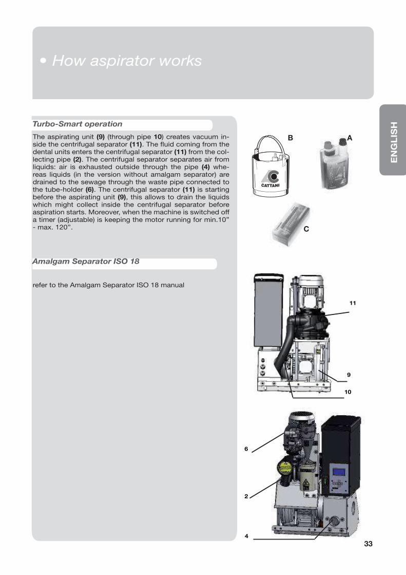
Turbo-Smart operation
The aspirating unit (9) (through pipe 10) creates vacuum in-side the centrifugal separator (11). The fl uid coming from the dental units enters the centrifugal separator (11) from the col-lecting pipe (2). The centrifugal separator separates air from liquids: air is exhausted outside through the pipe (4) whe-reas liquids (in the version without amalgam separator) are drained to the sewage through the waste pipe connected to the tube-holder (6). The centrifugal separator (11) is starting before the aspirating unit (9), this allows to drain the liquids which might collect inside the centrifugal separator before aspiration starts. Moreover, when the machine is switched off a timer (adjustable) is keeping the motor running for min.10’’ - max. 120’’.
refer to the Amalgam Separator ISO 18 manual
Amalgam Separator ISO 18
• Funzionamento aspiratore• How aspirator works
34
• Manutenzione ordinaria compressore
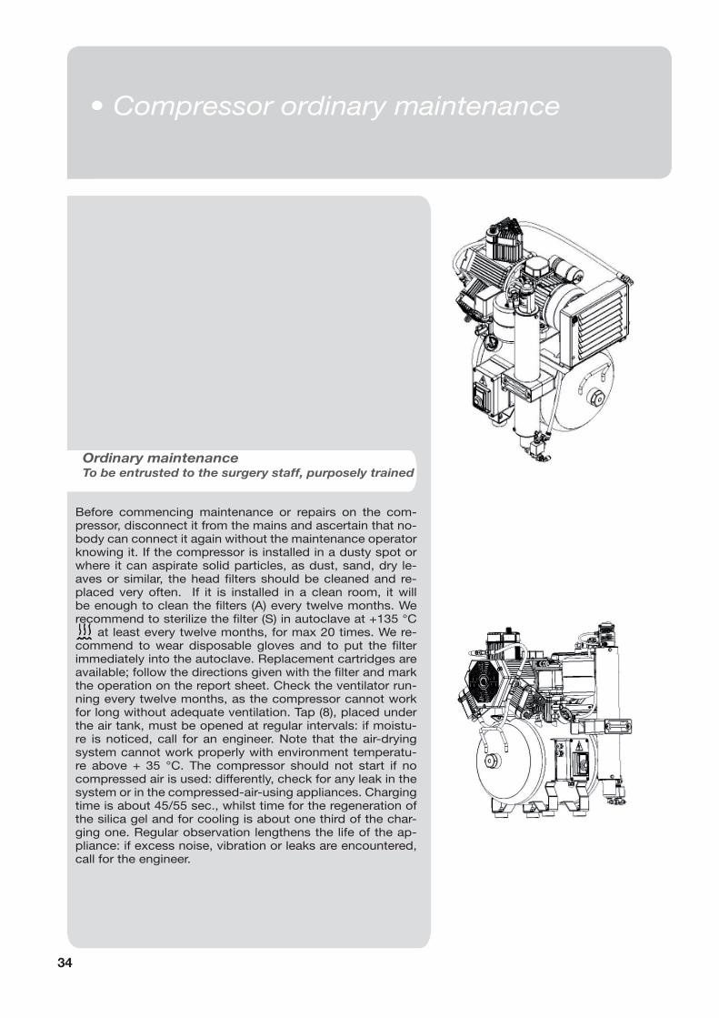
Before commencing maintenance or repairs on the com-pressor, disconnect it from the mains and ascertain that no-body can connect it again without the maintenance operator knowing it. If the compressor is installed in a dusty spot or where it can aspirate solid particles, as dust, sand, dry le-aves or similar, the head fi lters should be cleaned and re-placed very often. If it is installed in a clean room, it will be enough to clean the fi lters (A) every twelve months. We recommend to sterilize the fi lter (S) in autoclave at +135 °C
at least every twelve months, for max 20 times. We re-commend to wear disposable gloves and to put the fi lter immediately into the autoclave. Replacement cartridges are available; follow the directions given with the fi lter and mark the operation on the report sheet. Check the ventilator run-ning every twelve months, as the compressor cannot work for long without adequate ventilation. Tap (8), placed under the air tank, must be opened at regular intervals: if moistu-re is noticed, call for an engineer. Note that the air-drying system cannot work properly with environment temperatu-re above + 35 °C. The compressor should not start if no compressed air is used: differently, check for any leak in the system or in the compressed-air-using appliances. Charging time is about 45/55 sec., whilst time for the regeneration of the silica gel and for cooling is about one third of the char-ging one. Regular observation lengthens the life of the ap-pliance: if excess noise, vibration or leaks are encountered, call for the engineer.
Ordinary maintenanceTo be entrusted to the surgery staff, purposely trained
• Compressor ordinary maintenance
EN
GL
ISH
35
• Manutenzione straordinaria compressore
Experience and the volume of the surgery work will give indications to every operator about increa-sing or decreasing the frequency of the mentioned operation in comparison with our advice.
Always fi ll in the “Ordinary maintenance” report-sheet.
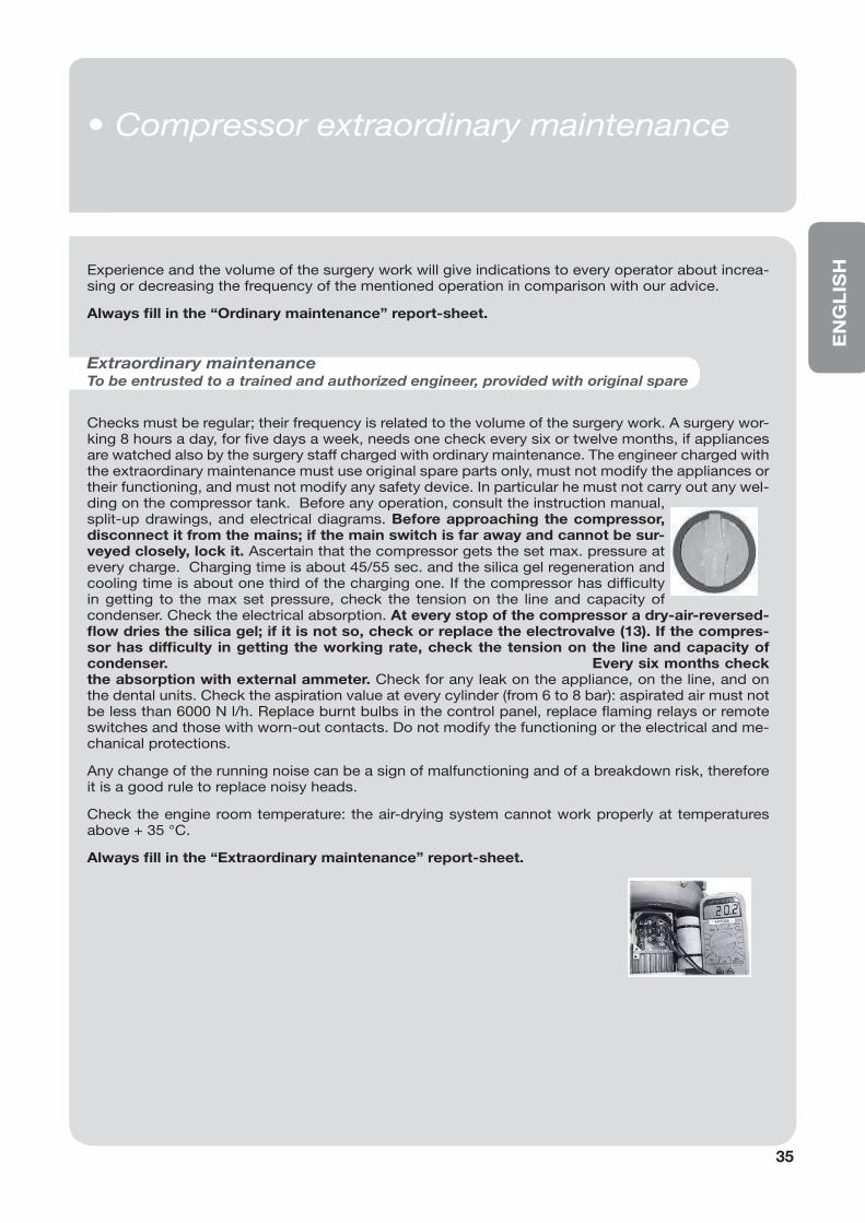
Checks must be regular; their frequency is related to the volume of the surgery work. A surgery wor-king 8 hours a day, for fi ve days a week, needs one check every six or twelve months, if appliances are watched also by the surgery staff charged with ordinary maintenance. The engineer charged with the extraordinary maintenance must use original spare parts only, must not modify the appliances or their functioning, and must not modify any safety device. In particular he must not carry out any wel-ding on the compressor tank. Before any operation, consult the instruction manual, split-up drawings, and electrical diagrams. Before approaching the compressor, disconnect it from the mains; if the main switch is far away and cannot be sur-veyed closely, lock it. Ascertain that the compressor gets the set max. pressure at every charge. Charging time is about 45/55 sec. and the silica gel regeneration and cooling time is about one third of the charging one. If the compressor has diffi culty in getting to the max set pressure, check the tension on the line and capacity of condenser. Check the electrical absorption. At every stop of the compressor a dry-air-reversed-fl ow dries the silica gel; if it is not so, check or replace the electrovalve (13). If the compres-sor has diffi culty in getting the working rate, check the tension on the line and capacity of condenser. Every six months check the absorption with external ammeter. Check for any leak on the appliance, on the line, and on the dental units. Check the aspiration value at every cylinder (from 6 to 8 bar): aspirated air must not be less than 6000 N l/h. Replace burnt bulbs in the control panel, replace fl aming relays or remote switches and those with worn-out contacts. Do not modify the functioning or the electrical and me-chanical protections.
Any change of the running noise can be a sign of malfunctioning and of a breakdown risk, therefore it is a good rule to replace noisy heads.
Check the engine room temperature: the air-drying system cannot work properly at temperatures above + 35 °C.
Always fi ll in the “Extraordinary maintenance” report-sheet.
Extraordinary maintenanceTo be entrusted to a trained and authorized engineer, provided with original spare
• Compressor extraordinary maintenance
36
• Manutenzione ordinaria
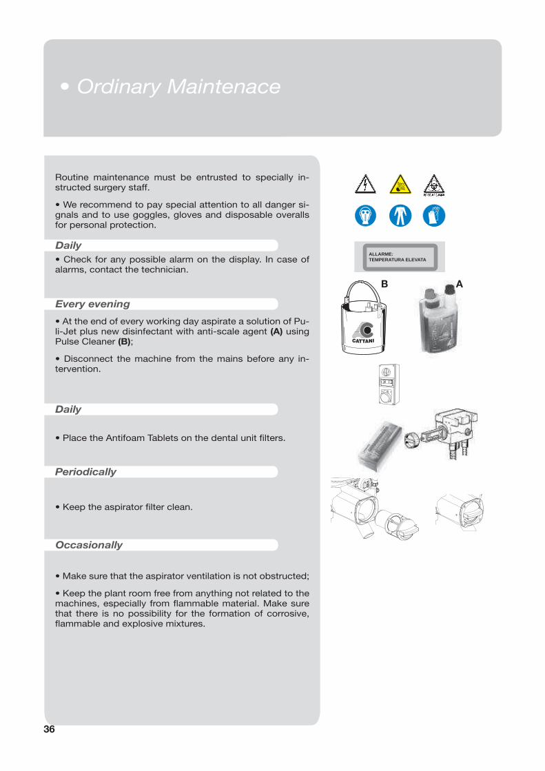
Routine maintenance must be entrusted to specially in-structed surgery staff.
• We recommend to pay special attention to all danger si-gnals and to use goggles, gloves and disposable overalls for personal protection.
• Check for any possible alarm on the display. In case of alarms, contact the technician.
• At the end of every working day aspirate a solution of Pu-li-Jet plus new disinfectant with anti-scale agent (A) using Pulse Cleaner (B);
• Disconnect the machine from the mains before any in-tervention.
• Place the Antifoam Tablets on the dental unit fi lters.
• Keep the aspirator fi lter clean.
• Make sure that the aspirator ventilation is not obstructed;
• Keep the plant room free from anything not related to the machines, especially from fl ammable material. Make sure that there is no possibility for the formation of corrosive, fl ammable and explosive mixtures.
Daily
Occasionally
B A
Every evening
Daily
Periodically
ALLARME:TEMPERATURA ELEVATA
• Ordinary Maintenace
EN
GL
ISH
37
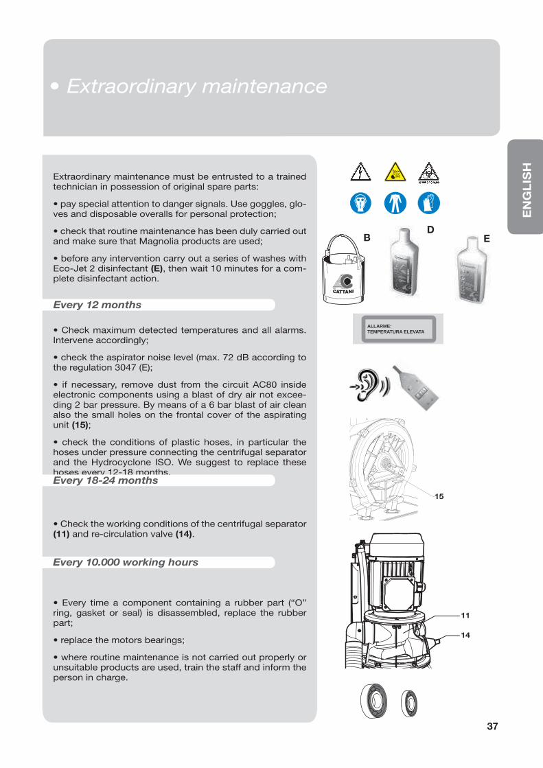
Extraordinary maintenance must be entrusted to a trained technician in possession of original spare parts:
• pay special attention to danger signals. Use goggles, glo-ves and disposable overalls for personal protection;
• check that routine maintenance has been duly carried out and make sure that Magnolia products are used;
• before any intervention carry out a series of washes with Eco-Jet 2 disinfectant (E), then wait 10 minutes for a com-plete disinfectant action.
• Check maximum detected temperatures and all alarms. Intervene accordingly;
• check the aspirator noise level (max. 72 dB according to the regulation 3047 (E);
• if necessary, remove dust from the circuit AC80 inside electronic components using a blast of dry air not excee-ding 2 bar pressure. By means of a 6 bar blast of air clean also the small holes on the frontal cover of the aspirating unit (15);
• check the conditions of plastic hoses, in particular the hoses under pressure connecting the centrifugal separator and the Hydrocyclone ISO. We suggest to replace these hoses every 12-18 months.
• Check the working conditions of the centrifugal separator (11) and re-circulation valve (14).
• Every time a component containing a rubber part (“O” ring, gasket or seal) is disassembled, replace the rubber part;
• replace the motors bearings;
• where routine maintenance is not carried out properly or unsuitable products are used, train the staff and inform the person in charge.
Every 12 months
Every 18-24 months
Every 10.000 working hours
B ED
• Manutenzione straordinaria
ALLARME:TEMPERATURA ELEVATA
15
11
14
• Extraordinary maintenance
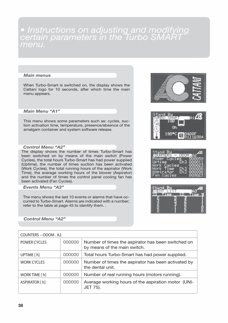
Main menus
When Turbo-Smart is switched on, the display shows the Cattani logo for 10 seconds, after which time the main menu appears.
Main Menu “A1”
This menu shows some parameters such as: cycles, suc-tion activation time, temperature, presence/absence of the amalgam container and system software release.
Control Menu “A2”The display shows the number of times Turbo-Smart has been switched on by means of the main switch (Power Cycles), the total hours Turbo-Smart has had power supplied (Uptime), the number of times suction has been activated (Work Cycles), the total running hours of the aspirator (Work Time), the average working hours of the blower (Aspirator) and the number of times the control panel cooling fan has been activated (Fan Cycles).
Events Menu “A3”
The menu shows the last 10 events or alarms that have oc-curred to Turbo-Smart. Alarms are indicated with a number; refer to the table at page 45 to identify them. .
Control Menu “A2”
38
COUNTERS – ODOM . A2
POWER CYCLES 000000 Number of times the aspirator has been switched on
by means of the main switch.
UPTIME [ h] 000000 Total hours Turbo-Smart has had power supplied.
WORK CYCLES 000000 Number of times the aspirator has been activated by
the dental unit.
WORK TIME [ h] 000000 Number of real running hours (motors running).
ASPIRATOR [ h] 000000 Average working hours of the aspiration motor (UNI-
JET 75).
• Manutenzione ordinaria• Instructions on adjusting and modifying certain parameters in the Turbo SMART menu.
EN
GL
ISH
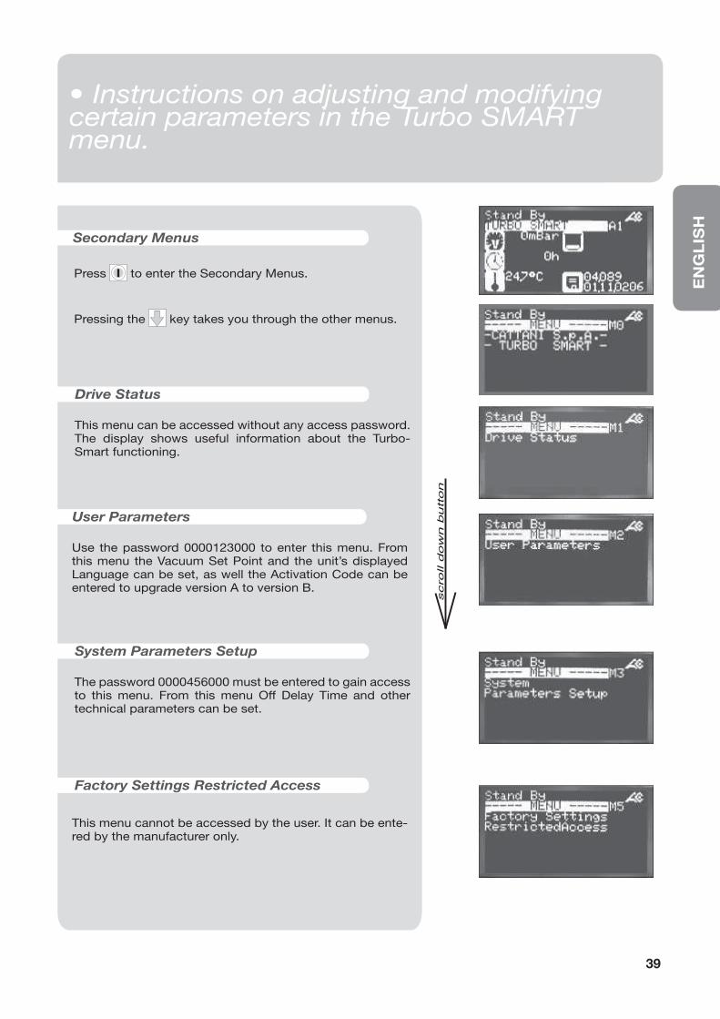
Press I to enter the Secondary Menus.
Pressing the key takes you through the other menus.
Drive Status
This menu can be accessed without any access password. The display shows useful information about the Turbo-Smart functioning.
User Parameters
Use the password 0000123000 to enter this menu. From this menu the Vacuum Set Point and the unit’s displayed Language can be set, as well the Activation Code can be entered to upgrade version A to version B.
System Parameters Setup
The password 0000456000 must be entered to gain access to this menu. From this menu Off Delay Time and other technical parameters can be set.
Factory Settings Restricted Access
Secondary Menus
This menu cannot be accessed by the user. It can be ente-red by the manufacturer only.
39
• Manutenzione ordinaria• Instructions on adjusting and modifying certain parameters in the Turbo SMART menu.
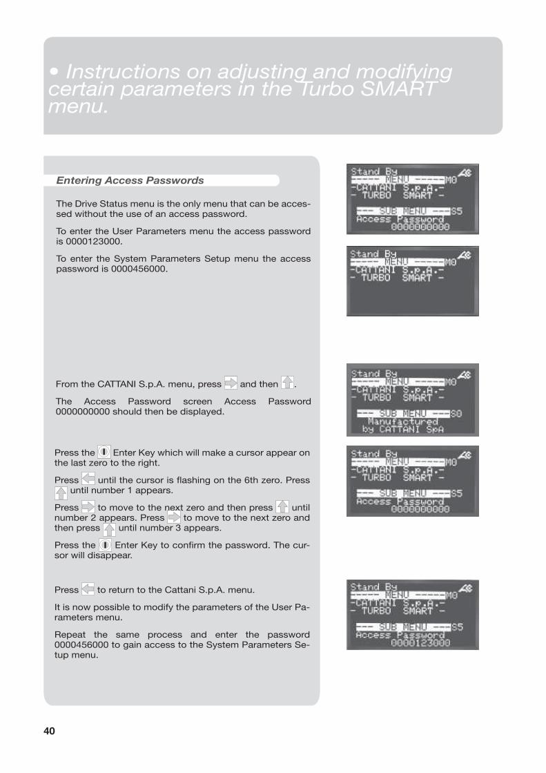
Entering Access Passwords
The Drive Status menu is the only menu that can be acces-sed without the use of an access password.
To enter the User Parameters menu the access password is 0000123000.
To enter the System Parameters Setup menu the access password is 0000456000.
From the CATTANI S.p.A. menu, press and then .
The Access Password screen Access Password 0000000000 should then be displayed.
Press the I Enter Key which will make a cursor appear on the last zero to the right.
Press until the cursor is fl ashing on the 6th zero. Press until number 1 appears.
Press to move to the next zero and then press until number 2 appears. Press to move to the next zero and then press until number 3 appears.
Press the I Enter Key to confi rm the password. The cur-sor will disappear.
Press to return to the Cattani S.p.A. menu.
It is now possible to modify the parameters of the User Pa-rameters menu.
Repeat the same process and enter the password 0000456000 to gain access to the System Parameters Se-tup menu.
40
• Manutenzione ordinaria• Instructions on adjusting and modifying certain parameters in the Turbo SMART menu.
EN
GL
ISH
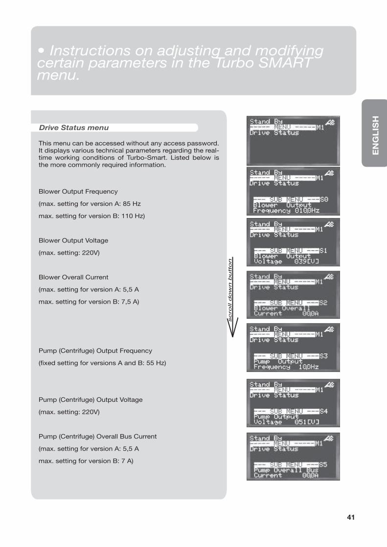
This menu can be accessed without any access password. It displays various technical parameters regarding the real-time working conditions of Turbo-Smart. Listed below is the more commonly required information.
Drive Status menu
Blower Output Frequency
(max. setting for version A: 85 Hz
max. setting for version B: 110 Hz)
Blower Output Voltage
(max. setting: 220V)
Blower Overall Current
(max. setting for version A: 5,5 A
max. setting for version B: 7,5 A)
Pump (Centrifuge) Output Frequency
(fi xed setting for versions A and B: 55 Hz)
Pump (Centrifuge) Output Voltage
(max. setting: 220V)
Pump (Centrifuge) Overall Bus Current
(max. setting for version A: 5,5 A
max. setting for version B: 7 A)
41
• Manutenzione ordinaria• Instructions on adjusting and modifying certain parameters in the Turbo SMART menu.
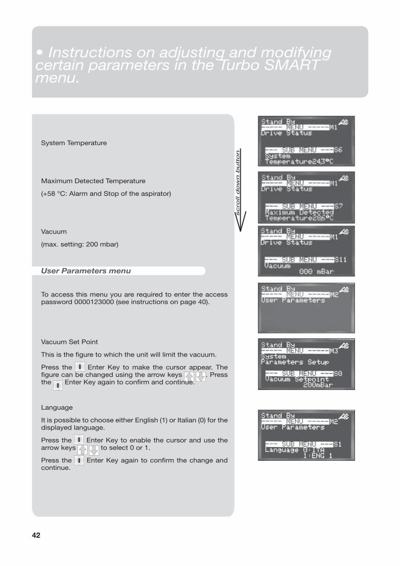
System Temperature
Maximum Detected Temperature
(+58 °C: Alarm and Stop of the aspirator)
Vacuum
(max. setting: 200 mbar)
To access this menu you are required to enter the access password 0000123000 (see instructions on page 40).
User Parameters menu
Vacuum Set Point
This is the fi gure to which the unit will limit the vacuum.
Press the I Enter Key to make the cursor appear. The fi gure can be changed using the arrow keys . Press the
I Enter Key again to confi rm and continue.
Language
It is possible to choose either English (1) or Italian (0) for the displayed language.
Press the I Enter Key to enable the cursor and use the arrow keys to select 0 or 1.
Press the I Enter Key again to confi rm the change and continue.
42
• Manutenzione ordinaria• Instructions on adjusting and modifying certain parameters in the Turbo SMART menu.
EN
GL
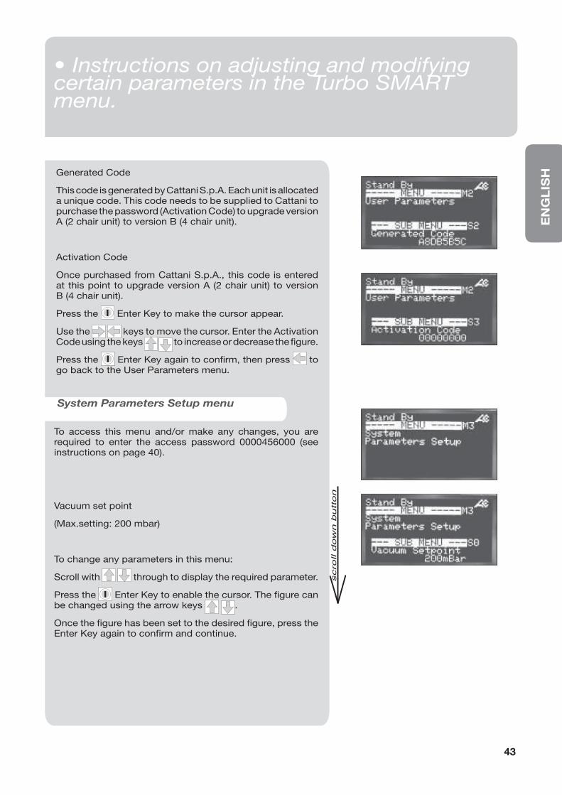
ISHGenerated Code
This code is generated by Cattani S.p.A. Each unit is allocated a unique code. This code needs to be supplied to Cattani to purchase the password (Activation Code) to upgrade version A (2 chair unit) to version B (4 chair unit).
Activation Code
Once purchased from Cattani S.p.A., this code is entered at this point to upgrade version A (2 chair unit) to version B (4 chair unit).
Press the I Enter Key to make the cursor appear.
Use the keys to move the cursor. Enter the Activation Code using the keys to increase or decrease the figure.
Press the I Enter Key again to confirm, then press to go back to the User Parameters menu.
System Parameters Setup menu
To access this menu and/or make any changes, you are required to enter the access password 0000456000 (see instructions on page 40).
Vacuum set point
(Max.setting: 200 mbar)
To change any parameters in this menu:
Scroll with through to display the required parameter.
Press the I Enter Key to enable the cursor. The fi gure can be changed using the arrow keys .
Once the fi gure has been set to the desired fi gure, press the Enter Key again to confi rm and continue.
43
• Manutenzione ordinaria• Instructions on adjusting and modifying certain parameters in the Turbo SMART menu.
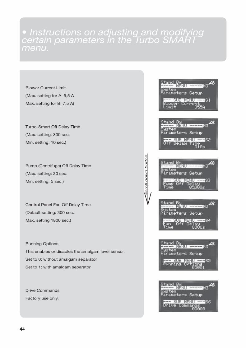
Blower Current Limit
(Max. setting for A: 5,5 A
Max. setting for B: 7,5 A)
Turbo-Smart Off Delay Time
(Max. setting: 300 sec.
Min. setting: 10 sec.)
Pump (Centrifuge) Off Delay Time
(Max. setting: 30 sec.
Min. setting: 5 sec.)
Control Panel Fan Off Delay Time
(Default setting: 300 sec.
Max. setting 1800 sec.)
Running Options
This enables or disables the amalgam level sensor.
Set to 0: without amalgam separator
Set to 1: with amalgam separator
Drive Commands
Factory use only.
44
• Manutenzione ordinaria• Instructions on adjusting and modifying certain parameters in the Turbo SMART menu.
EN
GL
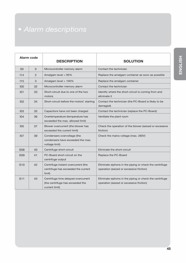
ISHAlarm code
DESCRIPTION SOLUTION
00 0 Microcontroller memory alarm Contact the technician
I14 2 Amalgam level > 95% Replace the amalgam container as soon as possible
I15 3 Amalgam level > 100% Replace the amalgam container
I00 32 Microcontroller memory alarm Contact the technician
I01 33 Short-circuit due to one of the two
motors
Identify where the short-circuit is coming from and
eliminate it
I02 34 Short-circuit before the motors’ starting Contact the technician (the PC-Board is likely to be
damaged)
I03 35 Capacitors have not been charged Contact the technician (replace the PC-Board)
I04 36 Overtemperature (temperature has
exceeded the max. allowed limit)
Ventilate the plant room
I05 37 Blower overcurrent (the blower has
exceeded the current limit)
Check the operation of the blower (seized or excessive
friction)
I07 39 Condensers overvoltage (the
condensers have exceeded the max.
voltage limit)
Check the mains voltage (max. 260V)
S08 40 Centrifuge short-circuit Eliminate the short-circuit
S09 41 PC-Board short-circuit on the
centrifuge output
Replace the PC-Board
S10 42 Centrifuge instant overcurrent (the
centrifuge has exceeded the current
limit)
Eliminate siphons in the piping or check the centrifuge
operation (seized or excessive friction)
S11 43 Centrifuge time delayed overcurrent
(the centrifuge has exceeded the
current limit)
Eliminate siphons in the piping or check the centrifuge
operation (seized or excessive friction)
45
• Manutenzione ordinaria• Alarm descriptions
• Packed appliances can be transported and stored at a temperature ranging from -10 °C to + 60 °C.
• Packages must be kept away from water and splashing and cannot tolerate humidity >70%.
• Packages with the same weight can be stored in piles of three only.
• Transport and storage
• Transport of second-hand appliances
• Before packing, cleanse and disinfect with Puli-Jet plus new (refer to the paragraphs “Signals and warnings” and “Routine maintenance“).
• Close with polyethylene plugs all machine inlets and outlets.
• Place the machine into a polyethylene bag, seal and pack it in 3-layer corrugated board.
• Important notices
• Appliances are guaranteed for one year from the date of sale, provided that the warranty slip is returned to the manufacturer with date of sale, retailer’s and customer’s name.
• Warranty and manufacturer’s liability cease in case appliances are treated with products which are unsuitable or different from those recommended by the manufacturer and also in case appliances are improperly used or tampered with operations of any kind carried out by people who are not authorized by the manufacturer.
• The manufacturer, concessionaires, agents and authorized technicians are at customers’ disposal for advice and assistance and to supply literature, spare parts and anything useful.
• The manufacturer reserves the right to modify the products for improvements, for technical, normative and functional reasons or for problems due to the availability of products or semi-fi nished products, without prior notice.
• Our updated manuals are available on the web site www.cattani.it. We recommend they are consulted especially for updates about safety.
• Turbo-Smart is a EEE device, therefore it is subject to the WEEE (Waste of Electrical and Electronic Equipment) regulations.
46
• Manutenzione ordinaria• Important notices• Transport and storage• Transport of second-hand appliances

EN
GL
ISH
47
Ed
. M
ay 2
01
4
ITALIAN PATENTS OR PATENT APPLICATIONS:
CATTANI: 1201707 - 1234828 - 1259318 - 1.187.187 - 1253460 - 233634 - 2337706 -1294904
ESAM: 1225173 - 1253783 - 0791751
FOREIGN PATENTS OR PATENT APPLICATIONS:
CATTANI: AU 546.143 - US 4,386,910 - US 4,787,846 - US 5,039,405 - US 5,002,486 AU 580839 - US 4,684,345 - US 5,330,641 - AT 0040181 - CH 0040181 - DE 0040181 FR 0040181 - GB 0040181 - LU 0040181 - SE 0040181 - CH 0211808 - DE 0211808 FR 0211808 - GB 0211808 - SE 0211808 - DE 0335061 - ES 0335061 - FR 0335061 GB 0335061 - AT 0557251 - DE 0557251 - ES 0557251 - FR 0557251 - GB 0557251 DE 0638295 - DK 0638295 - ES 0638295 - FR 0638295 - GB 0638295 - NL 0638295 SE 0638295 - US 6,083,306 - US 6,090,286 - US 6,022,216
ESAM: US 4,948,334 - DE 0351372 - ES 0351372 - FR 0351372 - GB 0351372 EP 0791751 - US 5,779,443 - CH 0791751 - DE 0791751 - ES 0791751 - FR 0791751 GB 0791751 - PT 0791751 - AU 93321 - ES 107358 - FR 222.394/395
PENDING PATENT
CATTANI: IT M098A000019 - IT M098A000119 - EP 99830010.7 - EP 99830011.5 EP 99830250.9 - EP 00830491.7 - IT M099A000165 - US 09/624,182
6/A Via Natta. 43122 Parma, Italy
10’21’48” EST - 44’50’46” NORD
Ph. +39.0521.607604
Fax +39.0521.607628 (Sales Dept.)
Fax +39.0521.607855 (Purchasing Dept.)
Fax +39.0521.399966 (Accounting Dept.)
www.cattani.it - e-mail: [email protected]
Company with Quality System Certifi ed according to
UNI EN ISO 9001:2008 - UNI EN ISO 13485:2012