Embed Size (px)
Citation preview
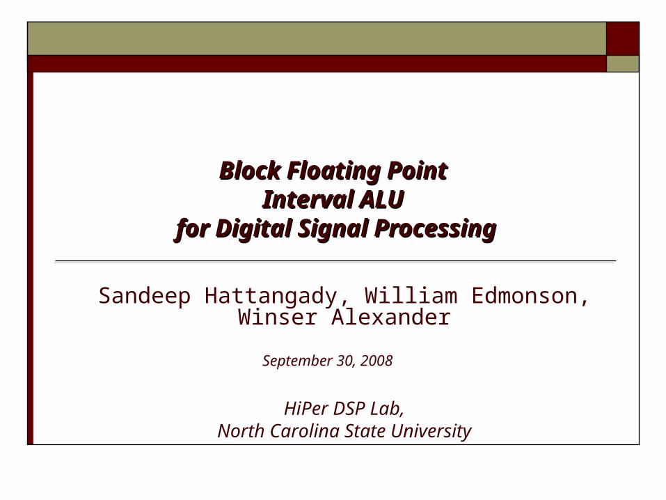
Block Floating Point Block Floating Point Interval ALU Interval ALU
for Digital Signal Processingfor Digital Signal Processing
Sandeep Hattangady, William Edmonson, Winser Alexander
September 30, 2008
HiPer DSP Lab,North Carolina State University
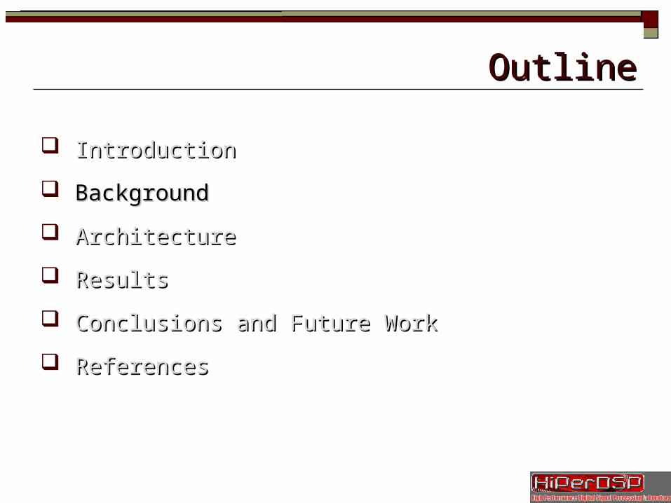
OutlineOutline
IntroductionIntroduction
BackgroundBackground
ArchitectureArchitecture
ResultsResults
Conclusions and Future WorkConclusions and Future Work
ReferencesReferences
OutlineOutline
IntroductionIntroduction
BackgroundBackground
ArchitectureArchitecture
ResultsResults
Conclusion s and Future WorkConclusion s and Future Work
ReferencesReferences
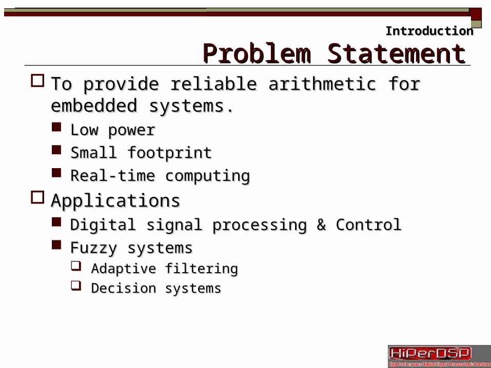
Problem StatementProblem Statement To provide reliable arithmetic for embedded systems.To provide reliable arithmetic for embedded systems.
Low powerLow power Small footprintSmall footprint Real-time computingReal-time computing
ApplicationsApplications Digital signal processing & ControlDigital signal processing & Control Fuzzy systemsFuzzy systems
Adaptive filteringAdaptive filtering Decision systemsDecision systems
IntroductionIntroduction
Problem StatementProblem StatementIntroductionIntroduction
Two’s complement formatTwo’s complement formatQ7.8 input dataQ7.8 input data
Q15.0 output dataQ15.0 output data
Upper BoundUpper Bound
Lower BoundLower Bound
Upper BoundUpper Bound
Lower BoundLower Bound
75
0n
na
15.1,10.1a
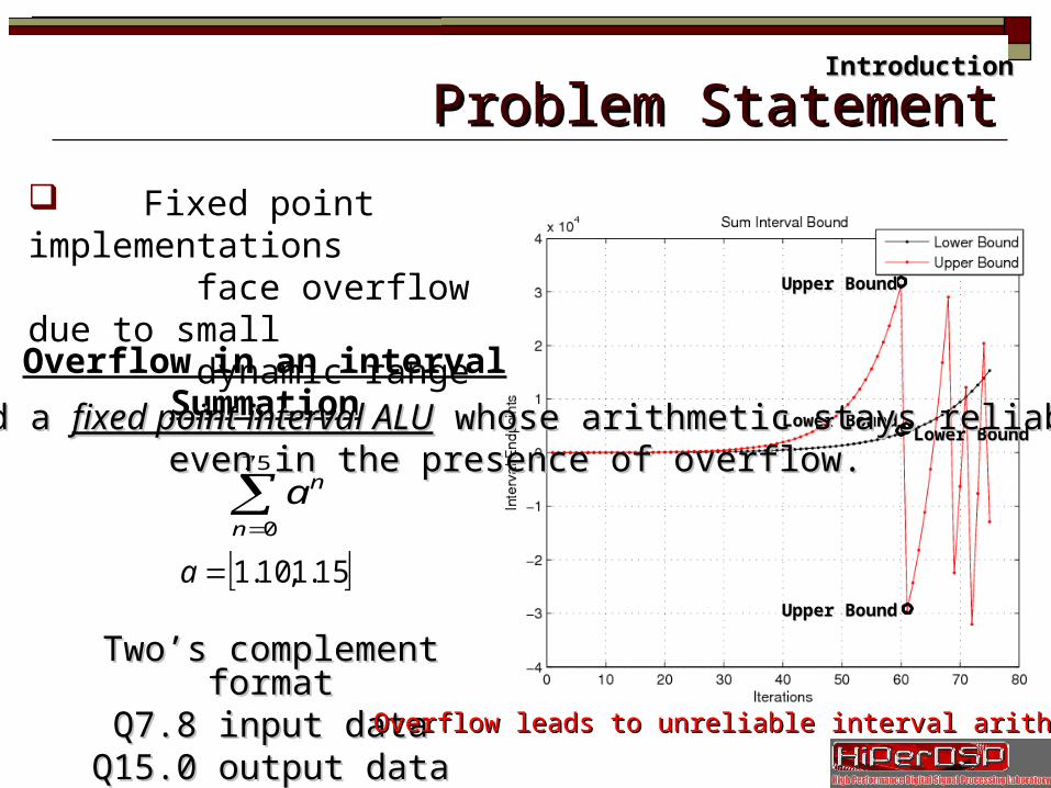
Overflow leads to unreliable interval arithmetic!Overflow leads to unreliable interval arithmetic!
Overflow in an interval SummationBuild a Build a fixed point interval ALUfixed point interval ALU whose arithmetic stays reliable whose arithmetic stays reliable
even in the presence of overflow.even in the presence of overflow.
Fixed point implementations face overflow due to small dynamic range
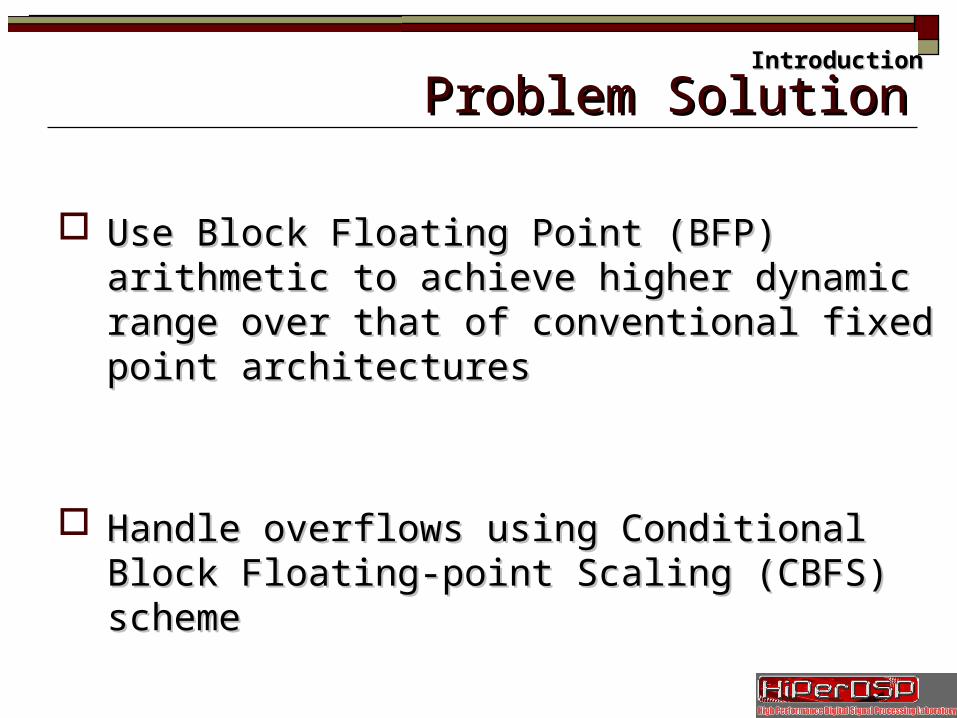
Problem SolutionProblem Solution
Use Block Floating Point (BFP) arithmetic to achieve Use Block Floating Point (BFP) arithmetic to achieve higher dynamic range over that of conventional fixed higher dynamic range over that of conventional fixed point architecturespoint architectures
Handle overflows using Conditional Block Floating-Handle overflows using Conditional Block Floating-point Scaling (CBFS) schemepoint Scaling (CBFS) scheme
IntroductionIntroduction
OutlineOutline
IntroductionIntroduction
BackgroundBackground
ArchitectureArchitecture
ResultsResults
Conclusions and Future WorkConclusions and Future Work
ReferencesReferences
Previous WorkPrevious Work
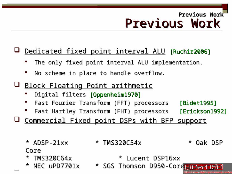
Dedicated fixed point interval ALUDedicated fixed point interval ALU [Ruchir2006][Ruchir2006]
The only fixed point interval ALU implementation.The only fixed point interval ALU implementation.
No scheme in place to handle overflow.No scheme in place to handle overflow.
Block Floating Point arithmeticBlock Floating Point arithmetic Digital filters Digital filters [Oppenheim1970][Oppenheim1970] Fast Fourier Transform (FFT) processors Fast Fourier Transform (FFT) processors [Bidet1995][Bidet1995] Fast Hartley Transform (FHT) processors Fast Hartley Transform (FHT) processors [Erickson1992][Erickson1992]
Commercial Fixed point DSPs with BFP supportCommercial Fixed point DSPs with BFP support
Previous WorkPrevious Work
* ADSP-21xx* ADSP-21xx * TMS320C54x* TMS320C54x * Oak DSP Core* Oak DSP Core* TMS320C64x* TMS320C64x * Lucent DSP16xx* Lucent DSP16xx* NEC uPD7701x* NEC uPD7701x * SGS Thomson D950-Core* SGS Thomson D950-Core
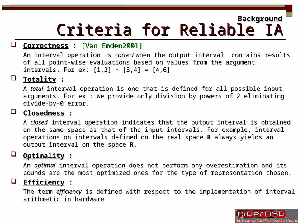
Criteria for Reliable IACriteria for Reliable IA CorrectnessCorrectness : : [Van Emden2001][Van Emden2001]
An interval operation is An interval operation is correct correct when the output interval contains results of all point-when the output interval contains results of all point-wise evaluations based on values from the argument intervals. For ex: [1,2] + [3,4] = wise evaluations based on values from the argument intervals. For ex: [1,2] + [3,4] = [4,6][4,6]
TotalityTotality : : A A totaltotal interval operation is one that is defined for all possible input arguments. For ex : interval operation is one that is defined for all possible input arguments. For ex : We provide only division by powers of 2 eliminating divide-by-0 error.We provide only division by powers of 2 eliminating divide-by-0 error.
ClosednessClosedness : : A A closedclosed interval operation indicates that the output interval is obtained on the same interval operation indicates that the output interval is obtained on the same space as that of the input intervals. For example, interval operations on intervals defined space as that of the input intervals. For example, interval operations on intervals defined on the real space on the real space R R always yields an output interval on the space always yields an output interval on the space RR..
OptimalityOptimality : : An An optimaloptimal interval operation does not perform any overestimation and its bounds are the interval operation does not perform any overestimation and its bounds are the most optimized ones for the type of representation chosen.most optimized ones for the type of representation chosen.
EfficiencyEfficiency : : The term The term efficiencyefficiency is defined with respect to the implementation of interval arithmetic in is defined with respect to the implementation of interval arithmetic in hardware.hardware.
BackgroundBackground
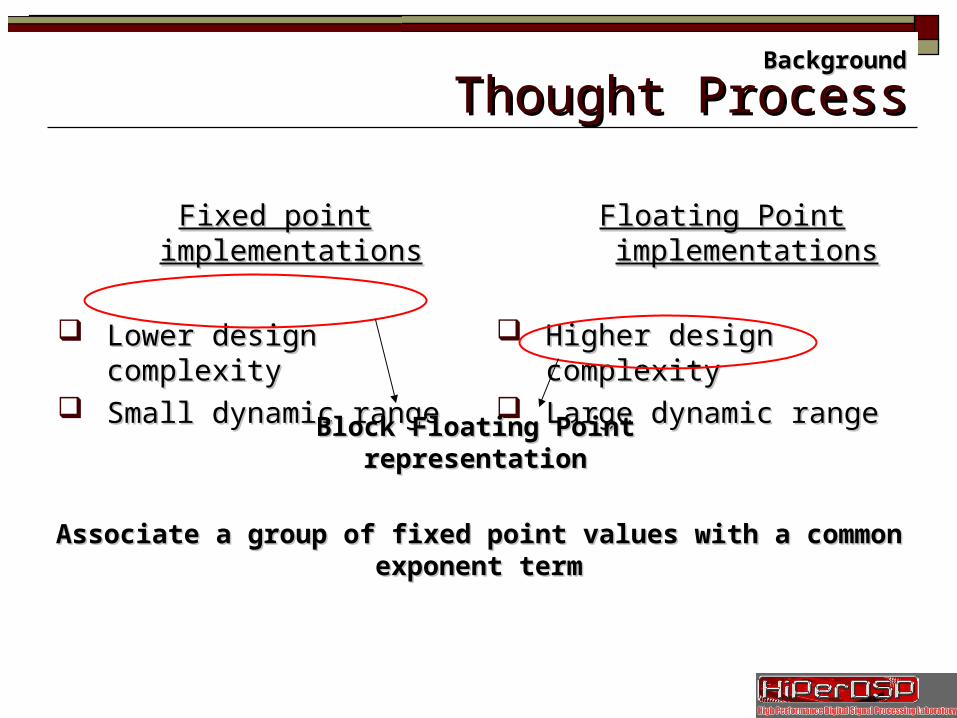
Thought ProcessThought Process
Fixed point implementationsFixed point implementations
Lower design complexityLower design complexity Small dynamic rangeSmall dynamic range
Floating Point implementationsFloating Point implementations
Higher design complexityHigher design complexity Large dynamic rangeLarge dynamic range
Block Floating PointBlock Floating Pointrepresentationrepresentation
Associate a group of fixed point values with a common exponent termAssociate a group of fixed point values with a common exponent term
BackgroundBackground
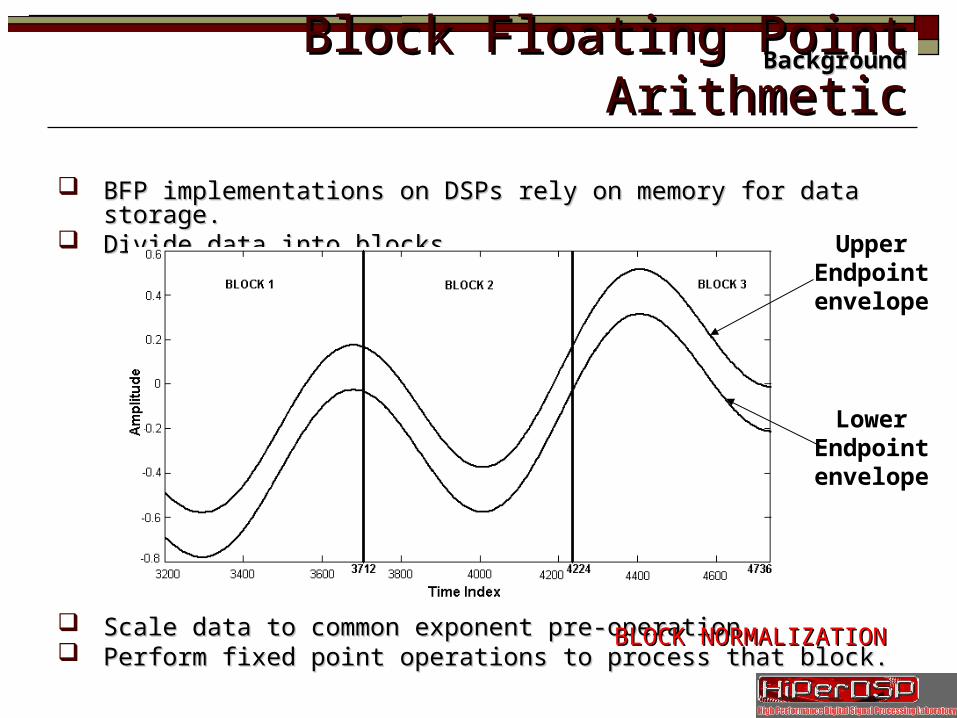
Block Floating Point ArithmeticBlock Floating Point Arithmetic
BFP implementations on DSPs rely on memory for data storage.BFP implementations on DSPs rely on memory for data storage. Divide data into blocks.Divide data into blocks.
Scale data to common exponent pre-operation.Scale data to common exponent pre-operation. Perform fixed point operations to process that block.Perform fixed point operations to process that block.
BLOCK NORMALIZATIONBLOCK NORMALIZATION
BackgroundBackground
UpperEndpointenvelope
LowerEndpointenvelope
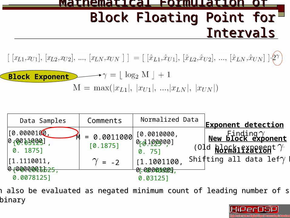
Mathematical Formulation of Mathematical Formulation of Block Floating Point for IntervalsBlock Floating Point for Intervals
[0.0000100, 0.0011000]
[1.1110011, 0.0000001]
Data Samples Normalized Data
[0.0010000, 0.1100000]
[1.1001100, 0.0000100]
M = 0.0011000[0.1875]
= -2
Exponent detectionFinding
NormalizationShifting all data left by
New block exponent(Old block exponent + )
γγ can also be evaluated as negated minimum count of leading number of sign bits can also be evaluated as negated minimum count of leading number of sign bits in binaryin binary
Block Exponent
[0.03125 , 0. 1875]
[-0.1015625, 0.0078125]
[0.125 , 0. 75]
[-0.40625, 0.03125]
Comments
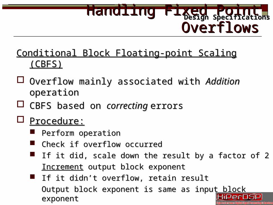
Handling Fixed Point OverflowsHandling Fixed Point Overflows
Conditional Block Floating-point Scaling (CBFS)Conditional Block Floating-point Scaling (CBFS)
Overflow mainly associated with Overflow mainly associated with AdditionAddition operation operation CBFS based on CBFS based on correcting correcting errorserrors
Procedure:Procedure: Perform operationPerform operation Check if overflow occurredCheck if overflow occurred If it did, scale down the result by a factor of 2If it did, scale down the result by a factor of 2
IncrementIncrement output block exponent output block exponent If it didn’t overflow, retain resultIf it didn’t overflow, retain result
Output block exponent is same as input block Output block exponent is same as input block exponentexponent
Design SpecificationsDesign Specifications
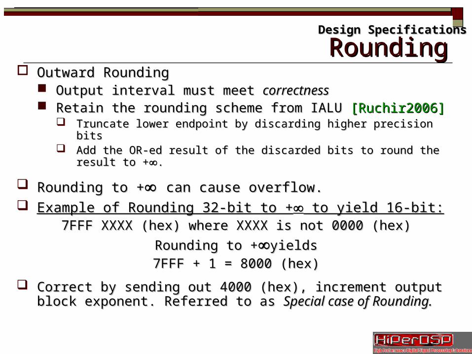
RoundingRounding Outward RoundingOutward Rounding
Output interval must meet Output interval must meet correctnesscorrectness Retain the rounding scheme from IALU Retain the rounding scheme from IALU [Ruchir2006][Ruchir2006]
Truncate lower endpoint by discarding higher precision bitsTruncate lower endpoint by discarding higher precision bits Add the OR-ed result of the discarded bits to round the result to +Add the OR-ed result of the discarded bits to round the result to +∞∞..
Rounding to +Rounding to +∞∞ can cause overflow.can cause overflow. Example of Rounding 32-bit to +Example of Rounding 32-bit to +∞∞ to yield 16-bit: to yield 16-bit:
7FFF XXXX (hex) where XXXX is not 0000 (hex)7FFF XXXX (hex) where XXXX is not 0000 (hex)
Rounding to +Rounding to +∞∞yieldsyields
7FFF + 1 = 8000 (hex)7FFF + 1 = 8000 (hex)
Correct by sending out 4000 (hex), increment output block Correct by sending out 4000 (hex), increment output block exponent. Referred to as exponent. Referred to as Special case of Rounding.Special case of Rounding.
Design SpecificationsDesign Specifications

OutlineOutline
IntroductionIntroduction
BackgroundBackground
ArchitectureArchitecture
ResultsResults
Conclusions and Future WorkConclusions and Future Work
ReferencesReferences
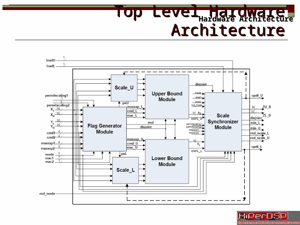
Top Level Hardware ArchitectureTop Level Hardware ArchitectureHardware ArchitectureHardware Architecture
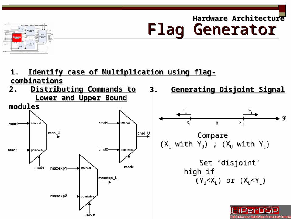
Slide 17/35 Flag GeneratorFlag Generator
1. 1. Identify case of Multiplication using flag-combinationsIdentify case of Multiplication using flag-combinations
2. 2. Distributing Commands toDistributing Commands to Lower and Upper Bound modulesLower and Upper Bound modules
3. 3. Generating Disjoint SignalGenerating Disjoint Signal
Compare Compare (X(XLL with Y with YUU) ; (X) ; (XUU with Y with YLL))
Set ‘disjoint’ high if Set ‘disjoint’ high if (Y(YUU<X<XLL) or (X) or (XUU<Y<YLL))
Hardware ArchitectureHardware Architecture
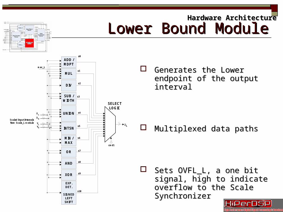
Slide 18/35 Lower Bound ModuleLower Bound ModuleHardware ArchitectureHardware Architecture
Generates the Lower endpoint of the Generates the Lower endpoint of the output intervaloutput interval
Multiplexed data pathsMultiplexed data paths
Sets OVFL_L, a one bit signal, high to Sets OVFL_L, a one bit signal, high to indicate overflow to the Scale indicate overflow to the Scale SynchronizerSynchronizer
ADD / MDPT
SUB / WIDTH
UNION
INTSN
MIN / MAX
OR
AND
XOR
EXP. DET.
SIGNED LEFT SHIFT
cmd1
SELECTLOGIC
XL
XU
YLY
16
16
16
16U
mac_L
s0
s1
s4
s5
s7
s6
s8
s9
s10
32ZL
4
MUL
s3
DIVs2
Scaled Input Intervals from Scale_L module
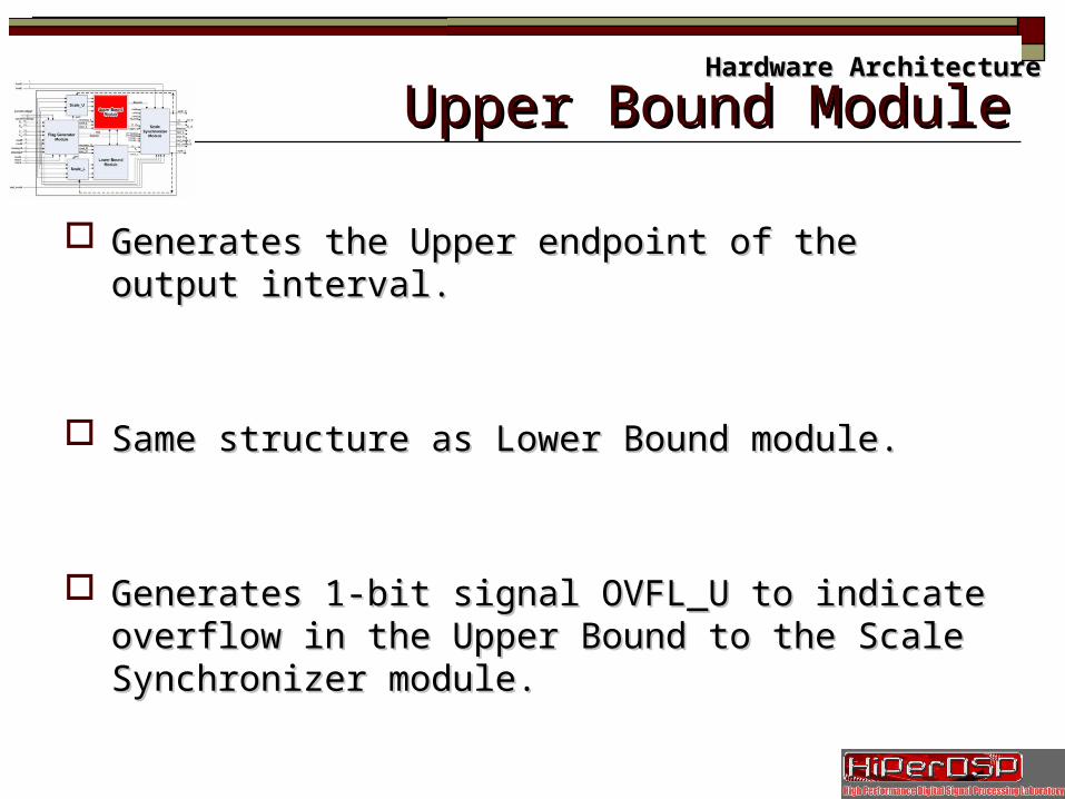
Slide 19/35 Upper Bound ModuleUpper Bound Module
Generates the Upper endpoint of the output interval.Generates the Upper endpoint of the output interval.
Same structure as Lower Bound module.Same structure as Lower Bound module.
Generates 1-bit signal OVFL_U to indicate overflow Generates 1-bit signal OVFL_U to indicate overflow in the Upper Bound to the Scale Synchronizer in the Upper Bound to the Scale Synchronizer module.module.
Hardware ArchitectureHardware Architecture
Slide 20/35 BFP OperationsBFP Operations
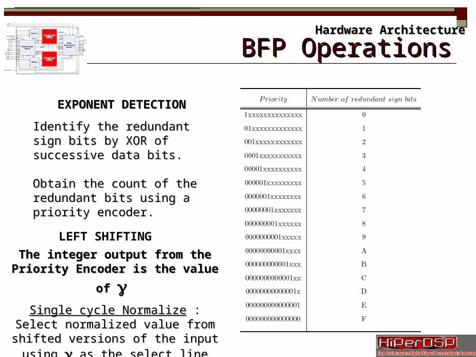
EXPONENT DETECTIONEXPONENT DETECTION
Identify the redundant sign bits by Identify the redundant sign bits by XOR of successive data bits.XOR of successive data bits.
Obtain the count of the redundant Obtain the count of the redundant bits using a priority encoder.bits using a priority encoder.
LEFT SHIFTING
The integer output from the Priority The integer output from the Priority
Encoder is the value of Encoder is the value of γγ
Single cycle NormalizeSingle cycle Normalize : Select : Select normalized value from shifted versions of normalized value from shifted versions of
the input using the input using γγ as the select line as the select line
Hardware ArchitectureHardware Architecture
Slide 21/35
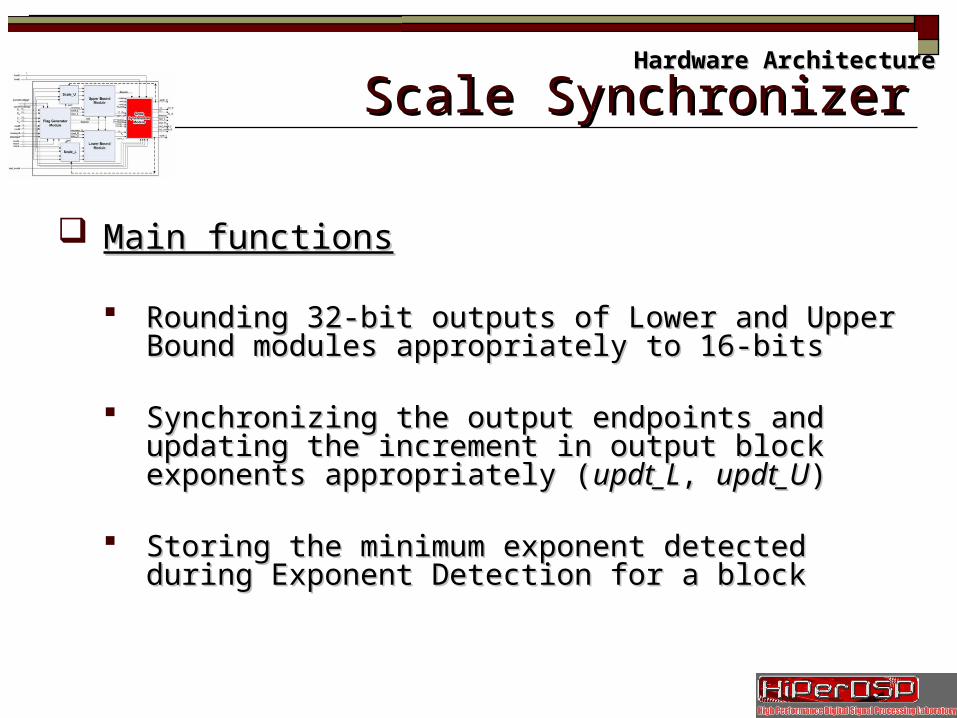
Main functionsMain functions
Rounding 32-bit outputs of Lower and Upper Bound Rounding 32-bit outputs of Lower and Upper Bound modules appropriately to 16-bitsmodules appropriately to 16-bits
Synchronizing the output endpoints and updating the Synchronizing the output endpoints and updating the increment in output block exponents appropriately increment in output block exponents appropriately ((updt_Lupdt_L, , updt_Uupdt_U))
Storing the minimum exponent detected during Exponent Storing the minimum exponent detected during Exponent Detection for a blockDetection for a block
Hardware ArchitectureHardware Architecture
Scale SynchronizerScale Synchronizer
Slide 22/35 Scale SynchronizerScale SynchronizerHardware ArchitectureHardware Architecture
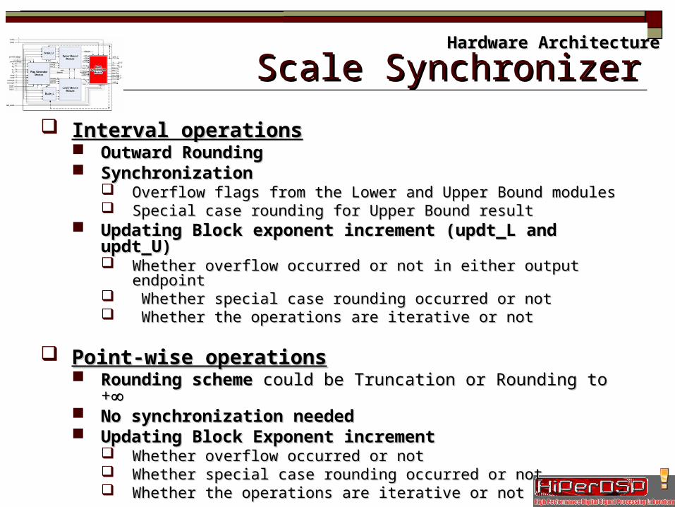
Interval operationsInterval operations Outward Rounding Outward Rounding SynchronizationSynchronization
Overflow flags from the Lower and Upper Bound modulesOverflow flags from the Lower and Upper Bound modules Special case rounding for Upper Bound resultSpecial case rounding for Upper Bound result
Updating Block exponent increment (updt_L and updt_U)Updating Block exponent increment (updt_L and updt_U) Whether overflow occurred or not in either output endpointWhether overflow occurred or not in either output endpoint Whether special case rounding occurred or not Whether special case rounding occurred or not Whether the operations are iterative or notWhether the operations are iterative or not
Point-wise operationsPoint-wise operations Rounding schemeRounding scheme could be Truncation or Rounding to + could be Truncation or Rounding to +∞∞ No synchronization neededNo synchronization needed Updating Block Exponent incrementUpdating Block Exponent increment
Whether overflow occurred or not Whether overflow occurred or not Whether special case rounding occurred or not Whether special case rounding occurred or not Whether the operations are iterative or notWhether the operations are iterative or not
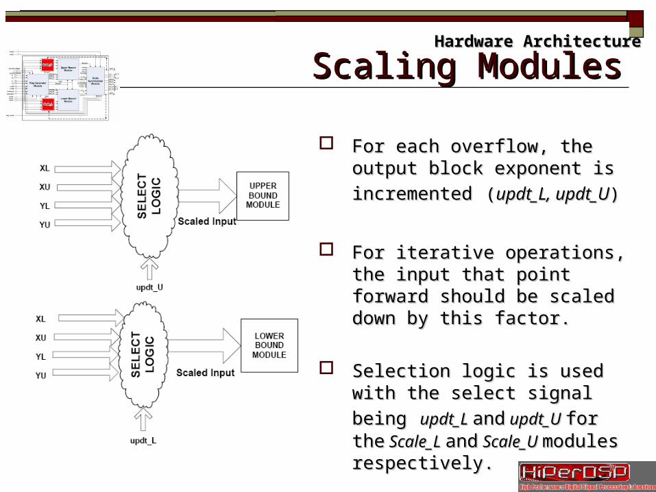
Slide 23/35 Scaling ModulesScaling ModulesHardware ArchitectureHardware Architecture
For each overflow, the output block For each overflow, the output block
exponent is incrementedexponent is incremented ((updt_L, updt_L, updt_Uupdt_U))
For iterative operations, the input For iterative operations, the input that point forward should be scaled that point forward should be scaled down by this factor.down by this factor.
Selection logic is used with the select Selection logic is used with the select
signal beingsignal being updt_L updt_L andand updt_U updt_U for for thethe Scale_L Scale_L andand Scale_U Scale_U modules modules respectively.respectively.

OutlineOutline
IntroductionIntroduction
BackgroundBackground
ArchitectureArchitecture
ResultsResults
Conclusions and Future WorkConclusions and Future Work
ReferencesReferences
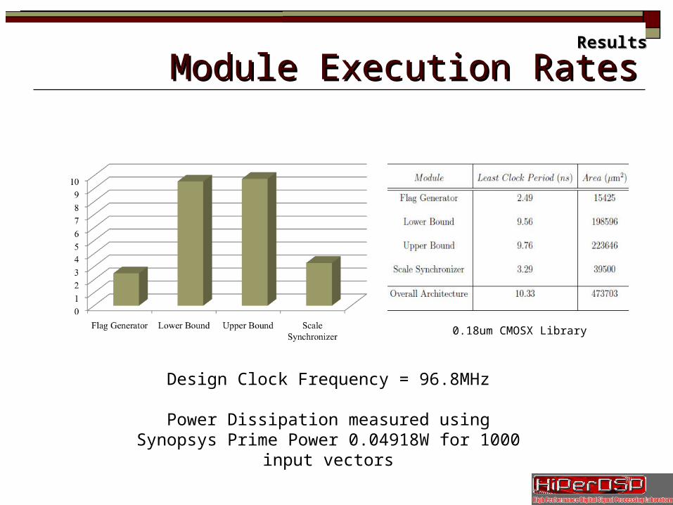
Module Execution RatesModule Execution Rates
Design Clock Frequency = 96.8MHz
Power Dissipation measured using Synopsys Prime Power 0.04918W for 1000 input vectors
0.18um CMOSX Library
ResultsResults
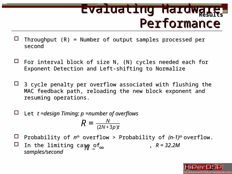
Evaluating Hardware PerformanceEvaluating Hardware Performance Throughput (R) = Number of output samples processed per secondThroughput (R) = Number of output samples processed per second
For interval block of size N, (N) cycles needed each for Exponent For interval block of size N, (N) cycles needed each for Exponent Detection and Left-shifting to NormalizeDetection and Left-shifting to Normalize
3 cycle penalty per overflow associated with flushing the MAC feedback 3 cycle penalty per overflow associated with flushing the MAC feedback path, reloading the new block exponent and resuming operations.path, reloading the new block exponent and resuming operations.
Let Let t =design Timing; p =number of overflowst =design Timing; p =number of overflows
Probability of Probability of nnthth overflow > Probability of overflow > Probability of (n-1)(n-1)thth overflow. overflow. In the limiting case of , In the limiting case of , R = 32.2M samples/secondR = 32.2M samples/second
ResultsResults
€
R = N2N +3 p( )t
€
N → ∞
Future WorkFuture Work
Pipeline the ArchitecturePipeline the Architecture
Adding Saturation for point-wise evaluationsAdding Saturation for point-wise evaluations
Exploring the BFPIALU as a coprocessorExploring the BFPIALU as a coprocessor
Developing a Superscalar or VLIW-based interval Developing a Superscalar or VLIW-based interval processor around the ALUprocessor around the ALU
Conclusions and Future WorkConclusions and Future Work
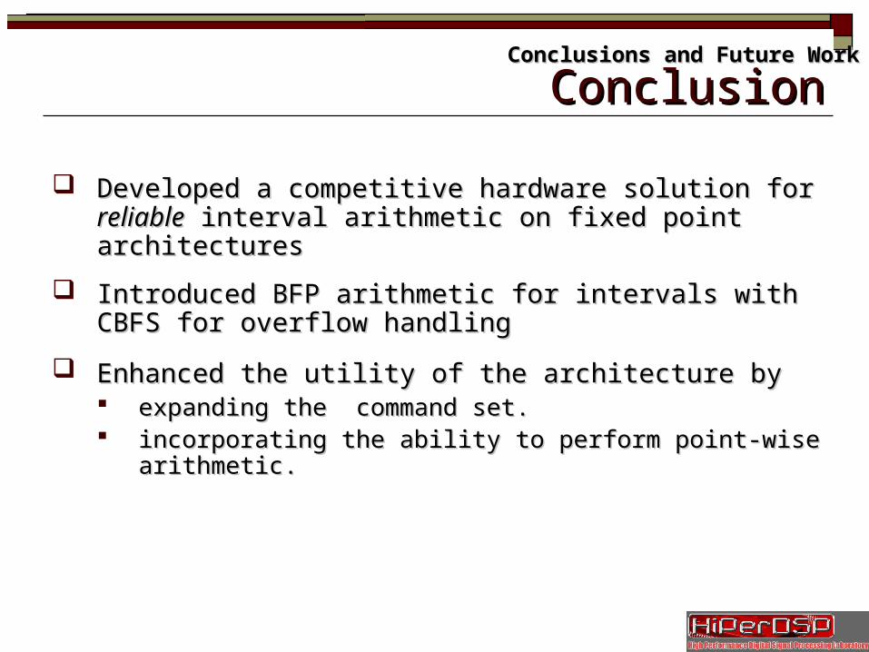
ConclusionConclusion
Developed a competitive hardware solution for Developed a competitive hardware solution for reliablereliable interval interval arithmetic on fixed point architecturesarithmetic on fixed point architectures
Introduced BFP arithmetic for intervals with CBFS for overflow Introduced BFP arithmetic for intervals with CBFS for overflow handlinghandling
Enhanced the utility of the architecture byEnhanced the utility of the architecture by expanding the command set.expanding the command set. incorporating the ability to perform point-wise arithmetic.incorporating the ability to perform point-wise arithmetic.
Conclusions and Future WorkConclusions and Future Work
OutlineOutline
IntroductionIntroduction
BackgroundBackground
ArchitectureArchitecture
ResultsResults
Conclusions and Future WorkConclusions and Future Work
ReferencesReferences
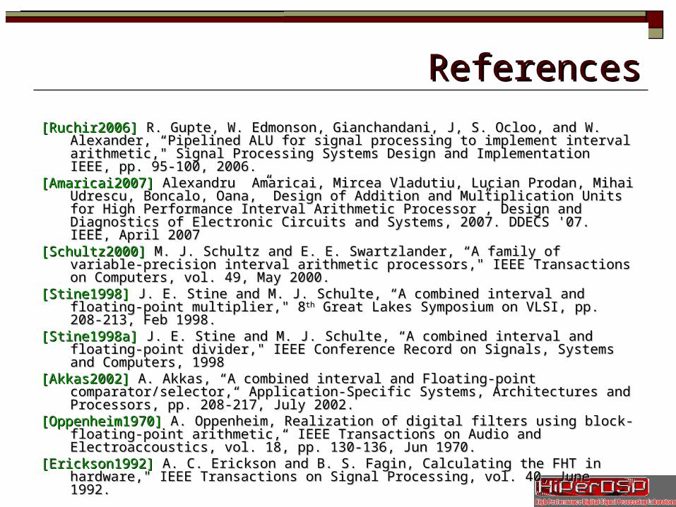
[Ruchir2006][Ruchir2006] R. Gupte, W. Edmonson, Gianchandani, J, S. Ocloo, and W. Alexander, R. Gupte, W. Edmonson, Gianchandani, J, S. Ocloo, and W. Alexander, “Pipelined ALU for signal processing to implement interval arithmetic," Signal “Pipelined ALU for signal processing to implement interval arithmetic," Signal Processing Systems Design and Implementation IEEE, pp. 95-100, 2006.Processing Systems Design and Implementation IEEE, pp. 95-100, 2006.
[Amaricai2007][Amaricai2007] Alexandru Amaricai, Mircea Vladutiu, Lucian Prodan, Mihai Udrescu, Alexandru Amaricai, Mircea Vladutiu, Lucian Prodan, Mihai Udrescu, Boncalo, Oana,” Design of Addition and Multiplication Units for High Performance Boncalo, Oana,” Design of Addition and Multiplication Units for High Performance Interval Arithmetic Processor”, Design and Diagnostics of Electronic Circuits and Interval Arithmetic Processor”, Design and Diagnostics of Electronic Circuits and Systems, 2007. DDECS '07. IEEE, April 2007 Systems, 2007. DDECS '07. IEEE, April 2007
[Schultz2000][Schultz2000] M. J. Schultz and E. E. Swartzlander, “A family of variable-precision interval M. J. Schultz and E. E. Swartzlander, “A family of variable-precision interval arithmetic processors," IEEE Transactions on Computers, vol. 49, May 2000.arithmetic processors," IEEE Transactions on Computers, vol. 49, May 2000.
[Stine1998][Stine1998] J. E. Stine and M. J. Schulte, “A combined interval and floating-point J. E. Stine and M. J. Schulte, “A combined interval and floating-point multiplier," 8multiplier," 8thth Great Lakes Symposium on VLSI, pp. 208-213, Feb 1998. Great Lakes Symposium on VLSI, pp. 208-213, Feb 1998.
[Stine1998a] [Stine1998a] J. E. Stine and M. J. Schulte, “A combined interval and floating-point divider," J. E. Stine and M. J. Schulte, “A combined interval and floating-point divider," IEEE Conference Record on Signals, Systems and Computers, 1998IEEE Conference Record on Signals, Systems and Computers, 1998
[Akkas2002][Akkas2002] A. Akkas, “A combined interval and Floating-point comparator/selector,“ A. Akkas, “A combined interval and Floating-point comparator/selector,“ Application-Specific Systems, Architectures and Processors, pp. 208-217, July 2002.Application-Specific Systems, Architectures and Processors, pp. 208-217, July 2002.
[Oppenheim1970][Oppenheim1970] A. Oppenheim, Realization of digital filters using block-floating-point A. Oppenheim, Realization of digital filters using block-floating-point arithmetic,“ IEEE Transactions on Audio and Electroaccoustics, vol. 18, pp. 130-136, arithmetic,“ IEEE Transactions on Audio and Electroaccoustics, vol. 18, pp. 130-136, Jun 1970.Jun 1970.
[Erickson1992][Erickson1992] A. C. Erickson and B. S. Fagin, Calculating the FHT in hardware," IEEE A. C. Erickson and B. S. Fagin, Calculating the FHT in hardware," IEEE Transactions on Signal Processing, vol. 40, June 1992.Transactions on Signal Processing, vol. 40, June 1992.
ReferencesReferences
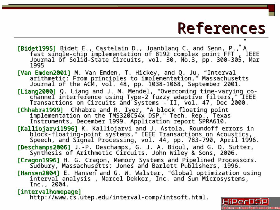
[Bidet1995][Bidet1995] Bidet E., Castelain D., Joanblanq C. and Senn, P.,”A fast single-chip Bidet E., Castelain D., Joanblanq C. and Senn, P.,”A fast single-chip implementation of 8192 complex point FFT”, IEEE Journal of Solid-State Circuits, implementation of 8192 complex point FFT”, IEEE Journal of Solid-State Circuits, vol. 30, No.3, pp. 300-305, Mar 1995vol. 30, No.3, pp. 300-305, Mar 1995
[Van Emden2001][Van Emden2001] M. Van Emden, T. Hickey, and Q. Ju, “Interval arithmetic: From M. Van Emden, T. Hickey, and Q. Ju, “Interval arithmetic: From principles to implementation,“ Massachusetts Journal of the ACM, vol. 48, pp. 1038-principles to implementation,“ Massachusetts Journal of the ACM, vol. 48, pp. 1038-1068, September 2001.1068, September 2001.
[Liang2000][Liang2000] Q. Liang and J. M. Mendel, “Overcoming time-varying co-channel interference Q. Liang and J. M. Mendel, “Overcoming time-varying co-channel interference using Type-2 fuzzy adaptive filters," IEEE Transactions on Circuits and Systems - II, using Type-2 fuzzy adaptive filters," IEEE Transactions on Circuits and Systems - II, vol. 47, Dec 2000.vol. 47, Dec 2000.
[Chhabra1999][Chhabra1999] Chhabra and R. Iyer, “A block floating point implementation on the Chhabra and R. Iyer, “A block floating point implementation on the TMS320C54x DSP," Tech. Rep., Texas Instruments, December 1999. Application TMS320C54x DSP," Tech. Rep., Texas Instruments, December 1999. Application report SPRA610.report SPRA610.
[Kalliojarvi1996][Kalliojarvi1996] K. Kalliojarvi and J. Astola, Roundoff errors in block-floating-point K. Kalliojarvi and J. Astola, Roundoff errors in block-floating-point systems," IEEE Transactions on Acoustics, Speech, and Signal Processing, vol. 44, pp. systems," IEEE Transactions on Acoustics, Speech, and Signal Processing, vol. 44, pp. 783-790, April 1996.783-790, April 1996.
[Deschamps2006][Deschamps2006] J.-P. Deschamps, G. J. A. Bioul, and G. D. Sutter, Synthesis of Arithmetic J.-P. Deschamps, G. J. A. Bioul, and G. D. Sutter, Synthesis of Arithmetic Circuits. John Wiley & Sons, 2006.Circuits. John Wiley & Sons, 2006.
[Cragon1996][Cragon1996] H. G. Cragon, Memory Systems and Pipelined Processors. Sudbury, H. G. Cragon, Memory Systems and Pipelined Processors. Sudbury, Massachusetts: Jones and Barlett Publishers, 1996. Massachusetts: Jones and Barlett Publishers, 1996.
[Hansen2004][Hansen2004] E. Hansen and G. W. Walster, “Global optimization using interval analysis”, E. Hansen and G. W. Walster, “Global optimization using interval analysis”, Marcel Dekker, Inc. and Sun Microsystems, Inc., 2004.Marcel Dekker, Inc. and Sun Microsystems, Inc., 2004.
[intervalhomepage][intervalhomepage] http://www.cs.utep.edu/interval-comp/intsoft.html. http://www.cs.utep.edu/interval-comp/intsoft.html.
ReferencesReferences

Slide 32/35
Thank You !!Thank You !!


![[DT] Hiper Disney 01](https://img.pdfslide.us/doc/110x75/577cc0501a28aba7118fa573/dt-hiper-disney-01.jpg)