Embed Size (px)
Citation preview
1
BLDC Ceiling Fan Controller with Sensor-less Sinusoidal Current Control, TIDA-00386
This reference design provides complete solution for 3-phase BLDC, ceiling fan applications. The solution consists of three sections:
1. AC-DC section: designed to work with universal main AC input range i.e. 90Vac-265Vac. It uses fly back ac/dc topology, to generate 24V DC input power from main AC. It is based on UCC28630 primary side PWM regulator.
2. Motor control section: It based on DRV10983, single chip IC operates at 24Vdc. This IC integrates all basic building blocks of 3-phase BLDC motor control i.e. sinusoidal sensor-less motion control engine + 3-phase H-bridge inverter including pre-drivers. It also provides 3.3V regulated output to support external loads up-to 100mA.
3. IR remote based Speed control section: based on value-line MSP430G2201, which decodes the remote inputs and
generate PWM duty cycle command for fan speed control.
Figure 1: Functional block diagram of BLDC ceiling fan controller
Measuring Equipment used for Testing:
1. Voltech single phase power analyzer PM100 for AC power measurement at input
2. Fluke digital Multi-meters for DC power measurement at 24Volt
3. Tektronix Digital Oscilloscope DPO4034 for waveform capture
Loading Equipment: 24V/16-pole 3-phase BLDC ceiling fan motor is utilize for testing. Motor is able to reach 310 rpm at
90% duty at 24Vdc input with power consumption of 40Watt at DC.
BLDC Ceiling Fan Controller, TIDA-00386
2
Motor Speed Control Firmware: A remote based on NEC IR transmission protocol runs at carrier frequency of 38 kHz is
used for speed control. Firmware is developed for MSP430G2201 to provide 5-step PWM duty cycle commands to DRV10983
with following features:
PWM duty cycle command is generated at 1.5 kHz and provides 10% step change in duty cycle.
Each time increment key is pressed duty-cycle is increased by 10%, similarly for decrement key duty-cycle is
reduced by 10%. Maximum duty cycle is 90% and minimum duty cycle is kept at 50%.
The firmware can be used with any IR remote that supports NEC IR transmission protocol, by changing key-codes in
software. Please refer to appendix-A for more details.
Test Results:
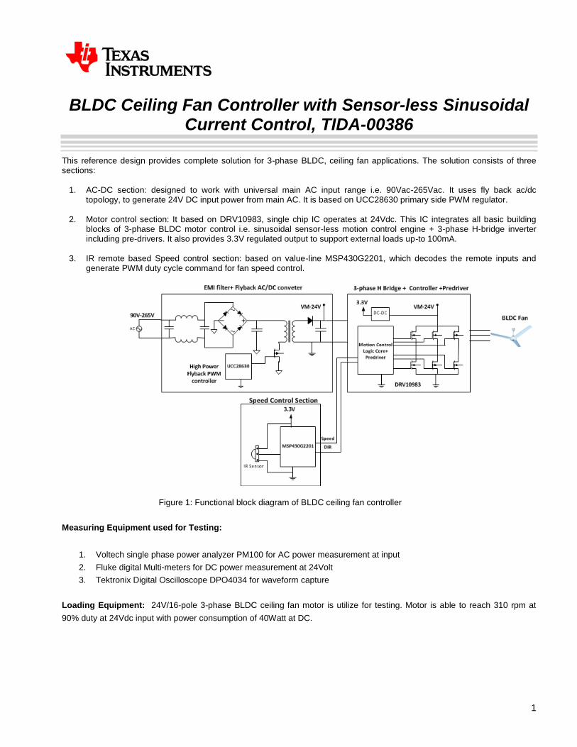
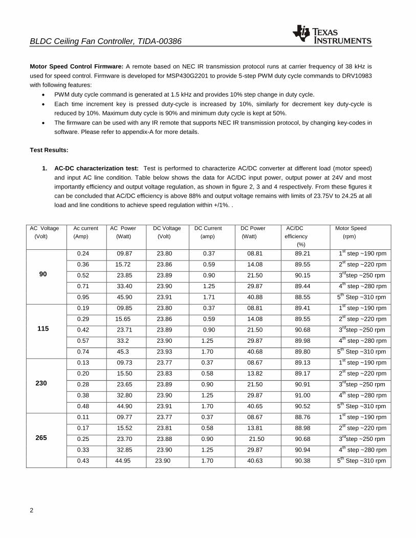
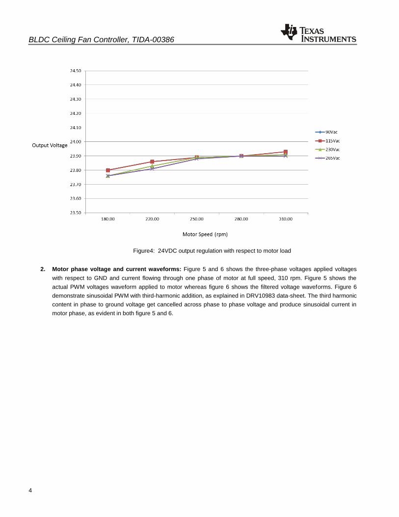
1. AC-DC characterization test: Test is performed to characterize AC/DC converter at different load (motor speed)
and input AC line condition. Table below shows the data for AC/DC input power, output power at 24V and most
importantly efficiency and output voltage regulation, as shown in figure 2, 3 and 4 respectively. From these figures it
can be concluded that AC/DC efficiency is above 88% and output voltage remains with limits of 23.75V to 24.25 at all
load and line conditions to achieve speed regulation within +/1%. .
AC Voltage
(Volt)
Ac current
(Amp)
AC Power
(Watt)
DC Voltage
(Volt)
DC Current
(amp)
DC Power
(Watt)
AC/DC
efficiency
(%)
Motor Speed
(rpm)
90
0.24 09.87 23.80 0.37 08.81 89.21 1st step ~190 rpm
0.36 15.72 23.86 0.59 14.08 89.55 2st step ~220 rpm
0.52 23.85 23.89 0.90 21.50 90.15 3rd
step ~250 rpm
0.71 33.40 23.90 1.25 29.87 89.44 4th
step ~280 rpm
0.95 45.90 23.91 1.71 40.88 88.55 5th
Step ~310 rpm
115
0.19 09.85 23.80 0.37 08.81 89.41 1st step ~190 rpm
0.29 15.65 23.86 0.59 14.08 89.55 2st step ~220 rpm
0.42 23.71 23.89 0.90 21.50 90.68 3rd
step ~250 rpm
0.57 33.2 23.90 1.25 29.87 89.98 4th
step ~280 rpm
0.74 45.3 23.93 1.70 40.68 89.80 5th
Step ~310 rpm
230
0.13 09.73 23.77 0.37 08.67 89.13 1st step ~190 rpm
0.20 15.50 23.83 0.58 13.82 89.17 2st step ~220 rpm
0.28 23.65 23.89 0.90 21.50 90.91 3rd
step ~250 rpm
0.38 32.80 23.90 1.25 29.87 91.00 4th
step ~280 rpm
0.48 44.90 23.91 1.70 40.65 90.52 5th
Step ~310 rpm
265
0.11 09.77 23.77 0.37 08.67 88.76 1st step ~190 rpm
0.17 15.52 23.81 0.58 13.81 88.98 2st step ~220 rpm
0.25 23.70 23.88 0.90 21.50 90.68 3rd
step ~250 rpm
0.33 32.85 23.90 1.25 29.87 90.94 4th
step ~280 rpm
0.43 44.95 23.90 1.70 40.63 90.38 5th
Step ~310 rpm
BLDC Ceiling Fan Controller, TIDA-00386
3
Figure2: AC/DC efficiency with respect to motor load at nominal voltages
Figure3: AC/DC efficiency with respect to motor load at Min& Max voltage
BLDC Ceiling Fan Controller, TIDA-00386
4
Figure4: 24VDC output regulation with respect to motor load
2. Motor phase voltage and current waveforms: Figure 5 and 6 shows the three-phase voltages applied voltages
with respect to GND and current flowing through one phase of motor at full speed, 310 rpm. Figure 5 shows the
actual PWM voltages waveform applied to motor whereas figure 6 shows the filtered voltage waveforms. Figure 6
demonstrate sinusoidal PWM with third-harmonic addition, as explained in DRV10983 data-sheet. The third harmonic
content in phase to ground voltage get cancelled across phase to phase voltage and produce sinusoidal current in
motor phase, as evident in both figure 5 and 6.

BLDC Ceiling Fan Controller, TIDA-00386
5
Figure5: Motor phase voltages & current at 310 rpm1
Figure6: Filtered Motor phase voltages & current at 310 rpm
1 Motor rpm =120*41.2Hz/16~ 310rpm

BLDC Ceiling Fan Controller, TIDA-00386
6
3. Start-up time: Figure 7 and 8 below shows the motor start-up time at different line condition. The maximum start-up
time occurs at low line condition i.e. at 90Vac and it in range of 1.3 seconds, whereas at 230Vac it is in range of
700msec.
Figure7: Motor Start-up time at 90Vac
Figure8: Motor Start-up time at 220Vac
BLDC Ceiling Fan Controller, TIDA-00386
7
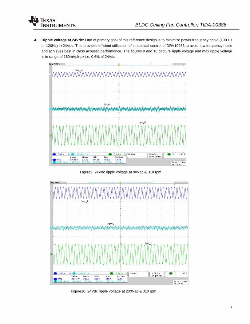
4. Ripple voltage at 24Vdc: One of primary goal of this reference design is to minimize power frequency ripple (100 Hz
or 120Hz) in 24Vdc. This provides efficient utilization of sinusoidal control of DRV10983 to avoid low frequency noise
and achieves best in class acoustic performance. The figures 9 and 10 capture ripple voltage and max ripple voltage
is in range of 160mVpk-pk i.e. 0.6% of 24Vdc.
Figure9: 24Vdc ripple voltage at 90Vac & 310 rpm
Figure10: 24Vdc ripple voltage at 230Vac & 310 rpm
BLDC Ceiling Fan Controller, TIDA-00386
8
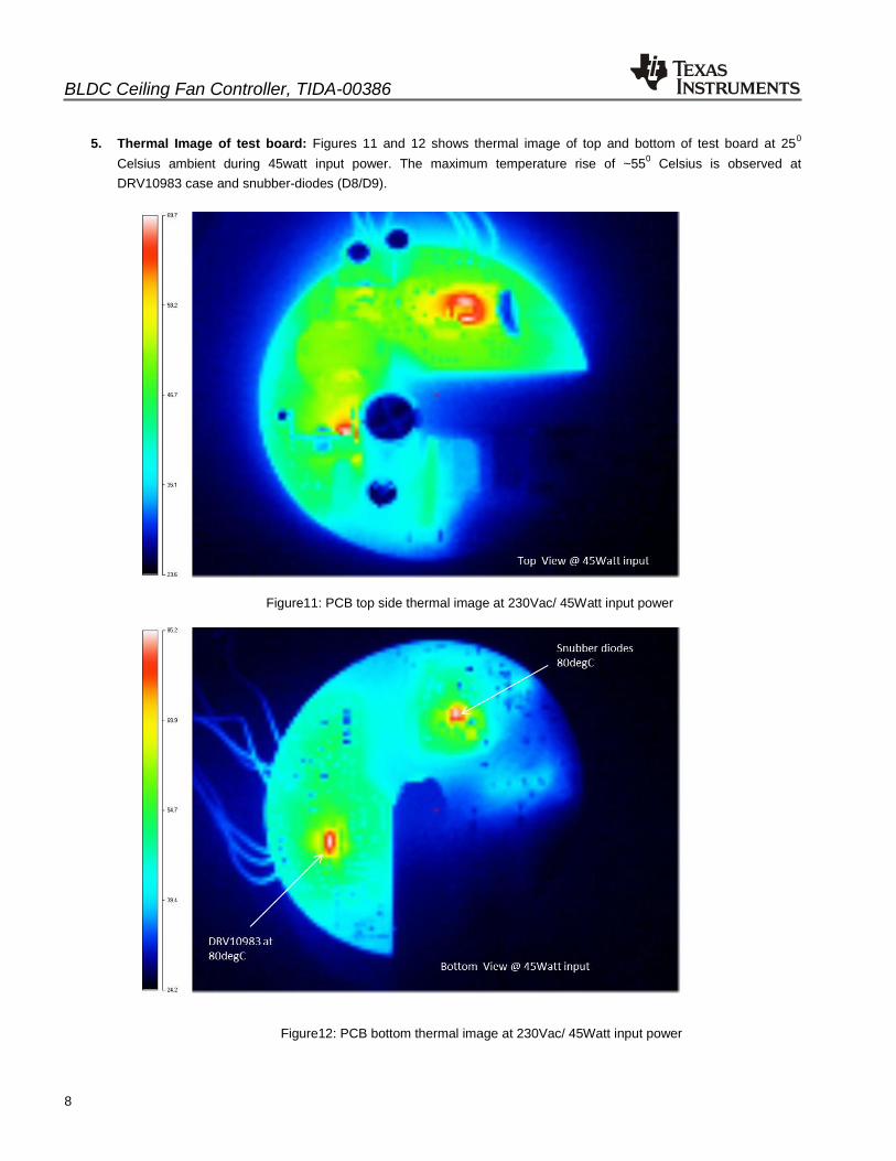
5. Thermal Image of test board: Figures 11 and 12 shows thermal image of top and bottom of test board at 250
Celsius ambient during 45watt input power. The maximum temperature rise of ~550 Celsius is observed at
DRV10983 case and snubber-diodes (D8/D9).
Figure11: PCB top side thermal image at 230Vac/ 45Watt input power
Figure12: PCB bottom thermal image at 230Vac/ 45Watt input power
BLDC Ceiling Fan Controller, TIDA-00386
9
Appendix-A Instruction to change the IR (infra-red) remote key codes for speed control Important Downloads:
1. The firmware for this design is developed for MSP430G2201 using Texas’s Instrument IDE- Code composer Studio
version 5.5.0 (CCS), therefore as first step user must have CCS version 5.5.0 or any other latest version after 5.5.0. For details to download CCS refer to http://www.ti.com/tool/ccstudio-msp430.
2. Download TIDA-00386Firmware Project files from reference design webpage.
Hardware Set-up:
To get the remote key-codes, do not apply main ac power to the board. Connector J2 on board provides 4-pin JTAG
interface for SPI-BY-WIRE Programming. It has pin for 3.3V and any utility which provides SPI-Programming support, should be able to provide 3.3V to on-board devices, MSP430G2201 and IR senor TSOP31338.
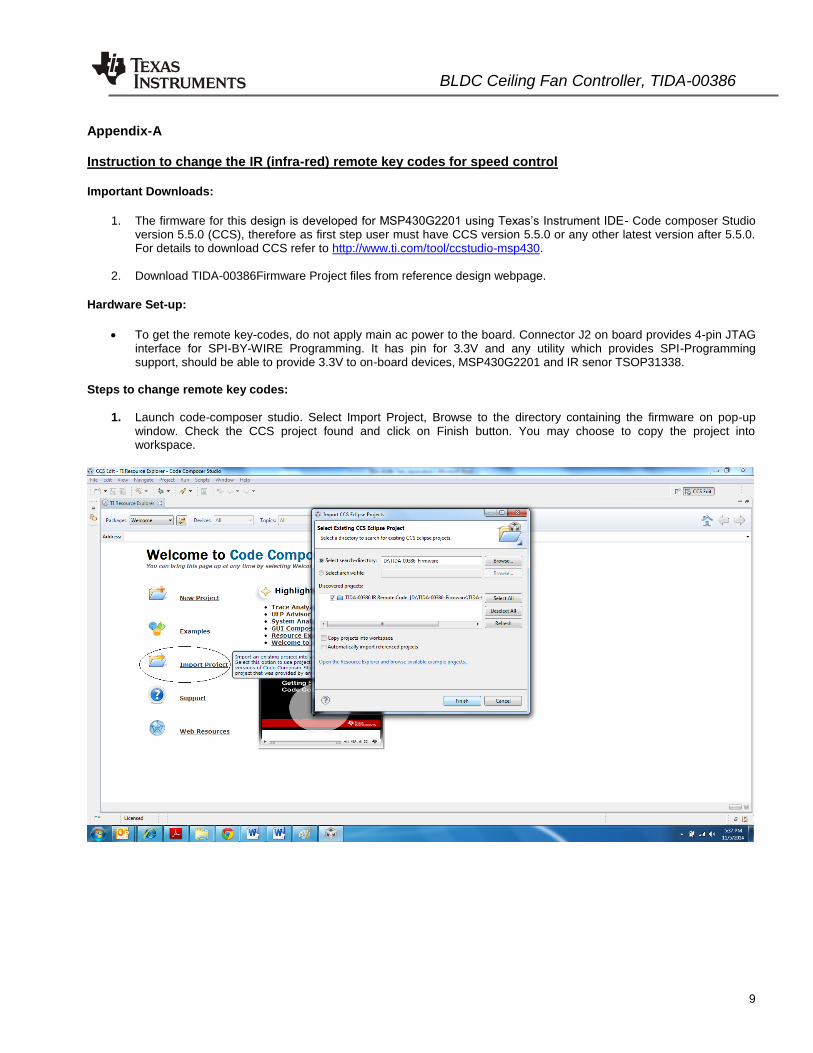
Steps to change remote key codes:
1. Launch code-composer studio. Select Import Project, Browse to the directory containing the firmware on pop-up window. Check the CCS project found and click on Finish button. You may choose to copy the project into workspace.
BLDC Ceiling Fan Controller, TIDA-00386
10
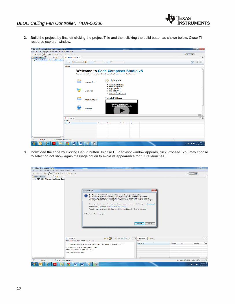
2. Build the project, by first left clicking the project Title and then clicking the build button as shown below. Close TI resource explorer window.
3. Download the code by clicking Debug button. In case ULP advisor window appears, click Proceed. You may choose to select do not show again message option to avoid its appearance for future launches.
BLDC Ceiling Fan Controller, TIDA-00386
11
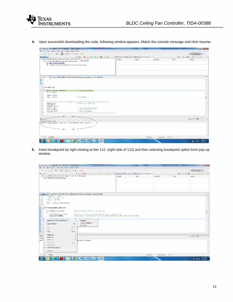
4. Upon successful downloading the code, following window appears. Match the console message and click resume.
5. Insert breakpoint by right clicking at line 112, (right side of 112) and then selecting breakpoint option from pop-up window.
BLDC Ceiling Fan Controller, TIDA-00386
12
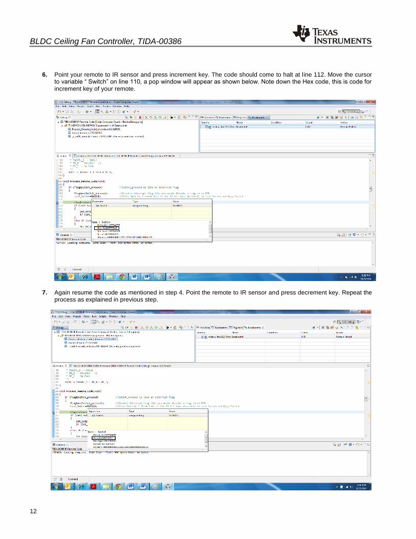
6. Point your remote to IR sensor and press increment key. The code should come to halt at line 112. Move the cursor
to variable “ Switch” on line 110, a pop window will appear as shown below. Note down the Hex code, this is code for increment key of your remote.
7. Again resume the code as mentioned in step 4. Point the remote to IR sensor and press decrement key. Repeat the process as explained in previous step.
BLDC Ceiling Fan Controller, TIDA-00386
13
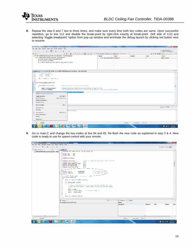
8. Repeat the step 6 and 7 two to three times, and make sure every time both key codes are same. Upon successful repetition, go to line 112 and disable the break-point by right-click exactly at break-point (left side of 112) and selecting “toggle breakpoint “option from pop-up window and terminate the debug launch by clicking red button next to resume.
9. Go to main.C and change the key-codes at line 64 and 65. Re-flash the new code as explained in step 3 & 4. New code is ready to use for speed control with your remote.
IMPORTANT NOTICE FOR TI REFERENCE DESIGNSTexas Instruments Incorporated ("TI") reference designs are solely intended to assist designers (“Buyers”) who are developing systems thatincorporate TI semiconductor products (also referred to herein as “components”). Buyer understands and agrees that Buyer remainsresponsible for using its independent analysis, evaluation and judgment in designing Buyer’s systems and products.TI reference designs have been created using standard laboratory conditions and engineering practices. TI has not conducted anytesting other than that specifically described in the published documentation for a particular reference design. TI may makecorrections, enhancements, improvements and other changes to its reference designs.Buyers are authorized to use TI reference designs with the TI component(s) identified in each particular reference design and to modify thereference design in the development of their end products. HOWEVER, NO OTHER LICENSE, EXPRESS OR IMPLIED, BY ESTOPPELOR OTHERWISE TO ANY OTHER TI INTELLECTUAL PROPERTY RIGHT, AND NO LICENSE TO ANY THIRD PARTY TECHNOLOGYOR INTELLECTUAL PROPERTY RIGHT, IS GRANTED HEREIN, including but not limited to any patent right, copyright, mask work right,or other intellectual property right relating to any combination, machine, or process in which TI components or services are used.Information published by TI regarding third-party products or services does not constitute a license to use such products or services, or awarranty or endorsement thereof. Use of such information may require a license from a third party under the patents or other intellectualproperty of the third party, or a license from TI under the patents or other intellectual property of TI.TI REFERENCE DESIGNS ARE PROVIDED "AS IS". TI MAKES NO WARRANTIES OR REPRESENTATIONS WITH REGARD TO THEREFERENCE DESIGNS OR USE OF THE REFERENCE DESIGNS, EXPRESS, IMPLIED OR STATUTORY, INCLUDING ACCURACY ORCOMPLETENESS. TI DISCLAIMS ANY WARRANTY OF TITLE AND ANY IMPLIED WARRANTIES OF MERCHANTABILITY, FITNESSFOR A PARTICULAR PURPOSE, QUIET ENJOYMENT, QUIET POSSESSION, AND NON-INFRINGEMENT OF ANY THIRD PARTYINTELLECTUAL PROPERTY RIGHTS WITH REGARD TO TI REFERENCE DESIGNS OR USE THEREOF. TI SHALL NOT BE LIABLEFOR AND SHALL NOT DEFEND OR INDEMNIFY BUYERS AGAINST ANY THIRD PARTY INFRINGEMENT CLAIM THAT RELATES TOOR IS BASED ON A COMBINATION OF COMPONENTS PROVIDED IN A TI REFERENCE DESIGN. IN NO EVENT SHALL TI BELIABLE FOR ANY ACTUAL, SPECIAL, INCIDENTAL, CONSEQUENTIAL OR INDIRECT DAMAGES, HOWEVER CAUSED, ON ANYTHEORY OF LIABILITY AND WHETHER OR NOT TI HAS BEEN ADVISED OF THE POSSIBILITY OF SUCH DAMAGES, ARISING INANY WAY OUT OF TI REFERENCE DESIGNS OR BUYER’S USE OF TI REFERENCE DESIGNS.TI reserves the right to make corrections, enhancements, improvements and other changes to its semiconductor products and services perJESD46, latest issue, and to discontinue any product or service per JESD48, latest issue. Buyers should obtain the latest relevantinformation before placing orders and should verify that such information is current and complete. All semiconductor products are soldsubject to TI’s terms and conditions of sale supplied at the time of order acknowledgment.TI warrants performance of its components to the specifications applicable at the time of sale, in accordance with the warranty in TI’s termsand conditions of sale of semiconductor products. Testing and other quality control techniques for TI components are used to the extent TIdeems necessary to support this warranty. Except where mandated by applicable law, testing of all parameters of each component is notnecessarily performed.TI assumes no liability for applications assistance or the design of Buyers’ products. Buyers are responsible for their products andapplications using TI components. To minimize the risks associated with Buyers’ products and applications, Buyers should provideadequate design and operating safeguards.Reproduction of significant portions of TI information in TI data books, data sheets or reference designs is permissible only if reproduction iswithout alteration and is accompanied by all associated warranties, conditions, limitations, and notices. TI is not responsible or liable forsuch altered documentation. Information of third parties may be subject to additional restrictions.Buyer acknowledges and agrees that it is solely responsible for compliance with all legal, regulatory and safety-related requirementsconcerning its products, and any use of TI components in its applications, notwithstanding any applications-related information or supportthat may be provided by TI. Buyer represents and agrees that it has all the necessary expertise to create and implement safeguards thatanticipate dangerous failures, monitor failures and their consequences, lessen the likelihood of dangerous failures and take appropriateremedial actions. Buyer will fully indemnify TI and its representatives against any damages arising out of the use of any TI components inBuyer’s safety-critical applications.In some cases, TI components may be promoted specifically to facilitate safety-related applications. With such components, TI’s goal is tohelp enable customers to design and create their own end-product solutions that meet applicable functional safety standards andrequirements. Nonetheless, such components are subject to these terms.No TI components are authorized for use in FDA Class III (or similar life-critical medical equipment) unless authorized officers of the partieshave executed an agreement specifically governing such use.Only those TI components that TI has specifically designated as military grade or “enhanced plastic” are designed and intended for use inmilitary/aerospace applications or environments. Buyer acknowledges and agrees that any military or aerospace use of TI components thathave not been so designated is solely at Buyer's risk, and Buyer is solely responsible for compliance with all legal and regulatoryrequirements in connection with such use.TI has specifically designated certain components as meeting ISO/TS16949 requirements, mainly for automotive use. In any case of use ofnon-designated products, TI will not be responsible for any failure to meet ISO/TS16949.
Mailing Address: Texas Instruments, Post Office Box 655303, Dallas, Texas 75265Copyright © 2014, Texas Instruments Incorporated