Embed Size (px)
Citation preview
8/8/2019 BLarge Deluxe
http://slidepdf.com/reader/full/blarge-deluxe 1/11
1
Brian Large
Physics 398 EMIFinal Report
Building a Vacuum Tube Amplifier
First, let me preface this paper by saying that I will try to write it for the idiot, because I
knew absolutely nothing about amplifiers before I started.
Project Selection
I had tried putting together a stomp box once before (in high school), with little
success, so the idea of building something as a project for this course intrigued me. I also
was intrigued with building an amplifier because it is the part of the sound creation
process that I understand the least. Maybe that’s why I’m not an electrical engineer.
Anyways, I already own a solid-state amplifier (a Fender Deluxe 112 Plus), so I decided
that it would be nice to add a tube amp. I drew up a list of “Things I wanted in an
Amplifier” and began to discuss the matters with the course instructor, Professor Steve
Errede, and my lab TA, Dan Finkenstadt. I had decided I wanted a class AB push-pull
amp putting out 10-20 Watts. I had decided against a reverb unit because it made the
schematic much more complicated and would also cost more.
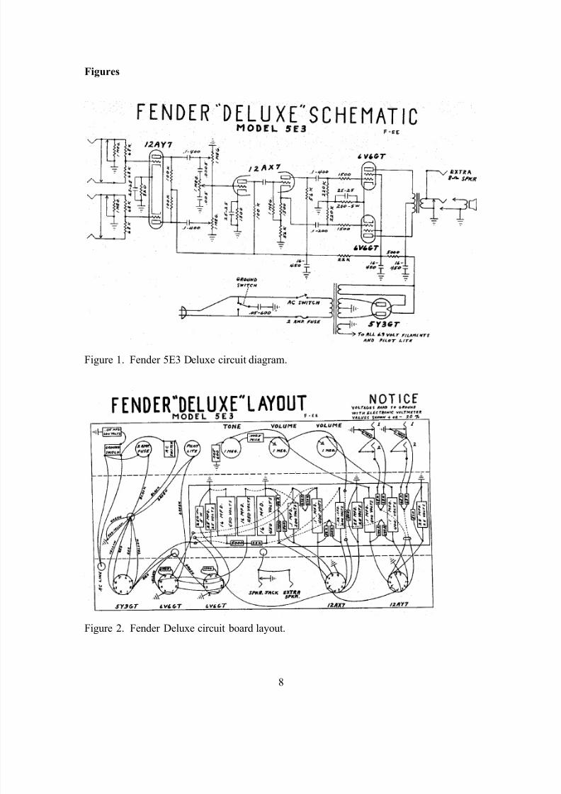
With these decisions in mind, we decided that a Fender Tweed Deluxe would bethe easiest to build that fit my needs. The Deluxe schematic that I built my amp off of
was a 5E3, built by Fender from 1955-1960 (Figure 1). The reason we chose such an old
amp is because they sound great and their schematics are considerably easier to build.
Steve had a book that had schematics in it, but I was able to get additional information
online from the Fender Field Guide at www.ampwares.com/ffg. I was also able to look at
Dan’s Tweed Deluxe for additional reference. Because I was unsure of whether I was
going to be able to afford a speaker, I decided to make my amp a head and cabinet
combo. I reasoned that if I couldn’t afford a speaker, I could add it later in a separate
cabinet. This decision later proved to have unforeseen and adverse consequences.
8/8/2019 BLarge Deluxe
http://slidepdf.com/reader/full/blarge-deluxe 2/11
2
Parts
Once I had decided what kind of amplifier I was going to build, I had to start
collecting parts. Steve already had some components (including power and output
transformers from a reissue Deluxe Reverb) that I was able to buy off of him and did not
need to order. Generally, cost was not a major concern of mine, but my amp was still
significantly cheaper to build than a new store-bought one. A lot of the resistors and
other cheap things I got from old lab equipment and the Physics storeroom. More
specialized parts like capacitors, audio-taper potentiometers, grounding input jacks, and
the chassis had to be ordered. The first thing I ordered was the chassis. The chassis I
chose was very close in size to the original Deluxe chassis, and was made of painted
steel. As I waited for my chassis to come, I started laying out my circuit according to the
Deluxe chassis layout (Figure 2).
Layout
Once I had all the parts laid out on the board, I started soldering them in place. I
left enough length on the leaders to be able to connect them to other parts of the amp.
When my chassis arrived I started concentrating on laying that out.
Because I had decided I was making just an amp head and not the whole
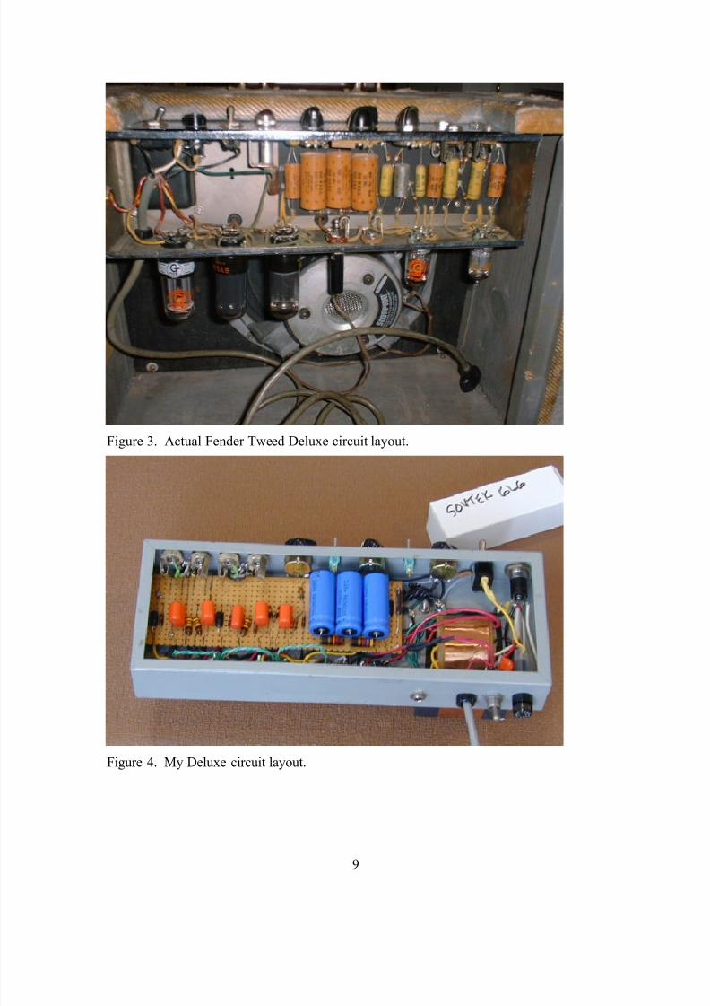
amplifier, my chassis had to be laid out differently. In production Deluxe, the
transformers are mounted on the bottom of the chassis (with the open side being
considered as the top), the tubes are mounted on one side, and the tone controls are
mounted on the far side from the tone controls. The chassis then hangs down in the
cabinet with the tone controls facing up and open side of the chassis facing the back of
the amplifier (Figure 3). However, because I was building a head, my transformers and
tubes were all mounted to the bottom of the chassis, with the tone controls being on the
side. I wanted the input jacks on the left of my amp, so I put the transformers on the
opposite side of the amp. This is done to try and isolate the power section from the input
section in order to reduce the amount of 60Hz hum that the amp picks up. Then, I
basically followed the Fender layout and laid out my tubes around my transformers. I put
the pre-amp tubes (12AX7 & 12AY7) as far away from the transformers and power
8/8/2019 BLarge Deluxe
http://slidepdf.com/reader/full/blarge-deluxe 3/11
3
section as possible. This is also done to reduce hum. The rectifier tube (5Y3) went right
next to the transformers, and the two power tubes (a pair of 6V6’s) went in between.
After I had laid out my chassis, I drilled all of the necessary holes with a drill
press. I had to use a hole punch for the tube sockets and I cut out the square hole for the
power transformer with a hacksaw. Finally, I was able to start putting things together!
Assembly
When I finally started putting all of my components in my chassis, I determined
that I had made a significant error in laying out my chassis. My circuit board was the
mirror image of what it needed to be! That is, if you drew a center line down the long
axis of my board and flipped each component over that line, that is what I should have
had (Figure 4). I discussed possible solutions with Steve and Dan, and we came up with
several solutions:
1. Reverse the location of the transformers and the input jacks, effectively
turning the chassis around and leaving the board the same. I didn’t do this
because I had already put holes in my chassis for the components.
2. Place the board in right-side up and run the leads underneath the board to their
proper components. This was discarded because of the fear that I might pick
up too much interference from all of the extra wire running around.
3. Put the board in upside down. This was also discarded because of the fear that
I would screw up soldering things together.
4. Take each component out, turn it around, and solder it back in.
This is what I eventually did, and it turned out for the better because I did a much better
job laying out the board and soldering the components together the second time around. I
had already had “practice” with the previous board and this layout was much neater than
the previous one.
After I had properly laid out my board, I went about trying to fit everything in my
chassis. It was a pretty tight fit. The chassis I had picked was slightly smaller than that
used in an original Deluxe. It was about a half inch shorter, and this kept me from
mounting my four input jacks on top of each other in the box pattern. Instead, I had to
mount the four jacks next to each other. This left me less room for my potentiometers
8/8/2019 BLarge Deluxe
http://slidepdf.com/reader/full/blarge-deluxe 4/11
4
and switches, so everything got kind of squished together, which made some of the
components hard to connect together.
Modifications
I made several modifications to the circuit I had, either due to Steve’s advice or to
lack of parts. Initially I changed some of the components on my circuit board. Instead of
16µFd-450V capacitors I used 20µFd-500V for the filter capacitors. This helps to
eliminate extra noise coming from the power section. I also used a 300-Ohm, 5-Watt
power resistor because that was the closest value resistor that we could find. One or two
of the resistors are also slightly different values. I wired all the grounds to a star ground
because I had a painted chassis and because grounding through the chassis is an
inefficient way of grounding things anyway. A star ground is simply one point in the
amp to which all of the grounds are wired. I also threw some switches on the in the
controls in case I decide to add a “Bright” or “Deep” switch to one of the input channels
later.
Steve also recommended that I put in a grounding power cord. The old amps only
have a two-prong power cord and a polarity switch. The switch is used to switch which
prong is the ground reference. This can be very unsafe because it allows the capacitors to
be charged from both directions. A musician could receive a very nasty shock if heaccidentally plugged his amplifier into the wall with the prongs reversed! The newer
amps have a three-prong power cord. The third prong is a ground reference, which gives
the amp a constant ground and counteracts the need for a ground switch.
Steve also recommended that I install a standby switch. A standby switch is used
to allow power to flow to the tube section without allowing power to flow to the rest of
the amplifier. This allows the tube heaters to turn on and warm up the tubes, without
allowing the voltage transients associated with powering up the transformers to flow
through to the circuit and potentially damage the capacitors. Finally, I installed a 0.1µFd
capacitor from the standby switch to ground. This also helps to reduce voltage transients.
Finally, Steve recommended that instead of running one of the heater wires to
ground (it’s labeled “green” in the layout), I run it to the other heater in the tubes (Pin 2
on the 6V6s and pin 9 on the 12AX7s.) I could then twist the two heater wires together.
8/8/2019 BLarge Deluxe
http://slidepdf.com/reader/full/blarge-deluxe 5/11
5
This has the effect of canceling out some of the 60Hz hum associated with the AC heater
voltages.
Troubleshooting
When we first turned the amp on, it passed “the smoke test,” which was a
tremendous relief. Next, we measured the voltages in the amp, and they all checked out.
All of the inputs worked as well and the amp sounded great! There were two problems,
though. First was that the tone control was acting strangely. I checked the value on the
capacitor and found that I had accidentally installed the wrong capacitor on the tone
knob! At least it was an easy fix. The other problem was that the amp had a terrible hum
problem. While all tube amplifiers have some hum, this was unusually loud. Steve
recommended I do several things and test the amp after each “fix” to see if the hum
problem had been corrected.
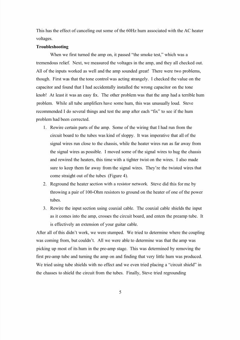
1. Rewire certain parts of the amp. Some of the wiring that I had run from the
circuit board to the tubes was kind of sloppy. It was imperative that all of the
signal wires run close to the chassis, while the heater wires run as far away from
the signal wires as possible. I moved some of the signal wires to hug the chassis
and rewired the heaters, this time with a tighter twist on the wires. I also made
sure to keep them far away from the signal wires. They’re the twisted wires that
come straight out of the tubes (Figure 4).
2. Reground the heater section with a resistor network. Steve did this for me by
throwing a pair of 100-Ohm resistors to ground on the heater of one of the power
tubes.
3. Rewire the input section using coaxial cable. The coaxial cable shields the input
as it comes into the amp, crosses the circuit board, and enters the preamp tube. It
is effectively an extension of your guitar cable.
After all of this didn’t work, we were stumped. We tried to determine where the coupling
was coming from, but couldn’t. All we were able to determine was that the amp was
picking up most of its hum in the pre-amp stage. This was determined by removing the
first pre-amp tube and turning the amp on and finding that very little hum was produced.
We tried using tube shields with no effect and we even tried placing a “circuit shield” in
the chasses to shield the circuit from the tubes. Finally, Steve tried regrounding
8/8/2019 BLarge Deluxe
http://slidepdf.com/reader/full/blarge-deluxe 6/11
6
everything. He ran each circuit ground as a separate wire, twisted them together, and
connected them to the star ground. This seemed to work. While the amp still has some
hum, it appears that we eliminated the largest factor.
The problem with the amp’s grounding was that the wires running to ground were
simply not big enough to carry the current back to ground. Rewiring each component to
ground gave the current less resistance and the ability to flow more freely.
Sound
As I worked on my project, I eventually did decide buy speakers for my amplifier.
I chose to run it into a 2x12 cabinet, for no very good reason. Both of my speakers I
bough off of used off of E-bay, and I feel that I got a pretty good deal on. I have one of
the speakers at the time of my writing this, but the other one hasn’t arrived yet. I also
haven’t built a cabinet, so I can’t comment on the amp’s final sound. I can say that I
have played it through Steve’s Mesa-Boogie 1x12 cabinet and it has an excellent, bluesy
tone. It is also very loud . Steve and I first tested the amp with 6V6’s as the power tubes,
but later switched to 6L6’s. These tubes give a beefier sound, and the are also more
robust, so they don’t have to work as hard and they stay cooler while powering the amp.
The rated wattage on my output transformer is 20-Watts using 6V6 power tubes, so using
6L6’s probably also bumps the wattage up a little. Plus, Steve’s Mesa-Boogie cabinet is
very efficient and probably makes the amp sound a little more powerful than it actually
is.
Conclusion
Surprisingly, what I ended up with is very close in sound to a Fender Tweed
Deluxe. I’m not sure what I had expected, but I am pleased with what I got. I am also
pleased that I was able to not only attempt to build an amplifier like this, but that I was
also able to complete it and have it work, which was my goal from the beginning. The
experience and help of my instructors and other members of my class was invaluable in
building my amp, and it was something that I wouldn’t have tried if I didn’t have
knowledgeable supervision.
8/8/2019 BLarge Deluxe
http://slidepdf.com/reader/full/blarge-deluxe 7/11
7
Finally, in general, I am pleased with my experience in Physics 398EMI. It is the
type of course that I believe we need more of. The ability to apply theories that I thought
were useless to things that I find interesting helps me to learn and to reinforce what I
have learned in other courses. I found the laboratory section most helpful because it
helped me to learn from tangible experiments; performed by myself, Steve, and other
members of the class; to analyze real data and to use it to solve the problems I was having
with my amplifier. Not only am I taking an amplifier and a 2½ inch 3-ring binder full of
lecture notes home from this class, but I am also taking away a lot of knowledge that I
know I won’t forget once the final is over.
8/8/2019 BLarge Deluxe
http://slidepdf.com/reader/full/blarge-deluxe 8/11
8
Figures
Figure 1. Fender 5E3 Deluxe circuit diagram.
Figure 2. Fender Deluxe circuit board layout.
8/8/2019 BLarge Deluxe
http://slidepdf.com/reader/full/blarge-deluxe 9/11
8/8/2019 BLarge Deluxe
http://slidepdf.com/reader/full/blarge-deluxe 10/11
10
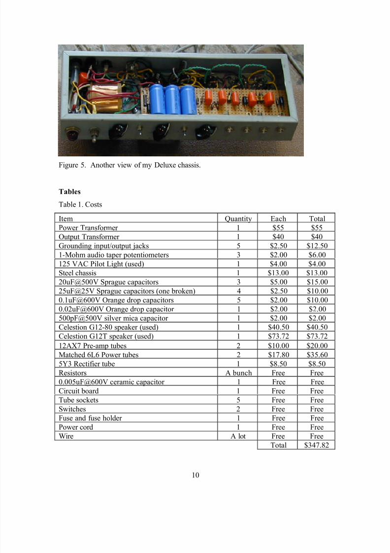
Figure 5. Another view of my Deluxe chassis.
TablesTable 1. Costs
Item Quantity Each Total
Power Transformer 1 $55 $55
Output Transformer 1 $40 $40
Grounding input/output jacks 5 $2.50 $12.50
1-Mohm audio taper potentiometers 3 $2.00 $6.00
125 VAC Pilot Light (used) 1 $4.00 $4.00
Steel chassis 1 $13.00 $13.00
20uF@500V Sprague capacitors 3 $5.00 $15.00
25uF@25V Sprague capacitors (one broken) 4 $2.50 $10.000.1uF@600V Orange drop capacitors 5 $2.00 $10.00
0.02uF@600V Orange drop capacitor 1 $2.00 $2.00
500pF@500V silver mica capacitor 1 $2.00 $2.00
Celestion G12-80 speaker (used) 1 $40.50 $40.50
Celestion G12T speaker (used) 1 $73.72 $73.72
12AX7 Pre-amp tubes 2 $10.00 $20.00
Matched 6L6 Power tubes 2 $17.80 $35.60
5Y3 Rectifier tube 1 $8.50 $8.50
Resistors A bunch Free Free
0.005uF@600V ceramic capacitor 1 Free Free
Circuit board 1 Free Free
Tube sockets 5 Free Free
Switches 2 Free Free
Fuse and fuse holder 1 Free Free
Power cord 1 Free Free
Wire A lot Free Free
Total $347.82
8/8/2019 BLarge Deluxe
http://slidepdf.com/reader/full/blarge-deluxe 11/11
11
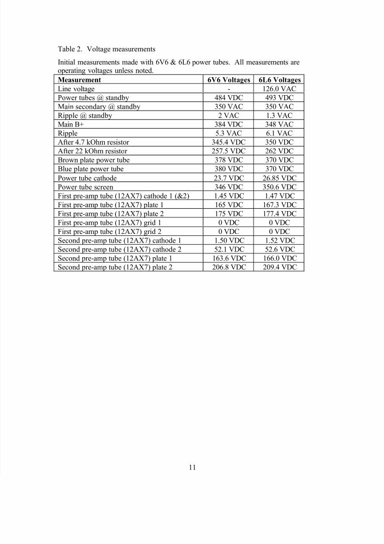
Table 2. Voltage measurements
Initial measurements made with 6V6 & 6L6 power tubes. All measurements areoperating voltages unless noted.
Measurement 6V6 Voltages 6L6 Voltages
Line voltage - 126.0 VAC
Power tubes @ standby 484 VDC 493 VDCMain secondary @ standby 350 VAC 350 VAC
Ripple @ standby 2 VAC 1.3 VAC
Main B+ 384 VDC 348 VAC
Ripple 5.3 VAC 6.1 VAC
After 4.7 kOhm resistor 345.4 VDC 350 VDC
After 22 kOhm resistor 257.5 VDC 262 VDC
Brown plate power tube 378 VDC 370 VDC
Blue plate power tube 380 VDC 370 VDC
Power tube cathode 23.7 VDC 26.85 VDC
Power tube screen 346 VDC 350.6 VDCFirst pre-amp tube (12AX7) cathode 1 (&2) 1.45 VDC 1.47 VDC
First pre-amp tube (12AX7) plate 1 165 VDC 167.3 VDC
First pre-amp tube (12AX7) plate 2 175 VDC 177.4 VDC
First pre-amp tube (12AX7) grid 1 0 VDC 0 VDC
First pre-amp tube (12AX7) grid 2 0 VDC 0 VDC
Second pre-amp tube (12AX7) cathode 1 1.50 VDC 1.52 VDC
Second pre-amp tube (12AX7) cathode 2 52.1 VDC 52.6 VDC
Second pre-amp tube (12AX7) plate 1 163.6 VDC 166.0 VDC
Second pre-amp tube (12AX7) plate 2 206.8 VDC 209.4 VDC