Embed Size (px)
Citation preview
DatOL-12771-01
C H A P T E R 4
Blade Server Integration into the Data Center with Intelligent Network ServicesThis chapter discusses the integration of intelligent services into the Cisco Data Center Architecture that uses blade server systems. It includes the following topics:
• Blade Server Systems and Intelligent Services
• Data Center Design Overview
• Design and Implementation Details
Blade Server Systems and Intelligent ServicesA blade server is an independent server that includes an operating system, memory, one or more processors, network controllers, and optional local storage. Blade servers reduce data center space, power, and cooling requirements by providing these services within a single chassis. Blade server systems are a key component of data center consolidation that help reduce costs and improve virtualization, automation, and provisioning capabilities.
Blade system vendors offer high availability, scalability, and security services such as load balancing, firewalls, and intrusion detection to enterprise applications. Depending on the vendor, these services are made available through the blade system integrated network devices or individual blade servers using service specific software. Figure 4-1 shows a service- enabled blade system. In this example, two software-based firewalls are located on two of the eight-blade servers in the chassis. This example also shows two integrated network switches, one on each side of the device, connecting to the outside network as well as to Layer 4 through Layer 7 services.
4-1a Center Blade Server Integration Guide

Chapter 4 Blade Server Integration into the Data Center with Intelligent Network Services Data Center Design Overview
Figure 4-1 Blade Server System Service Example
Traditionally, these services have been provided by appliances or integrated service modules located in the data center network. Modern blade systems are challenging this approach.
Data Center Design OverviewA data center design must consider application architecture and network services. This section reviews these needs and includes the following topics:
• Application Architectures
• Network Services in the Data Center
Application ArchitecturesThe data center is a repository for enterprise software applications. These applications are continuously changing to meet business requirements and to accommodate the latest technological advances and methods. Consequently, the logical and physical structure of the data center server farm and of the network infrastructure hosting these software applications is changing.
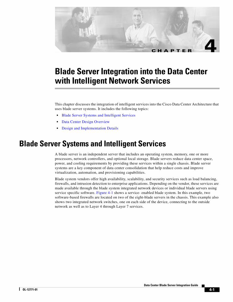
The server farm has evolved from the classic client/server model to an N-tier approach. The N-tier model logically or physically separates the enterprise application by creating functional areas. These areas are generally defined as the web front end, the application business logic, and the database tiers. Figure 4-2 illustrates the progression of the enterprise application from the client/server to the N-tier paradigm.
4-2Data Center Blade Server Integration Guide
OL-12771-01
Chapter 4 Blade Server Integration into the Data Center with Intelligent Network Services Data Center Design Overview
Figure 4-2 Client/Server and N-Tier Model
The N-tier model provides a more scalable and manageable enterprise application environment because it creates distinct serviceable areas in the software application. The application is distributed and becomes more resilient because single points of failure are removed from the design. In addition, the N-tier application architecture impacts the design of the data center network and the services it renders. The data center network must be able to adapt and meet the requirements of a multi-tiered server farm. It must also provide a reliable means for distributed servers to communicate and to benefit from other data center services such as the following:
• Infrastructure services (VLANs, RPVST+, UDLD, HSRP, VRRP, OSPF, QoS)
• Application optimization (load balancing, caching, SSL offloading)
• Security (ACLs, firewalls, intrusion detection/prevention)
The N-tier application architecture is the current standard for enterprise data center application deployments.
Note For more information on a flexible data center design for the N-tier application architecture, see the Data Center Infrastructure SRND v 2.0 at the following URL: http://www.cisco.com/en/US/docs/solutions/Enterprise/Data_Center/DC_Infra2_5/DCI_SRND_2_5_book.html.
There is a movement toward creating service-oriented architectures (SOAs) in the enterprise application space. SOAs advocate the ability to connect and integrate multi-tiered enterprise applications based on standards. Standard transport, standard messaging and standard data formats are used throughout the enterprise and between partners. The objective of a SOA architecture is to readily incorporate new functionality and provide flexible solutions to business requirements; ultimately creating a competitive advantage for the enterprise.
The data center network transports the messaging created by these distinct application services. In a SOA environment, reliable messaging is critical to the success of the enterprise. The network provides this end-to-end functionality, managing the messaging between services. If standard forms of communication are used by a service-oriented architecture, the network simply needs the ability to interpret those messages to make informed decisions and provide increasing value to the business.
4-3Data Center Blade Server Integration Guide
OL-12771-01

Chapter 4 Blade Server Integration into the Data Center with Intelligent Network Services Data Center Design Overview
Note One common type of SOA is using web services. A web service can be defined as “any piece of software that makes itself available over the Internet and uses a standardized XML messaging system” –Ethan Cerami, O’Reilly Press. The IP network supports the transport protocols typically used by web services such as HTTP, HTTPS, or SMTP. Messaging between web services is typically performed with a non-proprietary messaging protocol such as Simple Object Access Protocol (SOAP) allowing data exchange and remote process communication between dissimilar applications. The Extensible Markup Language (XML) provides a structured data format for these disparate services, allowing independent operating systems and programming languages to communicate and provide services to one another.
Network Services in the Data CenterThe data center network is the end-to-end transport for multi-tiered applications and service-based architecture. The network is in an ideal position to deploy intelligent services providing resiliency, security, and application optimization because it already manages communication between enterprise applications. Thus, the following two fundamental questions must be answered:
• How should the network services be deployed, such as in a consolidated or dispersed design?
• What hardware platforms should be considered or used for those network services?
Figure 4-3 illustrates a collapsed multi-tier design. This is the recommended design for data center networks. In Figure 4-2, the access layer switches provide port connectivity for the server farms and uplink connectivity to an aggregation layer. The aggregation layer provides a communication path between servers and a link to the remaining enterprise via the core.
Figure 4-3 Collapsed Multi-tier Design
This design is flexible and scalable, allowing many different operating systems and applications to share the same network infrastructure. Segmentation of the web, application and database tiers is achievable using VLANs; providing a logical boundary between the respective enterprise applications.
4-4Data Center Blade Server Integration Guide
OL-12771-01
Chapter 4 Blade Server Integration into the Data Center with Intelligent Network Services Data Center Design Overview
Note For more information about the Cisco Data Center Infrastructure, see the Cisco Data Center Infrastructure SRND v. 2.0 at the following URL: http://www.cisco.com/en/US/docs/solutions/Enterprise/Data_Center/DC_Infra2_5/DCI_SRND_2_5_book.html.
Centralized or Distributed Services
The aggregation layer of the data center is an ideal location to provide centralized network services because it transports client-to-server and server-to-server communication within the data center. The aggregation layer is a control point where network services can be deployed and shared across server farms and their software applications. The maturing set of standards defining enterprise service-oriented architectures improve the effectiveness of centralized network-based services. These standards improve effectiveness by providing well-understood protocols and message formats supporting application communications.
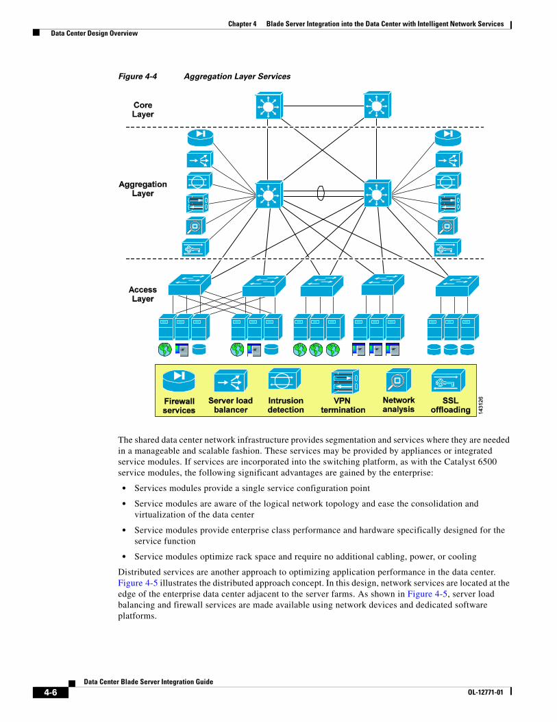
Figure 4-4 shows the collapsed multi-tier architecture with network services available at the aggregation layer. These services include the following:
• Server load balancing
• Firewalls
• Network analysis
• SSL offloading
• Intrusion detection
• Content caching
• VPN termination
4-5Data Center Blade Server Integration Guide
OL-12771-01
Chapter 4 Blade Server Integration into the Data Center with Intelligent Network Services Data Center Design Overview
Figure 4-4 Aggregation Layer Services
The shared data center network infrastructure provides segmentation and services where they are needed in a manageable and scalable fashion. These services may be provided by appliances or integrated service modules. If services are incorporated into the switching platform, as with the Catalyst 6500 service modules, the following significant advantages are gained by the enterprise:
• Services modules provide a single service configuration point
• Service modules are aware of the logical network topology and ease the consolidation and virtualization of the data center
• Service modules provide enterprise class performance and hardware specifically designed for the service function
• Service modules optimize rack space and require no additional cabling, power, or cooling
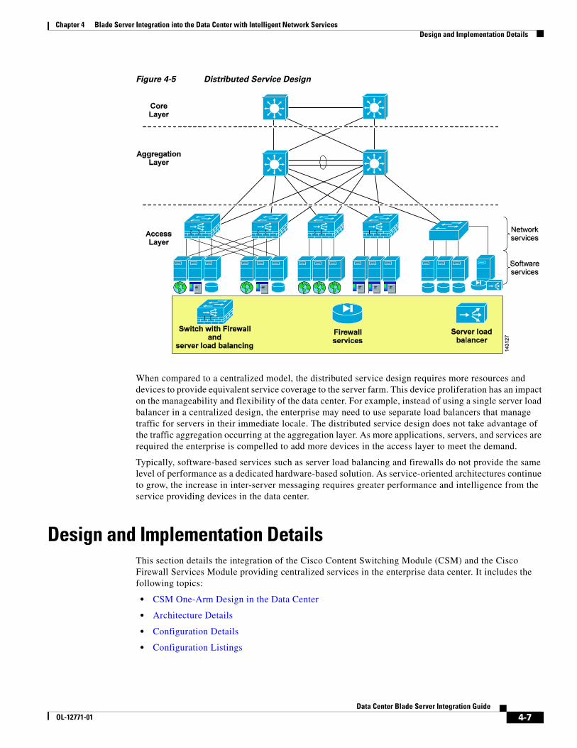
Distributed services are another approach to optimizing application performance in the data center. Figure 4-5 illustrates the distributed approach concept. In this design, network services are located at the edge of the enterprise data center adjacent to the server farms. As shown in Figure 4-5, server load balancing and firewall services are made available using network devices and dedicated software platforms.
4-6Data Center Blade Server Integration Guide
OL-12771-01
Chapter 4 Blade Server Integration into the Data Center with Intelligent Network Services Design and Implementation Details
Figure 4-5 Distributed Service Design
When compared to a centralized model, the distributed service design requires more resources and devices to provide equivalent service coverage to the server farm. This device proliferation has an impact on the manageability and flexibility of the data center. For example, instead of using a single server load balancer in a centralized design, the enterprise may need to use separate load balancers that manage traffic for servers in their immediate locale. The distributed service design does not take advantage of the traffic aggregation occurring at the aggregation layer. As more applications, servers, and services are required the enterprise is compelled to add more devices in the access layer to meet the demand.
Typically, software-based services such as server load balancing and firewalls do not provide the same level of performance as a dedicated hardware-based solution. As service-oriented architectures continue to grow, the increase in inter-server messaging requires greater performance and intelligence from the service providing devices in the data center.
Design and Implementation DetailsThis section details the integration of the Cisco Content Switching Module (CSM) and the Cisco Firewall Services Module providing centralized services in the enterprise data center. It includes the following topics:
• CSM One-Arm Design in the Data Center
• Architecture Details
• Configuration Details
• Configuration Listings
4-7Data Center Blade Server Integration Guide
OL-12771-01

Chapter 4 Blade Server Integration into the Data Center with Intelligent Network Services Design and Implementation Details
The design specifically addresses a multi-tier deployment of an IBM WebSphere application on a blade system platform. The CSM one-arm design provides centralized server load balancing and firewall services for the application.
CSM One-Arm Design in the Data CenterThe availability, scalability, and security of enterprise applications are typically dependent on the services provided by devices such as load balancers and firewalls. The CSM one-arm design promotes these goals and efficiently integrates these services within an N-tier application architecture. The design permits server load balancing and firewall functionality to be selectively applied at each tier of the architecture via the CSM and FWSM. This efficiency improves the overall performance of the data center by providing application services only where those services are required.
Figure 4-6 shows a logical view of the CSM one-arm design. The CSM and the FWSM physically reside within the same Catalyst 6500 chassis and are logically positioned to optimize the performance and services of the data center. The CSM is removed from any direct traffic flows, and relies on the advanced routing capabilities of the MSFC to make its services available. Conversely, situating the FWSM in front of the server farm and between the application and database tiers allows the use of security services where they are most often required.
Figure 4-6 CSM One-Arm Design Logical View
The CSM one-arm design follows the principal of centralized data center services, allowing web, application, and database servers to use the same service device located at the aggregation layer of the data center.
4-8Data Center Blade Server Integration Guide
OL-12771-01

Chapter 4 Blade Server Integration into the Data Center with Intelligent Network Services Design and Implementation Details
Traffic Pattern Overview
This section describes the traffic pattern in the data center for the following flows:
• Client-to-server
• Server-to-server
Client-to-Server
Figure 4-7 shows the client-to-server traffic flow through the data center when using the CSM in one-arm mode. The client is attempting to reach a web page located on a blade server in the enterprise data center.
Figure 4-7 Client-to-Server Traffic Flow
A successful transaction with the one-arm data center design includes the following sequence of events:
1. Client requests a URL associated with the CSM virtual IP (VIP) address.
2. The MSFC routes the request to the CSM VIP.
3. The CSM makes a load balancing decision and selects a real server. At this point, the CSM replaces the VIP address with the IP address of the real server if the nat server command is present in the virtual server configuration. The CSM forwards the request to its default gateway on the MSFC using the destination IP address of the real server and the source address of the client.
4. The MSFC routes the request to the real server protected by the FWSM.
4-9Data Center Blade Server Integration Guide
OL-12771-01

Chapter 4 Blade Server Integration into the Data Center with Intelligent Network Services Design and Implementation Details
5. The FWSM is bridging traffic between the “inside” and “outside” networks, applying the appropriate security policies to the network segment.
6. The switch forwards the traffic to the real server.
7. The real server forwards a reply to its default gateway the MSFC.
8. The FWSM receives the traffic from the access switch.
9. The FWSM forwards the traffic to the MSFC.
10. The MSFC uses policy-based routing (PBR) on the interface to forward the return traffic to the CSM.
11. The CSM rewrites the source IP address of the return traffic from the real server IP address to the VIP of the CSM. The rebuilt packet is sent to the default gateway of the CSM, the MSFC.
12. The MSFC forwards the reply to the client.
Server-to-Server
Figure 4-8 illustrates the traffic flow through the data center when using the CSM server load balancing with server-to-server traffic. In this scenario, a blade server hosting a web application is connecting through the load balancer in one-arm mode to another blade server hosting a middle-tier application.
Figure 4-8 Traffic Flow with Server-to-Server Load Balancing via the CSM
The following sequence of events result in a successful connection for the scenario shown in Figure 4-8:
1. The web server initiates a connection to the CSM VIP.
2. The firewall receives the traffic on its inside interface.
4-10Data Center Blade Server Integration Guide
OL-12771-01

Chapter 4 Blade Server Integration into the Data Center with Intelligent Network Services Design and Implementation Details
3. The firewall bridges the traffic to the default gateway of the web server, the MSFC.
4. The MSFC routes the traffic to the CSM alias address that is the static route for the CSM VIP.
5. The CSM selects a real application server based on a load balancing algorithm. It then performs server NAT and forwards the traffic to its default gateway located on the MSFC, using the destination IP address of the real application server and the source address of the web server.
6. The MSFC routes the traffic to the application tier through the FWSM.
7. The FWSM receives the packet and applies the appropriate security policies for that application tier network segment.
8. The switch forwards the traffic to the real application server.
9. The application server sends its response to the connection request to its default gateway located on the MSFC.
10. The FWSM receives the response on its inside interface of the application tier network segment.
11. The FWSM forwards the response to the MSFC located on the outside of the application network segment.
12. The MSFC applies PBR based on the Layer 4 port information and routes the traffic to the MSFC.
13. The CSM rewrites the source IP address of the return traffic from the real server IP address to the VIP of the CSM. The rebuilt packet is sent to the default gateway of the CSM, the MSFC.
14. The MSFC routes the traffic to the web tier through the outside interface of the FWSM.
15. The FWSM performs its packet filtering functions and bridges the traffic to its inside interface on the web tier network segment.
16. The packet is sent to the web server that initiated the transaction to the application tier.
Architecture DetailsThis section documents the application and network topology of the test bed and includes the following topics:
• WebSphere Solution Topology
• WebSphere Solution Topology with Integrated Network Services
• Additional Service Integration Options
WebSphere Solution Topology
This section is an overview of a test application topology. It identifies the hardware, software, and applications used during testing.
Software
Red Hat AS 3.0 is the operating system on each of the blade servers in the test environment. The WebSphere implementation used the following IBM software:
• IBM HTTP Server version 2.0.47
• IBM WebSphere Application Server (WAS) 5.1.0.3
• IBM DB2 UDB v8.1
4-11Data Center Blade Server Integration Guide
OL-12771-01

Chapter 4 Blade Server Integration into the Data Center with Intelligent Network Services Design and Implementation Details
The applications used to verify the functionality of the integrated network services design and a multi-tier blade server deployment were the following:
• Trade3
• Petstore
IBM provides each of these sample applications with their WebSphere installations for benchmarking performance and the functionality of a WebSphere-based solution.
Hardware
The following server platforms are used to host the WebSphere environment:
• A single IBM BladeCenter
• Seven HS20 blade servers with two Gigabit Ethernet adapters
– Blades 1–3 host the IBM HTTP servers
– Blades 4–6 host the WAS servers
– Blade 7 hosts the DB2 database
Topology
Figure 4-9 illustrates the WebSphere application topology. A user request made via the web browser reaches the HTTP server. The HTTP server uses an XML file referred to as a plug-in file. This plug-in is part of the HTTP server process. The plug-in decides which traffic the HTTP server should handle locally and which traffic to direct to the application servers.
Figure 4-9 WebSphere Solution Topology
4-12Data Center Blade Server Integration Guide
OL-12771-01
Chapter 4 Blade Server Integration into the Data Center with Intelligent Network Services Design and Implementation Details
The plug-in file routes request to the application servers. In addition, the plug-in file can load balance the traffic to application servers using a round robin, weighted round robin, or random algorithm. The transport method between the HTTP server and the web container defined on the application server is HTTP or HTTPS. The plug-in creates persistent connections between itself and the web container for service requests.
Note The plug-in does not actively monitor the health of the application servers. The plug-in-cfg.xml file is generated on one WebSphere application server and imported into the HTTP server. This assumes that all of the application servers have identical configurations.
WebSphere Solution Topology with Integrated Network Services
This section discusses the introduction of network services into the WebSphere solution topology. The main topics include the following:
• Hardware
• Software
• Topology
• Test topology
Hardware
The network equipment used for this testing includes the following:
• Cisco Catalyst 6500 with Supervisor 720 for wire speed PBR
• Cisco Intelligent Gigabit Ethernet Switch (CIGESM) for blade server access layer connectivity
• Cisco CSM for load balancing and health checking functionalities
• Cisco FWSM for security between the application tiers
Software
The images used for this testing includes the following:
• Cisco Native Internetwork Operating System (IOS) software version 12.2(18)SXD5 for the Catalyst 6500 Supervisor 720s
• Cisco IOS software version 12.1(22)AY1 for the CIGESMs
• Cisco CSM software version 4.2(2)
• Cisco FWSM software version 2.3(2) allowing the creation of virtual firewall instances
Note The WebSphere application environment remains unchanged; see WebSphere Solution Topology, page 4-11 for more details on the applications used.
4-13Data Center Blade Server Integration Guide
OL-12771-01

Chapter 4 Blade Server Integration into the Data Center with Intelligent Network Services Design and Implementation Details
Topology
The integration of advanced load balancing and security functionality into the WebSphere application environment is achievable with the Cisco data center architecture. Figure 4-10 illustrates the logical position of these services within a WebSphere solution. In Figure 4-10, positioning a load balancer and a firewall in front of the HTTP server farm and the WAS servers provides an increased level of security, scalability, and high availability to the WebSphere solution.
Figure 4-10 WebSphere Solution Topology with Integrated Services
The load balancer, such as a CSM, provides advanced health monitoring techniques to track the state of both the HTTP and WAS servers. The CSM supports the following methods to verify server availability:
• Probes (ICMP, SMTP, DNS, HTTP, FTP)
• Return code checks (monitors the success of TCP transactions between clients and servers)
• In-band monitoring (examines HTTP return codes from the servers)
The load balancing algorithms supported by the CSM include the following:
• Source/destination-based hashes
• URL hashing
• Least number of connections
• Round robin
• Weighted round robin
These algorithms allow the server farm to share the traffic load efficiently and scale effectively.
4-14Data Center Blade Server Integration Guide
OL-12771-01

Chapter 4 Blade Server Integration into the Data Center with Intelligent Network Services Design and Implementation Details
In addition, the CSM is able to provide session affinity because it understands how to read the cookie or URL data created by the WebSphere applications. With this piece of information, the CSM effectively binds a user of an application to a single server for the duration of their session. Session affinity to a single device allows the application to use the local cache of the server to retrieve session state information and not the resources of a shared session state database or another instance of the application server.
Typically, the HTTP server provides session persistence in a WebSphere solution, using processor resources to ensure affinity between clients and applications servers. By positioning the CSM logically in front of the web and application tiers, the network is able to provide session affinity. In addition to health monitoring and server load balancing, the CSM relieves the web server of its session affinity and load balancing responsibilities. This CSM functionality delivers an increase in the overall performance of the application and a decrease in its complexity.
Note The cookie or URL associated with J2EE applications is also known as a Clone ID. In either case, the name of the cookie or URL is “jsession” or “JSESSION.” The clone ID/jsession definitions can be found in the plug-in-cfg.xml file generated by the WebSphere Application Server and used by the HTTP server.
Figure 4-10 indicates firewall services between the web and application tiers. The logical segmentation of the network via VLANs provides this firewall. Administrators can apply granular security policies and traffic filtering rules to each network segment: web, application, and database.
The load balancer provides an increased level of availability by removing unresponsive servers from its load balancing calculations, and by making server farm transactions more efficient. Combined with the security services of a firewall, WebSphere application traffic can be secure and optimized.
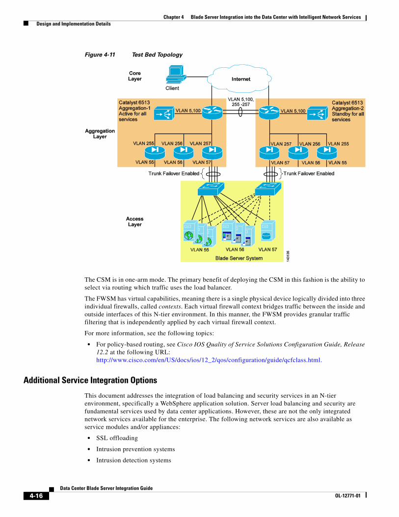
Test Topology
Figure 4-11 illustrates the logical topology of the test WebSphere application solution. A single blade system houses the web, application, and database tiers of the server farm. Each blade server is dual-homed to an integrated Ethernet switch. The network interface controllers (NICs) form a team in an active/standby configuration.
The integrated blade switches connect to the aggregation layer Catalyst 6500s using LACP (802.3ad) to bundle four Gigabit Ethernet ports into a single logical channel.
The channel uses the trunk failover feature of the integrated blade switch. Trunk failover is a high availability mechanism that binds the link state of an external uplink with the internal server ports on the blade switch.
A pair of Catalyst 6500 switches comprises the aggregation layer in the test network. The MSFC of each switch is the default gateway for the web, application, and database servers. In addition, the switches host the CSM and FWSM to provide integrated network services to the server farms.
4-15Data Center Blade Server Integration Guide
OL-12771-01
Chapter 4 Blade Server Integration into the Data Center with Intelligent Network Services Design and Implementation Details
Figure 4-11 Test Bed Topology
The CSM is in one-arm mode. The primary benefit of deploying the CSM in this fashion is the ability to select via routing which traffic uses the load balancer.
The FWSM has virtual capabilities, meaning there is a single physical device logically divided into three individual firewalls, called contexts. Each virtual firewall context bridges traffic between the inside and outside interfaces of this N-tier environment. In this manner, the FWSM provides granular traffic filtering that is independently applied by each virtual firewall context.
For more information, see the following topics:
• For policy-based routing, see Cisco IOS Quality of Service Solutions Configuration Guide, Release 12.2 at the following URL: http://www.cisco.com/en/US/docs/ios/12_2/qos/configuration/guide/qcfclass.html.
Additional Service Integration Options
This document addresses the integration of load balancing and security services in an N-tier environment, specifically a WebSphere application solution. Server load balancing and security are fundamental services used by data center applications. However, these are not the only integrated network services available for the enterprise. The following network services are also available as service modules and/or appliances:
• SSL offloading
• Intrusion prevention systems
• Intrusion detection systems
4-16Data Center Blade Server Integration Guide
OL-12771-01

Chapter 4 Blade Server Integration into the Data Center with Intelligent Network Services Design and Implementation Details
• Network analysis devices
• Caching devices
Configuration DetailsThis section details the modifications necessary in the web and application servers to use the load balancing services of the CSM. The firewall services are transparently provided via the FWSM and do not require any modifications at the server level.
IBM HTTP Server
The IBM HTTP Server (IHS) can route requests to WebSphere application servers located on remote machines. The plug-in file defines the application servers and available services. The plug-in file provides the following advantages:
• XML-based configuration file
• Standard protocol (HTTP) recognized by firewalls
• Secure transport using HTTPS
The WebSphere application server creates the plug-in file that must be manually installed into the IHS server.
The example below is a sample of a plug-in-cfg.xml file used by the IHS server. The virtual host group identifies requests that should be handled by the WebSphere application servers. In this example, all requests received on port 80 and 9080 are routed to an application server and are not serviced locally by the web server. A host name, IP address, or wildcard character may be used to define the HTTP header hosts.
<VirtualHostGroup Name="default_host"> <VirtualHost Name="*:9080"/> <VirtualHost Name="*:80"/> <VirtualHost Name="www.example.com:9443"/></VirtualHostGroup>
The ServerCluster element identifies WebSphere application servers that are configured to service the same type of requests. A cluster may contain one server or multiple servers and use either a round robin or random load balancing algorithm to direct requests to WebSphere application servers.
In the following sample of the plug-in file, the server cluster contains a single server, the CSM. The host names “LoadBalancer-WAS” and “LoadBalancer-WASSSL” refer to the DNS names given to the virtual IP addresses of the CSM listening on ports 9080 and 9443. This configuration allows the CSM to load balance traffic between the IHS web server and the WebSphere application servers.
<ServerCluster LoadBalance="Round Robin" Name="CSMVIPS"> <Server ConnectTimeout="0" MaxConnections="-1" Name="CSM"> <Transport Hostname="LoadBalancer-WAS" Port="9080" Protocol="http"/> <Transport Hostname="LoadBalancer-WASSSL" Port="9443" Protocol="https"> <Property Name="keyring" Value="/opt/WebSphere/AppServer/etc/plugin-key.kdb"/> <Property Name="stashfile" Value="/opt/WebSphere/AppServer/etc/plugin-key.sth"/> </Transport> </Server></ServerCluster>
4-17Data Center Blade Server Integration Guide
OL-12771-01

Chapter 4 Blade Server Integration into the Data Center with Intelligent Network Services Design and Implementation Details
Uniform Resource Identifiers (URI) are strings that identify application servers. The HTTP request includes the URI as a cookie or as part of the URL. This piece of information provides session persistence and affinity when used by the HTTP server or the CSM. In the case of WebSphere applications, the cookie and the URL are named “JSESSIONID” or “jsessionid” as shown in this snippet of the plug-in-cfg.xml.
<UriGroup Name="default_CSMVIPS_URIs"> <Uri AffinityCookie="JSESSIONID" AffinityURLIdentifier="jsessionid" Name="/petstore/*"/></UriGroup>
When present, the jsessionid allows the IHS server to send inbound requests to the originating WebSphere application server that is maintaining session affinity between the client and the application server.
Note The CSM may use the URI (jsessionid) of the application servers to provide session persistence, simplifying the configuration of the IHS server.
Note For more information on the plug-in-cfg.xml file, see WebSphere Redbook Domain at the following URL: http://www.redbooks.ibm.com/Redbooks.nsf/portals/WebSphere
IBM WebSphere Application Server
The IBM WebSphere server requires no changes to interoperate with the CSM or FWSM. Policy-based routing on the MSFC manages the direction of traffic between the web and application tiers of the example topology. The application server is unaware of these actions.
Note PBR on the MSFC is performed in hardware.
Configuration ListingsThe configuration listings here detail only the portions relevant to the topology described in this document (shown in Figure 4-11.)
Aggregation1 (Primary Root and HSRP Active)
firewall multiple-vlan-interfacesfirewall module 2 vlan-group 123firewall vlan-group 123 55-58,77,255-258,260vtp domain labvtp mode transparentudld enable
spanning-tree mode rapid-pvstspanning-tree loopguard defaultno spanning-tree optimize bpdu transmissionspanning-tree extend system-idspanning-tree pathcost method longspanning-tree vlan 5,13,55-57,77,255-257 priority 24576port-channel load-balance src-dst-port!
4-18Data Center Blade Server Integration Guide
OL-12771-01

Chapter 4 Blade Server Integration into the Data Center with Intelligent Network Services Design and Implementation Details
vlan internal allocation policy ascendingvlan dot1q tag native!vlan 2!vlan 5 name csm!vlan 13 name CSMft!vlan 55 name ihs_Blades!vlan 56 name was_Blades!vlan 57 name db2_blades!vlan 77 name FWSMft!vlan 255 name IHS_Blades!vlan 256 name WAS_Blades!vlan 257 name DB2_Blades!interface Port-channel4 description <<** Channel between two aggregation switches **>> no ip address switchport switchport trunk encapsulation dot1q switchport trunk allowed vlan 5,13,55-57,77,255-257 switchport mode trunk!!interface GigabitEthernet9/16 description <<** Port-channel 4 **>> no ip address logging event link-status load-interval 30 speed 1000 switchport switchport trunk encapsulation dot1q switchport trunk allowed vlan 5,13,55-57,77,255-257 switchport mode trunk channel-protocol lacp channel-group 4 mode active!!interface Vlan5 description <<** CSM VLAN **>> ip address 10.5.1.2 255.255.0.0 no ip redirects no ip proxy-arp logging event link-status load-interval 30 standby 1 ip 10.5.1.1 standby 1 timers 1 3
4-19Data Center Blade Server Integration Guide
OL-12771-01

Chapter 4 Blade Server Integration into the Data Center with Intelligent Network Services Design and Implementation Details
standby 1 priority 51 standby 1 preempt delay minimum 120 standby 1 name csm!interface Vlan255 description <** IHS Web Server Default Gateway **>> ip address 10.55.1.2 255.255.0.0 no ip redirects no ip proxy-arp ip policy route-map server-client-traffic logging event link-status load-interval 30 standby 1 ip 10.55.1.1 standby 1 timers 1 3 standby 1 priority 51 standby 1 preempt delay minimum 120 standby 1 name ibmwebservers!interface Vlan256 description <<** IBM WAS Default Gateway **>> ip address 10.56.1.2 255.255.0.0 no ip redirects no ip proxy-arp ip policy route-map was-csm-traffic logging event link-status load-interval 30 standby 1 ip 10.56.1.1 standby 1 timers 1 3 standby 1 priority 51 standby 1 preempt delay minimum 120 standby 1 name ibmWAS!interface Vlan257 description <<** IBM DB2 Server Default Gateway **>> ip address 10.57.1.2 255.255.0.0 no ip redirects no ip proxy-arp logging event link-status load-interval 30 standby 1 ip 10.57.1.1 standby 1 timers 1 3 standby 1 priority 51 standby 1 preempt delay minimum 120 standby 1 name ibmdb2!access-list 156 permit tcp 10.56.1.0 0.0.0.255 eq 9080 10.55.1.0 0.0.0.255access-list 156 deny ip any any!route-map server-client-traffic permit 10 set ip default next-hop 10.5.1.6!route-map was-csm-traffic permit 10 match ip address 156 set ip next-hop 10.5.1.6!end
Aggregation2 (Secondary Root and HSRP Standby)
The configuration of the second aggregation switch is similar to the primary aggregation switch except for the following:
4-20Data Center Blade Server Integration Guide
OL-12771-01

Chapter 4 Blade Server Integration into the Data Center with Intelligent Network Services Design and Implementation Details
!spanning-tree vlan 5,13,55-57,77,255-257 priority 28672!interface Vlan5 description <<** CSM VLAN **>> ip address 10.5.1.3 255.255.0.0 no ip redirects no ip proxy-arp logging event link-status load-interval 30 standby 1 ip 10.5.1.1 standby 1 timers 1 3 standby 1 priority 50 standby 1 name csm!interface Vlan255 description <** IHS Web Server Default Gateway **>> ip address 10.55.1.3 255.255.0.0 no ip redirects no ip proxy-arp ip policy route-map server-client-traffic logging event link-status load-interval 30 standby preempt delay minimum 120 sync 120 standby 1 ip 10.55.1.1 standby 1 timers 1 3 standby 1 priority 50 standby 1 name ibmwebservers!interface Vlan256 description <<** IBM WAS Default Gateway **>> ip address 10.56.1.3 255.255.0.0 no ip redirects no ip proxy-arp ip policy route-map was-csm-traffic logging event link-status load-interval 30 standby preempt delay minimum 120 sync 120 standby 1 ip 10.56.1.1 standby 1 timers 1 3 standby 1 priority 50 standby 1 name ibmWAS!interface Vlan257 description <<** IBM DB2 Server Default Gateway **>> ip address 10.57.1.3 255.255.0.0 no ip redirects no ip proxy-arp logging event link-status load-interval 30 standby preempt delay minimum 120 sync 120 standby 1 ip 10.57.1.1 standby 1 timers 1 3 standby 1 priority 50 standby 1 name ibmdb2!
CSM (Active)
module ContentSwitchingModule 3 variable NO_TIMEOUT_IP_STICKY_ENTRIES 1
4-21Data Center Blade Server Integration Guide
OL-12771-01

Chapter 4 Blade Server Integration into the Data Center with Intelligent Network Services Design and Implementation Details
! ft group 13 vlan 13 priority 11 heartbeat-time 1 failover 3 preempt! vlan 5 server ip address 10.5.1.4 255.255.0.0 gateway 10.5.1.1 alias 10.5.1.6 255.255.0.0!probe IHS_BLADES http request method get url /petstore/ expect status 200 205 interval 5 failed 3!serverfarm IHS_BLADES nat server no nat client real 10.55.1.101 inservice real 10.55.1.102 inservice real 10.55.1.103 inservice probe IHS_BLADES! serverfarm WAS_BLADES nat server no nat client real 10.56.1.102 inservice real 10.56.1.103 inservice real 10.56.1.101 inservice! sticky 1 cookie JSESSIONID timeout 10 cookie secondary jsessionid!policy APP_TIER sticky-group 1 serverfarm WAS_BLADES! policy FRONT_END serverfarm IHS_BLADES!vserver VBLADES virtual 10.10.10.55 tcp www replicate csrp sticky replicate csrp connection persistent rebalance slb-policy FRONT_END inservice! vserver VWAS virtual 10.10.10.56 any replicate csrp sticky replicate csrp connection persistent rebalance slb-policy APP_TIER inservice
4-22Data Center Blade Server Integration Guide
OL-12771-01
Chapter 4 Blade Server Integration into the Data Center with Intelligent Network Services Design and Implementation Details
!
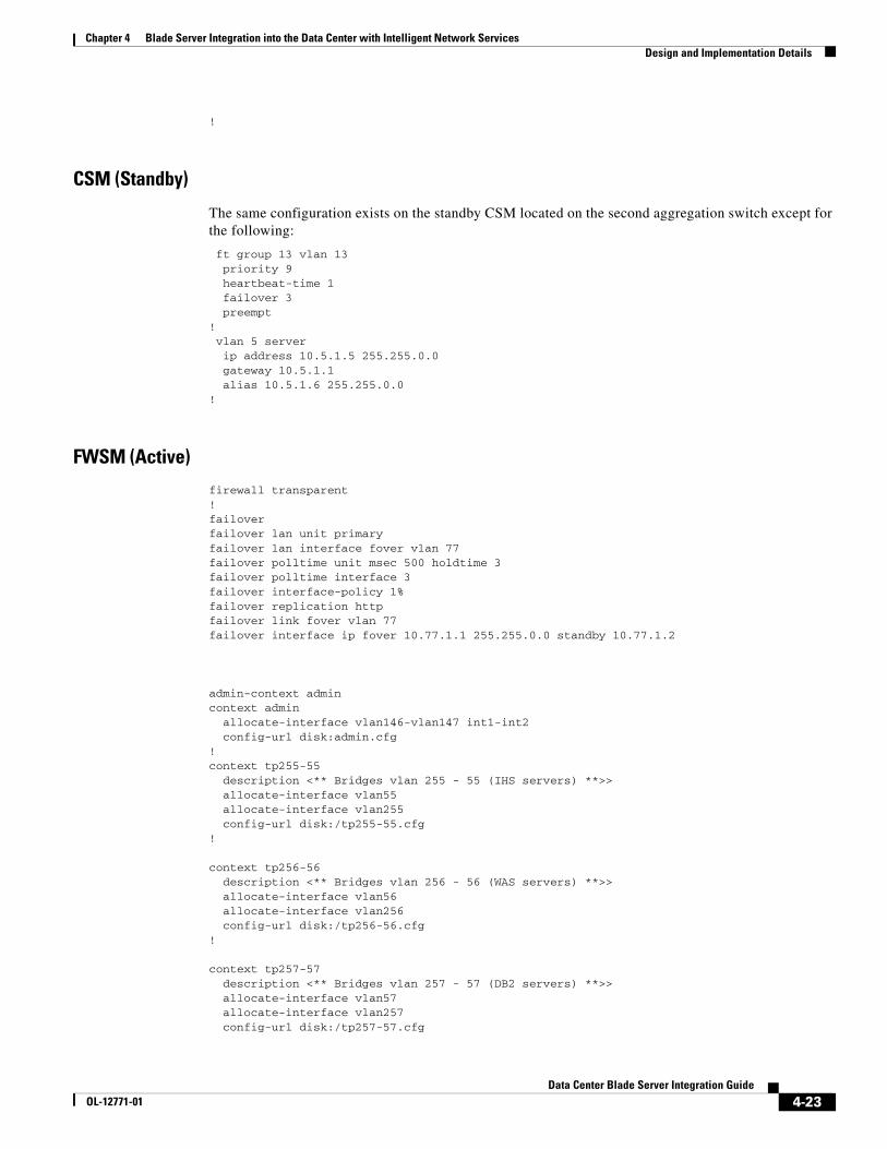
CSM (Standby)
The same configuration exists on the standby CSM located on the second aggregation switch except for the following:
ft group 13 vlan 13 priority 9 heartbeat-time 1 failover 3 preempt! vlan 5 server ip address 10.5.1.5 255.255.0.0 gateway 10.5.1.1 alias 10.5.1.6 255.255.0.0!
FWSM (Active)
firewall transparent!failoverfailover lan unit primaryfailover lan interface fover vlan 77failover polltime unit msec 500 holdtime 3failover polltime interface 3failover interface-policy 1%failover replication httpfailover link fover vlan 77failover interface ip fover 10.77.1.1 255.255.0.0 standby 10.77.1.2
admin-context admincontext admin allocate-interface vlan146-vlan147 int1-int2 config-url disk:admin.cfg!context tp255-55 description <** Bridges vlan 255 - 55 (IHS servers) **>> allocate-interface vlan55 allocate-interface vlan255 config-url disk:/tp255-55.cfg!
context tp256-56 description <** Bridges vlan 256 - 56 (WAS servers) **>> allocate-interface vlan56 allocate-interface vlan256 config-url disk:/tp256-56.cfg!
context tp257-57 description <** Bridges vlan 257 - 57 (DB2 servers) **>> allocate-interface vlan57 allocate-interface vlan257 config-url disk:/tp257-57.cfg
4-23Data Center Blade Server Integration Guide
OL-12771-01

Chapter 4 Blade Server Integration into the Data Center with Intelligent Network Services Design and Implementation Details
!: endSample of one of the virtual firewall contexts:FWSM/tp255-55# sh run: Saved:FWSM Version 2.3(2) <context>firewall transparentnameif vlan255 outside security0nameif vlan55 inside security100enable password 8Ry2YjIyt7RRXU24 encryptedpasswd 2KFQnbNIdI.2KYOU encryptedhostname tp255-55fixup protocol dns maximum-length 512fixup protocol ftp 21fixup protocol h323 H225 1720fixup protocol h323 ras 1718-1719fixup protocol rsh 514fixup protocol sip 5060no fixup protocol sip udp 5060fixup protocol skinny 2000fixup protocol smtp 25fixup protocol sqlnet 1521namesaccess-list deny-flow-max 4096access-list alert-interval 300access-list 101 extended permit ip any anyaccess-list 102 ethertype permit bpduno pagerlogging onlogging buffer-size 4096mtu outside 1500mtu inside 1500ip address 10.55.1.4 255.255.0.0icmp permit any outsideicmp permit any insidepdm location 10.55.0.0 255.255.0.0 insidepdm logging notifications 100pdm history enablearp timeout 14400static (inside,outside) 10.55.0.0 10.55.0.0 netmask 255.255.0.0access-group 102 in interface outsideaccess-group 101 in interface outsideaccess-group 102 in interface insideaccess-group 101 in interface inside!interface outside!interface inside!route outside 0.0.0.0 0.0.0.0 10.55.1.1 1timeout xlate 3:00:00timeout conn 1:00:00 half-closed 0:10:00 udp 0:02:00 icmp 0:00:02 rpc 0:10:00 h323 0:05:00 h225 1:00:00 mgcp 0:05:00 sip 0:30:00 sip_media 0:02:00timeout uauth 0:05:00 absoluteaaa-server TACACS+ protocol tacacs+aaa-server TACACS+ max-failed-attempts 3aaa-server TACACS+ deadtime 10aaa-server RADIUS protocol radiusaaa-server RADIUS max-failed-attempts 3aaa-server RADIUS deadtime 10aaa-server LOCAL protocol localno snmp-server locationno snmp-server contact
4-24Data Center Blade Server Integration Guide
OL-12771-01

Chapter 4 Blade Server Integration into the Data Center with Intelligent Network Services Design and Implementation Details
snmp-server community publicsnmp-server enable traps snmpfloodguard enablefragment size 200 outsidefragment chain 24 outsidefragment size 200 insidefragment chain 24 insidetelnet timeout 5ssh timeout 5terminal width 511: end
Note The security context listed is an example configuration and does not adhere to security best practices.
FWSM (Standby)
The configuration on the standby FWSM located on the second aggregation switch is the same except for the following:
failoverfailover lan unit secondaryfailover lan interface fover vlan 77failover polltime unit msec 500 holdtime 3failover polltime interface 3failover interface-policy 1%failover replication httpfailover link fover vlan 77failover interface ip fover 10.77.1.1 255.255.0.0 standby 10.77.1.2
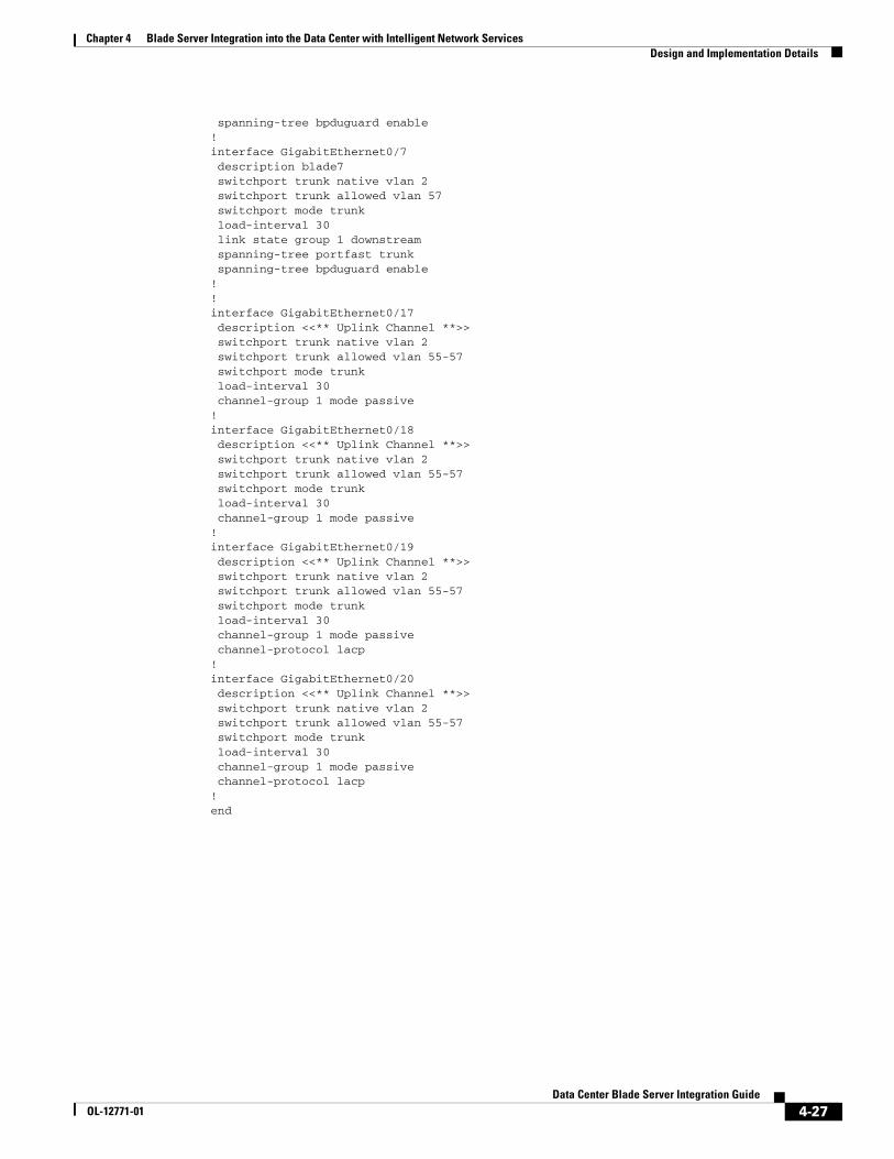
Access Layer (Integrated Switch)
The integrated blade server switches use the same configuration, providing a 4 GigE uplink using the trunk failover feature to the aggregation layer.
vtp mode transparentlink state track 1!port-channel load-balance src-ip!spanning-tree mode rapid-pvstno spanning-tree optimize bpdu transmissionspanning-tree extend system-idspanning-tree pathcost method long!vlan 2 name operational!vlan 55 name IHS_Blades!vlan 56 name WAS_Blades!vlan 57 name DB2_Blades!interface Port-channel1 description <<** Channel to Aggregation Layer **>>
4-25Data Center Blade Server Integration Guide
OL-12771-01

Chapter 4 Blade Server Integration into the Data Center with Intelligent Network Services Design and Implementation Details
switchport trunk native vlan 2 switchport trunk allowed vlan 55-57 switchport mode trunk load-interval 30 link state group 1 upstream!interface GigabitEthernet0/1 description blade1 switchport trunk native vlan 2 switchport trunk allowed vlan 55 switchport mode trunk load-interval 30 link state group 1 downstream spanning-tree portfast trunk spanning-tree bpduguard enable!interface GigabitEthernet0/2 description blade2 switchport trunk native vlan 2 switchport trunk allowed vlan 55 switchport mode trunk load-interval 30 link state group 1 downstream spanning-tree portfast trunk spanning-tree bpduguard enable!interface GigabitEthernet0/3 description blade3 switchport trunk native vlan 2 switchport trunk allowed vlan 55 switchport mode trunk load-interval 30 link state group 1 downstream spanning-tree portfast trunk spanning-tree bpduguard enable!interface GigabitEthernet0/4 description blade4 switchport trunk native vlan 2 switchport trunk allowed vlan 56 switchport mode trunk load-interval 30 link state group 1 downstream spanning-tree portfast trunk spanning-tree bpduguard enable!interface GigabitEthernet0/5 description blade5 switchport trunk native vlan 2 switchport trunk allowed vlan 56 switchport mode trunk load-interval 30 link state group 1 downstream spanning-tree portfast trunk spanning-tree bpduguard enable!interface GigabitEthernet0/6 description blade6 switchport trunk native vlan 2 switchport trunk allowed vlan 56 switchport mode trunk load-interval 30 link state group 1 downstream spanning-tree portfast trunk
4-26Data Center Blade Server Integration Guide
OL-12771-01
Chapter 4 Blade Server Integration into the Data Center with Intelligent Network Services Design and Implementation Details
spanning-tree bpduguard enable!interface GigabitEthernet0/7 description blade7 switchport trunk native vlan 2 switchport trunk allowed vlan 57 switchport mode trunk load-interval 30 link state group 1 downstream spanning-tree portfast trunk spanning-tree bpduguard enable!!interface GigabitEthernet0/17 description <<** Uplink Channel **>> switchport trunk native vlan 2 switchport trunk allowed vlan 55-57 switchport mode trunk load-interval 30 channel-group 1 mode passive!interface GigabitEthernet0/18 description <<** Uplink Channel **>> switchport trunk native vlan 2 switchport trunk allowed vlan 55-57 switchport mode trunk load-interval 30 channel-group 1 mode passive!interface GigabitEthernet0/19 description <<** Uplink Channel **>> switchport trunk native vlan 2 switchport trunk allowed vlan 55-57 switchport mode trunk load-interval 30 channel-group 1 mode passive channel-protocol lacp!interface GigabitEthernet0/20 description <<** Uplink Channel **>> switchport trunk native vlan 2 switchport trunk allowed vlan 55-57 switchport mode trunk load-interval 30 channel-group 1 mode passive channel-protocol lacp!end
4-27Data Center Blade Server Integration Guide
OL-12771-01

Chapter 4 Blade Server Integration into the Data Center with Intelligent Network Services Design and Implementation Details
4-28Data Center Blade Server Integration Guide
OL-12771-01