Embed Size (px)
Citation preview

SERVICE MANUAL
2005.052005.05Ver. 1.0Ver. 1.0
2005.05 Ver.1.0
2005.05 Ver.1.0
© 2005 KONICA MINOLTA BUSINESS TECHNOLOGIES, INC.© 2005 KONICA MINOLTA BUSINESS TECHNOLOGIES, INC.
FIELD SERVICE
FIE
LD S
ER
VIC
E
Printed in JapanPrinted in JapanDD4037PE1-P000DD4037PE1-P000
Use of this manual should be strictly supervised toavoid disclosure of confidential information.Use of this manual should be strictly supervised toavoid disclosure of confidential information.
This service manual is issued for C351 that has been changed from C450. Therefore please refer it along with the service manual of C450.
This service manual is issued for C351 that has been changed from C450. Therefore please refer it along with the service manual of C450.
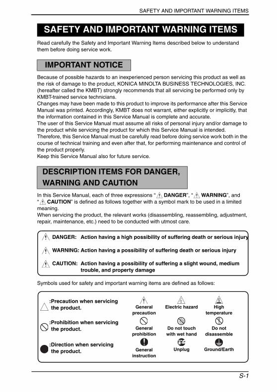
SAFETY AND IMPORTANT WARNING ITEMS
Read carefully the Safety and Important Warning Items described below to understand them before doing service work.
Because of possible hazards to an inexperienced person servicing this product as well as the risk of damage to the product, KONICA MINOLTA BUSINESS TECHNOLOGIES, INC. (hereafter called the KMBT) strongly recommends that all servicing be performed only by KMBT-trained service technicians.Changes may have been made to this product to improve its performance after this Service Manual was printed. Accordingly, KMBT does not warrant, either explicitly or implicitly, that the information contained in this Service Manual is complete and accurate.The user of this Service Manual must assume all risks of personal injury and/or damage to the product while servicing the product for which this Service Manual is intended.Therefore, this Service Manual must be carefully read before doing service work both in the course of technical training and even after that, for performing maintenance and control of the product properly.Keep this Service Manual also for future service.
In this Service Manual, each of three expressions “ DANGER”, “ WARNING”, and “ CAUTION” is defined as follows together with a symbol mark to be used in a limited meaning.When servicing the product, the relevant works (disassembling, reassembling, adjustment, repair, maintenance, etc.) need to be conducted with utmost care.
Symbols used for safety and important warning items are defined as follows:
SAFETY AND IMPORTANT WARNING ITEMS
IMPORTANT NOTICE
DESCRIPTION ITEMS FOR DANGER, WARNING AND CAUTION
DANGER: Action having a high possibility of suffering death or serious injury
WARNING: Action having a possibility of suffering death or serious injury
CAUTION: Action having a possibility of suffering a slight wound, medium trouble, and property damage
:Precaution when servicing the product. General
precautionElectric hazard High
temperature
:Prohibition when servicing the product. General
prohibitionDo not touch with wet hand
Do not disassemble
:Direction when servicing the product. General
instructionUnplug Ground/Earth
S-1
SAFETY AND IMPORTANT WARNING ITEMS
[1] MODIFICATIONS NOT AUTHORIZED BY KONICA MINOLTA BUSINESS TECHNOLOGIES, INC.
KONICA MINOLTA brand products are renowned for their high reliability. This reliability is achieved through high-quality design and a solid service network.Product design is a highly complicated and delicate process where numerous mechanical, physical, and electrical aspects have to be taken into consideration, with the aim of arriving at proper tolerances and safety factors. For this reason, unauthorized modifications involve a high risk of degradation in performance and safety. Such modifications are therefore strictly prohibited. the points listed below are not exhaustive, but they illustrate the reason-ing behind this policy.
SAFETY WARNINGS
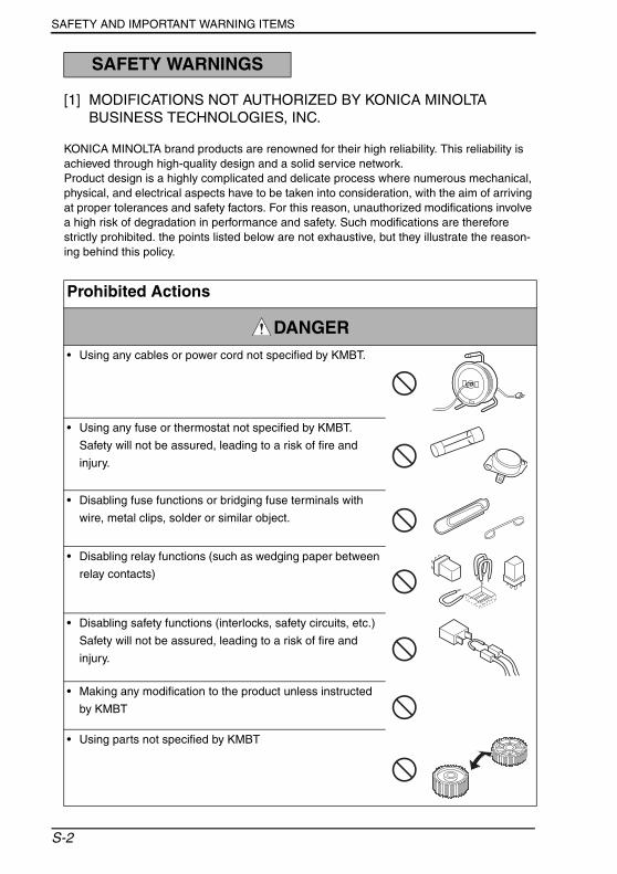
Prohibited Actions
DANGER• Using any cables or power cord not specified by KMBT.
• Using any fuse or thermostat not specified by KMBT.
Safety will not be assured, leading to a risk of fire and
injury.
• Disabling fuse functions or bridging fuse terminals with
wire, metal clips, solder or similar object.
• Disabling relay functions (such as wedging paper between
relay contacts)
• Disabling safety functions (interlocks, safety circuits, etc.)
Safety will not be assured, leading to a risk of fire and
injury.
• Making any modification to the product unless instructed
by KMBT
• Using parts not specified by KMBT
S-2

SAFETY AND IMPORTANT WARNING ITEMS
[2] POWER PLUG SELECTION
In some countries or areas, the power plug provided with the product may not fit wall outlet used in the area. In that case, it is obligation of customer engineer (hereafter called the CE) to attach appropriate power plug or power cord set in order to connect the product to the supply.
Power Cord Set or Power Plug
WARNING• Use power supply cord set which meets the following
criteria:
- provided with a plug having configuration intended for the connection to wall outlet appropriate for the prod-uct's rated voltage and current, and
- the plug has pin/terminal(s) for grounding, and
- provided with three-conductor cable having enough cur-rent capacity, and
- the cord set meets regulatory requirements for the area.
Use of inadequate cord set leads to fire or electric shock.
• Attach power plug which meets the following criteria:
- having configuration intended for the connection to wall outlet appropriate for the product's rated voltage and current, and
- the plug has pin/terminal(s) for grounding, and
- meets regulatory requirements for the area.
Use of inadequate cord set leads to the product connect-ing to inadequate power supply (voltage, current capacity, grounding), and may result in fire or electric shock.
• Conductors in the power cable must be connected to ter-
minals of the plug according to the following order:
• Black or Brown: L (line)
• White or Light Blue: N (neutral)
• Green/Yellow: PE (earth)
Wrong connection may cancel safeguards within the product, and results in fire or electric shock.
kw
S-3
SAFETY AND IMPORTANT WARNING ITEMS
[3] CHECKPOINTS WHEN PERFORMING ON-SITE SERVICE
KONICA MINOLTA brand products are extensively tested before shipping, to ensure that all applicable safety standards are met, in order to protect the customer and customer engi-neer (hereafter called the CE) from the risk of injury. However, in daily use, any electrical equipment may be subject to parts wear and eventual failure. In order to maintain safety and reliability, the CE must perform regular safety checks.
1. Power Supply
Connection to Power Supply
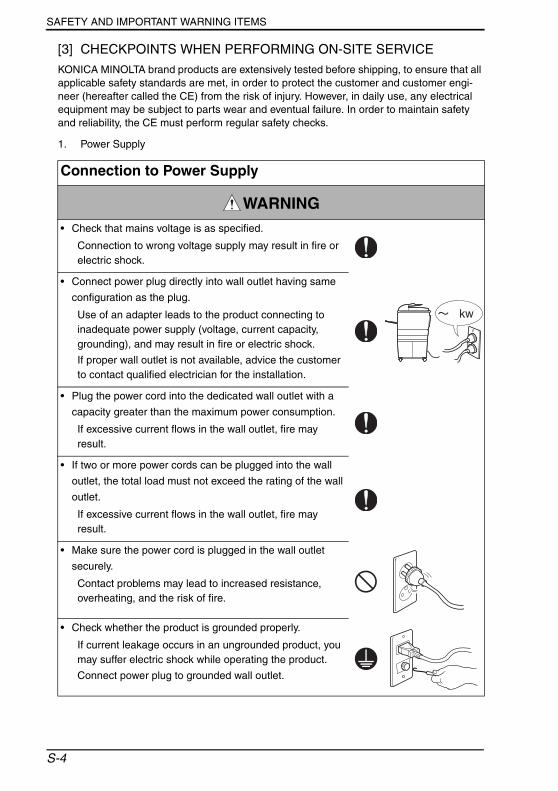
WARNING• Check that mains voltage is as specified.
Connection to wrong voltage supply may result in fire or electric shock.
• Connect power plug directly into wall outlet having same
configuration as the plug.
Use of an adapter leads to the product connecting to inadequate power supply (voltage, current capacity, grounding), and may result in fire or electric shock.
If proper wall outlet is not available, advice the customer to contact qualified electrician for the installation.
• Plug the power cord into the dedicated wall outlet with a
capacity greater than the maximum power consumption.
If excessive current flows in the wall outlet, fire may result.
• If two or more power cords can be plugged into the wall
outlet, the total load must not exceed the rating of the wall
outlet.
If excessive current flows in the wall outlet, fire may result.
• Make sure the power cord is plugged in the wall outlet
securely.
Contact problems may lead to increased resistance, overheating, and the risk of fire.
• Check whether the product is grounded properly.
If current leakage occurs in an ungrounded product, you may suffer electric shock while operating the product.
Connect power plug to grounded wall outlet.
kw
S-4

SAFETY AND IMPORTANT WARNING ITEMS
Power Plug and Cord
WARNING• When using the power cord set (inlet type) that came with
this product, make sure the connector is securely inserted
in the inlet of the product.
When securing measure is provided, secure the cord with
the fixture properly.
If the power cord (inlet type) is not connected to the prod-uct securely, a contact problem may lead to increased resistance, overheating, and risk of fire.
• Check whether the power cord is not stepped on or
pinched by a table and so on.
Overheating may occur there, leading to a risk of fire.
• Check whether the power cord is damaged. Check
whether the sheath is damaged.
If the power plug, cord, or sheath is damaged, replace with a new power cord (with plug and connector on each end) specified by KMBT. Using the damaged power cord may result in fire or electric shock.
• Do not bundle or tie the power cord.
Overheating may occur there, leading to a risk of fire.
• Check whether dust is collected around the power plug
and wall outlet.
Using the power plug and wall outlet without removing dust may result in fire.
• Do not insert the power plug into the wall outlet with a wet
hand.
The risk of electric shock exists.
• When unplugging the power cord, grasp the plug, not the
cable.
The cable may be broken, leading to a risk of fire and electric shock.
S-5
SAFETY AND IMPORTANT WARNING ITEMS
2. Installation Requirements
Wiring
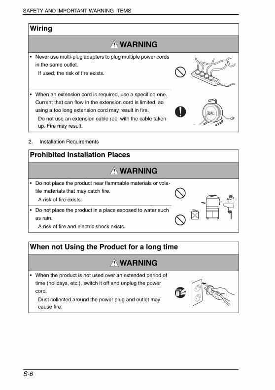
WARNING• Never use multi-plug adapters to plug multiple power cords
in the same outlet.
If used, the risk of fire exists.
• When an extension cord is required, use a specified one.
Current that can flow in the extension cord is limited, so
using a too long extension cord may result in fire.
Do not use an extension cable reel with the cable taken up. Fire may result.
Prohibited Installation Places
WARNING• Do not place the product near flammable materials or vola-
tile materials that may catch fire.
A risk of fire exists.
• Do not place the product in a place exposed to water such
as rain.
A risk of fire and electric shock exists.
When not Using the Product for a long time
WARNING• When the product is not used over an extended period of
time (holidays, etc.), switch it off and unplug the power
cord.
Dust collected around the power plug and outlet may cause fire.
S-6
SAFETY AND IMPORTANT WARNING ITEMS
Ventilation
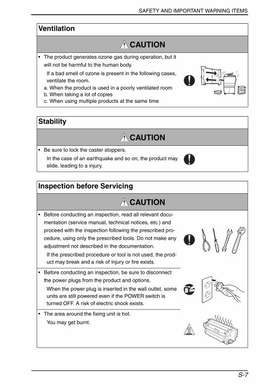
CAUTION• The product generates ozone gas during operation, but it
will not be harmful to the human body.
If a bad smell of ozone is present in the following cases, ventilate the room.
a. When the product is used in a poorly ventilated roomb. When taking a lot of copiesc. When using multiple products at the same time
Stability
CAUTION• Be sure to lock the caster stoppers.
In the case of an earthquake and so on, the product may slide, leading to a injury.
Inspection before Servicing
CAUTION• Before conducting an inspection, read all relevant docu-
mentation (service manual, technical notices, etc.) and
proceed with the inspection following the prescribed pro-
cedure, using only the prescribed tools. Do not make any
adjustment not described in the documentation.
If the prescribed procedure or tool is not used, the prod-uct may break and a risk of injury or fire exists.
• Before conducting an inspection, be sure to disconnect
the power plugs from the product and options.
When the power plug is inserted in the wall outlet, some units are still powered even if the POWER switch is turned OFF. A risk of electric shock exists.
• The area around the fixing unit is hot.
You may get burnt.
S-7

SAFETY AND IMPORTANT WARNING ITEMS
Work Performed with the Product Powered On
WARNING• Take every care when making adjustments or performing
an operation check with the product powered.
If you make adjustments or perform an operation check with the external cover detached, you may touch live or high-voltage parts or you may be caught in moving gears or the timing belt, leading to a risk of injury.
• Take every care when servicing with the external cover
detached.
High-voltage exists around the drum unit. A risk of elec-tric shock exists.
Safety Checkpoints
WARNING• Check the exterior and frame for edges, burrs, and other
damage.
The user or CE may be injured.
• Do not allow any metal parts such as clips, staples, and
screws to fall into the product.
They can short internal circuits and cause electric shock or fire.
• Check wiring for squeezing and any other damage.
Current can leak, leading to a risk of electric shock or fire.
• Carefully remove all toner remnants and dust from electri-
cal parts and electrode units such as a charging corona
unit.
Current can leak, leading to a risk of product trouble or fire.
• Check high-voltage cables and sheaths for any damage.
Current can leak, leading to a risk of electric shock or fire.
S-8
SAFETY AND IMPORTANT WARNING ITEMS
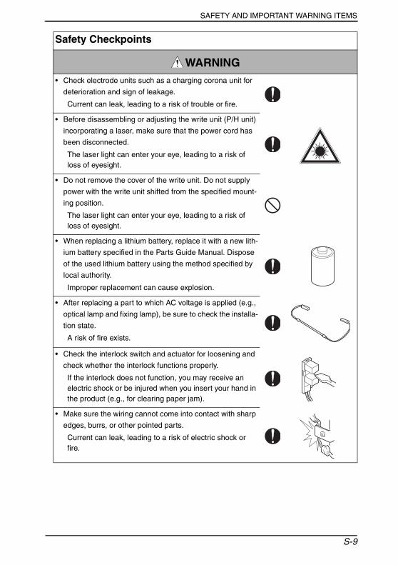
• Check electrode units such as a charging corona unit for
deterioration and sign of leakage.
Current can leak, leading to a risk of trouble or fire.
• Before disassembling or adjusting the write unit (P/H unit)
incorporating a laser, make sure that the power cord has
been disconnected.
The laser light can enter your eye, leading to a risk of loss of eyesight.
• Do not remove the cover of the write unit. Do not supply
power with the write unit shifted from the specified mount-
ing position.
The laser light can enter your eye, leading to a risk of loss of eyesight.
• When replacing a lithium battery, replace it with a new lith-
ium battery specified in the Parts Guide Manual. Dispose
of the used lithium battery using the method specified by
local authority.
Improper replacement can cause explosion.
• After replacing a part to which AC voltage is applied (e.g.,
optical lamp and fixing lamp), be sure to check the installa-
tion state.
A risk of fire exists.
• Check the interlock switch and actuator for loosening and
check whether the interlock functions properly.
If the interlock does not function, you may receive an electric shock or be injured when you insert your hand in the product (e.g., for clearing paper jam).
• Make sure the wiring cannot come into contact with sharp
edges, burrs, or other pointed parts.
Current can leak, leading to a risk of electric shock or fire.
Safety Checkpoints
WARNING
S-9
SAFETY AND IMPORTANT WARNING ITEMS
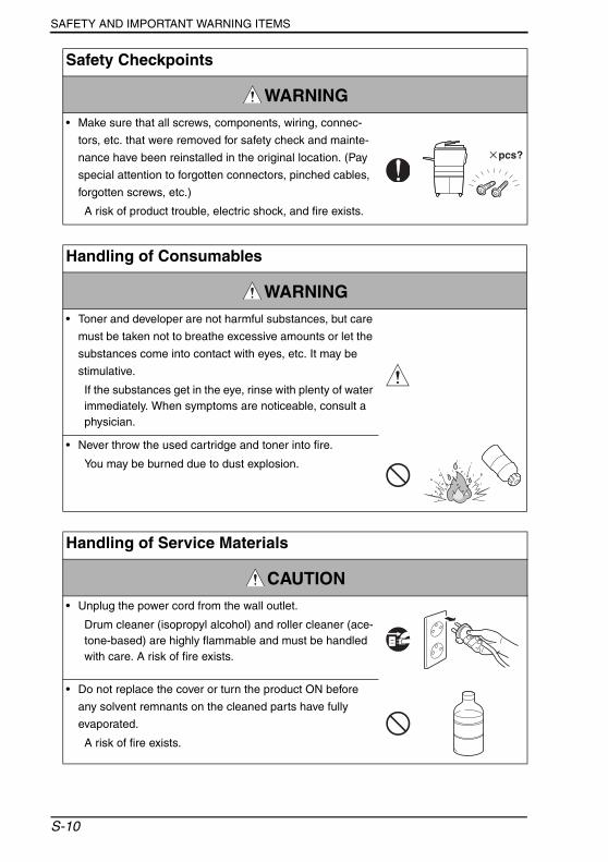
• Make sure that all screws, components, wiring, connec-
tors, etc. that were removed for safety check and mainte-
nance have been reinstalled in the original location. (Pay
special attention to forgotten connectors, pinched cables,
forgotten screws, etc.)
A risk of product trouble, electric shock, and fire exists.
Safety Checkpoints
WARNING
Handling of Consumables
WARNING• Toner and developer are not harmful substances, but care
must be taken not to breathe excessive amounts or let the
substances come into contact with eyes, etc. It may be
stimulative.
If the substances get in the eye, rinse with plenty of water immediately. When symptoms are noticeable, consult a physician.
• Never throw the used cartridge and toner into fire.
You may be burned due to dust explosion.
Handling of Service Materials
CAUTION• Unplug the power cord from the wall outlet.
Drum cleaner (isopropyl alcohol) and roller cleaner (ace-tone-based) are highly flammable and must be handled with care. A risk of fire exists.
• Do not replace the cover or turn the product ON before
any solvent remnants on the cleaned parts have fully
evaporated.
A risk of fire exists.
S-10
SAFETY AND IMPORTANT WARNING ITEMS
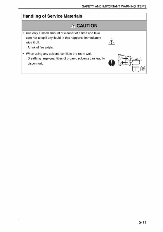
• Use only a small amount of cleaner at a time and take
care not to spill any liquid. If this happens, immediately
wipe it off.
A risk of fire exists.
• When using any solvent, ventilate the room well.
Breathing large quantities of organic solvents can lead to
discomfort.
Handling of Service Materials
CAUTION
S-11
SAFETY AND IMPORTANT WARNING ITEMS
[4] Used Batteries Precautions
ALL AreasCAUTION
Danger of explosion if battery is incorrectly replaced.Replace only with the same or equivalent type recommended by the manufacturer.Dispose of used batteries according to the manufacturer’s instructions.
GermanyVORSICHT!
Explosionsgefahr bei unsachgemäßem Austausch der Batterie.Ersatz nur durch denselben oder einen vom Hersteller empfohlenen gleichwertigen Typ.Entsorgung gebrauchter Batterien nach Angaben des Herstellers.
FranceATTENTION
Il y a danger d’explosion s’il y a remplacement incorrect de la batterie.Remplacer uniquement avec une batterie du même type ou d’un type équivalent recom-mandé par le constructeur.Mettre au rebut les batteries usagées conformément aux instructions du fabricant.
DenmarkADVARSEL!
Lithiumbatteri - Eksplosionsfare ved fejlagtig håndtering. Udskiftning må kun ske med batteri af samme fabrikat og type.Levér det brugte batteri tilbage til leverandøren.
Finland, SwedenVAROlTUS
Paristo voi räjähtää, jos se on virheellisesti asennettu.Vaihda paristo ainoastaan laitevalmistajan suosittelemaan tyyppiin. Hävitä käytetty paristo valmistajan ohjeiden mukaisesti.
VARNINGExplosionsfara vid felaktigt batteribyte.Använd samma batterityp eller en ekvivalent typ som rekommenderas av apparat-tillverkaren.Kassera använt batteri enligt fabrikantens instruktion.
NorwayADVARSEL
Eksplosjonsfare ved feilaktig skifte av batteri.Benytt samme batteritype eller en tilsvarende type anbefalt av apparatfabrikanten.Brukte batterier kasseres i henhold til fabrikantens instruksjoner.
S-12
SAFETY AND IMPORTANT WARNING ITEMS
[5] FUSE
[6] LED Radiation Safety
• This product is a copier which operates by means of a LED (light emitting diodes) expo-sure system. There is no possibility of danger from the LED optical radiation, because the LED optical radiation level dose not exceed the accessible radiation limit of class 1 under all conditions of operation, maintenance, service and failure.
CAUTIONDouble pole / neutral fusing
ATTENTIONDouble pôle / fusible sur le neutre.
S-13
SAFETY AND IMPORTANT WARNING ITEMS
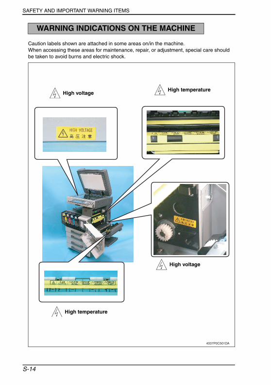
Caution labels shown are attached in some areas on/in the machine.When accessing these areas for maintenance, repair, or adjustment, special care should be taken to avoid burns and electric shock.
WARNING INDICATIONS ON THE MACHINE
4037P0C501DA
High voltage
High temperature High voltage
High temperature
S-14
SAFETY AND IMPORTANT WARNING ITEMS
4037P0C502DA
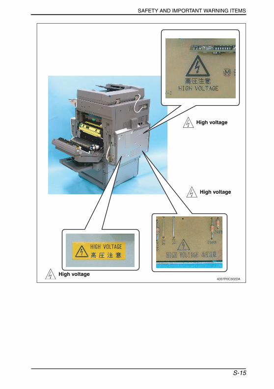
High voltage
High voltage
High voltage
S-15
SAFETY AND IMPORTANT WARNING ITEMS
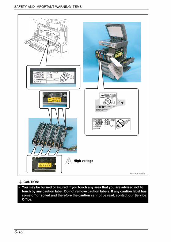
CAUTION:
4037P0C503DA
High voltage
• You may be burned or injured if you touch any area that you are advised not to touch by any caution label. Do not remove caution labels. If any caution label has come off or soiled and therefore the caution cannot be read, contact our Service Office.
S-16

MEASURES TO TAKE IN CASE OF AN ACCIDENT
1. If an accident has occurred, the distributor who has been notified first must immediately take emergency measures to provide relief to affected persons and to prevent further damage.
2. If a report of a serious accident has been received from a customer, an on-site evalua-tion must be carried out quickly and KMBT must be notified.
3. To determine the cause of the accident, conditions and materials must be recorded through direct on-site checks, in accordance with instructions issued by KMBT.
4. For reports and measures concerning serious accidents, follow the regulations speci-fied by every distributor.
MEASURES TO TAKE IN CASE OF AN ACCIDENT
S-17

MEASURES TO TAKE IN CASE OF AN ACCIDENT
S-18
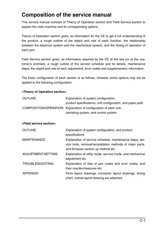
Composition of the service manualThis service manual consists of Theory of Operation section and Field Service section to
explain the main machine and its corresponding options.
Theory of Operation section gives, as information for the CE to get a full understanding of
the product, a rough outline of the object and role of each function, the relationship
between the electrical system and the mechanical system, and the timing of operation of
each part.
Field Service section gives, as information required by the CE at the site (or at the cus-
tomer’s premise), a rough outline of the service schedule and its details, maintenance
steps, the object and role of each adjustment, error codes and supplementary information.
The basic configuration of each section is as follows. However some options may not be
applied to the following configuration.
<Theory of Operation section>
<Field service section>
OUTLINE: Explanation of system configuration,
product specifications, unit configuration, and paper path
COMPOSITION/OPERATION: Explanation of configuration of each unit,
operating system, and control system
OUTLINE: Explanation of system configuration, and product
specifications
MAINTENANCE: Explanation of service schedule, maintenance steps, ser-
vice tools, removal/reinstallation methods of major parts,
and firmware version up method etc.
ADJUSTMENT/SETTING: Explanation of utility mode, service mode, and mechanical
adjustment etc.
TROUBLESHOOTING: Explanation of lists of jam codes and error codes, and
their countermeasures etc.
APPENDIX: Parts layout drawings, connector layout drawings, timing
chart, overall layout drawing are attached.
C-1

Notation of the service manualA. Product nameIn this manual, each of the products is described as follows:
B. Brand nameThe company names and product names mentioned in this manual are the brand name or
the registered trademark of each company.
(1) PWB-MC: Control Board
(2) bizhub C351: Main body
(3) Microsoft Windows 95: Windows 95
Microsoft Windows 98: Windows 98
Microsoft Windows Me: Windows Me
Microsoft Windows NT 4.0: Windows NT 4.0 or Windows NT
Microsoft Windows 2000: Windows 2000
Microsoft Windows XP: Windows XP
When the description is made in combination of the OS’s mentioned above:
Windows 95/98/Me
Windows NT 4.0/2000
Windows NT/2000/XP
Windows 95/98/Me/ NT/2000/XP
C-2

SERVICE MANUAL
2005.05Ver. 1.0
FIELD SERVICE
Main Unit

Revision historyAfter publication of this service manual, the parts and mechanism may be subject to change forimprovement of their performance. Therefore, the descriptions given in this service manual may not coincide with the actual machine.
When any change has been made to the descriptions in the service manual, a revised version will beissued with a revision mark added as required.
Revision mark:• To indicate clearly a section revised, show to the left of the revised section.
A number within represents the number of times the revision has been made.
• To indicate clearly a section revised, show in the lower outside section of the correspond-ing page. A number within represents the number of times the revision has been made.
NOTERevision marks shown in a page are restricted only to the latest ones with the old ones deleted.
• When a page revised in Ver. 2.0 has been changed in Ver. 3.0: The revision marks for Ver. 3.0 only are shown with those for Ver. 2.0 deleted.
• When a page revised in Ver. 2.0 has not been changed in Ver. 3.0: The revision marks for Ver. 2.0 are left as they are.
11
1
1
2005/05 1.0 — Issue of the first edition
Date Service manual Ver. Revision mark Descriptions of revision
biz
hu
b C
35
1G
en
era
lM
ain
ten
an
ce
Ad
justm
en
t /
Se
ttin
gT
rou
ble
sh
oo
tin
gA
pp
en
dix
Field Service Ver. 1.0 May. 2005
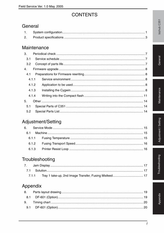
CONTENTS
General1. System configuration............................................................................................... 1
2. Product specifications ............................................................................................. 3
Maintenance3. Periodical check ...................................................................................................... 7
3.1 Service schedule .................................................................................................. 7
3.2 Concept of parts life.............................................................................................. 7
4. Firmware upgrade ................................................................................................... 8
4.1 Preparations for Firmware rewriting...................................................................... 8
4.1.1 Service environment ..................................................................................... 8
4.1.2 Application to be used................................................................................... 8
4.1.3 Installing the Cygwin ..................................................................................... 8
4.1.4 Writing into the Compact flash .................................................................... 11
5. Other ..................................................................................................................... 14
5.1 Special Parts of C351......................................................................................... 14
5.2 Special Parts List ................................................................................................ 14
Adjustment/Setting6. Service Mode ........................................................................................................ 15
6.1 Machine .............................................................................................................. 15
6.1.1 Fusing Temperature .................................................................................... 15
6.1.2 Fusing Transport Speed.............................................................................. 16
6.1.3 Printer Resist Loop ..................................................................................... 16
Troubleshooting7. Jam Display........................................................................................................... 17
7.1 Solution............................................................................................................... 17
7.1.1 Tray 1 take-up, 2nd Image Transfer, Fusing Misfeed................................... 17
Appendix8. Parts layout drawing .............................................................................................. 19
8.1 DF-601 (Option).................................................................................................. 19
9. Timing chart .......................................................................................................... 20
9.1 DF-601 (Option).................................................................................................. 20
i

biz
hu
b C
35
1G
en
era
lM
ain
ten
an
ce
Ad
justm
en
t /
Se
ttin
gT
rou
ble
sh
oo
tin
gA
pp
en
dix
Field Service Ver. 1.0 May. 2005
Blank Page
ii

Field Service Ver. 1.0 May. 2005 1. System configuration
biz
hu
b C
35
1G
en
era
l
General1. System configuration1/2 System Front View
[1] Machine [7] Job Separator JS-601
[2] Paper Feed Cabinet PC-202 [8] Finisher FS-603
[3] Paper Feed Cabinet PC-102 [9] Punch Kit PK-501
[4] Paper Feed Cabinet PC-402 [10] Reverse Automatic Document Feeder DF-601
[5] Desk DK-501 [11] Original Cover OC-501
[6] Finisher FS-507 [12] Working Table WT-501
[1]
[6]
[7]
[5]
[4]
[10][9]
[8]
[3]
[2]
[11] [12]
4037T1C301AA
1
1. System configuration Field Service Ver. 1.0 May. 2005b
izh
ub
C3
51
Ge
ne
ral
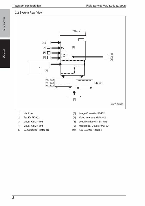
2/2 System Rear View
[1] Machine [6] Image Controller IC-402
[2] Fax Kit FK-502 [7] Video Interface Kit VI-502
[3] Mount Kit MK-703 [8] Local Interface Kit EK-702
[4] Mount Kit MK-704 [9] Mechanical Counter MC-501
[5] Dehumidifier Heater 1C [10] Key Counter Kit KIT-1
PC-102 PC-202PC-402
DK-501
[1]
[7]
[6]
[5]
[9]
[10]
[8] [2][3][4]
4037F1E503DA
2
Field Service Ver. 1.0 May. 2005 2. Product specifications
biz
hu
b C
35
1G
en
era
l
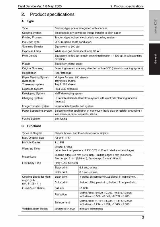
2. Product specificationsA. Type
B. Functions
Type Desktop-type printer integrated with scanner
Copying System Electrostatic dry-powdered image transfer to plain paper
Printing Process Tandem-type indirect electrostatic recording system
PC Drum Type OPC (organic photo conductor)
Scanning Density Equivalent to 600 dpi
Exposure Lamp White rare-gas fluorescent lamp 30 W
Print Density Equivalent to 600 dpi in main scanning direction × 1800 dpi in sub scanning direction
Platen Stationary (mirror scan)
Original Scanning Scanning in main scanning direction with a CCD (one-shot reading system)
Registration Rear left edge
Paper Feeding System (Standard)Three-way system
Multiple Bypass: 150 sheetsTray1: 250 sheetsTray2: 500 sheets
Exposure System Four-LED exposure
Developing System HMT developing system
Charging System DC comb electrode Scorotron system with electrode cleaning function (manual)
Image Transfer System Intermediate transfer belt system
Paper Separating System Selecting either application of nonwoven fabric bias or resistor grounding + low-pressure paper separator claws
Fusing System Belt fusing
Types of Original Sheets, books, and three-dimensional objects
Max. Original Size A3 or 11 × 17
Multiple Copies 1 to 999
Warm-up Time99 sec. or less (at ambient temperature of 23° C/73.4° F and rated source voltage)
Image LossLeading edge: 4.2 mm (3/16 inch), Trailing edge: 3 mm (1/8 inch), Rear edge: 3 mm (1/8 inch), Front edge: 3 mm (1/8 inch)
First Copy Time (Tray1, A4, full size)
Black print 6.8 sec. or less
Color print 8.5 sec. or less
Copying Speed for Multi-copy Cycle (A4, 8-1/2 × 11)
Black print 1-sided: 35 copies/min.; 2-sided: 31 copies/min.
Color print 1-sided: 35 copies/min.; 2-sided: 31 copies/min.
Fixed Zoom Ratios Full size ×1.000
ReductionMetric Area: ×0.500, ×0.707, ×0.816, ×0.866Inch Area: ×0.500, ×0.647, ×0.733, ×0.785
EnlargementMetric Area: ×1.154, ×1.224, ×1.414, ×2.000Inch Area: ×1.214, ×1.294, ×1.545, ×2.000
Variable Zoom Ratios ×0.250 to ×4.000 in 0.001 increments
3
2. Product specifications Field Service Ver. 1.0 May. 2005b
izh
ub
C3
51
Ge
ne
ral
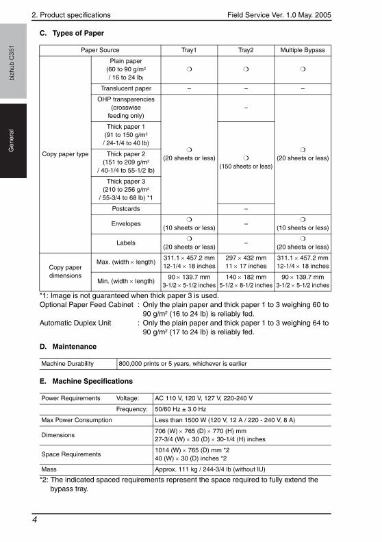
C. Types of Paper
*1: Image is not guaranteed when thick paper 3 is used.Optional Paper Feed Cabinet : Only the plain paper and thick paper 1 to 3 weighing 60 to
90 g/m2 (16 to 24 lb) is reliably fed.Automatic Duplex Unit : Only the plain paper and thick paper 1 to 3 weighing 64 to
90 g/m2 (17 to 24 lb) is reliably fed.
D. Maintenance
E. Machine Specifications
*2: The indicated spaced requirements represent the space required to fully extend the bypass tray.
Paper Source Tray1 Tray2 Multiple Bypass
Copy paper type
Plain paper (60 to 90 g/m2 / 16 to 24 lb)
❍ ❍ ❍
Translucent paper – – –
OHP transparencies (crosswise
feeding only)
❍
(20 sheets or less)
–
❍
(20 sheets or less)
Thick paper 1 (91 to 150 g/m2 / 24-1/4 to 40 lb)
❍
(150 sheets or less)
Thick paper 2 (151 to 209 g/m2
/ 40-1/4 to 55-1/2 lb)
Thick paper 3 (210 to 256 g/m2
/ 55-3/4 to 68 lb) *1
Postcards –
Envelopes❍
(10 sheets or less)–
❍
(10 sheets or less)
Labels❍
(20 sheets or less)–
❍
(20 sheets or less)
Copy paper dimensions
Max. (width × length)311.1 × 457.2 mm12-1/4 × 18 inches
297 × 432 mm11 × 17 inches
311.1 × 457.2 mm12-1/4 × 18 inches
Min. (width × length)90 × 139.7 mm
3-1/2 × 5-1/2 inches140 × 182 mm
5-1/2 × 8-1/2 inches90 × 139.7 mm
3-1/2 × 5-1/2 inches
Machine Durability 800,000 prints or 5 years, whichever is earlier
Power Requirements Voltage: AC 110 V, 120 V, 127 V, 220-240 V
Frequency: 50/60 Hz ± 3.0 Hz
Max Power Consumption Less than 1500 W (120 V, 12 A / 220 - 240 V, 8 A)
Dimensions706 (W) × 765 (D) × 770 (H) mm27-3/4 (W) × 30 (D) × 30-1/4 (H) inches
Space Requirements1014 (W) × 765 (D) mm *240 (W) × 30 (D) inches *2
Mass Approx. 111 kg / 244-3/4 lb (without IU)
4
Field Service Ver. 1.0 May. 2005 2. Product specifications
biz
hu
b C
35
1G
en
era
l
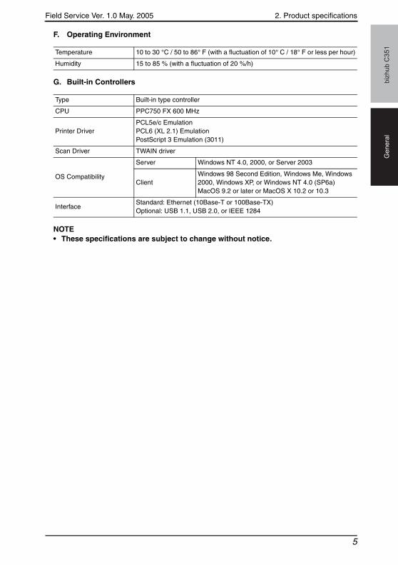
F. Operating Environment
G. Built-in Controllers
NOTE• These specifications are subject to change without notice.
Temperature 10 to 30 °C / 50 to 86° F (with a fluctuation of 10° C / 18° F or less per hour)
Humidity 15 to 85 % (with a fluctuation of 20 %/h)
Type Built-in type controller
CPU PPC750 FX 600 MHz
Printer DriverPCL5e/c EmulationPCL6 (XL 2.1) EmulationPostScript 3 Emulation (3011)
Scan Driver TWAIN driver
OS Compatibility
Server Windows NT 4.0, 2000, or Server 2003
ClientWindows 98 Second Edition, Windows Me, Windows 2000, Windows XP, or Windows NT 4.0 (SP6a) MacOS 9.2 or later or MacOS X 10.2 or 10.3
InterfaceStandard: Ethernet (10Base-T or 100Base-TX)Optional: USB 1.1, USB 2.0, or IEEE 1284
5

2. Product specifications Field Service Ver. 1.0 May. 2005b
izh
ub
C3
51
Ge
ne
ral
Blank Page
6
Field Service Ver. 1.0 May. 2005 3. Periodical check
biz
hu
b C
35
1M
ain
ten
an
ce
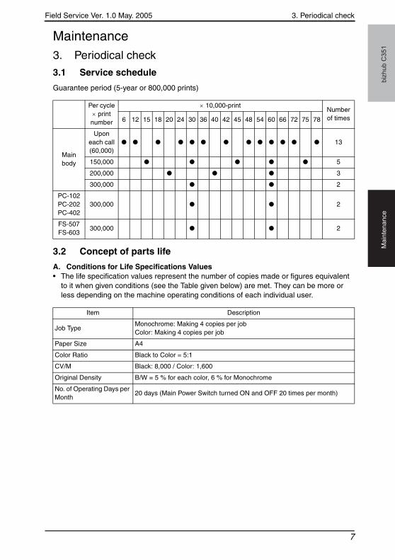
Maintenance3. Periodical check
3.1 Service schedule
Guarantee period (5-year or 800,000 prints)
3.2 Concept of parts life
A. Conditions for Life Specifications Values• The life specification values represent the number of copies made or figures equivalent
to it when given conditions (see the Table given below) are met. They can be more or less depending on the machine operating conditions of each individual user.
Per cycle × print
number
× 10,000-printNumber of times6 12 15 18 20 24 30 36 40 42 45 48 54 60 66 72 75 78
Main body
Upon each call (60,000)
● ● ● ● ● ● ● ● ● ● ● ● ● 13
150,000 ● ● ● ● ● 5
200,000 ● ● ● 3
300,000 ● ● 2
PC-102PC-202PC-402
300,000 ● ● 2
FS-507FS-603
300,000 ● ● 2
Item Description
Job TypeMonochrome: Making 4 copies per jobColor: Making 4 copies per job
Paper Size A4
Color Ratio Black to Color = 5:1
CV/M Black: 8,000 / Color: 1,600
Original Density B/W = 5 % for each color, 6 % for Monochrome
No. of Operating Days per Month
20 days (Main Power Switch turned ON and OFF 20 times per month)
7
4. Firmware upgrade Field Service Ver. 1.0 May. 2005b
izh
ub
C3
51
Ma
inte
na
nce
4. Firmware upgrade
4.1 Preparations for Firmware rewriting
4.1.1 Service environment
• OS: Windows 2000• Drive which enables writing/reading of Compact flash• Compact flash (with 128MB or more)
4.1.2 Application to be used
• Cygwin (Free software)
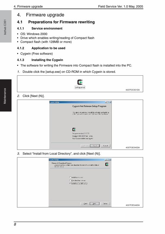
4.1.3 Installing the Cygwin
• The software for writing the Firmware into Compact flash is installed into the PC.
1. Double click the [setup.exe] on CD-ROM in which Cygwin is stored.
2. Click [Next (N)].
3. Select “Install from Local Directory”, and click [Next (N)].
4037F2C501DA
4037F2E545DA
4037F2E546DA
8
Field Service Ver. 1.0 May. 2005 4. Firmware upgrade
biz
hu
b C
35
1M
ain
ten
an
ce
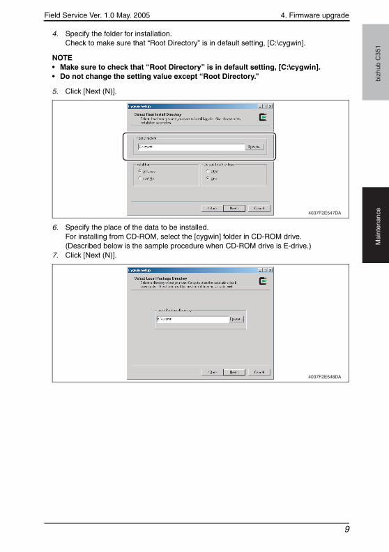
4. Specify the folder for installation.Check to make sure that “Root Directory” is in default setting, [C:\cygwin].
NOTE• Make sure to check that “Root Directory” is in default setting, [C:\cygwin].• Do not change the setting value except “Root Directory.”
5. Click [Next (N)].
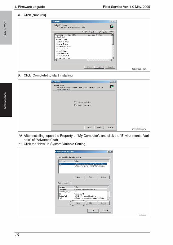
6. Specify the place of the data to be installed.For installing from CD-ROM, select the [cygwin] folder in CD-ROM drive.(Described below is the sample procedure when CD-ROM drive is E-drive.)
7. Click [Next (N)].
4037F2E547DA
4037F2E548DA
9
4. Firmware upgrade Field Service Ver. 1.0 May. 2005b
izh
ub
C3
51
Ma
inte
na
nce
8. Click [Next (N)].
9. Click [Complete] to start installing.
10. After installing, open the Property of “My Computer”, and click the “Environmental Vari-able” of “Advanced” tab.
11. Click the “New” in System Variable Setting.
4037F2E549DA
4037F2E550DA
4036fs2620e0
10

Field Service Ver. 1.0 May. 2005 4. Firmware upgrade
biz
hu
b C
35
1M
ain
ten
an
ce
12. Set the following two values as the Windows Environmental Variable.
4.1.4 Writing into the Compact flash
1. Put the data of Firmware in the optional directory. (C:\C351 in the below figure)
NOTE• The file name of Firmware data consists of the “Release
Date_Version_CHECKSUM-****.exe.”
Variable name Variable value
CYGWIN ntsec
HOME /home/username
4036fs2621e0
4037F2E551DA
11
4. Firmware upgrade Field Service Ver. 1.0 May. 2005b
izh
ub
C3
51
Ma
inte
na
nce
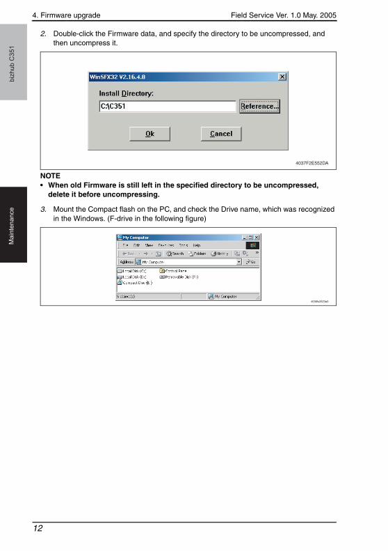
2. Double-click the Firmware data, and specify the directory to be uncompressed, and then uncompress it.
NOTE• When old Firmware is still left in the specified directory to be uncompressed,
delete it before uncompressing.
3. Mount the Compact flash on the PC, and check the Drive name, which was recognized in the Windows. (F-drive in the following figure)
4037F2E552DA
4036fs2623e0
12
Field Service Ver. 1.0 May. 2005 4. Firmware upgrade
biz
hu
b C
35
1M
ain
ten
an
ce
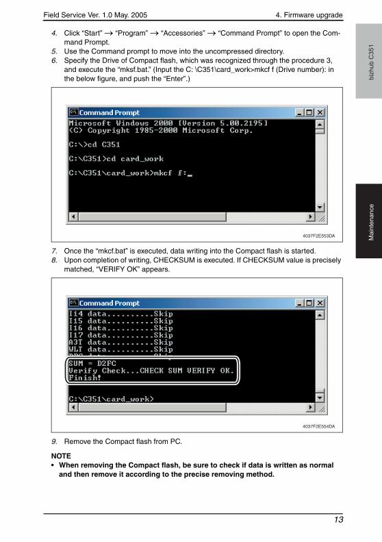
4. Click “Start” → “Program” → “Accessories” → “Command Prompt” to open the Com-mand Prompt.
5. Use the Command prompt to move into the uncompressed directory.6. Specify the Drive of Compact flash, which was recognized through the procedure 3,
and execute the “mksf.bat.” (Input the C: \C351\card_work>mkcf f (Drive number): in the below figure, and push the “Enter”.)
7. Once the “mkcf.bat” is executed, data writing into the Compact flash is started.8. Upon completion of writing, CHECKSUM is executed. If CHECKSUM value is precisely
matched, “VERIFY OK” appears.
9. Remove the Compact flash from PC.
NOTE• When removing the Compact flash, be sure to check if data is written as normal
and then remove it according to the precise removing method.
4037F2E553DA
4037F2E554DA
13

5. Other Field Service Ver. 1.0 May. 2005b
izh
ub
C3
51
Ma
inte
na
nce
5. Other
5.1 Special Parts of C351
• Special components intended for C351 are set for adjustment of transport speed.• Exchange procedures of the special components are same as C450.
For exchange procedures, see the service manual of C450.
5.2 Special Parts List
• LED Drive Board• Control Board• LPH Unit• LPH Assy
14
Field Service Ver. 1.0 May. 2005 6. Service Mode
biz
hu
b C
35
1A
dju
stm
en
t /
Se
ttin
g
Adjustment/Setting6. Service Mode
6.1 Machine
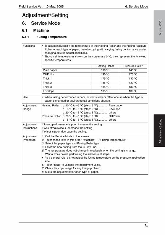
6.1.1 Fusing Temperature
Functions • To adjust individually the temperature of the Heating Roller and the Fusing Pressure Roller for each type of paper, thereby coping with varying fusing performance under changing environmental conditions.
* Though all temperatures shown on the screen are 0 °C, they represent the following specific temperatures.
Use • When fusing performance is poor, or wax streak or offset occurs when the type of paper is changed or environmental conditions change.
Adjustment Range
Heating Roller : -10 °C to +5 °C (step: 5 °C) ............. Plain paper: -5 °C to +5 °C (step: 5 °C) ............. Envelope: -20 °C to +5 °C (step: 5 °C) ............. others
Pressure Roller : -20 °C to +5 °C (step: 5 °C) ............. OHP film: -5 °C to +5 °C (step: 5 °C) ............. others
Adjustment Instructions
If fusing performance is poor, increase the setting.If wax streaks occur, decrease the setting.If offset is poor, decrease the setting.
Adjustment Procedure
1. Call the Service Mode to the screen.2. Touch these keys in this order: “Machine” → “Fusing Temperature.”3. Select the paper type and Fusing Roller type.4. Enter the new setting from the +/- key Pad.5. The temperature does not change immediately when the setting is change.
Wait a while before performing the subsequent steps.• As a general rule, do not adjust the fusing temperature on the pressure application
side.6. Touch “END” to validate the adjustment value.7. Check the copy image for any image problem.8. Make the adjustment for each type of paper.
Heating Roller Pressure Roller
Plain paper 190 °C 145 °C
OHP film 190 °C 170 °C
Thick 1 175 °C 130 °C
Thick 2 185 °C 130 °C
Thick 3 185 °C 130 °C
Envelope 185 °C 130 °C
15
6. Service Mode Field Service Ver. 1.0 May. 2005b
izh
ub
C3
51
Ad
justm
en
t /
Se
ttin
g
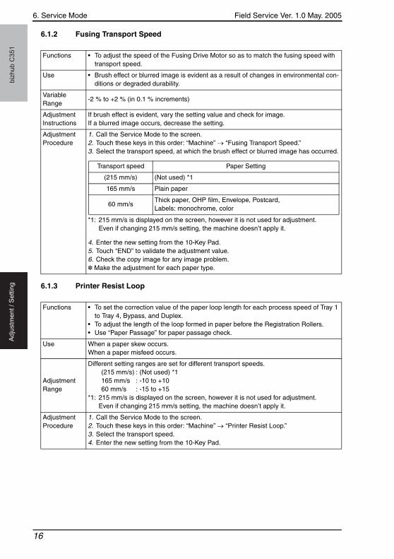
6.1.2 Fusing Transport Speed
6.1.3 Printer Resist Loop
Functions • To adjust the speed of the Fusing Drive Motor so as to match the fusing speed with transport speed.
Use • Brush effect or blurred image is evident as a result of changes in environmental con-ditions or degraded durability.
Variable Range
-2 % to +2 % (in 0.1 % increments)
Adjustment Instructions
If brush effect is evident, vary the setting value and check for image.If a blurred image occurs, decrease the setting.
Adjustment Procedure
1. Call the Service Mode to the screen.2. Touch these keys in this order: “Machine” → “Fusing Transport Speed.”3. Select the transport speed, at which the brush effect or blurred image has occurred.
*1: 215 mm/s is displayed on the screen, however it is not used for adjustment. Even if changing 215 mm/s setting, the machine doesn’t apply it.
4. Enter the new setting from the 10-Key Pad.5. Touch “END” to validate the adjustment value.6. Check the copy image for any image problem.✽ Make the adjustment for each paper type.
Transport speed Paper Setting
(215 mm/s) (Not used) *1
165 mm/s Plain paper
60 mm/sThick paper, OHP film, Envelope, Postcard,Labels: monochrome, color
Functions • To set the correction value of the paper loop length for each process speed of Tray 1 to Tray 4, Bypass, and Duplex.
• To adjust the length of the loop formed in paper before the Registration Rollers.• Use “Paper Passage” for paper passage check.
Use When a paper skew occurs.When a paper misfeed occurs.
Adjustment Range
Different setting ranges are set for different transport speeds.(215 mm/s) : (Not used) *1165 mm/s : -10 to +1060 mm/s : -15 to +15
*1: 215 mm/s is displayed on the screen, however it is not used for adjustment. Even if changing 215 mm/s setting, the machine doesn’t apply it.
Adjustment Procedure
1. Call the Service Mode to the screen.2. Touch these keys in this order: “Machine” → “Printer Resist Loop.”3. Select the transport speed.4. Enter the new setting from the 10-Key Pad.
16
Field Service Ver. 1.0 May. 2005 7. Jam Display
biz
hu
b C
35
1T
rou
ble
sh
oo
tin
g
Troubleshooting7. Jam Display
7.1 Solution
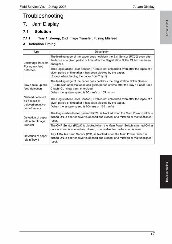
7.1.1 Tray 1 take-up, 2nd Image Transfer, Fusing Misfeed
A. Detection Timing
Type Description
2nd Image Transfer, Fusing misfeed detection
The leading edge of the paper does not block the Exit Sensor (PC30) even after the lapse of a given period of time after the Registration Roller Clutch has been energized.
The Registration Roller Sensor (PC28) is not unblocked even after the lapse of a given period of time after it has been blocked by the paper. (Except when feeding the paper from Tray 1)
Tray 1 take-up mis-feed detection
The leading edge of the paper does not block the Registration Roller Sensor (PC28) even after the lapse of a given period of time after the Tray 1 Paper Feed Clutch (CL1) has been energized. (When the system speed is 60 mm/s or 165 mm/s)
Misfeed detected as a result of delayed deactiva-tion of sensor
The Registration Roller Sensor (PC28) is not unblocked even after the lapse of a given period of time after it has been blocked by the paper. (When the system speed is 60/mms or 165 mm/s)
Detection of paper left in 2nd Image Transfer
The Registration Roller Sensor (PC28) is blocked when the Main Power Switch is turned ON, a door or cover is opened and closed, or a misfeed or malfunction is reset.
The OHP Sensor (PC27) is blocked when the Main Power Switch is turned ON, a door or cover is opened and closed, or a misfeed or malfunction is reset.
Detection of paper left in Tray 1
Tray 1 Double Feed Sensor (PC1) is blocked when the Main Power Switch is turned ON, a door or cover is opened and closed, or a misfeed or malfunction is reset.
17

7. Jam Display Field Service Ver. 1.0 May. 2005b
izh
ub
C3
51
Tro
ub
lesh
oo
tin
g
B. Action
Relevant Electrical Parts
Tray 1 Double Feed Sensor (PC1)Registration Roller Sensor (PC28)Exit Sensor (PC30)OHP Sensor (PC27)
Control Board (PWB-MC)Registration Roller Clutch (CL3)Tray 1 Paper Feed Clutch (CL1)
Step Action
WIRING DIAGRAM
Control SignalLocation
(Electrical Component)
1 Initial check items — —
2 PC1 I/O check, Sensor check PWB-MC PJ22MC-8 (ON) C to D-5
3 PC28 I/O check, Sensor check PWB-MC PJ24MC-6 (ON) C to D-3
4 PC30 I/O check, Sensor check PWB-MC PJ24MC-12 (ON) C to D-4
5 PC27 I/O check, Sensor check PWB-MC PJ24MC-2 (ON) C to D-3
6 CL3 operation check PWB-MC PJ24MC-14 (ON) C to D-4
7 CL1 operation check PWB-MC PJ14MC-3 (ON) C to D-5 to 6
8 Change PWB-MC — —
18
Field Service Ver. 1.0 May. 2005 8. Parts layout drawing
biz
hu
b C
35
1A
pp
en
dix
Appendix8. Parts layout drawing
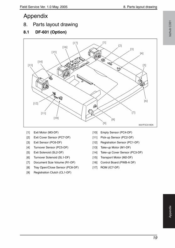
8.1 DF-601 (Option)
[1] Exit Motor (M3-DF) [10] Empty Sensor (PC4-DF)
[2] Exit Cover Sensor (PC7-DF) [11] Pick-up Sensor (PC2-DF)
[3] Exit Sensor (PC6-DF) [12] Registration Sensor (PC1-DF)
[4] Turnover Sensor (PC5-DF) [13] Take-up Motor (M1-DF)
[5] Exit Solenoid (SL2-DF) [14] Take-up Cover Sensor (PC3-DF)
[6] Turnover Solenoid (SL1-DF) [15] Transport Motor (M2-DF)
[7] Document Size Volume (R1-DF) [16] Control Board (PWB-A DF)
[8] Tray Open/Close Sensor (PC8-DF) [17] ROM (IC7-DF)
[9] Registration Clutch (CL1-DF)
4037F5C519DA
[1][2]
[3]
[4]
[5]
[6]
[7]
[8][9]
[10]
[11]
[12]
[13][14]
[15]
[16]
[17]
19

9. Timing chart Field Service Ver. 1.0 May. 2005b
izh
ub
C3
51
Ap
pe
nd
ix
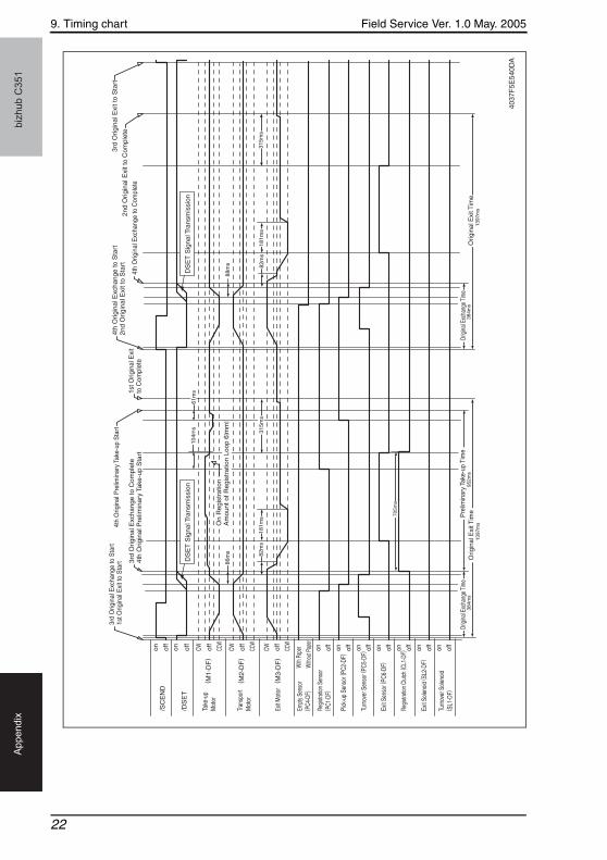
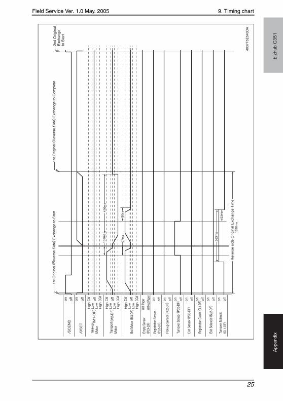
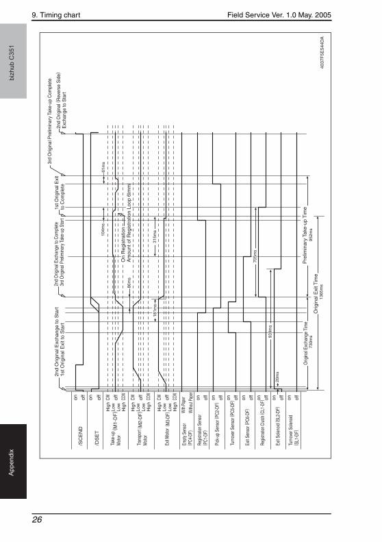
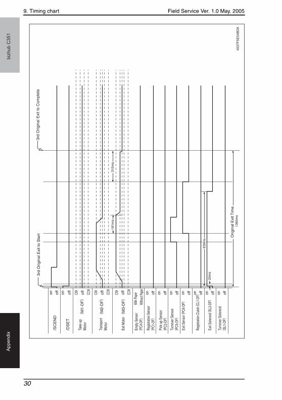
9. Timing chart
9.1 DF-601 (Option)
1-sided mode
/SC
EN
Don of
f
/DS
ET
on
Take
-up
Mot
or( M
1-D
F)
Tran
spor
tM
otor
Exit M
otor
( M3-
DF)
Empt
y Sen
sor
( PC4
-DF)
With
Pap
er
With
out P
aper
Regis
tratio
n Se
nsor
( PC1
-DF)
on off
on off
on off
on off
on off
on off
on off
Pick
-up
Sens
or ( P
C2-D
F)
Turn
over
Sen
sor (
PC5-
DF)
Exit
Sens
or ( P
C6-D
F)
Regis
tratio
n Cl
utch
( CL1
-DF)
Exit
Sole
noid
( SL2
-DF)
Turn
over
Sol
enoi
d( S
L1-D
F)
104m
s61
ms
104m
s61
ms
86m
s
50m
s
705m
s
766m
s
705m
s
952m
s38
4ms
900m
m/s
ec=
Hig
h15
0mm
/sec
=Lo
woff
CW off
CCW
Hig
hLo
wLo
wH
igh
( M2-
DF)
CW off
CCW
Hig
hLo
wLo
wH
igh
CW off
CCW
Hig
hLo
wLo
wH
igh
1st O
rigin
al P
relim
inar
y Ta
ke-u
p S
tart
Mis
ted
Orig
inal
Det
ectin
g S
igna
l Sta
rt1s
t Orig
inal
Exc
hang
e to
Sta
rt
1st O
rigin
al E
xcha
nge
to C
ompl
ete
2nd
Orig
inal
Pre
limin
ary
Take
-up
Sta
rt
2nd
Orig
inal
Pre
limin
ary
Take
-up
Com
plet
e2n
d O
rigin
al
Exc
hang
e to
Sta
rt
On
Reg
istr
atio
nA
mou
nt o
f Reg
istr
atio
n Lo
op 6
[ mm
]
DS
ET
Sig
nal T
rans
mis
sion
On
Reg
istr
atio
nA
mou
nt o
f Reg
istr
atio
n Lo
op 6
[ mm
]
Orig
inal
Exc
hang
e Ti
me
Pre
limin
ary
Take
-up
Tim
e
4037
F5E
538D
A
20

Field Service Ver. 1.0 May. 2005 9. Timing chart
biz
hu
b C
35
1A
pp
en
dix
104m
s61
ms
86m
s
705m
s
384m
s95
2ms
/SC
EN
Don of
f
/DS
ET
on
Take
-up
Mot
or( M
1-D
F)
Tran
spor
tM
otor
Exit M
otor
( M3-
DF
)
Empt
y Sen
sor
( PC4
-DF)
With
Pap
er
With
out P
aper
Regis
tratio
n Se
nsor
( PC1
-DF)
on off
on off
on off
on off
on off
on off
on off
Pick
-up
Sens
or ( P
C2-D
F)
Turn
over
Sen
sor (
PC5-
DF)
Exit
Sens
or ( P
C6-D
F)
Regis
tratio
n Cl
utch
( CL1
-DF)
Exit
Sole
noid
( SL2
-DF)
Turn
over
Sol
enoi
d( S
L1-D
F)
off
CW off
CCW
( M2-
DF
)CW of
f
CCW
CW off
CCW
2nd
Orig
inal
E
xcha
nge
to S
tart
1st O
rigin
al E
xcha
nge
to C
ompl
ete
3rd
Orig
inal
Pre
limin
ary
Take
-up
Sta
rt
3rd
Orig
inal
Pre
limin
ary
Take
-up
Com
plet
e
3rd
Orig
inal
E
xcha
nge
to S
tart
On
Reg
istr
atio
nA
mou
nt o
f Reg
istr
atio
n Lo
op 6
[ mm
]
DS
ET
Sig
nal T
rans
mis
sion
Orig
inal
Exc
hang
e Ti
me
Pre
limin
ary
Take
-up
Tim
e
4037
F5E
539D
A
21
9. Timing chart Field Service Ver. 1.0 May. 2005b
izh
ub
C3
51
Ap
pe
nd
ix
384m
s95
2ms
1397
ms
1397
ms
86m
s 82m
s18
1ms
315m
s
104m
s61
ms
82m
s18
1ms
315m
s
705m
s
88m
s
/SC
EN
Don of
f
/DS
ET
on
Take
-up
Mot
or( M
1-D
F)
Tran
spor
tM
otor
Exit M
otor
( M3-
DF
)
Empt
y Sen
sor
( PC4
-DF)
With
Pap
er
With
out P
aper
Regis
tratio
n Se
nsor
( PC1
-DF)
on off
on off
on off
on off
on off
on off
on off
Pick
-up
Sens
or ( P
C2-D
F)
Turn
over
Sen
sor (
PC5-
DF)
Exit
Sens
or ( P
C6-D
F)
Regis
tratio
n Cl
utch
( CL1
-DF)
Exit
Sole
noid
( SL2
-DF)
Turn
over
Sol
enoi
d( S
L1-D
F)
off
CW off
CCW
( M2-
DF
)CW of
f
CCW
CW off
CCW
3rd
Orig
inal
Exc
hang
e to
Sta
rt1s
t Orig
inal
Exi
t to
Sta
rt 3rd
Orig
inal
Exc
hang
e to
Com
plet
e4t
h O
rigin
al P
relim
inar
y Ta
ke-u
p S
tart
DS
ET
Sig
nal T
rans
mis
sion
DS
ET
Sig
nal T
rans
mis
sion
4th
Orig
inal
Pre
limin
ary
Take
-up
Sta
rt
1st O
rigin
al E
xit
to C
ompl
ete
4th
Orig
inal
Exc
hang
e to
Sta
rt2n
d O
rigin
al E
xit t
o S
tart
4th
Orig
inal
Exc
hang
e to
Com
plet
e
3rd
Orig
inal
Exi
t to
Sta
rt
2nd
Orig
inal
Exi
t to
Com
plet
e
On
Reg
istr
atio
nA
mou
nt o
f Reg
istr
atio
n Lo
op 6
[ mm
]
Origi
nal E
xcha
nge T
ime
Origi
nal E
xcha
nge T
ime
Orig
inal
Exi
t Tim
eO
rigin
al E
xit T
ime
Pre
limin
ary
Take
-up
Tim
e38
4ms
4037
F5E
540D
A
22

Field Service Ver. 1.0 May. 2005 9. Timing chart
biz
hu
b C
35
1A
pp
en
dix
3rd
Orig
inal
Exi
t to
Sta
rt3r
d O
rigin
al E
xit t
o C
ompl
ete
4th
Orig
inal
Exi
t to
Sta
rt
82m
s Orig
inal
Exi
t Tim
e13
97m
sO
rigin
al E
xit T
ime
1397
ms
4th
Orig
inal
E
xit t
o C
ompl
ete
181m
s31
5ms
82m
s18
1ms
315m
s
/SC
EN
Don of
f
/DS
ET
on
Take
-up
Mot
or( M
1-D
F)
Tran
spor
tM
otor
Exit M
otor
( M3-
DF
)
Empt
y Sen
sor
( PC4
-DF)
With
Pap
er
With
out P
aper
Regis
tratio
n Se
nsor
( PC1
-DF)
on off
on off
on off
on off
on off
on off
on off
Pick
-up
Sens
or( P
C2-D
F)
Turn
over
Sen
sor
( PC5
-DF)
Exit
Sens
or ( P
C6-D
F)
Regis
tratio
n Cl
utch
( CL1
-DF)
Exit
Sole
noid
( SL2
-DF)
Turn
over
Sol
enoi
d( S
L1-D
F)
off
CW off
CCW
( M2-
DF
)CW of
f
CCW
CW off
CCW
4037
F5E
541D
A
23

9. Timing chart Field Service Ver. 1.0 May. 2005b
izh
ub
C3
51
Ap
pe
nd
ix
Mixed original detection mode
104m
s61
ms
104m
s61
ms
50m
s
705m
s
766m
s
705m
s
Origi
nal E
xcha
nge T
ime
86m
s
384m
s
/SC
EN
Don of
f
/DS
ET
on
Take
-up
Mot
or( M
1-D
F)
Tran
spor
tM
otor
Exit M
otor
( M3-
DF)
Empt
y Sen
sor
( PC4
-DF)
With
Pap
er
With
out P
aper
Regis
tratio
n Se
nsor
( PC1
-DF)
on off
on off
on off
on off
on off
on off
on off
Pick
-up
Sens
or ( P
C2-D
F)
Turn
over
Sen
sor (
PC5-
DF)
Exit
Sens
or ( P
C6-D
F)
Regis
tratio
n Cl
utch
( CL1
-DF)
Exit
Sole
noid
( SL2
-DF)
Turn
over
Sol
enoi
d ( S
L1-D
F)
off
CW off
CCW
Hig
hLo
wLo
wH
igh
( M2-
DF)
CW off
CCW
Hig
hLo
wLo
wH
igh
CW off
CCW
Hig
hLo
wLo
wH
igh
1st O
rigin
al P
relim
inar
y Ta
ke-u
p S
tart
Mis
ted
Orig
inal
Det
ectin
g S
igna
l Sta
rt1s
t Orig
inal
E
xcha
nge
to S
tart
1st O
rigin
al E
xcha
nge
to C
ompl
ete
2nd
Orig
inal
Pre
limin
ary
Take
-up
Sta
rt
2nd
Orig
inal
Pre
limin
ary
Take
-up
Com
plet
e1s
t Orig
inal
(R
ever
se S
ide)
E
xcha
nge
to C
ompl
ete
DS
ET
Sig
nal T
rans
mis
sion
On
Reg
istr
atio
nA
mou
nt o
f Reg
istr
atio
n Lo
op 6
[ mm
]O
n R
egis
trat
ion
Am
ount
of R
egis
trat
ion
Loop
6[ m
m]
Pre
limin
ary
Take
-up
Tim
e95
2ms
4037
F5E
542D
A
24
Field Service Ver. 1.0 May. 2005 9. Timing chart
biz
hu
b C
35
1A
pp
en
dix
1st O
rigin
al (
Rev
erse
Sid
e) E
xcha
nge
to S
tart
103m
s45
6ms
150m
s97
ms
563m
s
133m
s
1330
ms
Rev
erse
sid
e O
rigin
al E
xcha
nge
Tim
e
1st O
rigin
al (
Rev
erse
Sid
e) E
xcha
nge
to C
ompl
ete
/SC
EN
Don of
f
/DS
ET
on
Take
-up
Mot
or( M
1-D
F)
Tran
spor
tM
otor
Exit M
otor
( M3-
DF)
Empt
y Sen
sor
( PC4
-DF)
With
Pap
er
With
out P
aper
Regis
tratio
n Se
nsor
( PC1
-DF)
on off
on off
on off
on off
on off
on off
on off
Pick
-up
Sens
or ( P
C2-D
F)
Turn
over
Sen
sor (
PC5-
DF)
Exit
Sens
or ( P
C6-D
F)
Regis
tratio
n Cl
utch
( CL1
-DF)
Exit
Sole
noid
( SL2
-DF)
Turn
over
Sol
enoi
d( S
L1-D
F)
off
CW off
CCW
Hig
hLo
wLo
wH
igh
( M2-
DF)
CW off
CCW
Hig
hLo
wLo
wH
igh
CW off
CCW
Hig
hLo
wLo
wH
igh
2nd
Orig
inal
E
xcha
nge
to S
tart
4037
F5E
543D
A
25
9. Timing chart Field Service Ver. 1.0 May. 2005b
izh
ub
C3
51
Ap
pe
nd
ix
104m
s61
ms
86m
s
181m
s31
5ms
705m
s
939m
s
730m
s
1365
ms
952m
s
20m
s
/SC
EN
Don of
f
/DS
ET
on
Take
-up
Mot
or( M
1-D
F)
Tran
spor
tM
otor
Exit M
otor
( M3-
DF)
Empt
y Sen
sor
( PC4
-DF)
With
Pap
er
With
out P
aper
Regis
tratio
n Se
nsor
( PC1
-DF)
on off
on off
on off
on off
on off
on off
on off
Pick
-up
Sens
or ( P
C2-D
F)
Turn
over
Sen
sor (
PC5-
DF)
Exit
Sens
or ( P
C6-D
F)
Regis
tratio
n Cl
utch
( CL1
-DF)
Exit
Sole
noid
( SL2
-DF)
Turn
over
Sol
enoi
d( S
L1-D
F)
off
CW off
CCW
Hig
hLo
wLo
wH
igh
( M2-
DF)
CW off
CCW
Hig
hLo
wLo
wH
igh
CW off
CCW
Hig
hLo
wLo
wH
igh
2nd
Orig
inal
Exc
hang
e to
Sta
rt1s
t Orig
inal
Exi
t to
Sta
rt2n
d O
rigin
al E
xcha
nge
to C
ompl
ete
3rd
Orig
inal
Pre
limin
ary
Take
-up
Star
t1s
t Orig
inal
Exi
t to
Com
plet
e
3rd
Orig
inal
Pre
limin
ary
Take
-up
Com
plet
e
2nd
Orig
inal
( Rev
erse
Sid
e)
Exc
hang
e to
Sta
rt
On
Reg
istr
atio
nA
mou
nt o
f Reg
istr
atio
n Lo
op 6
[ mm
]
Orig
inal
Exc
hang
e Ti
me
Orig
inal
Exi
t Tim
e
Pre
limin
ary
Take
-up
Tim
e
4037
F5E
544D
A
26

Field Service Ver. 1.0 May. 2005 9. Timing chart
biz
hu
b C
35
1A
pp
en
dix
103m
s
2nd
Orig
inal
(R
ever
se S
ide)
Exc
hang
e to
Com
plet
e1s
t Orig
inal
Exc
hang
e to
Sta
rt
456m
s
150m
s97
ms
563m
s
563m
s
1330
ms
/SC
EN
Don of
f
/DS
ET
on
Take
-up
Mot
or( M
1-D
F)
Tran
spor
tM
otor
Exit M
otor
( M3-
DF
)
Empt
y Sen
sor
( PC4
-DF)
With
Pap
er
With
out P
aper
Regis
tratio
n Se
nsor
(PC
1-DF
)
on off
on off
on off
on off
on off
on off
on off
Pick
-up
Sens
or ( P
C2-D
F)
Turn
over
Sen
sor (
PC5-
DF)
Exit
Sens
or ( P
C6-D
F)
Regis
tratio
n Cl
utch
( CL1
-DF)
Exit
Sole
noid
( SL2
-DF)
Turn
over
Sol
enoi
d( S
L1-D
F)
off
CW off
CCW
( M2-
DF
)CW of
f
CCW
CW off
CCW
2nd
Orig
inal
(R
ever
se S
ide)
Exc
hang
e to
Sta
rt
Rev
erse
sid
e O
rigin
al E
xcha
nge
Tim
e
4037
F5E
545D
A
27

9. Timing chart Field Service Ver. 1.0 May. 2005b
izh
ub
C3
51
Ap
pe
nd
ix
86m
s
2nd
Orig
inal
Exi
t to
Com
plet
e3r
d O
rigin
al (
Rev
erse
Sid
e)
Exc
hang
e to
Sta
rt
181m
s31
5ms
939m
s
730m
s
1365
ms
Orig
inal
Exc
hang
e Ti
me
20m
s
/SC
EN
Don of
f
/DS
ET
on
Take
-up
Mot
or( M
1-D
F)
Tran
spor
tM
otor
Exit M
otor
( M3-
DF)
Empt
y Sen
sor
( PC4
-DF)
With
Pap
er
With
out P
aper
Regis
tratio
n Se
nsor
( PC1
-DF)
on off
on off
on off
on off
on off
on off
on off
Pick
-up
Sens
or( P
C2-D
F)
Turn
over
Sen
sor (
PC5-
DF)
Exit
Sens
or ( P
C6-D
F)
Regis
tratio
n Cl
utch
( CL1
-DF)
Exit
Sole
noid
( SL2
-DF)
Turn
over
Sol
enoi
d( S
L1-D
F)
off
CW off
CCW
Hig
hLo
wLo
wH
igh
( M2-
DF)
CW off
CCW
Hig
hLo
wLo
wH
igh
CW off
CCW
Hig
hLo
wLo
wH
igh
3rd
Orig
inal
Exc
hang
e to
Com
plet
e3r
d O
rigin
al E
xcha
nge
to S
tart
2nd
Orig
inal
Exi
t to
Sta
rt
Orig
inal
Exi
t Tim
e40
37F
5E54
6DA
28

Field Service Ver. 1.0 May. 2005 9. Timing chart
biz
hu
b C
35
1A
pp
en
dix
3rd
Orig
inal
(R
ever
se S
ide)
Exc
hang
e to
Sta
rt
103m
s
3rd
Orig
inal
(R
ever
se S
ide)
Exc
hang
e to
Com
plet
e3r
d O
rigin
al
Exi
t to
Sta
rt
456m
s
150m
s97
ms
563m
s 1330
ms
133m
s
/SC
EN
Don of
f
/DS
ET
on
Take
-up
Mot
or( M
1-D
F)
Tran
spor
tM
otor
Exit M
otor
( M3-
DF
)
Empt
y Sen
sor
( PC4
-DF)
With
Pap
er
With
out P
aper
Regis
tratio
n Se
nsor
( PC1
-DF)
on off
on off
on off
on off
on off
on off
on off
Pick
-up
Sens
or ( P
C2-D
F)
Turn
over
Sen
sor (
PC5-
DF)
Exit
Sens
or ( P
C6-D
F)
Regis
tratio
n Cl
utch
( CL1
-DF)
Exit
Sole
noid
( SL2
-DF)
Turn
over
Sol
enoi
d( S
L1-D
F)
off
CW off
CCW
( M2-
DF
)CW of
f
CCW
CW off
CCW
Rev
erse
sid
e O
rigin
al E
xcha
nge
Tim
e
4037
F5E
547D
A
29
9. Timing chart Field Service Ver. 1.0 May. 2005b
izh
ub
C3
51
Ap
pe
nd
ix
3rd
Orig
inal
Exi
t to
Com
plet
e
181m
s31
5ms
939m
s
20m
s
1365
ms
3rd
Orig
inal
Exi
t to
Sta
rt
/SC
EN
Don of
f
/DS
ET
on
Take
-up
Mot
or( M
1-D
F)
Tran
spor
tM
otor
Exit M
otor
( M3-
DF
)
Empt
y Sen
sor
( PC4
-DF)
With
Pap
er
With
out P
aper
Regis
tratio
n Se
nsor
( PC1
-DF)
on off
on off
on off
on off
on off
on off
on off
Pick
-up
Sens
or( P
C2-D
F)
Turn
over
Sen
sor
( PC5
-DF)
Exit
Sens
or ( P
C6-D
F)
Regis
tratio
n Cl
utch
( CL1
-DF)
Exit
Sole
noid
( SL2
-DF)
Turn
over
Sol
enoi
d ( S
L1-D
F)
off
CW off
CCW
( M2-
DF
)CW of
f
CCW
CW off
CCW
Orig
inal
Exi
t Tim
e40
37F
5E54
8DA
30

SERVICE MANUAL
2005.052005.05Ver. 1.0Ver. 1.0
2005.05 Ver.1.0
2005.05 Ver.1.0
© 2005 KONICA MINOLTA BUSINESS TECHNOLOGIES, INC.© 2005 KONICA MINOLTA BUSINESS TECHNOLOGIES, INC.
FIELD SERVICE
FIE
LD S
ER
VIC
E
Printed in JapanPrinted in JapanDD4037PE1-P000DD4037PE1-P000
Use of this manual should be strictly supervised toavoid disclosure of confidential information.Use of this manual should be strictly supervised toavoid disclosure of confidential information.
This service manual is issued for C351 that has been changed from C450. Therefore please refer it along with the service manual of C450.
This service manual is issued for C351 that has been changed from C450. Therefore please refer it along with the service manual of C450.