Embed Size (px)
Citation preview

BIODEXBiodex Medical Systems, Inc.
20 Ramsey Road, Shirley, New York, 11967-4704, Tel: 800-224-6339 (Int’l 631-924-9000), Fax: 631-924-9338, Email: [email protected], www.biodex.com
FN: 10-202 Rev D 8/14
BIOSWAY PORTABLE BALANCE SYSTEM oPerAtion mAnuAl
950-460950-461
Biodex eLearning
As a valued Biodex customer, we invite you to learn how to use your Portable BioSway
with a series of online tutorials.
www.biodex.com/elearning

— ii —
This manual covers installation and operation procedures for the following products:
950-460 BioSway Portable Balance System w/Case950-461 BioSway Portable Balance System w/o Case
BIOSWAY PORTABLE BALANCE SYSTEM
CAUTION: Federal law restricts this device to sale of or on the order of a medicalpractitioner. When prescribed for therapeutic purpose, a physician should clearlydefine the parameters of use (i.e., total work, maximum heart rate, etc.) to reduce therisk of patient injury.

— iii — tABle of contentS
1. IntroductIon ..............................................................................................................................1-1What Does The BioSway Do?........................................................................................................1-1eLearning ..........................................................................................................................................1-2
2. SyStem SpecIfIcatIonS ............................................................................................................2-1
3. connectIonS and adjuStmentS ......................................................................................3-1
4. clInIcal conSIderatIonS ....................................................................................................4-1• Balance Overview ........................................................................................................................4-1• Limits of Stability ........................................................................................................................4-3• Clinical Test of Sensory Integration and Balance – CTSIB or
m-CTSIB (Modified CTSIB) ........................................................................................................4-4
5. GettInG Started ........................................................................................................................5-1• The Main Menu............................................................................................................................5-1• Display Panel Buttons ................................................................................................................5-1• Screen Keys ..................................................................................................................................5-1
6. traInInG ..........................................................................................................................................6-1• Postural Stability Training Access ............................................................................................6-2• Limits of Stability (LOS) Training ............................................................................................6-4• Weight Shift Training..................................................................................................................6-6• Maze Control Training................................................................................................................6-8• Random Control Training ........................................................................................................6-10• Percent Weight-Bearing Training............................................................................................6-13
7. teStInG ..............................................................................................................................................7-1• The Postural Stability Test..........................................................................................................7-2• Performing A Limits of Stability Test ......................................................................................7-4• Performing A Fall Risk Test Using The CTSIB ......................................................................7-5
8. reportS and data ......................................................................................................................8-1• Report Parameters ......................................................................................................................8-1• Data Interpretation For The Limits Of Stability......................................................................8-2• Dynamic Limits Of Stability Score Calculation ......................................................................8-3• Sample Balance Reports..............................................................................................................8-4• Progress Reports ..........................................................................................................................8-7
9. SyStem utIlItIeS ..........................................................................................................................9-1• System Utilities ............................................................................................................................9-1• Configuration ..............................................................................................................................9-2• Patient Management....................................................................................................................9-5• Custom Protocol List And Creating Custom Protocols ........................................................9-8
10. compatIble prInterS and component part lISt..............................................10-1
appendIx a: balance SyStem ClInIcal teSt of SenSory InteGratIon and balance (ctSIb) Sway Index equatIon ..................................a-1
• Test Description ..........................................................................................................................A-1• Equipment Description..............................................................................................................A-1
appendIx b: bIoSway relIabIlIty and ctSIb normatIve data......................b-1
TABLE OF CONTENTS

appendIx c: movement StrateGIeS for balance, SenSory orGanIzatIon, aGe-related chanGeS In balance and ctSIb teSt reSult InterpretatIon ................c-1
• Movement Strategies ..................................................................................................................C-1• Sensory Organization For Balance ..........................................................................................C-2• Age-Related Changes In Balance..............................................................................................C-4• CTSIB Test Result Interpretation..............................................................................................C-5
appendIx d: addItIonal noteS about ctSIb report InterpretatIon• A Note About CTSIB Report Interpretation ..........................................................................D-1
appendIx e: conformance StandardS ........................................................................E-1• Accompanying EMC Documents ............................................................................................E-1• List of Cable Accessories............................................................................................................E-1• Declararion of Conformity ........................................................................................................E-2• Recommended Separarion Distances ......................................................................................E-4• Operating Temperature..............................................................................................................E-4
appendIx f: cleanInG and maIntenance ..................................................................F-1
INTRODUCTION
introduction — iV —

The Biodex BioSway is compact, lightweight and easily portable.
The BioSway is a versatile Balance Assessment and Training Device. Lightweight and relativelysmall, it is easily portable. Set-up only takes minutes to provide the clinician with a choice of sixinteractive training modes or three standardized testing protocols including the Clinical Test ofSensory Integration and Balance protocol.
The easy-to-follow touch screen format makes BioSway simple to learn and operate. All testresults and training sessions can be stored and printed. Comparison to normative data helps tocommunicate need, progress and outcome.
An optional hard shell “wheelie board” case provides convenience and protection when usingthe BioSway outside the clinic.
what doeS the bIoSway do?1. Provides valid, reliable, and repeatable objectives measures of a patient’s neuromuscular
control and ability to balance on a firm and/or unstable surface.2. Documents balance rehabilitation and assessment.3. During rehabilitation provides visual feedback of a patient’s ability to control their center
of gravity (COG).
the biodex bioSway can be the cornerstone for the following programs:• Fall Risk Assessment and Conditioning Programs• Movement Disorders associated with neuromuscular control• Amputee prosthetic rehabilitation• Orthopedic rehabilitation associated with ligament sprains and poor neuromuscular control• Sports Medicine and Conditioning Programs• Core and Lumbar Stabilization Strategies• Pre- and post-head injury screening• Concussion Management Program with Play It S.A.F.E.®
For more specific applications, please refer to the Fall Risk Screening protocol and Compendiumof Balance Application protocols.
1. INTRODUCTIONTABLE OF CONTENTS
— 1-1 — introduction

elearning
eleArning — 1-2 —
elearnInG
We invite you to learn how to use your new Portable BioSway with a series of online tutorials.
www.biodex.com/elearning
The content of the BioSway Essentials eLearning course is based largely on this manual. It is acomprehensive collection of short product demonstrations and try-it-yourself interactive sessions. We believe you will find this to be a valuable educational resource if you are a newcustomer or if you have new employees who will need to be trained on the BioSway.
The course is accessible on most internet browsers and mobile devices.
Includes:Balance Platform, Color Touch Screen LCD display, Indexed Foam Pad, Blindfold, Power sup-ply and cables, Data collection software, Serial Cable and USB adapter
Power:115V/ 230VAC, 50/60 HZ, 15 amp lineThis system uses APS (Advanced Power Solutions) Power SupplyPart #: APS22ES-150160/KOB Order #:1101-00396
Line Voltage:AC Voltage 100 to 240 VAC, auto selectable by the power supply 0.6 – 0.3 amps
Output Voltage:15VDC, 1.6A
Line Frequency:50/60 HzDetachable line cord.Built-in EMI filter and transient suppression.
Patient weight capacity:500 lb (227 kg)
Platform Dimension:21.25” w x 19.00” l x 2.56” h
Weight:19 lb
Display Specifications:Display Size and Type: 12.1” (30.7 cm); color touch screen.Display resolution: 800 x 600 Operating System: Windows CE 6.0 R3Printing: PCL printing via USB port (see list of compatible printers)Memory: 256 MBAudio:
Audio out with standard stereo line jackVideo Out Display: supports simultaneous analog up to 800 x 600 resolution
User Interface and Device Capabilities: USB ports: Four 1.1 host ports to support
Mass Storage Device: USB Thumb driveMouse wired and wireless to allow for remote control operation, plus:
Remote CRT connectorSerial communication port
2. SYSTEM SPECIFICATIONS
— 2-1 — SyStem SPecificAtionS
0413

Weight:5 lb
Hard Case Dimension:23.75” w x 22.75” l x 10.75” h
Total weight in case:44 lb
Environmental Operating Conditions:Temperature:0 to 40°CHumidity:0 to 90% rh, non-condensing
For optimum performance, the BioSway should be operated in a normal environment where thetemperature and humidity are maintained for normal human comfort.
Certification:ETL and cETL listed to UL 60601-1, CAN/CSA C22.2 No.:601-1-M90 and EN60601-1EMC Certified to: EN 60601-1-2Class: Type (B) equipmentCE Conformity to MDD 93/42/EEC
Authorized European Community Representative:
Emergo Europe
Molenstraat 15
2513 BH, The Hague
The Netherlands
CONTENTS
SyStem SPecificAtionS — 2-2 —
EC REP

The BioSway is quick and easy to assemble. Simply remove the shipping knob and store it in thehandle, connect the components as described on the connection instruction placard, and levelthe platform as needed. The entire process should take only a few minutes.
Figure 3.1. Figure 3.2.
Figures 3.1 and 3.2. Remove the shipping knob and insert it into the handle for storage. Be sure to replacethe knob if transporting the system.
Figure 3.3. BioSway components shown in the optional hard case.1. Foam pad2. Cables3. AC power adapter4. Blindfold5. Connection instruction placard6. Base unit7. Display unit (NOTE: Store this upside down in the optional hard case.)8. Table Top Stand (included)
3. CONNECTIONS AND ADJUSTMENTS
— 3-1 — connectionS And AdjuStmentS
1
7
2
3
4
6
5
Shipping Knob inshipping position
Shipping Knob instorage position
8

base to display connections(See Figure 3.4.)
Connect the cable with the 15 pin Female D connector to the display. Connect the 15-pin Male Dconnector at the opposite end of the cable to the base.
Figure 3.4. Base to display connections.
ac power connections(See Figure 3.5.)
Plug the power supply into wall current. Plug the opposite end of the power supply into thebase unit. Insert plug and twist ? turn to lock.
Figure 3.5. AC power connections.
SYSTEM SPECIFICATIONS
connectionS And AdjuStmentS — 3-2 —

printer connection(See Figure 3.6.)
The USB port and cable are used to connect the printer.
NOTE: The printer is sold separately. Check Appendix 10 for list of compatible printers, or contactBiodex customer service
Figure 3.6. Printer connections.
Serial connection to laptop or pc(See Figure 3.7.)
The serial connection is used to connect the BioSway to a laptop or PC.
NOTE: See Chapter 9, System Utilities, for more information on patient data collection software.
Figure 3.7. Serial connection to a laptop or PC.
ASSEMBLY AND INSTALLATION
— 3-3 — connectionS And AdjuStmentS

platform Setup(See Figures 3.8 and 3.9.)
This routine ensures the platform is level. The platform is level when all four markers on thedisplay are green.
Figure 3.8. Figure 3.9.
Figures 3.8 and 3.9. Use the Adjustment Knob to compensate for floor irregularities when leveling theplatform. When all four boxes on the display are green, the platform is level.
X
connectionS And AdjuStmentS — 3-4 —
Adjustment Knob

choIce of dISplay StandSThe BioSway Display connects to either the Table Top Stand (included) or Telescoping Standwith a universal quick-connect mount. Both stands fold for compact transport.
950-463 BioSway Display Stand, Table Top (included)950-465 BioSway Display Stand, Telescoping
table top Stand for bioSway display (included)The Table Top Stand fits into the BioSway case for portability and can also be wall mounted.
bioSway display on telescoping Stand (sold separately)The Telescoping Stand adjusts vertically: 39”to 69” (99 to 175 cm) – measuring from the top ofthe display. The stand folds at the base to fit into its own travel case.
Telescoping Stand for BioSway.
CONTENTS
— 3-5 — connectionS And AdjuStmentS
Table Top Stand for BioSway, included.

connecting the display to the telescoping Stand:
Figure 1. Figure 2. Figure 3. - Release Tab shown.
connecting and disconecting to/from the telescoping Stand• Position so it clicks in place (See Figure 1 and 2)• Press the release tab to remove. (See Figure 3)
connecting the display to the table top Stand:
use the table top Stand for a wall mounted display
CONTENTS
connectionS And AdjuStmentS — 3-6 —

mount the display to veSa mIS-dThe BioSway Display mount even allows for direct attachment to other 100 mm VESA MIS-Dcompatible display mounts. It is best to leave the black mounting plate in place. VESA MIS-D isa common interface for a wide variety of monitor products.
designed for portability with compact Storage
CONTENTS
— 3-7 — connectionS And AdjuStmentS
Compact fortravel fromplace to place.
Loosen knoband fold up for travel.
Tilt and travelfor short trips.Power supplyand cablesstow in basechannel.
A travel bag isprovided toprotect theTelescopingStand. Thetravel bag caneasily fit ontop of case orbe carried separately.
BioSway tiltsto roll withstand.

Prior to using the BioSway with patients, make certain to read and comprehend this entire man-ual. Ensure that you are completely familiar with all aspects of training and testing, as well aspatient history. Be sure to adhere to the following clinical guidelines at all times when using thissystem. All users should have a verbal understanding of the BioSway prior to stepping on thedevice. Never allow a patient to use the BioSway while unsupervised.
1. A walker can be used as needed for patient’s that require or feel more comfortable with something to hold onto if needed.
2. When patients are working with their eyes closed, ensure that a clinician is ready to assist in case of loss of balance.
3. For optimal operation, ensure the patient is standing in the center of the platform. 4. Position the display so that the patient can look straight at it. This will help ensure good
posture during the test or exercise session. 5. There is a learning curve that must be considered when testing with this device. Clinical
research suggests practice trials be performed prior to testing. 6. It is highly recommended that the clinician remain with the patient during testing or training.
An outstretched arm, not touching is reassuring for the patient.
Figure 4.1. Figure 4.2.
Figures 4.1 and 4.2. Ensure all users have a verbal understanding of the BioSway before using the device.Never allow a patient to use the BioSway without supervision.
balance overvIewMaintaining postural balance involves complex coordination and integration of multiple sensory,motor, and biomechanical components as graphically represented below. Balance is a motor skillmost people take for granted. An individual senses body position in relation to gravity and envi-ronmental surroundings by combining vestibular, visual, and proprioceptive (somatosensory)inputs (1). Body position and smooth functional movement patterns result from these coordinatedactions along with integration of graded ankle, knee and hip movements along the kinetic chain (2).
A person’s ability to maintain Balance becomes compromised when one action does not func-tion accordingly and or equilibrium becomes altered. A variety of consequences can occur dueto poor balance therefore clinicians need to address each component in order to prevent injury,re-injury or further trauma. The Biodex BioSway provides valuable objective assessment of neu-romuscular control and somatosensory input important to balance.
4. CLINICAL CONSIDERATIONS
— 4-1 — clinicAl conSiderAtionS

components of balance(See Figure 4.3.)
Postural balance involves special sensory receptors that provide information in regards to vari-ous environmental and physiological conditions that may affect a person’s ability to maintainequilibrium. They are as follows:
Figure 4.3. Components of balance.
vestibular apparatusThe vestibular apparatus (VA) consists of three semicircular canals, and provides sensory infor-mation in regards to head position and gravitational changes. This information is used in threedistinct ways.
1. Assists with maintaining upright posture, these organs are referred to as “sense organs ofbalance.” As they provide a sense of space via gravitational stimuli. This is apparent whenthe eyes are closed and the subject must rely on VA input.
2. Controlling the movement of the eye muscles via the vestibular-ocular reflex (VOR), whichallows the eyes to remain fixed during movement or perturbation. The VOR is important formaintaining a frame of reference and providing spatial information regarding the environ-ment around the person. When the VA is disturbed, the eyes will exhibit nystagmus in orderto fix a reference point, otherwise, the movement of the eyes is equal and in the oppositedirection of head movement.
3. Provides conscious awareness in regards to the body’s position and acceleration. This infor-mation is provided after stimuli have been relayed by the thalamus to the cerebral cortex (3).
visual InputVisual input is important to integrate the stimuli of the VA with the subject’s physical environ-ment. The eyes function to detect a focal point on an object long enough for them to gain a clearimage of that point. When the head is moved, the endolymph in the semicircular canals specificto that plane of movement bends the tiny hairs located in the semicircular canals and sendsmessages to the 8th cranial nerve, assisting to elicit a vestibular-ocular reflex, in turn rotating theeyes in an equal and opposite direction of the head. This movement allows for a fixed referencepoint.
CONTENTS
clinicAl conSiderAtionS — 4-2 —

proprioception and Kinesthetic InputThe proprioceptive component of balance involves mechanoreceptors located within the skin,muscle tendons, and ligaments surrounding a joint. These structures play an important role inproviding sensory information relating to touch, body position and rate of movement fromexternal cues or conscious movement patterns associated with daily living. They also assist withproviding adequate response to perturbations or noxious stimuli via reflex loops within thespinal cord to protect the body from injury.
Two such mechanoreceptors of importance to postural balance are: Muscle Spindle Fibers (MSF)and Golgi Tendon Organs (GTO). They consist of afferent nerve fibers and provide the nervoussystem with continual impulses regarding the status of a muscle at rest and during movement,they are crucial to maintaining postural balance.
Muscle Spindle Fibers:1. Provide information in regards to muscle length, and the rate of change of a muscle’s length2. Myotatic Reflex.• This is possible due to efferent branches which complete a loop through the spinal cord with
the afferent tracts• Causes a muscular contraction to protect the muscle during rapid stretching
- Example: during force inversion of the ankle during walking
Golgi Tendon Organs:1. Located in the tendon near the musculotendinous junction2. Serve as the protective mechanism to relax an overstretched muscle3. Senses tension within the prospective muscle and transmits the information to the CNS, and
through polysynaptic reflexes• Inhibits the motor neurons of the contracting muscle.• Muscle tension is monitored through out the range of motion by the GTO; this is crucial to pre-
venting muscle strains and tears.
lImItS of StabIlItyThe Limits of Stability (LOS) for standing balance is defined as the maximum angle a person’sbody can achieve from vertical without losing balance. Basically, how well can a person controltheir Center of Gravity (COG) once it comes outside their Base of Support (BOS). MaintainingLOS is the result of integration of the sensory and motor control aspects of balance and plays animportant role in activities of daily living. Once the LOS is exceeded a corrective strategy musttake place in order to prevent a fall or stumble. LOS for bilateral stance in normal adults is 8ºanterior, 4º posterior, and 8º laterally to the right and 8º.
the limits of Stability (loS) testThis test challenges patients to move and control their center of gravity within their base of sup-port. During each test trial, patients must shift their weight to move the cursor from the centertarget to a blinking target and back as quickly and with as little deviation as possible. The sameprocess is repeated for each of nine targets. Targets on the screen blink in random order. Threeskill levels allow the targets to be grouped closer together or spread further apart. If desired,single leg LOS test may be performed but no bilateral comparison is provided.
This test is a good indicator of control within a normalized sway envelope. Poor control, incon-sistencies or increased times suggests further assessment for lower extremity strength, proprio-ception, vestibular or visual deficiencies may be indicated. The default setting for the LOS test is75% LOS (moderate skill level).
A static force plate is typically used to record a patient’s movement of their COG over their BOSas an average amount of angular displacement. This is then further defined as a percentage of thepatient’s LOS. For example, at 100% LOS, a patient will fall if they do not respond accordingly,(ankle, knee, hip strategy, or take a step to correct the BOS).
CLINICAL CONSIDERATIONS
— 4-3 — clinicAl conSiderAtionS

Figure 4.4. The Limits of Stability Test is a good indicator of control within a normalized sway envelope.
clInIcal teSt of SenSory InteGratIon and balance – ctSIb or mctSIb(modIfIed ctSIb)
The Clinical Test of Sensory Interaction and Balance CTSIB is an accepted test protocol forBalance assessment on a static surface. The CTSIB test protocol was selected for Fall Risk assess-ment as it is well documented in the literature as an effective test in identifying individuals withmild to severe balance problems. The CTSIB consists of six conditions. This test provides a gen-eralized assessment of how well a patient can integrate various senses with respect to balanceand compensate when one or more of those senses are compromised.
• Condition 1 – Eyes open firm surface: Baseline: Incorporates visual, vestibular andsomatosensory inputs
• Condition 2 – Eyes closed firm surface: Eliminate visual input to evaluate vestibular andsomatosensory inputs.
• Condition 3 – Visual conflict on firm surface: Some vision present but information conflictswith vestibular information. This condition brings in more vestibular and somatosensoryinputs.
• Condition 4 – Eyes open on a dynamic surface used to evaluate somatosensory interactionwith visually input.
• Condition 5 – Eyes closed on dynamic surface: used to evaluate somatosensory interactionwith vestibular input
• Condition 6 – Visual conflict on dynamic surface: Used to evaluate the mediation of visualwith and vestibular and somatosensory inputs.
Another version of this test called the modified CTSIB is often used. The m-CTSIB eliminatesconditions 3 and 6. The BioSway uses the M-CTSIB format of 4 conditions as the default withthe ability to include the other 2 if desired.
The CTSIB was selected as the primary test for Fall Screening for these reasons:
1. The breadth of the existing studies supporting and accepting the CTSIB as a valid clinicalassessment of balance
2. Well documented definitive correlations for fall risk assessment3. Clinician familiarity with the test
CONTENTS
clinicAl conSiderAtionS — 4-4 —

4. The comprehensiveness of the test to address each of the systems that contributes to balance:Visual, vestibular and somotosensory.
What is being measured during the CTSIB test?• Stability Index• Sway Index
Stability Index and Sway IndexThe BioSway tracks the subjects sway angle and direction from center. This measure is calledthe Stability Index. The Stability index is the average position from center. Specific informationon how the Stability index is calculated can be found in the appendix. The Stability index doesnot indicate how much the patient swayed only their position. To quantify how much the per-son swayed we use the standard deviation of the Stability index. This value we have called theSway Index.
For example:
If a patient is positioned in a manner that biases their placement from the center, the stabilityindex will be a large value. However, if the patient swayed very little the standard deviationwould be low. This is evident in the COG plots. A patient could have a score of equal 6.5, yetstandard deviation would only be .8 and the printout tracing would show they did not swayvery much. However, if they were positioned off-center, or even on-center – and swayed a lot -the standard deviation would be higher. Thus the standard deviation is indicative of sway.
The Sway Index is an objective quantification of what commonly is done with a time-basedpass/fail for completing the CTSIB stage in 30 seconds without falling, or assigning a value of 1to 4 to characterize the sway. 1= minimal sway, 4 = a fall.
The Sway Index is really the Standard deviation of the Sway Angle. The higher the Sway Index.The move unsteady the person was during the test.
bioSway ctSIb normative data ranges for each condition.
Reliability and normative data are described in more detail in Appendix B.
CTSIB Normative Sway Index ranges are:Condition 1: Eyes Open firm surface: .21-.48Condition 2: Eyes closed firm surface: .48-.99Condition 3: Visual conflict firm surface: .46-.88Condition 4: Eyes Open foam surface: .38-.71Condition 5: Eyes Closed foam surface: 1.07-2.22Condition 6: Visual conflict foam surface: .84-1.47
If a patient cannot complete a condition, it is noted as “Fell” on results screen and report.
NOTE: Visual Conflict Eye Glasses: Clinicians that want to do the Visual conflict conditions willrequire some type of glasses that provide a distorted yet transparent image. Commercially available Prismtype glasses are commonly used. Other improvised glasses are: 3D glasses, or clear safety glasses in whichthe lenses have been marred or covered with Scotch™ type tape.
CONTENTS
— 4-5 — clinicAl conSiderAtionS

references
1. Nashner, L., Practical biomechanics and physiology of balance. Handbook of BalanceFunction and Testing, 1993
2. Irrgang JJ, Whitney SL, Cox, ED: Balance and proprioceptive training for rehabilitation ofthe lower extremity. J Sport Rehabilitation 3:68-83, 1994
3. Vander, A., J. Sherman, and D. Luciano. Human Physiology: The Mechanisms of BodyFunction [5th ed.], 1990
4. Clark S, Rose DJ, Fujimoto K. Generalizability of the Limits of Stability Test in TheEvaluationof Dynamic Balance Among Older Adults. Arch Phys Med Rehabilitation, Vol 78,Oct 1997.
5. Cohen H, Blatchly CA, Gombash LL. A Study of the Clinical test of Sensory Interaction andBalance. Phys Ther. June 1993:73(6): pp346-354.
6. Marcia Hall, PT, Eric Miller, MSPA. Balance Function Testing.: 7/16/2001 Neurocom publi-cation
7. DiFabio RP, Badke MB. Phys Ther. Sept.1990: 70(9): pp542(7).8. Wrisley DM, Whitney SL. The Effect of Foot Position on Modified Clinical test of Sensory
Interaction and Balance. Arch Phys Med Rehab: Feb 2004: 85:pp 335-338.9. El-Kashlan, et al. Evaluation of Clinical Measures of Equilibrium. Laryngoscope. March
1998:108(3),pp 311-319.10. Nichols DS. Phys Ther. May 1997:77(5): pp553(6).11. Anacker SL, DiFabio RP, Horak FB. Influence of Sensory Inputs on Standing Balance in
Community Dwelling Elders with a Recent History of Falling. Phys Ther. Aug 1992:72(8):pp575(10).
12. DiFabio RP, Seay R. Use of the Fast Evaluation of Mobility, Balance and Fear in ElderlyCommunity Dwellers: Validity and Reliability. Phys Ther. Sept. 1997:77(9): pp904(14).
13. Horak, F.B. (1991). Assumptions underlying motor control for neurological rehabilitation. inFoundation for Physical Therapy: Contemporary Management of Motor Control Problems,Proceedings of the II-STEP Conference. Alexandria, VA: Author.
14. Guyton, A. A Textbook of Medical Physiology (7th ed.). Philadelphia: Saunders, 1986.
NOTE: Additional information on Movement Strategies for Balance, Sensory Organization, Age-relatedchanges in balance and CTSIB test result interpretation can be found in the Appendix C.
clinicAl conSiderAtionS — 4-6 —
CLINICAL CONSIDERATIONS

The BioSway software program is easy to master. Simply follow the screen prompts as they leadyou step-by-step through testing and training protocols or software utility options.
the maIn menu (See Figure 5.1.)To access the BioSway System Main Menu:
1. Press the <ON/STANDBY> button on the display to turn the BioSway ON. 2. There will be brief BIODEX splash screen prior to seeing the Main Menu screen.3. The Main Menu allows the user to select the Training, Testing or Utilities menus. 4. If security code was enable – enter 781. (See Chapter 9, System Utilities, Configuration, for
more information on security code access.)
Figure 5.1. The Main menu.
dISplay panel buttonS There are only three buttons located on the Display Panel. These buttons operate as follows:
1. <On/Standby> – <Power 0ff>: The only way to fully depower the BioSway is to disconnectthe AC adapter. When plugged in, the display still has power to it, even if it appears off. Youcan bring up or “awaken” the display by simply touching the screen. The <On/Standby>button will turn ON the display as well as turn it OFF.
2. The <Start> button is used to begin the selected training or testing protocol selected. 3. The <Stop> button is used to end the selected training or testing protocol selected.
Screen KeySThe following on-screen touch keys are consistent whenever they appear throughout the entireBioSway program.• <HOME>: Touch this key to return to the Main Menu.• <NEXT>: Touch this key to advance to the next logical screen.• <BACK>: Touch this key to return to the previous screen.• <OK>: Touch this key to confirm selections or entries and advance to the next screen.
— 5-1 — getting StArted
5. GETTING STARTED PRELIMINARIES

Figure 6.1. The Training screen.
The training modes provide a simple means of setting up Balance training sessions. Six interac-tive game-like training modes are provided. These allow for fast patient setups and less formalprotocols than the testing. All training modes can be customized to provide specific rehab goalswith the on-screen grid and score-keeping functions used to both help motivate users and keepthem focused on the task at hand. In addition, custom training protocols that were previouslycreated through the Utilities option can be selected. Typically a custom protocol is one that aclinician has developed and would like to use with various patients without having to recreateit each time.
In training mode, only the most basic parameters are addressed. If desired, a pre-existingpatient can be recalled from the Test/Rehab Results option in Patient Maintenance menu toallow for quick and easy repeat of a training or test session. The print screen function will allowthe user to generate a printout of training results.
Training results can also be saved and recalled for later use by touching the <Save> icon on theresults screen following any training session. A patient name is required to save the results. Ifno pre-existing name is available, the name entry screen will be displayed. Fill out the patientinformation and touch <Save> to record the training result numeric values, along with patientfoot position on the platform. To recall a patient and repeat an exercise session, select the desired patient from the PatientManagement screen (see Chapter 9, System Utilities) and touch <Repeat>. The Position Patientscreen with previous values is presented so the patient can be easily repositioned exactly as inthe previous training session.
Training mode formats include: postural stability, limits of stability, weight shift, maze control,random control and percent weight bearing training as described in the following sections.
— 6-1 — the trAining modeS
6. THE TRAINING MODESAPPLICATIONS

poStural StabIlIty traInInG (See Figure 6.2.)
Figure 6.2. The Postural Stability Training screen.
The Postural Stability Training mode is designed to emphasize specific movement patterns orstrategies by placing markers anywhere on the screen grid. The patient’s score is a tally of howmany times the patient can touch targets with the on-screen cursor during any session. Timecounts up or down as set.
postural Stability training accessTo Access The Postural Stability Mode: 1. At the Main Menu, touch <Training>. The Training Menu screen should now be displayed. 2. Touch <Postural Stability>. The User Setup Information screen should now be displayed. If
this is a new patient and you want to save this training session after its completion, youmust enter the patient’s name, height and weight. If you do not need to save the training ses-sion, touch <Next> and skip to step 8.
NOTE: Patient Height is entered so that the patient’s Center of gravity can be estimated. 55% of thepatient’s height is used to calculate where the COG is. Based on the COG height, the BioSway takesinto account that the theoretical angular excursion of the COG is different for different height people.Taller people will find it easier than shorter people to move their COG out to the extremes of the plat-form. Height is used to scale or compensate for this difference. What is described is also accommodatedfor with a cursor sensitivity selection. The cursor sensitivity can either be normal or more sensitivewhich allows the excursion to be a little easier. This is helpful with patient’s that have difficult timereaching the outermost targets.
3. Touch the <Keypad> icon for “Name” and enter the patient’s name. Touch <OK> to returnto the User Information screen.
4. Touch the <Keypad> icon for “Age” and enter the patient’s age. Touch <OK> to return tothe User Information screen.
5. Touch the <Keypad> icon for “Height” and enter the patient’s height. Touch <Next> toadvance to the Postural Stability Training screen.
6. At the Postural Stability Training screen, touch <Place Target> and then touch the screenlocation where you would like a target to be placed. Repeat this process to place up to ninetargets on the screen.
APPLICATIONS
the trAining modeS — 6-2 —

7. To clear any misplaced or unwanted targets, touch <Clear Target>. Each time this key ispressed, the most recent target added to the screen will be removed.
8. Touch <More Options> to advance to the Postural Stability Training Options screen ifdesired. Here you can set the total time for the exercise, enter initial and ending platform sta-bility settings, turn tracing ON/OFF and Scoring Tone ON/OFF. Touch <OK> to confirmyour selections and return to the Postural Stability Training Options screen, or <Cancel> toreturn to the Postural Stability Training Options screen without making changes.
• Use the <�> or <�> keys to set the total time in 10-second increments (during the routine the software will count down from the time setting selected).
• To turn tracing ON/OFF, touch <Tracing> to toggle between choices. Same for Scoring Tone.
9. Explain the training protocol to the patient and then press <Start> on the display to beginthe training session. The Stability Training grid on the screen charts the patient’s stabilityperformance through the course of the training session (touch the <Magnifying Glass> toenlarge the screen if desired).
NOTE: If you have selected to enlarge the screen by touching the <Magnifying Glass>, you mustreturn to the normal viewing screen format to make any changes.
10. At any time during the training session, the “tracing” can be erased by pressing <ClearTracing>.
11. To stop the training session at any time, press <Stop> on the display. 12. On all training screens tracing will automatically be drawn when the exercise is complete.
When you are finished reviewing the training screen, touch <Print> to print the screen (ifconnected to a printer), or <Save Results> to save the training session (numeric data only).
13. After printing or reviewing the screen, press <Start> to immediately begin another trainingsession using the same parameters, or press <Back> to return to the Training Setup screen.
— 6-3 — the trAining modeS
COMPUTER PRELIMINARIES

lImItS of StabIlIty (loS) traInInG routIne (See Figure 6.3.)
Figure 6.3. The Limits of Stability (LOS) Training screen.
The Limits of Stability Training screen is designed to challenge the user to move through amovement pattern consistent with the sway envelope. The sway envelope is that area a personcan move their COG within their base of support. It is approximated from vertical as 8 degreesto one side, 8 degrees to the other (total of 16 degrees of sway,) and 8 degrees forward and 4degrees back (12 degrees total). Limits of Stability training and testing are based on challengingthe patient within this sway envelope. Testing is usually done at 75% LOS, which is the moder-ate skill level. Easy skill level is 50% and hard skill level is 100% of the sway envelop. Scoringpercentage-based and reflects the directional accuracy of the movement to the blinking targets(see Appendix B-1) Time counts up during the LOS training.
loS training access and differences from other training modesAccess to the Limits of Stability Training mode is similar to Postural Stability Training with thefollowing differences:
1. Touch <Skill Level> to tighten or widen the spread between targets. Three skill levels areavailable from which to choose. Touch <Skill Level> until the desired target configuration isdisplayed.
2. If desired, touch <Clear Tracing> to remove any tracing that remains on the screen from aprevious exercise session.
3. Touch <More Options> to advance to the Limits of Stability Training Options screen ifdesired. Here you can set the Limits of Stability Hold Time for the exercise, Scoring ToneOn/OFF and turn Tracing ON/OFF. Touch <OK> to confirm your selections and return tothe Limits of Stability screen, or<Cancel> to return to the Limits of Stability screen withoutmaking changes. • To set a Limits of Stability Hold Time, use the <�> or <�> keys to scroll to the desired
setting. Hold times range from .025 to 5 seconds.• To turn tracing ON/OFF, touch <Tracing> to toggle between choices.
COMPUTER PRELIMINARIES
the trAining modeS — 6-4 —
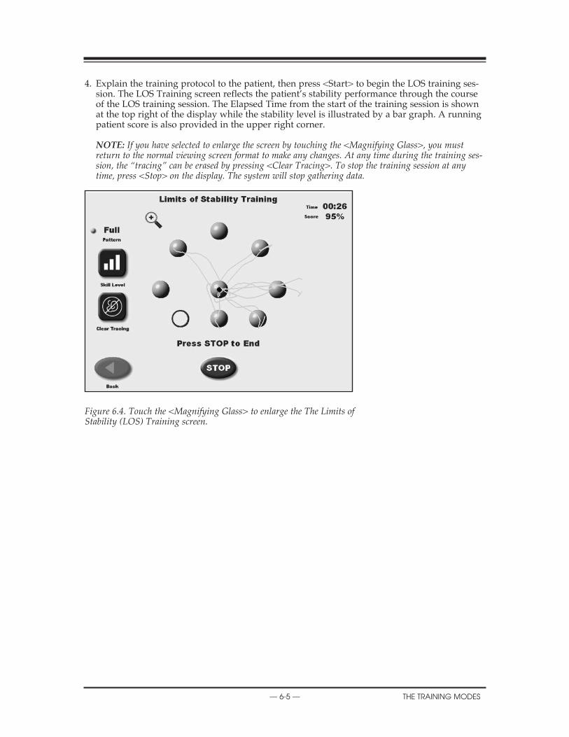
4. Explain the training protocol to the patient, then press <Start> to begin the LOS training ses-sion. The LOS Training screen reflects the patient’s stability performance through the courseof the LOS training session. The Elapsed Time from the start of the training session is shownat the top right of the display while the stability level is illustrated by a bar graph. A runningpatient score is also provided in the upper right corner.
NOTE: If you have selected to enlarge the screen by touching the <Magnifying Glass>, you mustreturn to the normal viewing screen format to make any changes. At any time during the training ses-sion, the “tracing” can be erased by pressing <Clear Tracing>. To stop the training session at anytime, press <Stop> on the display. The system will stop gathering data.
Figure 6.4. Touch the <Magnifying Glass> to enlarge the The Limits of Stability (LOS) Training screen.
— 6-5 — the trAining modeS
2. OPERATION

weIGht ShIft traInInG (See Figure 6.5.)
Figure 6.5 The Weight Shift Training screen.
This training mode allows for exercise in the most basic of activities; weight shifting. The patienthas the ability to shift weight in medial/lateral, anterior/posterior and diagonal planes. Duringthis training routine the target zone, defined by two parallel lines, can be rotated to any of threepositions while the amount of excursion within the target area can be modified to allow for themost limited to most difficult degree of weight shifting. To reposition the target zone hit lines atany time, simply touch the desired line and re-touch the screen where you want the line to berelocated.
Scoring is percentage-based and equals net good hits/total target hits. If you cross the bound-ary, that counts against the good hit total. All outside boundary hits are subtracted from thetotal amount of target hits. This value equals the net good hits. For example: Enter 10 as the # oftarget hits. There were 4 times when the cursor went outside the boundary:
10-4 = 6 good hits. Score = 6/10 or 60%.
NOTE: For weight shift training the time value always counts up.
weight Shift training access and differences from other training modesAccess to Weight Shift Training Mode is similar to other training modes with the following differences:
1. At the Weight Shift Training screen, touch <Rotate Target > to toggle through the threepatient target positions until the desired rotation is displayed on the grid.
2. Touch <Skill Level> to enlarge or decrease the target box size. Three skill levels are availablefrom which to choose. Touch <Skill Level> until the desired target configuration is displayed.
If desired, touch <Clear Tracing> to remove any tracing that remains on the screen from a previous exercise session.
XXX
the trAining modeS — 6-6 —

3. Touch <More Options> to advance to the Weight Shift Training Options screen if desired.Here you can set the total hits for the exercise (default = 60), turn tracing ON/OFF and setScoring Tone ON/OFF. Touch <OK> to confirm your selections and return to the WeightShift Training Options screen, or <Cancel> to return to the Weight Shift Training Optionsscreen without making changes.
• Use the <�> or <�> keys to set the total hits. • To turn tracing ON/OFF, touch <Tracing> to toggle between choices.
TESTING A PATIENT
— 6-7 — the trAining modeS

maze control traInInG (See Figures 6.6 and 6.7.)
This mode allows the patient to follow a reproducible pattern of movement throughout a mazein both static and dynamic environments. Three skill levels allow the maze to be modified tocreate a simple or more difficult environment for the patient to navigate through. Time countsup or down as set. Scoring is percentage-based on the net good hits/total target hits. If the cur-sor hits the boundary that hit is subtracted from the total possible amount of good hits.
• Easiest maze has 28 total targets, 14 in each direction• Moderate has 36 targets, 18 in each direction• Most difficult has 72 targets, 36 in each direction
In the case of the easiest maze, if the wall is hit 6 times the resulting score will be 22/28 = 78%
maze control training access and differences from other modesTo Access the Maze Control Mode is similar to other training modes with the following differ-ences:
1. Cursor sensitivity can be either more sensitive or Normal. The cursor sensitivity can either benormal or more sensitive which allows the excursion to be a little easier. This is helpful with patient’sthat have difficult time reaching the outermost targets.
2. Touch <Skill Level> to increase or decrease the number of targets displayed on the graph.Three skill levels are available from which to choose. Touch <Skill Level> until the desiredtarget configuration is displayed.
If desired, touch <Clear Tracing> to remove any tracing that remains on the screen from a previ-ous exercise session.
Figure 6.6. Change Cursor Sensitivity screen.
XX
the trAining modeS — 6-8 —

3. Touch <More Options> to advance to the Maze Control Training Options screen if desired.Here you can set the total time for the exercise, and turn tracing ON/OFF. Touch <OK> toconfirm your selections and return to the Maze Control Training Options screen, or <Cancel>to return to the Maze Control Training Options screen without making changes.
• Use the <�> or <�> keys to set the total hits.
Again please note: If you have selected to enlarge the screen by touching the <MagnifyingGlass>, you must return to the normal viewing screen format to make any changes. And at anytime during the training session, the “tracing” can be erased by pressing <Clear Tracing>.
Figure 6.7. The Maze Control Training screen.
XX
— 6-9 — the trAining modeS

random control traInInG(See Figures 6.8 and 6.9.)
The Random Control training mode allows the patient to perform neuromuscular control activi-ties in random patterns generated by the display and is ideal for motor control and vestibulartraining. The size and speed of the target can be modified for progressions ranging from easy todifficult. Scoring is percentage-based and equals the total time inside the circle/total time in andoutside of the circle. Time counts up or down as set.
random control training access and differences from other modesAccess to Random Control Training Mode is similar to other training modes with the followingdifferences:
1. Cursor sensitivity can be either more sensitive or Normal. The cursor sensitivity can either benormal or more sensitive which allows the excursion to be a little easier. This is helpful with patient’sthat have difficult time reaching the outermost targets.
2. At the Random Control Training screen, the target circle should be flashing in the center ofthe stability grid. Touch <Circle Speed > to toggle though the three target circle speeds untilthe target circle flashes at the desired speed.
3. Touch <Skill Level> to enlarge or decrease the target circle size. Three skill levels are avail-able from which to choose. Touch <Skill Level> until the desired target size is displayed.
Figure 6.8. The Random Control Training Start screen.
If desired, touch <Clear Tracing> to remove any tracing that remains on the screen from a previ-ous exercise session.
Touch <More Options> to advance to the Random Control Training Options screen if desired.Here you can set the total time for the exercise, enter initial and ending platform stability set-tings, turn tracing ON/OFF and scoring tone ON/OFF. Touch <OK> to confirm your selectionsand return to the Random Control Training Options screen, or <Cancel> to return to theRandom Control Training Options screen without making changes.
• Use the <�> or <�> keys to set the total time in 10-second increments (during the routinethe system will count down from the time setting selected).
CONTENTS
the trAining modeS — 6-10 —
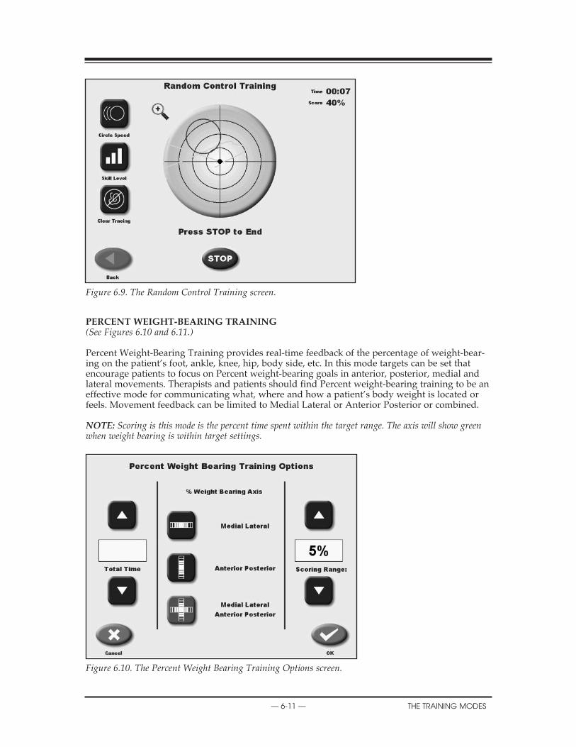
Figure 6.9. The Random Control Training screen.
percent weIGht-bearInG traInInG(See Figures 6.10 and 6.11.)
Percent Weight-Bearing Training provides real-time feedback of the percentage of weight-bear-ing on the patient’s foot, ankle, knee, hip, body side, etc. In this mode targets can be set thatencourage patients to focus on Percent weight-bearing goals in anterior, posterior, medial andlateral movements. Therapists and patients should find Percent weight-bearing training to be aneffective mode for communicating what, where and how a patient’s body weight is located orfeels. Movement feedback can be limited to Medial Lateral or Anterior Posterior or combined.
NOTE: Scoring is this mode is the percent time spent within the target range. The axis will show greenwhen weight bearing is within target settings.
Figure 6.10. The Percent Weight Bearing Training Options screen.
CONTENTS
— 6-11 — the trAining modeS

Figure 6.11. The Percent Weight Bearing Training screen. Scoring is the percent of time spent within the target range.
Figure 6.12. The position patient screen is used to adjust and record the patient’s foot position prior to beginning the training exercise.
CONTENTS
the trAining modeS — 6-12 —
percent weight bearing training access and differences from other modesAccess to Percent Weight-Bearing Training Mode is similar to other modes with the followingdifferences:
1. This is the one training mode where positioning the patient is required. Position the patient’sfeet as noted. If patient cannot be positioned as suggested, center patient and enter new footposition. The foot angle is determined by the line that is parallel with the inside of the foot.
Press <Start> on the display to activate the cursor and have the patient move the cursor to thecenter point on the grid. Touch <Record> to bring up the Position Patient Entry screen. Usingthe keypads, enter the patient’s left foot, left heel, right foot and right heel positions using themidline of the foot and the platform grid as reference points. Touch <Next> to advance to thePercent Weight Bearing Training screen.
The Percent Weight Bearing Training screen displays a Medial Lateral/Anterior Posterior grid.If you would prefer a Medial Lateral only grid, touch <More Options>. The More Optionsscreen also allows the clinician to set an end by time value. Touch <OK> after making changesto return to the Percent Weight Bearing Training screen.
If desired, shift the red Percent Weight Bearing target zone by touching and dragging the appro-priate red line to the desired Percent Weight Bearing target.
CONTENTS
— 6-13 — the trAining modeS

Static testing measures the angular excursion of the patient’s center of gravity. Body height mustcome into play for static measures. A person’s Center of Gravity (COG) is approximately 55% oftheir height. Based on the selected height an appropriate static measure scaling is applied.Testing provides a baseline for rehabilitation programs as well as balance screening. Good statictesting scores can lead to a progression into more dynamic testing and training. Test formatsinclude Postural Stability, Limits of Stability, m-CTSIB and the ability to select previously constructed custom protocols.
Figure 7.1. The Testing screen.
7. TESTING
— 7-1 — teSting

the poStural StablItIy teSt (See Figure 7.2.)
The Postural Stability Test emphasizes a patient’s ability to maintain center of balance. Thepatient’s score on this test assesses deviations from center, thus a lower score is more desirablethan a higher score.
Figure 7.2. The User Setup Information screen.
performing a postural Stability test
1. At the Main Menu, touch <Testing>. The Testing Menu screen should now be displayed. 2. Touch <Postural Stability>. The User Setup Information screen should now be displayed. 3. Touch the <Keypad> icon for “Name” and enter the patient’s name. Touch <OK> to return
to the User Setup Information screen. 4. Touch the <Keypad> icon for “Age” and then enter the patient’s age. Touch <OK> to return
to the User Setup Information screen. 5. Touch the appropriate <Height> key to highlight the patient height range setting desired.
Touch <Next> to advance to the Patient Position screen. 6. Position the patient on the system and explain the test protocol. Press <Start> on the display
to activate the cursor and have the patient move the cursor to the center point on the grid. 7. Touch <Record> to bring up the Position Patient Entry screen. Again, suggested standard-
ized foot positions are provided. (reference Mcllroy WE) Position the patient’s feet as noted.If patient cannot be positioned as suggested, center patient and enter new foot position.
8. Press <Start> on the display to activate the cursor and have the patient move the cursor tothe center point on the grid. Touch <Record> to bring up the Position Patient Entry screen.Using the keypads, enter the patient’s left foot, left heel, right foot and right heel positionsusing the midline of the foot and the platform grid as reference points. Touch <Next> toadvance to the Using the keypads, enter the patient’s left foot, left heel, right foot and rightheel positions using the midline of the foot and the platform grid as reference points. Touch<Next> to advance to the Postural Stability Testing screen.
9. At the Postural Stability Testing screen, touch <Stance> to scroll through the three stancepositions provided: left, right or both.
10. Touch <Tracing> to toggle tracing ON or OFF as desired. 11. Touch <Clear Tracing> to clear any tracing that remains from previous tests.
SERVICE PROCEDURES
teSting — 7-2 —

12. Touch <More Options> to advance to the Postural Stability Test Options screen if desired.Here you can set the Test Trial Time, enter initial and ending platform stability settings,enter the number of trials, enter the Rest Countdown, or toggle bilateral comparison to “Yes”or “No” and enter the Rest Countdown. You can also toggle the cursor ON/OFF and setScoring Tone. Touch <OK> to confirm your selections and return to the Postural StabilityTesting screen.
• Use the <�> or <�> keys to set the total time in five-second increments (during the routinethe system will count down from the time setting selected).
• To set the number of trials or rest countdown, touch the appropriate key and then enter thesetting from the keypad displayed.
• To turn the cursor ON/OFF, touch <Cursor> to toggle between choices. Same for ScoringTone.
• To toggle bilateral comparison “Yes” or “No,” touch <Bilateral Comparison>.
13. With the patient ready to begin the test, touch <Collect Data>. The screen will provide athree-second countdown before beginning the first of three test trials. The display screen willshow Total Trial Time, and Stance to the left of the grid. Trial Number and score are dis-played to the right of the grid. If desired, at this point you can touch the <Magnifying Glass>to select the zoom feature. You must, however, leave the zoom feature to make any changes.
NOTE: A Practice rep is suggested and is available prior to each test rep. Simple press Practice Repand a trial rep will be presented just like the test rep. The Practice rep can be stopped at anytime toproceed to the test rep.
14. After completing the test, a “Test Complete” message is displayed. Touch <Results> toadvance to the Postural Stability Test Results screen.
NOTE: If you have selected Bilateral Test, the system will begin by testing the initial side as set upabove. After the third trial on the initial side is finished, touch <Test Other Leg> to continue. The sys-tem automatically selects the opposite side and then allows the user to proceed from the PositionPatient screen. Repeat steps 8 – 17 to test the opposite side.
15. At the Postural Stability Test Results screen, touch <Print> to automatically generate a print-ed report if desired. If you have performed a Bilateral Test, the Test Results screen andreport will provide a bilateral comparison.
16. To save the test data, touch <Save Results> and then touch <OK> in response to the “SaveResults for later reporting or export?” prompt. The system will display “Save ResultsCompleted after the results are saved.
17. Another test for the same patient can be perform simply by touching <ANOTHER TESTSAME PATIENT>. You can also return to the Opening Menu by touching <HOME> or fromStability Test Results screen.
X
— 7-3 — teSting
X
teSting — 7-4 —
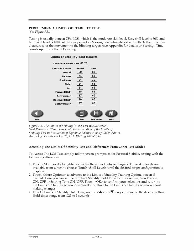
performInG a lImItS of StabIlIty teSt (See Figure 7.3.)
Testing is usually done at 75% LOS, which is the moderate skill level. Easy skill level is 50% andhard skill level is 100% of the sway envelop. Scoring percentage-based and reflects the direction-al accuracy of the movement to the blinking targets (see Appendix for details on scoring). Timecounts up during the LOS testing.
Figure 7.3. The Limits of Stability (LOS) Test Results screen.Goal Reference: Clark, Rose et al., Generalization of the Limits of Stability Test in Evaluation of Dynamic Balance Among Older Adults, Arch Phys Med Rehab Vol 78, Oct. 1997 pg 1078-1084.
accessing the limits of Stability test and differences from other test modes
To Access The LOS Test, simply follow screen prompts as for Postural Stability testing with thefollowing differences:
1. Touch <Skill Level> to tighten or widen the spread between targets. Three skill levels areavailable from which to choose. Touch <Skill Level> until the desired target configuration isdisplayed.
2. Touch <More Options> to advance to the Limits of Stability Training Options screen ifdesired. Here you can set the Limits of Stability Hold Time for the exercise, turn TracingON/OFF or Scoring Tone ON/OFF. Touch <OK> to confirm your selections and return tothe Limits of Stability screen, or<Cancel> to return to the Limits of Stability screen withoutmaking changes.
• To set a Limits of Stability Hold Time, use the <�> or <�> keys to scroll to the desired setting. Hold times range from .025 to 5 seconds.

performInG a ctSIb teSt(See Figures 7.4 – 7.7.)
To perform the CTSIB test, simply follow screen prompts.
Other points of interest:
1. Touch <More Options> to advance to the CTSIB Test Options screen if desired. Here you canset the Test Trial Time, enter the number of trials and enter the Rest Countdown, and changewhich conditions you want to test by simply touching to highlight the conditions you want todo. You can also toggle the cursor ON/OFF. The Cursor should be OFF during the actualtest. Touch <OK> to confirm your selections and return to the CTSIB Testing screen.
• Use the <�> or <�> keys to set the Test Trial time in five-second increments (during theroutine the system will count down from the time setting selected).
• To set the number of trials or rest countdown, touch the appropriate key and then enter thesetting from the keypad displayed.
Press <OK> to continue to do the test. The Press <START> to being the testing sequence foreach condition.
Figure 7.4. The m-CTSIB Testing Options screen.
X
— 7-5 — teSting

Figure 7.5. The m-CTSIB Testing screen with cursor turned OFF.
Figure 7.6. The m-CTSIB Testing screen prepared for condition #2.
2. Again as with the other tests you will have the option to perform a trial rep prior to each testcondition rep. The practice rep can be stopped at anytime to proceed to the test rep.
3. After completing the condition the next test condition will follow until all conditions havebeen completed. When the last condition is completed a “Test Complete” message is dis-played. Touch <Results> to advance to the CTSIB Test Results screen.
X
teSting — 7-6 —

Figure 7.7. The m-CTSIB Test Results screen.
4. At the Results screen, touch <Print> to automatically generate a printed report if desired.
5. To save the test data, touch <Save Results> and then touch <OK> in response to the “SaveResults for later reporting or export?” prompt. The system will display “Save ResultsCompleted” after the results are saved.
6. Another test for the same patient can be performed.
7. To return to the Opening Menu from the CTSIB screen, touch <Home>.
8. If a patient could not complete a stage, the stage is noted as “Fell”.
X
— 7-7 — teSting

The BioSway offers reports for each of the test modes. These can be used to objectively measureand record the patient’s balance ability. Progress reports that graph overall stability scores fromeach test date are also available.
Sample reports for each testing mode are provided later in this chapter.
report parameterS The following parameters appear on various reports:
Stability IndexStability index is the average position from center. The Stability index does not indicate howmuch the patient swayed. For this we use the standard deviation of the Stability index. Thisvalue we have called the Sway Index.
Sway IndexThe Sway Index is really the Standard deviation of the Sway Angle. The higher the Sway Indexthe more unsteady the person was during the test.
(Refer to Appendix C for additional information)
The Stability Index is represented in the following formats:
1. The Overall Stability Index takes into account COG displacement in the following directions2. Anterior/Posterior (A/P)-Sagital Plane3. Medial/Lateral (M/L)-Frontal Plane
overall Stability IndexThe following equation is used to calculate the Overall Stability Index.
(DI)2 = √ ∑ (0 – X)2
+ ∑ (0 – Y)2
DI = (DI)2
# of samples
anterior/posterior (a/p)The Anterior/Posterior Stability Index represents platform displacement in a sagital plane. Ahigh score in this direction may indicate poor neuromuscular control of:
1. The quadriceps and/or hamstring muscles2. The anterior/posterior compartment muscles of the lower leg.
The following equation is used to calculate the Anterior/Posterior Stability Index:
DIy = √ ∑ (0 – Y)2
# of samplesmedial/lateral (m/l)The Medial/Lateral Stability Index represents platform displacement in the frontal plane. Ahigh score in this direction may be indicative of:
1. Bilaterally- Poor neuromuscular control of the abductor and adductor muscles of the lower leg.
2. Unilaterally — Poor neuromuscular control of the inversion or eversion muscles of the lower leg, especially following an ankle sprain.
The following equation is used to calculate the Medial/Lateral Stability Index:
DIx = √ ∑ (0 – X)2
# of samples
8. REPORTS AND DATA
— 8-1 — rePortS And dAtA

Standard deviation (Sd)This is the amount of variability in the statistical measure between data points. A low standarddeviation demonstrates that the range of values from which the mean was calculated were closetogether. Standard Deviation should be relatively low.
∑ √(Xn – X)2 n = # of samplesn____________ Xn = n th sample
n X = mean deflection
data InterpretatIon for the lImItS of StabIlItySince the BioSway measures COG angular displacement from center it can be used to assess apatient’s LOS in two ways.
method 1Using the Stability Index (SI) gained from a Dynamic Balance Report it can be determined howwell a patient controls their balance within their LOS in both an Anterior/Posterior (A/P) direc-tion and a Medial/Lateral direction (M/L). For example, an A/P SI of 6.8 would mean that apatient remains within 57% of their A/P LOS:
A/P LOS = 12A/P SI = 6.8
therefore: 6.8/12 = .566 or .57 x 100 = 57%
The same method can be used to determine the M/L LOS control. They are both important fordetermining a patient’s potential risk for falling. Rehabilitation exercises can be properly pre-scribed from these results to effectively assist the patient to better control their LOS.
method 2By using the Limits of Stability Test protocol it can be determined exactly in which direction apatient may have more trouble controlling their LOS. The test results are based on 100, with 100being a perfect score. The patient’s score is based on their ability to accurately move the displaycursor to a target 10 º from a level platform position and back to level again. The more direct thepath to the target and back to center the higher their score will be. Lower Scores may be indica-tive of poor neuromuscular control.
Parameters for this Assessment can be found on the report for the Comprehensive LOS. Testreport. The formula found below is used to calculate the final score which is represented bothnumerically and graphically. From the results it can be determined how well the subject wasable to control their COG over their BOS. Higher numbers represent better control, with lowernumbers representing a poor control. The report also gives the total time it took the patient tocomplete the test which can also be compared between sessions.
X
rePortS And dAtA — 8-2 —

GENERAL MAINTENANCE
— 8-3 — rePortS And dAtA
dynamIc lImItS of StabIlIty Score calculatIon
dloS Score % = Straight Line Distance to Target x 100
Actual Distance Traveled
where:
Actual Straight Line Distance Distance to TargetTraveled(trace)
CENTER TARGET
overall dloS Score:
I =8
∑ (DLOS Scores)
I =1____________________8
Or the Average of all 8 Targets

Sample balance reportS(See Figures 8.1 – 8.4.)
Figure 8.1. The Postural Stability Test Report.
SERVICE PROCEDURES
rePortS And dAtA — 8-4 —

REPLACEMENT PARTS
— 8-5 — rePortS And dAtA
Figure 8.2. A Limits of Stability Test Report.
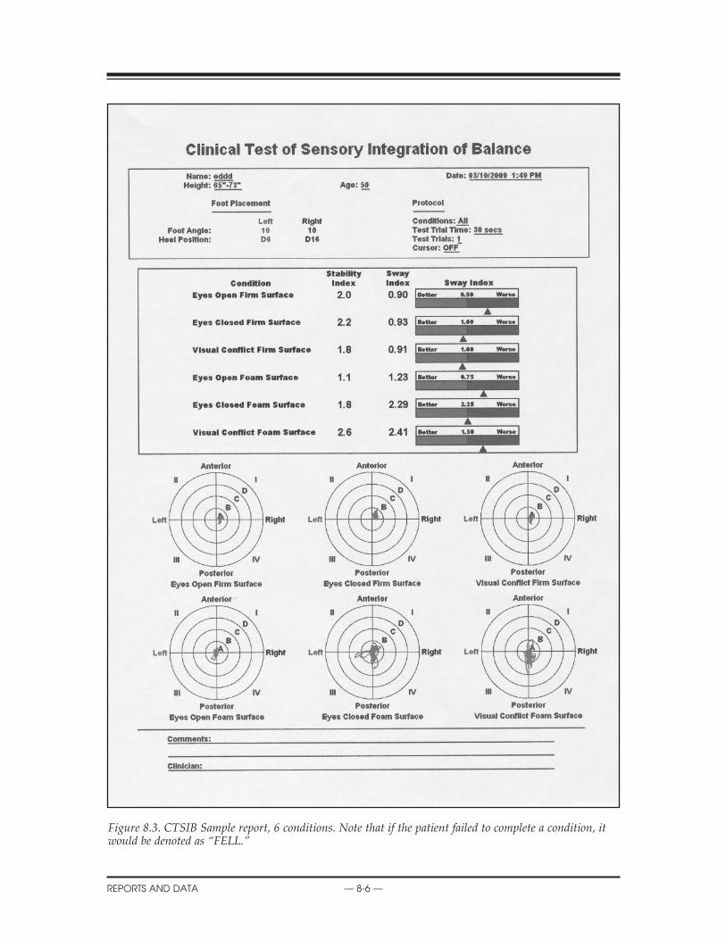
Figure 8.3. CTSIB Sample report, 6 conditions. Note that if the patient failed to complete a condition, itwould be denoted as “FELL.”
X
rePortS And dAtA — 8-6 —

SCHEMATICS
— 8-7 — rePortS And dAtA
proGreSS reportS(See Figure 8.4.)
Progress Reports graph overall stability scores for each Postural Stability Test date selected. Thetests are selected from Patient Maintenance on the Utilities Menu. The patient selected musthave multiple tests, with resultant Stability Index scores, to generate a report.
To Print A Progress Report: 1. Touch <Utilities> on the Main Menu. The System Utilities screen should now be displayed. 2. Touch <Patient Management> and enter code 781 to advance to the Patient Management
screen. 3. Touch the desired POS Postural Stability Test and then touch <Progress Report>. Note that
the report will be limited to the specific test type selected. 4. Up to ten test records can be displayed on the screen. Scroll right or left to see additional
tests. 5. Touch <Print> to print the Progress Report.
Figure 8.4. A sample Progress Report.

The System Utilities allow users to access the System Configuration and Patient Managementscreens.
To access the System Utilities, touch <Utilities> on the Main Menu. The System Utilities screenshould now be displayed. From here you can select Configuration or Patient Management bytouching the desired icon.
Figure 9.1. The Utilities screen.
SyStem utIlItIeS
CONFIGURATIONPATIENT MANAGEMENTCUSTOM PROTOCOL LISTPATIENT DATA STORAGE USAGESOFTWARE AND HARDWARE INFORMATIONHOURS OF USE
patient data Storage usage: A bar graph that shows how much of the storage capacity has beenused. It is suggest that once 85% in reached, that measures be taken to free up storage space. SeePatient management for more information.
9. SYSTEM UTILITIES
— 9-1 — SyStem utilitieS

confIGuratIonTouch <Configuration> and then enter 781 in response to the “Enter Access Code” prompt. Touch <OK>. The Configuration screen should now be displayed. At this screen users can setvalues for Screen Time Out, Date/Time and Default Settings. You can also turn Tone ON/OFF,adjust LCD brightness or Tone volume, and select Measurement Units, Printer Resolution orCTSIB Defaults. When you have finished making all of your selections and adjustments, touch<OK> to return to the Main Menu.
Figure 9.2. The Configuration screen.
Set Screen time out The Screen Time Out setting determines how long the display screen remains ON when the sys-tem is not in use of the test/exercise is completed. Once the selected time expires, the screenfades to black even if the system remains ON.
1. At the Configuration Screen, touch <Set Screen Time Out>. The Set Test/Exercise CompleteScreen Time Out screen should now be displayed.
2. Use the <�> or <�> arrows to increase or decrease the value displayed in 30-secondincre-ments. Time Out range is from 00:00 to 30:00.
3. Touch <OK> to confirm your changes and return to the Configuration screen. Touch<Cancel>to return to the Configuration screen without making any changes.
Set date/timeTime and Date are system-wide parameters that show on all printed reports.
1. At the Configuration Screen, touch <Set Date/Time>. The Set System Date/Time screenshould now be displayed.
2. Touch the parameter to set so that the selected field is highlighted. 3. Use the <�> or <�> arrows to increase or decrease the value displayed for the highlighted
parameter. 4. Repeat steps 2 and 3 until you have adjusted all the parameters you wish to correct.5. Touch <OK> to confirm your changes and return to the Configuration screen. Touch
<Cancel>to return to the Configuration screen without making any changes.
CONTENTS
SyStem utilitieS — 9-2 —

CONTENTS
— 9-3 — SyStem utilitieS
turn tone on/off: This setting enables or disables an audible tone which is used throughoutthe BioSway for scoring tones, test or exercise start signals, and completion or countdownbetween trials. At the Configuration screen, simply touch the ON or OFF icon to select the desired setting.
adjust tone volume: This setting raises or lowers the volume of the audible tone describedabove. between trials.
adjust lcd brightness: This setting brightens or darkens the display screen for all applica-tions.
At the Configuration screen, simply touch along the LCD Brightness Bar Scale until the desireddisplay brightness is achieved. The left end of the scale is darkest; the right end of the scale islightest.
At the Configuration screen, simply touch along the Tone Volume Bar Scale until the desiredlevel is achieved. The left end of the scale is least loud; the right end of the scale is most loud.
Select measure units or printer resolution These setting are simple toggle choices. Simply touch the desired parameter to view the choices,and then touch the setting you want to select. •Measure Units: Metric or US •Printer Resolution: normal or high
m-ctSIb default Settings(See Figure 9.3.)
Figure 9.3. The m-CTSIB Defaults screen.

REPLACEMENT PARTS
SyStem utilitieS — 9-4 —
Figure 9.4. The m-CTSIB Age Ranges screen.
At the Default Settings screen, users can set which conditions of the CTSIB they want as defaultsfor testing as well as the ability to enter in or change Sway Index Goals. Default settings can berestored to the “factory” defaults by pressing Restore Defaults.
changing the ctSIb default conditions 1. At the Configuration Screen, touch <Default Settings>. The Default Settings screen should
now be displayed. 2. Touch the conditions you want as defaults. The selection will be highlighted. 3. Touch <Ok> to save and return the Configuration screen.
adjusting the Sway Index Goals1. At the Configuration Screen, touch <Default Settings>. The Default Settings screen should
now be displayed. 2. Touch the goal value to you wish to adjust. 3. Use the <�> or <�> arrows to increase or decrease the value displayed.

— 9-5 — SyStem utilitieS
REPLACEMENT PARTS
Figure 9.5. An Entry Access Code provides a level of security to all default settings.
Secure code: Enabling this would require the 781 code to be entered each time the device isturned on. This provides some level of security.
patIent manaGement (See Figure 9.5.)
At the System Utilities screen, touch <Patient Management > and then enter 781 in response tothe “Enter Access Code” prompt. Touch <OK>. The Patient Management screen should now bedisplayed. This screen shows a listing of patient and associated saved test and training sessionsalong with the date performed. Use the <�> or <�> arrows to scroll through the list of patienttests.
NOTE: Patient data storage is close to 2 MB. That should be enough storage for 200 patient tests.

REPLACEMENT PARTS
SyStem utilitieS — 9-6 —
Figure 9.6. The Patient Management screen.
view test results
To view the results of any test displayed simply touch the desired entry on the PatientManagement screen to produce an on-screen report.
repeat (recalls a patient for a test or exercise session)
To repeat any saved test or exercise session, touch <Repeat> on the on-screen report. The systemwill return to the appropriate test or training Position Patient screen with the position values forfoot and heel reflecting the selected session. The selected name, age and height of the selectedpatient will also be recorded with the new test or training session if you save at completion.
Figure 9.7. Limits of Stability test results.

REPLACEMENT PARTS
— 9-7 — SyStem utilitieS
print test resultsTo print test results for any patient, touch the desired test to generate an on-screen report thentouch <Print> to print the test results.
Single patient exportTo export the results of any saved test, touch <Export Data>. The data will immediately be sentto the export program
Single patient deleteAlthough the BioSway can store hundreds of CTSIB patient tests, more patients if you do lessCTSIB conditions, you may want to decrease the number of stored records from time to time. Todelete any full page display of saved reports, touch <Delete>. Respond <OK> to the deleteprompt. The page displayed will be deleted from the display memory. The delete function onlyworks with pages; you cannot select a specific test or patient to delete without deleting everytest and patient displayed on the screen.
multiple patient export(See Figure 9.8.)
NOTE: This process requires Patient Data Export Software. Install the software as per instructions andconnect the serial interface cable from the BioSway display to the target computer. The program allowsboth multiple and single patient export. In addition to exporting any single patient record, multiplepatient records can be exported.
1. At the Patient Management screen touch <Multiple Export> to export multiple patientrecords. The Multiple Patient Data Export screen should now be displayed.
2. Four options are available for multiple export: all (export all patient records); prior-to (exportall patient records prior to selected date); from (delete all patient records after a selecteddate); and from-to (export all records between selected dates.) Touch <Options> until thedesired option is displayed.
• For prior-to and from-to, touch the date displayed to advance to the date screen. Touch thedate section to change and use the arrows to adjust.
3. Touch <Export Now> to export the selected patient files.
Figure 9.8. The Multiple Patient Data Export screen.

SCHEMATICS
SyStem utilitieS — 9-8 —
multiple patient deleteIn addition to deleting any single patient record, multiple patient records can be deleted.
1. At the Patient Management screen touch <Multiple Delete> to delete multiple patientrecords. The Multiple Patient Data Delete screen should now be displayed.
2. Three options are available for multiple delete: all (delete all patient records); prior-to (deleteall patient records prior to selected date); and from-to (delete all records between selecteddates). Touch <Options> until the desired option is displayed.
• For prior-to and from-to, touch the date displayed to advance to the date screen. Touch thedate section to change or use the arrows to adjust.
3. Touch <Delete Now> to delete the selected patient files.
cuStom protocol lISt and creatInG cuStom protocolS(See Figures 9.9 – 9.12.)
Custom protocols are organized as those for Training and those for Testing. Creating protocolsare the same for either case.
1. Select <Create Protocol>.2. Select from screen either Training or Testing.3. However you create this protocol, whether testing or training by setting the various options
or placing targets, it will be saved under whatever name you provide. The protocol can thenbe recalled exactly as stored for reuse as a custom protocol.
Figure 9.9. The Custom Protocol Management screen.
Figure 9.9. Protocols will be organized as Custom Training Protocols and Custom Testing Protocols. They will be listed under the name that was assigned.

Figure 9.10. Custom protocols can be organized under Training or Testing.
Figure 9.11. The Training Custom Protocols list. Note that all target placements and goal settings are saved and recalled for custom protocols.
CONTENTS
— 9-9 — SyStem utilitieS

Figure 9.12. The Postural Stability Training Protocol Set-Up.
NOTE: All target placements and goal settings are saved and recalled for custom protocols.
CONTENTS
SyStem utilitieS — 9-10 —

compatIble prInterS*PCL printers specifically HP H470HP 6000HP6940HP6940dtHP6988HP9800HPK5400HPD5360HP5650HP5550
compatIble poIntInG devIceS*manufacturer model # device type Logitech M500 MouseSeal Shield SSMSV5 MouseTargus AMU59US MouseRazer Naga RZ01-0028 MouseMicrosoft 1049 MouseBelkin F5L017-USB-BLK MouseToshiba PA3571U-1ETB MouseMicrosoft 1422 MouseTargus AMU75US MouseMicrosoft 1056, 1051 MouseLogitech V220 MouseHP WX414AA Mouse Dynex DX-PWLMSE MouseToshiba PA3651U-1ETC MouseLogitech G500 910-001259 MouseBTC M859C MouseLogitech M-BJ79 MouseDell MOA8BO MouseDell M-UK DEL3 MouseManhattan 176569 Mouse
compatIble KeyboardS*manufacturer model # device type Mini Keyboard ACK-5010U USB KeyboardAdesso AKB-210 KeyboardAdesso WKB-4000US KeyboardAdesso ACK-540UB KeyboardAdesso AKB-110B Keyboard
* Printers and other devices are subject to market availability. Please check with Biodex customer service if questions arise.
10. COMPATIBLE PRINTERS AND COMPONENT PART LIST
— 10-1 — comPAtiBle PrinterS

balance SyStem clInIcal teSt of SenSory InteGratIon and balance (ctSIb) Sway Index equatIon
teSt deScrIptIonThe objective of this test is to quantitatively determine a score defining a patient’s ability tomaintain a stable vertical posture while positioned on a stationary platform. The patient is posi-tioned on a stable platform and instructed to try to maintain a stable vertical posture under avariety of sensatory conditions, eyes open, eyes closed, and vision partially obscured.
equIpment deScrIptIonSway information is collected by positioning the patient on a static force plate and then sam-pling and recording patient movement. The system employs a series of strain gauges to deter-mine variation in the subject’s resultant center of pressure (COP). The center of pressure is thepatient’s center of gravity projection on the platform resulting from sway angle and the patientheight. Data is sampled at the rate of 20Hz. Each recorded sample consists of a (X, Y) coordi-nate. What is displayed is the sway angle derived from the position of the COG from zero andthe height of the patients COG taken as .55 times the patient height.
This data is recorded for later analysis and also displayed, in real time on, an LCD displayobservable by the patient. The resultant movement results in a “spaghetti plot” as shown below.This plot indicates patient movement from one sample to the next.
Essentially, the database consists of an array of (X, Y) coordinates defining the calculated COP.The data can be interpreted as an ordered series of sequential vectors from point to point.
For example: (X0, Y0)(X1, Y1)(X2, Y2)……….……….(Xn, Yn)
The “Score” is defined as the standard deviation of position over the length of the test. TheStandard deviation is interpreted to be the absolute vector length deviation from the mean vec-tor end point. Basically, all vectors (X,Y) coordinates are summed and divided by the number ofsamples, to obtain a vector sum which represents the position of the mean.
N-1σx = 1/N σ Xn
n=0
N-1σy = 1/N Σ Yn
n=0and
N-1 2 2φ = sqrt(Σ((Xn-σx)+(Yn-σy) )
n=0
N
APPENDIX A
— A-1 — SetuP And PoSitioning

bIoSway relIabIlIty and ctSIb normatIve data
BioSway Reliability and CTSIB data were collected from 100 randomly recruited people. All testsubjects were healthy, active, working people. Medical history was recorded via a confidentialquestionnaire. The testing and protocol followed IRB approval and was performed on site.
In addition to the CTSIB, all 100 recruits participated in a Timed Get up and Go (TUG) and GaitSpeed assessment. The TUG and Gait Speed tests are accepted tests for Balance assessment. Thereason for doing the additional tests with the CTSIB was to strengthen the results when a posi-tive correlation is made between the three accepted standardized assessments. Subjects weretested initially then again 2 weeks later. A third follow test was administered 3 months later on27 of the original 100 subjects. This third test was to negate any learning effect in the initial test-retest (given they were done consecutively with less than 2 weeks between trials).
descriptive Statistics
n minimum maximum mean Std. deviation
age 100 17.00 72.00 45.4400 10.80621
gender 0
Height (meters) 101 1.45 2.00 1.7263 .11410
Weight (KG) 101 44.09 137.73 81.4784 19.06182
Waist (CM) 59 26.00 44.00 34.4576 4.01000
bmi 101 12.50 44.60 27.3748 5.50826
Valid N (listwise) 0
Reliability: The resultant ICC is .81, which is considered acceptable.
Intraclass Correlation CoefficientIntraclass Correlation 95% Confidence Interval F Test with True Value 0 Lower Bound Upper Bound Value df1 df2 Sig Lower BoundSingle Measures .668 .573 .745 5.024 161.0 161 .000Average Measures .801 .729 .854 5.024 161.0 161 .000Two-way mixed effects model where people effects are random and measures effects are fixed.a Type C intraclass correlation coefficients using a consistency definition-the between-measure variance is excludedfrom the denominator variance.b The estimator is the same, whether the interaction effect is present or not.c This estimate is computed assuming the interaction effect is absent, because it is not estimable otherwise.
CTSIB Normative Sway Index ranges are:Condition 1: Eyes Open firm surface: .21-.48Condition 2: Eyes closed firm surface: .48-.99Condition 3: Visual conflict firm surface: .46-.88Condition 4: Eyes Open foam surface: .38-.71Condition 5: Eyes Closed foam surface: 1.07-2.22Condition 6: Visual conflict foam surface: .84-1.47
APPENDIX B
— B-1 — APPendix B

movement StrateGIeS for balance, SenSory orGanIzatIon, aGe-relatedchanGeS In balance and ctSIb teSt reSult InterpretatIon.
movement StrateGIeS for balance (Robertson)According to the Systems Approach to motor control, the nervous system uses preprogrammedstrategies or synergies to simplify movement. The central nervous system (CNS) takes advan-tage of pathways that link together groups of muscles in a flexible and repeatable sequence. Thislinking or packaging of muscle groups allows the brain to respond to an infinite variety of cir-cumstances by drawing on muscle responses that have been successful in the past. This linkingor packaging of muscles in a repeatable sequence is called a movement strategy.
Utilizing a movement strategy simplifies the way the nervous system accesses a motor reactionin response to sensory input. Strategies are automatic reactions that have evolved over time, tak-ing into account biomechanical and environmental constraints. Strategies that are successful formaintaining balance are stored so that the CNS is not forced to start from scratch each time aloss of balance occurs. Strategies are automatic reactions, slower than reflexes but much fasterthan voluntary movements. Three anterior-posterior movement strategies have been identified:the ankle, hip and stepping strategies.
ankle StrategyThe nervous system employs the ankle strategy in response to small losses of balance and toadjust balance in quiet standing. The ankle strategy is also called ankle sway and uses the lengthof the foot as a lever to correct for minor losses of balance. In the ankle strategy, activation of theleg muscles is from the floor up or distal to proximal. A small loss of balance in the forwarddirection causes contraction of the gastrocnemius, hamstrings, and lower-back muscles, in thatorder, to bring the body back into balance.
Figure C.1 Figure C.2
Figures C.1 and C.2: The ankle strategy that is used in response to small perturbations is also calledankle sway. Illustration © Wild Iris Medical Education.
A small loss of balance in the backward direction causes contraction of the anterior tibialis, quadri-ceps, and lower abdominal muscles, in that order, to bring the body back into balance. Our bodiesare constantly using this strategy to adjust for minor losses of balance. For example, you woulduse the ankle strategy to maintain balance when standing on a bus, to correct for losses of balanceand to prevent yourself from falling as the bus changes speed. You might also use the ankle strate-gy to maintain your balance on a very soft surface such as thick grass or a piece of foam.
APPENDIX C
— c-1 — APPendix c
hip StrategyThe hip strategy describes movement about the hip in response to larger losses of balance orwhen the support surface does not allow the use of the ankle lever, such as on an icy surface orwhen the surface is shorter than the length of the foot. In the hip strategy, activation of musclesis from the trunk down, or proximal to distal. A loss of balance in the forward direction causescontraction of the lower-back and hamstring muscles, in that order, to regain balance.
When the hip strategy is used, the muscles of the lower leg (anterior tibialis and gastrocnemius)are almost silent. Studies have shown that when a walker is used, the body largely abandons theankle strategy and relies heavily on the hip strategy for balance. This dependence on the hipstrategy for balance paradoxically may lead to a decrease in ankle sway and contribute to fur-ther decline in balance arising from loss of ankle strength and flexibility. For this reason the prosand cons of walker use must be carefully considered before a walker is recommended for fulltime use.
Stepping StrategyThe third strategy employed by the nervous system for balance is the stepping strategy. Thisstrategy is used when the loss of balance exceeds the area of stability and the person is forced tostep or fall.
SenSory orGanIzatIon for balancePerhaps the most confusing part of a balance evaluation is the part that examines the sensorysystem and its contribution to balance. The sensory system includes the eyes, ears, vestibularapparatus (inner ear), somatosensory system (touch and proprioception), taste, and smell. Theparts of the sensory system that contribute directly to balance are the visual, vestibular, andsomatosensory (touch and proprioception) systems. The use of multiple systems in balanceallows us to learn new movements quickly and to fine-tune and easily repeat familiar move-ments.
The sensory system receives input from the environment through specialized receptors locatedin the sensory end-organs in the eyes, vestibular apparatus of the inner ear, muscle spindles,Golgi tendon organs, and touch receptors in the skin. Sensory input is transmitted to the spinalcord via afferent nerve fibers and then to the brain via spinal nerve tracts such as the spinothala-mic tract (pain and temperature) and the dorsal column medial lemniscal tract (fine touch, mus-cle and tendon position sense).
Sensory input provides a continuous flow of information to the CNS, which in turn utilizes thisincoming information to make decisions about movement. The CNS sifts, compares, weighs,stores, and processes sensory input and uses this information to alter the force, speed, and rangeof a movement.
visionVision is a critical part of our balance system. It allows us to identify objects and determine theirmovement and tells us where we are in relation to other objects (object-to-object orientation).When we use vision to gather information about the position of our body in the environment orto determine the position of one body part vis à vis another, then vision is providing proprio-ceptive information to the CNS as well (visual proprioception).
Vision works in conjunction with the vestibular system, comparing information about velocityand rotation from the vestibular system with actual visual information. The visual system is acombination of both central and peripheral vision, although some research has suggested thatperipheral vision is more important for postural control and balance than central vision(Shumway-Cook & Woollacott, 2001).
CONTENTS
APPendix c — c-2 —

The visual system may provide inaccurate information to the nervous system. For example, aperson sitting at a stoplight in a car may think she has started to move when the car next to herstarts to move. The visual system “goes along” with the movement of the neighboring car andtells the brain that both cars are moving. The CNS mediates this sensory conflict by instructingthe leg to slam on the brake to stop the car from moving forward. As soon as the foot touchesthe brake the somatosensory and vestibular systems realize that the car is, in fact, not moving.For a split second, input from the visual system was given preference by the brain, even thoughthe information turned out to be inaccurate.
Visual input may also be inaccurate due to diseases or disorders that affect the visual system,such as diabetic retinopathy, cataracts, macular degeneration, injuries, or stroke.
vestibular InputThe vestibular system is responsible for processing information about movement with respect togravity —specifically, rotation, acceleration/deceleration, and head stabilization during gait.The vestibular system works in conjunction with the visual system to stabilize the eyes andmaintain posture during walking (vestibular-ocular reflex). Vestibular disorders cause a feelingof dizziness and unsteadiness. Vestibular dysfunction also affects the ability of the CNS to medi-ate intersensory conflicts such as that in the example given above.
Somatosensory InputSomatosensory input consists of touch and proprioception. Input from these two sensorysources provides critical feedback to the CNS regarding positioning in space, body sway, andchanges in terrain. The sensory input from touch and proprioception allows the muscles tomake constant, automatic adjustments to maintain balance and avoid falls.
In the example where the person in the stationary car slams on the brake, only to realizethrough somatosensory input that her car has not moved, the feeling that the car is movingwhen it is not is an example of a visual intersensory conflict; the conflict is resolved quickly bypressing on the brake and feeling that the car has not moved.
Sensory disorganizationThe loss or disruption of sensory input in the visual, vestibular, and/or somatosensory systemscan affect balance in a number of ways. How balance is affected depends on several factors,including the extent of the nervous system damage, the number and extent of sensory losses,and the availability of the other senses for compensation. In many instances, more than one sen-sory system is impaired, as in the case of a person with a peripheral neuropathy and visualimpairment (common with diabetes and stroke). But, just as an individual with impaired visiondevelops a keener sense of hearing, a person with any sensory loss will attempt to compensateby using the unaffected or less-affected senses to improve balance.
Sensory lossThe way balance is affected by loss of sensory input depends on the extent and nature of thesensory loss. Recall that the senses most associated with balance are somatosensory (touch andproprioception), visual, and vestibular. Of these, the somatosensory system plays the biggestrole in balance, so losses associated with peripheral neuropathies, stroke, and other neurologicdisorders can have a profound effect on balance.A person with sensory loss (eg, bilateral lower-leg peripheral neuropathy) who does not receivenormal sensory input from the sensory receptors in the feet and ankles will attempt to compen-sate by depending more on visual and vestibular input for balance. If there is significant sensoryloss in the feet, a person will be unable to adjust easily to changes in the support surface duringtasks such as walking on grass or uneven surfaces, or even walking in shoes with soft soles.
CONTENTS
— c-3 — APPendix c

A person with impaired vision from a stroke or cataracts will depend less on vision and moreon touch and vestibular feedback for balance. In this case, choice of assistive device, hand rail-ings for touch, and proper lighting are important. A person with a visual impairment may per-form well in a clinical setting but have difficulty with balance in more complex visual situationsthat demand rapid visual interpretation of multiple visual cues. For example, a person may besafe walking in a quiet, well-lit hallway but be unable to negotiate a busy, noisy hallway filledwith people and equipment.
Vestibular damage or loss can also have a profound effect on balance and postural control.Vestibular impairment can cause problems with gaze stabilization, including blurred vision,problems with balance and posture, and vertigo (Shumway-Cook & Woollacott, 2001).
Improper Sensory SelectionSensory loss may lead to inflexible or improper sensory weighting. A person may depend onone particular sense for postural control even if that sense leads to further instability(Shumway-Cook & Woollacott, 2001). You may notice a person walking with head down, care-fully watching every step. In this case, vision is the dominant sense being used for balance.Retraining would involve improving the use of somatosensory and vestibular input to reducedependence on visual input.
abnormal Internal representationsIndividuals’ perceptions of their limits of stability are difficult to assess and understand. Illnessand injury, including stroke, clearly affect confidence and may alter perceived stability limits. Aperson’s stability may be affected by fear of falling, even when the physical ability exists to per-form a task safely. Conversely, individuals may not have an accurate idea of the limits of theirstability and thus have little warning when loss of stability is occurring, leading to falls.
Sensorimotor adaptationThe nervous system has a powerful ability to compensate for actual or perceived disabilities.Once an injury has occurred, the nervous system immediately goes to work attempting to com-pensate for neurologic changes, weakness, and loss of function. But the brain doesn’t alwayschoose the best (or even a good) compensation; it chooses the fastest and most efficient in anattempt to continue functioning. One of the immediate goals of therapy is to help the nervoussystem develop strategies and compensations that minimize musculoskeletal damage and maxi-mize function.
aGe-related chanGeS In balanceMany changes in balance relate to normal aging. Some changes (i.e., slowed gait, decrease inlower-extremity strength, decreased ROM) can be easily addressed with a daily exercise pro-gram. Other changes (i.e., declining visual ability, including loss of visual acuity, declining visu-al fields, light-dark adaptation, increased sensitivity to glare, loss of peripheral vision and depthperception) are more complex and may require assessment by another healthcare professionalsuch as an optometrist or ophthalmologist.
Age-related changes in balance are the result of changes in every system in our bodies.Neurologic changes include slowed response to losses of balance, decreased righting responses,and abnormal sensory selection or weighting (i.e., overuse of vision or underuse of propriocep-tion). Orthopedic changes include loss of ankle sway, leading to an increase in the use of the hipand stepping strategies and lower-foot swing height. Psychomotor changes include loss of confi-dence (changes in the perceived limits of stability) and a propensity to fall in new or novel situa-tions, perhaps due to impaired anticipatory mechanisms. Sensory changes include abnormalsensation (i.e., peripheral neuropathies, abnormal tone, effects of drugs, visual disturbance suchas hemianopsia) and a reduction in the function of the vestibular system of the inner ear(Shumway-Cook and Woollacott, 2001).
CONTENTS
APPendix c — c-4 —

ctSIb teSt reSult InterpretatIon (Neurocom)The CTSIB is the Clinical Test for Sensory Integration and Balance. The CTSIB is the standardtest for differentiating balance problems as a result of visual, vestibular or somatosensory
The CTSIB uses 4 conditions to test contribution of visual, vestibular and somatosensory inputs:
1. Eyes Open, firm surface: This is the baseline condition. Accurate information is available to allthree sensory systems: visual, vestibular and somatosensory. Normal individuals are very stable inthis condition.
2. Eyes Closed, Firm surface: No visual input is available. The Patient must rely on somatosen-sory and vestibular inputs. Somatosensory is the primary sensory input. Vestibular inputs aresecondary. High sway scores are indicative of problems with somatosensory. In normal indi-viduals there is no significant difference in sway with eyes open or closed on a firm surface.
3. Eyes Open, Unstable (foam) surface. The unstable surface confounds the somatosensoryinformation as it imposes additional challenges to the musculoskeletal system. Primary inputsare visual with vestibular as secondary. Normal individuals will sway more on the unstable sur-face, but will not fall.
4. Eyes Closed, Unstable (foam) surface: This condition focuses on the vestibular sensory input asvisual is not available and somatosensory is challenged by the unstable surface. Again nor-mal individuals will sway more on the unstable surface, but will not fall.
To interpret or apply the test results consider under what condition was sway the greatest?
Normal balance includes the ability to hold still in various situations depending on the activityor circumstance demands. The COG sway scores indicate how well the patient accomplishedthis. Lower scores reflect little movement which are consider better than higher scores whichreflect more movement.
firm Surface: eyes open vs. eyes closedNormal individuals standing on a firm surface have similar amounts of sway with eyes open orclosed. On a firm surface, when significantly more sway is present with eyes closed then thepatient maybe having difficulty using somatosensory inputs (this is the input up from the feet).An ankle strategy should be used for primary balance control on a firm surface.
unstable (foam) Surface: eyes open vs eyes closedWith Eyes open on an unstable surface, normal individuals have significantly more sway thenwhen standing on a firm surface. And even more sway on the unstable surface with their eyesclosed. However – they do not become overly unstable or fall. Patients that do become unstableor fall when standing on foam with eyes open may have difficultly using visual information forbalance control and/or may have lower extremity musculoskeletal problems. A hip strategyshould be used on unstable surfaces.
NOTE: These tests are targeting sensory integration deficits. Standing on an unstable surface presentsbiomechanical and musculoskeletal challenges. Patient with ankle or foot problems, joint weakness or painwill have high scores. As such in these patients it can not be assumed that sensory abnormalities are theunderlying cause, as they can not be distinguished from motor (musculoskeletal) issues. Ideally patientshould be screen for motor problems prior to the CTSIB test. Only patients without motor problemsshould be tested with the CTSIB. The LOS test is an effective test to tease out this question.
CONTENTS
— c-5 — APPendix c

referencesShumway-Cook A, Woollacott MH. (2001). Motor Control: Theory and Practical Applications.Philadelphia: Lippincott, Williams & Wilkins.
Robertson, Lauren. Balance and Falls – continuing education course [Internet] Available from:http://www.therapyceu.com/courses/212/index_tceu.html
Neurocom International. Clinical Operations Guide. Rev 8. June 2008
foot placement referenceMcllroy WE., Maki BE. Preferred placement of the feet during quiet stance: development of astandardized foot placement for balance testing. Clinical Biomechanics, Vol 12, No.1 66-70 1997.
CONTENTS
APPendix c — c-6 —
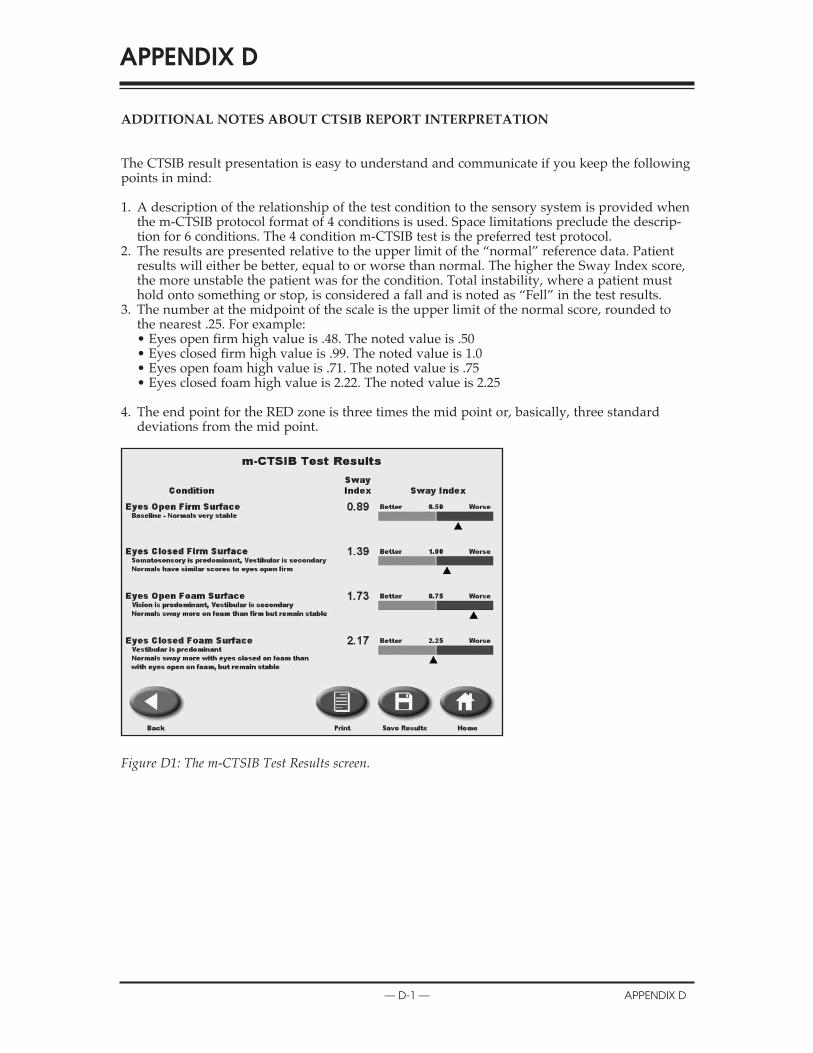
addItIonal noteS about ctSIb report InterpretatIon
The CTSIB result presentation is easy to understand and communicate if you keep the followingpoints in mind:
1. A description of the relationship of the test condition to the sensory system is provided whenthe m-CTSIB protocol format of 4 conditions is used. Space limitations preclude the descrip-tion for 6 conditions. The 4 condition m-CTSIB test is the preferred test protocol.
2. The results are presented relative to the upper limit of the “normal” reference data. Patientresults will either be better, equal to or worse than normal. The higher the Sway Index score,the more unstable the patient was for the condition. Total instability, where a patient musthold onto something or stop, is considered a fall and is noted as “Fell” in the test results.
3. The number at the midpoint of the scale is the upper limit of the normal score, rounded tothe nearest .25. For example:• Eyes open firm high value is .48. The noted value is .50• Eyes closed firm high value is .99. The noted value is 1.0• Eyes open foam high value is .71. The noted value is .75• Eyes closed foam high value is 2.22. The noted value is 2.25
4. The end point for the RED zone is three times the mid point or, basically, three standarddeviations from the mid point.
Figure D1: The m-CTSIB Test Results screen.
APPENDIX D
— d-1 — APPendix d

Figure D.2: These results indicate the patient was very unstable in the conditions with Eyes closed. They could not complete the test and as such the condition is noted as “Fell.”
Figure D.3: This is the screen from the Configuration area that allows for the Sway Index Goal to be entered. The values noted as defaults are the factory defaults from our existing normative data.
NOTE: Values entered or shown as goals will be rounded to nearest .25, as the goal shown in the midpoint of the report scale.
CONTENTS
APPendix d — d-2 —

a note about ctSIb report InterpretatIon.Normal individuals have significantly more sway when standing on a foam surface versus afirm surface with eyes open, and even more sway on foam with eyes closed. However they donot become unstable or fall. Patients who become unstable or fall when standing on foam witheyes open may have difficultly using visual information for balance control and or they mayhave lower extremity musculoskeletal problems, which make it difficult to stand on the foam orcompensate for the unstable surface.
NOTE: Caution should be used when interpreting the CTSIB test results. The test is assumed to reflectsensory integration deficits. However, standing on the foam surface provides a biomechanical challenge aswell as a sensory one. Patients with ankle or foot weakness, joint restrictions, or pain will have difficultystanding steadily on the foam and will produce high sway scores. In these patients it is not valid toassume sensory abnormalities are the sole cause of abnormally increased sway. Sensory problems may bepresent, but cannot be distinguished from the motor problems. Ideally patients should be screened formotor problems (central and musculoskeletal) prior to administration of the CTSIB. Only in patientswithout motor involvement can increased sway clearly be assumed to indicate sensory system deficits.One effective way to screen for motor deficits is to administer the LOS test prior to the CTSIB test, as theLOS test measure voluntary movement.
Reference: Clinical Operations Guide, Neurocom® International, Inc. June 2008
CONTENTS
— d-3 — APPendix d

conformance to StandardS
This equipment conforms to the following safety standards:
Standard edition and/or date
IEC60601-1-2 First edition, 2007
Table 1.1 Safety standards
accompanying emc documentsThis medical electrical equipment needs special precautions regarding EMC and needs to beinstalled and put into service according to the EMC information provided in this manual.
• Portable and mobile RF communications equipment can affect medical electrical equipment.• Use of accessories, transducers and cables other than those specified, with the exception of
accessories, transducers and cables sold by the manufacturer of this equipment, as replace-ment parts for internal and external components, may result in increased emissions ordecreased immunity of the equipment.
• The BioSway Balance system should not be used adjacent to or stacked with other equipment.If the BioSway Balance system is used while positioned adjacent to other equipment, itshould be observed to verify normal operation in the configuration in which it will be used.
list of cable accessoriesThe list in Table 1.2 includes all accessory cables supplied with the BioSway Balance system forwhich the manufacturer of this equipment claims compliance to EN 60601-1-2 when used with theBioSway Balance system.
cable description part no. cable length
Power cable Biodex # C13154 6ft
Data cable Biodex # C13141 10ft
Table 1.2 BioSway Balance cables
APPENDIX E
— e-1 — APPendix e

declaratIon of conformIty
CONTENTS
APPendix e — e-2 —
Emissions Manufacturer’s declaration electromagnetic emissions The BioSway Balance is intended for use in the electromagnetic environment specified below. The customer or the user of the BioSway Balance system should assure that it is used in such an environment Emission test Compliance Electromagnetic environment RF emissions CISPR 11
Group 1 The BioSway Balance system generates RF energy only for its internal functions. Therefore, its RF emission is very low and is not likely to cause any interference in nearby electronic equipment
RF emissions CISPR 11
Class A
Harmonic distortion EN 61000-3-2
Class A
Voltage fluctuations and flicker EN 61000-3-3
Complies
The BioSway Balance system is suitable for use in all establishments other than domestic and those directly connected to the public low-voltage power supply network supplying buildings used for domestic purposes.
Immunity Manufacturer’s declaration electromagnetic immunity The BioSway Balance is intended for use in the electromagnetic environment specified below. The customer or the user of the BioSway Balance system should assure that it is used in such an environment. Immunity test IEC 60601-1-2
Test level IEC 60601-1-2 Compliance level
Electromagnetic environment – guidance
Electrostatic discharge (ESD) IEC 61000-4-2
± 6 kV contact ± 8 kV air
Contact ± 6 kV Air ± 8 kV *
Floor should be wood, concrete or ceramic tiles. If floor is covered with synthetic material, the relative humidity should be at least 30%
Electrical fast transients/burst IEC 61000-4-4
± 2 kV for power lines ± 1 kV for input/output lines
Power ± 2 kV Signal ± 1 kV
Mains power quality should be that of a typical commercial or hospital environment
Surge IEC 61000-4-5
± 1 kV differential mode ± 2 kV common mode
± 1 kV diff. mode ± 2 kV com. mode
Mains power quality should be that of a typical commercial or hospital environment
* Reference test results for details
mi
noissiEm sceds’rerutcctaffauufnMacnaanlaByaawSoiBeThecnaanlaaByawSioBeth
tseesttenoiiossiisEmsnoissimeRF
11RPSCI
la tienoittiaralc siismeemcitengnaagmotrcctrleceleehtthniesuroffodednetnntisiec
e sititaath terussadluoh smetsy secnaillipmmpCo
1puoGr
ti
snoiiossicepstnemnorivnecitengamortc
tnemnorivnenaanhcusnidesusceEl mnoirvneciteetngaagmotr
tsysecnaanlaaByaawSoiBeThfu RifhTti
fi htthroremotsucehT.wolebdeifi
tneenmffoylnoygreneFRsetaatrenegmette
idlisioisFR
rn
foresueh
laalnrettenntistiroffolikl
rt
flfl
11RPSCI
meRF snoisis11RPSCI
trotsidcinomrHaar nio00016EN -3-2
snoittaatuttuculfegatlVoreckilfdan
l
AssaCl
AssaCl
seilpmCo
l
cnfuun Rtsi,eroffoerehT.snotie scau nnie cenreffeertterniyan
sysecnaanlaByawSoiBeThrehtthostnemhsilbates dnaanth
owlciblpuubl - egatlvo srewporupcittisemodrfo .sepos
nnir
sidnaanwolyrevisniosismeFRtenmpiueqc inorttrecleybaren
llaniesuroffoelbaabtiussimettnnocylttlceridesothdnaanictsemoddodilibugniyyiplpuskrrkowttwneypplus
toyleiklton
ehtthottodetcend esugsndi
00016EN -3-3
ytinumImceds’rerutcctaffauufnMacnaanlaByaawSoiBeTh
la mmiimcitengnaamorttrcctelenoittiaralcceleehtthniesuroffodednetnntisiec
yttyinumicepstnemnorivnecitengamortc
fi roremotsucehTwolebdeifi h tr
fores ueh
ta
ri
cnaanlaByaawSoiBeThecnaanlaaByawSioBeth
tsetteyttyinumIm
graarhcchsiddcitaattsorrottrceEl)DS(E
00016CIE -4-2
tsaffalaalcirttrceElnaantr strub/stnesi
00016CIE 4 4
tac
celeehtthniesuroffodednetnntisiece sititaath terussadluoh smetsy s
10606CIE -1-2 levelletsTe
eg Vk6± tactncoriakV8±
senilrewoporfforkV2± tuputtpo//outnpiorfforkV1 ±
lin
leli
icepstnemnorivnecitengamortctnemnorivnenaanhcusnidesus
10606CIE -1-2 leelveleccnaanilpmmpCo
El
VkkV6±tcaatnntCoVk8±rAi *
Fltimale
Vk2±rewPoVk1±langSi
Maty
floIftyr
tyyp
r toremotsucehT.wolebdeiffii h tr.
tnemnorivneencitengnaamorttrccteEl –
etercnoc,doowebdluuohsshrooFlthiwwderevocsiroloffI.slesytidimuhevittialerehtth,laairetmaat
t sale 30%htebdluohsytilauqrewopsniMaai
ipy enaltipsohrolaicermmcocal
yn
fores ueh
– ecnaddaiu g
cimaamrecroeictehtnysthtaatebdluohs
afotaathtenmnoriven
00016CIE -4-4egrSu
00016CIE -4-5tlusertsetecnereffeeR*
selineodmlaittnereffefffdikV1±
edomnommocVk2± sliatdeorfforst
edom.ff.fffidVk1± edom.mocVk2±
Maty
yprewopsniMaai htthe bdluohsytilaalu q
ipy enaltipsohrolaicermmcocal
afotahtenmnoriven

CONTENTS
— e-3 — APPendix e
*Reference test results for details
Immunity test IEC 60601-1-2 Test level
IEC 60601-1-2 Compliance level
Electromagnetic environment – guidance
Voltage dips, short interruptions and voltage variations on power supply input lines IEC 61000-4-11
< 5% UT (> 95% of dip in UT) for 1/2 cycle 40% UT (60% of dip in UT) for 5 cycle 70% UT (30% of dip in UT) for 25 cycle < 5% UT (> 95% of dip in UT) for 5 sec
< 5% UT (> 95% of dip in UT) for 1/2 cycle 40% UT (60% of dip in UT) for 5 cycle 70% UT (30% of dip in UT) for 25 cycle
< 5% UT (> 95% of dip in UT) for 5 sec *
Mains power quality should be that of a typical commercial or hospital environment. If a better mains power quality is required, it is recommended that the BioSway Balance is powered from an uninterruptible power supply
Power frequency (50/60 Hz) magnetic field IEC 61000-4-8
3 A/m 3 A/m If image distortion occurs, it may be necessary to position the BioSway display further from sources of power frequency magnetic fields or to install magnetic shielding. The power frequency magnetic field should be measured in the intended installation location to assure that it is sufficiently low
Conducted RF IEC 61000-4-6
3 Vrms, 150 KHz to 80 MHz
3 Vrms, 150KHz to 80 MHz
Radiated RF IEC 61000-4-3
3 V/m, 80 MHz to2.5 GHz
3 V/m, 80 MHz to2.5 GHz See Risk Analysis Report *
Portable and mobile RF communications equipment should be used no closer to any part of the BioSway Balance, including cables, than the recommended separation distance calculated from the equation applicable to the frequency of the transmitter. Recommended separation distance: d = 1.2! P 150 KHz to 80 MHz d = 1.2! P 80 MHz to 800 MHz d = 2.3! P 800 MHz to 2.5 GHz where P is the maximum output power rating of the transmitter in watt (W) according to the transmitter manufacturer, and d is the recommended separation distance in meters (m). Field strengths from fixed RF transmitters, as determined by an electromagnetic site survey, a should be less than the compliance level in each frequency range. b Interference may occur in the vicinity of equipment marked with the following symbol:
Note 1. UT is the a.c. mains voltage prior to application of the test level. Note 2. At 80 MHz and 800 MHz, the higher frequency range applies. Note 3. These guidelines may not apply in all situations. Electromagnetic propagation is affected by absorption and reflections from structures, objects and people
a Field strength from mixed transmitters, such as base stations for radio telephones and land mobile radios, amateur radio, AM or FM broadcast and TV broadcast cannot be predicted theoretically with accuracy. To assess the electromagnetic environment due to fixed RF transmitters, an electromagnetic site survey should be considered. If the measured field strength in the location in which the BioSway Balance is used exceeds the applicable RF compliance levels above, the BioSway Balance should be observed to verify normal operation. If abnormal performance is observed, additional measures may be necessary, such as reorienting or relocating the BioSway Balance system. b Over the frequency range 150 KHz to 80 MHz, field strengths should be less than 3 V/m.
tsetteyttyinumIm
hidl
10606CIE -1-2 levelltsTe
leli10606CIE -1-2
leelveleccenaanilpmmpCo
nemnorivneencitengnaagmorttrccteEl
bdlhili
tn – ecnaddaiu g
ifh cal
rrtrohs,spidegatlVo
snoontipuprretint dn a antvollt nosnoitaatiraarve ag
tputniypplusrewposelin
00016CIE -4-11
ycneuqerffrrewPociteetngam)zz)H06/0(5
dlefi
in
in
n
nipiddfo%59>(TU%5< elcyyccc2//21roffo)UT
nipdiipfo%60((60TU%40elcyc5roffo)UT
nipdiipfo%30((30TU%70elcyycc52roffo)UT
nipiddfo%59>(TU%5< ces5roffo)UT
m/A3
piddfo%59>(TU%5< in for)UTT elcyyccc2//21orf
pdiipfo%60((60TU%40in elcycc5roffo)UT
pdiipfo%30((30TU%70in elcycc52roffo)UT
nipiddifo%59>(TU%5< ces5roffo)UT *
m/A3
tyirmirty
ru
ebdluohsytilauqrewopsniMaanorivnelaaltiitpsohrolaaicremmco
riuqersiytilauqrewopsnimaa edyaawwaSoiBehtthtaathtthdeddenemmocre
d errepowwe biibtpurrettninunamofr
mti,srucconoitrotsidegamiIflpsidyawSioBehtthnoitisopto
ff
yptytt
fi
ipytafotaathte calafI.tnntemn rettbe
siti,edsiecnaanlaalBy
ylppusrewopelb
secenebyaam yrsarffrrethruffuyal omdlifit
dlefi00016CIE -4-8
FRdetcudnCo00016CIE -4-6
R FRedatiad00016CIE -4-3
,smrV3 otzHK015 zHM80
,m/V3 zHM80 to2. zHG5
,smrV3 zHK015 to zH M0 8
,m/V3 zHM80 .2to zHG5
ilAkiRSe
ta
m
mycneuqerffrrewopfosecrusoT.gindliehsctiengaml laatsintouohsdleifficittiengamycneuqefriotaatcolnotilaltaasindednetineth
wloyltneiciffifffusismmocFRelibomdnaanelbatrPoondesuebdluohstenmpiueq
diulnci,encaanclaaByawSoiBhettheofdniotaatraarpeepsdednemmocerethotelbaabcilppaapnoittiaatuqqueehtthmofr
.rettimsnantreth
rt
sdleifficitengam orrewopehT
niderusaemebdluerussatonio titaatth
snoitaatcinumuynaottersolc trpaar
n haan ttha,selbaabcngdiulcacecntaanis detlaat
efreht ncequ foy
sisylanAksiReSe*tropRe
ta
RFfifr
.rettimsnantrethtsidnoittiaatraarpesdednemmocRe
.1=d 2! zHK05 1 P to M0 8
.1=d zHM80P!2 to M00 8
.2=d zHM080P!3 to 2. G5 upttpuomumuixamehtsiPerewhca)W(t tawinrettimsnatrethdna,rerutcaffaunamrettttimsnatratsidnoittraaarapesdednemmocre
)(m .arttrFRdexifmorfshtthgtnerttrsdleFi
tt
:ecnaantzHMzHMzHG
gnittiaatrrweoptu oftogindrocc eth
ehtthisddrsetemniecnaan
sa,srettimsnaan
fr
ll
gnamorttrcelen aan ybd neimrettedepmocehtthnahtthss elebdluosh
arycenuqerfeach n .ge b
ehtthniruccoyamecnerferetInlloffoehtthhtthiwedkarmtenmpiipuieqqu
nym
setiscittiegn yveur , a
ecnailp inl evle
f oytinicivmysgniwwo :bol
tu
mfi
fyr
1etNo c.aeh ts iT U. 2etNo . azH M0 8tt 8 A3etNo . ilediu geseh T
ejbbjo,serutcurttrsmofr
a F morffrhtgnetrsdliednaantsacdaorbMForttimsnaanrtFRdexiftoBywaSoiBehthciwharepolaamroornyfirevto
cilpp a apotroir pegatlo vsniam.cuqer f frrehgiheh, tzH M00 8dd 8nanittiauttuisllaan iyy ilpp a apto nyy namseni
elpoepdnaanstc
absahcus,sreittmsnaanrttrdeixmtciderpebtonnaanctsacdaorbVTrusetiscittengamotrcelena,srettppapehtsdeecxedesusiecnaanlaB
ecnaanmrofforeplaalmronbaabfInoittiaat
.leve ltsetehtfonoitac.seilpp a apegnarycneu
taatgapor pcitengamorttrcel E.snoi
enohpleteiodaadrroffosnoittasesay.caruccahtiwyllaaciteroehtthdetthfI.deredisnoceblduohsyevraslevelecnaanilpmpocFRelbaabcilperusaemlaanoontiidddadevresbosi
fi
n an oittiprosbaaby bdetceffefffasinoitt
bomdnladnase ama,soidarileecittengamorttrceleehtssessaoT
ifderusaemeth nihtthgnerttrsdel thhsecnaanlaByaawSoiBehtth,evobaab
raarssecenebyaaymse ersahcusy, or
fl celfe rdn snoti
,iodarruetat AMivne eudtnemnro
ninotiacloethebdluoh devreersob
orngintteior
stulsertsetencereffee*R
arepolaamroornyffyirrevtowSoiBehtgnittiacolre
b ycneuqerffrehtreOv
sliatdeorffors
ecnaanmrofforeplaalmronbaabfI.noittiaat.metsysecnalaByaw
K051egnaanr eiffi,HzM08ottoHz
erusaemlaanoontiiddda,devresbosi
ahtthsselebdluohsshtthgnerttrsdle
raarssecenebyaaymse ersahcusy, or
.mV/3na
orngintteior

recommended SeparatIon dIStanceS
operating temperatureDo not expose the equipment to a temperature change of more than 5° F (3° C) per hour.Limits of low and high operating temperature ranges are 59° to 86° F (15° C to 30° C).
CONTENTS
APPendix e — e-4 —
Recommended separation distances between portable and mobile RF communications equipment and the BioSway Balance system. Table 6 The BioSway Balance system is intended for use in the electromagnetic environment in which radiated RF disturbance are controlled. The customer or the user of the BioSway Balance system can help prevent electromagnetic interference by maintaining a minimum distance between portable and mobile RF communication equipment (transmitters) and the BioSway Balance system as recommended below, according to the maximum output power of the communication
Separation distance according to frequency of transmitter [m] Rated maximum output power of transmitter [W] 150 kHz to 80 MHz
d = 1.2! P 80 MHz to 800 MHz d = 1.2! P
800 MHz to 2.5 GHz d = 2.3! P
0.01 0.12 0.12 0.23 0.1 0.38 0.38 0.73 1 1.2 1.2 2.3 10 3.8 3.8 7.3 100 12 12 23 For transmitters rated at a maximum output power not listed above, the recommended separation distance d in meters (m) can be estimated using the equation applicable to the frequency of the transmitter, where P is the maximum output power rating of the transmitter in watts (W) according to the transmitter manufacturer. Note 1. At 80 MHz and 800 MHz, the separation distance for the higher frequency range applies. Note 2. These guidelines may not apply in all situations. Electromagnetic propagation is affected by absorption and reflection from structures, objects and people.
ep
tp
itarapesdeeddneenmmocResyysssyecnallaBa elbaTTa.mteem
secnaanlaaByaawSoiBeThe hT.edllorttrnco ermotscu
muminmiagniniaaitnimaametsysecnaanlaByawSoBi
uptuomumiimxaaxmdetRa
io letw
t rttw
ti
attasidnoi elbattarrtopneenewteetbseesnc6
ehtthniesuroffodednettnisimetsysue htroer ByawSoiBe htthfoer
ecnaantsidm dnaaneblaabltropneewtbecac,wolebdednemmocersam co
aecnatsidnoitarapSeeptu
tile oitaccaiunmmoccoFRelibomndae
nitnemnorivnnecittengamorttrceletenntverpplehancmetsysse cnaal
quenoittiaatcinumomcFRelbiomdame htotgnidrco tputtpuouummxi
narttrfoofyccynenuqerffrottngidrocca
en
tu
awSSwoiBiehtthndatnempiipuqesno
ecnaanbrrbutsidFRdetteaidaadrhcihwnbe cenerfferrettenic iettinagmorttrecelt
ehtdna)sretttimsnaanrt(ttnepmiipmqunoittaatciunmomchettheofrepow
]mm][[mrettetttitmsn
yaay
eraareyb
tt
W[reertttttiitmssmanrttrfoofrepow
010.10.
110100
taatdetarsrettimsnaanrtrFohetngisudetamittsebe
]WW] zHM80 ottozHk0 15.1=d P!2
120.380.21.83.
12tonrewoptupttpuomumuixamat
rffrheto teblaablcipplaappln oittquae eq
tt
zHM800 ottozHM80 .1=d P!2
120.380.21.83.
12dednemmocerehtth,evobadetsilt
erhwrettimsnarttrehtfoycneueq
z 2.otzHM0 80 HG5 .2=d P!3
230.730.32.37.
23etemnidecnaantsidnoitaatrapesdoptuptuomumixamehtthsiPeer
zH
naanc)m(srrewo
tt
tu
hetngisudetamittsebegnitraat rettimsnarttrhetthof1etNo dnaanzHM0 8tAAt. 2etNo enilediugesehT.
stcejbbjo,serutcurttrsmofr
tu
rffrheto teblaablcipplaappln oittquae eqhettho tto g ndirocca)WW(sttttaatwnir
atsidnoitaatrapesehtth, zHM00 8dnoitaatutisllaaniylppaaptonyamse
.elpoepdnaan
tufr
erhw,rettttimsnarttrehtfoycneueq.rerutcanuffaaanmrettimsnanrttr
rycneuqerfrehgiheh troffoecnaannoittiagaporpcitenggnamortcelE. sn
rp
optuptuomumixamehtthsiPeer
.seilppaapegnaanrdnaannoittprosbaybdetceffefff as in
fl
rewo
noittcelfer

cleanInG and maIntenance
General maIntenanceThe Biodex BioSway requires only the most basic general maintenance, performed on an as-needed basis at least every three to four months.
cleanInG InStructIonSWith the system turned OFF, wipe down all surfaces with a damp cloth. Mild soap and watercan be used to remove stains and scuff marks. As needed, inspect all locking and adjustmentmechanisms for signs of wear or damage.
If you have any questions or need further assistance, contact the Biodex Customer ServiceDepartment.
CAUTION: Some steps of these procedures require the BioSway to be turned ON. When this isthe case, use extreme caution working on the system.
ATTENTION: Certaines étapes de la présente marche à suivre nécessitent que le système d’équili-brage soit mis SOUS TENSION. En pareille circonstance, user de précautions extrêmes dans lamaniplation du système.
APPENDIX F
— f-1 — APPendix f

BIODEXBiodex Medical Systems, Inc.
20 Ramsey Road, Shirley, New York, 11967-4704, Tel: 800-224-6339 (Int’l 631-924-9000), Fax: 631-924-9338, Email: [email protected], www.biodex.com