Embed Size (px)
Citation preview
Power-Gen Europe 2003
Biomass Combustion
With State Of The Art Bubbling Bed
Steam Generators
Ingo Tschanun
Martin Mineur
AUSTRIAN ENERGY & ENVIRONMENT
VERA - Hamburg
Austria
1/20
Power-Gen Europe 2003
1. Preamble
Austrian Energy & Environment AG (AE&E) is Austria’s largest systems supplier for thermal
energy production and environmental engineering. AE&E is the concentrate of 150 years in
successful tradition of the two predecessor companies Simmering-Graz-Pauker and Waagner-
Biro. The ATB Beteiligungs GmbH Wien, a holding company of private entrepreneurs, owns
the company.
The Business Unit Biomass, located at Vienna, is the centre of competence for future-oriented
green power solutions in the field of the thermal utilization of renewable fuels by means of
biomass-fired power stations, and has been able to assure a technological top position.
The company was and is a worldwide supplier of fluidised bed technology. The reference list
comprises plants with steam generating capacities from 9 t/h to 290 t/h and a fuel range from
coal, biomass, sludges, RDF to various industrial wastes.
Biomass fuel exists in various forms, traditionally as wood, bark, harvesting residues and
organic waste resulting from agricultural industry. In the new type of biomass the carbon
content for incineration is contained in the so-called “renewable energy sources” – residual
material and residues like industrial waste, tailings, sewage sludge and RDF.
Our main combustion technology for these biomass fuels is the bubbling fluidised bed
combustion named “EcoFluid” with our special design features.
We would like to present some examples of biomass-fired plants with different fuels and
plants under different stages of construction or operation. This will comprise of operating
results, experience made during initial operation, and plants under construction as well as in
start up condition and a preview of market development.
2/20
Power-Gen Europe 2003
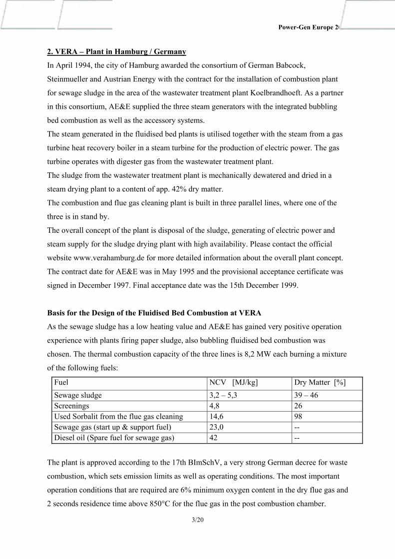
2. VERA – Plant in Hamburg / Germany
In April 1994, the city of Hamburg awarded the consortium of German Babcock,
Steinmueller and Austrian Energy with the contract for the installation of combustion plant
for sewage sludge in the area of the wastewater treatment plant Koelbrandhoeft. As a partner
in this consortium, AE&E supplied the three steam generators with the integrated bubbling
bed combustion as well as the accessory systems.
The steam generated in the fluidised bed plants is utilised together with the steam from a gas
turbine heat recovery boiler in a steam turbine for the production of electric power. The gas
turbine operates with digester gas from the wastewater treatment plant.
The sludge from the wastewater treatment plant is mechanically dewatered and dried in a
steam drying plant to a content of app. 42% dry matter.
The combustion and flue gas cleaning plant is built in three parallel lines, where one of the
three is in stand by.
The overall concept of the plant is disposal of the sludge, generating of electric power and
steam supply for the sludge drying plant with high availability. Please contact the official
website www.verahamburg.de for more detailed information about the overall plant concept.
The contract date for AE&E was in May 1995 and the provisional acceptance certificate was
signed in December 1997. Final acceptance date was the 15th December 1999.
Basis for the Design of the Fluidised Bed Combustion at VERA
As the sewage sludge has a low heating value and AE&E has gained very positive operation
experience with plants firing paper sludge, also bubbling fluidised bed combustion was
chosen. The thermal combustion capacity of the three lines is 8,2 MW each burning a mixture
of the following fuels:
Fuel NCV [MJ/kg] Dry Matter [%] Sewage sludge 3,2 – 5,3 39 – 46 Screenings 4,8 26 Used Sorbalit from the flue gas cleaning 14,6 98 Sewage gas (start up & support fuel) 23,0 -- Diesel oil (Spare fuel for sewage gas) 42 --
The plant is approved according to the 17th BImSchV, a very strong German decree for waste
combustion, which sets emission limits as well as operating conditions. The most important
operation conditions that are required are 6% minimum oxygen content in the dry flue gas and
2 seconds residence time above 850°C for the flue gas in the post combustion chamber.
3/20
Power-Gen Europe 2003
The air distributor in open design of AE&E enables the drain of bed material with impurities
over the whole bed cross-section during operation.
To keep the bed- and post-combustion chamber temperature with these low heating values in
the required range for the operation conditions, a marked staging of the combustion air is
foreseen. This air staging enables the control of the heat release in a distinct area and sets the
dimensions of the bed and the post combustion chamber.
The customer tightened up the already strong emission limits of the 17th BImSchV decree.
For example, the reference O2-content for the emission limits in the flue gas was lowered
from 11% to 6%. The residence time at 850°C was increased from two to three seconds.
The emission values for CO, NO2 and organic matter have to be obtained with the fluidised
bed combustion without secondary measures.
Plant description
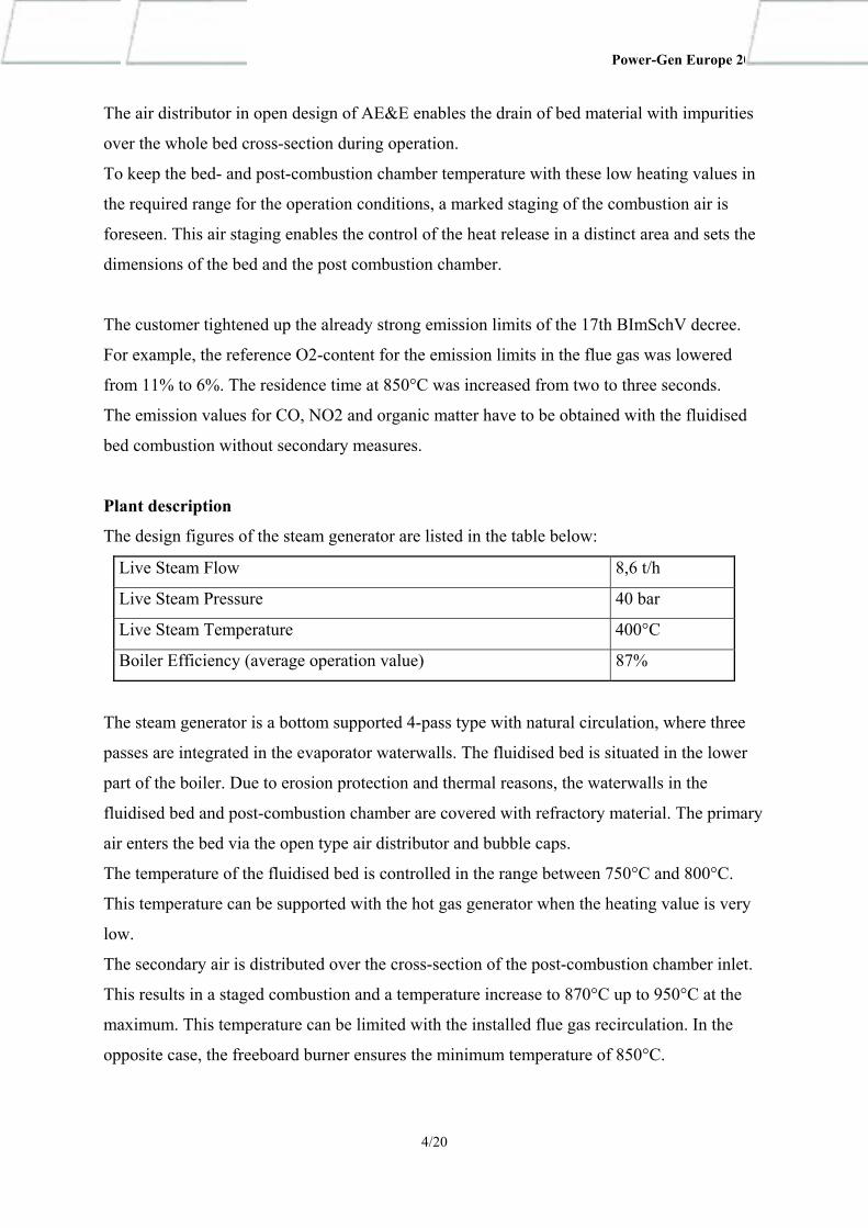
The design figures of the steam generator are listed in the table below:
Live Steam Flow 8,6 t/h
Live Steam Pressure 40 bar
Live Steam Temperature 400°C
Boiler Efficiency (average operation value) 87%
The steam generator is a bottom supported 4-pass type with natural circulation, where three
passes are integrated in the evaporator waterwalls. The fluidised bed is situated in the lower
part of the boiler. Due to erosion protection and thermal reasons, the waterwalls in the
fluidised bed and post-combustion chamber are covered with refractory material. The primary
air enters the bed via the open type air distributor and bubble caps.
The temperature of the fluidised bed is controlled in the range between 750°C and 800°C.
This temperature can be supported with the hot gas generator when the heating value is very
low.
The secondary air is distributed over the cross-section of the post-combustion chamber inlet.
This results in a staged combustion and a temperature increase to 870°C up to 950°C at the
maximum. This temperature can be limited with the installed flue gas recirculation. In the
opposite case, the freeboard burner ensures the minimum temperature of 850°C.
4/20
Power-Gen Europe 2003
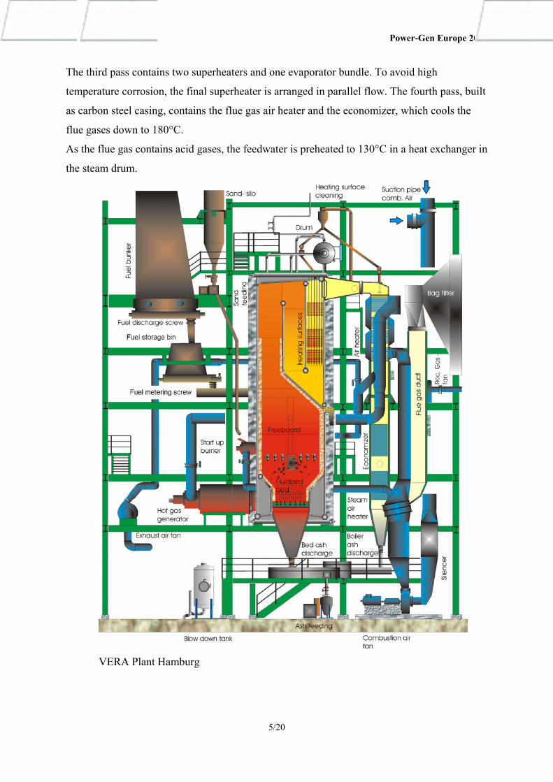
The third pass contains two superheaters and one evaporator bundle. To avoid high
temperature corrosion, the final superheater is arranged in parallel flow. The fourth pass, built
as carbon steel casing, contains the flue gas air heater and the economizer, which cools the
flue gases down to 180°C.
As the flue gas contains acid gases, the feedwater is preheated to 130°C in a heat exchanger in
the steam drum.
VERA Plant Hamburg
5/20
Power-Gen Europe 2003
Solid Fuel System
Belt conveyors transport the dried sewage sludge to three big day silos in the boiler house.
The shredded screenings are added to this belt conveyor. Push rods discharge the sludge from
the silos into small metering bins. Speed controlled double screws carry out the metering of
the fuel mixture. A screw conveys the fuel to the spreader, which distributes the sludge into
the fluidised bed. The contaminated sorbalit is added to this screw.
Combustion Air System and Burners
Effluent air from the sludge drying is mixed to the combustion air in front of the FD fan.
Downstream of the steam air preheater the air for the start up and freeboard burners branches
off. Before the air is divided into primary and secondary air, the tubular air heater increases
the air temperature to 320°C to 360°C. The primary air passes the hot gas generator and enters
the air distributor via an air plenum. The secondary air nozzles are situated in the boiler
sidewalls at the elevation of the spreader.
Start up of the fluidised bed boiler is carried out with a hot gas generator, heating the bed
material to the ignition temperature of the sludge via the primary air system. In addition, the
freeboard burners support the heating up of the boiler. The burners are designed for sewage
gas and diesel oil as back-up fuel.
Bed Material and Ash Handling
The bed material together with the impurities is drained as required from the furnace hopper
with water-cooled screws. The coarse parts are separated in a drum screen; the fine material is
conveyed either to the bed-material silo or to the ash silo.
The ash from the boiler passes is collected with water-cooled screws with drum-screens.
These screens separate the steel balls from the shot cleaning of the heating surfaces. The fly
ash is conveyed to the ash silo.
Denoxing of the Flue Gases
To keep the NOx Emissions below the limit, a selective non-catalytic reduction system
(SNCR) was installed. Urea can be injected into the post-combustion chamber at a suitable
place. Due to the optimised combustion process, the operation of this system could be
avoided.
6/20
Power-Gen Europe 2003
Flue Gas Cleaning
L&C Steinmueller GmbH supplied the flue gas cleaning plant. An electrostatic precipitator
removes the dust from the flue gas leaving the boiler. Then the flue gases pass through a 2-
stage wet scrubber. Sorbalit is injected into the flue gas after re-heating to adsorb dioxins,
furans and mercury. A baghouse filter collects this sorbalit. The sorbalit is circulating, new
material is added and a part is continuously drained and burned.
Commissioning and Initial Operation
The design of the fluidised bed combustion was confirmed during start up and the following
commercial operation by the achieved operation data. Most of the emission values are far
below the guaranteed limits.
The limit for self-sustaining combustion could also be lowered to 3,0 MJ/kg, what is
remarkable lower then the contractual guarantee.
A test operation with lowered O2–content in the flue gas showed that the low emission levels
could also be kept. Based on the good results the authorities approved an exception from the
decree for this plant and gave the permit to operate at >4% O2–content instead of >6% in dry
flue gas. This results in a higher efficiency of the steam generator. Also for the combustion
chamber temperature of 850°C VERA could get an exception to operate down to 810°C, what
increases the operation range and reduces the energy demand for support firing.
During the commercial operation of the last years, the owner of the plant carried out several
improvements, especially by optimising the operation conditions and parameters.
Operating Results of the VERA – Plant from the Years 1998 to 2002:
The following charts show the trend of the operation results from the year 1998 to 2002.
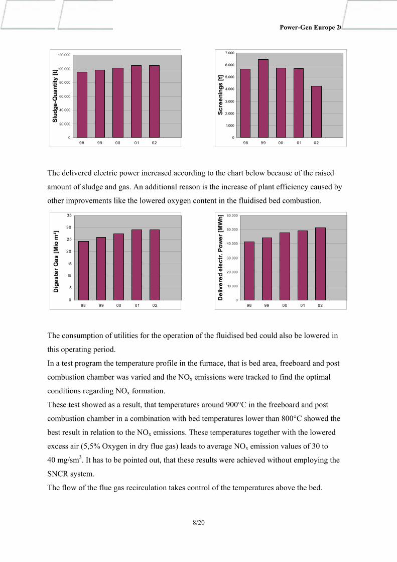
The first three diagrams show the development of the fuel input. The amount of sludge was
increasing because the wastewater treatment plant accepted additional foreign sludge and
residues.
The portion of screenings decreased because of optimising the dewatering equipment.
The volume of digester gas increased due to the additional organic residues in the wastewater
treatment plant, improved digesting process and a raised takeover capacity of the VERA
plant.
.
7/20
Power-Gen Europe 2003
0
20.000
40.000
60.000
80.000
100.000
120.000
98 99 00 01 02
Slud
ge-Q
uant
ity [t
]
0
1.000
2.000
3.000
4.000
5.000
6.000
7.000
98 99 00 01 02
Scre
enin
gs [t
]
The delivered electric power increased according to the chart below because of the raised
amount of sludge and gas. An additional reason is the increase of plant efficiency caused by
other improvements like the lowered oxygen content in the fluidised bed combustion.
0
5
10
15
20
25
30
35
98 99 00 01 02
Dig
este
r Gas
[Mio
m³]
0
10.000
20.000
30.000
40.000
50.000
60.000
98 99 00 01 02
Del
iver
ed e
lect
r. Po
wer
[MW
h]
The consumption of utilities for the operation of the fluidised bed could also be lowered in
this operating period.
In a test program the temperature profile in the furnace, that is bed area, freeboard and post
combustion chamber was varied and the NOx emissions were tracked to find the optimal
conditions regarding NOx formation.
These test showed as a result, that temperatures around 900°C in the freeboard and post
combustion chamber in a combination with bed temperatures lower than 800°C showed the
best result in relation to the NOx emissions. These temperatures together with the lowered
excess air (5,5% Oxygen in dry flue gas) leads to average NOx emission values of 30 to
40 mg/sm3. It has to be pointed out, that these results were achieved without employing the
SNCR system.
The flow of the flue gas recirculation takes control of the temperatures above the bed.
8/20
Power-Gen Europe 2003
As there is no flue gas recirculation into the fluidising air installed, the control of the bed
temperatures is more complicated. The solution is a combination of a minimum fluidising
airflow, variation of the heating value of the sludge (possible in this special case) and a water
injection into the bed that serves as a temperature limiter.
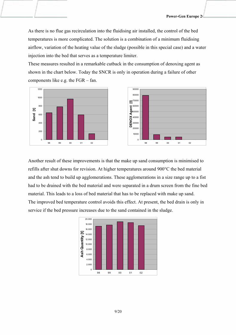
These measures resulted in a remarkable cutback in the consumption of denoxing agent as
shown in the chart below. Today the SNCR is only in operation during a failure of other
components like e.g. the FGR – fan.
0
200
400
600
800
1000
1200
98 99 00 01 02
Sand
[t]
0
10000
20000
30000
40000
50000
60000
70000
80000
90000
98 99 00 01 02
DEN
OX
Age
nt [
l]
Another result of these improvements is that the make up sand consumption is minimised to
refills after shut downs for revision. At higher temperatures around 900°C the bed material
and the ash tend to build up agglomerations. These agglomerations in a size range up to a fist
had to be drained with the bed material and were separated in a drum screen from the fine bed
material. This leads to a loss of bed material that has to be replaced with make up sand.
The improved bed temperature control avoids this effect. At present, the bed drain is only in
service if the bed pressure increases due to the sand contained in the sludge.
0
2.000
4.000
6.000
8.000
10.000
12.000
14.000
16.000
18.000
20.000
98 99 00 01 02
Ash
Qua
ntity
[t]
9/20
Power-Gen Europe 2003
The avoidance of the adding of make up sand has two positive impacts to the operating cost
of the plant. One is the direct costs for the sand supply and the other one is the reduction of
ash disposal costs for the drained bed material.
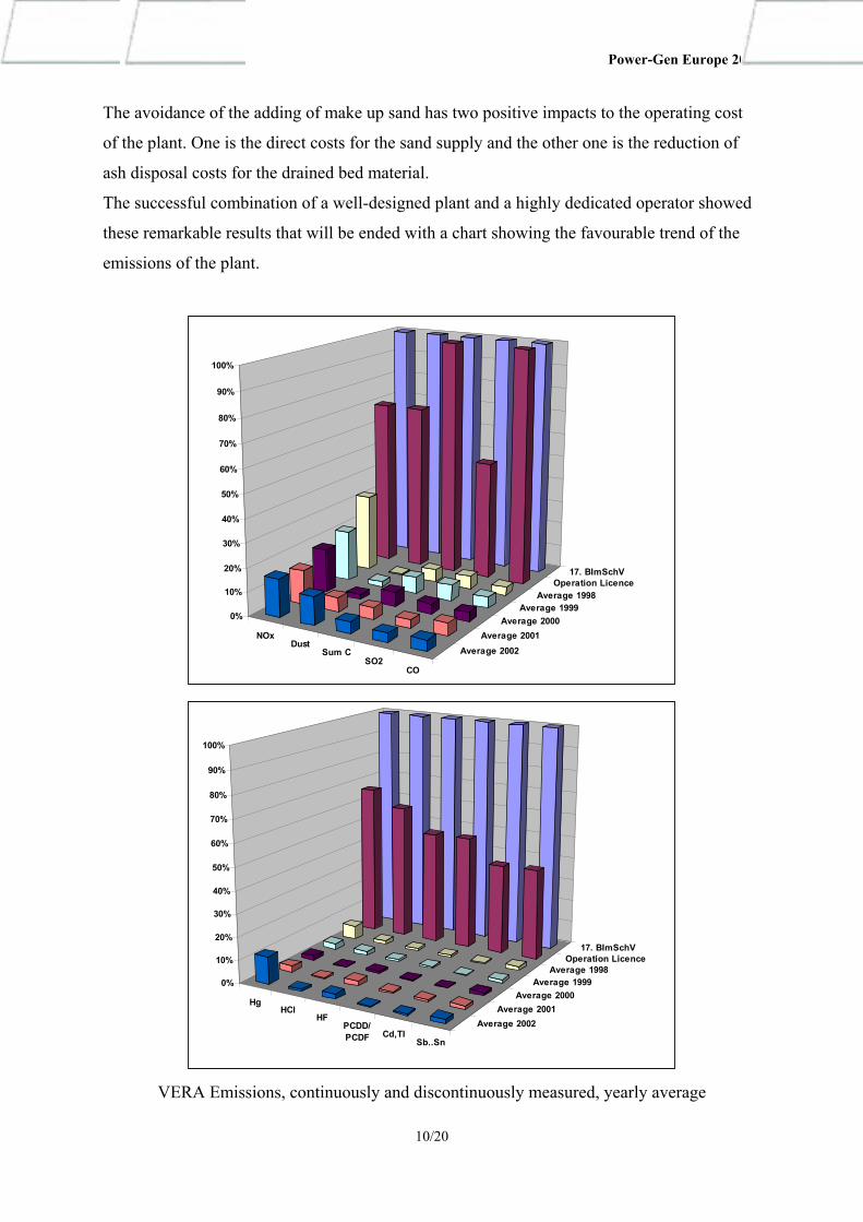
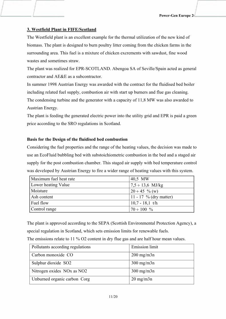
The successful combination of a well-designed plant and a highly dedicated operator showed
these remarkable results that will be ended with a chart showing the favourable trend of the
emissions of the plant.
NOxDust
Sum CSO2
CO
Average 2002Average 2001
Average 2000Average 1999
Average 1998Operation Licence
17. BImSchV
0%
10%
20%
30%
40%
50%
60%
70%
80%
90%
100%
HgHCl
HFPCDD/PCDF Cd,TI
Sb..Sn
Average 2002Average 2001
Average 2000Average 1999
Average 1998Operation Licence
17. BImSchV
0%
10%
20%
30%
40%
50%
60%
70%
80%
90%
100%
VERA Emissions, continuously and discontinuously measured, yearly average
10/20
Power-Gen Europe 2003
3. Westfield Plant in FIFE/Scotland
The Westfield plant is an excellent example for the thermal utilization of the new kind of
biomass. The plant is designed to burn poultry litter coming from the chicken farms in the
surrounding area. This fuel is a mixture of chicken excrements with sawdust, fine wood
wastes and sometimes straw.
The plant was realized for EPR-SCOTLAND. Abengoa SA of Seville/Spain acted as general
contractor and AE&E as a subcontractor.
In summer 1998 Austrian Energy was awarded with the contract for the fluidised bed boiler
including related fuel supply, combustion air with start up burners and flue gas cleaning.
The condensing turbine and the generator with a capacity of 11,8 MW was also awarded to
Austrian Energy.
The plant is feeding the generated electric power into the utility grid and EPR is paid a green
price according to the SRO regulations in Scotland.
Basis for the Design of the fluidised bed combustion
Considering the fuel properties and the range of the heating values, the decision was made to
use an EcoFluid bubbling bed with substoichiometric combustion in the bed and a staged air
supply for the post combustion chamber. This staged air supply with bed temperature control
was developed by Austrian Energy to fire a wider range of heating values with this system.
Maximum fuel heat rate 40,5 MW Lower heating Value 7,5 ÷ 13,6 MJ/kg Moisture 20 ÷ 45 % (w) Ash content 11 - 17 % (dry matter) Fuel flow 10,7 - 18,1 t/h Control range 70 ÷ 100 %
The plant is approved according to the SEPA (Scottish Environmental Protection Agency), a
special regulation in Scotland, which sets emission limits for renewable fuels.
The emissions relate to 11 % O2 content in dry flue gas and are half hour mean values.
Pollutants according regulations Emission limit
Carbon monoxide CO 200 mg/m3n
Sulphur dioxide SO2 300 mg/m3n
Nitrogen oxides NOx as NO2 300 mg/m3n
Unburned organic carbon Corg 20 mg/m3n
11/20
Power-Gen Europe 2003
Dust 25 mg/m3n
Hydro chloride HCl 150 mg/m3n
Dioxins and Furans PCDD/F 0,5 ng/m3n
Unburned matter in bed ash < 5 % (w)
Unburned matter in fly ash < 5 % (w)
The emission values for CO, NO2, SO2, unburned and organic matter have to be obtained
with the fluidised bed combustion.
Plant description
The design figures of the steam generator are listed in the table below:
Live Steam Flow 46,6 t/h
Live Steam Pressure 62 bar
Live Steam Temperature 460°C
Boiler Efficiency (actual average operation value) 89,5%
The steam generator is a bottom supported 4-pass type with natural circulation, where three
passes are integrated in the evaporator waterwalls. The bubbling fluidised bed and the post-
combustion chamber are the first pass. The waterwalls in the fluidised bed and a part of the
post-combustion chamber are covered with refractory material due to erosion protection and
thermal reasons. The second pass is a radiation chamber to cool down the flue gas before
entering the convection surfaces. The third pass contains the superheater bundles.
The fourth pass, built as carbon steel casing, contains the economizer, which cools the flue
gases down to 160°C.
The process characteristics of the EcoFluid bubbling bed are a substoichiometric air supply
through the air distributor to control the bed temperature. A proper designed secondary air
system feeds the balance of the required combustion air above the fluidised bed and results in
a good burnout in the post-combustion chamber. In addition, a flue-gas recirculation system
mixes flue-gas into the post combustion chamber as well as into the primary air. This enables
very good temperature control in the furnace according to legal and process requirements and
leads to lowest emissions.
12/20
Power-Gen Europe 2003
The requirements regarding the combustion, at the minimum 850°C for two seconds and a
minimum O2 content of 6% (vol) in the dry flue gas, as well as the ash properties regarding
agglomeration tendencies require these good temperature control possibilities.
The secondary air, which is the bigger part of the combustion air, is taken from the fuel
storage house. This avoids smell harassment in the surrounding area and the contaminated air
is disposed according to the regulations.
Together with the fuel, incombustible parts like stones, glass and metals come as tramp
material to the fluidised bed, where they collect and hinder the fluidization. To prevent this,
an open type air distributor in AE&E – design is built in and the bed material is consciously
drained and cleaned.
Start-up of the plant is carried out with two burners firing fuel oil No.2. They are not used
above minimum load of the boiler.
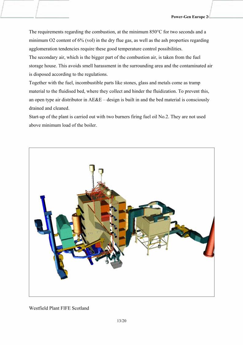
Westfield Plant FIFE Scotland
13/20

Power-Gen Europe 2003
Solid Fuel System
The fuel is collected from several chicken farms and therefore the composition can vary
depending on the feeding of the chicken and the binding material for the excrements.
Trucks dump the litter into a pit, from where a pocket crane takes it out and transports it into
the big storage pit. The pocket crane mixes and feeds the fuel to two bunkers in the storage
building. From these bunkers two trough chain conveyors elevate the fuel up into the day silos
in the boiler house. The day silo is unloaded into the metering screws by two push rod
systems. Each screw supplies one feeding point in the boiler sidewalls. Two air supplied
feeding chutes distribute the poultry litter across the fluidised bed.
Flue Gas Cleaning
A bag filter removes the fly ash from the flue gas. A hydrated limestone injection into the flue
gas in front of the bag filter reduces the SO2 and HCl emissions.
As an additional benefit, the owner of the plant has the target to sell the fly ash with its high
content of potassium and phosphor as a fertilizer. For this reason, "impurities" like sand and
Ca(OH)2 from the flue gas cleaning have to be minimized.
Commissioning and Initial Operation
The hot commissioning started in March 2000 and the plant was handed over to the client
after successful trial run in October 2000.
Some problems occurred with the conveying equipment for the fuel. Due to the fuel
properties, the friction forces of pressed litter were very high and required higher driving
forces.
Some serious problems were arising out of the ash properties. During the design, the expected
fouling tendencies of the ash were already considered. However, during continuous operation
fouling of heating surfaces turned out to be worse than expected.
Some agglomerations appeared in and above the fluidised bed region. The solution for this
problem was lowering the bed operation temperature to minimise the sintering.
The fouling in the furnace and radiation pass was higher than calculated. This caused higher
temperatures at the inlet of the convection surfaces and fouling there.
The initially installed soot blowers were not sufficient to clean the tube bundles. Therefore,
soot blowers with stronger cleaning power were installed. In the post combustion chamber
and the radiation pass wall soot blowers were refitted.
14/20
Power-Gen Europe 2003
An unexpected fouling of the economizer heating surfaces in low temperature regions
occurred and resulted in an unacceptable increase of the flue gas exit temperature.
A layer of phosphorpentoxide and calciumoxide caused the fouling. It appeared as a strongly
insulating and sticky layer of very fine powder that was very resistant to the soot blowing.
The solution was also increasing of the power of the soot blowers in the Economizer.
After these improvements and some optimisation in the operating conditions of the
combustion, the plant is now in successful commercial operation.
In addition, the achieved ash quality is sufficient for use as a fertilizer and gives additional
profit to the owner.
A clear evidence of the successful handling of this difficult fuel in the Westfield plant can be
seen in the fact that the same client has chosen AE&E for a follow up contract for a chicken
litter fired power plant in the Netherlands in a consortium with Siemens. This plant will burn
chicken litter with a lower heating value of 6 to 10 MJ/kg. Feathers and meat meal are
optional fuels for mixing.
The generating capacity of the boiler will be 130 t/h with 66 barg and 478°C. The Plant will
deliver 31, 5 MW of green electric power to the grid.
The project will start after reaching the purchase agreement for the electric power and the
financial closing.
4. Langerbrugge Plant for Stora Enso in Belgium
The Langerbrugge EcoFluid boiler plant is an example for the consistent development of the
AE&E bubbling fluidised bed boilers for the Pulp & Paper industry.
In November 2001, Austrian Energy was awarded with the contract for the fluidised bed
boiler including related equipment. The plant is located in the paper mill of Stora Enso in
Langerbrugge near Gent.
The plant will burn a mixture of deinking sludge, effluent sludge and fines without rejects of
the deinking plant for a new paper machine as the guarantee fuel. Wood waste can serve as
additional fuel.
The generated steam will be utilised in a backpressure turbine for generating electric power
and as low-pressure steam supply for the paper mill.
15/20
Power-Gen Europe 2003
Basis for the Design of the fluidised bed combustion
As the sludge has a minimum lower heating value of 2,9 MJ/kg, support firing of natural gas
will be necessary with these conditions of the solid fuel. Depending on the required steam
flow, the heating value of the mixture can go up to 8,1 MJ/kg. Considering this range of the
heating value, the EcoFluid bubbling bed is designed for traditional and substoichiometric
combustion in the bed and a staged air supply for the freeboard and post combustion chamber.
The flue gas recirculation system is equipped with a low and high-pressure fan to supply flue
gas into the freeboard and post combustion chamber as well as into the bed. Natural gas will
serve for start up and support fuel at low heating values of the solid fuel.
Maximum fuel heat rate 56,0 MW Lower heating Value of fuel mix (sludge, waste and gas) 3,6 ÷ 8,1 MJ/kg Moisture of the sludges 38 – 50 % Ash content 50 – 62 % (in dry matter)Fuel flow (sludge) 18,0 - 40,0 t/h Control range 55 ÷ 100 %
A flue gas air heater for the primary air is installed to minimise the support firing at the very
low heating values. In addition, a natural gas fired hot gas generator is installed to support the
bed temperature if required.
Plant description
The design figures of the steam generator are listed in the table below:
Live Steam Flow 65,0 t/h
Live Steam Pressure 80 bar
Live Steam Temperature 480°C
Boiler Efficiency (average operation value) 87,5%
The steam generator is of the standard EcoFluid design. The final superheater has due to the
high live steam temperature a protection against chlorine corrosion. This protection is a thin
layer of refractory on the five platen - type superheaters in the radiation pass. This protection
is a standard design in municipal waste burning boilers.
16/20
Power-Gen Europe 2003
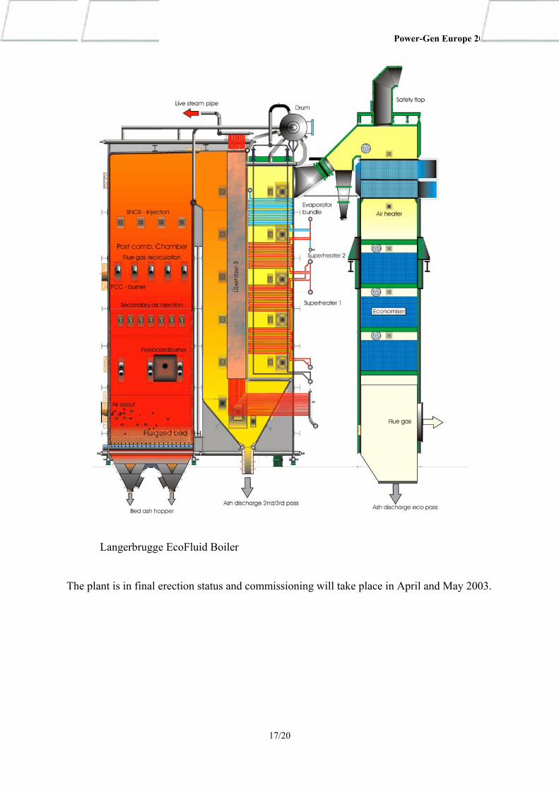
Langerbrugge EcoFluid Boiler
The plant is in final erection status and commissioning will take place in April and May 2003.
17/20
Power-Gen Europe 2003
5. Niklasdorf Plant in Austria
The plant is located in the Mur valley in Styria close to a paper mill. It is built and operated
by ENAGES, a special purpose company mainly owned by the styrian utility ESTAG.
The focus for the design of the entire waste to energy plant is the continuous thermal
treatment of residues with varying calorific values with a minimised impact to the
environment.
It is a part of the styrian waste concept and burns fractions from waste treatment plants.
The general contractor for the plant is SIEMENS AG AUSTRIA. AE&E supplies the fuel
handling and preparation, the fluidised bed boiler with associated equipment and the flue gas
cleaning. The power plant will replace the existing gas fired boiler of the paper mill and will
help to substitute fossil fuels for heat and power production.
Due to the fuel mix, the steam parameters are the traditional values for waste burning plants.
Even though all preventive measures for high availability have been taken, the risk of heat
surface fouling in a plant with this fuel mix is evident. The extremely high availability
required for the steam supply of the paper mill caused the installation of a 100% fluidised bed
boiler and three 50% gas fired steam blocks for stand by.
The plant is designed to burn a mixture of residues from waste paper treatment, waste woods
from construction and demolition, packaging materials, anaerobe stabilised sludge and light
fraction from municipal waste and various industrial wastes.
The generated steam will be utilised in an extraction/condensation turbine for generating
electric power and low-pressure steam for a nearby paper mill.
Basis for the Design of the fluidised bed combustion
Considering the wide variety of fuels and the range of the heating values, the EcoFluid
bubbling bed is designed for substoichiometric combustion in the bed and a flue gas
recirculation into the bed and into freeboard. In addition, there is a flue gas recirculation into
the second pass to keep superheating temperatures in part load.
Maximum fuel heat rate 40,0 MW Lower heating Value 8,0 ÷ 18,0 MJ/kg Moisture 10 ÷ 40 % (w) Ash content 10 - 35 % (w) Fuel flow 8,0 - 16,0 t/h Control range 60 ÷ 100 % Bed temperature 750 ÷ 850 °C Freeboard temperature 850 ÷ 950 °C
18/20
Power-Gen Europe 2003
The emission limits affected by the fluidised bed combustion relate to 11 % O2 content in dry
flue gas and are half hour mean values.
Pollutants according regulations Emission limit
Carbon monoxide CO 50 mg/m3n
Unburned organic carbon Corg 8 mg/m3n
The flue gas cleaning plant has to fulfil very strong emission limits. Therefore, it consists of a
bag filter with hydrated lime and activated carbon injection, 2- stage wet scrubber and a SCR
and is in the scope of AE&E too.
Plant description
The design figures of the steam generator are listed in the table below:
Live Steam Flow operation 25 – 51,7 t/h
Live Steam Pressure 43 barg
Live Steam Temperature 400°C
The steam generator has some special design features. It is a bottom supported 5-pass type
with natural circulation. The evaporator waterwalls contain three passes. The fluidised bed is
in the first pass. The second pass is a radiation chamber to cool down the flue gases before
entering the convection surfaces. At the entrance of the third pass, an evaporator bank serves
as a cooling trap in front of the superheaters. The last superheater in the third pass can be
bypassed on the steam side to keep the required temperatures in the cyclone that is situated
between the third and fourth pass. The cyclone separates fly ash at high temperature to reduce
reformation of dioxins and the portion of contaminated ash.
The fourth and fifth passes are built as carbon steel casing. The fourth pass contains two
superheaters and two economiser bundles. The fifth pass contains three economiser bundles,
which cool the flue gases down to 170°C.
As the fuel preparation and supply is essential for a plant firing this kind of fuel mix, much
attention is given to the design of this part of the plant.
Trucks will dump the already processed fuel into a bunker and a grapple crane will bring it to
a vibrating screen and a shredder. As the fuel preparation and the mixing are essential for
good combustion conditions, the storage bunker is sized for 4 days full load capacity. Another
grapple crane will mix the fuel and supplies it to the metering system for the combustion.
19/20
Power-Gen Europe 2003
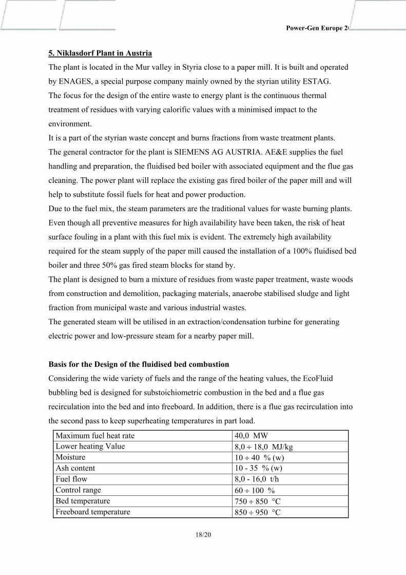
EcoFluid boiler Niklasdorf Austria
The plant is under construction and commissioning will take place in autumn of 2003.
6. Standard Biomass Power Plant for 20 MW
Based on the EEG decree in Germany AE&E designed a standardised biomass power plant
with the EcoFluid bubbling bed as combustion process. It comprises a turnkey plant for a
generating capacity of 20 MW electric Power. The plant consists mainly of the fuel handling,
EcoFluid boiler, Turbine, air condenser and the required electric equipment. The flue gas
cleaning is carried out in a conventional dry cleaning or with the TURBOSORP process
developed by AE&E. The choice depends on the wood used as fuel. The basic concept is for
already chipped wood. Several Projects in Germany are under negotiation.
7. Market Development
The business unit Biomass concentrates on the projects arising of the EU directives
2000/76/EC Incineration of waste and 2001/77/EC on the promotion of electricity produced
from renewable energy sources in the internal electricity market. These directives result in
various national guidelines creating a market for biomass and waste burning power plants.
With the EcoFluid combustion system, AE&E is well prepared to fulfil the requirements for
these plants in the EC an the candidate countries
20/20