Embed Size (px)
Citation preview

___. ___. ______ ________________________________
Designing a Bubbling Fluidized Bed (BFB) Boiler for Research
Purposes
Daniel Castiella Franco
Bachelor’s Thesis


“What we know is a drop of water; what we ignore is an ocean”
Isaac Newton
“I hear and I forget, I see and I remember, I do and I understand”
Confucius

ACKNOWLEDGEMENTS
I would like to express my deepest appreciation to the supervisor of this thesis, lec-
turer Jukka Huttunen. I cannot find words to express my gratitude. Without his
guidance and persistent help this thesis would not have been possible.
I am especially indebted to lecturer Irene Hyrkstedt. Her lessons were particularly
useful for, among many other things, enhancing my writing and oral skills. I take this
opportunity to record my sincere thanks to all the lecturers who have contributed to
impart their knowledge on me. Special thanks to Jorma Honkanen, David González
Ibáñez and Javier Jarne Sasal.
I would also like to thank lecturer Heikki Salkinoja for helping me find this interesting
thesis topic, which is completely integrated with my academic background.
I wish to express my gratitude to the European Union, Savonia University of Applied
Sciences and College of Engineering and Architecture of Zaragoza for making the
Erasmus exchange program possible. I would also like to thank the Spanish bank
Ibercaja for granting me a scholarship.
Last but not least, I am grateful to my parents, Carlos and Cristina, for supporting me
morally and financially throughout my studies. Thank you both for giving me strength
to chase my dreams.

SAVONIA UNIVERSITY OF APPLIED SCIENCES THESIS Abstract
Field of Study Mechanical Engineering Degree Programme Industrial Management Author(s) Daniel Castiella Franco Title of Thesis
Designing a Bubbling Fluidized Bed (BFB) Boiler for Research Purposes
Date 20/05/2013 Pages/Appendices 57/2
Supervisor(s) Jukka Huttunen Client Organisation/Partners Savonia University of Applied Sciences Abstract
This project is part of the efforts made by Savonia University of Applied Sciences to plan the future
EU-funded combustion research laboratory that will be located on Varkaus Campus.
The main objective of the present thesis was to carry out an optimal design, in technical, envi-
ronmental and economical terms, of a small-sized bubbling fluidized bed (BFB) boiler, which will be
used mainly for research purposes.
This design takes as a reference a former BFB boiler that was located at Lappeenranta University
of Technology. The efforts have been focused mainly on adapting this reference design to be used
for research activities and bringing construction and operating costs down.
All the drawings and virtual three-dimensional models of the components have been executed
using SolidWords, a computer-aided design program. The result of the design process is an efficient and environmentally friendly boiler that is going to
enable numerous testing services and lines of research.
Keywords Bubbling fluidized bed, BFB, boiler, design, SolidWorks
Confidentiality Public

CONTENTS
ACKNOWLEDGEMENTS
ABSTRACT
1 INTRODUCTION.............................................................................................. 8
1.1 Context and objectives .............................................................................12
1.2 Thesis structure .......................................................................................14
2 THEORETICAL BACKGROUND OF FLUIDIZED BED TECHNOLOGY ......................15
2.1 Fluidized bed phenomenon and practical applications .................................16
2.2 Fluidized bed combustion .........................................................................21
2.3 Reduction of pollutant emissions ...............................................................23
2.3.1 Sulphur dioxide ..............................................................................23
2.3.2 Nitrogen oxides ..............................................................................25
2.3.3 Particles.........................................................................................26
2.4 Bed temperature......................................................................................27
2.5 Depth of the bed .....................................................................................28
2.6 Combustion efficiency ..............................................................................28
2.7 Advantages of fluidized bed boilers ...........................................................29
3 DESIGNING A SMALL-SIZED BFB BOILER FOR RESEARCH PURPOSES ................31
3.1 Introduction to the design process ............................................................31
3.2 Reference design .....................................................................................34
3.3 Final design: components of the assembly and identification numbers .........35
3.4 Documentation of selected solutions and decisions .....................................39
3.4.1 Windbox ........................................................................................39
3.4.2 Furnace .........................................................................................42
3.4.3 Exhaust gas tube............................................................................47
3.5 Standard components ..............................................................................49
3.6 Connecting elements and welds ................................................................49
3.7 Additional systems...................................................................................50
3.7.1 Ignition system...............................................................................50
3.7.2 Bed drainage system......................................................................51
3.7.3 Temperature control system............................................................51
3.7.4 Ammonia injection system ..............................................................52
3.7.5 Flue gas cleaning system ...............................................................52

4 CONCLUSIONS ............................................................................................ 53
SOURCE MATERIAL
REFERENCES
APPENDICES
Appendix 1 Standard components
Appendix 2 Drawings

8
1 INTRODUCTION
The progress and industrial development have improved the standard of living in the
entire world. However, this evolution and growth has also caused an alarming in-
crease of the environmental risks.
The environmental policy, which began in the United Nations Conference on the Hu-
man Environment (Stockholm, 1972), has become one of the most important in the
European Union. (Prieto 2013,1.)
In the framework of this policy, community legislation on atmospheric emissions has
the following objectives:
-‐ Reducing the amount of pollutants emission: Human activity has increased
the proportion of greenhouse gases, such as carbon dioxide and methane, in
the atmosphere and, as a consequence, the mean global temperature is cur-
rently growing faster than at any time over the last 10.000 years. Furthermore,
the emission of nitrogen oxides and sulphur dioxide is causing acid rain. Other
restrictions are stated of CFCs, ozone (O3), hydrocarbons and other photo-
chemical oxidants, as well as limitations of volatile organic compounds and
ammonia. In order to reduce the amount of pollutants released into the at-
mosphere, it is necessary to lessen not only the emission of the substances
cited above but also the emission of ash particles. (Honkanen 2012, 6; Fossil-
fuel power station Wikipedia 2013; Air pollution Wikipedia 2013.)
-‐ Using the energy in a more efficient way: Earth’s supplies are limited and,
therefore, the challenge is to use them in a rational manner. (Prieto 2013,1.)
The sources of pollution are very varied: agricultural and domestic uses, transport,
industry in general, forest fires, etc. However, the efforts to reduce the pollutants
emission has been focused mainly on thermal power stations due to their relative
ease of identification, volume and growth. (Prieto 2013,1.)
World population growth and high levels of human development entail an increase in
global energy consumption as can be seen from Figure 1. The world is demanding
more and more energy but it has to be supplied in a way that ensures energy se-
curity, geopolitical balance and a minimization of environmental damages.

9
*Other includes geothermal, solar, wind, etc.
FIGURE 1. World’s total primary energy supply (Mtoe) from 1971 to 2010 by fuel.
(International Energy Agency 2012)
FIGURE 2. World net electricity generation from 2008 to 2035 by fuel type.
(U.S. Energy Information Administration. International Energy Outlook 2011)

10
A decade ago, hydroelectricity was the only renewable energy affordable compared
to other energy sources. However, continued research has reduced the cost of re-
newable energy technologies, especially of wind turbines, which is permitting them to
compete with conventional generation sources in some countries. This is an import-
ant step in the fundamental transition of the world’s energy mix towards renewable
sources. Nevertheless, greater social and political will is required to change the cur-
rent energy model and reduce dependence on fossil fuels. (Cost of electricity by
source Wikipedia 2013; Renewable energy commercialization Wikipedia 2013.)
According to IEO2011 predictions (see Figure 2), fossil fuels will remain the primary
source of electricity generation worldwide for the next few decades, especially in de-
veloping countries where the power sector is highly dependent on coal (U.S. Energy
Information Administration. International Energy Outlook 2011).
TABLE 1. Coal in electricity generation. (World Coal Association 2012)
South Africa 93% Poland 87% PR China 79%
Australia 78% Kazakhstan 75% India 68%
Israel 58% Czech Rep 51% Morocco 51%
Greece 54 % USA 45 % Germany 41%
The environmental impact of fossil fuels, especially coal, is a matter that concerns the
International Energy Agency (IEA) and other world organizations. Global warming
and acid rain are to a large extent caused by coal burning. These environmental
problems are mainly ascribed to the emission of gases such as nitrogen oxides, sul-
phur dioxide and carbon dioxide into the air. (Fossil-fuel power station Wikipedia
2013.)
Over the last few decades, important efforts have been made to deal with the envi-
ronmental challenges raised. Owing to the chemical composition of coal, the removal
of impurities from the fuel prior to its combustion involves serious difficulties. Thus,
the main objective of thermoelectric plants has been the improvement and develop-
ment of methods to reduce the contaminants of flue gases produced by coal combus-
tion. (Fossil-fuel power station Wikipedia 2013.)
11
At first, the main efforts were focused on the lessening of particles release and acid
emissions (Sistemas de Generación Eléctrica 2012, 159). Within this field, different
products were developed as a result of extensive research, among which some of the
most representative are:
-‐ Low NOx burners
-‐ Flue gas desulphurisation systems
-‐ Electrostatic precipitators
-‐ Filters
Thanks to these technological advances, modern day coal power plants are more
environmentally friendly than older designs.
In addition to developing methods for controlling the formation of pollutants and for
exhaust gas cleaning in conventional boilers, other novel methods were promoted
such as fluidized bed combustion (FBC). Fluidized bed technology has numerous
advantages to burn solid fuels and produce steam. This fact has made its develop-
ment possible from the seventies to the present becoming a viable alternative of con-
ventional firing systems. Low temperatures of fluidized beds contribute to high effi-
ciency of SOx retention and to a considerable reduction of NOx formation. Besides,
high overall system efficiency reduces fuel consumption and, consequently, pollutant
emissions. Another of its major advantages is the fuel flexibility: it is possible to burn
not only coal but also a large variety of fuels like biomass, petroleum coke, combus-
tible industrial wastes, etc. This fact makes them particularly important in countries
like Finland where biomass reserves are enormous. Besides, biomass is considered
as a renewable energy source. (Sistemas de Generación Eléctrica 2012, 159-160;
Prieto 2013, 2-3.)
Nowadays, research on clean combustion technologies is considered as an optimal
solution for the natural environment. Progress made by scientific institutions from all
around the world during the last years has bring about the optimization of combustion
in fluidized bed boilers, resulting in improved fuel utilization and, as a consequence,
economic and environmental benefits.
12
1.1 Context and objectives
The main objective of the present thesis is to carry out an optimal design, in techni-
cal, environmental and economical terms, of a small size bubbling fluidized bed
(BFB) boiler, which will be used mainly for research purposes.
In particular, the design process has focused on the following components:
-‐ Windbox
-‐ Boiler tube
-‐ Ceramic layers
-‐ Air nozzles
-‐ Fuel feeder
-‐ Sorbent and inert material feeder
-‐ Maintenance flanges
-‐ Flue gas measurement flanges
-‐ Pipes for pressure and temperature measurement
-‐ Bed material removal flange
-‐ Exhaust gases tube
This project is part of the efforts made by Savonia University of Applied Sciences to
plan the future EU-funded combustion research laboratory that will be located on
Varkaus Campus (see Figure 3).
The construction of this laboratory is going to enable, among others, the following
testing services and lines of research:
-‐ Fuel management
-‐ Fuel analysis
-‐ Fluid dynamic and thermal behaviour of the installation
-‐ Combustion characterization
-‐ Firing tests with different operating conditions: fuels, air speeds, tempera-
tures, sorbents, etc.
-‐ Exhaust gas cleaning and emissions control

13
The ultimate aim of the research activities is to transfer the results to companies so
as they can greatly improve their technology, bring the costs down and enhance pro-
duction.
FIGURE 3. Map of Varkaus Campus. (National Land Survey of Finland 2013)
L - Future research laboratory location
A, B and C - Savonia UAS buildings
It is important to mention that this laboratory will be used not only by the Research
and Development (R&D) department but also by students (Hämäläinen 2012, 1).
Thus, it will have both research and educational functions.
Besides, the boiler has a practical purpose because the hot water produced will be
probably used to generate electricity and to heat the laboratory building and perhaps

14
also the building C of Varkaus Campus (Huttunen 2 May 2013). However, the re-
search and educational functions prevail over this one and, therefore, it will be ne-
cessary to install a supplementary heating system to supply the demand when the
boiler is not working. It is estimated that the boiler will be operating for one week a
month on average (Hämäläinen 2012, 3). The rest of the time, the demand will be
supplied by a geothermal heating system connected to the hot water container of the
boiler (Hämäläinen 2012, 7-9). This seems to be the best solution because there are
many economical and technical problems of obtaining the thermal energy from the
district heating network of Varkauden Aluelampo Oy (Hämäläinen 2012, 4).
1.2 Thesis structure
The present thesis is divided into the following main parts:
1) Brief introduction of fluidized bed boilers, context of the thesis and objectives.
2) Theoretical background of fluidized bed technology.
3) Design of a small size bubbling fluidized bed boiler for research purposes
4) Conclusions
Appendix 1: List of all the standard components that are necessary to build the in-
stallation
Appendix 2: Installation drawings

15
2 THEORETICAL BACKGROUND OF FLUIDIZED BED TECHNOLOGY
Although fluidized bed properties have been known since 1921, it has been used for
energy production only during the last four decades. The need to minimize pollutant
emissions and reduce dependence on fossil fuels has led to the development of this
technology, which is currently in full expansion. Nowadays, fluidized bed boilers are
considered as an accepted technology for solid fuels combustion to generate electric
power. Besides, they are also used in combined heat and power (CHP) plants. (Teir
2003, 37,155; Sistemas de Generación Eléctrica 2012, 164.)
The different types of fluidized bed combustion can be classified according to the
following criteria:
• Pressure: there are two different families of fluidized bed combustion depending on
the pressure at which the combustion takes place:
- Atmospheric fluidized bed combustion (Atmospheric pressure)
- Pressurised fluidized bed combustion (Higher pressure than the atmospheric
one)
• Fluidization speed: this classification will be further explained in later chapters.
Basically, fluidized bed combustion processes can be classified in two main groups
according to the speed of the upward gas current that causes fluidization:
-‐ Bubbling fluidized bed combustion
-‐ Circulating fluidized bed combustion
The result is a comprehensive range of efficient and reliable boilers that can compete
successfully against other combustion technologies. (Prieto 2013, 2.)
The main advantages over conventional boilers are high combustion efficiency, fuel
flexibility and low atmospheric emissions. The combustion takes place in a turbulent
bed with high heat transfer coefficient. These features provide more effective chemi-
cal reactions and enable enormous flexibility when it comes to using different fuels,
especially those that are difficult to burn such as anthracite and petroleum coke, low
quality fuels such as combustible industrial wastes and coal with high moisture and
ash content, as well as fuels with highly variable heat value like biomass or mixtures

16
of fuels. The high gas-solid mixing along with the long residence time of fuel particles
reduce the amount of unburned fuel and, consequently, the combustion efficiency is
very high. Furthermore, this technology enables the combustion of solid fuels in a
more efficient and environmentally friendly way. The emission of atmospheric pollu-
tants such as SO2, NOx and dust is below the permitted limits. (Fluidized bed com-
bustion Wikipedia 2013; Prieto 2013, 14-15.)
2.1 Fluidized bed phenomenon and practical applications
Fluidized bed is the name given to a mixture of particles suspended in an upward
current of gas (Prieto 2013, 4). The operating principle of a fluidized bed is shown in
figure 4.
FIGURE 4. Diagram of a fluidized bed. (Fluidized bed Wikipedia 2013)
17
A granular material is placed in a vertical cylinder with a gas distributor plate or noz-
zles through which gas moves upwards in a vertical direction. The gas current moves
also through the bed formed by that granular material. If the speed of the gas current
is high enough, a process or phenomenon called fluidization occurs. This phenom-
enon consists of the contact between solids (granular material) and fluids so that the
solid particles are suspended in the fluid. (Prieto 2013, 4.)
It is very important to control the speed of the upward gas stream because it can lead
to different situations. The granular material contained in the cylinder is a porous me-
dia. When the speed of the fluid is very low, it only circulates through the winding
channels formed by this porous media and, thus, the bed remains fixed. The gas
moves from the bottom to the top through the bed without causing any significant
change on it. This situation is called “fixed bed” and it is defined by the following pa-
rameters:
L= length of the fixed bed
U= speed of the fluid, measured with respect to the cross section
(Prieto 2013, 4.)
Increasing the speed little by little a new state is reached in which the particles of the
bed start to vibrate and move in restricted zones. A bed with these properties is
known as “expanded bed”. (Prieto 2013, 4-5.)
If the fluid speed continues to increase, all the particles are suspended in the upward
flow. In this situation there is equilibrium between the weight of those particles and
the drag force that the fluid exerts on those particles as can be seen in Figure 4. This
is the moment when the phenomenon of fluidization starts. In this situation, the height
of the bed is known as “minimum fluidization height” (Lmf) and the speed of the fluid
as “minimum fluidization speed” (Umf). The value of this speed depends on numerous
factors such as particles size, gas viscosity, particles shape, particles and gas density
and bed porosity. (Prieto 2013, 5; Teir 2003, 155.)
An increase of the flow causes a more violent agitation. As a consequence, the bed is
a turbulent mixing of solids and gas similar to boiling lava inside a volcano. However,

18
the particles are held mainly in the bed, which does not expand along the boiler tube.
This state is called “bubbling fluidized bed”. (Honkanen 2012, 23; Prieto 2013, 5.)
If we continue increasing the speed of the injected gas, the turbulence degree be-
comes greater and a large number of bed particles are drawn by the gas stream, still
preserving the features of a fluidized bed. This is called “circulating fluidized bed”.
The greater flow of drawn particles makes the use of recirculation devices necessary.
(Prieto 2013, 5.)
If the speed is increased even more the state reached is known as “pneumatic trans-
port” in which all the particles are drawn and go out of the boiler through the flue gas
tube. (Prieto 2013, 5.)
FIGURE 6. Regimes of fluidized bed systems. (Teir 2003, 156)
As can be seen from the graph of figure 6, the fluid speed and the pressure drop due
to frictional losses are related.
This relation is described by the formula
Δpf=f(U) (1)
Where Δpf is the pressure drop and U is the fluid speed

19
The function is represented in the logarithmic coordinate system. This graphic is
known as fluidization curve and it enables the differentiation and classification of the
various families of fluidized beds. (Prieto 2013, 6-7.)
When the fluid speed is below the minimum fluidization speed (Umf) the bed is fixed
and pressure loss experienced by the flow, due to the particles friction, is proportional
to its speed. In other words, log Δpf increases linearly with log U until the maximum
porosity is reached (expanded bed). In this state the particles are still in contact.
Once the gas speed exceeds the minimum fluidization limit, all the particles are sus-
pended in the upward flow. When this happens, the pressure drop decreases slightly
since the bed particles move to a position in which the pressure drop is lower. (Prieto
2013, 6.)
An increase of the flow causes an intense agitation of the bed particles but the pres-
sure drop remains almost constant until the entrainment velocity is attained. This ve-
locity marks the transition from a bubbling bed to a circulating bed. From here on, if
the gas speed continues to rise, the pressure drop (Δp) falls suddenly on account of
the loss of bed particles. In other words, the gradual loss of the bed weight brings
about a decrease in gas flow resistance. (Prieto 2013, 6.)
Having explained the phenomenon of fluidization and the different types of fluidized
beds, it is necessary to define some of their applications. The properties of fluidized
beds can be used in many industrial activities such us fluid catalytic cracking, gasifi-
cation, mineral and metallurgical processes, etc. However, fluidized bed combustion
(FBC) is, without doubt, one of its most important practical applications. (Fluidization
Wikipedia 2013)
Some of the main advantages of fluidized beds in order to be used in combustion
processes are the following:
-‐ As a result of the high turbulence degree of the bed, the distribution of tem-
peratures is very homogenous, even reaching a nearly isothermal state (Pri-
eto 2013, 5).
-‐ High heat transfer between bed particles and gases (Prieto 2013, 5).
-‐ Heat exchangers may be placed in the bed ensuring a high heat transfer due
to the violent agitation of bed particles (Prieto 2013, 5).
20
-‐ The liquid behaviour of a fluidized bed makes it easier to remove or feed
solids (Prieto 2013, 5).
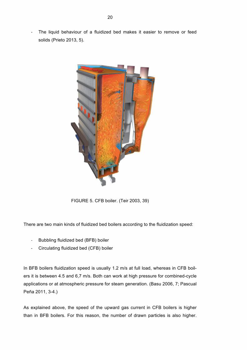
FIGURE 5. CFB boiler. (Teir 2003, 39)
There are two main kinds of fluidized bed boilers according to the fluidization speed:
-‐ Bubbling fluidized bed (BFB) boiler
-‐ Circulating fluidized bed (CFB) boiler
In BFB boilers fluidization speed is usually 1.2 m/s at full load, whereas in CFB boil-
ers it is between 4.5 and 6,7 m/s. Both can work at high pressure for combined-cycle
applications or at atmospheric pressure for steam generation. (Basu 2006, 7; Pascual
Peña 2011, 3-4.)
As explained above, the speed of the upward gas current in CFB boilers is higher
than in BFB boilers. For this reason, the number of drawn particles is also higher.

21
This fact brings about a cloud of suspended solids along the boiler tube, which is
called “fast bed”. In this kind of boilers, a large number of drawn particles is collected
by a high-temperature cyclone and recycled to the boiler (see Figure 5). Recycling
increases the efficiency and maintains the bed height. Due to the high turbulence in
CFB boilers, the chemical reactions are more complete. This causes a better fuel
utilization and, as will be seen in later chapters of this report, a more efficient reduc-
tion of SO2 emissions. (Teir 2003, 38; Prieto 2013, 23-24.)
2.2 Fluidized bed combustion
As already stated, fluidized bed combustion (FBC) is an important practical applica-
tion of the phenomenon of fluidization. This combustion technology is used in power
plants.
In fluidized bed boilers, a bed of particles is contained in the furnace chamber. This
bed is preheated with an ignition system formed by one or many burners whose func-
tion is to raise the temperature of the bed and furnace chamber to 500-600 ºC so as
the initial ignition of the fuel is ensured. The burners heat the air that is injected into
the furnace. In some boilers there are supplementary burners that preheat the upper
part of the boiler and/or directly the surface of the bed. (Huttunen, 2 May 2013; Pri-
eto 2013, 22.)
Firstly, the air speed is kept below the minimum fluidization speed until the bed tem-
perature reaches 400-500ºC. Once the minimum ignition temperature is reached, the
fuel particles are fed into the furnace. The bed temperature and the amount of excess
air must be monitored carefully. The fuel and air flow are increased gradually while, at
the same time, the burner power is reduced and finally turned off. The fuel flow con-
tinues to grow until operating conditions are attained. Operating temperature of the
bed is normally between 800 and 900 ºC. (Prieto 2013, 22; Basu 2006, 6.)
On account of the chemical reactions that occur in the furnace the bed is composed
of the following elements:
-‐ Fuel particles: due to the high turbulences, the fuel is distributed evenly
throughout the bed.
-‐ Ash

22
-‐ In most cases an inert additive such as sand or gravel (especially for burning
low-ash fuels like woodchips)
-‐ Sorbent: limestone or dolostone. This will be further explained in next chapter.
(Prieto 2013, 11-12; Basu 2006, 6.)
Fuel particles are constantly introduced into the combustion chamber though one or
more feeders. When those particles come into contact with the hot fluidized bed they
reach the ignition temperature almost immediately due to the high heat transfer typi-
cal of fluidized beds. The ash produced in the combustion process is extracted con-
tinually. Besides, the inert material and sorbent is also fed and removed continuously
to avoid problems of excessive calcination. All these feedings and extractions are
regulated ensuring that the weight of the bed remains approximately constant. (Prieto
2013, 7-8.)
FIGURE 7. Fluidized bed combustion. (Teir 2003, 10)
The combustion process does not take place only in the fluidized bed but also in the
stream of hot gases and particles above the bed. Some unburned components are
generated in the upper part because of the lack of sufficient oxygen. It is important to
mention that the air is injected into the furnace in different levels. Around 40% is in-
serted in the primary zone of fluidization through the gas distributor plate of the bot-
tom (primary air). The rest of the air (secondary air) is inserted through numerous air
23
nozzles situated in the walls of the furnace. (Prieto 2013, 8; Sistemas de Generación
Eléctrica 2012, 175.)
The unburned components of the bed rise through the boiler tube and react with the
secondary air giving off a significant amount of energy. This phenomenon raises the
temperature of the gases, which is generally higher than the temperature of the bed.
This staged combustion increases the efficiency and reduces the formation of nitro-
gen oxides (NOx). (Prieto 2013, 8; Basu 2006, 160)
The typical reactions that take place in the furnace are:
C + O2 ⇒ CO2 + 393.7 kJ/mol
C + ½ O2 ⇒ CO + 110.6 kJ/mol
H2 + ½ O2 ⇒ H2O + 242 kJ/mol
CH4 + 2O2 ⇒ CO2 + 2H2O + 74.9 kJ/mol
S + O2 ⇒ SO2 + 296.9 kJ/mol
N + O2 ⇒ NO2 – 33.7 kJ/mol
N + ½ O2 ⇒ NO – 90.4 kJ/mol
(Prieto 2013, 8.)
2.3 Reduction of pollutant emissions
2.3.1 Sulphur dioxide
Ever-tighter regulations on atmospheric emissions exclude important fuel resources
due to their high sulphur content. The fluidized bed combustion of solid fuels is an
alternative that has risen strongly worldwide in recent years.
In combustion processes, the sulphur contained in the fuel is oxidised producing sul-
phur dioxide (SO2). The release of this polluting gas into the atmosphere is one of the
main causes of acid rain. In conventional boilers, flue gas desulphurisation systems
are indispensable in order to remove the SO2 produced (Prieto 2013, 3).
.

24
One of the highlights of the fluidized bed boilers is the high sulphur retention in the
bed. A sorbent, which is normally limestone, is fed into the furnace chamber. At at-
mospheric pressure, limestone particles are calcined by producing calcium oxide
(CaO). This chemical compound reacts with the sulphur dioxide and produces gyp-
sum (CaSO4) that is removed with the ash. The desulphurization efficiency of this
process is around 90 %. As a result, in this kind of boilers is not necessary to add a
flue gas desulphurisation system to comply with the legislation of gas emissions.
(Sistemas de Generación Eléctrica 2012, 173; Prieto 2013, 8-9.)
FIGURE 8. Relationship between bed temperature and sulphur retention percentage
for different Ca/S ratios. (Prieto 2013, 10)
The efficiency of sulphur retention depends mainly on the following factors:
-‐ Temperature of the bed: the optimal temperature is around 800 - 850 ºC (see
Figure 8). A temperature above the optimal range would cause a growth of
the sulfation rate, plugging the pores of the CaO and, consequently, restricting
the reaction with the sulphur dioxide. Furthermore, a higher temperature

25
would lead to the decomposition of gypsum. On the other hand, a temperature
below the optimal range may cause a low calcination of limestone, which
would cause inadequate sulphur retention. (Basu 2006, 151.)
-‐ Ca/S ratio: The greater the ratio the greater the sulphur retention as can be
seen in Figure 8 (Prieto 2013, 9).
-‐ Residence time: A higher residence time of bed particles and gases results in
a raise of desulphurization reactions (Prieto 2013, 9).
-‐ Sorbent particle size: The efficiency of sulphur retention is higher when sorb-
ent particles are smaller. This is due to the high contact surface between sul-
phur dioxide and calcium oxide. Small sorbent particles leave finer unreacted
cores after sulfation. (Basu 2006, 155).
-‐ Sorbent reactivity has a positive influence on sulphur retention (Prieto 2013,
9).
2.3.2 Nitrogen oxides
NOx pollution is also considered as an important threat to the environment. A high
concentration of these gases in the atmosphere (above 0.5 ppm) may cause acid
rain, which has adverse effects on vegetation, water and aquatic species, buildings,
etc. It can also affect human health and, in this sense, it is even more dangerous than
sulphur dioxide. (U. S. Environmental Protection Agency 2012; Prieto 2013, 10)
NOx may come from the oxidation of nitrogen from the air (giving thermal NOx) or
organic nitrogen from the fuel (giving fuel NOx) (Energy Tech 2003). Formation of
nitrogen oxides depends mainly on the following factors:
-‐ Amount of Fuel-bound nitrogen: a high nitrogen proportion in the fuel in-
creases the formation of nitrogen oxides (Prieto 2013, 10).
-‐ Excess air ratio and combustion temperature (Basu 2006, 160). This relation
can be seen in Figure 9.
Other methods to suppress efficiently the formation of nitrogen oxides are staged
combustion as explained in chapter 2.2, as well as injecting ammonia (NH3) into the
cyclone or the higher part of the furnace (Basu 2006, 160-161).

26
FIGURE 9. NOx formation increases with combustion temperature and with excess
air ratio. (Basu 2006, 160)
2.3.3 Particles
Fundamentally, the particles that are removed from the bed are composed of the ash
contained in the fuel, gypsum produced by the reaction of calcium oxide with sulphur
dioxide, inert material of the bed (only if it is necessary to feed it) and the amount of
limestone that does not react. It is very important to reduce the emission of those
particles into the atmosphere, mainly the smallest ones, because it has been linked to
numerous respiratory and cardiac problems. (Clean Air Task Force 2004; Sistemas
de Generación Eléctrica 2012, 176-177.)
These particles are taken out by means of the following systems:
-‐ Bed drainage system: the major part is drained from the bed (bottom ash)
-‐ Flue gas cleaning system: the rest is called fly ash and it leaves the furnace
through the flue gas tube. It is collected by particulate collection equipment
such as cyclones, electrostatic precipitators and filters.

27
FIGURE 10. Structure of a CFB boiler with flue gas treatment facilities. (Teir 2003,
143)
2.4 Bed temperature
In fluidized bed boilers the combustion takes place in a low temperature bed. The
furnace temperature of conventional boilers, such as grate furnace and pulverized
coal fired (PCF) boilers, is much higher. Low temperature combustion is an advan-
tage because the ash melts at higher temperatures and therefore there are no prob-
lems of slag formation in the furnace. Furthermore, as already explained, this rela-
tively low combustion temperature reduces the formation of nitrogen oxides (NOx).
(Prieto 2013, 2.)
The most common temperature range of the bed is from 750 ºC to 950ºC. However, it
is more appropriate to maintain the temperature between 800 ºC and 900 ºC in order
to reduce the amount of SO2 released. A higher temperature should not be reached
because the ash would melt causing agglomeration. On the other hand, a lower tem-
perature would result in a large amount of non-combusted components reducing the
efficiency of the combustion process. Thus, due to the environmental and technical
risks of reaching extreme temperatures it is recommended to keep the bed at a tem-

28
perature as close as possible to 850ºC, which is considered the optimal operating
temperature. (Prieto 2013, 9-11.)
2.5 Depth of the bed
Accepted values for the depth of the bed are usually from 15-20 cm (superficial bed)
to 0,8-1m or more (deep bed). The choice depends on the desulphurization require-
ments. On the one hand, the combustion of fuels with high sulphur content requires a
deep bed with a sorbent in order to comply with international regulations on atmos-
pheric emissions. On the other hand, very low-sulphur fuels are commonly burned in
superficial beds. In this case, the emissions of SO2 are low so the bed does not have
to be composed of limestone or dolostone to meet the requirements. It is possible to
use an inert material such as sand only to achieve the phenomenon of fluidization.
(Prieto 2013, 12.)
Furthermore, it is very important to take into account the ash content of the fuel. As
mentioned above, the bed is also composed of the ash produced by the burning of
the fuels and, consequently, the use of fuels with high ash content increases the
depth of the bed (keeping the fluidization speed constant). (Prieto 2013, 12.)
2.6 Combustion efficiency
Combustion efficiency of a CFB boiler is normally between 97.5 and 99.5%. The effi-
ciency of a BFB boiler is commonly lower, from 90 to 98%. (Basu 2006, 11.)
Combustion efficiency depends mainly on the following factors:
-‐ High excess air reduces the amount of unburned components in the exhaust
gases. Thus, excess air has a positive influence on the combustion efficiency.
However, this improvement is less notable when the percentage of excess air
is above 20 %. BFB boilers may need a slightly higher proportion of excess air
than CFB boilers. (Basu 2006, 119).
-‐ More reactive fuels have higher combustion efficiency (Prieto 2013, 13).

29
-‐ Normally, the higher the temperature of the bed the higher the combustion ef-
ficiency (Basu 2006, 119). However, it should be kept around 850 ºC to re-
duce the environmental and technical problems already explained.
-‐ A deep bed provides longer residence time of fuel particles resulting in a re-
duction of total non-combusted components (Basu 2006, 121).
-‐ A high density of fuel feeders has a positive influence on combustion effi-
ciency (Prieto 2013, 13).
-‐ High fluidization speed intensifies entainment of unburned particles reducing
combustion efficiency. However, combustion efficiency improves with a high
recirculation rate of fly ash. (Basu 2006, 119-121).
-‐ Staged combustion increases combustion efficiency, especially in BFB boilers
(Basu 2006, 121).
2.7 Advantages of fluidized bed boilers
Fluidized bed boilers have numerous significant advantages over conventional com-
bustion technology:
-‐ Enormous fuel flexibility: It is possible to burn a large variety of fuels like pet-
roleum coke, biomass, combustible industrial wastes, low-grade coal, among
others (Fluidized bed combustion Wikipedia 2013).
-‐ This technology enables the disposal of combustible wastes providing signifi-
cant cost saving (Prieto 2013, 14).
-‐ It enables the combustion of low-grade fuels with high ash content (Prieto
2013, 14). This represents a major advantage over conventional boilers.
-‐ The fuel particle size may be varied. It is not necessary to pulverize the fuel
particles like in other technologies. (Prieto 2013, 14.)
-‐ The ash does not melt on account of the low combustion temperature. There-
fore, there are fewer problems of slag formation compared to conventional
boilers resulting in a reduction of maintenance costs. (Prieto 2013, 14.)
-‐ Heat exchangers may be placed in the bed or in the furnace walls ensuring a
high heat transfer due to the violent agitation of bed particles (Prieto 2013,
14).
-‐ High efficiency compared with conventional units. The efficiency (over lower
heating value) of a BFB boiler is normally above 90 %. The efficiency of a

30
CFB boiler is commonly higher (up to 95%) on account of the high heat trans-
fer and large internal solid recirculation. (Pascual Peña 2011, 3- 4.)
-‐ High reduction of sulphur and nitrogen oxides emission (Sistemas de Gen-
eración Eléctrica 2012, 173).
-‐ There are fewer corrosion problems (Prieto 2013, 14).
-‐ Effective response to all the needs of energy. An increase of the load demand
is satisfied relatively quickly (Prieto 2013, 14).
-‐ Low combustion temperature reduces dangerous thermal shocks (Prieto
2013, 14).
-‐ Less risk of breakdown because the furnace temperature is lower and there
are fewer moving parts (Prieto 2013, 14).
A refined design is required to maintain the benefits for the whole power range, from
small size boilers to 500-600 MWe or even more, and for a wide variety of fuels.
((Prieto 2013, 4; Jäntti, Nuortimo, Ruuskanen, & Kalenius 2012, abstract)

31
3 DESIGNING A SMALL-SIZED BFB BOILER FOR RESEARCH PURPOSES
3.1 Introduction to the design process
Once the main features of fluidized bed combustion have been explained, this section
proceeds with the design process of the future combustion research laboratory that
will be situated on Varkaus Campus.
The present thesis concentrates on the design of a small size bubbling fluidized bed
(BFB) boiler, which will be used mainly for research purposes. The nominal power of
this boiler will be between 250 kW and 300 kW in a normal bubbling fluidized bed
regime (Huttunen 14 May 2013). However, it will be possible to reach a maximum
power of up to 500 kW by reducing bed particles size and increasing the injected air
speed (Huttunen 14 May 2013). Even so, a power of 500 kW is still relatively low
compared with commercial size boilers (Jäntti et al. 2012, abstract). Fundamentally, a
low power boiler has the following advantages:
-‐ Reduced costs of construction, operation and maintenance
-‐ The small size bed will permit to perform short-duration research tests
-‐ It will not be necessary to use large quantities of fuel to perform experiments
However, it also has some disadvantages compared to bigger units:
-‐ Changes in moisture occur fast
-‐ A small size bed does not have enough heat capacity and, therefore, the bed
behaviour changes easily
-‐ The bed of particles may change quickly from balanced to unstable mode dur-
ing tests
-‐ A detailed simulation and calculation is necessary in order to extrapolate the
results to large size boilers
The main reasons for designing a BFB boiler instead of a CFB boiler are basically
economical and technical. The recirculation system of a CFB boiler entails increased
investment costs as well as a most sophisticated design that would not mean signifi-
cant advantages for the new lines of research that Savonia UAS R&D department
wants to develop. (Huttunen 2 May 2013.)

32
In particular, the design process has focused on the following components:
-‐ Windbox
-‐ Boiler tube
-‐ Ceramic layers
-‐ Air nozzles
-‐ Fuel feeder
-‐ Sorbent and inert material feeder
-‐ Maintenance flanges
-‐ Flue gas measurement flanges
-‐ Pipes for pressure and temperature measurement
-‐ Bed material removal flange
-‐ Exhaust gases tube
It is important to mention that the principal aim of this thesis was to carry out a pre-
liminary graphic design of these components. Afterwards, an advanced heat and fluid
dynamic simulation as well as a stress analysis should be done so as to ensure the
reliability and proper operation of the installation. This means that the drawings of
some components will probably be slightly modified in future stages of the design
process.
All the drawings have been executed using SolidWorks, a computer-aided design
program. Among many other things, this software enables the creation of a virtual
three-dimensional model that can be easily modified. Thanks to this three-
dimensional solution it is possible to make a detailed observation of the model to
identify and correct any defect before it is approved for construction. Besides, this
software enables a powerful simulation that will be necessary in further working
stages. Therefore, the use of this kind of programs is almost indispensable for de-
signing a complex installation such as this one.
The virtual model generated with this software is included in the CD attached to this
document. Furthermore, the drawings created from this model can be seen in Ap-
pendix 2. These documents should be considered as the principal aim of this thesis.
In addition to the components listed above, the installation has more elements that
form part of the following systems:

33
- Ignition system
- Bed drainage system
-Temperature control system
- Ammonia injection system
- Flue gas cleaning system
Some of the decisions about these systems that have been taken together with the
supervisor of this thesis, Jukka Huttunen (14 May 2013), are included in the chapter
3.7. However, this report does not include the drawings of many components that
form part of these systems because it is the task of other students that are also work-
ing on the design of this combustion laboratory.
FIGURE 11. Preliminary laboratory layout (Savonia UAS 2013)

34
3.2 Reference design
The design process takes as a reference a BFB boiler built by the former company
IVO (now part of Fortum Corporation). This small size boiler was sold to Kvaernev
Power (now part of Metso) and then transferred to Lappeenranta University of Tech-
nology (LUT). Finally, it was disassembled due to the space requirements of a new
nuclear power laboratory. (Huttunen 14 May 2013.) A three-dimensional representa-
tion of this model can be seen in Figure 12.
FIGURE 12. Reference design
All the efforts have been mainly directed towards improving the design of this boiler in
technical and economical terms and adapting it to be used for research purposes.
Firstly, it was observed that the reference design has many parts that are difficult and
expensive to build. To solve this problem, these parts have been replaced by others
that can be easily manufactured from standard components resulting in a consider-
able cost reduction. Besides, many tubes and components have been added to en-
able collecting data for research and control purposes throughout the entire boiler
tube.

35
3.3 Final design: components of the assembly and identification numbers
As a result of the design process, almost all the components of the reference model
have been entirely or partially modified. Figure 13 shows a graphic representation of
the final design.
FIGURE 13. Final design
The three-dimensional model is divided into the following seven main assemblies.
Each of them has its identification number in brackets:
-‐ Boiler assembly 1 (1.01)
-‐ Boiler assembly 2 (1.02)
-‐ Boiler assembly 3 (1.03)
-‐ Boiler assembly 4 (1.04)
-‐ Windbox (1.05)
-‐ Flue gas tube (1.06)

36
-‐ Heat exchangers assembly (1.07)
The identification numbers permit to identify clearly each part or assembly and its
corresponding drawing. These numbers are included in the title block situated on the
lower right-hand corner of each drawing (see Appendix 2). The standards do not
specify rules to assign these numbers, so each company or institution assigns them
according to its own criterion. The criterion used in this thesis is based on the idea
that identification numbers should provide information about the structure of the in-
stallation. The identification numbers are composed of different fields, each of them
explained below. (Auria Apilluelo, Ibáñez Carabantes & Ubieto 2000, 15-16.)
From the last to the first, the fields are the following:
1) The last digit refers to a specific component of a subassembly
2) Subassembly to which the component belongs
...) Upper units
n) Project number
(Auria Apilluelo, Ibáñez Carabantes & Ubieto 2000, 16.)
FIGURE 14. Identification numbers criterion. (Auria Apilluelo, Ibáñez Carabantes &
Ubieto 2000, 16)
Therefore, the component whose identification number is, for instance, 1.05.01 be-
longs to the subassembly “Windbox” (1.05), which in turn is part of the general as-
sembly “Boiler, flue gas tube and heat exchangers” (1.00) shown in Figure 13.
Table 2 shows a list of all the parts or subassemblies that form part of the general
assembly with their corresponding identification number. Furthermore, the quantity of
each component per assembly is also indicated.

37
TABLE 2. Parts and Subassemblies. Count per assembly
Id. Num. Designation Quantity per assembly 1.01 Boiler assembly 1
1.01.01 Boiler tube 1 1 1.01.02 Ceramic layer 1 1
0.01 Short pipe for P and T measurement 10 0.02 Short air nozzle 8 0.03 Flue gas measurement flange 2 0.04 Maintenance flange DN 200 1 1.02 Boiler assembly 2
1.02.01 Boiler tube 2 1 1.02.02 Ceramic layer 2 1
0.01 Short pipe for P ant T measurement 8 0.02 Short air nozzle 8 0.03 Flue gas measurement flange 2 0.04 Maintenance flange DN 200 1 1.03 Boiler assembly 3
1.03.01 Boiler tube 3 1 1.03.02 Ceramic layer 3 1 1.03.03 Short maintenance flange DN 300 1
0.01 Short pipe for P ant T measurement 6 1.03.04 Pipe for P and T measurement - connection 2
0.02 Short air nozzle 8 0.03 Flue gas measurement flange 2 1.04 Boiler assembly 4
1.04.01 Boiler tube 4 1 1.04.02 Ceramic layer 4 1 1.04.03 Fuel feeder-Air nozzle 1
1.04.03.01 Fuel feeder 1x1=1 1.04.03.02 Air nozzle of the fuel feeder 1x1=1
1.04.04 Sand feeder 1 1.04.05 Long maintenance flange DN 300 1 1.04.06 Long pipe for P and T measurement 10
0.02 Short air nozzle 4 1.04.07 Long air nozzle 4
1.05 Windbox 1.05.01 Windbox bottom frame 1 1.05.02 Windbox air nozzle 4 1.05.03 Sump 1 1.05.04 Sand and ash removal flange 1 1.05.05 Windbox upper frame 1
1.06 Flue gas tube 1.06.01 "Boiler-bellows" tube 1 1.06.02 "Bellows-heat exchangers assembly" connection 1
1.07 Heat exchangers assembly 1.07.01 Tube for heat exchangers 1
1.07.01.01 Tube 1x1=1 1.07.01.02 Short bar 1x8=8 1.07.01.03 Long bar 1x8=8
1.07.02 Cover 4 1.07.03 Outflow pipes 1

38
In order to make machinist‘s work easier, the table below shows a list with all the
components that appear in the Table 2 but, this time, the right column shows the
quantity of each component needed to build the general assembly.
TABLE 3. Parts and subassemblies. General count
Id. Num Designation Total Quantity
0.01 Short pipe for P and T measurement 24 0.02 Short air nozzle 28 0.03 Flue gas measurement flange 6 0.04 Maintenance flange DN 200 2
1.01.01 Boiler tube 1 1 1.01.02 Ceramic layer 1 1 1.02.01 Boiler tube 2 1 1.02.02 Ceramic layer 2 1 1.03.01 Boiler tube 3 1 1.03.02 Ceramic layer 3 1 1.03.03 Short maintenance flange DN 300 1 1.03.04 Pipe for P and T measurement - connection 2 1.04.01 Boiler tube 4 1 1.04.02 Ceramic layer 4 1 1.04.03 Fuel feeder-Air nozzle 1
1.04.03.01 Fuel feeder 1x1=1 1.04.03.02 Air nozzle of the fuel feeder 1x1=1
1.04.04 Sand feeder 1 1.04.05 Long maintenance flange DN 300 1 1.04.06 Long pipe for P and T measurement 10 1.04.07 Long air nozzle 4 1.05.01 Windbox bottom frame 1 1.05.02 Windbox air nozzle 4 1.05.03 Sump 1 1.05.04 Sand and ash removal flange 1 1.05.05 Windbox upper frame 1 1.06.01 "Boiler-bellows" tube 1
1.06.02 "Bellows-heat exchangers assembly"
connection 1 1.07.01 Tube for heat exchangers 1
1.07.01.01 Tube 1x1=1 1.07.01.02 Short bar 1x8=8 1.07.01.03 Long bar 1x8=8
1.07.02 Cover 4 1.07.03 Outflow pipes 1
As can be seen in Table 2 and Table 3, the criterion used in the following compo-
nents is different to the one explained above:

39
-‐ “Short pipe for P and T measurement” (0.01)
-‐ “Short air nozzle” (0.02)
-‐ “Flue gas measurement flange” (0.03)
-‐ “Maintenance flange DN 200” (0.04)
The reason for this new criterion is that these components belong to different assem-
blies. In other words, they are repeated in different constructional units and, conse-
quently, they cannot be defined as part of only one of them. The group 0 has been
created to identify these common components. On the other hand, the rest of the
components belong to only one assembly and, therefore, the quantity per assembly
and the total quantity are the same.
3.4 Documentation of selected solutions and decisions
The aim of this chapter is to describe the function of the main components as well as
to explain the selected solutions and decisions in order to design this installation.
3.4.1 Windbox
As already explained, the upward movement of the air bubbles through the bed
causes turbulences similar to a boiling liquid (Prieto 2013, 17). This phenomenon is
the reason why it is called bubbling fluidized bed boiler. The device that injects the
primary air into the furnace is called windbox.
An image of the windbox can be seen in Figure 15. However, a clearer representation
of this unit can be seen in the drawing 1.05 included in Appendix 2.
This assembly consists of the following main elements:
-‐ Windbox bottom frame (1.05.01)
-‐ Windbox air nozzle (1.05.02)
-‐ Sump (1.05.03)
-‐ Sand and ash removal flange (1.05.04)

40
-‐ Windbox upper frame (1.05.05)
FIGURE 15. Windbox
Particular attention has been paid during the design process to ensure that the as-
sembly and disassembly of all the components can be done without difficulty.
Figure 16 shows a section of the windbox in which the bed material drainage and
primary air flow are graphically represented.
Under normal operating conditions, the primary air is preheated in heat exchangers
situated in the flue gases tube. After that, it is injected into the windbox chamber
through the “windbox air nozzles” (1.05.02). Afterwards, the air goes upwards through
the air nozzles of the “sump” (1.05.03) and enters into the furnace causing the fluidi-
zation of the bed (only if the air speed is above the minimum fluidization speed).
Furthermore, the windbox assembly has another function. The greater part of the ash
produced in the combustion process (bottom ash) goes downwards through the
“sump” (1.05.03) and the “sand and ash removal flange” (1.05.04) as can be seen in
Figure 16. This process is called bed material drainage. A brief summary about the
system that enables this process is included in chapter 3.7.2.

41
FIGURE 16. Windbox section. Bed material drainage and primary air flow
The figure below shows a detailed view of the air nozzles through which the fluidized
air is injected into the furnace. A cap covers the upper part of each tube and the ori-
fices are drilled in the lateral surface so as to reduce significantly the amount of bed
material that enters into the pressurized air chamber. However, in spite of this design
some particles of the granular material may go downwards through the nozzles. Be-
sides, the ignition system (see chapter 3.7.1) injects flue gases into the pressurized
chamber that may cause slag formation on the walls. To solve these problems the
bottom part of the windbox can be easily taken apart enabling maintenance opera-
tions.
FIGURE 17. Sump air nozzles

42
3.4.2 Furnace
The furnace is the chamber where the combustion takes place. The figure below
shows a representation of this device along with all the peripheral pipes and flanges
that enable data collection as well as bed material, fuel and air feeding. The size of
this device is large enough to simulate the real behaviour of a commercial scale fur-
nace.
FIGURE 18. Furnace and windbox

43
In order to simplify the design, the furnace is divided into the following four assem-
blies (see Figure 13).
-‐ Boiler assembly 1
-‐ Boiler assembly 2
-‐ Boiler assembly 3
-‐ Boiler assembly 4
The bed of particles is contained in the bottom part of the furnace (Boiler assembly
4). The operating temperature of the bed will normally be between 820 ºC and 860 ºC
(Huttunen 2 May 2013). It is very important to operate in this range of temperatures
in order to comply with international regulations on atmospheric emissions and avoid
problems of slag formation.
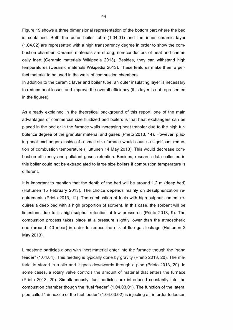
FIGURE 19. Boiler assembly 4
44
Figure 19 shows a three dimensional representation of the bottom part where the bed
is contained. Both the outer boiler tube (1.04.01) and the inner ceramic layer
(1.04.02) are represented with a high transparency degree in order to show the com-
bustion chamber. Ceramic materials are strong, non-conductors of heat and chemi-
cally inert (Ceramic materials Wikipedia 2013). Besides, they can withstand high
temperatures (Ceramic materials Wikipedia 2013). These features make them a per-
fect material to be used in the walls of combustion chambers.
In addition to the ceramic layer and boiler tube, an outer insulating layer is necessary
to reduce heat losses and improve the overall efficiency (this layer is not represented
in the figures).
As already explained in the theoretical background of this report, one of the main
advantages of commercial size fluidized bed boilers is that heat exchangers can be
placed in the bed or in the furnace walls increasing heat transfer due to the high tur-
bulence degree of the granular material and gases (Prieto 2013, 14). However, plac-
ing heat exchangers inside of a small size furnace would cause a significant reduc-
tion of combustion temperature (Huttunen 14 May 2013). This would decrease com-
bustion efficiency and pollutant gases retention. Besides, research data collected in
this boiler could not be extrapolated to large size boilers if combustion temperature is
different.
It is important to mention that the depth of the bed will be around 1.2 m (deep bed)
(Huttunen 15 February 2013). The choice depends mainly on desulphurization re-
quirements (Prieto 2013, 12). The combustion of fuels with high sulphur content re-
quires a deep bed with a high proportion of sorbent. In this case, the sorbent will be
limestone due to its high sulphur retention at low pressures (Prieto 2013, 9). The
combustion process takes place at a pressure slightly lower than the atmospheric
one (around -40 mbar) in order to reduce the risk of flue gas leakage (Huttunen 2
May 2013).
Limestone particles along with inert material enter into the furnace though the “sand
feeder” (1.04.04). This feeding is typically done by gravity (Prieto 2013, 20). The ma-
terial is stored in a silo and it goes downwards through a pipe (Prieto 2013, 20). In
some cases, a rotary valve controls the amount of material that enters the furnace
(Prieto 2013, 20). Simultaneously, fuel particles are introduced constantly into the
combustion chamber though the “fuel feeder” (1.04.03.01). The function of the lateral
pipe called “air nozzle of the fuel feeder” (1.04.03.02) is injecting air in order to loosen

45
the fuel particles, especially when their moisture content is high (Huttunen 13 April
2013).
The combustion process takes place both in the fluidized bed and in the stream of hot
gases and particles above the bed. Secondary air is injected in four different levels
along the boiler tube. This staged combustion increases the efficiency and sup-
presses efficiently the formation of nitrogen oxides (Basu 2006, 160).
The air nozzles are arranged around the boiler tube as can be seen in Figure 20. The
main purpose of this particular disposition is increasing the turbulence degree so as
to ensure a high fuel-air mixing. The air flow rotates spirally along the furnace and
reacts with unburned components that rise from the fluidized bed giving off a signifi-
cant amount of energy.
FIGURE 20. Secondary air injection
In commercial size boilers this phenomenon raises the temperature of the gases,
which is generally higher than the temperature of the bed. However, on account of
the high surface-to-volume ratio of this research boiler, the heat transfer through the
furnace walls is very high and therefore, the gas temperature would be lower than in

46
commercial size boilers. Obviously, the validity of the collected research data de-
pends on achieving similar combustion conditions as in commercial scale boilers. In
order to solve this serious problem, an additional system to control the gas tempera-
ture is being designed (see chapter 3.7.3). (Huttunen 14 May 2013.)
In addition to maintenance flanges (see figure 19) and feeders, there are other ele-
ments throughout the boiler tube whose purpose is collecting research and control
data:
-‐ Flue gas measurement flanges: Their function is analysing the exhaust gas
released in the combustion process and carrying out corrosion probes. These
flanges are located at three different levels in order to know the proportion of
pollutants and unburned components in different parts of the boiler. Thus,
these flanges along with the correspondent measurement devices will enable
the comparison of combustion efficiency and emissions with different operat-
ing conditions: fuels, air speeds, temperatures, sorbents, etc.
FIGURE 21. Flue gas measurement flanges

47
-‐ Pressure and temperature measurement pipes: They are located along the
entire boiler tube. Basically, they will enable the analysis of the fluid dynamic
and thermal behaviour of the installation. The density of these pipes is higher
in the bottom part of the furnace due to the particular importance of monitoring
the combustion conditions of the fluidized bed.
FIGURE 22. Pressure and temperature measurement pipes.
3.4.3 Exhaust gas tube
The exhaust gas tube has been divided into the following two assemblies (see figure
13) on account of its large size:
-‐ Flue gas tube (1.06)
-‐ Heat exchangers assembly (1.07)
The hot flue gases rise to the top of the furnace and go out through the “flue gas
tube”. Afterwards, they come into contact with the heat exchangers pipes in the “heat
exchangers assembly”.

48
The drawings of these elements can be seen in Appendix 2. The detailed view below
shows the top part of the “heat exchangers assembly”.
FIGURE 23. Detailed view of the “heat exchangers assembly” As can be seen in the figure, the frontal plate of the “tube for heat exchangers”
(1.07.01) is too thin to support the bolts of the cover. To avoid this problem, welded
bars have been added to the design.
Besides, three more covers have been placed along the exhaust gas tube. The func-
tion of these covers is to enable the assembly of heat exchangers inside the tube. In
the current design only two heat exchangers have been assembled below one of the
covers. These heat exchangers will be used to preheat the primary and secondary air
before it enters the combustion chamber. The function of the rest of the covers is to
enable a possible future assembly of the following devices:
- Superheater: superheats the saturated steam
- Economizer: preheats the water up to the boiling point
However, the budget for the construction of this laboratory is limited and therefore,
there is little prospect of buying these expensive heat exchangers, at least in the
short term (Huttunen 14 May 2013). Furthermore, an evaporator would be required to

49
produce steam resulting in, as already explained, technical problems to maintain the
suitable combustion temperature in the furnace (Huttunen 14 May 2013). It should
not be forgotten that this boiler will be used mainly for research purposes.
Once the flue gas leaves this tube it goes through fly ash cleaning devices (see chap-
ter 3.7.5) and enters an Organic Rankine Cycle (ORC) heat recovery boiler where
water is heated. The stream of hot gases leaves this device at a temperature of ap-
proximately 180 ºC. (Huttunen 14 May 2013.)
3.5 Standard components
Almost all the parts and assemblies that make up this unit can be manufactured from
the following standard components:
-‐ Flanges
-‐ Spades
-‐ Pipes
-‐ Bolts
-‐ Nuts
-‐ Muffs
-‐ Pipe reducers
-‐ Bellows
The tables in Appendix 1 show a complete list of all these components along with the
identification number of the drawing in which they are included.
3.6 Connecting elements and welds
Basically, there are two different connections between the structural elements of this
installation:
-‐ Permanent joints.
1) Gas tungsten arc welding, also known as tungsten inert gas (TIG).
2) Shielded metal arc welding
-‐ Detachable joints: bolts and nuts.

50
Furthermore, graphite sealing and ceramic material will be necessary in all the
flanges to reduce leakage risks.
All the connecting components and welds of the installation can be seen in the draw-
ings of Appendix 2.
3.7 Additional systems
The design process of this thesis has focused on the elements that have been ex-
plained in previous chapters. However, there are more systems that form part of this
installation.
Due to the large scale of this project, only the main features of the most important
systems are explained below.
3.7.1 Ignition system
The function of the ignition system is to raise the temperature of the bed and boiler so
as the initial ignition of the fuel is ensured. This is accomplished by two kinds of burn-
ers (Huttunen 14 May 2013):
-‐ An external wood pellets burner: the hot flue gases released in the pellets
combustion are injected into the windbox and, immediately afterwards, these
gases go upwards through the nozzles of the “sump” (1.05.03) entering the
furnace (Huttunen 14 May 2013).
-‐ Oil burners placed in different parts of the furnace and flue gas tube (Huttunen
2 May 2013).
These burners preheat the temperature of the bed and boiler to 500 ºC (sometimes
as high as 600 ºC) before solid fuel feeding sequence is started. The fuel and air
flows are increased gradually while, at the same time, the power of the burners is
reduced. (Huttunen 2 May 2013.)
Normally, the fuel feeding sequence is the following (the range of temperatures for
each fuel appears in brackets):

51
1) Wood pellets (500-700 ºC)
2) Wood chips (700-850ºC)
3) Waste fuels (once the operating conditions are reached)
(Huttunen 2 May 2013.)
3.7.2 Bed drainage system
The greater part of the ash produced in the combustion process (bottom ash) goes
downwards through the “sump” (1.05.03) and the “sand and ash removal flange”
(1.05.04) as can be seen in Figure 15. This process is called bed material drainage.
This extraction has to be regulated to ensure that the weight of the bed remains ap-
proximately constant.
In addition to these components, the bed drainage system includes:
-‐ Extraction tube
-‐ Cooling system to reduce the ash temperature
-‐ Rotary valve
-‐ Cooled screw feeder
-‐ Screen
-‐ Ash tray
(Huttunen 14 May 2013.)
3.7.3 Temperature control system
Research data collected in this boiler cannot be extrapolated to large size boilers if
combustion temperature is different. Due to the high surface-to-volume ratio of this
research boiler, the heat transfer through the furnace walls is very high and, there-
fore, a supplementary heating system is necessary in order to operate at suitable
temperature conditions along the entire boiler tube. Besides, when wastes are burned
it is necessary to reach a temperature of 1100 ºC in the flue gas tube for at least two
seconds in order to comply with environmental regulations. (Huttunen 14 May 2013;
Marín, Monné. & Uche 2007, 32)

52
This is achieved by the same burners used during the ignition process (see 3.7.1):
-‐ An external wood pellets burner
-‐ Oil burners placed in different parts of the furnace and flue gas tube
(Huttunen 14 May 2013.)
The only difference is that the hot flue gases released in the pellets combustion are
not injected into the windbox. This time those gases go through spiral pipes placed in
the ceramic layers of the furnace. Thus, heat is exchanged directly with the boiler
tube without injecting flue gases into the furnace. Those pipes can also be used as a
cooling system when the combustion conditions require it. (Huttunen 14 May 2013.)
3.7.4 Ammonia injection system
Ammonia (NH3) injection into the upper part of the furnace is a method to suppress
efficiently the formation of nitrogen oxides. Normally, one part of this component is
mixed with three parts of water. The injection of this aqueous solution in the flue gas
causes chemical reactions that convert the nitrogen oxides to free nitrogen and
water. (Huttunen 2 May 2013.)
3.7.5 Flue gas cleaning system
The fly ash that leaves the furnace through the flue gas tube is collected in a very
high proportion with the flue gas cleaning system, which is installed downstream after
the boiler. Basically, this system consists of the following components:
-‐ Ceramic bag filters
-‐ Flue gas scrubber
-‐ Cyclon
-‐ Electrostatic precipitator
(Huttunen 14 May 2013.)

53
4 CONCLUSIONS
The objective set in the beginning of this thesis, carrying out an optimal design in
technical, environmental and economical terms of a small size BFB boiler, has been
fully achieved. The design process has focused on adapting the reference design
provided by Lappeenranta University of Technology to be used for research purposes
and bringing construction and operating costs down. As a consequence of this proc-
ess, almost all the components of the reference model have been entirely or partially
modified. The result is an efficient and environmentally friendly boiler that is going to
enable numerous testing services and lines of research.
Furthermore, active participation in the design of other systems that form part of this
combustion facility has been crucial to ensure an optimum connection between all
components and a better understanding of the general installation. In this regard, the
lecturer Jukka Huttunen has played an essential role in the coordination of the teams
involved in the design process.
This thesis is without doubt an important step towards the construction of the future
combustion research laboratory of Varkaus Campus and I am extremely proud of
having contributed to such an important project.

54
SOURCE MATERIAL
Álvarez, J. & Calvo, M. 2011. Prácticas de Expresión Gráfica, Industriales.
Zaragoza: School of Engineering and Architecture. University of Zaragoza. Class
material for the subject “Expresión gráfica y diseño asistido por ordenador”. Mechani-
cal Engineering.
Calvo Lalanza, M. 2009. Dibujo Industrial. Normalización. Zaragoza: School of Engi-
neering and Architecture. University of Zaragoza.
Hexagon head bolts. Product grade C. SFS-EN ISO 4016.
Hexagon head screws. Product grade C. ISO/FDIS 4018:2010(E)
Hexagon nuts, style 1. Product grades A and B. SFS-EN ISO 4032.
Pipe class E10C1A for pressure purposes. Welded non-alloy steel pipe for elevated
temperatures. PSK 4202 E10C1A.
Pipe class E10C1B for pressure purposes. Seamless non-alloy steel pipe for ele-
vated temperatures. PSK 4203 E10C1B.
Solidworks Student Engineering Kit (2012-2013)
Suomen Haponkestävät SH-Trade Oy. R-183 Kauluslaippa EN 1092-1/11. [Read:
29.11.2012]. Available: http://www.sh-trade.fi/flanges
Ubieto, P. 2011. Conjuntos y Despieces. Zaragoza: School of Engineering and Archi-
tecture. University of Zaragoza. Class material for the subject “Dibujo II”. Mechanical
Engineering.
55
REFERENCES
Air pollution. Wikipedia [Read:18.4.2013]. Available:
http://en.wikipedia.org/wiki/Air_pollution
Auria Apilluelo, J.M., Ibáñez Carabantes, P. & Ubieto Artur, P. 2000. Dibujo Industrial
Conjuntos y Despieces. Madrid: International Thomson Editores Spain.
Basu, P. 2006. Combustion and Gasification in Fluidized Beds. USA: Taylor & Fran-
cis
Ceramic materials. Wikipedia [Read: 17.05.2013]. Available:
https://en.wikipedia.org/wiki/Ceramic_materials
Cost of electricity by source. Wikipedia [Read:18.4.2013]. Available:
http://en.wikipedia.org/wiki/Cost_of_electricity_by_source
Clean Air Task Force (CATF). Dirty air, dirty power: mortality and health damage due
to air pollution from power plants. 2004. [Read: 6.05.2013]. Available:
http://www.catf.us/resources/publications/view/24
Energy Tech. Power Plant Emissions Controls NOx Reduction Technologies & Sys-
tems. 2003 [Read: 5.5.2013]. Available: http://www.energy-
tech.com/article.cfm?id=17582
Fluidization. Wikipedia [Read:28.4.2013]. Available:
http://en.wikipedia.org/wiki/Fluidization
Fluidized bed combustion. Wikipedia Read: 21.04.2013]. Available:
http://en.wikipedia.org/wiki/Fluidized_bed_combustion
Fossil-fuel power station. Wikipedia [Read:16.4.2013]. Available:
http://en.wikipedia.org/wiki/Fossil_fuel_power_plant
Hämäläinen, V. 2012. Heat Utilization and Consumption in Research Laboratory
Building. Varkaus: Savonia University of Applied Sciences. Industrial Management. A
Thesis.

56
Honkanen, J. 2012. Energy Technology. Varkaus: Savonia University of Applies Sci-
ences. Class material for the subject Energy Technology. Industrial Management.
International Energy Agency. Key World Energy Statistics, 2012. [Read:15.4.2013].
Available: http://www.iea.org/publications/freepublications/publication/kwes.pdf
Jäntti, T., Nuortimo, K., Ruuskanen, M. & Kalenius, J. 2012. Samcheok Green Power
4 x 550 MWe, Supercritical Circulating Fluidized‐Bed, Steam Generators in South
Korea. Colon: PowerGen Europe. Presentation by Foster Wheeler Global Power
Group. [Read: 22.04.2013]. Available:
http://www.fwc.com/publications/tech_papers/files/TP_CFB_12_07.pdf
Marín, J.M., Monné, C. & Uche, J. 2007. Transferencia de Calor. Zaragoza: Kronos
National Land Survey of Finland. Finnish Ministry of Agriculture and Forestry [Read:
25.4.2013]. Available: http://www.maanmittauslaitos.fi
Pascual Peña, J.A. 2011. Bubbling fluidized bed (BFB), when to use this technology?
Johannesburg: Industrial Fluidization South Africa (IFSA). Presentation by Foster
Wheeler Global Power Group. [Read: 22.04.2013]. Available:
http://www.fwc.com/publications/tech_papers/files/TP_BFB_11_01.pdf
Prieto Fernandez, I. 2013. Fluidized bed combustion systems. Oviedo: University of
Oviedo. Class material for the subject “Centrales Térmicas”
Renewable energy commercialization. Wikipedia [Read:16.4.2013]. Available:
http://en.wikipedia.org/wiki/Renewable_energy_commercialization
Sistemas de Generación Eléctrica. 2012. Zaragoza: School of Engineering and Archi-
tecture. University of Zaragoza. Class material for the subject “Sistemas de Gen-
eración de Electricidad”. Electrical Engineering.
Teir, S. 2003. Steam Boiler Technology. 2nd Edition. Helsinki: Picaset

57
U.S. Energy Information Administration. International Energy Outlook, 2011.
[Read:15.4.2013]. Available: http://www.eia.gov/forecasts/ieo/world.cfm
U. S. Environmental Protection Agency (EPA). Effects of acid rain 2012 [Read:
5.5.2013]. Available: http://www.epa.gov/acidrain/effects/
World Coal Association. Coal & Electricity [Read: 22.4.2013]. Available:
http://www.worldcoal.org/coal/uses-of-coal/coal-electricity/