Embed Size (px)
Citation preview
HAL Id: hal-01684548https://hal.archives-ouvertes.fr/hal-01684548
Submitted on 11 Mar 2019
HAL is a multi-disciplinary open accessarchive for the deposit and dissemination of sci-entific research documents, whether they are pub-lished or not. The documents may come fromteaching and research institutions in France orabroad, or from public or private research centers.
L’archive ouverte pluridisciplinaire HAL, estdestinée au dépôt et à la diffusion de documentsscientifiques de niveau recherche, publiés ou non,émanant des établissements d’enseignement et derecherche français ou étrangers, des laboratoirespublics ou privés.
Biofidelic Abdominal Aorta Phantom: Cross-OverPreliminary Study Using UltraSound and Digital Image
Stereo-CorrelationVincent Perrot, Selina Meier, A. Bel-Brunon, Hélène Walter-Le Berre,
Benyebka Bou-Saïd, Philippe Chaudet, Valérie Detti, D. Vray, H. Liebgott
To cite this version:Vincent Perrot, Selina Meier, A. Bel-Brunon, Hélène Walter-Le Berre, Benyebka Bou-Saïd, et al..Biofidelic Abdominal Aorta Phantom: Cross-Over Preliminary Study Using UltraSound and DigitalImage Stereo-Correlation. Innovation and Research in BioMedical engineering, Elsevier Masson, 2017,38 (4), pp.238-244. �10.1016/j.irbm.2017.07.002�. �hal-01684548�
Biofidelic abdominal aorta phantom: cross-over preliminary study using
UltraSound and Digital Image Stereo-Correlation
Vincent Perrota, Selina Meierb, Aline Bel-Brunonb, Helene Walter-Le Berreb, Benyebka Bou-Saıdb, Philippe
Chaudetb, Valerie Dettia, Didier Vraya, Herve Liebgotta
aUniv. Lyon, INSA-Lyon, Univ. Claude Bernard Lyon 1, UJM-Saint-Etienne, CNRS, Inserm, CREATIS UMR 5220, U1206, F-69621, Lyon, FrancebUniv. Lyon, INSA-Lyon, LaMCoS UMR CNRS 5259, F-69621, Villeurbanne, France
Abstract
Purpose: EndoVascular Aneurysm Repair (EVAR) can be indicated to prevent Abdominal Aortic Aneurysm (AAA)
breaking. However, several complications may occur during and after surgery, such as endoleaks or migration. The
aim of this work is to develop and validate an experimental set-up designed to reproduce the comportment of an ab-
dominal aorta with aneurysm. Consequently, this paper presents the proof of concept of the experimental set-up.
Materiel and methods: We have developed an experimental set-up based on a patient-specific aorta phantom with
an aneurysm. Physiological conditions that are influent for EVAR (blood flow and mechanical support) are applied.
The set-up combines UltraSound (US) and Digital Image Stereo-Correlation (DISC) measurements to evaluate the
vascular structure motion due to blood flow and EVAR.
Results: Preliminary results show that our experimental set-up allows measuring local surface deformations on the
phantom using DISC as well as motions in the vessel wall thickness using US without surgical material. The mea-
surements from the two techniques are consistent with the applied pressure, realistic and complementary.
Conclusion: The set-up and methods in this paper are validated and our proof of concept is established. Futur work
will focus on the simultaneous use of the two measurement tools (US and DISC) and the introduction of stent-grafts
inside the phantom during pulsed cycles. Such measurements of local deformations and motions will help understand-
ing possible complications of EVAR.
Keywords: Biofidelic, phantom, AAA, EVAR, UltraSound, Digital Image Stereo-Correlation, biomechanical,
biomedical.
1. Introduction
EndoVascular Aneurysm Repair (EVAR) is a minimally-invasive technique that is commonly used to treat Abdom-
inal Aortic Aneurysms (AAA). It relies on the exclusion of the aneurysm sac by introducing one or more stent-grafts
through the femoral arteries and deploying them inside the aneurysm. During the procedure, several tools of varying
stiffness are introduced to enable the delivery of the stent graft to its deployment site, in particular by straightening
the often tortuous iliac arteries. During this process, the vascular structure undergoes major deformations [1]. It has
been shown [2] that these deformations are mainly regulated by the mechanical support provided by the connections
Preprint submitted to IRBM July 18, 2017
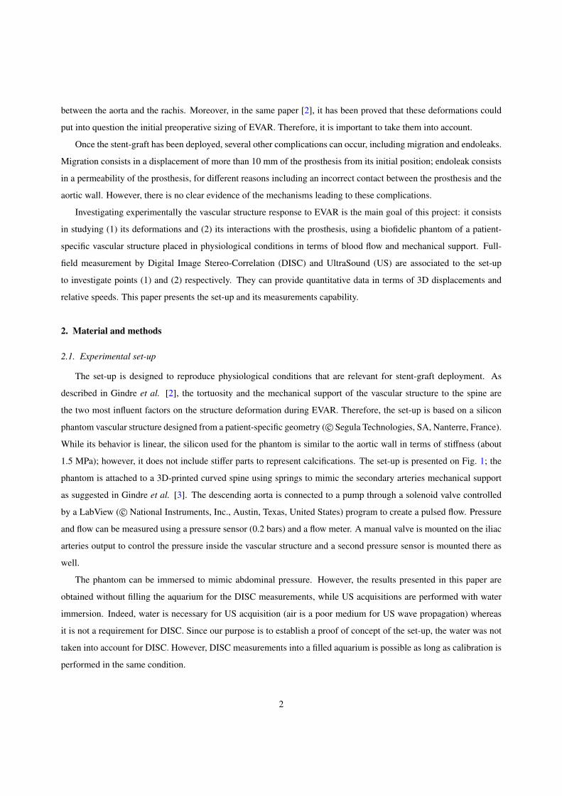
between the aorta and the rachis. Moreover, in the same paper [2], it has been proved that these deformations could
put into question the initial preoperative sizing of EVAR. Therefore, it is important to take them into account.
Once the stent-graft has been deployed, several other complications can occur, including migration and endoleaks.
Migration consists in a displacement of more than 10 mm of the prosthesis from its initial position; endoleak consists
in a permeability of the prosthesis, for different reasons including an incorrect contact between the prosthesis and the
aortic wall. However, there is no clear evidence of the mechanisms leading to these complications.
Investigating experimentally the vascular structure response to EVAR is the main goal of this project: it consists
in studying (1) its deformations and (2) its interactions with the prosthesis, using a biofidelic phantom of a patient-
specific vascular structure placed in physiological conditions in terms of blood flow and mechanical support. Full-
field measurement by Digital Image Stereo-Correlation (DISC) and UltraSound (US) are associated to the set-up
to investigate points (1) and (2) respectively. They can provide quantitative data in terms of 3D displacements and
relative speeds. This paper presents the set-up and its measurements capability.
2. Material and methods
2.1. Experimental set-up
The set-up is designed to reproduce physiological conditions that are relevant for stent-graft deployment. As
described in Gindre et al. [2], the tortuosity and the mechanical support of the vascular structure to the spine are
the two most influent factors on the structure deformation during EVAR. Therefore, the set-up is based on a silicon
phantom vascular structure designed from a patient-specific geometry ( c© Segula Technologies, SA, Nanterre, France).
While its behavior is linear, the silicon used for the phantom is similar to the aortic wall in terms of stiffness (about
1.5 MPa); however, it does not include stiffer parts to represent calcifications. The set-up is presented on Fig. 1; the
phantom is attached to a 3D-printed curved spine using springs to mimic the secondary arteries mechanical support
as suggested in Gindre et al. [3]. The descending aorta is connected to a pump through a solenoid valve controlled
by a LabView ( c© National Instruments, Inc., Austin, Texas, United States) program to create a pulsed flow. Pressure
and flow can be measured using a pressure sensor (0.2 bars) and a flow meter. A manual valve is mounted on the iliac
arteries output to control the pressure inside the vascular structure and a second pressure sensor is mounted there as
well.
The phantom can be immersed to mimic abdominal pressure. However, the results presented in this paper are
obtained without filling the aquarium for the DISC measurements, while US acquisitions are performed with water
immersion. Indeed, water is necessary for US acquisition (air is a poor medium for US wave propagation) whereas
it is not a requirement for DISC. Since our purpose is to establish a proof of concept of the set-up, the water was not
taken into account for DISC. However, DISC measurements into a filled aquarium is possible as long as calibration is
performed in the same condition.
2

2.2. Ultrasound
During this study an US research scanner, named Ula-Op (Ultrasound Advanced Open Platform) [4] is used, which
allows to program personalized US sequences through a MATLAB interface ( c© MATLAB, The MathWorks, Inc.,
Natick, Massachusetts, United States). A 1D linear US probe (LA 523, c© Esaote, Inc., Florence, Italy), composed of
192 elements for a total width of view of 47.04 mm corresponding to a pitch of 0.245 mm, is also used. An example
of the ultrasound images obtained with the scanner is shown on Fig. 2.
A particular US sequence was implemented on this scanner to acquire at high frame rate images of the wall
motion of the phantom along time. With the chosen sequence, high framerate imaging is reached, up to 5 000 images
per second during two seconds (resulting to 10 000 saved images) to appreciate each subtle displacement of the vessel
wall. In order to achieve this framerate, a plane wave sequence is implemented. In plane wave imaging, all elements
of the probe are excited simultaneously in order to produce a wave front close to a plane wave [5]. For our specific
mode, 64 elements located at the center of the probe and corresponding to a total width of 15.68 mm are successively
activated in emission and reception. The probe ultrasound frequency was 9.4 MHz and signal was sampled at 50 MHz
(scanner clock). One line per element was beamformed, the resulting pixel resolution is 0.0141×0.245 [mm2] in axial
and lateral directions, respectively.
The received single element raw US signals (RF images) are collected after each plane wave transmission/reception.
Afterwards, RF images are migrated/beamformed to obtain images [6]. Motion is estimated on the migrated images.
Our motion estimator is based on a 2D phase shift measurement between two successive images (Eq. 1) [7, 8]. How-
ever, with US, only a natural oscillation along the propagation axis is present. Therefore a virtual lateral oscillation is
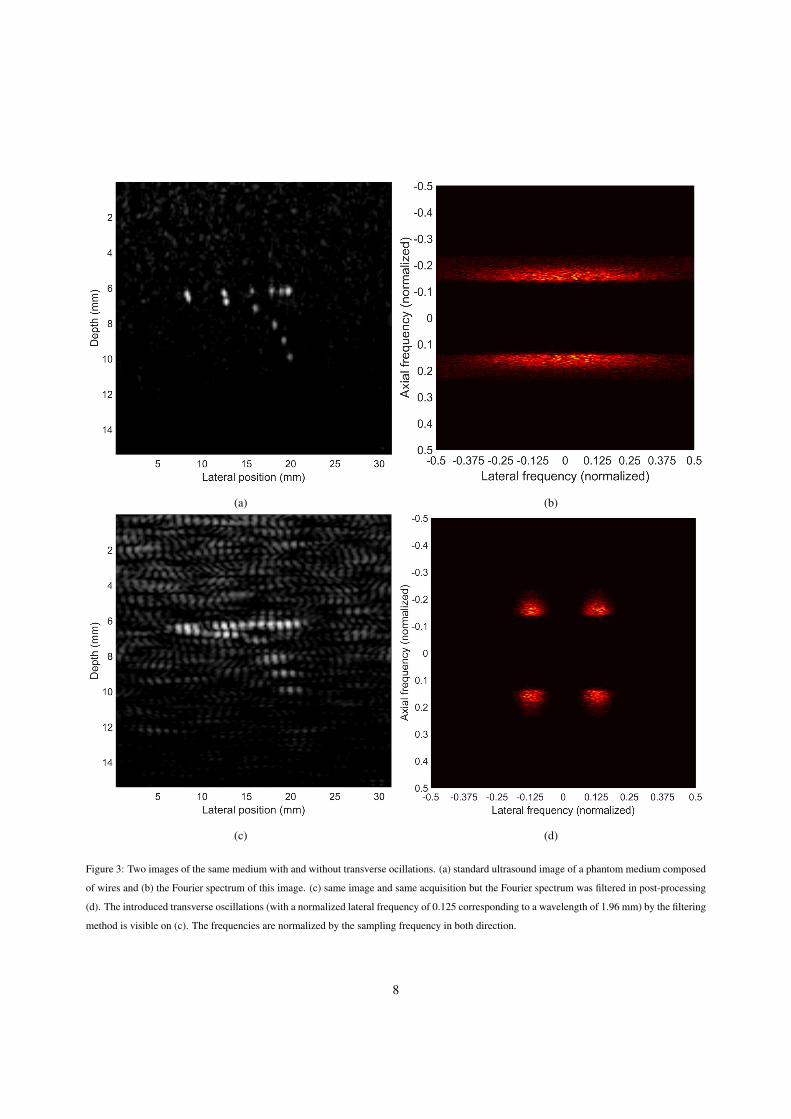
introduced in the Fourier domain to extract 2D phases from the images [9]. To this end, the Fourier spectrum of each
image is multiplied with a specific mask to only keep the desired wavelength (Fig. 3).
dz =∆Φz
4π fz
dx =∆Φx
4π fx
(1)
Where z and x are the subscripts for the axial (along the ultrasound beam) and the lateral (perpendicular to the
ultrasound beam) axis, respectively. d is the estimated displacement for each image. ∆Φ corresponds to the phase
change between two successive frames. f is the ultrasound frequency.
2.3. Digital Image Stereo-Correlation
To perform full-field strain measurement on the phantom surface, two digital cameras ( c© Limess 4 MPx, Limess,
Krefeld, Germany) are used, they are mounted on a rail that allows their displacement along the longitudinal axis
of the phantom. They form a 24 ◦ angle with each other and are equipped with 16 mm lenses. The adjustment of
aperture and exposure time, associated to powerful lightening, allows obtaining (1) the appropriate depth of field,
as iliac arteries are particularly tortuous in this patient case and (2) sharp images of the vascular structure along its
3

deformation. Once all the settings are done, calibration is performed so that the correlation software ( c© Vic 3D,
Correlated Solutions, Inc., Irmo, South California, United States) can calculate the cameras relative position (3 angles
and 3 distances, as well as optical parameters of each camera). A random pattern is applied on the phantom with white
and black paint in order to compute the correlation (Fig. 4). DISC is performed at several intermediate states captured
at 5 Hz.
3. Results
3.1. US measurements
Fig. 5 shows the results of motion estimation from the longitudinal section for the central point of the upper artery
wall. The solenoid valve is opened at the initial time (t = 0 s) and the influence of the flow on the wall displacement
can be seen. Axial and longitudinal displacements reach a maximum value around 1 mm and 0.6 mm respectively
after 0.8 seconds and decrease once the pulse shock is passed. After analysis of the displacement along the entire
upper wall, the motion is global and no pulse wave is visible with the current system.
3.2. DISC measurements
The phantom aorta is subject to inner pressure only for DISC measurements. Fig.6 displays a result of DISC in
terms of Lagrange first principal strain (e1) at maximal pressure. The descending aorta experiences larger deforma-
tions than the iliac arteries, 5 times less in average and in terms of Lagrange first principal strain. Besides, these
deformations are rather heterogeneous due to the complex geometry of the vascular structure. DISC emphasizes local
phenomena, which is relevant to investigate the interaction between the prosthesis and the vascular structure when
prosthesis will be deployed. The overall circumferential expansion due to fluid pressure corresponds to the range of
deformation observed in-vivo.
To evaluate the reliability of these measured displacements, we can plot the error field. Fig. 7 displays an example
of error distribution on the descending aorta in the deformed configuration. This error is the combination of noise and
correlation error. Noise error is due to camera sensors, light, etc, and can be evaluated by performing DISC on several
images of the undeformed configuration. It reaches 0.048 mm for our set-up configuration. Correlation error is due
to the correlation algorithm and related to the quality of the images and the random pattern. The total error locally
reaches 0.35 mm in the maximum pressure configuration, but in average it is close to 0.2 mm. The error results are
similar all along the phantom and satisfactory as we expect a circumferential dilatation of 5 mm in the descending
aorta, while the iliac arteries will mainly experience large bending deformations due to EVAR tools.
4. Discussion
The set-up developed in this work aims to provide experimental data concerning the interaction between vascular
structure and stent-graft in the descending aorta. Several features have been taken into account to ensure the biofidelity
4
of the set-up for EVAR applications, such as patient-specific geometry, mechanical support and inner pressure. These
features are known to have the largest influence on EVAR procedure.
From our preliminary results we have demonstrated that it is possible from ultrasound high frame rate imaging
to acquire and estimate motion of the phantom wall during flow cycles. In fact, thanks to the phase estimator, wall
motion can be seen in correspondence with flow cycles. Moreover, this method has a very high temporal (5 000 images
per second) and spatial (0.0154 mm per 0.245 mm) resolution. One limitation to study the motion of the complete
phantom is the rather short length of the probe itself which reduces the field of view.
DISC has a larger field of view and successfully estimates 3D surface displacements anywhere on the upper
surface of the phantom. The obtained accuracy is satisfactory and sufficient for the phenomena we aim to observe (for
instance the influence of the stent-graft oversizing). However, DISC measurement has been performed without outer
pressure while US method has been achieved with outer pressure.
Finally, the two methods are complementary because they allow measuring data at different time and space scales.
Consequently, both methods will be essential for our future works to study the phantom comportment during EVAR
and then during cardiac cycles. Later with stent-grafts, analysis of the 2D motion of the artery wall will be useful to
understand the influence of the prosthesis on the wall across heart pulsed cycles.
However, several improvements can be made. Firstly, a simultaneous use of the tools with inner and outer pres-
sures is the main priority. For this purpose, calibration of the cameras will be achieved with water immersion which
mimic abdominal pressure. Furthermore, we expect to have a larger field of view with US using a different sequence
(diverging wave or the use of a convex arrays are two solutions) and we also project to increase the framerate of our
cameras. The most important future work is the deployment of stent-grafts inside the abdominal aorta phantom. For
this project both imaging methods will be used and other parameters can be added like flow-rate and pressures at the
inlet and outlets of the phantom. All those parameters will be taken into account for a mechanical validation and to
extract markers to quantify migration and endoleak processes.
5. Conclusion
In this paper, an experimental set-up of an abdominal aorta that allows mimicking the behaviour of a real aneurysm
aorta with stent-graft during cardiac cycles has been described. Finally, the validity of the set-up and of measurement
methods (US and DISC) has been demonstrated.
The next step will be to collect more information about the interaction between aorta and stent-graft with the
simultaneous use of the two methods (US and DISC) and to implement objective parameters into EVAR per- and post-
surgery simulations to predict and prevent endoleaks or migrations of stent-graft after surgery. Using displacements,
pressures and flow measurements extracted from this set-up, we will evaluate if and which quantitative markers can
be proposed to predict and prevent the above-mentioned complications.
5
(a)
(b)
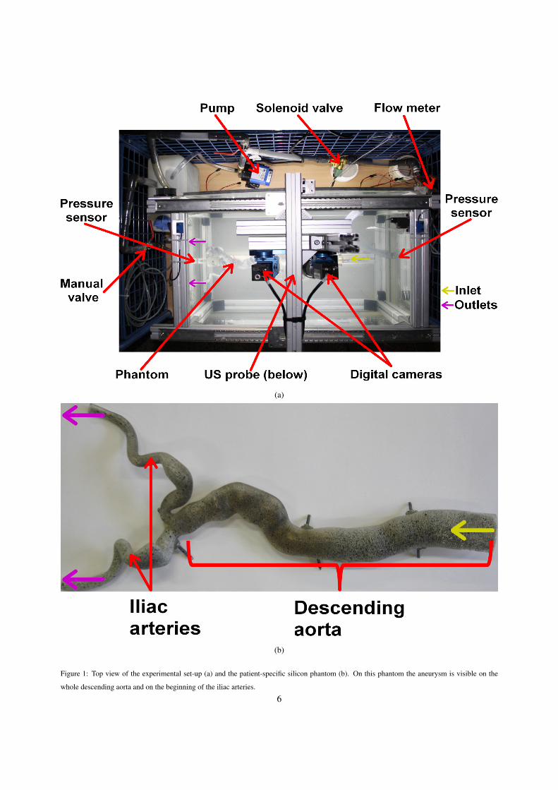
Figure 1: Top view of the experimental set-up (a) and the patient-specific silicon phantom (b). On this phantom the aneurysm is visible on the
whole descending aorta and on the beginning of the iliac arteries.
6

(a) (b)
Figure 2: Two images of the phantom without flow circulation obtained with the Ula-Op scanner; (1) and (2) correspond to the lumen and the walls
respectively and (3) is the central axis for motion estimation. Axial section (a) (perpendicular to the phantom wall) and longitudinal section (b)
(parallel to the phantom wall) highlight echoes from the interfaces (walls). It is clearly visible that it is not a regular medium as forecasted
7
(a) (b)
(c) (d)
Figure 3: Two images of the same medium with and without transverse ocillations. (a) standard ultrasound image of a phantom medium composed
of wires and (b) the Fourier spectrum of this image. (c) same image and same acquisition but the Fourier spectrum was filtered in post-processing
(d). The introduced transverse oscillations (with a normalized lateral frequency of 0.125 corresponding to a wavelength of 1.96 mm) by the filtering
method is visible on (c). The frequencies are normalized by the sampling frequency in both direction.
8

Figure 4: Close-up view of the descending aorta phantom covered with the black and white random pattern
Figure 5: Axial (red) and longitudinal (blue) motions extracted from longitudinal ultrasound data after a sudden opening of the solenoid valve
driving a pulsed flow inside the phantom.
9

Figure 6: First principal strain distribution on the vascular phantom on the maximally deformed configuration.
10

Figure 7: Error distribution on the maximally deformed configuration (in px)
11
Acknowledgements
This work has been supported thanks to a BQR-INSA (Bonus Qualite Recherche) grant and has been performed
within the framework of the LABEX CELYA (ANR-10-LABX-0060) and LABEX PRIMES (ANR-10-LABX-0063)
of Universite de Lyon, within the program ”Investissements d’Avenir” (ANR-11-IDEX-0007) operated by the French
National Research Agency (ANR).
References
[1] G. Mouktadiri, B. Bou-Saıd, H. Walter-Le-Berre, Aortic endovascular repair modeling using the finite element method, Journal of Biomedical
Science and Engineering 06 (09) (2013) 917–927.
[2] J. Gindre, A. Bel-Brunon, M. Rochette, A. Lucas, A. Kaladji, P. Haigron, A. Combescure, Patient-specific finite element simulation of the
insertion of guidewire during an EVAR procedure: Guidewire position prediction validation on 28 cases, IEEE Transactions on Biomedical
Engineering (2016) 1–1.
[3] J. Gindre, A. Bel-Brunon, A. Kaladji, A. Dumenil, M. Rochette, A. Lucas, P. Haigron, A. Combescure, Finite element simulation of the
insertion of guidewires during an EVAR procedure: example of a complex patient case, a first step toward patient-specific parameterized
models, International Journal for Numerical Methods in Biomedical Engineering 31 (7) (2015) e02716.
[4] P. Tortoli, L. Bassi, E. Boni, A. Dallai, F. Guidi, S. Ricci, ULA-OP: an advanced open platform for ultrasound research, IEEE Transactions on
Ultrasonics, Ferroelectrics and Frequency Control 56 (10) (2009) 2207–2216.
[5] J. Bercoff, Ultrafast ultrasound imaging, in: Ultrasound Imaging - Medical Applications, InTech, 2011.
[6] D. Garcia, L. L. Tarnec, S. Muth, E. Montagnon, J. Poree, G. Cloutier, Stolt’s f-k migration for plane wave ultrasound imaging, IEEE
Transactions on Ultrasonics, Ferroelectrics, and Frequency Control 60 (9) (2013) 1853–1867.
[7] J. Jensen, P. Munk, A new method for estimation of velocity vectors, IEEE Transactions on Ultrasonics, Ferroelectrics and Frequency Control
45 (3) (1998) 837–851.
[8] A. Basarab, H. Liebgott, P. Delachartre, Analytic estimation of subsample spatial shift using the phases of multidimensional analytic signals,
IEEE Transactions on Image Processing 18 (2) (2009) 440–447.
[9] S. Salles, D. Garcia, B. Bou-Said, F. Savary, A. Serusclat, D. Vray, H. Liebgott, Plane wave transverse oscillation (PWTO): An ultra-fast
transverse oscillation imaging mode performed in the fourier domain for 2d motion estimation of the carotid artery, in: 2014 IEEE 11th
International Symposium on Biomedical Imaging (ISBI), Institute of Electrical and Electronics Engineers (IEEE), 2014.
12


![933 dji phantom-4 spec-sheet-rev[1] - PLASTICASE · 2019. 10. 23. · 933 DJI™ PHANTOM 4 For all DJI™ Phantom 4 models Phantom 4 Phantom 4 Pro Phantom 4 Pro + 2.0 Phantom 4 RTK](https://img.pdfslide.us/doc/110x75/60c827405a7e465133218fc4/933-dji-phantom-4-spec-sheet-rev1-plasticase-2019-10-23-933-djia-phantom.jpg)