Embed Size (px)
Citation preview

BigLog Air/Fuel Ratio Meter
User Instruction Manual
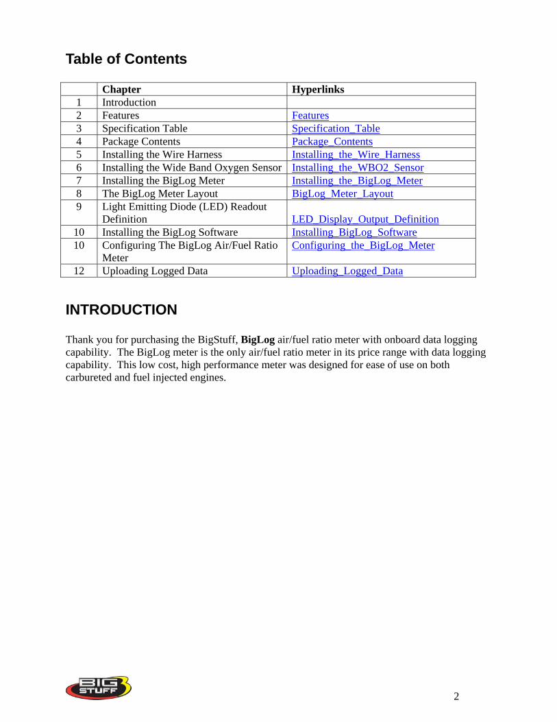
Table of Contents
Chapter Hyperlinks 1 Introduction 2 Features Features3 Specification Table Specification_Table4 Package Contents Package_Contents5 Installing the Wire Harness Installing_the_Wire_Harness6 Installing the Wide Band Oxygen Sensor Installing_the_WBO2_Sensor7 Installing the BigLog Meter Installing_the_BigLog_Meter8 The BigLog Meter Layout BigLog_Meter_Layout9 Light Emitting Diode (LED) Readout
Definition LED_Display_Output_Definition10 Installing the BigLog Software Installing_BigLog_Software10 Configuring The BigLog Air/Fuel Ratio
Meter Configuring_the_BigLog_Meter
12 Uploading Logged Data Uploading_Logged_Data
INTRODUCTION Thank you for purchasing the BigStuff, BigLog air/fuel ratio meter with onboard data logging capability. The BigLog meter is the only air/fuel ratio meter in its price range with data logging capability. This low cost, high performance meter was designed for ease of use on both carbureted and fuel injected engines.
2
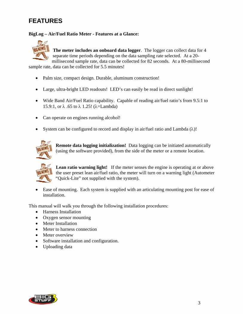
FEATURES BigLog – Air/Fuel Ratio Meter - Features at a Glance:
The meter includes an onboard data logger. The logger can collect data for 4 separate time periods depending on the data sampling rate selected. At a 20-millisecond sample rate, data can be collected for 82 seconds. At a 80-millisecond
sample rate, data can be collected for 5.5 minutes!
• Palm size, compact design. Durable, aluminum construction!
• Large, ultra-bright LED readouts! LED’s can easily be read in direct sunlight!
• Wide Band Air/Fuel Ratio capability. Capable of reading air/fuel ratio’s from 9.5:1 to 15.9:1, or λ .65 to λ 1.25! (λ=Lambda)
• Can operate on engines running alcohol!
• System can be configured to record and display in air/fuel ratio and Lambda (λ)!
Remote data logging initialization! Data logging can be initiated automatically (using the software provided), from the side of the meter or a remote location.
Lean ratio warning light! If the meter senses the engine is operating at or above the user preset lean air/fuel ratio, the meter will turn on a warning light (Autometer “Quick-Lite” not supplied with the system).
• Ease of mounting. Each system is supplied with an articulating mounting post for ease of
installation. This manual will walk you through the following installation procedures:
• Harness Installation • Oxygen sensor mounting • Meter Installation • Meter to harness connection • Meter overview • Software installation and configuration. • Uploading data
3
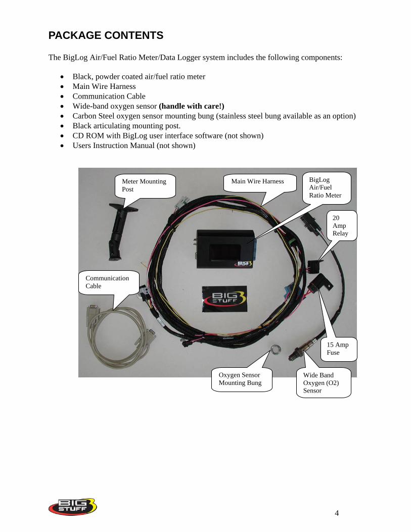
PACKAGE CONTENTS The BigLog Air/Fuel Ratio Meter/Data Logger system includes the following components:
• Black, powder coated air/fuel ratio meter • Main Wire Harness • Communication Cable • Wide-band oxygen sensor (handle with care!) • Carbon Steel oxygen sensor mounting bung (stainless steel bung available as an option) • Black articulating mounting post. • CD ROM with BigLog user interface software (not shown) • Users Instruction Manual (not shown)
20 Amp Relay
Oxygen Sensor Mounting Bung
15 Amp Fuse
Wide Band Oxygen (O2) Sensor
Main Wire Harness
Communication Cable
Meter Mounting Post
BigLog Air/Fuel Ratio Meter
4
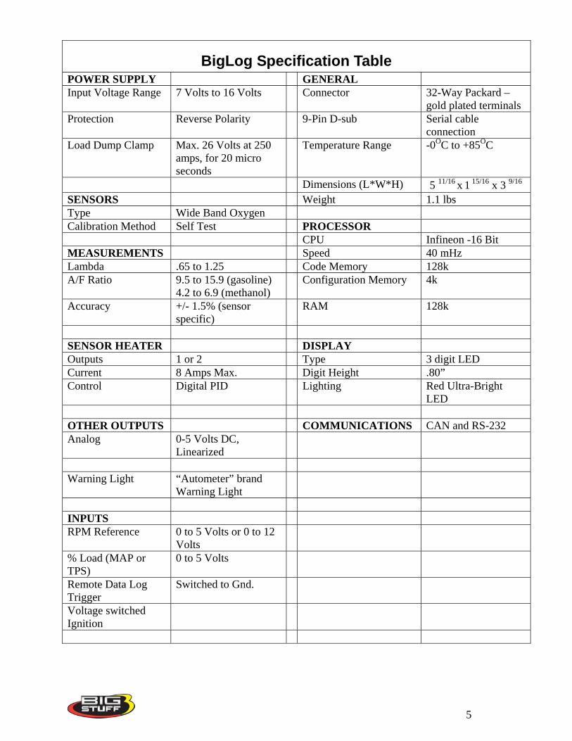
BigLog Specification Table POWER SUPPLY GENERAL Input Voltage Range 7 Volts to 16 Volts Connector 32-Way Packard –
gold plated terminals Protection Reverse Polarity 9-Pin D-sub Serial cable
connection Load Dump Clamp Max. 26 Volts at 250
amps, for 20 micro seconds
Temperature Range -0OC to +85OC
Dimensions (L*W*H) 5 11/16 x 1 15/16 x 3 9/16
SENSORS Weight 1.1 lbs Type Wide Band Oxygen Calibration Method Self Test PROCESSOR CPU Infineon -16 Bit MEASUREMENTS Speed 40 mHz Lambda .65 to 1.25 Code Memory 128k A/F Ratio 9.5 to 15.9 (gasoline)
4.2 to 6.9 (methanol) Configuration Memory 4k
Accuracy +/- 1.5% (sensor specific)
RAM 128k
SENSOR HEATER DISPLAY Outputs 1 or 2 Type 3 digit LED Current 8 Amps Max. Digit Height .80” Control Digital PID Lighting Red Ultra-Bright
LED OTHER OUTPUTS COMMUNICATIONS CAN and RS-232 Analog 0-5 Volts DC,
Linearized
Warning Light “Autometer” brand
Warning Light
INPUTS RPM Reference 0 to 5 Volts or 0 to 12
Volts
% Load (MAP or TPS)
0 to 5 Volts
Remote Data Log Trigger
Switched to Gnd.
Voltage switched Ignition
5
Installing the BigLog Air/Fuel Ratio Wire Harness To improve the overall installation process, the wire harness was manufactured with identification labels at the end of each wire or connector to ensure that connections are terminated correctly. Refer to the quick reference table below for further information.
Harness Label Wire Color / Connector Type Label Definition Connect To Further Details
No label Blue 32-way Header Connector with gold plated terminals.
The A/F Meter. This is the main connection between the A/F Meter and the wire harness
Wide Band O2 (DS)
Black 6-Way Rectangular shaped, connector with gold plated terminals.
Wide Band Oxygen Sensor Drivers Side (DS)
This 6-way connector mates to the wide band oxygen sensor, supplied with the system.
Wide_Band_O2
WBO2 DAC3 (DS)
Gray 2-way Packard style connector.
Wide Band Oxygen/Data Acquisition Drivers Side (DS)
This 2-way connector can be wired to an external data acquisition system
WBO2_DAC3
Data Log Trigger Yellow wire Remote trigger (switch) for the data logger.
A momentary push button switch, to ground (not provided)
DataLog_Trigger
% Load Black, 3 way Packard style connector
Represents the % load from either a Throttle Position Sensor (TPS) or Manifold Absolute Pressure (MAP) sensor input
Connect to the (TPS) or (MAP) sensor.
Percent_Load
12V Switch Pink Wire Switched 12V supply
To a 12V source which is “live” when the ignition key is in the “start” position
Switched_12v
6
Harness Label Wire Color / Connector Type Label Definition Connect To Further Details
Battery (+) and (-)
Two (2) 3/8 inch Ring Terminals. 2 red (+) and 1 black (-) wire.
Vehicle battery connections.
Highly recommended that these connections be made to the positive and negative battery posts
Battery Connections
Warning Light Small, brown 2 pin connector
Lean fuel warning light input wire
To an Autometer brand “Quick-Lite” lamp assembly.
Warning Light
Tach White wire with 5/16” female spade terminal
Tachometer (engine rpm) input wire.
To the tach signal on any aftermarket ignition box
Tach
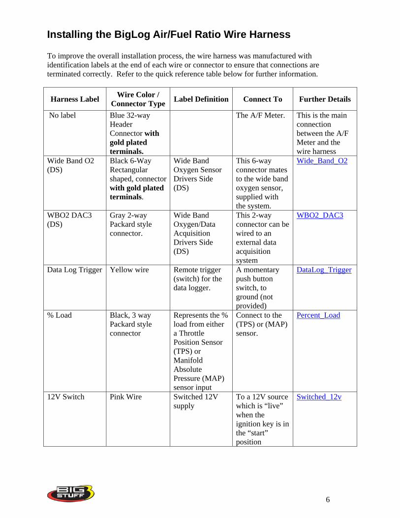
The paragraphs below provide further information to assist with the wire harness installation. This is the same information tied to the hyperlinks in the table above. Data Log Trigger (Yellow wire)
This wire allows the user to easily and safely initiate data logging from a remote location like the rear of the car or near the gear shifter. Connect the yellow wire to one end of a two- pole momentary push button switch. Ground the other side of the switch. Using a momentary push button switch is one of three ways to trigger the data logger. Back_to_Data_Log_Trigger
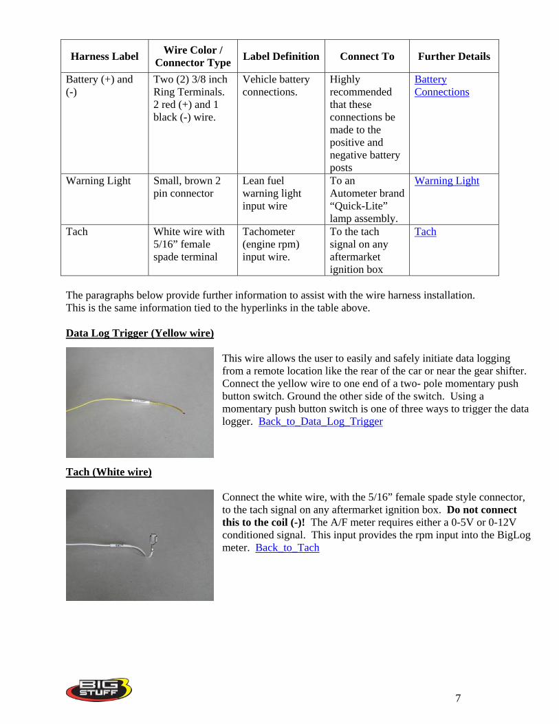
Tach (White wire) Connect the white wire, with the 5/16” female spade style connector, to the tach signal on any aftermarket ignition box. Do not connect this to the coil (-)! The A/F meter requires either a 0-5V or 0-12V conditioned signal. This input provides the rpm input into the BigLog meter. Back_to_Tach
7
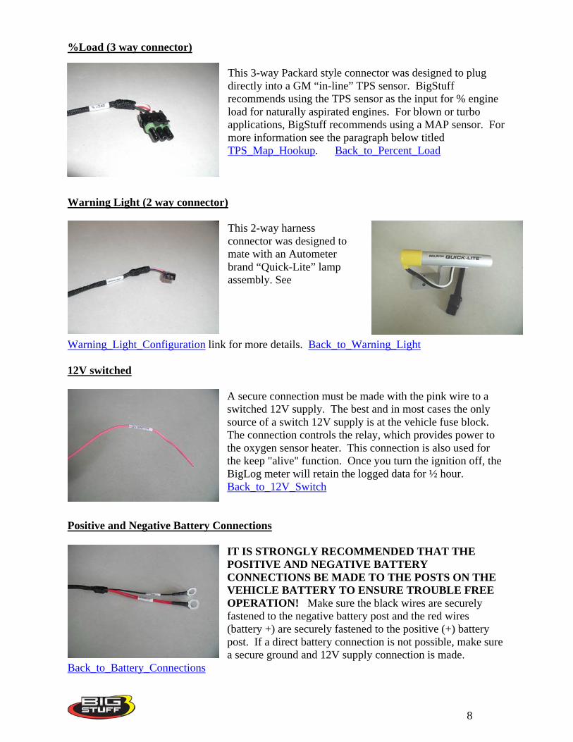
%Load (3 way connector) This 3-way Packard style connector was designed to plug directly into a GM “in-line” TPS sensor. BigStuff recommends using the TPS sensor as the input for % engine load for naturally aspirated engines. For blown or turbo applications, BigStuff recommends using a MAP sensor. For more information see the paragraph below titled TPS_Map_Hookup. Back_to_Percent_Load
Warning Light (2 way connector)
This 2-way harness connector was designed to mate with an Autometer brand “Quick-Lite” lamp assembly. See
Warning_Light_Configuration link for more details. Back_to_Warning_Light 12V switched
A secure connection must be made with the pink wire to a switched 12V supply. The best and in most cases the only source of a switch 12V supply is at the vehicle fuse block. The connection controls the relay, which provides power to the oxygen sensor heater. This connection is also used for the keep "alive" function. Once you turn the ignition off, the BigLog meter will retain the logged data for ½ hour. Back_to_12V_Switch
Positive and Negative Battery Connections
IT IS STRONGLY RECOMMENDED THAT THE POSITIVE AND NEGATIVE BATTERY CONNECTIONS BE MADE TO THE POSTS ON THE VEHICLE BATTERY TO ENSURE TROUBLE FREE OPERATION! Make sure the black wires are securely fastened to the negative battery post and the red wires (battery +) are securely fastened to the positive (+) battery post. If a direct battery connection is not possible, make sure a secure ground and 12V supply connection is made.
Back_to_Battery_Connections
8
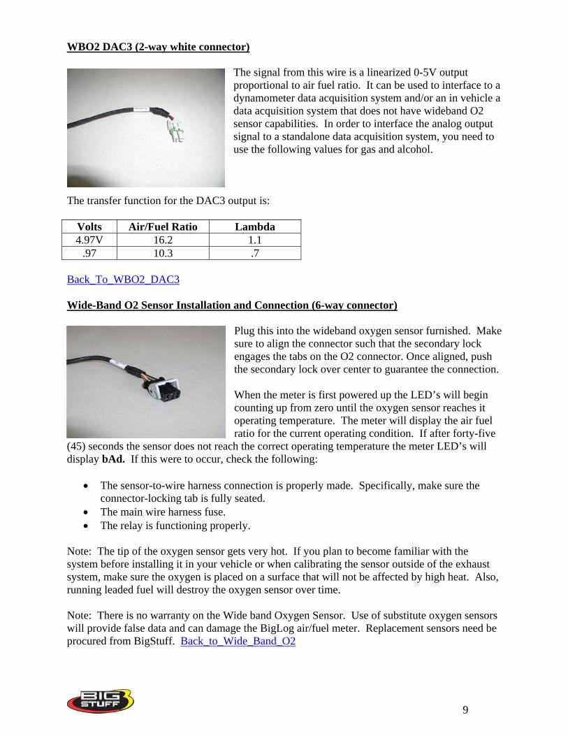
WBO2 DAC3 (2-way white connector)
The signal from this wire is a linearized 0-5V output proportional to air fuel ratio. It can be used to interface to a dynamometer data acquisition system and/or an in vehicle a data acquisition system that does not have wideband O2 sensor capabilities. In order to interface the analog output signal to a standalone data acquisition system, you need to use the following values for gas and alcohol.
The transfer function for the DAC3 output is:
Volts Air/Fuel Ratio Lambda 4.97V 16.2 1.1
.97 10.3 .7 Back_To_WBO2_DAC3 Wide-Band O2 Sensor Installation and Connection (6-way connector)
Plug this into the wideband oxygen sensor furnished. Make sure to align the connector such that the secondary lock engages the tabs on the O2 connector. Once aligned, push the secondary lock over center to guarantee the connection. When the meter is first powered up the LED’s will begin counting up from zero until the oxygen sensor reaches it operating temperature. The meter will display the air fuel ratio for the current operating condition. If after forty-five
(45) seconds the sensor does not reach the correct operating temperature the meter LED’s will display bAd. If this were to occur, check the following:
• The sensor-to-wire harness connection is properly made. Specifically, make sure the connector-locking tab is fully seated.
• The main wire harness fuse. • The relay is functioning properly.
Note: The tip of the oxygen sensor gets very hot. If you plan to become familiar with the system before installing it in your vehicle or when calibrating the sensor outside of the exhaust system, make sure the oxygen is placed on a surface that will not be affected by high heat. Also, running leaded fuel will destroy the oxygen sensor over time. Note: There is no warranty on the Wide band Oxygen Sensor. Use of substitute oxygen sensors will provide false data and can damage the BigLog air/fuel meter. Replacement sensors need be procured from BigStuff. Back_to_Wide_Band_O2
9
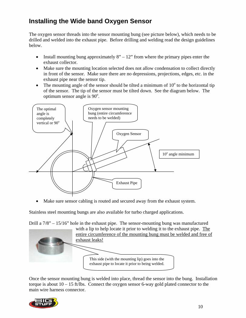
Installing the Wide band Oxygen Sensor The oxygen sensor threads into the sensor mounting bung (see picture below), which needs to be drilled and welded into the exhaust pipe. Before drilling and welding read the design guidelines below.
• Install mounting bung approximately 8” – 12” from where the primary pipes enter the exhaust collector.
• Make sure the mounting location selected does not allow condensation to collect directly in front of the sensor. Make sure there are no depressions, projections, edges, etc. in the exhaust pipe near the sensor tip.
• The mounting angle of the sensor should be tilted a minimum of 10o to the horizontal tip of the sensor. The tip of the sensor must be tilted down. See the diagram below. The optimum sensor angle is 90o.
The optimal angle is completely vertical or 90o
Exhaust Pipe
Oxygen Sensor
Oxygen sensor mounting bung (entire circumference needs to be welded)
10o angle minimum
• Make sure sensor cabling is routed and secured away from the exhaust system. Stainless steel mounting bungs are also available for turbo charged applications. Drill a 7/8” – 15/16” hole in the exhaust pipe. The sensor-mounting bung was manufactured
with a lip to help locate it prior to welding it to the exhaust pipe. The entire circumference of the mounting bung must be welded and free of exhaust leaks!
This side (with the mounting lip) goes into the exhaust pipe to locate it prior to being welded.
Once the sensor mounting bung is welded into place, thread the sensor into the bung. Installation torque is about 10 – 15 ft/lbs. Connect the oxygen sensor 6-way gold plated connector to the main wire harness connector.
10
BigLog Air/Fuel Ratio Meter Installation Once a mounting location inside the vehicle is selected, use the mounting post provided to secure the meter in place. The mounting post fastens to a mounting boss on the back of the meter (see picture below). The boss and post are fastened together with an Allen wrench (provided). Note: The meter was not designed to be fluid resistant or to be mounted outside of the vehicle. Exposing the meter to fluids or to outside elements could cause the meter to fail prematurely.
BigLog Meter to Main Harness Connection Once the harness and BigLog meter have been installed, plug the blue 32-way connector, on the main harness, into the side of the BigLog meter. Hold the meter and the harness side connector securely. Push the harness side connector into the meter’s mating connector until the connector-locking tab snaps into place.
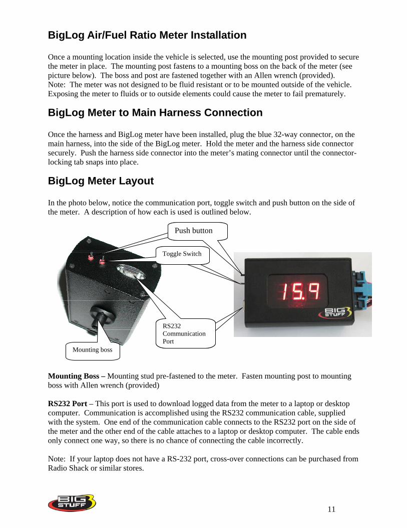
BigLog Meter Layout In the photo below, notice the communication port, toggle switch and push button on the side of the meter. A description of how each is used is outlined below.
Mounting boss
RS232 Communication Port
Toggle Switch
Push Button
Toggle Switch
Push button
Mounting Boss – Mounting stud pre-fastened to the meter. Fasten mounting post to mounting boss with Allen wrench (provided) RS232 Port – This port is used to download logged data from the meter to a laptop or desktop computer. Communication is accomplished using the RS232 communication cable, supplied with the system. One end of the communication cable connects to the RS232 port on the side of the meter and the other end of the cable attaches to a laptop or desktop computer. The cable ends only connect one way, so there is no chance of connecting the cable incorrectly. Note: If your laptop does not have a RS-232 port, cross-over connections can be purchased from Radio Shack or similar stores.
11
Push Button – The push button is used to scroll between the three main menu options. • LOg – Log Data • CAL – Checks the oxygen sensor calibration. • Prg – Programs the meter.
Toggle Switch – The toggle switch is used to select between the configuration options when in the programming mode (Prg).
• ALC/GAS – Gasoline or alcohol • Afr/LAA – Ratios displayed as air/fuel or Lambda • 4/6/8 – Number of cylinders the engine has.
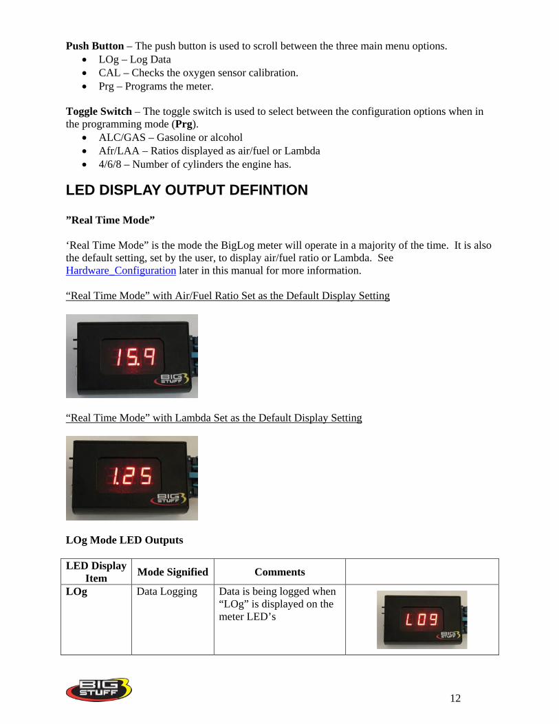
LED DISPLAY OUTPUT DEFINTION ”Real Time Mode” ‘Real Time Mode” is the mode the BigLog meter will operate in a majority of the time. It is also the default setting, set by the user, to display air/fuel ratio or Lambda. See Hardware_Configuration later in this manual for more information. “Real Time Mode” with Air/Fuel Ratio Set as the Default Display Setting
“Real Time Mode” with Lambda Set as the Default Display Setting
LOg Mode LED Outputs LED Display
Item Mode Signified Comments
LOg Data Logging Data is being logged when “LOg” is displayed on the meter LED’s
12
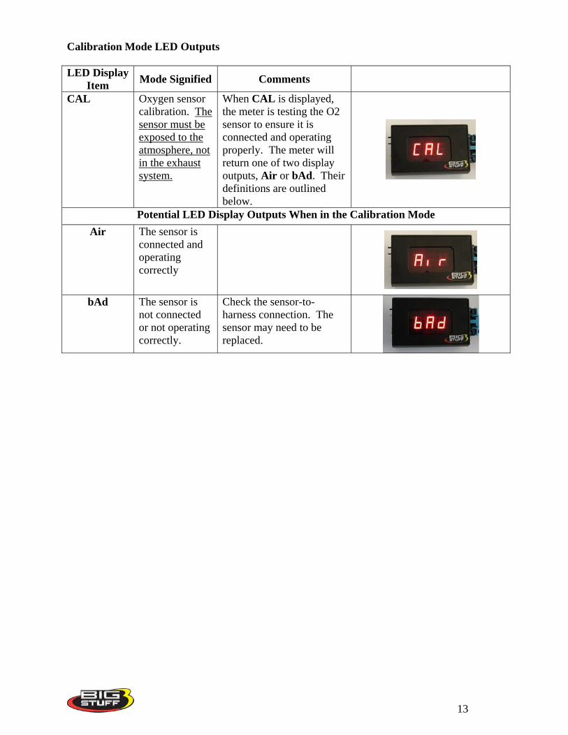
Calibration Mode LED Outputs LED Display
Item Mode Signified Comments
CAL Oxygen sensor calibration. The sensor must be exposed to the atmosphere, not in the exhaust system.
When CAL is displayed, the meter is testing the O2 sensor to ensure it is connected and operating properly. The meter will return one of two display outputs, Air or bAd. Their definitions are outlined below.
Potential LED Display Outputs When in the Calibration Mode Air The sensor is
connected and operating correctly
bAd The sensor is
not connected or not operating correctly.
Check the sensor-to-harness connection. The sensor may need to be replaced.
13
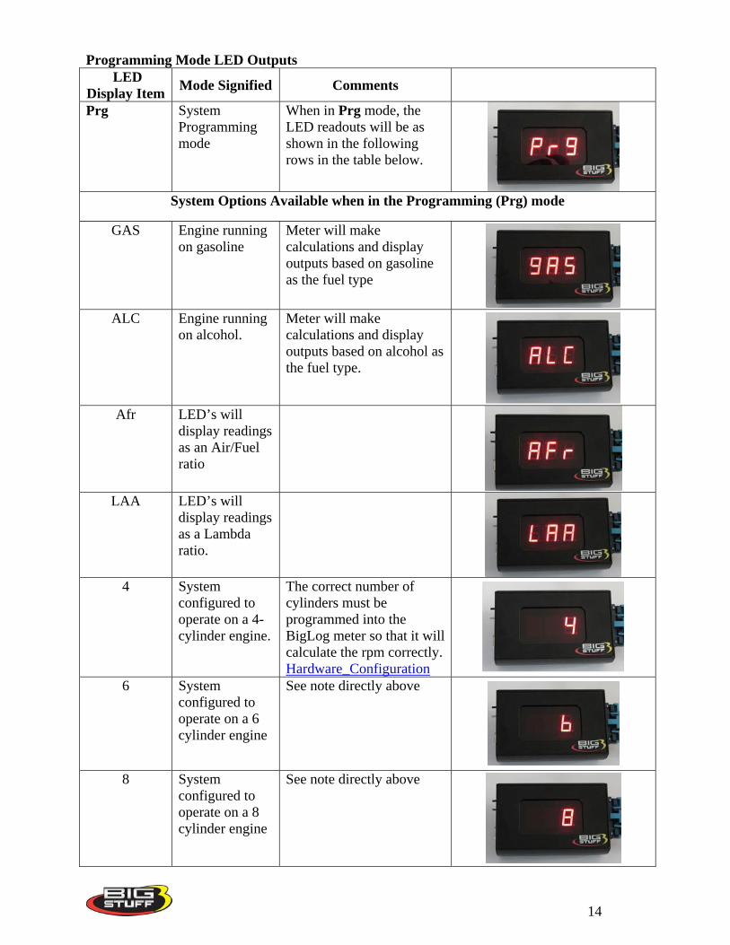
Programming Mode LED Outputs LED
Display Item Mode Signified Comments
Prg System Programming mode
When in Prg mode, the LED readouts will be as shown in the following rows in the table below.
System Options Available when in the Programming (Prg) mode
GAS Engine running on gasoline
Meter will make calculations and display outputs based on gasoline as the fuel type
ALC Engine running
on alcohol. Meter will make calculations and display outputs based on alcohol as the fuel type.
Afr LED’s will
display readings as an Air/Fuel ratio
LAA LED’s will
display readings as a Lambda ratio.
4 System
configured to operate on a 4-cylinder engine.
The correct number of cylinders must be programmed into the BigLog meter so that it will calculate the rpm correctly. Hardware_Configuration
6 System configured to operate on a 6 cylinder engine
See note directly above
8 System
configured to operate on a 8 cylinder engine
See note directly above
14
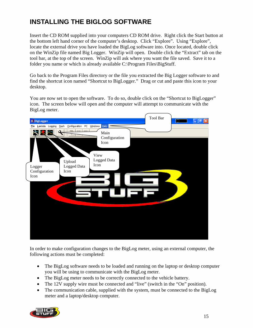
INSTALLING THE BIGLOG SOFTWARE Insert the CD ROM supplied into your computers CD ROM drive. Right click the Start button at the bottom left hand corner of the computer’s desktop. Click “Explore”. Using “Explore”, locate the external drive you have loaded the BigLog software into. Once located, double click on the WinZip file named Big Logger. WinZip will open. Double click the “Extract” tab on the tool bar, at the top of the screen. WinZip will ask where you want the file saved. Save it to a folder you name or which is already available C:\Program Files\BigStuff. Go back to the Program Files directory or the file you extracted the Big Logger software to and find the shortcut icon named “Shortcut to BigLogger.” Drag or cut and paste this icon to your desktop. You are now set to open the software. To do so, double click on the “Shortcut to BigLogger” icon. The screen below will open and the computer will attempt to communicate with the BigLog meter.
Logger Configuration Icon
Upload Logged Data Icon
Main Configuration Icon
View Logged Data Icon
Tool Bar
In order to make configuration changes to the BigLog meter, using an external computer, the following actions must be completed:
• The BigLog software needs to be loaded and running on the laptop or desktop computer you will be using to communicate with the BigLog meter.
• The BigLog meter needs to be correctly connected to the vehicle battery. • The 12V supply wire must be connected and “live” (switch in the “On” position). • The communication cable, supplied with the system, must be connected to the BigLog
meter and a laptop/desktop computer.
15
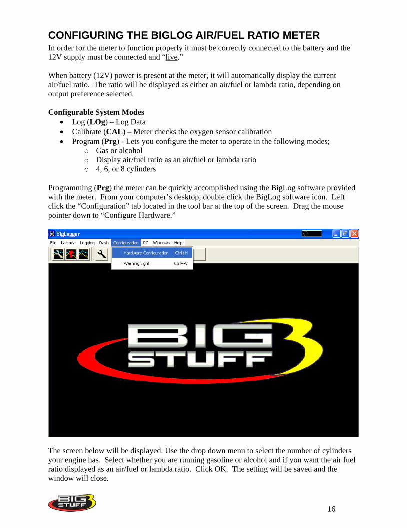
CONFIGURING THE BIGLOG AIR/FUEL RATIO METER In order for the meter to function properly it must be correctly connected to the battery and the 12V supply must be connected and “live.” When battery (12V) power is present at the meter, it will automatically display the current air/fuel ratio. The ratio will be displayed as either an air/fuel or lambda ratio, depending on output preference selected. Configurable System Modes
• Log (LOg) – Log Data • Calibrate (CAL) – Meter checks the oxygen sensor calibration • Program (Prg) - Lets you configure the meter to operate in the following modes;
o Gas or alcohol o Display air/fuel ratio as an air/fuel or lambda ratio o 4, 6, or 8 cylinders
Programming (Prg) the meter can be quickly accomplished using the BigLog software provided with the meter. From your computer’s desktop, double click the BigLog software icon. Left click the “Configuration” tab located in the tool bar at the top of the screen. Drag the mouse pointer down to “Configure Hardware.”
The screen below will be displayed. Use the drop down menu to select the number of cylinders your engine has. Select whether you are running gasoline or alcohol and if you want the air fuel ratio displayed as an air/fuel or lambda ratio. Click OK. The setting will be saved and the window will close.
16
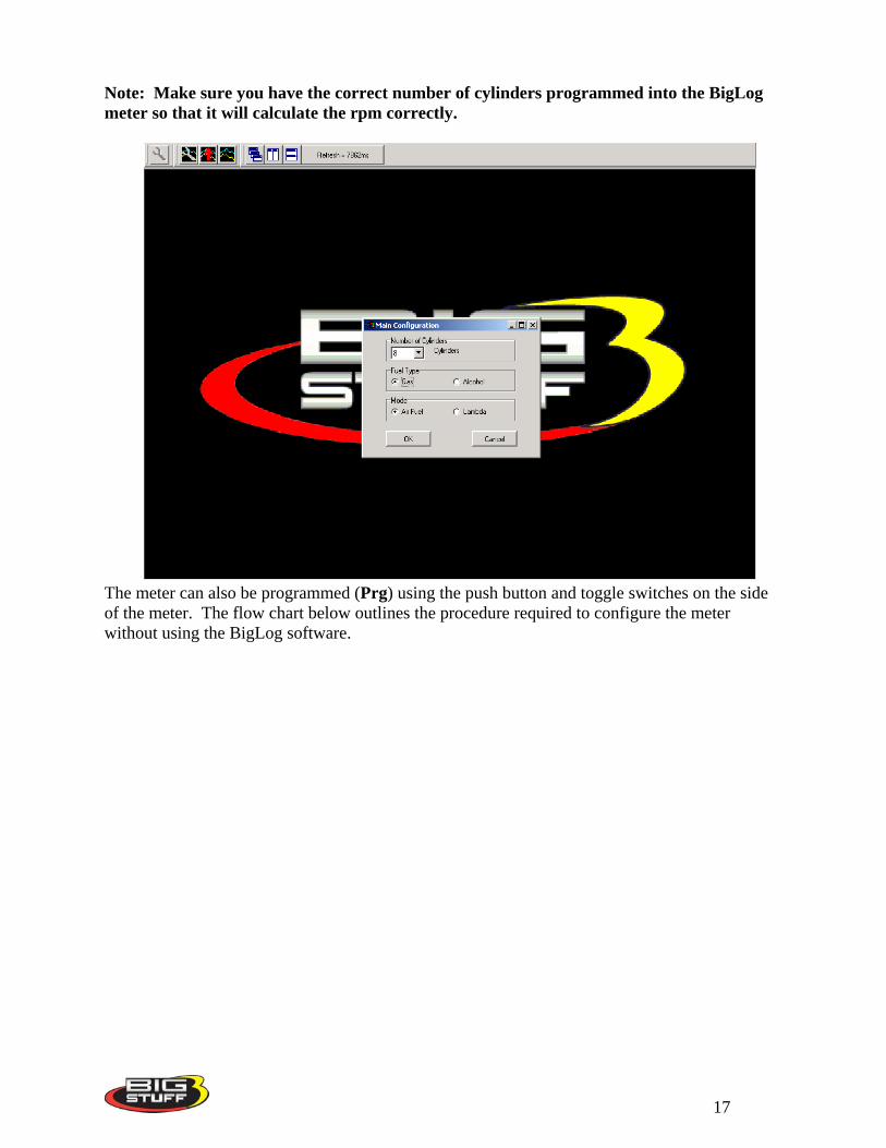
Note: Make sure you have the correct number of cylinders programmed into the BigLog meter so that it will calculate the rpm correctly.
The meter can also be programmed (Prg) using the push button and toggle switches on the side of the meter. The flow chart below outlines the procedure required to configure the meter without using the BigLog software.
17
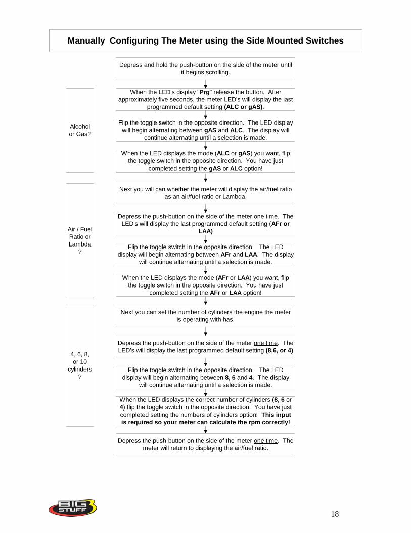
Manually Configuring The Meter using the Side Mounted Switches
Depress and hold the push-button on the side of the meter untilit begins scrolling.
When the LED's display "Prg" release the button. Afterapproximately five seconds, the meter LED's will display the last
programmed default setting (ALC or gAS).
Flip the toggle switch in the opposite direction. The LED displaywill begin alternating between gAS and ALC. The display will
continue alternating until a selection is made.
When the LED displays the mode (ALC or gAS) you want, flipthe toggle switch in the opposite direction. You have just
completed setting the gAS or ALC option!
Next you will can whether the meter will display the air/fuel ratioas an air/fuel ratio or Lambda.
Depress the push-button on the side of the meter one time. TheLED's will display the last programmed default setting (AFr or
LAA)
Flip the toggle switch in the opposite direction. The LEDdisplay will begin alternating between AFr and LAA. The display
will continue alternating until a selection is made.
When the LED displays the mode (AFr or LAA) you want, flipthe toggle switch in the opposite direction. You have just
completed setting the AFr or LAA option!
Next you can set the number of cylinders the engine the meteris operating with has.
Depress the push-button on the side of the meter one time. TheLED's will display the last programmed default setting (8,6, or 4)
Flip the toggle switch in the opposite direction. The LEDdisplay will begin alternating between 8, 6 and 4. The display
will continue alternating until a selection is made.
When the LED displays the correct number of cylinders (8, 6 or4) flip the toggle switch in the opposite direction. You have justcompleted setting the numbers of cylinders option! This inputis required so your meter can calculate the rpm correctly!
Depress the push-button on the side of the meter one time. Themeter will return to displaying the air/fuel ratio.
Alcoholor Gas?
Air / FuelRatio orLambda
?
4, 6, 8,or 10
cylinders?
18
Calibration (CAL) Mode When the meter is in “Calibration” (CAL) mode it is checking the oxygen sensor to ensure it is functioning properly. Note: The sensor must be calibrated with the sensor exposed to atmosphere. The sensor cannot be in the exhaust system. While in “Calibration Mode” there are no meter or software adjustments necessary. You can only enter into the calibration (CAL) mode by using the push button switch on the side of the BigLog meter. When in the CAL mode, the meter will begin counting up from zero to heat the sensor and check that it is sensing the correct % of O2 in the atmosphere (not in the exhaust system). Follow the procedure below to enter CAL mode. The sensor must be exposed to atmosphere, meaning it should not be in the exhaust system.
• With the meter in “Real Time Mode” (reading air/fuel ratio or lambda). Depress and hold the push-button on the side of the meter until it begins scrolling.
• When CAL is displayed in the meter’s LED’s quickly release the pushbutton. • The sensor will then begin counting up from zero. If the sensor is connected properly
and is sensing the correct % of O2 in the atmosphere, the meter will display Air. • If the meter counts up to 25 seconds and was not able to make a connection with the
sensor and/or sense the correct percent of O2 in the atmosphere, the meter’s LED’s display bAd. If the sensor dispays bAd, check to make sure the sensor’s 6-way connector is fully engaged with the main harness mating connector. If the problem persists, the following items should be checked:
The sensor-to-harness connection The fuse may be blown. The fuse is located on the main harness. The relay may have failed. The sensor may be damaged. Running leaded fuel will destroy the oxygen sensor over time.
• If the sensor has failed it is mostly likely due to lead poisoning. • The meter will return to “Real Time Mode”, displaying the default mode set as air/fuel
ratio or Lambda. Data Log (LOg) mode. The following three methods can be used to initiate the BigLog meter’s data logging feature.
• Depress the push button on the side of the meter. • Depress the remote mounted, momentary push button switch (not provided) connected to
the yellow wire of the main wire harness. • The auto-trigger mode, which can be configured using the BigLog software.
19
The procedure below outlines how to initiate data logging using the push switch on the side of the BigLog meter or a remote mount, momentary push button switch.
• While the meter LED’s are displaying the current air/fuel ratio or Lambda also known as the “Real Time Mode,” depress and hold the push-button on the side of the meter or remote mounted switch for approximately 1 second. Within this one-second time frame, the meter will scroll to LOg mode. Upon seeing LOg in the meter LED’s, quickly release the push button. You are now logging data! The LED’s will continue to display LOg until the preset data logging time is completed.
• When the meter is finished collecting data, the meter LED’s will stop displaying LOg and will return to the “Real Time Mode,” reading the current air/fuel ratio or Lambda default mode (Air or LAA) programmed into the meter.
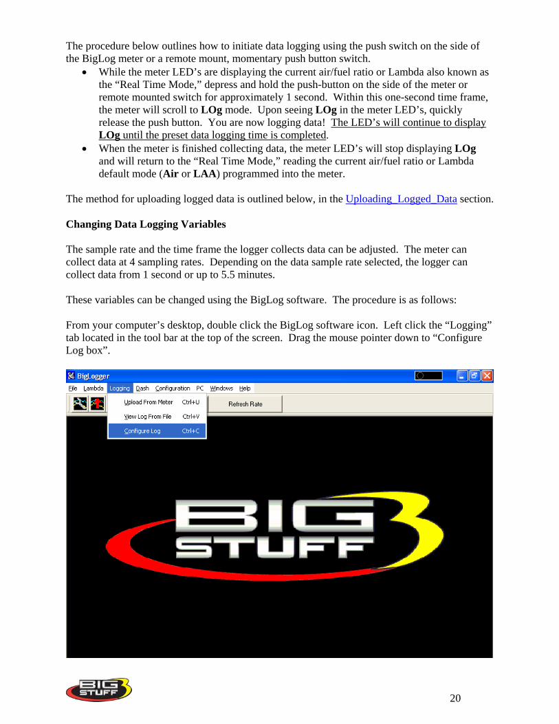
The method for uploading logged data is outlined below, in the Uploading_Logged_Data section. Changing Data Logging Variables The sample rate and the time frame the logger collects data can be adjusted. The meter can collect data at 4 sampling rates. Depending on the data sample rate selected, the logger can collect data from 1 second or up to 5.5 minutes. These variables can be changed using the BigLog software. The procedure is as follows: From your computer’s desktop, double click the BigLog software icon. Left click the “Logging” tab located in the tool bar at the top of the screen. Drag the mouse pointer down to “Configure Log box”.
20
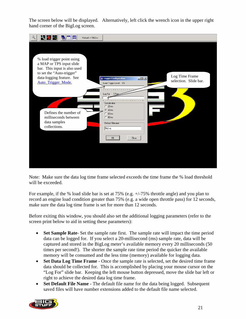
The screen below will be displayed. Alternatively, left click the wrench icon in the upper right hand corner of the BigLog screen.
% load trigger point using a MAP or TPS input slide bar. This input is also used to set the “Auto-trigger” data-logging feature. See Auto_Trigger_Mode.
Defines the number of milliseconds between data samples collections.
Log Time Frame selection. Slide bar.
Note: Make sure the data log time frame selected exceeds the time frame the % load threshold will be exceeded. For example, if the % load slide bar is set at 75% (e.g. +/-75% throttle angle) and you plan to record an engine load condition greater than 75% (e.g. a wide open throttle pass) for 12 seconds, make sure the data log time frame is set for more than 12 seconds. Before exiting this window, you should also set the additional logging parameters (refer to the screen print below to aid in setting these parameters):
• Set Sample Rate- Set the sample rate first. The sample rate will impact the time period data can be logged for. If you select a 20-millisecond (ms) sample rate, data will be captured and stored in the BigLog meter’s available memory every 20 milliseconds (50 times per second!). The shorter the sample rate time period the quicker the available memory will be consumed and the less time (memory) available for logging data.
• Set Data Log Time Frame - Once the sample rate is selected, set the desired time frame data should be collected for. This is accomplished by placing your mouse cursor on the “Log For” slide bar. Keeping the left mouse button depressed, move the slide bar left or right to achieve the desired data log time frame.
• Set Default File Name - The default file name for the data being logged. Subsequent saved files will have number extensions added to the default file name selected.
21
Once the desired changes have been made, click OK at the bottom of the window. Your changes will be saved. Auto-trigger Mode The meter can also be programmed to automatically (“Auto-trigger Mode”) begin collecting or logging data as a function of engine load using a Throttle Position Sensor (TPS) or Manifold Absolute Pressure (MAP) sensor. To configure the “Auto-trigger Mode” use the “Load Trigger Level” button within the Logger Configuration screen (see screen print above). Using load inputs from the TPS or MAP sensor, you can trigger the meter to start logging once the percent load, set with the BigLog software, is reached! This is accomplished by placing your mouse cursor on the “Load Trigger Level” slide bar. Keeping the left mouse button depressed, move the slide bar left or right to achieve the desired load trigger threshold. TPS and MAP Sensor Mounting and Hook-up In order to record % percent engine load a Throttle Position Sensor (TPS) or Manifold Absolute Pressure (MAP) must be implemented into the BigLog system. For naturally aspirated engines, BigStuff recommends using a TPS to detect engine load. For turbo charged engines, a MAP sensor should be used. A MAP or TPS sensor is necessary in order to use the “Auto-trigger” logging feature described in the paragraph above. The output from these sensors represents the % load the engine is experiencing on the data logger screen. BigStuff offers jumper harnesses, which can be used to connect non-inline GM style TPS and GM style MAP sensors to the main wire harness. BigLog TPS Jumper Harness – JMI-006-01. For use with a non “in-line” GM style TPS BigLog MAP Jumper Harness – JMI-006-012 For use with GM style MAP sensors Warning Light Configuration The BigLog software needs to be installed on a remote computer before initiating this procedure. It is important to verify that the warning light works. To do so, connect the BigLog meter to a laptop or desktop computer. Once the system software is installed and a connection has been established with the meter, go to the tool bar at the top of the screen. Left-click the “Configuration” tab on the main tool bar.
22
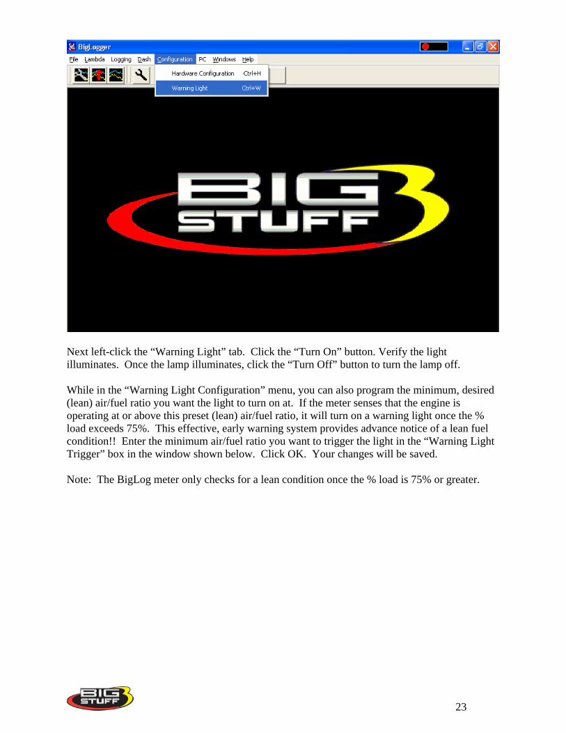
Next left-click the “Warning Light” tab. Click the “Turn On” button. Verify the light illuminates. Once the lamp illuminates, click the “Turn Off” button to turn the lamp off. While in the “Warning Light Configuration” menu, you can also program the minimum, desired (lean) air/fuel ratio you want the light to turn on at. If the meter senses that the engine is operating at or above this preset (lean) air/fuel ratio, it will turn on a warning light once the % load exceeds 75%. This effective, early warning system provides advance notice of a lean fuel condition!! Enter the minimum air/fuel ratio you want to trigger the light in the “Warning Light Trigger” box in the window shown below. Click OK. Your changes will be saved. Note: The BigLog meter only checks for a lean condition once the % load is 75% or greater.
23
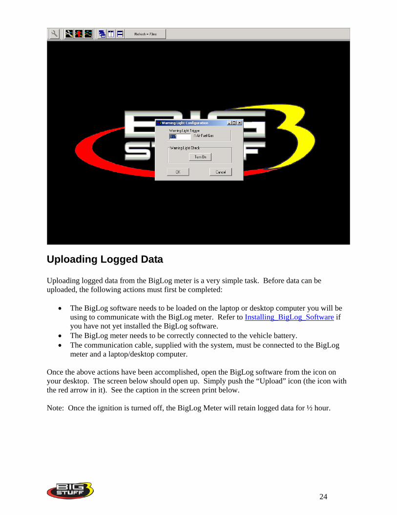
Uploading Logged Data Uploading logged data from the BigLog meter is a very simple task. Before data can be uploaded, the following actions must first be completed:
• The BigLog software needs to be loaded on the laptop or desktop computer you will be using to communicate with the BigLog meter. Refer to Installing_BigLog_Software if you have not yet installed the BigLog software.
• The BigLog meter needs to be correctly connected to the vehicle battery. • The communication cable, supplied with the system, must be connected to the BigLog
meter and a laptop/desktop computer. Once the above actions have been accomplished, open the BigLog software from the icon on your desktop. The screen below should open up. Simply push the “Upload” icon (the icon with the red arrow in it). See the caption in the screen print below. Note: Once the ignition is turned off, the BigLog Meter will retain logged data for ½ hour.
24

Click on the box with the red arrow to upload logged data.
25