Embed Size (px)
Citation preview

Page 1 of 20
MODEL BF3 & BF5
INSTALLATION MANUAL
RESIDENTIAL OIL BURNERS
THIS BURNER IS NOT EQUIPPED FOR 2 LINE OPERATION.
FOR 2 LINE OPERATION ORDER: PART # C7001025 FOR BF3, C7001026 FOR BF5
IMPORTANT: If this burner is being installed in a packaged unit (i.e. Burner comes with a boiler or furnace), follow the installation and set-up instructions supplied with the heating unit, as settings may differ from those shown in this manual.
C6505027 REV 6.1 0202

Page 2 of 20
TABLE OF CONTENTS TECHNICAL DATA - Model BF3................................................................................................3 TECHNICAL DATA – Model BF5 ...............................................................................................4 OIL BURNER COMPONENT IDENTIFICATION .....................................................................5
Burner Components ............................................................................................................5 Serial Number Identification................................................................................................5
INITIAL SET-UP ..........................................................................................................................5 MOUNTING BURNER TO BOILER OR FURNACE..................................................................6
Method 1 - Universal Mounting Flange ................................................................................6 Method 2 - Pedestal Mount.................................................................................................7
ELECTRICAL CONNECTIONS..................................................................................................7 APPLICATION FIELD WIRING STANDARD (NO BURNER FAN OFF DELAY) ..................8 NOZZLE PLACEMENT...............................................................................................................9 INSERTION/REMOVAL OF DRAWER ASSEMBLY.................................................................9 ELECTRODE SETTING...............................................................................................................10 TURBULATOR SETTING............................................................................................................10 OIL LINE CONNECTIONS.........................................................................................................10
Single Line (Gravity Feed)...................................................................................................11 Two Line (Lift System)........................................................................................................11
PUMP PURGE ..............................................................................................................................12 Single Line (Gravity System)................................................................................................12 Two Line (Lift System)........................................................................................................12
SETTING THE AIR DAMPER ADJUSTMENT............................................................................13 BF BURNER CHAMBER PRESSURE FIELD..............................................................................13 BURNER ADJUSTMENT TABLES..............................................................................................14 BF BURNER TROUBLE SHOOTING CHART............................................................................15 BF BURNER INTAKE AIR LAYOUT..........................................................................................16 SPARE PARTS EXPLODED VIEW .............................................................................................17 SPARE PARTS LIST.....................................................................................................................18 PRECAUTIONS............................................................................................................................19
ATTENTION: The burner settings used in this manual were obtained under laboratory conditions and may vary from those obtained in the actual installation of the burner. Combustion results must be verified using proper combustion test equipment. Riello will not be responsible for the improper installation or set-up of the appliance.

Page 3 of 20
RIELLO 40 BF3 TECHNICAL DATA
DIMENSIONS MODEL BF3 A B C D E F Inches 9 13/16 11 1/4 7 1/2 3 1/2 4 1/4 8 1/4 mm 249 286 193 89 108 210 *E1: 6” (152 mm), 8 7/8” (225 mm) & 10” (254 mm) tubes are also available. SPECIFICATIONS FUEL: No. 2 Fuel Oil FIRING RATE: 0.50 to 0.95 US GPH EFFECTIVE OUTPUT: 70,000 to 133,000 BTU/h VOLTAGE (Single Phase): 120V 60Hz (± 10% - 15%) ABSORBED ELECTRICAL POWER: 192 Watts MOTOR (rated): 3250 rpm Run Current 2.2 AMP CAPACITOR: 12.5 Microfarads 260V PUMP PRESSURE: 100 to 200 PSI PRIMARY CONTROL: RIELLO 530 SE/C IGNITION TRANSFORMER: 8 kV 16mA *with intake air temperature at 20ºC (68ºF) MOUNTING FLANGE DIMENSIONS
MODEL BF3 A B C D E F Inch 7/16 7 3/32 3 9/16 5 9/16 7 9/16 8 1/2 mm 11 180 90 141 192 216
AC
D
BE
*E1F
30º45º60º
A
B
FEDC

Page 4 of 20
RIELLO 40 BF5 TECHNICAL DATA
DIMENSIONS MODEL BF5 A B C D E F Inches 9 13/16 11 1/2 7 1/2 3 1/2 4 1/4 8 3/4 mm 249 292 193 89 108 222 *E1: 6” (152 mm) & 10” (254 mm) tubes are also available. SPECIFICATIONS FUEL: No. 2 Fuel Oil FIRING RATE: 0.75 to 1.65 US GPH EFFECTIVE OUTPUT: 105,000 to 231,000 BTU/h VOLTAGE (Single Phase): 120V 60Hz (± 10% - 15%) ABSORBED ELECTRICAL POWER: 204 Watts MOTOR (rated): 3250 rpm Run Current 2.2 AMP CAPACITOR: 12.5 Microfarads 260V PUMP PRESSURE: 100 to 200 PSI PRIMARY CONTROL: RIELLO 530 SE/C IGNITION TRANSFORMER: 8 kV 16mA *with intake air temperature at 20ºC (68ºF) MOUNTING FLANGE DIMENSIONS
MODEL BF5 A B C D E F Inch 7/16 7 3/32 3 9/16 5 9/16 7 9/16 8 1/2 mm 11 180 90 141 192 216
AC
D
BE
*E1F
30º45º60º
A
B
FEDC

Page 5 of 20
RIELLO 40 SERIES OIL BURNER COMPONENT IDENTIFICATION
BF3 & BF5 BURNER COMPONENTS 1) Primary Control Sub-base 10) Universal Mounting Flange 2) Primary Control 11) Turbulator Adjustment Screw 3) Lockout Indicator Lamp and Reset Button 12) Air Tube Cover 4) Pump Pressure Regulator Adjustment Screw 13) Pump Plug 5) Motor 14) Inlet Fuel Line Port 6) Capacitor 15) Return Fuel Line Port 7) Air Damper 16) Bleeder and Pressure Gauge Port 8) End Cone Assembly 17) Coil 9) Mounting Gasket SERIAL NUMBER IDENTIFICATION The Riello 15 character serial number, example, 97 A 8511111 00025, is identified as follow: 97 = last two digits of the year of manufacture; A = BI-week of manufacture; 8511111 = burner product code; 00025 = increment of 1 for each burner produced – specific to product code – reset to zero each January 1st.
(97) (A) (8511111) (00025)
Year of manufacture BI-week of manufacture Burner product code Sequence
INITIAL SET-UP A) Remove burner from the carton. Check parts list (inside cover) to ensure all parts are present. B) Remove burner cover by loosening the four screws securing it. Remove control box and air tube
cover. C) Remove drawer assembly, insert nozzle and set turbulator adjustment for specific input required.
5
17

Page 6 of 20
MOUNTING THE BURNER TO THE BOILER OR FURNACE
There are two possible methods to mount the burner, depending on the individual application. These are: 1) Universal flange bolted to Boiler/Furnace unit. 2) Universal flange mounted to optional Pedestal mount, where flange mounting direct to appliance is
not possible. Pedestal kit must be ordered separately. METHOD 1 – UNIVERSAL MOUNTING FLANGE A) Slide the UNIVERSAL MOUNTING FLANGE (1) over the end cone assembly with the flat flange
surface towards the heating unit.
B) Secure the UNIVERSAL MOUNTING FLANGE to the AIR TUBE by tightening the ALLEN
BOLT (2). Be sure that the MOUNTING FLANGE is properly positioned. The outer edge of the END CONE will be at least ¼” (6.5 mm) back from the inside wall of the refractory chamber or inside wall of the combustion chamber (see dimension B above). The measured length (A) is to include the MOUNTING GASKET (3) and FLANGE.
C) For dry based appliances it is suggested that an amulet or cera-felt sleeve be used on the end cone
to help reduce the risk of end cone burn-off. This amulet also provides an additional benefit of sealing the chamber air tube hole when this hole is larger then our air tube diameter. Please refer to amulet instructions in regards to installing amulet to the burners air tube end cone.
C E R A - F E L TS L E E V E O RA M U L E TS H O W N
Page 7 of 20
1
2
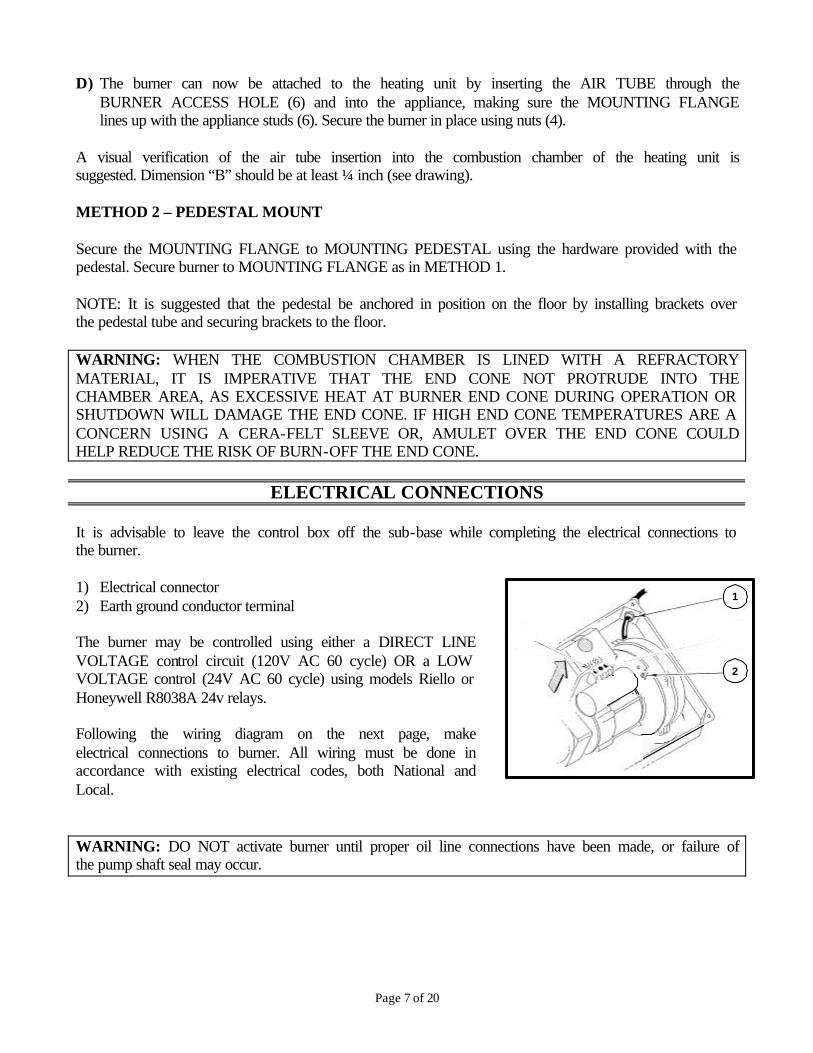
D) The burner can now be attached to the heating unit by inserting the AIR TUBE through the
BURNER ACCESS HOLE (6) and into the appliance, making sure the MOUNTING FLANGE lines up with the appliance studs (6). Secure the burner in place using nuts (4).
A visual verification of the air tube insertion into the combustion chamber of the heating unit is suggested. Dimension “B” should be at least ¼ inch (see drawing). METHOD 2 – PEDESTAL MOUNT Secure the MOUNTING FLANGE to MOUNTING PEDESTAL using the hardware provided with the pedestal. Secure burner to MOUNTING FLANGE as in METHOD 1. NOTE: It is suggested that the pedestal be anchored in position on the floor by installing brackets over the pedestal tube and securing brackets to the floor. WARNING: WHEN THE COMBUSTION CHAMBER IS LINED WITH A REFRACTORY MATERIAL, IT IS IMPERATIVE THAT THE END CONE NOT PROTRUDE INTO THE CHAMBER AREA, AS EXCESSIVE HEAT AT BURNER END CONE DURING OPERATION OR SHUTDOWN WILL DAMAGE THE END CONE. IF HIGH END CONE TEMPERATURES ARE A CONCERN USING A CERA-FELT SLEEVE OR, AMULET OVER THE END CONE COULD HELP REDUCE THE RISK OF BURN-OFF THE END CONE.
ELECTRICAL CONNECTIONS It is advisable to leave the control box off the sub-base while completing the electrical connections to the burner. 1) Electrical connector 2) Earth ground conductor terminal The burner may be controlled using either a DIRECT LINE VOLTAGE control circuit (120V AC 60 cycle) OR a LOW VOLTAGE control (24V AC 60 cycle) using models Riello or Honeywell R8038A 24v relays. Following the wiring diagram on the next page, make electrical connections to burner. All wiring must be done in accordance with existing electrical codes, both National and Local. WARNING: DO NOT activate burner until proper oil line connections have been made, or failure of the pump shaft seal may occur.

Page 8 of 20
APPLICATION FIELD WIRING – STANDARD
REMOTE SENSING OF SAFETY LOCKOUT: The SAFETY SWITCH in the 530SE CONTROL BOX is equipped with a contact allowing remote sensing of burner lockout. The electrical connection is made at terminal 4 (•) on the SUB-BASE. Should lockout occur the 530SE CONTROL BOX will supply a power source of 120Vac to the connection terminal. The maximum allowable current draw on this terminal (4) is 1 Amp. WARNING: If a neutral or ground lead is attached to this terminal, the CONTROL BOX on the burner will be damaged should lockout occur.
N • L
HO
T LI
NE
(B
LAC
K)
EA
RTH
GR
OU
ND
(G
RE
EN
)
NE
UTR
AL
(WH
ITE
)
LINE SAFETYSWITCH
OPERATINGLIMIT SWITCH
SAFETYLIMIT SWITCH
FUS
E 1
5A
N • L
T
T
NE
UTR
AL
(WH
ITE
)
HO
T LI
NE
(B
LAC
K)
EA
RTH
GR
OU
ND
(G
RE
EN
)
LINE SAFETYSWITCH
OPERATINGLIMIT SWITCH
SAFETYLIMIT SWITCH
FUS
E 1
5A
24V
AC
120V
AC
120V
AC
DIRECT LINEVOLTAGE LOW VOLTAGE
TRANSFORMER &SWITCHING RELAY
1 2 43 765 98
N • L
MOTOR
CAPACITOR
BLACK
COIL
BLU
EB
RO
WN
BLA
CK
VA
LVE
BLU
E
WH
ITE
BLA
CK
BR
OW
N
WH
ITE
WH
ITE
RIELLOFACTORY
WIRED SUBBASE
FIELDWIRING

Page 9 of 20
NOZZLE PLACEMENT A) Determine the proper firing rate for the boiler
or furnace unit, considering the specific application and use the Burner Set-Up charts on page 14 to select the proper nozzle and pump pressure to obtain the required input from the burner.
B) Remove the NOZZLE ADAPTER (2) from the DRAWER ASSEMBLY by loosening the SCREW (1).
C) Insert the proper NOZZLE into the NOZZLE ADAPTER and tighten securely (DO NOT over tighten).
D) Replace adapter, with nozzle installed, into drawer assembly and secure with screw (1).
INSERTION/REMOVAL OF DRAWER ASSEMBLY A) To remove drawer assembly, loosen SCREW (3), and then unplug CONTROL BOX (1) by
carefully pulling it back and then up. B) Remove the AIR TUBE COVER PLATE (5) by loosening the retaining SCREW (4) (Two
SCREWS – Model BF5). C) Loosen SCREW (2), and then slide the complete drawer assembly out of the combustion head as
shown. D) To insert drawer assembly, reverse the procedure in items A to C above, and then attach fuel line to
the pump.

Page 10 of 20
04
3 0
3
2
1
ELECTRODE SETTING
IMPORTANT: THESE DIMENSIONS MUST BE OBSERVED AND VERIFIED
TURBULATOR SETTING A) Loosen NUT (1), and then turn SCREW (2) until the INDEX
MARKER (3) is aligned with the correct index number as per the Burner Setup charts, on page 14.
B) Retighten the RETAINING NUT (1). NOTE: MODEL BF3: Zero and three are scale indicators only. From left to right, the first line is 3 and the last line 0. MODEL BF5: Same as above except scale indicators are 0 and 4.
OIL LINE CONNECTIONS WARNING: The burner is shipped with the pump set to operate on a ONE-line system. To operate on a Two-line system, the by-pass plug (3) must be installed. To install the by-pass plug: 1) Remove the plug from the return port of the pump. 2) Insert the by-pass (3) plug into the return port of the pump and screw into place. 3) Connect the return line connection pipe (4) to the return port of the pump and tighten securely. NOTE: Pump pressure must be set at time of burner startup. Attach a pressure gauge to the PRESSURE PORT (2) for pressure readings. All pump port threads are British Parallel thread design. Direct connection of NPT threads to the pump will damage the pump body. Riello manometers and vacuum gauges do not require any adapters, and can be safely connected directly to pump ports. An NPT (metric) adapter must be used when connecting other gauge models.
5/32" - 4mm
5/64" to 7/64" or 2 to 2.5mm
13/64" or5mm

Page 11 of 20
SINGLE LINE (GRAVITY FEED) Install the required fitting NPTF to NPT adapter into the pump's SUCTION LINE CONNECTION FITTING on left side of burner on top. Attach the required tubing to this fitting. Be sure that the plug in the RETURN LINE CONNECTION FITTING is tightened securely.
SINGLE LINE SYSTEM-PIPE LENGTHS H 3/8” OD 1/2” OD
FT M FT M FT M
1.5 0.5 33 10 65 20 3.0 1.0 65 20 130 40 5.0 1.5 130 40 260 80 6.5 2.0 195 60 325 100
TWO LINE (LIFT SYSTEM) (Accessory package required) Convert the pump for operation as a two-line system by installing the by-pass plug.
2 LINE (LIFT) SYSTEM-PIPE LENGTHS H 3/8” OD 1/2” OD
FT M FT M FT M
0.0 0.0 115 35 330 100 1.5 0.5 100 30 330 100 3.0 1.0 80 25 330 100 5.0 1.5 65 20 295 90 6.5 2.0 50 15 230 70 9.5 3.0 25 8 100 30 11 3.5 20 6 65 20
A) Suction and return lines should be sized in accordance with local codes. The suction line should
extend down near the bottom of the oil tank. The return line should terminate near the top of the oil tank.
B) Suction and return lines should be sized in accordance with local codes and both should extend to the same depth inside the fuel tank. Be sure there are no air leaks or blockages in the piping system. Any obstructions in the return line will cause failure of the pump shaft seal. Do not exceed the pipe lengths indicated in the tables on page 11.
Install the required fittings (NPT THREAD) in the SUCTION LINE and RETURN LINE CONNECTION FITTINGS. Attach the required tubing to these fittings. WARNING: Pipe dope or Teflon tapes are NOT to be used on any direct oil connection to the fuel pump.
A
B

Page 12 of 20
fuel pump.
WARNING: The height “P” in Pipe Length charts on page 11 should not exceed 13 feet (4m).
WARNING: The vacuum should not exceed 11.44 inches of mercury.
WARNING: An external, appropriately listed and certified oil filter must be placed in the fuel line between the fuel tank and the burner pump.
PUMP PURGE NOTE: To protect the pump gears. It is advisable to lubricate the pump before purge all air out of oil line(s) system. Apply oil through the VACUUM PORT. 1) SINGLE LINE (GRAVITY SYSTEM) Turn off all power to burner/appliance, and then attach a hose over bleeder plug fitting put other end of hose into a bucket. Loosen bleeder plug, when oil comes out of bleeder plug and appears clear tighten bleeder port plug, and remove hose. The burner should have purge all air of pump, and oil line and burner is ready to operate. 2) TWO LINE (LIFT SYSTEM) 2 options A) Turn off the main power source to the burner and
remove the air tube cover. Shine a light source on the photocell on the control box (now visible where the air tube cover was removed), return power to the burner and activate the burner. With the light source in place, the burner will operate in prepurge only. Once the burner is purged, turn off the power source and replace the air tube cover. Return power to the burner. The burner is now ready to operate.
B) Turn off the main power source to the burner/ appliance and then remove control box module. Get a jumper wire and jumper sub-base terminals # 5 & # 6, this will operate the motor and pump only with the control module off. Attach a hose over the bleeder port fitting and put the other end into a bucket. Restore power and run burner without control box module until oil flows out of bleeder port fitting and appears to be clear. Remove power and reinstall control box module, now the burner is ready to operate.
ATTENTION: It is important that the fuel line be completely sealed and free from air leaks or any internal blockages. WARNING! WHEN THE BYPASS PLUG IS INSTALLED, A TWO-PIPE SYSTEM MUST BE USED OR FAILURE OF THE PUMP SHAFT SEAL WILL OCCUR.

Page 13 of 20
SETTING THE AIR DAMPER ADJUSTMENT
A) The initial air damper setting is made by turning screw
(2) until the top edge of the air damper (3) is aligned with the number according to the burner setup chart.
B) Further adjustments can be made with the burner cover
in place by removing plastic plug on the top right hand side of the cover. Turn the screw counter clockwise (+ indicator) to increase combustion air, turn the screw clockwise (- indicator) to decrease combustion air.
C) The final position of the air damper will vary on each
installation. Use instruments to establish the proper settings for maximum CO2 and a smoke reading of zero.
NOTE: Variations in flue gas, smoke, CO2, and temperature readings may be experienced when the burner cover is put in place. Therefore, the burner cover must be in place when making the final combustion instrument readings, to ensure proper test results.
COMBUSTION CHAMBER PRESSURE CHART
0.500.0 0.75 1.00 1.25 1.50 1.75
BURNER OUTPUT (US GPH)
0.1
0.2
0.3
0.4
0.5
BURNER OUTPUT VS CHAMBER PRESSURE CHART
CH
AM
BE
R P
RE
SS
UR
E (
INC
HE
S W
C)

Page 14 of 20
BURNER ADJUSTMENT TABLES
IMPORTANT: The following charts indicate initial setting with combustion air at 20ºC (68ºF).
MODEL BF3 BURNER SETUP CHART 1
ACTUAL FIRING RATE 5% ±
2 NOZZLE
SIZE
3 PUMP
PRESSURE US GPH GPH PSI BAR
4 TURBULATOR
SETTING
5 AIR DAMPER
SETTING
0.50 0.40 X 60/ 80° 160 11 0.0 3.2 0.60 0.50 X 60/ 80° 145 10 1.0 3.8 0.75 0.60 X 60/ 80° 160 11 1.5 4.4 0.80 0.65 X 60/ 80° 150 10 2.0 5.0 0.95 0.75 X 60/ 80° 160 11 3.0 7.0
MODEL BF5 BURNER SETUP CHART
1 ACTUAL FIRING
RATE 5% ±
2 NOZZLE
SIZE
3 PUMP
PRESSURE US GPH GPH PSI BAR
4 TURBULATOR
SETTING
5 AIR DAMPER
SETTING
0.75 0.65 X 60/ 80° 145 10 0.0 3.3 0.85 0.75 X 60/ 80° 145 10 0.5 3.5 1.00 0.85 X 60/ 80° 145 10 1.0 4.0 1.10 1.00 X 60/ 80° 145 10 1.5 4.5 1.25 1.10 X 60/ 80° 145 10 2.0 5.0 1.50 1.25 X 60/ 80° 145 10 3.0 6.0 1.65 1.35 X 60/ 80° 145 10 4.0 7.0
?? Actual input values given in above table are based on zero (0) chamber pressure, fired in Riello Canada Inc. Test Lab DIN (small) test boiler (chamber length 17”, chamber diameter of 11”). Input values calculated using pump pressures listed above in the set-up table. Some variations will occur depending on application. This above set-up table is used to assist in the initial set-up only. Proper test equipment must be used to set the burner up properly.
?? Please refer to appliance literature or recommendation regarding nozzle size, spray pattern and spray angle. If no suggestions or literature are given, using above set-up table for desired input value set burner to table setting until burner is firing then make suitable adjustments to burner to achieve desirable combustion results.
MODEL BF3 & BF 5 NOZZLES: Any nozzle manufacturer, size, and angle spray pattern. The appliance in which the burner is installed into determines BF burner nozzle selection. COMBUSTION CHAMBER Follow the instructions furnished by the boiler/furnace manufacturer. Size retrofit application according to the appropriate installation codes (e.g. CSA B139 or NFPA #31). NON-RETROFIT APPLICATIONS If this BF burner is packaged with the appliance, it is considered an OEM package; please read all instructions the related to the burner, this information will supercede our installation manual.
Page 15 of 20
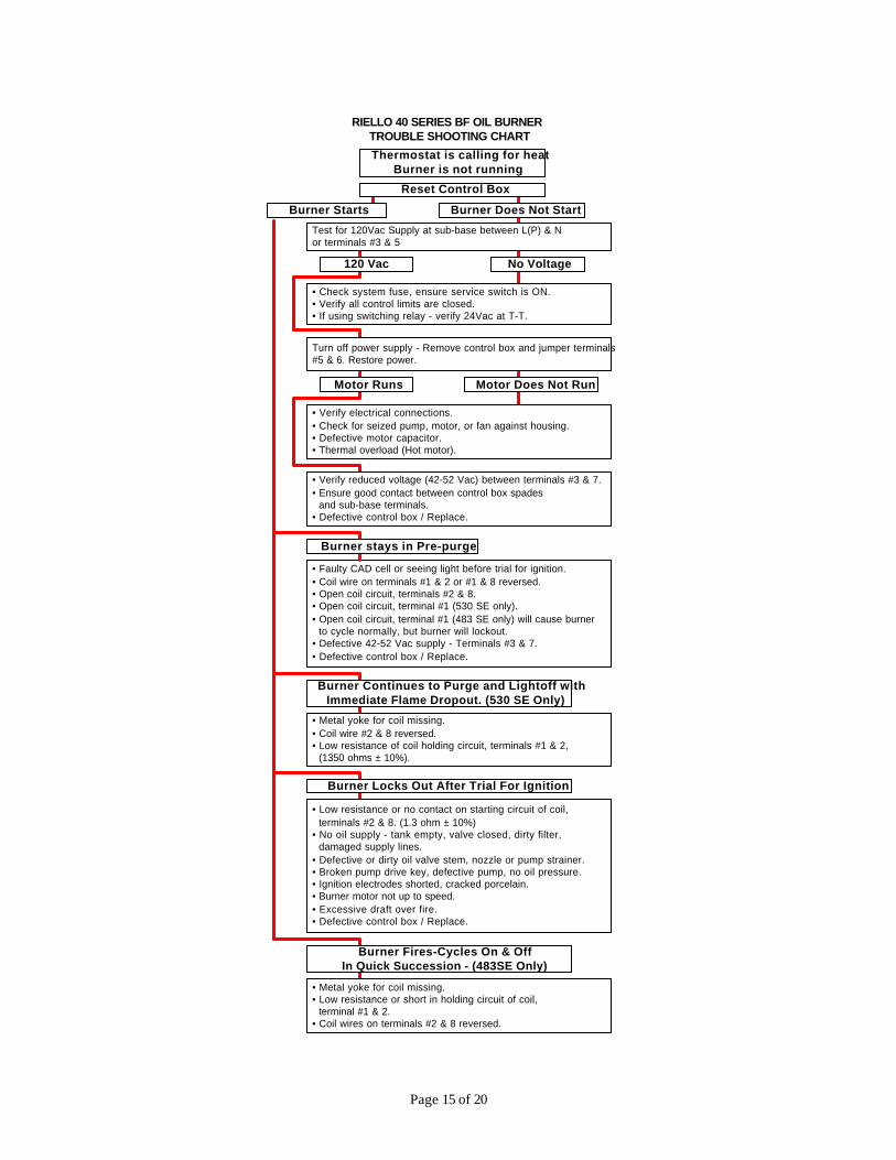
• Faulty CAD cell or seeing light before trial for ignition.• Coil wire on terminals #1 & 2 or #1 & 8 reversed.• Open coil circuit, terminals #2 & 8.• Open coil circuit, terminal #1 (530 SE only).• Open coil circuit, terminal #1 (483 SE only) will cause burner to cycle normally, but burner will lockout.• Defective 42-52 Vac supply - Terminals #3 & 7.• Defective control box / Replace.
Burner Continues to Purge and Lightoff withImmediate Flame Dropout. (530 SE Only)
• Metal yoke for coil missing.• Coil wire #2 & 8 reversed.• Low resistance of coil holding circuit, terminals #1 & 2, (1350 ohms ± 10%).
Burner Locks Out After Trial For Ignition
• Low resistance or no contact on starting circuit of coil, terminals #2 & 8. (1.3 ohm ± 10%)• No oil supply - tank empty, valve closed, dirty filter, damaged supply lines.• Defective or dirty oil valve stem, nozzle or pump strainer.• Broken pump drive key, defective pump, no oil pressure.• Ignition electrodes shorted, cracked porcelain.• Burner motor not up to speed.• Excessive draft over fire.• Defective control box / Replace.
Burner Fires-Cycles On & OffIn Quick Succession - (483SE Only)
• Metal yoke for coil missing.• Low resistance or short in holding circuit of coil, terminal #1 & 2.• Coil wires on terminals #2 & 8 reversed.
RIELLO 40 SERIES BF OIL BURNERTROUBLE SHOOTING CHART
Thermostat is calling for heatBurner is not running
Reset Control Box
Burner Does Not StartBurner Starts
Test for 120Vac Supply at sub-base between L(P) & Nor terminals #3 & 5
120 Vac No Voltage
• Check system fuse, ensure service switch is ON.• Verify all control limits are closed.• If using switching relay - verify 24Vac at T-T.
Turn off power supply - Remove control box and jumper terminals#5 & 6. Restore power.
Motor Runs Motor Does Not Run
• Verify electrical connections.• Check for seized pump, motor, or fan against housing.• Defective motor capacitor.• Thermal overload (Hot motor).
• Verify reduced voltage (42-52 Vac) between terminals #3 & 7.• Ensure good contact between control box spades and sub-base terminals.• Defective control box / Replace.
Burner stays in Pre-purge

Page 16 of 20
A TYPICAL LAYOUT FOR BF BURNER INTAKE AIR A) Use an approved air intake kit. B) Always keep intake air run to the minimum. C) Maximum intake air run of 4 (inch) diameter, flexible or rigid type of venting = 100’ D) Reduce intake air length by 10’ for every 90° elbow used. 5’ for every 45° elbow used. E) It is suggested that air intake venting be insulated with R7 (min) foil lined insulation a minimum of 10’ from
air intake source. (Prevent condensation or corrosion of intake air venting) F) Used approved type of intake air vacuum breaker and to be installed in the same room and the burner, for the
event of intake air source being blocked, this device should be tested to prove that in the event of intake air source is blocked that the vacuum breaker balancer is set correctly and can provide sufficient air for combustion for the burner. If the room that the burner is installed into cannot provide enough air or air quality is a concern, an additional air inlet source will have to be providing to this room.
IF THIS BF BURNER IS INSTALLED ON AN OEM APPLIANCE PLEASE
REFER TO INTAKE AIR LAYOUT SUGGESTED IN THEIR LITERATURE.
THIS INTAKE AIR LAYOUT FOR CHIMNEY APPLICATIONS ONLY

Page 17 of 17
SPARE PARTS
38

Page 18 of 18
RIELLO BF3 & BF5 SPARE PARTS LIST
• Indicates applicable model for each part. No CODE BF3 BF5 DESCRIPTION No CODE BF3 BF5 DESCRIPTION
3008019 • Burner Cover 22 3002280 • • Photo Cell 1 3008023 • Burner Cover 23 C5283000 • • Electrical Fitting
2 3007077 • • Crushable Metal Washer 3/8” ID. 24 3000932 • • Moveable Flange 3 3007568 • • Bleeder 25 3005856 • • Mounting Gasket 4 3007028 • • O-Ring – Pump Pressure Regulator 3008020 • Oil Supply Tube & Adapter Fitting 5 N/A • • Regulator 26 3008024 • Oil Supply Tube & Adapter Fitting 6 C7010002 • • O-Ring – Pump Cover 27 3007901 • • Plug 7 3005719 • • Pump Screen 28 N/A Adapter Washer 8 3006925 • • Valve Stem 29 3007630 • • Gasket – Burner Cover 9 3007203 • • Plate – Valve Stem Retainer 30 3000681 • • Manual Air Damper Regulator 10 3007029 • • O-Ring – Valve Stem, upper 31 3008021 • • Air Damper 11 3007156 • • O-Ring – Valve Stem, lower 3007207 • Air Intake Housing 12 3007268 • • Nozzle Outlet Fitting
32 3007824 • Air Intake Housing
13 3007087 • • Crushable Metal Washer 5/8” ID 33 3005844 • • Capacitor 12.5µF 14 3006553 • • Coil U-bracket and Retainer Nut 34 3005708 • • Fan 15 3002279 • • Coil 35 3007707 • • Cover Screw and Washer 16 3007802 • • Pump 36 3007628 • • Filter Assembly 17 3000443 • • Pump Drive Key 37 3007627 • • Plug–Cover Opening–Burner Reset 18 3005843 • • Motor 120V 60Hz 3008078 • Back plate 19 3007315 • • Air Tube Cover Plate
38 3008079 • Back plate
20 3002278 • • Primary Control Sub Base AL1009 Post Purge Control (not shown)21 3001157 • • Primary Control 530 SE/C
VERY SHORT 3” COMBUSTION HEAD 8 7/8" COMBUSTION HEAD 3948876 • VSBT Combustion Head 3948877 • Combustion Head 40 3948976 • VSBT Combustion Head 40 3948975 • Combustion Head 3006968 • Turbulator Disc 3006968 • Turbulator Disc 41 3006977 • Turbulator Disc 41 3006977 • Turbulator Disc
42 3006966 • • Electrode Support 42 3006966 • • Electrode Support 43 3006965 • • Nozzle Adapter 43 3006965 • • Nozzle Adapter
3008627 • Nozzle Oil Tube 3008790 • Nozzle Oil Tube 44 3008629 • Nozzle Oil Tube 44 3008628 • Nozzle Oil Tube 3008633 • Regulator Assembly 3008846 • Regulator Assembly 45 3008634 • Regulator Assembly
45 3008635 • Regulator Assembly
3008630 • Electrode Assembly 3008789 • Electrode Assembly 46 3008631 • Electrode Assembly 46 3008632 • Electrode Assembly 47 3005869 • • Electrode Porcelain 47 3005869 • • Electrode Porcelain
3008623 • Very Short Air Tube 3008788 • Air Tube 48 3008626 • Very Short Air Tube 48 3008625 • Air Tube SHORT 6” COMBUSTION HEAD 10" COMBUSTION HEAD
3948873 • Combustion Head 3948874 • Combustion Head 40 3948973 • Combustion Head 40 3948974 • Combustion Head 3006968 • Turbulator Disc 3006968 • Turbulator Disc 41 3006977 • Turbulator Disc
41 3006977 • Turbulator Disc
42 3006966 • • Electrode Support 42 3006966 • • Electrode Support 43 3006965 • • Nozzle Adapter 43 3006965 • • Nozzle Adapter
3006969 • Nozzle Oil Tube 3006970 • Nozzle Oil Tube 44 3006973 • Nozzle Oil Tube 44 3006974 • Nozzle Oil Tube 3006324 • Regulator Assembly 3005867 • Regulator Assembly 45 3006323 • Regulator Assembly 45 3005878 • Regulator Assembly 3006330 • Electrode Assembly 3005870 • Electrode Assembly 46 3006329 • Electrode Assembly 46 3005880 • Electrode Assembly
47 3005869 • • Electrode Porcelain 47 3005869 • • Electrode Porcelain 3007592 • Short Air Tube 3007593 • Long Air Tube 48 3007594 • Short Air Tube
48 3007595 • Long Air Tube
C7001084

Page 19 of 20
PRECAUTIONS
AIR FOR COMBUSTION Do not install burner in room with insufficient air for combustion. Be sure there is an adequate air supply for combustion if the boiler/furnace room is enclosed. It may be necessary to create a window to permit sufficient air to enter the boiler/furnace room. The installer must follow local ordinances in this regard. CANADA: It is suggested that the installer follow CSA standard B139. USA: It is suggested that the installer follow NFPA manual #31.
CHIMNEY Be sure chimney is sufficient to handle the exhaust gases. It is recommended that only the burner be connected to the chimney. Be sure that it is clean and clear of obstructions.
OIL FILTER An external oil filter is REQUIRED, even though there is an internal strainer in the pump. The filter should be replaced at least once a year, and the filter container should be thoroughly cleaned prior to installing a new filter cartridge.
DRAFT Follow the instructions furnished with the heating appliance.
The pressure in the combustion area should be kept as close to zero as possible. The burner will operate with a slight draft or pressure in the chamber.
ELECTRICAL CONNECTIONS CANADA All electrical connections should be done in accordance with the C.E.C. Part 1, and all local codes. The system should be grounded. USA All electrical connections should be done in accordance with the National Electrical Code, and all local ordinances. The system should be grounded.
CONTROL BURNER OPERATION Check out the burner and explain its operation to the homeowner. Be sure to leave the Owner’s Instruction sheet with the homeowner.
FIRE EXTINGUISHER If required by local codes, install an approved fire extinguisher.
ELECTRICAL CONNECTIONS . In most localities, a number 14 wire should be used inside a metal conduit. The system should be grounded. A service switch should be placed close to the burner on a fireproof wall in an easily accessible location.

Page 20 of 20
RIELLO BURNERS NORTH AMERICA
35 Pond Park Road Hingham, MA 02043 Phone 781-749-8292 Toll Free 800-992-7637 Fax 781-740-2069
1-800-4-RIELLO 1-800-474-3556
www.riello-burners.com
2165 Meadowpine Blvd Mississauga, ON L5N 6H6 Phone 905-542-0303 Toll Free 800-387-3898 Fax 905-542-1525


![Queen’s Gambit - Keres Defence (Baltic Defence) 1.d4 d5 2 ... [Keres Defence-1] Queen’s Gambit - Keres Defence (Baltic Defence) 1.d4 d5 2.c4 Bf5 10) 2.c4 Bf5 20) 2.c4 Bf5 3.Nf3WARNING✕Site](https://img.pdfslide.us/doc/110x75/5a788d417f8b9a7b698cab99/queens-gambit-keres-defence-baltic-defence-1d4-d5-2-keres-defence-1.jpg)