Embed Size (px)
Citation preview
RT50
BetriebsanleitungInstructions de serviceOperating Instructions
Sollwert
SP1
Vorlauf
S1
ºC
ºC80
65

57
Operating instructions control system RT50
1. General comments 2. Range of application 3. Operating elements and displays 4. Switching on 5. Switching off 6. Displays 7. Programming 8. Programming example 9. Control options 10. Operation with interface 11. Appendix 1. General comments
The Regloplas RT50 microprocessor control system consists of a control component with operating and display elements, as well as a performance component with several inserts for accessories such as interfaces etc. 2. Range of application
The RT50 control system was developed for use in temperature control unit (hereafter referred to as “units“). It enables dialog between one or more units and the production facility computer as well as operation independent of the computer. 3. Control and indicating elements (Fig. 1)
1 LCD display. 2 Keys for programming and selection of displayed value. 3 Alarm reset key. 4 On/off key. 5 Key for leak-stop mode. 6 Key for drainage and blowing out modes. 7 Key for switching between SP1 and SP2. 8 Key for operation with timer. 9 Keys for setting the set-point value and programming. 10 Status line. Set-point and actual value display
When the unit is turned on via the ON/OFF key, the set temperature SP1 or SP2 (SP= set-point value) appears in the lower part of the display while the upper part of the display indicates the outlet temperature (actual value) S1 of the sensor in the heat transfer fluid or S2 of the external sensor in the consumer (S=sensor). Key for setting the set-point value and programming
Increase and decrease the set-point value and change programmed values. Timer key
Activates the timer, when present. The timer turns the controller on and off.
Fig. 1: Operating elements and displays
1
10
2
3
4 5
9 8 7 6
57
57
57
59
59
60
74
74
74
75
58

58
Leak-stop key Pressing this key will switch the unit over to leak-stop mode. Leak-stop mode is possible only when: - If water is the heat transfer fluid, the set-point value should lie in the runout temperature range
(Section 7.2, P 4.3) of 0 to 80 °C max. - If oil is the heat transfer fluid, the set-point value should be in the range of 0 to 250 °C. With leak-stop mode and oil, the max. heating capacity is 60 %, to keep the oil’s thermal load due to reduced pump capacity low. Leak-stop mode can be interrupted by pressing the ON/OFF key. Pressing the ON/OFF key again (after waiting for OFF to appear on the display) will return the unit to its normal mode. Suction key Pressing this key initiates the evacuation program. The consumer connected to the unit is evacuated either by the pump via suction or by blowing out with compressed air. Evacuation is only possible when the temperature of the heat transfer fluid is below the programmed runout temperature (Section 7.2, P 4.3). If this is not the case, the unit will cool the heat transfer fluid to this level. The pump is switched off. Once the pump’s run-down time (Section 4.9) has elapsed, the pump is switched on again in the opposite direction of rotation. It then empties the consumer during the programmed value for evacuation time (Section 7.2, P 4.6). The blow-out program using compressed air is activated once the pump’s run-down time has elapsed. After the programmed evacuation time, the unit will switch itself off automatically. The suction and blow-out programs can be interrupted by pressing the ON/OFF key. Pressing the ON/Off key again (after waiting for OFF to appear on the display) will return the unit to its normal mode. Note: In pressurised water units, the pressure relief valve closes 5 °C above the value runout temperature, i.e. at max. 85 °C, and opens at the programmed runout temperature during the cooling process. Alarm reset key
Functions: - Manual resetting of the alarm relay (e.g. horn switched off). As soon as the malfunction has been corrected, the
alarm display can be switched off by pressing this key once more. - Manual acknowledgment of the automatic switch-over from consumer temperature control or cascade control to
outlet temperature for defective or missing sensor S2. - SP key
Switch-over from set-point value 1 (SP1) to set-point value 2 (SP2) and vice versa. The set-point values can also be activated by an external digital signal. A switch-over can only take place if no alarm is active. Operation with code
To prevent the set or programmed values from being changed inadvertently, we strongly recommend the use of a code. There are four possibilities: - Code input value - Code set-point value - Code user setting 1 - Code user setting 2 They can be programmed as described in Section 7.2, P 15. The input value code for the RT50 is set to 50 at the factory. Save/Reset for factory and user settings
The RT 50 control system offers the possibility to change the factory setting simply and at any time. In the same way, two different customer-specific settings can be reloaded (user settings 1 and 2). Programming is described in Section 7.2, P 14. 4. Switching on
Once the main switch has been turned on, OFF will appear on the display. The RT50 is now ready for operation. Switch the unit on by pressing the ON/OFF key. Depending on the programming, the set-point and actual values as well as information on the operating condition of the control system and unit. See also Section 6. If the unit is equipped with the suction equipment and the phase sequence is wrong, two phases are switched automatically, so that the pump operates in positive pressure mode.

59
5. Switching off
The switching off procedure is initiated by pressing the ON/OFF key or by the timer. The switching off program runs automatically as follows, depending on the temperature of the heat transfer fluid: - Pump and control system are switched off. The RT50 is still powered (stand-by mode). The display shows OFF. - The pump continues to run. The unit cools until the temperature of the heat transfer fluid reaches the programmed run
temperature (Section 7.2, P 4.3). The pump and controller are then switched off. The RT50 stays in stand-by mode. The display indicates OFF.
6. Displays The following boxed text can appear on the display: 6.1 Operating displays
Outlet (upper value) as actual value: S1, internal sensor. S2, external sensor. Inlet sensor S3.
Set-point value: SP1, SP2 or Extern.
External control via external set-point value entry.
External set-point Cascade control with external sensor S2.
Suction The unit will cool to the programmed runout temperature and then switch itself off automatically. Service due This message indicates that the unit is due for maintenance. However, the unit can still be operated normally. Programming: Section 7.2, P 3.8. 6.2 Status displays
Unit On, Off. 1 hour Timer operation.
Leak-stop
Leak-stop clock
Suction
Ser_A3 Interface and unit address (e.g. 3).
6.3 Alarm displays
The alarm display blinks every second. Malfunctions must always be corrected by qualified personnel.
For control Outlet sensor, Inlet or External. If a sensor becomes defective, the will switch automatically to cooling.
During cascade control, a defective external sensor (S2, consumer) will cause the unit to control to the internal sensor S1. The actual value of the internal sensor temperature at the time of sensor malfunction will be used as the new set-point value. The alarm must be acknowledged.
Level too low
Wrong phase sequence
The pump will switch off a few seconds after it is switched on. Pump and control system remain switched off.
Motor current exceeded
Malfunction of motor contactor One or more phases is missing or no response was received from the motor contactor via the auxiliary contact.
Safety therm. triggered The unit cools automatically.
Heater thermostat triggered (Model P140S). The unit cools automatically.
Maximum set-point exceeded The unit cools automatically.
Flow monitor triggered The heat switches off automatically.
Flow rate too low The heat switches off automatically.

60
Dev. set-point/Actual, Set-point/External actual Set-point/Inlet have been exceeded or fallen short of. Unit and control system continue to run normally.
Heating contact malfunction Cause: Despite command, the contact did not pick up.
Set-point or actual value is too high for leak-stop mode
External set-point signal interrupted or not present The unit cools automatically.
Analog/Digital transformer defective Unit and control system are switched off.
Program memory defective Unit and control system are switched off.
Microprocessor malfunction Unit and control system are switched off.
Calibrated values changed or wrong Unit and control system run normally.
Unit data in memory wrong or lost Unit and control system are switched off. Press the alarm reset key twice: The initialisation data are imported anew. If the initialisation data can be imported successfully, the normal display appears. If not, the alarm appears again.
Timer battery defective or dead Unit and control system continue to run normally.
Unit mains voltage too low Unit and control system are switched off.
Two flow monitors are connected at the same time The message goes away as soon as only one flow monitor is connected.
No data available The factory or user settings contain no data.
Memory not present or defective e.g. memory not inserted.
6.4 Additional messages
In addition to the messages listed under 6.1. through 6.3, one of eight possible additional messages may be overlaid. See Section 7.2, item 16. 7. Programming 7.1 Programming keys
See also Fig. 1. Functions
- Change the set-point value. - Change the line within the corresponding programming level.
- Change the value of the corresponding input line.
- Switch from the operating level to the program overview. - Switch from one programming level to another.
- Back to the operating level. - Back to the program overview. 7.2 Programming process
- The sheet, “Menu RT50” in the Appendix is critical to understanding the following: - Numbering refers to the sheet, “Menu RT50”. - The following text contains a “P” before the section number to differentiate the programming section from the rest of the sections. - Display depends on special equipment. - Programming can be done with the control system switched on or off.

61
P 1 Show actual value On this level, the following actual values are shown:
P 1.1 Outlet
Outlet temperature. Temperature S1 of the heat transfer fluid (Sensor Sn1).
P 1.2 External
Consumer temperature. External sensor Sn2 in consumer.
P 1.3 Inlet
Inlet temperature S3 at unit entrance.
P 1.4 Heating/cooling cap.
Shows the current power as a percentage of the nominal power. Example: Nominal power of the unit 9 kW. Value shown 33 %, i.e. the currently required power for the control system is 3 kW. A negative number indicates cooling.
P 1.5 Flow rate
Flow rate in l/min or GPM.
P 1.6 Pump current L1
Current, phase 1 of the pump motor in A.
P 1.7 Pump current L2
Current, phase 2 of the pump motor in A.
P 1.8 Pump current L3
Current, phase 3 of the pump motor in A.
P 1.9 Operating hours
Number of the unit’s operating hours.
P 1.10 Service after
Hours remaining until next maintenance service.
P 1.11 Software version
Software version being used.
P 1.12 Interface
Built-in interface (hardware), e.g. RS 485.
P 1.13 Protocol
Protocol installed (software), e.g. Profibus.
P 1.14 Address
Unit address when operating with an interface.
P 1.15 Day/time
Programmed day of the week and time
P 2 Select language P 2.1 Sprache Deutsch
P 2.2 Language English
P 2.3 Langue Française

62
P 3 User configuration For P 3.1 and 3.2 see also Section 11, Abb. 2.
P 3.1 Deviation Set/Actual
Values for deviation above ( ) or below ( ), with respect to Set-point/outlet Set-point/external Set-point/inlet Entry xx °C Setting range 0 to 99 °C
P 3.2 Outlet limit
Limitation of the maximum and minimum outlet temperatures, i.e. Outlet limit, max Outlet limit, min Entry xx °C
Setting range 0 to 99 °C
P 3.3 Minimum flow rate
Entry xx l/min Setting range 2 to 50 l/min
P 3.4 Interface
Address Protocol Number entry as described in Section 10.
P 3.5 Temperature display
Display in °C Display in °F
P 3.6 Flow rate display
Display in l/min Display in GPM
P 3.7 Set-point at start
Last active set-point When switched on, the unit will control to the last active set-point. Always SP1will control to the last set-point 1 (SP1) entered. Always SP2 When switched on, the unit will control to set-point 2 (SP2).
P 3.8 Next service
P 3.9 The number of elapsed operating hours shows on the display. Enter the number of operating hours until the next service procedure. The value entered must be higher than the number of Operating hours shown. Setting range: 0 to 9999 (value in hours).

63
P 4 Unit configuration P 4.1 Heat transfer fluid
The type of heat transfer fluid is entered at the factory, depending on the type of unit. Heat transfer fluid Water
Oil
P 4.2 External sensor type
Type pf external sensor Sn 2. Resist. Therm. Pt 100 Thermocoup. K NiCr-Ni Thermocoup. J Fe-CuNi Thermocoup. T Cu-CuNi
P 4.3 Run-out temperature
See also Section 11, Fig. 2. Before the unit is switched off by the OFF key or when suction is activated, the unit will first cool to the temperature set in the next step. Units with direct cooling: Value must be 0. This initiates automatic pressure release for 30 seconds after the unit is switched off by the OFF key. First cool to Entry xx °C (then autom. off) Setting range 0 to 80 °C. 0 = Function off. Leak-stop and suction modes not possible.
P 4.4 Maximum set-point See also Section 11, Fig. 2. The maximum set-point value can be set in this position. The value will vary with the type of unit. The value set must not exceed the value Tmax. on the rating plate. Max. setting Set-point Entry xxx °C See rating plate on unit Setting range 0 to 420 °C.
P 4.5 Evacuation options
Evacuation with pump Evac. w/comp. air
P 4.6 Evacuation time The suction or blow out time will vary with the type of heat transfer fluid used. Evacuation time Entry xxx s Setting range 0 to 500 s. Only displayed when accessory present.
P 4.7 Pump current
Pump current on Rating plate x.x A Entered at the factory in accordance with the information provided on the rating plate. Can be changed by ±10 % as needed.
64
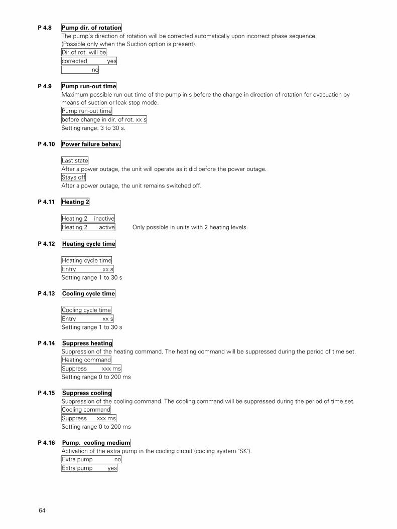
P 4.8 Pump dir. of rotation
The pump’s direction of rotation will be corrected automatically upon incorrect phase sequence. (Possible only when the Suction option is present). Dir.of rot. will be corrected yes no
P 4.9 Pump run-out time
Maximum possible run-out time of the pump in s before the change in direction of rotation for evacuation by means of suction or leak-stop mode. Pump run-out time before change in dir. of rot. xx s Setting range: 3 to 30 s.
P 4.10 Power failure behav.
Last state After a power outage, the unit will operate as it did before the power outage. Stays off After a power outage, the unit remains switched off.
P 4.11 Heating 2
Heating 2 inactive Heating 2 active Only possible in units with 2 heating levels.
P 4.12 Heating cycle time
Heating cycle time Entry xx s Setting range 1 to 30 s
P 4.13 Cooling cycle time
Cooling cycle time Entry xx s Setting range 1 to 30 s
P 4.14 Suppress heating
Suppression of the heating command. The heating command will be suppressed during the period of time set. Heating command Suppress xxx ms Setting range 0 to 200 ms
P 4.15 Suppress cooling
Suppression of the cooling command. The cooling command will be suppressed during the period of time set. Cooling command Suppress xxx ms Setting range 0 to 200 ms
P 4.16 Pump. cooling medium
Activation of the extra pump in the cooling circuit (cooling system "SK"). Extra pump no Extra pump yes

65
P 4.17 Func. of ext. contact
Switch on/off via external contact: Ext. contact Code 0 When the external contact is closed, the unit is switched off and the ON/OFF key blocked. Ext. contact Code 1 When the external contact is opened, the unit is switched off and the ON/OFF switch blocked. Ext. contact Code 2 The unit can be switched on and off via the external contact as follows: Closing the external contact: Unit switches off. Opening the external contact: Unit switches on. Ext. contact Code 3 The unit can be switched on and off via the external contact as follows: Closing the external contact: Unit switches on. Opening the external contact: Unit switches off. For codes 2 and 3: Switching on and off via the ON/OFF key is always possible.
P 4.18 Level alarm
Pump run-out time Entry xx s After the level monitor has been triggered due to insufficient level of heat transfer fluid, the pump will continue to run after its set run-out time to prevent the unit from being switched off suddenly. Setting range 3 to 60 s
Refill time window Entry xx s The refill time window is the maximum time the refill valve can be open. If the level is still insufficient after this time has elapsed, the alarm message Level too low remains. Setting range 3 to 60 s No. of insufficient Levels before Alarm Entry xx The number of level insufficiencies before the alarm is triggered. It is set to 1 for approximately 30 minutes after the last level insufficiency. Valid only for units using water as the heat transfer fluid (Section 4.1). 0 = Alarm counter off Setting range 1 to 40 Alarm suppression time after switch on Entry xx min Once the power has been switched on (main switch) the heat transfer fluid can be refilled as often as desired during the time period set. 0 = Function off. Setting range 0 to 15 min
P 4.19 Pressure relief valve
Time delay Valve xx s Time delay until the pressurised water unit’s pressure relief valve Y 8 opens. 0 = No delay. The set value may not be 0 for P 140S units. Valid only when using water as the heat transfer fluid (Section 4.1). Setting range 1 to 9 s

66
P 4.20 Viscosity
When flow measurement available, enter the kinematic viscosity in mm2/s at 20 °C. When water is used as the heat transfer fluid (Section 4.1) the value 1.0 is entered automatically. Kinematic viscosity of medium at 20 °C / 68 °F Entry xx.x mm2/s
P 5 Control
P 5.1 Type of control
Select the desired type of control: PID Outlet With sensor in outlet PID External With sensor in consumer PID Inlet With sensor in inlet Casc. External/outlet With sensor in consumer and in outlet Casc. Inlet/outlet With sensor in inlet and in outlet Casc. Cavity control With sensor in outlet and in mould cavity
At this level the operator selects the sensor(s) to be used. The control system can, for example, be set to PID outlet, even if a sensor is in the consumer.
P 5.2 Control par. PID selection
Control par. PID fix Control par. PID man. The operator can choose between PID fix and PID man. For the fixed parameter sets, the operator can choose between set 1 (strong reaction to control deviations) and set 10 (weak reaction to control deviations). The units are set to set 5 when they leave the factory.
P 5.3 Control par. PID fix
Par. set heating fix Parameter set heating Entry xx Setting range 1 to 10 Par.set cooling fix Parameter set cooling Entry xx Setting range 1 to 10
P 5.4 Control par. PID man.
P heating in % Tmax Entry x.x % Proportional band in % xx °C The proportional band in °C appears on the display, with reference to Tmax. Setting range 0 to 50.0 % I heating Entry xxxx s Run-out time (integral) in seconds. Setting range 0 to 9999 s

67
D heating Entry xxx s Rate time (differential) in seconds. Setting range 0 to 999 s
Capacity lim. heating
Entry xxx % No heating command below the set value. Setting range 10 to 100 % P cooling in % Tmax. Entry xx.x % Proportional band in % xx °C The proportional band in °C appears on the display, with reference to Tmax. Setting range 0 to 50.0 % I cooling Entry xxxx s Run-out time (integral) in seconds. Setting range 0 to 9999 s D cooling Entry xxx s Rate time (differential) in seconds. Setting range 0 to 999 s Capacity lim. cooling Entry xxx % No cooling command below the set value. Setting range 10 to 100 % Cooling dead zone Entry x.x °C The cooling dead zone is the zone over the set-point in which cooling commands are suppressed. Setting range 0 to 9.9 °C
P 5.5 Control par. casc. sel
Control par. casc. fix Control par. casc. man
P 5.6 Control par. casc. fix
Control par. casc. fix Control par. casc. man Fix cascade par. set Entry xx Setting range 1 to 10
P 5.7 Control par. casc. man
Cascade amp. Setting range 0 to 99.9 Cascade integral Setting range 0 to 9999 s Cascade differential Setting range 0 to 999 s M.Diff.heat Int/Ext Max. acceptable temperature difference between internal and external sensor during heating. Setting range 0 to 420 °C. Enter a value not higher than Tmax. M.Diff cool Int/Ext Max. acceptable temperature difference between internal and external sensor during cooling.

68
Setting range 0 to 420 °C. Enter a value not higher than Tmax. P heat aux controller Setting range 0 to 50 % I heat aux controller Setting range 0 to 9999 s D heat aux controller Setting range 0 to 999 s P cool aux controller Setting range 0 to 50 % I cool aux controller Setting range 0 to 9999 s D cool aux controller Setting range 0 to 999 s Dead zone aux contr Setting range 0 to 9.9 °C These parameters should be entered by a control specialist.
P 6 Offset
Offset can be used to compensate for errors caused by instrument leads, measurement errors from sensors, etc.
P 6.1 Offset outlet sensor
Entry 0.0 °C Setting range ±20 °C
P 6.2 Offset ext. sensor
Entry 0.0 °C Setting range ±20 °C
P 6.3 Offset inlet sensor
Entry 0.0 °C Setting range ±20 °C
P 6.4 Offset analog input
Entry 0.0 °C Setting range ±20 °C
P 6.5 Offset analog out. 1
Entry 0.0 °C Setting range ±20 °C
P 6.6 Offset analog out. 2
Entry 0.0 °C Setting range ±20 °C
P 7 Analog output 1 On this level the measuring method is first chosen for analog output 1 and then the corresponding upper and lower values are entered.

69

70
P 10.6 Alarm level
Alarm level inactive Alarm level active
P 10.7 Alarm pump current
Alarm P.curr. inact Alarm P.curr. active The following alarms always trigger the common alarm relay: Sensor outlet defect
Sensor extern defect. Contr. w/outlet sens
Phase seq wrong
Malf. motor contactor
Safetytherm.triggered Cooling on
Max setpoint exceeded Cooling on
Dev. sp/outl exceeded
Dev sp/outl exceeded Dev sp/ext act excd.
Dev sp/ext act exdc.
Dev sp/inlet exceeded
Dev sp/inlet exceeded
Ext sp signal interrupted or not present
Analog-dig transf def
Memory chip defect
Malf. microprocessor
Calibration values changed or wrong
Unit mains voltage too low
No data present

71
P 11 Relay configuration P 11.1 Relay K1 function
Relay K1 pick up Relay K1 release
P 11.2 Relay K1 selection
The following selection is available:
K1 Common alarm K1 Heat 1 K1 Heat 2 K1 Flow rate K1 Flow indicator K1 Level 1 K1 Level 2 K1 Pump current K1 Dev set/outlet K1 Dev set/outlet K1 Dev set/extern K1 Dev set/extern K1 Dev set/inlet K1 Dev set/inlet K1 Temp. breakover Actual value of the active sensor, through which the relay picks up or releases. K1 Temp. breakover Entry xxx °C Setting range 0 to Tmax. K1 Band deviation Band deviation, with respect to the active set point. For example, an entered value of 20 corresponds to a band of 20°C above and below the set point. K1 Band deviation Entry xx °C Setting range 0 to 99 °C
K1 Control on K1 Timer active K1 Pump runs K1 Level 1 reached K1 Level 2 reached K1 Heat 1 on K1 Heat 2 on K1 Cooling on
P 11.3 Relay K2
Programmed as described under Relay K1.
P 11.4 Relay K3
Programmed as described under Relay K1.
P 11.5 Relay K4
Programmed as described under Relay K1.

72
P 12 Programming the timer
10 steps are available for programming the timer. A weekday or group of days of the week, a time, and the type of time (On/Off time) must be programmed for each step. This means that to turn the unit on and off again requires 2 steps. The unused steps are set to inactive. On the second sublevel, it can be seen at a glance which steps are active (On/Off) and which are inactive.
P 12.1 01 Day of the week
01 Monday 01 Tuesday 01 Wednesday 01 Thursday 01 Friday 01 Saturday 01 Sunday 01 Mo-Th 01 Mo-Fr 01 Mo-Sa 01 Mo-Su
P 12.2 Hour/minute
01 Time Entry xx:xx
P 12.3 Inactive/On/Off
01: Inactive 01: On 01: Off The remaining steps are programmed as needed.
To ensure that the On and Off times are correct, the timer must be synchronised.
P 13 Synchronising the timer P 13.1 Enter day
Day Monday etc.
P 13.2 Enter hour/minute
Enter hour/minute Entry 00:00
P 14 Reset/Factory/User
For saving and loading set values.
P 14.1 Save as fact. setting
This can be programmed only at the factory.
P 14.2 Reset to fact. set
When this level is left, the factory settings will be reloaded.

73
P 14.3 Save user set 1
When this level is left, all currently programmed values will be saved as User settings 1.
P 14.4 Reset to user set 1
When this level is left, User settings 1 will be loaded.
P 14.5 Save as user set 2
When this level is left, all currently programmed values will be saved as User settings 2.
P 14.6 Reset to user set 2
By entering the correct code and leaving this level, User settings 2 will be loaded.
P 15 Change code P 15.1 Code <Entry value>
Code Entry xxxx The code must first be entered here. Code <Entry value> Change entry xxxx The new code can be entered here. When this level is left, the new code is activated.
P 15.2 Code <Set-point> Entry as 15.1
P 15.3 Code <Fact setting>
Entry as 15.1
P 15.4 Code <User setting 1> Entry as 15.1
P 15.5 Code <User setting 2>
Entry as 15.1
P 16 Additional display
Select the additional display. It will appear after this level is left, in the operating level as the second to last line.
P 16.1 No additional display
P 16.2 Outlet
P 16.3 External
P 16.4 Inlet
P 16.5 Heat/cool cap.
P 16.6 Flow rate
P 16.7 Operating hours
P 16.8 Service after
P 16.9 Day/time

74
8. Programming example
The sheet entitled “Programming example” shows the entry of an individual code and the programming of the deviation between set-point value and actual value. See also sheets entitled “Menu RT50” and “Temperature limit values” in the Appendix. Entering the value 5 °C means that when the actual value exceeds the set-point value entered, the alarm Deviation Set-point/Actual will appear on the controller display.
9. Types of control The RT 50 control system works with the following computer programs (control algorithms): - PID control to outlet, inlet or external sensor. For this type of control, there are 10 fixed parameter sets for each of heating and cooling as well as a manual set. Cascade control with external and outlet sensors or outlet and inlet sensors. This type of control also has 10 fixed parameter sets as well as a manual set. 9.1 Fixed parameter sets
To save the operator the time-intensive determination of the P, I und D control parameters for heating and cooling, the fixed parameter set which best matches the application can be loaded. In most cases, the operator can determine the best fixed parameter set for his application, by following these simple rules: 1. Basic setting: Parameter set 5 2. If the set-point value entered is not attained after a reasonable amount of time, the next lower parameter set should be selected (Example parameter set 4 instead of 5). 3. If the actual value exceeds the set-point value, or the set-point oscillates, the next higher fixed parameter set is chosen. If none of these parameter sets results in the desired control, because the controlled system deviates from the standard, an individual set can be entered. Note: The set-point is reached most quickly when the actual value exceeds the set-point a bit. If an overshoot is not acceptable, the operator must expect a somewhat longer heat-up time. 9.2 Fixed cascade set Notes and procedure as described in Section 9.1.
10. Operation with data interface (optional equipment) Control of the unit from the process control computer by connecting the “unit/process control computer”. For selection of the protocol and address, see Section 3.4 of the Programming section. Available protocols: 1 Arburg 4800 Bd 20 mA-CL 2 Engel 4800 Bd 20 mA-CL 3 Bühler Datacess 4800 Bd RS 422 spec. 4 Firsttech 4800 Bd 20 mA-CL 5 Stork 1200 Bd 20 mA-CL 6 Ferromatik Milakron 4800 Bd 20 mA-CL 7 Klöckner Desma 4800 Bd 20 mA-CL 8 Demag Ergotech 4800 Bd 20 mA-CL 9 Krauss Maffei 4800 Bd 20 mA-CL 10 Dr. Boy 4800 Bd RS 232 11 Euromap 17 9600 Bd RS 485 12 Euromap 17 4800 Bd RS 485 13 Euromap 17 2400 Bd RS 485 14 Euromap 17 1200 Bd RS 485 15 Sächsische Kunststofftechnik 4800 Bd RS 485 16 CAN Demag Ergotech 615 kBit/s Can RS 485 17 Müller-Weingarten 4800 Bd RS 422 spec. 18 Engel 4800 Bd RS 232 19 SPI 19200 Bd RS 485 20 SPI 9600 Bd RS 485 21 SPI 4800 Bd RS 485 22 SPI 2400 Bd RS 485 23 SPI 1200 Bd RS 485 24 Bühler Dataspeed 4800 Bd RS 485 25 Frech Datacontrol 9600 Bd RS 485 26 Frech Datacontrol 4800 Bd RS 485 27 Frech Datacontrol 2400 Bd RS 485 28 Frech Datacontrol 1200 Bd RS 485 29 CAN Demag Ergotech 500 kBit/s CAN RS 485

75
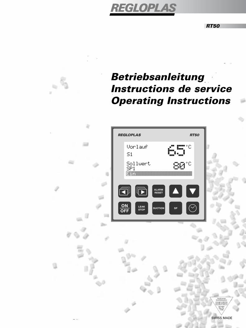
30 CAN Demag Ergotech 250 kBit/s CAN RS 485 31 CAN Demag Ergotech 125 kBit/s CAN RS 485 32 Euromap 17 Billon 9600 Bd RS 485 33 Profibus DP 12 MBit/s RS 485 34 Ferromatik Milakron 4800 Bd RS 485 11. Appendix
Terminal markings
Temperature limit values
Technical data
Menu RT50
Programming example
Construction

Terminal labels
No. Label Function No. Label Function
1 Output L Protection pumping 76 Not used 2 Output L Reserve 1 77 Not used 3 Output L Reserve 2 78 Not used 4 Output L Motor cooling SK 79 Not used 5 Output PE Motor cooling SK 80 Not used 6 Output N Motor cooling SK 81 Input External heating signal 7 Output L Flush valve 82 Input External cooling signal 8 Output PE Flush valve 83 Input External heating/cooling active 9 Output N Flush valve 84 Input External on/off signal 10 Output L Cooling valve 85 Input External set-point 2(SP2) 11 Output PE Cooling valve 86 Input Acknowledgement monitor flow 12 Output N Cooling valve 13 Output L Refill valve 87 Input Acknowledgement level 2 14 Output PE Refill valve 88 Output Common for inputs 15 Output N Refill valve 81–87 and 89–90 16 Output L Valve pressure release 89 Output Flow measurement F150 17 Output PE Valve pressure release 90 Input Flow measurement F150 18 Output N Valve pressure release 91 Input External heating signal 19 Output L Blow out valve/air inlet 92 Input External cooling signal 20 Output PE Blow out valve/air inlet 93 Input External heating/cooling active 21 Output N Blow out valve/air inlet 94 Input External on/off signal 22 Output L Contactor heater 1 95 Input Ext. set-point signal 2(SP2) 23 Input L NC T-Max switch 96 Input Acknowledgement flow monitor 24 Output L T-Max switch common 25 Input L NO T-Max switch 97 Input Acknowledgement level 2 26 Input Heater 1 acknowledgement 98 Output Common for inputs 27 Output L Heater 1 acknowledgement 91–97 and 99 –100 28 Input L1 Motor current measurement 99 Output Flow measurement F350 29 Output L1 Motor current measurement 100 Input Flow measurement F350 30 Input L2 Motor current measurement 101 Output Analog 1(+) 31 Output L2 Motor current measurement 102 Output Analog 2(+) 32 Input L3 Motor current measurement 103 Output Thermoelement TC (+) 33 Output L3 Motor current measurement 104 Input Analog set-point (+) 34 Connection PE Pump 105 Gemeinsam Analog for 101–104 (–) 35 Input PE Mains connection 106 Input External heating signal 36 Input N Mains connection 107 Input External cooling signal 37 Input L Mains connection 108 Input External heating/cooling active 38 Output L Acknowledgement reserve 109 Output Common for inputs 39 Input Acknowledgement reserve 106 –108 40 Output L Acknowledgement reserve 111 20 mA-CL Interface TxD+ RxD+ 41 Input Acknowledgement reserve 112 20 mA-CL Interface TxD– RxD– 42 Output L Acknowledgement flow 113 RS 485– Interface 43 Input Acknowledgement flow 114 RS 485– Interface 44 Input Sensor Sn2+ connection 115 RS 485– Interface, 45 Input Sensor Sn2– connection TxD+ RxD+/A/DATA 46 Input Sensor Sn1+ connection 116 RS 485– Interface, 47 Input Sensor Sn1– connection TxD– RxD–/B/DATA* 48 Input Digital input reserve 3 117 RS 485– Interface, ground 49 Input Digital input reserve 2 118 Output PE 50 Input Comm. digital input reserve 2 + 3 121 RxD RS422 Bühler/Müller-Weing. 51 Input Digital input reserve 1 122 CTS RS422 Bühler/Müller-Weing. 52 Input Digital input reserve 1 123 TxD RS422 Bühler/Müller-Weing. 53 Input Digital input level 124 +5V RS422 Bühler/Müller-Weing. 54 Input Digital input level 125 GND RS422 Bühler/Müller-Weing. 55 Output Digital output 1, 24V DC 131 CAN-L CAN ISO High speed 56 Ground Ground to digital output 1 132 CAN-H CAN ISO High speed 57 Output Digital output 2, 24V DC 133 V+ 58 Ground Ground tp digital output 2 134 Rt 59 Not used 135 Bus-L 60 Not used 136 Bus-H 61 Not used 137 Ground 62 Not used 138 Shield 63 Not used 149 Output Flow measurement 4-20 mA 64 Not used 150 Input Flow measurement 4-20 mA 65 Not used 66 Not used 67 Not used 68 Not used 69 Not used 70 Not used 71 Input Sensor Sn3 (Print for options) 72 Input Sensor Sn3 (Print for options) 73 Output Sensor Sn3 (Print for options) 74 Not used 75 Not used

Tem
per
atu
re l
imit
val
ues
H
H
eatin
g ar
ea.
K
Coo
ling
area
.
SP
S
et-p
oint
val
ue.
T N
Pum
p ru
n-ou
t te
mpe
ratu
re, m
easu
red
with
sen
sor
S2
(abs
olut
e va
lue)
. Sec
tion,
7.2
, P 4
.3.
Lo
wer
lim
it va
lue
of m
ediu
m t
empe
ratu
re, w
ith r
espe
ct t
o th
e se
t-po
int
valu
e,
mea
sure
d w
ith s
enso
r S
1. S
ectio
n 7.
2, P
3.1
.
U
pper
lim
it va
lue
of f
luid
tem
pera
ture
, with
res
pect
to
the
set-
poin
t va
lue,
m
easu
red
with
sen
sor
S1.
* Lo
wer
lim
it va
lue
of c
onsu
mer
tem
pera
ture
, with
res
pect
to
the
set-
poin
t va
lue,
m
easu
red
with
S2.
Sec
tion
3.1.
* U
pper
lim
it va
lue
of c
onsu
mer
tem
pera
ture
, with
res
pect
to
the
set-
poin
t va
lue,
m
easu
red
with
sen
sor
S2.
Sec
tion
3.1.
T S
P
Max
imum
adj
usta
ble
set-
poin
t va
lue
(abs
olut
e va
lue)
. Sec
tion
7.2,
P 4
.4.
T max
. Tr
igge
r te
mpe
ratu
re o
f th
e el
ectr
omec
hani
cal s
afet
y th
erm
omet
er in
uni
t (a
bsol
ute
valu
e).
S
et a
t th
e fa
ctor
y.
A
bb. 2
Tem
pera
ture
lim
it va
lues

78
Technical Data
Temperature range 0 to 420 °C Control method Outlet control: PID, with 1 of 10 pre-programmed PID-parameter
sets or with a manually adjustable PID set. Separate parameter sets for heating and cooling.
Consumer control: Cascade PI/PID, with 1 of 10 pre-programmed PID-parameter sets or with a manually adjustable cascade set PI/PID.
Control parameter input Via keyboard and LCD display. Data storage Memory chip with min. 10 years of data preservation.
Clock switch with lithium battery and about 10 years of data preservation.
Limit values Adjustable maximum set-point limit value.
Programmable minimum and maximum deviation of the medium and consumer temperatures from the set-point value.
Monitoring systems Control and power systems have permanent self-monitoring.
Sensor breakage and short-circuit (only for Pt 100). Limit values for temperature, pump flow (all 3 phases), level, function of the heating and pump contactors, as well as flow rate*. Data plausibility monitoring in memory, monitoring of the service interval, flow monitor, calibrated values of the pump motor phase sequence in normal and leak-stop mode*, as well as external set-point value signal*.
Inputs
Temperature sensor Outlet Pt 100. External (consumer)* Choose Pt 100, J (Fe-CuNi), K (NiCr-Ni), or T (Cu-CuNi). Inlet* Pt 100.
External Set-point value input Normalised and scaleable analogue interface with 0/4 to 20 mA or 0 to 10 V DC. Heating/cooling commands, external* Via potential-free contacts. Set-point value changeover Via keyboard (key SP) or via potential-free external contacts. Serial interface* See "Data interfaces". Outputs
Heating/Cooling Triac outputs for contactors or valves or solid-state relays. Individually adjustable cycle times for heating and cooling. Relay functions* Up to 4 optional relays as either common alarm or with individual
functions such as temperature switching point, deviation, etc. Analog outlets1 and 2* Galvanically separate analogue outputs with scaleable signal 0/4 to
20 mA or 0 to 10 V DC. Each output can be assigned an actual or set-point value. In addition, the thermal e.m.f. of a J, K or T thermocouple output at analog output 2.
Data interfaces*
Data transmission to master computer (Hardware) CL-20 mA; RS232; Bühler Datacess; Bühler Dataspeed; RS485;
CAN; SPI; Profibus-DP. Data transfer to other RS 422 (max. 32 units); CL-20 mA (2 to 4 units); RS485 (max. 32 Regloplas units units); CAN (max. 5 units); Bühler Dataspeed (max. 16 units); Profibus DP (max. 32 units). Transmission protocol See section 10 "Data interfaces".

79
Display Modern, white backlit DOT matrix LCD display with black writing. Simultaneous display of actual and set-point values, and an extra line for an important display value as well as a status line are shown on the display.
Disturbances Shown on the display
Precision
Class precision/Linearization Pt 100: 0.3 %. Thermocouple: 0.3% Deviation of display Pt 100: ± 1 digit. Thermocouple: ± 2 digits Operation Operation via short-stroke keys with pressure points on the
membrane keyboard. Simple menu system in multiple languages via scroll keys. Set-point value and parameter setting protected by programmable codes.
Mains voltage Switched mode power supply unit; 85 to 265 V AC Degree of protection Display unit with membrane keyboard: IP54 Service Insertable memory chip, attached to the temperature control unit,
allows the operator to switch the electronics quickly and simply without losing any data. The user data are read automatically into the new electronic component. Integrated operating hours counter and service interval display.
Front dimensions 96 x 96 mm. Notes * Optional equipment.

1Sh
ow a
ctua
l val
ue0
2Se
lect
lang
uage
03
Use
r con
figur
atio
n04
Uni
t con
figur
atio
n5
Cont
rol
6O
ffset
07
Ana
log
outp
ut 1
08
Ana
log
outp
ut 2
0
1.1
Outle
t11
2 °C
1.2
Exte
rnal
110
°C1.
3In
let
1.4
Heat
ing/
cool
ingc
ap.
1.5
Flow
rate
1.6
Pum
p cu
rren
t L1
1.2
A1.
7Pu
mp
curr
ent L
21.
2 A
1.8
Pum
p cu
rren
t L3
1.3
A1.
9Op
erat
ing
hour
s14
725
1.10
Serv
ice
afte
r27
5 h
1.11
Softw
are
vers
ion
5005
1.12
Inte
rface
RS48
51.1
3Pr
otoc
olPR
OFIB
US1.1
4Ad
dres
s3
1.15
Day/
time
Do 0
7:16
2.1
Spra
che
Deut
sch
2.2
Lang
uage
Eng
lish
2.3
Lang
ue F
ranç
ais
3.1
Devi
atio
n se
t/act
ual
3.2
Outle
t lim
it3.
3M
inim
um fl
ow ra
te3.
4In
terfa
ce3.
5Te
mpe
ratu
re d
ispl
ay3.
6Fl
ow ra
te d
ispl
ay3.
7Se
t-poi
nt a
t sta
rt3.
8N
ext s
ervi
ce3.
9Op
erat
ing
hour
s14
725
4.1
Heat
tran
sfer
flui
d4.
2Ex
tern
al s
enso
r typ
e4.
3Ru
nout
tem
pera
ture
4.4
Max
imum
set
-poi
nt4.
5Ev
acua
tion
optio
ns4.
6Ev
acua
tion
time
4.7
Pum
p cu
rren
t4.
8Pu
mp
dir.
of ro
tatio
n4.
9Pu
mp
run-
out t
ime
4.10
Pow
er fa
ilure
beh
av.
4.11
Heat
ing
24.
12He
atin
g cy
cle
time
4.13
Cool
ing
cycl
e tim
e4.
14Su
ppre
ss h
eatin
g4.
15Su
ppre
ss c
oolin
g4.
16Pu
mp.
coo
ling
med
ium
4.17
Func
. of e
xt. c
onta
ct4.
18Le
vel a
larm
4.19
Pres
sure
relie
f val
ve4.
20Vi
scos
ity
5.1
Type
of c
ontro
l5.
2Co
ntro
l par
. PID
sel
ectio
n5.
3Co
ntro
l par
. PID
fix
5.4
Cont
rol p
ar. P
ID m
an.
5.5
Cont
rol p
ar. c
asc.
sel
5.6
Cont
rol p
ar. c
asc.
fix
5.7
Cont
rol p
ar. c
asc.
man
6.1
Offs
et o
utle
t sen
sor
6.2
Offs
et e
xt. s
enso
r6.
3Of
fset
inle
t sen
sor
6.4
Offs
et a
nalo
g in
put
6.5
Offs
et a
nalo
g ou
t. 1
6.6
Offs
et a
nalo
g ou
t. 2
7.1
Outp
ut 1
Outle
t4–2
0m
A7.
2Ou
tput
1Ou
tlet0
–20
mA
7.3
Outp
ut 1
Outle
t0–1
0V
7.4
Outp
ut 1
Ext.
4–20
mA
7.5
Outp
ut 1
Ext.
0–20
mA
7.6
Outp
ut 1
Ext.
0–10
V7.
7Ou
tput
1In
let4
–20m
A7.
8Ou
tput
1In
let0
–20m
A7.
9Ou
tput
1In
let0
–10
V7.
10Ou
tput
1Se
t14–
20m
A7.
11Ou
tput
1Se
t10–
20m
A7.
12Ou
tput
1Se
t10–
10V
7.13
Outp
ut 1
Set2
4–20
mA
7.14
Outp
ut 1
Set2
0–20
mA
7.15
Outp
ut 1
Set2
0–10
V7.
16Ou
tput
1Fl
ow4–
20m
A7.
17Ou
tput
1Fl
ow0–
20m
A7.
18Ou
tput
1Fl
ow0–
10V
8.1
Outp
ut 2
Outle
t4–2
0m
A8.
2Ou
tput
2Ou
tlet0
–20
mA
8.3
Outp
ut 2
Outle
t0–1
0V
8.4
Outp
ut 2
Actu
alTE
–FE
8.5
Outp
ut 2
Actu
al T
E–CA
8.6
Outp
ut 2
Actu
al T
E–Cu
8.7
Outp
ut 2
Exte
rn4–
20m
A8.
8Ou
tput
2Ex
tern
0–20
mA
8.9
Outp
ut 2
Exte
rn0–
10V
8.10
Outp
ut 2
Inle
t4–2
0mA
8.11
Outp
ut 2
Inle
t0–2
0mA
8.12
Outp
ut 2
Inle
t0–1
0m
A8.
13Ou
tput
2Se
t 14–
20m
A8.
14Ou
tput
2Se
t 10–
20m
A8.
15Ou
tput
2Se
t 10–
10V
8.16
Outp
ut 2
Set 2
4–20
mA
8.17
Outp
ut 2
Set 2
0–20
mA
8.18
Outp
ut 2
Set 2
0–10
V8.
19Ou
tput
2Fl
ow4–
20m
A8.
20Ou
tput
2Fl
ow0–
20m
A8.
21Ou
tput
2Fl
ow0–
10V
9A
nalo
g in
put0
10Co
mm
on a
larm
11Re
lay
confi
gura
tion0
12Pr
ogra
mm
ing
the
timer
013
Sync
hron
isin
g th
e tim
er14
Rese
t/Fa
ctor
y/U
ser0
15Ch
ange
cod
e16
Add
ition
al d
ispl
ay
9.1
Anal
og in
put i
nact
ive
9.2
Anal
og in
put 4
–20
mA
9.3
Anal
og in
put 0
–20
mA
9.4
Anal
og in
put 0
–10
V
10.1
Alar
m re
peat
tim
e10
.2Al
arm
hea
ting
110
.3Al
arm
hea
ting
210
.4Al
arm
flow
rate
10.5
Alar
m fl
ow m
onito
r10
.6Al
arm
leve
l10
.7Al
arm
pum
p cu
rren
t
10.8
Rela
y K1
func
tion
10.9
Rela
y K1
sele
ctio
n10
.10R
elay
K2
func
tion
10.1
1Rel
ay K
2se
lect
ion
10.1
2Rel
ay K
3fu
nctio
n10
.13Re
lay
K3se
lect
ion
10.1
4Rel
ay K
4fu
nctio
n10
.15Re
lay
K4se
lect
ion
12.1
01: I
nact
ive
12.2
02: I
nact
ive
12.3
03: I
nact
ive
12.4
04: I
nact
ive
12.5
05: I
nact
ive
12.6
06: I
nact
ive
12.7
07: I
nact
ive
12.8
08: I
nact
ive
12.9
09: I
nact
ive
12.10
10: I
nact
ive
13.1
Ente
r day
13.2
Ente
r hou
r/min
ute
14.1
Save
as
fact
. set
ting
14.2
Rese
t to
fact
. set
14.3
Save
as
user
set
114
.4Re
set t
o us
er s
et 1
14.5
Save
as
user
set
214
.6Re
set t
o us
er s
et2
15.1
Code
‹Ent
ry v
alue
›15
.2Co
de ‹S
et-p
oint
›15
.3Co
de ‹F
act s
ettin
g›15
.4Co
de ‹U
ser s
ettin
g 1›
15.5
Code
‹Use
r set
ting
2›
16.1
No
addi
tiona
l dis
play
16.2
Outle
t5
°C16
.3Ex
tern
al24
°C
16.4
Inle
t23
°C
16.5
Heat
/Coo
l cap
.–1
00%
16.6
Flow
rate
16.7
Oper
atio
n ho
urs
1472
516
.8Se
rvic
e af
ter
275
h16
.9Da
y/tim
eDo
07:
16
Set value
SP1
Outlet
S1
ºC
ºC
80
65
1Sh
ow a
ctua
l val
ue2
Sele
ct la
ngua
ge3
User
con
figur
atio
n4
Unit
confi
gura
tion
5Co
ntro
l6
Offs
et7
Anal
og o
utpu
t 18
Anal
og o
utpu
t 29
Anal
og in
put
10Co
mm
on a
larm
11Re
lay
confi
gura
tion
12Pr
ogra
mm
ing
the
timer
13Sy
nchr
onis
ing
the
timer
14Re
set/
Fact
ory/
User
15Ch
ange
cod
e16
Addi
tiona
l dis
play
Men
u R
T5
0
* Be
ispi
ele
Die
Zahl
en v
or d
en T
extz
eile
n be
ziehe
n si
ch a
uf d
ie B
etrie
bsan
leitu
ng.
*
*
*

3U
ser c
onfig
urat
ion0
3.1
Devi
atio
n se
t/act
ual
3.2
Outle
t lim
it3.
3M
inim
um fl
ow ra
te3.
4In
terfa
ce3.
5Te
mpe
ratu
re d
ispl
ay3.
6Fl
ow ra
te d
ispl
ay3.
7Se
t-poi
nt a
t sta
rt
Set-p
oint
/out
let
Set-p
oint
/out
let
Set-p
oint
/ext
erna
lSe
t-poi
nt/e
xter
nal
Set-p
oint
/inle
tSe
t-poi
nt/in
let
Set-p
oint
/out
let
Entry
0°C
Code
Entry
0
Set-p
oint
/out
let
Entry
5 °C
Code
Entry
282
Code
Entry
0
Wro
ngCo
de
Set value
SP1
Outlet
S1
ºC
ºC
80
65
Show
act
ual v
alue
Sele
ct la
ngua
ge3.
1Us
er c
onfig
urat
ion
Unit
confi
gura
tion
Cont
rol
Offs
etAn
alog
out
put 1
Pro
gra
mm
ing e
xam
ple
:D
evia
tion s
et/a
ctual
upper
lim
it e
ntr
y 5
°C
The
num
ber i
n fro
nt o
f the
text
line
s re
fers
to th
e in
stru
ctio
n m
anua
l.
If w
rong
:Le
vel c
hang
e
Chan
ge o
f lin
eor
val
ueor
cod
e en
try
If co
rrec
t:
Lege
nd

Fus
eF
801
2.5
A H
Plu
gg. c
onne
ctio
nX
801
RJ4
5
Rep
lace
men
t fus
e2.
5 A
H
6 so
cket
s fo
r op
tions
Soc
ket f
or
rela
y-bo
ard
K3
4580
7
Soc
ket f
or
rela
y-bo
ard
K3
4580
7
Soc
ket f
or
rela
y-bo
ard
K3
4580
7
Soc
ket f
or
rela
y-bo
ard
K3
4580
7

Regloplas Flurhofstrasse 158CH-9006 St.Gallen
Telefon +41-71-282 58 00Fax +41-71-282 58 40
E-mail [email protected] www.regloplas.com
BA RT50 0309/de/fr/en
• • •
• • •
• • •
• • •
• • •
• • •
• •
• • •
• • •
• • •
• • •
• • •
• • •
•
• • •
• • •
• • •
• • •
• • •
• • •
• •
• • •
• • •
• • •
• • •
• • •
• • •
•
• • •
• • •
• • •
• • •
• • •
• • •
• •
• • •
• • •
• • •
• • •
• • •
• • •
•
• • •
• • •
• • •
• • •
• • •
• • •
• •
• • •
• • •
• • •
• • •
• • •
• • •
•
• • •
• • •
• • •
• • •
• • •
• • •
•
• • •
• • •
• • •
• • •
• • •
• • •
•
• • •
• • •
• • •
• • •
• • •
• • •
• •
• • •
• • •
• • •
• • •
• • •
• • •
•
• • •
• • •
• • •
• • •
• • •
• • •
• •
• • •
• • •
• • •
• • •
• • •
• • •
•
• • •
• • •
• • •
• • •
• • •
• • •
• •
• • •
• • •
• • •
• • •
• • •
• • •
•
• • •
• • •
• • •
• • •
• • •
• • •
• •
• • •
• • •
• • •
• • •
• • •
• • •
•
• • •
• • •
• • •
• • •
• • •
• • •
• •
• • •
• • •
• • •
• • •
• • •
• • •
•
• • •
• • •
• • •
• • •
• • •
• • •
• •
• • •
• • •
• • •
• • •
• • •
• • •
•
• • •
• • •
• • •
• • •
• • •
• • •
• •
• • •
• • •
• • •
• • •
• • •
• • •
•
• • •
• • •
• • •
• • •
• • •
• • •
• •
• • •
• • •
• • •
• • •
• • •
• • •
•
• • •
• • •
• • •
• • •
• • •
• • •
• •
• • •
• • •
• • •
• • •
• • •
• • •
•
• • •
• • •
• • •
• • •
• • •
• • •
• •
• • •
• • •
• • •
• • •
• • •
• • •
•
• • •
• • •
• • •
• • •
• • •
• • •
• •
• • •
• • •
• • •
• • •
• • •
• • •
•
• • •
• • •
• • •
• • •
• • •
• • •
• •
• • •
• • •
• • •
• • •
• • •
• • •
•
• • •
• • •
• • •
• • •
• • •
• • •
• •
• • •
• • •
• • •
• • •
• • •
• • •
•
• • •
• • •
• • •
• • •
• • •
• • •
• •
• • •
• • •
• • •
• • •
• • •
• • •
•
• • •
• • •
• • •
• • •
• • •
• • •
• •
• • • • •
•
• • • • •
•
• • • • •
•
• • • • •
•
• • • • •
•
• • • • •
•
• • • • •
•
• • • • •
•
• • • • •
•
• • •
• •
•
• • • • •
•
• • • • •
•
• • • • •
•
• • • • •
•
• • • • •
•
• • • • •
•
• • • • •
• • •
• • •
• • •
• • •
• • •
• •
• • •
• • •
• • •
• • •
• • •
• • •
• •
• • •
• • •
• • •
• • •
• • •
• • •
•
• • •
• • •
• • •
• • •
• • •
• • •
• •
• • •
• • •
• • •
• • •
• • •
• • •
•
• • •
• • •
• • •
• • •
• • •
• • •
• •