Embed Size (px)
Citation preview

8/22/2019 Best Application
http://slidepdf.com/reader/full/best-application 1/457
Relion® 670 series
Busbar protection REB670 Application manual

8/22/2019 Best Application
http://slidepdf.com/reader/full/best-application 2/457

8/22/2019 Best Application
http://slidepdf.com/reader/full/best-application 3/457
Document ID: 1MRK 505 211-UENIssued: December 2012
Revision: CProduct version: 1.2
© Copyright 2012 ABB. All rights reserved

8/22/2019 Best Application
http://slidepdf.com/reader/full/best-application 4/457
Copyright
This document and parts thereof must not be reproduced or copied without written
permission from ABB, and the contents thereof must not be imparted to a third party, nor used for any unauthorized purpose.
The software and hardware described in this document is furnished under a licenseand may be used or disclosed only in accordance with the terms of such license.
Trademarks
ABB and Relion are registered trademarks of the ABB Group. All other brand or product names mentioned in this document may be trademarks or registeredtrademarks of their respective holders.
Warranty
Please inquire about the terms of warranty from your nearest ABB representative.
ABB AB
Substation Automation Products
SE-721 59 Västerås
Sweden
Telephone: +46 (0) 21 32 50 00
Facsimile: +46 (0) 21 14 69 18
http://www.abb.com/substationautomation

8/22/2019 Best Application
http://slidepdf.com/reader/full/best-application 5/457
Disclaimer
The data, examples and diagrams in this manual are included solely for the concept
or product description and are not to be deemed as a statement of guaranteed properties. All persons responsible for applying the equipment addressed in thismanual must satisfy themselves that each intended application is suitable andacceptable, including that any applicable safety or other operational requirementsare complied with. In particular, any risks in applications where a system failure and/or product failure would create a risk for harm to property or persons (including butnot limited to personal injuries or death) shall be the sole responsibility of the
person or entity applying the equipment, and those so responsible are herebyrequested to ensure that all measures are taken to exclude or mitigate such risks.
This document has been carefully checked by ABB but deviations cannot becompletely ruled out. In case any errors are detected, the reader is kindly requestedto notify the manufacturer. Other than under explicit contractual commitments, inno event shall ABB be responsible or liable for any loss or damage resulting fromthe use of this manual or the application of the equipment.

8/22/2019 Best Application
http://slidepdf.com/reader/full/best-application 6/457
Conformity
This product complies with the directive of the Council of the European
Communities on the approximation of the laws of the Member States relating toelectromagnetic compatibility (EMC Directive 2004/108/EC) and concerningelectrical equipment for use within specified voltage limits (Low-voltage directive2006/95/EC). This conformity is the result of tests conducted by ABB inaccordance with the product standards EN 50263 and EN 60255-26 for the EMCdirective, and with the product standards EN 60255-1 and EN 60255-27 for the lowvoltage directive. The product is designed in accordance with the internationalstandards of the IEC 60255 series.

8/22/2019 Best Application
http://slidepdf.com/reader/full/best-application 7/457
Table of contents
Section 1 Introduction.....................................................................11Introduction to the application manual..............................................11
About the complete set of manuals for an IED............................11
About the application manual......................................................12
Intended audience.......................................................................12
Revision notes.............................................................................13
Section 2 Requirements.................................................................15Current transformer requirements....................................................15
Current tr ansformer classification................................................15Conditions....................................................................................16
Fault current................................................................................17
Secondary wire resistance and additional load...........................17
General current transformer requirements..................................18
Rated equivalent secondary e.m.f. requirements........................18
Busbar protection...................................................................18
Breaker failure protection.......................................................19
Non-directional instantaneous and definitive time, phase
and residual overcurrent protection........................................20
Non-directional inverse time delayed phase and residualovercurrent protection............................................................21
Current transfor mer requirements for CTs according to
other standards............................................................................22
Current transformers according to IEC 60044-1,
class P, PR.............................................................................22
Current transformers according to IEC 60044-1, class
PX, IEC 60044-6, class TPS
(and old British Standard, class X).........................................22
Current transformers according to ANSI/IEEE.......................22
Voltage transformer requirements....................................................23
SNTP server requirements...............................................................24
Section 3 IED application...............................................................25General IED application....................................................................25
Analog inputs....................................................................................28
Introduction..................................................................................28
Setting guidelines........................................................................28
Setting of the phase reference channel..................................28
Setting parameters......................................................................53
Local human-machine interface.......................................................59
Table of contents
1
Application manual

8/22/2019 Best Application
http://slidepdf.com/reader/full/best-application 8/457

8/22/2019 Best Application
http://slidepdf.com/reader/full/best-application 9/457
Setting parameters.................................................................77
Signal matrix for analog inputs SMAI..........................................77
Application..............................................................................77
Frequency values...................................................................77Setting guidelines...................................................................78
Setting parameters.................................................................83
Summation block 3 phase 3PHSUM...........................................84
Application..............................................................................84
Setting guidelines...................................................................84
Setting parameters............................................................ .....85
Authority status ATHSTAT..........................................................85
Application..............................................................................85
Setting parameters.................................................................85
Denial of ser vice DOS.................................................................85Setting guidelines...................................................................86
Differential protection........................................................................86
Busbar differential protection ......................................................86
Basic applications...................................................................87
Busbar protection applications...............................................88
Different busbar arrangements.............................................111
Summation principle.............................................................130
Setting parameters...............................................................140
Current protection..................................................................... ......148
Four step phase overcurrent protection OC4PTOC .................148 Application............................................................................148
Setting guidelines.................................................................149
Setting parameters...............................................................154
Four step single phase overcurrent protection
PH4SPTOC ..............................................................................159
Application............................................................................159
Setting guidelines.................................................................161
Setting parameters...............................................................168
Thermal overload protection, two time constants TRPTTR ......172
Application............................................................................172Setting guideline...................................................................173
Setting parameters...............................................................176
Breaker failure protection CCRBRF .........................................177
Application............................................................................177
Setting guidelines.................................................................177
Setting parameters...............................................................181
Breaker failure protection, single phase version
CCSRBRF ................................................................................181
Application............................................................................182
Setting guidelines.................................................................182
Table of contents
3
Application manual

8/22/2019 Best Application
http://slidepdf.com/reader/full/best-application 10/457
Setting parameters...............................................................184
Directional underpower protection GUPPDUP..........................185
Application............................................................................185
Setting guidelines.................................................................187Setting parameters...............................................................191
Directional overpower protection GOPPDOP ...........................192
Application............................................................................192
Setting guidelines.................................................................194
Setting parameters...............................................................198
Capacitor bank protection CBPGAPC.......................................199
Application............................................................................199
Setting guidelines.................................................................203
Setting parameters...............................................................206
Voltage protection...........................................................................206Two step undervoltage protection UV2PTUV ...........................206
Setting guidelines.................................................................207
Setting parameters...............................................................210
Two step overvoltage protection OV2PTOV .............................212
Application............................................................................212
Setting guidelines.................................................................213
Setting parameters...............................................................216
Two step residual overvoltage protection ROV2PTOV ............218
Application............................................................................218
Setting guidelines.................................................................218Setting parameters...............................................................223
Voltage differential protection VDCPTOV .................................224
Application............................................................................225
Setting guidelines.................................................................226
Setting parameters...............................................................227
Loss of voltage check LOVPTUV .............................................228
Application............................................................................228
Setting guidelines.................................................................228
Setting parameters...............................................................228
Frequency protection......................................................................229Underfrequency protection SAPTUF ........................................229
Setting guidelines.................................................................229
Setting parameters...............................................................230
Rate-of-change frequency protection SAPFRC ........................231
Application............................................................................231
Setting guidelines.................................................................231
Setting parameters...............................................................232
Multipurpose pr otection..................................................................233
General curr ent and voltage protection CVGAPC.....................233
Table of contents
4
Application manual

8/22/2019 Best Application
http://slidepdf.com/reader/full/best-application 11/457
Application............................................................................233
Setting guidelines.................................................................239
Setting parameters...............................................................248
Secondary system supervision.......................................................255Fuse failure supervision SDDRFUF..........................................255
Setting parameters...............................................................255
Control............................................................................................256
Autorecloser SMBRREC ..........................................................256
Application............................................................................256
Setting guidelines.................................................................268
Setting parameters...............................................................278
Apparatus contr ol APC..............................................................279
Application............................................................................279
Interaction between modules...............................................286Setting guidelines.................................................................288
Setting parameters...............................................................289
Interlocking ...............................................................................291
Configuration guidelines.......................................................293
Interlocking f or line bay ABC_LINE .....................................293
Interlocking f or bus-coupler bay ABC_BC ...........................298
Interlocking for transformer bay AB_TRAFO .......................304
Interlocking for bus-section breaker A1A2_BS.....................305
Interlocking f or bus-section disconnector A1A2_DC ...........308
Interlocking f or busbar earthing switch BB_ES ...................316Interlocking f or double CB bay DB ......................................322
Interlocking f or 1 1/2 CB BH ................................................324
Horizontal communication via GOOSE for interlocking
GOOSEINTLKRCV..............................................................325
Logic rotating switch for function selection and LHMI
presentation SLGGIO................................................................325
Application............................................................................325
Setting guidelines.................................................................326
Setting parameters...............................................................327
Selector mini switch VSGGIO....................................................327 Application............................................................................327
Setting guidelines.................................................................328
Setting parameters...............................................................328
IEC61850 generic communication I/O functions DPGGIO........328
Application............................................................................329
Setting guidelines.................................................................329
Single point generic control 8 signals SPC8GGIO....................329
Application............................................................................329
Setting guidelines.................................................................329
Setting parameters...............................................................330
Table of contents
5
Application manual

8/22/2019 Best Application
http://slidepdf.com/reader/full/best-application 12/457
AutomationBits, command function for DNP3.0 AUTOBITS.... .330
Application............................................................................330
Setting guidelines.................................................................331
Setting parameters...............................................................331Single command, 16 signals SINGLECMD...............................345
Application............................................................................345
Setting guidelines.................................................................347
Setting parameters...............................................................347
Logic...............................................................................................348
Configurable logic blocks...........................................................348
Application............................................................................348
Setting parameters...............................................................349
Fixed signal function block FXDSIGN.......................................350
Application............................................................................350Setting parameters...............................................................351
Boolean 16 to Integer conversion B16I.....................................351
Application............................................................................351
Setting guidelines.................................................................351
Boolean 16 to Integer conversion with logic node
representation B16IFCVI...........................................................351
Application............................................................................352
Setting guidelines.................................................................352
Integer to Boolean 16 conversion IB16.....................................352
Application............................................................................352Setting parameters...............................................................352
Integer to Boolean 16 conversion with logic node
representation IB16FCVB..........................................................352
Application............................................................................352
Setting parameters...............................................................353
Monitoring.......................................................................................353
Measurement.............................................................................353
Application...................................................................... ......354
Zero clamping.......................................................................355
Setting guidelines.................................................................356Setting parameters...............................................................366
Event counter CNTGGIO...........................................................379
Identification.........................................................................379
Application............................................................................379
Setting parameters...............................................................379
Event function EVENT...............................................................379
Introduction...........................................................................379
Setting guidelines.................................................................379
Setting parameters...............................................................380
Logical signal status report BINSTATREP................................382
Table of contents
6
Application manual

8/22/2019 Best Application
http://slidepdf.com/reader/full/best-application 13/457
Application............................................................................382
Setting guidelines.................................................................383
Setting parameters...............................................................383
Measured value expander block RANGE_XP...........................383 Application............................................................................383
Setting guidelines.................................................................384
Disturbance report DRPRDRE..................................................384
Application............................................................................384
Setting guidelines.................................................................385
Setting parameters...............................................................390
Event list....................................................................................399
Application............................................................................399
Setting guidelines.................................................................399
Indications.................................................................................400 Application............................................................................400
Setting guidelines.................................................................400
Event recorder ..........................................................................401
Application............................................................................401
Setting guidelines.................................................................401
Trip value recorder....................................................................401
Application............................................................................401
Setting guidelines.................................................................402
Disturbance recorder.................................................................402
Application............................................................................402Setting guidelines.................................................................403
Metering..........................................................................................403
Pulse-counter logic PCGGIO.....................................................403
Application............................................................................404
Setting guidelines.................................................................404
Setting parameters...............................................................405
Function for energy calculation and demand handling
ETPMMTR.................................................................................405
Application............................................................................405
Setting guidelines.................................................................406Setting parameters...............................................................407
Section 4 Station communication.................................................409Overview.........................................................................................409
IEC 61850-8-1 communication protocol.........................................409
Application IEC 61850-8-1.........................................................409
Setting guidelines......................................................................411
Setting parameters....................................................................411
IEC 61850 generic communication I/O functions SPGGIO,
SP16GGIO................................................................................411
Table of contents
7
Application manual
8/22/2019 Best Application
http://slidepdf.com/reader/full/best-application 14/457
Application............................................................................411
Setting guidelines.................................................................411
Setting parameters...............................................................411
IEC 61850 generic communication I/O functions MVGGIO.......411 Application............................................................................412
Setting guidelines.................................................................412
Setting parameters...............................................................412
IEC 61850-8-1 redundant station bus communication..............412
Application............................................................................413
Setting guidelines.................................................................414
Setting parameters...............................................................416
LON communication protocol.........................................................416
Application.................................................................................416
Setting parameters....................................................................418SPA communication protocol.........................................................418
Application.................................................................................418
Setting guidelines......................................................................420
Setting parameters....................................................................421
IEC 60870-5-103 communication protocol.....................................421
Application.................................................................................421
Setting parameters....................................................................426
Multiple command and transmit MULTICMDRCV,
MULTICMDSND.............................................................................429
Application.................................................................................430Setting guidelines......................................................................430
Settings................................................................................430
Setting parameters....................................................................430
Section 5 Remote communication................................................431Binary signal transfer......................................................................431
Application.................................................................................431
Communication hardware solutions.....................................431
Application possibility with one-phase REB670...................432
Setting guidelines......................................................................434
Setting parameters....................................................................436
Section 6 Configuration................................................................439Description of configuration REB670..............................................439
Description of 3 ph package A20...............................................439
Description of 3 ph package A31...............................................439
Description of 1 ph packages B20 and B21..............................439
Description of 1 ph package B31...............................................440
Available configurations for pre-configured REB670.................440
Configuration X01......................................................................440
Table of contents
8
Application manual

8/22/2019 Best Application
http://slidepdf.com/reader/full/best-application 15/457
Configuration X02......................................................................441
Configuration X03......................................................................441
Section 7 Glossary.......................................................................443
Table of contents
9
Application manual

8/22/2019 Best Application
http://slidepdf.com/reader/full/best-application 16/457
10

8/22/2019 Best Application
http://slidepdf.com/reader/full/best-application 17/457
Section 1 Introduction
About this chapter
This chapter introduces the user to the manual as such.
1.1 Introduction to the application manual
1.1.1 About the complete set of manuals for an IED
The user’s manual (UM) is a complete set of five different manuals:
IEC09000744-1-en.vsd
P l a n n i n g & p u r c h a s e
d i s p o s a l
E n g i n e e r i n g
I n s t a l l i n g
C o m m i s s i o n i n g
O p e r a t i o n
M a i n t e n a n c e
D e c o m m i s s i o n i n g
d e i n s t a l l i n g &
Application manual
Operator’s manual
Installation and
Engineeringmanual
Commissioning manual
manual
Technical reference
IEC09000744 V1 EN
The Application Manual (AM) contains application descriptions, settingguidelines and setting parameters sorted per function. The application manualshould be used to find out when and for what purpose a typical protection functioncould be used. The manual should also be used when calculating settings.
The Technical Reference Manual (TRM) contains application and functionalitydescriptions and it lists function blocks, logic diagrams, input and output signals,setting parameters and technical data sorted per function. The technical reference
1MRK 505 211-UEN C Section 1Introduction
11
Application manual

8/22/2019 Best Application
http://slidepdf.com/reader/full/best-application 18/457
manual should be used as a technical reference during the engineering phase,installation and commissioning phase, and during normal service.
The Installation and Commissioning Manual (ICM) contains instructions on
how to install and commission the protection IED. The manual can also be used asa reference during periodic testing. The manual covers procedures for mechanicaland electrical installation, energizing and checking of external circuitry, setting andconfiguration as well as verifying settings and performing directional tests. Thechapters are organized in the chronological order (indicated by chapter/sectionnumbers) in which the protection IED should be installed and commissioned.
The Operator’s Manual (OM) contains instructions on how to operate the protection IED during normal service once it has been commissioned. Theoperator’s manual can be used to find out how to handle disturbances or how toview calculated and measured network data in order to determine the cause of a fault.
The Engineering Manual (EM) contains instructions on how to engineer the IEDsusing the different tools in PCM600. The manual provides instructions on how toset up a PCM600 project and insert IEDs to the project structure. The manual alsorecommends a sequence for engineering of protection and control functions, LHMIfunctions as well as communication engineering for IEC 61850 and DNP3.
1.1.2 About the application manual
The application manual contains the following chapters:
• The chapter “Requirements” describes current and voltage transformer
requirements.• The chapter “IED application” describes the use of the included software
functions in the IED. The chapter discusses application possibilities and givesguidelines for calculating settings for a particular application.
• The chapter “Station communication“ describes the communication possibilities in a SA-system.
• The chapter “Remote communication“ describes the remote end datacommunication possibilities through binary signal transferring.
• The chapter “Configuration” describes the preconfiguration of the IED andits complements.
• The chapter “Glossary” is a list of terms, acronyms and abbreviations used in
ABB technical documentation.
1.1.3 Intended audience
General
The application manual is addressing the system engineer/technical responsiblethat is responsible for specifying the application of the IED.
Section 1 1MRK 505 211-UEN C
Introduction
12
Application manual

8/22/2019 Best Application
http://slidepdf.com/reader/full/best-application 19/457
Requirements
The system engineer/technical responsible must have a good knowledge about protection systems, protection equipment, protection functions and the configured
functional logics in the protection.
1.1.4 Revision notes
Revision Description
A Minor corrections made
B Updates made for REB670 1.2.4
C Maintenance updates, PR corrections
1MRK 505 211-UEN C Section 1Introduction
13
Application manual

8/22/2019 Best Application
http://slidepdf.com/reader/full/best-application 20/457
14

8/22/2019 Best Application
http://slidepdf.com/reader/full/best-application 21/457
Section 2 Requirements
About this chapter
This chapter describes current and voltage transformer requirements.
2.1 Current transformer requirements
The performance of a protection function will depend on the quality of the
measured current signal. Saturation of the current transformer (CT) will causedistortion of the current signal and can result in a failure to operate or causeunwanted operations of some functions. Consequently CT saturation can have aninfluence on both the dependability and the security of the protection. This
protection IED has been designed to permit heavy CT saturation with maintainedcorrect operation.
2.1.1 Current transformer classification
To guarantee correct operation, the current transformers (CTs) must be able tocorrectly reproduce the current for a minimum time before the CT will begin to
saturate. To fulfill the requirement on a specified time to saturation the CTs mustfulfill the requirements of a minimum secondary e.m.f. that is specified below.
There are several different ways to specify CTs. Conventional magnetic core CTsare usually specified and manufactured according to some international or nationalstandards, which specify different protection classes as well. There are manydifferent standards and a lot of classes but fundamentally there are three differenttypes of CTs:
• High remanence type CT• Low remanence type CT• Non remanence type CT
The high remanence type has no limit for the remanent flux. This CT has amagnetic core without any airgap and a remanent flux might remain almost infinitetime. In this type of transformers the remanence can be up to around 80% of thesaturation flux. Typical examples of high remanence type CT are class P, PX, TPS,TPX according to IEC, class P, X according to BS (old British Standard) and nongapped class C, K according to ANSI/IEEE.
The low remanence type has a specified limit for the remanent flux. This CT ismade with a small air gap to reduce the remanence to a level that does not exceed10% of the saturation flux. The small air gap has only very limited influences on
1MRK 505 211-UEN C Section 2Requirements
15
Application manual

8/22/2019 Best Application
http://slidepdf.com/reader/full/best-application 22/457
the other properties of the CT. Class PR, TPY according to IEC are low remanencetype CTs.
The non remanence type CT has practically negligible level of remanent flux.
This type of CT has relatively big air gaps in order to reduce the remanence to practically zero level. In the same time, these air gaps reduce the influence of the DC-component from the primary fault current. The air gaps will also decrease themeasuring accuracy in the non-saturated region of operation. Class TPZ accordingto IEC is a non remanence type CT.
Different standards and classes specify the saturation e.m.f. in different ways but itis possible to approximately compare values from different classes. The ratedequivalent limiting secondary e.m.f. Eal according to the IEC 60044 – 6 standard isused to specify the CT requirements for the IED. The requirements are alsospecified according to other standards.
2.1.2 Conditions
The requirements are a result of investigations performed in our network simulator.The current transformer models are representative for current transformers of highremanence and low remanence type. The results may not always be valid for nonremanence type CTs (TPZ).
The performances of the protection functions have been checked in the range fromsymmetrical to fully asymmetrical fault currents. Primary time constants of at least120 ms have been considered at the tests. The current requirements below are thus
applicable both for symmetrical and asymmetrical fault currents.Depending on the protection function phase-to-earth, phase-to-phase and three-
phase faults have been tested for different relevant fault positions for example,close in forward and reverse faults, zone 1 reach faults, internal and external faults.The dependability and security of the protection was verified by checking for example, time delays, unwanted operations, directionality, overreach and stability.
The remanence in the current transformer core can cause unwanted operations or minor additional time delays for some protection functions. As unwantedoperations are not acceptable at all maximum remanence has been considered for fault cases critical for the security, for example, faults in reverse direction and
external faults. Because of the almost negligible risk of additional time delays andthe non-existent risk of failure to operate the remanence have not been consideredfor the dependability cases. The requirements below are therefore fully valid for allnormal applications.
It is difficult to give general recommendations for additional margins for remanence to avoid the minor risk of an additional time delay. They depend on the
performance and economy requirements. When current transformers of lowremanence type (for example, TPY, PR) are used, normally no additional margin isneeded. For current transformers of high remanence type (for example, P, PX, TPS,TPX) the small probability of fully asymmetrical faults, together with high
Section 2 1MRK 505 211-UEN C
Requirements
16
Application manual

8/22/2019 Best Application
http://slidepdf.com/reader/full/best-application 23/457
remanence in the same direction as the flux generated by the fault, has to be kept inmind at the decision of an additional margin. Fully asymmetrical fault current will
be achieved when the fault occurs at approximately zero voltage (0°).Investigations have shown that 95% of the faults in the network will occur whenthe voltage is between 40° and 90°. In addition fully asymmetrical fault currentwill not exist in all phases at the same time.
2.1.3 Fault current
The current transformer requirements are based on the maximum fault current for faults in different positions. Maximum fault current will occur for three-phasefaults or single phase-to-earth faults. The current for a single phase-to-earth faultwill exceed the current for a three-phase fault when the zero sequence impedancein the total fault loop is less than the positive sequence impedance.
When calculating the current transformer requirements, maximum fault current for the relevant fault position should be used and therefore both fault types have to beconsidered.
2.1.4 Secondary wire resistance and additional load
The voltage at the current transformer secondary terminals directly affects thecurrent transformer saturation. This voltage is developed in a loop containing thesecondary wires and the burden of all relays in the circuit. For earth faults the loopincludes the phase and neutral wire, normally twice the resistance of the singlesecondary wire. For three-phase faults the neutral current is zero and it is justnecessary to consider the resistance up to the point where the phase wires areconnected to the common neutral wire. The most common practice is to use four wires secondary cables so it normally is sufficient to consider just a singlesecondary wire for the three-phase case.
The conclusion is that the loop resistance, twice the resistance of the singlesecondary wire, must be used in the calculation for phase-to-earth faults and the
phase resistance, the resistance of a single secondary wire, may normally be usedin the calculation for three-phase faults.
As the burden can be considerable different for three-phase faults and phase-to-
earth faults it is important to consider both cases. Even in a case where the phase-to-earth fault current is smaller than the three-phase fault current the phase-to-earthfault can be dimensioning for the CT depending on the higher burden.
In isolated or high impedance earthed systems the phase-to-earth fault is not thedimensioning case and therefore the resistance of the single secondary wire alwayscan be used in the calculation, for this case.
1MRK 505 211-UEN C Section 2Requirements
17
Application manual

8/22/2019 Best Application
http://slidepdf.com/reader/full/best-application 24/457
2.1.5 General current transformer requirements
The current transformer ratio is mainly selected based on power system data for example, maximum load. However, it should be verified that the current to the
protection is higher than the minimum operating value for all faults that are to bedetected with the selected CT ratio. The minimum operating current is different for different functions and normally settable so each function should be checked.
The current error of the current transformer can limit the possibility to use a verysensitive setting of a sensitive residual overcurrent protection. If a very sensitivesetting of this function will be used it is recommended that the current transformer should have an accuracy class which have an current error at rated primary currentthat is less than ±1% (for example, 5P). If current transformers with less accuracyare used it is advisable to check the actual unwanted residual current during thecommissioning.
2.1.6 Rated equivalent secondary e.m.f. requirements
With regard to saturation of the current transformer all current transformers of highremanence and low remanence type that fulfill the requirements on the ratedequivalent secondary e.m.f. Eal below can be used. The characteristic of the nonremanence type CT (TPZ) is not well defined as far as the phase angle error isconcerned. If no explicit recommendation is given for a specific function wetherefore recommend contacting ABB to confirm that the non remanence type can
be used.
The CT requirements for the different functions below are specified as a ratedequivalent limiting secondary e.m.f. Eal according to the IEC 60044-6 standard.Requirements for CTs specified in different ways are given at the end of this section.
2.1.6.1 Busbar protection
The main CT requirement for REB670 is that the CT do not saturate within 2 msafter fault current zero crossing.
The CT can be of high remanence or low remanence type and they can be usedtogether within the same zone of protection. Each of them must have a rated
equivalent secondary e.m.f. Eal that is larger than or equal to the requiredsecondary e.m.f. Ealreq below:
The high remanence type CT must fulfill
sn R al alreq f max CT L 2
pn r
I SE E 0.5 I R R
I I³ = × × × + +
æ öç ÷è ø
EQUATION1534 V1 EN (Equation 1)
Section 2 1MRK 505 211-UEN C
Requirements
18
Application manual

8/22/2019 Best Application
http://slidepdf.com/reader/full/best-application 25/457
The low remanence type CT must fulfill
sn R al alreq f max CT L 2
pn r
I SE E 0.2 I R R
I I
³ = × × × + +æ öç ÷
è øEQUATION1535 V1 EN (Equation 2)
where
Ifmax Maximum primary fundamental frequency fault current on the busbar (A)
Ipn The rated primary CT current (A)
Isn The rated secondary CT current (A)
Ir The rated current of the protection IED (A)
RCT The secondary resistance of the CT (W)
RL The resistance of the secondary wire and additional load (W). The loopresistance containing the phase and neutral wires, must be used for faults insolidly earthed systems. The resistance of a single secondary wire should beused for faults in high impedance earthed systems.
SR The burden of an IED current input channel (VA). SR=0.020 VA/channel for Ir =1
A and SR=0.150 VA/channel for Ir =5 A.
The non remanence type CT
CTs of non remanence type (for example, TPZ) can be used but in this case theCTs within the differential zone must be of non remanence type. They must fulfill
the same requirements as for the low remanence type CTs and have a ratedequivalent secondary e.m.f. Eal that is larger than or equal to required secondarye.m.f. Ealreq below:
sn R al alreq f max CT L 2
pn r
I SE E 0.2 I R R
I I³ = × × × + +
æ öç ÷è ø
EQUATION1536 V1 EN (Equation 3)
2.1.6.2 Breaker failure protection
The CTs must have a rated equivalent secondary e.m.f. Eal that is larger than or equal to the required secondary e.m.f. Ealreq below:
1MRK 505 211-UEN C Section 2Requirements
19
Application manual

8/22/2019 Best Application
http://slidepdf.com/reader/full/best-application 26/457
sn R al alreq op CT L 2
pn r
I SE E 5 I R R
I I
æ ö³ = × × × + +ç ÷
è øEQUATION1380 V1 EN (Equation 4)
where:
Iop The primary operate value (A)
Ipn The rated primary CT current (A)
Isn The rated secondary CT current (A)
Ir The rated current of the protection IED (A)
RCT The secondary resistance of the CT (W)
RL The resistance of the secondary cable and additional load (W). The loop resistancecontaining the phase and neutral wires, must be used for faults in solidly earthed systems.The resistance of a single secondary wire should be used for faults in high impedanceearthed systems.
SR The burden of an IED current input channel (VA). SR=0.020 VA/channel for Ir =1 A and
SR=0.150 VA/channel for Ir =5 A
2.1.6.3 Non-directional instantaneous and definitive time, phase and residual
overcurrent protection
The CTs must have a rated equivalent secondary e.m.f. Eal that is larger than or equal to the required secondary e.m.f. Ealreq below:
sn R al alreq op CT L 2
pn r
I SE E 1,5 I R R
I I
æ ö³ = × × × + +ç ÷
è øEQUATION1381 V1 EN (Equation 5)
where:
Iop The primary operate value (A)
Ipn The rated primary CT current (A)
Isn The rated secondary CT current (A)
Ir The rated current of the protection IED (A)
RCT The secondary resistance of the CT (W)
RL The resistance of the secondary cable and additional load (W). The loop resistancecontaining the phase and neutral wires, must be used for faults in solidly earthed systems.The resistance of a single secondary wire should be used for faults in high impedanceearthed systems.
SR The burden of an IED current input channel (VA). SR=0.020 VA/channel for Ir =1 A and
SR=0.150 VA/channel for Ir =5 A
Section 2 1MRK 505 211-UEN C
Requirements
20
Application manual

8/22/2019 Best Application
http://slidepdf.com/reader/full/best-application 27/457
2.1.6.4 Non-directional inverse time delayed phase and residual overcurrent
protection
The requirement according to Equation 6 and Equation 7 does not need to befulfilled if the high set instantaneous or definitive time stage is used. In this caseEquation 5 is the only necessary requirement.
If the inverse time delayed function is the only used overcurrent protection functionthe CTs must have a rated equivalent secondary e.m.f. Eal that is larger than or equal to the required secondary e.m.f. Ealreq below:
sn R al alreq op CT L 2
pn r
I SE E 20 I R R
I I
æ ö³ = × × × + +ç ÷
è øEQUATION1076 V1 EN (Equation 6)
where
Iop The primary current set value of the inverse time function (A)
Ipn The rated primary CT current (A)
Isn The rated secondary CT current (A)
Ir The rated current of the protection IED (A)
RCT The secondary resistance of the CT (W)
RL The resistance of the secondary cable and additional load (W). The loopresistance containing the phase and neutral wires, must be used for faults insolidly earthed systems. The resistance of a single secondary wire should beused for faults in high impedance earthed systems.
SR The burden of an IED current input channel (VA). SR=0.020 VA/channel for Ir =1
A and SR=0.150 VA/channel for Ir =5 A
Independent of the value of Iop the maximum required Eal is specified according tothe following:
sn R al alreq max k max CT L 2
pn r
I SE E I R R
I I
æ ö³ = × × + +ç ÷
è øEQUATION1077 V1 EN (Equation 7)
where
Ikmax Maximum primary fundamental frequency current for close-in faults (A)
1MRK 505 211-UEN C Section 2Requirements
21
Application manual

8/22/2019 Best Application
http://slidepdf.com/reader/full/best-application 28/457
2.1.7 Current transformer requirements for CTs according to
other standards
All kinds of conventional magnetic core CTs are possible to use with the IEDs if they fulfill the requirements corresponding to the above specified expressed as therated equivalent secondary e.m.f. Eal according to the IEC 60044-6 standard. Fromdifferent standards and available data for relaying applications it is possible toapproximately calculate a secondary e.m.f. of the CT comparable with Eal. Bycomparing this with the required secondary e.m.f. Ealreq it is possible to judge if theCT fulfills the requirements. The requirements according to some other standardsare specified below.
2.1.7.1 Current transformers according to IEC 60044-1, class P, PR
A CT according to IEC 60044-1 is specified by the secondary limiting e.m.f. E2max.The value of the E2max is approximately equal to the corresponding Eal accordingto IEC 60044-6. Therefore, the CTs according to class P and PR must have asecondary limiting e.m.f. E2max that fulfills the following:
2maxmax
alreq E E >
EQUATION1383 V2 EN (Equation 8)
2.1.7.2 Current transformers according to IEC 60044-1, class PX, IEC
60044-6, class TPS (and old British Standard, class X)
CTs according to these classes are specified approximately in the same way by arated knee-point e.m.f. Eknee (Ek for class PX, EkneeBS for class X and the limitingsecondary voltage Ual for TPS). The value of the Eknee is lower than thecorresponding Eal according to IEC 60044-6. It is not possible to give a generalrelation between the Eknee and the Eal but normally the Eknee is approximately 80 %
of the Eal. Therefore, the CTs according to class PX, X and TPS must have a ratedknee-point e.m.f. Eknee that fulfills the following:
Eknee » Ek » EkneeBS » Ual > 0.8 · (maximum of Ealreq)
EQUATION2100 V1 EN (Equation 9)
2.1.7.3 Current transformers according to ANSI/IEEE
Current transformers according to ANSI/IEEE are partly specified in differentways. A rated secondary terminal voltage UANSI is specified for a CT of class C.
Section 2 1MRK 505 211-UEN C
Requirements
22
Application manual

8/22/2019 Best Application
http://slidepdf.com/reader/full/best-application 29/457
UANSI is the secondary terminal voltage the CT will deliver to a standard burden at20 times rated secondary current without exceeding 10 % ratio correction. Thereare a number of standardized UANSI values for example, UANSI is 400 V for a C400
CT. A corresponding rated equivalent limiting secondary e.m.f. EalANSI can beestimated as follows:
EalANSI
20 Isn
RCT
U A NSI
+× × 20 Isn
RC T
× × 20 Isn
ZbANSI
× ×+= =
EQUATION971 V1 EN (Equation 10)
where:
ZbANSI The impedance (that is, complex quantity) of the standard ANSI burden for the specific Cclass (W)
U ANSI The secondary terminal voltage for the specific C class (V)
The CTs according to class C must have a calculated rated equivalent limitingsecondary e.m.f. EalANSI that fulfills the following:
alANSI alreqE max imum of E>
EQUATION1384 V1 EN (Equation 11)
A CT according to ANSI/IEEE is also specified by the knee-point voltageUkneeANSI that is graphically defined from an excitation curve. The knee-point
voltage UkneeANSI normally has a lower value than the knee-point e.m.f. accordingto IEC and BS. UkneeANSI can approximately be estimated to 75 % of thecorresponding Eal according to IEC 60044 6. Therefore, the CTs according to ANSI/IEEE must have a knee-point voltage UkneeANSI that fulfills the following:
EkneeANSI > 0.75 · (maximum of Ealreq)
EQUATION2101 V1 EN (Equation 12)
2.2 Voltage transformer requirements
The performance of a protection function will depend on the quality of themeasured input signal. Transients caused by capacitive voltage transformers(CVTs) can affect some protection functions.
Magnetic or capacitive voltage transformers can be used.
The capacitive voltage transformers (CVTs) should fulfill the requirementsaccording to the IEC 60044–5 standard regarding ferro-resonance and transients.The ferro-resonance requirements of the CVTs are specified in chapter 7.4 of thestandard.
1MRK 505 211-UEN C Section 2Requirements
23
Application manual

8/22/2019 Best Application
http://slidepdf.com/reader/full/best-application 30/457
The transient responses for three different standard transient response classes, T1,T2 and T3 are specified in chapter 15.5 of the standard. CVTs according to allclasses can be used.
The protection IED has effective filters for these transients, which gives secure andcorrect operation with CVTs.
2.3 SNTP server requirements
The SNTP server to be used is connected to the local network, that is not more than4-5 switches or routers away from the IED. The SNTP server is dedicated for itstask, or at least equipped with a real-time operating system, that is not a PC withSNTP server software. The SNTP server should be stable, that is, either
synchronized from a stable source like GPS, or local without synchronization.Using a local SNTP server without synchronization as primary or secondary server in a redundant configuration is not recommended.
Section 2 1MRK 505 211-UEN C
Requirements
24
Application manual

8/22/2019 Best Application
http://slidepdf.com/reader/full/best-application 31/457
Section 3 IED application
About this chapter
This chapter describes the use of the included software functions in the IED. Thechapter discusses application possibilities and gives guidelines for calculatingsettings for a particular application.
3.1 General IED application
REB670 is designed for the selective, reliable and fast differential protection of busbars, T-connections and meshed corners. REB670 can be used for protection of single and double busbar with or without transfer bus, double circuit breaker or one-and-half circuit breaker stations. The IED is applicable for the protection of medium voltage (MV), high voltage (HV) and extra high voltage (EHV)installations at a power system frequency of 50Hz or 60Hz. The IED can detect alltypes of internal phase-to-phase and phase-to-earth faults in solidly earthed or lowimpedance earthed power systems, as well as all internal multi-phase faults inisolated or high-impedance earthed power systems.
Ordering of VT inputs inside of the busbar protection IED will allow integration of
voltage related functionality like under-voltage release, residual over-voltage, power functions, metering and voltage recording during the faults. However attention shall be given to the fact that inclusion of VT inputs will reduce number of available CT inputs (in total 24 analogue inputs are the product limit).Consequently when VT inputs are ordered the busbar protection IED will beapplicable for buses with a fewer number of bays. Practically the number of available CT inputs will limit the size of the station which can be protected.
REB670 has very low requirements on the main current transformers (that is, CTs)and no interposing current transformers are necessary. For all applications, it is
possible to include and mix main CTs with 1A and 5A rated secondary current
within the same protection zone. Typically, CTs with up to 10:1 ratio differencecan be used within the same differential protection zone. Adjustment for differentmain CT ratios is achieved numerically by a parameter setting.
The numerical, low-impedance differential protection function is designed for fastand selective protection for faults within protected zone. All connected CT inputsare provided with a restraint feature. The minimum pick-up value for thedifferential current is set to give a suitable sensitivity for all internal faults. For
busbar protection applications typical setting value for the minimum differentialoperating current is from 50% to 150% of the biggest CT. This setting is madedirectly in primary amperes. The operating slope for the differential operatingcharacteristic is fixed to 53% in the algorithm.
1MRK 505 211-UEN C Section 3IED application
25
Application manual

8/22/2019 Best Application
http://slidepdf.com/reader/full/best-application 32/457
The fast tripping time of the low-impedance differential protection function isespecially advantageous for power system networks with high fault levels or wherefast fault clearance is required for power system stability.
The advanced open CT detection algorithm detects instantly the open CTsecondary circuits and prevents differential protection operation without any needfor additional check zone.
Differential protection zones in REB670 include a sensitive operational level. Thissensitive operational level is designed to be able to detect internal busbar earthfaults in low impedance earthed power systems (that is, power systems where theearth-fault current is limited to a certain level, typically between 300A and 2000A
primary by a neutral point reactor or resistor). Alternatively this sensitive level can be used when high sensitivity is required from busbar differential protection (thatis, energizing of the bus via long line).
Overall operating characteristic of the differential function in REB670 is shown infigure 1.
Differential protectionoperation characteristic
Operate
region
Diff Oper Level
I d [ P r i m a r y A m p s ]
Iin
[Primary Amps]
s=0.53
I d
= I i n
Sensitivedifferentialprotection
en06000142.vsd
Sensitive Oper LevelSens Iin
Block
IEC06000142 V1 EN
Figure 1: REB670 operating characteristic
Integrated overall check zone feature, independent from any disconnector position,is available. It can be used in double busbar stations to secure stability of the
busbar differential protection in case of entirely wrong status indication of busbar disconnector in any of the feeder bays.
Flexible, software based dynamic Zone Selection enables easy and fast adaptationto the most common substation arrangements such as single busbar with or withouttransfer bus, double busbar with or without transfer bus, one-and-a-half breaker stations, double busbar-double breaker stations, ring busbars, and so on. Thesoftware based dynamic Zone Selections ensures:
Section 3 1MRK 505 211-UEN C
IED application
26
Application manual

8/22/2019 Best Application
http://slidepdf.com/reader/full/best-application 33/457
• Dynamic linking of measured CT currents to the appropriate differential protection zone as required by substation topology
• Efficient merging of the two differential zones when required by substationtopology (that is load-transfer)
• Selective operation of busbar differential protection ensures tripping only of circuit breakers connected to the faulty zone
• Correct marshaling of backup-trip commands from internally integrated or external circuit breaker failure protections to all surrounding circuit breakers
• Easy incorporation of bus-section and/or bus-coupler bays (that is, tie- breakers) with one or two sets of CTs into the protection scheme
• Disconnector and/or circuit breaker status supervision
Advanced Zone Selection logic accompanied by optionally available end-fault and/or circuit breaker failure protections ensure minimum possible tripping time andselectivity for faults within the blind spot or the end zone between bay CT and baycircuit breaker. Therefore REB670 offers best possible coverage for such faults infeeder and bus-section/bus-coupler bays.
Optionally available circuit breaker failure protection, one for every CT input intoREB670, offers secure local back-up protection for the circuit breakers in the station.
Optionally available four-stage, non-directional overcurrent protections, one for every CT input into REB670, provide remote backup functionality for connectedfeeders and remote-end stations.
Optionally available voltage and frequency protection functions open possibility toinclude voltage release criterion for busbar protection or to integrate independentover-, under-voltage protection for the bus in the busbar protection IED.
Optionally available over-current, thermal overload and capacitor bank protectionfunctions open possibilities to integrate protection of shunt reactors and shuntcapacitor banks into the busbar protection IED.
It is normal practice to have just one busbar protection IED per busbar. Nevertheless some utilities do apply two independent busbar protection IEDs per zone of protection. REB670 IED fits both solutions.
A simplified bus differential protection for multi-phase faults and earth faults can be obtained by using a single, one-phase REB670 IED with external auxiliarysummation current transformers.
The wide application flexibility makes this product an excellent choice for bothnew installations and the refurbishment of existing installations.
Optional apparatus control for up to 30 objects can provide a facility to drawsimplified single line diagram (SLD) of the station on the local HMI. Note that insuch case medium-size, graphic display shall be ordered.
Note that customized REB670 is delivered without anyconfiguration. Thus the complete IED engineering shall be done by
the customer or its system integrator. In order to secure proper
1MRK 505 211-UEN C Section 3IED application
27
Application manual

8/22/2019 Best Application
http://slidepdf.com/reader/full/best-application 34/457
operation of the busbar protection it is strictly recommended toalways start engineering work from the PCM600 project for the pre-configured REB670 which is the closest to the actual application.Then, necessary modifications shall be applied in order to adopt thecustomized IED configuration to suite the actual station layout. ThePCM600 project for the pre-configured REB670 IEDs is availablein the Connectivity Package DVD.
3.2 Analog inputs
3.2.1 Introduction
Analog input channels must be configured and set properly to get correctmeasurement results and correct protection operations. For power measuring andall directional and differential functions the directions of the input currents must bedefined properly. Measuring and protection algorithms in the IED use primarysystem quantities. Setting values are in primary quantities as well and it isimportant to set the data about the connected current and voltage transformers
properly.
A reference PhaseAngleRef can be defined to facilitate service values reading. Thisanalog channels phase angle will always be fixed to zero degrees and all other angle information will be shown in relation to this analog input. During testing and
commissioning of the IED the reference channel can be changed to facilitate testingand service values reading.
The availability of VT inputs depends on the ordered transformer input module (TRM) type.
3.2.2 Setting guidelines
The available setting parameters related to analog inputs are
depending on the actual hardware (TRM) and the logicconfiguration made in PCM600.
3.2.2.1 Setting of the phase reference channel
All phase angles are calculated in relation to a defined reference. An appropriateanalog input channel is selected and used as phase reference. The parameter
PhaseAngleRef defines the analog channel that is used as phase angle reference.
Section 3 1MRK 505 211-UEN C
IED application
28
Application manual

8/22/2019 Best Application
http://slidepdf.com/reader/full/best-application 35/457
ExampleThe setting PhaseAngleRef=10 shall be used if a phase-to-earth voltage (usuallythe L1 phase-to-earth voltage connected to VT channel number 10 of the analogcard) is selected to be the phase reference.
Setting of current channelsThe direction of a current to the IED is depending on the connection of the CT.Unless indicated otherwise, the main CTs are supposed to be star connected andcan be connected with the earthing point to the object or from the object. Thisinformation must be set in the IED. The convention of the directionality is definedas follows: A positive value of current, power, and so on means that the quantityhas the direction into the object and a negative value means direction out from theobject. For directional functions the direction into the object is defined as Forwardand the direction out from the object is defined as Reverse. See figure 2
A positive value of current, power, and so on (forward) means that the quantity hasa direction towards the object. - A negative value of current, power, and so on(reverse) means a direction away from the object. See figure 2.
Protected Object
Line, transformer, etc
ForwardReverse
Definition of direction
for directional functions
Measured quantity is
positive when flowing
towards the object
e.g. P, Q, I
ReverseForward
Definition of direction
for directional functions
e.g. P, Q, I
Measured quantity is
positive when flowing
towards the object
Set parameter
CTStarPoint
Correct Setting is
"ToObject"
Set parameter
CTStarPoint
Correct Setting is
"FromObject"
en05000456.vsd
IEC05000456 V1 EN
Figure 2: Internal convention of the directionality in the IED
With correct setting of the primary CT direction, CTStarPoint set to FromObject or ToObject , a positive quantities always flowing towards the object and a direction
defined as Forward always is looking towards the object. The following examplesshow the principle.
Example 1Two IEDs used for protection of two objects.
1MRK 505 211-UEN C Section 3IED application
29
Application manual

8/22/2019 Best Application
http://slidepdf.com/reader/full/best-application 36/457
Transformer
protection
Transformer
Line
Line
Setting of current input:
Set parameter CTStarPoint with
Transformer as
reference object.
Correct setting is
"ToObject"
ForwardReverse
Definition of direction
for directional functions
Line protection
Setting of current input:
Set parameter CTStarPoint with
Transformer as
reference object.
Correct setting is
"ToObject"
Setting of current input:
Set parameter CTStarPoint with
Line as
reference object.
Correct setting is
"FromObject"
en05000753.vsd
Is
Is
Ip
Ip I
p
IEC05000753 V1 EN
Figure 3: Example how to set CTStarPoint parameters in the IED
The figure 3 shows the normal case where the objects have their own CTs. Thesettings for CT direction shall be done according to the figure. To protect the line
the direction of the directional functions of the line protection shall be set to Forward . This means that the protection is looking towards the line.
Example 2Two IEDs used for protection of two objects and sharing a CT.
Section 3 1MRK 505 211-UEN C
IED application
30
Application manual

8/22/2019 Best Application
http://slidepdf.com/reader/full/best-application 37/457
Transformer
protection
Transformer
Line
Setting of current input:
Set parameter
CTStarPoint with
Transformer as
reference object.
Correct setting is
"ToObject"
ForwardReverse
Definition of direction
for directional functions
Line protection
Setting of current input:
Set parameter
CTStarPoint with
Transformer as
reference object.
Correct setting is
"ToObject"
Setting of current input:
Set parameter
CTStarPoint with
Line as
reference object.
Correct setting is
"FromObject"
en05000460.vsd
IEC05000460 V1 EN
Figure 4: Example how to set CTStarPoint parameters in the IED
This example is similar to example 1, but here the transformer is feeding just oneline and the line protection uses the same CT as the transformer protection does.The CT direction is set with different reference objects for the two IEDs though itis the same current from the same CT that is feeding the two IEDs. With thesesettings the directional functions of the line protection shall be set to Forward tolook towards the line.
Example 3One IED used to protect two objects.
1MRK 505 211-UEN C Section 3IED application
31
Application manual

8/22/2019 Best Application
http://slidepdf.com/reader/full/best-application 38/457
Transformer and
Line protection
Transformer
Line
Setting of current input:
Set parameter
CTStarPoint with
Transformer as
reference object.
Correct setting is
"ToObject"
ReverseForward
Definition of direction
for directional
line functions
Setting of current input:
Set parameter
CTStarPoint with
Transformer as
reference object.
Correct setting is
"ToObject"
en05000461.vsd
IEC05000461 V1 EN
Figure 5: Example how to set CTStarPoint parameters in the IED
In this example one IED includes both transformer and line protection and the line protection uses the same CT as the transformer protection does. For both currentinput channels the CT direction is set with the transformer as reference object. Thismeans that the direction Forward for the line protection is towards the transformer.To look towards the line the direction of the directional functions of the line
protection must be set to Reverse. The direction Forward / Reverse is related to thereference object that is the transformer in this case.
When a function is set to Reverse and shall protect an object in reverse direction it
shall be noted that some directional functions are not symmetrical regarding thereach in forward and reverse direction. It is in first hand the reach of the directionalcriteria that can differ. Normally it is not any limitation but it is advisable to have itin mind and check if it is acceptable for the application in question.
If the IED has a sufficient number of analog current inputs an alternative solution isshown in figure 6. The same currents are fed to two separate groups of inputs andthe line and transformer protection functions are configured to the different inputs.The CT direction for the current channels to the line protection is set with the lineas reference object and the directional functions of the line protection shall be set to
Forward to protect the line.
Section 3 1MRK 505 211-UEN C
IED application
32
Application manual

8/22/2019 Best Application
http://slidepdf.com/reader/full/best-application 39/457
Transformer and
Line protection
Transformer
Line
Setting of current input
for transformer functions:
Set parameter
CTStarPoint with
Transformer as
reference object.
Correct setting is
"ToObject"
ForwardReverse
Definition of direction
for directional
line functions
Setting of current input
for transformer functions:
Set parameter
CTStarPoint with
Transformer as
reference object.
Correct setting is
"ToObject"
Setting of current input
for line functions:
Set parameter
CTStarPoint withLine as
reference object.
Correct setting is
"FromObject"
en05000462.vsd
IEC05000462 V1 EN
Figure 6: Example how to set CTStarPoint parameters in the IED
1MRK 505 211-UEN C Section 3IED application
33
Application manual

8/22/2019 Best Application
http://slidepdf.com/reader/full/best-application 40/457
Busbar
Protection
Busbar
1
2
2
1
en06000196.vsd
IEC06000196 V1 EN
Figure 7: Example how to set CTStarPoint parameters in the IED
For busbar protection it is possible to set the CTStarPoint parameters in two ways.
The first solution will be to use busbar as a reference object. In that case for all CT
inputs marked with 1 in figure 7, set CTStarPoint = ToObject , and for all CT inputsmarked with 2 in figure 7, set CTStarPoint = FromObject .
The second solution will be to use all connected bays as reference objects. In thatcase for all CT inputs marked with 1 in figure 7, set CTStarPoint = FromObject ,and for all CT inputs marked with 2 in figure 7, set CTStarPoint = ToObject .
Regardless which one of the above two options is selected busbar differential protection will behave correctly.
Section 3 1MRK 505 211-UEN C
IED application
34
Application manual

8/22/2019 Best Application
http://slidepdf.com/reader/full/best-application 41/457
The main CT ratios must also be set. This is done by setting the two parametersCTsec and CTprim for each current channel. For a 1000/1 A CT the followingsetting shall be used:
• CTprim = 1000 (value in A)• CTsec =1 (value in A).
Examples on how to connect, configure and set CT inputs for most
commonly used CT connectionsFigure 8 defines the marking of current transformer terminals commonly usedaround the world:
In the SMAI function block, you have to set if the SMAI block ismeasuring current or voltage. This is done with the parameter:
AnalogInputType: Current/voltage. The ConnectionType: phase - phase/phase-earth and GlobalBaseSel .
ISec I P
r i
S1 (X1)
P1
(H1)
P2(H2)
S2 (X2)
P2
(H2)
P1(H1)
x x
a) b) c)
en06000641.vsd
S2 (X2) S1 (X1)
IEC06000641 V1 EN
Figure 8: Commonly used markings of CT terminals
Where:
a) is symbol and terminal marking used in this document. Terminals marked with a dot indicatesthe primary and secondary winding terminals with the same (that is, positive) polarity
b) and c) are equivalent symbols and terminal marking used by IEC (ANSI) standard for CTs. Note thatfor these two cases the CT polarity marking is correct!
It shall be noted that depending on national standard and utility practices, the ratedsecondary current of a CT has typically one of the following values:
• 1A• 5A
However in some cases the following rated secondary currents are used as well:
1MRK 505 211-UEN C Section 3IED application
35
Application manual

8/22/2019 Best Application
http://slidepdf.com/reader/full/best-application 42/457
• 2A• 10A
The IED fully supports all of these rated secondary values.
It is recommended to:
• use 1A rated CT input into the IED in order to connect CTswith 1A and 2A secondary rating
• use 5A rated CT input into the IED in order to connect CTswith 5A and 10A secondary rating
Example on how to connect a star connected three-phase CT set to
the IEDFigure 9 gives an example on how to connect a star connected three-phase CT setto the IED. It gives an overview of required actions by the user in order to makethis measurement available to the built-in protection and control functions withinthe IED as well.
L1
I L 1
I L 2
I L 3
L2 L3
Protected Object
CT 600/5
Star Connected
IL1
IL2
IL3
IED
1
2
3
4
SMAI_20
IEC11000025-2-en.vsd
IEC11000025 V2 EN
Figure 9: Star connected three-phase CT set with star point towards the protected object
Section 3 1MRK 505 211-UEN C
IED application
36
Application manual

8/22/2019 Best Application
http://slidepdf.com/reader/full/best-application 43/457
Where:
1) The drawing shows how to connect three individual phase currents from a star connectedthree-phase CT set to the three CT inputs of the IED.
2) shows how to connect residual/neutral current from the three-phase CT set to the fourth
inputs in the IED. It shall be noted that if this connection is not made, the IED will stillcalculate this current internally by vectorial summation of the three individual phase currents.
3) is the TRM where these current inputs are located. It shall be noted that for all thesecurrent inputs the following setting values shall be entered.
• CTprim=600A• CTsec=5A• CTStarPoint=ToObject
Inside the IED only the ratio of the first two parameters is used. The third parameter as setin this example will have no influence on the measured currents (that is, currents arealready measured towards the protected object).
4) are three connections made in the Signal Matrix tool (SMT), which connects these three
current inputs to the first three input channels on the preprocessing function block 6).Depending on the type of functions, which need this current information, more than onepreprocessing block might be connected in parallel to these three CT inputs.
5) is a connection made in the Signal Matrix tool (SMT), which connects the residual/neutralcurrent input to the fourth input channel of the preprocessing function block 6). Note thatthis connection in SMT shall not be done if the residual/neutral current is not connected tothe IED. In that case the pre-processing block will calculate it by vectorial summation of the three individual phase currents.
6) is a Preprocessing block that has the task to digitally filter the connected analog inputs andcalculate:
• fundamental frequency phasors for all four input channels• harmonic content for all four input channels• positive, negative and zero sequence quantities by using the fundamental frequency
phasors for the first three input channels (channel one taken as reference for
sequence quantities)
These calculated values are then available for all built-in protection and control functionswithin the IED, which are connected to this preprocessing function block in theconfiguration tool. For this application most of the preprocessing settings can be left to thedefault values.If frequency tracking and compensation is required (this feature is typically required onlyfor IEDs installed in the generating stations), then the setting parameters DFTReferenceshall be set accordingly.
Another alternative is to have the star point of the three-phase CT set as shown infigure :
1MRK 505 211-UEN C Section 3IED application
37
Application manual

8/22/2019 Best Application
http://slidepdf.com/reader/full/best-application 44/457
7
8
9
10
11
12
1
2
3
4
5
6
L1
I L 1
I L 2
I L 3
L2 L3
Protected Object
CT 800/1
Star ConnectedIL1
IL2
IL3
AI 01 (I)
AI 02 (I)
AI 03 (I)
AI 04 (I)
AI 05 (I)
AI 06 (I)
IR
IED
1
3
4
2
5
IEC06000644-3-en.vsd
6
SMAI2
BLOCK AI3P
AI1
AI2
AI3
AI4
AIN
^GRP2L2
^GRP2L1
^GRP2L3
^GRP2N
IEC06000644 V3 EN
Figure 10: Star connected three-phase CT set with its star point away from the protected object
In this case everything is done in a similar way as in the above described example,except that for all used current inputs on the TRM the following setting parametersshall be entered as shown in the example figure 10:
• CTprim=600A• CTsec=5A• CTStarPoint =FromObject
Inside the IED only the ratio of the first two parameters is used. The third parameter as set in this example will invert the measured currents (that is, turn thecurrents by 180°) in order to ensure that the currents within the IED are measuredtowards the protected object.
Example how to connect delta connected three-phase CT set to the
IEDFigure 11 gives an example how to connect a delta connected three-phase CT set tothe IED. It gives an overview of the required actions by the user in order to makethis measurement available to the built-in protection and control functions in theIED as well.
Section 3 1MRK 505 211-UEN C
IED application
38
Application manual
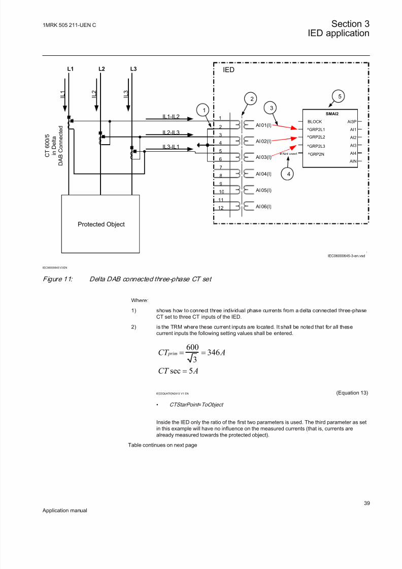
8/22/2019 Best Application
http://slidepdf.com/reader/full/best-application 45/457
7
8
9
10
11
12
1
2
3
4
5
6
L1
I
L 1
I
L 2
I
L 3
L2 L3
Protected Object
AI 01 (I)
AI 02 (I)
AI 03 (I)
AI 04 (I)
AI 05 (I)
AI 06 (I)
IED
IL1-IL2
IL2-IL3
IL3-IL1
1
2
3
.
# Not used
5
IEC06000645-3-en.vsd
SMAI2
BLOCK
^GRP2L1
AI3P
AI1
AI2
AI3
AI4
AIN
^GRP2L2
^GRP2L3
^GRP2N
4
C T 6 0 0 / 5
i n D e l t a
D A B C o n n e c t e d
IEC06000645 V3 EN
Figure 11: Delta DAB connected three-phase CT set
Where:
1) shows how to connect three individual phase currents from a delta connected three-phaseCT set to three CT inputs of the IED.
2) is the TRM where these current inputs are located. It shall be noted that for all thesecurrent inputs the following setting values shall be entered.
600346
3sec 5
primCT A
CT A
= =
=
IECEQUATION2413 V1 EN (Equation 13)
• CTStarPoint =ToObject
Inside the IED only the ratio of the first two parameters is used. The third parameter as setin this example will have no influence on the measured currents (that is, currents arealready measured towards the protected object).
Table continues on next page
1MRK 505 211-UEN C Section 3IED application
39
Application manual

8/22/2019 Best Application
http://slidepdf.com/reader/full/best-application 46/457
3) are three connections made in Signal Matrix Tool (SMT), which connect these threecurrent inputs to first three input channels of the preprocessing function block 6).Depending on the type of functions which need this current information, more then onepreprocessing block might be connected in parallel to these three CT inputs.
4) shows that the fourth input channel of the preprocessing function block shall not beconnected in SMT.
5) is a Preprocessing block that has the task to digitally filter the connected analog inputs andcalculate:
• fundamental frequency phasors for all four input channels• harmonic content for all four input channels• positive, negative and zero sequence quantities by using the fundamental frequency
phasors for the first three input channels (channel one taken as reference for sequence quantities)
These calculated values are then available for all built-in protection and control functionswithin the IED, which are connected to this preprocessing function block in theconfiguration tool. For this application most of the preprocessing settings can be left to thedefault values.If frequency tracking and compensation is required (this feature is typically required onlyfor IEDs installed in the generating stations) then the setting parameters DFTReference
shall be set accordingly.
Another alternative is to have the delta connected CT set as shown in figure 12:
7
8
9
10
1112
1
2
3
4
5
6
L1
I L 1
I L 2
I L 3
L2 L3
Protected Object
AI 01 (I)
AI 02 (I)
AI 03 (I)
AI 04 (I)
AI 05 (I)
AI 06 (I)
IED
IL3-IL2
IL2-IL1
IL1-IL3
2
3
#Not used
5
IEC06000646-3-en.vsd
4
SMAI2
BLOCK
^GRP2L1
AI3P
AI1
AI2
AI3
AI4
AIN
^GRP2L2
^GRP2L3
^GRP2N C T 8 0 0 / 1
i n d e l t a
D C A C o n n e c t e d
IEC06000646 V3 EN
Figure 12: Delta DAC connected three-phase CT set
Section 3 1MRK 505 211-UEN C
IED application
40
Application manual

8/22/2019 Best Application
http://slidepdf.com/reader/full/best-application 47/457
In this case, everything is done in a similar way as in the above described example,except that for all used current inputs on the TRM the following setting parametersshall be entered:
sec
800 4623
1
primCT A
CT A
= =
=IECEQUATION2414 V1 EN (Equation 14)
• CTStarPoint =ToObject
Inside the IED only the ratio of the first two parameters is used. The third parameter as set in this example will have no influence on the measured currents(that is, currents are already measured towards the protected object).
Example how to connect single-phase CT to the IEDFigure 13 gives an example how to connect the single-phase CT to the IED. Itgives an overview of the required actions by the user in order to make thismeasurement available to the built-in protection and control functions within theIED as well.
Protected Object
7
8
9
10
11
12
1
2
3
4
5
6
L1 L2 L3
AI01 (I)
AI02 (I)
AI03 (I)
AI04 (I)
AI05 (I)
AI06 (I)
IED
I N P
INP
INP
2
1
3
# Not used
# Not used
# Not used
IEC06000647-3-en.vsd
5
SMAI2
BLOCK
^GRP2L1
AI3P
AI1
AI2
AI3
AI4
AIN
^GRP2L2
^GRP2L3
^GRP2N
4
C T 1 0 0 0 / 1
a)
b)
IEC06000647 V3 EN
Figure 13: Connections for single-phase CT input
1MRK 505 211-UEN C Section 3IED application
41
Application manual

8/22/2019 Best Application
http://slidepdf.com/reader/full/best-application 48/457
Where:
1) shows how to connect single-phase CT input in the IED.
2) is TRM where these current inputs are located. It shall be noted that for all thesecurrent inputs the following setting values shall be entered.
For connection (a) shown in figure 13:
sec
600
5
primCT A
CT A
=
=IECEQUATION2415 V1 EN (Equation 15)
CTStarPoint =ToObject
Inside the IED only the ratio of the first two parameters is used. The third parameter asset in this example will have no influence on the measured currents (that is, currentsare already measured towards the protected object). For connection (b) shown in figure 13:
sec
600
5
primCT A
CT A
=
=IECEQUATION2415 V1 EN (Equation 16)
CTStarPoint =FromObject
Inside the IED only the ratio of the first two parameters is used. The third parameter asset in this example will invert the measured currents (that is, turn the currents by 180°)in order to ensure that the currents within the IED are measured towards the protectedobject.
3) shows that in this example the first three input channel of the preprocessing block isnot connected in Signal Matrix Tool (SMT).
4) shows the connection made in SMT tool, which connect this CT input to the fourth inputchannel of the preprocessing function block 5).
5) is a Preprocessing block that has the task to digitally filter the connected analog inputs
and calculate:
• fundamental frequency phasors for all four input channels• harmonic content for all four input channels• positive, negative and zero sequence quantities by using the fundamental
frequency phasors for the first three input channels (channel one taken asreference for sequence quantities)
These calculated values are then available for all built-in protection and controlfunctions within the IED, which are connected to this preprocessing function block. inthe configuration tool. For this application most of the preprocessing settings can be leftto the default valuesIf frequency tracking and compensation is required (this feature is typically requiredonly for IEDs installed in the generating stations) then the setting parametersDFTReference shall be set accordingly.
Setting of voltage channelsAs the IED uses primary system quantities the main VT ratios must be known tothe IED. This is done by setting the two parameters VTsec and VTprim for eachvoltage channel. The phase-to-phase value can be used even if each channel isconnected to a phase-to-earth voltage from the VT.
ExampleConsider a VT with the following data:
Section 3 1MRK 505 211-UEN C
IED application
42
Application manual

8/22/2019 Best Application
http://slidepdf.com/reader/full/best-application 49/457
132 110
3 3
kV V
EQUATION2016 V1 EN (Equation 17)
The following setting should be used: VTprim=132 (value in kV) VTsec=110
(value in V)
Examples how to connect, configure and set VT inputs for most
commonly used VT connectionsFigure 14 defines the marking of voltage transformer terminals commonly usedaround the world.
A
(H1)
B
(H2)
b
(X2)
a
(X1) A
(H1)
N
(H2)
n
(X2)
a
(X1)
b) c)
A
(H1)
N
(H2)
dn
(X2)
da
(X1)
d)
UPri
+ +
USec
a)
en06000591.vsd
IEC06000591 V1 EN
Figure 14: Commonly used markings of VT terminals
Where:
a) is the symbol and terminal marking used in this document. Terminals marked with a dot
indicate the primary and secondary winding terminals with the same (positive) polarity
b) is the equivalent symbol and terminal marking used by IEC (ANSI) standard for phase-to-earth connected VTs
c) is the equivalent symbol and terminal marking used by IEC (ANSI) standard for open deltaconnected VTs
d) is the equivalent symbol and terminal marking used by IEC (ANSI) standard for phase-to-phase connected VTs
It shall be noted that depending on national standard and utility practices the ratedsecondary voltage of a VT has typically one of the following values:
• 100 V• 110 V• 115 V• 120 V• 230 V
The IED fully supports all of these values and most of them will be shown in thefollowing examples.
1MRK 505 211-UEN C Section 3IED application
43
Application manual

8/22/2019 Best Application
http://slidepdf.com/reader/full/best-application 50/457
Examples on how to connect a three phase-to-earth connected VT to
the IEDFigure 15 gives an example on how to connect a three phase-to-earth connected VTto the IED. It as well gives overview of required actions by the user in order tomake this measurement available to the built-in protection and control functionswithin the IED.
19
20
21
22
23
24
13
14
15
16
17
18
L1
AI 07 (I)
AI 08 (U)
AI 09 (U)
AI 10 (U)
AI 11 (U)
AI 12 (U)
IEDL2
L3
66
3110
3
kV
V
1
3
2
66
3
1103
kV
V
66
3110
3
kV
V
.
#Not used
5
IEC06000599-3-en.vsd
SMAI2
BLOCK
^GRP2L1
AI3P
AI1
AI2
AI3
AI4
AIN
^GRP2L2
^GRP2L3
^GRP2N
4
IEC06000599 V3 EN
Figure 15: A Three phase-to-earth connected VT
Section 3 1MRK 505 211-UEN C
IED application
44
Application manual

8/22/2019 Best Application
http://slidepdf.com/reader/full/best-application 51/457
Where:
1) shows how to connect three secondary phase-to-earth voltages to three VT inputs onthe IED
2) is the TRM where these three voltage inputs are located. For these three voltage
inputs, the following setting values shall be entered:VTprim =66 kV
VTsec = 110 V
Inside the IED, only the ratio of these two parameters is used. It shall be noted that theratio of the entered values exactly corresponds to ratio of one individual VT.
6666 3
1101103
=
EQUATION1903 V1 EN (Equation 18)
3) are three connections made in Signal Matrix Tool (SMT), which connect these three
voltage inputs to first three input channels of the preprocessing function block 5).Depending on the type of functions which need this voltage information, more then onepreprocessing block might be connected in parallel to these three VT inputs.
4) shows that in this example the fourth (that is, residual) input channel of thepreprocessing block is not connected in SMT tool. Thus the preprocessing block willautomatically calculate 3Uo inside by vectorial sum from the three phase to earthvoltages connected to the first three input channels of the same preprocessing block.
Alternatively, the fourth input channel can be connected to open delta VT input, asshown in figure 17.
5) is a Preprocessing block that has the task to digitally filter the connected analog inputsand calculate:
• fundamental frequency phasors for all four input channels• harmonic content for all four input channels
• positive, negative and zero sequence quantities by using the fundamentalfrequency phasors for the first three input channels (channel one taken asreference for sequence quantities)
These calculated values are then available for all built-in protection and controlfunctions within the IED, which are connected to this preprocessing function block in theconfiguration tool. For this application most of the preprocessing settings can be left tothe default values. However the following settings shall be set as shown here:UBase=66 kV (that is, rated Ph-Ph voltage)If frequency tracking and compensation is required (this feature is typically requiredonly for IEDs installed in the generating stations) then the setting parametersDFTReference shall be set accordingly.
Example on how to connect a phase-to-phase connected VT to the IEDFigure 16 gives an example how to connect a phase-to-phase connected VT to theIED. It gives an overview of the required actions by the user in order to make thismeasurement available to the built-in protection and control functions within theIED as well. It shall be noted that this VT connection is only used on lower voltagelevels (that is, rated primary voltage below 40 kV).
1MRK 505 211-UEN C Section 3IED application
45
Application manual

8/22/2019 Best Application
http://slidepdf.com/reader/full/best-application 52/457
1920
21
22
23
24
13
14
15
16
17
18
L1
AI 07(I)
AI08(U)
AI09(U)
AI 10(U)
AI11(U)
AI12(U)
IED
L2
L3
13.8120
kV V
1
2
3
#Not Used
13.8120
kV V
.
5
IEC06000600-3-en.vsd
4
SMAI2
BLOCK
^GRP2L1
AI3P
AI1
AI2
AI3
AI4
AIN
^GRP2L2
^GRP2L3
^GRP2N
IEC06000600 V3 EN
Figure 16: A Two phase-to-phase connected VT
Where:
1) shows how to connect the secondary side of a phase-to-phase VT to the VT inputs on theIED
2) is the TRM where these three voltage inputs are located. It shall be noted that for thesethree voltage inputs the following setting values shall be entered:VTprim =13.8 kVVTsec =120 VPlease note that inside the IED only ratio of these two parameters is used.
Table continues on next page
Section 3 1MRK 505 211-UEN C
IED application
46
Application manual

8/22/2019 Best Application
http://slidepdf.com/reader/full/best-application 53/457
3) are three connections made in the Signal Matrix tool (SMT), which connects these threevoltage inputs to first three input channels of the preprocessing function block 5).Depending on the type of functions, which need this voltage information, more than onepreprocessing block might be connected in parallel to these three VT inputs
4) shows that in this example the fourth (that is, residual) input channel of the preprocessingblock is not connected in SMT.
5) Preprocessing block has a task to digitally filter the connected analog inputs and calculate:
• fundamental frequency phasors for all four input channels• harmonic content for all four input channels• positive, negative and zero sequence quantities by using the fundamental frequency
phasors for the first three input channels (channel one taken as reference for sequence quantities)
These calculated values are then available for all built-in protection and control functionswithin the IED, which are connected to this preprocessing function block in theconfiguration tool. For this application most of the preprocessing settings can be left to thedefault values. However the following settings shall be set as shown here:ConnectionType =Ph-Ph
UBase=13.8 kVIf frequency tracking and compensation is required (this feature is typically required onlyfor IEDs installed in the generating stations) then the setting parameters DFTReference
shall be set accordingly.
Example on how to connect an open delta VT to the IED for high
impedance earthed or unearthedFigure 17 gives an example about the wiring of an open delta VT to the IED for high impedance earthed or unearthed power systems. It shall be noted that this typeof VT connection presents a secondary voltage proportional to 3U0 to the IED.
In case of a solid earth fault close to the VT location the primary value of 3Uo will be equal to:
3 0 3. 3. Ph Ph Ph E U U U - -= =EQUATION1921 V2 EN (Equation 19)
The primary rated voltage of an open Delta VT is always equal to UPh-E. Threeseries connected VT secondary windings gives a secondary voltage equal to threetimes the individual VT secondary winding rating. Thus the secondary windings of open delta VTs quite often have a secondary rated voltage equal to one third of therated phase-to-phase VT secondary voltage (110/3V in this particular example).
Figure gives overview of required actions by the user in order to make thismeasurement available to the built-in protection and control functions within theIED as well.
1MRK 505 211-UEN C Section 3IED application
47
Application manual

8/22/2019 Best Application
http://slidepdf.com/reader/full/best-application 54/457
19
20
21
22
23
24
13
14
15
16
17
18
L1
AI 07 (I)
AI 08 (U)
AI 09 (U)
AI 10 (U)
AI 11 (U)
AI 12 (U)
IEDL2
L3
6.6
3110
3
kV
V
+3Uo
6.6
3110
3
kV
V
6.6
3110
3
kV
V
1
2
4
3# Not Used
5
IEC06000601-3-en.vsd
# Not Used
# Not Used
SMAI2
BLOCK
^GRP2L1
^GRP2L2
^GRP2L3
^GRP2N
AI3P
AI1
AI2
AI3
AI4
AIN
IEC06000601 V3 EN
Figure 17: Open delta connected VT in high impedance earthed power system
Section 3 1MRK 505 211-UEN C
IED application
48
Application manual

8/22/2019 Best Application
http://slidepdf.com/reader/full/best-application 55/457
Where:
1) shows how to connect the secondary side of the open delta VT to one VT input on the IED.
+3U0 shall be connected to the IED
2) is the TRM where this voltage input is located. It shall be noted that for this voltage inputthe following setting values shall be entered:
3 6.6 11.43VTprim kV = × =
EQUATION1923 V1 EN (Equation 20)
110sec 3 110
3VT V = × =
EQUATION1924 V1 EN (Equation 21)
Inside the IED, only the ratio of these two parameters is used. It shall be noted that theratio of the entered values exactly corresponds to ratio of one individual open delta VT.
6.63 6.6 3
1101103
×=
EQUATION1925 V1 EN (Equation 22)
3) shows that in this example the first three input channel of the preprocessing block is notconnected in SMT tool.
4) shows the connection made in Signal Matrix Tool (SMT), which connect this voltage inputto the fourth input channel of the preprocessing function block 5).
5) is a Preprocessing block that has the task to digitally filter the connected analog input andcalculate:
• fundamental frequency phasors for all four input channels• harmonic content for all four input channels• positive, negative and zero sequence quantities by using the fundamental frequency
phasors for the first three input channels (channel one taken as reference for sequence quantities)
These calculated values are then available for all built-in protection and control functionswithin the IED, which are connected to this preprocessing function block in the
configuration tool. For this application most of the preprocessing settings can be left to thedefault values.If frequency tracking and compensation is required (this feature is typically required only for IEDs installed in the generating stations ) then the setting parameters DFTReference shallbe set accordingly.
1MRK 505 211-UEN C Section 3IED application
49
Application manual

8/22/2019 Best Application
http://slidepdf.com/reader/full/best-application 56/457
Example how to connect the open delta VT to the IED for low
impedance earthed or solidly earthed power systemsFigure 18 gives an example about the connection of an open delta VT to the IEDfor low impedance earthed or solidly earthed power systems. It shall be noted thatthis type of VT connection presents secondary voltage proportional to 3U0 to the IED.
In case of a solid earth fault close to the VT location the primary value of 3Uo will be equal to:
33
Ph Ph
Ph E
U Uo U -
-= =
EQUATION1926 V1 EN (Equation 23)
The primary rated voltage of such VT is always equal to UPh-E Therefore, three
series connected VT secondary windings will give the secondary voltage equalonly to one individual VT secondary winding rating. Thus the secondary windingsof such open delta VTs quite often has a secondary rated voltage close to rated phase-to-phase VT secondary voltage, that is, 115V or 115/√3V as in this particular example. Figure 18 gives an overview of the actions which are needed to make thismeasurement available to the built-in protection and control functions within the IED.
19
20
21
22
23
24
13
14
15
16
17
18
L1
AI07 (I)
AI08 (U)
AI09 (U)
AI10 (U)
AI11 (U)
AI12 (U)
IEDL2
L3
1383115
3
kV
V
+3Uo
138
3115
3
kV
V
1383115
3
kV
V
1
2
4
3
IEC06000602-3-en.vsd
SMAI2
BLOCK
^GRP2L1
^GRP2L2
^GRP2L3
^GRP2N
AI3P
AI1
AI2
AI3
AI4
AIN
5
# Not Used
# Not Used
# Not Used
IEC06000602 V3 EN
Figure 18: Open delta connected VT in low impedance or solidly earthed power system
Section 3 1MRK 505 211-UEN C
IED application
50
Application manual

8/22/2019 Best Application
http://slidepdf.com/reader/full/best-application 57/457
Where:
1) shows how to connect the secondary side of open delta VT to one VT input in the IED.
+3Uo shall be connected to the IED.
2) is TRM where this voltage input is located. It shall be noted that for this voltage inputthe following setting values shall be entered:
1383 138
3VTprim kV = × =
EQUATION1928 V1 EN (Equation 24)
115sec 3 115
3
VT V = × =
EQUATION1929 V1 EN (Equation 25)
Inside the IED, only the ratio of these two parameters is used. It shall be noted thatthe ratio of the entered values exactly corresponds to ratio of one individual opendelta VT.
138138 3
1151153
=
EQUATION1930 V1 EN (Equation 26)
3) shows that in this example the first three input channel of the preprocessing block isnot connected in SMT tool.
4) shows the connection made in Signal Matrix Tool (SMT), which connect this voltageinput to the fourth input channel of the preprocessing function block 4).
5) preprocessing block has a task to digitally filter the connected analog inputs andcalculate:
• fundamental frequency phasors for all four input channels• harmonic content for all four input channels• positive, negative and zero sequence quantities by using the fundamental
frequency phasors for the first three input channels (channel one taken asreference for sequence quantities)
These calculated values are then available for all built-in protection and controlfunctions within the IED, which are connected to this preprocessing function block inthe configuration tool. For this application most of the preprocessing settings can beleft to the default values.If frequency tracking and compensation is required (this feature is typically requiredonly for IEDs installed in the generating stations) then the setting parametersDFTReference shall be set accordingly.
Example on how to connect a neutral point VT to the IEDFigure 19 gives an example on how to connect a neutral point VT to the IED. Thistype of VT connection presents secondary voltage proportional to U0 to the IED.
1MRK 505 211-UEN C Section 3IED application
51
Application manual

8/22/2019 Best Application
http://slidepdf.com/reader/full/best-application 58/457
In case of a solid earth fault in high impedance earthed or unearthed systems the primary value of Uo voltage will be equal to:
03
Ph Ph Ph E
U U U
--= =
EQUATION1931 V2 EN (Equation 27)
Figure 19 gives an overview of required actions by the user in order to make thismeasurement available to the built-in protection and control functions within theIED as well.
19
20
21
22
23
24
13
14
15
16
17
18
L1 L2 L3
AI07 (I)
AI08 (I)
AI09 (I)
AI10 (U)
AI11 (U)
AI12 (U)
IED
6.6
3100
kV
V
RUo
1
2
3
IEC06000603-3-en.vsd
5
SMAI2
BLOCK
^GRP2L1
^GRP2L2
^GRP2L3
^GRP2N
AI3P
AI1
AI2
AI3
AI4
AIN
# Not Used
# Not Used
# Not Used
4
Protected Object
IEC06000603 V3 EN
Figure 19: Neutral point connected VT
Section 3 1MRK 505 211-UEN C
IED application
52
Application manual

8/22/2019 Best Application
http://slidepdf.com/reader/full/best-application 59/457
Where:
1) shows how to connect the secondary side of neutral point VT to one VT input in the IED.
U0 shall be connected to the IED.
2) is the TRM where this voltage input is located. It shall be noted that for this voltage inputthe following setting values shall be entered:is the TRM or AIM where this voltage input is located. For this voltage input the followingsetting values shall be entered:
6.63.81
3VTprim kV = =
EQUATION1933 V1 EN (Equation 28)
sec 100VT V =EQUATION1934 V1 EN (Equation 29)
Inside the IED, only the ratio of these two parameters is used. It shall be noted that theratio of the entered values exactly corresponds to ratio of the neutral point VT.
3) shows that in this example the first three input channel of the preprocessing block is notconnected in SMT tool.
4) shows the connection made in Signal Matrix Tool (SMT), which connects this voltage inputto the fourth input channel of the preprocessing function block 5).
5) is a preprocessing block that has the task to digitally filter the connected analog inputs andcalculate:
• fundamental frequency phasors for all four input channels• harmonic content for all four input channels• positive, negative and zero sequence quantities by using the fundamental frequency
phasors for the first three input channels (channel one taken as reference for sequence quantities)
These calculated values are then available for all built-in protection and control functionswithin the IED, which are connected to this preprocessing function block in theconfiguration tool. For this application most of the preprocessing settings can be left to thedefault values.If frequency tracking and compensation is required (this feature is typically required onlyfor IEDs installed in the generating stations) then the setting parameters DFTReference
shall be set accordingly.
3.2.3 Setting parameters
The available setting parameters related to analog inputs aredepending on the actual hardware (TRM) and the logicconfiguration made in PCM600.
1MRK 505 211-UEN C Section 3IED application
53
Application manual

8/22/2019 Best Application
http://slidepdf.com/reader/full/best-application 60/457
Table 1: AISVBAS Non group settings (basic)
Name Values (Range) Unit Step Default Description
PhaseAngleRef TRM40-Ch1TRM40-Ch2
TRM40-Ch3TRM40-Ch4TRM40-Ch5TRM40-Ch6TRM40-Ch7TRM40-Ch8TRM40-Ch9TRM40-Ch10TRM40-Ch11TRM40-Ch12TRM41-Ch1TRM41-Ch2TRM41-Ch3TRM41-Ch4TRM41-Ch5TRM41-Ch6TRM41-Ch7TRM41-Ch8TRM41-Ch9TRM41-Ch10TRM41-Ch11TRM41-Ch12MU1-L1IMU1-L2IMU1-L3IMU1-L4IMU1-L1UMU1-L2UMU1-L3UMU1-L4UMU2-L1I
MU2-L2IMU2-L3IMU2-L4IMU2-L1UMU2-L2UMU2-L3UMU2-L4UMU3-L1IMU3-L2IMU3-L3IMU3-L4IMU3-L1UMU3-L2UMU3-L3UMU3-L4U
- - TRM40-Ch1 Reference channel for phase anglepresentation
Table 2: TRM_12I Non group settings (basic)
Name Values (Range) Unit Step Default Description
CTStarPoint1 FromObjectToObject
- - ToObject ToObject= towards protected object,FromObject= the opposite
CTsec1 1 - 10 A 1 1 Rated CT secondary current
CTprim1 1 - 99999 A 1 3000 Rated CT primary current
CTStarPoint2 FromObjectToObject
- - ToObject ToObject= towards protected object,FromObject= the opposite
Table continues on next page
Section 3 1MRK 505 211-UEN C
IED application
54
Application manual
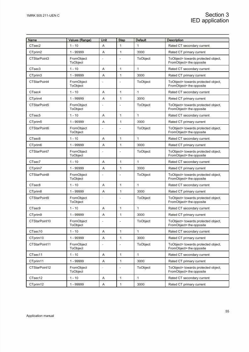
8/22/2019 Best Application
http://slidepdf.com/reader/full/best-application 61/457
Name Values (Range) Unit Step Default Description
CTsec2 1 - 10 A 1 1 Rated CT secondary current
CTprim2 1 - 99999 A 1 3000 Rated CT primary current
CTStarPoint3 FromObjectToObject
- - ToObject ToObject= towards protected object,FromObject= the opposite
CTsec3 1 - 10 A 1 1 Rated CT secondary current
CTprim3 1 - 99999 A 1 3000 Rated CT primary current
CTStarPoint4 FromObjectToObject
- - ToObject ToObject= towards protected object,FromObject= the opposite
CTsec4 1 - 10 A 1 1 Rated CT secondary current
CTprim4 1 - 99999 A 1 3000 Rated CT primary current
CTStarPoint5 FromObjectToObject
- - ToObject ToObject= towards protected object,FromObject= the opposite
CTsec5 1 - 10 A 1 1 Rated CT secondary current
CTprim5 1 - 99999 A 1 3000 Rated CT primary current
CTStarPoint6 FromObjectToObject
- - ToObject ToObject= towards protected object,FromObject= the opposite
CTsec6 1 - 10 A 1 1 Rated CT secondary current
CTprim6 1 - 99999 A 1 3000 Rated CT primary current
CTStarPoint7 FromObjectToObject
- - ToObject ToObject= towards protected object,FromObject= the opposite
CTsec7 1 - 10 A 1 1 Rated CT secondary current
CTprim7 1 - 99999 A 1 3000 Rated CT primary current
CTStarPoint8 FromObjectToObject
- - ToObject ToObject= towards protected object,FromObject= the opposite
CTsec8 1 - 10 A 1 1 Rated CT secondary current
CTprim8 1 - 99999 A 1 3000 Rated CT primary current
CTStarPoint9 FromObjectToObject
- - ToObject ToObject= towards protected object,FromObject= the opposite
CTsec9 1 - 10 A 1 1 Rated CT secondary current
CTprim9 1 - 99999 A 1 3000 Rated CT primary current
CTStarPoint10 FromObjectToObject
- - ToObject ToObject= towards protected object,FromObject= the opposite
CTsec10 1 - 10 A 1 1 Rated CT secondary current
CTprim10 1 - 99999 A 1 3000 Rated CT primary current
CTStarPoint11 FromObjectToObject
- - ToObject ToObject= towards protected object,FromObject= the opposite
CTsec11 1 - 10 A 1 1 Rated CT secondary current
CTprim11 1 - 99999 A 1 3000 Rated CT primary current
CTStarPoint12 FromObjectToObject
- - ToObject ToObject= towards protected object,FromObject= the opposite
CTsec12 1 - 10 A 1 1 Rated CT secondary current
CTprim12 1 - 99999 A 1 3000 Rated CT primary current
1MRK 505 211-UEN C Section 3IED application
55
Application manual

8/22/2019 Best Application
http://slidepdf.com/reader/full/best-application 62/457
Table 3: TRM_6I_6U Non group settings (basic)
Name Values (Range) Unit Step Default Description
CTStarPoint1 FromObjectToObject
- - ToObject ToObject= towards protected object,FromObject= the opposite
CTsec1 1 - 10 A 1 1 Rated CT secondary current
CTprim1 1 - 99999 A 1 3000 Rated CT primary current
CTStarPoint2 FromObjectToObject
- - ToObject ToObject= towards protected object,FromObject= the opposite
CTsec2 1 - 10 A 1 1 Rated CT secondary current
CTprim2 1 - 99999 A 1 3000 Rated CT primary current
CTStarPoint3 FromObjectToObject
- - ToObject ToObject= towards protected object,FromObject= the opposite
CTsec3 1 - 10 A 1 1 Rated CT secondary current
CTprim3 1 - 99999 A 1 3000 Rated CT primary current
CTStarPoint4 FromObjectToObject
- - ToObject ToObject= towards protected object,FromObject= the opposite
CTsec4 1 - 10 A 1 1 Rated CT secondary current
CTprim4 1 - 99999 A 1 3000 Rated CT primary current
CTStarPoint5 FromObjectToObject
- - ToObject ToObject= towards protected object,FromObject= the opposite
CTsec5 1 - 10 A 1 1 Rated CT secondary current
CTprim5 1 - 99999 A 1 3000 Rated CT primary current
CTStarPoint6 FromObjectToObject
- - ToObject ToObject= towards protected object,FromObject= the opposite
CTsec6 1 - 10 A 1 1 Rated CT secondary current
CTprim6 1 - 99999 A 1 3000 Rated CT primary current
VTsec7 0.001 - 999.999 V 0.001 110.000 Rated VT secondary voltage
VTprim7 0.05 - 2000.00 kV 0.05 400.00 Rated VT primary voltage
VTsec8 0.001 - 999.999 V 0.001 110.000 Rated VT secondary voltage
VTprim8 0.05 - 2000.00 kV 0.05 400.00 Rated VT primary voltage
VTsec9 0.001 - 999.999 V 0.001 110.000 Rated VT secondary voltage
VTprim9 0.05 - 2000.00 kV 0.05 400.00 Rated VT primary voltage
VTsec10 0.001 - 999.999 V 0.001 110.000 Rated VT secondary voltage
VTprim10 0.05 - 2000.00 kV 0.05 400.00 Rated VT primary voltage
VTsec11 0.001 - 999.999 V 0.001 110.000 Rated VT secondary voltage
VTprim11 0.05 - 2000.00 kV 0.05 400.00 Rated VT primary voltage
VTsec12 0.001 - 999.999 V 0.001 110.000 Rated VT secondary voltage
VTprim12 0.05 - 2000.00 kV 0.05 400.00 Rated VT primary voltage
Section 3 1MRK 505 211-UEN C
IED application
56
Application manual
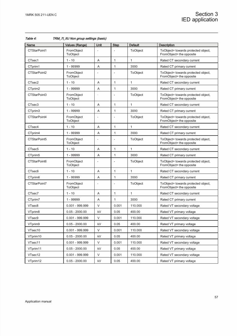
8/22/2019 Best Application
http://slidepdf.com/reader/full/best-application 63/457
Table 4: TRM_7I_5U Non group settings (basic)
Name Values (Range) Unit Step Default Description
CTStarPoint1 FromObjectToObject
- - ToObject ToObject= towards protected object,FromObject= the opposite
CTsec1 1 - 10 A 1 1 Rated CT secondary current
CTprim1 1 - 99999 A 1 3000 Rated CT primary current
CTStarPoint2 FromObjectToObject
- - ToObject ToObject= towards protected object,FromObject= the opposite
CTsec2 1 - 10 A 1 1 Rated CT secondary current
CTprim2 1 - 99999 A 1 3000 Rated CT primary current
CTStarPoint3 FromObjectToObject
- - ToObject ToObject= towards protected object,FromObject= the opposite
CTsec3 1 - 10 A 1 1 Rated CT secondary current
CTprim3 1 - 99999 A 1 3000 Rated CT primary current
CTStarPoint4 FromObjectToObject
- - ToObject ToObject= towards protected object,FromObject= the opposite
CTsec4 1 - 10 A 1 1 Rated CT secondary current
CTprim4 1 - 99999 A 1 3000 Rated CT primary current
CTStarPoint5 FromObjectToObject
- - ToObject ToObject= towards protected object,FromObject= the opposite
CTsec5 1 - 10 A 1 1 Rated CT secondary current
CTprim5 1 - 99999 A 1 3000 Rated CT primary current
CTStarPoint6 FromObjectToObject
- - ToObject ToObject= towards protected object,FromObject= the opposite
CTsec6 1 - 10 A 1 1 Rated CT secondary current
CTprim6 1 - 99999 A 1 3000 Rated CT primary current
CTStarPoint7 FromObjectToObject
- - ToObject ToObject= towards protected object,FromObject= the opposite
CTsec7 1 - 10 A 1 1 Rated CT secondary current
CTprim7 1 - 99999 A 1 3000 Rated CT primary current
VTsec8 0.001 - 999.999 V 0.001 110.000 Rated VT secondary voltage
VTprim8 0.05 - 2000.00 kV 0.05 400.00 Rated VT primary voltage
VTsec9 0.001 - 999.999 V 0.001 110.000 Rated VT secondary voltage
VTprim9 0.05 - 2000.00 kV 0.05 400.00 Rated VT primary voltage
VTsec10 0.001 - 999.999 V 0.001 110.000 Rated VT secondary voltageVTprim10 0.05 - 2000.00 kV 0.05 400.00 Rated VT primary voltage
VTsec11 0.001 - 999.999 V 0.001 110.000 Rated VT secondary voltage
VTprim11 0.05 - 2000.00 kV 0.05 400.00 Rated VT primary voltage
VTsec12 0.001 - 999.999 V 0.001 110.000 Rated VT secondary voltage
VTprim12 0.05 - 2000.00 kV 0.05 400.00 Rated VT primary voltage
1MRK 505 211-UEN C Section 3IED application
57
Application manual

8/22/2019 Best Application
http://slidepdf.com/reader/full/best-application 64/457
Table 5: TRM_9I_3U Non group settings (basic)
Name Values (Range) Unit Step Default Description
CTStarPoint1 FromObjectToObject
- - ToObject ToObject= towards protected object,FromObject= the opposite
CTsec1 1 - 10 A 1 1 Rated CT secondary current
CTprim1 1 - 99999 A 1 3000 Rated CT primary current
CTStarPoint2 FromObjectToObject
- - ToObject ToObject= towards protected object,FromObject= the opposite
CTsec2 1 - 10 A 1 1 Rated CT secondary current
CTprim2 1 - 99999 A 1 3000 Rated CT primary current
CTStarPoint3 FromObjectToObject
- - ToObject ToObject= towards protected object,FromObject= the opposite
CTsec3 1 - 10 A 1 1 Rated CT secondary current
CTprim3 1 - 99999 A 1 3000 Rated CT primary current
CTStarPoint4 FromObjectToObject
- - ToObject ToObject= towards protected object,FromObject= the opposite
CTsec4 1 - 10 A 1 1 Rated CT secondary current
CTprim4 1 - 99999 A 1 3000 Rated CT primary current
CTStarPoint5 FromObjectToObject
- - ToObject ToObject= towards protected object,FromObject= the opposite
CTsec5 1 - 10 A 1 1 Rated CT secondary current
CTprim5 1 - 99999 A 1 3000 Rated CT primary current
CTStarPoint6 FromObjectToObject
- - ToObject ToObject= towards protected object,FromObject= the opposite
CTsec6 1 - 10 A 1 1 Rated CT secondary current
CTprim6 1 - 99999 A 1 3000 Rated CT primary current
CTStarPoint7 FromObjectToObject
- - ToObject ToObject= towards protected object,FromObject= the opposite
CTsec7 1 - 10 A 1 1 Rated CT secondary current
CTprim7 1 - 99999 A 1 3000 Rated CT primary current
CTStarPoint8 FromObjectToObject
- - ToObject ToObject= towards protected object,FromObject= the opposite
CTsec8 1 - 10 A 1 1 Rated CT secondary current
CTprim8 1 - 99999 A 1 3000 Rated CT primary current
CTStarPoint9 FromObject
ToObject
- - ToObject ToObject= towards protected object,
FromObject= the opposite
CTsec9 1 - 10 A 1 1 Rated CT secondary current
CTprim9 1 - 99999 A 1 3000 Rated CT primary current
VTsec10 0.001 - 999.999 V 0.001 110.000 Rated VT secondary voltage
VTprim10 0.05 - 2000.00 kV 0.05 400.00 Rated VT primary voltage
VTsec11 0.001 - 999.999 V 0.001 110.000 Rated VT secondary voltage
VTprim11 0.05 - 2000.00 kV 0.05 400.00 Rated VT primary voltage
VTsec12 0.001 - 999.999 V 0.001 110.000 Rated VT secondary voltage
VTprim12 0.05 - 2000.00 kV 0.05 400.00 Rated VT primary voltage
Section 3 1MRK 505 211-UEN C
IED application
58
Application manual
8/22/2019 Best Application
http://slidepdf.com/reader/full/best-application 65/457
3.3 Local human-machine interface
3.3.1 Human machine interfaceThe local HMI is equipped with a LCD that is used among other things to locallydisplay the following crucial information:
• Connection of each bay, respecting the two differential protection zones andthe check zone. In the Parameter Setting Tool the user sets individual baynames to facilitate the identification of each primary bay for station personnel.
• Status of each individual primary switchgear device, for example, open,closed, 00 as intermediate state and 11 as bad state. In PCM600 the user setsthe individual primary switchgear object names to facilitate the identificationof each switchgear device for the station personnel.
The local HMI is divided into zones with different functionality.
• Status indication LEDs.• Alarm indication LEDs, which consist of 15 LEDs (6 red and 9 yellow) with
user printable label. All LEDs are configurable from PCM600.• Liquid crystal display (LCD).• Keypad with push buttons for control and navigation purposes, switch for
selection between local and remote control and reset.• Isolated RJ45 communication port.
1MRK 505 211-UEN C Section 3IED application
59
Application manual

8/22/2019 Best Application
http://slidepdf.com/reader/full/best-application 66/457
IEC06000143 V1 EN
Figure 20: Example of medium graphic HMI
Section 3 1MRK 505 211-UEN C
IED application
60
Application manual

8/22/2019 Best Application
http://slidepdf.com/reader/full/best-application 67/457
IEC06000191 V1 EN
Figure 21: Bay to zone connection example
1 User settable bay name
2 Internally used bay FB
3 Connections to internal zones
1MRK 505 211-UEN C Section 3IED application
61
Application manual

8/22/2019 Best Application
http://slidepdf.com/reader/full/best-application 68/457
IEC06000192 V1 EN
Figure 22: Example of status of primary switchgear objects
1 User settable switchgear names
2 Switchgear object status
3.3.2 Local HMI related functions
3.3.2.1 Introduction
The local HMI can be adapted to the application configuration and to user preferences.
• Function block LocalHMI• Function block LEDGEN• Setting parameters
Section 3 1MRK 505 211-UEN C
IED application
62
Application manual

8/22/2019 Best Application
http://slidepdf.com/reader/full/best-application 69/457
3.3.2.2 General setting parameters
Table 6: SCREEN Non group settings (basic)
Name Values (Range) Unit Step Default Description
Language EnglishOptionalLanguage
- - English Local HMI language
DisplayTimeout 10 - 120 Min 10 60 Local HMI display timeout
AutoRepeat Off On
- - On Activation of auto-repeat (On) or not (Off)
ContrastLevel -10 - 20 % 1 0 Contrast level for display
DefaultScreen 0 - 0 - 1 0 Default screen
EvListSrtOrder Latest on topOldest on top
- - Latest on top Sort order of event list
SymbolFont IEC ANSI
- - IEC Symbol font for Single Line Diagram
3.3.3 Indication LEDs
3.3.3.1 Introduction
The function block LEDGEN controls and supplies information about the status of the indication LEDs. The input and output signals of LEDGEN are configured withPCM600. The input signal for each LED is selected individually with the SignalMatrix Tool in PCM600.
• LEDs (number 1–6) for trip indications are red.• LEDs (number 7–15) for start indications are yellow.
Each indication LED on the local HMI can be set individually to operate in sixdifferent sequences
• Two sequences operate as follow type.• Four sequences operate as latch type.
• Two of the latching sequence types are intended to be used as a protection indication system, either in collecting or restarting mode, with
reset functionality.• Two of the latching sequence types are intended to be used as signalingsystem in collecting (coll) mode with an acknowledgment functionality.
The light from the LEDs can be steady (-S) or flashing (-F). See the technicalreference manual for more information.
1MRK 505 211-UEN C Section 3IED application
63
Application manual

8/22/2019 Best Application
http://slidepdf.com/reader/full/best-application 70/457
3.3.3.2 Setting parameters
Table 7: LEDGEN Non group settings (basic)
Name Values (Range) Unit Step Default Description
Operation Off On
- - Off Operation mode for the LED function
tRestart 0.0 - 100.0 s 0.1 0.0 Defines the disturbance length
tMax 0.0 - 100.0 s 0.1 0.0 Maximum time for the definition of adisturbance
SeqTypeLED1 Follow-SFollow-FLatchedAck-F-SLatchedAck-S-FLatchedColl-SLatchedReset-S
- - Follow-S Sequence type for LED 1
SeqTypeLED2 Follow-S
Follow-FLatchedAck-F-SLatchedAck-S-FLatchedColl-SLatchedReset-S
- - Follow-S Sequence type for LED 2
SeqTypeLED3 Follow-SFollow-FLatchedAck-F-SLatchedAck-S-FLatchedColl-SLatchedReset-S
- - Follow-S Sequence type for LED 3
SeqTypeLED4 Follow-SFollow-FLatchedAck-F-S
LatchedAck-S-FLatchedColl-SLatchedReset-S
- - Follow-S Sequence type for LED 4
SeqTypeLED5 Follow-SFollow-FLatchedAck-F-SLatchedAck-S-FLatchedColl-SLatchedReset-S
- - Follow-S Sequence type for LED 5
SeqTypeLED6 Follow-SFollow-FLatchedAck-F-SLatchedAck-S-FLatchedColl-SLatchedReset-S
- - Follow-S Sequence type for LED 6
SeqTypeLED7 Follow-SFollow-FLatchedAck-F-SLatchedAck-S-FLatchedColl-SLatchedReset-S
- - Follow-S Sequence type for LED 7
SeqTypeLED8 Follow-SFollow-FLatchedAck-F-SLatchedAck-S-FLatchedColl-SLatchedReset-S
- - Follow-S sequence type for LED 8
Table continues on next page
Section 3 1MRK 505 211-UEN C
IED application
64
Application manual

8/22/2019 Best Application
http://slidepdf.com/reader/full/best-application 71/457
Name Values (Range) Unit Step Default Description
SeqTypeLED9 Follow-SFollow-FLatchedAck-F-SLatchedAck-S-F
LatchedColl-SLatchedReset-S
- - Follow-S Sequence type for LED 9
SeqTypeLED10 Follow-SFollow-FLatchedAck-F-SLatchedAck-S-FLatchedColl-SLatchedReset-S
- - Follow-S Sequence type for LED 10
SeqTypeLED11 Follow-SFollow-FLatchedAck-F-SLatchedAck-S-FLatchedColl-SLatchedReset-S
- - Follow-S Sequence type for LED 11
SeqTypeLED12 Follow-SFollow-FLatchedAck-F-SLatchedAck-S-FLatchedColl-SLatchedReset-S
- - Follow-S Sequence type for LED 12
SeqTypeLED13 Follow-SFollow-FLatchedAck-F-SLatchedAck-S-FLatchedColl-SLatchedReset-S
- - Follow-S Sequence type for LED 13
SeqTypeLED14 Follow-SFollow-FLatchedAck-F-SLatchedAck-S-FLatchedColl-SLatchedReset-S
- - Follow-S Sequence type for LED 14
SeqTypeLED15 Follow-SFollow-FLatchedAck-F-SLatchedAck-S-FLatchedColl-SLatchedReset-S
- - Follow-S Sequence type for LED 15
3.4 Basic IED functions
3.4.1 Self supervision with internal event list
3.4.1.1 Application
The protection and control IEDs have many functions included . The included self-supervision with internal event list function block provides good supervision of theIED. The fault signals make it easier to analyze and locate a fault.
1MRK 505 211-UEN C Section 3IED application
65
Application manual

8/22/2019 Best Application
http://slidepdf.com/reader/full/best-application 72/457
Both hardware and software supervision is included and it is also possible toindicate possible faults through a hardware contact on the power supply module and/or through the software communication.
Internal events are generated by the built-in supervisory functions. The supervisoryfunctions supervise the status of the various modules in the IED and, in case of failure, a corresponding event is generated. Similarly, when the failure is corrected,a corresponding event is generated.
Apart from the built-in supervision of the various modules, events are alsogenerated when the status changes for the:
• built-in real time clock (in operation/out of order).• external time synchronization (in operation/out of order).
Events are also generated:• whenever any setting in the IED is changed.
The internal events are time tagged with a resolution of 1 ms and stored in a list.The list can store up to 40 events. The list is based on the FIFO principle, that is,when it is full, the oldest event is overwritten. The list cannot be cleared and itscontent cannot be modified.
The list of internal events provides valuable information, which can be used duringcommissioning and fault tracing.
The information can only be retrieved with the aid of PCM600 Event MonitoringTool. The PC can either be connected to the front port, or to the port at the back of the IED.
3.4.1.2 Setting parameters
The function does not have any parameters available in the local HMI or PCM600.
3.4.2 Time synchronization
3.4.2.1 Application
Use time synchronization to achieve a common time base for the IEDs in a protection and control system. This makes it possible to compare events anddisturbance data between all IEDs in the system.
Time-tagging of internal events and disturbances are an excellent help whenevaluating faults. Without time synchronization, only the events within the IED can
be compared to one another. With time synchronization, events and disturbanceswithin the entire station, and even between line ends, can be compared at evaluation.
In the IED, the internal time can be synchronized from a number of sources:
Section 3 1MRK 505 211-UEN C
IED application
66
Application manual

8/22/2019 Best Application
http://slidepdf.com/reader/full/best-application 73/457
• BIN (Binary Minute Pulse)• GPS• SNTP• IRIG-B• SPA• LON• PPS
Odut of these, LON and SPA contains two types of synchronization messages:
• Coarse time messages are sent every minute and contain complete date andtime, that is year, month, day, hour, minute, second and millisecond.
• Fine time messages are sent every second and comprise only seconds andmilliseconds.
The setting tells the IED which of these that shall be used to synchronize the IED.
It is possible to set a backup time-source for GPS signal, for instance SNTP. In thiscase, when the GPS signal quality is bad, the IED will automatically choose SNTPas the time-source. At a given point in time, only one time-source will be used.
3.4.2.2 Setting guidelines
System timeThe time is set with years, month, day, hour, minute, second and millisecond.
SynchronizationThe setting parameters for the real-time clock with external time synchronization(TIME) are set via local HMI or PCM600.
TimeSynchWhen the source of the time synchronization is selected on the local HMI, the
parameter is called TimeSynch. The time synchronization source can also be setfrom PCM600. The setting alternatives are:
FineSyncSource which can have the following values:
• Off • SPA
• LON
• BIN (Binary Minute Pulse)• GPS
• GPS+SPA
• GPS+LON
• GPS+BIN
• SNTP
• GPS+SNTP
1MRK 505 211-UEN C Section 3IED application
67
Application manual

8/22/2019 Best Application
http://slidepdf.com/reader/full/best-application 74/457
• GPS+IRIG-B
• IRIG-B
• PPS
CoarseSyncSrc which can have the following values:
• Off
• SPA
• LON
• SNTP
• DNP
CoarseSyncSrc which can have the following values:
• Off
• SNTP • DNP
• IEC60870-5-103
The function input to be used for minute-pulse synchronization is called TIME-MINSYNC.
The system time can be set manually, either via the local HMI or via any of thecommunication ports. The time synchronization fine tunes the clock (seconds andmilliseconds).
The parameter SyncMaster defines if the IED is a master, or not a master for timesynchronization in a system of IEDs connected in a communication network (IEC61850-8-1). The SyncMaster can have the following values:
• Off
• SNTP -Server
Set the course time synchronizing source (CoarseSyncSrc) to Off
when GPS time synchronization of line differential function is used.Set the fine time synchronization source ( FineSyncSource) to GPS .The GPS will thus provide the complete time synchronization. GPS
alone shall synchronize the analogue values in such systems.
3.4.2.3 Setting parameters
Path in the local HMI is located under Main menu/Setting/Time
Path in PCM600 is located under Main menu/Settings/Time/Synchronization
Section 3 1MRK 505 211-UEN C
IED application
68
Application manual

8/22/2019 Best Application
http://slidepdf.com/reader/full/best-application 75/457
Table 8: SYNCHBIN Non group settings (basic)
Name Values (Range) Unit Step Default Description
ModulePosition 3 - 16 - 1 3 Hardware position of IO module for timesynchronization
BinaryInput 1 - 16 - 1 1 Binary input number for timesynchronization
BinDetection PositiveEdgeNegativeEdge
- - PositiveEdge Positive or negative edge detection
Table 9: SYNCHSNTP Non group settings (basic)
Name Values (Range) Unit Step Default Description
ServerIP-Add 0 - 18 IP Address
1 0.0.0.0 Server IP-address
RedServIP-Add 0 - 18 IP
Address
1 0.0.0.0 Redundant server IP-address
Table 10: DSTBEGIN Non group settings (basic)
Name Values (Range) Unit Step Default Description
MonthInYear JanuaryFebruaryMarch
AprilMayJuneJuly
August
September October November December
- - March Month in year when daylight time starts
DayInWeek SundayMondayTuesdayWednesdayThursdayFridaySaturday
- - Sunday Day in week when daylight time starts
WeekInMonth LastFirstSecond
ThirdFourth
- - Last Week in month when daylight time starts
UTCTimeOfDay 0 - 172800 s 1 3600 UTC Time of day in seconds whendaylight time starts
1MRK 505 211-UEN C Section 3IED application
69
Application manual

8/22/2019 Best Application
http://slidepdf.com/reader/full/best-application 76/457
Table 11: DSTEND Non group settings (basic)
Name Values (Range) Unit Step Default Description
MonthInYear JanuaryFebruary
March AprilMayJuneJuly
AugustSeptember October November December
- - October Month in year when daylight time ends
DayInWeek SundayMondayTuesdayWednesdayThursday
FridaySaturday
- - Sunday Day in week when daylight time ends
WeekInMonth LastFirstSecondThirdFourth
- - Last Week in month when daylight time ends
UTCTimeOfDay 0 - 172800 s 1 3600 UTC Time of day in seconds whendaylight time ends
Table 12: TIM EZO NE Non group settings (basic)
Name Values (Range) Unit Step Default Description
NoHalfHourUTC -24 - 24 - 1 0 Number of half-hours from UTC
Table 13: SYNCHIRIG-B Non group settings (basic)
Name Values (Range) Unit Step Default Description
SynchType BNCOpto
- - Opto Type of synchronization
TimeDomain LocalTimeUTC
- - LocalTime Time domain
Encoding IRIG-B
13441344TZ
- - IRIG-B Type of encoding
TimeZoneAs1344 MinusTZPlusTZ
- - PlusTZ Time zone as in 1344 standard
Section 3 1MRK 505 211-UEN C
IED application
70
Application manual

8/22/2019 Best Application
http://slidepdf.com/reader/full/best-application 77/457
3.4.3 Parameter setting groups
3.4.3.1 Application
Six sets of settings are available to optimize IED operation for different power system conditions. By creating and switching between fine tuned setting sets, either from the local HMI or configurable binary inputs, results in a highly adaptable IEDthat can cope with a variety of power system scenarios.
Different conditions in networks with different voltage levels require highlyadaptable protection and control units to best provide for dependability, securityand selectivity requirements. Protection units operate with a higher degree of availability, especially, if the setting values of their parameters are continuouslyoptimized according to the conditions in the power system.
Operational departments can plan for different operating conditions in the primaryequipment. The protection engineer can prepare the necessary optimized and pre-tested settings in advance for different protection functions. Six
A function block, SETGRPS, defines how many setting groups are used. Setting isdone with parameter MAXSETGR and shall be set to the required value for eachIED. Only the number of setting groups set will be available in the Parameter Setting tool for activation with the ActiveGroup function block.
3.4.3.2 Setting guidelines
The setting ActiveSetGrp, is used to select which parameter group to be active. Theactive group can also be selected with configured input to the function block SETGRPS.
The length of the pulse, sent out by the output signal SETCHGD when an activegroup has changed, is set with the parameter t .
The parameter MAXSETGR defines the maximum number of setting groups in useto switch between. Only the selected number of setting groups will be available inthe Parameter Setting tool (PST) for activation with the ActiveGroup function block.
3.4.3.3 Setting parameters
Table 14: ActiveG roup N on group settings (basic)
Name Values (Range) Unit Step Default Description
t 0.0 - 10.0 s 0.1 1.0 Pulse length of pulse when settingchanged
1MRK 505 211-UEN C Section 3IED application
71
Application manual

8/22/2019 Best Application
http://slidepdf.com/reader/full/best-application 78/457
Table 15: SETG RPS Non group settings (basic)
Name Values (Range) Unit Step Default Description
ActiveSetGrp SettingGroup1SettingGroup2
SettingGroup3SettingGroup4SettingGroup5SettingGroup6
- - SettingGroup1 ActiveSettingGroup
MAXSETGR 1 - 6 No 1 1 Max number of setting groups 1-6
3.4.4 Test mode functionality TEST
3.4.4.1 Application
The protection and control IEDs may have a complex configuration with manyincluded functions. To make the testing procedure easier, the IEDs include thefeature that allows individual blocking of a single-, several-, or all functions.
This means that it is possible to see when a function is activated or trips. It alsoenables the user to follow the operation of several related functions to check correct functionality and to check parts of the configuration, and so on.
3.4.4.2 Setting guidelines
Remember always that there are two possible ways to place the IED in theTestMode= On” state. If, the IED is set to normal operation (TestMode = Off ), butthe functions are still shown being in the test mode, the input signal INPUT on theTESTMODE function block might be activated in the configuration.
3.4.4.3 Setting parameters
Table 16: TESTM ODE Non group settings (basic)
Name Values (Range) Unit Step Default Description
TestMode Off On
- - Off Test mode in operation (On) or not (Off)
EventDisable Off
On
- - Off Event disable during testmode
CmdTestBit Off On
- - Off Command bit for test required or notduring testmode
3.4.5 Change lock CHNGLCK
Section 3 1MRK 505 211-UEN C
IED application
72
Application manual

8/22/2019 Best Application
http://slidepdf.com/reader/full/best-application 79/457
3.4.5.1 Application
Change lock function CHNGLCK is used to block further changes to the IEDconfiguration once the commissioning is complete. The purpose is to make it
impossible to perform inadvertent IED configuration and setting changes.
However, when activated, CHNGLCK will still allow the following actions thatdoes not involve reconfiguring of the IED:
• Monitoring• Reading events• Resetting events• Reading disturbance data• Clear disturbances• Reset LEDs
• Reset counters and other runtime component states• Control operations• Set system time• Enter and exit from test mode• Change of active setting group
The binary input controlling the function is defined in ACT or SMT. TheCHNGLCK function is configured using ACT.
LOCK Binary input signal that will activate/deactivate the function, defined in ACT or SMT.
When CHNGLCK has a logical one on its input, then all attempts to modify theIED configuration and setting will be denied and the message "Error: Changes
blocked" will be displayed on the local HMI; in PCM600 the message will be"Operation denied by active ChangeLock". The CHNGLCK function should beconfigured so that it is controlled by a signal from a binary input card. Thisguarantees that by setting that signal to a logical zero, CHNGLCK is deactivated. If any logic is included in the signal path to the CHNGLCK input, that logic must bedesigned so that it cannot permanently issue a logical one to the CHNGLCK input.
If such a situation would occur in spite of these precautions, then please contact thelocal ABB representative for remedial action.
3.4.5.2 Setting parameters
Table 17: CHNGLCK Non group settings (basic)
Name Values (Range) Unit Step Default Description
Operation LockHMI and ComLockHMI,EnableComEnableHMI,LockCom
- - LockHMI and Com Operation mode of change lock
1MRK 505 211-UEN C Section 3IED application
73
Application manual

8/22/2019 Best Application
http://slidepdf.com/reader/full/best-application 80/457
3.4.6 IED identifiers
3.4.6.1 Application
IED identifiers (TERMINALID) function allows the user to identify the individualIED in the system, not only in the substation, but in a whole region or a country.
Use only characters A-Z, a-z and 0-9 in station, object and unit names.
3.4.6.2 Setting parameters
Table 18: TERMINALID Non group settings (basic)
Name Values (Range) Unit Step Default Description
StationName 0 - 18 - 1 Station name Station name
StationNumber 0 - 99999 - 1 0 Station number
ObjectName 0 - 18 - 1 Object name Object name
ObjectNumber 0 - 99999 - 1 0 Object number
UnitName 0 - 18 - 1 Unit name Unit name
UnitNumber 0 - 99999 - 1 0 Unit number
3.4.7 Product information
3.4.7.1 Application
The Product identifiers function identifies the IED. The function has seven pre-set,settings that are unchangeable but nevertheless very important:
• IEDProdType• ProductDef • FirmwareVer • SerialNo
• OrderingNo• ProductionDate
The settings are visible on the local HMI , under Main menu/Diagnostics/IED
status/Product identifiers
They are very helpful in case of support process (such as repair or maintenance).
3.4.7.2 Setting parameters
The function does not have any parameters available in the local HMI or PCM600.
Section 3 1MRK 505 211-UEN C
IED application
74
Application manual

8/22/2019 Best Application
http://slidepdf.com/reader/full/best-application 81/457
Factory defined settingsThe factory defined settings are very useful for identifying a specific version andvery helpful in the case of maintenance, repair, interchanging IEDs betweendifferent Substation Automation Systems and upgrading. The factory made settingscan not be changed by the customer. They can only be viewed. The settings arefound in the local HMI under Main menu/Diagnostics/IED status/Product
identifiers
The following identifiers are available:
• IEDProdType
• Describes the type of the IED (like REL, REC or RET). Example: REL670
• FirmwareVer
• Describes the firmware version. Example: 1.4.51
• Firmware versions numbers are “running” independently from therelease production numbers. For every release numbers (like 1.5.0.17 )there can be one or more firmware versions, depending on the smallissues corrected in between releases.
• IEDMainFunType
• Main function type code according to IEC 60870-5-103. Example: 128(meaning line protection).
• SerialNo• OrderingNo• ProductionDate
3.4.8 Rated system frequency PRIMVAL
3.4.8.1 Application
The rated system frequency is set under Main menu/General settings/ Power
system/ Primary Values in the local HMI and PCM600 parameter setting tree.
3.4.8.2 Setting guidelines
Set the system rated frequency. Refer to section "Signal matrix for analog inputsSMAI" for description on frequency tracking.
3.4.8.3 Setting parameters
Table 19: PRIMVAL Non group settings (basic)
Name Values (Range) Unit Step Default Description
Frequency 50.0 - 60.0 Hz 10.0 50.0 Rated system frequency
1MRK 505 211-UEN C Section 3IED application
75
Application manual

8/22/2019 Best Application
http://slidepdf.com/reader/full/best-application 82/457
3.4.9 Signal matrix for binary inputs SMBI
3.4.9.1 Application
The Signal matrix for binary inputs function SMBI is used within the ApplicationConfiguration tool in direct relation with the Signal Matrix tool. SMBI representsthe way binary inputs are brought in for one IED configuration.
3.4.9.2 Setting guidelines
There are no setting parameters for the Signal matrix for binary inputs SMBIavailable to the user in Parameter Setting tool. However, the user shall give a nameto SMBI instance and the SMBI inputs, directly in the Application Configuration
tool. These names will define SMBI function in the Signal Matrix tool. The user defined name for the input or output signal will also appear on the respectiveoutput or input signal.
3.4.9.3 Setting parameters
The function does not have any parameters available in local HMI or PCM600.
3.4.10 Signal matrix for binary outputs SMBO
3.4.10.1 Application
The Signal matrix for binary outputs function SMBO is used within theApplication Configuration tool in direct relation with the Signal Matrix tool.SMBO represents the way binary outputs are sent from one IED configuration.
It is important that SMBO inputs are connected when SMBOs
are connected to physical outputs through the Signal Matrix
Tool. If SMBOs are connected (in SMT) but their inputs not, all
the physical outputs will be set by default. This might cause
malfunction of primary equipment and/or injury to personnel.
3.4.10.2 Setting guidelines
There are no setting parameters for the Signal matrix for binary outputs SMBOavailable to the user in Parameter Setting tool. However, the user must give a nameto SMBO instance and SMBO outputs, directly in the Application Configurationtool. These names will define SMBO function in the Signal Matrix tool.
Section 3 1MRK 505 211-UEN C
IED application
76
Application manual
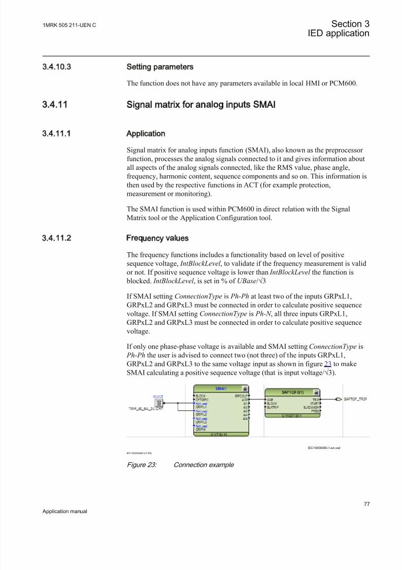
8/22/2019 Best Application
http://slidepdf.com/reader/full/best-application 83/457
3.4.10.3 Setting parameters
The function does not have any parameters available in local HMI or PCM600.
3.4.11 Signal matrix for analog inputs SMAI
3.4.11.1 Application
Signal matrix for analog inputs function (SMAI), also known as the preprocessor function, processes the analog signals connected to it and gives information aboutall aspects of the analog signals connected, like the RMS value, phase angle,frequency, harmonic content, sequence components and so on. This information isthen used by the respective functions in ACT (for example protection,
measurement or monitoring).The SMAI function is used within PCM600 in direct relation with the SignalMatrix tool or the Application Configuration tool.
3.4.11.2 Frequency values
The frequency functions includes a functionality based on level of positivesequence voltage, IntBlockLevel , to validate if the frequency measurement is validor not. If positive sequence voltage is lower than IntBlockLevel the function is
blocked. IntBlockLevel , is set in % of UBase/√3
If SMAI setting ConnectionType is Ph-Ph at least two of the inputs GRPxL1,GRPxL2 and GRPxL3 must be connected in order to calculate positive sequencevoltage. If SMAI setting ConnectionType is Ph-N , all three inputs GRPxL1,GRPxL2 and GRPxL3 must be connected in order to calculate positive sequencevoltage.
If only one phase-phase voltage is available and SMAI setting ConnectionType is Ph-Ph the user is advised to connect two (not three) of the inputs GRPxL1,GRPxL2 and GRPxL3 to the same voltage input as shown in figure 23 to makeSMAI calculating a positive sequence voltage (that is input voltage/√3).
IEC10000060-1-en.vsd
IEC10000060 V1 EN
Figure 23: Connection example
1MRK 505 211-UEN C Section 3IED application
77
Application manual

8/22/2019 Best Application
http://slidepdf.com/reader/full/best-application 84/457
The above described scenario does not work if SMAI settingConnectionType is Ph-N . If only one phase-earth voltage isavailable, the same type of connection can be used but the SMAIConnectionType setting must still be Ph-Ph and this has to beaccounted for when setting IntBlockLevel . If SMAI settingConnectionType is Ph-N and the same voltage is connected to allthree SMAI inputs, the positive sequence voltage will be zero andthe frequency functions will not work properly.
The outputs from the above configured SMAI block shall only beused for Overfrequency protection (SAPTOF), Underfrequency
protection (SAPTUF) and Rate-of-change frequency protection(SAPFRC) due to that all other information except frequency and
positive sequence voltage might be wrongly calculated.
3.4.11.3 Setting guidelines
The parameters for the signal matrix for analog inputs (SMAI) functions are set viathe local HMI or PCM600.
Every SMAI function block can receive four analog signals (three phases and oneneutral value), either voltage or current. SMAI outputs give information aboutevery aspect of the 3ph analog signals acquired (phase angle, RMS value,
frequency and frequency derivates, and so on – 244 values in total). Besides the block “group name”, the analog inputs type (voltage or current) and the analoginput names that can be set directly in ACT.
Instantaneous protection function with a 3 ms cycle time, needs to be connected tothe processing SMAI function block, which is also running at 3 ms task cycle. Inaddition, logic function blocks used with these fast cycle protection functions needto have 3 ms task cycle. Same procedure needs to be followed for each cycle time.
DFTRefExtOut : Parameter valid only for function block SMAI1 .
Reference block for external output (SPFCOUT function output).
DFTReference: Reference DFT for the block.
These DFT reference block settings decide DFT reference for DFT calculations.The settings InternalDFTRef will use fixed DFT reference based on set systemfrequency. AdDFTRefChn will use DFT reference from the selected group block,when own group selected adaptive DFT reference will be used based on calculatedsignal frequency from own group. The setting ExternalDFTRef will use reference
based on what is connected to input DFTSPFC.
Section 3 1MRK 505 211-UEN C
IED application
78
Application manual

8/22/2019 Best Application
http://slidepdf.com/reader/full/best-application 85/457
ConnectionType: Connection type for that specific instance (n) of the SMAI (if it is Ph-N or Ph-Ph). Depending on connection type setting the not connected Ph-N or Ph-Ph outputs will be calculated.
Negation: If the user wants to negate the 3ph signal, it is possible to choose tonegate only the phase signals Negate3Ph, only the neutral signal NegateN or both
Negate3Ph+N . negation means rotation with 180° of the vectors.
UBase: Base voltage setting (for each instance x).
MinValFreqMeas: The minimum value of the voltage for which the frequency iscalculated, expressed as percent of UBase (for each instance n).
Settings DFTRefExtOut and DFTReference shall be set to defaultvalue InternalDFTRef if no VT inputs are available.
Even if the user sets the AnalogInputType of a SMAI block to“Current ”, the MinValFreqMeas is still visible. However, using thecurrent channel values as base for frequency measurement is not
recommendable for a number of reasons, not last among them being the low level of currents that one can have in normaloperating conditions.
Examples of adaptive frequency tracking
1MRK 505 211-UEN C Section 3IED application
79
Application manual

8/22/2019 Best Application
http://slidepdf.com/reader/full/best-application 86/457
IEC07000197.vsd
SMAI instance 3 phase group
SMAI1:1 1
SMAI2:2 2
SMAI3:3 3
SMAI4:4 4
SMAI5:5 5
SMAI6:6 6
SMAI7:7 7
SMAI8:8 8
SMAI9:9 9
SMAI10:10 10
SMAI11:11 11
SMAI12:12 12
Task time group 1
SMAI instance 3 phase group
SMAI1:13 1
SMAI2:14 2
SMAI3:15 3
SMAI4:16 4
SMAI5:17 5
SMAI6:18 6
SMAI7:19 7
SMAI8:20 8
SMAI9:21 9
SMAI10:22 10
SMAI11:23 11
SMAI12:24 12
Task time group 2
SMAI instance 3 phase group
SMAI1:25 1
SMAI2:26 2
SMAI3:27 3
SMAI4:28 4
SMAI5:29 5
SMAI6:30 6
SMAI7:31 7
SMAI8:32 8
SMAI9:33 9
SMAI10:34 10
SMAI11:35 11
SMAI12:36 12
Task time group 3
AdDFTRefCh7
AdDFTRefCh4
IEC07000197 V2 EN
Figure 24: Twelve SMAI instances are grouped within one task time. SMAI
blocks are available in three different task times in the IED. Two
pointed instances are used in the following examples.
The examples shows a situation with adaptive frequency tracking with onereference selected for all instances. In practice each instance can be adapted to theneeds of the actual application.
Example 1
Section 3 1MRK 505 211-UEN C
IED application
80
Application manual
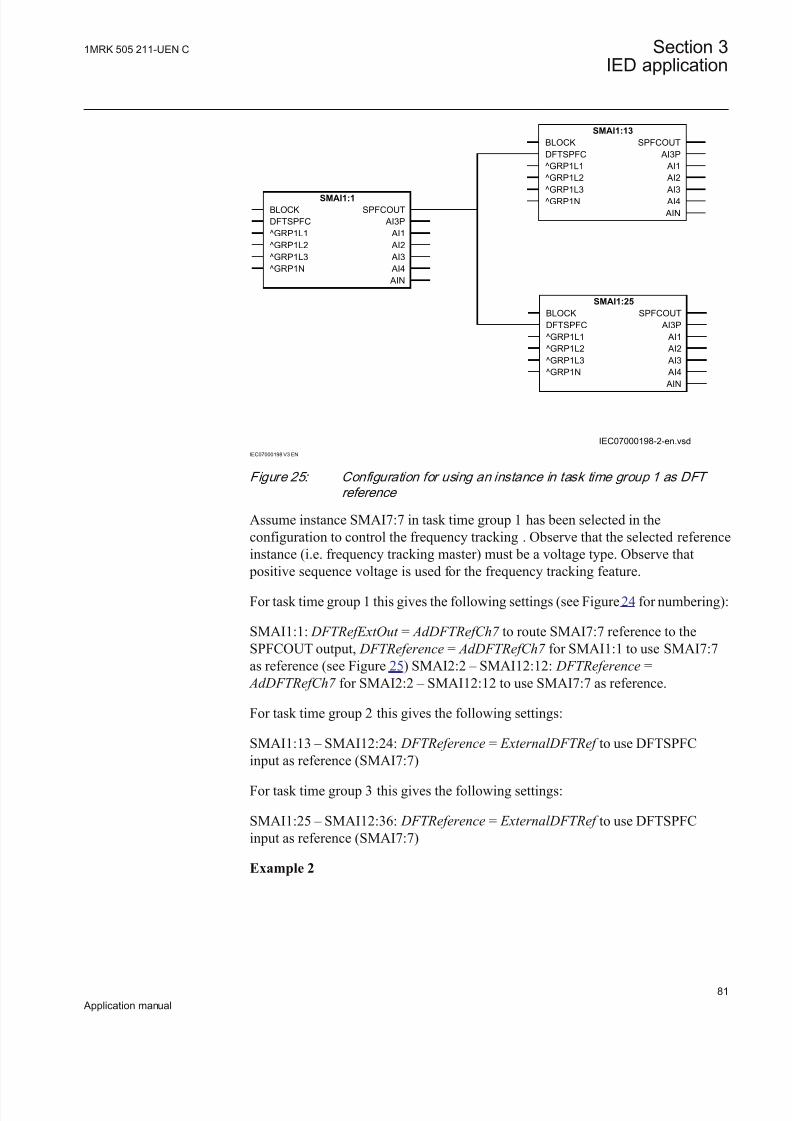
8/22/2019 Best Application
http://slidepdf.com/reader/full/best-application 87/457
IEC07000198-2-en.vsd
SMAI1:1
BLOCK
DFTSPFC
^GRP1L1
^GRP1L2
^GRP1L3
^GRP1N
SPFCOUT
AI3P
AI1
AI2
AI3
AI4
AIN
SMAI1:13
BLOCK
DFTSPFC
^GRP1L1
^GRP1L2
^GRP1L3^GRP1N
SPFCOUT
AI3P
AI1
AI2
AI3 AI4
AIN
SMAI1:25
BLOCK
DFTSPFC
^GRP1L1
^GRP1L2
^GRP1L3
^GRP1N
SPFCOUT
AI3P
AI1
AI2
AI3
AI4
AIN
IEC07000198 V3 EN
Figure 25: Configuration for using an instance in task time group 1 as DFT
reference
Assume instance SMAI7:7 in task time group 1 has been selected in theconfiguration to control the frequency tracking . Observe that the selected referenceinstance (i.e. frequency tracking master) must be a voltage type. Observe that
positive sequence voltage is used for the frequency tracking feature.
For task time group 1 this gives the following settings (see Figure 24 for numbering):
SMAI1:1: DFTRefExtOut = AdDFTRefCh7 to route SMAI7:7 reference to theSPFCOUT output, DFTReference = AdDFTRefCh7 for SMAI1:1 to use SMAI7:7as reference (see Figure 25) SMAI2:2 – SMAI12:12: DFTReference =
AdDFTRefCh7 for SMAI2:2 – SMAI12:12 to use SMAI7:7 as reference.
For task time group 2 this gives the following settings:
SMAI1:13 – SMAI12:24: DFTReference = ExternalDFTRef to use DFTSPFCinput as reference (SMAI7:7)
For task time group 3 this gives the following settings:
SMAI1:25 – SMAI12:36: DFTReference = ExternalDFTRef to use DFTSPFCinput as reference (SMAI7:7)
Example 2
1MRK 505 211-UEN C Section 3IED application
81
Application manual

8/22/2019 Best Application
http://slidepdf.com/reader/full/best-application 88/457
IEC07000199-2-en.vsd
SMAI1:13
BLOCK
DFTSPFC
^GRP1L1
^GRP1L2
^GRP1L3
^GRP1N
SPFCOUT
AI3P
AI1
AI2
AI3
AI4
AIN
SMAI1:1
BLOCK
DFTSPFC
^GRP1L1
^GRP1L2
^GRP1L3^GRP1N
SPFCOUT
AI3P
AI1
AI2
AI3 AI4
AIN
SMAI1:25
BLOCK
DFTSPFC
^GRP1L1
^GRP1L2
^GRP1L3
^GRP1N
SPFCOUT
AI3P
AI1
AI2
AI3
AI4
AIN
IEC07000199 V3 EN
Figure 26: Configuration for using an instance in task time group 2 as DFT
reference.
Assume instance SMAI4:16 in task time group 2 has been selected in theconfiguration to control the frequency tracking for all instances. Observe that theselected reference instance (i.e. frequency tracking master) must be a voltage type.Observe that positive sequence voltage is used for the frequency tracking feature.
For task time group 1 this gives the following settings (see Figure 24 for numbering):
SMAI1:1 – SMAI12:12: DFTReference = ExternalDFTRef to use DFTSPFC inputas reference (SMAI4:16)
For task time group 2 this gives the following settings:
SMAI1:13: DFTRefExtOut = AdDFTRefCh4 to route SMAI4:16 reference to theSPFCOUT output, DFTReference = AdDFTRefCh4 for SMAI1:13 to useSMAI4:16 as reference (see Figure 26) SMAI2:14 – SMAI12:24: DFTReference =
AdDFTRefCh4 to use SMAI4:16 as reference.
For task time group 3 this gives the following settings:
SMAI1:25 – SMAI12:36: DFTReference = ExternalDFTRef to use DFTSPFCinput as reference (SMAI4:16)
Section 3 1MRK 505 211-UEN C
IED application
82
Application manual

8/22/2019 Best Application
http://slidepdf.com/reader/full/best-application 89/457
3.4.11.4 Setting parameters
Table 20: SMAI1 Non group settings (basic)
Name Values (Range) Unit Step Default Description
DFTRefExtOut InternalDFTRef AdDFTRefCh1 AdDFTRefCh2 AdDFTRefCh3 AdDFTRefCh4 AdDFTRefCh5 AdDFTRefCh6 AdDFTRefCh7 AdDFTRefCh8 AdDFTRefCh9 AdDFTRefCh10 AdDFTRefCh11 AdDFTRefCh12External DFT ref
- - InternalDFTRef DFT reference for external output
DFTReference InternalDFTRef AdDFTRefCh1 AdDFTRefCh2 AdDFTRefCh3 AdDFTRefCh4 AdDFTRefCh5 AdDFTRefCh6 AdDFTRefCh7 AdDFTRefCh8 AdDFTRefCh9 AdDFTRefCh10 AdDFTRefCh11 AdDFTRefCh12External DFT ref
- - InternalDFTRef DFT reference
ConnectionType Ph-N
Ph-Ph
- - Ph-N Input connection type
TYPE 1 - 2 Ch 1 1 1=Voltage, 2=Current
Table 21: SM AI1 Non group settings (advanced)
Name Values (Range) Unit Step Default Description
Negation Off NegateNNegate3PhNegate3Ph+N
- - Off Negation
MinValFreqMeas 5 - 200 % 1 10 Limit for frequency calculation in % of UBase
UBase 0.05 - 2000.00 kV 0.05 400.00 Base voltage
1MRK 505 211-UEN C Section 3IED application
83
Application manual

8/22/2019 Best Application
http://slidepdf.com/reader/full/best-application 90/457
Table 22: SMAI2 Non group settings (basic)
Name Values (Range) Unit Step Default Description
DFTReference InternalDFTRef AdDFTRefCh1
AdDFTRefCh2 AdDFTRefCh3 AdDFTRefCh4 AdDFTRefCh5 AdDFTRefCh6 AdDFTRefCh7 AdDFTRefCh8 AdDFTRefCh9 AdDFTRefCh10 AdDFTRefCh11 AdDFTRefCh12External DFT ref
- - InternalDFTRef DFT reference
ConnectionType Ph-NPh-Ph
- - Ph-N Input connection type
TYPE 1 - 2 Ch 1 1 1=Voltage, 2=Current
Table 23: SMAI2 Non group settings (advanced)
Name Values (Range) Unit Step Default Description
Negation Off NegateNNegate3PhNegate3Ph+N
- - Off Negation
MinValFreqMeas 5 - 200 % 1 10 Limit for frequency calculation in % of UBase
UBase 0.05 - 2000.00 kV 0.05 400.00 Base voltage
3.4.12 Summation block 3 phase 3PHSUM
3.4.12.1 Application
The analog summation block 3PHSUM function block is used in order to get thesum of two sets of 3 phase analog signals (of the same type) for those IEDfunctions that might need it.
3.4.12.2 Setting guidelines
The summation block receives the three-phase signals from SMAI blocks. Thesummation block has several settings.
SummationType: Summation type (Group 1 + Group 2, Group 1 - Group 2, Group
2 - Group 1 or –(Group 1 + Group 2)).
DFTReference: The reference DFT block ( InternalDFT Ref , DFTRefGrp1 or External DFT ref ) .
Section 3 1MRK 505 211-UEN C
IED application
84
Application manual

8/22/2019 Best Application
http://slidepdf.com/reader/full/best-application 91/457
FreqMeasMinVal : The minimum value of the voltage for which the frequency iscalculated, expressed as percent of UBase base voltage setting (for each instance x).
UBase: Base voltage setting.
3.4.12.3 Setting parameters
Table 24: 3PHSUM Non group settings (basic)
Name Values (Range) Unit Step Default Description
SummationType Group1+Group2Group1-Group2Group2-Group1-(Group1+Group2)
- - Group1+Group2 Summation type
DFTReference InternalDFTRef AdDFTRefCh1External DFT ref
- - InternalDFTRef DFT reference
Table 25: 3PHSUM Non group settings (advanced)
Name Values (Range) Unit Step Default Description
FreqMeasMinVal 5 - 200 % 1 10 Amplitude limit for frequency calculationin % of Ubase
UBase 0.05 - 2000.00 kV 0.05 400.00 Base voltage
3.4.13 Authority status ATHSTAT
3.4.13.1 Application
Authority status (ATHSTAT) function is an indication function block, whichinforms about two events related to the IED and the user authorization:
• the fact that at least one user has tried to log on wrongly into the IED and itwas blocked (the output USRBLKED)
• the fact that at least one user is logged on (the output LOGGEDON)
The two outputs of ATHSTAT function can be used in the configuration for different indication and alarming reasons, or can be sent to the station control for the same purpose.
3.4.13.2 Setting parameters
The function does not have any parameters available in the local HMI or PCM600.
3.4.14 Denial of service DOS
1MRK 505 211-UEN C Section 3IED application
85
Application manual

8/22/2019 Best Application
http://slidepdf.com/reader/full/best-application 92/457
3.4.14.1 Setting guidelines
The function does not have any parameters available in the local HMI or PCM600.
3.5 Differential protection
3.5.1 Busbar differential protection
Busbar differential protection, 3-phase version
Function descriptionIEC 61850
identification
IEC 60617
identification
ANSI/IEEE C37.2
device number
Busbar differential protection, 2 zones,three phase/4 bays
BUTPTRC 3Id/I
SYMBOL-JJ V1 EN
87B
Busbar differential protection, 2 zones,three phase/4 or 8 bays
BTCZPDIF 3Id/I
SYMBOL-JJ V1 EN
87B
Busbar differential protection, 2 zones,three phase/4 or 8 bays
BTZNPDIF 3Id/I
SYMBOL-JJ V1 EN
87B
Busbar differential protection, 2 zones,three phase/4 or 8 bays
BTZNPDIF 3Id/I
SYMBOL-JJ V1 EN
87B
Busbar differential protection, 2 zones,three phase/4 or 8 bays
BZITGGIO 3Id/I
SYMBOL-JJ V1 EN
87B
Section 3 1MRK 505 211-UEN C
IED application
86
Application manual

8/22/2019 Best Application
http://slidepdf.com/reader/full/best-application 93/457
Busbar differential protection, 1-phase version
Function description IEC 61850
identification
IEC 60617
identification
ANSI/IEEE C37.2
device number
Busbar differential protection, 2 zones,single phase/12 or 24 bays
BUSPTRC 3Id/I
SYMBOL-JJ V1 EN
87B
Busbar differential protection, 2 zones,single phase/12 or 24 bays
BCZSPDIF 3Id/I
SYMBOL-JJ V1 EN
87B
Busbar differential protection, 2 zones,single phase/12 or 24 bays
BZNSPDIF 3Id/I
SYMBOL-JJ V1 EN
87B
Busbar differential protection, 2 zones,single phase/12 or 24 bays
BZNSPDIF 3Id/I
SYMBOL-JJ V1 EN
87B
Busbar differential protection, 2 zones,single phase/12 or 24 bays
BZISGGIO 3Id/I
SYMBOL-JJ V1 EN
87B
Status of primary switching object for Busbar protection zone selection
Function description IEC 61850
identification
IEC 60617
identification
ANSI/IEEE C37.2
device number
Status of primary switching object for
Busbar protection zone selection
SWSGGIO - -
3.5.1.1 Basic applications
GeneralBasic types of applications for REB670 IED are shown and described in thischapter. For these applications usually three phase version of the IED, with twodifferential zone and four (or even eight) 3-phase CT inputs, is used.
1MRK 505 211-UEN C Section 3IED application
87
Application manual

8/22/2019 Best Application
http://slidepdf.com/reader/full/best-application 94/457
Meshed corner application and T-connection applicationThe REB670 general differential function is suitable for application on mesh-corner arrangements. Mesh corners might have four or even up to six CT inputsand are basically simple single busbar arrangements. A similar application willoccur when a T-protection is required for one-and-half breaker or ring busbar arrangements.
IEC11000237-1-en.vsd
IEC11000237 V1 EN
Figure 27: Example of REB670 application on T-connection
3.5.1.2 Busbar protection applications
GeneralA busbar protection is a device which protects busbars against short-circuits andearth-faults. In the early development of electricity systems, no separate protectiondevice was used for busbar protection. Remote end line protections were used asmain protection for busbar faults. With the increased short-circuit power in thenetwork separate differential IEDs for busbar protection have to be installed inorder to limit the damage caused by the primary fault currents. In the same time, itis also a must to secure the network stability, as a delayed tripping for busbar faultscan also lead to network instability, pole slip of near-by generators and even totalsystem collapse.
For bus zone protection applications, it is extremely important to have goodsecurity since an unwanted operation might have severe consequences. Theunwanted operation of the bus differential IED will have the similar effect from theoperational point of view as simultaneous faults on all power system elementsconnected to the bus. On the other hand, the IED has to be dependable as well.
Failure to operate or even slow operation of the differential IED, in case of anactual internal fault, can have serious consequences. Human injuries, power system blackout, transient instability or considerable damage to the surrounding substationequipment and the close-by generators are some of the possible outcomes.
Therefore, Busbar differential protection must fulfill the following requirements:
1. Must be absolutely stable during all external faults. External faults are muchmore common than internal faults. The magnitude of external faults can beequal to the stations maximum short circuit capacity. Heavy CT-saturation dueto high DC components and/or remanence at external faults must not lead tomaloperation of the busbar differential protection. The security against
Section 3 1MRK 505 211-UEN C
IED application
88
Application manual

8/22/2019 Best Application
http://slidepdf.com/reader/full/best-application 95/457
misoperation must be extremely high due to the heavy impact on the overallnetwork service.
2. Must have as short tripping time as possible in order to minimize the damage,minimize the danger and possible injury to the people who might be workingin the station at the moment of internal fault, and secure the network stability.
3. Must be able to detect and securely operate for internal faults even with heavyCT saturation. The protection must also be sensitive enough to operate for minimum fault currents, which sometimes can be lower than the maximumload currents.
4. Must be able to selectively detect faults and trip only the faulty part of the busbar system.
5. Must be secure against maloperation due to auxiliary contact failure, possiblehuman mistakes and faults in the secondary circuits and so on.
Distinctive features of busbar protection schemesA busbar protection scheme design, depends very much on the substationarrangement. Complexity of the scheme can drastically vary from station to station.Typical applications problems, for the most common busbar protection schemes,are described in this chapter.
Differential protectionThe basic concept for any differential IED is that the sum of all currents, whichflow to and from the protection zone, must be equal to zero. If this is not the case,an internal fault has occurred. This is practically a direct use of well knownKirchhoffss first law. However, busbar differential IEDs do not measure directlythe primary currents in the high voltage conductors, but the secondary currents of magnetic core current transformers (that is, CTs), which are installed in all high-voltage bays connected to the busbar.
Therefore, the busbar differential IED is unique in this respect, that usually quite afew CTs, often with very different ratios and classes, are connected to the samedifferential protection zone. Because the magnetic core current transformers are non-linear measuring devices, under high current conditions in the primary CT circuitsthe individual secondary CT currents can be drastically different from the original
primary currents. This is caused by CT saturation, a phenomenon that is wellknown to protection engineers. During the time when any of the currenttransformer connected to the differential IED is saturated, the sum of all CT
secondary currents will not be equal to zero and the IED will measure falsedifferential current. This phenomenon is especially predominant for busbar differential protection applications, because it has the strong tendency to causeunwanted operation of the differential IED.
Remanence in the magnetic core of a current transformer is an additional factor,which can influence the secondary CT current. It can improve or reduce thecapability of the current transformer to properly transfer the primary current to thesecondary side. However, the CT remanence is a random parameter and it is not
possible in practice to precisely predict it.
1MRK 505 211-UEN C Section 3IED application
89
Application manual

8/22/2019 Best Application
http://slidepdf.com/reader/full/best-application 96/457
Another, and maybe less known, transient phenomenon appears in the CTsecondary circuit at the instant when a high primary current is interrupted. It is
particularly dominant if the HV circuit breaker chops the primary current before itsnatural zero crossing. This phenomenon is manifested as an exponentially decayingdc current component in the CT secondary circuit. This secondary dc current hasno corresponding primary current in the power system. The phenomenon can besimply explained as a discharge of the magnetic energy stored in the magnetic coreof the current transformer during the high primary current condition. Depending onthe type and design of the current transformer this discharging current can have atime constant in the order of a hundred milliseconds.
Consequently, all these phenomena have to be considered during the design stageof a busbar differential IED in order to prevent the unwanted operation of the IEDduring external fault conditions.
The analog generation of the busbar differential IEDs (that is,RADHA, RADSS,REB 103) generally solves all these problems caused by the CT non-linear characteristics by using the galvanic connection between the secondary circuits of all CTs connected to the protected zone. These IEDs are designed in such a waythat the current distribution through the IED differential branch during all transientconditions caused by non-linearity of the CTs will not cause the unwantedoperation of the differential IED. In order to obtain the required secondary CTcurrent distribution, the resistive burden in the individual CT secondary circuitsmust be kept below the pre-calculated value in order to guaranty the stability of theIED.
In new numerical protection IEDs, all CT and VT inputs are galvanically separated
from each other. All analog input quantities are sampled with a constant samplingrate and these discreet values are then transferred to corresponding numericalvalues (that is, AD conversion). After these conversions, only the numbers are usedin the protection algorithms. Therefore, for the modern numerical differential IEDsthe secondary CT circuit resistance might not be a decisive factor any more.
The important factor for the numerical differential IED is the time available to theIED to make the measurements before the CT saturation, which will enable theIED to take the necessary corrective actions. This practically means that the IEDhas to be able to make the measurement and the decision during the short period of time, within each power system cycle, when the CTs are not saturated. From the
practical experience, obtained from heavy current testing, this time, even under extremely heavy CT saturation, is for practical CTs around two milliseconds.Because of this, it was decided to take this time as the design criterion in REB 670IED, for the minimum acceptable time before saturation of a practical magneticcore CT. Thus, the CT requirements for REB 670 IED are kept to an absoluteminimum. Refer to section "Rated equivalent secondary e.m.f. requirements" for more details.
However, if the necessary preventive action has to be taken for every single CTinput connected to the differential IED, the IED algorithm would be quite complex.Thus, it was decided to re-use the ABB excellent experience from the analog
Section 3 1MRK 505 211-UEN C
IED application
90
Application manual

8/22/2019 Best Application
http://slidepdf.com/reader/full/best-application 97/457
percentage restrained differential protection IED (that is, RADSS and REB 103),and use only the following three quantities:
1. incoming current (that is, sum of all currents which are entering the protection
zone)2. outgoing current (that is, sum of all currents which are leaving the protection
zone)3. differential current (that is, sum of all currents connected to the protection zone)
as inputs into the differential algorithm in the numerical IED design.
These three quantities can be easily calculated numerically from the raw samplevalues (that is, twenty times within each power system cycle in the IED) from allanalog CT inputs connected to the differential zone. At the same time, they haveextremely valuable physical meaning, which clearly describes the condition of the
protected zone during all operating conditions.By using the properties of only these three quantities, a new patented differentialalgorithm has been formed in the IED. This differential algorithm is completelystable for all external faults. All problems caused by the non-linearity of the CTsare solved in an innovative numerical way. In the same time, very fast trippingtime, down to 10 ms, can be commonly obtained for heavy internal faults.
Please refer to the technical reference manual for more details about the working principles of the Differential Function algorithm.
Zone selection (CT switching)
The so-called CT switching (that is, zone selection) is r equired in situation whenone particular circuit (that is, bay) can be connected to different busbars byindividual disconnectors. Typical example is a station with double busbars with or without transfer bus as shown in figure 56 and figure 49, where any feeder bay can
be connected to any of the two buses. In such cases the status of all busbar disconnectors and all transfer disconnectors shall be given to the busbar protection.
Traditionally, the CT switching has been done in CT secondary circuits. However,with REB670 this is not the case. All necessary zone selection (that is, CTswitching) is done in software. Therefore, the CT secondary circuits are alwaysintact and without any auxiliary relay contacts.
To provide proper zone selection (that is, busbar replica) the position informationfrom all relevant primary switches (that is, disconnectors and/or circuit breakers)must be given to the IED. This is typically done by connecting two auxiliarycontacts (that is, normaly open and normaly closed aux contacts) from each
primary switch to the IED binary inputs (that is, optocouplers). In REB670configuration one SwitchStatus function block shall be associated with each
primary switching device. This block is then used internally to derive the primaryobject status and then pass this information to the busbar protection internal ZoneSelection logic.
1MRK 505 211-UEN C Section 3IED application
91
Application manual

8/22/2019 Best Application
http://slidepdf.com/reader/full/best-application 98/457
Auxiliary contact requirement and evaluation
Auxiliary contact requirements for disconnectors and circuit breakers
The position of the primary switching object is typically obtained via two auxiliarycontacts of the primary apparatus. The first auxiliary contact indicates that primarydevice is closed. In protection literature it is called by different names as stated below:
• Normally open auxiliary contact• “a” contact (that is, 52a)• “closed”
The second auxiliary contact indicates that primary device is open. In protectionliterature it is called by different names as stated below:
• Normally closed auxiliary contact
• “b” contact (that is, 52b)• “open”
Typically both contacts are used to provide position indication and supervision for busbar protection.
Minimum contact requirementsThe minimum requirement for the busbar replica is the record of the disconnector
position by using just one auxiliary contact, either NO or NC type. However recording a pair of auxiliary contacts, representing the OPEN and CLOSE position,offer additional features which can improve the reliability of the bus replica
including supervision possibilities.
Auxiliary contact evaluation logicTwo logic schemes can be found.
Scheme1_RADSS "If not OPEN then CLOSED"As the name of the scheme suggests, only when the auxiliary contacts signal cleanopen position ("normally open auxiliary (NO) contact input" = inactive and"normally closed auxiliary (NC) contact input" = active), the disconnector is takento be open. For all other signal combinations the disconnector is considered to beclosed. This scheme does not pose any special requirements to the auxiliary contact
timing. Only the disconnector NC contact must open before the disconnector maincontact is within arcing distance. The time during which the OPEN and CLOSEDsignal inputs disagree (that is, both binary inputs are active or both are inactive) ismonitored by the isolator supervision function. The maximum time allowed beforean alarm is given can be set according to the disconnector timing.
Scheme2_INX "Closed or open if clear indication available otherwise lastposition saved"As the name of the scheme suggests, only when the auxiliary contacts signal cleanOPEN or clean CLOSED position disconnector is considered to be openrespectively closed. However this poses the stringent requirements on the auxiliary
Section 3 1MRK 505 211-UEN C
IED application
92
Application manual

8/22/2019 Best Application
http://slidepdf.com/reader/full/best-application 99/457
contacts that the CLOSED signal must become active a certain time (>150 ms) before current starts flowing for example, through arcing. Otherwise this currentwill not be taken into account in the busbar protection and this can result in amaloperation. Therefore, good timing of two auxiliary contacts is definitely required.
The time during which the OPEN and CLOSED signals disagree (that is, both binary inputs are active or both are inactive) is monitored by the isolator supervision function for both of the above two schemes. The maximum timeallowed before an alarm is given can be set according to the disconnector timing.
Table 26 and the following two figures summarize the properties of these twoschemes.
Tab le 26: T reatment of pr imary objec t aux il ia ry contac t s ta tus w ithin BBP in REB670
Primary equipment Status in busbar protection Alarm facility
Normally
Openauxiliary
contact status
(“closed” or
“a” contact)
Normally
Closedauxiliary
contact status
(“open” or “b”
contact)
when
“Scheme 1RADSS”
is selected
when
“Scheme 2INX”
is selected
Alarm after
settable timedelay
Information
visible onlocal HMI
open open closed Lastpositionsaved
yes intermediate_00
open
closed open open no open
closed
open closed closed no closed
closed closed closed closed yes badState_1
1
BBP
input „closed“
input „open“
N.O.
N.C.
1
0
1
0
1
0
closed
open
arcing possible
current
assignment
1) 1)
1) disconnector supervision running
en06000084.vsd
IEC06000084 V1 EN
Figure 28: Scheme_1 RADSS
1MRK 505 211-UEN C Section 3IED application
93
Application manual

8/22/2019 Best Application
http://slidepdf.com/reader/full/best-application 100/457
BBP
input „closed“
input „open“
N.O.
N.C.
1
0
1
0
1
0
closed
open
arcing possible
current
assignment
2)
1) 1)
1) disconnector supervision running
2) BI „closed“ should change before arcing distance
en06000085.vsd
IEC06000085 V1 EN
Figure 29: Scheme2_INX
Circuit breaker replicaThe circuit breaker position from a bay shall be given to the busbar protectionwhen the position of this particular breaker can influence the busbar protectionoperation. Typical examples are Blind Spot protection in Bus-section and Bus-coupler bays or End Fault Protection in feeder bays. In both cases the measuringrange of a busbar protection is limited by the CT location. By additionallyrecording the CB position of a feeder or a coupler the zone between the CT and the
CB can be better protected while CB is open. However in such cases it is of utmostimportance to connect the CB closing command to the busbar protection in order toinclude again the CT current to the busbar protection zones in time. It is as stronglyrecommended to always use Scheme1_RADSS for all CBs positions connected tothe IED in order to minimize any risk of possible problems due to late inclusion of CT current to the relevant differential zones.
Line disconnector replicaThe line disconnector position from a feeder bay might be required for busbar
protection under certain circumstances. Typical example is when the linedisconnector QB9 and associated earthing switch are located between CT and
protected busbar as indicated in figure 30.
Section 3 1MRK 505 211-UEN C
IED application
94
Application manual

8/22/2019 Best Application
http://slidepdf.com/reader/full/best-application 101/457
BI1
QA1
QB1
ZA
ZB
QB2
QB9QC1
en06000086.vsd
IEC06000086 V1 EN
Figure 30: Feeder bay layout when line disconnector position might be
required for busbar protection
Such feeder set-up can be often found in GIS stations where cable CTs are used for busbar protection. If in such feeder the line disconnector QB9 is open and thenimmediately the earthing switch QC1 is closed before the busbar disconnectorsQB1 & QB2 are open there is a danger to get current unbalance into the zonedifferential measurement under following circumstances:
• In case of parallel lines zero sequence mutual coupling can induce zerosequence current into the grounded line especially during external earth-faults.
• In case of cable feeder the stored energy in the cable will be dischargedthrough the earthing switch at the moment of its closing.
In order to avoid such problems for busbar protection the status of linedisconnector can be monitored by busbar protection and CT measurement can bedisconnected from both differential zones as soon line disconnector is open.Similar functionality can be obtained by instead monitoring the position of feeder
breaker QA1. In such case the breaker closing signal shall be connected to busbar protection as well.
Zone selection featuresThe IED offers an extremely effective solution for stations where zone selection(that is, CT switching) is required. This is possible due to the software facility,which gives full and easy control over all CT inputs connected to the IED. The
philosophy is to allow every CT input to be individually controlled by a setting parameter. This parameter called ZoneSel can be individually configured for everyCT input. This parameter, for every bay, can be set to only one of the followingfive alternatives:
1. FIXEDtoZA
2. FIXEDtoZB
3. FIXEDtoZA&-ZB
4. CtrlIncludes
5. CtrlExcludes
1MRK 505 211-UEN C Section 3IED application
95
Application manual

8/22/2019 Best Application
http://slidepdf.com/reader/full/best-application 102/457
If for a particular CT input setting parameter ZoneSel is set to FIXEDtoZA, thenthis CT input will be only included to the differential zone A. This setting istypically used for simple single zone application such as: single busbar staions, one-and-a-half breaker stations or double breaker stations.
If for a particular CT input setting parameter ZoneSel is set to FIXEDtoZB, thenthis CT input will be only included to the differential zone B. This setting istypically used for applications such as: one-and-a-half breaker stations or double
breaker stations.
If for a particular CT input setting parameter ZoneSel is set to FIXEDtoZA&-ZB,then this CT input will be included to the differential zone A, but its invertedcurrent value will be as well included to the differential zone B. This setting istypically used for bus coupler or bus section bays when only one currenttransformer is available see figure 32.
If for a particular CT input setting parameter ZoneSel is set to Ctrl_Includes, thenthis CT input will be:
• included to the differential zone A when input signal CTRLZA oncorresponding bay block is given logical value one and it will be excludedfrom the differential zone A when input signal CTRLZA on corresponding bay
block is given logical value zero.• included to the differential zone B when input signal CTRLZB on
corresponding bay block is given logical value one and it will be excludedfrom the differential zone B when input signal CTRLZB on corresponding bay
block is given logical value zero.
This setting is typically used for feeder bays in double busbar stations in order toform proper busbar disconnector replica. It is especially suitable when normallyopen and normally closed (that is, a and b) auxiliary contacts from the busbar disconnectors are available to the IED.
If for a particular CT input setting parameter ZoneSel is set to Ctrl_Excludes, thenthis CT input will be:
• excluded from the differential zone A when input signal CTRLZA oncorresponding bay block is given logical value one and it will be included tothe differential zone A when input signal CTRLZA on corresponding bay
block is given logical value zero• excluded from the differential zone B when input signal CTRLZB on
corresponding bay block is given logical value one and it will be included tothe differential zone B when input signal CTRLZB on corresponding bay
block is given logical value zero
This setting is typically used for feeder bays in double busbar single breaker stations in order to form proper busbar disconnector replica. It is especially suitablewhen only normally closed (that is, b) auxiliary contact from the busbar
Section 3 1MRK 505 211-UEN C
IED application
96
Application manual

8/22/2019 Best Application
http://slidepdf.com/reader/full/best-application 103/457
disconnector(s) is available to the IED. For more information please refer tofigure 51.
In applications where zone selection (that is, CT switching) is required (for
example double or multiple busbar stations) all CTs will be permanently connectedto the analogue input module(s), as shown in figure 50. Therefore, all necessaryswitching of currents will be performed in internal software logic.
CT disconnection for bus section and bus coupler current transformer
coresIn practice there are three different solutions for bus section or bus coupler baylayout. First solution is with two sets of main CTs, which are located on both sidesof the circuit breaker, as shown in figure 31.
ZA
21 8
ZB
21 8
BS
en01000013.vsd
IEC01000013 V1 EN
Figure 31: Example of station with two sets of main CTs in the bus-section bay
This is the most expensive, but good solution for busbar protection. Twodifferential zones overlapping across the bus-section or bus-coupler circuit breaker.All faults in the overlapping zone will be instantly tripped by both zonesirrespective of the section/coupler circuit breaker status. However with modern
busbar protection it is possible to disconnect both CTs from the relevant zones
when the bus-section or bus-coupler circuit breaker is open. This will insure that if internal fault happen, in the overlapping zone, while breaker is open, only thefaulty zone will be tripped while other busbar section will remain in service.However, due to low probability of such fault happening, while the breaker is open,such special considerations are typically not included in the busbar protectionscheme for this type of stations. In such application the bus section or bus coupler current transformers shall be wired just to two separate current input of the IED.Then in the parameter setting tool (PST) for the corresponding bays the parameter
ZoneSel shall be set to FIXEDtoZA in one bay and FIXEDtoZB in another bay. Thiswill insure that these currents are given to both differential zones.
1MRK 505 211-UEN C Section 3IED application
97
Application manual
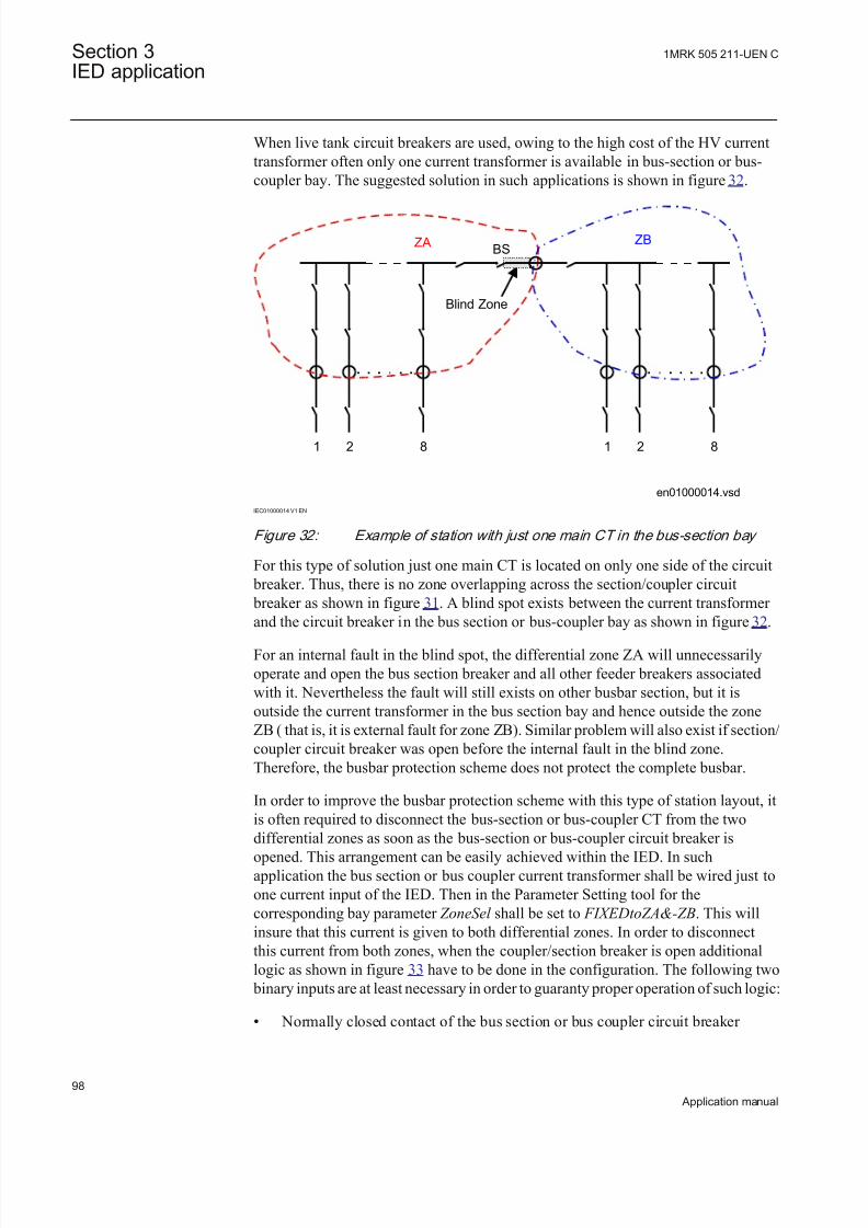
8/22/2019 Best Application
http://slidepdf.com/reader/full/best-application 104/457
When live tank circuit breakers are used, owing to the high cost of the HV currenttransformer often only one current transformer is available in bus-section or bus-coupler bay. The suggested solution in such applications is shown in figure 32.
en01000014.vsd
ZA
21 8
ZB
21 8
BS
Blind Zone
IEC01000014 V1 EN
Figure 32: Example of station with just one main CT in the bus-section bay
For this type of solution just one main CT is located on only one side of the circuit breaker. Thus, there is no zone overlapping across the section/coupler circuit breaker as shown in figure 31. A blind spot exists between the current transformer and the circuit breaker in the bus section or bus-coupler bay as shown in figure 32.
For an internal fault in the blind spot, the differential zone ZA will unnecessarilyoperate and open the bus section breaker and all other feeder breakers associatedwith it. Nevertheless the fault will still exists on other busbar section, but it isoutside the current transformer in the bus section bay and hence outside the zoneZB ( that is, it is external fault for zone ZB). Similar problem will also exist if section/coupler circuit breaker was open before the internal fault in the blind zone.Therefore, the busbar protection scheme does not protect the complete busbar.
In order to improve the busbar protection scheme with this type of station layout, itis often required to disconnect the bus-section or bus-coupler CT from the two
differential zones as soon as the bus-section or bus-coupler circuit breaker isopened. This arrangement can be easily achieved within the IED. In suchapplication the bus section or bus coupler current transformer shall be wired just toone current input of the IED. Then in the Parameter Setting tool for thecorresponding bay parameter ZoneSel shall be set to FIXEDtoZA&-ZB. This willinsure that this current is given to both differential zones. In order to disconnectthis current from both zones, when the coupler/section breaker is open additionallogic as shown in figure 33 have to be done in the configuration. The following two
binary inputs are at least necessary in order to guaranty proper operation of such logic:
• Normally closed contact of the bus section or bus coupler circuit breaker
Section 3 1MRK 505 211-UEN C
IED application
98
Application manual
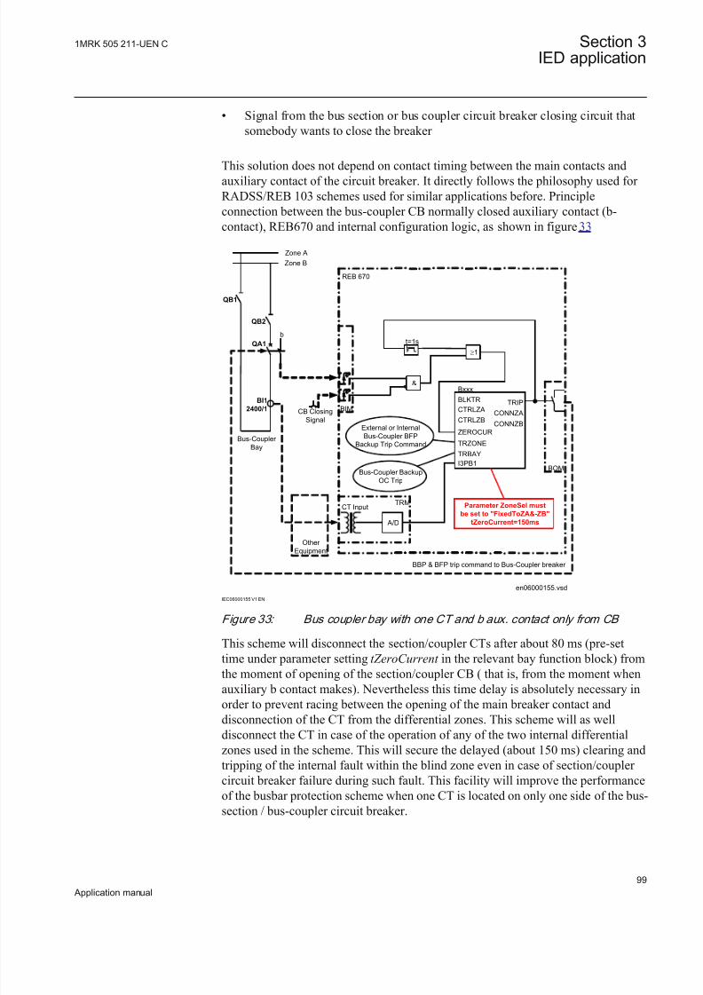
8/22/2019 Best Application
http://slidepdf.com/reader/full/best-application 105/457
• Signal from the bus section or bus coupler circuit breaker closing circuit thatsomebody wants to close the breaker
This solution does not depend on contact timing between the main contacts andauxiliary contact of the circuit breaker. It directly follows the philosophy used for RADSS/REB 103 schemes used for similar applications before. Principleconnection between the bus-coupler CB normally closed auxiliary contact (b-contact), REB670 and internal configuration logic, as shown in figure 33
en06000155.vsd
Zone A
Zone B
Bus-Coupler
Bay
REB 670
CTRLZA
CTRLZB
TRIP
CONNZA
CONNZB
Bxxx
I3PB1
BLKTR
TRZONE
TRBAY
BBP & BFP trip command to Bus-Coupler breaker
BOM
A/D
Parameter ZoneSel must
be set to "FixedToZA&-ZB"tZeroCurrent=150ms
Other
Equipment
CT InputTRM
External or Internal
Bus-Coupler BFP
Backup Trip Command
Bus-Coupler Backup
OC Trip
QB1
QB2
b
BI1
2400/1
QA1
ZEROCUR
BIMCB Closing
Signal
³1tt=1s
&
IEC06000155 V1 EN
Figure 33: Bus coupler bay with one CT and b aux. contact only from CB
This scheme will disconnect the section/coupler CTs after about 80 ms (pre-settime under parameter setting tZeroCurrent in the relevant bay function block) fromthe moment of opening of the section/coupler CB ( that is, from the moment when
auxiliary b contact makes). Nevertheless this time delay is absolutely necessary inorder to prevent racing between the opening of the main breaker contact anddisconnection of the CT from the differential zones. This scheme will as welldisconnect the CT in case of the operation of any of the two internal differentialzones used in the scheme. This will secure the delayed (about 150 ms) clearing andtripping of the internal fault within the blind zone even in case of section/coupler circuit breaker failure during such fault. This facility will improve the performanceof the busbar protection scheme when one CT is located on only one side of the bus-section / bus-coupler circuit breaker.
1MRK 505 211-UEN C Section 3IED application
99
Application manual

8/22/2019 Best Application
http://slidepdf.com/reader/full/best-application 106/457
With GIS or live tank circuit breakers, owing to high cost of HV CT installations,sometimes no current transformers are available in bus-section or bus-coupler bay.This is the third solution shown in figure 34
en04000283.vsd
ZA
21 10
ZB
21 10
BS
IEC04000283 V1 EN
Figure 34: Example of station without main CTs in the bus-section bay
In such case two separate zones can be maintained only while bus coupler breaker is open. As soon as bus coupler breaker is going to be closed the zoneinterconnection feature must be activated and complete busbars will beautomatically protected with just one overall differential zone.
Since there are no current transformer in the bus coupler bay, there is no need toallocate internal bay function block for the bus coupler bay. However someadditional configuration logic is required to obtain automatic zone interconnectionactivation when bus coupler breaker shall be closed. Example of such logic, asshown in figure 35.
Section 3 1MRK 505 211-UEN C
IED application
100
Application manual

8/22/2019 Best Application
http://slidepdf.com/reader/full/best-application 107/457
en06000137.vsd
QA1
Zone A
Zone B
ZI
ACTIVE
BOMBIM
REB 670
Bus coupler
EXTSTART
ALARM
Indication that
Zone interconnection
is active
&
B C
C B
c l o
s i n g
s w
i t c h
QB1 QB2
t
tOFF=1.0s
1
IEC06000137 V1 EN
Figure 35: Configuration logic for bus coupler without main CTs
End fault protectionWhen Live tank CBs or GIS are involved, there is a physical separation betweenthe CT and the CB. End Fault Protection is related to primary faults between mainCT and CB in a feeder bay. Therefore, it is directly related to the position of themain CT in feeder bay. Three CT positions in feeder bays are typically used in
power systems around the world, as shown in figure 36.
en06000138.vsd
BI1
QA1
BI1Busbar
Protection
Feeder
Protection BI1
QA1
Busbar
Protection
Feeder
Protection
QA1
BI1
Busbar
Protection
Feeder
Protection
A B
1
C
1
IEC06000138 V1 EN
Figure 36: Typical CT locations in a feeder bay
where:
A = two CTs are available one on each side of the feeder circuit breaker
B = one CT is available on the line side of the feeder circuit breaker
C = one CT is available on the bus side of the feeder circuit breaker
1 = End fault region
1MRK 505 211-UEN C Section 3IED application
101
Application manual

8/22/2019 Best Application
http://slidepdf.com/reader/full/best-application 108/457
In figure 36, /A where two CTs are available in a feeder bay the end fault protection is not an issue. The busbar and feeder protection zones overlap acrossfeeder circuit breaker and all faults between these two CTs will be instantlydetected and tripped by both protection schemes. As a consequence of such fault
both busbar and feeder will be disconnected from the power system.
In figure 36/B where one CT is available on the line side of the feeder circuit breaker the primary fault between CT and CB will cause certain problems.Typically such fault will be detected and tripped by busbar protection. However tocompletely clear such fault the remote feeder end CB must be tripped as well. Itshall be noted that for the feeder protection such fault will be either a reverse fault(that is, distance protection used for feeder protection) or external fault (that is, line/transformer differential protection used for feeder protection).
In figure 36/C where one CT is available on the bus side of the feeder circuit
breaker the primary fault between CT and CB will cause pr oblem as well.Typically such fault will be detected and tripped by feeder protection. However, tocompletely clear such fault the associated busbar section must be tripped as well. Itshall be noted that the busbar differential protection will classify such fault asexternal and without any additional measures the busbar protection will remain stable.
For better understanding end fault protection applications within busbar protection,the figure 37 is used.
BI1 BI1
QA1 QA1
ZA
QA1 QA1
BI1 BI1
xx06000139.vsd
4
3
1
2
IEC06000139 V1 EN
Figure 37: Busbar protection measuring and fault clearing boundaries
where:1 is Busbar Protection measuring boundary determined by feeder CT locations
2 is Busbar Protection internal fault clearing boundary determined by feeder CB locations
3 is End fault region for feeders as shown in f igure 36/B
4 is End fault region for feeders as shown in f igure 36/C
In figure 37 single busbar station is shown. Two feeders on the left-hand side haveCTs on the line side of the breaker. The two feeders on the right-hand side of the
Section 3 1MRK 505 211-UEN C
IED application
102
Application manual
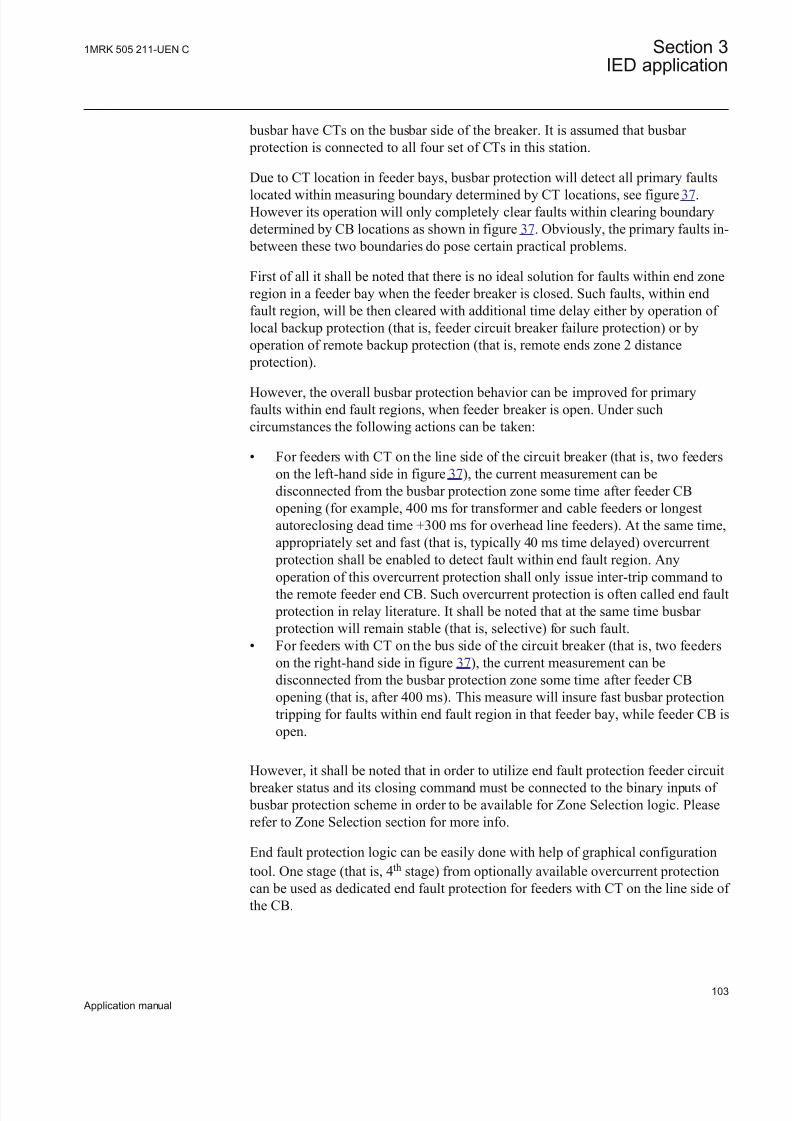
8/22/2019 Best Application
http://slidepdf.com/reader/full/best-application 109/457
busbar have CTs on the busbar side of the breaker. It is assumed that busbar protection is connected to all four set of CTs in this station.
Due to CT location in feeder bays, busbar protection will detect all primary faults
located within measuring boundary determined by CT locations, see figure 37.However its operation will only completely clear faults within clearing boundarydetermined by CB locations as shown in figure 37. Obviously, the primary faults in-
between these two boundaries do pose certain practical problems.
First of all it shall be noted that there is no ideal solution for faults within end zoneregion in a feeder bay when the feeder breaker is closed. Such faults, within endfault region, will be then cleared with additional time delay either by operation of local backup protection (that is, feeder circuit breaker failure protection) or byoperation of remote backup protection (that is, remote ends zone 2 distance
protection).
However, the overall busbar protection behavior can be improved for primaryfaults within end fault regions, when feeder breaker is open. Under suchcircumstances the following actions can be taken:
• For feeders with CT on the line side of the circuit breaker (that is, two feederson the left-hand side in figure 37), the current measurement can bedisconnected from the busbar protection zone some time after feeder CBopening (for example, 400 ms for transformer and cable feeders or longestautoreclosing dead time +300 ms for overhead line feeders). At the same time,appropriately set and fast (that is, typically 40 ms time delayed) overcurrent
protection shall be enabled to detect fault within end fault region. Any
operation of this overcurrent protection shall only issue inter-trip command tothe remote feeder end CB. Such overcurrent protection is often called end fault protection in relay literature. It shall be noted that at the same time busbar protection will remain stable (that is, selective) for such fault.
• For feeders with CT on the bus side of the circuit breaker (that is, two feederson the right-hand side in figure 37), the current measurement can bedisconnected from the busbar protection zone some time after feeder CBopening (that is, after 400 ms). This measure will insure fast busbar protectiontripping for faults within end fault region in that feeder bay, while feeder CB isopen.
However, it shall be noted that in order to utilize end fault protection feeder circuit breaker status and its closing command must be connected to the binary inputs of busbar protection scheme in order to be available for Zone Selection logic. Pleaserefer to Zone Selection section for more info.
End fault protection logic can be easily done with help of graphical configurationtool. One stage (that is, 4th stage) from optionally available overcurrent protectioncan be used as dedicated end fault protection for feeders with CT on the line side of the CB.
1MRK 505 211-UEN C Section 3IED application
103
Application manual

8/22/2019 Best Application
http://slidepdf.com/reader/full/best-application 110/457
End fault protection is here explained for simple single busbar station. However thesame principles are applicable to almost all other station layouts. However, under certain circumstances, for stations with a transfer bus more extensive logic for endfault protection implementation might be required.
Zone interconnection (Load transfer)In double busbar stations or double busbar with transfer bus stations it is commonrequirement to use the possibility of zone interconnection of load current in anyfeeder bay from one busbar to the other. The sequence of operation during zoneinterconnection is normally as the following:
• bus coupler bay is closed (that is, CB and both disconnectors).• feeder bay busbar disconnector to the busbar not already in service is then
closed. The switchgear interlocking system shall allow this only when the buscoupler breaker is already closed. Depending on the thermal capacity of the
feeder busbar disconnectors (QB1 and QB2) the opening of the bus coupler circuit breaker is sometimes interlocked while both busbar disconnectorswithin one of the feeder bays are closed.
• opening of the feeder bay busbar disconnector originally closed. The load isnow transferred from one to other bus.
• opening of bus coupler CB.
The zone interconnection has to be taken into consideration for the busbar differential protection scheme, as the two busbar zones are interconnected together via two disconnectors. The primary current split between the two busbars is notknown and the two separate measuring zones cannot be maintained.
In conventional, analog busbar protection systems the solutions have been to, byextensive zone switching IEDs, disconnect one zone (normally zone B) and toconnect all feeders to other zone (normally zone A). At the same time the currentfrom the bus-coupler bay, which just circulates between two zones, must bedisconnected from the measuring differential zone.
Similar situation regarding busbar protection can occur between two single busbar sections interconnected via sectionalizing disconnector, as shown in figure 42.When sectionalizer is closed then two separate protection zones becomes one and
busbar protection must be able to dynamically handle this.
Due to the numerical design the IED can manage this situation in an elegant andsimple way. Internal feature called ZoneInterconnection will be used to handle bothsituations. This feature can be activated either externally via binary input or derived internally by built-in logic. Internally, this “zone switching” feature will beactivated if the following conditions are met:
• bays have parameter ZoneSel set to either CtrlInclude or CtrlExcludes
• internal zone selection logic concludes that this particular bay shall besimultaneously connected to both internal differential zones
Section 3 1MRK 505 211-UEN C
IED application
104
Application manual

8/22/2019 Best Application
http://slidepdf.com/reader/full/best-application 111/457
This situation only means that for this particular bay both busbar disconnectors areclosed and therefore zone interconnection switching is happening in the station.
When zone switching feature is activated inside the IED, each individual bay
current will behave in the predetermined way as dictated by a parameter setting ZoneSwitching . This parameter, for every bay, can be set to only one of thefollowing three alternatives
• ForceOut
• ForceIn
• Conditionally
If for a particular CT input setting parameter ZoneSwitching is set to ForceOut ,then this CT input will be disconnected from both the differential zones, regardlessof any other set value or active binary input, while zone switching feature is active
within the IED. This setting is typically used for bus coupler bay in double busbar stations.
If for a particular CT input setting parameter ZoneSwitching is set to ForceIn, thenthis CT input will be connected to both the differential zones, regardless of anyother set value or active binary input, while zone switching feature is active withinthe IED. This setting is typically used for all feeders bay in a station with twosingle zone interconnected by a sectionalizing disconnector.
If for a particular CT input setting parameter ZoneSwitching is set to Conditionally,then this CT input will be connected to both the differential zones only if it wasincluded to any of the two zones for 2ms before the zone switching feature was
activated. This setting is typically used for all feeders bay in double busbar stations. With this setting all feeder bays, which were not connected to any of thetwo zones before the zone interconnection activation (that is, out for scheduledmaintenance), will not either be included during zone interconnection.
This practically means that for double busbar station, when zone switching featureis active, all feeder bays will be connected to both differential zones, while buscoupler CT will be disconnected from both zones. In this way simple but effectivesolution is formed. It is as well important to notice that all necessary changes in theindividual bay tripping arrangements will be automatically performed within theinternal logic.
A dedicated binary signal will be immediately activated in the internal logic whenzone interconnection feature is activated. If this feature is active longer than the pre-set time separate alarm binary signal is activated, in order to alarm the station
personnel about such operating conditions. ZoneInterconnection feature can bedisabled by a parameter setting for substation arrangements where it is not requiredthat is, single busbar stations, one-and-half breakerbreaker-and-a-half stations andso on.
Discriminating zones (that is, Zone A and Zone B) in the IED includes a sensitiveoperational level. This sensitive operational level is designed to be able to detect
busbar earth faults in low impedance earth power systems (that is, power systems
1MRK 505 211-UEN C Section 3IED application
105
Application manual

8/22/2019 Best Application
http://slidepdf.com/reader/full/best-application 112/457
where the earth-fault current is limited to a certain level, typically between 300 Aand 2000 A by neutral point reactor or resistor) or for some other specialapplications where increased sensitivity is required. Operation and operatingcharacteristic of the sensitive differential protection can be set independently fromthe operating characteristic of the main differential protection. The sensitivedifferential level is blocked as soon as the total incoming current exceeds the pre-set level. By appropriate setting then it can be insured that this sensitive level is
blocked for external phase-to-phase or three-phase faults, which can cause CTsaturation. Comparison between these two characteristics is shown in figure 38.
Differential protectionoperation characteristic
Operate
region
Diff Oper Level
I d [ P r i m a r y A m p s ]
Iin
[Primary Amps]
s=0.53
I d = I i n
Sensitivedifferentialprotection
en06000142.vsd
Sensitive Oper LevelSens Iin
Block
IEC06000142 V1 EN
Figure 38: Differential protection operation characteristic
Additionally the sensitive differential protection can be time delayed and it must beexternally enabled by a binary signal (that is, from external open delta VTovervoltage relay or power transformer neutral point overcurrent relay).
The setting parameters for the check zone are set via the local HMI or PCM600.
Such check zone is included in the IED. By a parameter setting CheckZoneSel = NotConnected /Connected can be decided, individually for every bay, if it shall be
connected to the check zone or not. This setting is available in bay function block.
For every zone there is a setting parameter CheckZoneSup, which can be set to On
or Off . This setting parameter determines if the individual zone shall be supervisedor not by a check zone. This setting is available in both Zone functions. Finally thecheck zone shall be enabled (that is, setting parameter Operation shall be set to On)in order to fully enable the check zone. Operating characteristics for the check zonecan be set independently from the two discriminating zones.
However, it is to be observed that the check zone has slightly different operatingcharacteristic from the usual discriminating zones. For the check zone the resultant
Section 3 1MRK 505 211-UEN C
IED application
106
Application manual

8/22/2019 Best Application
http://slidepdf.com/reader/full/best-application 113/457
outgoing current is used as stabilizing current instead of total incoming current inorder to guarantee the check zone operation for all possible operating conditions inthe station. The check zone operating characteristic is shown in figure 39:
en06000062.vsd
Oper Levels=0.0-0.90 (settable)
Iout [Primary Amps]
I d [ P r i m a r y A m p s ]
Operate
region
IEC06000062 V1 EN
Figure 39: Check zone operation characteristic
Note that the check zone minimum differential operational level OperLevel shall beset equal to or less than the corresponding operating level of the usualdiscriminating zones.
For substations where traditional “CT switching” is not required (that is, single busbar station or one-and-half breaker station) the check zone must not be used.
For such applications the check zone shall be disabled by setting check zone setting parameter Operation to Off .
When CT-circuits are switched depending on the position of the busbar disconnectors there is a possibility that some of the CT secondary circuits can beopen circuited by a mistake. At the same time this can cause unwanted operation of the differential protection scheme.
For this reason, a so-called check zone is often required for a traditional high-impedance busbar protection scheme when switching in CT-circuit is done. Thecheck zone is fixed and has no switching of CTs in any of the outgoing circuits andis not connected to busbar section and busbar coupler bays. The check zone, will
detect faults anywhere in the substation but can not distinguish in which part of thestation the fault is located. When the check zone detects a fault it gives a releasesignal to the busbar protection relays in all individual, discriminating zones. The
busbar protection discriminating zones will than trip the part of the substation thatis faulty. However, this principle creates not only a high cost as separate CT coresare required, but also a need for extra cabling and a separate check zone differentialrelay.
There is no need for an external check zone due to the following facts:
1MRK 505 211-UEN C Section 3IED application
107
Application manual

8/22/2019 Best Application
http://slidepdf.com/reader/full/best-application 114/457
• the CT switching is made only in software, and CT secondary current circuitsdo not include any auxiliary contacts, as shown in figure 50.
• the IED is always supplied with a special zone and phase selective “Open CTDetection” algorithm, which can instantly block the differential function incase of an open CT secondary circuits caused by accidents or mistakes.
• internal check zone feature is available
This means that a very cost effective solution can be achieved using REB670, producing extra savings during scheme engineering, installation, commissioning,service and maintenance.
The pre-configured binary output contacts, are provided in the IED in order toalarm the open CT circuit condition. At the same time, one of the LEDs on thelocal HMI can be programmed to light up. It shall be noted that the Open CTCircuit alarm can only be manually reset by one of the three following ways:
1. By using the reset menu on the local HMI2. By energizing the dedicated binary input called “Reset OCT” via
communication links3. By energizing the dedicated binary input called “Reset OCT” via logic done in
the internal configuration
For more details about the working principles of the Open CT Detection algorithm,refer to Technical reference manual.
Tripping circuit arrangement
The contact outputs are of medium duty type. It is possible to use them to directlytrip the individual bay circuit breakers. This solution is suitable for all types of station arrangements. The internal zone selection logic provides individual bay tripsignals in the internal software and no external relay for this purpose are required.This arrangement insures correct trip signal distribution to all circuit breakers incase of busbar protection operation or individual bay breaker failure protectionoperation. Breaker failure protection can be internal or external to the IED.
By a parameter setting it is possible to provide self-rest or latched trip outputcontacts from the IED. However it shall be noted that the latching is electrical (thatis, if dc supply to the IED is lost the output contacts will reset).
However, sometimes due to a large number of required trip output contacts (that is,single pole operated circuit breakers and/or main and backup trip coils), a separatetrip repeat relay unit is applied for the tripping of the circuit breakers in the station.In that case the tripping arrangement can be done in different ways.
Trip arrangement with one-phase versionWhen one-phase version of the IED is used it is typically required to have threeIEDs (that is, one per phase). Thus, when busbar protection in one IED operates thetrip commands will be given to all bays but internal circuit breaker failure functionwill be started in the same phase only. In order to secure internal breaker failurestarting in all three phases it is advisable to do the following. Connect Zone A trip
Section 3 1MRK 505 211-UEN C
IED application
108
Application manual

8/22/2019 Best Application
http://slidepdf.com/reader/full/best-application 115/457
signal from one IED to the external trip input of the Zone A in the other two IEDs.Thus all three IEDs will then issue trip in Zone A and start internally circuit
breaker failure protection in all three phases.
Note that:
• similar arrangements shall be done for Zone B• this have to be done between all three IEDs (that is, three times)
Such a scheme can be arranged in one of the following ways:
• by wiring between three IEDs• by using GOOSE messages when IEC 61850-8-1 is used• by using LDCM communication module.
Note that in this case the external trip signal from other two IEDs shall be arrangedvia pulse timer in configuration in order to avoid locking of the trip signal betweenthree IED. Such arrangement via GOOSE is given in figure 40:
IED 670
IED 670
IED 670
Switch
ZoneA Trip
ZoneB Trip
Ext ZoneA Trip
Ext ZoneB Trip
Ext ZoneA Trip
Ext ZoneB Trip
50 ms
50 ms
50 ms
t
50 ms
I E C
6 1 8 5 0
P o r t
( O E M )
I E C
6 1 8 5 0
P o r t
( O E M )
en06000227.vsd
S a m e
G O O S E f r o m
I E D
# 3
t o w a r d s
I E D
# 1 a n
d I E D
# 2 S
a m e
G O O S E f r o m
I E D
# 2
t o w a r d s
I E D
# 1
a n
d I E D
# 3
I E C
6 1 8 5 0
P o r t
( O E M ) GOOSE for ZoneA
GOOSE for ZoneB
IEC06000227 V1 EN
Figure 40: Principal trip arrangement via GOOSE between three one-phase
IEDs
Centralized trip unitTripping is performed directly from the IED contacts, which then activate anauxiliary trip unit, which multiplies the number of required trip contacts. Separate
1MRK 505 211-UEN C Section 3IED application
109
Application manual

8/22/2019 Best Application
http://slidepdf.com/reader/full/best-application 116/457
potential free contacts are provided for each bay and are supplied by the bayauxiliary voltage and will activate the trip coil of each bay circuit breaker atoperation. This tripping setup is suitable when no individual circuit breaker failureIEDs or lock-out of individual bay CB closing coils is required. A suitable externaltrip unit consists of a combination of RXMS1/RXMH 2 when heavy duty contactsare required and only RXMS 1 relays when medium duty contacts are sufficient.
Decentralized trip arrangementTripping is performed directly from the IED contacts, which then activatededicated auxiliary trip unit per bay. This individual auxiliary trip unit can bemounted either in the busbar protection cubicle or in the individual bay cubicles.This tripping setup is suitable when individual circuit breaker failure relays exist inall bays. A suitable external trip unit consists of a combination of RXMS1/RXMH2 when heavy duty contacts are required and only RXMS 1 relays when mediumduty contacts are sufficient.
This solution is especially suitable for the station arrangements, which require thedynamic zone selection logic (that is, so called CT switching).
Mechanical lock-out functionIt is sometimes required to use lock-out relays for busbar protection operation.
The IED has built-in feature to provide either self-reset or latched tripping in caseof busbar protection operation. Which type of trip signal each zone will issue isdetermined by a parameter setting DiffTripOut which can be set either to SelfReset
or Latched . When Latched is selected the trip output from the IED will only reset if:
1. Manual reset command is given to the IED2. DC power auxiliary supply to the IED is interrupted (that is, switched-off)
However, if it is required to have mechanically latched tripping and lock-out in thecircuit breaker closing circuit, then it is recommended to use one dedicated lockoutIED for each bay. Such mechanical lock-out trip IEDs are available in theCOMBIFLEX range (for example RXMVB2 or RXMVB4 bistable IEDs).
From the application point of view lock-out trip IEDs might have the followingdrawbacks:
• The trip contacts will remain closed. If the breaker would fail to open thetripping coil will be burnt and the DC supply short-circuited.
• The trip circuit supervision (TCS) IEDs will reset and give alarm for a failurein the trip circuit if the alarm is not opened by the lock-out IED or a doubletrip circuit supervision is recommended where the trip circuit is supervisedwith two alternatively, TCS IEDs.
Contact reinforcement with heavy duty relaysThere is sometimes a request for heavy duty trip relays. Normally the circuit
breaker trip coils, with a power consumption of 200 to 300 W, are provided with anauxiliary contact opening the trip circuit immediately at breaker tripping.
Section 3 1MRK 505 211-UEN C
IED application
110
Application manual

8/22/2019 Best Application
http://slidepdf.com/reader/full/best-application 117/457
Therefore, no heavy duty breaking capacity is required for the tripping relays. Nevertheless heavy duty trip relays are still often specified to ensure trip circuitopening also if the circuit breaker fails due to a mechanical failure or a lack of energy for operation. This can particularly occur during site testing. In this case itis recommended to use COMBIFLEX RXMH 2 or RXMVB 2 heavy duty relays.
Trip circuit supervision for busbar protectionTrip circuit supervision is mostly required to supervise the trip circuit from theindividual bay IED panel to the circuit breaker. It can be arranged also for thetripping circuits from the busbar protection.
However, it can be stated that the circuit from a busbar protection trip relay locatedin the busbar protection panel is not so essential to supervise as busbar faults arevery rare compared to faults in bays, especially on overhead power lines. Also it isnormally a small risk for faults in the tripping circuit and if there is a fault it affects
only one bay and all other bays are thus correctly tripped meaning that the faultcurrent disappears or is limited to a low value.
3.5.1.3 Different busbar arrangements
GeneralBusbar differential protection application principles for typical busbar arrangements are shown and described in this chapter.
Single busbar arrangementsThe simplest form of busbar protection is a one-zone protection for single busbar
configuration, as shown in figure 41. When different CT ratios exist in the bayscompensation is done by setting the CT ratio individually for each bay.
The only requirement for busbar protection is that the protection scheme must haveone differential zone. For any internal fault all cir cuit breakers must be tripped,which will cause loss of supply to all loads connected to the station.
BI1 BI1 BI1 BI1
QA1 QA1 QA1 QA1
ZA
xx06000087.vsd
IEC06000087 V1 EN
Figure 41: Example of single busbar section with six feeder bays
This type of busbar arrangement can be very easily protected. The most commonsetups for this type of station are described in the following table.
1MRK 505 211-UEN C Section 3IED application
111
Application manual

8/22/2019 Best Application
http://slidepdf.com/reader/full/best-application 118/457
T ab le 27 : T yp ic al so lu tio ns for s in gle bu sb ar ar ran ge me nt
Version of REB670 IED Numbers of feeders per
busbar
Number of REB670
IEDs required for the
scheme
3PH; 2-zones, 4-bays BBP (A20) 4 1
3PH; 2-zones, 8-bays BBP (A31) 8 1
1Ph; 2-zones, 12-bays BBP (B20) 12 3
1Ph; 2-zones, 12-bays BBP (B21) 12 3
1Ph; 2-zones, 24-bays BBP (B31) 24 3
Please note that the above table 27 is given for the preconfigured versions of REB670 which do not contain any VT inputs.
Single busbar arrangements with sectionalizerThis arrangement is very similar to the single busbar arrangement. Thesectionalizer allows the operator to split the station into two separate buses.However, switching of the sectionalizing disconnector has to be done without anyload. This means that one of the two busbars has to be de-energized before anyopening or closing of the sectionalizer.
For this case the protection scheme must have two differential zones, which can beeither split to work independently from each other or switched to one overalldifferential zone when sectionalizing disconnector is closed. Nevertheless, whensectionalizer is closed, for internal fault on any of the two buses all feeder circuit
breakers have to be tripped, which causes loss of supply to all loads connected to
this station.
BI1 BI1 BI1 BI1 BI1 BI1 BI1
QA1 QA1 QA1 QA1 QA1 QA1 QA1
QB1
ZA ZB
IEC11000238-1-en.vsdIEC11000238 V1 EN
Figure 42: Example of two single busbar sections with bus-sectionalizing
disconnector and eight feeder bays per each busbar section
The most common setups for this type of station are described in the following table.
Section 3 1MRK 505 211-UEN C
IED application
112
Application manual

8/22/2019 Best Application
http://slidepdf.com/reader/full/best-application 119/457
Table 28: Typical so lu tions for stat ions with two s ingle busbar sect ions with bus-sectional iz ing
disconnector
Version of REB670 IED Total Number of feeders
in both busbar sections
Number of REB670
IEDs required for the
scheme3PH; 2-zones, 4-bays BBP (A20) 4 1
3PH; 2-zones, 8-bays BBP (A31) 8 1
1Ph; 2-zones, 12-bays BBP (B20) 12 3
1Ph; 2-zones, 12-bays BBP (B21) 12 3
1Ph; 2-zones, 24-bays BBP (B31) 24 3
Please note that table 28 is given for the preconfigured versions of REB670 whichdo not contain any VT inputs.
Two differential zones are available in the IED and the connecting of the two zonesis simply controlled via zone interconnection logic, as described in section "Zoneinterconnection (Load transfer)". In practice, the closed position of thesectionalizer shall start the zone interconnection logic inside the IED. All other thinks (that is, tripping) will automatically be arranged.
Single busbar arrangements with bus-section breakerThis arrangement is very similar to the single busbar arrangement. The bus-section
breaker allows the operator to split the station into two separate buses under fullload. The requirement for busbar protection scheme is that the scheme must havetwo independent differential zones, one for each busbar section. If there is an
internal fault on one of the two sections, bus-section circuit breaker and all feeder circuit breakers associated with this section have to be tripped, leaving the other
busbar section in normal operation.
xx06000088.vsd
ZA ZB
BI1
QA1
BI1
QA1
BI1
QA1
BI1
QA1
BI1
QA1
BI1
QA1
QA1
BI1
IEC06000088 V1 EN
Figure 43: Example of two single busbar sections with bus-section circuit
breaker and eight feeder bays per each busbar section
This type of busbar arrangement can be quite easily protected. The most commonsetups for this type of station are described in the following table.
1MRK 505 211-UEN C Section 3IED application
113
Application manual

8/22/2019 Best Application
http://slidepdf.com/reader/full/best-application 120/457
Table 29: Typical solut ions for s ingle busbar arrangements with bus-section breaker
Version of REB670 IED Total number of feeders
in both busbar sections
Number of REB670 IEDs
required for the scheme
3PH; 2-zones, 4-bays BBP (A20) 3*)/6 1/2
3PH; 2-zones, 8-bays BBP (A31) 7*)/14 1/2
1Ph; 2-zones, 12-bays BBP (B20) 11*)/22 3/6
1Ph; 2-zones, 12-bays BBP (B21) 11*)/22 3/6
1Ph; 2-zones, 24-bays BBP (B31) 23*)/46 3/6
*) with just one CT input from bus-section bay
Please note that table 29 is given for the preconfigured versions of REB670 whichdo not contain any VT inputs.
For station with just one CT in the bus-section bay, it might be required, dependingon the client requirements, to provide the special scheme for disconnection of bus-section CT when the bus-section CB is open. For more information, refer tofigure 33.
H-type busbar arrangementsThe H-type stations are often used in transmission and sub-transmission networksas load-centre substations, as shown in figure 44. These arrangements are verysimilar to the single busbar station with sectionalizer or bus-section breaker, but arecharacterized by very limited number of feeder bays connected to the station(normally only two OHL and two transformers).
Section 3 1MRK 505 211-UEN C
IED application
114
Application manual

8/22/2019 Best Application
http://slidepdf.com/reader/full/best-application 121/457
01 02
04
BS
03
ZA ZB
xx06000121.vsd
IEC06000121 V1 EN
Figure 44: Example of H-type station
The requirement for the busbar protection scheme for this type of station may
differ from utility to utility. It is possible to apply just one overall differential zone,which protects both busbar sections. However, at an internal fault on any of the two buses all feeder circuit breakers have to be tripped, which will cause loss of supplyto all loads connected to this station. Some utilities prefer to have two differentialzones, one for each bus section.
The most common setups for this type of station are given in the following table.
Table 30: Typical solutions for H -type stations
Version of REB670 IED Number of differential
zones/number of feeders
per zone
Number of REB670
IEDs required for the
scheme
3PH; 2-zones, 4-bays BBP (A20) 1/4 1
3PH; 2-zones, 8-bays BBP (A31) 2/3 1
1Ph; 2-zones, 12-bays BBP (B20) NA NA
1Ph; 2-zones, 12-bays BBP (B21) NA NA
1Ph; 2-zones, 24-bays BBP (B31) NA NA
Please note that table 30 is given for the preconfigured versions of REB670 whichdo not contain any VT inputs.
1MRK 505 211-UEN C Section 3IED application
115
Application manual

8/22/2019 Best Application
http://slidepdf.com/reader/full/best-application 122/457
For station with double zone protection and just one set of CTs in the bus-section bay, it might be required, depending on the client requirements, to provide thespecial scheme for disconnection of bus-section CT when the bus-section CB isopen. For more information, refer to figure 33.
Double circuit breaker busbar arrangementThe circuit breaker, disconnectors and instrument transformers are duplicated for every feeder, as shown in figure 45.
QA1
BI1 BI2
QA2 QA1
BI1 BI2
QA2 QA1
BI1 BI2
QA2 QA1
BI1 BI2
QA2 QA1
BI1 BI2
QA2
ZA
ZB
xx06000018.vsd
IEC06000018 V1 EN
Figure 45: Example of double breaker station
This is an extremely flexible solution. In normal service all breakers are closed.The requirement for busbar protection scheme is that the scheme must have twoindependent differential zones, one for each busbar. If there is an internal fault onone of the two buses all circuit breakers associated with the faulty busbar have to
be tripped, but supply to any load will not be interrupted. The tripping logic for thecircuit breaker failure protection must be carefully arranged.
The most common setups for this type of busbar arrangement are described in thefollowing table.
Tab le 31 : Typ ical so lu tions fo r double c ircu it breaker busbar a rrangement
Version of REB670 IED Numbers of feeders per
station
Number of REB670
IEDs required for the
scheme
3PH; 2-zones, 4-bays BBP (A20) 4 2
3PH; 2-zones, 8-bays BBP (A31) 4/8 1/2
1Ph; 2-zones, 12-bays BBP (B20) 6/12 3/6
1Ph; 2-zones, 12-bays BBP (B21) 6/12 3/6
1Ph; 2-zones, 24-bays BBP (B31) 12/24 3/6
Please note that table 31 is given for the preconfigured versions of REB670 whichdo not contain any VT inputs.
A principle overall drawing of how to use REB670 for this type of station is givenin figure 46.
Section 3 1MRK 505 211-UEN C
IED application
116
Application manual

8/22/2019 Best Application
http://slidepdf.com/reader/full/best-application 123/457
en06000148.vsd
Double
breaker
REB 670
CTRLZA
CTRLZB
TRIP
CONNZA
CONNZB
Bxxx
I3PB1
BLKTR
TRZONE
TRBAY
BOM
CTRLZA
CTRLZB
TRIP
CONNZA
CONNZB
Bxxx
I3PB1
BLKTR
TRZONE
TRBAY
CT Input
TRM
QA1 Internal BFP
Backup Trip Command
BI1
1500/1
QA1
QA2
BI2
1500/1
Zone B
Other
Equipment
Other
Equipment
CT Input
Zone A
A/D
A/D
QA2 Internal BFP
Backup Trip Command
BBP &
BFP
TRIP
QA1
BBP &
BFP
TRIPQA2
OR
BFP
Remote
Feeder
End
Inter-
Trip
F e e
d e r
Parameter ZoneSel must
be set to "FixedToZB"
Parameter ZoneSel must
be set to "FixedToZA"
IEC06000148 V1 EN
Figure 46: Feeder bay in double bus – double breaker station
One-and-half circuit breakerA fewer number of circuit breakers are needed for the same flexibility as for doublecircuit breaker busbar arrangement, as shown in figure 47.
1MRK 505 211-UEN C Section 3IED application
117
Application manual

8/22/2019 Best Application
http://slidepdf.com/reader/full/best-application 124/457
BI3
BI1
QA1
BI2
QA2
QA3
BI3
BI1
QA1
BI2
QA2
QA3
BI3
BI1
QA1
BI2
QA2
QA3
BI3
BI1
QA1
BI2
QA2
QA3
BI3
BI1
QA1
BI2
QA2
QA3
ZA
ZB
IEC11000240-1-en.vsd
IEC11000240 V1 EN
Figure 47: Example of one-and-half circuit breaker station
All breakers are normally closed. The requirement for the busbar protectionscheme is that the scheme must have two independent differential zones, one for each busbar. In case of an internal fault on one of the two buses, all circuit breakersassociated with the faulty busbar have to be tripped, but the supply to any load willnot be interrupted. The breaker failure protection tripping logic also needs carefuldesign.
This type of busbar arrangement can be very easily protected. The most common
setups for this type of station are described in the following table.Table 32: Typical so lu tions for one-and-half ci rcui t breaker stat ions when CBF for middle
breaker is not required
Version of REB670 IED Number of diameters in
the station
Number of REB670
IEDs required for the
scheme
3PH; 2-zones, 4-bays BBP (A20) 2/4 1/2
3PH; 2-zones, 8-bays BBP (A31) 4/8 1/2
1Ph; 2-zones, 12-bays BBP (B20) 6/12 3/6
1Ph; 2-zones, 12-bays BBP (B21) 6/12 3/6
1Ph; 2-zones, 24-bays BBP (B31) 12/24 3/6
Please note that table 32 is given for the preconfigured versions of REB670 whichdo not contain any VT inputs.
A principle overall drawing of how to use REB670 for one-and-half circuit breaker station including internal CBF protection for middle breaker is given in figure 48.
Section 3 1MRK 505 211-UEN C
IED application
118
Application manual

8/22/2019 Best Application
http://slidepdf.com/reader/full/best-application 125/457
en06000149.vsd
REB 670
OR
BFP
Remote
End
Inter-
Trip
Feeder 1
CTRLZA
CTRLZB
TRIP
CONNZA
CONNZB
Bxxx
I3PB1
BLKTR
TRZONE
TRBAY
Zone A
BBP &
BFP
TRIP
QA1
BFP
TRIP
QA2
BBP &
BFP
TRIP
QA3
BFP
Remote
End
Inter-
Trip
Feeder 2
1½ breaker
Diameter
CTRLZA
CTRLZB
TRIP
CONNZA
CONNZB
Bxxx
I3PB1
BLKTR
TRZONE
TRBAY
BOM
Parameter ZoneSel must
be set to "FixedToZB"
Parameter ZoneSel must
be set to "FixedToZA"
CT Input
TRM
QA1 Internal BFPBackup Trip Command
BI1
2000/1
QA1
BI2
2000/1
QA2
QA3
BI3
2000/1
Zone B
Other
Equipment
Other
Equipment
Other
Equipment
CT Input
CT Input
CTRLZA
CTRLZB
TRIP
CONNZA
CONNZB
Bxxx
I3PB1
BLKTR
TRZONE
TRBAY
A/D
A/D
A/D
Parameter ZoneSel must
be set to "CtrlIncludes"
and CTConnection="Off"
ZERO-
ZERO-
QA2 Internal BFP
Backup Trip Command
OR
OR
F e e
d e r
1
F e e
d e r
2
QA3 Internal BFP
Backup Trip Command
IEC06000149 V1 EN
Figure 48: Diameter in one-and-half breaker station with breaker failure
protection for all three breakers inside REB670
Double busbar single breaker arrangementThis type of arrangement is shown in figure 49.
BI1
QA1
QB1 QB2
BI1
QA1
QB1 QB2
BI1
QA1
QB1 QB2
BI1
QA1
QB1 QB2
BI1
QA1
QB1 QB2
BI1
QA1
BI1
QB1 QB2
QA1
ZA
ZB
IEC11000239-1-en.vsd
IEC11000239 V1 EN
Figure 49: Example of double busbar station
1MRK 505 211-UEN C Section 3IED application
119
Application manual

8/22/2019 Best Application
http://slidepdf.com/reader/full/best-application 126/457
This type of busbar arrangement is very common. It is often preferred for larger installations. It provides good balance between maintenance work requirementsand security of supply. If needed, two busbars can be split during normal service.The requirement for busbar protection scheme is that the scheme must have twoindependent differential zones, one for each busbar. In case of an internal fault onone of the two buses, bus-coupler circuit breaker and all feeder circuit breakersassociated with the faulty bus have to be tripped, leaving other busbar still innormal operation. Provision for zone selection, disconnector replica and zoneinterconnection have to be included into the scheme design.
This type of busbar arrangement can be protected as described in the following table:
Table 33: Typical solutions for double busbar stations
Version of REB670 IED Number of feeders in the
station (excluding bus-
coupler bay)
Number of
REB670 IED
required for the
scheme
3PH; 2-zones, 4-bays BBP (A20) 3*) 1
3PH; 2-zones, 8-bays BBP (A31) 7*) 1
1Ph; 2-zones, 12-bays BBP (B20) NA NA
1Ph; 2-zones, 12-bays BBP (B21) 11*) 3
1Ph; 2-zones, 24-bays BBP (B31) 23*) 3
*) with just one CT input from bus-coupler bay
Please note that table 33 is given for the preconfigured versions of REB670 which
do not contain any VT inputs.
For station with just one CT in the bus-coupler bay, it might be required, dependingon the client requirements, to provide the special scheme for disconnection of bus-coupler CT when the bus-coupler CB is open. For more info please refer to figure33.
Some principle overall drawings of how to use REB670 in this type of station aregiven in figure 50 to figure 54.
Section 3 1MRK 505 211-UEN C
IED application
120
Application manual

8/22/2019 Best Application
http://slidepdf.com/reader/full/best-application 127/457
en06000151.vsd
Zone A
Zone B
BI1
1200/1
Feeder Bay
Other
Equipment
REB 670
b a
A/D
CT Input
Main
contact Aux. a
contact
Aux. bcontact
Open
Open
Closed Open
Closed
Closed
b a
CTRLZA
CTRLZB
TRIP
CONNZA
CONNZB
Bxxx
I3PB1
BLKTR
TRZONE
TRBAY
NO
NC
CLOSED
OPEN
ALARM
FORCED
SSxx
DISABLE
NO
NC
CLOSED
OPEN
ALARM
FORCED
SSxx
DISABLE
BBP & BFP trip command to feeder breaker
BIM
BOM
Set Parameter
ZoneSel="CtrlIncludes"
TRM
External or Internal
Feeder BFP Backup TripCommand
Feeder Backup
OC Trip
Disconnector aux. contact timing
(Aux. contact a timing is only crucial when Scheme2_INX is used)
QB2
QB1
QB9
QA1
IEC06000151 V1 EN
Figure 50: Feeder bay where a&b aux. contacts are used
1MRK 505 211-UEN C Section 3IED application
121
Application manual
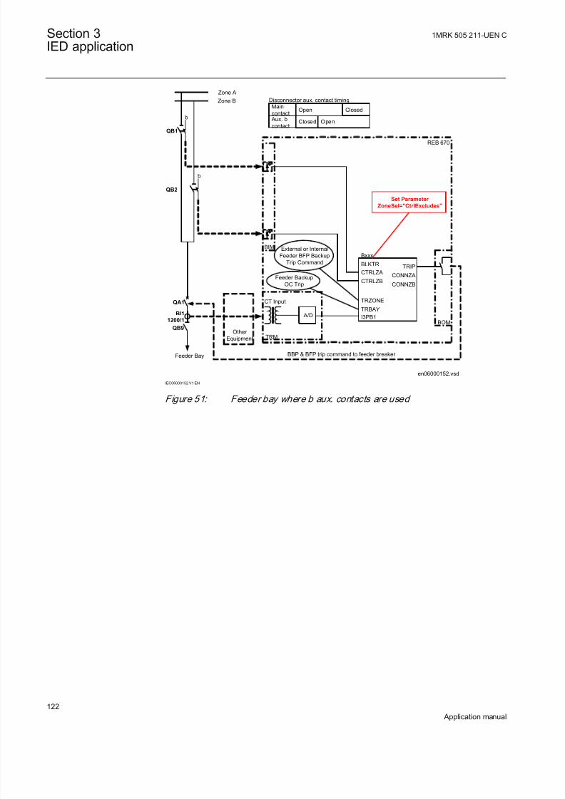
8/22/2019 Best Application
http://slidepdf.com/reader/full/best-application 128/457
en06000152.vsd
Zone A
Zone B
BI1
1200/1
REB 670
b
CT Input
Aux. b
contactClosed Open
b
CTRLZACTRLZB
TRIP
CONNZA
CONNZB
Bxxx
I3PB1
BLKTR
TRZONE
TRBAY
BBP & BFP trip command to feeder breaker
BIM
BOM
Main
contactOpen Closed
Set Parameter
ZoneSel="CtrlExcludes"
Feeder Bay
Other
Equipment
A/D
TRM
Feeder Backup
OC Trip
Disconnector aux. contact timing
QB9
QB1
QB2
QA1
External or Internal
Feeder BFP Backup
Trip Command
IEC06000152 V1 EN
Figure 51: Feeder bay where b aux. contacts are used
Section 3 1MRK 505 211-UEN C
IED application
122
Application manual

8/22/2019 Best Application
http://slidepdf.com/reader/full/best-application 129/457
en06000153.vsd
BOM
QB1
Zone A
Zone B
Bus-Coupler
Bay
REB 670
CTRLZA
CTRLZB
TRIP
CONNZA
CONNZB
Bxxx
I3PB1
BLKTR
TRZONE
TRBAY
BBP & BFP trip command to Bus-Coupler breaker
BI1
2400/1
BI2
2400/1
CT Input
A/D
A/D
CTRLZA
CTRLZB
TRIP
CONNZA
CONNZB
Bxxx
I3PB1
BLKTR
TRZONE
TRBAY
Parameter ZoneSel must
be set to "FixedToZA"
OR
Other
Equipment
Other
Equipment
CT Input
TRM
Bus-Coupler Backup
OC Trip
QB2
QA1
External or Internal
Bus-Coupler BFP
Backup Trip Command
Parameter ZoneSel must
be set to "FixedToZB"
IEC06000153 V1 EN
Figure 52: Bus coupler bay with two sets of CTs
1MRK 505 211-UEN C Section 3IED application
123
Application manual

8/22/2019 Best Application
http://slidepdf.com/reader/full/best-application 130/457
en06000154.vsd
Zone A
Zone B
Bus-Coupler
Bay
REB 670
CTRLZA
CTRLZB
TRIP
CONNZA
CONNZB
Bxxx
I3PB1
BLKTR
TRZONE
TRBAY
BBP & BFP trip command to Bus-Coupler breaker
BOM
A/D
Parameter ZoneSel must be
set to "FixedToZA&-ZB"
tZeroCurrent=150ms
Other
Equipment
CT InputTRM
External or Internal
Bus-Coupler BFP
Backup Trip Command
Bus-Coupler Backup
OC Trip
QB1
QB2
b a
BI1
2400/1
QA1
NO
NC
CLOSED
OPEN
ALARM
FORCED
SSxx
DISABLE
ZEROCUR
BIM
CB Closing
Signal
³1tt=1s
IEC06000154 V1 EN
Figure 53: Bus coupler bay with one CT and a&b aux. contact from CB
Section 3 1MRK 505 211-UEN C
IED application
124
Application manual

8/22/2019 Best Application
http://slidepdf.com/reader/full/best-application 131/457
en06000155.vsd
Zone A
Zone B
Bus-Coupler
Bay
REB 670
CTRLZA
CTRLZB
TRIP
CONNZA
CONNZB
Bxxx
I3PB1
BLKTR
TRZONE
TRBAY
BBP & BFP trip command to Bus-Coupler breaker
BOM
A/D
Parameter ZoneSel must
be set to "FixedToZA&-ZB"
tZeroCurrent=150ms
Other
Equipment
CT InputTRM
External or Internal
Bus-Coupler BFP
Backup Trip Command
Bus-Coupler Backup
OC Trip
QB1
QB2
b
BI1
2400/1
QA1
ZEROCUR
BIMCB Closing
Signal
³1tt=1s
&
IEC06000155 V1 EN
Figure 54: Bus coupler bay with one CT and b aux. contact only from CB
Double busbar arrangements with two bus-section breakers and two
bus-coupler breakersThis type of station is commonly used for GIS installations. It offers highoperational flexibility. For this type of stations, two schemes similar to the double
busbar station scheme can be used.
BI1
QA1
QB1 QB2
BI1
QA1
QB1 QB2
BI1
QA1
QB1 QB2
BI1
QA1
QB1 QB2
BI1
QA1
QB1 QB2
BI1
QA1
QB1 QB2
BI1
QA1
QB1 QB2
BI1
QA1
QB1 QB2
BI1
QA1
BI1QA1
BI1 QA1
BI1
QB1 QB2
QA1
BI1
QA1
ZA1
ZB1
ZA2
ZB2
xx06000016.vsd
IEC06000016 V1 EN
Figure 55: Example of typical GIS station layout
With REB670 this type of arrangement can be protected as described in thefollowing table.
1MRK 505 211-UEN C Section 3IED application
125
Application manual
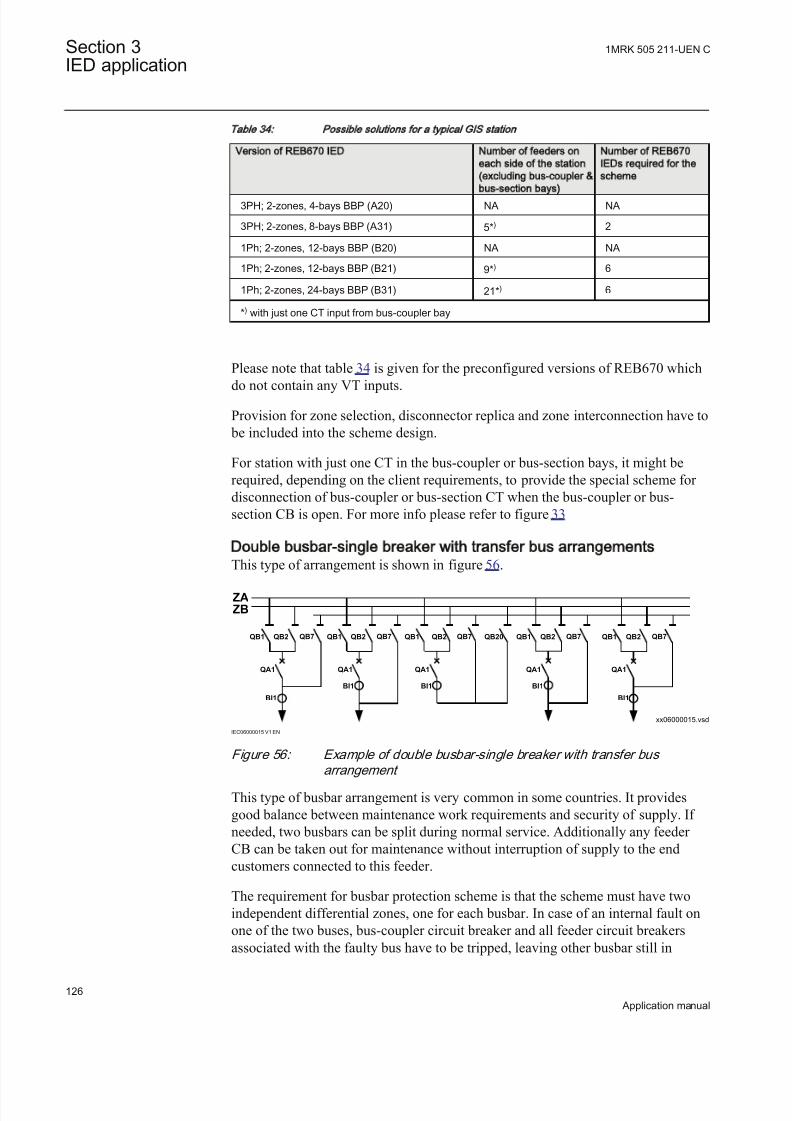
8/22/2019 Best Application
http://slidepdf.com/reader/full/best-application 132/457
Table 34: Possible solutions for a typical GIS station
Version of REB670 IED Number of feeders on
each side of the station
(excluding bus-coupler &
bus-section bays)
Number of REB670
IEDs required for the
scheme
3PH; 2-zones, 4-bays BBP (A20) NA NA
3PH; 2-zones, 8-bays BBP (A31) 5*) 2
1Ph; 2-zones, 12-bays BBP (B20) NA NA
1Ph; 2-zones, 12-bays BBP (B21) 9*) 6
1Ph; 2-zones, 24-bays BBP (B31) 21*) 6
*) with just one CT input from bus-coupler bay
Please note that table 34 is given for the preconfigured versions of REB670 which
do not contain any VT inputs.
Provision for zone selection, disconnector replica and zone interconnection have to be included into the scheme design.
For station with just one CT in the bus-coupler or bus-section bays, it might berequired, depending on the client requirements, to provide the special scheme for disconnection of bus-coupler or bus-section CT when the bus-coupler or bus-section CB is open. For more info please refer to figure 33
Double busbar-single breaker with transfer bus arrangementsThis type of arrangement is shown in figure 56.
BI1
QB1 QB2 QB7
BI1
QB1 QB2 QB7
BI1
QB1 QB2 QB7
BI1
QB1 QB2 QB7
BI1
QB20QB2 QB7QB1
QA1 QA1 QA1 QA1 QA1
ZAZB
xx06000015.vsd
IEC06000015 V1 EN
Figure 56: Example of double busbar-single breaker with transfer bus
arrangement
This type of busbar arrangement is very common in some countries. It providesgood balance between maintenance work requirements and security of supply. If needed, two busbars can be split during normal service. Additionally any feeder CB can be taken out for maintenance without interruption of supply to the endcustomers connected to this feeder.
The requirement for busbar protection scheme is that the scheme must have twoindependent differential zones, one for each busbar. In case of an internal fault onone of the two buses, bus-coupler circuit breaker and all feeder circuit breakersassociated with the faulty bus have to be tripped, leaving other busbar still in
Section 3 1MRK 505 211-UEN C
IED application
126
Application manual

8/22/2019 Best Application
http://slidepdf.com/reader/full/best-application 133/457
normal operation. When transfer bus is in operation it will be protected as anintegral part of one of the two internally available zones. Special attention shall begiven that appropriate logic for zone selection is done with help of graphicalconfiguration tool. At the same time, load transfer and possible transfer of tripsignals from the feeder under transfer to the transfer circuit breaker shall bearranged in appropriate way as well. This type of busbar arrangement can be
protected as described in the following table:
Table 35: Possible solut ions for double busbar-sing le breaker with t ransfer bus arrangements
Version of REB670 IED Total number of feeder
bays in the station
(excluding buscoupler &
bus-section bays)
Number of REB670
IEDs required for the
scheme
3PH; 2-zones, 4-bays BBP (A20) NA NA
3PH; 2-zones, 8-bays BBP (A31) 7*) 1
1Ph; 2-zones, 12-bays BBP (B20) NA NA1Ph; 2-zones, 12-bays BBP (B21) 11*) 3
1Ph; 2-zones, 24-bays BBP (B31) 23*) 3
*) with one set of CTs in bus-coupler bay and separate transfer and bus-coupler breaker
Please note that table 35 is given for the preconfigured versions of REB670 whichdo not contain any VT inputs.
Note that for station layouts where combined transfer and bus-coupler bay is used,as for example is shown in figure 56, two internal bay function blocks must be
allocated to such primary bay, reducing number of available feeder bays. In suchstation maximum available number of feeder bays is less for one from the valuesshown in table 35, on condition that just one main CT is available from Bus-Coupler/Transfer bay. For station with just one CT in the bus-coupler bay, it might berequired, depending on the client requirements, to provide the logic scheme for disconnection of bus-coupler CT when the bus-coupler CB is open. For moreinformation, refer to figure 33.
Combined busbar arrangementsThere are stations which are practically a combination between two normal typesof station arrangements, which are already previously described. Some typical
examples will be shown here:
1MRK 505 211-UEN C Section 3IED application
127
Application manual

8/22/2019 Best Application
http://slidepdf.com/reader/full/best-application 134/457
BI3
BI1
QA1
BI2
QA2
QA3
BI3
BI1
QA1
BI2
QA2
QA3
BI3
BI1
QA1
BI2
QA2
QA3
BI3
BI1
QA1
BI2
QA2
QA3
BI3
BI1
QA1
BI2
QA2
QA3
ZA
ZB
xx06000123.vsd
QA1
BI1 BI2
QA2
IEC06000123 V1 EN
Figure 57: Combination between one-and-half and double breaker station
layouts
This type of stations can be encountered very often in practice. Usually the stationis arranged in such a way that double breaker bays can be, at a later stage,transformed into one-and-half breaker setup. For busbar protection this type of station can be protected in exactly the same way as one-and-half breaker stationsdescribed above. The same type of IEDs can be used, and same limitationsregarding the number of diameters apply.
xx06000124.vsd
QA1
BI1 BI2
QA2
BI1
QA1
QB1 QB2
BI1
QA1
QB1 QB2
ZA
ZB
QA1
BI1 BI2
QA2
IEC06000124 V1 EN
Figure 58: Combination between double breaker and double busbar station
layouts
In this type of arrangement the double breaker bay has in the same time the role of the bus-coupler bay for normal double busbar single breaker stations. Therefore,zone interconnection, zone selection and disconnector replica facilities have to be
provided for all double busbar bays. Because of the very specific requirements onzone interconnection feature, the following should be considered for this type of application:
Section 3 1MRK 505 211-UEN C
IED application
128
Application manual

8/22/2019 Best Application
http://slidepdf.com/reader/full/best-application 135/457
• current inputs CT1 and CT2 shall be used for the first double breaker bay.• current inputs CT3 and CT4 shall be used for the second double breaker bay.• current inputs CT5 and CT6 shall be used for the third double breaker bay
(only available in 1ph version).
Accordingly the following solutions are possible:
Table 36: Typical solut ions for combinat ion between double breaker and double busbar
station layouts
Version of REB670 IED Number of double
breaker feeders /
Number of double
busbar feeders in the
station
Number of REB670
IEDs required for the
scheme
3PH; 2-zones, 4-bays BBP (A20) NA NA
3PH; 2-zones, 8-bays BBP (A31) 2/4 1
1Ph; 2-zones, 12-bays BBP (B20) NA NA
1Ph; 2-zones, 12-bays BBP (B21) 3/6 3
1Ph; 2-zones, 24-bays BBP (B31) 3/18 3
Please note that table 36 is given for the preconfigured versions of REB670 whichdo not contain any VT inputs.
xx06000125.vsd
BI3
BI1
QA1
BI2
QA2
QA3
BI3
BI1
QA1
BI2
QA2
QA3
BI3
BI1
QA1
BI2
QA2
QA3
BI3
BI1
QA1
BI2
QA2
QA3
BI3
BI1
QA1
BI2
QA2
QA3
ZA
ZB
BI1
QA1
QB1 QB2
BI1
QA1
QB1 QB2
IEC06000125 V1 EN
Figure 59: Combination between one-and-half breaker and double busbar
station layouts
For this type of busbar arrangement the double busbar bay is usually connected tothe reactive power compensation equipment (that is, shunt reactor or shuntcapacitor). The diameters in the one-and-half breaker part of the station have at the
1MRK 505 211-UEN C Section 3IED application
129
Application manual

8/22/2019 Best Application
http://slidepdf.com/reader/full/best-application 136/457
same time the role of the bus-coupler bay. Therefore, zone interconnection, zoneselection and disconnector replica facilities have to be provided for all double
busbar bays.
3.5.1.4 Summation principle
IntroductionA simplified bus differential protection for phase and earth faults can be obtained
by using a single, one-phase IED with external auxiliary summation currenttransformers. By using this approach, more cost effective bus differential
protection can be obtained. Such a solution makes it feasible to apply busdifferential protection even to medium voltage substations. The principaldifferences between full, phase-segregated bus differential protection scheme andsummation type bus differential protection scheme are shown in figure 60.
Auxiliary Summation CT *)
type SLCE 8; 1/1A, 2/1A or 5/1A
+
Three one-phase
REB670Single one-phase
REB670
Up to 18 pcs
auxiliary CTs
*) One SLCE 8 per main CT
REB670with 1A
CT inputs
REB670
REB670
REB670
@
IEC06000126_2_en.vsd
IEC06000126 V2 EN
Figure 60: Difference between phase segregated & summation type
differential protection
In the full, phase-segregated design three, one-phase REB670 IEDs (that is, one per phase) are used. However for the summation type only single, one-phase REB670IED plus one auxiliary summation CT per each main CT is required. Theseauxiliary summation CTs convert each main CT three-phase currents to a single-
phase output current, which are all measured by one REB670 IED. The differentialcalculation is then made on a single-phase basis. By doing so, this more costeffective bus differential protection can be applied. Due to this characteristic, this
summation type of bus differential protection can be applied for all types of stations arrangements as shown section "Different busbar arrangements", for three,one-phase IEDs.
As an example, the necessary equipment for the summation type, busbar differential protection for a single busbar station with up to 24 bays, is shown infigure 61.
Section 3 1MRK 505 211-UEN C
IED application
130
Application manual
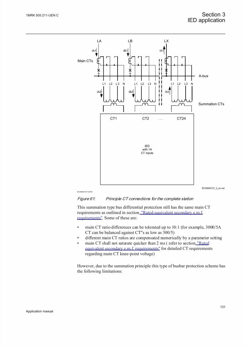
8/22/2019 Best Application
http://slidepdf.com/reader/full/best-application 137/457
IED
with 1A
CT inputs
IB2 IX2IA2
L1 L2 L3 N
IA1 IB1 IX1
LA LB LX
A-bus
Summation CTs
Main CTs
CT1 CT2 . . . CT24
IEC06000127_2_en.vsd
L1 L2 L3 N L1 L2 L3 N
IEC06000127 V2 EN
Figure 61: Principle CT connections for the complete station
This summation type bus differential protection still has the same main CTrequirements as outlined in section "Rated equivalent secondary e.m.f.requirements". Some of these are:
• main CT ratio differences can be tolerated up to 10:1 (for example, 3000/5ACT can be balanced against CT"s as low as 300/5)
• different main CT ratios are compensated numerically by a parameter setting• main CT shall not saturate quicker than 2 ms ( refer to section "Ratedequivalent secondary e.m.f. requirements" for detailed CT requirementsregarding main CT knee-point voltage)
However, due to the summation principle this type of busbar protection scheme hasthe following limitations:
1MRK 505 211-UEN C Section 3IED application
131
Application manual

8/22/2019 Best Application
http://slidepdf.com/reader/full/best-application 138/457
• Only one measuring circuit is utilized for all fault types (that is, no redundancyfor multi-phase faults)
• Primary fault sensitivity varies depending on the type of fault and involved phase(s), see table 38
• The load currents in the healthy phases might produce the stabilizing currentwhen an internal, single phase to ground fault occurs. However, there is no
problem for solidly earthed systems with high earth-fault currents• No indication of faulty phase(s) in case of an internal fault• Not possible to fully utilize Open CT detection feature
Auxiliary summation CTsAuxiliary Summation Current Transformer (that is, ASCT in further text) of thetype SLCE 8 is used with the summation principle of the IED. The principledrawing of one such ASCT is shown in figure 62.
Auxiliary Summation CT
type SLCE 8; X/1A
N4
S1
S2
en03000118.vsd
P1
N1
P2
P3
N2
P4
P5
N3
P6
IEC03000118 V1 EN
Figure 62: Principle ASCT drawing
The ASCT has three primary windings and one secondary winding. In further text,turn numbers of these windings will be marked with N1, N2, N3 & N4,
respectively (see figure 62 for more information).
There are three types of ASCT for REB670:
1. ASCT type with ratio 1/1A, for balanced 3-Ph current input, shall be used withall main current transformers with 1A rated secondary current (that is, 2000/1A)
2. ASCT type with ratio 5/1A, for balanced 3-Ph current input, shall be used withall main current transformers with 5A rated secondary current (that is, 3000/5A)
3. ASCT type with ratio 2/1A, for balanced 3-Ph current input, shall be used withall main current transformers with 2A rated secondary current (that is, 1000/2A)
Section 3 1MRK 505 211-UEN C
IED application
132
Application manual

8/22/2019 Best Application
http://slidepdf.com/reader/full/best-application 139/457
Note the following:
• main CT rated primary current is not important for ASCT selection• possible main CT ratio differences will be compensated by a parameter setting
in the IED• rated secondary current of ASCT is 1A for all types. That means that
secondary ASCT winding should be always connected to the IED with 1A CTinputs, irrespective of the rated secondary current of the main CT
All of these features simplify the ordering of the ASCTs. Practically, in order to purchase ASCTs, the only required information is the main CT rated secondarycurrent that is, (1A, 2A or 5A).
Table 37 summarizes the ASCT data:
Table 37: Auxiliary summation CT data
Type of fault N1 N2 N3 N4 Ukp [V] Burden
[VA]
ASCT SLCE 8;1/1A
52 52 104 90 33 1.0
ASCT SLCE 8;5/1A
12 12 24 104 38 1.0
ASCT SLCE 8;2/1A
26 26 52 90 33 1.0
where:
• N1, N2, N3 & N4 are ASCT windings turn numbers (see figure 62)• Ukp is knee point voltage, at 1.6T, of the secondary winding with N4 turns• Burden is the total 3Ph load of ASCT imposed to the main CT
Due to ASCT design, the ASCTs for summated bus differential protection, must always be mounted as close as possible to the IED(that is, in the same protection cubicle).
Possible ASCT connections for REB670It is possible to connect the ASCTs for summated bus differential protection withREB670:
• at the end of the main CT circuit (for example, beyond the other protectiverelays, as shown in figure 63
• in series with other secondary equipment when some other relay must belocated at the end of the main CT circuit , as shown in figure 64
1MRK 505 211-UEN C Section 3IED application
133
Application manual

8/22/2019 Best Application
http://slidepdf.com/reader/full/best-application 140/457
End connection is the preferred arrangement as it gives greater sensitivity for summation type bus differential protection (as shown in table 38 for moreinformation).
However, it should be noted that these two connection types must not be mixed.This means that within one busbar installation all auxiliary summation CTs have to
be either end-connected or series-connected.
Typical end-connection with ASCT is shown in figure 63.
L1
L2
L3
N
IL1
IL2
IL3
IN
Other relays
Auxiliary Summation CT
type SLCE 8;
1/1A or 5/1A or 2/1A
N4
S1
S2
en06000128.vsd
Main CT
2000/1A or 2000/5A
or 2000/2A
AI03
X401
5
6
REB 670 with 1A CTsP1
N1
P2
P3
N2
P4
P5
N3
P6
ISUMM
IEC06000128 V1 EN
Figure 63: End-connection with ASCT connected to CT3 inpu t
It is important to notice that even in the case of 5A or 2A main CTs, secondarycurrent of the summation CTs shall be connected to the IED with 1A CT inputs (asshown in figure 63). The reason for this is that the rated secondary current of ASCT is always 1A irrespective of the rated secondary current of the main CT.
Refer to section "SLCE 8/ASCT characteristics for end-connection" for detailedASCT current calculations for end-connection.
Typical series-connection with ASCT is shown in figure 64.
Section 3 1MRK 505 211-UEN C
IED application
134
Application manual

8/22/2019 Best Application
http://slidepdf.com/reader/full/best-application 141/457
Other
relays
IL1 IL2 IL3
en06000129.vsd
IL3
Auxiliary Summation CT
type SLCE 8; 1/1 or 5/1A or 2/1A
N4
S1
S2
A103
X401
5
6
REB 670 with 1A CTs
L3L2L1 N
IL1
IN
IN
Main CT
2000/1A
or 2000/5A
or 2000/2A
ISUMM
Other
relays
P1N1
P2
P3N2
P4
P5N3
P6
IEC06000129 V1 EN
Figure 64: Series-connection with ASCT connected to CT3 input
Refer to section "SLCE 8/ASCT characteristics for series-connection"for detailedASCT current calculation for series-connection.
Main CT ratio mismatch correctionAs stated before, three types of ASCTs for REB670 are available. The first typeshall be used for main CTs with 1A rated secondary current. The second type shall
be used for main CTs with 5A rated secondary current. The third type shall be usedwith 2A main CTs. However REB670 with 1A CT inputs is always used. Thereforemain CT ratio shall always be set in such a way that the primary current is enteredas for the main CT, but secondary current is always entered as 1A (that is, 3000/5main CT will be entered as 3000/1 CT in REB670).
Primary pick-up levels for summation type differential protection
The minimal differential operating current level is entered directly in primaryamperes. However, as stated previously, in case of the summated differential protection the primary fault sensitivity varies depending on the type of fault andinvolved phase(s). The entered value, for the minimal differential operating currentlevel, will exactly correspond to the REB670 start value in the event of a 3-phaseinternal fault. For all other fault types this value must be multiplied by a coefficientshown in the table 38 in order to calculate the actual primary start value.
1MRK 505 211-UEN C Section 3IED application
135
Application manual

8/22/2019 Best Application
http://slidepdf.com/reader/full/best-application 142/457
Tab le 38: S ta rt coe ff ic ients for Summated D ifferen tial P ro tect ion
Type of fault L1-Gnd L2-Gnd L3-Gnd L1-L2 L2-L3 L3-L1 L1L2L3
ASCT endconnected
0.434 0.578 0.867 1.732 1.732 0.867 1.0
ASCT seriesconnected
1.732 0.867 0.578 1.732 1.732 0.867 1.0
The coefficients in table 38 are only relevant for ideal internalfaults (that is, load currents do not exist in the healthy phases).
Example 1:
The minimal differential operating current level in the IED is set to 1250A. All
ASCTs are series connected. What is the theoretical primary start value in case of L3-Gnd fault?
Answer 1:
According to table 38, pickup coefficient for this type of ASCT connection and thistype of fault is 0.578. Therefore:
IPickup L3 Gnd – ( ) 0.578 1250× 722.5A= =
EQUATION1106 V1 EN (Equation 30)
( ) 0.578 1250 722.5 Pickup
I C Gnd A- = × =
EQUATION1784 V1 EN (Equation 30)
This means that if 722.5 primary amperes is injected only in phase L3 of any of theconnected main CTs, the IED shall display the differential current of 1250A(primary) and should be on the point of the start (that is, trip).
In addition to busbar protection differential zones, the IED can incorporate other additional functions and features. If and how they can be used together withsummation busbar protection design is shown in table 39:
Section 3 1MRK 505 211-UEN C
IED application
136
Application manual

8/22/2019 Best Application
http://slidepdf.com/reader/full/best-application 143/457
Table 39: Functions
Functions Comment
Busbar Differential Protection Differential Protection, Sensitive differential protection,OCT algorithm, Check Zone and Differential Supervision
features will be connected to the summated baycurrents. Therefore, they will have different start leveldepending on the type of fault and involved phase(s).For more information, refer to table 38. However, if allthese limitations are acceptable it is still possible to useall these internal busbar protection features. Note thatOCT operating logic will not work properly in case of opening or shorting the main CT secondary leads (thatis, in-between main CT and ASCT). In case of openingor shorting the ASCT secondary leads (that is, in-between ASCT and the IED) the OCT logic will operatecorrectly.
Dynamic Zone Selection feature Zone Selection feature in the IED can be used in theexactly same way as with phase segregated design. Allbuilt-in features, even including breaker failure
protection, protection back-up trip command routing,EnFP logic can be used in the exactly same way as for phase segregated design.
CCRBRF/CCSRBRF function Breaker Fail Protection function will be connected to thesummated bay current. Therefore it will have differentstart level depending on the type of fault and involvedphase(s). See table 38 for more info. It will not bepossible to have individual starting per phase, but onlythree-phase starting can be effectively used. However, if all these limitations are acceptable it is still possible touse internal CCRBRF/CCSRBRF functions.
OC4PTOC/PHS4PTOCfunction Overcurrent Protection function will be connected to thesummated bay current. Therefore, it will have differentstart level depending on the type of fault and involved
phase(s). See table 38 for more info. Thus it will be verydifficult to insure proper start and time grading withdownstream overcurrent protection relays. Hence it willbe quite difficult to use OC4PTOC/PHS4PTOC asbackup feeder protection with summation design.
OC4PTOC/PHS4PTOC function End Fault Protection feature will be connected to thesummated bay current. Therefore it will have differentstart level depending on the type of fault and involvedphase(s). See table 38 for more info. However,OC4PTOC/PHS4PTOC do not need any start or timecoordination with any other overcurrent protection. Thusif above limitations are acceptable OC4PTOC/PHS4PTOC can be used with summation design.
DRPRDRE function Disturbance Recording feature will be connected to the
individual summated bay current. Therefore recordedcurrents will not correspond to any actual primarycurrents. However such DRPRDRE records can still beused to evaluate internal busbar protection, CCRBRF/CCSRBRF and OC4PTOC/PHS4PTOC protectionsoperation.
DRPRDRE function Event List feature in the IED can be used in the exactlythe same way as with phase segregated design.
Table continues on next page
1MRK 505 211-UEN C Section 3IED application
137
Application manual
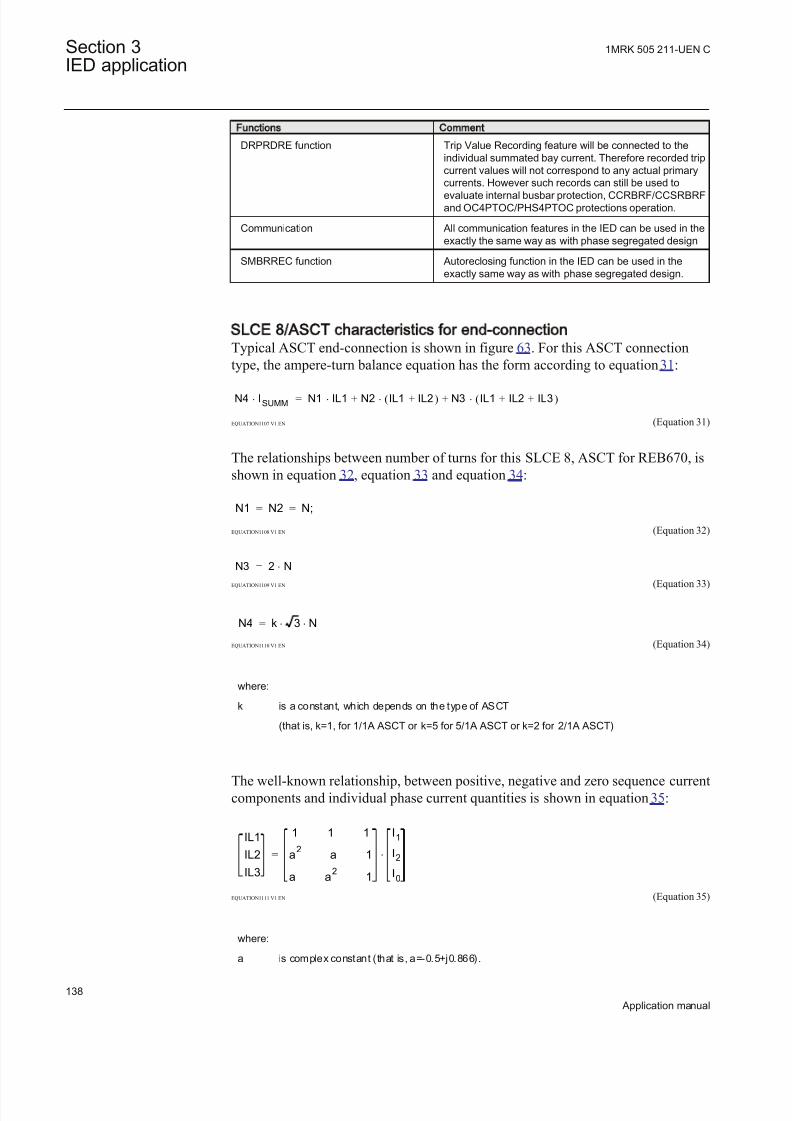
8/22/2019 Best Application
http://slidepdf.com/reader/full/best-application 144/457
Functions Comment
DRPRDRE function Trip Value Recording feature will be connected to theindividual summated bay current. Therefore recorded tripcurrent values will not correspond to any actual primarycurrents. However such records can still be used to
evaluate internal busbar protection, CCRBRF/CCSRBRFand OC4PTOC/PHS4PTOC protections operation.
Communication All communication features in the IED can be used in theexactly the same way as with phase segregated design
SMBRREC function Autoreclosing function in the IED can be used in theexactly same way as with phase segregated design.
SLCE 8/ASCT characteristics for end-connectionTypical ASCT end-connection is shown in figure 63. For this ASCT connectiontype, the ampere-turn balance equation has the form according to equation 31:
N4 ISUMM× N1 IL1× N2 IL1 IL2+( )× N3 IL1 IL2 IL3+ +( )×+ +=
EQUATION1107 V1 EN (Equation 31)
The relationships between number of turns for this SLCE 8, ASCT for REB670, isshown in equation 32, equation 33 and equation 34:
N1 N2 N;= =
EQUATION1108 V1 EN (Equation 32)
N3 2 N×=
EQUATION1109 V1 EN (Equation 33)
N4 k 3 N× ×=
EQUATION1110 V1 EN (Equation 34)
where:
k is a constant, which depends on the type of ASCT
(that is, k=1, for 1/1A ASCT or k=5 for 5/1A ASCT or k=2 for 2/1A ASCT)
The well-known relationship, between positive, negative and zero sequence currentcomponents and individual phase current quantities is shown in equation 35:
IL1
IL2
IL3
1 1 1
a2
a 1
a a2
1
I1
I2
I0
×=
EQUATION1111 V1 EN (Equation 35)
where:
a is complex constant (that is, a=-0.5+j0.866).
Section 3 1MRK 505 211-UEN C
IED application
138
Application manual
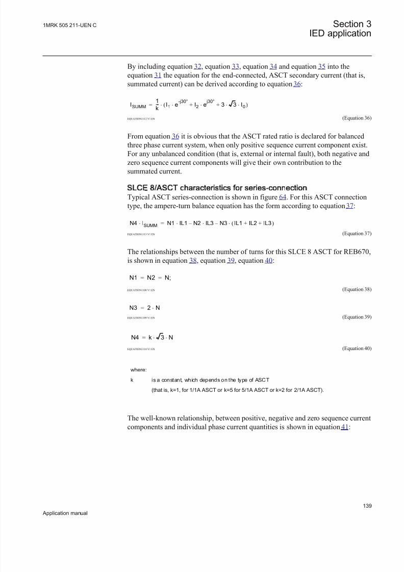
8/22/2019 Best Application
http://slidepdf.com/reader/full/best-application 145/457
By including equation 32, equation 33, equation 34 and equation 35 into theequation 31 the equation for the end-connected, ASCT secondary current (that is,summated current) can be derived according to equation 36:
ISUMM1
k--- I1 e
-j30°× I2 e
j30°× 3 3 I0× ×+ +( )×=
EQUATION1112 V1 EN (Equation 36)
From equation 36 it is obvious that the ASCT rated ratio is declared for balancedthree phase current system, when only positive sequence current component exist.For any unbalanced condition (that is, external or internal fault), both negative andzero sequence current components will give their own contribution to thesummated current.
SLCE 8/ASCT characteristics for series-connection
Typical ASCT series-connection is shown in figure 64. For this ASCT connectiontype, the ampere-turn balance equation has the form according to equation 37:
N4 ISUMM× N1 IL1 N2 – IL3 N3 – IL1 IL2 IL3+ +( )× × ×=
EQUATION1113 V1 EN (Equation 37)
The relationships between the number of turns for this SLCE 8 ASCT for REB670,is shown in equation 38, equation 39, equation 40:
N1 N2 N;= =
EQUATION1108 V1 EN (Equation 38)
N3 2 N×=
EQUATION1109 V1 EN (Equation 39)
N4 k 3 N× ×=
EQUATION1110 V1 EN (Equation 40)
where:
k is a constant, which depends on the type of ASCT
(that is, k=1, for 1/1A ASCT or k=5 for 5/1A ASCT or k=2 for 2/1A ASCT).
The well-known relationship, between positive, negative and zer o sequence currentcomponents and individual phase current quantities is shown in equation 41:
1MRK 505 211-UEN C Section 3IED application
139
Application manual

8/22/2019 Best Application
http://slidepdf.com/reader/full/best-application 146/457
IL1
IL2
IL3
1 1 1
a2
a 1
a a2
1
I1
I2
I0
×=
EQUATION1111 V1 EN (Equation 41)
where:
a is complex constant (that is, a=-0.5+j0.866).
By including equation 38, equation 39, equation 40 and equation 41 into theequation 37 the equation for the series-connected, ASCT secondary current (that is,summated current) can be derived according to equation 42:
ISUMM1k--- I1 e-j30°× I2 e j30°× 2 3 I0× ×+ +( )×=
EQUATION1114 V1 EN (Equation 42)
From equation 42 it is obvious that the ASCT rated ratio is declared for balancedthree phase current system, when only positive sequence current component exist.For any unbalanced condition (that is, external or internal fault), both negative andzero sequence current components will give their own contribution to thesummated current.
3.5.1.5 Setting parameters
All general settings for Busbar differential protection are only relevant for proper event reporting via IEC 61850-8-1. They are not important for proper operation of Busbar differential protection.
Note that all settings for busbar protection under relevant parameter setting groupare directly related to proper operation of the Busbar differential protection.
Table 40: BZNTPDIF_A G roup settings (basic)
Name Values (Range) Unit Step Default Description
Operation Off On
- - Off Differential protection operation
DiffOperLev 1 - 99999 A 1 1000 Differential protection operation level inprimary amperes
DiffTripOut SelfResetLatched
- - SelfReset Differential protection trip output mode
tTripHold 0.000 - 60.000 s 0.001 0.200 Differential trip drop-off delay inSelfReset mode
CheckZoneSup Off On
- - Off Check zone supervises differentialprotection operation
SlowOCTOper Off BlockSupervise
- - Block Operation of slow open CT alarm
Table continues on next page
Section 3 1MRK 505 211-UEN C
IED application
140
Application manual

8/22/2019 Best Application
http://slidepdf.com/reader/full/best-application 147/457

8/22/2019 Best Application
http://slidepdf.com/reader/full/best-application 148/457
Name Values (Range) Unit Step Default Description
IINL2 zeroDb 0 - 100000 - 1 500 Values less than this are forced to zeroin 0,001% of range
IINL2 L2hhLim 0.000 -
10000000000.000
- 0.001 5000.000 High High limit
IINL2 hLim 0.000 -10000000000.000
- 0.001 3000.000 High limit
IINL2 lLim 0.000 -10000000000.000
- 0.001 100.000 Low limit
IINL2 llLim 0.000 -10000000000.000
- 0.001 50.000 Low Low limit
IINL2 min 0.000 -10000000000.000
- 0.001 25.000 Minimum value
IINL2 max 0.000 -10000000000.000
- 0.001 6000.000 Maximum value
IINL2 dbType Cyclic
Dead bandInt deadband
- - Dead band Reporting type (0=cyclic, 1=db,
2=integral db)
IINL2 limHys 0.000 - 100.000 - 0.001 5.000 Hysteresis value in % of range and iscommon for all limits
IINL3 db 0 - 300 s,%,%s 1 10 Deadband value in % of range (in %s if integral is used)
IINL3 zeroDb 0 - 100000 - 1 500 Values less than this are forced to zeroin 0,001% of range
IINL3 hhLim 0.000 -10000000000.000
- 0.001 5000.000 High High limit
IINL3 hLim 0.000 -10000000000.000
- 0.001 3000.000 High limit
IINL3 lLim 0.000 -10000000000.000
- 0.001 100.00 Low limit
IINL3 llLim 0.000 -10000000000.000
- 0.001 50.000 Low Low limit
IINL3 min 0.000 -10000000000.000
- 0.001 25.000 Minimum value
IINL3 max 0.000 -10000000000.000
- 0.001 6000.000 Maximum value
IINL3 dbType CyclicDead bandInt deadband
- - Dead band Reporting type (0=cyclic, 1=db,2=integral db)
IINL3 limHys 0.000 - 100.000 - 0.001 5.000 Hysteresis value in % of range and is
common for all limits
IDL1 db 0 - 300 s,%,%s 1 10 Deadband value in % of range (in %s if integral is used)
IDL1 zeroDb 0 - 100000 - 1 500 Values less than this are forced to zeroin 0,001% of range
IDL1 hhLim 0.000 -10000000000.000
- 0.001 5000.000 High High limit
IDL1 hLim 0.000 -10000000000.000
- 0.001 3000.000 High limit
IDL1 lLim 0.000 -10000000000.000
- 0.001 100.000 Low limit
Table continues on next page
Section 3 1MRK 505 211-UEN C
IED application
142
Application manual

8/22/2019 Best Application
http://slidepdf.com/reader/full/best-application 149/457
Name Values (Range) Unit Step Default Description
IDL1 llLim 0.000 -10000000000.000
- 0.001 50.000 Low Low limit
IDL1 min 0.000 -
10000000000.000
- 0.001 25.000 Minimum value
IDL1 max 0.000 -10000000000.000
- 0.001 6000.000 Maximum value
IDL1 dbType CyclicDead bandInt deadband
- - Dead band Reporting type (0=cyclic, 1=db,2=integral db)
IDL1 limHys 0.000 - 100.000 - 0.001 5.000 Hysteresis value in % of range and iscommon for all limits
IDL2 db 0 - 300 s,%,%s 1 10 Deadband value in % of range (in %s if integral is used)
IDL2 zeroDb 0 - 100000 - 1 500 Values less than this are forced to zeroin 0,001% of range
IDL2 hhLim 0.000 -10000000000.000
- 0.001 5000.000 High High limit
IDL2 hLim 0.000 -10000000000.000
- 0.001 3000.000 High limit
IDL2 lLim 0.000 -10000000000.000
- 0.001 100.000 Low limit
IDL2 llLim 0.000 -10000000000.000
- 0.001 50.000 Low Low limit
IDL2 min 0.000 -10000000000.000
- 0.001 25.000 Minimum value
IDL2 max 0.000 -10000000000.000
- 0.001 6000.000 Maximum value
IDL2 dbType CyclicDead bandInt deadband
- - Dead band Reporting type (0=cyclic, 1=db,2=integral db)
IDL2 limHys 0.000 - 100.000 - 0.001 5.000 Hysteresis value in % of range and iscommon for all limits
IDL3 db 0 - 300 s,%,%s 1 10 Deadband value in % of range (in %s if integral is used)
IDL3 zeroDb 0 - 100000 - 1 500 Values less than this are forced to zeroin 0,001% of range
IDL3 hhLim 0.000 -10000000000.000
- 0.001 5000.000 High High limit
IDL3 hLim 0.000 -
10000000000.000
- 0.001 3000.000 High limit
IDL3 lLim 0.000 -10000000000.000
- 0.001 100.000 Low limit
IDL3 llLim 0.000 -10000000000.000
- 0.001 50.000 Low Low limit
IDL3 min 0.000 -10000000000.000
- 0.001 25.000 Minimum value
Table continues on next page
1MRK 505 211-UEN C Section 3IED application
143
Application manual

8/22/2019 Best Application
http://slidepdf.com/reader/full/best-application 150/457
Name Values (Range) Unit Step Default Description
IDL3 max 0.000 -10000000000.000
- 0.001 6000.000 Maximum value
IDL3 dbType Cyclic
Dead bandInt deadband
- - Dead band Reporting type (0=cyclic, 1=db,
2=integral db)
IDL3 limHys 0.000 - 100.000 - 0.001 5.000 Hysteresis value in % of range and iscommon for all limits
Table 42: BZNSPDIF_A Group settings (basic)
Name Values (Range) Unit Step Default Description
Operation Off On
- - Off Differential protection operation
DiffOperLev 1 - 99999 A 1 1000 Differential protection operation level inprimary amperes
DiffTripOut SelfResetLatched
- - SelfReset Differential protection trip output mode
tTripHold 0.000 - 60.000 s 0.001 0.200 Differential trip drop-off delay inSelfReset mode
CheckZoneSup Off On
- - Off Check zone supervises differentialprotection operation
SlowOCTOper Off BlockSupervise
- - Block Operation of slow open CT alarm
FastOCTOper Off BlockSupervise
- - Block Operation of fast open CT alarm
OCTOperLev 1 - 99999 A 1 200 Open CT operation level in primaryamperes
tSlowOCT 0.00 - 6000.00 s 0.01 20.000 Time delay for slow open CT alarm
OCTReleaseLev 1 - 99999 A 1 2500 Id level above which OCT alarmreleases in supervision mode
IdAlarmLev 1 - 99999 A 1 200 Differential current alarm level in primaryamperes
tIdAlarm 0.00 - 6000.00 s 0.01 30.000 Time delay for Differential Current AlarmLevel in sec.
IinAlarmLev 1 - 99999 A 1 3000 Incoming current alarm level in primaryamperes
SensDiffOper Off On
- - Off Sensitive differential protection operation
SensOperLev 1 - 99999 A 1 200 Sensitive differential operation level inprimary amperes
SensIinBlock 1 - 99999 A 1 1000 Iin level above which sensitive diff.protection is blocked
tSensDiff 0.000 - 60.000 s 0.001 0.400 Time delay for sensitive differentialfunction operation
Section 3 1MRK 505 211-UEN C
IED application
144
Application manual

8/22/2019 Best Application
http://slidepdf.com/reader/full/best-application 151/457
Table 43: BZNSPDIF_A Non group settings (basic)
Name Values (Range) Unit Step Default Description
IIN db 0 - 300 s,%,%s 1 10 Deadband value in % of range (in %s if integral is used)
IIN zeroDb 0 - 100000 - 1 500 Values less than this are forced to zeroin 0,001% of range
IIN hhLim 0.000 -10000000000.000
- 0.001 5000.000 High High limit
IIN hLim 0.000 -10000000000.000
- 0.001 3000.000 High limit
IIN lLim 0.000 -10000000000.000
- 0.001 100.000 Low limit
IIN llLim 0.000 -10000000000.000
- 0.001 50.000 Low Low limit
IIN min 0.000 -10000000000.000
- 0.001 25.000 Minimum value
IIN max 0.000 -10000000000.000
- 0.001 6000.000 Maximum value
IIN dbType CyclicDead bandInt deadband
- - Dead band Reporting type (0=cyclic, 1=db,2=integral db)
IIN limHys 0.000 - 100.000 - 0.001 5.000 Hysteresis value in % of range and iscommon for all limits
ID db 0 - 300 s,%,%s 1 10 Deadband value in % of range (in %s if integral is used)
ID zeroDb 0 - 100000 - 1 500 Values less than this are forced to zeroin 0,001% of range
ID hhLim 0.000 -10000000000.000
- 0.001 5000.000 High High limit
ID hLim 0.000 -10000000000.000
- 0.001 3000.000 High limit
ID lLim 0.000 -10000000000.000
- 0.001 100.000 Low limit
ID llLim 0.000 -10000000000.000
- 0.001 50.000 Low Low limit
ID min 0.000 -10000000000.000
- 0.001 25.000 Minimum value
ID max 0.000 -10000000000.000
- 0.001 6000.000 Maximum value
ID dbType CyclicDead bandInt deadband
- - Dead band Reporting type (0=cyclic, 1=db,2=integral db)
ID limHys 0.000 - 100.000 - 0.001 5.000 Hysteresis value in % of range and iscommon for all limits
1MRK 505 211-UEN C Section 3IED application
145
Application manual

8/22/2019 Best Application
http://slidepdf.com/reader/full/best-application 152/457
Table 44: BCZTPDIF Group settings (basic)
Name Values (Range) Unit Step Default Description
Operation Off On
- - Off Check zone operation
OperLevel 1 - 99999 A 1 1000 Check zone operation level in primaryamperes
Slope 0.00 - 0.90 - 0.01 0.15 Check zone slope
Table 45: BCZSPDIF Group settings (basic)
Name Values (Range) Unit Step Default Description
Operation Off On
- - Off Check zone operation
OperLevel 0 - 99999 A 1 1000 Check zone operation level in primaryamperes
Slope 0.00 - 0.90 - 0.01 0.15 Check zone slope
Table 46: SWSGGIO Group settings (basic)
Name Values (Range) Unit Step Default Description
OperMode Off Scheme1_RADSSScheme2_INXForceOpenForceClosed
- - Off Switch operating mode (Scheme 1,Scheme 2 or forced)
tAlarm 0.00 - 6000.00 s 0.01 15.00 Alarm time delay for abnormal aux.contact status
Table 47: SW SGGIO Non group settings (basic)
Name Values (Range) Unit Step Default Description
SwitchName 0 - 13 - 1 Switch# User defined name for switch
Table 48: BUTPTRC_B1 Group settings (basic)
Name Values (Range) Unit Step Default Description
CTConnection Conn Inverted
NotConnectedConnected
- - Connected Hardware CT input connection to the bay
function block
ZoneSel FixedToZAFixedToZBFixedToZA&-ZBCtrlIncludesCtrlExcludes
- - CtrlIncludes How bay/CT is controlled toward thezones
ZoneSwitching ForceOutForceInConditionally
- - ForceIn Bay/CT status during zone switching
CheckZoneSel NotConnectedConnected
- - NotConnected Bay/CT status for the check zone
Table continues on next page
Section 3 1MRK 505 211-UEN C
IED application
146
Application manual

8/22/2019 Best Application
http://slidepdf.com/reader/full/best-application 153/457
Name Values (Range) Unit Step Default Description
tTripPulse 0.000 - 60.000 s 0.001 0.200 Bay trip pulse duration if zone trips inSelfReset mode
tZeroCurrent 0.000 - 60.000 s 0.001 0.200 Time delay to force current to zero via
binary signal
tInvertCurrent 0.000 - 60.000 s 0.001 0.200 Time delay to invert current via binarysignal
Table 49: BUTPTRC_B1 Non group settings (basic)
Name Values (Range) Unit Step Default Description
BAY01 0 - 13 - 1 BayName01 User defined name for bay
Table 50: BUSPTRC_B1 Group settings (basic)
Name Values (Range) Unit Step Default Description
CTConnection Conn InvertedNotConnectedConnected
- - Connected Hardware CT input connection to the bayfunction block
ZoneSel FixedToZAFixedToZBFixedToZA&-ZBCtrlIncludesCtrlExcludes
- - CtrlIncludes How bay/CT is controlled toward thezones
ZoneSwitching ForceOutForceInConditionally
- - ForceIn Bay/CT status during zone switching
CheckZoneSel NotConnectedConnected
- - NotConnected Bay/CT status for the check zone
tTripPulse 0.000 - 60.000 s 0.001 0.200 Bay trip pulse duration if zone trips inSelfReset mode
tZeroCurrent 0.000 - 60.000 s 0.001 0.200 Time delay to force current to zero viabinary signal
tInvertCurrent 0.000 - 60.000 s 0.001 0.200 Time delay to invert current via binarysignal
Table 51: BUSPTRC_B1 Non group settings (basic)
Name Values (Range) Unit Step Default Description
BAY01 0 - 13 - 1 BayName01 User defined name for bay
Table 52: BZITGGIO Group settings (basic)
Name Values (Range) Unit Step Default Description
Operation Off On
- - Off Load Transfer/Zone Interconnectionoperation
tAlarm 0.00 - 6000.00 s 0.01 300.00 Time delayed alarm for too long LoadTransfer/Zone Intercon
1MRK 505 211-UEN C Section 3IED application
147
Application manual

8/22/2019 Best Application
http://slidepdf.com/reader/full/best-application 154/457
Table 53: BZISGGIO Group settings (basic)
Name Values (Range) Unit Step Default Description
Operation Off On
- - Off Load Transfer/Zone Interconnectionoperation
tAlarm 0.00 - 6000.00 s 0.01 300.00 Time delayed alarm for too long LoadTransfer/Zone Intercon.
3.6 Current protection
3.6.1 Four step phase overcurrent protection OC4PTOC
Function description IEC 61850
identification
IEC 60617
identification
ANSI/IEEE C37.2
device numberFour step phase overcurrent protection OC4PTOC
4
4alt
3I>
TOC-REVA V1 EN
51/67
3.6.1.1 Application
The Four step phase overcurrent protection 3-phase output OC4PTOC is used inseveral applications in the power system. Some applications are:
• Short circuit protection of feeders in distribution and subtransmission systems. Normally these feeders have radial structure.
• Back-up short circuit protection of transmission lines.• Back-up short circuit protection of power transformers.• Short circuit protection of different kinds of equipment connected to the power
system such as; shunt capacitor banks, shunt reactors, motors and others.• Back-up short circuit protection of power generators.
If VT inputs are not available or not connected, setting parameter DirModex ( x = step 1, 2, 3 or 4) shall be left to default value Non-
directional .
In many applications several steps with different current pick up levels and timedelays are needed. OC4PTOC can have up to four different, individual settable,steps. The flexibility of each step of OC4PTOC is great. The following options are
possible:
Non-directional / Directional function: In most applications the non-directionalfunctionality is used. This is mostly the case when no fault current can be fed fromthe protected object itself. In order to achieve both selectivity and fast faultclearance, the directional function can be necessary.
Section 3 1MRK 505 211-UEN C
IED application
148
Application manual

8/22/2019 Best Application
http://slidepdf.com/reader/full/best-application 155/457
Choice of delay time characteristics: There are several types of delay timecharacteristics available such as definite time delay and different types of inversetime delay characteristics. The selectivity between different overcurrent protectionsis normally enabled by co-ordination between the function time delays of thedifferent protections. To enable optimal co-ordination between all overcurrent
protections, they should have the same time delay characteristic. Therefore a widerange of standardized inverse time characteristics are available: IEC and ANSI. Itis also possible to tailor make the inverse time characteristic.
Normally it is required that the phase overcurrent protection shall reset as fast as possible when the current level gets lower than the operation level. In some casessome sort of delayed reset is required. Therefore different kinds of resetcharacteristics can be used.
For some protection applications there can be a need to change the current pick-up
level for some time. A typical case is when the protection will measure the currentto a large motor. At the start up sequence of a motor the start current can besignificantly larger than the rated current of the motor. Therefore there is a
possibility to give a setting of a multiplication factor to the current pick-up level.This multiplication factor is activated from a binary input signal to the function.
Power transformers can have a large inrush current, when being energized. This phenomenon is due to saturation of the transformer magnetic core during parts of the period. There is a risk that inrush current will reach levels above the pick-upcurrent of the phase overcurrent protection. The inrush current has a large 2ndharmonic content. This can be used to avoid unwanted operation of the protection.Therefore, OC4PTOC have a possibility of 2nd harmonic restrain if the level of
this harmonic current reaches a value above a set percentage of the fundamentalcurrent.
The phase overcurrent protection is often used as protection for two and three phase short circuits. In some cases it is not wanted to detect single-phase earthfaults by the phase overcurrent protection. This fault type is detected and clearedafter operation of earth fault protection. Therefore it is possible to make a choicehow many phases, at minimum, that have to have current above the pick-up level,to enable operation. If set 1 of 3 it is sufficient to have high current in one phaseonly. If set 2 of 3 or 3 of 3 single-phase earth faults are not detected.
3.6.1.2 Setting guidelines
When inverse time overcurrent characteristic is selected, theoperate time of the stage will be the sum of the inverse time delayand the set definite time delay. Thus, if only the inverse time delayis required, it is of utmost importance to set the definite time delayfor that stage to zero.
The parameters for Four step phase overcurrent protection 3-phase outputOC4PTOC are set via the local HMI or PCM600.
1MRK 505 211-UEN C Section 3IED application
149
Application manual

8/22/2019 Best Application
http://slidepdf.com/reader/full/best-application 156/457
The following settings can be done for OC4PTOC.
MeasType: Selection of discrete Fourier filtered ( DFT ) or true RMS filtered ( RMS )signals. RMS is used when the harmonic contents are to be considered, for example
in applications with shunt capacitors.
Operation: The protection can be set to Off or On
IBase: Base current in primary A. This current is used as reference for currentsetting. It can be suitable to set this parameter to the rated primary current of thecurrent of the protected object.
UBase: Base voltage level in kV. This voltage is give as a phase-to-phase voltageand this is the reference for voltage related settings of the function. Normally thesetting should be chosen to the rated phase-to-phase voltage of the voltagetransformer feeding the protection IED.
AngleRCA: Protection characteristic angle set in degrees. If the angle of the faultloop current has the angle RCA the direction to fault is forward.
AngleROA: Angle value, given in degrees, to define the angle sector of thedirectional function, see figure 65.
IminOpPhSel : Minimum current for phase selection set in % of IBase. This settingshould be less than the lowest step setting. Default setting is 7%.
StartPhSel : Number of phases, with high current, required for operation. Thesetting possibilities are: Not used ,1 out of 3, 2 out of 3 and 3 out of 3. Default
setting is 1 out of 3.2ndHarmStab: Operate level of 2nd harmonic current restrain set in % of thefundamental current. The setting range is 5 - 100% in steps of 1%. Default settingis 20%.
Section 3 1MRK 505 211-UEN C
IED application
150
Application manual

8/22/2019 Best Application
http://slidepdf.com/reader/full/best-application 157/457
Uref
Idir
IEC09000636_1_vsd
1
2
2
3
4
IEC09000636 V1 EN
Figure 65: Directional function characteristic
1. RCA = Relay characteristic angle2. ROA = Relay operating angle3. Reverse4. Forward
Settings for each step
x means step 1, 2, 3 and 4.
DirModex: The directional mode of step x. Possible settings are Off / Non-
directional / Forward / Reverse.
Characteristx: Selection of time characteristic for step x. Definite time delay anddifferent types of inverse time characteristics are available according to table 54.
1MRK 505 211-UEN C Section 3IED application
151
Application manual

8/22/2019 Best Application
http://slidepdf.com/reader/full/best-application 158/457
Table 54: Inverse time characteristics
Curve name
ANSI Extremely Inverse
ANSI Very Inverse ANSI Normal Inverse
ANSI Moderately Inverse
ANSI/IEEE Definite time
ANSI Long Time Extremely Inverse
ANSI Long Time Very Inverse
ANSI Long Time Inverse
IEC Normal Inverse
IEC Very Inverse
IEC Inverse
IEC Extremely Inverse
IEC Short Time Inverse
IEC Long Time Inverse
IEC Definite Time
User Programmable
ASEA RI
RXIDG (logarithmic)
The different characteristics are described in Technical reference manual. Ix>: Operate phase current level for step x given in % of IBase.
tx: Definite time delay for step x. Used if definite time characteristic is chosen.
kx: Time multiplier for inverse time delay for step x.
IMinx: Minimum operate current for step x in % of IBase. Set IMinx below Ix> for every step to achieve ANSI reset characteristic according to standard. If IMinx isset above Ix> for any step the ANSI reset works as if current is zero when currentdrops below IMinx.
IxMult : Multiplier for scaling of the current setting value. If a binary input signal(enableMultiplier) is activated the current operation level is increase by this settingconstant. Setting range: 1.0-10.0
txMin: Minimum operate time for all inverse time characteristics. At high currentsthe inverse time characteristic might give a very short operation time. By settingthis parameter the operation time of the step can never be shorter than the setting.Setting range: 0.000 - 60.000s in steps of 0.001s.
Section 3 1MRK 505 211-UEN C
IED application
152
Application manual

8/22/2019 Best Application
http://slidepdf.com/reader/full/best-application 159/457
Current
Operatetime
IMinx
txMin
IEC10000058-1-en.vsd
IEC10000058 V1 EN
Figure 66: Minimum operate current and operation time for inverse time
characteristics
In order to fully comply with curves definition setting parameter txMin shall be setto the value, which is equal to the operating time of the selected inverse curve for measured current of twenty times the set current pickup value. Note that theoperating time value is dependent on the selected setting value for time multiplier kx.
ResetTypeCrvx: The reset of the delay timer can be made in different ways. Bychoosing setting the possibilities are according to table 55.
Table 55: Reset possibilities
Curve name Curve index no.Instantaneous 1
IEC Reset (constant time) 2
ANSI Reset (inverse time) 3
The delay characteristics are described in the technical reference manual. There aresome restrictions regarding the choice of reset delay.
For the definite time delay characteristics the possible delay time settings areinstantaneous (1) and IEC (2 = set constant time reset).
1MRK 505 211-UEN C Section 3IED application
153
Application manual

8/22/2019 Best Application
http://slidepdf.com/reader/full/best-application 160/457
For ANSI inverse time characteristics all three types of reset time characteristicsare available; instantaneous (1), IEC (2 = set constant time reset) and ANSI (3 =current dependent reset time).
For IEC inverse time characteristics the possible delay time settings areinstantaneous (1) and IEC (2 = set constant time reset).
For the customer tailor made inverse time delay characteristics (type 17) all threetypes of reset time characteristics are available; instantaneous (1), IEC (2 = setconstant time reset) and ANSI (3 = current dependent reset time). If the currentdependent type is used settings pr, tr and cr must be given.
HarmRestrainx: Enable block of step x from the harmonic restrain function (2ndharmonic). This function should be used when there is a risk if power transformer inrush currents might cause unwanted trip. Can be set Off /On.
tPCrvx, tACrvx, tBCrvx, tCCrvx: Parameters for customer creation of inverse timecharacteristic curve (Curve type = 17). See equation 43 for the time characteristicequation.
[ ]
>
p
At s B IxMult
iC
in
= + ×
-
æ öç ÷ç ÷ç ÷æ öç ÷ç ÷è øè ø
EQUATION1261 V2 EN (Equation 43)
For more information, refer to the technical reference manual.
tPRCrvx, tTRCrvx, tCRCrvx: Parameters for customer creation of inverse reset timecharacteristic curve (Reset Curve type = 3). Further description can be found in thetechnical reference manual.
3.6.1.3 Setting parameters
Table 56: OC4PTOC Group settings (basic)
Name Values (Range) Unit Step Default Description
Operation Off
On
- - Off Operation Off / On
IBase 1 - 99999 A 1 3000 Base current
UBase 0.05 - 2000.00 kV 0.05 400.00 Base voltage
AngleRCA 40 - 65 Deg 1 55 Relay characteristic angle (RCA)
AngleROA 40 - 89 Deg 1 80 Relay operation angle (ROA)
StartPhSel 1 out of 32 out of 33 out of 3
- - 1 out of 3 Number of phases required for op (1 of 3, 2 of 3, 3 of 3)
Table continues on next page
Section 3 1MRK 505 211-UEN C
IED application
154
Application manual
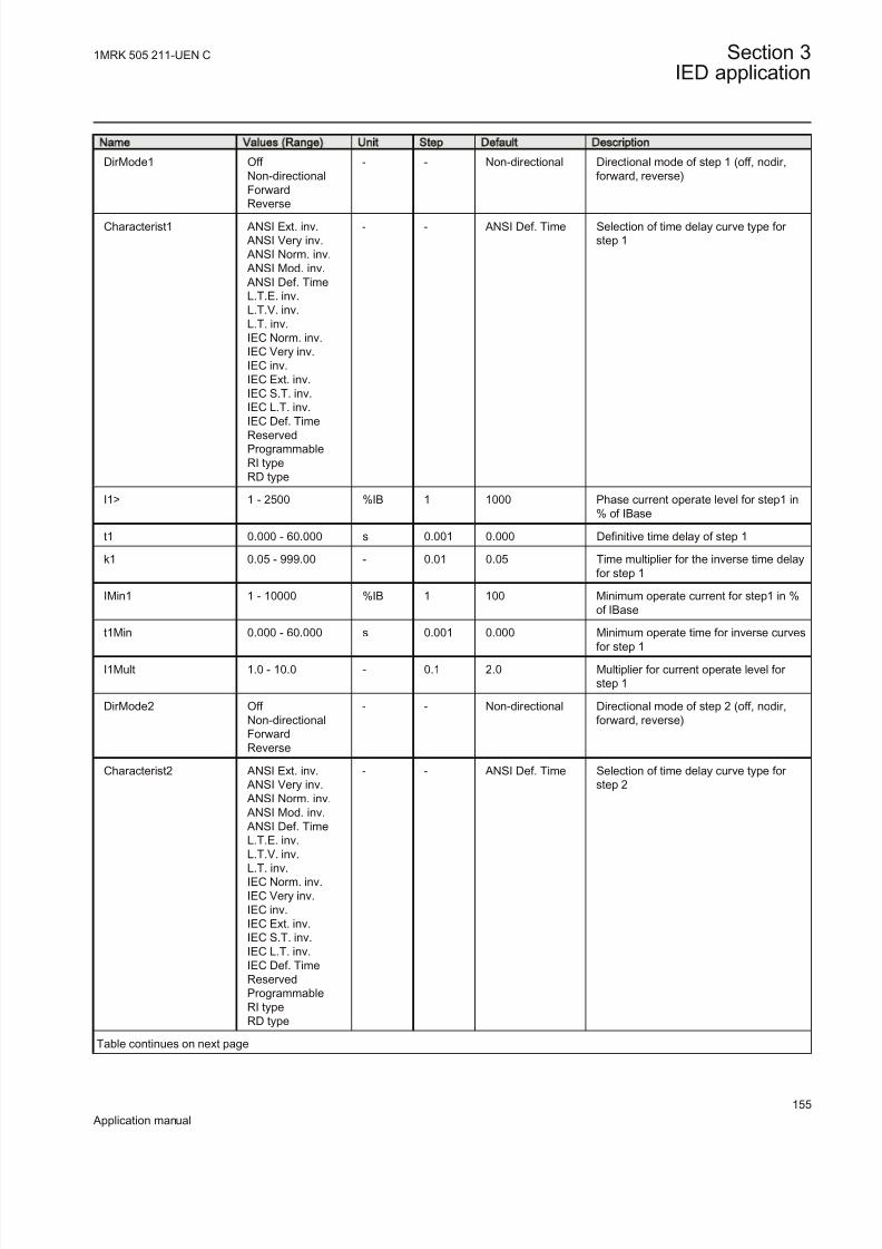
8/22/2019 Best Application
http://slidepdf.com/reader/full/best-application 161/457
Name Values (Range) Unit Step Default Description
DirMode1 Off Non-directionalForwardReverse
- - Non-directional Directional mode of step 1 (off, nodir,forward, reverse)
Characterist1 ANSI Ext. inv. ANSI Very inv. ANSI Norm. inv. ANSI Mod. inv. ANSI Def. TimeL.T.E. inv.L.T.V. inv.L.T. inv.IEC Norm. inv.IEC Very inv.IEC inv.IEC Ext. inv.IEC S.T. inv.IEC L.T. inv.IEC Def. TimeReservedProgrammableRI typeRD type
- - ANSI Def. Time Selection of time delay curve type for step 1
I1> 1 - 2500 %IB 1 1000 Phase current operate level for step1 in% of IBase
t1 0.000 - 60.000 s 0.001 0.000 Definitive time delay of step 1
k1 0.05 - 999.00 - 0.01 0.05 Time multiplier for the inverse time delayfor step 1
IMin1 1 - 10000 %IB 1 100 Minimum operate current for step1 in %of IBase
t1Min 0.000 - 60.000 s 0.001 0.000 Minimum operate time for inverse curves
for step 1
I1Mult 1.0 - 10.0 - 0.1 2.0 Multiplier for current operate level for step 1
DirMode2 Off Non-directionalForwardReverse
- - Non-directional Directional mode of step 2 (off, nodir,forward, reverse)
Characterist2 ANSI Ext. inv. ANSI Very inv. ANSI Norm. inv. ANSI Mod. inv. ANSI Def. TimeL.T.E. inv.L.T.V. inv.L.T. inv.IEC Norm. inv.IEC Very inv.IEC inv.IEC Ext. inv.IEC S.T. inv.IEC L.T. inv.IEC Def. TimeReservedProgrammableRI typeRD type
- - ANSI Def. Time Selection of time delay curve type for step 2
Table continues on next page
1MRK 505 211-UEN C Section 3IED application
155
Application manual

8/22/2019 Best Application
http://slidepdf.com/reader/full/best-application 162/457
Name Values (Range) Unit Step Default Description
I2> 1 - 2500 %IB 1 500 Phase current operate level for step2 in% of IBase
t2 0.000 - 60.000 s 0.001 0.400 Definitive time delay of step 2
k2 0.05 - 999.00 - 0.01 0.05 Time multiplier for the inverse time delayfor step 2
IMin2 1 - 10000 %IB 1 50 Minimum operate current for step2 in %of IBase
t2Min 0.000 - 60.000 s 0.001 0.000 Minimum operate time for inverse curvesfor step 2
I2Mult 1.0 - 10.0 - 0.1 2.0 Multiplier for current operate level for step 2
DirMode3 Off Non-directionalForwardReverse
- - Non-directional Directional mode of step 3 (off, nodir,forward, reverse)
Characterist3 ANSI Ext. inv. ANSI Very inv. ANSI Norm. inv. ANSI Mod. inv. ANSI Def. TimeL.T.E. inv.L.T.V. inv.L.T. inv.IEC Norm. inv.IEC Very inv.IEC inv.IEC Ext. inv.IEC S.T. inv.IEC L.T. inv.IEC Def. Time
ReservedProgrammableRI typeRD type
- - ANSI Def. Time Selection of time delay curve type for step 3
I3> 1 - 2500 %IB 1 250 Phase current operate level for step3 in% of IBase
t3 0.000 - 60.000 s 0.001 0.800 Definitive time delay of step 3
k3 0.05 - 999.00 - 0.01 0.05 Time multiplier for the inverse time delayfor step 3
IMin3 1 - 10000 %IB 1 33 Minimum operate current for step3 in %of IBase
t3Min 0.000 - 60.000 s 0.001 0.000 Minimum operate time for inverse curvesfor step 3
I3Mult 1.0 - 10.0 - 0.1 2.0 Multiplier for current operate level for step 3
DirMode4 Off Non-directionalForwardReverse
- - Non-directional Directional mode of step 4 (off, nodir,forward, reverse)
Table continues on next page
Section 3 1MRK 505 211-UEN C
IED application
156
Application manual
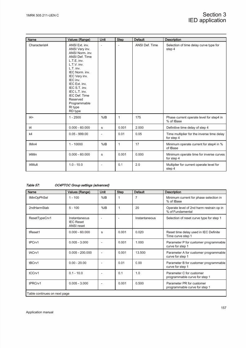
8/22/2019 Best Application
http://slidepdf.com/reader/full/best-application 163/457
Name Values (Range) Unit Step Default Description
Characterist4 ANSI Ext. inv. ANSI Very inv. ANSI Norm. inv. ANSI Def. Time
L.T.E. inv.L.T.V. inv.L.T. inv.IEC Norm. inv.IEC Very inv.IEC inv.IEC Ext. inv.IEC S.T. inv.IEC L.T. inv.IEC Def. TimeReservedProgrammableRI typeRD type
- - ANSI Def. Time Selection of time delay curve type for step 4
I4> 1 - 2500 %IB 1 175 Phase current operate level for step4 in% of IBase
t4 0.000 - 60.000 s 0.001 2.000 Definitive time delay of step 4
k4 0.05 - 999.00 - 0.01 0.05 Time multiplier for the inverse time delayfor step 4
IMin4 1 - 10000 %IB 1 17 Minimum operate current for step4 in %of IBase
t4Min 0.000 - 60.000 s 0.001 0.000 Minimum operate time for inverse curvesfor step 4
I4Mult 1.0 - 10.0 - 0.1 2.0 Multiplier for current operate level for step 4
Table 57: OC4PTOC Group settings (advanced)
Name Values (Range) Unit Step Default Description
IMinOpPhSel 1 - 100 %IB 1 7 Minimum current for phase selection in% of IBase
2ndHarmStab 5 - 100 %IB 1 20 Operate level of 2nd harm restrain op in% of Fundamental
ResetTypeCrv1 InstantaneousIEC Reset
ANSI reset
- - Instantaneous Selection of reset curve type for step 1
tReset1 0.000 - 60.000 s 0.001 0.020 Reset time delay used in IEC DefiniteTime curve step 1
tPCrv1 0.005 - 3.000 - 0.001 1.000 Parameter P for customer programmablecurve for step 1
tACrv1 0.005 - 200.000 - 0.001 13.500 Parameter A for customer programmablecurve for step 1
tBCrv1 0.00 - 20.00 - 0.01 0.00 Parameter B for customer programmablecurve for step 1
tCCrv1 0.1 - 10.0 - 0.1 1.0 Parameter C for customer programmable curve for step 1
tPRCrv1 0.005 - 3.000 - 0.001 0.500 Parameter PR for customer programmable curve for step 1
Table continues on next page
1MRK 505 211-UEN C Section 3IED application
157
Application manual

8/22/2019 Best Application
http://slidepdf.com/reader/full/best-application 164/457
Name Values (Range) Unit Step Default Description
tTRCrv1 0.005 - 100.000 - 0.001 13.500 Parameter TR for customer programmable curve for step 1
tCRCrv1 0.1 - 10.0 - 0.1 1.0 Parameter CR for customer
programmable curve for step 1
HarmRestrain1 Off On
- - Off Enable block of step 1 from harmonicrestrain
ResetTypeCrv2 InstantaneousIEC Reset
ANSI reset
- - Instantaneous Selection of reset curve type for step 2
tReset2 0.000 - 60.000 s 0.001 0.020 Reset time delay used in IEC DefiniteTime curve step 2
tPCrv2 0.005 - 3.000 - 0.001 1.000 Parameter P for customer programmablecurve for step 2
tACrv2 0.005 - 200.000 - 0.001 13.500 Parameter A for customer programmablecurve for step 2
tBCrv2 0.00 - 20.00 - 0.01 0.00 Parameter B for customer programmablecurve for step 2
tCCrv2 0.1 - 10.0 - 0.1 1.0 Parameter C for customer programmable curve for step 2
tPRCrv2 0.005 - 3.000 - 0.001 0.500 Parameter PR for customer programmable curve for step 2
tTRCrv2 0.005 - 100.000 - 0.001 13.500 Parameter TR for customer programmable curve for step 2
tCRCrv2 0.1 - 10.0 - 0.1 1.0 Parameter CR for customer programmable curve for step 2
HarmRestrain2 Off On
- - Off Enable block of step 2 from harmonicrestrain
ResetTypeCrv3 InstantaneousIEC Reset
ANSI reset
- - Instantaneous Selection of reset curve type for step 3
tReset3 0.000 - 60.000 s 0.001 0.020 Reset time delay used in IEC DefiniteTime curve step 3
tPCrv3 0.005 - 3.000 - 0.001 1.000 Parameter P for customer programmablecurve for step 3
tACrv3 0.005 - 200.000 - 0.001 13.500 Parameter A for customer programmablecurve for step 3
tBCrv3 0.00 - 20.00 - 0.01 0.00 Parameter B for customer programmablecurve for step 3
tCCrv3 0.1 - 10.0 - 0.1 1.0 Parameter C for customer
programmable curve for step 3
tPRCrv3 0.005 - 3.000 - 0.001 0.500 Parameter PR for customer programmable curve for step 3
tTRCrv3 0.005 - 100.000 - 0.001 13.500 Parameter TR for customer programmable curve for step 3
tCRCrv3 0.1 - 10.0 - 0.1 1.0 Parameter CR for customer programmable curve for step 3
HarmRestrain3 Off On
- - Off Enable block of step3 from harmonicrestrain
Table continues on next page
Section 3 1MRK 505 211-UEN C
IED application
158
Application manual

8/22/2019 Best Application
http://slidepdf.com/reader/full/best-application 165/457
Name Values (Range) Unit Step Default Description
ResetTypeCrv4 InstantaneousIEC Reset
ANSI reset
- - Instantaneous Selection of reset curve type for step 4
tReset4 0.000 - 60.000 s 0.001 0.020 Reset time delay used in IEC DefiniteTime curve step 4
tPCrv4 0.005 - 3.000 - 0.001 1.000 Parameter P for customer programmablecurve for step 4
tACrv4 0.005 - 200.000 - 0.001 13.500 Parameter A for customer programmablecurve for step 4
tBCrv4 0.00 - 20.00 - 0.01 0.00 Parameter B for customer programmablecurve for step 4
tCCrv4 0.1 - 10.0 - 0.1 1.0 Parameter C for customer programmable curve for step 4
tPRCrv4 0.005 - 3.000 - 0.001 0.500 Parameter PR for customer programmable curve for step 4
tTRCrv4 0.005 - 100.000 - 0.001 13.500 Parameter TR for customer programmable curve for step 4
tCRCrv4 0.1 - 10.0 - 0.1 1.0 Parameter CR for customer programmable curve for step 4
HarmRestrain4 Off On
- - Off Enable block of step 4 from harmonicrestrain
Table 58: OC4PTOC Non group settings (basic)
Name Values (Range) Unit Step Default Description
MeasType DFTRMS
- - DFT Selection between DFT and RMSmeasurement
3.6.2 Four step single phase overcurrent protection PH4SPTOC
Function description IEC 61850
identification
IEC 60617
identification
ANSI/IEEE C37.2
device number
Four step single phase overcurrentprotection
PH4SPTOC
4
4alt
I>
OC V1 EN
51
3.6.2.1 Application
The Four step single phase overcurrent protection(PH4SPTOC) function is used inseveral applications in the power system. Some applications are:
1MRK 505 211-UEN C Section 3IED application
159
Application manual

8/22/2019 Best Application
http://slidepdf.com/reader/full/best-application 166/457
• Short circuit protection of feeders in distribution and subtransmission systems. Normally these feeders have radial structure.
• Back-up short circuit protection of transmission lines.• Back-up short circuit protection of power transformers• Short circuit protection of different kinds of equipment connected to the power
system such as; shunt capacitor banks, shunt reactors, motors and others.• Back-up short circuit protection of power generators.
The single phase overcurrent protection is used in IEDs having only input from one phase, for example busbar protection for large busbars (with many bays).
In many applications several steps with different current pick up levels and timedelays are needed. PH4SPTOCcan have up to four different, individual settable,steps. The flexibility of each step of PH4SPTOC function is great. The followingoptions are possible:
Choice of delay time characteristics: There are several types of time delaycharacteristics available such as definite time delay and different types of inversetime delay characteristics. The selectivity between different overcurrent protectionsis normally enabled by co-ordination between the function time delays of thedifferent protections. To enable optimal co-ordination all overcurrent IEDs, to be co-ordinated against each other, should have the same time delay characteristic.Therefore a wide range of standardised inverse time characteristics are available:IEC and ANSI. It is also possible to programme a user defined inverse timecharacteristic.
Normally it is required that the phase overcurrent function shall reset as fast as possible when the current level gets lower than the operation level. In some casessome sort of time delayed reset is required. Therefore three different kinds of resettime characteristics can be used.
For some protection applications there can be a need to change the current pick-uplevel for some time. A typical case is when the protection will measure the currentto a large motor. At the start up sequence of a motor the start current can besignificantly larger then the rated current of the motor. Therefore there is a
possibility to give a setting of a multiplication factor to the current pick-up level.This multiplication factor is activated from a binary input signal to the function.
Power transformers can have a large inrush current, when being energized. This phenomenon is due to saturation of the transformer magnetic core during parts of the period. There is a risk that inrush current will reach levels above the pick-upcurrent of the phase overcurrent protection. The inrush current has a large secondharmonic content. This can be used to avoid unwanted operation of the protection.Therefore the Four step phase overcurrent protection (OC4PTOC) function have a
possibility of second harmonic restrain if the level of this harmonic current reachesa value above a set percentage of the fundamental current.
Section 3 1MRK 505 211-UEN C
IED application
160
Application manual

8/22/2019 Best Application
http://slidepdf.com/reader/full/best-application 167/457
3.6.2.2 Setting guidelines
The parameters for the four step phase overcurrent protection function (OC) are setvia the local HMI or Protection and Control IED Manager (PCM 600).
The following settings can be done for the four step phase overcurrent protection.
Operation: Off/On
IBase: Base current in primary A. This current is used as reference for currentsetting. It can be suitable to set this parameter to the rated primary current of the
protected object.
2ndHarmStab: Operate level of 2nd harmonic current restrain set in % of thefundamental current. The setting range is 5-100% I steps of 1%. Default setting is20%.
HarmRestrainx: Disabled/Enabled , enables blocking from harmonic restrain.
Settings for each step (x = 1-4)Characteristx: Selection of time delay characteristic for step x. Definite time delayand different types of inverse time delay characteristics are available according totable 59.
Table 59: Inverse tim e delay characteristics
Curve name
ANSI Extremely Inverse
ANSI Very Inverse ANSI Normal Inverse
ANSI Moderately Inverse
ANSI/IEEE Definite time
ANSI Long Time Extremely Inverse
ANSI Long Time Very Inverse
ANSI Long Time Inverse
IEC Normal Inverse
IEC Very Inverse
IEC Inverse
IEC Extremely Inverse
IEC Short Time Inverse
IEC Long Time Inverse
IEC Definite Time
User Programmable
ASEA RI
RXIDG (logarithmic)
1MRK 505 211-UEN C Section 3IED application
161
Application manual

8/22/2019 Best Application
http://slidepdf.com/reader/full/best-application 168/457
The different characteristics are described in the “Technical reference manual ”.
Ix>: Operation phase current level for step x given in % of IBase.
tx: Definite time delay for step x. Used if definite time characteristic is chosen.Setting range: 0.000-60.000 s in step of 0.001 s
kx: Time multiplier for the dependent (inverse) characteristic.
InxMult : Multiplier for scaling of the current setting value. If a binary input signal(enableMultiplier) is activated the current operation level is increase by this settingconstant. Setting range: 1.0-10.0
txMin: Minimum operation time for IEC inverse time characteristics. At highcurrents the inverse time characteristic might give a very short operation time. Bysetting this parameter the operation time of the step can never be shorter than the
setting. Setting range: 0.000-60.000 s in step of 0.001 s. ResetTypeCrvx: The reset of the delay timer can be made in different ways. Bychoosing setting the possibilities are according to table 60.
Table 60: Reset possibilities
Curve name Curve index no.
Instantaneous 1
IEC Reset (constant time) 2
ANSI Reset (inverse time) 3
The delay characteristics are described in the “Technical reference manual ”. Thereare some restrictions regarding the choice of reset delay.
For the independent time delay characteristics the possible delay time settings areinstantaneous (1) and IEC (2 = set constant time reset).
For ANSI inverse time delay characteristics all three types of reset timecharacteristics are available; instantaneous (1), IEC (2 = set constant time reset)and ANSI (3 = current dependent reset time).
For IEC inverse time delay characteristics the possible delay time settings are
instantaneous (1) and IEC (2 = set constant time reset).
For the customer tailor made inverse time delay characteristics (type 17) all threetypes of reset time characteristics are available; instantaneous (1), IEC (2 = setconstant time reset) and ANSI (3 = current dependent reset time). If the currentdependent type is used settings pr, tr and cr must be given.
HarmRestrainx: Enable block of step x from the harmonic restrain function (2ndharmonic). This function should be used when there is a risk if power transformer inrush currents might cause unwanted trip. Can be set Off/On.
Section 3 1MRK 505 211-UEN C
IED application
162
Application manual

8/22/2019 Best Application
http://slidepdf.com/reader/full/best-application 169/457
tPCrvx, tACrvx, tBCrvx, tCCrvx: Parameters for customer creation of inverse timecharacteristic curve (Curve type = 17). See equation 44 for the time characteristicequation.
[ ]
>
p
At s B IxMult
iC
in
= + ×
-
æ öç ÷ç ÷ç ÷æ öç ÷ç ÷è øè ø
EQUATION1261 V2 EN (Equation 44)
For more information, please refer to the “Technical ref erence manual ”.
tPRCrvx, tTRCrvx, tCRCrvx: Parameters for customer creation of inverse reset timecharacteristic curve (Reset Curve type = 3). Further description can be found in the
“Technical reference manual ”.
Second harmonic restrainIf a power transformer is energized there is a risk that the transformer core willsaturate during part of the period, resulting in an inrush transformer current. Thiswill give a declining residual current in the network, as the inrush current isdeviating between the phases. There is a risk that the phase overcurrent functionwill give an unwanted trip. The inrush current has a relatively large ratio of 2nd
harmonic component. This component can be used to create a restrain signal to prevent this unwanted function.
The settings for the 2nd harmonic restrain are described below.2ndHarmStab: The rate of second harmonic current content for activation of the2nd harmonic restrain signal, to block chosen steps. The setting is given in % of thefundamental frequency residual current. The setting range is 5-100% in step of 1%.The default setting is 20%.
HarmRestrainx: This parameter can be set Off/On, disable or enable the 2nd
harmonic restrain.
The four-step phase overcurrent protection can be used in different ways,depending on the application where the protection is used. A general description is
given below.
The pick up current setting inverse time protection or the lowest current stepconstant inverse time protection must be given a current setting so that the highest
possible load current does not cause protection operation. Here consideration alsohas to be taken to the protection reset current, so that a short peak of overcurrentdoes not cause operation of the protection even when the overcurrent has ceased.This phenomenon is described in figure 67.
1MRK 505 211-UEN C Section 3IED application
163
Application manual

8/22/2019 Best Application
http://slidepdf.com/reader/full/best-application 170/457
Operate current
Current I
The IED does not reset
Line phase current
Time t
Reset current
IEC05000203-en-2.vsd
IEC05000203 V3 EN
Figure 67: Pick up and reset current for an overcurrent protection
The lowest setting value can be written according to equation 45.
ImaxIpu 1.2
k ³ ×
EQUATION1262 V2 EN (Equation 45)
where:
1.2 is a safety factor,
k is the resetting ratio of the protection, and
Imax is the maximum load current.
The maximum load current on the line has to be estimated. From operationstatistics the load current up to the present situation can be found. The currentsetting must be valid also for some years ahead. It is, in most cases, realistic thatthe setting values are updated not more often than once every five years. In manycases this time interval is still longer. Investigate the maximum load current thatdifferent equipment on the line can withstand. Study components such as lineconductors, current transformers, circuit breakers, and disconnectors. Themanufacturer of the equipment normally gives the maximum thermal load currentof the equipment.
Section 3 1MRK 505 211-UEN C
IED application
164
Application manual

8/22/2019 Best Application
http://slidepdf.com/reader/full/best-application 171/457
There is also a demand that all faults, within the zone that the protection shallcover, must be detected by the phase overcurrent protection. The minimum faultcurrent Iscmin, to be detected by the protection, must be calculated. Taking thisvalue as a base, the highest pick up current setting can be written according toequation 46.
Ipu 0.7 Isc min£ ×
EQUATION1263 V2 EN (Equation 46)
where:
0.7 is a safety factor and
Iscmin is the smallest fault current to be detected by the overcurrent protection.
As a summary the pick up current shall be chosen within the interval stated inequation 47.
Imax1.2 Ipu 0.7 Iscmin
k × £ £ ×
EQUATION1264 V2 EN (Equation 47)
The high current function of the overcurrent protection, which only has a shortdelay of the operation, must be given a current setting so that the protection isselective to other protection in the power system. It is desirable to have a rapidtripping of faults within as large portion as possible of the part of the power system
to be protected by the protection (primary protected zone). A fault currentcalculation gives the largest current of faults, Iscmax, at the most remote part of the
primary protected zone. Considerations have to be made to the risk of transientoverreach, due to a possible DC component of the short circuit current. The lowestcurrent setting of the most rapid stage, of the phase overcurrent protection, can bewritten according to
max1.2 t schigh I k I ³ × ×
EQUATION1265 V1 EN (Equation 48)
where:
1.2 is a safety factor,
kt is a factor that takes care of the transient overreach due to the DC component of the faultcurrent and can be considered to be less than 1.1
Iscmax is the largest fault current at a fault at the most remote point of the primary protection zone.
The operate times of the phase overcurrent protection has to be chosen so that thefault time is so short so that equipment will not be destroyed due to thermaloverload, at the same time as selectivity is assured. For overcurrent protection, in a
1MRK 505 211-UEN C Section 3IED application
165
Application manual

8/22/2019 Best Application
http://slidepdf.com/reader/full/best-application 172/457
radial fed network, the time setting can be chosen in a graphical way. This ismostly used in the case of inverse time overcurrent protection. In the figure belowis shown how the time-versus-current curves are plotted in a diagram. The timesetting is chosen to get the shortest fault time with maintained selectivity.Selectivity is assured if the time difference between the curves is larger than acritical time difference.
en05000204.wmf
IEC05000204 V1 EN
Figure 68: Fault time with maintained selectivity
The operation time can be set individually for each overcurrent protection. Toassure selectivity between different protective protections, in the radial network,there have to be a minimum time difference Dt between the time delays of two
protections. The minimum time difference can be determined for different cases.
To determine the shortest possible time difference between we must haveknowledge about operation time of protections, breaker opening time and
protection resetting time. These time delays can vary significantly betweendifferent pieces of equipment. The following time delays can be estimated:
protection operation time: 15-60 ms
protection resetting time: 15-60 ms
Breaker opening time: 20-120 ms
Section 3 1MRK 505 211-UEN C
IED application
166
Application manual

8/22/2019 Best Application
http://slidepdf.com/reader/full/best-application 173/457
Example
Assume two substations A and B directly connected to each other via one line, asshown in the figure below. We study a fault located at another line from the station
B. The fault current to the overcurrent protection of IED B1 has a magnitude sothat the protection will have instantaneous function. The overcurrent protection of IED A1 must have a delayed function. The sequence of events during the fault can
be described using a time axis, see figure 69.
I> I>
A1 B1Feeder
Time axis
t=0 t=t1
t=t2
t=t3
The fault
occurs
Protection
B1 trips
Breaker at
B1 opens
Protection
A1 resets
en05000205.vsd
IEC05000205 V1 EN
Figure 69: Sequence of events during fault
where:
t=0 is the fault occurs,
t=t1 is the trip signal from the overcurrent protection at IED B1 is sent. Operation time of thisprotection is t1,
t=t2 is the circuit breaker at IED B1 opens. The circuit breaker opening time is t2 - t1 and
t=t3 is the overcurrent protection at IED A1 resets. The protection resetting time is t3 - t2.
To ensure that the overcurrent protection at IED A1, is selective to the overcurrent
protection at IED B1, the minimum time difference must be larger that the time t3.There are uncertainties in the values of protection operation time, breaker openingtime and protection resetting time. Therefor a safety margin has to be included.With normal values the needed time difference can be calculated according toequation 49.
1MRK 505 211-UEN C Section 3IED application
167
Application manual

8/22/2019 Best Application
http://slidepdf.com/reader/full/best-application 174/457
40 100 40 40 220t ms ms ms ms msD ³ + + + =EQUATION1266 V1 EN (Equation 49)
where it is considered that:
the operation time of overcurrent protection B1 is 40 ms
the breaker open time is 100 ms
the resetting time of protection A1 is 40 ms and
the additional margin is 40 ms
3.6.2.3 Setting parameters
Table 61: PH4SPTOC Group settings (basic)
Name Values (Range) Unit Step Default Description
Operation Off On
- - Off Operation Off / On
IBase 1 - 99999 A 1 3000 Base setting for current values in A
OpStep1 Off On
- - On Operation over current step 1 Off / On
Characterist1 ANSI Ext. inv. ANSI Very inv. ANSI Norm. inv. ANSI Mod. inv. ANSI Def. TimeL.T.E. inv.L.T.V. inv.
IEC Norm. inv.IEC Very inv.IEC inv.IEC Ext. inv.IEC L.T. inv.IEC Def. TimeReservedProgrammableRI typeRD type
- - ANSI Def. Time Selection of time delay curve type for step 1
I1> 1 - 2500 %IB 1 1000 Operate phase current level for step1 in% of IBase
t1 0.000 - 60.000 s 0.001 0.000 Independent (defenitive) time delay of step 1
k1 0.05 - 999.00 - 0.01 0.05 Time multiplier for the dependent timedelay for step 1
I1Mult 1.0 - 10.0 - 0.1 2.0 Multiplier for operate current level for step 1
t1Min 0.000 - 60.000 s 0.001 0.000 Minimum operate time for IEC IDMTcurves for step 1
OpStep2 Off On
- - On Operation over current step 2 Off / On
Table continues on next page
Section 3 1MRK 505 211-UEN C
IED application
168
Application manual

8/22/2019 Best Application
http://slidepdf.com/reader/full/best-application 175/457
Name Values (Range) Unit Step Default Description
Characterist2 ANSI Ext. inv. ANSI Very inv.IEC Reset
ANSI Norm. inv.
ANSI Mod. inv. ANSI Def. TimeL.T.E. inv.L.T.V. inv.L.T. inv.IEC Norm. inv.IEC Very inv.IEC inv.IEC Ext. inv.IEC L.T. inv.IEC Def. TimeReservedProgrammableRI typeRD type
- - ANSI Def. Time Selection of time delay curve type for step 2
I2> 1 - 2500 %IB 1 500 Operate phase current level for step2 in%of IBase
t2 0.000 - 60.000 s 0.001 0.400 Independent (defenitive) time delay of step 2
k2 0.05 - 999.00 - 0.01 0.05 Time multiplier for the dependent timedelay for step 2
I2Mult 1.0 - 10.0 - 0.1 2.0 Multiplier for scaling the current settingvalue for step 2
t2Min 0.000 - 60.000 s 0.001 0.000 Minimum operate time for IEC IDMTcurves for step 2
OpStep3 Off On
- - On Operation over current step 3 Off / On
Characterist3 ANSI Ext. inv.ReportEvents
ANSI Very inv. ANSI Norm. inv. ANSI Mod. inv. ANSI Def. TimeL.T.E. inv.L.T.V. inv.L.T. inv.IEC Norm. inv.IEC Very inv.IEC inv.IEC Ext. inv.IEC S.T. inv.IEC L.T. inv.
IEC Def. TimeProgrammableRI typeRD type
- - ANSI Def. Time Selection of time delay curve type for step 3
I3> 1 - 2500 %IB 1 250 Operate phase current level for step3 in%of Ibase
t3 0.000 - 60.000 s 0.001 0.800 Independent (definitive) time delay for step 3
k3 0.05 - 999.00 - 0.01 0.05 Time multiplier for the dependent timedelay for step 3
Table continues on next page
1MRK 505 211-UEN C Section 3IED application
169
Application manual

8/22/2019 Best Application
http://slidepdf.com/reader/full/best-application 176/457
Name Values (Range) Unit Step Default Description
I3Mult 1.0 - 10.0 - 0.1 2.0 Multiplier for scaling the current settingvalue for step 3
t3Min 0.000 - 60.000 s 0.001 0.000 Minimum operate time for IEC IDMT
curves for step 3
OpStep4 Off On
- - On Operation over current step 4 Off / On
Characterist4 ANSI Ext. inv. ANSI Very inv. ANSI Norm. inv. ANSI Mod. inv. ANSI Def. TimeL.T.E. inv.L.T.V. inv.L.T. inv.IEC Norm. inv.IEC Very inv.IEC inv.
IEC Ext. inv.IEC S.T. inv.IEC L.T. inv.IEC Def. TimeReservedProgrammableRI typeRD type
- - ANSI Def. Time Selection of time delay curve type for step 4
I4> 1 - 2500 %IB 1 175 Operate phase current level for step4 in% of IBase
t4 0.000 - 60.000 s 0.001 2.000 Independent (definitive) time delay of step4
k4 0.05 - 999.00 - 0.01 0.05 Time multiplier for the dependent timedelay for step 4
I4Mult 1.0 - 10.0 - 0.1 2.0 Multiplier for scaling the current settingvalue for step 4
t4Min 0.000 - 60.000 s 0.001 0.000 Minimum operate time for IEC IDMTcurves for step 4
Table 62: PH4SPTOC Group settings (advanced)
Name Values (Range) Unit Step Default Description
2ndHarmStab 5 - 100 %IB 1 20 Operate level of 2nd harm restrain op in% of Fundamental
ResetTypeCrv1 Instantaneous
IEC Reset ANSI reset
- - Instantaneous Selection of reset curve type for step
tReset1 0.000 - 60.000 s 0.001 0.020 Reset time delay used in IEC DefiniteTime curve step 1
tPCrv1 0.005 - 3.000 - 0.001 1.000 Parameter P for customer programmablecurve for step 1
tACrv1 0.005 - 200.000 - 0.001 13.500 Parameter A for customer programmablecurve for step 1
tBCrv1 0.00 - 20.00 - 0.01 0.00 Parameter B for customer programmablecurve for step 1
Table continues on next page
Section 3 1MRK 505 211-UEN C
IED application
170
Application manual
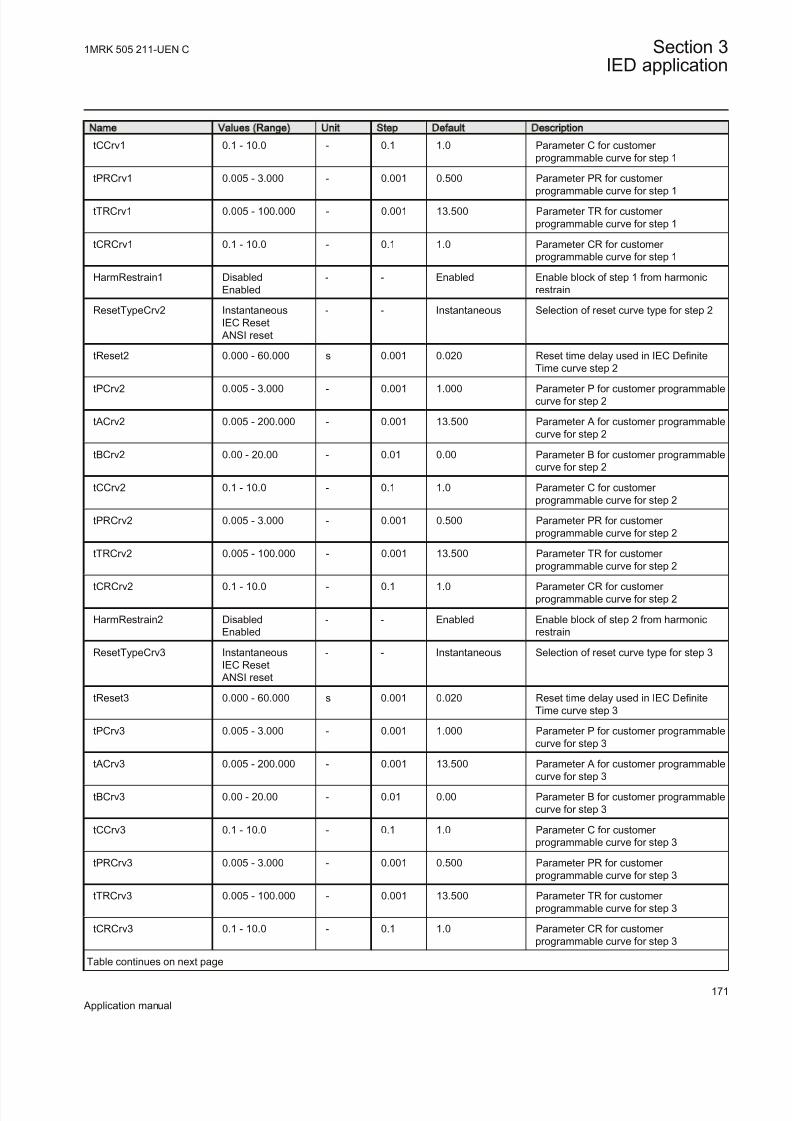
8/22/2019 Best Application
http://slidepdf.com/reader/full/best-application 177/457
Name Values (Range) Unit Step Default Description
tCCrv1 0.1 - 10.0 - 0.1 1.0 Parameter C for customer programmable curve for step 1
tPRCrv1 0.005 - 3.000 - 0.001 0.500 Parameter PR for customer
programmable curve for step 1
tTRCrv1 0.005 - 100.000 - 0.001 13.500 Parameter TR for customer programmable curve for step 1
tCRCrv1 0.1 - 10.0 - 0.1 1.0 Parameter CR for customer programmable curve for step 1
HarmRestrain1 DisabledEnabled
- - Enabled Enable block of step 1 from harmonicrestrain
ResetTypeCrv2 InstantaneousIEC Reset
ANSI reset
- - Instantaneous Selection of reset curve type for step 2
tReset2 0.000 - 60.000 s 0.001 0.020 Reset time delay used in IEC DefiniteTime curve step 2
tPCrv2 0.005 - 3.000 - 0.001 1.000 Parameter P for customer programmablecurve for step 2
tACrv2 0.005 - 200.000 - 0.001 13.500 Parameter A for customer programmablecurve for step 2
tBCrv2 0.00 - 20.00 - 0.01 0.00 Parameter B for customer programmablecurve for step 2
tCCrv2 0.1 - 10.0 - 0.1 1.0 Parameter C for customer programmable curve for step 2
tPRCrv2 0.005 - 3.000 - 0.001 0.500 Parameter PR for customer programmable curve for step 2
tTRCrv2 0.005 - 100.000 - 0.001 13.500 Parameter TR for customer programmable curve for step 2
tCRCrv2 0.1 - 10.0 - 0.1 1.0 Parameter CR for customer programmable curve for step 2
HarmRestrain2 DisabledEnabled
- - Enabled Enable block of step 2 from harmonicrestrain
ResetTypeCrv3 InstantaneousIEC Reset
ANSI reset
- - Instantaneous Selection of reset curve type for step 3
tReset3 0.000 - 60.000 s 0.001 0.020 Reset time delay used in IEC DefiniteTime curve step 3
tPCrv3 0.005 - 3.000 - 0.001 1.000 Parameter P for customer programmablecurve for step 3
tACrv3 0.005 - 200.000 - 0.001 13.500 Parameter A for customer programmable
curve for step 3
tBCrv3 0.00 - 20.00 - 0.01 0.00 Parameter B for customer programmablecurve for step 3
tCCrv3 0.1 - 10.0 - 0.1 1.0 Parameter C for customer programmable curve for step 3
tPRCrv3 0.005 - 3.000 - 0.001 0.500 Parameter PR for customer programmable curve for step 3
tTRCrv3 0.005 - 100.000 - 0.001 13.500 Parameter TR for customer programmable curve for step 3
tCRCrv3 0.1 - 10.0 - 0.1 1.0 Parameter CR for customer programmable curve for step 3
Table continues on next page
1MRK 505 211-UEN C Section 3IED application
171
Application manual
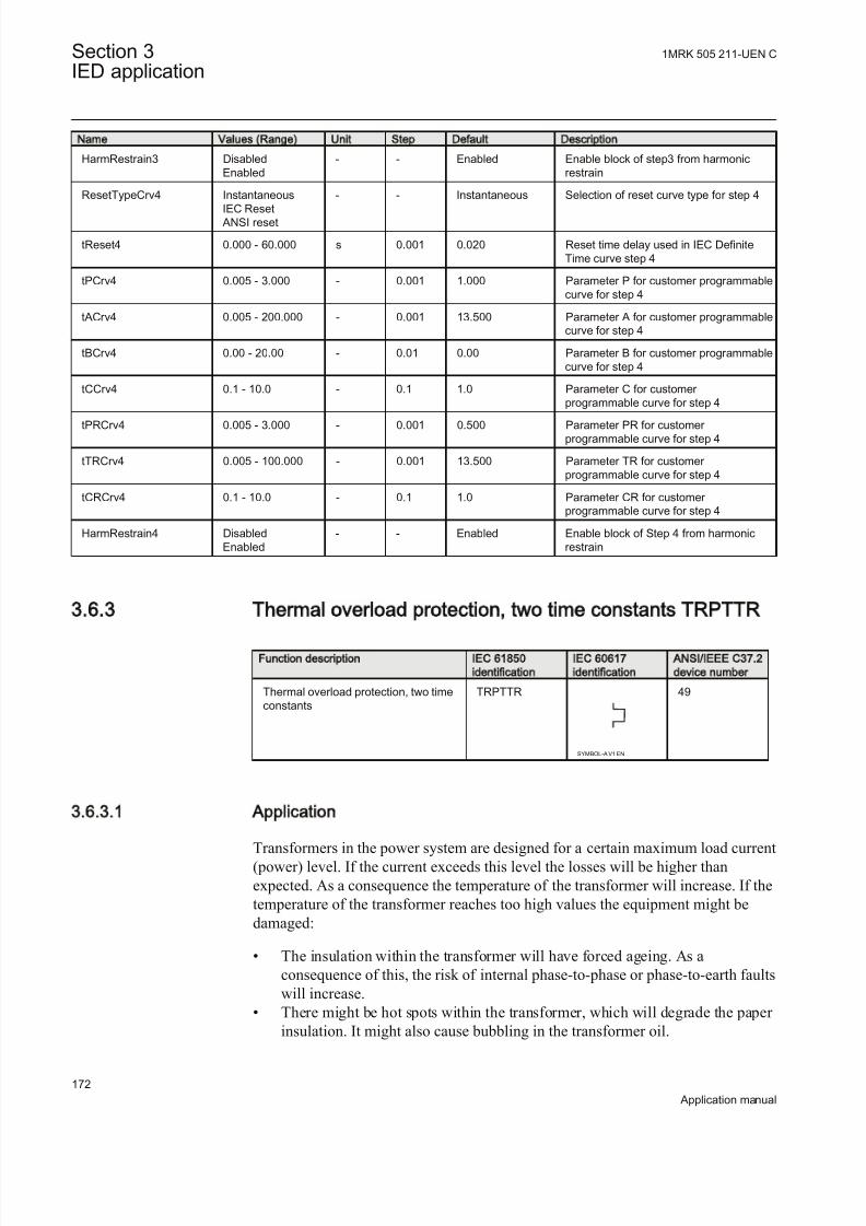
8/22/2019 Best Application
http://slidepdf.com/reader/full/best-application 178/457
Name Values (Range) Unit Step Default Description
HarmRestrain3 DisabledEnabled
- - Enabled Enable block of step3 from harmonicrestrain
ResetTypeCrv4 Instantaneous
IEC Reset ANSI reset
- - Instantaneous Selection of reset curve type for step 4
tReset4 0.000 - 60.000 s 0.001 0.020 Reset time delay used in IEC DefiniteTime curve step 4
tPCrv4 0.005 - 3.000 - 0.001 1.000 Parameter P for customer programmablecurve for step 4
tACrv4 0.005 - 200.000 - 0.001 13.500 Parameter A for customer programmablecurve for step 4
tBCrv4 0.00 - 20.00 - 0.01 0.00 Parameter B for customer programmablecurve for step 4
tCCrv4 0.1 - 10.0 - 0.1 1.0 Parameter C for customer programmable curve for step 4
tPRCrv4 0.005 - 3.000 - 0.001 0.500 Parameter PR for customer programmable curve for step 4
tTRCrv4 0.005 - 100.000 - 0.001 13.500 Parameter TR for customer programmable curve for step 4
tCRCrv4 0.1 - 10.0 - 0.1 1.0 Parameter CR for customer programmable curve for step 4
HarmRestrain4 DisabledEnabled
- - Enabled Enable block of Step 4 from harmonicrestrain
3.6.3 Thermal overload protection, two time constants TRPTTR
Function description IEC 61850
identification
IEC 60617
identification
ANSI/IEEE C37.2
device number
Thermal overload protection, two timeconstants
TRPTTR
SYMBOL-A V1 EN
49
3.6.3.1 Application
Transformers in the power system are designed for a certain maximum load current(power) level. If the current exceeds this level the losses will be higher thanexpected. As a consequence the temperature of the transformer will increase. If thetemperature of the transformer reaches too high values the equipment might bedamaged:
• The insulation within the transformer will have forced ageing. As aconsequence of this, the risk of internal phase-to-phase or phase-to-earth faultswill increase.
• There might be hot spots within the transformer, which will degrade the paper insulation. It might also cause bubbling in the transformer oil.
Section 3 1MRK 505 211-UEN C
IED application
172
Application manual

8/22/2019 Best Application
http://slidepdf.com/reader/full/best-application 179/457
In stressed situations in the power system it can be required to overloadtransformers for a limited time. This should be done without the above mentionedrisks. The thermal overload protection provides information and makes temporaryoverloading of transformers possible.
The permissible load level of a power transformer is highly dependent on thecooling system of the transformer. There are two main principles:
• OA: The air is naturally circulated to the coolers without fans and the oil isnaturally circulated without pumps.
• FOA: The coolers have fans to force air for cooling and pumps to force thecirculation of the transformer oil.
The protection can have two sets of parameters, one for non-forced cooling and onefor forced cooling. Both the permissive steady state loading level as well as the
thermal time constant is influenced by the cooling system of the transformer. Thetwo parameters sets can be activated by the binary input signal COOLING. Thiscan be used for transformers where forced cooling can be taken out of operation,for example at fan or pump faults.
The thermal overload protection estimates the internal heat content of thetransformer (temperature) continuously. This estimation is made by using a thermalmodel of the transformer, which is based on current measurement.
If the heat content of the protected transformer reaches a set alarm level a signalcan be given to the operator. Two alarm levels are available. This enables
preventive actions in the power system to be taken before dangerous temperatures
are reached. If the temperature continues to increase to the trip value, the protectioninitiates a trip of the protected transformer.
After tripping by the thermal overload protection, the transformer will cool downover time. There will be a time gap before the heat content (temperature) reachessuch a level so that the transformer can be taken into service again. Therefore, thefunction will continue to estimate the heat content using a set cooling timeconstant. Energizing of the transformer can be blocked until the heat content hasreached a set level.
3.6.3.2 Setting guideline
The parameters for the thermal overload protection, two time constants (TRPTTR)are set via the local HMI or Protection and Control IED Manager (PCM600).
The following settings can be done for the thermal overload protection:
Operation: Off /On
Operation: Sets the mode of operation. Off switches off the complete function.
1MRK 505 211-UEN C Section 3IED application
173
Application manual

8/22/2019 Best Application
http://slidepdf.com/reader/full/best-application 180/457
IBase: Base current in primary A. This current is used as reference for currentsetting. It can be suitable to set this parameter to the rated primary current of thetransformer winding where the current measurement is made.
IRef : Reference level of the current given in % of IBase. When the current is equalto IRef the final (steady state) heat content is equal to 1. It is suggested to give asetting corresponding to the rated current of the transformer winding.
IRefMult : If a binary input ENMULT is activated the reference current value can be multiplied by the factor IRefMult . The activation could be used in case of deviating ambient temperature from the reference value. In the standard for loadingof a transformer an ambient temperature of 20°C is used. For lower ambienttemperatures the load ability is increased and vice versa. IRefMult can be set withina range: 0.01 - 10.00.
IBase1: Base current for setting given as percentage of IBase. This setting shall berelated to the status with no COOLING input. It is suggested to give a settingcorresponding to the rated current of the transformer with natural cooling (OA).
IBase2: Base current for setting given as percentage of IBase. This setting shall berelated to the status with activated COOLING input. It is suggested to give asetting corresponding to the rated current of the transformer with forced cooling(FOA). If the transformer has no forced cooling IBase2 can be set equal to IBase1.
Tau1: The thermal time constant of the protected transformer, related to IBase1 (nocooling) given in minutes.
Tau2: The thermal time constant of the protected transformer, related to IBase2
(with cooling) given in minutes.
The thermal time constant should be obtained from the transformer manufacturersmanuals. The thermal time constant is dependent on the cooling and the amount of oil. Normal time constants for medium and large transformers (according to IEC60076-7) are about 2.5 hours for naturally cooled transformers and 1.5 hours for forced cooled transformers.
The time constant can be estimated from measurements of the oil temperatureduring a cooling sequence (described in IEC 60076-7). It is assumed that thetransformer is operated at a certain load level with a constant oil temperature
(steady state operation). The oil temperature above the ambient temperature isDQo0. Then the transformer is disconnected from the grid (no load). After a time tof at least 30 minutes the temperature of the oil is measured again. Now the oiltemperature above the ambient temperature is DQot. The thermal time constant cannow be estimated as:
0ln lno ot
t t =
DQ - DQEQUATION1180 V1 EN (Equation 50)
Section 3 1MRK 505 211-UEN C
IED application
174
Application manual

8/22/2019 Best Application
http://slidepdf.com/reader/full/best-application 181/457
If the transformer has forced cooling (FOA) the measurement should be made bothwith and without the forced cooling in operation, giving Tau2 and Tau1.
The time constants can be changed if the current is higher than a set value or lower
than a set value. If the current is high it is assumed that the forced cooling isactivated while it is deactivated at low current. The setting of the parameters belowenables automatic adjustment of the time constant.
Tau1High: Multiplication factor to adjust the time constant Tau1 if the current ishigher than the set value IHighTau1. IHighTau1 is set in % of IBase1.
Tau1Low: Multiplication factor to adjust the time constant Tau1 if the current islower than the set value ILowTau1. ILowTau1 is set in % of IBase1.
Tau2High: Multiplication factor to adjust the time constant Tau2 if the current ishigher than the set value IHighTau2. IHighTau2 is set in % of IBase2.
Tau2Low: Multiplication factor to adjust the time constant Tau2 if the current islower than the set value ILowTau2. ILowTau2 is set in % of IBase2.
The possibility to change time constant with the current value as the base can beuseful in different applications. Below some examples are given:
• In case a total interruption (low current) of the protected transformer allcooling possibilities will be inactive. This can result in a changed value of thetime constant.
• If other components (motors) are included in the thermal protection, there is arisk of overheating of that equipment in case of very high current. The thermal
time constant is often smaller for a motor than for the transformer.
ITrip: The steady state current that the transformer can withstand. The setting isgiven in % of IBase1 or IBase2.
Alarm1: Heat content level for activation of the signal ALARM1. ALARM1 is setin % of the trip heat content level.
Alarm2: Heat content level for activation of the output signal ALARM2. ALARM2is set in % of the trip heat content level.
ResLo: Lockout release level of heat content to release the lockout signal. Whenthe thermal overload protection trips a lock-out signal is activated. This signal isintended to block switching on of the protected circuit transformer as long as thetransformer temperature is high. The signal is released when the estimated heatcontent is below the set value. This temperature value should be chosen below thealarm temperature. ResLo is set in % of the trip heat content level.
ThetaInit : Heat content before activation of the function. This setting can be set alittle below the alarm level. If the transformer is loaded before the activation of the
protection function, its temperature can be higher than the ambient temperature.The start point given in the setting will prevent risk of no trip at overtemperature
1MRK 505 211-UEN C Section 3IED application
175
Application manual

8/22/2019 Best Application
http://slidepdf.com/reader/full/best-application 182/457
during the first moments after activation. ThetaInit: is set in % of the trip heatcontent level.
Warning : If the calculated time to trip factor is below the setting Warning a
warning signal is activated. The setting is given in minutes.
3.6.3.3 Setting parameters
Table 63: TRPTTR Group settings (basic)
Name Values (Range) Unit Step Default Description
Operation Off On
- - Off Operation Off / On
IBase 1 - 99999 A 1 3000 Base current in A
IRef 10.0 - 1000.0 %IB 1.0 100.0 Reference current in % of IBASE
IRefMult 0.01 - 10.00 - 0.01 1.00 Multiplication Factor for reference current
IBase1 30.0 - 250.0 %IB 1.0 100.0 Base current,IBase1 without Coolinginpout in % of IBASE
IBase2 30.0 - 250.0 %IB 1.0 100.0 Base Current,IBase2, with Cooling inputON in % of IBASE
Tau1 1.0 - 500.0 Min 1.0 60.0 Time constant without cooling input inmin, with IBase1
Tau2 1.0 - 500.0 Min 1.0 60.0 Time constant with cooling input in min,with IBase2
IHighTau1 30.0 - 250.0 %IB1 1.0 100.0 Current Sett, in % of IBase1 for rescalingTC1 by TC1-IHIGH
Tau1High 5 - 2000 %tC1 1 100 Multiplier in % to TC1 when current is >
IHIGH-TC1
ILowTau1 30.0 - 250.0 %IB1 1.0 100.0 Current Set, in % of IBase1 for rescalingTC1 by TC1-ILOW
Tau1Low 5 - 2000 %tC1 1 100 Multiplier in % to TC1 when current is <ILOW-TC1
IHighTau2 30.0 - 250.0 %IB2 1.0 100.0 Current Set, in % of IBase2 for rescalingTC2 by TC2-IHIGH
Tau2High 5 - 2000 %tC2 1 100 Multiplier in % to TC2 when current is>IHIGH-TC2
ILowTau2 30.0 - 250.0 %IB2 1.0 100.0 Current Set, in % of IBase2 for rescalingTC2 by TC2-ILOW
Tau2Low 5 - 2000 %tC2 1 100 Multiplier in % to TC2 when current is <
ILOW-TC2
ITrip 50.0 - 250.0 %IBx 1.0 110.0 Steady state operate current level in %of IBasex
Alarm1 50.0 - 99.0 %Itr 1.0 80.0 First alarm level in % of heat content tripvalue
Alarm2 50.0 - 99.0 %Itr 1.0 90.0 Second alarm level in % of heat contenttrip value
ResLo 10.0 - 95.0 %Itr 1.0 60.0 Lockout reset level in % of heat contenttrip value
Table continues on next page
Section 3 1MRK 505 211-UEN C
IED application
176
Application manual

8/22/2019 Best Application
http://slidepdf.com/reader/full/best-application 183/457
Name Values (Range) Unit Step Default Description
ThetaInit 0.0 - 95.0 % 1.0 50.0 Initial Heat content, in % of heat contenttrip value
Warning 1.0 - 500.0 Min 0.1 30.0 Time setting, below which warning would
be set (in min)
tPulse 0.01 - 0.30 s 0.01 0.10 Length of the pulse for trip signal (inmsec).
3.6.4 Breaker failure protection CCRBRF
Function description IEC 61850
identification
IEC 60617
identification
ANSI/IEEE C37.2
device number
Breaker failure protection CCRBRF
3I>BF
SYMBOL-U V1 EN
50BF
3.6.4.1 Application
In the design of the fault clearance system the N-1 criterion is often used. Thismeans that a fault needs to be cleared even if any component in the fault clearancesystem is faulty. One necessary component in the fault clearance system is thecircuit breaker. It is from practical and economical reason not feasible to duplicatethe circuit breaker for the protected component. Instead a breaker failure protectionis used.
Breaker failure protection, 3-phase activation and output (CCRBRF) will issue a back-up trip command to adjacent circuit breakers in case of failure to trip of the“normal” circuit breaker for the protected component. The detection of failure to
break the current through the breaker is made by means of current measurement or as detection of remaining trip signal (unconditional).
CCRBRF can also give a re-trip. This means that a second trip signal is sent to the protected circuit breaker. The re-trip function can be used to increase the probability of operation of the breaker, or it can be used to avoid back-up trip of
many breakers in case of mistakes during relay maintenance and test.
3.6.4.2 Setting guidelines
The parameters for Breaker failure protection 3-phase activation and outputCCRBRF are set via the local HMI or PCM600.
The following settings can be done for the breaker failure protection.
Operation: Off /On
1MRK 505 211-UEN C Section 3IED application
177
Application manual

8/22/2019 Best Application
http://slidepdf.com/reader/full/best-application 184/457
IBase: Base current in primary A. This current is used as reference for currentsetting. It can be suitable to set this parameter to the rated primary current of thecurrent transformer where the current measurement is made.
FunctionMode This parameter can be set Current or Contact . This states the waythe detection of failure of the breaker is performed. In the mode current the currentmeasurement is used for the detection. In the mode Contact the long duration of
breaker position signal is used as indicator of failure of the breaker. The modeCurrent&Contact means that both ways of detections are activated. Contact modecan be usable in applications where the fault current through the circuit breaker issmall. This can be the case for some generator protection application (for examplereverse power protection) or in case of line ends with weak end infeed.
RetripMode: This setting states how the re-trip function shall operate. Retrip Off
means that the re-trip function is not activated. CB Pos Check (circuit breaker
position check) and Current means that a phase current must be larger than theoperate level to allow re-trip. CB Pos Check (circuit breaker position check) andContact means re-trip is done when circuit breaker is closed (breaker position isused). No CBPos Check means re-trip is done without check of breaker position.
Tab le 64: Dependenc ies between parameters Ret ripMode and FunctionMode
RetripMode FunctionMode Description
Retrip Off N/A the re-trip function is notactivated
CB Pos Check Current a phase current must be larger than the operate level to allowre-trip
Contact re-trip is done when breaker position indicates that breaker is still closed after re-trip timehas elapsed
Current&Contact both methods are used
No CBPos Check Current re-trip is done without check of breaker position
Contact re-trip is done without check of breaker position
Current&Contact both methods are used
BuTripMode: Back-up trip mode is given to state sufficient current criteria to detectfailure to break. For Current operation 2 out of 4 means that at least two currents,of the three-phase currents and the residual current, shall be high to indicate
breaker failure. 1 out of 3 means that at least one current of the three-phase currentsshall be high to indicate breaker failure. 1 out of 4 means that at least one current of the three-phase currents or the residual current shall be high to indicate breaker failure. In most applications 1 out of 3 is sufficient. For Contact operation means
back-up trip is done when circuit breaker is closed (breaker position is used).
IP>: Current level for detection of breaker failure, set in % of IBase. This parameter should be set so that faults with small fault current can be detected. The
Section 3 1MRK 505 211-UEN C
IED application
178
Application manual

8/22/2019 Best Application
http://slidepdf.com/reader/full/best-application 185/457
setting can be chosen in accordance with the most sensitive protection function tostart the breaker failure protection. Typical setting is 10% of IBase.
I>BlkCont : If any contact based detection of breaker failure is used this function
can be blocked if any phase current is larger than this setting level. If the FunctionMode is set Current&Contact breaker failure for high current faults aresafely detected by the current measurement function. To increase security thecontact based function should be disabled for high currents. The setting can begiven within the range 5 – 200% of IBase.
IN>: Residual current level for detection of breaker failure set in % of IBase. Inhigh impedance earthed systems the residual current at phase- to-earth faults arenormally much smaller than the short circuit currents. In order to detect breaker failure at single-phase-earth faults in these systems it is necessary to measure theresidual current separately. Also in effectively earthed systems the setting of the
earth-fault current protection can be chosen to relatively low current level. The BuTripMode is set 1 out of 4. The current setting should be chosen in accordance tothe setting of the sensitive earth-fault protection. The setting can be given withinthe range 2 – 200 % of IBase.
t1: Time delay of the re-trip. The setting can be given within the range 0 – 60s insteps of 0.001 s. Typical setting is 0 – 50ms.
t2: Time delay of the back-up trip. The choice of this setting is made as short as possible at the same time as unwanted operation must be avoided. Typical setting is90 – 200ms (also dependent of re-trip timer).
The minimum time delay for the re-trip can be estimated as:
_ 2 1³ + + +cbo pen BFP reset margin
t t t t t
EQUATION1430 V1 EN (Equation 51)
where:
tcbopen is the maximum opening time for the circuit breaker
tBFP_reset is the maximum time for breaker failure protection to detect correct breaker function (thecurrent criteria reset)
tmargin is a safety margin
It is often required that the total fault clearance time shall be less than a givencritical time. This time is often dependent of the ability to maintain transientstability in case of a fault close to a power plant.
1MRK 505 211-UEN C Section 3IED application
179
Application manual

8/22/2019 Best Application
http://slidepdf.com/reader/full/best-application 186/457
Time
The fault
occurs
Protectionoperate time
Trip and StartCCRBRF
Normal tcbopen
Margin
Retrip delay t1 tcbopen after re-trip
tBFPreset
Minimum back-up trip delay t2
Critical fault clearance time for stability
IEC05000479_2_en.vsd
IEC05000479 V2 EN
Figure 70: Time sequence
t2MPh: Time delay of the back-up trip at multi-phase start. The critical faultclearance time is often shorter in case of multi-phase faults, compared to single phase-to-earth faults. Therefore there is a possibility to reduce the back-up trip delay for multi-phase faults. Typical setting is 90 – 150 ms.
t3: Additional time delay to t2 for a second back-up trip TRBU2. In someapplications there might be a requirement to have separated back-up trip functions,tripping different back-up circuit breakers.
tCBAlarm: Time delay for alarm in case of indication of faulty circuit breaker.There is a binary input CBFLT from the circuit breaker. This signal is activatedwhen internal supervision in the circuit breaker detect that the circuit breaker isunable to clear fault. This could be the case when gas pressure is low in a SF6circuit breaker, of others. After the set time an alarm is given, so that actions can bedone to repair the circuit breaker. The time delay for back-up trip is bypassed whenthe CBFLT is active. Typical setting is 2.0 seconds.
tPulse: Trip pulse duration. This setting must be larger than the critical impulsetime of circuit breakers to be tripped from the breaker failure protection. Typicalsetting is 200 ms.
Section 3 1MRK 505 211-UEN C
IED application
180
Application manual

8/22/2019 Best Application
http://slidepdf.com/reader/full/best-application 187/457
3.6.4.3 Setting parameters
Table 65: CCRBRF Group settings (basic)
Name Values (Range) Unit Step Default Description
Operation Off On
- - Off Operation Off / On
IBase 1 - 99999 A 1 3000 Base current
FunctionMode CurrentContactCurrent&Contact
- - Current Detection principle for back-up trip
BuTripMode 2 out of 41 out of 31 out of 4
- - 1 out of 3 Back-up trip mode
RetripMode Retrip Off CB Pos CheckNo CBPos Check
- - Retrip Off Operation mode of re-trip logic
IP> 5 - 200 %IB 1 10 Operate phase current level in % of IBase
IN> 2 - 200 %IB 1 10 Operate residual current level in % of IBase
t1 0.000 - 60.000 s 0.001 0.000 Time delay of re-trip
t2 0.000 - 60.000 s 0.001 0.150 Time delay of back-up trip
t2MPh 0.000 - 60.000 s 0.001 0.150 Time delay of back-up trip at multi-phasestart
tPulse 0.000 - 60.000 s 0.001 0.200 Trip pulse duration
Table 66: CCRBRF Group settings (advanced)
Name Values (Range) Unit Step Default Description
I>BlkCont 5 - 200 %IB 1 20 Current for blocking of CB contactoperation in % of IBase
t3 0.000 - 60.000 s 0.001 0.030 Additional time delay to t2 for a secondback-up trip
tCBAlarm 0.000 - 60.000 s 0.001 5.000 Time delay for CB faulty signal
3.6.5 Breaker failure protection, single phase version CCSRBRF
Function description IEC 61850identification IEC 60617identification ANSI/IEEE C37.2device number
Breaker failure protection, single phaseversion
CCSRBRF
I>BF
SYMBOL-II V1 EN
50BF
1MRK 505 211-UEN C Section 3IED application
181
Application manual

8/22/2019 Best Application
http://slidepdf.com/reader/full/best-application 188/457
3.6.5.1 Application
In the design of the fault clearance system the N-1 criterion is often used. Thismeans that a fault shall be cleared even if any component in the fault clearance
system is faulty. One necessary component in the fault clearance system is thecircuit breaker. It is from practical and economical reason not feasible to duplicatethe circuit breaker for the protected component. Instead a breaker failure protectionis used.
Breaker failure protection, single phase version (CCSRBRF) function will issue a back-up trip command to adjacent circuit breakers in case of failure to trip of the“normal” circuit breaker for the protected component. The detection of failure to
break the current through the breaker is made by means of current measurement or as detection of remaining trip signal (unconditional).
CCSRBRF function can also give a re-trip. This means that a second trip signal issent to the protected circuit breaker. The re-trip function can be used to increase the
probability of operation of the breaker, or it can be used to avoid back-up trip of many breakers in case of mistakes during relay maintenance and test.
3.6.5.2 Setting guidelines
The parameters for Breaker failure protection, single phase version (CCSRBRF)are set via the local HMI or PCM600.
The following settings can be done for the breaker failure protection.
Operation: Off or On
IBase: Base current in primary A. This current is used as reference for currentsetting. It can be suitable to set this parameter to the rated primary current of thecurrent transformer where the current measurement is made.
FunctionMode: This parameter can be set to Current or Contact . This states theway the detection of failure of the breaker is performed. In the mode Current thecurrent measurement is used for the detection. In the mode Contact the longduration of start signal (trip) is used as indicator of failure of the breaker. The modeCurrent&Contact means that both ways of detections are activated. Contact modecan be usable in applications where the fault current through the circuit breaker is
small. This can be the case for some generator protection application (for example,reverse power protection) or in case of line ends with weak end infeed.
RetripMode: This setting states how the re-trip function shall operate. Retrip Off
means that the re-trip function is not activated. CB Pos Check (circuit breaker position check) and Current means that a phase current must be larger than theoperate level to allow re-trip. CB Pos Check (circuit breaker position check) andConntact means retrip is done when circuit breaker is closed (breaker position isused). No CB Pos Check means re-trip is done without check of breaker position.
Section 3 1MRK 505 211-UEN C
IED application
182
Application manual

8/22/2019 Best Application
http://slidepdf.com/reader/full/best-application 189/457
IP>: Current level for detection of breaker failure, set in % of IBase. This parameter must be set so that faults with small fault current can be detected. Thesetting can be chosen in accordance with the most sensitive protection function tostart the breaker failure protection. Typical setting is 10% of IBase.
I>BlkCont : If any contact based detection of breaker failure is used this functioncan be blocked if the current is larger than this setting level. If the FunctionMode isset to Current&Contact breaker failure for high current faults are safely detected
by the current measurement function. To increase security the contact basedfunction must be disabled for high currents. The setting can be given within therange 5 – 200% of IBase.
t1: Time delay of the re-trip. The setting can be given within the range 0 – 60 s insteps of 0.001 s. Typical setting is 0 – 50 ms.
t2: Time delay of the back-up trip. The choice of this setting is made as short as possible at the same time as unwanted operation must be avoided. Typical setting is90 – 150 ms (also dependent of re-trip timer).
The minimum time delay for the re-trip can be estimated as:
_ 2 1³ + + +cbo pen BFP reset margin
t t t t t
EQUATION1430 V1 EN (Equation 52)
where:
tcbopen is the maximum opening time for the circuit breaker
tBFP_reset is the maximum time for breaker failure protection to detect correct breaker function (thecurrent criteria reset)
tmargin is a safety margin
It is often required that the total fault clearance time shall be less than a givencritical time. This time is often dependent of the ability to maintain transientstability in case of a fault close to a power plant.
1MRK 505 211-UEN C Section 3IED application
183
Application manual

8/22/2019 Best Application
http://slidepdf.com/reader/full/best-application 190/457
Time
The fault
occurs
Protectionoperate time
Trip and StartCCRBRF
Normal tcbopen
Margin
Retrip delay t1 tcbopen after re-trip
tBFPreset
Minimum back-up trip delay t2
Critical fault clearance time for stability
IEC05000479_2_en.vsd
IEC05000479 V2 EN
Figure 71: Time sequence
t3: Additional time delay to t2 for a second back-up trip TRBU2. In someapplications there might be a requirement to have separated back-up trip functions,tripping different back-up circuit breakers.
tCBAlarm: Time delay for alarm in case of indication of faulty circuit breaker.There is a binary input CBFLT from the circuit breaker. This signal is activatedwhen internal supervision in the circuit breaker detect that the circuit breaker isunable to clear fault. This could be the case when gas pressure is low in a SF6circuit breaker, of others. After the set time an alarm is given, so that actions can bedone to repair the circuit breaker. The time delay for back-up trip is bypassed whenthe CBFLT is active. Typical setting is 2.0 seconds.
tPulse: Trip pulse duration. This setting must be larger than the critical impulsetime of circuit breakers to be tripped from the breaker failure protection. Typicalsetting is 200 ms.
3.6.5.3 Setting parameters
Table 67: CCSRBRF Group settings (basic)
Name Values (Range) Unit Step Default Description
Operation Off On
- - Off Operation Off / On
IBase 1 - 99999 A 1 3000 Base setting for current level settings
FunctionMode CurrentContactCurrent&Contact
- - Current Detection for trip Current/Contact/Current&Contact
Table continues on next page
Section 3 1MRK 505 211-UEN C
IED application
184
Application manual

8/22/2019 Best Application
http://slidepdf.com/reader/full/best-application 191/457
Name Values (Range) Unit Step Default Description
RetripMode Retrip Off I> CheckNo I> Check
- - Retrip Off Operation mode of re-trip logic: OFF /I>check/ No I> check
IP> 5 - 200 %IB 1 10 Operate level in % of IBase
I>BlkCont 5 - 200 %IB 1 20 Current for blocking of CB contactoperation in % of IBase
t1 0.000 - 60.000 s 0.001 0.000 Delay for re-trip
t2 0.000 - 60.000 s 0.001 0.150 Delay of back-up trip
t3 0.000 - 60.000 s 0.001 0.030 Additional delay to t2 for a second back-up trip
tCBAlarm 0.000 - 60.000 s 0.001 5.000 Delay for CB faulty signal
tPulse 0.000 - 60.000 s 0.001 0.200 Trip pulse duration
3.6.6 Directional underpower protection GUPPDUP
Function description IEC 61850
identification
IEC 60617
identification
ANSI/IEEE C37.2
device number
Directional underpower protection GUPPDUPP <
SYMBOL-LL V1 EN
37
3.6.6.1 Application
The task of a generator in a power plant is to convert mechanical energy availableas a torque on a rotating shaft to electric energy.
Sometimes, the mechanical power from a prime mover may decrease so much thatit does not cover bearing losses and ventilation losses. Then, the synchronousgenerator becomes a synchronous motor and starts to take electric power from therest of the power system. This operating state, where individual synchronousmachines operate as motors, implies no risk for the machine itself. If the generator under consideration is very large and if it consumes lots of electric power, it may
be desirable to disconnect it to ease the task for the rest of the power system.
Often, the motoring condition may imply that the turbine is in a very dangerousstate. The task of the reverse power protection is to protect the turbine and not to
protect the generator itself.
Steam turbines easily become overheated if the steam flow becomes too low or if the steam ceases to flow through the turbine. Therefore, turbo-generators shouldhave reverse power protection. There are several contingencies that may causereverse power: break of a main steam pipe, damage to one or more blades in thesteam turbine or inadvertent closing of the main stop valves. In the last case, it is
1MRK 505 211-UEN C Section 3IED application
185
Application manual

8/22/2019 Best Application
http://slidepdf.com/reader/full/best-application 192/457
highly desirable to have a reliable reverse power protection. It may prevent damageto an otherwise undamaged plant.
During the routine shutdown of many thermal power units, the reverse power
protection gives the tripping impulse to the generator breaker (the unit breaker). Bydoing so, one prevents the disconnection of the unit before the mechanical power has become zero. Earlier disconnection would cause an acceleration of the turbinegenerator at all routine shutdowns. This should have caused overspeed and highcentrifugal stresses.
When the steam ceases to flow through a turbine, the cooling of the turbine bladeswill disappear. Now, it is not possible to remove all heat generated by the windagelosses. Instead, the heat will increase the temperature in the steam turbine andespecially of the blades. When a steam turbine rotates without steam supply, theelectric power consumption will be about 2% of rated power. Even if the turbine
rotates in vacuum, it will soon become overheated and damaged. The turbineoverheats within minutes if the turbine loses the vacuum.
The critical time to overheating a steam turbine varies from about 0.5 to 30 minutesdepending on the type of turbine. A high-pressure turbine with small and thin
blades will become overheated more easily than a low-pressure turbine with longand heavy blades. The conditions vary from turbine to turbine and it is necessary toask the turbine manufacturer in each case.
Power to the power plant auxiliaries may come from a station service transformer connected to the secondary side of the step-up transformer. Power may also comefrom a start-up service transformer connected to the external network. One has to
design the reverse power protection so that it can detect reverse power independentof the flow of power to the power plant auxiliaries.
Hydro turbines tolerate reverse power much better than steam turbines do. OnlyKaplan turbine and bulb turbines may suffer from reverse power. There is a risk that the turbine runner moves axially and touches stationary parts. They are notalways strong enough to withstand the associated stresses.
Ice and snow may block the intake when the outdoor temperature falls far belowzero. Branches and leaves may also block the trash gates. A complete blockage of the intake may cause cavitations. The risk for damages to hydro turbines can justifyreverse power protection in unattended plants.
A hydro turbine that rotates in water with closed wicket gates will draw electric power from the rest of the power system. This power will be about 10% of therated power. If there is only air in the hydro turbine, the power demand will fall toabout 3%.
Diesel engines should have reverse power protection. The generator will take about15% of its rated power or more from the system. A stiff engine may require
perhaps 25% of the rated power to motor it. An engine that is good run in mightneed no more than 5%. It is necessary to obtain information from the enginemanufacturer and to measure the reverse power during commissioning.
Section 3 1MRK 505 211-UEN C
IED application
186
Application manual

8/22/2019 Best Application
http://slidepdf.com/reader/full/best-application 193/457
Gas turbines usually do not require reverse power protection.
Figure 72 illustrates the reverse power protection with underpower protection andwith overpower protection. The underpower protection gives a higher margin and
should provide better dependability. On the other hand, the risk for unwantedoperation immediately after synchronization may be higher. One should set theunderpower protection (reference angle set to 0) to trip if the active power from thegenerator is less than about 2%. One should set the overpower protection(reference angle set to 180) to trip if the power flow from the network to thegenerator is higher than 1%.
Underpower protection Overpower protection
Q Q
P P
Operating point
withoutturbine torque
Margin Margin
Operate
LineOperate
Line
Operating point
without
turbine torque
IEC09000019-2-en.vsd
IEC09000019 V2 EN
Figure 72: Reverse power protection with underpower or overpower protection
3.6.6.2 Setting guidelines
Operation: With the parameter Operation the function can be set On/Off .
IBase: The parameter IBase is set to the generator rated current in A, seeequation 53.
3 N
N
S IBase
U =
×
EQUATION1707 V1 EN (Equation 53)
UBase: The parameter UBase is set to the generator rated voltage (phase-phase) inkV.
Mode: The voltage and current used for the power measurement. The setting possibilities are shown in table 68.
1MRK 505 211-UEN C Section 3IED application
187
Application manual

8/22/2019 Best Application
http://slidepdf.com/reader/full/best-application 194/457
Table 68: Complex power calculation
Set value Mode Formula used for complex power calculation
L1, L2, L3 * * *1 1 2 2 3 3 L L L L L LS U I U I U I = × + × + ×
EQUATION1697 V1 EN (Equation 54)
Arone * *1 2 1 2 3 3 L L L L L LS U I U I = × - ×
EQUATION1698 V1 EN (Equation 55)
PosSeq *3 PosSeq PosSeqS U I = × ×
EQUATION1699 V1 EN (Equation 56)
L1L2 * *1 2 1 2( ) L L L LS U I I = × -
EQUATION1700 V1 EN (Equation 57)
L2L3 * *2 3 2 3( ) L L L LS U I I = × -
EQUATION1701 V1 EN (Equation 58)
L3L1 * *3 1 3 1( ) L L L LS U I I = × -
EQUATION1702 V1 EN (Equation 59)
L1 *1 13 L LS U I = × ×
EQUATION1703 V1 EN (Equation 60)
L2 *2 23 L LS U I = × ×
EQUATION1704 V1 EN (Equation 61)
L3 *3 33 L LS U I = × ×
EQUATION1705 V1 EN (Equation 62)
The function has two stages that can be set independently.
With the parameter OpMode1(2) the function can be set On/Off .
The function gives trip if the power component in the direction defined by thesetting Angle1(2) is smaller than the set pick up power value Power1(2)
Section 3 1MRK 505 211-UEN C
IED application
188
Application manual

8/22/2019 Best Application
http://slidepdf.com/reader/full/best-application 195/457
Operate
Angle1(2)
Power1(2)
P
Q
en06000441.vsd
IEC06000441 V1 EN
Figure 73: Underpower mode
The setting Power1(2) gives the power component pick up value in the Angle1(2)
direction. The setting is given in p.u. of the generator rated power, see equation 63.
Minimum recommended setting is 0.2% of S N when metering class CT inputs intothe IED are used.
3 N S UBase IBase= × ×
EQUATION1708 V1 EN (Equation 63)
The setting Angle1(2) gives the characteristic angle giving maximum sensitivity of the power protection function. The setting is given in degrees. For active power theset angle should be 0° or 180°. 0° should be used for generator low forward active
power protection.
1MRK 505 211-UEN C Section 3IED application
189
Application manual

8/22/2019 Best Application
http://slidepdf.com/reader/full/best-application 196/457
Operate
Angle1(2) = 0 °
Power1(2)
P
Q
en06000556.vsd
IEC06000556 V1 EN
Figure 74: For low forward power the set angle should be 0° in the
underpower function
TripDelay1(2) is set in seconds to give the time delay for trip of the stage after pick up.
Hysteresis1(2) is given in p.u. of generator rated power according to equation 64.
3 N S UBase IBase= × ×
EQUATION1708 V1 EN (Equation 64)
The drop out power will be Power1(2) + Hysteresis1(2).
The possibility to have low pass filtering of the measured power can be made asshown in the formula:
( )1Old Calculated S k S k S = × + - ×
EQUATION1893 V1 EN (Equation 65)
Where
S is a new measured value to be used for the protection function
Sold is the measured value given from the function in previous execution cycle
SCalculated is the new calculated value in the present execution cycle
k is settable parameter
Section 3 1MRK 505 211-UEN C
IED application
190
Application manual

8/22/2019 Best Application
http://slidepdf.com/reader/full/best-application 197/457
The value of k =0.92 is recommended in generator applications as the trip delay isnormally quite long.
The calibration factors for current and voltage measurement errors are set % of
rated current/voltage:
IAmpComp5, IAmpComp30, IAmpComp100
UAmpComp5, UAmpComp30, UAmpComp100
IAngComp5, IAngComp30, IAngComp100
The angle compensation is given as difference between current and voltage angleerrors.
The values are given for operating points 5, 30 and 100% of rated current/voltage.
The values should be available from instrument transformer test protocols.
3.6.6.3 Setting parameters
Table 69: GUPPDUP Group settings (basic)
Name Values (Range) Unit Step Default Description
Operation Off On
- - Off Operation Off / On
OpMode1 Off UnderPower
- - UnderPower Operation mode 1
Power1 0.0 - 500.0 %SB 0.1 1.0 Power setting for stage 1 in % of Sbase
Angle1 -180.0 - 180.0 Deg 0.1 0.0 Angle for stage 1
TripDelay1 0.010 - 6000.000 s 0.001 1.000 Trip delay for stage 1
DropDelay1 0.010 - 6000.000 s 0.001 0.060 Drop delay for stage 1
OpMode2 Off UnderPower
- - UnderPower Operation mode 2
Power2 0.0 - 500.0 %SB 0.1 1.0 Power setting for stage 2 in % of Sbase
Angle2 -180.0 - 180.0 Deg 0.1 0.0 Angle for stage 2
TripDelay2 0.010 - 6000.000 s 0.001 1.000 Trip delay for stage 2
DropDelay2 0.010 - 6000.000 s 0.001 0.060 Drop delay for stage 2
Table 70: GUPPDUP G roup settings (advanced)
Name Values (Range) Unit Step Default Description
k 0.000 - 0.999 - 0.001 0.000 Low pass filter coefficient for power measurement, P and Q
Hysteresis1 0.2 - 5.0 pu 0.1 0.5 Absolute hysteresis of stage 1 in % Sbase
Hysteresis2 0.2 - 5.0 pu 0.1 0.5 Absolute hysteresis of stage 2 in % Sbase
IAmpComp5 -10.000 - 10.000 % 0.001 0.000 Amplitude factor to calibrate current at5% of Ir
Table continues on next page
1MRK 505 211-UEN C Section 3IED application
191
Application manual
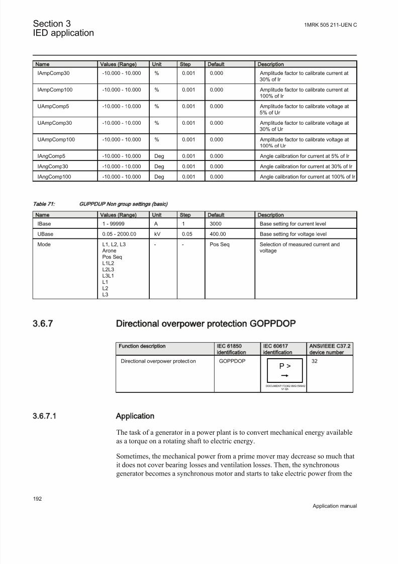
8/22/2019 Best Application
http://slidepdf.com/reader/full/best-application 198/457
Name Values (Range) Unit Step Default Description
IAmpComp30 -10.000 - 10.000 % 0.001 0.000 Amplitude factor to calibrate current at30% of Ir
IAmpComp100 -10.000 - 10.000 % 0.001 0.000 Amplitude factor to calibrate current at
100% of Ir
UAmpComp5 -10.000 - 10.000 % 0.001 0.000 Amplitude factor to calibrate voltage at5% of Ur
UAmpComp30 -10.000 - 10.000 % 0.001 0.000 Amplitude factor to calibrate voltage at30% of Ur
UAmpComp100 -10.000 - 10.000 % 0.001 0.000 Amplitude factor to calibrate voltage at100% of Ur
IAngComp5 -10.000 - 10.000 Deg 0.001 0.000 Angle calibration for current at 5% of Ir
IAngComp30 -10.000 - 10.000 Deg 0.001 0.000 Angle calibration for current at 30% of Ir
IAngComp100 -10.000 - 10.000 Deg 0.001 0.000 Angle calibration for current at 100% of Ir
Table 71: GUPPDUP Non group settings (basic)
Name Values (Range) Unit Step Default Description
IBase 1 - 99999 A 1 3000 Base setting for current level
UBase 0.05 - 2000.00 kV 0.05 400.00 Base setting for voltage level
Mode L1, L2, L3 AronePos SeqL1L2L2L3L3L1L1L2L3
- - Pos Seq Selection of measured current andvoltage
3.6.7 Directional overpower protection GOPPDOP
Function description IEC 61850
identification
IEC 60617
identification
ANSI/IEEE C37.2
device number
Directional overpower protection GOPPDOPP >
DOCUMENT172362-IMG158942
V1 EN
32
3.6.7.1 Application
The task of a generator in a power plant is to convert mechanical energy availableas a torque on a rotating shaft to electric energy.
Sometimes, the mechanical power from a prime mover may decrease so much thatit does not cover bearing losses and ventilation losses. Then, the synchronousgenerator becomes a synchronous motor and starts to take electric power from the
Section 3 1MRK 505 211-UEN C
IED application
192
Application manual

8/22/2019 Best Application
http://slidepdf.com/reader/full/best-application 199/457
rest of the power system. This operating state, where individual synchronousmachines operate as motors, implies no risk for the machine itself. If the generator under consideration is very large and if it consumes lots of electric power, it may
be desirable to disconnect it to ease the task for the rest of the power system.
Often, the motoring condition may imply that the turbine is in a very dangerousstate. The task of the reverse power protection is to protect the turbine and not to
protect the generator itself.
Steam turbines easily become overheated if the steam flow becomes too low or if the steam ceases to flow through the turbine. Therefore, turbo-generators shouldhave reverse power protection. There are several contingencies that may causereverse power: break of a main steam pipe, damage to one or more blades in thesteam turbine or inadvertent closing of the main stop valves. In the last case, it ishighly desirable to have a reliable reverse power protection. It may prevent damage
to an otherwise undamaged plant.During the routine shutdown of many thermal power units, the reverse power
protection gives the tripping impulse to the generator breaker (the unit breaker). Bydoing so, one prevents the disconnection of the unit before the mechanical power has become zero. Earlier disconnection would cause an acceleration of the turbinegenerator at all routine shutdowns. This should have caused overspeed and highcentrifugal stresses.
When the steam ceases to flow through a turbine, the cooling of the turbine bladeswill disappear. Now, it is not possible to remove all heat generated by the windagelosses. Instead, the heat will increase the temperature in the steam turbine and
especially of the blades. When a steam turbine rotates without steam supply, theelectric power consumption will be about 2% of rated power. Even if the turbinerotates in vacuum, it will soon become overheated and damaged. The turbineoverheats within minutes if the turbine loses the vacuum.
The critical time to overheating of a steam turbine varies from about 0.5 to 30minutes depending on the type of turbine. A high-pressure turbine with small andthin blades will become overheated more easily than a low-pressure turbine withlong and heavy blades. The conditions vary from turbine to turbine and it isnecessary to ask the turbine manufacturer in each case.
Power to the power plant auxiliaries may come from a station service transformer
connected to the primary side of the step-up transformer. Power may also comefrom a start-up service transformer connected to the external network. One has todesign the reverse power protection so that it can detect reverse power independentof the flow of power to the power plant auxiliaries.
Hydro turbines tolerate reverse power much better than steam turbines do. OnlyKaplan turbine and bulb turbines may suffer from reverse power. There is a risk that the turbine runner moves axially and touches stationary parts. They are notalways strong enough to withstand the associated stresses.
1MRK 505 211-UEN C Section 3IED application
193
Application manual

8/22/2019 Best Application
http://slidepdf.com/reader/full/best-application 200/457
Ice and snow may block the intake when the outdoor temperature falls far belowzero. Branches and leaves may also block the trash gates. A complete blockage of the intake may cause cavitations. The risk for damages to hydro turbines can justifyreverse power protection in unattended plants.
A hydro turbine that rotates in water with closed wicket gates will draw electric power from the rest of the power system. This power will be about 10% of therated power. If there is only air in the hydro turbine, the power demand will fall toabout 3%.
Diesel engines should have reverse power protection. The generator will take about15% of its rated power or more from the system. A stiff engine may require
perhaps 25% of the rated power to motor it. An engine that is well run in mightneed no more than 5%. It is necessary to obtain information from the enginemanufacturer and to measure the reverse power during commissioning.
Gas turbines usually do not require reverse power protection.
Figure 75 illustrates the reverse power protection with underpower IED and withoverpower IED. The underpower IED gives a higher margin and should provide
better dependability. On the other hand, the risk for unwanted operationimmediately after synchronization may be higher. One should set the underpower IED to trip if the active power from the generator is less than about 2%. Oneshould set the overpower IED to trip if the power flow from the network to thegenerator is higher than 1%.
Underpower IED Overpower IED
Q Q
P P
Operating pointwithoutturbine torque
Margin Margin
OperateLine
OperateLine
Operating pointwithoutturbine torque
IEC06000315-2-en.vsd
IEC06000315 V2 EN
Figure 75: Re verse power protection with underpower IED and overpower IED
3.6.7.2 Setting guidelines
Operation: With the parameter Operation the function can be set On/Off .
IBase: The parameter IBase is set to the generator rated current in A, seeequation 66.
Section 3 1MRK 505 211-UEN C
IED application
194
Application manual

8/22/2019 Best Application
http://slidepdf.com/reader/full/best-application 201/457
3 N
N
S IBase
U =
×
EQUATION1707 V1 EN (Equation 66)
UBase: The parameter UBase is set to the generator rated voltage (phase-phase) inkV.
Mode: The voltage and current used for the power measurement. The setting possibilities are shown in table 72.
Table 72: Complex power calculation
Set value Mode Formula used for complex power calculation
L1, L2, L3 * * *
1 1 2 2 3 3 L L L L L LS U I U I U I = × + × + ×
EQUATION1697 V1 EN (Equation 67)
Arone * *1 2 1 2 3 3 L L L L L LS U I U I = × - ×
EQUATION1698 V1 EN (Equation 68)
PosSeq *3 PosSeq PosSeqS U I = × ×
EQUATION1699 V1 EN (Equation 69)
L1L2 * *1 2 1 2( ) L L L LS U I I = × -
EQUATION1700 V1 EN (Equation 70)
L2L3 * *2 3 2 3( ) L L L LS U I I = × -
EQUATION1701 V1 EN (Equation 71)
L3L1 * *3 1 3 1( ) L L L LS U I I = × -
EQUATION1702 V1 EN (Equation 72)
L1 *1 13 L LS U I = × ×
EQUATION1703 V1 EN (Equation 73)
L2 *2 23 L LS U I = × ×
EQUATION1704 V1 EN (Equation 74)
L3 *3 33 L LS U I = × ×
EQUATION1705 V1 EN (Equation 75)
The function has two stages that can be set independently.
With the parameter OpMode1(2) the function can be set On/Off .
The function gives trip if the power component in the direction defined by thesetting Angle1(2) is larger than the set pick up power value Power1(2)
1MRK 505 211-UEN C Section 3IED application
195
Application manual

8/22/2019 Best Application
http://slidepdf.com/reader/full/best-application 202/457
Operate
Angle1(2)
Power1(2)
P
Q
en06000440.vsd
IEC06000440 V1 EN
Figure 76: Overpower mode
The setting Power1(2) gives the power component pick up value in the Angle1(2)
direction. The setting is given in p.u. of the generator rated power, see equation 76.
Minimum recommended setting is 0.2% of S N when metering class CT inputs intothe IED are used.
3 N S UBase IBase= × ×
EQUATION1708 V1 EN (Equation 76)
The setting Angle1(2) gives the characteristic angle giving maximum sensitivity of
the power protection function. The setting is given in degrees. For active power theset angle should be 0° or 180°. 180° should be used for generator reverse power protection.
Section 3 1MRK 505 211-UEN C
IED application
196
Application manual
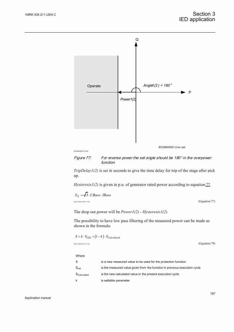
8/22/2019 Best Application
http://slidepdf.com/reader/full/best-application 203/457
Operate Angle1(2 ) = 180 o
Power1(2)
P
Q
IEC06000557-2-en.vsd
IEC06000557 V2 EN
Figure 77: For reverse power the set angle should be 180° in the overpower
function
TripDelay1(2) is set in seconds to give the time delay for trip of the stage after pick up.
Hysteresis1(2) is given in p.u. of generator rated power according to equation 77.
3 N S UBase IBase= × ×
EQUATION1708 V1 EN (Equation 77)
The drop out power will be Power1(2) - Hysteresis1(2).
The possibility to have low pass filtering of the measured power can be made asshown in the formula:
( )1Old Calculated S k S k S = × + - ×
EQUATION1893 V1 EN (Equation 78)
Where
S is a new measured value to be used for the protection function
Sold is the measured value given from the function in previous execution cycle
SCalculated is the new calculated value in the present execution cycle
k is settable parameter
1MRK 505 211-UEN C Section 3IED application
197
Application manual
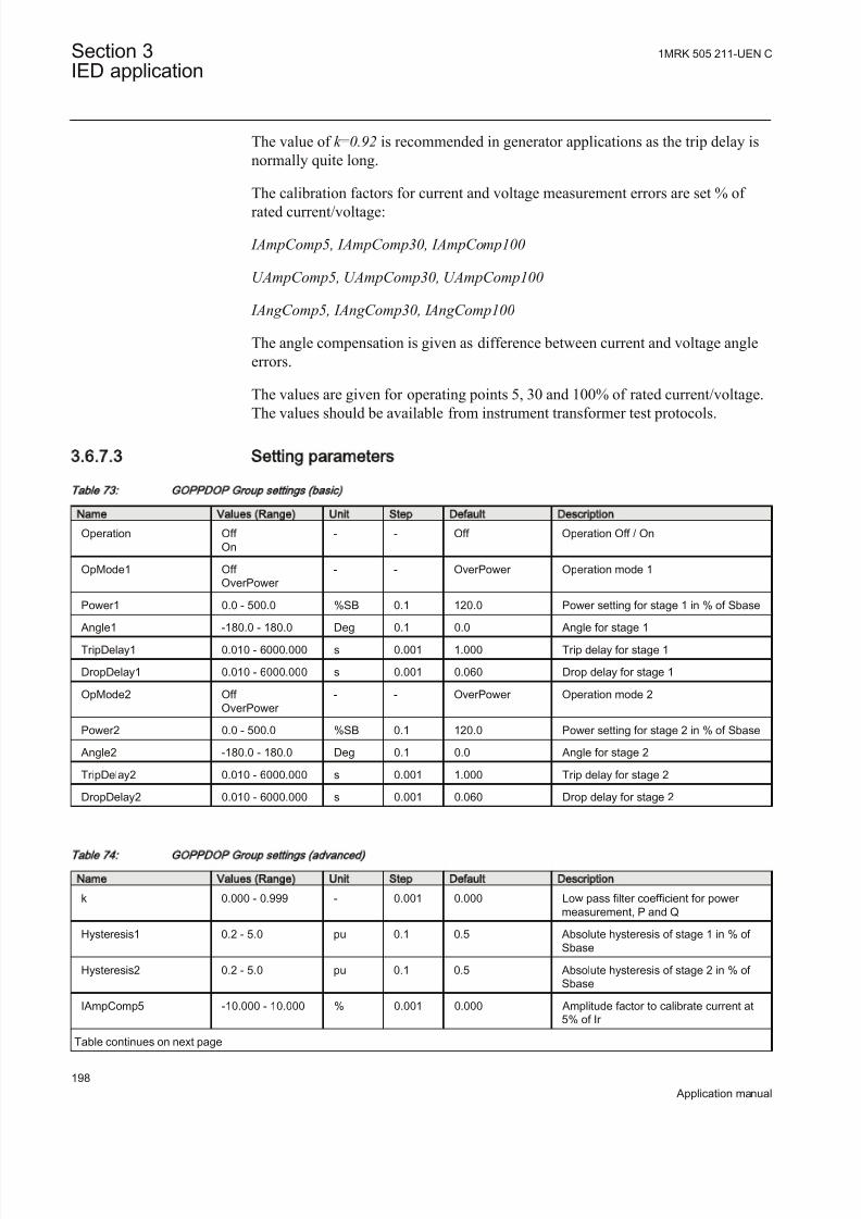
8/22/2019 Best Application
http://slidepdf.com/reader/full/best-application 204/457
The value of k =0.92 is recommended in generator applications as the trip delay isnormally quite long.
The calibration factors for current and voltage measurement errors are set % of
rated current/voltage:
IAmpComp5, IAmpComp30, IAmpComp100
UAmpComp5, UAmpComp30, UAmpComp100
IAngComp5, IAngComp30, IAngComp100
The angle compensation is given as difference between current and voltage angleerrors.
The values are given for operating points 5, 30 and 100% of rated current/voltage.
The values should be available from instrument transformer test protocols.
3.6.7.3 Setting parameters
Table 73: GOPPDOP Group settings (basic)
Name Values (Range) Unit Step Default Description
Operation Off On
- - Off Operation Off / On
OpMode1 Off OverPower
- - OverPower Operation mode 1
Power1 0.0 - 500.0 %SB 0.1 120.0 Power setting for stage 1 in % of Sbase
Angle1 -180.0 - 180.0 Deg 0.1 0.0 Angle for stage 1
TripDelay1 0.010 - 6000.000 s 0.001 1.000 Trip delay for stage 1
DropDelay1 0.010 - 6000.000 s 0.001 0.060 Drop delay for stage 1
OpMode2 Off OverPower
- - OverPower Operation mode 2
Power2 0.0 - 500.0 %SB 0.1 120.0 Power setting for stage 2 in % of Sbase
Angle2 -180.0 - 180.0 Deg 0.1 0.0 Angle for stage 2
TripDelay2 0.010 - 6000.000 s 0.001 1.000 Trip delay for stage 2
DropDelay2 0.010 - 6000.000 s 0.001 0.060 Drop delay for stage 2
Table 74: GOPPDO P Group settings (advanced)
Name Values (Range) Unit Step Default Description
k 0.000 - 0.999 - 0.001 0.000 Low pass filter coefficient for power measurement, P and Q
Hysteresis1 0.2 - 5.0 pu 0.1 0.5 Absolute hysteresis of stage 1 in % of Sbase
Hysteresis2 0.2 - 5.0 pu 0.1 0.5 Absolute hysteresis of stage 2 in % of Sbase
IAmpComp5 -10.000 - 10.000 % 0.001 0.000 Amplitude factor to calibrate current at5% of Ir
Table continues on next page
Section 3 1MRK 505 211-UEN C
IED application
198
Application manual

8/22/2019 Best Application
http://slidepdf.com/reader/full/best-application 205/457
Name Values (Range) Unit Step Default Description
IAmpComp30 -10.000 - 10.000 % 0.001 0.000 Amplitude factor to calibrate current at30% of Ir
IAmpComp100 -10.000 - 10.000 % 0.001 0.000 Amplitude factor to calibrate current at
100% of Ir
UAmpComp5 -10.000 - 10.000 % 0.001 0.000 Amplitude factor to calibrate voltage at5% of Ur
UAmpComp30 -10.000 - 10.000 % 0.001 0.000 Amplitude factor to calibrate voltage at30% of Ur
UAmpComp100 -10.000 - 10.000 % 0.001 0.000 Amplitude factor to calibrate voltage at100% of Ur
IAngComp5 -10.000 - 10.000 Deg 0.001 0.000 Angle calibration for current at 5% of Ir
IAngComp30 -10.000 - 10.000 Deg 0.001 0.000 Angle calibration for current at 30% of Ir
IAngComp100 -10.000 - 10.000 Deg 0.001 0.000 Angle calibration for current at 100% of Ir
Table 75: GOPPDOP Non group settings (basic)
Name Values (Range) Unit Step Default Description
IBase 1 - 99999 A 1 3000 Base setting for current level
UBase 0.05 - 2000.00 kV 0.05 400.00 Base setting for voltage level
Mode L1, L2, L3 AronePos SeqL1L2L2L3L3L1L1L2L3
- - Pos Seq Selection of measured current andvoltage
3.6.8 Capacitor bank protection CBPGAPC
Function description IEC 61850
identification
IEC 60617
identification
ANSI/IEEE C37.2
device number
Capacitor bank protection CBPGAPC - -
3.6.8.1 Application
Shunt capacitor banks (SCBs) are somewhat specific and different from other power system elements. These specific features of SCB are briefly summarized inthis section.
A capacitor unit is the building block used for SCB construction. The capacitor unitis made up of individual capacitor elements, arranged in parallel or seriesconnections. Capacitor elements normally consist of aluminum foil, paper, or film-insulated cells immersed in a biodegradable insulating fluid and are sealed in ametallic container. The internal discharge resistor is also integrated within the
1MRK 505 211-UEN C Section 3IED application
199
Application manual

8/22/2019 Best Application
http://slidepdf.com/reader/full/best-application 206/457
capacitor unit in order to reduce trapped residual voltage after disconnection of theSCB from the power system. Units are available in a variety of voltage ratings(240V to 25kV) and sizes (2.5kVAr to about 1000kVAr). Capacitor unit can bedesigned with one or two bushings.
The high-voltage SCB is normally constructed using individual capacitor unitsconnected in series and/or parallel to obtain the required voltage and MVAr rating.Typically the neighboring capacitor units are mounted in racks. Each rack must beinsulated from the other by insulators because the can casing within each rack areat a certain potential. Refer figure 78 for an example:
Capacitor Unit(Can)
Rack
IEC09000753_1_en.vsd
IEC09000753 V1 EN
Figure 78: Replacement of a faulty capacitor unit within SCB
There are four types of the capacitor unit fusing designs which are used for construction of SCBs:
Section 3 1MRK 505 211-UEN C
IED application
200
Application manual

8/22/2019 Best Application
http://slidepdf.com/reader/full/best-application 207/457
Externallyfused
where an individual fuse, externally mounted, protects each capacitor unit.
Internallyfused
where each capacitor element is fused inside the capacitor unit
Fuseless where SCB is built from series connections of the individual capacitor units (that is,strings) and without any fuses
Unfused where, in contrary to the fuseless configuration, a series or parallel connection of the capacitor units is used to form SCB, still without any fuses
Which type of fusing is used may depend on can manufacturer or utility preferenceand previous experience.
Because the SCBs are built from the individual capacitor units the overallconnections may vary. Typically used SCB configurations are:
1. Delta-connected banks (generally used only at distribution voltages)2. Single wye-connected banks3. Double wye-connected banks4. H-configuration, where each phase is connected in a bridge
Additionally, the SCB star point, when available, can be either directly earthed ,earthed via impedance or isolated from earth. Which type of SCB earthing is useddepends on voltage level, used circuit breaker, utility preference and previousexperience. Many utilities have standard system earthing principle to earth neutralsof SCB above 100 kV.
Switching of SCB will produce transients in power system. The transient inrushcurrent during SCB energizing typically has high frequency components and canreach peak current values, which are multiples of SCB rating. Opening of capacitor
bank circuit breaker may produce step recovery voltages across open CB contact,which can consequently cause restrikes upon the first interruption of capacitivecurrent. In modern power system the synchronized CB closing/opening may beutilized in such a manner that transients caused by SCB switching are avoided.
SCB protectionIED protection of shunt capacitor banks requires an understanding of thecapabilities and limitations of the individual capacitor units and associated
electrical equipment. Different types of shunt capacitor bank fusing, configurationor earthing may affect the IED selection for the protection scheme. Availability and placement of CTs and VTs can be additional limiting factor during protectionscheme design.
SCB protection schemes are provided in order to detect and clear faults within thecapacitor bank itself or in the connected leads to the substation busbar. Bank
protection may include items such as a means to disconnect a faulted capacitor unitor capacitor element(s), a means to initiate a shutdown of the bank in case of faultsthat may lead to a catastrophic failure and alarms to indicate unbalance within the
bank.
1MRK 505 211-UEN C Section 3IED application
201
Application manual

8/22/2019 Best Application
http://slidepdf.com/reader/full/best-application 208/457
Capacitor bank outages and failures are often caused by accidental contact byanimals. Vermin, monkeys, birds, may use the SCB as a resting place or a landingsite. When the animal touches the HV live parts this can result in a flash-over, canrapture or a cascading failures that might cause extensive damages, fire or eventotal destruction of the whole SCB, unless the bank is sufficiently fitted with
protection IEDs.
In addition, to fault conditions SCB can be exposed to different types of abnormaloperating conditions. In accordance with IEC and ANSI standards capacitors shall
be capable of continuous operation under contingency system and bank conditions, provided the following limitations are not exceeded:
1. Capacitor units should be capable of continuous operation includingharmonics, but excluding transients, to 110% of rated IED root-mean-square(RMS) voltage and a crest voltage not exceeding of rated RMS voltage. The
capacitor should also be able to carry 135% of nominal current. The voltagecapability of any series element of a capacitor unit shall be considered to be itsshare of the total capacitor unit voltage capability.
2. Capacitor units should not give less than 100% nor more than 110% of ratedreactive power at rated sinusoidal voltage and frequency, measured at auniform case and internal temperature of 25°C.
3. Capacitor units mounted in multiple rows and tiers should be designed for continuous operation for a 24h average temperature of 40 °C during the hottestday, or −40 °C during the coldest day expected at the location.
4. Capacitor units should be suitable for continuous operation at up to 135% of rated reactive power caused by the combined effects of:
• Voltage in excess of the nameplate rating at fundamental frequency, butnot over 110% of rated RMS voltage• Harmonic voltages superimposed on the fundamental frequency• Reactive power manufacturing tolerance of up to 115% of rated reactive
power
5. Capacitor units rated above 600 V shall have an internal discharge device toreduce the residual voltage to 50 V or less in 5 or 10 minutes (depending onnational standard).
Note that capacitor units designed for special applications can exceed these ratings.
Thus, as a general rule, the minimum number of capacitor units connected in parallel within a SCB is such that isolation of one capacitor unit in a group shouldnot cause a voltage unbalance sufficient to place more than 110% of rated voltageon the remaining capacitors of that parallel group. Equally, the minimum number of series connected groups within a SCB is such that complete bypass of one groupshould not pause voltage higher than 110% of the rated voltage on the remainingcapacitors of that serial group. The value of 110% is the maximum continuousovervoltage capability of capacitor units as per IEEE Std 18-1992.
The SCB typically requires the following types of IED protection:
Section 3 1MRK 505 211-UEN C
IED application
202
Application manual

8/22/2019 Best Application
http://slidepdf.com/reader/full/best-application 209/457
1. Short circuit protection for SCB and connecting leads (can be provided byusing PHPIOC, OC4PTOC, CVGAPC, T2WPDIF/T3WPDIF or HZPDIFfunctions)
2. Earth-fault protection for SCB and connecting leads (can be provided by usingEFPIOC, EF4PTOC, CVGAPC, T2WPDIF/T3WPDIF or HZPDIF functions)
3. Current or Voltage based unbalance protection for SCB (can be provided byusing EF4PTOC, OC4PTOC, CVGAPC or VDCPTOV functions)
4. Overload protection for SCB5. Undercurrent protection for SCB6. Reconnection inhibit protection for SCB7. Restrike condition detection
CBPGAPC function can be used to provide the last four types of protectionmentioned in the above list.
3.6.8.2 Setting guidelines
This setting example will be done for application as shown in figure 79:
Preprocessing
Function Block
Capacitor bank
protection function
400kV
CBPGAPCSMAI
200MVAr
400kV
500/1
IED
IEC09000754-1-en.vsd
IEC09000754 V1 EN
Figure 79: Single line diagram for the application example
From figure 79 it is possible to calculate the following rated fundamental frequencycurrent for this SCB:
1000 200[ ]289
3 400[ ]r
MVAr I A
kV
×= =
×IEC09000755 V1 EN (Equation 79)
1MRK 505 211-UEN C Section 3IED application
203
Application manual

8/22/2019 Best Application
http://slidepdf.com/reader/full/best-application 210/457
or on the secondary CT side:
_ ec
2890.578
500 1r S
A I A= =
IEC09000756 V1 EN (Equation 80)
Note that the SCB rated current on the secondary CT side is important for secondary injection of the function.
The parameters for the Capacitor bank protection function CBPGAPC are set viathe local HMI or PCM600. The following settings are done for this function:
General Settings:
Operation =On; to enable the function
IBase =289A; Fundamental frequency SCB rated current in primary amperes. Thisvalue is used as a base value for pickup settings of all other features integrated inthis function.
Reconnection inhibit feature:
OperationRecIn =On; to enable this feature
IRecnInhibit< =10% (of IBase); Current level under which function will detect thatSCB is disconnected from the power system
tReconnInhibit =300s; Time period under which SCB shall discharge remaining
residual voltage to less than 5%.
Overcurrent feature:
OperationOC =On; to enable this feature
IOC> =135% (of IBase); Current level for overcurrent pickup. Selected valuegives pickup recommended by international standards.
tOC =30s; Time delay for overcurrent trip
Undercurrent feature:
OperationUC =On; to enable this feature
IUC< =70% (of IBase); Current level for undercurrent pickup
tUC =5s; Time delay for undercurrent trip
Undercurrent feature is blocked by operation of Reconnectioninhibit feature.
Reactive power overload feature:
Section 3 1MRK 505 211-UEN C
IED application
204
Application manual

8/22/2019 Best Application
http://slidepdf.com/reader/full/best-application 211/457
OperationQOL =On; to enable this feature
QOL> =130% (of SCB MVAr rating); Reactive power level required for pickup.Selected value gives pickup recommended by international standards.
tQOL =60s; Time delay for reactive power overload trip
Harmonic voltage overload feature:
OperationHOL =On; to enable this feature
Settings for definite time delay step
HOLDTU> =200% (of SCB voltage rating); Voltage level required for pickup
tHOLDT =10s; Definite time delay for harmonic overload trip
Settings for IDMT delay step
HOLIDMTU> =110% (of SCB voltage rating); Voltage level required for pickupof IDMT stage. Selected value gives pickup recommended by international standards.
kHOLIDMT =1.0; Time multiplier for IDMT stage. Selected value gives operatetime in accordance with international standards
tMaxHOLIDMT =2000s; Maximum time delay for IDMT stage for very low levelof harmonic overload
tMinHOLIDMT =0.1s; Minimum time delay for IDMT stage. Selected value gives
operate time in accordance with international standards
Restrike detectionOpening of SCBs can be quite problematic for certain types of circuit breakers(CBs). Typically such problems are manifested as CB restrikes.
In simple words this means that the CB is not breaking the current at the first zerocrossing after separation of the CB contacts. Instead current is re-ignited and only
braked at consecutive current zero crossings. This condition is manifested as highcurrent pulses at the moment of current re-ignition.
To detect this CB condition, the built in overcurrent feature can be used. Simply,
any start of the overcurrent feature during breaker normal opening means arestrike. Therefore simple logic can be created in the Application Configurationtool to detect such CB behavior. Such CB condition can be just alarmed, and if required, the built in disturbance recorder can also be triggered.
To create this logic, a binary signal that the CB is going to be opened (but not tripcommand) shall be made available to the IED.
1MRK 505 211-UEN C Section 3IED application
205
Application manual

8/22/2019 Best Application
http://slidepdf.com/reader/full/best-application 212/457
3.6.8.3 Setting parameters
Table 76: CBPGAPC Group settings (basic)
Name Values (Range) Unit Step Default Description
Operation Off On
- - Off Operation Off/On
IBase 1 - 99999 A 1 3000 Rated capacitor bank current
OperationRecIn Off On
- - On Operation reconnection inhibit Off/On
IRecnInhibit< 4 - 1000 %IB 1 10 Cap bank cut off current level for inhibitin % of IBase
tReconnInhibit 1.00 - 6000.00 s 0.01 300.00 Time delay for reconnected inhibit signal
OperationOC Off On
- - On Operation over current Off/On
IOC> 0 - 900 %IB 1 135 Start level for over current operation, %
of IBase
tOC 0.00 - 6000.00 s 0.01 30.00 Time delay for over current operation
OperationUC Off On
- - Off Operation under current Off/On
IUC< 5 - 100 %IB 1 70 Start level for under current operation, %of IBase
tUC 0.00 - 6000.00 s 0.01 5.00 Time delay for under current operation
OperationQOL Off On
- - On Operation reactive power over load Off/On
QOL> 5 - 900 % 1 130 Start level for reactive power over load in%
tQOL 1.00 - 6000.00 s 0.01 60.00 Time delay for reactive power overloadoperation
OperationHOL Off On
- - On Operation harmonic over load Off/On
HOLDTU> 5 - 500 % 1 200 Start value of voltage for harmOvLoadfor DT stage in %
tHOLDT 0.00 - 6000.00 s 0.01 10.00 Time delay for minimum operation for harmonic overload
HOLIDMTU> 80 - 200 % 1 110 Start value of voltage for harmOvLoad inIDMT stage in %
kHOLIDMT 0.50 - 1.50 - 0.01 1.00 Time multiplier for harmonic overloadIDMT curve
tMaxHOLIDMT 0.05 - 6000.00 s 0.01 2000.00 Maximum trip delay for harmonic overload
tMinHOLIDMT 0.05 - 60.00 s 0.01 0.10 Minimum trip delay for harmonic overload
3.7 Voltage protection
3.7.1 Two step undervoltage protection UV2PTUV
Section 3 1MRK 505 211-UEN C
IED application
206
Application manual

8/22/2019 Best Application
http://slidepdf.com/reader/full/best-application 213/457
Function description IEC 61850
identification
IEC 60617
identification
ANSI/IEEE C37.2
device number
Two step undervoltage protection UV2PTUV
3U<
SYMBOL-R-2U-GREATER-THANV2 EN
27
3.7.1.1 Setting guidelines
All the voltage conditions in the system where UV2PTUV performs its functionsshould be considered. The same also applies to the associated equipment, itsvoltage and time characteristic.
There is a very wide application area where general undervoltage functions are
used. All voltage related settings are made as a percentage of the settings basevoltage UBase and base current IBase, which normally is set to the primary ratedvoltage level (phase-to-phase) of the power system or the high voltage equipmentunder consideration.
The setting for UV2PTUV is normally not critical, since there must be enough timeavailable for the main protection to clear short circuits and earth faults.
Some applications and related setting guidelines for the voltage level are describedin the following sections.
Equipment protection, such as for motors and generators
The setting must be below the lowest occurring "normal" voltage and above thelowest acceptable voltage for the equipment.
Disconnected equipment detectionThe setting must be below the lowest occurring "normal" voltage and above thehighest occurring voltage, caused by inductive or capacitive coupling, when theequipment is disconnected.
Power supply qualityThe setting must be below the lowest occurring "normal" voltage and above thelowest acceptable voltage, due to regulation, good practice or other agreements.
Voltage instability mitigationThis setting is very much dependent on the power system characteristics, andthorough studies have to be made to find the suitable levels.
Backup protection for power system faultsThe setting must be below the lowest occurring "normal" voltage and above thehighest occurring voltage during the fault conditions under consideration.
Settings for Two step undervoltage protectionThe following settings can be done for Two step undervoltage protection UV2PTUV:
1MRK 505 211-UEN C Section 3IED application
207
Application manual

8/22/2019 Best Application
http://slidepdf.com/reader/full/best-application 214/457
ConnType: Sets whether the measurement shall be phase-to-earth fundamentalvalue, phase-to-phase fundamental value, phase-to-earth RMS value or phase-to-
phase RMS value.
Operation: Off or On.
UBase: Base voltage phase-to-phase in primary kV. This voltage is used asreference for voltage setting. UV2PTUV measures selectively phase-to-earthvoltages, or phase-to-phase voltage chosen by the setting ConnType. The functionwill operate if the voltage gets lower than the set percentage of UBase. WhenConnType is set to PhN DFT or PhN RMS then the IED automatically divides setvalue for UBase by √3. UBase is used when ConnType is set to PhPh DFT or PhPh
RMS . Therefore, always set UBase as rated primary phase-to-phase voltage of the protected object. This means operation for phase-to-earth voltage under:
(%) ( ) 3U UBase kV < ×EQUATION1447 V1 EN (Equation 81)
and operation for phase-to-phase voltage under:
U (%) UBase(kV)< ×
EQUATION1990 V1 EN (Equation 82)
The below described setting parameters are identical for the two steps (n = 1 or 2).Therefore, the setting parameters are described only once.
Characteristicn: This parameter gives the type of time delay to be used. The settingcan be Definite time, Inverse Curve A, Inverse Curve B, Prog. inv. curve. Theselection is dependent on the protection application.
OpModen: This parameter describes how many of the three measured voltages thatshould be below the set level to give operation for step n. The setting can be 1 out
of 3, 2 out of 3 or 3 out of 3. In most applications, it is sufficient that one phasevoltage is low to give operation. If UV2PTUV shall be insensitive for single phase-to-earth faults, 2 out of 3 can be chosen. In subtransmission and transmissionnetworks the undervoltage function is mainly a system supervision function and 3out of 3 is selected.
Un<: Set operate undervoltage operation value for step n, given as % of the parameter UBase. The setting is highly dependent of the protection application. Itis essential to consider the minimum voltage at non-faulted situations. Normallythis voltage is larger than 90% of nominal voltage.
tn: time delay of step n, given in s. This setting is dependent of the protectionapplication. In many applications the protection function shall not directly tripwhen there is a short circuit or earth faults in the system. The time delay must becoordinated to the short circuit protections.
Section 3 1MRK 505 211-UEN C
IED application
208
Application manual
8/22/2019 Best Application
http://slidepdf.com/reader/full/best-application 215/457
tResetn: Reset time for step n if definite time delay is used, given in s. The defaultvalue is 25 ms.
tnMin: Minimum operation time for inverse time characteristic for step n, given in
s. When using inverse time characteristic for the undervoltage function during verylow voltages can give a short operation time. This might lead to unselective trip.By setting t1Min longer than the operation time for other protections suchunselective tripping can be avoided.
ResetTypeCrvn: This parameter for inverse time characteristic can be set to Instantaneous, Frozen time, Linearly decreased . The default settingis Instantaneous.
tIResetn: Reset time for step n if inverse time delay is used, given in s. The defaultvalue is 25 ms.
kn: Time multiplier for inverse time characteristic. This parameter is used for coordination between different inverse time delayed undervoltage protections.
ACrvn, BCrvn, CCrvn, DCrvn, PCrvn: Parameters to set to create programmableunder voltage inverse time characteristic. Description of this can be found in thetechnical reference manual.
CrvSatn: When the denominator in the expression of the programmable curve isequal to zero the time delay will be infinity. There will be an undesireddiscontinuity. Therefore, a tuning parameter CrvSatn is set to compensate for this
phenomenon. In the voltage interval Un< down to Un< · (1.0 - CrvSatn/100) theused voltage will be: Un< · (1.0 - CrvSatn/100). If the programmable curve is usedthis parameter must be calculated so that:
0100
CrvSatn B C × - >
EQUATION1448 V1 EN (Equation 83)
IntBlkSeln: This parameter can be set to Off , Block of trip, Block all . In case of alow voltage the undervoltage function can be blocked. This function can be used to
prevent function when the protected object is switched off. If the parameter is set Block of trip or Block all unwanted trip is prevented.
IntBlkStValn: Voltage level under which the blocking is activated set in % of UBase. This setting must be lower than the setting Un<. As switch of shall bedetected the setting can be very low, that is, about 10%.
tBlkUVn: Time delay to block the undervoltage step n when the voltage level is below IntBlkStValn, given in s. It is important that this delay is shorter than theoperate time delay of the undervoltage protection step.
1MRK 505 211-UEN C Section 3IED application
209
Application manual

8/22/2019 Best Application
http://slidepdf.com/reader/full/best-application 216/457
3.7.1.2 Setting parameters
Table 77: UV2PTUV Group settings (basic)
Name Values (Range) Unit Step Default Description
Operation Off On
- - Off Operation Off / On
UBase 0.05 - 2000.00 kV 0.05 400.00 Base voltage
OperationStep1 Off On
- - On Enable execution of step 1
Characterist1 Definite timeInverse curve AInverse curve BProg. inv. curve
- - Definite time Selection of time delay curve type for step 1
OpMode1 1 out of 32 out of 33 out of 3
- - 1 out of 3 Number of phases required for op (1 of 3, 2 of 3, 3 of 3) from step 1
U1< 1 - 100 %UB 1 70 Voltage setting/start val (DT & IDMT) in% of UBase, step 1
t1 0.00 - 6000.00 s 0.01 5.00 Definitive time delay of step 1
t1Min 0.000 - 60.000 s 0.001 5.000 Minimum operate time for inverse curvesfor step 1
k1 0.05 - 1.10 - 0.01 0.05 Time multiplier for the inverse time delayfor step 1
IntBlkSel1 Off Block of tripBlock all
- - Off Internal (low level) blocking mode, step 1
IntBlkStVal1 1 - 100 %UB 1 20 Voltage setting for internal blocking in %of UBase, step 1
tBlkUV1 0.000 - 60.000 s 0.001 0.000 Time delay of internal (low level)blocking for step 1
HystAbs1 0.0 - 100.0 %UB 0.1 0.5 Absolute hysteresis in % of UBase, step 1
OperationStep2 Off On
- - On Enable execution of step 2
Characterist2 Definite timeInverse curve AInverse curve BProg. inv. curve
- - Definite time Selection of time delay curve type for step 2
OpMode2 1 out of 32 out of 33 out of 3
- - 1 out of 3 Number of phases required for op (1 of 3, 2 of 3, 3 of 3) from step 2
U2< 1 - 100 %UB 1 50 Voltage setting/start val (DT & IDMT) in% of UBase, step 2
t2 0.000 - 60.000 s 0.001 5.000 Definitive time delay of step 2
t2Min 0.000 - 60.000 s 0.001 5.000 Minimum operate time for inverse curvesfor step 2
k2 0.05 - 1.10 - 0.01 0.05 Time multiplier for the inverse time delayfor step 2
IntBlkSel2 Off Block of tripBlock all
- - Off Internal (low level) blocking mode, step 2
Table continues on next page
Section 3 1MRK 505 211-UEN C
IED application
210
Application manual

8/22/2019 Best Application
http://slidepdf.com/reader/full/best-application 217/457
Name Values (Range) Unit Step Default Description
IntBlkStVal2 1 - 100 %UB 1 20 Voltage setting for internal blocking in %of UBase, step 2
tBlkUV2 0.000 - 60.000 s 0.001 0.000 Time delay of internal (low level)
blocking for step 2
HystAbs2 0.0 - 100.0 %UB 0.1 0.5 Absolute hysteresis in % of UBase, step 2
Table 78: UV2PTUV Group settings (advanced)
Name Values (Range) Unit Step Default Description
tReset1 0.000 - 60.000 s 0.001 0.025 Reset time delay used in IEC DefiniteTime curve step 1
ResetTypeCrv1 InstantaneousFrozen timer Linearly decreased
- - Instantaneous Selection of used IDMT reset curve typefor step 1
tIReset1 0.000 - 60.000 s 0.001 0.025 Time delay in IDMT reset (s), step 1
ACrv1 0.005 - 200.000 - 0.001 1.000 Parameter A for customer programmablecurve for step 1
BCrv1 0.50 - 100.00 - 0.01 1.00 Parameter B for customer programmablecurve for step 1
CCrv1 0.0 - 1.0 - 0.1 0.0 Parameter C for customer programmable curve for step 1
DCrv1 0.000 - 60.000 - 0.001 0.000 Parameter D for customer programmable curve for step 1
PCrv1 0.000 - 3.000 - 0.001 1.000 Parameter P for customer programmablecurve for step 1
CrvSat1 0 - 100 % 1 0 Tuning param for prog. under voltage
IDMT curve, step 1
tReset2 0.000 - 60.000 s 0.001 0.025 Reset time delay used in IEC DefiniteTime curve step 2
ResetTypeCrv2 InstantaneousFrozen timer Linearly decreased
- - Instantaneous Selection of used IDMT reset curve typefor step 2
tIReset2 0.000 - 60.000 s 0.001 0.025 Time delay in IDMT reset (s), step 2
ACrv2 0.005 - 200.000 - 0.001 1.000 Parameter A for customer programmablecurve for step 2
BCrv2 0.50 - 100.00 - 0.01 1.00 Parameter B for customer programmablecurve for step 2
CCrv2 0.0 - 1.0 - 0.1 0.0 Parameter C for customer programmable curve for step 2
DCrv2 0.000 - 60.000 - 0.001 0.000 Parameter D for customer programmable curve for step 2
PCrv2 0.000 - 3.000 - 0.001 1.000 Parameter P for customer programmablecurve for step 2
CrvSat2 0 - 100 % 1 0 Tuning param for prog. under voltageIDMT curve, step 2
1MRK 505 211-UEN C Section 3IED application
211
Application manual

8/22/2019 Best Application
http://slidepdf.com/reader/full/best-application 218/457
Table 79: UV2PTUV Non group settings (basic)
Name Values (Range) Unit Step Default Description
ConnType PhN DFTPhPh RMS
PhN RMSPhPh DFT
- - PhN DFT Group selector for connection type
3.7.2 Two step overvoltage protection OV2PTOV
Function description IEC 61850
identification
IEC 60617
identification
ANSI/IEEE C37.2
device number
Two step overvoltage protection OV2PTOV
3U>
SYMBOL-C-2U-SMALLER-THANV2 EN
59
3.7.2.1 Application
Two step overvoltage protection OV2PTOV is applicable in all situations, wherereliable detection of high voltage is necessary. OV2PTOV is used for supervisionand detection of abnormal conditions, which, in combination with other protectionfunctions, increase the security of a complete protection system.
High overvoltage conditions are caused by abnormal situations in the power system. OV2PTOV is applied to power system elements, such as generators,transformers, motors and power lines in order to detect high voltage conditions.OV2PTOV is used in combination with low current signals, to identify atransmission line, open in the remote end. In addition to that, OV2PTOV is alsoused to initiate voltage correction measures, like insertion of shunt reactors, tocompensate for low load, and thereby decreasing the voltage. The function has ahigh measuring accuracy and hysteresis setting to allow applications to controlreactive load.
OV2PTOV is used to disconnect apparatuses, like electric motors, which will bedamaged when subject to service under high voltage conditions. It deals with high
voltage conditions at power system frequency, which can be caused by:1. Different kinds of faults, where a too high voltage appears in a certain power
system, like metallic connection to a higher voltage level (broken conductor
Section 3 1MRK 505 211-UEN C
IED application
212
Application manual

8/22/2019 Best Application
http://slidepdf.com/reader/full/best-application 219/457
falling down to a crossing overhead line, transformer flash over fault from thehigh voltage winding to the low voltage winding and so on).
2. Malfunctioning of a voltage regulator or wrong settings under manual control(symmetrical voltage decrease).
3. Low load compared to the reactive power generation (symmetrical voltagedecrease).
4. Earth-faults in high impedance earthed systems causes, beside the high voltagein the neutral, high voltages in the two non-faulted phases, (unsymmetricalvoltage increase).
OV2PTOV prevents sensitive equipment from running under conditions that couldcause their overheating or stress of insulation material, and, thus, shorten their lifetime expectancy. In many cases, it is a useful function in circuits for local or remote automation processes in the power system.
3.7.2.2 Setting guidelines
The parameters for Two step overvoltage protection (OV2PTOV) are set via thelocal HMI or PCM600.
All the voltage conditions in the system where OV2PTOV performs its functionsshould be considered. The same also applies to the associated equipment, itsvoltage and time characteristic.
There is a very wide application area where general overvoltage functions are used.All voltage related settings are made as a percentage of a settable base primary
voltage, which normally is set to the nominal voltage level (phase-to-phase) of the power system or the high voltage equipment under consideration.
The time delay for the OV2PTOV can sometimes be critical and related to the sizeof the overvoltage - a power system or a high voltage component can withstandsmaller overvoltages for some time, but in case of large overvoltages the relatedequipment should be disconnected more rapidly.
Some applications and related setting guidelines for the voltage level are given below:
Equipment protection, such as for motors, generators, reactors and
transformers
High voltage will cause overexcitation of the core and deteriorate the windinginsulation. The setting has to be well above the highest occurring "normal" voltageand well below the highest acceptable voltage for the equipment.
Equipment protection, capacitorsHigh voltage will deteriorate the dielectricum and the insulation. The setting has to
be well above the highest occurring "normal" voltage and well below the highestacceptable voltage for the capacitor.
1MRK 505 211-UEN C Section 3IED application
213
Application manual

8/22/2019 Best Application
http://slidepdf.com/reader/full/best-application 220/457

8/22/2019 Best Application
http://slidepdf.com/reader/full/best-application 221/457
phases at single phase-to-earth faults. In subtransmission and transmissionnetworks the UV function is mainly a system supervision function and 3 out of 3 isselected.
Un>: Set operate overvoltage operation value for step n, given as % of UBase. Thesetting is highly dependent of the protection application. Here it is essential toconsider the maximum voltage at non-faulted situations. Normally this voltage isless than 110% of nominal voltage.
tn: time delay of step n, given in s. The setting is highly dependent of the protectionapplication. In many applications the protection function is used to preventdamages to the protected object. The speed might be important for example in caseof protection of transformer that might be overexcited. The time delay must be co-ordinated with other automated actions in the system.
tResetn: Reset time for step n if definite time delay is used, given in s. The defaultvalue is 25 ms.
tnMin: Minimum operation time for inverse time characteristic for step n, given ins. For very high voltages the overvoltage function, using inverse timecharacteristic, can give very short operation time. This might lead to unselectivetrip. By setting t1Min longer than the operation time for other protections suchunselective tripping can be avoided.
ResetTypeCrvn: This parameter for inverse time characteristic can be set: Instantaneous, Frozen time, Linearly decreased . The default setting is Instantaneous.
tIResetn: Reset time for step n if inverse time delay is used, given in s. The defaultvalue is 25 ms.
kn: Time multiplier for inverse time characteristic. This parameter is used for co-ordination between different inverse time delayed undervoltage protections.
ACrvn, BCrvn, CCrvn, DCrvn, PCrvn: Parameters to set to create programmableunder voltage inverse time characteristic. Description of this can be found in thetechnical reference manual.
CrvSatn: When the denominator in the expression of the programmable curve isequal to zero the time delay will be infinity. There will be an undesireddiscontinuity. Therefore a tuning parameter CrvSatn is set to compensate for this
phenomenon. In the voltage interval Un> up to Un> · (1.0 + CrvSatn/100) the usedvoltage will be: Un> · (1.0 + CrvSatn/100). If the programmable curve is used, this
parameter must be calculated so that:
0100
CrvSatn B C × - >
EQUATION1448 V1 EN (Equation 86)
1MRK 505 211-UEN C Section 3IED application
215
Application manual

8/22/2019 Best Application
http://slidepdf.com/reader/full/best-application 222/457
HystAbsn: Absolute hysteresis set in % of UBase. The setting of this parameter ishighly dependent of the application. If the function is used as control for automaticswitching of reactive compensation devices the hysteresis must be set smaller thanthe voltage change after switching of the compensation device.
3.7.2.3 Setting parameters
Table 80: OV2PTOV Group settings (basic)
Name Values (Range) Unit Step Default Description
Operation Off On
- - Off Operation Off / On
UBase 0.05 - 2000.00 kV 0.05 400.00 Base voltage
OperationStep1 Off On
- - On Enable execution of step 1
Characterist1 Definite timeInverse curve AInverse curve BInverse curve CProg. inv. curve
- - Definite time Selection of time delay curve type for step 1
OpMode1 1 out of 32 out of 33 out of 3
- - 1 out of 3 Number of phases required for op (1 of 3, 2 of 3, 3 of 3) from step 1
U1> 1 - 200 %UB 1 120 Voltage setting/start val (DT & IDMT) in% of UBase, step 1
t1 0.00 - 6000.00 s 0.01 5.00 Definitive time delay of step 1
t1Min 0.000 - 60.000 s 0.001 5.000 Minimum operate time for inverse curvesfor step 1
k1 0.05 - 1.10 - 0.01 0.05 Time multiplier for the inverse time delayfor step 1
HystAbs1 0.0 - 100.0 %UB 0.1 0.5 Absolute hysteresis in % of UBase, step 1
OperationStep2 Off On
- - On Enable execution of step 2
Characterist2 Definite timeInverse curve AInverse curve BInverse curve CProg. inv. curve
- - Definite time Selection of time delay curve type for step 2
OpMode2 1 out of 32 out of 33 out of 3
- - 1 out of 3 Number of phases required for op (1 of 3, 2 of 3, 3 of 3) from step 2
U2> 1 - 200 %UB 1 150 Voltage setting/start val (DT & IDMT) in% of UBase, step 2
t2 0.000 - 60.000 s 0.001 5.000 Definitive time delay of step 2
t2Min 0.000 - 60.000 s 0.001 5.000 Minimum operate time for inverse curvesfor step 2
k2 0.05 - 1.10 - 0.01 0.05 Time multiplier for the inverse time delayfor step 2
HystAbs2 0.0 - 100.0 %UB 0.1 0.5 Absolute hysteresis in % of UBase, step 2
Section 3 1MRK 505 211-UEN C
IED application
216
Application manual

8/22/2019 Best Application
http://slidepdf.com/reader/full/best-application 223/457
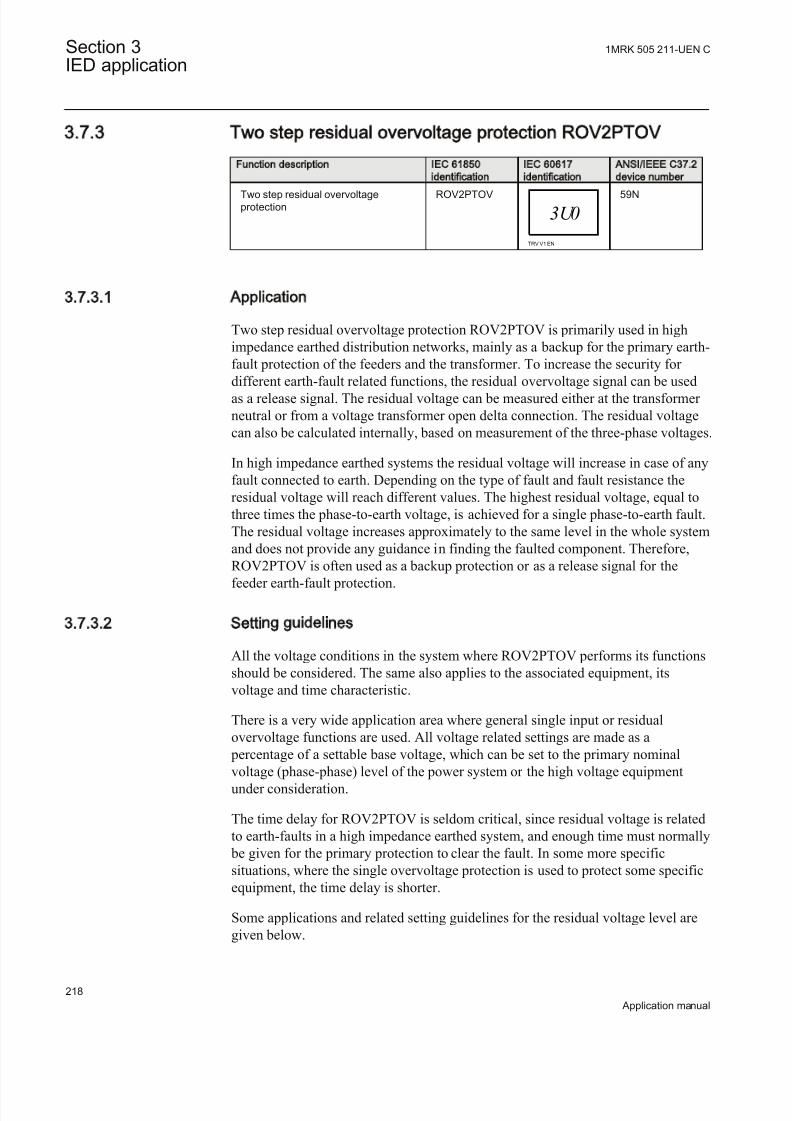
8/22/2019 Best Application
http://slidepdf.com/reader/full/best-application 224/457
3.7.3 Two step residual overvoltage protection ROV2PTOV
Function description IEC 61850
identification
IEC 60617
identification
ANSI/IEEE C37.2
device number
Two step residual overvoltageprotection
ROV2PTOV
3U0
TRV V1 EN
59N
3.7.3.1 Application
Two step residual overvoltage protection ROV2PTOV is primarily used in highimpedance earthed distribution networks, mainly as a backup for the primary earth-fault protection of the feeders and the transformer. To increase the security for
different earth-fault related functions, the residual overvoltage signal can be usedas a release signal. The residual voltage can be measured either at the transformer neutral or from a voltage transformer open delta connection. The residual voltagecan also be calculated internally, based on measurement of the three-phase voltages.
In high impedance earthed systems the residual voltage will increase in case of anyfault connected to earth. Depending on the type of fault and fault resistance theresidual voltage will reach different values. The highest residual voltage, equal tothree times the phase-to-earth voltage, is achieved for a single phase-to-earth fault.The residual voltage increases approximately to the same level in the whole systemand does not provide any guidance in finding the faulted component. Therefore,ROV2PTOV is often used as a backup protection or as a release signal for the
feeder earth-fault protection.
3.7.3.2 Setting guidelines
All the voltage conditions in the system where ROV2PTOV performs its functionsshould be considered. The same also applies to the associated equipment, itsvoltage and time characteristic.
There is a very wide application area where general single input or residualovervoltage functions are used. All voltage related settings are made as a
percentage of a settable base voltage, which can be set to the primary nominal
voltage (phase-phase) level of the power system or the high voltage equipmentunder consideration.
The time delay for ROV2PTOV is seldom critical, since residual voltage is relatedto earth-faults in a high impedance earthed system, and enough time must normally
be given for the primary protection to clear the fault. In some more specificsituations, where the single overvoltage protection is used to protect some specificequipment, the time delay is shorter.
Some applications and related setting guidelines for the residual voltage level aregiven below.
Section 3 1MRK 505 211-UEN C
IED application
218
Application manual

8/22/2019 Best Application
http://slidepdf.com/reader/full/best-application 225/457
Equipment protection, such as for motors, generators, reactors and
transformersHigh residual voltage indicates earth-fault in the system, perhaps in the componentto which Two step residual overvoltage protection (ROV2PTOV) is connected. For selectivity reasons to the primary protection for the faulted device ROV2PTOVmust trip the component with some time delay. The setting must be above thehighest occurring "normal" residual voltage and below the highest acceptableresidual voltage for the equipment
Equipment protection, capacitorsHigh voltage will deteriorate the dielectric and the insulation. Two step residualovervoltage protection (ROV2PTOV) has to be connected to a neutral or open deltawinding. The setting must be above the highest occurring "normal" residual voltageand below the highest acceptable residual voltage for the capacitor.
Power supply qualityThe setting must be above the highest occurring "normal" residual voltage and
below the highest acceptable residual voltage, due to regulation, good practice or other agreements.
High impedance earthed systemsIn high impedance earthed systems, earth faults cause a neutral voltage in thefeeding transformer neutral. Two step residual overvoltage protection ROV2PTOVis used to trip the transformer, as a backup protection for the feeder earth-fault
protection, and as a backup for the transformer primary earth-fault protection. Thesetting must be above the highest occurring "normal" residual voltage, and below
the lowest occurring residual voltage during the faults under consideration. Ametallic single-phase earth fault causes a transformer neutral to reach a voltageequal to the nominal phase-to-earth voltage.
The voltage transformers measuring the phase-to-earth voltages measure zerovoltage in the faulty phase. The two healthy phases will measure full phase-to-
phase voltage, as the faulty phase will be connected to earth. The residualovervoltage will be three times the phase-to-earth voltage. See figure 80.
1MRK 505 211-UEN C Section 3IED application
219
Application manual
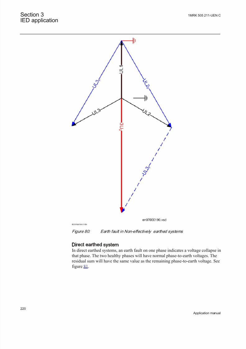
8/22/2019 Best Application
http://slidepdf.com/reader/full/best-application 226/457
IEC07000190 V1 EN
Figure 80: Earth fault in Non-effectively earthed systems
Direct earthed systemIn direct earthed systems, an earth fault on one phase indicates a voltage collapse inthat phase. The two healthy phases will have normal phase-to-earth voltages. Theresidual sum will have the same value as the remaining phase-to-earth voltage. Seefigure 81.
Section 3 1MRK 505 211-UEN C
IED application
220
Application manual

8/22/2019 Best Application
http://slidepdf.com/reader/full/best-application 227/457
IEC07000189 V1 EN
Figure 81: Earth fault in Direct earthed system
Settings for Two step residual overvoltage protectionOperation: Off or On
UBase is used as voltage reference for the voltage. The voltage can be fed to theIED in different ways:
1. The IED is fed from a normal voltage transformer group where the residualvoltage is calculated internally from the phase-to-earth voltages within the
protection. The setting of the analog input is given as UBase=Uph-ph.2. The IED is fed from a broken delta connection normal voltage transformer
group. In an open delta connection the protection is fed by the voltage 3U0(single input). The Setting chapter in the application manual explains how theanalog input needs to be set.
3. The IED is fed from a single voltage transformer connected to the neutral point
of a power transformer in the power system. In this connection the protectionis fed by the voltage UN=U0 (single input). The Setting chapter in theapplication manual explains how the analog input needs to be set.ROV2PTOV will measure the residual voltage corresponding nominal phase-to-earth voltage for a high impedance earthed system. The measurement will be
based on the neutral voltage displacement.
The below described setting parameters are identical for the two steps (n = step 1and 2). Therefore the setting parameters are described only once.
1MRK 505 211-UEN C Section 3IED application
221
Application manual

8/22/2019 Best Application
http://slidepdf.com/reader/full/best-application 228/457
Characteristicn: Selected inverse time characteristic for step n. This parameter gives the type of time delay to be used. The setting can be, Definite time or Inverse
curve A or Inverse curve B or Inverse curve C or Prog. inv. curve. The choice ishighly dependent of the protection application.
Un>: Set operate overvoltage operation value for step n, given as % of residualvoltage corresponding to UBase:
( ) ( )% 3U UBase kV > ×
IECEQUATION2290 V1 EN (Equation 87)
The setting is dependent of the required sensitivity of the protection and the systemearthing. In non-effectively earthed systems the residual voltage can be maximumthe rated phase-to-earth voltage, which should correspond to 100%.
In effectively earthed systems this value is dependent of the ratio Z0/Z1. Therequired setting to detect high resistive earth-faults must be based on network calculations.
tn: time delay of step n, given in s. The setting is highly dependent of the protectionapplication. In many applications, the protection function has the task to preventdamages to the protected object. The speed might be important for example in caseof protection of transformer that might be overexcited. The time delay must be co-ordinated with other automated actions in the system.
tResetn: Reset time for step n if definite time delay is used, given in s. The defaultvalue is 25 ms.
tnMin: Minimum operation time for inverse time characteristic for step n, given ins. For very high voltages the overvoltage function, using inverse timecharacteristic, can give very short operation time. This might lead to unselectivetrip. By setting t1Min longer than the operation time for other protections suchunselective tripping can be avoided.
ResetTypeCrvn: Set reset type curve for step n. This parameter can be set: Instantaneous, Frozen time, Linearly decreased . The default setting is Instantaneous.
tIResetn: Reset time for step n if inverse time delay is used, given in s. The defaultvalue is 25 ms.
kn: Time multiplier for inverse time characteristic. This parameter is used for co-ordination between different inverse time delayed undervoltage protections.
ACrvn, BCrvn, CCrvn, DCrvn, PCrvn: Parameters for step n, to set to create programmable undervoltage inverse time characteristic. Description of this can befound in the technical reference manual.
CrvSatn: Set tuning parameter for step n. When the denominator in the expressionof the programmable curve is equal to zero the time delay will be infinity. Therewill be an undesired discontinuity. Therefore, a tuning parameter CrvSatn is set tocompensate for this phenomenon. In the voltage interval U> up to U> · (1.0 +
Section 3 1MRK 505 211-UEN C
IED application
222
Application manual

8/22/2019 Best Application
http://slidepdf.com/reader/full/best-application 229/457
CrvSatn/100) the used voltage will be: U> · (1.0 + CrvSatn/100). If the programmable curve is used this parameter must be calculated so that:
0100CrvSatn
B C × - >EQUATION1448 V1 EN (Equation 88)
HystAbsn: Absolute hysteresis for step n, set in % of UBase. The setting of this parameter is highly dependent of the application.
3.7.3.3 Setting parameters
Table 83: ROV2PTOV Group settings (basic)
Name Values (Range) Unit Step Default Description
Operation Off On
- - Off Operation Off / On
UBase 0.05 - 2000.00 kV 0.05 400.00 Base voltage
OperationStep1 Off On
- - On Enable execution of step 1
Characterist1 Definite timeInverse curve AInverse curve BInverse curve CProg. inv. curve
- - Definite time Selection of time delay curve type for step 1
U1> 1 - 200 %UB 1 30 Voltage setting/start val (DT & IDMT),step 1 in % of UBase
t1 0.00 - 6000.00 s 0.01 5.00 Definitive time delay of step 1t1Min 0.000 - 60.000 s 0.001 5.000 Minimum operate time for inverse curves
for step 1
k1 0.05 - 1.10 - 0.01 0.05 Time multiplier for the inverse time delayfor step 1
HystAbs1 0.0 - 100.0 %UB 0.1 0.5 Absolute hysteresis in % of UBase, step 1
OperationStep2 Off On
- - On Enable execution of step 2
Characterist2 Definite timeInverse curve AInverse curve BInverse curve CProg. inv. curve
- - Definite time Selection of time delay curve type for step 2
U2> 1 - 100 %UB 1 45 Voltage setting/start val (DT & IDMT),step 2 in % of UBase
t2 0.000 - 60.000 s 0.001 5.000 Definitive time delay of step 2
t2Min 0.000 - 60.000 s 0.001 5.000 Minimum operate time for inverse curvesfor step 2
k2 0.05 - 1.10 - 0.01 0.05 Time multiplier for the inverse time delayfor step 2
HystAbs2 0.0 - 100.0 %UB 0.1 0.5 Absolute hysteresis in % of UBase, step 2
1MRK 505 211-UEN C Section 3IED application
223
Application manual

8/22/2019 Best Application
http://slidepdf.com/reader/full/best-application 230/457
Table 84: ROV2PTOV G roup settings (advanced)
Name Values (Range) Unit Step Default Description
tReset1 0.000 - 60.000 s 0.001 0.025 Reset time delay used in IEC DefiniteTime curve step 1
ResetTypeCrv1 InstantaneousFrozen timer Linearly decreased
- - Instantaneous Selection of used IDMT reset curve typefor step 1
tIReset1 0.000 - 60.000 s 0.001 0.025 Time delay in IDMT reset (s), step 1
ACrv1 0.005 - 200.000 - 0.001 1.000 Parameter A for customer programmablecurve for step 1
BCrv1 0.50 - 100.00 - 0.01 1.00 Parameter B for customer programmablecurve for step 1
CCrv1 0.0 - 1.0 - 0.1 0.0 Parameter C for customer programmable curve for step 1
DCrv1 0.000 - 60.000 - 0.001 0.000 Parameter D for customer programmable curve for step 1
PCrv1 0.000 - 3.000 - 0.001 1.000 Parameter P for customer programmablecurve for step 1
CrvSat1 0 - 100 % 1 0 Tuning param for prog. over voltageIDMT curve, step 1
tReset2 0.000 - 60.000 s 0.001 0.025 Time delay in DT reset (s), step 2
ResetTypeCrv2 InstantaneousFrozen timer Linearly decreased
- - Instantaneous Selection of used IDMT reset curve typefor step 2
tIReset2 0.000 - 60.000 s 0.001 0.025 Time delay in IDMT reset (s), step 2
ACrv2 0.005 - 200.000 - 0.001 1.000 Parameter A for customer programmablecurve for step 2
BCrv2 0.50 - 100.00 - 0.01 1.00 Parameter B for customer programmablecurve for step 2
CCrv2 0.0 - 1.0 - 0.1 0.0 Parameter C for customer programmable curve for step 2
DCrv2 0.000 - 60.000 - 0.001 0.000 Parameter D for customer programmable curve for step 2
PCrv2 0.000 - 3.000 - 0.001 1.000 Parameter P for customer programmablecurve for step 2
CrvSat2 0 - 100 % 1 0 Tuning param for prog. over voltageIDMT curve, step 2
3.7.4 Voltage differential protection VDCPTOV
Function description IEC 61850
identification
IEC 60617
identification
ANSI/IEEE C37.2
device number
Voltage differential protection VDCPTOV - 60
Section 3 1MRK 505 211-UEN C
IED application
224
Application manual

8/22/2019 Best Application
http://slidepdf.com/reader/full/best-application 231/457
3.7.4.1 Application
The Voltage differential protection VDCPTOV functions can be used in somedifferent applications.
• Voltage unbalance protection for capacitor banks. The voltage on the bus issupervised with the voltage in the capacitor bank, phase- by phase. Differenceindicates a fault, either short-circuited or open element in the capacitor bank. Itis mainly used on elements with external fuses but can also be used onelements with internal fuses instead of a current unbalance protectionmeasuring the current between the neutrals of two half’s of the capacitor bank.The function requires voltage transformers in all phases of the capacitor bank.Figure 82 shows some different alternative connections of this function.
Ud>L1
Ph L2Ph L3
U1
U2
Ud>L1
Ph L2Ph L3
U1 U2
Ph L3 Ph L2
Single earthed wye
Double wye
IEC06000390_1_en.vsd
IEC06000390 V3 EN
Figure 82: Connection of voltage differential protection VDCPTOV function to
detect unbalance in capacitor banks (one phase only is shown)
VDCPTOV function has a block input (BLOCK) where a fuse failure supervision(or MCB tripped) can be connected to prevent problems if one fuse in the capacitor
bank voltage transformer set has opened and not the other (capacitor voltage isconnected to input U2). It will also ensure that a fuse failure alarm is given insteadof a Undervoltage or Differential voltage alarm and/or tripping.
1MRK 505 211-UEN C Section 3IED application
225
Application manual

8/22/2019 Best Application
http://slidepdf.com/reader/full/best-application 232/457
3.7.4.2 Setting guidelines
The parameters for the voltage differential function are set via the local HMI or PCM600.
The following settings are done for the voltage differential function.
Operation: Off /On
UBase: Base voltage level in kV. The base voltage is used as reference for thevoltage setting factors. Normally, it is set to the system voltage level.
BlkDiffAtULow: The setting is to block the function when the voltages in the phases are low.
RFLx: Is the setting of the voltage ratio compensation factor where possible
differences between the voltages is compensated for. The differences can be due todifferent voltage transformer ratios, different voltage levels e.g. the voltagemeasurement inside the capacitor bank can have a different voltage level but thedifference can also e.g. be used by voltage drop in the secondary circuits. Thesetting is normally done at site by evaluating the differential voltage achieved as aservice value for each phase. The factor is defined as U2 · RFLx and shall be equalto the U1 voltage. Each phase has its own ratio factor.
UDTrip: The voltage differential level required for tripping is set with this parameter. For application on capacitor banks the setting will depend of thecapacitor bank voltage and the number of elements per phase in series and parallel.Capacitor banks must be tripped before excessive voltage occurs on the healthycapacitor elements. The setting values required are normally given by the capacitor
bank supplier. For other applications it has to be decided case by case. For fusesupervision normally only the alarm level is used.
tTrip: The time delay for tripping is set by this parameter. Normally, the delay doesnot need to be so short in capacitor bank applications as there is no fault requiringurgent tripping.
tReset : The time delay for reset of tripping level element is set by this parameter. Normally, it can be set to a short delay as faults are permanent when they occur.
For the advanced users following parameters are also available for setting. Defaultvalues are here expected to be acceptable.
U1Low: The setting of the undervoltage level for the first voltage input is decided by this parameter. The proposed default setting is 70%.
U2Low: The setting of the undervoltage level for the second voltage input isdecided by this parameter. The proposed default setting is 70%.
tBlock : The time delay for blocking of the function at detected undervoltages is set by this parameter.
Section 3 1MRK 505 211-UEN C
IED application
226
Application manual

8/22/2019 Best Application
http://slidepdf.com/reader/full/best-application 233/457

8/22/2019 Best Application
http://slidepdf.com/reader/full/best-application 234/457
3.7.5 Loss of voltage check LOVPTUV
Function description IEC 61850
identification
IEC 60617
identification
ANSI/IEEE C37.2
device number
Loss of voltage check LOVPTUV - 27
3.7.5.1 Application
The trip of the circuit breaker at a prolonged loss of voltage at all the three phasesis normally used in automatic restoration systems to facilitate the systemrestoration after a major blackout. Loss of voltage check (LOVPTUV) generates aTRIP signal only if the voltage in all the three phases is low for more than the settime. If the trip to the circuit breaker is not required, LOVPTUV is used for signallization only through an output contact or through the event recording function.
3.7.5.2 Setting guidelines
Loss of voltage check (LOVPTUV) is in principle independent of the protectionfunctions. It requires to be set to open the circuit breaker in order to allow a simplesystem restoration following a main voltage loss of a big part of the network andonly when the voltage is lost with breakers still closed.
All settings are in primary values or per unit. Set UBase to rated voltage of thesystem or the voltage transformer primary rated voltage. Set operating level per
phase UPE to typically 70% of rated UBase level. Set the time delay tTrip=5-20
seconds.
Advanced users settingsFor advanced users the following parameters need also to be set. Set the length of the trip pulse to typical tPulse=0.15 sec. Set the blocking time tBlock to block Loss of voltage check (LOVPTUV), if some but not all voltage are low, to typical5.0 seconds and set the time delay for enabling the function after restorationtRestore to 3 - 40 seconds.
3.7.5.3 Setting parameters
Table 87: LOVPTUV Group settings (basic)
Name Values (Range) Unit Step Default Description
Operation Off On
- - Off Operation Off/On
UBase 0.1 - 9999.9 kV 0.1 400.0 Base voltage
UPE 1 - 100 %UB 1 70 Operate voltagein% of base voltageUbase
tTrip 0.000 - 60.000 s 0.001 7.000 Operate time delay
Section 3 1MRK 505 211-UEN C
IED application
228
Application manual

8/22/2019 Best Application
http://slidepdf.com/reader/full/best-application 235/457
Table 88: LOVPTUV Group settings (advanced)
Name Values (Range) Unit Step Default Description
tPulse 0.050 - 60.000 s 0.001 0.150 Duration of TRIP pulse
tBlock 0.000 - 60.000 s 0.001 5.000 Time delay to block when all 3phvoltages are not low
tRestore 0.000 - 60.000 s 0.001 3.000 Time delay for enable the function after restoration
3.8 Frequency protection
3.8.1 Underfrequency protection SAPTUF
3.8.1.1 Setting guidelines
All the frequency and voltage magnitude conditions in the system where SAPTUF performs its functions should be considered. The same also applies to theassociated equipment, its frequency and time characteristic.
There are especially two specific application areas for SAPTUF:
1. to protect equipment against damage due to low frequency, such as generators,transformers, and motors. Overexcitation is also related to low frequency
2. to protect a power system, or a part of a power system, against breakdown, by
shedding load, in generation deficit situations.
The underfrequency START value is set in Hz. All voltage magnitude relatedsettings are made as a percentage of a settable base voltage, which normally is setto the nominal primary voltage level (phase-phase) of the power system or the highvoltage equipment under consideration.
Some applications and related setting guidelines for the frequency level are given below:
Equipment protection, such as for motors and generators
The setting has to be well below the lowest occurring "normal" frequency and wellabove the lowest acceptable frequency for the equipment.
Power system protection, by load shedding
The setting has to be below the lowest occurring "normal" frequency and wellabove the lowest acceptable frequency for power stations, or sensitive loads. Thesetting level, the number of levels and the distance between two levels (in time and/or in frequency) depends very much on the characteristics of the power systemunder consideration. The size of the "largest loss of production" compared to "thesize of the power system" is a critical parameter. In large systems, the load
1MRK 505 211-UEN C Section 3IED application
229
Application manual

8/22/2019 Best Application
http://slidepdf.com/reader/full/best-application 236/457
shedding can be set at a fairly high frequency level, and the time delay is normallynot critical. In smaller systems the frequency START level has to be set at a lower value, and the time delay must be rather short.
The voltage related time delay is used for load shedding. The settings of SAPTUFcould be the same all over the power system. The load shedding is then performedfirstly in areas with low voltage magnitude, which normally are the most
problematic areas, where the load shedding also is most efficient.
Equipment protection, such as for motors and generatorsThe setting has to be well below the lowest occurring "normal" frequency and wellabove the lowest acceptable frequency for the equipment.
Power system protection, by load sheddingThe setting has to be well below the lowest occurring "normal" frequency and well
above the lowest acceptable frequency for power stations, or sensitive loads. Thesetting level, the number of levels and the distance between two levels (in time and/or in frequency) depends very much on the characteristics of the power systemunder consideration. The size of the "largest loss of production" compared to "thesize of the power system" is a critical parameter. In large systems, the loadshedding can be set at a fairly high frequency level, and the time delay is normallynot critical. In smaller systems the frequency start level has to be set at a lower value, and the time delay must be rather short.
The voltage related time delay is used for load shedding. The settings of theunderfrequency function could be the same all over the power system. The loadshedding is then performed firstly in areas with low voltage magnitude, which
normally are the most problematic areas, where the load shedding also is mostefficient.
3.8.1.2 Setting parameters
Table 89: SAPTUF Group settings (basic)
Name Values (Range) Unit Step Default Description
Operation Off On
- - Off Operation Off / On
UBase 0.05 - 2000.00 kV 0.05 400.00 Base voltage
StartFrequency 35.00 - 75.00 Hz 0.01 48.80 Frequency setting/start value.
IntBlockLevel 0 - 100 %UB 1 50 Internal blocking level in % of UBase.
TimeDlyOperate 0.000 - 60.000 s 0.001 0.200 Operate time delay in over/under-frequency mode.
TimeDlyReset 0.000 - 60.000 s 0.001 0.000 Time delay for reset.
TimeDlyRestore 0.000 - 60.000 s 0.001 0.000 Restore time delay.
RestoreFreq 45.00 - 65.00 Hz 0.01 50.10 Restore frequency if frequency is abovefrequency value.
TimerOperation Definite timer Volt based timer
- - Definite timer Setting for choosing timer mode.
Table continues on next page
Section 3 1MRK 505 211-UEN C
IED application
230
Application manual

8/22/2019 Best Application
http://slidepdf.com/reader/full/best-application 237/457
Name Values (Range) Unit Step Default Description
UNom 50 - 150 %UB 1 100 Nominal voltage in % of UBase for voltage based timer.
UMin 50 - 150 %UB 1 90 Lower operation limit in % of UBase for
voltage based timer.
Exponent 0.0 - 5.0 - 0.1 1.0 For calculation of the curve form for voltage based timer.
tMax 0.010 - 60.000 s 0.001 1.000 Maximum time operation limit for voltagebased timer.
tMin 0.010 - 60.000 s 0.001 1.000 Minimum time operation limit for voltagebased timer.
3.8.2 Rate-of-change frequency protection SAPFRC
Function description IEC 61850
identification
IEC 60617
identification
ANSI/IEEE C37.2
device number
Rate-of-change frequency protection SAPFRC
df/dt ><
SYMBOL-N V1 EN
81
3.8.2.1 Application
Rate-of-change frequency protection (SAPFRC), is applicable in all situations,
where reliable detection of change of the fundamental power system voltagefrequency is needed. SAPFRC can be used both for increasing frequency and for decreasing frequency. SAPFRC provides an output signal, suitable for loadshedding or generator shedding, generator boosting, HVDC-set-point change, gasturbine start up and so on. Very often SAPFRC is used in combination with a lowfrequency signal, especially in smaller power systems, where loss of a fairly largegenerator will require quick remedial actions to secure the power system integrity.In such situations load shedding actions are required at a rather high frequencylevel, but in combination with a large negative rate-of-change of frequency theunderfrequency protection can be used at a rather high setting.
3.8.2.2 Setting guidelines
The parameters for Rate-of-change frequency protection SAPFRC are set via thelocal HMI or PCM600.
All the frequency and voltage magnitude conditions in the system where SAPFRC performs its functions should be considered. The same also applies to theassociated equipment, its frequency and time characteristic.
There are especially two application areas for SAPFRC:
1MRK 505 211-UEN C Section 3IED application
231
Application manual
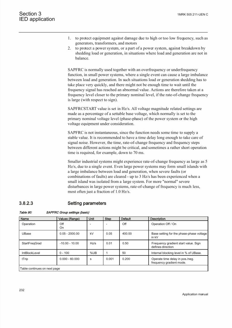
8/22/2019 Best Application
http://slidepdf.com/reader/full/best-application 238/457

8/22/2019 Best Application
http://slidepdf.com/reader/full/best-application 239/457

8/22/2019 Best Application
http://slidepdf.com/reader/full/best-application 240/457
• Definite time delay or Inverse Time Overcurrent TOC/IDMT delay for both steps
• Second harmonic supervision is available in order to only allowoperation of the overcurrent stage(s) if the content of the secondharmonic in the measured current is lower than pre-set level
• Directional supervision is available in order to only allow operation of the overcurrent stage(s) if the fault location is in the pre-set direction( Forward or Reverse). Its behavior during low-level polarizing voltage issettable ( Non-Directional , Block , Memory)
• Voltage restrained/controlled feature is available in order to modify the pick-up level of the overcurrent stage(s) in proportion to the magnitudeof the measured voltage
• Current restrained feature is available in or der to only allow operation of the overcurrent stage(s) if the measured current quantity is bigger thanthe set percentage of the current restrain quantity.
2. Two undercurrent steps with the following built-in features:
• Definite time delay for both steps
3. Two overvoltage steps with the following built-in features
• Definite time delay or Inverse Time Overcurrent TOC/IDMT delay for both steps
4. Two undervoltage steps with the following built-in features
• Definite time delay or Inverse Time Overcurrent TOC/IDMT delay for both steps
All these four protection elements within one general protection function worksindependently from each other and they can be individually enabled or disabled.However it shall be once more noted that all these four protection elementsmeasure one selected current quantity and one selected voltage quantity (seetable 91 and table 92). It is possible to simultaneously use all four-protectionelements and their individual stages. Sometimes in order to obtain desiredapplication functionality it is necessary to provide interaction between two or more
protection elements/stages within one CVGAPC function by appropriate IEDconfiguration (for example, dead machine protection for generators).
Current and voltage selection for CVGAPC function
CVGAPC function is always connected to three-phase current and three-phasevoltage input in the configuration tool, but it will always measure only the singlecurrent and the single voltage quantity selected by the end user in the setting tool(selected current quantity and selected voltage quantity).
The user can select, by a setting parameter CurrentInput , to measure one of thefollowing current quantities shown in table 91.
Section 3 1MRK 505 211-UEN C
IED application
234
Application manual

8/22/2019 Best Application
http://slidepdf.com/reader/full/best-application 241/457
Tab le 91 : Ava ilab le se lection fo r cur rent quan tity w ithin CVGAPC func tion
Set value for parameter
"CurrentInput”
Comment
1 phase1 CVGAPC function will measure the phase L1 current phasor
2 phase2 CVGAPC function will measure the phase L2 current phasor
3 phase3 CVGAPC function will measure the phase L3 current phasor
4 PosSeq CVGAPC function will measure internally calculated positivesequence current phasor
5 NegSeq CVGAPC function will measure internally calculated negativesequence current phasor
6 3 · ZeroSeq CVGAPC function will measure internally calculated zerosequence current phasor multiplied by factor 3
7 MaxPh CVGAPC function will measure current phasor of the phasewith maximum magnitude
8 MinPh CVGAPC function will measure current phasor of the phase
with minimum magnitude
9 UnbalancePh CVGAPC function will measure magnitude of unbalancecurrent, which is internally calculated as the algebraicmagnitude difference between the current phasor of the phasewith maximum magnitude and current phasor of the phasewith minimum magnitude. Phase angle will be set to 0° all thetime
10 phase1 -phase2 CVGAPC function will measure the current phasor internallycalculated as the vector difference between the phase L1current phasor and phase L2 current phasor (IL1-IL2)
11 phase2 -phase3 CVGAPC function will measure the current phasor internallycalculated as the vector difference between the phase L2current phasor and phase L3 current phasor (IL2-IL3)
12 phase3 -phase1 CVGAPC function will measure the current phasor internallycalculated as the vector difference between the phase L3current phasor and phase L1 current phasor ( IL3-IL1)
13 MaxPh-Ph CVGAPC function will measure ph-ph current phasor with themaximum magnitude
14 MinPh-Ph CVGAPC function will measure ph-ph current phasor with theminimum magnitude
15 UnbalancePh-Ph CVGAPC function will measure magnitude of unbalancecurrent, which is internally calculated as the algebraicmagnitude difference between the ph-ph current phasor withmaximum magnitude and ph-ph current phasor with minimummagnitude. Phase angle will be set to 0° all the time
The user can select, by a setting parameter VoltageInput , to measure one of thefollowing voltage quantities shown in table 92.
Tab le 92 : Ava ilab le se lection fo r voltage quant ity w ithin CVGAPC func tion
Set value for parameter
"VoltageInput"
Comment
1 phase1 CVGAPC function will measure the phase L1 voltage phasor
2 phase2 CVGAPC function will measure the phase L2 voltage phasor
3 phase3 CVGAPC function will measure the phase L3 voltage phasor
Table continues on next page
1MRK 505 211-UEN C Section 3IED application
235
Application manual

8/22/2019 Best Application
http://slidepdf.com/reader/full/best-application 242/457
Set value for parameter
"VoltageInput"
Comment
4 PosSeq CVGAPC function will measure internally calculated positivesequence voltage phasor
5 -NegSeq CVGAPC function will measure internally calculated negativesequence voltage phasor. This voltage phasor will beintentionally rotated for 180° in order to enable easier settingsfor the directional feature when used.
6 -3*ZeroSeq CVGAPC function will measure internally calculated zerosequence voltage phasor multiplied by factor 3. This voltagephasor will be intentionally rotated for 180° in order to enableeasier settings for the directional feature when used.
7 MaxPh CVGAPC function will measure voltage phasor of the phasewith maximum magnitude
8 MinPh CVGAPC function will measure voltage phasor of the phasewith minimum magnitude
9 UnbalancePh CVGAPC function will measure magnitude of unbalance
voltage, which is internally calculated as the algebraicmagnitude difference between the voltage phasor of the phasewith maximum magnitude and voltage phasor of the phasewith minimum magnitude. Phase angle will be set to 0° all thetime
10 phase1 -phase2 CVGAPC function will measure the voltage phasor internallycalculated as the vector difference between the phase L1voltage phasor and phase L2 voltage phasor (UL1-UL2)
11 phase2 -phase3 CVGAPC function will measure the voltage phasor internallycalculated as the vector difference between the phase L2voltage phasor and phase L3 voltage phasor (UL2-UL3)
12 phase3 -phase1 CVGAPC function will measure the voltage phasor internallycalculated as the vector difference between the phase L3voltage phasor and phase L1 voltage phasor (UL3-UL1)
13 MaxPh-Ph CVGAPC function will measure ph-ph voltage phasor with themaximum magnitude
14 MinPh-Ph CVGAPC function will measure ph-ph voltage phasor with theminimum magnitude
15 UnbalancePh-Ph CVGAPC function will measure magnitude of unbalancevoltage, which is internally calculated as the algebraicmagnitude difference between the ph-ph voltage phasor withmaximum magnitude and ph-ph voltage phasor with minimummagnitude. Phase angle will be set to 0° all the time
It is important to notice that the voltage selection from table 92 is alwaysapplicable regardless the actual external VT connections. The three-phase VTinputs can be connected to IED as either three phase-to-earth voltages UL1, UL2 &UL3 or three phase-to-phase voltages UL1L2, UL2L3 & UL3L1VAB, VBC and VCA.This information about actual VT connection is entered as a setting parameter for the pre-processing block, which will then take automatically care about it.
Base quantities for CVGAPC functionThe parameter settings for the base quantities, which represent the base (100%) for
pickup levels of all measuring stages shall be entered as setting parameters for every CVGAPC function.
Section 3 1MRK 505 211-UEN C
IED application
236
Application manual

8/22/2019 Best Application
http://slidepdf.com/reader/full/best-application 243/457
Base current shall be entered as:
1. rated phase current of the protected object in primary amperes, when themeasured Current Quantity is selected from 1 to 9, as shown in table 91.
2. rated phase current of the protected object in primary amperes multiplied by√3 (1.732 x Iphase), when the measured Current Quantity is selected from 10to 15, as shown in table 91.
Base voltage shall be entered as:
1. rated phase-to-earth voltage of the protected object in primary kV, when themeasured Voltage Quantity is selected from 1 to 9, as shown in table 92.
2. rated phase-to-phase voltage of the protected object in primary kV, when themeasured Voltage Quantity is selected from 10 to 15, as shown in table 92.
Application possibilitiesDue to its flexibility the general current and voltage protection (CVGAPC)function can be used, with appropriate settings and configuration in many differentapplications. Some of possible examples are given below:
1. Transformer and line applications:
• Underimpedance protection (circular, non-directional characteristic)• Underimpedance protection (circular mho characteristic)• Voltage Controlled/Restrained Overcurrent protection• Phase or Negative/Positive/Zero Sequence (Non-Directional or
Directional) Overcurrent protection
• Phase or phase-to-phase or Negative/Positive/Zero Sequence over/under voltage protection
• Special thermal overload protection• Open Phase protection• Unbalance protection
2. Generator protection
• 80-95% Stator earth fault protection (measured or calculated 3Uo)• Rotor earth fault protection (with external COMBIFLEX RXTTE4
injection unit)• Underimpedance protection
• Voltage Controlled/Restrained Overcurrent protection• Turn-to-Turn & Differential Backup protection (directional NegativeSequence. Overcurrent protection connected to generator HV terminalCTs looking into generator)
• Stator Overload protection• Rotor Overload protection• Loss of Excitation protection (directional pos. seq. OC protection)• Reverse power/Low forward power protection (directional pos. seq. OC
protection, 2% sensitivity)• Dead-Machine/Inadvertent-Energizing protection• Breaker head flashover protection• Improper synchronizing detection
1MRK 505 211-UEN C Section 3IED application
237
Application manual

8/22/2019 Best Application
http://slidepdf.com/reader/full/best-application 244/457
• Sensitive negative sequence generator over current protection and alarm• Phase or phase-to-phase or Negative/Positive/Zero Sequence over/under
voltage protection• Generator out-of-step detection (based on directional pos. seq. OC)• Inadvertent generator energizing
Inadvertent generator energizationWhen the generator is taken out of service, and non-rotating, there is a risk that thegenerator circuit breaker is closed by mistake.
Three-phase energizing of a generator, which is at standstill or on turning gear,causes it to behave and accelerate similarly to an induction motor. The machine, atthis point, essentially represents the subtransient reactance to the system and it can
be expected to draw from one to four per unit current, depending on the equivalent
system impedance. Machine terminal voltage can range from 20% to 70% of ratedvoltage, again, depending on the system equivalent impedance (including the block transformer). Higher quantities of machine current and voltage (3 to 4 per unitcurrent and 50% to 70% rated voltage) can be expected if the generator isconnected to a strong system. Lower current and voltage values (1 to 2 per unitcurrent and 20% to 40% rated voltage) are representative of weaker systems.
Since a generator behaves similarly to an induction motor, high currents willdevelop in the rotor during the period it is accelerating. Although the rotor may bethermally damaged from excessive high currents, the time to damage will be on theorder of a few seconds. Of more critical concern, however, is the bearing, whichcan be damaged in a fraction of a second due to low oil pressure. Therefore, it is
essential that high speed tripping is provided. This tripping should be almostinstantaneous (< 100 ms).
There is a risk that the current into the generator at inadvertent energization will belimited so that the “normal” overcurrent or underimpedance protection will notdetect the dangerous situation. The delay of these protection functions might be toolong. The reverse power protection might detect the situation but the operation timeof this protection is normally too long.
For big and important machines, fast protection against inadvertent energizingshould, therefore, be included in the protective scheme.
The protection against inadvertent energization can be made by a combination of undervoltage, overvoltage and overcurrent protection functions. The undervoltagefunction will, with a delay for example 10 s, detect the situation when the generator is not connected to the grid (standstill) and activate the overcurrent function. Theovervoltage function will detect the situation when the generator is taken intooperation and will disable the overcurrent function. The overcurrent function willhave a pick-up value about 50% of the rated current of the generator. The trip delaywill be about 50 ms.
Section 3 1MRK 505 211-UEN C
IED application
238
Application manual

8/22/2019 Best Application
http://slidepdf.com/reader/full/best-application 245/457
3.9.1.2 Setting guidelines
When inverse time overcurrent characteristic is selected, theoperate time of the stage will be the sum of the inverse time delayand the set definite time delay. Thus, if only the inverse time delayis required, it is of utmost importance to set the definite time delayfor that stage to zero.
The parameters for the general current and voltage protection function (CVGAPC)are set via the local HMI or Protection and Control Manager (PCM600).
The overcurrent steps has a IMinx ( x=1 or 2 depending on step)setting to set the minimum operate current. Set IMinx below
StartCurr_OCx for every step to achieve ANSI reset characteristicaccording to standard. If IMinx is set above StartCurr_OCx for anystep the ANSI reset works as if current is zero when current drops
below IMinx.
Directional negative sequence overcurrent protectionDirectional negative sequence overcurrent protection is typically used as sensitiveearth-fault protection of power lines were incorrect zero sequence polarization mayresult from mutual induction between two or more parallel lines. Additionally, itcan be used in applications on underground cables where zero-sequence impedance
depends on the fault current return paths, but the cable negative-sequenceimpedance is practically constant. It shall be noted that directional negativesequence OC element offers protection against all unbalance faults (phase-to-phasefaults as well). Care shall be taken that the minimum pickup of such protectionfunction shall be set above natural system unbalance level.
An example will be given, how sensitive-earth-fault protection for power lines can be achieved by using negative-sequence directional overcurrent protectionelements within a CVGAPC function.
This functionality can be achieved by using one CVGAPC function. The followingshall be done to ensure proper operation of the function:
1. Connect three-phase power line currents and three-phase power line voltagesto one CVGAPC instance (for example, GF04)
2. Set CurrentInput to NegSeq (please note that CVGAPC function measures I2current and NOT 3I2 current; this is essential for proper OC pickup level setting)
3. Set VoltageInput to -NegSeq (please note that the negative sequence voltage phasor is intentionally inverted in order to simplify directionality
4. Set base current IBase value equal to the rated primary current of power line CTs5. Set base voltage UBase value equal to the rated power line phase-to-phase
voltage in kV6. Set RCADir to value +65 degrees ( NegSeq current typically lags the inverted
NegSeq voltage for this angle during the fault)
1MRK 505 211-UEN C Section 3IED application
239
Application manual

8/22/2019 Best Application
http://slidepdf.com/reader/full/best-application 246/457
7. Set ROADir to value 90 degree8. Set LowVolt_VM to value 2% ( NegSeq voltage level above which the
directional element will be enabled)9. Enable one overcurrent stage (for example, OC1)10. By parameter CurveType_OC1 select appropriate TOC/IDMT or definite time
delayed curve in accordance with your network protection philosophy11. Set StartCurr_OC1 to value between 3-10% (typical values)12. Set tDef_OC1 or parameter “k” when TOC/IDMT curves are used to insure
proper time coordination with other earth-fault protections installed in thevicinity of this power line
13. Set DirMode_OC1 to Forward
14. Set DirPrinc_OC1 to IcosPhi&U
15. Set ActLowVolt1_VM to Block
• In order to insure proper restraining of this element for CT saturationsduring three-phase faults it is possible to use current restraint feature andenable this element to operate only when NegSeq current is bigger than acertain percentage (10% is typical value) of measured PosSeq current inthe power line. To do this the following settings within the same functionshall be done:
16. Set EnRestrainCurr to On
17. Set RestrCurrInput to PosSeq
18. Set RestrCurrCoeff to value 0.10
If required, this CVGAPC function can be used in directional comparison protection scheme for the power line protection if communication channels to the
remote end of this power line are available. In that case typically two NegSeqovercurrent steps are required. One for forward and one for reverse direction. Asexplained before the OC1 stage can be used to detect faults in forward direction.The built-in OC2 stage can be used to detect faults in reverse direction.
However the following shall be noted for such application:
• the set values for RCADir and ROADir settings will be as well applicable for OC2 stage
• setting DirMode_OC2 shall be set to Reverse
• setting parameter StartCurr_OC2 shall be made more sensitive than pickupvalue of forward OC1 element (that is, typically 60% of OC1 set pickup level)
in order to insure proper operation of the directional comparison schemeduring current reversal situations
• start signals from OC1 and OC2 elements shall be used to send forward andreverse signals to the remote end of the power line
• the available scheme communications function block within IED shall be used between multipurpose protection function and the communication equipmentin order to insure proper conditioning of the above two start signals
Furthermore the other built-in UC, OV and UV protection elements can be used for other protection and alarming purposes.
Section 3 1MRK 505 211-UEN C
IED application
240
Application manual

8/22/2019 Best Application
http://slidepdf.com/reader/full/best-application 247/457
Negative sequence overcurrent protectionExample will be given how to use one CVGAPC function to provide negativesequence inverse time overcurrent protection for a generator with capabilityconstant of 20s, and maximum continuous negative sequence rating of 7% of thegenerator rated current.
The capability curve for a generator negative sequence overcurrent protection,often used world-wide, is defined by the ANSI standard in accordance with thefollowing formula:
2op
NS
r
k t
I
I
=æ öç ÷è ø
EQUATION1372 V1 EN (Equation 89)
where:
top is the operating time in seconds of the negative sequence overcurrent IED
k is the generator capabili ty constant in seconds
INS is the measured negative sequence current
Ir is the generator rated current
By defining parameter x equal to maximum continuous negative sequence rating of the generator in accordance with the following formula
7% 0, 07 x pu= =EQUATION1373 V1 EN (Equation 90)
Equation 89 can be re-written in the following way without changing the value for the operate time of the negative sequence inverse overcurrent IED:
2
2
1
op
NS
r
k xt
I
x I
×=
æ öç ÷
×è øEQUATION1374 V1 EN (Equation 91)
In order to achieve such protection functionality with one CVGAPC functions thefollowing must be done:
1MRK 505 211-UEN C Section 3IED application
241
Application manual

8/22/2019 Best Application
http://slidepdf.com/reader/full/best-application 248/457
1. Connect three-phase generator currents to one CVGAPC instance (for example, GF01)
2. Set parameter CurrentInput to value NegSeq
3. Set base current value to the rated generator current in primary amperes4. Enable one overcurrent step (for example, OC1)5. Select parameter CurveType_OC1 to value Programmable
op P
At k B
M C
æ ö= × +ç ÷-è øEQUATION1375 V1 EN (Equation 92)
where:
top is the operating time in seconds of the Inverse Time Overcurrent TOC/IDMT algorithm
k is time multiplier (parameter setting)
M is ratio between measured current magnitude and set pickup current level
A, B, C and P are user settable coefficients which determine the curve used for Inverse TimeOvercurrent TOC/IDMT calculation
When the equation 89 is compared with the equation 91 for the inverse timecharacteristic of the OC1 it is obvious that if the following rules are followed:
1. set k equal to the generator negative sequence capability value2. set A_OC1 equal to the value 1/x2
3. set B_OC1 = 0.0, C_OC1=0.0 and P_OC1=2.04. set StartCurr_OC1 equal to the value x
then the OC1 step of the CVGAPC function can be used for generator negativesequence inverse overcurrent protection.
For this particular example the following settings shall be entered to insure proper function operation:
1. select negative sequence current as measuring quantity for this CVGAPCfunction
2. make sure that the base current value for the CVGAPC function is equal to the
generator rated current3. set k_OC1 = 204. set A_OC1= 1/0.072 = 204.08165. set B_OC1 = 0.0, C_OC1 = 0.0 and P_OC1 = 2.06. set StartCurr_OC1 = 7%
Proper timing of the CVGAPC function made in this way can easily be verified bysecondary injection. All other settings can be left at the default values. If requireddelayed time reset for OC1 step can be set in order to ensure proper functionoperation in case of repetitive unbalance conditions.
Section 3 1MRK 505 211-UEN C
IED application
242
Application manual

8/22/2019 Best Application
http://slidepdf.com/reader/full/best-application 249/457
Furthermore the other built-in protection elements can be used for other protectionand alarming purposes (for example, use OC2 for negative sequence overcurrentalarm and OV1 for negative sequence overvoltage alarm).
Generator stator overload protection in accordance with IEC or ANSIstandardsExample will be given how to use one CVGAPC function to provide generator stator overload protection in accordance with IEC or ANSI standard if minimum-operating current shall be set to 116% of generator rating.
The generator stator overload protection is defined by IEC or ANSI standard for turbo generators in accordance with the following formula:
2
1
op
m
r
k t
I
I
=æ ö
-ç ÷è øEQUATION1376 V1 EN (Equation 93)
where:
top is the operating time of the generator stator overload IED
k is the generator capability constant in accordance with the relevant standard (k = 37.5 for theIEC standard or k = 41.4 for the ANSI standard)
Im is the magnitude of the measured current
Ir is the generator rated current
This formula is applicable only when measured current (for example, positivesequence current) exceeds a pre-set value (typically in the range from 105 to 125%of the generator rated current).
By defining parameter x equal to the per unit value for the desired pickup for theoverload IED in accordance with the following formula:
x = 116% = 1.16 pu
EQUATION1377 V2 EN (Equation 94)
formula 3.5can be re-written in the following way without changing the value for the operate time of the generator stator overload IED:
2
2
2
1
1op
m
r
k xt
I
x I x
×=
æ ö-ç ÷×è ø
EQUATION1378 V1 EN (Equation 95)
1MRK 505 211-UEN C Section 3IED application
243
Application manual

8/22/2019 Best Application
http://slidepdf.com/reader/full/best-application 250/457
In order to achieve such protection functionality with one CVGAPC functions thefollowing must be done:
1. Connect three-phase generator currents to one CVGAPC instance (for
example, GF01)2. Set parameter CurrentInput to value PosSeq
3. Set base current value to the rated generator current in primary amperes4. Enable one overcurrent step (for example OC1)5. Select parameter CurveType_OC1 to value Programmable
op P
At k B
M C
æ ö= × +ç ÷-è øEQUATION1375 V1 EN (Equation 96)
where:
top is the operating time in seconds of the Inverse Time Overcurrent TOC/IDMT algorithm
k is time multiplier (parameter setting)
M is ratio between measured current magnitude and set pickup current level
A, B, C and P are user settable coefficients which determine the curve used for Inverse TimeOvercurrent TOC/IDMT calculation
When the equation 95 is compared with the equation 96 for the inverse timecharacteristic of the OC1 step in it is obvious that if the following rules are followed:
1. set k equal to the IEC or ANSI standard generator capability value2. set parameter A_OC1 equal to the value 1/x23. set parameter C_OC1 equal to the value 1/x24. set parameters B_OC1 = 0.0 and P_OC1=2.05. set StartCurr_OC1 equal to the value x
then the OC1 step of the CVGAPC function can be used for generator negativesequence inverse overcurrent protection.
1. select positive sequence current as measuring quantity for this CVGAPCfunction
2. make sure that the base current value for CVGAPC function is equal to thegenerator rated current
3. set k = 37.5 for the IEC standard or k = 41.4 for the ANSI standard4. set A_OC1= 1/1.162 = 0.74325. set C_OC1= 1/1.162 = 0.74326. set B_OC1 = 0.0 and P_OC1 = 2.07. set StartCurr_OC1 = 116%
Proper timing of CVGAPC function made in this way can easily be verified bysecondary injection. All other settings can be left at the default values. If required
Section 3 1MRK 505 211-UEN C
IED application
244
Application manual

8/22/2019 Best Application
http://slidepdf.com/reader/full/best-application 251/457
delayed time reset for OC1 step can be set in order to insure proper functionoperation in case of repetitive overload conditions.
Furthermore the other built-in protection elements can be used for other protection
and alarming purposes.
In the similar way rotor overload protection in accordance with ANSI standard can be achieved.
Open phase protection for transformer, lines or generators and circuit
breaker head flashover protection for generatorsExample will be given how to use one CVGAPC function to provide open phase
protection. This can be achieved by using one CVGAPC function by comparing theunbalance current with a pre-set level. In order to make such a function moresecure it is possible to restrain it by requiring that at the same time the measured
unbalance current must be bigger than 97% of the maximum phase current. Bydoing this it will be insured that function can only pickup if one of the phases isopen circuited. Such an arrangement is easy to obtain in CVGAPC function byenabling the current restraint feature. The following shall be done in order to insure
proper operation of the function:
1. Connect three-phase currents from the protected object to one CVGAPCinstance (for example, GF03)
2. Set CurrentInput to value UnbalancePh
3. Set EnRestrainCurr to On
4. Set RestrCurrInput to MaxPh
5. Set RestrCurrCoeff to value 0.97
6. Set base current value to the rated current of the protected object in primaryamperes
7. Enable one overcurrent step (for example, OC1)8. Select parameter CurveType_OC1 to value IEC Def. Time
9. Set parameter StartCurr_OC1 to value 5%10. Set parameter tDef_OC1 to desired time delay (for example, 2.0s)
Proper operation of CVGAPC function made in this way can easily be verified bysecondary injection. All other settings can be left at the default values. However itshall be noted that set values for restrain current and its coefficient will as well beapplicable for OC2 step as soon as it is enabled.
Furthermore the other built-in protection elements can be used for other protectionand alarming purposes. For example, in case of generator application by enablingOC2 step with set pickup to 200% and time delay to 0.1s simple but effective
protection against circuit breaker head flashover protection is achieved.
Voltage restrained overcurrent protection for generator and step-up
transformerExample will be given how to use one CVGAPC function to provide voltagerestrained overcurrent protection for a generator. Let us assume that the timecoordination study gives the following required settings:
1MRK 505 211-UEN C Section 3IED application
245
Application manual

8/22/2019 Best Application
http://slidepdf.com/reader/full/best-application 252/457
• Inverse Time Over Current TOC/IDMT curve: ANSI very inverse• Pickup current of 185% of generator rated current at rated generator voltage• Pickup current 25% of the original pickup current value for generator voltages
below 25% of rated voltage
This functionality can be achieved by using one CVGAPC function. The followingshall be done in order to insure proper operation of the function:
1. Connect three-phase generator currents and voltages to one CVGAPC instance(for example, GF05)
2. Set CurrentInput to value MaxPh
3. Set VoltageInput to value MinPh-Ph (it is assumed that minimum phase-to- phase voltage shall be used for restraining. Alternatively, positive sequencevoltage can be used for restraining by selecting PosSeq for this setting parameter)
4. Set base current value to the rated generator current primary amperes
5. Set base voltage value to the rated generator phase-to-phase voltage in kV6. Enable one overcurrent step (for example, OC1)7. Select CurveType_OC1 to value ANSI Very inv
8. If required set minimum operating time for this curve by using parameter tMin_OC1 (default value 0.05s)
9. Set StartCurr_OC1 to value 185%10. Set VCntrlMode_OC1 to On
11. Set VDepMode_OC1 to Slope
12. Set VDepFact_OC1 to value 0.2513. Set UHighLimit_OC1 to value 100%14. Set ULowLimit_OC1 to value 25%
Proper operation of the CVGAPC function made in this way can easily be verified by secondary injection. All other settings can be left at the default values.Furthermore the other built-in protection elements can be used for other protectionand alarming purposes.
Loss of excitation protection for a generatorExample will be given how by using positive sequence directional overcurrent
protection element within a CVGAPC function, loss of excitation protection for agenerator can be achieved. Let us assume that from rated generator data thefollowing values are calculated:
• Maximum generator capability to contentiously absorb reactive power at zeroactive loading 38% of the generator MVA rating
• Generator pull-out angle 84 degrees
This functionality can be achieved by using one CVGAPC function. The followingshall be done in order to insure proper operation of the function:
1. Connect three-phase generator currents and three-phase generator voltages toone CVGAPC instance (for example, GF02)
2. Set parameter CurrentInput to PosSeq
3. Set parameter VoltageInput to PosSeq
Section 3 1MRK 505 211-UEN C
IED application
246
Application manual

8/22/2019 Best Application
http://slidepdf.com/reader/full/best-application 253/457
4. Set base current value to the rated generator current primary amperes5. Set base voltage value to the rated generator phase-to-phase voltage in kV6. Set parameter RCADir to value -84 degree (that is, current lead voltage for this
angle)7. Set parameter ROADir to value 90 degree8. Set parameter LowVolt_VM to value 5%9. Enable one overcurrent step (for example, OC1)10. Select parameter CurveType_OC1 to value IEC Def. Time
11. Set parameter StartCurr_OC1 to value 38%12. Set parameter tDef_OC1 to value 2.0s (typical setting)13. Set parameter DirMode_OC1 to Forward
14. Set parameter DirPrinc_OC1 to IcosPhi&U
15. Set parameter ActLowVolt1_VM to Block
Proper operation of the CVGAPC function made in this way can easily be verified by secondary injection. All other settings can be left at the default values. However it shall be noted that set values for RCA & ROA angles will be applicable for OC2step if directional feature is enabled for this step as well. Figure 83 shows overall
protection characteristic
Furthermore the other build-in protection elements can be used for other protectionand alarming purposes.
0.2 0.4 0.6
-0.2
0.6
0.8
0.8 1
DILowSet
B
A
C
0.4
0.2
0
1.2 1.4
-0.4
-0.6
-0.8
-rca
Operating Region
Q [pu]
P
[pu]
rca
UPS
IPSILowSet
Operating region
en05000535.vsd
IEC05000535 V2 EN
Figure 83: Loss of excitation
1MRK 505 211-UEN C Section 3IED application
247
Application manual

8/22/2019 Best Application
http://slidepdf.com/reader/full/best-application 254/457
3.9.1.3 Setting parameters
Table 93: CVGAPC Group settings (basic)
Name Values (Range) Unit Step Default Description
Operation Off On
- - Off Operation Off / On
CurrentInput phase1phase2phase3PosSeqNegSeq3*ZeroSeqMaxPhMinPhUnbalancePhphase1-phase2phase2-phase3phase3-phase1
MaxPh-PhMinPh-PhUnbalancePh-Ph
- - MaxPh Select current signal which will bemeasured inside function
IBase 1 - 99999 A 1 3000 Base Current
VoltageInput phase1phase2phase3PosSeq-NegSeq-3*ZeroSeqMaxPhMinPhUnbalancePhphase1-phase2
phase2-phase3phase3-phase1MaxPh-PhMinPh-PhUnbalancePh-Ph
- - MaxPh Select voltage signal which will bemeasured inside function
UBase 0.05 - 2000.00 kV 0.05 400.00 Base Voltage
OperHarmRestr Off On
- - Off Operation of 2nd harmonic restrain Off /On
l_2nd/l_fund 10.0 - 50.0 % 1.0 20.0 Ratio of second to fundamental currentharmonic in %
EnRestrainCurr Off On
- - Off Enable current restrain function On / Off
RestrCurrInput PosSeqNegSeq3*ZeroSeqMax
- - PosSeq Select current signal which will be usedfor curr restrain
RestrCurrCoeff 0.00 - 5.00 - 0.01 0.00 Restraining current coefficient
RCADir -180 - 180 Deg 1 -75 Relay Characteristic Angle
ROADir 1 - 90 Deg 1 75 Relay Operate Angle
LowVolt_VM 0.0 - 5.0 %UB 0.1 0.5 Below this level in % of Ubase setting ActLowVolt takes over
Operation_OC1 Off On
- - Off Operation OC1 Off / On
Table continues on next page
Section 3 1MRK 505 211-UEN C
IED application
248
Application manual

8/22/2019 Best Application
http://slidepdf.com/reader/full/best-application 255/457
Name Values (Range) Unit Step Default Description
StartCurr_OC1 2.0 - 5000.0 %IB 1.0 120.0 Operate current level for OC1 in % of Ibase
CurveType_OC1 ANSI Ext. inv.
ANSI Very inv. ANSI Norm. inv. ANSI Mod. inv. ANSI Def. TimeL.T.E. inv.L.T.V. inv.L.T. inv.IEC Norm. inv.IEC Very inv.IEC inv.IEC Ext. inv.IEC S.T. inv.IEC L.T. inv.IEC Def. TimeProgrammableRI typeRD type
- - ANSI Def. Time Selection of time delay curve type for OC1
tDef_OC1 0.00 - 6000.00 s 0.01 0.50 Independent (definitive) time delay of OC1
k_OC1 0.05 - 999.00 - 0.01 0.30 Time multiplier for the dependent timedelay for OC1
IMin1 1 - 10000 %IB 1 100 Minimum operate current for step1 in %of IBase
tMin_OC1 0.00 - 6000.00 s 0.01 0.05 Minimum operate time for IEC IDMTcurves for OC1
VCntrlMode_OC1 Voltage controlInput controlVolt/Input control
Off
- - Off Control mode for voltage controlled OC1function
VDepMode_OC1 StepSlope
- - Step Voltage dependent mode OC1 (step,slope)
VDepFact_OC1 0.02 - 5.00 - 0.01 1.00 Multiplying factor for I pickup when OC1is U dependent
ULowLimit_OC1 1.0 - 200.0 %UB 0.1 50.0 Voltage low limit setting OC1 in % of Ubase
UHighLimit_OC1 1.0 - 200.0 %UB 0.1 100.0 Voltage high limit setting OC1 in % of Ubase
HarmRestr_OC1 Off On
- - Off Enable block of OC1 by 2nd harmonicrestrain
DirMode_OC1 Non-directionalForwardReverse
- - Non-directional Directional mode of OC1 (nondir,forward,reverse)
DirPrinc_OC1 I&UIcosPhi&U
- - I&U Measuring on IandU or IcosPhiandU for OC1
ActLowVolt1_VM Non-directionalBlockMemory
- - Non-directional Low voltage level action for Dir_OC1(Nodir, Blk, Mem)
Operation_OC2 Off On
- - Off Operation OC2 Off / On
StartCurr_OC2 2.0 - 5000.0 %IB 1.0 120.0 Operate current level for OC2 in % of Ibase
Table continues on next page
1MRK 505 211-UEN C Section 3IED application
249
Application manual

8/22/2019 Best Application
http://slidepdf.com/reader/full/best-application 256/457
Name Values (Range) Unit Step Default Description
CurveType_OC2 ANSI Ext. inv. ANSI Very inv. ANSI Norm. inv. ANSI Mod. inv.
ANSI Def. TimeL.T.E. inv.L.T.V. inv.L.T. inv.IEC Norm. inv.IEC Very inv.IEC inv.IEC Ext. inv.IEC S.T. inv.IEC L.T. inv.IEC Def. TimeProgrammableRI typeRD type
- - ANSI Def. Time Selection of time delay curve type for OC2
tDef_OC2 0.00 - 6000.00 s 0.01 0.50 Independent (definitive) time delay of OC2
k_OC2 0.05 - 999.00 - 0.01 0.30 Time multiplier for the dependent timedelay for OC2
IMin2 1 - 10000 %IB 1 50 Minimum operate current for step2 in %of IBase
tMin_OC2 0.00 - 6000.00 s 0.01 0.05 Minimum operate time for IEC IDMTcurves for OC2
VCntrlMode_OC2 Voltage controlInput controlVolt/Input controlOff
- - Off Control mode for voltage controlled OC2function
VDepMode_OC2 Step
Slope
- - Step Voltage dependent mode OC2 (step,
slope)
VDepFact_OC2 0.02 - 5.00 - 0.01 1.00 Multiplying factor for I pickup when OC2is U dependent
ULowLimit_OC2 1.0 - 200.0 %UB 0.1 50.0 Voltage low limit setting OC2 in % of Ubase
UHighLimit_OC2 1.0 - 200.0 %UB 0.1 100.0 Voltage high limit setting OC2 in % of Ubase
HarmRestr_OC2 Off On
- - Off Enable block of OC2 by 2nd harmonicrestrain
DirMode_OC2 Non-directionalForwardReverse
- - Non-directional Directional mode of OC2 (nondir,forward,reverse)
DirPrinc_OC2 I&UIcosPhi&U
- - I&U Measuring on IandU or IcosPhiandU for OC2
ActLowVolt2_VM Non-directionalBlockMemory
- - Non-directional Low voltage level action for Dir_OC2(Nodir, Blk, Mem)
Operation_UC1 Off On
- - Off Operation UC1 Off / On
EnBlkLowI_UC1 Off On
- - Off Enable internal low current level blockingfor UC1
BlkLowCurr_UC1 0 - 150 %IB 1 20 Internal low current blocking level for UC1 in % of Ibase
Table continues on next page
Section 3 1MRK 505 211-UEN C
IED application
250
Application manual

8/22/2019 Best Application
http://slidepdf.com/reader/full/best-application 257/457
Name Values (Range) Unit Step Default Description
StartCurr_UC1 2.0 - 150.0 %IB 1.0 70.0 Operate undercurrent level for UC1 in %of Ibase
tDef_UC1 0.00 - 6000.00 s 0.01 0.50 Independent (definitive) time delay of UC1
tResetDef_UC1 0.00 - 6000.00 s 0.01 0.00 Reset time delay used in IEC DefiniteTime curve UC1
HarmRestr_UC1 Off On
- - Off Enable block of UC1 by 2nd harmonicrestrain
Operation_UC2 Off On
- - Off Operation UC2 Off / On
EnBlkLowI_UC2 Off On
- - Off Enable internal low current level blockingfor UC2
BlkLowCurr_UC2 0 - 150 %IB 1 20 Internal low current blocking level for UC2 in % of Ibase
StartCurr_UC2 2.0 - 150.0 %IB 1.0 70.0 Operate undercurrent level for UC2 in %of Ibase
tDef_UC2 0.00 - 6000.00 s 0.01 0.50 Independent (definitive) time delay of UC2
HarmRestr_UC2 Off On
- - Off Enable block of UC2 by 2nd harmonicrestrain
Operation_OV1 Off On
- - Off Operation OV1 Off / On
StartVolt_OV1 2.0 - 200.0 %UB 0.1 150.0 Operate voltage level for OV1 in % of Ubase
CurveType_OV1 Definite timeInverse curve AInverse curve BInverse curve CProg. inv. curve
- - Definite time Selection of time delay curve type for OV1
tDef_OV1 0.00 - 6000.00 s 0.01 1.00 Operate time delay in sec for definitetime use of OV1
tMin_OV1 0.00 - 6000.00 s 0.01 0.05 Minimum operate time for IDMT curvesfor OV1
k_OV1 0.05 - 999.00 - 0.01 0.30 Time multiplier for the dependent timedelay for OV1
Operation_OV2 Off On
- - Off Operation OV2 Off / On
StartVolt_OV2 2.0 - 200.0 %UB 0.1 150.0 Operate voltage level for OV2 in % of Ubase
CurveType_OV2 Definite timeInverse curve A
Inverse curve BInverse curve CProg. inv. curve
- - Definite time Selection of time delay curve type for OV2
tDef_OV2 0.00 - 6000.00 s 0.01 1.00 Operate time delay in sec for definitetime use of OV2
tMin_OV2 0.00 - 6000.00 s 0.01 0.05 Minimum operate time for IDMT curvesfor OV2
k_OV2 0.05 - 999.00 - 0.01 0.30 Time multiplier for the dependent timedelay for OV2
Operation_UV1 Off On
- - Off Operation UV1 Off / On
Table continues on next page
1MRK 505 211-UEN C Section 3IED application
251
Application manual

8/22/2019 Best Application
http://slidepdf.com/reader/full/best-application 258/457
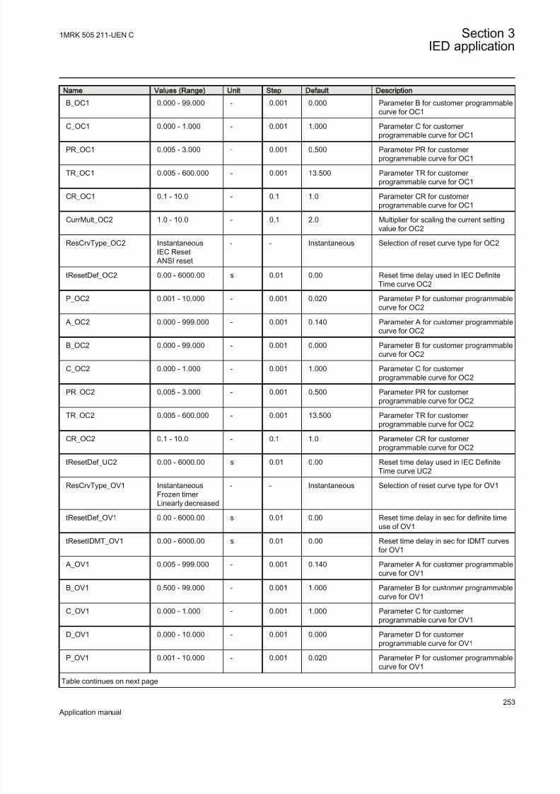
8/22/2019 Best Application
http://slidepdf.com/reader/full/best-application 259/457
Name Values (Range) Unit Step Default Description
B_OC1 0.000 - 99.000 - 0.001 0.000 Parameter B for customer programmablecurve for OC1
C_OC1 0.000 - 1.000 - 0.001 1.000 Parameter C for customer
programmable curve for OC1
PR_OC1 0.005 - 3.000 - 0.001 0.500 Parameter PR for customer programmable curve for OC1
TR_OC1 0.005 - 600.000 - 0.001 13.500 Parameter TR for customer programmable curve for OC1
CR_OC1 0.1 - 10.0 - 0.1 1.0 Parameter CR for customer programmable curve for OC1
CurrMult_OC2 1.0 - 10.0 - 0.1 2.0 Multiplier for scaling the current settingvalue for OC2
ResCrvType_OC2 InstantaneousIEC Reset
ANSI reset
- - Instantaneous Selection of reset curve type for OC2
tResetDef_OC2 0.00 - 6000.00 s 0.01 0.00 Reset time delay used in IEC DefiniteTime curve OC2
P_OC2 0.001 - 10.000 - 0.001 0.020 Parameter P for customer programmablecurve for OC2
A_OC2 0.000 - 999.000 - 0.001 0.140 Parameter A for customer programmablecurve for OC2
B_OC2 0.000 - 99.000 - 0.001 0.000 Parameter B for customer programmablecurve for OC2
C_OC2 0.000 - 1.000 - 0.001 1.000 Parameter C for customer programmable curve for OC2
PR_OC2 0.005 - 3.000 - 0.001 0.500 Parameter PR for customer programmable curve for OC2
TR_OC2 0.005 - 600.000 - 0.001 13.500 Parameter TR for customer programmable curve for OC2
CR_OC2 0.1 - 10.0 - 0.1 1.0 Parameter CR for customer programmable curve for OC2
tResetDef_UC2 0.00 - 6000.00 s 0.01 0.00 Reset time delay used in IEC DefiniteTime curve UC2
ResCrvType_OV1 InstantaneousFrozen timer Linearly decreased
- - Instantaneous Selection of reset curve type for OV1
tResetDef_OV1 0.00 - 6000.00 s 0.01 0.00 Reset time delay in sec for definite timeuse of OV1
tResetIDMT_OV1 0.00 - 6000.00 s 0.01 0.00 Reset time delay in sec for IDMT curves
for OV1
A_OV1 0.005 - 999.000 - 0.001 0.140 Parameter A for customer programmablecurve for OV1
B_OV1 0.500 - 99.000 - 0.001 1.000 Parameter B for customer programmablecurve for OV1
C_OV1 0.000 - 1.000 - 0.001 1.000 Parameter C for customer programmable curve for OV1
D_OV1 0.000 - 10.000 - 0.001 0.000 Parameter D for customer programmable curve for OV1
P_OV1 0.001 - 10.000 - 0.001 0.020 Parameter P for customer programmablecurve for OV1
Table continues on next page
1MRK 505 211-UEN C Section 3IED application
253
Application manual

8/22/2019 Best Application
http://slidepdf.com/reader/full/best-application 260/457
Name Values (Range) Unit Step Default Description
ResCrvType_OV2 InstantaneousFrozen timer Linearly decreased
- - Instantaneous Selection of reset curve type for OV2
tResetDef_OV2 0.00 - 6000.00 s 0.01 0.00 Reset time delay in sec for definite timeuse of OV2
tResetIDMT_OV2 0.00 - 6000.00 s 0.01 0.00 Reset time delay in sec for IDMT curvesfor OV2
A_OV2 0.005 - 999.000 - 0.001 0.140 Parameter A for customer programmablecurve for OV2
B_OV2 0.500 - 99.000 - 0.001 1.000 Parameter B for customer programmablecurve for OV2
C_OV2 0.000 - 1.000 - 0.001 1.000 Parameter C for customer programmable curve for OV2
D_OV2 0.000 - 10.000 - 0.001 0.000 Parameter D for customer programmable curve for OV2
P_OV2 0.001 - 10.000 - 0.001 0.020 Parameter P for customer programmablecurve for OV2
ResCrvType_UV1 InstantaneousFrozen timer Linearly decreased
- - Instantaneous Selection of reset curve type for UV1
tResetDef_UV1 0.00 - 6000.00 s 0.01 0.00 Reset time delay in sec for definite timeuse of UV1
tResetIDMT_UV1 0.00 - 6000.00 s 0.01 0.00 Reset time delay in sec for IDMT curvesfor UV1
A_UV1 0.005 - 999.000 - 0.001 0.140 Parameter A for customer programmablecurve for UV1
B_UV1 0.500 - 99.000 - 0.001 1.000 Parameter B for customer programmable
curve for UV1
C_UV1 0.000 - 1.000 - 0.001 1.000 Parameter C for customer programmable curve for UV1
D_UV1 0.000 - 10.000 - 0.001 0.000 Parameter D for customer programmable curve for UV1
P_UV1 0.001 - 10.000 - 0.001 0.020 Parameter P for customer programmablecurve for UV1
ResCrvType_UV2 InstantaneousFrozen timer Linearly decreased
- - Instantaneous Selection of reset curve type for UV2
tResetDef_UV2 0.00 - 6000.00 s 0.01 0.00 Reset time delay in sec for definite timeuse of UV2
tResetIDMT_UV2 0.00 - 6000.00 s 0.01 0.00 Reset time delay in sec for IDMT curvesfor UV2
A_UV2 0.005 - 999.000 - 0.001 0.140 Parameter A for customer programmablecurve for UV2
B_UV2 0.500 - 99.000 - 0.001 1.000 Parameter B for customer programmablecurve for UV2
Table continues on next page
Section 3 1MRK 505 211-UEN C
IED application
254
Application manual

8/22/2019 Best Application
http://slidepdf.com/reader/full/best-application 261/457
Name Values (Range) Unit Step Default Description
C_UV2 0.000 - 1.000 - 0.001 1.000 Parameter C for customer programmable curve for UV2
D_UV2 0.000 - 10.000 - 0.001 0.000 Parameter D for customer
programmable curve for UV2
P_UV2 0.001 - 10.000 - 0.001 0.020 Parameter P for customer programmablecurve for UV2
3.10 Secondary system supervision
3.10.1 Fuse failure supervision SDDRFUF
3.10.1.1 Setting parameters
Table 95: SDDRFUF Group settings (basic)
Name Values (Range) Unit Step Default Description
Operation Off On
- - On Operation Off / On
IBase 1 - 99999 A 1 3000 Base current
UBase 0.05 - 2000.00 kV 0.05 400.00 Base voltage
OpMode Off UNsINsUZsIZs
UZsIZs OR UNsINsUZsIZs ANDUNsINsOptimZsNs
- - UZsIZs Operating mode selection
3U0> 1 - 100 %UB 1 30 Operate level of residual overvoltageelement in % of UBase
3I0< 1 - 100 %IB 1 10 Operate level of residual undercurrentelement in % of IBase
3U2> 1 - 100 %UB 1 30 Operate level of neg seq overvoltageelement in % of UBase
3I2< 1 - 100 %IB 1 10 Operate level of neg seq undercurrentelement in % of IBase
OpDUDI Off On
- - Off Operation of change based function Off/On
DU> 1 - 100 %UB 1 60 Operate level of change in phase voltagein % of UBase
DI< 1 - 100 %IB 1 15 Operate level of change in phase currentin % of IBase
UPh> 1 - 100 %UB 1 70 Operate level of phase voltage in % of UBase
IPh> 1 - 100 %IB 1 10 Operate level of phase current in % of IBase
Table continues on next page
1MRK 505 211-UEN C Section 3IED application
255
Application manual

8/22/2019 Best Application
http://slidepdf.com/reader/full/best-application 262/457
Name Values (Range) Unit Step Default Description
SealIn Off On
- - On Seal in functionality Off/On
USealln< 1 - 100 %UB 1 70 Operate level of seal-in phase voltage in
% of UBase
IDLD< 1 - 100 %IB 1 5 Operate level for open phase currentdetection in % of IBase
UDLD< 1 - 100 %UB 1 60 Operate level for open phase voltagedetection in % of UBase
3.11 Control
3.11.1 Autorecloser SMBRREC
Function Description IEC 61850
identification
IEC 60617
identification
ANSI/IEEE C37.2
device number
Autorecloser SMBRREC
O->I
SYMBOL-L V1 EN
79
3.11.1.1 Application
In certain countries it is standard practice to provide delayed restoration after busbar protection operation for internal fault, reason being that many busbar faultsare of the transient natures that is, animals, birds, storm, flying objects, etc. In suchapplications, typically one pre-selected feeder is automatically closed with certaintime delay in order to try to re-energize the faulty bus. Typically, the longestoverhead line is selected in order to limit the fault current in case of permanent
busbar fault. If the first feeder is successfully closed, all other feeder which have been connected to the same bus, are automatically put back into service.
Sensitive differential protection level available in REB670 can be used during such
operation, if increased sensitivity from busbar protection is required. Such busbar restoration logic can be implemented by using optionally available autoreclosingfunctions and built-in logical gates. Two autoreclosing functions are available, onefor each zone.
Automatic reclosing is a well-established method for the restoration of service in a power system after a transient line fault. The majority of line faults are flashover arcs, which are transient by nature. When the power line is switched off by theoperation of line protection and line breakers, the arc de-ionizes and recovers itsability to withstand voltage at a somewhat variable rate. Thus, a certain dead timewith a de-energized line is necessary. Line service can then be resumed by
Section 3 1MRK 505 211-UEN C
IED application
256
Application manual

8/22/2019 Best Application
http://slidepdf.com/reader/full/best-application 263/457
automatic reclosing of the line breakers. The dead time selected should be longenough to ensure a high probability of arc de-ionization and successful reclosing.
For individual line breakers, auto-reclosing equipment or functions, the auto-
reclosing open time is used to determine line “dead time”. When simultaneoustripping and reclosing at the two line ends occurs, auto-reclosing open time isapproximately equal to the line “dead time”. If the open time and dead time differ then, the line will be energized until the breakers at both ends have opened.
Open
Closed
Operate time
Lineprotection
Circuitbreaker
Break time
T r i p c o m m a n d
C o n t a c t s s e p a r a t e d
A r e e x t i n g u i s h e r s
Fault duration AR open time for breaker Fault duration
R e s e t s
I n s t a n t o f f a u
l t
O p e r a t e s
Break timeClosing time
Operate time
F a u l t
O p e r a t e s
R e s e t s
C l o s e c o m m a n d
C o n t a c t c l o s e
d
Set AR open time Reclaim time Auto-reclosing
function
S t a r t A R
R e c l o s i n g
c o m m a n d
A R
r e s e t
en04000146.vsd
IEC04000146 V1 EN
Figure 84: Single-shot automatic reclosing at a permanent fault
Single-phase tripping and single-phase automatic reclosing is a way of limiting theeffect of a single-phase line fault on power system operation. Especially at higher voltage levels, the majority of faults are of single-phase type (around 90%). Tomaintain system stability in power systems with limited meshing or parallel routingsingle phase auto reclosing is of particular value. During the single phase dead timethe system is still capable of transmitting load on the two healthy phases and thesystem is still synchronized. It requires that each phase breaker operatesindividually, which is usually the case for higher transmission voltages.
1MRK 505 211-UEN C Section 3IED application
257
Application manual

8/22/2019 Best Application
http://slidepdf.com/reader/full/best-application 264/457
A somewhat longer dead time may be required for single-phase reclosingcompared to high-speed three-phase reclosing. This is due to the influence on thefault arc from the voltage and the current in the non-tripped phases.
To maximize the availability of the power system it is possible to choose single pole tripping and automatic reclosing during single-phase faults and three poletripping and automatic reclosing during multi-phase faults. Three-phase automaticreclosing can be performed with or without the use of a synchronicity check, andan energizing check, such as dead line or dead busbar check.
During the single-pole open time there is an equivalent "series"-fault in the systemresulting in a flow of zero sequence current. It is therefore necessary to coordinatethe residual current protections (earth fault protection) with the single pole trippingand the auto-reclosing function. Attention shall also be paid to "pole discordance"that arises when circuit breakers are provided with single pole operating devices.
These breakers need pole discordance protection. They must also be coordinatedwith the single pole auto-recloser and blocked during the dead time when a normaldiscordance occurs. Alternatively, they should use a trip time longer than the setsingle phase dead time.
For the individual line breakers and auto-reclosing equipment, the ”auto-reclosingopen time” expression is used. This is the dead time setting for the Auto-Recloser.During simultaneous tripping and reclosing at the two line ends, auto-reclosingopen time is approximately equal to the line dead time. Otherwise these two timesmay differ as one line end might have a slower trip than the other end which meansthat the line will not be dead until both ends have opened.
If the fault is permanent, the line protection will trip again when reclosing isattempted in order to clear the fault.
It is common to use one automatic reclosing function per line circuit-breaker (CB).When one CB per line end is used, then there is one auto-reclosing function per line end. If auto-reclosing functions are included in duplicated line protection,which means two auto-reclosing functions per CB, one should take measures toavoid uncoordinated reclosing commands. In 1 1/2 breaker, double-breaker andring bus arrangements, two CBs per line end are operated. One auto-reclosingfunction per CB is recommended. Arranged in such a way, sequential reclosing of the two CBs can be arranged with a priority circuit available in the auto-reclosefunction. In case of a permanent fault and unsuccessful reclosing of the first CB,reclosing of the second CB is cancelled and thus the stress on the power system islimited. Another advantage with the breaker connected auto-recloser is thatchecking that the breaker closed before the sequence, breaker prepared for an auto-reclose sequence and so on. is much simpler.
The auto-reclosing function can be selected to perform single-phase and/or three- phase automatic-reclosing from several single-shot to multiple-shot reclosing programs. The three-phase auto-reclosing open time can be set to give either High-Speed Automatic Reclosing (HSAR) or Delayed Automatic-Reclosing (DAR).These expressions, HSAR and DAR, are mostly used for three-phase Reclosing as
Section 3 1MRK 505 211-UEN C
IED application
258
Application manual

8/22/2019 Best Application
http://slidepdf.com/reader/full/best-application 265/457
single phase is always high speed to avoid maintaining the unsymmetricalcondition. HSAR usually means a dead time of less than 1 second.
In power transmission systems it is common practise to apply single and/or three
phase, single-shot Auto-Reclosing. In Sub-transmission and Distribution systemstripping and auto-reclosing are usually three-phase. The mode of automatic-reclosing varies however. Single-shot and multi-shot are in use. The first shot canhave a short delay, HSAR, or a longer delay, DAR. The second and followingreclosing shots have a rather long delay. When multiple shots are used the deadtime must harmonize with the breaker duty-cycle capacity.
Automatic-reclosing is usually started by the line protection and in particular byinstantaneous tripping of such protection. The auto-reclosing function can beinhibited (blocked) when certain protection functions detecting permanent faults,such as shunt reactor, cable or busbar protection are in operation. Back-up
protection zones indicating faults outside the own line are also connected to inhibitthe Auto-Reclose.
Automatic-reclosing should not be attempted when closing a CB and energizing aline onto a fault (SOTF), except when multiple-shots are used where shots 2 etc.will be started at SOTF. Likewise a CB in a multi-breaker busbar arrangementwhich was not closed when a fault occurred should not be closed by operation of the Auto-Reclosing function. Auto-Reclosing is often combined with a releasecondition from synchrocheck and dead line or dead busbar check. In order to limitthe stress on turbo-generator sets from Auto-Reclosing onto a permanent fault, onecan arrange to combine Auto-Reclosing with a synchrocheck on line terminalsclose to such power stations and attempt energizing from the side furthest away
from the power station and perform the synchrocheck at the local end if theenergizing was successful.
Transmission protection systems are usually sub-divided and provided with tworedundant protection IEDs. In such systems it is common to provide auto-reclosingin only one of the sub-systems as the requirement is for fault clearance and afailure to reclose because of the auto-recloser being out of service is not considereda major disturbance. If two auto-reclosers are provided on the same breaker, theapplication must be carefully checked and normally one must be the master and beconnected to inhibit the other auto-recloser if it has started. This inhibit can for example be done from Autorecloser for 3-phase operation(SMBRREC) In progress.
When Single and/or three phase auto-reclosing is considered, there are a number of cases where the tripping shall be three phase anyway. For example:
• Evolving fault where the fault during the dead-time spreads to another phase.The other two phases must then be tripped and a three phase dead-time and auto-reclose initiated
• Permanent fault• Fault during three phase dead-time• Auto-reclose out of service or CB not ready for an auto-reclosing cycle
1MRK 505 211-UEN C Section 3IED application
259
Application manual

8/22/2019 Best Application
http://slidepdf.com/reader/full/best-application 266/457
“Prepare three-phase tripping” is then used to switch the tripping to three-phase.This signal is generated by the auto-recloser and connected to the trip function
block and also connected outside the IED through IO when a common auto-recloser is provided for two sub-systems. An alternative signal “Prepare 1 Phasetripping” is also provided and can be used as an alternative when the autorecloser isshared with another subsystem. This provides a fail safe connection so that even afailure in the IED with the auto-recloser will mean that the other sub-system willstart a three-phase trip.
A permanent fault will cause the line protection to trip again when it recloses in anattempt to clear the fault.
The auto-reclosing function allows a number of parameters to be adjusted.
Examples:
• number of auto-reclosing shots• auto-reclosing program• auto-reclosing open times (dead time) for each shot
Auto-reclosing operation OFF and ONOperation of the automatic reclosing can be set OFF and ON by a setting parameter and by external control. Parameter Operation= Off , or On sets the function OFFand ON. In setting Operation= ExternalCtrl , OFF and ON control is made by inputsignal pulses, for example, from the control system or from the binary input (andother systems).
When the function is set ON and operative (other conditions such as CB closed andCB Ready are also fulfilled), the output SETON is activated (high). When thefunction is ready to accept a reclosing start.
Start auto-reclosing and conditions for start of a reclosing cycleThe usual way to start a reclosing cycle, or sequence, is to start it at tripping by line
protection by applying a signal to the input START. Starting signals can be either,General Trip signals or, only the conditions for Differential, Distance protectionZone 1 and Distance protection Aided trip. In some cases also Directional Earthfault function Aided trip can be connected to start an Auto-Reclose attempt.
In cases where one wants to differentiate three-phase “auto-reclosing open time”,(“dead time”) for different power system configuration or at tripping by different protection stages, one can also use the input STARTHS (Start High-SpeedReclosing). When initiating STARTHS, the auto-reclosing open time for three-
phase shot 1, t1 3PhHS is used.
A number of conditions need to be fulfilled for the start to be accepted and a newauto-reclosing cycle to be started. They are linked to dedicated inputs. The inputs are:
Section 3 1MRK 505 211-UEN C
IED application
260
Application manual

8/22/2019 Best Application
http://slidepdf.com/reader/full/best-application 267/457
• CBREADY, CB ready for a reclosing cycle, for example, charged operating gear.• CBPOS to ensure that the CB was closed when the line fault occurred and start
was applied.• No signal at input INHIBIT that is, no blocking or inhibit signal present. After
the start has been accepted, it is latched in and an internal signal “Started” isset. It can be interrupted by certain events, like an “Inhibit” signal.
Start auto-reclosing from CB open informationIf a user wants to initiate auto-reclosing from the "CB open" position instead of from protection trip signals, the function offers such a possibility. This startingmode is selected with the setting parameter StartByCBOpen=On. It is thennecessary to block reclosing for all manual trip operations. TypicallyCBAuxContType= NormClosed is also set and a CB auxiliary contact of type NC(normally closed) is connected to inputs CBPOS and START. When the signal
changes from “CB closed” to “CB open” an auto-reclosing start pulse is generatedand latched in the function, subject to the usual checks. Then the reclosingsequence continues as usual. One needs to connect signals from manual trippingand other functions, which shall prevent reclosing, to the input INHIBIT.
Blocking of the autorecloserAuto-Reclose attempts are expected to take place only in the event of transientfaults on the own line. The Auto-Recloser must be blocked for the followingconditions:
• Tripping from Delayed Distance protection zones• Tripping from Back-up protection functions
• Tripping from Breaker failure function• Intertrip received from remote end Breaker failure function• Busbar protection tripping
Depending of the starting principle (General Trip or only Instantaneous trip)adopted above the delayed and back-up zones might not be required. Breaker failure local and remote must however always be connected.
Control of the auto-reclosing open time for shot 1Up to four different time settings can be used for the first shot, and one extensiontime. There are separate settings for single-, two- and three-phase auto-reclosing
open time, t1 1Ph, t1 2Ph, t1 3Ph. If no particular input signal is applied, and an auto-reclosing program with single-phase reclosing is selected, the auto-reclosing opentime t1 1Ph will be used. If one of the inputs TR2P or TR3P is activated inconnection with the start, the auto-reclosing open time for two-phase or three-phasereclosing is used. There is also a separate time setting facility for three-phase high-speed auto-reclosing without Synchrocheck, t1 3PhHS , available for use whenrequired. It is activated by the STARTHS input.
An auto-reclosing open time extension delay, tExtended t1, can be added to thenormal shot 1 delay. It is intended to come into use if the communication channelfor permissive line protection is lost. In such a case there can be a significant time
1MRK 505 211-UEN C Section 3IED application
261
Application manual

8/22/2019 Best Application
http://slidepdf.com/reader/full/best-application 268/457
difference in fault clearance at the two ends of the line. A longer “auto-reclosingopen time” can then be useful. This extension time is controlled by setting
parameter Extended t1=On and the input PLCLOST.
Long trip signalIn normal circumstances the trip command resets quickly because of faultclearance. The user can set a maximum trip pulse duration tTrip. A longer tripsignal extends the auto-reclosing open time by tExtended t1. If Extended t1=Off , along trip signal interrupts the reclosing sequence in the same way as a signal toinput INHIBIT.
Maximum number of reclosing shotsThe maximum number of reclosing shots in an auto-reclosing cycle is selected bythe setting parameter NoOfShots. The type of reclosing used at the first reclosingshot is set by parameter FirstShot . The first alternative is three-phase reclosing.
The other alternatives include some single-phase or two-phase reclosing. Usuallythere is no two-phase tripping arranged, and then there will be no two-phase reclosing.
The decision is also made in the tripping logic (SMPTTRC) function block wherethe setting 3Ph, 1/3Ph (or1/2/3Ph) is selected.
FirstShot=3ph (normal setting for a single 3 phase shot)3-phase reclosing, one to five shots according to setting NoOfShots. The outputPrepare three-phase trip PREP3P is always set (high). A trip operation is made as athree-phase trip at all types of fault. The reclosing is as a three-phase Reclosing asin mode 1/2/3ph described below. All signals, blockings, inhibits, timers,requirements and so on. are the same as in the example described below.
FirstShot=1/2/3ph1-phase, 2-phase or 3-phase reclosing first shot, followed by 3-phase reclosingshots, if selected. Here, the auto-reclosing function is assumed to be "On" and"Ready". The breaker is closed and the operation gear ready (operating energystored). Input START (or STARTHS) is received and sealed-in. The outputREADY is reset (set to false). Output ACTIVE is set.
• If TR2P is low and TR3P is low (1-phase trip): The timer for 1-phase reclosingopen time is started and the output 1PT1 (1-phase reclosing in progress) isactivated. It can be used to suppress pole disagreement trip and earth-fault
protection during the 1-phase open interval.• If TR2P is high and TR3P is low (2-phase trip): The timer for 2-phasereclosing open time is started and the output 2PT1 (2-phase reclosing in
progress) is activated.• If TR3P is high (3-phase trip): The timer for 3-phase auto-reclosing open time,
t1 3Ph or t1 3PhHS is started and output 3PT1 (3-phase auto-reclosing shot 1in progress) is set.
While any of the auto-reclosing open time timers are running, the outputINPROGR is activated. When the "open time" timer runs out, the respective
Section 3 1MRK 505 211-UEN C
IED application
262
Application manual

8/22/2019 Best Application
http://slidepdf.com/reader/full/best-application 269/457
internal signal is transmitted to the output module for further checks and to issue aclosing command to the circuit breaker.
When a CB closing command is issued the output prepare 3-phase trip is set. When
issuing a CB closing command a “reclaim” timer tReclaim is started. If no trippingtakes place during that time the auto-reclosing function resets to the “Ready” stateand the signal ACTIVE resets. If the first reclosing shot fails, a 3-phase trip will beinitiated and 3-phase reclosing can follow, if selected.
FirstShot=1/2ph 1-phase or 2-phase reclosing in the first shot.In 1-phase or 2-phase tripping, the operation is as in the above described example,
program mode 1/2/3ph. If the first reclosing shot fails, a 3-phase trip will be issuedand 3-phase reclosing can follow, if selected. In the event of a 3-phase trip, TR3Phigh, the auto-reclosing will be blocked and no reclosing takes place.
FirstShot=1ph + 1*2ph 1-phase or 2-phase reclosing in the first shotThe 1-phase reclosing attempt can be followed by 3-phase reclosing, if selected. Afailure of a 2-phase reclosing attempt will block the auto-reclosing. If the first tripis a 3-phase trip the auto-reclosing will be blocked. In the event of a 1-phase trip,(TR2P low and TR3P low), the operation is as in the example described above,
program mode 1/2/3ph. If the first reclosing shot fails, a 3-phase trip will beinitiated and 3-phase reclosing can follow, if selected. A maximum of four additional shots can be done (according to the NoOfShots parameter). At 2-phasetrip (TR2P high and TR3P low), the operation is similar to the above. But, if thefirst reclosing shot fails, a 3-phase trip will be issued and the auto-reclosing will be
blocked. No more shots are attempted! The expression 1*2ph should be understoodas “Just one shot at 2-phase reclosing” During 3-phase trip (TR2P low and TR3Phigh) the auto-reclosing will be blocked and no reclosing takes place.
FirstShot=1ph + 1*2/3ph 1-phase, 2-phase or 3-phase reclosing in
the first shotAt 1-phase trip, the operation is as described above. If the first reclosing shot fails,a 3-phase trip will be issued and 3-phase reclosing will follow, if selected. At 2-
phase or 3-phase trip, the operation is similar to the above. But, if the first reclosingshot fails, a 3-phase trip command will be issued and the auto-reclosing will be
blocked. No more shots take place 1*2/3ph should be understood as “Just one shotat 2-phase or 3-phase reclosing”.
FirstShot=1ph + 1*2/3ph 1-phase, 2-phase or 3-phase reclosing inthe first shotAt 1-phase trip, the operation is as described above. If the first reclosing shot fails,a 3-phase trip will be issued and 3-phase reclosing will follow, if selected. At 2-
phase or 3-phase trip, the operation is similar as above. But, if the first reclosingshot fails, a 3-phase trip will be issued and the auto-reclosing will be blocked. Nomore shots take place! “1*2/3ph” should be understood as “Just one shot at 2-phaseor 3-phase reclosing”.
1MRK 505 211-UEN C Section 3IED application
263
Application manual

8/22/2019 Best Application
http://slidepdf.com/reader/full/best-application 270/457
Tab le 96 : Type o f rec losing sho ts at d ifferen t set tings of “FirstSho t”
First Shot 1st shot 2nd-5th shot
3ph 3ph 3ph
1/2/3ph 1ph 3ph2ph 3ph --
3ph 3ph --
1/2ph 1ph 3ph
2ph 3ph --
-- --
1ph + 1*2ph 1ph 3ph
2ph -- --
-- --
1/2ph + 1*3ph 1ph 3ph
2ph 3ph
3ph --
1ph + 1*2/3ph 1ph 3ph
2ph --
3ph --
A start of a new reclosing cycle is blocked during the set “reclaim time” after theselected number of reclosing shots have been made.
External selection of auto-reclose modeThe auto-reclose mode can be selected by use of the available logic function
blocks. Below is an example where the choice of mode is done from a symbol onthe local HMI through selector switch function block with only 3 phase or 1/3
phase mode, but alternatively there can for example, be a physical selector switchon the front of the panel which is connected to a binary to integer function block (B16I).
If the PSTO input is used, connected to the Local-Remote switch on the local HMI,the choice can also be from the station HMI system, typically ABB Microscadathrough IEC 61850 communication.
The connection example for selection of the auto-reclose mode is shown in .Selected names are just examples but note that the symbol on local HMI can onlyshow three signs.
Section 3 1MRK 505 211-UEN C
IED application
264
Application manual

8/22/2019 Best Application
http://slidepdf.com/reader/full/best-application 271/457
IEC07000119_en.vsd
SMBRREC
MODEINT
PSTO
SWPOSNNAME1NAME2
31/3
INTONE
SLGGIO
IEC07000119 V2 EN
Figure 85: Selection of the auto-reclose mode from a local HMI symbol
through a selector switch function block
Reclosing reclaim timerThe reclaim timer tReclaim defines the time it takes from issue of the reclosingcommand, until the reclosing function resets. Should a new trip occur during thistime, it is treated as a continuation of the first fault. The reclaim timer is startedwhen the CB closing command is given.
Pulsing of the CB closing command and CounterThe CB closing command, CLOSECB is given as a pulse with a duration set by
parameter tPulse. For circuit-breakers without an anti-pumping function, close pulse cutting can be used. It is selected by parameter CutPulse=On. In case of anew trip pulse (start), the closing command pulse is then cut (interrupted). Theminimum closing pulse length is always 50 ms. At the issue of the Reclosingcommand, the appropriate Reclosing operation counter is incremented. There is acounter for each type of Reclosing and one for the total number of Reclosing
commands.
Transient faultAfter the Reclosing command the reclaim timer keeps running for the set time. If no tripping occurs within this time, tReclaim, the Auto-Reclosing will reset. TheCB remains closed and the operating gear recharges. The input signals CBPOS andCBREADY will be set
Permanent fault and reclosing unsuccessful signalIf a new trip occurs, and a new input signal START or TRSOTF appears, after theCB closing command, the output UNSUCCL (unsuccessful closing) is set high.
The timer for the first shot can no longer be started. Depending on the set number of Reclosing shots further shots may be made or the Reclosing sequence is ended.After reclaim timer time-out the Auto-Reclosing function resets, but the CBremains open. The “CB closed” information through the input CBPOS is missing.Thus, the reclosing function is not ready for a new reclosing cycle.
Normally, the signal UNSUCCL appears when a new trip and start is received after the last reclosing shot has been made and the auto-reclosing function is blocked.The signal resets after reclaim time. The “unsuccessful” signal can also be made todepend on CB position input. The parameter UnsucClByCBChk should then be setto CBCheck , and a timer tUnsucCl should be set too. If the CB does not respond to
1MRK 505 211-UEN C Section 3IED application
265
Application manual

8/22/2019 Best Application
http://slidepdf.com/reader/full/best-application 272/457
the closing command and does not close, but remains open, the output UNSUCCLis set high after time tUnsucCl . The Unsuccessful output can for example, be usedin Multi-Breaker arrangement to cancel the auto-reclosing function for the second
breaker, if the first breaker closed onto a persistent fault. It can also be used togenerate a Lock-out of manual closing until the operator has reset the Lock-out, seeseparate section.
Lock-out initiationIn many cases there is a requirement that a Lock-out is generated when the auto-reclosing attempt fails. This is done with logic connected to the in- and outputs of the Autoreclose function and connected to Binary IO as required. Many alternativeways of performing the logic exist depending on whether manual closing isinterlocked in the IED, whether an external physical Lock-out relay exists andwhether the reset is hardwired, or carried out by means of communication. Thereare also different alternatives regarding what shall generate Lock-out. Examples of
questions are:
• Shall back-up time delayed trip give Lock-out (normally yes)• Shall Lock-out be generated when closing onto a fault (mostly)• Shall Lock-out be generated when the Autorecloser was OFF at the fault or for
example, in Single phase AR mode and the fault was multi-phase (normallynot as not closing attempt has been given)
• Shall Lock-out be generated if the Breaker did not have sufficient operating power for an auto-reclosing sequence (normally not as no closing attempt has been given)
In figures 86 and 87 the logic shows how a closing Lock-out logic can be designedwith the Lock-out relay as an external relay alternatively with the Lock-out createdinternally with the manual closing going through the Synchro-check function. Anexample of Lock-out logic.
Lock-out
RXMD1
11
12
21
MAIN ZAK CLOSE CLOSE COMMAND
SMBO
OR
SMBRRECOR
CCRBRF
BJ-TRIP
ZCVPSOF-TRIP INHIBIT
UNSUCCL
TRBU
IEC05000315_2_en.vsd
IEC05000315-WMF V2 EN
Figure 86: Lock-out arranged with an external Lock-out relay
Section 3 1MRK 505 211-UEN C
IED application
266
Application manual

8/22/2019 Best Application
http://slidepdf.com/reader/full/best-application 273/457
CLOSE COMMAND
OR
SMBRRECOR
CCRBRF
BU-TRIP
ZCVPSOF-TRIP INHIBIT
UNSUCCL
TRBU
SMPPTRC
AND
RESET LOCK-OUT
OR
OR
SESRSYN
SOFTWARE
OR IO RESET
AUTO STOP
MAN ENOK
MAN CLOSE
SMBRREC CLOSE
CLLKOUT
RSTLOUT
SETLKOUT
IEC05000316_2_en.vsd
SMBO
IEC05000316-WMF V2 EN
Figure 87: Lock-out arranged with internal logic with manual closing going
through in IED
Evolving faultAn evolving fault starts as a single-phase fault which leads to single-phase trippingand then the fault spreads to another phase. The second fault is then cleared by three-
phase tripping.
The Auto-Reclosing function will first receive a trip and start signal (START)without any three-phase signal (TR3P). The Auto-Reclosing function will start a
single-phase reclosing, if programmed to do so. At the evolving fault clearancethere will be a new signal START and three-phase trip information, TR3P. The single- phase reclosing sequence will then be stopped, and instead the timer, t1 3Ph, for three- phase reclosing will be started from zero. The sequence will continue as a three- phase reclosing sequence, if it is a selected alternative reclosing mode.
The second fault which can be single phase is tripped three phase because tripmodule (TR) in the IED has an evolving fault timer which ensures that second faultis always tripped three phase. For other types of relays where the relays do notinclude this function the output PREP3PH (or the inverted PERMIT1PH) is used to
prepare the other sub-system for three phase tripping. This signal will, for evolvingfault situations be activated a short time after the first trip has reset and will thus
ensure that new trips will be three phase.
Automatic continuation of the reclosing sequenceSMBRREC function can be programmed to proceed to the following reclosingshots (if multiple shots are selected) even if start signals are not received from the
protection functions, but the breaker is still not closed. This is done by setting parameter AutoCont = On and tAutoContWait to the required delay for the functionto proceed without a new start.
1MRK 505 211-UEN C Section 3IED application
267
Application manual

8/22/2019 Best Application
http://slidepdf.com/reader/full/best-application 274/457
Thermal overload protection holding the auto-reclosing function backIf the input THOLHOLD (thermal overload protection holding reclosing back) isactivated, it will keep the reclosing function on a hold until it is reset. There maythus be a considerable delay between start of Auto-Reclosing and reclosingcommand to the circuit-breaker. An external logic limiting the time and sending aninhibit to the INHIBIT input can be used. The input can also be used to set the Auto-Reclosing on hold for a longer or shorter period.
3.11.1.2 Setting guidelines
ConfigurationUse the PCM600 configuration tool to configure signals.
Autorecloser function parameters are set via the local HMI or Parameter SettingTool (PST). Parameter Setting Tool is a part of PCM600.
Recommendations for input signalsPlease see examples in figure 88, figure 89 and figure 90 of default factoryconfigurations.
ON and OFF
These inputs can be connected to binary inputs or to a communication interface block for external control.
START
It should be connected to the trip output protection function, which starts theautorecloser for 3-phase operation (SMBRREC) function. It can also be connectedto a binary input for start from an external contact. A logical OR-gate can be usedto combine the number of start sources.
If StartByCBOpen is used, the CB Open condition shall also beconnected to the input START.
STARTHS, Start High-speed auto-reclosing
It is often not used and connected to FALSE. It may be used when one wants to use
two different dead times in different protection trip operations. This input starts thedead time t1 3PhHS . High-speed reclosing shot 1 started by this in put is without asynchronization check.
INHIBIT
To this input shall be connected signals that interrupt a reclosing cycle or prevent astart from being accepted. Such signals can come from protection for a lineconnected shunt reactor, from transfer trip receive, from back-up protectionfunctions, busbar protection trip or from breaker failure protection. When the CBopen position is set to start SMBRREC, then manual opening must also be
Section 3 1MRK 505 211-UEN C
IED application
268
Application manual

8/22/2019 Best Application
http://slidepdf.com/reader/full/best-application 275/457
connected here. The inhibit is often a combination of signals from external IEDsvia the IO and internal functions. An OR gate is then used for the combination.
CBPOS and CBREADY
These should be connected to binary inputs to pick-up information from the CB.The CBPOS input is interpreted as CB Closed, if parameter CBAuxContType is set
NormOpen, which is the default setting. At three operating gears in the breaker (single pole operated breakers) the connection should be “All poles closed” (seriesconnection of the NO contacts) or “At least one pole open” (parallel connection of
NC contacts) if the CBAuxContType is set to NormClosed . The “CB Ready” is asignal meaning that the CB is ready for a reclosing operation, either Close-Open(CO), or Open-Close-Open (OCO). If the available signal is of type “CB notcharged” or “not ready”, an inverter can be inserted in front of the CBREADY input.
SYNC
This is connected to the internal synchrocheck function when required. It can also be connected to a binary input for synchronization from an external device. If neither internal nor external synchronism or energizing check is required, it can beconnected to a permanently high source, TRUE. The signal is required for three
phase shots 1-5 to proceed (Note! Not the HS step).
PLCLOST
This is intended for line protection permissive signal channel lost (fail) for example, PLC= Power Line Carrier fail. It can be connected, when required to
prolong the AutoReclosing time when communication is not working, that is, one
line end might trip with a zone 2 delay. When the function is not used it is set toFALSE.
TRSOTF
This is the signal “Trip by Switch Onto Fault”. It is usually connected to the“switch onto fault” output of line protection if multi-shot Auto-Reclose attemptsare used. The input will start the shots 2-5. For single shot applications the input isset to FALSE.
THOLHOLD
Signal “Thermal overload protection holding back Auto-Reclosing”. It is normally
set to FALSE. It can be connected to a thermal overload protection trip signalwhich resets only when the thermal content has gone down to an acceptable level,for example, 70%. As long as the signal is high, indicating that the line is hot, theAuto-Reclosing is held back. When the signal resets, a reclosing cycle willcontinue. Please observe that this have a considerable delay. Input can also be usedfor other purposes if for some reason the Auto-Reclose shot is halted.
TR2P and TR3P
Signals for two-phase and three-phase trip. They are usually connected to thecorresponding output of the TRIP block. They control the choice of dead time and
1MRK 505 211-UEN C Section 3IED application
269
Application manual

8/22/2019 Best Application
http://slidepdf.com/reader/full/best-application 276/457
the reclosing cycle according to the selected program. Signal TR2P needs to beconnected only if the trip has been selected to give 1/2/3 phase trip and an autoreclosing cycle with two phase reclosing is foreseen.
WAIT
Used to hold back reclosing of the “low priority unit” during sequential reclosing.See “Recommendation for multi-breaker arrangement” below. The signal isactivated from output WFMASTER on the second breaker Auto-Recloser in multi-
breaker arrangements.
BLKON
Used to block the autorecloser for 3-phase operation (SMBRREC) function for example, when certain special service conditions arise. Input is normally set toFALSE. When used, blocking must be reset with BLOCKOFF.
BLOCKOFF
Used to Unblock SMBRREC function when it has gone to Block due to activatinginput BLKON or by an unsuccessful Auto-Reclose attempt if thesetting BlockByUnsucCl is set to On. Input is normally set to FALSE.
RESET
Used to Reset SMBRREC to start condition. Possible Thermal overload Hold will be reset. Positions, setting On-Off. will be started and checked with set times. Inputis normally set to FALSE.
Recommendations for output signalsPlease see figure 88, figure 89 and figure 90 and default factory configuration for examples.
SETON
Indicates that Autorecloser for 3-phase operation (SMBRREC) function isswitched on and operative.
BLOCKED
Indicates that SMRREC function is temporarily or permanently blocked.
ACTIVE
Indicates that SMBRREC is active, from start until end of Reclaim time.
INPROGR
Indicates that a sequence is in progress, from start until reclosing command.
UNSUCCL
Indicates unsuccessful reclosing.
Section 3 1MRK 505 211-UEN C
IED application
270
Application manual

8/22/2019 Best Application
http://slidepdf.com/reader/full/best-application 277/457
CLOSECB
Connect to a binary output for circuit-breaker closing command.
READYIndicates that SMBRREC function is ready for a new and complete reclosingsequence. It can be connected to the zone extension of a line protection shouldextended zone reach before automatic reclosing be necessary.
1PT1 and 2PT1
Indicates that single-phase or two-phase automatic reclosing is in progress. It isused to temporarily block an earth-fault and/or pole disagreement function duringthe single-phase or two-phase open interval.
3PT1,-3PT2,-3PT3,-3PT4 and -3PT5
Indicates that three-phase automatic reclosing shots 1-5 are in progress. The signalscan be used as an indication of progress or for own logic.
PREP3P
Prepare three-phase trip is usually connected to the trip block to force a coming tripto be a three-phase one. If the function cannot make a single-phase or two-phasereclosing, the tripping should be three-phase.
PERMIT1P
Permit single-phase trip is the inverse of PREP1P. It can be connected to a binary
output relay for connection to external protection or trip relays. In case of a totalloss of auxiliary power, the output relay drops and does not allow single-phase trip.If needed, the signal can be inverted by a contact of the output relay breaking.
WFMASTER
Wait from master is used in high priority units to hold back reclosing of the low priority unit during sequential reclosing. Refer to the recommendation for multi- breaker arrangements in figure 90.
Other outputs
The other outputs can be connected for indication, disturbance recording, as required.
1MRK 505 211-UEN C Section 3IED application
271
Application manual

8/22/2019 Best Application
http://slidepdf.com/reader/full/best-application 278/457
ON
OFFBLKON
BLOCKOFF
INHIBIT
BLOCKED
SETONINPROGR
ACTIVE
UNSUCCL
SUCCL
CLOSECB
CBREADY
CBPOS
PLCLOST
1PT1
WFMASTER
RESET
START
THOLHOLD
READY
TRSOTF
SYNC
INPUT
xx
xxxx
xx
xx
xx
xx
xx
xx
xx
>1
>1
OUTPUT
xx
xxxx
xx
xx
xx
xx
xx
xx
xx
PROTECTION
xxxx-TRIP
ZCVPSOF-TRIPZMQPDIS-TRIP
SESRSYN-AUTOOK
IOM IOM
SMBRREC
IEC04000135_2_en.vsd
PERMIT1PPREP3P
F
F
T
STARTHS
SKIPHS
F
F
TR2P
TR3P
F
T
WAIT
RSTCOUNT
F
F
3PT12PT1
3PT2
3PT3
3PT4
3PT5
F
IEC04000135 V2 EN
Figure 88: Example of I/O-signal connections at a three-phase reclosing
function
Setting recommendations for multi-breaker arrangementsSequential reclosing in multi-breaker arrangements, like 1 1/2-breaker, double
breaker and ring bus, is achieved by giving the two line breakers different priorities. Please refer to figure 90. In a single breaker arrangement the setting is Priority = None. In a multi-breaker arrangement the setting for the first CB, theMaster, is Priority = High and for the other CB Priority = Low.
While the reclosing of the master is in progress, it issues the signal WFMASTER.A reset delay of one second ensures that the WAIT signal is kept high for theduration of the breaker closing time. After an unsuccessful reclosing it is alsomaintained by the signal UNSUCCL. In the slave unit, the signal WAIT holds back a reclosing operation. When the WAIT signal is reset at the time of a successfulreclosing of the first CB, the slave unit is released to continue the reclosingsequence. A parameter tWait sets a maximum waiting time for the reset of theWAIT. At time-out it interrupts the reclosing cycle of the slave unit. If reclosing of the first breaker is unsuccessful, the output signal UNSUCCL connected to theinput INHIBIT of the slave unit interrupts the reclosing sequence of the latter.
Section 3 1MRK 505 211-UEN C
IED application
272
Application manual

8/22/2019 Best Application
http://slidepdf.com/reader/full/best-application 279/457
The signals can be cross-connected to allow simple changing of the priority by just setting the High and the Low priorities withoutchanging the configuration. The inputs CBPOS for each breaker areimportant in multi breaker arrangements to ensure that the CB wasclosed at the beginning of the cycle. If the High priority breaker isnot closed the High priority moves to the low priority breaker.
ON
OFF
BLKON
BLOCKOFF
INHIBIT
BLOCKED
SETON
INPROGR
ACTIVE
UNSUCCL
SUCCL
CLOSECB
PERMIT1P
CBREADYCBPOS
PLCLOST
3PT1
WFMASTER
RESET
START1PT1
2PT1
TRSOTF
TR2P
TR3P
SYNC
INPUT
xx
xx
xx
xxxx
xx
xx
xx
xx
xx
>1
>1
OUTPUT
xx
>1
PROTECTION
xxxx-TRIP
ZCVPSOF-TRIPZMQPDIS--TRIP
TRIP-TR2PTRIP-TR3P
SESRSYN-AUTOOK
EF4PTOC-BLOCK
IOM IOM
SMBRREC
IEC04000136_2_en.vsd
xxxx
xx
xxxx
xxxxxxxx
STARTHS
SKIPHSF
F
THOLHOLDF
WAIT
RSTCOUNTF
F
3PT2
3PT3
3PT4
3PT5
F
T
F
READYPREP3P TRIP-P3PTR
IEC04000136 V2 EN
Figure 89: Example of I/O-signal connections in a single-phase reclosing
function
1MRK 505 211-UEN C Section 3IED application
273
Application manual

8/22/2019 Best Application
http://slidepdf.com/reader/full/best-application 280/457
IEC04000137_2_en.vsd
ACTIVE
UNSUCCL
READY
CLOSECB
3PT23PT3
WAIT
CBPOSCBREADY
TRSOTF
START
RESET
BLOCKOFF
BLKON
OFF
ON BLOCKED
SETON
INPROGR
3PT4SYNC
INHIBIT
Terminal ‘‘ Master ”
Priority = High
SMBRREC
CLOSECB
WAIT
Terminal ‘‘ Slave ”
Priority = Low
CB1
CB2
WFMASTER
WFMASTER
*) Other input/output signals as in previous single
breaker arrangements
PLCLOST
SUCCL
SKIPHS
STARTHS
RSTCOUNT
THOLHOLD
PERMIT1P
PREP3P
3PT1
2PT11PT1
3PT5
RESET
BLOCKOFF
BLKONOFF
ON
INHIBIT
PLCLOST
START
SKIPHS
STARTHS
CBPOSCBREADY
SYNC
THOLHOLD
TRSOTF
3PT2
3PT33PT4
PERMIT1P
PREP3P
3PT12PT11PT1
3PT5
ACTIVE
UNSUCCL
READY
BLOCKED
SETONINPROGR
x
x
SUCCL
SMBRREC
IEC04000137 V2 EN
Figure 90: Additional input and output signals at multi-breaker arrangement
Auto-recloser parameter settings
Section 3 1MRK 505 211-UEN C
IED application
274
Application manual

8/22/2019 Best Application
http://slidepdf.com/reader/full/best-application 281/457
Operation
The operation of the Autorecloser for 3-phase operation (SMBRREC) function can be switched On and Off . The setting External ctrl makes it possible to switch it On
or Off using an external switch via IO or communication ports.
NoOfShots, Number of reclosing shots
In power transmission 1 shot is mostly used. In most cases one reclosing shot issufficient as the majority of arcing faults will cease after the first reclosing shot. In
power systems with many other types of faults caused by other phenomena, for example wind, a greater number of reclose attempts (shots) can be motivated.
First shot and reclosing program
There are six different possibilities in the selection of reclosing programs. The typeof reclosing used for different kinds of faults depends on the power system
configuration and the users practices and preferences. When the circuit-breakersonly have three-phase operation, then three-phase reclosing has to be chosen. Thisis usually the case in subtransmission and distribution lines. Three-phase trippingand reclosing for all types of faults is also widely accepted in completely meshed
power systems. In transmission systems with few parallel circuits, single-phasereclosing for single-phase faults is an attractive alternative for maintaining serviceand system stability.
Auto-reclosing open times, dead times
Single-phase auto-reclosing time: A typical setting is t1 1Ph = 800ms. Due to theinfluence of energized phases the arc extinction may not be instantaneous. In long
lines with high voltage the use of shunt reactors in the form of a star with a neutralreactor improves the arc extinction.
Three-phase shot 1 delay: For three-phase High-Speed Auto-Reclosing (HSAR) atypical open time is 400ms. Different local phenomena, such as moisture, salt,
pollution, can influence the required dead time. Some users apply Delayed Auto-Reclosing (DAR) with delays of 10s or more. The delay of reclosing shot 2 and
possible later shots are usually set at 30s or more. A check that the CB duty cyclecan manage the selected setting must be done. The setting can in some cases berestricted by national regulations. For multiple shots the setting of shots 2-5 must
be longer than the circuit breaker duty cycle time.
Extended t1 and tExtended t1, Extended auto-reclosing open time for shot 1.
The communication link in a permissive (not strict) line protection scheme, for instance a power line carrier (PLC) link, may not always be available. If lost, it canresult in delayed tripping at one end of a line. There is a possibility to extend the auto-reclosing open time in such a case by use of an input to PLCLOST, and the setting
parameters. Typical setting in such a case: Extended t1 = On and tExtended t1 =
0.8 s.
1MRK 505 211-UEN C Section 3IED application
275
Application manual

8/22/2019 Best Application
http://slidepdf.com/reader/full/best-application 282/457
tSync, Maximum wait time for synchronizationcheck
The time window should be coordinated with the operate time and other settings of the synchronization check function. Attention should also be paid to the possibility
of a power swing when reclosing after a line fault. Too short a time may prevent a potentially successful reclosing.
tTrip, Long trip pulse
Usually the trip command and start auto-reclosing signal reset quickly as the faultis cleared. A prolonged trip command may depend on a CB failing to clear thefault. A trip signal present when the CB is reclosed will result in a new trip.Depending on the setting Extended t1 = Off or On a trip/start pulse longer than the
set time tTrip will either block the reclosing or extend the auto-reclosing open time.A trip pulse longer than the set time tTrip will inhibit the reclosing. At a settingsomewhat longer than the auto-reclosing open time, this facility will not influence
the reclosing. A typical setting of tTrip could be close to the auto-reclosing open time.
tInhibit, Inhibit resetting delay
A typical setting is tInhibit = 5.0 s to ensure reliable interruption and temporary blocking of the function. Function will be blocked during this time after the tinhibit
has been activated.
tReclaim, Reclaim time
The Reclaim time sets the time for resetting the function to its original state, after which a line fault and tripping will be treated as an independent new case with anew reclosing cycle. One may consider a nominal CB duty cycle of for instance,
O-0.3sec CO- 3 min. – CO. However the 3 minute (180 s) recovery time is usuallynot critical as fault levels are mostly lower than rated value and the risk of a newfault within a short time is negligible. A typical time may be tReclaim = 60 or 180
s dependent of the fault level and breaker duty cycle.
StartByCBOpen
The normal setting is Off . It is used when the function is started by protection tripsignals.
FollowCB
The usual setting is Follow CB = Off . The setting On can be used for delayedreclosing with long delay, to cover the case when a CB is being manually closedduring the “auto-reclosing open time” before the auto-reclosing function has issuedits CB closing command.
tCBClosedMin
A typical setting is 5.0 s. If the CB has not been closed for at least this minimumtime, a reclosing start will not be accepted.
Section 3 1MRK 505 211-UEN C
IED application
276
Application manual

8/22/2019 Best Application
http://slidepdf.com/reader/full/best-application 283/457
CBAuxContType, CB auxiliary contact type
It shall be set to correspond to the CB auxiliary contact used. A NormOpen contactis recommended in order to generate a positive signal when the CB is in the closed
position.
CBReadyType, Type of CB ready signal connected
The selection depends on the type of performance available from the CB operatinggear. At setting OCO (CB ready for an Open – Close – Open cycle), the conditionis checked only at the start of the reclosing cycle. The signal will disappear after tripping, but the CB will still be able to perform the C-O sequence. For theselection CO (CB ready for a Close – Open cycle) the condition is also checkedafter the set auto-reclosing dead time. This selection has a value first of all at multi-shot reclosing to ensure that the CB is ready for a C-O sequence at shot 2 andfurther shots. During single-shot reclosing, the OCO selection can be used. A
breaker shall according to its duty cycle always have storing energy for a COoperation after the first trip. (IEC 56 duty cycle is O-0.3sec CO-3minCO).
tPulse, Breaker closing command pulse duration
The pulse should be long enough to ensure reliable operation of the CB. A typicalsetting may be tPulse=200 ms. A longer pulse setting may facilitate dynamicindication at testing, for example, in “Debug” mode of Application Configurationtool (ACT). In CBs without anti-pumping relays, the setting CutPulse = On can beused to avoid repeated closing operation when reclosing onto a fault. A new startwill then cut the ongoing pulse.
BlockByUnsucCl
Setting of whether an unsuccessful auto-reclose attempt shall set the Auto-Reclosein block. If used the inputs BLOCKOFF must be configured to unblock thefunction after an unsuccessful Reclosing attempt. Normal setting is Off .
UnsucClByCBCheck, Unsuccessful closing by CB check
The normal setting is NoCBCheck . The “auto-reclosing unsuccessful” event is thendecided by a new trip within the reclaim time after the last reclosing shot. If onewants to get the UNSUCCL (Unsuccessful closing) signal in the case the CB doesnot respond to the closing command, CLOSECB, one can set UnsucClByCBCheck =CB Check and set tUnsucCl for instance to 1.0 s.
Priority and time tWaitForMaster
In single CB applications, one sets Priority = None. At sequential reclosing thefunction of the first CB, e.g. near the busbar, is set Priority = High and for thesecond CB Priority = Low. The maximum waiting time, tWaitForMaster of thesecond CB is set longer than the “auto-reclosing open time” and a margin for synchrocheck at the first CB. Typical setting is tWaitForMaster=2sec.
1MRK 505 211-UEN C Section 3IED application
277
Application manual

8/22/2019 Best Application
http://slidepdf.com/reader/full/best-application 284/457
AutoCont and tAutoContWait , Automatic continuation to the next shotif the CB is not closed within the set time
The normal setting is AutoCont = Off . The tAutoContWait is the length of time
SMBRREC waits to see if the breaker is closed when AutoCont is set to On. Normally, the setting can be tAutoContWait = 2 sec.
3.11.1.3 Setting parameters
Table 97: SMBRREC Group settings (basic)
Name Values (Range) Unit Step Default Description
Operation Off External ctrlOn
- - External ctrl Off, ExternalCtrl, On
ARMode 3 phase1/2/3ph
1/2ph1ph+1*2ph1/2ph+1*3ph1ph+1*2/3ph
- - 1/2/3ph The AR mode selection e.g. 3ph, 1/3ph
t1 1Ph 0.000 - 60.000 s 0.001 1.000 Open time for shot 1, single-phase
t1 3Ph 0.000 - 60.000 s 0.001 6.000 Open time for shot 1, delayed reclosing3ph
t1 3PhHS 0.000 - 60.000 s 0.001 0.400 Open time for shot 1, high speedreclosing 3ph
tReclaim 0.00 - 6000.00 s 0.01 60.00 Duration of the reclaim time
tSync 0.00 - 6000.00 s 0.01 30.00 Maximum wait time for synchrocheck OK
tTrip 0.000 - 60.000 s 0.001 0.200 Maximum trip pulse duration
tPulse 0.000 - 60.000 s 0.001 0.200 Duration of the circuit breaker closingpulse
tCBClosedMin 0.00 - 6000.00 s 0.01 5.00 Min time that CB must be closed beforenew sequence allows
tUnsucCl 0.00 - 6000.00 s 0.01 30.00 Wait time for CB before indicatingUnsuccessful/Successful
Priority NoneLowHigh
- - None Priority selection between adjacentterminals None/Low/High
tWaitForMaster 0.00 - 6000.00 s 0.01 60.00 Maximum wait time for release fromMaster
Section 3 1MRK 505 211-UEN C
IED application
278
Application manual

8/22/2019 Best Application
http://slidepdf.com/reader/full/best-application 285/457
Table 98: SM BRREC Group settings (advanced)
Name Values (Range) Unit Step Default Description
NoOfShots 12
345
- - 1 Max number of reclosing shots 1-5
StartByCBOpen Off On
- - Off To be set ON if AR is to be started byCB open position
CBAuxContType NormClosedNormOpen
- - NormOpen Select the CB aux contact type NC/NOfor CBPOS input
CBReadyType COOCO
- - CO Select type of circuit breaker readysignal CO/OCO
t1 2Ph 0.000 - 60.000 s 0.001 1.000 Open time for shot 1, two-phase
t2 3Ph 0.00 - 6000.00 s 0.01 30.00 Open time for shot 2, three-phase
t3 3Ph 0.00 - 6000.00 s 0.01 30.00 Open time for shot 3, three-phase
t4 3Ph 0.00 - 6000.00 s 0.01 30.00 Open time for shot 4, three-phase
t5 3Ph 0.00 - 6000.00 s 0.01 30.00 Open time for shot 5, three-phase
Extended t1 Off On
- - Off Extended open time at loss of permissive channel Off/On
tExtended t1 0.000 - 60.000 s 0.001 0.500 3Ph Dead time is extended with thisvalue at loss of perm ch
tInhibit 0.000 - 60.000 s 0.001 5.000 Inhibit reclosing reset time
CutPulse Off On
- - Off Shorten closing pulse at a new trip Off/On
Follow CB Off On
- - Off Advance to next shot if CB has beenclosed during dead time
AutoCont Off On
- - Off Continue with next reclosing-shot if breaker did not close
tAutoContWait 0.000 - 60.000 s 0.001 2.000 Wait time after close command beforeproceeding to next shot
UnsucClByCBChk NoCBCheckCB check
- - NoCBCheck Unsuccessful closing signal obtained bychecking CB position
BlockByUnsucCl Off On
- - Off Block AR at unsuccessful reclosing
ZoneSeqCoord Off On
- - Off Coordination of down stream devices tolocal prot unit’s AR
3.11.2 Apparatus control APC
3.11.2.1 Application
The apparatus control is a function for control and supervising of circuit breakers,disconnectors, and earthing switches within a bay. Permission to operate is givenafter evaluation of conditions from other functions such as interlocking,synchrocheck, operator place selection and external or internal blockings.
1MRK 505 211-UEN C Section 3IED application
279
Application manual

8/22/2019 Best Application
http://slidepdf.com/reader/full/best-application 286/457
Figure 91 gives an overview from what places the apparatus control functionreceive commands. Commands to an apparatus can be initiated from the ControlCentre (CC), the station HMI or the local HMI on the IED front.
Station HMI
GW
cc
Station bus
breakers disconnectors earthing switches
IEC08000227.vsd
Apparatus
Control
IED
I/O
Local
HMI
Apparatus
Control
IED
I/O
Apparatus
Control
IED
I/O
Local
HMI
Local
HMI
IEC08000227 V1 EN
Figure 91: Overview of the apparatus control functions
Features in the apparatus control function:
• Operation of primary apparatuses• Select-Execute principle to give high security• Selection and reservation function to prevent simultaneous operation• Selection and supervision of operator place• Command supervision• Block/deblock of operation• Block/deblock of updating of position indications• Substitution of position indications• Overriding of interlocking functions• Overriding of synchrocheck • Pole discordance supervision• Operation counter • Suppression of Mid position
The apparatus control function is realized by means of a number of function blocksdesignated:
Section 3 1MRK 505 211-UEN C
IED application
280
Application manual

8/22/2019 Best Application
http://slidepdf.com/reader/full/best-application 287/457
• Switch controller SCSWI• Circuit breaker SXCBR • Circuit switch SXSWI• Bay control QCBAY• Position evaluation POS_EVAL• Bay reserve QCRSV• Reservation input RESIN• Local remote LOCREM• Local remote control LOCREMCTRL
SCSWI, SXCBR, SXSWI and CBAY are logical nodes according to IEC 61850.The signal flow between these function blocks appears in figure 92. To realize thereservation function, the function blocks Reservation input (RESIN) and Bayreserve (QCRSV) also are included in the apparatus control function. Theapplication description for all these functions can be found below. The functionSCILO in the figure below is the logical node for interlocking.
Control operation can be performed from the local IED HMI. If the administrator has defined users with the UMT tool, then the local/remote switch is under authority control. If not, the default (factory) user is the SuperUser that can
perform control operations from the local IED HMI without LogOn. The default position of the local/remote switch is on remote.
1MRK 505 211-UEN C Section 3IED application
281
Application manual

8/22/2019 Best Application
http://slidepdf.com/reader/full/best-application 288/457
en05000116.vsd
SXCBRSCSWI
SCILO
SXCBR
SXCBR
SCSWI
SCILO
SXSWI
-QA1
-QB1
-QB9
IEC 61850
QCBAY
IEC05000116 V1 EN
Figure 92: Signal flow between apparatus control function blocks
The IEC 61850 communication has always priority over binaryinputs, e.g. a block command on binary inputs will not preventcommands over IEC 61850.
Bay control (QCBAY)
The Bay control (QCBAY) is used to handle the selection of the operator place per bay. The function gives permission to operate from two types of locations either from Remote (for example, control centre or station HMI) or from Local (localHMI on the IED) or from all (Local and Remote). The Local/Remote switch
position can also be set to Off, which means no operator place selected that is,operation is not possible neither from local nor from remote.
QCBAY also provides blocking functions that can be distributed to differentapparatuses within the bay. There are two different blocking alternatives:
• Blocking of update of positions• Blocking of commands
Section 3 1MRK 505 211-UEN C
IED application
282
Application manual

8/22/2019 Best Application
http://slidepdf.com/reader/full/best-application 289/457
The function does not have a corresponding functionality defined in the IEC 61850standard, which means that this function is included as a vendor specific logical node.
Switch controller (SCSWI)
SCSWI may handle and operate on one three-phase device or three one-phaseswitching devices.
After the selection of an apparatus and before the execution, the switch controller performs the following checks and actions:
• A request initiates to reserve other bays to prevent simultaneous operation.• Actual position inputs for interlocking information are read and evaluated if
the operation is permitted.• The synchrocheck/synchronizing conditions are read and checked, and
performs operation upon positive response.• The blocking conditions are evaluated• The position indications are evaluated according to given command and its
requested direction (open or closed).
The command sequence is supervised regarding the time between:
• Select and execute.• Select and until the reservation is granted.• Execute and the final end position of the apparatus.• Execute and valid close conditions from the synchrocheck.
At error the command sequence is cancelled.In the case when there are three one-phase switches (SXCBR) connected to theswitch controller function, the switch controller will "merge" the position of thethree switches to the resulting three-phase position. In case of a pole discordancesituation, that is, the positions of the one-phase switches are not equal for a timelonger than a settable time; an error signal will be given.
The switch controller is not dependent on the type of switching device SXCBR or SXSWI. The switch controller represents the content of the SCSWI logical node(according to IEC 61850) with mandatory functionality.
Switch (SXCBR/SXSWI)The Switch is a function used to close and interrupt an ac power circuit under normal conditions, or to interrupt the circuit under fault, or emergency conditions.The intention with this function is to represent the lowest level of a power-switching device with or without short circuit breaking capability, for example,circuit breakers, disconnectors, earthing switches etc.
The purpose of this function is to provide the actual status of positions and to perform the control operations, that is, pass all the commands to the primaryapparatus via output boards and to supervise the switching operation and position.
The Switch has this functionality:
1MRK 505 211-UEN C Section 3IED application
283
Application manual

8/22/2019 Best Application
http://slidepdf.com/reader/full/best-application 290/457
• Local/Remote switch intended for the switchyard• Block/deblock for open/close command respectively• Update block/deblock of position indication• Substitution of position indication• Supervision timer that the primary device starts moving after a command• Supervision of allowed time for intermediate position• Definition of pulse duration for open/close command respectively
The realization of this function is performed with SXCBR representing a circuit breaker and with SXSWI representing a circuit switch that is, a disconnector or anearthing switch.
The Circuit breaker (SXCBR) can be realized either as three one-phase switches or as one three-phase switch.
The content of this function is represented by the IEC 61850 definitions for thelogical nodes Circuit breaker (SXCBR) and Circuit switch (SXSWI) withmandatory functionality.
Reservation function (QCRSV/RESIN)The purpose of the reservation function is primarily to transfer interlockinginformation between IEDs in a safe way and to prevent double operation in a bay,switchyard part, or complete substation.
For interlocking evaluation in a substation, the position information from switchingdevices, such as circuit breakers, disconnectors and earthing switches can berequired from the same bay or from several other bays. When information isneeded from other bays, it is exchanged over the serial station bus between thedistributed IEDs. The problem that arises, even at a high speed of communication,is a space of time during which the information about the position of the switchingdevices are uncertain. The interlocking function uses this information for evaluation, which means that also the interlocking conditions will be uncertain.
To ensure that the interlocking information is correct at the time of operation, aunique reservation method is available in the IEDs. With this reservation methodthe operation will temporarily be blocked for all switching devices in other bays,which switching states are used for evaluation of permission to operate. Actual
position indications from these bays are then transferred over the serial bus for
evaluation in the IED. After the evaluation the operation can be executed with highsecurity.
This functionality is realized over the station bus by means of the function blocksQCRSV and RESIN. The application principle appears from figure 93.
The function block QCRSV handles the reservation. It sends out either thereservation request to other bays or the acknowledgement if the bay has received arequest from another bay.
The other function block RESIN receives the reservation information from other bays. The number of instances is the same as the number of involved bays (up to
Section 3 1MRK 505 211-UEN C
IED application
284
Application manual

8/22/2019 Best Application
http://slidepdf.com/reader/full/best-application 291/457
60 instances are available). The received signals are either the request for reservation from another bay or the acknowledgment from each bay respectively,which have received a request from this bay. Also the information of validtransmission over the station bus must be received.
en05000117.vsd
IEDIED
From other
SCSWI in
the bayTo other
SCSWI
in thebay
3
Station bus
.
.
.
. . .
. . .
3
RESIN
EXCH_OUTEXCH_IN
RESIN
EXCH_OUT
EXCH_IN
..
SCSWI
RES_RQ
RES_GRT
RES_DATA
QCRSV
RES_RQ1
RES_RQ8
RES_GRT1
RES_GRT8
..
2
IEC05000117 V2 EN
Figure 93: Application principles for reservation over the station bus
The reservation can also be realized with external wiring according to theapplication example in figure 94. This solution is realized with external auxiliary
relays and extra binary inputs and outputs in each IED, but without use of function blocks QCRSV and RESIN.
SCSWI
SELECTED
RES_EXT
+
IED
BI BO
IED
BIBO
OROther SCSWI in the bay
en05000118.vsd
IEC05000118 V2 EN
Figure 94: Application principles for reservation with external wiring
The solution in figure 94 can also be realized over the station bus according to theapplication example in figure 95. The solutions in figure 94 and figure 95 do not
1MRK 505 211-UEN C Section 3IED application
285
Application manual

8/22/2019 Best Application
http://slidepdf.com/reader/full/best-application 292/457
have the same high security compared to the solution in figure 93, but have insteada higher availability. This because no acknowledgment is required.
SCSWI
SELECTED
RES_EXT
IEDIED
OROther SCWI in
the bay
Station bus
. . .
SPGGIOIN
RESGRANT
IntlReceive
.
.
.
.
.
.
RESGRANT
IntlReceive
en05000178.vsd
IEC05000178 V2 EN
Figure 95: Application principle for an alternative reservation solution
3.11.2.2 Interaction between modules
A typical bay with apparatus control function consists of a combination of logicalnodes or functions that are described here:
• The Switch controller (SCSWI) initializes all operations for one apparatus and performs the actual switching and is more or less the interface to the drive of one apparatus. It includes the position handling as well as the control of the
position.• The Circuit breaker (SXCBR) is the process interface to the circuit breaker for
the apparatus control function.• The Circuit switch (SXSWI) is the process interface to the disconnector or the
earthing switch for the apparatus control function.• The Bay control (QCBAY) fulfils the bay-level functions for the apparatuses,
such as operator place selection and blockings for the complete bay.• The Reservation (QCRSV) deals with the reservation function.
• The Four step residual overcurrent protection (EF4PTOC) trips the breaker incase of Distance protection zones (ZMQPDIS).• The Protection trip logic (SMPPTRC) connects the "trip" outputs of one or
more protection functions to a common "trip" to be transmitted to SXCBR.• The Autorecloser (SMBRREC) consists of the facilities to automatically close
a tripped breaker with respect to a number of configurable conditions.• The logical node Interlocking (SCILO) provides the information to SCSWI
whether it is permitted to operate due to the switchyard topology. Theinterlocking conditions are evaluated with separate logic and connected toSCILO .
• The Synchrocheck, energizing check, and synchronizing (SESRSYN)calculates and compares the voltage phasor difference from both sides of an
Section 3 1MRK 505 211-UEN C
IED application
286
Application manual

8/22/2019 Best Application
http://slidepdf.com/reader/full/best-application 293/457
open breaker with predefined switching conditions (synchrocheck). Also thecase that one side is dead (energizing-check) is included.
• The logical node Generic Automatic Process Control, GAPC, is an automaticfunction that reduces the interaction between the operator and the system.With one command, the operator can start a sequence that will end with aconnection of a process object (for example a line) to one of the possible busbars.
The overview of the interaction between these functions is shown in figure 96 below.
en05000120.vsd
ZMQPDIS
(Distance)
SXCBR
(Circuit breaker)
Interlocking
functionblock
(Not a LN)
SCSWI
(Switching control)
QCBAY
(Bay control)
SMBRREC
(Auto-
reclosure)I/O
Trip
Close rel.
Res. req. S t a r t A R
Close CB
Position
Res. granted
Operator placeselection
SCSWI
(Switching control)
SXSWI
(Disconnector)
Open cmd
Close cmd
Position
SECRSYN
(Synchrocheck)
SCILO
SCILO
Synchrocheck
OK
QCRSV
(Reservation) Res. req.
Res.
grantedGAPC
(Generic
Automatic
Process
Control) Open/Close
Open/Close
Enable
close
Enable
open
Open rel.
Close rel.
Open rel.
SMPPTRC
(Trip logic)
Position
E n a b l e
o p e n
E n a b l e
c l o s e
P o s .
f r o m
o t h e r b a y s
I/O
Open cmd
Close cmd
(Interlocking)
(Interlocking)
IEC05000120 V1 EN
Figure 96: Example overview of the interactions between functions in a typical
bay
1MRK 505 211-UEN C Section 3IED application
287
Application manual

8/22/2019 Best Application
http://slidepdf.com/reader/full/best-application 294/457
3.11.2.3 Setting guidelines
The setting parameters for the apparatus control function are set via the local HMIor PCM600.
Bay control (QCBAY)If the parameter AllPSTOValid is set to No priority, all originators from local andremote are accepted without any priority.
Switch controller (SCSWI)The parameter CtlModel specifies the type of control model according to IEC61850. For normal control of circuit breakers, disconnectors and earthing switchesthe control model is set to SBO Enh (Select-Before-Operate) with enhanced security.
When the operation shall be performed in one step, the model direct control with
normal security is used.At control with enhanced security there is an additional supervision of the statusvalue by the control object, which means that each command sequence must beterminated by a termination command.
The parameter PosDependent gives permission to operate depending on the position indication, that is, at Always permitted it is always permitted to operateindependent of the value of the position. At Not perm at 00/11 it is not permitted tooperate if the position is in bad or intermediate state.
tSelect is the maximum time between the select and the execute command signal,
that is, the time the operator has to perform the command execution after theselection of the object to operate. When the time has expired, the selected outputsignal is set to false and a cause-code is given over IEC 61850.
The time parameter tResResponse is the allowed time from reservation request tothe feedback reservation granted from all bays involved in the reservation function.When the time has expired, the control function is reset.
tSynchrocheck is the allowed time for the synchrocheck function to fulfill the closeconditions. When the time has expired, the control function is reset.
The timer tSynchronizing supervises that the signal synchronizing in progress is
obtained in SCSWI after start of the synchronizing function. The start signal for thesynchronizing is obtained if the synchrocheck conditions are not fulfilled. Whenthe time has expired, the control function is reset. If no synchronizing function isincluded, the time is set to 0, which means no start of the synchronizing function.
tExecutionFB is the maximum time between the execute command signal and thecommand termination. When the time has expired, the control function is reset.
tPoleDiscord is the allowed time to have discrepancy between the poles at controlof three one-phase breakers. At discrepancy an output signal is activated to be usedfor trip or alarm.
Section 3 1MRK 505 211-UEN C
IED application
288
Application manual

8/22/2019 Best Application
http://slidepdf.com/reader/full/best-application 295/457
Switch (SXCBR/SXSWI)tStartMove is the supervision time for the apparatus to start moving after acommand execution. When the time has expired, the switch function is reset.
During the tIntermediate time the position indication is allowed to be in anintermediate (00) state. When the time has expired, the switch function is reset. Theindication of the mid-position at SCSWI is suppressed during this time periodwhen the position changes from open to close or vice-versa.
If the parameter AdaptivePulse is set to Adaptive the command output pulse resetswhen a new correct end position is reached. If the parameter is set to Not adaptive
the command output pulse remains active until the timer tOpenPulsetClosePulse
has elapsed.
tOpenPulse is the output pulse length for an open command. The default length isset to 200 ms for a circuit breaker (SXCBR) and 500 ms for a disconnector (SXSWI).
tClosePulse is the output pulse length for a close command. The default length isset to 200 ms for a circuit breaker (SXCBR) and 500 ms for a disconnector (SXSWI).
SuppressMidPos when On will suppress the mid-position during the timetIntermediate.
Bay Reserve (QCRSV)The timer tCancelRes defines the supervision time for canceling the reservation,when this cannot be done by requesting bay due to for example communicationfailure.
When the parameter ParamRequestx ( x=1-8) is set to Only own bay res.
individually for each apparatus (x) in the bay, only the own bay is reserved, that is,the output for reservation request of other bays (RES_BAYS) will not be activatedat selection of apparatus x.
Reservation input (RESIN)With the FutureUse parameter set to Bay future use the function can handle baysnot yet installed in the SA system.
3.11.2.4 Setting parameters
Table 99: QCBAY Non group settings (basic)
Name Values (Range) Unit Step Default Description
AllPSTOValid PriorityNo priority
- - Priority Priority of originators
Table 100: LO CRE M N on group settings (basic)
Name Values (Range) Unit Step Default Description
ControlMode Internal LR-switchExternal LR-switch
- - Internal LR-switch Control mode for internal/external LR-switch
1MRK 505 211-UEN C Section 3IED application
289
Application manual

8/22/2019 Best Application
http://slidepdf.com/reader/full/best-application 296/457
Table 101: SCSW I Non group settings (basic)
Name Values (Range) Unit Step Default Description
CtlModel Dir NormSBO Enh
- - SBO Enh Specifies control model type
PosDependent Always permittedNot perm at 00/11
- - Always permitted Permission to operate depending on theposition
tSelect 0.00 - 600.00 s 0.01 30.00 Maximum time between select andexecute signals
tResResponse 0.000 - 60.000 s 0.001 5.000 Allowed time from reservation request toreservation granted
tSynchrocheck 0.00 - 600.00 s 0.01 10.00 Allowed time for synchrocheck to fulfilclose conditions
tSynchronizing 0.00 - 600.00 s 0.01 0.00 Supervision time to get the signalsynchronizing in progress
tExecutionFB 0.00 - 600.00 s 0.01 30.00 Maximum time from command executionto termination
tPoleDiscord 0.000 - 60.000 s 0.001 2.000 Allowed time to have discrepancybetween the poles
Table 102: SXCBR Non group settings (basic)
Name Values (Range) Unit Step Default Description
tStartMove 0.000 - 60.000 s 0.001 0.100 Supervision time for the apparatus tomove after a command
tIntermediate 0.000 - 60.000 s 0.001 0.150 Allowed time for intermediate position
AdaptivePulse Not adaptive Adaptive
- - Not adaptive Output resets when a new correct endposition is reached
tOpenPulse 0.000 - 60.000 s 0.001 0.200 Output pulse length for open command
tClosePulse 0.000 - 60.000 s 0.001 0.200 Output pulse length for close command
SuppressMidPos Off On
- - On Mid-position is suppressed during thetime tIntermediate
Table 103: SXSW I Non group settings (basic)
Name Values (Range) Unit Step Default Description
tStartMove 0.000 - 60.000 s 0.001 3.000 Supervision time for the apparatus tomove after a command
tIntermediate 0.000 - 60.000 s 0.001 15.000 Allowed time for intermediate position
AdaptivePulse Not adaptive Adaptive
- - Not adaptive Output resets when a new correct endposition is reached
tOpenPulse 0.000 - 60.000 s 0.001 0.200 Output pulse length for open command
tClosePulse 0.000 - 60.000 s 0.001 0.200 Output pulse length for close command
SwitchType Load BreakDisconnector Earthing SwitchHS Earthing Switch
- - Disconnector 1=LoadBreak,2=Disconnector,3=EarthSw,4=HighSpeedEarthSw
SuppressMidPos Off On
- - On Mid-position is suppressed during thetime tIntermediate
Section 3 1MRK 505 211-UEN C
IED application
290
Application manual

8/22/2019 Best Application
http://slidepdf.com/reader/full/best-application 297/457
Table 104: QCRSV Non group settings (basic)
Name Values (Range) Unit Step Default Description
tCancelRes 0.000 - 60.000 s 0.001 10.000 Supervision time for canceling thereservation
ParamRequest1 Other bays res.Only own bay res.
- - Only own bay res. Reservation of the own bay only, atselection of apparatus 1
ParamRequest2 Other bays res.Only own bay res.
- - Only own bay res. Reservation of the own bay only, atselection of apparatus 2
ParamRequest3 Other bays res.Only own bay res.
- - Only own bay res. Reservation of the own bay only, atselection of apparatus 3
ParamRequest4 Other bays res.Only own bay res.
- - Only own bay res. Reservation of the own bay only, atselection of apparatus 4
ParamRequest5 Other bays res.Only own bay res.
- - Only own bay res. Reservation of the own bay only, atselection of apparatus 5
ParamRequest6 Other bays res.Only own bay res.
- - Only own bay res. Reservation of the own bay only, atselection of apparatus 6
ParamRequest7 Other bays res.Only own bay res.
- - Only own bay res. Reservation of the own bay only, atselection of apparatus 7
ParamRequest8 Other bays res.Only own bay res.
- - Only own bay res. Reservation of the own bay only, atselection of apparatus 8
Table 105: R ES IN 1 Non group settings (basic)
Name Values (Range) Unit Step Default Description
FutureUse Bay in useBay future use
- - Bay in use The bay for this ResIn block is for futureuse
Table 106: R ES IN 2 Non group settings (basic)
Name Values (Range) Unit Step Default Description
FutureUse Bay in useBay future use
- - Bay in use The bay for this ResIn block is for futureuse
3.11.3 Interlocking
The main purpose of switchgear interlocking is:
• To avoid the dangerous or damaging operation of switchgear • To enforce restrictions on the operation of the substation for other reasons for
example, load configuration. Examples of the latter are to limit the number of parallel transformers to a maximum of two or to ensure that energizing isalways from one side, for example, the high voltage side of a transformer.
This section only deals with the first point, and only with restrictions caused byswitching devices other than the one to be controlled. This means that switchinterlock, because of device alarms, is not included in this section.
1MRK 505 211-UEN C Section 3IED application
291
Application manual

8/22/2019 Best Application
http://slidepdf.com/reader/full/best-application 298/457
Disconnectors and earthing switches have a limited switching capacity.Disconnectors may therefore only operate:
• With basically zero current. The circuit is open on one side and has a small
extension. The capacitive current is small (for example, < 5A) and power transformers with inrush current are not allowed.
• To connect or disconnect a parallel circuit carrying load current. The switchingvoltage across the open contacts is thus virtually zero, thanks to the parallelcircuit (for example, < 1% of rated voltage). Paralleling of power transformersis not allowed.
Earthing switches are allowed to connect and disconnect earthing of isolated points. Due to capacitive or inductive coupling there may be some voltage (for example < 40% of rated voltage) before earthing and some current (for example <100A) after earthing of a line.
Circuit breakers are usually not interlocked. Closing is only interlocked againstrunning disconnectors in the same bay, and the bus-coupler opening is interlockedduring a busbar transfer.
The positions of all switching devices in a bay and from some other bays determinethe conditions for operational interlocking. Conditions from other stations areusually not available. Therefore, a line earthing switch is usually not fullyinterlocked. The operator must be convinced that the line is not energized from theother side before closing the earthing switch. As an option, a voltage indication can
be used for interlocking. Take care to avoid a dangerous enable condition at theloss of a VT secondary voltage, for example, because of a blown fuse.
The switch positions used by the operational interlocking logic are obtained fromauxiliary contacts or position sensors. For each end position (open or closed) a trueindication is needed - thus forming a double indication. The apparatus controlfunction continuously checks its consistency. If neither condition is high (1 or TRUE), the switch may be in an intermediate position, for example, moving. Thisdynamic state may continue for some time, which in the case of disconnectors may
be up to 10 seconds. Should both indications stay low for a longer period, the position indication will be interpreted as unknown. If both indications stay high,something is wrong, and the state is again treated as unknown.
In both cases an alarm is sent to the operator. Indications from position sensorsshall be self-checked and system faults indicated by a fault signal. In theinterlocking logic, the signals are used to avoid dangerous enable or release
conditions. When the switching state of a switching device cannot be determinedoperation is not permitted.
For switches with an individual operation gear per phase, the evaluation mustconsider possible phase discrepancies. This is done with the aid of an AND-
function for all three phases in each apparatus for both open and close indications.Phase discrepancies will result in an unknown double indication state.
Section 3 1MRK 505 211-UEN C
IED application
292
Application manual

8/22/2019 Best Application
http://slidepdf.com/reader/full/best-application 299/457
3.11.3.1 Configuration guidelines
The following sections describe how the interlocking for a certain switchgear configuration can be realized in the IED by using standard interlocking modules
and their interconnections. They also describe the configuration settings. Theinputs for delivery specific conditions (Qx_EXy) are set to 1=TRUE if they are notused, except in the following cases:
• QB9_EX2 and QB9_EX4 in modules BH_LINE_A and BH_LINE_B• QA1_EX3 in module AB_TRAFO
when they are set to 0=FALSE.
3.11.3.2 Interlocking for line bay ABC_LINE
ApplicationThe interlocking for line bay (ABC_LINE) function is used for a line connected toa double busbar arrangement with a transfer busbar according to figure 97. Thefunction can also be used for a double busbar arrangement without transfer busbar or a single busbar arrangement with/without transfer busbar.
QB1 QB2
QC1
QA1
QC2
QB9
QC9
WA1 (A)
WA2 (B)
WA7 (C)
QB7
en04000478.vsd
IEC04000478 V1 EN
Figure 97: Switchyard layout ABC_LINE
The signals from other bays connected to the module ABC_LINE are described below.
Signals from bypass busbarTo derive the signals:
1MRK 505 211-UEN C Section 3IED application
293
Application manual

8/22/2019 Best Application
http://slidepdf.com/reader/full/best-application 300/457
Signal
BB7_D_OP All line disconnectors on bypass WA7 except in the own bay are open.
VP_BB7_D The switch status of disconnectors on bypass busbar WA7 are valid.
EXDU_BPB No transmission error from any bay containing disconnectors on bypass busbar WA7
These signals from each line bay (ABC_LINE) except that of the own bay are needed:
Signal
QB7OPTR Q7 is open
VPQB7TR The switch status for QB7 is valid.
EXDU_BPB No transmission error from the bay that contains the above information.
For bay n, these conditions are valid:
QB7OPTR (bay 1)QB7OPTR (bay 2)
. . .
. . .QB7OPTR (bay n-1)
& BB7_D_OP
VPQB7TR (bay 1)VPQB7TR (bay 2)
. . .
. . .VPQB7TR (bay n-1)
& VP_BB7_D
EXDU_BPB (bay 1)EXDU_BPB (bay 2)
. . .
. . .EXDU_BPB (bay n-1)
& EXDU_BPB
en04000477.vsd
IEC04000477 V1 EN
Figure 98: Signals from bypass busbar in line bay n
Signals from bus-couplerIf the busbar is divided by bus-section disconnectors into bus sections, the busbar-
busbar connection could exist via the bus-section disconnector and bus-coupler
within the other bus section.
Section 3 1MRK 505 211-UEN C
IED application
294
Application manual

8/22/2019 Best Application
http://slidepdf.com/reader/full/best-application 301/457
Section 1 Section 2
A1A2_DC(BS)B1B2_DC(BS)
ABC_LINE ABC_BC ABC_LINE ABC_BC
(WA1)A1
(WA2)B1
(WA7)C C
B2
A2
en04000479.vsd
IEC04000479 V1 EN
Figure 99: Busbars divided by bus-section disconnectors (circuit breakers)
To derive the signals:
Signal
BC_12_CL A bus-coupler connection exists between busbar WA1 and WA2.
BC_17_OP No bus-coupler connection between busbar WA1 and WA7.
BC_17_CL A bus-coupler connection exists between busbar WA1and WA7.
BC_27_OP No bus-coupler connection between busbar WA2 and WA7.
BC_27_CL A bus-coupler connection exists between busbar WA2 and WA7.
VP_BC_12 The switch status of BC_12 is valid.
VP_BC_17 The switch status of BC_17 is valid.
VP_BC_27 The switch status of BC_27 is valid.
EXDU_BC No transmission error from any bus-coupler bay (BC).
These signals from each bus-coupler bay (ABC_BC) are needed:
Signal
BC12CLTR A bus-coupler connection through the own bus-coupler exists between busbar WA1and WA2.
BC17OPTR No bus-coupler connection through the own bus-coupler between busbar WA1 andWA7.
BC17CLTR A bus-coupler connection through the own bus-coupler exists between busbar WA1and WA7.
BC27OPTR No bus-coupler connection through the own bus-coupler between busbar WA2 andWA7.
BC27CLTR A bus-coupler connection through the own bus-coupler exists between busbar WA2
and WA7.
VPBC12TR The switch status of BC_12 is valid.
VPBC17TR The switch status of BC_17 is valid.
VPBC27TR The switch status of BC_27 is valid.
EXDU_BC No transmission error from the bay that contains the above information.
These signals from each bus-section disconnector bay (A1A2_DC) are also needed.For B1B2_DC, corresponding signals from busbar B are used. The same type of
1MRK 505 211-UEN C Section 3IED application
295
Application manual

8/22/2019 Best Application
http://slidepdf.com/reader/full/best-application 302/457
module (A1A2_DC) is used for different busbars, that is, for both bus-sectiondisconnector A1A2_DC and B1B2_DC.
Signal
DCOPTR The bus-section disconnector is open.
DCCLTR The bus-section disconnector is closed.
VPDCTR The switch status of bus-section disconnector DC is valid.
EXDU_DC No transmission error from the bay that contains the above information.
If the busbar is divided by bus-section circuit breakers, the signals from the bus-section coupler bay (A1A2_BS), rather than the bus-section disconnector bay(A1A2_DC) must be used. For B1B2_BS, corresponding signals from busbar B areused. The same type of module (A1A2_BS) is used for different busbars, that is,for both bus-section circuit breakers A1A2_BS and B1B2_BS.
Signal
S1S2OPTR No bus-section coupler connection between bus-sections 1 and 2.
S1S2CLTR A bus-section coupler connection exists between bus-sections 1 and 2.
VPS1S2TR The switch status of bus-section coupler BS is valid.
EXDU_BS No transmission error from the bay that contains the above information.
For a line bay in section 1, these conditions are valid:
Section 3 1MRK 505 211-UEN C
IED application
296
Application manual

8/22/2019 Best Application
http://slidepdf.com/reader/full/best-application 303/457
BC12CLTR (sect.1)
DCCLTR (A1A2)DCCLTR (B1B2)
>1&
BC12CLTR (sect.2)
&VPBC12TR (sect.1)
VPDCTR (A1A2)VPDCTR (B1B2)
VPBC12TR (sect.2)
>1&
BC17OPTR (sect.1)
DCOPTR (A1A2)BC17OPTR (sect.2)
>1&
BC17CLTR (sect.1)
DCCLTR (A1A2)
BC17CLTR (sect.2)
&VPBC17TR (sect.1)
VPDCTR (A1A2)VPBC17TR (sect.2)
>1&
>1
&
&
&
BC27OPTR (sect.1)
DCOPTR (B1B2)BC27OPTR (sect.2)
BC27CLTR (sect.1)
DCCLTR (B1B2)BC27CLTR (sect.2)
VPBC27TR (sect.1)VPDCTR (B1B2)
VPBC27TR (sect.2)
EXDU_BC (sect.1)EXDU_DC (A1A2)EXDU_DC (B1B2)EXDU_BC (sect.2)
BC_12_CL
VP_BC_12
BC_17_OP
BC_17_CL
VP_BC_17
BC_27_OP
BC_27_CL
VP_BC_27
EXDU_BC
en04000480.vsd
IEC04000480 V1 EN
Figure 100: Signals to a line bay in section 1 from the bus-coupler bays in each section
For a line bay in section 2, the same conditions as above are valid by changingsection 1 to section 2 and vice versa.
Configuration settingIf there is no bypass busbar and therefore no QB7 disconnector, then theinterlocking for QB7 is not used. The states for QB7, QC71, BB7_D, BC_17,BC_27 are set to open by setting the appropriate module inputs as follows. In thefunctional block diagram, 0 and 1 are designated 0=FALSE and 1=TRUE:
1MRK 505 211-UEN C Section 3IED application
297
Application manual

8/22/2019 Best Application
http://slidepdf.com/reader/full/best-application 304/457
• QB7_OP = 1• QB7_CL = 0
• QC71_OP = 1• QC71_CL = 0
• BB7_D_OP = 1
• BC_17_OP = 1• BC_17_CL = 0• BC_27_OP = 1• BC_27_CL = 0
• EXDU_BPB = 1
• VP_BB7_D = 1• VP_BC_17 = 1• VP_BC_27 = 1
If there is no second busbar WA2 and therefore no QB2 disconnector, then theinterlocking for QB2 is not used. The state for QB2, QC21, BC_12, BC_27 are setto open by setting the appropriate module inputs as follows. In the functional block diagram, 0 and 1 are designated 0=FALSE and 1=TRUE:
• QB2_OP = 1
• QB2_CL = 0
• QC21_OP = 1• QC21_CL = 0
• BC_12_CL = 0• BC_27_OP = 1• BC_27_CL = 0
• VP_BC_12 = 1
3.11.3.3 Interlocking for bus-coupler bay ABC_BC
ApplicationThe interlocking for bus-coupler bay (ABC_BC) function is used for a bus-coupler
bay connected to a double busbar arrangement according to figure 101. Thefunction can also be used for a single busbar arrangement with transfer busbar or double busbar arrangement without transfer busbar.
Section 3 1MRK 505 211-UEN C
IED application
298
Application manual
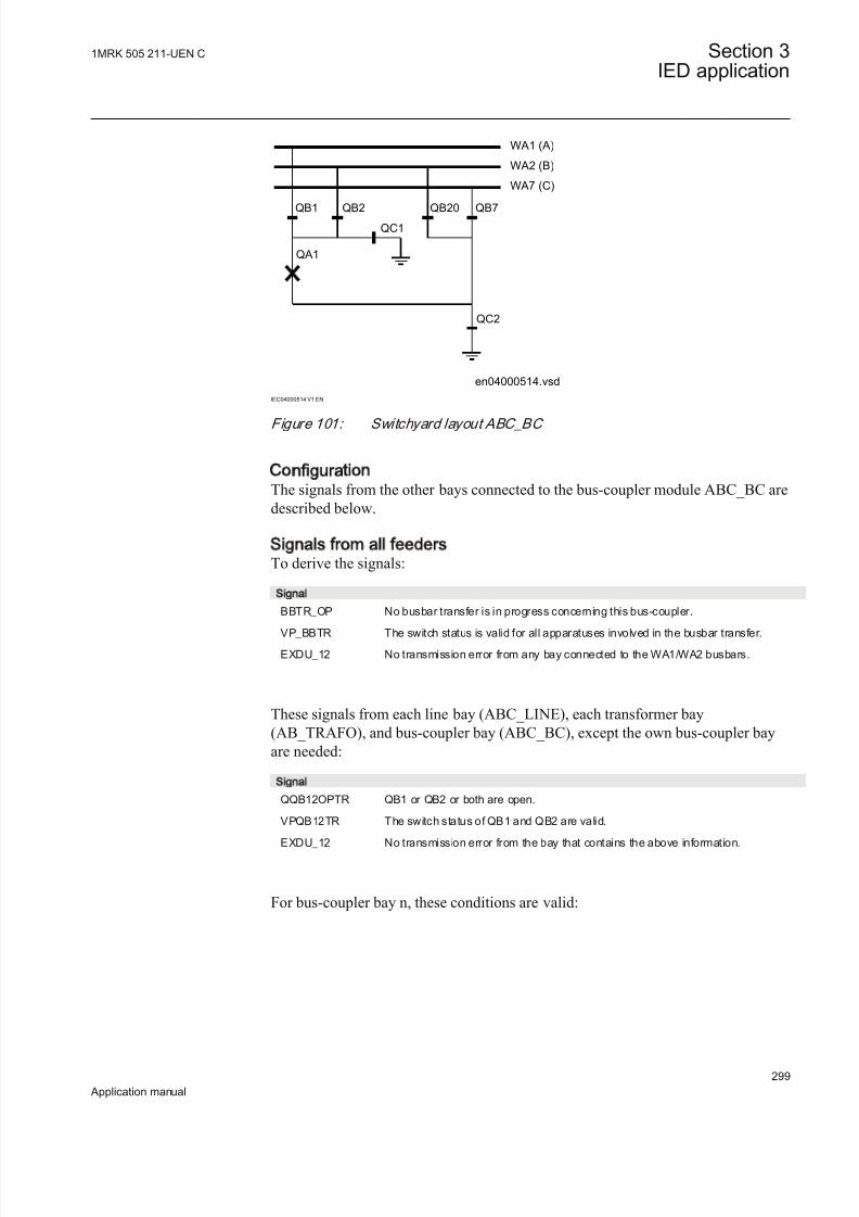
8/22/2019 Best Application
http://slidepdf.com/reader/full/best-application 305/457
QB1 QB2
QC1
QA1
WA1 (A)
WA2 (B)
WA7 (C)
QB7QB20
QC2
en04000514.vsd
IEC04000514 V1 EN
Figure 101: Switchyard layout ABC_BC
ConfigurationThe signals from the other bays connected to the bus-coupler module ABC_BC aredescribed below.
Signals from all feedersTo derive the signals:
Signal
BBTR_OP No busbar transfer is in progress concerning this bus-coupler.
VP_BBTR The switch status is valid for all apparatuses involved in the busbar transfer.
EXDU_12 No transmission error from any bay connected to the WA1/WA2 busbars.
These signals from each line bay (ABC_LINE), each transformer bay(AB_TRAFO), and bus-coupler bay (ABC_BC), except the own bus-coupler bayare needed:
Signal
QQB12OPTR QB1 or QB2 or both are open.
VPQB12TR The switch status of QB1 and QB2 are valid.
EXDU_12 No transmission error from the bay that contains the above information.
For bus-coupler bay n, these conditions are valid:
1MRK 505 211-UEN C Section 3IED application
299
Application manual

8/22/2019 Best Application
http://slidepdf.com/reader/full/best-application 306/457
QB12OPTR (bay 1)QB12OPTR (bay 2)
. . .
. . .QB12OPTR (bay n-1)
& BBTR_OP
VPQB12TR (bay 1)VPQB12TR (bay 2)
. . .
. . .VPQB12TR (bay n-1)
& VP_BBTR
EXDU_12 (bay 1)EXDU_12 (bay 2)
. . .
. . .EXDU_12 (bay n-1)
& EXDU_12
en04000481.vsd
IEC04000481 V1 EN
Figure 102: Signals from any bays in bus-coupler bay n
If the busbar is divided by bus-section disconnectors into bus-sections, the signalsBBTR are connected in parallel - if both bus-section disconnectors are closed. Sofor the basic project-specific logic for BBTR above, add this logic:
Section 1 Section 2
A1A2_DC(BS)B1B2_DC(BS)
ABC_LINE
ABC_BC
ABC_LINE ABC_BC
(WA1)A1
(WA2)B1
(WA7)C C
B2
A2
en04000482.vsd
AB_TRAFO
IEC04000482 V1 EN
Figure 103: Busbars divided by bus-section disconnectors (circuit breakers)
The following signals from each bus-section disconnector bay (A1A2_DC) areneeded. For B1B2_DC, corresponding signals from busbar B are used. The sametype of module (A1A2_DC) is used for different busbars, that is, for both bus-section disconnector A1A2_DC and B1B2_DC.
Signal
DCOPTR The bus-section disconnector is open.
VPDCTR The switch status of bus-section disconnector DC is valid.
EXDU_DC No transmission error from the bay that contains the above information.
If the busbar is divided by bus-section circuit breakers, the signals from the bus-section coupler bay (A1A2_BS), rather than the bus-section disconnector bay(A1A2_DC), have to be used. For B1B2_BS, corresponding signals from busbar B
Section 3 1MRK 505 211-UEN C
IED application
300
Application manual

8/22/2019 Best Application
http://slidepdf.com/reader/full/best-application 307/457
are used. The same type of module (A1A2_BS) is used for different busbars, thatis, for both bus-section circuit breakers A1A2_BS and B1B2_BS.
Signal
S1S2OPTR No bus-section coupler connection between bus-sections 1 and 2.
VPS1S2TR The switch status of bus-section coupler BS is valid.
EXDU_BS No transmission error from the bay that contains the above information.
For a bus-coupler bay in section 1, these conditions are valid:
BBTR_OP (sect.1)
DCOPTR (A1A2)DCOPTR (B1B2)
BBTR_OP (sect.2)
&VP_BBTR (sect.1)
VPDCTR (A1A2)VPDCTR (B1B2)
VP_BBTR (sect.2)
EXDU_12 (sect.1)
EXDU_DC (B1B2)EXDU_12 (sect.2)
VP_BBTR
EXDU_12
en04000483.vsd
&EXDU_DC (A1A2)
BBTR_OP
>1&
IEC04000483 V1 EN
Figure 104: Signals to a bus-coupler bay in section 1 from any bays in each
section
For a bus-coupler bay in section 2, the same conditions as above are valid bychanging section 1 to section 2 and vice versa.
Signals from bus-couplerIf the busbar is divided by bus-section disconnectors into bus-sections, the signalsBC_12 from the busbar coupler of the other busbar section must be transmitted tothe own busbar coupler if both disconnectors are closed.
Section 1 Section 2
A1A2_DC(BS)B1B2_DC(BS)
ABC_BC ABC_BC
(WA1)A1
(WA2)B1(WA7)C C
B2
A2
en04000484.vsd
IEC04000484 V1 EN
Figure 105: Busbars divided by bus-section disconnectors (circuit breakers)
To derive the signals:
1MRK 505 211-UEN C Section 3IED application
301
Application manual

8/22/2019 Best Application
http://slidepdf.com/reader/full/best-application 308/457
Signal
BC_12_CL Another bus-coupler connection exists between busbar WA1 and WA2.
VP_BC_12 The switch status of BC_12 is valid.
EXDU_BC No transmission error from any bus-coupler bay (BC).
These signals from each bus-coupler bay (ABC_BC), except the own bay, are needed:
Signal
BC12CLTR A bus-coupler connection through the own bus-coupler exists between busbar WA1and WA2.
VPBC12TR The switch status of BC_12 is valid.
EXDU_BC No transmission error from the bay that contains the above information.
These signals from each bus-section disconnector bay (A1A2_DC) are also needed.For B1B2_DC, corresponding signals from busbar B are used. The same type of module (A1A2_DC) is used for different busbars, that is, for both bus-sectiondisconnector A1A2_DC and B1B2_DC.
Signal
DCCLTR The bus-section disconnector is closed.
VPDCTR The switch status of bus-section disconnector DC is valid.
EXDU_DC No transmission error from the bay that contains the above information.
If the busbar is divided by bus-section circuit breakers, the signals from the bus-section coupler bay (A1A2_BS), rather than the bus-section disconnector bay(A1A2_DC), must be used. For B1B2_BS, corresponding signals from busbar Bare used. The same type of module (A1A2_BS) is used for different busbars, thatis, for both bus-section circuit breakers A1A2_BS and B1B2_BS.
Signal
S1S2CLTR A bus-section coupler connection exists between bus sections 1 and 2.
VPS1S2TR The switch status of bus-section coupler BS is valid.
EXDU_BS No transmission error from the bay containing the above information.
For a bus-coupler bay in section 1, these conditions are valid:
Section 3 1MRK 505 211-UEN C
IED application
302
Application manual

8/22/2019 Best Application
http://slidepdf.com/reader/full/best-application 309/457
DCCLTR (A1A2)DCCLTR (B1B2)
BC12CLTR (sect.2)
VPDCTR (A1A2)VPDCTR (B1B2)VPBC12TR (sect.2)
EXDU_DC (A1A2)
EXDU_DC (B1B2)EXDU_BC (sect.2)
& BC_12_CL
VP_BC_12
EXDU_BC
en04000485.vsd
&
&
IEC04000485 V1 EN
Figure 106: Signals to a bus-coupler bay in section 1 from a bus-coupler bay in
another section
For a bus-coupler bay in section 2, the same conditions as above are valid bychanging section 1 to section 2 and vice versa.
Configuration settingIf there is no bypass busbar and therefore no QB2 and QB7 disconnectors, then theinterlocking for QB2 and QB7 is not used. The states for QB2, QB7, QC71 are setto open by setting the appropriate module inputs as follows. In the functional block diagram, 0 and 1 are designated 0=FALSE and 1=TRUE:
• QB2_OP = 1• QB2_CL = 0
• QB7_OP = 1• QB7_CL = 0
• QC71_OP = 1• QC71_CL = 0
If there is no second busbar B and therefore no QB2 and QB20 disconnectors, thenthe interlocking for QB2 and QB20 are not used. The states for QB2, QB20, QC21,BC_12, BBTR are set to open by setting the appropriate module inputs as follows.In the functional block diagram, 0 and 1 are designated 0=FALSE and 1=TRUE:
• QB2_OP = 1• QB2_CL = 0
• QB20_OP = 1• QB20_CL = 0
• QC21_OP = 1• QC21_CL = 0
1MRK 505 211-UEN C Section 3IED application
303
Application manual

8/22/2019 Best Application
http://slidepdf.com/reader/full/best-application 310/457
• BC_12_CL = 0• VP_BC_12 = 1
• BBTR_OP = 1• VP_BBTR = 1
3.11.3.4 Interlocking for transformer bay AB_TRAFO
ApplicationThe interlocking for transformer bay (AB_TRAFO) function is used for atransformer bay connected to a double busbar arrangement according to figure 107.The function is used when there is no disconnector between circuit breaker andtransformer. Otherwise, the interlocking for line bay (ABC_LINE) function can be
used. This function can also be used in single busbar arrangements.
QB1 QB2
QC1
QA1
QC2
WA1 (A)
WA2 (B)
QA2
QC3
T
QC4
QB4QB3
QA2 and QC4 are not
used in this interlocking
AB_TRAFO
en04000515.vsdIEC04000515 V1 EN
Figure 107: Switchyard layout AB_TRAFO
The signals from other bays connected to the module AB_TRAFO are described below.
Signals from bus-couplerIf the busbar is divided by bus-section disconnectors into bus-sections, the busbar-
busbar connection could exist via the bus-section disconnector and bus-coupler within the other bus-section.
Section 3 1MRK 505 211-UEN C
IED application
304
Application manual

8/22/2019 Best Application
http://slidepdf.com/reader/full/best-application 311/457
Section 1 Section 2
A1A2_DC(BS)B1B2_DC(BS)
AB_TRAFO ABC_BC AB_TRAFO ABC_BC
(WA1)A1
(WA2)B1
(WA7)C C
B2
A2
en04000487.vsd
IEC04000487 V1 EN
Figure 108: Busbars divided by bus-section disconnectors (circuit breakers)
The project-specific logic for input signals concerning bus-coupler are the same asthe specific logic for the line bay (ABC_LINE):
Signal
BC_12_CL A bus-coupler connection exists between busbar WA1 and WA2.
VP_BC_12 The switch status of BC_12 is valid.
EXDU_BC No transmission error from bus-coupler bay (BC).
The logic is identical to the double busbar configuration “Signals from bus-coupler“.
Configuration settingIf there are no second busbar B and therefore no QB2 disconnector, then theinterlocking for QB2 is not used. The state for QB2, QC21, BC_12 are set to open
by setting the appropriate module inputs as follows. In the functional block diagram, 0 and 1 are designated 0=FALSE and 1=TRUE:
• QB2_OP = 1• QB2QB2_CL = 0
• QC21_OP = 1• QC21_CL = 0
• BC_12_CL = 0• VP_BC_12 = 1
If there is no second busbar B at the other side of the transformer and therefore noQB4 disconnector, then the state for QB4 is set to open by setting the appropriatemodule inputs as follows:
• QB4_OP = 1• QB4_CL = 0
3.11.3.5 Interlocking for bus-section breaker A1A2_BS
1MRK 505 211-UEN C Section 3IED application
305
Application manual

8/22/2019 Best Application
http://slidepdf.com/reader/full/best-application 312/457
Signals from all feedersIf the busbar is divided by bus-section circuit breakers into bus-sections and bothcircuit breakers are closed, the opening of the circuit breaker must be blocked if a
bus-coupler connection exists between busbars on one bus-section side and if onthe other bus-section side a busbar transfer is in progress:
Section 1 Section 2
A1A2_BSB1B2_BS
ABC_LINE
ABC_BC
ABC_LINE
ABC_BC
(WA1)A1
(WA2)B1
(WA7)C C
B2
A2
en04000489.vsd
AB_TRAFO AB_TRAFO
IEC04000489 V1 EN
Figure 109: Busbars divided by bus-section circuit breakers
To derive the signals:
Signal
BBTR_OP No busbar transfer is in progress concerning this bus-section.
VP_BBTR The switch status of BBTR is valid.
EXDU_12 No transmission error from any bay connected to busbar 1(A) and 2(B).
These signals from each line bay (ABC_LINE), each transformer bay
(AB_TRAFO), and bus-coupler bay (ABC_BC) are needed:
Signal
QB12OPTR QB1 or QB2 or both are open.
VPQB12TR The switch status of QB1 and QB2 are valid.
EXDU_12 No transmission error from the bay that contains the above information.
These signals from each bus-coupler bay (ABC_BC) are needed:
Signal
BC12OPTR No bus-coupler connection through the own bus-coupler between busbar WA1 andWA2.
VPBC12TR The switch status of BC_12 is valid.
EXDU_BC No transmission error from the bay that contains the above information.
These signals from the bus-section circuit breaker bay (A1A2_BS, B1B2_BS) areneeded.
Section 3 1MRK 505 211-UEN C
IED application
306
Application manual

8/22/2019 Best Application
http://slidepdf.com/reader/full/best-application 313/457
Signal
S1S2OPTR No bus-section coupler connection between bus-sections 1 and 2.
VPS1S2TR The switch status of bus-section coupler BS is valid.
EXDU_BS No transmission error from the bay that contains the above information.
For a bus-section circuit breaker between A1 and A2 section busbars, theseconditions are valid:
S1S2OPTR (B1B2)BC12OPTR (sect.1)
QB12OPTR (bay 1/sect.2)
QB12OPTR (bay n/sect.2)
S1S2OPTR (B1B2)BC12OPTR (sect.2)
QB12OPTR (bay 1/sect.1)
QB12OPTR (bay n /sect.1)
BBTR_OP
VP_BBTR
EXDU_12
en04000490.vsd
>1
&
>1
&
. . .
. . .
. . .
. . .
&
&
VPS1S2TR (B1B2)VPBC12TR (sect.1)
VPQB12TR (bay 1/sect.2)
VPQB12TR (bay n/sect.1)
. . .
. . .
VPBC12TR (sect.2)VPQB12TR (bay 1/sect.1)
VPQB12TR (bay n/sect.1)
. . .
. . .
&
EXDU_12 (bay 1/sect.2)
EXDU_12 (bay n /sect.2)
EXDU_12(bay 1/sect.1)
EXDU_12 (bay n /sect.1)
EXDU_BS (B1B2)EXDU_BC (sect.1)
EXDU_BC (sect.2)
. . .
. . .
. . .
. . .
IEC04000490 V1 EN
Figure 110: Signals from any bays for a bus-section circuit breaker between
sections A1 and A2
For a bus-section circuit breaker between B1 and B2 section busbars, theseconditions are valid:
1MRK 505 211-UEN C Section 3IED application
307
Application manual

8/22/2019 Best Application
http://slidepdf.com/reader/full/best-application 314/457
S1S2OPTR (A1A2)BC12OPTR (sect.1)
QB12OPTR (bay 1/sect.2)
QB12OPTR (bay n/sect.2)
S1S2OPTR (A1A2)BC12OPTR (sect.2)
QB12OPTR (bay 1/sect.1)
QB12OPTR (bay n /sect.1)
BBTR_OP
VP_BBTR
EXDU_12
en04000491.vsd
>1
&
>1
&
. . .
. . .
. . .
. . .
&
&
VPS1S2TR (A1A2)VPBC12TR (sect.1)
VPQB12TR (bay 1/sect.2)
VPQB12TR (bay n/sect.1)
. . .
. . .
VPBC12TR (sect.2)VPQB12TR (bay 1/sect.1)
VPQB12TR (bay n/sect.1)
. . .
. . .
&
EXDU_12(bay 1/sect.2)
EXDU_12 (bay n /sect.2)
EXDU_12 (bay 1/sect.1)
EXDU_12 (bay n /sect.1)
EXDU_BS (A1A2)EXDU_BC (sect.1)
EXDU_BC (sect.2)
. . .
. . .
. . .
. . .
IEC04000491 V1 EN
Figure 111: Signals from any bays for a bus-section circuit breaker between
sections B1 and B2
Configuration settingIf there is no other busbar via the busbar loops that are possible, then either theinterlocking for the QA1 open circuit breaker is not used or the state for BBTR isset to open. That is, no busbar transfer is in progress in this bus-section:
• BBTR_OP = 1• VP_BBTR = 1
3.11.3.6 Interlocking for bus-section disconnector A1A2_DC
Section 3 1MRK 505 211-UEN C
IED application
308
Application manual

8/22/2019 Best Application
http://slidepdf.com/reader/full/best-application 315/457
ApplicationThe interlocking for bus-section disconnector (A1A2_DC) function is used for one
bus-section disconnector between section 1 and 2 according to figure 112.A1A2_DC function can be used for different busbars, which includes a bus-sectiondisconnector.
WA1 (A1) WA2 (A2)
QB
QC1 QC2
A1A2_DCen04000492.vsd
IEC04000492 V1 EN
Figure 112: Switchyard layout A1A2_DC
The signals from other bays connected to the module A1A2_DC are described below.
Signals in single breaker arrangementIf the busbar is divided by bus-section disconnectors, the condition no other
disconnector connected to the bus-section must be made by a project-specific logic.
The same type of module (A1A2_DC) is used for different busbars, that is, for both bus-section disconnector A1A2_DC and B1B2_DC. But for B1B2_DC,
corresponding signals from busbar B are used.
Section 1 Section 2
A1A2_DC(BS)B1B2_DC(BS)
ABC_LINE ABC_BC
ABC_LINE
(WA1)A1
(WA2)B1
(WA7)C C
B3
A3
en04000493.vsd
AB_TRAFO AB_TRAFO
A2
B2
IEC04000493 V1 EN
Figure 113: Busbars divided by bus-section disconnectors (circuit breakers)
To derive the signals:
Signal
S1DC_OP All disconnectors on bus-section 1 are open.
S2DC_OP All disconnectors on bus-section 2 are open.
VPS1_DC The switch status of disconnectors on bus-section 1 is valid.
VPS2_DC The switch status of disconnectors on bus-section 2 is valid.
EXDU_BB No transmission error from any bay that contains the above information.
1MRK 505 211-UEN C Section 3IED application
309
Application manual

8/22/2019 Best Application
http://slidepdf.com/reader/full/best-application 316/457
These signals from each line bay (ABC_LINE), each transformer bay(AB_TRAFO), and each bus-coupler bay (ABC_BC) are needed:
Signal
QB1OPTR QB1 is open.
QB2OPTR QB2 is open (AB_TRAFO, ABC_LINE).
QB220OTR QB2 and QB20 are open (ABC_BC).
VPQB1TR The switch status of QB1 is valid.
VPQB2TR The switch status of QB2 is valid.
VQB220TR The switch status of QB2 and QB20 are valid.
EXDU_BB No transmission error from the bay that contains the above information.
If there is an additional bus-section disconnector, the signal from the bus-section
disconnector bay (A1A2_DC) must be used:Signal
DCOPTR The bus-section disconnector is open.
VPDCTR The switch status of bus-section disconnector DC is valid.
EXDU_DC No transmission error from the bay that contains the above information.
If there is an additional bus-section circuit breaker rather than an additional bus-section disconnector the signals from the bus-section, circuit-breaker bay(A1A2_BS) rather than the bus-section disconnector bay (A1A2_DC) must be used:
Signal
QB1OPTR QB1 is open.
QB2OPTR QB2 is open.
VPQB1TR The switch status of QB1 is valid.
VPQB2TR The switch status of QB2 is valid.
EXDU_BS No transmission error from the bay BS (bus-section coupler bay) that contains theabove information.
For a bus-section disconnector, these conditions from the A1 busbar section are valid:
Section 3 1MRK 505 211-UEN C
IED application
310
Application manual

8/22/2019 Best Application
http://slidepdf.com/reader/full/best-application 317/457
QB1OPTR (bay 1/sect.A1)S1DC_OP
VPS1_DC
EXDU_BB
en04000494.vsd
&
&
&
QB1OPTR (bay n/sect.A1)
. . .
. . .
. . .
VPQB1TR (bay 1/sect.A1)
VPQB1TR (bay n/sect.A1)
EXDU_BB (bay 1/sect.A1)
EXDU_BB (bay n/sect.A1)
. . .
. . .
. . .
. . .
. . .
. . .
IEC04000494 V1 EN
Figure 114: Signals from any bays in section A1 to a bus-section disconnector
For a bus-section disconnector, these conditions from the A2 busbar section are valid:
QB1OPTR (bay 1/sect.A2)S2DC_OP
VPS2_DC
EXDU_BB
en04000495.vsd
QB1OPTR (bay n/sect.A2)
. . .
. . .
. . .
VPQB1TR (bay 1/sect.A2)
VPQB1TR (bay n/sect.A2)
VPDCTR (A2/A3)
EXDU_BB (bay n/sect.A2)
. . .
. . .
. . .
. . .
. . .
. . .
&
&
&
DCOPTR (A2/A3)
EXDU_BB (bay 1/sect.A2)
EXDU_DC (A2/A3)
IEC04000495 V1 EN
Figure 115: Signals from any bays in section A2 to a bus-section disconnector
For a bus-section disconnector, these conditions from the B1 busbar section are valid:
1MRK 505 211-UEN C Section 3IED application
311
Application manual

8/22/2019 Best Application
http://slidepdf.com/reader/full/best-application 318/457
QB2OPTR (QB220OTR)(bay 1/sect.B1)S1DC_OP
VPS1_DC
EXDU_BB
en04000496.vsd
QB2OPTR (QB220OTR)(bay n/sect.B1)
. . .
. . .
. . .
VPQB2TR (VQB220TR)(bay 1/sect.B1)
VPQB2TR (VQB220TR)(bay n/sect.B1)
EXDU_BB (bay 1/sect.B1)
EXDU_BB (bay n/sect.B1)
. . .
. . .
. . .
. . .
. . .
. . .
&
&
&
IEC04000496 V1 EN
Figure 116: Signals from any bays in section B1 to a bus-section disconnector
For a bus-section disconnector, these conditions from the B2 busbar section are valid:
QB2OPTR (QB220OTR)(bay 1/sect.B2) S2DC_OP
VPS2_DC
EXDU_BB
en04000497.vsd
QB2OPTR (QB220OTR)(bay n/sect.B2)
. . .
. . .
. . .
VPQB2TR(VQB220TR) (bay 1/sect.B2)
VPQB2TR(VQB220TR) (bay n/sect.B2)VPDCTR (B2/B3)
EXDU_BB (bay n/sect.B2)
. . .
. . .
. . .
. . .
. . .
. . .
&
&
&
DCOPTR (B2/B3)
EXDU_BB (bay 1/sect.B2)
EXDU_DC (B2/B3)
IEC04000497 V1 EN
Figure 117: Signals from any bays in section B2 to a bus-section disconnector
Signals in double-breaker arrangement
If the busbar is divided by bus-section disconnectors, the condition for the busbar disconnector bay no other disconnector connected to the bus-section must be made
by a project-specific logic.
The same type of module (A1A2_DC) is used for different busbars, that is, for both bus-section disconnector A1A2_DC and B1B2_DC. But for B1B2_DC,corresponding signals from busbar B are used.
Section 3 1MRK 505 211-UEN C
IED application
312
Application manual

8/22/2019 Best Application
http://slidepdf.com/reader/full/best-application 319/457
Section 1 Section 2
A1A2_DC(BS)B1B2_DC(BS)
DB_BUS DB_BUSDB_BUS DB_BUS
(WA1)A1
(WA2)B1 B2
A2
en04000498.vsd
IEC04000498 V1 EN
Figure 118: Busbars divided by bus-section disconnectors (circuit breakers)
To derive the signals:
Signal
S1DC_OP All disconnectors on bus-section 1 are open.
S2DC_OP All disconnectors on bus-section 2 are open.
VPS1_DC The switch status of all disconnectors on bus-section 1 is valid.
VPS2_DC The switch status of all disconnectors on bus-section 2 is valid.
EXDU_BB No transmission error from double-breaker bay (DB) that contains the aboveinformation.
These signals from each double-breaker bay (DB_BUS) are needed:
Signal
QB1OPTR QB1 is open.
QB2OPTR QB2 is open.
VPQB1TR The switch status of QB1 is valid.
VPQB2TR The switch status of QB2 is valid.
EXDU_DB No transmission error from the bay that contains the above information.
The logic is identical to the double busbar configuration “Signals in single breaker arrangement”.
For a bus-section disconnector, these conditions from the A1 busbar section are valid:
1MRK 505 211-UEN C Section 3IED application
313
Application manual

8/22/2019 Best Application
http://slidepdf.com/reader/full/best-application 320/457
QB1OPTR (bay 1/sect.A1)S1DC_OP
VPS1_DC
EXDU_BB
en04000499.vsd
&
&
&
QB1OPTR (bay n/sect.A1)
. . .
. . .
. . .
VPQB1TR (bay 1/sect.A1)
VPQB1TR (bay n/sect.A1)
EXDU_DB (bay 1/sect.A1)
EXDU_DB (bay n/sect.A1)
. . .
. . .
. . .
. . .
. . .
. . .
IEC04000499 V1 EN
Figure 119: Signals from double-breaker bays in section A1 to a bus-section
disconnector
For a bus-section disconnector, these conditions from the A2 busbar section are valid:
QB1OPTR (bay 1/sect.A2)S2DC_OP
VPS2_DC
EXDU_BB
en04000500.vsd
&
&
&
QB1OPTR (bay n/sect.A2)
. . .
. . .
. . .
VPQB1TR (bay 1/sect.A2)
VPQB1TR (bay n/sect.A2)
EXDU_DB (bay 1/sect.A2)
EXDU_DB (bay n/sect.A2)
. . .
. . .
. . .
. . .
. . .
. . .
IEC04000500 V1 EN
Figure 120: Signals from double-breaker bays in section A2 to a bus-section
disconnector
For a bus-section disconnector, these conditions from the B1 busbar section are valid:
Section 3 1MRK 505 211-UEN C
IED application
314
Application manual
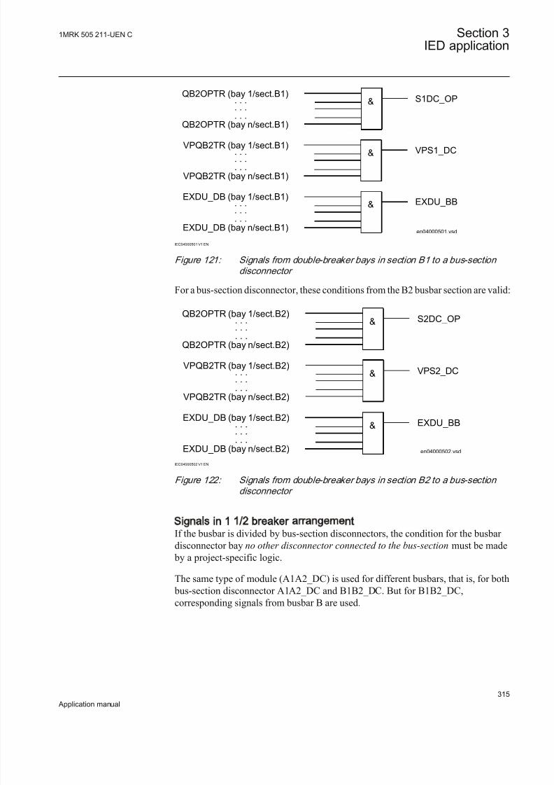
8/22/2019 Best Application
http://slidepdf.com/reader/full/best-application 321/457
QB2OPTR (bay 1/sect.B1)S1DC_OP
VPS1_DC
EXDU_BB
en04000501.vsd
&
&
&
QB2OPTR (bay n/sect.B1)
. . .
. . .
. . .
VPQB2TR (bay 1/sect.B1)
VPQB2TR (bay n/sect.B1)
EXDU_DB (bay 1/sect.B1)
EXDU_DB (bay n/sect.B1)
. . .
. . .
. . .
. . .
. . .
. . .
IEC04000501 V1 EN
Figure 121: Signals from double-breaker bays in section B1 to a bus-section
disconnector
For a bus-section disconnector, these conditions from the B2 busbar section are valid:
QB2OPTR (bay 1/sect.B2)S2DC_OP
VPS2_DC
EXDU_BB
en04000502.vsd
&
&
&
QB2OPTR (bay n/sect.B2)
. . .
. . .
. . .
VPQB2TR (bay 1/sect.B2)
VPQB2TR (bay n/sect.B2)
EXDU_DB (bay 1/sect.B2)
EXDU_DB (bay n/sect.B2)
. . .
. . .
. . .
. . .
. . .
. . .
IEC04000502 V1 EN
Figure 122: Signals from double-breaker bays in section B2 to a bus-section
disconnector
Signals in 1 1/2 breaker arrangementIf the busbar is divided by bus-section disconnectors, the condition for the busbar disconnector bay no other disconnector connected to the bus-section must be made
by a project-specific logic.
The same type of module (A1A2_DC) is used for different busbars, that is, for both bus-section disconnector A1A2_DC and B1B2_DC. But for B1B2_DC,corresponding signals from busbar B are used.
1MRK 505 211-UEN C Section 3IED application
315
Application manual

8/22/2019 Best Application
http://slidepdf.com/reader/full/best-application 322/457

8/22/2019 Best Application
http://slidepdf.com/reader/full/best-application 323/457
Section 1 Section 2
A1A2_DC(BS)B1B2_DC(BS)
AB_TRAFO ABC_LINEBB_ES
ABC_LINE
(WA1)A1
(WA2)B1
(WA7)C C
B2
A2
en04000505.vsd
BB_ES ABC_BC
IEC04000505 V1 EN
Figure 125: Busbars divided by bus-section disconnectors (circuit breakers)
To derive the signals:
Signal
BB_DC_OP All disconnectors on this part of the busbar are open.
VP_BB_DC The switch status of all disconnector on this part of the busbar is valid.
EXDU_BB No transmission error from any bay containing the above information.
These signals from each line bay (ABC_LINE), each transformer bay(AB_TRAFO), and each bus-coupler bay (ABC_BC) are needed:
Signal
QB1OPTR QB1 is open.
QB2OPTR QB2 is open (AB_TRAFO, ABC_LINE)
QB220OTR QB2 and QB20 are open (ABC_BC)
QB7OPTR QB7 is open.
VPQB1TR The switch status of QB1 is valid.
VPQB2TR The switch status of QB2 is valid.
VQB220TR The switch status of QB2and QB20 is valid.
VPQB7TR The switch status of QB7 is valid.
EXDU_BB No transmission error from the bay that contains the above information.
These signals from each bus-section disconnector bay (A1A2_DC) are also needed.For B1B2_DC, corresponding signals from busbar B are used. The same type of
module (A1A2_DC) is used for different busbars, that is, for both bus-sectiondisconnectors A1A2_DC and B1B2_DC.
Signal
DCOPTR The bus-section disconnector is open.
VPDCTR The switch status of bus-section disconnector DC is val id.
EXDU_DC No transmission error from the bay that contains the above information.
If no bus-section disconnector exists, the signal DCOPTR, VPDCTR andEXDU_DC are set to 1 (TRUE).
1MRK 505 211-UEN C Section 3IED application
317
Application manual

8/22/2019 Best Application
http://slidepdf.com/reader/full/best-application 324/457
If the busbar is divided by bus-section circuit breakers, the signals from the bus-section coupler bay (A1A2_BS) rather than the bus-section disconnector bay(A1A2_DC) must be used. For B1B2_BS, corresponding signals from busbar B areused. The same type of module (A1A2_BS) is used for different busbars, that is,for both bus-section circuit breakers A1A2_BS and B1B2_BS.
Signal
QB1OPTR QB1 is open.
QB2OPTR QB2 is open.
VPQB1TR The switch status of QB1 is valid.
VPQB2TR The switch status of QB2 is valid.
EXDU_BS No transmission error from the bay BS (bus-section coupler bay) that contains theabove information.
For a busbar earthing switch, these conditions from the A1 busbar section are valid:
QB1OPTR (bay 1/sect.A1)BB_DC_OP
VP_BB_DC
EXDU_BB
en04000506.vsd
QB1OPTR (bay n/sect.A1)
. . .
. . .
. . .
VPQB1TR (bay 1/sect.A1)
VPQB1TR (bay n/sect.A1)VPDCTR (A1/A2)
EXDU_BB (bay n/sect.A1)
. . .
. . .
. . .
. . .
. . .
. . .
&
&
&
DCOPTR (A1/A2)
EXDU_BB (bay 1/sect.A1)
EXDU_DC (A1/A2)
IEC04000506 V1 EN
Figure 126: Signals from any bays in section A1 to a busbar earthing switch in
the same section
For a busbar earthing switch, these conditions from the A2 busbar section are valid:
Section 3 1MRK 505 211-UEN C
IED application
318
Application manual

8/22/2019 Best Application
http://slidepdf.com/reader/full/best-application 325/457
QB1OPTR (bay 1/sect.A2)BB_DC_OP
VP_BB_DC
EXDU_BB
en04000507.vsd
QB1OPTR (bay n/sect.A2)
. . .
. . .
. . .
VPQB1TR (bay 1/sect.A2)
VPQB1TR (bay n/sect.A2)VPDCTR (A1/A2)
EXDU_BB (bay n/sect.A2)
. . .
. . .
. . .
. . .
. . .
. . .
&
&
&
DCOPTR (A1/A2)
EXDU_BB (bay 1/sect.A2)
EXDU_DC (A1/A2)
IEC04000507 V1 EN
Figure 127: Signals from any bays in section A2 to a busbar earthing switch in
the same section
For a busbar earthing switch, these conditions from the B1 busbar section are valid:
QB2OPTR(QB220OTR)(bay 1/sect.B1)BB_DC_OP
VP_BB_DC
EXDU_BB
en04000508.vsd
QB2OPTR (QB220OTR)(bay n/sect.B1)
. . .
. . .
. . .
VPQB2TR(VQB220TR) (bay 1/sect.B1)
VPQB2TR(VQB220TR) (bay n/sect.B1)VPDCTR (B1/B2)
EXDU_BB (bay n/sect.B1)
. . .
. . .
. . .
. . .
. . .
. . .
&
&
&
DCOPTR (B1/B2)
EXDU_BB (bay 1/sect.B1)
EXDU_DC (B1/B2)
IEC04000508 V1 EN
Figure 128: Signals from any bays in section B1 to a busbar earthing switch in
the same section
For a busbar earthing switch, these conditions from the B2 busbar section are valid:
1MRK 505 211-UEN C Section 3IED application
319
Application manual

8/22/2019 Best Application
http://slidepdf.com/reader/full/best-application 326/457
QB2OPTR(QB220OTR) (bay 1/sect.B2)BB_DC_OP
VP_BB_DC
EXDU_BB
en04000509.vsd
QB2OPTR(QB220OTR) (bay n/sect.B2)
. . .
. . .
. . .
VPQB2TR(VQB220TR) (bay 1/sect.B2)
VPQB2TR(VQB220TR) (bay n/sect.B2)VPDCTR (B1/B2)
EXDU_BB (bay n/sect.B2)
. . .
. . .
. . .
. . .
. . .
. . .
&
&
&
DCOPTR (B1/B2)
EXDU_BB (bay 1/sect.B2)
EXDU_DC (B1/B2)
IEC04000509 V1 EN
Figure 129: Signals from any bays in section B2 to a busbar earthing switch in
the same section
For a busbar earthing switch on bypass busbar C, these conditions are valid:
QB7OPTR (bay 1)BB_DC_OP
VP_BB_DC
EXDU_BB
en04000510.vsd
&
&
&
QB7OPTR (bay n)
. . .
. . .
. . .
VPQB7TR (bay 1)
VPQB7TR (bay n)
EXDU_BB (bay 1)
EXDU_BB (bay n)
. . .
. . .
. . .
. . .
. . .
. . .
IEC04000510 V1 EN
Figure 130: Signals from bypass busbar to busbar earthing switch
Signals in double-breaker arrangementThe busbar earthing switch is only allowed to operate if all disconnectors of the bussection are open.
Section 3 1MRK 505 211-UEN C
IED application
320
Application manual

8/22/2019 Best Application
http://slidepdf.com/reader/full/best-application 327/457

8/22/2019 Best Application
http://slidepdf.com/reader/full/best-application 328/457
Section 1 Section 2
A1A2_DC(BS)B1B2_DC(BS) BB_ESBB_ES
BH_LINE
(WA1)A1
(WA2)B1 B2
A2
en04000512.vsdBH_LINE
IEC04000512 V1 EN
Figure 132: Busbars divided by bus-section disconnectors (circuit breakers)
The project-specific logic are the same as for the logic for the double busbar configuration described in section “Signals in single breaker arrangement”.
Signal
BB_DC_OP All disconnectors on this part of the busbar are open.
VP_BB_DC The switch status of all disconnectors on this part of the busbar is valid.EXDU_BB No transmission error from any bay that contains the above information.
3.11.3.8 Interlocking for double CB bay DB
ApplicationThe interlocking for a double busbar double circuit breaker bay includingDB_BUS_A, DB_BUS_B and DB_LINE functions are used for a line connected toa double busbar arrangement according to figure 133.
Section 3 1MRK 505 211-UEN C
IED application
322
Application manual

8/22/2019 Best Application
http://slidepdf.com/reader/full/best-application 329/457
WA1 (A)
WA2 (B)
QB1
QC1
QA1
QC2
QC9
QB61
QB9
QB2
QC4
QA2
QC5
QC3
QB62
DB_BUS_B
DB_LINE
DB_BUS_A
en04000518.vsd
IEC04000518 V1 EN
Figure 133: Switchyard layout double circuit breaker
Three types of interlocking modules per double circuit breaker bay are defined.DB_LINE is the connection from the line to the circuit breaker parts that areconnected to the busbars. DB_BUS_A and DB_BUS_B are the connections from
the line to the busbars.
For a double circuit-breaker bay, the modules DB_BUS_A, DB_LINE andDB_BUS_B must be used.
Configuration settingFor application without QB9 and QC9, just set the appropriate inputs to open stateand disregard the outputs. In the functional block diagram, 0 and 1 are designated0=FALSE and 1=TRUE:
• QB9_OP = 1• QB9_CL = 0
• QC9_OP = 1• QC9_CL = 0
If, in this case, line voltage supervision is added, then rather than setting QB9 toopen state, specify the state of the voltage supervision:
• QB9_OP = VOLT_OFF• QB9_CL = VOLT_ON
1MRK 505 211-UEN C Section 3IED application
323
Application manual

8/22/2019 Best Application
http://slidepdf.com/reader/full/best-application 330/457
If there is no voltage supervision, then set the corresponding inputs as follows:
• VOLT_OFF = 1• VOLT_ON = 0
3.11.3.9 Interlocking for 1 1/2 CB BH
ApplicationThe interlocking for 1 1/2 breaker diameter (BH_CONN, BH_LINE_A,BH_LINE_B) functions are used for lines connected to a 1 1/2 breaker diameter according to figure 134.
WA1 (A)
WA2 (B)
QB1
QC1
QA1
QC2
QC9
QB6
QB9
QB2
QC1
QA1
QC2
QC3
QB6
QC3
QB62QB61 QA1
QC1 QC2
QC9
QB9
BH_LINE_A BH_LINE_B
BH_CONNen04000513.vsd
IEC04000513 V1 EN
Figure 134: Switchyard layout 1 1/2 breaker
Three types of interlocking modules per diameter are defined. BH_LINE_A andBH_LINE_B are the connections from a line to a busbar. BH_CONN is theconnection between the two lines of the diameter in the 1 1/2 breaker switchyardlayout.
For a 1 1/2 breaker arrangement, the modules BH_LINE_A, BH_CONN andBH_LINE_B must be used.
Section 3 1MRK 505 211-UEN C
IED application
324
Application manual

8/22/2019 Best Application
http://slidepdf.com/reader/full/best-application 331/457
Configuration settingFor application without QB9 and QC9, just set the appropriate inputs to open stateand disregard the outputs. In the functional block diagram, 0 and 1 are designated0=FALSE and 1=TRUE:
• QB9_OP = 1• QB9_CL = 0
• QC9_OP = 1• QC9_CL = 0
If, in this case, line voltage supervision is added, then rather than setting QB9 toopen state, specify the state of the voltage supervision:
• QB9_OP = VOLT_OFF
• QB9_CL = VOLT_ON
If there is no voltage supervision, then set the corresponding inputs as follows:
• VOLT_OFF = 1• VOLT_ON = 0
3.11.3.10 Horizontal communication via GOOSE for interlocking
GOOSEINTLKRCV
T able 1 07 : G OO SE IN TL KR CV N on g rou p se ttin gs (ba sic)
Name Values (Range) Unit Step Default Description
Operation Off On
- - Off Operation Off/On
3.11.4 Logic rotating switch for function selection and LHMI
presentation SLGGIO
Function description IEC 61850
identification
IEC 60617
identification
ANSI/IEEE C37.2
device numberLogic rotating switch for functionselection and LHMI presentation
SLGGIO - -
3.11.4.1 Application
The logic rotating switch for function selection and LHMI presentation function(SLGGIO) (or the selector switch function block, as it is also known) is used to geta selector switch functionality similar with the one provided by a hardware multi-
position selector switch. Hardware selector switches are used extensively by
1MRK 505 211-UEN C Section 3IED application
325
Application manual

8/22/2019 Best Application
http://slidepdf.com/reader/full/best-application 332/457
utilities, in order to have different functions operating on pre-set values. Hardwareswitches are however sources for maintenance issues, lower system reliability andextended purchase portfolio. The virtual selector switches eliminate all these
problems.
SLGGIO function block has two operating inputs (UP and DOWN), one blockinginput (BLOCK) and one operator position input (PSTO).
SLGGIO can be activated both from the local HMI and from external sources(switches), via the IED binary inputs. It also allows the operation from remote (likethe station computer). SWPOSN is an integer value output, giving the actual outputnumber. Since the number of positions of the switch can be established by settings(see below), one must be careful in coordinating the settings with the configuration(if one sets the number of positions to x in settings – for example, there will beonly the first x outputs available from the block in the configuration). Also the
frequency of the (UP or DOWN) pulses should be lower than the setting tPulse.From the local HMI, there are two modes of operating the switch: from the menuand from the Single-line diagram (SLD).
3.11.4.2 Setting guidelines
The following settings are available for the Logic rotating switch for functionselection and LHMI presentation (SLGGIO) function:
Operation: Sets the operation of the function On or Off .
NrPos: Sets the number of positions in the switch (max. 32). This setting influencethe behavior of the switch when changes from the last to the first position.
OutType: Steady or Pulsed .
tPulse: In case of a pulsed output, it gives the length of the pulse (in seconds).
tDelay: The delay between the UP or DOWN activation signal positive front andthe output activation.
StopAtExtremes: Sets the behavior of the switch at the end positions – if set to Disabled , when pressing UP while on first position, the switch will jump to the last
position; when pressing DOWN at the last position, the switch will jump to the first position; when set to Enabled , no jump will be allowed.
Section 3 1MRK 505 211-UEN C
IED application
326
Application manual

8/22/2019 Best Application
http://slidepdf.com/reader/full/best-application 333/457
3.11.4.3 Setting parameters
Table 108: SLG GIO N on group settings (basic)
Name Values (Range) Unit Step Default Description
Operation Off On
- - Off Operation Off/On
NrPos 2 - 32 - 1 32 Number of positions in the switch
OutType PulsedSteady
- - Steady Output type, steady or pulse
tPulse 0.000 - 60.000 s 0.001 0.200 Operate pulse duration, in [s]
tDelay 0.000 - 60000.000 s 0.010 0.000 Time delay on the output, in [s]
StopAtExtremes DisabledEnabled
- - Disabled Stop when min or max position is reached
3.11.5 Selector mini switch VSGGIO
Function description IEC 61850
identification
IEC 60617
identification
ANSI/IEEE C37.2
device number
Selector mini switch VSGGIO - -
3.11.5.1 Application
Selector mini switch (VSGGIO) function is a multipurpose function used in the
configuration tool in PCM600 for a variety of applications, as a general purposeswitch. VSGGIO can be used for both acquiring an external switch position(through the IPOS1 and the IPOS2 inputs) and represent it through the single linediagram symbols (or use it in the configuration through the outputs POS1 andPOS2) as well as, a command function (controlled by the PSTO input), givingswitching commands through the CMDPOS12 and CMDPOS21 outputs.
The output POSITION is an integer output, showing the actual position as aninteger number 0 – 3.
An example where VSGGIO is configured to switch Autorecloser on–off from a button symbol on the local HMI is shown in figure 135. The I and O buttons on the
local HMI are normally used for on–off operations of the circuit breaker.
1MRK 505 211-UEN C Section 3IED application
327
Application manual

8/22/2019 Best Application
http://slidepdf.com/reader/full/best-application 334/457
IEC07000112-2-en.vsd
PSTO
CMDPOS12
IPOS1
NAM_POS1
NAM_POS2
IPOS2
CMDPOS21OFF
ON
VSGGIO
SMBRRECON
OFF
SETON
INTONE
INVERTER
INPUT OUT
IEC07000112 V2 EN
Figure 135: Control of Autorecloser from local HMI through Selector mini switch
VSGGIO is also provided with IEC 61850 communication so it can be controlled
from SA system as well.
3.11.5.2 Setting guidelines
Selector mini switch (VSGGIO) function can generate pulsed or steady commands(by setting the Mode parameter). When pulsed commands are generated, the lengthof the pulse can be set using the tPulse parameter. Also, being accessible on thesingle line diagram (SLD), this function block has two control modes (settablethrough CtlModel ): Dir Norm and SBO Enh.
3.11.5.3 Setting parametersTable 109: VSG GIO Non group settings (basic)
Name Values (Range) Unit Step Default Description
Operation Off On
- - Off Operation Off / On
CtlModel Dir NormSBO Enh
- - Dir Norm Specifies the type for control modelaccording to IEC 61850
Mode SteadyPulsed
- - Pulsed Operation mode
tSelect 0.000 - 60.000 s 0.001 30.000 Max time between select and executesignals
tPulse 0.000 - 60.000 s 0.001 0.200 Command pulse lenght
3.11.6 IEC61850 generic communication I/O functions DPGGIO
Function description IEC 61850
identification
IEC 60617
identification
ANSI/IEEE C37.2
device number
IEC 61850 generic communication I/Ofunctions
DPGGIO - -
Section 3 1MRK 505 211-UEN C
IED application
328
Application manual

8/22/2019 Best Application
http://slidepdf.com/reader/full/best-application 335/457
3.11.6.1 Application
The IEC61850 generic communication I/O functions (DPGGIO) function block isused to send three logical outputs to other systems or equipment in the substation.
The three inputs are named OPEN, CLOSE and VALID, since this function block is intended to be used as a position indicator block in interlocking and reservationstation-wide logics.
3.11.6.2 Setting guidelines
The function does not have any parameters available in the local HMI or PCM600.
3.11.7 Single point generic control 8 signals SPC8GGIO
Function description IEC 61850
identification
IEC 60617
identification
ANSI/IEEE C37.2
device number
Single point generic control 8 signals SPC8GGIO - -
3.11.7.1 Application
The Single point generic control 8 signals (SPC8GGIO) function block is acollection of 8 single point commands, designed to bring in commands fromREMOTE (SCADA) to those parts of the logic configuration that do not needcomplicated function blocks that have the capability to receive commands (for
example SCSWI). In this way, simple commands can be sent directly to the IEDoutputs, without confirmation. Confirmation (status) of the result of the commandsis supposed to be achieved by other means, such as binary inputs and SPGGIOfunction blocks.
PSTO is the universal operator place selector for all controlfunctions. Even if PSTO can be configured to allow LOCAL or ALL operator positions, the only functional position usable with theSPC8GGIO function block is REMOTE.
3.11.7.2 Setting guidelines
The parameters for the single point generic control 8 signals (SPC8GGIO) functionare set via the local HMI or PCM600.
Operation: turning the function operation On/Off .
There are two settings for every command output (totally 8):
Latchedx: decides if the command signal for output x is Latched (steady) or Pulsed .
1MRK 505 211-UEN C Section 3IED application
329
Application manual

8/22/2019 Best Application
http://slidepdf.com/reader/full/best-application 336/457
tPulsex: if Latchedx is set to Pulsed , then tPulsex will set the length of the pulse (inseconds).
3.11.7.3 Setting parameters
Table 110: SPC 8G GIO Non group settings (basic)
Name Values (Range) Unit Step Default Description
Operation Off On
- - Off Operation Off/On
Latched1 PulsedLatched
- - Pulsed Setting for pulsed/latched mode for output 1
tPulse1 0.01 - 6000.00 s 0.01 0.10 Output1 Pulse Time
Latched2 PulsedLatched
- - Pulsed Setting for pulsed/latched mode for output 2
tPulse2 0.01 - 6000.00 s 0.01 0.10 Output2 Pulse Time
Latched3 PulsedLatched
- - Pulsed Setting for pulsed/latched mode for output 3
tPulse3 0.01 - 6000.00 s 0.01 0.10 Output3 Pulse Time
Latched4 PulsedLatched
- - Pulsed Setting for pulsed/latched mode for output 4
tPulse4 0.01 - 6000.00 s 0.01 0.10 Output4 Pulse Time
Latched5 PulsedLatched
- - Pulsed Setting for pulsed/latched mode for output 5
tPulse5 0.01 - 6000.00 s 0.01 0.10 Output5 Pulse Time
Latched6 PulsedLatched
- - Pulsed Setting for pulsed/latched mode for output 6
tPulse6 0.01 - 6000.00 s 0.01 0.10 Output6 Pulse Time
Latched7 PulsedLatched
- - Pulsed Setting for pulsed/latched mode for output 7
tPulse7 0.01 - 6000.00 s 0.01 0.10 Output7 Pulse Time
Latched8 PulsedLatched
- - Pulsed Setting for pulsed/latched mode for output 8
tPulse8 0.01 - 6000.00 s 0.01 0.10 Output8 pulse time
3.11.8 AutomationBits, command function for DNP3.0 AUTOBITS
Function description IEC 61850
identification
IEC 60617
identification
ANSI/IEEE C37.2
device number
AutomationBits, command function for DNP3
AUTOBITS - -
3.11.8.1 Application
Automation bits, command function for DNP3 (AUTOBITS) is used withinPCM600 in order to get into the configuration the commands coming through the
Section 3 1MRK 505 211-UEN C
IED application
330
Application manual

8/22/2019 Best Application
http://slidepdf.com/reader/full/best-application 337/457
DNP3.0 protocol.The AUTOBITS function plays the same role as functionsGOOSEBINRCV (for IEC 61850) and MULTICMDRCV (for LON).AUTOBITSfunction block have 32 individual outputs which each can be mapped as a BinaryOutput point in DNP3. The output is operated by a "Object 12" in DNP3. Thisobject contains parameters for control-code, count, on-time and off-time. Tooperate an AUTOBITS output point, send a control-code of latch-On, latch-Off,
pulse-On, pulse-Off, Trip or Close. The remaining parameters are regarded asappropriate. For example, pulse-On, on-time=100, off-time=300, count=5 wouldgive 5 positive 100 ms pulses, 300 ms apart.
For description of the DNP3 protocol implementation, refer to the Communicationmanual.
3.11.8.2 Setting guidelines
AUTOBITS function block has one setting, (Operation: On/Off ) enabling or disabling the function. These names will be seen in the DNP3 communicationmanagement tool in PCM600.
3.11.8.3 Setting parameters
Table 111: D NP GEN N on group settings (basic)
Name Values (Range) Unit Step Default Description
Operation Off On
- - Off Operation mode Off / On
Table 112: C HS ER RS485 Non group settings (basic)
Name Values (Range) Unit Step Default Description
Operation Off Serial-Mode
- - Off Operation mode
BaudRate 300 Bd600 Bd1200 Bd2400 Bd4800 Bd9600 Bd19200 Bd
- - 9600 Bd Baud-rate for serial port
WireMode Four-wireTwo-wire
- - Two-wire RS485 wire mode
T able 1 13 : C HS ER RS 48 5 N on g ro up se ttin gs (a dv an ce d)
Name Values (Range) Unit Step Default Description
DLinkConfirm Never Sometimes
Always
- - Never Data-link confirm
tDLinkTimeout 0.000 - 60.000 s 0.001 2.000 Data-link confirm timeout in s
DLinkRetries 0 - 255 - 1 3 Data-link maximum retries
Table continues on next page
1MRK 505 211-UEN C Section 3IED application
331
Application manual

8/22/2019 Best Application
http://slidepdf.com/reader/full/best-application 338/457
Name Values (Range) Unit Step Default Description
tRxToTxMinDel 0.000 - 60.000 s 0.001 0.000 Rx to Tx minimum delay in s
ApLayMaxRxSize 20 - 2048 - 1 2048 Application layer maximum Rx fragmentsize
ApLayMaxTxSize 20 - 2048 - 1 2048 Application layer maximum Tx fragmentsize
StopBits 1 - 2 - 1 1 Stop bits
Parity NoEvenOdd
- - Even Parity
tRTSWarmUp 0.000 - 60.000 s 0.001 0.000 RTS warm-up in s
tRTSWarmDown 0.000 - 60.000 s 0.001 0.000 RTS warm-down in s
tBackOffDelay 0.000 - 60.000 s 0.001 0.050 RS485 back-off delay in s
tMaxRndDelBkOf 0.000 - 60.000 s 0.001 0.100 RS485 maximum back-off random delayin s
Table 114: CH 2TC P N on group settings (basic)
Name Values (Range) Unit Step Default Description
Operation Off TCP/IPUDP-Only
- - Off Operation mode
TCPIPLisPort 1 - 65535 - 1 20000 TCP/IP listen port
UDPPortAccData 1 - 65535 - 1 20000 UDP port to accept UDP datagrams frommaster
UDPPortInitNUL 1 - 65535 - 1 20000 UDP port for initial NULL response
UDPPortCliMast 0 - 65535 - 1 0 UDP port to remote client/master
Table 115: CH 2TC P N on group settings (advanced)
Name Values (Range) Unit Step Default Description
ApLayMaxRxSize 20 - 2048 - 1 2048 Application layer maximum Rx fragmentsize
ApLayMaxTxSize 20 - 2048 - 1 2048 Application layer maximum Tx fragmentsize
Table 116: CH 3TC P N on group settings (basic)
Name Values (Range) Unit Step Default Description
Operation Off TCP/IPUDP-Only
- - Off Operation mode
TCPIPLisPort 1 - 65535 - 1 20000 TCP/IP listen port
UDPPortAccData 1 - 65535 - 1 20000 UDP port to accept UDP datagrams frommaster
UDPPortInitNUL 1 - 65535 - 1 20000 UDP port for initial NULL response
UDPPortCliMast 0 - 65535 - 1 0 UDP port to remote client/master
Section 3 1MRK 505 211-UEN C
IED application
332
Application manual

8/22/2019 Best Application
http://slidepdf.com/reader/full/best-application 339/457
Table 117: C H3TC P N on group settings (advanced)
Name Values (Range) Unit Step Default Description
ApLayMaxRxSize 20 - 2048 - 1 2048 Application layer maximum Rx fragmentsize
ApLayMaxTxSize 20 - 2048 - 1 2048 Application layer maximum Tx fragmentsize
Table 118: C H4TC P N on group settings (basic)
Name Values (Range) Unit Step Default Description
Operation Off TCP/IPUDP-Only
- - Off Operation mode
TCPIPLisPort 1 - 65535 - 1 20000 TCP/IP listen port
UDPPortAccData 1 - 65535 - 1 20000 UDP port to accept UDP datagrams from
master
UDPPortInitNUL 1 - 65535 - 1 20000 UDP port for initial NULL response
UDPPortCliMast 0 - 65535 - 1 0 UDP port to remote client/master
Table 119: C H4TC P N on group settings (advanced)
Name Values (Range) Unit Step Default Description
ApLayMaxRxSize 20 - 2048 - 1 2048 Application layer maximum Rx fragmentsize
ApLayMaxTxSize 20 - 2048 - 1 2048 Application layer maximum Tx fragmentsize
Table 120: C H5TC P N on group settings (basic)
Name Values (Range) Unit Step Default Description
Operation Off TCP/IPUDP-Only
- - Off Operation mode
TCPIPLisPort 1 - 65535 - 1 20000 TCP/IP listen port
UDPPortAccData 1 - 65535 - 1 20000 UDP port to accept UDP datagrams frommaster
UDPPortInitNUL 1 - 65535 - 1 20000 UDP port for initial NULL response
UDPPortCliMast 0 - 65535 - 1 0 UDP port to remote client/master
Table 121: C H5TC P N on group settings (advanced)
Name Values (Range) Unit Step Default Description
ApLayMaxRxSize 20 - 2048 - 1 2048 Application layer maximum Rx fragmentsize
ApLayMaxTxSize 20 - 2048 - 1 2048 Application layer maximum Tx fragmentsize
1MRK 505 211-UEN C Section 3IED application
333
Application manual

8/22/2019 Best Application
http://slidepdf.com/reader/full/best-application 340/457
Table 122: M STR S485 Non group settings (basic)
Name Values (Range) Unit Step Default Description
Operation Off On
- - Off Operation Off / On
SlaveAddress 0 - 65519 - 1 1 Slave address
MasterAddres 0 - 65519 - 1 1 Master address
Obj1DefVar 1:BISingleBit2:BIWithStatus
- - 1:BISingleBit Object 1, default variation
Obj2DefVar 1:BIChWithoutTime2:BIChWithTime3:BIChWithRelTime
- - 3:BIChWithRelTime
Object 2, default variation
Obj4DefVar 1:DIChWithoutTime2:DIChWithTime
3:DIChWithRelTime
- - 3:DIChWithRelTime
Object 4, default variation
Obj10DefVar 1:BO2:BOStatus
- - 2:BOStatus Object 10, default variation
Obj20DefVar 1:BinCnt322:BinCnt165:BinCnt32WoutF6:BinCnt16WoutF
- - 5:BinCnt32WoutF Object 20, default variation
Obj22DefVar 1:BinCnt32EvWoutT2:BinCnt16EvWoutT5:BinCnt32EvWithT
6:BinCnt16EvWithT
- - 1:BinCnt32EvWoutT
Object 22, default variation
Obj30DefVar 1:AI32Int2:AI16Int3:AI32IntWithoutF4:AI16IntWithoutF5:AI32FltWithF6:AI64FltWithF
- - 3:AI32IntWithoutF Object 30, default variation
Obj32DefVar 1:AI32IntEvWoutF2:AI16IntEvWoutF3:AI32IntEvWithFT4:AI16IntEvWithFT5:AI32FltEvWithF6:AI64FltEvWithF
7:AI32FltEvWithFT8:AI64FltEvWithFT
- - 1:AI32IntEvWoutF Object 32, default variation
Section 3 1MRK 505 211-UEN C
IED application
334
Application manual

8/22/2019 Best Application
http://slidepdf.com/reader/full/best-application 341/457
Table 123: M STR S485 Non group settings (advanced)
Name Values (Range) Unit Step Default Description
ValMasterAddr NoYes
- - Yes Validate source (master) address
AddrQueryEnbl NoYes
- - Yes Address query enable
tApplConfTout 0.00 - 300.00 s 0.01 10.00 Application layer confim timeout
ApplMultFrgRes NoYes
- - Yes Enable application for multiple fragmentresponse
ConfMultFrag NoYes
- - Yes Confirm each multiple fragment
UREnable NoYes
- - Yes Unsolicited response enabled
URSendOnline NoYes
- - No Unsolicited response sends when on-line
UREvClassMask Off Class 1Class 2Class 1 and 2Class 3Class 1 and 3Class 2 and 3Class 1, 2 and 3
- - Off Unsolicited response, event class mask
UROfflineRetry 0 - 10 - 1 5 Unsolicited response retries before off-line retry mode
tURRetryDelay 0.00 - 60.00 s 0.01 5.00 Unsolicited response retry delay in s
tUROfflRtryDel 0.00 - 60.00 s 0.01 30.00 Unsolicited response off-line retry delayin s
UREvCntThold1 1 - 100 - 1 5 Unsolicited response class 1 event countreport treshold
tUREvBufTout1 0.00 - 60.00 s 0.01 5.00 Unsolicited response class 1 eventbuffer timeout
UREvCntThold2 1 - 100 - 1 5 Unsolicited response class 2 event countreport treshold
tUREvBufTout2 0.00 - 60.00 s 0.01 5.00 Unsolicited response class 2 eventbuffer timeout
UREvCntThold3 1 - 100 - 1 5 Unsolicited response class 3 event countreport treshold
tUREvBufTout3 0.00 - 60.00 s 0.01 5.00 Unsolicited response class 3 eventbuffer timeout
DelOldBufFull NoYes
- - No Delete oldest event when buffer is full
tSynchTimeout 30 - 3600 s 1 1800 Time synch timeout before error status isgenerated
TSyncReqAfTout NoYes
- - No Time synchronization request after timeout
DNPToSetTime NoYes
- - Yes Allow DNP to set time in IED
Table continues on next page
1MRK 505 211-UEN C Section 3IED application
335
Application manual
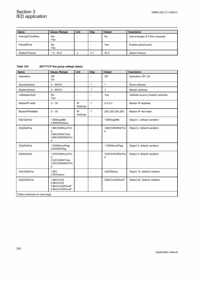
8/22/2019 Best Application
http://slidepdf.com/reader/full/best-application 342/457
Name Values (Range) Unit Step Default Description
Averag3TimeReq NoYes
- - No Use average of 3 time requests
PairedPoint No
Yes
- - Yes Enable paired point
tSelectTimeout 1.0 - 60.0 s 0.1 30.0 Select timeout
Table 124: M ST1TC P N on group settings (basic)
Name Values (Range) Unit Step Default Description
Operation Off On
- - Off Operation Off / On
SlaveAddress 0 - 65519 - 1 1 Slave address
MasterAddres 0 - 65519 - 1 1 Master address
ValMasterAddr NoYes
- - Yes Validate source (master) address
MasterIP-Addr 0 - 18 IP Address
1 0.0.0.0 Master IP-address
MasterIPNetMsk 0 - 18 IP Address
1 255.255.255.255 Master IP net mask
Obj1DefVar 1:BISingleBit2:BIWithStatus
- - 1:BISingleBit Object 1, default variation
Obj2DefVar 1:BIChWithoutTime2:BIChWithTime3:BIChWithRelTime
- - 3:BIChWithRelTime
Object 2, default variation
Obj3DefVar 1:DIWithoutFlag2:DIWithFlag
- - 1:DIWithoutFlag Object 3, default variation
Obj4DefVar 1:DIChWithoutTime2:DIChWithTime3:DIChWithRelTime
- - 3:DIChWithRelTime
Object 4, default variation
Obj10DefVar 1:BO2:BOStatus
- - 2:BOStatus Object 10, default variation
Obj20DefVar 1:BinCnt322:BinCnt165:BinCnt32WoutF6:BinCnt16WoutF
- - 5:BinCnt32WoutF Object 20, default variation
Table continues on next page
Section 3 1MRK 505 211-UEN C
IED application
336
Application manual

8/22/2019 Best Application
http://slidepdf.com/reader/full/best-application 343/457
Name Values (Range) Unit Step Default Description
Obj22DefVar 1:BinCnt32EvWoutT2:BinCnt16EvWoutT
5:BinCnt32EvWithT6:BinCnt16EvWithT
- - 1:BinCnt32EvWoutT
Object 22, default variation
Obj30DefVar 1:AI32Int2:AI16Int3:AI32IntWithoutF4:AI16IntWithoutF5:AI32FltWithF6:AI64FltWithF
- - 3:AI32IntWithoutF Object 30, default variation
Obj32DefVar 1:AI32IntEvWoutF2:AI16IntEvWoutF3:AI32IntEvWithFT4:AI16IntEvWithFT
5:AI32FltEvWithF6:AI64FltEvWithF7:AI32FltEvWithFT8:AI64FltEvWithFT
- - 1:AI32IntEvWoutF Object 32, default variation
Table 125: M ST1TCP Non group settings (advanced)
Name Values (Range) Unit Step Default Description
AddrQueryEnbl NoYes
- - Yes Address query enable
tApplConfTout 0.00 - 300.00 s 0.01 10.00 Application layer confim timeout
ApplMultFrgRes No
Yes
- - Yes Enable application for multiple fragment
response
ConfMultFrag NoYes
- - Yes Confirm each multiple fragment
UREnable NoYes
- - Yes Unsolicited response enabled
UREvClassMask Off Class 1Class 2Class 1 and 2Class 3Class 1 and 3Class 2 and 3Class 1, 2 and 3
- - Off Unsolicited response, event class mask
UROfflineRetry 0 - 10 - 1 5 Unsolicited response retries before off-line retry mode
tURRetryDelay 0.00 - 60.00 s 0.01 5.00 Unsolicited response retry delay in s
tUROfflRtryDel 0.00 - 60.00 s 0.01 30.00 Unsolicited response off-line retry delayin s
UREvCntThold1 1 - 100 - 1 5 Unsolicited response class 1 event countreport treshold
tUREvBufTout1 0.00 - 60.00 s 0.01 5.00 Unsolicited response class 1 eventbuffer timeout
UREvCntThold2 1 - 100 - 1 5 Unsolicited response class 2 event countreport treshold
Table continues on next page
1MRK 505 211-UEN C Section 3IED application
337
Application manual

8/22/2019 Best Application
http://slidepdf.com/reader/full/best-application 344/457
Name Values (Range) Unit Step Default Description
tUREvBufTout2 0.00 - 60.00 s 0.01 5.00 Unsolicited response class 2 eventbuffer timeout
UREvCntThold3 1 - 100 - 1 5 Unsolicited response class 3 event count
report treshold
tUREvBufTout3 0.00 - 60.00 s 0.01 5.00 Unsolicited response class 3 eventbuffer timeout
DelOldBufFull NoYes
- - No Delete oldest event when buffer is full
ExtTimeFormat LocalTimeUTC
- - UTC External time format
DNPToSetTime NoYes
- - No Allow DNP to set time in IED
tSynchTimeout 30 - 3600 s 1 1800 Time synch timeout before error status isgenerated
TSyncReqAfTout No
Yes
- - No Time synchronization request after
timeout
Averag3TimeReq NoYes
- - No Use average of 3 time requests
PairedPoint NoYes
- - Yes Enable paired point
tSelectTimeout 1.0 - 60.0 s 0.1 30.0 Select timeout
tBrokenConTout 0 - 3600 s 1 0 Broken connection timeout
tKeepAliveT 0 - 3600 s 1 10 Keep-Alive timer
Table 126: M ST2TC P N on group settings (basic)
Name Values (Range) Unit Step Default Description
Operation Off On
- - Off Operation Off / On
SlaveAddress 0 - 65519 - 1 1 Slave address
MasterAddres 0 - 65519 - 1 1 Master address
ValMasterAddr NoYes
- - Yes Validate source (master) address
MasterIP-Addr 0 - 18 IP Address
1 0.0.0.0 Master IP-address
MasterIPNetMsk 0 - 18 IP Address
1 255.255.255.255 Master IP net mask
Obj1DefVar 1:BISingleBit2:BIWithStatus
- - 1:BISingleBit Object 1, default variation
Obj2DefVar 1:BIChWithoutTime2:BIChWithTime3:BIChWithRelTime
- - 3:BIChWithRelTime
Object 2, default variation
Obj3DefVar 1:DIWithoutFlag2:DIWithFlag
- - 1:DIWithoutFlag Object 3, default variation
Table continues on next page
Section 3 1MRK 505 211-UEN C
IED application
338
Application manual

8/22/2019 Best Application
http://slidepdf.com/reader/full/best-application 345/457
Name Values (Range) Unit Step Default Description
Obj4DefVar 1:DIChWithoutTime2:DIChWithTime3:DIChWithRelTim
e
- - 3:DIChWithRelTime
Object 4, default variation
Obj10DefVar 1:BO2:BOStatus
- - 2:BOStatus Object 10, default variation
Obj20DefVar 1:BinCnt322:BinCnt165:BinCnt32WoutF6:BinCnt16WoutF
- - 5:BinCnt32WoutF Object 20, default variation
Obj22DefVar 1:BinCnt32EvWoutT2:BinCnt16EvWoutT5:BinCnt32EvWithT
6:BinCnt16EvWithT
- - 1:BinCnt32EvWoutT
Object 22, default variation
Obj30DefVar 1:AI32Int2:AI16Int3:AI32IntWithoutF4:AI16IntWithoutF5:AI32FltWithF6:AI64FltWithF
- - 3:AI32IntWithoutF Object 30, default variation
Obj32DefVar 1:AI32IntEvWoutF2:AI16IntEvWoutF3:AI32IntEvWithFT4:AI16IntEvWithFT5:AI32FltEvWithF6:AI64FltEvWithF7:AI32FltEvWithFT8:AI64FltEvWithFT
- - 1:AI32IntEvWoutF Object 32, default variation
Table 127: M ST2TCP Non group settings (advanced)
Name Values (Range) Unit Step Default Description
AddrQueryEnbl NoYes
- - Yes Address query enable
tApplConfTout 0.00 - 300.00 s 0.01 10.00 Application layer confim timeout
ApplMultFrgRes NoYes
- - Yes Enable application for multiple fragmentresponse
ConfMultFrag NoYes
- - Yes Confirm each multiple fragment
UREnable NoYes
- - Yes Unsolicited response enabled
UREvClassMask Off Class 1Class 2Class 1 and 2Class 3Class 1 and 3Class 2 and 3Class 1, 2 and 3
- - Off Unsolicited response, event class mask
Table continues on next page
1MRK 505 211-UEN C Section 3IED application
339
Application manual
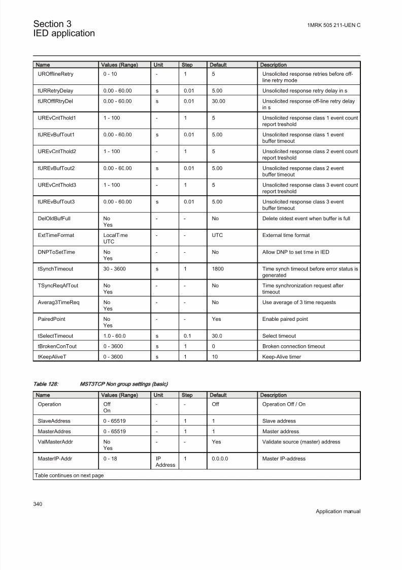
8/22/2019 Best Application
http://slidepdf.com/reader/full/best-application 346/457
Name Values (Range) Unit Step Default Description
UROfflineRetry 0 - 10 - 1 5 Unsolicited response retries before off-line retry mode
tURRetryDelay 0.00 - 60.00 s 0.01 5.00 Unsolicited response retry delay in s
tUROfflRtryDel 0.00 - 60.00 s 0.01 30.00 Unsolicited response off-line retry delayin s
UREvCntThold1 1 - 100 - 1 5 Unsolicited response class 1 event countreport treshold
tUREvBufTout1 0.00 - 60.00 s 0.01 5.00 Unsolicited response class 1 eventbuffer timeout
UREvCntThold2 1 - 100 - 1 5 Unsolicited response class 2 event countreport treshold
tUREvBufTout2 0.00 - 60.00 s 0.01 5.00 Unsolicited response class 2 eventbuffer timeout
UREvCntThold3 1 - 100 - 1 5 Unsolicited response class 3 event countreport treshold
tUREvBufTout3 0.00 - 60.00 s 0.01 5.00 Unsolicited response class 3 eventbuffer timeout
DelOldBufFull NoYes
- - No Delete oldest event when buffer is full
ExtTimeFormat LocalTimeUTC
- - UTC External time format
DNPToSetTime NoYes
- - No Allow DNP to set time in IED
tSynchTimeout 30 - 3600 s 1 1800 Time synch timeout before error status isgenerated
TSyncReqAfTout No
Yes
- - No Time synchronization request after
timeout Averag3TimeReq No
Yes- - No Use average of 3 time requests
PairedPoint NoYes
- - Yes Enable paired point
tSelectTimeout 1.0 - 60.0 s 0.1 30.0 Select timeout
tBrokenConTout 0 - 3600 s 1 0 Broken connection timeout
tKeepAliveT 0 - 3600 s 1 10 Keep-Alive timer
Table 128: M ST3TC P N on group settings (basic)
Name Values (Range) Unit Step Default Description
Operation Off On
- - Off Operation Off / On
SlaveAddress 0 - 65519 - 1 1 Slave address
MasterAddres 0 - 65519 - 1 1 Master address
ValMasterAddr NoYes
- - Yes Validate source (master) address
MasterIP-Addr 0 - 18 IP Address
1 0.0.0.0 Master IP-address
Table continues on next page
Section 3 1MRK 505 211-UEN C
IED application
340
Application manual
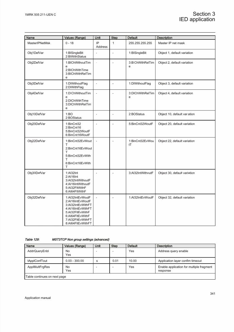
8/22/2019 Best Application
http://slidepdf.com/reader/full/best-application 347/457
Name Values (Range) Unit Step Default Description
MasterIPNetMsk 0 - 18 IP Address
1 255.255.255.255 Master IP net mask
Obj1DefVar 1:BISingleBit
2:BIWithStatus
- - 1:BISingleBit Object 1, default variation
Obj2DefVar 1:BIChWithoutTime2:BIChWithTime3:BIChWithRelTime
- - 3:BIChWithRelTime
Object 2, default variation
Obj3DefVar 1:DIWithoutFlag2:DIWithFlag
- - 1:DIWithoutFlag Object 3, default variation
Obj4DefVar 1:DIChWithoutTime2:DIChWithTime3:DIChWithRelTime
- - 3:DIChWithRelTime
Object 4, default variation
Obj10DefVar 1:BO2:BOStatus
- - 2:BOStatus Object 10, default variation
Obj20DefVar 1:BinCnt322:BinCnt165:BinCnt32WoutF6:BinCnt16WoutF
- - 5:BinCnt32WoutF Object 20, default variation
Obj22DefVar 1:BinCnt32EvWoutT2:BinCnt16EvWoutT5:BinCnt32EvWithT6:BinCnt16EvWithT
- - 1:BinCnt32EvWoutT
Object 22, default variation
Obj30DefVar 1:AI32Int2:AI16Int3:AI32IntWithoutF4:AI16IntWithoutF5:AI32FltWithF6:AI64FltWithF
- - 3:AI32IntWithoutF Object 30, default variation
Obj32DefVar 1:AI32IntEvWoutF2:AI16IntEvWoutF3:AI32IntEvWithFT4:AI16IntEvWithFT5:AI32FltEvWithF6:AI64FltEvWithF7:AI32FltEvWithFT8:AI64FltEvWithFT
- - 1:AI32IntEvWoutF Object 32, default variation
Table 129: M ST3TCP Non group settings (advanced)
Name Values (Range) Unit Step Default Description
AddrQueryEnbl NoYes
- - Yes Address query enable
tApplConfTout 0.00 - 300.00 s 0.01 10.00 Application layer confim timeout
ApplMultFrgRes NoYes
- - Yes Enable application for multiple fragmentresponse
Table continues on next page
1MRK 505 211-UEN C Section 3IED application
341
Application manual

8/22/2019 Best Application
http://slidepdf.com/reader/full/best-application 348/457
Name Values (Range) Unit Step Default Description
ConfMultFrag NoYes
- - Yes Confirm each multiple fragment
UREnable No
Yes
- - Yes Unsolicited response enabled
UREvClassMask Off Class 1Class 2Class 1 and 2Class 3Class 1 and 3Class 2 and 3Class 1, 2 and 3
- - Off Unsolicited response, event class mask
UROfflineRetry 0 - 10 - 1 5 Unsolicited response retries before off-line retry mode
tURRetryDelay 0.00 - 60.00 s 0.01 5.00 Unsolicited response retry delay in s
tUROfflRtryDel 0.00 - 60.00 s 0.01 30.00 Unsolicited response off-line retry delay
in s
UREvCntThold1 1 - 100 - 1 5 Unsolicited response class 1 event countreport treshold
tUREvBufTout1 0.00 - 60.00 s 0.01 5.00 Unsolicited response class 1 eventbuffer timeout
UREvCntThold2 1 - 100 - 1 5 Unsolicited response class 2 event countreport treshold
tUREvBufTout2 0.00 - 60.00 s 0.01 5.00 Unsolicited response class 2 eventbuffer timeout
UREvCntThold3 1 - 100 - 1 5 Unsolicited response class 3 event countreport treshold
tUREvBufTout3 0.00 - 60.00 s 0.01 5.00 Unsolicited response class 3 event
buffer timeout
DelOldBufFull NoYes
- - No Delete oldest event when buffer is full
ExtTimeFormat LocalTimeUTC
- - UTC External time format
DNPToSetTime NoYes
- - No Allow DNP to set time in IED
tSynchTimeout 30 - 3600 s 1 1800 Time synch timeout before error status isgenerated
TSyncReqAfTout NoYes
- - No Time synchronization request after timeout
Averag3TimeReq NoYes - - No Use average of 3 time requests
PairedPoint NoYes
- - Yes Enable paired point
tSelectTimeout 1.0 - 60.0 s 0.1 30.0 Select timeout
tBrokenConTout 0 - 3600 s 1 0 Broken connection timeout
tKeepAliveT 0 - 3600 s 1 10 Keep-Alive timer
Section 3 1MRK 505 211-UEN C
IED application
342
Application manual

8/22/2019 Best Application
http://slidepdf.com/reader/full/best-application 349/457
Table 130: M ST4TCP Non group settings (basic)
Name Values (Range) Unit Step Default Description
Operation Off On
- - Off Operation Off / On
SlaveAddress 0 - 65519 - 1 1 Slave address
MasterAddres 0 - 65519 - 1 1 Master address
ValMasterAddr NoYes
- - Yes Validate source (master) address
MasterIP-Addr 0 - 18 IP Address
1 0.0.0.0 Master IP-address
MasterIPNetMsk 0 - 18 IP Address
1 255.255.255.255 Master IP net mask
Obj1DefVar 1:BISingleBit2:BIWithStatus
- - 1:BISingleBit Object 1, default variation
Obj2DefVar 1:BIChWithoutTim
e2:BIChWithTime3:BIChWithRelTime
- - 3:BIChWithRelTim
e
Object 2, default variation
Obj3DefVar 1:DIWithoutFlag2:DIWithFlag
- - 1:DIWithoutFlag Object 3, default variation
Obj4DefVar 1:DIChWithoutTime2:DIChWithTime3:DIChWithRelTime
- - 3:DIChWithRelTime
Object 4, default variation
Obj10DefVar 1:BO2:BOStatus
- - 2:BOStatus Object 10, default variation
Obj20DefVar 1:BinCnt322:BinCnt165:BinCnt32WoutF6:BinCnt16WoutF
- - 5:BinCnt32WoutF Object 20, default variation
Obj22DefVar 1:BinCnt32EvWoutT2:BinCnt16EvWoutT5:BinCnt32EvWithT6:BinCnt16EvWithT
- - 1:BinCnt32EvWoutT
Object 22, default variation
Obj30DefVar 1:AI32Int2:AI16Int
3:AI32IntWithoutF4:AI16IntWithoutF5:AI32FltWithF6:AI64FltWithF
- - 3:AI32IntWithoutF Object 30, default variation
Obj32DefVar 1:AI32IntEvWoutF2:AI16IntEvWoutF3:AI32IntEvWithFT4:AI16IntEvWithFT5:AI32FltEvWithF6:AI64FltEvWithF7:AI32FltEvWithFT8:AI64FltEvWithFT
- - 1:AI32IntEvWoutF Object 32, default variation
1MRK 505 211-UEN C Section 3IED application
343
Application manual
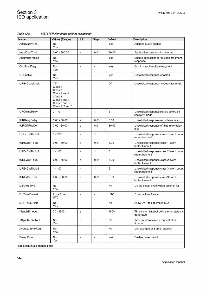
8/22/2019 Best Application
http://slidepdf.com/reader/full/best-application 350/457
Table 131: M ST4TC P N on group settings (advanced)
Name Values (Range) Unit Step Default Description
AddrQueryEnbl NoYes
- - Yes Address query enable
tApplConfTout 0.00 - 300.00 s 0.01 10.00 Application layer confim timeout
ApplMultFrgRes NoYes
- - Yes Enable application for multiple fragmentresponse
ConfMultFrag NoYes
- - Yes Confirm each multiple fragment
UREnable NoYes
- - Yes Unsolicited response enabled
UREvClassMask Off Class 1Class 2Class 1 and 2Class 3
Class 1 and 3Class 2 and 3Class 1, 2 and 3
- - Off Unsolicited response, event class mask
UROfflineRetry 0 - 10 - 1 5 Unsolicited response retries before off-line retry mode
tURRetryDelay 0.00 - 60.00 s 0.01 5.00 Unsolicited response retry delay in s
tUROfflRtryDel 0.00 - 60.00 s 0.01 30.00 Unsolicited response off-line retry delayin s
UREvCntThold1 1 - 100 - 1 5 Unsolicited response class 1 event countreport treshold
tUREvBufTout1 0.00 - 60.00 s 0.01 5.00 Unsolicited response class 1 eventbuffer timeout
UREvCntThold2 1 - 100 - 1 5 Unsolicited response class 2 event countreport treshold
tUREvBufTout2 0.00 - 60.00 s 0.01 5.00 Unsolicited response class 2 eventbuffer timeout
UREvCntThold3 1 - 100 - 1 5 Unsolicited response class 3 event countreport treshold
tUREvBufTout3 0.00 - 60.00 s 0.01 5.00 Unsolicited response class 3 eventbuffer timeout
DelOldBufFull NoYes
- - No Delete oldest event when buffer is full
ExtTimeFormat LocalTimeUTC
- - UTC External time format
DNPToSetTime NoYes
- - No Allow DNP to set time in IED
tSynchTimeout 30 - 3600 s 1 1800 Time synch timeout before error status isgenerated
TSyncReqAfTout NoYes
- - No Time synchronization request after timeout
Averag3TimeReq NoYes
- - No Use average of 3 time requests
PairedPoint NoYes
- - Yes Enable paired point
Table continues on next page
Section 3 1MRK 505 211-UEN C
IED application
344
Application manual

8/22/2019 Best Application
http://slidepdf.com/reader/full/best-application 351/457
Name Values (Range) Unit Step Default Description
tSelectTimeout 1.0 - 60.0 s 0.1 30.0 Select timeout
tBrokenConTout 0 - 3600 s 1 0 Broken connection timeout
tKeepAliveT 0 - 3600 s 1 10 Keep-Alive timer
3.11.9 Single command, 16 signals SINGLECMD
Function description IEC 61850
identification
IEC 60617
identification
ANSI/IEEE C37.2
device number
Single command, 16 signals SINGLECMD - -
3.11.9.1 Application
Single command, 16 signals (SINGLECMD) is a common function and alwaysincluded in the IED.
The IEDs may be provided with a function to receive commands either from asubstation automation system or from the local HMI. That receiving function block has outputs that can be used, for example, to control high voltage apparatuses inswitchyards. For local control functions, the local HMI can also be used. Together with the configuration logic circuits, the user can govern pulses or steady outputsignals for control purposes within the IED or via binary outputs.
Figure 136 shows an application example of how the user can connectSINGLECMD via configuration logic circuit to control a high-voltage apparatus.This type of command control is normally carried out by sending a pulse to the
binary outputs of the IED. Figure 136 shows a close operation. An open breaker operation is performed in a similar way but without the synchro-check condition.
1MRK 505 211-UEN C Section 3IED application
345
Application manual

8/22/2019 Best Application
http://slidepdf.com/reader/full/best-application 352/457
Single
command
function
SINGLECMD
CMDOUTy
OUTy
Close CB1
&User-
defined
conditions
Synchro-
check
Configuration logic circuits
en04000206.vsdIEC04000206 V2 EN
Figure 136: Application example showing a logic diagram for control of a circuit
breaker via configuration logic circuits
Figure 137 and figure 138 show other ways to control functions, which requiresteady On/Off signals. Here, the output is used to control built-in functions or external devices.
Singlecommand
functionSINGLECMD
CMDOUTy
OUTy
Function n
en04000207.vsd
Function n
IEC04000207 V2 EN
Figure 137: Application example showing a logic diagram for control of built-in
functions
Section 3 1MRK 505 211-UEN C
IED application
346
Application manual
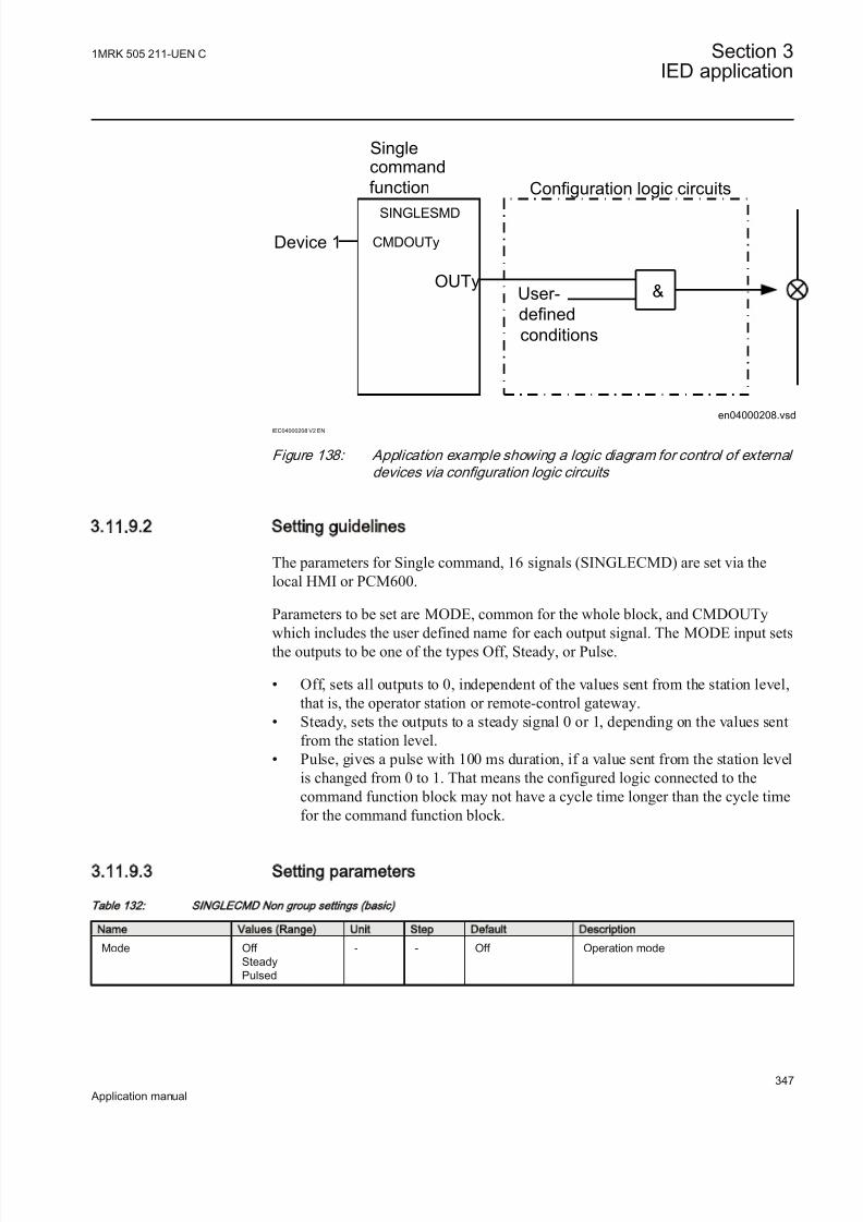
8/22/2019 Best Application
http://slidepdf.com/reader/full/best-application 353/457
Singlecommand
function
SINGLESMD
CMDOUTy
OUTy
Device 1
User-
defined
conditions
Configuration logic circuits
en04000208.vsd
&
IEC04000208 V2 EN
Figure 138: Application example showing a logic diagram for control of external
devices via configuration logic circuits
3.11.9.2 Setting guidelines
The parameters for Single command, 16 signals (SINGLECMD) are set via thelocal HMI or PCM600.
Parameters to be set are MODE, common for the whole block, and CMDOUTy
which includes the user defined name for each output signal. The MODE input setsthe outputs to be one of the types Off, Steady, or Pulse.
• Off, sets all outputs to 0, independent of the values sent from the station level,that is, the operator station or remote-control gateway.
• Steady, sets the outputs to a steady signal 0 or 1, depending on the values sentfrom the station level.
• Pulse, gives a pulse with 100 ms duration, if a value sent from the station levelis changed from 0 to 1. That means the configured logic connected to thecommand function block may not have a cycle time longer than the cycle timefor the command function block.
3.11.9.3 Setting parameters
Table 132: SIN GLEC MD Non group settings (basic)
Name Values (Range) Unit Step Default Description
Mode Off SteadyPulsed
- - Off Operation mode
1MRK 505 211-UEN C Section 3IED application
347
Application manual

8/22/2019 Best Application
http://slidepdf.com/reader/full/best-application 354/457
3.12 Logic
3.12.1 Configurable logic blocks
3.12.1.1 Application
A set of standard logic blocks, like AND, OR etc, and timers are available for adapting the IED configuration to the specific application needs.
There are no settings for AND gates, OR gates, inverters or XOR gates.
For normal On/Off delay and pulse timers the time delays and pulse lengths are setfrom the local HMI or via the PST tool.
Both timers in the same logic block (the one delayed on pick-up and the onedelayed on drop-out) always have a common setting value.
For controllable gates, settable timers and SR flip-flops with memory, the setting parameters are accessible via the local HMI or via the PST tool.
ConfigurationLogic is configured using the ACT configuration tool in PCM600.
Execution of functions as defined by the configurable logic blocks runs accordingto a fixed sequence with different cycle times.
For each cycle time, the function block is given an serial execution number. This isshown when using the ACT configuration tool with the designation of the function
block and the cycle time, see example below.
IEC09000695_2_en.vsd
IEC09000695 V2 EN
Figure 139: Example designation, serial execution number and cycle time for
logic function
The execution of different function blocks within the same cycle is determined bythe order of their serial execution numbers. Always remember this whenconnecting two or more logical function blocks in series.
Section 3 1MRK 505 211-UEN C
IED application
348
Application manual

8/22/2019 Best Application
http://slidepdf.com/reader/full/best-application 355/457
Always be careful when connecting function blocks with a fastcycle time to function blocks with a slow cycle time.Remember to design the logic circuits carefully and always check the execution sequence for different functions. In other cases,additional time delays must be introduced into the logic schemes to
prevent errors, for example, race between functions.
3.12.1.2 Setting parameters
Table 133: TIMER Non group settings (basic)
Name Values (Range) Unit Step Default Description
T 0.000 - 90000.000 s 0.001 0.000 Time delay of function
Table 134: PU LSE TIM ER Non group settings (basic)
Name Values (Range) Unit Step Default Description
T 0.000 - 90000.000 s 0.001 0.010 Time delay of function
Table 135: SRM EM ORY Group settings (basic)
Name Values (Range) Unit Step Default Description
Memory Off On
- - On Operating mode of the memory function
Table 136: RSM EM ORY Group settings (basic)
Name Values (Range) Unit Step Default Description
Memory Off On
- - On Operating mode of the memory function
Table 137: GATE Group settings (basic)
Name Values (Range) Unit Step Default Description
Operation Off On
- - Off Operation Off/On
Table 138: TIMERSET Group settings (basic)
Name Values (Range) Unit Step Default Description
Operation Off On
- - Off Operation Off/On
t 0.000 - 90000.000 s 0.001 0.000 Delay for settable timer n
1MRK 505 211-UEN C Section 3IED application
349
Application manual

8/22/2019 Best Application
http://slidepdf.com/reader/full/best-application 356/457
3.12.2 Fixed signal function block FXDSIGN
Function description IEC 61850
identification
IEC 60617
identification
ANSI/IEEE C37.2
device number
Fixed signals FXDSIGN - -
3.12.2.1 Application
The Fixed signals function (FXDSIGN) generates a number of pre-set (fixed)signals that can be used in the configuration of an IED, either for forcing theunused inputs in other function blocks to a certain level/value, or for creatingcertain logic.
Example for use of GRP_OFF signal in FXDSIGN
The Restricted earth fault function REFPDIF can be used both for auto-transformers and normal transformers.
When used for auto-transformers, information from both windings parts, together with the neutral point current, needs to be available to the function. This means thatthree inputs are needed.
I3PW1CT1
I3PW2CT1
I3P
REFPDIF
IEC09000619_3_en.vsd
IEC09000619 V3 EN
Figure 140: REFPDIF function inputs for autotransformer application
For normal transformers only one winding and the neutral point is available. Thismeans that only two inputs are used. Since all group connections are mandatory to
be connected, the third input needs to be connected to something, which is theGRP_OFF signal in FXDSIGN function block.
Section 3 1MRK 505 211-UEN C
IED application
350
Application manual

8/22/2019 Best Application
http://slidepdf.com/reader/full/best-application 357/457
I3PW1CT1
I3PW2CT1
I3P
REFPDIF
GRP_OFF
FXDSIGN
IEC09000620_3_en.vsd
IEC09000620 V3 EN
Figure 141: REFPDIF function inputs for normal transformer application
3.12.2.2 Setting parameters
The function does not have any parameters available in Local HMI or Protectionand Control IED Manager (PCM 600)
3.12.3 Boolean 16 to Integer conversion B16I
Function description IEC 61850
identification
IEC 60617
identification
ANSI/IEEE C37.2
device number
Boolean 16 to integer conversion B16I - -
3.12.3.1 Application
Boolean 16 to integer conversion function B16I is used to transform a set of 16 binary (logical) signals into an integer. It can be used – for example, to connectlogical output signals from a function (like distance protection) to integer inputsfrom another function (like line differential protection). B16I does not have alogical node mapping.
3.12.3.2 Setting guidelines
The function does not have any parameters available in Local HMI or Protectionand Control IED Manager (PCM600).
3.12.4 Boolean 16 to Integer conversion with logic node
representation B16IFCVI
Function description IEC 61850
identification
IEC 60617
identification
ANSI/IEEE C37.2
device number
Boolean 16 to integer conversion withlogic node representation
B16IFCVI - -
1MRK 505 211-UEN C Section 3IED application
351
Application manual

8/22/2019 Best Application
http://slidepdf.com/reader/full/best-application 358/457
3.12.4.1 Application
Boolean 16 to integer conversion with logic node representation functionB16IFCVI is used to transform a set of 16 binary (logical) signals into an integer.
B16IFCVI can receive an integer from a station computer – for example, over IEC61850–8–1. These functions are very useful when you want to generate logicalcommands (for selector switches or voltage controllers) by inputting an integer number. B16IFCVI has a logical node mapping in IEC 61850.
3.12.4.2 Setting guidelines
The function does not have any parameters available in the local HMI or Protectionand Control IED Manager (PCM600).
3.12.5 Integer to Boolean 16 conversion IB16
Function description IEC 61850
identification
IEC 60617
identification
ANSI/IEEE C37.2
device number
Integer to boolean 16 conversion IB16 - -
3.12.5.1 Application
Integer to boolean 16 conversion function (IB16) is used to transform an integer into a set of 16 binary (logical) signals. It can be used – for example, to connect
integer output signals from one function to binary (logical) inputs to another function. IB16 function does not have a logical node mapping.
3.12.5.2 Setting parameters
The function does not have any parameters available in the local HMI or Protectionand Control IED Manager (PCM600).
3.12.6 Integer to Boolean 16 conversion with logic node
representation IB16FCVB
Function description IEC 61850
identification
IEC 60617
identification
ANSI/IEEE C37.2
device number
Integer to boolean 16 conversion withlogic node representation
IB16FCVB - -
3.12.6.1 Application
Integer to boolean 16 conversion with logic node representation function(IB16FCVB) is used to transform an integer into a set of 16 binary (logical)
Section 3 1MRK 505 211-UEN C
IED application
352
Application manual

8/22/2019 Best Application
http://slidepdf.com/reader/full/best-application 359/457
signals. IB16FCVB function can receive an integer from a station computer – for example, over IEC 61850–8–1. These functions are very useful when the user wants to generate logical commands (for selector switches or voltage controllers)
by inputting an integer number. IB16FCVB function has a logical node mapping inIEC 61850.
3.12.6.2 Setting parameters
The function does not have any parameters available in the local HMI or Protectionand Control IED Manager (PCM600)
3.13 Monitoring
3.13.1 Measurement
Function description IEC 61850
identification
IEC 60617
identification
ANSI/IEEE C37.2
device number
Measurements CVMMXN
P, Q, S, I, U, f
SYMBOL-RR V1 EN
-
Phase current measurement CMMXU
I
SYMBOL-SS V1 EN
-
Phase-phase voltage measurement VMMXU
U
SYMBOL-UU V1 EN
-
Current sequence componentmeasurement
CMSQI
I1, I2, I0
SYMBOL-VV V1 EN
-
Voltage sequence measurement VMSQI
U1, U2, U0
SYMBOL-TT V1 EN
-
Phase-neutral voltage measurement VNMMXU
U
SYMBOL-UU V1 EN
-
1MRK 505 211-UEN C Section 3IED application
353
Application manual
8/22/2019 Best Application
http://slidepdf.com/reader/full/best-application 360/457
3.13.1.1 Application
Measurement functions is used for power system measurement, supervision andreporting to the local HMI, monitoring tool within PCM600 or to station level for
example, via IEC 61850. The possibility to continuously monitor measured valuesof active power, reactive power, currents, voltages, frequency, power factor etc. isvital for efficient production, transmission and distribution of electrical energy. It
provides to the system operator fast and easy overview of the present status of the power system. Additionally, it can be used during testing and commissioning of protection and control IEDs in order to verify proper operation and connection of instrument transformers (CTs and VTs). During normal service by periodiccomparison of the measured value from the IED with other independent meters the
proper operation of the IED analog measurement chain can be verified. Finally, itcan be used to verify proper direction orientation for distance or directionalovercurrent protection function.
The available measured values of an IED are depending on theactual hardware (TRM) and the logic configuration made in PCM600.
All measured values can be supervised with four settable limits that is, low-lowlimit, low limit, high limit and high-high limit. A zero clamping reduction is alsosupported, that is, the measured value below a settable limit is forced to zero whichreduces the impact of noise in the inputs.
Dead-band supervision can be used to report measured signal value to station levelwhen change in measured value is above set threshold limit or time integral of all
changes since the last time value updating exceeds the threshold limit. Measurevalue can also be based on periodic reporting.
The measurement function, CVMMXN, provides the following power systemquantities:
• P, Q and S: three phase active, reactive and apparent power • PF: power factor • U: phase-to-phase voltage amplitude• I: phase current amplitude• F: power system frequency
Main menu/Measurement/Monitoring/Service values/CVMMXN
The measuring functions CMMXU, VNMMXU and VMMXU provide physicalquantities:
• I: phase currents (amplitude and angle) (CMMXU)• U: voltages (phase-to-earth and phase-to-phase voltage, amplitude and angle)
(VMMXU, VNMMXU)
Section 3 1MRK 505 211-UEN C
IED application
354
Application manual
8/22/2019 Best Application
http://slidepdf.com/reader/full/best-application 361/457
It is possible to calibrate the measuring function above to get better then class 0.5 presentation. This is accomplished by angle and amplitude compensation at 5, 30and 100% of rated current and at 100% of rated voltage.
The power system quantities provided, depends on the actualhardware, (TRM) and the logic configuration made in PCM600.
The measuring functions CMSQI and VMSQI provide sequence componentquantities:
• I: sequence currents (positive, zero, negative sequence, amplitude and angle)• U: sequence voltages (positive, zero and negative sequence, amplitude and
angle).
The CVMMXN function calculates three-phase power quantities by usingfundamental frequency phasors (DFT values) of the measured current respectivelyvoltage signals. The measured power quantities are available either, asinstantaneously calculated quantities or, averaged values over a period of time (low
pass filtered) depending on the selected settings.
3.13.1.2 Zero clamping
The measuring functions, CMMXU, VMMXU, VNMMXU and CVMMXN haveno interconnections regarding any setting or parameter.
Zero clampings are also entirely handled by the ZeroDb for each and every signalseparately for each of the functions. For example, the zero clamping of U12 ishandled by UL12ZeroDb in VMMXU, zero clamping of I1 is handled by
IL1ZeroDb in CMMXU ETC.
Example how CVMMXN is operating:
The following outputs can be observed on the local HMI under Monitoring/
Servicevalues/SRV1
S Apparent three-phase power
P Active three-phase power
Q Reactive three-phase power
PF Power factor
ILAG I lagging U
ILEAD I leading U
U System mean voltage, calculated according to selected mode
I System mean current, calculated according to selected mode
F Frequency
1MRK 505 211-UEN C Section 3IED application
355
Application manual

8/22/2019 Best Application
http://slidepdf.com/reader/full/best-application 362/457
The settings for this function is found under Setting/General setting/Monitoring/
Service values/SRV1
It can be seen that:
• When system voltage falls below UGenZeroDB, the shown value for S, P, Q,PF, ILAG, ILEAD, U and F on the local HMI is forced to zero
• When system current falls below IGenZeroDB, the shown value for S, P, Q,PF, ILAG, ILEAD, U and F on the local HMI is forced to zero
• When the value of a single signal falls below the set dead band for that specificsignal, the value shown on the local HMI is forced to zero. For example, if apparent three-phase power falls below SZeroDb the value for S on the localHMI is forced to zero.
3.13.1.3 Setting guidelines
The available setting parameters of the measurement function CVMMXN,CMMXU, VMMXU, CMSQI, VMSQI, VNMMXU are depending on the actualhardware (TRM) and the logic configuration made in PCM600.
The parameters for the Measurement functions CVMMXN, CMMXU, VMMXU,CMSQI, VMSQI, VNMMXU are set via the local HMI or PCM600.
Operation: Off /On. Every function instance (CVMMXN, CMMXU, VMMXU,CMSQI, VMSQI, VNMMXU) can be taken in operation (On) or out of operation(Off ).
The following general settings can be set for the Measurement function
(CVMMXN).
PowAmpFact : Amplitude factor to scale power calculations.
PowAngComp: Angle compensation for phase shift between measured I & U.
Mode: Selection of measured current and voltage. There are 9 different ways of calculating monitored three-phase values depending on the available VT inputsconnected to the IED. See parameter group setting table.
k : Low pass filter coefficient for power measurement, U and I.
UGenZeroDb: Minimum level of voltage in % of UBase used as indication of zerovoltage (zero point clamping). If measured value is below UGenZeroDb calculatedS, P, Q and PF will be zero.
IGenZeroDb: Minimum level of current in % of IBase used as indication of zerocurrent (zero point clamping). If measured value is below IGenZeroDb calculatedS, P, Q and PF will be zero.
Section 3 1MRK 505 211-UEN C
IED application
356
Application manual

8/22/2019 Best Application
http://slidepdf.com/reader/full/best-application 363/457
UBase: Base voltage in primary kV. This voltage is used as reference for voltagesetting. It can be suitable to set this parameter to the rated primary voltagesupervised object.
IBase: Base current in primary A. This current is used as reference for currentsetting. It can be suitable to set this parameter to the rated primary current of thesupervised object.
SBase: Base setting for power values in MVA.
UAmpCompY : Amplitude compensation to calibrate voltage measurements at Y%of Ur, where Y is equal to 5, 30 or 100.
IAmpCompY : Amplitude compensation to calibrate current measurements at Y% of Ir, where Y is equal to 5, 30 or 100.
IAngCompY : Angle compensation to calibrate angle measurements at Y% of Ir,where Y is equal to 5, 30 or 100.
Parameters IBase, Ubase and SBase have been implemented as asettings instead of a parameters, which means that if the values of the parameters are changed there will be no restart of theapplication. As restart is required to activate new parametersvalues, the IED must be restarted in some way. Either manually or
by changing some other parameter at the same time.
The following general settings can be set for the Phase-phase current
measurement (CMMXU).
IAmpCompY : Amplitude compensation to calibrate current measurements at Y% of Ir, where Y is equal to 5, 30 or 100.
IAngCompY : Angle compensation to calibrate angle measurements at Y% of Ir,where Y is equal to 5, 30 or 100.
The following general settings can be set for the Phase-phase voltage
measurement (VMMXU).
UAmpCompY : Amplitude compensation to calibrate voltage measurements at Y%
of Ur, where Y is equal to 5, 30 or 100.UAngCompY : Angle compensation to calibrate angle measurements at Y% of Ur,where Y is equal to 5, 30 or 100.
The following general settings can be set for all monitored quantities included inthe functions (CVMMXN, CMMXU, VMMXU, CMSQI, VMSQI, VNMMXU) Xin setting names below equals S, P, Q, PF, U, I, F, IL1-3, UL1-3UL12-31, I1, I2,3I0, U1, U2 or 3U0.
Xmin: Minimum value for analog signal X set directly in applicable measuring unit.
1MRK 505 211-UEN C Section 3IED application
357
Application manual

8/22/2019 Best Application
http://slidepdf.com/reader/full/best-application 364/457
Xmax: Maximum value for analog signal X.
XZeroDb: Zero point clamping. A signal value less than XZeroDb is forced to zero.
Observe the related zero point clamping settings in Setting group N for CVMMXN(UGenZeroDb and IGenZeroDb). If measured value is below UGenZeroDb and/or IGenZeroDb calculated S, P, Q and PF will be zero and these settings will override XZeroDb.
XRepTyp: Reporting type. Cyclic (Cyclic), amplitude deadband ( Dead band ) or integral deadband ( Int deadband ). The reporting interval is controlled by the
parameter XDbRepInt .
XDbRepInt : Reporting deadband setting. Cyclic reporting is the setting value and isreporting interval in seconds. Amplitude deadband is the setting value in % of measuring range. Integral deadband setting is the integral area, that is, measured
value in % of measuring range multiplied by the time between two measured values.
XHiHiLim: High-high limit. Set in applicable measuring unit.
XHiLim: High limit.
XLowLim: Low limit.
XLowLowLim: Low-low limit.
XLimHyst : Hysteresis value in % of range and is common for all limits.
All phase angles are presented in relation to defined reference channel. The parameter PhaseAngleRef defines the reference.
Calibration curves
It is possible to calibrate the functions (CVMMXN, CMMXU, VNMMXU andVMMXU) to get class 0.5 presentations of currents, voltages and powers. This isaccomplished by amplitude and angle compensation at 5, 30 and 100% of ratedcurrent and voltage. The compensation curve will have the characteristic for amplitude and angle compensation of currents as shown in figure 142 (example).The first phase will be used as reference channel and compared with the curve for calculation of factors. The factors will then be used for all related channels.
Section 3 1MRK 505 211-UEN C
IED application
358
Application manual

8/22/2019 Best Application
http://slidepdf.com/reader/full/best-application 365/457
IEC05000652 V2 EN
Figure 142: Calibration curves
Setting examplesThree setting examples, in connection to Measurement function (CVMMXN), are
provided:
• Measurement function (CVMMXN) application for a 400 kV OHL• Measurement function (CVMMXN) application on the secondary side of a
transformer • Measurement function (CVMMXN) application for a generator
For each of them detail explanation and final list of selected setting parametersvalues will be provided.
The available measured values of an IED are depending on theactual hardware (TRM) and the logic configuration made in PCM600.
Measurement function application for a 400 kV OHLSingle line diagram for this application is given in figure 143:
1MRK 505 211-UEN C Section 3IED application
359
Application manual
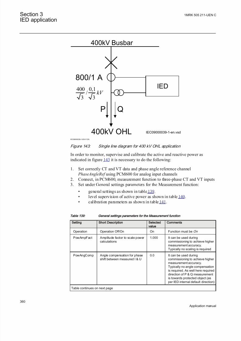
8/22/2019 Best Application
http://slidepdf.com/reader/full/best-application 366/457
400kV Busbar
400kV OHL
P Q
800/1 A
400 0,1/
3 3kV
IEC09000039-1-en.vsd
IED
IEC09000039-1-EN V1 EN
Figure 143: Single line diagram for 400 kV OHL application
In order to monitor, supervise and calibrate the active and reactive power asindicated in figure 143 it is necessary to do the following:
1. Set correctly CT and VT data and phase angle reference channel
PhaseAngleRef using PCM600 for analog input channels2. Connect, in PCM600, measurement function to three- phase CT and VT inputs3. Set under General settings parameters for the Measurement function:
• general settings as shown in table 139.• level supervision of active power as shown in table 140.• calibration parameters as shown in table 141.
Tab le 139: General se tt ings pa ramete rs fo r the Measurement func tion
Setting Short Description Selected
value
Comments
Operation Operation Off/On On Function must be On
PowAmpFact Amplitude factor to scale power calculations
1.000 It can be used duringcommissioning to achieve higher measurement accuracy.Typically no scaling is required
PowAngComp Angle compensation for phaseshift between measured I & U
0.0 It can be used duringcommissioning to achieve higher measurement accuracy.Typically no angle compensationis required. As well here requireddirection of P & Q measurementis towards protected object (asper IED internal default direction)
Table continues on next page
Section 3 1MRK 505 211-UEN C
IED application
360
Application manual

8/22/2019 Best Application
http://slidepdf.com/reader/full/best-application 367/457
Setting Short Description Selected
value
Comments
Mode Selection of measured currentand voltage
L1, L2, L3 All three phase-to-earth VTinputs are available
k Low pass filter coefficient for power measurement, U and I
0.00 Typically no additional filtering isrequired
UGenZeroDb Zero point clamping in % of Ubase
25 Set minimum voltage level to25%. Voltage below 25% willforce S, P and Q to zero.
IGenZeroDb Zero point clamping in % of Ibase 3 Set minimum current level to 3%.Current below 3% will force S, Pand Q to zero.
UBase Base setting for voltage level inkV
400.00 Set rated OHL phase-to-phasevoltage
IBase Base setting for current level in A 800 Set rated primary CT currentused for OHL
T ab le 140 : S etting s p aram ete rs fo r lev el su pe rvision
Setting Short Description Selected
value
Comments
PMin Minimum value -750 Minimum expected load
PMax Minimum value 750 Maximum expected load
PZeroDb Zero point clamping in 0.001% of range
3000 Set zero point clamping to 45MW that is, 3% of 1500 MW
PRepTyp Reporting type db Select amplitude deadbandsupervision
PDbRepInt Cycl: Report interval (s), Db: In% of range, Int Db: In %s
2 Set ±Δdb=30 MW that is, 2%(larger changes than 30 MW willbe reported)
PHiHiLim High High limit (physical value) 600 High alarm limit that is, extremeoverload alarm
PHiLim High limit (physical value) 500 High warning limit that is,overload warning
PLowLim Low limit (physical value) -800 Low warning limit. Not active
PLowLowlLim Low Low limit (physical value) -800 Low alarm limit. Not active
PLimHyst Hysteresis value in % of range(common for all limits)
2 Set ±Δ Hysteresis MW that is, 2%
Table 141: S ettings for calibration param eters
Setting Short Description Selected
value
Comments
IAmpComp5 Amplitude factor to calibratecurrent at 5% of Ir
0.00
IAmpComp30 Amplitude factor to calibratecurrent at 30% of Ir
0.00
IAmpComp100 Amplitude factor to calibratecurrent at 100% of Ir
0.00
Table continues on next page
1MRK 505 211-UEN C Section 3IED application
361
Application manual

8/22/2019 Best Application
http://slidepdf.com/reader/full/best-application 368/457
Setting Short Description Selected
value
Comments
UAmpComp5 Amplitude factor to calibratevoltage at 5% of Ur
0.00
UAmpComp30 Amplitude factor to calibratevoltage at 30% of Ur
0.00
UAmpComp100 Amplitude factor to calibratevoltage at 100% of Ur
0.00
IAngComp5 Angle calibration for current at5% of Ir
0.00
IAngComp30 Angle pre-calibration for currentat 30% of Ir
0.00
IAngComp100 Angle pre-calibration for currentat 100% of Ir
0.00
Measurement function application for a power transformer Single line diagram for this application is given in figure 144.
Section 3 1MRK 505 211-UEN C
IED application
362
Application manual

8/22/2019 Best Application
http://slidepdf.com/reader/full/best-application 369/457
110kV Busbar
200/1
35/0,1kV
35kV Busbar
500/5
P Q
31,5 MVA110/36,75/(10,5) kV
Yy0(d5)
UL1L2
IEC09000040-1-en.vsd
IED
IEC09000040-1-EN V1 EN
Figure 144: Single line diagram for transformer application
In order to measure the active and reactive power as indicated in figure 144, it isnecessary to do the following:
1. Set correctly all CT and VT and phase angle reference channel PhaseAngleRef
data using PCM600 for analog input channels2. Connect, in PCM600, measurement function to LV side CT & VT inputs3. Set the setting parameters for relevant Measurement function as shown in the
following table 142:
1MRK 505 211-UEN C Section 3IED application
363
Application manual

8/22/2019 Best Application
http://slidepdf.com/reader/full/best-application 370/457
Tab le 142: General se tt ings pa ramete rs fo r the Measurement func tion
Setting Short description Selected
value
Comment
Operation Operation Off /On On Function must be On
PowAmpFact Amplitude factor to scale power calculations
1.000 Typically no scaling is required
PowAngComp Angle compensation for phaseshift between measured I & U
180.0 Typically no angle compensationis required. However here therequired direction of P & Qmeasurement is towards busbar (Not per IED internal defaultdirection). Therefore anglecompensation have to be used inorder to get measurements inaliment with the requireddirection.
Mode Selection of measured currentand voltage
L1L2 Only UL1L2 phase-to-phasevoltage is available
k Low pass filter coefficient for power measurement, U and I
0.00 Typically no additional filtering isrequired
UGenZeroDb Zero point clamping in % of Ubase
25 Set minimum voltage level to 25%
IGenZeroDb Zero point clamping in % of Ibase 3 Set minimum current level to 3%
UBase Base setting for voltage level inkV
35.00 Set LV side rated phase-to-phase voltage
IBase Base setting for current level in A 495 Set transformer LV winding ratedcurrent
Measurement function application for a generator Single line diagram for this application is given in figure 145.
Section 3 1MRK 505 211-UEN C
IED application
364
Application manual

8/22/2019 Best Application
http://slidepdf.com/reader/full/best-application 371/457
220kV Busbar
300/1
15/0,1kV
4000/5
100 MVA
242/15,65 kV
Yd5
UL1L2 , UL2L3
G
P Q
100MVA15,65kV
IEC09000041-1-en.vsd
IED
IEC09000041-1-EN V1 EN
Figure 145: Single line diagram for generator application
In order to measure the active and reactive power as indicated in figure 145, it is
necessary to do the following:
1. Set correctly all CT and VT data and phase angle reference channel PhaseAngleRef using PCM600 for analog input channels
2. Connect, in PCM600, measurement function to the generator CT & VT inputs3. Set the setting parameters for relevant Measurement function as shown in the
following table:
1MRK 505 211-UEN C Section 3IED application
365
Application manual

8/22/2019 Best Application
http://slidepdf.com/reader/full/best-application 372/457
Tab le 143: General se tt ings pa ramete rs fo r the Measurement func tion
Setting Short description Selected
value
Comment
Operation Operation Off/On On Function must be On
PowAmpFact Amplitude factor to scale power calculations
1.000 Typically no scaling is required
PowAngComp Angle compensation for phaseshift between measured I & U
0.0 Typically no angle compensationis required. As well here requireddirection of P & Q measurementis towards protected object (asper IED internal default direction)
Mode Selection of measured currentand voltage
Arone Generator VTs are connectedbetween phases (V-connected)
k Low pass filter coefficient for power measurement, U and I
0.00 Typically no additional filtering isrequired
UGenZeroDb Zero point clamping in % of
Ubase
25% Set minimum voltage level to 25%
IGenZeroDb Zero point clamping in % of Ibase 3 Set minimum current level to 3%
UBase Base setting for voltage level inkV
15,65 Set generator rated phase-to-phase voltage
IBase Base setting for current level in A 3690 Set generator rated current
3.13.1.4 Setting parameters
The available setting parameters of the measurement function (MMXU, MSQI) aredepending on the actual hardware (TRM) and the logic configuration made in
PCM600.
Table 144: CV MM XN Non group settings (basic)
Name Values (Range) Unit Step Default Description
SLowLim 0.0 - 2000.0 %SB 0.1 80.0 Low limit in % of SBase
SLowLowLim 0.0 - 2000.0 %SB 0.1 60.0 Low Low limit in % of SBase
SMin 0.0 - 2000.0 %SB 0.1 50.0 Minimum value in % of SBase
SMax 0.0 - 2000.0 %SB 0.1 200.0 Maximum value in % of SBase
SRepTyp CyclicDead bandInt deadband
- - Cyclic Reporting type
PMin -2000.0 - 2000.0 %SB 0.1 -200.0 Minimum value in % of SBase
PMax -2000.0 - 2000.0 %SB 0.1 200.0 Maximum value in % of SBase
PRepTyp CyclicDead bandInt deadband
- - Cyclic Reporting type
QMin -2000.0 - 2000.0 %SB 0.1 -200.0 Minimum value in % of SBase
QMax -2000.0 - 2000.0 %SB 0.1 200.0 Maximum value in % of SBase
QRepTyp CyclicDead bandInt deadband
- - Cyclic Reporting type
Table continues on next page
Section 3 1MRK 505 211-UEN C
IED application
366
Application manual

8/22/2019 Best Application
http://slidepdf.com/reader/full/best-application 373/457
Name Values (Range) Unit Step Default Description
PFMin -1.000 - 1.000 - 0.001 -1.000 Minimum value
PFMax -1.000 - 1.000 - 0.001 1.000 Maximum value
PFRepTyp CyclicDead bandInt deadband
- - Cyclic Reporting type
UMin 0.0 - 200.0 %UB 0.1 50.0 Minimum value in % of UBase
UMax 0.0 - 200.0 %UB 0.1 200.0 Maximum value in % of UBase
URepTyp CyclicDead bandInt deadband
- - Cyclic Reporting type
IMin 0.0 - 500.0 %IB 0.1 50.0 Minimum value in % of IBase
IMax 0.0 - 500.0 %IB 0.1 200.0 Maximum value in % of IBase
IRepTyp CyclicDead band
Int deadband
- - Cyclic Reporting type
FrMin 0.000 - 100.000 Hz 0.001 0.000 Minimum value
FrMax 0.000 - 100.000 Hz 0.001 70.000 Maximum value
FrRepTyp CyclicDead bandInt deadband
- - Cyclic Reporting type
Operation Off On
- - Off Operation Off / On
IBase 1 - 99999 A 1 3000 Base setting for current values in A
UBase 0.05 - 2000.00 kV 0.05 400.00 Base setting for voltage value in kV
SBase 0.05 - 200000.00 MVA 0.05 2080.00 Base setting for power values in MVA
Mode L1, L2, L3 AronePos SeqL1L2L2L3L3L1L1L2L3
- - L1, L2, L3 Selection of measured current andvoltage
PowAmpFact 0.000 - 6.000 - 0.001 1.000 Amplitude factor to scale power calculations
PowAngComp -180.0 - 180.0 Deg 0.1 0.0 Angle compensation for phase shiftbetween measured I & U
k 0.000 - 1.000 - 0.001 0.000 Low pass filter coefficient for power measurement, U and I
Table 145: C VM MX N N on group settings (advanced)
Name Values (Range) Unit Step Default Description
SDbRepInt 1 - 300 Type 1 10 Cycl: Report interval (s), Db: In % of range, Int Db: In %s
SZeroDb 0 - 100000 m% 1 500 Zero point clamping in 0,001% of range
SHiHiLim 0.0 - 2000.0 %SB 0.1 150.0 High High limit in % of SBase
Table continues on next page
1MRK 505 211-UEN C Section 3IED application
367
Application manual

8/22/2019 Best Application
http://slidepdf.com/reader/full/best-application 374/457
Name Values (Range) Unit Step Default Description
SHiLim 0.0 - 2000.0 %SB 0.1 120.0 High limit in % of SBase
SLimHyst 0.000 - 100.000 % 0.001 5.000 Hysteresis value in % of range (commonfor all limits)
PDbRepInt 1 - 300 Type 1 10 Cycl: Report interval (s), Db: In % of range, Int Db: In %s
PZeroDb 0 - 100000 m% 1 500 Zero point clamping in 0,001% of range
PHiHiLim -2000.0 - 2000.0 %SB 0.1 150.0 High High limit in % of SBase
PHiLim -2000.0 - 2000.0 %SB 0.1 120.0 High limit in % of SBase
PLowLim -2000.0 - 2000.0 %SB 0.1 -120.0 Low limit in % of SBase
PLowLowLim -2000.0 - 2000.0 %SB 0.1 -150.0 Low Low limit in % of SBase
PLimHyst 0.000 - 100.000 % 0.001 5.000 Hysteresis value in % of range (commonfor all limits)
QDbRepInt 1 - 300 Type 1 10 Cycl: Report interval (s), Db: In % of range, Int Db: In %s
QZeroDb 0 - 100000 m% 1 500 Zero point clamping in 0,001% of range
QHiHiLim -2000.0 - 2000.0 %SB 0.1 150.0 High High limit in % of SBase
QHiLim -2000.0 - 2000.0 %SB 0.1 120.0 High limit in % of SBase
QLowLim -2000.0 - 2000.0 %SB 0.1 -120.0 Low limit in % of SBase
QLowLowLim -2000.0 - 2000.0 %SB 0.1 -150.0 Low Low limit in % of SBase
QLimHyst 0.000 - 100.000 % 0.001 5.000 Hysteresis value in % of range (commonfor all limits)
PFDbRepInt 1 - 300 Type 1 10 Cycl: Report interval (s), Db: In % of range, Int Db: In %s
PFZeroDb 0 - 100000 m% 1 500 Zero point clamping in 0,001% of range
PFHiHiLim -1.000 - 1.000 - 0.001 1.000 High High limit (physical value)
PFHiLim -1.000 - 1.000 - 0.001 0.800 High limit (physical value)
PFLowLim -1.000 - 1.000 - 0.001 -0.800 Low limit (physical value)
PFLowLowLim -1.000 - 1.000 - 0.001 -1.000 Low Low limit (physical value)
PFLimHyst 0.000 - 100.000 % 0.001 5.000 Hysteresis value in % of range (commonfor all limits)
UDbRepInt 1 - 300 Type 1 10 Cycl: Report interval (s), Db: In % of range, Int Db: In %s
UZeroDb 0 - 100000 m% 1 500 Zero point clamping in 0,001% of range
UHiHiLim 0.0 - 200.0 %UB 0.1 150.0 High High limit in % of UBase
UHiLim 0.0 - 200.0 %UB 0.1 120.0 High limit in % of UBase
ULowLim 0.0 - 200.0 %UB 0.1 80.0 Low limit in % of UBase
ULowLowLim 0.0 - 200.0 %UB 0.1 60.0 Low Low limit in % of UBase
ULimHyst 0.000 - 100.000 % 0.001 5.000 Hysteresis value in % of range (commonfor all limits)
IDbRepInt 1 - 300 Type 1 10 Cycl: Report interval (s), Db: In % of range, Int Db: In %s
IZeroDb 0 - 100000 m% 1 500 Zero point clamping in 0,001% of range
IHiHiLim 0.0 - 500.0 %IB 0.1 150.0 High High limit in % of IBase
Table continues on next page
Section 3 1MRK 505 211-UEN C
IED application
368
Application manual

8/22/2019 Best Application
http://slidepdf.com/reader/full/best-application 375/457
Name Values (Range) Unit Step Default Description
IHiLim 0.0 - 500.0 %IB 0.1 120.0 High limit in % of IBase
ILowLim 0.0 - 500.0 %IB 0.1 80.0 Low limit in % of IBase
ILowLowLim 0.0 - 500.0 %IB 0.1 60.0 Low Low limit in % of IBase
ILimHyst 0.000 - 100.000 % 0.001 5.000 Hysteresis value in % of range (commonfor all limits)
FrDbRepInt 1 - 300 Type 1 10 Cycl: Report interval (s), Db: In % of range, Int Db: In %s
FrZeroDb 0 - 100000 m% 1 500 Zero point clamping in 0,001% of range
FrHiHiLim 0.000 - 100.000 Hz 0.001 65.000 High High limit (physical value)
FrHiLim 0.000 - 100.000 Hz 0.001 63.000 High limit (physical value)
FrLowLim 0.000 - 100.000 Hz 0.001 47.000 Low limit (physical value)
FrLowLowLim 0.000 - 100.000 Hz 0.001 45.000 Low Low limit (physical value)
FrLimHyst 0.000 - 100.000 % 0.001 5.000 Hysteresis value in % of range (common
for all limits)
UGenZeroDb 1 - 100 %UB 1 5 Zero point clamping in % of Ubase
IGenZeroDb 1 - 100 %IB 1 5 Zero point clamping in % of Ibase
UAmpComp5 -10.000 - 10.000 % 0.001 0.000 Amplitude factor to calibrate voltage at5% of Ur
UAmpComp30 -10.000 - 10.000 % 0.001 0.000 Amplitude factor to calibrate voltage at30% of Ur
UAmpComp100 -10.000 - 10.000 % 0.001 0.000 Amplitude factor to calibrate voltage at100% of Ur
IAmpComp5 -10.000 - 10.000 % 0.001 0.000 Amplitude factor to calibrate current at5% of Ir
IAmpComp30 -10.000 - 10.000 % 0.001 0.000 Amplitude factor to calibrate current at30% of Ir
IAmpComp100 -10.000 - 10.000 % 0.001 0.000 Amplitude factor to calibrate current at100% of Ir
IAngComp5 -10.000 - 10.000 Deg 0.001 0.000 Angle calibration for current at 5% of Ir
IAngComp30 -10.000 - 10.000 Deg 0.001 0.000 Angle calibration for current at 30% of Ir
IAngComp100 -10.000 - 10.000 Deg 0.001 0.000 Angle calibration for current at 100% of Ir
Table 146: CMM XU Non group settings (basic)
Name Values (Range) Unit Step Default Description
IL1DbRepInt 1 - 300 Type 1 10 Cycl: Report interval (s), Db: In % of range, Int Db: In %s
Operation Off On
- - Off Operation Mode On / Off
IBase 1 - 99999 A 1 3000 Base setting for current level in A
IL1Max 0.000 -10000000000.000
A 0.001 1000.000 Maximum value
IL1RepTyp CyclicDead bandInt deadband
- - Cyclic Reporting type
Table continues on next page
1MRK 505 211-UEN C Section 3IED application
369
Application manual

8/22/2019 Best Application
http://slidepdf.com/reader/full/best-application 376/457
Name Values (Range) Unit Step Default Description
IL1AngDbRepInt 1 - 300 Type 1 10 Cycl: Report interval (s), Db: In % of range, Int Db: In %s
IL2DbRepInt 1 - 300 Type 1 10 Cycl: Report interval (s), Db: In % of
range, Int Db: In %s
IL2Max 0.000 -10000000000.000
A 0.001 1000.000 Maximum value
IL2RepTyp CyclicDead bandInt deadband
- - Cyclic Reporting type
IL2AngDbRepInt 1 - 300 Type 1 10 Cycl: Report interval (s), Db: In % of range, Int Db: In %s
IL3DbRepInt 1 - 300 Type 1 10 Cycl: Report interval (s), Db: In % of range, Int Db: In %s
IL3Max 0.000 -10000000000.000
A 0.001 1000.000 Maximum value
IL3RepTyp CyclicDead bandInt deadband
- - Cyclic Reporting type
IL3AngDbRepInt 1 - 300 Type 1 10 Cycl: Report interval (s), Db: In % of range, Int Db: In %s
Table 147: CM MX U N on group settings (advanced)
Name Values (Range) Unit Step Default Description
IL1ZeroDb 0 - 100000 m% 1 0 Zero point clamping in 0,001% of range
IL1HiHiLim 0.000 -10000000000.000
A 0.001 900.000 High High limit (physical value)
IL1HiLim 0.000 -10000000000.000
A 0.001 800.000 High limit (physical value)
IAmpComp5 -10.000 - 10.000 % 0.001 0.000 Amplitude factor to calibrate current at5% of Ir
IAmpComp30 -10.000 - 10.000 % 0.001 0.000 Amplitude factor to calibrate current at30% of Ir
IL1LowLim 0.000 -10000000000.000
A 0.001 0.000 Low limit (physical value)
IL1LowLowLim 0.000 -10000000000.000
A 0.001 0.000 Low Low limit (physical value)
IAmpComp100 -10.000 - 10.000 % 0.001 0.000 Amplitude factor to calibrate current at
100% of Ir
IAngComp5 -10.000 - 10.000 Deg 0.001 0.000 Angle calibration for current at 5% of Ir
IL1Min 0.000 -10000000000.000
A 0.001 0.000 Minimum value
IAngComp30 -10.000 - 10.000 Deg 0.001 0.000 Angle calibration for current at 30% of Ir
IAngComp100 -10.000 - 10.000 Deg 0.001 0.000 Angle calibration for current at 100% of Ir
IL1LimHys 0.000 - 100.000 % 0.001 5.000 Hysteresis value in % of range and iscommon for all limits
IL2ZeroDb 0 - 100000 m% 1 0 Zero point clamping in 0,001% of range
Table continues on next page
Section 3 1MRK 505 211-UEN C
IED application
370
Application manual

8/22/2019 Best Application
http://slidepdf.com/reader/full/best-application 377/457
Name Values (Range) Unit Step Default Description
IL2HiHiLim 0.000 -10000000000.000
A 0.001 900.000 High High limit (physical value)
IL2HiLim 0.000 -
10000000000.000
A 0.001 800.000 High limit (physical value)
IL2LowLim 0.000 -10000000000.000
A 0.001 0.000 Low limit (physical value)
IL2LowLowLim 0.000 -10000000000.000
A 0.001 0.000 Low Low limit (physical value)
IL2Min 0.000 -10000000000.000
A 0.001 0.000 Minimum value
IL2LimHys 0.000 - 100.000 % 0.001 5.000 Hysteresis value in % of range and iscommon for all limits
IL3ZeroDb 0 - 100000 m% 1 0 Zero point clamping in 0,001% of range
IL3HiHiLim 0.000 -10000000000.000
A 0.001 900.000 High High limit (physical value)
IL3HiLim 0.000 -10000000000.000
A 0.001 800.000 High limit (physical value)
IL3LowLim 0.000 -10000000000.000
A 0.001 0.000 Low limit (physical value)
IL3LowLowLim 0.000 -10000000000.000
A 0.001 0.000 Low Low limit (physical value)
IL3Min 0.000 -10000000000.000
A 0.001 0.000 Minimum value
IL3LimHys 0.000 - 100.000 % 0.001 5.000 Hysteresis value in % of range and iscommon for all limits
Table 148: VN MM XU N on group settings (basic)
Name Values (Range) Unit Step Default Description
UL1DbRepInt 1 - 300 Type 1 10 Cycl: Report interval (s), Db: In % of range, Int Db: In %s
Operation Off On
- - Off Operation Mode On / Off
UBase 0.05 - 2000.00 kV 0.05 400.00 Base setting for voltage level in kV
UL1Max 0.000 -10000000000.000
V 0.001 300000.000 Maximum value
UL1RepTyp CyclicDead bandInt deadband
- - Cyclic Reporting type
UL1LimHys 0.000 - 100.000 % 0.001 5.000 Hysteresis value in % of range and iscommon for all limits
UL1AnDbRepInt 1 - 300 Type 1 10 Cycl: Report interval (s), Db: In % of range, Int Db: In %s
UL2DbRepInt 1 - 300 Type 1 10 Cycl: Report interval (s), Db: In % of range, Int Db: In %s
UL2Max 0.000 -10000000000.000
V 0.001 300000.000 Maximum value
Table continues on next page
1MRK 505 211-UEN C Section 3IED application
371
Application manual
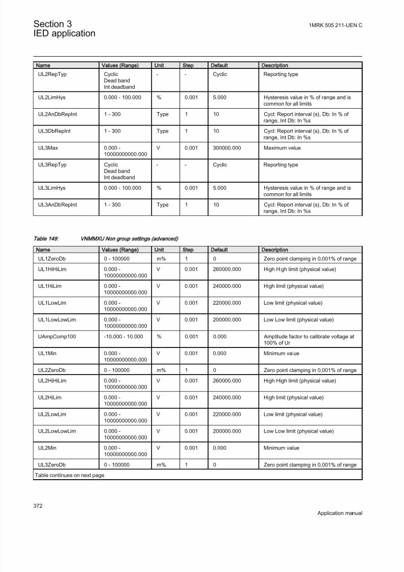
8/22/2019 Best Application
http://slidepdf.com/reader/full/best-application 378/457
Name Values (Range) Unit Step Default Description
UL2RepTyp CyclicDead bandInt deadband
- - Cyclic Reporting type
UL2LimHys 0.000 - 100.000 % 0.001 5.000 Hysteresis value in % of range and iscommon for all limits
UL2AnDbRepInt 1 - 300 Type 1 10 Cycl: Report interval (s), Db: In % of range, Int Db: In %s
UL3DbRepInt 1 - 300 Type 1 10 Cycl: Report interval (s), Db: In % of range, Int Db: In %s
UL3Max 0.000 -10000000000.000
V 0.001 300000.000 Maximum value
UL3RepTyp CyclicDead bandInt deadband
- - Cyclic Reporting type
UL3LimHys 0.000 - 100.000 % 0.001 5.000 Hysteresis value in % of range and is
common for all limitsUL3AnDbRepInt 1 - 300 Type 1 10 Cycl: Report interval (s), Db: In % of
range, Int Db: In %s
Table 149: VN MM XU Non group settings (advanced)
Name Values (Range) Unit Step Default Description
UL1ZeroDb 0 - 100000 m% 1 0 Zero point clamping in 0,001% of range
UL1HiHiLim 0.000 -10000000000.000
V 0.001 260000.000 High High limit (physical value)
UL1HiLim 0.000 -10000000000.000
V 0.001 240000.000 High limit (physical value)
UL1LowLim 0.000 -10000000000.000
V 0.001 220000.000 Low limit (physical value)
UL1LowLowLim 0.000 -10000000000.000
V 0.001 200000.000 Low Low limit (physical value)
UAmpComp100 -10.000 - 10.000 % 0.001 0.000 Amplitude factor to calibrate voltage at100% of Ur
UL1Min 0.000 -10000000000.000
V 0.001 0.000 Minimum value
UL2ZeroDb 0 - 100000 m% 1 0 Zero point clamping in 0,001% of range
UL2HiHiLim 0.000 -10000000000.000
V 0.001 260000.000 High High limit (physical value)
UL2HiLim 0.000 -10000000000.000
V 0.001 240000.000 High limit (physical value)
UL2LowLim 0.000 -10000000000.000
V 0.001 220000.000 Low limit (physical value)
UL2LowLowLim 0.000 -10000000000.000
V 0.001 200000.000 Low Low limit (physical value)
UL2Min 0.000 -10000000000.000
V 0.001 0.000 Minimum value
UL3ZeroDb 0 - 100000 m% 1 0 Zero point clamping in 0,001% of range
Table continues on next page
Section 3 1MRK 505 211-UEN C
IED application
372
Application manual

8/22/2019 Best Application
http://slidepdf.com/reader/full/best-application 379/457
Name Values (Range) Unit Step Default Description
UL3HiHiLim 0.000 -10000000000.000
V 0.001 260000.000 High High limit (physical value)
UL3HiLim 0.000 -
10000000000.000
V 0.001 240000.000 High limit (physical value)
UL3LowLim 0.000 -10000000000.000
V 0.001 220000.000 Low limit (physical value)
UL3LowLowLim 0.000 -10000000000.000
V 0.001 200000.000 Low Low limit (physical value)
UL3Min 0.000 -10000000000.000
V 0.001 0.000 Minimum value
Table 150: VM MXU Non group settings (basic)
Name Values (Range) Unit Step Default Description
UL12DbRepInt 1 - 300 Type 1 10 Cycl: Report interval (s), Db: In % of range, Int Db: In %s
Operation Off On
- - Off Operation Mode On / Off
UBase 0.05 - 2000.00 kV 0.05 400.00 Base setting for voltage level in kV
UL12Max 0.000 -10000000000.000
V 0.001 500000.000 Maximum value
UL12RepTyp CyclicDead bandInt deadband
- - Cyclic Reporting type
UL12AnDbRepInt 1 - 300 Type 1 10 Cycl: Report interval (s), Db: In % of range, Int Db: In %s
UL23DbRepInt 1 - 300 Type 1 10 Cycl: Report interval (s), Db: In % of range, Int Db: In %s
UL23Max 0.000 -10000000000.000
V 0.001 500000.000 Maximum value
UL23RepTyp CyclicDead bandInt deadband
- - Cyclic Reporting type
UL23AnDbRepInt 1 - 300 Type 1 10 Cycl: Report interval (s), Db: In % of range, Int Db: In %s
UL31DbRepInt 1 - 300 Type 1 10 Cycl: Report interval (s), Db: In % of range, Int Db: In %s
UL31Max 0.000 -
10000000000.000
V 0.001 500000.000 Maximum value
UL31RepTyp CyclicDead bandInt deadband
- - Cyclic Reporting type
UL31AnDbRepInt 1 - 300 Type 1 10 Cycl: Report interval (s), Db: In % of range, Int Db: In %s
1MRK 505 211-UEN C Section 3IED application
373
Application manual

8/22/2019 Best Application
http://slidepdf.com/reader/full/best-application 380/457
Table 151: VM MXU Non group settings (advanced)
Name Values (Range) Unit Step Default Description
UL12ZeroDb 0 - 100000 m% 1 0 Zero point clamping in 0,001% of range
UL12HiHiLim 0.000 -10000000000.000 V 0.001 450000.000 High High limit (physical value)
UL12HiLim 0.000 -10000000000.000
V 0.001 420000.000 High limit (physical value)
UL12LowLim 0.000 -10000000000.000
V 0.001 380000.000 Low limit (physical value)
UL12LowLowLim 0.000 -10000000000.000
V 0.001 350000.000 Low Low limit (physical value)
UAmpComp100 -10.000 - 10.000 % 0.001 0.000 Amplitude factor to calibrate voltage at100% of Ur
UL12Min 0.000 -10000000000.000
V 0.001 0.000 Minimum value
UL12LimHys 0.000 - 100.000 % 0.001 5.000 Hysteresis value in % of range and iscommon for all limits
UL23ZeroDb 0 - 100000 m% 1 0 Zero point clamping in 0,001% of range
UL23HiHiLim 0.000 -10000000000.000
V 0.001 450000.000 High High limit (physical value)
UL23HiLim 0.000 -10000000000.000
V 0.001 420000.000 High limit (physical value)
UL23LowLim 0.000 -10000000000.000
V 0.001 380000.000 Low limit (physical value)
UL23LowLowLim 0.000 -10000000000.000
V 0.001 350000.000 Low Low limit (physical value)
UL23Min 0.000 -10000000000.000
V 0.001 0.000 Minimum value
UL23LimHys 0.000 - 100.000 % 0.001 5.000 Hysteresis value in % of range and iscommon for all limits
UL31ZeroDb 0 - 100000 m% 1 0 Zero point clamping in 0,001% of range
UL31HiHiLim 0.000 -10000000000.000
V 0.001 450000.000 High High limit (physical value)
UL31HiLim 0.000 -10000000000.000
V 0.001 420000.000 High limit (physical value)
UL31LowLim 0.000 -10000000000.000
V 0.001 380000.000 Low limit (physical value)
UL31LowLowLim 0.000 -
10000000000.000
V 0.001 350000.000 Low Low limit (physical value)
UL31Min 0.000 -10000000000.000
V 0.001 0.000 Minimum value
UL31LimHys 0.000 - 100.000 % 0.001 5.000 Hysteresis value in % of range and iscommon for all limits
Section 3 1MRK 505 211-UEN C
IED application
374
Application manual

8/22/2019 Best Application
http://slidepdf.com/reader/full/best-application 381/457
Table 152: CMSQI Non group settings (basic)
Name Values (Range) Unit Step Default Description
3I0DbRepInt 1 - 300 Type 1 10 Cycl: Report interval (s), Db: In % of range, Int Db: In %s
3I0Min 0.000 -10000000000.000
A 0.001 0.000 Minimum value
3I0Max 0.000 -10000000000.000
A 0.001 1000.000 Maximum value
3I0RepTyp CyclicDead bandInt deadband
- - Cyclic Reporting type
3I0LimHys 0.000 - 100.000 % 0.001 5.000 Hysteresis value in % of range and iscommon for all limits
3I0AngDbRepInt 1 - 300 Type 1 10 Cycl: Report interval (s), Db: In % of range, Int Db: In %s
Operation Off On
- - Off Operation Mode On / Off
3I0AngMin -180.000 - 180.000 Deg 0.001 -180.000 Minimum value
3I0AngMax -180.000 - 180.000 Deg 0.001 180.000 Maximum value
3I0AngRepTyp CyclicDead bandInt deadband
- - Cyclic Reporting type
I1DbRepInt 1 - 300 Type 1 10 Cycl: Report interval (s), Db: In % of range, Int Db: In %s
I1Min 0.000 -10000000000.000
A 0.001 0.000 Minimum value
I1Max 0.000 -
10000000000.000
A 0.001 1000.000 Maximum value
I1RepTyp CyclicDead bandInt deadband
- - Cyclic Reporting type
I1AngDbRepInt 1 - 300 Type 1 10 Cycl: Report interval (s), Db: In % of range, Int Db: In %s
I1AngMax -180.000 - 180.000 Deg 0.001 180.000 Maximum value
I1AngRepTyp CyclicDead bandInt deadband
- - Cyclic Reporting type
I2DbRepInt 1 - 300 Type 1 10 Cycl: Report interval (s), Db: In % of range, Int Db: In %s
I2Min 0.000 -10000000000.000
A 0.001 0.000 Minimum value
I2Max 0.000 -10000000000.000
A 0.001 1000.000 Maximum value
I2RepTyp CyclicDead bandInt deadband
- - Cyclic Reporting type
I2LimHys 0.000 - 100.000 % 0.001 5.000 Hysteresis value in % of range and iscommon for all limits
Table continues on next page
1MRK 505 211-UEN C Section 3IED application
375
Application manual

8/22/2019 Best Application
http://slidepdf.com/reader/full/best-application 382/457
Name Values (Range) Unit Step Default Description
I2AngDbRepInt 1 - 300 Type 1 10 Cycl: Report interval (s), Db: In % of range, Int Db: In %s
I2AngMin -180.000 - 180.000 Deg 0.001 -180.000 Minimum value
I2AngRepTyp CyclicDead bandInt deadband
- - Cyclic Reporting type
Table 153: CM SQ I N on group settings (advanced)
Name Values (Range) Unit Step Default Description
3I0ZeroDb 0 - 100000 m% 1 0 Zero point clamping in 0,001% of range
3I0HiHiLim 0.000 -10000000000.000
A 0.001 900.000 High High limit (physical value)
3I0HiLim 0.000 -
10000000000.000
A 0.001 800.000 High limit (physical value)
3I0LowLim 0.000 -10000000000.000
A 0.001 0.000 Low limit (physical value)
3I0LowLowLim 0.000 -10000000000.000
A 0.001 0.000 Low Low limit (physical value)
3I0AngZeroDb 0 - 100000 m% 1 0 Zero point clamping in 0,001% of range
I1ZeroDb 0 - 100000 m% 1 0 Zero point clamping in 0,001% of range
I1HiHiLim 0.000 -10000000000.000
A 0.001 900.000 High High limit (physical value)
I1HiLim 0.000 -10000000000.000
A 0.001 800.000 High limit (physical value)
I1LowLim 0.000 -10000000000.000
A 0.001 0.000 Low limit (physical value)
I1LowLowLim 0.000 -10000000000.000
A 0.001 0.000 Low Low limit (physical value)
I1LimHys 0.000 - 100.000 % 0.001 5.000 Hysteresis value in % of range and iscommon for all limits
I1AngZeroDb 0 - 100000 m% 1 0 Zero point clamping in 0,001% of range
I1AngMin -180.000 - 180.000 Deg 0.001 -180.000 Minimum value
I2ZeroDb 0 - 100000 m% 1 0 Zero point clamping in 0,001% of range
I2HiHiLim 0.000 -10000000000.000
A 0.001 900.000 High High limit (physical value)
I2HiLim 0.000 -10000000000.000
A 0.001 800.000 High limit (physical value)
I2LowLim 0.000 -10000000000.000
A 0.001 0.000 Low limit (physical value)
I2LowLowLim 0.000 -10000000000.000
A 0.001 0.000 Low Low limit (physical value)
I2AngZeroDb 0 - 100000 m% 1 0 Zero point clamping in 0,001% of range
I2AngMax -180.000 - 180.000 Deg 0.001 180.000 Maximum value
Section 3 1MRK 505 211-UEN C
IED application
376
Application manual
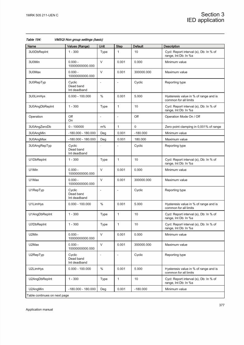
8/22/2019 Best Application
http://slidepdf.com/reader/full/best-application 383/457
Table 154: VM SQI Non group settings (basic)
Name Values (Range) Unit Step Default Description
3U0DbRepInt 1 - 300 Type 1 10 Cycl: Report interval (s), Db: In % of range, Int Db: In %s
3U0Min 0.000 -10000000000.000
V 0.001 0.000 Minimum value
3U0Max 0.000 -10000000000.000
V 0.001 300000.000 Maximum value
3U0RepTyp CyclicDead bandInt deadband
- - Cyclic Reporting type
3U0LimHys 0.000 - 100.000 % 0.001 5.000 Hysteresis value in % of range and iscommon for all limits
3U0AngDbRepInt 1 - 300 Type 1 10 Cycl: Report interval (s), Db: In % of range, Int Db: In %s
Operation Off On
- - Off Operation Mode On / Off
3U0AngZeroDb 0 - 100000 m% 1 0 Zero point clamping in 0,001% of range
3U0AngMin -180.000 - 180.000 Deg 0.001 -180.000 Minimum value
3U0AngMax -180.000 - 180.000 Deg 0.001 180.000 Maximum value
3U0AngRepTyp CyclicDead bandInt deadband
- - Cyclic Reporting type
U1DbRepInt 1 - 300 Type 1 10 Cycl: Report interval (s), Db: In % of range, Int Db: In %s
U1Min 0.000 -10000000000.000
V 0.001 0.000 Minimum value
U1Max 0.000 -10000000000.000
V 0.001 300000.000 Maximum value
U1RepTyp CyclicDead bandInt deadband
- - Cyclic Reporting type
U1LimHys 0.000 - 100.000 % 0.001 5.000 Hysteresis value in % of range and iscommon for all limits
U1AngDbRepInt 1 - 300 Type 1 10 Cycl: Report interval (s), Db: In % of range, Int Db: In %s
U2DbRepInt 1 - 300 Type 1 10 Cycl: Report interval (s), Db: In % of range, Int Db: In %s
U2Min 0.000 -
10000000000.000
V 0.001 0.000 Minimum value
U2Max 0.000 -10000000000.000
V 0.001 300000.000 Maximum value
U2RepTyp CyclicDead bandInt deadband
- - Cyclic Reporting type
U2LimHys 0.000 - 100.000 % 0.001 5.000 Hysteresis value in % of range and iscommon for all limits
U2AngDbRepInt 1 - 300 Type 1 10 Cycl: Report interval (s), Db: In % of range, Int Db: In %s
U2AngMin -180.000 - 180.000 Deg 0.001 -180.000 Minimum value
Table continues on next page
1MRK 505 211-UEN C Section 3IED application
377
Application manual

8/22/2019 Best Application
http://slidepdf.com/reader/full/best-application 384/457
Name Values (Range) Unit Step Default Description
U2AngMax -180.000 - 180.000 Deg 0.001 180.000 Maximum value
U2AngRepTyp CyclicDead band
Int deadband
- - Cyclic Reporting type
UAmpPreComp5 -10.000 - 10.000 % 0.001 0.000 Amplitude factor to pre-calibrate voltageat 5% of Ir
UAmpPreComp30 -10.000 - 10.000 % 0.001 0.000 Amplitude factor to pre-calibrate voltageat 30% of Ir
UAmpPreComp100 -10.000 - 10.000 % 0.001 0.000 Amplitude factor to pre-calibrate voltageat 100% of Ir
Table 155: VM SQ I Non group settings (advanced)
Name Values (Range) Unit Step Default Description
3U0ZeroDb 0 - 100000 m% 1 0 Zero point clamping in 0,001% of range
3U0HiHiLim 0.000 -10000000000.000
V 0.001 260000.000 High High limit (physical value)
3U0HiLim 0.000 -10000000000.000
V 0.001 240000.000 High limit (physical value)
3U0LowLim 0.000 -10000000000.000
V 0.001 220000.000 Low limit (physical value)
3U0LowLowLim 0.000 -10000000000.000
V 0.001 200000.000 Low Low limit (physical value)
U1ZeroDb 0 - 100000 m% 1 0 Zero point clamping in 0,001% of range
U1HiHiLim 0.000 -10000000000.000
V 0.001 260000.000 High High limit (physical value)
U1HiLim 0.000 -10000000000.000
V 0.001 240000.000 High limit (physical value)
U1LowLim 0.000 -10000000000.000
V 0.001 220000.000 Low limit (physical value)
U1LowLowLim 0.000 -10000000000.000
V 0.001 200000.000 Low Low limit (physical value)
U1AngZeroDb 0 - 100000 m% 1 0 Zero point clamping in 0,001% of range
U1AngMin -180.000 - 180.000 Deg 0.001 -180.000 Minimum value
U1AngMax -180.000 - 180.000 Deg 0.001 180.000 Maximum value
U1AngRepTyp CyclicDead band
Int deadband
- - Cyclic Reporting type
U2ZeroDb 0 - 100000 m% 1 0 Zero point clamping in 0,001% of range
U2HiHiLim 0.000 -10000000000.000
V 0.001 260000.000 High High limit (physical value)
U2HiLim 0.000 -10000000000.000
V 0.001 240000.000 High limit (physical value)
U2LowLim 0.000 -10000000000.000
V 0.001 220000.000 Low limit (physical value)
U2LowLowLim 0.000 -10000000000.000
V 0.001 200000.000 Low Low limit (physical value)
U2AngZeroDb 0 - 100000 m% 1 0 Zero point clamping in 0,001% of range
Section 3 1MRK 505 211-UEN C
IED application
378
Application manual

8/22/2019 Best Application
http://slidepdf.com/reader/full/best-application 385/457
3.13.2 Event counter CNTGGIO
3.13.2.1 Identification
Function description IEC 61850
identification
IEC 60617
identification
ANSI/IEEE C37.2
device number
Event counter CNTGGIO
S00946 V1 EN
-
3.13.2.2 Application
Event counter (CNTGGIO) has six counters which are used for storing the number of times each counter has been activated. CNTGGIO can be used to count how
many times a specific function, for example the tripping logic, has issued a tripsignal. All six counters have a common blocking and resetting feature.
3.13.2.3 Setting parameters
The function does not have any parameters available in Local HMI or Protectionand Control IED Manager (PCM600)
3.13.3 Event function EVENT
Function description IEC 61850
identification
IEC 60617
identification
ANSI/IEEE C37.2
device number
Event function EVENT
S00946 V1 EN
-
3.13.3.1 Introduction
When using a Substation Automation system with LON or SPA communication,time-tagged events can be sent at change or cyclically from the IED to the stationlevel. These events are created from any available signal in the IED that is
connected to the Event function (EVENT). The event function block is used for LON and SPA communication.
Analog and double indication values are also transferred through EVENT function.
3.13.3.2 Setting guidelines
The parameters for the Event (EVENT) function are set via the local HMI or PCM600.
EventMask (Ch_1 - 16)The inputs can be set individually as:
1MRK 505 211-UEN C Section 3IED application
379
Application manual
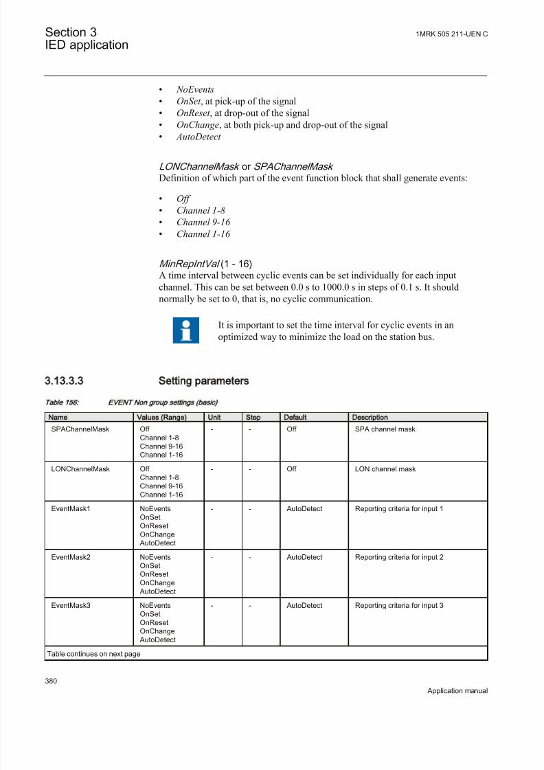
8/22/2019 Best Application
http://slidepdf.com/reader/full/best-application 386/457
• NoEvents
• OnSet , at pick-up of the signal• OnReset , at drop-out of the signal• OnChange, at both pick-up and drop-out of the signal• AutoDetect
LONChannelMask or SPAChannelMask Definition of which part of the event function block that shall generate events:
• Off
• Channel 1-8
• Channel 9-16
• Channel 1-16
MinRepIntVal (1 - 16)A time interval between cyclic events can be set individually for each inputchannel. This can be set between 0.0 s to 1000.0 s in steps of 0.1 s. It shouldnormally be set to 0, that is, no cyclic communication.
It is important to set the time interval for cyclic events in anoptimized way to minimize the load on the station bus.
3.13.3.3 Setting parameters
Table 156: EVENT Non group settings (basic)
Name Values (Range) Unit Step Default Description
SPAChannelMask Off Channel 1-8Channel 9-16Channel 1-16
- - Off SPA channel mask
LONChannelMask Off Channel 1-8Channel 9-16Channel 1-16
- - Off LON channel mask
EventMask1 NoEventsOnSetOnResetOnChange
AutoDetect
- - AutoDetect Reporting criteria for input 1
EventMask2 NoEventsOnSetOnResetOnChange
AutoDetect
- - AutoDetect Reporting criteria for input 2
EventMask3 NoEventsOnSetOnResetOnChange
AutoDetect
- - AutoDetect Reporting criteria for input 3
Table continues on next page
Section 3 1MRK 505 211-UEN C
IED application
380
Application manual

8/22/2019 Best Application
http://slidepdf.com/reader/full/best-application 387/457
Name Values (Range) Unit Step Default Description
EventMask4 NoEventsOnSetOnResetOnChange
AutoDetect
- - AutoDetect Reporting criteria for input 4
EventMask5 NoEventsOnSetOnResetOnChange
AutoDetect
- - AutoDetect Reporting criteria for input 5
EventMask6 NoEventsOnSetOnResetOnChange
AutoDetect
- - AutoDetect Reporting criteria for input 6
EventMask7 NoEventsOnSet
OnResetOnChange AutoDetect
- - AutoDetect Reporting criteria for input 7
EventMask8 NoEventsOnSetOnResetOnChange
AutoDetect
- - AutoDetect Reporting criteria for input 8
EventMask9 NoEventsOnSetOnResetOnChange
AutoDetect
- - AutoDetect Reporting criteria for input 9
EventMask10 NoEvents
OnSetOnResetOnChange
AutoDetect
- - AutoDetect Reporting criteria for input 10
EventMask11 NoEventsOnSetOnResetOnChange
AutoDetect
- - AutoDetect Reporting criteria for input 11
EventMask12 NoEventsOnSetOnResetOnChange
AutoDetect
- - AutoDetect Reporting criteria for input 12
EventMask13 NoEventsOnSetOnResetOnChange
AutoDetect
- - AutoDetect Reporting criteria for input 13
EventMask14 NoEventsOnSetOnResetOnChange
AutoDetect
- - AutoDetect Reporting criteria for input 14
Table continues on next page
1MRK 505 211-UEN C Section 3IED application
381
Application manual

8/22/2019 Best Application
http://slidepdf.com/reader/full/best-application 388/457
Name Values (Range) Unit Step Default Description
EventMask15 NoEventsOnSetOnResetOnChange
AutoDetect
- - AutoDetect Reporting criteria for input 15
EventMask16 NoEventsOnSetOnResetOnChange
AutoDetect
- - AutoDetect Reporting criteria for input 16
MinRepIntVal1 0 - 3600 s 1 2 Minimum reporting interval input 1
MinRepIntVal2 0 - 3600 s 1 2 Minimum reporting interval input 2
MinRepIntVal3 0 - 3600 s 1 2 Minimum reporting interval input 3
MinRepIntVal4 0 - 3600 s 1 2 Minimum reporting interval input 4
MinRepIntVal5 0 - 3600 s 1 2 Minimum reporting interval input 5
MinRepIntVal6 0 - 3600 s 1 2 Minimum reporting interval input 6
MinRepIntVal7 0 - 3600 s 1 2 Minimum reporting interval input 7
MinRepIntVal8 0 - 3600 s 1 2 Minimum reporting interval input 8
MinRepIntVal9 0 - 3600 s 1 2 Minimum reporting interval input 9
MinRepIntVal10 0 - 3600 s 1 2 Minimum reporting interval input 10
MinRepIntVal11 0 - 3600 s 1 2 Minimum reporting interval input 11
MinRepIntVal12 0 - 3600 s 1 2 Minimum reporting interval input 12
MinRepIntVal13 0 - 3600 s 1 2 Minimum reporting interval input 13
MinRepIntVal14 0 - 3600 s 1 2 Minimum reporting interval input 14
MinRepIntVal15 0 - 3600 s 1 2 Minimum reporting interval input 15
MinRepIntVal16 0 - 3600 s 1 2 Minimum reporting interval input 16
3.13.4 Logical signal status report BINSTATREP
Function description IEC 61850
identification
IEC 60617
identification
ANSI/IEEE C37.2
device number
Logical signal status report BINSTATREP - -
3.13.4.1 Application
The Logical signal status report (BINSTATREP) function makes it possible for aSPA master to poll signals from various other function blocks.
BINSTATREP has 16 inputs and 16 outputs. The output status follows the inputsand can be read from the local HMI or via SPA communication.
When an input is set, the respective output is set for a user defined time. If theinput signal remains set for a longer period, the output will remain set until theinput signal resets.
Section 3 1MRK 505 211-UEN C
IED application
382
Application manual
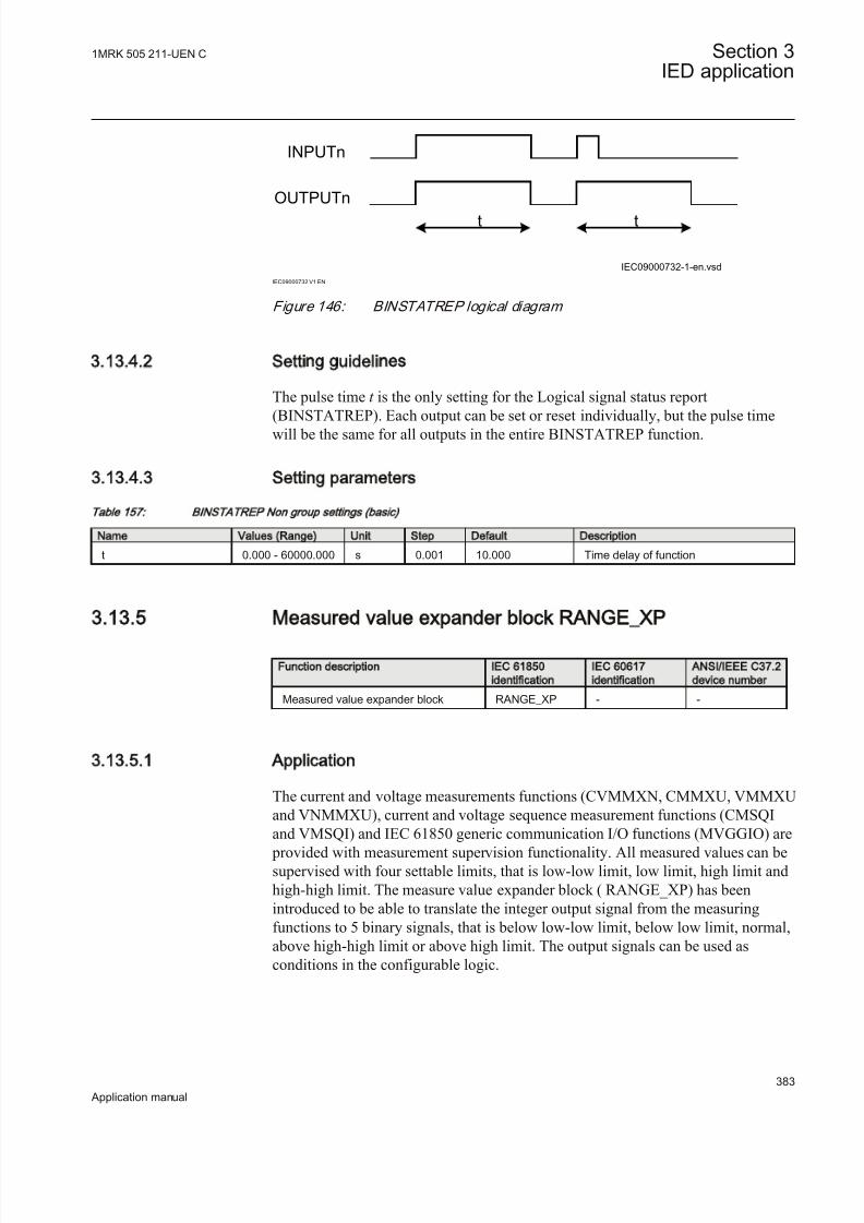
8/22/2019 Best Application
http://slidepdf.com/reader/full/best-application 389/457
t t
INPUTn
OUTPUTn
IEC09000732-1-en.vsd
IEC09000732 V1 EN
Figure 146: BINSTATREP logical diagram
3.13.4.2 Setting guidelines
The pulse time t is the only setting for the Logical signal status report
(BINSTATREP). Each output can be set or reset individually, but the pulse timewill be the same for all outputs in the entire BINSTATREP function.
3.13.4.3 Setting parameters
Table 157: BIN STA TR EP Non group settings (basic)
Name Values (Range) Unit Step Default Description
t 0.000 - 60000.000 s 0.001 10.000 Time delay of function
3.13.5 Measured value expander block RANGE_XP
Function description IEC 61850
identification
IEC 60617
identification
ANSI/IEEE C37.2
device number
Measured value expander block RANGE_XP - -
3.13.5.1 Application
The current and voltage measurements functions (CVMMXN, CMMXU, VMMXUand VNMMXU), current and voltage sequence measurement functions (CMSQIand VMSQI) and IEC 61850 generic communication I/O functions (MVGGIO) are
provided with measurement supervision functionality. All measured values can besupervised with four settable limits, that is low-low limit, low limit, high limit andhigh-high limit. The measure value expander block ( RANGE_XP) has beenintroduced to be able to translate the integer output signal from the measuringfunctions to 5 binary signals, that is below low-low limit, below low limit, normal,above high-high limit or above high limit. The output signals can be used asconditions in the configurable logic.
1MRK 505 211-UEN C Section 3IED application
383
Application manual
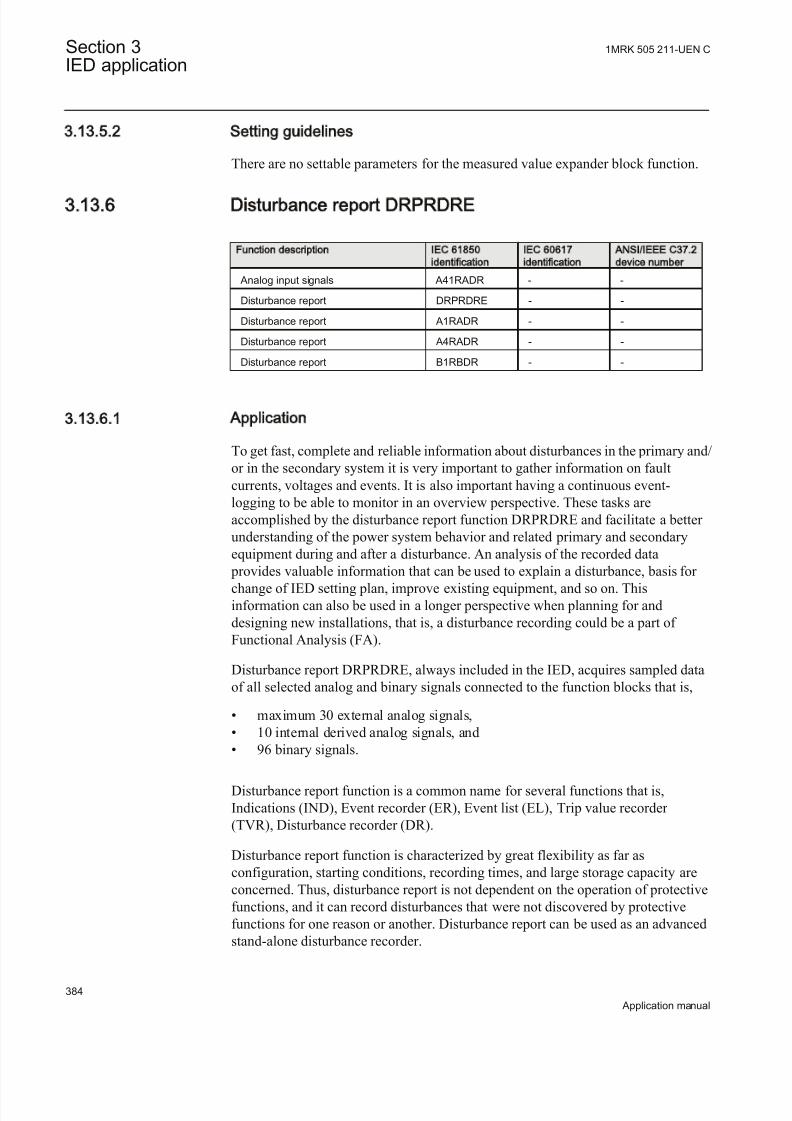
8/22/2019 Best Application
http://slidepdf.com/reader/full/best-application 390/457
3.13.5.2 Setting guidelines
There are no settable parameters for the measured value expander block function.
3.13.6 Disturbance report DRPRDRE
Function description IEC 61850
identification
IEC 60617
identification
ANSI/IEEE C37.2
device number
Analog input signals A41RADR - -
Disturbance report DRPRDRE - -
Disturbance report A1RADR - -
Disturbance report A4RADR - -
Disturbance report B1RBDR - -
3.13.6.1 Application
To get fast, complete and reliable information about disturbances in the primary and/or in the secondary system it is very important to gather information on faultcurrents, voltages and events. It is also important having a continuous event-logging to be able to monitor in an overview perspective. These tasks areaccomplished by the disturbance report function DRPRDRE and facilitate a better understanding of the power system behavior and related primary and secondaryequipment during and after a disturbance. An analysis of the recorded data
provides valuable information that can be used to explain a disturbance, basis for change of IED setting plan, improve existing equipment, and so on. Thisinformation can also be used in a longer perspective when planning for anddesigning new installations, that is, a disturbance recording could be a part of Functional Analysis (FA).
Disturbance report DRPRDRE, always included in the IED, acquires sampled dataof all selected analog and binary signals connected to the function blocks that is,
• maximum 30 external analog signals,• 10 internal derived analog signals, and• 96 binary signals.
Disturbance report function is a common name for several functions that is,Indications (IND), Event recorder (ER), Event list (EL), Trip value recorder (TVR), Disturbance recorder (DR).
Disturbance report function is characterized by great flexibility as far asconfiguration, starting conditions, recording times, and large storage capacity areconcerned. Thus, disturbance report is not dependent on the operation of protectivefunctions, and it can record disturbances that were not discovered by protectivefunctions for one reason or another. Disturbance report can be used as an advancedstand-alone disturbance recorder.
Section 3 1MRK 505 211-UEN C
IED application
384
Application manual
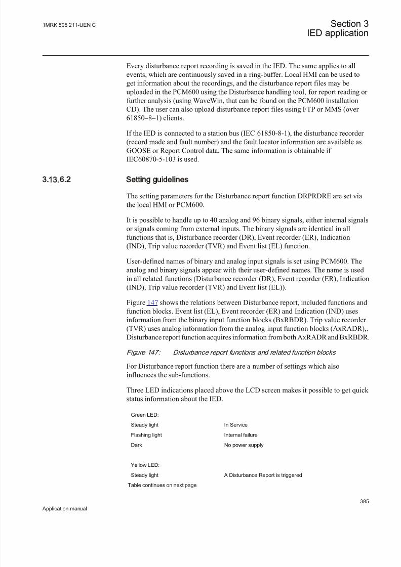
8/22/2019 Best Application
http://slidepdf.com/reader/full/best-application 391/457
Every disturbance report recording is saved in the IED. The same applies to allevents, which are continuously saved in a ring-buffer. Local HMI can be used toget information about the recordings, and the disturbance report files may beuploaded in the PCM600 using the Disturbance handling tool, for report reading or further analysis (using WaveWin, that can be found on the PCM600 installationCD). The user can also upload disturbance report files using FTP or MMS (over 61850–8–1) clients.
If the IED is connected to a station bus (IEC 61850-8-1), the disturbance recorder (record made and fault number) and the fault locator information are available asGOOSE or Report Control data. The same information is obtainable if IEC60870-5-103 is used.
3.13.6.2 Setting guidelines
The setting parameters for the Disturbance report function DRPRDRE are set viathe local HMI or PCM600.
It is possible to handle up to 40 analog and 96 binary signals, either internal signalsor signals coming from external inputs. The binary signals are identical in allfunctions that is, Disturbance recorder (DR), Event recorder (ER), Indication(IND), Trip value recorder (TVR) and Event list (EL) function.
User-defined names of binary and analog input signals is set using PCM600. Theanalog and binary signals appear with their user-defined names. The name is usedin all related functions (Disturbance recorder (DR), Event recorder (ER), Indication(IND), Trip value recorder (TVR) and Event list (EL)).
Figure 147 shows the relations between Disturbance report, included functions andfunction blocks. Event list (EL), Event recorder (ER) and Indication (IND) usesinformation from the binary input function blocks (BxRBDR). Trip value recorder (TVR) uses analog information from the analog input function blocks (AxRADR),.Disturbance report function acquires information from both AxRADR and BxRBDR.
Figure 147: Disturbance report functions and related function blocks
For Disturbance report function there are a number of settings which alsoinfluences the sub-functions.
Three LED indications placed above the LCD screen makes it possible to get quick status information about the IED.
Green LED:
Steady light In Service
Flashing light Internal failure
Dark No power supply
Yellow LED:
Steady light A Disturbance Report is triggered
Table continues on next page
1MRK 505 211-UEN C Section 3IED application
385
Application manual

8/22/2019 Best Application
http://slidepdf.com/reader/full/best-application 392/457
Flashing light The IED is in test mode
Red LED:
Steady light Triggered on binary signal N with SetLEDN = On
OperationThe operation of Disturbance report function DRPRDRE has to be set On or Off . If Off is selected, note that no disturbance report is registered, and none sub-functionwill operate (the only general parameter that influences Event list (EL)).
Operation = Off :
• Disturbance reports are not stored.• LED information (yellow - start, red - trip) is not stored or changed.
Operation = On:
• Disturbance reports are stored, disturbance data can be read from the localHMI and from a PC using PCM600.
• LED information (yellow - start, red - trip) is stored.
Every recording will get a number (0 to 999) which is used as identifier (localHMI, disturbance handling tool and IEC 61850). An alternative recordingidentification is date, time and sequence number. The sequence number isautomatically increased by one for each new recording and is reset to zero atmidnight. The maximum number of recordings stored in the IED is 100. The oldestrecording will be overwritten when a new recording arrives (FIFO).
To be able to delete disturbance records, Operation parameter hasto be On.
The maximum number of recordings depend on each recordingstotal recording time. Long recording time will reduce the number of recordings to less than 100.
The IED flash disk should NOT be used to store any user files. Thismight cause disturbance recordings to be deleted due to lack of disk space.
Section 3 1MRK 505 211-UEN C
IED application
386
Application manual

8/22/2019 Best Application
http://slidepdf.com/reader/full/best-application 393/457
Recording timesThe different recording times for Disturbance report are set (the pre-fault time, post-fault time, and limit time). These recording times affect all sub-functions more or less but not the Event list (EL) function.
Prefault recording time ( PreFaultRecT ) is the recording time before the starting point of the disturbance. The setting should be at least 0.1 s to ensure enoughsamples for the estimation of pre-fault values in the Trip value recorder (TVR)function.
Postfault recording time ( PostFaultRecT ) is the maximum recording time after thedisappearance of the trig-signal (does not influence the Trip value recorder (TVR)function).
Recording time limit (TimeLimit ) is the maximum recording time after trig. The parameter limits the recording time if some trigging condition (fault-time) is verylong or permanently set (does not influence the Trip value recorder (TVR) function).
Post retrigger ( PostRetrig ) can be set to On or Off . Makes it possible to choose performance of Disturbance report function if a new trig signal appears in the post-fault window.
PostRetrig = Off
The function is insensitive for new trig signals during post fault time.
PostRetrig = On
The function completes current report and starts a new complete report that is, thelatter will include:
• new pre-fault- and fault-time (which will overlap previous report)• events and indications might be saved in the previous report too, due to overlap• new trip value calculations if installed, in operation and started
Operation in test modeIf the IED is in test mode and OpModeTest = Off . Disturbance report function doesnot save any recordings and no LED information is displayed.
If the IED is in test mode and OpModeTest = On. Disturbance report functionworks in normal mode and the status is indicated in the saved recording.
Binary input signalsUp to 96 binary signals can be selected among internal logical and binary inputsignals. The configuration tool is used to configure the signals.
For each of the 96 signals, it is also possible to select if the signal is to be used as atrigger for the start of the Disturbance report and if the trigger should be activatedon positive (1) or negative (0) slope.
OperationN : Disturbance report may trig for binary input N (On) or not (Off ).
1MRK 505 211-UEN C Section 3IED application
387
Application manual

8/22/2019 Best Application
http://slidepdf.com/reader/full/best-application 394/457
TrigLevelN : Trig on positive (Trig on 1) or negative (Trig on 0) slope for binaryinput N.
Func103N : Function type number (0-255) for binary input N according to
IEC-60870-5-103, that is, 128: Distance protection, 160: overcurrent protection,176: transformer differential protection and 192: line differential protection.
Info103N : Information number (0-255) for binary input N according toIEC-60870-5-103, that is, 69-71: Trip L1-L3, 78-83: Zone 1-6.
See also description in the chapter IEC 60870-5-103.
Analog input signalsUp to 40 analog signals can be selected among internal analog and analog inputsignals. PCM600 is used to configure the signals.
For retrieving remote data from LDCM module, the Disturbancereport function should not be connected to a 3 ms SMAI function
block if this is the only intended use for the remote data.
The analog trigger of Disturbance report is not affected if analog input M is to beincluded in the disturbance recording or not (OperationM = On/Off ).
If OperationM = Off , no waveform (samples) will be recorded and reported ingraph. However, Trip value, pre-fault and fault value will be recorded and reported.The input channel can still be used to trig the disturbance recorder.
If OperationM = On, waveform (samples) will also be recorded and reported in graph.
NomValueM : Nominal value for input M.
OverTrigOpM , UnderTrigOpM : Over or Under trig operation, Disturbance reportmay trig for high/low level of analog input M (On) or not (Off ).
OverTrigLeM , UnderTrigLeM : Over or under trig level, Trig high/low levelrelative nominal value for analog input M in percent of nominal value.
Sub-function parametersAll functions are in operation as long as Disturbance report is in operation.
Indications IndicationMaN : Indication mask for binary input N. If set (Show), a status changeof that particular input, will be fetched and shown in the disturbance summary onlocal HMI. If not set ( Hide), status change will not be indicated.
SetLEDN : Set red LED on local HMI in front of the IED if binary input N changesstatus.
Section 3 1MRK 505 211-UEN C
IED application
388
Application manual

8/22/2019 Best Application
http://slidepdf.com/reader/full/best-application 395/457
Disturbance recorder OperationM : Analog channel M is to be recorded by the disturbance recorder (On)or not (Off ).
If OperationM = Off , no waveform (samples) will be recorded and reported ingraph. However, Trip value, pre-fault and fault value will be recorded and reported.The input channel can still be used to trig the disturbance recorder.
If OperationM = On, waveform (samples) will also be recorded and reported in graph.
Event recorder Event recorder (ER) function has no dedicated parameters.
Trip value recorder ZeroAngleRef : The parameter defines which analog signal that will be used as phase angle reference for all other analog input signals. This signal will also beused for frequency measurement and the measured frequency is used whencalculating trip values. It is suggested to point out a sampled voltage input signal,for example, a line or busbar phase voltage (channel 1-30).
Event listEvent list (EL) (SOE) function has no dedicated parameters.
ConsiderationThe density of recording equipment in power systems is increasing, since thenumber of modern IEDs, where recorders are included, is increasing. This leads toa vast number of recordings at every single disturbance and a lot of information has
to be handled if the recording functions do not have proper settings. The goal is tooptimize the settings in each IED to be able to capture just valuable disturbancesand to maximize the number that is possible to save in the IED.
The recording time should not be longer than necessary ( PostFaultrecT andTimeLimit ).
• Should the function record faults only for the protected object or cover more?• How long is the longest expected fault clearing time?• Is it necessary to include reclosure in the recording or should a persistent fault
generate a second recording ( PostRetrig )?
Minimize the number of recordings:
• Binary signals: Use only relevant signals to start the recording that is, protection trip, carrier receive and/or start signals.
• Analog signals: The level triggering should be used with great care, sinceunfortunate settings will cause enormously number of recordings. If nevertheless analog input triggering is used, chose settings by a sufficientmargin from normal operation values. Phase voltages are not recommended for trigging.
1MRK 505 211-UEN C Section 3IED application
389
Application manual

8/22/2019 Best Application
http://slidepdf.com/reader/full/best-application 396/457
Remember that values of parameters set elsewhere are linked to the information ona report. Such parameters are, for example, station and object identifiers, CT andVT ratios.
3.13.6.3 Setting parameters
Table 158: DR PR DR E N on group settings (basic)
Name Values (Range) Unit Step Default Description
Operation Off On
- - Off Operation Off/On
PreFaultRecT 0.05 - 9.90 s 0.01 0.10 Pre-fault recording time
PostFaultRecT 0.1 - 10.0 s 0.1 0.5 Post-fault recording time
TimeLimit 0.5 - 10.0 s 0.1 1.0 Fault recording time limit
PostRetrig Off
On
- - Off Post-fault retrig enabled (On) or not (Off)
ZeroAngleRef 1 - 30 Ch 1 1 Reference channel (voltage), phasors,frequency measurement
OpModeTest Off On
- - Off Operation mode during test mode
Table 159: A1RA DR N on group settings (basic)
Name Values (Range) Unit Step Default Description
Operation01 Off On
- - Off Operation On/Off
NomValue01 0.0 - 999999.9 - 0.1 0.0 Nominal value for analogue channel 1UnderTrigOp01 Off
On- - Off Use under level trig for analogue cha 1
(on) or not (off)
UnderTrigLe01 0 - 200 % 1 50 Under trigger level for analogue cha 1 in% of signal
OverTrigOp01 Off On
- - Off Use over level trig for analogue cha 1(on) or not (off)
OverTrigLe01 0 - 5000 % 1 200 Over trigger level for analogue cha 1 in% of signal
Operation02 Off On
- - Off Operation On/Off
NomValue02 0.0 - 999999.9 - 0.1 0.0 Nominal value for analogue channel 2
UnderTrigOp02 Off On
- - Off Use under level trig for analogue cha 2(on) or not (off)
UnderTrigLe02 0 - 200 % 1 50 Under trigger level for analogue cha 2 in% of signal
OverTrigOp02 Off On
- - Off Use over level trig for analogue cha 2(on) or not (off)
OverTrigLe02 0 - 5000 % 1 200 Over trigger level for analogue cha 2 in% of signal
Operation03 Off On
- - Off Operation On/Off
Table continues on next page
Section 3 1MRK 505 211-UEN C
IED application
390
Application manual

8/22/2019 Best Application
http://slidepdf.com/reader/full/best-application 397/457
Name Values (Range) Unit Step Default Description
NomValue03 0.0 - 999999.9 - 0.1 0.0 Nominal value for analogue channel 3
UnderTrigOp03 Off On
- - Off Use under level trig for analogue cha 3(on) or not (off)
UnderTrigLe03 0 - 200 % 1 50 Under trigger level for analogue cha 3 in% of signal
OverTrigOp03 Off On
- - Off Use over level trig for analogue cha 3(on) or not (off)
OverTrigLe03 0 - 5000 % 1 200 Overtrigger level for analogue cha 3 in %of signal
Operation04 Off On
- - Off Operation On/Off
NomValue04 0.0 - 999999.9 - 0.1 0.0 Nominal value for analogue channel 4
UnderTrigOp04 Off On
- - Off Use under level trig for analogue cha 4(on) or not (off)
UnderTrigLe04 0 - 200 % 1 50 Under trigger level for analogue cha 4 in% of signal
OverTrigOp04 Off On
- - Off Use over level trig for analogue cha 4(on) or not (off)
OverTrigLe04 0 - 5000 % 1 200 Over trigger level for analogue cha 4 in% of signal
Operation05 Off On
- - Off Operation On/Off
NomValue05 0.0 - 999999.9 - 0.1 0.0 Nominal value for analogue channel 5
UnderTrigOp05 Off On
- - Off Use under level trig for analogue cha 5(on) or not (off)
UnderTrigLe05 0 - 200 % 1 50 Under trigger level for analogue cha 5 in
% of signal
OverTrigOp05 Off On
- - Off Use over level trig for analogue cha 5(on) or not (off)
OverTrigLe05 0 - 5000 % 1 200 Over trigger level for analogue cha 5 in% of signal
Operation06 Off On
- - Off Operation On/Off
NomValue06 0.0 - 999999.9 - 0.1 0.0 Nominal value for analogue channel 6
UnderTrigOp06 Off On
- - Off Use under level trig for analogue cha 6(on) or not (off)
UnderTrigLe06 0 - 200 % 1 50 Under trigger level for analogue cha 6 in
% of signalOverTrigOp06 Off
On- - Off Use over level trig for analogue cha 6
(on) or not (off)
OverTrigLe06 0 - 5000 % 1 200 Over trigger level for analogue cha 6 in% of signal
Operation07 Off On
- - Off Operation On/Off
NomValue07 0.0 - 999999.9 - 0.1 0.0 Nominal value for analogue channel 7
UnderTrigOp07 Off On
- - Off Use under level trig for analogue cha 7(on) or not (off)
Table continues on next page
1MRK 505 211-UEN C Section 3IED application
391
Application manual

8/22/2019 Best Application
http://slidepdf.com/reader/full/best-application 398/457
Name Values (Range) Unit Step Default Description
UnderTrigLe07 0 - 200 % 1 50 Under trigger level for analogue cha 7 in% of signal
OverTrigOp07 Off
On
- - Off Use over level trig for analogue cha 7
(on) or not (off)
OverTrigLe07 0 - 5000 % 1 200 Over trigger level for analogue cha 7 in% of signal
Operation08 Off On
- - Off Operation On/Off
NomValue08 0.0 - 999999.9 - 0.1 0.0 Nominal value for analogue channel 8
UnderTrigOp08 Off On
- - Off Use under level trig for analogue cha 8(on) or not (off)
UnderTrigLe08 0 - 200 % 1 50 Under trigger level for analogue cha 8 in% of signal
OverTrigOp08 Off On
- - Off Use over level trig for analogue cha 8(on) or not (off)
OverTrigLe08 0 - 5000 % 1 200 Over trigger level for analogue cha 8 in% of signal
Operation09 Off On
- - Off Operation On/Off
NomValue09 0.0 - 999999.9 - 0.1 0.0 Nominal value for analogue channel 9
UnderTrigOp09 Off On
- - Off Use under level trig for analogue cha 9(on) or not (off)
UnderTrigLe09 0 - 200 % 1 50 Under trigger level for analogue cha 9 in% of signal
OverTrigOp09 Off On
- - Off Use over level trig for analogue cha 9(on) or not (off)
OverTrigLe09 0 - 5000 % 1 200 Over trigger level for analogue cha 9 in% of signal
Operation10 Off On
- - Off Operation On/Off
NomValue10 0.0 - 999999.9 - 0.1 0.0 Nominal value for analogue channel 10
UnderTrigOp10 Off On
- - Off Use under level trig for analogue cha 10(on) or not (off)
UnderTrigLe10 0 - 200 % 1 50 Under trigger level for analogue cha 10in % of signal
OverTrigOp10 Off On
- - Off Use over level trig for analogue cha 10(on) or not (off)
OverTrigLe10 0 - 5000 % 1 200 Over trigger level for analogue cha 10 in% of signal
Table 160: A4RA DR N on group settings (basic)
Name Values (Range) Unit Step Default Description
Operation31 Off On
- - Off Operation On/off
NomValue31 0.0 - 999999.9 - 0.1 0.0 Nominal value for analogue channel 31
UnderTrigOp31 Off On
- - Off Use under level trig for analogue cha 31(on) or not (off)
Table continues on next page
Section 3 1MRK 505 211-UEN C
IED application
392
Application manual
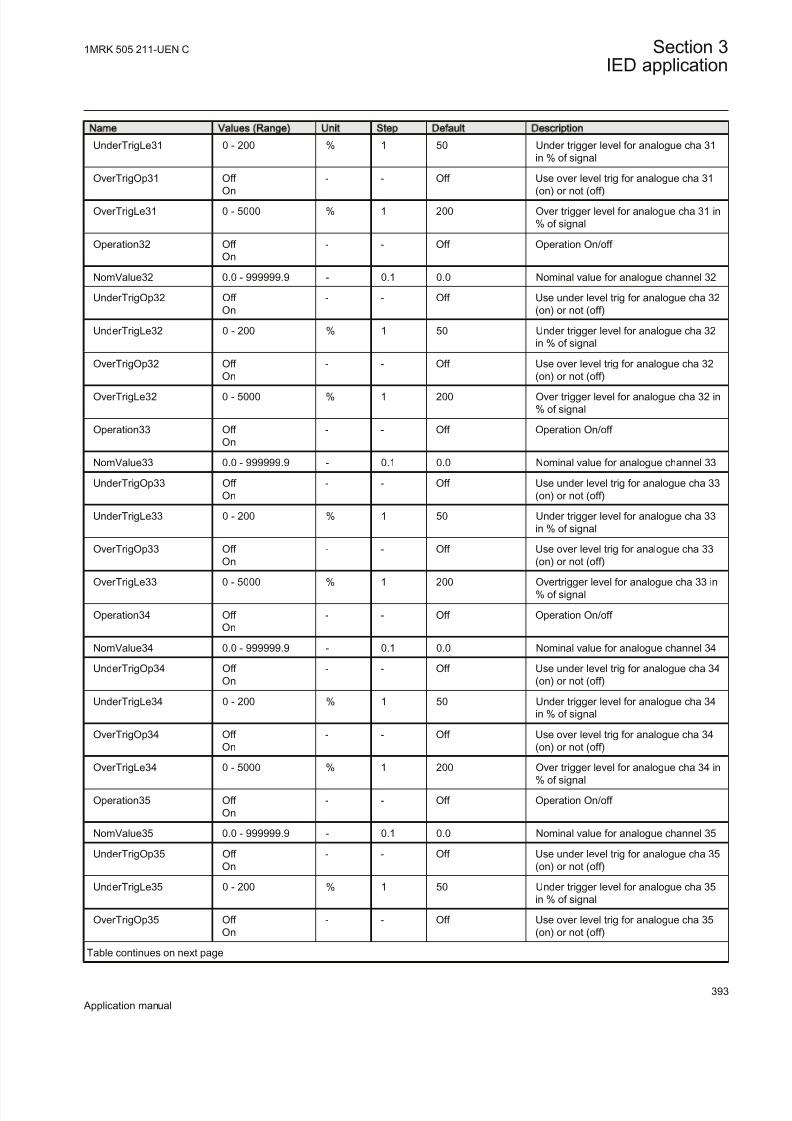
8/22/2019 Best Application
http://slidepdf.com/reader/full/best-application 399/457
Name Values (Range) Unit Step Default Description
UnderTrigLe31 0 - 200 % 1 50 Under trigger level for analogue cha 31in % of signal
OverTrigOp31 Off
On
- - Off Use over level trig for analogue cha 31
(on) or not (off)
OverTrigLe31 0 - 5000 % 1 200 Over trigger level for analogue cha 31 in% of signal
Operation32 Off On
- - Off Operation On/off
NomValue32 0.0 - 999999.9 - 0.1 0.0 Nominal value for analogue channel 32
UnderTrigOp32 Off On
- - Off Use under level trig for analogue cha 32(on) or not (off)
UnderTrigLe32 0 - 200 % 1 50 Under trigger level for analogue cha 32in % of signal
OverTrigOp32 Off On
- - Off Use over level trig for analogue cha 32(on) or not (off)
OverTrigLe32 0 - 5000 % 1 200 Over trigger level for analogue cha 32 in% of signal
Operation33 Off On
- - Off Operation On/off
NomValue33 0.0 - 999999.9 - 0.1 0.0 Nominal value for analogue channel 33
UnderTrigOp33 Off On
- - Off Use under level trig for analogue cha 33(on) or not (off)
UnderTrigLe33 0 - 200 % 1 50 Under trigger level for analogue cha 33in % of signal
OverTrigOp33 Off On
- - Off Use over level trig for analogue cha 33(on) or not (off)
OverTrigLe33 0 - 5000 % 1 200 Overtrigger level for analogue cha 33 in% of signal
Operation34 Off On
- - Off Operation On/off
NomValue34 0.0 - 999999.9 - 0.1 0.0 Nominal value for analogue channel 34
UnderTrigOp34 Off On
- - Off Use under level trig for analogue cha 34(on) or not (off)
UnderTrigLe34 0 - 200 % 1 50 Under trigger level for analogue cha 34in % of signal
OverTrigOp34 Off On
- - Off Use over level trig for analogue cha 34(on) or not (off)
OverTrigLe34 0 - 5000 % 1 200 Over trigger level for analogue cha 34 in% of signal
Operation35 Off On
- - Off Operation On/off
NomValue35 0.0 - 999999.9 - 0.1 0.0 Nominal value for analogue channel 35
UnderTrigOp35 Off On
- - Off Use under level trig for analogue cha 35(on) or not (off)
UnderTrigLe35 0 - 200 % 1 50 Under trigger level for analogue cha 35in % of signal
OverTrigOp35 Off On
- - Off Use over level trig for analogue cha 35(on) or not (off)
Table continues on next page
1MRK 505 211-UEN C Section 3IED application
393
Application manual

8/22/2019 Best Application
http://slidepdf.com/reader/full/best-application 400/457
Name Values (Range) Unit Step Default Description
OverTrigLe35 0 - 5000 % 1 200 Over trigger level for analogue cha 35 in% of signal
Operation36 Off
On
- - Off Operation On/off
NomValue36 0.0 - 999999.9 - 0.1 0.0 Nominal value for analogue channel 36
UnderTrigOp36 Off On
- - Off Use under level trig for analogue cha 36(on) or not (off)
UnderTrigLe36 0 - 200 % 1 50 Under trigger level for analogue cha 36in % of signal
OverTrigOp36 Off On
- - Off Use over level trig for analogue cha 36(on) or not (off)
OverTrigLe36 0 - 5000 % 1 200 Over trigger level for analogue cha 36 in% of signal
Operation37 Off On
- - Off Operation On/off
NomValue37 0.0 - 999999.9 - 0.1 0.0 Nominal value for analogue channel 37
UnderTrigOp37 Off On
- - Off Use under level trig for analogue cha 37(on) or not (off)
UnderTrigLe37 0 - 200 % 1 50 Under trigger level for analogue cha 37in % of signal
OverTrigOp37 Off On
- - Off Use over level trig for analogue cha 37(on) or not (off)
OverTrigLe37 0 - 5000 % 1 200 Over trigger level for analogue cha 37 in% of signal
Operation38 Off On
- - Off Operation On/off
NomValue38 0.0 - 999999.9 - 0.1 0.0 Nominal value for analogue channel 38
UnderTrigOp38 Off On
- - Off Use under level trig for analogue cha 38(on) or not (off)
UnderTrigLe38 0 - 200 % 1 50 Under trigger level for analogue cha 38in % of signal
OverTrigOp38 Off On
- - Off Use over level trig for analogue cha 38(on) or not (off)
OverTrigLe38 0 - 5000 % 1 200 Over trigger level for analogue cha 38 in% of signal
Operation39 Off On
- - Off Operation On/off
NomValue39 0.0 - 999999.9 - 0.1 0.0 Nominal value for analogue channel 39UnderTrigOp39 Off
On- - Off Use under level trig for analogue cha 39
(on) or not (off)
UnderTrigLe39 0 - 200 % 1 50 Under trigger level for analogue cha 39in % of signal
OverTrigOp39 Off On
- - Off Use over level trig for analogue cha 39(on) or not (off)
OverTrigLe39 0 - 5000 % 1 200 Over trigger level for analogue cha 39 in% of signal
Operation40 Off On
- - Off Operation On/off
Table continues on next page
Section 3 1MRK 505 211-UEN C
IED application
394
Application manual

8/22/2019 Best Application
http://slidepdf.com/reader/full/best-application 401/457
Name Values (Range) Unit Step Default Description
NomValue40 0.0 - 999999.9 - 0.1 0.0 Nominal value for analogue channel 40
UnderTrigOp40 Off On
- - Off Use under level trig for analogue cha 40(on) or not (off)
UnderTrigLe40 0 - 200 % 1 50 Under trigger level for analogue cha 40in % of signal
OverTrigOp40 Off On
- - Off Use over level trig for analogue cha 40(on) or not (off)
OverTrigLe40 0 - 5000 % 1 200 Over trigger level for analogue cha 40 in% of signal
Table 161: B1R BD R Non group settings (basic)
Name Values (Range) Unit Step Default Description
Operation01 Off
On
- - Off Trigger operation On/Off
TrigLevel01 Trig on 0Trig on 1
- - Trig on 1 Trig on positiv (1) or negative (0) slopefor binary inp 1
IndicationMa01 HideShow
- - Hide Indication mask for binary channel 1
SetLED01 Off On
- - Off Set red-LED on HMI for binary channel 1
Operation02 Off On
- - Off Trigger operation On/Off
TrigLevel02 Trig on 0Trig on 1
- - Trig on 1 Trig on positiv (1) or negative (0) slopefor binary inp 2
IndicationMa02 Hide
Show
- - Hide Indication mask for binary channel 2
SetLED02 Off On
- - Off Set red-LED on HMI for binary channel 2
Operation03 Off On
- - Off Trigger operation On/Off
TrigLevel03 Trig on 0Trig on 1
- - Trig on 1 Trig on positiv (1) or negative (0) slopefor binary inp 3
IndicationMa03 HideShow
- - Hide Indication mask for binary channel 3
SetLED03 Off On
- - Off Set red-LED on HMI for binary channel 3
Operation04 Off On
- - Off Trigger operation On/Off
TrigLevel04 Trig on 0Trig on 1
- - Trig on 1 Trig on positiv (1) or negative (0) slopefor binary inp 4
IndicationMa04 HideShow
- - Hide Indication mask for binary channel 4
SetLED04 Off On
- - Off Set red-LED on HMI for binary channel 4
Operation05 Off On
- - Off Trigger operation On/Off
Table continues on next page
1MRK 505 211-UEN C Section 3IED application
395
Application manual
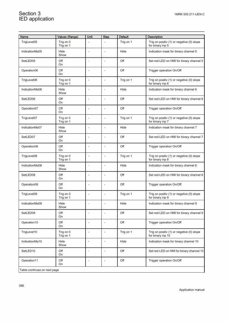
8/22/2019 Best Application
http://slidepdf.com/reader/full/best-application 402/457
Name Values (Range) Unit Step Default Description
TrigLevel05 Trig on 0Trig on 1
- - Trig on 1 Trig on positiv (1) or negative (0) slopefor binary inp 5
IndicationMa05 Hide
Show
- - Hide Indication mask for binary channel 5
SetLED05 Off On
- - Off Set red-LED on HMI for binary channel 5
Operation06 Off On
- - Off Trigger operation On/Off
TrigLevel06 Trig on 0Trig on 1
- - Trig on 1 Trig on positiv (1) or negative (0) slopefor binary inp 6
IndicationMa06 HideShow
- - Hide Indication mask for binary channel 6
SetLED06 Off On
- - Off Set red-LED on HMI for binary channel 6
Operation07 Off
On
- - Off Trigger operation On/Off
TrigLevel07 Trig on 0Trig on 1
- - Trig on 1 Trig on positiv (1) or negative (0) slopefor binary inp 7
IndicationMa07 HideShow
- - Hide Indication mask for binary channel 7
SetLED07 Off On
- - Off Set red-LED on HMI for binary channel 7
Operation08 Off On
- - Off Trigger operation On/Off
TrigLevel08 Trig on 0Trig on 1
- - Trig on 1 Trig on positiv (1) or negative (0) slopefor binary inp 8
IndicationMa08 HideShow - - Hide Indication mask for binary channel 8
SetLED08 Off On
- - Off Set red-LED on HMI for binary channel 8
Operation09 Off On
- - Off Trigger operation On/Off
TrigLevel09 Trig on 0Trig on 1
- - Trig on 1 Trig on positiv (1) or negative (0) slopefor binary inp 9
IndicationMa09 HideShow
- - Hide Indication mask for binary channel 9
SetLED09 Off On
- - Off Set red-LED on HMI for binary channel 9
Operation10 Off On
- - Off Trigger operation On/Off
TrigLevel10 Trig on 0Trig on 1
- - Trig on 1 Trig on positiv (1) or negative (0) slopefor binary inp 10
IndicationMa10 HideShow
- - Hide Indication mask for binary channel 10
SetLED10 Off On
- - Off Set red-LED on HMI for binary channel 10
Operation11 Off On
- - Off Trigger operation On/Off
Table continues on next page
Section 3 1MRK 505 211-UEN C
IED application
396
Application manual

8/22/2019 Best Application
http://slidepdf.com/reader/full/best-application 403/457
Name Values (Range) Unit Step Default Description
TrigLevel11 Trig on 0Trig on 1
- - Trig on 1 Trig on positiv (1) or negative (0) slopefor binary inp 11
IndicationMa11 Hide
Show
- - Hide Indication mask for binary channel 11
SetLED11 Off On
- - Off Set red-LED on HMI for binary channel 11
Operation12 Off On
- - Off Trigger operation On/Off
TrigLevel12 Trig on 0Trig on 1
- - Trig on 1 Trig on positiv (1) or negative (0) slopefor binary inp 12
IndicationMa12 HideShow
- - Hide Indication mask for binary channel 12
SetLED12 Off On
- - Off Set red-LED on HMI for binary input 12
Operation13 Off
On
- - Off Trigger operation On/Off
TrigLevel13 Trig on 0Trig on 1
- - Trig on 1 Trig on positiv (1) or negative (0) slopefor binary inp 13
IndicationMa13 HideShow
- - Hide Indication mask for binary channel 13
SetLED13 Off On
- - Off Set red-LED on HMI for binary channel 13
Operation14 Off On
- - Off Trigger operation On/Off
TrigLevel14 Trig on 0Trig on 1
- - Trig on 1 Trig on positiv (1) or negative (0) slopefor binary inp 14
IndicationMa14 HideShow - - Hide Indication mask for binary channel 14
SetLED14 Off On
- - Off Set red-LED on HMI for binary channel 14
Operation15 Off On
- - Off Trigger operation On/Off
TrigLevel15 Trig on 0Trig on 1
- - Trig on 1 Trig on positiv (1) or negative (0) slopefor binary inp 15
IndicationMa15 HideShow
- - Hide Indication mask for binary channel 15
SetLED15 Off On
- - Off Set red-LED on HMI for binary channel 15
Operation16 Off On
- - Off Trigger operation On/Off
TrigLevel16 Trig on 0Trig on 1
- - Trig on 1 Trig on positiv (1) or negative (0) slopefor binary inp 16
IndicationMa16 HideShow
- - Hide Indication mask for binary channel 16
SetLED16 Off On
- - Off Set red-LED on HMI for binary channel 16
FUNT1 0 - 255 FunT 1 0 Function type for binary channel 1 (IEC-60870-5-103)
Table continues on next page
1MRK 505 211-UEN C Section 3IED application
397
Application manual

8/22/2019 Best Application
http://slidepdf.com/reader/full/best-application 404/457
Name Values (Range) Unit Step Default Description
FUNT2 0 - 255 FunT 1 0 Function type for binary channel 2 (IEC-60870-5-103)
FUNT3 0 - 255 FunT 1 0 Function type for binary channel 3 (IEC
-60870-5-103)
FUNT4 0 - 255 FunT 1 0 Function type for binary channel 4 (IEC-60870-5-103)
FUNT5 0 - 255 FunT 1 0 Function type for binary channel 5 (IEC-60870-5-103)
FUNT6 0 - 255 FunT 1 0 Function type for binary channel 6 (IEC-60870-5-103)
FUNT7 0 - 255 FunT 1 0 Function type for binary channel 7 (IEC-60870-5-103)
FUNT8 0 - 255 FunT 1 0 Function type for binary channel 8 (IEC-60870-5-103)
FUNT9 0 - 255 FunT 1 0 Function type for binary channel 9 (IEC
-60870-5-103)
FUNT10 0 - 255 FunT 1 0 Function type for binary channel 10 (IEC-60870-5-103)
FUNT11 0 - 255 FunT 1 0 Function type for binary channel 11 (IEC-60870-5-103)
FUNT12 0 - 255 FunT 1 0 Function type for binary channel 12 (IEC-60870-5-103)
FUNT13 0 - 255 FunT 1 0 Function type for binary channel 13 (IEC-60870-5-103)
FUNT14 0 - 255 FunT 1 0 Function type for binary channel 14 (IEC-60870-5-103)
FUNT15 0 - 255 FunT 1 0 Function type for binary channel 15 (IEC-60870-5-103)
FUNT16 0 - 255 FunT 1 0 Function type for binary channel 16 (IEC-60870-5-103)
INFNO1 0 - 255 InfNo 1 0 Information number for binary channel 1(IEC -60870-5-103)
INFNO2 0 - 255 InfNo 1 0 Information number for binary channel 2(IEC -60870-5-103)
INFNO3 0 - 255 InfNo 1 0 Information number for binary channel 3(IEC -60870-5-103)
INFNO4 0 - 255 InfNo 1 0 Information number for binary channel 4(IEC -60870-5-103)
INFNO5 0 - 255 InfNo 1 0 Information number for binary channel 5(IEC -60870-5-103)
INFNO6 0 - 255 InfNo 1 0 Information number for binary channel 6(IEC -60870-5-103)
INFNO7 0 - 255 InfNo 1 0 Information number for binary channel 7(IEC -60870-5-103)
INFNO8 0 - 255 InfNo 1 0 Information number for binary channel 8(IEC -60870-5-103)
INFNO9 0 - 255 InfNo 1 0 Information number for binary channel 9(IEC -60870-5-103)
Table continues on next page
Section 3 1MRK 505 211-UEN C
IED application
398
Application manual

8/22/2019 Best Application
http://slidepdf.com/reader/full/best-application 405/457
Name Values (Range) Unit Step Default Description
INFNO10 0 - 255 InfNo 1 0 Information number for binary channel10 (IEC -60870-5-103)
INFNO11 0 - 255 InfNo 1 0 Information number for binary channel
11 (IEC -60870-5-103)
INFNO12 0 - 255 InfNo 1 0 Information number for binary channel12 (IEC -60870-5-103)
INFNO13 0 - 255 InfNo 1 0 Information number for binary channel13 (IEC -60870-5-103)
INFNO14 0 - 255 InfNo 1 0 Information number for binary channel14 (IEC -60870-5-103)
INFNO15 0 - 255 InfNo 1 0 Information number for binary channel15 (IEC -60870-5-103)
INFNO16 0 - 255 InfNo 1 0 Information number for binary channel16 (IEC -60870-5-103)
3.13.7 Event list
3.13.7.1 Application
From an overview perspective, continuous event-logging is a useful systemmonitoring instrument and is a complement to specific disturbance recorder functions.
The event list (EL), always included in the IED, logs all selected binary inputsignals connected to the Disturbance report function. The list may contain of up to1000 time-tagged events stored in a ring-buffer where, if the buffer is full, theoldest event is overwritten when a new event is logged.
The difference between the event list (EL) and the event recorder (ER) function isthat the list function continuously updates the log with time tagged events while therecorder function is an extract of events during the disturbance report time window.
The event list information is available in the IED via the local HMI or PCM600.
3.13.7.2 Setting guidelines
The setting parameters for the Event list function (EL) are a part of the Disturbancereport settings.
It is possible to event handle up to 96 binary signals, either internal signals or signals from binary input channels. These signals are identical with the binarysignals recorded by the disturbance recorder.
There is no dedicated setting for the EL function.
1MRK 505 211-UEN C Section 3IED application
399
Application manual

8/22/2019 Best Application
http://slidepdf.com/reader/full/best-application 406/457
3.13.8 Indications
3.13.8.1 Application
Fast, condensed and reliable information about disturbances in the primary and/or in the secondary system is important. Binary signals that have changed statusduring a disturbance are an example of this. This information is used primarily inthe short term (for example, immediate disturbance analysis, corrective actions) toget information via the local HMI in a straightforward way without any knowledgeof how to handle the IED.
There are three LEDs on the local HMI (green, yellow and red), which will displaystatus information about the IED (in service, internal failure, and so on) and theDisturbance report function (trigged).
The Indication function (IND), always included in the IED, shows all selected binary input signals connected to the Disturbance Report function that have beenactivated during a disturbance. The status changes are logged during the entirerecording time, which depends on the set of recording times (pre-, post-fault andlimit time) and the actual fault time. The indications are not time-tagged.
The indication information is available for each of the recorded disturbances in theIED and the user may use the local HMI to view the information.
3.13.8.2 Setting guidelines
The setting parameters for LEDs and the Indication function (IND) are a part of thedisturbance report settings.
Available signals are identical with the binary signals recorded by the disturbancereport. It is possible to use all binary input signals for the Indication function on thelocal HMI, but it is not recommended since the general view will be lost. Theintention is to point out some important signals, not to many, to be shown. If amore thorough analysis is to be done information from the event recorder should beused.
To be able to control the red LED in the local HMI:
SetLEDn: Set red LED on LMHI in front of the IED if binary input N changes status.For the IND function there are a number dedicated settings:
IndicationMaN : Indication mask for binary input N. If set (Show), a status changeof that particular input, will be fetched and shown on the local HMI. If not set( Hide), status change will not be indicated.
Section 3 1MRK 505 211-UEN C
IED application
400
Application manual

8/22/2019 Best Application
http://slidepdf.com/reader/full/best-application 407/457
3.13.9 Event recorder
3.13.9.1 Application
Quick, complete and reliable information about disturbances in the primary and/or in the secondary system is vital, for example, time tagged events logged duringdisturbances. This information is used for different purposes in the short term, for example, disturbance analysis, corrective actions and in the long term, for example,disturbance analysis, statistics and maintenance, that is Functional Analysis).
The event recorder, always included in the IED, logs all selected binary inputsignals connected to the disturbance report function DRPRDRE. Each recordingcan contain up to 150 time-tagged events. The events are logged during the totalrecording time, which depends on the set of recording times (pre-, post-fault andlimit time) and the actual fault time. During this time, the first 150 events for all 96
binary signals are logged and time-tagged.
The event recorder information is available for each of the recorded disturbances inthe IED and the user may use the local HMI to get the information. Theinformation is included in the disturbance recorder file, which may be uploaded toPCM600 and further analyzed using the Disturbance Handling tool.
The event recording information is an integrated part of the disturbance record(Comtrade file).
3.13.9.2 Setting guidelines
The setting parameters for the Event Recorder (ER) function are a part of theDisturbance Report settings.
It is possible to event handle up to 96 binary signals, either internal signals or signals from binary input channels. These signals are identical to the binary signalsrecorded by the disturbance report.
For the ER function there is no dedicated setting.
3.13.10 Trip value recorder
3.13.10.1 Application
Fast, complete and reliable information about disturbances such as fault currentsand voltage faults in the power system is vital. This information is used for different purposes in the short perspective (for example, fault location, disturbanceanalysis, corrective actions) and the long term (for example, disturbance analysis,statistics and maintenance, that is Functional Analysis).
The trip value recorder (TVR), always included in the IED, calculates the values of all selected external analog input signals (channel 1-30) connected to the
1MRK 505 211-UEN C Section 3IED application
401
Application manual

8/22/2019 Best Application
http://slidepdf.com/reader/full/best-application 408/457
Disturbance Report function. The estimation is performed immediately after finalizing each recording and available in the disturbance report. The result ismagnitude and phase angle before and during the fault for each analog input signal.
The information is used as input to the fault location function (FL), if included inthe IED and in operation.
The trip value recorder (TVR) information is available for each of the recordeddisturbances in the IED and the user may use the local HMI to get the information.The information is included in the disturbance recorder file, which can be uploadedto PCM600 and further analyzed using the Disturbance Handling tool.
3.13.10.2 Setting guidelines
The trip value recorder (TVR) setting parameters are a part of the disturbance
report settings.For the trip value recorder (TVR) there is one dedicated setting:
ZeroAngleRef : The parameter defines which analog signal to use as phase-anglereference for all other input signals. It is suggested to point out a sampled voltageinput signal, for example a line or busbar phase voltage (channel 1-30).
3.13.11 Disturbance recorder
3.13.11.1 Application
The maximum number of recordings depend on each recordingstotal recording time. Long recording time will reduce the number of recordings to less than 100.
The IED flash disk should NOT be used to store any user files. Thismight cause disturbance recordings to be deleted due to lack of disk space.
To get fast, complete and reliable information about fault current, voltage, binarysignal and other disturbances in the power system is very important. This isaccomplished by the Disturbance Recorder function and facilitates a better understanding of the behavior of the power system and related primary andsecondary equipment during and after a disturbance. An analysis of the recordeddata provides valuable information that can be used to explain a disturbance, basisfor change of IED setting plan, improvement of existing equipment, and so on.This information can also be used in a longer perspective when planning for anddesigning new installations, that is a disturbance recording could be a part of Functional Analysis (FA).
Section 3 1MRK 505 211-UEN C
IED application
402
Application manual

8/22/2019 Best Application
http://slidepdf.com/reader/full/best-application 409/457
The Disturbance Recorder (DR), always included in the IED, acquires sampleddata from all selected analog input and binary signals connected to the function
blocks, that is maximum 30 external analog, 10 internal (derived) analog and 96 binary signals.
The function is characterized by great flexibility as far as configuration, startingconditions, recording times, and large storage capacity are concerned. Thus, thedisturbance recorder is not dependent on the operation of protective functions, andit can record disturbances that were not discovered by protective functions.
The disturbance recorder information is saved for each of the recorded disturbancesin the IED and the user may use the local HMI to get some general informationabout the recordings. The disturbance recording information is included in thedisturbance recorder files, which may be uploaded to PCM600 for further analysisusing the Disturbance Handling tool. The information is also available on a station
bus according to IEC 61850 and according to IEC 60870-5-103.
3.13.11.2 Setting guidelines
The setting parameters for the Disturbance Recorder function (DR) is a part of theDisturbance Report settings.
It is possible to handle up to 40 analog and 96 binary signals, either internal signalsor signals coming from external inputs. The binary signals are identical with thesignals recorded by the other functions in the Disturbance Report function, that isEvent recorder (ER), Indication (IND) and Trip value recorder (TVR) function.
For the DR function there is one dedicated setting:
OperationM : Analog channel M is to be recorded by the disturbance recorder (On)or not (Off ). Other disturbance report settings, such as Operation and TrigLevel for
binary signals, will also influence the disturbance recorder.
3.14 Metering
3.14.1 Pulse-counter logic PCGGIO
Function description IEC 61850
identification
IEC 60617
identification
ANSI/IEEE C37.2
device number
Pulse-counter logic PCGGIO
S00947 V1 EN
-
1MRK 505 211-UEN C Section 3IED application
403
Application manual

8/22/2019 Best Application
http://slidepdf.com/reader/full/best-application 410/457
3.14.1.1 Application
Pulse counter logic function counts externally generated binary pulses, for instance pulses coming from an external energy meter, for calculation of energy
consumption values. The pulses are captured by the binary input module (BIM),and read by the pulse counter function. The number of pulses in the counter is thenreported via the station bus to the substation automation system or read via thestation monitoring system as a service value. When using IEC 61850–8–1, a scaledservice value is available over the station bus.
The normal use for this function is the counting of energy pulses from externalenergy meters. An optional number of inputs from an arbitrary input module inIED can be used for this purpose with a frequency of up to 40 Hz. The pulsecounter can also be used as a general purpose counter.
3.14.1.2 Setting guidelines
From PCM600, these parameters can be set individually for each pulse counter:
• Operation: Off /On
• tReporting : 0-3600s
• EventMask : NoEvents/ ReportEvents
The configuration of the inputs and outputs of the Pulse counter function block ismade with PCM600.
On the Binary Input Module, the debounce filter time is fixed set to 5 ms, that is,the counter suppresses pulses with a pulse length less than 5 ms. The inputoscillation blocking frequency is preset to 40 Hz. That means that the counter findsthe input oscillating if the input frequency is greater than 40 Hz. The oscillationsuppression is released at 30 Hz. The values for blocking/release of the oscillationcan be changed in the local HMI and PCM600 under Main menu/Settings/
General settings/I/O-modules
The setting is common for all input channels on a Binary InputModule, that is, if changes of the limits are made for inputs notconnected to the pulse counter, the setting also influences the inputson the same board used for pulse counting.
Section 3 1MRK 505 211-UEN C
IED application
404
Application manual

8/22/2019 Best Application
http://slidepdf.com/reader/full/best-application 411/457
3.14.1.3 Setting parameters
Table 162: PC GG IO N on group settings (basic)
Name Values (Range) Unit Step Default Description
Operation Off On
- - Off Operation Off/On
EventMask NoEventsReportEvents
- - NoEvents Report mask for analog events frompulse counter
CountCriteria Off RisingEdgeFalling edgeOnChange
- - RisingEdge Pulse counter criteria
Scale 1.000 - 90000.000 - 0.001 1.000 Scaling value for SCAL_VAL output tounit per counted value
Quantity Count ActivePower
ApparentPower ReactivePower
ActiveEnergy ApparentEnergyReactiveEnergy
- - Count Measured quantity for SCAL_VAL output
tReporting 0 - 3600 s 1 60 Cycle time for reporting of counter value
3.14.2 Function for energy calculation and demand handling
ETPMMTR
Function description IEC 61850identification
IEC 60617identification
ANSI/IEEE C37.2device number
Energy calculation and demandhandling
ETPMMTR -
3.14.2.1 Application
Energy calculation and demand handling function ETPMMTR is intended for statistics of the forward and reverse active and reactive energy. It has a highaccuracy basically given by the measurements function (CVMMXN). This functionhas a site calibration possibility to further increase the total accuracy.
The function is connected to the instantaneous outputs of (CVMMXN) as shown infigure 148.
1MRK 505 211-UEN C Section 3IED application
405
Application manual

8/22/2019 Best Application
http://slidepdf.com/reader/full/best-application 412/457
P
Q
STACC
RSTACC
RSTDMD
TRUE
FALSEFALSE
CVMMXN
IEC09000106.vsd
ETPMMTRP_INST
Q_INST
IEC09000106 V1 EN
Figure 148: Connection of energy calculation and demand handling function
ETPMMTR to the measurements function (CVMMXN)
The energy values can be read through communication in MWh and MVarh inmonitoring tool of PCM600 and/or alternatively the values can be presented on thelocal HMI. The local HMI graphical display is configured with PCM600 Graphicaldisplay editor tool (GDE) with a measuring value which is selected to the active
and reactive component as preferred. All four values can also be presented.Maximum demand values are presented in MWh or MVarh in the same way.
Alternatively, the values can be presented with use of the pulse counters function(PCGGIO). The output values are scaled with the pulse output setting values
EAFAccPlsQty, EARAccPlsQty, ERFAccPlsQty and ERVAccPlsQty of the energymetering function and then the pulse counter can be set-up to present the correctvalues by scaling in this function. Pulse counter values can then be presented onthe local HMI in the same way and/or sent to the SA system throughcommunication where the total energy then is calculated by summation of theenergy pulses. This principle is good for very high values of energy as the
saturation of numbers else will limit energy integration to about one year with 50kV and 3000 A. After that the accumulation will start on zero again.
3.14.2.2 Setting guidelines
The parameters are set via the local HMI or PCM600.
The following settings can be done for the energy calculation and demand handlingfunction ETPMMTR:
Operation: Off /On
tEnergy: Time interval when energy is measured.
StartAcc: Off /On is used to switch the accumulation of energy on and off.
The input signal STACC is used to start accumulation. Input signalSTACC cannot be used to halt accumulation. The energy content isreset every time STACC is activated. STACC can for example, beused when an external clock is used to switch two active energymeasuring function blocks on and off to have indication of two tariffs.
Section 3 1MRK 505 211-UEN C
IED application
406
Application manual

8/22/2019 Best Application
http://slidepdf.com/reader/full/best-application 413/457
tEnergyOnPls: gives the pulse length ON time of the pulse. It should be at least100 ms when connected to the Pulse counter function block. Typical value can be100 ms.
tEnergyOffPls: gives the OFF time between pulses. Typical value can be 100 ms.
EAFAccPlsQty and EARAccPlsQty: gives the MWh value in each pulse. It should be selected together with the setting of the Pulse counter (PCGGIO) settings togive the correct total pulse value.
ERFAccPlsQty and ERVAccPlsQty : gives the MVarh value in each pulse. It should be selected together with the setting of the Pulse counter (PCGGIO) settings togive the correct total pulse value.
For the advanced user there are a number of settings for direction, zero clamping,max limit, and so on. Normally, the default values are suitable for these parameters.
3.14.2.3 Setting parameters
Table 163: ETP MM TR N on group settings (basic)
Name Values (Range) Unit Step Default Description
Operation Off On
- - Off Operation Off/On
StartAcc Off On
- - Off Activate the accumulation of energyvalues
tEnergy 1 Minute5 Minutes10 Minutes15 Minutes30 Minutes60 Minutes180 Minutes
- - 1 Minute Time interval for energy calculation
tEnergyOnPls 0.000 - 60.000 s 0.001 1.000 Energy accumulated pulse ON time insecs
tEnergyOffPls 0.000 - 60.000 s 0.001 0.500 Energy accumulated pulse OFF time insecs
EAFAccPlsQty 0.001 - 10000.000 MWh 0.001 100.000 Pulse quantity for active forwardaccumulated energy value
EARAccPlsQty 0.001 - 10000.000 MWh 0.001 100.000 Pulse quantity for active reverseaccumulated energy value
ERFAccPlsQty 0.001 - 10000.000 MVArh 0.001 100.000 Pulse quantity for reactive forwardaccumulated energy value
ERVAccPlsQty 0.001 - 10000.000 MVArh 0.001 100.000 Pulse quantity for reactive reverseaccumulated energy value
1MRK 505 211-UEN C Section 3IED application
407
Application manual

8/22/2019 Best Application
http://slidepdf.com/reader/full/best-application 414/457
Table 164: ETPM MTR Non group settings (advanced)
Name Values (Range) Unit Step Default Description
EALim 0.001 -10000000000.000
MWh 0.001 1000000.000 Active energy limit
ERLim 0.001 -10000000000.000
MVArh 0.001 1000.000 Reactive energy limit
DirEnergyAct ForwardReverse
- - Forward Direction of active energy flow Forward/Reverse
DirEnergyReac ForwardReverse
- - Forward Direction of reactive energy flow Forward/Reverse
EnZeroClamp Off On
- - On Enable of zero point clamping detectionfunction
LevZeroClampP 0.001 - 10000.000 MW 0.001 10.000 Zero point clamping level at active Power
LevZeroClampQ 0.001 - 10000.000 MVAr 0.001 10.000 Zero point clamping level at reactivePower
EAFPrestVal 0.000 - 10000.000 MWh 0.001 0.000 Preset Initial value for forward activeenergy
EARPrestVal 0.000 - 10000.000 MWh 0.001 0.000 Preset Initial value for reverse activeenergy
ERFPresetVal 0.000 - 10000.000 MVArh 0.001 0.000 Preset Initial value for forward reactiveenergy
ERVPresetVal 0.000 - 10000.000 MVArh 0.001 0.000 Preset Initial value for reverse reactiveenergy
Section 3 1MRK 505 211-UEN C
IED application
408
Application manual
8/22/2019 Best Application
http://slidepdf.com/reader/full/best-application 415/457
Section 4 Station communication
About this chapter
This chapter describes the communication possibilities in a SA-system.
4.1 Overview
Each IED is provided with a communication interface, enabling it to connect to one
or many substation level systems or equipment, either on the SubstationAutomation (SA) bus or Substation Monitoring (SM) bus.
Following communication protocols are available:
• IEC 61850-8-1 communication protocol• LON communication protocol• SPA or IEC 60870-5-103 communication protocol• DNP3.0 communication protocol
Theoretically, several protocols can be combined in the same IED.
4.2 IEC 61850-8-1 communication protocol
4.2.1 Application IEC 61850-8-1
IEC 61850-8-1 communication protocol allows vertical communication to HSIclients and allows horizontal communication between two or more intelligentelectronic devices (IEDs) from one or several vendors to exchange information andto use it in the performance of their functions and for correct co-operation.
GOOSE (Generic Object Oriented Substation Event), which is a part of IEC 61850– 8–1 standard, allows the IEDs to communicate state and control informationamongst themselves, using a publish-subscribe mechanism. That is, upon detectingan event, the IED(s) use a multi-cast transmission to notify those devices that haveregistered to receive the data. An IED can, by publishing a GOOSE message,report its status. It can also request a control action to be directed at any device inthe network.
Figure 149 shows the topology of an IEC 61850–8–1 configuration. IEC 61850–8– 1 specifies only the interface to the substation LAN. The LAN itself is left to thesystem integrator.
1MRK 505 211-UEN C Section 4Station communication
409
Application manual

8/22/2019 Best Application
http://slidepdf.com/reader/full/best-application 416/457
KIOSK 2 KIOSK 3
Station HSI
Base System
Engineering
Workstation
SMS
Gateway
Printer
CC
IEC09000135_en.v
sd
KIOSK 1
IED
1
IED
2
IED
3
IED
1
IED
2
IED
3
IED
1
IED
2
IED
3
IEC09000135 V1 EN
Figure 149: SA system with IEC 61850–8–1
Figure 150 shows the GOOSE peer-to-peer communication.
Control Protection Control ProtectionControl and protection
GOOSE
en05000734.vsd
Station HSI
MicroSCADAGateway
IED
A
IED
A
IED
A
IED
A
IED
A
IEC05000734 V1 EN
Figure 150: Example of a broadcasted GOOSE message
Section 4 1MRK 505 211-UEN C
Station communication
410
Application manual

8/22/2019 Best Application
http://slidepdf.com/reader/full/best-application 417/457
4.2.2 Setting guidelines
There are two settings related to the IEC 61850–8–1 protocol:
Operation User can set IEC 61850 communication to On or Off .
GOOSE has to be set to the Ethernet link where GOOSE traffic shall be send andreceived.
4.2.3 Setting parameters
T able 1 65 : IE C6 18 50-8-1 N on g ro up se ttin gs (b as ic)
Name Values (Range) Unit Step Default Description
Operation Off On
- - Off Operation Off/On
GOOSE FrontOEM311_ABOEM311_CD
- - OEM311_AB Port for GOOSE communication
Table 166: G OO SEB INR CV Non group settings (basic)
Name Values (Range) Unit Step Default Description
Operation Off On
- - Off Operation Off/On
4.2.4 IEC 61850 generic communication I/O functions SPGGIO,SP16GGIO
4.2.4.1 Application
IEC 61850–8–1 generic communication I/O functions (SPGGIO) function is usedto send one single logical output to other systems or equipment in the substation. Ithas one visible input, that should be connected in ACT tool.
4.2.4.2 Setting guidelinesThere are no settings available for the user for SPGGIO. However, PCM600 must
be used to get the signals sent by SPGGIO.
4.2.4.3 Setting parameters
The function does not have any parameters available in the local HMI or PCM600.
4.2.5 IEC 61850 generic communication I/O functions MVGGIO
1MRK 505 211-UEN C Section 4Station communication
411
Application manual

8/22/2019 Best Application
http://slidepdf.com/reader/full/best-application 418/457
4.2.5.1 Application
IEC61850 generic communication I/O functions (MVGGIO) function is used tosend the instantaneous value of an analog signal to other systems or equipment in
the substation. It can also be used inside the same IED, to attach a RANGE aspectto an analog value and to permit measurement supervision on that value.
4.2.5.2 Setting guidelines
The settings available for IEC61850 generic communication I/O functions(MVGGIO) function allows the user to choose a deadband and a zero deadband for the monitored signal. Values within the zero deadband are considered as zero.
The high and low limit settings provides limits for the high-high-, high, normal,low and low-low ranges of the measured value. The actual range of the measured
value is shown on the range output of MVGGIO function block. When a Measuredvalue expander block (RANGE_XP) is connected to the range output, the logicaloutputs of the RANGE_XP are changed accordingly.
4.2.5.3 Setting parameters
Table 167: M VG GIO Non group settings (basic)
Name Values (Range) Unit Step Default Description
MV db 1 - 300 Type 1 10 Cycl: Report interval (s), Db: In % of range, Int Db: In %s
MV zeroDb 0 - 100000 m% 1 500 Zero point clamping in 0,001% of range
MV hhLim -10000000000.000- 10000000000.000
- 0.001 90.000 High High limit
MV hLim -10000000000.000- 10000000000.000
- 0.001 80.000 High limit
MV lLim -10000000000.000- 10000000000.000
- 0.001 -80.000 Low limit
MV llLim -10000000000.000- 10000000000.000
- 0.001 -90.000 Low Low limit
MV min -10000000000.000- 10000000000.000
- 0.001 -100.000 Minimum value
MV max -10000000000.000- 10000000000.000
- 0.001 100.000 Maximum value
MV dbType CyclicDead bandInt deadband
- - Dead band Reporting type
MV limHys 0.000 - 100.000 % 0.001 5.000 Hysteresis value in % of range (commonfor all limits)
4.2.6 IEC 61850-8-1 redundant station bus communication
Section 4 1MRK 505 211-UEN C
Station communication
412
Application manual

8/22/2019 Best Application
http://slidepdf.com/reader/full/best-application 419/457
Function description IEC 61850
identification
IEC 60617
identification
ANSI/IEEE C37.2
device number
Parallel Redundancy Protocol Status PRPSTATUS - -
Duo driver configuration DUODRV - -
4.2.6.1 Application
Parallel redundancy protocol status (PRPSTATUS) together with Duo driver configuration (DUODRV) are used to supervise and assure redundant Ethernetcommunication over two channels. This will secure data transfer even though onecommunication channel might not be available for some reason. Together PRPSTATUS and DUODRV provide redundant communication over station busrunning IEC 61850-8-1 protocol. The redundant communication use both port ABand CD on OEM module.
1MRK 505 211-UEN C Section 4Station communication
413
Application manual

8/22/2019 Best Application
http://slidepdf.com/reader/full/best-application 420/457

8/22/2019 Best Application
http://slidepdf.com/reader/full/best-application 421/457
The settings can then be viewed, but not set, in the Parameter Setting tool inPCM600 under Main menu/IED Configuration/Communication/Ethernet
configuration/DUODRV:
Operation: The redundant communication will be activated when this parameter isset to On.After confirmation the IED will restart and the setting alternatives Rear
OEM - Port AB and CD will not be further displayed in the local HMI. The ETHLANAB and ETHLANCD in the Parameter Setting Tool are irrelevant when theredundant communication is activated, only DUODRV IPAdress and IPMask arevalid.
IEC10000057-1-en.vsd
IEC10000057 V1 EN
Figure 152: PST screen: DUODRV Operation is set to On, which affect Rear
OEM - Port AB and CD which are both set to Duo
1MRK 505 211-UEN C Section 4Station communication
415
Application manual

8/22/2019 Best Application
http://slidepdf.com/reader/full/best-application 422/457
4.2.6.3 Setting parameters
Table 168: DU OD RV N on group settings (basic)
Name Values (Range) Unit Step Default Description
Operation Off On
- - Off Operation Off / On
IPAddress 0 - 18 IP Address
1 192.168.7.10 IP-Address
IPMask 0 - 18 IP Address
1 255.255.255.0 IP-Mask
4.3 LON communication protocol
4.3.1 Application
Control Center
IED IEDIED
Gateway
Star coupler RER 111
Station HSIMicroSCADA
IEC05000663-1-en.vsd
IEC05000663 V2 EN
Figure 153: Example of LON communication structure for a substation automation system
An optical network can be used within the substation automation system. Thisenables communication with the IEDs in the 670 series through the LON bus fromthe operator’s workplace, from the control center and also from other IEDs via bay-to-bay horizontal communication.
The fibre optic LON bus is implemented using either glass core or plastic core fibreoptic cables.
Section 4 1MRK 505 211-UEN C
Station communication
416
Application manual

8/22/2019 Best Application
http://slidepdf.com/reader/full/best-application 423/457
T ab le 169 : S pe cific ation of th e fibre optic co nne cto rs
Glass fibre Plastic fibre
Cable connector ST-connector snap-in connector
Cable diameter 62.5/125 m 1 mmMax. cable length 1000 m 10 m
Wavelength 820-900 nm 660 nm
Transmitted power -13 dBm (HFBR-1414) -13 dBm (HFBR-1521)
Receiver sensitivity -24 dBm (HFBR-2412) -20 dBm (HFBR-2521)
The LON ProtocolThe LON protocol is specified in the LonTalkProtocol Specification Version 3from Echelon Corporation. This protocol is designed for communication in control
networks and is a peer-to-peer protocol where all the devices connected to thenetwork can communicate with each other directly. For more information of the bay-to-bay communication, refer to the section Multiple command function.
Hardware and software modulesThe hardware needed for applying LON communication depends on theapplication, but one very central unit needed is the LON Star Coupler and opticalfibres connecting the star coupler to the IEDs. To interface the IEDs fromMicroSCADA, the application library LIB670 is required.
The HV Control 670 software module is included in the LIB520 high-voltage process package, which is a part of the Application Software Library within
MicroSCADA applications.
The HV Control 670 software module is used for control functions in IEDs in the670 series. This module contains the process picture, dialogues and a tool togenerate the process database for the control application in MicroSCADA.
Use the LON Network Tool (LNT) to set the LON communication. This is asoftware tool applied as one node on the LON bus. To communicate via LON, theIEDs need to know
• The node addresses of the other connected IEDs.• The network variable selectors to be used.
This is organized by LNT.
The node address is transferred to LNT via the local HMI by setting the parameter ServicePinMsg = Yes. The node address is sent to LNT via the LON bus, or LNTcan scan the network for new nodes.
The communication speed of the LON bus is set to the default of 1.25 Mbit/s. Thiscan be changed by LNT.
1MRK 505 211-UEN C Section 4Station communication
417
Application manual

8/22/2019 Best Application
http://slidepdf.com/reader/full/best-application 424/457
4.3.2 Setting parameters
Table 170: HO RZC OM M N on group settings (basic)
Name Values (Range) Unit Step Default DescriptionOperation Off
On- - Off Operation
Table 171: ADE Non group settings (basic)
Name Values (Range) Unit Step Default Description
Operation Off On
- - Off Operation
TimerClass SlowNormalFast
- - Slow Timer class
4.4 SPA communication protocol
4.4.1 Application
SPA communication protocol as an alternative to IEC 60870-5-103. The samecommunication port as for IEC 60870-5-103 is used.
SPA communication is applied using the front communication port. For this
purpose, no serial communication module is required in the IED. Only PCM600software in the PC and a crossed-over Ethernet cable for front connection is required.
When communicating with a PC (as shown in figure 155), using the rear SPA porton the serial communication module (SLM), the only hardware required for a localmonitoring system is:
• Optical fibres for the SPA bus loop• Optical/electrical converter for the PC• PC
A remote monitoring system for communication over the public telephone network also requires telephone modems and a remote PC.
The software required for a local monitoring system is PCM600, and for a remotemonitoring system it is PCM600 in the remote PC only.
Section 4 1MRK 505 211-UEN C
Station communication
418
Application manual

8/22/2019 Best Application
http://slidepdf.com/reader/full/best-application 425/457
Local monitoring
system with
PCM600
IED IEDIED
Optical to electrical
converter, e.g. SPA-ZC 22
or Fiberdata modem
Teleph
one
modem
Teleph
one
modem
Remote monitoring
system with
PCM600
en05000672.vsd
IEC05000672 V2 EN
Figure 154: SPA communication structure for a monitoring system. The
monitoring system can either be local, remote or a combination of
both
When communicating with a PC connected to the utility substation LAN, via WANand the utility office LAN, as shown in figure 155, and using the rear Ethernet porton the optical Ethernet module (OEM), the only hardware required for a stationmonitoring system is:
• Optical fibres from the IED to the utility substation LAN.• PC connected to the utility office LAN.
The software required is PCM600.
IED IEDIED
Substation LAN
en05000715.vsd
Remote
monitoring
system with
PCM600
Utility LAN
WAN
IEC05000715 V2 EN
Figure 155: SPA communication structure for a remote monitoring system via a
substation LAN, WAN and utility LAN
The SPA communication is mainly used for the Station Monitoring System. It caninclude different IEDs with remote communication possibilities. Connection to acomputer (PC) can be made directly (if the PC is located in the substation) or bytelephone modem through a telephone network with ITU (former CCITT)characteristics or via a LAN/WAN connection.
1MRK 505 211-UEN C Section 4Station communication
419
Application manual

8/22/2019 Best Application
http://slidepdf.com/reader/full/best-application 426/457
glass <1000 m according to optical budget
plastic <20 m (inside cubicle) according to optical budget
FunctionalityThe SPA protocol V2.5 is an ASCII-based protocol for serial communication. Thecommunication is based on a master-slave principle, where the IED is a slave andthe PC is the master. Only one master can be applied on each fibre optic loop. A
program is required in the master computer for interpretation of the SPA-bus codesand for translation of the data that should be sent to the IED.
For the specification of the SPA protocol V2.5, refer to SPA-bus CommunicationProtocol V2.5.
4.4.2 Setting guidelines
The setting parameters for the SPA communication are set via the local HMI.
SPA, IEC 60870-5-103 and DNP3 uses the same rear communication port. Set the parameter Operation, under Main menu /Settings /General settings /
Communication /SLM configuration /Rear optical SPA-IEC-DNP port /
Protocol selection to the selected protocol.
When the communication protocols have been selected, the IED is automaticallyrestarted.
The most important settings in the IED for SPA communication are the slavenumber and baud rate (communication speed). These settings are absolutelyessential for all communication contact to the IED.
These settings can only be done on the local HMI for rear channel communicationand for front channel communication.
The slave number can be set to any value from 1 to 899, as long as the slavenumber is unique within the used SPA loop.
The baud rate, which is the communication speed, can be set to between 300 and38400 baud. Refer to technical data to determine the rated communication speed
for the selected communication interfaces. The baud rate should be the same for thewhole station, although different baud rates in a loop are possible. If different baudrates in the same fibre optical loop or RS485 network are used, consider this whenmaking the communication setup in the communication master, the PC.
For local fibre optic communication, 19200 or 38400 baud is the normal setting. If telephone communication is used, the communication speed depends on the qualityof the connection and on the type of modem used. But remember that the IED doesnot adapt its speed to the actual communication conditions, because the speed is seton the local HMI.
Section 4 1MRK 505 211-UEN C
Station communication
420
Application manual

8/22/2019 Best Application
http://slidepdf.com/reader/full/best-application 427/457
4.4.3 Setting parameters
Table 172: SPA Non group settings (basic)
Name Values (Range) Unit Step Default DescriptionSlaveAddress 1 - 899 - 1 30 Slave address
BaudRate 300 Bd1200 Bd2400 Bd4800 Bd9600 Bd19200 Bd38400 Bd
- - 9600 Bd Baudrate on serial line
Table 173: LO NSPA Non group settings (basic)
Name Values (Range) Unit Step Default Description
Operation Off On
- - Off Operation
SlaveAddress 1 - 899 - 1 30 Slave address
4.5 IEC 60870-5-103 communication protocol
4.5.1 Application
TCP/IP
Control Center
IED IEDIED
Gateway
Star coupler RER 125
Station HSI
en05000660.vsd
IEC05000660 V3 EN
Figure 156: Example of IEC 60870-5-103 communication structure for a
substation automation system
1MRK 505 211-UEN C Section 4Station communication
421
Application manual

8/22/2019 Best Application
http://slidepdf.com/reader/full/best-application 428/457
IEC 60870-5-103 communication protocol is mainly used when a protection IEDcommunicates with a third party control or monitoring system. This system musthave software that can interpret the IEC 60870-5-103 communication messages.
FunctionalityIEC 60870-5-103 is an unbalanced (master-slave) protocol for coded-bit serialcommunication exchanging information with a control system. In IEC terminologya primary station is a master and a secondary station is a slave. The communicationis based on a point-to-point principle. The master must have software that caninterpret the IEC 60870-5-103 communication messages. For detailed informationabout IEC 60870-5-103, refer to IEC60870 standard part 5: Transmission
protocols, and to the section 103, Companion standard for the informative interfaceof protection equipment.
Design
GeneralThe protocol implementation consists of the following functions:
• Event handling• Report of analog service values (measurands)• Fault location• Command handling
• Autorecloser ON/OFF• Teleprotection ON/OFF• Protection ON/OFF
• LED reset• Characteristics 1 - 4 (Setting groups)
• File transfer (disturbance files)• Time synchronization
HardwareWhen communicating locally with a Personal Computer (PC) or a RemoteTerminal Unit (RTU) in the station, using the SPA/IEC port, the only hardwareneeded is:· Optical fibres, glass/plastic· Opto/electrical converter for the PC/RTU·PC/RTU
CommandsThe commands defined in the IEC 60870-5-103 protocol are represented in adedicated function blocks. These blocks have output signals for all availablecommands according to the protocol.
• IED commands in control direction
Function block with defined IED functions in control direction, I103IEDCMD.This block use PARAMETR as FUNCTION TYPE, and INFORMATION
NUMBER parameter is defined for each output signal.
Section 4 1MRK 505 211-UEN C
Station communication
422
Application manual
8/22/2019 Best Application
http://slidepdf.com/reader/full/best-application 429/457
• Function commands in control direction
Function block with pre defined functions in control direction, I103CMD. This
block includes the FUNCTION TYPE parameter, and the INFORMATION NUMBER parameter is defined for each output signal.
• Function commands in control direction
Function block with user defined functions in control direction, I103UserCMD.These function blocks include the FUNCTION TYPE parameter for each block inthe private range, and the INFORMATION NUMBER parameter for each outputsignal.
StatusThe events created in the IED available for the IEC 60870-5-103 protocol are
based on the:
• IED status indication in monitor direction
Function block with defined IED functions in monitor direction, I103IED. This block use PARAMETER as FUNCTION TYPE, and INFORMATION NUMBER parameter is defined for each input signal.
• Function status indication in monitor direction, user-defined
Function blocks with user defined input signals in monitor direction, I103UserDef.
These function blocks include the FUNCTION TYPE parameter for each block inthe private range, and the INFORMATION NUMBER parameter for each inputsignal.
• Supervision indications in monitor direction
Function block with defined functions for supervision indications in monitor direction, I103Superv. This block includes the FUNCTION TYPE parameter, andthe INFORMATION NUMBER parameter is defined for each output signal.
• Earth fault indications in monitor direction
Function block with defined functions for earth fault indications in monitor direction, I103EF. This block includes the FUNCTION TYPE parameter, and theINFORMATION NUMBER parameter is defined for each output signal.
• Fault indications in monitor direction, type 1
Function block with defined functions for fault indications in monitor direction,I103FltDis. This block includes the FUNCTION TYPE parameter, and theINFORMATION NUMBER parameter is defined for each input signal. This block is suitable for distance protection function.
1MRK 505 211-UEN C Section 4Station communication
423
Application manual

8/22/2019 Best Application
http://slidepdf.com/reader/full/best-application 430/457

8/22/2019 Best Application
http://slidepdf.com/reader/full/best-application 431/457
to the disturbance function blocks A1RADR to A4RADR. The eight first ones belong to the public range and the remaining ones to the private range.
Settings
Settings from the local HMISPA, IEC 60870-5-103 and DNP3 uses the same rear communication port. Set the
parameter Operation, under Main menu/Settings /General settings /
Communication /SLM configuration /Rear optical SPA-IEC-DNP port /
Protocol selection to the selected protocol.
When the communication protocols have been selected, the IED is automaticallyrestarted.
The general settings for IEC 60870-5-103 communication are the following:
• SlaveAddress and BaudRate: Settings for slave number and communicationspeed (baud rate).The slave number can be set to any value between 1 and 31. Thecommunication speed, can be set either to 9600 bits/s or 19200 bits/s.
• RevPolarity: Setting for inverting the light (or not).• CycMeasRepTime: Setting for CycMeasRepTime must be coordinated with the
xDbRepInt and xAngDbRepInt reporting setting on the MMXU measurementfunction blocks. See I103MEAS function block for more information.
• EventRepMode: Defines the mode for how events are reported.
Event reporting modeThe settings for communication parameters slave number and baud rate can befound on the local HMI under: Main menu/Settings /General settings /
Communication /SLM configuration /Rear optical SPA-IEC-DNP port /
Protocol selection to the selected protocol
Settings from PCM600EventFor each input of the Event (EVENT) function there is a setting for the informationnumber of the connected signal. The information number can be set to any value
between 0 and 255. To get proper operation of the sequence of events the event
masks in the event function is to be set to ON_CHANGE. For single-commandsignals, the event mask is to be set to ON_SET.
In addition there is a setting on each event block for function type. Refer todescription of the Main Function type set on the local HMI.
CommandsAs for the commands defined in the protocol there is a dedicated function block with eight output signals. Use PCM600 to configure these signals. To realize theBlockOfInformation command, which is operated from the local HMI, the outputBLKINFO on the IEC command function block ICOM has to be connected to an
1MRK 505 211-UEN C Section 4Station communication
425
Application manual

8/22/2019 Best Application
http://slidepdf.com/reader/full/best-application 432/457
input on an event function block. This input must have the information number 20(monitor direction blocked) according to the standard.
Disturbance Recordings
For each input of the Disturbance recorder function there is a setting for theinformation number of the connected signal. The information number can be set toany value between 0 and 255.
Furthermore, there is a setting on each input of the Disturbance recorder functionfor the function type. Refer to description of Main Function type set on the local HMI.
Function and information typesThe function type is defined as follows:
128 = distance protection
160 = overcurrent protection
176 = transformer differential protection
192 = line differential protection
Refer to the tables in the Technical reference manual /Station communication,specifying the information types supported by the communication protocol IEC60870-5-103.
To support the information, corresponding functions must be included in the protection IED.
There is no representation for the following parts:
• Generating events for test mode• Cause of transmission: Info no 11, Local operation
EIA RS-485 is not supported. Glass or plastic fibre should be used. BFOC/2.5 isthe recommended interface to use (BFOC/2.5 is the same as ST connectors). STconnectors are used with the optical power as specified in standard.
For more information, refer to IEC standard IEC 60870-5-103.
4.5.2 Setting parameters
T ab le 1 74 : IE C60 870 -5 -1 03 N on g ro up se ttin gs (b as ic)
Name Values (Range) Unit Step Default Description
SlaveAddress 0 - 255 - 1 30 Slave address
BaudRate 9600 Bd19200 Bd
- - 9600 Bd Baudrate on serial line
RevPolarity Off On
- - On Invert polarity
CycMeasRepTime 1.0 - 3600.0 - 0.1 5.0 Cyclic reporting time of measurments
Section 4 1MRK 505 211-UEN C
Station communication
426
Application manual

8/22/2019 Best Application
http://slidepdf.com/reader/full/best-application 433/457
Table 175: I103IED CM D N on group settings (basic)
Name Values (Range) Unit Step Default Description
FUNTYPE 1 - 255 FunT 1 255 Function type (1-255)
Table 176: I103C MD Non group settings (basic)
Name Values (Range) Unit Step Default Description
FUNTYPE 1 - 255 FunT 1 1 Function type (1-255)
Table 177: I103U SR CM D Non group settings (basic)
Name Values (Range) Unit Step Default Description
PULSEMOD 0 - 1 Mode 1 1 Pulse mode 0=Steady, 1=Pulsed
T 0.200 - 60.000 s 0.001 0.400 Pulse length
FUNTYPE 1 - 255 FunT 1 1 Function type (1-255)
INFNO_1 1 - 255 InfNo 1 1 Information number for output 1 (1-255)
INFNO_2 1 - 255 InfNo 1 2 Information number for output 2 (1-255)
INFNO_3 1 - 255 InfNo 1 3 Information number for output 3 (1-255)
INFNO_4 1 - 255 InfNo 1 4 Information number for output 4 (1-255)
INFNO_5 1 - 255 InfNo 1 5 Information number for output 5 (1-255)
INFNO_6 1 - 255 InfNo 1 6 Information number for output 6 (1-255)
INFNO_7 1 - 255 InfNo 1 7 Information number for output 7 (1-255)
INFNO_8 1 - 255 InfNo 1 8 Information number for output 8 (1-255)
Table 178: I103IED Non group settings (basic)
Name Values (Range) Unit Step Default Description
FUNTYPE 1 - 255 FunT 1 1 Function type (1-255)
Table 179: I103U SR DEF Non group settings (basic)
Name Values (Range) Unit Step Default Description
FUNTYPE 1 - 255 FunT 1 5 Function type (1-255)
INFNO_1 1 - 255 InfNo 1 1 Information number for binary input 1(1-255)
INFNO_2 1 - 255 InfNo 1 2 Information number for binary input 2(1-255)
INFNO_3 1 - 255 InfNo 1 3 Information number for binary input 3(1-255)
INFNO_4 1 - 255 InfNo 1 4 Information number for binary input 4(1-255)
INFNO_5 1 - 255 InfNo 1 5 Information number for binary input 5(1-255)
Table continues on next page
1MRK 505 211-UEN C Section 4Station communication
427
Application manual

8/22/2019 Best Application
http://slidepdf.com/reader/full/best-application 434/457
Name Values (Range) Unit Step Default Description
INFNO_6 1 - 255 InfNo 1 6 Information number for binary input 6(1-255)
INFNO_7 1 - 255 InfNo 1 7 Information number for binary input 7
(1-255)
INFNO_8 1 - 255 InfNo 1 8 Information number for binary input 8(1-255)
Table 180: I103S UPE RV Non group settings (basic)
Name Values (Range) Unit Step Default Description
FUNTYPE 1 - 255 FunT 1 1 Function type (1-255)
Table 181: I103E F N on group settings (basic)
Name Values (Range) Unit Step Default Description
FUNTYPE 1 - 255 FunT 1 160 Function type (1-255)
Table 182: I103F LTD IS Non group settings (basic)
Name Values (Range) Unit Step Default Description
FUNTYPE 1 - 255 FunT 1 128 Function type (1-255)
Table 183: I103F LTS TD Non group settings (basic)
Name Values (Range) Unit Step Default Description
FUNTYPE 1 - 255 FunT 1 1 Function type (1-255)
Table 184: I103A R Non group settings (basic)
Name Values (Range) Unit Step Default Description
FUNTYPE 1 - 255 FunT 1 1 Function type (1-255)
Table 185: I103M EA S N on group settings (basic)
Name Values (Range) Unit Step Default Description
RatedIL1 1 - 99999 A 1 3000 Rated current phase L1
RatedIL2 1 - 99999 A 1 3000 Rated current phase L2
RatedIL3 1 - 99999 A 1 3000 Rated current phase L3
RatedIN 1 - 99999 A 1 3000 Rated residual current IN
RatedUL1 0.05 - 2000.00 kV 0.05 230.00 Rated voltage for phase L1
RatedUL2 0.05 - 2000.00 kV 0.05 230.00 Rated voltage for phase L2
RatedUL3 0.05 - 2000.00 kV 0.05 230.00 Rated voltage for phase L3
RatedUL1-UL2 0.05 - 2000.00 kV 0.05 400.00 Rated voltage for phase-phase L1-L2
Table continues on next page
Section 4 1MRK 505 211-UEN C
Station communication
428
Application manual

8/22/2019 Best Application
http://slidepdf.com/reader/full/best-application 435/457
Name Values (Range) Unit Step Default Description
RatedUN 0.05 - 2000.00 kV 0.05 230.00 Rated residual voltage UN
RatedP 0.00 - 2000.00 MW 0.05 1200.00 Rated value for active power
RatedQ 0.00 - 2000.00 MVA 0.05 1200.00 Rated value for reactive power
RatedF 50.0 - 60.0 Hz 10.0 50.0 Rated system frequency
FUNTYPE 1 - 255 FunT 1 1 Function type (1-255)
Table 186: I103M EAS US R N on group settings (basic)
Name Values (Range) Unit Step Default Description
FUNTYPE 1 - 255 FunT 1 25 Function type (1-255)
INFNO 1 - 255 InfNo 1 1 Information number for measurands(1-255)
RatedMeasur1 0.05 -
10000000000.00
- 0.05 1000.00 Rated value for measurement on input 1
RatedMeasur2 0.05 -10000000000.00
- 0.05 1000.00 Rated value for measurement on input 2
RatedMeasur3 0.05 -10000000000.00
- 0.05 1000.00 Rated value for measurement on input 3
RatedMeasur4 0.05 -10000000000.00
- 0.05 1000.00 Rated value for measurement on input 4
RatedMeasur5 0.05 -10000000000.00
- 0.05 1000.00 Rated value for measurement on input 5
RatedMeasur6 0.05 -10000000000.00
- 0.05 1000.00 Rated value for measurement on input 6
RatedMeasur7 0.05 -10000000000.00
- 0.05 1000.00 Rated value for measurement on input 7
RatedMeasur8 0.05 -10000000000.00
- 0.05 1000.00 Rated value for measurement on input 8
RatedMeasur9 0.05 -10000000000.00
- 0.05 1000.00 Rated value for measurement on input 9
4.6 Multiple command and transmit MULTICMDRCV,
MULTICMDSND
Function description IEC 61850
identification
IEC 60617
identification
ANSI/IEEE C37.2
device number
Multiple command and transmit MULTICMDRCV - -
Multiple command and transmit MULTICMDSND - -
1MRK 505 211-UEN C Section 4Station communication
429
Application manual

8/22/2019 Best Application
http://slidepdf.com/reader/full/best-application 436/457

8/22/2019 Best Application
http://slidepdf.com/reader/full/best-application 437/457
Section 5 Remote communication
About this chapter
This chapter describes the remote end data communication possibilities through binary signal transferring.
5.1 Binary signal transfer
Function description IEC 61850
identification
IEC 60617
identification
ANSI/IEEE C37.2
device number
Binary signal transfer BinSignReceive - -
Binary signal transfer BinSignTransm - -
5.1.1 Application
The IEDs can be equipped with communication devices for line differentialcommunication and/or communication of binary signals between IEDs. The samecommunication hardware is used for both purposes.
Communication between two IEDs geographically on different locations is afundamental part of the line differential function.
Sending of binary signals between two IEDs, one in each end of a power line isused in teleprotection schemes and for direct transfer trips. In addition to this, thereare application possibilities, for example, blocking/enabling functionality in theremote substation, changing setting group in the remote IED depending on theswitching situation in the local substation and so on.
When equipped with a LDCM, a 64 kbit/s communication channel can beconnected to the IED, which will then have the capacity of 192 binary signals to be
communicated with a remote IED.
5.1.1.1 Communication hardware solutions
The LDCM (Line Data Communication Module) has an optical connection suchthat two IEDs can be connected over a direct fibre (multimode), as shown in figure157. The protocol used is IEEE/ANSI C37.94. The distance with this solution istypical 110 km.
1MRK 505 211-UEN C Section 5Remote communication
431
Application manual

8/22/2019 Best Application
http://slidepdf.com/reader/full/best-application 438/457
L D C M
L D C M
L D C M
L D C M
L D C M
L D C M
L D C M
L D C M
L D C M
L D C M
L D C M
L D C M
L D C M
L D C M
L D C M
L D C M
en06000519-2.vsd
IEC06000519 V2 EN
Figure 157: Direct fibre optical connection between two IEDs with LDCM
The LDCM can also be used together with an external optical to galvanic G.703converter or with an alternative external optical to galvanic X.21 converter asshown in figure 158. These solutions are aimed for connections to a multiplexer,which in turn is connected to a telecommunications transmission network (for example, SDH or PDH).
L D C M
L D C M
L D C M
L D C M
Telecom. Network
*) *)
Multiplexer Multiplexer
L D C M
L D C M
L D C M
L D C M
L D C M
L D C M
L D C M
L D C M
L D C M
L D C M
L D C M
L D C M
en05000527.vsd
*) Converting optical to galvanic G.703 or X.21 alternatively
IEC05000527 V1 EN
Figure 158: LDCM with an external optical to galvanic converter and a multiplexer
When an external modem G.703 or X21 is used, the connection between LDCM
and the modem is made with a multimode fibre of max. 3 km length. The IEEE/ANSI C37.94 protocol is always used between LDCM and the modem.
Alternatively, a LDCM with X.21 built-in converter and micro D-sub 15-poleconnector output can be used.
5.1.1.2 Application possibility with one-phase REB670
For busbar protection applications in substations where dynamic zone selection isrequired, it is typically necessary to wire the normally open and normally closed
Section 5 1MRK 505 211-UEN C
Remote communication
432
Application manual

8/22/2019 Best Application
http://slidepdf.com/reader/full/best-application 439/457
auxiliary contacts from every monitored disconnector and/or circuit breaker to theoptocoupler inputs of the busbar protection. When one phase version of REB670 isused, then six optocoupler inputs (that is, two in each phase/IED) are required for every primary switchgear object. For big stations (for example, with 24 bays) thiswill require quite a lot of binary inputs into every IED. To limit the number of required optocoupler inputs into every IED it is possible to use LDCMcommunication modules to effectively share the binary Ios between three units, asshown in figure 159159.
IEC06000198 V1 EN
Figure 159: Example how to share binary IO between one-phase REB670 IEDs
by using LDCM modules
As shown in figure 159, it is possible to wire only the status for bays 01-08 to L1-IED. After that the information about auxiliary contact status for switchgear objects
from these eight bays can be sent via LDCM modules to other two phases. In thesimilar way information from other bays can be only wired to L2, respectively L3
phase IED and then shared to the other two phases via LDCM communication.
Typical LDCM communication delay between two IEDs is in order of 30-40 ms. Note that for disconnector status this delay will not pose any practical problems.However, time delay caused by LDCM communication can be crucial for circuit
breakers status. In such cases it is strongly recommended that at least the circuit breaker closing command from every circuit breaker is directly wired to all three phases/IEDs to minimize any risk for unwanted operation of the busbar differential
1MRK 505 211-UEN C Section 5Remote communication
433
Application manual

8/22/2019 Best Application
http://slidepdf.com/reader/full/best-application 440/457
protection zones due to late inclusion of respective bay current into the differentialmeasuring circuit.
5.1.2 Setting guidelines
ChannelMode: This parameter can be set On or Off . Besides this, it can be setOutOfService which signifies that the local LDCM is out of service. Thus, with thissetting, the communication channel is active and a message is sent to the remoteIED that the local IED is out of service, but there is no COMFAIL signal and theanalog and binary values are sent as zero.
TerminalNo: This setting shall be used to assign an unique address to each LDCM,in all current differential IEDs. Up to 256 LDCMs can be assigned a uniquenumber. Consider a local IED with two LDCMs:
• LDCM for slot 302: Set TerminalNo to 1 and RemoteTermNo to 2• LDCM for slot 303: Set TerminalNo to 3 and RemoteTermNo to 4
In multiterminal current differential applications, with 4 LDCMs in each IED, up to20 unique addresses must be set.
The unique address is necessary to give high security againstincorrect addressing in the communication system. Using the samenumber for setting TerminalNo in some of the LDCMs, a loop-back test in the communication system can give incorrect trip.
RemoteTermNo: This setting assigns a number to each related LDCM in the remoteIED. For each LDCM, the parameter RemoteTermNo shall be set to a differentvalue than parameter TerminalNo, but equal to the TerminalNo of the remote endLDCM. In the remote IED the TerminalNo and RemoteTermNo settings arereversed as follows:
• LDCM for slot 302: Set TerminalNo to 2 and RemoteTermNo to 1• LDCM for slot 303: Set TerminalNo to 4 and RemoteTermNo to 3
The redundant channel is always configured in the lower position,for example
• Slot 302: Main channel• Slot 303: Redundant channel
The same is applicable for slot 312-313 and slot 322-323.
DiffSync: Here the method of time synchronization, Echo or GPS , for the linedifferential function is selected.
Section 5 1MRK 505 211-UEN C
Remote communication
434
Application manual

8/22/2019 Best Application
http://slidepdf.com/reader/full/best-application 441/457
GPSSyncErr : If GPS synchronization is lost, the synchronization of the linedifferential function will continue during 16 s. based on the stability in the localIED clocks. Thereafter the setting Block will block the line differential function or the setting Echo will make it continue by using the Echo synchronization method.It shall be noticed that using Echo in this situation is only safe as long as there is norisk of varying transmission asymmetry.
CommSync: This setting decides the Master or Slave relation in the communicationsystem and shall not be mistaken for the synchronization of line differential currentsamples. When direct fibre is used, one LDCM is set as Master and the other oneas Slave. When a modem and multiplexer is used, the IED is always set as Slave, asthe telecommunication system will provide the clock master.
OptoPower : The setting LowPower is used for fibres 0 – 1 km and HighPower for fibres >1 km.
TransmCurr : This setting decides which of 2 possible local currents that shall betransmitted, or if and how the sum of 2 local currents shall be transmitted, or finally if the channel shall be used as a redundant channel.
In a 1½ breaker arrangement, there will be 2 local currents, and the earthing on theCTs can be different for these. CT-SUM will transmit the sum of the 2 CT groups.CT-DIFF1 will transmit CT group 1 minus CT group 2 and CT-DIFF2 willtransmit CT group 2 minus CT group 1.
CT-GRP1 or CT-GRP2 will transmit the respective CT group, and the setting RedundantChannel makes the channel be used as a backup channel.
ComFailAlrmDel : Time delay of communication failure alarm. In communicationsystems, route switching can sometimes cause interruptions with a duration up to50 ms. Thus, a too short time delay setting might cause nuisance alarms in thesesituations.
ComFailResDel : Time delay of communication failure alarm reset.
RedChSwTime: Time delay before switchover to a redundant channel in case of primary channel failure.
RedChRturnTime: Time delay before switchback to a the primary channel after channel failure.
AsymDelay: The asymmetry is defined as transmission delay minus receive delay.If a fixed asymmetry is known, the Echo synchronization method can be used if the
parameter AsymDelay is properly set. From the definition follows that theasymmetry will always be positive in one end, and negative in the other end.
AnalogLatency: Local analog latency; A parameter which specifies the time delay(number of samples) between actual sampling and the time the sample reaches thelocal communication module, LDCM. The parameter shall be set to 2 whentransmitting analog data from the local transformer module, TRM. .
1MRK 505 211-UEN C Section 5Remote communication
435
Application manual

8/22/2019 Best Application
http://slidepdf.com/reader/full/best-application 442/457
RemAinLatency: Remote analog latency; This parameter corresponds to the LocAinLatency set in the remote IED.
MaxTransmDelay: Data for maximum 40 ms transmission delay can be buffered
up. Delay times in the range of some ms are common. It shall be noticed that if data arrive in the wrong order, the oldest data will just be disregarded.
CompRange: The set value is the current peak value over which truncation will bemade. To set this value, knowledge of the fault current levels should be known.The setting is not overly critical as it considers very high current values for whichcorrect operation normally still can be achieved.
MaxtDiffLevel : Allowed maximum time difference between the internal clocks inrespective line end.
5.1.3 Setting parametersT ab le 1 89 : LD CM Re cB in Sta t1 Non gro up se ttin gs (ba sic)
Name Values (Range) Unit Step Default Description
ChannelMode Off OnOutOfService
- - On Channel mode of LDCM, 0=OFF, 1=ON,2=OutOfService
TerminalNo 0 - 255 - 1 0 Terminal number used for line differentialcommunication
RemoteTermNo 0 - 255 - 1 0 Terminal number on remote terminal
CommSync SlaveMaster
- - Slave Com Synchronization mode of LDCM,0=Slave, 1=Master
OptoPower LowPower HighPower
- - LowPower Transmission power for LDCM, 0=Low,1=High
ComFailAlrmDel 5 - 500 ms 5 100 Time delay before communication error signal is activated
ComFailResDel 5 - 500 ms 5 100 Reset delay before communication error signal is reset
InvertPolX21 Off On
- - Off Invert polarization for X21 communication
T ab le 1 90 : LD CM Re cB in Sta t2 Non gro up se ttin gs (ba sic)
Name Values (Range) Unit Step Default Description
ChannelMode Off OnOutOfService
- - On Channel mode of LDCM, 0=OFF, 1=ON,2=OutOfService
NAMECH1 0 - 13 - 1 LDCM#-CH1 User define string for analogue input 1
TerminalNo 0 - 255 - 1 0 Terminal number used for line differentialcommunication
RemoteTermNo 0 - 255 - 1 0 Terminal number on remote terminal
NAMECH2 0 - 13 - 1 LDCM#-CH2 User define string for analogue input 2
Table continues on next page
Section 5 1MRK 505 211-UEN C
Remote communication
436
Application manual
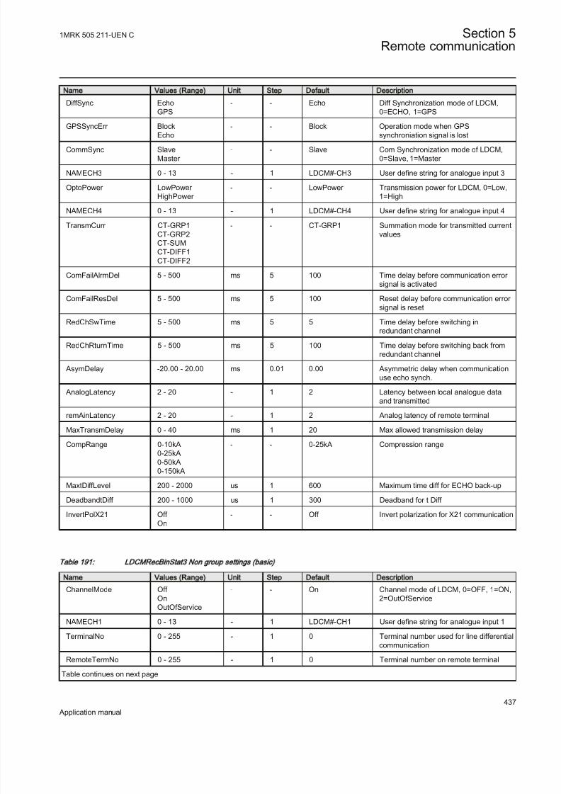
8/22/2019 Best Application
http://slidepdf.com/reader/full/best-application 443/457
Name Values (Range) Unit Step Default Description
DiffSync EchoGPS
- - Echo Diff Synchronization mode of LDCM,0=ECHO, 1=GPS
GPSSyncErr Block
Echo
- - Block Operation mode when GPS
synchroniation signal is lost
CommSync SlaveMaster
- - Slave Com Synchronization mode of LDCM,0=Slave, 1=Master
NAMECH3 0 - 13 - 1 LDCM#-CH3 User define string for analogue input 3
OptoPower LowPower HighPower
- - LowPower Transmission power for LDCM, 0=Low,1=High
NAMECH4 0 - 13 - 1 LDCM#-CH4 User define string for analogue input 4
TransmCurr CT-GRP1CT-GRP2CT-SUMCT-DIFF1CT-DIFF2
- - CT-GRP1 Summation mode for transmitted currentvalues
ComFailAlrmDel 5 - 500 ms 5 100 Time delay before communication error signal is activated
ComFailResDel 5 - 500 ms 5 100 Reset delay before communication error signal is reset
RedChSwTime 5 - 500 ms 5 5 Time delay before switching inredundant channel
RedChRturnTime 5 - 500 ms 5 100 Time delay before switching back fromredundant channel
AsymDelay -20.00 - 20.00 ms 0.01 0.00 Asymmetric delay when communicationuse echo synch.
AnalogLatency 2 - 20 - 1 2 Latency between local analogue dataand transmitted
remAinLatency 2 - 20 - 1 2 Analog latency of remote terminal
MaxTransmDelay 0 - 40 ms 1 20 Max allowed transmission delay
CompRange 0-10kA0-25kA0-50kA0-150kA
- - 0-25kA Compression range
MaxtDiffLevel 200 - 2000 us 1 600 Maximum time diff for ECHO back-up
DeadbandtDiff 200 - 1000 us 1 300 Deadband for t Diff
InvertPolX21 Off On
- - Off Invert polarization for X21 communication
T able 1 91 : L DC MR ecB in Sta t3 N on g ro up se ttin gs (b as ic )
Name Values (Range) Unit Step Default Description
ChannelMode Off OnOutOfService
- - On Channel mode of LDCM, 0=OFF, 1=ON,2=OutOfService
NAMECH1 0 - 13 - 1 LDCM#-CH1 User define string for analogue input 1
TerminalNo 0 - 255 - 1 0 Terminal number used for line differentialcommunication
RemoteTermNo 0 - 255 - 1 0 Terminal number on remote terminal
Table continues on next page
1MRK 505 211-UEN C Section 5Remote communication
437
Application manual

8/22/2019 Best Application
http://slidepdf.com/reader/full/best-application 444/457
Name Values (Range) Unit Step Default Description
NAMECH2 0 - 13 - 1 LDCM#-CH2 User define string for analogue input 2
DiffSync EchoGPS
- - Echo Diff Synchronization mode of LDCM,0=ECHO, 1=GPS
GPSSyncErr BlockEcho
- - Block Operation mode when GPSsynchroniation signal is lost
CommSync SlaveMaster
- - Slave Com Synchronization mode of LDCM,0=Slave, 1=Master
NAMECH3 0 - 13 - 1 LDCM#-CH3 User define string for analogue input 3
OptoPower LowPower HighPower
- - LowPower Transmission power for LDCM, 0=Low,1=High
NAMECH4 0 - 13 - 1 LDCM#-CH4 User define string for analogue input 4
TransmCurr CT-GRP1CT-GRP2CT-SUMCT-DIFF1
CT-DIFF2RedundantChannel
- - CT-GRP1 Summation mode for transmitted currentvalues
ComFailAlrmDel 5 - 500 ms 5 100 Time delay before communication error signal is activated
ComFailResDel 5 - 500 ms 5 100 Reset delay before communication error signal is reset
RedChSwTime 5 - 500 ms 5 5 Time delay before switching inredundant channel
RedChRturnTime 5 - 500 ms 5 100 Time delay before switching back fromredundant channel
AsymDelay -20.00 - 20.00 ms 0.01 0.00 Asymmetric delay when communicationuse echo synch.
AnalogLatency 2 - 20 - 1 2 Latency between local analogue dataand transmitted
remAinLatency 2 - 20 - 1 2 Analog latency of remote terminal
MaxTransmDelay 0 - 40 ms 1 20 Max allowed transmission delay
CompRange 0-10kA0-25kA0-50kA0-150kA
- - 0-25kA Compression range
MaxtDiffLevel 200 - 2000 us 1 600 Maximum time diff for ECHO back-up
DeadbandtDiff 200 - 1000 us 1 300 Deadband for t Diff
InvertPolX21 Off
On
- - Off Invert polarization for X21 communication
Section 5 1MRK 505 211-UEN C
Remote communication
438
Application manual

8/22/2019 Best Application
http://slidepdf.com/reader/full/best-application 445/457
Section 6 Configuration
About this chapter
This chapter describes the IED configurations.
6.1 Description of configuration REB670
6.1.1 Description of 3 ph package A20
Three-phase version of the IED with two low-impedance differential protectionzones and four three-phase CT inputs A20. The version is intended for simpler applications such as T-connections, meshed corners, and so on.
6.1.2 Description of 3 ph package A31
Three-phase version of the IED with two low-impedance differential protectionzones and eight three-phase CT inputs A31. The version is intended for applications on smaller busbars, with up to two zones and eight CT inputs.
6.1.3 Description of 1 ph packages B20 and B21
One-phase version of the IED with two low-impedance differential protectionzones and twelve CT inputs B20, B21.
• Due to three available binary input modules, the B20 is intended for applications without need for dynamic Zone Selection such as substations withsingle busbar with or without bus-section breaker, one-and-half breaker or double breaker arrangements. Three such IEDs offer cost effective solutionsfor such simple substation arrangements with up to twelve CT inputs.
• The B21 is intended for applications in substations where dynamic Zone
Selection or bigger number of binary inputs and outputs is needed. Suchstations for example are double busbar station with or without transfer buswith up to 12 CT inputs. Note that binary inputs can be shared between phases
by including the LDCM communication module. This simplifies panel wiringand saves IO boards.
• This version can be used with external auxiliary 3-phase to 1-phase summationcurrent transformers with different turns ratio for each phase.
1MRK 505 211-UEN C Section 6Configuration
439
Application manual

8/22/2019 Best Application
http://slidepdf.com/reader/full/best-application 446/457
6.1.4 Description of 1 ph package B31
One-phase version of the IED with two low-impedance differential protectionzones and twenty-four CT inputs B31.
• The IED is intended for busbar protection applications in big substationswhere dynamic Zone Selection, quite large number of binary inputs andoutputs and many CT inputs are needed. The IED includes two differentialzones and twenty-four CT inputs. Note that binary inputs can be shared
between phases by including the LDCM communication module. Thissimplifies panel wiring and saves IO boards.
• This version can be used with external auxiliary 3-phase to 1-phase summationcurrent transformers with different turns ratio for each phase.
6.1.5 Available configurations for pre-configured REB670
Three configurations have been made available for pre-configured REB670 IED. Itshall be noted that all three configurations include the following features:
• fully configured for the total available number of bays in each REB670 variant• facility to take any bay out of service via the local HMI or externally via
binary input• facility to block any of the two zones via the local HMI or externally via
binary input
• facility to block all bay trips via the local HMI or externally via binary input, but leaving all other function in service (that is BBP Zones, BFP and OCPwhere applicable)
• facility to externally initiate built-in disturbance recorder • facility to connect external breaker failure backup trip signal from every bay• facility to connect external bay trip signal
6.1.6 Configuration X01
• This configuration includes just busbar protection for simple stations layouts
(that is One-and-a-half breaker, Double Breaker or Single Breaker stations).Additionally it can be used for double busbar-single breaker stations wheredisconnector replica is done by using just b auxiliary contact from everydisconnector and/or circuit breakers. As a consequence no disconnector/
breaker supervision will be available. It is as well possible to adapt thisconfiguration by the Signal Matrix tool to be used as direct replacement of RED521 · 1.0 terminals. This configuration is available for all five REB670variants (that is A20, A31, B20, B21 & B31). It shall be noted that optionalfunctions breaker failure protection CCRBRF, end fault protection andovercurrent protection PH4SPTOC can be ordered together with this
Section 6 1MRK 505 211-UEN C
Configuration
440
Application manual

8/22/2019 Best Application
http://slidepdf.com/reader/full/best-application 447/457
configuration, but they will not be pre-configured. Thus these optionalfunctions shall be configured by the end user.
6.1.7 Configuration X02
• This configuration includes just busbar protection for double busbar-single breaker stations, where Zone Selection is done by using a and b auxiliarycontacts from every disconnector and/or circuit breaker. Thus full disconnector/
breaker supervision is available. This configuration is available for only threeREB670 variants (that is A31, B21 and B31). It shall be noted that optionalfunctions breaker failure protection CCRBRF, end fault protection andovercurrent protection PH4SPTOC can be ordered together with thisconfiguration, but they will not be pre-configured. Thus these optionalfunctions shall be configured by the end user.
6.1.8 Configuration X03
• This configuration includes BBP with breaker failure protection CCRBRF, endfault protection and overcurrent protection PH4SPTOC for double busbar-single breaker stations, where Zone Selection is done by using a and bauxiliary contacts from every disconnectors and/or circuit breakers. Thus fulldisconnector/breaker supervision is available. This configuration is availablefor only three REB670 variants (that is A31, B21 and B31).
1MRK 505 211-UEN C Section 6Configuration
441
Application manual

8/22/2019 Best Application
http://slidepdf.com/reader/full/best-application 448/457
442

8/22/2019 Best Application
http://slidepdf.com/reader/full/best-application 449/457
Section 7 Glossary
About this chapter
This chapter contains a glossary with terms, acronyms and abbreviations used inABB technical documentation.
AC Alternating current
ACT Application configuration tool within PCM600
A/D converter Analog-to-digital converter
ADBS Amplitude deadband supervisionADM Analog digital conversion module, with time synchronization
AI Analog input
ANSI American National Standards Institute
AR Autoreclosing
ArgNegRes Setting parameter/ZD/
ArgDir Setting parameter/ZD/
ASCT Auxiliary summation current transformer
ASD Adaptive signal detectionAWG American Wire Gauge standard
BBP Busbar protection
BFP Breaker failure protection
BI Binary input
BIM Binary input module
BOM Binary output module
BOS Binary outputs status
BR External bistable relay
BS British Standards
BSR Binary signal transfer function, receiver blocks
BST Binary signal transfer function, transmit blocks
C37.94 IEEE/ANSI protocol used when sending binary signals between IEDs
CAN Controller Area Network. ISO standard (ISO 11898) for serial communication
CB Circuit breaker
1MRK 505 211-UEN C Section 7Glossary
443
Application manual

8/22/2019 Best Application
http://slidepdf.com/reader/full/best-application 450/457
CBM Combined backplane module
CCITT Consultative Committee for International Telegraph andTelephony. A United Nations-sponsored standards body
within the International Telecommunications Union.CCM CAN carrier module
CCVT Capacitive Coupled Voltage Transformer
Class C Protection Current Transformer class as per IEEE/ ANSI
CMPPS Combined megapulses per second
CMT Communication Management tool in PCM600
CO cycle Close-open cycle
Codirectional Way of transmitting G.703 over a balanced line. Involves
two twisted pairs making it possible to transmit informationin both directions
COMTRADE Standard format according to IEC 60255-24
Contra-directional Way of transmitting G.703 over a balanced line. Involvesfour twisted pairs, two of which are used for transmittingdata in both directions and two for transmitting clock signals
CPU Central processor unit
CR Carrier receive
CRC Cyclic redundancy check
CROB Control relay output block CS Carrier send
CT Current transformer
CVT Capacitive voltage transformer
DAR Delayed autoreclosing
DARPA Defense Advanced Research Projects Agency (The USdeveloper of the TCP/IP protocol etc.)
DBDL Dead bus dead line
DBLL Dead bus live lineDC Direct current
DFC Data flow control
DFT Discrete Fourier transform
DHCP Dynamic Host Configuration Protocol
DIP-switch Small switch mounted on a printed circuit board
DI Digital input
DLLB Dead line live bus
Section 7 1MRK 505 211-UEN C
Glossary
444
Application manual

8/22/2019 Best Application
http://slidepdf.com/reader/full/best-application 451/457
DNP Distributed Network Protocol as per IEEE/ANSI Std.1379-2000
DR Disturbance recorder
DRAM Dynamic random access memory
DRH Disturbance report handler
DSP Digital signal processor
DTT Direct transfer trip scheme
EHV network Extra high voltage network
EIA Electronic Industries Association
EMC Electromagnetic compatibility
EMF (Electric Motive Force)
EMI Electromagnetic interference
EnFP End fault protection
EPA Enhanced performance architecture
ESD Electrostatic discharge
FCB Flow control bit; Frame count bit
FOX 20 Modular 20 channel telecommunication system for speech,data and protection signals
FOX 512/515 Access multiplexer
FOX 6Plus Compact time-division multiplexer for the transmission of up to seven duplex channels of digital data over optical fibers
G.703 Electrical and functional description for digital lines used by local telephone companies. Can be transported over balanced and unbalanced lines
GCM Communication interface module with carrier of GPSreceiver module
GDE Graphical display editor within PCM600
GI General interrogation command
GIS Gas-insulated switchgear GOOSE Generic object-oriented substation event
GPS Global positioning system
GSAL Generic security application
GTM GPS Time Module
HDLC protocol High-level data link control, protocol based on the HDLCstandard
HFBR connector
type
Plastic fiber connector
1MRK 505 211-UEN C Section 7Glossary
445
Application manual

8/22/2019 Best Application
http://slidepdf.com/reader/full/best-application 452/457
HMI Human-machine interface
HSAR High speed autoreclosing
HV High-voltage
HVDC High-voltage direct current
IDBS Integrating deadband supervision
IEC International Electrical Committee
IEC 60044-6 IEC Standard, Instrument transformers – Part 6:Requirements for protective current transformers for transient performance
IEC 60870-5-103 Communication standard for protective equipment. A serialmaster/slave protocol for point-to-point communication
IEC 61850 Substation automation communication standardIEC 61850–8–1 Communication protocol standard
IEEE Institute of Electrical and Electronics Engineers
IEEE 802.12 A network technology standard that provides 100 Mbits/son twisted-pair or optical fiber cable
IEEE P1386.1 PCI Mezzanine Card (PMC) standard for local busmodules. References the CMC (IEEE P1386, also known asCommon Mezzanine Card) standard for the mechanics andthe PCI specifications from the PCI SIG (Special InterestGroup) for the electrical EMF (Electromotive force).
IEEE 1686 Standard for Substation Intelligent Electronic Devices(IEDs) Cyber Security Capabilities
IED Intelligent electronic device
I-GIS Intelligent gas-insulated switchgear
IOM Binary input/output module
Instance When several occurrences of the same function areavailable in the IED, they are referred to as instances of thatfunction. One instance of a function is identical to another of the same kind but has a different number in the IED user
interfaces. The word "instance" is sometimes defined as anitem of information that is representative of a type. In thesame way an instance of a function in the IED isrepresentative of a type of function.
IP 1. Internet protocol. The network layer for the TCP/IP protocol suite widely used on Ethernet networks. IP is aconnectionless, best-effort packet-switching protocol. It
provides packet routing, fragmentation and reassemblythrough the data link layer.
2. Ingression protection, according to IEC standard
Section 7 1MRK 505 211-UEN C
Glossary
446
Application manual

8/22/2019 Best Application
http://slidepdf.com/reader/full/best-application 453/457
IP 20 Ingression protection, according to IEC standard, level 20
IP 40 Ingression protection, according to IEC standard, level 40
IP 54 Ingression protection, according to IEC standard, level 54
IRF Internal failure signal
IRIG-B: InterRange Instrumentation Group Time code format B,standard 200
ITU International Telecommunications Union
LAN Local area network
LIB 520 High-voltage software module
LCD Liquid crystal display
LDCM Line differential communication module
LDD Local detection device
LED Light-emitting diode
LNT LON network tool
LON Local operating network
MCB Miniature circuit breaker
MCM Mezzanine carrier module
MIM Milli-ampere module
MPM Main processing module
MVB Multifunction vehicle bus. Standardized serial busoriginally developed for use in trains.
NCC National Control Centre
NUM Numerical module
OCO cycle Open-close-open cycle
OCP Overcurrent protection
OEM Optical ethernet module
OLTC On-load tap changer
OV Over-voltage
Overreach A term used to describe how the relay behaves during afault condition. For example, a distance relay isoverreaching when the impedance presented to it is smaller than the apparent impedance to the fault applied to the
balance point, that is, the set reach. The relay “sees” thefault but perhaps it should not have seen it.
PCI Peripheral component interconnect, a local data bus
PCM Pulse code modulation
1MRK 505 211-UEN C Section 7Glossary
447
Application manual

8/22/2019 Best Application
http://slidepdf.com/reader/full/best-application 454/457
PCM600 Protection and control IED manager
PC-MIP Mezzanine card standard
PMC PCI Mezzanine card
POR Permissive overreach
POTT Permissive overreach transfer trip
Process bus Bus or LAN used at the process level, that is, in near proximity to the measured and/or controlled components
PSM Power supply module
PST Parameter setting tool within PCM600
PT ratio Potential transformer or voltage transformer ratio
PUTT Permissive underreach transfer trip
RASC Synchrocheck relay, COMBIFLEX
RCA Relay characteristic angle
RFPP Resistance for phase-to-phase faults
RFPE Resistance for phase-to-earth faults
RISC Reduced instruction set computer
RMS value Root mean square value
RS422 A balanced serial interface for the transmission of digitaldata in point-to-point connections
RS485 Serial link according to EIA standard RS485
RTC Real-time clock
RTU Remote terminal unit
SA Substation Automation
SBO Select-before-operate
SC Switch or push button to close
SCS Station control system
SCADA Supervision, control and data acquisition
SCT System configuration tool according to standard IEC 61850
SDU Service data unit
SLM Serial communication module. Used for SPA/LON/IEC/DNP3 communication.
SMA connector Subminiature version A, A threaded connector withconstant impedance.
SMT Signal matrix tool within PCM600
SMS Station monitoring system
Section 7 1MRK 505 211-UEN C
Glossary
448
Application manual

8/22/2019 Best Application
http://slidepdf.com/reader/full/best-application 455/457
SNTP Simple network time protocol – is used to synchronizecomputer clocks on local area networks. This reduces therequirement to have accurate hardware clocks in every
embedded system in a network. Each embedded node caninstead synchronize with a remote clock, providing therequired accuracy.
SPA Strömberg protection acquisition, a serial master/slave protocol for point-to-point communication
SRY Switch for CB ready condition
ST Switch or push button to trip
Starpoint Neutral point of transformer or generator
SVC Static VAr compensation
TC Trip coilTCS Trip circuit supervision
TCP Transmission control protocol. The most common transportlayer protocol used on Ethernet and the Internet.
TCP/IP Transmission control protocol over Internet Protocol. Thede facto standard Ethernet protocols incorporated into4.2BSD Unix. TCP/IP was developed by DARPA for Internet working and encompasses both network layer andtransport layer protocols. While TCP and IP specify two
protocols at specific protocol layers, TCP/IP is often used
to refer to the entire US Department of Defense protocolsuite based upon these, including Telnet, FTP, UDP andRDP.
TEF Time delayed earth-fault protection function
TNC connector Threaded Neill-Concelman, a threaded constant impedanceversion of a BNC connector
TPZ, TPY, TPX,
TPS
Current transformer class according to IEC
UMT User management tool
Underreach A term used to describe how the relay behaves during afault condition. For example, a distance relay isunderreaching when the impedance presented to it isgreater than the apparent impedance to the fault applied tothe balance point, that is, the set reach. The relay does not“see” the fault but perhaps it should have seen it. See alsoOverreach.
UTC Coordinated Universal Time. A coordinated time scale,maintained by the Bureau International des Poids etMesures (BIPM), which forms the basis of a coordinateddissemination of standard frequencies and time signals.
1MRK 505 211-UEN C Section 7Glossary
449
Application manual

8/22/2019 Best Application
http://slidepdf.com/reader/full/best-application 456/457
UTC is derived from International Atomic Time (TAI) bythe addition of a whole number of "leap seconds" tosynchronize it with Universal Time 1 (UT1), thus allowingfor the eccentricity of the Earth's orbit, the rotational axistilt (23.5 degrees), but still showing the Earth's irregular rotation, on which UT1 is based. The CoordinatedUniversal Time is expressed using a 24-hour clock, anduses the Gregorian calendar. It is used for aeroplane andship navigation, where it is also sometimes known by themilitary name, "Zulu time." "Zulu" in the phonetic alphabetstands for "Z", which stands for longitude zero.
UV Undervoltage
WEI Weak end infeed logic
VT Voltage transformer
X.21 A digital signalling interface primarily used for telecomequipment
3IO Three times zero-sequence current. Often referred to as theresidual or the earth-fault current
3UO Three times the zero sequence voltage. Often referred to asthe residual voltage or the neutral point voltage
Section 7 1MRK 505 211-UEN C
Glossary
450
Application manual

8/22/2019 Best Application
http://slidepdf.com/reader/full/best-application 457/457


![[Lchn] application for best o gip](https://img.pdfslide.us/doc/110x75/54957cf6b47959b0658b459c/lchn-application-for-best-o-gip.jpg)
