Embed Size (px)
Citation preview

BELL LABORATORIES R E C O R D
VOL. XXVI NO. 5 MAY 1948
A. A. ROETKEN
Radio
Projects Engineering
,,::..... v n: ;;'::,:.
REPEATERS FOR THE NEW YORK -
BOSTON RADIO RELAY SYSTEM
.,:.:,.,::.;:,. ..:... a.. ....... . _..... ......
Operating at frequencies in the vicinity of 4,000 megacycles per second, the microwave radio relay system* now in experimental service between New York and Boston provides two two -way broad- band channels each capable of carrying a standard black and white television program or a considerable number of telephone channels by various multiplex methods. Each of the seven repeater stations, one of which is shown on the °RECORD, December, 1947, page 437.
Fig. 1- Close -up view of receiving waveguides, receiving converters, and preamplifiers at top of the c'gnipuzent bat/
May 1148
next page, has four repeaters-two for each direction of transmission. Four antennas are mounted on the roof of the repeater station, two for north -to -south transmission and two for south -to- north. Of the two antennas for one direction of transmission, one receives the two channels from the previous repeater and the other transmits the two channels to the next repeater. Each repeater provides a maximum gain of approximately 80 db, which in combi- nation with the highly directional antennas is sufficient to make up for normal trans- mission losses plus additional losses due to fading to a depth of 20 db.
Although amplifier tubes are available which would provide the required gain and bandwidth at 4,000 megacycles, they are still not developed to the point where the internal tube noise energy is low enough for satisfactory use in the low level stages of a repeater. To obtain a favorable signal -to -noise ratio, therefore, it was necessary to provide low -level amplifi- cation at frequencies of less than 100 megacycles. Fortunately, silicon rectifiers make fairly good modulators at microwave frequencies, and they are therefore used to shift the signal band from 4,000 megacycles to an intermediate frequency band centered around 65 megacycles. After amplification
193
www.americanradiohistory.com
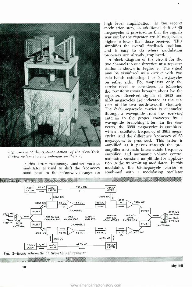
Fig. 2 -One of the repeater stations of the New York - Boston system showing antennas on the roof
at this latter frequency, another varistor modulator is used to shift the frequency band back to the microwave range for
high level amplification. In the second modulation step, an additional shift of 40 megacycles is provided so that the signals sent out by the repeater are 40 megacycles higher or lower than those received. This simplifies the overall feedback problem, and is easy to do where modulation processes are already employed.
A block diagram of the circuit for the two channels in one direction at a repeater station is shown in Figure 3. The signal may be visualized as a carrier with two side bands extending 4 or 5 megacycles on either side. For simplicity only the carrier need be considered in following the transformations brought about by the repeater. Received signals of 3930 and 4130 megacycles are indicated as the car- riers of the two south -to -north channels. The 3930 -megacycle carrier is channeled through a waveguide from the receiving antenna to the proper converter by a waveguide branching filter. In the con- verter, the 3930 megacycles is combined with an oscillator frequency of 3865 mega- cycles, and the difference frequency of 65 megacycles is produced. This latter is amplified as it passes through the pre- amplifier and main intermediate frequency amplifier, and automatic volume control maintains constant amplitude for applica- tion to the transmitting modulator. In this modulator, the 65- megacycle carrier is
combined with a modulating oscillator
: ,t . <:, ..;...:ßà': , .,.«. NO
3930 MC
4130 MC
OSCIL- LATOR
40 MC -
3930 MC
MODU- LATOR
3905 MC OSCIL- LATOR
3865 MC
65 MC
3905 MC
65 MC - 65 MC 3970
MC 3970 MC
FILTER CHANNEL I FILTER
RECEIVING PRE - CONVERTERS AMPLIFIERS
MAIN IF AND AVC
TRANS- MICRO - MITTING WAVE
MODULATORS AMPLIFIERS
ANTENNA FILTER
4130 MC
CHANNEL 2 FILTER
65MC 6SMC - 65MC
4195 MC 4235 MC
OSCIL- 40 MC MODU- 4235 MC
LATOR LATOR
Fig. 3 -Block schematic of two -channel repeater '. .:.::..: .....,. ..... . ..,... : .. .,b....,....,........aA.
114
' * `riy`tw'áti nmuu \nt.`
OSCIL- LATOR
4170 4170 MC MC
. .> C3 `.`vJ ... ..:.:\::.... w
3970 MC
4170 MC
ANTENNA
May 1948
www.americanradiohistory.com

Fig. 4 -Front (left) and rear views of two relay bays at a repeater station
frequency of 3905 megacycles to produce a new carrier frequency of 3970 mega- cycles. This is further amplified in the microwave amplifier, and is then carried by waveguide to the transmitting antenna through a combining filter. The filter per- mits the combination of the two transmitted signals into one antenna with negligible interaction losses.
The two modulating frequencies 40 megacycles apart are provided by using a 3905 -megacycle highly stabilized reflex oscillator and a very stable 40- megacycle crystal oscillator. The former supplies the transmitting modulator directly, while the receiving modulating frequency is obtained by combining output from the two oscil- lators in a modulator and selecting the difference frequency. Since the same micro- wave oscillator frequency is involved in the receiving and transmitting modulating steps, its absolute frequency is not a factor in determining the transmitted frequency.
May 1948
Should this oscillator be in error by some small amount, the intermediate frequency carrier will be in error by the same amount, but the error will be cancelled in the process of shifting back to the microwave range. The overall frequency stability of the repeater system is thus determined only by the microwave oscillator at the transmitting terminal and the various crys- tal controlled 40- megacycle oscillators in the repeater chain. Although the frequen- cies of both oscillators are controlled to the same percentage precision - about 0.005 per cent - the possible variation in the absolute frequency of the microwave oscil- lator is 100 times that of the 40- megacycle oscillator, because of the 100 -fold difference in frequency. This method of deriving the modulating frequencies thus insures a very small variation in the transmitted frequencies.
Front and rear view of a two- channel repeater are shown in Figure 4, each bay
115
www.americanradiohistory.com

comprising one complete channel. The bays are 11 feet, 6 inches high, and mount 23- inch width panels. Each side of the bay forms an air duct, and a blower at the base supplies cooling air through the ducts for some of the components. Inter -panel wiring passes through vertical wiring ducts with removable covers. On the rear view can be seen the receiving waveguide, two- channel branching filter, receiving con- verters and preamplifiers mounted at the top of the bays. A close -up of this apparatus is shown in Figure 1. A little below the center of the bays at the rear can be seen the transmitting branching filter which connects to a waveguide running up to the ceiling. A close -up of this section is shown in Figure 5. The motor- driven blowers at the bottom of each bay take air through
av.rr . Q ..w ae. ..a.. ai iiL.¡.'. +.0
Fig. 5- Close -up view of transmitting waveguides
a filter located at the front of the bay. Four low -voltage electronically regulated
power rectifiers are mounted just below the receiving waveguides, converters, and pre- amplifiers at the top of the bay. A high -
voltage regulated rectifier is mounted just above the blower air in -take. All of these rectifiers are of a type already described*, but of an improved form and of different voltages. Below the low- voltage rectifiers are panels in the following order: the main intermediate frequency amplifier and auto- matic volume control circuits, the micro- wave oscillator and the servo circuits that »RECORD, May, 1937, page 298.
Fig. 8 -Front view of microwave amplifier panel above, and buffer amplifier and trans- mitting modulator below
196
Fig. 6 -Front view of stabilized microwave oscillator panel
Fig. 7 -Rear view of stabilized oscillator panel
www.americanradiohistory.com

control its frequency, Figures 6 and 7, the 40- megacycle oscillator and mixer circuits, the control panel for the microwave ampli- fier tubes, the microwave amplifier, and the transmitting modulator and buffer amplifiers.
A view of the microwave amplifier, and of the transmitting modulator and buffer amplifiers beneath it, with covers removed, is shown in Figure S. The microwave amplifier uses four vacuum tubes of the velocity modulation type. Each tube is mounted in a two-cavity assembly with an associated permanent magnet for focussing the electron beam. Cavities are tuned by threaded studs which project into the cavities and are adjusted externally. Another adjustment allows the rotation of a small sheet of resistance material inside the cavity for loading purposes. The anode end of each tube extends through the panel into an air- cooling duct. The circuit elements themselves, that is, the cavities and coupling machanism, are temperature controlled to close limits within the front cover compartment. Two similar tubes are used as buffer amplifiers associated with the modulator. Although these tubes are performing satisfactorily in the New York - Boston system, they will not be used in future systems. Newer tubes, now in development, offer important advantages in ease of maintenance and better figures of merit.
The microwave tubes require protection against momentary overloads which might occur under some abnormal operating con- ditions. This is provided by incorporating an overload relay which removes the high voltage when the overload occurs. Since the repeaters are to be operated unattended, however, it was necessary to include an automatic recycling or restoring mechanism which will replace the high voltage if the overload condition is not of a permanent nature. The automatic restor- ing circuits will make a maximum of five consecutive attempts to restore the repeaters to service at approximately one - second intervals. If the overload condition is removed during this recycling period, the high voltage will restore, and normal operating conditions will he maintained.
May 1141
Otherwise, all plate power will be removed from the repeater after the fifth restoration attempt, and an alarm will be sent to a control center indicating the repeater is shut down.
As described previously,* the terminal equipment converts a television video signal (or other broad -band signal) to a frequency- modulated carrier for radio transmission through the repeaters. To pass this signal along from transmitting terminal to receiving terminal without observable degradation in quality, it is necessary for the repeaters to pass a band of frequencies at least 10 megacycles wide,
MUM S M:..: o
J
3 2
ó Z 3
W O 4
á 5
6
> < ' J or 6
-9
RELATIVE AMPLITUDE
DEL AY DISTORTION
- 2 - 0 -8 -6 -4 -2 0 2 4
90 u) 0
60
J 50 5
40 O
6 8 10 12 FREQUENCY IN MEGACYCLES PER SECOND (OFF MID -BAND)
Fig. 9- Amplitude and delay distortion characteristics of a repeater of the New York -Boston system. without equalization
30 O
20 N
10
0
4 W 0
over which band the delay distortion must not be very great. Also the repeaters must not introduce noise of sufficient amplitude to be observable in the reproduced picture through the overall system. The effect of delay distortion on a television picture is to destroy the sharpness of detail. In trans- mitting the image of a picket fence, for example, there will be a prominent low frequency component proportional to the spacing of the pickets, and the sharply defined edges of the pickets will depend upon components of much higher frequen- cies. If the latter are delayed relative to the low picket frequency they will appear °RECoen, March, 1948, page 97.
197
www.americanradiohistory.com

as light in the spaces between pickets which should be dark, and with severe delay the result would tend to resemble a solid fence rather than a picket one.
The amplitude and delay characteristics of a typical repeater is shown in Figure 9. Amplitude variations are less than 0.1 db over the 10- megacycle band. It will be noticed that to either side of the mid - hand frequency the delay is relatively greater than at mid -band so that at the edges of the 10- megacycle band the dis- tortion is approximately 25 millimicro- seconds. For the seven -repeater system the total delay distortion without equalization would he a little more than is thought to
THE AUTHOR: A. A. ROETKEN received the B.E.E. degree in 1927 and the M.Sc. degree in
1929 from the Ohio State University. Joining the radio research group of the Laboratories in 1929, he worked on the development of radio receiving equipment for overseas telephone serv- ices, and of ultra -high frequency point -to -point radio telephone circuits for domestic service. During the war, he worked principally on pulse multiplex microwave radio repeaters for the armed forces. Since then he has been associated with the radio projects group of the Research Department. and has been responsible for the circuit design of the microwave radio -relay equipment which he describes in this issue of the RECORD.
be tolerable. As a result, delay equalizers have been inserted at each repeater which reduce this distortion by a factor of approximately 10 to 1.
The noise introduced by a repeater is determined by a number of factors, the principal ones being the radiated power from the preceding repeater, path length, antenna gains, fading, and the noise characteristics of the low -level amplifier tubes. In the present repeaters, the balance between these factors is such that even for the highly improbable condition of simul- taneous fades of 20 db on all links, the total noise due to the relay system will be barely discernable in the television picture.
; `...Y ,:C!:.R. .
:. AIM
AIRBORNE MAGNETOMETER EXPLORES VOLCANO
A magnetic eye that can look into the cone of a volcano and locate the magma of molten rock that spews itself over the landscape during an eruption, that can locate deeply buried volcanoes and great cracks in the earth where there have been or may occur earthquakes was described by Dr. Fred Keller, Jr., at the meeting of the American Geophysical Union today. Dr. Keller and his associates composed a team which investigated the active volcano Mt. Sitka, in the Aleutian Islands, for the Navy Department. They used an airborne magnetometer, developed for locating submarines, and with it were able to locate abnormal magnetic conditions around Mt. Sitka and three other volcanoes in the Aleutians. -New York Herald Tribune, April 21, 1948.
[The airborne magnetometer (Record, April, 1947, page 142) was developed in the Laboratories during the war by E. P. Fetch's and W. J. Means' groups under the general leadership of W. J. Shackelton and R. G. McCurdy.]
lu May 1M1
www.americanradiohistory.com

..;'n \ . +. .. . v .á. .:, v ...vv:+:g. y : %v tr't:..,,:' i:a`tr ,.á.::.tr*. Ài...50i"TS::A.á nWOn . .c.:1.:.:'};$t;'k.i::' Ó' { :;t: :Ca <'9:+iF°3:3'.j+";¿ó.
P. F. JONES
Transmission Development
.,«: >: ,: t :.4, 4-.2zä: «á,.:..:..nsi;á`3... á^
a!ñd¿C" i °C.t'R¢ - ::?kë: °::ïi <: y;' YP'<
A PROBE FOR TESTING K AMPLIFIERS
:2 `^'S° qt.:.?i;:.+`ß::::t :ï.::z:.3`::.:. s o, éç2S,.t:q;;c:F't$o'. /SAO
k.,tr,St°S$ 7i:óá"ti..ti.:x:+::<.:i..,:.,.án^..:ë:;': ï '$aY.tr.'v..C:ti.9.
In their most commonly used form, test probes are merely sharp steel points attached to the end of a wire to enable test men to make contact with cable pairs or other insulated conductors without the delay and inconvenience of removing insulation and cleaning the conductor surfaces to secure a good contact. A more elaborate probe that includes a small and accurately adjusted network in its handle has recently been designed for use with the 31 -type transmission measuring set* for investigating trouble conditions in
readings under these conditions. Its impedance was high enough so that the connection of the set to a 135 -ohm circuit would not disturb the existing voltage relationships.
Within the K amplifier itself, the circuit is not balanced, and the impedances may have a wide range of value at different points. To help in locating trouble that may develop, it would be very desirable to be able to measure the voltage of the pilot frequencies at various points within the repeater, but the 31 -type set was not
Fig. 1 -The 598A tool for high impedance probing
amplifiers of the type -K carrier system without disturbing the soldered connections or affecting the operation of the amplifier.
A number of pilot signals are transmitted over a K carrier system to control the regulators, and the 31 -type set, when con- nected across the input or output of a repeater or other point of the circuit, selects one or the other of these pilot frequencies, and measures its level with respect to reference voltage. These measurements are used for analyzing the gains and losses of sections of the circuit. The K carrier system operates over a circuit balanced to ground and of 135 ohms impedance, and the 31- type set was designed to give correct REcoxn, April, 1948, page 156.
i May MU
suitable for this purpose in its original design, because its impedance was low enough to affect amplifier performance seriously.
To extend the scope of the set by per- mitting it to give measurements of voltages within the repeaters themselves, the high impedance probe, or 598A tool as it is coded, was developed. Its functions are to provide a high enough impedance in series with the measuring set so that when connected to points of the highest imped- ance encountered it will not seriously affect the circuit conditions, to provide for a grounded rather than a balanced reading, and to give uniform results over a range of frequency up to 150 kc.
131
www.americanradiohistory.com

With this objective in view, a small network is mounted in the handle of the probe and connected in series with the probe conductor. This network consists of an SOO,000 -ohm resistor shunted by an
Fig. 2 -The, probing tool has a iuuc it e -joot coaxial cord and plug
adjustable 4444 capacitor, and in series with it is a 500 414 capacitor. These may be seen in Figure 1, which shows the probe with the outer metal sheath removed. Since the inner diameter of the sleeve is only slightly over half an inch, all these elements must be extremely small, and stray capacitances from the probe to the sleeve must be kept as small as practicable. The 800,000 -ohm resistor and the capacitor in parallel with it are mounted in the small cylindrical unit near the middle of the probe. The value of this capacitor may be
4.00.ROMPROMPINIMPh,
THE AUTHOR: .'into' F. JONES reccisrcl the degree of B.S. in E.L. from the University of Vermont in May. 1918, and after a short period with the Coast Artillery Corps, he joined the A T & T in 1919. With the D & H, ;u ul since 1934 with the Laboratories, he has engaged in maintenance engineering and development for transmission systems, and has participated in the design and standardization of many of the trans- mission testing systems now in use. During the war he was concerned with problems of emergency operations and with trouble investigations of the toll telephone transmission plant. At the present time he is developing ways and means of lining up and maintaining the new circuits which will use the \'3 repeater, and on other transmission systems.
201
adusted by a screw at its lower end, but the adjustment is made at the factory and should not require a change thereafter. The series capacitor, which blocks direct current from the measuring set, is the small irregular shaped unit near the cord end of the probe. At the prod end is a
chuck assembly which will permit the use of other tools, such as a test clip, in place of the sharp point normally provided.
Connected to the probe is a twelve -foot coaxial cord terminating in a plug, Figure 2. A jack has been provided on the 31A and 31B sets to take this cord when measure- ments are to be made within an amplifier circuit. A ground wire with a clip is fastened to the sheath of the coaxial cord, and during a test is clipped to some ground point of the amplifier.
The loss of the probe is adjusted to 40 db. When used in connection with a 31 -type set, voltages corresponding to from -55 dbm to +55 dbm in 135 ohms may be measured, or voltages from 0.7 millivolt to 200 volts. Voltage readings are obtained in db relative to 0.37 volt, which facilitates the measurement of voltage gains or losses. The probe has an input impedance of 800,000 ohms in parallel with about 9µµf.
Measuring voltages at selected frequen- cies within the amplifier circuit, which this new probe makes possible, is a technique new to the maintenance people but one that has proven very helpful in initial installations. The success attained promises more extensive use of this method of test in the future.
May 1M!
www.americanradiohistory.com

A. S. WINDELER
Outside Plant Development
Video signals from the camera and asso- ciated equipment of a television pick -up installation, involve frequency components ranging from a few cycles to several mc. It has been found practicable to transmit these video signals over short intracity wire circuits from the pick -up point to broad- casting stations, or to the terminals of long
Fig. 1 -G. J. Schaible at the Point Breeze Works of the Western Electric Company measures insertion loss on an experimental length of video pair used for television pick -up installations
May 1141
distance links, without further modulation or shift of frequency. Such circuits, which have come to be known as "video" circuits, have, up to the present time, utilized paper - insulated pairs in existing exchange area cables. The high attenuation of these pairs makes it necessary to introduce amplifica- tion at frequent intervals and, since only a limited number of amplifiers can be operated in tandem with satisfactory pic- ture quality, this factor in turn confines the length of line. Also, crosstalk between unshielded pairs restricts the number of video circuits which can be obtained from a given cable. These limitations become much more severe if broader bands are to be transmitted.
By the early part of 1944, it became evident that special construction would be required for such video circuits in exchange area cables. Both coaxial conductors and shielded balanced pairs have been used for such purposes, but when the signal is not shifted in frequency there are advantages in the pair construction. This is because serious noise and crosstalk problems are met in the coaxial structure at the low frequency end of the video range where the shielding of the outer conductor be- comes inadequate. Another advantage of the shielded balanced pairs is that they may be connected to existing unshielded paper -insulated pairs without special ap- paratus at the junction. Special apparatus is necessary if coaxials are connected to the paper -insulated pairs to avoid connect- ing the grounded outer conductor of the coaxial to one side of the balanced pair and thus allowing the noise voltage between the two wires of the pair and ground to act directly within the pair itself.
211
www.americanradiohistory.com
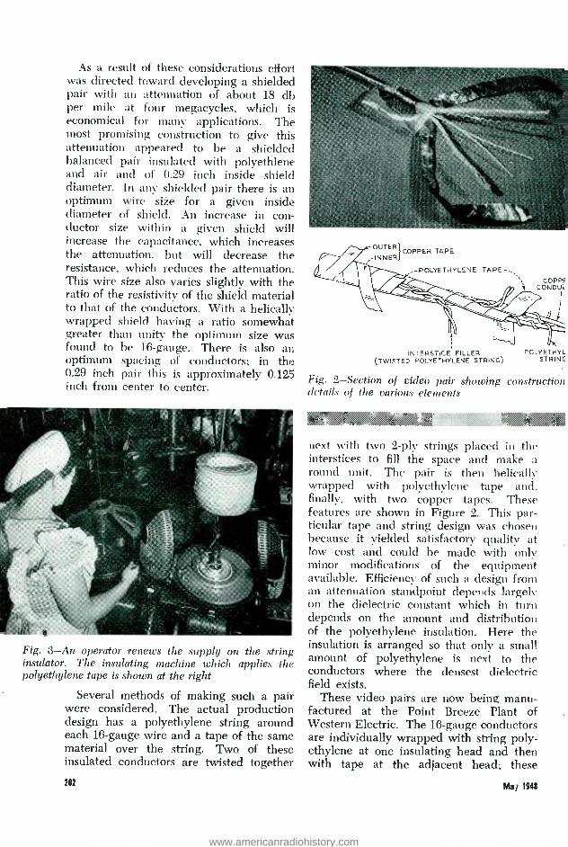
As a result of these considerations effort was directed toward developing a shielded pair with an attenuation of about 18 db per mile at four megacycles, which is economical for many applications. The most promising construction to give this attenuation appeared to be a shielded balanced pair insulated with polyethlene and air and of 0.29 inch inside shield diameter. In any shielded pair there is an optimum wire size for a given inside diameter of shield. An increase in con- ductor size within a given shield will increase the capacitance, which increases the attenuation, but will decrease the resistance, which reduces the attenuation. This wire size also varies slightly with the ratio of the resistivity of the shield material to that of the conductors. With a helically wrapped shield having a ratio somewhat greater than unity the optimum size was found to be 16- gauge. There is also an optimum spacing of conductors; in the 0.29 inch pair this is approximately 0.125 inch from center to center.
Fig. 3 -An operator renews the supply on the string insulator. The insulating machine which applies the polyethylene tape is shown at the right
Several methods of making such a pair were considered. The actual production design has a polyethylene string around each 16 -gauge wire and a tape of the same material over the string. Two of these insulated conductors are twisted together
202
OUTER COPPER TAPE
.INNER
-POLYETHYLENE TAPE
COPPI CONDUR
INTERSTICE FILLER (TWISTED POLYETHYLENE STRING)
POLYETHYL STRINC
Fig. 2- Section of video pair showing construction details of the various elements
44 $ x:
next with two 2 -ply strings placed in the interstices to fill the space and make a round unit. The pair is then helically wrapped with polyethylene tape and, finally, with two copper tapes. These features are shown in Figure 2. This par- ticular tape and string design was chosen because it yielded satisfactory quality at low cost and could be made with only minor modifications of the equipment available. Efficiency of such a design from an attenuation standpoint depends largely on the dielectric constant which in turn depends on the amount and distribution of the polyethylene insulation. Here the insulation is arranged so that only a small amount of polyethylene is next to the conductors where the densest dielectric field exists.
These video pairs are now being manu- factured at the Point Breeze Plant of Western Electric. The 16 -gauge conductors are individually wrapped with string poly- ethylene at one insulating head and then with tape at the adjacent head; these
Mai 11148
www.americanradiohistory.com
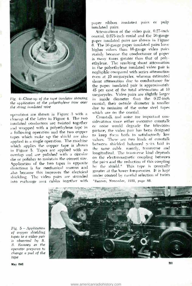
Fig. 4- Close -up of the tape insulator showing the application of the polyethylene tape over the string insulated wire
operations are shown in Figure 3 with a
closeup of the latter in Figure 4. The two insulated conductors are twisted together and wrapped with a polyethylene tape in a following operation and the two copper tapes which make up the shield are also applied in a single operation. The machine which applies the copper tape is shown in Figure 5. Tapes are applied with an overlap and are polished with a circular die or polisher to maintain the correct size. Application of the two tapes in opposite directions is for mechanical reasons and also because this improves the electrical shielding. The video pairs are stranded into exchange area cables together with
Fig. 5 - Application of copper shielding tapes to a video pair is observed by R. B. Ramsey as the operator prepares to change a pad of the tape
May 1948
paper ribbon insulated pairs or pulp insulated pairs.
Attenuations of the video pair, 0.27 -inch coaxial, 0.375 -inch coxial and the 16 -gauge paper insulated pairs are shown in Figure 6. The 16 -gauge paper insulated pairs have higher values than 16 -gauge video pairs mainly because the conductance of paper is many times greater than that of poly - ethylene. The resulting shunt attenuation in the polyethylene insulated video pair is
negligible compared with series attenuation even at 10 megacycles, whereas estimated shunt attenuation due to conductance for the paper insulated pair is approximately 45 per cent of the total attenuation at 10
megacycles. Video pairs are slightly larger in inside diameter than the 0.27 -inch coaxial; their outside diameter is smaller due to omission of the outer steel tapes which are on the coaxial.
Crosstalk and noise are important con- siderations since either excessive crosstalk or noise would degrade the television picture; the video pair has been designed to keep them both to satisfactorily low values. There are two kinds of crosstalk between shielded balanced purs laid in the same cable, namely, transverse and longitudinal. The transverse kind depends on the electromagnetic coupling between the pairs and the reduction of this coupling by the shield.° This type is generally greater at the lower frequencies. It is kept under control by careful selection of twists
*RECORD, November, 1939, page 88.
203
www.americanradiohistory.com

Y
boo
60
û 40 o
e-
20
L11
J 10
2 Cr 6 á
4 J m
w 2 o z I
z ó 0.6
D 0.4 z w
<0.2
QI 10 20 40 100 200 400 1000 2000 4000
FREQUENCY IN KILOCYCLES PER SECOND
A 16 -GAUGE PAIR, RAPER INSULATED. B 16 -GAUGE VIDEO PAIR, POLYETHYLENE INSULATED
COAXIAL, POLYETHYLENE DISC INSULATED: C 0.27-INCH DISC - D 0.375 -INCH DISC
10.000
Fig. 6- Attenuation of a video pair compared with other types of circuits at video frequencies
;:; ::. .. e; and by the use of an adequately thick shield. Longitudinal crosstalk depends on the electrostatic coupling between the wires of the pair and its own shield, that is, on the difference of direct capacitance
? . M:`C 4d s.zz' < a, <..
THE AUTHOR: A. S. WINDELER was graduated from Rutgers University in 1930 with a B.S. degree and joined the Laboratories Technical Staff the same year. As a member of the Outside Plant Development Department, he engaged in cable development work at Kearny for a brief period before being transferred to Point Breeze to carry on with the same type of work. Among the developments with which he has been asso- ciated are type K carrier cable, coaxial cable, and video -pair cable. During the war, Mr. Windeler was concerned with the design and standardization of microwave cables.
204
to the shield, and the shield's surface transfer -impedance. This transfer -impe- dance is a measure of the penetration through the shield by a current set up on one of its surfaces. The longitudinal crosstalk is usually greater at the higher frequencies. It is controlled by selecting adjacent lengths of wire from the same source for the pair and by subsequent careful twisting of the two wires; both of these methods help to maintain a low difference of direct capacitance to the shield. The surface transfer- impedance of the shield, which is the other factor affect- ing longitudinal crosstalk, is kept to the minimum obtainable in a flexible shield of a given thickness by applying two tapes in opposite directions. The same factors affecting the crosstalk suppression apply similarly to noise.
The video pair has a large crosstalk advantage over the non -shielded pairs at all frequencies and, as indicated, has par- ticular advantages over coaxials in respect to crosstalk and noise at the very low frequencies.
Video pairs of this type have been installed in exchange area cable, since the fall of 1946, in cases where anticipated requirements for television circuits could be coordinated with requirements for new telephone plant.
May 1948
www.americanradiohistory.com

W. G. PFANN
Chemical Laboratories
::;.,<«. . a::<'..<.ç.,.:. r.h4«axn3. o.,:r!'
The problem of forming a point on a
wire smaller in diameter than a human hair arose in the recent appearance of silicon and germanium point contact recti- fiers as circuit elements in microwave radar*. In these devices a pointed tungsten wire makes a delicate contact with the surface of a semiconductor. Because the quality of such rectifiers is largely deter- mined by the nature of this contact con- siderable attention has been given to the formation of the metal point. A high degree of reproducibility of contour and freedom from burrs and even microscopic irregularities are considered essential. The operations involved must be simple and rapid enough for mass production.
Previously tungsten wires had been pointed by a grinding method which involved rotating a wire about its axis and causing it to bear at an oblique angle against a spinning abrasive disc. This was later complemented with an electrolytic polishing treatment which removed burrs and microscopic irregularities from the ground point and also rounded it off at the tip - a desirable feature. Finally these operations were supplanted by the electrolytic pointing method described here.
In the electropointing process tungsten wires are partially immersed in a vertical position in an electrolyte as shown in Figure 1 and acquire smooth rounded points of a controllable contour entirely by electro- chemical action. The process is inde- pendent of the depths to which the wires penetrate the electrolyte because the points are formed at the surface level while the submerged portions go into solution. It °Development of Silicon Crystal Rectifiers for Microwave Radar Receivers ", J. H. Scaff and R. S. Ohl, Bell System Technical Journal, January, 1947, page 1 -30.
May 1141
ELEGTROPOINTED TUNGSTEN WIRES
- ,..:.... ,> ...:.: .:.::.:.. _,.:... .........:.. ..:::.:.:.:.:.:.::.:..:,:.;:
may be used to point a single wire or many of them simultaneously and is applicable to wires of different diameters within a limited range.
Solution of the immersed portion of the tungsten wire is accomplished by making it the positive electrode, or anode, in an electrolytic cell. While the wire is main- tained at constant voltage the current through the cell falls continuously, prin- cipally because of the decrease in wetted area which results from solution of the tungsten. This increase in resistance occurs in a reproducible manner and is used as a control in the process.
Fig. 1- Electropointing apparatus in the Chemical Laboratories of Murray Hill being used by D. Dorsi
i11
www.americanradiohistory.com
.:
Fig. 2- Drawing of tungsten wire at one stage of the pointing action. The decreased rate of solution inside the meniscus results in the taper between a and b
A
1
Fig. 3- Photomicrographs of 0.005 inch tungsten wires at successive stages of anodic solution. Contour F is most representative of those used in point contact rectifiers. Magnification -1O0X
Fig. 4- Electropointing circuit. A potential difference is maintained between the tungsten wires and the cathode throughout the pointing action
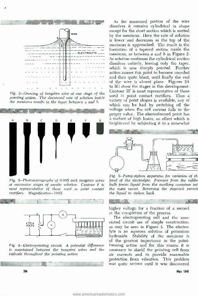
20i
As the immersed portion of the wire dissolves it remains cylindrical in shape except for the short section which is wetted by the meniscus. Here the rate of solution is lower and decreases as the top of the meniscus is approached. The result is the formation of a tapered section inside the meniscus, as between a and b in Figure 2. As solution continues the cylindrical section dissolves entirely, leaving only the taper, which is now sharply pointed. Further action causes this point to become rounded and then quite blunt, until finally the end of the wire is almost plane. Figures 3A to 3G show the stages in this development. Contour 3F is most representative of those used in point contact rectifiers. Thus a variety of point shapes is available, any of which can be had by switching off the voltage when the cell current falls to the proper value. The electroformed point has a surface of high luster, an effect which is heightened by subjecting it to a somewhat
,,, .: , ;>:.:» : H i<`:", , ;
Fig. 5- Pump -siphon apparatus for variation of th level of the electrolyte. Pressure from the rubbe bulb forces liquid from the auxiliary container int the main vessel. Reversing the stopcock permit the liquid to siphon back
ú,i yy K.là'd 3'. 4@
higher voltage for a fraction of a second at the completion of the process.
The electropointing cell and the asso- ciated circuit are of simple construction, as may be seen in Figure 4. The electro- lyte is an aqueous solution of potassium hydroxide. Stability of the meniscus is of the greatest importance in the point - forming action and for this reason it is necessary to shield the pointing cell from air currents and to provide reasonable protection from vibration. This problem was quite serious until it was discovered
May 1141
I
www.americanradiohistory.com

..V
ig. 6- Method of mounting spring assemblies. If he holder is horizontal all the springs will have the ame length when pointed. In practice 40 to loo vires are pointed simultaneously
.<::.,;< < ; ;..,+` 4".:h
that the solution of a small amount of copper in the electrolyte strikingly im- proved the ability of the menisci to hold. The electrolyte container is a glass vessel of convenient size and shape. Its upper rim is ground flat and provision is made for levelling it by means of a tripod base with adjustable feet.
An arrangement for regulating the level of the electrolyte is shown in Figure 5. Auxiliary to the main vessel is a smaller reservoir for transfer of electrolyte to or from the larger container by a pump -siphon arrangement. To raise the level, pressure is applied to the reserve liquid by a rub- ber aspirator -bulb fitted with a one -way valve. To lower the level, the two -way stopcock is opened to atmospheric pressure. thus permitting the liquid to flow from the
':k u.:*jo ^ï`f:?: %, f >'á al5' O .x
r- -
ELECTROLYTE
SPRING HOLDER
CONTAINER WALL
Fig. 7 -Level indicator. The mean length of the pins corresponds to the spring length desired after pointing. The liquid is raised until it wets the longer pin only. The pins differ in length by only a few thousandths of an inch
k : , ;
main vessel by siphon action. The level in the electrolyte vessel can be controlled quite precisely by carefully manipulating the rubber aspirator bulb.
Accurate control of the height of the electrolyte is of practical value because it is a means of bringing all contact wires to a desired overall length. This may be illustrated for the S- spring assemblies used in one type of rectifier, as shown in Figure 6. These springs are seated in a holder so that the bottoms of all of them are in the same plane. When this holder is inverted and placed on the rim of the container all springs will have the same length after pointing if the rim is in a horizontal plane. Spring lengths can be controlled fairly well by judging the liquid level by eye. For greater accuracy the
r. .. .< ..
THE AUTHOR: W. G. PFANN joined the Lab- oratories in 1935 and for several years was engaged in microscopic work in the metallurgical research group. In 1940 he was graduated from Cooper Union with a B.Ch.E. degree. During the war he participated in the development of silicon rectifiers and at present he is investigating materials for electrical contacts.
May 1948 217
www.americanradiohistory.com

arrangement of Figure 7 may be used. Two flat bottomed pins of a non -conducting material project downward from the holder so that their mean length corresponds to that desired for the springs. One of them is set one or two thousandths of an inch shorter and the other the same amount longer than this length. The liquid is then carefully raised so that it wets only the lower pin. A pair of such pins placed at each end of the bar can be used to obtain equivalent accuracy in levelling the holder.
This electropointing method was devel-
oped and used extensively in manufacture during the war. It is simple and rapid and requires only elementary apparatus. A difference in size of wire or in the point configuration desired involves little more than a change in the value of the shut -off current. The method has a very general aspect in that it is possible to produce points of any desired degree of sharpness on tungsten and molybdenum. Further- more, by selection of suitable electrolytes, cathodes, and voltages the principles should be applicable to a variety of metals.
%/5.,:; .s..+.:^tr. .
145 . .` . ...
RELAY COMPUTER FOR THE ARMY
As a result of the successful performance of relay computers developed by the Laboratories at the Army Ground Force Laboratories at Fort Bliss and the Naval Research Laboratories, Washington, the Government has had us develop and build two more powerful computers, one of
which was installed in 1946 at Langley Field for the National Advisory Committee on Aeronautics; the second computer at the Ballistics Research Laboratory, U. S. Army, at Aberdeen, has been placed in service. Outstanding in its flexibility, this computer is being used to work out a wide variety of
211 May 1141
www.americanradiohistory.com

research problems, particularly those which are not amenable to attack by computers of other types.
The operating room equipment which the computing staff uses to place problems on the machines and read off their answers is shown at the bottom of opposite page. Suggestive of a telephone central office, the panels below house the thousands of relays used for performing the actual
May 1148
calculations. A power control panel for the computer (above left) closely re- sembles a type used in telephone central offices. An indicator and manual control panel analogous to trouble indicator panels in crossbar offices is shown at the right above. Facilities are here provided for analyzing problems as they progress and for inserting computing instructions on a manual basis when required.
201
www.americanradiohistory.com

HISTORIC FIRSTS:
THE START -STOP OSCILLATOR
One of the precision problems of radar was timing the pulses as they traveled to the target and back with the speed of light. For a target two and one -half miles away, the round -trip time for the pulses is less than 27 microseconds, and this time must be measured correctly to within about one -tenth of a microsecond. Since the pulses were not sent out at regular intervals in the later radar circuits, the timer had to be started and stopped for each pulse -a sort of stop watch action but measuring in tenths of a microsecond in- stead of tenths of a second. The timer de- veloped for this purpose, and used in many radar equipments, has already been de- scribed.* The complete timing circuit incor- porated many ingenious arrangements, but its basic electronic stop watch, included at the suggestion of S. C. Hight, had al- ready been used at very much slower speeds. It had been invented a few years earlier by W. T. Rea and J. R. Wilkerson of the Telegraph Transmission Develop- ment Department.
Teletypewriter pulses, instead of being sent out one at a time as ate radar pulses, are sent out in small groups, and the tran- sitions from "mark" to "space" or from "space" to "mark" that form the sides of the pulses must occur within certain limits following the initial mark -to -space tran- sition or the character will be misinter- preted. In maintaining teletypewriter cir- cuits, therefore, it is necessary from time to time to measure the "distortion" -the departure of the transitions from their proper times -so that adjustments can be made when needed. A standard start- stop telegraph distributor was being used to guide the time measurements in the ex- isting distortion measuring sets, but it re-
RECORD, June, 1947, page 231.
211
quired considerable maintenance to keep its timing to the required precision.
In 1937, while developing a measuring set employing a cathode -ray tube for its indicator, Rea suggested the use of a sim- ple tuned circuit consisting of a coil and capacitor as the timing element. Prior to the start pulse, a steady current would be flowing through the coil from a connection to a suitable external circuit, but at the arrival of the start pulse, this connection would be broken, and the electromagnetic energy stored in the coil would oscillate between coil and capacitor, giving a pure sine -wave voltage across the capacitor. By making sure there were no other energy - storing elements in the circuit but the coil and capacitor, the oscillations would start without initial transients and would con- tinue at a constant frequency -thus furnish- ing a succession of equally spaced time intervals where the wave crossed the zero axis or at any other set of equal -phase points. At the end of the character, the oscillating circuit would stop within less than one cycle by critical damping.
The amplitude of the wave of such an oscillating circuit decreases in proportion to the loss in the circuit, and on trying this circuit out it was found that no coil was available that would keep the decre- ment to the small value desired. Wil- kerson then suggested connecting a vacuum tube into the circuit to supply the losses to the extent needed. The resulting circuit is shown at the left of Figure 1. Before the arrival of a start pulse, current flows through the coil from the connection marked B. At the arrival of the start pulse, the circuit is opened at s. The coil and capacitor at once start to oscillate without initial transients and with their losses sup- plied by the vacuum tube.
May 1948
www.americanradiohistory.com

In essentially this form, the circuit was used with the 118C1 telegraph transmis- sion measuring set,* the TG -29 and the 143A1 regenerative repeaters, and in the radar application already mentioned. A somewhat modified form, shown at the
SINE
OUTPUT
Fig. 1 -Two forms
COSINE
of the start -stop oscillator circuit .0`
right of Figure 1, arranged to provide both a sine and cosine output, was used in the 164A1 and the X -75041 Telegraph Distortion Measuring Sets.f In a still
`RECORD, December, 1943, page 174. RFCORD, April, 1947, page 150.
slightly different form, suggested by B. Ostendorf of Transmission Engineering, it was used in several airborne and ground radars. The circuit that is shown at the right of Figure 1, with equal sine and cosine outputs, was designed originally to permit the beam of a cathode -ray tube to be spirally or circularly rotated. By suitably combining the sine and cosine outputs, however, it is possible to secure a simple sine wave of any phase - thus greatly widening the usefulness of the circuit.
In all these forms and in other possible ones, its essential features are the same: an oscillating circuit consisting of a coil and capacitor with no other energy- storing ele- ments in or coupled to the circuit; a source to hold the energy in the oscillating circuit at a predetermined value until the time to start arrives; and a vacuum tube circuit to supply the losses so that the decrement of the circuit can be held to the desired value. The circuit was first shown in Pat- ent No. 2,370,685 covering the 118C1 dis- tortion measuring set, which was filed February 28, 1942, and issued March 6, 1945. Its subsequent use has been wide, and may be still wider in the future.
The 753 -E Volume Indicator shown at the right has been developed by Bell Telephone Laboratories for maintenance work on mobile radio telephone equipment
May 1!a 211
www.americanradiohistory.com

Do microwaves travel a straight -line path, or do they, at times, wander a bit as light waves do in a mirage? This question and others pertaining to micro- wave propagation have been answered by the use of a highly directive radio lens - antenna located atop Crawford's Hill, a 375 -foot eminence near Holmdel, New Jersey. A 1.25 centimeter radar signal is transmitted through the lens; goes out to a distant target; is reflected, and the angle of arrival of the returning pulse is measured. Results to date show that only minute deviations in angle of arrival ( less than 1 /10 degree) are normally found in the horizontal plane whereas greater changes (up to 3/4 degree) are at times found in the vertical plane. The deviations are due to a non -uniform distribution of temperature and humidity in the lower atmosphere.
The turntable mounting, shown at the
MICROWAVE "TELESCOPE" SWEEPS
SKY PATH
left in the illustration below, is a con- venient means of pointing the radio tele- scope at any desired target. In the foreground is shown the metallic lens which is fed from its focal point 48 feet to the rear, in the small cupola atop the building. Outgoing waves are transmitted like a narrow light beam from a powerful lighthouse. Incoming waves pass through the lens system in the reverse order and are concentrated on the receiving collector. The three circular parabolic dish antennas located on the tower are used for experiments at a wavelength of approxi- mately seven centimeters.
Vertical metal plates, (below, right ) accurately profiled and separated, form a lens for 1.25 cm waves. By raising and lowering the entire assembly, the beam is scanned over a small vertical angle.
R. A. Desmond, above, adjusts one of the receiver -recorder sets in the test house.
212 May 1148
www.americanradiohistory.com

pF:J,:ë'c`.:i::`i:::? ::::.......................:..... . .
F. S. ENTZ
Switching Development
:^:L:^:ï 'v4: :.::.J'.Y+:y.,v,:ni'::ivf?'t}:::::ï::ïï.>:. ç? ¢:i:;iñ0. .o&2Ái,:msisncu:va`'ä'::t:E... .'s'i::.i:.is
WIRE TELEPHONE NETWORK FOR
NEW YORK STATE POLICE
A new statewide radio -telephone net- work was cut into service last year for the New York State Police. With the approval of Governor Thomas E. Dewey it was established to meet the requirements of the State Police as recommended by Super- intendent John A. Gaffney for a communi- cations system that would enable troopers to give people throughout the state the maximum protection. The new system
Fig. 1 -A New York State Police sergeant takes down the facts of an alarm broadcast over the new state -wide mobile telephone system
provides two -way communication between headquarters at any level of the organiza- tion and troopers in the field, as well as between troopers operating in the same section of the state.
Supplementing the statewide teletype- writer system,* which has been in use for more than sixteen years, this new system provides local radio communication for patrol cars, police boats, and sub -stations, in addition to telephone communication over a wire network between police head- quarters and associated sub -stations on a statewide basis. In the radio communica- °RECOBD, October, 1931, page 58.
tion between sub -stations and police cars or boats, two frequencies are employed, one for land transmitters, the other for mobile transmitters. The frequency of a mobile transmitter, however, can be changed by the operation of a key to that of the land transmitters to which all mobile receivers are tuned, thus enabling patrol cars to communicate directly with each other. All sub -stations are equipped with receivers for monitoring car -to -car trans- missions. In addition to the equipment at fixed locations and in the patrol cars and boats, portable radio equipments with portable generators are provided to permit radio -telephone communication be- tween strategic points during emergencies. Walkie- talkie sets are also furnished so that troopers away from their patrol cars can communicate with nearby cars and with each other when such a need arises.
The system exclusive of the radio equip- ment was furnished and installed by the New York Telephone Company and is maintained by them, while the network and switching control facilities were de- signed by Bell Telephone Laboratories. The first part of the new voice network was cut into service in June 1947, and the remaining parts were progressively placed in operation during following months. The new network supplanted an existing radio system which outside of Long ,Island pro- vided one -way communication from fixed AM transmitters to patrol vehicles. Each of the progressive cutovers was carefully coordinated to maintain existing service.
New York State is divided into six State Police troop areas, as shown in Figure 2. under the supervision of State Head- quarters at Albany. Each area is divided into a number of zones, usually three. Each zone has several sub -stations, one of which serves as zone headquarters, and each
May 1141 213
www.americanradiohistory.com

R :
...Z...., K. ..aR6u'6Y,GL.vt `i Afta 4
RADIO STATION
RECEIVER
1< TRANSMITTER
Fig. 4 - Simplified schematic of the state system from a single radio station at the left, to the state headquarters at Albany, at the right
ZONE REMOTE CONTROL STATION
r
CONTROL CABINET
O
- LOUDSPEAKER)
L
DISPATCH STATION (WITHOUT RADIO)
CONTROL CABINET
L
ZONE BRIDGE
`INTERMEDIATE BRIDGE
RADIO BRIDGE
s ç s
TO RADIO STATIONS VIA REMOTE.CONTROL STATIONS
.v,.u. É.%.....,
.. 4i..
á!`,;v:».,,w.w. )1a?.».......,;"äw.w ...
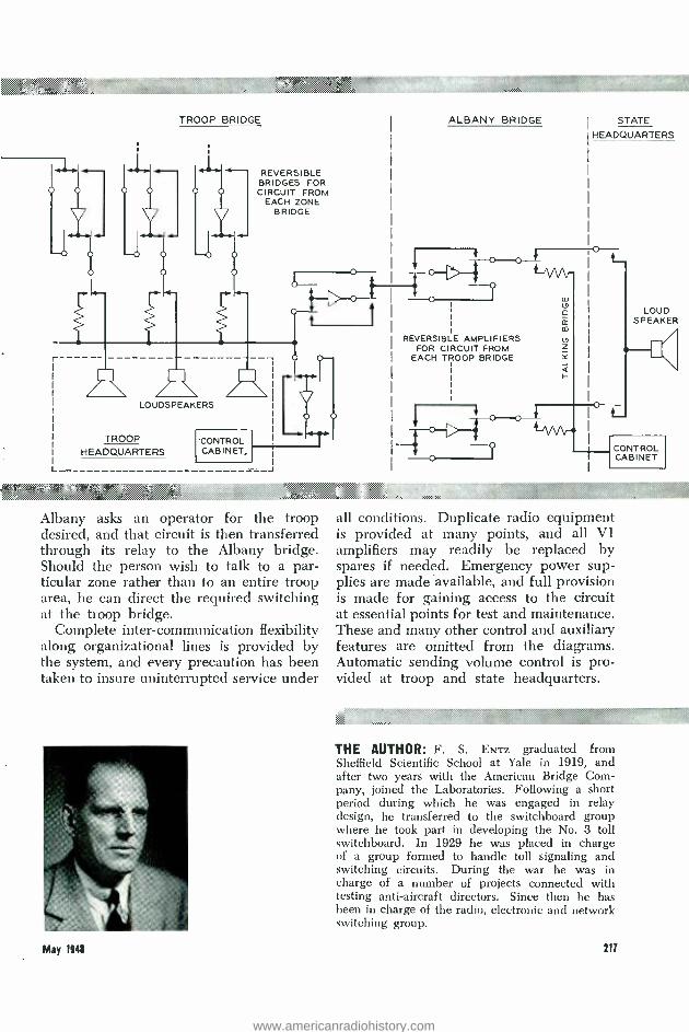
reversing pair, thence through the inter- mediate bridge to a power amplifier, and then to the output bridge, where it is distributed to all sub -stations - including the sub -station controlling the radio station - and to the circuit to the troop bridge.
Should a trooper at a sub -station wish to talk, he would operate his push -to -talk button. This transfers his circuit from the output bridge through an equalizing pad to the contacts of a relay which operates to reverse the direction of amplification. He could then talk over the radio channel, and would also be heard on the network.
A remote control station may also talk directly over the radio circuit without going through the bridge by operating a local three -position key. This key is shown at the zone remote control station in Figure 4. In the position shown, the radio receiver is connected to the radio bridge, and the network circuit to the control cabinet. In the second position, the radio receiver is transferred from the bridge to the loud speaker while the network circuit remains connected to the control cabinet. In the
216
third position, the loud speaker is trans- ferred to the network, and the control cabinet is connected to the radio station to permit talking to cars without the con- versation's being heard over the network.
At the troop bridge, all the circuits from the zone bridges are connected through reversible amplifiers to individual relay springs. Through a back contact, these circuits are normally connected to a loud speaker for monitoring, but under control from troop headquarters they may be con- nected through a front contact to the troop bridge, and the amplifiers may be reversed so that personnel at troop headquarters or Albany headquarters may talk through any one or cohbination of zone bridges.
At the Albany bridge each circuit from a troop bridge is connected through a reversible amplifier to a relay spring. The back contacts of these relays connect to Albany headquarters where keys permit them to be connected to a monitoring loud speaker. The front contacts of the relays connect to the Albany bridge. A person wishing to talk over the network from
May 1848
www.americanradiohistory.com
36X
Y ...........::.:ip,::,e4..;:xn,
< <..:` ........ .. :,
TROOP BRIDGE
[,Li] O
REVERSIBLE BRIDGES FOR CIRCUIT FROM
EACH ZONE BRIDGE
O O
r ii /i\ n LOUDSPEAKERS
TROOP HEADQUARTERS
CONTROL CABINET,
L J
raw Albany asks an operator for the troop desired, and that circuit is then transferred through its relay to the Albany bridge. Should the person wish to talk to a par- ticular zone rather than to an entire troop area, he can direct the required switching at the troop bridge.
Complete inter -communication flexibility along organizational lines is provided by the system, and every precaution has been taken to insure uninterrupted service under
May 194$
ALBANY BRIDGE
REVERSIBLE AMPLIFIERS FOR CIRCUIT FROM
EACH TROOP BRIDGE
STATE
HEADQUARTERS
LOUD SPEAKER
CONTROL CABINET
all conditions. Duplicate radio equipment is provided at many points, and all VI amplifiers may readily be replaced by spares if needed. Emergency power sup- plies are made available, and full provision is made for gaining access to the circuit at essential points for test and maintenance. These and many other control and auxiliary features are omitted from the diagrams. Automatic sending volume control is pro- vided at troop and state headquarters.
.^::__? Si$`','.::::
THE AUTHOR: F. S. ENTZ graduated from Sheffield Scientific School at Yale in 1919, and after two years with the American Bridge Com- pany, joined the Laboratories. Following a short period during which he was engaged in relay design, he transferred to the switchboard group where he took part in developing the No. 3 toll switchboard. In 1929 he was placed in charge of a group formed to handle toll signaling and switching circuits. During the war he was in charge of a number of projects connected with testing anti -aircraft directors. Since then he has been in charge of the radio, electronic and network switching group.
217
www.americanradiohistory.com

MULTI - FREQUENCY KEY PULSING
Laboratories people whose home tele- phones are served by certain manual offices in northern New Jersey -Belleville, Boon- ton and Westfield for example -will have noticed that on some short haul calls a succession of musical tones are heard, one set for each digit of the called number. These tones convey to the crossbar sender at Jersey Tandem the same information about the number called as would be given by the corresponding sets of dial pulses.
The story goes back before the war when multi- frequency key sets were installed in manual toll positions to reach No. 1 cross- bar terminating subscribers and later as a means to complete calls from the No. 4 toll crossbar system in Philadelphia. Six different tones, two at a time, are used. These provide 15 combinations of which 12 are used, 10 for the numerals and two for control purposes.
P. L. Wright holds a 39M vacuum tube, part of the low impedance bridging circuit which he is discussing in the Circuit Development laboratory with B. McKim
218
Jersey Tandem has senders that will accept multi- frequency pulses and the manual switchboards that work into it have recently been equipped to send such pulses. These switchboards could have been equipped with the conventional multi- frequency key set circuits used at toll switchboards but the cord splitting relays then required to isolate the sub- scriber's line from the key set and sender would have been prohibitive in cost. So a group of engineers, of whom D. L. Moody, P. L. Wright and B. McKim were most active, worked out an arrangement that permits the key pulsing circuit to be bridged across the cord circuit in place of the operator's telephone circuit without requiring cord splitting keys.
When the operator throws her listening key and presses the pulsing keys in suc- cession, she applies the tones from the multi- frequency source of supply to her headset and to the calling line and the trunk in parallel. (This is why the calling subscriber hears these "elfin horns"). The six tones have frequencies of 700, 900, 1100, 1300, 1500 and 1700 cycles. None of them are in harmonic ratio with any others ( except 900 and 1500 which form a musical "fifth ") but the combinations are not unpleasant.
When a call comes to a manual operator for a number that can be reached through Jersey Tandem, she leaves her listening key operated, selects an idle trunk, presses a key marked KP, followed by the keys required for the office designation, line number ( and party letter if any) . Then she presses a key marked ST, releases her listening key and takes up the next call. At Jersey Tandem the sender registers the call and completes it into crossbar or panel dial offices, or gives the called subscriber number to a manual "B" operator on that operator's lamp call indicator.
May 1948
www.americanradiohistory.com
J. B. JOHNSON
Physical Electronics
A MOVABLE- SCREEN CATHODE RAY TUBE
In one of the systems of visual speech developed by the Laboratories*, continuous patterns are projected on the screen of a special cathode -ray tube in which the beam sweeps vertically on the phosphorescent sidewall of the tube while the tube revolves. The moving screen in this new translator furnishes uninterrupted and continuous traces, contrasted to those of the familiar oscilloscope where the electron beam makes a periodic and limited time -base fly -back across the end of the tube. The translator tube displays patterns before an observer as the animated words in a news sign spell out their significance. °RECORD, January, 1946, page 7.
May 1948
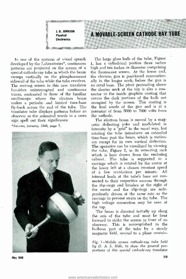
The large glass bulb of the tube, Figure 1, has a cylindrical portion three inches high and ten inches in diameter comprising the fluorescent screen. At the lower end, the electron gun is positioned convention- ally in the longer neck; below the gun is
an octal base. The pivot protruding above the shorter neck at the top is also a con- nector to the inside graphite coating that covers the dark portions of the bulb not occupied by the screen. This coating is
the final anode of the gun and is at a
potential of from 5000 to 7000 volts from the cathode.
The electron beam is moved by a mag- netic deflecting yoke and modulated in intensity by a "grid" in the usual way, but rotating the tube introduces an extended time -base past the beam, which is station- ary except for its own vertical deflection. The operation can be visualized by viewing the tube, Figure 2, in its mounting rack which is here drawn from the enclosing cabinet. The tube is supported in a carriage which is rotated by the motor at the lower left at a chosen constant speed of a few revolutions per minute. All internal leads at the tube's base are con- nected to their respective sources through the slip -rings and brushes at the right of the motor and the slip -rings are inde- pendently driven at the same rate as the carriage to prevent strain on the tube. The high voltage connection may be seen at the top.
The beam is directed initially up along the axis of the tube and must be bent forward to strike the screen in front of an observer. This is accomplished in the bulbous part of the tube by a steady magnetic field, normal to a plane contain -
Fig. 1- Mobile screen cathode -ray tube held by D. A. S. Hale, to show the general pro- portions of this special cathode -ray translator
219
www.americanradiohistory.com

Fig. 2 -With the mounting rack removed from the equipment cabinet the translator is seen positioned in its carriage. All but the viewing section, within the area of the forefront of the control coils, is covered during normal equipment operation
ing the axis, created by direct current in a set of four "bending coils" surrounding the bulb. Two of these coils are seen at the front and right of the bulb portion. Superimposed on the bending of the beam is a variable magnetic deflection, below the bending field, governed by the yoke which surrounds the tube at the top of the long neck. By means of this latter coil the beam is swept up and down across the screen with a linear repetition of about 100 times per second. Controls on the tube are
29
ELECTRON BEAM
Fig. 3 -Cross section of the tube in the plane of electron beam showing schematically the bending the beam
slow horizontal movement of the screen past the stationary plane of the beam, the vertical sweep of the beam and the modu- lation of beam intensity in response to a signal impressed on the grid of the tube. The operation of the coils upon the beam is shown in Figure 3, a schematic cross - section of the tube in the plane of the deflected electron beam looked at from the left of the observer's position. Although the coils themselves are not shown, their magnetic lines of force, which are perpendicular to the paper, are repre- sented by dots for both the bending and the deflecting fields. The electron beam first is bent slightly to one side or the other, in passing through the deflecting field, then through nearly a right angle, in the bending field, to its impingement on the screen.
May 1141
www.americanradiohistory.com

Fig. 4 -Two patterns for "Very unusual pictures" as spoken by a male voice using different inflections in each case. The lower trace of each picture is the intensity. A trained visual "listener" could recognize the letters and words of the frequency configurations in the upper portions which are actually brighter than they appear in the illustration
May 1948
Since the screen is of the persistent type of phosphor a pattern made on it by the beam is in evidence for several seconds after the initial excitation which occurs at a point just to the right of the observer's window. The observer continues to see a record of the input signal for about one - sixth of the screen's circumference. After a full rotation, the intensity of this pattern has decayed to such a low level that a negligible trace of it remains in a new pattern; at higher rates of rotation the old pattern may be quenched sufficiently by irradiation with long wavelength light.
In the circuits of the visual speech systems the vertical sweep is syncronized with the rate of an analyzer which samples the energy content of the oral speech in a succession of frequency ranges. One sweep covers the frequency ranges from the lowest to the highest and this is repeated many times per speech syllable. The pat- tern produced in the translator is an immediate pictorial representation of the spoken sounds which can be read by people suitably trained. Such a pattern reproduced in Figure 4 represents the phrase: "Very unusual pictures ", in two inflections of a male voice.
s; .;tz:.
THE AUTHOR: J. B. Jose sou received the B.S. degree from the University of North Dakota in
1913 and M.S. the next year. His Ph.D. was conferred by Yale in 1917 and that same year he joined what is now the Research Department of the Laboratories. In World War I his work was concerned with problems of vacuum tube opera- tion. Subsequently he was occupied with the Western Electric 224 cathode ray oscillograph tube, which became the first common laboratory tool of its kind, and with the "shot" noise and "thermal" noise in amplifiers. From the latter studies the "Johnson effect" concept has become universally applied in this field. In World War II Dr. Johnson was engaged with problems of high- frequency electron tubes, cathode -ray tubes, crystal projectors and restricted government proj- ects. His research at present deals with secondary electron emission.
221
www.americanradiohistory.com

EDT AND DKT CRYSTALS FOR
CARRIER CHANNEL FILTERS
W. P. MASON
Mechanics
Research
Shortages of quartz suitable for piezo- electric crystals had been anticipated by the Laboratories several years prior to the recent war and studies had been under- taken to find other crystals which could be grown artificially that might be substi- tuted in some applications for those of quartz. This program made important con- tributions to the production of synthetic piezoelectric crystals which were used in large quantity during the recent war.* It has since resulted in two other crystals
*RECORD, July, 1946, page 257.
222
that can be cut to yield plates whose resonant frequencies of vibration do not change appreciably within a useful temp- erature range and which have little or no water of crystallization. This makes them suitable as substitutes for quartz in carrier channel filters. Other favorable properties of these crystals are reasonable immunity to changes of humidity of the air and to show changes of internal structure with time; a high "coupling" ratio of conver- sion of electrical into mechanical energy; and low dissipation of that energy due to internal friction.
These crystals are ethylene diamine tar- trate, a photograph of which is shown in the headpiece, and dipotassium tartrate. The first has been given the designa- tion EDT and the second DKT. EDT (C6H14N206 ), has no water of crystalliza- tion and hence will not dehydrate. DKT (K2C2H408 3z H2O) has one molecule of water for each two of potassium tartrate, but it is tightly bound and tests show that no dehydration takes place up to 80 de- grees C. The temperature- frequency and temperature- coupling characteristics of DKT are more stable than those of EDT, but the former is harder to grow and re- quires more careful handling. Accordingly, the Western Electric Company is growing EDT crystals for electrical filter units in a
plant at Allentown, Pa., as the first com- mercial application of these materials.
Both of these crystals belong to the monoclinic class which has two axes, a and c, Figure 1, not at right angles to each other, and a third axis, b, perpendicular to the other two. In cross section, the EDT
-4- Ethylene diamine tartrate (EDT) crystals, grown artificially, will be used in carrier line filters as a substitute for quartz
May 1948
www.americanradiohistory.com

crystal is a parallelogram with a 105 -degree angle between its a and c axes. The b axis is parallel to the long direction of the crys- tal. Crystals of this type of symmetry have thirteen elastic, eight piezoelectric and four dielectric constants compared with six, two and two, respectively, in quartz. The vibra- tional characteristics of EDT crystals are therefore more complicated than those of quartz. This complication is beneficial in one way because it permits balancing the temperature coefficient of one elastic con- stant against those of others, thus provid- ing modes of vibration with zero tempera- ture coefficient. It is also detrimental be- cause it results in more coupling with undesirable modes. Since a filter crystal has to have a single main resonance frequency, free from parasitic modes over a wide range, a thorough study of the modes of motion of these crystals and in particular those of dimensional ratios which are free from secondary modes had to be made.
The inductance of the equivalent elec-
trical circuit of the crystal for a filter as well as its resonance frequency has to be speci- fied. With quartz crystal plates, these two requirements can be met by simultaneously varying their length, widths and thicknesses
. <::t,:: :`r:`. :_. <. Ww:a: :.
..:.
loi
Fig. 1 -EDT crystals are classified as monoclinic. They have two axis, a and c, with a 105 -degree angle between them and a third axis, b, perpendicu- lar to the others and parallel to the crrtstal's length
r',
Z
±20'
X
X
Fig. 2 -There are six orientations in EDT crystals at which crystal plates with zero ficients can be cut. Two have been designated A and Y.
temperature coef-
Vt''.,. 1,,
May 1948 228
www.americanradiohistory.com

until the right impedances and resonant frequencies are obtained. In EDT crystals, however, this process led to plates which had parasitic resonances too close to the main mode to be usable, on account of the more numerous coupled modes. To get around this difficulty, new orientations were developed, which have zero tem- perature coefficients at the mean tempera- ture of 80 degrees F., but for which the unwanted modes will have frequencies farther away than previously. This allows a considerably larger latitude in simulta- neously satisfying the frequency and in- ductance requirements while still obtaining a single resonance over a sufficiently wide frequency range.
Six orientations have been located at which EDT crystals with zero temperature coefficients in the range near 80 degrees F. can be cut. Figure 2 shows these cuts with reference to rectangular axes. In specify- ing them and calculating the effect of ori- enting crystal plates with respect to the crystal axes, it is easier to use a right -angled system of axes X, Y, Z rather than the crystallographic axes a, b, and c, which are not at right angles for a monoclinic crystal.
ä!tä \: :,Fiï
w.'ü"'aaefä%i'i
0Ú202
}Y U ZZ 200 w-
z Ñ 198
9.6
I- 9.2
Ñw p 8.8 UU
ED 8.4 F-
JN ó w 8.0
7.6 -80 -60 -40 -20 0 20 40 60
TEMPERATURE IN DEGREES CENTIGRADE
.7 RATIO OF
CAPACITIES ..
DIELECTRIC CONSTANT
34 > Q
V
30 ow
Ó
26 o
N
22 u- <
18 U
Ó O
80 Q 1Y
Fig. 3- Characteristics of the Y cut EDT crystal, which has its major surface perpendicular to the Y axis and its length along the X axis ], .. i s':,,:i`:wC8x,.
224
;f: ... ..: VC'
zdalk x:.. ..>.. r .
7P,M"
Fig. 4 -In an electrical circuit, a piezo -electric crystal acts like a series inductance L1, and capac- ity Cl, both shunted by a capacity CO
L
Co
:' .A.2,`: .a ......
These are specified, as indicated in Figure 2, by letting Z lie along c, Y along b and X at such an angle in the a, c =Z plane, as to make a right- handed system of axes with the other two axes Y and Z. One of the principal cuts for filter plates is that which makes their major surface perpendicular to the Y axis and their length along X. The properties of this cut are shown as a function of the ambient temperature in Figure 3, where the frequency of a crystal one centimeter long, called its frequency constant, also the ratio of ca- pacities co to ci of the equivalent network of the crystal (Figure 4) and its dielectric constant are plotted as a function of the ambient temperature.
0 171 UV
ZZ 170 w- z Cl
(xi- LL
8.0
RATIO OF CAPACITIES
DIELECTRIC CONSTANT
6.0 -80 -60 -40 -20 0 20 40 60 6C
TEMPERATURE IN DEGREES CENTIGRADE
Fig. 5- Characteristics of the A cut EDT crystal. frequency variation with changes of temperature is ..
half that of the Y cut
Min. >switwwA*.1'.'..w.. f ,a::>:: .:..
...
May.184i
www.americanradiohistory.com

?: e.: -. Z..: ss? .._._....:...
The A cut of Figure 2 provides another longitudinally vibrating crystal having a zero temperature coefficient at 25 degrees C., whose properties are considerably more stable with temperature than those of the Y cut. As shown by Figure 5, the frequency and inductance variation for a given tem- perature change is only half as much as that for the Y cut. The ratio of capacities is about one and a half times as much, how- ever, and results in an inductance value in the equivalent circuit nearly double that of the Y cut for a given frequency.
THE AUTHOR: W. P. MASON graduated from the University of Kansas with the B.S. degree in E.E. in 1921 and joined the Laboratories that year. He received his M.A. degree in 1924 and Ph.D. in 1927 from Columbia University. Dr. Mason spent four years investigating carrier transmission sys- tems and then became concerned with the de- velopment of transmission networks and in research on piezoelectric crystals and ultrasonics, which have since occupied his time.
Although a zero temperature coefficient is obtainable over a short range on both sides of a specified temperature, the fre- quency does not remain constant above or below this range. As shown by Figure 3 and Figure 5, it varies as the square of the dif- ference between the ambient temperature and that at which the coefficient is zero. This is true also for most quartz crystals whose temperature coefficients are zero, but the curvature constant of DKT and EDT is from 10 to 25 times as large as that for quartz.
,t...., .
xx .., u...
,,;a.s. >>:;: .:n,..x->;. " v
,:.f,v:. ,:.,. .... : .
,.x.:. c, .. . . :°.a,`
. a`'wa Aso Ë á. »:
May 1141
MODERNISTIC HEAD -DRESS
This crown of thorns modelled by Jane Conlon of the Publication Department is not a Hitlerian device of torture but a scientific instrument. It was designed and built by R. Guenther of the Station Apparatus Development Department to measure the sizes and shapes of the heads of telephone operators. In developing a new head band for operators' telephone sets, it was necessary to supplement pre- vious head measurements to insure that the new band would be comfortable to wear and easy to adjust. From measure- ments made with this multi-arm calipering instrument in Montreal, New York, and Atlanta, the typical ranges of size and shape of operators' heads were determined. The new head band subsequently became a part of the 52A headset.
www.americanradiohistory.com

W. A. SHEWHART RETURNS FROM INDIA
A delegate to the Indian Science Congress by invitation from Prime Minister Nehru, W. A. Shewhart visited all the principal centers of India as a guest of the Government of India. Purpose of the trip was to cooperate with the Indian Standards Institution and the Indian Statistical Institute in acquainting Indian industrialists with the importance of quality control, and to show their engineers how to use this powerful manufacturing tool.
Leaving the United States late in November, Dr. Shewhart travelled by water to Rome, thence by air to Bombay. Typical of the re- ception accorded him throughout the trip, in Bombay he was the house guest of the governor of the Reserve Bank of India. Flying to New Delhi, he addressed the Minister of Supply's Conference on Industrial Develop- ment at which more than 300 of India's top - ranking industrialists and government officials were assembled. By way of Calcutta, he went to Patna for the Indian Science Congress, and then to the great Tata Iron and Steel Works at Jamshedpur where he was entertained at the guest -house maintained for the company's directors. Here Dr. Shewhart addressed more than a hundred executives of this largest steel producer in the British Empire. He then delivered a public lecture to engineers and others, and was guest speaker before the Rotary Club.
At Hyderabad Dr. Shewhart was a guest of the State and visited the large American - built aircraft factory. He was taken to Auran- gabad to see the famous caverns, many of which were excavated and elaborately dec- orated long before the Christian era. At Mysore he saw the dam -third largest in the world - and its acres of gardens. Statistical and engineering students at the University of Travancore's statistical laboratory participated in a conference on quality control.
Timed to coincide with his visit was a seven -day conference at Presidency College, Calcutta, on quality control attended by two hundred people from all industrial centers. Dr. Shewhart was chosen president, and con- ducted a series of lecture- conferences at which great interest was shown. At the end of the conference the Indian Quality Control Society was organized.
n8
It was during this period that Mahatma Gandhi was assassinated; Dr. Shewhart watched a crowd of more than a million pouring out of the city to see the ashes scattered on the Ganges.
On a second visit to New Delhi, he dis- cussed with government officials and others, including the president of the Council of Scientific and Industrial Research, tentative plans for introducing quality control into Indian industry. During this visit he was guest of honor at a dinner in the home of Prime Minister Nehru. After a side trip as a State Guest to Agra and the Taj Mahal, Dr. Shewhart proceeded via Bombay to London by air.
Dr. Shewhart reached New York by means of steamer on March 18th. During his stay in India, he delivered thirty public lectures, participated in fourteen large conferences, visited forty factories, and was guest of honor at twenty-eight official luncheons, teas, and
M. J. Kelly greeted by M. R. Sullivan, president of the Pacific Telephone and Telegraph Company, before speaking to a conference of the Pacific Com- pany's area managers and their staffs. This was an incident of Dr. Kelly's trip in the company of Admiral A. G. Noble, to survey research work of the Bureau of Ordnance, at Inyokern, Los Angeles, Pasadena, Point Mugu and San Francisco
Mq 1998
www.americanradiohistory.com

dinners. Mrs. Shewhart accompanied him and acted as his secretary.
Summing up his trip, Dr. Shewhart said, "In addition to the utter poverty and abject misery, which seem to be the strongest im- pressions of many travelers, I brought back from India the inspiration of the eagerness and energy of the younger men who see a great future now that their destiny is in their own control. All too often, of course, the clamor for manufactured goods has relaxed many of the older group into slipshod methods. But competition is becoming a stimulant of quality at low cost. The trip was arduous but interesting. I made many new friends and have the personal satisfaction of helping to get quality control started in India."
New Headquarters Building for the Western Electric Company
A new headquarters building, to be erected on the largest single plot of land now available on Manhattan Island, was recently announced by the Western Electric Company, comprises a solid area equal to four entire city blocks in the lower Manhattan commerce center, bounded by Varick, Hudson, and Laight Streets and Ericsson Place (formerly Beach Street) and represents a frontage of 440 feet on Varick and Hudson Streets and 405 feet on Ericsson Place and Laight Street.
The I. R. E. Annual Meeting The national convention of the Institute of
Radio Engineers was held in New York from March 22 to March 26. During the convention, Fellow awards for 1948 were granted to H. S. Black for his work on the negative- feedback amplifier and for his application of pulse techniques to radio communication systems; to L. A. Meacham for his contributions in the field of radar range measurement and pulse code modulation; and to J. R. Pierce for his many contributions to the theory and design of vacuum tubes.
Papers presented at the meeting included Ratio of Frequency Swing to Phase Shift in Phase- and Frequency- Modulation Systems Transmitting Speech, by D. K. Gannett and W. R. Young; Synthetic Crystals for Telephone Systems by W. L. Casper; Crystal Filters Using Ethylene Diamine Tartrate in Place of Quartz, by E. S. Willis; Design, Fabrication and Performance of Ethylene Diamine Tar- trate Crystal Units, by E. S. Pennell and J. P. Griffin; and Growing Crystals of Ethylene Diamine Tartrate by A. C. Walker and G. T. Kohman. In conjunction with the last paper,
May 1142
J. J. Harley presented a colored motion picture showing details of crystal growth. Other presented papers were by H. T. Budenbom, Analysis and Performance of Wave Guide Hybrid Rings for Microwaves; by Claude Shannon, Information Theory, the latter a contribution to the Symposium on Advances Significant to Electronics; and by N. Monk and S. B. Wright, Technical Aspects of
Acme oto The microwave demonstration of the A T & T at Grand Central Palace for the 1948 I.R.E. convention was seen by more than 5,000 visitors, including many Bell Laboratories people. The exhibit represented an actual operating model of the New York -Boston radio relay system. Henry Kostkos was active in the develop- ment of the exhibit. W. L. Tierney and F. F. Merriam provided the metal lens antennas and a bay of radio relay equipment
Experimental Public Telephone Service on Railroad Trains. R. L. Dietzold presided as chairman of the Networks session; S. A. Schelkunoff, the Wave Propagation session; A. G. Jensen, the Television session; H. W. Bode, the Systems session; F. B. Llewellyn, the Electronics IV session on New Forms of Tubes; and Ralph Bown, the Microwaves session. Serving on various committees of the convention were L. E. Hunt, member of the Facilities Committee; F. A. Polkinghorn, chairman of the Registration Committee; R. A. Heising, vice -chairman of the Section Activ- ities Committee; Lloyd E. Hunt, A. G. Jensen, Pierre Mertz and J. C. Schelleng, members of the Technical Program Committee. On the Women's Activities Committee, Mrs. F. B. Llewellyn served as chairman and Mrs. G. W. Gilman, as a committee member.
221
www.americanradiohistory.com

DR. FLETCHER
ADDRESSES
LIFE
MEMBERS
CLUB
Pioneer activities at the Laboratories re- cently have included the initial meeting at West Street of the Life Members Club, a noon -hour show at Murray Hill for Pioneers at that location, and a buffet supper and organizing meeting at West Street for women Pioneers from all locations. Life members were welcomed in the Auditorium by Harvey Fletcher, president of the Frank B. Jewett chapter, who then turned the meeting over to A. E. Petrie, chairman of the Organizing Committee. In addition to entertainment by
The Systems Glee Club, under the direction of R. P. Yeaton, sang four selections for the Pioneers. Comprising the Club are left to right, front row, J. M. Marko, A. O. Jagau, H. K. Warnke, L. W. Drenkard, W. H. DeZavala, C. G. Peter- son, J. L. Larew and C. A.
Collins; in the rear row, T. G. Fischer, E. C. Tundel, F. J. Bertola, H. A. Miloche, J. E. Greene, Jr., L. P. Brown, C. B. Swenson and J. R. P. Goller
!t/
Magician C. N. Hickman demon- strating one of his tricks for J. R. Townsend at a noon -hour hobby show for Murray Hill Pioneers
the Systems Glee Club, a motion picture film of the Arctic was shown. A nominating com- mittee was elected and the constitution read by Hattie Bodenstein, secretary of the Pioneers. In addition to Miss Bodenstein, A. B. Kvaal acted as liaison between active and retired members.
At Murray Hill, C. N. Hickman, who holds many patents for magic and is a member of the American Society of Magicians, enter- tained Pioneers at that location with his rope and card tricks, particularly with his ol- factory amplifier, a device which recorded by a light those cards that had been touched by the six engineers who assisted Dr. Hickman. His act was followed by J. J. Harley's movie Design in White.
Eighty -three women Pioneers attended a
buffet supper at West Street and then launched a program of activities, beginning with sewing classes now under way, which will help them to learn new skills now and possibly earn money for them after retirement. Hazel Mayhew, chairman of the Women's Activities Committee, was the group leader.
May 1148
www.americanradiohistory.com

Personal Income Tax Reduction Under Revenue Act of 1948
Under the Revenue Act of 1948 the personal income tax liability of individuals for the year 1948 is reduced by the introduction of several changes in the law. The following indicates those changes which it is believed are of general interest to Laboratories employees:
(a) The exemption allowed the taxpayer for himself, his spouse, and each dependent is increased from $500 to $600.
(b) Although the tax rates under the Revenue Act of 1948 remain the same as for 1947, a series of reductions in the amount of the aggregate tax (normal tax and surtax) is provided as follows: If the aggregate tax The reduction is: ( normal tax and surtax) is: Not over $400, 17 % of the aggregate; Over $400 but not over $68 plus 12% of excess $100,000, over $400; Over $100,000, $12,020 plus 9.75% of
excess over $100,000. (c) A husband and wife may now split
their income, thus enabling them in some cases to keep their taxable income in lower surtax brackets.
(d) The optional standard deduction, which was limited to $500 in 1947, is in- creased under the new law to 10 percent of adjusted gross income, not to exceed $1,000, in instances in which a joint return is filed by a husband and wife or a separate return is filed by an unmarried taxpayer. Where a married taxpayer files a separate return, how- ever, the maximum standard deduction remains at $500, as under the old law.
No action is necessary by employees with respect to income tax withholdings by the Payroll Department. Reduced withholdings become effective with the week beginning April 26 for weekly rated employees and with the month beginning May 1 for monthly rated employees. Since the tax reductions outlined above are, however, effective January 1, 1948, adjustments in the form of refunds covering the over -withholding of tax during the first part of the year will, where the taxpayer is entitled thereto, be made by the Collector of Internal Revenúe subsequent to the filing of individual returns for the year 1948.
Taxpayers who filed a Form 1040 -ES, "Declaration of Estimated Income Tax for 1948 ", may, in view of the above, elect to recompute the 1948 estimated tax under the new law and file an amended declaration on or before June 15, 1948, which will give effect
May liii
to the amount already paid on the estimate and the aggregate amount to be withheld for 1948. It is expected that forms for this purpose will become available about May 15, 1948.
Mobile Radio on N. Y., N. H. & H.
Tests are now under way looking toward the installation of telephone service between trains of the New York, New Haven and Hartford and highway radio stations of the Bell System. As these stations operate in the 30 -44 me range, noise produced by the New Haven's 11,000 -volt electrification presents a
real problem. The tests are being made in cooperation between the railroad, three Bell companies, and the Laboratories. A special car has been fitted up with radio equipment; pictured in the foreground above are J. L. Lindner and H. S. Winbigler of Radio Transmission Engineering.
Forty -two Per Cent of U. S. Farms Have Telephone Service
Forty-two per cent of America's farms now have telephone service. The Bell System added 309,000 telephones in rural areas last year, bringing telephone service to farm
221
www.americanradiohistory.com

regions at the rate of about 1,000 additional families every working day of the year. At
the beginning of 1948, there were over 2,000,000 telephones in rural territories served by the Bell companies.
Changes in Organization
The progress toward the completion of the Murray Hill II Project with occupancy sched- uled to begin in August of this year, has necessitated an expansion of the group heretofore available to assist employees whose work location is to be changed from New York to New Jersey. Accordingly, effec- tive April 5, an Employees' Relocation Service Organization was set up in the Personnel Department with A. J. Daly as Director reporting to F. D. Learner, Personnel Director.
Mr. Daly's organization will comprise the following: K. M. Weeks In Charge of Counseling
Service M. J. Doody Counselor A. J. Kuczma Counselor A. J. Akehurst In Charge of Field Service C. M. Casazza Field Representative V. H. Lyon Field Representative Mrs. E. H. Wylie Service
D. D. Haggerty will, in addition to his regular duties relating to the Bell Laboratories Club, act in an advisory capacity to Mr. Daly.
Miracle at Flat Rock
Before the eyes of a chance observer, the walls and roof of a small neat building simply vanished. Disclosed was the building's contents: the step -by -step dial office for Flat Rock, Michigan. Largest single piece of brick- work was some three square feet; the roof Kvas on top of a nearby residence. But the
equipment was not damaged, not even the glass battery-jars. Following the explosion, debris was shovelled out, compressors were brought up to blow dust out of the switches, a tent was put over the site. Service began to go back within a few hours and by after- noon of the next day had been completely restored. All in all, the episode was a testi- monial to the ruggedness of Western Electric equipment and the determination of Bell
System people.
Television Network Rates
On May 1, rates became effective for the use of Bell System interstate television cir- cuits. A television or "video" channel between two cities will cost the broadcaster $35 a
month per airline mile for eight consecutive hours each day, and $2 a month per mile for each additional consecutive hour. For occa- sional or part-time service the rate will be $1
per airline mile for the first hour of use and one- quarter of that amount for each additional consecutive 15 minutes.
For the use of terminal equipment and its maintenance, there is a charge of $500 a
month for connecting stations to the television network for eight consecutive hours daily. For stations which require only occasional service, the charge will be $200 per month plus $10 per hour of use.
Rates now in effect for sound or "audio" broadcasting will apply for the separate sound channel needed for the complete television program.
By the end of this year, the Bell System expects to connect the existing East Coast television network with a new network in the Middle West, and thus link the two regions for simultaneous broadcast of the same pro-
www.americanradiohistory.com
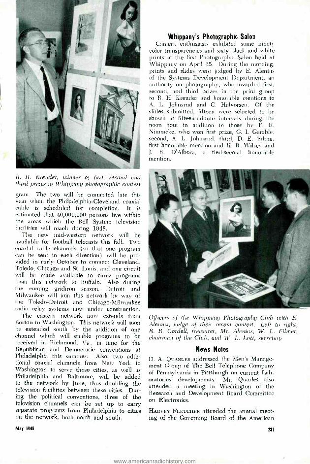
R. H. Kreuder, winner of first, second and third prizes in Whippany photographic contesi
gram. The two will be connected late this year when the Philadelphia- Cleveland coaxial cable is scheduled for completion. It is estimated that 40,000,000 persons live within the areas which the Bell System television facilities will reach during 1948.
The new mid -western network will be available for football telecasts this fall. Two coaxial cable channels (so that one program can be sent in each direction) will be pro- vided in early October to connect Cleveland, Toledo, Chicago and St. Louis, and one circuit will be made available to carry programs from this network to Buffalo. Also during the coming gridiron season, Detroit and Milwaukee will join this network by way of the Toledo- Detroit and Chicago -Milwaukee radio relay systems now under construction.
The eastern network now extends from Boston to Washington. This network will soon he extended south by the addition of one channel which will enable programs to be received in Richmond, Va., in time for the Republican and Democratic conventions at Philadelphia this summer. Also, two addi- tional coaxial channels from New York to Washington to serve these cities, as well as Philadelphia and Baltimore, will be added to the network by June, thus doubling the television facilities between these cities. Dur- ing the political conventions, three of the television channels can be set up to carry separate programs from Philadelphia to cities on the network, both north and south.
May 1941
Whippany's Photographic Salon Camera enthusiasts exhibited some ninety
color transparencies and sixty black and white prints at the first Photographic Salon held at Whippany on April 15. During the morning, prints and slides were judged by E. Alenius of the Systems Development Department, an authority on photography, who awarded first, second, and third prizes in the print group to R. H. Kreuder and honorable mentions to X. L. Johnsrud and C. Halvorsen. Of the slides submitted, fifteen were selected to be shown at fifteen -minute intervals during the noon hour in addition to those by F. E. Nimmcke, who won first prize, G. I. Gamble. second, A. L. Johnsrud, third, D. E. Bilton. first honorable mention and H. R. Wilsey and J. B. D'Albora, a tied -second honorable mention.
Officers of the Whippany Photography Club with E. Alenius, judge of their recent contest. Left to right, R. R. Cordell, treasurer, Mr. Alenius. W. L. Filmer, chairman of the Cluh. and W. L. Lott, secretary
News Notes
D. A. QUARLES addressed the Men's Manage- ment Group of The Bell Telephone Company of Pennsylvania in Pittsburgh on current Lab- oratories' developments. Mr. Quarles also attended a meeting in Washington of the Research and Development Board Committee on Electronics.
HARVEY FLETCRER attended the annual meet- ing of the Governing Board of the American
231
www.americanradiohistory.com
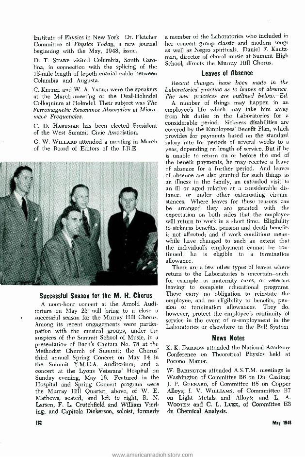
Institute of Physics in New York. Dr. Fletcher Committee of Physics Today, a new journal beginning with the May, 1948, issue.
D. T. SHARP visited Columbia, South Caro- lina, in connection with the splicing of the 75 -mile length of lepeth coaxial cable between Columbia and Augusta.
C. KrrFEL and W. A. YACER were the speakers at the March .meeting of the Deal- Hohndel Colloquium at Holmdel. Their subject was The Ferromagnetic Resonance Absorption at Micro- wave Frequencies.
C. D. HARTMAN has been elected President of the West Summit Civic Association.
G. W. Wn.LARD attended a meeting in March of the Board of Editors of the I.R.E.
Successful Season for the M. H. Chorus A noon -hour concert at the Arnold Audi-
torium on May 25 will bring to a close a successful season for the Murray Hill Chorus. Among its recent engagements were partici- pation with the musical groups, under the auspices of the Summit School of Music, in a presentation of Bach's Cantata No. 78 at the Methodist Church of Summit; the Chorus' third annual Spring Concert on May 14 in the Summit Y.M.C.A. Auditorium; and a concert at the Lyons Veterans' Hospital on Sunday evening, May 16. Featured in the Hospital and Spring Concert program were the Murray Hill Quartet, above, of W. E. Mathews, seated, and left to right, R. N. Larsen, F. L. Crutchfield and William Vierl- ing; and Capitola Dickerson, soloist, formerly
232
a member of the Laboratories who included in
her concert group classic and modern songs as well as Negro spirituals. Daniel F. Kautz - man, director of choral music at Summit High School, directs the Murray Hill Chorus.
Leaves of Absence
Recent changes have been made in the Laboratories' practice as to leaves of absence. The new practices are outlined below. Ed.
A number of things may happen in an employee's life which may take him away from his duties in the Laboratories for a
considerable period. Sickness disabilities are covered by the Employees' Benefit Plan, which provides for payments based on the standard salary rate for periods of several weeks to a
year, depending on length of service. But if he is unable to return on or before the end of the benefit payments, he may receive a leave of absence for a further period. And leaves of absence are also granted for such things as an illness in the family, an extended visit to an ill or aged relative at a considerable dis- tance, or under other extenuating circum- stances. Where leaves for these reasons can be arranged they are granted with the expectation on both sides that the employee will return to work in a short time. Eligibility to sickness benefits, pension and death benefits is not affected; and if work conditions mean- while have changed to such an extent that the individual's employment cannot be con- tinued, he is eligible to a termination allowance.
There are a few other types of leaves where return to the Laboratories is uncertain -such, for example, as maternity cases, or veterans leaving to complete educational programs. These carry no obligation to reinstate the employee, and no eligibility to benefits, pen- sion or termination allowances. They do, however, protect the employee's continuity of service in the event of re- employment in the Laboratories or elsewhere in the Bell System.
News Notes
K. K. DARROW attended the National Academy Conference on Theoretical Physics held at Pocono Manor.
W. BAEINGTON attended A.S.T.M. meetings in Washington of Committee B6 on Die Casting: J. P. GUERARD, of Committee B5 on Copper Alloys; I. V. WILLIAMS, of Commmittee B7 on Light Metals and Alloys; and L. A. WOOTEN and C. L. Lvxn, of Committee E3 on Chemical Analysis,
May 1146
www.americanradiohistory.com
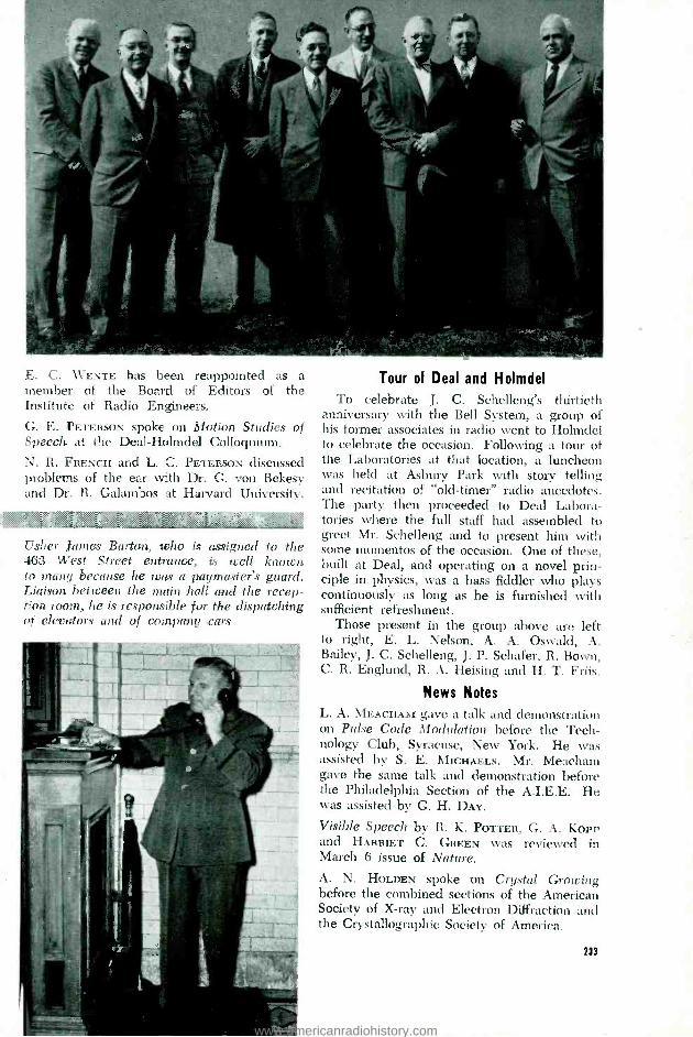
s3;
E. C. WENTE has been reappointed as a member of the Board of Editors of the Institute of Radio Engineers.
G. E. PETERSON spoke on Motion Studies of Speech at the Deal- Holmdel Colloquium.
N. R. FRENCH and L. C. PETERSON discussed problems of the ear with Dr. G. von Bekesy and Dr. R. Galambos at Harvard University.
Usher James Barton, who is assigned to the 463 West Street entrance, is well known to many because he was a paymaster's guard. Liaison between the main hall and the recep- tion room, he is responsible for the dispatching of elevators and of company ears
Tour of Deal and Holmdel To celebrate J. C. Schelleng's thirtieth
anniversary with the Bell System, a group of his former associates in radio went to Holmdel to celebrate the occasion. Following a tour of the Laboratories at that location, a luncheon was held at Asbury Park with story telling and recitation of `old- timer" radio anecdotes. The party then proceeded to Deal Labora- tories where the full staff had assembled to greet Mr. Schelleng and to present him with some momentos of the occasion. One of these, built at Deal, and operating on a novel prin- ciple in physics, was a bass fiddler who plays continuously as long as he is furnished with sufficient refreshment.
Those present in the group above are left to right, E. L. Nelson, A. A. Oswald, A. Bailey, J. C. Schelleng, J. P. Schafer, R. Bown, C. R. Englund. R. A. Heising and H. T. Friis.
News Notes
L. A. MEACHAM gave a talk and demonstration on Pulse Code Modulation before the Tech- nology Club, Syracuse, New York. He was assisted by S. E. MICHAELS. Mr. Meacham gave the same talk and demonstration before the Philadelphia Section of the A.I.E.E. He was assisted by G. H. DAY.
Visible Speech by R. K. POTTER, G. A. KoPr and HARRIET C. GREEN was reviewed in March 6 issue of Nature. A. N. HOLDEN spoke on Crystal Growing before the combined sections of the American Society of X -ray and Electron Diffraction and the Crystallographic Society of America.
213
www.americanradiohistory.com

RETIREMENTS
Members of the Laboratories who retired on April 30 were E. V. Griggs, with 30 years of service, and W. E. Viol, with 39 years.
ELMER V. GRIGGS WALTER E. VIOL
Mr. Griggs began his patent career in the United States Patent Office where he served for several years as an Examiner. He left the Patent Office to join the Patent Department of the Westinghouse Electric and Manufactur- ing Company in Pittsburgh and from there he came to the Patent Department of Western.
That was just prior to the inauguration of carrier transmission and at the beginning of an era of great expansion and development in radio transmission; and Mr. Griggs played a leading part in the handling of patent matters in these two fields. Later he became Division Attorney responsible for general transmission patent problems including those relating both to carrier and radio transmission systems and apparatus. In 1937 Mr. Griggs became As- sistant General Patent Attorney and in addi- tion to his duties as such, he has more recently been supervising patent work on television, telephotography and automatic regulation.
Mr. Griggs received a B.S. degree from Iowa State College in 1908, a B.M.E. degree from the same institution a year later, and an LL.B. degree from George Washington Uni- versity Law School in 1915. He is a member of the Bar of the State of New York and of the Bar of the District of Columbia and has been admitted to practice in the Court of Customs and Patent Appeals, in several of the District and Circuit Federal Courts and in the United States Supreme Court.
WALTER E. VIOL Immediately upon receiving his B.S. in E.E.
degree from Purdue University in 1908, Mr. Viol joined the Western Electric Company at Hawthorne. The following year he was lent
234
to the General Electric Company, to which the manufacture of power appartus was trans- ferred, and for a year he was at their Lynn, Massachusetts, plant concerning himself with telephone power machines, charging genera- tors and ringing machines. On his return to Hawthorne he joined the Telephone Engineer- ing Department. He came to West Street in 1919 for step -by -step engineering and par- ticipated in the development of the first dial central offices of this type.
In 1922, Mr. Viol transferred to local systems circuit development work, becoming head of the testing group in the local circuit laboratories, and a year later he took charge of the groups devoted to relay design, instal- lation, and maintenance requirements of
J. A. St. Clair, above presents "growler" al check to E. Von Nostitz for having the low grc score in the annual bowling tournament of t Quality Assurance Department. Left to right, IV
Von Nostitz, W. F. Vieth. J. J. Burke, B. R. Ey and Mr. St. Clair
operation. In 1927 he again assumed charge of the local systems circuit laboratories and later took over the sender switching labora- tories. From 1941 to 1947 he supervised the panel and crossbar laboratories and since then has been in charge of laboratories facilities for Switching Development.
May 11u1e
www.americanradiohistory.com

W. SHOCKLEY and F. S. COUCHER attended a special session on Fundamentals of Solid State Theory and Experiment, and their Rela- tion to Photoconductivity at Massachusetts Institute of Technology preceding the Physical Electronics Conference. Dr. Coucher pre- sented a paper at the Conference entitled Photoelectric Effects in PN Rectifying Barriers of Silicon and Germanium; G. E. MooRE and H. WALLISON, Reduction of Alkaline Earth Oxides by Tungsten in Vacuum; J. P. MOLNAR and J. A. HORNBECK, Secondary Electron Emission in the Townsend Discharge; C. HERRING, Theory of the Temperature Varia- tion of the Work Functions of Metals; and R. R. NEWTON, Ejection of Electrons by Positive Ions at High Fields.
H. W. HERMANCE and T. F. EGAN made observations in several Philadelphia central offices as part of a general study of switch - room dusts and their effects on equipment.
I. L. HOPKINS' visit to the National Bureau of Standards concerned physical and mechanical properties of rubbers and plastics.
GEORGE LINEHAN, Who Won the Australian doubles championship, and J. V. ELLIOTT, present table tennis player champion of the Laboratories, gave an exhibition of their skill at the Men's Club Monthly meeting of the Bayside Community Church. B. F. LEWIS was in charge of the meeting.
Mothering Foundlings
Foundling babies receive a mother's care through an association of young women called Volunteer Aids who assist nurses at the New York Foundling Home in bathing, dressing, feeding, loving and airing the little ones at that Home. In all, twenty Laboratories' girls are engaged in the work, and one of them, Catherine Lennon of Systems Development shown on the right in the photograph, is a
Genevieve Weiden of the Laboratories (left) , Florence McIntyre and Catherine Lennon (right), also of the Laboratories, in the Foundling Home
supervisor. Most of the girls volunteer after working hours to bathe and dress toddlers. love them and tuck them into bed at night. On Saturdays or Sundays, some of the girls may be seen with their charges in Central Park, giving them a chance to play rough and tumble with other children. Later they teach children to feed and dress themselves.
Young women volunteers must pass a physical examination to assure that they have no communicable diseases and buy their own uniforms and white shoes which they leave in their nursery lockers. They are brought up to date in the latest methods of child care with emphasis on love and security by lectures of a well -known child psychologist whose talks are supplemented by nurses and super- visors as they instruct volunteers in their duties and by a monthly bulletin published by the Foundling Home.
W`a to v: \*3.ca ar
,.,<.k
May Service Anniversaries of Members of the Laboratories 45 years H. R. Jeffcoatt Janet Dein E. Van Horn W. A. Landy
Joseph Irish J. S. McDonough James G. Ferguson A. H. Yeager J. J. Lempa 35 years A. C. Millard John Fierst 20 years Ruth Leonard
R. B. Shanck H. L. Mueller A. I. Heitzman C. W. Anderson J. F. Smyth 30 years C. E. Swenson John Kelly M. A. Collins C. J. Yunger
H. H. Bogart N. J. Velardi Mignonette Krieger Joseph Doherty 15 years H. P. Franz F. A. Zupa Estelle Lee Gladyce Farber R. W. Widman C. J. Gallon 25 years E. R. Morton S. G. Hale 10 years Harry Gessner T. V. Borlund Gladys Paret E. Hollopeter J. P. Craven J. P. Greene C. R. Breaty Thomas Smith E. W. Holman F. W. Ryan
..'.... May 1118 285
www.americanradiohistory.com

.<...,.....
"The Telephone Hour" NBC, Monday Nights, 9:00 p.m.
May 17 Seymour Lipkin, winner of the Raclin aninoff Fund Contest
May 24 Bidu Sayao May 31 Blanche Thebom June 7 Gladys Swarthout June 14 William Kapell
s *;.:<.:::`>>: .:.:;a .,.........
R. K. HONAMAN addressed the Cincinnati Engineering Society in Cincinnati on Frontiers of Telephone Development.
w. O. BAKER selected Elements of the Struc- ture of Chain Polymers as his subject when he spoke before a Colloquium at Princeton.
D. A. MCLEAN and H. A. SAUER, with D. J. Manning of Western Electric, discussed con- denser paper problems at the Schweitzer Paper Company, Mt. Holly Springs, Pa. Mr. McLean and Mr. Manning also visited the Crocker, Burbank Company in Fitchburg, Mass., in the sane connection.
U. B. THOMAS and M. SPARKS participated in a Signal Corps conference on battery develop- ments at Red Bank.
W. E. JANSSEN discussed the pressing of ceramic materials at the Denison Engineering Company, Columbus, Ohio.
THE COLOR MOVING PICTURE of the fenestra- tion or "window" operation for the alleviation of middle -ear deafness was shown by M. B. GARDNER in the Arnold Auditorium to a group of engineers engaged in research and hearing aid work. Obtained through the courtesy of the Lempert Institute of Otology in New York, the movie showed the operation from the first incision to the post- operative view of the ear after healing had taken place. It was repeated at 195 Broadway for a group of Western engineers.
W. A. MARRISON has been elected a Fellow of the British Horological Institute.
J. W. MCRAE discussed Microwaves and Pulse Code Modulated Transmission with general application to military communication before the Armed Forces Communication Association.
A NUMBER OF BELL LABORATORIES people participated in the A.I.E.E. Conference on Electron Tubes for Instrumentation and Indus- trial Use, which was held at Philadelphia on
236
March 29 and 30. E. I. GREEN, as Chairman of the A.I.E.E. Committee on Instruments and Measurements, presided at one of the sessions. J. R. WILSON spoke on electron tube develop- ment. W. H. TIDD was Chairman of the Publicity Committee and took part in the discussion of tube types.
W. A. TYRRELL spoke at Yale University on the subject Resonant Cavity Measurement of Afirmware Losses.
Stenotypist Helen Travaglia is one of five member! of the Laboratories whose picture appeared in Office Management and Equipment to illustrate an article on Laboratories telephone dictation facilities. Mis! Travaglia's picture also appeared in La Salle Uni- versity's school publication in connection with . reprint of the story
F. J. GIVEN has recently been appointed Chairman of the Panel on Components of the Research and Development Board.
D. R. BROBST and R. O. GBISDALE conferred with Western Electric engineers at the Tona- wanda Plant on switchboard wire and cable and enamel wire.
C. A. WEBBER and W. J. KING conferred on high- voltage cables and connectors with Air Materiel Command engineers at Wright Field.
HENRY KOSTKOS spoke on and demonstrated microwave phenomena at a meeting of 350 members of the Stanley S. Holmes Chapter of the Telephone Pioneers of America at Kearny. He accompanied his talk with a demonstration and was assisted by J. W. Por.Llo.
May 1946
www.americanradiohistory.com

A. J. CHRIsToeHER attended a R.M.A. meeting on Standards Proposal for capacitors held in the Hotel New Yorker. Mr. Christopher also attended a Committee meeting of the De- velopment and Research Board Panel on capacitors held at the Solar Manufacturing Company in North Bergen, N. J.
D. E. CAVENAUGH, T. G. BLANCHARD and A. B. HAINES visited Sperry Gyroscope Com- pany in connection with the construction of model transformers. Mr. Blanchard and Mr. Haines attended conferences at the Magnetic Windings Company, Easton, Pa., on trans- formers for airborne equipments.
R. H. COLLEY made observations on the rate of heating in southern pine poles during con- trolled steaming and vacuum experiments at Spartanburg, S. C.
G. Q. LUyISDEN, A. H. HEARN and J. LEU- TRrrz, JR., inspected treated -wood specimens in the Gulfport, Miss., test plot. Mr. Hearn continued inspection of creosoted southern pine poles in line in the territory of the Southern Bell Telephone Company.
C. H. AMADON inspected cedar poles in line in Arizona and carried out experimental ground line treatment, external and internal, for control of termites and decay.
"She's been like that for a telephone pole»
May 1948
A. P. JAHN and J. M. HARDESTY attended the Spring Meeting of the American Society for Testing Materials at Washington. Mr. Jahn also conferred with engineers of the Davison Chemical Company and the American Instru- ment Company at Baltimore and Silver Springs, Md., respectively.
J. G. BREARLEY and H. D. BREINER were engaged in testing lightning protected cable in South Carolina.
R. I. Wilkinson observing the Prow N of starting a call in the machine on which the load carrying capacity of No. 5 exchanges is being explored. With him are left, Catherine Duman, who handles the marker position, and Mary Tracy, who originates the calls and deter- mines which subscriber lines are idle or busy
C. T. VVYMAN and E. V. Koss() were in Point Breeze discussing general cable problems.
C. C. LAW SON observed installations of jacketed station wires at Birmingham.
D. C. SMITH attended a meeting of A.S.T.M. Committee D7 in Chicago. He also discussed the problem of squirrel damage to cable at the University of Massachusetts at Amherst.
W. W. WERRINC conducted a committee meet- ing of the A.S.T.M. on Impact Testing. W. J. KINDERMAN visited Winston -Salem to discuss special winding machine problems. F. A. ZUPA examined U and Y type relays in broadcast program circuits at a telephone office in Washington.
237
www.americanradiohistory.com

W. T. Boom WILLIAM WISSEI,
1879 -1948 1887 -1948
WILLIAM T. BOOTH, April .11
Mr. Booth's retirement five years ago under the Retirement Age Rule brought to a close his thirty-six years of Bell System Service which began in 1899 when he joined the Western Electric Company. He gained con- siderable telephone service there, then left to do work in various small telephone manu- facturing concerns and later studied at Cooper Union where he received his bachelor of science degree. Returning to Western in 1905, he was assigned to the staff of the European Chief Engineer and sent to Europe where he remained for nine years. In 1914 he was placed in charge of one of the apparatus design groups and later, during World War I, became the engineering representative to the Signal Corps and Navy working on airplane radio and field signaling sets. After the war ended he assumed charge of the dial apparatus group and in 1925 was assigned to cost savings work and special investigations. This assign- ment led to his becoming Repaired Apparatus Engineer, responsible for the preparation of recovery and repair requirements on appa- ratus and of maintenance practices dealing with station and teletypewriter apparatus. In the course of this assignment he assumed responsibility also for the development of electrolytic capacitors, varistors and thermis- tors, and for the work associated with the Underwriters' Laboratories.
WILLIAM WISSEL, March 25 Mr. Wissel was a Staff Assistant in the Plant
Department. His Bell System service began in 1901 when he was a member of the Western Electric Company for a year. Upon leaving he was employed five years by another concern and then became a member of the New York City Fire Department where he spent twenty
238
years first as a fireman and later a fire inspector. When he was retired from the Fire Depart- ment in 1927, Mr. Wissel returned to the Laboratories as a building inspector assigned to fire protection and inspection duties. In over twenty years of fire prevention work he became known to almost everyone in the Laboratories.
News Notes
O. M. HovGAARn, S. j. ELLIOTT, F. P. BALACEK and N. J. VELARDI were at Allentown to attend a production conference and investi- gate 218 -A switch production.
W. C. TINUS, W. H. C. HIGGINS, H. G. OCH and R. R. HOUGH participated in conferences at the Sperry Gyroscope Company at Lake Success. Mr. Higgins, W. L. SHAFFER and J. T. MULLER visited the Western Electric Electronic Shop at Allentown.
J. F. WENTZ has been appointed chairman of Pack 51 Boy Scouts of America Cubs for 1948 -49 in Basking Ridge, N. J. He attended a two -day course in Cubbing over the March 5 weekend at Camp Stewart, Newburgh, N. Y.
A. E. CuRRIE observed tests of military equip- ment at the General Electric Plant, Pittsfield.
H. T. BUDENBOM attended a meeting of the Radio Manufacturers Association in New York.
C. R. TAFT consulted with engineers of General Mills at Minneapolis on submarine equipment.
J. H. HERSHEY'S trip to the Naval Research Laboratory, Chesapeake Bay, concerned the testing of special control apparatus.
N. W. BRYANT, at Burlington, conferred on a special development for the Navy.
AT WINSTON -SALEM, W. H. DOHERTY, J. W. SMITH, F. E. NIMMCIcR and B. H. NORDSTROM participated in a conference on designs of equipment; R. F. ARMErr, on production prob- lems; R. F. DEMorrv, on testing procedures; M. N. YARBOROUGH, on antenna equipment; and J. B. D'ALBORA, on automatic frequency control units.
A. H. LINCE and T. J. GRIESER examined the first completed model of a new delay lens antenna for the New York -Chicago radio relay system at the plant of the Tennessee Aircraft Company at Nashville.
W. W. BROWN visited Hawthorne in con- nection with new developments on operator chairs. He also discussed a trial installation
May 1141
www.americanradiohistory.com
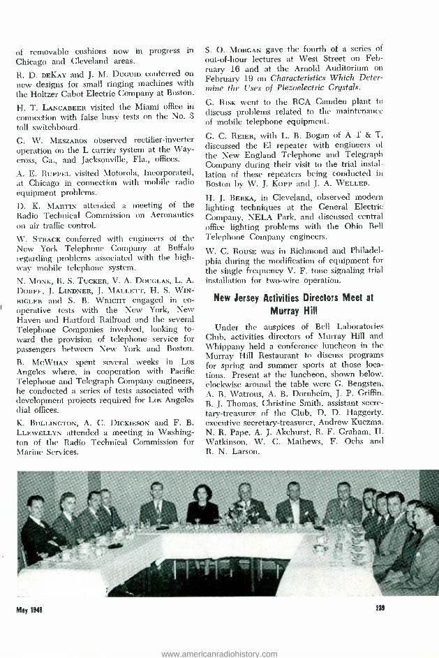
of removable cushions now in progress in Chicago and Cleveland areas.
R. D. DEKAY and J. M. DUGUID conferred on new designs for small ringing machines with the Holtzer Cabot Electric Company at Boston.
H. T. LANGABEER visited the Miami office m connection with false busy tests on the No. 3
toll switchboard.
G. W. MESZAROS observed rectifier -inverter operation on the L carrier system at the Way- cross, Ga., and Jacksonville, Fla., offices.
A. E. RUPPEL visited Motorola, Incorporated, at Chicago in connection with mobile radio equipment problems.
D. K. MARTIN attended a meeting of the Radio Technical Commission on Aeronautics on air traffic control.
W. STRACK conferred with engineers of the New York Telephone Company at Buffalo regarding problems associated with the high- way mobile telephone system.
N. MONK, R. S. TUCKER, V. A. DOUGLAS, L. A.
DORFF, J. LINDNER, J. MALLETT, H. S. WIN - BIGLER and S. B. WRIGHT engaged in co- operative tests with the New York, New Haven and Hartford Railroad and the several Telephone Companies involved, looking to- ward the provision of telephone service for passengers between New York and Boston.
B. MCWHAN spent several weeks in Los Angeles where, in cooperation with Pacific Telephone and Telegraph Company engineers, he conducted a series of tests associated with development projects required for Los Angeles dial offices.
K. BULLINGTON, A. C. DICKIESON and F. B. LLEWELLYN attended a meeting in Washing- ton of the Radio Technical Commission for Marine Services.
S. O. MORGAN gave the fourth of a series of
out -of -hour lectures at West Street on Feb- ruary 16 and at the Arnold Auditorium on February 19 on Characteristics Which Deter- mine the Uses of Piezoelectric Crystals.
G. RISK went to the RCA Camden plant to
discuss problems related to the maintenance of mobile telephone equipment.
G. C. REIER, with L. B. Bogan of A T & T, discussed the El repeater with engineers of
the New England Telephone and Telegraph Company during their visit to the trial instal- lation of these repeaters being conducted in Boston by W. J. KoPP and J. A. WELLER.
H. J. BERKA, in Cleveland, observed modern lighting techniques at the General Electric Company, NELA Park, and discussed central office lighting problems with the Ohio Bell Telephone Company engineers.
W. C. ROUSE was in Richmond and Philadel- phia during the modification of equipment for the single frequency V. F. tone signaling trial installation for two -wire operation.
New Jersey Activities Directors Meet at
Murray Hill
Under the auspices of Bell Laboratories Club, activities directors of Murray Hill and Whippany held a conference luncheon in the Murray Hill Restaurant to discuss programs for spring and summer sports at those loca- tions. Present at the luncheon, shown below, clockwise around the table were G. Bengsten, A. B. Watrous, A. B. Dornheim, J. P. Griffin, B. J. Thomas, Christine Smith, assistant secre- tary- treasurer of the Club, D. D. Haggerty. executive secretary- treasurer, Andrew Kuczma, N. R. Pape, A. J. Akehurst, R. F. Graham, H. Watkinson, W. C. Mathews, F. Ochs and R. N. Larson.
May 1948 239
www.americanradiohistory.com

Engagements
Dorothy Burgess" -Stanley G. Wood Dorothy Bouldin- Roland Vaughan Mary Conti -Carmine V. Sabio Louise Costella° -Remo Del \ laestro Anna Marie Eilbacher -Carl W. Fink Elizabeth FrankIin°- George Daniel Ethel Freeman ° -John Overs Mildred Hoogstratt ° -\V. Thornton Read* Eleanor Hoppe° -Johu W. Po11io° June Ilongltaliug'- Robert L. Hill Dorothy \Ieissner'- Charles W. Unser Frances \Iurray- Lawrence J. Ryan Keitha Randal-James R. Davey Margaret Wallsehleger- Edward B. Pistroski° Kathleen Zier° -Byron Il. Downeiì
Weddings Irene haring' -Frank J. Buckley Gloria Iannone- Joseph A. Caldiero Jean Kackeumester`- William G. Belden Jennie Nuzzo' -Andrew J. Pinto Yvonne Ousset °- \Villiam J. Pair Emily Seifert*-Peter Karpowicz, Jr.
°Members of the Laboratories. Notices of engagements and weddings should be given to Mrs. Helen McLoughlin, Room 803C, 14th St., Extension 296.
1°' . Blue Print for Health
Timely health articles and subjects of general interest are published quarterly in a digest size magazine Blue Print for Health available free to members of the Laboratories who subscribe to the Blue Cross Plan of the American Hospital Association. Editorial con- tent of a recent digest contains original articles and condensation of articles on such subjects as "Why Can't You Sleep ? "; "How Good Are Your Hospital Manners ? "; "Behind Your Smile "; and "Rabies, A Year Round Menace." If you are interested in receiving Blue Print for Health, regularly, please fill in the accom- panying form and mail it to Miss Ruth Robinson, Employee Service Department, Building T -245, West Street.
, >.,.:.
:
APPLICATION FOR BLUE PRINT FOR HEALTH
Name
Home Address: Street
Town or City
State
241
News Notes
S. C. DEL VECCHIO spent a few days in Rich- mond in connection with the trial installation of tuned reed signaling equipment for urban mobile radio systems.
M. M. BOWER and C. F. BOECK are testing coaxial cables with new types of polyethylene - lead sheaths near Columbia, S. C.
B DISART and L. C. ROBERTS, at Cleveland and Buffalo, investigated the operation of voice frequency telegraph circuits over coaxial facilities.
J. A. MORTON delivered the fifth and con- cluding lecture A New Microwave Triode in a series designed to acquaint employees with certain areas of Laboratories work. Mr. Morton spoke on March 15 at West Street and on March 17 in the Arnold Auditorium.
R. S. CARUTHERS, W. H. BENDERNAGEL, J. W. DEIST, J. W. EMLING and L. PEDERSEN Con- ferred with Wisconsin Telephone Company engineers on a contemplated trial installation of the N1 carrier telephone system.
F. E. ENGELKE and J. M. ROGIE were at Point Breeze on hearing -aid cord problems.
T. H. CRABTREE visited Burlington in con- nection with hearing aids. He also went ±o
Newton, Mass., for conferences about sub- miniature vacuum tubes with the Raytheon Manufacturing Company.
L. VIETH, H. F. HomaNs and H. W. HOLMLIN discussed loud speaker problems and W. C. JONES and Mr. Vieth those of microphones during visits at Burlington.
J. R. POWER visited Northwestern University, University of Iowa, and St. Louis Institute for the Deaf on various matters affecting the hard of hearing.
THE LABORATORIES were represented in inter- ference proceedings at the Patent Office by N. S. EWINC, R. T. HoLCOMR and E. C. LAUGHLIN before the Primary Examiner.
E. W. ADAMS, JR., was at the Patent Office in Washington during the month of March relative to patent matters.
E. B. CAVE appeared before the Board of Appeals at the Patent Office relative to an application for patent.
W. C. KIRKMAN has been elected for a three - year term to the Board of Education of Rochelle Park, N. J.
May 1948
www.americanradiohistory.com