Embed Size (px)
Citation preview

Technical ManualWD 290
Item Number: 10274-109
Version: 001-08/08
Index of contents
Index of contents
1 Introduction . . . . . . . . . . . . . . . . . . . . . . . . . . . . . . . . . . . . . . . . . . . 8
1.1 Before you read on . . . . . . . . . . . . . . . . . . . . . . . . . . . . . . . . . . . . . . 8
1.2 Target group . . . . . . . . . . . . . . . . . . . . . . . . . . . . . . . . . . . . . . . . . . . 8
1.3 Changes . . . . . . . . . . . . . . . . . . . . . . . . . . . . . . . . . . . . . . . . . . . . . . 8
1.4 Symbols and references used . . . . . . . . . . . . . . . . . . . . . . . . . . . . . 8
2 For your safety . . . . . . . . . . . . . . . . . . . . . . . . . . . . . . . . . . . . . . . . 9
2.1 Intended use . . . . . . . . . . . . . . . . . . . . . . . . . . . . . . . . . . . . . . . . . . . 9
2.2 Care responsibilities for dealing with the device . . . . . . . . . . . . . . . . 9
2.3 Instruction of personnel. . . . . . . . . . . . . . . . . . . . . . . . . . . . . . . . . . . 9
2.4 Fields of application for the device . . . . . . . . . . . . . . . . . . . . . . . . . 10
2.5 Process validation. . . . . . . . . . . . . . . . . . . . . . . . . . . . . . . . . . . . . . 10
3 Device specifications . . . . . . . . . . . . . . . . . . . . . . . . . . . . . . . . . . 11
3.1 Device dimensions . . . . . . . . . . . . . . . . . . . . . . . . . . . . . . . . . . . . . 11
3.2 Device dimensions with condenser (optional). . . . . . . . . . . . . . . . . 12
3.3 Optional additional components . . . . . . . . . . . . . . . . . . . . . . . . . . . 13
3.3.1 Additional panneling . . . . . . . . . . . . . . . . . . . . . . . . . . . . . . . . . . . . 13
3.3.2 Switchable heating . . . . . . . . . . . . . . . . . . . . . . . . . . . . . . . . . . . . . 13
3.3.3 Condenser with heat retrieval . . . . . . . . . . . . . . . . . . . . . . . . . . . . . 13
3.3.4 Dosing pump set with "empty" indicators and flow meter . . . . . . . . 13
3.3.5 Miscellaneous . . . . . . . . . . . . . . . . . . . . . . . . . . . . . . . . . . . . . . . . . 14
3.3.6 Independent content documentation system (IPD). . . . . . . . . . . . . 14
3.4 Technical data. . . . . . . . . . . . . . . . . . . . . . . . . . . . . . . . . . . . . . . . . 15
3.5 Setup conditions . . . . . . . . . . . . . . . . . . . . . . . . . . . . . . . . . . . . . . . 16
3.5.1 Surrounding conditions . . . . . . . . . . . . . . . . . . . . . . . . . . . . . . . . . . 16
3.5.2 Building conditions . . . . . . . . . . . . . . . . . . . . . . . . . . . . . . . . . . . . . 16
3.6 Connection modules . . . . . . . . . . . . . . . . . . . . . . . . . . . . . . . . . . . . 17
3.6.1 Electric (possible versions) . . . . . . . . . . . . . . . . . . . . . . . . . . . . . . . 17
3.6.2 Water connections . . . . . . . . . . . . . . . . . . . . . . . . . . . . . . . . . . . . . 18
3.6.3 Steam . . . . . . . . . . . . . . . . . . . . . . . . . . . . . . . . . . . . . . . . . . . . . . . 19
3.6.4 Exhaust air . . . . . . . . . . . . . . . . . . . . . . . . . . . . . . . . . . . . . . . . . . . 19
3.6.5 Connection requirements for installation. . . . . . . . . . . . . . . . . . . . . 20
3.6.6 Connection diagrams . . . . . . . . . . . . . . . . . . . . . . . . . . . . . . . . . . . 21
3.6.7 Electrical function diagram . . . . . . . . . . . . . . . . . . . . . . . . . . . . . . . 22
3.6.8 Electrical function diagram with steam drying. . . . . . . . . . . . . . . . . 23
4 Consumption data . . . . . . . . . . . . . . . . . . . . . . . . . . . . . . . . . . . . 24
4.1 Water consumption for tiered tracks . . . . . . . . . . . . . . . . . . . . . . . . 24
4.2 Water consumption for anaesthesia rack . . . . . . . . . . . . . . . . . . . . 24
5 Device description . . . . . . . . . . . . . . . . . . . . . . . . . . . . . . . . . . . . 25
5.1 Device loading side (LS) . . . . . . . . . . . . . . . . . . . . . . . . . . . . . . . . . 25
5.2 Device unloading side (US) . . . . . . . . . . . . . . . . . . . . . . . . . . . . . . 26
5.3 Electro drawer with PCBs . . . . . . . . . . . . . . . . . . . . . . . . . . . . . . . . 27
5.4 Operating unit loading side (LS) . . . . . . . . . . . . . . . . . . . . . . . . . . . 28
5.5 Operating unit unloading side (US). . . . . . . . . . . . . . . . . . . . . . . . . 28
6 Service modules, software configuration. . . . . . . . . . . . . . . . . . 29
2/136 001 Technical Manual WD290
10274 © Belimed
Index of contents
6.1 Access rights. . . . . . . . . . . . . . . . . . . . . . . . . . . . . . . . . . . . . . . . . . 29
6.2 Accessing the Service Module . . . . . . . . . . . . . . . . . . . . . . . . . . . . 29
6.3 Operation within the input modules. . . . . . . . . . . . . . . . . . . . . . . . . 30
6.4 Simultaneous opening of both doors for servicing operations . . . . 30
6.5 Service modules overview . . . . . . . . . . . . . . . . . . . . . . . . . . . . . . . 31
6.6 Analysis module . . . . . . . . . . . . . . . . . . . . . . . . . . . . . . . . . . . . . . . 32
6.6.1 Starting the Analysis Module . . . . . . . . . . . . . . . . . . . . . . . . . . . . . 32
6.6.2 Software index . . . . . . . . . . . . . . . . . . . . . . . . . . . . . . . . . . . . . . . . 32
6.6.3 Current values of temperature sensors 1-4 . . . . . . . . . . . . . . . . . . 32
6.6.4 Current values of Temperature Sensors 5+6 . . . . . . . . . . . . . . . . . 32
6.6.5 Current values of level sensors. . . . . . . . . . . . . . . . . . . . . . . . . . . . 33
6.6.6 Current values of flow meter . . . . . . . . . . . . . . . . . . . . . . . . . . . . . . 33
6.6.7 Input switching statuses S101-S106. . . . . . . . . . . . . . . . . . . . . . . . 33
6.6.8 Input switching statuses S107-S112. . . . . . . . . . . . . . . . . . . . . . . . 33
6.6.9 Input switching status S113 . . . . . . . . . . . . . . . . . . . . . . . . . . . . . . 33
6.6.10 Input switching statuses S201-206 . . . . . . . . . . . . . . . . . . . . . . . . . 34
6.6.11 Input switching statuses S207-212 . . . . . . . . . . . . . . . . . . . . . . . . . 34
6.6.12 Input switching status S213 . . . . . . . . . . . . . . . . . . . . . . . . . . . . . . 34
6.6.13 Input switching statuses Interface PCB S301-S306 . . . . . . . . . . . . 34
6.6.14 Input switching statuses Interface PCB S307-S312 . . . . . . . . . . . . 34
6.6.15 Input switching statuses Interface PCB S313 . . . . . . . . . . . . . . . . . 34
6.6.16 Input switching statuses SA to SF . . . . . . . . . . . . . . . . . . . . . . . . . 35
6.6.17 Door position. . . . . . . . . . . . . . . . . . . . . . . . . . . . . . . . . . . . . . . . . . 35
6.6.18 Last ten errors. . . . . . . . . . . . . . . . . . . . . . . . . . . . . . . . . . . . . . . . . 35
6.6.19 Batch number for programs 1-12 . . . . . . . . . . . . . . . . . . . . . . . . . . 35
6.6.20 Hours of operation of air filter . . . . . . . . . . . . . . . . . . . . . . . . . . . . . 35
6.6.21 Skipping steps. . . . . . . . . . . . . . . . . . . . . . . . . . . . . . . . . . . . . . . . . 36
6.7 Dosing module . . . . . . . . . . . . . . . . . . . . . . . . . . . . . . . . . . . . . . . . 36
6.7.1 Starting the Dosing Module. . . . . . . . . . . . . . . . . . . . . . . . . . . . . . . 36
6.7.2 Display / Modify. . . . . . . . . . . . . . . . . . . . . . . . . . . . . . . . . . . . . . . . 36
6.7.3 Program number and name . . . . . . . . . . . . . . . . . . . . . . . . . . . . . . 36
6.7.4 Program steps. . . . . . . . . . . . . . . . . . . . . . . . . . . . . . . . . . . . . . . . . 37
6.7.5 Calibrating Dosing Pumps 1-4 . . . . . . . . . . . . . . . . . . . . . . . . . . . . 37
6.7.6 Calibrating Flow Meters 1-4 . . . . . . . . . . . . . . . . . . . . . . . . . . . . . . 37
6.7.7 Flow meter - current values . . . . . . . . . . . . . . . . . . . . . . . . . . . . . . 37
6.7.8 MIX-Dosing . . . . . . . . . . . . . . . . . . . . . . . . . . . . . . . . . . . . . . . . . . . 38
6.7.9 Calibrating the dosing pumps (Time) . . . . . . . . . . . . . . . . . . . . . . . 39
6.7.10 Calibrating the flow meters (impulses) . . . . . . . . . . . . . . . . . . . . . . 40
6.8 Control Module . . . . . . . . . . . . . . . . . . . . . . . . . . . . . . . . . . . . . . . . 41
6.8.1 Starting the Control Module . . . . . . . . . . . . . . . . . . . . . . . . . . . . . . 41
6.8.2 Direct selection of Actuators K11-K16 . . . . . . . . . . . . . . . . . . . . . . 41
6.8.3 Direct activation Linear Drive (M41) LS . . . . . . . . . . . . . . . . . . . . . 41
6.8.4 Direct activation Linear Drive (M42) US . . . . . . . . . . . . . . . . . . . . . 41
6.9 Parameter Module . . . . . . . . . . . . . . . . . . . . . . . . . . . . . . . . . . . . . 42
6.9.1 Starting the Parameter Module . . . . . . . . . . . . . . . . . . . . . . . . . . . . 42
6.9.2 Selecting Programs P1-P6 (Shift P7-P12) . . . . . . . . . . . . . . . . . . . 42
6.9.3 Allocation of the program library . . . . . . . . . . . . . . . . . . . . . . . . . . . 42
6.9.4 Entering recipes . . . . . . . . . . . . . . . . . . . . . . . . . . . . . . . . . . . . . . . 43
6.9.5 Program library (program labels) . . . . . . . . . . . . . . . . . . . . . . . . . . 43
6.9.6 Parameter entry overview . . . . . . . . . . . . . . . . . . . . . . . . . . . . . . . . 44
Technical Manual WD290 001 3/136© Belimed 10274
Index of contents
6.9.7 Utility M1 Cold Water Step (CW) . . . . . . . . . . . . . . . . . . . . . . . . . . 45
6.9.8 Utility M2 Warm Water Step (WW) . . . . . . . . . . . . . . . . . . . . . . . . . 46
6.9.9 Utility M3 Mixed Water Step (CW+WW) . . . . . . . . . . . . . . . . . . . . . 46
6.9.10 Utility M4 DI Water Step . . . . . . . . . . . . . . . . . . . . . . . . . . . . . . . . . 47
6.9.11 Utility M5 Drying . . . . . . . . . . . . . . . . . . . . . . . . . . . . . . . . . . . . . . . 47
6.9.12 Condenser M6 functions . . . . . . . . . . . . . . . . . . . . . . . . . . . . . . . . . 47
6.9.13 Pre-heated DI water M9 (Final Rinse) . . . . . . . . . . . . . . . . . . . . . . 47
6.9.14 Utility MA (1 step with 4 or more phases) . . . . . . . . . . . . . . . . . . . . 48
6.9.15 Function F0 - inactive step . . . . . . . . . . . . . . . . . . . . . . . . . . . . . . . 48
6.9.16 Function F1 - Pre Rinsing . . . . . . . . . . . . . . . . . . . . . . . . . . . . . . . . 48
6.9.17 Functions F2-F5, F8, FD, FE . . . . . . . . . . . . . . . . . . . . . . . . . . . . . 49
6.9.18 Function F9 Clean Rinsing (optional IPD). . . . . . . . . . . . . . . . . . . . 49
6.9.19 Functions F6+F7 - thermal or chemical disinfection . . . . . . . . . . . . 49
6.9.20 Function FA - thermal disinfection A0=3000 . . . . . . . . . . . . . . . . . . 49
6.9.21 Function FB - thermal disinfection A0=600 . . . . . . . . . . . . . . . . . . . 50
6.9.22 Function FC - thermal disinfection A0=60. . . . . . . . . . . . . . . . . . . . 50
6.9.23 Functions FD, FE and FF . . . . . . . . . . . . . . . . . . . . . . . . . . . . . . . . 50
6.10 Configuration Module 1. . . . . . . . . . . . . . . . . . . . . . . . . . . . . . . . . . 51
6.10.1 Starting the Configuration Module . . . . . . . . . . . . . . . . . . . . . . . . . 51
6.10.2 Setting the self-disinfection timer . . . . . . . . . . . . . . . . . . . . . . . . . . 51
6.10.3 Maintenance (batch number) . . . . . . . . . . . . . . . . . . . . . . . . . . . . . 51
6.10.4 Ventilator operating hours (cumulative sum of drying time) . . . . . . 51
6.10.5 Language . . . . . . . . . . . . . . . . . . . . . . . . . . . . . . . . . . . . . . . . . . . . 51
6.10.6 Units . . . . . . . . . . . . . . . . . . . . . . . . . . . . . . . . . . . . . . . . . . . . . . . . 52
6.10.7 Date / time. . . . . . . . . . . . . . . . . . . . . . . . . . . . . . . . . . . . . . . . . . . . 52
6.10.8 Signal K28. . . . . . . . . . . . . . . . . . . . . . . . . . . . . . . . . . . . . . . . . . . . 52
6.10.9 Machine label . . . . . . . . . . . . . . . . . . . . . . . . . . . . . . . . . . . . . . . . . 52
6.10.10Entering door contact pressure. . . . . . . . . . . . . . . . . . . . . . . . . . . . 52
6.10.11Pre-heating temperature / holding time DI boiler . . . . . . . . . . . . . . 53
6.10.12Disinfection temperature / disinfection time DI boiler . . . . . . . . . . . 53
6.10.13Door configuration. . . . . . . . . . . . . . . . . . . . . . . . . . . . . . . . . . . . . . 53
6.10.14Pumping off in the event of programm interruption. . . . . . . . . . . . . 53
6.10.15Supressing drainage of washing liquid according to applicable
laws for protection against infectious diseases. . . . . . . . . . . . . . . . 54
6.10.16Automatic rack recognition . . . . . . . . . . . . . . . . . . . . . . . . . . . . . . . 55
6.10.17Message text in case of error . . . . . . . . . . . . . . . . . . . . . . . . . . . . . 56
6.10.18Printer drivers . . . . . . . . . . . . . . . . . . . . . . . . . . . . . . . . . . . . . . . . . 56
6.10.19Door opening at end of program . . . . . . . . . . . . . . . . . . . . . . . . . . . 56
6.10.20Door Interlock LS . . . . . . . . . . . . . . . . . . . . . . . . . . . . . . . . . . . . . . 56
6.10.21User identification . . . . . . . . . . . . . . . . . . . . . . . . . . . . . . . . . . . . . . 57
6.10.22Rack identification. . . . . . . . . . . . . . . . . . . . . . . . . . . . . . . . . . . . . . 57
6.10.23Content On / Off . . . . . . . . . . . . . . . . . . . . . . . . . . . . . . . . . . . . . . . 58
6.10.24Step Repetition (Foam control) . . . . . . . . . . . . . . . . . . . . . . . . . . . . 58
6.11 Configuration Module 2. . . . . . . . . . . . . . . . . . . . . . . . . . . . . . . . . . 59
6.11.1 Service programs . . . . . . . . . . . . . . . . . . . . . . . . . . . . . . . . . . . . . . 59
6.11.2 Circulation pump operating level. . . . . . . . . . . . . . . . . . . . . . . . . . . 59
6.11.3 Entering the empty level . . . . . . . . . . . . . . . . . . . . . . . . . . . . . . . . . 59
6.11.4 Pumping-off time. . . . . . . . . . . . . . . . . . . . . . . . . . . . . . . . . . . . . . . 60
6.11.5 Drain . . . . . . . . . . . . . . . . . . . . . . . . . . . . . . . . . . . . . . . . . . . . . . . . 60
6.11.6 Calibrating the temperature sensors. . . . . . . . . . . . . . . . . . . . . . . . 60
6.11.7 Temperature sensor allocation . . . . . . . . . . . . . . . . . . . . . . . . . . . . 60
6.11.8 LS door frame final position when doors are open . . . . . . . . . . . . . 61
4/136 001 Technical Manual WD290
10274 © Belimed
Index of contents
6.11.9 LS door frame final position when doors are closed . . . . . . . . . . . . 61
6.11.10US door frame final position when doors are open. . . . . . . . . . . . . 61
6.11.11US door frame final position when doors are closed . . . . . . . . . . . 62
6.11.12Drying lag time . . . . . . . . . . . . . . . . . . . . . . . . . . . . . . . . . . . . . . . . 62
6.11.13DI Boiler heater interlock with tank heater . . . . . . . . . . . . . . . . . . . 62
6.11.14Steam heated dryer . . . . . . . . . . . . . . . . . . . . . . . . . . . . . . . . . . . . 62
6.11.15Potential-free output K28, K57 and K58 . . . . . . . . . . . . . . . . . . . . . 63
6.11.16Rack position in automatic loading and unloading station . . . . . . . 63
6.11.17Delay interval for washing-liquid heating . . . . . . . . . . . . . . . . . . . . 64
6.11.18Waste water cooling . . . . . . . . . . . . . . . . . . . . . . . . . . . . . . . . . . . . 64
6.11.19Allocation of address for the ICS 85X5 archiving system . . . . . . . . 64
6.11.20Activating Error 188 . . . . . . . . . . . . . . . . . . . . . . . . . . . . . . . . . . . . 64
6.11.21Display activation . . . . . . . . . . . . . . . . . . . . . . . . . . . . . . . . . . . . . . 65
6.11.22Password for detergent manufacturers. . . . . . . . . . . . . . . . . . . . . . 65
6.11.23Password for clinical technicians . . . . . . . . . . . . . . . . . . . . . . . . . . 65
6.11.24Entering the machine number. . . . . . . . . . . . . . . . . . . . . . . . . . . . . 65
6.11.25Entering the manufacturing date. . . . . . . . . . . . . . . . . . . . . . . . . . . 65
6.11.26PCB replacement . . . . . . . . . . . . . . . . . . . . . . . . . . . . . . . . . . . . . . 65
6.11.27Batch counter adjustment . . . . . . . . . . . . . . . . . . . . . . . . . . . . . . . . 66
6.11.28Modem connection (optional) . . . . . . . . . . . . . . . . . . . . . . . . . . . . . 66
6.12 Error threshold values (Limits Module) . . . . . . . . . . . . . . . . . . . . . . 66
7 Batch print-out . . . . . . . . . . . . . . . . . . . . . . . . . . . . . . . . . . . . . . . 68
7.1 Program operation batch print-out (batch documentation) . . . . . . . 68
7.2 Batch print-out in the event of error or program interruption. . . . . . 69
7.3 Printing the setup settings and program recipe . . . . . . . . . . . . . . . 69
8 Configuration of connections . . . . . . . . . . . . . . . . . . . . . . . . . . . 70
8.1 Inputs / outputs . . . . . . . . . . . . . . . . . . . . . . . . . . . . . . . . . . . . . . . . 70
8.2 Inputs X4. . . . . . . . . . . . . . . . . . . . . . . . . . . . . . . . . . . . . . . . . . . . . 71
8.2.1 SA Peak load block (building) . . . . . . . . . . . . . . . . . . . . . . . . . . . . . 71
8.2.2 SB Floor pan leakage . . . . . . . . . . . . . . . . . . . . . . . . . . . . . . . . . . . 71
8.2.3 SC DI boiler code . . . . . . . . . . . . . . . . . . . . . . . . . . . . . . . . . . . . . . 71
8.2.4 SD DI boiler float switch . . . . . . . . . . . . . . . . . . . . . . . . . . . . . . . . . 71
8.2.5 SE Open LS door . . . . . . . . . . . . . . . . . . . . . . . . . . . . . . . . . . . . . . 71
8.2.6 SF Close door . . . . . . . . . . . . . . . . . . . . . . . . . . . . . . . . . . . . . . . . . 71
8.3 Temperature sensors . . . . . . . . . . . . . . . . . . . . . . . . . . . . . . . . . . . 71
8.4 Interfaces . . . . . . . . . . . . . . . . . . . . . . . . . . . . . . . . . . . . . . . . . . . . 72
8.4.1 Batch Documentation System ICS 8535 / 8565 . . . . . . . . . . . . . . . 72
8.4.2 Telegram allocation for batch documentation system. . . . . . . . . . . 72
8.4.3 Overview of printer, barcode reader and modem interfaces. . . . . . 74
9 Downloading the control software . . . . . . . . . . . . . . . . . . . . . . . 75
9.1 Software selection and download . . . . . . . . . . . . . . . . . . . . . . . . . . 75
10 Errors with program interruption and their elimination . . . . . . 76
10.1 Procedure in the event of errors with process interruption . . . . . . . 76
10.2 Low voltage colour code . . . . . . . . . . . . . . . . . . . . . . . . . . . . . . . . . 76
10.3 Error display / error code table / cause and remedy . . . . . . . . . . . . 77
11 Process data of factory programs. . . . . . . . . . . . . . . . . . . . . . . . 90
11.1 Process time . . . . . . . . . . . . . . . . . . . . . . . . . . . . . . . . . . . . . . . . . . 90
Technical Manual WD290 001 5/136© Belimed 10274
Index of contents
11.2 Water and electric power consumption. . . . . . . . . . . . . . . . . . . . . . 90
11.3 Why self-disinfection? . . . . . . . . . . . . . . . . . . . . . . . . . . . . . . . . . . . 90
11.4 Validated process parameters P1-P12 . . . . . . . . . . . . . . . . . . . . . . 91
11.4.1 Deleting programs. . . . . . . . . . . . . . . . . . . . . . . . . . . . . . . . . . . . . . 91
11.5 Allocation of the utilities . . . . . . . . . . . . . . . . . . . . . . . . . . . . . . . . . 91
11.5.1 With condenser . . . . . . . . . . . . . . . . . . . . . . . . . . . . . . . . . . . . . . . . 91
11.5.2 DI water pre-heating . . . . . . . . . . . . . . . . . . . . . . . . . . . . . . . . . . . . 92
11.5.3 Deactivating program steps . . . . . . . . . . . . . . . . . . . . . . . . . . . . . . 92
11.6 Overview of ex-factory programs . . . . . . . . . . . . . . . . . . . . . . . . . . 92
11.7 P1 Alkaline washing of anaesthetic material. . . . . . . . . . . . . . . . . . 93
11.8 P2 Mildly alkaline washing of anaesthetics material . . . . . . . . . . . . 94
11.9 P3 Alkaline washing of OP shoes . . . . . . . . . . . . . . . . . . . . . . . . . . 95
11.10 P4 Alkaline washing of instruments . . . . . . . . . . . . . . . . . . . . . . . . 96
11.11 P5 Alkaline intensive washing of instruments . . . . . . . . . . . . . . . . . 97
11.12 P6 Highly alkaline washing of instruments . . . . . . . . . . . . . . . . . . . 98
11.13 P7 Neutral washing of containers . . . . . . . . . . . . . . . . . . . . . . . . . . 99
11.14 P8 Neutral washing of MIS instruments . . . . . . . . . . . . . . . . . . . . 100
11.15 P9 Alkaline washing of MIS instruments. . . . . . . . . . . . . . . . . . . . 101
11.16 P10 Alkaline washing of baby bottles . . . . . . . . . . . . . . . . . . . . . . 102
11.17 P11 Alkaline intensive washing of laboratory glassware . . . . . . . 103
11.18 P12 Supplemental drying . . . . . . . . . . . . . . . . . . . . . . . . . . . . . . . 104
12 Maintenance . . . . . . . . . . . . . . . . . . . . . . . . . . . . . . . . . . . . . . . . 105
12.1 Maintenance in general. . . . . . . . . . . . . . . . . . . . . . . . . . . . . . . . . 105
12.2 Replacing the controller . . . . . . . . . . . . . . . . . . . . . . . . . . . . . . . . 105
12.3 Error code and batch number statistics . . . . . . . . . . . . . . . . . . . . 106
12.4 Overview of maintenance intervals . . . . . . . . . . . . . . . . . . . . . . . . 107
12.5 Spare parts for maintenance. . . . . . . . . . . . . . . . . . . . . . . . . . . . . 109
12.6 Maintenance of the bottom washing arm . . . . . . . . . . . . . . . . . . . 110
12.7 Maintenance of the top washing arm . . . . . . . . . . . . . . . . . . . . . . 111
12.8 Cleaning fine screens and coarse screen. . . . . . . . . . . . . . . . . . . 112
12.9 Cleaning the water intake pre-filter . . . . . . . . . . . . . . . . . . . . . . . . 113
12.10 Tube clamps . . . . . . . . . . . . . . . . . . . . . . . . . . . . . . . . . . . . . . . . . 114
12.11 Heating elements / dryer. . . . . . . . . . . . . . . . . . . . . . . . . . . . . . . . 114
12.12 Steam heating. . . . . . . . . . . . . . . . . . . . . . . . . . . . . . . . . . . . . . . . 114
12.13 Dosing system . . . . . . . . . . . . . . . . . . . . . . . . . . . . . . . . . . . . . . . 115
12.13.1Peristaltic tubes for peristaltic pumps . . . . . . . . . . . . . . . . . . . . . . 115
12.14 Drying system . . . . . . . . . . . . . . . . . . . . . . . . . . . . . . . . . . . . . . . . 116
12.14.1Air tubes . . . . . . . . . . . . . . . . . . . . . . . . . . . . . . . . . . . . . . . . . . . . 116
12.14.2Pre-filter and fine filter (HEPA) . . . . . . . . . . . . . . . . . . . . . . . . . . . 116
12.14.3Non-return valve . . . . . . . . . . . . . . . . . . . . . . . . . . . . . . . . . . . . . . 117
12.14.4Differential pressure (optional) . . . . . . . . . . . . . . . . . . . . . . . . . . . 118
12.15 Door system . . . . . . . . . . . . . . . . . . . . . . . . . . . . . . . . . . . . . . . . . 118
12.15.1Safety switch actuator. . . . . . . . . . . . . . . . . . . . . . . . . . . . . . . . . . 118
12.15.2Replacing the door seal . . . . . . . . . . . . . . . . . . . . . . . . . . . . . . . . 119
12.15.3Retighten door belt . . . . . . . . . . . . . . . . . . . . . . . . . . . . . . . . . . . . 119
12.15.4Vertical door movement . . . . . . . . . . . . . . . . . . . . . . . . . . . . . . . . 120
6/136 001 Technical Manual WD290
10274 © Belimed
Index of contents
12.15.5Readjusting door clearance . . . . . . . . . . . . . . . . . . . . . . . . . . . . . 121
12.15.6Calibrate door setting . . . . . . . . . . . . . . . . . . . . . . . . . . . . . . . . . . 121
12.16 Pull out electro drawer . . . . . . . . . . . . . . . . . . . . . . . . . . . . . . . . . 122
12.17 Maintenance of electrical installations . . . . . . . . . . . . . . . . . . . . . 123
12.18 Dismantling the door system (loading side) . . . . . . . . . . . . . . . . . 124
12.19 Dismantling the door system (unloading side) . . . . . . . . . . . . . . . 128
12.20 Dismantling linear motors . . . . . . . . . . . . . . . . . . . . . . . . . . . . . . . 129
12.21 Calibrating temperature sensors. . . . . . . . . . . . . . . . . . . . . . . . . . 131
12.21.1Objective . . . . . . . . . . . . . . . . . . . . . . . . . . . . . . . . . . . . . . . . . . . . 131
12.21.2Using calibrated reference sensor . . . . . . . . . . . . . . . . . . . . . . . . 131
12.21.3Using calibrating bath . . . . . . . . . . . . . . . . . . . . . . . . . . . . . . . . . . 132
12.22 Automatic loading and unloading (optional) . . . . . . . . . . . . . . . . . 132
13 Disposal . . . . . . . . . . . . . . . . . . . . . . . . . . . . . . . . . . . . . . . . . . . . 133
13.1 Disposing of packaging material . . . . . . . . . . . . . . . . . . . . . . . . . . 133
13.2 Disposal of the device. . . . . . . . . . . . . . . . . . . . . . . . . . . . . . . . . . 133
14 Conformity and certifications . . . . . . . . . . . . . . . . . . . . . . . . . . 134
15 Organisation Belimed AG . . . . . . . . . . . . . . . . . . . . . . . . . . . . . 135
15.1 Manufacturer. . . . . . . . . . . . . . . . . . . . . . . . . . . . . . . . . . . . . . . . . 135
15.2 Subsidiaries, Customer Service . . . . . . . . . . . . . . . . . . . . . . . . . . 135
16 Notes . . . . . . . . . . . . . . . . . . . . . . . . . . . . . . . . . . . . . . . . . . . . . . 136
Technical Manual WD290 001 7/136© Belimed 10274
Introduction
1 Introduction
1.1 Before you read on
Your product meets high standards and is easy to operate. Nevertheless, please
take time to read these instructions carefully. You will become familiarised with
your product and be able to use it to its best.
1.2 Target group
These instructions are a component of the product and are intended for the own-
er, users, operators, as well as servicing personnel. They must be accessible for
this group of persons.
1.3 Changes
The text, graphics and data correspond to the technical status of the product at
the time of going to print. Changes due to further development may occur.
Language original for this document is German (DE)
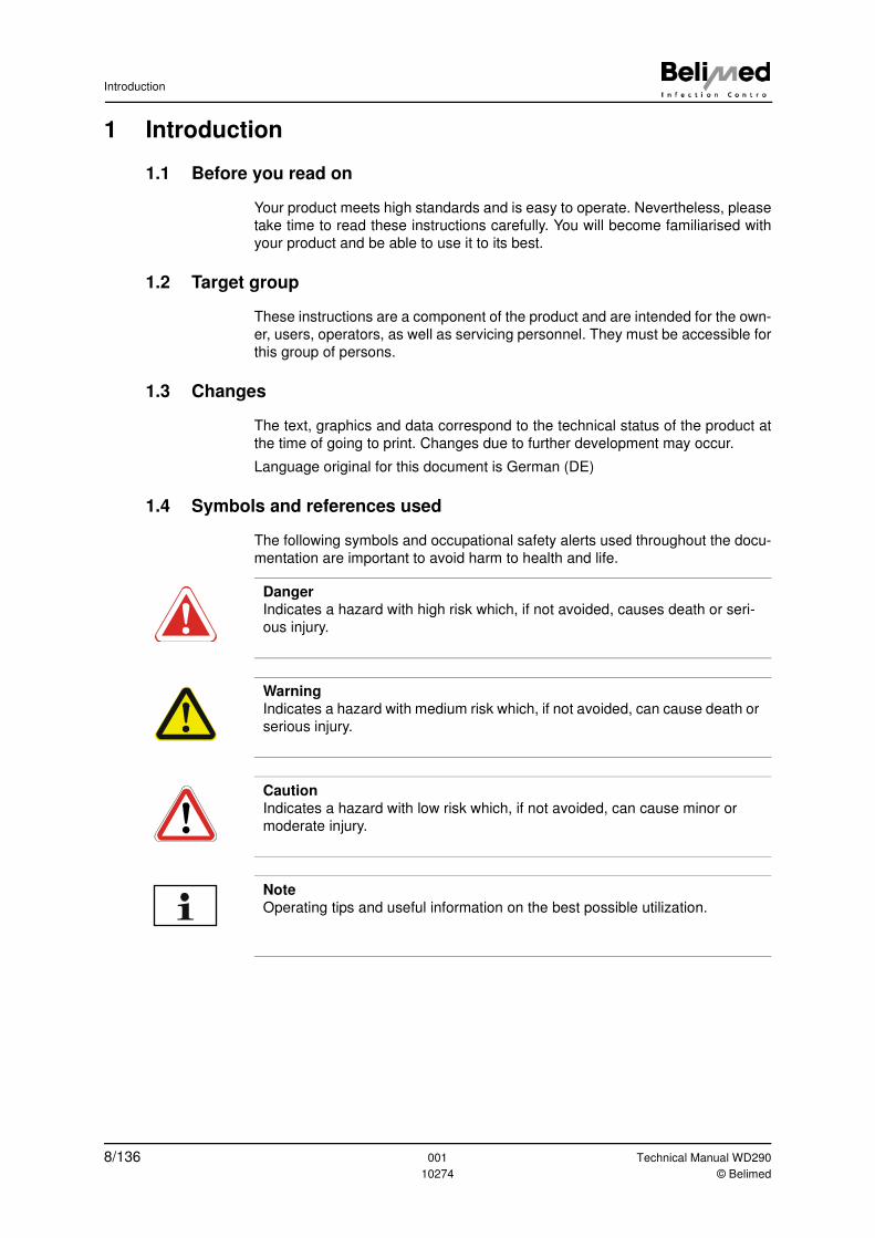
1.4 Symbols and references used
The following symbols and occupational safety alerts used throughout the docu-
mentation are important to avoid harm to health and life.
Danger
Indicates a hazard with high risk which, if not avoided, causes death or seri-
ous injury.
Warning
Indicates a hazard with medium risk which, if not avoided, can cause death or
serious injury.
Caution
Indicates a hazard with low risk which, if not avoided, can cause minor or
moderate injury.
Note
Operating tips and useful information on the best possible utilization.
8/136 001 Technical Manual WD290
10274 © Belimed
For your safety
2 For your safety
We affirm with the EC Declaration of Conformity and the CE mark that this prod-
uct complies with the basic health and safety requirements in accordance with
Directive 93/42/EEC Annex II (see Chap. 14 "Conformity and certifications").
Hazards may still arise from the product if it is used incorrectly by inadequately
trained personnel or not as intended.
2.1 Intended use
This product is exclusively approved for the uses stated in the instructions.
Namely for central sterilisation, substerilisation in surgery, in hospitals, clinical
laboratories and in industry. All other applications are considered as non-intend-
ed use.
2.2 Care responsibilities for dealing with the device
• Only use original racks, spare parts and accessories
• Load racks as intended (see Chap. 5 "Device description")
• Daily maintenance work on the device must be performed regularly and ac-
cording to instructions (see Chap. 12 "Maintenance")
• Validation of the program parameters must be performed regularly (see
Chap. 2.5 "Process validation")
• Installation, deinstallation, maintenance or modification must only be
performed by persons authorised by Belimed
2.3 Instruction of personnel
This product must only be used, maintained and repaired by authorised, trained
and briefed personnel. This assumes that these instructions are read and under-
stood.
Responsibilities and competencies in operation, servicing and maintenance
must be clearly defined and observed.
Technical Manual WD290 001 9/136© Belimed 10274
For your safety
2.4 Fields of application for the device
Cleaning and disinfection of:
• surgical instruments
• minimal-invasive instruments
• instruments used in anaesthesia and intensive care
• baby bottles and teats
• containers
• OP shoes
• laboratory instruments from research and production
• rigid endoscopes
• eye instruments
• neurosurgery
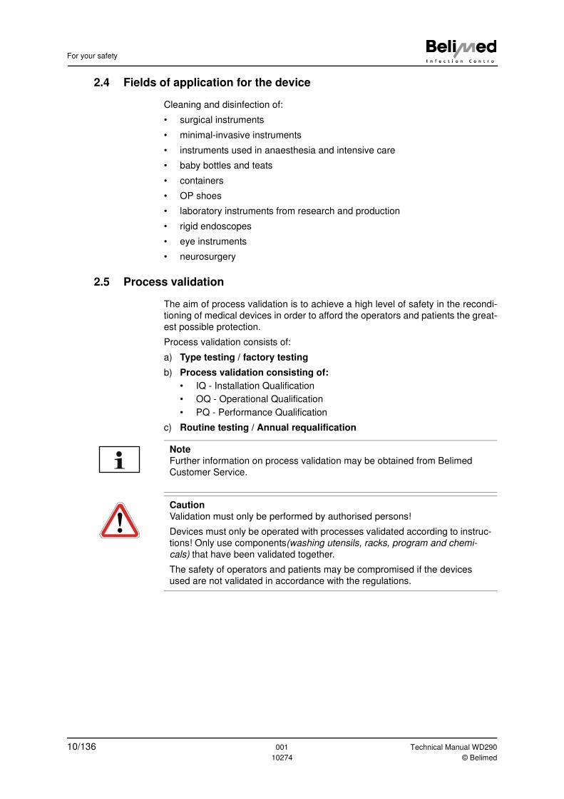
2.5 Process validation
The aim of process validation is to achieve a high level of safety in the recondi-
tioning of medical devices in order to afford the operators and patients the great-
est possible protection.
Process validation consists of:
a) Type testing / factory testing
b) Process validation consisting of:
• IQ - Installation Qualification
• OQ - Operational Qualification
• PQ - Performance Qualification
c) Routine testing / Annual requalification
Note
Further information on process validation may be obtained from Belimed
Customer Service.
Caution
Validation must only be performed by authorised persons!
Devices must only be operated with processes validated according to instruc-
tions! Only use components(washing utensils, racks, program and chemi-
cals) that have been validated together.
The safety of operators and patients may be compromised if the devices
used are not validated in accordance with the regulations.
10/136 001 Technical Manual WD290
10274 © Belimed
Device specifications
3 Device specifications
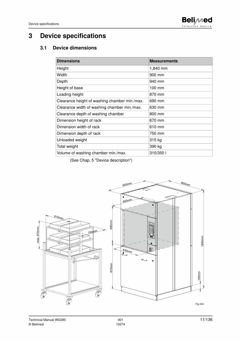
3.1 Device dimensions
(See Chap. 5 "Device description")
Dimensions Measurements
Height 1,840 mm
Width 900 mm
Depth 940 mm
Height of base 100 mm
Loading height 870 mm
Clearance height of washing chamber min./max. 690 mm
Clearance width of washing chamber min./max. 630 mm
Clearance depth of washing chamber 800 mm
Dimension height of rack 670 mm
Dimension width of rack 610 mm
Dimension depth of rack 750 mm
Unloaded weight 315 kg
Total weight 390 kg
Volume of washing chamber min./max. 310/350 l
940mm 900mm
69
0m
m
800mm1840m
m
100m
m
630mm
870
mm
610mm
750mm
ma
x.
67
0m
m
Fig 234
Technical Manual WD290 001 11/136© Belimed 10274
Device specifications
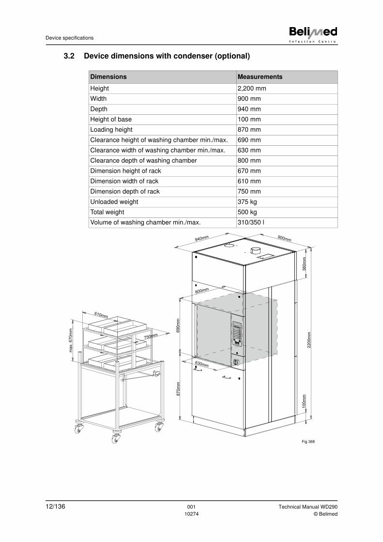
3.2 Device dimensions with condenser (optional)
Dimensions Measurements
Height 2,200 mm
Width 900 mm
Depth 940 mm
Height of base 100 mm
Loading height 870 mm
Clearance height of washing chamber min./max. 690 mm
Clearance width of washing chamber min./max. 630 mm
Clearance depth of washing chamber 800 mm
Dimension height of rack 670 mm
Dimension width of rack 610 mm
Dimension depth of rack 750 mm
Unloaded weight 375 kg
Total weight 500 kg
Volume of washing chamber min./max. 310/350 l
940mm 900mm
69
0m
m
800mm
22
00m
m
10
0m
m
630mm
87
0m
m
610mm
750mm
ma
x.
670m
m
Fig 368
36
0m
m
12/136 001 Technical Manual WD290
10274 © Belimed
Device specifications
3.3 Optional additional components
3.3.1 Additional panneling
• Side panel, 2 doors
• Side panel, single door
• Rear panel, single door
• Base panelling
• Intermediate panelling
• Panelling for condenser and DI water pre-heating
Detailed descriptions (see installation instructions WD290 Item No. 10273)
3.3.2 Switchable heating
• Dual water heating with steam or electricity, manually switchable (see in-
structions WD290 Item No. 10268) and (spare parts list Item No. 76861)
• Dual water heating with steam or electricity, automatically switchable (see
spare parts list Item No. 76861)
3.3.3 Condenser with heat retrieval
• Condenser with DI water pre-heating and heat retrieval
• Exhaust air condenser
• DI water pre-heating
Detailed descriptions:
(Chap. 6.10.11 "Pre-heating temperature / holding time DI boiler")
(Chap. 6.10.12 "Disinfection temperature / disinfection time DI boiler")
(Chap. 6.11.13 "DI Boiler heater interlock with tank heater")
(Chap. 3.6.7 "Electrical function diagram")
3.3.4 Dosing pump set with "empty" indicators and flow meter
• Empty state monitor for dosage media small/large (see Chap. 6.7 "Dosing
module") and (instructions Item No. 10268).
• Flow monitor for dosage media (see Chap. 6.7 "Dosing module") and (in-
structions Item No. 10268).
• Dosing pumps with "empty" indicators (max. 5 units) (see Chap. 6.7 "Dosing
module") and (instructions Item No. 10268).
Technical Manual WD290 001 13/136© Belimed 10274
Device specifications
3.3.5 Miscellaneous
• Diverse racks (instructions supplied separately with the rack)
• Steam heating (tank heating) (see Chap. 6.11.17 "Delay interval for washing-
liquid heating") and (Chap. 3.6.8 "Electrical function diagram with steam dry-
ing")
• Steam dryer (see Chap. 6.11.14 "Steam heated dryer") and (Chap. 3.6.8
"Electrical function diagram with steam drying")
• Floor pan with leakage - sensor (see Chap. 8.2.2 "SB Floor pan leakage")
and (installation instructions Item No. 73895)
• Drainage pump for emptying the device (see Chap. 6.11.5 "Drain")
• Build-in printer LS or US (see instructions WD290 Item No. 10268)
• Tabletop printer (see installation instructions Item No. 73726)
• Service program recipe management with diagnostic software CADI for PC
via RS 232 (see instructions Item No. 73473)
• Pressure gradient monitoring system sterile filter to dryer (see spare parts list
Item No. 76848)
• Modem connector for remote maintenance (see Chap. 6.11.28 "Modem con-
nection (optional)")
• Automatic loading and unloading (see instructions Item No. 76356)
• User, content and rack identification system using barcode reader (instruc-
tions Item No. 73939)
• Content documentation system with PC ICS 8535 or 8565 (see Chap.
6.11.19 "Allocation of address for the ICS 85X5 archiving system")
• Emergency Stop unloading side (see instructions WD290 Item No. 10268)
• IQ, OQ, PQ documentation
• Barcode reader for PC (siehe Chap. 6.10.16 "Automatic rack recognition")
and (instructions Item No. 73939)
• Potential-free contacts (see Chap. 6.11.15 "Potential-free output K28, K57
and K58") and (installation instructions Item No. 76896)
3.3.6 Independent content documentation system (IPD)
Independent content documentation system (IPD) for conductivity measurement,
analogue pressure, two additional temperature sensors and redundant flow mon-
itoring system. Process verification between controller and independent content
documentation system
Detailed information:
(see technical manual IPD Item No. 76666)
14/136 001 Technical Manual WD290
10274 © Belimed
Device specifications
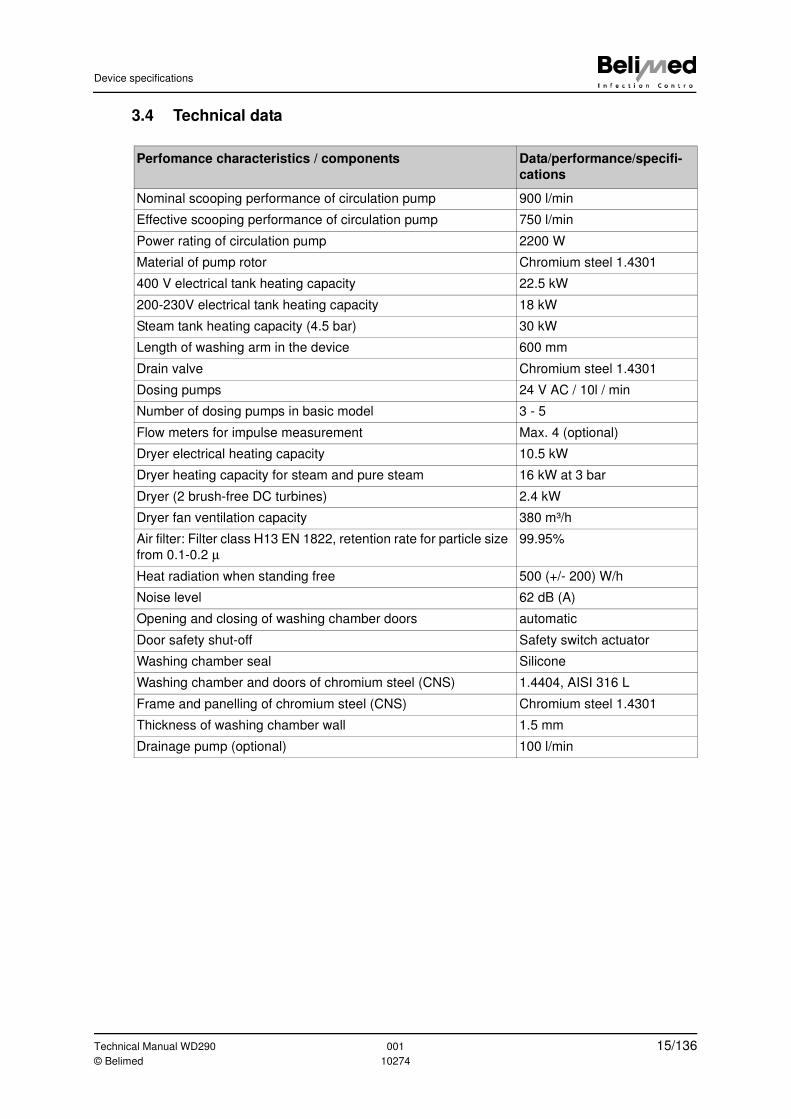
3.4 Technical data
Perfomance characteristics / components Data/performance/specifi-
cations
Nominal scooping performance of circulation pump 900 l/min
Effective scooping performance of circulation pump 750 l/min
Power rating of circulation pump 2200 W
Material of pump rotor Chromium steel 1.4301
400 V electrical tank heating capacity 22.5 kW
200-230V electrical tank heating capacity 18 kW
Steam tank heating capacity (4.5 bar) 30 kW
Length of washing arm in the device 600 mm
Drain valve Chromium steel 1.4301
Dosing pumps 24 V AC / 10l / min
Number of dosing pumps in basic model 3 - 5
Flow meters for impulse measurement Max. 4 (optional)
Dryer electrical heating capacity 10.5 kW
Dryer heating capacity for steam and pure steam 16 kW at 3 bar
Dryer (2 brush-free DC turbines) 2.4 kW
Dryer fan ventilation capacity 380 m³/h
Air filter: Filter class H13 EN 1822, retention rate for particle size
from 0.1-0.2 µ
99.95%
Heat radiation when standing free 500 (+/- 200) W/h
Noise level 62 dB (A)
Opening and closing of washing chamber doors automatic
Door safety shut-off Safety switch actuator
Washing chamber seal Silicone
Washing chamber and doors of chromium steel (CNS) 1.4404, AISI 316 L
Frame and panelling of chromium steel (CNS) Chromium steel 1.4301
Thickness of washing chamber wall 1.5 mm
Drainage pump (optional) 100 l/min
Technical Manual WD290 001 15/136© Belimed 10274
Device specifications
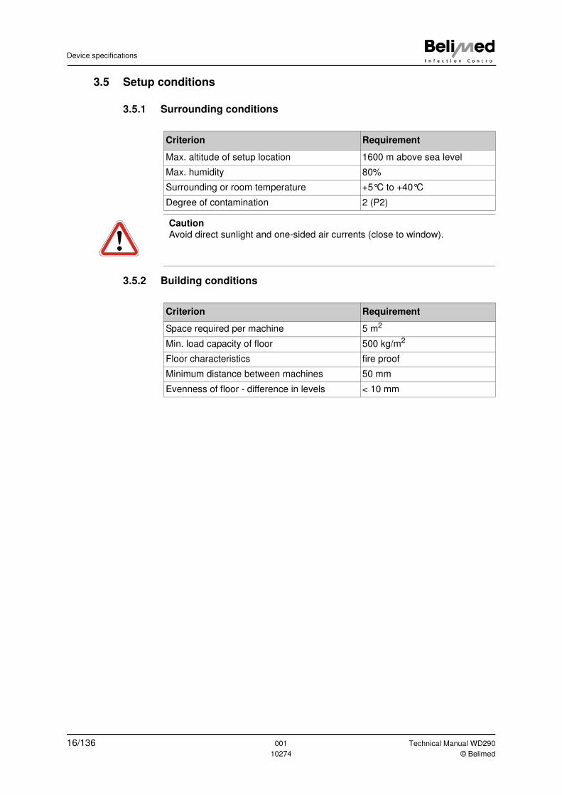
3.5 Setup conditions
3.5.1 Surrounding conditions
3.5.2 Building conditions
Criterion Requirement
Max. altitude of setup location 1600 m above sea level
Max. humidity 80%
Surrounding or room temperature +5°C to +40°C
Degree of contamination 2 (P2)
Caution
Avoid direct sunlight and one-sided air currents (close to window).
Criterion Requirement
Space required per machine 5 m2
Min. load capacity of floor 500 kg/m2
Floor characteristics fire proof
Minimum distance between machines 50 mm
Evenness of floor - difference in levels < 10 mm
16/136 001 Technical Manual WD290
10274 © Belimed
Device specifications
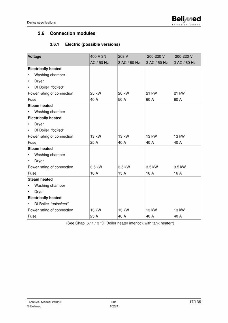
3.6 Connection modules
3.6.1 Electric (possible versions)
(See Chap. 6.11.13 "DI Boiler heater interlock with tank heater")
Voltage 400 V 3N
AC / 50 Hz
208 V
3 AC / 60 Hz
200-220 V
3 AC / 50 Hz
200-220 V
3 AC / 60 Hz
Electrically heated
• Washing chamber
• Dryer
• DI Boiler "locked"
Power rating of connection 25 kW 20 kW 21 kW 21 kW
Fuse 40 A 50 A 60 A 60 A
Steam heated
• Washing chamber
Electrically heated
• Dryer
• DI Boiler "locked"
Power rating of connection 13 kW 13 kW 13 kW 13 kW
Fuse 25 A 40 A 40 A 40 A
Steam heated
• Washing chamber
• Dryer
Power rating of connection 3.5 kW 3.5 kW 3.5 kW 3.5 kW
Fuse 16 A 15 A 16 A 16 A
Steam heated
• Washing chamber
• Dryer
Electrically heated
• DI Boiler "unlocked"
Power rating of connection 13 kW 13 kW 13 kW 13 kW
Fuse 25 A 40 A 40 A 40 A
Technical Manual WD290 001 17/136© Belimed 10274
Device specifications
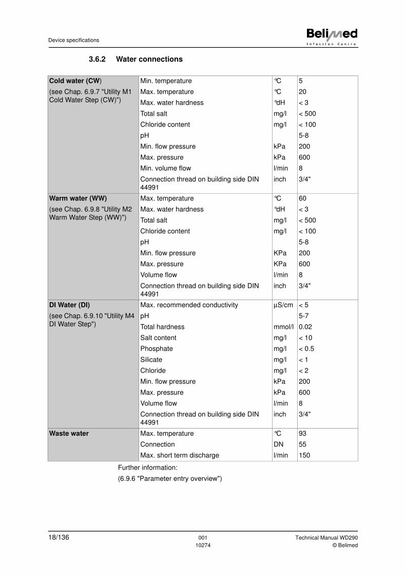
3.6.2 Water connections
Further information:
(6.9.6 "Parameter entry overview")
Cold water (CW)
(see Chap. 6.9.7 "Utility M1
Cold Water Step (CW)")
Min. temperature
Max. temperature
Max. water hardness
Total salt
Chloride content
pH
Min. flow pressure
Max. pressure
Min. volume flow
Connection thread on building side DIN
44991
°C
°C
°dH
mg/l
mg/l
kPa
kPa
l/min
inch
5
20
< 3
< 500
< 100
5-8
200
600
8
3/4"
Warm water (WW)
(see Chap. 6.9.8 "Utility M2
Warm Water Step (WW)")
Max. temperature
Max. water hardness
Total salt
Chloride content
pH
Min. flow pressure
Max. pressure
Volume flow
Connection thread on building side DIN
44991
°C
°dH
mg/l
mg/l
KPa
KPa
l/min
inch
60
< 3
< 500
< 100
5-8
200
600
8
3/4"
DI Water (DI)
(see Chap. 6.9.10 "Utility M4
DI Water Step")
Max. recommended conductivity
pH
Total hardness
Salt content
Phosphate
Silicate
Chloride
Min. flow pressure
Max. pressure
Volume flow
Connection thread on building side DIN
44991
µS/cm
mmol/l
mg/l
mg/l
mg/l
mg/l
kPa
kPa
l/min
inch
< 5
5-7
0.02
< 10
< 0.5
< 1
< 2
200
600
8
3/4"
Waste water Max. temperature
Connection
Max. short term discharge
°C
DN
l/min
93
55
150
18/136 001 Technical Manual WD290
10274 © Belimed
Device specifications
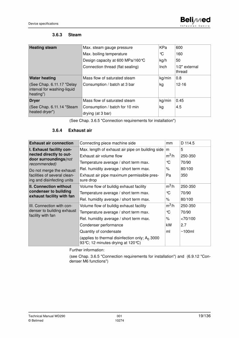
3.6.3 Steam
(See Chap. 3.6.5 "Connection requirements for installation")
3.6.4 Exhaust air
Further information:
(see Chap. 3.6.5 "Connection requirements for installation") and (6.9.12 "Con-
denser M6 functions")
Heating steam Max. steam gauge pressure
Max. boiling temperature
Design capacity at 600 MPa/160°C
Connection thread (flat sealing)
KPa
°C
kg/h
Inch
600
160
50
1/2" external
thread
Water heating
(See Chap. 6.11.17 "Delay
interval for washing-liquid
heating")
Mass flow of saturated steam
Consumption / batch at 3 bar
kg/min
kg
0.8
12-16
Dryer
(See Chap. 6.11.14 "Steam
heated dryer")
Mass flow of saturated steam
Consumption / batch for 10 min
drying (at 3 bar)
kg/min
kg
0.45
4.5
Exhaust air connection Connecting piece machine side mm D 114.5
I. Exhaust facility con-
nected directly to out-
door surroundings(not
recommended)
Do not merge the exhaust
facilities of several clean-
ing and disinfecting units
Max. length of exhaust air pipe on building side
Exhaust air volume flow
Temperature average / short term max.
Rel. humidity average / short term max.
Exhaust air pipe maximum permissible pres-
sure drop
m
m3/h
°C
%
Pa
5
250-350
70/90
80/100
350
II. Connection without
condenser to building
exhaust facility with fan
Volume flow of buildig exhaust facility
Temperature average / short term max.
Rel. humidity average / short term max.
m3/h
°C
%
250-350
70/90
80/100
III. Connection with con-
denser to building exhaust
facility with fan
Volume flow of buildig exhaust facility
Temperature average / short term max.
Rel. humidity average / short term max.
Condenser performance
Quantity of condensate
(applies to thermal disinfection only; A0 3000
93°C; 12 minutes drying at 120°C)
m3/h
°C
%
kW
ml
250-350
70/90
<70/100
2.7
~100ml
Technical Manual WD290 001 19/136© Belimed 10274
Device specifications
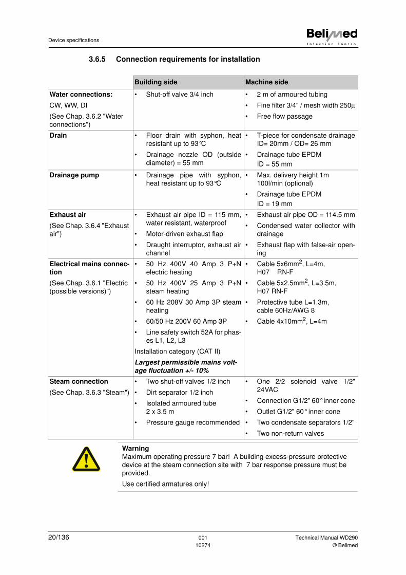
3.6.5 Connection requirements for installation
Building side Machine side
Water connections:
CW, WW, DI
(See Chap. 3.6.2 "Water
connections")
• Shut-off valve 3/4 inch • 2 m of armoured tubing
• Fine filter 3/4" / mesh width 250µ
• Free flow passage
Drain • Floor drain with syphon, heat
resistant up to 93°C
• Drainage nozzle OD (outside
diameter) = 55 mm
• T-piece for condensate drainage
ID= 20mm / OD= 26 mm
• Drainage tube EPDM
ID = 55 mm
Drainage pump • Drainage pipe with syphon,
heat resistant up to 93°C
• Max. delivery height 1m
100l/min (optional)
• Drainage tube EPDM
ID = 19 mm
Exhaust air
(See Chap. 3.6.4 "Exhaust
air")
• Exhaust air pipe ID = 115 mm,
water resistant, waterproof
• Motor-driven exhaust flap
• Draught interruptor, exhaust air
channel
• Exhaust air pipe OD = 114.5 mm
• Condensed water collector with
drainage
• Exhaust flap with false-air open-
ing
Electrical mains connec-
tion
(See Chap. 3.6.1 "Electric
(possible versions)")
• 50 Hz 400V 40 Amp 3 P+N
electric heating
• 50 Hz 400V 25 Amp 3 P+N
steam heating
• 60 Hz 208V 30 Amp 3P steam
heating
• 60/50 Hz 200V 60 Amp 3P
• Line safety switch 52A for phas-
es L1, L2, L3
Installation category (CAT II)
Largest permissible mains volt-
age fluctuation +/- 10%
• Cable 5x6mm2, L=4m,
H07 RN-F
• Cable 5x2.5mm2, L=3.5m,
H07 RN-F
• Protective tube L=1.3m,
cable 60Hz/AWG 8
• Cable 4x10mm2, L=4m
Steam connection
(See Chap. 3.6.3 "Steam")
• Two shut-off valves 1/2 inch
• Dirt separator 1/2 inch
• Isolated armoured tube
2 x 3.5 m
• Pressure gauge recommended
• One 2/2 solenoid valve 1/2"
24VAC
• Connection G1/2" 60° inner cone
• Outlet G1/2" 60° inner cone
• Two condensate separators 1/2"
• Two non-return valves
Warning
Maximum operating pressure 7 bar! A building excess-pressure protective
device at the steam connection site with 7 bar response pressure must be
provided.
Use certified armatures only!
20/136 001 Technical Manual WD290
10274 © Belimed
Device specifications
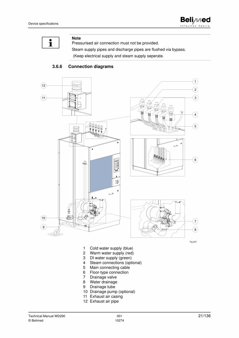
3.6.6 Connection diagrams
1 Cold water supply (blue)
2 Warm water supply (red)
3 DI water supply (green)
4 Steam connections (optional)
5 Main connecting cable
6 Floor-type connection
7 Drainage valve
8 Water drainage
9 Drainage tube
10 Drainage pump (optional)
11 Exhaust air casing
12 Exhaust air pipe
Note
Pressurised air connection must not be provided.
Steam supply pipes and discharge pipes are flushed via bypass.
(Keep electrical supply and steam supply seperate.
Fig 207
1
2
3
4
5
6
10
9
11
12
7
8
Technical Manual WD290 001 21/136© Belimed 10274
Device specifications
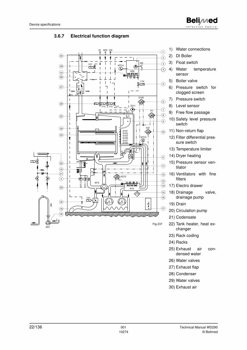
3.6.7 Electrical function diagram
1) Water connections
2) DI Boiler
3) Float switch
4) Water temperature
sensor
5) Boiler valve
6) Pressure switch for
clogged screen
7) Pressure switch
8) Level sensor
9) Free flow passage
10) Safety level pressure
switch
11) Non-return flap
12) Filter differential pres-
sure switch
13) Temperature limiter
14) Dryer heating
15) Pressure sensor ven-
tilator
16) Ventilators with fine
filters
17) Electro drawer
18) Drainage valve,
drainage pump
19) Drain
20) Circulation pump
21) Codensate
22) Tank heater, heat ex-
changer
23) Rack coding
24) Racks
25) Exhaust air con-
densed water
26) Water valves
27) Exhaust flap
28) Condenser
29) Water valves
30) Exhaust air
4
T
T
P
T T
M31
DI WW CW
NTC4Y27
SD
Y14
R26
S109
P1
S211Y13 Y12 Y11
S101S102S103S106
S105S107
S212
R18
P18
M17.2M17.1
M15
Y31
NTC2
S31
NT
C 5
NT
C 1
2
1
3
5
6
7
8
9
10
11
11
12
13
14
15
17
16
30
29
14
28
27
26
25
24
23
14
4
20
18
19
21
18
22
Fig 237
22/136 001 Technical Manual WD290
10274 © Belimed
Device specifications
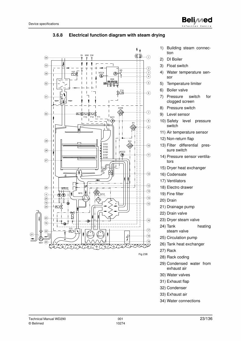
3.6.8 Electrical function diagram with steam drying
1) Building steam connec-
tion
2) DI Boiler
3) Float switch
4) Water temperature sen-
sor
5) Temperature limiter
6) Boiler valve
7) Pressure switch for
clogged screen
8) Pressure switch
9) Level sensor
10) Safety level pressure
switch
11) Air temperature sensor
12) Non-return flap
13) Filter differential pres-
sure switch
14) Pressure sensor ventila-
tors
15) Dryer heat exchanger
16) Codensate
17) Ventilators
18) Electro drawer
19) Fine filter
20) Drain
21) Drainage pump
22) Drain valve
23) Dryer steam valve
24) Tank heating
steam valve
25) Circulation pump
26) Tank heat exchanger
27) Rack
28) Rack coding
29) Condensed water from
exhaust air
30) Water valves
31) Exhaust flap
32) Condenser
33) Exhaust air
34) Water connections
T
T
P
T T
DI WW CW
Y27NTC4
SD
R26
Y14
S109
S211
P1
S31
NTC2
S102
S103
S106
S107
S105
S101
Y13 Y12 Y11
S212
P18
M17.2M17.1
NT
C1
NT
C5
M15
M31
1
2
3
4
5
6
7
8
9
10
11
12
12
13
14
15
16
19
17
18
16
Y31
20
22
21
23
24
16
25
4
26
28
27
29
30
31
32
30
33
34
Fig 238
Technical Manual WD290 001 23/136© Belimed 10274
Consumption data
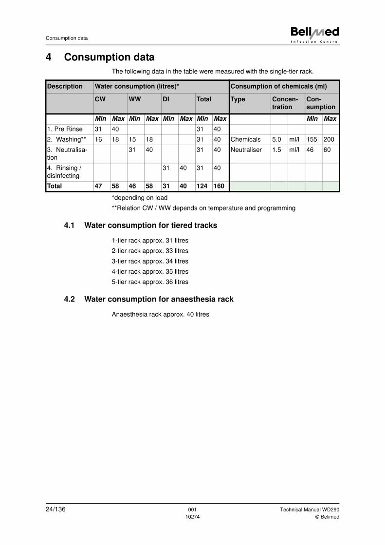
4 Consumption data
The following data in the table were measured with the single-tier rack.
*depending on load
**Relation CW / WW depends on temperature and programming
4.1 Water consumption for tiered tracks
1-tier rack approx. 31 litres
2-tier rack approx. 33 litres
3-tier rack approx. 34 litres
4-tier rack approx. 35 litres
5-tier rack approx. 36 litres
4.2 Water consumption for anaesthesia rack
Anaesthesia rack approx. 40 litres
Description Water consumption (litres)* Consumption of chemicals (ml)
CW WW DI Total Type Concen-
tration
Con-
sumption
Min Max Min Max Min Max Min Max Min Max
1. Pre Rinse 31 40 31 40
2. Washing** 16 18 15 18 31 40 Chemicals 5.0 ml/l 155 200
3. Neutralisa-
tion
31 40 31 40 Neutraliser 1.5 ml/l 46 60
4. Rinsing /
disinfecting
31 40 31 40
Total 47 58 46 58 31 40 124 160
24/136 001 Technical Manual WD290
10274 © Belimed
Device description
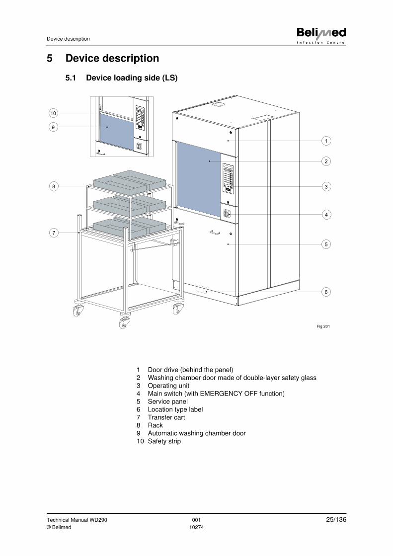
5 Device description
5.1 Device loading side (LS)
1 Door drive (behind the panel)
2 Washing chamber door made of double-layer safety glass
3 Operating unit
4 Main switch (with EMERGENCY OFF function)
5 Service panel
6 Location type label
7 Transfer cart
8 Rack
9 Automatic washing chamber door
10 Safety strip
1
3
4
5
2
8
7
9
10
Fig 201
6
Technical Manual WD290 001 25/136© Belimed 10274
Device description
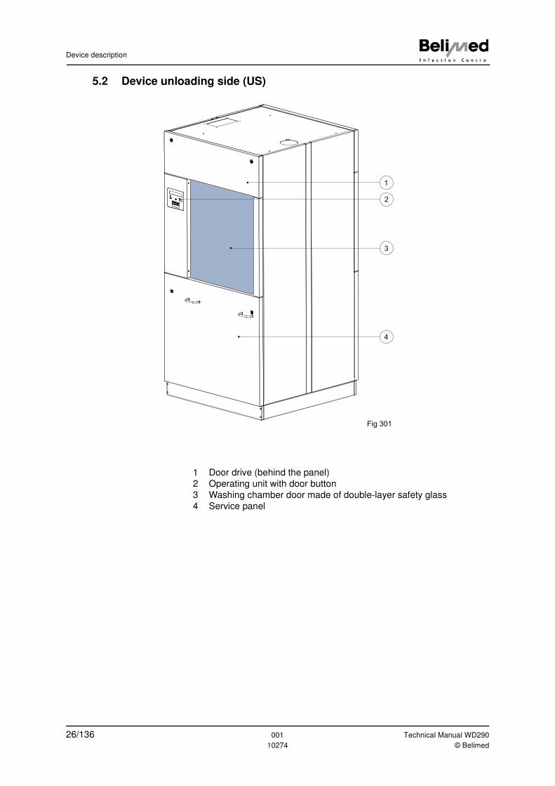
5.2 Device unloading side (US)
1 Door drive (behind the panel)
2 Operating unit with door button
3 Washing chamber door made of double-layer safety glass
4 Service panel
1
2
4
3
Fig 301
26/136 001 Technical Manual WD290
10274 © Belimed
Device description
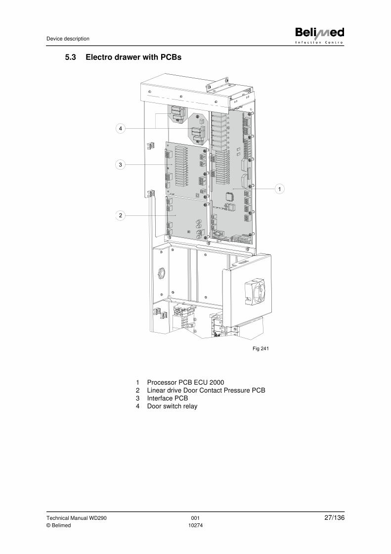
5.3 Electro drawer with PCBs
1 Processor PCB ECU 2000
2 Linear drive Door Contact Pressure PCB
3 Interface PCB
4 Door switch relay
1
2
3
4
Fig 241
Technical Manual WD290 001 27/136© Belimed 10274
Device description
5.4 Operating unit loading side (LS)
5.5 Operating unit unloading side (US)
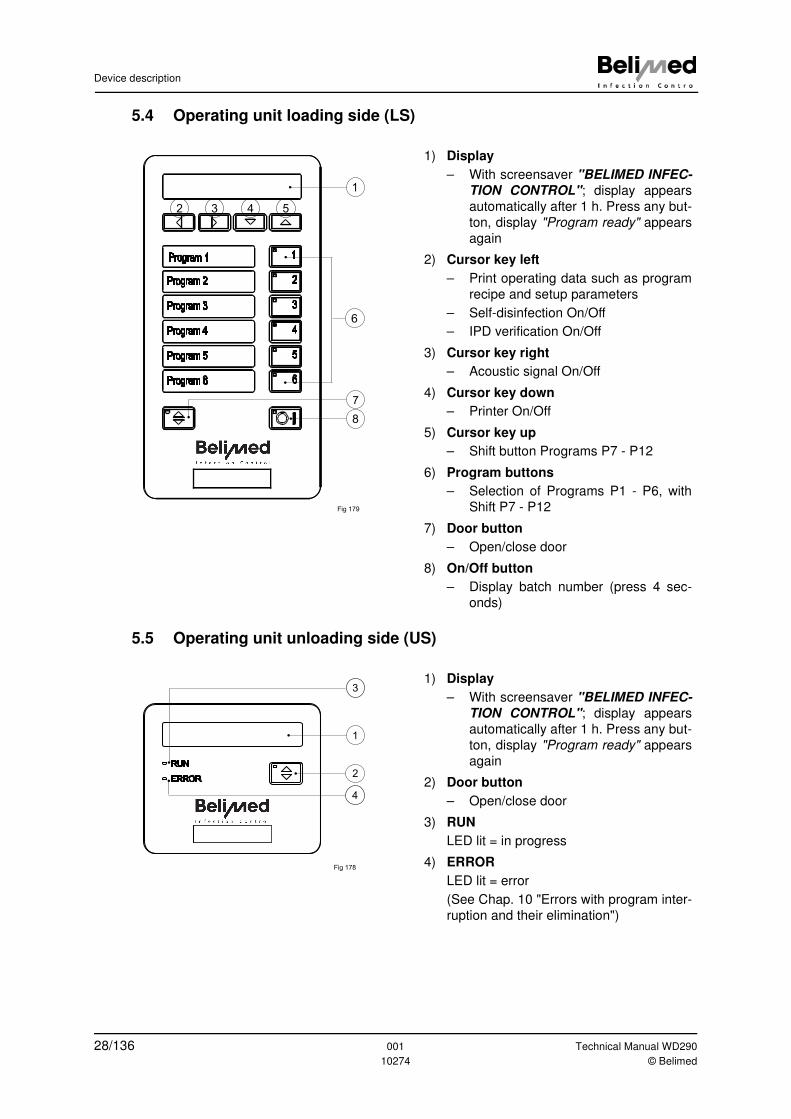
1) Display
– With screensaver "BELIMED INFEC-
TION CONTROL"; display appears
automatically after 1 h. Press any but-
ton, display "Program ready" appears
again
2) Cursor key left
– Print operating data such as program
recipe and setup parameters
– Self-disinfection On/Off
– IPD verification On/Off
3) Cursor key right
– Acoustic signal On/Off
4) Cursor key down
– Printer On/Off
5) Cursor key up
– Shift button Programs P7 - P12
6) Program buttons
– Selection of Programs P1 - P6, with
Shift P7 - P12
7) Door button
– Open/close door
8) On/Off button
– Display batch number (press 4 sec-
onds)
1
2
3
4
5
6
Program 1
Program 2
Program 3
Program 4
Program 5
Program 6
1
432 5
6
7
8
Fig 179
1) Display
– With screensaver "BELIMED INFEC-
TION CONTROL"; display appears
automatically after 1 h. Press any but-
ton, display "Program ready" appears
again
2) Door button
– Open/close door
3) RUN
LED lit = in progress
4) ERROR
LED lit = error
(See Chap. 10 "Errors with program inter-
ruption and their elimination")
RUN
ERROR
1
2
Fig 178
4
3
28/136 001 Technical Manual WD290
10274 © Belimed

Service modules, software configuration
6 Service modules, software configuration
6.1 Access rights
6.2 Accessing the Service Module
Specialised personnel Input modules Access
Detergent manufacturers Analysis Module; Dosing Module Password A
Hospital clinical technicians Analysis Module; Dosing Mod-
ule; Servo Control Module;
Parameter Module; Configura-
tion Module 1; Configuration
Module 2
Password B
Belimed service techni-
cians
All modules Hardware key
1 Analysis2 Dosage
3 Control4 Parameter
5 Configuration6 Limits
Password ?---
Pa
ssw
ord
corr
ect
Remote SupportInitialize Modem
Enter Password
Select buttons 1-6
0 I Without Hardwarekey push button for 5 sec.
0 I
With
Ha
rdw
are
ke
y p
ush b
utton for
5 s
ec.
Fig 110
Technical Manual WD290 001 29/136© Belimed 10274
Service modules, software configuration
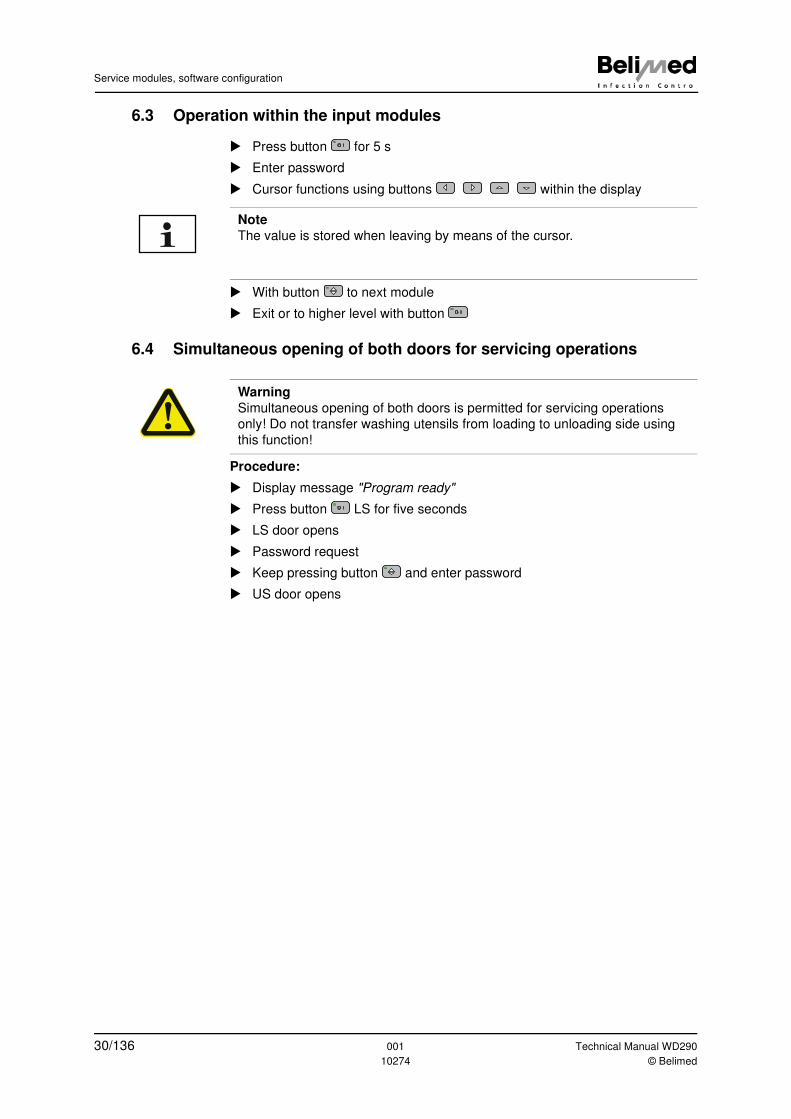
6.3 Operation within the input modules
� Press button for 5 s
� Enter password
� Cursor functions using buttons within the display
� With button to next module
� Exit or to higher level with button
6.4 Simultaneous opening of both doors for servicing operations
Procedure:
� Display message "Program ready"
� Press button LS for five seconds
� LS door opens
� Password request
� Keep pressing button and enter password
� US door opens
0 I
Note
The value is stored when leaving by means of the cursor.
0 I
Warning
Simultaneous opening of both doors is permitted for servicing operations
only! Do not transfer washing utensils from loading to unloading side using
this function!
0 I
30/136 001 Technical Manual WD290
10274 © Belimed
Se
rvic
e m
od
ule
s, s
oftw
are
co
nfig
ura
tion
Te
ch
nic
al M
an
ua
l WD
29
00
01
31/1
36
© B
elim
ed
10
27
4
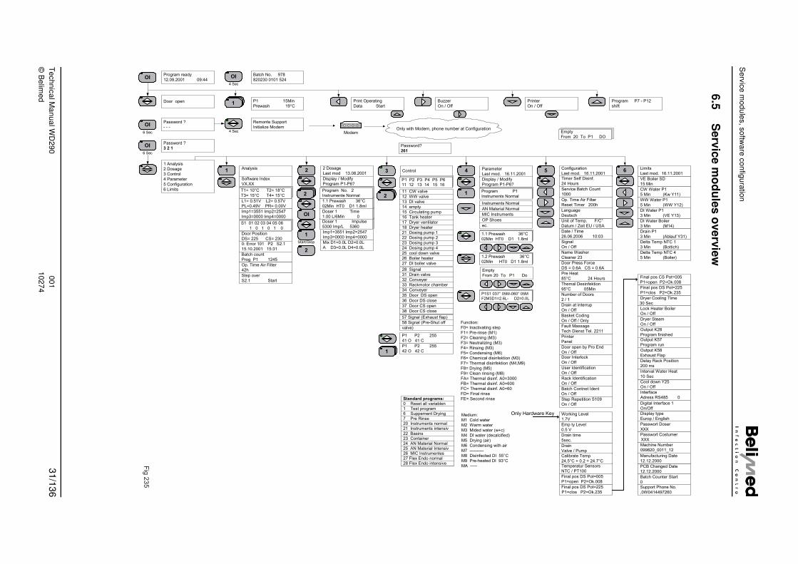
6.5
Se
rvic
e m
od
ule
s o
ve
rvie
w
Printer
On / Off
Program P7 - P12
shift
6.11.2001
ify
P6?
ormal
ormal
nts
Empty
From 20 To P1 DO
Configuration
Last mod. 16.11.2001
Service Batch Count
1000
Op. Time Air Filter
Reset Timer 200h
P1
ormal
Signal
On / Off
Unit of Temp. F/C°
Datum / Zeit EU / USA
Door Press Force
DS = 0.6A CS = 0.6A
Name Washer
Cleaner 23
Pre Heat
85°C 24 Hours
Themal Desinfektion
95°C 05Min
Printer
Panel
Working Level
1.7V
Door open by Pro End
On / Off
Language
Deutsch
Drain
Valve / Pump
Drain time
5sec.
Emp ty Level
0.5 V
Final pos DS Pot=225
P1=clos P2=Ok.235
Final pos DS Pot=005
P1=open P2=Ok.008
Temperatur Sensors
NTC / PT100
Dryer Cooling Time
30 Sec
Final pos DS Pot=225
P1=clos P2=Ok.235
Final pos CS Pot=005
P1=open P2=Ok.008
VE Boiler SD
15 Min
WW Water P1
5 Min (WW Y12)
CW Water P1
5 Min (Kw Y11)
Limits
Last mod. 16.11.2001
DI Water Boiler
3 Min (M14)
Delta Temp NTC 1
3 Min (Bottich)
Drain P1
3 Min (Ablauf Y31)
DI Water P1
3 Min (VE Y13)
Delta Temp NTC 4
5 Min (Boiler)
Dryer Steam
On / Off
Delay Rack Position
200 ms
Output K28
Program finished
Lock Heater Boiler
On / Off
Cool down Y25
On / Off
Interface
Adress RS485 0
Interval Water Heat
10 Sec
Passwort Doser
XXX
Machine Number
099820_0011_12
Passwort Costumer
XXX
Display type
Europ / English
PCB Changed Date
12.12.2000
Support Phone No.
,0W0414497260
Batch Counter Start
0
Manufacturing Date
12.12.2000
Only Hardware Key
Number of Doors
2 / 1
Basket Coding
On / Off / Only
Drain at interrup
On / Off
Fault Massage
Tech Dienst Tel. 2211
36°C
D1 1.8ml
P1 Do
36°C
D1 1.8ml
M-060° 05M
- D2=0.0L
Output K58
Exhaust Flap
Output K57
Program run
Calibrate Temp
24,5°C + 0.2 = 24.7°C
Door Interlock
On / Off
Batch Contnet Ident
On / Off
Rack Identification
On / Off
User Identification
On / Off
Date / Time
26.06.2006 10:03
Timer Self Disinf.
24 Hours
n (M3)
(M4,M9)
3000
600
60
d)
Step Repetition S109
On / Off Digital Interface 1
On/Off
5 6
Program ready
12.09.2001 09:44
Door open P1 15Min
Prewash 19°C
Print Operating
Data Start
Buzzer
On / Off
Batch No. 978
820230 0101 524
Password ?
- - -
Remonte Support
Initialize Modem Only with Modem, phone number at Configuration
Password ?
3 2 1
1 Analysis
2 Dosage
3 Control
4 Parameter
5 Configuration
6 Limits
2 Dosage
Last mod 13.08.2001Parameter
Last mod. 13
Modem
Analysis
Software Index
VX.XX
L1= 0.51V L2= 0.57VPL=0.49V PR= 0.00V
Imp1=3551 Imp2=2547
Imp3=0000 Imp4=0000
0: Error 101 P2 S2.1
15.10.2001 15:31
Batch count
Prog P1 1245
Op. Time Air Filter
42h
Step over
S2.1 Start
Display / Modify
Program P1-P6?
Imp1=3551 Imp2=2547
Imp3=0000 Imp4=0000
Display / Mod
Program P1-
Instruments N
AN Material N
MIC Instrume
OP Shoes
ec.
4 Sec6 Sec
6 Sec
4 Sec
T1= 10°C T2= 18°C
T3= 15°C T4= 15°C
S1 01 02 03 04 05 06
1 0 1 0 1 0
Doser 1 Impulse
5300 Imp/L 5360
Doser 1 Time
1.00 L/6Min 0
1.1 Prewash 36°C
02Min HT0 D1 1.8ml
Program No. 2
Instrumente Normal
Start/Stop
Control
P1 P2 P3 P4 P5 P611 12 13 14 15 16
Program
Instruments N
Password?
261
1
P1 P2 255
41 O 41 C
P1 P2 255
42 O 42 C
1.1 Prewash
02Min HT0
Empty
From 20 To
1.2 Prewash
02Min HT0
P1S1 037° 05
F2M3D1=2.6L
Door Position
DS= 225 CS= 230Mix D1=0.0L D2=0.0L
A D3=0.0L D4=0.0L
Standard programs:0 Reset all variablen1 Test program6 Suppement Drying7 Pre Rinse20 Instruments normal21 Instruments intensiv22 Basins23 Container24 AN Material Normal25 AN Material Intensiv26 MIC Instrumentes27 Flex Endo normal28 Flex Endo intensive
Function:
F0= Inactivating step
F1= Pre-rinse (M1)
F2= Cleaning (M3)
F3= Neutralizing (M3)
F4= Rinsing (M3)
F5= Condensing (M6)
F6= Chemical disinfektio
F7= Thermal disinfektion
F8= Drying (M5)
F9= Clean rinsing (M8)
FA= Thermal disinf. A0=
FB= Thermal disinf. A0=
FC= Thermal disinf. A0=
FD= Final rinse
FE= Second rinse
Medium:
M1 Cold water
M2 Warm water
M3 Mided water (w+c)
M4 DI water (decalcifie
M5 Drying (air)
M6 Condensing with air
M7 ----------
M8 Disinfected DI 55°C
M9 Pre-heated DI 93°C
MA -----
11 CW valve
12 WW valve
13 DI valve
14 empty
15 Circulating pump
16 Tank heater
17 Dryer ventilator
18 Dryer heater
21 Dosing pump 1
22 Dosing pump 2
23 Dosing pump 3
24 Dosing pump 4
25 cool down valve
26 Boiler heater
27 DI boiler valve
35 Door DS open
36 Door DS close
37 Door CS open
38 Door CS close
28 Signal
31 Drain valve
32 Conveyer
33 Rackmotor chamber
34 Conveyer
57 Signal (Exhaust flap)
58 Signal (Pre-Shut off
valve)
21
2
1
2
OI
2
4
1
OI
OI
OI OI
1
Fig
235
Service modules, software configuration
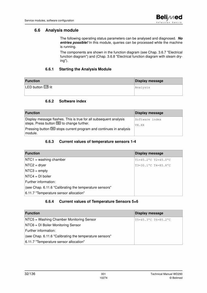
6.6 Analysis module
The following operating status parameters can be analysed and diagnosed. No
entries possible! In this module, queries can be processed while the machine
is running.
The components are shown in the function diagram (see Chap. 3.6.7 "Electrical
function diagram") and (Chap. 3.6.8 "Electrical function diagram with steam dry-
ing").
6.6.1 Starting the Analysis Module
6.6.2 Software index
6.6.3 Current values of temperature sensors 1-4
6.6.4 Current values of Temperature Sensors 5+6
Function Display message
LED button lit Analysis1
Function Display message
Display message flashes. This is true for all subsequent analysis
steps. Press button to change further.
Pressing button stops current program and continues in analysis
module.
Software index
VX.XX0 I
Function Display message
NTC1 = washing chamber
NTC2 = dryer
NTC3 = empty
NTC4 = DI boiler
Further information:
(see Chap. 6.11.6 "Calibrating the temperature sensors"
6.11.7 "Temperature sensor allocation"
T1=45.2°C T2=45.0°C
T3=30.1°C T4=85.8°C
Function Display message
NTC5 = Washing Chamber Monitoring Sensor
NTC6 = DI Boiler Monitoring Sensor
Further information:
(see Chap. 6.11.6 "Calibrating the temperature sensors"
6.11.7 "Temperature sensor allocation"
T5=45.3°C T6=85.2°C
32/136 001 Technical Manual WD290
10274 © Belimed
Service modules, software configuration
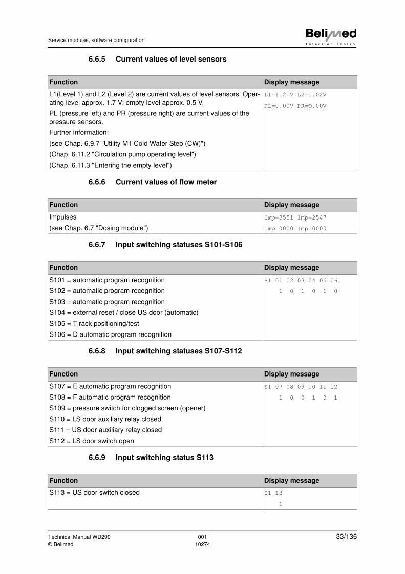
6.6.5 Current values of level sensors
6.6.6 Current values of flow meter
6.6.7 Input switching statuses S101-S106
6.6.8 Input switching statuses S107-S112
6.6.9 Input switching status S113
Function Display message
L1(Level 1) and L2 (Level 2) are current values of level sensors. Oper-
ating level approx. 1.7 V; empty level approx. 0.5 V.
PL (pressure left) and PR (pressure right) are current values of the
pressure sensors.
Further information:
(see Chap. 6.9.7 "Utility M1 Cold Water Step (CW)")
(Chap. 6.11.2 "Circulation pump operating level")
(Chap. 6.11.3 "Entering the empty level")
L1=1.20V L2=1.02V
PL=0.00V PR=O.00V
Function Display message
Impulses
(see Chap. 6.7 "Dosing module")
Imp=3551 Imp=2547
Imp=0000 Imp=0000
Function Display message
S101 = automatic program recognition
S102 = automatic program recognition
S103 = automatic program recognition
S104 = external reset / close US door (automatic)
S105 = T rack positioning/test
S106 = D automatic program recognition
S1 01 02 03 04 05 06
1 0 1 0 1 0
Function Display message
S107 = E automatic program recognition
S108 = F automatic program recognition
S109 = pressure switch for clogged screen (opener)
S110 = LS door auxiliary relay closed
S111 = US door auxiliary relay closed
S112 = LS door switch open
S1 07 08 09 10 11 12
1 0 0 1 0 1
Function Display message
S113 = US door switch closed S1 13
1
Technical Manual WD290 001 33/136© Belimed 10274
Service modules, software configuration
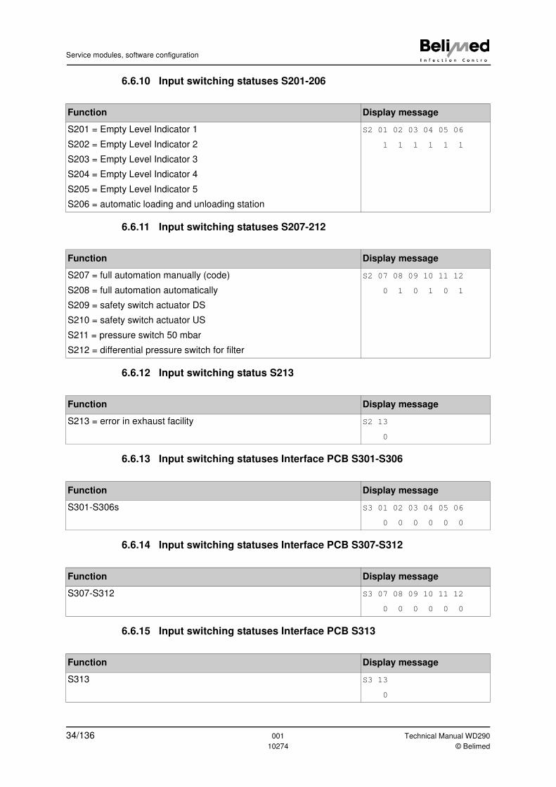
6.6.10 Input switching statuses S201-206
6.6.11 Input switching statuses S207-212
6.6.12 Input switching status S213
6.6.13 Input switching statuses Interface PCB S301-S306
6.6.14 Input switching statuses Interface PCB S307-S312
6.6.15 Input switching statuses Interface PCB S313
Function Display message
S201 = Empty Level Indicator 1
S202 = Empty Level Indicator 2
S203 = Empty Level Indicator 3
S204 = Empty Level Indicator 4
S205 = Empty Level Indicator 5
S206 = automatic loading and unloading station
S2 01 02 03 04 05 06
1 1 1 1 1 1
Function Display message
S207 = full automation manually (code)
S208 = full automation automatically
S209 = safety switch actuator DS
S210 = safety switch actuator US
S211 = pressure switch 50 mbar
S212 = differential pressure switch for filter
S2 07 08 09 10 11 12
0 1 0 1 0 1
Function Display message
S213 = error in exhaust facility S2 13
0
Function Display message
S301-S306s S3 01 02 03 04 05 06
0 0 0 0 0 0
Function Display message
S307-S312 S3 07 08 09 10 11 12
0 0 0 0 0 0
Function Display message
S313 S3 13
0
34/136 001 Technical Manual WD290
10274 © Belimed
Service modules, software configuration
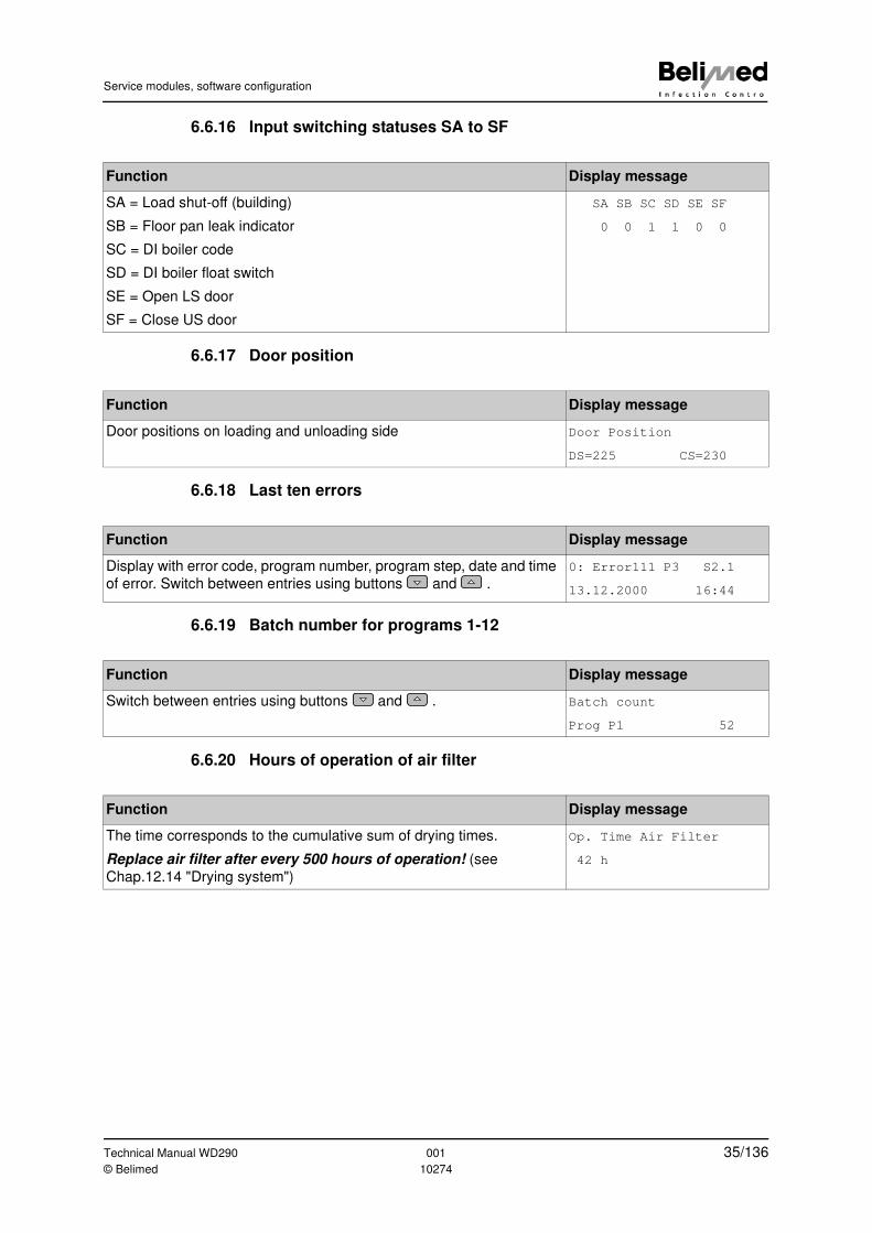
6.6.16 Input switching statuses SA to SF
6.6.17 Door position
6.6.18 Last ten errors
6.6.19 Batch number for programs 1-12
6.6.20 Hours of operation of air filter
Function Display message
SA = Load shut-off (building)
SB = Floor pan leak indicator
SC = DI boiler code
SD = DI boiler float switch
SE = Open LS door
SF = Close US door
SA SB SC SD SE SF
0 0 1 1 0 0
Function Display message
Door positions on loading and unloading side Door Position
DS=225 CS=230
Function Display message
Display with error code, program number, program step, date and time
of error. Switch between entries using buttons and .
0: Error111 P3 S2.1
13.12.2000 16:44
Function Display message
Switch between entries using buttons and . Batch count
Prog P1 52
Function Display message
The time corresponds to the cumulative sum of drying times.
Replace air filter after every 500 hours of operation! (see
Chap.12.14 "Drying system")
Op. Time Air Filter
42 h
Technical Manual WD290 001 35/136© Belimed 10274
Service modules, software configuration
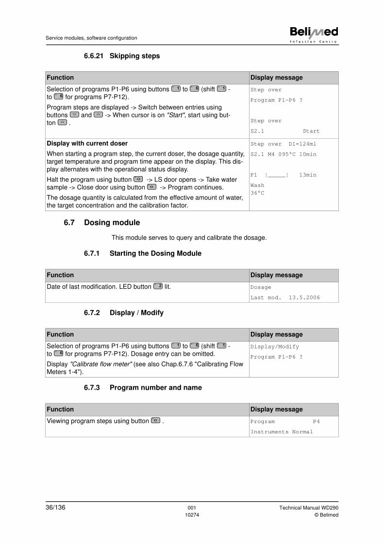
6.6.21 Skipping steps
6.7 Dosing module
This module serves to query and calibrate the dosage.
6.7.1 Starting the Dosing Module
6.7.2 Display / Modify
6.7.3 Program number and name
Function Display message
Selection of programs P1-P6 using buttons to (shift -
to for programs P7-P12).
Program steps are displayed -> Switch between entries using
buttons and -> When cursor is on "Start", start using but-
ton .
Step over
Program P1-P6 ?
Step over
S2.1 Start
Display with current doser
When starting a program step, the current doser, the dosage quantity,
target temperature and program time appear on the display. This dis-
play alternates with the operational status display.
Halt the program using button -> LS door opens -> Take water
sample -> Close door using button -> Program continues.
The dosage quantity is calculated from the effective amount of water,
the target concentration and the calibration factor.
Step over D1=124ml
S2.1 M4 095°C 10min
P1 ¦_____¦ 13min
Wash
36°C
1 6 1
6
Function Display message
Date of last modification. LED button lit. Dosage
Last mod. 13.5.2006
2
Function Display message
Selection of programs P1-P6 using buttons to (shift -
to for programs P7-P12). Dosage entry can be omitted.
Display "Calibrate flow meter" (see also Chap.6.7.6 "Calibrating Flow
Meters 1-4").
Display/Modify
Program P1-P6 ?
1 6 1
6
Function Display message
Viewing program steps using button . Program P4
Instruments Normal
36/136 001 Technical Manual WD290
10274 © Belimed
Service modules, software configuration
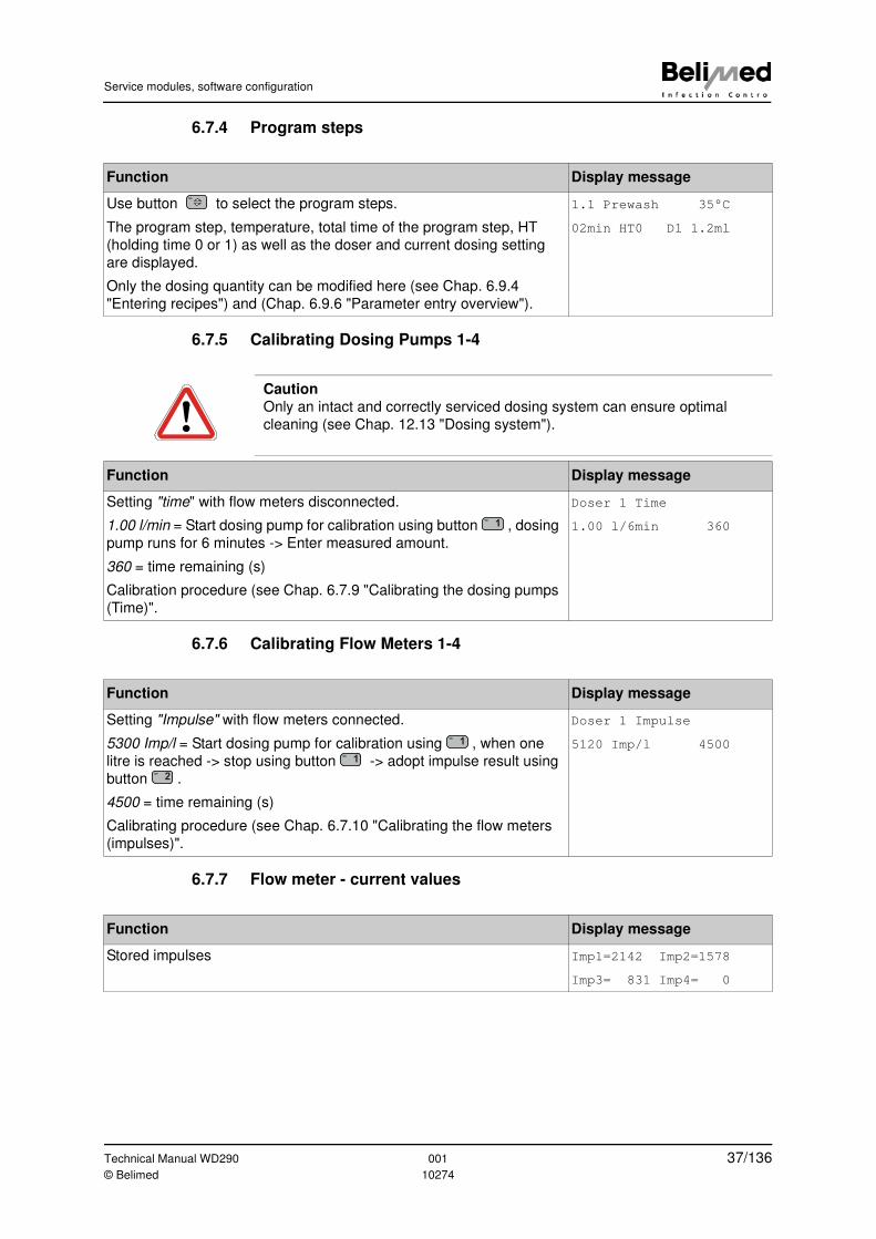
6.7.4 Program steps
6.7.5 Calibrating Dosing Pumps 1-4
6.7.6 Calibrating Flow Meters 1-4
6.7.7 Flow meter - current values
Function Display message
Use button to select the program steps.
The program step, temperature, total time of the program step, HT
(holding time 0 or 1) as well as the doser and current dosing setting
are displayed.
Only the dosing quantity can be modified here (see Chap. 6.9.4
"Entering recipes") and (Chap. 6.9.6 "Parameter entry overview").
1.1 Prewash 35°C
02min HT0 D1 1.2ml
Caution
Only an intact and correctly serviced dosing system can ensure optimal
cleaning (see Chap. 12.13 "Dosing system").
Function Display message
Setting "time" with flow meters disconnected.
1.00 l/min = Start dosing pump for calibration using button , dosing
pump runs for 6 minutes -> Enter measured amount.
360 = time remaining (s)
Calibration procedure (see Chap. 6.7.9 "Calibrating the dosing pumps
(Time)".
Doser 1 Time
1.00 l/6min 3601
Function Display message
Setting "Impulse" with flow meters connected.
5300 Imp/l = Start dosing pump for calibration using , when one
litre is reached -> stop using button -> adopt impulse result using
button .
4500 = time remaining (s)
Calibrating procedure (see Chap. 6.7.10 "Calibrating the flow meters
(impulses)".
Doser 1 Impulse
5120 Imp/l 45001
1
2
Function Display message
Stored impulses Imp1=2142 Imp2=1578
Imp3= 831 Imp4= 0
Technical Manual WD290 001 37/136© Belimed 10274
Service modules, software configuration
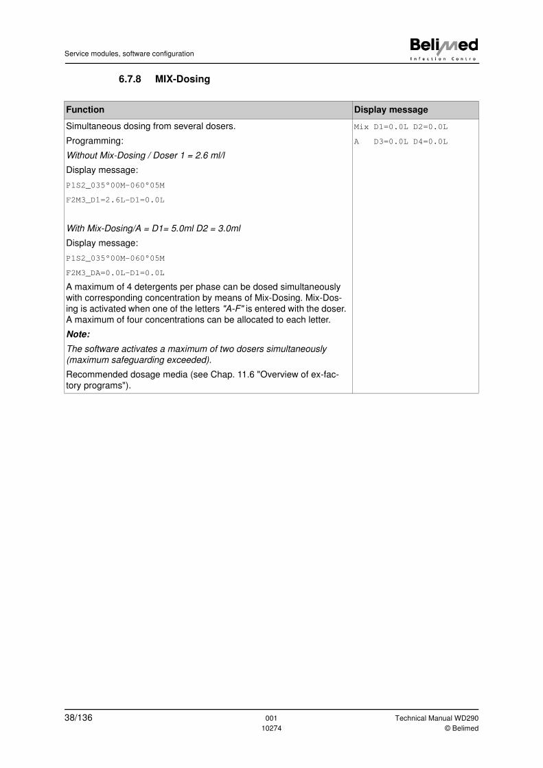
6.7.8 MIX-Dosing
Function Display message
Simultaneous dosing from several dosers.
Programming:
Without Mix-Dosing / Doser 1 = 2.6 ml/l
Display message:
P1S2_035°00M-060°05M
F2M3_D1=2.6L-D1=0.0L
With Mix-Dosing/A = D1= 5.0ml D2 = 3.0ml
Display message:
P1S2_035°00M-060°05M
F2M3_DA=0.0L-D1=0.0L
A maximum of 4 detergents per phase can be dosed simultaneously
with corresponding concentration by means of Mix-Dosing. Mix-Dos-
ing is activated when one of the letters "A-F" is entered with the doser.
A maximum of four concentrations can be allocated to each letter.
Note:
The software activates a maximum of two dosers simultaneously
(maximum safeguarding exceeded).
Recommended dosage media (see Chap. 11.6 "Overview of ex-fac-
tory programs").
Mix D1=0.0L D2=0.0L
A D3=0.0L D4=0.0L
38/136 001 Technical Manual WD290
10274 © Belimed
Service modules, software configuration
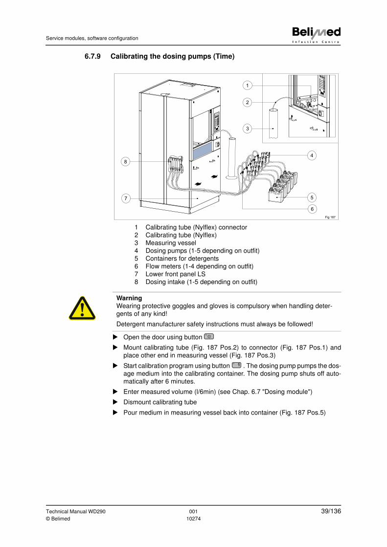
6.7.9 Calibrating the dosing pumps (Time)
1 Calibrating tube (Nylflex) connector
2 Calibrating tube (Nylflex)
3 Measuring vessel
4 Dosing pumps (1-5 depending on outfit)
5 Containers for detergents
6 Flow meters (1-4 depending on outfit)
7 Lower front panel LS
8 Dosing intake (1-5 depending on outfit)
� Open the door using button
� Mount calibrating tube (Fig. 187 Pos.2) to connector (Fig. 187 Pos.1) and
place other end in measuring vessel (Fig. 187 Pos.3)
� Start calibration program using button . The dosing pump pumps the dos-
age medium into the calibrating container. The dosing pump shuts off auto-
matically after 6 minutes.
� Enter measured volume (l/6min) (see Chap. 6.7 "Dosing module")
� Dismount calibrating tube
� Pour medium in measuring vessel back into container (Fig. 187 Pos.5)
Fig 187
4
57
8
3
1
2
6
Warning
Wearing protective goggles and gloves is compulsory when handling deter-
gents of any kind!
Detergent manufacturer safety instructions must always be followed!
1
Technical Manual WD290 001 39/136© Belimed 10274
Service modules, software configuration
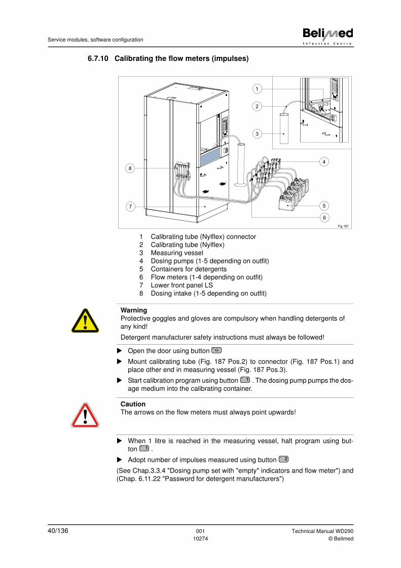
6.7.10 Calibrating the flow meters (impulses)
1 Calibrating tube (Nylflex) connector
2 Calibrating tube (Nylflex)
3 Measuring vessel
4 Dosing pumps (1-5 depending on outfit)
5 Containers for detergents
6 Flow meters (1-4 depending on outfit)
7 Lower front panel LS
8 Dosing intake (1-5 depending on outfit)
� Open the door using button
� Mount calibrating tube (Fig. 187 Pos.2) to connector (Fig. 187 Pos.1) and
place other end in measuring vessel (Fig. 187 Pos.3).
� Start calibration program using button . The dosing pump pumps the dos-
age medium into the calibrating container.
� When 1 litre is reached in the measuring vessel, halt program using but-
ton .
� Adopt number of impulses measured using button
(See Chap.3.3.4 "Dosing pump set with "empty" indicators and flow meter") and
(Chap. 6.11.22 "Password for detergent manufacturers")
Fig 187
4
57
8
3
1
2
6
Warning
Protective goggles and gloves are compulsory when handling detergents of
any kind!
Detergent manufacturer safety instructions must always be followed!
1
Caution
The arrows on the flow meters must always point upwards!
1
2
40/136 001 Technical Manual WD290
10274 © Belimed
Service modules, software configuration
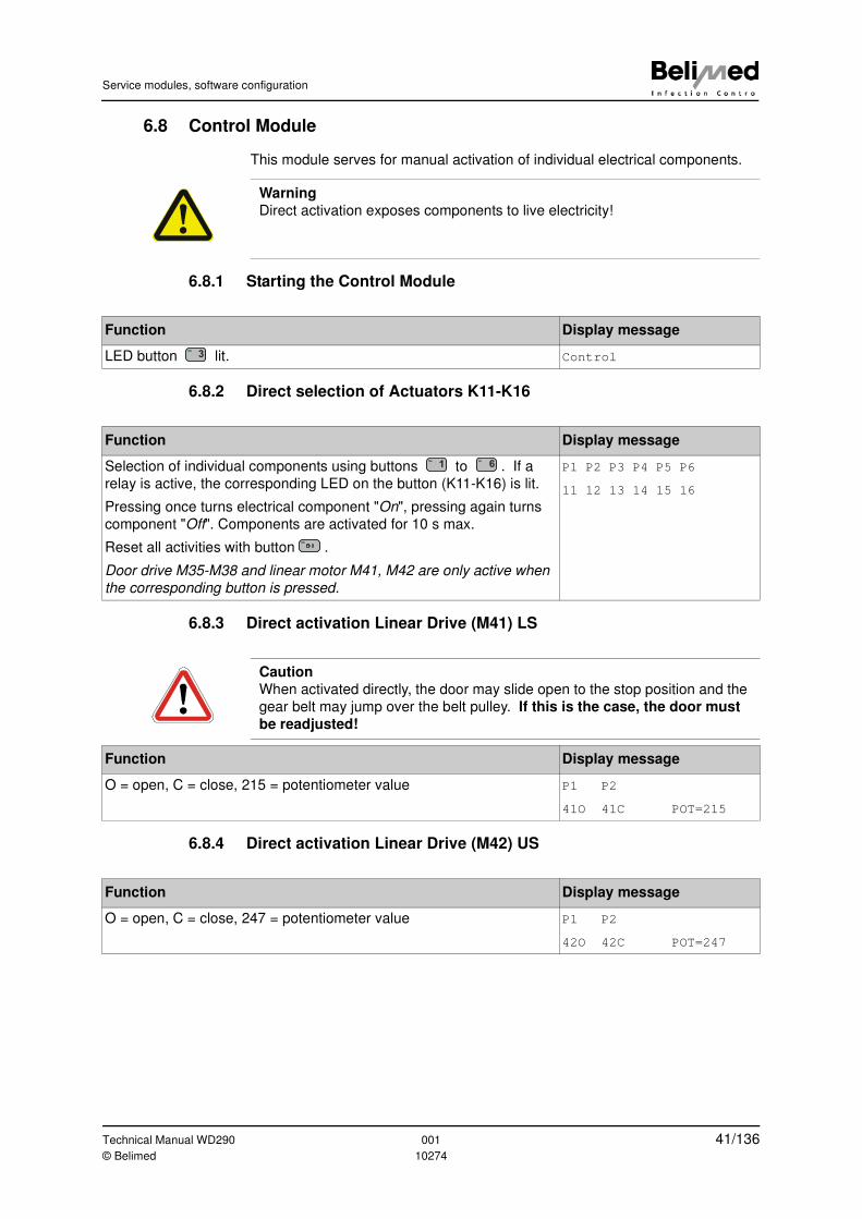
6.8 Control Module
This module serves for manual activation of individual electrical components.
6.8.1 Starting the Control Module
6.8.2 Direct selection of Actuators K11-K16
6.8.3 Direct activation Linear Drive (M41) LS
6.8.4 Direct activation Linear Drive (M42) US
Warning
Direct activation exposes components to live electricity!
Function Display message
LED button lit. Control3
Function Display message
Selection of individual components using buttons to . If a
relay is active, the corresponding LED on the button (K11-K16) is lit.
Pressing once turns electrical component "On", pressing again turns
component "Off". Components are activated for 10 s max.
Reset all activities with button .
Door drive M35-M38 and linear motor M41, M42 are only active when
the corresponding button is pressed.
P1 P2 P3 P4 P5 P6
11 12 13 14 15 16
1 6
0 I
Caution
When activated directly, the door may slide open to the stop position and the
gear belt may jump over the belt pulley. If this is the case, the door must
be readjusted!
Function Display message
O = open, C = close, 215 = potentiometer value P1 P2
41O 41C POT=215
Function Display message
O = open, C = close, 247 = potentiometer value P1 P2
42O 42C POT=247
Technical Manual WD290 001 41/136© Belimed 10274
Service modules, software configuration
6.9 Parameter Module
This module serves for entering and adjusting process parameters.
6.9.1 Starting the Parameter Module
6.9.2 Selecting Programs P1-P6 (Shift P7-P12)
6.9.3 Allocation of the program library
Function Display message
Date of last modification. LED button lit. Parameter
Last mod. 16.05.2006
4
Function Display message
Select program to (Shift P7-P12) -> Select recipe (can be
skipped using button ) -> Program library.
(See Chap. 11.4 "Validated process parameters P1-P12")
Display / Modify
Program P1-P6?
Program name allocation
Change program name using buttons and .
Name is displayed in batch print-out and batch documentation (see
Chap. 7 "Batch print-out"). If "empty" appears, nothing is printed out.
Program P1
Instruments Normal
Holding time
Enter temperature and time specification for each step. Utility and step
allocation are not modified here (see Chap. 6.9.4 "Entering recipes").
HT (Holding time) program time is only measured if actual value
exceeds target value. 1 = "On"; 0 = "Off"
Note:
Holding time 1 always applies in thermal and chemical disinfection
(F6, F7 and FA). Holding time 0 applies in drying and condensing (M5,
M6).
1.1 Prewash 00°C
00 min HT0 D1 1.5ml
1 6
Function Display message
Displays the selected program from the program library (see Chap.
6.9.5 "Program library (program labels)").
Press button on "Do" and confirm using button . After confir-
mation, "Ok" is displayed.
From 03 = program number
To P1 = allocated program button
Do = execute
0 = delete all variables
Empty
From 03 To P1 Do
42/136 001 Technical Manual WD290
10274 © Belimed
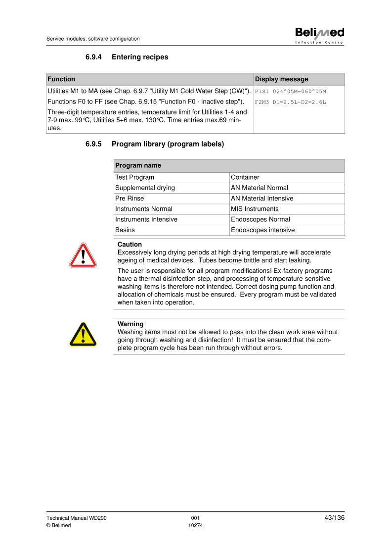
Service modules, software configuration
6.9.4 Entering recipes
6.9.5 Program library (program labels)
Function Display message
Utilities M1 to MA (see Chap. 6.9.7 "Utility M1 Cold Water Step (CW)").
Functions F0 to FF (see Chap. 6.9.15 "Function F0 - inactive step").
Three-digit temperature entries, temperature limit for Utilities 1-4 and
7-9 max. 99°C, Utilities 5+6 max. 130°C. Time entries max.69 min-
utes.
P1S1 024°05M-060°05M
F2M3 D1=2.5L-D2=2.6L
Program name
Test Program Container
Supplemental drying AN Material Normal
Pre Rinse AN Material Intensive
Instruments Normal MIS Instruments
Instruments Intensive Endoscopes Normal
Basins Endoscopes intensive
Caution
Excessively long drying periods at high drying temperature will accelerate
ageing of medical devices. Tubes become brittle and start leaking.
The user is responsible for all program modifications! Ex-factory programs
have a thermal disinfection step, and processing of temperature-sensitive
washing items is therefore not intended. Correct dosing pump function and
allocation of chemicals must be ensured. Every program must be validated
when taken into operation.
Warning
Washing items must not be allowed to pass into the clean work area without
going through washing and disinfection! It must be ensured that the com-
plete program cycle has been run through without errors.
Technical Manual WD290 001 43/136© Belimed 10274
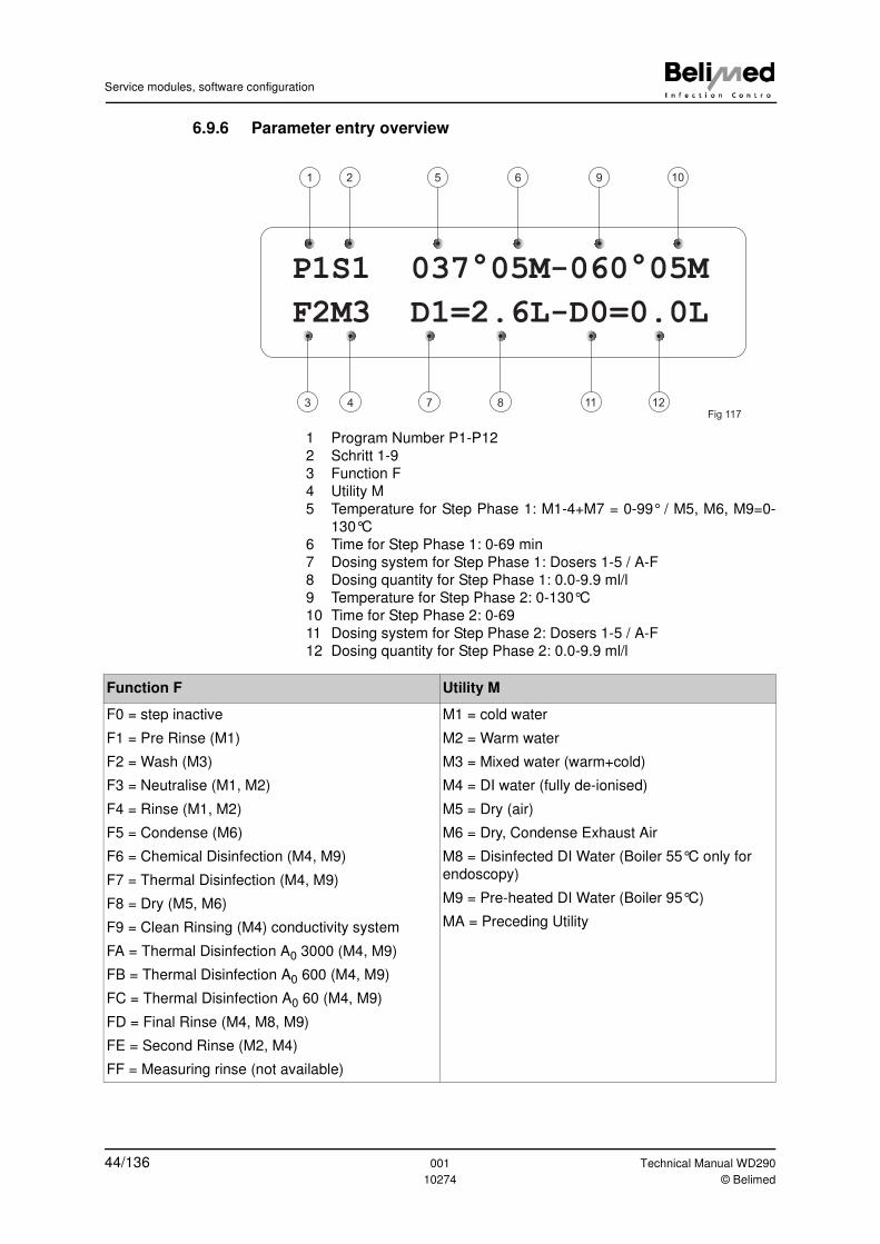
Service modules, software configuration
6.9.6 Parameter entry overview
1 Program Number P1-P12
2 Schritt 1-9
3 Function F
4 Utility M
5 Temperature for Step Phase 1: M1-4+M7 = 0-99° / M5, M6, M9=0-
130°C
6 Time for Step Phase 1: 0-69 min
7 Dosing system for Step Phase 1: Dosers 1-5 / A-F
8 Dosing quantity for Step Phase 1: 0.0-9.9 ml/l
9 Temperature for Step Phase 2: 0-130°C
10 Time for Step Phase 2: 0-69
11 Dosing system for Step Phase 2: Dosers 1-5 / A-F
12 Dosing quantity for Step Phase 2: 0.0-9.9 ml/l
P1S1 037°05M-060°05M
96 521
12118743
10
Fig 117
F2M3 D1=2.6L-D0=0.0L
Function F Utility M
F0 = step inactive
F1 = Pre Rinse (M1)
F2 = Wash (M3)
F3 = Neutralise (M1, M2)
F4 = Rinse (M1, M2)
F5 = Condense (M6)
F6 = Chemical Disinfection (M4, M9)
F7 = Thermal Disinfection (M4, M9)
F8 = Dry (M5, M6)
F9 = Clean Rinsing (M4) conductivity system
FA = Thermal Disinfection A0 3000 (M4, M9)
FB = Thermal Disinfection A0 600 (M4, M9)
FC = Thermal Disinfection A0 60 (M4, M9)
FD = Final Rinse (M4, M8, M9)
FE = Second Rinse (M2, M4)
FF = Measuring rinse (not available)
M1 = cold water
M2 = Warm water
M3 = Mixed water (warm+cold)
M4 = DI water (fully de-ionised)
M5 = Dry (air)
M6 = Dry, Condense Exhaust Air
M8 = Disinfected DI Water (Boiler 55°C only for
endoscopy)
M9 = Pre-heated DI Water (Boiler 95°C)
MA = Preceding Utility
44/136 001 Technical Manual WD290
10274 © Belimed
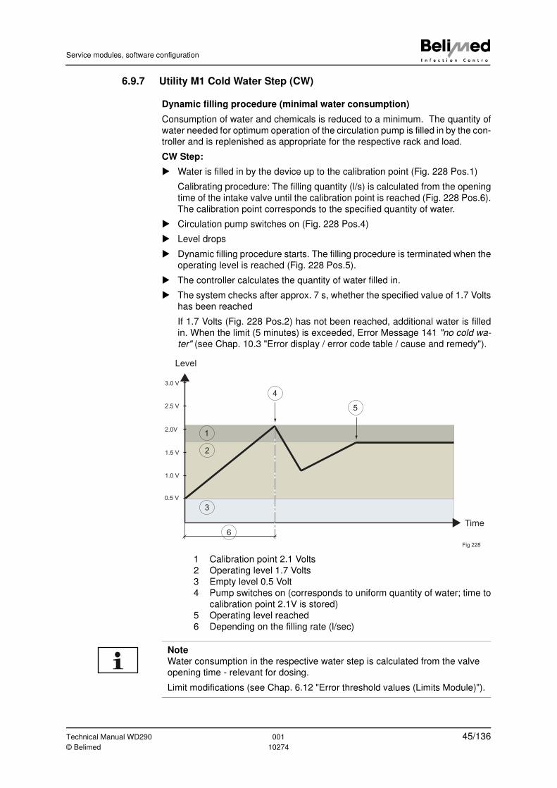
Service modules, software configuration
6.9.7 Utility M1 Cold Water Step (CW)
Dynamic filling procedure (minimal water consumption)
Consumption of water and chemicals is reduced to a minimum. The quantity of
water needed for optimum operation of the circulation pump is filled in by the con-
troller and is replenished as appropriate for the respective rack and load.
CW Step:
� Water is filled in by the device up to the calibration point (Fig. 228 Pos.1)
Calibrating procedure: The filling quantity (l/s) is calculated from the opening
time of the intake valve until the calibration point is reached (Fig. 228 Pos.6).
The calibration point corresponds to the specified quantity of water.
� Circulation pump switches on (Fig. 228 Pos.4)
� Level drops
� Dynamic filling procedure starts. The filling procedure is terminated when the
operating level is reached (Fig. 228 Pos.5).
� The controller calculates the quantity of water filled in.
� The system checks after approx. 7 s, whether the specified value of 1.7 Volts
has been reached
If 1.7 Volts (Fig. 228 Pos.2) has not been reached, additional water is filled
in. When the limit (5 minutes) is exceeded, Error Message 141 "no cold wa-
ter" (see Chap. 10.3 "Error display / error code table / cause and remedy").
1 Calibration point 2.1 Volts
2 Operating level 1.7 Volts
3 Empty level 0.5 Volt
4 Pump switches on (corresponds to uniform quantity of water; time to
calibration point 2.1V is stored)
5 Operating level reached
6 Depending on the filling rate (l/sec)
Level
Time
4
5
1
2
3
0.5 V
1.0 V
1.5 V
2.0V
2.5 V
3.0 V
6
Fig 228
Note
Water consumption in the respective water step is calculated from the valve
opening time - relevant for dosing.
Limit modifications (see Chap. 6.12 "Error threshold values (Limits Module)").
Technical Manual WD290 001 45/136© Belimed 10274
Service modules, software configuration
Further information:
(See Chap. 6.9.10 "Utility M4 DI Water Step")
(Chap. 6.11.2 "Circulation pump operating level")
(Chap. 6.11.3 "Entering the empty level")
Temperature control
• Monitoring starts with heating up
• A max. of 45°C is permissible for F1 "Pre Rinse". If this water temperature is
exceeded, the process is stopped with Error Code 163 "Water too Hot".
• If the target temperature is not reached, the software stops the process with
Error Code 161 "No heat".
Dosing procedure
1) Dosing of the additives is calculated by means of the calibrating procedure
and can be added at the start after the target temperature is reached.
2) Dosing can be controlled via the dosing pump or the flow meter (see Chap.
6.7.10 "Calibrating the flow meters (impulses)").
Example 1:
Example 2:
6.9.8 Utility M2 Warm Water Step (WW)
Same functions as in Cold Water Step (see Chap. 6.9.7 "Utility M1 Cold Water
Step (CW)").
6.9.9 Utility M3 Mixed Water Step (CW+WW)
Same functions as in Cold Water Step (see Chap. 6.9.7 "Utility M1 Cold Water
Step (CW)").
During the dynamic filling procedure, cold and warm water are filled in up to the
specified temperature. WW is added first, and after the target temperature is
reached, CW is added.
Phase 1- Phase 2
P1S1_ 035°00M- 060°05M Phase 1: Filling at 35°C, dosing 2.6 ml
F1M3_ D1 = 2.6L- D1 = 0.0L Phase 2: Heating up to 60°C
Phase 1- Phase 2
P1S1_ 035°00M- 060°05M Phase 1: Filling without dosing
F1M3_ D1 = 0.0L- D1 = 5.0L Phase 2: Heating up to 60°C, dosing 5 ml
Note
If dosing is entered together with a temperature in the first program phase,
dosing is carried out only after the target temperature has been reached.
Note
If no temperature is programmed (00), the program starts with the present
temperature of the warm water.
46/136 001 Technical Manual WD290
10274 © Belimed
Service modules, software configuration
6.9.10 Utility M4 DI Water Step
Same functions as in Cold Water Step (see Chap. 6.9.7 "Utility M1 Cold Water
Step (CW)").
6.9.11 Utility M5 Drying
Ventilator (Outlet K17) and dryer heater (K18) are controlled by means of air tem-
perature sensor input (NTC2). Temperature indicated on display or printer corre-
sponds to air temperature sensor (NTC2) at tub intake (see Chap. 6.10.14
"Pumping off in the event of programm interruption").
6.9.12 Condenser M6 functions
In order to activate the condenser, Utility M6 "Condense" must be programmed
instead of M5 "Dry". In this medium, the CW valve (Y27) is opened for drying.
After 8 minutes of drying, the CW valve remains closed, as the exhaust air hu-
midity drops below 20%.
6.9.13 Pre-heated DI water M9 (Final Rinse)
Enter M9 instead of M4 for Final Rinse.
Content can be kept at the desired pre-heating temperature for e.g. 24 hours.
When no program is selected, the temperature of the water tank drops after the
preset time has elapsed (economy mode).
Setup functions:
(See Chap. 6.10.11 "Pre-heating temperature / holding time DI boiler" (Chap.
6.10.12 "Disinfection temperature / disinfection time DI boiler") (Chap. 6.11.13
"DI Boiler heater interlock with tank heater") (Chap. 8.2.3 "SC DI boiler code")
Filling procedure corresponds to the same functions as in Cold Water Step (see
Chap. 6.9.7 "Utility M1 Cold Water Step (CW)").
Note
If temperature drops below target, WW is added.
Note
A fixed lag is always programmed for the ventilator (see Chap. 6.11.12 "Dry-
ing lag time").
Note
Preferably enter Holding-Temperature 95°C, 0 minutes for the thermal disin-
fection temperature of the DI Tank. This reduces the heating up of the Final
Rinse water in the washing chamber.
Note
When programming condenser DI water pre-heating (optional), Utilities M6
and M9 must always be included in the same program. If this is not the case,
the DI water runs via the overflow into the drain.
Technical Manual WD290 001 47/136© Belimed 10274
Service modules, software configuration
6.9.14 Utility MA (1 step with 4 or more phases)
An unspecified number of temperature holding points and dosages can be pro-
grammed. Washing with a complex heating-up slope is possible
Example:
Because Utility MA has been selected: No emptying and refilling.
6.9.15 Function F0 - inactive step
A step can be switched on or off. If for example two clean rinsing steps have
been programmed, one of them can be deactivated with F0 in spite of being pro-
grammed with various parameters.
6.9.16 Function F1 - Pre Rinsing
A maximum water temperature of 45°C is permissible for this function. If this limit
is exceeded, Error Code 163 "Water too Hot" is displayed and the process is
stopped.
Phase 1- Phase 2
P1S1 035°00M- 060°05M Filling at 35°C -> Dosing 2.6 ml -> Heating up
to 60°C -> Holding time 5 min-> Dosing 1.0
mlF2M3 D1 = 2.6L- D2 = 1.0L
Phase 3- Phase 4
P1S2_ 070°03M- 080°05M Heating up to 70°C -> Holding time 3 min ->
Heating up to 80°C ->Holding time 5 minF2MA D1 = 0.0L- D1 = 0.0L
Note
F2 is automatically inserted when MA is selected. This can be changed man-
ually if necessary.
Warning
Do not set programs inactive. Programs that are not used must be deleted
completely! There is the risk of an unwanted program being selected with
"Automatic Program Recognition" (see Chap. 11.4.1 "Deleting programs").
Note
Temperatures above 45°C can lead to protein coagulation during the rinsing
phase. Query S109 is only active in F1 (see Chap. 6.10.24 "Step Repetition
(Foam control)").
48/136 001 Technical Manual WD290
10274 © Belimed
Service modules, software configuration
6.9.17 Functions F2-F5, F8, FD, FE
These are only display functions. Holding time is set to 0.
Only use M4 and M9 together with F9.
6.9.18 Function F9 Clean Rinsing (optional IPD)
After the neutralising step, rinsing with DI water is carried out. The step "Clean
Rinsing F9" should be repeated until the required conductivity value is reached.
Water is drained off and the step is restarted. This procedure is repeated for a
max. of 4 times. The number of repetitions can be set in the service program
"CAST for IPD" (see Chap. 3.3.6 "Independent content documentation system
(IPD)"). In the following step, "thermal disinfection" can be selected for example.
6.9.19 Functions F6+F7 - thermal or chemical disinfection
In both display functions, holding time is set at 1 (see Chap. 6.10.11 "Pre-heating
temperature / holding time DI boiler").
6.9.20 Function FA - thermal disinfection A0=3000
A0 = germ destruction comparable to procedures using moist heat.
The action time for thermal disinfection can be shortened using Function FA. The
device continuously measures and sums up the heat quantities during heating-
up time and terminates the phase when the required A0-Value 3000 has been
reached.
Equation:
Selection of A0-Values in practice
Definition:
"Reduction of the number of living microorganisms on a product to a pre-speci-
fied level, which is appropriate for the subsequent utilization of the product".
Reduction factor values of mostly 4 or 5 logarrhythmic steps are required of dos-
age media, depending on the type of germ.
– Disinfect containers for human excretions at minimum with A0-Value=60
– Disinfect surgical instruments at minimum with A0-Value=600
According to standard requirements, disinfection with A0-Value=3000 must be
possible. However, the application is not defined.
Fig 210
(10 ) (Z=10, =10 Sec above 65°C)t tA = Σ (T-80)/Z
0
Note
We recommend disinfection with A0-Value=3000 of all semi-critical instru-
ments which require thermal disinfection but need not be sterilised subse-
quently.
Technical Manual WD290 001 49/136© Belimed 10274
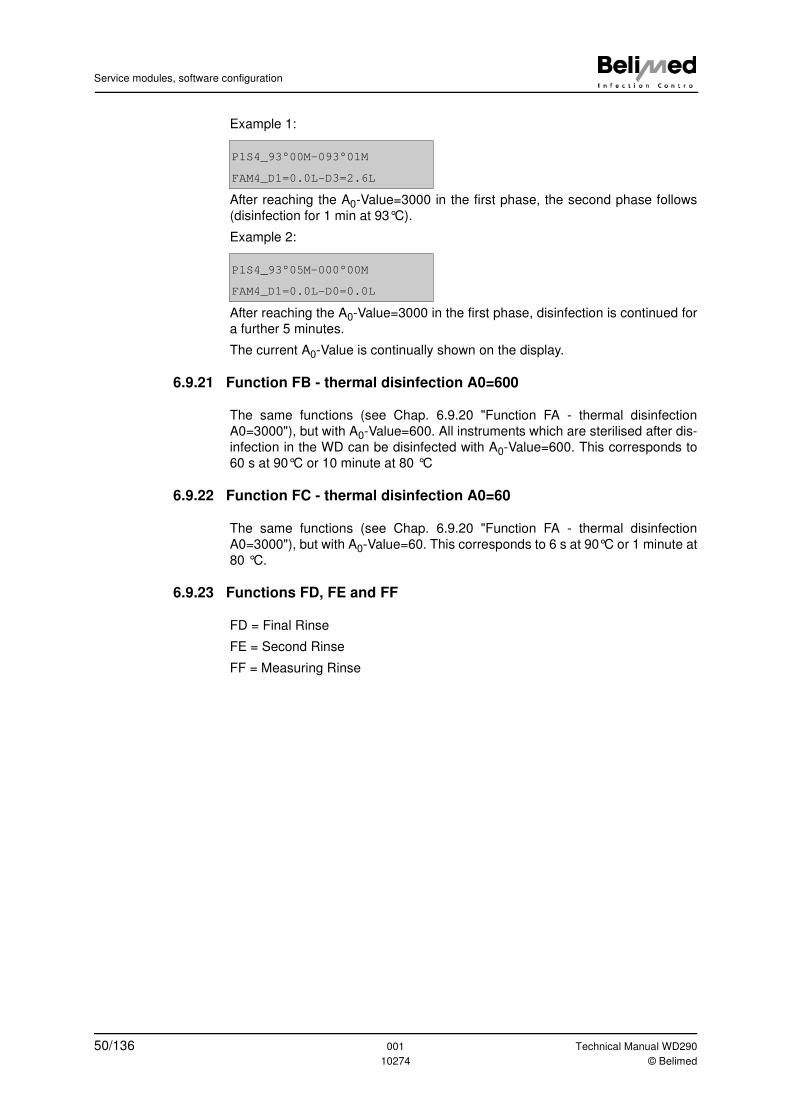
Service modules, software configuration
Example 1:
After reaching the A0-Value=3000 in the first phase, the second phase follows
(disinfection for 1 min at 93°C).
Example 2:
After reaching the A0-Value=3000 in the first phase, disinfection is continued for
a further 5 minutes.
The current A0-Value is continually shown on the display.
6.9.21 Function FB - thermal disinfection A0=600
The same functions (see Chap. 6.9.20 "Function FA - thermal disinfection
A0=3000"), but with A0-Value=600. All instruments which are sterilised after dis-
infection in the WD can be disinfected with A0-Value=600. This corresponds to
60 s at 90°C or 10 minute at 80 °C
6.9.22 Function FC - thermal disinfection A0=60
The same functions (see Chap. 6.9.20 "Function FA - thermal disinfection
A0=3000"), but with A0-Value=60. This corresponds to 6 s at 90°C or 1 minute at
80 °C.
6.9.23 Functions FD, FE and FF
FD = Final Rinse
FE = Second Rinse
FF = Measuring Rinse
P1S4_93°00M-093°01M
FAM4_D1=0.0L-D3=2.6L
P1S4_93°05M-000°00M
FAM4_D1=0.0L-D0=0.0L
50/136 001 Technical Manual WD290
10274 © Belimed
Service modules, software configuration
6.10 Configuration Module 1
Configuration 1 of the Setup Settings
6.10.1 Starting the Configuration Module
6.10.2 Setting the self-disinfection timer
6.10.3 Maintenance (batch number)
6.10.4 Ventilator operating hours (cumulative sum of drying time)
6.10.5 Language
Function Display message
Accessible without hardware key. Includes date of last modification.
LED Program Button lit.
Configuration
Last mod. 16.05.20065
Function Display message
Time between last program cycle and self-disinfection prompting (see
Chap. 11.3 "Why self-disinfection?").
Settings range 1-99 hours, 0 = inactive, default setting = 24 h
Caution!
For active self-disinfection, the entry in Mode "Basket Coding" must be
on "On" (see Chap. 6.10.16 "Automatic rack recognition").
Timer Self Disinf.
24 Hours
Function Display message
Upon reaching the specified number of hours of operation of the venti-
lator, "Periodical Service" appears instead of "Program ready". The
device can still continue operating.
00 = Maintenance display is switched off.
Following maintenance, the number must be increased by the respec-
tive number of batches (see Chap. 6.11.27 "Batch counter adjust-
ment").
Service Batch Count
1000
Function Display message
After replacing the air filter, set the hours of operation to zero using
button .
Op. Time Air Filter
Reset Timer 200 h
Function Display message
Switching to other language using buttons and . Language
English
Technical Manual WD290 001 51/136© Belimed 10274
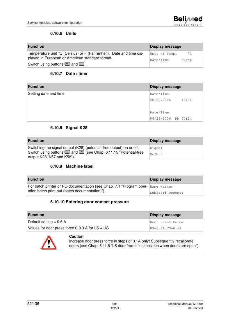
Service modules, software configuration
6.10.6 Units
6.10.7 Date / time
6.10.8 Signal K28
6.10.9 Machine label
6.10.10 Entering door contact pressure
Function Display message
Temperature unit °C (Celsius) or F (Fahrenheit). Date and time dis-
played in European or American standard format.
Switch using buttons and .
Unit of Temp. °C
Date/Time Europ
Function Display message
Setting date and time Date/Time
28.06.2006 16:24
Date/Time
06/28/2006 PM 04:24
Function Display message
Switching the signal output (K28) (potential-free output) on or off.
Switch using buttons and (see Chap. 6.11.15 "Potential-free
output K28, K57 and K58").
Signal
On/Off
Function Display message
For batch printer or PC-documentation (see Chap. 7.1 "Program oper-
ation batch print-out (batch documentation)").
Name Washer
Substeri Decont1
Function Display message
Default setting = 0.6 A
Values for door press force 0-0.9 A for LS + US
Door Press Force
US=0.6A CS=0.6A
Caution
Increase door press force in steps of 0.1A only! Subsequently recalibrate
doors (see Chap. 6.11.8 "LS door frame final position when doors are open").
52/136 001 Technical Manual WD290
10274 © Belimed
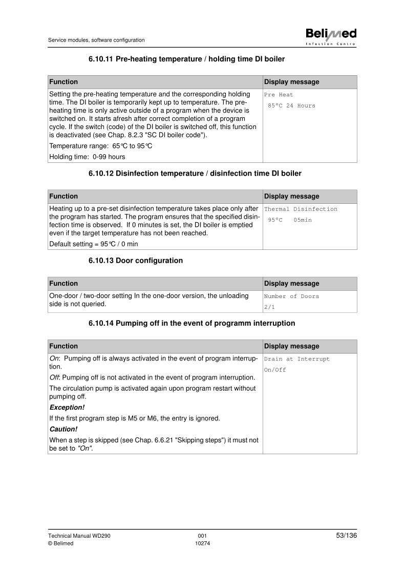
Service modules, software configuration
6.10.11 Pre-heating temperature / holding time DI boiler
6.10.12 Disinfection temperature / disinfection time DI boiler
6.10.13 Door configuration
6.10.14 Pumping off in the event of programm interruption
Function Display message
Setting the pre-heating temperature and the corresponding holding
time. The DI boiler is temporarily kept up to temperature. The pre-
heating time is only active outside of a program when the device is
switched on. It starts afresh after correct completion of a program
cycle. If the switch (code) of the DI boiler is switched off, this function
is deactivated (see Chap. 8.2.3 "SC DI boiler code").
Temperature range: 65°C to 95°C
Holding time: 0-99 hours
Pre Heat
85°C 24 Hours
Function Display message
Heating up to a pre-set disinfection temperature takes place only after
the program has started. The program ensures that the specified disin-
fection time is observed. If 0 minutes is set, the DI boiler is emptied
even if the target temperature has not been reached.
Default setting = 95°C / 0 min
Thermal Disinfection
95°C 05min
Function Display message
One-door / two-door setting In the one-door version, the unloading
side is not queried.
Number of Doors
2/1
Function Display message
On: Pumping off is always activated in the event of program interrup-
tion.
Off: Pumping off is not activated in the event of program interruption.
The circulation pump is activated again upon program restart without
pumping off.
Exception!
If the first program step is M5 or M6, the entry is ignored.
Caution!
When a step is skipped (see Chap. 6.6.21 "Skipping steps") it must not
be set to "On".
Drain at Interrupt
On/Off
Technical Manual WD290 001 53/136© Belimed 10274
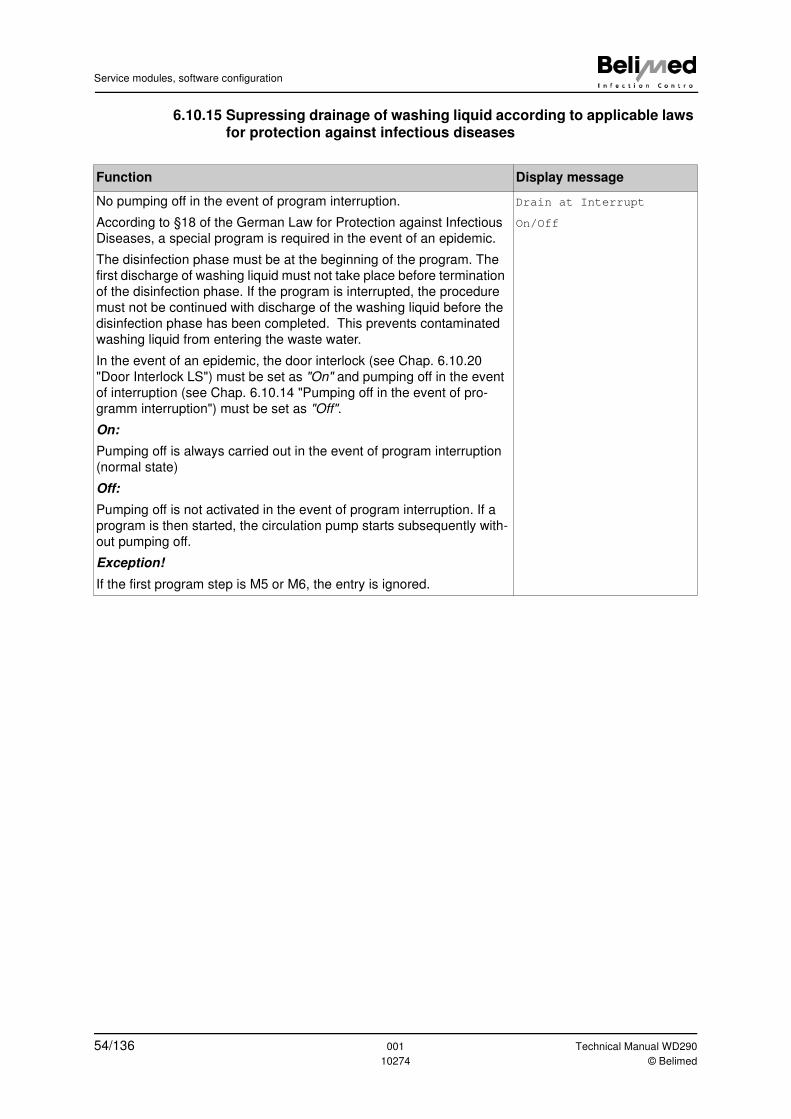
Service modules, software configuration
6.10.15 Supressing drainage of washing liquid according to applicable laws for protection against infectious diseases
Function Display message
No pumping off in the event of program interruption.
According to §18 of the German Law for Protection against Infectious
Diseases, a special program is required in the event of an epidemic.
The disinfection phase must be at the beginning of the program. The
first discharge of washing liquid must not take place before termination
of the disinfection phase. If the program is interrupted, the procedure
must not be continued with discharge of the washing liquid before the
disinfection phase has been completed. This prevents contaminated
washing liquid from entering the waste water.
In the event of an epidemic, the door interlock (see Chap. 6.10.20
"Door Interlock LS") must be set as "On" and pumping off in the event
of interruption (see Chap. 6.10.14 "Pumping off in the event of pro-
gramm interruption") must be set as "Off".
On:
Pumping off is always carried out in the event of program interruption
(normal state)
Off:
Pumping off is not activated in the event of program interruption. If a
program is then started, the circulation pump starts subsequently with-
out pumping off.
Exception!
If the first program step is M5 or M6, the entry is ignored.
Drain at Interrupt
On/Off
54/136 001 Technical Manual WD290
10274 © Belimed
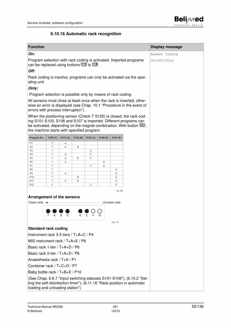
Service modules, software configuration
6.10.16 Automatic rack recognition
Function Display message
On:
Program selection with rack coding is activated. Imported programs
can be replaced using buttons to .
Off:
Rack coding is inactive, programs can only be activated via the oper-
ating unit.
Only:
Program selection is possible only by means of rack coding.
All sensors must close at least once when the rack is inserted, other-
wise an error is displayed (see Chap. 10.1 "Procedure in the event of
errors with process interruption").
When the positioning sensor (Check T S105) is closed, the rack cod-
ing S101-S103, S106 and S107 is imported. Different programs can
be activated, depending on the magnet combination. With button ,
the machine starts with specified program.
Arrangement of the sensors
Standard rack coding
Instrument rack 3-5 tiers / T+A+C / P4
MIS instrument rack / T+A+E / P6
Basic rack 1-tier / T+A+D / P6
Basic rack 2-tier / T+A+D / P6
Anaesthesia rack / T+A / P1
Container rack / T+C+D / P7
Baby bottle rack / T+B+E / P10
(See Chap. 6.6.7 "Input switching statuses S101-S106"); (6.10.2 "Set-
ting the self-disinfection timer"); (6.11.16 "Rack position in automatic
loading and unloading station")
Basket Coding
On/Off/Only1 6
Program No. S105 (T) S101 (A) S102 (B) S103 (C) S106 (D) S107 (E)
P1
P2
P3
P4
P5
P6
P8
P7
P9
P10
P11
P12
T
T
T
T
T
T
T
T
T
T
T
T
A
A
A
A
A
A
A
B
B
B
B
C
C
C
C
C
D
D
E
E
E
E
E
Fig 186
T A B C D E F G
Unclean sideClean side
Fig. 371
Technical Manual WD290 001 55/136© Belimed 10274
Service modules, software configuration
6.10.17 Message text in case of error
6.10.18 Printer drivers
6.10.19 Door opening at end of program
6.10.20 Door Interlock LS
Function Display message
Technical support phone number (see Chap. 10 "Errors with program
interruption and their elimination").
Error Message
Tech. support Phone XXXX
Function Display message
Panel: Print-out from the panel printer (custom)
Panel Katakana: Print-out from the panel printer (Katakana)
Desk (Star SP2000): Print-out from the desktop printer Star SP2000
Desk (Star SP200): Print-out from the desktop printer Star SP200
Panel Upside Down: Print-out upside down (custom panel printer)
(See Chap. 7 "Batch print-out") and (8.4.3 "Overview of printer, bar-
code reader and modem interfaces").
Printer
Panel
Function Display message
With full automation always "On"
On = US door opens automatically at end of program.
Off = Door remains closed at end of program.
Default setting ="Off"
Door open by Pro End
On/Off
Function Display message
"On" = After pressing the button , the LS door remains closed after
program interruption by means of button . "Door Interlock"
appears on the display. The LS door can be opened after termination
of the program.
Default setting = "On"
Door Interlock
On/Off0 I
56/136 001 Technical Manual WD290
10274 © Belimed
Service modules, software configuration
6.10.21 User identification
6.10.22 Rack identification
Function Display message
The names or numbers are read into the system via the operating unit
or via bar code reader for batch documentation.
When user identification is active, a user query appears at the start of
the program.
Identification number must lie between 11-65 (barcode type EAN 13).
Identification name 20 characters max. (barcode type 39).
This is forwarded to the printer with Connector X31 (RS232) or to the
interface with Screw Clamp X32 (RS485). The barcode scanner is
also connected to Connector X31. A program can only be started once
an entry has been made, otherwise the software remains on query.
If "66" is entered, the text "No Identification" is forwarded.
Default setting ="Off"
User Identification
On/Off
Function Display message
The rack numbers are read into the system via the operating unit or
via bar code reader for batch documentation.
When rack identification is active, a rack number query appears on the
display after start of the program: "Rack Name or No.". After being
entered, the number is forwarded to the printer and Batch Documenta-
tion System 8535 (see Chap. 8.4.1 "Batch Documentation System ICS
8535 / 8565").
Identification number must lie between 11-65 (barcode type EAN 13).
Identification name 20 characters max. (barcode type 39).
Note:
Only Digits 1-6 can be used for a number. (not possible: e.g. 17, 18,
19, 27, 28, 29...)
This is forwarded to the printer with Connector X31 (RS232) or to the
interface with Screw Clamp X32 (RS485). The barcode scanner is
also connected to Connector X31. A program can only be started once
an entry has been made, otherwise the software remains on query. If
"66" is entered, the text "No Identification" is forwarded.
On/Off: Rack identification activated/deactivated
Rack Identification
On/Off
Technical Manual WD290 001 57/136© Belimed 10274
Service modules, software configuration
6.10.23 Content On / Off
6.10.24 Step Repetition (Foam control)
Function Display message
When content identification is active, a content query (e.g. sieve tray
number) appears on the display instead of "Door is open" when the
door is open.
The content is read (e.g. sieve trays)
Identification number must lie between 11-65 or reads a text by means
of a barcode scanner.
Note:
Only Digits 1-6 can be used for a number. (not possible: 17, 18, 19,
27, 28, 29...)
This is forwarded to the printer with Connector X31 (RS232) or to the
interface with Screw Clamp X32 (RS485). The barcode scanner is
also connected to Connector X31. A program can only be started once
an entry has been made, otherwise the software remains on query. If
"66" is entered, the text "No Identification" is forwarded.
Default setting ="Off"
Batch Content Ident
On/Off
Function Display message
Function F1 (see Chap. 6.9.16 "Function F1 - Pre Rinsing").
On
If S109 opens during pre-rinsing (only in Function F1), the pre-rinsing
step is repeated without error display. Two pre-rinse steps without
comment appear in the batch documentation (see Chap. 7.1 "Program
operation batch print-out (batch documentation)").
If during repeat S109 opens again, an error signal is triggered, and
pre-rinsing is discontinued with Error 113 (see Chap. 10.3 "Error dis-
play / error code table / cause and remedy").
Off
If S109 opens during pre-rinsing, Error 113 (see Chap. 10.3 "Error dis-
play / error code table / cause and remedy") is triggered and pre-rins-
ing is discontinued.
Step Repetition S109
On/Off
58/136 001 Technical Manual WD290
10274 © Belimed
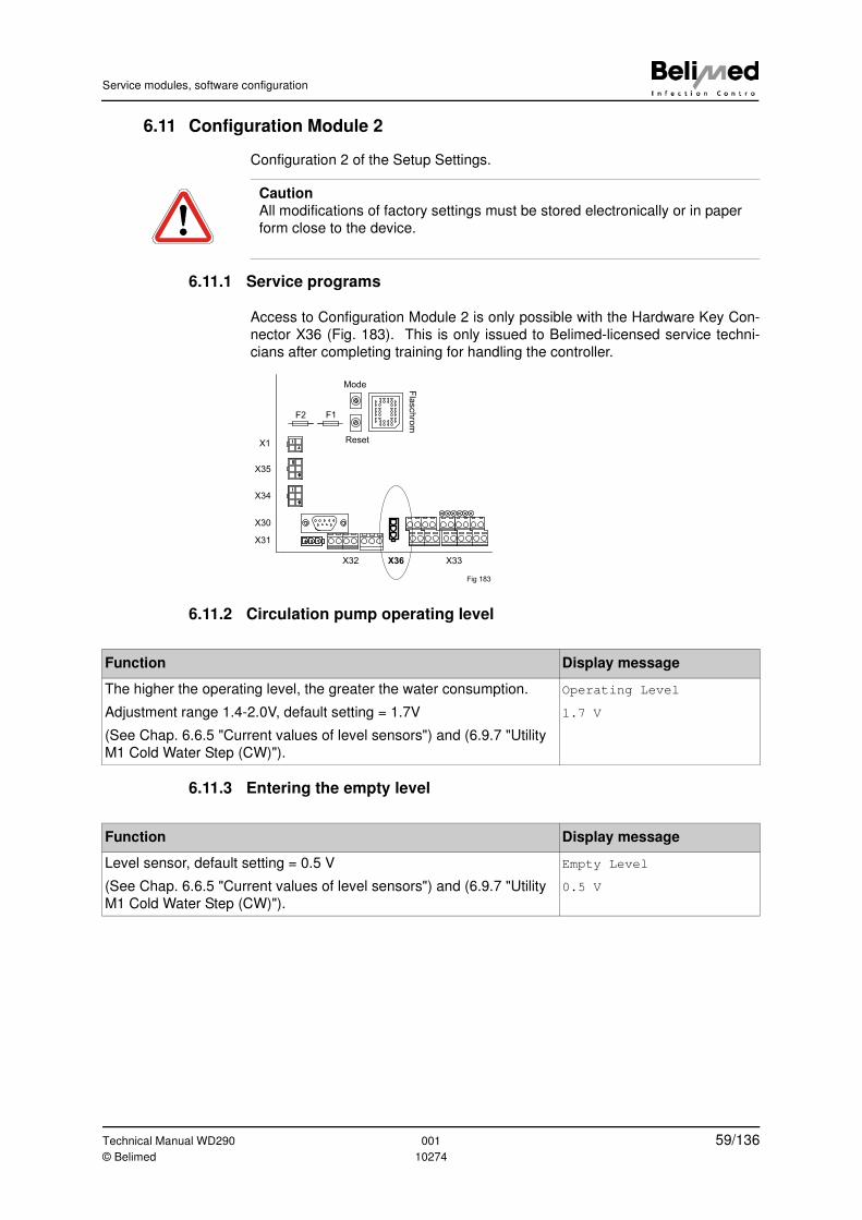
Service modules, software configuration
6.11 Configuration Module 2
Configuration 2 of the Setup Settings.
6.11.1 Service programs
Access to Configuration Module 2 is only possible with the Hardware Key Con-
nector X36 (Fig. 183). This is only issued to Belimed-licensed service techni-
cians after completing training for handling the controller.
6.11.2 Circulation pump operating level
6.11.3 Entering the empty level
Caution
All modifications of factory settings must be stored electronically or in paper
form close to the device.
1
4
1
6
1
6
123
X32 X36 X33
F2 F1
Mode
ResetF
lasch
rom
X1
X35
X34
X30
X31
Fig 183
Function Display message
The higher the operating level, the greater the water consumption.
Adjustment range 1.4-2.0V, default setting = 1.7V
(See Chap. 6.6.5 "Current values of level sensors") and (6.9.7 "Utility
M1 Cold Water Step (CW)").
Operating Level
1.7 V
Function Display message
Level sensor, default setting = 0.5 V
(See Chap. 6.6.5 "Current values of level sensors") and (6.9.7 "Utility
M1 Cold Water Step (CW)").
Empty Level
0.5 V
Technical Manual WD290 001 59/136© Belimed 10274
Service modules, software configuration
6.11.4 Pumping-off time
6.11.5 Drain
6.11.6 Calibrating the temperature sensors
6.11.7 Temperature sensor allocation
Function Display message
The holding time (t-drain) can be changed between program steps. It
is measured only after the empty level (e.g. 0.5 V) has been reached.
Depending on the drainage situation, the value must be readjusted
and the time increased accordingly.
Warning!
Residual water can lead to transfer of suds between water steps.
Range 0-99 s, default setting = 5 s
Drainage pump opens for 20 s before every start of a program.
(See also Chap.6.12 "Error threshold values (Limits Module)").
Drain Time
30 sec
Function Display message
Drainage pump configuration or drainage valve
Default setting = drainage valve (pumping off is carried out in intervals
when drainage pump is activated).
(See Chap. 3.6.5 "Connection requirements for installation")
Drain
Valve/Pump
Function Display message
Temperature and compensation factor for temperature sensors
Range: +/- 5°C in steps of 0.1°C
When a temperature sensor deviates more than +/- 1°C from the cali-
brated reference sensor, the temperature sensor must be corrected.
NTC1 = Washing chamber sump control sensor (controls the process)
NTC4 = DI water tank (not required)
NTC5 = washing chamber sump monitoring sensor (display and
printer)
Further information (see Chap. 12.21 "Calibrating temperature sen-
sors").
Calibrate Temp NTC1
28.5°C+0.0°C=28.5°C
Function Display message
The measurement type NTC or PT100 can be allocated to the temper-
ature sensors.
NTC = T1-6, PT100 = T7-10, default setting = NTC
Temperature Sensors
NTC/PT100
60/136 001 Technical Manual WD290
10274 © Belimed
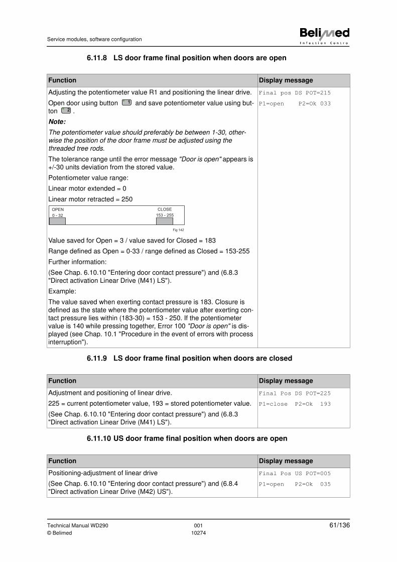
Service modules, software configuration
6.11.8 LS door frame final position when doors are open
6.11.9 LS door frame final position when doors are closed
6.11.10 US door frame final position when doors are open
Function Display message
Adjusting the potentiometer value R1 and positioning the linear drive.
Open door using button and save potentiometer value using but-
ton .
Note:
The potentiometer value should preferably be between 1-30, other-
wise the position of the door frame must be adjusted using the
threaded tree rods.
The tolerance range until the error message "Door is open" appears is
+/-30 units deviation from the stored value.
Potentiometer value range:
Linear motor extended = 0
Linear motor retracted = 250
Value saved for Open = 3 / value saved for Closed = 183
Range defined as Open = 0-33 / range defined as Closed = 153-255
Further information:
(See Chap. 6.10.10 "Entering door contact pressure") and (6.8.3
"Direct activation Linear Drive (M41) LS").
Example:
The value saved when exerting contact pressure is 183. Closure is
defined as the state where the potentiometer value after exerting con-
tact pressure lies within (183-30) = 153 - 250. If the potentiometer
value is 140 while pressing together, Error 100 "Door is open" is dis-
played (see Chap. 10.1 "Procedure in the event of errors with process
interruption").
Final pos DS POT=215
P1=open P2=Ok 0331
2
OPEN CLOSE
0 - 32 153 - 255
Fig 142
Function Display message
Adjustment and positioning of linear drive.
225 = current potentiometer value, 193 = stored potentiometer value.
(See Chap. 6.10.10 "Entering door contact pressure") and (6.8.3
"Direct activation Linear Drive (M41) LS").
Final Pos DS POT=225
P1=close P2=Ok 193
Function Display message
Positioning-adjustment of linear drive
(See Chap. 6.10.10 "Entering door contact pressure") and (6.8.4
"Direct activation Linear Drive (M42) US").
Final Pos US POT=005
P1=open P2=Ok 035
Technical Manual WD290 001 61/136© Belimed 10274
Service modules, software configuration
6.11.11 US door frame final position when doors are closed
6.11.12 Drying lag time
6.11.13 DI Boiler heater interlock with tank heater
6.11.14 Steam heated dryer
Function Display message
Positioning-adjustment of linear drive
(See Chap. 6.10.10 "Entering door contact pressure") and (6.8.4
"Direct activation Linear Drive (M42) US")
Final Pos CS POT=235
P1=close P2=Ok 205
Function Display message
A fixed ventilator lag time is programmed in order to prevent damage
to the electrical heating. The lag time is added to the programmed dry-
ing time.
Adjustment range 1-60 s; default setting = 30 s
Dryer Cooling Time
30 sec
Function Display message
On: Tank heater (R16) is interlocked with DI Boiler heater (R26). The
DI Boiler heater (R26) is interlocked with the dryer heater (R18).
Off: Tank heater and DI Boiler heater are not interlocked.
(See Chap.3.6.8 "Electrical function diagram with steam drying").
Lock Heater Boiler
On/Off
Function Display message
For steam heated drying, both heaters are opened in parallel. Air and
tank heaters are switched on when drying.
Caution!
Never set to "On" with electrical tank heater on! Default setting ="Off"
Further information:
(See Chap. 6.11.17 "Delay interval for washing-liquid heating") and
(Chap. 3.6.8 "Electrical function diagram with steam drying").
Dryer Steam
On/Off
62/136 001 Technical Manual WD290
10274 © Belimed
Service modules, software configuration
6.11.15 Potential-free output K28, K57 and K58
6.11.16 Rack position in automatic loading and unloading station
Function Display message
The signals can be allocated to Outputs (K28), (K57) and (K58). The
relay (K28) is in the electro drawer. Default setting = end of program.
Connection can be made potential-free or with voltage, depending on
the type of connection.
Signals:
Error; program running (Run); end of program; open exhaust flap (dry-
ing); pre shut-off valves; chamber lighting
Error
An error causes the current program to be interrupted and closes
(K28), (K57) and (K58). Information for the house control system.
Exhaust flap function (drying)
When the drying or condensing step M5, M6 starts, (K28), (K57) and
(K58) close. (K28) closes before the relay (K17) is activated. In auto-
matically propelled exhaust flaps, the flap can be opened before the
drying ventilator is activated.
Pre shut-off valve function
(K28), (K57) or (K58) are closed when a program is running or the
valve (Y27) for DI water pre-heating is activated.
Chamber lighting function
(K28), (K57) and (K58) are closed when a program is running, the
doors are open or a program has been finished in which the door has
not yet been opened.
Note:
(K57) and (K58) are optional and only possible with additional PCB!
(See Chap. 6.10.8 "Signal K28") and (Chap. 5.3 "Electro drawer with
PCBs")
Output K28
Program finished
Output K57
Program run
Output K58
Exhaust Flap
Function Display message
After Switch (S105) has been read in, the automatic loading and
unloading motor (M33) continues running for the selected delay inter-
val. Delay interval is shown in milliseconds.
Note:
Rack must be positioned correctly.
(See Chap. 6.10.16 "Automatic rack recognition") and (12.22 "Auto-
matic loading and unloading (optional)").
Delay Rack Position
200 ms
Technical Manual WD290 001 63/136© Belimed 10274
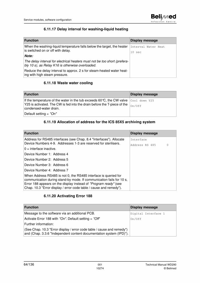
Service modules, software configuration
6.11.17 Delay interval for washing-liquid heating
6.11.18 Waste water cooling
6.11.19 Allocation of address for the ICS 85X5 archiving system
6.11.20 Activating Error 188
Function Display message
When the washing-liquid temperature falls below the target, the heater
is switched on or off with delay.
Note:
The delay interval for electrical heaters must not be too short (prefera-
bly 10 s), as Relay K16 is otherwise overloaded.
Reduce the delay interval to approx. 2 s for steam-heated water heat-
ing with high steam pressure.
Interval Water Heat
10 sec
Function Display message
If the temperature of the water in the tub exceeds 60°C, the CW valve
Y25 is activated. The CW is fed into the drain before the T-piece of the
condensed-water drain.
Default setting = "On"
Cool down Y25
On/Off
Function Display message
Address for RS485 interfaces (see Chap. 8.4 "Interfaces"). Allocate
Device Numbers 4-9. Addresses 1-3 are reserved for sterilisers.
0 = interface inactive.
Device Number 1: Address 4
Device Number 2: Address 5
Device Number 3: Address 6
Device Number 4: Address 7
When Address RS485 is not 0, the RS485 interface is queried for
communication during stand-by mode. If communication fails for 10 s,
Error 188 appears on the display instead of "Program ready" (see
Chap. 10.3 "Error display / error code table / cause and remedy").
Interface
Address RS 485 0
Function Display message
Message to the software via an additional PCB.
Activate Error 188 with "On". Default setting = "Off"
Further information:
(See Chap. 10.3 "Error display / error code table / cause and remedy")
and (Chap. 3.3.6 "Independent content documentation system (IPD)").
Digital Interface 1
On/Off
64/136 001 Technical Manual WD290
10274 © Belimed
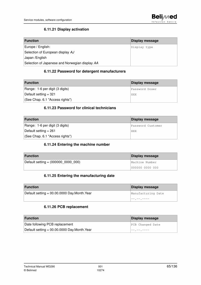
Service modules, software configuration
6.11.21 Display activation
6.11.22 Password for detergent manufacturers
6.11.23 Password for clinical technicians
6.11.24 Entering the machine number
6.11.25 Entering the manufacturing date
6.11.26 PCB replacement
Function Display message
Europe / English:
Selection of European display AJ
Japan /English
Selection of Japanese and Norwegian display AA
Display type
Function Display message
Range: 1-6 per digit (3 digits)
Default setting = 321
(See Chap. 6.1 "Access rights")
Password Doser
XXX
Function Display message
Range: 1-6 per digit (3 digits)
Default setting = 261
(See Chap. 6.1 "Access rights")
Password Customer
XXX
Function Display message
Default setting = (000000_0000_000) Machine Number
000000 0000 000
Function Display message
Default setting = 00.00.0000 Day.Month.Year Manufacturing Date
--.--.----
Function Display message
Date following PCB replacement
Default setting = 00.00.0000 Day.Month.Year
PCB Changed Date
--.--.----
Technical Manual WD290 001 65/136© Belimed 10274
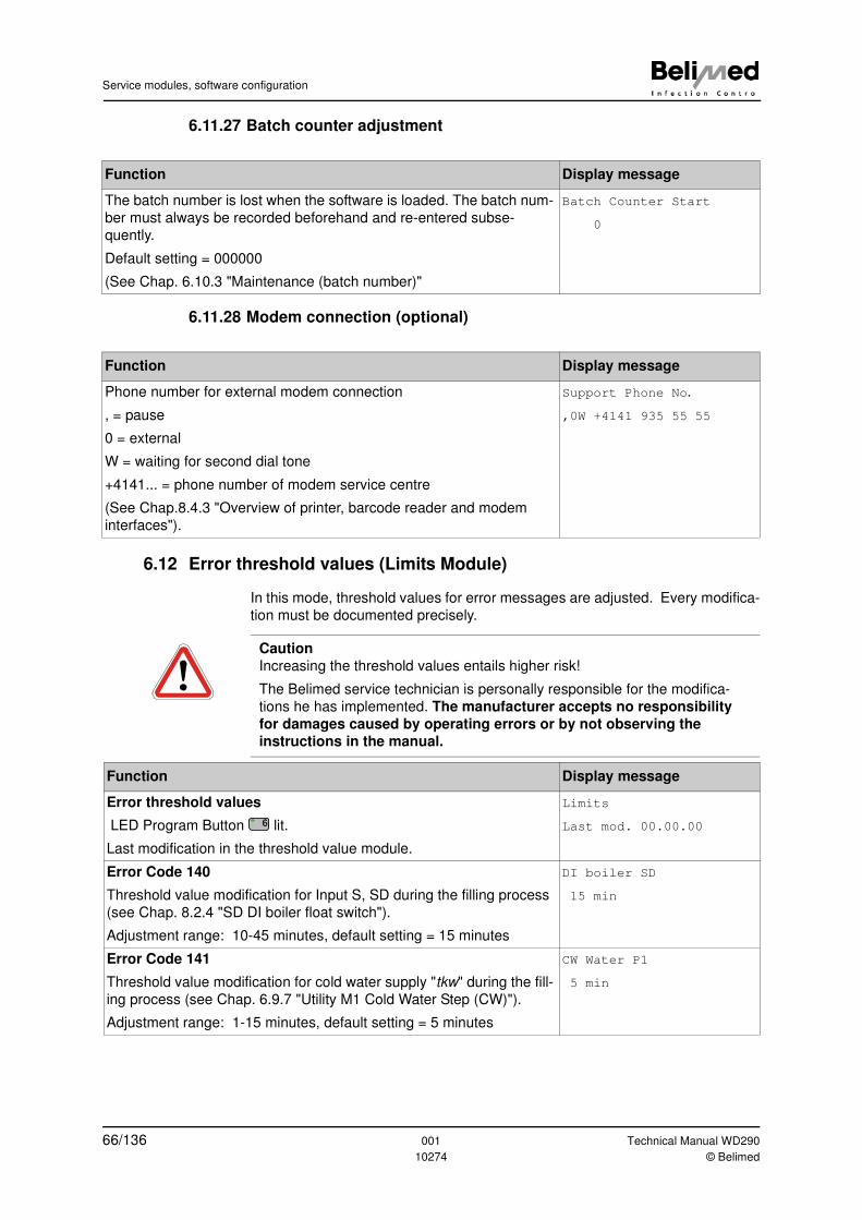
Service modules, software configuration
6.11.27 Batch counter adjustment
6.11.28 Modem connection (optional)
6.12 Error threshold values (Limits Module)
In this mode, threshold values for error messages are adjusted. Every modifica-
tion must be documented precisely.
Function Display message
The batch number is lost when the software is loaded. The batch num-
ber must always be recorded beforehand and re-entered subse-
quently.
Default setting = 000000
(See Chap. 6.10.3 "Maintenance (batch number)"
Batch Counter Start
0
Function Display message
Phone number for external modem connection
, = pause
0 = external
W = waiting for second dial tone
+4141... = phone number of modem service centre
(See Chap.8.4.3 "Overview of printer, barcode reader and modem
interfaces").
Support Phone No.
,0W +4141 935 55 55
Caution
Increasing the threshold values entails higher risk!
The Belimed service technician is personally responsible for the modifica-
tions he has implemented. The manufacturer accepts no responsibility
for damages caused by operating errors or by not observing the
instructions in the manual.
Function Display message
Error threshold values
LED Program Button lit.
Last modification in the threshold value module.
Limits
Last mod. 00.00.00
Error Code 140
Threshold value modification for Input S, SD during the filling process
(see Chap. 8.2.4 "SD DI boiler float switch").
Adjustment range: 10-45 minutes, default setting = 15 minutes
DI boiler SD
15 min
Error Code 141
Threshold value modification for cold water supply "tkw" during the fill-
ing process (see Chap. 6.9.7 "Utility M1 Cold Water Step (CW)").
Adjustment range: 1-15 minutes, default setting = 5 minutes
CW Water P1
5 min
6
66/136 001 Technical Manual WD290
10274 © Belimed
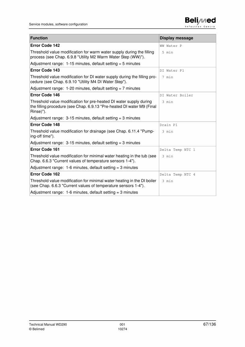
Service modules, software configuration
Error Code 142
Threshold value modification for warm water supply during the filling
process (see Chap. 6.9.8 "Utility M2 Warm Water Step (WW)").
Adjustment range: 1-15 minutes, default setting = 5 minutes
WW Water P
5 min
Error Code 143
Threshold value modification for DI water supply during the filling pro-
cedure (see Chap. 6.9.10 "Utility M4 DI Water Step").
Adjustment range: 1-20 minutes, default setting = 7 minutes
DI Water P1
7 min
Error Code 146
Threshold value modification for pre-heated DI water supply during
the filling procedure (see Chap. 6.9.13 "Pre-heated DI water M9 (Final
Rinse)").
Adjustment range: 3-15 minutes, default setting = 3 minutes
DI Water Boiler
3 min
Error Code 148
Threshold value modification for drainage (see Chap. 6.11.4 "Pump-
ing-off time").
Adjustment range: 3-15 minutes, default setting = 3 minutes
Drain P1
3 min
Error Code 161
Threshold value modification for minimal water heating in the tub (see
Chap. 6.6.3 "Current values of temperature sensors 1-4").
Adjustment range: 1-6 minutes, default setting = 3 minutes
Delta Temp NTC 1
3 min
Error Code 162
Threshold value modification for minimal water heating in the DI boiler
(see Chap. 6.6.3 "Current values of temperature sensors 1-4").
Adjustment range: 1-6 minutes, default setting = 3 minutes
Delta Temp NTC 4
3 min
Function Display message
Technical Manual WD290 001 67/136© Belimed 10274
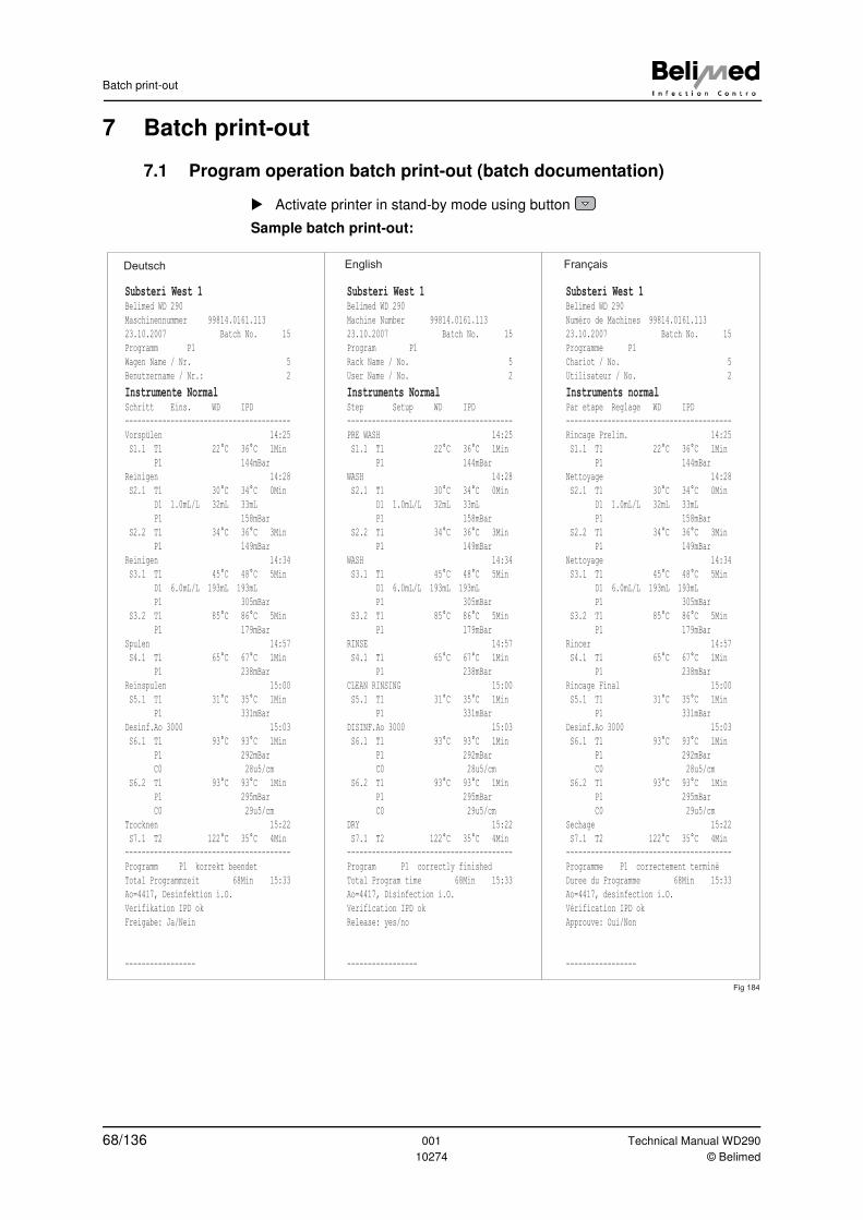
Batch print-out
7 Batch print-out
7.1 Program operation batch print-out (batch documentation)
� Activate printer in stand-by mode using button
Sample batch print-out:
Substeri West 1
Belimed WD 290
Maschinennummer 99814.0161.113
23.10.2007 Batch No. 15
Programm P1
Wagen Name / Nr. 5
Benutzername / Nr.: 2
Instrumente Normal
Schritt Eins. WD IPD
----------------------------------------
Vorspülen 14:25
S1.1 T1 22°C 36°C 1Min
P1 144mBar
Reinigen 14:28
S2.1 T1 30°C 34°C 0Min
D1 1.0mL/L 32mL 33mL
P1 158mBar
S2.2 T1 34°C 36°C 3Min
P1 149mBar
Reinigen 14:34
S3.1 T1 45°C 48°C 5Min
D1 6.0mL/L 193mL 193mL
P1 305mBar
S3.2 T1 85°C 86°C 5Min
P1 179mBar
Spulen 14:57
S4.1 T1 65°C 67°C 1Min
P1 238mBar
Reinspulen 15:00
S5.1 T1 31°C 35°C 1Min
P1 331mBar
Desinf.Ao 3000 15:03
S6.1 T1 93°C 93°C 1Min
P1 292mBar
C0 28u5/cm
S6.2 T1 93°C 93°C 1Min
P1 295mBar
C0 29u5/cm
Trocknen 15:22
S7.1 T2 122°C 35°C 4Min
----------------------------------------
Programm P1 korrekt beendet
Total Programmzeit 68Min 15:33
Ao=4417, Desinfektion i.O.
Verifikation IPD ok
Freigabe: Ja/Nein
-----------------
Deutsch English Français
Fig 184
Substeri West 1
Belimed WD 290
Machine Number 99814.0161.113
23.10.2007 Batch No. 15
Program P1
Rack Name / No. 5
User Name / No. 2
Instruments Normal
Step Setup WD IPD
----------------------------------------
PRE WASH 14:25
S1.1 T1 22°C 36°C 1Min
P1 144mBar
WASH 14:28
S2.1 T1 30°C 34°C 0Min
D1 1.0mL/L 32mL 33mL
P1 158mBar
S2.2 T1 34°C 36°C 3Min
P1 149mBar
WASH 14:34
S3.1 T1 45°C 48°C 5Min
D1 6.0mL/L 193mL 193mL
P1 305mBar
S3.2 T1 85°C 86°C 5Min
P1 179mBar
RINSE 14:57
S4.1 T1 65°C 67°C 1Min
P1 238mBar
CLEAN RINSING 15:00
S5.1 T1 31°C 35°C 1Min
P1 331mBar
DISINF.Ao 3000 15:03
S6.1 T1 93°C 93°C 1Min
P1 292mBar
C0 28u5/cm
S6.2 T1 93°C 93°C 1Min
P1 295mBar
C0 29u5/cm
DRY 15:22
S7.1 T2 122°C 35°C 4Min
----------------------------------------
Program P1 correctly finished
Total Program time 68Min 15:33
Ao=4417, Disinfection i.O.
Verification IPD ok
Release: yes/no
-----------------
Substeri West 1
Belimed WD 290
Numéro de Machines 99814.0161.113
23.10.2007 Batch No. 15
Programme P1
Chariot / No. 5
Utilisateur / No. 2
Instruments normal
Par etape Reglage WD IPD
----------------------------------------
Rincage Prelim. 14:25
S1.1 T1 22°C 36°C 1Min
P1 144mBar
Nettoyage 14:28
S2.1 T1 30°C 34°C 0Min
D1 1.0mL/L 32mL 33mL
P1 158mBar
S2.2 T1 34°C 36°C 3Min
P1 149mBar
Nettoyage 14:34
S3.1 T1 45°C 48°C 5Min
D1 6.0mL/L 193mL 193mL
P1 305mBar
S3.2 T1 85°C 86°C 5Min
P1 179mBar
Rincer 14:57
S4.1 T1 65°C 67°C 1Min
P1 238mBar
Rincage Final 15:00
S5.1 T1 31°C 35°C 1Min
P1 331mBar
Desinf.Ao 3000 15:03
S6.1 T1 93°C 93°C 1Min
P1 292mBar
C0 28u5/cm
S6.2 T1 93°C 93°C 1Min
P1 295mBar
C0 29u5/cm
Sechage 15:22
S7.1 T2 122°C 35°C 4Min
----------------------------------------
Programme P1 correctement terminè
Duree du Programme 68Min 15:33
Ao=4417, desinfection i.O.
Vèrification IPD ok
Approuve: Oui/Non
-----------------
68/136 001 Technical Manual WD290
10274 © Belimed
Batch print-out
7.2 Batch print-out in the event of error or program interruption
When the printer is activated in stand-by mode using button , all inputs, out-
puts, sensor values and the error code for program interruption are recorded.
7.3 Printing the setup settings and program recipe
� Press button
� "Print operating" appears on the display.
� Activate printer using button
� Press button
� "Print operating data" appears on the display.
� During this display message, press button . Printing process starts
Further information:
(See Chap.6.9.6 "Parameter entry overview") and (Chap. 6.10.18 "Printer driv-
ers")
Note
All parameters and configurations are lost when the Processor PCB is
replaced (see Chap. 9 "Downloading the control software").
Keep a print-out of the data with the device after taking the device into opera-
tion.
Technical Manual WD290 001 69/136© Belimed 10274
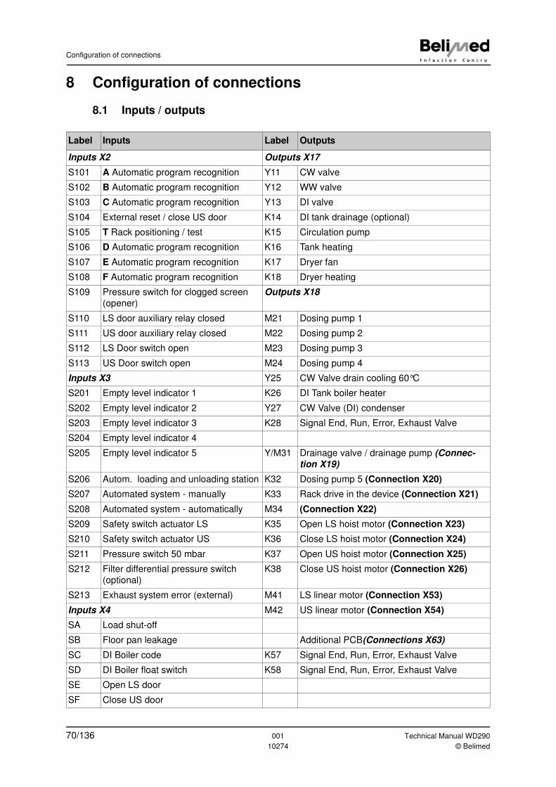
Configuration of connections
8 Configuration of connections
8.1 Inputs / outputs
Label Inputs Label Outputs
Inputs X2 Outputs X17
S101 A Automatic program recognition Y11 CW valve
S102 B Automatic program recognition Y12 WW valve
S103 C Automatic program recognition Y13 DI valve
S104 External reset / close US door K14 DI tank drainage (optional)
S105 T Rack positioning / test K15 Circulation pump
S106 D Automatic program recognition K16 Tank heating
S107 E Automatic program recognition K17 Dryer fan
S108 F Automatic program recognition K18 Dryer heating
S109 Pressure switch for clogged screen
(opener)
Outputs X18
S110 LS door auxiliary relay closed M21 Dosing pump 1
S111 US door auxiliary relay closed M22 Dosing pump 2
S112 LS Door switch open M23 Dosing pump 3
S113 US Door switch open M24 Dosing pump 4
Inputs X3 Y25 CW Valve drain cooling 60°C
S201 Empty level indicator 1 K26 DI Tank boiler heater
S202 Empty level indicator 2 Y27 CW Valve (DI) condenser
S203 Empty level indicator 3 K28 Signal End, Run, Error, Exhaust Valve
S204 Empty level indicator 4
S205 Empty level indicator 5 Y/M31 Drainage valve / drainage pump (Connec-
tion X19)
S206 Autom. loading and unloading station K32 Dosing pump 5 (Connection X20)
S207 Automated system - manually K33 Rack drive in the device (Connection X21)
S208 Automated system - automatically M34 (Connection X22)
S209 Safety switch actuator LS K35 Open LS hoist motor (Connection X23)
S210 Safety switch actuator US K36 Close LS hoist motor (Connection X24)
S211 Pressure switch 50 mbar K37 Open US hoist motor (Connection X25)
S212 Filter differential pressure switch
(optional)
K38 Close US hoist motor (Connection X26)
S213 Exhaust system error (external) M41 LS linear motor (Connection X53)
Inputs X4 M42 US linear motor (Connection X54)
SA Load shut-off
SB Floor pan leakage Additional PCB(Connections X63)
SC DI Boiler code K57 Signal End, Run, Error, Exhaust Valve
SD DI Boiler float switch K58 Signal End, Run, Error, Exhaust Valve
SE Open LS door
SF Close US door
70/136 001 Technical Manual WD290
10274 © Belimed
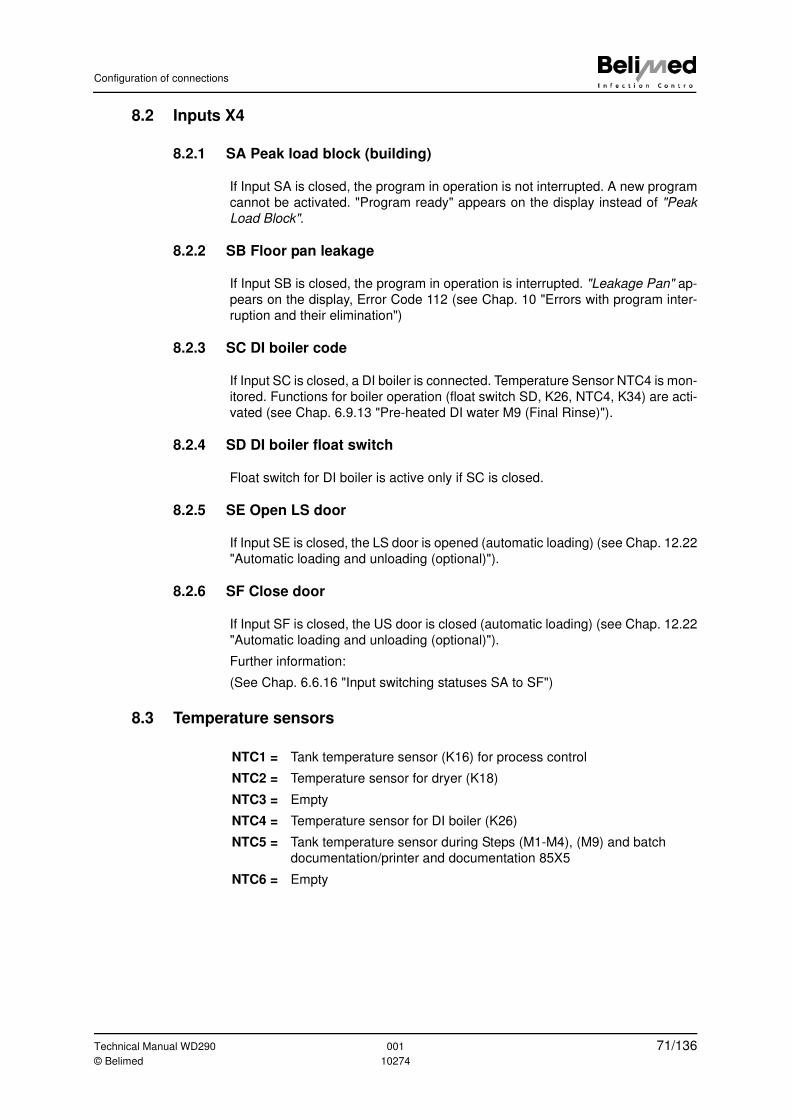
Configuration of connections
8.2 Inputs X4
8.2.1 SA Peak load block (building)
If Input SA is closed, the program in operation is not interrupted. A new program
cannot be activated. "Program ready" appears on the display instead of "Peak
Load Block".
8.2.2 SB Floor pan leakage
If Input SB is closed, the program in operation is interrupted. "Leakage Pan" ap-
pears on the display, Error Code 112 (see Chap. 10 "Errors with program inter-
ruption and their elimination")
8.2.3 SC DI boiler code
If Input SC is closed, a DI boiler is connected. Temperature Sensor NTC4 is mon-
itored. Functions for boiler operation (float switch SD, K26, NTC4, K34) are acti-
vated (see Chap. 6.9.13 "Pre-heated DI water M9 (Final Rinse)").
8.2.4 SD DI boiler float switch
Float switch for DI boiler is active only if SC is closed.
8.2.5 SE Open LS door
If Input SE is closed, the LS door is opened (automatic loading) (see Chap. 12.22
"Automatic loading and unloading (optional)").
8.2.6 SF Close door
If Input SF is closed, the US door is closed (automatic loading) (see Chap. 12.22
"Automatic loading and unloading (optional)").
Further information:
(See Chap. 6.6.16 "Input switching statuses SA to SF")
8.3 Temperature sensors
NTC1 = Tank temperature sensor (K16) for process control
NTC2 = Temperature sensor for dryer (K18)
NTC3 = Empty
NTC4 = Temperature sensor for DI boiler (K26)
NTC5 = Tank temperature sensor during Steps (M1-M4), (M9) and batch
documentation/printer and documentation 85X5
NTC6 = Empty
Technical Manual WD290 001 71/136© Belimed 10274
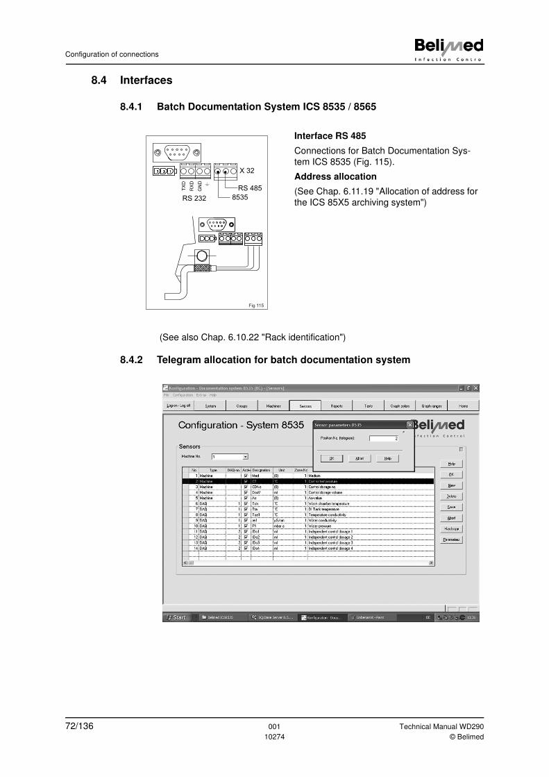
Configuration of connections
8.4 Interfaces
8.4.1 Batch Documentation System ICS 8535 / 8565
(See also Chap. 6.10.22 "Rack identification")
8.4.2 Telegram allocation for batch documentation system
Interface RS 485
Connections for Batch Documentation Sys-
tem ICS 8535 (Fig. 115).
Address allocation
(See Chap. 6.11.19 "Allocation of address for
the ICS 85X5 archiving system")
123
TX
D
GN
D
RX
D
RS 232
RS 485
8535
X 32
Fig 115
72/136 001 Technical Manual WD290
10274 © Belimed
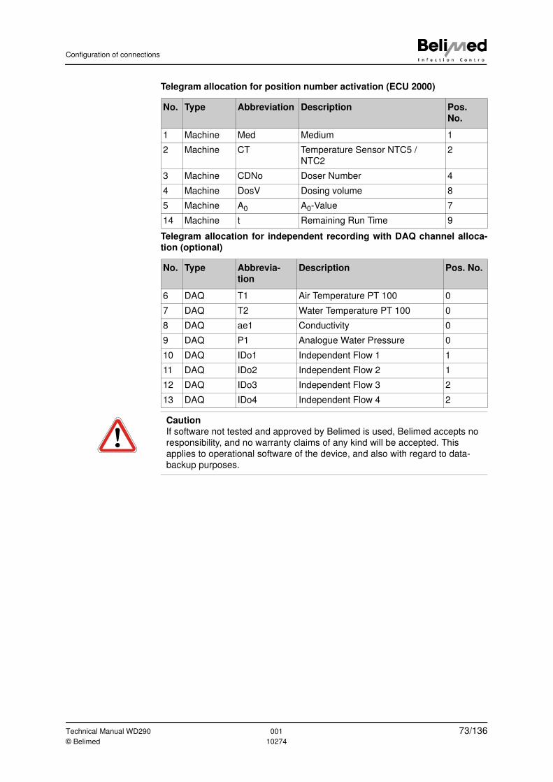
Configuration of connections
Telegram allocation for position number activation (ECU 2000)
Telegram allocation for independent recording with DAQ channel alloca-
tion (optional)
No. Type Abbreviation Description Pos.
No.
1 Machine Med Medium 1
2 Machine CT Temperature Sensor NTC5 /
NTC2
2
3 Machine CDNo Doser Number 4
4 Machine DosV Dosing volume 8
5 Machine A0 A0-Value 7
14 Machine t Remaining Run Time 9
No. Type Abbrevia-
tion
Description Pos. No.
6 DAQ T1 Air Temperature PT 100 0
7 DAQ T2 Water Temperature PT 100 0
8 DAQ ae1 Conductivity 0
9 DAQ P1 Analogue Water Pressure 0
10 DAQ IDo1 Independent Flow 1 1
11 DAQ IDo2 Independent Flow 2 1
12 DAQ IDo3 Independent Flow 3 2
13 DAQ IDo4 Independent Flow 4 2
Caution
If software not tested and approved by Belimed is used, Belimed accepts no
responsibility, and no warranty claims of any kind will be accepted. This
applies to operational software of the device, and also with regard to data-
backup purposes.
Technical Manual WD290 001 73/136© Belimed 10274
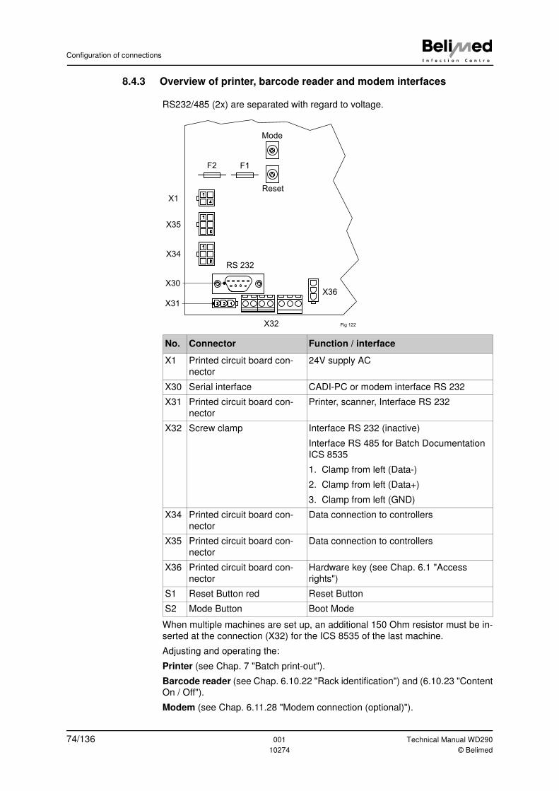
Configuration of connections
8.4.3 Overview of printer, barcode reader and modem interfaces
RS232/485 (2x) are separated with regard to voltage.
When multiple machines are set up, an additional 150 Ohm resistor must be in-
serted at the connection (X32) for the ICS 8535 of the last machine.
Adjusting and operating the:
Printer (see Chap. 7 "Batch print-out").
Barcode reader (see Chap. 6.10.22 "Rack identification") and (6.10.23 "Content
On / Off").
Modem (see Chap. 6.11.28 "Modem connection (optional)").
No. Connector Function / interface
X1 Printed circuit board con-
nector
24V supply AC
X30 Serial interface CADI-PC or modem interface RS 232
X31 Printed circuit board con-
nector
Printer, scanner, Interface RS 232
X32 Screw clamp Interface RS 232 (inactive)
Interface RS 485 for Batch Documentation
ICS 8535
1. Clamp from left (Data-)
2. Clamp from left (Data+)
3. Clamp from left (GND)
X34 Printed circuit board con-
nector
Data connection to controllers
X35 Printed circuit board con-
nector
Data connection to controllers
X36 Printed circuit board con-
nector
Hardware key (see Chap. 6.1 "Access
rights")
S1 Reset Button red Reset Button
S2 Mode Button Boot Mode
1
4
1
6
1
6
123
Mode
Reset
RS 232
X32
X36
X1
X35
X34
X30
X31
F2 F1
Fig 122
74/136 001 Technical Manual WD290
10274 © Belimed
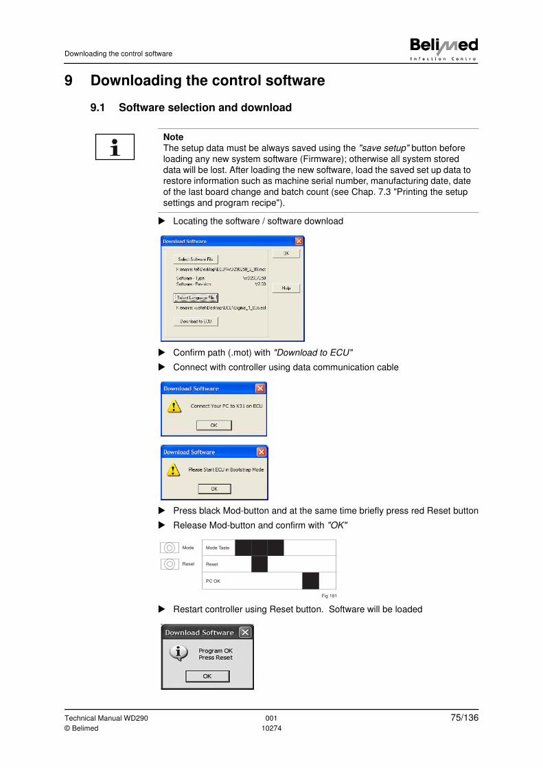
Downloading the control software
9 Downloading the control software
9.1 Software selection and download
� Locating the software / software download
� Confirm path (.mot) with "Download to ECU"
� Connect with controller using data communication cable
� Press black Mod-button and at the same time briefly press red Reset button
� Release Mod-button and confirm with "OK"
� Restart controller using Reset button. Software will be loaded
Note
The setup data must be always saved using the "save setup" button before
loading any new system software (Firmware); otherwise all system stored
data will be lost. After loading the new software, load the saved set up data to
restore information such as machine serial number, manufacturing date, date
of the last board change and batch count (see Chap. 7.3 "Printing the setup
settings and program recipe").
Mode
Reset
Mode Taste
Reset
PC OK
Fig 191
Technical Manual WD290 001 75/136© Belimed 10274
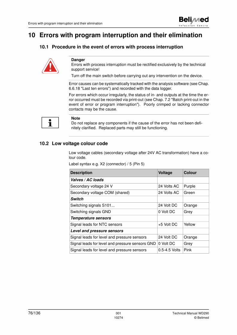
Errors with program interruption and their elimination
10 Errors with program interruption and their elimination
10.1 Procedure in the event of errors with process interruption
Error causes can be systematically tracked with the analysis software (see Chap.
6.6.18 "Last ten errors") and recorded with the data logger.
For errors which occur irregularly, the status of in- and outputs at the time the er-
ror occurred must be recorded via print-out (see Chap. 7.2 "Batch print-out in the
event of error or program interruption"). Poorly crimped or lacking connector
contacts may be the cause.
10.2 Low voltage colour code
Low voltage cables (secondary voltage after 24V AC transformation) have a co-
lour code.
Label syntax e.g. X2 (connector) / 5 (Pin 5)
Danger
Errors with process interruption must be rectified exclusively by the technical
support service!
Turn off the main switch before carrying out any intervention on the device.
Note
Do not replace any components if the cause of the error has not been defi-
nitely clarified. Replaced parts may still be functioning.
Description Voltage Colour
Valves / AC loads
Secondary voltage 24 V 24 Volts AC Purple
Secondary voltage COM (shared) 24 Volts AC Green
Switch
Switching signals S101... 24 Volt DC Orange
Switching signals GND 0 Volt DC Grey
Temperature sensors
Signal leads for NTC sensors +5 Volt DC Yellow
Level and pressure sensors
Signal leads for level and pressure sensors 24 Volt DC Orange
Signal leads for level and pressure sensors GND 0 Volt DC Grey
Signal leads for level and pressure sensors 0.5-4.5 Volts Pink
76/136 001 Technical Manual WD290
10274 © Belimed
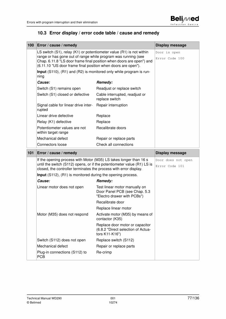
Errors with program interruption and their elimination
10.3 Error display / error code table / cause and remedy
100 Error / cause / remedy Display message
LS switch (S1), relay (K1) or potentiometer value (R1) is not within
range or has gone out of range while program was running (see
Chap. 6.11.8 "LS door frame final position when doors are open") and
(6.11.10 "US door frame final position when doors are open").
Input (S110), (R1) and (R2) is monitored only while program is run-
ning
Door is open
Error Code 100
Cause: Remedy:
Switch (S1) remains open Readjust or replace switch
Switch (S1) closed or defective Cable interrupted, readjust or
replace switch
Signal cable for linear drive inter-
rupted
Repair interruption
Linear drive defective Replace
Relay (K1) defective Replace
Potentiometer values are not
within target range
Recalibrate doors
Mechanical defect Repair or replace parts
Connectors loose Check all connections
101 Error / cause / remedy Display message
If the opening process with Motor (M35) LS takes longer than 16 s
until the switch (S112) opens, or if the potentiometer value (R1) LS is
closed, the controller terminates the process with error display.
Input (S112), (R1) is monitored during the opening process.
Door does not open
Error Code 101
Cause: Remedy:
Linear motor does not open Test linear motor manually on
Door Panel PCB (see Chap. 5.3
"Electro drawer with PCBs")
Recalibrate door
Replace linear motor
Motor (M35) does not respond Activate motor (M35) by means of
contactor (K35)
Replace door motor or capacitor
(6.8.2 "Direct selection of Actua-
tors K11-K16")
Switch (S112) does not open Replace switch (S112)
Mechanical defect Repair or replace parts
Plug-in connections (S112) to
PCB
Re-crimp
Technical Manual WD290 001 77/136© Belimed 10274
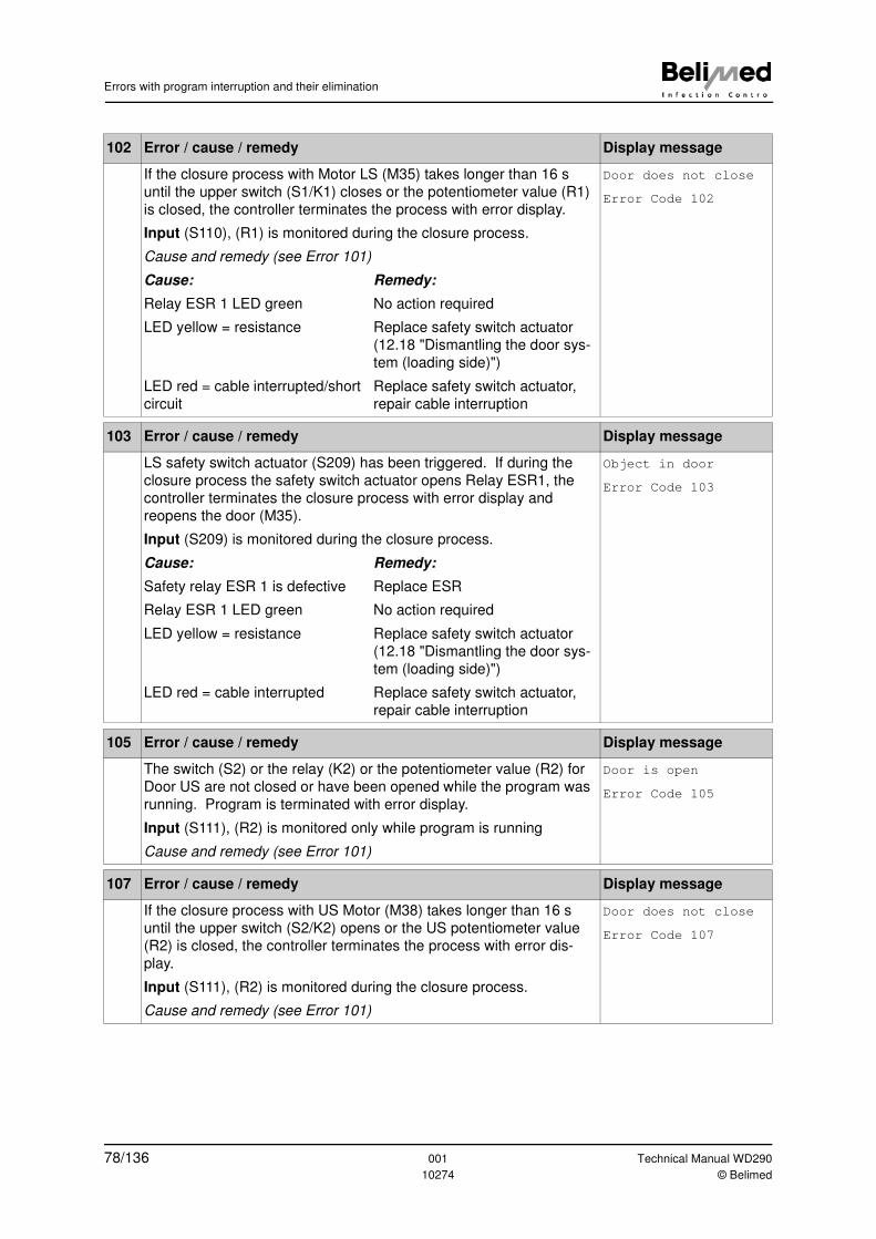
Errors with program interruption and their elimination
102 Error / cause / remedy Display message
If the closure process with Motor LS (M35) takes longer than 16 s
until the upper switch (S1/K1) closes or the potentiometer value (R1)
is closed, the controller terminates the process with error display.
Input (S110), (R1) is monitored during the closure process.
Cause and remedy (see Error 101)
Door does not close
Error Code 102
Cause: Remedy:
Relay ESR 1 LED green No action required
LED yellow = resistance Replace safety switch actuator
(12.18 "Dismantling the door sys-
tem (loading side)")
LED red = cable interrupted/short
circuit
Replace safety switch actuator,
repair cable interruption
103 Error / cause / remedy Display message
LS safety switch actuator (S209) has been triggered. If during the
closure process the safety switch actuator opens Relay ESR1, the
controller terminates the closure process with error display and
reopens the door (M35).
Input (S209) is monitored during the closure process.
Object in door
Error Code 103
Cause: Remedy:
Safety relay ESR 1 is defective Replace ESR
Relay ESR 1 LED green No action required
LED yellow = resistance Replace safety switch actuator
(12.18 "Dismantling the door sys-
tem (loading side)")
LED red = cable interrupted Replace safety switch actuator,
repair cable interruption
105 Error / cause / remedy Display message
The switch (S2) or the relay (K2) or the potentiometer value (R2) for
Door US are not closed or have been opened while the program was
running. Program is terminated with error display.
Input (S111), (R2) is monitored only while program is running
Cause and remedy (see Error 101)
Door is open
Error Code 105
107 Error / cause / remedy Display message
If the closure process with US Motor (M38) takes longer than 16 s
until the upper switch (S2/K2) opens or the US potentiometer value
(R2) is closed, the controller terminates the process with error dis-
play.
Input (S111), (R2) is monitored during the closure process.
Cause and remedy (see Error 101)
Door does not close
Error Code 107
78/136 001 Technical Manual WD290
10274 © Belimed
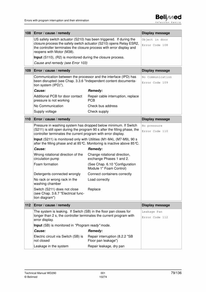
Errors with program interruption and their elimination
108 Error / cause / remedy Display message
US safety switch actuator (S210) has been triggered. If during the
closure process the safety switch actuator (S210) opens Relay ESR2,
the controller terminates the closure process with error display and
reopens with Motor (M38).
Input (S110), (R2) is monitored during the closure process.
Cause and remedy (see Error 103)
Object in door
Error Code 108
109 Error / cause / remedy Display message
Communication between the processor and the interface (IPD) has
been disrupted (see Chap. 3.3.6 "Independent content documenta-
tion system (IPD)").
No Communication
Error Code 109
Cause: Remedy:
Additional PCB for door contact
pressure is not working
Repair cable interruption, replace
PCB
No Communication Check bus address
Supply voltage Check supply
110 Error / cause / remedy Display message
Pressure in washing system has dropped below minimum. If Switch
(S211) is still open during the program 90 s after the filling phase, the
controller terminates the current program with error display.
Input (S211) is monitored only with Utilities (M1-M4), (M7-M9), 90 s
after the filling phase and at 85°C. Monitoring is inactive above 85°C.
No pressure
Error Code 110
Cause: Remedy:
Wrong rotational direction of the
circulation pump
Change rotational direction,
exchange Phases 1 and 2.
Foam formation (See Chap. 6.10 "Configuration
Module 1" Foam Control)
Detergents connected wrongly Connect containers correctly
No rack or wrong rack in the
washing chamber
Load correctly
Switch (S211) does not close
(see Chap. 3.6.7 "Electrical func-
tion diagram")
Replace
112 Error / cause / remedy Display message
The system is leaking. If Switch (SB) in the floor pan closes for
longer than 2 s, the controller terminates the current program with
error display.
Input (SB) is monitored in "Program ready" mode.
Leakage Pan
Error Code 112
Cause: Remedy:
Electric circuit via Switch (SB) is
not closed
Repair interruption (8.2.2 "SB
Floor pan leakage")
Leakage in the system Repair leakage, dry pan
Technical Manual WD290 001 79/136© Belimed 10274
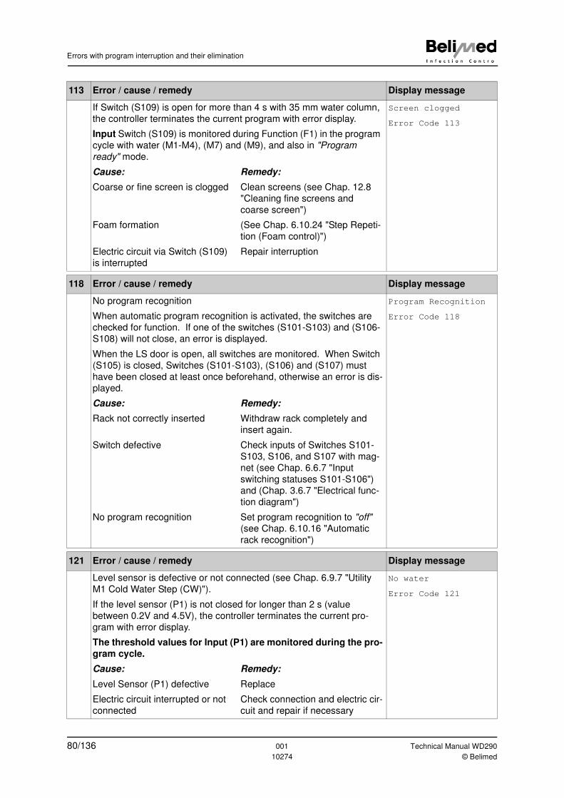
Errors with program interruption and their elimination
113 Error / cause / remedy Display message
If Switch (S109) is open for more than 4 s with 35 mm water column,
the controller terminates the current program with error display.
Input Switch (S109) is monitored during Function (F1) in the program
cycle with water (M1-M4), (M7) and (M9), and also in "Program
ready" mode.
Screen clogged
Error Code 113
Cause: Remedy:
Coarse or fine screen is clogged Clean screens (see Chap. 12.8
"Cleaning fine screens and
coarse screen")
Foam formation (See Chap. 6.10.24 "Step Repeti-
tion (Foam control)")
Electric circuit via Switch (S109)
is interrupted
Repair interruption
118 Error / cause / remedy Display message
No program recognition
When automatic program recognition is activated, the switches are
checked for function. If one of the switches (S101-S103) and (S106-
S108) will not close, an error is displayed.
When the LS door is open, all switches are monitored. When Switch
(S105) is closed, Switches (S101-S103), (S106) and (S107) must
have been closed at least once beforehand, otherwise an error is dis-
played.
Program Recognition
Error Code 118
Cause: Remedy:
Rack not correctly inserted Withdraw rack completely and
insert again.
Switch defective Check inputs of Switches S101-
S103, S106, and S107 with mag-
net (see Chap. 6.6.7 "Input
switching statuses S101-S106")
and (Chap. 3.6.7 "Electrical func-
tion diagram")
No program recognition Set program recognition to "off"
(see Chap. 6.10.16 "Automatic
rack recognition")
121 Error / cause / remedy Display message
Level sensor is defective or not connected (see Chap. 6.9.7 "Utility
M1 Cold Water Step (CW)").
If the level sensor (P1) is not closed for longer than 2 s (value
between 0.2V and 4.5V), the controller terminates the current pro-
gram with error display.
The threshold values for Input (P1) are monitored during the pro-
gram cycle.
No water
Error Code 121
Cause: Remedy:
Level Sensor (P1) defective Replace
Electric circuit interrupted or not
connected
Check connection and electric cir-
cuit and repair if necessary
80/136 001 Technical Manual WD290
10274 © Belimed
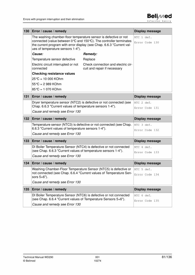
Errors with program interruption and their elimination
130 Error / cause / remedy Display message
The washing chamber-floor temperature sensor is defective or not
connected (value between 0°C and 150°C). The controller terminates
the current program with error display (see Chap. 6.6.3 "Current val-
ues of temperature sensors 1-4").
NTC 1 def.
Error Code 130
Cause: Remedy:
Temperature sensor defective Replace
Electric circuit interrupted or not
connected
Check connection and electric cir-
cuit and repair if necessary
Checking resistance values
25°C = 10 000 KOhm
55°C = 2 989 KOhm
85°C = 1 070 KOhm
131 Error / cause / remedy Display message
Dryer temperature sensor (NTC2) is defective or not connected (see
Chap. 6.6.3 "Current values of temperature sensors 1-4").
Cause and remedy see Error 130
NTC 2 def.
Error Code 131
132 Error / cause / remedy Display message
Temperature sensor (NTC3) is defective or not connected (see Chap.
6.6.3 "Current values of temperature sensors 1-4").
Cause and remedy see Error 130
NTC 3 def.
Error Code 132
133 Error / cause / remedy Display message
DI Boiler Temperature Sensor (NTC4) is defective or not connected
(see Chap. 6.6.3 "Current values of temperature sensors 1-4").
Cause and remedy see Error 130
NTC 4 def.
Error Code 133
134 Error / cause / remedy Display message
Washing Chamber-Floor Temperature Sensor (NTC5) is defective or
not connected (see Chap. 6.6.4 "Current values of Temperature Sen-
sors 5+6").
Cause and remedy see Error 130
NTC 5 def.
Error Code 134
135 Error / cause / remedy Display message
DI Boiler Temperature Sensor (NTC6) is defective or not connected
(see Chap. 6.6.4 "Current values of Temperature Sensors 5+6").
Cause and remedy see Error 130
NTC 6 def.
Error Code 135
Technical Manual WD290 001 81/136© Belimed 10274
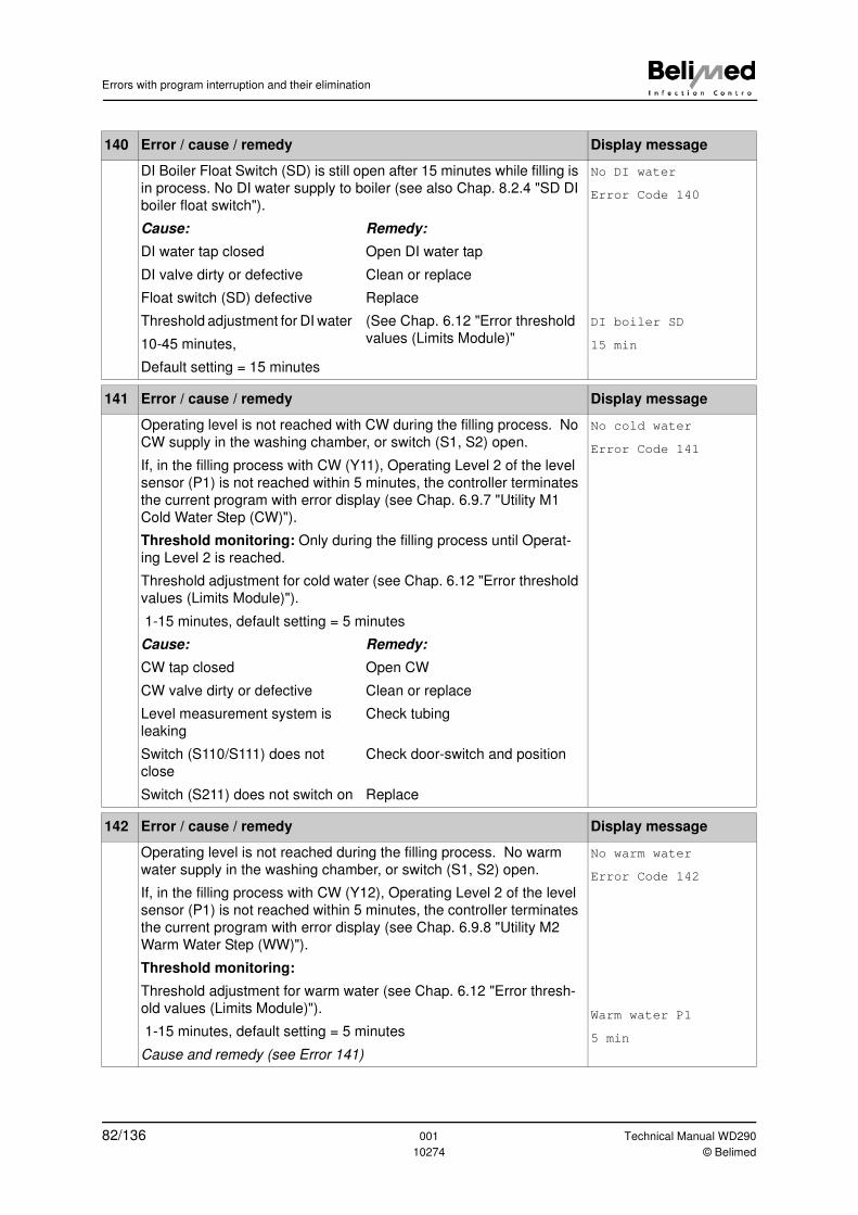
Errors with program interruption and their elimination
140 Error / cause / remedy Display message
DI Boiler Float Switch (SD) is still open after 15 minutes while filling is
in process. No DI water supply to boiler (see also Chap. 8.2.4 "SD DI
boiler float switch").
No DI water
Error Code 140
Cause: Remedy:
DI water tap closed Open DI water tap
DI valve dirty or defective Clean or replace
Float switch (SD) defective Replace
Threshold adjustment for DI water
10-45 minutes,
Default setting = 15 minutes
(See Chap. 6.12 "Error threshold
values (Limits Module)"
DI boiler SD
15 min
141 Error / cause / remedy Display message
Operating level is not reached with CW during the filling process. No
CW supply in the washing chamber, or switch (S1, S2) open.
If, in the filling process with CW (Y11), Operating Level 2 of the level
sensor (P1) is not reached within 5 minutes, the controller terminates
the current program with error display (see Chap. 6.9.7 "Utility M1
Cold Water Step (CW)").
Threshold monitoring: Only during the filling process until Operat-
ing Level 2 is reached.
Threshold adjustment for cold water (see Chap. 6.12 "Error threshold
values (Limits Module)").
1-15 minutes, default setting = 5 minutes
No cold water
Error Code 141
Cause: Remedy:
CW tap closed Open CW
CW valve dirty or defective Clean or replace
Level measurement system is
leaking
Check tubing
Switch (S110/S111) does not
close
Check door-switch and position
Switch (S211) does not switch on Replace
142 Error / cause / remedy Display message
Operating level is not reached during the filling process. No warm
water supply in the washing chamber, or switch (S1, S2) open.
If, in the filling process with CW (Y12), Operating Level 2 of the level
sensor (P1) is not reached within 5 minutes, the controller terminates
the current program with error display (see Chap. 6.9.8 "Utility M2
Warm Water Step (WW)").
Threshold monitoring:
Threshold adjustment for warm water (see Chap. 6.12 "Error thresh-
old values (Limits Module)").
1-15 minutes, default setting = 5 minutes
Cause and remedy (see Error 141)
No warm water
Error Code 142
Warm water P1
5 min
82/136 001 Technical Manual WD290
10274 © Belimed
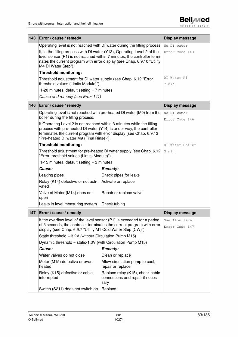
Errors with program interruption and their elimination
143 Error / cause / remedy Display message
Operating level is not reached with DI water during the filling process.
If, in the filling process with DI water (Y13), Operating Level 2 of the
level sensor (P1) is not reached within 7 minutes, the controller termi-
nates the current program with error display (see Chap. 6.9.10 "Utility
M4 DI Water Step").
Threshold monitoring:
Threshold adjustment for DI water supply (see Chap. 6.12 "Error
threshold values (Limits Module)").
1-20 minutes, default setting = 7 minutes
Cause and remedy (see Error 141)
No DI water
Error Code 143
DI Water P1
7 min
146 Error / cause / remedy Display message
Operating level is not reached with pre-heated DI water (M9) from the
boiler during the filling process.
If Operating Level 2 is not reached within 3 minutes while the filling
process with pre-heated DI water (Y14) is under way, the controller
terminates the current program with error display (see Chap. 6.9.13
"Pre-heated DI water M9 (Final Rinse)").
No DI water
Error Code 146
Threshold monitoring:
Threshold adjustment for pre-heated DI water supply (see Chap. 6.12
"Error threshold values (Limits Module)").
1-15 minutes, default setting = 3 minutes
DI Water Boiler
3 min
Cause: Remedy:
Leaking pipes Check pipes for leaks
Relay (K14) defective or not acti-
vated
Activate or replace
Valve of Motor (M14) does not
open
Repair or replace valve
Leaks in level measuring system Check tubing
147 Error / cause / remedy Display message
If the overflow level of the level sensor (P1) is exceeded for a period
of 3 seconds, the controller terminates the current program with error
display (see Chap. 6.9.7 "Utility M1 Cold Water Step (CW)").
Static threshold = 3.2V (without Circulation Pump M15)
Dynamic threshold = static-1.3V (with Circulation Pump M15)
Overflow level
Error Code 147
Cause: Remedy:
Water valves do not close Clean or replace
Motor (M15) defective or over-
heated
Allow circulation pump to cool,
repair or replace
Relay (K15) defective or cable
interrupted
Replace relay (K15), check cable
connections and repair if neces-
sary
Switch (S211) does not switch on Replace
Technical Manual WD290 001 83/136© Belimed 10274
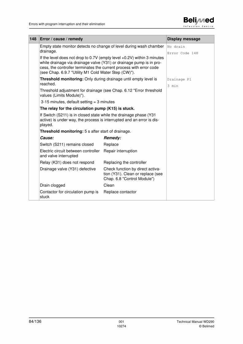
Errors with program interruption and their elimination
148 Error / cause / remedy Display message
Empty state monitor detects no change of level during wash chamber
drainage.
If the level does not drop to 0.7V (empty level +0.2V) within 3 minutes
while drainage via drainage valve (Y31) or drainage pump is in pro-
cess, the controller terminates the current process with error code
(see Chap. 6.9.7 "Utility M1 Cold Water Step (CW)").
No drain
Error Code 148
Threshold monitoring: Only during drainage until empty level is
reached.
Threshold adjustment for drainage (see Chap. 6.12 "Error threshold
values (Limits Module)").
3-15 minutes, default setting = 3 minutes
The relay for the circulation pump (K15) is stuck.
If Switch (S211) is in closed state while the drainage phase (Y31
active) is under way, the process is interrupted and an error is dis-
played.
Threshold monitoring: 5 s after start of drainage.
Drainage P1
3 min
Cause: Remedy:
Switch (S211) remains closed Replace
Electric circuit between controller
and valve interrupted
Repair interruption
Relay (K31) does not respond Replacing the controller
Drainage valve (Y31) defective Check function by direct activa-
tion (Y31). Clean or replace (see
Chap. 6.8 "Control Module")
Drain clogged Clean
Contactor for circulation pump is
stuck
Replace contactor
84/136 001 Technical Manual WD290
10274 © Belimed
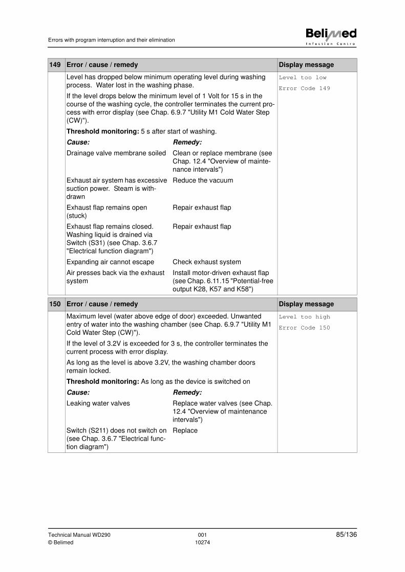
Errors with program interruption and their elimination
149 Error / cause / remedy Display message
Level has dropped below minimum operating level during washing
process. Water lost in the washing phase.
If the level drops below the minimum level of 1 Volt for 15 s in the
course of the washing cycle, the controller terminates the current pro-
cess with error display (see Chap. 6.9.7 "Utility M1 Cold Water Step
(CW)").
Threshold monitoring: 5 s after start of washing.
Level too low
Error Code 149
Cause: Remedy:
Drainage valve membrane soiled Clean or replace membrane (see
Chap. 12.4 "Overview of mainte-
nance intervals")
Exhaust air system has excessive
suction power. Steam is with-
drawn
Reduce the vacuum
Exhaust flap remains open
(stuck)
Repair exhaust flap
Exhaust flap remains closed.
Washing liquid is drained via
Switch (S31) (see Chap. 3.6.7
"Electrical function diagram")
Repair exhaust flap
Expanding air cannot escape Check exhaust system
Air presses back via the exhaust
system
Install motor-driven exhaust flap
(see Chap. 6.11.15 "Potential-free
output K28, K57 and K58")
150 Error / cause / remedy Display message
Maximum level (water above edge of door) exceeded. Unwanted
entry of water into the washing chamber (see Chap. 6.9.7 "Utility M1
Cold Water Step (CW)").
If the level of 3.2V is exceeded for 3 s, the controller terminates the
current process with error display.
As long as the level is above 3.2V, the washing chamber doors
remain locked.
Threshold monitoring: As long as the device is switched on
Level too high
Error Code 150
Cause: Remedy:
Leaking water valves Replace water valves (see Chap.
12.4 "Overview of maintenance
intervals")
Switch (S211) does not switch on
(see Chap. 3.6.7 "Electrical func-
tion diagram")
Replace
Technical Manual WD290 001 85/136© Belimed 10274
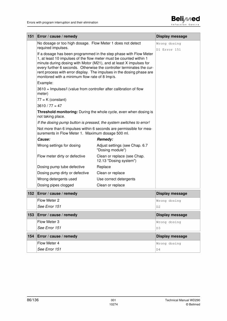
Errors with program interruption and their elimination
151 Error / cause / remedy Display message
No dosage or too high dosage. Flow Meter 1 does not detect
required impulses.
If a dosage has been programmed in the step phase with Flow Meter
1, at least 10 impulses of the flow meter must be counted within 1
minute during dosing with Motor (M21), and at least X impulses for
every further 6 seconds. Otherwise the controller terminates the cur-
rent process with error display. The impulses in the dosing phase are
monitored with a minimum flow rate of 8 Imp/s.
Example:
3610 = Impulses/l (value from controller after calibration of flow
meter)
77 = K (constant)
3610 / 77 = 47
Threshold monitoring: During the whole cycle, even when dosing is
not taking place.
If the dosing pump button is pressed, the system switches to error!
Not more than 6 impulses within 6 seconds are permissible for mea-
surements in Flow Meter 1. Maximum dosage 500 ml.
Wrong dosing
D1 Error 151
Cause: Remedy:
Wrong settings for dosing Adjust settings (see Chap. 6.7
"Dosing module")
Flow meter dirty or defective Clean or replace (see Chap.
12.13 "Dosing system")
Dosing pump tube defective Replace
Dosing pump dirty or defective Clean or replace
Wrong detergents used Use correct detergents
Dosing pipes clogged Clean or replace
152 Error / cause / remedy Display message
Flow Meter 2
See Error 151
Wrong dosing
D2
153 Error / cause / remedy Display message
Flow Meter 3
See Error 151
Wrong dosing
D3
154 Error / cause / remedy Display message
Flow Meter 4
See Error 151
Wrong dosing
D4
86/136 001 Technical Manual WD290
10274 © Belimed
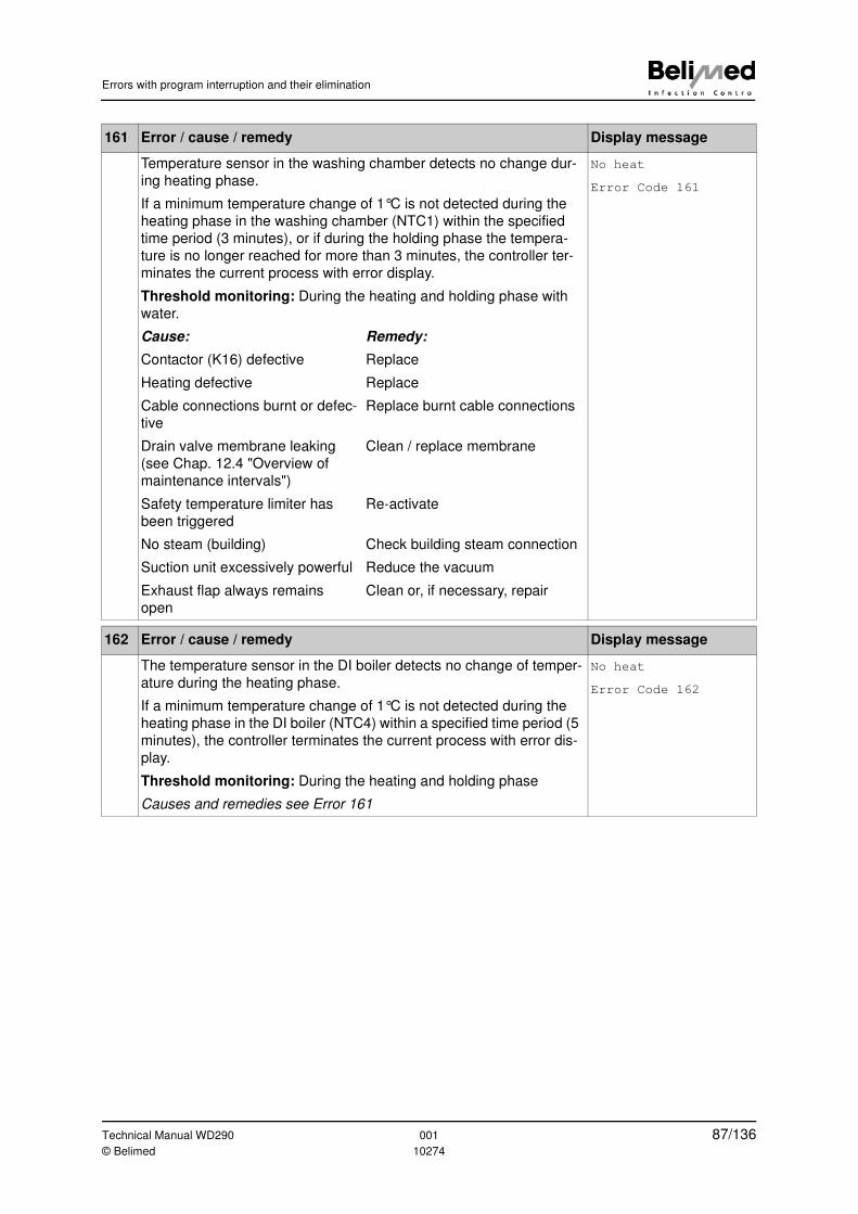
Errors with program interruption and their elimination
161 Error / cause / remedy Display message
Temperature sensor in the washing chamber detects no change dur-
ing heating phase.
If a minimum temperature change of 1°C is not detected during the
heating phase in the washing chamber (NTC1) within the specified
time period (3 minutes), or if during the holding phase the tempera-
ture is no longer reached for more than 3 minutes, the controller ter-
minates the current process with error display.
Threshold monitoring: During the heating and holding phase with
water.
No heat
Error Code 161
Cause: Remedy:
Contactor (K16) defective Replace
Heating defective Replace
Cable connections burnt or defec-
tive
Replace burnt cable connections
Drain valve membrane leaking
(see Chap. 12.4 "Overview of
maintenance intervals")
Clean / replace membrane
Safety temperature limiter has
been triggered
Re-activate
No steam (building) Check building steam connection
Suction unit excessively powerful Reduce the vacuum
Exhaust flap always remains
open
Clean or, if necessary, repair
162 Error / cause / remedy Display message
The temperature sensor in the DI boiler detects no change of temper-
ature during the heating phase.
If a minimum temperature change of 1°C is not detected during the
heating phase in the DI boiler (NTC4) within a specified time period (5
minutes), the controller terminates the current process with error dis-
play.
Threshold monitoring: During the heating and holding phase
Causes and remedies see Error 161
No heat
Error Code 162
Technical Manual WD290 001 87/136© Belimed 10274
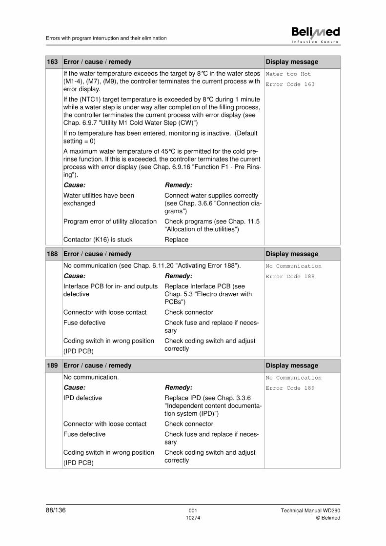
Errors with program interruption and their elimination
163 Error / cause / remedy Display message
If the water temperature exceeds the target by 8°C in the water steps
(M1-4), (M7), (M9), the controller terminates the current process with
error display.
If the (NTC1) target temperature is exceeded by 8°C during 1 minute
while a water step is under way after completion of the filling process,
the controller terminates the current process with error display (see
Chap. 6.9.7 "Utility M1 Cold Water Step (CW)")
If no temperature has been entered, monitoring is inactive. (Default
setting = 0)
A maximum water temperature of 45°C is permitted for the cold pre-
rinse function. If this is exceeded, the controller terminates the current
process with error display (see Chap. 6.9.16 "Function F1 - Pre Rins-
ing").
Water too Hot
Error Code 163
Cause: Remedy:
Water utilities have been
exchanged
Connect water supplies correctly
(see Chap. 3.6.6 "Connection dia-
grams")
Program error of utility allocation Check programs (see Chap. 11.5
"Allocation of the utilities")
Contactor (K16) is stuck Replace
188 Error / cause / remedy Display message
No communication (see Chap. 6.11.20 "Activating Error 188"). No Communication
Error Code 188Cause: Remedy:
Interface PCB for in- and outputs
defective
Replace Interface PCB (see
Chap. 5.3 "Electro drawer with
PCBs")
Connector with loose contact Check connector
Fuse defective Check fuse and replace if neces-
sary
Coding switch in wrong position
(IPD PCB)
Check coding switch and adjust
correctly
189 Error / cause / remedy Display message
No communication. No Communication
Error Code 189Cause: Remedy:
IPD defective Replace IPD (see Chap. 3.3.6
"Independent content documenta-
tion system (IPD)")
Connector with loose contact Check connector
Fuse defective Check fuse and replace if neces-
sary
Coding switch in wrong position
(IPD PCB)
Check coding switch and adjust
correctly
88/136 001 Technical Manual WD290
10274 © Belimed
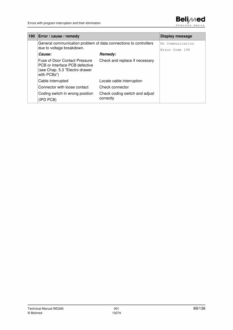
Errors with program interruption and their elimination
190 Error / cause / remedy Display message
General communication problem of data connections to controllers
due to voltage breakdown.
No Communication
Error Code 190
Cause: Remedy:
Fuse of Door Contact Pressure
PCB or Interface PCB defective
(see Chap. 5.3 "Electro drawer
with PCBs")
Check and replace if necessary
Cable interrupted Locate cable interruption
Connector with loose contact Check connector
Coding switch in wrong position
(IPD PCB)
Check coding switch and adjust
correctly
Technical Manual WD290 001 89/136© Belimed 10274
Process data of factory programs
11 Process data of factory programs
11.1 Process time
These process data are valid only for electrically heated devices without DI water
pre-heating. The disinfection process can be shortened by approx. 14 minutes
by use of DI water pre-heating.
11.2 Water and electric power consumption
Water consumption depends on rack, washing items and loading. As cold and
warm water are mixed, the proportion of the latter depends on the supply tem-
peratures of the different utilities.
The electric power consumption data (kWh) apply only to electrically heated
models. They include pumps, ventilator and heat energy for device operation,
from heating-up to the starting temperature to process fluid target temperature
and air for drying. The energy content of warm water from the building is not in-
cluded in energy balance calculations. In steam-heated versions, the energy
portion for heating up the water does not apply.
11.3 Why self-disinfection?
Micro-organisms form in the washing chamber, tubing and DI boiler after a pro-
longed period not using the device. Following thermal disinfection step, residues
of dead bacteria on the medical device may constitute a risk for patients.
In the case of active self-disinfection, the owner is requested to perform self-dis-
infection after a programmed period (24 hours as standard) following the last pro-
gram run.
Note
If supply temperatures are low, the proportion of warm water is increased.
Note
If there is no mains power (mains switch OFF), the timer is not active, there-
fore the request for "Self Disinfection Start" of the device is always displayed
when the device is switched on and self-disinfection is active.
90/136 001 Technical Manual WD290
10274 © Belimed
Process data of factory programs
11.4 Validated process parameters P1-P12
The 12 programs with specific program parameters, such as rinsing steps, dos-
age media concentrations, washing temperature and washing time, have been
compiled with respect to the suitability of the dosing agents and the racks (instru-
ment racks, OP shoes...). The procedures have been validated as device soft-
ware and are supplied by the factory as ex-factory programs.
11.4.1 Deleting programs
Program deletion (see Chap. 6.9.3 "Allocation of the program library").
11.5 Allocation of the utilities
11.5.1 With condenser
In order to activate the condenser, Utility M6 "Condense" must be programmed
instead of M5 "Dry". M6 opens the DI water valve (Y27) in addition to drying.
Warning
Washing items must not be allowed to pass into the clean work area without
going through washing and disinfection! It must be ensured that the com-
plete program cycle has been run through without errors.
Note
All program modifications must at all times be accessible to the technical ser-
vice! All ex-factory programs have a thermal disinfection step, and process-
ing of temperature-sensitive washing items is therefore not intended. Correct
dosing pump function and allocation of chemicals must be ensured. Every
program must be validated when taken into operation (see Chap. 2.5 "Pro-
cess validation").
Warning
Do not set programs inactive. Programs that are not used must be deleted
completely! There is the risk of an unwanted program being selected with
"Automatic Program Recognition".
Note
In the condenser option and DI water pre-heating option, the utilities must be
re-allocated accordingly.
Technical Manual WD290 001 91/136© Belimed 10274
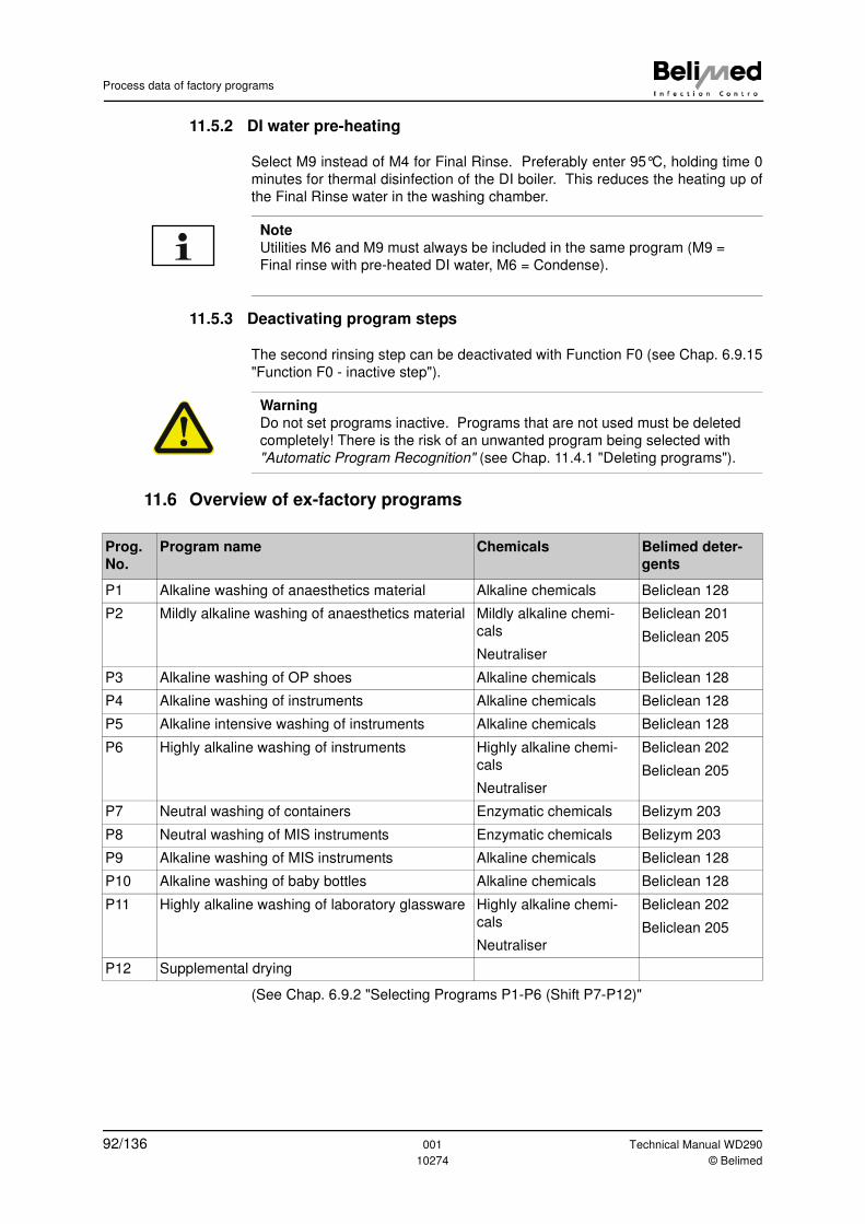
Process data of factory programs
11.5.2 DI water pre-heating
Select M9 instead of M4 for Final Rinse. Preferably enter 95°C, holding time 0
minutes for thermal disinfection of the DI boiler. This reduces the heating up of
the Final Rinse water in the washing chamber.
11.5.3 Deactivating program steps
The second rinsing step can be deactivated with Function F0 (see Chap. 6.9.15
"Function F0 - inactive step").
11.6 Overview of ex-factory programs
(See Chap. 6.9.2 "Selecting Programs P1-P6 (Shift P7-P12)"
Note
Utilities M6 and M9 must always be included in the same program (M9 =
Final rinse with pre-heated DI water, M6 = Condense).
Warning
Do not set programs inactive. Programs that are not used must be deleted
completely! There is the risk of an unwanted program being selected with
"Automatic Program Recognition" (see Chap. 11.4.1 "Deleting programs").
Prog.
No.
Program name Chemicals Belimed deter-
gents
P1 Alkaline washing of anaesthetics material Alkaline chemicals Beliclean 128
P2 Mildly alkaline washing of anaesthetics material Mildly alkaline chemi-
cals
Neutraliser
Beliclean 201
Beliclean 205
P3 Alkaline washing of OP shoes Alkaline chemicals Beliclean 128
P4 Alkaline washing of instruments Alkaline chemicals Beliclean 128
P5 Alkaline intensive washing of instruments Alkaline chemicals Beliclean 128
P6 Highly alkaline washing of instruments Highly alkaline chemi-
cals
Neutraliser
Beliclean 202
Beliclean 205
P7 Neutral washing of containers Enzymatic chemicals Belizym 203
P8 Neutral washing of MIS instruments Enzymatic chemicals Belizym 203
P9 Alkaline washing of MIS instruments Alkaline chemicals Beliclean 128
P10 Alkaline washing of baby bottles Alkaline chemicals Beliclean 128
P11 Highly alkaline washing of laboratory glassware Highly alkaline chemi-
cals
Neutraliser
Beliclean 202
Beliclean 205
P12 Supplemental drying
92/136 001 Technical Manual WD290
10274 © Belimed
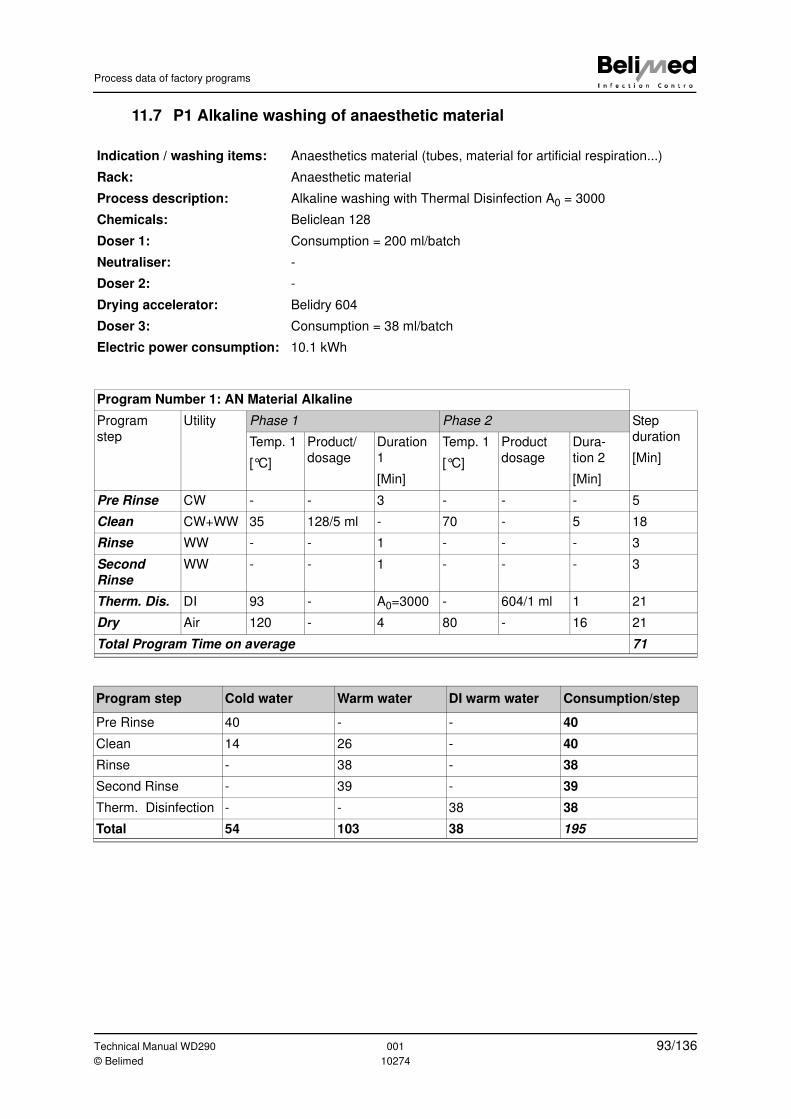
Process data of factory programs
11.7 P1 Alkaline washing of anaesthetic material
Indication / washing items: Anaesthetics material (tubes, material for artificial respiration...)
Rack: Anaesthetic material
Process description: Alkaline washing with Thermal Disinfection A0 = 3000
Chemicals: Beliclean 128
Doser 1: Consumption = 200 ml/batch
Neutraliser: -
Doser 2: -
Drying accelerator: Belidry 604
Doser 3: Consumption = 38 ml/batch
Electric power consumption: 10.1 kWh
Program Number 1: AN Material Alkaline
Program
step
Utility Phase 1 Phase 2 Step
duration
[Min]
Temp. 1
[°C]
Product/
dosage
Duration
1
[Min]
Temp. 1
[°C]
Product
dosage
Dura-
tion 2
[Min]
Pre Rinse CW - - 3 - - - 5
Clean CW+WW 35 128/5 ml - 70 - 5 18
Rinse WW - - 1 - - - 3
Second
Rinse
WW - - 1 - - - 3
Therm. Dis. DI 93 - A0=3000 - 604/1 ml 1 21
Dry Air 120 - 4 80 - 16 21
Total Program Time on average 71
Program step Cold water Warm water DI warm water Consumption/step
Pre Rinse 40 - - 40
Clean 14 26 - 40
Rinse - 38 - 38
Second Rinse - 39 - 39
Therm. Disinfection - - 38 38
Total 54 103 38 195
Technical Manual WD290 001 93/136© Belimed 10274

Process data of factory programs
11.8 P2 Mildly alkaline washing of anaesthetics material
Indication / washing items: Anaesthetics material (tubes, material for artificial respiration...)
Rack: Anaesthetic material
Process description: Alkaline washing with Thermal Disinfection A0 = 3000
Chemicals: Beliclean 201
Doser 1: Consumption = 200 ml/batch
Neutraliser: Beliclean 205
Doser 2: Consumption = 75 ml/batch
Drying accelerator: Belidry 604
Doser 3: Consumption = 39 ml/batch
Electric power consumption: 10.0 kWh
Program Number 2: AN Material Mild Alkaline
Program
step
Utility Phase 1 Phase 2 Step
duration
[Min]
Temp. 1
[°C]
Product/
dosage
Duration
1
[Min]
Temp. 1
[°C]
Product
dosage
Dura-
tion 2
[Min]
Pre Rinse CW - - 3 - - - 5
Clean CW+WW 35 201/5 ml - 60 - 7 19
Rinse WW - 205/2 ml 1 - - - 3
Second
Rinse
WW - - 1 - - - 3
Therm. Dis. DI 93 - A0=3000 - 604/1 ml 1 21
Dry Air 120 - 4 80 - 16 20
Total Program Time on average 71
Program step Cold water Warm water DI warm water Consumption/step
Pre Rinse 40 - - 40
Clean 15 25 - 40
Rinse 38 - - 38
Second Rinse - 39 - 39
Therm. Disinfection - - 39 39
Total 93 64 39 196
94/136 001 Technical Manual WD290
10274 © Belimed

Process data of factory programs
11.9 P3 Alkaline washing of OP shoes
Indication / washing items: OP shoes
Rack: For OP shoes in 2 tiers basic rack
Process description: Highly alkaline washing with Thermal Disinfection A0 = 600
Chemicals: Beliclean 128
Doser 1: Consumption = 160 ml/batch
Neutraliser: -
Doser 2: -
Drying accelerator: Belidry 604
Doser 3: Consumption = 29 ml/batch
Electric power consumption: 7.7 kWh
Program Number 3: OP Shoes Alkaline
Program
step
Utility Phase 1 Phase 2 Step
duration
[Min]
Temp. 1
[°C]
Product/
dosage
Duration
1
[Min]
Temp. 1
[°C]
Product
dosage
Dura-
tion 2
[Min]
Pre Rinse CW - - 2 - - - 4
Clean CW+WW 35 128/5 ml - 70 - 7 14
Rinse WW - - 1 - - - 3
Second
Rinse
WW - - 1 - - - 3
Therm. Dis. DI 80 604/1 ml A0=600 - - - 21
Dry Air 120 - 4 80 - 10 14
Total Program Time on average 59
Program step Cold water Warm water DI warm water Consumption/step
Pre Rinse 30 - - 30
Clean 10 20 - 30
Rinse - 29 - 29
Second Rinse - 30 - 30
Therm. Disinfection - - 29 29
Total 40 79 29 148
Technical Manual WD290 001 95/136© Belimed 10274
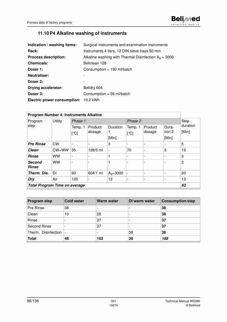
Process data of factory programs
11.10 P4 Alkaline washing of instruments
Indication / washing items: Surgical instruments and examination instruments
Rack: Instruments 4 tiers, 12 DIN sieve trays 50 mm
Process description: Alkaline washing with Thermal Disinfection A0 = 3000
Chemicals: Beliclean 128
Doser 1: Consumption = 190 ml/batch
Neutraliser: -
Doser 2: -
Drying accelerator: Belidry 604
Doser 3: Consumption = 38 ml/batch
Electric power consumption: 10.2 kWh
Program Number 4: Instruments Alkaline
Program
step
Utility Phase 1 Phase 2 Step
duration
[Min]
Temp. 1
[°C]
Product/
dosage
Duration
1
[Min]
Temp. 1
[°C]
Product
dosage
Dura-
tion 2
[Min]
Pre Rinse CW - - 3 - - - 5
Clean CW+WW 35 128/5 ml - 70 - 5 19
Rinse WW - - 1 - - - 3
Second
Rinse
WW - - 1 - - - 3
Therm. Dis. DI 93 604/1 ml A0=3000 - - - 20
Dry Air 120 - 12 - - - 13
Total Program Time on average 63
Program step Cold water Warm water DI warm water Consumption/step
Pre Rinse 38 - - 38
Clean 10 28 - 38
Rinse - 37 - 37
Second Rinse - 37 - 37
Therm. Disinfection - - 38 38
Total 48 102 38 188
96/136 001 Technical Manual WD290
10274 © Belimed
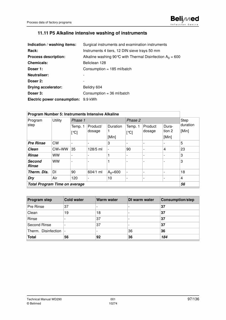
Process data of factory programs
11.11 P5 Alkaline intensive washing of instruments
Indication / washing items: Surgical instruments and examination instruments
Rack: Instruments 4 tiers, 12 DIN sieve trays 50 mm
Process description: Alkaline washing 90°C with Thermal Disinfection A0 = 600
Chemicals: Beliclean 128
Doser 1: Consumption = 185 ml/batch
Neutraliser: -
Doser 2: -
Drying accelerator: Belidry 604
Doser 3: Consumption = 36 ml/batch
Electric power consumption: 9.9 kWh
Program Number 5: Instruments Intensive Alkaline
Program
step
Utility Phase 1 Phase 2 Step
duration
[Min]
Temp. 1
[°C]
Product/
dosage
Duration
1
[Min]
Temp. 1
[°C]
Product
dosage
Dura-
tion 2
[Min]
Pre Rinse CW - - 3 - - - 5
Clean CW+WW 35 128/5 ml - 90 - 4 23
Rinse WW - - 1 - - - 3
Second
Rinse
WW - - 1 - - - 3
Therm. Dis. DI 90 604/1 ml A0=600 - - - 18
Dry Air 120 - 10 - - - 4
Total Program Time on average 56
Program step Cold water Warm water DI warm water Consumption/step
Pre Rinse 37 - - 37
Clean 19 18 - 37
Rinse - 37 - 37
Second Rinse - 37 - 37
Therm. Disinfection - - 36 36
Total 56 92 36 184
Technical Manual WD290 001 97/136© Belimed 10274
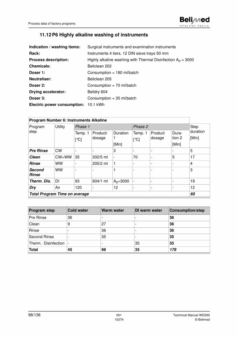
Process data of factory programs
11.12 P6 Highly alkaline washing of instruments
Indication / washing items: Surgical instruments and examination instruments
Rack: Instruments 4 tiers, 12 DIN sieve trays 50 mm
Process description: Highly alkaline washing with Thermal Disinfection A0 = 3000
Chemicals: Beliclean 202
Doser 1: Consumption = 180 ml/batch
Neutraliser: Beliclean 205
Doser 2: Consumption = 70 ml/batch
Drying accelerator: Belidry 604
Doser 3: Consumption = 35 ml/batch
Electric power consumption: 10.1 kWh
Program Number 6: Instruments Alkaline
Program
step
Utility Phase 1 Phase 2 Step
duration
[Min]
Temp. 1
[°C]
Product/
dosage
Duration
1
[Min]
Temp. 1
[°C]
Product
dosage
Dura-
tion 2
[Min]
Pre Rinse CW - - 3 - - - 5
Clean CW+WW 35 202/5 ml - 70 - 5 17
Rinse WW - 205/2 ml 1 - - - 4
Second
Rinse
WW - - 1 - - - 3
Therm. Dis. DI 93 604/1 ml A0=3000 - - - 19
Dry Air 120 - 12 - - - 12
Total Program Time on average 60
Program step Cold water Warm water DI warm water Consumption/step
Pre Rinse 36 - - 36
Clean 9 27 - 36
Rinse - 36 - 36
Second Rinse - 35 - 35
Therm. Disinfection - - 35 35
Total 45 98 35 178
98/136 001 Technical Manual WD290
10274 © Belimed
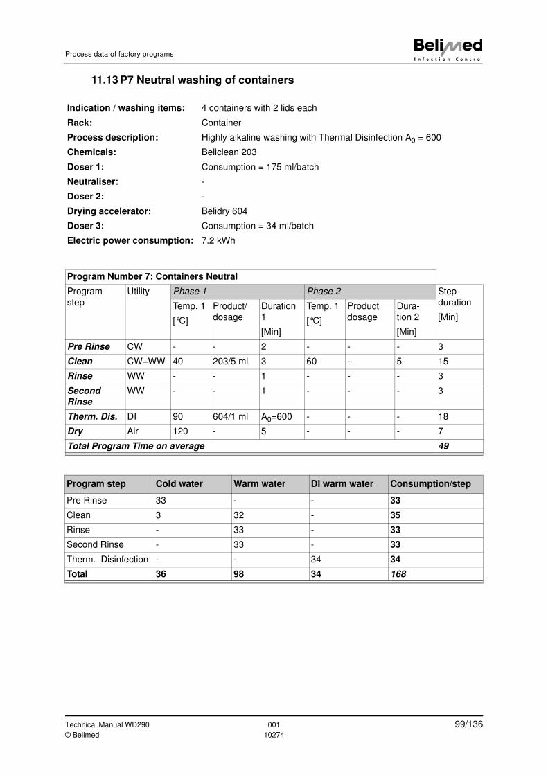
Process data of factory programs
11.13 P7 Neutral washing of containers
Indication / washing items: 4 containers with 2 lids each
Rack: Container
Process description: Highly alkaline washing with Thermal Disinfection A0 = 600
Chemicals: Beliclean 203
Doser 1: Consumption = 175 ml/batch
Neutraliser: -
Doser 2: -
Drying accelerator: Belidry 604
Doser 3: Consumption = 34 ml/batch
Electric power consumption: 7.2 kWh
Program Number 7: Containers Neutral
Program
step
Utility Phase 1 Phase 2 Step
duration
[Min]
Temp. 1
[°C]
Product/
dosage
Duration
1
[Min]
Temp. 1
[°C]
Product
dosage
Dura-
tion 2
[Min]
Pre Rinse CW - - 2 - - - 3
Clean CW+WW 40 203/5 ml 3 60 - 5 15
Rinse WW - - 1 - - - 3
Second
Rinse
WW - - 1 - - - 3
Therm. Dis. DI 90 604/1 ml A0=600 - - - 18
Dry Air 120 - 5 - - - 7
Total Program Time on average 49
Program step Cold water Warm water DI warm water Consumption/step
Pre Rinse 33 - - 33
Clean 3 32 - 35
Rinse - 33 - 33
Second Rinse - 33 - 33
Therm. Disinfection - - 34 34
Total 36 98 34 168
Technical Manual WD290 001 99/136© Belimed 10274
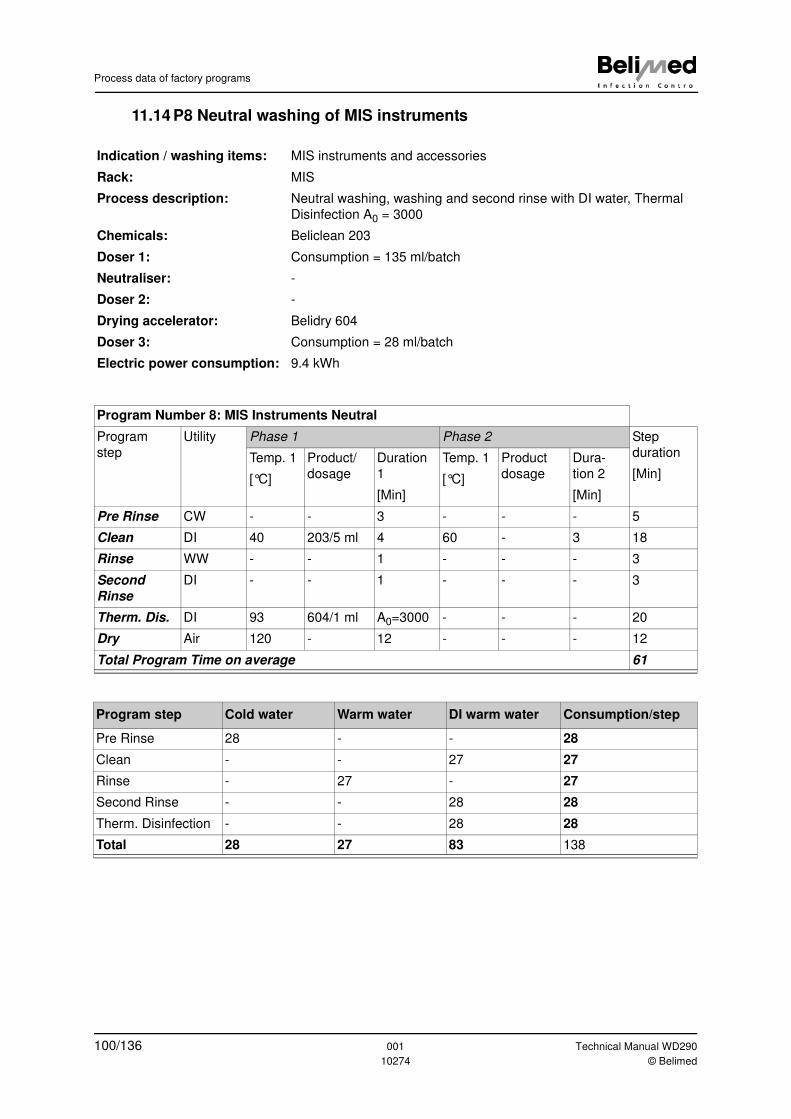
Process data of factory programs
11.14 P8 Neutral washing of MIS instruments
Indication / washing items: MIS instruments and accessories
Rack: MIS
Process description: Neutral washing, washing and second rinse with DI water, Thermal
Disinfection A0 = 3000
Chemicals: Beliclean 203
Doser 1: Consumption = 135 ml/batch
Neutraliser: -
Doser 2: -
Drying accelerator: Belidry 604
Doser 3: Consumption = 28 ml/batch
Electric power consumption: 9.4 kWh
Program Number 8: MIS Instruments Neutral
Program
step
Utility Phase 1 Phase 2 Step
duration
[Min]
Temp. 1
[°C]
Product/
dosage
Duration
1
[Min]
Temp. 1
[°C]
Product
dosage
Dura-
tion 2
[Min]
Pre Rinse CW - - 3 - - - 5
Clean DI 40 203/5 ml 4 60 - 3 18
Rinse WW - - 1 - - - 3
Second
Rinse
DI - - 1 - - - 3
Therm. Dis. DI 93 604/1 ml A0=3000 - - - 20
Dry Air 120 - 12 - - - 12
Total Program Time on average 61
Program step Cold water Warm water DI warm water Consumption/step
Pre Rinse 28 - - 28
Clean - - 27 27
Rinse - 27 - 27
Second Rinse - - 28 28
Therm. Disinfection - - 28 28
Total 28 27 83 138
100/136 001 Technical Manual WD290
10274 © Belimed
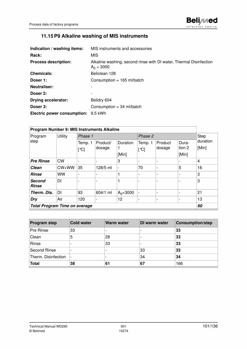
Process data of factory programs
11.15 P9 Alkaline washing of MIS instruments
Indication / washing items: MIS instruments and accessories
Rack: MIS
Process description: Alkaline washing, second rinse with DI water, Thermal Disinfection
A0 = 3000
Chemicals: Beliclean 128
Doser 1: Consumption = 165 ml/batch
Neutraliser: -
Doser 2: -
Drying accelerator: Belidry 604
Doser 3: Consumption = 34 ml/batch
Electric power consumption: 9.5 kWh
Program Number 9: MIS Instruments Alkaline
Program
step
Utility Phase 1 Phase 2 Step
duration
[Min]
Temp. 1
[°C]
Product/
dosage
Duration
1
[Min]
Temp. 1
[°C]
Product
dosage
Dura-
tion 2
[Min]
Pre Rinse CW - - 3 - - - 4
Clean CW+WW 35 128/5 ml - 70 - 5 16
Rinse WW - - 1 - - - 3
Second
Rinse
DI - - 1 - - - 3
Therm. Dis. DI 93 604/1 ml A0=3000 - - - 21
Dry Air 120 - 12 - - - 13
Total Program Time on average 60
Program step Cold water Warm water DI warm water Consumption/step
Pre Rinse 33 - - 33
Clean 5 28 - 33
Rinse - 33 - 33
Second Rinse - - 33 33
Therm. Disinfection - - 34 34
Total 38 61 67 166
Technical Manual WD290 001 101/136© Belimed 10274
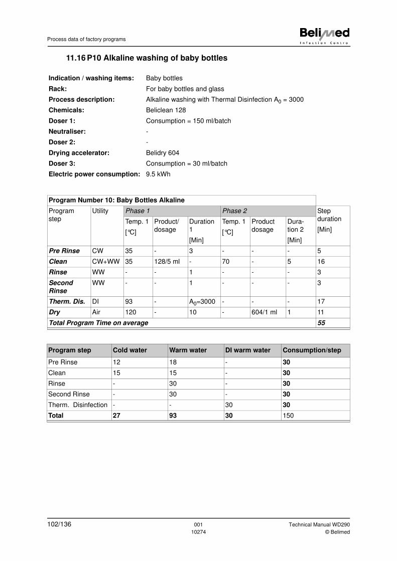
Process data of factory programs
11.16 P10 Alkaline washing of baby bottles
Indication / washing items: Baby bottles
Rack: For baby bottles and glass
Process description: Alkaline washing with Thermal Disinfection A0 = 3000
Chemicals: Beliclean 128
Doser 1: Consumption = 150 ml/batch
Neutraliser: -
Doser 2: -
Drying accelerator: Belidry 604
Doser 3: Consumption = 30 ml/batch
Electric power consumption: 9.5 kWh
Program Number 10: Baby Bottles Alkaline
Program
step
Utility Phase 1 Phase 2 Step
duration
[Min]
Temp. 1
[°C]
Product/
dosage
Duration
1
[Min]
Temp. 1
[°C]
Product
dosage
Dura-
tion 2
[Min]
Pre Rinse CW 35 - 3 - - - 5
Clean CW+WW 35 128/5 ml - 70 - 5 16
Rinse WW - - 1 - - - 3
Second
Rinse
WW - - 1 - - - 3
Therm. Dis. DI 93 - A0=3000 - - - 17
Dry Air 120 - 10 - 604/1 ml 1 11
Total Program Time on average 55
Program step Cold water Warm water DI warm water Consumption/step
Pre Rinse 12 18 - 30
Clean 15 15 - 30
Rinse - 30 - 30
Second Rinse - 30 - 30
Therm. Disinfection - - 30 30
Total 27 93 30 150
102/136 001 Technical Manual WD290
10274 © Belimed
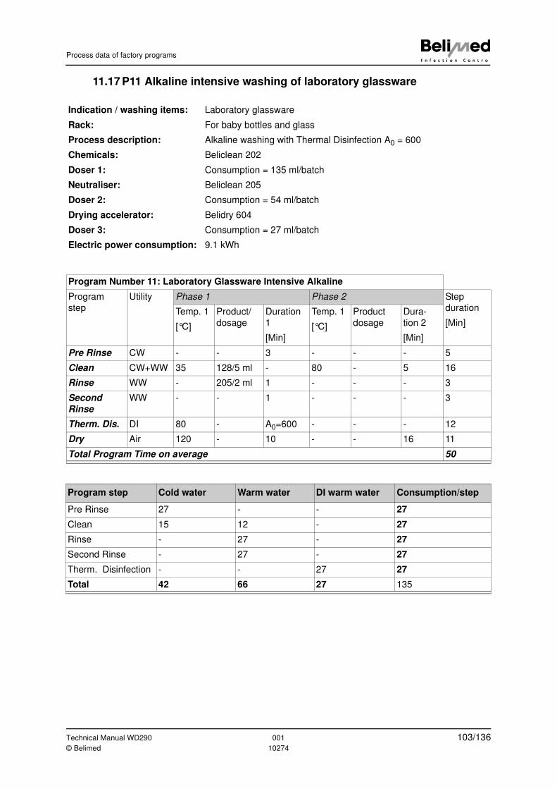
Process data of factory programs
11.17 P11 Alkaline intensive washing of laboratory glassware
Indication / washing items: Laboratory glassware
Rack: For baby bottles and glass
Process description: Alkaline washing with Thermal Disinfection A0 = 600
Chemicals: Beliclean 202
Doser 1: Consumption = 135 ml/batch
Neutraliser: Beliclean 205
Doser 2: Consumption = 54 ml/batch
Drying accelerator: Belidry 604
Doser 3: Consumption = 27 ml/batch
Electric power consumption: 9.1 kWh
Program Number 11: Laboratory Glassware Intensive Alkaline
Program
step
Utility Phase 1 Phase 2 Step
duration
[Min]
Temp. 1
[°C]
Product/
dosage
Duration
1
[Min]
Temp. 1
[°C]
Product
dosage
Dura-
tion 2
[Min]
Pre Rinse CW - - 3 - - - 5
Clean CW+WW 35 128/5 ml - 80 - 5 16
Rinse WW - 205/2 ml 1 - - - 3
Second
Rinse
WW - - 1 - - - 3
Therm. Dis. DI 80 - A0=600 - - - 12
Dry Air 120 - 10 - - 16 11
Total Program Time on average 50
Program step Cold water Warm water DI warm water Consumption/step
Pre Rinse 27 - - 27
Clean 15 12 - 27
Rinse - 27 - 27
Second Rinse - 27 - 27
Therm. Disinfection - - 27 27
Total 42 66 27 135
Technical Manual WD290 001 103/136© Belimed 10274
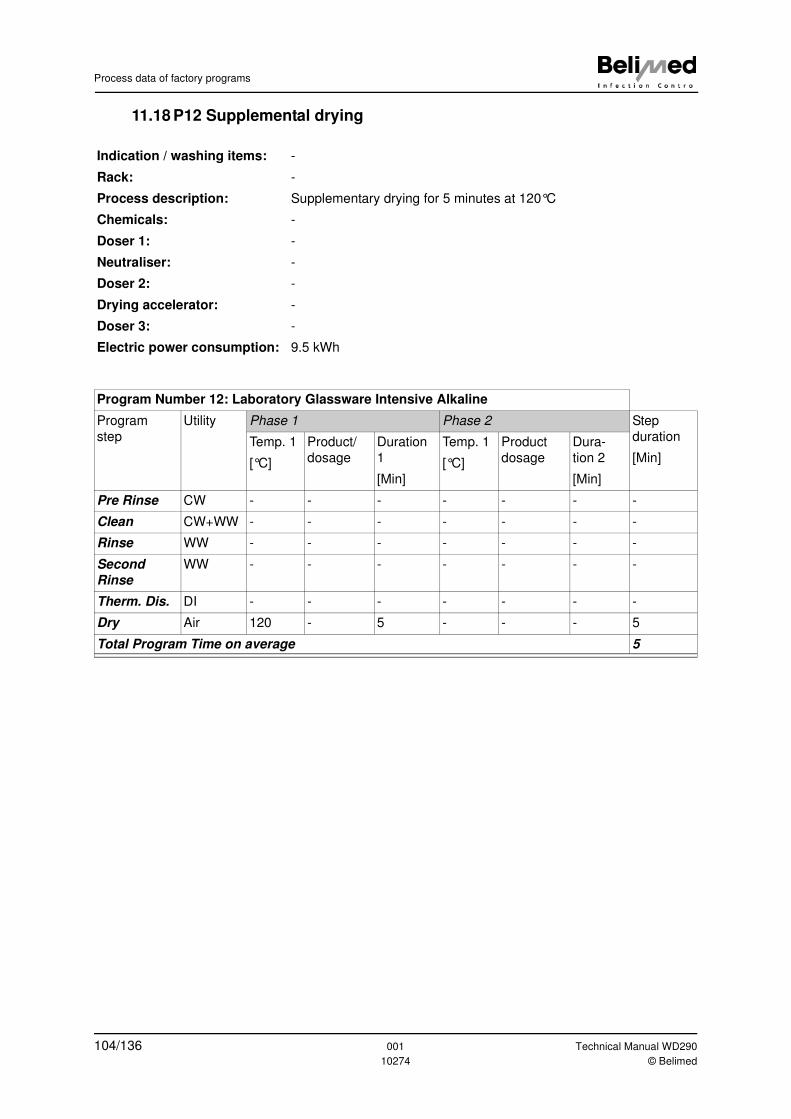
Process data of factory programs
11.18 P12 Supplemental drying
Indication / washing items: -
Rack: -
Process description: Supplementary drying for 5 minutes at 120°C
Chemicals: -
Doser 1: -
Neutraliser: -
Doser 2: -
Drying accelerator: -
Doser 3: -
Electric power consumption: 9.5 kWh
Program Number 12: Laboratory Glassware Intensive Alkaline
Program
step
Utility Phase 1 Phase 2 Step
duration
[Min]
Temp. 1
[°C]
Product/
dosage
Duration
1
[Min]
Temp. 1
[°C]
Product
dosage
Dura-
tion 2
[Min]
Pre Rinse CW - - - - - - -
Clean CW+WW - - - - - - -
Rinse WW - - - - - - -
Second
Rinse
WW - - - - - - -
Therm. Dis. DI - - - - - - -
Dry Air 120 - 5 - - - 5
Total Program Time on average 5
104/136 001 Technical Manual WD290
10274 © Belimed
Maintenance
12 Maintenance
12.1 Maintenance in general
The technical service is responsible for carrying out the periodic maintenance
tasks.
Maintenance tasks which have been completed must be documented in the in-
spection and maintenance booklet included in delivery.
12.2 Replacing the controller
The Processor PCB is supplied without software. This must be loaded using the
CADI PC software (see Chap. 9 "Downloading the control software"). If the data
are lost, the device must be reconfigured.
Note
We recommend to make use of the Belimed customer service for all mainte-
nance and repair work.
Danger
Switch off at the main switch prior to performing all maintenance work.
Only carry out maintenance and cleaning work with safety goggles and
gloves! Contamination residues can cause infections!
Warning
Only carry out maintenance and cleaning work after the device has been
allowed to cool.
Caution
Never spray the device for cleaning. The device is not waterproof.
Only use chrome steel cleaning agents or surface disinfectants for cleaning
the outside of the device. No solvents!
Caution
When the Processor PCB is replaced, all data, such as date of manufacture,
batch counter, program data and setup settings, are lost as well.
Technical Manual WD290 001 105/136© Belimed 10274
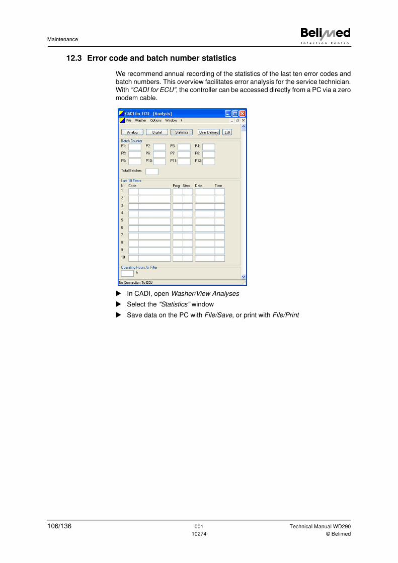
Maintenance
12.3 Error code and batch number statistics
We recommend annual recording of the statistics of the last ten error codes and
batch numbers. This overview facilitates error analysis for the service technician.
With "CADI for ECU", the controller can be accessed directly from a PC via a zero
modem cable.
� In CADI, open Washer/View Analyses
� Select the "Statistics" window
� Save data on the PC with File/Save, or print with File/Print
106/136 001 Technical Manual WD290
10274 © Belimed
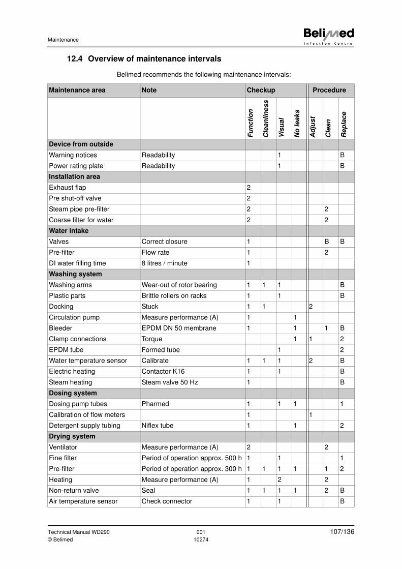
Maintenance
12.4 Overview of maintenance intervals
Belimed recommends the following maintenance intervals:
Maintenance area Note Checkup Procedure
Fu
ncti
on
Cle
an
lin
ess
Vis
ual
No
leak
s
Ad
jus
t
Cle
an
Re
pla
ce
Device from outside
Warning notices Readability 1 B
Power rating plate Readability 1 B
Installation area
Exhaust flap 2
Pre shut-off valve 2
Steam pipe pre-filter 2 2
Coarse filter for water 2 2
Water intake
Valves Correct closure 1 B B
Pre-filter Flow rate 1 2
DI water filling time 8 litres / minute 1
Washing system
Washing arms Wear-out of rotor bearing 1 1 1 B
Plastic parts Brittle rollers on racks 1 1 B
Docking Stuck 1 1 2
Circulation pump Measure performance (A) 1 1
Bleeder EPDM DN 50 membrane 1 1 1 B
Clamp connections Torque 1 1 2
EPDM tube Formed tube 1 2
Water temperature sensor Calibrate 1 1 1 2 B
Electric heating Contactor K16 1 1 B
Steam heating Steam valve 50 Hz 1 B
Dosing system
Dosing pump tubes Pharmed 1 1 1 1
Calibration of flow meters 1 1
Detergent supply tubing Niflex tube 1 1 2
Drying system
Ventilator Measure performance (A) 2 2
Fine filter Period of operation approx. 500 h 1 1 1
Pre-filter Period of operation approx. 300 h 1 1 1 1 1 2
Heating Measure performance (A) 1 2 2
Non-return valve Seal 1 1 1 1 2 B
Air temperature sensor Check connector 1 1 B
Technical Manual WD290 001 107/136© Belimed 10274
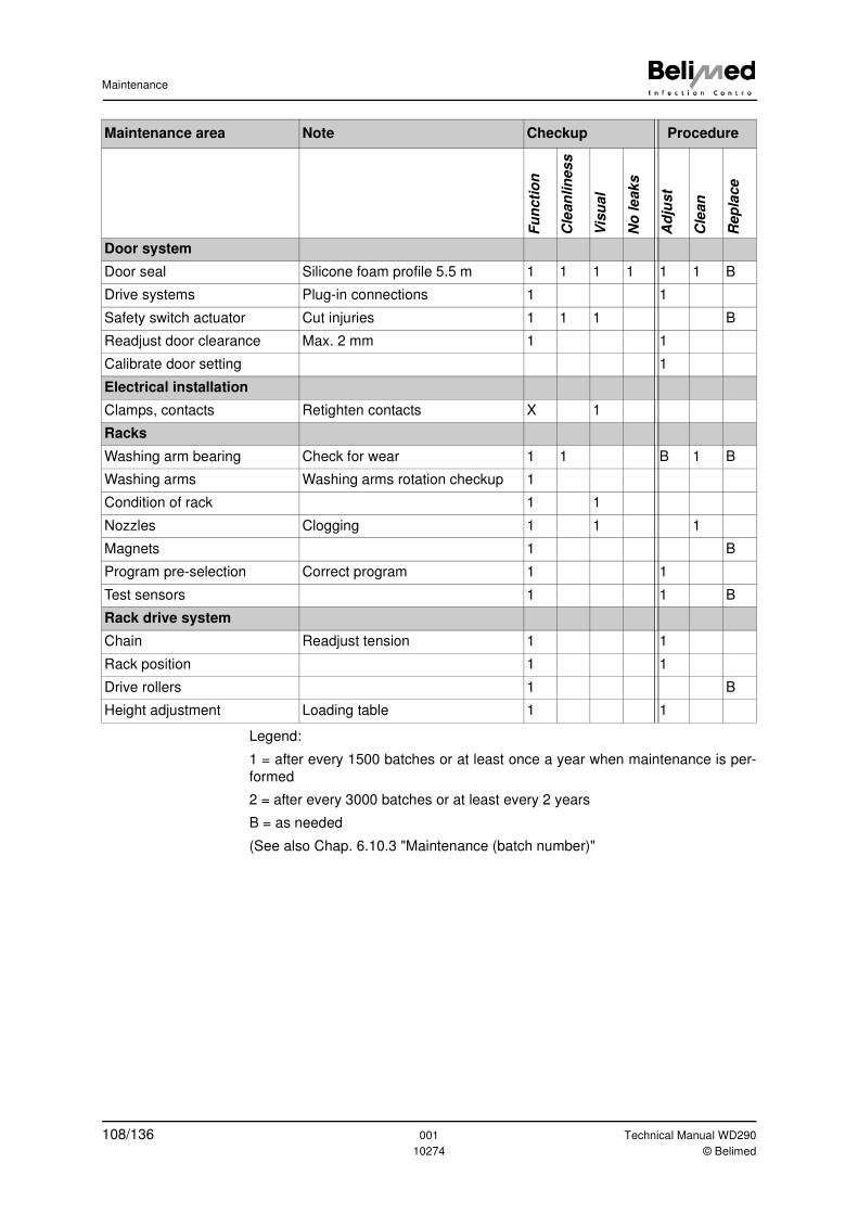
Maintenance
Legend:
1 = after every 1500 batches or at least once a year when maintenance is per-
formed
2 = after every 3000 batches or at least every 2 years
B = as needed
(See also Chap. 6.10.3 "Maintenance (batch number)"
Fu
ncti
on
Cle
an
lin
es
s
Vis
ual
No
le
aks
Ad
just
Cle
an
Rep
lace
Door system
Door seal Silicone foam profile 5.5 m 1 1 1 1 1 1 B
Drive systems Plug-in connections 1 1
Safety switch actuator Cut injuries 1 1 1 B
Readjust door clearance Max. 2 mm 1 1
Calibrate door setting 1
Electrical installation
Clamps, contacts Retighten contacts X 1
Racks
Washing arm bearing Check for wear 1 1 B 1 B
Washing arms Washing arms rotation checkup 1
Condition of rack 1 1
Nozzles Clogging 1 1 1
Magnets 1 B
Program pre-selection Correct program 1 1
Test sensors 1 1 B
Rack drive system
Chain Readjust tension 1 1
Rack position 1 1
Drive rollers 1 B
Height adjustment Loading table 1 1
Maintenance area Note Checkup Procedure
108/136 001 Technical Manual WD290
10274 © Belimed
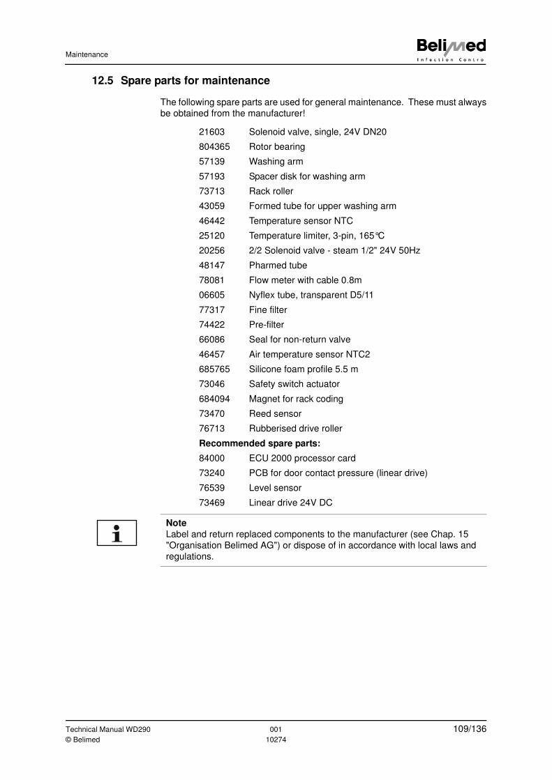
Maintenance
12.5 Spare parts for maintenance
The following spare parts are used for general maintenance. These must always
be obtained from the manufacturer!
21603 Solenoid valve, single, 24V DN20
804365 Rotor bearing
57139 Washing arm
57193 Spacer disk for washing arm
73713 Rack roller
43059 Formed tube for upper washing arm
46442 Temperature sensor NTC
25120 Temperature limiter, 3-pin, 165°C
20256 2/2 Solenoid valve - steam 1/2" 24V 50Hz
48147 Pharmed tube
78081 Flow meter with cable 0.8m
06605 Nyflex tube, transparent D5/11
77317 Fine filter
74422 Pre-filter
66086 Seal for non-return valve
46457 Air temperature sensor NTC2
685765 Silicone foam profile 5.5 m
73046 Safety switch actuator
684094 Magnet for rack coding
73470 Reed sensor
76713 Rubberised drive roller
Recommended spare parts:
84000 ECU 2000 processor card
73240 PCB for door contact pressure (linear drive)
76539 Level sensor
73469 Linear drive 24V DC
Note
Label and return replaced components to the manufacturer (see Chap. 15
"Organisation Belimed AG") or dispose of in accordance with local laws and
regulations.
Technical Manual WD290 001 109/136© Belimed 10274
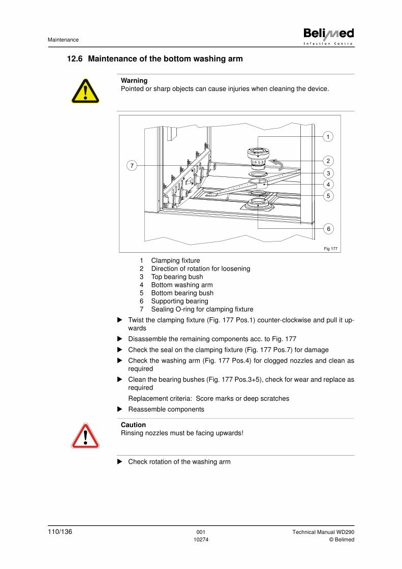
Maintenance
12.6 Maintenance of the bottom washing arm
1 Clamping fixture
2 Direction of rotation for loosening
3 Top bearing bush
4 Bottom washing arm
5 Bottom bearing bush
6 Supporting bearing
7 Sealing O-ring for clamping fixture
� Twist the clamping fixture (Fig. 177 Pos.1) counter-clockwise and pull it up-
wards
� Disassemble the remaining components acc. to Fig. 177
� Check the seal on the clamping fixture (Fig. 177 Pos.7) for damage
� Check the washing arm (Fig. 177 Pos.4) for clogged nozzles and clean as
required
� Clean the bearing bushes (Fig. 177 Pos.3+5), check for wear and replace as
required
Replacement criteria: Score marks or deep scratches
� Reassemble components
� Check rotation of the washing arm
Warning
Pointed or sharp objects can cause injuries when cleaning the device.
2
1
5
4
3
6
Fig 177
7
Caution
Rinsing nozzles must be facing upwards!
110/136 001 Technical Manual WD290
10274 © Belimed
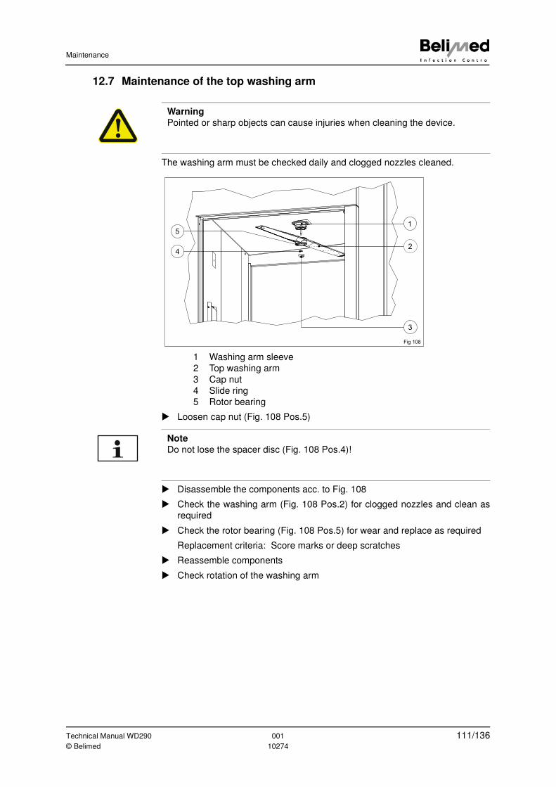
Maintenance
12.7 Maintenance of the top washing arm
The washing arm must be checked daily and clogged nozzles cleaned.
1 Washing arm sleeve
2 Top washing arm
3 Cap nut
4 Slide ring
5 Rotor bearing
� Loosen cap nut (Fig. 108 Pos.5)
� Disassemble the components acc. to Fig. 108
� Check the washing arm (Fig. 108 Pos.2) for clogged nozzles and clean as
required
� Check the rotor bearing (Fig. 108 Pos.5) for wear and replace as required
Replacement criteria: Score marks or deep scratches
� Reassemble components
� Check rotation of the washing arm
Warning
Pointed or sharp objects can cause injuries when cleaning the device.
Fig 108
2
1
4
3
5
Note
Do not lose the spacer disc (Fig. 108 Pos.4)!
Technical Manual WD290 001 111/136© Belimed 10274
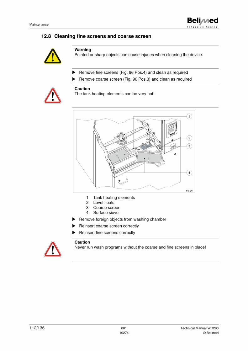
Maintenance
12.8 Cleaning fine screens and coarse screen
� Remove fine screens (Fig. 96 Pos.4) and clean as required
� Remove coarse screen (Fig. 96 Pos.3) and clean as required
1 Tank heating elements
2 Level floats
3 Coarse screen
4 Surface sieve
� Remove foreign objects from washing chamber
� Reinsert coarse screen correctly
� Reinsert fine screens correctly
Warning
Pointed or sharp objects can cause injuries when cleaning the device.
Caution
The tank heating elements can be very hot!
Fig 96
3
4
1
2
Caution
Never run wash programs without the coarse and fine screens in place!
112/136 001 Technical Manual WD290
10274 © Belimed
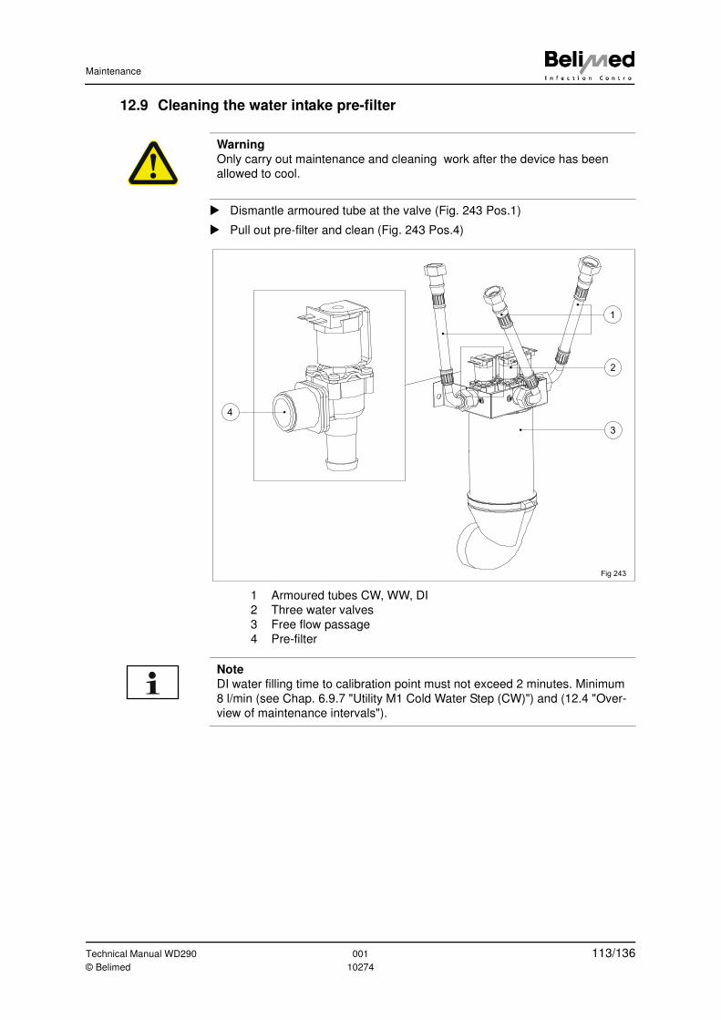
Maintenance
12.9 Cleaning the water intake pre-filter
� Dismantle armoured tube at the valve (Fig. 243 Pos.1)
� Pull out pre-filter and clean (Fig. 243 Pos.4)
1 Armoured tubes CW, WW, DI
2 Three water valves
3 Free flow passage
4 Pre-filter
Warning
Only carry out maintenance and cleaning work after the device has been
allowed to cool.
1
2
3
4
Fig 243
Note
DI water filling time to calibration point must not exceed 2 minutes. Minimum
8 l/min (see Chap. 6.9.7 "Utility M1 Cold Water Step (CW)") and (12.4 "Over-
view of maintenance intervals").
Technical Manual WD290 001 113/136© Belimed 10274
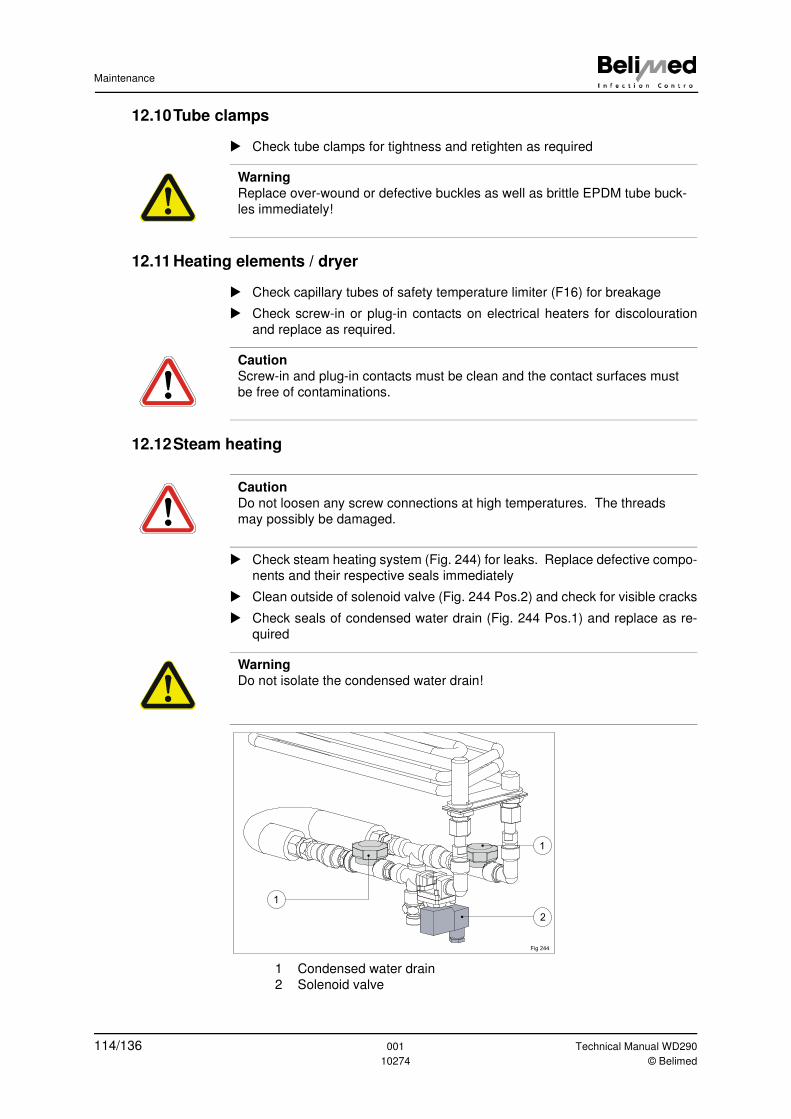
Maintenance
12.10Tube clamps
� Check tube clamps for tightness and retighten as required
12.11 Heating elements / dryer
� Check capillary tubes of safety temperature limiter (F16) for breakage
� Check screw-in or plug-in contacts on electrical heaters for discolouration
and replace as required.
12.12Steam heating
� Check steam heating system (Fig. 244) for leaks. Replace defective compo-
nents and their respective seals immediately
� Clean outside of solenoid valve (Fig. 244 Pos.2) and check for visible cracks
� Check seals of condensed water drain (Fig. 244 Pos.1) and replace as re-
quired
1 Condensed water drain
2 Solenoid valve
Warning
Replace over-wound or defective buckles as well as brittle EPDM tube buck-
les immediately!
Caution
Screw-in and plug-in contacts must be clean and the contact surfaces must
be free of contaminations.
Caution
Do not loosen any screw connections at high temperatures. The threads
may possibly be damaged.
Warning
Do not isolate the condensed water drain!
1
2
1
Fig 244
114/136 001 Technical Manual WD290
10274 © Belimed
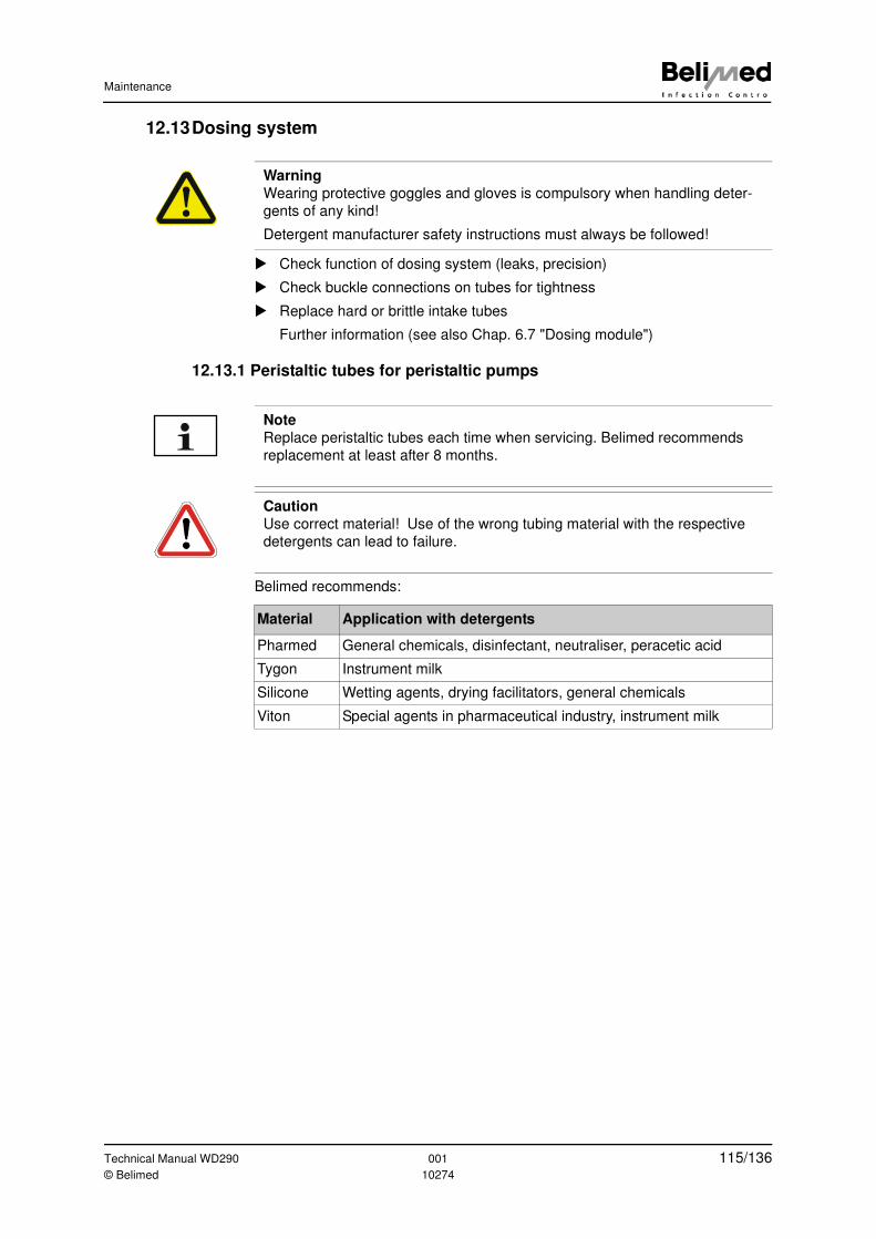
Maintenance
12.13Dosing system
� Check function of dosing system (leaks, precision)
� Check buckle connections on tubes for tightness
� Replace hard or brittle intake tubes
Further information (see also Chap. 6.7 "Dosing module")
12.13.1 Peristaltic tubes for peristaltic pumps
Belimed recommends:
Warning
Wearing protective goggles and gloves is compulsory when handling deter-
gents of any kind!
Detergent manufacturer safety instructions must always be followed!
Note
Replace peristaltic tubes each time when servicing. Belimed recommends
replacement at least after 8 months.
Caution
Use correct material! Use of the wrong tubing material with the respective
detergents can lead to failure.
Material Application with detergents
Pharmed General chemicals, disinfectant, neutraliser, peracetic acid
Tygon Instrument milk
Silicone Wetting agents, drying facilitators, general chemicals
Viton Special agents in pharmaceutical industry, instrument milk
Technical Manual WD290 001 115/136© Belimed 10274
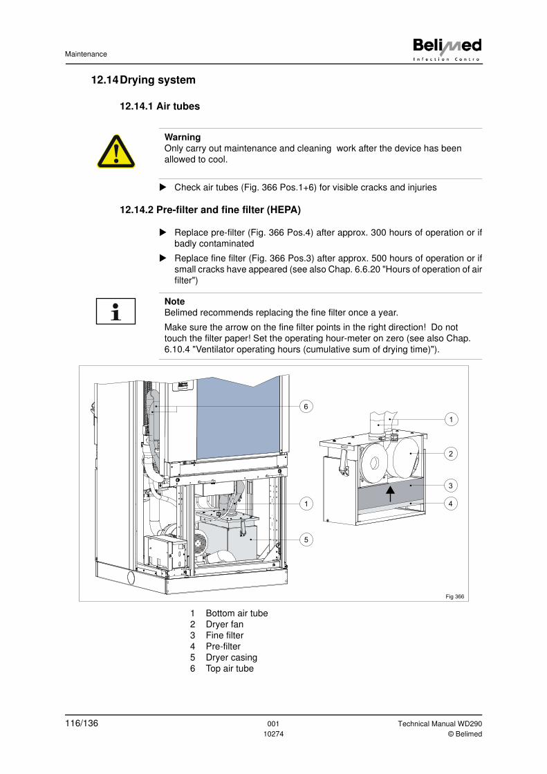
Maintenance
12.14Drying system
12.14.1 Air tubes
� Check air tubes (Fig. 366 Pos.1+6) for visible cracks and injuries
12.14.2 Pre-filter and fine filter (HEPA)
� Replace pre-filter (Fig. 366 Pos.4) after approx. 300 hours of operation or if
badly contaminated
� Replace fine filter (Fig. 366 Pos.3) after approx. 500 hours of operation or if
small cracks have appeared (see also Chap. 6.6.20 "Hours of operation of air
filter")
1 Bottom air tube
2 Dryer fan
3 Fine filter
4 Pre-filter
5 Dryer casing
6 Top air tube
Warning
Only carry out maintenance and cleaning work after the device has been
allowed to cool.
Note
Belimed recommends replacing the fine filter once a year.
Make sure the arrow on the fine filter points in the right direction! Do not
touch the filter paper! Set the operating hour-meter on zero (see also Chap.
6.10.4 "Ventilator operating hours (cumulative sum of drying time)").
2
3
4
1
1
5
6
Fig 366
116/136 001 Technical Manual WD290
10274 © Belimed
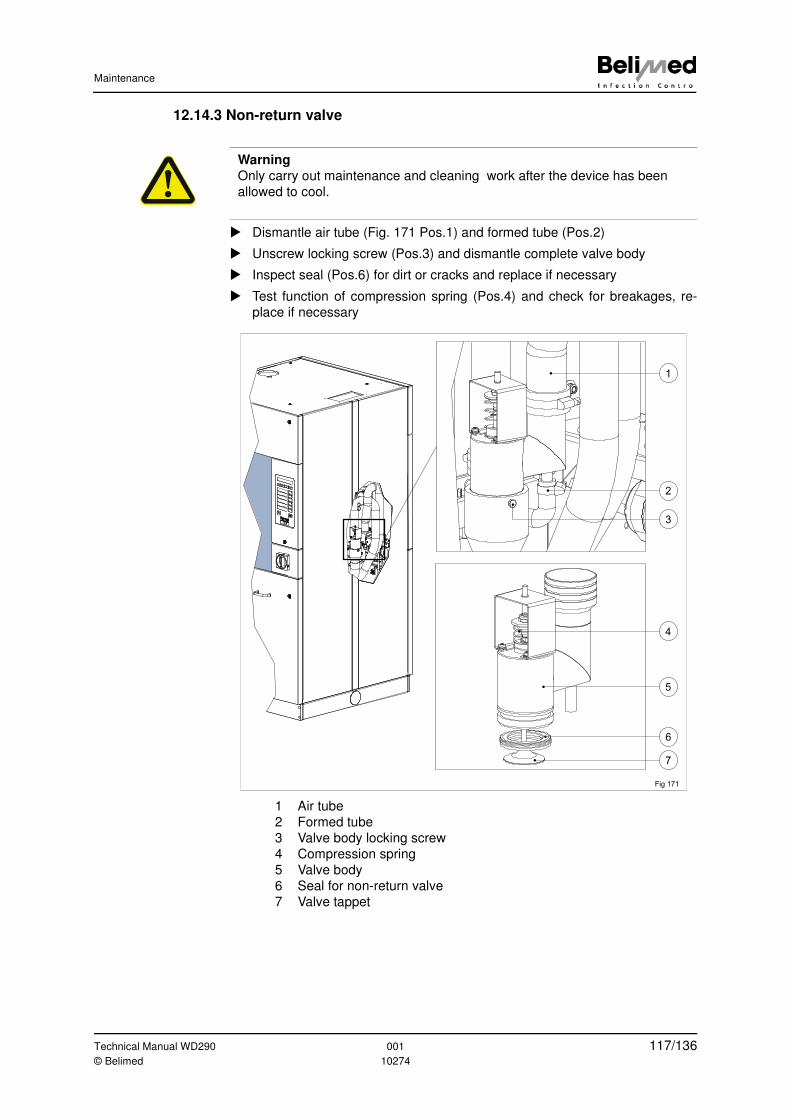
Maintenance
12.14.3 Non-return valve
� Dismantle air tube (Fig. 171 Pos.1) and formed tube (Pos.2)
� Unscrew locking screw (Pos.3) and dismantle complete valve body
� Inspect seal (Pos.6) for dirt or cracks and replace if necessary
� Test function of compression spring (Pos.4) and check for breakages, re-
place if necessary
1 Air tube
2 Formed tube
3 Valve body locking screw
4 Compression spring
5 Valve body
6 Seal for non-return valve
7 Valve tappet
Warning
Only carry out maintenance and cleaning work after the device has been
allowed to cool.
Fig 171
B
1
6
7
3
2
4
5
Technical Manual WD290 001 117/136© Belimed 10274
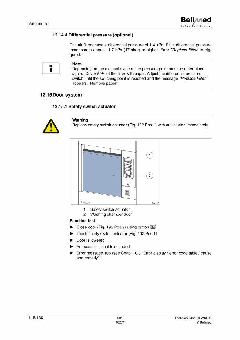
Maintenance
12.14.4 Differential pressure (optional)
The air filters have a differential pressure of 1.4 kPa. If the differential pressure
increases to approx. 1.7 kPa (17mbar) or higher, Error "Replace Filter" is trig-
gered.
12.15Door system
12.15.1 Safety switch actuator
1 Safety switch actuator
2 Washing chamber door
Function test
� Close door (Fig. 192 Pos.2) using button
� Touch safety switch actuator (Fig. 192 Pos.1)
� Door is lowered
� An acoustic signal is sounded
� Error message 108 (see Chap. 10.3 "Error display / error code table / cause
and remedy")
Note
Depending on the exhaust system, the pressure point must be determined
again. Cover 50% of the filter with paper. Adjust the differential pressure
switch until the switching point is reached and the message "Replace Filter"
appears. Remove paper.
Warning
Replace safety switch actuator (Fig. 192 Pos.1) with cut injuries immediately.
1
2
Fig 192
118/136 001 Technical Manual WD290
10274 © Belimed
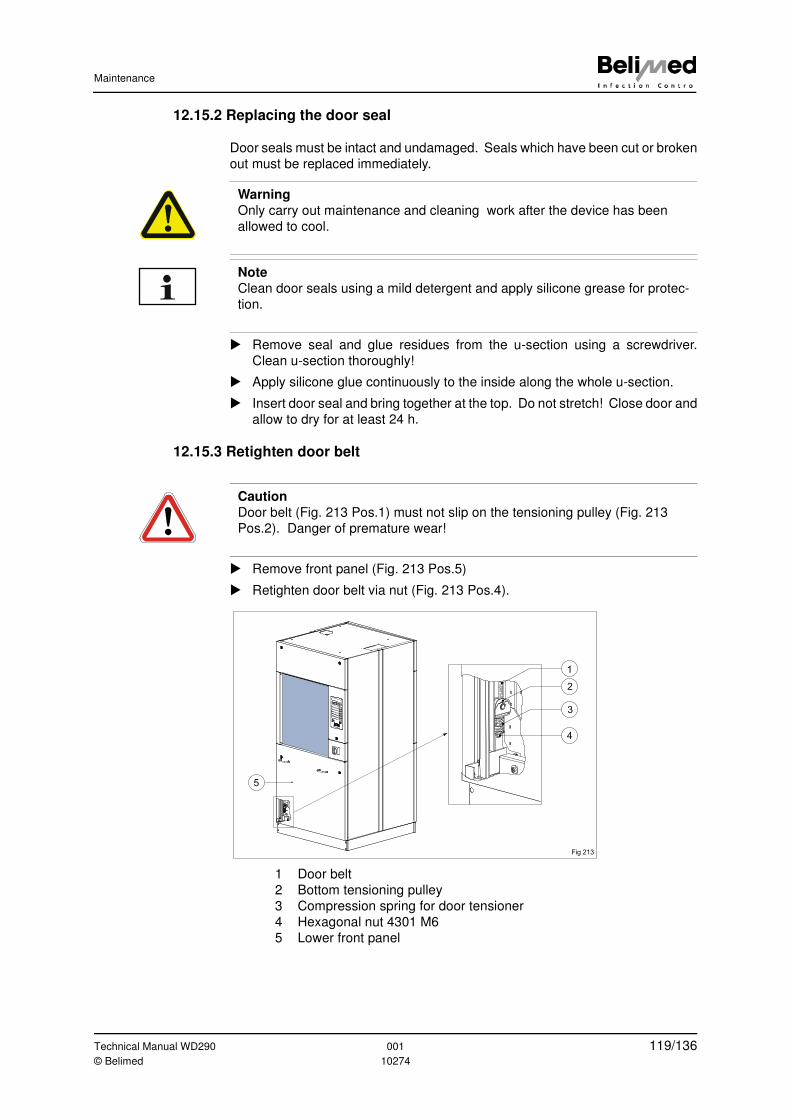
Maintenance
12.15.2 Replacing the door seal
Door seals must be intact and undamaged. Seals which have been cut or broken
out must be replaced immediately.
� Remove seal and glue residues from the u-section using a screwdriver.
Clean u-section thoroughly!
� Apply silicone glue continuously to the inside along the whole u-section.
� Insert door seal and bring together at the top. Do not stretch! Close door and
allow to dry for at least 24 h.
12.15.3 Retighten door belt
� Remove front panel (Fig. 213 Pos.5)
� Retighten door belt via nut (Fig. 213 Pos.4).
1 Door belt
2 Bottom tensioning pulley
3 Compression spring for door tensioner
4 Hexagonal nut 4301 M6
5 Lower front panel
Warning
Only carry out maintenance and cleaning work after the device has been
allowed to cool.
Note
Clean door seals using a mild detergent and apply silicone grease for protec-
tion.
Caution
Door belt (Fig. 213 Pos.1) must not slip on the tensioning pulley (Fig. 213
Pos.2). Danger of premature wear!
4
3
Fig 213
5
1
2
Technical Manual WD290 001 119/136© Belimed 10274
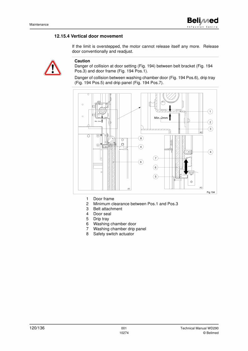
Maintenance
12.15.4 Vertical door movement
If the limit is overstepped, the motor cannot release itself any more. Release
door conventionally and readjust.
1 Door frame
2 Minimum clearance between Pos.1 and Pos.3
3 Belt attachment
4 Door seal
5 Drip tray
6 Washing chamber door
7 Washing chamber drip panel
8 Safety switch actuator
Caution
Danger of collision at door setting (Fig. 194) between belt bracket (Fig. 194
Pos.3) and door frame (Fig. 194 Pos.1).
Danger of collision between washing chamber door (Fig. 194 Pos.6), drip tray
(Fig. 194 Pos.5) and drip panel (Fig. 194 Pos.7).
Min. 2mm
Fig 194
Min. 2mm
4
2
7
5
6
8
4
6
A1
A2
A3
1
3
120/136 001 Technical Manual WD290
10274 © Belimed
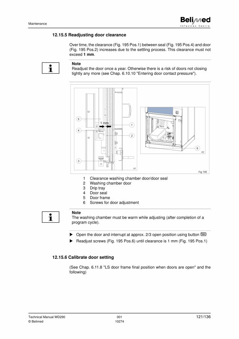
Maintenance
12.15.5 Readjusting door clearance
Over time, the clearance (Fig. 195 Pos.1) between seal (Fig. 195 Pos.4) and door
(Fig. 195 Pos.2) increases due to the settling process. This clearance must not
exceed 1 mm.
1 Clearance washing chamber door/door seal
2 Washing chamber door
3 Drip tray
4 Door seal
5 Door frame
6 Screws for door adjustment
� Open the door and interrupt at approx. 2/3 open position using button
� Readjust screws (Fig. 195 Pos.6) until clearance is 1 mm (Fig. 195 Pos.1)
12.15.6 Calibrate door setting
(See Chap. 6.11.8 "LS door frame final position when doors are open" and the
following)
Note
Readjust the door once a year. Otherwise there is a risk of doors not closing
tightly any more (see Chap. 6.10.10 "Entering door contact pressure").
Fig 195
1 mm
2
4
5
3
1
A1
A2
6
Note
The washing chamber must be warm while adjusting (after completion of a
program cycle).
0 I
Technical Manual WD290 001 121/136© Belimed 10274
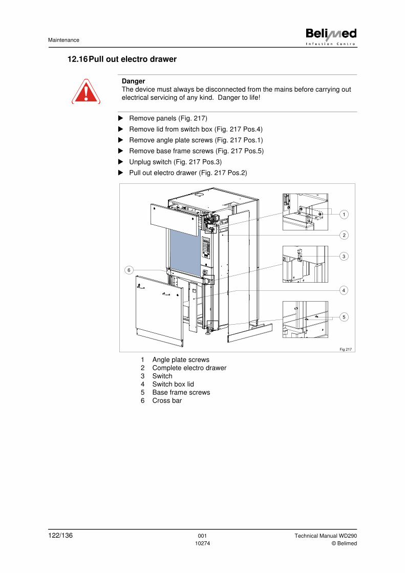
Maintenance
12.16Pull out electro drawer
� Remove panels (Fig. 217)
� Remove lid from switch box (Fig. 217 Pos.4)
� Remove angle plate screws (Fig. 217 Pos.1)
� Remove base frame screws (Fig. 217 Pos.5)
� Unplug switch (Fig. 217 Pos.3)
� Pull out electro drawer (Fig. 217 Pos.2)
1 Angle plate screws
2 Complete electro drawer
3 Switch
4 Switch box lid
5 Base frame screws
6 Cross bar
Danger
The device must always be disconnected from the mains before carrying out
electrical servicing of any kind. Danger to life!
5
3
1
6
2
4
Fig 217
122/136 001 Technical Manual WD290
10274 © Belimed
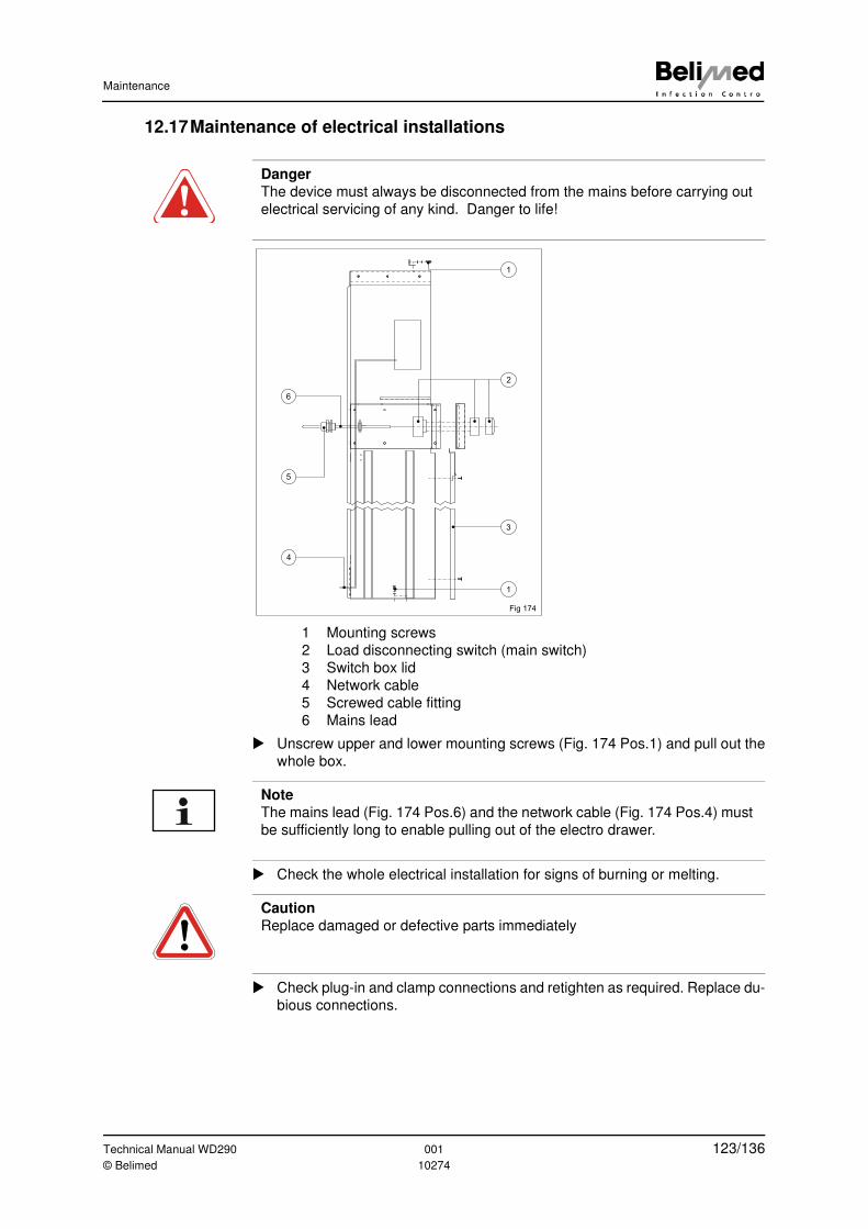
Maintenance
12.17Maintenance of electrical installations
1 Mounting screws
2 Load disconnecting switch (main switch)
3 Switch box lid
4 Network cable
5 Screwed cable fitting
6 Mains lead
� Unscrew upper and lower mounting screws (Fig. 174 Pos.1) and pull out the
whole box.
� Check the whole electrical installation for signs of burning or melting.
� Check plug-in and clamp connections and retighten as required. Replace du-
bious connections.
Danger
The device must always be disconnected from the mains before carrying out
electrical servicing of any kind. Danger to life!
1
2
1
6
5
3
Fig 174
4
Note
The mains lead (Fig. 174 Pos.6) and the network cable (Fig. 174 Pos.4) must
be sufficiently long to enable pulling out of the electro drawer.
Caution
Replace damaged or defective parts immediately
Technical Manual WD290 001 123/136© Belimed 10274
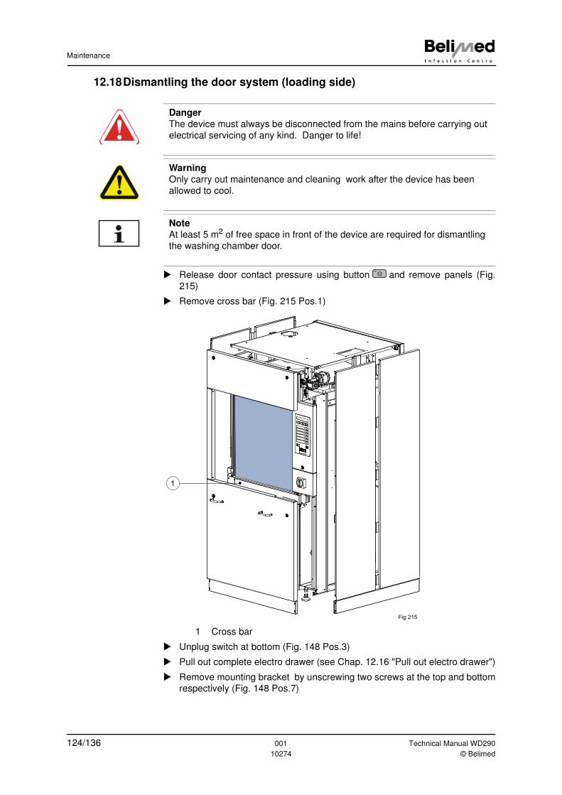
Maintenance
12.18Dismantling the door system (loading side)
� Release door contact pressure using button and remove panels (Fig.
215)
� Remove cross bar (Fig. 215 Pos.1)
1 Cross bar
� Unplug switch at bottom (Fig. 148 Pos.3)
� Pull out complete electro drawer (see Chap. 12.16 "Pull out electro drawer")
� Remove mounting bracket by unscrewing two screws at the top and bottom
respectively (Fig. 148 Pos.7)
Danger
The device must always be disconnected from the mains before carrying out
electrical servicing of any kind. Danger to life!
Warning
Only carry out maintenance and cleaning work after the device has been
allowed to cool.
Note
At least 5 m2 of free space in front of the device are required for dismantling
the washing chamber door.
Fig 215
1
124/136 001 Technical Manual WD290
10274 © Belimed
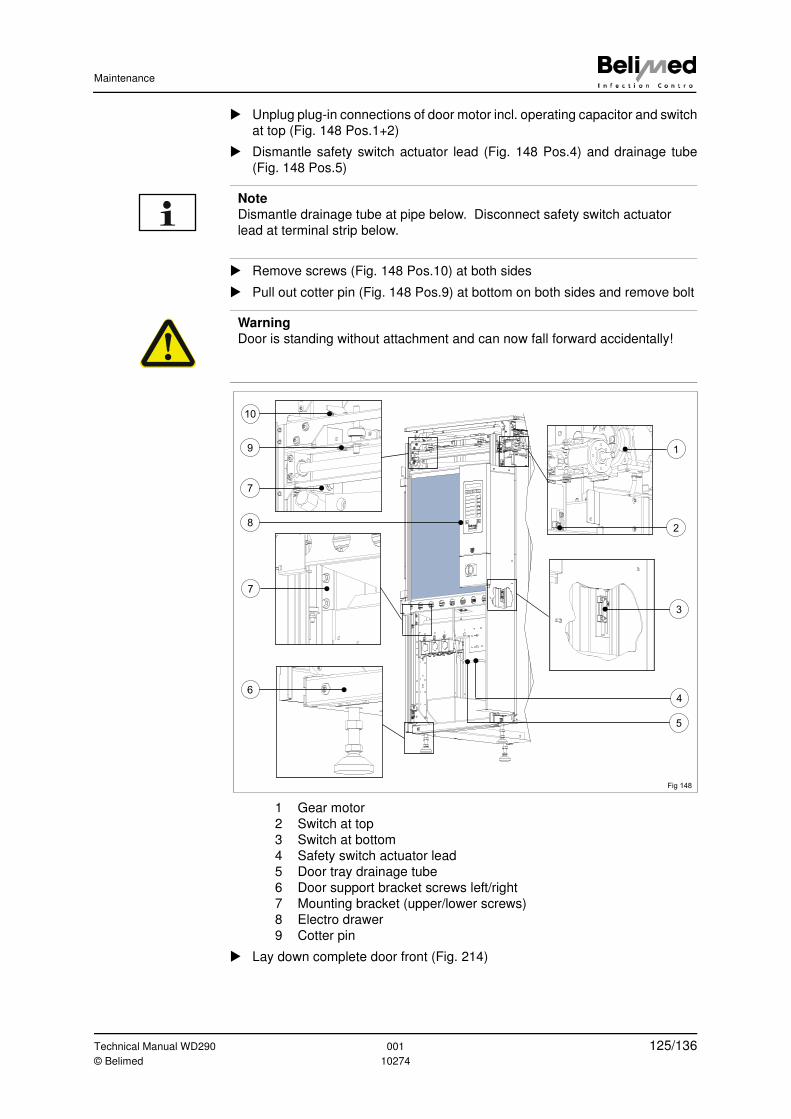
Maintenance
� Unplug plug-in connections of door motor incl. operating capacitor and switch
at top (Fig. 148 Pos.1+2)
� Dismantle safety switch actuator lead (Fig. 148 Pos.4) and drainage tube
(Fig. 148 Pos.5)
� Remove screws (Fig. 148 Pos.10) at both sides
� Pull out cotter pin (Fig. 148 Pos.9) at bottom on both sides and remove bolt
1 Gear motor
2 Switch at top
3 Switch at bottom
4 Safety switch actuator lead
5 Door tray drainage tube
6 Door support bracket screws left/right
7 Mounting bracket (upper/lower screws)
8 Electro drawer
9 Cotter pin
� Lay down complete door front (Fig. 214)
Note
Dismantle drainage tube at pipe below. Disconnect safety switch actuator
lead at terminal strip below.
Warning
Door is standing without attachment and can now fall forward accidentally!
1
2
3
Fig 148
10
9
7
7
6
8
4
5
Technical Manual WD290 001 125/136© Belimed 10274
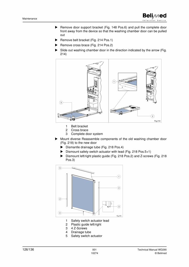
Maintenance
� Remove door support bracket (Fig. 148 Pos.6) and pull the complete door
front away from the device so that the washing chamber door can be pulled
out
� Remove belt bracket (Fig. 214 Pos.1)
� Remove cross brace (Fig. 214 Pos.2)
� Slide out washing chamber door in the direction indicated by the arrow (Fig.
214)
1 Belt bracket
2 Cross brace
3 Complete door system
� Mount diverse Reassemble components of the old washing chamber door
(Fig. 218) to the new door
� Dismantle drainage tube (Fig. 218 Pos.4)
� Dismount safety switch actuator with lead (Fig. 218 Pos.5+1)
� Dismount left/right plastic guide (Fig. 218 Pos.2) and Z-screws (Fig. 218
Pos.3)
1 Safety switch actuator lead
2 Plastic guide left/right
3 4 Z-Screws
4 Drainage tube
5 Safety switch actuator
3
Fig 214
1
2
2
3
2
1
5
4
Fig 218
126/136 001 Technical Manual WD290
10274 © Belimed
Maintenance
� Put new washing chamber door in place and remount complete door front
� Recalibrate door (see Chap. 6.11.8 "LS door frame final position when doors
are open")
Technical Manual WD290 001 127/136© Belimed 10274
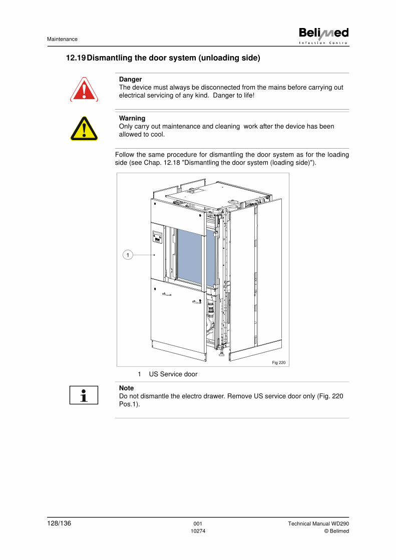
Maintenance
12.19Dismantling the door system (unloading side)
Follow the same procedure for dismantling the door system as for the loading
side (see Chap. 12.18 "Dismantling the door system (loading side)").
1 US Service door
Danger
The device must always be disconnected from the mains before carrying out
electrical servicing of any kind. Danger to life!
Warning
Only carry out maintenance and cleaning work after the device has been
allowed to cool.
1
Fig 220
Note
Do not dismantle the electro drawer. Remove US service door only (Fig. 220
Pos.1).
128/136 001 Technical Manual WD290
10274 © Belimed
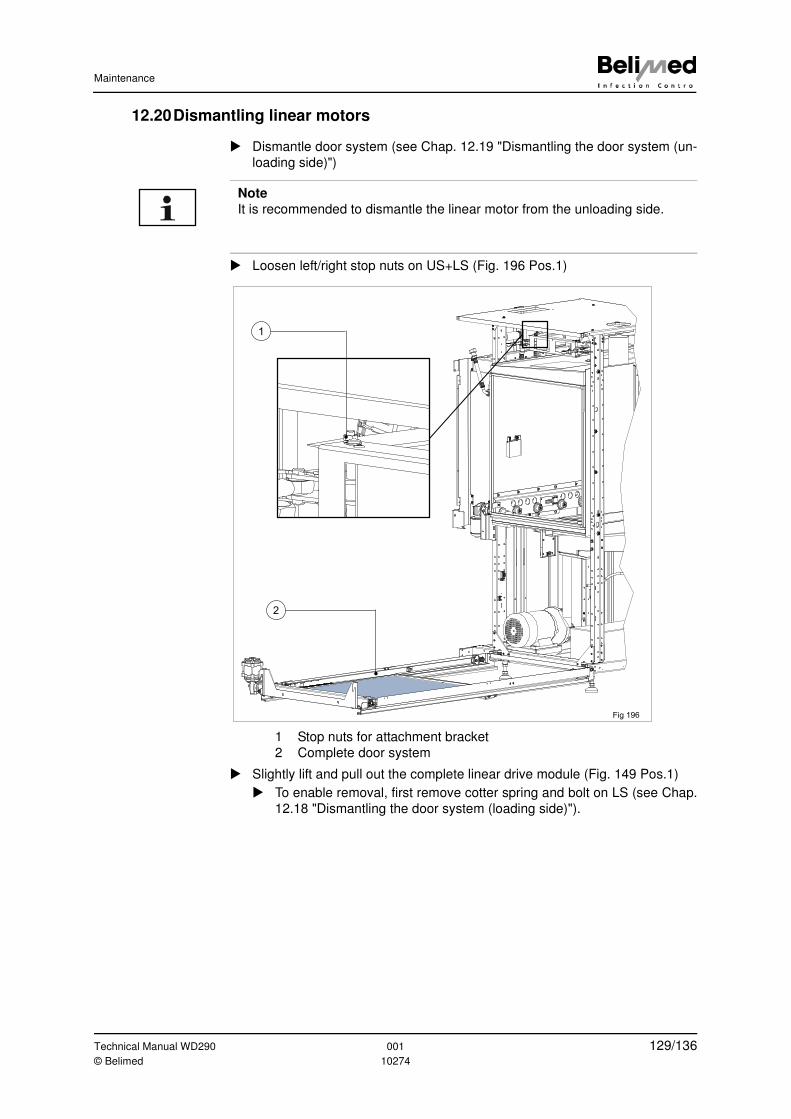
Maintenance
12.20Dismantling linear motors
� Dismantle door system (see Chap. 12.19 "Dismantling the door system (un-
loading side)")
� Loosen left/right stop nuts on US+LS (Fig. 196 Pos.1)
1 Stop nuts for attachment bracket
2 Complete door system
� Slightly lift and pull out the complete linear drive module (Fig. 149 Pos.1)
� To enable removal, first remove cotter spring and bolt on LS (see Chap.
12.18 "Dismantling the door system (loading side)").
Note
It is recommended to dismantle the linear motor from the unloading side.
2
Fig 196
1
Technical Manual WD290 001 129/136© Belimed 10274
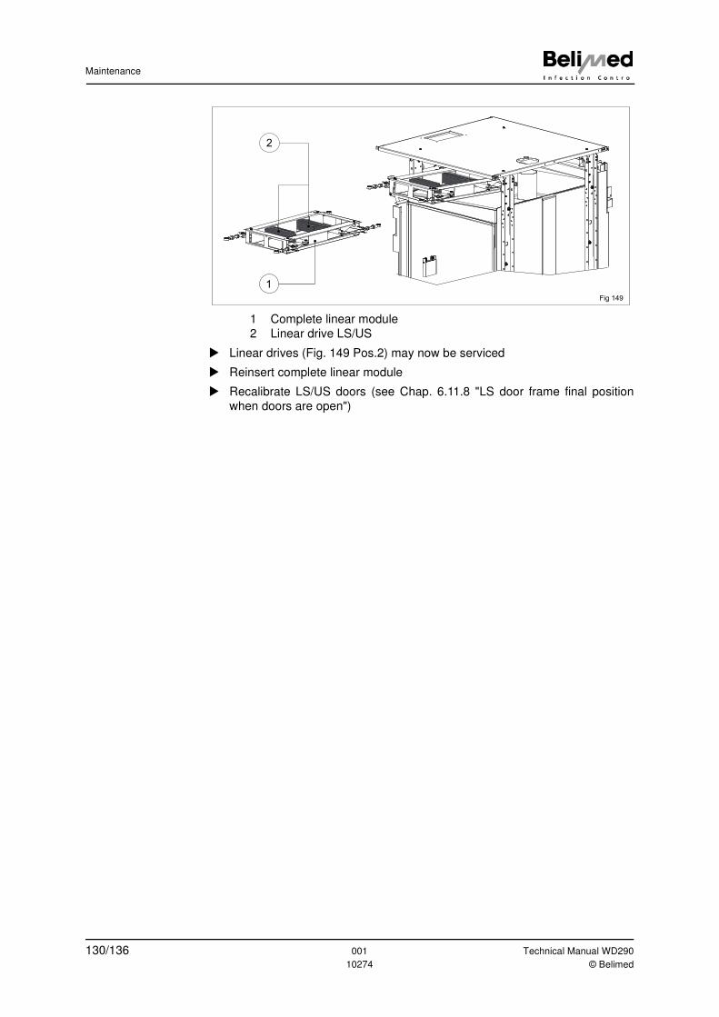
Maintenance
1 Complete linear module
2 Linear drive LS/US
� Linear drives (Fig. 149 Pos.2) may now be serviced
� Reinsert complete linear module
� Recalibrate LS/US doors (see Chap. 6.11.8 "LS door frame final position
when doors are open")
Fig 149
1
2
130/136 001 Technical Manual WD290
10274 © Belimed
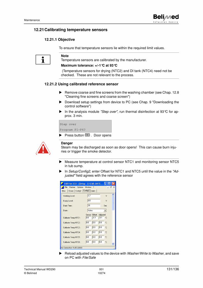
Maintenance
12.21Calibrating temperature sensors
12.21.1 Objective
To ensure that temperature sensors lie within the required limit values.
12.21.2 Using calibrated reference sensor
� Remove coarse and fine screens from the washing chamber (see Chap. 12.8
"Cleaning fine screens and coarse screen")
� Download setup settings from device to PC (see Chap. 9 "Downloading the
control software")
� In the analysis module "Step over", run thermal disinfection at 93°C for ap-
prox. 3 min.
� Press button . Door opens
� Measure temperature at control sensor NTC1 and monitoring sensor NTC5
in tub sump.
� In Setup/Config2, enter Offset for NTC1 and NTC5 until the value in the "Ad-
justed" field agrees with the reference sensor
� Reload adjusted values to the device with Washer/Write to Washer, and save
on PC with File/Safe
Note
Temperature sensors are calibrated by the manufacturer.
Maximum tolerance: +/-1°C at 93°C
(Temperature sensors for drying (NTC2) and DI tank (NTC4) need not be
checked. These are not relevant to the process.
Step over
Program P1-P6?
Danger
Steam may be discharged as soon as door opens! This can cause burn inju-
ries or trigger the smoke detector.
Technical Manual WD290 001 131/136© Belimed 10274
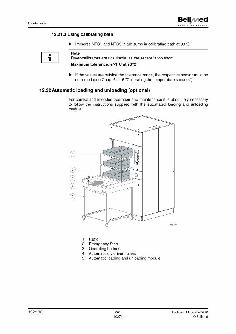
Maintenance
12.21.3 Using calibrating bath
� Immerse NTC1 and NTC5 in tub sump in calibrating bath at 93°C.
� If the values are outside the tolerance range, the respective sensor must be
corrected (see Chap. 6.11.6 "Calibrating the temperature sensors")
12.22Automatic loading and unloading (optional)
For correct and intended operation and maintenance it is absolutely necessary
to follow the instructions supplied with the automated loading and unloading
module.
1 Rack
2 Emergency Stop
3 Operating buttons
4 Automatically driven rollers
5 Automatic loading and unloading module
Note
Dryer-calibrators are unsuitable, as the sensor is too short.
Maximum tolerance: +/-1°C at 93°C
Fig 206
1
5
2
3
4
132/136 001 Technical Manual WD290
10274 © Belimed
Disposal
13 Disposal
13.1 Disposing of packaging material
Packaging material (cardboard, plastic, wood, EPS polystyrene etc.) is labelled
according to type and should as far as possible be recycled and disposed of with-
out causing environmental pollution.
13.2 Disposal of the device
The old device is not worthless waste material. If disposed of appropriately, the
raw materials can be recovered and re-used. Make sure that the device is dis-
posed of in accordance with current locally applicable government laws and reg-
ulations.
Technical Manual WD290 001 133/136© Belimed 10274
Conformity and certifications
14 Conformity and certifications
134/136 001 Technical Manual WD290
10274 © Belimed
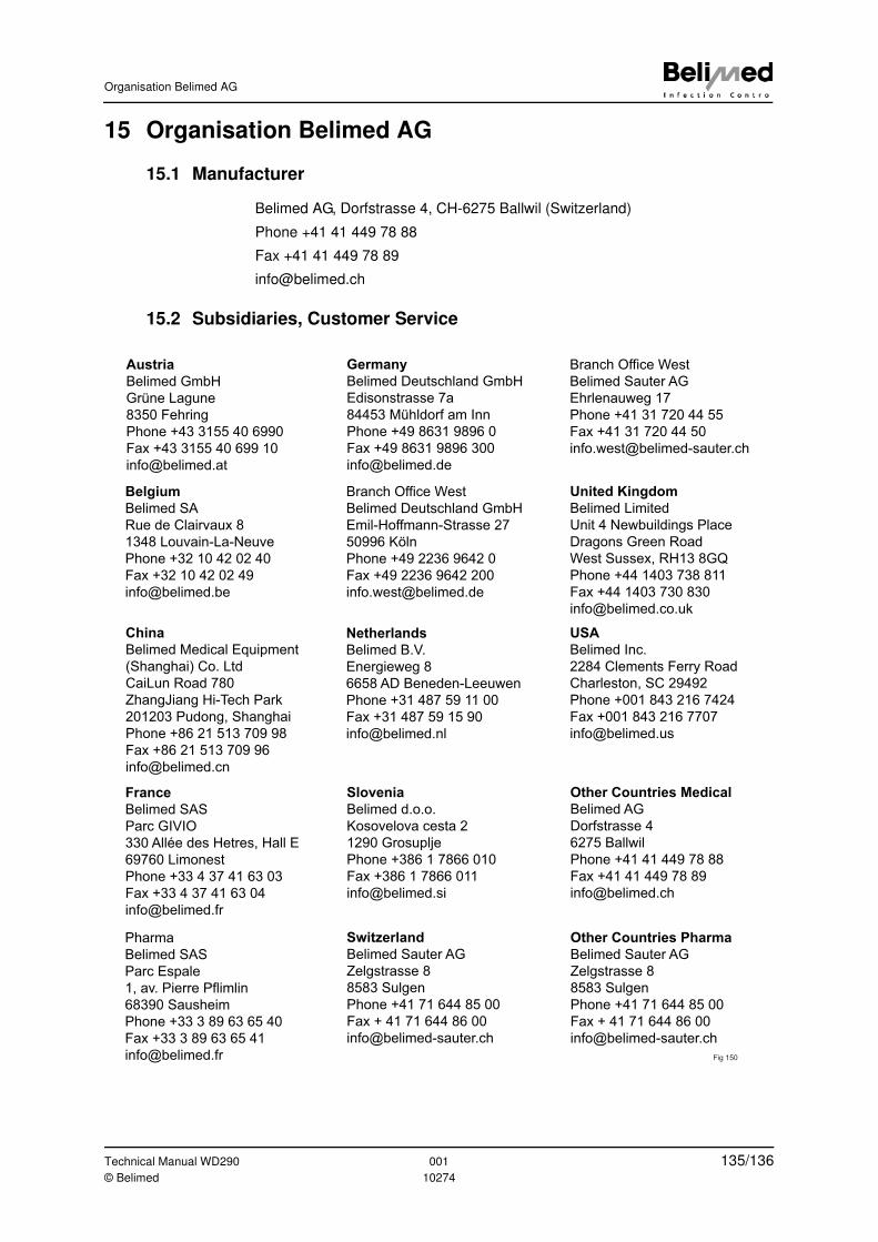
Organisation Belimed AG
15 Organisation Belimed AG
15.1 Manufacturer
Belimed AG, Dorfstrasse 4, CH-6275 Ballwil (Switzerland)
Phone +41 41 449 78 88
Fax +41 41 449 78 89
15.2 Subsidiaries, Customer Service
Belgium
Belimed SA
Rue de Clairvaux 8
1348 Louvain-La-Neuve
Phone +32 10 42 02 40
Fax +32 10 42 02 49
Germany
Belimed Deutschland GmbH
Edisonstrasse 7a
84453 Mühldorf am Inn
Phone +49 8631 9896 0
Fax +49 8631 9896 300
Branch Office West
Belimed Deutschland GmbH
Emil-Hoffmann-Strasse 27
50996 Köln
Phone +49 2236 9642 0
Fax +49 2236 9642 200
France
Belimed SAS
Parc GIVIO
330 Allée des Hetres, Hall E
69760 Limonest
Phone +33 4 37 41 63 03
Fax +33 4 37 41 63 04
Pharma
Belimed SAS
Parc Espale
1, av. Pierre Pflimlin
68390 Sausheim
Phone +33 3 89 63 65 40
Fax +33 3 89 63 65 41
United Kingdom
Belimed Limited
Unit 4 Newbuildings Place
Dragons Green Road
West Sussex, RH13 8GQ
Phone +44 1403 738 811
Fax +44 1403 730 830
Netherlands
Belimed B.V.
Energieweg 8
6658 AD Beneden-Leeuwen
Phone +31 487 59 11 00
Fax +31 487 59 15 90
Austria
Belimed GmbH
Grüne Lagune
8350 Fehring
Phone +43 3155 40 6990
Fax +43 3155 40 699 10
Switzerland
Belimed Sauter AG
Zelgstrasse 8
8583 Sulgen
Phone +41 71 644 85 00
Fax + 41 71 644 86 00
Slovenia
Belimed d.o.o.
Kosovelova cesta 2
1290 Grosuplje
Phone +386 1 7866 010
Fax +386 1 7866 011
USA
Belimed Inc.
2284 Clements Ferry Road
Charleston, SC 29492
Phone +001 843 216 7424
Fax +001 843 216 7707
Other Countries Medical
Belimed AG
Dorfstrasse 4
6275 Ballwil
Phone +41 41 449 78 88
Fax +41 41 449 78 89
Other Countries Pharma
Belimed Sauter AG
Zelgstrasse 8
8583 Sulgen
Phone +41 71 644 85 00
Fax + 41 71 644 86 00
Fig 150
China
Belimed Medical Equipment
(Shanghai) Co. Ltd
CaiLun Road 780
ZhangJiang Hi-Tech Park
201203 Pudong, Shanghai
Phone +86 21 513 709 98
Fax +86 21 513 709 96
Branch Office West
Belimed Sauter AG
Ehrlenauweg 17
Phone +41 31 720 44 55
Fax +41 31 720 44 50
Technical Manual WD290 001 135/136© Belimed 10274

Notes
16 Notes
136/136 001 Technical Manual WD290
10274 © Belimed