Embed Size (px)
Citation preview
5th International & 26th All India Manufacturing Technology, Design and Research Conference (AIMTDR 2014) December 12th–14th, 2014,
IIT Guwahati, Assam, India
516-1
Behaviour of Cutting Forces in Hard Turning Considering Effect of Tool
Wear on Principal Flank, Auxiliary Flank and Rake Faces: Individually
and in Combination
Amarjit Prakashrao Kene1*, S.K. Choudhury2
1*Ph.D. Scholar, Indian Institute of Technology Kanpur, Kanpur, 208016, Email: [email protected]
2Professor, Indian Institute of Technology Kanpur, Kanpur, 208016, Email: [email protected]
Abstract
In the present work behaviour of cutting forces was investigated considering the effect of tool wear on flank and
rake face individually and also in combination. The relationship between cutting forces and wear land was
studied by performing the turning operation on EN24 hardened steel of diameter 70 mm and length 400 mm
using commercially available single layer PVD coated TiSiN-TiAlN nanolayer insert at constant cutting
conditions. In the beginning the inserts were worn out artificially using electric discharge machining process.
From the plot of cutting forces with wear land and experimental results taken individually, it has been observed
that the tangential cutting force was more affected by crater wear. However axial and radial forces observed to
be predominantly affected by principle flank wear. On the other hand, wear on auxiliary flank face showed no
specific effect on any of the forces. Axial and radial forces were observed to be affected mostly when
combination of flank wear and crater wear was considered. The average axial force Fx, tangential force Fz, radial
force Fywere found to be 176.73 N, 225.56 N and 245.84 N respectively in case of no wear (zero wear) and
165.26 N, 219.27 N and 198.36 N respectively in case of combination of wear. Keywords: Hard turning, cutting forces, PVD coated insert, Artificial tool wear.
1 Introduction
Hard turning is a process which involves the
machining of steel of above 45 HRC. In the present
scenario, hard turning gained the popularity because
of its noticeable advantages over conventional
grinding process such as greater accuracy, higher
productivity, more flexibility and above all, the
economy (Hembrug Machine Tools Manual, Finish
Hard Turning). Hard turning is being widely used in
industries for the production of gears, hydraulic
pistons and injection pump components etc. In this
process, the forces generated are expected to be high,
so as per convention of machining a harder tool
material with low wearing capabilities is required for
continuous machining operations. Hard turning is of a
great interest to both the manufacturing industry and
research community.
Hard materials require harder tools to carry out
machining process and indulge more cutting forces in
the process. The cutting forces were in feed direction,
in the direction normal to the workpiece axis and in
vertical direction are named as axial force Fx, radial
force Fy and tangential force Fzrespectively. The value
of these forces is expected to be low and dependent on
practical cutting conditions. Hamdi et al (2012) have
claimed that the cutting force components are
influenced principally by the depth of cut and
workpiece hardness whereas feed is responsible for
surface roughness. Chinchanikar et al. (2013) have
used the optimization technique and found that cutting
forces were mostly affected by depth of cut (60-70 %)
and feed (25-30 %), while tool life is prominently
dependent on cutting speed and then depth of cut for
hard materials. Kaynak et al. (2013) proclaimed that
cryogenic cooling plays a significant role on reducing
notch wear which decreases the cutting force
requirement. Agustina et al. (2013) have proclaimed
that the magnitude of cutting forces are strongly
related to the amount of heat in the cutting area, tool
wear, quality of machined surface and accuracy of the
workpiece. Chinchanikar et al. (2013) have concluded
that coatings increases the limiting cutting speed for
machining of AISI 4340 steel of 35 HRC. Dimla et al.
(2000) have suggested that the vertical components
(z-direction) of both cutting forces and the vibration
signatures were the most sensitive to tool wear.
Behaviour of Cutting Forces in Hard Turning Considering Effect of Tool Wear on Principal
Individually and in Combination
For the machining of hard materials, different tool
materialslike CBN, Ceramics and carbides
tried by many researchers. Tugrul et al. (2007) have
used ceramic tool insert for machining 60 HRC steel.
The cutting forces were observed to be reduced but
roughness remained unaffected. Suresh et al. (2012)
have used multilayer coated carbide tool for
machining of hardened AISI 4340 steel
proclaimed that the reduction in cutting forces were
observed while turning at higher cutting speeds.
Coelho et al. (2007) have used PCBN coated and
uncoated edges for machining of AISI 4340 steel. The
surface finish was observed to be increase
PCBN compared to uncoated edge. The carbide
been chosen in present study to attain eco
process as CBN and ceramic tools are costlier
wear is also a big challenge in the field of machining
as it directly affects the machining performanc
particular operation. During a continuous turning
process, the online monitoring of tool condition plays
a vital role which can be used to protect the process
from unexpected hike in cutting forces as well as
workpiece roughness. Therefore in the p
the behaviour of the cutting forces was
respect to the tool wear. The data was collected from
the force measurement sensor (force dynamometer)
which was then analysed to minimize
The artificially worn-out insertswere used to carry out
the turning operation on EN24 hardened steel of 45
HRC hardness with single layer PVD coated TiSiN
TiAlN insert. The work was mainly concentrate
the artificial tool wear generation and then machining
using these worn out tools to identify performance of
cutting process at constant cutting conditions.
2 Experimental details
2.1 Cutting conditions
Turning operations were carried out on the HMT
center lathe with artificially worn out inserts. Wear
patterns on principle flank face, auxiliary flank face
and rake face, were considered as varying parameters
in present experimentation. Therefore experimen
were carried out at constant values of cutting
parameters viz. cutting speed(V), feed(f
cut(d). According to capability of machine,
recommendation from insert manufacturer, and
literature review, the values of cutting parameters
used in the present work are as given in Table 1.
Table 1 Cutting parameters
Parameters
Cutting Speed, V (m/min)
Feed, f (mm/rev)
Depth of Cut, d (mm)
2.2 Workpiece material and cutting insert
Behaviour of Cutting Forces in Hard Turning Considering Effect of Tool Wear on Principal Flank, Auxiliary Flank and Rake Faces:
For the machining of hard materials, different tool
like CBN, Ceramics and carbides have been
tried by many researchers. Tugrul et al. (2007) have
ert for machining 60 HRC steel.
The cutting forces were observed to be reduced but
Suresh et al. (2012)
have used multilayer coated carbide tool for
machining of hardened AISI 4340 steel and
proclaimed that the reduction in cutting forces were
observed while turning at higher cutting speeds.
Coelho et al. (2007) have used PCBN coated and
r machining of AISI 4340 steel. The
observed to be increased with
The carbide has
been chosen in present study to attain economy in the
are costlier. Tool
wear is also a big challenge in the field of machining
as it directly affects the machining performance for a
particular operation. During a continuous turning
process, the online monitoring of tool condition plays
a vital role which can be used to protect the process
from unexpected hike in cutting forces as well as
roughness. Therefore in the present work
was observed with
s collected from
the force measurement sensor (force dynamometer)
to minimize the tool wear.
e used to carry out
the turning operation on EN24 hardened steel of 45
HRC hardness with single layer PVD coated TiSiN-
mainly concentrated on
the artificial tool wear generation and then machining
entify performance of
at constant cutting conditions.
Turning operations were carried out on the HMT
center lathe with artificially worn out inserts. Wear
patterns on principle flank face, auxiliary flank face
varying parameters
ore experiments
were carried out at constant values of cutting
(f) and depth of
. According to capability of machine,
recommendation from insert manufacturer, and
literature review, the values of cutting parameters
in Table 1.
Table 1 Cutting parameters
Values
150
0.1
0.6
Workpiece material and cutting insert
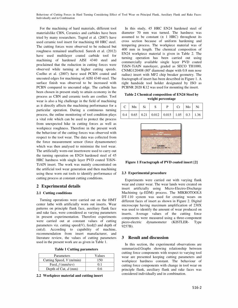
In this study, 45 HRC EN24 hardened
diameter 70 mm was turned. The hardness was
assumed to be constant (± 1 HRC) throughout its
cross section because of uniform hardening and
tempering process. The workpiece material wa
400 mm in length. The chemical composition of
EN24 workpiece material is given in Table 2. The
turning operation has been carried out using
commercially available single layer PVD coated
TiSiN-TiAlN nanolayer, graded as SECO TH1000,
CNMG120408 (80o diamond shape with 0.8 mm nose
radius) insert with MF2 chip breaker geometry. The
fractograph of insert has been described in Figure 1. A
right handside tool holder designated by ISO as
PCBNR 2020 K12 was used for mounting the insert.
Table 2 Chemical composition of EN24 Steel by
weight percentage
C Mn Si S P Cr
0.4 0.65 0.21 0.012 0.015 1.05
Figure 1 Fractograph of PVD coated insert [2]
2.3 Experimental procedure
Experiments were carried out with varying flank
wear and crater wear. The wear lands
insert artificially using Micro-Electro
Machining (µ-EDM) process. The MIKROTOOLS
DT-110 system was used for creat
different faces of insert as shown in Figure 2. Digital
microscope having maximum amplification
was used to identify the amount of wear produced on
inserts. Average values of the cutting force
components were measured using a three
piezo-electric dynamometer (KISTLER
9257B).
3 Result and discussion
In this section, the experimental observations
summarized.Graphs showing relationship between
cutting force components with respect to
wear are presented keeping cutting parameters and
workpiece hardness constant. The behaviour of
cutting force components with change in tool wear on
principle flank, auxiliary flank and rake faces
considered individually and in combination.
Flank, Auxiliary Flank and Rake Faces:
516-2
In this study, 45 HRC EN24 hardened steel of
diameter 70 mm was turned. The hardness was
assumed to be constant (± 1 HRC) throughout its
cross section because of uniform hardening and
rocess. The workpiece material was of
400 mm in length. The chemical composition of
e material is given in Table 2. The
turning operation has been carried out using
commercially available single layer PVD coated
TiAlN nanolayer, graded as SECO TH1000,
diamond shape with 0.8 mm nose
r geometry. The
fractograph of insert has been described in Figure 1. A
right handside tool holder designated by ISO as
PCBNR 2020 K12 was used for mounting the insert.
Table 2 Chemical composition of EN24 Steel by
Cr Mo Ni
1.05 0.3 1.36
Figure 1 Fractograph of PVD coated insert [2]
Experiments were carried out with varying flank
lands were created on
Electro-Discharge
EDM) process. The MIKROTOOLS
creating wears on
different faces of insert as shown in Figure 2. Digital
amplification of 230X
identify the amount of wear produced on
inserts. Average values of the cutting force
components were measured using a three-component
electric dynamometer (KISTLER- Type
In this section, the experimental observations are
.Graphs showing relationship between
cutting force components with respect to varying tool
wear are presented keeping cutting parameters and
workpiece hardness constant. The behaviour of
cutting force components with change in tool wear on
inciple flank, auxiliary flank and rake faces was
considered individually and in combination.
5th International & 26th All India Manufacturing Technology, Design and Research Conference (AIMTDR 2014) December 12th–14th, 2014,
IIT Guwahati, Assam, India
516-3
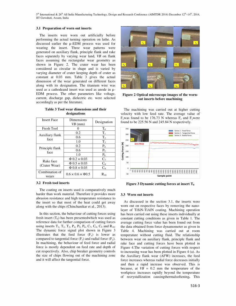
3.1 Preparation of worn out inserts
The inserts were worn out artificially before
performing the actual turning operation on lathe. As
discussed earlier the µ-EDM process was used for
wearing the insert. Three wear patterns were
generated on auxiliary flank, principle flank and rake
faces separately by varying wear land, VB on flank
faces assuming the rectangular wear geometry as
shown in Figure 2. The crater wear has been
considered as circular in shape and is varied by
varying diameter of crater keeping depth of crater as
constant at 0.03 mm. Table 3 gives the actual
dimension of the wear generated on different faces
along with its designation. The titanium wire was
used as a cathodeand insert was used as anode in µ-
EDM process. The other parameters like voltage,
current, discharge gap, dielectric etc. were selected
accordingly as per the literature.
Table 3 Tool wear dimensions and their
designations
Insert Face Dimensions
VB (mm) Designation
Fresh Tool 0 T0
Auxiliary flank
face
0.2 T1
0.6 T2
1.0 T3
Principle flank
face
0.2 P4
0.6 P5
1.0 P6
Rake face
(Crater Wear)
Φ 0.2 × 0.03 C7
Φ 0.5 × 0.03 C8
Φ 0.8 × 0.03 C9
Combination of
wears 0.6 × 0.6 × Φ0.5 R10
3.2 Fresh tool inserts
The coating on inserts used is comparatively much
harder than work material. Therefore it provides more
abrasion resistance and high temperature resistance to
the insert so that most of the heat could get away
along with the chips (Chinchanikar et al., 2013).
In this section, the behaviour of cutting forces using
fresh insert (T0) has been presentedwhich was used as
reference data for further comparison of cutting forces
using inserts T1, T2, T3, P4, P5, P6, C7, C8, C9 and R10.
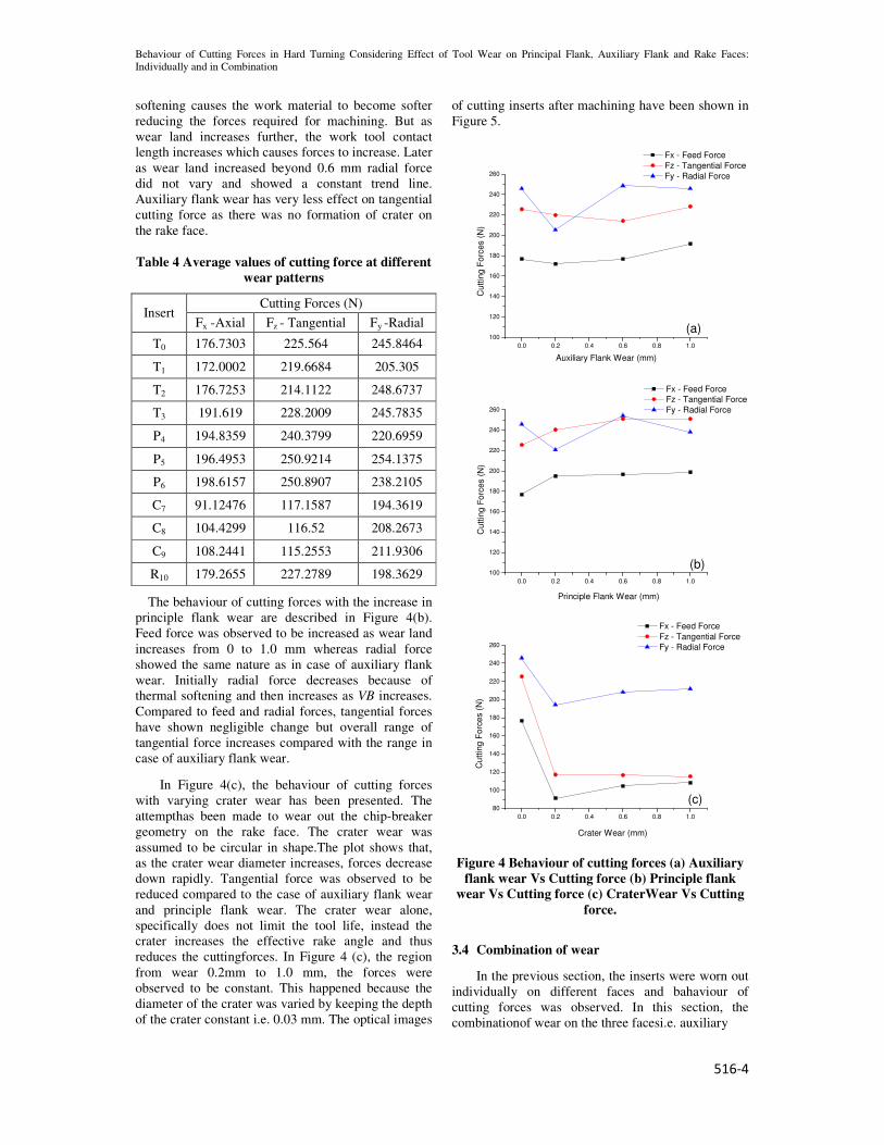
The dynamic force signal plot shown in Figure 3
illustrates that the feed force (Fx) is lower as
compared to tangential force (Fz) and radial force (Fy).
In machining, the behaviour of feed force and radial
force is mostly dependent on feed rate and depth of
cut respectively. Also, chip breaker geometry controls
the size of chips flowing out of the machining zone
and it will affect the tangential force.
Figure 2 Optical microscope images of the worn-
out inserts before machining
The machining was carried out at higher cutting
velocity with low feed rate. The average value of
Fxwas found to be 176.73 N whereas Fz and Fywere
found to be 225.56 N and 245.84 N respectively.
Figure 3 Dynamic cutting forces at insert T0
3.3 Worn out inserts
As discussed in the section 3.1, the inserts were
worn out on respective faces by removing the nano-
layer of TiSiN-TiAlN coating. Machining operation
has been carried out using these inserts individually at
constant cutting conditions as given in Table 1. The
average cutting force value has been found out from
the data obtained from force dynamometer as given in
Table 4. Machining was carried out at room
temperature without cutting fluid. The relationship
between wear on auxiliary flank, principle flank and
rake face and cutting forces have been plotted in
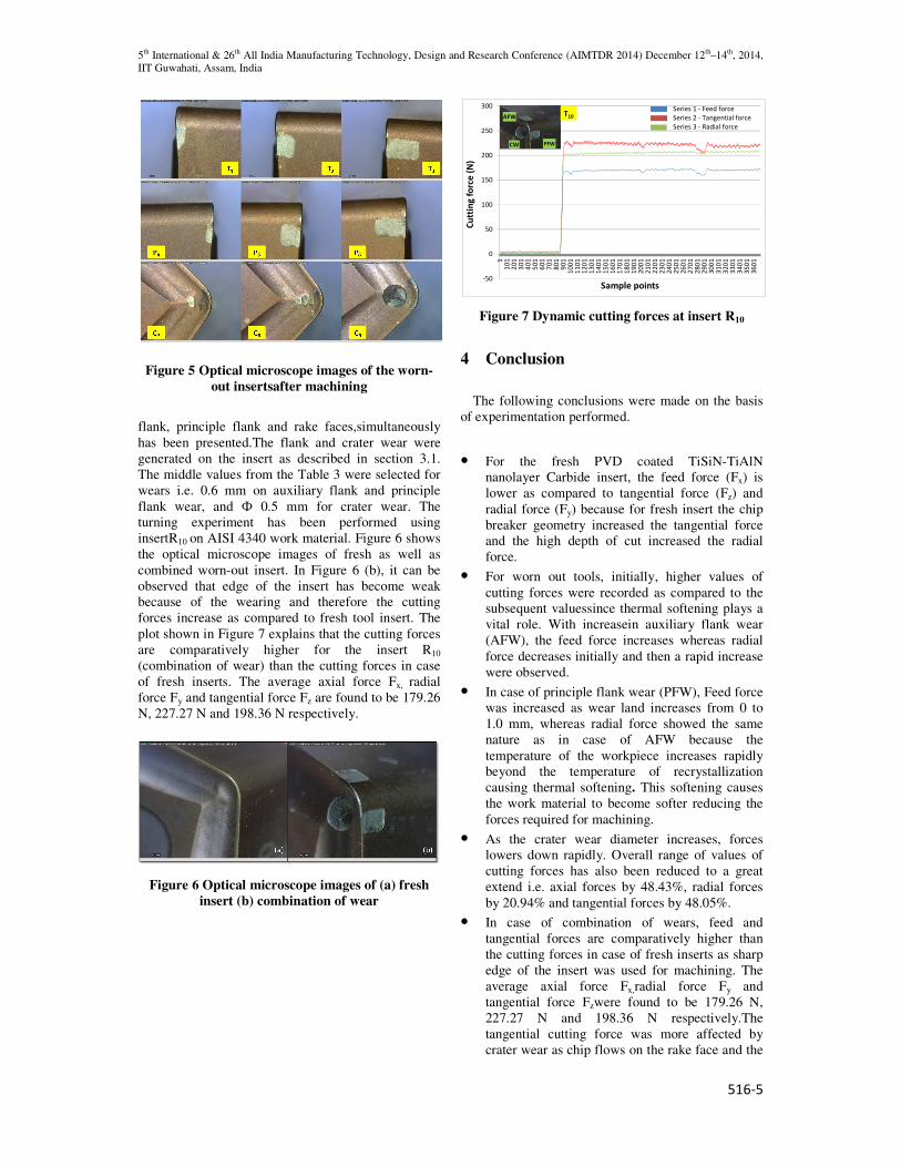
Figure 4.The variation of cutting forces with respect
to increasing wear has been plotted in Figure 4 (a). As
the Auxiliary flank wear (AFW) increases, the feed
force increases whereas radial force decreases initially
and then a rapid increase was observed. This is
because, at VB = 0.2 mm the temperature of the
workpiece increases rapidly beyond the temperature
of recrystallization causingthermalsoftening. This
-50
0
50
100
150
200
250
300
3501
10
1
20
1
30
1
40
1
50
1
60
1
70
1
80
1
90
1
10
01
11
01
12
01
13
01
14
01
15
01
16
01
17
01
18
01
19
01
20
01
21
01
22
01
23
01
24
01
25
01
26
01
27
01
28
01
Cu
ttin
g F
orc
e (
N)
Sample point
Zero Wear
Series 1 - Feed force
Series 2 - Tangential force
Series 3 - Radial force
T0
Behaviour of Cutting Forces in Hard Turning Considering Effect of Tool Wear on Principal Flank, Auxiliary Flank and Rake Faces:
Individually and in Combination
516-4
softening causes the work material to become softer
reducing the forces required for machining. But as
wear land increases further, the work tool contact
length increases which causes forces to increase. Later
as wear land increased beyond 0.6 mm radial force
did not vary and showed a constant trend line.
Auxiliary flank wear has very less effect on tangential
cutting force as there was no formation of crater on
the rake face.
Table 4 Average values of cutting force at different
wear patterns
Insert Cutting Forces (N)
Fx -Axial Fz - Tangential Fy -Radial
T0 176.7303 225.564 245.8464
T1 172.0002 219.6684 205.305
T2 176.7253 214.1122 248.6737
T3 191.619 228.2009 245.7835
P4 194.8359 240.3799 220.6959
P5 196.4953 250.9214 254.1375
P6 198.6157 250.8907 238.2105
C7 91.12476 117.1587 194.3619
C8 104.4299 116.52 208.2673
C9 108.2441 115.2553 211.9306
R10 179.2655 227.2789 198.3629
The behaviour of cutting forces with the increase in
principle flank wear are described in Figure 4(b).
Feed force was observed to be increased as wear land
increases from 0 to 1.0 mm whereas radial force
showed the same nature as in case of auxiliary flank
wear. Initially radial force decreases because of
thermal softening and then increases as VB increases.
Compared to feed and radial forces, tangential forces
have shown negligible change but overall range of
tangential force increases compared with the range in
case of auxiliary flank wear.
In Figure 4(c), the behaviour of cutting forces
with varying crater wear has been presented. The
attempthas been made to wear out the chip-breaker
geometry on the rake face. The crater wear was
assumed to be circular in shape.The plot shows that,
as the crater wear diameter increases, forces decrease
down rapidly. Tangential force was observed to be
reduced compared to the case of auxiliary flank wear
and principle flank wear. The crater wear alone,
specifically does not limit the tool life, instead the
crater increases the effective rake angle and thus
reduces the cuttingforces. In Figure 4 (c), the region
from wear 0.2mm to 1.0 mm, the forces were
observed to be constant. This happened because the
diameter of the crater was varied by keeping the depth
of the crater constant i.e. 0.03 mm. The optical images
of cutting inserts after machining have been shown in
Figure 5.
Figure 4 Behaviour of cutting forces (a) Auxiliary
flank wear Vs Cutting force (b) Principle flank
wear Vs Cutting force (c) CraterWear Vs Cutting
force.
3.4 Combination of wear
In the previous section, the inserts were worn out
individually on different faces and bahaviour of
cutting forces was observed. In this section, the
combinationof wear on the three facesi.e. auxiliary
0.0 0.2 0.4 0.6 0.8 1.0
100
120
140
160
180
200
220
240
260
Cutt
ing
Fo
rces (
N)
Auxiliary Flank Wear (mm)
Fx - Feed Force
Fz - Tangential Force
Fy - Radial Force
(a)
0.0 0.2 0.4 0.6 0.8 1.0
100
120
140
160
180
200
220
240
260
(b)
Principle Flank Wear (mm)
Cutt
ing
Fo
rces (
N)
Fx - Feed Force
Fz - Tangential Force
Fy - Radial Force
0.0 0.2 0.4 0.6 0.8 1.0
80
100
120
140
160
180
200
220
240
260
(c)
Crater Wear (mm)
Cu
ttin
g F
orc
es (
N)
Fx - Feed Force
Fz - Tangential Force
Fy - Radial Force
5th International & 26th All India Manufacturing Technology, Design and Research Conference (AIMTDR 2014) December 12th–14th, 2014,
IIT Guwahati, Assam, India
516-5
Figure 5 Optical microscope images of the worn-
out insertsafter machining
flank, principle flank and rake faces,simultaneously
has been presented.The flank and crater wear were
generated on the insert as described in section 3.1.
The middle values from the Table 3 were selected for
wears i.e. 0.6 mm on auxiliary flank and principle
flank wear, and Ф 0.5 mm for crater wear. The
turning experiment has been performed using
insertR10 on AISI 4340 work material. Figure 6 shows
the optical microscope images of fresh as well as
combined worn-out insert. In Figure 6 (b), it can be
observed that edge of the insert has become weak
because of the wearing and therefore the cutting
forces increase as compared to fresh tool insert. The
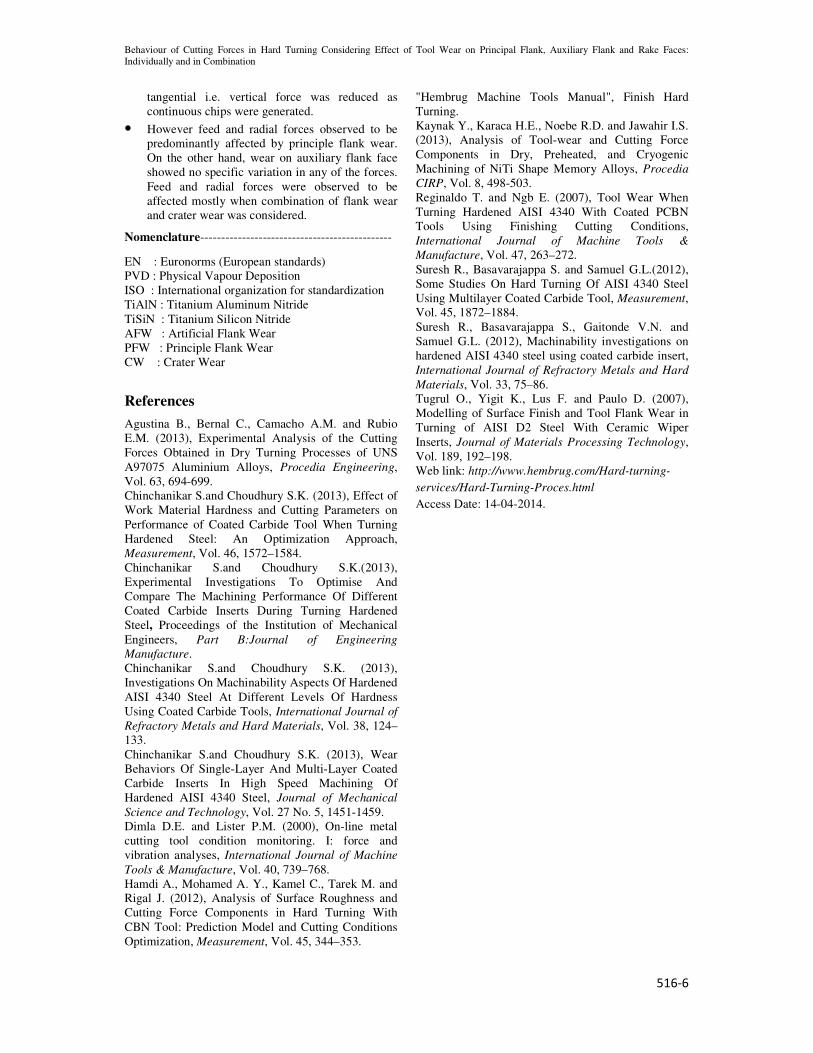
plot shown in Figure 7 explains that the cutting forces
are comparatively higher for the insert R10
(combination of wear) than the cutting forces in case
of fresh inserts. The average axial force Fx, radial
force Fy and tangential force Fz are found to be 179.26
N, 227.27 N and 198.36 N respectively.
Figure 6 Optical microscope images of (a) fresh
insert (b) combination of wear
Figure 7 Dynamic cutting forces at insert R10
4 Conclusion
The following conclusions were made on the basis
of experimentation performed.
• For the fresh PVD coated TiSiN-TiAlN
nanolayer Carbide insert, the feed force (Fx) is
lower as compared to tangential force (Fz) and
radial force (Fy) because for fresh insert the chip
breaker geometry increased the tangential force
and the high depth of cut increased the radial
force.
• For worn out tools, initially, higher values of
cutting forces were recorded as compared to the
subsequent valuessince thermal softening plays a
vital role. With increasein auxiliary flank wear
(AFW), the feed force increases whereas radial
force decreases initially and then a rapid increase
were observed.
• In case of principle flank wear (PFW), Feed force
was increased as wear land increases from 0 to
1.0 mm, whereas radial force showed the same
nature as in case of AFW because the
temperature of the workpiece increases rapidly
beyond the temperature of recrystallization
causing thermal softening. This softening causes
the work material to become softer reducing the
forces required for machining.
• As the crater wear diameter increases, forces
lowers down rapidly. Overall range of values of
cutting forces has also been reduced to a great
extend i.e. axial forces by 48.43%, radial forces
by 20.94% and tangential forces by 48.05%.
• In case of combination of wears, feed and
tangential forces are comparatively higher than
the cutting forces in case of fresh inserts as sharp
edge of the insert was used for machining. The
average axial force Fx,radial force Fy and
tangential force Fzwere found to be 179.26 N,
227.27 N and 198.36 N respectively.The
tangential cutting force was more affected by
crater wear as chip flows on the rake face and the
-50
0
50
100
150
200
250
300
11
01
20
13
01
40
15
01
60
17
01
80
19
01
10
01
11
01
12
01
13
01
14
01
15
01
16
01
17
01
18
01
19
01
20
01
21
01
22
01
23
01
24
01
25
01
26
01
27
01
28
01
29
01
30
01
31
01
32
01
33
01
34
01
35
01
36
01
Cu
ttin
g f
orc
e (
N)
Sample points
T10
PFWCW
AFW
Series 1 - Feed force
Series 2 - Tangential force
Series 3 - Radial force
Behaviour of Cutting Forces in Hard Turning Considering Effect of Tool Wear on Principal Flank, Auxiliary Flank and Rake Faces:
Individually and in Combination
516-6
tangential i.e. vertical force was reduced as
continuous chips were generated.
• However feed and radial forces observed to be
predominantly affected by principle flank wear.
On the other hand, wear on auxiliary flank face
showed no specific variation in any of the forces.
Feed and radial forces were observed to be
affected mostly when combination of flank wear
and crater wear was considered.
Nomenclature----------------------------------------------
EN : Euronorms (European standards)
PVD : Physical Vapour Deposition
ISO : International organization for standardization
TiAlN : Titanium Aluminum Nitride
TiSiN : Titanium Silicon Nitride
AFW : Artificial Flank Wear
PFW : Principle Flank Wear
CW : Crater Wear
References
Agustina B., Bernal C., Camacho A.M. and Rubio
E.M. (2013), Experimental Analysis of the Cutting
Forces Obtained in Dry Turning Processes of UNS
A97075 Aluminium Alloys, Procedia Engineering,
Vol. 63, 694-699.
Chinchanikar S.and Choudhury S.K. (2013), Effect of
Work Material Hardness and Cutting Parameters on
Performance of Coated Carbide Tool When Turning
Hardened Steel: An Optimization Approach,
Measurement, Vol. 46, 1572–1584.
Chinchanikar S.and Choudhury S.K.(2013),
Experimental Investigations To Optimise And
Compare The Machining Performance Of Different
Coated Carbide Inserts During Turning Hardened
Steel, Proceedings of the Institution of Mechanical
Engineers, Part B:Journal of Engineering
Manufacture.
Chinchanikar S.and Choudhury S.K. (2013),
Investigations On Machinability Aspects Of Hardened
AISI 4340 Steel At Different Levels Of Hardness
Using Coated Carbide Tools, International Journal of
Refractory Metals and Hard Materials, Vol. 38, 124–
133.
Chinchanikar S.and Choudhury S.K. (2013), Wear
Behaviors Of Single-Layer And Multi-Layer Coated
Carbide Inserts In High Speed Machining Of
Hardened AISI 4340 Steel, Journal of Mechanical
Science and Technology, Vol. 27 No. 5, 1451-1459.
Dimla D.E. and Lister P.M. (2000), On-line metal
cutting tool condition monitoring. I: force and
vibration analyses, International Journal of Machine
Tools & Manufacture, Vol. 40, 739–768.
Hamdi A., Mohamed A. Y., Kamel C., Tarek M. and
Rigal J. (2012), Analysis of Surface Roughness and
Cutting Force Components in Hard Turning With
CBN Tool: Prediction Model and Cutting Conditions
Optimization, Measurement, Vol. 45, 344–353.
"Hembrug Machine Tools Manual", Finish Hard
Turning.
Kaynak Y., Karaca H.E., Noebe R.D. and Jawahir I.S.
(2013), Analysis of Tool-wear and Cutting Force
Components in Dry, Preheated, and Cryogenic
Machining of NiTi Shape Memory Alloys, Procedia
CIRP, Vol. 8, 498-503.
Reginaldo T. and Ngb E. (2007), Tool Wear When
Turning Hardened AISI 4340 With Coated PCBN
Tools Using Finishing Cutting Conditions,
International Journal of Machine Tools &
Manufacture, Vol. 47, 263–272.
Suresh R., Basavarajappa S. and Samuel G.L.(2012),
Some Studies On Hard Turning Of AISI 4340 Steel
Using Multilayer Coated Carbide Tool, Measurement,
Vol. 45, 1872–1884.
Suresh R., Basavarajappa S., Gaitonde V.N. and
Samuel G.L. (2012), Machinability investigations on
hardened AISI 4340 steel using coated carbide insert,
International Journal of Refractory Metals and Hard
Materials, Vol. 33, 75–86.
Tugrul O., Yigit K., Lus F. and Paulo D. (2007),
Modelling of Surface Finish and Tool Flank Wear in
Turning of AISI D2 Steel With Ceramic Wiper
Inserts, Journal of Materials Processing Technology,
Vol. 189, 192–198.
Web link: http://www.hembrug.com/Hard-turning-
services/Hard-Turning-Proces.html
Access Date: 14-04-2014.