Embed Size (px)
Citation preview
University of Nairobi
Department of Real Estate and Construction Management
BCM 112
CIVIL ENGINEERING CONSTRUCTION I
DR. NYAMBANE OSANO
2013
BCM 112 – CIVIL ENGINEERING CONSTRUCTION I OSN - Lecture Notes
University of Nairobi Page i
TABLE OF CONTENTS
1 OVERVIEW ....................................................................................... 1
1.1 COURSE DESCRIPTION AND OUTLINE 1
1.2 PREREQUISITE 1
1.3 STUDENT LEARNING OUTCOME 1
1.4 TEACHING METHODOLOGY AND TECHNIQUES 1
1.5 REQUIRED TEXT BOOKS 2
2 INTRODUCTION TO SOIL MECHANICS ............................................. 3
2.1 DEFINITION OF SOIL 3
2.2 SOIL MECHANICS AND GEOTECHNICAL ENGINEERING 3
3 SOIL FORMATION ............................................................................ 5
3.1 DEFINITION 5
3.2 WEATHERING 5 3.2.1 INTRODUCTION 5 3.2.2 PHYSICAL WEATHERING 5 3.2.3 CHEMICAL WEATHERING 5
3.3 TYPES OF SOILS 6 3.3.1 SANDY SOIL 6 3.3.2 SILTY SOIL 6 3.3.3 CLAY SOIL 6 3.3.4 PEATY SOIL 6 3.3.5 SALINE SOIL 7
4 SOIL PROPERTIES ........................................................................... 8
4.1 INTRODUCTION 8
4.2 SOIL PHYSICAL PROPERTIES 8 4.2.1 SOIL TEXTURE 8 4.2.2 SOIL STRUCTURE 9 4.2.3 SOIL POROSITY 11
4.3 SOME USEFUL TERMS AND ASSOCIATED SYMBOLS 11
4.4 PHASE RELATIONSHIP 12 4.4.1 PHASE DIAGRAM 12 4.4.2 VOID RATIO (E) 13 4.4.3 MOISTURE CONTENT (WATER CONTENT) (W) 13 4.4.4 POROSITY (N) 13
BCM 112 – CIVIL ENGINEERING CONSTRUCTION I OSN - Lecture Notes
University of Nairobi Page ii
4.4.5 SPECIFIC VOLUME (V) 13 4.4.6 RELATIVE DENSITY (SPECIFIC GRAVITY) (GS) 14 4.4.7 DEGREE OF SATURATION (SR) 14 4.4.8 AIR CONTENT (A) 15 4.4.9 DENSITY OF SOLIDS (ΡS) 15 4.4.10 BULK DENSITY (Ρ) 15 4.4.11 SATURATED DENSITY (ΡSAT) 15 4.4.12 DRY DENSITY (ΡD) 15
5 SOIL INVESTIGATIONS / EXPLORATION ....................................... 16
5.1 PURPOSE OF SOIL EXPLORATION 16
5.2 PLANNING AN EXPLORATION PROGRAMME 16 5.2.1 RECONNAISSANCE OF THE AREA 16 5.2.2 PRELIMINARY SITE INVESTIGATION 16 5.2.3 DETAILED SITE INVESTIGATION 17
5.3 METHODS OF EXPLORATION 17 5.3.1 TEST PITS 17 5.3.2 BORINGS AND SAMPLING 17
5.4 FIELD IN-SITU TESTS 19
5.5 GEOPHYSICAL METHODS 19
5.6 LABORATORY METHODS 20
6 BEARING CAPACITY OF SOILS ....................................................... 21
6.1 INTRODUCTION 21
6.2 COMMON TYPES OF SOILS AND THEIR BEARING CAPACITY CHARACTERISTICS 21
6.2.1 ROCK 21 6.2.2 GRAVEL 21 6.2.3 SAND 21 6.2.4 CLAY 21 6.2.5 SILT 22
6.3 DESIGN PRINCIPLES 22 6.3.1 FOUNDATION TYPE 22 6.3.2 METHODS OF ASSESSING SOIL PROPERTIES 23 6.3.3 DISPLACEMENT AND SETTLEMENT OF FOUNDATIONS 24
7 SHEAR STRENGTHS AND EFFECTIVE STRESSES ............................. 25
7.1 INTRODUTION 25 7.1.1 SHEAR STRENGTH IN SOILS 26 7.1.2 THE MOHR – COULOMB FAILURE CRITERION 26
7.2 DETERMINATION OF SHEAR STRESS PARAMETERS 29 7.2.1 DIRECT SHEAR TEST 30
BCM 112 – CIVIL ENGINEERING CONSTRUCTION I OSN - Lecture Notes
University of Nairobi Page iii
8 SOIL COMPACTION ........................................................................ 34
8.1 INTRODUTION 34
8.2 THEORY OF COMPACTION 34 8.2.1 GENERAL 34 8.2.2 VARIATION IN COMPACTION CURVE 35
8.3 LABORATORY COMPACTION TESTS 36
8.4 FIELD COMPACTION 37 8.4.1 COMPACTION 37 8.4.2 FIELD CONTROL OF COMPACTION 38 8.4.3 SPECIFICATION OF THE FIELD COMPACTED DENSITY 39
9 LATERAL PRESSURES AND RETAINING WALLS .............................. 40
9.1 INTRODUTION 40
9.2 CATERGORIES OF EARTH PRESSURE 41 9.2.1 AT REST EARTH PRESSURE 41 9.2.2 ACTIVE EARTH PRESSURE 41 9.2.3 PASSIVE EARTH PRESSURE 42
9.3 CALCULATING LATERAL EARTH PRESSURE COEFFICIENTS 42 9.3.1 AT REST COEFFICIENT 42 9.3.2 ACTIVE AND PASSIVE COEFFICIENT 43
9.4 EARTH PRESSURE DISTRIBUTION 46
9.5 APPLICATIONS 47 9.5.1 RETAINING WALLS 47
10 ROAD DESIGN ................................................................................ 48
10.1 ROAD PAVEMENT 48
10.2 FACTORS INFLUENCING DESIGN OF THE PAVEMENT 48
10.3 ROAD CONSTRUCTION MATERIALS 48
10.4 PAVEMENT DESIGN PHILOSOPHY (CRITERIA) 48
10.5 PAVEMENT TYPES 48 10.5.1 FLEXIBLE PAVEMENTS 48 10.5.2 RIGID PAVEMENTS 49
BCM 112 – CIVIL ENGINEERING CONSTRUCTION I OSN - Lecture Notes
UNIVERSITY OF NAIROBI Page 1
1 OVERVIEW
1.1 COURSE DESCRIPTION AND OUTLINE
This course is an introductory part of Civil Engineering, which focuses on soil Mechanics.
The Course Outline in summarized below;
a) Soil properties, Soil investigation, methods adopted in soil investigation. Various types of soils;
b) Load bearing capacity of soils and foundations;
c) Shear Strengths and effective stresses,
d) Soil compaction
e) Lateral Pressures and Retaining Walls
f) Road design
1.2 PREREQUISITE
None
1.3 STUDENT LEARNING OUTCOME
Upon successful completion of this course, the students should acquire the following knowledge:
a) Developed competence in the principles of soil mechanics and application
in engineering practice.
b) Ability to list the relevant engineering properties of soils and their characteristics and
describe the factors which control these properties.
c) Ability to identify common situations when the soil becomes a factor in an
engineering or environmental problem.
d) Ability to apply basic analytical procedures to obtain the engineering
quantity desired and understand their limitations.
1.4 TEACHING METHODOLOGY AND TECHNIQUES
This course relies on lectures and Power Point presentation by the lecturer. Worked examples will be offered. Students will then be required to contribute to discussions based on the explanations and will need to read the corresponding section in the assigned textbook.

BCM 112 – CIVIL ENGINEERING CONSTRUCTION I OSN - Lecture Notes
UNIVERSITY OF NAIROBI Page 2
1.5 REQUIRED TEXT BOOKS
a) Modern Geotechnical Engineering, CBS Publishers & Distributors, New Dheli b) Geotechnical Engineering (Basics of Soil Mechanics), S. Chand & Company Ltd,
New Dheli c) Foundation Engineering Handbook, CBS Publishers & Distributors, New Dheli.
BCM 112 – CIVIL ENGINEERING CONSTRUCTION I OSN - Lecture Notes
UNIVERSITY OF NAIROBI Page 3
2 INTRODUCTION TO SOIL MECHANICS
2.1 DEFINITION OF SOIL
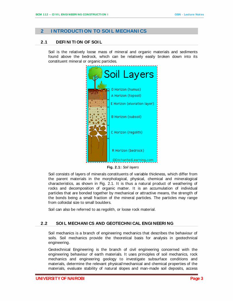
Soil is the relatively loose mass of mineral and organic materials and sediments found above the bedrock, which can be relatively easily broken down into its constituent mineral or organic particles.
Fig. 2.1: Soil layers
Soil consists of layers of minerals constituents of variable thickness, which differ from the parent materials in the morphological, physical, chemical and mineralogical characteristics, as shown in Fig. 2.1. It is thus a natural product of weathering of rocks and decomposition of organic matter. It is an accumulation of individual particles that are bonded together by mechanical or attractive means, the strength of the bonds being a small fraction of the mineral particles. The particles may range from colloidal size to small boulders.
Soil can also be referred to as regolith, or loose rock material.
2.2 SOIL MECHANICS AND GEOTECHNICAL ENGINEERING
Soil mechanics is a branch of engineering mechanics that describes the behaviour of soils. Soil mechanics provide the theoretical basis for analysis in geotechnical engineering.
Geotechnical Engineering is the branch of civil engineering concerned with the engineering behaviour of earth materials. It uses principles of soil mechanics, rock mechanics and engineering geology to investigate subsurface conditions and materials, determine the relevant physical/mechanical and chemical properties of the materials, evaluate stability of natural slopes and man-made soil deposits, access
BCM 112 – CIVIL ENGINEERING CONSTRUCTION I OSN - Lecture Notes
UNIVERSITY OF NAIROBI Page 4
risks posed by site conditions, design earthworks and structure foundations and monitor site conditions, earthwork and foundation construction.
A typical geotechnical engineering project begins with a review of project needs to define the required material properties. Then follows a site investigation of soil, rock, fault distribution and bedrock properties on and below an area of interest to determine their engineering properties.
Site investigations are needed to gain an understanding of the area in or on which the engineering will take place. Investigations can include the assessment of the risk to humans, property and the environment from natural hazards such as earthquakes, landslides, soil liquefaction, debris flows and rock falls.
A geotechnical engineer then determines and designs the type of foundations, earthworks and pavement subgrades required for the intended man-made structures to be built. Foundations are designed and constructed for structures of various sizes such as high-rise buildings, bridges, medium to large commercial buildings, and smaller structures where the soil conditions do not allow code-based design.
Foundations built for above-ground structures include shallow and deep foundations. Retaining structures include earth-filled dams and retaining walls. Earthworks include embankments, tunnels and sanitary landfills.
Geotechnical engineering is also related to coastal and ocean engineering. Coastal engineering can involve the design and construction of wharves (structures on the shore of harbour where ships may dock to load and unload cargo or passengers) and jetties (structures that projects into a body of water to influence the current or tide or to protect a harbour or shoreline from storms or erosion).
BCM 112 – CIVIL ENGINEERING CONSTRUCTION I OSN - Lecture Notes
UNIVERSITY OF NAIROBI Page 5
3 SOIL FORMATION
3.1 DEFINITION
Soil formation is the process by which soil is created. The formation of soil happens over a very long period of time. Soil is formed from the weathering of rocks and minerals.
3.2 WEATHERING
3.2.1 Introduction
Weathering is the process of breaking down rocks. Weathering occurs in situ or “with no movement”, and thus should not be confused with erosion, which involves the movement of rocks and minerals by agents such as water, ice, wind, and gravity.
Two important classifications of weathering processes exist – Physical and Chemical Weathering
3.2.2 Physical weathering
Involves the breakdown of rocks and soils through direct contact with atmospheric conditions, such as heat, water, ice and pressure, without any change in chemical condition. The soil formed due to physical weathering will be cohesionless (sand and gravel).
In summary, the physical agencies causing mechanical weathering of rocks are; (i) Daily and seasonal temperature changes. (ii) Flowing water, glaciers and wind, which produce impact and abrasive
action on rock. (iii) Splitting action of ice. (iv) Growth of roots of plants in rock fissures and to a minor degree burrowing
activities of small animals like earthworms.
3.2.3 Chemical weathering
Chemical weathering changes the composition of rocks by decomposing the parent minerals, transforming them into new compounds such as clay silica particles, carbonates and iron oxides.
The decomposition of rock is the result of the following reactions; (i) Oxidation (ii) Carbonation (iii) Hydration (iv) Leaching
i) Oxidation
Within the weathering environment, oxidation of a variety of metals occurs. The most commonly observed is the oxidation of Fe2+ (iron) and combination with oxygen and water to form Fe3+ hydroxides and oxides such as goethite, limonite and hematite. This gives the affected rocks a reddish-brown coloration on the
BCM 112 – CIVIL ENGINEERING CONSTRUCTION I OSN - Lecture Notes
UNIVERSITY OF NAIROBI Page 6
surface which crumbles easily and weakens the rock. This process is better known as ‘rusting’.
ii) Carbonation
Carbonation of rock material is caused by carbon dioxide in the presence of water. Limestones are very much affected by carbonation.
iii) Hydration
Mineral hydration is a form of chemical weathering that involves the rigid attachment of H+ and OH- ions to the atoms and molecules of a mineral. When rock minerals take up water, the increased volume creates physical stresses within the rock. For example iron oxides are converted to iron hydroxides and the hydration of anhydrite forms gypsum. Another example of hydration is the chemical decomposition of mineral fieldspar in granite to form kaolite.
iv) Leaching
Leaching is the process in which percolating water washes out water-soluble salts from the soil.
Soil produced by chemical weathering of rocks will be cohesive (silt and clay).
3.3 TYPES OF SOILS
3.3.1 Sandy Soil
This soil type has the biggest particles; and the bigger size of the particles in a soil the better is aeration and drainage of the soil. This soil is granular and consists of rock and mineral particles that are very small. Sandy soil is formed by the disintegration and weathering of rocks such as limestone, granite, quartz and shale. Sandy soil is easier to cultivate if it is rich in organic material, but then it allows drainage more than is needed, thus resulting in over-drainage and dehydration of the plants.
3.3.2 Silty Soil
Silty soil has much smaller particles than sandy soil so it’s smooth to the touch. When moistened, it’s soapy slick. When you roll it between your fingers, dirt is left on your skin.
3.3.3 Clay Soil
Clay soil has the smallest particles among the three so it has good water storage qualities. It’s sticky to the touch when wet, but smooth when dry.
3.3.4 Peaty Soil
Peaty soil is dark brown or black in color, soft, easily compressed due to its high water content, and rich in organic matter. Peat soil started forming over 9,000 years ago, with the rapid melting of glaciers. This rapid melt drowned plants quickly and died in the process. Their decay was so slow underwater that it led to the accumulation of organic area in a concentrated spot.

BCM 112 – CIVIL ENGINEERING CONSTRUCTION I OSN - Lecture Notes
UNIVERSITY OF NAIROBI Page 7
3.3.5 Saline Soil
The soil in extremely dry regions is usually brackish because of its high salt content. Known as saline soil, it can cause damage to and stall plant growth, impede germination, and cause difficulties in irrigation.
The salinity is due to the buildup of soluble salts in the rhizosphere—high salt contents prevent water uptake by plants, leading to drought stress.
BCM 112 – CIVIL ENGINEERING CONSTRUCTION I OSN - Lecture Notes
UNIVERSITY OF NAIROBI Page 8
4 SOIL PROPERTIES
4.1 INTRODUCTION
Soil is comprised of minerals, soil organic matter, water, and air. The composition and proportion of these components greatly influence soil physical properties, including texture, structure, and porosity, the fraction of pore space in a soil. In turn, these properties affect air and water movement in the soil, and thus the soil’s ability to function. Although soil organic matter comprises a relatively small portion of soil, typically only 1–4%, it plays a key role in many soil processes
4.2 SOIL PHYSICAL PROPERTIES
4.2.1 Soil Texture
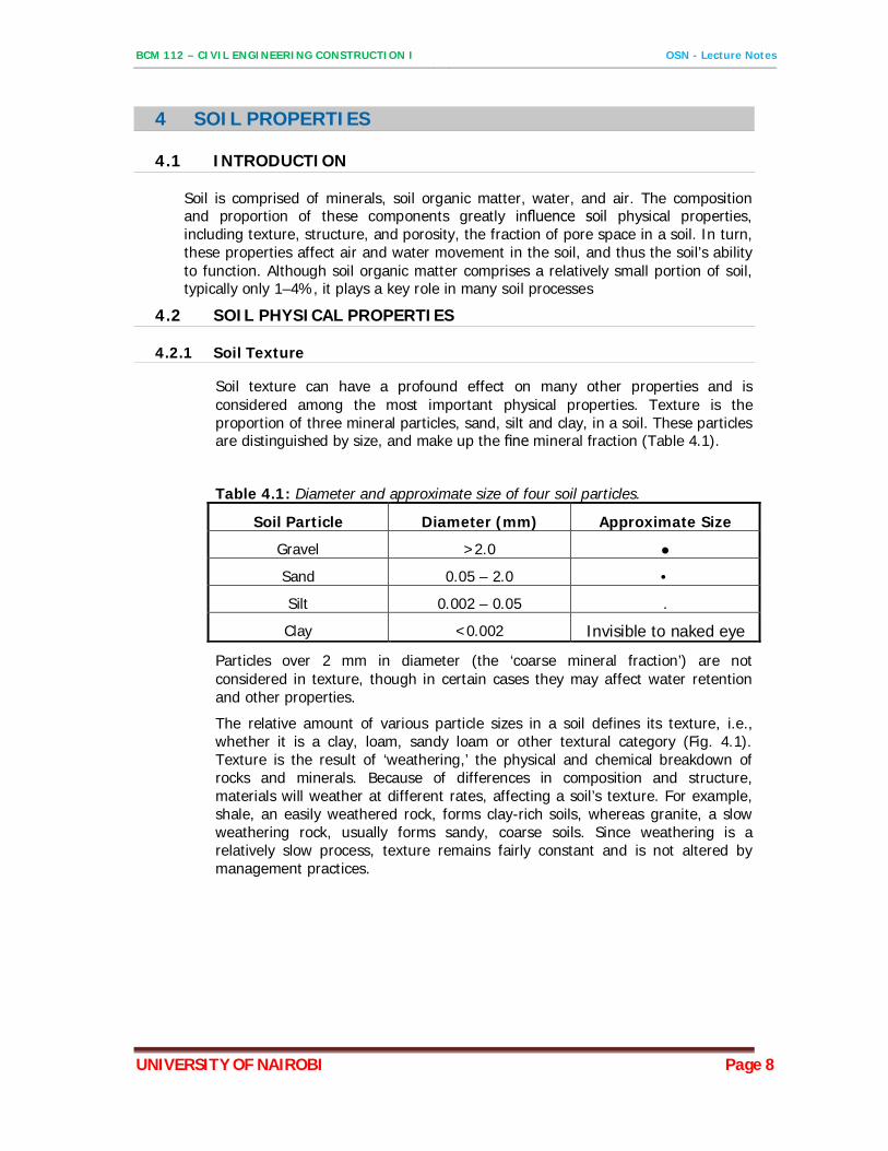
Soil texture can have a profound effect on many other properties and is considered among the most important physical properties. Texture is the proportion of three mineral particles, sand, silt and clay, in a soil. These particles are distinguished by size, and make up the fine mineral fraction (Table 4.1).
Table 4.1: Diameter and approximate size of four soil particles.
Soil Particle Diameter (mm) Approximate Size
Gravel >2.0 ●
Sand 0.05 – 2.0 •
Silt 0.002 – 0.05 .
Clay <0.002 Invisible to naked eye
Particles over 2 mm in diameter (the ‘coarse mineral fraction’) are not considered in texture, though in certain cases they may affect water retention and other properties.
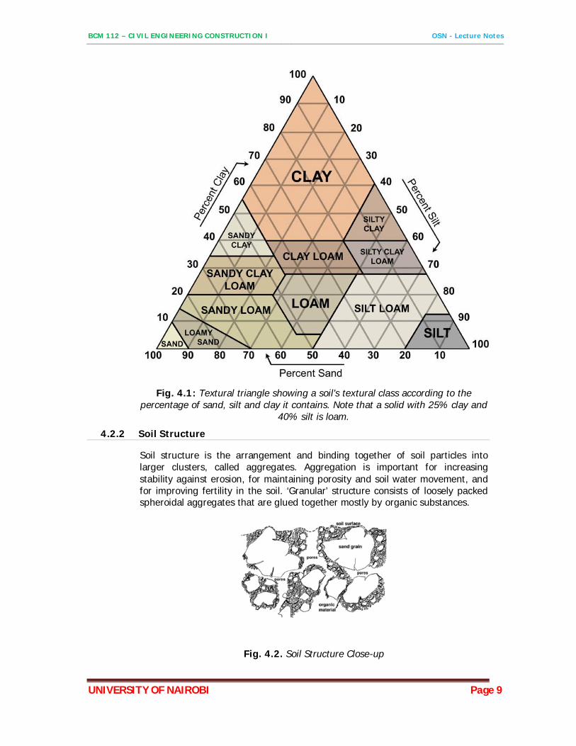
The relative amount of various particle sizes in a soil defines its texture, i.e., whether it is a clay, loam, sandy loam or other textural category (Fig. 4.1). Texture is the result of ‘weathering,’ the physical and chemical breakdown of rocks and minerals. Because of differences in composition and structure, materials will weather at different rates, affecting a soil’s texture. For example, shale, an easily weathered rock, forms clay-rich soils, whereas granite, a slow weathering rock, usually forms sandy, coarse soils. Since weathering is a relatively slow process, texture remains fairly constant and is not altered by management practices.
BCM 112 – CIVIL ENGINEERING CONSTRUCTION I OSN - Lecture Notes
UNIVERSITY OF NAIROBI Page 9
Fig. 4.1: Textural triangle showing a soil’s textural class according to the percentage of sand, silt and clay it contains. Note that a solid with 25% clay and
40% silt is loam.
4.2.2 Soil Structure
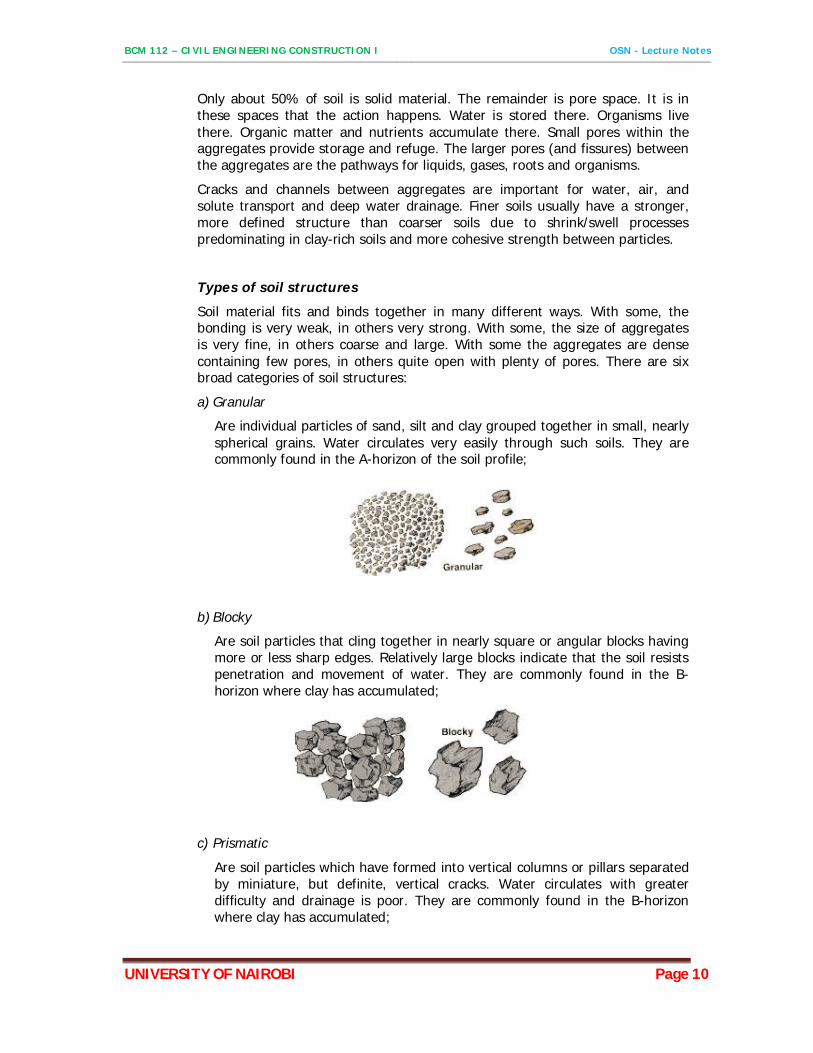
Soil structure is the arrangement and binding together of soil particles into larger clusters, called aggregates. Aggregation is important for increasing stability against erosion, for maintaining porosity and soil water movement, and for improving fertility in the soil. ‘Granular’ structure consists of loosely packed spheroidal aggregates that are glued together mostly by organic substances.
Fig. 4.2. Soil Structure Close-up
BCM 112 – CIVIL ENGINEERING CONSTRUCTION I OSN - Lecture Notes
UNIVERSITY OF NAIROBI Page 10
Only about 50% of soil is solid material. The remainder is pore space. It is in these spaces that the action happens. Water is stored there. Organisms live there. Organic matter and nutrients accumulate there. Small pores within the aggregates provide storage and refuge. The larger pores (and fissures) between the aggregates are the pathways for liquids, gases, roots and organisms.
Cracks and channels between aggregates are important for water, air, and solute transport and deep water drainage. Finer soils usually have a stronger, more defined structure than coarser soils due to shrink/swell processes predominating in clay-rich soils and more cohesive strength between particles.
Types of soil structures
Soil material fits and binds together in many different ways. With some, the bonding is very weak, in others very strong. With some, the size of aggregates is very fine, in others coarse and large. With some the aggregates are dense containing few pores, in others quite open with plenty of pores. There are six broad categories of soil structures:
a) Granular
Are individual particles of sand, silt and clay grouped together in small, nearly spherical grains. Water circulates very easily through such soils. They are commonly found in the A-horizon of the soil profile;
b) Blocky
Are soil particles that cling together in nearly square or angular blocks having more or less sharp edges. Relatively large blocks indicate that the soil resists penetration and movement of water. They are commonly found in the B-horizon where clay has accumulated;
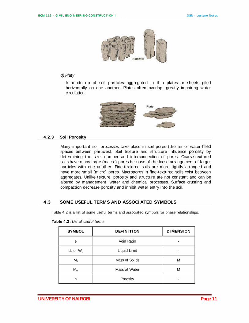
c) Prismatic
Are soil particles which have formed into vertical columns or pillars separated by miniature, but definite, vertical cracks. Water circulates with greater difficulty and drainage is poor. They are commonly found in the B-horizon where clay has accumulated;
BCM 112 – CIVIL ENGINEERING CONSTRUCTION I OSN - Lecture Notes
UNIVERSITY OF NAIROBI Page 11
d) Platy
Is made up of soil particles aggregated in thin plates or sheets piled horizontally on one another. Plates often overlap, greatly impairing water circulation.
4.2.3 Soil Porosity
Many important soil processes take place in soil pores (the air or water-filled spaces between particles). Soil texture and structure influence porosity by determining the size, number and interconnection of pores. Coarse-textured soils have many large (macro) pores because of the loose arrangement of larger particles with one another. Fine-textured soils are more tightly arranged and have more small (micro) pores. Macropores in fine-textured soils exist between aggregates. Unlike texture, porosity and structure are not constant and can be altered by management, water and chemical processes. Surface crusting and compaction decrease porosity and inhibit water entry into the soil.
4.3 SOME USEFUL TERMS AND ASSOCIATED SYMBOLS
Table 4.2 is a list of some useful terms and associated symbols for phase relationships.
Table 4.2: List of useful terms
SYMBOL DEFINITION DIMENSION
e Void Ratio -
LL or WL Liquid Limit -
Ms Mass of Solids M
Mw Mass of Water M
n Porosity -
BCM 112 – CIVIL ENGINEERING CONSTRUCTION I OSN - Lecture Notes
UNIVERSITY OF NAIROBI Page 12
Sr Degree Of Saturation -
Va Volume of Air L3
Vs Volume of Solids L3
Vv Volume of Voids L3
W Water Content -
ρd Dry Density M/L3
ρs Density of Solids M L3
ρsat Saturated Density M/L3
ρw Density of Water M/L3
ρ Bulk Density M/L3
4.4 PHASE RELATIONSHIP
4.4.1 Phase diagram
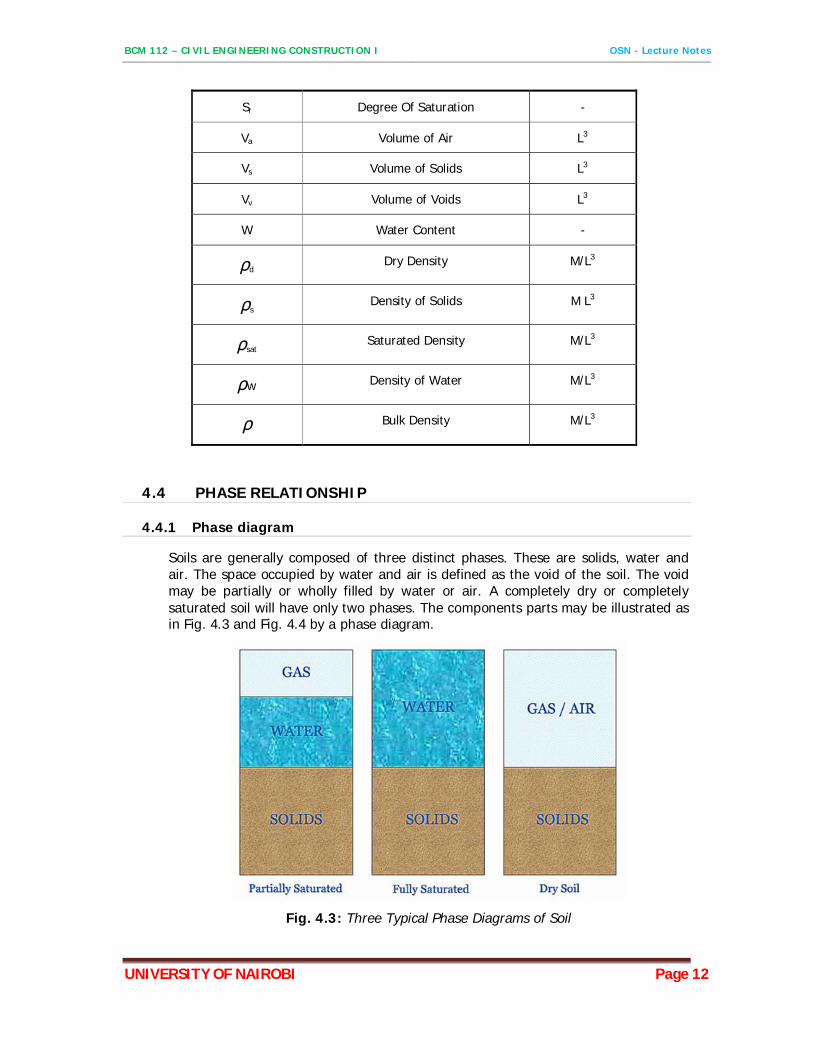
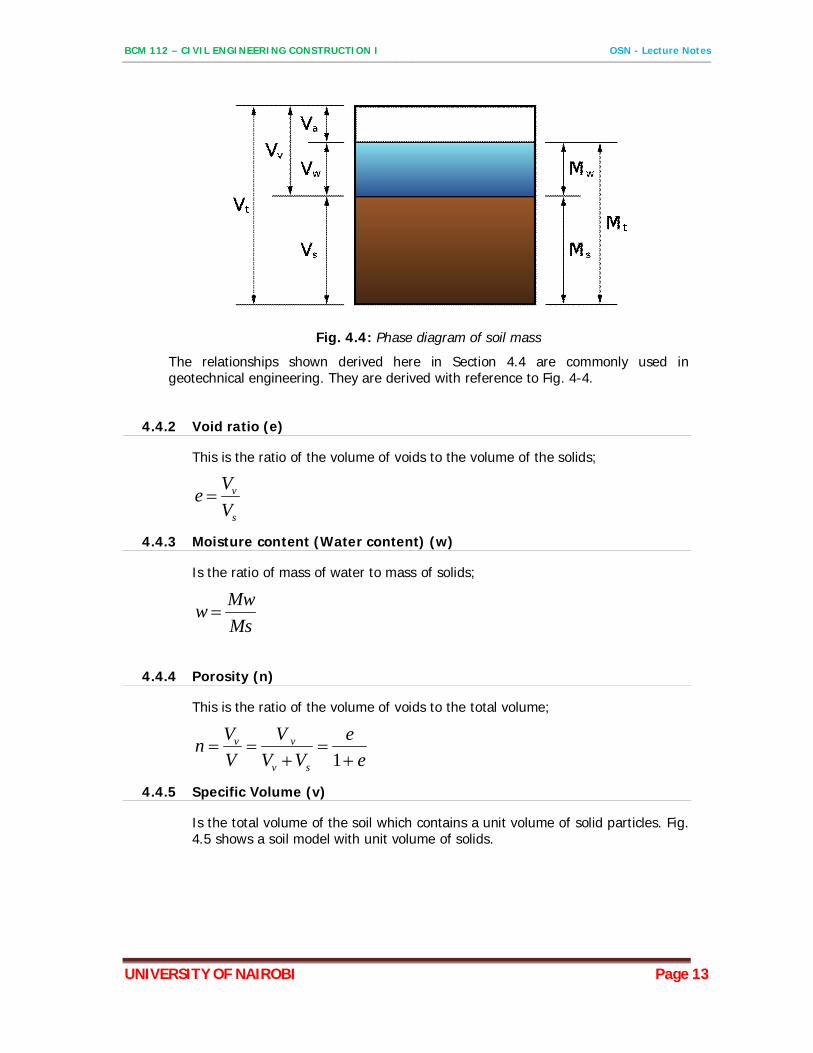
Soils are generally composed of three distinct phases. These are solids, water and air. The space occupied by water and air is defined as the void of the soil. The void may be partially or wholly filled by water or air. A completely dry or completely saturated soil will have only two phases. The components parts may be illustrated as in Fig. 4.3 and Fig. 4.4 by a phase diagram.
Fig. 4.3: Three Typical Phase Diagrams of Soil
BCM 112 – CIVIL ENGINEERING CONSTRUCTION I OSN - Lecture Notes
UNIVERSITY OF NAIROBI Page 13
Fig. 4.4: Phase diagram of soil mass
The relationships shown derived here in Section 4.4 are commonly used in geotechnical engineering. They are derived with reference to Fig. 4-4.
4.4.2 Void ratio (e)
This is the ratio of the volume of voids to the volume of the solids;
s
v
VVe
4.4.3 Moisture content (Water content) (w)
Is the ratio of mass of water to mass of solids;
MsMww
4.4.4 Porosity (n)
This is the ratio of the volume of voids to the total volume;
ee
VVV
VVn
sv
vv
1
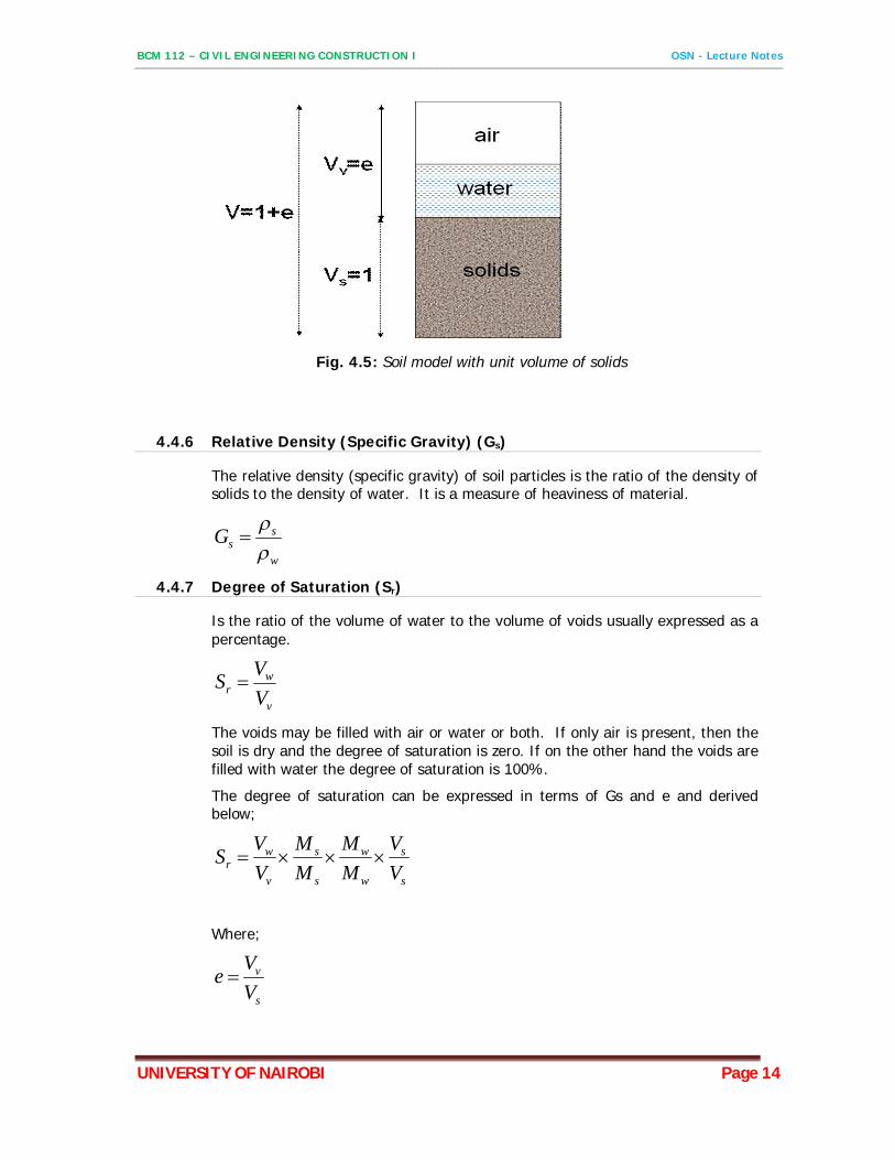
4.4.5 Specific Volume (v)
Is the total volume of the soil which contains a unit volume of solid particles. Fig. 4.5 shows a soil model with unit volume of solids.
BCM 112 – CIVIL ENGINEERING CONSTRUCTION I OSN - Lecture Notes
UNIVERSITY OF NAIROBI Page 14
Fig. 4.5: Soil model with unit volume of solids
4.4.6 Relative Density (Specific Gravity) (Gs)
The relative density (specific gravity) of soil particles is the ratio of the density of solids to the density of water. It is a measure of heaviness of material.
w
ssG
4.4.7 Degree of Saturation (Sr)
Is the ratio of the volume of water to the volume of voids usually expressed as a percentage.
v
wr V
VS
The voids may be filled with air or water or both. If only air is present, then the soil is dry and the degree of saturation is zero. If on the other hand the voids are filled with water the degree of saturation is 100%.
The degree of saturation can be expressed in terms of Gs and e and derived below;
s
s
w
w
s
s
v
wr V
VMM
MM
VVS
Where;
s
v
VVe
BCM 112 – CIVIL ENGINEERING CONSTRUCTION I OSN - Lecture Notes
UNIVERSITY OF NAIROBI Page 15
w
w
s
s
w
ss M
VVMG
MsMww
ewG
eGwS ss
r
4.4.8 Air Content (A)
Is the ratio of the volume of air to the total volume of the soil
VVA a
4.4.9 Density of Solids (ρs)
Is the ratio of the mass of the solids to the volume of the solids.
s
ss V
M
4.4.10 Bulk Density (ρ)
Is the ratio of the total mass of soil to the total volume of the soil.
VM
4.4.11 Saturated Density (ρsat)
The saturated density ρsat is the bult density of a soil mass when fully saturated.
4.4.12 Dry Density (ρd)
Is the mass of soil solids per unit of total volume of a dry soil mass.
BCM 112 – CIVIL ENGINEERING CONSTRUCTION I OSN - Lecture Notes
UNIVERSITY OF NAIROBI Page 16
5 SOIL INVESTIGATIONS / EXPLORATION
5.1 PURPOSE OF SOIL EXPLORATION
The purpose of soil exploration is to find out strength characteristics of the sub-soil over which the structure has to be built. Soil characteristics vary both with respect to depth from the ground surface and stretch in the horizontal direction. It is, therefore, the prime objective of soil exploration for a building, bridge or other Civil Engineering works, to analyze the nature of soil in all respects.
The main purposes of soil exploration are: - a. Selection of alternative construction sites or the choice of the most economical sites. b. Selection of alternative types or depth of foundation c. Selection of alternative methods of construction. d. Evaluation of the safety of existing structure. e. Location and selection of construction materials.
The soil exploration should provide the following data: 1. Soil parameters and properties of different layers (e.g. for classification, bearing capacity
or settlement calculation) 2. Thickness of soil layers and depth to bedrock (stratification of soil) 3. Location of ground water level.
5.2 PLANNING AN EXPLORATION PROGRAMME
The planning of a program for soil exploration depends upon; i. The nature of sub-soil ii. The type of structure iii. The importance of structure
The soil engineer should constantly keep in mind, when planning the exploration program, the purpose of the program and the relative costs involved. Normally, the cost involved in the soil exploration is a function of the total cost of the project. It is always advisable to spend a little more on soil investigation to understand clearly the nature of the soil so that suitable foundation can be recommended. Often an indication of the extent of an exploration of program can be estimated from the history of foundations successes and failures in an area. Also, for planning the program, the engineer should be well acquainted with the current methods of soil boring, sampling and testing and have some idea of the limitations on both the field and laboratory equipments and methods. The actual planning of a subsurface exploration program includes some or all of the following steps: -
5.2.1 Reconnaissance of the Area
Assembly of all available information on type and use of the structure, and also of the general topographic and geological character of the site. This also involves inspection of behavior of adjacent structures, rock outcrops, cuts, etc.
5.2.2 Preliminary Site Investigation
This is usually in the form of a few borings or a test pit to establish the types of materials, stratification of the soil, and possibly the location of the ground water level. For small projects
BCM 112 – CIVIL ENGINEERING CONSTRUCTION I OSN - Lecture Notes
UNIVERSITY OF NAIROBI Page 17
this step may be sufficient to establish foundation criteria, in which case the exploration program is finished.
5.2.3 Detailed Site Investigation
For complex projects or where the soil is of poor quality and/or erratic, a more detailed investigation may be undertaken. This may involve sinking several boreholes, taking soil samples for laboratory investigations, conducting sounding and other field tests.
5.3 METHODS OF EXPLORATION
Methods of determining the stratification and engineering characteristics of sub-surface soil conditions are
i. Test pits ii. Boring and sampling iii. Field tests iv. Geophysical methods v. Laboratory tests
5.3.1 Test pits
The simplest and cheapest method of shallow soil exploration is to sink test pit to depths of 3 to 4 m. The use of Test pits enables the in-situ soil conditions to be examined visually, thus the boundaries between strata and the nature of any macro-fabric can be accurately determined. It is relatively easy to obtain disturbed or undisturbed soil samples: in cohesive soils block samples can be cut by hand from the bottom of the pit and tube samples can be obtained from the sides of the pit.
5.3.2 Borings and Sampling
(1) Borings
This is the most widely used method. It provides samples from shallow to deeper depths for visual inspection as well as laboratory tests. The most commonly used methods of boring are:
i. Auger boring ii. Wash boring iii. Percussion drilling iv. Rotary drilling
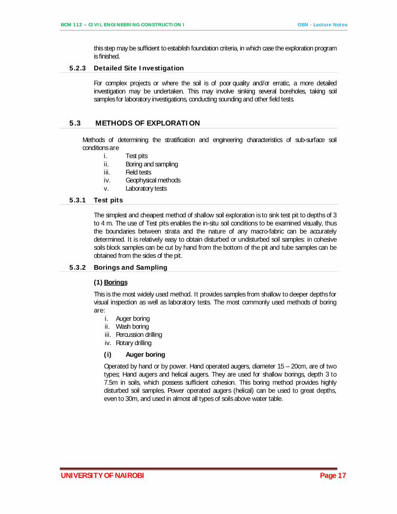
(i) Auger boring
Operated by hand or by power. Hand operated augers, diameter 15 – 20cm, are of two types; Hand augers and helical augers. They are used for shallow borings, depth 3 to 7.5m in soils, which possess sufficient cohesion. This boring method provides highly disturbed soil samples. Power operated augers (helical) can be used to great depths, even to 30m, and used in almost all types of soils above water table.
BCM 112 – CIVIL ENGINEERING CONSTRUCTION I OSN - Lecture Notes
UNIVERSITY OF NAIROBI Page 18
Fig. 5.1: Hand Augers
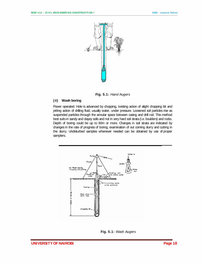
(ii) Wash boring
Power operated. Hole is advanced by chopping, twisting action of alight chopping bit and jetting action of drilling fluid, usually water, under pressure. Loosened soil particles rise as suspended particles through the annular space between casing and drill rod. This method best suits in sandy and clayey soils and not in very hard soil strata (i.e. boulders) and rocks. Depth of boring could be up to 60m or more. Changes in soil strata are indicated by changes in the rate of progress of boring, examination of out coming slurry and cutting in the slurry. Undisturbed samples whenever needed can be obtained by use of proper samplers.
Fig. 5.1: Wash Augers
BCM 112 – CIVIL ENGINEERING CONSTRUCTION I OSN - Lecture Notes
UNIVERSITY OF NAIROBI Page 19
(iii) Percussion boring
Power operated. Hole is advanced by repeated blows of a heavy chisel into the bottom of the hole. The resulting slurry formed at bottom of borehole is removed by bailer or sand pump. Because of the deep disturbance of the soil this method of boring is not favored. Casing is generally required. Maximum depth of boring is 60m.
(iv) Rotary boring
Power operated. Hole is advanced by a rapidly rotating bit which cuts the material at the bottom of the hole into small particles which are removed by circulating fluids, which may be water, bentonite slurry or mud slurry. This is the most rapid method for penetrating highly resistant materials (e.g. bed rock). In this method undisturbed samples can be obtained at desired depths by using suitable samplers. Maximum depth of drilling is 80 to150m.
(2) Soil sampling
There are two main types of soil samples which can be recovered from bore holes or trial pits. These are: Disturbed and Undisturbed samples.
a) Disturbed Samples
Are samples where the structure of the natural soil has been disturbed to a considerable degree by the action of the boring tolls or excavation equipment. Disturbed samples, however, need to be truly representative of the stratum. Disturbed samples are satisfactory for performing classification tests such as, sieve analysis, Atterberg limits etc.
b) Undisturbed Samples
Are samples, which represent as closely as is practicable, the true in-situ structure and water content of the soil. Undisturbed samples are required for determining reliable information on the shearing resistance and stress-deformation characteristics of a deposit. Undisturbed samples in cohesionless deposits are extremely difficult to obtain. Because of this the above characteristics are provided by field tests.
5.4 FIELD IN-SITU TESTS
These tests are valuable means of determining the relative densities; shear strengths and bearing capacities of soils directly without disturbing effects of boring and sampling.
The most commonly used field tests are; - i. Penetration or sounding tests ii. Vane shear test iii. Plate loading test iv. Pile loading test
5.5 GEOPHYSICAL METHODS
These comprise the seismic and resistivity methods. These methods are usually limited to establishing location of bedrock underlying softer material (by seismic method) or locating gravel or sand deposits (by resistivity method). The seismic method is based on the fact that sound waves
BCM 112 – CIVIL ENGINEERING CONSTRUCTION I OSN - Lecture Notes
UNIVERSITY OF NAIROBI Page 20
travel faster through rocks than through soils. The resistivity method makes use of the fact some soils (e.g. soft clays) have low electrical resistivity than others (e.g. sand or gravel). These methods are normally employed as preliminary or supplementary to other methods of exploration.
5.6 LABORATORY METHODS
Laboratory tests are useful in providing reliable data for calculating ultimate bearing capacity of soils, stability and settlement behavior of foundation, and for determining physical characteristics of soils. Results of laboratory tests should be used in conjunction with borehole records and results of field test. The common laboratory tests that concern the foundation engineers are;
i. Grain size analysis ii. Atterberg limits iii. Natural moisture content iv. Unit weight v. Unconfined compression test vi. Direct shear test vii. Triaxial compression test viii. Consolidation test ix. Compaction test x. Chemical analysis
BCM 112 – CIVIL ENGINEERING CONSTRUCTION I OSN - Lecture Notes
UNIVERSITY OF NAIROBI Page 21
6 BEARING CAPACITY OF SOILS
6.1 INTRODUCTION
The function of the foundation of structures is to transfer the load throughout the soil without overstressing the soil. Overstressing can result in either excessive settlement or shear failure of soil. Therefore, in designing foundations the bearing capacity of soils must be evaluated. When designing foundations for a structure there is a need to determine the bearing capacity of the soil. This applies to all forms of foundation, from a simple pad footing to a pile cap. The bearing stress capacity of the soil is the key variable that has a direct impact on the form and size of foundations. This topic explains the principles of how bearing capacity of soils are determined and how it impacts on the design. There are essentially five different types of soil and/or strata (some of which have further sub-divisions) that have an impact on the design of foundations. Section 6.2 summarises these soils.
6.2 COMMON TYPES OF SOILS AND THEIR BEARING CAPACITY CHARACTERISTICS
6.2.1 Rock
Most commonly has a high bearing capacity; its weakness lies with any fissures that exist within its make-up and its weathering state. Reinforced pad foundation that serves more to fix the sub-structure to the rock strata rather than spread its load.
6.2.2 Gravel
These are non-cohesive course soils that tend to be mixed with sand. They have a high bearing capacity and low compressibility. The presence of ground water can reduce its bearing capacity by half and the soil’s relative density also has an impact on its bearing capacity. Pad foundations due to the high bearing capacity. Piling is rare in these types of soils as it is often not needed.
6.2.3 Sand
Similar to gravel in many respects, sandy soils also have a high bearing capacity and low compressibility. Where it is loosely compacted however, there is a risk of significant settlement as load is applied. Like gravel, the presence of ground water has a detrimental effect on both the soil’s bearing capacity and relative density.
6.2.4 Clay
Clays are soils that are made up of very small particles and are described as ‘cohesive’. They typically have a lower bearing capacity than non-cohesive soils and compress when placed under load, which can occur over a long period of time, causing settlement. This is countered when they are over-consolidated at which point their properties are very similar to that of sand. Water has a
BCM 112 – CIVIL ENGINEERING CONSTRUCTION I OSN - Lecture Notes
UNIVERSITY OF NAIROBI Page 22
significant impact on clay soils with its properties sensitive to the level of moisture content. Pad foundations to light 1-2 storey structures and then piled foundations for all other forms of structure. In cases where settlement is undesirable e.g. extensions to existing structures, piling may be necessary.
6.2.5 Silt
Silt have a relatively high bearing capacity when confined, but their underlying structure breaks down when exposed to water. Silts can retain volumes of water that can freeze, causing the soil to heave. It is rare for structures to be directly founded upon silt due to its unpredictable nature. When encountered, a piling solution is adopted that passes through the silt into a more solid strata.
6.3 DESIGN PRINCIPLES
The bearing capacity of a soil is dependent upon its structure, moisture content and the type of foundation that is placed upon it. It is important therefore to be familiar with the various types of soil that can be encountered. From simply knowing the soil type, it is possible to develop reasonable design solutions for any given sub-structure.
6.3.1 Foundation Type
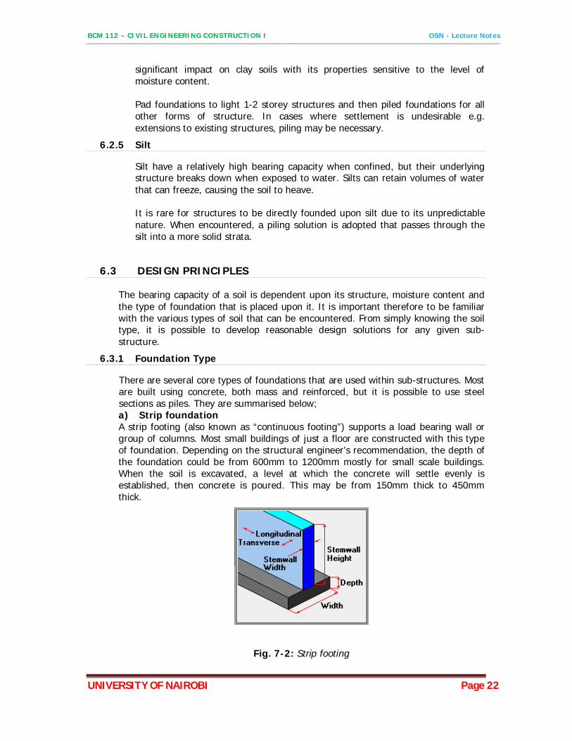
There are several core types of foundations that are used within sub-structures. Most are built using concrete, both mass and reinforced, but it is possible to use steel sections as piles. They are summarised below; a) Strip foundation A strip footing (also known as “continuous footing”) supports a load bearing wall or group of columns. Most small buildings of just a floor are constructed with this type of foundation. Depending on the structural engineer’s recommendation, the depth of the foundation could be from 600mm to 1200mm mostly for small scale buildings. When the soil is excavated, a level at which the concrete will settle evenly is established, then concrete is poured. This may be from 150mm thick to 450mm thick.
Fig. 7-2: Strip footing
BCM 112 – CIVIL ENGINEERING CONSTRUCTION I OSN - Lecture Notes
UNIVERSITY OF NAIROBI Page 23
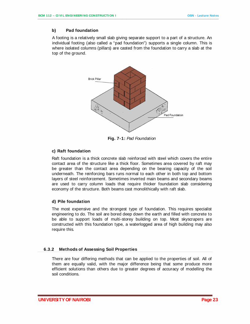
b) Pad foundation
A footing is a relatively small slab giving separate support to a part of a structure. An individual footing (also called a “pad foundation”) supports a single column. This is where isolated columns (pillars) are casted from the foundation to carry a slab at the top of the ground.
Fig. 7-1: Pad Foundation
c) Raft foundation
Raft foundation is a thick concrete slab reinforced with steel which covers the entire contact area of the structure like a thick floor. Sometimes area covered by raft may be greater than the contact area depending on the bearing capacity of the soil underneath. The reinforcing bars runs normal to each other in both top and bottom layers of steel reinforcement. Sometimes inverted main beams and secondary beams are used to carry column loads that require thicker foundation slab considering economy of the structure. Both beams cast monolithically with raft slab.
d) Pile foundation
The most expensive and the strongest type of foundation. This requires specialist engineering to do. The soil are bored deep down the earth and filled with concrete to be able to support loads of multi-storey building on top. Most skyscrapers are constructed with this foundation type, a waterlogged area of high building may also require this.
6.3.2 Methods of Assessing Soil Properties
There are four differing methods that can be applied to the properties of soil. All of them are equally valid, with the major difference being that some produce more efficient solutions than others due to greater degrees of accuracy of modelling the soil conditions.
BCM 112 – CIVIL ENGINEERING CONSTRUCTION I OSN - Lecture Notes
UNIVERSITY OF NAIROBI Page 24
a) Geotechnical Design by Calculations This method is reliant on the quality of data retrieved from geotechnical investigations carried out on the prospective site. Assumptions are made based on this data and in some instances simplifications will need to be applied to the calculation model that can lead to conservative results.
b) Geotechnical design by prescriptive measures In instances where the soil conditions of the site are well known, it is possible to prepare a set of parameters against which any sub-structure can be designed. Due to the generalised nature of this method, it’s common for it to produce conservatively designed solutions.
c) Geotechnical design based on load tests and experimental models In addition to geotechnical investigations that focus on the soil type and location of the water table, it is possible to carry out tests to determine the soil’s bearing capacity. These tests provide unique results for that particular site and thus are more accurate than making assumptions based on data collected from a standard investigation. This approach typically results in economical design solutions due to the accuracy of the data. Load tests however need to be at the correct scale to ensure the test mirrors the proposed foundation, which can prove to be expensive.
d) Geotechnical design based on observations In instances where it is not possible to predict how the soil will interact with a proposed substructure, it is possible to apply an observational based method of design. This requires the design of the substructure to be altered as new data is revealed about the soil during the construction of the foundations. Careful monitoring is needed throughout the construction process, as well as quick responses to the data being delivered, in order to prevent delays during the substructure works. This method is unlikely to provide a practical approach to the majority of foundation designs and is not recommended for designing substructures for buildings. Regardless of the method of soil analysis adopted, all results must be interpreted by a suitably qualified geotechnical engineer, which can then be passed onto the designer of the substructure.
6.3.3 Displacement and Settlement of Foundations
In addition to determining the design bearing capacity of soil, it is also necessary to determine the settlement of the foundations. This is done by using serviceability limit state principles that rely on the application of characteristic loads.
BCM 112 – CIVIL ENGINEERING CONSTRUCTION I OSN - Lecture Notes
UNIVERSITY OF NAIROBI Page 25
7 SHEAR STRENGTHS AND EFFECTIVE STRESSES
7.1 INTRODUTION
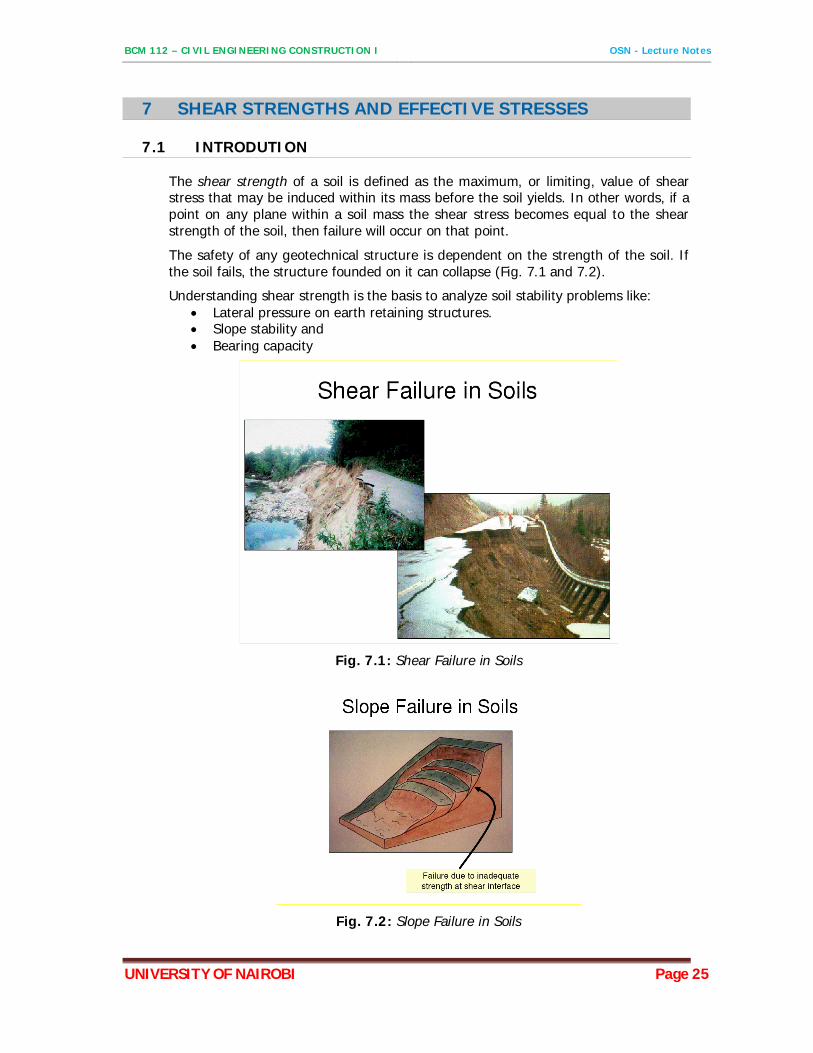
The shear strength of a soil is defined as the maximum, or limiting, value of shear stress that may be induced within its mass before the soil yields. In other words, if a point on any plane within a soil mass the shear stress becomes equal to the shear strength of the soil, then failure will occur on that point.
The safety of any geotechnical structure is dependent on the strength of the soil. If the soil fails, the structure founded on it can collapse (Fig. 7.1 and 7.2).
Understanding shear strength is the basis to analyze soil stability problems like: Lateral pressure on earth retaining structures. Slope stability and Bearing capacity
Fig. 7.1: Shear Failure in Soils
Fig. 7.2: Slope Failure in Soils
BCM 112 – CIVIL ENGINEERING CONSTRUCTION I OSN - Lecture Notes
UNIVERSITY OF NAIROBI Page 26
7.1.1 Shear Strength in Soils
The shear strength of a soil is its resistance to shearing stresses. It is a measure of the soil resistance to deformation by continuous displacement of its individual soil particles. Shear strength in soils depends primarily on interactions between particles. Shear failure occurs when the stresses between the particles are such that they slide or roll past each other.
The shear strength () of a soil at a point on a particular plane was originally expressed by Coulomb as a linear function of the normal stress () on the plane at the same point:
tan c
where = shear strength c = cohesion; = angle of internal friction;
Soil derives its shear strength from two sources:
a) Shear Strength of Soils - Cohesion
Cohesion (c), is a measure of the forces that cement particles of soils.
b) Shear Strength of Soils – Internal Friction
This is the angle of shearing resistance, .
c and are the shear strength parameters commonly described as the cohesion intercept (or the apparent cohesion) and the angle of shearing resistance, or internal friction angle respectively.
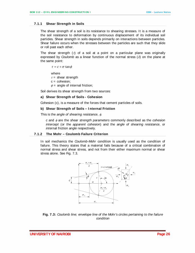
7.1.2 The Mohr – Coulomb Failure Criterion
In soil mechanics the Coulomb-Mohr condition is usually used as the condition of failure. This theory states that a material fails because of a critical combination of normal stress and shear stress, and not from their either maximum normal or shear stress alone. See Fig. 7.3.
c
3
1
2
231
tanc231
1
3
1
3
Fig. 7.3: Coulomb line; envelope line of the Mohr’s circles pertaining to the failure condition
BCM 112 – CIVIL ENGINEERING CONSTRUCTION I OSN - Lecture Notes
UNIVERSITY OF NAIROBI Page 27
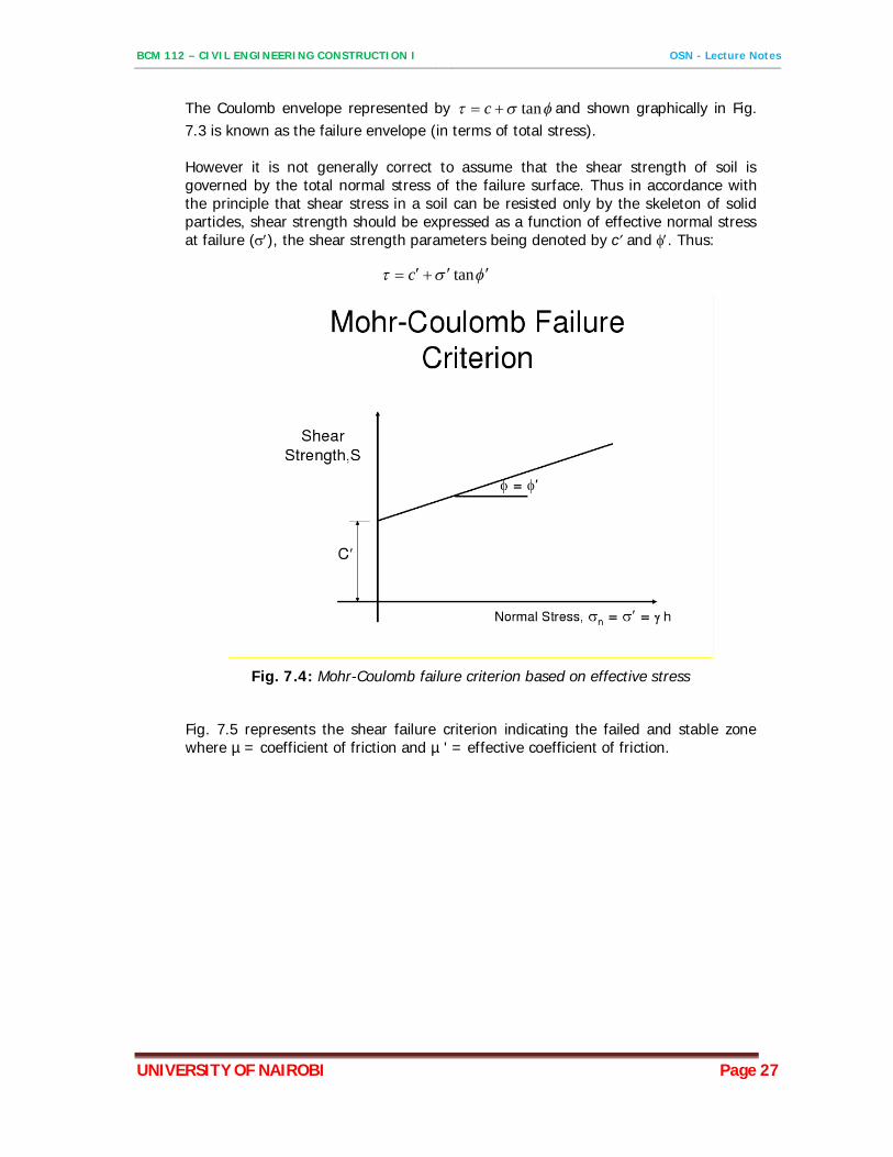
The Coulomb envelope represented by tan c and shown graphically in Fig. 7.3 is known as the failure envelope (in terms of total stress). However it is not generally correct to assume that the shear strength of soil is governed by the total normal stress of the failure surface. Thus in accordance with the principle that shear stress in a soil can be resisted only by the skeleton of solid particles, shear strength should be expressed as a function of effective normal stress at failure (), the shear strength parameters being denoted by c and . Thus:
tanc
Fig. 7.4: Mohr-Coulomb failure criterion based on effective stress
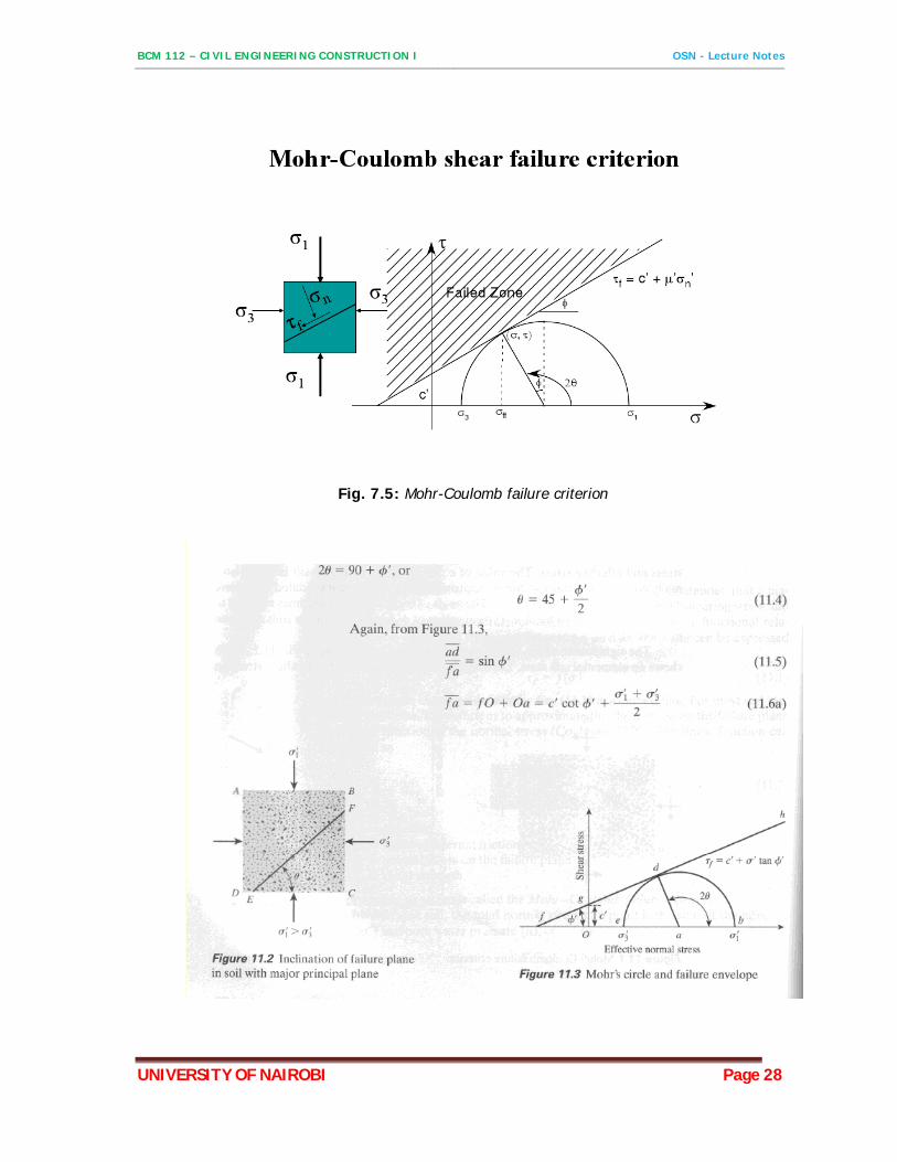
Fig. 7.5 represents the shear failure criterion indicating the failed and stable zone where µ = coefficient of friction and µ ' = effective coefficient of friction.
BCM 112 – CIVIL ENGINEERING CONSTRUCTION I OSN - Lecture Notes
UNIVERSITY OF NAIROBI Page 28
Fig. 7.5: Mohr-Coulomb failure criterion
BCM 112 – CIVIL ENGINEERING CONSTRUCTION I OSN - Lecture Notes
UNIVERSITY OF NAIROBI Page 29
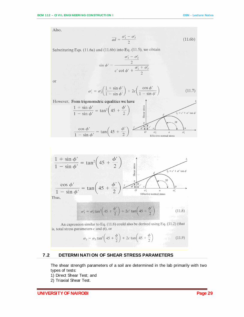
7.2 DETERMINATION OF SHEAR STRESS PARAMETERS
The shear strength parameters of a soil are determined in the lab primarily with two types of tests: 1) Direct Shear Test; and 2) Triaxial Shear Test.
BCM 112 – CIVIL ENGINEERING CONSTRUCTION I OSN - Lecture Notes
UNIVERSITY OF NAIROBI Page 30
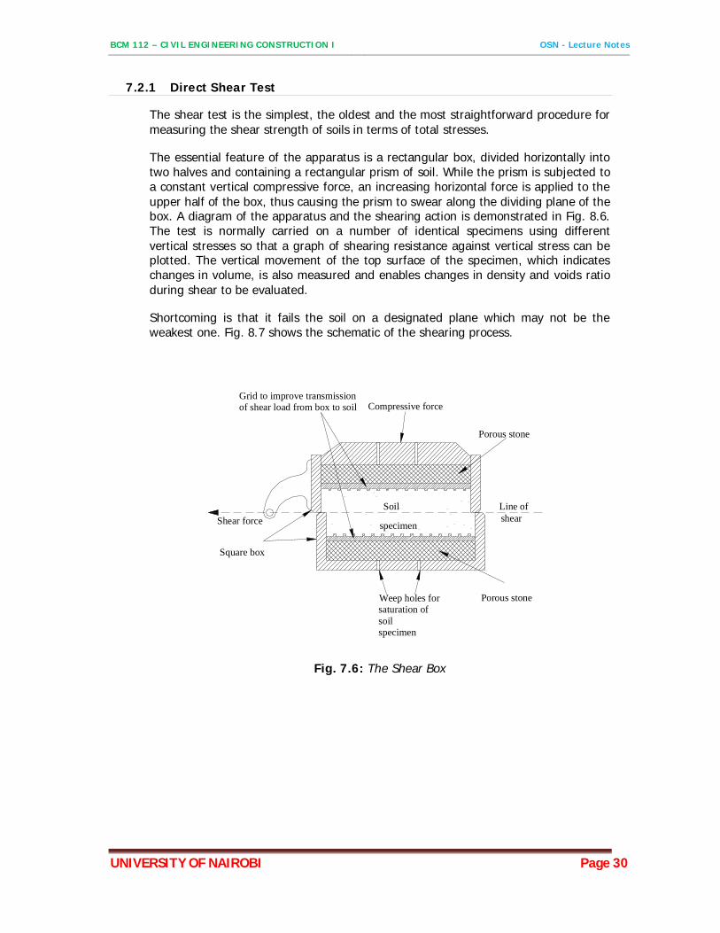
7.2.1 Direct Shear Test
The shear test is the simplest, the oldest and the most straightforward procedure for measuring the shear strength of soils in terms of total stresses.
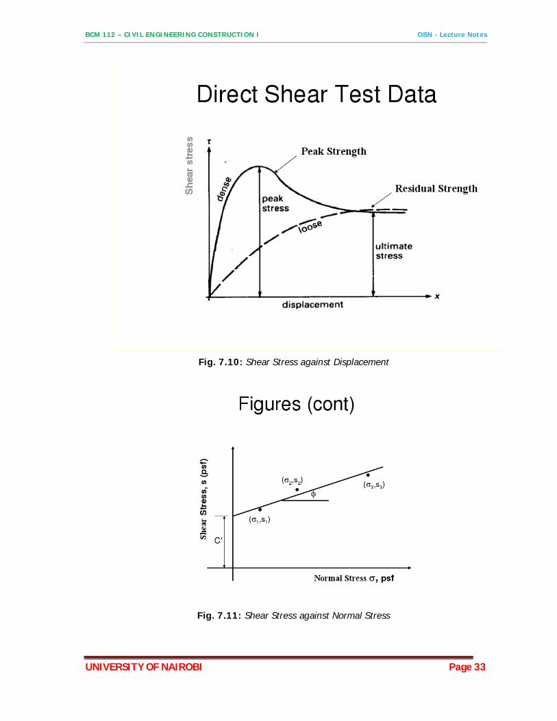
The essential feature of the apparatus is a rectangular box, divided horizontally into two halves and containing a rectangular prism of soil. While the prism is subjected to a constant vertical compressive force, an increasing horizontal force is applied to the upper half of the box, thus causing the prism to swear along the dividing plane of the box. A diagram of the apparatus and the shearing action is demonstrated in Fig. 8.6. The test is normally carried on a number of identical specimens using different vertical stresses so that a graph of shearing resistance against vertical stress can be plotted. The vertical movement of the top surface of the specimen, which indicates changes in volume, is also measured and enables changes in density and voids ratio during shear to be evaluated.
Shortcoming is that it fails the soil on a designated plane which may not be the weakest one. Fig. 8.7 shows the schematic of the shearing process.
Compressive force
Shear force
Square box
Weep holes for saturation of soilspecimen
Porous stone
shear
Porous stone
Grid to improve transmission of shear load from box to soil
Line ofSoil
specimen
Fig. 7.6: The Shear Box
BCM 112 – CIVIL ENGINEERING CONSTRUCTION I OSN - Lecture Notes
UNIVERSITY OF NAIROBI Page 31
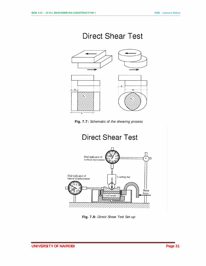
Fig. 7.7: Schematic of the shearing process
Fig. 7.8: Direct Shear Test Set-up
BCM 112 – CIVIL ENGINEERING CONSTRUCTION I OSN - Lecture Notes
UNIVERSITY OF NAIROBI Page 32
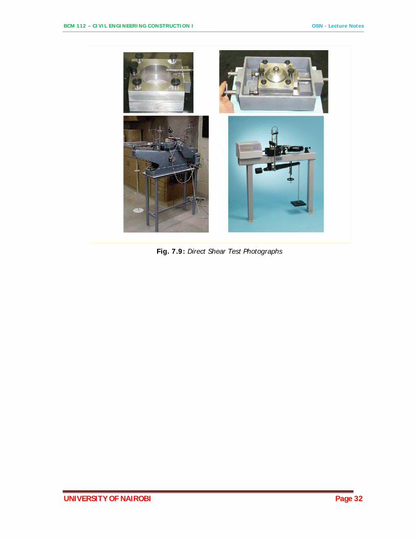
Fig. 7.9: Direct Shear Test Photographs
BCM 112 – CIVIL ENGINEERING CONSTRUCTION I OSN - Lecture Notes
UNIVERSITY OF NAIROBI Page 33
Fig. 7.10: Shear Stress against Displacement
Fig. 7.11: Shear Stress against Normal Stress
BCM 112 – CIVIL ENGINEERING CONSTRUCTION I OSN - Lecture Notes
UNIVERSITY OF NAIROBI Page 34
8 SOIL COMPACTION
8.1 INTRODUTION
Soil compaction is the process of increasing the density of soil by packing the particles together with reduction in volume of air. The process does not involve removal of water. The process primarily results in the increase of soil unit weight (density). The reduction of the air content results in the reduction of pores which act as conduits of water and consequently reduce the permeability of the soil. In addition compaction reduces the liquefaction and increases the erosion resistance of the soil. The result is increased shear strength and less compressibility of the soil.
The purpose of the compaction is to produce a soil having the physical properties appropriate to the particular project. A good measure of compaction is needed in the construction of road embankments, improvement of road subgrade, subbase and base layers. Compaction of materials in dams is needed to ensure stability and water tightness of the dam walls
8.2 THEORY OF COMPACTION
8.2.1 General
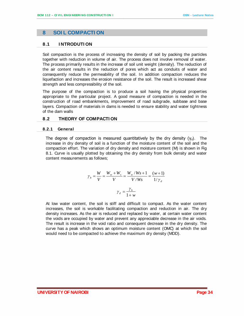
The degree of compaction is measured quantitatively by the dry density (γd). The increase in dry density of soil is a function of the moisture content of the soil and the compaction effort. The variation of dry density and moisture content (M) is shown in Fig 8.1. Curve is usually plotted by obtaining the dry density from bulk density and water content measurements as follows;
d
wswb
wWsV
WsWV
WWVW
/1)1(
/1/
wb
d
1
At low water content, the soil is stiff and difficult to compact. As the water content increases, the soil is workable facilitating compaction and reduction in air. The dry density increases. As the air is reduced and replaced by water, at certain water content the voids are occupied by water and prevent any appreciable decrease in the air voids. The result is increase in the void ratio and consequent decrease in the dry density. The curve has a peak which shows an optimum moisture content (OMC) at which the soil would need to be compacted to achieve the maximum dry density (MDD).
BCM 112 – CIVIL ENGINEERING CONSTRUCTION I OSN - Lecture Notes
UNIVERSITY OF NAIROBI Page 35
10
15
20
25
0.0 10.0 20.0 30.0
Dry
uni
t wei
ght (
kN/m
3)
Water Content (%)
Dry Density (kN/m3)
Power (Zero air voids)
MDD
OMC
Fig. 8.1: Typical compaction curve
8.2.2 Variation in Compaction Curve
A) Variation in compaction effort
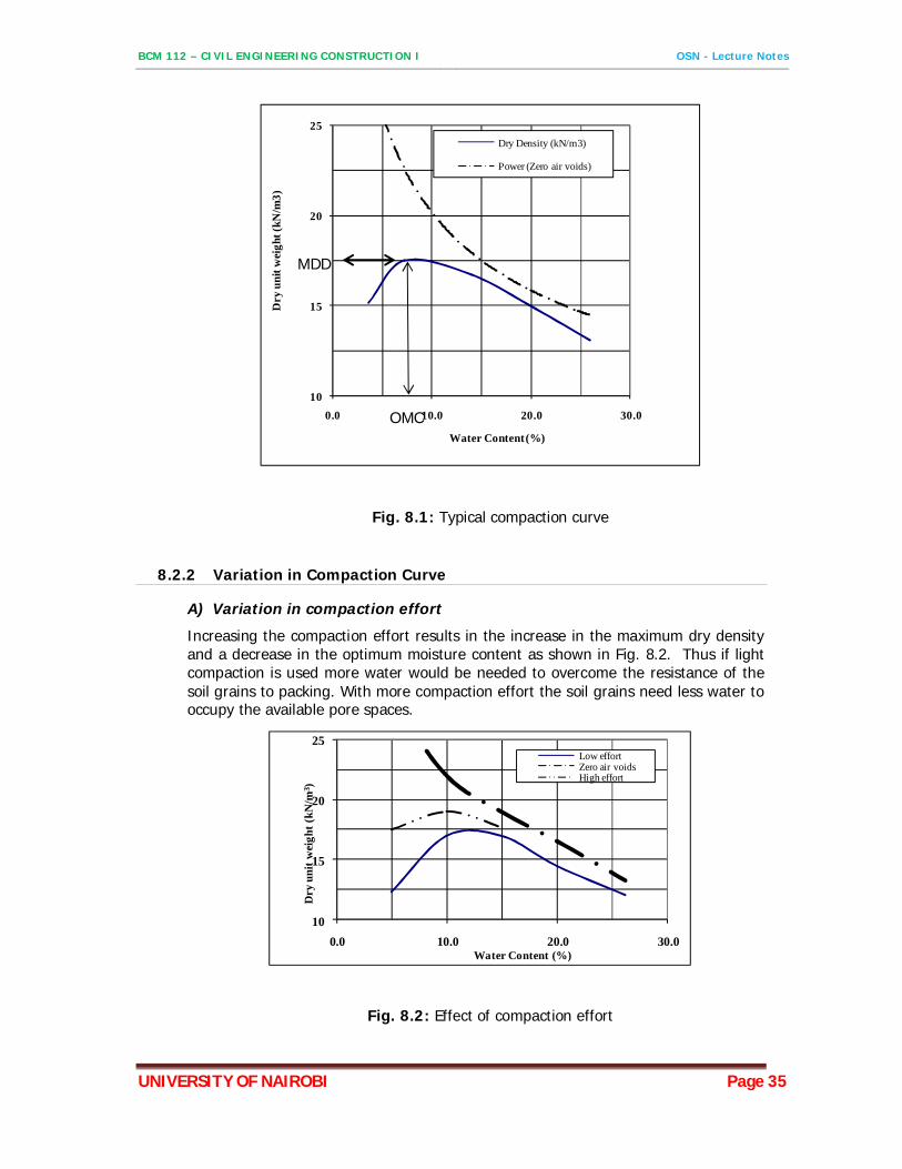
Increasing the compaction effort results in the increase in the maximum dry density and a decrease in the optimum moisture content as shown in Fig. 8.2. Thus if light compaction is used more water would be needed to overcome the resistance of the soil grains to packing. With more compaction effort the soil grains need less water to occupy the available pore spaces.
10
15
20
25
0.0 10.0 20.0 30.0
Dry
uni
t wei
ght (
kN/m
3 )
Water Content (%)
Low effortZero air voidsHigh effort
Fig. 8.2: Effect of compaction effort
BCM 112 – CIVIL ENGINEERING CONSTRUCTION I OSN - Lecture Notes
UNIVERSITY OF NAIROBI Page 36
B) Variation in soil grading soil type The particle size distribution influences the arrangement of particles in the compaction of soils. A well-graded soil will compact to lesser voids than a poorly graded soil. The effect is that the well-graded soils will have an increased density and improved properties such as bearing capacity on compaction. These enhanced strength characteristics of compacted fills are important because of the increasing need of embankments capable of supporting higher loads.
8.3 LABORATORY COMPACTION TESTS
Three types of compaction tests are explained. The first is the light manual compaction test with 2.5kg hammer. The second is heavy compaction test in which much greater compaction is achieved by use of 4.5kg hammer. The third is use of a vibrating hammer and is intended mainly for granular soils passing 37.5 mm test sieve with no more than 30% retained on a 20mm test sieve. For each type of test a small variation of the test is done to take recognition of whether the soil crushes during compaction.
The mould for 2.5 kg rammer method is 1000 cm3 and 100mm diameter. The test covers soil with particles finer than 20mm sieve size. The compaction is effected by free fall of the 2.5 kg rammer through 300mm in three layers. Each layer receives 27 blows
In 4.5kg method the rammer is 4.5kg. The rammer is made to freely fall through 450mm. In addition the soil in the same type of mould is compacted through 5 layers. Each layer receives 62 blows. The test is suitable for soils containing not more than 30% retained on 20mm sieve size. These particles may include particles retained on 37.5mm sieve size.
In the vibratory rammer method the mould is 2360cm3 and 152 mm diameter. The compaction is effected by placing the rammer on the soil surface and vibrating the rammer at 60±2seconds. During this period a steady downward force on the rammer is applied to enable a force of between 300 and 400 N to be applied on the soil. Like the method using 4.5 kg rammer the test is suitable for soils containing not more than 30% retained on 20mm sieve size. These particles may include particles retained on 37.5mm sieve size. The test is however not suitable for cohesive soils.
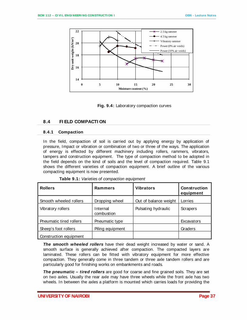
After the compaction using any of the three methods the mould is trimmed at the top. The soil bulk density and moisture content are determined. The soil dry density is then computed. The procedure is repeated at different moisture contents to enable the plotting of the compaction curve. The coordinates of the peak dry density define the MDD and OMC. Typical results are shown on Fig 9.4.
BCM 112 – CIVIL ENGINEERING CONSTRUCTION I OSN - Lecture Notes
UNIVERSITY OF NAIROBI Page 37
14
16
18
20
22
0 5 10 15 20 25 30
Dry
uni
t wei
ght (
kN/m
2 )
Moisture content (%)
2.5 kg rammer
4.5 kg rammer
Vibratory rammer
Power (0% air voids)
Power (10% air voids)
Fig. 9.4: Laboratory compaction curves
8.4 FIELD COMPACTION
8.4.1 Compaction
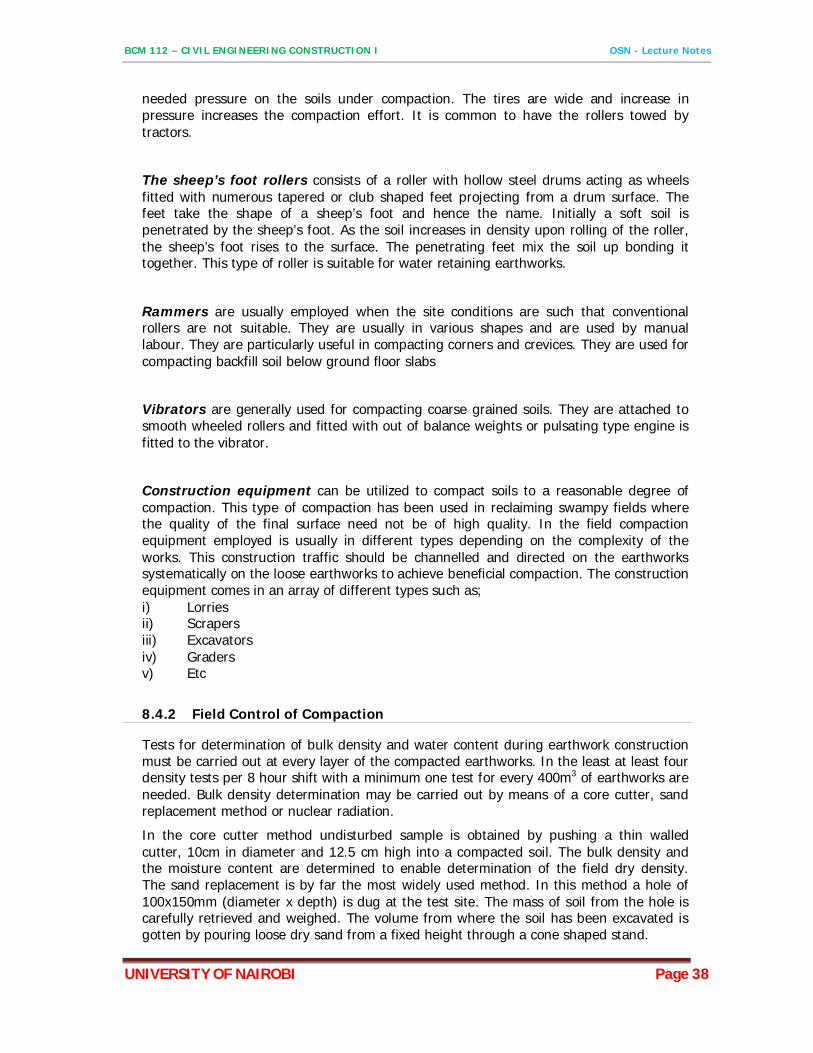
In the field, compaction of soil is carried out by applying energy by application of pressure, Impact or vibration or combination of two or three of the ways. The application of energy is effected by different machinery including rollers, rammers, vibrators, tampers and construction equipment. The type of compaction method to be adopted in the field depends on the kind of soils and the level of compaction required. Table 9.1 shows the different varieties of compaction equipment. A brief outline of the various compacting equipment is now presented.
Table 9.1: Varieties of compaction equipment
Rollers Rammers Vibrators Construction equipment
Smooth wheeled rollers Dropping wheel Out of balance weight Lorries
Vibratory rollers Internal combustion
Pulsating hydraulic Scrapers
Pneumatic tired rollers Pneumatic type Excavators
Sheep’s foot rollers Piling equipment Graders
Construction equipment
The smooth wheeled rollers have their dead weight increased by water or sand. A smooth surface is generally achieved after compaction. The compacted layers are laminated. These rollers can be fitted with vibratory equipment for more effective compaction. They generally come in three tandem or three axle tandem rollers and are particularly good for finishing works on embankments and roads.
The pneumatic – tired rollers are good for coarse and fine grained soils. They are set on two axles. Usually the rear axle may have three wheels while the front axle has two wheels. In between the axles a platform is mounted which carries loads for providing the
BCM 112 – CIVIL ENGINEERING CONSTRUCTION I OSN - Lecture Notes
UNIVERSITY OF NAIROBI Page 38
needed pressure on the soils under compaction. The tires are wide and increase in pressure increases the compaction effort. It is common to have the rollers towed by tractors.
The sheep’s foot rollers consists of a roller with hollow steel drums acting as wheels fitted with numerous tapered or club shaped feet projecting from a drum surface. The feet take the shape of a sheep’s foot and hence the name. Initially a soft soil is penetrated by the sheep’s foot. As the soil increases in density upon rolling of the roller, the sheep’s foot rises to the surface. The penetrating feet mix the soil up bonding it together. This type of roller is suitable for water retaining earthworks.
Rammers are usually employed when the site conditions are such that conventional rollers are not suitable. They are usually in various shapes and are used by manual labour. They are particularly useful in compacting corners and crevices. They are used for compacting backfill soil below ground floor slabs
Vibrators are generally used for compacting coarse grained soils. They are attached to smooth wheeled rollers and fitted with out of balance weights or pulsating type engine is fitted to the vibrator.
Construction equipment can be utilized to compact soils to a reasonable degree of compaction. This type of compaction has been used in reclaiming swampy fields where the quality of the final surface need not be of high quality. In the field compaction equipment employed is usually in different types depending on the complexity of the works. This construction traffic should be channelled and directed on the earthworks systematically on the loose earthworks to achieve beneficial compaction. The construction equipment comes in an array of different types such as; i) Lorries ii) Scrapers iii) Excavators iv) Graders v) Etc
8.4.2 Field Control of Compaction
Tests for determination of bulk density and water content during earthwork construction must be carried out at every layer of the compacted earthworks. In the least at least four density tests per 8 hour shift with a minimum one test for every 400m3 of earthworks are needed. Bulk density determination may be carried out by means of a core cutter, sand replacement method or nuclear radiation.
In the core cutter method undisturbed sample is obtained by pushing a thin walled cutter, 10cm in diameter and 12.5 cm high into a compacted soil. The bulk density and the moisture content are determined to enable determination of the field dry density. The sand replacement is by far the most widely used method. In this method a hole of 100x150mm (diameter x depth) is dug at the test site. The mass of soil from the hole is carefully retrieved and weighed. The volume from where the soil has been excavated is gotten by pouring loose dry sand from a fixed height through a cone shaped stand.
BCM 112 – CIVIL ENGINEERING CONSTRUCTION I OSN - Lecture Notes
UNIVERSITY OF NAIROBI Page 39
The nuclear radiation technique uses a nuclear gauge. In the usage of the gauge, an aluminum probe is inserted in the compacted soil. Neutrons are then released from a source. The neutrons loose energy depending on the soil density and water content as they pass through the soil. The instrument is calibrated to give water content, bulk density and the dry density of the soil. The instrument should be calibrated against the sand replacement test results.
8.4.3 Specification of the Field Compacted Density
The compacted density is usually specified as a percentage of the MDD as determined in the laboratory. In some instances the moisture content is required to be within a small band above or below the OMC. In rare instances the air content is specified. The specification usually ranges from 95-100% MDD when a 2.5 kg hammer is used the field control. A minimum number of roller passes is usually required to reach the desired compaction. The usual range is between 3 and 12 passes.
In road work embankments the specification for the lower layers is usually a minimum of 95% MDD. The compaction for the upper subgrade and the pavement layers should however be raised to between 100 and 105 MDD.
BCM 112 – CIVIL ENGINEERING CONSTRUCTION I OSN - Lecture Notes
UNIVERSITY OF NAIROBI Page 40
9 LATERAL PRESSURES AND RETAINING WALLS
9.1 INTRODUTION
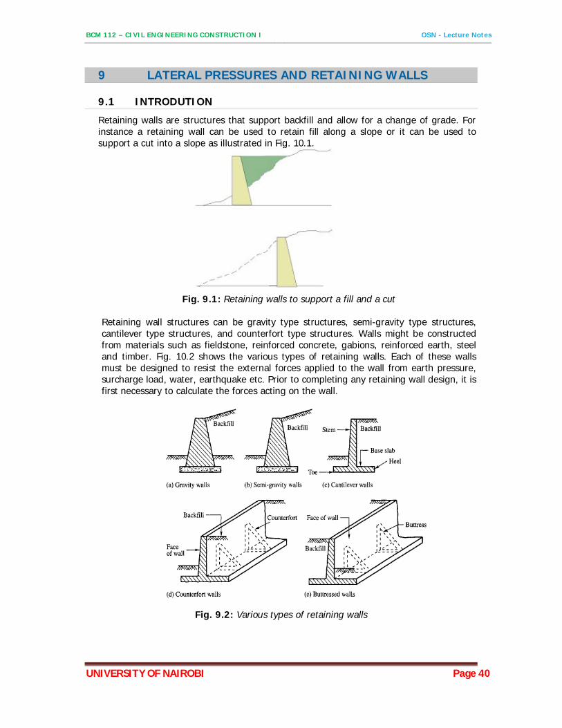
Retaining walls are structures that support backfill and allow for a change of grade. For instance a retaining wall can be used to retain fill along a slope or it can be used to support a cut into a slope as illustrated in Fig. 10.1.
Fig. 9.1: Retaining walls to support a fill and a cut
Retaining wall structures can be gravity type structures, semi-gravity type structures, cantilever type structures, and counterfort type structures. Walls might be constructed from materials such as fieldstone, reinforced concrete, gabions, reinforced earth, steel and timber. Fig. 10.2 shows the various types of retaining walls. Each of these walls must be designed to resist the external forces applied to the wall from earth pressure, surcharge load, water, earthquake etc. Prior to completing any retaining wall design, it is first necessary to calculate the forces acting on the wall.
Fig. 9.2: Various types of retaining walls
BCM 112 – CIVIL ENGINEERING CONSTRUCTION I OSN - Lecture Notes
UNIVERSITY OF NAIROBI Page 41
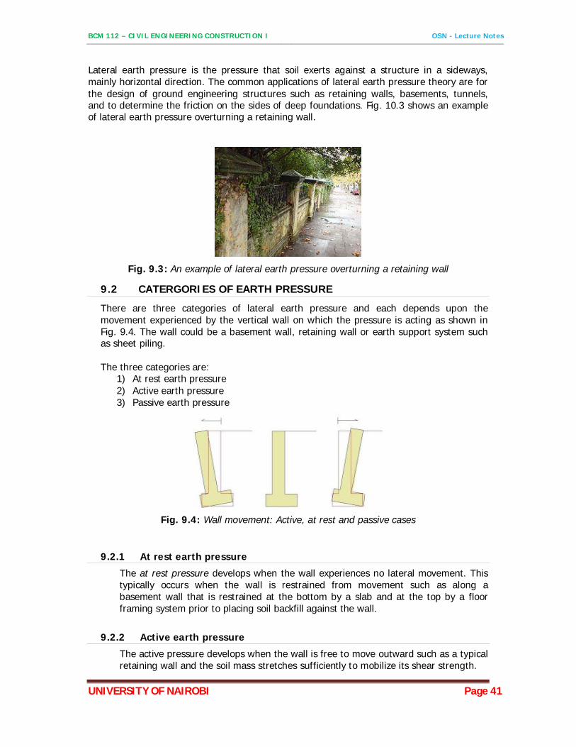
Lateral earth pressure is the pressure that soil exerts against a structure in a sideways, mainly horizontal direction. The common applications of lateral earth pressure theory are for the design of ground engineering structures such as retaining walls, basements, tunnels, and to determine the friction on the sides of deep foundations. Fig. 10.3 shows an example of lateral earth pressure overturning a retaining wall.
Fig. 9.3: An example of lateral earth pressure overturning a retaining wall
9.2 CATERGORIES OF EARTH PRESSURE
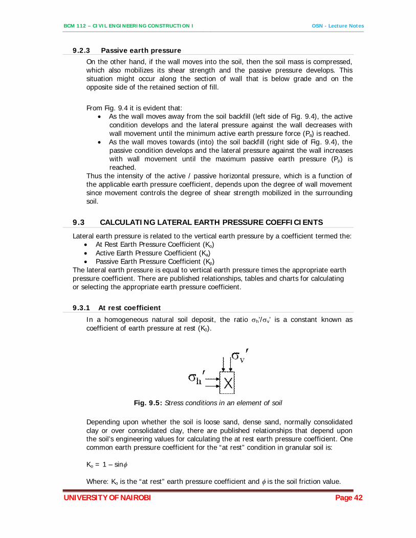
There are three categories of lateral earth pressure and each depends upon the movement experienced by the vertical wall on which the pressure is acting as shown in Fig. 9.4. The wall could be a basement wall, retaining wall or earth support system such as sheet piling. The three categories are:
1) At rest earth pressure 2) Active earth pressure 3) Passive earth pressure
Fig. 9.4: Wall movement: Active, at rest and passive cases
9.2.1 At rest earth pressure
The at rest pressure develops when the wall experiences no lateral movement. This typically occurs when the wall is restrained from movement such as along a basement wall that is restrained at the bottom by a slab and at the top by a floor framing system prior to placing soil backfill against the wall.
9.2.2 Active earth pressure
The active pressure develops when the wall is free to move outward such as a typical retaining wall and the soil mass stretches sufficiently to mobilize its shear strength.
BCM 112 – CIVIL ENGINEERING CONSTRUCTION I OSN - Lecture Notes
UNIVERSITY OF NAIROBI Page 42
9.2.3 Passive earth pressure On the other hand, if the wall moves into the soil, then the soil mass is compressed, which also mobilizes its shear strength and the passive pressure develops. This situation might occur along the section of wall that is below grade and on the opposite side of the retained section of fill.
From Fig. 9.4 it is evident that:
As the wall moves away from the soil backfill (left side of Fig. 9.4), the active condition develops and the lateral pressure against the wall decreases with wall movement until the minimum active earth pressure force (Pa) is reached.
As the wall moves towards (into) the soil backfill (right side of Fig. 9.4), the passive condition develops and the lateral pressure against the wall increases with wall movement until the maximum passive earth pressure (Pp) is reached.
Thus the intensity of the active / passive horizontal pressure, which is a function of the applicable earth pressure coefficient, depends upon the degree of wall movement since movement controls the degree of shear strength mobilized in the surrounding soil.
9.3 CALCULATING LATERAL EARTH PRESSURE COEFFICIENTS
Lateral earth pressure is related to the vertical earth pressure by a coefficient termed the: At Rest Earth Pressure Coefficient (Ko) Active Earth Pressure Coefficient (Ka) Passive Earth Pressure Coefficient (Kp)
The lateral earth pressure is equal to vertical earth pressure times the appropriate earth pressure coefficient. There are published relationships, tables and charts for calculating or selecting the appropriate earth pressure coefficient.
9.3.1 At rest coefficient
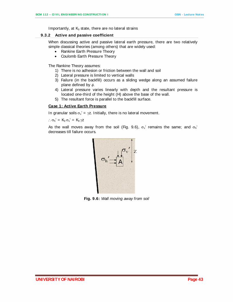
In a homogeneous natural soil deposit, the ratio h’/v’ is a constant known as coefficient of earth pressure at rest (K0).
Fig. 9.5: Stress conditions in an element of soil
Depending upon whether the soil is loose sand, dense sand, normally consolidated clay or over consolidated clay, there are published relationships that depend upon the soil’s engineering values for calculating the at rest earth pressure coefficient. One common earth pressure coefficient for the “at rest” condition in granular soil is: Ko = 1 – sin
Where: Ko is the “at rest” earth pressure coefficient and is the soil friction value.
BCM 112 – CIVIL ENGINEERING CONSTRUCTION I OSN - Lecture Notes
UNIVERSITY OF NAIROBI Page 43
Importantly, at K0 state, there are no lateral strains
9.3.2 Active and passive coefficient
When discussing active and passive lateral earth pressure, there are two relatively simple classical theories (among others) that are widely used:
Rankine Earth Pressure Theory Coulomb Earth Pressure Theory
The Rankine Theory assumes:
1) There is no adhesion or friction between the wall and soil 2) Lateral pressure is limited to vertical walls 3) Failure (in the backfill) occurs as a sliding wedge along an assumed failure
plane defined by . 4) Lateral pressure varies linearly with depth and the resultant pressure is
located one-third of the height (H) above the base of the wall. 5) The resultant force is parallel to the backfill surface.
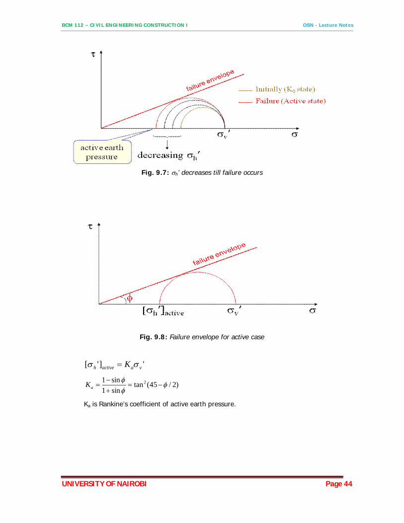
Case 1: Active Earth Pressure
In granular soils v’ = z. Initially, there is no lateral movement.
h’ = K0 v’ = K0 z
As the wall moves away from the soil (Fig. 9.6), v’ remains the same; and h’ decreases till failure occurs.
Fig. 9.6: Wall moving away from soil
BCM 112 – CIVIL ENGINEERING CONSTRUCTION I OSN - Lecture Notes
UNIVERSITY OF NAIROBI Page 44
Fig. 9.7: h’ decreases till failure occurs
Fig. 9.8: Failure envelope for active case
']'[ vaactiveh K
)2/45(tansin1sin1 2
aK
Ka is Rankine’s coefficient of active earth pressure.
BCM 112 – CIVIL ENGINEERING CONSTRUCTION I OSN - Lecture Notes
UNIVERSITY OF NAIROBI Page 45
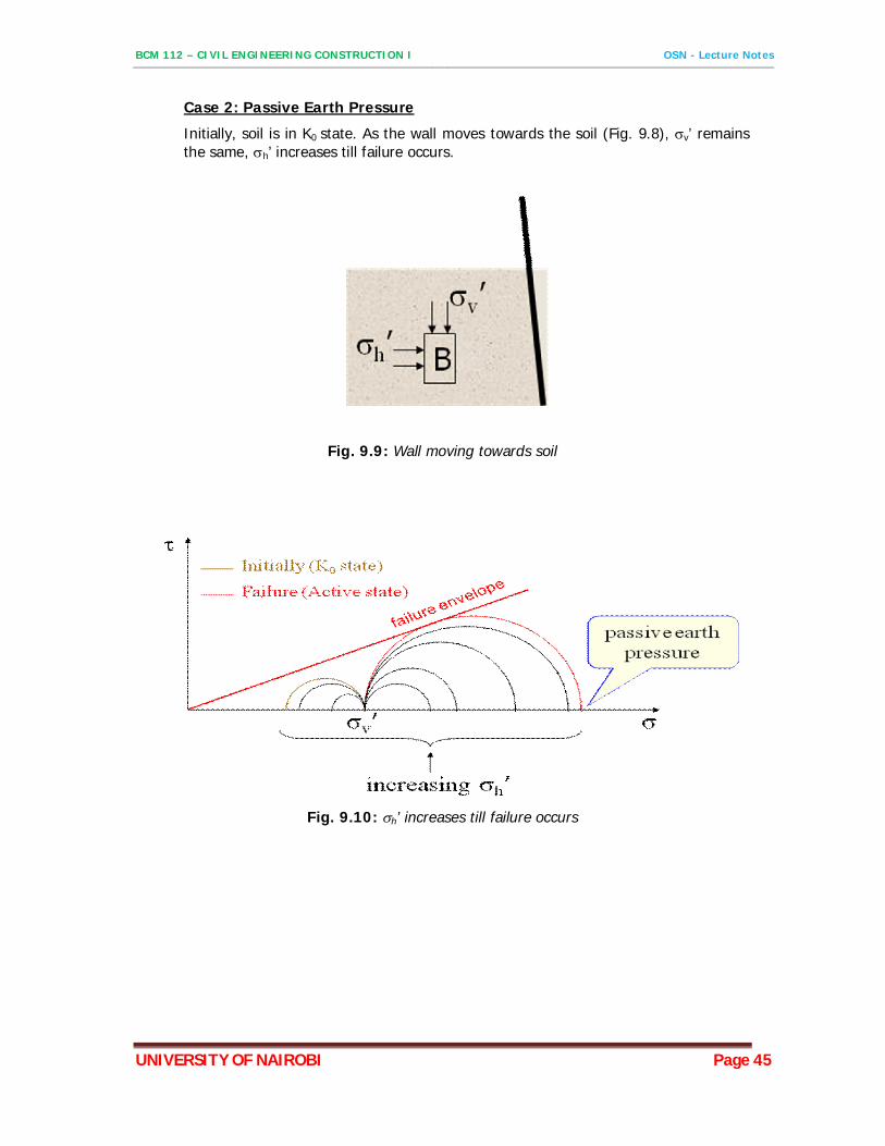
Case 2: Passive Earth Pressure
Initially, soil is in K0 state. As the wall moves towards the soil (Fig. 9.8), v’ remains the same, h’ increases till failure occurs.
Fig. 9.9: Wall moving towards soil
Fig. 9.10: h’ increases till failure occurs
BCM 112 – CIVIL ENGINEERING CONSTRUCTION I OSN - Lecture Notes
UNIVERSITY OF NAIROBI Page 46
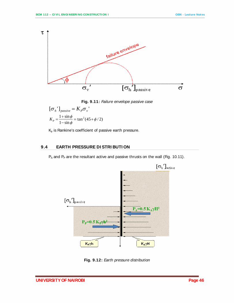
Fig. 9.11: Failure envelope passive case
']'[ vPpassiveh K
)2/45(tansin1sin1 2
PK
Kp is Rankine’s coefficient of passive earth pressure.
9.4 EARTH PRESSURE DISTRIBUTION
PA and PP are the resultant active and passive thrusts on the wall (Fig. 10.11).
Fig. 9.12: Earth pressure distribution
BCM 112 – CIVIL ENGINEERING CONSTRUCTION I OSN - Lecture Notes
UNIVERSITY OF NAIROBI Page 47
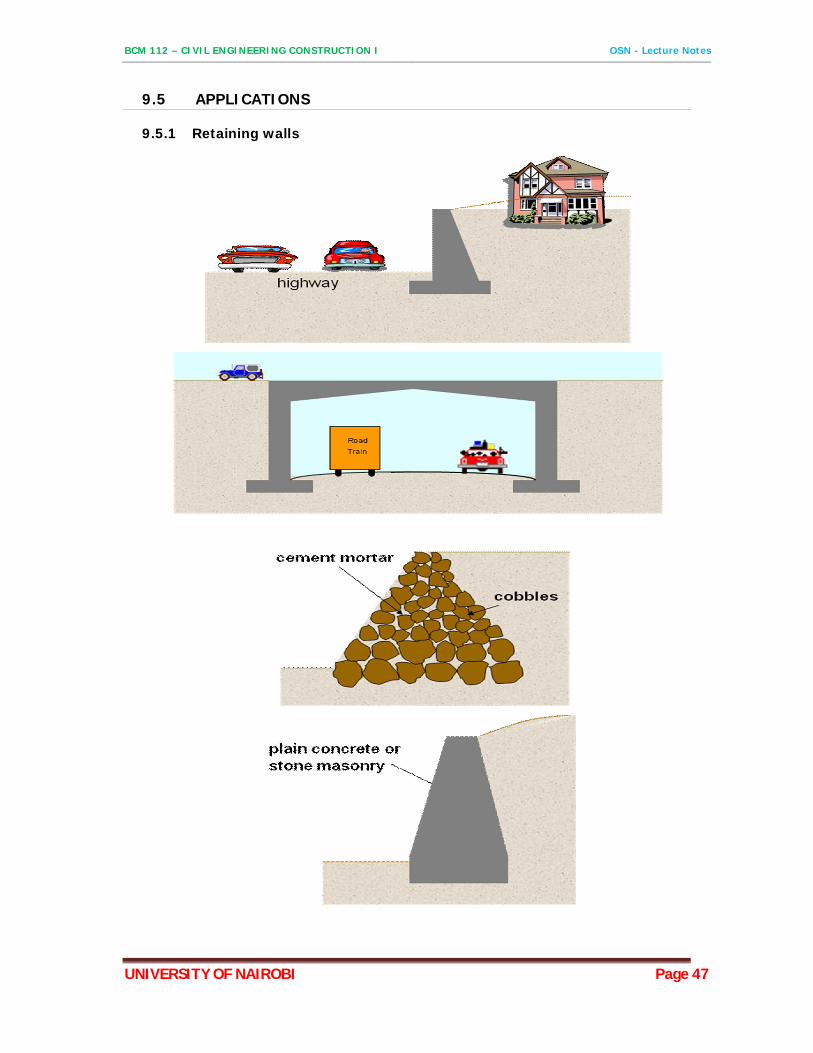
9.5 APPLICATIONS
9.5.1 Retaining walls
BCM 112 – CIVIL ENGINEERING CONSTRUCTION I OSN - Lecture Notes
UNIVERSITY OF NAIROBI Page 48
10 ROAD DESIGN
10.1 ROAD PAVEMENT
Is that component of a road system that is designed, constructed and maintained to ensure that stresses, strains and deflections that emanate from traffic loading as well as from changes in foundation and environmental conditions do not result into premature failure of the road.
10.2 FACTORS INFLUENCING DESIGN OF THE PAVEMENT
Traffic loading Foundation condition Environmental condition e.g. weather, rainfall, temperature etc Material characteristics Performance characteristics Cost consideration
10.3 ROAD CONSTRUCTION MATERIALS
Soils Rock Binders – bitumen, tar, cement, lime, Water Plastics/Geofabrics/Geotextiles Steel
10.4 PAVEMENT DESIGN PHILOSOPHY (CRITERIA)
Resistance to deformation Resistance to cracking Resistance to breaking, crushing of granular materials Resistance to weathering
10.5 PAVEMENT TYPES
10.5.1 Flexible pavements
Is pavement structure that allows a certain amount of flexibility while maintaining sufficient rigidity to resist deformation.
It comprises of a number of layers being dependent on loading, soil quality, availability of materials etc.
A typical flexible pavement structure consists of the surface course and the underlying base and subbase courses. Each of these layers contributes to structural support and drainage. The surface course is the stiffest and contributes the most to pavement strength. The underlying layers are less stiff but are still important to pavement strength as well as drainage and frost protection.
BCM 112 – CIVIL ENGINEERING CONSTRUCTION I OSN - Lecture Notes
UNIVERSITY OF NAIROBI Page 49
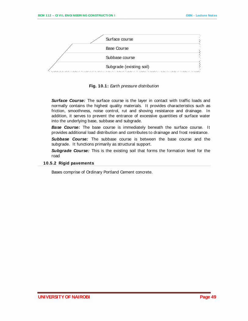
Surface course
Base Course
Subbase course
Subgrade (existing soil)
Fig. 10.1: Earth pressure distribution
Surface Course: The surface course is the layer in contact with traffic loads and normally contains the highest quality materials. It provides characteristics such as friction, smoothness, noise control, rut and shoving resistance and drainage. In addition, it serves to prevent the entrance of excessive quantities of surface water into the underlying base, subbase and subgrade. Base Course: The base course is immediately beneath the surface course. It provides additional load distribution and contributes to drainage and frost resistance.
Subbase Course: The subbase course is between the base course and the subgrade. It functions primarily as structural support. Subgrade Course: This is the existing soil that forms the formation level for the road
10.5.2 Rigid pavements
Bases comprise of Ordinary Portland Cement concrete.