Embed Size (px)
Citation preview
MIAMI - The Florida Department of Transportation (FDOT) contracted with the Miami Access Tunnel (MAT) concessionaire group to construct two 42-feet (12.8m) outside diameter tunnels with two lanes of traffic each way between Watson and Dodge Islands to alleviate traffic congestion in downtown Miami. Malcolm Drilling Company Inc. (MDCI) is the specialty foundation con-tractor constructing the two sets of support of excavation (SOE), break-in and break-out plugs and soil improve-ment for the launch and reception of the Tunnel Boring Machine (TBM) on each island. Bouygues Civil Work Florida (BCWF), a minority partner in the MAT conces-sionaire group, is the General Contractor for the Port of Miami Tunnel (POMT) project. The POMT project is a public-private partnership (PPP or P3) that is responsible for the design-build-finance-operate-and-maintenance of the tunnels.
As part of the Panama Canal expansion and the dredg-ing of the Government Cut Channel, the Port of Miami is planning for an increase in container traffic. Currently all of the trucking containers are routed from the inter-state through downtown Miami causing congestion on the downtown streets. The POMT Project will route the commercial traffic directly from MacArthur Causeway expressway to the Port of Miami which only allows com-mercial traffic and buses for the cruise ships in the port. Private vehicles and taxis going to the cruise terminals will continue to use the current downtown Miami access. “The Watson Island support of excavation and TBM plug is where the TBM will be launched. The TBM will go from Watson Island between the MacArthur Causeway Eastbound and Westbound lanes, and then it will make a gradual curve south going underneath the channel and cruise ship port. Then it will gradually sweep to the west and exit on Dodge Island between the Port Boulevard Eastbound and Westbound lanes,” said Charlie Bartlett, Malcolm Drilling’s Regional Vice President and Techni-cal Project Manager.
The geologic profile on Watson and Dodge Islands pres-ents a formidable challenge for the installation of the var-ious foundation elements. Fill material with rubble over-
BAUER-PILECOnewsNorth America
January 2011
Malcolm Drilling Builds Break-In Plugs for Port of Miami Tunnel with BAUER Equipment
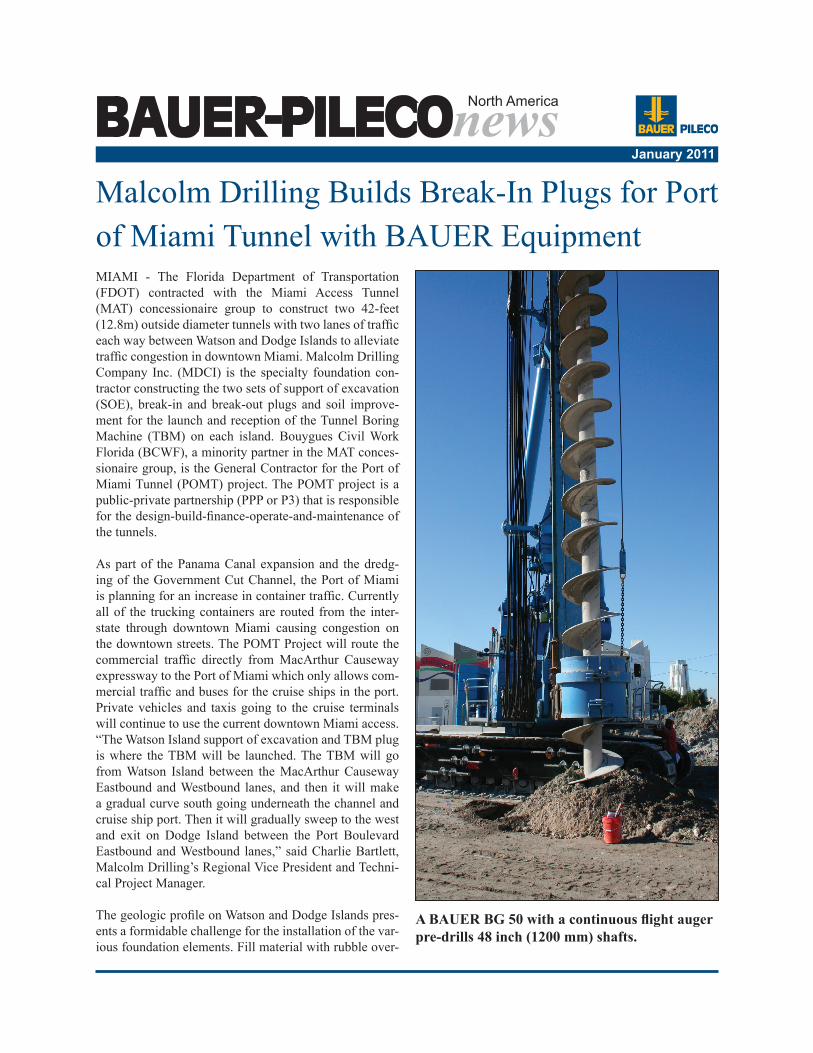
A BAUER BG 50 with a continuous flight auger pre-drills 48 inch (1200 mm) shafts.
lies the native sand. Underneath the native sand, several layers of very porous, vuggy limestone of inconsistent strengths serve as the bearing layer for the various foun-dation elements. Loss of material into the highly voided lower limestone layers was a primary concern prior to the start of the project.
Malcolm Drilling was challenged with various founda-tion elements on the POMT which includes a 48-inch (1219mm) continuous flight auger predrill through soil and rock for preparation of the subsurface predrilled ma-terial for cutter soil mixing (CSM), with embedded W36 soldier piles, 12-ft (3.65m) diameter unreinforced secant piles, 36-inch (915mm) diameter drilled shaft tension ele-ments with embedded H14-pile, unreinforced CSM bar-rettes, 6-inch diameter tieback anchors, 8.5-inch diameter minipiles from sectional barges and 9-ft (2.74m) diam-eter shallow soil mixed columns. Prior to commencement of production work all of the foundation elements were subjected to a testing program to confirm Malcolm Drill-ing’s methodology would meet the project specifications, permeability requirements and design loading. During production work, an extensive quality control program is ongoing to verify and document proper installation of the various elements. These foundation elements were used in combination to construct the walls for the SOE, the tremie seal for the SOE, the break-in/break-out plug for the TBM and the ground improved arch constructed in
the soil adjacent to the plug which will allow the TBM to maintain air pressure in shallow ground.
Malcolm Drilling’s work on the POMT highlights the versatility of the Bauer BG and the Klemm drill rigs. The Bauer BG50, the first of its kind in the world, is being used to perform pre-drilling of the overlying soil and limestone to a depth of over 65 feet (20 m) using a 48-inch (1219mm) diameter Continuous Flight Auger (CFA). The BG 50 was switch over to kelly drilling mode for installation of 12-ft (3.65m) diameter secant piles in the break-in/break-out plug after completion of the pre-drilling. The BG 40’s are being used to install the CSM panels, 36-inch (915mm) diameter drilled shaft tension elements and 9-ft (2.74m) diameter shallow soil mixed columns. The Klemm is being used to install the tieback anchors and minipiles. To date, Malcolm Drilling has completed over 800 linear feet (244m) or 45,000 square feet (4,166 square meters) of SOE wall consisting of 101 4-ft (1.2m) wide by 9.2 ft (2.8m) CSM panels with two W36 soldier piles embed-ded in each panel. Six verification boreholes with rising head permeability test values of less than 1 x 10⁻⁷ cm/sec confirmed the maximum permeability of 1 x 10⁻⁶ cm/sec requirement was met. Daily wet bulk samples of the CSM material and subsequent cores from the verification borings confirmed the minimum strength requirement of
January 2011BAUER-PILECOnews Page 2
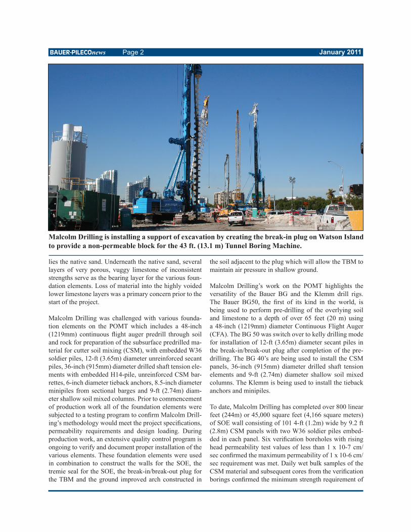
Malcolm Drilling is installing a support of excavation by creating the break-in plug on Watson Island to provide a non-permeable block for the 43 ft. (13.1 m) Tunnel Boring Machine.
250 psi was achieved.
The 110-ft by 400-ft (33.5m x 121.9m) excavation will be performed in two stages. First, a dry excavation to Elev. 3 ft, was performed to install the tie-backs. The second stage, a wet excavation, will be performed to the bottom of the tremie seal slab. The excavated surface will cre-ate a gradual ramp at an approximately 6 percent grade from Elev. 10 feet (3m) to Elev. -35 feet (-10.6m) with a tremie seal slab thickness of 4 to 5 feet. A finish slab will be poured after the completion of the tunneling work for the pavement of the traffic lanes. Two types of tension elements will be installed to resist the hydrostatic uplift on the tremie seal and provide axial support of the TBM during erection.
Prior to excavating the tieback bench, a BG 40 was used to install 36-inch (915mm) diameter Type II tension ele-ments which are drilled shafts made highly challenging by reinforcement and concrete cut-offs from 15 to 25 below grade. Temporary 48-inch (1220mm) casing was initially installed and excavated below concrete cutoff to provide support of excavation during the removal of ex-cess concrete. A 39-inch (1000mm) sectional casing was installed inside the 48-inch (1220mm) casing to the tip of the tension element. Malcolm Drilling developed an
innovative system of installing the H14 x 102 Grade 50 H-piles with 2 ft by 2 ft (600mm x 600mm) bearing plates at the cutoff elevation. A multi-positional follower beam of the same size as the pile reinforcement with a bearing plate to match the bearing plate of the pile was used to guide the H-pile into the excavation and place it at the proper elevation. Styrofoam block outs placed at the top of the H-pile kept a clean bonding surface for the subse-quent tremie seal.
After BCWF excavated a 30-ft wide bench from Eleva-tion 10 feet to Elevation 3 feet on each side of the SOE, Malcolm Drilling installed 122 6-inch diameter, 5 to 9 strand, tiebacks with lengths of 110 (33m) to 140 feet (43m) using the dual rotary Klemm 806-3. A down-the-hole (DTH) hammer was used to excavate while casing was twisted into place with the lower rotary unit. Geo-textile socks and grout additives were used to control the amount of grout which would migrate into the highly po-rous limestone. The anchors were placed just above the water table at Elev. 2.5 ft. (762mm). The placement of the anchor heads above the water table eased the con-struction process while maximizing the performance of the tieback. Walers connected to the tiebacks transfer the load to the soldier piles in the CSM wall to provide lat-eral restraint for the top of the wall. The CSM panels are
January 2011BAUER-PILECOnews Page 3
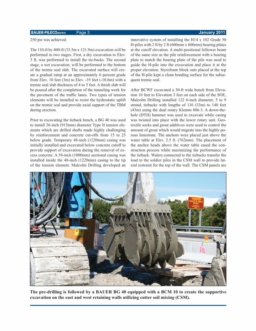
The pre-drilling is followed by a BAUER BG 40 equipped with a BCM 10 to create the supportive excavation on the east and west retaining walls utilizing cutter soil mixing (CSM).
embedded into the most competent limestone layer on the site to provide passive resistance at the toe of the SOE wall.
Malcolm Drilling recently completed construction of the TBM plug for the Eastbound and Westbound tunnels on Watson Island using the BG 40 BCM-10 cutter soil mixer and a BG 50 equipped with a 12-ft (3.65m) rock digging bucket constructed for the job by Continental Tool Com-pany (CTC). “As the CSM rig comes down to the end of the East SOE wall, we’ll start returning to work on the plug lattice pattern. We’re making boxes. The CSM box-es along with the 12-ft (3.65m) secant piles make up the break-in plug for the tunnel boring machine. If they just started the TBM without the break-in plug, the ground would not provide the lateral thrust resistance required to advance the machine and absent overburden confin-ing pressure the earth pressure balanced machine could not maintain the pressure required to keep the water from flooding the machine” said, Malcolm Drilling Superin-tendent Wayne Broughton.
The idea for the design of the 114-ft (35m) wide by 62-ft (19m) long by 50-ft (15m) deep TBM plug was devel-oped by Malcolm Drilling during the pre-construction phase. The purpose of the plug is to provide the TBM a water tight entry point for the start of the tunneling pro-
cess. After the TBM penetrates approximately 40 feet (12.1m) into the plug, the sealing system between the tun-nel shield and the pre-cast 2-ft (600mm) thick concrete segments that comprise the tunnel lining can be installed to prevent water seepage into the completed tunnel. The break-in plug is comprised of a square lattice of over-lapping cutter soil mix (CSM) panels with an inside face to face of 7 feet (2.1m). Daily wet bulk samples of the CSM material and subsequent cores from the verification borings confirmed the minimum strength requirement of 250 psi is achieved. After completion of the CSM panels the unmixed soil within the lattice is excavated in a se-cant pile pattern in both directions and replaced with a minimum 750 psi controlled density fill. The lattice work of CSM panels serves as the support of excavation for the 12-ft (3.65m) secant piles as well as the impermeable material in the unexcavated material between the secant piles.
After completion of the TBM plug, the second stage of the excavation will proceed. The Klemm 806 will be used to install 8.5-inch (216mm) diameter minipiles in the 30 to 40-foot (9.14m to 12.20m) deep portion of the excava-tion from sectional barges. A DTH will be used to ex-cavate within the casing while the casing is twisted into place with the lower rotary unit. A 3-inch Grade 150 high-strength threaded bar will be placed in the cased excava-
January 2011BAUER-PILECOnews Page 4
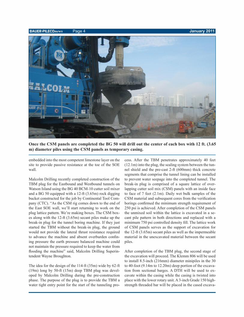
Once the CSM panels are completed the BG 50 will drill out the center of each box with 12 ft. (3.65 m) diameter piles using the CSM panels as temporary casing.
tion prior to tremie of a 4,000 psi grout. Geotextile socks and grout additives will be used to control the amount of grout migrating into the highly porous deeper limestone. Divers will later attach the shear plate connection on the top of the threaded bar prior to pouring the tremie seal.
The BG 40 which performed the kelly drilling on the 36-inch (915mm) diameter tension elements was recently converted to CFA mode to perform ground improvement on a loose top layer of fill material overlying the East-bound and Westbound tunnels. The 9-ft (2.74m) diam-eter overlapping shallow soil mixed columns prevents the upper layer of fill from caving in on the TBM before in reaches the deeper limestone layers. “We’re going to in-stall the shallow soil mix columns down to approximately 20 feet (6.1m) from grade to the S3 layer which is the Miami Limestone layer. It is the first competent limestone layer at the site. Above it is loose fill and sand. When the TBM starts, the top of it will be approximately 10 feet above grade and the cutting head has to have a balanced pressure on it for it to cut evenly. We are improving the ground from existing grade at Elev. 10 ft (3.04m) to Elev. -10 ft. (-3.04m). The client is adding roller compacted concrete (RCC) material to an Elevation of 27 ft (8.23m) prior to start of tunneling to ensure the TBM is confined and to allow the cutting head to function properly.” said Bartlett.
The TBM will continue its path over to Dodge Island be-fore turning around to begin the second tunnel. Malcolm Drilling is scheduled to start work on Dodge Island SOE in May 2011.
Malcolm Drilling is installing 36 inch diameter type two tie-downs which are drilled shafts with cut-offs using a BAUER BG 40.
January 2011BAUER-PILECOnews Page 5
PUBLISHER’S DETAILS
Editor: Ty WeaverTechnical Writer: Charlie Bartlett, Malcolm Drilling Company
BAUER-Pileco111 Berry Road, Houston, TX 77022bauerpileco.com | facebook.com/bauerpileco | (713) 691-3000
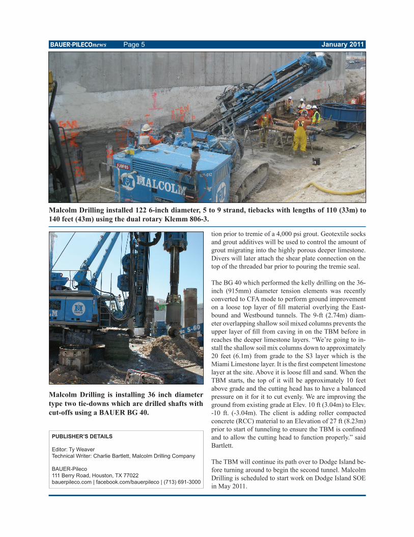
Malcolm Drilling installed 122 6-inch diameter, 5 to 9 strand, tiebacks with lengths of 110 (33m) to 140 feet (43m) using the dual rotary Klemm 806-3.